© 2006 Panasonic HA Air-Conditioning (M) Sdn. Bhd. (11969-T). All rights reserved. Unauthorized copying and distribution is a violation of law. Order No. MAC0612070C3 Air Conditioner CS-C18GKV CU-C18GKV CS-C24GKV CU-C24GKV TABLE OF CONTENTS PAGE PAGE 1 Safety Precautions ----------------------------------------------- 3 2 Specifications ----------------------------------------------------- 5 2.1. CS-C18GKV CU-C18GKV ------------------------------ 5 2.2. CS-C24GKV CU-C24GKV ------------------------------ 7 3 Features ------------------------------------------------------------- 9 4 Location of Controls and Components ------------------10 4.1. Product Overview-----------------------------------------10 5 Dimensions -------------------------------------------------------- 11 5.1. Indoor Unit & Remote Control -------------------------11 5.2. Outdoor Unit -----------------------------------------------12 6 Refrigeration Cycle Diagram --------------------------------13 7 Block Diagram----------------------------------------------------14 8 Wiring Connection Diagram ---------------------------------15 8.1. CS-C18GK CU-C18GK ---------------------------------15 8.2. CS-C24GK CU-C24GK ---------------------------------16 9 Electronic Circuit Diagram -----------------------------------17 10 Printed Circuit Board-------------------------------------------18 10.1. Indoor Unit--------------------------------------------------18 10.2. Indicator-----------------------------------------------------20 11 Installation Instruction ---------------------------------------- 21 11.1. Indoor Unit ------------------------------------------------- 22 11.2. Outdoor Unit----------------------------------------------- 24 12 Operation and Control ---------------------------------------- 27 12.1. Cooling Operation---------------------------------------- 27 12.2. Soft Dry Operation --------------------------------------- 28 12.3. Automatic Operation ------------------------------------ 29 12.4. Operation Control ---------------------------------------- 30 12.5. Indoor Fan Speed Control ----------------------------- 33 12.6. Outdoor Fan Speed Control --------------------------- 34 12.7. Vertical Airflow Direction Control--------------------- 35 12.8. Horizontal Airflow Direction Control ----------------- 35 12.9. Powerful Operation -------------------------------------- 36 12.10. Quiet Operation------------------------------------------- 37 12.11. Timer Control---------------------------------------------- 37 12.12. Random Auto Restart Control ------------------------ 38 12.13. Remote Control Signal Receiving Sound ---------- 38 12.14. Patrol Operation ------------------------------------------ 39 12.15. e-ion Operation ------------------------------------------- 42

Welcome message from author
This document is posted to help you gain knowledge. Please leave a comment to let me know what you think about it! Share it to your friends and learn new things together.
Transcript
Order No. MAC0612070C3
Air ConditionerCS-C18GKV CU-C18GKVCS-C24GKV CU-C24GKV
TABLE OF CONTENTSPAGE PAGE
1 Safety Precautions----------------------------------------------- 32 Specifications ----------------------------------------------------- 5
2.1. CS-C18GKV CU-C18GKV ------------------------------ 52.2. CS-C24GKV CU-C24GKV ------------------------------ 7
3 Features ------------------------------------------------------------- 94 Location of Controls and Components ------------------10
4.1. Product Overview-----------------------------------------105 Dimensions--------------------------------------------------------11
5.1. Indoor Unit & Remote Control -------------------------115.2. Outdoor Unit -----------------------------------------------12
6 Refrigeration Cycle Diagram --------------------------------137 Block Diagram----------------------------------------------------148 Wiring Connection Diagram ---------------------------------15
8.1. CS-C18GK CU-C18GK ---------------------------------158.2. CS-C24GK CU-C24GK ---------------------------------16
9 Electronic Circuit Diagram -----------------------------------1710 Printed Circuit Board-------------------------------------------18
10.1. Indoor Unit--------------------------------------------------1810.2. Indicator-----------------------------------------------------20
11 Installation Instruction ---------------------------------------- 2111.1. Indoor Unit ------------------------------------------------- 2211.2. Outdoor Unit----------------------------------------------- 24
12 Operation and Control ---------------------------------------- 2712.1. Cooling Operation---------------------------------------- 2712.2. Soft Dry Operation --------------------------------------- 2812.3. Automatic Operation ------------------------------------ 2912.4. Operation Control ---------------------------------------- 3012.5. Indoor Fan Speed Control ----------------------------- 3312.6. Outdoor Fan Speed Control --------------------------- 3412.7. Vertical Airflow Direction Control --------------------- 3512.8. Horizontal Airflow Direction Control ----------------- 3512.9. Powerful Operation -------------------------------------- 36
12.10. Quiet Operation------------------------------------------- 3712.11. Timer Control---------------------------------------------- 3712.12. Random Auto Restart Control ------------------------ 3812.13. Remote Control Signal Receiving Sound ---------- 3812.14. Patrol Operation------------------------------------------ 3912.15. e-ion Operation ------------------------------------------- 42
© 2006 Panasonic HA Air-Conditioning (M) Sdn.Bhd. (11969-T). All rights reserved. Unauthorizedcopying and distribution is a violation of law.
13 Servicing Mode -------------------------------------------------- 4513.1. Auto OFF/ON Button ------------------------------------ 4513.2. Select Remote Control Transmission Code ------- 4513.3. Remote Control Button --------------------------------- 46
14 Troubleshooting Guide---------------------------------------- 4714.1. Refrigeration cycle system----------------------------- 47
15 Disassembly and Assembly Instructions --------------- 4915.1. Indoor Electronic Controllers and Control
Board Removal Procedures --------------------------- 4915.2. Indoor Fan Motor and Cross Flow Fan
Removal Procedures------------------------------------ 5216 Technical Data---------------------------------------------------- 54
16.1. Thermostat Characteristics ---------------------------- 5416.2. Operation Characteristics ------------------------------ 55
17 Exploded View and Replacement Parts List ----------- 5917.1. Indoor Unit ------------------------------------------------- 5917.2. Outdoor Unit ----------------------------------------------- 61
2
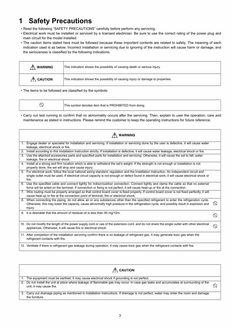
1 Safety Precautions• Read the following “SAFETY PRECAUTIONS” carefully before perform any servicing.• Electrical work must be installed or serviced by a licensed electrician. Be sure to use the correct rating of the power plug and
main circuit for the model installed.• The caution items stated here must be followed because these important contents are related to safety. The meaning of each
indication used is as below. Incorrect installation or servicing due to ignoring of the instruction will cause harm or damage, andthe seriousness is classified by the following indications.
• The items to be followed are classified by the symbols:
• Carry out test running to confirm that no abnormality occurs after the servicing. Then, explain to user the operation, care andmaintenance as stated in instructions. Please remind the customer to keep the operating instructions for future reference.
This indication shows the possibility of causing death or serious injury.
This indication shows the possibility of causing injury or damage to properties.
This symbol denotes item that is PROHIBITED from doing.
1. Engage dealer or specialist for installation and servicing. If installation or servicing done by the user is defective, it will cause waterleakage, electrical shock or fire.
2. Install according to this installation instruction strictly. If installation is defective, it will cause water leakage, electrical shock or fire. 3. Use the attached accessories parts and specified parts for installation and servicing. Otherwise, it will cause the set to fall, water
leakage, fire or electrical shock.4. Install at a strong and firm location which is able to withstand the set’s weight. If the strength is not enough or installation is not
properly done, the set will drop and cause injury.5. For electrical work, follow the local national wiring standard, regulation and the installation instruction. An independent circuit and
single outlet must be used. If electrical circuit capacity is not enough or defect found in electrical work, it will cause electrical shock orfire.
6. Use the specified cable and connect tightly for indoor/outdoor connection. Connect tightly and clamp the cable so that no externalforce will be acted on the terminal. If connection or fixing is not perfect, it will cause heat-up or fire at the connection.
7. Wire routing must be properly arranged so that control board cover is fixed properly. If control board cover is not fixed perfectly, it willcause heat-up or fire at the connection point of terminal, fire or electrical shock.
8. When connecting the piping, do not allow air or any substances other than the specified refrigerant to enter the refrigeration cycle.Otherwise, this may lower the capacity, cause abnormally high pressure in the refrigeration cycle, and possibly result in explosion andinjury.
9. It is desirable that the amount of residual oil is less than 40 mg/10m.
10. Do not modify the length of the power supply cord or use of the extension cord, and do not share the single outlet with other electricalappliances. Otherwise, it will cause fire or electrical shock.
11. After completion of the installation servicing confirm there is no leakage of refrigerant gas. It may generate toxic gas when therefrigerant contacts with fire.
12. Ventilate if there is refrigerant gas leakage during operation. It may cause toxic gas when the refrigerant contacts with fire.
1. The equipment must be earthed. It may cause electrical shock if grounding is not perfect.2. Do not install the unit at place where leakage of flammable gas may occur. In case gas leaks and accumulates at surrounding of the
unit, it may cause fire.
3. Carry out drainage piping as mentioned in installation instructions. If drainage is not perfect, water may enter the room and damagethe furniture.
3
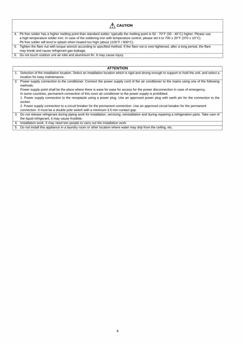
4. Pb free solder has a higher melting point than standard solder; typically the melting point is 50 - 70°F (30 - 40°C) higher. Please usea high temperature solder iron. In case of the soldering iron with temperature control, please set it to 700 ± 20°F (370 ± 10°C).Pb free solder will tend to splash when heated too high (about 1100°F / 600°C).
5. Tighten the flare nut with torque wrench according to specified method. If the flare nut is over-tightened, after a long period, the flaremay break and cause refrigerant gas leakage.
6. Do not touch outdoor unit air inlet and aluminium fin. It may cause injury.
ATTENTION1. Selection of the installation location. Select an installation location which is rigid and strong enough to support or hold the unit, and select a
location for easy maintenance.2. Power supply connection to the conditioner. Connect the power supply cord of the air conditioner to the mains using one of the following
methods.Power supply point shall be the place where there is ease for ease for access for the power disconnection in case of emergency.In some countries, permanent connection of this room air conditioner to the power supply is prohibited.1. Power supply connection to the receptacle using a power plug. Use an approved power plug with earth pin for the connection to thesocket.2. Power supply connection to a circuit breaker for the permanent connection. Use an approved circuit breaker for the permanentconnection. It must be a double pole switch with a minimum 3.5 mm contact gap.
3. Do not release refrigerant during piping work for installation, servicing, reinstallation and during repairing a refrigeration parts. Take care ofthe liquid refrigerant, it may cause frostbite.
4. Installation work. It may need two people to carry out the installation work.5. Do not install this appliance in a laundry room or other location where water may drip from the ceiling, etc.
4
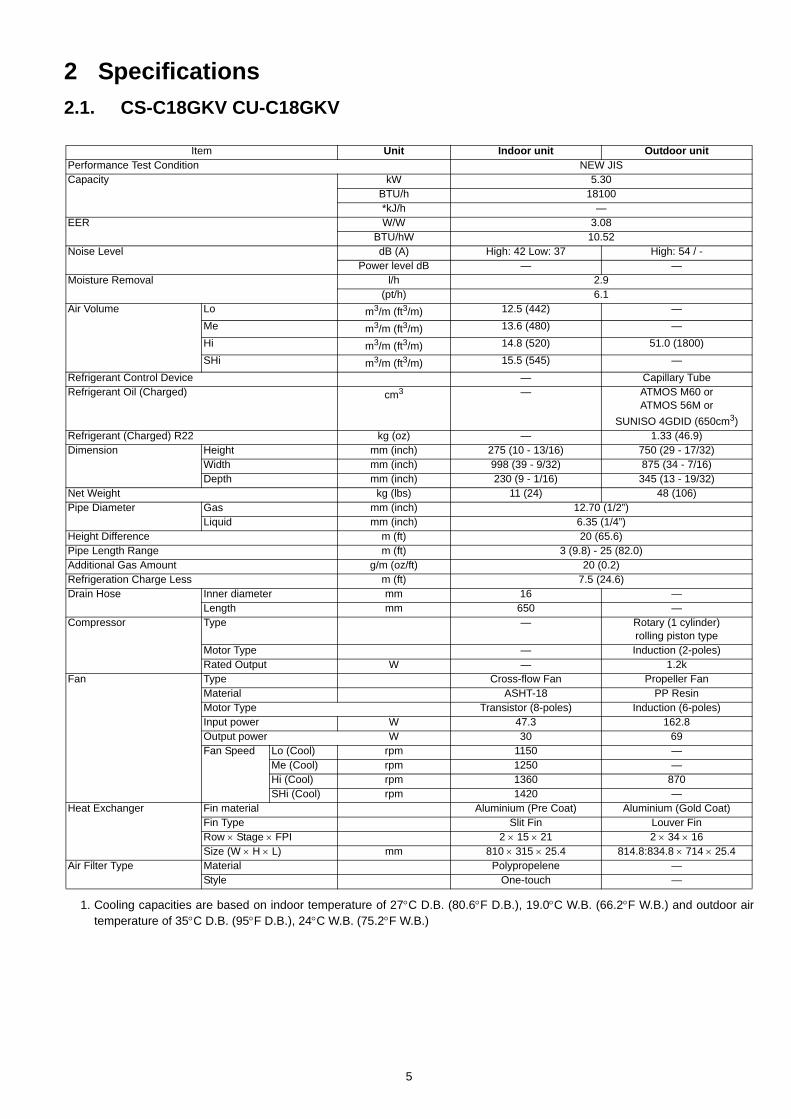
2 Specifications2.1. CS-C18GKV CU-C18GKV
1. Cooling capacities are based on indoor temperature of 27°C D.B. (80.6°F D.B.), 19.0°C W.B. (66.2°F W.B.) and outdoor airtemperature of 35°C D.B. (95°F D.B.), 24°C W.B. (75.2°F W.B.)
Item Unit Indoor unit Outdoor unitPerformance Test Condition NEW JISCapacity kW 5.30
BTU/h 18100*kJ/h —
EER W/W 3.08BTU/hW 10.52
Noise Level dB (A) High: 42 Low: 37 High: 54 / -Power level dB — —
Moisture Removal l/h 2.9(pt/h) 6.1
Air Volume Lo m3/m (ft3/m) 12.5 (442) —Me m3/m (ft3/m) 13.6 (480) —Hi m3/m (ft3/m) 14.8 (520) 51.0 (1800)SHi m3/m (ft3/m) 15.5 (545) —
Refrigerant Control Device — Capillary TubeRefrigerant Oil (Charged) cm3 — ATMOS M60 or
ATMOS 56M orSUNISO 4GDID (650cm3)
Refrigerant (Charged) R22 kg (oz) — 1.33 (46.9)Dimension Height mm (inch) 275 (10 - 13/16) 750 (29 - 17/32)
Width mm (inch) 998 (39 - 9/32) 875 (34 - 7/16)Depth mm (inch) 230 (9 - 1/16) 345 (13 - 19/32)
Net Weight kg (lbs) 11 (24) 48 (106)Pipe Diameter Gas mm (inch) 12.70 (1/2”)
Liquid mm (inch) 6.35 (1/4”)Height Difference m (ft) 20 (65.6)Pipe Length Range m (ft) 3 (9.8) - 25 (82.0)Additional Gas Amount g/m (oz/ft) 20 (0.2)Refrigeration Charge Less m (ft) 7.5 (24.6)Drain Hose Inner diameter mm 16 —
Length mm 650 —Compressor Type — Rotary (1 cylinder)
rolling piston typeMotor Type — Induction (2-poles)Rated Output W — 1.2k
Fan Type Cross-flow Fan Propeller FanMaterial ASHT-18 PP ResinMotor Type Transistor (8-poles) Induction (6-poles)Input power W 47.3 162.8Output power W 30 69Fan Speed Lo (Cool) rpm 1150 —
Me (Cool) rpm 1250 —Hi (Cool) rpm 1360 870SHi (Cool) rpm 1420 —
Heat Exchanger Fin material Aluminium (Pre Coat) Aluminium (Gold Coat)Fin Type Slit Fin Louver FinRow × Stage × FPI 2 × 15 × 21 2 × 34 × 16Size (W × H × L) mm 810 × 315 × 25.4 814.8:834.8 × 714 × 25.4
Air Filter Type Material Polypropelene —Style One-touch —
5
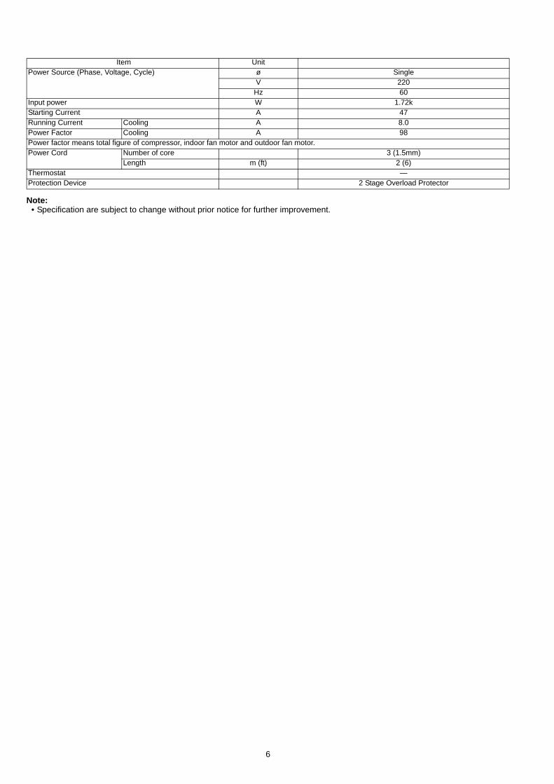
Note:• Specification are subject to change without prior notice for further improvement.
Item UnitPower Source (Phase, Voltage, Cycle) ø Single
V 220Hz 60
Input power W 1.72kStarting Current A 47Running Current Cooling A 8.0Power Factor Cooling A 98Power factor means total figure of compressor, indoor fan motor and outdoor fan motor.Power Cord Number of core 3 (1.5mm)
Length m (ft) 2 (6)Thermostat —Protection Device 2 Stage Overload Protector
6
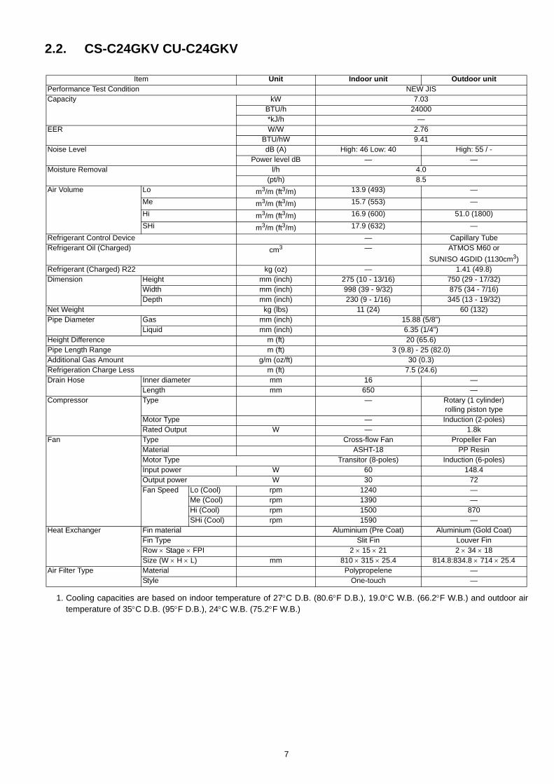
2.2. CS-C24GKV CU-C24GKV
1. Cooling capacities are based on indoor temperature of 27°C D.B. (80.6°F D.B.), 19.0°C W.B. (66.2°F W.B.) and outdoor airtemperature of 35°C D.B. (95°F D.B.), 24°C W.B. (75.2°F W.B.)
Item Unit Indoor unit Outdoor unitPerformance Test Condition NEW JISCapacity kW 7.03
BTU/h 24000*kJ/h —
EER W/W 2.76BTU/hW 9.41
Noise Level dB (A) High: 46 Low: 40 High: 55 / -Power level dB — —
Moisture Removal l/h 4.0(pt/h) 8.5
Air Volume Lo m3/m (ft3/m) 13.9 (493) —Me m3/m (ft3/m) 15.7 (553) —Hi m3/m (ft3/m) 16.9 (600) 51.0 (1800)SHi m3/m (ft3/m) 17.9 (632) —
Refrigerant Control Device — Capillary TubeRefrigerant Oil (Charged) cm3 — ATMOS M60 or
SUNISO 4GDID (1130cm3)Refrigerant (Charged) R22 kg (oz) — 1.41 (49.8)Dimension Height mm (inch) 275 (10 - 13/16) 750 (29 - 17/32)
Width mm (inch) 998 (39 - 9/32) 875 (34 - 7/16)Depth mm (inch) 230 (9 - 1/16) 345 (13 - 19/32)
Net Weight kg (lbs) 11 (24) 60 (132)Pipe Diameter Gas mm (inch) 15.88 (5/8”)
Liquid mm (inch) 6.35 (1/4”)Height Difference m (ft) 20 (65.6)Pipe Length Range m (ft) 3 (9.8) - 25 (82.0)Additional Gas Amount g/m (oz/ft) 30 (0.3)Refrigeration Charge Less m (ft) 7.5 (24.6)Drain Hose Inner diameter mm 16 —
Length mm 650 —Compressor Type — Rotary (1 cylinder)
rolling piston typeMotor Type — Induction (2-poles)Rated Output W — 1.8k
Fan Type Cross-flow Fan Propeller FanMaterial ASHT-18 PP ResinMotor Type Transitor (8-poles) Induction (6-poles)Input power W 60 148.4Output power W 30 72Fan Speed Lo (Cool) rpm 1240 —
Me (Cool) rpm 1390 —Hi (Cool) rpm 1500 870SHi (Cool) rpm 1590 —
Heat Exchanger Fin material Aluminium (Pre Coat) Aluminium (Gold Coat)Fin Type Slit Fin Louver FinRow × Stage × FPI 2 × 15 × 21 2 × 34 × 18Size (W × H × L) mm 810 × 315 × 25.4 814.8:834.8 × 714 × 25.4
Air Filter Type Material Polypropelene —Style One-touch —
7
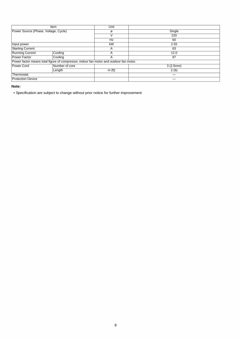
Note:
• Specification are subject to change without prior notice for further improvement.
Item UnitPower Source (Phase, Voltage, Cycle) ø Single
V 220Hz 60
Input power kW 2.55Starting Current A 63Running Current Cooling A 12.0Power Factor Cooling A 97Power factor means total figure of compressor, indoor fan motor and outdoor fan motor.Power Cord Number of core 3 (2.5mm)
Length m (ft) 2 (6)Thermostat —Protection Device —
8
3 Features• High Efficiency
• Compact Design
• Wider range of horizontal discharge air
• Air Filter with function to reduce dust and smoke
• Automatic air swing by Remote Control for vertical andhorizontal airflow
• Long Installation Piping- CS/CU-C18GK, CS/CU-C24GK, long piping up to 25
meter
• e-ion Air Purifying System with Patrol Sensor- Discharged Active e-ions capture dust particles and
bring it back with a boomerang-like mechanism
• Quality Improvement- Random auto restart after power failure for safety restart
operation- Gas leakage protection- Prevent compressor reverse cycle- Inner protector to protect Compressor- Noise prevention during soft dry operation- Gold Coated Condenser for high resistance to corrosion
• Operation Improvement- Quiet mode to provide quiet operation- Powerful mode to reach the desired room temperature
quickly- 24-hour timer setting
• Serviceability Improvement- Removable and washable front panel
9
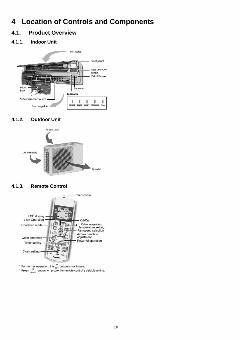
4 Location of Controls and Components4.1. Product Overview4.1.1. Indoor Unit
4.1.2. Outdoor Unit
4.1.3. Remote Control
10
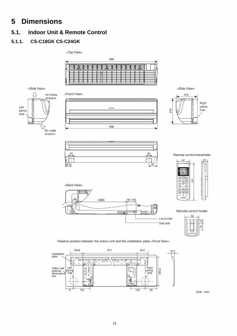
5 Dimensions5.1. Indoor Unit & Remote Control5.1.1. CS-C18GK CS-C24GK
11
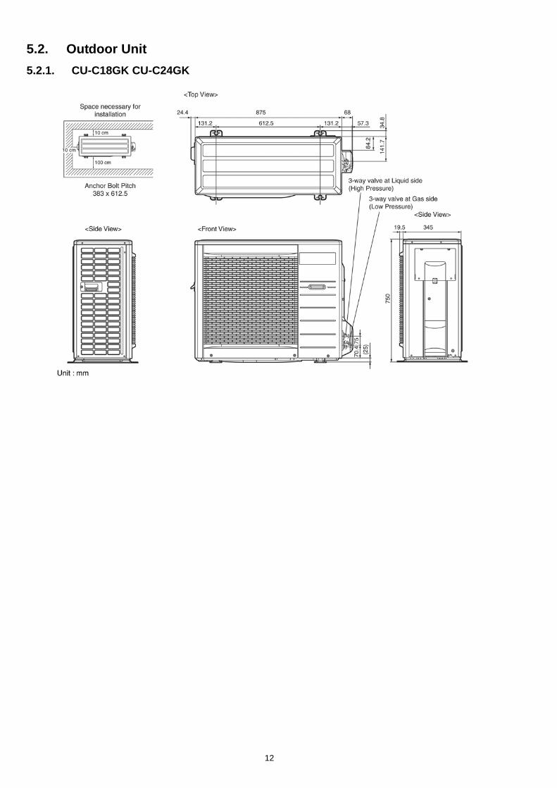
5.2. Outdoor Unit5.2.1. CU-C18GK CU-C24GK
12
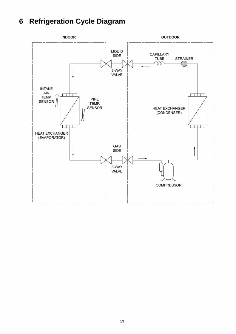
6 Refrigeration Cycle Diagram
13
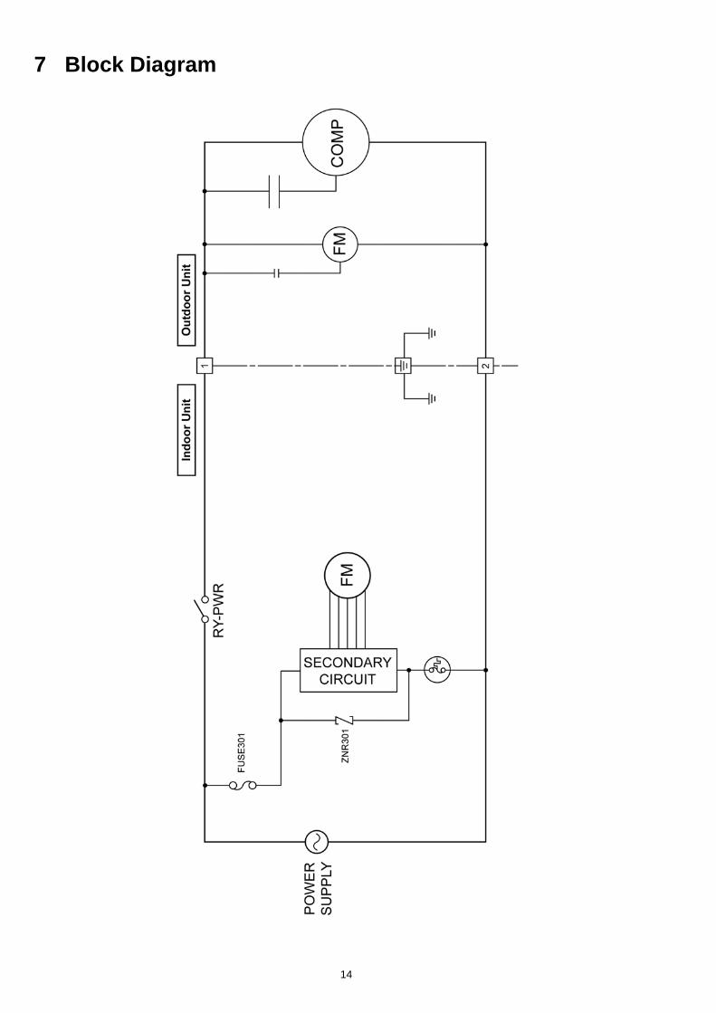
7 Block Diagram
14
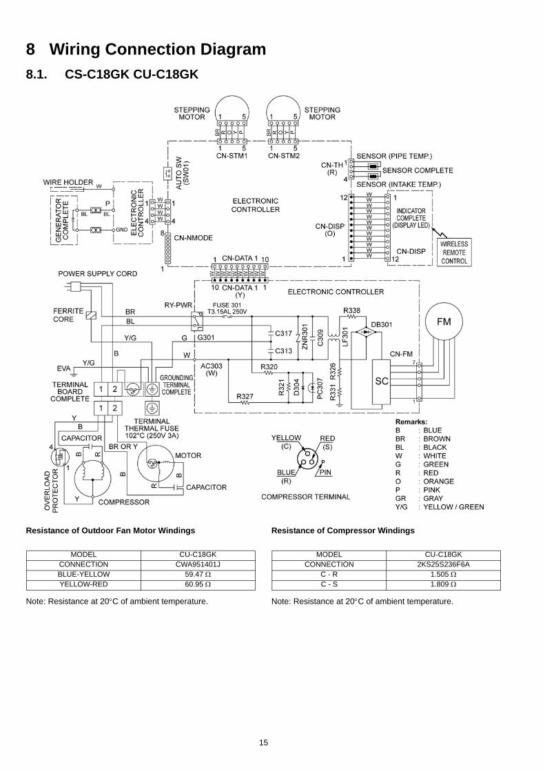
8 Wiring Connection Diagram8.1. CS-C18GK CU-C18GK
Resistance of Outdoor Fan Motor Windings
Note: Resistance at 20°C of ambient temperature.
Resistance of Compressor Windings
Note: Resistance at 20°C of ambient temperature.
MODEL CU-C18GKCONNECTION CWA951401JBLUE-YELLOW 59.47 ΩYELLOW-RED 60.95 Ω
MODEL CU-C18GKCONNECTION 2KS25S236F6A
C - R 1.505 ΩC - S 1.809 Ω
15
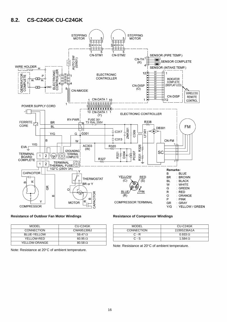
8.2. CS-C24GK CU-C24GK
Resistance of Outdoor Fan Motor Windings
Note: Resistance at 20°C of ambient temperature.
Resistance of Compressor Windings
Note: Resistance at 20°C of ambient temperature.
MODEL CU-C24GKCONNECTION CWA951399JBLUE-YELLOW 59.47 ΩYELLOW-RED 60.95 Ω
YELLOW-ORANGE 80.58 Ω
MODEL CU-C24GKCONNECTION 2J39S236A1A
C - R 0.933 ΩC - S 1.584 Ω
16
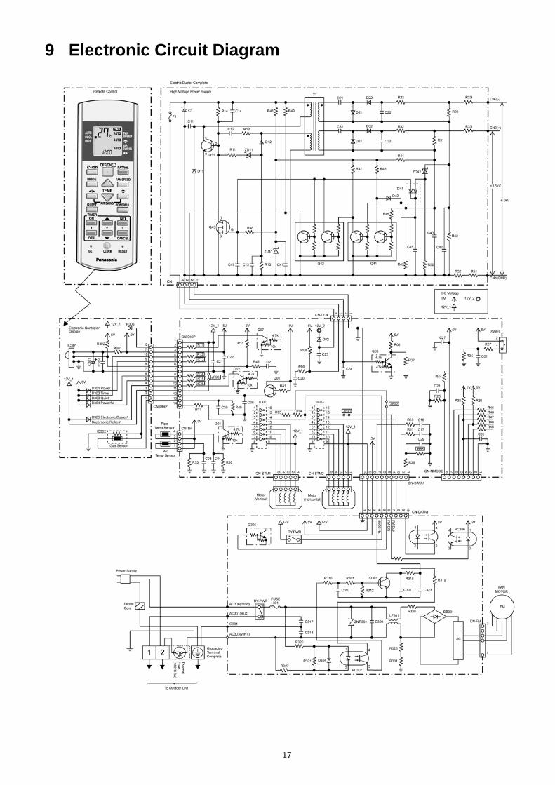
9 Electronic Circuit Diagram
17
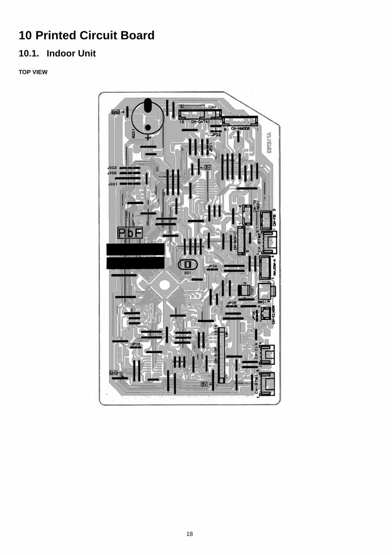
10 Printed Circuit Board10.1. Indoor Unit
TOP VIEW
18
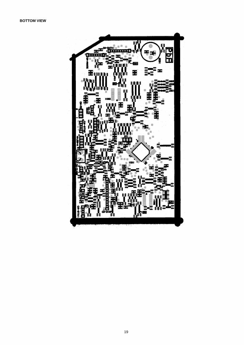
BOTTOM VIEW
19
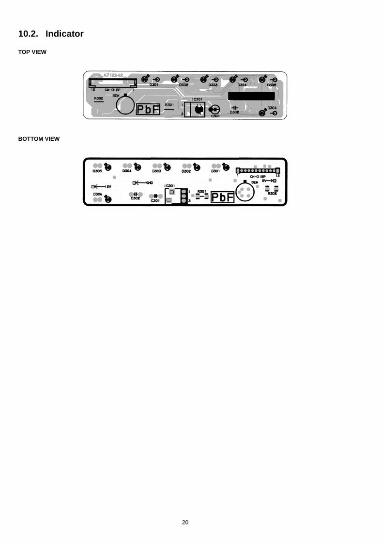
10.2. Indicator
TOP VIEW
BOTTOM VIEW
20
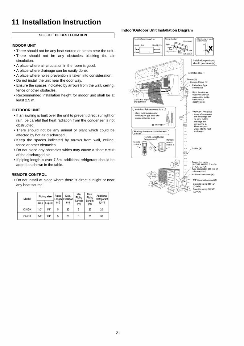
11 Installation Instruction
INDOOR UNIT• There should not be any heat source or steam near the unit.• There should not be any obstacles blocking the air
circulation.• A place where air circulation in the room is good.• A place where drainage can be easily done.• A place where noise prevention is taken into consideration.• Do not install the unit near the door way.• Ensure the spaces indicated by arrows from the wall, ceiling,
fence or other obstacles.• Recommended installation height for indoor unit shall be at
least 2.5 m.
OUTDOOR UNIT• If an awning is built over the unit to prevent direct sunlight or
rain, be careful that heat radiation from the condenser is notobstructed.
• There should not be any animal or plant which could beaffected by hot air discharged.
• Keep the spaces indicated by arrows from wall, ceiling,fence or other obstacles.
• Do not place any obstacles which may cause a short circuitof the discharged air.
• If piping length is over 7.5m, additional refrigerant should beadded as shown in the table.
REMOTE CONTROL• Do not install at place where there is direct sunlight or near
any heat source.
Indoor/Outdoor Unit Installation DiagramSELECT THE BEST LOCATION
21
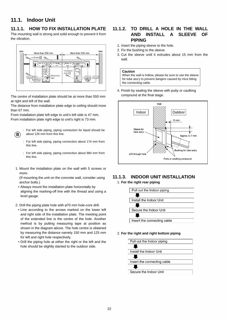
11.1. Indoor Unit11.1.1. HOW TO FIX INSTALLATION PLATEThe mounting wall is strong and solid enough to prevent it fromthe vibration.
The centre of installation plate should be at more than 550 mmat right and left of the wall.The distance from installation plate edge to ceiling should morethan 67 mm.From installation plate left edge to unit’s left side is 47 mm.From installation plate right edge to unit’s right is 73 mm.
1. Mount the installation plate on the wall with 5 screws ormore.(If mounting the unit on the concrete wall, consider usinganchor bolts.)
• Always mount the installation plate horizontally byaligning the marking-off line with the thread and using alevel gauge.
2. Drill the piping plate hole with ø70 mm hole-core drill.• Line according to the arrows marked on the lower left
and right side of the installation plate. The meeting pointof the extended line is the centre of the hole. Anothermethod is by putting measuring tape at position asshown in the diagram above. The hole centre is obtainedby measuring the distance namely 150 mm and 125 mmfor left and right hole respectively.
• Drill the piping hole at either the right or the left and thehole should be slightly slanted to the outdoor side.
11.1.2. TO DRILL A HOLE IN THE WALLAND INSTALL A SLEEVE OFPIPING
1. Insert the piping sleeve to the hole.2. Fix the bushing to the sleeve.3. Cut the sleeve until it extrudes about 15 mm from the
wall.
4. Finish by sealing the sleeve with putty or caulkingcompound at the final stage.
11.1.3. INDOOR UNIT INSTALLATION1. For the right rear piping
2. For the right and right bottom piping
:
:
:
For left side piping, piping connection for liquid should beabout 126 mm from this line.
For left side piping, piping connection about 174 mm fromthis line.
For left side piping, piping connection about 984 mm fromthis line.
CautionWhen the wall is hollow, please be sure to use the sleeve for tube ass’y to prevent dangers caused by mice biting the connecting cable.
22
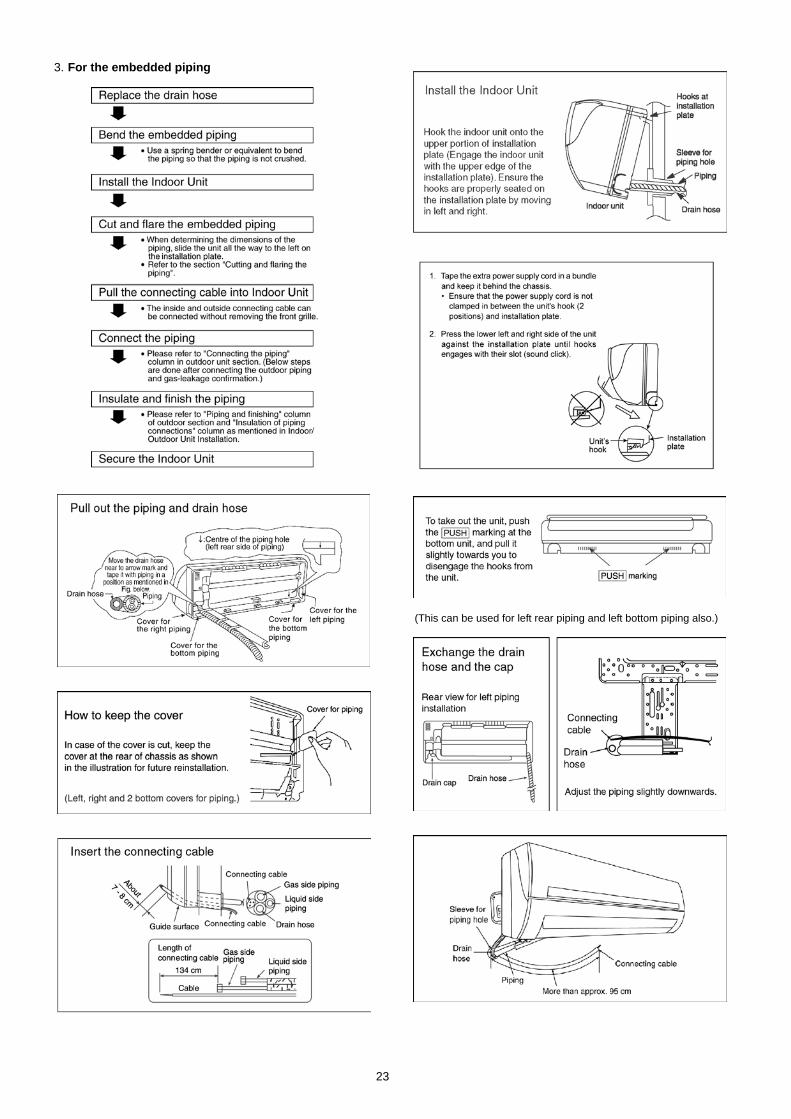
3. For the embedded piping
(This can be used for left rear piping and left bottom piping also.)
23
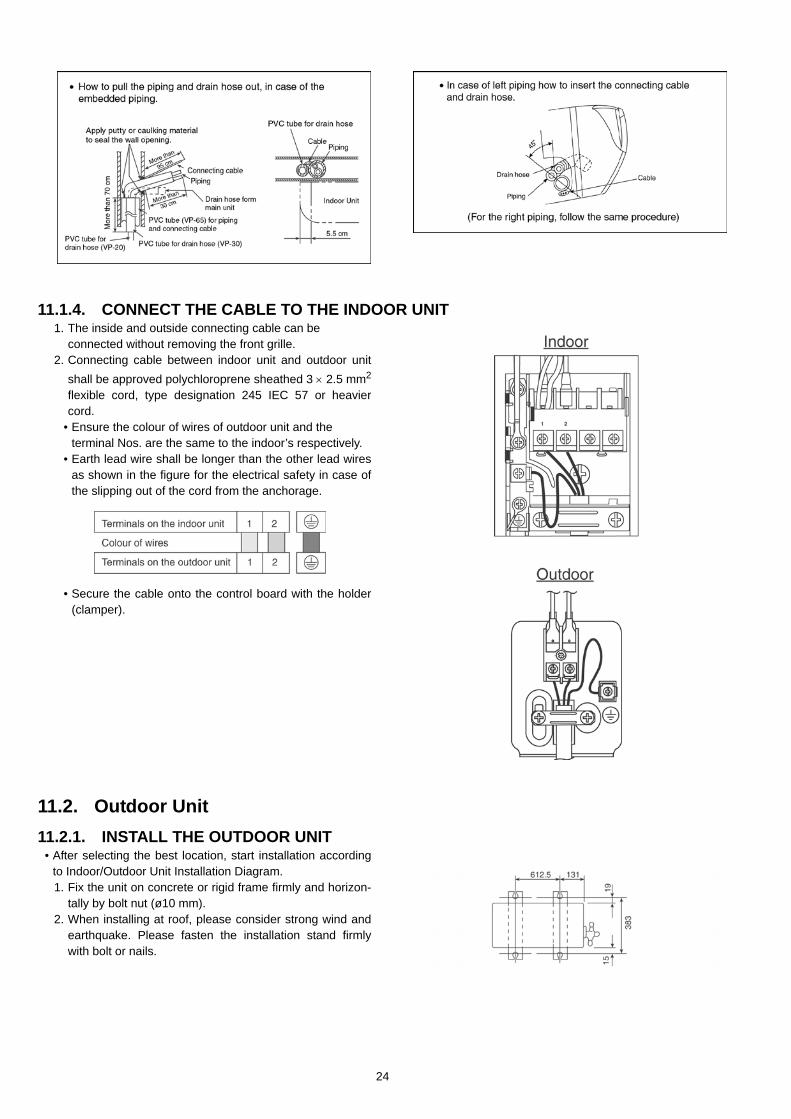
11.1.4. CONNECT THE CABLE TO THE INDOOR UNIT1. The inside and outside connecting cable can be
connected without removing the front grille.2. Connecting cable between indoor unit and outdoor unit
shall be approved polychloroprene sheathed 3 × 2.5 mm2
flexible cord, type designation 245 IEC 57 or heaviercord.
• Ensure the colour of wires of outdoor unit and theterminal Nos. are the same to the indoor’s respectively.
• Earth lead wire shall be longer than the other lead wiresas shown in the figure for the electrical safety in case ofthe slipping out of the cord from the anchorage.
• Secure the cable onto the control board with the holder(clamper).
11.2. Outdoor Unit11.2.1. INSTALL THE OUTDOOR UNIT
• After selecting the best location, start installation accordingto Indoor/Outdoor Unit Installation Diagram.1. Fix the unit on concrete or rigid frame firmly and horizon-
tally by bolt nut (ø10 mm).2. When installing at roof, please consider strong wind and
earthquake. Please fasten the installation stand firmlywith bolt or nails.
24
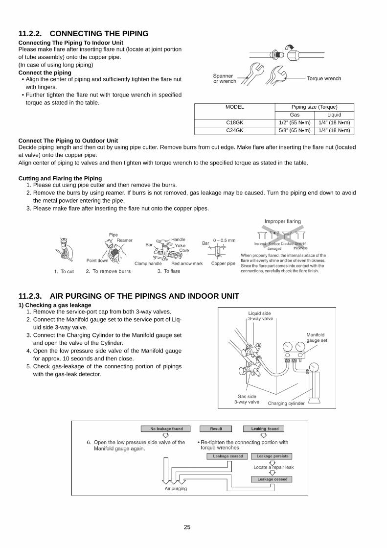
11.2.2. CONNECTING THE PIPINGConnecting The Piping To Indoor UnitPlease make flare after inserting flare nut (locate at joint portionof tube assembly) onto the copper pipe. (In case of using long piping)Connect the piping
• Align the center of piping and sufficiently tighten the flare nutwith fingers.
• Further tighten the flare nut with torque wrench in specifiedtorque as stated in the table.
Connect The Piping to Outdoor UnitDecide piping length and then cut by using pipe cutter. Remove burrs from cut edge. Make flare after inserting the flare nut (locatedat valve) onto the copper pipe.Align center of piping to valves and then tighten with torque wrench to the specified torque as stated in the table.
Cutting and Flaring the Piping1. Please cut using pipe cutter and then remove the burrs.2. Remove the burrs by using reamer. If burrs is not removed, gas leakage may be caused. Turn the piping end down to avoid
the metal powder entering the pipe.3. Please make flare after inserting the flare nut onto the copper pipes.
11.2.3. AIR PURGING OF THE PIPINGS AND INDOOR UNIT1) Checking a gas leakage
1. Remove the service-port cap from both 3-way valves.2. Connect the Manifold gauge set to the service port of Liq-
uid side 3-way valve.3. Connect the Charging Cylinder to the Manifold gauge set
and open the valve of the Cylinder.4. Open the low pressure side valve of the Manifold gauge
for approx. 10 seconds and then close.5. Check gas-leakage of the connecting portion of pipings
with the gas-leak detector.
MODEL Piping size (Torque)Gas Liquid
C18GK 1/2” (55 N•m) 1/4” (18 N•m)C24GK 5/8” (65 N•m) 1/4” (18 N•m)
25
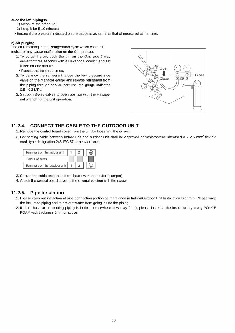
<For the left pipings>1) Measure the pressure.2) Keep it for 5-10 minutes
•Ensure if the pressure indicated on the gauge is as same as that of measured at first time.
2) Air purgingThe air remaining in the Refrigeration cycle which containsmoisture may cause malfunction on the Compressor.
1. To purge the air, push the pin on the Gas side 3-wayvalve for three seconds with a Hexagonal wrench and setit free for one minute.
• Repeat this for three times.2. To balance the refrigerant, close the low pressure side
valve on the Manifold gauge and release refrigerant fromthe piping through service port until the gauge indicates0.5 - 0.3 MPa.
3. Set both 3-way valves to open position with the Hexago-nal wrench for the unit operation.
11.2.4. CONNECT THE CABLE TO THE OUTDOOR UNIT1. Remove the control board cover from the unit by loosening the screw.2. Connecting cable between indoor unit and outdoor unit shall be approved polychloroprene sheathed 3 × 2.5 mm2 flexible
cord, type designation 245 IEC 57 or heavier cord.
3. Secure the cable onto the control board with the holder (clamper).4. Attach the control board cover to the original position with the screw.
11.2.5. Pipe Insulation1. Please carry out insulation at pipe connection portion as mentioned in Indoor/Outdoor Unit Installation Diagram. Please wrap
the insulated piping end to prevent water from going inside the piping.2. If drain hose or connecting piping is in the room (where dew may form), please increase the insulation by using POLY-E
FOAM with thickness 6mm or above.
26
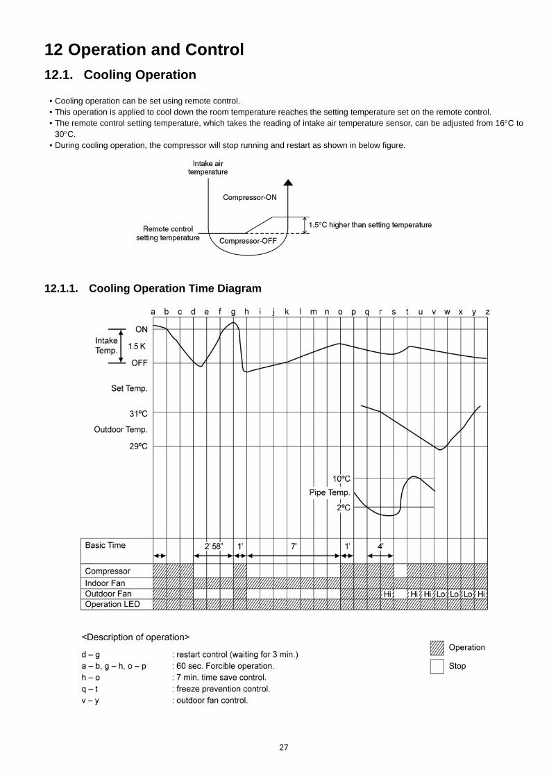
12 Operation and Control12.1. Cooling Operation
• Cooling operation can be set using remote control.• This operation is applied to cool down the room temperature reaches the setting temperature set on the remote control.• The remote control setting temperature, which takes the reading of intake air temperature sensor, can be adjusted from 16°C to
30°C.• During cooling operation, the compressor will stop running and restart as shown in below figure.
12.1.1. Cooling Operation Time Diagram
27
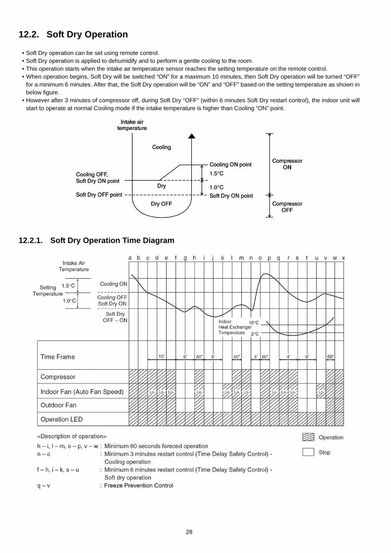
12.2. Soft Dry Operation
• Soft Dry operation can be set using remote control.• Soft Dry operation is applied to dehumidify and to perform a gentle cooling to the room.• This operation starts when the intake air temperature sensor reaches the setting temperature on the remote control.• When operation begins, Soft Dry will be switched “ON” for a maximum 10 minutes, then Soft Dry operation will be turned “OFF”
for a minimum 6 minutes. After that, the Soft Dry operation will be “ON” and “OFF” based on the setting temperature as shown inbelow figure.
• However after 3 minutes of compressor off, during Soft Dry “OFF” (within 6 minutes Soft Dry restart control), the indoor unit willstart to operate at normal Cooling mode if the intake temperature is higher than Cooling “ON” point.
12.2.1. Soft Dry Operation Time Diagram
28
12.3. Automatic Operation
• Automatic operation can be set using remote control.• This operation starts to operate with indoor fan at SLo speed for 25 seconds to judge the intake air temperature.• After judged the temperature, the operation mode is determined by referring to the below standard.
• Then, the unit start to operate at determined operation mode, until it is switched off using remote control, with the settingtemperature as shown in below table.
• The setting temperature for all the operations can be changed one level up or one level down from the standard temperature asshown in below table by pressing on the temperature up or temperature down button at remote control.
• The operation mode judging temperature and standard setting temperature can be increased by 2°C permanently, by open thecircuit of JX1 at indoor electronic controller.
29
12.4. Operation Control12.4.1. Restart Control (Time Delay Safety Control)
• When the thermo-off temperature (temperature which compressor stops to operate) is reached during:-- Cooling operation - the compressor stops for 3 minutes (minimum) before resume operation.- Soft Dry operation - the compressor stops for 6 minutes (minimum) before resume operation.
• If the operation is stopped by the remote control, the compressor will not turn on within 3 minutes from the moment operationstop, although the unit is turn on again within the period.
• This phenomenon is to balance the pressure inside the refrigerant cycle.
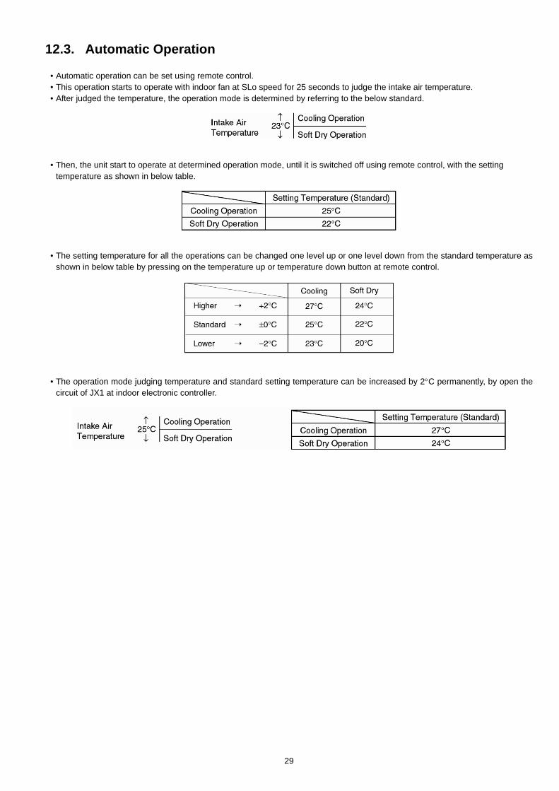
12.4.2. 7 Minutes Time Save Control• The compressor will start automatically if it has stopped for 7 minutes and the intake air temperature falls between the
compressor ON temperature (A) and compressor OFF temperature (B) during the period.• This phenomenon is to reduce the built up humidity inside a room.
12.4.3. 60 Seconds Forced Operation• Once the air conditioner is turned on, the compressor will not stop within 60 seconds in a normal operation although the intake air
temperature has reached the thermo-off temperature. However, force stop by pressing the OFF/ON operation button at theremote control is permitted.
• The reason for the compressor to force operate at minimum 60 seconds is to allow the refrigerant oil run in a full cycle and returnback to the outdoor unit.
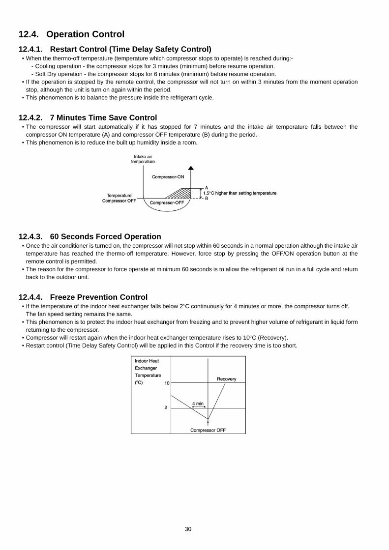
12.4.4. Freeze Prevention Control• If the temperature of the indoor heat exchanger falls below 2°C continuously for 4 minutes or more, the compressor turns off.
The fan speed setting remains the same.• This phenomenon is to protect the indoor heat exchanger from freezing and to prevent higher volume of refrigerant in liquid form
returning to the compressor.• Compressor will restart again when the indoor heat exchanger temperature rises to 10°C (Recovery).• Restart control (Time Delay Safety Control) will be applied in this Control if the recovery time is too short.
30
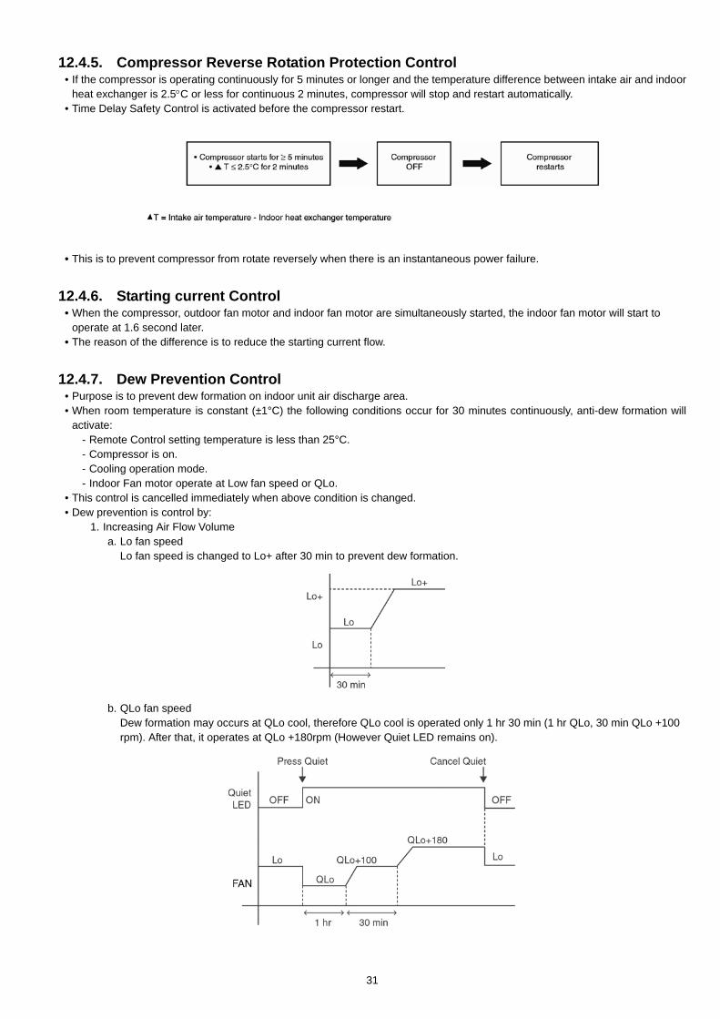
12.4.5. Compressor Reverse Rotation Protection Control• If the compressor is operating continuously for 5 minutes or longer and the temperature difference between intake air and indoor
heat exchanger is 2.5°C or less for continuous 2 minutes, compressor will stop and restart automatically.• Time Delay Safety Control is activated before the compressor restart.
• This is to prevent compressor from rotate reversely when there is an instantaneous power failure.
12.4.6. Starting current Control• When the compressor, outdoor fan motor and indoor fan motor are simultaneously started, the indoor fan motor will start to
operate at 1.6 second later.• The reason of the difference is to reduce the starting current flow.
12.4.7. Dew Prevention Control• Purpose is to prevent dew formation on indoor unit air discharge area.• When room temperature is constant (±1°C) the following conditions occur for 30 minutes continuously, anti-dew formation will
activate:- Remote Control setting temperature is less than 25°C.- Compressor is on.- Cooling operation mode.- Indoor Fan motor operate at Low fan speed or QLo.
• This control is cancelled immediately when above condition is changed.• Dew prevention is control by:
1. Increasing Air Flow Volumea. Lo fan speed
Lo fan speed is changed to Lo+ after 30 min to prevent dew formation.
b. QLo fan speedDew formation may occurs at QLo cool, therefore QLo cool is operated only 1 hr 30 min (1 hr QLo, 30 min QLo +100rpm). After that, it operates at QLo +180rpm (However Quiet LED remains on).
31
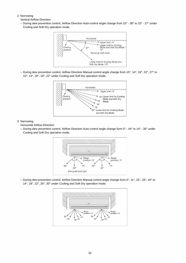
2. NorrowingVertical Airflow Direction– During dew prevention control, Airflow Direction Auto-control angle change from 10° - 38° to 10° - 27° under
Cooling and Soft Dry operation mode.
– During dew prevention control, Airflow Direction Manual control angle change from 10°, 14°, 18°, 22°, 27° to10°, 13°, 16°, 19°, 22° under Cooling and Soft Dry operation mode.
3. NarrowingHorizontal Airflow Direction– During dew prevention control, Airflow Direction Auto-control angle change form 0° - 44° to 14° - 30° under
Cooling and Soft Dry operation mode.
– During dew prevention control, Airflow Direction Manual control angle change from 0°, 11°, 22°, 33°, 44° to14°, 18°, 22°, 26°, 30° under Cooling and Soft Dry operation mode.
32
12.5. Indoor Fan Speed Control• Indoor Fan Speed can be set using remote control.
12.5.1. Fan Speed Rotation Chart
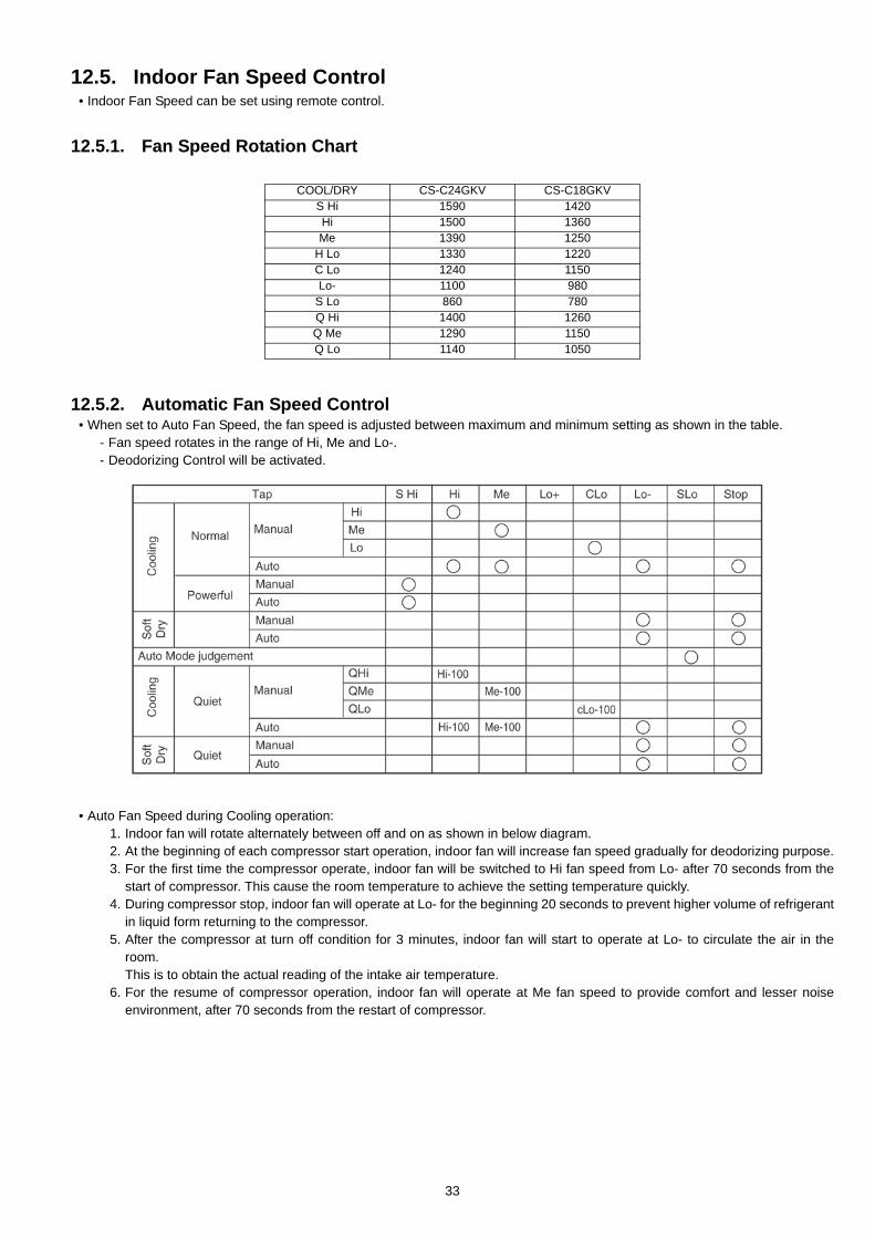
12.5.2. Automatic Fan Speed Control• When set to Auto Fan Speed, the fan speed is adjusted between maximum and minimum setting as shown in the table.
- Fan speed rotates in the range of Hi, Me and Lo-.- Deodorizing Control will be activated.
• Auto Fan Speed during Cooling operation:1. Indoor fan will rotate alternately between off and on as shown in below diagram.2. At the beginning of each compressor start operation, indoor fan will increase fan speed gradually for deodorizing purpose.3. For the first time the compressor operate, indoor fan will be switched to Hi fan speed from Lo- after 70 seconds from the
start of compressor. This cause the room temperature to achieve the setting temperature quickly.4. During compressor stop, indoor fan will operate at Lo- for the beginning 20 seconds to prevent higher volume of refrigerant
in liquid form returning to the compressor.5. After the compressor at turn off condition for 3 minutes, indoor fan will start to operate at Lo- to circulate the air in the
room. This is to obtain the actual reading of the intake air temperature.
6. For the resume of compressor operation, indoor fan will operate at Me fan speed to provide comfort and lesser noiseenvironment, after 70 seconds from the restart of compressor.
COOL/DRY CS-C24GKV CS-C18GKVS Hi 1590 1420Hi 1500 1360Me 1390 1250
H Lo 1330 1220C Lo 1240 1150Lo- 1100 980
S Lo 860 780Q Hi 1400 1260Q Me 1290 1150Q Lo 1140 1050
33
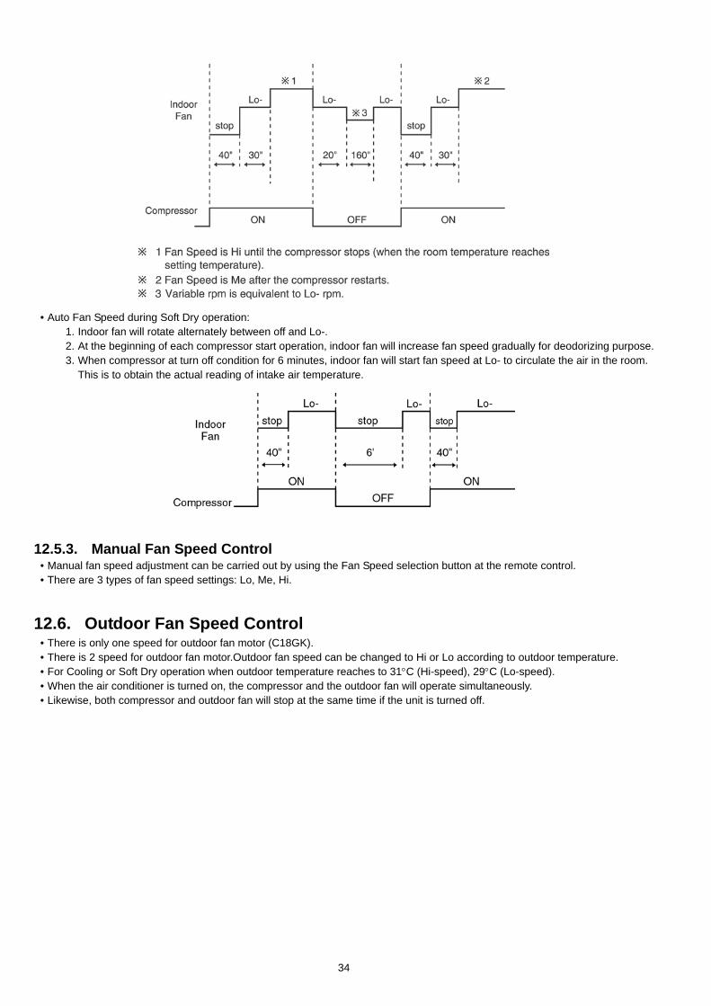
• Auto Fan Speed during Soft Dry operation:1. Indoor fan will rotate alternately between off and Lo-.2. At the beginning of each compressor start operation, indoor fan will increase fan speed gradually for deodorizing purpose.3. When compressor at turn off condition for 6 minutes, indoor fan will start fan speed at Lo- to circulate the air in the room.
This is to obtain the actual reading of intake air temperature.
12.5.3. Manual Fan Speed Control• Manual fan speed adjustment can be carried out by using the Fan Speed selection button at the remote control.• There are 3 types of fan speed settings: Lo, Me, Hi.
12.6. Outdoor Fan Speed Control• There is only one speed for outdoor fan motor (C18GK).• There is 2 speed for outdoor fan motor.Outdoor fan speed can be changed to Hi or Lo according to outdoor temperature.• For Cooling or Soft Dry operation when outdoor temperature reaches to 31°C (Hi-speed), 29°C (Lo-speed).• When the air conditioner is turned on, the compressor and the outdoor fan will operate simultaneously.• Likewise, both compressor and outdoor fan will stop at the same time if the unit is turned off.
34
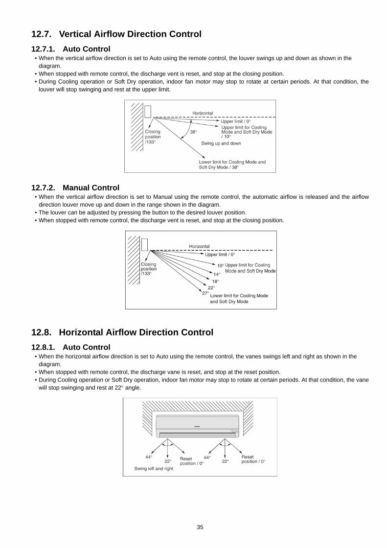
12.7. Vertical Airflow Direction Control12.7.1. Auto Control
• When the vertical airflow direction is set to Auto using the remote control, the louver swings up and down as shown in thediagram.
• When stopped with remote control, the discharge vent is reset, and stop at the closing position.• During Cooling operation or Soft Dry operation, indoor fan motor may stop to rotate at certain periods. At that condition, the
louver will stop swinging and rest at the upper limit.
12.7.2. Manual Control• When the vertical airflow direction is set to Manual using the remote control, the automatic airflow is released and the airflow
direction louver move up and down in the range shown in the diagram.• The louver can be adjusted by pressing the button to the desired louver position.• When stopped with remote control, the discharge vent is reset, and stop at the closing position.
12.8. Horizontal Airflow Direction Control12.8.1. Auto Control
• When the horizontal airflow direction is set to Auto using the remote control, the vanes swings left and right as shown in thediagram.
• When stopped with remote control, the discharge vane is reset, and stop at the reset position.• During Cooling operation or Soft Dry operation, indoor fan motor may stop to rotate at certain periods. At that condition, the vane
will stop swinging and rest at 22° angle.
35
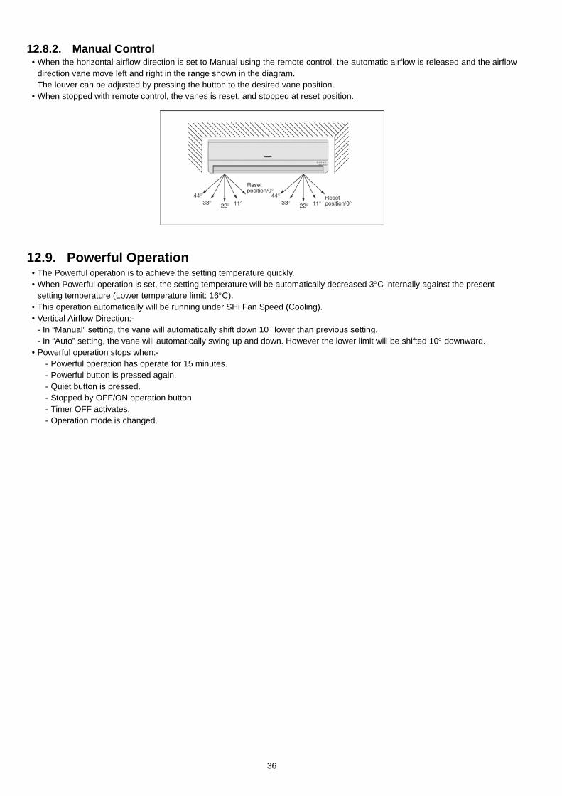
12.8.2. Manual Control• When the horizontal airflow direction is set to Manual using the remote control, the automatic airflow is released and the airflow
direction vane move left and right in the range shown in the diagram.The louver can be adjusted by pressing the button to the desired vane position.
• When stopped with remote control, the vanes is reset, and stopped at reset position.
12.9. Powerful Operation• The Powerful operation is to achieve the setting temperature quickly.• When Powerful operation is set, the setting temperature will be automatically decreased 3°C internally against the present
setting temperature (Lower temperature limit: 16°C).• This operation automatically will be running under SHi Fan Speed (Cooling).• Vertical Airflow Direction:-
- In “Manual” setting, the vane will automatically shift down 10° lower than previous setting.- In “Auto” setting, the vane will automatically swing up and down. However the lower limit will be shifted 10° downward.
• Powerful operation stops when:-- Powerful operation has operate for 15 minutes.- Powerful button is pressed again.- Quiet button is pressed.- Stopped by OFF/ON operation button.- Timer OFF activates.- Operation mode is changed.
36
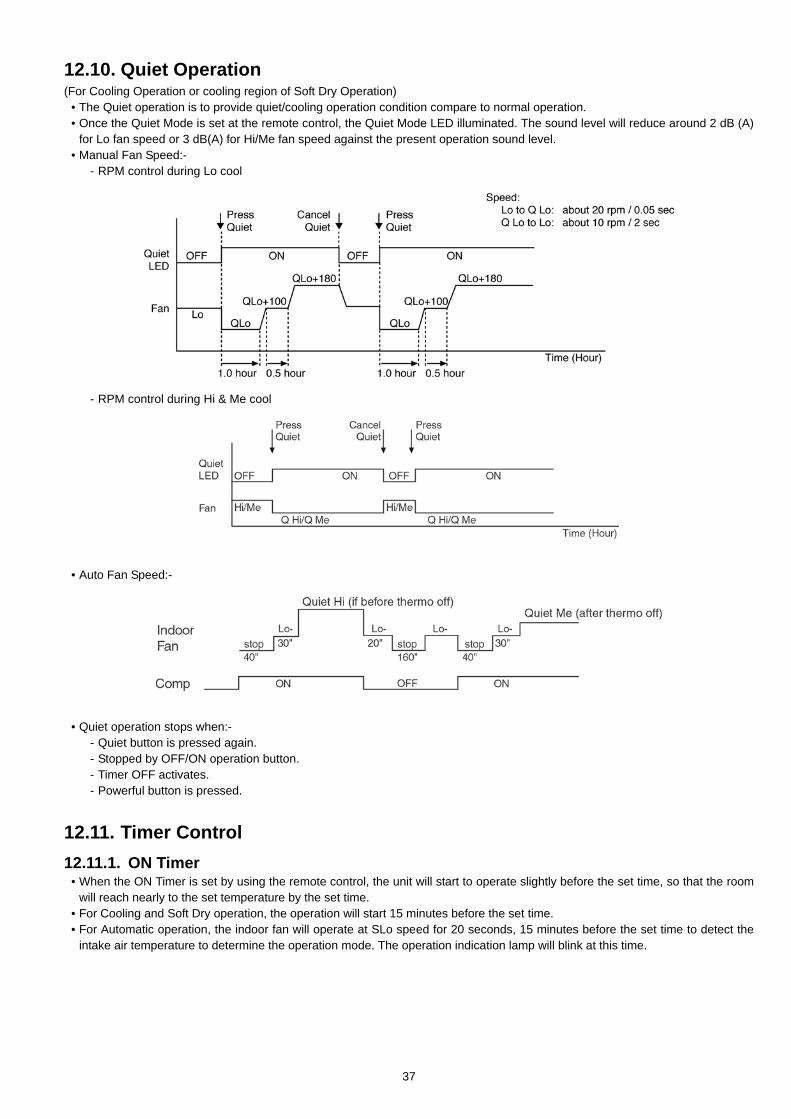
12.10. Quiet Operation(For Cooling Operation or cooling region of Soft Dry Operation)
• The Quiet operation is to provide quiet/cooling operation condition compare to normal operation.• Once the Quiet Mode is set at the remote control, the Quiet Mode LED illuminated. The sound level will reduce around 2 dB (A)
for Lo fan speed or 3 dB(A) for Hi/Me fan speed against the present operation sound level.• Manual Fan Speed:-
- RPM control during Lo cool
- RPM control during Hi & Me cool
• Auto Fan Speed:-
• Quiet operation stops when:-- Quiet button is pressed again.- Stopped by OFF/ON operation button.- Timer OFF activates.- Powerful button is pressed.
12.11. Timer Control12.11.1. ON Timer
• When the ON Timer is set by using the remote control, the unit will start to operate slightly before the set time, so that the roomwill reach nearly to the set temperature by the set time.
• For Cooling and Soft Dry operation, the operation will start 15 minutes before the set time.• For Automatic operation, the indoor fan will operate at SLo speed for 20 seconds, 15 minutes before the set time to detect the
intake air temperature to determine the operation mode. The operation indication lamp will blink at this time.
37
12.11.2. OFF Timer• When the OFF Timer is set by using the remote control, the unit will stop operate according to the desired setting.
Notes1. By pressing ON/OFF operation button, the ON Timer or OFF Timer setting will not be cancelled.2. To cancel the previous timer setting, press CANCEL button.3. To activate the previous timer setting, press SET button.4. If main power supply is switched off, the Timer setting will be cancelled.
12.12. Random Auto Restart Control• If there is a power failure during operation, the air conditioner will automatically restart after 3 to 4 minutes when the power is
resumed.• It will start with previous operation mode and airflow direction.• If there are more than one air conditioner unit in operation and power failure occur, restart time for each unit to operate will be
decided randomly using 4 parameters:- intake air temperature, setting temperature, fan speed and air swing louver position.• This Random Auto Restart Control is not available when Timer is set.
12.13. Remote Control Signal Receiving Sound• Long beep sound will be heard when:
- Stopping the air conditioner using ON/OFF switch.- Disable e-ion and Pastrol operation.
• Short beep sound will be heard for others setting.
38
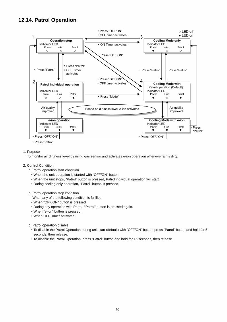
12.14. Patrol Operation
1. PurposeTo monitor air dirtiness level by using gas sensor and activates e-ion operation whenever air is dirty.
2. Control Conditiona. Patrol operation start condition
• When the unit operation is started with “OFF/ON” button.• When the unit stops, “Patrol” button is pressed, Patrol individual operation will start.• During cooling only operation, “Patrol” button is pressed.
b. Patrol operation stop conditionWhen any of the following condition is fulfilled:
• When “OFF/ON” button is pressed.• During any operation with Patrol, "Patrol" button is pressed again.• When “e-ion” button is pressed.• When OFF Timer activates.
c. Patrol operation disable• To disable the Patrol Operation during unit start (default) with “OFF/ON” button, press “Patrol” button and hold for 5
seconds, then release.• To disable the Patrol Operation, press “Patrol” button and hold for 15 seconds, then release.
39
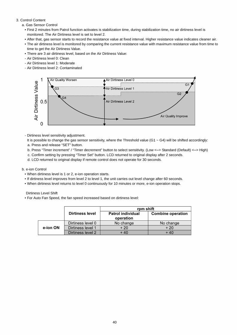
3. Control Contenta. Gas Sensor Control
• First 2 minutes from Patrol function activates is stabilization time, during stabilization time, no air dirtiness level ismonitored. The Air Dirtiness level is set to level 2.
• After that, gas sensor starts to record the resistance value at fixed interval. Higher resistance value indicates cleaner air.• The air dirtiness level is monitored by comparing the current resistance value with maximum resistance value from time to
time to get the Air Dirtiness Value.• There are 3 air dirtiness level, based on the Air Dirtiness Value:- Air Dirtiness level 0: Clean- Air Dirtiness level 1: Moderate- Air Dirtiness level 2: Contaminated
- Dirtiness level sensitivity adjustment.It is possible to change the gas sensor sensitivity, where the Threshold value (G1 ~ G4) will be shifted accordingly:a. Press and release “SET” button.b. Press “Timer increment” / “Timer decrement” button to select sensitivity. (Low <–> Standard (Default) <–> High)c. Confirm setting by pressing “Timer Set” button. LCD returned to original display after 2 seconds.d. LCD returned to original display if remote control does not operate for 30 seconds.
b. e-ion Control• When dirtiness level is 1 or 2, e-ion operation starts.• If dirtiness level improves from level 2 to level 1, the unit carries out level change after 60 seconds.• When dirtiness level returns to level 0 continuously for 10 minutes or more, e-ion operation stops.
Dirtiness Level Shift• For Auto Fan Speed, the fan speed increased based on dirtiness level:
40
c. Indoor Fan Control• During any operation mode combines with Patrol operation, fan speed follows respective operation mode.• During Patrol individual operation if e-ion starts, only Auto Fan Speed and no Powerful operation is allowed. Even if “Fan
Speed” button is pressed, no signal is sent to air conditioner, and no change on LCD display.• During Patrol individual operation if e-ion stops, Indoor Fan stop operation.
d. Airflow direction (Horizontal, Vertical) Control• During any operation mode combines with Patrol operation, air flow direction follows respective operation mode.• During Patrol individual operation if e-ion starts, only Auto Air Swing is allowed. Even if “Air Swing” button is pressed, no
signal is sent to air conditioner, and no change on LCD display.• During Patrol individual operation if e-ion stops, Airflow direction louver closed.
e. Indicator• When Patrol operation starts, Patrol Sensor indicator ON.• When e-ion operation starts based on dirtiness level, e-ion indicator ON.
f. Remote Control Receiving Sound
g. Timer Control• When ON timer activates when unit stops, previous operation resumes without Patrol operation.• When ON timer activates during any operation, no change and carry on current operation.• When OFF timer activates during any operation, all operation stops.
h. Power failure• During Patrol individual operation, if power failure occurs, after power resumes, Patrol individual operation resumes
immediately.• During combination operation, if power failure occurs, after power resumes combination operation resume immediately.
• Normal Operation → Patrol Mode : Beep• Patrol Mode → Stop : Long Beep• Patrol Mode → Normal Operation : Beep• Stop → Patrol : Beep
41
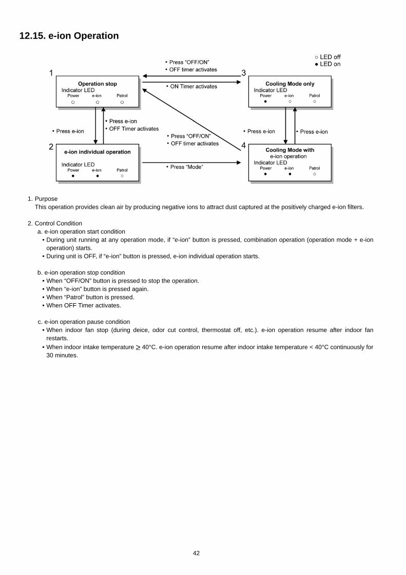
12.15. e-ion Operation
1. PurposeThis operation provides clean air by producing negative ions to attract dust captured at the positively charged e-ion filters.
2. Control Conditiona. e-ion operation start condition
• During unit running at any operation mode, if “e-ion” button is pressed, combination operation (operation mode + e-ionoperation) starts.
• During unit is OFF, if “e-ion” button is pressed, e-ion individual operation starts.
b. e-ion operation stop condition• When “OFF/ON” button is pressed to stop the operation.• When “e-ion” button is pressed again.• When “Patrol” button is pressed.• When OFF Timer activates.
c. e-ion operation pause condition• When indoor fan stop (during deice, odor cut control, thermostat off, etc.). e-ion operation resume after indoor fan
restarts.• When indoor intake temperature 40°C. e-ion operation resume after indoor intake temperature < 40°C continuously for
30 minutes.
42
3. Control Contenta. Indoor fan control
• During any operation mode combines with e-ion operation, fan speed follows respective operation mode.• During e-ion individual operation - only Auto Fan Speed and no Powerful operation is allowed. Even if Fan Speed button
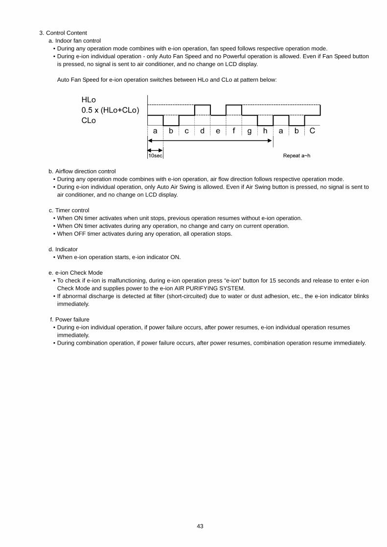
is pressed, no signal is sent to air conditioner, and no change on LCD display.
Auto Fan Speed for e-ion operation switches between HLo and CLo at pattern below:
b. Airflow direction control• During any operation mode combines with e-ion operation, air flow direction follows respective operation mode.• During e-ion individual operation, only Auto Air Swing is allowed. Even if Air Swing button is pressed, no signal is sent to
air conditioner, and no change on LCD display.
c. Timer control• When ON timer activates when unit stops, previous operation resumes without e-ion operation.• When ON timer activates during any operation, no change and carry on current operation.• When OFF timer activates during any operation, all operation stops.
d. Indicator• When e-ion operation starts, e-ion indicator ON.
e. e-ion Check Mode• To check if e-ion is malfunctioning, during e-ion operation press “e-ion” button for 15 seconds and release to enter e-ion
Check Mode and supplies power to the e-ion AIR PURIFYING SYSTEM.• If abnormal discharge is detected at filter (short-circuited) due to water or dust adhesion, etc., the e-ion indicator blinks
immediately.
f. Power failure• During e-ion individual operation, if power failure occurs, after power resumes, e-ion individual operation resumes
immediately.• During combination operation, if power failure occurs, after power resumes, combination operation resume immediately.
43
g. Error Detection ControlWhen e-ion indicator blink, it indicates error listed below:a. e-ion AIR PURIFYING SYSTEM main connector to PCB is open:
Judgment Method• During e-ion operation (include during Patrol operation), e-ion AIR PURIFYING SYSTEM main connector to PCB is
opened.
Troubleshooting Methods• Connect the connector or stop operation (include during Patrol operation) to cancel the blinking.
b. Abnormal DischargeJudgment Method
• During e-ion operation, when feedback voltage is-Lo (at micro controller) is detected, it is judged abnormal discharge andstops power supplies to the e-ion AIR PURIFYING SYSTEM.
• The unit retries after 30 minutes and repeat for 24 times. (not applicable for e-ion Check Mode)
Troubleshooting Method• Press “e-ion” button or “OFF/ON” button to stop the operation and check the e-ion AIR PURIFYING SYSTEM main
connector to PCB.• After that, press “e-ion” button again to confirm the e-ion indicator not blinking.• The 24 times counter will be clear after 10 minutes of normal operation or when operation stops.
Error Reset Method• Press “OFF/ON” button to OFF the operation.• Press AUTO OFF/ON button at indoor unit to OFF the operation.• OFF Timer activates.• Press “e-ion” button during e-ion individual mode.• Power supply reset.
c. e-ion breakdownJudgment Method
• When hi-feedback voltage (at micro controller) supplied to filter during e-ion stop, due to PCB or filter's high voltage powersupply damage.
• Operations except e-ion continue. Both Timer indicator and e-ion indicator blinks.
Troubleshooting Method• Press “e-ion” button or “OFF/ON” button to stop the operation.• Change main circuit board or filter's high voltage power supply.• When lo-feedback voltage supplied to e-ion AIR PURIFYING SYSTEM during e-ion operation, e-ion indicator and Timer
indicator stop blinking.
44
13 Servicing Mode13.1. Auto OFF/ON Button
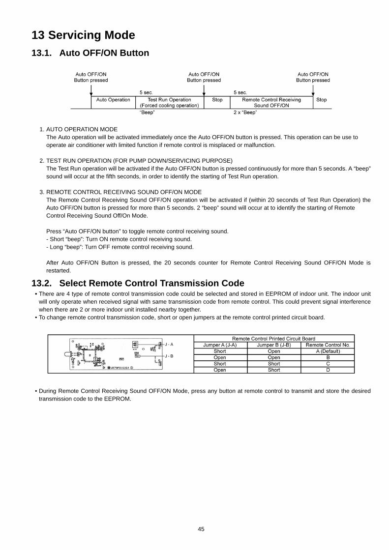
1. AUTO OPERATION MODEThe Auto operation will be activated immediately once the Auto OFF/ON button is pressed. This operation can be use tooperate air conditioner with limited function if remote control is misplaced or malfunction.
2. TEST RUN OPERATION (FOR PUMP DOWN/SERVICING PURPOSE)The Test Run operation will be activated if the Auto OFF/ON button is pressed continuously for more than 5 seconds. A “beep”sound will occur at the fifth seconds, in order to identify the starting of Test Run operation.
3. REMOTE CONTROL RECEIVING SOUND OFF/ON MODEThe Remote Control Receiving Sound OFF/ON operation will be activated if (within 20 seconds of Test Run Operation) theAuto OFF/ON button is pressed for more than 5 seconds. 2 “beep” sound will occur at to identify the starting of RemoteControl Receiving Sound Off/On Mode.
Press “Auto OFF/ON button” to toggle remote control receiving sound.- Short “beep”: Turn ON remote control receiving sound.- Long “beep”: Turn OFF remote control receiving sound.
After Auto OFF/ON Button is pressed, the 20 seconds counter for Remote Control Receiving Sound OFF/ON Mode isrestarted.
13.2. Select Remote Control Transmission Code• There are 4 type of remote control transmission code could be selected and stored in EEPROM of indoor unit. The indoor unit
will only operate when received signal with same transmission code from remote control. This could prevent signal interferencewhen there are 2 or more indoor unit installed nearby together.
• To change remote control transmission code, short or open jumpers at the remote control printed circuit board.
• During Remote Control Receiving Sound OFF/ON Mode, press any button at remote control to transmit and store the desiredtransmission code to the EEPROM.
45
13.3. Remote Control Button13.3.1. SET BUTTON
• To check current remote control transmission code.- Press for more than 10 seconds.
• To change the air quality sensor sensitivity:- Press and release with pointer.- Press the Timer Decrement button to select sensitivity:
1. Low Sensitivity2. Standard (Default)3. Hi Sensitivity
- Confirm setting by pressing Timer Set button, a “Beep” sound will be heard. LCD returns to original display after 2 seconds.- LCD returns to original display if remote control does not operate for 30 seconds.
13.3.2. CLOCK BUTTON• To change the remote control’s time format.
- Press for more than 5 seconds.
13.3.3. RESET (RC)• To clear and restore the remote control setting to factory default.
- Press once to clear the memory.
13.3.4. TIMER • To change indoor unit indicator’s LED intensity.
- Press continuously for 5 seconds.
13.3.5. TIMER • To change remote control display from Degree Celsius to Degree Fahrenheit.
- Press continuously for 10 seconds.
46
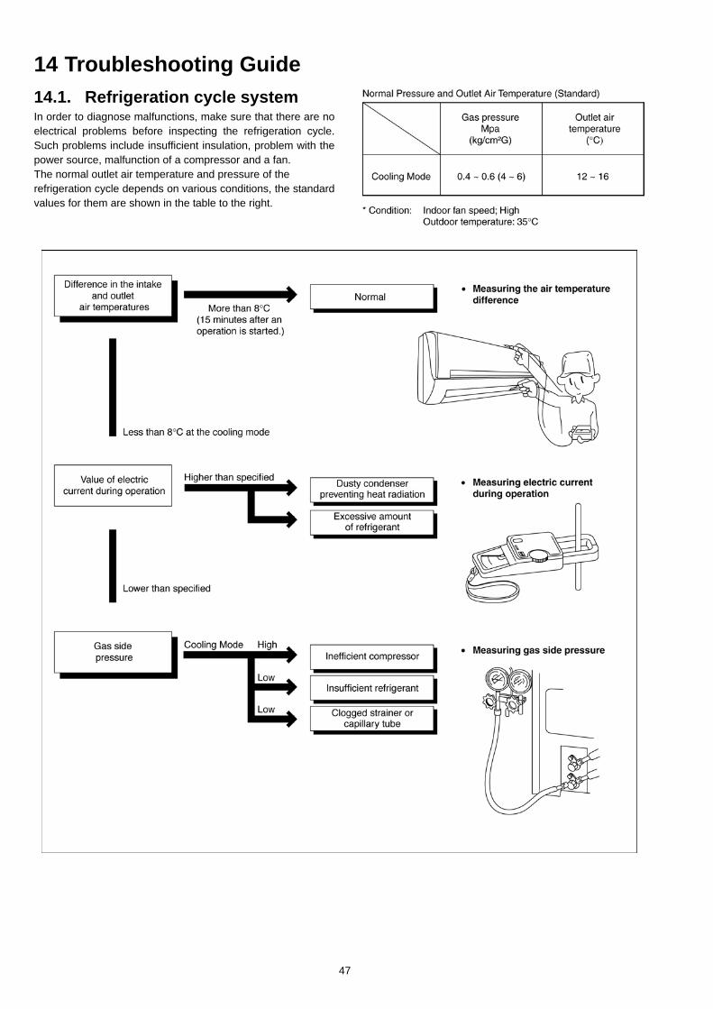
14 Troubleshooting Guide14.1. Refrigeration cycle systemIn order to diagnose malfunctions, make sure that there are noelectrical problems before inspecting the refrigeration cycle.Such problems include insufficient insulation, problem with thepower source, malfunction of a compressor and a fan.The normal outlet air temperature and pressure of therefrigeration cycle depends on various conditions, the standardvalues for them are shown in the table to the right.
47
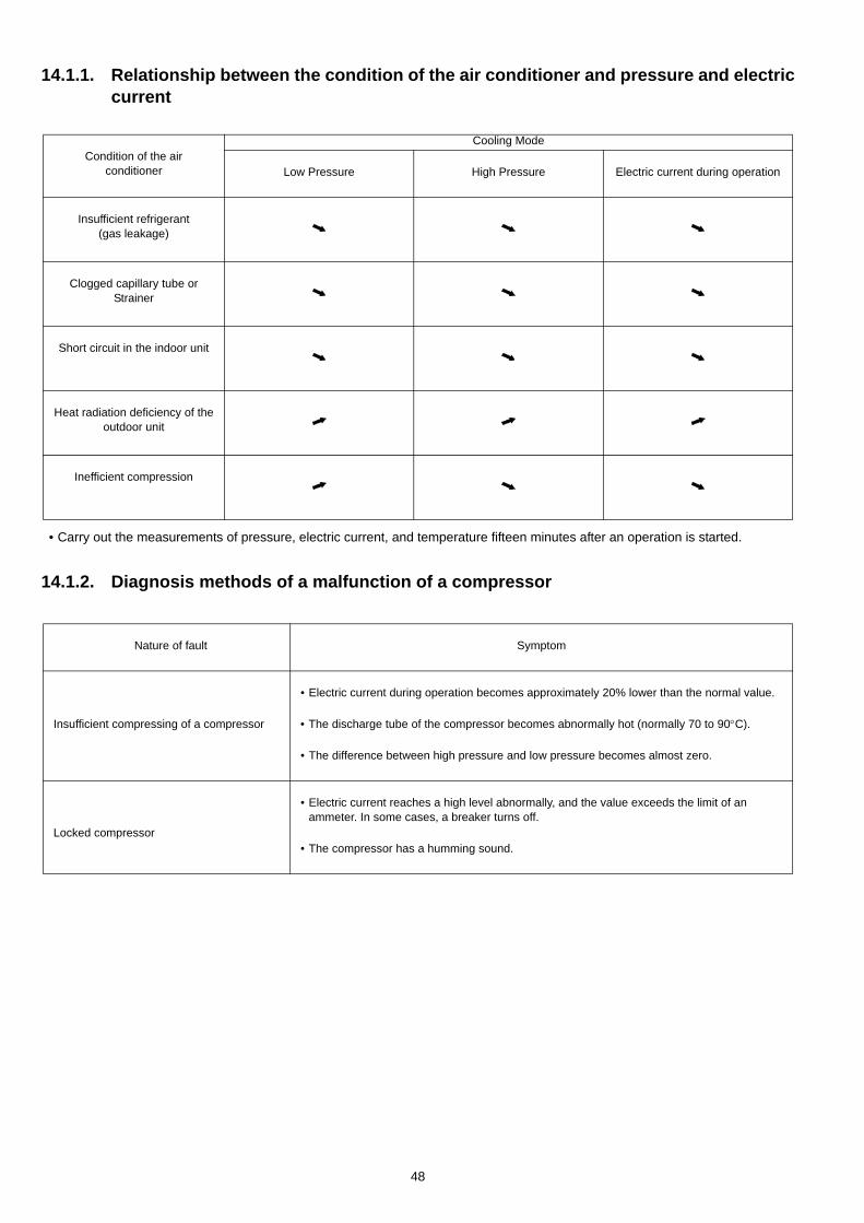
14.1.1. Relationship between the condition of the air conditioner and pressure and electriccurrent
• Carry out the measurements of pressure, electric current, and temperature fifteen minutes after an operation is started.
14.1.2. Diagnosis methods of a malfunction of a compressor
Cooling ModeCondition of the air
conditioner Low Pressure High Pressure Electric current during operation
Insufficient refrigerant(gas leakage)
Clogged capillary tube orStrainer
Short circuit in the indoor unit
Heat radiation deficiency of the outdoor unit
Inefficient compression
Nature of fault Symptom
• Electric current during operation becomes approximately 20% lower than the normal value.
Insufficient compressing of a compressor • The discharge tube of the compressor becomes abnormally hot (normally 70 to 90°C).
• The difference between high pressure and low pressure becomes almost zero.
• Electric current reaches a high level abnormally, and the value exceeds the limit of anammeter. In some cases, a breaker turns off.
Locked compressor• The compressor has a humming sound.
48
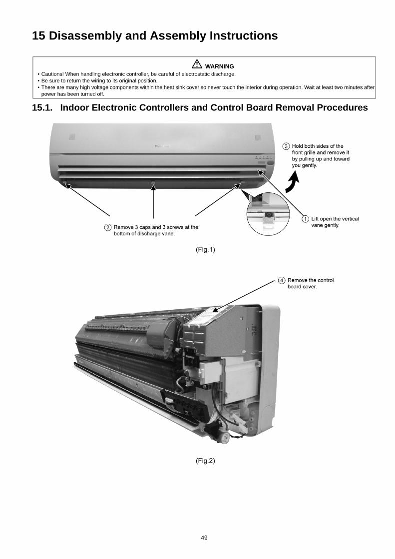
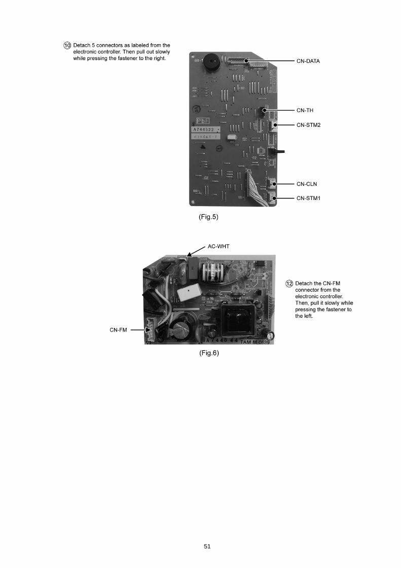
15 Disassembly and Assembly Instructions
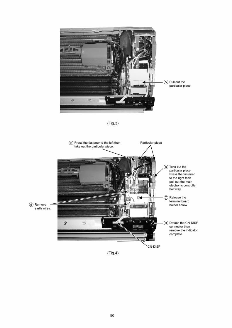
15.1. Indoor Electronic Controllers and Control Board Removal Procedures
WARNING• Cautions! When handling electronic controller, be careful of electrostatic discharge.• Be sure to return the wiring to its original position.• There are many high voltage components within the heat sink cover so never touch the interior during operation. Wait at least two minutes after
power has been turned off.
49
50
51
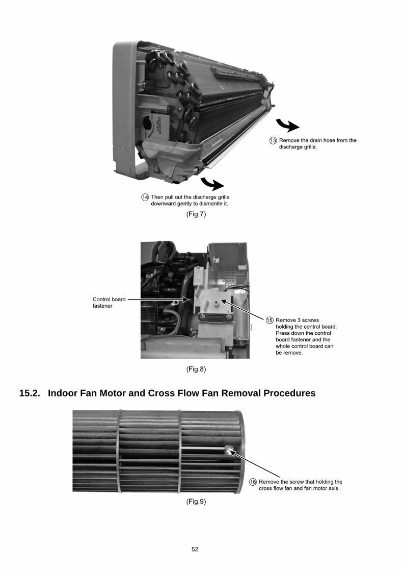
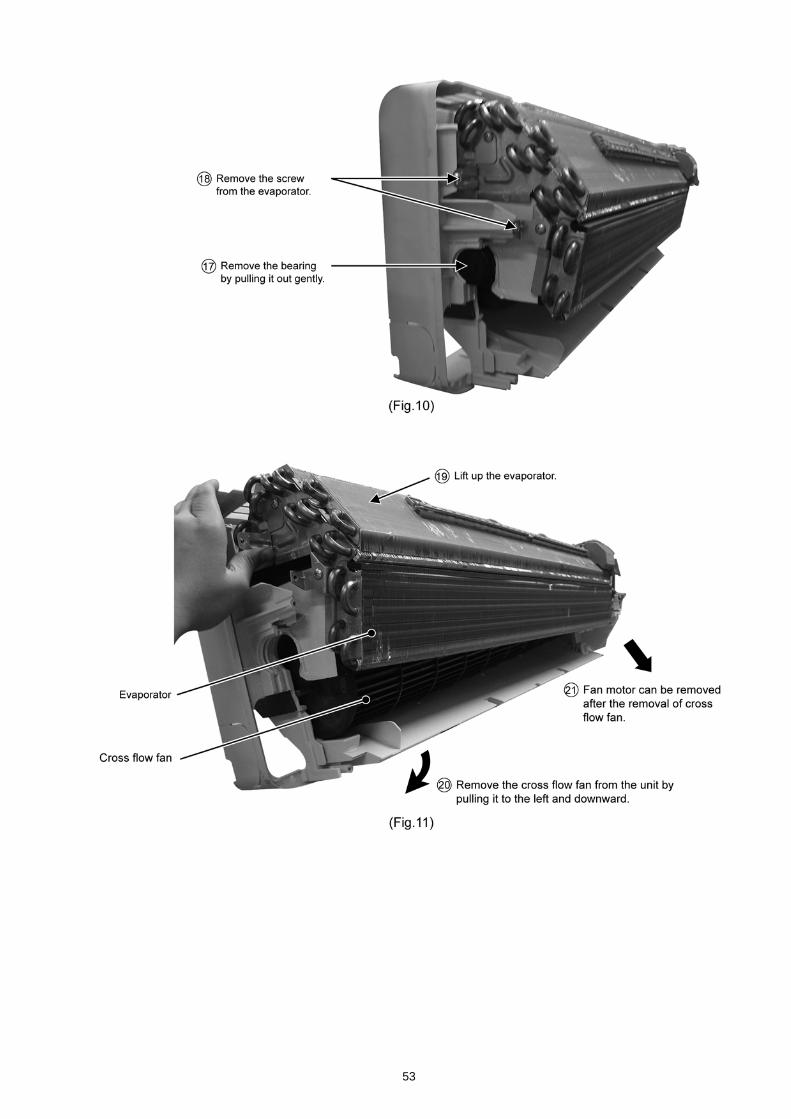
15.2. Indoor Fan Motor and Cross Flow Fan Removal Procedures
52
53
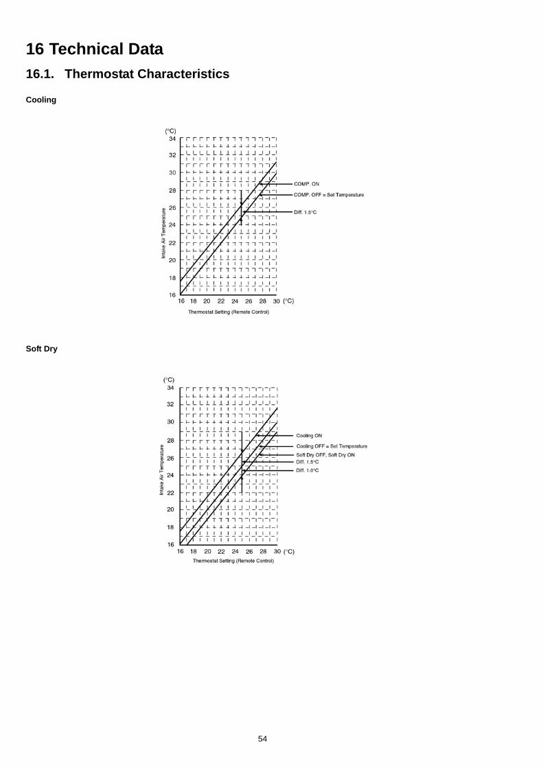
16 Technical Data16.1. Thermostat Characteristics
Cooling
Soft Dry
54
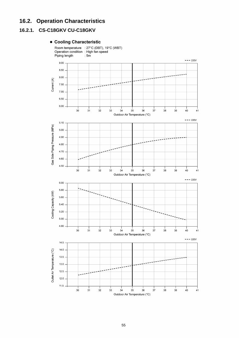
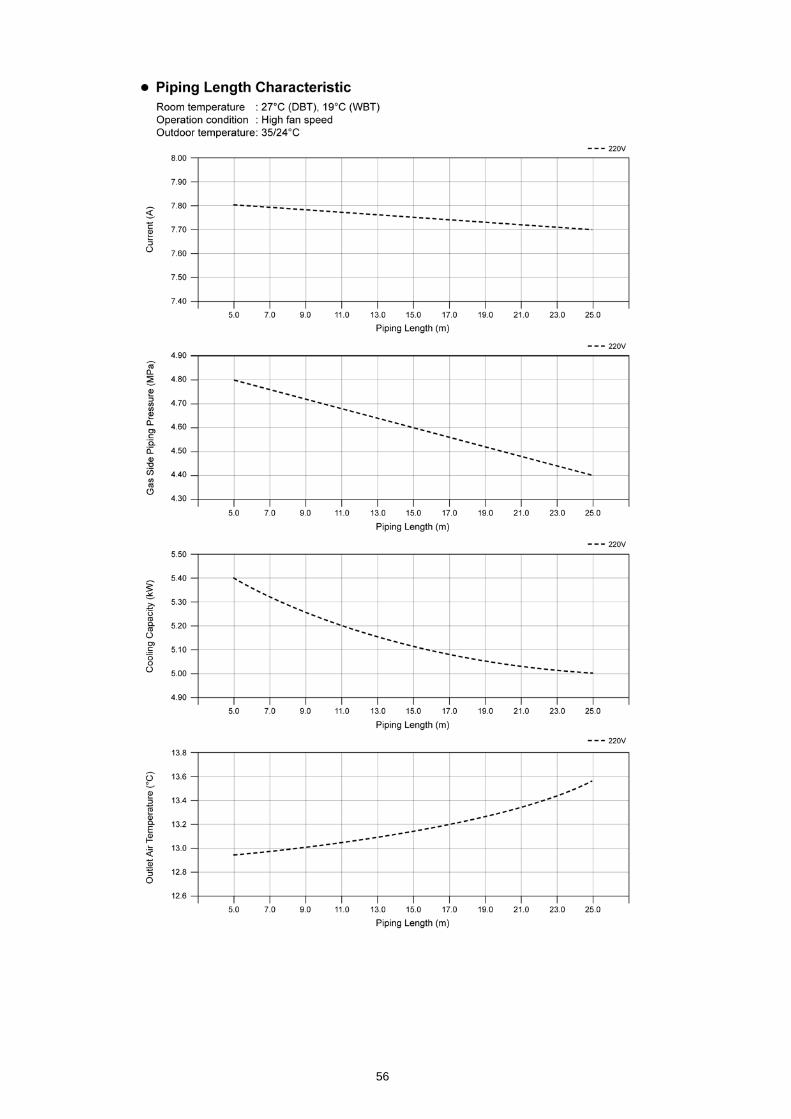
16.2. Operation Characteristics16.2.1. CS-C18GKV CU-C18GKV
55
56
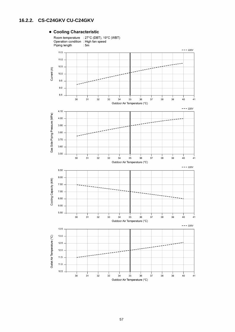
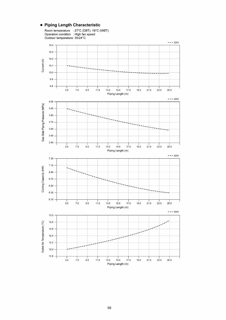
16.2.2. CS-C24GKV CU-C24GKV
57
58
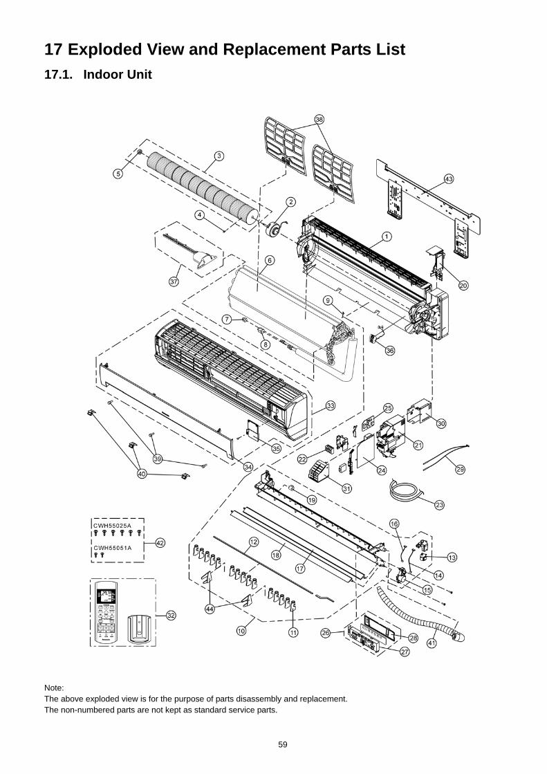
17 Exploded View and Replacement Parts List17.1. Indoor Unit
Note:The above exploded view is for the purpose of parts disassembly and replacement. The non-numbered parts are not kept as standard service parts.
59
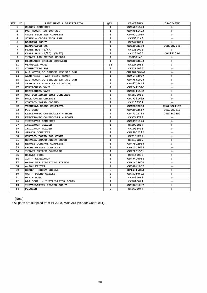
(Note)• All parts are supplied from PHAAM, Malaysia (Vendor Code: 061).
REF. NO. PART NAME & DESCRIPTION QTY. CS-C18GKV CS-C24GKV1 CHASSY COMPLETE 1 CWD50C1520 ←2 FAN MOTOR, DC 30W 3PH 1 CWA981149J ←3 CROSS FLOW FAN COMPLETE 1 CWH02C1010 ←4 SCREW - CROSS FLOW FAN 1 CWH551146 ←5 BEARING ASS’Y 1 CWH64K007 ←6 EVAPORATOR CO. 1 CWB30C2150 CWB30C21497 FLARE NUT (1/4”) 1 CWT251026 ←8 FLARE NUT (1/2”) (5/8”) 1 CWT251035 CWT251036 9 INTAKE AIR SENSOR HOLDER 1 CWH32143 ←10 DISCHARGE GRILLE COMPLETE 1 CWE20C2683 ←11 VERTICAL VANE 15 CWE241088 ←12 CONNECTING BAR 1 CWE261025 ←13 A.S.MOTOR,DC SINGLE 12V 300 OHM 1 CWA98260+MJ ←14 LEAD WIRE - AIR SWING MOTOR 1 CWA67C3977 ←15 A.S.MOTOR,DC SINGLE 12V 300 OHM 1 CWA98K1008 ←16 LEAD WIRE - AIR SWING MOTOR 1 CWA67C4445 ←17 HORIZONTAL VANE 1 CWE241152C ←18 HORIZONTAL VANE 1 CWE241153C ←19 CAP FOR DRAIN TRAY COMPLETE 1 CWH521096 ←20 BACK COVER CHASSIS 1 CWD932162B ←21 CONTROL BOARD CASING 1 CWH102334 ←22 TERMINAL BOARD COMPLETE 1 CWA28C2068 CWA28C2119J23 P.S.CORD 1 CWA20C2617 CWA20C261024 ELECTRONIC CONTROLLER - MAIN 1 CWA73C2718 CWA73C265025 ELECTRONIC CONTROLLER - POWER 1 CWA744788 ←26 INDICATOR COMPLETE 1 CWE39C1174 ←27 INDICATOR HOLDER 1 CWD932817 ←28 INDICATOR HOLDER 1 CWD932818 ←29 SENSOR COMPLETE 1 CWA50C2122 ←30 CONTROL BOARD TOP COVER 1 CWH131209 ←31 CONTROL BOARD FRONT COVER 1 CWH131210 ←32 REMOTE CONTROL COMPLETE 1 CWA75C2988 ←33 FRONT GRILLE COMPLETE 1 CWE11C3669 ←34 INTAKE GRILLE COMPLETE 1 CWE22C1361 ←35 GRILLE DOOR 1 CWE141076 ←36 ION - GENERATOR 1 CWH94C0014 ←37 e-ION AIR PURIFYING SYSTEM 1 CWH14C5600 ←38 e-ION FILTER 2 CWD00K1002 ←39 SCREW - FRONT GRILLE 3 XTT4+16CFJ ←40 CAP - FRONT GRILLE 3 CWH521062A ←41 DRAIN HOSE 1 CWH851063 ←42 BAG COMP. - INSTALLATION SCREW 1 CWH82C067 ←43 INSTALLATION HOLDER ASS’Y 1 CWH36K1007 ←44 FULCRUM 2 CWH621047 ←
60
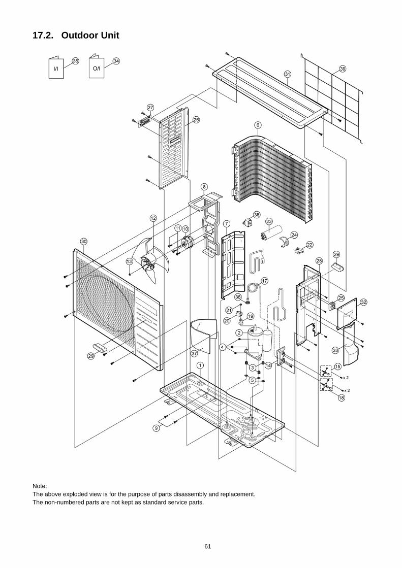
17.2. Outdoor Unit
Note:The above exploded view is for the purpose of parts disassembly and replacement. The non-numbered parts are not kept as standard service parts.
61
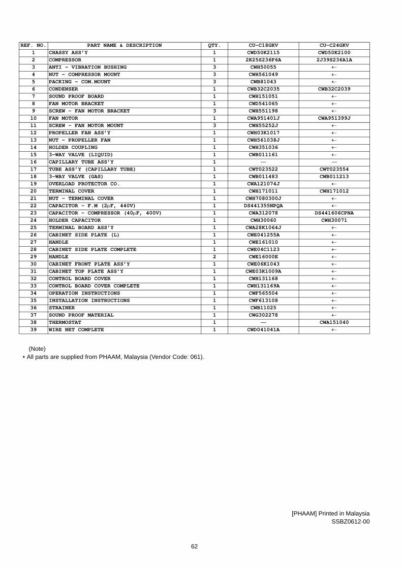
(Note)• All parts are supplied from PHAAM, Malaysia (Vendor Code: 061).
[PHAAM] Printed in MalaysiaSSBZ0612-00
REF. NO. PART NAME & DESCRIPTION QTY. CU-C18GKV CU-C24GKV1 CHASSY ASS’Y 1 CWD50K2115 CWD50K21002 COMPRESSOR 1 2K25S236F6A 2J39S236A1A3 ANTI - VIBRATION BUSHING 3 CWH50055 ←4 NUT - COMPRESSOR MOUNT 3 CWH561049 ←5 PACKING - COM.MOUNT 3 CWB81043 ←6 CONDENSER 1 CWB32C2035 CWB32C20397 SOUND PROOF BOARD 1 CWH151051 ←8 FAN MOTOR BRACKET 1 CWD541065 ←9 SCREW - FAN MOTOR BRACKET 3 CWH551198 ←10 FAN MOTOR 1 CWA951401J CWA951399J11 SCREW - FAN MOTOR MOUNT 3 CWH55252J ←12 PROPELLER FAN ASS’Y 1 CWH03K1017 ←13 NUT - PROPELLER FAN 1 CWH561038J ←14 HOLDER COUPLING 1 CWH351036 ←15 3-WAY VALVE (LIQUID) 1 CWB011161 ←16 CAPILLARY TUBE ASS’Y 1 — —17 TUBE ASS’Y (CAPILLARY TUBE) 1 CWT023522 CWT02355418 3-WAY VALVE (GAS) 1 CWB011483 CWB01121319 OVERLOAD PROTECTOR CO. 1 CWA121074J ←20 TERMINAL COVER 1 CWH171011 CWH17101221 NUT - TERMINAL COVER 1 CWH7080300J ←22 CAPACITOR - F.M (2μF, 440V) 1 DS441355NPQA ←23 CAPACITOR - COMPRESSOR (40μF, 400V) 1 CWA312078 DS441606CPNA24 HOLDER CAPACITOR 1 CWH30060 CWH3007125 TERMINAL BOARD ASS’Y 1 CWA28K1064J ←26 CABINET SIDE PLATE (L) 1 CWE041255A ←27 HANDLE 1 CWE161010 ←28 CABINET SIDE PLATE COMPLETE 1 CWE04C1123 ←29 HANDLE 2 CWE16000E ←30 CABINET FRONT PLATE ASS’Y 1 CWE06K1043 ←31 CABINET TOP PLATE ASS’Y 1 CWE03K1009A ←32 CONTROL BOARD COVER 1 CWH131168 ←33 CONTROL BOARD COVER COMPLETE 1 CWH131169A ←34 OPERATION INSTRUCTIONS 1 CWF565504 ←35 INSTALLATION INSTRUCTIONS 1 CWF613108 ←36 STRAINER 1 CWB11025 ←37 SOUND PROOF MATERIAL 1 CWG302278 ←38 THERMOSTAT 1 — CWA15104039 WIRE NET COMPLETE 1 CWD041041A ←
62
Related Documents