Panacea-BOCAF On-Line University The educational series covering clean energy technology towards building our children a future. Panacea-BOCAF is a registered non-profit organization, dedicated to educational study and research. All copyrights belong to their owners and are acknowledged. All material presented on this web site is either news reporting or information presented for non-profit study and research, or has previously been publicly disclosed or has implicitly or explicitly been put into the public domain. Fair Use applies. Contact us. Overview…………………………………………………………………………………………………... Description………………………………………………………………………………………………… Replication………………………………………………………………………………………………… Faculty information……………………………………………………………………………………… Patents and related information……………………………………………………………………… Related Links………………………………………………………………………………………………. Technical discussion…………………………………………………………………………………….. Replication Videos………………………………………………………………………………………. Credits……………………………………………………………………………………………………… Over View Quote- If this is the first time you are viewing this page I ask you to share this link immediately to everyone you have in your email address list and ask them to do the same no matter what you or they may think. We need to give this back to the World a.s.a.p. Next I ask everyone to stop experimenting if you can and help with this, since I believe it is the one of the most promising real effect at this time (that I know of) that is fully shared on the Internet. Nothing will be hidden here. You can view the development of everything that is going on. End quote Luc open source engineer and original inventor of the Ganga Shakti - Water Power concept Before experimentation please note the following advice provided by open source engineer Mart:

Welcome message from author
This document is posted to help you gain knowledge. Please leave a comment to let me know what you think about it! Share it to your friends and learn new things together.
Transcript

Panacea-BOCAF On-Line University The educational series covering clean energy technology towards building our children a future. Panacea-BOCAF is a registered non-profit organization, dedicated to educational study and research. All copyrights belong to their owners and are acknowledged. All material presented on this web site is either news reporting or information presented for non-profit study and research, or has previously been publicly disclosed or has implicitly or explicitly been put into the public domain. Fair Use applies. Contact us.
Overview…………………………………………………………………………………………………...
Description…………………………………………………………………………………………………
Replication…………………………………………………………………………………………………
Faculty information………………………………………………………………………………………
Patents and related information………………………………………………………………………
Related Links……………………………………………………………………………………………….
Technical discussion……………………………………………………………………………………..
Replication Videos……………………………………………………………………………………….
Credits………………………………………………………………………………………………………
Over View Quote- If this is the first time you are viewing this page I ask you to share this link immediately to everyone you have in your email address list and ask them to do the same no matter what you or they may think. We need to give this back to the World a.s.a.p. Next I ask everyone to stop experimenting if you can and help with this, since I believe it is the one of the most promising real effect at this time (that I know of) that is fully shared on the Internet. Nothing will be hidden here. You can view the development of everything that is going on. End quote Luc open source engineer and original inventor of the Ganga Shakti - Water Power concept
Before experimentation please note the following advice provided by open source engineer Mart:
1.DANGEROUS very high voltage need to be extra careful on this one. 2. FUN! But safety wins out with me over fun. Trips to the hospital are no fun. 3. Wear some dark glasses before watching the sparks, don’t hurt you eyes
Please take care of your eyes!!! I have a feeling that too much exposure to this spark will lead to eye damage. My eyes are still feeling kind of dry and find I need to re-focus more than before. So wear UV protective shaded glasses when looking at the spark.
Unless you are experienced and are aware of the components and their potential effects, please do not attempt to do this. Batteries are capable of producing hydrogen; if too much voltage is applied to them they are able to spark internally. If this happens you will have exploding electrolyte (sulfuric acid) every where. Please be safe and treat this experiment with respect. Do not attempt it unless you are a qualified electrician with adequate safety precautions in place.
There is many phenomena present in this research device which given the current laws do not make sense. The water spark plug is currently at this time not running a house in a third world country, but there is awareness and lessons contained there waiting to be harnessed.
What direction is the application of this device heading? Currently it’s heading towards a potential water engine, plasma circuit, Firestorm spark plug duplication and many more. Open source Individuals like Aaron, Gotoluc, Calanan and Ossie have since shown interesting variations and as Aaron has put it; there are more and other enhancements. There are many elements in this circuit to work with like gas pressure analogies, get them in mind and you'll figure out more.
We need to continue our present direction in designing, improving and applying the plasma spark to water to release the energy in it necessary to drive a piston down in an internal combustion engine, AS WELL AS THE MULTITUDE OF OTHER APPLICATIONS to which this technology can be applied. We are definitely on to something here with LUC, Ossie, qiman(Aaron), capacitor70, XBox, geovel56 and others actually doing experiments and coming up with real results.
These engineers providing this research have worked on with no budget and are true to their word about open source disclosure. The Non profit organization Panacea-BOCAF intends to support open source engineers working with this and other suppressed clean energy technologies. These engineers require grants, resources, faculty recognition and security. All this can be created in Panacea’s proposed granted research and development center. For those able to help this effort, please Contact us.
Description
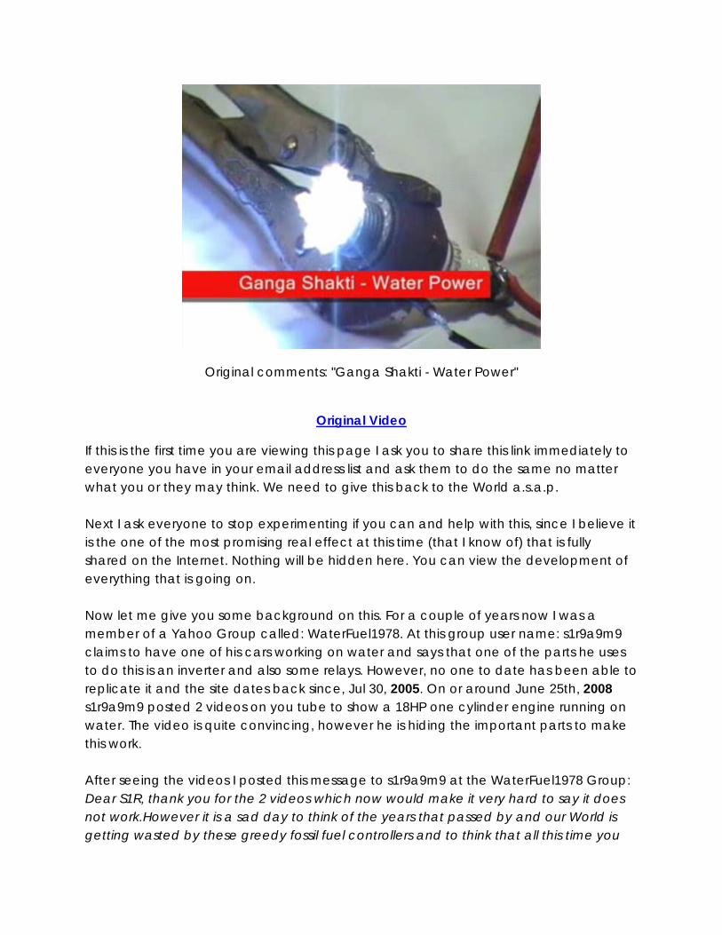
Original comments: "Ganga Shakti - Water Power"
Original Video
If this is the first time you are viewing this page I ask you to share this link immediately to everyone you have in your email address list and ask them to do the same no matter what you or they may think. We need to give this back to the World a.s.a.p. Next I ask everyone to stop experimenting if you can and help with this, since I believe it is the one of the most promising real effect at this time (that I know of) that is fully shared on the Internet. Nothing will be hidden here. You can view the development of everything that is going on. Now let me give you some background on this. For a couple of years now I was a member of a Yahoo Group called: WaterFuel1978. At this group user name: s1r9a9m9 claims to have one of his cars working on water and says that one of the parts he uses to do this is an inverter and also some relays. However, no one to date has been able to replicate it and the site dates back since, Jul 30, 2005. On or around June 25th, 2008 s1r9a9m9 posted 2 videos on you tube to show a 18HP one cylinder engine running on water. The video is quite convincing, however he is hiding the important parts to make this work. After seeing the videos I posted this message to s1r9a9m9 at the WaterFuel1978 Group: Dear S1R, thank you for the 2 videos which now would make it very hard to say it does not work.However it is a sad day to think of the years that passed by and our World is getting wasted by these greedy fossil fuel controllers and to think that all this time you

have been a chosen one to put the pieces together that could change all that... and what do you do with it, hide it, just as they do. All gift of knowledge comes from one place and it is testing man to see what he does with it. All that is good to help keep balance is meant to be shared with all...just as the structure of the Universe keeps balance and is giving. When one stops the flow that would be good for Billions of others I would think of that as a great sin and your life could be in much greater danger than you think. All who have tried to control their inventions that could of made our World a better place have lost their life over it or have been bought out just to hide the information. I'm sure Stanley Meyer would do it differently if he had a second chance but it's too late when your dead and the knowledge is lost. Hiding things will not protect you, sharing will...since you will be welcomed in all the homes of America and the World as a Hero. Nowthat is protection if you think you need it. By hiding things you are doing exactly as they want and that makes a small target for them since it is not spread out and can be easily extinguished, 99.99% of the World won't even know it has happen. You chose your destiny. But I am here to help you in every way I humanly can and I think many others who are here are ready to do the same. I hope this time we can do it all together, united we stand, divided we. End I have believed for many years that water could be used as a fuel. The next day I posted the message to s1r9a9m9 I started replication attempts of his system and while working on it I accidentally shorted the DC side of the bridge rectifier and saw a flame spark which made me think of plasma. So I tried many different circuit possibilities to try and incorporate this short circuit effect when the high voltage spark jumped the gap. After 2 days of work I came up with a very simple circuit which is posted at the bottom of this page. I had to work hard to make the circuit so simple since our minds think something like this should be complicated, so don't come to the conclusion that something so simple will not work until you try it. At the bottom is my original circuit but I updated the diode part number and the quantity thanks to user name: callanan's added his improvement ideas. His circuit is more complex than mine and could work for you if you are advanced enough in electronics but one way or the other I would recommend (if you want to replicate) that you start with the simple circuit first and after seeing the effect you can add the extra components if you wish. Please note that I believe both circuits give the same effect. Also, please note that most Spark plug have a resistance in them which needs to be removed. In many models of Spark Plugs you can remove the resistor by heating up the
ceramic around the top electrode to unlock the seal and then unscrew it and remove the resistor and spring and replace it with a piece of 10 gauge copper wire or 3 pieces of 14 gauge regular home copper wiring to complete the contact. Make sure the wire you added touches the top electrode just before it sets when you are screwing it back in. The gap of the plug can be standard but you could play with it after a successful replication and see what it does. We will be testing all these things and updating this page with the most current information, so keep checking this page for updates. A note about the video above. I realized only after seeing the video that you cannot see the complete flame that I was seeing when doing the demonstration video. There is an orange red glow around the spark when the water explodes which the video does not pick-up. Also take note that not much water is needed to see the glow and you can kill the effect if you add too much water mist. Thank you for looking and please remember to Share. - Luc
End
There have since been a few experimenters like Aaron, Dr Peter Lindermann and others investigating the anomalies, these are included in the faculty information section. More of these results will be added into this document, if you discover any please send them to us.
Replication Replicate first, observe the effect then add one change at a time and if you find an improvement please post your finding. Other than that we will loose focus. -Luc
Updated Ganga Shakti - Water Fuel Circuit
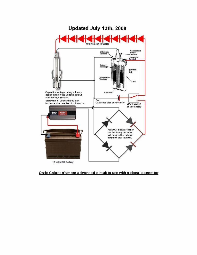
Ossie Calanan's more advanced circuit to use with a signal generator
I said it is an explosion and the result is expanding gases very fast but I said nothing about heat! The explosion is cold! No heat! Forget about your heating plans with this. This is cold kinetic energy. I don't know about water plasma flames but I do remember that you can run your hand through a pure HHO flame without getting burnt. Those were the days of Brown's gas.-Ossie

Ossie’s original instructions: I have fully replicated the effect that Luc describes and shows. It is truly astounding! With no water and a dry spark plug you get normal cap discharges and nothing special. Spray a bit of water and it is like fire crackers going off! The water will continue to explode when fired repetitively until it has all gone from within the spark plug. This can take a minute or two at a 1 second repetition rate. The more fine the water and spray, the more powerful an explosion and it is undoubtedly an extreme fuel based explosion which in this case, the fuel is water. Please see my video where I have tried to capture the explosions with angle shots but my digital camera does not do justice in representing the true power of the explosive ignitions of the water. This is very real stuff indeed folks! - Video
I am attaching a circuit diagram of my test setup and some pictures to this post. Regarding the circuit, the most important part of the discharge side is the need for a high current high voltage diode. I have simply used 16 x 1N5404 in series. They are 4 amp diodes. My oscillator is a basic radiant oscillator that I released years ago and is a very good and simple radiant energy oscillator. As far as RE being at work here, we all need to do much more experimentation to prove it is required as opposed to convention energy. I do know that my simple circuit uses 1-1.5 amps input at 12 volts and this energy input can be brought down significantly with more efficient circuit design.
It is VERY SIMPLE to get water to explode with little energy input in the spark plug discharge of an ignition system. All that is needed is a small cap of a few hundred volts and a few uf and a high CURRENT high voltage diode, placed in series across the spark plug. You can use WHATEVER to charge the cap to a few hundred volts DC. An inverter, oscillator, anything. All you need to do is make sure that the series loop of the capacitor, diode and spark plug is very very low resistance. In fact as low as you can get it for your components. The lower the resistance of this loop, the lower the energy input requirement is to make the water explode. It is possible to do this with even a few hundred milliamps. The key component here is the diode. It MUST be a HV diode to protect the capacitor and power supply from shunting the ignition pulse but it also MUST be a HIGH CURRENT diode to reduce the series loop resistance as much as possible. A microwave diode is a good HV diode but it is NOT a good high current diode. The diode must be able to handle very short surges in the hundreds of amps! This is why I use many 1N5404 diodes in series. These are 400V 4 amp diodes they can handle surges in the hundreds of amps. Putting them in series turns them into a single HV diode capable of handling thousands
of volts. If you have many microwave oven diodes then put as many as you got in parallel. But they are expensive so it is much more cost effective to simply use many 1N5404 diodes in series or series parallel combinations. As I have explained the circuit requirement and operation to explode water in an ignition is very simple. So simply that no one will believe it but it just is. S1r9a9m9's circuit uses heavy 60 amp diodes but is too complicated and not necessary. His use of coils is simply to get the same effect as a capacitor, just in an inverse reactive way. There is no energy gain in this circuit! The in his circuit the measured difference between 36K 0.8 amp input and 24K 6amp output is just what his meters are showing when the ignition pulse and the inverter pulse is mixed. It is NOT real power. The real power and energy and magic is the water explosion itself. This is the only place in this circuit where something unconventional is occurring. The energy appears the be negative in this explosion.
Ossies simplified water explosion experiment
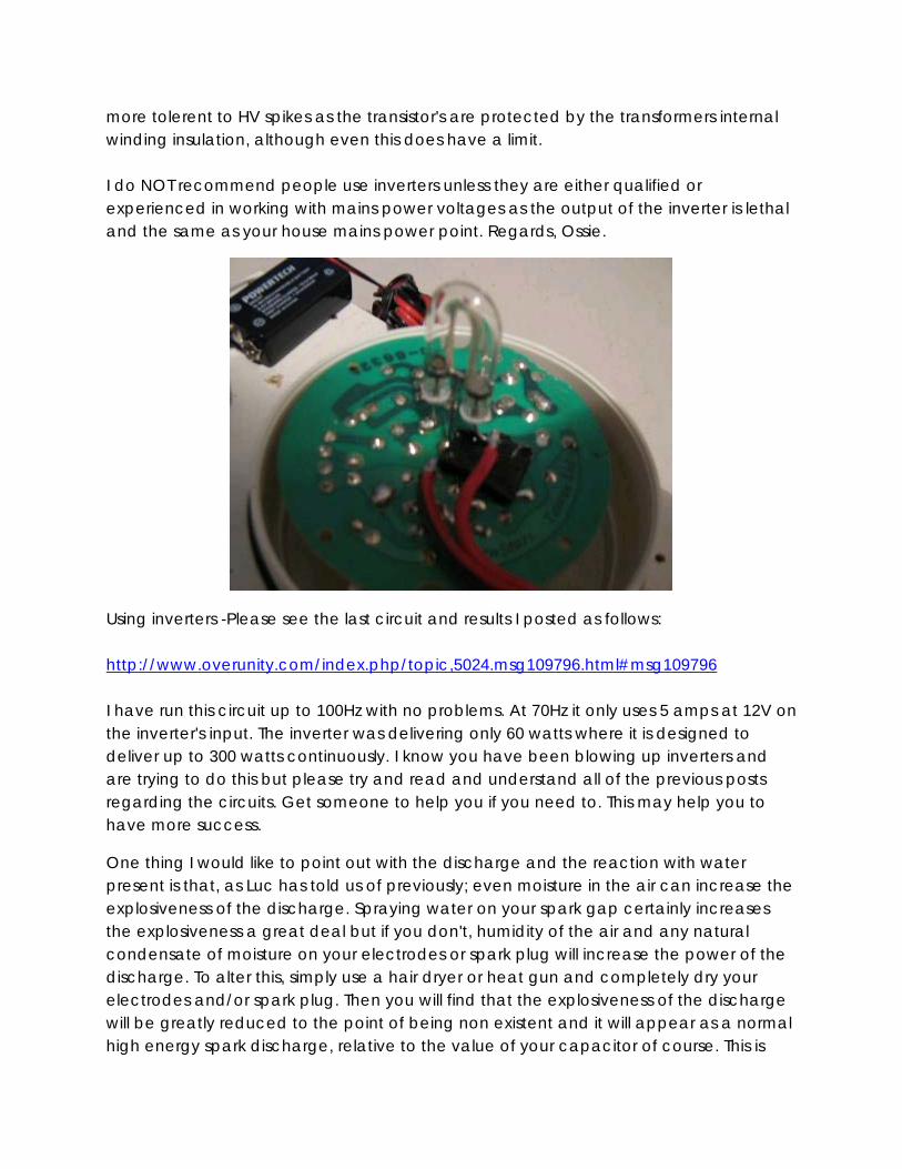
Because it seems that people, who may or may not lack experience in electronics, are having trouble building and replicating the exploding water effect in previously described and shown devices, I have designed, built and tested what I believe to be a very simple to build device that most people can construct themselves at home that is powered only by a small square 9V battery that is commonly used in smoke alarms. I believe even kids can make this. Please see my latest video here:
The purpose of this device is not to be able to power your car on water with it but simply to allow everyone to see for themselves and show others how water can directly explode on demand with little energy input. The device produces the required discharge in the spark plug about every 1 second and uses about 100-150ma from the 9V battery. At this current level the battery won't last too long but it is fine for demonstrations. For longer and continuous runs, just use a small 12V sealed lead acid battery of say 2 A/Hs. Please see the circuit diagram and some pictures attached below. All that is required to build this device is the following. - A 12V, 150ma Security Xenon Strobe Light. Available from electronic and security stores. Color does not matter!
- An old car ignition coil. Available from automobile wreckers. - A non resistor spark plug. Available from auto shops. Must not have a resistor in it! - Five 1N5404 diodes or five large rectifying diodes. Part number doesn't really matter. Avaliable from electronic shops. - A 9 volt battery. The same as used in smoke alarms. Available from anywhere. - Some hook up wire.
- Basic tools including a soldering iron and some solder. - Handheld water sprayer filled with water. That's all folks!! Please build this and show it to your friends, family, your teachers, professors, work mates anyone and everyone who can't believe that water can explode. Help your kids build this as their school science fair project. Just build it for fun!
On another note, my very good friend Ben has been doing some great research on this process as there is surprisingly quite a bit in the internet about it. He has found some references claiming that the energy released, when the water apparently explodes, is one thousand times the input energy required to cause the explosion. He has found some great info out about what may actually be happening but I will leave it to him to share if he gets time. Enjoy!
if you are going to use inverters as your power supply please avoid using new and modern inverters that are all HF semiconductor based and are effectively the reverse of a switch mode power supply and does not have a large standard transformer in it. These modern inverters, because they are all semconductor based, will be very sensitive to any reverse HV spikes and you will blow the semiconductors in them quite easily. The best inverters to use are the older type that are very heavy because they have a large transformer in them. They work in reverse to a normal step down mains transformer and use transistors to oscillate at 50-60Hz the 12V side of the transformer. The 110-240V side is just the transformer's output winding. So these inverters are much
more tolerent to HV spikes as the transistor's are protected by the transformers internal winding insulation, although even this does have a limit. I do NOT recommend people use inverters unless they are either qualified or experienced in working with mains power voltages as the output of the inverter is lethal and the same as your house mains power point. Regards, Ossie.
Using inverters -Please see the last circuit and results I posted as follows: http://www.overunity.com/index.php/topic,5024.msg109796.html#msg109796 I have run this circuit up to 100Hz with no problems. At 70Hz it only uses 5 amps at 12V on the inverter's input. The inverter was delivering only 60 watts where it is designed to deliver up to 300 watts continuously. I know you have been blowing up inverters and are trying to do this but please try and read and understand all of the previous posts regarding the circuits. Get someone to help you if you need to. This may help you to have more success.
One thing I would like to point out with the discharge and the reaction with water present is that, as Luc has told us of previously; even moisture in the air can increase the explosiveness of the discharge. Spraying water on your spark gap certainly increases the explosiveness a great deal but if you don't, humidity of the air and any natural condensate of moisture on your electrodes or spark plug will increase the power of the discharge. To alter this, simply use a hair dryer or heat gun and completely dry your electrodes and/or spark plug. Then you will find that the explosiveness of the discharge will be greatly reduced to the point of being non existent and it will appear as a normal high energy spark discharge, relative to the value of your capacitor of course. This is
also a good way to look at both extremes of having water present in the discharge and no water, or very little water present and noting the difference in the discharge. I think you will find it quite significant and unexpected Regards,Ossie.
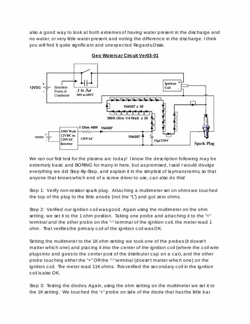
Geo Watercar Circuit Ver03-01
We ran our first test for the plasma arc today! I know the description following may be extremely basic and BORING for many in here, but as promised, I said I would divulge everything we did Step-By-Step, and explain it in the simplest of laymans terms, so that anyone that knows which end of a screw driver to use, can also do this! Step 1: Verify non-resistor spark plug. Attaching a multimeter set on ohms we touched the top of the plug to the little anode (not the "L") and got zero ohms. Step 2: Verified our ignition coil was good. Again using the multimeter on the ohm setting, we set it to the 1 ohm position. Taking one probe and attaching it to the "+" terminal and the other probe on the "-" terminal of the ignition coil, the meter read 1 ohm. That verifies the primary coil of the ignition coil was OK. Setting the multimeter to the 1K ohm setting we took one of the probes (it doesn't matter which one) and placing it into the center of the ignition coil (where the coil wire plugs into and goes to the center post of the distributor cap on a car), and the other probe touching either the "+" OR the "-" terminal (doesn't matter which one) on the ignition coil. The meter read 11K ohms. This verified the secondary coil in the ignition coil is also OK. Step 3: Testing the diodes. Again, using the ohm setting on the multimeter we set it to the 1K setting. We touched the '+" probe on side of the diode that has the little bar
printed on it, and the "-" probe on the other side. It showed no resistance which is what we expected. We the reversed the probes and the meter did not move at all, again, what was expected. If there was any movement in that position, the diode has leakage and therefore bad. We repeated this with every diode to verify they were good. Step 4: Connected all the components according to our schematic Step 5: Test the "Points and Condenser" emulator Leaving the diode chain, capacitor/diode in parallel, and leading diode from the inverter disconnected from the spark plug, we flipped the switch back and forth and got a good spark at the spark plug. This verified our "points and condenser" emulator was working properly as well as verifying the ignition coil was putting out HV. Step 6: Testing whether the ignition coil is "+" ve or "-" ve. We connected the diode string, the diode/capacitor parallel arrangement, and leading rectifying diode to the spark plug, but didn't plug in the AC. We got NOTHING from the spark plug at all. We quickly deduced we had an ignition coil that had a "-" ve discharge instead of "+" ve. To verify this, we disconnected the entire diode string from the other components, reversed it's direction, and placed the string across the spark plug. We got spark from the coil. This verified we had a "-" ve coil. Step 7: Reverse the circuit for a "-" ve coil. We reversed the capacitor/diode parallel combination, as well the leading rectifier diode coming off of the inverter. We disconnected the diode string from the spark plug base and attached it to the capacitor/diode parallel arrangement and the now reversed leading diode. Again, before plugging in the AC, we tested the spark from the HV. We got spark every time we opened and closed the switch. This verified the reversed circuit design for a "-" ve coil. Step 8: Plug in the AC Step 9: Fire up the circuit DRY (no water) We flipped the switch back and forth. We got good, not great PLASMA arcs although they were intermittent. We observed the HV spark every time we flipped the switch, but the plasma arcs were sporadic. Step 10: Test the circuit with water. We misted the spark plug with water and started flipping the switch back and forth. The plasma arcs generated were substantially bigger and brighter arcs and louder bangs than when fired dry, however the plasma arcs were still intermittent and didn't yield an arc every time the switch was opened
and closed, although we did get the HV spark every time. A few comments as to why the circuit is designed as is. The 30 1N4007 diodes are connected in series to prevent the HV from reversing back toward the inverter. The 500K ohm resistors in parallel with each diode essentially equalizes the diodes. Sometimes a diode may not have all the proper characteristics as rated. If one diode is actually weaker and internally not functioning up to specifications, it will blow and cause a cascading chain of blown diodes. The 500K ohm resistors in parallel with the diodes equalizes the diodes. The rectified AC LV side of the circuit will never see the 500K in forward direction because electricity will take the path of least resistance and flow through the diode. In the reverse direction it will see the reverse opposition of the diode, but if the diode is deficient, it will also see the 500K ohm resistor and thus protect the inverter. The diode in parallel with capacitor is another safety precaution for the inverter. The lead diode from the inverter simply rectifies the AC to DC. The 1 Ohm 40 watt resistor is another protective component for the inverter. We are very happy about the first test here, but are pretty disappointed in the sporadic plasma arcs. Does anyone have ideas as to how we can achieve plasma arcs every time we flip the switch back and forth as we have observed with the HV sparks? Suggestions welcomed!
The 1N5404 diodes are only 400 volts 3 amps vs. 1N4007 diodes at 1000 volts 1 amp. A standard ignition coil HV output typically ranges from 30Kv to 45Kv. That is why we have thirty 1N4007 diodes. 1N5404 diodes x 16 is only 6,400 volts of protection. If the HV coil output somehow fed back to the LV side of the circuit, it would never handle the 30Kv - 45Kv hitting it. Although the 1N5404 diodes have a 1200 watt rating (400 volts x 3 amps) vs. the 1N4007 at 1000 watts (1000 volts x 1 amp), it is not the amperage (substantially less than 1 amp) coming from the HV coil we need to worry about "blasting" the inverter... it's the volts!
Although an alternator with or without it's diodes delivers plenty of volts and amps, in order for it to function, it has to be turning, which means the engine has to be running. We need to have the plasma arc during startup of the car, as well as while it's running. Regards,Geo
Radiant Water Spark Plug Schematic By Aaron
Enjoy this video. You will need:
Any car coil, Any little photoflash capacitor
HV diode or a lot of smaller low volt ones in series.
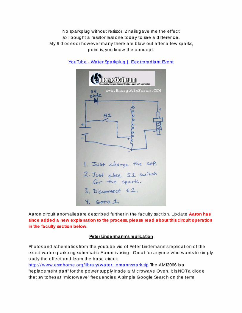
No sparkplug without resistor, 2 nails gave me the effect so I bought a resistor less one today to see a difference.
My 9 diodes or however many there are blow out after a few sparks, point is, you know the concept.
YouTube - Water Sparkplug | Electroradiant Event
Aaron circuit anomalies are described further in the faculty section. Update Aaron has since added a new explanation to the process, please read about this circuit operation in the faculty section below.
Peter Lindermann’s replication
Photos and schematics from the youtube vid of Peter Lindemann's replication of the exact water sparkplug schematic Aaron is using. Great for anyone who wants to simply study the effect and learn the basic circuit. http://www.esmhome.org/library/water...emannspark.zip The AMI2066 is a "replacement part" for the power supply inside a Microwave Oven. It is NOT a diode that switches at "microwave" frequencies. A simple Google Search on the term
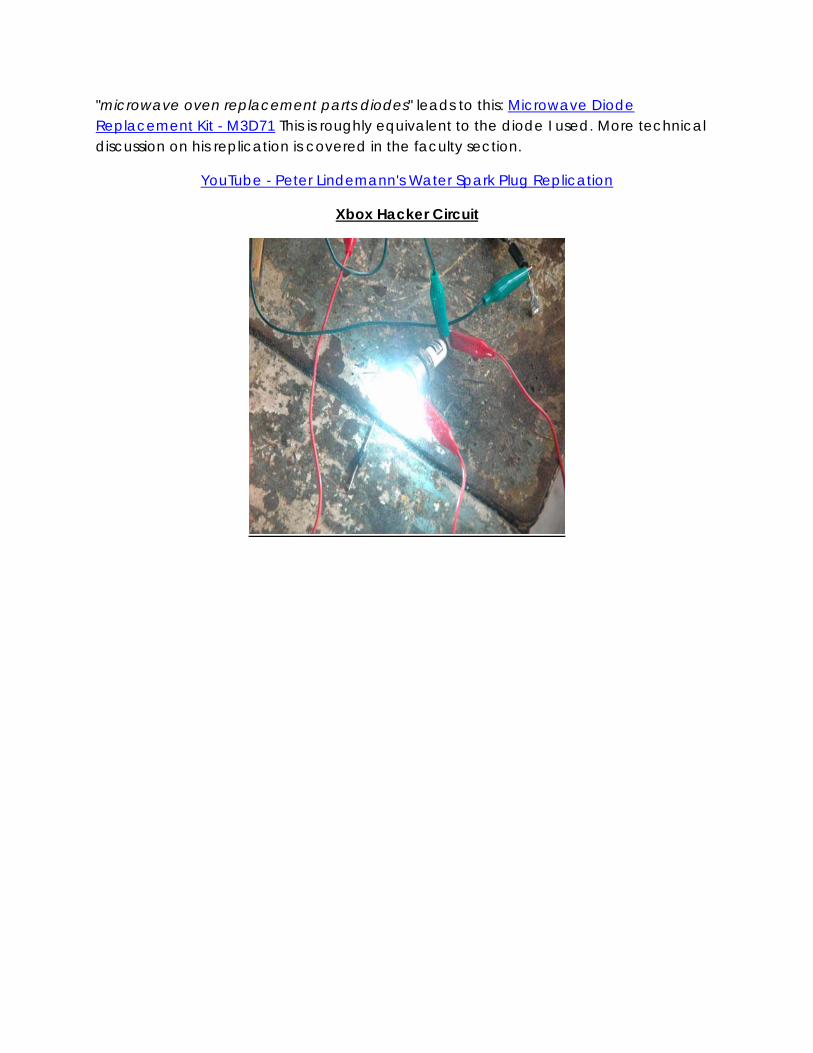
"microwave oven replacement parts diodes" leads to this: Microwave Diode Replacement Kit - M3D71 This is roughly equivalent to the diode I used. More technical discussion on his replication is covered in the faculty section.
YouTube - Peter Lindemann's Water Spark Plug Replication
Xbox Hacker Circuit
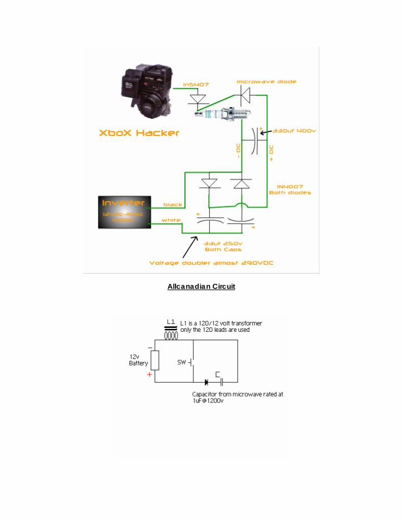
Allcanadian Circuit
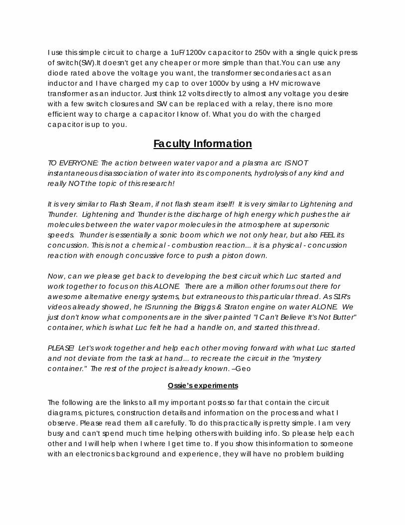
I use this simple circuit to charge a 1uF/1200v capacitor to 250v with a single quick press of switch(SW).It doesn't get any cheaper or more simple than that.You can use any diode rated above the voltage you want, the transformer secondaries act as an inductor and I have charged my cap to over 1000v by using a HV microwave transformer as an inductor. Just think 12 volts directly to almost any voltage you desire with a few switch closures and SW can be replaced with a relay, there is no more efficient way to charge a capacitor I know of. What you do with the charged capacitor is up to you.
Faculty Information TO EVERYONE: The action between water vapor and a plasma arc IS NOT instantaneous disassociation of water into its components, hydrolysis of any kind and really NOT the topic of this research! It is very similar to Flash Steam, if not flash steam itself! It is very similar to Lightening and Thunder. Lightening and Thunder is the discharge of high energy which pushes the air molecules between the water vapor molecules in the atmosphere at supersonic speeds. Thunder is essentially a sonic boom which we not only hear, but also FEEL its concussion. This is not a chemical - combustion reaction... it is a physical - concussion reaction with enough concussive force to push a piston down. Now, can we please get back to developing the best circuit which Luc started and work together to focus on this ALONE. There are a million other forums out there for awesome alternative energy systems, but extraneous to this particular thread. As S1R's videos already showed, he IS running the Briggs & Straton engine on water ALONE. We just don't know what components are in the silver painted "I Can't Believe It's Not Butter" container, which is what Luc felt he had a handle on, and started this thread. PLEASE! Let's work together and help each other moving forward with what Luc started and not deviate from the task at hand... to recreate the circuit in the "mystery container." The rest of the project is already known. –Geo
Ossie’s experiments
The following are the links to all my important posts so far that contain the circuit diagrams, pictures, construction details and information on the process and what I observe. Please read them all carefully. To do this practically is pretty simple. I am very busy and can't spend much time helping others with building info. So please help each other and I will help when I where I get time to. If you show this information to someone with an electronics background and experience, they will have no problem building
and replicating this. So please seek help from whoever if you are having difficulty, even if they don't believe it because once it is working, they will believe indeed.
http://www.overunity.com/index.php/topic,5024.msg108614.html#msg108614 http://www.overunity.com/index.php/topic,5024.msg108731.html#msg108731 http://www.overunity.com/index.php/topic,5024.msg108838.html#msg108838 http://www.overunity.com/index.php/topic,5024.msg108956.html#msg108956 http://www.overunity.com/index.php/topic,5024.msg109072.html#msg109072
Also, please save any gratitude for Luc who stepped out and first showed how he produced the effect in a simple circuit setup and encouraged others to replicate it with this thread. Because an ignition coil is basically inductor, it will have back emf. So this means the output essentially will be AC. Whether the main HV pulse is on the positive or negative side of the AC wave output will be determined by the circuit driving the primary of the ignition coil. If you look at the circuits I have posted, you will see that this is not consistent and wholey reliant on the overall circuit. So this can be a source of confusion and problem in terms of polarity for those who are trying to come up with their own circuits. I can only suggest that a reverse diode across the primary of the ignition coil will keep the output polarity consistent if that is what you are after.
thought it important to point something out regarding previous work related to this topic. There are many videos and demonstrations and documentation of water being burnt and exploded using very high power and powerful arc discharges. These are brute force devices and setups where in most cases more electrical energy is being put into the device than is being generated by the water combustion. This is NOT what we are doing and have demonstrated in this thread. The devices and setups we are showing in this thread are using small amounts of electrical energy to cause the combustion of water which releases more energy than what was put in electrically. What is unique in our circuits here, when compared to previous examples on the internet, is that we are utilizing the HV spark from an ignition coil as the precursor that allows enough ionization of the air in the spark gap to conduct the minimum required energy pulse of 100-300 volts through the spark gap and the surrounding moisture near it. This results in the moisture/water exploding and thus releasing the energy contained in it. This process only requires minimal energy pulses in addition to the ignition spark and is very efficient. We have developed these devices in an attempt to duplicate the work of s1r9a9m9 who has been able to demonstrate that he can run an engine solely on water instead of petrol by using a similar setup which uses the same process here as described. He in fact claims to have run his adapted V8 automobile for 30,000 miles at a fuel efficiency rate of 300 miles per gallon of water. Most of us could not believe such claims but now
after being able to reproduce the effect of being able to explode water with minimal energy input, it appears that what s1r9a9m9 claims is indeed possible. So please do not find videos and demonstrations of people burning and exploding water with powerful arc discharges and assume it is the same thing we are doing here because it is not. The process we are demonstrating here is very efficient to the point that it CAN be adapted to existing combustion engines to allow the engine to be run solely on water fed directly through the engine's existing fuel system. The adaption would be applied only to the engines existing ignition system.
If you are using 110V from the wall and your 1:1 toroid transformer is big enough, all you are seeing is a standard arc discharge as that in an arc welder. The ignition spark will simply be providing the ionization for the arc to start. Just as in arc welders that have a HF spark start so that you don't need to touch the electrode and risk sticking to get the arc going. So you will find that your input energy will be significant. That is not to say that this won't be effective to test on an engine as I think it might be a good and simple test rig to prove that you can fire an engine with water in the cylinder. But I don't think it would be an efficient way to get an engine running on water in a stand alone setup. For this we need to get the electrical energy input down. I have also gotten such an bright arc effect like an arc welder by using my simple security strobe setup/circuit and connecting 5 or 6 12V lead acid batteries in series with a large HV diode (diodes) across the spark plug. Yes the spark plug will glow red and perish and it will use heaps of input energy and be nothing more than a brute force device.
It is quite correct that you only need amps. But then the question of at what voltage the amps needs to be applied is purely determined by the voltage across the spark plug gap when hit by the ionising HV pulse of the ignition coil. The voltage from your battery or inverter or other power supply that is to provide the amps needs to be higher than the voltage across the ionised spark plug gap for the energy to flow into the ionised gap and produce the plasma. The voltage of the ionised spark gap is determined by a number of factors. In particular is the spark gap distance, as well as the conductivity of the air in which moisture plays a role and finally there is the voltage and current coming from the ignition coil/pulse. In practice I have found that by reducing the spark gap to as small as about .3 mm I can get the plasma to occur with applied voltages as low as 24 volts. But a gap so small is not too functional and is prone to clogging and shorting. A good size gap needs at least 90-100 volts applied to the spark gap to produce the plasma.
In regard to the power required. A continuous DC source will only waste input energy if one is to take advantage and increase the overall efficiency of the process. Increasing the efficiency must be done by altering the time that the minimum required energy to produce the plasma and explode the required amount of water is applied. This must be done with a DC pulse discharge for the minimum time period required. Typically a capacitor discharge performs this purpose well. In regard to the output energy from the exploding water, if we were to make a comparative analysis, with the assumption that the exploding water process yields more output energy than the electrical energy put into the process, with a petrol explosion that is also ignited by the same spark we would find that the total output energy is not caused by the localized process of the ignition spark igniting the petrol, but we would find that it is the chain reaction in the petrol gas where each igniting gas molecule releases more energy that ignites the next molecule, and so on until all or most of the petrol gas has been ignited. If we apply this same analysis to water we would also find that if the exploding water indeed produced more energy than what was required to ignite it, then we may also assume that a chain reaction will take place where the water molecules will continue to ignite themselves until most or all have been ignited. But the water needs to be under the right pressurized conditions in the ignition cavity, just like the petrol gas is under the right conditions in the cylinder of a combustion engine.
The xenon tube is only acting as a switch to discharge the 14uf, 350V capacitor inside the strobe light circuit. In regard to the operation of the circuits I have posted, please read through this thread from the beginning as I have describe most things about them in my previous posts. Here is a summary of some of my posts in chronological order.
http://www.overunity.com/index.php/topic,5024.msg108614.html#msg108614 http://www.overunity.com/index.php/topic,5024.msg108731.html#msg108731 http://www.overunity.com/index.php/topic,5024.msg108838.html#msg108838 http://www.overunity.com/index.php/topic,5024.msg108956.html#msg108956 http://www.overunity.com/index.php/topic,5024.msg109072.html#msg109072 http://www.overunity.com/index.php/topic,5024.msg109229.html#msg109229 http://www.overunity.com/index.php/topic,5024.msg109420.html#msg109420 http://www.overunity.com/index.php/topic,5024.msg109475.html#msg109475
Please see my previous posts as follows:
http://www.overunity.com/index.php/topic,5024.msg108614.html#msg108614 http://www.overunity.com/index.php/topic,5024.msg108838.html#msg108838 http://www.overunity.com/index.php/topic,5024.msg109072.html#msg109072
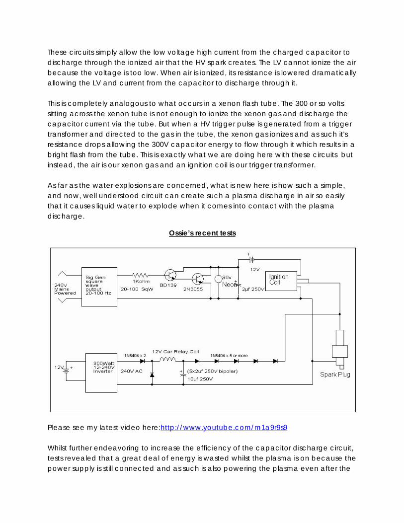
These circuits simply allow the low voltage high current from the charged capacitor to discharge through the ionized air that the HV spark creates. The LV cannot ionize the air because the voltage is too low. When air is ionized, its resistance is lowered dramatically allowing the LV and current from the capacitor to discharge through it. This is completely analogous to what occurs in a xenon flash tube. The 300 or so volts sitting across the xenon tube is not enough to ionize the xenon gas and discharge the capacitor current via the tube. But when a HV trigger pulse is generated from a trigger transformer and directed to the gas in the tube, the xenon gas ionizes and as such it's resistance drops allowing the 300V capacitor energy to flow through it which results in a bright flash from the tube. This is exactly what we are doing here with these circuits but instead, the air is our xenon gas and an ignition coil is our trigger transformer. As far as the water explosions are concerned, what is new here is how such a simple, and now, well understood circuit can create such a plasma discharge in air so easily that it causes liquid water to explode when it comes into contact with the plasma discharge.
Ossie’s recent tests
Please see my latest video here:http://www.youtube.com/m1a9r9s9 Whilst further endeavoring to increase the efficiency of the capacitor discharge circuit, tests revealed that a great deal of energy is wasted whilst the plasma is on because the power supply is still connected and as such is also powering the plasma even after the
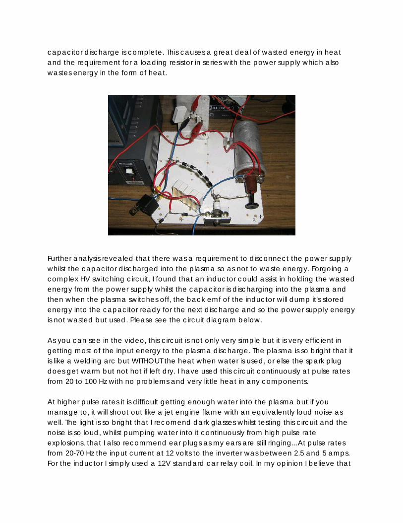
capacitor discharge is complete. This causes a great deal of wasted energy in heat and the requirement for a loading resistor in series with the power supply which also wastes energy in the form of heat.
Further analysis revealed that there was a requirement to disconnect the power supply whilst the capacitor discharged into the plasma so as not to waste energy. Forgoing a complex HV switching circuit, I found that an inductor could assist in holding the wasted energy from the power supply whilst the capacitor is discharging into the plasma and then when the plasma switches off, the back emf of the inductor will dump it's stored energy into the capacitor ready for the next discharge and so the power supply energy is not wasted but used. Please see the circuit diagram below. As you can see in the video, this circuit is not only very simple but it is very efficient in getting most of the input energy to the plasma discharge. The plasma is so bright that it is like a welding arc but WITHOUT the heat when water is used, or else the spark plug does get warm but not hot if left dry. I have used this circuit continuously at pulse rates from 20 to 100 Hz with no problems and very little heat in any components. At higher pulse rates it is difficult getting enough water into the plasma but if you manage to, it will shoot out like a jet engine flame with an equivalently loud noise as well. The light is so bright that I recomend dark glasses whilst testing this circuit and the noise is so loud, whilst pumping water into it continuously from high pulse rate explosions, that I also recommend ear plugs as my ears are still ringing...At pulse rates from 20-70 Hz the input current at 12 volts to the inverter was between 2.5 and 5 amps. For the inductor I simply used a 12V standard car relay coil. In my opinion I believe that
this circuit so far will perform the best on a real engine. So I think I am ready for this step next.
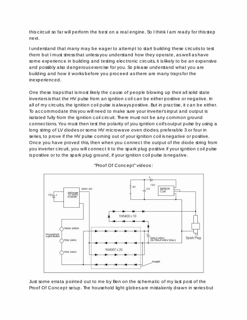
I understand that many may be eager to attempt to start building these circuits to test them but I must stress that unless you understand how they operate, as well as have some experience in building and testing electronic circuits, it is likely to be an expensive and possibly also dangerous exercise for you. So please understand what you are building and how it works before you proceed as there are many traps for the inexperienced. One these traps that is most likely the cause of people blowing up their all solid state inverters is that the HV pulse from an ignition coil can be either positive or negative. In all of my circuits, the ignition coil pulse is always positive. But in practise, it can be either. To accommodate this you will need to make sure your inverter's input and output is isolated fully from the ignition coil circuit. There must not be any common ground connections. You must then test the polarity of you ignition coil's output pulse by using a long string of LV diodes or some HV microwave oven diodes, preferable 3 or four in series, to prove if the HV pulse coming out of your ignition coil is negative or positive. Once you have proved this, then when you connect the output of the diode string from you inverter circuit, you will connect it to the spark plug positive if your ignition coil pulse is positive or to the spark plug ground, if your ignition coil pulse is negative.
"Proof Of Concept" videos :
Just some errata pointed out to me by Ben on the schematic of my last post of the Proof Of Concept setup. The household light globes are mistakenly drawn in series but
are actually connected in parallel relative to each other only. Also, the output from the string of diodes in the discharge circuit should be connected to the spark plug's ground base and not it's top pin. Apologies for these mistakes.
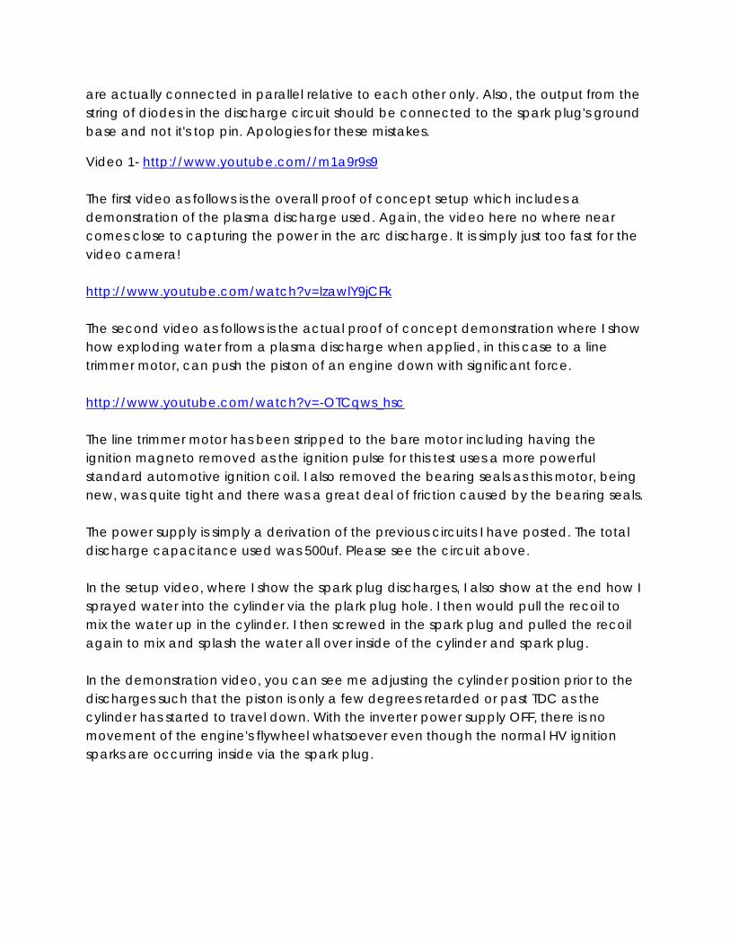
Video 1- http://www.youtube.com//m1a9r9s9 The first video as follows is the overall proof of concept setup which includes a demonstration of the plasma discharge used. Again, the video here no where near comes close to capturing the power in the arc discharge. It is simply just too fast for the video camera! http://www.youtube.com/watch?v=lzawlY9jCFk The second video as follows is the actual proof of concept demonstration where I show how exploding water from a plasma discharge when applied, in this case to a line trimmer motor, can push the piston of an engine down with significant force. http://www.youtube.com/watch?v=-OTCqws_hsc The line trimmer motor has been stripped to the bare motor including having the ignition magneto removed as the ignition pulse for this test uses a more powerful standard automotive ignition coil. I also removed the bearing seals as this motor, being new, was quite tight and there was a great deal of friction caused by the bearing seals. The power supply is simply a derivation of the previous circuits I have posted. The total discharge capacitance used was 500uf. Please see the circuit above. In the setup video, where I show the spark plug discharges, I also show at the end how I sprayed water into the cylinder via the plark plug hole. I then would pull the recoil to mix the water up in the cylinder. I then screwed in the spark plug and pulled the recoil again to mix and splash the water all over inside of the cylinder and spark plug. In the demonstration video, you can see me adjusting the cylinder position prior to the discharges such that the piston is only a few degrees retarded or past TDC as the cylinder has started to travel down. With the inverter power supply OFF, there is no movement of the engine's flywheel whatsoever even though the normal HV ignition sparks are occurring inside via the spark plug.
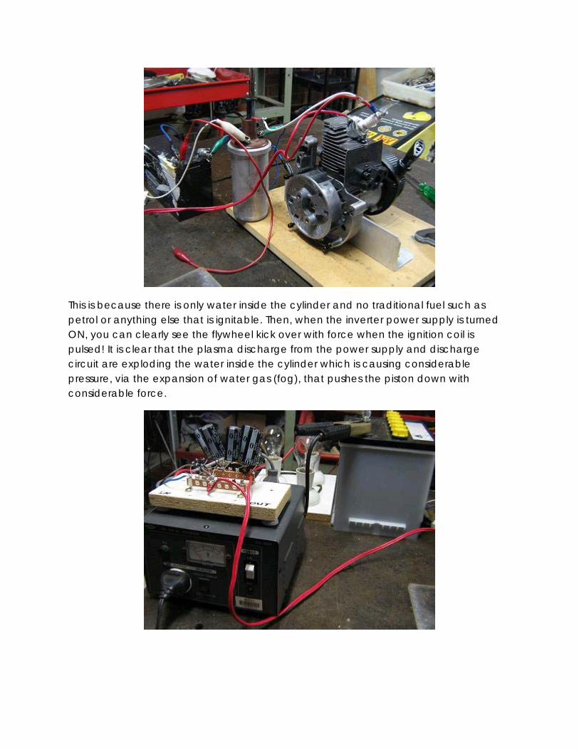
This is because there is only water inside the cylinder and no traditional fuel such as petrol or anything else that is ignitable. Then, when the inverter power supply is turned ON, you can clearly see the flywheel kick over with force when the ignition coil is pulsed! It is clear that the plasma discharge from the power supply and discharge circuit are exploding the water inside the cylinder which is causing considerable pressure, via the expansion of water gas (fog), that pushes the piston down with considerable force.
After only a few of these discharges the flywheel stops turning. That is because all of the water making contact with the spark plug inside has been exploded off. But I can then simply just pull the recoil again which will cause the water in the cylinder to splash up and onto the spark plug. Although, appropriately, I make no claims of the overall energy input, output and efficiency here, I have no doubt that the kinetic force generated by the exploding water within this engine, as demonstrated, will allow it to run using water only as the fuel once the appropriate ignition synchronisation and timing circuit has been built and put into place. Please see above for a circuit diagram of the power supply and discharge circuit used, a s well as some pictures of the proof of concept setup.
All of my tests have shown that only a higher power supply voltage ,and/or a higher capacitance discharge, will result in a more powerfull water explosion as long as you can get enough water to come in contact with the larger and stranger arc plasma. There doesn't seem to be any real way that I have seen or tested where you can put a "passive network" into the discharge circuit and get a larger water explosion. Let alone power the discharge circuit from as low a voltage as 12 volts. A passive network will only waste and reduce the energy of the discharge and as a consequence, the water explosion will be smaller. Regards, Ossie
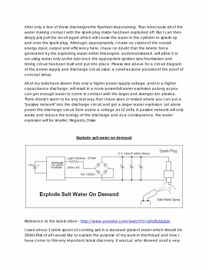
Explode salt water on demand
Reference to the latest video - http://www.youtube.com/watch?v=LDU3U1gzLzc
I used about 1 table spoon of cooking salt in a standard glass of water which should be 250ml.First of all I would like to explain the purpose of my work in this thread and how I have come to this very important latest discovery. It was Luc who showed us all a very
interesting and simple circuit he discovered whilst attempting to work out how SR1 could be powering an engine with only water in his videos. In my previous posts I was able to reproduce the effect of exploding pure water with an electrical circuit and verify Luc's circuit and the results. I went on to show how the basic effect could be done with little input power and also at high repetition rates comparable to that of a running engine's ignition system. With the help of my good friend Ben, it was discovered that exploding water with electrical energy was shown to have more energy output then what was required as electrical input according to the published Graneau paper as described in my previous posts. This paper explained that the released energy was from the conversion of the molecular bond energy in liquid water. This conversion occurred when liquid water came into contact with an electrical plasma and the liquid water was converted into a cool fog. No heat is generated in this conversion but the explosion does result in significant kinetic energy which was shown to be greater than the input electrical energy. This process and conversion did not disassociate or split the atomic bonds of the H2O molecule but did split the molecular bonds that hold water in a liquid state. The energy released, although significant, is far less than if the H2O molecule was split and then the hydrogen was to be ignited. The above mentioned circuits were based on having a charged capacitor and blocking diode/diodes connected across a spark plug. Then a HV spark from an ignition coil is also placed across the spark plug. This ignition spark ionized the air and any water in contact with the spark plug electrodes. This ionization allowed the energy in the capacitor to be discharged and cause a strong and bright electrical plasma discharge between the spark plug electrodes. The water on the electrodes, when in contact with the plasma, would explode as described in the Graneau paper. The diagrams or schematics, videos and pictures of these built and proven circuits can be found in my previous posts on this thread. Now to my latest discovery. Whilst looking at the ionizing effect of the ignition spark and how it allowed the capacitor energy to piggy back itself and jump across the spark plug gap, I wondered if it was possible and if there was another way to do this that did not required a HV ignition spark to ionize the spark plug gap. After a number of tests and trials using a fouled or blocked with water spark plug gap, I soon realized that two things were going on. I could see that the water in the clogged spark plug gap would bubble slightly and that the water itself had significant resistance such that not enough current could be discharged from the capacitor. This was because there was not much ionization going on in the water itself. Also, on noticing the bubbles I realized that there was electrolysis or the splitting of the H2O molecule going on and that hydrogen was being released from the water that was clogging the gap. So it was then I realized that
to get more current flowing in the water so as to be able to discharge the capacitor, I needed to lower the resistance of the water. I needed to get the ionization to occur in the water itself. So this was simple, I just needed to add an electrolyte to the water so this is what I did. I added SALT to the water. As soon as I did this and sprayed it on the spark plug gap to block it, it almost immediately bubbled away and exploded indicating it was being split. After only a few tests without any HV ignition coil or ignition spark I got it to repeatedly explode!!!! The spark plug gap is a factor and the amount of salt in the water but it all works and they are just some variable factors to the performance! The explosions are unlike anything I have experienced before. They are far more powerful and loud and very HOT! They contained on demand generated hydrogen explosions!!!! Please see my videos above. With this understanding I then was able to simplify the circuit to do this considerably. Please see the schematic below. You only need a capacitor of a few hundred uF and a bridge rectifier. You can use an inverter or the power from the wall to power it and that's all! The power yielded is far greater than that of the cool fog explosions! These explosions are HOT hydrogen explosion and are very powerful! The salt water is being split on demand in the spark plug gap and the capacitor discharge plasma is igniting the hydrogen. It is now my opinion that if the videos of SR1. are real indeed then this is what is occurring inside his engine which will justify the power observed as my experiments have shown that the previously described cool fog explosions could not account for the power shown in the firings of his engine. He has also verified that his engine does get hot which is not possible with the cool fog explosions of the previous circuits in this thread. It is likely that the water SR1. uses has salt or other minerals in it that he may not know of, particularly if it is from a bore. This can be enough to reduce the resistance of the water. I must also point out that it is also possible that capacitor70's motorcycle engine ran on this process as he did mention that he was using bore water to power it. Any acid or base can be used in the water to change it's PH level and lower it's resistance. But now it becomes a requirement to be able to get allot of ionized or PH altered water to the spark plug so as to block it for this to work in an engine. Also, because the ignition circuit is not required, the cylinder's compression will be required to also condensate enough water in the spark plug gap to get it to explode. The operation will be vey similar, if not the same as a diesel engine. But many variables will have to be tested with the right combinations for a particular engine for this to work. Such as the spark plug gap, cylinder compression, type of spark plug, carburetor or water injection method, conductivity of the water and so on. But I believe that this process can be used to
power an engine as it yields significantly more power than the previous cool fog water explosions that have been previously described. There is room to be able to derive an ignition type circuit to create this same described effect and HHO explosion but use the ignition timing and even the HV spark to merely trigger the connection of the capacitor to the spark plug. This can also be done via another spark gap. But this will be explored and reported further in later experiments. Such a circuit will allow the effect and process to be used in a standard HV ignition timed engine. But it is important to understand and show that HV has NOTHING to do with the resulting explosion and output energy of this process as I have done above.
The results of my research and experiments on this topic to date indicate that the initial circuit that Luc posted causes a cool fog explosion of water as that described in the Graneau paper. As further described in the Graneau paper, the explosion may yield more energy output than what was required electrically to cause it. The experimental results shown indicated that in 5 out of 8 tests, the output energy exceeded the input energy to the factor of 100-160% of the input energy. My observations confirm this degree of energy conversion in my own experiments but also confirm that this small amount of energy increase CANNOT account for the energy being displayed in the firing of the engine in s1r9a9m9's videos. It is because of this understanding and the results of my research that I believe that your simple circuit cannot be used or developed as you have presented to be able to allow an engine to run on pure water. Regards,Ossie
Aaron’s anomalies
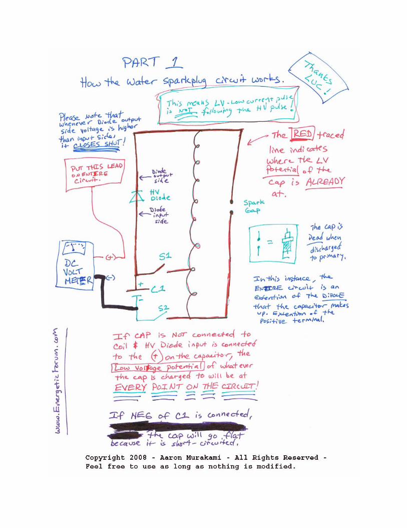
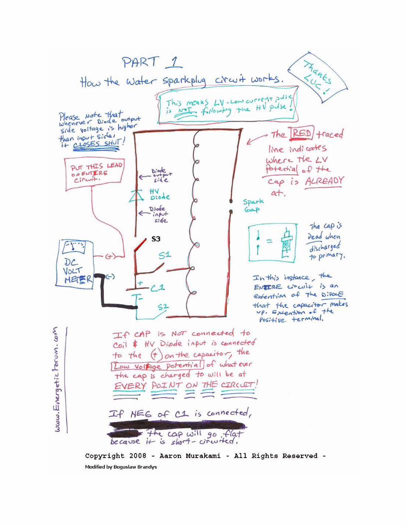
Updated information-The HV from the coil moves through the HV diode to the + of the low voltage source to ground back to itself. It seeks ground through the diode. That diode is open. When the HV is off, take a volt meter and put the negative on ground and + on the HV diode cathode/output. You will see that you can measure the low voltage side's voltage potential on the output of the diode because the diode is open. Many people think the diode is automatically closed and won't let the HV through but that isn't true. That is the whole point that diodes have reverse ratings...and if the diodes were automatically always shut, then the low voltage from the anode/input could never get through. Also, the diode closing is not instantaneous...it is fast, yes, but not instantaneous...once the HV moves through the HV diode. It takes a bit of time for it to get the reverse current through it in order to slam shut. The HV potential, which is the voltage gas (it is a gas composed of "particles" smaller than a hydrogen atom - smaller than an electron - very, very small fractional charges -
Mendeleev's original periodic table of elements showed some of this) has MOMENTUM. As it is moving, the HV diode slams shut and the voltage potential with its momentum slams against the diode. Compressing it more and more...now that re-compressed potential...which is expanded 90 degrees from the wire has to go somewhere...the only path to ground as of now is the gap on the plug. That un-condensed/expanded potential is what causes the primary effect of the cold plasma. Then, when voltage on the cathode/output of the HV diode drops below the anode/input of the HV diode, then and only then can LV source move out of it and over the gap. The LV source is not the cause of the effect; it simply can boost the primary effect - which can be had all by itself with one small cap that is virtually empty when discharged to the primary. Primary effect is that potential slamming against a diode. Many think the simple HV spark jumping a gap is enough to ionize the gap to reduce the resistance enough to have the LW source follow it that is simply a fairytale. Only the recompressed potential against the diode's abrupt shut off can cause the cold plasma ionization that is necessary to allow the LV source to follow. At this circuit's scale of operation, this is all necessary to make these effects. This is a method of "splitting the positive" that Bedini has shown for years in the open but nobody really got it. If I am wrong, I apologize and will correct all my explanations but until then, that's my story and I'm sticking to it until proven wrong but following the logic of all this, it is very consistent with what Tesla explained, it is consistent with other technologies that utilize this concept, etc...
Working of the Gray Tube
This will put what I'm saying into context with something that many people have studied but I am not sure anyone gets it. Many are convinced in all the free electron concepts in the Gray Tube, etc... McGratten mailed me a package about 7 years ago with that explanation but I always saw it happening in a different way. The Gray Tube has a low voltage rod and high voltage rod. Low voltage rod has a diode on it that has the cathode/emitter pointed towards the gap. Low voltage source can be any low voltage source and Gray showed he used a 12v battery...the negative of that battery is connected to the negative of the HV capacitor at 3000-4000 volts and a few uf's. The + of the HV source goes to the HV rod.
(-)12vdc(+)diode->(gap)(+)3000vdc(-) I have made the Gray tube analogy to the spark method and most have automatically thought that they look at 2 gaps and think they serve the same purpose. I'll show you why the 2 gaps have nothing to do with each other but why they are making the same effect. It is necessary to actually understand how the Gray tube works in order to see what the real analogies to the spark plug circuit are. When the low voltage side is connected by commutator, whatever...the HV source immediately sees path to ground...it sees that the diode is open and has conductivity to the low voltage source which has conductivity to ground which is its own ground...it jumps and as soon as it moves through the diode for a small unit of time, the diode slams shut....only a small fraction of the HV potential made it through. That HV potential from the cap slams against the diode and compresses against it very strongly forcing it to explode 90 degrees from the wire outwards...the only other path to ground it by going to the grids...through the electromagnet that pulses a magnet or other electromagnet to provide motive force on a motor to a + on another low voltage source and that LV source has a - that winds up being connected back to the HV -'s. Take a balloon and push it flat against a wall. It compresses and the contents of the balloon wind up exploding 90 degrees perpendicular to the direction of original propagation. Gray tube comparison- The gap in the Gray tube is simply a mechanism to get the HV to jump into a diode with a LV potential sitting on it so that it can move into it to have the diode slam shut to compress the potential against it. The secondary discharge from ignition coil is a mechanism to get a HV to jump into a diode with a lv potential sitting on it so that it can move into it to have the diode slam shut to compress the potential against it. The Grids on the Gray Tube are the secondary path for the expanded potential to move to ground. The ground on the spark plug is the secondary path for the expanded potential to move to ground. Here is what this method is: You are giving the HV 2 paths to travel in order for it to move back to its own ground or relative ground. 1 path is a high resistance path 1 path is a low resistance path
The Gray tube high resistance path is out to grids back to ground. The water sparkplug circuit's high resistance paths are over spark gap back to ground. The Gray tube low resistance path is through the diode to LV side back to ground. The water sparkplug circuit's low resistance path is through the diode to LV side back to ground. 1. The HV will choose the low resistance path FIRST 2. Diode slams shut expanding that potential 3. Expanded potential (electro-radiant event) has only the high resistance path left back to ground. So when it is explained that the HV spark jumps the gap ionizing it to reduce the resistance of it and have the LV source follow it...its incorrect. And seeing the analogy in comparison to the Gray tube, that popular explanation of how Luc's spark method works would be the same as claiming that this is how the Gray tube works: The HV from the HV cap first jumps to the grids ionizing the air to reduce the resistance of it enough for the 12v battery potential to jump from the low voltage rod to the grids...all the while never needing the hv to jump the gap in order to slam against the diode. We know the above is NOT how the Gray tube works but that is what people are claiming when they say the Spark plug circuit works by the HV simply going to jump over the gap to ionize it for the lv source to follow. -End
The water plug is not what you may think. I can do this discharge constantly at higher frequency. It is STONE COLD. It is not what you think. I can also have the HV diodes coming off of the + of the BRIDGE when the bridge is disconnected from the cap AND with the inverter turned off and it gives me the same effect so there is no high temp high current arc across the gap. See below:
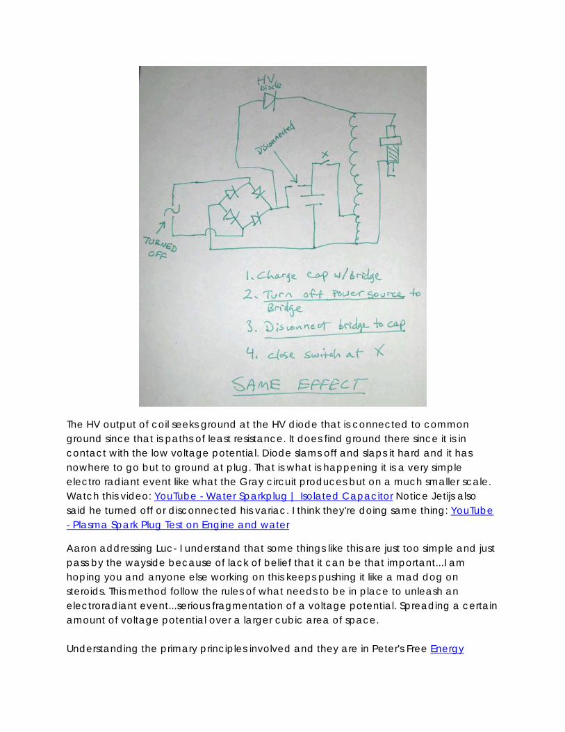
The HV output of coil seeks ground at the HV diode that is connected to common ground since that is paths of least resistance. It does find ground there since it is in contact with the low voltage potential. Diode slams off and slaps it hard and it has nowhere to go but to ground at plug. That is what is happening it is a very simple electro radiant event like what the Gray circuit produces but on a much smaller scale. Watch this video: YouTube - Water Sparkplug | Isolated Capacitor Notice Jetijs also said he turned off or disconnected his variac. I think they're doing same thing: YouTube - Plasma Spark Plug Test on Engine and water
Aaron addressing Luc- I understand that some things like this are just too simple and just pass by the wayside because of lack of belief that it can be that important...I am hoping you and anyone else working on this keeps pushing it like a mad dog on steroids. This method follow the rules of what needs to be in place to unleash an electroradiant event...serious fragmentation of a voltage potential. Spreading a certain amount of voltage potential over a larger cubic area of space. Understanding the primary principles involved and they are in Peter's Free Energy
Secrets of Cold Electricity book on the Gray Tube technology....they give the insights into everything that is necessary in order to enhance this entire effect, make it more powerful...not worried about efficiency because charging those caps take nothing at all to begin with. If you haven't read that book, I suggest reading it and if you have, then you can see that it describes perfectly what you are working with . My experiments today show me that capacitance is virtually irrelevant and it is all about the voltage. I went up in capacitance for the same voltage...no matter what, the effect didn't improve...and didn't necessarily diminish either going down in capacitance. Did you say in a vid or posted somewhere you used as small as 2uf capacitor? Or someone else did? That proves the point. What about .1 .01 .001uf at the same voltage. It is all about tuning the gas pressures on the front and back for each system and it probably won't take long for most of it to be worked out. At such small capacitances, they can obviously charge up lightening fast and not only fast but can be charged a long time using watch batteries, AA batts, etc. People want caps and strobes to play with. Don't buy them. Tell people to go to a grocery store that processes film. Say they're working on a science project and need a haldful of the disposable cameras that already have the film ripped out. They have caps about 120uf and 120v or so plus the battery and charging circuit plus the strobe, etc... I went to one store about 7 years ago and I got about a dozen of them. Personally, from the simplicity of this, I think the gas production requirements posted by the "gurus" of water gas production are bogus and are meant to distract people from the real secret. Meyer shows in the first patent and last patent about spark discharge and then spark at the plug. With the potential of this method, I can see how it is possible to run an engine on just water vapor, but an obvious enhancement to make it work really easily is that any engine running on it can easily produce a good amount of HHO gas from a booster to add to the moisture. This is where I think it needs to go. Over all this time, nobody has created enough water gas to power an entire car. All the effort.... even with claims of hundreds of percent over Faraday, that isn't nearly enough. However, the amount people are currently making with everything they have tried *COULD* just be enough already...if they were using Krupas plug...but that may be unnecessary anymore...cost me about $2 for a NGK resistorless plug at Schucks. About $1 worth of diodes. Cars already have ignition systems in the car with the coil and battery and caps are free in those cameras sometimes for the asking.
If the potential, no pun intended, of this whole thing is apparently as simple as it sounds...and from collective experience on all these things together, this is an irresistible offer that cannot be turned down.I hope this rapidly becomes one of the most popular experiments in the world in the "free energy" field. I have a feeling there are more things
to surface really soon. I felt for a long time that the Krupa plugs were the key to unlock it but I don't have the means to duplicate a Krupa plug...the one thing Krupa was quiet about is the "ignition". I chatted with him on yahoo groups off an on the last few years and anytime I asked about the ignition...he stops typing back. lol With his plug the annode is very large surface area like a mushroom head. If you take x mount of voltage potential and divide it by a certain surface area...there is more ability for it to fragment itself apart than with a small surface area. Anyway, this is an awesome breakthrough Luc and if there are any further updates that you want to get out to a lot of people, just post them here and a lot of people will see them.
Luc’s response
Hi Arron and everyone, you are right! it is not about capacitance. I also noticed that the first time I discovered this simple circuit. In this video: YouTube - Ganga Shakti - Water Power Test 2 I am using a 3.3uf capacitor with the input voltage to the bridge at about 150 volts from my isolation transformer connected to a variac to regular 120 vac from the grid. I am using a one side of a DPDT relay as the switch and the relay coil is triggered by a transistor which is pulsed by my signal generator. The video is not capable of showing the light coming from the spark and you cannot look strait at it with your eyes it is much like the Sun light, this you can see in the video. There is much UV light, just look at the plywood board that the plug is on, you can see the blue light reflect on the wood. If anyone gets to this point stop! and get some heavy UV protection glasses since you will damage your eyes. To play with a disposable camera flash circuit is a great ideal and would be a easy way to also see results. Overunity forum user: calanan has a circuit that he posted using a strobe light that you can copy and post here if you wish. Feel free to copy enything you need as this belongs to the public. It sad about the Krupa plug not coming out! this is the World we have created by not taking responsibility. They would be difficult to make since you would need precision equipment. As Aaron has said, do not be fooled by the simplicity of this circuit. Play safe and find all the uses for it.
Peter Lindermann’s reposnse
Just so Aaron is not left out on a limb here I have personally witnessed many of Aaron's test set-ups, INCLUDING many of the temperature reading tests. I do not claim to understand the results, but I absolutely report that EVERY TIME we have pointed the IR temperature device at the spark, the reading goes DOWN BELOW AMBIENT! I was the first to question the validity of these tests. We aimed the IR thermometer at every other surface we could find, even other metal objects, like pliers and screw drivers nearby. No
other objects changed temperature. Period! The spark plug never got hot. Aaron was pointing the laser right at the spark zone itself. THE SPARK TEMPERATURE was below the ambient temperature. That is the ONLY reasonable CONCLUSION I could draw from the evidence I witnessed. I also saw no evidence of EMP effects from the spark to effect the IR thermometer. The spark was repeating approximately once a second due to an automatic relay driver circuit we built based on a 555 timer chip. IR temperature readings of other objects did not show anomalous behavior with the spark operating in the background. Theoretical posturing is meaningless. Ranting about the infallibility of Thermodynamics is equally un-useful. The behavior of the spark in this experimental set-up is most unexpected, and one of the most astonishing phenomena I have seen in years. –Peter
Spark temp by Aaron
What the thermometer is seeing is the temperature of the spark while it is sparking..that is the only variable changing..once the spark is gone...the only thing the thermometer is measuring is the metal..., which is unchanged. It is POSSIBLE, the measurement of the thermometer is questionable as the spark is happening...of course possible but not likely. However, what is undeniable is that what is happening is that when I measure the spark plug's metal BEFORE the sparking and take measurement...I then let it spark...even up to 10-15 minutes or more...no matter how long, I then turn off the circuit and then measure the metal AFTER all the sparking is stopped, the temp will either be the same or less compared to what it was before any sparking occurred. This second example rules out 100% of any possibility that there is "noise" at the thermometer and is also 100% rules out any possibility that the spark temperature itself is in question. A fact that is gained from this experiment is this simply: I take a base temp reading before any sparking...let it spark for any length of time..turn off circuit...then take the spark plug temp reading afterwards and none of the sparking has increased the temperature of the metal. Take any spark plug and spark it conventionally...take a before reading..let it spark...then test temp after...there will be an increase, I tried it...that increase does not exist with this type of spark that I have been able to observe no matter how long I let it spark. 100% of the time I have repeated this test over and over, I get the following results: zero increase in temp I can measure the temp of objects around me and those temperature show EXACTLY the same temp before and after the tests...that shows that the temperature reading of the thermometer is accurate.....consistent. Also, as I have said, a few times the temperature of the metal went DOWN a few times...all while testing when the circuit is totally off.

Modified circuit By boguslaw
This method is different from Luc's method and appears more powerful if it is able to run a car better (so far). However, Luc's method has shown some things that some people have a hard time believing in my explanation. I have a Goldstar OS 9020-A...not a Rolls Royce but gives me what I need. Has anyone scoped the cap to prove to themselves the activity of what the personality of the cap is while dumping to the ignition coil? How many times is something happening per pulse, etc. I am now using a 5A 150V variac...the output of variac...one lead to bridge and other lead to light bulb and light bulb to bridge...bulb is 110V 40W and limits current quite well. I can crank it up no problem.
YouTube - Water Spark Plug | Radiant Energy | Temperature Drop Temperature drops on plug spark 7 degrees when running a couple seconds.
Peter Lindermann’s replication
I finished my Water Spark circuit today, and Aaron came over to my shop and filmed me doing a simple walk-through and demo. As soon as Aaron edits the footage, he'll put it up on YouTube and put a link to it in this forum. I charge a 47uf capacitor to about 140 volts DC using a variac, dropping resistor and full-wave-bridge rectifier. Then I completely disconnect the cap from the charging source and discharge it through the primary of the ignition coil. The Radio Shack relay is operated by a simple 555 timer circuit to vary the relay operation from 1 Cycle Per Second to about 15 CPS on a variable potentiometer. The cap has less than .6 Joules of energy in it per discharge. The HV diode is connected across the HV secondary of the ignition coil, between the High Voltage + and the Low Voltage + of the coil. All schematics for the complete circuit and the 555 timer circuit are given so others can easily build a circuit that produces the effect reliably. I show three different effects. First, just the spark from the capacitor discharge. Then, the spark WITH the HV diode connected. And finally, the spark with the HV diode connected igniting water sprayed at the spark plug. I do not claim to understand WHY this happens. I built this circuit to STUDY the effect. Thank you, GoToLuc for publishing this circuit, and thank you, Aaron, for helping me with my circuit and for filming my demonstration!I MHO, we need more circuit builders in this thread, and less theoretical guessing about what this is. Build a unit. Run the experiment. Live in the presence of the phenomena and think about what you are seeing. This is what will open up new insights. Nothing else!
My circuit choices were about simplification. I was just trying to see what the functions of each component were in their simplest form. The first circuit that Aaron showed me used 10 1N4007's soldered in series. That worked great, so it should work for you, too. I just pulled out the old microwave power supply diodes because I happen to have
them. The part number on the diode I used is the AMI2066. Aaron's first model had a 160uf cap. Gotoluc had said that the cap size was irrelevant, so we tried a 1uf cap. That didn't work. It was just too small. So, we started to work our way back up. 47uf was the smallest cap we tried that worked well enough to demonstrate the effect convincingly. The Variac is optional. Gotoluc has already shown the cap being charged straight from the wall with a FWB rectifier. The Variac allows the option of charging the cap to different voltages for studying the effect. Aaron's unit fried two relays at my shop when we were testing it, so I decided to wire up a relay SOCKET so I could change relays easily if that happened to mine. The capacitor is connected to the movable wipers in the relay. The input power from the Variac is connected to the NC (normally closed) contacts, and the primary of the ignition coil is connected to the NO (normally open) contacts. As for the snubbers on the relay contacts, we got rid of them. We started out charging the caps with an inverter, like Gotoluc did. That's when we welded the relay shut using Aaron's larger capacitor. So, we put snubbers across the contacts to save the relay, and that's when we FRIED THE INVERTER!!! As it turned out, capacitive snubbers across the relay contacts just direct coupled the high frequency of the spark back to the MOSFETs in the inverter. Two fried inverters in 5 minutes was the cost of that lesson! So, now I run a Variac and NO SNUBBERS. After seeing Ossie Callanan's YouTube video showing the plasma spark triggered by a little Xenon flash strobe from a 9 volt battery, I had the idea to try this with an old Radio Shack Party Strobe that I had left over from another project. When the primary of the ignition coil is placed in series with the discharge path of the Xenon bulb, sure enough, the spark plug fires. When the extra HV diode is connected, sure enough, the plasma spark appears. So, this showed me that the entire process CAN BE accomplished solid-state, and without relays. The effect from the strobe was not as strong as the effect from the relay system for the same capacitor discharge, because most of the power was dissipated across the Xenon bulb, and not in the primary of the ignition coil. So, I still think there is a better way to trigger this. The party strobe was simple and convenient, but not as efficient. Then Aaron came over and we added his new, little parallel capacitor dump system across the spark plug. Sure enough, the method adds more energy to the spark discharge. In our experiments, we charged the secondary caps up from a variac connected to a microwave power supply step-up transformer and a HV rectifier bridge. We ran the initial spark gap from my newly created strobe circuit. The higher the voltage we put on the secondary caps, the louder the spark would get. So, like the
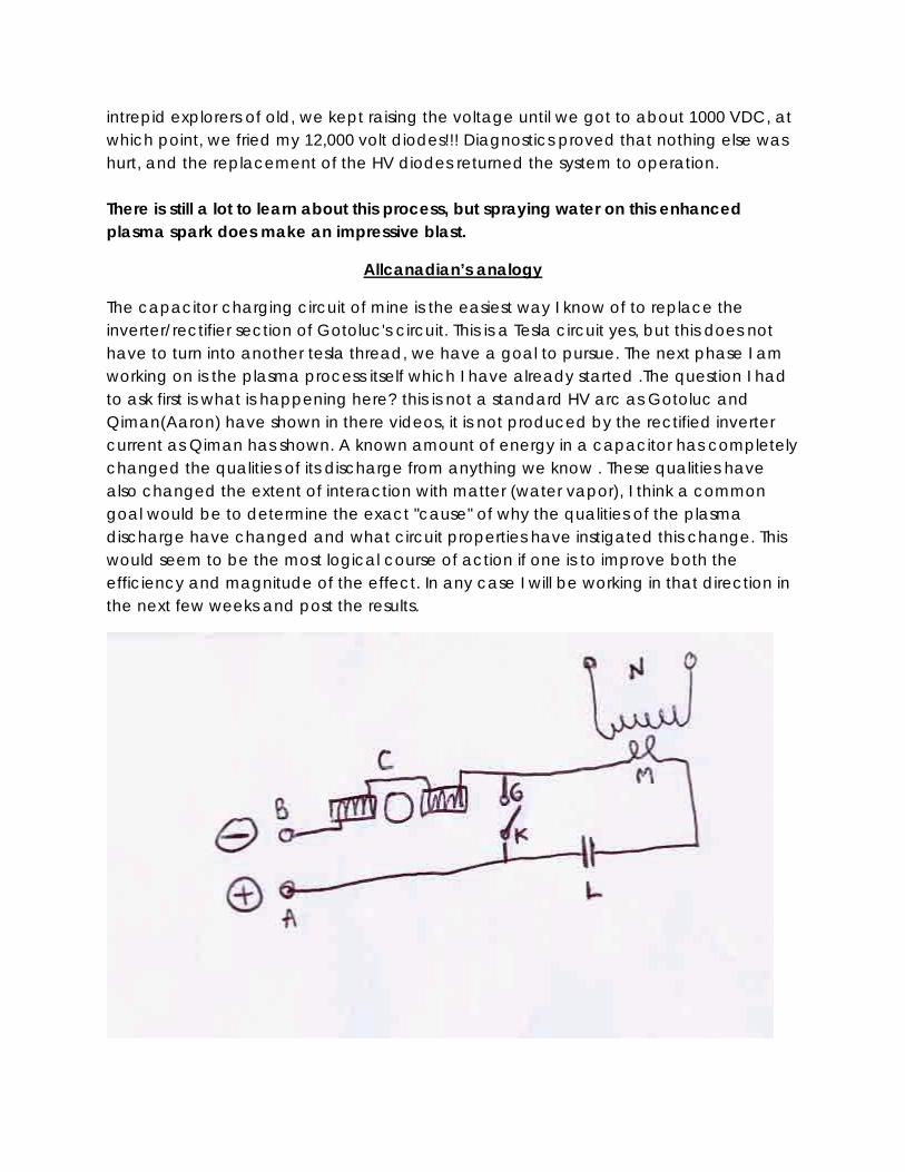
intrepid explorers of old, we kept raising the voltage until we got to about 1000 VDC, at which point, we fried my 12,000 volt diodes!!! Diagnostics proved that nothing else was hurt, and the replacement of the HV diodes returned the system to operation. There is still a lot to learn about this process, but spraying water on this enhanced plasma spark does make an impressive blast.
Allcanadian’s analogy
The capacitor charging circuit of mine is the easiest way I know of to replace the inverter/rectifier section of Gotoluc's circuit. This is a Tesla circuit yes, but this does not have to turn into another tesla thread, we have a goal to pursue. The next phase I am working on is the plasma process itself which I have already started .The question I had to ask first is what is happening here? this is not a standard HV arc as Gotoluc and Qiman(Aaron) have shown in there videos, it is not produced by the rectified inverter current as Qiman has shown. A known amount of energy in a capacitor has completely changed the qualities of its discharge from anything we know . These qualities have also changed the extent of interaction with matter (water vapor), I think a common goal would be to determine the exact "cause" of why the qualities of the plasma discharge have changed and what circuit properties have instigated this change. This would seem to be the most logical course of action if one is to improve both the efficiency and magnitude of the effect. In any case I will be working in that direction in the next few weeks and post the results.
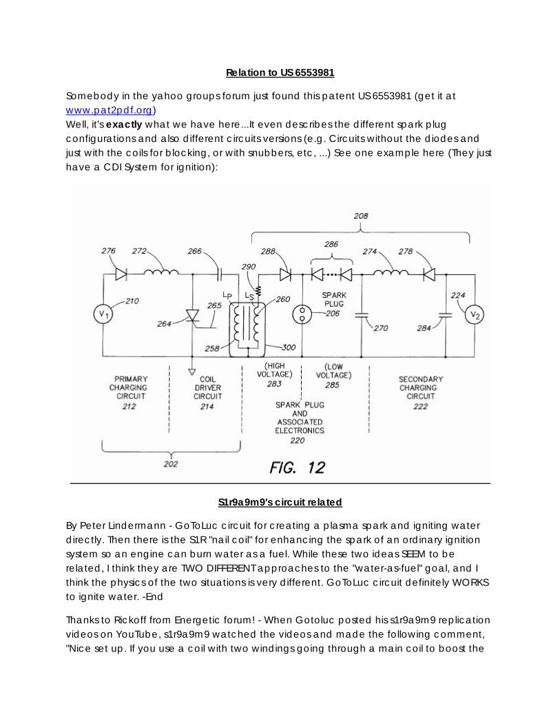
Relation to US 6553981
Somebody in the yahoo groups forum just found this patent US 6553981 (get it at www.pat2pdf.org) Well, it's exactly what we have here...It even describes the different spark plug configurations and also different circuits versions (e.g. Circuits without the diodes and just with the coils for blocking, or with snubbers, etc, ...) See one example here (They just have a CDI System for ignition):
S1r9a9m9's circuit related
By Peter Lindermann - GoToLuc circuit for creating a plasma spark and igniting water directly. Then there is the S1R "nail coil" for enhancing the spark of an ordinary ignition system so an engine can burn water as a fuel. While these two ideas SEEM to be related, I think they are TWO DIFFERENT approaches to the "water-as-fuel" goal, and I think the physics of the two situations is very different. GoToLuc circuit definitely WORKS to ignite water. -End
Thanks to Rickoff from Energetic forum! - When Gotoluc posted his s1r9a9m9 replication videos on YouTube, s1r9a9m9 watched the videos and made the following comment, "Nice set up. If you use a coil with two windings going through a main coil to boost the

output spark up about 10 times what you have now, you will have a system almost like mine." Today, sir9a9m9 posted a new message concerning this coil, along with a document explaining it further. He also said that he would be posting a video soon, showing how the coil is actually wound. Hopefully he will also share some additional details. Here is a link to the transformer file: S1r9a9m9 transformer coil.rtf - Windows Live SkyDrive UPDATE - S1r9a9m9 has now also posted a photo showing the silver cup that appeared in his YouTube video of the 18 hp engine running on water, and also shows what was inside the cup. You will see this photo, and a close-up of the photo, plus a new pdf file in which s1r9a9m9 explains the step-up transformer coil that was in the silver cup. See them here: S1r step up transformer coil.jpg - Windows Live SkyDrive Note that s1r9a9m9 says the inverter isn't needed, and that in fact it can not even be used with the transformer setup. It looks like s1r is finally going to show us the missing pieces (or at least some of them), and that is great. I hope this information spurs some additional experimentation and modification of the circuitry. I have been watching this thread with interest, and you have all been making excellent contributions to the effort. Keep up the great work!
Please see my last post in this thread (#73) http://www.energeticforum.com/renewable-energy/2242-water-sparkplug-3.html which I have edited to include links to a photo showing what was inside the mysterious silver cup that appeared in the YouTube videos showing sir9a9m9 running the 18 hp engine on water. I have posted the photo, and a close-up of it, along with an rtf file and pdf file showing s1r's description of the device. This is key to getting an engine to run on water. It's the part Gotoluc didn't know about when he built his s1r9a9m9 replication, because it was hidden from view by the silver cup. Note also that s1r9a9m9 has promised to release a new video within the next few days that will make everything clearer, but there is already enough shown in the photo and documents to enable proper modification of the Gotoluc circuit to achieve a plasma spark capable of running an engine.
I have posted it here: S1rRelay in bw.jpg - Windows Live SkyDrive It is much easier to read in black & white than with the yellow background. That one shows the relay circuitry that s1r9a9m9 uses. The only reason why s1r uses an inverter is because the heavy duty appliance relays that he has been using require 110V AC power to operate. You will note that the relay circuit does not show s1r's step-up-transformer, which is really
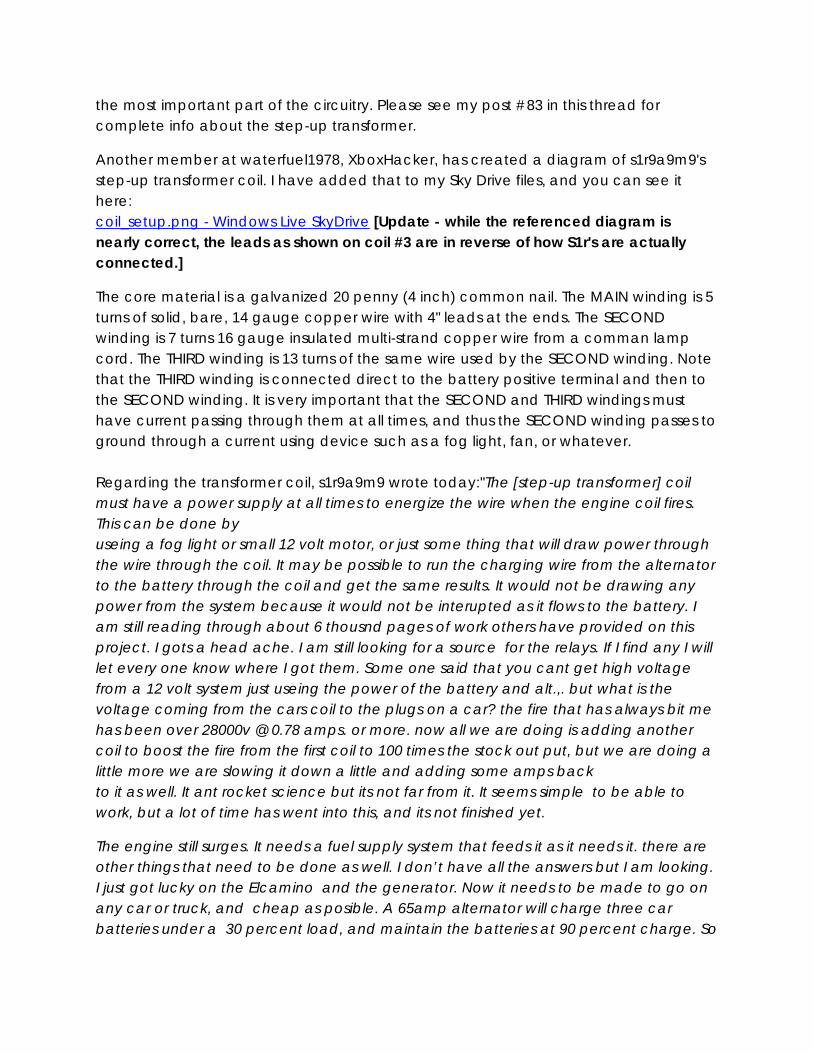
the most important part of the circuitry. Please see my post #83 in this thread for complete info about the step-up transformer.
Another member at waterfuel1978, XboxHacker, has created a diagram of s1r9a9m9's step-up transformer coil. I have added that to my Sky Drive files, and you can see it here: coil_setup.png - Windows Live SkyDrive [Update - while the referenced diagram is nearly correct, the leads as shown on coil #3 are in reverse of how S1r's are actually connected.]
The core material is a galvanized 20 penny (4 inch) common nail. The MAIN winding is 5 turns of solid, bare, 14 gauge copper wire with 4" leads at the ends. The SECOND winding is 7 turns 16 gauge insulated multi-strand copper wire from a comman lamp cord. The THIRD winding is 13 turns of the same wire used by the SECOND winding. Note that the THIRD winding is connected direct to the battery positive terminal and then to the SECOND winding. It is very important that the SECOND and THIRD windings must have current passing through them at all times, and thus the SECOND winding passes to ground through a current using device such as a fog light, fan, or whatever. Regarding the transformer coil, s1r9a9m9 wrote today:"The [step-up transformer] coil must have a power supply at all times to energize the wire when the engine coil fires. This can be done by useing a fog light or small 12 volt motor, or just some thing that will draw power through the wire through the coil. It may be possible to run the charging wire from the alternator to the battery through the coil and get the same results. It would not be drawing any power from the system because it would not be interupted as it flows to the battery. I am still reading through about 6 thousnd pages of work others have provided on this project. I gots a head ache. I am still looking for a source for the relays. If I find any I will let every one know where I got them. Some one said that you cant get high voltage from a 12 volt system just useing the power of the battery and alt.,. but what is the voltage coming from the cars coil to the plugs on a car? the fire that has always bit me has been over 28000v @ 0.78 amps. or more. now all we are doing is adding another coil to boost the fire from the first coil to 100 times the stock out put, but we are doing a little more we are slowing it down a little and adding some amps back to it as well. It ant rocket science but its not far from it. It seems simple to be able to work, but a lot of time has went into this, and its not finished yet.
The engine still surges. It needs a fuel supply system that feeds it as it needs it. there are other things that need to be done as well. I don’t have all the answers but I am looking. I just got lucky on the Elcamino and the generator. Now it needs to be made to go on any car or truck, and cheap as posible. A 65amp alternator will charge three car batteries under a 30 percent load, and maintain the batteries at 90 percent charge. So
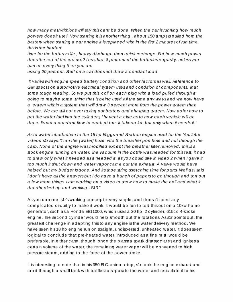
how many math-tithions will say this cant be done. When the car is running how much powere does it use? Now starting it is another thing , about 150 amps is pulled from the battery when starting a car engine it is replaced with in the first 2 minutes of run time. this is the hardest time for the batterys life , heavy discharge then quick recharge. But how much power does the rest of the car use? Less than 8 percent of the batteries copasity. unless you turn on every thing then you are useing 20 percent. Stuff on a car does not draw a constant load.
It varies with engine speed battery condition and other factors as well. Reference to GM spects on automotive electrical system uses and condition of components. That some tough reading. So we put this coil on each plug with a load pulled through it going to maybe some thing that is being used all the time any ways and we now have a system within a system that will draw 3 percent more from the power system than before. We are still not over taxing our battery and charging system. Now as for how to get the water fuel into the cylinders, I havent a clue as to how each vehicle will be done. Its not a constant flow to each piston. It takes a lot, but only when it needs it." As to water introduction to the 18 hp Briggs and Stratton engine used for the YouTube videos, s1r says, "I ran the [water] hose into the breather port hole and not through the carb. None of the engine was modified except the breather filter removed. This is a stock engine running on water. The vacuum in the bottle was needed for this test, it had to draw only what it needed as it needed it, as you could see in video 2 when I gave it too much it shut down and water vapor came out the exhaust. A valve would have helped but my budget is gone, And its shoe string stretching time for parts. Well as I said I don’t have all the answers but I do have a bunch of papers to go through and sort out a few more things. I am working on a video to show how to make the coil and what it does hooked up and working.- S1R." As you can see, s1r's working concept is very simple, and doesn't need any complicated circuitry to make it work. It would be fun to test this out on a 10kw home generator, such as a Honda EB11000, which uses a 20 hp, 2 cylinder, 615cc 4-stroke engine. The second cylinder would help smooth out the rotations. As s1r points out, the greatest challenge in adapting this to any engine is the water delivery method. We have seen his 18 hp engine run on straight, undispersed, unheated water. It does seem logical to conclude that pre-heated water, introduced as a fine mist, would be preferable. In either case, though, once the plasma spark disassociates and ignites a certain volume of the water, the remaining water vapor will be converted to high pressure steam, adding to the force of the power stroke. It is interesting to note that in his 350 El Camino setup, s1r took the engine exhaust and ran it through a small tank with baffles to separate the water and reticulate it to his
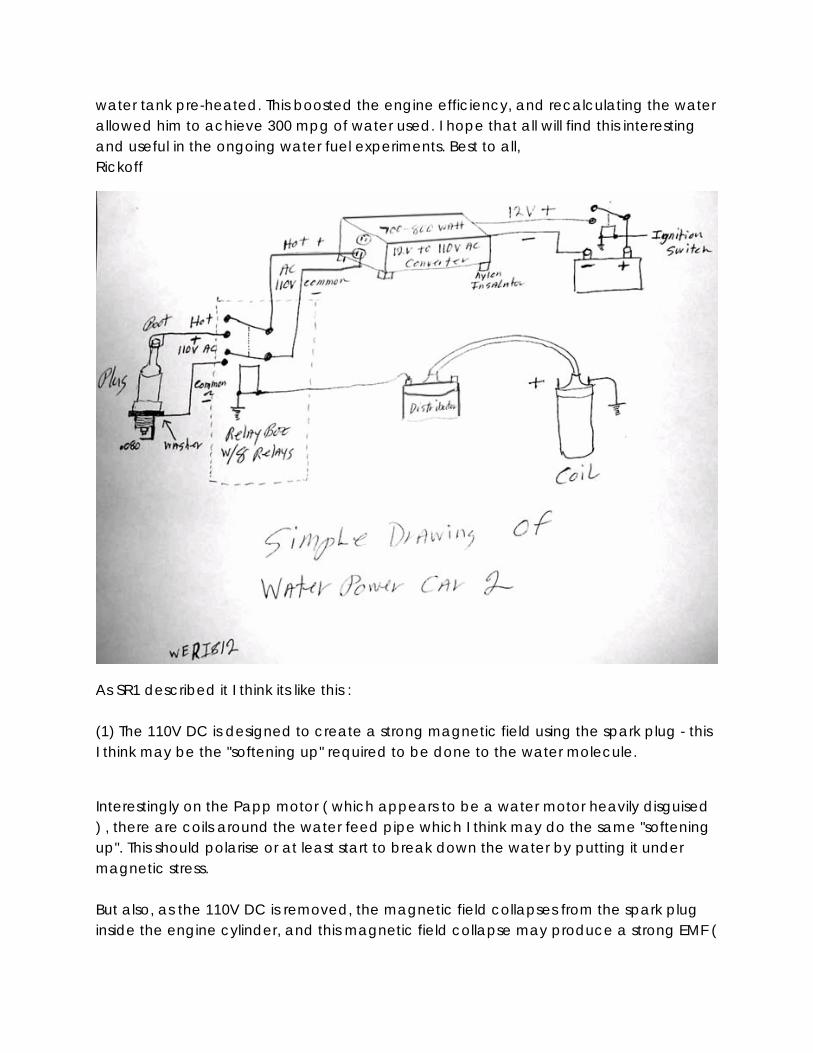
water tank pre-heated. This boosted the engine efficiency, and recalculating the water allowed him to achieve 300 mpg of water used. I hope that all will find this interesting and useful in the ongoing water fuel experiments. Best to all, Rickoff
As SR1 described it I think its like this : (1) The 110V DC is designed to create a strong magnetic field using the spark plug - this I think may be the "softening up" required to be done to the water molecule.
Interestingly on the Papp motor ( which appears to be a water motor heavily disguised ) , there are coils around the water feed pipe which I think may do the same "softening up". This should polarise or at least start to break down the water by putting it under magnetic stress. But also, as the 110V DC is removed, the magnetic field collapses from the spark plug inside the engine cylinder, and this magnetic field collapse may produce a strong EMF (
voltage ) that may stress water vapor already in the engine cyclinder and may provide a rapid step up in the stress on the water in the cyclinder of the engine, at that moment. Thinking about this a bit more, it appears this might be a two stage pulse stress on the water, *possibly* similar to the like the "pulse train" Meyer showed in his patent and shows on his drawings. (2) The 110V DC is applied all the time to the spark plug - except at the exact moments the ignition coil is firing through the spark plug. SR1 cleverly uses the distributor to send a pulse to his relays to open and close them at the required times to achieve this. The 8 relays in the box that SR1 uses appears to be nothing more than one relay per cylinder for his V8 engine. Each relay ( one per cyclinder ) is connected to the distributor to disconnect the 110V DC from each plug just before the spark fires through the spark plug and then reconnects immediately afterward to re-establish the magnetic field through the spark plug again. According to SR1, it seems that the 110V DC is *not* what burns the water, rather the ignition spark does - but his circuits appear to have the coil current up to 10 Amps, which at 50 KV is quite a boot. Intersting point - If I understand GotoLucs circuit correctly, what SR1 is saying is slightly different to what GotoLuc is doing. GotoLuc uses a cap to pulse the spark plug, *but* doesnt have the 110V DC applied to the spark plug just before the spark fires and so no magnetic field is present before the capacitor fires. FYI - the text from the above URL: ( http://www.overunity.com/index.php/topic,3977.0.html ) Sr1 -The relay I used has two sets of coils and resisters in them. The same thing can be made by blocking the currents from the plug wire from going into the inverter and blocking the current from the inverter going to the plug wire, but leaving an open loop for both at the plug by grounding the inverter at the plug base and no where else on the vehicle. The inverter has a constant current going to the plug except when the distrubitor sends fire through the plug wire. The inverter needs to be blocked only for the time it takes the plug to fire from the distrubitor, and the same for the distrubitor blocked from the inverter. What goes on with the plug tip? well the inverter sends a current to the tip where there
is water , the plug tip now has a magnetic field around it when the plug is fired from the distrubitor the field is incressed and the extra amps causes a arc to form in the clyender that expands the water as like a lighting bolt would. You can expand water but you cant compress it. Yes if to much water is in the cylender it will lock the engine. Thats why the timing is set after TDC . Gas will not burn, gas vapor will burn. A carberator is designed to vaporize gas as it inters the intake manifold under a vacummn. Water will become partly vaporized and the rest is used to increase the compression in the clyender. A fuel injecter sprays a mist of fluid not vapor. It will partly vaporize in the clyender before the plug fires. That is why cars with carbs and cars with injecters have defferent time even for the same size engines. There is a few degrees defferences in them. The relays I used did not have any numbers or names or any marking on them at all. The parts I found that would work cost $600.00(US) for each clyender, and I was ask not to give out that info because of what they were used for. Home Land Secuirty Issue's. I dont ask , I dont tell. Plus how many people would spend their rent money for the parts. None of this can be patented and sold. I hope this will help others finish their projects."Thoughts and ideas welcome!
Ossie’s Sr1 Replication
Please see my two new videos here:http://www.youtube.com/m1a9r9s9 I believe I have replicated a setup that does the same thing as s1r9a9m9 shows in his videos. I believe the setup configuration can allow a combustion engine to be run on water only instead of petrol/gas through the same fuel system on the engine. In my videos, you will see I am now replicating an engine's ignition system using a signal generator switching a transistor driver that pulses an ignition coil at 20 Hz. This is powered separately by a small 12V battery although the sig gen is powered from mains power. I am now using a 300W 12-240V DC to AC inverter to charge up a small capacitor that is effectively in parallel with the spark plug via some diodes. The system works very well, as you can see in the video and only uses 2-2.5 amps on the inverter's input. With this new setup I was again surprised to find that even after running it continuously for 15 minutes, the spark plug is stone cold to the touch. The water explosions are cold and there is no heat that I can feel. I cannot explain this and my assumption that it was

hot and warmed up the water was incorrect. It is a cold explosion or the explosion itself cools the plug tremendously through very fast evaporation of the water. So it would seem that because the explosions may actually cool the cylinder, external heating to assist the humidity and moisture content of the air may be required after all for cooler climates. Also, there is no smell whatsoever and only cold moisture around the spark plug. Regards,Ossie
Technical discussion -s1r9a9m9 water fuel circuit
Diagrams -- http://waterfuel.t35.com/water_explosion.html
WATCH WORKING s1r9a9m9 REPLICATION
http://www.youtube.com/watch?v=nnUv6M0N6z4
Details- http://www.overunity.com/index.php/topic,3977.new.html
Sr1 Video related
Internal Video of a running engine
2 videos from the Youtube user s1r9a9m9, who got his motor already to run on water and this special spark plug system: http://www.youtube.com/user/s1r9a9m9
S1r test #1
YouTube - Working s1r9a9's Replication
Suggest faculty reading
Arc-liberated chemical energy exceeds electrical input energy
Patents and related information Patents
Plasma Arc Ignition System" designed in 1993. It describes the concept of a combined high voltage, high current system. Although this was designed for gasoline there are some parallels to the work being done here. The diagrams even suggest some spark
plug designs that may work best with a plasma arc. Click on 'Documents' to view the 45 page pdf
http://www.wipo.int/pctdb/en/wo.jsp?IA=CA1992000510&DISPLAY=DOCS
More of his patents
http://www.google.de/patents?q=PLASMA-ARC+IGNITION+SYSTEM&btnG=Search+Patents
http://www.pat2pdf.org/patents/pat6553981.pdf If that links doesn't work, goto:
PAT2PDF - Free PDF copies of patents: Download and print! and enter patent # 6553981
Dual-mode ignition system utilizing traveling spark ignitor - Patent 6553981
http://freenrg.info/Patents/Tesla/TESLA_US00568177.pdf http://freenrg.info/Patents/Tesla/TESLA_US00609250.pdf
Papers
A plasma discharge effect and explode the water such that it may release more energy then what was put into it. Please see this post:
Paper discussion- From the over unity forum
For anyone who, understandably, has concerns as to the validity of the premise that the energy output exceeds the electrical energy input in this process, then I must strongly urge them to read and study a paper that was previously mentioned a few posts ago and was found and shown to me by my good friend Ben, who has now done some good research on this topic. The paper was published by Cambridge University Press and was written by Peter Graneau from Northeastern University Boston USA and Neal Graneau from Oxford University UK. The title of the paper is, "Arc-liberated chemical energy exceeds electrical input energy". It is an excellent paper that fully supports and describes what we have seen in the basic and simple experiments described in this thread. Ben found the paper here as follows: http://tech.groups.yahoo.com/group/WaterFuel1978/files/ Stephan has also uploaded the paper here:
http://www.overunity.com/index.php?action=tpmod;dl=get93 The paper clearly explains that the output energy is NOT from any H2O dissassociation and ignition process but simply an electrochemical process where the hydrogen bonds of the H2O molecule, that causes water to remain in a liquid state, are broken by an electric plasma pulse which converts the water into a dense fog state. A fog state is where the H2O molecules are not bonded with each other to form a liquid state but are unbonded and densely dispersed with air to form a fog.
Quotes: "Experimental observations leave little doubt that internal water energy is being liberated by the sudden electrodynamic conversion of about one-third of the water into dense fog", "The loss of intermolecular bond energy in the conversion from liquid to fog must be the source of the explosion energy", "This bond energy is said to be equal to the latent heat of evaporation, and therefore could contribute up to 2200 J g^-1." So there is already some good academic science behind what we are seeing in this process. I have no doubt that the effects we have seen, as well as other effects yet to be discovered which you yourself have found, can be used and utilised to build a working engine or motor that is powered solely by pure water. Regardless if the result turns out to be a completely new design and form of engine or a simple retofit to existing engines, the goal in the end is the same although the later would have a more rapid impact in terms of the application of the technology. So I am very encouraged and pleased by your interest in this thread and some of the basic tests you have already done to see for yourself if there is anything real in the claims made. I hope that more important and serious researchers, like yourself, can come together to openly assist and work on what has been described in this thread for the benefit of all.
End
Related Links water jet plasma
http://www.powerlabs.org/waterarc.htm
Non resistor plugs
http://peswiki.com/index.php/Firestorm_spark_plug
http://web.archive.org/web/20050307163215/www.robertstanley.biz/firestorm.htm
http://www.electricianeducation.com/theory/electric_transformers.htm
National High Magnetic Field Laboratory - Ignition Coil Tutorial
Technical Discussion Added link to schematics: http://www.overunity.com/index.php/topic,5024.0.html
http://www.overunity.com/index.php/topic,5154.0.html
http://www.overunity.com/index.php/topic,5112.msg113486.html#msg113486

Water Sparkplug –energetic forum
http://tech.groups.yahoo.com/group/WaterFuel1978/
Replication Videos Original Luc videos
Ganga Shakti - Water Power (updated circuit)
allcanadian circuit test 1
Ganga Shakti - Water Power Test 1
Ganga Shakti - Water Power Test 2
Ganga Shakti - Water Power Test 3
Related experimenters video’s
YouTube - water explosion
YouTube - plasma arc with gasoline
YouTube - New Circuit
Homemade injector/spark plug Plasma arc
Hydrogen reactor 12
Exploding Water With Just a 9V Battery
Plasma Spark Plug Test on Engine and water
YouTube - Water spark
YouTube - navigation2000's Channel
YouTube - Aaron's Water Spark Plug Amplifier
Plasma spark in running engine
Plasma Spark Plug Test on Engine and water
Remove the resistor from a sparkplug
How to remove the top on a Champion 8339 plug
YouTube - Water spark plug

Plasma spark, no water
water exploded plasma spark
johncarl43447
http://www.youtube.com/watch?v=l_kxaLBo_Xo http://www.youtube.com/watch?v=fe2-czkeq2o
User crob227
http://www.youtube.com/watch?v=YKpEXXvIZZ8
http://www.youtube.com/watch?v=PWglLC_UEwc
http://www.youtube.com/watch?v=LRX89SDHEiM
Plasma fusion related
Wasser / Water Explosion - Free Energy
Plasma Electrolysis Tero
hydrogen cold fusion plasma electrolysis Reactor CFR
Plasma electrolysis cell test
Water Arc Acceleration Plasma Ignition - HHO Hydrogen Cell
Cold Fusion Plasma 9
HHO flame / ionized spark gap 2
Injector with Water
YouTube - Water Arc Acceleration Plasma Ignition - HHO Hydrogen Cell
YouTube - The Jumping Marble (Water & Plasma)
YouTube - Plasma Water Engine Proof Of Concept Demo
Laser induced air breakdown (w/sound)
Credits Open source engineers!

If you are able to contribute to this document in ANY way, IE- replication details, faculty info and or additional data please contact the non profit organization.
http://www.panacea-bocaf.org
http://www.panaceauniversity.org
Related Documents