
Welcome message from author
This document is posted to help you gain knowledge. Please leave a comment to let me know what you think about it! Share it to your friends and learn new things together.
Transcript
Electron¡cs Which digital voltmeter? page 84 Sensors for celestial guidance: page 94
Transistors can multiply, divide: page 109
April 4, 1966
75 cents
A McGraw-Hill Publication
Below: Scratch-pad memory increases computer capability: page 118
k«......111:0NEERS IN INIATURIZeTION
NEW
DI-T200
111 ! 1!!!!
TRANSFORMERS PICTURED ACTUAL SIZE
ERIES
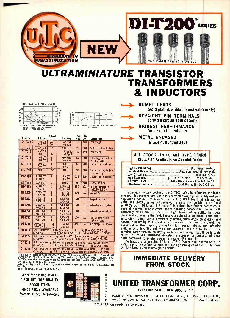
ULTRA MINIATURE TRANSISTOR TRANSFORMERS & INDUCTORS
zoo.. 4oci".• ROO,. IKC 20KC
15
e TYPICAL Dl-1200 PERFORMANCE
SOURCE RATED PRI IMP AND D C LOAD RATED SEC Imp.
Type No. DCmaT
Pri. Im. in Pri.
e:21 ° D ;
loo zoo .00 ..c 20C .11{C URIC 2DD 4CRC D) F RE OU E NC Y
Mw Sec. Ima. Res. Leve
DI-T225 —
80 CT 100 CT
12 10
32 split 40 split
10 500 Interstage
DI-1230 300 CT 7 600 CT 20 500 Output or line to line DI-T235 400 CT
500 CT 8 6
40 split 50 Split
50 500 Interstage
DI-1240 400 CT 500 CT
8 6
400 split 500 split
50 500 Interstage or output (Ratio 2:1:1)
DI-T245
-
500 CT 600 CT
3 3
50 CT 60 CT
65 500 Output or matching
DI-T250 500 CT 5.5 600 CT 35 500 Output or line to line or mixing
DI-T255 1,000 CT 1,200 CT
3 3
50 CT 60 CT
110 500 Output or matching
DI-1280 1,500 CT 3 600 CT 90 500 Output to line DI-T265 2,000 CT
2,500 CT 3 3
8.000 split 10,000 split
180 100 Isle or interstage (Ratio 1:1:1)
DI-1270 10,000 CT 12,000 CT
1 1
500 CT 600 CT
870 100 Output or driver
D14273 10,000 CT 12,500 CT
1 1
1,200 CT 1,500 CT
870 100 Output or driver
DI-T276 10,000 CT 12,000 CT
1 1
2,000 CT 2,400 CT
870 100 Interstage or driver
DI-1278 10,000 CT 12,500 CT
1 1
2,000 split 2,500 split
620 100 Interstage or driver
DI-T283 10,000 CT 12,000 CT
1 1
10,000 CT 12,000 CT
970 100 Isol, or interstage (Ratio 1:1)
DI-1288 20,000 CT 30,0® CT
.5
.5 800 CT
1,200 CT 870 50 Interstage or driver
DI-T204 Split Inductor g .1 Hy e 4 maDC, .08 Hys e 10 maDC, DCR 25(.1 (2 wdgs) ;It .025 Hys 0 8 maDC, .02 Hys e 20 maDC, DCR 613
DI-T208 Split Inductor g .9 Hys 0 2 maDC, .5 Hys ® 6 maDC, DCR 105i1 (2 wdgs) gg .2 Hys e 4 maDC, .1 Hys 0 12 maDC, DCR 26U
DI-T212 Split Inductor 8 2.5 Hys 0 2 maDC, .9 Hys e 4 maDC, DCR 630L1 (2 wdgs) ig .6 Hys 04 maDC, .2 Hys e 8 maDC, DCR 157a
DI-1216
........
Split Inductor § 4.5 Hys e 2 maDC, 1.2 Hys e 4 maDC, OCR 2300L1 (2 wdgs) §§ 1.1 Hys e 4 maDC, .3 Hys 64 8 maDC, DCR 575i1
ma snow Is for single ended useage (under 59, distortion -100mw 1 KC)... for push pull, DCma can be ny balanced value taken by 5W transistors (under 5% distortion-500mw -1 KC Dl-T200 units have been designed for trapsistor application only.., not for vacuum tube service U.S. Pat. No. 2,949,591 other pending. Where windings are listed as split, 'A of the listed impedance is available by paralleling the 'winding. ¡Series connected; §§Parallei connected.
Write for catalog of over 1,300 UTC TOP QUALITY
STOCK ITEMS IMMEDIATELY AVAILABLE From your local distributor.
DUMET LEADS
(gold plated, weldable and solderable)
am.* STRAIGHT PIN TERMINALS (printed circuit application)
HIGHEST PERFORMANCE for size in the industry
is.> METAL ENCASED (Grade 4, Ruggedized)
IALL STOCK UNITS MIL TYPE TF4RX Class "S" Available on Special Order
High Power Rating up to 100 times greater. Excellent Response twice as good at low end. Low Distortion reduced 80%. High Efficiency up to 30% better ... compare DCR. Moisture Proof hermetically sealed to MIL-T-27B. Ultraminiature Size 5/16 Dia. x Ye" H, 1/15 Oz.
The unique structural design of the DI-T200 series transformers and induc-tors provides the excellent electrical characteristics, high reliability and wide application possibilities inherent in the UTC DO-T family of miniaturized units. The DI-T200 series units employ the same high quality design found in UTC's DO-T, DI-T, and PIP lines. This unique transformer constructural concept affords unprecedented power handling capabilities coupled with extremely small size. Further, the high degree of reliability has been dynamically proven in the field. These characteristics are basic in the struc-ture, which is ruggedized, hermetically sealed, employing a completely rigid bobbin, eliminating stress and wire movement. The turns are circular in shape rather than square, eliminating turn corner stress, and effecting uniform wire lay. The coil wire and external lead are rigidly anchored terminal board fashion, employing no tapes and brought out through strain relief. The curves illustrated indicate the superior performance of these units compared to similar size units now on the market.
The leads are uninsulated 1" long, .016 D Dumet wire, spaced on a .1" radius circle to conform to terminal spacing techniques of the "TO-5" case semiconductors and micrologic elements.
IMMEDIATE DELIVERY FROM STOCK
UNITED TRANSFORMER CORP. •
150 VARICK STREET, NEW YORK 13, N.Y. • •
PACIFIC MFG. DIVISION: 3630 EASTHAM DRIVE, CULVER CITY, CALIF. EXPORT DIVISION: 13 EAST 4018 STREET, NEW YORK 16, N. Y. CABLE; "ARI.Ale
Circle 900 on reader service card
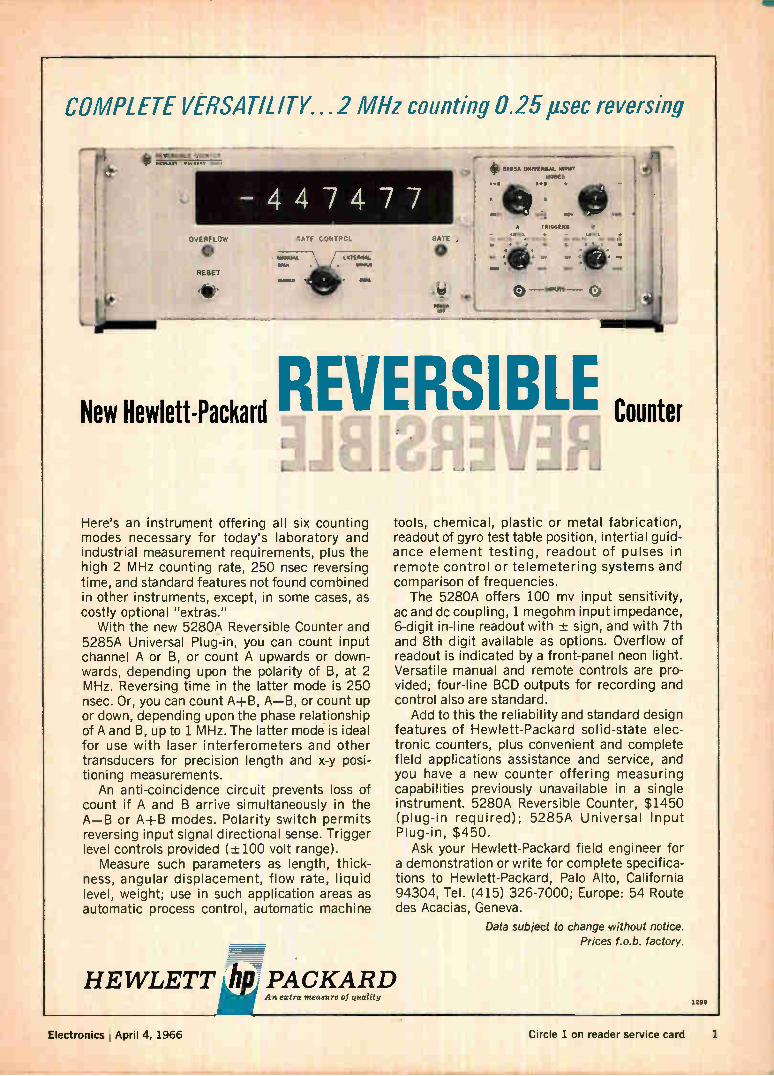
COMPLETE VERSATILITY...2 MHz counting 0.25 psec reversing
Le.
- 4 4 7 4 7 7 OVERFLOW
e RESET
de.
REVERSIBLE Counter New Hewlett-Packard
Here's an instrument offering all six counting modes necessary for today's laboratory and industrial measurement requirements, plus the high 2 MHz counting rate, 250 nsec reversing time, and standard features not found combined in other instruments, except, in some cases, as costly optional "extras."
With the new 5280A Reversible Counter and 5285A Universal Plug-in, you can count input channel A or B, or count A upwards or down-wards, depending upon the polarity of B, at 2 MHz. Reversing time in the latter mode is 250 nsec. Or, you can count Al-B, A—B, or count up or down, depending upon the phase relationship of A and B, up to 1 MHz. The latter mode is ideal for use with laser interferometers and other transducers for precision length and x-y posi-tioning measurements.
An anti-coincidence circuit prevents loss of count if A and B arrive simultaneously in the A—B or Al-B modes. Polarity switch permits reversing input signal directional sense. Trigger level controls provided (-±-100 volt range).
Measure such parameters as length, thick-ness, angular displacement, flow rate, liquid level, weight; use in such application areas as automatic process control, automatic machine
tools, chemical, plastic or metal fabrication, readout of gyro test table position, intertial guid-ance element testing, readout of pulses in remote control or telemetering systems and comparison of frequencies.
The 5280A offers 100 mv input sensitivity, ac and dc coupling, 1 megohm input impedance, 6-digit in-line readout with -± sign, and with 7th and 8th digit available as options. Overflow of readout is indicated by a front-panel neon light. Versatile manual and remote controls are pro-vided; four-line BCD outputs for recording and control also are standard.
Add to this the reliability and standard design features of Hewlett-Packard solid-state elec-tronic counters, plus convenient and complete field applications assistance and service, and you have a new counter offering measuring capabilities previously unavailable in a single instrument. 5280A Reversible Counter, $1450 (plug-in required); 5285A Universal Input Plug-in, $450.
Ask your Hewlett-Packard field engineer for a demonstration or write for complete specifica-tions to Hewlett-Packard, Palo Alto, California 94304, Tel. (415) 326-7000; Europe: 54 Route des Acacias, Geneva.
Data subject to change without notice. Prices f.o.b. factory.
= HEWLETT ilk PACKARD
An extra measure of quality 1298
Electronics I April 4, 1966 Circle 1 on reader service card 1
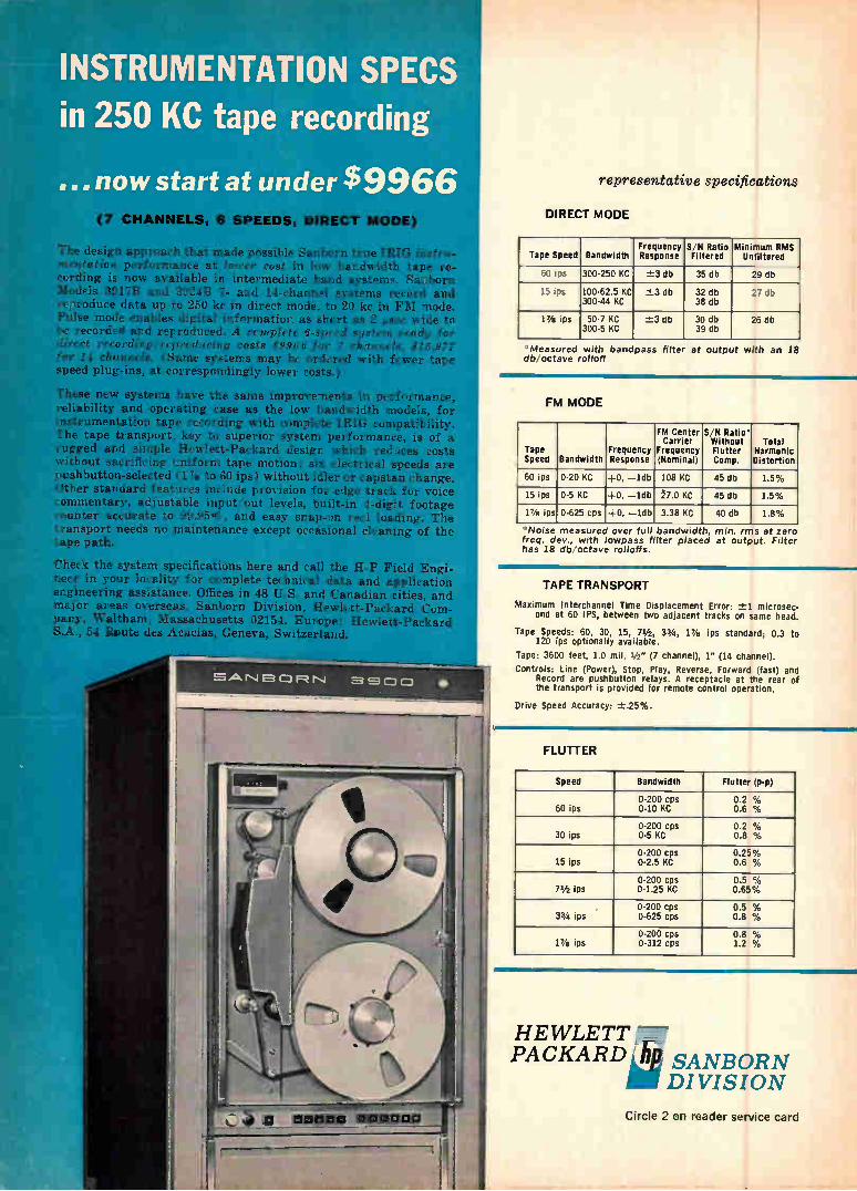
INSTRUMENTATION SPECS in 250 KC tape recording
... now start at under $9966 (7 CHANNELS, 6 SPEEDS, DIRECT MODE)
Ile design approach that made possible Sanborn true IRIG instr mentation performance at lower cost in low bandwidth tape re-cording is now available in intermediate band systems. Sanborn Models 3917B and 3924B 7- and 14-channel systems record and reproduce data up to 250 kc in direct mode, to 20 kc in FM mode. Pulse mode enables digital information as short as 2 gsec wide to, be recorded and reproduced. A complete 6-speed system ready for direct recording reproducing costs $9966 for 7 channels, $15.977 for 14 channels. (Same systems may be ordered with fewer tape speed plug-ins, at correspondingly lower costs.)
These new systems have the same improvements in performance reliability and operating ease as the low bandwidth models, fo instrumentation tape recording with complete IRIG compatibility* The tape transport, key to superior system performance, is of a rugged and simple Hewlett-Packard design which reduces costs without sacrificing uniform tape motion: six electrical speeds are pushbutton-selected (1% to 60 ips) without idler or capstan change. Other standard features include provision for edge track for voice commentary, adjustable input out levels, built-in 4-digit footage counter accurate to 99.955, and easy snap-on reel loading. The transport needs no maintenance except occasional cleaning of the tape path.
Check the system specifications here and call the H-P Field Engi-neer in your locality for complete technical data and application engineering assistance. Offices in 48 U.S. and Canadian cities, and major areas overseas. Sanborn Division, Hewlett-Packard Com-pany, Waltham, Massachusetts 02154. Europe: Hewlett-Packard S.A., 54 Route des Acacias, Geneva, Switzerland.
representative specifications
DIRECT MODE
Tape Speed Bandwidth Frequency Response
S/N Ratio Filtered
Minimum RMS Unfiltered
60 ips 300-250 KC -±3 db 35 db 29 db
15 ips 100-62.5 KC 300-44 KC
-±-3 db 32 db 38 db
27 db
17/8 ips 50-7 KC 300-5 KC
-±3 db 30 db 39 db
26 db
'Measured with bandpass filter at output with an 18 db; octave rolloff
FM MODE
Tape Speed Bandwidth
Frequency Response
FM Center Carrier
Frequency (Nominal)
S/N Ratio' Without Flutter Comp.
Total Harmonic Distortion
60 ips 0-20 KC +0, —1db 108 KC 45 db 1.5°.
15 ips 0-5 KC -,0, —1db 7.0 KC 45 db 1.5%
17,S ips 0-625 cps +0, —1db 3.38 KC 40 db 1.8%
Noise measured over full bandwidth, min. rms at zero freq. dey., with owpass filter placed at outp,it. Filter has 18 db octave rolloffs.
TAPE TRANSPORT
Maximum Interchannel Time Displacement Error: -±-1 microsec-ond at 60 IPS, between two adjacent tracks on same head.
Tape Speeds: 60, 30, 15, 71/2 , 33/4 , 17/8 ips standard; 0.3 to 120 ips optionally available.
Tape: 3600 feet, 1.0 mil, 1/2 " (7 channel), 1" (14 channel).
Controls: Line (Power), Stop, Play, Reverse, Forward (fast) and Record are pushbutton relays. A receptacle at the rear of the transport is provided for remote control operation.
Drive Speed Accuracy: ±.25%.
Speed Bandwidth Flutter (p-p)
0-200 cps 0.2 % 60 ips 0-10 KC 0.6 %
0-200 cps 0.2 % 30 ips 0-5 KC 0.8 %
0-200 cps 0.25% 15 ips 0-2.5 KC 0.6 %
0-200 cps 0.5 % 71/2 ips 0-1.25 KC 0.65%
0-200 cps 0.5 % 33/4 ips 0-625 cps 0.8 %
0-200 cps 0.8 % 17/8 ips 0-312 cps 1.2 %
HEWLETT PACKARD â sANBORN
DIVISION
Circle 2 on reader service card
Electronics
April 4. 1966 Volume 39. Number 7
Page 4 Readers Comment
8 People 14 Meetings
16 Meeting Preview 23 Editorial 25 Electronics Newsletter
69 Washington Newsletter
175 New Products 222 New Books 224 Technical Abstracts 230 New Literature
Title R registered U.S. Patent Office;
copyright 1966 by McGraw-Hill, Inc. All rights reserved, including the right to reproduce the contents of this publication, in whole or in part.
Electronics Review Page 35 Clearer fiber-optics
35 More scratch pads 36 Fast computer
37 Conversational program
37 Invisible sentry 38 Banking on computers 40 Taking heart
40 One-man tv crew 42 Breeding computers
44 TI DIP's in
45 Army drafts IC's 46 Ten-way masks
46 Recruiting at IEEE
48 IEEE jotting
Probing the News 151 Avionics for a more mobile army 156 Why some people fall often: EMG signals studied
for clues 161 Electronics booming in East Germany
233 234 234
Electronics Abroad Spot check X rays on tape Down with defects
235 Competition for Comsat?
236 Thin-film filters 237 Around the world
Technical articles
I. Design Instrumentation 84 Technical articles
Selecting the right digital voltmeter;
now there are four choices Billy G. Kay, Hewlett-Packard Co.
Circuit design 91 Designer's casebook • Overload protection for d-c amplifier
• Latching gate removes counter ambiguity • Delay circuit varies turn-on and turn-off
• Transistors control small d-c motor
Advanced technology
II. Application
94. Automatic celestial guidance, part II
Now that the principles are known, the
next step is to develop hardware R.L. Lillestrand, J.E. Carroll and J.S. Newcomb,
Control Data Corp.
Circuit design 109 Using transistors to multiply and divide
The logarithmic relationship between current
and voltage in a pn function is put to work
George E. Platzer Jr., Chrysler Corp.
Computers 118 Integrated scratch pads sire a new generation
of computers (cover) With eight bits on a single silicon chip, the scratch pad becomes economically feasible
G.B. Potter, Scientific Data Systems
and S. Sirkin, Signetics Corp.
Electronics Editor: Lewis H. Young
Senior editors
Technical: Samuel Weber
News: Kemp Anderson Jr.
Senior associate editors: John F. Mason, George Sideris
Department editors
Advanced technology: Joan Blum Avionics: W.J. Evanzia
Computers: Wallace B. Riley Consumer electronics: Richard Lipkin Electronics abroad: Arthur Erikson Electronics review: Stanley Zarowin instrumentation: Carl Moskowitz Manufacturing: George Sideris
Military electronics: John F. Mason
New products: William P. O'Brien
Solid state: Jerome Eimbinder Space electronics: Robert Henkel
Regional editors
Domestic
Boston: Thomas Maguire, editor; Robin Carlson Los Angeles: William B. Wallace, Walter Barney, editors; June RaniII San Francisco: Laurence D. Shergalis, Edmond G. Addeo, editors; Mary Jo JadIn
Foreign European: Derek Barlow, (London) Bonn: John Gosch Tokyo: Charles Cohen
Copy editors
Howard Rausch, Sally Powell, Kenneth Munn, James J. Moran
Graphic design
Art director: Saul Sussman
Assistant art directors: Donna M. Griffiths, Ann Mella
Production editor: Arthur C. Miller
Editorial secretaries: Claire Benell, Mary D'Angelo, Lynn Emery, Lorraine Fabry, Kay Fontana, Lorraine Longo, Carolyn Michnowicz
McGraw-Hill News Service
Director: John Wilhelm; Atlanta: Fran Ridgway; Chicago: Reck Johnson; Cleveland: Arthur Zimmerman; Dallas: Marvin Reid;
Detroit: N. Hunter; Houston: Ron Lovell; Los Angeles: Michael Murphy, Gerald Parkinson; San Francisco: Margaret Ralston;
Seattle: Ray Bloomberg; Washington: Arthur L. Moore, Charles Gardner,
Herbert W. Cheshire, Seth Payne, Warren Burkett, Warren Kornberg
McGraw-Hill World News Service
Bonn: John Johnsrud; London: John Shinn;
Mexico City: Bruce Cross; Milan: Ronald Taggiasco;
Moscow: Donald Winston; Paris: Peter Kilborn;
Rio de Janeiro: Wes Perry; Tokyo: Marvin Petal
Circulation manager: Hugh J. Quinn
Reprints: T.M. Egan
Publisher: C.C. Randolph
Electronics: April 4, 1966, Vol. 39, No. 7
Printed at 99 North Broadway, Albany, N.Y., 12207 Second class postage paid at Albany, N.Y.
Subscriptions are solicited only from those actively engaged in the field of the publication. Position and company connection must be indicated on orders. Subscription prices: United States and Possessions and Canada. $6.00 one year, $9.00 two years, $12.00 three years. All other countries $20.00 one year. Single copies. United States and Possessions and Canada 75e. Single copies all other countries $1.50.
Published every other Monday by McGraw-Hill Inc. 330 West 42nd Street, New York, N.Y. 10036. Founder: James H. McGraw. 1860-1948. Corporate officers: Shelton Fisher, President: John J. Cooke, Secretary; John L. McGraw, Treasurer.
Subscribers: The Publisher, upon written request to our New York office from any subscriber, agrees to refund that part of the subscription price applying to copies not yet mailed. Please send change of address notices, subscription orders or complaints to Fulfillment Manager, Electronics, at the address below. Change of address notices should provide old as well as new address, including postal zone number if any. If possible, attach address label from recent issue. Allow one month for change to become effective.
Postmaster: Please send Form 3579 to Fulfillment Manager, Electronics, P.O. Box 430, Hightstown, New Jersey 08520
Readers Comment
Strip line discussion
To the Editor: In my opinion the article, "Using
strip transmission line to design microwave circuits" [Feb. 7, p. 72] contains a number of misleading ideas. The authors state that the strip
transmission line is formed by etch-ing one side of a doubly-clad board and using pressure plates for rigidity. The Electronized Chemical Corp. of Burlington, Mass., manu-factures a low-loss material, Poly-guide, which can be purchased with aluminum backing adhered to the dielectric. The authors also imply that the
coupling arrangement shown on page 74 of the article is the only acceptable form. On the contrary, coplanar coupling as described is useful only for loose to moderate coupling. The lumped-element equivalents
are almost completely erroneous. The equation shown by Dangl and Steele for the characteristic im-pendance of strip line is useful only for w/b < 0.35. With center con-ductors etched from one- or two-ounce copper and w/b < 0.35, only characteristic impedances greater than 100 ohms are possible. The authors also show a means
for creating a series inductance in strip line and describe how series capacitances can be formed. An abrupt change in the width of the center conductor actually behaves as a transformer, while a trans-verse slit acts as a Pi-network hav-ing a series capacitance and two shunt inductances. The equation as given for the series inductance, if this simplification is to be used, should read:
XL = [ 2W2 (413/71) ln 2 Z02 X
Zo2 ln CSC ( 2 o. z
Steven March HRB-Singer, Inc. State College, Pa.
• The authors reply:
The authors are indebted to Mr.
4 Electronics I April 4, 1966

New Bridge Design For Safe, Accurate, Easy Measurement of 'Lytic Capacitors
The Sprague Model 1W2A Capaci-tance Bridge introduces new, im-proved technical refinements as well as restyling for added attractiveness and ease of operation. Built by ca-pacitor engineersfor capacitor users, it incorporates the best features of bridges used for many years in Sprague laboratories and produc-tion facilities.
Precision Measurements over Entire Range from 0 to 120,000 uF The internal generator of the 1W2A Bridge is a line-driven frequency con-verter, and detection is obtained from an internal tuned transistor amplifier-null detector, whose sensitivity increases as the balance point is approached. It has provision for 2-terminal, 3-terminal, and 4-termi-nal capacitance measurements, which are essential for accurate measure-ment . . . 1% of reading + lOppF ... of medium, low, and high capac-itance values, respectively.
No Damage to Capacitors The model 1W2A Capacitance Bridge will not cause degradation or failure in electrolytic or low-voltage ceramic capacitors during test, as is the case in many conventional bridges and test circuits. The 120 cycle A-C volt-age, applied to capacitors under test from a built-in source, never exceeds 0.5 volt! It is usually unnecessary to apply d-c polarizing voltage to elec-trolytic capacitors because of this safe, low voltage.
Complete Specifications Available For complete technical data on this precision instrument, write for Engi-neering Bulletin 90,010A to Technical Literature Service, Sprague Electric Company, 35 Marshall Street, North Adams, Massachusetts.
New from Sprague!
Silicontrol® High Gate Drives Stop SCR Failures
Caused by dihit Effect • Silicontrol Gate Drives are ideally suited for completely bal-anced, reliable SCR firing in 3-phase a-c or d-c power control.
• High-output gate drive with fast-rise-time pulse avoids SCR failures due to dildt effect.
• No bias for pulse reset required—failsafe--load and control circuits fully isolated.
• Each gate signal output is a pulse of substantially constant amplitude in excess of 210° wide at full SCR conduction.
• Gate pulse output: 18 volts min. (open circuit), 1.7 amperes (short circuit), less than 1 psec pulse rise time to meet gate firing requirements of high current SCRs.
• Available in half-wave or full-wave designs—Series VS6532 produces one gate pulse per cycle per phase, while Series VS6732 provides two isolated gate pulses per card for a total of six gate pulses per cycle.
10' , control signal 50" control signal 100', control signal
Gate Pulse Phase Shifting as Control Signal is Applied
For complete technical data, write for Engineering Bulletin 85525 to the Technical Literature Service, Sprague Electric Co., 35 Marshall St., North Adams, Mass. 01248.
SPRAGUE COMPONENTS
PACKAGED COMPONENT ASSEMBLIES
THIN-FILM MICROCIRCUITS
INTEGRATED CIRCUITS
CERAMIC-BASE PRINTED NETWORKS
FUNCTIONAL DIGITAL CIRCUITS
PULSE-FORMING NETWORKS 4Sfrilaa
CAPACITORS
TRANSISTORS
RESISTORS
INTERFERENCE FILTERS
MAGNETIC COMPONENTS
PULSE TRANSFORMERS
SPRAGUE® THE MARK OF RELIABILITY
'Sprague and 2 are registered trademarks of the Sprague Electric Co. 48/1.11111.1111
Circle 4 on reader service card Circle 5 on reader service card 5
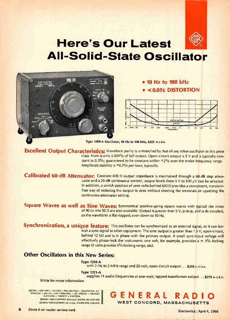
Here's Our Latest All-Solid-State Oscillator
• 10 Hz to 100 kHz
• <0.05% DISTORTION
20 50 100 200
SPECIFICATION
TYPICAL
500 11.2 2 FREQUENCY
Type 1309-A Oscillator, 10 Hz to 100 kHz, $325 in U.S.A.
10 20 50 loo
Excellent Output Characteristics: Waveform purity is unmatched by that of any other oscillator in this price class. Hum is only 0.001% of full output. Open-circuit output is 5 V and is typically con-stant to 0.50/o; guaranteed to be constant within ±20/o over the entire frequency range. Amplitude stability is ±0.2% per hour, typically.
Calibrated 60-dB Attenuator: Constant 600 n output impedance is maintained through a 60-dB step atten-uator and a 20-dB continuous control; output levels from 5 V to 500 V can be selected. In addition, a switch position of zero volts behind 600 (..2 provides a convenient, transient-free way of reducing the output to zero without shorting the terminals or upsetting the continuous attenuator setting.
Square Waves as well as Sine Waves: Symmetrical positive-going square waves with typical rise times of 40 ns into 50 52 are also available. Output is greater than 5 V, p-to-p, and is dc coupled, so the waveform is flat-topped, even down to 10 Hz.
Synchronization, a unique feature: This oscillator can be synchronized to an external signal, or it can fur-nish a sync signal to other equipment. The sync output is greater than 1.5 V, open-circuit, behind 12 k1.2 and is in phase with the primary output. A small sync-input voltage will
effectively phase-lock the instrument; one volt, for example, provides a 2: 3°/o locking range (2 volts provide 6°/o locking range, etc).
Other Oscillators in this New Series: Type 1310-A
with 2-Hz to 2-MHz range and 20-volt, open-circuit output ... $295 in U.S.A.
Type 1311-A supplies 11 audio frequencies at one-watt; tapped-transformer output ... $215 in U.S.A.
Write for more information
BOSTON • NEW YORK • CHICAGO • PHILADELPHIA • WASHINGTON. D.0 SYRACUSE • DALLAS • SAN FRANCISCO • LOS ANGELES • ORLANDO
CLEVELAND • TORONTO • MONTREAL
GENERAL RADIO COMPANY (Overseas), ZURICH, SWITZERLAND
GENERAL RADIO COMPANY (U.K.) LW., BOURNE END, ENGLAND
GENERAL RADIO WEST CONCORD, MASSACHUSETTS
6 Circle 6 on reader service card Electronics April 4, 1966
March for pointing out the obvious omission in the equation for series inductance. But we disagree with his com-
ments about material with adhering aluminum backing. It is the experi-ence of the authors that final pro-duction designs often incorporate such items as mounting bosses, line stretchers, and isolators in the backing plate structure. In these cases, the separately fabricated pressure plates serve a dual pur-pose and are therefore advan-tageous.
His comments on coupling and simplified lumped circuit equiva-lents indicate possible misunder-standing of the purpose of these sections in the article. The sections are purposely limited in scope to the minimum felt necessary to understand the circuits presented in later paragraphs. The references designated in the article also pro-vide additional information, includ-ing graphs, for the design engineer requiring detailed data.
J. R. Dangl K. Steele
Sylvania Electronic Systems Williamsville, N. Y.
Applauds stand
To the Editor: As an IEEE member and active
participant at the section and group levels since 1946, please accept my heartfelt thanks for penetrating the shroud of silence covering internal IEEE policies through your percep-tive editorial entitled "IEEE settles for second rate sessions" and for publishing the letter headed "Rais-ing the standards" [March 21, 19661. It takes raw courage and dedication to shout that the Em-peror is naked!
SUBSCRIPTION SERVICE T Please include an ElectronIcs Magazine address label to insure prompt service whenever you write us about your subscription.
I Mail to: Fulfillment Manager Electronics P.O. Box 430 Hightstown, N.J. 08520
To subscribe mail this form with I and check new subscription I present subscription
I Subscription rates: in the U.S.: 1 year, $6; two I years, $9; three years, $12. Subscription rates
for foreign countries available on request
Your payment EJ renew my
The IEEE establishment, in ad-dition to ineptly handling the qual-ity of the 1966 convention's tech-nical sessions, appears to lack the sense of command responsibility that can cope with mundane prob-lems such as a tricky computer that switched my address from Doyles-town, PENNSYLVANIA, to Doyles-town, OHIO, with the subsequent loss and diversion of IEEE publica-tions and notices. During the past 10 months, I contacted the former and present IEEE presidents, the headquarters staff including the general manager, the Philadelphia section chairman and officers while trying to soften an ossified struc-ture. Only the regional director had the administrative maturity to in-quire, question and call for reme-dial action. Maybe it is the time to re-exam-
ine the power structure of the IEEE and recognize that the presidency should not be a sort of super fel-lowship, an accolade that is auto-matically bestowed yearly, but is indeed a hot seat for attempting to get an unwieldy monster on its feet. Your editorial highlights a po-
tentially lethal IEEE deficiency: there are no IEEE channels at con-ventions, section and group meet-ings, nor in the correspondence columns of IEEE publications for the rank-and-file to discuss vital internal questions relating to tech-nical-programs substance, quality and atmosphere; criteria for select-ing fellows; fiscal solvency; office procedures and practices. It does you at Electronics great credit that a feedback path to the IEEE lead-ership has been completed.
Sam Levine Senior member, IEEE Doylestown, Pa.
ATTACH LABEL HERE
CHANGE OF ADDRESS If you arc moving, please let us know
five weeks before changing your address.
Place magazine address label here, print
your new address below.
name
address
city state zip code _1
Picking the right miniature connector N
is a small problem It's not hard to locate a miniature con-nector small enough to meet tight space specs. Lots of people make them.
There is a small problem, though, in finding the quality you need at the price you'd like to pay.
— . That's why business is booming at Transitron's Precision Connector Divi-sion. We design and produce miniature and subminiature connectors to exceed — not merely meet specifications. They are built to outlast the equipment you mount them on. Precision fabrication, knowledgeable design, the finest ma-terials provide a combination that can't be surpassed by any manufacturer. Yet in quantity they cost no more than units that will barely squeeze by incoming inspection. Send today for our new condensed catalog covering a complete line of miniature and sub-miniature connectors, as well as printed circuit connectors and many other types. And if you need a custom connector design, we're your source. Just give us the facts.
Precision Connector Division
ira nsitron electronic corporation Wakefield, Massachusetts
Electronics April 4, 1966 Circle 7 on reader service card 7
-1 RAYTHEON
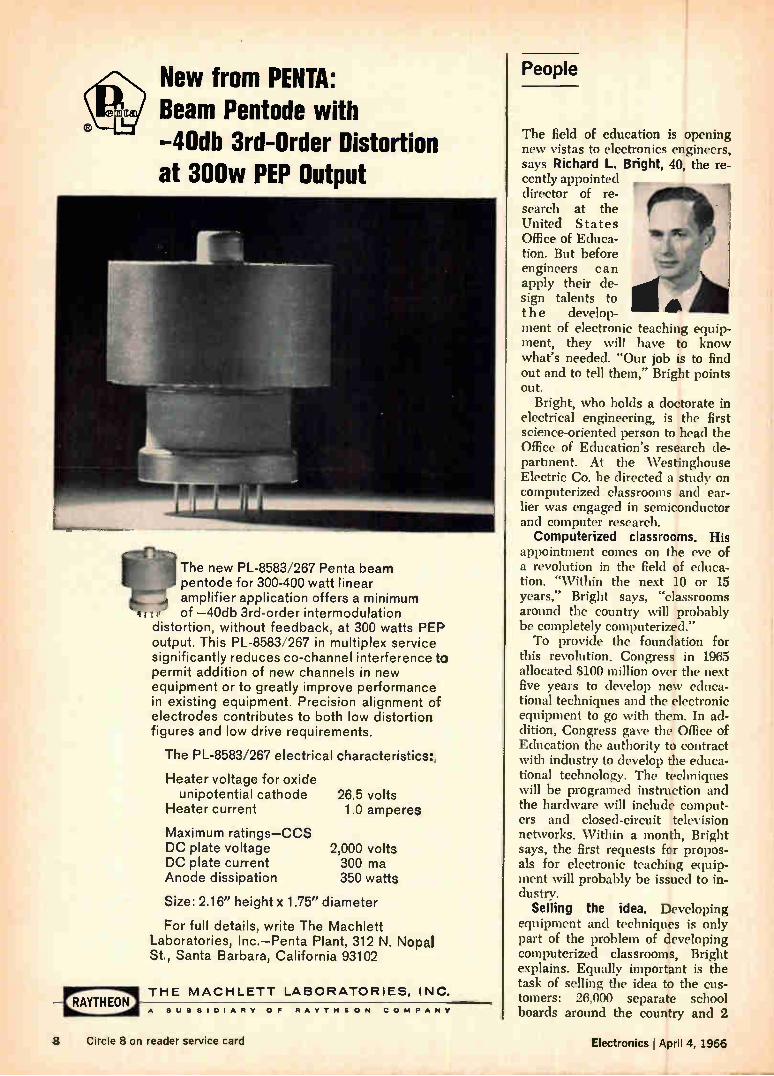
New from PENTA: Beam Pentode with —40db 3rd-Order Distortion at 300w PEP Output
The new PL-8583/267 Penta beam pentode for 300-400 watt linear amplifier application offers a minimum of —40db 3rd-order intermodulation
distortion, without feedback, at 300 watts PEP output. This PL-8583/267 in multiplex service significantly reduces co-channel interference to permit addition of new channels in new equipment or to greatly improve performance in existing equipment. Precision alignment of electrodes contributes to both low distortion figures and low drive requirements.
The PL-8583/267 electrical characteristics:.
Heater voltage for oxide unipotential cathode
Heater current
Maximum ratings—CCS DC plate voltage DC plate current Anode dissipation
26.5 volts 1.0 amperes
2,000 volts 300 ma 350 watts
Size: 2.16" height x 1.75" diameter
For full details, write The Machlett Laboratories, Inc.—Penta Plant, 312 N. Nopal St., Santa Barbara, California 93102
THE MACHLETT LABORATORIES, INC.
A SUBSIDIARY OF RAYTHEON COMPANY
People
The field of education is opening new vistas to electronics engineers, says Richard L. Bright, 40, the re-cently appointed director of re-search at the United States Office of Educa-tion. But before engineers can apply their de-sign talents to the develop-ment of electronic teaching equip-ment, they will have to know what's needed. "Our job is to find out and to tell them," Bright points out.
Bright, who holds a doctorate in electrical engineering, is the first science-oriented person to head the Office of Education's research de-partment. At the Westinghouse Electric Co. he directed a study on computerized classrooms and ear-lier was engaged in semiconductor and computer research.
Computerized classrooms. His appointment comes on the eve of a revolution in the field of educa-tion. "Within the next 10 or 15 years," Bright says, "classrooms around the country will probably be completely computerized." To provide the foundation for
this revolution. Congress in 1965 allocated $100 million over the next five years to develop new educa-tional techniques and the electronic equipment to go with them. In ad-dition, Congress gave the Office of Education the authority to contract with industry to develop the educa-tional technology. The techniques will be programed instruction and the hardware will include comput-ers and closed-circuit television networks. Within a month, Bright says, the first requests for propos-als for electronic teaching equip-ment will probably be issued to in-dustry.
Selling the idea. Developing equipment and techniques is only part of the problem of developing computerized classrooms, Bright explains. Equally important is the task of selling the idea to the cus-tomers: 26,000 separate school boards around the country and 2
8 Circle 8 on reader service card Electronics l April 4, 1966
ENIAGW't
RAYTHEON
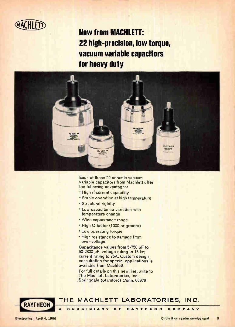
Now from MACHLETT: 22 high-precision, low torque, vacuum variable capacitors for heavy duty
Each of these 22 ceramic vacuum variable capacitors from Machlett offer the following advantages:
• High rf current capability
• Stable operation at high temperature
• Structural rigidity
• Low capacitance variation with temperature change
• Wide capacitance range
• High Q factor (1000 or greater)
• Low operating torque
• High resistance to damage from over-voltage.
Capacitance values from 5-750 pF to 50-2300 pF; voltage rating to 15 kv; current rating to 75A. Custom design consultation for special applications is available from Machlett.
For full details on this new line, write to The Machlett Laboratories, Inc., Springdale (Stamford) Conn. 06879
THE MACHLETT LABORATORIES, INC.
A SUBSIDIARY OF RAYTHEON COMPANY
Electronics April 4, 1966 Circle 9 on reader service card 9
Spit
All from Sprague!
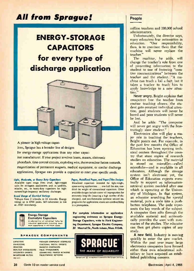
ENERGY-STORAGE
CAPACITORS
for every type of discharge application
"AnGuE
SPRAGUE
SeRRsgE
A pioneer in high voltage capac-
itors, Sprague has a broader line of designs
for energy-storage applications than any other capac-
itor manufacturer. If your project involves lasers, masers, electronic
photoflash, time-control circuits, exploding wire, thermonuclear fusion research,
magnetization of permanent magnets, medical equipment, or similar discharge
applications, Sprague can provide a capacitor to meet your specific needs.
Light, Moderate, or Heavy Duty Capacitors Available types range from small, light-weight units for aerospace applications such as satellites, missiles, etc., to heavy-duty capacitors for high-current/high-frequency oscillatory discharges.
Broad Range of Electrkal Ratings Voltages from 2 kilovolts to 24 kilovolts. Energy ratings up to 6700 joules. Self-inductance as low as .0025 microhenry.
Energy-Storage Electrolytic Capacitors A selected I, nu of cylindrical lytica for industrial applications requiring masti• mum capacitance in minimum spore.
SPRAGUE COMPONENTS
Paper, Metallized Paper, and Papen Film Designs
Metallized capacitors intended for light-weight, space-saving applications . . . one-half the size, one-third the weight of conventional capacitors. Other
available designs include castor oil impregnation for extremely long life (assuring a high number of dis-
charges), and non-flammable synthetic askarel im-pregnat ion for applications where non-combustibility is a prerequisite.
For complete information or application
engineering assistance on Sprague Energy-
Storage Capacitors, write to Field Engineer-
ing Department, Sprague Electric Compart>,
35 Marshall St, North Adams, Mass. 01248.
CAPACITORS
TRANSISTORS
RESISTORS
THIN-FILM MICROCIRCUITS
INTEGRATED CIRCUITS
INTERFERENCE FILTERS
416-15171
PACKAGED COMPONENT ASSEMBLIES
FUNCTIONAL DIGITAL CIRCUITS
MAGNETIC COMPONENTS
PULSE TRANSFORMERS
CERAMIC-BASE PRINTED NETWORKS
PULSE-FORMING NETWORKS
SPRAGUE THE MARK OF RELIABILITY
'Sprague and l. are registered trademarks ot the Sprague Electric Co.
People
million teachers and 100,000 school administrators.
Unfortunately, the director says, many educators fear automation in education. "Our responsibility, then, is to convince them that the machine will never replace the teacher." The machine, he adds, will
change the teacher's role from one of presenting information to the student to one of fostering "crea-tive communications" between the teacher and the student. "A ma-chine can teach a kid a fact, but it takes a teacher to teach him to apply knowledge to a new situa-tion."
Never angry. Bright explains that computers free the teacher from routine teaching chores; the stu-dent gets constant individual atten-tion; good students will never be bored and poor students will never be lost. And he adds: "The computer
will never get angry with the frus-tratingly slow student."
Electronics also will play a ma-jor role in teaching the teachers, Bright points out. For example, in the past few months the Office of Education has been opening tech-nical centers throughout the coun-try that store copies of research studies on education. The material is stored on microfilm—called microfiche—and is available to all educators. Although the storage system isn't electronic yet, the Office of Education expects even-tually to support an information-retrieval system modeled after one which is operating at the Univer-sity of Michigan. In that system, an educator searching for special material, puts a code into a push-button telephone. The code repre-sents the key words of the subject. A computer then sifts through the available material and automati-cally provides the user with sum-maries of the studies. The educator can then get photo copies of any study. A new field. Industry is moving
quickly to enter the new market. Within the past year many large electronics companies have formed either their own educational sub-sidiary or have acquired an estab-lished publishing concern.
10 Circle 10 on reader service card Electronics April 4, 1966
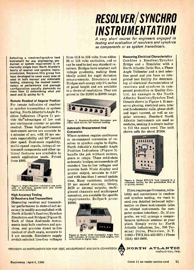
RESOLVER/SYNCHRO INSTRUMENTATION A very short course for engineers engaged in testing and evaluation of resolvers and synchros as components or as system transducers.
Selecting a resolver/synchro test instrument for any engineering, pro-duction or system requirement is re-markably simple from North Atlantic's family of resolver and synchro instru-mentation. Because this group has been developed to cover every area of need in both manual and automatic testing, obtaining the desired combi-nation of performance and package configuration usually demands no more than 1) determining what you need and 2) asking for it.
Remote Readout of Angular Position For remote indication of resolver or synchro transmitters in system testing, North Atlantic's Angle Po-sition Indicators (Figure 1) pro-vide theadvantages of low cost and continuous counter or pointer readout. These high-performance instrument servos are accurate to 4 minutes of arc, with 30 arc sec-onds repeatability and 25°/second slew speed. Dual-mode capability, multi-speed inputs, integral re-transmit components and other op-tional features are available to match application needs. Priced from $895.
'MU
Figure 1. Angle Position Indicators are avail-able in half-rack, quarter-rack and 3-inch round servo packages.
High-Accuracy Testing Of Receivers And Transmitters Measuring receiver and transmit-ter performance to state-of-art ac-curacy is readily accomplished with North Atlantic's Resolver/Synchro Simulators and Bridges (Figure 2). Each of these dual-mode instru-ments tests both resolvers and syn-chros, and provides direct in-line readout of shaft angle, accurate to 2 arc seconds. Simulators supply switch-selected line-line voltages
from 11.8 to 115 volts from either 26 or 115 volts excitation, and so can be used to test any standard re-ceivers. Bridges have constant null voltage gradients, making them ideally suited for rapid deviation measurements. Simulators and Bridges each occupy only 31/2 inches of panel height and are available in a choice of resolutions. They are priced in the $1500 to $3000 range.
• Lalseemii...._
iia a a j - t
- Figure 2. Resolver/Synchro Simulator pro-vides ideal source for receiver testing.
Automatic Measurement And Conversion Where systems require continuous or on-command conversion of re-solver or synchro angles to digits, North Atlantic's Automatic Angle Position Indicators (Figure 3) handle the job without motors, gears or relays. These solid-state automatic bridges accommodate all standard line-to-line voltages and provide both Nixie display and printer output, accurate to 0.01° and with less than 1 second update time. Many variations, including 10 arc second accuracy; binary, BCD or decimal outputs; multi-plexed channels and multispeed operation, are available for specific requirements. Ballpark price: $5900.
Figure 3. Model 5450 Automatic Angle Posi-tion Indicator. It measures shaft angles, con-verts them to digital data.
Measuring Electrical Characteristics Combine a Resolver/Synchro Bridge and a Simulator with a North Atlantic Ratio Box, a Phase Angle Voltmeter and a test selec-tion panel and you have an inte-grated test facility for determin-ing all electrical characteristics of resolvers and synchros in com-ponent production or Quality Con-trol. An example is the North Atlantic Resolver/Synchro Test Console shown in Figure 4. It mea-sures phasing, electrical zero, total and fundamental nulls, phase shift and input current, as well as an-gular accuracy. Standard North Atlantic instruments are used as modules, making it a simple matter to fill the exact need. The unit shown sells for about $7500.
Figure 4. Model RTS-573 Test Console is a complete facility for the production line or in quality control.
If you require performance, relia-bility and convenience in resolver and synchro testing, we want to send you detailed technical infor-mation on these instruments (also on related instruments for com-puter system interface) . Or, if you prefer, we will arrange a compre-hensive technical seminar at your plant. Simply write to: North Atlantic Industries, Inc., 200 Ter-minal Drive, Plainview, N.Y. 11803 • TWX 516-433-9271 • Phone (516) 861-8600.
• PRECISION AC INSTRUMENTATION FOR TEST, MEASUREMENT AND DATA CONVERSION NOFt.'1"1-1 ATT....A.W erZC industries. inc.
Electronics 1April 4, 1966 Circle 11 on reader service card 11
EXPAND lilt line
nsec alL 10
ED
sped.. adissiption
isolation All Radiation integrated circuits are dielectrically isolated.
12 Electronics April 4, 1966

Having procurement problems? Check our delivery time on monolithic DTL circuits!
provides mw
Circuit
Gates Dual 4 Triple 3 Quad 2
RS Flip Flop
Line Driver
Expander
*New high-speed JK Flip Flop soon to be introduced. -Maintained over full temperature range.
Expanded Radiation DTL Line* RD 200 SERIES
Temp. Range —55 to 125°C
Type FOt
210 8 205 8 206 8
208 7
209 12
111
RD 300 SERIES
Temp. Range —55 to 125°C
Type FOt
310 305 306
308
309
111
5 5 5
4
8
RD 500 SERIES
Temp. Range 0 to 75°C
Type FOt
510 505 506
508
509
711
8 8 8
7
12
11›-IC
Why compromise on DTL performance or delivery? Radiation offers immediate shipment of industry's finest line of cir-cuits! Radiation's dielectric isolation tech-nique assures the best combination of speed, power dissipation and noise im-munity.
And Radiation supplies a full line of DTL integrated circuits-17 in all. They include Series 200 and 300, designed for military use, and Series 500 for in-dustrial applications. Compatible fan outs in each series are maintained over the full specified temperature ranges.
Other characteristics include: 7.0 nsec propagation delay (tpd); 250mv "0" out-put voltage (Vsat); and 10.0na "1" input current (lidr).
All circuits are specially engineered to provide superior performance for their specific applications. All are supplied in TO-84 flat packages. Why not keep up to date on the latest
advances in integrated circuits! Write or phone for our data sheets which include worst-case limits, and contain all infor-mation required by design engineers. We'll also send a brochure describing our broad range of engineering and manufac-turing capabilities.
Radiation Incorporated, Physical Elec-tronics, Department EL-04, Melbourne, Florida 32901. Phone: (305) 723-1511, extension 554.
RD 209 Line Driver Speed/Load Characteristics 35
30
25
20
4t,
115
10
5
o
---.4„,
C1 = 1000 pf
Vcc TA
= 5.0v = 25
,_ C
..........C..L..= 5.100 pf
CL = 200 p
C = 100
2 4 6 8 10 12 14 16 18 20
Fan out
RADIATION inicoRPORATEL)
Sales offices: 650 North Sepulveda Blvd.,Suite 622, El Segundo,Calif. (213) 772-6371-600 Old Country Road, Suite 438, Garden City, N. Y. (516) 747-3730
Electronics ;April 4, 1966 Circle 13 on reader service card 13
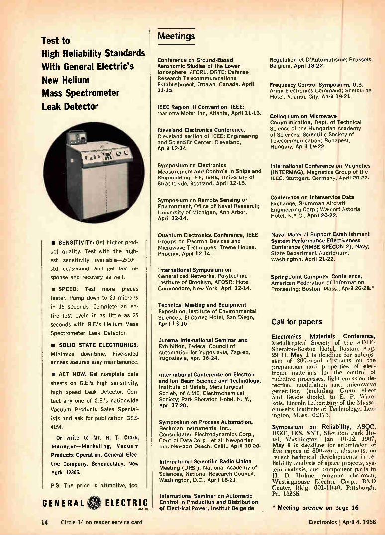
Test to High Reliability Standards
With General Electric's
New Helium
Mass Spectrometer
Leak Detector
II SENSITIVITY: Get higher prod-
uct quality. Test with the high-
est sensitivity available-2x10⁻¹ t
std. cc/second. And get fast re-
sponse and recovery as well.
• SPEED: Test more pieces
faster. Pump down to 20 microns
in 15 seconds. Complete an en-
tire test cycle in as little as 25
seconds with G.E.'s Helium Mass
Spectrometer Leak Detector.
• SOLID STATE ELECTRONICS:
Minimize downtime. Five-sided
access assures easy maintenance.
NI ACT NOW: Get complete data
sheets on G.E.'s high sensitivity,
high speed Leak Detector. Con-
tact any one of G.E.'s nationwide
Vacuum Products Sales Special-
ists and ask for publication GEZ-
4154.
Or write to Mr. R. T. Clark,
Manager—Marketing, Vacuum
Products Operation, General Elec-
tric Company, Schenectady, New
York 12305.
P.S. The price is attractive, too.
GENERAL
Meetings
Conference on Ground-Based Aeronomic Studies of the Lower Ionosphere, AFCRL, DRTE; Defense Research Telecommunications Establishment, Ottawa, Canada, April 11-15.
IEEE Region III Convention, IEEE; Mariotta Motor Inn, Atlanta, April 11-13.
Cleveland Electronics Conference, Cleveland section of IEEE; Engineering and Scientific Center, Cleveland, April 12-14.
Symposium on Electronics Measurement and Controls in Ships and Shipbuilding, IEE, IERE; University of Strathclyde, Scotland, April 12-15.
Symposium on Remote Sensing of Environment, Office of Naval Research; University of Michigan, Ann Arbor, April 12-14.
Quantum Electronics Conference, IEEE Groups on Electron Devices and Microwave Techniques; Towne House, Phoenix, April 12-14.
'iternational Symposium on Generalized Networks, Polytechnic I istitute of Brooklyn, AFOSR; Hotel Commodore, New York, April 12-14.
Technical Meeting and Equipment Exposition, Institute of Environmental Sciences; El Cortez Hotel, San Diego, April 13-15.
urema International Seminar and Exhibition, Federal Council of Automation for Yugoslavia; Zagreb, Yugoslavia, Apr. 16-24.
International Conference on Electron and Ion Beam Science and Technology, Institute of Metals, Metallurgical Society of AIME, Electrochemical Society; Park Sheraton Hotel, N. Y., Apr. 17-20.
Symposium on Process Automation, Beckman Instruments, Inc., Consolidated Electrodynamics Corp., Control Data Corp., et al: Newporter Inn, Newport Beach, Calif., April 18-20.
International Scientific Radio Union Meeting (URSI), National Academy of Sciences, National Research Council; Washington, D.C., April 18-21.
International Seminar on Automatic Control in Production and Distribution of Electrical Power, Institut Belge de
Regulation et D'Automatisme; Brussels, Belgium, April 18-22.
Frequency Control Symposium, U.S. Army Electronics Command; Shelburne Hotel, Atlantic City, April 19-21.
Colloquium on Microwave Communication, Dept. of Technical Science of the Hungarian Academy of Sciences, Scientific Society of Telecommunication; Budapest, Hungary, April 19-22.
International Conference on Magnetics (INTERMAG), Magnetics Group of the IEEE, Stuttgart, Germany, April 20-22.
Conference on lnterservice Data Exchange, Grumman Aircraft Engineering Corp.; Waldorf Astoria Hotel, N.Y.C., April 20-22.
Naval Material Support Establishment System Performance Effectiveness Conference (NMSE SPECON 2), Navy; State Department Auditorium, Washington, April 21-22.
Spring Joint Computer Conference, American Federation of Information Processing; Boston, Mass., April 26-28.*
Call for papers
Electronics Materials Conference, Metallurgical Society of the AIME; Sheraton-Boston Hotel, Boston, Aug. 29-31. May 1 is deadline for submis-sion of :300-word abstracts on the preparation and properties of elec-tronic materials for the control of radiative processes, light-emission de-tection, modulation and microwave generation (including Gunn effect and Reade diode), to E. P. Ware-kois, Lincoln Laboratory of the Massa-chusetts Institute of Technology, Lex-ington, Mass. 02173.
Symposium on Reliability, ASQC, IEEE, IES, SNT; Sheraton Park ¡In-tel, Washington, Jan. 10-12. 1967, May 6 is deadline for submission of five copies of 800-word abstracts, on recent technical developments in re-liability analysis of space projects, sys-tem analysis, and component parts to H. D. bulme, program chairman, Westinghouse Electric Corp., R&D Center, Bldg. 601-1B46, Pittsburgh, Pa. 15235.
* Meeting preview on page 16
14 Circle 14 on reader service card Electronics ; April 4, 1966
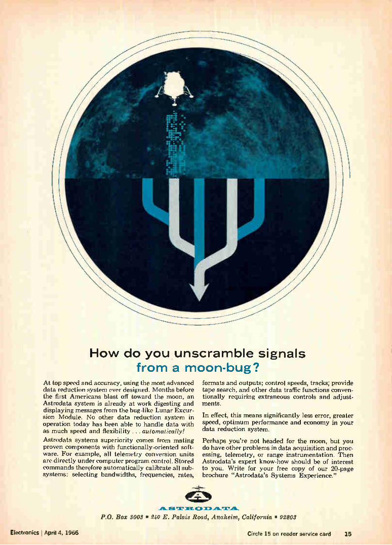
How do you unscramble signals from a moon-bug?
At top speed and accuracy, using the most advanced data reduction system ever designed. Months before the first Americans blast off toward the moon, an Astrodata system is already at work digesting and displaying messages from the bug-like Lunar Excur-sion Module. No other data reduction system in operation today has been able to handle data with as much speed and flexibility. .. automatically!
Astrodata systems superiority comes from mating proven components with functionally-oriented soft-ware. For example, all telemetry conversion units are directly under computer program control. Stored commands therefore automatically calibrate all sub-systems: selecting bandwidths, frequencies, rates,
formats and outputs; control speeds, tracks; provide tape search, and other data traffic functions conven-tionally requiring extraneous controls and adjust-ments.
In effect, this means significantly less error, greater speed, optimum performance and economy in your data reduction system.
Perhaps you're not headed for the moon, but you do have other problems in data acquisition and proc-essing, telemetry, or range instrumentation. Then Astrodata's expert know-how should be of interest to you. Write for your free copy of our 20-page brochure "Astrodata's Systems Experience."
Electronics I April 4, 1966
P.O. Box 3003 • 240 E. Palais Road, Anaheim, California • 92803
Circle 15 on reader service card 15
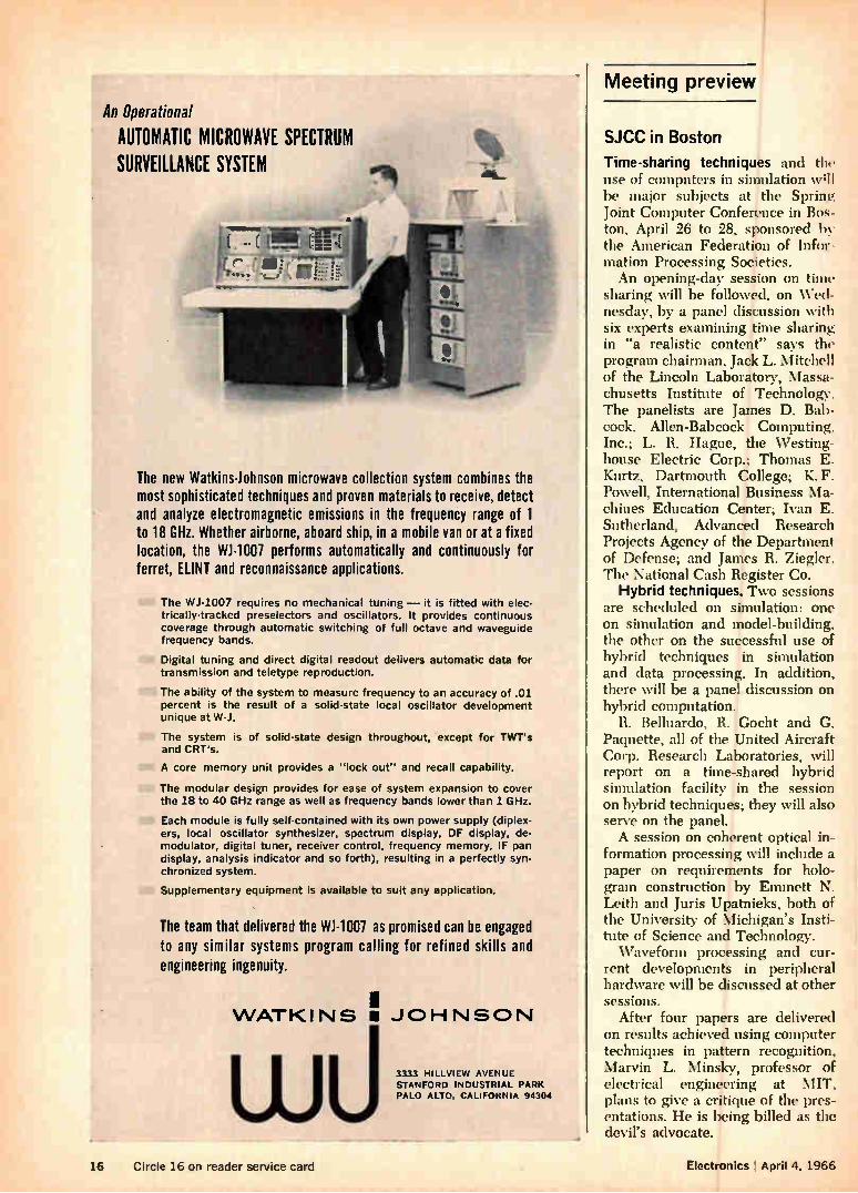
Meeting preview An Operational
AUTOMATIC MICROWAVE SPECTRUM SURVEILLANCE SYSTEM
The new Watkins-Johnson microwave collection system combines the most sophisticated techniques and proven materials to receive, detect and analyze electromagnetic emissions in the frequency range of 1 to 18 GHz. Whether airborne, aboard ship, in a mobile van or at a fixed location, the WJ-1007 performs automatically and continuously for ferret, [LINT and reconnaissance applications.
The WJ-1007 requires no mechanical tuning — it is fitted with elec-trically-tracked preselectors and oscillators. It provides continuous coverage through automatic switching of full octave and waveguide frequency bands.
Digital tuning and direct digital readout delivers automatic data for transmission and teletype reproduction.
The ability of the system to measure frequency to an accuracy of .01 percent is the result of a solid-state local oscillator development unique at W-J.
The system is of solid-state design throughout, except for TWT's and CRT's.
A core memory unit provides a "lock out" and recall capability.
The modular design provides for ease of system expansion to cover the 18 to 40 GHz range as well as frequency bands lower than 1 GHz.
Each module is fully self-contained with its own power supply (diplex-ers, local oscillator synthesizer, spectrum display, DF display, de-modulator, digital tuner, receiver control, frequency memory, IF pan display, analysis indicator and so forth), resulting in a perfectly syn-chronized system.
Supplementary equipment is available to suit any application.
The team that delivered the W1-1007 as promised can be engaged to any similar systems program calling for refined skills and engineering ingenuity.
VVATKINS • JOHNSON
3333 HILLVIEW AVENUE
STANFORD INDUSTRIAL PARK PALO ALTO, CALIFORNIA 94304
.4
SJCC in Boston
Time-sharing techniques and the use of computers in simulation wql be major subjects at the Spring Joint Computer Conference in Bos-ton, April 26 to 28, sponsored by the American Federation of Infor-mation Processing Societies. An opening-day session on time
sharing will be followed, on Wed-nesday, by a panel discussion with six experts examining time sharing in "a realistic content" says the program chairman, Jack L. Mitchell of the Lincoln Laboratory, Massa-chusetts Institute of Technology. The panelists are James D. Bab-cock, Allen-Babcock Computing. Inc.; L. R. Hague, the Westing-house Electric Corp.; Thomas E. Kurtz, Dartmouth College; K. F. Powell, International Business Ma-chines Education Center; Ivan E. Sutherland, Advanced Research Projects Agency of the Department of Defense; and James R. Ziegler. The National Cash Register Co.
Hybrid techniques. Two sessions are scheduled on simulation: one on simulation and model-building, the other on the successful use of hybrid techniques in simulation and data processing. In addition, there will be a panel discussion on hybrid computation.
R. Belluardo, R. Gocht and G. Paquette, all of the United Aircraft Corp. Research Laboratories, will report on a time-shared hybrid simulation facility in the session on hybrid techniques; they will also serve on the panel. A session on coherent optical in-
formation processing will include a paper on requirements for holo-gram construction by Emmett N. Leith and Juris Upatnieks, both of the University of Michigan's Insti-tute of Science and Technology. Waveform processing and cur-
rent developments in peripheral hardware will be discussed at other sessions.
After four papers are delivered on results achieved using computer techniques in pattern recognition, Marvin L. Minsky, professor of electrical engineering at MIT, plans to give a critique of the pres-entations. He is being billed as the devil's advocate.
16 Circle 16 on reader service card Electronics April 4, 1966
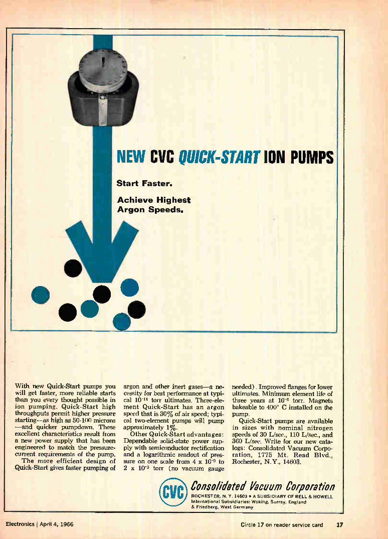
With new Quick-Start pumps you will get faster, more reliable starts than you every thought possible in ion pumping. Quick-Start high throughputs permit higher pressure starting—as high as 50-100 microns —and quicker pumpdown. These excellent characteristics result from a new power supply that has been engineered to match the pressure-current requirements of the pump. The more efficient design of
Quick-Start gives faster pumping of
NEW ClIC QUICK-START ION PUMPS Start Faster.
Achieve Highest Argon Speeds.
argon and other inert gases—a ne-cessity for best performance at typi-cal 10-" torr ultimates. Three-ele-ment Quick-Start has an argon speed that is 30% of air speed; typi-cal two-element pumps will pump approximately 1%. Other Quick-Start advantages:
Dependable solid-state power sup-ply with semiconductor rectification and a logarithmic readout of pres-sure on one scale from 4 x 10⁻⁹ to 2 x 10⁻⁵ torr (no vacuum gauge
needed) . Improved flanges for lower ultimates. Minimum element life of three years at 10-6 torr. Magnets bakeable to 400° C installed on the pump.
Quick-Start pumps are available in sizes with nominal nitrogen speeds of 30 L/sec., 110 L/sec., and 360 L/sec. Write for our new cata-logs: Consolidated Vacuum Corpo-ration, 1775 Mt. Read Blvd., Rochester, N.Y., 14603.
Consolidated Vacuum Corporation ROCHESTER, N. Y. 14603 • A SUBSIDIARY OF BELL & HOWELL International Subsidiaries: Woking, Surrey, England & Friedberg, West Germany
Electronics April 4, 1966 Circle 17 on reader service card 17
New Tektronix Automatic Oscilloscope System SEEKS and presents a measurable display
New Type 385 Time Base Unit Makes Automatic Operation Possible The Tektronix Automatic Oscilloscope System, with the new Type 3B5 Automatic/ Programmable Time Base Unit, now makes DC-to-15 MHz measurements faster and simpler than ever before.
The automatic system package includes the Type 365, the companion Type 3A5 Automatic/Programmable Amplifier Plug-in Unit, a P6030 Probe and a Type 561A, RM561A, 564 or RM564 oscilloscope.
Upon SEEK command, the oscilloscope automatically presents an optimum dis-
play. The SEEK command to the plug-in units automatically controls the time and
amplitude settings, eliminating the need
for continuous front-panel adjustments.
Indicators on the plug-ins light automati-
cally to show these settings. Measurements
can then be made quickly and accurately
from the CRT display.
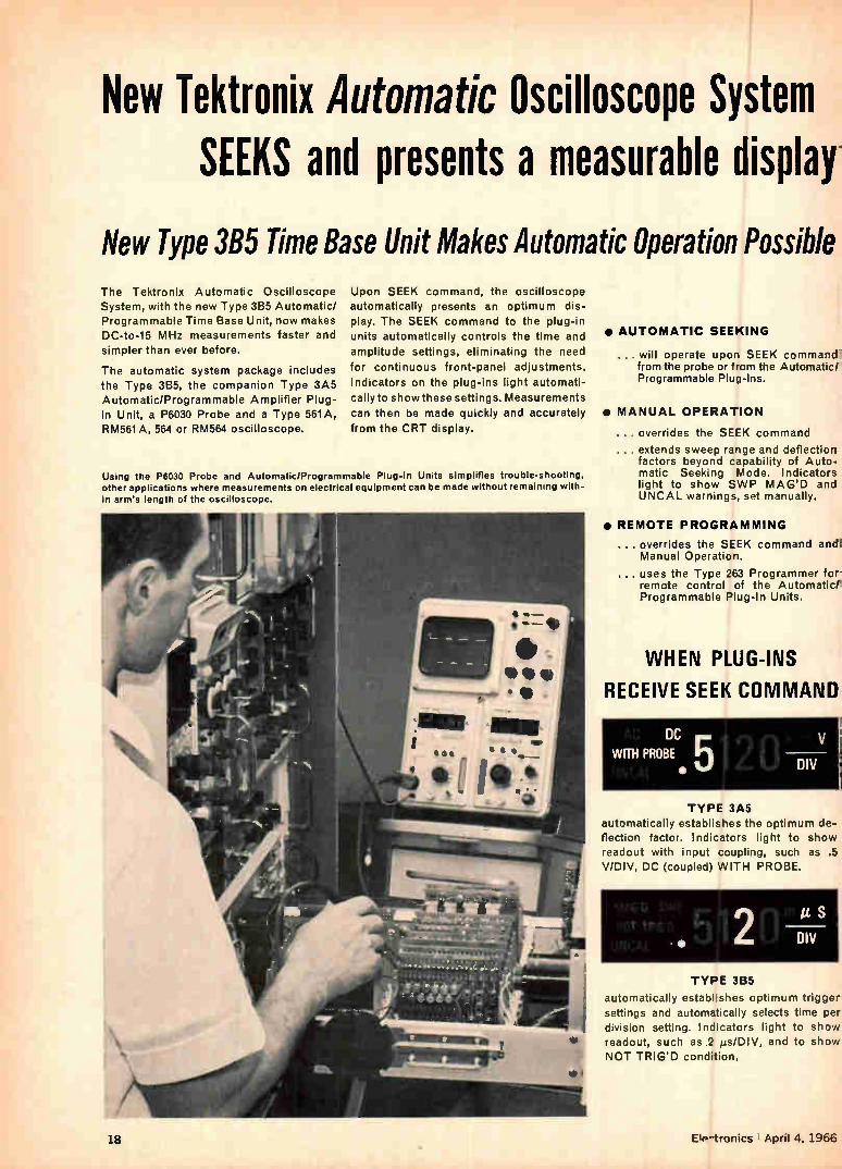
Using the P6030 Probe and Automatic/Programmable Plug-In Units simplifies trouble-shooting, other applications where measurements on electrical equipment can be made without remaining with-in arm's length of the oscilloscope.
• AUTOMATIC SEEKING
... will operate upon SEEK command from the probe or from the Automatic/ Programmable Plug-Ins.
• MANUAL OPERATION
... overrides the SEEK command
... extends sweep range and deflection factors beyond capability of Auto-matic Seeking Mode. Indicators light to show SWP MAG'D and UNCAL warnings, set manually.
• REMOTE PROGRAMMING
... overrides the SEEK command andl Manual Operation.
uses the Type 263 Programmer for remote control of the Automatic!: Programmable Plug-In Units.
WHEN PLUG-INS
RECEIVE SEEK COMMAND
DC WITH PROBE • r irl r t, V
Li DIV
TYPE 3A5 automatically establishes the optimum de-flection factor. Indicators light to show readout with input coupling, such as .5 V/DIV, DC (coupled) WITH PROBE.
• • 2 DIV TYPE 3B5
automatically establishes optimum trigger. settings and automatically selects time per division setting. Indicators light to show readout, such as .2 µs/DIV, and to show NOT TRIG'D condition.
18 EIP-tronics ' April 4, 1966
Add a Type 263 Programmer and Speed Up Sequential Measurements
TYPE 3A5
Operating Modes: SEEK, Manual, and External.
Deflection Factor: 10 mV/div to 50 V/div in SEEK and External Modes. 1 mV/div to 50 V/div in Manual Mode.
Bandwidth: DC-to->15 MHz, from 10 mV/div ,to 50 V/div. 5 MHz at 1, 2, or 5 mV/div, in Manual Mode only.
Risetime: <23 ns at a deflection factor of 10 mV/div to 50 V/div.
Input RC:1 megohm by í 24 pF.
Programmable Functions: V/div, 10X probe attenuation, and AC, DC or AC stabilized coupling, by contact closure to ground. Vertical positioning by analog current.
P6030 Probe supplied with Type 3A5 —has SEEK COMMAND button and 6 ft. cable. Type 3A5 Automatic Programmable
Amplifier Unit $760
TYPE 3135
Operating Modes: SEEK, manual, and External.
Sweep Range: 5 s/div to 0.1 µs/dIv in SEEK Mode.
5 s/div to 10 ns/div in Manual and External Modes.
Delayed Sweep Magnifier: X10 or X100. A calibrated delay control selects starting point of the magnified sweep, allows view-ing of both the normal sweep (before start of the magnified sweep) and the delayed magnified sweep. With the magnifier op-erative, readout is automatically corrected to indicate the setting and SWP MAG'D condition.
Trigger Modes: Internal, either AC-coupled or AUTO (combined level-seeking and bright-line Automatic); External, either AC-coupled or DC-coupled.
Programmable Functions: Time/div, magnifier range, trigger mode with cou-pling, and trigger slope, by contact closure to ground. Horizontal positioning, trigger level, and magnifier delay, by analog cur. rent.
Type 3B5 Automatic/Programmable Time-Base Unit $890
• Remote Program Feature in the Auto-matic Oscilloscope System permits the instrument to be externally preset for a given measurement. With selection of elev-en different programmable functions from Automatic/Programmable Plug-Ins, the combination offers new convenience for applications involving many measure-ments, as in production-line testing and systems checkouts, and also simplifies "away-from-the-oscilloscope" tests, where manual manipulation of the front-panel controls would be inconvenient.
• Plug-In Type Program Card Feature The Type 263 accepts up to six plug-In
type program cards, each of which can be programmed for a specific measurement. Each program card, after initial set-up, establishes the plug-in control functions required for a particular test or measure-
ment. Programming each card can be done simply by changing jumper wires and po-tentiometer settings. Any number of pro-grammers can be cascaded for applica-tions requiring pushbutton control of more than six measurement set-ups.
Once set up, the programs on the Auto-matic Oscilloscope System can be carried out by non-technical personnel with little or no training, since the instrument set-tings are all pre-selected. Actual measure-ments can be made conveniently from the CRT display, as usual.
Type 263 Programmer $325 (complete with 6 program cards)
(Size: 5/' 2" by Ws" by 9";
Weight: 7-k;.5 lbs.)
U.S. Sales Prices, fob. Beaverton, Oregon
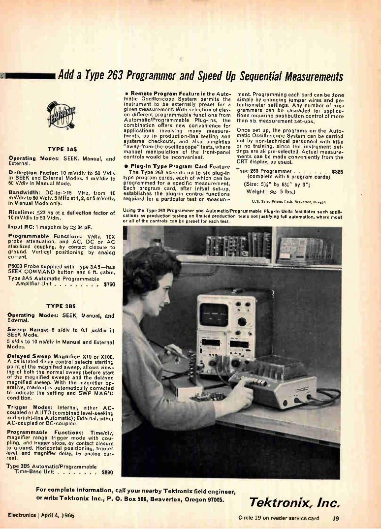
Using the Type 283 Programmer and Automatic/Programmable Plug-In Units facilitates such appli-cations as production testing on limited production items not justifying full automation, where most or all of the controls can be preset for each test.
For complete information, call your nearby Tektronix field engineer,
or write Tektronix Inc., P. O. Box 500, Beaverton, Oregon 97005. Tektronix, Inc. Electronics I April 4, 1966 Circle 19 on reader service card 19
FOUR SPECIALISTS (and what they can do for you)
These four high power Nu-Base germanium transistors were created to relieve some special problems where reliable peak pow-er handling is a requirement. Each is in a class by itself with special benefits for ignition, TV horizontal sweep circuits and high power audio output (tentative speci-fications are provided).
These are rugged, durable transistors with built-in protection against secondary breakdown (thanks to Delco's Hydrokinetic Alloy process). Extreme parameter stability is a result of our Surface Passivation and Ambient Control (SPAC).
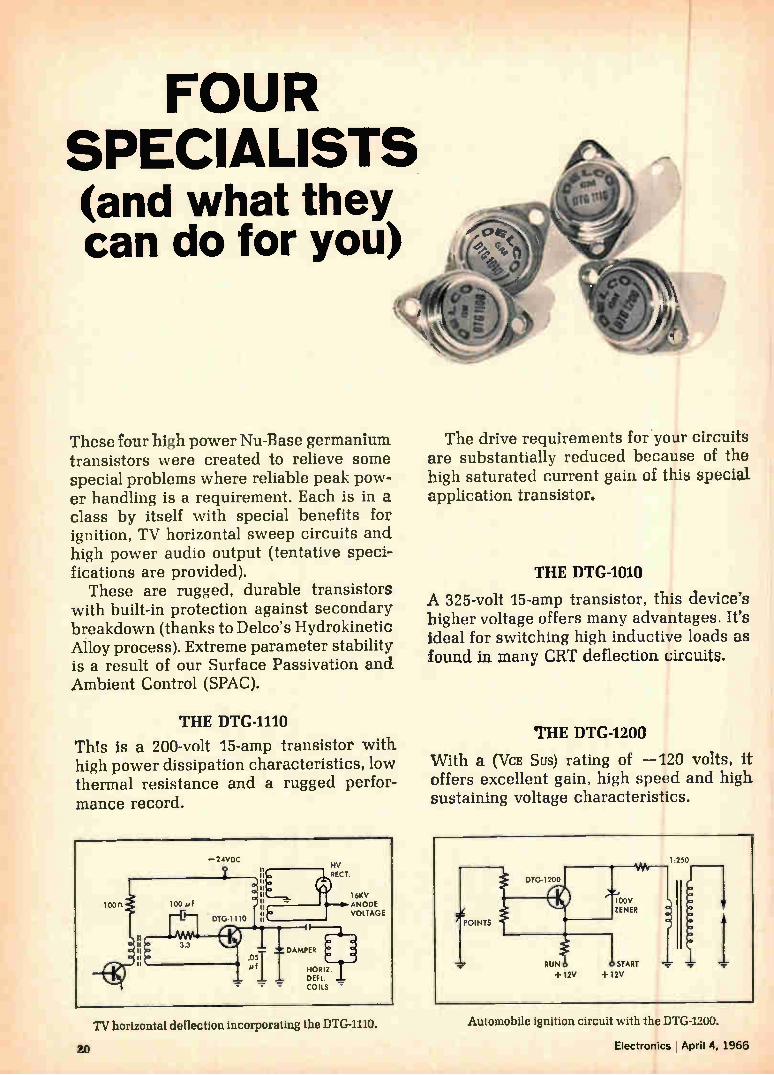
THE DTG-1110
This is a 200-volt 15-amp transistor with high power dissipation characteristics, low thermal resistance and a rugged perfor-mance record.
The drive requirements for your circuits are substantially reduced because of the high saturated current gain of this special application transistor.
THE DTG-1010
A 325-volt 15-amp transistor, this device's higher voltage offers many advantages. It's ideal for switching high inductive loads as found in many CRT deflection circuits.
THE DTG-1200
With a (VcE Sus) rating of —120 volts, it offers excellent gain, high speed and high sustaining voltage characteristics.
TV horizontal deflection incorporating the DTG-1110.
20
Automobile ignition circuit with the DTG-1200.
Electronics lApril 4, 1966
•
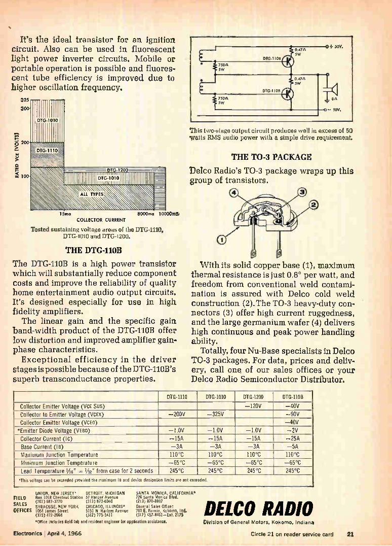
It's the ideal transistor for an ignition circuit. Also can be used in fluorescent light power inverter circuits. Mobile or portable operation is possible and fluores-cent tube efficiency is improved due to higher oscillation frequency.
325
300-
200
o
L00
15ma
COLLECTOR CURRENT
Tested sustaining voltage areas of the DTG-1110, DTG-1010 and DTG-1200.
THE DTG-110B
The DTG-110B is a high power transistor which will substantially reduce component costs and improve the reliability of quality home entertainment audio output circuits. It's designed especially for use in high fidelity amplifiers. The linear gain and the specific gain
band-width product of the DTG-110B offer low distortion and improved amplifier gain-phase characteristics. Exceptional efficiency in the driver
stages is possible because of the DTG-LIOB's superb transconductance properties.
This two-stage output circuit produces well in excess of 50 'watts RMS audio power with a simple drive requirement.
THE TO-3 PACKAGE
Delco Radio's TO-3 package wraps up this group of transistors.
With its solid copper base (1), maximum thermal resistance is just 0.8° per watt, and freedom from conventional weld contami-nation is assured with Delco cold weld construction (2). The TO-3 heavy-duty con-nectors (3) offer high current ruggedness, and the large germanium wafer (4) delivers high continuous and peak power handling ability.
Totally, four Nu-Base specialists in Delco TO-3 packages. For data, prices and deliv-ery, call one, of our sales offices or your Delco Radio Semiconductor Distributor.
DTG-1110 DTG-1010 DTG-1200 DTG-110B
Collector Emitter Voltage (VcE Sus) —120V —40V
Collector to Emitter Voltage (VcEx) —200V —325V —90V
Collector Emitter Voltage (VcEo) —40V
*Emitter Diode Voltage (VEBO) —1.0V —1.0V —1.0V —2V
Collector Current (lc) —15A —15A —15A —25A
Base Current (IB) —3A —3A —3A —5A
Maximum Junction Temperature 110°C 110°C 110°C 110°C
Minimum Junction Temperature —65°C —65°C —65°C —65°C
Lead Temperature '/16" 1- 1/2 2" from case for 2 seconds 245°C 245°C 245°C 245°C
'This voltage can be exceeded provided the maximum 111 and device dissipation limits are not exceeded.
SALES SYRACUSE, NEW YORK CHICAGO, ILLINOIS'
OFFICES 1054 lames Street 5151 N. Harlem Avenue (315) 472-2668 (312) 775-5411
UNION, NEW JERSEY'« DETROIT, MICHIGAN FIELD Box 1018 Chestnut Station 57 Harper Avenue
(201) 687.3770 (313) 873-6560
SANTA MONICA, CALIFORNIA. 726 Santa Monica Blvd. (213) 870-8807 General Sales Office: 700 E. Emir', Kokomo, Ind. (317) 457-8461—Ext. 2175 DELCO RADIO
*Office includes field lab and resident engineer tot application assistance.
Electronics I April 4, 1966
Division of General Motors, Kokomo, Indiana
Circle 21 on reader service card 21
MODULES
6 BRAND NEW PROGRAMMABLE SUPPLIES
OFFER MORE PRECISE REGULATION
GREATER POWER AND HIGHER
OPERATING TEMPERATURES
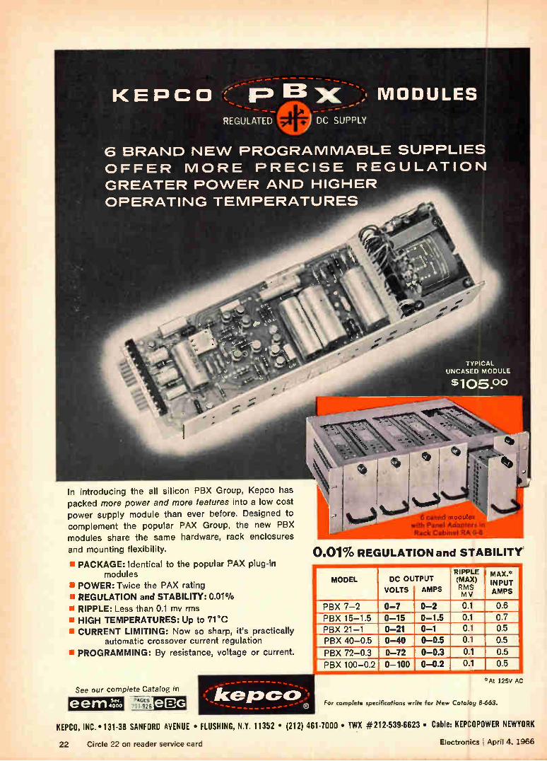
In introducing the all silicon PBX Group, Kepco has packed more power and more features into a low cost
power supply module than ever before. Designed to
complement the popular PAX Group, the new PBX
modules share the same hardware, rack enclosures
and mounting flexibility.
• PACKAGE: Identical to the popular PAX plug-in modules
• POWER: Twice the PAX rating
• REGULATION and STABILITY: 0.01%
• RIPPLE: Less than 0.1 mv rms
• HIGH TEMPERATURES: Up to 71 °C • CURRENT LIMITING: Now so sharp, it's practically
automatic crossover current regulation
PROGRAMMING: By resistance, voltage or current.
See our complete Catalog in
eem 4,e1 PAGES
791826
-------------' kerocco:,
TYPICAL UNCASED MODULE
$105.00
6 cased modules with Panel Adapter; in Rack Cabinet RA G-6
0.01% REGULATION and STABILITY
MODEL DC OUTPUT
VOLTS AMPS
RIPPLE (MAX) RMS M V
MAL*
IN PUT AMPS
PBX 7-2 0-7 0-2 0.1 0.6
PBX 15-1.5 0-15 0-1.5 0.1 0.7
PBX 21-1 0-21 0-1 0.1 0.5
PBX 40-0.5 0-40 0-0.5 0.1 0.5
PBX 72-0.3 0-72 0-0.3 0.1 0.5
PBX 100-0.2 0-100 0-0.2 0.1 0.5
'› At 125V AC
For complete specifications write for New Catalog 6-663.
KEPCO, INC. • 131-38 SANFORD AVENUE • FLUSHING, N.Y. 11352 • (212) 461-7000 • TWX #212-539-6623 • Cable: KEPCOPOWER NEWYORK
22 Circle 22 on reader service card Electronics April 4, 1966
Electronics
Editorial
Playing both sides of the street Now that it's clear that integrated circuits are moving into industrial, commercial and con-sumer equipment far faster than anybody ex-pected a couple of years ago, makers of instru-ments, subassemblies and systems are seriously pondering whether they should make their own integrated circuits or buy them—a question that has been nagging equipment people almost since the IC was born. The way they answer this question will affect almost everybody in the elec-tronics industry. It will determine where a lot of the engineering will be done—at the equipment maker's or semiconductor producer's plants— and what technical direction many companies will take. Makers of integrated circuits are quick to
point out that there are large-scale economies to be reaped if equipment makers buy off-the-shelf IC's from a semiconductor specialist. The customers also receive, the argument continues, the advantage of the best and latest technology, because a specialist in semiconductors is the man who has to keep pace with fast-moving technology, who must keep abreast of the tech-nology or drop out of the business. David Packard, president of the Hewlett-Pack-
ard Co., the large instrument, microwave and medical equipment producer, concedes there is an economic advantage to buying off-the-shelf integrated circuits, but he feels that is only one part of the picture. He says, "If you design around available circuits, you get some cost ad-vantages, but the equipment is limited. To im-prove the equipment design, we have to design our own circuits."
That's why Hewlett-Packard is setting up in-tegrated-circuit production facilities at three separate divisions, and why Packard says that soon every H-P division will have its own inte-grated-circuit manufacturing facility. The IC fa-cility at H-P's Frequency and Time division in Palo Alto, Calif., is already in operation and one at the company's Dymec division nearby is al-
April 4, 1966
most ready. Space has been cleared for an IC facility at the company's Loveland (Colorado) division and development work should start there next month. Packard has concluded that the technology of
designing with IC's differs so radically from that of designing with discrete components that the IC shop has to be near the engineers. "Maybe you can design computers whose circuits are repetitious and whose logic design is often more important than the hardware without a micro-circuit capability," he says. "But you can't de-sign sophisticated instruments without your own integrated facilities." He adds, "If you go to a store and buy a lot
of parts which we then assemble, anybody else can go to the same store, buy the same parts and produce the same thing. If we have depth, do our own design and engineering, then we can make products that other people cannot make." With its many IC facilities, H-P expects to
develop both monolithic and hybrid circuits as well as digital and linear circuits. In his busi-ness Packard believes that monolithic techniques lend themselves better to digital circuitry, and many of the applications in instrument and mi-crowave fields are better done with linear cir-cuits. For example, hybrid techniques will be applied to one of the first projects that the Love-land facility will tackle: an integrated-circuit sampling probe, which is a diode gate—and some linear circuitry—that's turned on and off at a rapid rate by a pulse generator. Though Hewlett-Packard's chief reason for set-
ting up its own facilities is to retain design initia-tive, there is another important consideration. The company has contracts for design projects with three separate integrated-circuit suppliers, and every single project has been delayed, falling way behind schedule. Packard says sadly, "We've had difficulty getting what we want from outside suppliers. They are so busy filling orders from the computer makers they don't have time for us. Our volume could never match that needed by a computer maker so we take a back seat." At least a handful of other equipment sup-
pliers feel as David Packard does about inte-grated-circuit facilities. In Boston, both the Digital Equipment Corp. and the Computer Control Corp. have set up their own IC facilities. The latter has a policy that might well become the pattern for the electronics industry. It has set up a model shop that builds pilot quantities of newly designed circuits, then turns over the designs to an outside contractor for production runs. "That kind of capability," comments Pack-ard, "lets you play both sides of the street."
23

Will this new
General Purpose P&B relay make
our best seller obsolete?
Never?
Never!
Our new KU relay is quite excep-tional. For many relay users, it will be more convenient, more versa-tile, easier to install and replace . . . and cost substantially less money. Here's why.
MODERN, COST SAVING TERMINALS
Quick-connect terminals mean faster installation on your produc-tion line . . . easier replacement in the field. Standard models have .187" terminals, but .205" may be ordered. All terminals are punched for those who prefer solder connections. Barriers molded into the sturdy front meet U/L and CSA requirements.
TRUE 10 AMP NYLON SOCKET
A nylon socket— rated for carrying r-10-amperes—can be supplied to make the KU a handy plug-in relay. Covered (KUP) relays, incidentally, cost
dramatically less than similar re-lays having octal-type plugs.
You may specify five- or ten-ampere KU relays. Longer movable arms and a unique method of staking the stationary contacts to the header contribute to the improved reliabil-ity and longer life of this new series.
WIDE CHOICE OF FEATURES
Two styles of heat and shock resis-tant polycarbonate dust covers are available. One, with slotted flanges, provides a quick, convenient method for mounting the relay directly to a chassis. A handy push-button which op-erates the mov-able contacts can also be supplied for manually checking circuits. KUP relays are
STANDARD PO RELAYS ARE AVAILABLE AT
Well, maybe!
available with a neon lamp wired in parallel with their coils to indi-cate that power is reaching the relays.
Longer life, improved reliability, exceptional versatility and, in the case of covered relays, substan-tially lower costs are all part of the KU Series. Interested? Call your P&B sales representative today, or get in touch with us direct.
KU SERIES SPECIFICATIONS GENERAL: Description: 5 or 10 amperes General Purpose Relay.
Expected Life: 10,000,000 cycles, Mech. Breakdown Voltage: 1,500V rms 60 Hz between all elements; 500V rms 60 Hz between open contacts.
CONTACTS: Arrangements: Up to 3 Form C. Rating: 5 or 10 amps (a 28V DC or 115V AC resistive.
COILS: Voltage: DC to 110V; AC to 230V 80 Hz. Power: DC 1.2 W; AC 1 and 2 poles 2.0 VA;
AC 3 poles 2.7 VA. Resistance: 16,500 ohms max.
MOUNTING: (open relay) 6/ae mtg. stud, 7/32' locating tab on 7/16" centers. Socket available.
LEADING ELECTRONIC PARTS DISTRIBUTORS
POTTER s. BRUMFIELD Division of American Machine & Foundry Company, Princeton, Indiana Export: AMF International, 261 Madison Avenue, New York, N. Y.
24 Circle 24 on reader service card Electronics April 4, 1966
Electronics Newsletter April 4, 1966
Hewlett-Packard
plans to build IC's
at all its divisions
The Hewlett-Packard Co. has decided that it must have its own facilities for the production of integrated circuits. What's more, there must be separate facilities at each of the company's divisions, says David Pack-ard, chairman of the producer of instruments, microwave equipment and medical electronics.
Packard's reason: the coordination between IC makers and equipment designers must be very close, much closer in fact than the coordination between circuit designers and the designers of equipment using discrete components; also, the company has been experiencing delays in getting special circuit orders filled by contractors (see Editorial, page 23).
Color tv recorder The Illinois Institute of Technology's Research Center says it has de-veloped a home color television tape recorder that could sell for between designed to sell $300 and $500. Several companies have home black-and-white recorders
for less than $500 on the market, selling for about $1,000, but no one is offering a home color recorder. The institute's 30-pound recorder has a stationary recording and play-
back head, rather than a rotating head, which is used on typical black-and-white recorders. The quarter-inch tape moves at 120 inches per second; it has a two-megacycle bandwidth. In studio color tv recorders, the effective speed of the tape past the head is 1,000 to 3,600 inches per second. The institute says it is negotiating license agreements with certain
manufacturers; however, it declines to identify them.
Hybrid IC's due
in '66 Philco tv's
Honeywell plans
two acquisitions
This year the Philco Corp. will introduce black-and-white television sets that use hybrid integrated circuits. The disclosure was made following word that the Radio Corp. of America and the Admiral Corp. are intro-ducing sets that use monolithic integrated circuits. Philco, a subsidiary of the Ford Motor Co., is already using thick-film IC's in car radios in the 1967 Ford line. Philco's IC's are made by bonding transistor and capacitor chips to ceramic-based passive circuits. The IC's are being used in tv receivers' horizontal phase comparators.
Philco has stopped producing all-tube color sets. A combination of tubes and transistors makes up the circuits in all its new color tv sets. A spokesman said that the use of IC's in color sets is under study.
Honeywell, Inc., plans two diversification moves: the acquisition of the Computer Control Corp. of Framingham, Mass., a maker of digital com-puters and digital computer equipment, and the purchase of Electro-Instruments, Inc., of San Diego, a producer of digital voltmeters and printers.
Electro-Instruments will probably become Honeywell's test instru-mentation division, filling many gaps in Honeywell's commercial lines.
Three years ago Computer Control moved heavily into the integrated circuit field. During the past year the company introduced a line of monolithic IC logic modules, an all-IC computer and an all-IC core memory. Honeywell has never set up in-house production of integrated circuits.
25
Electronics Newsletter
Gemini 9 to keep
May date in space
A moving thought
Airlines may test
system to bar
midair crashes
Paris eases stand
on U. S. investments
The next Gemini space shot will meet its mid-May schedule despite Gemini 8's brush with disaster. Gemini 9 will dock with a new Agena and possibly also with the Agena that was launched for the Gemini 8 mission. The three-day flight will repeat Gemini 8 mission objectives. In addition, astronaut Eugene A. Crenan will "walk" in space with a rocket-powered backpack. Gemini 8's near-disaster is causing space officials to reevaluate con-
siderations for a space rescue service. Currently, officials of the National Aeronautics and Space Administration say they lack the techniques for space rescue. One major problem: the need for a way to fire a rescue craft into space on a few hours' notice; it now takes weeks of plan-ning before a spaceship can be launched.
Future astronauts may have to think twice before they think because thought impulses may be used to activate systems and machinery. The National Aeronautics and Space Administration has awarded a contract to the Case Institute of Technology to study the possibility of using sensors to pick up a man's electromyographic signals and a computer to translate them into an order for a machine (see page 156).
By the end of the year domestic airlines may flight test a collision-avoid-ance system that would warn a pilot of an impending collision and tell him how to avert it, the Air Transport Association says. Its forecast is based on McDonnell Aircraft Corp.'s announcement that it has been test-ing a collision-avoidance system.
In the McDonnell system, each aircraft would transmit a signal at 1,545 megacycles every two seconds at an assigned two-millisecond period; this would provide 1,000 separate airplane-identification codes. One plane would determine the closing speed with another by measuring the doppler shift of the received signal. A warning would be flashed to a pilot 60 seconds before a possible collision. At 40-seconds-to-collision, the system would direct one pilot to climb and the other to descend. About 60 ground stations throughout the United States may be needed
to provide continual resetting of the "clocks" the planes would carry to maintain the millisecond accuracy of the transmitters.
Others working on similar systems are the Collins Radio Co., Bendix Corp., National Co., Sierra Research Corp. and Control Data Corp. In-stallation of operational units could begin within three years.
United States electronics companies apparently can count on special treatment when they apply for permission to build plants in France. Late last month the de Gaulle government made much ado about the fact that it had taken only two months for Motorola, Inc., to get a go-ahead for its plan to build a $10-million semiconductor plant in Southwest France. Ordinarily, French officials drag their heels for as much as two years when U. S. companies apply for plant-building permits.
All of the "Big Three" U.S. semiconductor producers will be repre-sented in France when Motorola's plant starts up in late 1967 near Toulouse. Texas Instruments Incorporated has a plant near Nice; SGS-Fairchild, an affiliate of Fairchild Camera dc Instrument Corp., has one at Rennes.
26 Electronics I April 4, 1966
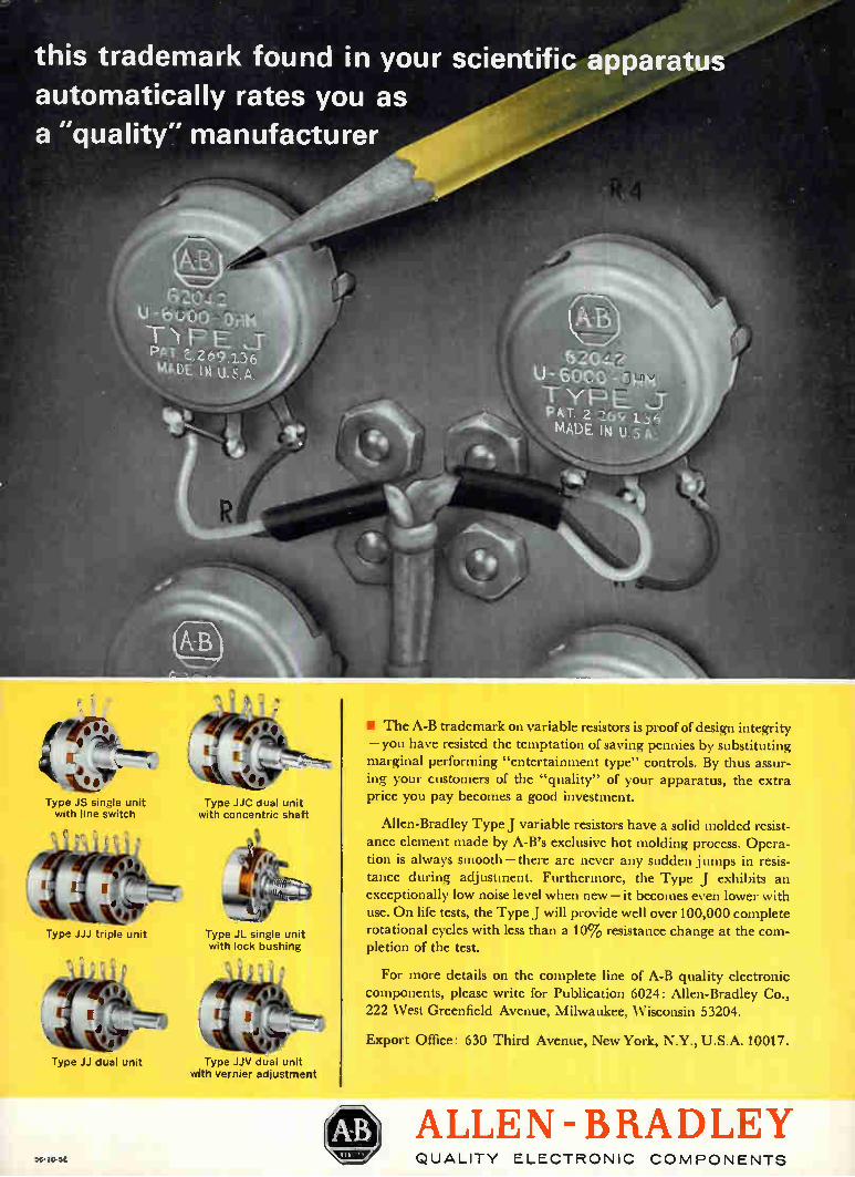
this trademark found in your scientific apparatus automatically rates you as
a "quality" manufacturer
• vjilr Type JS single unit with line switch
lirie eAs,i,»
I
e - t'
Type JJJ triple unit
Type JJ dual unit
Type JJC dual unit with concentric shaft
Type JL single unit with lock bushing
Type JJV dual unit with vernier adjustment
• The A-B trademark on variable resistors is proof of design integrity — you have resisted the temptation of saving pennies by substituting marginal performing "entertainment type" controls. By thus assur-ing your customers of the "quality" of your apparatus, the extra price you pay becomes a good investment.
Allen-Bradley Type J variable resistors have a solid molded resist-ance element made by A-B's exclusive hot molding process. Opera-tion is always smooth — there are never any sudden jumps in resis-tance during adjustment. Furthermore, the Type J exhibits an exceptionally low noise level when new — it becomes even lower with use. On life tests, the Type J will provide well over 100,000 complete rotational cycles with less than a 10% resistance change at the com-pletion of the test.
For more details on the complete line of A-B quality electronic
components, please write for Publication 6024: Allen-Bradley Co., 222 West Greenfield Avenue, Milwaukee, Wisconsin 53204.
Export Office: 630 Third Avenue, New York, N.Y., U.S.A. 10017.
54-10-SE
ALLEN-BRADLEY IV QUALITY ELECTRONIC COMPONENTS
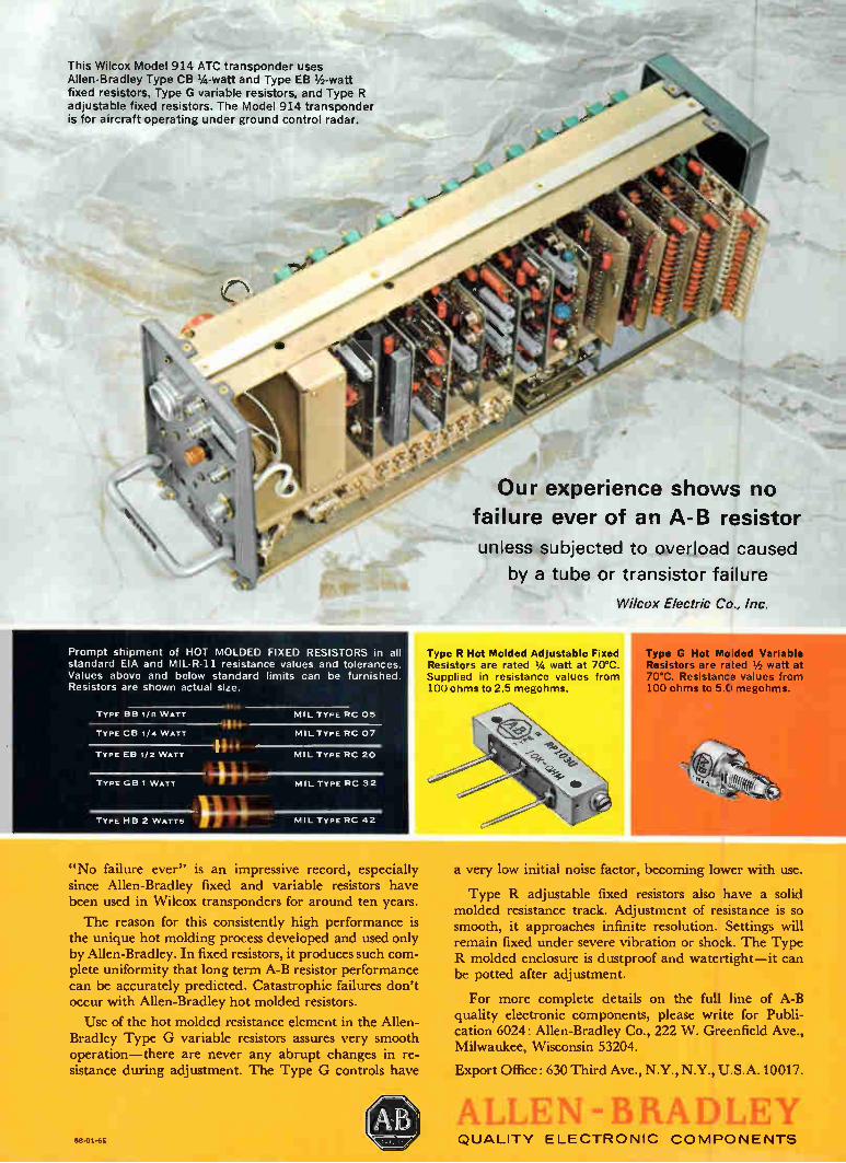
This Wilcox Model 914 ATC transponder uses Allen-Bradley Type CB 1/4 -watt and Type EB 1/2 -watt fixed resistors, Type G variable resistors, and Type R adjustable fixed resistors. The Model 914 transponder is for aircraft operating under ground control radar.
Prompt shipment of HOT MOLDED FIXED RESISTORS in all standard EIA and MIL-R-11 resistance values and tolerances. Values above and below standard limits can be furnished. Resistors are shown actual size.
TYPE BB 1/8 W ATT
TYPE CB 1/4 W ATT
TYPE EB 1/2 W ATT
TY PE GB 1 W ATT
P14* MIL TY PE RC 05
MIL Typ E RC 07
MIL TY PE RC 20
TYPE HB 2 W ATTS )
MIL TY PE RC 32
MIL TYPE RC 42
Our experience shows no failure ever of an A-B resistor
unless subjected to overload caused
by a tube or transistor failure
Wilcox Electric Co., Inc.
Type R Hot Molded Adjustable Fixed Resistors are rated 1/4 watt at 70°C. Supplied in resistance values from 100 ohms to 2.5 megohms.
Type G Hot Molded Variable Resistors are rated 1/2 watt at 70°C. Resistance values from
ohms to 5.0 megohms.
"No failure ever" is an impressive record, especially since Allen-Bradley fixed and variable resistors have been used in Wilcox transponders for around ten years.
The reason for this consistently high performance is the unique hot molding process developed and used only by Allen-Bradley. In fixed resistors, it produces such com-plete uniformity that long term A-B resistor performance can be accurately predicted. Catastrophic failures don't occur with Allen-Bradley hot molded resistors.
Use of the hot molded resistance element in the Allen-Bradley Type G variable resistors assures very smooth operation—there are never any abrupt changes in re-sistance during adjustment. The Type G controls have
a very low initial noise factor, becoming lower with use.
Type R adjustable fixed resistors also have a solid molded resistance track. Adjustment of resistance is so smooth, it approaches infinite resolution. Settings will remain fixed under severe vibration or shock. The Type R molded enclosure is dustproof and watertight—it can be potted after adjustment.
For more complete details on the full line of A-B quality electronic components, please write for Publi-cation 6024: Allen-Bradley Co., 222 W. Greenfield Ave., Milwaukee, Wisconsin 53204.
Export Office: 630 Third Ave., N.Y., N.Y., U.S.A. 10017.
58-01-6E
T EN -13RA ni QUALITY ELECTRONIC COMPONENTS
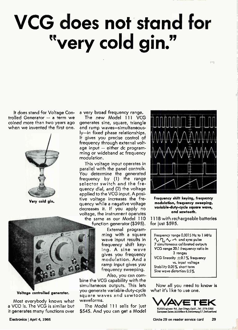
VCG does not stand for "very cold gin."
It does stand for Voltage Con-trolled Generator — a term we coined more than two years ago when we invented the first one.
Very cold gin.
Voltage controlled generator.
Most everybody knows what a VCO is. The VCG is similar but it generates many functions over
a very broad frequency range. The new Model 111 VCG
generates sine, square, triangle and ramp waves—simultaneous-ly—in fixed phase relationships. It gives you precise control of frequency through external volt-age input — either dc program-ming or wideband ac frequency modulation.
This voltage input operates in parallel with the panel controls. You determine the generated frequency by (1) the range selector switch and the fre-quency dial, and (2) the voltage applied to the VCG input. A posi-tive voltage increases the fre-quency while a negative voltage decreases it. If you apply no voltage, the instrument operates
the same as our Model 110 function generator ($395).
External program-ming with a square wave input results in frequency shift key-ing. A sine wave gives you frequency modulation. And a ramp input gives you frequency sweeping.
Also, you can com-bine the VCG capability with the simultaneous outputs. This lets you generate variable-duty-cycle square waves and sawtooth waveforms.
The Model 111 sells for just $545. And you can get a Model
gigr,mgm, I k mum",
Mae Frequency shift keying, frequency modulation, frequency sweeping, variable-duty-cycle square wave,
and sawtooth.
1 1 1 B with rechargeable batteries for just $595.
Frequency range 0.0015 Hz to 1 MHz iNj ri /\, -A- and sync pulse 7 simultaneous calibrated outputs VCG range 20:1 frequency ratio in
3 ranges VCG linearity ±-0.1% frequency
vs. input voltage Stability 0.05% short term Sine wave distortion 0.5%
Now all you need to know is what it's like to use one.
\/\46V.E TE K 8159 Engineer Rd.,San Diego,Calif.,Tel. 279-2200 European Sales:3000 Bern 9,Seidenweg17,Switzerland
Electronics I April 4, 1966 Circle 29 on reader service card 29
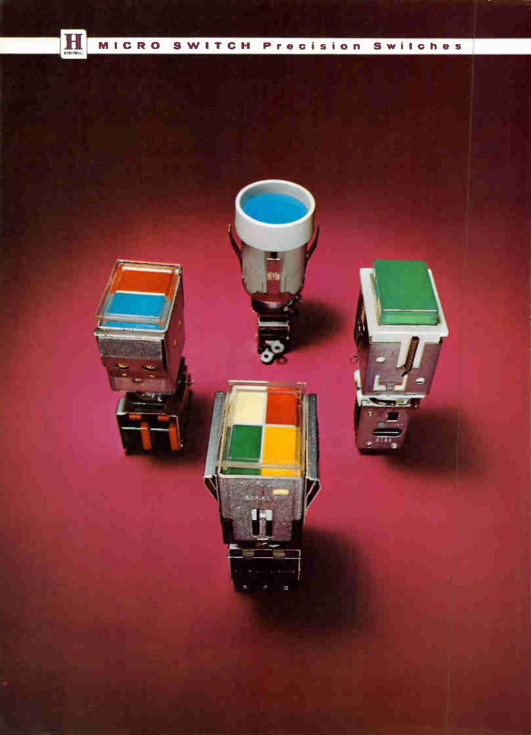
How to make sure you are not in the dark on the latest in Lighted Pushbutton Switches
Take a new look Into the complete line available from MICRO SWITCH. Ever since MICRO SWITCH introduced the first modu-
lar pushbutton switch with lighted legends, the line has been expanding. New modules, new assemblies, new ideas now offer you more opportunities to work out cus-tom answers to today's panel requirements.
In addition to the popular Series 2 which started the modular trend, the line now includes Series 2N and Series 2C200. All three offer unequalled freedom of design—in
sheer number of possible control and display combina-tions—in ease of installation—and in panel appearance. MICRO SWITCH gives you another bonus: application
experience. Our specially trained field engineers will be glad to discuss your requirements. They are backed by the industry's most elaborate research and development facilities.
For information, contact a Branch Office or Distribu-tor (see Yellow Pages, under "Switches, Electric") or write for literature.
MICRO SWITCH—the line providing unequalled freedom of design with all this versatility
EED Series 2 offers both rectangular and round display, permitting shape-coding of stations or group functions. Snap-in mounting. Solenoid pull-in and/or hold-in coil for remote control.
Series 2C200. Snap-in mounting. Relamp without tools. Available with RFI shield, and solenoid pull-in or hold-in coil for re-mote control.
Neu/ NINO
41011101 7
Series 2N. Shock-resistant spring-lock mounting. Hold-in coil. Re-lamp without tools. Molded-color hous-ings.
in BUTTONS—Choice of 1, 2, 3, or 4-section buttons.
in COLOR—Wide selection of transmitted and projected (filtered) color schemes, and 1 to 4 lamps for up to 4-color display.
In CIRCUITRY—Up to 4-pole double-throw and 2-circuit double-break contact arrangements.
in RATINGS—Wide selection of modules for handling low energy to heavy duty electrical loads.
in WIRING—Solder, screw or quick connect wiring ter-minations.
in MOUNTING—Snap-in flange and barrier mountings or spring-lock panel attachment.
in REMOTE CONTROL—Only MICRO SWITCH has both remote actuation and release of switching contacts.
MICRO SWITCH FREEPORT, ILLINOIS 61032
A DIVISION OF HONEYWELL HomywiLLINTERNAnoNAL- Sales and service offices in all principal cities of the world. Manufacturing in United States, United Kingdom, Canada, Netherlands, Germany. France,Japan.
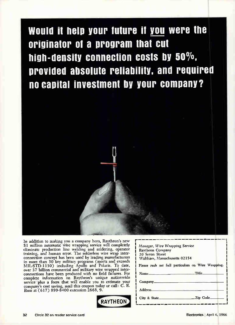
Would it help your future if you were the originator of a program that cut high-density connection costs by 50,5,
provided absolute reliability, and required
no capital investment by your company?
In addition to making you a company hero, Raytheon's new $1 million automatic wire wrapping service will completely eliminate production line welding and soldering, operator training, and human error. The solderless wire wrap inter-connection concept has been used by leading manufacturers in more than 30 key military programs (meets and exceeds MIL-STD-1130) including Apollo and Polaris. To date, over 37 billion commercial and military wire wrapped inter-connections have been produced with no field failures. For complete information on Raytheon's unique nationwide service plus a form that will enable you to estimate your company's cost saving, mail this coupon today or call: C. E. Russ at (617) 899-8400 extension 2668, 9.
Manager, Wire Wrapping Service Raytheon Company 20 Seyon Street Waltham, Massachusetts 02154
Please rush me full particulars on Wire Wrapping.
Name Title
Company
Address
City & State Zip Code
32 Circle 32 on reader service card Electronics April 4. 1966
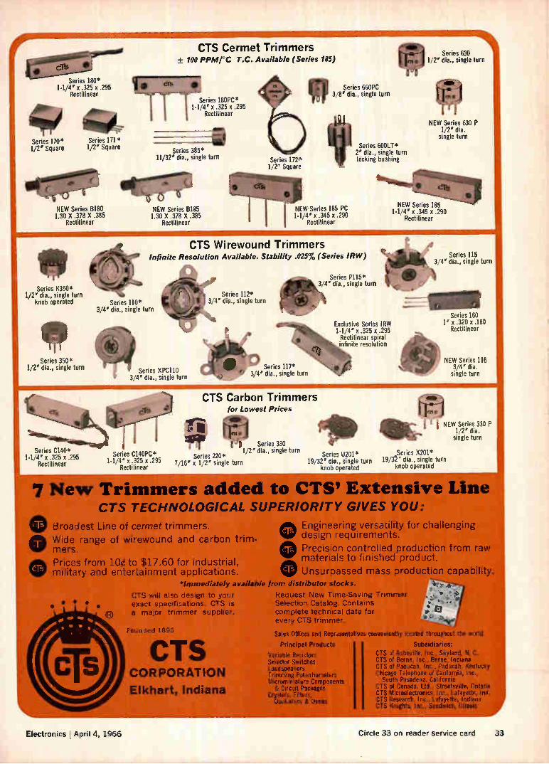
Series 180* 14/4' x .325 x .295
Rectilinear
Series 170* 1/2' Square
CTS Cermet Trimmers ± 100 PPM/°C T.C. Available (Series 185)
Series 180PC* 1-1/4R'eji2ne5 xar .295
Series 171* 1/2' Square Series 385*
11/32' dia., single turn
«le ilem NEW Series B180 NEW Series 8185 1.30 X .378 X .385 1.30 X .378 X .385
Rectilinear Rectilinear
Series 172* 1/2" Square
Irp Series 660PC 3/8' dia., single turn
It Series 600LT* 2' dia., single turn locking bushing
NEW Series 185 PC 1-1/4' x.345 x .290
Rectilinear
Series 630 1/2' dia., single turn
NEW Series 630 P 1/2' dia.
single turn
NEW Series 185 1-1/4' x .345 x.290
Rectilinear
Series K350* 1/2' dia., single turn
knob operated
Series 350* 1/2' dia., single turn
Series C140* 1-1/4' x .325 x .295
Rectilinear
".1eraMerli
CTS Wirewound Trimmers Infinite Resolution Available. Stability .025% (Series IRW)
Series 110* 3/4' dia., single turn
Series XPC110 3/4' dia., single turn
Series C140PC* 1-1/4' x .325 x .295
Rectilinear
Series P115* 3/4' dia., single turn
Series 112* 3/4' dia., single turn
Exclusive Series IRW 1-1/4' x .325 x .295 Rectilinear spiral infinite resolution
CTS Carbon Trimmers for Lowest Prices
'Ø Series 330 1/2' dia., single turn
Series 220* Series U201* 7/16' x 1/2' single turn 19/32' dia., single turn
knob operated
Series 115 3/4' dia., single turn
Series 160 1' x .320 x .180
Rectilinear
NEW Series 116 3/4' dia. single turn
erg,
lei i NEW Series 330 P 1/2' dia.
single turn
_Series X201* 19/32' dia., single turn
knob operated
7 New Trimmers added to CTS' Extensive Line CTS TECHNOLOGICAL SUPERIORITY GIVES YOU:
Broadest Line of cermet trimmers.
Wide range of wirewound and carbon trim-mers.
Prices from 10¢ to $17.60 for industrial, military and entertainment applications.
Engineering versatility for challenging • design requirements.
• Precision controlled production from raw materials to finished product.
IV Unsurpassed mass production capability *Immediately available from distributor stocks.
CTS will also design to your Request New Time-Saving Trimmer exact specifications. CTS is Selection Catalog. Contains a major trimmer supplier, complete technical data for
every CTS trimmer.
Founded 1896
CTS CORPORATION
Elkhart, Indiana
11,
• y
Sales Offices and Representatives conveniently located throughout the world
Principal Products Subsidiaries:
Variable Resistors Selector Switches Loudspeakers Trimming Potentiometers Microminiature Components & Circuit Packages
Crystals, Filters, Oscillators & Ovens
CTS of Asheville, Inc., Skyland, N. C. CTS of Berne, Inc., Berne, Indiana CTS of Paducah, Inc., Paducah, Kentucky Chicago Telephone of California, I nc.,
South Pasadena, California CTS of Canada, Ltd., Streetsville, Ontario CTS Microelectronics, Inc., Lafayette, Ind. CTS Research, Inc., Lafayette, Indiana CTS Knights, Inc., Sandwich, Illinois
•
Electronics April 4, 1966 Circle 33 on reader service card 33
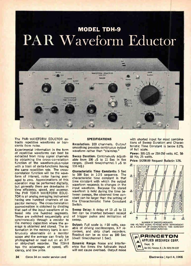
MODEL TDH-9
PA R Waveform Eductor
SIGMAS
GAIN
VAS•ABiE
COOK IMG ZERO
41V-44
WAVEFORM EDUCTOR MUNI UM
TRIGGee MOON
CMARACTER1STK TOM CONSIANt
I. SIC WIC ale mom.
Ore
SWEEP
DUDA ftC.N
The PAR, WAVEFORM EDUCTOR ex-tracts repetitive waveforms or tran-sients from noise. Experimental information in the form of repetitive waveforms can best be extracted from noisy signal channels by obtaining the cross-correlation function of the waveform-plus-noise with a train of delta-functions having the same repetition rate. The cross-correlation function will be the wave-form of interest, noise having aver-aged to zero. Approximations of this operation may be performed digitally, but generally there are drawbacks in time efficiency, speed, and expense. The PAR TDH-9 WAVEFORM EDUC-TOR is an analog averaging instrument having one hundred channels of ca-pacitor memory. The cross-correlation approximation is obtained by dividing that part of the input waveform of in-terest into one hundred segments. These are switched sequentially and synchronously through a resistor to the memory capacitors where the av-erage is obtained and stored. The in-formation in the memory bank is con-tinuously observable on a monitor scope and the average can finally be photographed or read out on an X-Y or strip-chart recorder. The TDH-9 has the advantages of speed, effi-ciency, and low price.
SPECIFICATIONS
Resolution: 100 channels. Output smoothing provides continuous output waveform rather than "stairstep."
Sweep Duration: Continuously adjust-able from 100 AS to 11 Sec in five ranges. (Dwell time/channel: 1 AS to 110 mS.)
Characteristic Time Constants: 5 Sec to 100 Sec in 1-2-5 sequence. The characteristic time constant is that time constant with which the output waveform responds to changes in the input waveform. Because the stored waveform is held during the time be-tween sweeps, the observed time con-stant can be larger than the setting of the Characteristic Time Constant Switch.
Sweep Delay: A delay of 10 AS to 11 Sec can be inserted between receipt of trigger pulse and initiation of sweep.
Output: Full scale is -±10 volts, cap-able of driving oscilloscopes, X-Y re-corders, and strip chart recorders. Readout can be as slow as 100 Sec (dwell time/channel 1 Sec).
Dynamic Range: Noise and interfer-ence five times the full-scale input will not cause overload. Output noise
with shorted input for most combina-tions of Sweep Duration and Charac-teristic Time Constant is below 0.2% of full scale.
Power: 105-125 or 210-250 volts AC, 50-60 Hz; 25 watts. Price: $4200.00 Request Bulletin 126. 100 SEC.
55 SEC
20 SE
10 SEC.
SID SWEEP DURATION
).2 1 10 103 m8 m8 enS SEC.
NUMBER OF SWEEPS AVERAGED AND VOLTAGE SIGNAL-TO-NOISE RATIO IMPROVEMENT AS A FUNCTION OF CHARACTERISTIC TIME CONSTANT
AND SWEEP DURATION
PRINCETON APPLIED RESEARCH CORP.
Dept. D R Box 565, Princeton, N. J., Tel. (609) 799-1222
34 Circle 34 on reader service card Electronics I April 4, 1966
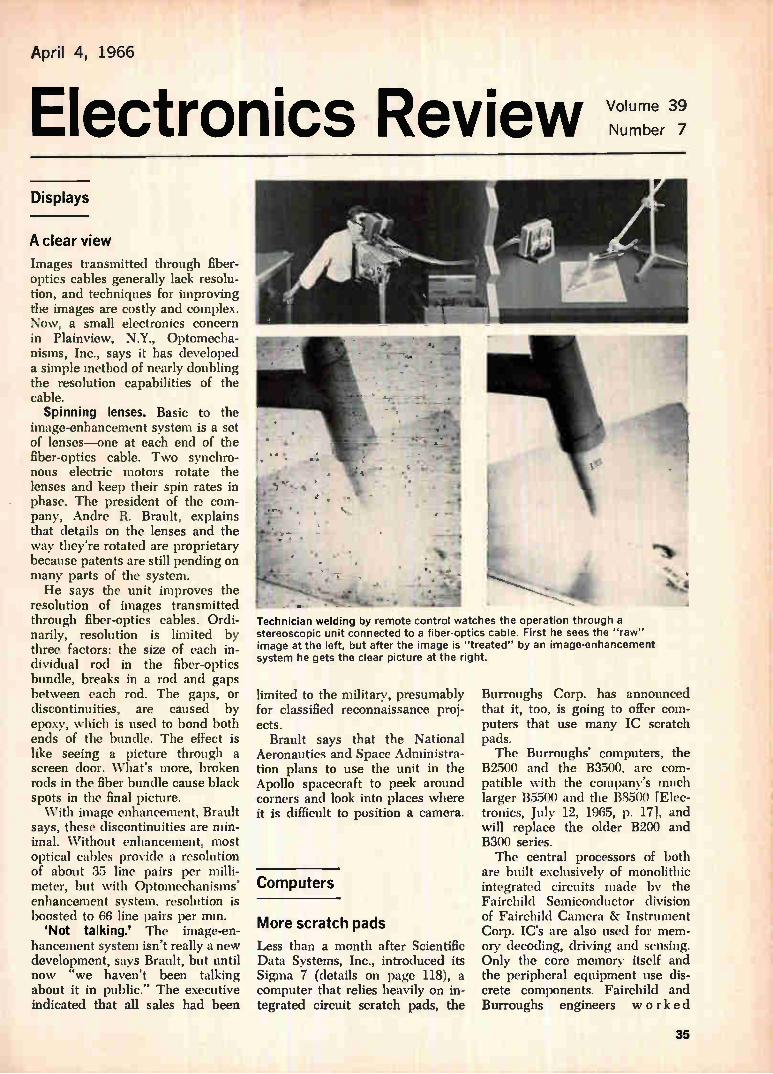
April 4, 1966
Electronics Review NN/oulurar, Displays
A clear view Images transmitted through fiber-optics cables generally lack resolu-tion, and techniques for improving the images are costly and complex. Now, a small electronics concern in Plainview, N.Y., Optomecha-nisms, Inc., says it has developed a simple method of nearly doubling the resolution capabilities of the cable.
Spinning lenses. Basic to the image-enhancement system is a set of lenses—one at each end of the fiber-optics cable. Two synchro-nous electric motors rotate the lenses and keep their spin rates in phase. The president of the com-pany, Andre R. Brault, explains that details on the lenses and the way they're rotated are proprietary because patents are still pending on many parts of the system. He says the unit improves the
resolution of images transmitted through fiber-optics cables. Ordi-narily, resolution is limited by three factors: the size of each in-dividual rod in the fiber-optics bundle, breaks in a rod and gaps between each rod. The gaps, or discontinuities, are caused by epoxy, which is used to bond both ends of the bundle. The effect is like seeing a picture through a screen door. What's more, broken rods in the fiber bundle cause black spots in the final picture. With image enhancement, Brault
says, these discontinuities are min-imal. Without enhancement, most optical cables provide a resolution of about 35 line pairs per milli-meter, but with Optomechanisms' enhancement system, resolution is boosted to 66 line pairs per mm.
'Not talking.' The image-en-hancement system isn't really a new development, says Brault, but until now "we haven't been talking about it in public." The executive indicated that all sales had been
1
Technician welding by remote control watches the operation through a stereoscopic unit connected to a fiber-optics cable. First he sees the "raw" image at the left, but after the image is "treated" by an image-enhancement system he gets the clear picture at the right.
limited to the military, presumably for classified reconnaissance proj-ects.
Brault says that the National Aeronautics and Space Administra-tion plans to use the unit in the Apollo spacecraft to peek around corners and look into places where it is difficult to position a camera.
Computers
More scratch pads
Less than a month after Scientific Data Systems, Inc., introduced its Sigma 7 (details on page 118), a computer that relies heavily on in-tegrated circuit scratch pads, the
•
44-.1
Burroughs Corp. has announced that it, too, is going to offer com-puters that use many IC scratch pads. The Burroughs' computers, the
B2500 and the B3500, are com-patible with the company's much larger B5500 and the B8500 (Elec-tronics, July 12, 1965, p. 171, and will replace the older B200 and B300 series. The central processors of both
are built exclusively of monolithic integrated circuits made by the Fairchild Semiconductor division of Fairchild Camera & Instrument Corp. IC's are also used for mem-ory decoding, driving and sensing. Only the core memory itself and the peripheral equipment use dis-crete components. Fairchild and Burroughs engineers worked
35
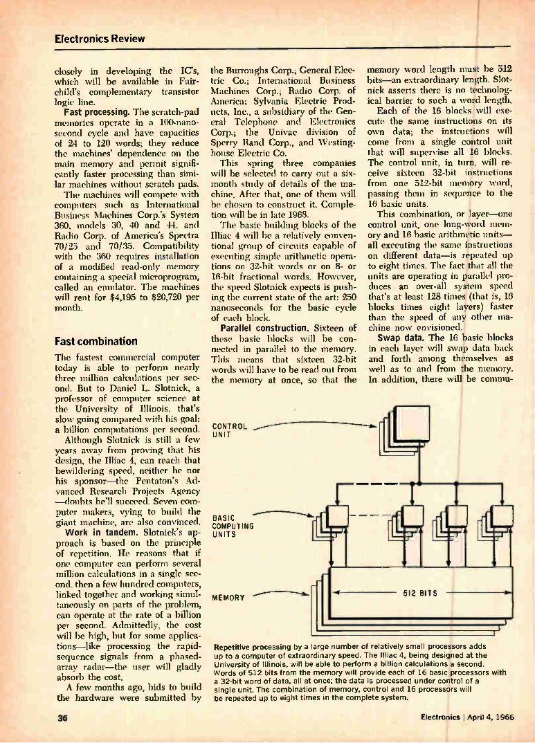
Electronics Review
closely in developing the IC's, which will be available in Fair-child's complementary transistor logic line.
Fast processing. The scratch-pad memories operate in a 100-nano-second cycle and have capacities of 24 to 120 words; they reduce the machines' dependence on the main memory and permit signifi-cantly faster processing than simi-lar machines without scratch pads. The machines will compete with
computers such as International Business Machines Corp.'s System 360, models 30, 40 and 44, and Radio Corp. of America's Spectra 70/25 and 70/35. Compatibility with the 360 requires installation of a modified read-only memory containing a special microprogram, called an emulator. The machines will rent for $4,195 to $20,720 per month.
Fast combination
The fastest commercial computer today is able to perform nearly three million calculations per sec-ond. But to Daniel L. Slotnick, a professor of computer science at the University of Illinois, that's slow going compared with his goal: a billion computations per second. Although Slotnick is still a few
years away from proving that his design, the Iliac 4, can reach that bewildering speed, neither he nor his sponsor—the Pentaton's Ad-vanced Research Projects Agency —doubts he'll succeed. Seven com-puter makers, vying to build the giant machine, are also convinced. Work in tandem. Slotnick's ap-
proach is based on the principle of repetition. He reasons that if one computer can perform several million calculations in a single sec-ond, then a few hundred computers, linked together and working simul-taneously on parts of the problem, can operate at the rate of a billion per second. Admittedly, the cost will be high, but for some applica-tions—like processing the rapid-sequence signals from a phased-array radar—the user will gladly absorb the cost. A few months ago, bids to build
the hardware were submitted by
the Burroughs Corp.; General Elec-tric Co.; International Business Machines Corp.; Radio Corp. of America; Sylvania Electric Prod-ucts, Inc., a subsidiary of the Gen-eral Telephone and Electronics Corp.; the Univac division of Sperry Rand Corp., and Westing-house Electric Co.
This spring three companies will be selected to carry out a six-month study of details of the ma-chine. After that, one of them will be chosen to construct it. Comple-tion will be in late 1968. The basic building blocks of the
Iliac 4 will be a relatively conven-tional group of circuits capable of executing simple arithmetic opera-tions on 32-bit words or on 8- or 16-bit fractional words. However, the speed Slotnick expects is push-ing the current state of the art: 250 nanoseconds for the basic cycle of each block.
Parallel construction. Sixteen of these basic blocks will be con-nected in parallel to the memory. This means that sixteen 32-bit words will have to be read out from the memory at once, so that the
CONTROL UNIT
BASIC COMPUT ING UNITS
MEMORY
memory word length must be 512 bits—an extraordinary length. Slot-nick asserts there is no technolog-ical barrier to such a word length. Each of the 16 blocks will exe-
cute the same instructions on its own data; the instructions will come from a single control unit that will supervise all 16 blocks. The control unit, in turn, will re-ceive sixteen 32-bit instructions from one 512-bit memory word, passing them in sequence to the 16 basic units. This combination, or layer—one
control unit, one long-word mem-ory and 16 basic arithmetic units— all executing the same instructions on different data—is repeated up to eight times. The fact that all the units are operating in parallel pro-duces an over-all system speed that's at least 128 times (that is, 16 blocks times eight layers) faster than the speed of any other ma-chine now envisioned. Swap data. The 16 basic blocks
in each layer will swap data back and forth among themselves as well as to and from the memory. In addition, there will be commu-
512 BITS
Repetitive processing by a arge number of relatively small processors adds up to a computer of extraordinary speed. The Illiac 4, being designed at the University of Illinois, will be able to perform a billion calculations a second. Words of 512 bits from the memory will provide each of 16 basic processors with a 32-bit word of data, all at once; the data is processed under control of a single unit. The combination of memory, control and 16 processors will be repeated up to eight times in the complete system.
36 Electronics April 4, 1966
I. fr.:
Electronics Review
nication among each of the blocks in the different layers. Beyond the military applications,
Slotnick sees Illiac 4's being used for such problems as the evaluation of high-order determinants, which requires an enormous number of simple calculations.
Conversational program
Soon anyone who can hunt and peck on a typewriter will be able to converse with a computer. An ex-perimental software program, called Deacon, is already being used to help a computer under-stand and answer simple questions in colloquial English. Deacon, which stands for direct
English access and control, is being developed by Tempo, General Elec-tric Co.'s center for advanced stu-dies in Santa Barbara, Calif. Event-ually, it will be possible for an operator to use a computer without any knowledge of computer lan-guage or programing. Simple questions. GE says the
final version of Deacon will answer questions asked in relatively com-plex conversational English, such as: "What are all the ways of gen-erating microwaves?" For the time being, however, it will deal with simpler questions.
It will have no difficulty distin-guishing among: "What is the loca-tion of the cruiser Phoenix?"; "Where is the Phoenix?"; Find the ship Phoenix!" Regardless of which way the question is asked, Deacon should be able to provide the cor-rect answer. Computer grammar. The Deacon
system is based on the interaction of three parts of the program: a dictionary, which lists the words the computer can recognize; a rules catalog, which contains the gram-mar of the system; and a data base, which provides the interconnec-tions among words that gives the system its "intelligence." When queried, Deacon first
searches for the important words in the dictionary. If a word is not there, the computer will ask the operator to rephrase his question or define his terms. Eventually, when all the words are found, linkages
are established through the data base; this tells the computer what is being asked. For example, if the question is "What is the location of the cruiser Phoenix?", the com-puter would recognize that "loca-tion," "cruiser" and "Phoenix" are important words and search for linkages among them.
Linkages are often complex. For example, the memory might contain data about the Phoenix on weight or manpower; the locations and other facts on cruisers named Dallas, Cleveland or Miami; and data about a city, an insurance company and a mythical bird, all named "Phoenix." The program may have to follow
more than one track to make sure it doesn't give a correct but inap-propriate answer. The question "Where is Phoenix?" could be answered: "The cruiser Phoenix is in San Francisco Bay"; the city Phoenix is in Arizona," and so on.
Recondite language. Most infor-mation-retrieval systems now in use require that questions be asked in a specialized language, using key words and standard forms. Also, many of them can tell only where to find the answer. Deacon is being developed on
relatively unsophisticated hard-ware. The computer is a GE 295 with one magnetic disk file that has a capacity of 18 million six-bit characters. Communication with the computer is through a tele-printer or a GE Datanet 760, which acts like a teleprinter but produces an image on a cathode-ray tube in-stead of printing on paper. The teleprinters and the Datanet 760 communicate with the GE 225 central processor through a GE Datanet 15.
Herbert R. J. Grosch, director of the project, says he does not think the kind of equipment being used will limit the Deacon project, "be-cause I am certain that hardware development will keep ahead of our needs." The system's speed and versatil-
ity could be improved, however, by giving it an associative memory— a development still in the experi-mental phase. An associative mem-ory can pluck a bit of information from storage by making an adroit
association rather than going se-quentially through its memory until the information sought is reached. It would know immedi-ately if it "recognized" a specific word in a question without having to look it up in its dictionary.
Instrumentation
Invisible sentry
Most electronic sentries have two crucial disadvantages: if they are active, an intruder can detect their radiation; if they are passive, they can't be detected but have a range of only one or two feet. A passive infrared sentry that can sense an intruder up to 250 feet away has been developed by the Huggins Laboratories, Inc., of Sunnyvale, Calif. With the Huggins system, the in-
truder inadvertently does all the work, by supplying the two com-ponents that activate the alarm— motion and a radiometric signal. The front of the detector is covered with a grid. Any motion of an in-frared source creates a low-fre-quency modulation of the radio-metric signal as it is interrupted by the grid. The resulting signal is amplified and used as a d-c trigger for firing the circuit. No current flows in the system until an intruder comes into range. Before that, the system is dormant and safe from detection. Target temperature. For the in-
frared sensor of the motion detec-tor Huggins used a capacitor bolo-meter it had developed earlier. The capacitor bolometer's frequency response is at least five times greater than that of the thermistor bolometer usually employed in in-frared systems, making the sentry responsive to rapid movement. The bolometer is arranged in a double-ended bridge circuit that adjusts to changes in the ambient temper-ature. It then will react to radio-metric signals that differ as little as 1°F from the ambient tempera-ture. Tests showed the differences between a person's clothing and ambient temperature were usually
Electronics I April 4, 1966 37
Electronics Review
more than 1°F—even at the pants' cuff. A lens with flat transmission
characteristics from 4.2 to 15 mi-crons is used to increase optical efficiency. The 9.3-micron wave-length of human infrared radiation is well within the lens' range. A filter in front of the lens prevents sunlight from affecting the detec-tor. The sentry will function ef-fectively at ambient temperatures from 25° to 120°F. This range can be lowered or raised by adjust-ing the detectors' electronics. Other systems. Active intruder
detectors, such as ultrasonic sen-tries, are detected easily with elec-tronic sensors. Even acoustic sys-tems, which are only partially passive because they limit r-f radi-ation, can be detected; they have the added disadvantage of being sensitive to random noises, such as the ring of a telephone or the sound of a passing car. Doppler radar systems, besides being very expensive, can be detected with a wide-band crystal detector. Sys-tems that use a change in capaci-tance or inductance of a tuned os-cillator circuit approach being pas-sive but have a range of about two feet. A disadvantage of the Huggins'
sentry is that it would be triggered by any moving infrared source in the 4.2- to 15-micron range, and this includes everything from squir-rels to grizzly bears. The Air Force has had a similar problem with a capacitance-type detection system for its Minuteman missile site at Ellsworth Air Force Base in South Dakota. The system is reportedly so touchy that high-leaping grass-hoppers periodically set it off. A modified version of a doppler radar detection system at Titan II missile sites can distinguish between men
CHRISTMAS CLUB
= A A
and animals by measuring differ-ences in frequency and intensity of the returning radar signal. [Elec-tronics, Nov. 16, 1964, p. 32].
Friend or foe. William E. Os-borne, chief scientist at Huggins, says the Air Force is interested in the infrared sentry for perimeter surveillance. The Army also sees a potential as a weapon: it could be used to trigger antipersonnel mines from a safe position. "The next step," Osborne says,
"is to develop a system that can distinguish between friend and foe. Osborne says he has discussed
possible traffic control applications with officials in several cities. De-tectors could be used at highways to monitor traffic. If traffic slowed to a predetermined rate and stayed that way for a time, the sentry would trigger signs warning motor-ists of the congestion, would re-route traffic or would prevent more cars from entering the highway.
Data processing
Banking on computers
The banking industry is on the verge of being overwhelmed—by a mountain of checks. Some 70 mil-lion are now cashed daily, and each year the number grows. To move each of these millions of bits of paper—from the place where it is written to the issuer's bank for de-duction—banks spend some $3.3 billion a year. A solution, however, is in sight. Slowly, in still uncoordinated
steps, the banking industry is es-tablishing a nationwide financial utility that eventually will tie the money transaction of banks and
LOANS SAVINGS CHECKING
7—( --r-
[ -INVESTMENTS
customers into a vast computerized network. Some time from now, many bankers agree, checks will be as obsolete as Indian pennies. Pay the phone. A precursor of
the network was started last month in Wilmington, Del. [Electronics, Nov. 15, 1965, p. 41]. A person with an account at the Bank of Delaware can pay for a purchase at nearby Stroms department stores even if he has left his wallet home and has no credit account at Stroms. After a purchase, the salesman simply "dials" the number of the bank on a touch-tone telephone, enters a code that identifies the customer and then enters the amount of the purchase. Automatically, through a team of International Business Ma-chines Corp. computers, the pur-chase amount is deducted from the customer's checking account—with-out the writing of a check. The Bank of Delaware is already
planning a step beyond. This year it will conduct an experiment in which customers will use touch-tone telephones at home, paying bills to companies with accounts in the bank.
Novel as the system is, it gives only a hint of what's in store. Within a decade many bankers foresee a network in which banks will be tied to retailers through a central computer clearing house. From there, the banking network could expand. Employee payrolls, for example, could automatically feed from corporate accounts into individual accounts; and the em-ployee's regular monthly payments —mortgage, utilities and savings— would be automatically deducted. The Treasury Department could tie in: income tax withholding pay-ments and social security payments could be deducted. The Federal Reserve System, in a side benefit,
38 Electronics April 4, 1966
w
10111 400111c
G0 11/07/ 10
04 a.
Vc, =- 28 V.
200 300 400 FREQUENCY MC /S
500
1/4
NEW UHF POWER TRANSISTOR '."• The new TRW 10 W/400Mc (2N4040) UHF
Power Transistor provides full rated performance in
conventional circuits...no need to resort to emitter tuning
or other techniques which contribute to circuit instability.
TRW 2N4040 is available now at competitive prices.
For detailed technical information phone, write or wire:
TRW Semiconductors, Transistor Plant, 14520 Aviation
Blvd., Lawndale, Calif. 90260. Phone: (213) 679-4561, Ext. 477
TWX: 213 647-5113
TRW designs and manufactures high performance transistors for the communications industry and specialized types for military and industrial applications.
TRW SEMICONDUCTORS Electronics April 4, 1966 Circle 39 on reader service card 39
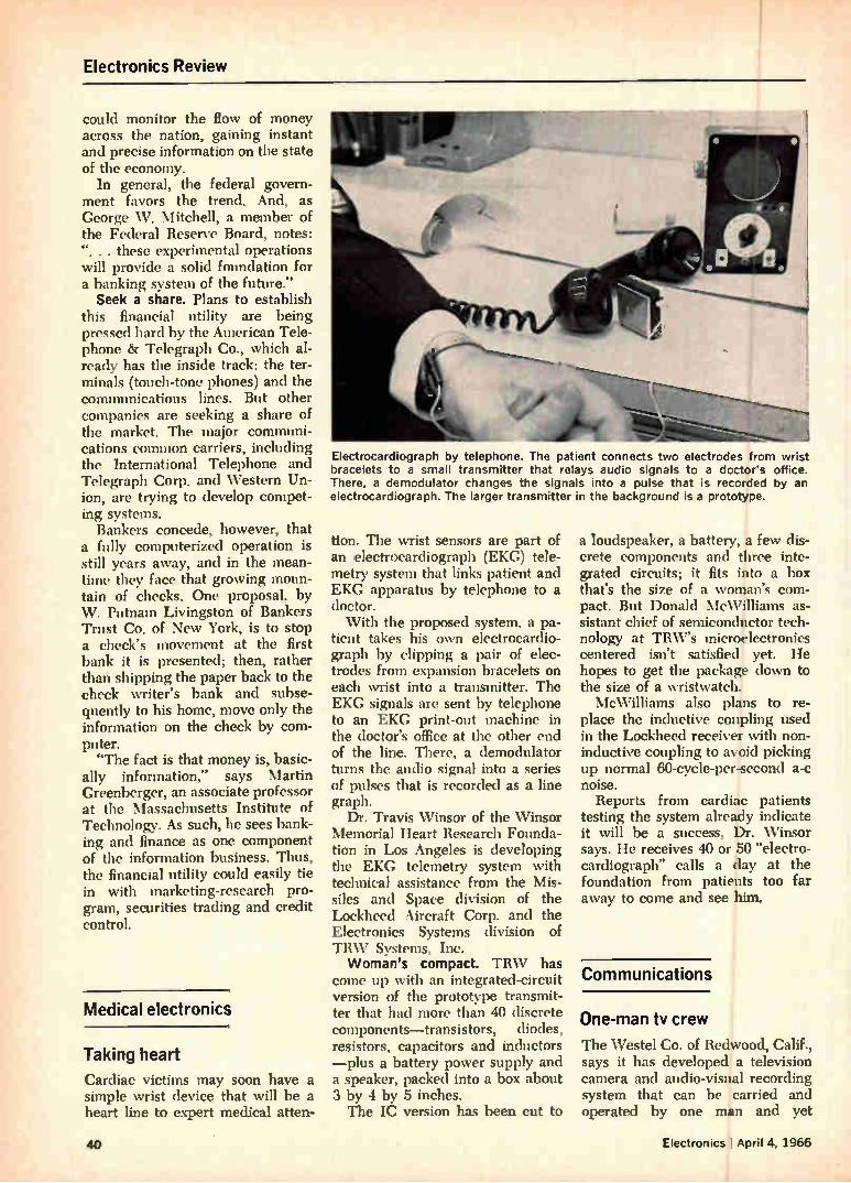
Electronics Review
could monitor the flow of money across the nation, gaining instant and precise information on the state of the economy.
In general, the federal govern-ment favors the trend. And, as George W. Mitchell, a member of the Federal Reserve Board, notes: . . these experimental operations
will provide a solid foundation for a banking system of the future."
Seek a share. Plans to establish this financial utility are being pressed hard by the American Tele-phone 8r Telegraph Co., which al-ready has the inside track: the ter-minals (touch-tone phones) and the communications lines. But other companies are seeking a share of the market. The major communi-cations common carriers, including the International Telephone and Telegraph Corp. and Western Un-ion, are trying to develop compet-ing systems.
Bankers concede, however, that a fully computerized operation is still years away, and in the mean-time they face that growing moun-tain of checks. One proposal, by W. Putnam Livingston of Bankers Trust Co. of New York, is to stop a check's movement at the first bank it is presented; then, rather than shipping the paper back to the check writer's bank and subse-quently to his home, move only the information on the check by com-puter. "The fact is that money is, basic-
ally information," says Martin Greenberger, an associate professor at the Massachusetts Institute of Technology. As such, he sees bank-ing and finance as one component of the information business. Thus, the financial utility could easily tie in with marketing-research pro-gram, securities trading and credit control.
Medical electronics
Taking heart
Cardiac victims may soon have a simple wrist device that will be a heart line to expert medical atten-
Electrocardiograph by telephone. The patient connects two electrodes from wrist bracelets to a small transmitter that relays audio signals to a doctor's office. There, a demodulator changes the signals into a pulse that is recorded by an electrocardiograph. The larger transmitter in the background is a prototype.
tion. The wrist sensors are part of an electrocardiograph (EKG) tele-metry system that links patient and EKG apparatus by telephone to a doctor. With the proposed system, a pa-
tient takes his own electrocardio-graph by clipping a pair of elec-trodes from expansion bracelets on each wrist into a transmitter. The EKG signals are sent by telephone to an EKG print-out machine in the doctor's office at the other end of the line. There, a demodulator turns the audio signal into a series of pulses that is recorded as a line graph.
Dr. Travis Winsor of the Winsor Memorial Heart Research Founda-tion in Los Angeles is developing the EKG telemetry system with technical assistance from the Mis-siles and Space division of the Lockheed Aircraft Corp. and the Electronics Systems division of TRW Systems, Inc. Woman's compact. TRW has
come up with an integrated-circuit version of the prototype transmit-ter that had more than 40 discrete components—transistors, diodes, resistors, capacitors and inductors —plus a battery power supply and a speaker, packed into a box about 3 by 4 by 5 inches. The IC version has been cut to
a loudspeaker, a battery, a few dis-crete components and three inte-grated circuits; it fits into a box that's the size of a woman's com-pact. But Donald McWilliams as-sistant chief of semiconductor tech-nology at TRW's microelectronics centered isn't satisfied yet. He hopes to get the package down to the size of a wristwatch. McWilliams also plans to re-
place the inductive coupling used in the Lockheed receiver with non-inductive coupling to avoid picking up normal 60-cycle-per-second a-c noise.
Reports from cardiac patients testing the system already indicate it will be a success, Dr. Winsor says. He receives 40 or 50 "electro-cardiograph" calls a day at the foundation from patients too far away to come and see him.
Communications
One-man tv crew
The Westel Co. of Redwood, Calif., says it has developed a television camera and audio-visual recording system that can be carried and operated by one man and yet
40 Electronics I April 4, 1966
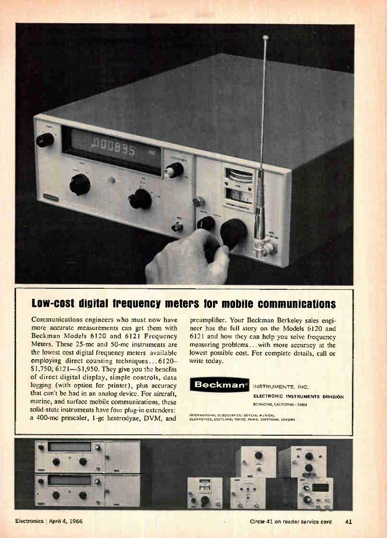
Low-cost digital treouency meters tor mobile Communications engineers who must now have more accurate measurements can get them with Beckman Models 6120 and 6121 Frequency Meters. These 25-mc and 50-mc instruments are the lowest cost digital frequency meters available employing direct counting techniques ... 6120-$1,750; 6121—$1,950. They give you the benefits of direct digital display, simple controls, data logging (with option for printer), plus accuracy that can't be had in an analog device. For aircraft, marine, and surface mobile communications, these solid-state instruments have four plug-in extenders: a 400-mc prescaler, 1-gc heterodyne, DVM, and
communication preamplifier. Your Beckman Berkeley sales engi-neer has the full story on the Models 6120 and 6121 and how they can help you solve frequency measuring problems...with more accuracy at the lowest possible cost. For complete details, call or write today.
Beckman' INSTRUMENTS. INC.
ELECTRONIC INSTRUMENTS DIVISION
RICHMOND, CALIFORNIA • 94844
INTERNATIONAL SUBSIDIARIES: GENEVA; MUNICH;
GLENROTHES, SCOTLAND; TOKYO; PARIS; CAPETOWN; LONDON
Electronics April 4, 1966 Circle 41 on reader service card 41
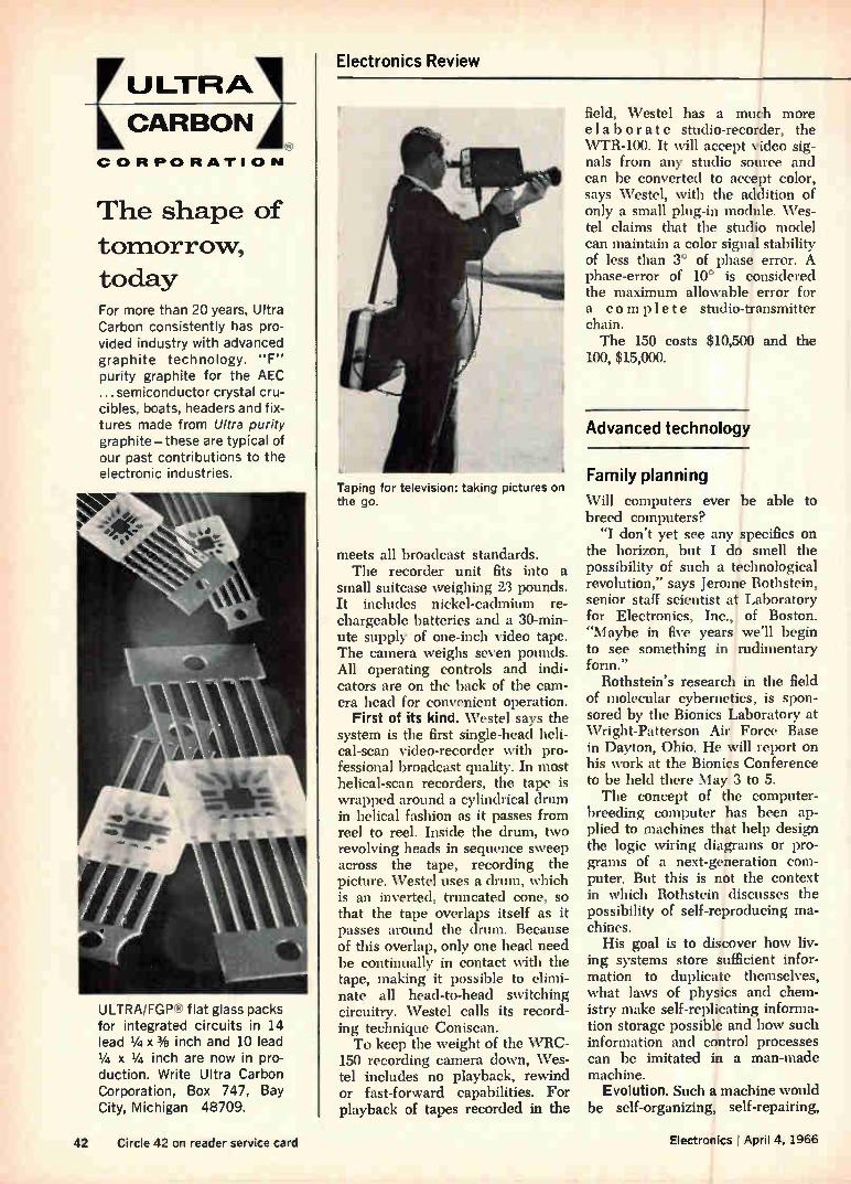
U LTRA]
CARBON
CORPORATION
The shape of
tomorrow, today For more than 20 years, Ultra Carbon consistently has pro-vided industry with advanced graphite technology. "F" purity graphite for the AEC ... semiconductor crystal cru-cibles, boats, headers and fix-tures made from Ultra purity graphite—these are typical of our past contributions to the electronic industries.
ULTRA/FGP flat glass packs for integrated circuits in 14 lead 1/4 x3/8 inch and 10 lead 1/4 x 1/4 inch are now in pro-
duction. Write Ultra Carbon Corporation, Box 747, Bay City, Michigan 48709.
Electronics Review
Taping for television: taking pictures un the go.
meets all broadcast standards. The recorder unit fits into a
small suitcase weighing 23 pounds. It includes nickel-cadmium re-chargeable batteries and a 30-min-ute supply of one-inch video tape. The camera weighs seven pounds. All operating controls and indi-cators are on the back of the cam-era head for convenient operation.
First of its kind. Westel says the system is the first single-head heli-cal-scan video-recorder with pro-fessional broadcast quality. In most helical-scan recorders, the tape is wrapped around a cylindrical drum in helical fashion as it passes from reel to reel. Inside the drum, two revolving heads in sequence sweep across the tape, recording the picture. Westel uses a drum, which is an inverted, truncated cone, so that the tape overlaps itself as it passes around the drum. Because of this overlap, only one head need be continually in contact with the tape, making it possible to elimi-nate all head-to-head switching circuitry. Westel calls its record-ing technique Coniscan. To keep the weight of the VVRC-
150 recording camera down, Wes-tel includes no playback, rewind or fast-forward capabilities. For playback of tapes recorded in the
field, Westel has a much more elaborate studio-recorder, the VVTR-100. It will accept video sig-nals from any studio source and can be converted to accept color, says Westel, with the addition of only a small plug-in module. Wes-tel claims that the studio model can maintain a color signal stability of less than 3° of phase error. A phase-error of 10° is considered the maximum allowable error for a complete studio-transmitter chain. The 150 costs $10,500 and the
100, $15,000.
Advanced technology
Family planning
Will computers ever be able to breed computers?
"I don't yet see any specifics on the horizon, but I do smell the possibility of such a technological revolution," says Jerome Rothstein, senior staff scientist at Laboratory for Electronics, Inc., 1 of Boston. "Maybe in five years I we'll begin to see something in rudimentary form."
Rothstein's research in the field of molecular cybernetics, is spon-sored by the Bionics Laboratory at Wright-Patterson Air Force Base in Dayton, Ohio. He will report on his work at the Bionics Conference to be held there May 3 to 5. The concept of the computer-
breeding computer has been ap-plied to machines that help design the logic wiring diagrams or pro-grams of a next-generation com-puter. But this is not the context in which Rothstein discusses the possibility of self-reproducing ma-chines.
His goal is to discover how liv-ing systems store sufficient infor-mation to duplicate themselves, what laws of physics and chem-istry make self-replicating informa-tion storage possible and how such information and control processes can be imitated in a man-made machine.
Evolution. Such a machine would be self-organizing, self-repairing,
42 Circle 42 on reader service card Electroilics April 4, 1966
Jerome Rothstein: it takes inspiration.
self-correcting and adaptive. In a word, it would be evolutionary. Much of the activity in bionics
today consists of investigations of circuits and networks designed to perform biomorphic functions. But Rothstein is exploring information and control processes in biochem-ical systems at the molecular level.
In the face of a staggering com-plexity of variables, Rothstein plays it like a chess game—but not like a computer playing chess. The computer gets swamped trying to cope with the large number and combinations of variables. A skill-ful human player learns the prin-ciples, discovers tactics and strate-gies and throws out the time-con-suming and irrelevant cases, he ex-plains. Using information. In genetic
structures, from virus to man, there must be storage of information at the molecular level. Rothstein's in-vestigations have led to grouping configurations of molecules into "families." Control actions deter-mine whether a molecule can change its configuration from one family to another; catalysts exert such controls.
Rothstein investigates chain molecules—beads connected by links; the order of beads consti-tutes a message. Such messages are the catalysts that make control possible.
"It is this family structure—or something like it—an extra struc-ture that may be exploited by the living organism to permit at a chemical level the control processes that we know in engineering,"
hp 203A Variable-Phase Function Generator provides reference and variable-phase sine, square waves range 0.00005 Hz to 60 kHz distortion less than 0.06% continuously variable phase shift 0-360° four simultaneous adjustable outputs 0-30 y peak-to-peak
Use it for: phase shift measurements low-distortion signal generation vibration studies frequency response measurements servo applications medical research geophysical problems subsonic, audio testing
Here is a solid-state function generator offering simultaneous sine and square-wave signals 0.005 Hz to 60 kHz in 7 overlapping bands (two optional bands available, down to 0.00005 Hz). Total harmonic distortion hum and noise (0.06%) is less than 64 db below funda-mental.
Accurate 1% frequency dial calibra-tion with 180 dial division, vernier drive for precise adjustment. All four floating output circuits have individual 40 db continuously adjustable attenuators. One each of the sine and square-wave outputs
118G
contain the 0-360° phase shifter. A front-panel calibration provision permits easy line-frequency calibration of the oscil-lator to the environment in which it's being used. Price, $1200.
For a demonstration of the unique 203A call your Hewlett-Packard field en-gineer. Or write for complete specifica-tions to Hewlett-Packard, Palo Alto, California 94304, Tel. (415) 326-7000; Europe: 54 Route des Acacias, Geneva.
Data subject to change without notice. Price f.o.b, factory.
â An extra measure of quality HEWLETT PACKARD
Electronics I April 4, 1966 Circle 4,3 on reader service card 43
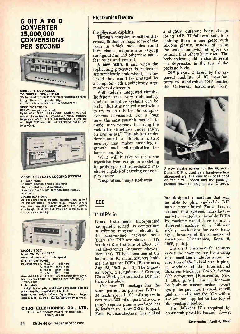
6 BIT A TO D CONVERTER 15,000,000 CONVERSIONS PER SECOND
MODEL 834A ANALOG TO DIGITAL CONVERTER Well-suited for telemetering or process control
Long life and high stability All solid state, silicon semi-conductors
SPECIFICATIONS Method: successive comparison. Digital output: B.C.D. 12 bit parallel. Stability: ±0.2%/6 months. Conversion time: approximately 240s. Operating temperature: —10°C to +50°C.Width:480mm. Height: 199 mm. Depth: 2250 mm. AC Input: 100/1101220/240V±10% 50 or 60 c/s.
MODEL 198C DATA LOGGING SYSTEM
All solid state Random access analog scanner High reliability and accuracy Operates over large temperature ranges Low cost
SPECIFICATIONS Scanning capability: 16 channels. Scanning speed: up to 5 channels per second. Accuracy: 0.1%. Output: printing paper tape. Logging cycles: 10 seconds to 1 hour (specify on ordering). AC input: 100110,220,240V ±10% 50 or 60 cps (specify on ordering).
DIGITAL VOLTMETER
All solid state and high speed. SPECIFICATIONS Measuring range: (11 0.001 to 1.599 volts
(21 0.01 to 15.99 volts (3) 0.1 to 159.9 volts (4) 1 to 1,599 volts
Accuracy: 0.1% of full scale. A D conversion time: 600ps. Max. repetition rate: 1 kc. Reading mode auto: 100 c, 's repetition rate. Digital output: 4 digit decimal 10C i. parallel code connectable to the line
printer Operating temperature: 0 to 40°C. Width:480 mm. Height: 199 mm. Depth: 350 mm. Weight: approx. 13 kg. AC input: 100/110/220/240V 50 or 60cps.
CHUO ELECTRONICS CO., LTD. No. 21 Motohongo-machi Hachioji-shi,
Tokyo, Japan
Electronics Review
the physicist explains. Through complex transition dia-
grams, Rothstein maps some of the ways in which molecules could form chains, migrate into varying configurations and otherwise mani-fest order and control. A new math. If and when the
replicating processes in molecules are sufficiently understood, it is be-lieved they could be imitated by a computer with a sufficiently large number of elements. With today's integrated circuits,
Rothstein says, very rudimentary kinds of adaptive systems can be built. "But it is not yet worthwhile to try to do this for the complex systems envisioned. For a long time, the most sensible tactic is to model such systems, including the molecular structures under study, on computers." His lab has under development a thin-film matrix memory that makes modeling of growth and self-replicative be-havior possible. What will it take to make the
transition from computer modeling to prototype self-reproducing ma-chines capable of carrying out com-plex tasks?
"Inspiration," says Rothstein.
IEEE
TI DIP's in
Texas Instruments Incorporated has quietly joined its competitors in offering integrated circuits in the dual-in-line package style (DIP). The DIP was shown at TI's booth at the Institute of Electrical and Electronics Engineers show in New York. TI had been one of the last major IC manufacturers hold-ing out against DIP's [Electronics, Aug. 23, 1965, p. 118]. The Signet-íes Corp., a subsidiary of Corning Glass Works, introduced a DIP just before the show. The new TI package has the
same pattern as previous DIP's-14 leads spaced 100 mils apart in two rows 300 mils apart. The com-pany's regular plug-in package has 16 leads in two rows 200 mils apart. Each IC manufacturer has picked
a slightly different body design for its DIP. TI followed suit, it is molding them in one piece with silicone plastic, instead of using the sealed sandwich of epoxy or ceramic that others have used. The body indexing aid is also different —a depression in the top of the package body. DIP picker. Unfazed by the ap-
parent inability of IC manufac-tures to standardize DIP bodies, the Universal Instrument Corp.
A new plastic carrier for the Signetics Corp.'s DIP is used as a hand-insertion alignment jig. The carrier is positioned on the circuit board and the package pushed down to plug in the ;C leads.
has designed a machine that will be able to plug anybody's DIP into a circuit board. For a time, it seemed that systems manufactur-ers who wanted to assemble DIP's by machine would have to buy a different machine or a different pickup mechanism for each body style, because of the dimensional variations [Electronics, Sept. 8, 1965, p. 40].
Universal Instrument's solution is one the company has been using in its machines made for automatic insertion of the hybrid-circuit plug-in modules of the International Business Machines Corp.'s System 360 computers [Electronics, Nov. 1, 1965, p. 90]. The machine—to be built on custom orders—won't grasp the package. Instead, it will pick up and insert the IC's with a suction tool applied to the top of the package bodies. The different IC's required by
an assembly will be loaded—facing
44 Circle 44 on reader service card ElectrOnics I April 4, 1966
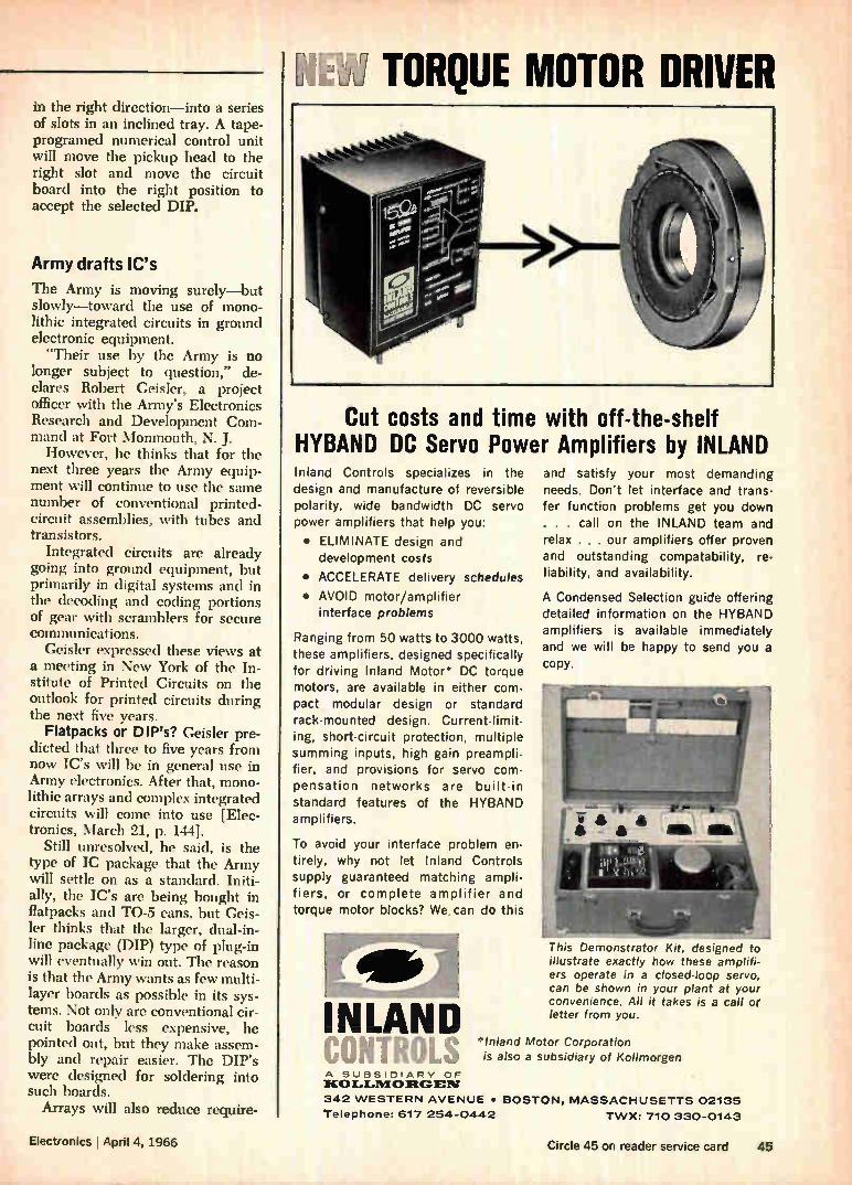
V.Z3 TORQUE MOTOR DRIVER in the right direction—into a series of slots in an inclined tray. A tape-programed numerical control unit will move the pickup head to the right slot and move the circuit board into the right position to accept the selected DIP.
Army drafts IC's
The Army is moving surely—but slowly—toward the use of mono-lithic integrated circuits in ground electronic equipment. -Their use by the Army is no
longer subject to question,- de-clares Robert Geisler, a project officer with the Army's Electronics Research and Development Com-mand at Fort Monmouth, N. J. However, he thinks that for the
next three years the Army equip-ment will continue to use the saine number of conventional printed-circuit assemblies, with tubes and transistors.
Integrated circuits are already going into ground equipment, but primarily in digital systems and in the decoding and coding portions of gear with scramblers for secure communications.
Ceisler expressed these views at a meeting in New York of the In-stitute of Printed Circuits on the outlook for printed circuits during the next five years.
Flatpacks or DIP's? Geisler pre-dicted that three to five years from now IC's will be in general use in Army electronics. After that, mono-lithic arrays and complex integrated circuits will come into use [Elec-tronics, March 21, p. 144].
Still unresolved, he said, is the type of IC package that the Army will settle on as a standard. Initi-ally. the IC's are being bought in flatpacks and TO-5 cans, but Geis-ler thinks that the larger, dual-in-line package (DIP) type of plug-in will eventually win out. The reason is that the Army wants as few multi-layer boards as possible in its sys-tems. Not only are conventional cir-cuit boards less expensive, he pointed out, but they make assem-bly and repair easier. The DIP's were designed for soldering into such boards.
Arrays will also reduce require-
Cut costs and time with off-the-shelf HYBAND DC Servo Power Amplifiers by INLAND Inland Controls specializes in the design and manufacture of reversible polarity, wide bandwidth DC servo power amplifiers that help you:
• ELIMINATE design and development costs
• ACCELERATE delivery schedules
• AVOID motor/amplifier interface problems
Ranging from 50 watts to 3000 watts, these amplifiers, designed specifically for driving Inland Motor* DC torque motors, are available in either com-pact modular design or standard rack-mounted design. Current-limit-ing, short-circuit protection, multiple summing inputs, high gain preampli-fier, and provisions for servo com-pensation networks are built-in
standard features of the HYBAND amplifiers.
To avoid your interface problem en-tirely, why not let Inland Controls supply guaranteed matching ampli-fiers, or complete amplifier and torque motor blocks? We. can do this
INLAND COMUS
and satisfy your most demanding needs. Don't let interface and trans-fer function problems get you down
. . . call on the INLAND team and relax . . . our amplifiers offer proven and outstanding compatability, re-liability, and availability.
A Condensed Selection guide offering detailed information on the HYBAND amplifiers is available immediately and we will be happy to send you a copy.
This Demonstrator Kit, designed to illustrate exactly how these amplifi-ers operate in a closed-loop servo, can be shown in your plant at your convenience. All it takes is a call or letter from you.
*Inland Motor Corporation is also a subsidiary of Kollmorgen
A SUBSIDIARY OF ICOLLIVIORGEN
342 WESTERN AVENUE • BOSTON, MASSACHUSETTS 02135 Telephone: 617 254-0442 TWX: 710 330-0143
Electronics April 4, 1966 Circle 45 on reader service card 45
Use
TUNING FORK TORS OSCILLA
For Low Cost Frequency Control
/ FOR CRYSTAL ACCURACY'
AI AUDIO FREQUENCIES
New Inexpensive Model G Frequency—from below 1 CPS to 30 KC with choice of accuracy for each of five temperature ranges. Standardized construction allows excellent delivery of prototypes or production runs. Many special features are available. Long-term stability-2-year guar-
antee. Prices start at $35.00. Send for
complete information. Other style cases avail-able, including models for printed circuit use.
Catalogued in eern visg,F
FD0 R K —STANDARDS, INC.
221 Main Street • West Chicago, 111.60185 Telephone: Area Code 312 231-3511
Electronics Review
naents for multilayer boards, Geisler believes, since much of the inter-connections for the circuitry of sys-tems built with arrays is done by thin-film wiring on the silicon chips. Hot computers. Another speaker
at the meeting, E. G. Lorenz of the International Business Machines Corp., predicted the continued use of multilayer boards in computers, with radical changes in wiring size, board materials and fabrica-tion methods.
Besides the continued use of multilayer transmission-line inter-connections [Electronics, Nov. 1, 1965, p. 90], Lorenz expects in-creased use of operational circuitry made by printed-circuit techniques. One example is capacitor type, read-only memories. These are made by etching wiring electrode arrays on either side of dielectric layers. Because IC's result in increased
functional density, he predicts that wiring line widths will shrink from present minimum widths of about 10 mils down to about 1 mil (0.001 inch). The wiring patterns will probably be fabricated by high-energy beams; he sees the boards being designed, made and tested under computer control. The high circuit density, Lorenz
says, may result in operating tem-peratures ranging from 400° to 600° F. Since the dielectrics will have to hold dimensional tolerances as tight as 0.1 mil, organic dielec-trics may be discarded in favor of ceramics.
Ten-way masks
Thanks to some optical legerde-main, engineers at the Martin Mari-etta Corp.'s Martin division in Or-lando, Fla., have invented a way to make as many as 10 different deposition or etching masks from a single master artwork pattern. The process eliminates the te-
dious preparation of individual patterns for each mask needed to make a multilayer thin-film circuit or printed circuit. Because Martin uses a single master pattern, all the masks are automatically in near-perfect registration. Now you see it . . . Martin's
invention was described at the IEEE Convention by Burton J. Askowith during a session on mi-crocircuit fabrication. The master pattern is prepared
with six different kinds of bire-fringent tape. Each time the inci-dent angle of polarized light is changed, a different mask pattern on the master pattern becomes opaque. When different wave-lengths of light are used, as many as 10 different patterns can be seen, one at a time.
This allows the entire pattern to be made as one piece of artwork. For a simple thin-film circuit one type of tape would be used for the resistor deposition mask; another type would be used for the elec-trode mask and a third for the in-terconnections. Slow light. Birefringent tapes are
made by stressing plastic materials so that they have two optical axes with different indexes of refraction. One axis passes polarized light faster than the other. Depending on the film thickness, the slow axis retards the passage of light one-half or one-quarter wave-length.
Martin cuts the tapes lengthwise to the fast axis, crosswise and on biases of 45° and 135° to get the six different kinds of tape. The masks are made by exposing pho-tographic film to light shining through a polarizer, the pattern and analyzers. The polarizer and analyzers are
rotated to correspond with the kind of tape forming the pattern for each circuit layer.
Help! The rules said "no recruiting" dur-ing the IEEE show in New York. But one company official summed up the intensity of the talent search when he said: "The show was a success. Our company lost only three men."
Outside the Coliseum a shouting match took place between recruit-ers and IEEE officials who tried to move the recruiters away from the entrance to the show. In hotels nearby, engineers awoke to find job offers stuffed under their doors. An agency representing 42 compa-nies seeking talent ran a shuttle
46 Circle 46 on reader service card Electronics I April 4, 1966
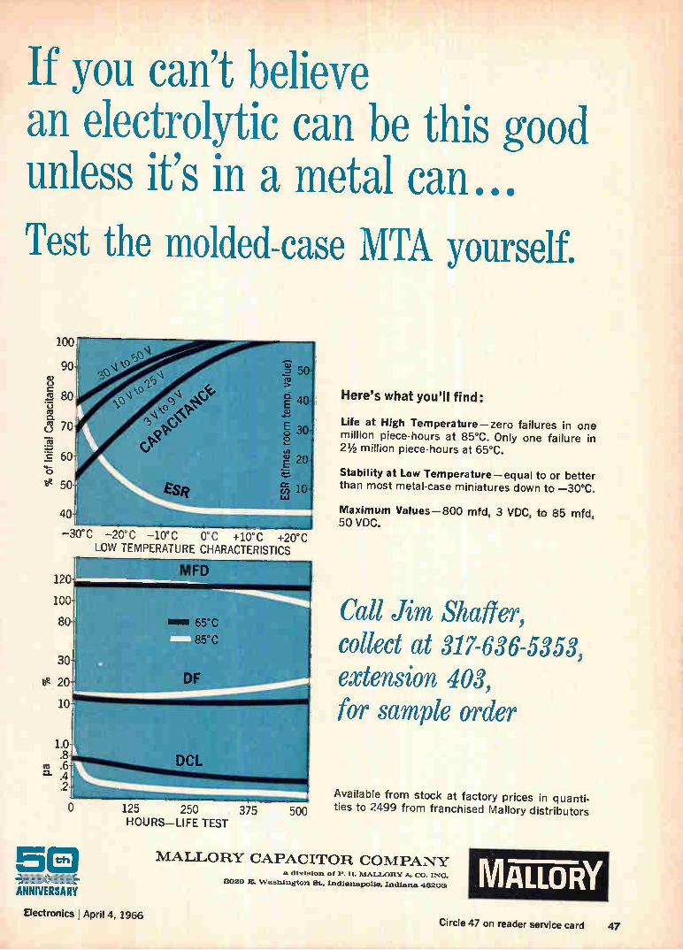
If you can't believe an electrolytic can be this good unless it's in a metal can... Test the molded-case MTA yourself.
100
90
u
co
o co
('.3 70 co
c 60o
be 50-
80
40
'el ep()
0\.
Esi?
-§ 50
O. 40 ta.)
Éo 30
20
(c) io
t 1 -30° C -20°C -10' C 0°C +10°C +20` C
LOW TEMPERATURE CHARACTERISTICS
125 250 375 HOURS-LIFE TEST
Here's what you'll find:
Life at High Temperature-zero failures in one million piece-hours at 85°C. Only one failure in 21/2 million piece-hours at 65°C.
Stability at Low Temperature-equal to or better than most metal-case miniatures down to -30°C.
Maximum Values-800 mfd, 3 VDC, to 85 mfd, 50 VDC.
Call Jim Shaffer, collect at 317-636-5353, extension 403, for sample order
Available from stock at factory prices in quanti-500 ties to 2499 from franchised Mallory distributors
MALLORY CAPACITOR COMPANY divlaltax P. It. MALLORY 8.7. CO. INC.
3028 IL Washington St.. Indianapolis. Indiana 48208. MALLORY Electronics ' April 4, 1966
Circle 47 on reader service card 47
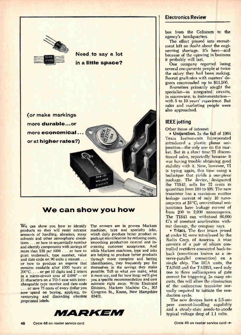
We can show you how
We can show you how to identify products so they will resist extreme amounts of handling, abrasion, many solvents and other atmospheric condi-tions. . or how to sequentially number and identify components with savings of more than $50 per 1000 . . . or how to print trademark, type number, value and date code on 90 units a minute . . . or how to produce an imprint that remains readable after 1000 hours at 200°C. .. . or get 10 digits and 2 letters in a micro-circuit area of 0.090" — or 21 characters on a TO-5 case with inter-changeable type number and date code . . . or save 75 cents of every dollar you now spend on buying, applying, in-ventorying and dirarding obsolete preprinted labels.
The answers are in proven Markem machines, type and specialty inks, which daily produce better product or package identification by reducing costs, smoothing production control and in-creasing customer acceptance. And while Markem machines, type and inks are helping to produce better products through more complete and lasting identification, they frequently pay for themselves in the savings they make possible. Tell us what you make, what it must say, and for how long: we'll give you a specific recommendation and cost estimate right away. Write Electrical Division, Markem Machine Co., 305 Congress St., Keene, New Hampshire 03431.
mAgaileoemm
ElectronicS Review
bus from the Coliseum to the agency's headquarters. The effort poured into recruit-
ment left no doubt about the engi-neering shortage. It's here—and because of the upswing in business it probably will last. One company reported losing
several components people at twice the salary they had been making. Recent graduates with masters' de-grees commanded up to $11,500.
Recruiters primarily sought the specialist—in integrated circuits, in microwave, in instrumentation— with 5 to 10 years' experience. But sales and marketing people were also approached.
IEEE jotting
Other items of interest: • Uni junction. In the fall of 1964
Texas Instruments Incorporated introduced a plastic planar uni-junction—the only one on the mar-ket. But in a short time TI discon-tinued sales, reportedly because it was having trouble obtaining good stability with it. Now, however, TI is trying again, this time using a technique that yields s one-piece package. The device, designated the TIS43, sells for 72 cents in quantifies from 100 to 999. The new transistor has a maximum emitter leakage current of only 10 nano-amperes at 25°C; conventional uni-junctions have leakage current of from 200 to 2,000 nanoamperes. The TIS43 can withstand 60,000 G's of constant acceleration with-out damage, the company says. • Triacs. The first triacs priced
at under $1 were introduced by the Radio Corp. of America. A triac consists of a pair of silicon con-trolled rectifiers connected back-to-back (sometimes known as a re-verse-parallel connection) on a single chip. The RCA units, the TA2892 and the TA2893, need only one to three milliamperes of gate current for triggering. In many cir-cuits, this will allow the elimination of the unijunction transistor nor-mally required to initiate the con-duction cycle. The new devices have a 2.5-am-
pere current-handling capability and a steady-state anode-to-anode typical voltage drop of 1.1 volts.
48 Circle 48 on reader service card Circle 49 on reader service card-3-
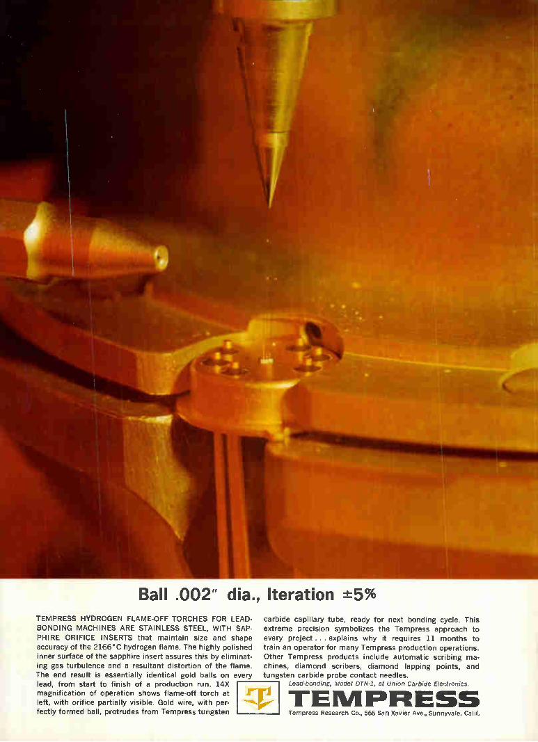
Ball .002" dia., Iteration -±5% TEMPRESS HYDROGEN FLAME-OFF TORCHES FOR LEAD-
BONDING MACHINES ARE STAINLESS STEEL, WITH SAP-
PHIRE ORIFICE INSERTS that maintain size and shape accuracy of the 2166°C hydrogen flame. The highly polished
inner surface of the sapphire insert assures this by eliminat-ing gas turbulence and a resultant distortion of the flame.
The end result is essentially identical gold balls on every lead, from start to finish of a production run. 14X magnification of operation shows flame-off torch at
left, with orifice partially visible. Gold wire, with per-
fectly formed ball, protrudes from Tempress tungsten
carbide capillary tube, ready for next bonding cycle. This
extreme precision symbolizes the Tempress approach to every project ... explains why it requires 11 months to
train an operator for many Tempress production operations.
Other Tempress products include automatic scribing ma-chines, diamond scribers, diamond lapping points, and
tungsten carbide probe contact needles. Lead-bonding, Model DTN-1, at Union Carbide Electronics.
TEMPRIESS Tempress Research Co., 566 San Xavier Ave., Sunnyvale, Calif.
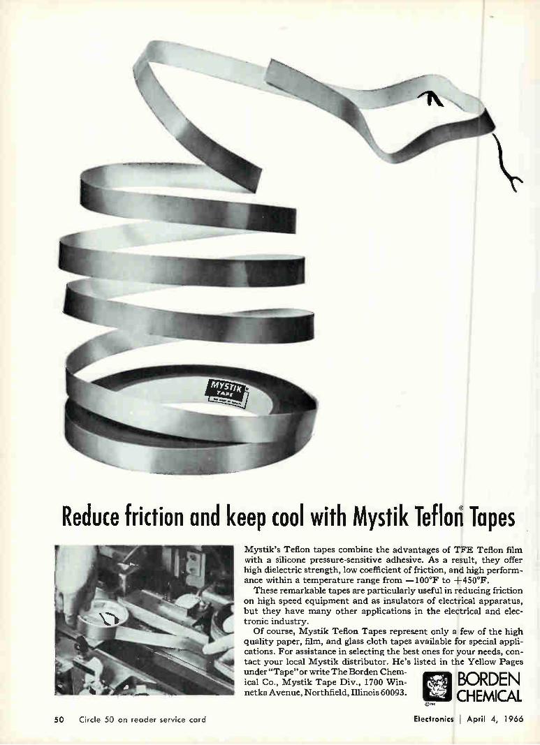
- Ala
Reduce friction and keep cool with Mystik Teflori Tapes Mystik's Teflon tapes combine the advantages of TFE Teflon film with a silicone pressure-sensitive adhesive. As a result, they offer high dielectric strength, low coefficient of friction, and high perform-ance within a temperature range from —100°F to +450°F. These remarkable tapes are particularly useful in reducing friction
on high speed equipment and as insulators of electrical apparatus, but they have many other applications in the electrical and elec-tronic industry. Of course, Mystik Teflon Tapes represent only a few of the high
quality paper, film, and glass cloth tapes available for special appli-cations. For assistance in selecting the best ones for your needs, con-tact your local Mystik distributor. He's listed in the Yellow Pages under "Tape" or write The Borden Chem-ical Co., Mystik Tape Div., 1700 Win- BORDEN netka Avenue, Northfield, Illinois 60093. CHEMICAL ..‘
50 Circle 50 on reader service card Electronics April 4, 1966
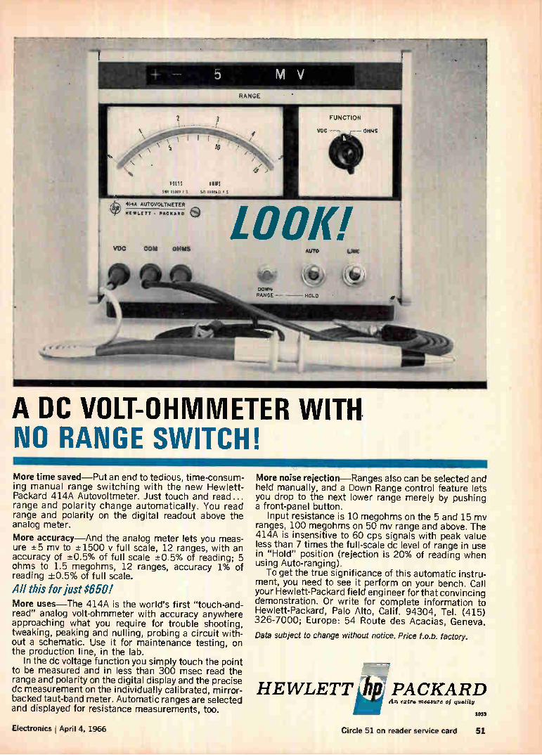
MV
IP
1 3
• VETS SINS
51N.NN t SQ Main f
ee 414A AUTOVOLTNETER HEWLETT PACKARD •
Vie GOAI 0.041%
RANGE
1
) vac FUNCTION
OHMS 1
LOOK! AUTO LINE
Çite « RANGE HOLD
.._.......aiiiie• - ¡WWII, • '•-•
A DC VOLT-OHMMETER WITH NO RANGE SWITCH! More time saved—Put an end to tedious, time-consum-ing manual range switching with the new Hewlett-Packard 414A Autovoltmeter. Just touch and read... range and polarity change automatically. You read range and polarity on the digital readout above the analog meter.
More accuracy—And the analog meter lets you meas-ure ±5 mv to ±-1500 y full scale, 12 ranges, with an accuracy of ±0.5% of full scale -±0.5% of reading; 5 ohms to 1.5 megohms, 12 ranges, accuracy 1% of reading -±0.5% of full scale.
All this for just $650! More uses—The 414A is the world's first "touch-and-read" analog volt-ohmmeter with accuracy anywhere approaching what you require for trouble shooting, tweaking, peaking and nulling, probing a circuit with-out a schematic. Use it for maintenance testing, on the production line, in the lab.
In the dc voltage function you simply touch the point to be measured and in less than 300 msec read the range and polarity on the digital display and the precise dc measurement on the individually calibrated, mirror-backed taut-band meter. Automatic ranges are selected and displayed for resistance measurements, too.
More noise rejection—Ranges also can be selected and held manually, and a Down Range control feature lets you drop to the next lower range merely by pushing a front-panel button.
Input resistance is 10 megohms on the 5 and 15 mv ranges, 100 megohms on 50 mv range and above. The 414A is insensitive to 60 cps signals with peak value less than 7 times the full-scale dc level of range in use in "Hold" position (rejection is 20% of reading when using Auto-ranging).
To get the true significance of this automatic instru-ment, you need to see it perform on your bench. Call your Hewlett-Packard field engineer for that convincing demonstration. Or write for complete information to Hewlett-Packard, Palo Alto, Calif. 94304, Tel. (415) 326-7000; Europe: 54 Route des Acacias, Geneva.
Data subject to change without notice. Price f.o.b. factory.
HEWLETT à PACKARD An extra measure of
1033
Electronics I April 4, 1966 Circle 51 on reader service card 51
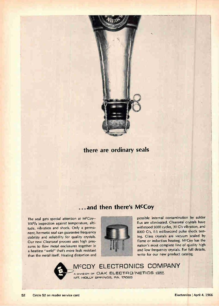
there are ordinary seals
...and then there's McCoy
The seal gets special attention at McCoy-100% inspection against temperature, alti-tude, vibration and shock. Only a perma-nent, hermetic seal can guarantee frequency stability and reliability for quality crystals.
Our new Cleanseal process uses high pres-sures to flow metal enclosures together in a heatless "weld" that's more leak resistant
than the metal itself. Heating distortion and
possible internal contamination by solder flux are eliminated. C/eanseal crystals have
withstood 5000 cycles, 30 G's vibration, and 8000 G's, 0.5 millisecond pulse shock test-ing. Glass crystals are vacuum sealed by flame or induction heating. McCoy has the nation's most complete line of quality high and low frequency crystals. For full details, write for our new product catalog.
McCOY ELECTRONICS COMPANY A DIVISION OF OAK ELECTRO'NETICS CORP. MT. HOLLY SPRINGS, PA. 17065
52 Circle 52 on reader service card Electronics 1 April 4, 1966
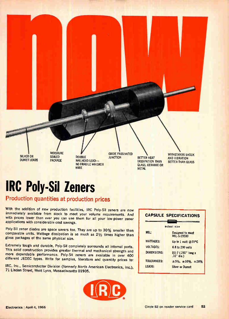
SILVER OR DUMET LEADS
MOISTURE SEALED PACKAGE
OXIDE PASSIVATED DOUBLE JUNCTION NAILHEAD LEAD— NO FRAGILE WHISKER WIRE
IRC Poly-Sil Zeners Production quantities at production prices
With the addition of new production facilities, IRC Poly-Sil zeners are now
immediately available from stock to meet your volume requirements. And with prices lower than ever you can use them for all your low-power zener applications with considerable cost savings.
Poly-Sil zener diodes are space savers too. They are up to 30% smaller than comparable units. Wattage dissipation is as much as 21/2 times higher than glass packages of the same physical size.
Extremely tough and durable, Poly -Sil completely surrounds all internal parts.
This solid construction provides greater thermal and mechanical strength and
more dependable performance. Poly-Sil zeners are available in over 400 different JEDEC types. Write for samples, literature and quantity prices to:
IRC, Inc., Semiconductor Division (formerly North American Electronics, Inc.), 71 Linden Street, West Lynn, Massachusetts 01905.
BETTER HEAT DISSIPATION THAN GLASS, CERAMIC OR METAL
WITHSTANDS SHOCK AND VIBRATION BETTER THAN GLASS
CAPSULE SPECIFICATIONS
MIL:
WATTAGES:
VOLTAGES:
DIMENSIONS:
TOLERANCES:
LEADS:
actual stze
Designed to meet MIL-S-19500
Up to 1 watt @70°C
6.8 to 200 volts
DO-7 (.265" long x .10" dia.)
-±5%, ±10%, ±20%
Silver or Dumet
Electronics April 4, 1966 Circle 53 on reader service card 53
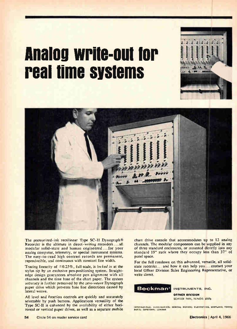
Analog write-out for real time systems
The pressurized-ink rectilinear Type SC-II Dynographe Recorder is the ultimate in direct-writing recorders ...all modular solid-state and human engineered ... for your analog computer, telemetry, or special instrument systems. The easy-to-read high contrast records are permanent, reproducible, and continuous with constant line width.
Tracing linearity of ±0.25%, full scale, is locked in at the stylus tip by an exclusive pen-positioning system. Straight-edge design guarantees absolute pen alignment with all channels and the time base of the chart paper. The system accuracy is further preserved by the zero-weave Dynograph paper drive which prevents base line distortions caused by lateral weave.
All level and function controls are quickly and accurately selectable by push buttons. Applications versatility of the Type SC-II is enhanced by the availability of either hori-zontal or vertical paper drives, as well as a separate mobile
• • • • • • •
• • • • • • . • jl • • .
chart drive console that accommodates up to 12 analog channels. The modular components can be supplied in any of three standard enclosures, or mounted directly into any standard 19" rack where they occupy less than 37" of panel space.
For the full rundown on this advanced, versatile, all solid-state recorder... and how it can help you ... contact your local Offner Division Sales Engineering Representative, or write direct.
Beckman INSTRUMENTS, INC.
OFFNER DIVISION
SCHILLER PARK, ILLINOIS 60176
INTERNATIONAL SUBSIDIARIES GENEVA; MUNICH; GLEN ROTH ES, SCOTLAN TOKYO; PARIS; CAPETOWN; LONDON
54 Circle 54 on reader service card Electronics April 4, 1966
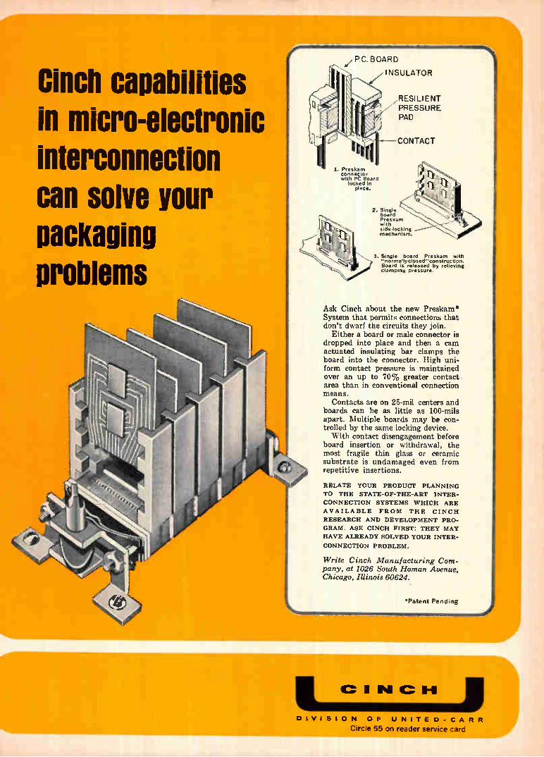
Cinch capabilities in micro-electronic interconnection can solve your packaging Problems
P.C. BOARD
I NSULATOR
1. Preskam connector with PC Board
locked in place.
RESI LI ENT PRESSURE PAD
CONTACT
2. Single board Preskam with side-locking mechanism.
3. Single board Preskam with "normallyclosed"construction. Board is released by relieving clamping pressure.
Ask Cinch about the new Preskam System that permits connections that don't dwarf the circuits they join.
Either a board or male connector is dropped into place and then a cam actuated insulating bar clamps the board into the connector. High uni-form contact pressure is maintained over an up to 70% greater contact area than in conventional connection means.
Contacts are on 25-mil centers and boards can be as little as 100-mils apart. Multiple boards may be con-trolled by the same locking device. With contact disengagement before
board insertion or withdrawal, the most fragile thin glass or ceramic substrate is undamaged even from repetitive insertions.
RELATE YOUR PRODUCT PLANNING
TO THE STATE-OF-THE-ART INTER-
CONNECTION SYSTEMS WHICH ARE
AVAILABLE FROM THE CINCH
RESEARCH AND DEVELOPMENT PRO-
GRAM. ASK CINCH FIRST: THEY MAY
HAVE ALREADY SOLVED YOUR INTER-
CONNECTION PROBLEM.
Write Cinch Manufacturing Com-pany, at 1026 South Homan Avenue, Chicago, Illinois 60624.
'Patent Pending •••••
P1 IC II-11
DIVISION OF UNITED-CARR
Circle 55 on reader service card
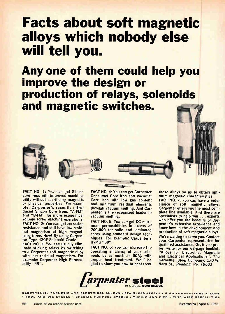
Facts about soft magnetic alloys which nobody else will tell you.
Any one of them could help you improve the design or production of relays, solenoids and magnetic switches.
FACT NO. 1: You can get Silicon core irons with improved machina-bility without sacrificing magnetic or physical properties. For exam-ple: Carpenter's recently intro-duced Silicon Core Irons "A-FM" and "B-FM" for more economical volume screw machine operations. FACT NO. 2: You can get corrosion resistance and still have low resid-ual magnetism at high magnet-izing force. How? By using Carpen-ter Type 430F Solenoid Grade. FACT NO. 3: You can usually elim-inate sticking relays by switching to a Carpenter soft magnetic alloy with less residual magnetism. For example: Carpenter High Permea-bility "49".
FACT NO. 4: You can get Carpenter Consumet Core Iron and Vacumet Core Iron with low gas content and minimum residual elements through vacuum melting. And Car-penter is the recognized leader in vacuum melting.
FACT NO. 5: You can get DC maxi-mum permeabilities in excess of 200,000 for solid and laminated cores using standard design tech-niques. For example: Carpenter's HyMu "80".
FACT NO. 6: You can increase the operating efficiency of your sole-noids by as much as 50% with proper heat treatment. We'll be glad to show you how to heat treat
these alloys so as to obtain opti-mum magnetic characteristics. FACT NO. 7: You can have a wider choice of soft magnetic alloys. Carpenter offers you the most com-plete line available. And there are specialists to help you . . . experts who offer you the benefits of Car-penter's extensive experience and know-how in the development and production of soft magnetic alloys.
We're waiting to serve you. Contact your Carpenter representative for qualified assistance. Or, if you pre-fer, write for our 68-page booklet, "Alloys for Electronic, Magnetic and Electrical Applications". The Carpenter Steel Company, 170 W. Bern St., Reading, Pa. 19603
pipenter steel IN A WORD. CONFIDENCE
ELECTRONIC, MAGNETIC AND ELECTRICAL ALLOYS • STAINLESS STEELS • HIGH TEMPERATURE ALLOYS
• TOOL AND DIE STEELS • SPECIAL-PURPOSE STEELS • TUBING AND PIPE • FINE WIRE SPECIALTIES
56 Circle 56 on reader service card Electronics April 4, 1966

CONSIDER THE SOURCE!
1000 111111
10 .
1
••• • • SAFE FOR . SOLID- STATE::•.f;
001 •
0.1
Avoid systems problems by careful evaluation of klystrons vs. solid-state
H TUBE TERRITORY
LOOK. BEFORE YOU LEAP
1 10 FREQUE,NCY (se)
A premature stampede to solid-state for microwave power sources can cause serious problems for system designers. This is the major finding of recent Sperry studies which objectively compared solid-state with klystron oscillators.
While substantial solid-state progress should not be denigrated, compara-tive data prove that the era of the klystron is far from over. For sys-tem designers, the net result is this: microwave source selection now de-mands more careful attention than ever. The drawing above approximates
today's state-of-the-art. Solid-state sources show clear superiority only at low levels. The dominance of the klystron is unchallenged for high-level applications, and source selection in the large mid-range area demands extremely careful consideration.
In general, power-frequency re-quirements will be the most influen-tial factors in making the choice. Solid-state devices offer many
sources
cannot and
100
advantages when operated well within the design envelope. However, when solid-state devices are applied too near their state-of-the-art, some perform-ance degradation and loss of reliability must be ac-cepted. Power handling considerations are particularly critical, because of the extreme temperature sensitivity
of solid-state devices. Klystrons, on the other hand, still
enjoy numerous inherent advan-tages. At frequencies of X band or higher they are usually the more attractive choice, even for low- and medium-power applications.
In general, klystrons satisfy band-width requirements better than solid-state sources. They also offer superior AM and FM noise char-acteristics, much better temperature stability and longer, more predict-able life.
Details of Sperry's comparative studies are available on request. For your free copy of this unusually use-ful technical paper, contact your Cain &Co. representative or write to-day to Sperry, Gainesville, Florida.
When system designers need a basis for comparison of complex alternatives, where can they turn? To Sperry's Storehouse of Knowledge. Ob-jective, in-depth technical in-formation is a major advan-tage of keeping in touch with the world's first builder of klystron tubes.
ORO
DIVISION OF
SPERRY RAND
CORPORATION
SPERRY ELECTRONIC TUBE DIVISION, Gainesville, Fla. National Representatives: Cain & Co., Los Angeles, 783-4700; Boston, 665-8893; Arlington Heights, 253-3578; Dallas, 357-8645; Dayton, 228-2433; East Chester. 337-3445; Philadelphia. 828-3861; San Francisco. 948-6533; Syracuse, 463-0462; Washington,
296-8265; South Amboy, 727-1900; Huntsville, 534-7955; Montreal, 844-0089.
Electronics April 4, 1966 Circle 57 on reader service card 57
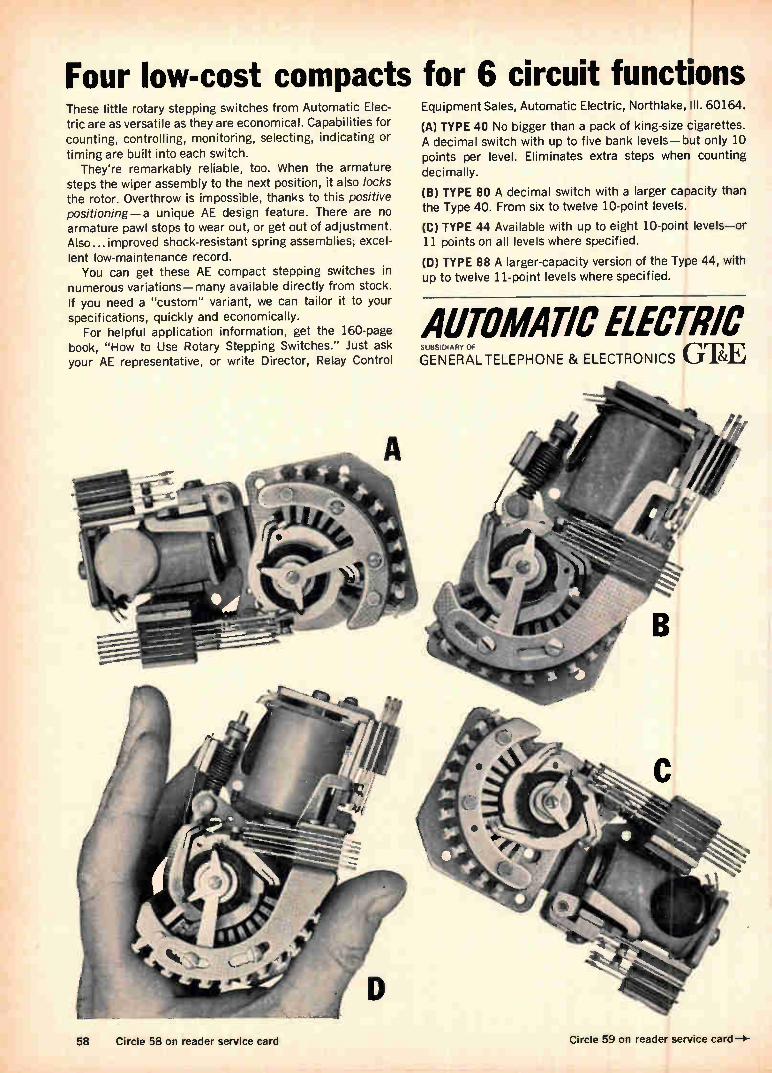
Four low-cost compacts for 6 circuit functions These little rotary stepping switches from Automatic Elec-tric are as versatile as they are economical. Capabilities for counting, controlling, monitoring, selecting, indicating or
timing are built into each switch. They're remarkably reliable, too. When the armature
steps the wiper assembly to the next position, it also locks the rotor. Overthrow is impossible, thanks to this positive positioning—a unique AE design feature. There are no armature pawl stops to wear out, or get out of adjustment. Also... improved shock-resistant spring assemblies; excel-lent low-maintenance record.
You can get these AE compact stepping switches in numerous variations—many available directly from stock. If you need a "custom" variant, we can tailor it to your specifications, quickly and economically.
For helpful application information, get the 160-page book, "How to Use Rotary Stepping Switches." Just ask your AE representative, or write Director, Relay Control
58 Circle 58 on reader service card
Equipment Sales, Automatic Electric, Northlake, III. 60164.
(A) TYPE 40 No bigger than a pack of king-size cigarettes. A decimal switch with up to five bank levels—but only 10 points per level. Eliminates extra steps when counting
decimally.
(B) TYPE 80 A decimal switch with a larger capacity than the Type 40. From six to twelve 10-point levels.
(C) TYPE 44 Available with up to eight 10-point levels—or 11 points on all levels where specified.
(D) TYPE 88 A larger-capacity version of the Type 44, with up to twelve 11-point levels where specified.
AUTOMATIC ELECTRIC GENERAL TELEPHONE & ELECTRONICS GTE SUBSIDIARY OF
Circle 59 on reader service card
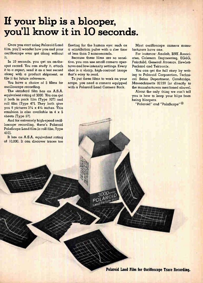
If your blip is a blooper, you'll know it in 10 seconds. Once you start using Polaroid Land
film, you'll wonder how you and your oscilloscope ever got along without it.
In 10 seconds, you get an on-the-spot record. You can study it, attach it to a report, send it as a test record along with a product shipment, or file it for future reference. You have a choice of 5 films for
oscilloscope recording. The standard film has an A.S.A.
equivalent rating of 3000. You can get it both in pack film [Type 107] and roll film [Type 47]. They both give you 8 pictures 31/4 x 41/4 inches. This emulsion is also available in 4 x 5 sheets [Type 571. And for extremely high-speed oscil-
loscope recording, there's Polaroid PolaScope Land film [a roll film, Type 410].
It has an A.S.A. equivalent rating of 10,000. It can discover traces too
fleeting for the human eye: such as a scintillation pulse with a rise time of less than 3 nanoseconds. Because these films are so sensi-
tive, you can use small camera aper-tures and low-intensity settings. Every shot is a sharp, high-contrast image that's easy to read. To put these films to work on your
scope, you need a camera equipped with a Polaroid Land Camera Back.
Most oscilloscope camera manu-facturers have one.
For instance: Analab, BNK Associ-ates, Coleman Engineering, EG&G, Fairchild, General Atronics, Hewlett-Packard and Tektronix. You can get the full story by writ-
ing to Polaroid Corporation, Techni-
cal Sales Department, Cambridge, Massachusetts 02139 [or directly to the manufacturers mentioned above]. About the only thing we can't tell
you is how to keep your blips from being bloopers.
"Polaroid" and "PolaScope" ®
Polaroid Land Film for Oscilloscope Trace Recording.
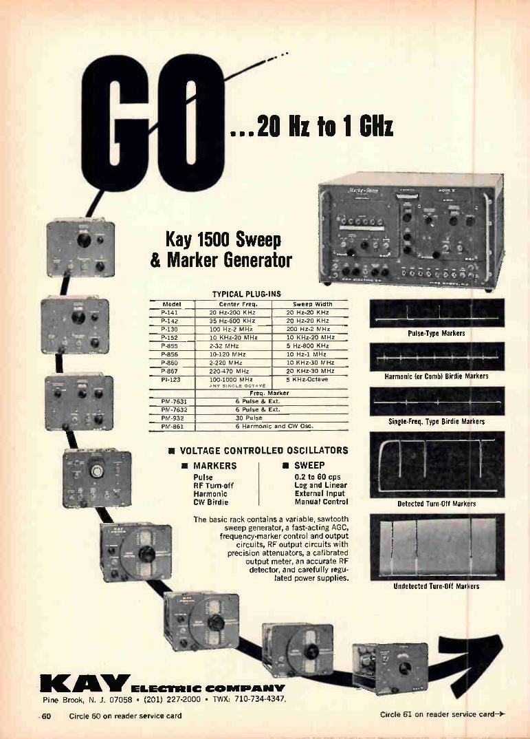
...20 Hz to 1 Gill
Kay 1500 Sweep & Marker Generator
TYPICAL PLUG-INS Model Center Freq. Sweep Width
P-141 20 Hz-200 KHz 20 Hz-20 KHz
P-142 35 Hz-600 KHz 20 Hz-20 KHz
P-130 100 Hz-2 MHz 200 Hz-2 MHz
P-152 10 KHz-20 MHz 10 KHz-20 MHz
P-855 2-32 MHz 5 Hz-800 KHz
P-856 10-120 MHz 10 Hz-1 MHz
P-860 2-220 MHz 10 KHz-30 MHz
P-867 220-470 MHz 20 KHz-30 MHz
PI-123 100-1000 MHz ANY SINGLE OCTAVE
5 KHz-Octave
Freq. Marker
PM-7631 6 Pulse & Ext.
PM-7632 6 Pulse & Ext.
PM-932 30 Pulse
PM-861 6 Harmonic and CW Osc.
II VOLTAGE CONTROLLED OSCILLATORS
II MARKERS Pulse RF Turn-off Harmonic CW Birdie
• SWEEP 0.2 to 60 cps Log and Linear External Input Manual Control
The basic rack contains a variable, sawtooth sweep generator, a fast-acting AGC,
frequency-marker control and output circuits, RF output circuits with
precision attenuators, a calibrated output meter, an accurate RF detector, and carefully regu-
lated power supplies.
see N
IKAILVELIECTIEIC COMAIIPAINIV Pine Brook, N. J. 07058 • (201) 227-2000 • TWX: 710-734-4347,
Pulse-Type Markers
Harmonic (or Comb) Birdie Markers
Single-Freq. Type Birdie Markers
Detected Turn-Off Markers
Undetected Turn-Off Markers
60 Circle 60 on reader service card Circle 61 on reader service card—›-
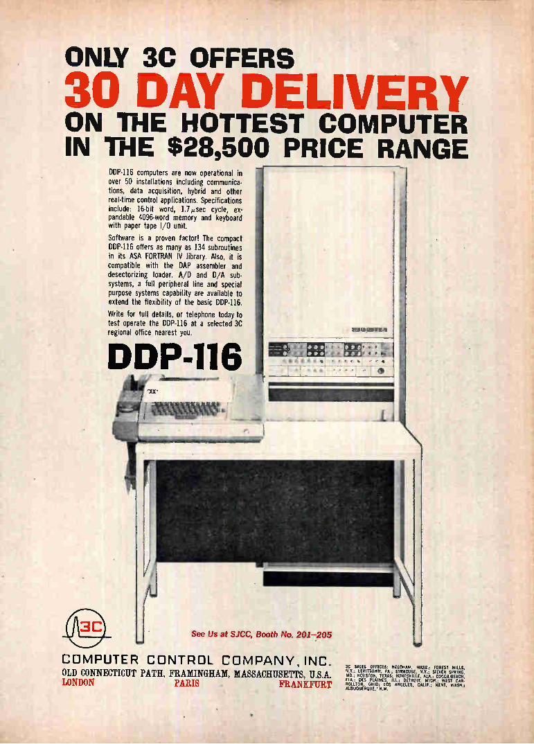
ONLY 3C OFFERS
mqn DAY DELIVERY ON THE HOTTEST COMPUTER IN THE $28,500 PRICE RANGE
DDP-116 computers are now operational in over 50 installations including communica-tions, data acquisition, hybrid and other real-time control applications. Specifications include: 16-bit word, 1.7,usec cycle, ex-pandable 4096-word memory and keyboard with paper tape I/O unit.
Software is a proven factor! The compact DDP-116 offers as many as 134 subroutines in its ASA FORTRAN IV library. Also, it is compatible with the DAP assembler and desectorizing loader. A/D and DIA sub-systems, a full peripheral line and special purpose systems capability are available to extend the flexibility of the basic DDP-116.
Write for full details, or telephone today to test operate the DDP-116 at a selected 3C regional office nearest you.
DDP-116
See Us at SJCC, Booth No. 2017205
p• f
• e r t • t • ••
COMPUTER CONTROL COMPANY, INC. OLD CONNECTICUT PATH, FRAMINGHAM, MASSACHUSETTS, U.S.A. LONDON PARIS . FRANKFURT
3E SALES OFFICES: NEEDHAM, MASS.; FOREST HILLS, N.Y.; LEVITTOWN, PA.; SYRACUSE, N.Y.; SILVER SPRING, MD.; HOUSTON, TEXAS; HUNTSVILLE, ALA.; COCOA BEACH, FLA.; DES PLAINES, ILL.; DETROIT, MICH.; WEST CAR. ROLLTON, OHIO; LOS ANGELES, CALIF.; RENT. WASH.; ALBUQUERQUE, N.M.
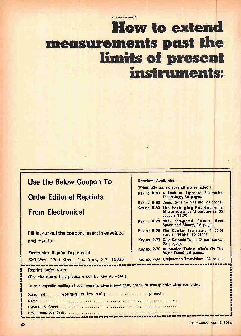
(advertisement)
How to extend measurements past the
limits of present instruments:
Use the Below Coupon To
Order Editorial Reprints
From Electronics!
Fill in, cut out the coupon, insert in envelope
and mail to:
Electronics Reprint Department
330 West 42nd Street, New York, N.Y. 10036
Reprints Available:
(Price: 50e each unless otherwise noted.)
Key no. R-83
Key no. R-82
Key no. R-80
Key no. R-79
Key no. R-78
Key no. R-77
Key no. R-76
Key no. R-74
A Look at Japanese Electronics Technology, 36 pages.
Computer Time Sharing, 20 pages.
The Packaging Revolution In Microelectronics (2 part series, 32 pages.) $1.00.
MOS Integrated Circuits Save Space and Money, 16 pages.
The Overlay Transistor, 4 color special feature, 15 pages.
Cold Cathode Tubes (3 part series, 28 pages).
Automated Trains: Who's On The Right Track? 16 pages.
Unijunction Transistors, 24 pages.
Reprint order form
(See the above list, please order by key number.)
To help expedite mailing of your reprints, please send cash, check, or money order
Send me reprint(s) of key no(s) at 0 each.
Name
Number & Street
when you order.
City, State, Zip Code
62 Electrunirs , April 4, 1966
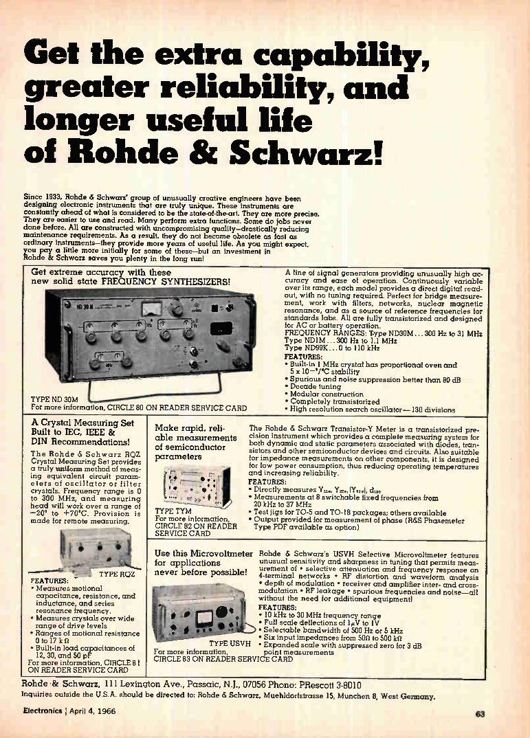
Get the extra capability, greater reliability, and longer useful life of Rohde 8i Schwarz! Since 1933, Rohde & Schwarz' group of unusually creative engineers have been designing electronic instruments that are truly unique. These instruments are constantly ahead of what is considered to be the state-of-the-art. They are more precise. They are easier to use and read. Many perform extra functions. Some do jobs never done before. All are constructed with uncompromising quality—drastically reducing maintenance requirements. As a result, they do not become obsolete as fast as ordinary instruments—they provide more years of useful life. As you might expect. you pay a little more initially for some of these—but an investment in Rohde 8c Schwarz saves you plenty in the long run!
Get extreme accuracy with these new solid state FREQUENCY SYNTHESIZERS!
TYPE ND 30M For more information, CIRCLE 80 ON READER SERVICE CARD
A line of signal generators providing unusually high ac-curacy and ease of operation. Continuously variable over its range, each model provides a direct digital read-out, with no tuning required. Perfect for bridge measure-ment, work with filters, networks, nuclear magnetic resonance, and as a source of reference frequencies for standards labs. All are fully transistorized and designed for AC or battery operation. FREQUENCY RANGES: T-ype ND3OM ... 300 Hz to 31 MHz Type ND1M ... 300 Hz to 1.1 MHz Type ND99K 0 to 110 kHz FEATURES: • Built-in 1 MHz crystal has proportional oven and 5 x 10— 'PC stability • Spurious and noise suppression better than 80 dB • Decade tuning • Modular construction • Completely transistorized • High resolution search oscillator-130 divisions
A Crystal Measuring Set Built to IEC, IEEE & DIN Recommendations! The Rohde & Schwarz RQZ Crystal Measuring Set provides a truly uniform method of meas-ing equivalent circuit param-eters of oscillator or filter crystals. Frequency range is 0 to 300 MHz, and measuring head will work over a range of — 20° to +70°C. Provision is made for remote measuring.
+:* TYPE RQZ FEATURES: • Measures motional capacitance, resistance, and inductance, and series resonance frequency. • Measures crystals over wide range of drive levels • Ranges of motional resistance 0 to 17 k • Built-in load capacitances of
12, 30, and 50 pr For more information, CIRCLE 8 I ON READER SERVICE CARD
Make rapid, reli-able measurements of semiconductor parameters
( 7- r.- • 4 e. -.1 . e ,
-- , •#
TYPE TYM For more information, CIRCLE 82 ON READER SERVICE CARD
The Rohde & Schwarz Transistor-Y Meter is a transistorized pre-cision instrument which provides a complete measuring system for both dynamic and static parameters associated with diodes, tran-sistors and other semiconductor devices and circuits. Also suitable for impedance measurements on other components, it is designed for low power consumption, thus reducing operating temperatures and increasing reliability. FEATURES: • Directly measures Y.., Yr.. 11121el, • Measurements at 8 switchable fixed frequencies from 20 kHz to 37 MHz • Test jigs for TO-5 and TO-18 packages; others available • Output provided for measurement of phase (R&S Phasemeter Type PDF available as option)
Use this Microvoltmeter for applications never before possible!
Rohde & Schwan's USVH Selective Microvoltmeter features unusual sensitivity and sharpness in tuning that permits meas-urement of • selective attenuation and frequency response on 4-terminal networks • RF distortion and waveform analysis • depth of modulation • receiver and amplifier inter- and cross-modulation • RF leakage • spurious frequencies and noise—all without the need for additional equipmentl FEATURES: • 10 kHz to 30 MHz frequency range • Full scale deflections of 1µV to IV • Selectable bandwidth of 500 Hz or 5 kHz • Six input impedances from 509 to 500 ki.1
TYPE USVH • Expanded scale with suppressed zero for 3 dB For more information, point measurements CIRCLE 83 ON READER SERVICE CARD
Rohde -8z Schwarz, Ill Lexington Ave., Passaic, N.J., 07056 Phone: PRescott 3-8010 Inquiries outside the U.S.A. should be directed to: Rohde & Schwarz, Muehldorfstrasse 15, Munchen 8, West Germany.
Electronics April 4, 1966 63
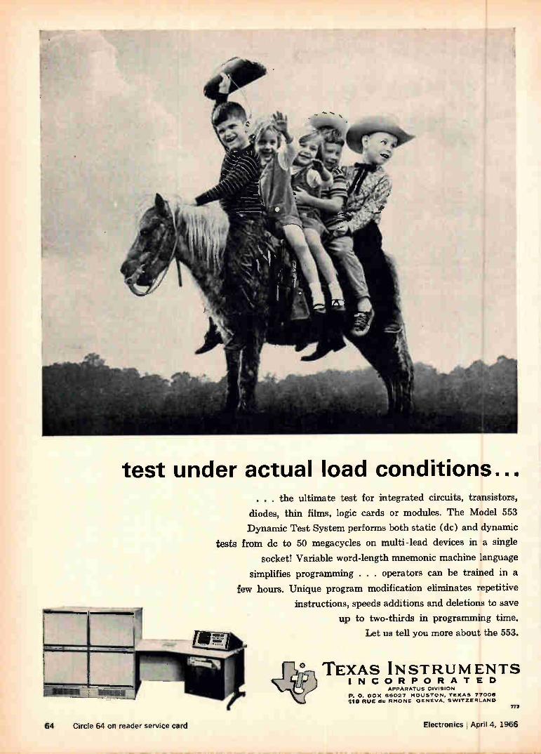
efrgee, e ittl4A4
test under actual load conditions... . . . the ultimate test for integrated circuits, transistors,
diodes, thin films, logic cards or modules. The Model 553
Dynamic Test System performs both static (dc) and dynamic
tests from dc to 50 megacycles on multi-lead devices in a single
socket! Variable word-length mnemonic machine language
simplifies programming . . . operators can be trained in a
few hours. Unique program modification eliminates repetitive
instructions, speeds additions and deletions to save
up to two-thirds in programming time. Let us tell you more about the 553.
TEXAS INSTRUMENTS INCORPORATED
APPARATUS DIVISION
P. 0. BOX 66027 HOUSTON. TEXAS 77006 1113 RUE du RHONE GENEVA. SWITZERLAND
777
64 Circle 64 on reader service card Electronics April 4, 1966
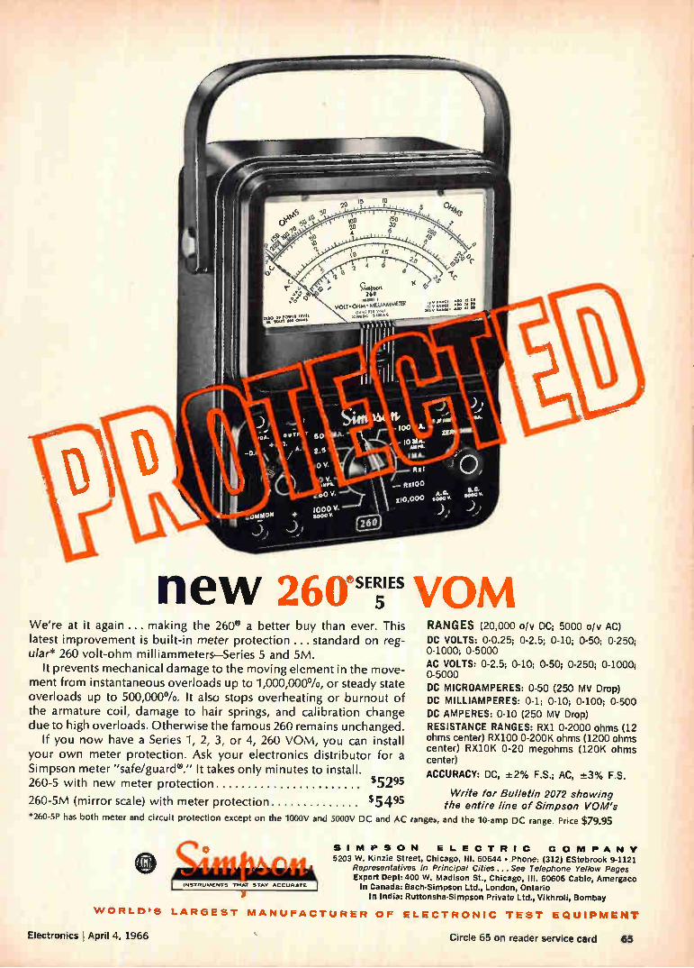
new 26oesur vom We're at it again ... making the 260® a better buy than ever. This
latest improvement is built-in meter protection ... standard on reg-
ular* 260 volt-ohm milliammeters—Series 5 and 5M.
It prevents mechanical damage to the moving element in the move-
ment from instantaneous overloads up to 1,000,000Vo, or steady state
overloads up to 500,000%. It also stops overheating or burnout of
the armature coil, damage to hair springs, and calibration change
due to high overloads. Otherwise the famous 260 remains unchanged.
If you now have a Series 1, 2, 3, or 4, 260 VOM, you can install
your own meter protection. Ask your electronics distributor for a
Simpson meter "safe/guard®." It takes only minutes to install.
260-5 with new meter protection $5295
260-5M (mirror scale) with meter protection $5495
RANGES (20,000 oiv DC; 5000 of y AC) DC VOLTS: 0-0.25; 0-2.5; 0-10; 0-50; 0-250; 0-1000; 0-5000 AC VOLTS: 0-2.5; 0-10; 0-50; 0-250; 0-1000; 0-5000
DC MICROAMPERES: 0-50 (250 niv Drop) DC MILLIAMPERES: 0-1; 0-10; 0-100; 0-500
DC AMPERES: 0-10 (250 my Drop) RESISTANCE RANGES: RX1 0-2000 ohms (12 ohms center) RX100 0-200K ohms (1200 ohms center) RX1OK 0-20 megohms (120K ohms center)
ACCURACY: DC, ±2% F.S.; AC, ±3% F.S.
Write for Bulletin 2072 showing the entire line of Simpson VOM's
*260-5P has both meter and circuit protection except on the 1000V and 5000V DC and AC ranges, and the 10-amp DC range. Price $79.95
C• t4 t r# r • rrly p •
INSTRUMENTS THAT STAY ACCURATE
SIMPSON ELECTRIC COMPANY 5203 W. Kinzie Street, Chicago, III. 60644 • Phone: (312) EStebrook 9-1121
Representatives in Principal Cities...See Telephone Yellow Pages Export Dept: 400 W. Madison St., Chicago, III. 60606 Cable, Amergaco In Canada: Bach-Simpson Ltd., London, Ontario
In India: Ruttonsha-Simpson Private Ltd., Vikhroli, Bombay
WORLD'S LARGEST MANUFACTURER OF ELECTRONIC TEST EQUIPMENT
Electronics I April 4, 1966 Circle 65 on reader service card 65
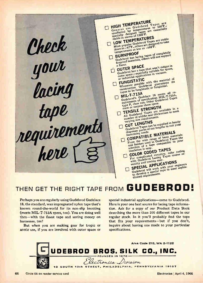
eta
tope
HIGH TEMPERATURE are General use Gudebrod 'rapes 250°F ; unaffected by temperatures to • specially designed tapes are esse
0 ntially
stable in excess of 1500°F•
0 LOW 'TEMPERATURES st Most popular Gudebrod 'rapes are able down to —67°F ., others are designed to take
temperatures as low as —100°F.
Gudebrod has lacing tapes of completely 0 BURNPROOF fireproof materials, others will not support
_ a flame. 0 OUTER SPACE Gudebrod has a tape that won't outgas in
outer space—especially suitable for space, or industrial applications in vacuum.
0 FTATIC Whenever possible with material of construction Gudebrod guarantees its
UNGIS the
tapes to be fungistatic or fungicidal.
Gudebrod's Gudelace 18 meets el re-0 MIL-T-713A quire of specification MIL-T-713A, type P, class two. Other Gudebrod 'r apes
meet or surpass these specs.
0 'TENSILE STRENGTH All Gudebrod 'rapes are available in a number of widths and thicknesses to meet
ements varYing size requir
be supp . in handy 0 CUT LENGTHS Gudebrod Tapes can lied dispenser packs of cut lengths to suit your
o COMPATIBLE MATERIALS harne ssing needs.
From the wide range of basic materials and finishes used in Gudebrod Tapes the selection of a tape compatible to your
insulation is easy.
o COLOR coDED TAPES For complicated circuiuy, color coding with Gudebrod Lacing Tapes makes as-
sembly and tracing eaSY.
D SA. APPLICATI PECIL work with your -BONS Gudebrod will engineers to develop a special tape to meet sophis-
ticated requirements.
THEN GET THE RIGHT TAPE FROM GUDEBROW, Perhaps you are regularly using Gudebrod Gudelace 18, the standard, wax impregnated nylon tape that's known round-the-world for its non-slip knotting (meets MIL-T-713A specs, too). You are doing well then—with the finest tape and saving money on harnesses, too! But when you are making gear for tropic or
arctic use, if you are involved with outer space or
special industrial applications—come to Gudebrod. Here is your one best source for lacing tape informa-tion. Ask for a copy of our Product Data Book describing the more than 200 different tapes in our regular stock. In it you'll probably find the tape that fits your requirements—but if you don't, inquire about having one made to your particular specifications.
Area Code 215, WA 2-1122
UDEBROD BROS. SILK CO., FOUNDED IN 1870
12 SOUTH 12th STREET. PHILADELPHIA, PENNSYLVANIA 19107
66 Circle 66 on reader service card Electronics April 4, 1966

e
You save
money! Quantity-order prices for vol-ume buyers are below comparable pivot and jewel meters!
•
Now availa rein many styles! This revolutionary new meter comes in conventional Bakelite models in 21/2, 31/2, and 41/2 -inch sizes — a modern, dull black model "45" with a pic-ture frame window — brand new clear plastic 41/2 -inch square meter priced for the volume user — the distinctive Medalist series and the con-
temporary "MS" series, each in 3 standard sizes. Auto-Torque meters give you the widest selection of band-type meters available today.
.«. More Reliable! 4"- •
Auto-Torque's simplified design has 50% fewer parts. And since Auto-Torque meters are machine made, they
4"2 % 6Q give you uniform quality and precision never before possible
in conventional
-'40)er meters. You can just about say good-bye 41r1
to service problems!
•Ik•em wr
oillletees
ip Self-shielded mechanism Auto-Torque meters can be mounted on any panel without special calibration; accuracy is unaffected by external fields!
t 1 IVO I TS
beimoubesf"'
Outlasts conventional
meters! Auto-Torque's moving system is sus-pended on metal bands under tension. As a result,
-fflinhere's no friction and wear.
or more information on the revolutionary Auto-
, Torque meters, write Honey-?' well Precision Meter Division,
Manchester, N. H. 03105.
111
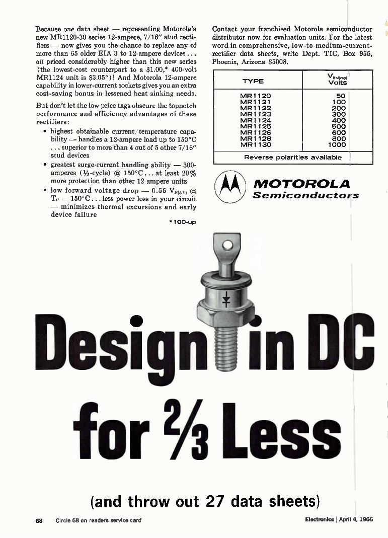
Because one data sheet — representing Motorola's new MR1120-30 series 12-ampere, 7/16" stud recti-fiers — now gives you the chance to replace any of more than 65 older EIA 3 to 12-ampere devices... all priced considerably higher than this new series (the lowest-cost counterpart to a $1.00,* 400-volt MR1124 unit is $3.05*)! And Motorola 12-ampere capability in lower-current sockets gives you an extra cost-saving bonus in lessened heat sinking needs.
But don't let the low price tags obscure the topnotch performance and efficiency advantages of these rectifiers:
• highest obtainable current temperature capa-bility — handles a 12-ampere load up to 150°C ... superior to more than 4 out of 5 other 7/16" stud devices
• greatest surge-current handling ability — 300-amperes ( 1/2 -cycle) @ 150°C . at least 20% more protection than other 12-ampere units
• low forward voltage drop — 0.55 VF(AV) @ = 150'C ... less power loss in your circuit
— minimizes thermal excursions and early device failure
*100-up
Contact your franchised Motorola semiconductor distributor now for evaluation units. For the latest word in comprehensive, low-to-medium-current-rectifier data sheets, write Dept. TIC, Box 955, Phoenix, Arizona 85008.
TYPE
MR1120 MR1121 MR1122 MR1123 MR1124 MR1125 MR1126 MR1128 MR1130
VRM(rep)
Volts
50 100 200 300 400 500 600 800 1000
Reverse polarities available
MOTOROLA sernicarlductors
Des gli. in DC for % Less
•
(and throw out 27 data sheets) 68 Circle 68 on readers service card Electronics April 4, 1966
Washington Newsletter
April 4, 1966
Congress likely
to expand NSF's
scope, not power
Pentagon to rate
off-the-shelf dealers
Supreme court
again tightens
rules on patents
Congress is expected to approve a bill this year greatly expanding the scope but not the power of the National Science Foundation. Because of strong White House opposition, the House Science and
Astronautics Committee has decided not to push to have the foundation take over as chief scientific adviser to the President and as coordinator of all federal research activities. The drive to overhaul the foundation was initiated last February by Emilio Q. Daddario (D., Conn.), chairman of the committee's Science, Research and Development subcommittee. Under the Daddario plan that Congress is expected to approve, the
foundation's area of interest would be expanded into such fields as engi-neering, scientific manpower and resources and scientific information. Hearings are scheduled for April 19 to 21. The science foundation once had much broader power but never
fully exercised it. With the rapid growth of the military and space research programs, power was concentrated within the agencies involved, such as the Pentagon and the National Aeronautics and Space Adminis-tration. When President Kennedy took office, he created the Office of Science and Technology and conferred on it the responsibilities that the foundation never assumed [Electronics, July 12, 1965, p. 121]. Since this placed the Office of Science and Technology directly under the Presi-dent's wing, the White House saw the recent effort to change this line of command as a drive to usurp a power of the President.
Apparently satisfied with results of evaluating contractors' performance on major weapons systems, the Pentagon is extending the report-card system to vendors of off-the-shelf electronic equipment. The evaluations of past performance will help determine who will get future contracts. The program will cover military equipment supplied under contracts totaling $100,000 or more. As a test, the Defense Supply Agency is evaluating producers of
selected supplies and equipment. Starting June 1, the Defense Elec-tronic Supply Center, the Defense Construction Supply Center and the Defense General Supply Center will begin using the evaluations for new contracts. By Jan. 1, 1967, the Defense Department will refine the evalua-tion program and put it on a permanent basis.
Contractors will be judged on the basis of how well they fulfill their contracts with respect to technical performance, milestones and cost levels. They will be allowed to see the evaluations and comment on them. In case of bad marks, they can advise the Pentagon immediately of cor-rective steps or make them evident in subsequent contract proposals.
The Supreme Court is continuing to tighten the rules regulating patent applications by inventors. Setting a precedent that the Patent Office and lower courts will have to follow, the High Court has ruled that com-mercial usefulness must underlie a patent request. The court turned down the inventor of a process to turn out steroid chemicals. The process has no known usefulness—but could prove helpful to scientists doing further research.
69

Washington Newsletter
Immigration eased
for skilled workers
June 1 a deadline
on accelerator site
All-U. S. Early Bird
proposed by AT&T
Defense priority
briefings scheduled
Addendum
Immigration of skilled workers has been eased by a Labor Department certification that there is a critical nationwide shortage of technicians, draftsmen, engineers and machinists. Under the certification, companies in all regions will no longer have to document their own local shortages before going abroad for wholesale hiring.
The Atomic Energy Commission is trying to pick a winner in the "200-bey sweepstakes" by June 1. The AEC has been given a list of seven locales in six states as best bets for location of the proposed 200-billion-electron-volt particle accelerator.
Sites still in the running are Arm Arbor, Mich.; Madison, Wis.; South Barrington or Weston, Ill., near Chicago; Brookhaven National Labora-tory, near Upton, N. Y.; Sierra Foothills, near Sacramento, Calif.; and Denver.
Unless the AEC meets the June 1 deadline for final selection, it may lose its chance to get about $7 million in a supplemental appropriation for fiscal 1967 to start engineering and design.
The American Telephone 8z Telegraph Corp, has asked the Communi-cations Satellite Corp. to consider launching a satellite for domestic communications. The request may open a battle over who owns the ground stations—Comsat or the common carriers. AT&T says there is a need to supplement its continental cable and
microwave network with a large-capacity satellite. Comsat is interested in the plan; earlier it had invited industry pro-
posals on a multipurpose satellite for domestic use. AT&T has suggested that ground stations for the system be owned by the carriers. But the Federal Communications Commission ruled earlier that domestic ground stations for Comsat's international network should be owned by Comsat —at least at first. However, this decision is not likely to be binding on an entirely domestic network.
The Business and Defense Services Administration will begin a series of briefings April 11 to prepare industry for the speeded-up demand for priority deliveries of all defense goods at the expense of civilian orders. A series of 20 or more sessions for defense contractors will be held by the Commerce Department agency to make sure contractors know what to expect and how to comply with the regulations under the Defense Production Act. Firm dates for future briefings now include Dallas, April 11; Atlanta, April 18; Birmingham, April 20; Orlando, Fla., April 22; Cleveland, April 25, and Philadelphia, May 10. The briefings are in re-sponse to an increasing flow of requests from contractors for guidance on how to handle the priority requirements.
By the end of April, the Federal Communications Commission is expected to propose rules governing the use of long-distance communications lines by time-shared computer-service operations. Any FCC action will in-fluence the rates charged on the communications lines and the growth of the industry.
70 Electronics I April 4, 1966
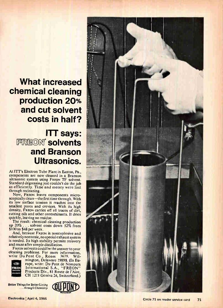
What increased chemical cleaning
production 20% and cut solvent costs in half?
ITT says: FOIEC)Kg solvents
and Branson Ultrasonics.
At ITT's Electron Tube Plant in Easton, Pa., components are now cleaned in a Branson ultrasonic system using FREON TF solvent. Standard degreasing just couldn't do the job as efficiently. Time and money were lost through recleaning. Now, FREON leaves components micro-
scopically clean—the first time through. With its low surface tension it reaches into the smallest pores and crevices. With its high density, FREON carries off all traces of dirt, cutting oils and other contaminants. It dries quickly, leaving no residue. The result: chemical cleaning production
up 20% . . . solvent costs down 52% from $100 to $48 per week. And, because FREON is nonexplosive and
relatively nontoxic, no special exhaust system is needed. Its high stability permits recovery and reuse after simple distillation. FREON solvents could be the answer to your
cleaning problems. For more information, write Du Pont Co., Room 3679. Wil-
mington, Delaware 19898. (In Eu-rope, write: Du Pont de Nemours International S.A., "FREON" Products Div., 81 Route de l'Aire, CH 1211 Geneva 24, Switzerland.)
uula-
FREON
SOLVENTS
Better Things for Better Living ... through Chemistry
Electronics I Anril A. 1 <KA r service cara /1.
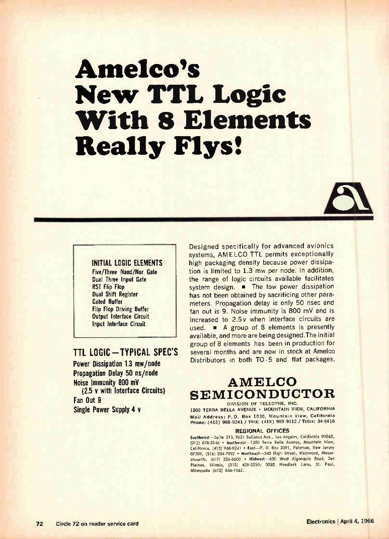
Amelco's New TTL Logic With 8 Elements Really Flys:
INITIAL LOGIC ELEMENTS Five/Three Nand/Nor Gate Dual Three Input Gate RST Flip Flop Dual Shift Register Gated Buffer Flip Flop Driving Buffer Output Interface Circuit Input Interface Circuit
TTL LOGIC-TYPICAL SPEC'S Power Dissipation 1.3 mw/node Propagation Delay 50 ns/node Noise Immunity 800 mV
(2.5 y with Interface Circuits) Fan Out 9 Single Power Supply 4 y
Designed specifically for advanced avionics systems, AM ELCO TTL permits exceptionally high packaging density because power dissipa-tion is limited to 1.3 mw per node. In addition, the range of logic circuits available facilitates system design. • The low power dissipation has not been obtained by sacrificing other para-meters. Propagation delay is only 50 nsec and fan out is 9. Noise immunity is 800 mV and is increased to 2.5v when interface circuits are used. • A group of 8 elements is presently available, and more are being designed.The initial group of 8 elements has been in production for several months and are now in stock at Amelco Distributors in both TO-5 and flat packages.
AMELCO SEMICONDUCTOR
DIVISION OF TELEDYNE, INC.
1300 TERRA BELLA AVENUE • MOUNTAIN VIEW, CALIFORNIA
Mail Address: P.O. Box 1030, Mountain View, California
Phone: (415) 968-9241 / TWX: (415) 969-9112 / Telex: 34-8416
REGIONAL OFFICES Southwest—Suite 213, 9621 Bellanca Ave., Los Angeles, California 90045,
(213) 678-3146 • Northwest -1300 Terra Bella Avenue, Mountain View,
California, (415) 968-9241 • East—P. 0. Box 2091, Paterson, New Jersey 07509, (516) 334-7997 • Northeast-543 High Street, Westwood, Massa-
chusetts, (617) 326-6600 • Midwest-650 West Algonquin Road, Des Plaines, Illinois, (312) 439-3250; 3020 Woodlark Lane, St. Paul,
Minnesota (612) 646-1161.
72 Circle 72 on reader service card Electronics I April 4, 1966
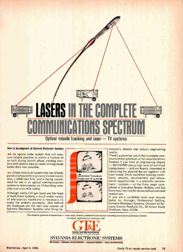
o LASERS IN THE COMPLETE COMMIMICATIOUS SPECTRUM
Optical missile tracking and laser — TV systems
Now in development at Sylvania Electronic Systems
Bo An optical radar system that will mea-sure missile position to within a fraction of an inch during launch phase, yielding posi-tion and velocity data an order of magnitude better than now possible.
ow A laser television system that has already produced excellent picture transmission over a 6000-foot link, and is being consid-ered for use in an optical communications system to interconnect an 11-building com-plex over a six-mile radius.
Although stable CW gas lasers are the heart of both these systems, a much wider variety of electronics hardware is necessary to make the systems successful. And behind the hardware are the men and women of Sylvania Electronic Systems who bring to-
Conventional TV broadcast. Through laser TV system.''
morrow's dreams into today's engineering reality. There's a place for you in the complete com-munications spectrum at Sylvania Electronic Systems if you have an engineering degree — BS/MS/PhD plus a high level of technical competence — and are keenly interested in advancing the state-of-the-art together with your career. Enjoy excellent working condi-tions, security, advancement and educa-tional opportunities in a scientific environ-ment. Location — at the firms major com-plexes in Suburban Boston, Buffalo, and San Francisco, near world-renowned educational institutions. If you are a candidate send your resume today to: Manager, Professional Staffing, Sylvania Electronic Systems, Division of Syl-vania Electric Products Inc., 56 Sylvan Road, Waltham, Mass. 02154.
The complete spectrum of opportunity— work range, location, professional satisfaction is awaiting you at Sylvania Electronic Systems An equal opportunity employer m/f
GEE GENERAL TELEPHONE it ELECTRONICS Total C.olmoucal.e.s 'flee a sow" lh NNNNN
Electronics I Aoril 4. 1966
SYLVAN.IA ELECTRONIC SYSTEMS RESEARCH • PRODUCT DEVELOPMENT • MANUFACTURING • FIELD ENGINEERING
ri rel. 7 '2 n reà.‘ele.. C UM CI VIUM h.azu 73
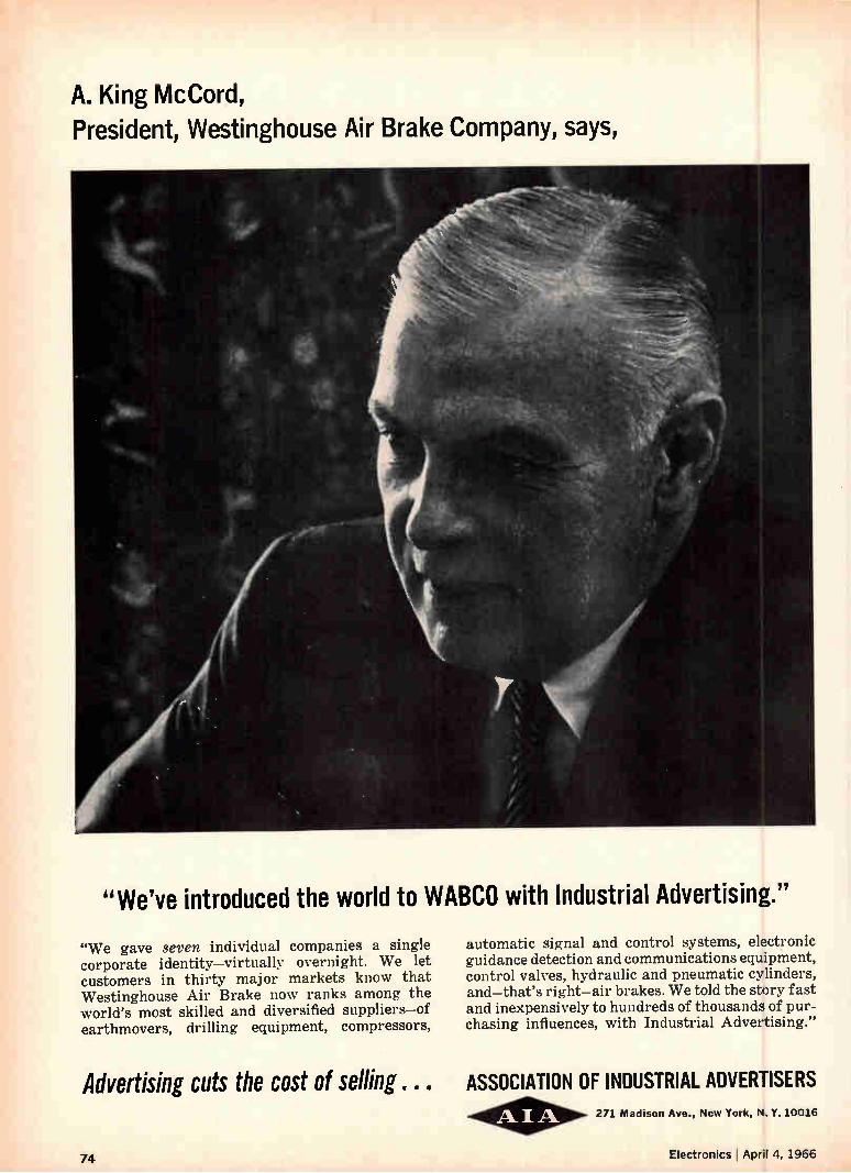
A. King McCord, President, Westinghouse Air Brake Company, says,
"We've introduced the world to WABCO with Industrial Advertising."
"We gave seven individual companies a single corporate identity—virtually overnight. We let customers in thirty major markets know that Westinghouse Air Brake now ranks among the world's most skilled and diversified suppliers—of earthmovers, drilling equipment, compressors,
automatic signal and control systems, electronic guidance detection and communications equipment, control valves, hydraulic and pneumatic cylinders, and—that's right—air brakes. We told the story fast and inexpensively to hundreds of thousands of pur-chasing influences, with Industrial Advertising."
Advertising cuts the cost of selling . . . ASSOCIATION OF INDUSTRIAL ADVERTISERS
74
271 Madison Ave., New York, N. Y.10016
Electronics April 4, 1966
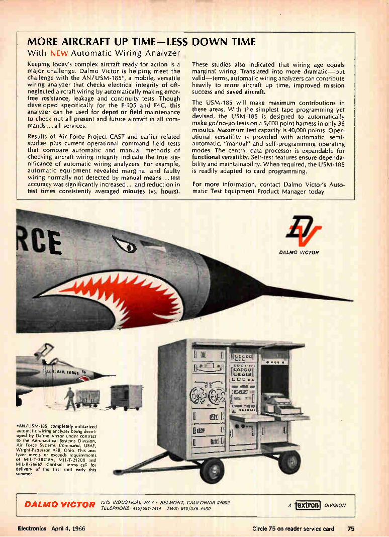
MORE AIRCRAFT UP TIME-LESS DOWN TIME With NEW Automatic Wiring Analyzer Keeping today's complex aircraft ready for action is a major challenge. DaImo Victor is helping meet the
challenge with the AN /USM-185 *, a mobile, versatile
wiring analyzer that checks electrical integrity of oft-
neglected aircraft wiring by automatically making error-
free resistance, leakage and continuity tests. Though
developed specifically for the F-105 and F4C, this
analyzer can be used for depot or field maintenance to check out all present and future aircraft in all com-
mands...all services.
Results of Air Force Project CAST and earlier related
studies plus current operational command field tests
that compare automatic and manual methods of
checking aircraft wiring integrity indicate the true sig-
nificance of automatic wiring analyzers. For example,
automatic equipment revealed marginal and faulty
wiring normally not detected by manual means... test
accuracy was significantly increased ...and reduction in
test times consistently averaged minutes (vs. hours).
These studies also indicated that wiring age equals
marginal wiring. Translated into more dramatic—but
valid—terms, automatic wiring analyzers can contribute
heavily to more aircraft up time, improved mission
success and saved aircraft.
The USM-185 will make maximum contributions in
these areas. With the simplest tape programming yet
devised, the USM-185 is designed to automatically
make go/no-go tests on a 5,000 point harness in only 36
minutes. Maximum test capacity is 40,000 points. Oper-
ational versatility is provided with automatic, semi-
automatic, "manual" and self-programming operating
modes. The central data processor is expandable for
functional versatility. Self-test features ensure dependa-bility and maintainability. When required, the USM-185
is readily adapted to card programming.
For more information, contact DaImo Victor's Auto-matic Test Equipment Product Manager today.
CALMO VICTOR
le" -,-„7-----. weet.,..444. , - .Atit pews 4
*AN/USM-185, completely militarized automatic wiring analyzer being devel-oped by Dalmo Victor under contract to the Aeronautical Systems Division, Air Force Systems Command, USAF, Wright-Patterson MB, Ohio. This ana-lyzer meets or exceeds requirements of MIL-T-38218A, MIL-T-21200 and MIL-R-26667. Contract terms call for delivery of the first unit early this summer.
DALMO VICTOR 1515 INDUSTRIAL WAY • BELMONT, CALIFORNIA 94002 TELEPHONE: 415/591-1414 TWX: 9101376-4400
A tex— ingon, DIVISION
Electronics lApril 4, 1966 Circle 75 on reader service card 75
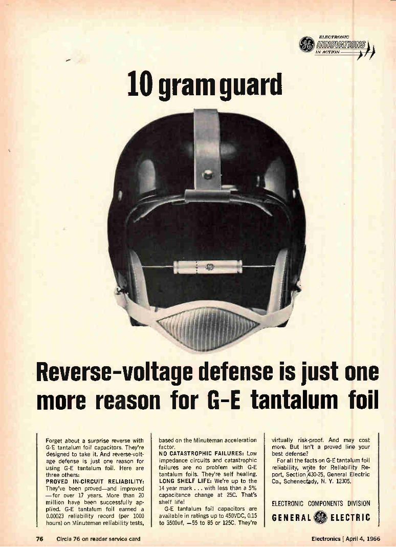
ELECTRONIC
011110FAYIER72 I IN ACTION
I
10 gram guard
Reverse-voltage defense is just one more reason for G-E tantalum foil
Forget about a surprise reverse with G-E tantalum foil capacitors. They're designed to take it. And reverse-volt-age defense is just one reason for using G-E tantalum foil. Here are three others: PROVED IN-CIRCUIT RELIABILITY: They've been proved—and improved —for over 17 years. More than 20 million have been successfully ap-plied. G-E tantalum foil earned a 0.00023 reliability record (per 1000 hours) on Minuteman reliability tests,
based on the Minuteman acceleration factor. NO CATASTROPHIC FAILURES: Low impedance circuits and catastrophic failures are no problem with G-E tantalum foils. They're self healing. LONG SHELF LIFE: We're up to the 14 year mark ... with less than a 5% capacitance change at 25C. That's shelf life! G-E tantalum foil capacitors are
available in ratings up to 450VDC, 0.15 to 3500uf, —55 to 85 or 125C. They're
virtually risk-proof. And may cost more. But isn't a proved line your best defense? For all the facts on G-E tantalum foil
reliability, write for Reliability Re-port, Section 2430-25, General Electric Co., Schenecf4dy, N. Y. 12305.
ELECTRONIC COMPONENTS DIVISION
GENERAL ELECTRIC
76 Circle 76 on reader service card Electronics ! April 4, 1966
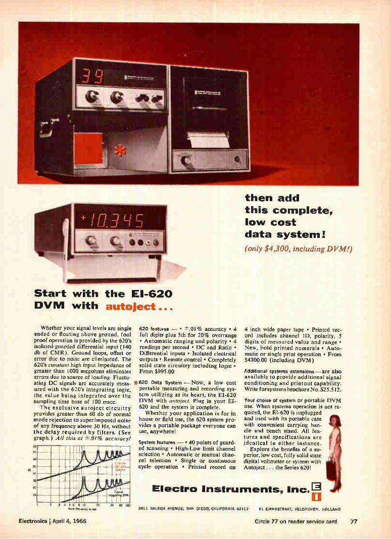
Start with the El-620 DVM with autoject
Whether your signal levels are single ended or floating above ground, fool proof operation is provided by the 620's isolated-guarded differential input (140 db of CMR). Ground loops, offset or error due to noise are eliminated. The 620's constant high input impedance of greater than 1000 megohms eliminates errors due to source of loading. Fluctu-ating DC signals are accurately meas-ured with the 620's integrating logic, the value being integrated over the sampling time base of 100 msec. The exclusive autoject circuitry
provides greater than 60 db of normal mode rejection to superimposed noise of any frequency above 30 Hz, without the delay required by filters. (See graph.) All this at ±.01% accuracy. 40
70
00
SO db e
30
20
620 features — • ±.01% accuracy • 4 full digits plus 5th for 20% overrange • Automatic ranging and polarity • 4 readings per second • DC and Ratio • Differential inputs • Isolated electrical outputs • Remote control • Completely solid state circuitry including logic • From $995.00
*620 Data System — Now, a low cost portable measuring and recording sys-tem utilizing as its heart, the EI-620 DVM with autoject. Plug in your EI-620 and the system is complete. Whether your application is for in
house or field use, the 620 system pro-vides a portable package everyone can use, anywhere!
System features — • 40 points of guard-ed scanning • High-Low limit channel selection • Automatic or manual chan-nel selection • Single or continuous cycle operation • Printed record on
then add this complete, low cost data system!
(only „S4,300, including DVM!)
4 inch wide paper tape • Printed rec-ord includes channel ID, polarity, 5 digits of measured value and range • New, bold printed numerals • Auto-matic or single print operation • From $4300.00 (including DVM)
Additional systems extensions—are also available to provide additional signal conditioning and printout capability. Write for systems brochure No. S25.512.
Your choice of system or portable DVM use. When systems operation is not re-quired, the EI-620 is unplugged and used with its portable case with convenient carrying han-dle and bench stand. All fea-tures and specifications are identical in either instance.
Explore the benefits of a su-perior, low cost, fully solid state digital voltmeter or system with Autoject ... the Series 620!
Electro Instruments, Inc.?.
2 3 4 1, , 10 20 40 60 100 Notse frequency In 41»
Electronics ¡April 4, 1966
8611 BALBOA AVENUE, SAN DIEGO, CALIFORNIA 92112 41 EMMASTRAAT, VELDHOVEN, HOLLAND
Circle 77 on reader service card 77
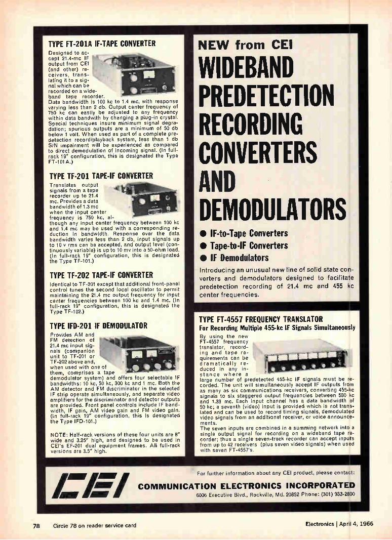
TYPE FT-201A IF-TAPE CONVERTER Designed to ac-cept 21.4-mc IF output from CEI (and other) re-ceivers, trans-lating it to a sig-nal which can be recorded on a wide-band tape recorder. Data bandwidth is 100 kc to 1.4 mc, with response varying less than 2 db. Output center frequency of 750 kc can easily be adjusted to any frequency within data bandwith by changing a plug-in crystal. Special techniques insure minimum signal degra-dation; spurious outputs are a minimum of 50 db below 1 volt. When used as part of a complete pre-detection record/playback system, less than 1 db S/N impairment will be experienced as compared to direct demodulation of incoming signal. (In full-rack 19" configuration, this is designated the Type FT-101A.)
TYPE TF-201 TAPE-IF CONVERTER Translates output signals from a tape recorder up to 21.4 mc. Provides a data bandwidth of 1.3 mc when the input center frequency is 750 kc, al-though any input center frequency between 100 kc and 1.4 mc may be used with a corresponding re-duction in bandwidth. Response over the data bandwidth varies less than 2 db, input signals up to 10 y rms can be accepted, and output level (con-tinuously variable) is up to 10 my into a 50-ohm load. (In full-rack 19" configuration, this is designated the Type TF-101.)
TYPE TF-202 TAPE-IF CONVERTER Identical to TF-201 except that additional front-panel control tunes the second local oscillator to permit maintaining the 21.4 mc output frequency for input center frequencies between 100 kc and 1.4 mc. (In full-rack 19" configuration, this is designated the Type TF-102.)
TYPE IFD-201 IF DEMODULATOR Provides AM and FM detection of 21.4 mc input sig-nals (companion unit to TF-201 or TF-202 above and, when used with one of them, comprises a tape demodulator system) and offers four selectable IF bandwidths: 10 kc, 50 kc, 300 kc and 1 mc. Both the AM detector and FM discriminator in the selected IF strip operate simultaneously, and separate video amplifiers for the discriminator and detector outputs are provided. Front panel controls include IF band-width, IF gain, AM video gain and FM video gain. (In full-rack 19" configuration, this is designated the Type IFD-101.)
NOTE: Half-rack versions of these four units are 8" wide and 3.25" high, and designed to be used in CEI's EE-201 dual equipment frames. All full-rack versions are 3.5" high.
NEW from CEI
WIDEBAND PREDETECTION RECORDING CONVERTERS AND DEMODULATORS • IF-to-Tape Converters • Tape-to-IF Converters • IF Demodulators Introducing an unusual new line of solid state con-verters and demodulators designed to facilitate predetection recording of 21.4 mc and 455 kc center frequencies.
TYPE FT-4557 FREQUENCY TRANSLATOR For Recording Multiple 455-kc IF Signals Simultaneously By using the new FT-4557 frequency translator, record-ing and tape re-quirements can be dramatically re-duced in any in-stance where a large number of predetected 455-kc IF signals must be re-corded. The unit will simultaneously accept IF outputs from as many as six communications receivers, converting 455-kc signals to six staggered output frequencies between 580 kc and 1.33 mc. Each input channel has a data bandwidth of 50 kc; a seventh (video) input is provided which is not trans-lated and can be used to record timing signals, demodulated video signals from an additional receiver, or voice announce-ments. The seven inputs are combined in a summing network into a single output signal for recording on a wideband tape re-corder; thus a single seven-track recorder can accept inputs from up to 42 receivers (plus seven video signals) when used with seven FT-4557's.
/ For further information about any CEI product, please contact: 1
MIY AIV 7 COMMUNICAT ON ELECTRON ICS INCORPORATED 6006 Executive Blvd., Rockville, Md. 20852 Phone: (301) 933-2800
78 Circle 78 on reader service card Electronics I April 4, 1966
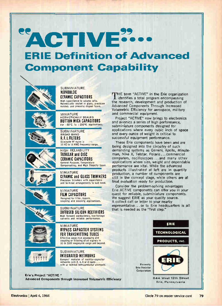
ee ee
ERIE Definition of Advanced Component Capability
SUBMINIATURE MONOBLOC CERAMIC CAPACITORS High capacitance to volume ratio. Hermetically sealed in glass; precision molded, and phenolic dipped types.
MINIATURE HERMETICALLY SEALED
BUTTON MICA CAPACITORS For —55'C. to -1-200°C. applications.
SUBMINIATURE BROAD BAND
R. F.I.FILTERS Eliminate RF noise in 10 KC to 10 KMC frequency range.
HIGH RELIABILIIY TUBULAR and DISC
'1 CERAMIC CAPACITORS General Purpose; Temperature Compensating; and High Stability types.
MINIATURE CERAMIC and GLASS TRIMMERS Precision trimmers with capacitance and terminal arrangements to suit need.
MINIATURE FILM CAPACITORS Designed for filter, bypass, coupling and blocking applications.
SUBMINIATURE DIFFUSED SILICON RECTIFIERS High forward conductance, low-leakage currents and reliable performance.
MINIATURE BYPASS CAPACITOR SYSTEMS FOR TRANSMITTING TUBES Effective capacitive bypassing and coupling or filtering of all signals in 10 to 3000 megacycle range and beyond.
SUBMINIATURE INTEGRATED NETWORKS Compact modules of resistor-capacitor networks with 2, 4, 6 or 8 leads ... with or without semiconductor elements.
THE term "ACTIVE" in the Erie organization identifies a total program encompassing
the research, development and production of Advanced Components Through Increased Volumetric Efficiency for aerospace, military and commercial equipment.
Project "ACTIVE" now brings to electronics and avionics a series of high performance, subminiature components designed for applications where every cubic inch of space and every ounce of weight is critical to successful equipment performance.
These Erie components have been and are being designed into the circuitry of such demanding systems as Gemini, Apollo, Minute-man, Nike X, Telstar, Polaris...commercial computers, oscilloscopes...and many other applications where size, weight and dependable performance are vital. While the advanced products illustrated at left are in quantity production, a number of components are still in the concept stage, while others are at final evaluation ready for production.
Consider the problem-solving advantages Erie ACTIVE components can offer you in your quest for reliable, subminiature components. We suggest ERIE as your quality source. A collect call or letter to your nearby representative ...or to Erie headquarters is all that is needed as the "first step."
Erie's Project "ACTIVE " Advanced Components through Increased Volumetric Efficiency
Formerly Erie Resistor Corporation
ERIE
TECHNOLOGICAL
PRODUCTS, INC.
644 West 12th Street
Erie, Pennsylvania
Electronics April 4, 1966 Circle 79 on reader service card 79
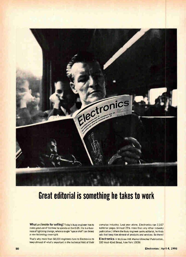
Great editorial is something he takes to work
What a climate for selling! Today's busy engineer has to make good use of the time he spends on the 8:05. His is a busi-ness of lightning change, where a single "space shot" can breed a new technology overnight.
That's why more than 68,000 engineers turn to Electronics to keep abreast of what's important in the technical field of their
complex industry. Last year alone, Electronics ran 2,167 editorial pages (almost 25% more than any other industry
publication.) Where the busy engineer seeks editorial, he finds
ads that keep him abreast of products and services. Be there!
Electronics A McGraw-Hill Market-Directed Publication, 330 West 42nd Street, New York 10036
80 Electronics !April 4, 1966
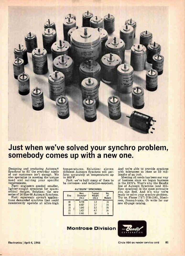
Just when we've solved your synchro problem, somebody comes up with a new one.
Designing and producing Autosyn® Synchros to fill the everyday needs of our customers isn't enough. We also specialize in meeting the unique need and solving your specific requirements.
Fact: engineers needed smaller, lighter-weight synchros for space-critical designs. Solution: the new series of 16 Size 08 Autosyn Synchros.
Fact: supersonic aircraft applica-tions demanded synchros that could consistently operate at ultra-high
temperatures. Solution: eleven different Autosyn Synchros will per-form accurately at temperatures up to 800°F.
Fact: we've built many of them to be corrosion- and radiation-resistant.
AUTOSYN SY NC H ROS
Max. Size Diameter
(In.)
08 10
11 15 22
0.750
0.937 1.062 1.437 2.161
Typical Weight (Oz.)
1.3 1.7
3.2 4.7 18
No. of
Models
16
25 29
24
Montrose Division
And we're able td provide synchros with tolerances as close as 50 mil-lionths of an inch.
Meeting all needs has been our way of business since we began business in the 1920's. That's why the Bendix line of Autosyn Synchros (and Mil-Spec synchros) is the most extensive you can find. And it's why we're ready to solve your synchro problem. Try us. Phone (717) 278-1161, Mont-rose, Pennsylvania. Or write for our new 42-page catalog.
T71 1Enje,
CORPORATION
Electronics April 4, 1966 Circle 464 on reader service card 81
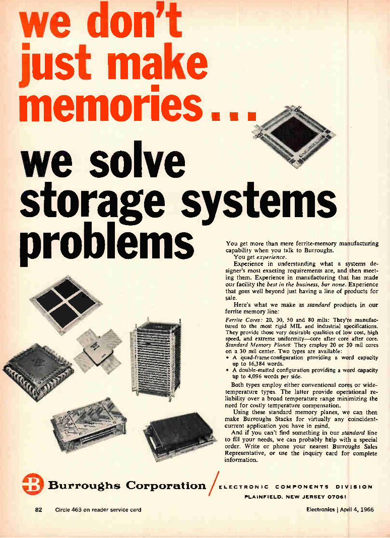
we don't just make memories. we solve storage systems problems You get more than mere ferrite-memory manufacturing
capability when you talk to Burroughs. You get experience. Experience in understanding what a systems de-
signer's most exacting requirements are, and then meet-ing them. Experience in manufacturing that has made our facility the best in the business, bar none. Experience that goes well beyond just having a line of products for sale.
Here's what we make as standard products in our ferrite memory line:
Ferrite Cores: 20, 30, 50 and 80 mils: They're manufac-tured to the most rigid MIL and industrial specifications. They provide those very desirable qualities of low cost, high speed, and extreme uniformity—core after core after core. Standard Memory Planes: They employ 20 or 30 mil cores on a 30 mil center. Two types are available: • A quad-frame configuration providing a word capacity
up to 16,384 words. • A double-matted configuration providing a word capacity
tip to 4,096 words per side.
Both types employ either conventional cores or wide-temperature types. The latter provide operational re-liability over a broad temperature range minimizing the need for costly temperature compensation.
Using these standard memory planes, we can then make Burroughs Stacks for virtually any coincident-current application you have in mind. And if you can't find something in our standard line
to fill your needs, we can probably help with a special order. Write or phone your nearest Burroughs Sales Representative, or use the inquiry card for complete information.
Burroughs Corporation. ELECTRON IC COMPONENTS DIV
PLAINFIELD. NEW JERSEY 07061
ISION
82 Circle 463 on reader service card Electronics April 4, 1966
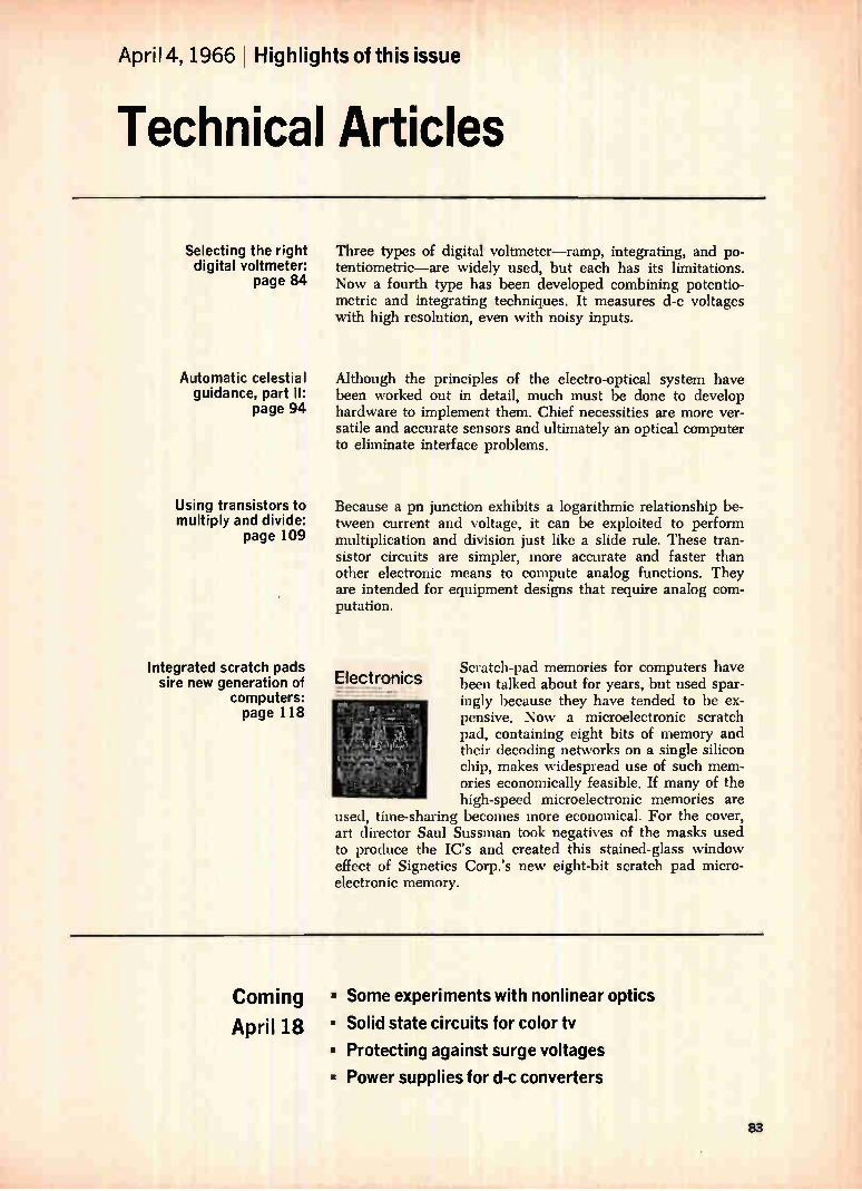
April 4, 1966 Highlights of this issue
Technical Articles
Selecting the right digital voltmeter:
page 84
Automatic celestial guidance, part II:
page 94
Using transistors to multiply and divide:
page 109
Integrated scratch pads sire new generation of
computers: page 118
Three types of digital voltmeter—ramp, integrating, and po-tentiometric—are widely used, but each has its limitations. Now a fourth type has been developed combining potentio-metric and integrating techniques. It measures d-c voltages with high resolution, even with noisy inputs.
Although the principles of the electro-optical system have been worked out in detail, much must be done to develop hardware to implement them. Chief necessities are more ver-satile and accurate sensors and ultimately an optical computer to eliminate interface problems.
Because a pn junction exhibits a logarithmic relationship be-tween current and voltage, it can be exploited to perform multiplication and division just like a slide rule. These tran-sistor circuits are simpler, more accurate and faster than other electronic means to compute analog functions. They are intended for equipment designs that require analog com-putation.
Electronics Scratch-pad memories for computers have been talked about for years, but used spar-ingly because they have tended to be ex-pensive. Now a microelectronic scratch pad, containing eight bits of memory and their decoding networks on a single silicon chip, makes widespread use of such mem-ories economically feasible. If many of the high-speed microelectronic memories are
used, time-sharing becomes more economical. For the cover, art director Saul Sussman took negatives of the masks used to produce the IC's and created this stained-glass window effect of Signetics Corp.'s new eight-bit scratch pad micro-electronic memory.
Coming
April 18
• Some experiments with nonlinear optics
• Solid state circuits for color tv
• Protecting against surge voltages
• Power supplies for d-c converters
83
Instrumentation
Selecting the right digital voltmeter
Three types of dvm's—ramp, integrating and potentiometric—are widely
used, but each has its limitations. Now a fourth provides d-c measurements
with high resolution, even when inputs are noisy
By Bill G. Kay
Loveland division, Hewlett-Packard Co., Loveland, Colo.
The ideal digital voltméter—one that combines the lowest cost with high accuracy, resolution, sensitivity, stability, reading rate, superimposed and common mode noise rejection—just doesn't exist. Three basic techniques that enable a digital voltmeter to convert analog measurements to digi-tal displays—ramp or slope, integrating, and the potentiometric or successive approximation—are widely used, but each has limited applications. For example, the ramp type voltmeter is a rela-
tively low-cost instillment, but is usually only accu-rate within 0.05%. If higher accuracy within 0.005% coupled with good stability is sought, the potentiometric technique is probably the most de-sirable—but its reading rate is low. And if a good reading rate combined with relatively high ac-curacy and good superimposed noise rejection is needed, then an instrument based on the integrating technique is the best but the most expensive. Approaching the ideal is a new, relatively low-
cost instrument that provides d-c measurements with high resolution, accuracy, stability, and read-ing rate even with noisy input signals. The in-strument combines the potentiometric and inte-grating methods. This techniques employs a voltage-to-frequency converter to achieve noise re-jection, while its accuracy depends on the poten-tiometric method with its precision d-c power sup-ply and resistive divider. Still, not everybody wants
The author
Bill G. Kay has designed digital voltmeters since joining the Hewlett-Packard Co. in 1962. He is currently a digital-voltmeter project leader in H-P's Loveland research and development laboratory.
this new type and the problem is which of the four kinds of digital voltmeter to use.
The ramp method
Digital voltmeters that utilize the ramp tech-nique are in what can be considered the econ-omy class of dvm's. These voltmeters meas-ure the length of time it takes an internally generated ramp voltage with a precisely known slope, starting from a known level, to become equal to the unknown input voltage.
In a typical dvm of this type, the ramp voltage— shown in the diagram on page 85—is compared with two voltage levels: ground and the unknown voltage E. to be measured. When they ramp voltage equals ground potential, the first comparator gen-erates a coincidence pulse that opens the gate at time t1. The second comparator closes the gate when the ramp and unknown voltage coincide at time t2. The time T = t2 — ti is proportional to E. While the gate is open, a train of pulses from
the fixed oscillator passes to decimal counters and the number of pulses counted during the gating interval is also proportional to E. The relationship between the number of counts,
N, entered into the counters and the gating time, T, with respect to the oscillator's fixed rate, R, is simply N = RT. Thus, the appropriate choice of <, ramp slope and oscillator frequency provides a direct readout in volts of the totalizing circuit. For example, a four-digit voltmeter might have a ramp slope R = 60 volts per second and an oscillator frequency of 600 kilocycles per second. With the dvm set on the one-volt range, if E. = 0.75 volt, then T = 0.75/60 second, and the number of gated oscillator cycles—N =RT—is 7,500.
Integrating dvm technique
Rnmp type meters are usually limited in accu-racy to within 0.05% by the accuracy of the corn-
84 Electronics I April 4, 1966
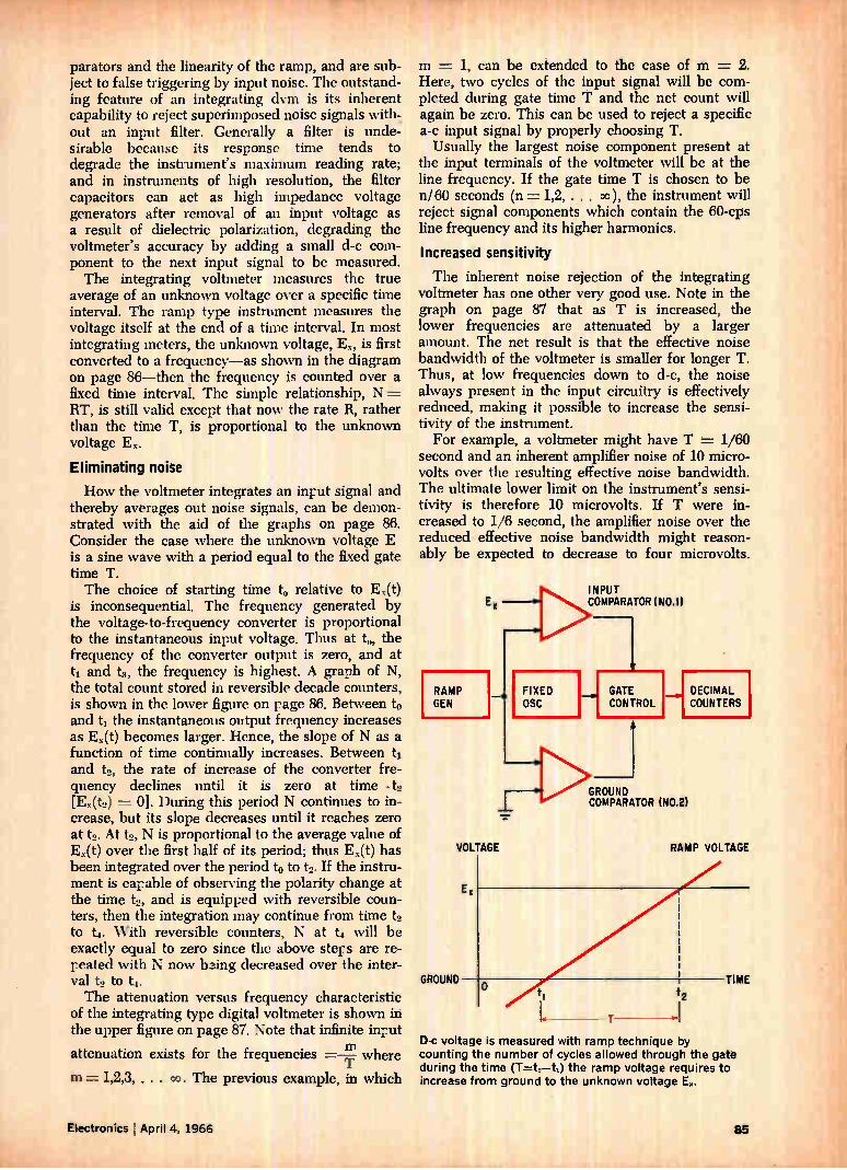
parators and the linearity of the ramp, and are sub-ject to false triggering by input noise. The outstand-ing feature of an integrating dvm is its inherent capability to reject superimposed noise signals with-out an input filter. Generally a filter is unde-sirable because its response time tends to degrade the instrument's maximum reading rate; and in instruments of high resolution, the filter capacitors can act as high impedance voltage generators after removal of an input voltage as a result of dielectric polarization, degrading the voltmeter's accuracy by adding a small d-c com-ponent to the next input signal to be measured. The integrating voltmeter measures the true
average of an unknown voltage over a specific time interval. The ramp type instrument measures the voltage itself at the end of a time interval. In most integrating meters, the unknown voltage, Ex, is first converted to a frequency—as shown in the diagram on page 86—then the frequency is counted over a fixed time interval. The simple relationship, N = RT, is still valid except that now the rate R, rather than the time T, is proportional to the unknown voltage E.
Eliminating noise
How the voltmeter integrates an input signal and thereby averages out noise signals, can be demon-strated with the aid of the graphs on page 86. Consider the case where the unknown voltage E is a sine wave with a period equal to the fixed gate time T. The choice of starting time t, relative to Ex(t)
is inconsequential. The frequency generated by the voltage-to-frequency converter is proportional to the instantaneous input voltage. Thus at to, the frequency of the converter output is zero, and at ti and t3, the frequency is highest. A graph of N, the total count stored in reversible decade counters, is shown in the lower figure on page 86. Between to and ti the instantaneous output frequency increases as Ex(t) becomes larger. Hence, the slope of N as a function of time continually increases. Between ti and t2, the rate of increase of the converter fre-quency declines until it is zero at time - t2 [Ex(to) = 0]. During this period N continues to in-crease, but its slope decreases until it reaches zero at t2. At to, N is proportional to the average value of Ex(t) over the first half of its period; thus Ex(t) has been integrated over the period to to to. If the instru-ment is capable of observing the polarity change at the time t2, and is equipped with reversible coun-ters, then the integration may continue from time t2 to t.. With reversible counters, N at t4 will be exactly equal to zero since the above steps are re-peated with N now bzing decreased over the inter-val t2 to The attenuation versus frequency characteristic
of the integrating type digital voltmeter is shown in the upper figure on page 87. Note that infinite input
attenuation exists for the frequencies =—n1 where
m = 1,2,3, . . . co. The previous example, in which
m = 1, can be extended to the case of m = 2. Here, two cycles of the input signal will be com-pleted during gate time T and the net count will again be zero. This can be used to reject a specific a-c input signal by properly choosing T. Usually the largest noise component present at
the input terminals of the voltmeter will be at the line frequency. If the gate time T is chosen to be n/60 seconds (n = 1,2, . . . co), the instrument will reject signal components which contain the 60-cps line frequency and its higher harmonics.
Increased sensitivity
The inherent noise rejection of the integrating voltmeter has one other very good use. Note in the graph on page 87 that as T is increased, the lower frequencies are attenuated by a larger amount. The net result is that the effective noise bandwidth of the voltmeter is smaller for longer T. Thus, at low frequencies down to d-c, the noise always present in the input circuitry is effectively reduced, making it possible to increase the sensi-tivity of the instrument. For example, a voltmeter might have T = 1/60
second and an inherent amplifier noise of 10 micro-volts over the resulting effective noise bandwidth. The ultimate lower limit on the instrument's sensi-tivity is therefore 10 microvolts. If T were in-creased to 1/6 second, the amplifier noise over the reduced effective noise bandwidth might reason-ably be expected to decrease to four microvolts.
RAMP GEN
VOLTAGE
GROUND
FIXED OSC
INPUT COMPARATOR (N0.1)
GATE CONTROL
__01DECIMAL COUNTERS
GROUND COMPARATOR (N0.2)
RAMP VOLTAGE
13-c voltage is measured with ramp technique by counting the number of cycles allowed through the gate during the time (T=t. —ti) the ramp voltage requires to increase from ground to the unknown voltage E.
Electronics April 4, 1966

This is the technique used in integrating digi-tal voltmeters to resolve low-level signals in the microvolt region, at the sacrifice of reading rate. The ramp technique has an attenuation versus
frequency curve similar to that shown on page 87. However, since T is proportional to the un-known input signal, the cusps of infinite rejection are not fixed with respect to frequency. Thus the ramp technique cannot easily be used to integrate out, or reject a specific a-c input signal.
Although the integrating technique itself places no limit on reading rate, the limitations of the voltage-to-frequency converter and the selection of the cusps of infinite rejection do. To reject noise signals at line frequency, T is
chosen to be at least 1/60 second. This means that if no dwell time is required between readings for such operations as resetting the range, the maxi-mum possible reading rate is 60 per second. Some three- and four-digit integrating voltmeters ap-proach this rate, but in a five-digit instrument the reading rate is usually considerably slower because of the voltage-to-frequency converter's limitations. The outputs of typical voltage-to-frequency con-verters are 500 kc or less because of cost and linearity problems. The maximum reading rate of a given instrument
can be determined from the basic formula, N = RT. For a 5-digit instrument, a full-scale indication is equivalent to N = 105 counts. Thus if Rinax = 500 kc, then T = 105/5(105) = 1/5 second. This implies that the maximum reading rate for the 5-digit instrument is 5 readings per second. From the equation N = RT, the accuracy of the
integrating instrument is obviously dependent upon the accuracy of both T and R. T may be controlled with great precision by using a crystal time base; essentially then, the accuracy of the instrument de-pends on R. The ideal and realizable transfer curves for a
typical voltage-to-frequency converter are shown on page 87. A detailed discussion of why the curves differ is beyond the scope of this article, but the linearity of a voltage-to-frequency converter becomes more difficult to control as frequency is increased, and the cost of building a converter rises rapidly as the maximum frequency output in-creases. Converter nonlinearity and stability are
formidable design problems.
Successive approximation
The potentiometric or successive approximation technique is quite different in concept and imple-mentation from the two methods already described.
Digital voltmeters of this type use a precision d-c power supply with a resistive divider to null out the unknown input voltage. As shown in the diagram on page 88, the resistor divider is con-trolled by a logical programer to quantize the out-put of the power supply. The discrete increments of voltage thus created are applied to a comparator amplifier whose other input is the unknown voltage, E. The amplifier output serves as the input for the
VOLTAGE -TO- FREQUENCY
SIGNAL AT A
SIGNAL AT B
n an integrating dvm the time interval, rather than the frequency, is fixed. The unknown input voltage is converted to a proportional frequency, which is counted for a fixed period.
Ex
(INPUT VOLTAGE)
N (TOTAL COUNT STORED IN REVERSIBLE DECADE COUNTERS)
TIME
TIME
TIME
TIME
Integrating darn has high immunity to noise since a-c signals are averaged out by reversible decade counters in the instrument. The number of counts builds up during one-half the sine wave. But during the second half of Me cycle, the counts are subtracted. The net count is zero.
logical programer, which drives the resistor divider in a prescribed sequence, adding or subtracting more voltage increments to null out the unknown input signal. The final setting of the divider can be sensed logically by determining whether the indi-vidual resistors are connected to ground or the reference supply. This simple code is then con-verted to decimal information that can be displayed. Both the accuracy and stability of a potcntio-
metric instrument depend upon the d-c reference supply and the resistive divider. Both the stability and temperature coefficient of the reference diodes or standard cell contribute to inaccuracies in the reference supply. As a result, the critical compo-nents associated with the supply are usually placed in an oven whosé temperature is accurately con-trolled. The divider is generally constructed of precision wire-wound resistors. The linearity of the quantized output from the divider and the stability of this system are much more easily controlled than the linearity and stability of the voltage-to-fre-
86 Electronics April 4, 1966
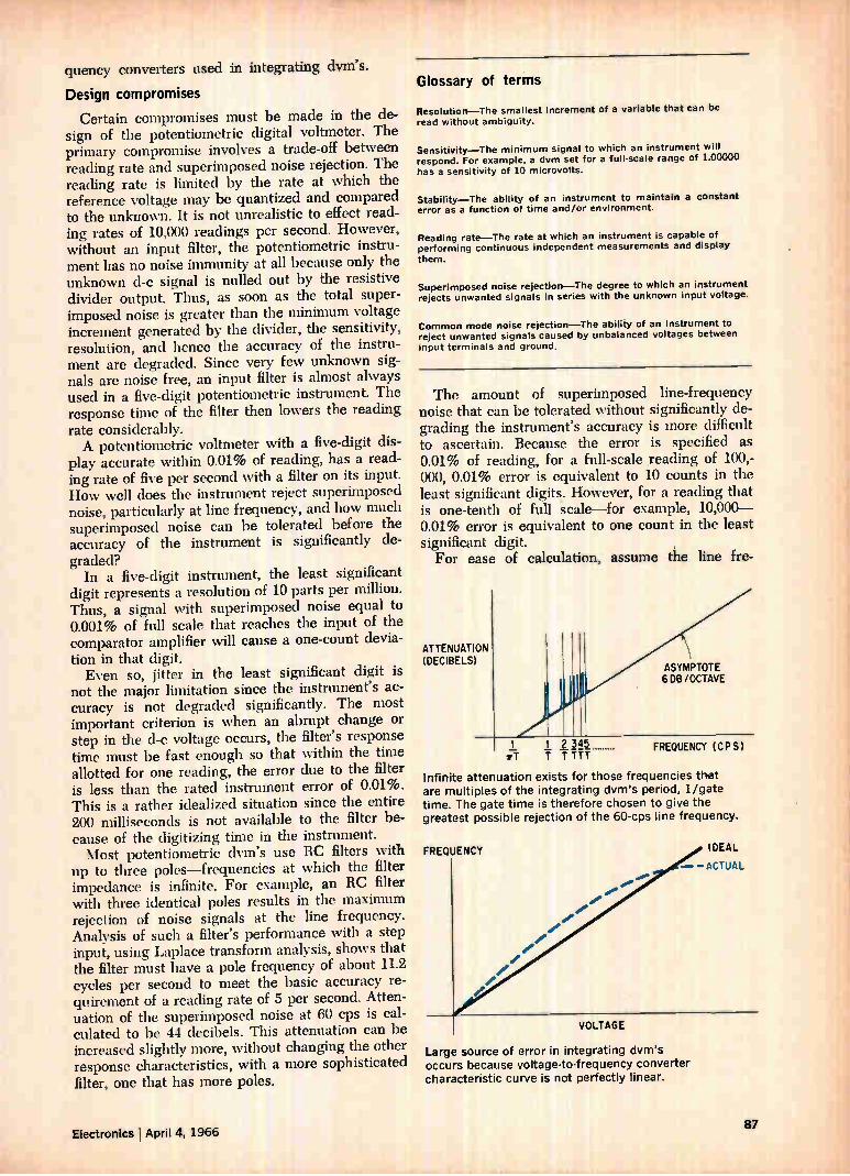
quency converters used in integrating dvm's.
Design compromises
Certain compromises must be made in the de-sign of the potentiometric digital voltmeter. The primary compromise involves a trade-off between reading rate and superimposed noise rejection. The reading rate is limited by the rate at which the reference voltage may be quantized and compared to the unknown. It is not unrealistic to effect read-ing rates of 10,000 readings per second. However, without an input filter, the potentiometric instru-ment has no noise immunity at all because only the unknown d-c signal is nulled out by the resistive divider output. Thus, as soon as the total super-imposed noise is greater than the minimum voltage increment generated by the divider, the sensitivity, resolution, and hence the accuracy of the instru-ment are degraded. Since very few unknown sig-nals are noise free, an input filter is almost always used in a five-digit potentiometric instrument. The response time of the filter then lowers the reading rate considerably. A potentiometric voltmeter with a five-digit dis-
play accurate within 0.01% of reading, has a read-ing rate of five per second with a filter on its input. How well does the instrument reject superimposed noise, particularly at line frequency, and how much superimposed noise can be tolerated before the accuracy of the instrument is significantly de-graded?
In a five-digit instrument, the least significant digit represents a resolution of 10 parts per million. Thus, a signal with superimposed noise equal to 0.001% of full scale that reaches the input of the comparator amplifier will cause a one-count devia-tion in that digit. Even so, jitter in the least significant digit is
not the major limitation since the instrument's ac-curacy is not degraded significantly. The most important criterion is when an abrupt change or step in the d-c voltage occurs, the filter's response time must be fast enough so that within the time allotted for one reading, the error due to the filter is less than the rated instrument error of 0.01%. This is a rather idealized situation since the entire 200 milliseconds is not available to the filter be-cause of the digitizing time in the instrument. Most potentiometric dvm's use RC filters with
up to three poles—frequencies at which the filter impedance is infinite. For example, an RC filter with three identical poles results in the maximum rejection of noise signals at the line frequency. Analysis of such a filter's performance with a step input, using Laplace transform analysis, shows that the filter must have a pole frequency of about 11.2 cycles per second to meet the basic accuracy re-quirement of a reading rate of 5 per second. Atten-uation of the superimposed noise at 60 cps is cal-culated to be 44 decibels. This attenuation can be increased slightly more, without changing the other response characteristics, with a more sophisticated filter, one that has more poles.
Glossary of terms
Resolution—The smallest increment of a varhible that can be read without ambiguity.
Sensitivity—The minimum signal to which an instrument will respond. For example, a dvm set for a full-scale range of 1.00000 has a sensitivity of 10 microvolts.
Stability—The ability of an instrument to maintain a constant error as a function of time and/or environment.
Reading rate—The rate at which an instrument is capable of performing continuous independent measurements and display them.
Superimposed noise rejection—The degree to which an instrument rejects unwanted signals in series with the unknown input voltage.
Common mode noise rejection—The ability of an instrument to reject unwanted signals caused by unbalanced voltages between input terminals and ground.
The amount of superimposed line-frequency noise that can be tolerated without significantly de-grading the instrument's accuracy is more difficult to ascertain. Because the error is specified as 0.01% of reading, for a full-scale reading of 100,-000, 0.01% error is equivalent to 10 counts in the least significant digits. However, for a reading that is one-tenth of full s'cale—for example, 10,000-0.01% error is equivalent to one count in the least significant digit. For ease of calculation, assume the line fre-
ATTENUATION (DECIBELS)
1 2 345 ;FT T TTTT
ASYMPTOTE 608 /OCTAVE
FREQUENCY (CP SI
Infinite attenuation exists for those frequencies thet
are multiples of the integrating dvm's period, 1/gate
time. The gate time is therefore chosen to give the greatest possible rejection of the 60-cps line frequency.
FREQUENCY
VOLTAGE
••••••
Large source of error in integrating dvm's
occurs because voltage-to-frequency converter
characteristic curve is not perfectly linear.
IDEAL
—ALTUAL
Electronics ' April 4, 1966 87
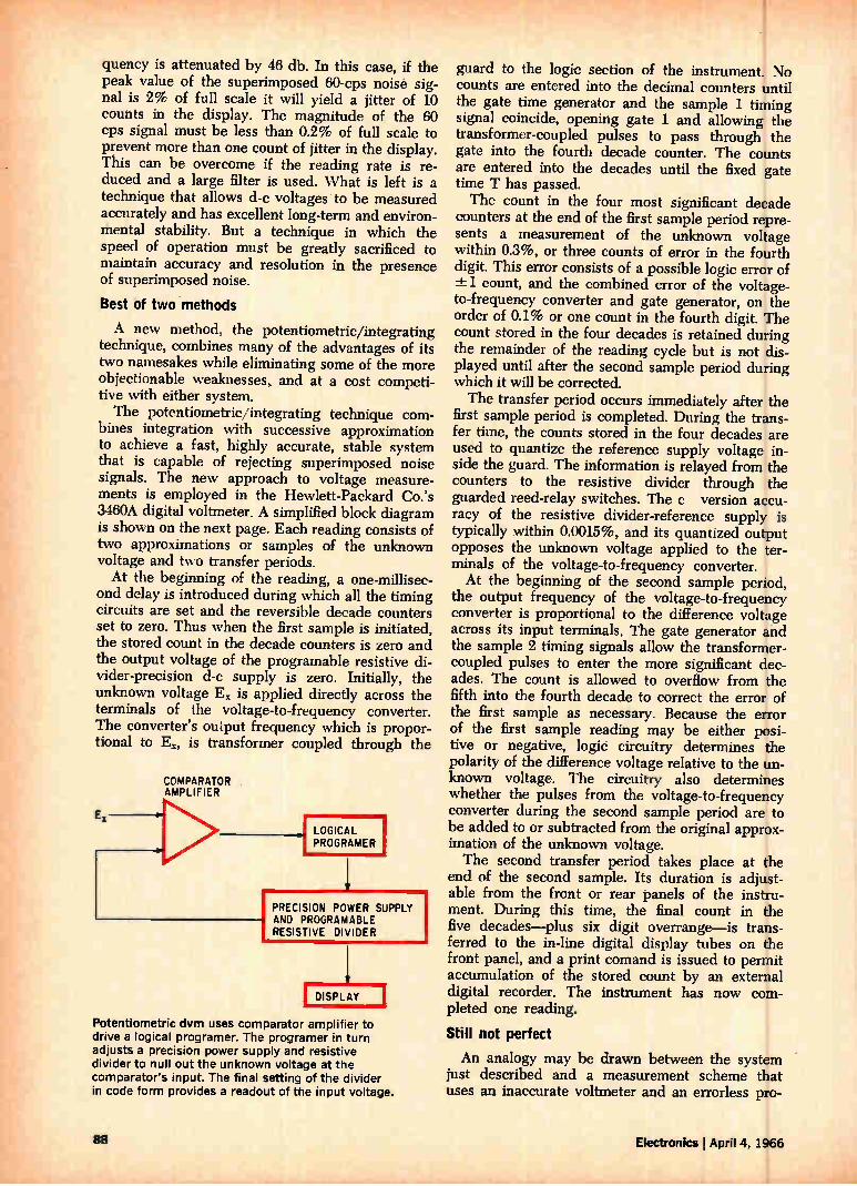
quency is attenuated by 46 db. In this case, if the peak value of the superimposed 60-cps noise sig-nal is 2% of full scale it will yield a jitter of 10 counts in the display. The magnitude of the 60 cps signal must be less than 0.2% of full scale to prevent more than one count of jitter in the display. This can be overcome if the reading rate is re-duced and a large filter is used. What is left is a technique that allows d-c voltages to be measured accurately and has excellent long-term and environ-mental stability. But a technique in which the speed of operation must be greatly sacrificed to maintain accuracy and resolution in the presence of superimposed noise.
Best of two methods
A new method, the potentiometric/integrating technique, combines many of the advantages of its two namesakes while eliminating some of the more objectionable weaknesses, and at a cost competi-tive with either system. The potentiometric/integrating technique com-
bines integration with successive approximation to achieve a fast, highly accurate, stable system that is capable of rejecting superimposed noise signals. The new approach to voltage measure-ments is employed in the Hewlett-Packard Co.'s 3460A digital voltmeter. A simplified block diagram is shown on the next page. Each reading consists of two approximations or samples of the unknown voltage and two transfer periods. At the beginning of the reading, a one-millisec-
ond delay is introduced during which all the timing circuits are set and the reversible decade counters set to zero. Thus when the first sample is initiated, the stored count in the decade counters is zero and the output voltage of the programable resistive di-vider-precision d-c supply is zero. Initially, the unknown voltage Ex is applied directly across the terminals of the voltage-to-frequency converter. The converter's output frequency which is propor-tional to Ei, is transformer coupled through the
COMPARATOR AMPLIFIER
LOGICAL PROGRAMER
PRECISION POWER SUPPLY AND PROGRAMABLE RESISTIVE DIVIDER
DISPLAY
Potentiometric dvm uses comparator amplifier to drive a logical programer. The programer in turn adjusts a precision power supply and resistive divider to null out the unknown voltage at the comparator's input. The final setting of the divider in code form provides a readout of the input voltage.
guard to the logic section of the instrument. No counts are entered into the decimal counters until the gate time generator and the sample 1 timing signal coincide, opening gate 1 and allowing the transformer-coupled pulses to pass through the gate into the fourth decade counter. The counts are entered into the decades until the fixed gate time T has passed. The count in the four most significant decade
counters at the end of the first sample period repre-sents a measurement of the unknown voltage within 0.3%, or three counts of error in the fourth digit. This error consists of a possible logic error of -±1 count, and the combined error of the voltage-to-frequency converter and gate generator, on the order of 0.1% or one count in the fourth digit. The count stored in the four decades is retained during the remainder of the reading cycle but is not dis-played until after the second sample period during which it will be corrected. The transfer period occurs immediately after the
first sample period is completed. During the trans-fer time, the counts stored in the four decades are used to quantize the reference supply voltage in-side the guard. The information is relayed from the counters to the resistive divider through the guarded reed-relay switches. The c version accu-racy of the resistive divider-reference supply is typically within 0.0015%, and its quantized output opposes the unknown voltage applied to the ter-minals of the voltage-to-frequency converter. At the beginning of the second sample period,
the output frequency of the voltage-to-frequency converter is proportional to the difference voltage across its input terminals. The gate generator and the sample 2 timing signals allow the transformer-coupled pulses to enter the more significant dec-ades. The count is allowed to overflow from the fifth into the fourth decade to correct the error of the first sample as necessary. Because the error of the first sample reading may be either posi-tive or negative, logic circuitry determines the polarity of the difference voltage relative to the un-known voltage. The circuitry also determines whether the pulses from the voltage-to-frequency converter during the second sample period are to be added to or subtracted from the original approx-imation of the unknown voltage. The second transfer period takes place at the
end of the second sample. Its duration is adjust-able from the front or rear panels of the instru-ment. During this time, the final count in the five decades—plus six digit overrange—is trans-ferred to the in-line digital display tubes on the front panel, and a print comand is issued to permit accumulation of the stored count by an external digital recorder. The instrument has now com-pleted one reading.
Still not perfect
An analogy may be drawn between the system just described and a measurement scheme that uses an inaccurate voltmeter and an errorless pro-
88 Electronics I April 4, 1966
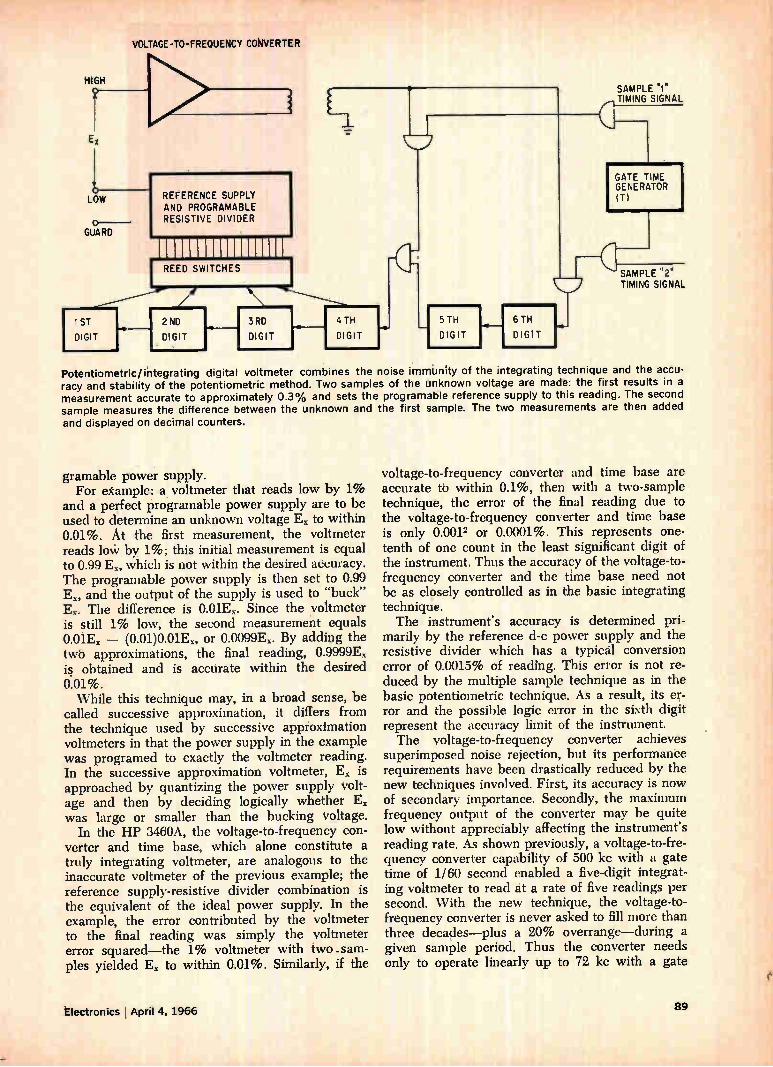
VOLTAGE-TO-FREQUENCY CONVERTER
HIGH
Ex
LOW
o GUARD
1ST
DIGIT
REFERENCE SUPPLY AND PROGRAMABLE RESISTIVE DIVIDER
2 ND
DIGIT
3RD
DIGIT
REED SWITCHES
4 TH
DIGIT
-C--
5TH
DIGIT
6 TH
DIGIT
SAMPLE "1" TIMING SIGNAL
GATE TIME GENERATOR (T)
SAMPLE "2" TIMING SIGNAL
Potentiometric/integrating digital voltmeter combines the noise immunity of the integrating technique and the accu-racy and stability of the potentiometric method. Two samples of the unknown voltage are made: the first results in a measurement accurate to approximately 0.3% and sets the programable reference supply to this reading. The second sample measures the difference between the unknown and the first sample. The two measurements are then added and displayed on decimal counters.
gramable power supply. For etample: a voltmeter that reads low by 1%
and a perfect programable power supply are to be used to determine an unknown voltage E. to within 0.01%. At the first measurement, the voltmeter reads lotir by, 1%; this initial measurement is equal to 0.99 E., which is not within the desired accuracy. The programable power supply is then set to 0.99 E., and the output of the supply is used to "buck" E.. The difference is 0.01E.. Since the voltmeter is still 1% low, the second measurement equals 0.01E. — (0.01)0.01E., or 0.0099E.. By addktg the twó approximations, the final reading, 0.9999E. is obtained and is accurate within the desired 0.01%. While this technique may, in a broad sense, be
called successive approximation, it differs from the technique used by successive approximation voltmeters in that the power supply in the example was programed to exactly the voltmeter reading. In the successive approximation voltmeter, E. is approached by quantizing the power supply volt-age and then by deciding logically whether E. was large or smaller than the bucking Voltage.
In the HP 3460A, the voltage-to-frequency con-verter and time base, which alone constitute a truly integrating voltmeter, are analogous to the inaccurate voltmeter of the previous example; the reference supply-resistive divider combination is the equivalent of the ideal power supply. In the example, the error contributed by the voltmeter to the final reading was simply the voltmeter error squared—the 1% voltmeter with two .sam-ples yielded E. to within 0.01%. Similarly, if the
voltage-to-frequency converter and time base are accurate tb within 0.1%, then with a two-sample technique, the error of the final reading due to the voltage-to-frequency converter and time base is only 0.0012 or 0.0001%. This represents one-tenth of one count in the least significant digit of the instrument. Thus the accuracy of the voltage-to-frequency converter and the time base need not be as closely controlled as in the basic integrating technique. The instrument's accuracy is determined pri-
marily by the reference d-c power supply and the resistive divider which has a typical conversion error of 0.0015% of reading. This error is not re-duced by the multiple sample technique as in the basic potentiometric technique. As a result, its er-ror and the possible logic error in thc sixth digit represent the accuracy limit of the instrument. The voltage-to-frequency converter achieves
superimposed noise rejection, but its performance requirements have been drastically reduced by the new techniques involved. First, its accuracy is now of secondary importance. Secondly, the maximum frequency output of the converter may be quite low without appreciably affecting the instrument's reading rate. As shown previously, a voltage-to-fre-quency converter capability of 500 kc with a gate time of 1/60 second enabled a five-digit integrat-ing voltmeter to read at a rate of five readings per second. With the new technique, the voltage-to-frequency converter is never asked to fill more than three decaliles—plus a 20% overrange—during a given sample period. Thus the converter needs only to operate linearly up to 72 kc with a gate
Electronics I April 4, 1966 89
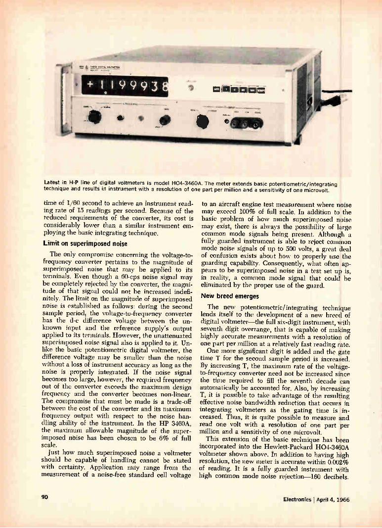
Latest in H-P line of digital voltmeters is model H04-3460A. The meter extends basic potentiometric/integrating technique and results id instrument with a resolution of one part per million and a sensitivity of one microvolt.
time of 1/60 second to achieve an instrument read-ing rate of 15 readings per second. Because of the reduced requirements of the converter, its cost is considerably lower than a similar instrument em-ploying the basic integrating technique.
Limit on superimposed noise
The only compromise concerning the voltage-to-frequency converter pertains to the magnitude of superimposed noise that may be applied to its terminals. Even though a 60-cps noise signal may be completely rejected by the converter, the magni-tude of that signal could not be increased indefi-nitely. The limit on the magnitude of superimposed noise is established as follows: during the second sample periodi the voltage-to-frequency converter has the d-c difference voltage between the un-known input and the reference supply's output applied to its terminals. However, the unattenuated superimposed noise signal also is applied to it. Un-like the basic potentiometric digital voltmeter, the difference voltage may be smaller than the noise without a loss of instrument accuracy as long as the noise is properly integrated. If the noise signal becomes too large, however, the required frequency out of the converter exceeds the maximum design frequency and the converter becomes non-linear. The compromise that must be made is a trade-off between the cost of the converter and its maximum frequency output with respect to the noise han-dling ability of the instrument. In the HP 3460A, the maximum allowable magnitude of the super-imposed noise has been chosen to be 6% of full scale.
Just how much superimposed noise a voltmeter should be capable of handling cannot be stated with certainty. Application may range from the measurement of a noise-free standard cell voltage
to an aircraft engine test measurement where noise may exceed 100% of full scale. In addition to the basic problem of how much superimposed noise may exist, there is always the possibility of large common mode signals being present. Although a fully guarded instrument is able to reject common mode noise signals of up to 500 volts, a great deal of confusion exists about how to properly use the guarding capability. Consequently, what often ap-pears to be superimposed noise in a test set up is, in reality, a common mode signal that could be eliminated by the proper use of the guard.
New breed emerges
The new potentiometric/integrating technique lends itself to the development of a new breed of digital voltmeter—the full six-digit instrument, with seventh digit overrange, that is capable of making highly accurate measurements with a resolution of one part per million at a relatively fast reading rate. One more significant digit is added and the gate
time T for the second sample period is increased. By increasing T, the maximum rate of the voltage-to-frequency converter need not be increased since the time required to fill the seventh decade can automatically be accounted for. Also, by increasing T, it is possible to take advantage of the resulting effective noise bandwidth reduction that occurs in integrating voltmeters as the gating time is in-creased. Thus, it is quite possible to measure and read one volt with a resolution of one part per million and a sensitivity of one microvolt.
This extension of the basic technique has been incorporated into the Hewlett-Packard H04-3460A voltmeter shown above. In addition to having high resolution, the new meter is accurate within 0.002% of reading. It is a fully guarded instrument with high common mode noise rejection-160 decibels.
90 Electronics j April 4, 1966

Circuit design
Designer's casebook
Overload protection
for d-c amplifier
By Leander Payen, Visolux-Electronic GmbH, Berlin
In spite of the loss which occurs, a high series resistance is often included in a d-c amplifier to protect it in the event of an overload. In the d-c amplifier circuit at the right however, an elec-tronic fuse switches the high series resistance R3 into the circuit only when an overload or short circuit actually occurs. This circuit restores the full output voltage immedaitely after the short circuit or overload is removed. During normal operation, there is only a small
resistance in the load, formed by R. and the col-lector-emitter resistance of Q. In this state the voltage drop across 110 is less than the turn-on base-emitter voltage of Qi. Hence, Qi and Q4 are off, and Q. is on, shunting R3.
If Iout increases beyond a certain level because of short circuit or overload, the voltage drop across R. increases and Qi turns on. Simultaneously, tran-sistor Q. turns on and zero-biases the base of Q2. This cuts off Q . so that R3 limits the current.
Switching will occur when IoutR2 VBE1. In this
Designer's casebook is a regular feature in Electronics. Readers are invited to submit novel circuit ideas, packaging schemes, or other unusual solutions to design problems. Descriptions should be short. We'll pay $50 for each item published.
+24V DC
OUTPUT:
0___22V OC 40 ma
Electronic fuse in d-c amp ifier cuts in high series resistance Ri when there is an overload or short circuit and bypasses Ri instantly when they are removed. All resistors 0.5 w unless otherwise specified.
circuit, maximum output current is 40 milliamperes. When Q. turns off, voltage R. may decrease
enough to turn off Q. This circuit will thus oscillate at an amplitude and frequency determined by R3 until the fault is removed. In the circuit shown, the amplitude of the oscillation is 1.5 volts peak to peak; its frequency is about 250 kc. The base of Q4 is shunted by a small capacitor to prevent oscilla-tions that might be excited by fast load changes.
Latching gate removes counter ambiguity
By Roy A. Wilson Hycon Manufacturing Co. Monrovia, Calif.
Clock pulses being gated into a register require positive gating action to avoid putting an extra count into the register. The ordinary diode gate provides this positive gating action with the addi-tion of a silicon controlled rectifier.
1N270 CLOCK INPUT
—12V
Adding latching feature to diode gate allows output to follow clock input when S, is closed. When Si is opened, output will be fixed at existing clock level.
Electronics April 4, 1966 91

The latching gate on page 91 allows the output to follow the clock input when S1 is closed and, after Si is opened, the output remains indefinitely at the level of the clock input at the time the switch opened.
Closing of switch Si grounds point A; this for-ward-biases the gate-to-cathode terminals of the scr every time the clock input is at —6 volts. When the clock returns to zero, the scr has no voltage across it and thus turns off.
If Si is opened during the time the scr is off the
output will remain at zero as long as Si remains open. This is because point A is now at —12 volts, precluding any possibility of the gate becoming forward-biased.
If SI is opened when the ser is conducting, the output vill remain at —6 volts. Opening of the switch applies —12 volts to the ser cathode through R1 and D. This reverse-biases D,, maintaining the voltage across the scr. The scr will continue to conduct and maintain the output at —6 volts until Si is again closed.
Delay circuit varies
turn-on, turn-off
By Cruz R. Mora North American Aviation, Inc., Downey, Calif.
Turn-on and turn-off delays, independently and con-tinuously variable, are achieved with the four-stage circuit shown below. Both input and output delays are variable from 1.5 to 1500 milliseconds; a limita-tion on the maximum turn-on delay is the duration
TURN- ON DELAY STAGE 1
28V I INPUT I
TURN -OFF DELAY STAGE 2
r---
Q2
L_____J
STAGE 1
Rf
R2 -680
R3 -330
R4 -100
Cf 2.5pf
-2N1671
R5 - 82K
R5 -22K
R7 -1M
Re -75
Q3 -2N1132
STAGE 2
C2- 2.5»F
DI - 1N645
D2- 1N645
02- 2N167IA
Increasing time constants R,C, and 1,27C2, in con-junction with unijunction transistors having
higher intrinsic stand-off ratios, increases possible time delays up to four minutes. See pulses at top of page 93.
of the input pulse, which it can never exceed. An input voltage of 28 volts d-c is applied to the
turn-on delay circuit, a relaxation oscillator. The turn-on time for the unijunction transistor Qi is set by adjusting ill, which controls the charging rate of C1. As CI is charging, the emitter voltage of Qi rises exponentally towards the supply voltage. When the emitter voltage reaches its peak, the emitter becomes forward biased, providing a dis-charge path for Ci and briefly turning on Q1. The resulting voltage pulse across R4 is coupled through D3, to the gate of SCRi. This turns on SCRI, re-sulting in a voltage drop across R11 which provides forward bias to Q4. In turn, Q4 provides forward bias to Q5 turning it on. The resultant output volt-
ON-OFF CONTROL STAGE 3
L.
STAGE 3
R9-1 K
R10-1.2 K
R14 - 220
R12- 470
C3 -0.056»F
D3 -1N645
SCR1-2N1595
r
IN AMPLIFIER STAGE 4
— — — —
L__
STAGE 4
R13-390
R14- 3.3 K
R - LOAD RESISTOR
D4 -1N645
D5 -1N645
124 - 2N388
05 -2N1132
28V
1,27.5 V !OUTPUT
92 Electronics i April 4, 1966
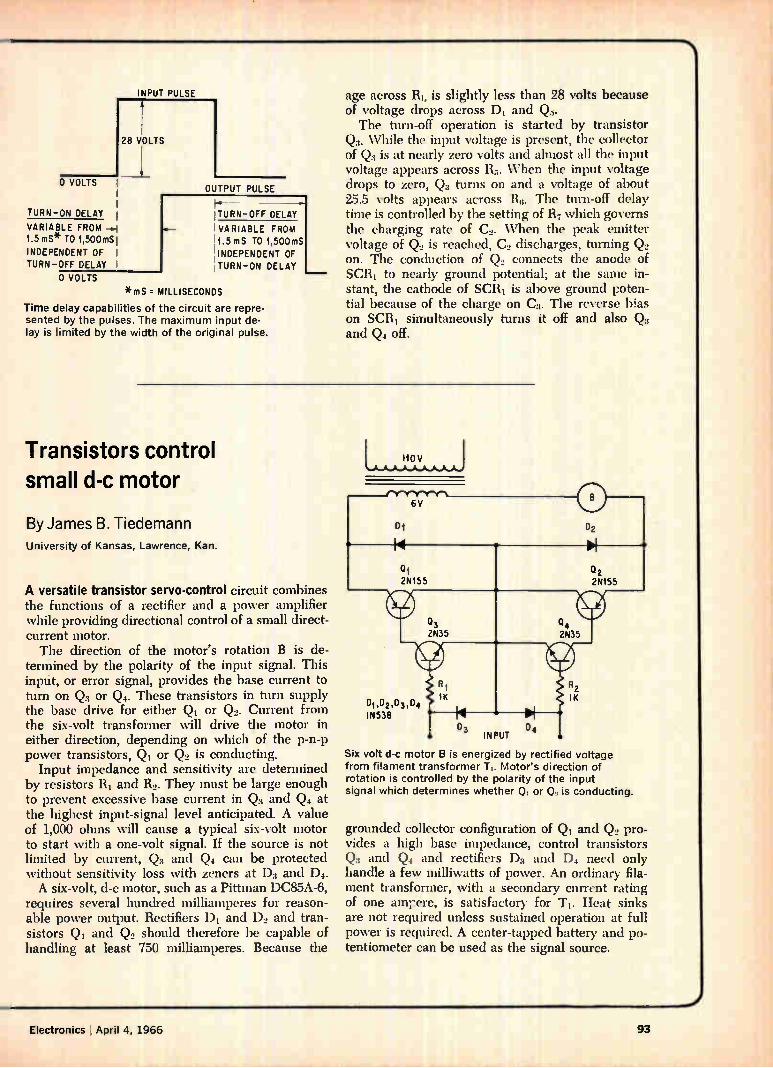
INPUT PUL SE
28 VOLTS
0 VOLTS OUTPUT PUL SE
TURN-ON DE LAY
VARIA BLE FROM 1.5 mS* TO 1,500mS
INDE PENDE NT OF I TURN-OFF DE LAY i
0 VOLTS
ITURN-OFF DELAY
IVA RIA BLE FROM 14.5mS TO 1,500mS
'INDEPENDENT OF TURN -ON DELAY
*mS . MILLI SECONDS
Time delay capabilities of the circuit are repre-
sented by the pulses. The maximum input de-
lay is limited by the width of the original pulse.
age across RI, is slightly less than 28 volts because of voltage drops across DI and Q. The turn-off operation is started by transistor
Q. While the input voltage is present, the collector of Q3 is at nearly zero volts and almost all the input voltage appears across R. When the input voltage drops to zero, Q3 turns on and a voltage of about 25.5 volts appears across 116. The turn-off delay time is controlled by the setting of R7 which governs the charging rate of C.. When the peak emitter voltage of Q. is reached, C2 discharges, turning Q2 on. The conduction of Q2 connects the anode of SCRI to nearly ground potential; at the same in-stant, the cathode of SCRi is above ground poten-tial because of the charge on C3. The reverse bias on SCRI simultaneously turns it off and also Q3 and Q4 off.
Transistors control small d-c motor
By James B. Tiedemann University of Kansas, Lawrence, Kan.
A versatile transistor servo-control circuit combines the functions of a rectifier and a power amplifier while providing directional control of a small direct-current motor. The direction of the motor's rotation B is de-
termined by the polarity of the input signal. This inptit, or error signal, provides the base current to turn on Q3 or Q4. These transistors in turn supply the base drive for either Qi or Q2. Current from the six-volt transformer will drive the motor in either direction, depending on which of the p-n-p power transistors, Qi or Q. is conducting.
Input impedance and sensitivity are determined by resistors R1 and R2. They must be large enough to prevent excessive base current in Q3 and Q4 at the highest input-signal level anticipated. A value of 1,000 ohms will cause a typical six-volt motor to start with a one-volt signal. If the source is not limited by current, Q3 and Q. can be protected without sensitivity loss with zeners at D3 and D4. A six-volt, d-c motor, such as a Pittman DC85A-6,
requires several hundred milliamperes for reason-able power output. Rectifiers D1 and D. and tran-sistors Q1 and Q2 should therefore be capable of handling at least 750 milliamperes. Because the
110V AWW
Six volt d-c motor B is energized by rectified voltage from filament transformer T,. Motor's direction of rotation is controlled by the polarity of the input signal which determines whether Q or Qs is conducting.
grounded collector configuration of Qi and Q2 pro-vides a high base impedance, control transistors Q3 and Q4 and rectifiers D3 and D4 need only handle a few milliwatts of power. An ordinary fila-ment transformer, with a secondary current rating of one amr ere, is satisfactory for T1. Heat sinks are not required unless sustained operation at full power is required. A center-tapped battery and po-tentiometer can be used as the signal source.
Electronics April 4, 1966 93
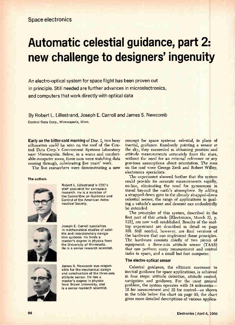
Space electronics
Automatic celestial guidance, part 2: new challenge to designers' ingenuity
An electro-optical system for space flight has been proven out
in principle. Still needed are further advances in microelectronics,
and computers that work directly with optical data
By Robert L. Lillestrand, Joseph E. Carroll and James S. Newcomb Control Data Corp., Minneapolis, Minn.
Early on the bitter-cold morning of Dec. 1, two busy silhouettes could be seen on the roof of the Con-trol Data Corp.'s Government Systems laboratory near Minneapolis. Below, in a warm and comfort-able computer room, three men were watching data coming through, culminating five years' work. The five researchers were demonstrating a new
The authors
twee Robert L. Lillestrand is CDC's staff specialist for aerospace research. He is a member of the Committee on Guidance and Control of the American Astro-nautical Society.
Joseph E. Carroll specializes in mathematical studies of satel-lite and interplanetary naviga-tion systems. He holds a master's degree in physics from the University of Minnesota. He is a senior research scientist.
James S. Newcomb was respon-sible for the mechanical design and construction of the three-axis attitude sensor. He has a master's degree in physics from Brown University, and is a senior research scientist.
concept for space systems: celestial, in place of inertial, guidance. Randomly pointing a sensor at the sky, they succeeded in obtaining position and attitude measurements accurately from the stars, without the need for an external reference or any previous assumptions about orientation. The men on the roof were George Zenk and Robert Willey, electronics specialists. The experiment showed further that the system
could provide its accurate measurements rapidly, on-line, eliminating the need for gyroscopes in travel beyond the earth's atmosphere. By adding a strapped-down gyro to the already strapped-down celestial sensor, the range of applications to guid-ing a vehicle's ascent and descent can undoubtedly be extended. The principles of this system, described in the
first part of this article [Electronics, March 21, p. 115], are now well established. Results of the roof-top experiment are described in detail on page 103. Still needed, however, are final versions of the hardware that can implement these principles. The hardware consists chiefly of two pieces of equipment: a three-axis attitude sensor (TAAS) that can perform many measurement and control tasks in space, and a small but fast computer.
The electro-optical sensor
Celestial guidance, the ultimate successor to inertial guidance for space applications, is achieved in four steps: attitude detection, attitude control, navigation and guidance. For the most general problem, the system operates with 24 unknowns-12 for measurement and 12 for control—as shown in the table below the chart on page 95; the chart gives more detailed descriptions of various applica-
94 Electronics I April 4, 1966
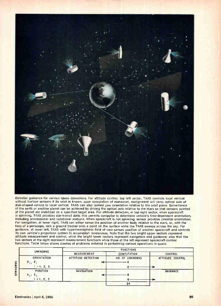
Celestial guidance for various space operations. For attitude control, top left sector, TAAS controls local vertical without horizon sensors if its orbit is known; upon completion of maneuver, realignment will carry optical axis of disk-shaped vehicle to local vertical. TAAS can also control yaw orientation relative to the orbit plane. Surveillance of the earth or another planet can be achieved by driving the optical axis relative to the stars so that sensors pointed at the planet are stabilized on a specified target area. For attitude detection, in top right sector, when spacecraft is spinning, TAAS provides star-transit data; this permits computer to determine vehicle's time-dependent orientation, including processional and nutational motions. When spacecraft is not spinning, sensor provides celestial orientation. For navigation, at lower right, TAAS can either sense the position of another body relative to the stars, or, with the help of a periscope, lock a ground tracker onto a point on the surface while the TAAS sweeps across the sky. For guidance, at lower left, TAAS with hyperhemispheric field of view senses position of another spacecraft and controls its own vehicle's propulsion system to accomplish rendezvous. Note that the two bright upper sectors represent attitude measurement and control, while the bright lower sectors represent navigation and guidance; also that the two sectors at the right represent measurement functions while those at the left represent spacecraft control functions. Table below shows classes of problems entailed in performing various operations in space.
co z 3e o z àc z o
UNKNOWNS FUNCTIONS
MEASUREMENT COMPUTATION CONTROL ORIENTATION
I .1, 2, 3
ATTITUDE DETECTION NO. OF UNKNOWNS ATTITUDE CONTROL
6
POSITION 4i, ii i .1, 2, 3
NAVIGATION GUIDANCE
24
Electronics ! April 4, 1966 95
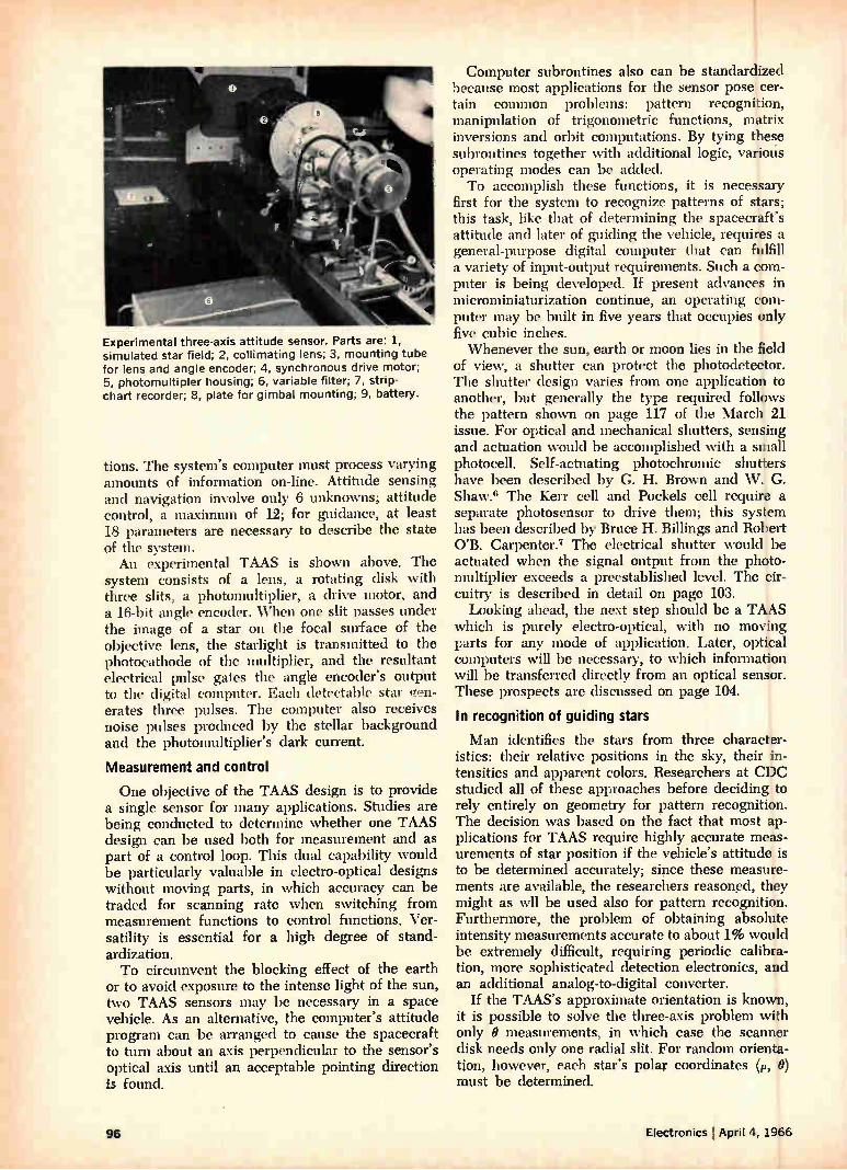
Experimental three-axis attitude sensor. Parts are: 1, simulated star field; 2, collimating lens; 3, mounting tube for lens and angle encoder; 4, synchronous drive motor; 5, photomultipler housing; 6, variable filter; 7, strip-chart recorder; 8, plate for gimbal mounting; 9, battery.
tions. The system's computer must process varying amounts of information on-line. Attitude sensing and navigation involve only 6 unknowns; attitude control, a maximum of 12; for guidance, at least 18 parameters are necessary to describe the state of the system. An experimental TAAS is shown above. The
system consists of a lens, a rotating disk with three slits, a photomultiplier, a drive motor, and a 16-bit angle encoder. When one slit passes under the image of a star on the focal surface of the objective lens, the starlight is transmitted to the photocathode of the multiplier, and the resultant electrical pulse gates the angle encoder's output to the digital computer. Each detectable star gen-erates three pulses. The computer also receives noise pulses produced by the stellar background and the photomultiplier's dark current.
Measurement and control
One objective of the TAAS design is to provide a single sensor for many applications. Studies are being conducted to determine whether one TAAS design can be used both for measurement and as part of a control loop. This dual capability would be particularly valuable in electro-optical designs without moving parts, in which accuracy can be traded for scanning rate when switching from measurement functions to control functions. Ver-satility is essential for a high degree of stand-ardization. To circumvent the blocking effect of the earth
or to avoid exposure to the intense light of the sun, two TAAS sensors may be necessary in a space vehicle. As an alternative, the computer's attitude program can be arranged to cause the spacecraft to turn about an axis perpendicular to the sensor's optical axis until an acceptable pointing direction is found.
Computer subroutines also can be standardized because most applications for the sensor pose cer-tain common problems: pattern recognition, manipulation of trigonometric functions, matrix inversions and orbit computations. By tying these subroutines together with additional logic, various operating modes can be added. To accomplish these functions, it is necessary
first for the system to recognize patterns of stars; this task, like that of determining the spacecraft's attitude and later of guiding the vehicle, requires a general-purpose digital computer that can fulfill a variety of input-output requirements. Such a com-puter is being developed. If present advances in microminiaturization continue, an operating com-puter may be built in five years that occupies only five cubic inches. Whenever the sun, earth or moon lies in the field
of view, a shutter can protect the photodetector. The shutter design varies from one application to another, but generally the type required follows the pattern shown on page 117 of the March 21 issue. For optical and mechanical shutters, sensing and actuation would be accomplished with a small photocell. Self-actuating photochromic shutters have been described by G. H. Brown and W. G. Shaw.6 The Kerr cell and Pockels cell require a separate photosensor to drive them; this system has been described by Bruce H. Billings and Robert O'B. Carpenter.7 The electrical shutter would be actuated when the signal output from the photo-multiplier exceeds a preestablished level. The cir-cuitry is described in detail on page 103. Looking ahead, the next step should be a TAAS
which is purely electro-optical, with no moving parts for any mode of application. Later, optical computers will be necessary, to which information will be transferred directly from an optical sensor. These prospects are discussed on page 104.
In recognition of guiding stars
Man identifies the stars from three character-istics: their relative positions in the sky, their in-tensities and apparent colors. Researchers at CDC studied all of these approaches before deciding to rely entirely on geometry for pattern recognition. The decision was based on the. fact that most ap-plications for TAAS require highly accurate meas-urements of star position if the vehicle's attitude is to be determined accurately; since these measure-ments are available, the researchers reasoned, they might as wll be used also for pattern recognition. Furthermore, the problem of obtaining absolute intensity measurements accurate to about 1% would be extremely difficult, requiring periodic calibra-tion, more sophisticated detection electronics, and an additional analog-to-digital converter.
If the TAAS's approximate orientation is known, it is possible to solve the three-axis problem with only O measurements, in which case the scanner disk needs only one radial slit. For random orienta-tion, however, each star's polar coordinates (p, 0)
must be determined.
94 Electronics April 4, 1966
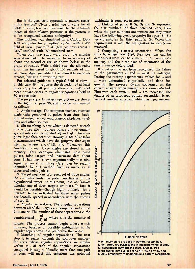
• I • I • .c".1,71RIV
But is the geometric approach to pattern recog-n!tion feasible? Given a minimum of stars for all fields of view, how accurate must be the measure-ments of their relative positions if the pattern is to be recognized without ambiguity? The problem was simulated on a Control Data
1604 computer for an optical system with a 46° field of view, "pointed" at 2,580 positions across a "sky" studded with 789 simulated stars. When only two stars were used, the angular
separation had to be measured to an accuracy of about one second of arc, as shown below in the graph of results. With a third star, the allowable error was increased to about 100 seconds of arc. As more stars are added, the allowable error in-creases, but at a diminishing rate. For celestial guidance, a typical field of view—
in this case 46°—requires the detection of at least three stars for all pointing directions, with root mean square errors in angular separations held to 30 arc-seconds. The seven steps in pattern recognition are shown
in the figure on page 98, and may be summarized as follows:
1. Angle storage. The computer memory receives angle data generated by pulses from stars, back-ground noise, dark current, planets, airplanes, satel-lites and other sources.
2. Slit matching. A star which is detected at each of the three slits produces pulses at two equally spaced intervals, designated àij and àjk. The com-puter logic then searches through a list of angular measurements which have the property that àij = àjk ± E., where co << àij, àjk. Whenever this condition is met, three angles are stored in the memory. This technique eliminates most noise pulses, false targets and inaccurate data about stars. It has been shown experimentally that nine signal pulses (from three stars) can be readily identified by this method from as many as e associated noise pulses.
3. Target positions. For each set of three angles, the computer finds the polar coordinates of the hypothetical target. At this point, it is not known whether any of these targets are stars. In fact, it would be possible—though highly unlikely—for a "target" to be indicated by three noise pulses accidentally spaced in accordance with the criteria of step 2.
4. Angular separations. The angular separations between all of the targets are computed and stored in memory. The number of these separations is the
combinatorial n! where n is the number of (n-2)! 2!
targets. The process cannot begin unless n= 2; however, because of possible ambiguities in the angular separations, it is preferable that n 3.
5. Matching of angular separations. The next step is to search through the computer memory for stars whose angular separations are similar within -±-e, of each of the angular separations computed in step 4. Usually, more than one pair of stars will meet this criterion; this potential
5
ambiguity is removed in step 6. 6. Linking of pairs. If Si, S2 and Ss represent
the star numbers for three detected stars, then when the pair numbers are written out they must have the following cyclic property: first pair, S1' S2; second pair, S2, SE third pair, Ss, Si. When this requirement is met, the ambiguities in step 5 are removed.
7. Computing sensor's orientation. When the stars have been identified, their positions can be determined from star lists stored in the computer's memory and the three axes of orientation of the sensor can be determined.
If a pattern has not been recognized, the values of the parameters ee and cp must be enlarged. During the rooftop experiments, value's for ee and
were determined empirically, and done fre-quently; the process always converged on the correct answer when enough stars were detected. However, each time and e„ are increased, the danger of an erroneous pattern recognition is en-hanced. Another approach which has been success-
10
-4 10 2 3 4
NUMBER OF STARS
When more stars are used in pattern recognition, larger errors are permissible in measurements of angu-lar separations between the stars. Shaded area gives approximate values for a 46° field of view and a 99% probability of unambiguous pattern recognition.
6
Electronics I April 4, 1966 97
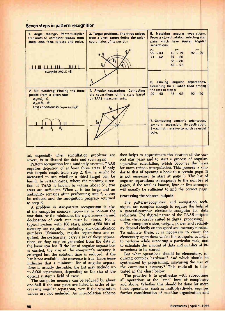
Seven steps in pattern recognition
1. Angle storage. Photomultiplier transmits to computer pulses from stars, also false targets and noise.
i i iii t i i ti i HIM
3. Target positions. from a given target coordinates of its position.
* P
The three pulses define the polar
*
5. Matching angular separations. From a stored catalog, selecting star pairs which have similar angular separations.
p12 P= p» 29 — 43 13 — 19 92 — 29 7.1 — 62 24 — 60
35 — 80 43 — 92
e2 es V e%
SCANNER ANGLE (0)
P
*
. 6. Linking angular separations. Searching for a linked triad among the lists in step 5 29 — 43 43 — 92 92 — 29
2. Slit matching. Finding the three pulses from a given star
=0,-0, Ajk=ek —0,
Test condition: is ,J=.1.11,± €0?
,--- 1 11 1 --) 11 1
4. Angular separations. the separations of on TAAS measurements.
P 1
31
2 .
Computing the stars based
, / / /
//
// 7. Computing sensor's orientation. a-.---right ascension, 6=declination, (3=azimuth relative to north celestial pole.
. 8 i 8 8 ) k ''' -
'
ful, especially when scintillation problems are severe, is to discard the data and scan again.
Pattern recognition for a randomly oriented TAAS requires detection of at least three stars. If only twb targets result from step 2, then Eo might be increased to see whether a third target can be found. In certain cases, where the pointing direc-tion of TAAS is known to within about 5°, two stars are sufficient. When Ep is too large and an ambiguity remains after performing step 6, Ep can be reduced and the recognition program returned to step 5. A problem in star-pattern recognititon is size
of the computer memory necessary to contain the star data. At the minimum, the right ascension and declination of each star must be stored. For a typical system with 100 stars, about 4,200 bits of memory are required, including star-identification numbers. Ultimately, angular separations are re-quired; the system may carry a list of these separa-tions, or they may be generated from the data in the basic star list. If the list of angular separations is carried, the size of the computer's memory is enlarged but the solution time is reduced; if the list is not available, the converse is true. Experience indicates that a minimum list of angular separa-tions is usually desirable; the list may include up to 3,000 separations, depending on the size of the optical system's field of view. The computer memory can be reduced by about
one-half if the star pairs are listed in order of in-creasing angular separation, even if the separation values are not included. An interpolation scheme
then helps to approximate the location of the cor-rect star pairs and to start a process of angular-separation calculation, which becomes the basis for more refined interpolation. This process is sim-ilar to that of opening a book to a certain page. It is not necessary to start at page 1. The list of angular separations corresponds to the number of pages; if the total is known, four or five attempts will usually be sufficient to find the correct page.
Processing the sensors' outputs
The pattern-recognition and navigation tech-niques are complex enough to require the help of a general-purpose electronic computer for data reduction. The digital nature of the TAAS outputs makes them ideally suited to digital processing. The computer's size, weight, power and reliabil-
ity depend chiefly on the speed and memory needed. To estimate these, it is necessary to count the elementary operations which the computer is likely to perform while executing a particular task, and to calculate the amount of data and number of in-structions to be stored. But what operations should be elementary, re-
quiring complex hardware? And which should be synthesized by programing, increasing the size of the computer's memory? This trade-off is illus-trated in the chart below. The practice is to synthesize with subroutines
all operations at the "sine" level of complexity and above. Whether this should be done for more basic operations, such as multiply/divide, requires further consideration of machine organization and
98 Electronics I April 4, 1966
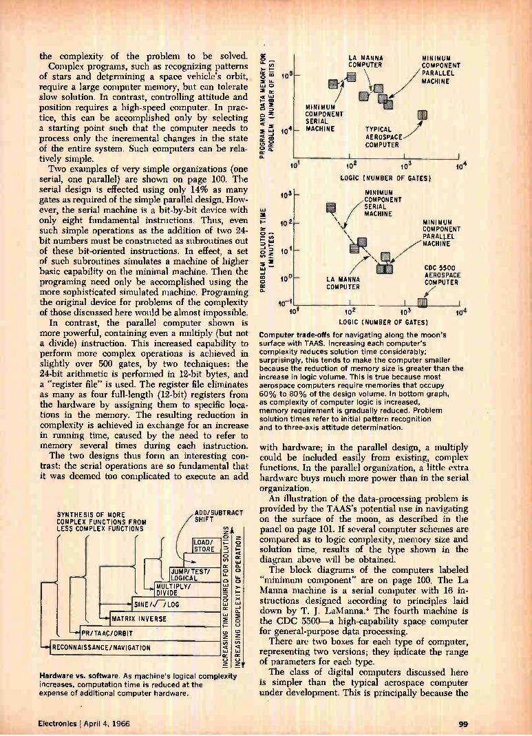
the complexity of the problem to be solved. Complex programs, such as recognizing patterns
of stars and determining a space vehicle's orbit, require a large computer memory, but can tolerate slow solution. In contrast, controlling attitude and position requires a high-speed computer. In prac-tice, this can be accomplished only by selecting a starting point such that the computer needs to process only the incremental changes in the state of the entire system. Such computers can be rela-tively simple. Two examples of very simple organizations (one
serial, one parallel) are shown on page 100. The serial design is effected using only 14% as many gates as required of the simple parallel design. How-ever, the serial machine is a bit-by-bit device with only eight fundamental instructions. Thus, even such simple operations as the addition of two 24-bit numbers must be constructed as subroutines out of these bit-oriented instructions. In effect, a set of such subroutines simulates a machine of higher basic capability on the minimal machine. Then the programing need only be accomplished using the more sophisticated simulated machine. Programing the original device for problems of the complexity of those discussed here would be almost impossible.
In contrast, the parallel computer shown is more powerful, containing even a multiply (but not a divide) instruction. This increased capability to perform more complex operations is achieved in slightly over 500 gates, by two techniques: the 24-bit arithmetic is performed in 12-bit bytes, and a "register file" is used. The register file eliminates as many as four full-length (12-bit) registers from the hardware by assigning them to specific loca-tions in the memory. The resulting reduction in complexity is achieved in exchange for an increase in running time, caused by the need to refer to memory several times during each instruction. The two designs thus form an interesting con-
trast: the serial operations are so fundamental that it was deemed too complicated to execute an add
SYNTHESIS OF MORE COMPLEX FUNCTIONS FROM LE S5 COMPLEX FUNCTIONS ADD/SUBTRACT ( SHIFT LOAD/ STORE
JUMP/ TEST/ LOGICAL HMULTIPLY/ DIVIDE
SINE/I/LOG MATRIX INVERSE
HPR/TAAC/ORBIT --i-IRECONNAISSANCE/NAVIGATION
TIME REQUIRED FOR SOLUTIONS
INCR
EASI
NG
Hardware vs. software. As machine's logical complexity increases, computation time is reduced at the expense of additional computer hardware.
10 5
104
LA MANNA COMPUTER
MINIMUM COMPONENT SERIAL MACHINE TYPICAL AEROSPACE COMPUTER
MINIMUM COMPONENT PARALLEL MACHINE
2 101 10 103 LOGIC (NUMBER OF GATES)
103
10 2 101 100 LA MANNA COMPUTER
MINIMUM COMPONENT SERIAL MACHINE
10-1 101 102 103
MINIMUM COMPONENT PARALLEL MACHINE CDC 5500 AEROSPACE COMPUTER
104 LOGIC (NUMBER OF GATES)
Computer trade-offs for navigating along the moon's surface with TAAS. Increasing each computer's complexity reduces solution time considerably; surprisingly, this tends to make the computer smaller because the reduction of memory size is greater than the increase in logic volume. This is true because most aerospace computers require memories that occupy 60% to 80% of the design volume. In bottom graph, as complexity of computer logic is increased, memory requirement is gradually reduced. Problem solution times refer to initial pattern recognition and to three-axis attitude determination.
with hardware; in the parallel design, a multiply could be included easily from existing, complex functions. In the parallel organization, a little extra hardware buys much more power than in the serial organization. An illustration of the data-processing problem is
provided by the TAAS's potential use in navigating on the surface of the moon, as described in the panel on page 101. If several computer schemes are compared as to logic complexity, memory size and solution time, results of the type shown in the diagram above will be obtained. The block diagrams of the computers labeled
"minimum component" are on page 100. The La Manna machine is a serial computer with 16 in-structions designed according to principles laid down by T. J. LaManna.4 The fourth machine is the CDC 5500 a high-capability space computer for general-purpose data processing. There are two boxes for each type of computer,
representing two versions; they indicate the range of parameters for each type. The class of digital computers discussed here
is simpler than the typical aerospace computer under development. This is principally because the
Electronics April 4, 1966 99
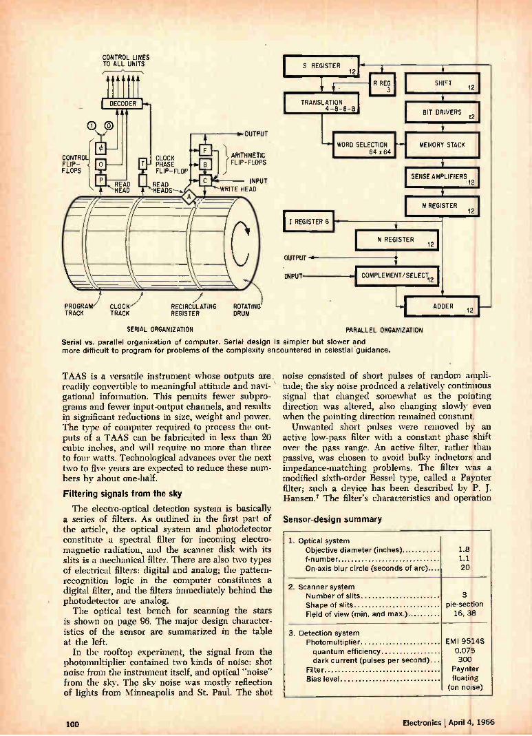
CONTROL FLIP-FLOPS
CONTROL LINES TO ALL UNITS
PROGRAM CLOCK TRACK TRACK
RECIRCULATING ROTATING
CLOCK PHASE FLIP-FLOP
READ HEADS-,
REGISTER
SERIAL ORGANIZATION
OUTPUT
}ARITHMETIC FLIP-FLOPS
INPUT WRITE HEAD
DRUM
S REGISTER 12
TRANSLATION 4-8-8-8
II REGISTER 6 OUTPUT
INPUT
WORD SELECTION 64 x 64
SHIFT 12
BIT DRIVERS
MEMORY STACK
SENSE AMPLIFIERS 12
M REGISTER 12
N REGISTER 12
COMPLEMENT/ SELECT
ADDER 12
PARALLEL ORGANIZATION
Serial vs. parallel organization of computer. Serial design is simpler but slower and more difficult to program for problems of the complexity encountered in celestial guidance.
TAAS is a versatile instrument whose outputs are. readily convertible to meaningful attitude and navi-gational information. This permits fewer subpro-grams and fewer input-output channels, and results in significant reductions in size, weight and power. The type of computer required to process the out-puts of a TAAS can be fabricated in less than 20 cubic inches, and will require no more than three to four watts. Technological advances over the next two to five years are expected to reduce these num-bers by about one-half.
Filtering signals from the sky
The electro-optical detection system is basically a series of filters. As outlined in the first part of the article, the optical system and photodetector constitute a spectral filter for incoming electro-magnetic radiation, and the scanner disk with its slits is a mechanical filter. There are also two types of electrical filters: digital and analog; the pattern-recognition logic in the computer constitutes a digital filter, and the filters immediately behind the photodetector are analog. The optical test bench for scanning the stars
is shown on page 96. The major design character-istics of the sensor are summarized in the table at the left.
In the rooftop experiment, the signal from the photomultiplier contained two kinds of noise: shot noise from the instrument itself, and optical "noise" from the sky. The sky noise was mostly reflection of lights from Minneapolis and St. Paul. The shot
noise consisted of short pulses of random ampli-tude; the sky noise produced a relatively continuous signal that changed somewhat as the pointing direction was altered, also changing slowly even when the pointing direction remained constant. Unwanted short pulses were removed by an
active low-pass filter with a constant phase shift over the pass range. An active filter, rather than passive, was chosen to avoid bulky inductors and impedance-matching problems. The filter was a modified sixth-order Bessel type, called a Paynter filter; such a device has been described by P. J. Hansen.7 The filter's characteristics and operation
Sensor-design summary
1. Optical system Objective diameter (inches) f-number On-axis blur circle (seconds of arc)
1.8 1.1 20
2. Scanner system Number of slits Shape of slits Field of view (min. and max.)
3 pie-section
16, 38
3. Detection system Photomultiplier quantum efficiency dark current (pulses per second)
Filter Bias level
EMI 9514S 0.075 300
Paynter floating
(on noise)
100 Electronics I April 4, 1966
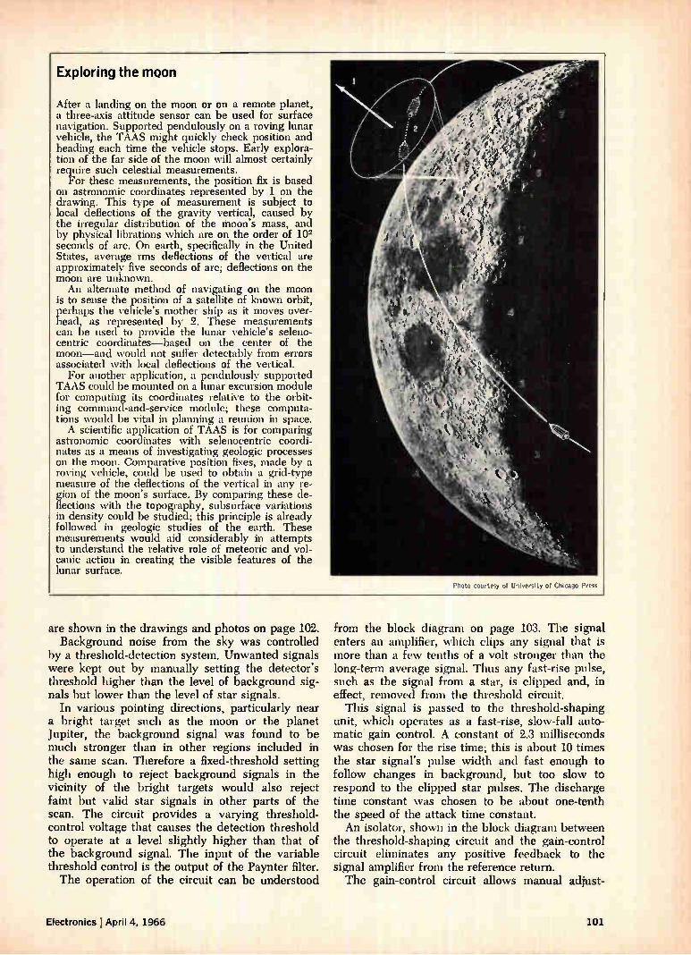
Exploring the moon
After a landing on the moon or on a remote planet, a three-axis attitude sensor can be used for surface navigation. Supported pendulously on a roving lunar vehicle, the TAAS might quickly check position and heading each time the vehicle stops. Early explora-tion of the far side of the moon will almost certainly require such celestial measurements.
For these measurements, the position fix is based on astronomic coordinates represented by 1 on the drawing. This type of measurement is subject to local deflections of the gravity vertical, caused by the irregular distribution of the moon's mass, and by physical librations which are on the order of 102 seconds of arc. On earth, specifically in the United States, average rms deflections of the vertical are approximately five seconds of arc; deflections on the moon are unknown. An alternate method of navigating on the moon
is to sense the position of a satellite of known orbit, perhaps the vehicle's mother ship as it moves over-head, as represented by 2. These measurements can be used to provide the lunar vehicle's seleno-centric coordinates—based on the center of the moon—and would not suffer detectably from errors associated with local deflections of the vertical.
For another application, a pendulously supported TAAS could be mounted on a lunar excursion module for computing its coordinates relative to the orbit-ing command-and-service module; these computa-tions would be vital in planning a reunion in space. A scientific application of TAAS is for comparing
astronomic coordinates with selenocentric coordi-nates as a means of investigating geologic processes on the moon. Comparative position fixes, made by a roving vehicle, could be used to obtain a grid-type measure of the deflections of the vertical in any re-gion of the moon's surface. By comparing these de-flections with the topography, subsurface variations in density could be studied; this principle is already followed in geologic studies of the earth. These measurements would aid considerably in attempts to understand the relative role of meteoric and vol-canic action in creating the visible features of the lunar surface.
Photo courtesy of University of Chicago Press
are shown in the drawings and photos on page 102. Background noise from the sky was controlled
by a threshold-detection system. Unwanted signals were kept out by manually setting the detector's threshold higher than the level of background sig-nals but lower than the level of star signals.
In various pointing directions, particularly near a bright target such as the moon or the planet Jupiter, the background signal was found to be much stronger than in other regions included in the same scan. Therefore a fixed-threshold setting high enough to reject background signals in the vicinity of the bright targets would also reject faint but valid star signals in other parts of the scan. The circuit provides a varying threshold-control voltage that causes the detection threshold to operate at a level slightly higher than that of the background signal. The input of the variable threshold control is the output of the Paynter filter. The operation of the circuit can be understood
from the block diagram on page 103. The signal enters an amplifier, which clips any signal that is more than a few tenths of a volt stronger than the long-term average signal. Thus any fast-rise pulse, such as the signal from a star, is clipped and, in effect, removed from the threshold circuit. This signal is passed to the threshold-shaping
unit, which operates as a fast-rise, slow-fall auto-matic gain control. A constant of 2.3 milliseconds was chosen for the rise time; this is about 10 times the star signal's pulse width and fast enough to follow changes in background, but too slow to respond to the clipped star pulses. The discharge time constant was chosen to be about one-tenth the speed of the attack time constant. An isolator, shown in the block diagram between
the threshold-shaping circuit and the gain-control circuit eliminates any positive feedback to the signal amplifier from the reference return. The gain-control circuit allows manual adjust-
Electronics I April 4, 1966 101
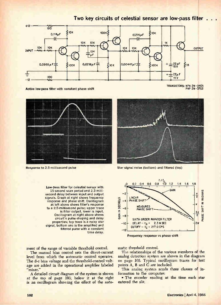
Two key circuits of celestial sensor are low-pass filter . .
TRANSISTORS: NPN 2N-3405 PNP 2N-3702 Active low-pass filter with constant phase shift
Response to 2.5 millisecond pulse Star signal noise (bottom) and filtered (top)
Low-pass filter for celestial sensor with 15-second scan period and 2.3-milli-
second delay between input and output signals. Graph at right shows frequency response and phase shift. Oscillogram
at left above shows filter's response to a 2.5-millisecond pulse; upper trace
is filter output, lower is input. Oscillogram at right above shows circuit's pulse-shaping and delay
properties; top trace is a noisy star signal, bottom one is the amplified and
filtered pulse with a constant time delay.
ment of the range of variable threshold control. The manual bias control sets the direct-current
level from which the automatic control operates. The d-c bias voltage and the threshold-control volt-age are added in the operational amplifier labeled "mixer." A detailed circuit diagram of the system is shown
at the top of page 103; below it at the right is an oscillogram showing the effect of the auto-
GAIN IN DECIBELS
f / fc 02 0.4 0.6 0.8 1.0 1.2 1.4 1.6 1.8
LINEAR y PHASE SHIFT
MEASURED PHASE SHIFT
SIXTH ORDER PAYNTER FILTER
DELAY -TD 2.3 M SEC
CUTOFF - fc 217.0 CPS I I 1
Frequency response vs phase shift
3r 2
2n
PHASE SHIFT
IN RADIANS
matic threshold controL The relationships of the various members of the
analog detection system are shown in the diagram on page 105. Typical oscillogram traces for test points A, B and C are included.
This analog system sends three classes of in-formation to the computer: • The encoder reading at the time each star
entered the slit.
102 Electronics April 4, 1966
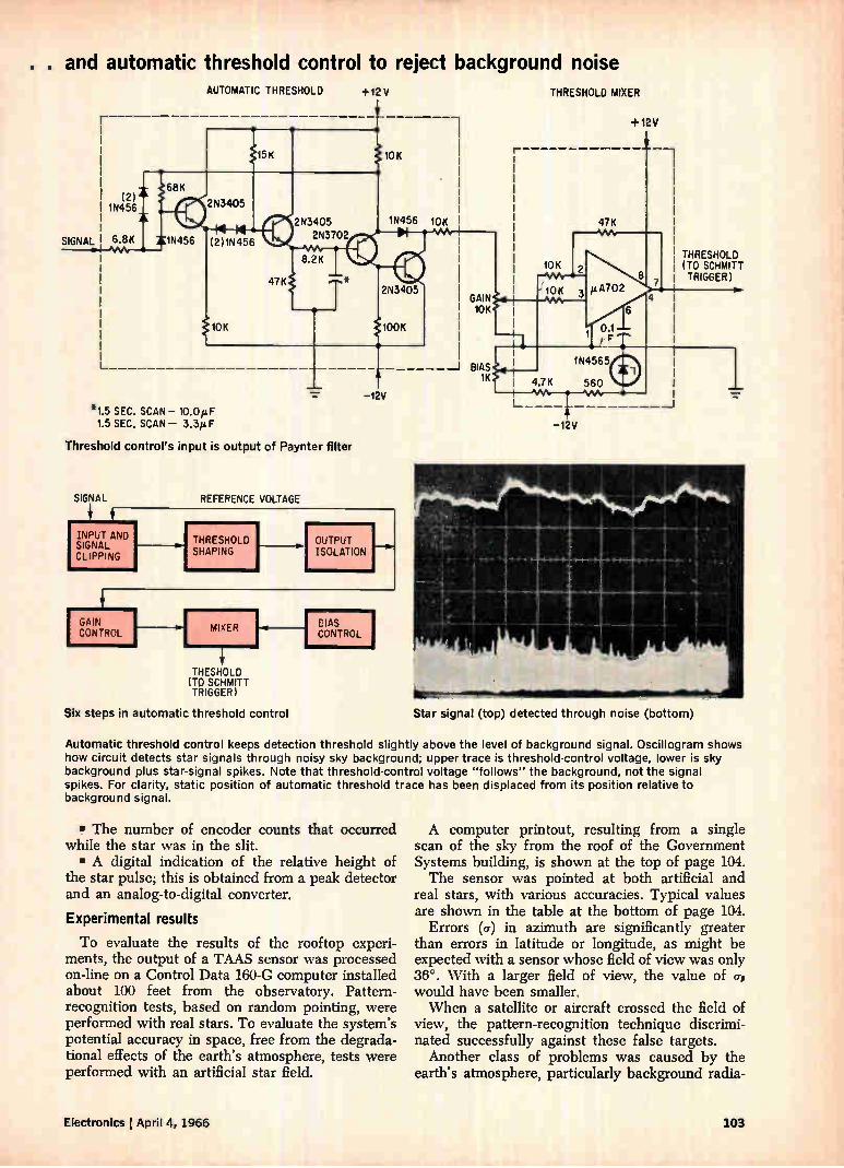
. . and automatic threshold control to reject background noise
SIGNAL
(2) I 1N456
6.8K
—12V -.7
1N456
AUTOMATIC THRESHOLD +12V
2N3405
(2)1N456
2N3405 2N3702
*1.5 SEC. SCAN —10.0µF 1.5 SEC. SCAN — 3.3p F
Threshold control's input is output of Paynter filter
SIGNAL REFERENCE VOLTAGE
INPUT AND SIGNAL CLIPPING
GAIN CONTROL
THRESHOLD SHAPING
MIXER
THESHOLD (TO SCHMITT TRIGGER)
10K
1N456 10K
2N3405 GAIN 10K
BIAS 1K
THRESHOLD MIXER
+12V
10K 2
-10K 3 4A.A.
47K
p.A702
1N4565
4.7K 560 44•4.04. • vo.
—12V
_J
THRESHOLD (TO SCHMITT TRIGGER)
Six steps in automatic threshold control Star signal (top) detected through noise (bottom)
OUTPUT ISOLATION
EIAS CONTROL
Automatic threshold control keeps detection threshold slightly above the level of background signal. Oscillogram shows how circuit detects star signals through noisy sky background; upper trace is threshold-control voltage, lower is sky background plus star-signal spikes. Note that threshold-control voltage "follows" the background, not the signal spikes. For clarity, static position of automatic threshold trace has been displaced from its position relative to background signal.
• The number of encoder counts that occurred while the star was in the slit. • A digital indication of the relative height of
the star pulse; this is obtained from a peak detector and an analog-to-digital converter.
Experimental results
To evaluate the results of the rooftop experi-ments, the output of a TAAS sensor was processed on-line on a Control Data 160-G computer installed about 100 feet from the observatory. Pattern-recognition tests, based on random pointing, were performed with real stars. To evaluate the system's potential accuracy in space, free from the degrada-tional effects of the earth's atmosphere, tests were performed with an artificial star field.
A computer printout, resulting from a single scan of the sky from the roof of the Government Systems building, is shown at the top of page 104. The sensor was pointed at both artificial and
real stars, with various accuracies. Typical values are shown in the table at the bottom of page 104.
Errors (u) in azimuth are significantly greater than errors in latitude or longitude, as might be expected with a sensor whose field of view was only 36°. With a larger field of view, the value of 0-, would have been smaller. When a satellite or aircraft crossed the field of
view, the pattern-recognition technique discrimi-nated successfully against these false targets.
Another class of problems was caused by the earth's atmosphere, particularly background radia-
Electronics lApril 4, 1966 103
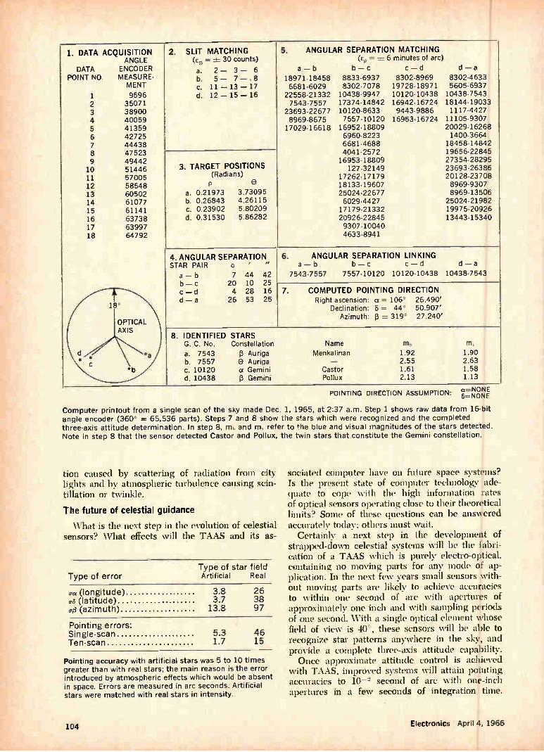
1. DATA ACQUISITION ANGLE
DATA ENCODER POINT NO MEASURE-
MENT
1 9596 2 35071 3 38900 4 40059 5 41359 6 42725 7 44438 8 47523 9 49442 10 51446 11 57005 12 58548 13 60502 14 61077 15 61141 16 63738 17 63997 18 64792
2. SLIT MATCHING (so = 30 counts)
a. 2 - 3 - 6 b. 5 - 7 - 8 c. 11 - 13 - 17 d. 12 - 15 - 16
3. TARGET POSITIONS (Radians)
0 a. 0.21973 3.73095 b. 0.26843 4.26115 c. 0.23902 5.80209 d. 0.31530 5.86282
5. ANGULAR SEPARATION MATCHING = 6 minutes of arc)
b - c c - d
18971-18458 8833-6937 8302-8969 6681-6029 8302-7078 19728-18971
22558-21332 10438-9947 10120-10438 7543-7557 17374-14842 16942-16724
23693-22677 10120-8633 9443-9886 8969-8675 7557-10120 16953-16724 17029-16618 16952-18809
6960-8223 6681-4688 4041-2572 16953-18809
127-32149 17262-17179 18133-19607 25024-22677 6029-4427 17179-21332 20926-22845 9307-10040 4633-8941
a - b d - a
8302-4633 5605-6937 10438-7543 18144-19033 1117-4427
11105-9307 20029-16268 1400-3664
18458-14842 19656-22845 27354-28295 23693-26386 20128-23708 8969-9307 8969-13506
25024-21982 19975-20926 13443-15340
4. ANGULAR SEPARATION STAR PAIR o
a - b b - c c - d d - a
7 44 42 20 10 25 4 28 16 26 53 25
6. ANGULAR SEPARATION LINKING a - b b - c c - d d - a
7543-7557 7557-10120 10120-10438 10438-7543
7. COMPUTED POINTING DIRECTION Right ascension: a = 106 26.490'
Declination: 8 = 44' 50.907' Azimuth: pi =r. 319' 27.240'
8. IDENTIFIED STARS G. C. No. Constellation
a. 7543 pi Auriga b. 7557 0 Auriga C. 10120 a Gemini d. 10438 13 Gemini
Name
Menkalinan
Castor Pollux
rn,
1.92 2.55 1.61 2.13
m,
1.90 2.63 1.58 1.13
POINTING DIRECTION ASSUMPTION: a=NONE 5=NONF
Computer printout from a single scan of the sky made Dec. 1, 1965, at 2:37 a.m. Step 1 shows raw data from 16-bit angle encoder (360' = 65,536 parts). Steps 7 and 8 show the stars which were recognized and the completed three-axis attitude determination. In step 8, m, and m, refer to the blue and visual magnitudes of the stars detected. Note in step 8 that the sensor detected Castor and Pollux, the twin stars that constitute the Gemini constellation.
tion caused by scattering of radiation from city lights and by atmospheric turbulence causing scin-tillation or twinkle.
The future of celestial guidance
What is the next step in the evolution of celestial sensors? What effects will the TAAS and its as-
Type of star field Type of error Artificial Real
(Ta (longitude) 3.8 26 ffs (latitude) 3.7 38 cre (azimuth) 13.8 97
Pointing errors: Single-scan 5.3 46 Ten-scan 1.7 15
Pointing accuracy with artificial stars was 5 to 10 times greater than with real stars; the main reason is the error introduced by atmospheric effects which would be absent in space. Errors are measured in arc seconds. Artificial stars were matched with real stars in intensity.
sociated computer have on future space systems? Is the present state of computer technology ade-quate to cope with the high information rates of optical sensors operating close to their theoretical limits? Some of these questions can be answered accurately today; others must wait.
Certainly a next step in the development of strapped-down celestial systems will be the fabri-cation of a TAAS which is purely electro-optical, containing no moving parts for any mode of ap-plication. In the next few years small sensors with-out moving parts are likely to achieve accuracies to within one second of arc with apertures of approximately one inch and with sampling periods of one second. With a single optical element whose field of view is 40 , these sensors will be able to recognize star patterns anywhere in the sky, and provide a complete three-axis attitude capability. Once approximate attitude control is achieved
with TAAS, improved systems will attain pointing accuracies to 10-2 second of arc with one-inch apertures in a few seconds of integration time.
104 Electronics April 4, 1966
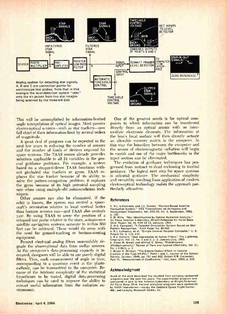
SENSOR
STAR 7 SIGNALS
BACK-GROUND UNFILTERED STAR SIGNAL
PHOTO MULTIPLIER A
STAR SIGNALS
BACK-GROUND FILTERED STAR SIGNAL
PAYNTER LOW PASS FILTER
COMBINED OUTPUTS OF POINTS B AND C
SIGNAL INPUT
Analog system for detecting star signals.
A, B and C are connection points for
oscilloscope test probes. Note that in this
example the level-detection system "sees"
only the six pulses from two star images
being scanned by the three-slit disk.
lAUTOMATIC THRESHOLD CONTROL
This will be accomplished by information-limited angle interpolation of optical images. Most passive electro-optical sensors—such as star trackers—now fall short of their information limit by several orders of magnitude. A great deal of progress can be expected in the
next few years in reducing the number of sensors and the number of kinds of devices required for space systems. The TAAS sensor already provides solutions applicable to all 24 variables in the gen-eral guidance problems. For example, a system based on a strapped-down TAAS functions with-out gimbaled star trackers or gyros. TAAS re-places the star tracker because of its ability to solve the pattern-recognition problem; it replaces the gyros because of its high potential sampling rate when using multiple-slit autocorrelation tech-niques.
Other sensors can also be eliminated. If the orbit is known, the system can control a space-craft's orientation relative to local vertical better than horizon sensors can—and TAAS also controls yaw. By using TAAS to sense the position of a released test probe relative to the stars, autonomous satellite navigation systems accurate to within 500 feet can be achieved. These would do away with the need for ground-tracking or horizon-sensing equipment.
Present electrical analog filters unavoidably de-grade the observational data from stellar sources. As the computer's data-processing capacity is in-creased, designers will be able to use purely digital filters. Thus, each measurement of angle or time, correspónding to a quantum event at the photo-cathode, can be transmitted to the computer. Be-cause of the intrinsic complexity of the statistical hypotheses to be tested, digital data-processing techniques can be used to improve the ability to extract useful information from the radiation en-vironment.
CONTROL INPUT
THRESHOLD CONTROL VOLTAGE
SCHMITT TRIGGER LEVEL DETECTOR
NET INPUTS TO LEVEL DETECTOR
TO COMPUTER INTER-FACE
STAR-IN-SLIT SIGNALS
•••.0
IZERO REFERENCE 4
One of the greatest needs is for optical com-puters to which information can be transferred directly from an optical sensor with no inter-mediate electronic elements. The information at the lens's focal surface will then directly actuate an alterable memory matrix in the computer. In this way the boundary between the computer and the sensor of electromagnetic radiation will begin to vanish and one of the major bottlenecks in the input section can be eliminated. The evolution of guidance techniques has pro-
gressed from instinct to dead reckoning to inertial guidance. The logical next step for space systems is celestial guidance. The mechanical simplicity and versatility resulting from application of modern electro-optical technology makes the approach par-ticularly attractive.
References
1. R.L. Lillestrand, and J.E. Carroll, "Horizon-Based Satellite Navigation System," IEEE Transactions on Aerospace and Navigational Electronics, Vol. ANE-10, No. 3, September, 1963, p. 266. 2. D. Wille, "Star Identification by Optical Radiation Analysis," Air Force Avionics Laboratory, Wright-Patterson Air Force Base, Ohio. Report No, AL TDR 64-13, January, 1964. 3. M.E. Campbell, "A Celestial Orientation System Based on Star Pattern Recognition," AIAA Paper No. 64-652. 4. R.J. LaManna, et al, "Simple General Purpose Computer," U. S. Patent No. 3, 116, 410. 5. P.J. Hansen, "New Approaches to Active Filters," The Lightning Empiricist, Vol. 12, No. 1 and 2, p. 3, January-July, 1965. 6. Glenn H. Brown and Wilfred G. Shaw, "Phototropism (Photochromism)," Review of Pure and Applied Chemistry, Vol. 11, No. 1 (1961),.p. 2. 7. Bruce H. Billings, "The Electro-Optical Effect in Uniaxial Crystals of the Type XH2P0i," Parts I and il, Journal of the Optical Society, October, 1949, pp. 797 and 802; Robert OB. Carpenter, Part III, "Measurement of Coefficients," ibid, April, 1950, p. 225.
Acknowledgment
Much of the work described has resulted from company-sponsored programs over the past five years. The experimental program was sponsored in part by the Avionics Laboratory at Wright-Patterson Air Force Base, Ohio. Various analytical programs were sponsored by NASA laboratories—mainly the Goddard Space Flight Center, Md., and Langley Research Center, Va.
Electronics April 4, 1966 105
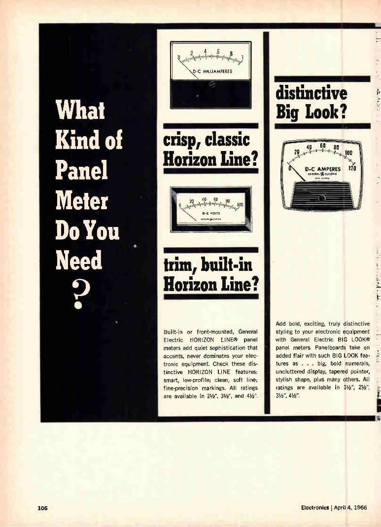
2 .4 .6
D-C MILLIAMPERES
crisp, classic Horizon Line?
trim, built-in Horizon Line?
Built-in or front-mounted, General
Electric HORIZON LINE® panel
meters add quiet sophistication that
accents, never dominates your elec-
tronic equipment. Check these dis-
tinctive HORIZON LINE features:
smart, low-profile; clean, soft line;
fine-precision • markings. All ratings
are available in 21/2 ", 31/2 ", and 41/2 ".
distinctive Big Look?
40 60 80 20 ,..'t""1"°»/..,,,,,"'"vo,,,„ 100 SN‘
D-C AMPERES 120 SI RRRRR (8, mean
.111111•114
Add bold, exciting, truly distinctive
styling to your electronic equipment
with General Electric BIG LOOK®
panel meters. Panelboards take on
added flair with such BIG LOOK fea-
tures as . . . big, bold numerals,
uncluttered display, tapered pointer,
stylish shape, plus many others. All
ratings are available in 11/2 ", 21/2",
31/2 ", 41/2 ".
106 Electronics April 4, 1966
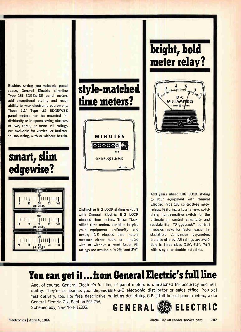
Besides saving you valuable panel
space, General Electric slim-line
Type 185 EDGEWISE panel meters
add exceptional styling and read-
ability to your electronic equipment.
These 21/4 " Type 185 EDGEWISE
panel meters can be mounted in-
dividually or in space-saving clusters
of two, three, or more. All ratings
are available for vertical or horizon-
tal mounting, with or without bezels.
smart, slim edgewise?
0 25 50 75 100 DC VOLTS
111,
e Il IllIllIllIlIllIll 0 25 50 75 100
DC VOLTS
IlllIllllIlIIlIlIllI 0 25 50 75 100
DC VOLTS
style-matched time meters?
MINUTES
00000 o I /10
GENERAL ELECTRIC
P 227174
Distinctive BIG LOOK styling is yours
with .General Electric BIG LOOK
elapsed time meters. These "look-
alike" time meters combine to give
your equipment uniformity and
beauty. G-E elapsed time meters
measure either hours or minutes
with or without a reset knob. All
ratings are available in 21/2" and 31/2 ".
bright, bold meter relay?
Add years ahead BIG LOOK styling
to your equipment with General
Electric Type 195 contactless meter
relays, featuring a totally new, solid-
state, light-sensitive switch for the
ultimate in control simplicity and
readability. "Piggyback" control
modules make for faster, easier in-
stallation. Companion pyrometers
are also offered. All ratings are avail-
able in three sizes (21/2 ", 31/2 ", 41/2 ")
with single or double setpoints.
You can get it...from General Electric's full line And, of course, General Electric's full line of panel meters is unmatched for accuracy and reli-
ability. They're as near as your dependable G-E electronic distributor or sales office. You get
fast delivery, too. For free descriptive bulletins describing G.E.'s full line of panel meters, write
General Electric Co., Section 592-25A,
Schenectady, New York 12305. GENERAL ELECTRIC Electronics I April 4, 1966 Circle 107 on reader service card 107
This little sample will help explain some...
New ideas
for multi-layer circuitry Formica's MLC system permits accurate registration of circuits, maximum packaging density, high-temperature stability, plus! Many common multi-layer circuitry problems
can be solved. Just ask your Formica rep
to bring in his kit (with samples) detailing
Formica's new M LC system. System's
base laminate is FORMICA* brand copper
clad laminated plastic, FR-45—documented reliability. Pre-preg has resin specifically
developed for use with FR-45 . . . has in-organic additives which increase thermal
conductivity of laminate; OKs use of thin
circuit lines, thin copper foil, dense packag-
ing. And circuit pads hold tight for accurate registration ... no slippage. Go ahead and
weld or solder: bond holds. Reliable circuits . resin stays viscous (but not watery) to
fill around all elements. Many tiny, closely. spaced holes to drill? Your Formica rep
can tell you how. Also how you can use one laminate (instead of 4)for G-10, G-11, FR-4,
FR-5 requirements. Write, Dept. ID-5.
® 1 = FORMICA
Incluetrial plaatica
Leadership through innovation • FORMICA CORPORATION • Cincinnati, Ohio 45232 subsidiary of CYANAMID
FORMICAe is our trademark for various products, including our brand of laminated plastic.
108 Circle 108 on reader service card Electronics April 4, 1966
Circuit design
Using transistor circuits to multiply and divide
They effectively employ the transistor's
current-voltage characteristics to
raise numbers exponentially and extract roots
By George E. Platzer Jr. Chrysler Corp., Detroit
Because a pn semiconductor junction exhibits a logarithmic relationship between current and volt-age, it can be exploited to perform calculations such as multiplication, just as a slide rule does. Since the junctions may be used to take antiloga-rithms as well as logarithms, it is possible to mul-tiply, divide and raise to exponents in the loga-rithmic domain by simple addition and subtraction. Thus, in instrumentation and control systems, tran-sistor circuits can perform the same function as a slide rule, but with the advantage that the mathe-matical operation is performed continuously and rapidly as the input quantities change. Although there are other electronic ways of per-
forming analog operations, these transistor cir-cuits'. 2 generally have advantages of simplicity, accuracy and faster response time. For example, conventional servomultipliers, which use ganged potentiometers to perform multiplication, operate more accurately but the frequency response is gen-erally poor. Other devices require complex circuits. Analog circuits most closely equivalent to transis-tor circuits in performance utilize Hall effect de-vices and magnetoresistors. Compared with these, the transistor circuits are generally more accurate and less sensitive to temperature.
The author
George E. Platzer Jr. heads the physics group of Chrysler Corp.'s physics-instrumentation research laboratory, where he directs the development of solid state circuitry for automobiles. His background includes degrees in physics and in electrical and automotive engineering.
Engineers at the Chrysler Corp. use the transis-torized computers for controlling the input energy of a resistance welder, for calculating the average of squared values and root mean square values, and for direct computation of efficiency and slip in mechanical systems. In the welding application, a multiplier computes the instantaneous power de-livered to the weld area. The frequency response of the multiplier is high enough to respond to the transients caused by the welder's phase controlled transformer. Within limits, the circuit is able to compensate for line voltage variations, electrode wear, and dimensional variations of the workpiece.
Log and antilog
The basic principle of the electronic slide ntle is that for low-level input signals, the current and voltage in an ideal diode junction are related by
qV qV le ek? 1) iitekT
where I = the diode current in amperes
(1)
IR = the diode reverse-saturation current in amperes
V = the voltage across the diode in volts q = electron charge in coulombs k = Boltzmann's constant T = temperature in degrees Kelvin
At the current levels used for logarithmic compu-tations, the approximation in equation 1 is in error by less than 1 part in 10 million. The diode's saturation reverse current, In, is tem-
perature sensitive and is given by3
) 1.4 EG ( T
IR IRO e k T (2)
where IRO is the reverse saturation current at tem-perature To in amperes and EG is the energy gap
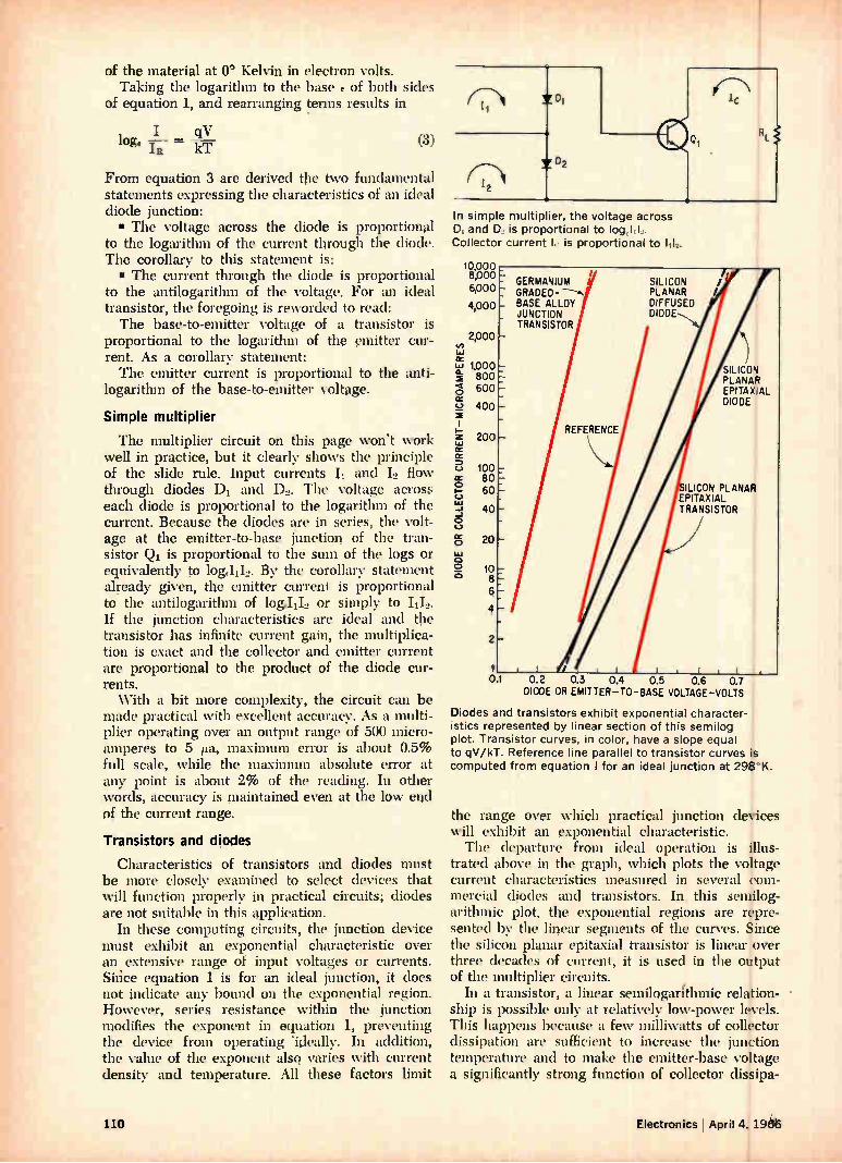
of the material at 0° Kelvin in electron volts. Taking the logarithm to the base E of both sides
of equation 1, and rearranging terms results in
I qV log. = kT (3)
From equation 3 are derived the two fundamental statements expressing the characteristics of an ideal diode junction: • The voltage across the diode is proportional
to the logarithm of the current through the diode. The corollary to this statement is: • The current through the diode is proportional
to the antilogarithm of the voltage. For an ideal transistor, the foregoing is reworded to read: The base-to-emitter voltage of a transistor is
proportional to the logarithm of the emitter cur-rent. As a corollary statement: The emitter current is proportional to the anti-
logarithm of the base-to-emitter voltage.
Simple multiplier
The multiplier circuit on this page won't work well in practice, but it clearly shows the principle of the slide rule. Input currents II and 12 flow through diodes DI and D2. The voltage across each diode is proportional to the logarithm of the current. Because the diodes are in series, the volt-age at the emitter-to-base function of the tran-sistor Q1 is proportional to the sum of the logs or equivalently to log.1112. By the corollary statement already given, the emitter current is proportional to the antilogarithm of log.1112 or simply to 1112. If the junction characteristics are ideal and the transistor has infinite current gain, the multiplica-tion is exact and the collector and emitter current are proportional to the product of the diode cur-rents. With a bit more complexity, the circuit can be
made practical with excellent accuracy. As a multi-plier operating over an output range of 500 micro-amperes to 5 eta, maximum error is about 0.5% full scale, while the maximum absolute error at any point is about 2% of the reading. In other words, accuracy is maintained even at the low end of the current range.
Transistors and diodes
Characteristics of transistors and diodes must be more closely examined to select devices that will function properly in practical circuits; diodes are not suitable in this application.
In these computing circuits, the junction device must exhibit an exponential characteristic over an extensive range of input voltages or currents. Sirice equation 1 is for an ideal junction, it does not indicate any bound on the exponential region. However, series resistance within the junction modifies the exponent in equation 1, preventing the device from operating 'ideally. In addition, the value of the exponent also varies with current density and temperature. All these factors limit
(7«:«1 y Di
7 D2
In simple multip ier, the voltage across D, and D is proportional to log, 1.1. Collector current k is proportional to 1-1_.
10,000 8,000 6,000
4,000
2,000
cc 1.1 1,000 0-• 800
600 o cc
1.1 cr rr
100 cr 80 o - 60
400
200
111 40
o -J
C-)
OC o 20
o o ▪ 10
8 6
4
2
1 01 0.2 0.3 0.4 0.5 0.6 0.7
DIODE OR EMITTER-TO-BASE VOLTAGE-VOLTS
Diodes and transistors exhibit exponential character-istics represented by linear section of this semilog plot. Transistor curves, in color, have a slope equal to qV/kT. Reference line parallel to transistor curves is computed from equation I for an ideal junction at 290°K.
RL
the range over which practical junction devices will exhibit an exponential characteristic. The departure from ideal operation is illus-
trated above in the graph, which plots the voltage current characteristics measured in several com-mercial diodes and transistors. In this semilog-arithmic plot, the exponential regions are repre-sented by the linear segments of the curves. Since the silicon planar epitaxial transistor is linear over three decades of current, it is used in the output of the multiplier circuits.
In a transistor, a linear semilogarithmic relation-ship is possible only at relatively low-power levels. This happens because a few milliwatts of collector dissipation are sufficient to increase the junction temperature and to make the emitter-base voltage a significantly strong function of collector dissipa-
110 Electronics April 4, 196
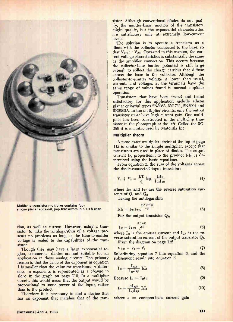
Multichip transistor multiplier contains four silicon planar epitaxial, pnp transistors in a TO-5 case.
tion, as well as current. However, using a tran-sistor to take the antilogarithm of a voltage pre-sents no problems as long as, the base-to-emitter voltage is scaled to the capabilities of the tran-sistor. Though the may have a large exponential re-
gion, commercial diodes are not suitable for an application in these analog circuits. The primary reason is that the value of the exponent in equation 1 is smaller than the value for transistors. A differ-ence in exponents is represented ás à change in slope in the graph on page 110. In a multiplier circuit, this would mean that the output would be proportional to some power of the input, rather than to the product.
Therefore it is necessary to find a device that has an exponent that matches that uf the tran-
sistor. Although conventional diodes do not quai ify, the emitter-base junction of the transistors might qualify, but the exponential characteristics are satisfactory only at extremely low-current levels. The solution is to operate a transistor as a
diode with the collector connected to the base, so that VeR = VBR. Operated in this manner, the cur-rent-voltage characteristics is substantially the sa,me as the amplifier connection. This occurs because the collector-base barrier potential is still large enough to collect the charge carriers that diffuse across the base to the collector. Although the collector-to-emitter voltage is lower than usual, currents and voltages at the terminals have the same range of values found in normal amplifier operation.
Transistors that have been tested and found satisfactory for this application include silicon planar epitaxial types 2N3053, 2N1711, 2N2904 and 2N2905A. In the multiplier circuits, only the output transistor must have high current gain. One multi-plier has been constructed in the multichip tran-sistor in the photograph at the left. Called the SC-286 it is manufactured by Motorola Inc.
Multiplier theory
A more exact multiplier circiiit at the top of page 112 is similar to the simple multiplier, except that transistors are used in place of diodes. The output current Ic, proportional to the product 1112, is de-termined using the basic equations. From equation 2, the sum of the voltages across
the diode-connected input transistors
kT II 1 , ± Y2 - T
q imiR2 (4)
where 'RI and IR2 are the reverse saturation cur-rents of Q1 and Q2 Taking the antilogarithm
eVri-V2) kT
For the output transistor Qs,
qV BE
(5)
IE = IREE "kT (6) where IE is the emitter current and IRE is the re-verse saturation current of the output transistor Q8. From the diagram on page 112
VBE = ± V2 (7) Substituting equation 7 into equation 8, and the subsequent result into equation 5
IRE IR = T y 1112
.I.R11R2
Because IE =
aIRE Io — T T 1112
£R1111,2
where a = common-base current gain
Electronics : April 4, 1966 111
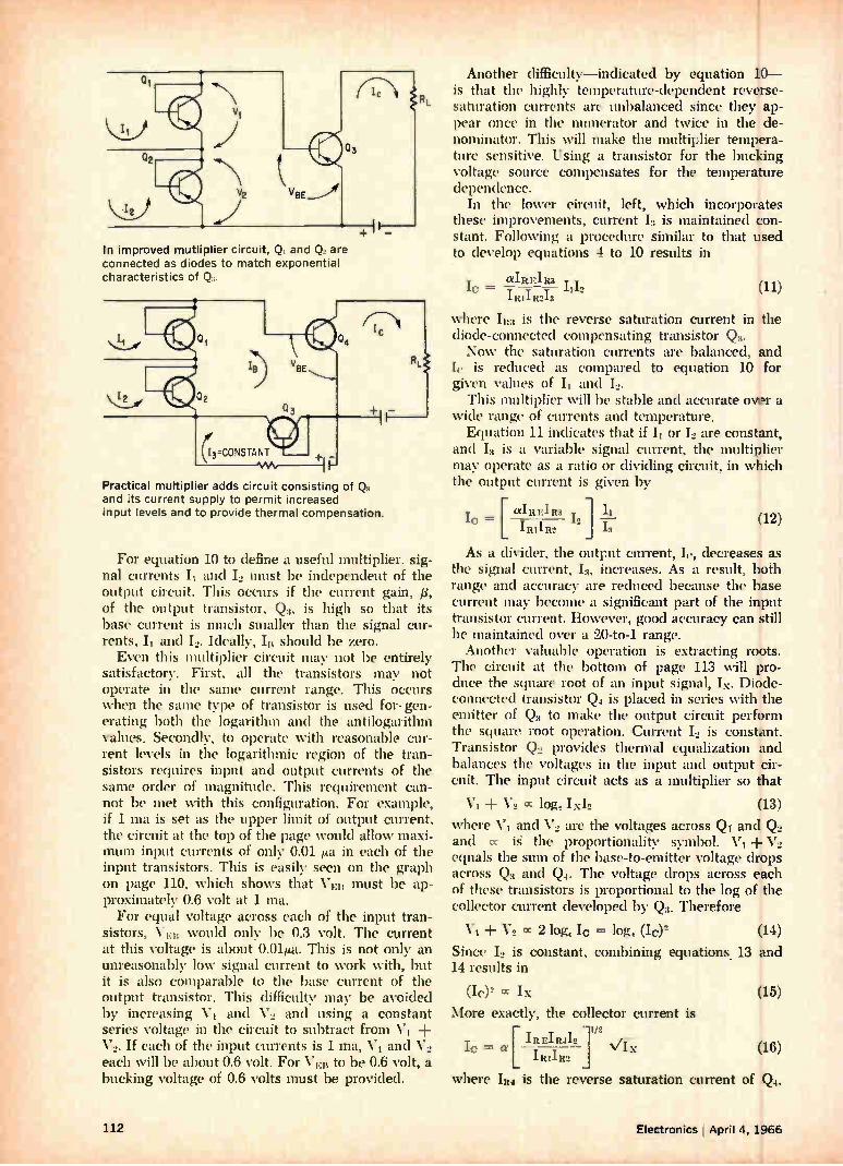
In improved mutliplier circuit, Q. and Q are connected as diodes to match exponential characteristics of Q.
(I3=CONSTANT
Practical multiger adds circuit consisting of Q, and its current supply to permit increased input !evels and to provide thermal compensation.
For equation 10 to define a useful multiplier, sig-nal currents II and I.» must be independent of the output circuit. This occurs if the current gain, /3, of the output transistor, Q3, is high so that its base current is much smaller than the signal cur-rents, 11 and I.». Ideally, I should be zero. Even this multiplier circuit may not be entirely
satisfactory. First, all the transistors may not operate in the same current range. This occurs when the same type of transistor is used for- gen-erating both the logarithm and the antilogarithm values. Secondly, to operate with reasonable cur-rent levels in the logarithmic region of the tran-sistors requires input and output currents of the same order of magnitude. This requirement can-not be met with this configuration. For example, if 1 ma is set as the upper limit of output current, the circuit at the top of the page would allow maxi-mum input currents of only 0.01 a in each of the input transistors. This is easily seen on the graph on page 110, which shows that VER must be ap-proximately 0.6 volt at 1 ma. For equal voltage across each of the input tran-
sistors, VEit would only be 0.3 volt. The current at this voltage is about 0.01iLa. This is not only an unreasonably low signal current to work with, but it is also comparable to the base current of the output transistor. This difficulty may be avoided by increasing V1 and V.» and using a constant series voltage in the circuit to subtract from VI + V, If each of the input currents is 1 ma, V1 and V2 each will be about 0.6 volt. For VEll to be 0.6 volt, a bucking voltage of 0.6 volts must be provided.
Another difficulty—indicated by equation 10— is that the highly temperature-dependent reverse-saturation currents are unbalanced since they ap-pear once in the numerator and twice in the de-nominator. This will make the multiplier tempera-ture sensitive. Using a transistor for the bucking voltage source compensates for the temperature dependence.
In the lower circuit, left, which incorporates these improvements, current 13 is maintained con-stant. Following a procedure similar to that used to develop equations 4 to 10 results in
aIRFIR3 T IC — • 1112 11111R213
(11)
where Iit3 is the reverse saturation current in the diode-connected compensating transistor Q3. Now the saturation currents are balanced, and
Iv is reduced as compared to equation 10 for given values of II and 12.
This multiplier will be stable and accurate over a wide range of currents and temperature. Equation 11 indicates that if II or 12 are constant,
and 13 is a variable signal current, the multiplier may operate as a ratio or dividing circuit, in which the output current is given by
[ aIREIR3 y IC Ire 12
I RIIR2 J 12 (12)
As a divider, the ot tput current, decreases as the signal current, I3 increases. As a result, both range and accuracy are reduced because the base current may become a significant part of the input transistor current. However, good accuracy can still be maintained over a 20-to-1 range. Another valuable operation is extracting roots.
The circuit at the bottom of page 113 will pro-duce the square root of an input signal, Ix. Diode-connected transistor Q4 is placed in series with the emitter of Q3 to make the output circuit perform the square root operation. Current 12 is constant. Transistor Q2 provides thermal equalization and balances the voltages in the input and output cir-cuit. The input circuit acts as a multiplier so that
VI V2 CC log, Ix12 (13)
where V1 and V2 are the voltages across Q1 and Q2 and (x iS the proportionality symbol. V1 + V2 equals the sum of the base-to-emitter voltage drops across Q3 and Q. The voltage drops across each of these transistors is proportional to the log of the collector current developed by Q3. Therefore
+ V2 cc 2 log, lc = log, (le (14)
Since 12 is constant, combining equations. 13 and 14 results in
(Ic)2 cc Ix (15)
More exactly, the collector current is
[ IREIBA12 lc = a IMIR2 '‘/Ix (16)
where IR4 is the reverse saturation current of Q.
1/2
112 Electronics April 4, 1966
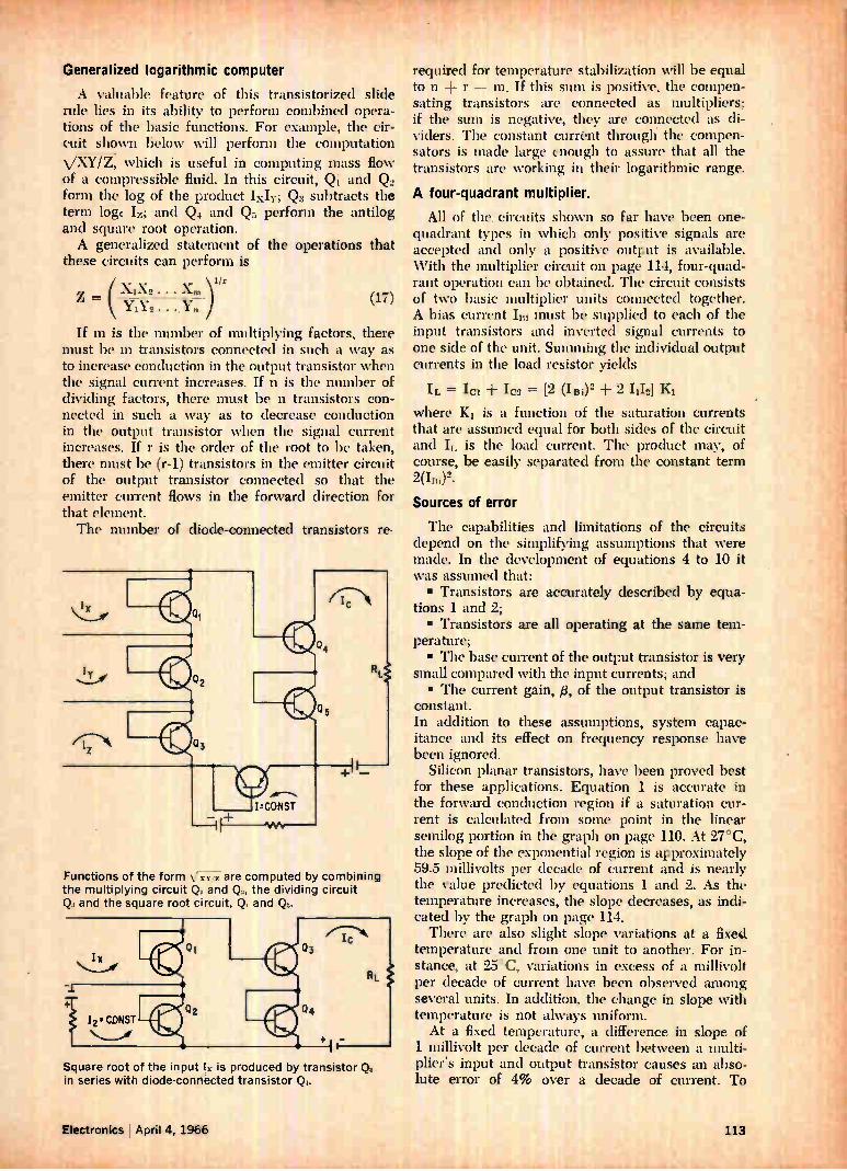
'11r*,-"r:P',' • .
Generalized logarithmic computer
A valuable feature of this transistorized slide rule lies in its ability to perform combined opera-tions of the basic functions. For example, the cir-cuit shown below will perform the computation VXY/i, which is useful in computing mass flow of a compressible fluid. In this circuit, Qi and Q., form the log of the product 'XII"; (23 subtracts the term loge Iz; and Q. and Q5 perform the antilog and square root operation. A generalized statement of the operations that
these circuits can perform is
= X1X2 • • • Ám
f/r
YiY2 .
If m is the number of multiplying factors, there must be in transistors connected in such a way as to increase conduction in the output transistor when the signal current increases. If n is the number of dividing factors, there must be n transistors con-nected in such a way as to decrease conduction in the output transistor when the signal current increases. If r is the order of the root to be taken, there must be (r-1) transistors in the emitter circuit of the output transistor connected so that the emitter current flows in the forward direction for that element. The number of diode-connected transistors re-
(17)
Functions of the form \ are computed by combining the multiplying circuit Q, and Q,, the dividing circuit Q.: and the square root circuit Q, and Q.
Square root of the input lx is produced by transistor Q. in series with diode-connected transistor Q.
'
required for temperature stabilization will be equal to n r — m. If this sum is positive, the compen-sating transistors are connected as multipliers; if the sum is negative, they are connected as di-viders. The constant current through the compen-sators is made large enough to assure that all the transistors are working in their logarithmic range.
A four-quadrant multiplier.
All of the, circuits shown so far have been one-quadrant types in which only positive signals are accepted and only a positive output is available. With the multiplier circuit on page 114, four-quad-rant operation can be obtained. The circuit consists of two basic multiplier units connected together. A bias current Im must be supplied to each of the input transistors and inverted signal currents to one side of the unit. Summing the individual output currents in the load resistor yields
IL = Ici 'Cs = [2 (le + 2 1112]
where Ki is a function of the saturation currents that are assumed equal for both sides of the circuit and IL is the load current. The product may, of course, be easily separated from the constant term
Sources of error
The capabilities and limitations of the circuits depend on the simplifying assumptions that were made. In the development of equations 4 to 10 it was assumed that: • Transistors are accurately described by equa-
tions 1 and 2; • Transistors are all operating at the same tem-
perature; • The base current of the output transistor is very
small compared with the input currents; and • The current gain, 13, of the output transistor is
constant. In addition to these assumptions, system capac-itance and its effect on frequency response have been ignored.
Silicon planar transistors, have been proved best for these applications. Equation 1 is accurate in the forward conduction region if a saturation cur-rent is calculated from some point in the linear semilog portion in the graph on page 110. At 27°C, the slope of the exponential region is approximately 59.5 millivolts per decade of current and is nearly the value predicted by equations 1 and 2. As the temperature increases, the slope decreases, as indi-cated by the graph on page 114. There are also slight slope variations at a fixed.
temperature and from one unit to another. For in-stance, at 25°C, variations in excess of a millivolt per decade of current have been observed among several units. In addition, the change in slope with temperature is not always uniform. At a fixed temperature, a difference in slope of
1 millivolt per decade of current between a multi-plier's input and output transistor causes an abso-lute error of 4% over a decade of current. To
Electronics April 4, 1966 111
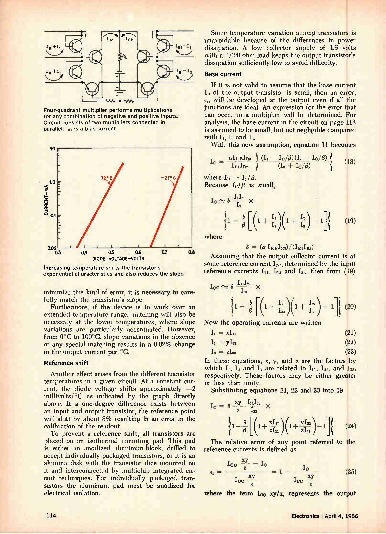
Four-quadrant multiplier performs multiplications for any combination of negative and positive inputs. Circuit consists of two multipliers connected in parallel. l is a bias current.
10
0.01 03 0.4 0.5 0.6
DIODE VOLTAGE-VOLTS 0.7
Increasing temperature shifts the transistor's exponential characteristics and also reduces the stepe.
0.8
minimize this kind of error, it is necessary to care-fully match the transistor's slope.
Furthermore, if the device is to work over an extended temperature range, matching will also be necessary at the lower temperatures, where slope variations are particularly accentuated. However, from 0°C to 100°C, slope variations in the absence of any special matching results in a 0.02% change in the output current per °C.
Reference shift
Another effect arises from the different transistor temperatures in a given circuit. At a constant cur-rent, the diode voltage shifts approximately —2 millivolteC as indicated by the graph directly above. If a one-degree difference exists between an input and output transistor, the reference point will shift by about 8% resulting in an error in the calibration of the readout. To prevent a reference shift, all transistors tire
placed on an isothermal mounting pad. This pad is either an anodized alumindm-block, drilled to accept individually packaged transistors, or it is an alumina disk with the transistor dice mounted on it and interconnected by multichip integrated cir-cuit techniques. For individually packaged tran-sistors the aluminum pad must be anodized for electrical isolation.
Some temperature variation among transistors is unavoidable because of the differences in power dissipation. A low collector supply of 1.5 volts with a 1,000-ohm load keeps the output transistor's dissipation sufficiently low to avoid difficulty.
Base current
If it is not valid to assume that the base current III of the output transistor is small, then an error, Er, will be developed at the output even if all the junctions are ideal. An expression for the error that can occur in a multiplier will be determined. For analysis, the base current in the circuit on page 112 is assumed to be small, but not negligible compared with II, I., and With this new assumption, equation 11 becomes
aIREIR2 IC = y y
±Rix R2
— WO) (12 — Ic/e) (I3 + Ic/a)
where In = Because Ir/ 13 is small,
1112 lc - - X
-13
— O [ (1 + 11 )(1 + 13
\vhere
(18)
(19)
8 = (cr IREIR3)/(IRIIR2)
Assuming that the output collector current is at some reference current In ., determined by the input reference currents Ili, I and I33, then from (19)
111122 ICC c-2 6 X
— 8 [(1 /1( i") A— /33 1 ± 1 (20)
Now the operating currents are written
(21)
(22) (23)
In these equations, x, y, and z are the factors by which II, I and Ill are related to In, L.», and 133,
respectively. These factors may be either greater or less than unity.
Substituting equations 21, 22 and 23 into 19
XV 111122 = 1 " X
z 122
— [(1 ) (1+ Y,I22 ) 1] (24) p 2133 Z 133
The relative error of any point referred to the reference currents is defined as
er =
xY ICC — IC
ICC z = 1 — (25)
where the term 'cc xy/z, represents the output
114 Electronics April 4, 1966
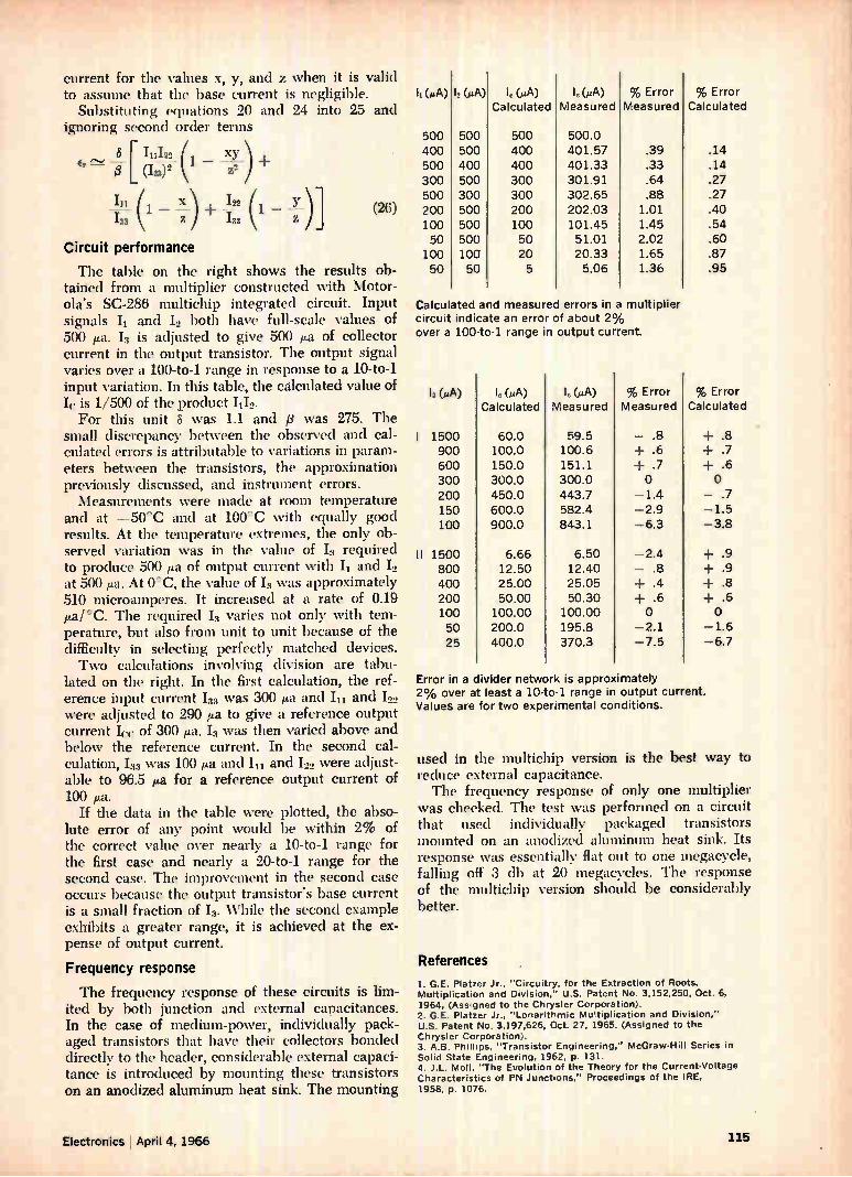
current for the values x, y, and z when it is valid to assume that the base current is negligible.
Substituting equations 20 and 24 into 25 and ignoring second order terms
fi (133)2 3 [ 111122 (1 xy
z2
If-11 (1 - + -122 (1 - )] 1,33
Circuit performance
The table on the right shows the results ob-tained from a multiplier constructed with Motor-ola's SC-286 multichip integrated circuit. Input signals Is and 12 both have full-scale values of 500 p.a. 13 is adjusted to give 500 ea of collector current in the output transistor. The output signal varies over a 100-to-1 range in response to a 10-to-1 input variation. In this table, the calculated value of Ic is 1/500 of the product 1112.
For this unit 8 was 1.1 and fl was 275. The small discrepancy between the observed and cal-culated errors is attributable to variations in param-eters between the transistors, the approximation previously discussed, and instrument errors. Measurements were made at room temperature
and at -50°C and at 100°C with equally good results. At the temperature extremes, the only ob-served variation was in the value of Is required to produce 500 pa of output current with h and 12 at 500 ea. At 0°C, the value of Is was approximately 510 microamperes. It increased at a rate of 0.19 p.a/ °C. The required h varies not only with tem-perature, but also from unit to unit because of the difficulty in selecting perfectly matched devices. Two calculations involving division are tabu-
lated on the right. In the first calculation, the ref-erence input current 133 was 300 µa and hi and 122 were adjusted to 290 ea to give a reference output current Icc of 300 ea. 13 was then varied above and below the reference current. In the second cal-culation, 133 was 100 ea and 11 and 122 were adjust-able to 96.5 ea for a reference output current of 100 ea.
If the data in the table were plotted, the abso-lute error of any point would be within 2% of the correct value over nearly a 10-to-1 range for the first case and nearly a 20-to-1 range for the second case. The improvement in the second case occurs because the output transistor's base current is a small fraction of 13. While the second example exhibits a greater range, it is achieved at the ex-pense of output current.
Frequency response
The frequency response of these circuits is lim-ited by both junction and external capacitances. In the case of medium-power, individually pack-aged transistors that have their collectors bonded directly to the header, considerable external capaci-tance is introduced by mounting these transistors on an anodized aluminum heat sink. The mounting
(26)
(eA) (pA) 1.(PA) Calculated
le(PA) Measured
% Error Measured
% Error Calculated
500 500 500 500.0 400 500 400 401.57 .39 .14 500 400 400 401.33 .33 .14 300 500 300 301.91 .64 .27 500 300 300 302.65 .88 .27 200 500 200 202.03 1.01 .40 100 500 100 101.45 1.45 .54 50 500 50 51.01 2.02 .60 100 100 20 20.33 1.65 .87 50 50 5 5.06 1.36 .95
Calculated and measured errors in a multiplier circuit indicate an error of about 2% over a 100-to-1 range in output current
(PA) le (PA) (jLA) % Error % Error Calculated Measured Measured Calculated
I 1500 60.0 59.5 - .8 -I- .9 900 100.0 100.6 + .6 + .7 600 150.0 151.1 + .7 ± .6 300 300.0 300.0 0 0 200 450.0 443.7 -1.4 - .7 150 600.0 582.4 -2.9 -1.5 100 900.0 843.1 -6.3 -3.8
II 1500 6.66 6.50 -2.4 + .9 800 12.50 12.40 - .8 ± .9 400 25.00 25.05 + .4 + .8 200 50.00 50.30 + .6 .6 100 100.00 100.00 0 0 50 200.0 195.8 -2.1 -1.6 25 400.0 370.3 -7.5 -6.7
Error in a divider network is approximately 2% over at least a 10-to-1 range in output current. Values are for two experimental conditions.
used in the multichip version is the best way to reduce external capacitance. The frequency response of only one multiplier
was checked. The test was performed on a circuit that used individually packaged transistors mounted on an anodized aluminum heat sink. Its response was essentially flat out to one megacycle, falling off 3 db at 20 megacycles. The response of the multichip version should be considerably better.
References
1. G.E. Platzer Jr., "Circuitry, for the Extraction of Roots, Multiplication and Division," U.S. Patent No. 3,152,250, Oct. 6. 1964, (Assigned to the Chrysler Corporation). 2. G.E. Platzer Jr., "Lonarithmic Multiplication and Division," U.S. Patent No. 3,197,626, Oct. 27, 1965. (Assigned to the Chrysler Corporation). 3. A.B. Phillips, "Transistor Engineering," McGraw-Hill Series In Solid State Engineering, 1962, p. 131. 4. J.L. Moll, "The Evolution of the Theory for the Current-Voltage Characteristics of PN Junctions," Proceedings of the IRE, 1958, p. 1076.
Electronics April 4, 1966 115
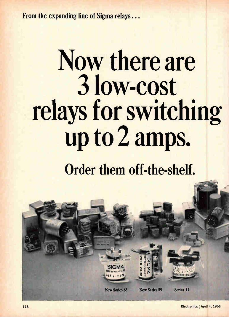
From the expanding line of Sigma relays...
Now there are 3 low-cost
relays for switching up to 2 amps. Order them off-the-shelf.
•
eirrnt• m "'" - tSF 1 240C
New Series 59 Series 11 New Series 65
116 Electronics Apri 4. 1966

Match these specifications against your requirements. Then contact Sigma or your distributor.
Series 11:
Contact rating 1 ampere. Unenclosed, screw mounted, solder or printed-circuit terminals, all UL-listed (E28610 Yellow Card). Choice of 3 physical types, 11 coil resistances, 2 adjustments, 3 DC or 2 AC coil voltages.
Series 59: Contact rating 2 amperes. Unenclosed, screw mounted, solder terminals; or metal dust cover, 8-pin plug. Choice of 3 DC coil voltages.
Series 65:
Contact rating 1 ampere. Unenclosed, screw mounted, solder terminals, or terminals for printed circuit mounting. Choice of 3 DC coil voltages.
New Sigma Series 59 and 65 relays now join the popular Series 11 to provide a broader range of low-cost SPDT relays for general purpose switching. Each of these small, one-ounce relays provides optimum operation for controlling light industrial and commercial loads. All are immediately available from stock at low prices.
How low in cost? Take the new Series 65. These DC relays are available in quantity at less than a dollar. They are specifically designed for simple, reliable on-off switching.
New Sigma Series 59 relays are built for gradually changing signals as well as on-off operation. This is made possible by the unique construction of these DC relays which use a snap-switch instead of conventional contacts.
Sigma Series 11 relays are available in both AC and DC versions. They are UL-listed and combine low price and high sensitivity with the ability to respond to gradually changing and on-off DC.
The new Sigma Series 59 and 65 relays and the Series 11 are suitable for applications ranging from vending machines and alarm systems to industrial controls. Use them wherever there is need for small, low-cost, highly dependable relays.
FREE CATALOG: Send today for the new Sigma Preferred Standard and Stock Relay Catalog and up-to-date stock I ist.They will help you select the relay types immediately available in quantity from your distributor or Sigma direct.
SIGMA DIVISION SIGMA INSTRUMENTS INC 'maw' Assured Reliability With Advanced Design/ Braintree, Mass. 02185
Sigma's line of over 100,000 relays includes (from left to right) Sensitive, High Performance, Pulse and Telegraph, General Purpose, Power, and Special Purpose types.
Electronics April 4, 1966 Circle 117 on reader service card 117
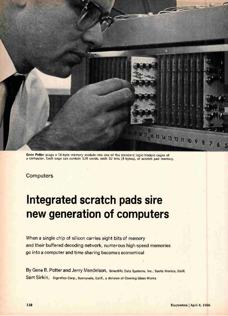
Gene Potter plugs a 16-byte memory module into one of the standard logic-module cages of a computer. Each cage can contain 128 words, each 32 bits (4 bytes), of scratch pad memory.
16 15 14 13 12 11 10 9 8 7 6 5
Computers
Integrated scratch pads sire new generation of computers
When a single chip of silicon carries eight bits of memory
and their buffered decoding network, numerous high-speed memories
go into a computer and time sharing becomes economical
By Gene B. Potter and Jerry Mendelson, Scientific Data Systems, Inc., Santa Monica, Calif.
Sam Sirkin, signetics Corp., Sunnyvale, Calif., a division of Corning Glass Works
118 Electronics April 4, 1966
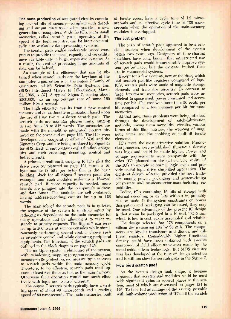
The maSs production of integrated circuits contain-ing several bits of memory—complete with decod-ing and output circuitry—makes practical a new generation of computers. With the IC's, many small memories, called scratch pads, operating at the speed of the logic circuitry, can be built economi-cally into workaday data-processing systems. The scratch pads enable moderately priced com-
puters to provide the speed, capacity and versatility once available only in huge, expensive systems. As a result, the cost of processing large amounts of data can be halved. An example of the efficiency that can be ob-
tained when scratch pads are the keystone of the computer organization is in the Sigma 7 family of computers, which Scientific Data Systems, Inc. (SDS) introduced March 15 [Electronics, March 21, 1966, p. 37]. A typical Sigma 7, costing about $500,000, has an input-output rate of some 160 million bits a second. The high efficiency results from a new control
memory and an arithmetic organization based upon the use of from two to a dozen scratch pads. The scratch pads are modular plug-in units, ranging in size from 16 to 512 words. The memories are made with the monolithic integrated circuits pic-tured on the cover and on page 122. The IC's were developed in a cooperative effort of SDS and the Signetics Corp. and are being produced by Signetics for SDS. Each circuit contains eight flip-flop storage bits and their encoding, decoding, control and buffer circuits. A printed circuit card, carrying 16 IC's plus the
drive circuitry pictured on page 121, forms a 16-byte module (8 bits per byte) that is the basic building block for all Sigma 7 scratch pads. For example, four such modules make up a 16-word scratch pad. If more capacity is needed, more boards are plugged into the computer's address and data buses. The modules are self-contained, having address-decoding circuits for up to 128 words. The main job of the scratch pads is to quicken
the response of the system to multiple inputs by reducing its dependence on the main memories for many operations and by allowing it to react in-stantly to priority requests. The Sigma 7 can serv-ice up to 200 users at remote consoles while simul-taneously performing several routine chores such as inventory control and while operating peripheral equipments. The functions of the scratch pads are outlined in the block diagram on page 125. The multiple-register architecture of the system,
with its indexing, mapping (program relocation) and memory-write protection, requires multiple accesses to scratch pads within the main memory cycle. Therefore, to be effective, scratch pads must op-erate at least five times as fast as the main memory. Otherwise their operation would not mesh effec-tively with logic and control circuitry. The Sigma 7 scratch pads typically have a writ-
ing speed of about 90 nanoseconds and a reading speed of 60 nanoseconds. The main memories, built
of ferrite cores, have a cycle time of 1.2 micro-seconds and an effective cycle time of 700 nano-seconds when the operation of the main-memory modules is overlapped.
The cost problem
The costs of scratch pads appeared to be a cru-cial problem when development of the system began two years ago. Designers of time-sharing machines have long known that unrestricted use of scratch pads would immeasurably improve sys-tem performance, but the expense limited their use in commercial systems. Except for a few systems, new at the time, which
had scratch pad-like' registers composed of logic IC's, scratch pads were made of magnetic storage elements and transistor circuitry. In contrast to large, ferrite-core memories, scratch pads were in-efficient in space used, power consumed and access time per bit. The cost was more than 50 cents per bit compared to a few pennies per bit for mass memories. At that time, these problems were being attacked
through the development of batch-fabrication methods, among them monolithic circuits, various forms of thin-film matrices, the weaving of mag-netic wires and the molding of multibit ferrite elements.
IC's were the most attractive solution. Produc-tion processes were established. Functional density was 'high and could be made higher. Power and voltage requirements were compatible with the other IC's planned for the system. The ability of the IC's to operate at normal logic levels and pro-vide useful logic drive simplified application. The eight-bit design selected provided the best trade-offs among power, packaging and system-design constraints and semiconductor-manufacturing ca-pabilities.
Today, IC's containing 16 bits of storage with internal decoding, or 32 bits without it, probably can be made. If the system constraints on power dissipation and packaging can be eased, they may be used. One advantage of the present IC design is that it can be packaged in a 10-lead, TO-5 can, which is low in cost, easily assembled and reliable. The design selected has 178 components on a
silicon die measuring 104 by 95 mils. The compo-nents are bipolar transistors and diodes, and dif-fused resistors. Considerably higher functional density could have been obtained with circuits composed of field effect transistors made by the metal-oxide-silicon technology. But MOS circuitry was less developed at the time of design selection and is still too slow for scratch pads in the Sigma 7.
How big a scratch pad?
As the system design took shape, it became apparent that scratch pad modules could be used with significant gains in several places in the sys-tem, most of which are discussed on pages 124 to 126. To take full advantage of the savings possible with high-volume production of IC's, all the scratch
Electronics April 4, 1966 119
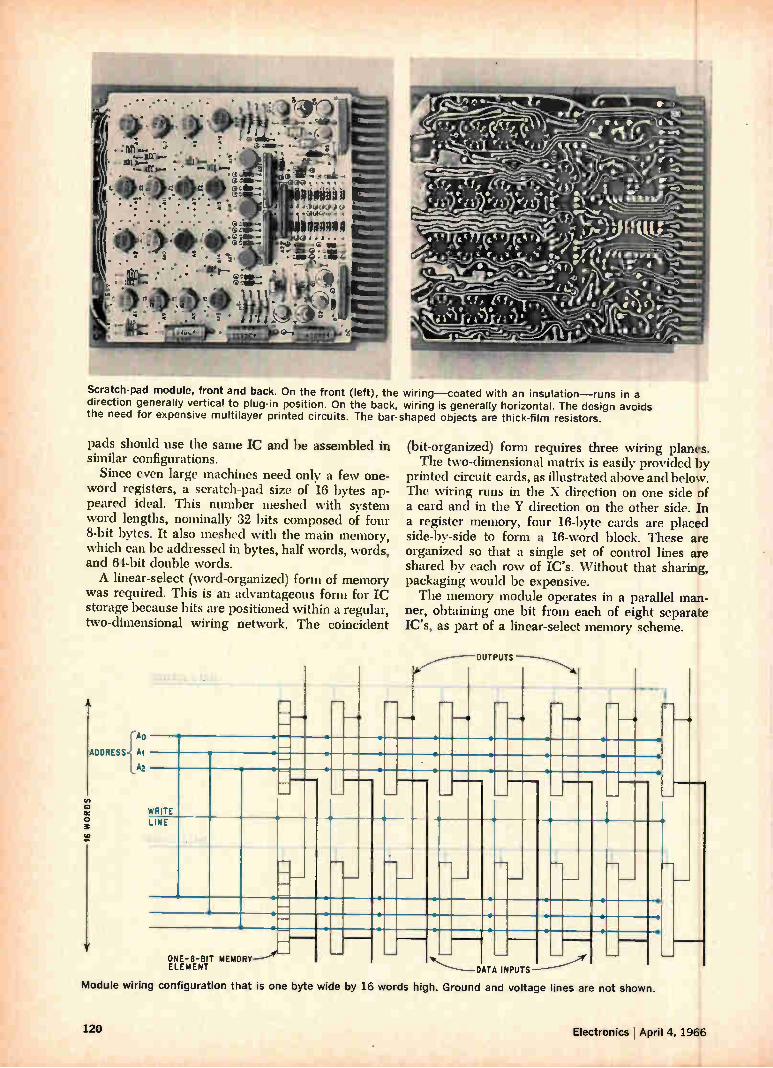
. • • . • • . • . • • • •-:raft'.-- • •‘' •
Scratch-pad module, front and back. On the front (left), the wiring—coated with an insulation—runs in a direction generally vertical to plug-in position. On the back, wiring is generally horizontal. The design avoids the need for expensive multilayer printed circuits. The bar-shaped objects are thick-film resistors.
pads should use the same IC and be assembled in similar configurations.
Since even large machines need only a few one-word registers, a scratch-pad size of 16 bytes ap-peared ideal. This number meshed with system word lengths, nominally 32 bits composed of four 8-bit bytes. It also meshed with the main memory, which can be addressed in bytes, half words, words, and 64-bit double words. A linear-select (word-organized) form of memory
was required. This is an advantageous form for IC storage because bits are positioned within a regular, two-dimensional wiring network. The coincident
-110
ADDRESS; A1
, A2
q_.
WRITE
LINE
•
J--
(bit-organized) form requires three wiring planes. The two-dimensional matrix is easily provided by
printed circuit cards, as illustrated above and below. The wiring runs in the X direction on one side of a card and in the Y direction on the other side. In a register memory, four 16-byte cards are placed side-by-side to form a 16-word block. These are organized so that a single set of control lines are shared by each row of IC's. Without that sharing, packaging would be expensive. The memory module operates in a parallel man-
ner, obtaining one bit from each of eight separate IC's, as part of a linear-select memory scheme.
1--
ONE-8-817 MEMORY-----e— ELEMENT
'OUTPUTS
DATA INPUTS
Module wiring configuration that is one byte wide by 16 words high. Ground and voltage lines are not shown.
120 Electronics April 4, 1966
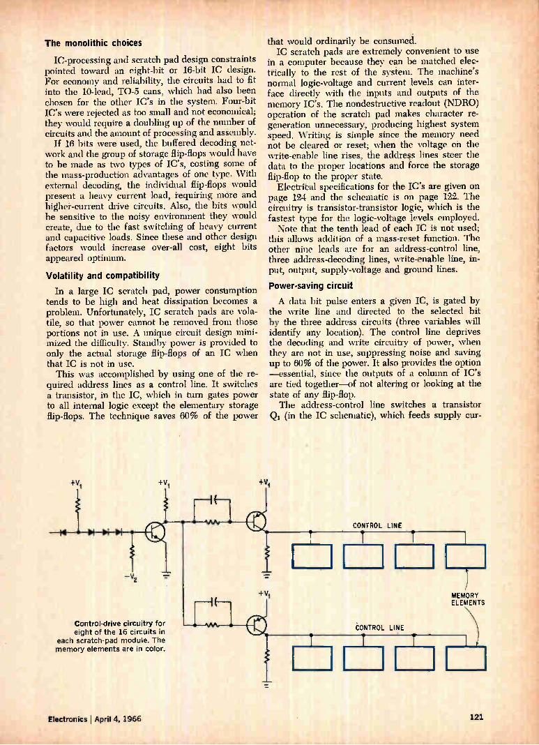
The monolithic choices
IC-processing and scratch pad design constraints pointed toward an eight-bit or 16-bit IC design. For economy and reliability, the circuits had to fit into the 10-lead, TO-5 cans, which had also been chosen for the other IC's in the system. Four-bit IC's were rejected as too small and not economical; they would require a doubling up of the number of circuits and the amount of processing and assembly.
If 16 bits were used, the buffered decoding net-work and the group of storage flip-flops would have to be made as two types of IC's, costing some of the mass-production advantages of one type. With external decoding, the individual flip-flops would present a heavy current load, requiring mère and higher-current drive circuits. Also, the bits would be sensitive to the noisy environment they would create, due to the fast switching of heavy current and capacitive loads. Since these and other design factors would increase over-all cost, eight bits appeared optimum.
Volatility and compatibility
In a large IC scratch pad, power consumption tends to be high and heat dissipation becomes a problem. Unfortunately, IC scratch pads are vola-tile, so that power cannot be removed from those portions not in use. A unique circuit design mini-mized the difficulty. Standby power is provided to only the actual storage flip-flops of an IC when that IC is not in use.
This was accomplished by using one of the re-quired address lines as a control line. It switches a transistor, in the IC, which in turn gates power to all internal logic except the elementary storage flip-flops. The technique saves 60% of the power
+VI
— V2
Control-drive circuitry for eight of the 16 circuits in
each scratch-pad module. The memory elements are in color.
Electronics ' April 4, 1966
that would ordinarily be consumed. IC scratch pads are extremely convenient to use
in a computer because they can be matched elec-trically to the rest of the system. The machine's normal logic-voltage and current levels can inter-face directly with the inputs and outputs of the memory IC's. The nondestructive readout (NDRO) operation of the scratch pad makes character re-generation unnecessary, producing highest system speed. Writing is simple since the memory need not be cleared or reset; when the voltage oh the write-enable line rises, the address lines steer the data to the proper locations and force the storage flip-flop to the proper state.
Electribal specifications for the IC's are given on page 124 and the schematic is on page 122. The circuitry is trarisistor-transistor logic, which is the fastest type for the logic-voltage levels employed. Note that the tenth lead of each IC is not used;
this allows addition of a mass-reset function. The other nine leads are for an address-control line, three address-decoding lines, write-enable line, in-put, output, supply-voltage and ground lines.
Power-saving circuit
A data bit pulse enters a given IC, is gated by the write line and directed to the selected bit by the three address circuits (three variables will identify any location). The control line deprives the decoding and write circuitry of power, when they are not in use, suppressing noise and saving up to 60% of the power. It also provides the option —essential, since the outputs of a column of IC's are tied together—of not altering or looking at the state of any flip-flop. The address-control line switches a transistor (in the IC schematic), which feeds supply cur-
+V1
121
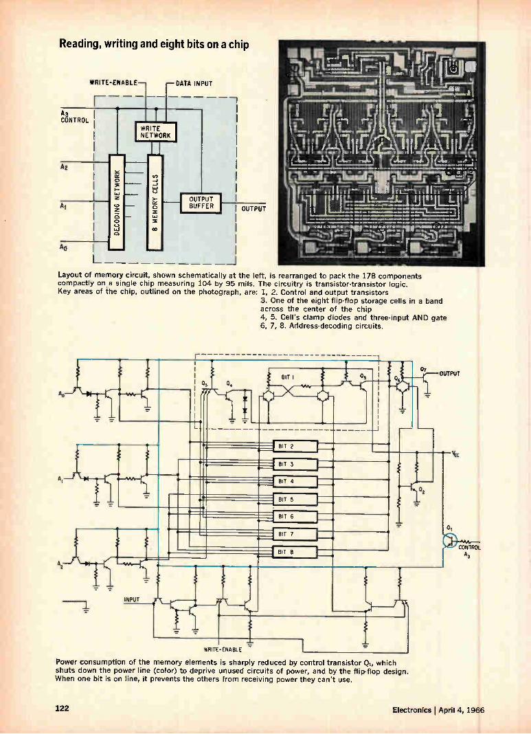
Reading, writing and eight bits on a chip
WRITE-ENABLE— —DATA INPUT
A3
CONTROL
A1
Ao
WRITE NETWORK
_1
1.0
(-7
›-
CC
CD
1.1.1
OUTPUT BUFFER OUTPUT
III IIII. al ..7.1. „,—,„ I 'il iligli
" 1;
114"t I thumie,,.._L._IJiia _a
.m.,,Ét isimilmilp r(iL l i in/ r,ifj ""«, rIL-.«,
tmleJe L f»ji
ij II 11 r, ,,, ,,,1 o
lii:rIL :111,r . , ...•, N." nt!"1 7EtL1.412. i.re-arr:ii)
!:77-171 I ri r—e771 Ili. J. jj 141 .21.
I IL— - . »we ••• eill.....••••• N011e .101111, • *MM.
la.. .”.MAI lItIeridbia 1.1,111•1011 II.* I/ 11.04111 . gp.ej Fore eloa.db, m
00.er 111V-11,«Md“ - 1111 d r da ot,
Layout of memory circuit, shown schematically at the left, is rearranged to pack the 178 components compactly on a single chip measuring 104 by 95 mils. The circuitry is transistor-transistor logic. Key areas of the chip, outlined on the photograph, are: 1, 2. Control and output transistors
3. One of the eight flip-flop storage cells in a band across the center of the chip 4, 5. Cell's clamp diodes and three-input AND gate 6, 7, 8. Address-decoding circuits.
03 04 içif \__r"
—
BIT 5
•
_J
I BIT 2
BIT 3
BIT 4
e
BIT 5
BIT 6
BIT 7
r
BIT
WRITE-ENABLE
Power consumption of the memory elements is sharply reduced by control transistor Q,, which shuts down the power line (color) to deprive unused circuits of power, and by the flip-flop design. When one bit is on line, it prevents the others from receiving power they can't use.
01
CONTROL A,
122 Electronics lApril 4, 1966
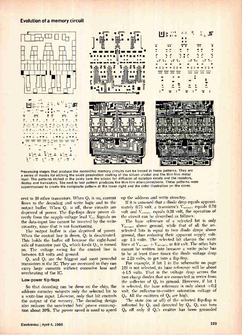
Evolution of a memory circuit
E
I I
I«
q 1. --'
_ • . si I. si Is
1:1
• - :17 _ . — — _
I I
si is si is
I•ii •1 l• s s•I I s• Is•I
11• 71 17•I C•1 • t•
_ ! ! = = ! ! ! ! = ! ! =
1 " • • 747 • "
_
_ .
.ur=
• [r" • Ír[rm Gm -11
anima ea - uffl • u MI.M . . le •ti Piatt.1 -
• ma Igo
J. m u
à mm U U
1.77 P —mi—mr—IP me Le.
t'LR2,1 r TT T1
FrL 11-41[1
111 II l• I* II a a a
7 II II II MI MI
• • • •
• .
.r
••• ••• ••• •••
•
•
1:
r • • • .r .r
••
• •• ••• ••• •••
Processing stages that produce the monolithic memory circuits can be traced in these patterns. They are a series of masks for etching the oxide passivation coating of the silicon crystal and the thin-film metal layer. The patterns etched in the oxide bare the silicbn for diffusion of isolation moats and the resistors, diodes and transistors. The next to last pattern produces the thin-film interconnections. These patterns were superimposed to create the composite pattern at the lower right and the color illustration on the cover.
rent to 20 other transistors. When Qi is on, current flows to the decoding and write logic and to the output buffer. When Qi is off, these circuits are deprived of power. The flip-flops draw power di-rectly from the supply-voltage lead V(.1.. Signals on the data-input line cannot be inserted by the write circuitry, since that is not functioning. The output buffer is also deprived of power.
When the control line is down, Q., is deactivated. This holds the buffer off because the right-hand side of transistor pair Qn, which feeds Q7, is turned on. The voltage swing for the control line is between 6.6 volts and ground. Qi and Q7 are the biggest and most powerful
transistors in the IC. They are oversized so they can carry large currents without excessive loss and overheating of the IC.
Low-power flip-flops
So that decoding can be done on the chip, the address circuitry subjects only the selected bit to a write-line input. Likewise, only that bit controls the output of the memory. The decoding design also reduces the unselected bits' power consump-tion about 30%. The power saved is used to speed
up the address and write circuitry. If it is assumed that a diode drop equals approxi-
mately 0.75 volt, a transistor's VI,co.,t, equals 0.70 volt and V5„,,•11, equals 0.20 volt, the operation of the circuit can be described as follows: The base reference of a selected bit is only
above ground, while that of all the un-selected bits is equal to two diode drops above ground, thus reducing their apparent supply volt-age 1.5 volts. The selected bit clamps the write lines at VI„.,,„,t, + Vceo,„t„ or 0.9 volt. The other bits cannot be written into because a write pulse has to be at least three times the diode voltage drop or 2.25 volts, to get into a flip-flop. For example, if bit 1 in the schematic on page
122 is not selected, its base reference will be about +1.5 volts. That is the voltage drop across the two clamp diodes that are connected in series from the collector of Q4 to ground. However, if bit 1 is selected, the base reference is only about +0.2 volt, the collector-to-emitter saturation voltage of Q 1. All the emitters of Q3 are high. The state (on or off) of the selected flip-flop is
reflected by Q5 and detected by Q6. Q5 can turn (26 off only if Q's emitter has been grounded
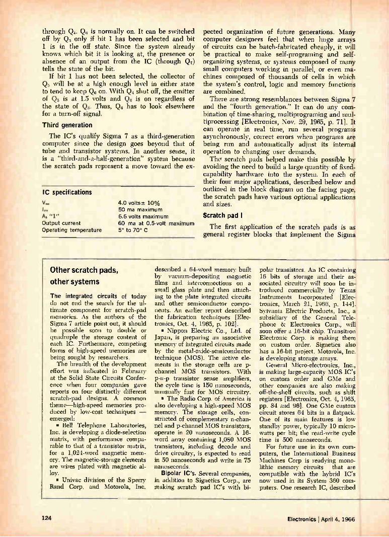
through Q4. Qg is normally on. It can be switched off by Q5 only if bit 1 has been selected and bit 1 is in the off state. Since the system already knows which bit it is looking at, the presence or absence of an output from the IC (through Q7) tells the state of the bit.
If bit 1 has not been selected, the collector of Q5 will be at a high enough level in either state to tend to keep Qg on. With Q4 shut off, the emitter of Q5 is at 1.5 volts and Qg is on regardless of the state of Q. Thus, Qg has to look elsewhere for a turn-off signal.
Third generation
The IC's qualify Sigma 7 as a third-generation computer since the design goes beyond that of tube and transistor systems. In another sense, it is a "third-and-a-half-generation" system because the scratch pads represent a move toward the ex-
IC specifications
V„
Output current Operating temperature
4.0 volts-± 10% 50 ma maximum 6.6 volts maximum 60 ma at 0.5-volt maximum 5 to 70 C
pected organization of future generations. Many computer designers feel that when huge arrays of circuits can be batch-fabricated cheaply, it will be practical to make self-programing and self-organizing systems, or systems composed of many small computers working in parallel, or even ma-chines composed of thousands of cells in which the system's control, logic and memory functions are combined. There are strong resemblances between Sigma 7
and the "fourth generation." It can do any com-bination of time-sharing, multiprograming and mul-tiprocessing [Electronics, Nov. 29, 1965, p. 71]. It can operate in real time, run several programs asynchronously, correct errors when programs are being run and automatically adjust its internal operation to changing user demands. Th er scratch pads helped make this possible by
avoiding the need to build a large quantity of fixed-capability hardware into the system. In each of their four major applications, described below and outlined in the block diagram on the facing page, the scratch pads have various optional applications and sizes.
Scratch pad I
The first application of the scratch pads is as general register blocks that implement the Sigma
Other scratch pads,
other systems
The integrated circuits of today do not end the search for the ul-timate component for scratch-pad memories. As the authors of the Sigma 7 article point out, it should be possible soon to double or quadruple the storage content of each IC. Furthermore, competing forms of high-speed memories are being sought by researchers. The breadth of the development
effort was indicated in February at the Solid State Circuits Confer-ence when four companies gave reports on four distinctly different scratch-pad designs. A common theme—high-speed memories pro-duced by low-cost techniques — emerged: • Bell Telephone Laboratories,
Inc. is developing a diode-selection matrix, with performance compa-rable to that of a transistor matrix, for a 1,024-word magnetic mem-ory. The magnetic-storage elements are wires plated with magnetic al-loy. • Univac division of the Sperry
Rand Corp. and Motorola, Inc.
described a 64-word memory built by vacuum-depositing magnetic films and interconnections on a small glass plate and then attach-ing to the plate integrated circuits and other semiconductor compo-nents. An earlier report described the fabrication techniques [Elec-tronics, Oct. 4, 1965, p. 102]. • Nippon Electric Co., Ltd. of
japan, is preparing an associative memory of integrated circuits made by the metal-oxide-semiconductor technique (MOS). The active ele-ments in the storage cells are p-channel MOS transistors. With p-n-p transistor sense amplifiers, the cycle time is 150 nanoseconds, unusually fast for MOS circuitry. • The Radio Corp. of America is
also developing a high-speed MOS memory. The storage cells, con-structed of complementary n-chan-nel and p-channel MOS transistors, operate in 20 nanoseconds. A 16-word array containing 1,080 MOS transistors, including decode and drive circuitry, is expected to read in 50 nanoseconds and write in 75 nanoseconds.
Bipolar IC's. Several companies, in addition to Signetics Corp., are making scratch pad IC's with bi-
polar transistors. An IC containing 16 bits of storage and their as-sociated circuitry will soon be in-troduced commercially by Texas Instruments Incorporated [Elec-tronics, March 21, 1966, p. 144]. Sylvania Electric Products, Inc., a subsidiary of the General Tele-phone & Electronics Corp., will soon offer a 16-bit chip. Transitron Electronic Corp. is making them on custom order. Signetics also has a 16-bit project. Motorola, Inc. is developing storage arrays.
General Micro-electronics, Inc., is making large-capacity MOS IC's on custom order and GMe and other companies are also making off-the-shelf circuits, such as shift registers [Electronics, Oct. 4, 1965, pp. 84 and 96]. One GMe custom circuit stores 64 bits in a flatpack. One of its main features is low standby power, typically 10 micro-watts per bit; the read-write cycle time is 500 nanoseconds.
For future use in its own com-puters, the International Business Machines Corp is readying mono-lithic memory circuits that are compatible with the hybrid IC's now used in its System 360 com-puters. One research IC, described
124 Electronics ; April 4, 1966
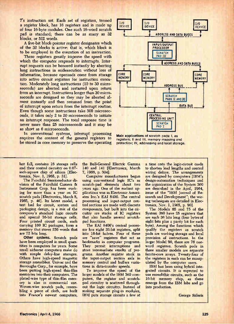
rs instruction set. Each set of registers, termed a register block, has 16 registers and is made up of four 16-byte modules. One such 16-word scratch pad is standard; there can be as many as 32 blocks, or 512 words. A five-bit block-pointer register designates which
of the 32 blocks is active: that is, which block is to be employed in the execution of an instruction. These registers greatly improve the speed with
which the computer responds to interrupts. Inter-rupt requests can be honored instantly by aborting long instructions in midexecution without loss of information, because operands come from storage into active circuit registers for instruction execu-tion. Moderately long instructions (10 to 30 micro-seconds) are aborted and restarted upon return from an interrupt. Instructions longer than 30 micro-seconds are designed so they may be aborted al-most instantly and then resumed from the point of interrupt upon return from the interrupt routine. Even though some instructions take 500 microsec-onds, it takes only 2 to 20 microseconds to initiate an interrupt response. The total response time is never more than 25 microseconds and it may be as short as 6 microseconds.
In conventional systems, interrupt processing requires the content of the general registers to be stored in core memory to preserve the operating
I/O DEVICE
ADDRESS AND DATA BUSES
IN PROCESSOR
SCRATCH PAD Dir
ADDRESS AND DATA BUSES
CORE MEMORY
CORE MEMORY
ADDRESS BUS
SCRATCH PADS IL AND":
DATA BUS
CENTRAL PROCESSING UNIT
SCRATCH PAD I
Main applications of scratch pads: I, as registers; Il and Ill, memory mapping and protection; IV, addressing and local storage.
CORE MEMORY
last fall. contains 16 storage cells and their control circuitry on 0.07-inch-square chip of silicon [Elec-tronics, Nov. 1, 1965, p. 31]. The Fairchild Semiconductor di-
vision of the Fairchild Camera 8z Instrument Corp. has been work-ing for more than a year on IC scratch pads [Electronics, March 8, 1965, p. 46]. Its latest model, a test bed for circuit, system and packaging design, is a mix of the company's standard logic circuits and special 36-bit storage cells. Four printed circuit cards, each carrying 160 IC packages, form a memory that stores 256 words that are 72 bits long.
Other systems. Scratch pads have been employed in small quan-tities in computers for years. Some small airborne computers make do with simple delay-line storages. Others have high-speed magnetic storage assemblies. Univac and the Burroughs Corp., for example, have been putting high-speed thin-film memories into their computers. The plated-wire type of thin-film mem-ory is also in commercial use. Woven-wire scratch pads, resem-bling a piece of cloth, are built into France's newest computers,
the Bull-General Electric Gamma 140 and 141 [Electronics, March 7, 1966, p. 304]. Computer manufacturers began
using conventional logic IC's as scratch-pad elements about two years ago. One of the earliest ap-plications was in Electronic Associ-ates Inc.'s EAI 8400. The central processing and input-output con-trol sections are made with discrete components, but built into the cir-cuitry are stacks of IC registers that also handle several scratch-pad functions. The EAI 8400's central proces-
sor has eight 32-bit registers, split into 16-bit halves. Four of these are "save" registers that act as bookmarks in computer programs. They permit interruptions and store intermediate results of pro-grams. Another register stack in the input-output section aids in memory control and buffers varia-tions in data-transfer speeds. To improve the speed of the
larger models of the IBM 360 com-puters, the register and scratch-pad circuitry is scattered through-out the logic circuitry. Instead of making separate plug-in modules, IBM puts storage circuits a few at
a time onto the logic-circuit cards to shorten lead lengths and control wiring delays. The arrangements are designed by computers [IBM's design-automation techniques and the organization of the System 360 are described in the April, 1964, issue of the "IBM Journal of Re-search and Development"; the wir-ing techniques are detailed in Elec-tronics, Nov. 1, 1965, p. 90]. The Models 65 and 75 of the
System 360 have 25 registers that are each 36 bits long (four bytes of eight bits plus a parity bit for each byte). Among the functions which qualify the registers as scratch pads are working storage and local provision of instructions. In the larger Model 90, there are 76 one-word registers. Scratch pads in three smaller models are separate ferrite-core arrays. Twenty-four of the registers in each can be manip-ulated by the computer users. IBM has been using hybrid inte-
grated circuits. It is expected to use monolithic circuits, such as the 16-bit memory chip, as these emerge from the IBM labs and go into production.
George Sideris
Electronics April 4, 1966 125
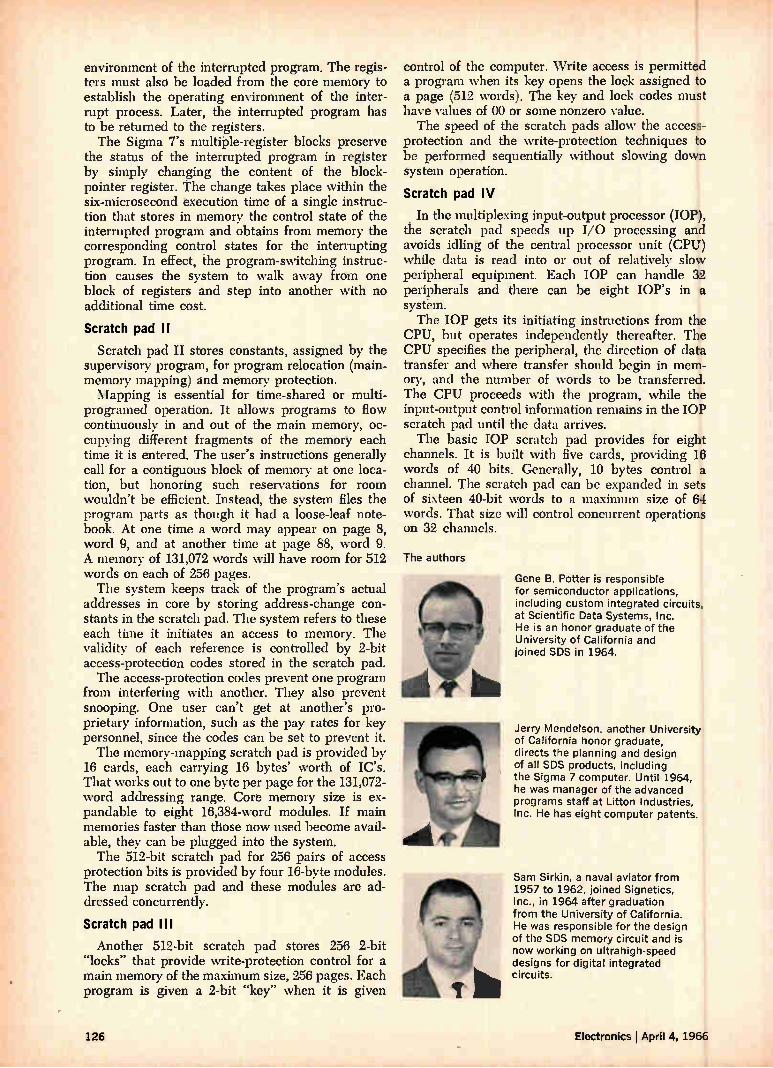
environment of the interrupted program. The regis-ters must also be loaded from the core memory to establish the operating environment of the inter-rupt process. Later, the interrupted program has to be returned to the registers. The Sigma 7's multiple-register blocks preserve
the status of the interrupted program in register by simply changing the content of the block-pointer register. The change takes place within the six-microsecond execution time of a single instruc-tion that stores in memory the control state of the interrupted program and obtains from memory the corresponding control states for the interrupting program. In effect, the program-switching instruc-tion causes the system to walk away from one block of registers and step into another with no additional time cost.
Scratch pad II
Scratch pad II stores constants, assigned by the supervisory program, for program relocation (main-memory mapping) and memory protection. Mapping is essential for time-shared or multi-
programed operation. It allows programs to flow continuously in and out of the main memory, oc-cupying different fragments of the memory each time it is entered. The user's instructions generally call for a contiguous block of memory at one loca-tion, but honoring such reservations for room wouldn't be efficient. Instead, the system files the program parts as though it had a loose-leaf note-book. At one time a word may appear on page 8, word 9, and at another time at page 88, word 9. A memory of 131,072 words will have room for 512 words on each of 256 pages. The system keeps track of the program's actual
addresses in core by storing address-change con-stants in the scratch pad. The system refers to these each time it initiates an access to memory. The validity of each reference is controlled by 2-bit access-protection codes stored in the scratch pad. The access-protection codes prevent one program
from interfering with another. They also prevent snooping. One user can't get at another's pro-prietary information, such as the pay rates for key personnel, since the codes can be set to prevent it. The memory-mapping scratch pad is provided by
16 cards, each carrying 16 bytes' worth of IC's. That works out to one byte per page for the 131,072-word addressing range. Core memory size is ex-pandable to eight 16,384-word modules. If main memories faster than those now used become avail-able, they can be plugged into the system. The 512-bit scratch pad for 256 pairs of access
protection bits is provided by four 16-byte modules. The map scratch pad and these modules are ad-dressed concurrently.
Scratch pad III
Another 512-bit scratch pad stores 256 2-bit "locks" that provide write-protection control for a main memory of the maximum size, 256 pages. Each program is given a 2-bit "key" when it is given
control of the computer. Write access is permitted a program when its key opens the lock assigned to a page (512 words). The key and lock codes must have values of 00 or some nonzero value. The speed of the scratch pads allow the access-
protection and the write-protection techniques to be performed sequentially without slowing down system operation.
Scratch pad IV
In the multiplexing input-output processor (I0P), the scratch pad speeds up I/O processing and avoids idling of the central processor unit (CPU) while data is read into or out of relatively slow peripheral equipment. Each IOP can handle 32 peripherals and there can be eight IOP's in a systém. The IOP gets its initiating instructions from the
CPU, but operates independently thereafter. The CPU specifies the peripheral, the direction of data transfer and where transfer should begin in mem-ory, and the number of words to be transferred. The CPU proceeds with the program, while the input-output control information remains in the IOP scratch pad until the data arrives. The basic IOP scratch pad provides for eight
channels. It is built with five cards, providing 16 words of 40 bits. Generally, 10 bytes control a channel. The scratch pad can be expanded in sets of sixteen 40-bit words to a maximum size of 64 words. That size will control concurrent operations on 32 channels.
The authors
(7), Gene B. Potter is responsible for semiconductor applications, including custom integrated circuits, at Scientific Data Systems, Inc. He is an honor graduate of the university of California and joined SDS in 1964.
Jerry Mendelson. another University of California honor graduate, directs the planning and design of all SDS products, including the Sigma 7 computer. Until 1964, he was manager of the advanced programs staff at Litton Industries. Inc. He has eight computer patents.
Sam Sirkin, a naval aviator from 1957 to 1962, joined Signetics, Inc., in 1964 after graduation from the University of California. He was responsible for the design of the SDS memory circuit and is now working on ultrahigh-speed designs for digital integrated circuits.
126 Electronics !April 4, 1966
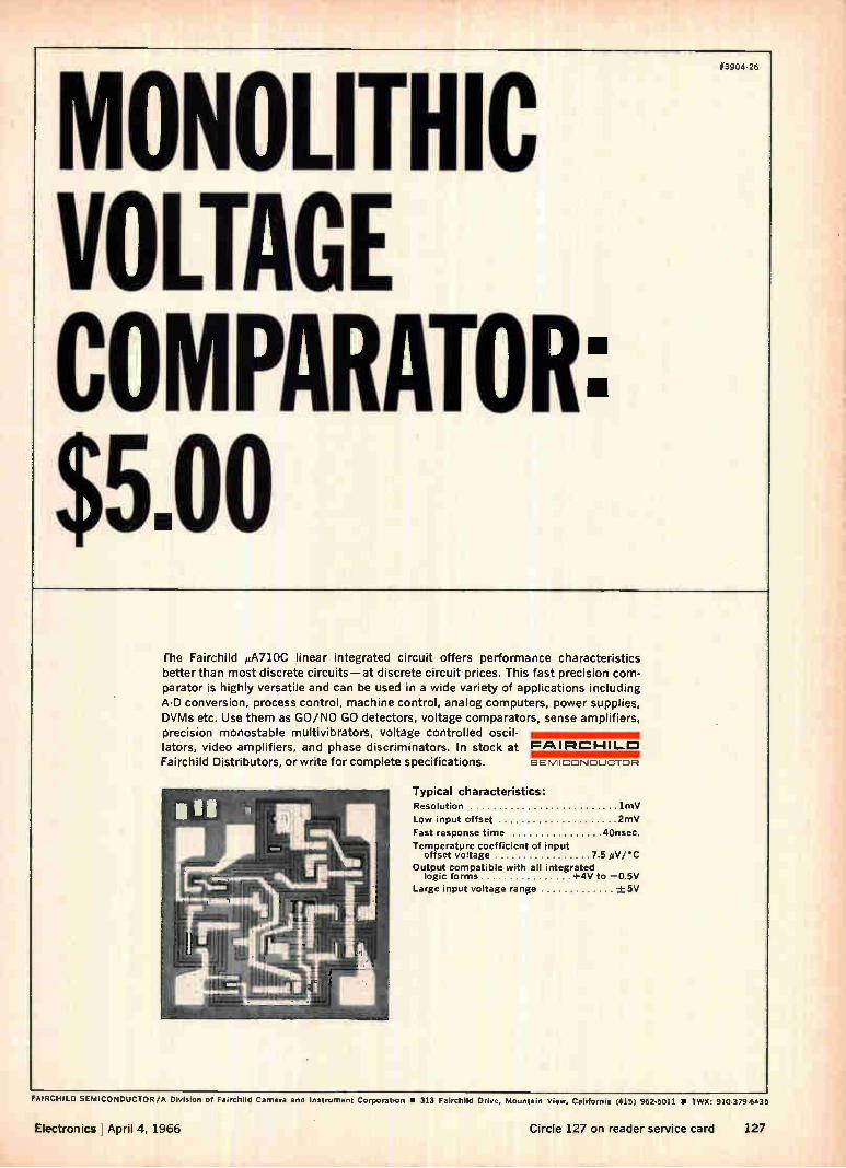
MONOLITHIC VOLTAGE COMPARATOR: $5.00
fhe Fairchild µA710C linear integrated circuit offers performance characteristics
better than most discrete circuits—at discrete circuit prices. This fast precision com-parator is highly versatile and can be used in a wide variety of applications including
A-D conversion, process control, machine control, analog computers, power supplies, DVMs etc. Use them as GO/NO GO detectors, voltage comparators, sense amplifiers, precision monostable multivibrators, voltage controlled oscil-lators, video amplifiers, and phase discriminators. In stock at FAIRCHILD Fairchild Distributors, or write for complete specifications. SEMICONDUCTOR
Typical characteristics: Resolution lmV
Low input offset 2mV
Fast response time 4Onsec.
Temperature coefficient of input offset voltage 7 5 ,iiV/•C
Output compatible with all integrated logic forms +4V to —0.5V
Large input voltage range -+ 5V
FAIRCHILD SEMICONDUCTOR/A Division of Fairchild Camera and Instrument Corporation la 313 Fairchild Drive. Mountain View, California (415) 962-5011 • TWX: 910-379-6435
Electronics April 4, 1966 Circle 127 on reader service card 127
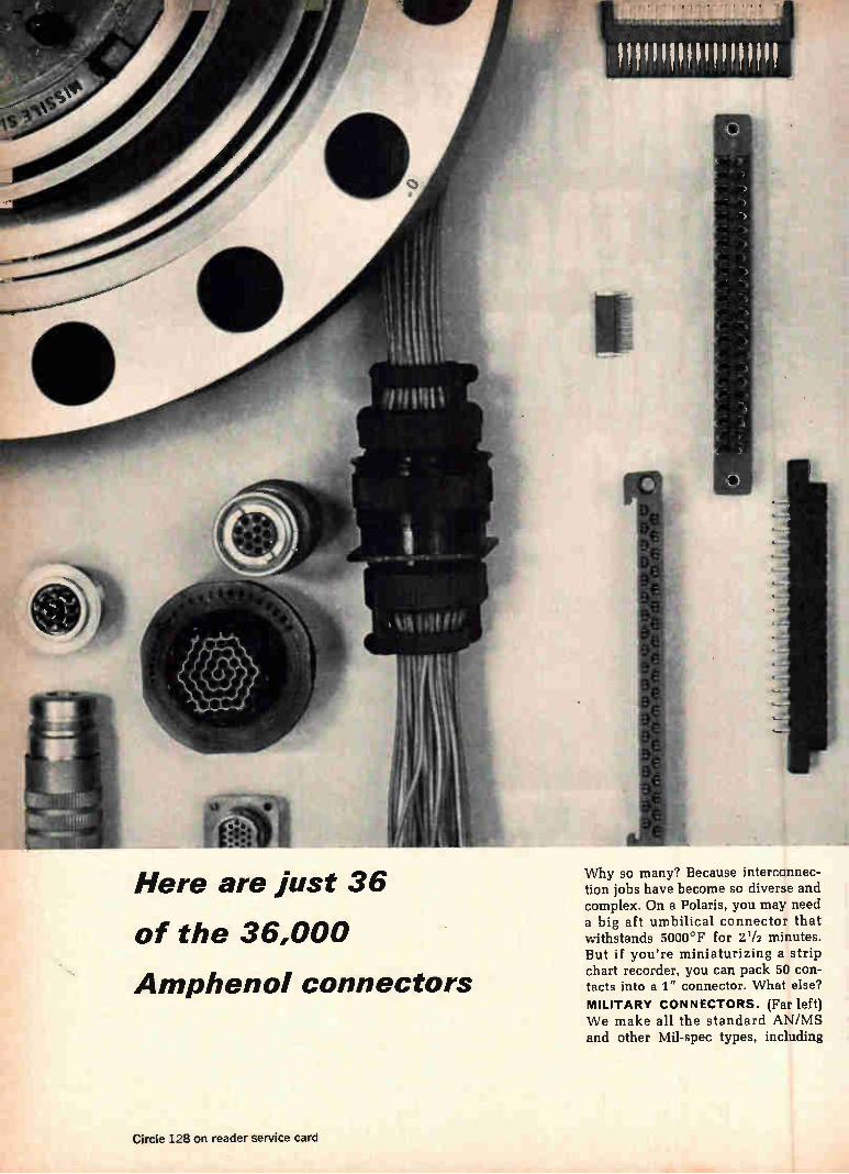
Here are just 36
of the 36,000
Amphenol connectors
Why so many? Because interconnec-tion jobs have become so diverse and complex. On a Polaris, you may need a big aft umbilical connector that withstands 5000°F for 21/2 minutes. But if you're miniaturizing a strip chart recorder, you can pack 50 con-tacts into a 1" connector. What else? MILITARY CONNECTORS. (Far left) We make all the standard AN/MS and other Mil-spec types, including
Circle 128 on reader service card
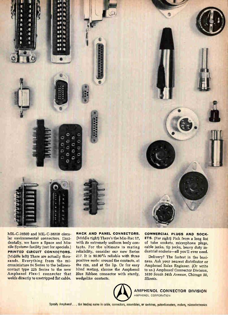
MIL-C-26500 and MIL-C-38300 circu-lar environmental connectors. (Inci-dentally, we have a Space and Mis-sile Systems facility just for specials.) PRINTED CIRCUIT CONNECTORS.
(Middle left) There are actually thou-sands. Everything from the mi-crominiature 64 Series to the bellows-contact type 225 Series to the new Amphenol Flex-1 connector that welds directly to unstripped flat cable.
RACK AND PANEL CONNECTORS.
(Middle right) There's the Min-Rac 17, with its extremely uniform body con-tacts. For the ultimate in mating reliability, consider our new Series 217. It is 99.99% reliable with three positive seals: around the contacts, at the rim, and at the lip. Or for easy blind mating, choose the Amphenol Blue Ribbon connector with sturdy, wedgelike contacts,
COMMERCIAL PLUGS AND SOCK-
ETS. (Far right) Pick from a long list of tube sockets, microphone plugs, cable jacks, tip jacks, heavy duty in-dustrial sockets—all you'll ever need.
Delivery? The fastest in the busi-ness. Ask your nearest distributor or Amphenol Sales Engineer. (Or write to us.) Amphenol Connector Division, 1830 South 54th Avenue, Chicago 50, Illinois,
AMPHENOL CONNECTOR DIVISION AMPHENOL CORPORATION
Specify Amphenol... the leading name in cable, connectors, assemblies, RF switches, potentiometers, motors, microelectronics

I'm an engineer.
Let me tell you, it's the most stimulating work I've ever done. How about your job? It's been only a year or two now since you got your degree. Do you still enjoy straight engineering assignments? Or do you want something more?
Jack Pietri wanted more. So, he became an IBM Marketing Rep. His job combines the challenge of engineering with the excitement of selling. And he thinks it's the most stimulating work in the world.
You might think so, too. You'd still apply your engineering know-how. To solve critical management problems. To get the right information to the right place at the right time in the right form. To give your customers maximum control, maximum output or maximum economy.
I'm a marketing man.
We'll teach you how to work with real-time control of industrial processes. Communications-based information systems. Time-shared computer systems. Graphic data processing. Computer-controlled manufacturing systems. Management operating sys-tems. Or engineering design automation.
When you finish our Computer Systems Science Program you're ready for the most absorbing, stimulating assign-ments you've ever had. And for the opportunities that go with them at IBM. Growth, advancement, responsibility.
With branch offices in over 150 major cities coast to coast, we'll try to match your assignment with your preferences.
You can get a better idea of the Market-ing Rep's job at the nearest IBM
office. Talk it over with the branch manager. Or write to Dr. E. S. Sayas, IBM Data Processing Division, Dept. 015, 112 East Post Road, White Plains, New York 10601. IBM is an Equal Opportunity Employer (M/F).
IBM Marketing Representative John H. Pietri is assigned to a manufacturing territory in Houston. He received his B.S.M.E. degree from Rice University.
IBM®
130 Electronics April 4, 1966
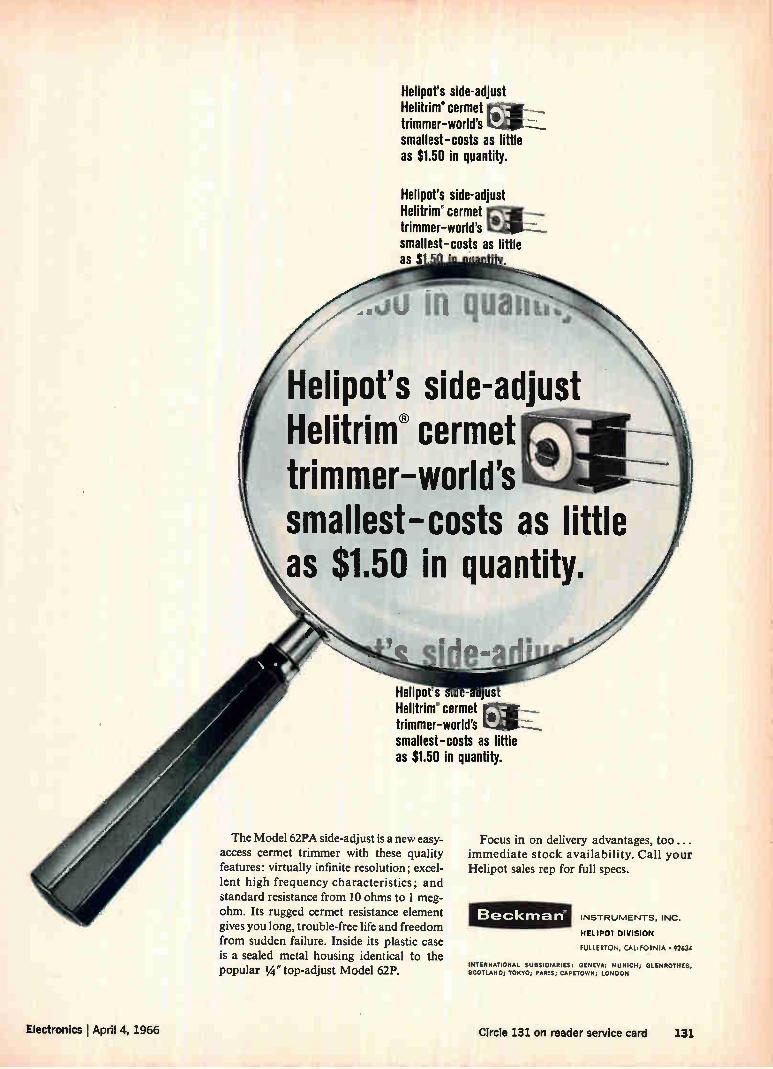
Helipot's side-adjust Helitrim" cermet trimmer-world's smallest-costs as little as $1.50 in quantity.
Helipot's side-adjust Helitrim' cermet trimmer-world's smallest-costs as little as $
.Ju IR quanta.,
Helipot's side-adjust Helitrim e cermet trimmer—world's smallest—costs as little as $1.50 in quantity.
Helipot s s •-a 'just Helitrim cermet a _ trimmer-world's smallest-costs as little as $1.50 in quantity.
The Model 62PA side-adjust is a new easy-access cermet trimmer with these quality features: virtually infinite resolution; excel-lent high frequency characteristics; and standard resistance from 10 ohms to 1 meg-ohm. Its rugged cermet resistance element gives you long, trouble-free life and freedom from sudden failure. Inside its plastic case is a sealed metal housing identical to the popular IA" top-adjust Model 62P.
Focus in on delivery advantages, too... immediate stock availability. Call your Helipot sales rep for full specs.
Beckman INSTRUMENTS, INC.
HELIPOT DIVISION
FULLERTON, CALIFORNIA • 92634
INTERNATIONAL SUBSIDIARIES: GENEVA; MUNICH; GLENROTHES, SCOTLAND; TOKYO; PARIS; CAPETOWN; LONDON
Electronics I April 4, 1966 Circle 131 on reader service card 131
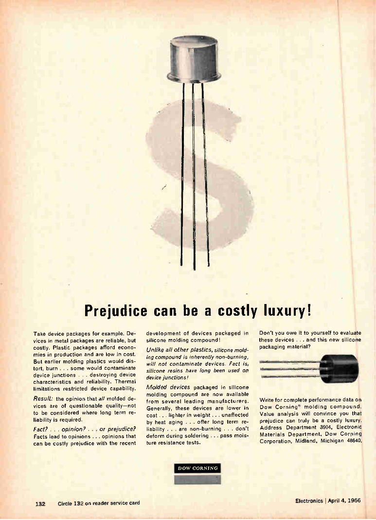
Prejudice can be a costly luxury! Take device packages for example. De-vices in metal packages are reliable, but costly. Plastic packages afford econo-mies in production and are low in cost. But earlier molding plastics would dis-tort, burn ... some would contaminate device junctions . . . destroying device characteristics and reliability. Thermal limitations restricted device capability.
Result: the opinion that all molded de-vices are of questionable quality—not to be considered where long term re-liability is required.
Fact? . . . opinion? . . . or prejudice? Facts lead to opinions ... opinions that can be costly prejudice with the recent
development of devices packaged in silicone molding compound!
Unlike all other plastics, silicone mold-ing compound is inherently non-burning, will not contaminate devices. Fact is, silicone resins have long been used on device junctions!
Molded devices packaged in silicone molding compound are now available from several leading manufacturers. Generally, these devices are lower in cost ... lighter in weight ... unaffected by heat aging . . . offer long term re-liability . . . are non-burning . . . don't deform during soldering ... pass mois-ture resistance tests.
DOW CORNING
Don't you owe it to yourself to evaluate these devices ... and this new silicone packaging material?
Write for complete performance data on Dow Corning • molding compound. Value analysis will convince you that prejudice can truly be a costly luxury. Address Department 3904, Electronic Materials Department, Dow Corning Corporation, Midland, Michigan 48640.
132 Circle 132 on reader service card Electronics April 4, 1966
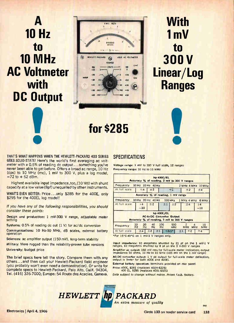
10 Hz to
10 MHz AC Voltmeter
with DC Output
for $285
THAT'S WHAT HAPPENS WHEN THE HEWLETT-PACKARD 400 SERIES GOES SOLID-STATE! Here's the world's first averaging ac volt-meter with a 0.5% of reading dc output ...something you've never been able to get before. Offers a broad ac range, 10 Hz (cps) to 10 MHz (mc), 1 mV to 300 V, plus a log model, —72 to + 52 dBm.
Highest available input impedance, too, (10 Ms» with shunt capacity at a low value (8pf) unequalled by other instruments.
WHAT'S EVEN BETTER: Price...only $285 for the 400E, only $295 for the 400EL log model!
If you have any of the following responsibilities, you should consider these points:
Design and production: 1 mV-300 V range, adjustable meter setting
Systems: 0.5% of reading dc out (1 V) for ac/dc conversion
Communications: 10 Hz-10 MHz, dB scales, external battery operation
Sciences: ac amplifier output (150 mV), long-term stability
Military: More rugged than the reliability-proven tube versions
University: budget price
The brief specs here tell the story. Compare them with any others...and then call your Hewlett-Packard field engineer (you probably won't even need a demonstration). Or write for complete specs to Hewlett-Packard, Palo Alto, Calif. 94304, Tel. (415) 326-7000; Europe: 54 Route des Acacias, Geneva.
SPECIFICATIONS
With lmV to
300 V Linear/Log Ranges
Voltage range: 1 mV to 300 V full scale, 12 ranges
Frequency range: 10 Hz to 10 MHz
hp 400E/EL Accuracy % of reading, 3 mV to 300 V ranges
Frequency 10 Hz 20 Hz 40 Hz 2 MHz 4 MHz 10 MHz
At full scale ±-4 -±-2 +1 7.1:2 I -±-4
Accuracy % of reading, 1 mV range
Frequency 10 Hz 20 Hz 40 Hz 500 kHz 1 MHz 4 MHz 6 MHz
At full scale +4 -±2 -1- 1 -+- 2 -±-4 +4 —10 —10
hp 400E/EL AC- 0-DC Converter Output
Accuracy % of reading, 3 mV to 300 V ranges
10 20 40 100 500 2 4 10 Frequency Hz Hz Hz Hz kHz MHz MHz MHz
At full scale I -±4 1 ±-2 1 -±1 1 ±0.5°1 ±-1 1 -±-2 I -±-4
*For 15°C-40•C on 1 mV-1 V ranges only.
Input impedance: 10 megohms shunted by 21 pf on the 1 mV-1 V ranges, 10 megohms shunted by 8 pf on the 3 V-300 V ranges
Amplifier ac output: 150 mV rms for full-scale meter indication; output impedance 50 ohms, 10 Hz to 10 MHz (105 mV on the 1 mV range)
AC-DC converter output: 1 V dc output for full-wale meter deflection; output is linear for both 400E and 400EL
External battery operation: terminals provided on rear panel
Price: 400E, $285 (replaces 400H-$325) 400 EL, $295 (replaces 400L-$325)
Data subject to change without notice. Prices f.o.b. factory.
HEWLETT khpj PACKARD An extra measure of quality
Electronics I April 4, 1966
862
Circle 133 on reader service card 133
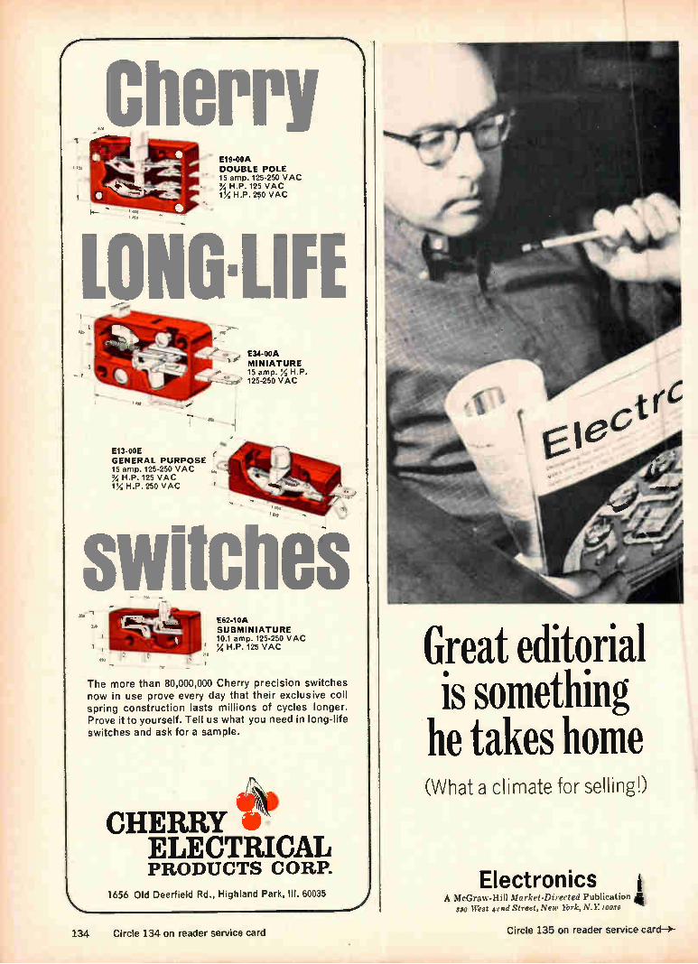
Cherry E19-00A DOUBLE POLE 15 amp. 125-250 VAC
H.P. 125 VAC 1% H.P. 250 VAC
Lo E34-00A MINIATURE 15 amp. '; H.P.
' 125-250 VAC
E13-00E GENERAL PURPOSE 15 amp. 125-250 VAC % H.P. 125 VAC VA H.P. 250 VAC
zwitches The more than 80,000,000 Cherry precision switches now in use prove every day that their exclusive coil spring construction lasts millions of cycles longer. Prove it to yourself. Tell us what you need in long-life switches and ask for a sample.
í•t' CHERRY
ELECTRICAL PRODUCTS CORP.
1656 Old Deerfield Rd., Highland Park, III. 60035
E62-10A SUBMINIATURE 10.1 amp. 125-250 VAC 17, H.P. 125 VAC Great editorial
is something he takes home (What a climate for selling!)
Electronics A McGraw-Hill Market-Directed Publication
330 West 42nd Street, New York, N.Y 10038
134 Circle 134 on reader service card Circle 135 on reader service card—)-

A whole litter of them, in fact. In the form
of technical bulletins covering the most complete line of ferrite materials and shapes in the world. Included are core
sizes and shapes not available as standard from any other manufacturer and ferrite
materials made only by Indiana General.
Take flyback transformers, for example. In color-TV our 05 ferrite is the leading core material because of its high-voltage per-
formance. Where ferrites for filters are con-
cerned, our TC-7 combines extremely high "Q" and low loss with the most linear
temperature coefficient of inductance found anywhere.
In all, we list 11 ferrite materials in 315
standard shapes and sizes including: cup cores; toroids; transformer C cores; rods
and strips; E, I, U, and C cores; the interna-tional series of cup cores, and cross cores.
Whether you are designing circuits o
purchasing components, you can have ou Ferramie Materials Bulletins Nos. 101 thru 105 on your desk. Write Mr. K. S Talbot, Manager of Sales, Indiana Genera
Corporation, Electronics Division/Ferrites Keasbey, New Jersey.
INDIANA GENERAL CO COPYRIGHT 1966. INDIANA GLNLRAL COHPURATION
We're ready to let the cat out on our 315 standard ferrite core shapes and 11 different materials.
0
and Control Engineers' Book Club The Electronics helps you keep ahead in your field.
Start your membershio with any of these selections:
Introduction to Radar Sys-tems by M. Skolnik. Covers everything from the predic-tion of radar range perform-ance to applications.
Publisher's Price, $14.50 Club Price, $12.35
Mathematics for Electronics with Applications by H. M. Nodelman and F. W. Smith, Jr. Methods for solving practical problems.
Publisher's Price, $7.00 Club Price, $5.95
Transistor Circuit Design, prepared by the Engineer-ing Staff of Texas Instru-ments Inc. Reduces theory to actual practice.
Publisher's Price, $15.00 Club Price, $12.75
Electronic Amplifier Cir-cuits by J. M. Pettit and M. M. McWhorter. Gives reliable guidance on elec-tronic amplifier circuit de-sign.
Publisher's Price, $10.50 Club Price, $8.05
Modern Digital Circuits by Samuel Weber. A practical reference on design aspects of digital-type circuits.
Publisher's Price, $9.50 Club Price, $8.10
Electronic and Radio Engi-neering by F. E. Terman. 4th Ed. Helps solve modern problems in the electronic and radio engineering fields.
Publisher's Price, $16.00 Club Price, $13.60
Electronic Measuring In-struments by H. Soisson. Covers electronic equipment used for precise measure-ments and cotrtrol.
Publisher's Price, $7.50 Club Price. $6.40
Your engineering career owes a great deal to books. Why not take advantage of this convenient, economical way to have the best professional books available when you need them? THE ELECTRONICS AND CONTROL ENGINEERS' BOOK CLUB brings you the essential technical literature in your field. It also helps you overcome today's high cost of building a profes-sional library by saving you an average of 15% from publisher's prices.
How the Club Operates. You regularly receive free of charge The Electronics and Control Engineers' Book Bulletin, as issued. This gives complete advance no-tice of the next selection-of-the-month, as well as many alternate selections. If you want the main selection you do nothing; the book will be mailed to you. If you want an alternate selection—or no book at all—you can notify the Club by returning the convenient card en-closed with each Bulletin.
Saves You Time and Money. You agree only to the purchase of four books over a two-year period. Certainly out of the large number of books offered in your field there are at least four you would buy anyway. By joining the Club you save both money and the trouble of searching.
Send No Money Now. Just check the book you want as your first selection on the coupon below. With it you will be sent Handbook of Semiconductor Elec-tronics for only one dollar. Take ad-vantage of this offer and receive two books for less than the regular price of one. (If coupon is detached, write to The Electronics and Control Engineers' Book Club, Dept. I.X0418, 330 W. 42nd St., New York 36. N. Y.)
• • at a savings
ACCEPT THIS
$19.50 BOOK
FOR ONLY
sio_o with membership in
The Electronics and
Control Engineers'
Book Club
HANDBOOK OF SEMICONDUCTOR
ELECTRONICS
Prepared by et Staff of 18 Specialists
Edited by LLOYD P. HUNTER
Here is a wealth of reliable information to assist you in understanding the basic physical action of transistors, diodes, and photocells — for assembling necessary equipment, and fabricating typical semi-conductors—and, above all, for designing a large variety of transistor circuits for use in various ferquency ranges.
Handbook of Semiconductor Electron-ics is typical of the selections of THE ELECTRONICS AND CONTROL ENGINEERS' BOOK CLUB. All books are chosen by quali-fied editors and consultants. Their thor-oughgoing understanding of the stand-ards and values of the literature in your field guarantees the authoritativeness of the selections.
. NOTE: If you already own this volume, you may substitute any other book on this page as your DOLLAR book. Check two books below and you will receive the higher priced selection for only $1.00.
CLIP AND MAIL THIS COUPON TODAY The Electronics and Control Engineers' Book Club, Dept. LX0418 330 West 42nd Street, New York, N.Y. 10036
I'lease enroll me as a member of the Electronics and Control Engi-neers' Book Club. You will bill me for my first selection indicated at righ• at the special club price and $1 for Handbook of Semicon-ductor Electronics (or alternate choice), plus local tax where applic-able, and e few cents delivery costs. (The Club assumes delivery costs on prepaid orders.) Forthcoming selections will be described in advance and I may decline any book. I need take only 4 selections or alternates In 2 years of membership. (This offer good in U. S. only.) PLEASE PRINT Name Address City State Zie
Company
NO RISK GUARANTEE: and your mem rahlp orill be cancel L-32.1ax
Send as my first selection: (It more than one book is checked we will send the higher priced selection as year 81.00 book.)
D Introduction to Radar Systems, $12.35 D Mathematics for Electronics with Ap-
plications, $5.95 D Transistor Circuit Desfon. $12.75 0 Electrenrc Amplifier Circuits, $8.95 O Modern Digital Circuits, $8.10
Electronic and Radio Engineering, $13.60 Electronic. Measuring Instruments, $6.40
If not comPleter satished, you may return your first shipment within 10 dare
136 Electronics April 4, 1966

e AUTHORIZED DISTRIBUTORS
ALABAMA Argo & Company Birmingham
ARIZONA Electrical Specialty Co. Phoenix
CALIFORNIA Electrical Specialty Co. Los Angeles Electrical Specialty Co. South San Francisco R. V. Weatherford Co. Glendale
COLORADO Electrical Specialty Co. Denver
CONNECTICUT R. H. Carlson Co., Inc. Greenwich
D. C. Read Plastics, Inc. Washington
FLORIDA Gulf Semiconductors, Inc. Coral Gables Gulf Semiconductors, Inc. Winter Park
ILLINOIS Allied Radio Corp. Chicago Federal Insulation Corp. Chicago J. J. Glenn and Co., Inc. Chicago
INDIANA Hyaline Plastics Corp. Indianapolis
IOWA Plastic Supply, Inc. Des Moines
KENTUCKY General Rubber &
Supply Co. Louisville
MASSACHUSETTS Northeast Chemical Co. Boston
MICHIGAN F. B. Wright Co., Inc. Dearborn Ren Plastics Inc. Lansing
MINNESOTA D. A. Schultz Company Minneapolis
MISSOURI D. A. James Company St. Louis Regal Plastic Supply Co. Kansas City
NEBRASKA Regal Plastic Supply Co. Omaha
NEW JERSEY Smooth-on Mfg. Co. Jersey City
NEW YORK Punt, Inc. Floral Park Queen City Rubber Co. Buffalo Adhesive Products Corp. New York Chamberlin Rubber CO. Rochester Syracuse
OHIO Philpott Rubber Co. Cleveland Parkway Products, Inc. Cincinnati
OREGON Electrical Specialty Co. Portland
PENNSYLVANIA Smith of Philadelphia, Inc. Philadelphia Speck-Marshall Co. McKees Rocks
TEXAS Lawrence Electronic Co. Dallas Houston Industrial
Supply Co., Inc. Houston
WASHINGTON Electrical Specialty Co. Seattle
WISCONSIN R. J. Wittenburg Co. Milwaukee
G-E ultra high strength RTV-630: slash it, flex it double...it never tears
General Electric RTV-630 silicone rubber has a tear strength of 100 psi-die B. That's more than twice the tear resistance of any other RTV. It also has a hardness of 55-70 durometer, tensile strength up to 850 psi and elongation of up to 400%.
Because of its great strength. RTV-630 can be used in thinner conformal coatings and improved
RTV-7 foam for shock and vibration damping. Foams to 5 times original size and cures in 10 min-utes. Density can be varied. Extremely resilient.
For more data, ask your nearest dis-
tributor as listed or write Section
N4193R, Silicone Products Dept., General Electric Co., Waterford, N. Y.
production line potting. RTV-630 is designed to protect against the worst environments of ther-mal shock, vibration, moisture, ozone and tem-peratures from —65°F to 500°F.
Experience shows RTV-630 molds for elec-tronic parts last up to twice as long as conven-tional RTV. As a punch die, it has performed more than six times as long.
Ready-to-use RTV-102 cartridge speeds produc-tion line sealing. No catalyst, no priming needed. Tough, flexible. UL recognition.
GENERAL j ELECTRIC
Circle 137 on reader service card
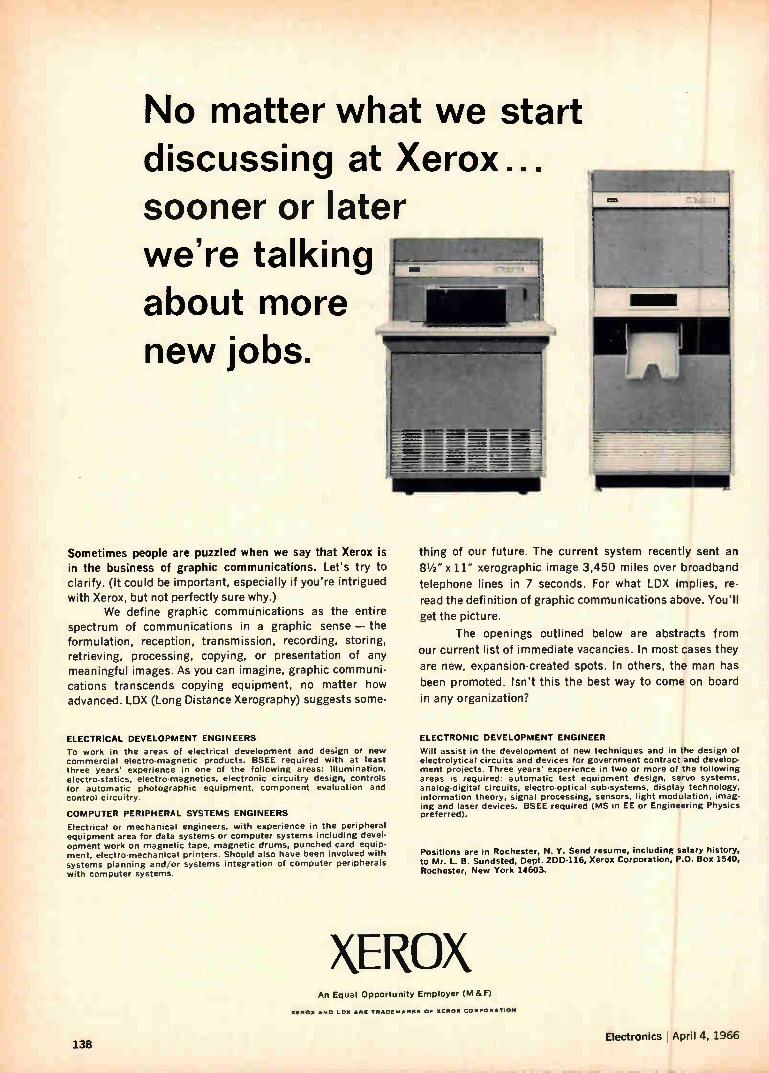
No matter what we start discussing at Xerox... sooner or later we're talking about more new jobs.
Sometimes people are puzzled when we say that Xerox is in the business of graphic communications. Let's try to clarify. (It could be important, especially if you're intrigued with Xerox, but not perfectly sure why.)
We define graphic communications as the entire spectrum of communications in a graphic sense — the formulation, reception, transmission, recording, storing, retrieving, processing, copying, or presentation of any meaningful images. As you can imagine, graphic communi-cations transcends copying equipment, no matter how advanced. LDX (Long Distance Xerography) suggests some-
ELECTRICAL DEVELOPMENT ENGINEERS
To work in the areas of electrical development and design of new commercial electro-magnetic products. BSEE required with at least three years' experience in one of the following areas: Illumination, electro-statics, electro-magnetics, electronic circuitry design, controls for automatic photographic equipment, component evaluation and control circuitry.
COMPUTER PERIPHERAL SYSTEMS ENGINEERS
Electrical or mechanical engineers, with experience in the peripheral equipment area for data systems or computer systems including devel-opment work on magnetic tape, magnetic drums, punched card equip-ment, electro-mechanical printers. Should also have been involved with systems planning and/or systems integration of computer peripherals with computer systems.
thing of our future. The current system recently sent an
81/2 " x 11" xerographic image 3,450 miles over broadband
telephone lines in 7 seconds. For what LDX implies, re-
read the definition of graphic communications above. You'll
get the picture.
The openings outlined below are abstracts from
our current list of immediate vacancies. In most cases they
are new, expansion-created spots. In others, the man has
been promoted. Isn't this the best way to come on board
in any organization?
ELECTRONIC DEVELOPMENT ENGINEER
Will assist in the development of new techniques and in the design of electrolytical circuits and devices for government contract and develop-ment projects. Three years' experience in two or more of the following areas is required: automatic test equipment design, servo systems, analog-digital circuits, electro-optical sub-systems, display technology, information theory, signal processing, sensors, light modulation, imag-ing and laser devices. BSEE required (MS in EE or Engineering Physics preferred).
Positions are in Rochester, N. Y. Send resume, including salary history, to Mr. L. B. Sundsted, Dept. ZDD-116, Xerox Corporation, P.O. Box 1540, Rochester, New York 14603.
XEROX An Equal Opportunity Employer (M &F)
138
XEROX AND LOX ARE TR•DEMARKS OF XEROX CORPORATION
Electronics April 4, 1966
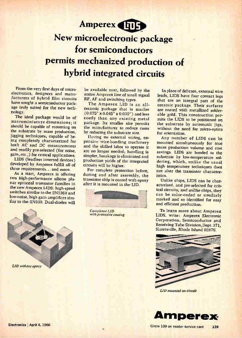
Amperex
New microelectronic package for semiconductors
permits mechanized production of hybrid integrated circuits
From the very first days of micro-electronics, designers and manu-facturers of hybrid film circuits have sought a semiconductor pack-age truly suited for the new tech-nology. The ideal package would be of
microminiature dimensions ; it should be capable of mounting on the substrate by mass production, jigging techniques; capable of be-ing completely characterized for both AC and DC measurements and readily pre-selected (for noise, gain, etc.,) for critical applications. LIDS (leadless inverted devices)
developed by Amperex fulfill all of these requirements ... and more. As a start, Amperex is offering
two high-performance silicon pla-nar epitaxial transistor families in the new Amperex LIDS: high-speed switches similar to the 2N2369 and low-noise, high gain amplifiers sim-ilar to the 2N930. Dual-diodes will
be available next, followed by the entire Amperex line of small signal RF, AF and switching types. The Amperex LID is an all-
ceramic package that is smaller (0.075" x 0.045" x 0.032") and less costly than any existing metal package. Its smaller size permits the manufacturer to reduce costs by reducing the substrate size. Having no external wiring, ex-
pensive wire-bonding machinery and the skilled labor to operate it are no longer needed; handling is simpler, breakage is eliminated and production yields of the integrated circuits will be higher. For complete protection before,
during and after assembly, the transistor chip is coated with epoxy after it is mounted in the LID.
Completed LID with protective coating
In place of delicate, external wire leads, LIDS have four contact legs that are an integral part of the ceramic package. Their surfaces are coated with metallized solder-able gold. This construction per-mits the LIDS to be positioned on the substrate by automatic jigs, without the need for micro-optics for orientation. Any number of LIDS can be
mounted simultaneously for true mass production volume and cost savings. LIDS are bonded to the substrate by low-temperature sol-dering, which, unlike the usual high temperature techniques does not alter the transistor character-istics.
Unlike chips, LIDS can be char-acterized, and pre-selected for crit-ical circuits; and unlike chips, they can be color-coded or similarly marked and so identified for easy and efficient production.
To learn more about Amperex LIDS, write: Amperex Electronic Corporation, Semiconductor and Receiving Tube Division, Dept. 371, Slatersville, Rhode Island 02876.
LID mounted on circuit
Amperex Electronics April 4, 1966
Circle 139 on reader service card 139
LOWEST COST
HIGHEST QUALITY
Quality and reliability demon-strated by a proven 41/2 mil-lion hours MTBF
GREATEST VERSATILITY
Complete families of rugged potted germanium and silicon
modules
For example, 100 Kcps S-R flip-flop module $3.95 each in quantities of 100
Practical reasons why so many engineers
choose EMC %solo digital logic modules
potted in TIMONIUM
Complete families of digital logic modules operate over
an ambient temperature range of —55°C to +125°C
11111C11311illa o 0111113111 131O D LIII11113111 Electronic Modules Corporation • COMPONENTS DIVISION
Bola o GI A DU O al 1949 GREENSPRING DRIVE • TIMONIUM, MARYLAND • TEL. (301) 252-2900 • TWX-301-252-0723
#66-4
140 Circle 140 on reader service card Electronics April 4, 1966

Westinghouse announces epoxy diodes with
guaranteed hermeticity TAWATIMULTATAM
ee• Westinghouse Semiconductor Lifetime Guarantee
Westinghouse warrants to the original purchaser that it will cor-rect any defect or defects in workmanship, by repair or replacement f.o.b, factory, for any JEDEC•type silicon power semiconductor dur. ing the life of the equipment in which it is originally installed, pro. vided said device is used within manufacturer's published ratings and applied in accordance with good engineering practice. This war. ranty is applicable to devices of the stated types shipped after March 9, 1964, until further notice. This warranty shall constitute a fulfillment of all Westinghouse liabilities in respect to said products. This warranty is in lieu of all other warranties expressed or implied. Westinghouse shall not be liable for any consequential damages.
mist o AVIVÁVÁVAVnaiffi
Now what have glass or metal types got besides high price? The new Westinghouse 1N4816 series diodes feature glass-to-metal reliability at epoxy prices. Hermeticity is assured by humid-ity tests per MIL-S-750, method 1021. With a current rating of 1.5 amps, voltages to 1000 V, and a 50 amp surge rating, this new series replaces hundreds of conventional types. And they save you money. Prices range from 160 at 50 volts to 750 for 1000 volts, in lots of 5,000 to 9,999. Call your Westinghouse distributor for samples and details now. Or write to Westinghouse Semiconductor Division, Youngwood, Pennsylvania. 5C•2058
You can be sure if it's Westinghouse
Electronics April 4, 1966 Circle 141 on reader service card 141
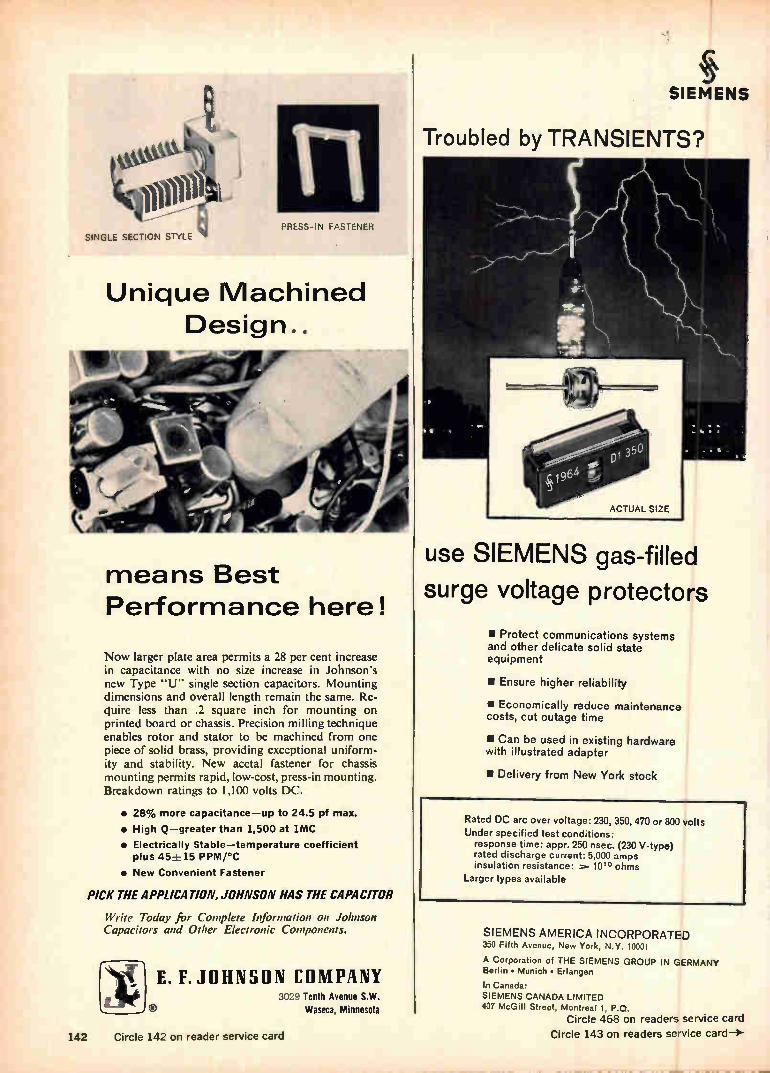
PiiLSS-IN FASTENER SINGLE SECTION STYLE
Unique Machined Design..
means Best Performance here!
Now larger plate area permits a 28 per cent increase in capacitance with no size increase in Johnson's new Type "U" single section capacitors. Mounting dimensions and overall length remain the same. Re-(luire less than .2 square inch for mounting on printed board or chassis. Precision milling technique enables rotor and stator to be machined from one piece of solid brass, providing exceptional uniform-ity and stability. New acetal fastener for chassis mounting permits rapid, low-cost, press-in mounting. Breakdown ratings to 1,100 volts DC.
• 28% more capacitance—up to 24.5 pf max.
• High Q—greater than 1,500 at 1MC
• Electrically Stable—temperature coefficient plus 452.•-_15 PPM/°C
• New Convenient Fastener
PICK THE APPLICATION, JOHNSON HAS THE CAPACITOR
Write Today for Complete Information on Johnson Capacitors and Other Electronic Components.
E. F. JOHNSON COMPANY 3029 Tenth Avenue S.W.
Waseca, Minnesota
142 Circle 142 on reader service card
SIEMENS
Troubled by TRANSIENTS?
4
use SIEMENS gas-filled
surge voltage protectors
• Protect communications systems and other delicate solid state equipment
• Ensure higher reliability
• Economically reduce maintenance costs, cut outage time
• Can be used in existing hardware with illustrated adapter
• Delivery from New York stock
Rated DC arc over voltage: 230, 350, 470 or 800 volts Under specified test conditions: response time: appr. 250 nsec. (230 V-type) rated discharge current: 5,000 amps insulation resistance: 10'° ohms
Larger types available
SIEMENS AMERICA INCORPORATED 350 Fifth Avenue, New York, N.Y. 10001
A Corporation of THE SIEMENS GROUP IN GERMANY Berlin • Munich • Erlangen
In Canada: SIEMENS CANADA LIMITED 407 McGill Street, Montreal 1, P.Q.
Circle 468 on readers service card Circle 143 on readers service card-*

Upset? Power contactor deliveries rescheduled again? Next time call Leach!
We've got hundreds of power contactors in stock through-out the country. Contactors like the models 9324 (zo amp), 9123 (25 amp), and the 9124 (50 amp).
These new units are the smallest, lightest power con-tactors meeting ma-R-6106e. True balanced armature con-struction lets them take up to 5og shock and 25g vibration with a contact opening of less than io microseconds. The Model 9324 (ms27428) is a 20 amp, 3PST/NO
contactor. Under motor load, its rating is 15 amp break and 75 amp make at 115 VAC, 3 phase. Operate time 20 milliseconds, with release at lo milliseconds. The 25 amp model 9123 (ms27997) and 50 amp 9124
(ms27222) meet the latest requirement of the aircraft and aerospace industries. Basic models are 3rs-r/No and 3psr/No with 5 amp auxiliary contacts. Industry standard mounting makes them interchangeable with older, larger, top-hat type ms24143 and ms24376.
Interested? Then ask for our new Power Contactor Bro-chure, or better still, send us your purchase order. You'll have your power contactors by return mail. Leach Corporation, Relay Division, 5915 Avalon BI.
P Los Angeles, California; 90003hone (Area code 213) 232-8221 LEAmi Export: LEACH INTERNATIONAL S. A.
Engineers and Scientists:
The Hughes Aircraft Company
is proud to announce the establishment of
EJ
CAR
-4
OF -a A.
IUGITES HSSIONAL DiV -,1LOPMENT
ROGRAM This new Program emphasizes individual
career growth through a sequence of selected work assignments for graduate
engineers who have acquired between two and eight years of professional ex-
perience. It is designed primarily for two types of development:
1 Specialized, in-depth assignments o to develop unusual proficiency in a spe-
cific area of interest.
2. Broad, systems-types of assign-ments to prepare for system and project engineering responsibilities. There will be a maximum of three
assignments which will be determined
jointly by the participant and the Profes-
sional Development Section.The assign-ments, which are flexible in length would normally extend for one year each. They
may be selected from a broad spectrum
of aerospace electronics hardware and systems-oriented programs and will be
designed to provide optimum back-
grounds in specialized areas of interest. The Program will be limited to 50 par-
ticipants in 1966. These will be selected
from candidates who are graduates in
E.E., M.E. or Physics from fully-accredit-
ed universities and who have acquired from two to eight years of professional-
level technical experience. U.S. citizen-
ship is required. Those in the Program will receive sal-
aries commensurate with levels estab-lished by their overall experience and
qualifications. We invite interested Engineers and
Physicists to submit their qualifications
for consideration. Please forward your resume including
details of your educational and experi-ence background to:
Mr. Robert A. Martin Head of Employment HUGHES Aerospace Divisions
11940 W. Jefferson Blvd. Culver City 10, California
HUGHES HUGHES AIRCRAFT COMPANY
AEROSPACE DIVISIONS
An equal opportunity employer
144 Electronics April 4, 1966
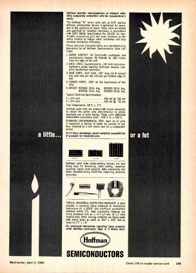
Electronics April LI, 1966
Hoffman provides semiconductors of inherent relia bility completely compatible with the manufacturer's needs.
The Hoffman "N" series solar cell. an N/P, shallow diffused, photovoltaic device is optimized for opera tion in the spectrum of space. These cells are tested and qualified for radiation resistance in accordance with GSFC (NASA) Specification No. 63-106. An elec-trically conducting grid has been sintered to the active surface to reduce sheet resistance and thus increase conversion efficiency.
These physical characteristics are manufacturing tolerances for all Hoffman Semiconductor Solar Cell Types.
1. OHMIC CONTACT: (A) Electrically continuous and mechanically bonded. (8) Extends to .032 inches from the edge of the cell.
2. GRID LINES: Guaranteed to .100 inch tolerance. Hoffman's photo masking technique assures com-plete mechanical tolerances.
3. EDGE CHIPS: .010" wide, .100" long not to exceed one such chip per top and one per bottom edge of cell.
4. CORNER CHIPS: .030" on the chip.
5. WEIGHT: N120CG .18 Gr. Avg. N210CG .18 Gr. Avg.
Typical Electrical Specifications
2 x 2cm cell 1 x 2cm cell
Test Temperature: 28°C ± 2°C.
Hoffman solar cells are coated with silicon monoxide to render the active area anti-reflective to obtain maximum use of solar energy. These cells withstand temperature excursions from —196°C to +200°C.
STANDARD ENVIRONMENTAL TEST: Each lot of cells is immersed in boiling DI water for periods to one hour followed by a live steam test for a comparable period.
All of these advantages insure complete compatibility of products for industrial uses.
hypotenuse of the
N220CG .36 Gr. Avg. N230CG .54 Gr. Avg.
430 mV (F2) 135 mA 430 mV à 65 mA
Hoffman solid state photo-sensing devices are now being used for measuring, cloth cutting, sequence counting, liquid level gauging, data processing and other manufacturing functions requiring absolute accuracy.
ille"."1112!
Wow
TYPICAL INDUSTRIAL COMPATIBLE PRODUCTS: A shaft encoder is currently being produced to mechanical tolerances of ±.0005" and electrical parameters matched within 2%. Data processing readouts are being produced with an Id of 3 µA max. at 1.5 volts reverse bias. Other sensing elements are being made with active areas as small as .002" x .023" and as large as 2.5" x 1.0". For additional information regarding these products write: Hoffman Electronics, Dept. A, El Monte, Calif.
SEMICONDUCTORS Circle 145 on reader service card 145
THE HULL STORY ENCAPSULATION BY TRANSFER MOLDING
Why do the world's leading electronic firms come to HULL?
For superior systems to encapsulate electronic componente small or large ... that's why
There's more to "The HULL Story" than simply building better machines for superior encapsulation. It starts back in 1956 when we helped Western Electric package their varistors in the then "short-cure" resins. The resul-tant process proved ideal.
In the decade that followed, we worked in strict confidence with many elec-tronic firms . . . helping them solve their encapsulation problems . . . adapting methods and materials to
the needs of new components.*
Today, several hundred installations later, we're proud to claim unques-tioned leadership in the field of en-capsulation, offering a complete system capability. Our list of customers reads like a "Who's Who" in electronics: Texas Instruments, General Electric, IBM, Motorola, Philips, Fairchild Semiconductor—to name a few. Get "The HULL Story" on a pack-*Such as transistors, integrated circuits, capacitors, resistors, modules, transformers, and coils.
aged system . . . including molds, loading frames, and controls . . . for rapid and economical encapsulation of your component or circuit. Write or phone today! HULL CORPORATION, 6033 Davisville Rd., Hatboro, Pa. 19040 Tel.: (215) 675-5000 Export: 1505 Race St., Phila., Pa. 19102
Circle 146 on reader service card
Electronics
Great editorial is something he takes on a business trip (What a climate for selling!)
Electronics ill A McGraw-Hill Market-Directed Publication
la Wat told Streit, Now York, N.Y. IBM
146 Electronics L April 4, 1966
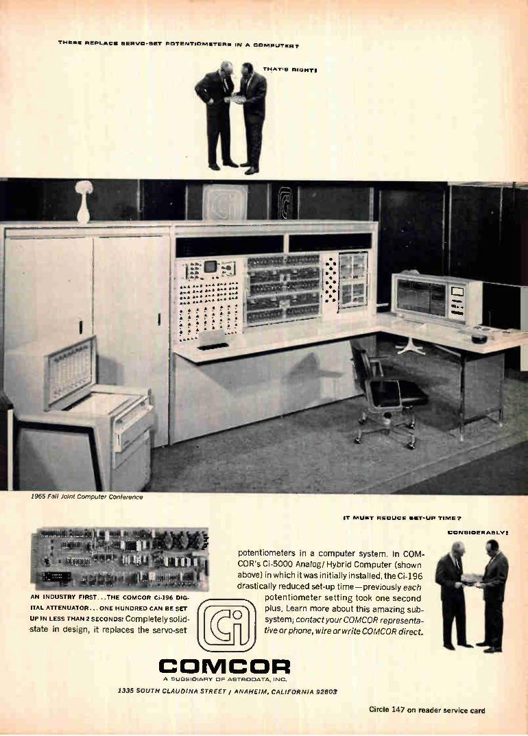
THESE REPLACE SERVO-SET POTENTIOMETERS IN A COMPUTER?
1965 Fall Joint Computer Conference
IT MUST REDUCE SET-LIP TIME?
«giit4
e ,giv
etti AN INDUSTRY FIRST...THE COMCOR Ci-196 DIG-
ITAL ATTENUATOR... ONE HUNDRED CAN BE SET
UP IN LESS THAN 2 SECONDS! Completely solid-state in design, it replaces the servo-set
nfi potentiometers in a computer system. In COM-COR's Ci-5000 Analog/ Hybrid Computer (shown
above) in which it was initially installed, the Ci-196 drastically reduced set-up time—previously each
potentiometer setting took one second plus. Learn more about this amazing sub-
system; contact your COMCOR representa-
tive or phone, wire or write COMCOR direct.
COMCOR A SUBSIDIARY OF ASTRODATA. INC.
CONSIDERABLY:
1335 SOUTH CLAUDINA STREET / ANAHEIM, CALIFORNIA 92803
Circle 147 on reader service card
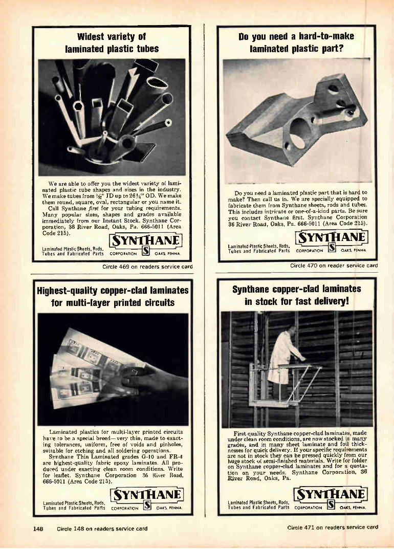
Laminated Plastic Sheets, Rods, Tubes and Fabricated Parts CORPORATION
Widest variety of laminated plastic tubes
We are able to offer you the widest variety of lami-nated plastic tube shapes and sizes in the industry. We make tubes from ID up to 26h" OD. We make them round, square, oval, rectangular or you name it.
Call Synthane first for your tubing requirements. Many popular sizes, shapes and grades available immediately from our Instant Stock. Synthane Cor-poration, 36 River Road, Oaks, Pa. 666-5011 (Area Code 215).
SYIVITFIAN s OAKS PENNA
Circle 469 on readers service card
Highest-quality copper-clad laminates for multi-layer printed circuits
Laminated plastics for multi-layer printed circuits have to be a special breed— very thin, made to exact-ing tolerances, uniform, free of voids and pinholes, suitable for etching and all soldering operations.
Synthane Thin Laminated grades G-10 and FR-4 are highest-quality fabric epoxy laminates. All pro-duced under exacting clean room conditions. Write for leaflet. Synthane Corporation 36 River Road. 666-5011 (Area Code 215).
Laminated Plastic Sheets, Rods, Tubes and Fabricated Parts
EsYN1HANEI CORPORATION â OAK PENNA
Do you need a hard-to-make laminated plastic part?
Do you need a laminated plastic part that is hard to make? Then call us in. We are specially equipped to fabricate them from Synthane sheets, rods and tubes. This includes intricate or one-of-a-kind parts. Be sure you contact Synthane first. Synthane Corporation 36 River Road, Oaks, Pa. 666-5011 (Area Code 215).
C SYNTÍFIAN Tubes and Fabricated Parts CORPORATION S O AKS PENNA
Laminated Plastic Sheets, Rods,
Circle 470 on reader service card
Synthane copper-clad laminates in stock for fast delivery!
First quality Synthane copper-clad laminates, made under clean room conditions, are now stocked in many grades, and in many sheet laminate and foil thick-nesses for quick delivery. If your specific requirements are not in stock they can be pressed quickly from our huge stock of semi-finished materials. Write for folder on Synthane copper-clad laminates and for a quota-tion on your needs. Synthane Corporation, 36 River Road, Oaks, Pa.
Laminated Plastic Sheets, Rods, Tubes and Fabricated Parts CORPORATION OAKS PENNA
SYNTillAN
148 Circle 148 on readers service card Circle 471 on readers service card
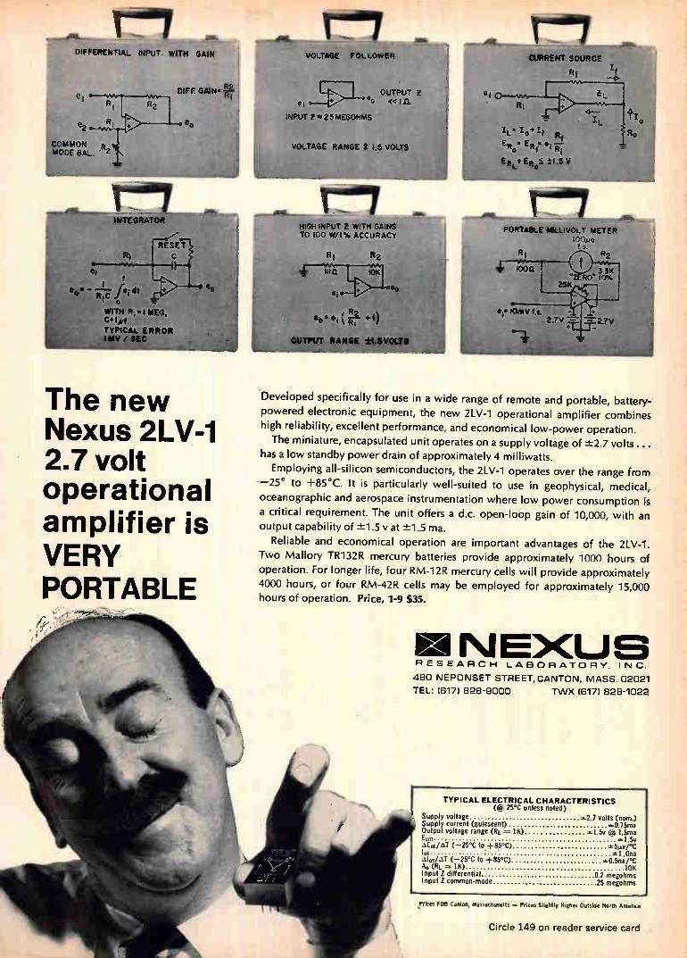
DIFFERENTIAL INPUT WITH GAIN VOLTAGE FOLLOWER CURRENT SOURCE
e2
COMMON MODE BAL.
ri INTEGRATOR
D1FF. GAIN. RI
R1
et
es. dt o WITH R; • I MEG. C IMf TYPICAL ERROR I eAV / SEC
The new Nexus 2LV-1 2.7 volt operational amplifier is VERY PORTABLE
OUTPUT Z • ee « I It e ¡
INPUT g25MEGOHMS
VOLTAGE RANGE 5 .5 VOLTS
re-17 HIGH INPUT E WITH GAINS TO 100 W/I% ACCURACY
RI
1110 10K
thammeileiafgitnITk R2 RANGE t1SVOLTS
to.
ei RI
ei
R1
1000
eit1OrnV f.s. 2-TV --- 2.7V
Developed specifically for use in a wide range of remote and portable, battery-powered electronic equipment, the new 2LV-1 operational amplifier combines
high reliability, excellent performance, and economical low-power operation.
The miniature, encapsulated unit operates on a supply voltage of -±2.7 volts...• has a low standby power drain of approximately 4 mil liwatts.
Employing all-silicon semiconductors, the 2LV-1 operates over the range from
—25° to +85°C. It is particularly well-suited to use in geophysical, medical,
oceanographic and aerospace instrumentation where low power consumption is a critical requirement. The unit offers a d.c. open-loop gain of 10,000, with an output capability of -±-1.5 vat -±1.5 ma.
Reliable and economical operation are important advantages of the 2LV-1. Two Mallory TR132R mercury batteries provide approximately 1000 hours of operation. For longer life, four RM-12R mercury cells will provide approximately
4000 hours, or four RM-42R cells may be employed for approximately 15,000 hours of operation. Price, 1-9 $35.
N E>CU RESEARCH LABORATORY, INC.
480 NEPONSET STREET, CANTON, MASS. 02021
TEL: (617) 828-9000 TWX (617) 828-1022
TYPICAL ELECTRICAL CHARACTERISTICS ((a, 25°C unless noted)
Supply voltage =2.7 volts (nom.) Supply current (quiescent) 0.75ma Output voltage range (Ri = 1K) =1.5v (0 1.5ma
=1.5v .1E0,RJ (-25°C to +85°C) =5mv/°C 1. =1.0na .51./T (-25°C to +85°C) =0.5na/°C Ao (Rt. = 1K) 10K Input Z differential 02 megohms Input Z common-mode 25 megohms
ECM
R1
IL
IC 'pelf Rt
ERo• ER ir el -eiî
Ee l...4' 4 0 5. ± 1.5 V
Ro
o
ri PORTABLE MILLIVOLT METER
100pa f. s.
R2
!rises FOB Canton, Massachusetts — Prices Slightly Higher Outside North Amer's.'
Circle 149 on reader service card
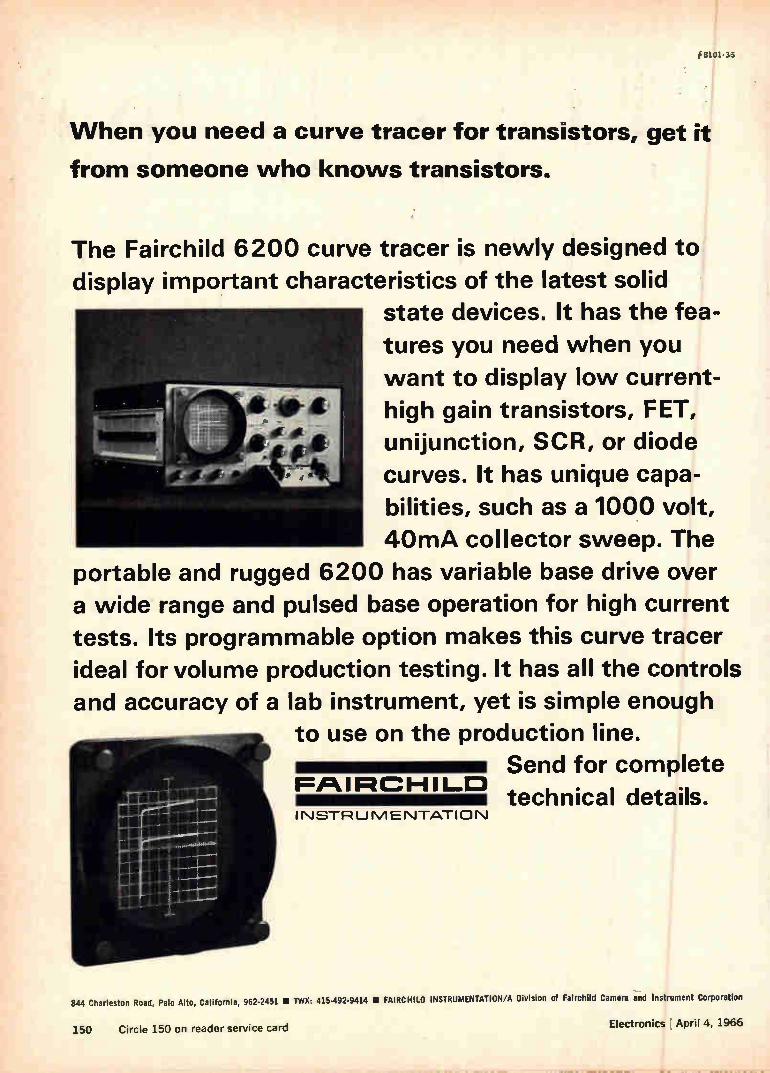
When you need a curve tracer for transistors, get it
from someone who knows transistors.
The Fairchild 6200 curve tracer is newly designed to
display important characteristics of the latest solid state devices. It has the fea-
tures you need when you
want to display low current-
high gain transistors, FET,
unijunction, SCR, or diode
curves. It has unique capa-
bilities, such as a 1000 volt,
40mA collector sweep. The
portable and rugged 6200 has variable base drive over a wide range and pulsed base operation for high current
tests. Its programmable option makes this curve tracer
ideal for volume production testing. It has all the controls
and accuracy of a lab instrument, yet is simple enough to use on the production line.
Send for complete FPtIRHILD
technical details. INSTRUMENTATION
844 Charleston Road, Palo Alto, California, 962-2451 • TWX: 415-492-9414 • FAIRCHILD INSTRUMENTATION/A Division of Fairchild Camera and Instrument Corporation
Electronics April 4, 1966 150 Circle 150 on reader service card
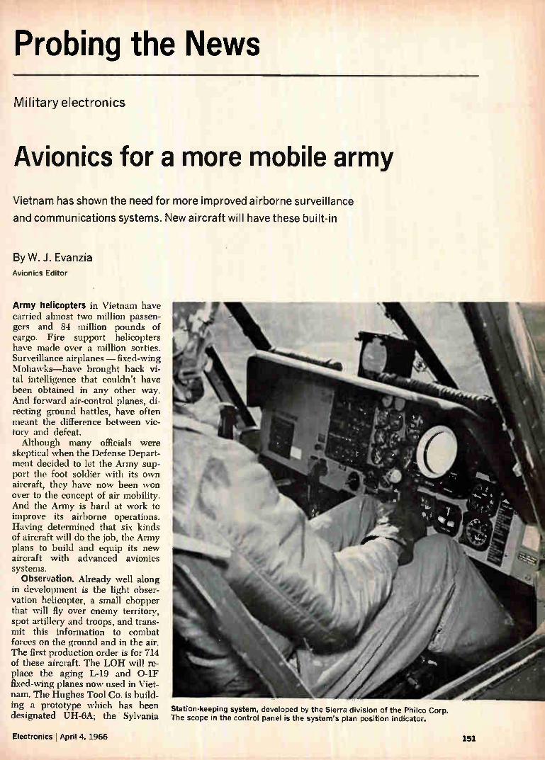
Probing the News
Military electronics
Avionics for a more mobile army
Vietnam has shown the need for more improved airborne surveillance
and communications systems. New aircraft will have these built-in
By W. J. Evanzia Avionics Editor
Army helicopters in Vietnam have carried almost two million passen-gers and 84 million pounds of cargo. Fire support helicopters have made over a million sorties. Surveillance airplanes — fixed-wing Mohawks—have brought back vi-tal intelligence that couldn't have been obtained in any other way. And forward air-control planes, di-recting ground battles, have often meant the difference between vic-tory and defeat. Although many officials were
skeptical when the Defense Depart-ment decided to let the Army sup-port the foot soldier with its own aircraft, they have now been won over to the concept of air mobility. And the Army is hard at work to improve its airborne operations. Having determined that six kinds of aircraft will do the job, the Army plans to build and equip its new aircraft with advanced avionics systems.
Observation. Already well along in development is the light obser-vation helicopter, a small chopper that will fly over enemy territory, spot artillery and troops, and trans-mit this information to combat forces on the ground and in the air. The first production order is for 714 of these aircraft. The LOH will re-place the aging L-19 and 0-1F fixed-wing planes now used in Viet-nam. The Hughes Tool Co. is build-ing a prototype which has been designated UH-6A; the Sylvania The scope in the control panel is the system's plan position indicator.
Station-keeping system, developed by the Sierra division of the Philco Corp.
Electronics , April 4, 1966 151

Electronic Systems division of the General Telephone & Electronics Corp. is working on the avionics package.
Fire-support missions. The ad-vanced airborne fire support system will be the Army's first helicopter specifically designed for fire-sup-port missions. Scheduled to be in the field in 1969, it will replace the UH-1B armed escort helicopter, which was hurriedly outfitted with machine guns and 2.75-mm rocket guns for combat in Vietnam. The Lockheed Aircraft Corp. is devel-oping the prototype airframe. The new helicopter will have the inte-grated helicopter avionics system (IHAS). Although it is being de-veloped by the Navy, the Army is funding 40% of the production con-tract for IHAS avionics.
Surveillance. In the development phase is a surveillance and target acquisition system (Stass) that will replace the hardworking Mohawk which is equipped with side-look-ing radar, infrared, ultraviolet and other detection devices. Stass will be equipped with advanced ver-sions of Mohawk's equipment.
Transport. The Army is not plan-ning to replace its present transport aircraft, but as new avionic sys-tems are developed, planes built within the same time period will utilize them. The Army has divided its rotary-winged transport aircraft into three categories: utility tactical transport, typified by the Bell Heli-copter Co.'s UH-1D Huey; light tactical transport, such as the Vertol division's CH-47A Chinook; and heavy-lift transport helicopters, like the Sikorsky Aircraft division's CH-54 Flying Crane. Sikorsky is a subsidiary of the United Aircraft Corp. and Vertol is a division of the Boeing Co.
I. Light observation helicopter
The prime purpose of the LOH is to provide company commanders with more information. In addition to artillery and troop spotting, the helicopter will be used for radio relays, psychological warfare mis-sions, target marking, flare drop-ping and supply hauling. Although - human eyes, rather than electronic sensors, will do the observing, the helicopter's communications sys-tem will be able to communicate with other supporting aircraft as
well as ground troops. Radio links. Frequency-modu-
lated radio equipment will link the flying observer with infantry, armored and artillery forces; very high frequency and ultrahigh fre-quency amplitude-modulated sets will mesh with supporting Air Force, Navy and Marine aircraft. The helicopter's communications system will also work with radio equipment used by terminal air traffic controllers and ground-based forward air controllers. LOH avionics will not be avail-
able for installation until about the third procurement year of the air-frame, when the Army will decide how many of the operating LOH aircraft will be retrofitted. Until that time, conventional avionic subsystems will be used. The new equipment is much
smaller. In many instances, all of the electronics for the new sets fits into the same space as the old unit's control box. This eliminates the need for bulky cabling and re-duces the failure rate. One set that typifies the new
aircraft's avionics is the AN/ARC-114, a multichannel vhf/f-m trans-ceiver. It weighs only 8 pounds, takes up 150 cubic inches of space and has a power output of 10 watts. The transceiver operates over a frequency range of 30 to 75.95 megacycles with 920 chan-nels spaced every 50 kcs. Because solid state circuitry is used, the mean time between failures is about 1,000 hours. This set is designed to replace the AN/ARC-54 radio, which weighs about 26.5 pounds, is less reliable and takes up about three times the space. The homing capability of the
ARC-115 will enable the LOH to operate efficiently out of jungle air
fields. It uses keyed tactical ground transmitters for orientation.
Smaller transceivers. The AN/ ARC-115, a lightweight vhf/a-m multichannel set with retransmis-sion and homing capability, will replaee the 30-pound AN/ARC-73. This new transceiver, about one-fourth the size of the old one, weighs 10 pounds and has an ef-fective transmitted power output of 10 watts. It covers a frequency band of 116 to 150 Mc in 1,360 distinct channels (channel spacing is 25 kc). LOH's will also carry the AN/
ARC-116, a lightweight uhf/a-m transceiver. Slightly smaller than the ARC-114, it will replace the 38-pound AN/ARC-51 radio and will cover a frequency range of 225 to 399.95 Mc in 3,500 channels (50 kc channel spacing). Army engi-neers are designing a flush-mounted integrated antenna for it. The helicopter will also carry a
five-pound radio receiver—R-1297/ ARC—an auxiliary vhf/f-m radio receiver for voice communications that covers a frequency range of 30 to 75.95 Mc. In addition, the aircraft will have automatic low-frequency, medium-frequency air-borne direction finders. Two models are being produced, one covers a frequency range of 190 to 1,750 kes in three bands: 190 to 412 kc, 410 to 850 kc, and 850 to 1,750 kc. The second model will cover the range from 100 kc to 3,000 kc in four bands. This equipment will be a functional replacement for the present - generation AN/ARN - 59 and AN/ARN-83 directional find-ers. Although the helicopter will not
carry long-range communications systems, a high-frequency, single sideband system will be installed
One multichannel ultrahigh-frequency a-m transceiver the ARC 116, left, replaces LOH's two-part ARC 51 which had a transceiver and a control unit.
192 ri,...4.-nniec I A nril A 1 CIAA
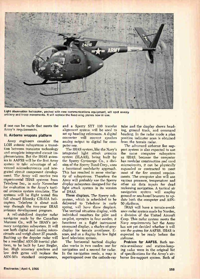
Light observation helicopter, packed with new communications equipment, will spot enemy artillery and troop movements. It will replace the fixed-wing planes now in use.
if one can be made that meets the Army's requirements.
II. Airborne weapons platform
Army engineers consider the LOH avionic subsystems a transi-tion between transistor technology and complete integrated circuit im-plementation. But the IHAS avion-ics in AAFSS will be the first Army system to take advantage of ad-vanced microelectronics and inte-grated circuit component develop-ment. The Army will receive two experimental IHAS systems from Teledyne Inc., in early November for evaluation in the Army's tacti-cal avionics system simulator. The systems will be flight tested this fall aboard Sikorsky CH-53A heli-copters. Teledyne is about mid-way through the two-year IHAS avionics development program. A roll-stabilized doppler radar
navigator made by the Canadian Marconi Co., will be IHAS's pri-mary navigation subsystem. It will use both digital and analog micro-circuits and weigh about 37 pounds. Backing up the doppler radar will be a modified ASN-50 inertial plat-form, to be built by Lear Siegler, Inc. High accuracy synchros and low drift gyros will replace the ASN-50's standard components,
and a Sperry SYT 110 transfer alignment system will be used to set up heading references. A digital converter will convert synchro analog output to digital for com-puter use. The IHAS system, like the Navy's
integrated light attack avionics system (ILAAS), being built by the Sperry Gyroscope Co., a divi-sion of the Sperry Rand Corp., uses a functional modularity approach. This has resulted in some similar-ity of subsystems. Therefore the Army will probably use the Sperry display subsystem designed for the light attack system in its version of IHAS. Three displays. The Sperry sub-
system, which is scheduled to be delivered to Teledyne in early spring, will have three displays. The vertical situation display, with individual monitors for pilot and co-pilot, operates in four modes; it functions as a flight instrument command display, a shades-of-grey display for terrain avoidance, E-scan, and as a display for low light level television system. The horizontal tactical display
also works in two modes: one for navigation and a second for radar. In the navigation mode, a map is superimposed over the cathode-ray
tube and the display shows head-ing, ground track, and command heading. In the radar mode a plan position indicator scan is obtained from the terrain radar. The advanced airborne fire sup-
port system is also expected to use the same computer subsystem as IHAS, because the computer has modular construction and used microcircuits, it can be physically expanded or contracted to meet most of the fire control require-ments. The computer also will use various pressure, temperature and other air data inputs for dead reckoning navigation. A tactical air navigation system will employ ground or sea-based beacons to up-date both the computer and ASN-50 platform. IHAS will have a terrain-avoid-
ance radar system made by Norden, a division of the United Aircraft Corp. This radar system meets the Navy requirements but the Army has not yet decided whether it will use the system for AAFSS. IHAS is expected to be ready before the airframe. . . Problem for AAFSS. Both ter-rain-avoidance and station-keep-ing radar were in the original list of specifications for the Army's air-borne fire-support system. Both of
Electronics April 4, 1966 153
Great editorial is something he takes home (What a climate for selling!)
Electronics it A McGraw-Hill Market-Directed Publication
330 Wed 42nd Street, New York, N.Y. 10038
these control radar systems have advanced rapidly enough to be in-cluded in the prototype aircraft. The Army expects to have opera-tional terrain-avoidance and sta-tion-keeping radars in the late 1960's. According to the Army, the need
for terrain avoidance radar had not been acute until now. But the change in military tactics brought about by Vietnam has made the radar mandatory. Therefore, the Army is investigating terrain-avoid-ance radar systems for both rotary and fixed-wing aircraft. The Army is evaluating the AN/
APN-165 on the Mohawk. But the radar developed by the Air Force for its drone aircraft has thus far failed to meet requirements. So the Army is taking a close look at other systems being developed for its sis-ter services. The Army wants station-keeping
radars to help huge flotillas of helicopters to maintain their rela-tive positions throughout an opera-tion. This would result in greater safety and a more effective con-centration of firepower, say Army tacticians. The Army is interested in both manual and automatic station-keeping systems. Four firms are working on developing them: Teledyne, Inc.; the Sierra division of the PhiIco Corp.; the Lockheed Electronics Co., a division of the Lockheed Aircraft Corp.; and TRG Inc. The Army has bought four sys-
tems from Sierra for evaluation. Engineers at the Avionics Labora-tory are using Sierra's systems to determine the station-keeping re-quirements for the fire-support system. The Sierra SN-64/2A provides
manual and automatic station-keep-ing at ranges from 75 feet to 3 miles (with an expansion capability to 10 miles). It has a range accu-racy of ± 10% and a bearing of accuracy of -±-2°.
But the system does not have the operational capability needed for fire support. Only range and bearing are presented on a plan-position indicator scope, which the Army says is too hard to read. Equally as important as range and bearing, is relative altitude. The Army wants to be able to resolve altitude differences of less than 20 feet.
The Army will also evaluate two Teledyne station-keeping systems. The Navy is now testing early models of the IHAS subsystem at the Naval Air Development Center in Johnsville, Pa., but the Navy's problem is different from the Army's. The Navy can make do with a 500-foot separation between aircraft instead of the Army's 20-foot requirement. Also, the IHAS station-keeper weighs about 85 pounds; the Army's weight limit is about 30 pounds. The Air Force is evaluating a
manual station-keeping system for its C-130 transport aircraft. The C-130's must maintain station at ranges from 2,500 feet to 10 miles.
In the cockpit. The Army has un-der way a program designed to develop cockpit instrumentation to display the information generated by advanced avionics systems such as IHAS. The goal of the program, called the advanced Army aircraft instrumentation system, is to pro-vide equipment that will take over time-consuming cockpit operations such as continuous instrument scan, navigation computation and fuel management. An analog system will be used
to determine the physical and psychological stresses faced by a pilot. The primary displays in the system are a 14-inch vertical situa-tion display which gives the pilot the view below him, and a hori-zontal display which presents the side, front and rear view—all in real time. Inputs into the system could be from television, infrared or other types of scanners.
Transports. The CH-47 Chinooks have become the mainstay of the 1st Air Cavalry Division. They fly an average of 850 missions per day carrying 550 tons of equipment and 1,500 passengers. Avionics for transports like these need not be as sophisticated as those in the fire-support system or as compact as those on the LOU. It is there-fore unlikely that the Army will retrofit any of its transport family with advanced systems. However, as the systems become generally available, certain subsystems will be included in new aircraft.
Ill. Surveillance program
The surveillance and target ac-quisition system is about two years behind the advanced airborne fire-
154 Electronics j April 4, 1966

support system in the Army's time-table. The Army has not chosen either the airframe or the avionic subsystems, although one Army official has said that the. avionics will probably be an optimized mix of the subsystems for the light observation helicopter, the inte-grated helicopter avionics system and the integrated light attack avionics system. However, the surveillance and target acquisi-tion system will have some require-ments that the three other sys-tems cannot now fulfill. Several types of airframes—vertical short take-off and land (V/STOL), STOL. tilt wing, tilt prop and jet aircraft —are all prime candidates for the system. The Research Analysis Corp. in
McLean, Va., is now completing a study of the surveillance concept, including techniques of acquiring surveillance data, the optimum location of the aircraft to the front lines, types of aircraft—VTOL versus conventional or short take-off types—runways and the time required to get collected surveil-lance data to Division or Corps headquarters.
Quite apart from the Research Analysis study is a request for a surveillance program sent in Feb-ruary to the Pentagon by the Com-bat Surveillance and Target Ac-quisition Laboratory of the Army Electronics Command at Fort Monmouth. The Army's Chief of research and development is sched-uled to take action on this request soon. Whatever form the system takes,
its surveillance and data collection equipment will be very different from that which the Mohawk 0V-l's now carry. Lasers and optoelec-tronics will be used extensively and its electronics subsystems will be almost exclusively microminiturized and/or molecularized. Side-looking and forward-looking radar anten-nas will have low silhouettes; some systems will use the aircraft's skin as a radar reflector. Night vision systems—low-light level television and infrared sensors—will be standard equipment. The surveil-lance aircraft of the 1970's also will have new high-speed panchromatic cameras and have on-board photo-processing, recording, pattern rec-ognition and reconnaissance analy-sis equipment
...your assurance of quality
Glass-EIMMI
C01100111Clad
through TAYLOR'S TOTAL RELIABILITY PLAN: Raw materials, panels or punched blanks to your reliability re-quirements. You get what you order from a fully integrated source.
FAST DELIVERY from two fully equipped plants — one at Valley Forge, Pa., the other at La Verne, Calif. Or from ware-houses in Chicago, Ill, and other key locations.
.. STANDARD AND ULTRA-THIN FORMS. Standard sheets in all grades. Ultra-thin sheets and multilayer prepregs in GEC 500 (G-10) and Fireban 600 (G-10, FR-4).
. . . FULL SIZE SHEETS, CUT-TO-SIZE PANELS or PUNCHED BLANKS to satisfy fabricating and processing requirements. Ease of fabrication is a plus value in printed circuit production.
... WHITE GLOVE HAN-DLING in atmosphere-controlled white rooms, careful processing, extremely tight quality control and special packaging assure top performance.
Taylor's copper-clad has proven total reliability demon-strated by an ever increasing number of major OEM's and commercial etchers. This acceptance substantiates our claim for unsurpassed quality, ease of fabrication and delivery to your scheduled requirements. Let us demonstrate this relia-bility to you. Ask for a sample (give grade designation and copper combination) and a copy of Bulletin GB-2.
--ereor copper-clad TAYLOR CORPORATION • Valley Forge, Pa. 19481
Phone: 215-666-0300 TWX: 215-666-0659
West Coast Plant: La Verne, Calif.
Also manufacturer of Taylor laminated plastics, Taylorite® vulcanized fibre and Tayloron0 prepregs
Electronics l April 4, 1966 Circle 155 on reader service card 155
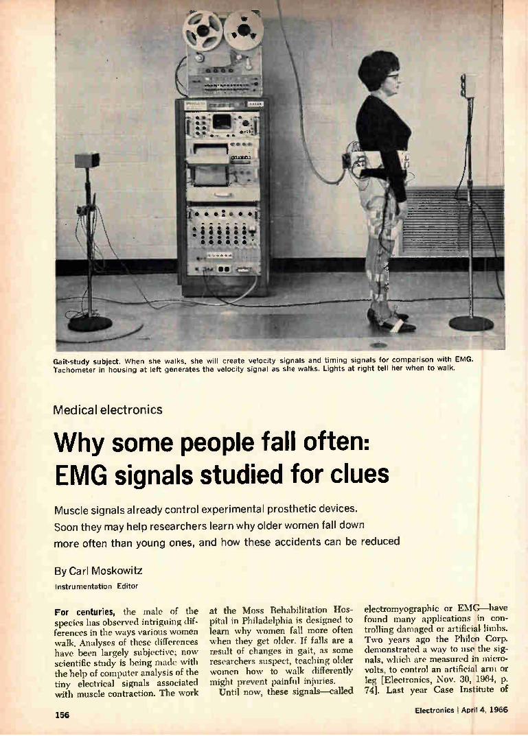
Gait-study subject. When she walks, she will create velocity signals and timing signals for comparison with EMG. Tachometer in housing at left generates the velocity signal as she walks. Lights at right tell her when to walk.
Medical electronics
Why some people fall often: EMG signals studied for clues Muscle signals already control experimental prosthetic devices.
Soon they may help researchers learn why older women fall down
more often than young ones, and how these accidents can be reduced
By Carl Moskowitz
Instrumentation Editor
For centuries, the male of the species has observed intriguing dif-ferences in the ways various women walk. Analyses of these differences have been largely subjective; now scientific study is being made with the help of computer analysis of the tiny electrical signals associated with muscle contraction. The work
at the Moss Rehabilitation Hos-pital in Philadelphia is designed to learn why women fall more often when they get older. If falls are a result of changes in gait, as some researchers suspect, teaching older women how to walk differently might prevent painful injuries.
Until now, these signals—called
electromyographic or EMG—have found many applications in con-trolling damaged or artificial limbs. Two years ago the Philco Corp. demonstrated a way to use the sig-nals, which are measured in micro-volts, to control an artificial arm or leg [Electronics, Nov. 30, 1964, p. 74]. Last year Case Institute of
156 Electronics I Apo« 4, 1966

When you look at electronic components are you seeing only half the picture?
We're the last people to argue with component purchasers who put performance, price and delivery first — meeting these three basic requirements is what keeps us in business. But most en-gineers are also on the lookout for something more, and many of them find it at Mullard. Take research and development for instance. Out of Mullard R&D have come outstanding devices such as the travelling wave tubes for the New York — San Francisco and Montreal — Vancouver microwave links. Production resources? Mullard
DIODES • TRANSISTORS • PHOTO-DEVICES AND RADIATION DETECTORS •
RECTIFIER DIODES AND STACKS • THYRISTORS AND STACKS • INTEGRATED
CIRCUITS • CATHODE RAY TUBES • RECEIVING TUBES • ELECTRON OPTICAL
DEVICES • PHOTOSENSITIVE DEVICES • COLD CATHODE DEVICES • POWER
DEVICES • TRANSMITTING TUBES • MICROWAVE DEVICES • CAPACITORS •
FERRITE MATERIALS AND ASSEMBLIES • COMPUTER COMPONENTS AND
ASSEMBLIES • MAGNETIC MATERIALS •SPECIAL PURPOSE MAGNETS• VACUUM
DEVICES • WOUND COMPONENTS.
plants are among the most efficient anywhere, with a reputation for the production of tight-tolerance devices to proved standards of reliability. As for circuit know-how, Mullard has the best equipped applications laboratories in Britain. And when it comes to technical services, you will find that Mullard provides the kind of comprehensive performance specs, survey documents and application reports that are just that much more useful. If you want to get the whole picture, why not ask us to help you with some of your component problems ?
where the product is only part of the deal MULLARD LIMITED • TORRINGTON PLACE • LONDON WCI • ENGLAND
Circle 157 on reader service card MU6
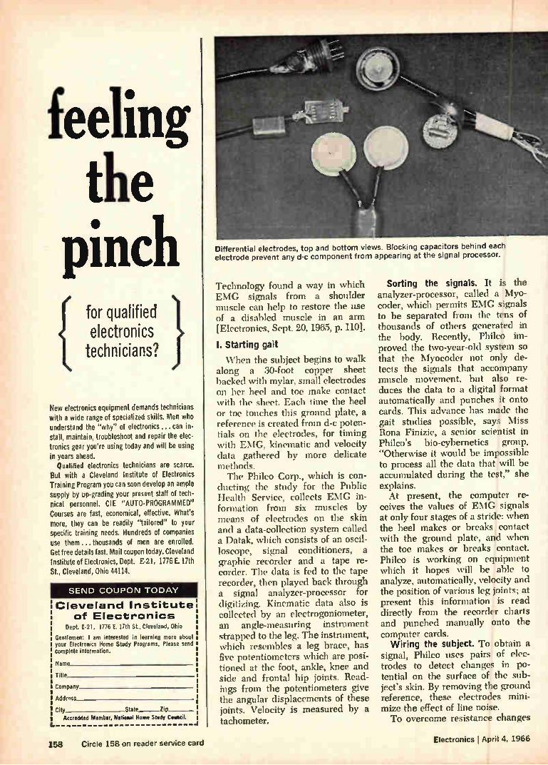
feeling the
pinch
1 for qualified electronics technicians?
New electronics equipment demands technicians with a wide range of specialized skills. Men who understand the "why" of electronics... can in-stall, maintain, troubleshoot and repair the elec-tronics gear you're using today and will be using in years ahead.
Qualified electronics technicians are scarce. But with a Cleveland Institute of Electronics Training Program you can soon develop an ample supply by up-grading your present staff of tech-nical personnel. CIE "AUTO-PROGRAMMED" Courses are fast, economical, effective. What's more, they can be readily "tailored" to your specific training needs. Hundreds of companies use them ...thousands of men are enrolled. Get free details fast. Mail coupon today. Cleveland Institute of Electronics, Dept. E-21, 1776 E. 17th Gt., Cleveland, Ohio 44114.
SEND COUPON TODAY
Cleveland Institute of Electronics
Dept E-21, 1776 E. 17th St., Cleveland, Ohio Gentlemen: I am interested in learning more about your Electronics Home Study Programs. Please send complete information.
Name
Title
Company
Address
City State Zip
Accredited Member, National Home Study Council.
Differential electrodes, top and bottom views. Blocking capacitors behind each electrode prevent any d-c component from appearing at the signal processor.
Technology found a way in which EMG signals from a shoulder muscle can help to restore the use of a disabled muscle in an arm [Electronics. Sept. 20, 1965, p. 110].
I. Starting gait
When the subject begins to walk along a 30-foot copper sheet backed with mylar, small electrodes on her heel and toe make contact with the sheet. Each time the heel or toe touches this ground plate, a reference is created from d-c poten-tials on the electrodes, for timing with EMG, kinematic and velocity data gathered by more delicate methods. The Philco Corp., which is con-
ducting the study for the Public Health Service, collects EMG in-formation from six muscles by means of electrodes on the skin and a data-collection system called a Datak, which consists of an oscil-loscope, signal conditioners, a graphic recorder and a tape re-corder. The data is fed to the tape recorder, then played back through a signal analyzer-processor for digitizing. Kinematic data also is collected by an electrogoniometer, an angle-measuring instrument strapped to the leg. The instrument, which resembles a leg brace, has five potentiometers which are posi-tioned at the foot, ankle, knee and side and frontal hip joints. Read-ings from the potentiometers give the angular displacements of these joints. Velocity is measured by a tachometer.
Sorting the signals. It is the analyzer-processor, called a Myo-coder, which permits EMG signals to be separated from the tens of thousands of others generated in the body. Recently, Philco im-proved the two-year-old system so that the Myocoder not only de-tects the signals that accompany muscle movement, but also re-duces the data to a digital format automatically and punches it onto cards. This advance has made the gait studies possible, says Miss Rona Finizie, a senior scientist in Philco's bio-cybernetics group. "Otherwise it would be impossible to process all the data that will be accumulated during the test," she explains. At present, the computer re-
ceives the values of EMG signals at only four stages of a stride: when the heel makes or breaks contact with the ground plate, and when the toe makes or breaks contact. Philco is working on equipment which it hopes will be able to analyze, automatically, velocity and the position of various leg joints; at present this information is read directly from the recorder charts and punched manually onto the computer cards. Wiring the subject. To obtain a
signal, Philco uses pairs of elec-trodes to detect changes in po-tential on the surface of the sub-ject's skin. By removing the ground reference, these electrodes mini-mize the effect of line noise. To overcome resistance changes
158 Circle 158 on reader service card Electronics April 4, 1966

between skin and electrode, caused by shifting of the contact as the subject walks, electrodes had to be designed with input impedance high enough to overcome the effect of the changes on the signals. To solve the impedance problem, Philco chose a microminiature am-plifier with an emitter-follower first stage. Besides providing the neces-sary high-input impedance, this amplifier boosts the EMG signal to a level that overcomes the at-• tenuation caused by the long cable that connects the subject to the data-collection system. Another net-work on each electrode prevents any d-c portion of the EMG signal from passing through to the proc-essing equipment.
II. Before the countdown
The time required to get a sub-ject ready for a test still has to be reduced. She must stand on a raised platform for about an hour; first the electrogoniometer is strapped in place, with each potentiometer adjusted to make sure it is at ex-actly the right spot. When all the instruments are in place, they are checked out; while the subject walks about 10 feet, the instruments indicate the level of her EMG sig-nals, and the Datak operator sets the attenuation levels of the 12 data channels accordingly. For the study, data from 200
women over 65 years of age will be compared with data from a control group of 35 women of 18 to 25. Beyond the Philadelphia project,
broader applications are envisioned for Philco's approach to the study of electromyographic signals. Walter Wasserman, director of the company's biomedical development laboratory, sees it helping in the design of automobile seats by studying driver fatigue. He notes that some researchers believe that tired muscles may exhibit differ-ences in their EMG patterns. If this is true, changes in the levels of an individual's EMG signals may pro-vide a measure of his fatigue as he sits behind the steering wheel hour after hour. EMG is also the subject of an-
other Philco study whose goal is to learn whether electromechanical machinery for automobile assembly plants could be designed more efficiently if their motions followed those of human limbs more closely.
There is a single source for all oscillographic paper and chemical needs
The place is CEC
Today, the broad spectrum of oscillo-
graphy covers twelve different papers and chemicals. You are probably using some of these CEC products now. How-
ever, since there are important differ-ences between them, we'd like you to meet the entire family.
DATACOLOR 88. A two-color red and cyan emulsion paper which produces oscillograph records in distinctly differ-ent hues for rapid and positive trace iden-tification.
DATAFLASH 55. The extreme sensitiv-ity of this paper now makes it possible to obtain perfect oscillograph records at writing speeds in excess of 75,000 ips.
DATAFLASH 56. A high writing speed product which produces superb traces, timing, and grid lines where Xenon lamps are used.
DATAFLASH 57. High writing speed Dataflash 57 features a "develop-out" op-tion for oscillograms of archival quality.
DATATRACE 11 & 31. Heat sensitive recording papers for use with CEC's DG-5511 Portable Two-Channel Thermal Writing Recorder. High contrast or repro-duceable types are available.
DATARITE 33. DATARITE refers to CEC's Datarite Magazine in which oscil-lograms are automatically developed and dried as quickly as data is recorded. DATARITE 33 is ideal for high writing speed applications.
DATARITE 22. Type 22 has less sensi-tive emulsion than Type 33. At low writ-ing speeds, it will give excellent oscillo-grams.
Type 49943-3 Datarite Developer Solu-tion is a non-ammonia, general purpose formula which provides exceptionally high trace contrast and high writing speed capability.
Type 49943-4 Datarite Developer Solu-tion is an ammonia-type formula which combines high writing speeds with re-duced paper staining in high humidity en-vironments.
Hi-Speed Chemical Kit — No. 217050. Designed for use in CEC's new 23-109B and 23-109A Processors. Easily capable of processing more than 1500 square feet of oscillographic paper without replenish-ment, it's the logical choice where numer-ous rolls of recorded material must be processed.
Liquid Concentrate Chemical Kit — No. 145455. The "economy" package for use with the 23-109A. Processes up to 500 square feet of paper, on an intermit-tent basis, thereby avoiding costly waste of solutions.
For further information about CEC oscillographic papers and chemicals,
call or write for CEC Bulletin Kit 9053-X2.
cec Data Instruments Division
CONSOLIDATED ELECTRODYNAMICS A SUBSIDIARY OF BELL & HOWELL/PASADENA, CALIF. 91109
INTERNATIONAL SUBSIDIARIES: WOKING. SURREY. ENGLAND
AND FRIEDBERG (HESSEN), W. GERMANY
Electronics I April 4, 1966 Circle 159 on reader service card 159

How many MATCHED radar channels?
Build all you need with LK& Gain and Phase Matched Amplifiers and Mating Mixer-Preamplifiers
. () . - hlaasiell hi" ell hie efi
. ell se nase
imuminek, . x 'I . 'en hase nase
LEL 2- or 3-Channel matched post amplifier units offer superior performance over the widest range of gain control. They're ideal for use in monopulse radar applications. In such an application you can
Mixer. Preamplifiers
Signal Input 3.95 to 5.85 Ghzt IF Center Frequency 30, 60 or 70 Mhz Bandwidth (3 db) 25 Mhz Gain (RF to IF) 20 db Gain Reduction 20 db Maximum RF Input Signal for
Linear Output —20 dbm Output Impedance 50 ohms Noise Figure as low as 7.5 db Power Required —20 VDC Phase Tracking (as compared to
another similar unit operated off a common AGC bias) 2* (max)
Gain Tracking (as compared to another similar unit operated off a common AGC bias) 1 db (max)
Chassis Adjustments Phase Trim and Gain Trim
136 ranges available between 0.1 and 40 Ghz.
also build with LEL's monopulse comparators, matched mixer-preamplifiers and appropriate LEL-LINE strip components now available up through Ku Band. Send for LEL's new catalog now.
Dual Channel Amplifier
Center Frequency 30, 60 or 70 Mhz Bandwidth (3 db) 10 Mhz Gain (IF) 65 db Gain Reduction 40 db (min)
+10 dbm Max. Output Signal for
Linear Operation Max. Input Signal for
Linear Operation —15 dbm Input Impedance 50 ohms Output Impedance 50 ohms Power Required 160 ma @ —20 VDC
AGC: 0 to +10 VDC Phase Match 2.5° (max)* Gain Match 1.0 db (max)* Dimensions 7" Lx 11/4 " El x 21/2 "W Weight 11/4 lb. max Chassis Adjustments Gain and Phase Trim
Triple Channel Amplifier
Center Frequency 30, 60 or 70 Mhz Bandwidth (3 db) 10 Mhz Gain (IF) 65 db Gain Reduction 40 db (min) Max. Output Signal for
Linear Operation +10 dbm Max. Input Signal for
Linear Operation —15 dbm Input Impedance 50 ohms Output Impedance 50 ohms Power Required 240 ma @ —20 VDC
AGC: 0 to +10 VDC Phase Match 3.5° (max)* Gain Match 1.5 db (max)* Dimensions 7" I. x 11/2 " H x 33/4 " W Weight 2 lb. max Chassis Adjustments Gain and Phase Trim
*These data are maximum variations within temperature range of —50°C to +75°C and over the full specified gain control range, for a signal spectrum greater than 60% of the IF bandwidth.
Arm -e. DIVISION AKRON STREET, COPIAGUE, L. I., NEW YORK 1 1726
(516) AMityville 4-2200 / (516) PYramid 9-8200 / TWX Code 516-691-5085 VARIAN ea sectatee
160 Circle 160 on reader service card Electronics April 4, 1966
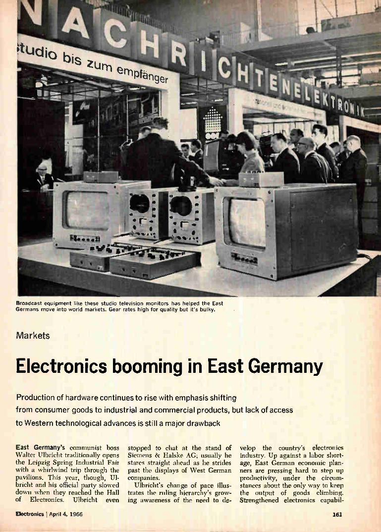
nucjio bis zurn e
I • r"-rhi
Broadcast equipment like these studio television monitors has helped the East Germans move into world markets. Gear rates high for quality but it's bulky.
Markets
Electronics booming in East Germany
Production of hardware continues to rise with emphasis shifting
from consumer goods to industrial and commercial products, but lack of access
to Western technological advances is still a major drawback
East Germany's communist boss Walter Ulbricht traditionally opens the Leipzig Spring Industrial Fair with a whirlwind trip through the pavilions. This year, though, Ul-bricht and his official party slowed down when they reached the Hall of Electronics. Ulbricht even
stopped to chat at the stand of Siemens & Ilalske AG; usually he stares straight ahead as he strides past the displays of West German companies.
Ulbricht's change of pace illus-trates the ruling hierarchy's grow-ing awareness of the need to de-
velop the country's electronics industry. Up against a labor short-age, East German economic plan-ners are pressing hard to step up productivity, under the circum-stances about the only way to keep the output of goods climbing. Strengthened electronics capabil-
Electronics !April 4, 1966 161
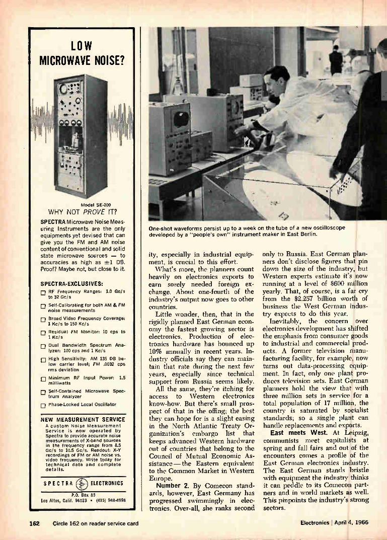
LOW MICROWAVE NOISE?
Model SE-200
WHY NOT PROVE IT?
SPECTRA Microwave Noise Meas-uring Instruments are the only equipments yet devised that can give you the FM and AM noise content of conventional and solid state microwave sources — to accuracies as high as 2-21 DB. Proof? Maybe not, but close to it.
SPECTRA-EXCLUSIVES: E RF Frequency Ranges: 1.0 Gc/s
to 32 Gc/s
u Self-Calibrating for both AM & FM noise measurements
• Broad Video Frequency Coverage: 1 Kc/s to 150 Kc/s
E Residual FM Monitor: 10 cps to 1 Kc/s
u Dual Bandwidth Spectrum Ana-lyzer: 100 cps and 1 Kc, s
E High Sensitivity: AM 135 DB be-low carrier level; FM .0032 cps rms deviation
E Minimum RF Input Power: 1.5 milliwatts
D Self-Contained Microwave Spec-trum Analyzer
• Phase-Locked Local Oscillator
NEW MEASUREMENT SERVICE A custom Noise Measurement Service is now operated by Spectra to provide accurate noise measurements of X-band sources in the frequency range from 8.5 Gc/s to 10.5 Cc's. Readout: X-Y recordings of FM or AM noise vs. video frequency. Write today for technical data and complete details.
SPECTRA ELECTRONICS
P.O. Box 85 Los Altos, Calif. 94023 • (415) 948-4998
One-shot waveforms persist up to a week on the tube of a new oscilloscope developed by a "people's own" instrument maker in East Berlin.
ity, especially in industrial equip-ment, is crucial to this effort. What's more, the planners count
heavily on electronics exports to earn sorely needed foreign ex-change. About one-fourth of the industry's output now goes to other countries.
Little wonder, then, that in the rigidly planned East German econ-omy the fastest growing sector is electronics. Production of elec-tronics hardware has bounced up 10% annually in recent years. In-dustry officials say they can main-tain that rate during the next few years, especially since technical support from Russia seems likely.
All the same, they're itching for access to Western electronics know-how. But there's small pros-pect of that in the offing; the best they can hope for is a slight easing in the North Atlantic Treaty Or-ganization's embargo list that keeps advanced Western hardware out of countries that belong to the Council of Mutual Economic As-sistance— the Eastern equivalent to the Common Market in Western Europe. Number 2. By Comecon stand-
ards, however, East Germany has progressed swimmingly in elec-tronics. Over-all, she ranks second
only to Russia. East German plan-ners don't disclose figures that pin down the size of the industry, but Western experts estimate it's now running at a level of $600 million yearly. That, of course, is a far cry from the $2.257 billion worth of business the West German indus-try expects to do this year.
Inevitably, the concern over electronics development has shifted the emphasis from consumer goods to industrial and commercial prod-ucts. A former television manu-facturing facility, for example, now turns out data-processing equip-ment. In fact, only one plant pro-duces television sets. East German planners hold the view that with three million sets in service for a total population of 17 million, the country is saturated by socialist standards; so a single plant can handle replacements and exports.
East meets West. At Leipzig, communists meet capitalists at spring and fall fairs and out of the encounters comes a profile of the East German electronics industry. The East German stands bristle with equipment the industry thinks it can peddle to its Comecon part-ners and in world markets as well. This pinpoints the industry's strong sectors.
162 Circle 162 on reader service card Electronics I April 4, 1966
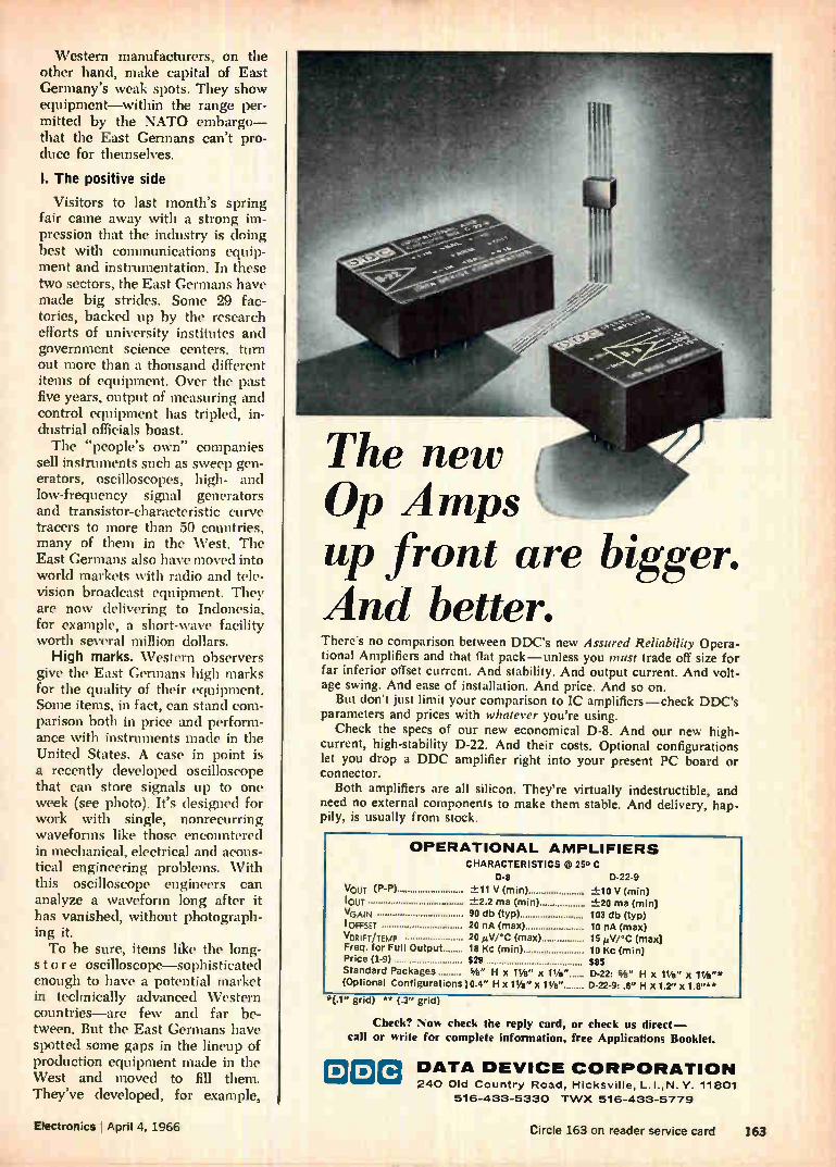
Western manufacturers, on the other hand, make capital of East Germany's weak spots. They show equipment—within the range per-mitted by the NATO embargo— that the East Germans can't pro-duce for themselves.
I. The positive side
Visitors to last month's spring fair came away with a strong im-pression that the industry is doing best with communications equip-ment and instrumentation. In these two sectors, the East Germans have made big strides. Some 29 fac-tories, backed up by the research efforts of university institutes and government science centers, turn out more than a thousand different items of equipment. Over the past five years, output of measuring and control equipment has tripled, in-dustrial officials boast. The "people's own" companies
sell instruments such as sweep gen-erators, oscilloscopes, high- and low-frequency signal generators and transistor-characteristic curve tracers to more than 50 countries, many of them in the West. The East Germans also have moved into world markets with radio and tele-vision broadcast equipment. They are now delivering to Indonesia, for example, a short-wave facility worth several million dollars.
High marks. Western observers give the East Germans high marks for the quality of their equipment. Some items, in fact, can stand com-parison both in price and perform-ance with instruments made in the United States. A case in point is a recently developed oscilloscope that can store signals up to one week (see photo). It's designed for work with single, nonrecurring waveforms like those encountered in mechanical, electrical and acous-tical engineering problems. With this oscilloscope engineers can analyze a waveform long after it has vanished, without photograph-ing it. To be sure, items like the long-
stor e oscilloscope—sophisticated enough to have a potential market in technically advanced Western countries—are few and far be-tween. But the East Germans have spotted some gaps in the lineup of production equipment made in the West and moved to fill them. They've developed, for example,
The new Op Amps up front are bigger. And better. There's no comparison between DDC's new Assured Reliability Opera-tional Amplifiers and that flat pack—unless you must trade off size for far inferior offset current. And stability. And output current. And volt-age swing. And ease of installation. And price. And so on.
But don't just limit your comparison to IC amplifiers—check DDC's parameters and prices with whatever you're using.
Check the specs of our new economical D-8. And our new high-current, high-stability D-22. And their costs. Optional configurations let you drop a DDC amplifier right into your present PC board or connector.
Both amplifiers are all silicon. They're virtually indestructible, and need no external components to make them stable. And delivery, hap-. pily, is usually from stock.
OPERATIONAL AMPLIFIERS CHARACTERISTICS @ 25° C
134 D-22-9 VouT (P43) ±11 V (min) +10 V (min) 'OUT +2.2 ma (mm) +20 ma (min) VGAIN 90 db (typ) 103 db (typ) 'OFFSET 20 nA (max) 10 nA (max) VORIFTiTEMP 20 ihV/"C (max) 15 Aiv/°c (max) Freq. or Full Output 18 Kc (min) 10 Kc (min) Price (1-9) $28 $85
Standard Packages 3/4 " H x Pk" X 1W' D-22: We" H x 11/2 " X 1¼"* (Optional Configurations) 0.4" H x 11/a" x Ws" D-22-9: .8" H x 1.2"x 1.8"**
"(.1" grid) ** (.3" grid)
Check? Now check the reply card, or check us direct—
call or write for complete information, free Applications Booklet.
o DATA DEVICE CORPORATION 240 Old Country Road, Hicksville, L.I.,N. Y. 11801
516-433-5330 TWX 516-433-5779
Electronics I April 4, 1966 Circle 163 on reader service card 163
When 'Voter Specifications¡
• HIGH INITIAL TORQUE
• FLEXIBLE SPEEDS
• CONTINUOUS USE
• RESISTANCE TO HEAT OR COLD
turn the job over to, SYNCHRON® MOTORSf No matter whether you need a motor that can "do tricks" or handle simple routine work, think of a SYNCHRON Motor first. Here at Hansen Manufac-turing Co., we've helped designers and production people solve problems rang-ing from unusual cycling patterns, to meeting swiftly varying temperatures, and a hundred other special applica-tions. And of course we've supplied in-dustry with literally millions of motors for uncomplicated designs. We can help you, too; write or phone us!
HANSEN MANUFACTURING COMPANY, INC.
PRINCETON,
INDIANA
HANSEN REPRESENTATIVES: CAREY 8. ASSOCI-ATES, Houston, Tex., R. S. HOPKINS CO., Sher-man Oaks, Calif., MELCHIOR 8. MACPHERSON, INC., San Carlos, Calif., THE FROMM CO., Chi-cago, III., H. C. JOHNSON AGENCY, INC., Rochester, N. Y., WINSLOW ELECTRIC CO., Es-sex, Conn., Narberth, Pa., and New York, N. Y. EXPORT DEPARTMENT, 64-14 Woodside Ave., Woodside, N. Y.
automatic stator-winding machines, program-controlled equipment for forming wiring harnessess, and computer-controlled resistor-malc-ing machines. Another sector where the indus-
try is going full steam ahead is shipboard equipment. Despite a dearth of advanced devices, East German engineers have managed to develop complete navigational radar systems, automatic ship-con-trol equipment, cargo handling equipment, ultrasonic fish spotters, and communications gear. The thriving East-German shipbuild-ing industry supplies completely equipped vessels to both Western and Eastern countries.
Office equipment, too, is a main-stay of East German electronics. The annual output is estimated at close to $100 million. Soemtron, Ascota and Optima electronic cal-culating and invoicing machines are exported to some 80 countries including the United States. The Soemtron 220 shows how
far along the East Germans are with small electronic desk-top cal-culators. This machine can add, subtract, multiply, divide or raise to powers 15-digit numbers at an average speed of 0.5 second. VEB Büromaschinenwerkc Soemmerda, the largest office-machine manu-facturer in the country, sells the calculator for about $2,250. The VEB in the firm's name is the acronym for "people's own factory" in German.
II. Where they lag
Although it has done well with small office machines, the East German industry has a lot of catch-ing up to do in computers. It has developed a small computer and made much of it last spring at the Leipzig fair. But mass production won't start until later this year.
This state of affairs leaves the industry far behind neighboring Poland and hopelessly outdistanced by West Germany and the United States. Along with high-quality solid state components, medium and large computers at the moment are a leading market for outsiders in the country. Reiner Staehr, dep-uty director of the industry asso-ciation for data-processing equip-ment, says East Germany needs at least 10 complete installations in the large-machine category. All will
have to be imported. The need for medium computers
is even greater. Hundreds, plan-ners say, are required to push in-dustrialization of the country. But Staehr hopes much of the demand can be met in the future by the industry.
Kingpin. To that end, the East Germans have developed the Robo-tron 300. The machine presumably will be a kingpin attraction at next fall's Leipzig fair. Officials hint it will be unveiled then. They say it will be three times as fast as its predecessor, the Robotron 100, which has serial addition and sub-traction time of 0.5 millisecond. The Robotron 300, then, will be
comparable to the Siemens 3003 computer, made by Siemens & Halske of West Germany. Until the Robotrons start coming off the pro-duction line, though, Siemens can almost surely count on more orders for its 3003 model; one already is installed in a warehouse in Leipzig. One computer East Germany will
have in production later this year is a small machine for scientific problems and statistical applica-tions. It's called the Cellatron SER 2c and sells in the $16,000 to $20,-000 range. Büromaschinenwerke AC of Zella-Mehlis makes it. For their money, buyers get a
punched-tape controlled machine with addition and subtraction time —without address—of 2.5 millisec-onds. With an address, the same operations take 50 milliseconds. Speeds for multiplication and divi-sion, with or without address, are 140 and 180 seconds, respectively. The memory is a magnetic drum with access time of 11 seconds. On the heels of the Cellatron
SER 2c will come the Cellatron D4a intended for administration, industrial, and scientific applica-tions. It has a maximum computing speed of 2,400 operations per sec-ond. This machine sells for $22,500 to $30,000, depending on peripheral equipment.
Semiconductor woes. The East Germans can make the conven-tional components and the memory devices for these small computers, but they have to buy high-quality transistors and diodes outside the country. Chief suppliers are Rus-sia, West Germany and Japan.
This dependence on foreign im-ports points up one of the sore
164 Circle 164 on reader service card Electronics I April 4, 1966

kv
nts from 50 cps
ta from 100 ohms
'election of all
measurements.
'minimizes
re, 200 3-wire
Its for group
es input cabling.
h. S .. si
11111
estim tria iota. :1
APPLICATION
Dytnec Data Acquisition Systems aj.e
measure analog data derived tram ,48111at ler P•doec data sources, and to display and record ,,.,:lab,: •
tion in digital lOrnt To Present tie." formation in its most useful atectuni. Petceibl 1 available with a cholce fa ,...,
, wilao-fgo oes, For direct reacting by the
, th Iper.i'te. ' - •.i‘put ce,,,en,,tett , i
Ire* di" ad cards, or digital Magnetic -tar.:
out n paper tape Is PrOYlideit e data la to be entered lnm tbe
ate.
may be recorded on punched mb,, ,,
_ Craw:
(Pagó ma, Road, Pate Alto. Crew** 44.306 Ate* Cod. III 4261,66
Route Otto Aeneas. Otteasea. Seetten.Att pit-
";
...Just turn to an hp Data Sheet! Feature 2013 Seri«
(economy) 2010 Series
(noise rejection) 2015 Series
(sneer', accuracy) 2017 Series
(readout In env. units)
Number of Input Channels
25 (2-wire) or 50 11-wire) 2013 A-0
25 (3-wire) expansible to 100 20108, B, E, H
25 13-wire) expansible to 100 2015A, B, E, H
25 (3-wire) expans,ble to 100 2017A, B. E, H
25 (3-wire) expansible to 100 2013 J-M
200 (3-wire) or 100 (6-wire)
2010C, D, F, J
200 (3-wire) or 100 (6-wire)
20150, 13, FA
. 200 (3 wire) or 100 (6-wire)
2017C, D, F, J
Newt
Noise Rejection
ECPAR
30 dB at 60 cis (filter) inf. at 60 c/ s (integrating) inf. at 60 c/S
20 ilb min. all freq. (integrating)
At least 105 dB, all frequencies (floating)
DC Voltage
Range 10, 100, 1000 V. fo 0.1, 1, 10, 100,
MOO V. fs 1, 10, 100, 1000 V. fa 0.1, 1, 10, 100,
1000 V. Is
Resolution (rnV/ digit)
100 ,.V 10 ,,v with amplifier
1,Ar standard 0,1 eV with amplifier 10,01 1 eV standee
0.1 eV with amplifier
Accuracy 1% rotor) .05% .015% .005% 015%
Max. Speed, Readings/Sec,
DC Volts 1.7 (4 digits)
18 (3 digits) 7 (4 digits) 1 (5 digits)
12 (5 digits) 18 (3 digits) 7 (4 digits) 1(5 digits)
Optional Measurement Capability
AC voltage, resStance, dc current
AC voltage, resistance frequency is standard) AC voltage, resistance AC voltage, resistance
(frequency is standard)
Programming standard with DY-2901A; add DV-2911C or DY-2560A With US-2911
Trees of Output Recording
Printed strip, typewriter, punched tape, cards
Printed paper strip, perforated tape, punched card (IBM 526) magnetic tape
Price Range (Basic System) $4495 - $6000
. $8310 - $18,550 $8160 - $18,400 $10,960 - $21,200
Data subject to change without notice. Prices f.o.b. factory.
If you have a data acquisition application, just call your Hewlett-Packard field engineer for a solution . .. from a data sheet. Dymec Division offers 32 basic configurations of standard medium-speed systems, one of which is sure to solve the problem. They're completely spec'd, field proved, right off a production line (without special engi-neering)—and the economy of "off-the-shelf" delivery is passed along to you.
The four basic lines of systems are briefly specified in the chart. They differ primarily in the basic measuring instrument, and each series offers a wide variety of meas-uring parameters and an equally wide assortment of recorded outputs, including printed paper tape, perfor-ated tape, punched card, magnetic tape and typewritten record.
For accurate measurement of low-level signals, espe-cially in the presence of noise problems, look at the 2010 Series. For economical systems, offering a wide variety of voltmeter plug-in capabilities, the 2013 Series. High-speed, high-accuracy data acquisition can be solved by the 2015 Systems, while data acquisition from transducers with readout in engineering units (i.e., psi, rpm, °C or F) at the time of measurement is possible with the 2017 Series.
Complete information is available (on data sheets) from your Hewlett-Packard field engineer. Or write Hewlett-Packard, Dymec Division, 395 Page Mill Road, Palo Alto, California 94306, Tel. (415) 326-1755; Europe: 54 Route des Acacias, Geneva.
HEWLETTS PACKARD DYME C
DIVISION Electronics I April 4, 1966 Circle 165 on reader service card 165
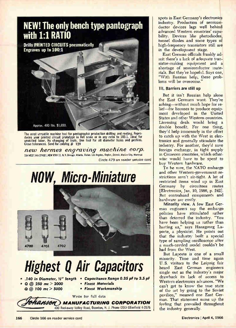
NEW! The only bench type pantograph with 1:1 RATIO Drills PRINTED CIRCUITS pneumatically Engraves up to 100:1
Approx. 400 lbs. $1,650.
The most versatile machine tool for pantographic production drilling and routing. Repro-duces your printed circuit prototype in full scale or in any ratio to 100:1. Ideal for unskilled labor. No changing of tools. One tool for all diameter holes and profiles. Close tolerances. Send for catalog # 139
new hermes engraving machine corp. 154 WEST 14th STREET, NEW YORK 11, N. Y. Chicago. Atlanta, Dallas. Los Angeles, Dayton, Detroit. Mexico City, Montreal
Circle 479 on reader service card
NOW, Micro-Miniature
Highest Q Air Capacitors • .140 in Diameter, !í" length • Capacitance Range 0.35 pf to 3.5 pF
• Q @ 250 mc > 2000 • Finest Materials
CI @ 100 mc > 5000 • Finest Workmanship
‘Yrite for full data
Cr/Oltailefeb MANUFACTURING CORPORATION 400 Rockaway Valley Road, Boonton, N. J. Phone (201) DEerfield 4-2676
spots in East Germany's electronics industry. Production of semicon-ductor devices lags well behind advanced Western countries' capa-bility. Devices like photodiodes, tunnel diodes and some types of high-frequency transistors still are in the development stage.
East German officials frankly ad-mit there's a lack of adequate tran-sistor-making equipment and a shortage of semiconductor mate-rials. But they're hopeful. Says one, "With Russian help, these prob-lems will be overcome."
Ill. Barriers are still up
But it isn't Russian help alone the East Germans want. They're aching—without much hope for re-lief—for licenses to produce equip-ment developed in the United States and other Western countries. Licensing deals would bring a double benefit. For one thing, they'd help immensely in the effort to catch up with the West in elec-tronics and generally stimulate the industry. For another, they'd save foreign exchange, in tight supply in Comecon countries, which other-wise would have to be spent to buy Western hardware. To be sure, the NATO embargo
and other Western-government re-strictions aren't air-tight. A lot of restricted items wind up in East Germany by circuitous routes [Electronics, Jan. 10, 1966, p. 242]. But contraband components and hardware are costly.
Minority view. A few East Ger-man engineers say the embargo policies have stimulated rather than deterred the industry. "You have been helping us rather than hurting us," says Hansgeorg La-porte, a physicist. He points out that the industry built a special type of sampling oscilloscope after a much-needed model couldn't be had from the West.
But Laporte is one of a small minority. Time and time again U. S. visitors to the Leipzig fair heard East German engineers single out as the industry's major drawback its lack of access to Western electronics advances. "We can't get to know the true state of the art by going to the Soviet pavilion," moaned one East Ger-man. That statement sums up the feeling that prevailed throughout the industry generally.
166 Circle 166 on reader service card Electronics I April 4, 1966
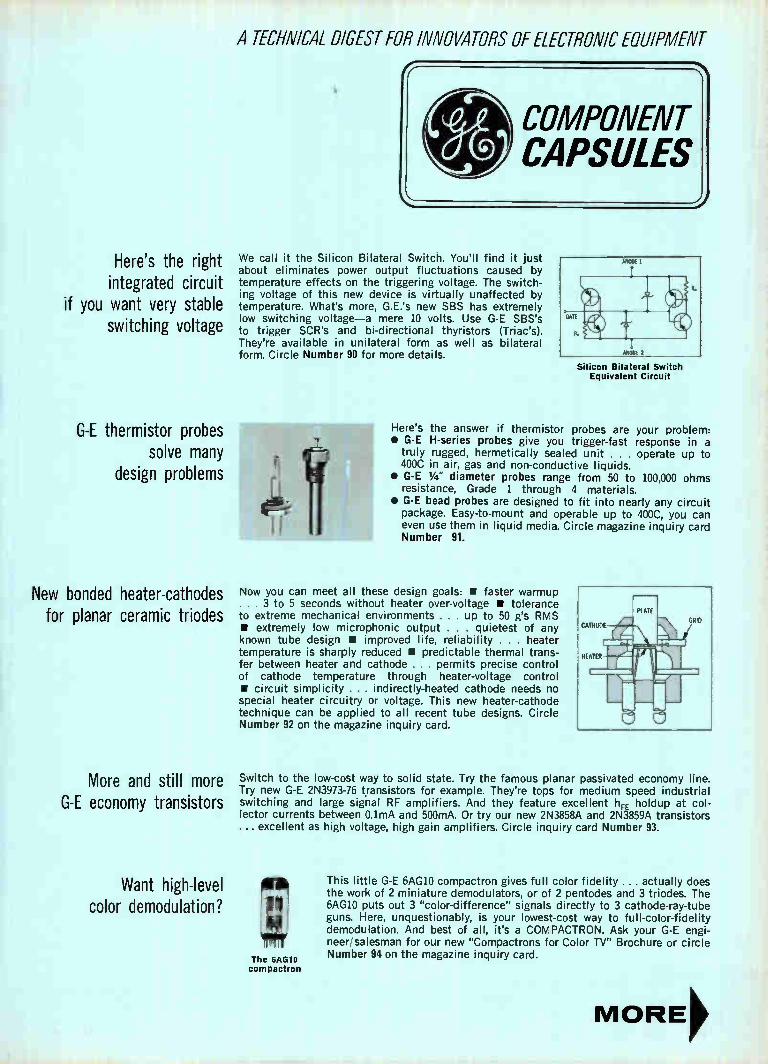
A TECHNICAL DIGEST FOR INNOVATORS OF ELECTRONIC EQUIPMENT
Here's the right integrated circuit
if you want very stable switching voltage
G-E thermistor probes solve many
design problems
New bonded heater-cathodes for planar ceramic triodes
More and still more G-E economy transistors
Want high-level color demodulation?
We call it the Silicon Bilateral Switch. You'll find it just about eliminates power output fluctuations caused by temperature effects on the triggering voltage. The switch-ing voltage of this new device is virtually unaffected by temperature. What's more, G.E.'s new SBS has extremely low switching voltage—a mere 10 volts. Use G-E SBS's to trigger SCR's and bi-directional thyristors (Triac's). They're available in unilateral form as well as bilateral form. Circle Number 90 for more details.
Silicon Bilateral Switch Equivalent Circuit
Here's the answer if thermistor probes are your problem: • G-E H-series probes give you trigger-fast response in a
truly rugged, hermetically sealed unit . . . operate up to 400C in air, gas and non-conductive liquids.
• G-E 1/4 " diameter probes range from 50 to 100,000 ohms resistance, Grade 1 through 4 materials.
• G-E bead probes are designed to fit into nearly any circuit package. Easy-to-mount and operable up to 400C, you can even use them in liquid media. Circle magazine inquiry card Number 91.
Now you can meet all these design goals: • faster warmup . . . 3 to 5 seconds without heater over-voltage • tolerance to extreme mechanical environments . . . up to 50 g's RMS • extremely low microphonic output . . . quietest of any known tube design • improved life, reliability . . . heater temperature is sharply reduced • predictable thermal trans-fer between heater and cathode . . . permits precise control of cathode temperature through heater-voltage control l• circuit simplicity . . . indirectly-heated cathode needs no special heater circuitry or voltage. This new heater-cathode technique can be applied to all recent tube designs. Circle Number 92 on the magazine inquiry card.
Switch to the low-cost way to solid state. Try the famous planar passivated economy line. Try new G-E 2N3973-76 transistors for example. They're tops for medium speed industrial switching and large signal RF amplifiers. And they feature excellent hFE holdup at col-lector currents between 0.1mA and 500mA. Or try our new 2N3858A and 2N3859A transistors ... excellent as high voltage, high gain amplifiers. Circle inquiry card Number 93.
The 6AG10 compactron
This little G-E 6AGIO compactron gives full color fidelity .... actually does the work of 2 miniature demodulators, or of 2 pentodes and 3 triodes. The 6AG10 puts out 3 "color-difference" signals directly to 3 cathode-ray-tube guns. Here, unquestionably, is your lowest-cost way to full-color-fidelity demodulation. And best of all, it's a COMPACTRON. Ask your G-E engi-neer/salesman for our new "Compactrons for Color TV" Brochure or circle Number 94 on the magazine inquiry card.

COMPONENT CAPSULES
Solid-state light-sensitive switch
controls G.E.'s meter relays
PREDICTION: Crystal-can relays out.
150-grid relay family in.
Give critical components the protection they deserve
Try this new ramp-and-pedestal
precision temperature regulator
8 different case sizes now for
Black Hawk capacitors
.4 .6 .2 1' I .8
I '/ ‘, D-C
MILLIAMP ES ••
GE-Type 195 meter relay with single setpoint
Contactless pass-through control action—that's the advantage you get with these solid-state meter relays. Completely self-contained control action is initiated by a light-sensitive switch directly controlling the load relay. No troublesome pointer contacts. No external amplifiers, power supplies or load relays. No mechanical interference with meter movement. Pointer travel is unrestricted across the entire scale. You get contin-uous indication above and below the setpoints. And you get all this in a distinctive, easy-to-read BIG LOOK meter package. Ask for Publication GEA-8014 or circle magazine inquiry card Number 95.
G-E low-profile 150 Grid-space relays set the trend for things to come in relay applications. Available now in 2-pole and 4-pole arrangements (and a latching version's due this year, too) these small devices have 150-mil ter-minal spacing, are only 0.32" high. This growing family of new relays offers you the best in space-saving ability with all the performance required from a mil-spec relay. Circle Number 96.
Triggered Vacuum Gap
At maximum gain setting, this low cost circuit controls load power over its entire range by a mere 3°C change in therm-istor temperature. What's more its feedback control network is stabilized by the circuit's adjustable gain. How's it work? Ask your G-E engineer/salesman for Appli-cation Information Publica-tion 671.1 and cost details. Or circle magazine inquiry card Number 98.
Family will soon include new latching version
Divert system and component faults through a General Electric triggered vacuum gap. Nothing else will do the job as well. TVG's trigger remarkably easily, just as low pressure gas gaps do. Yet TVG's are gas-free. Their voltage holdoff capabilities won't degenerate. They are also free from adverse atmosphere damage, adaptable to any en-vironment, and will protect against faults ranging from 10 to 100% of their rated voltage. Circle Number 97 for more information on all 5 available models.
U.IT TRIGGERING LEVEL PEDESTAL
Uff EMITTER VOLTAGE
R,. R.-2200 OHAIS, 2 WATTS
R. '4700 OHMS. W
THERMISTOR. APPROX 5000 OHMS AT OPERATING TEMPERATURE. GE-441
Rb 1D000 OHMS WW POTENTIOMETER
R. 5 MEGOHM POTENTIOMETER
R, 100 1(..2. ,2W
R., 1000 OHMS.
2N2646 UNUUNGT1071
13.R. SC41613 TRIM
TRIM T, 352M923 OR EQUIVALENT
D,. 1111693
D. - Z4XL22
1111692
pkt 34 V
And each capacitor size has 5 different voltages to choose from-50, 100, 200, 400 or 600 VDC. Black Hawk capacitors are molded to give you a hard, moisture-resistant shell around the capacitor roll. Each one you use has strong welded leads, extended foil construction, and very precise dimensions (±0.005). Circle Number 99 on the magazine inquiry card for all the facts.
Featuring I molded encapsulation
WE MAY NOT OFFER EVERYTHING YOU WANT FROM ONE COMPONENTS
SUPPLIER. BUT WE DO COME A LITTLE CLOSER THAN ANYONE ELSE. 285-12
GENERAL ELECTRIC
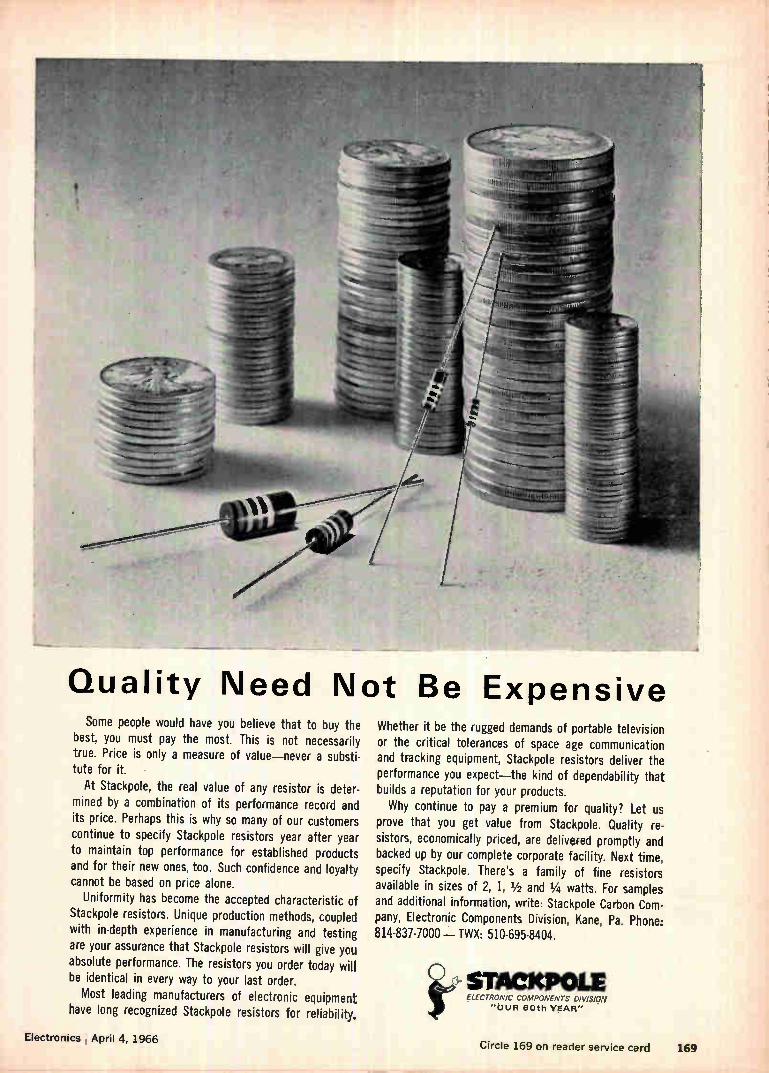
Quality Need Not Be Expensive Some people would have you believe that to buy the
best, you must pay the most. This is not necessarily true. Price is only a measure of value—never a substi-tute for it.
At Stackpole, the real value of any resistor is deter-mined by a combination of its performance record and its price. Perhaps this is why so many of our customers continue to specify Stackpole resistors year after year to maintain top performance for established products and for their new ones, too. Such confidence and loyalty cannot be based on price alone.
Uniformity has become the accepted characteristic of Stackpole resistors. Unique production methods, coupled with in-depth experience in manufacturing and testing are your assurance that Stackpole resistors will give you absolute performance. The resistors you order today will be identical in every way to your last order.
Most leading manufacturers of electronic equipment have long recognized Stackpole resistors for reliability.
Electronics , April 4, 1966
Whether it be the rugged demands of portable television or the critical tolerances of space age communication and tracking equipment, Stackpole resistors deliver the performance you expect—the kind of dependability that builds a reputation for your products. Why continue to pay a premium for quality? Let us
prove that you get value from Stackpole. Quality re-sistors, economically priced, are delivered promptly and backed up by our complete corporate facility. Next time, specify Stackpole. There's a family of fine resistors available in sizes of 2, 1, 1/2 and 1/4 watts. For samples and additional information, write: Stackpole Carbon Com-pany, Electronic Components Division, Kane, Pa. Phone: 814-837-7000-- TWX: 510-695-8404.
ÎeC.> SMACKPOLE ELECTRONIC COMPONENTS eviSION
"OUR 80th VgAR"
Circle 169 on reader service card 169
WHERE CAN MAN GO...IN ELECTRONICS?
Electronics is a discipline unlike any other. For what-ever name we give to these fast paced times in which we live—the Age of Space, the Age of Mass Commun-ications, the Age of Transportation—electronics plays a vital role. Through advances in this single key tech-nology, advances in all others are brought nearer to reality. And nowhere is this truth more evident than at Lockheed, where to all programs, electronics is essential. Research. Development. Systems. At Lockheed, those knowledgeable in the nuances of electronics help to further man's achieve-ment upon this planet. They bring practical-ity to investigative ocean vehicles such as Lockheed's Deep Quest, a two-place re-search submarine. They permit land vehicles of the future to achieve reality. And they extend the reach of mankind heavenward through spacecraft systems such as Agena. Undersea, on land, and in space en-vironments, Lockheed electronic systems control and guide, communicate and compute. Now, generalists and specialists, experienced and interested in a broad spectrum of electronics assignments, are invited to write Mr. K. R. Kiddoo, Professional Placement Manager, Sunnyvale, California. Lockheed is an equal opportunity employer. SSILES 8. SPACE COMPANY
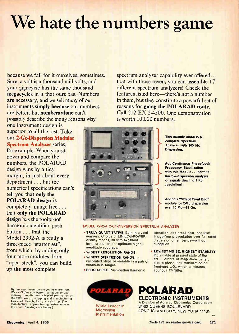
We hate the numbers game
because we fall for it ourselves, sometimes. Sure, a volt is a thousand millivolts, and your gigacycle has the same thousand megacycles in it that ours has. Numbers are necessary, and we sell many of our instruments simply because our numbers are better; but numbers alone can't possibly describe the many reasons why one instrument design is superior to all the rest. Take our 2-Gc-Dispersion Modular Spectrum Analyzer series, for example. When you sit down and compare the numbers, the POLARAD design wins by a tidy margin, in just about every department . . . but the numerical specifications can't tell you that only the POLARAD design is completely image-free . . . that only the POLARAD design has the foolproof harmonic-identifier push button ... that the Model 2992-A is really a three-piece "starter set", from which, by adding only four more modules, from "open stock", you can build up the most complete
By the way, those rumors you hear are true. We can't give you better than about 60-day delivery, despite nearly tripled production on the 2992. We are shipping and manufacturing like mad, though, to try to catch up. (No manufacturer enjoys having instruments on the shelf. Backlogs are better.) World Leader in
Microwave Instrumentation
spectrum analyzer capability ever offered ... that with those seven, you can assemble 17 different spectrum analyzers! Check the features listed here—there's not a number in them, but they constitute a powerful set of reasons for going the POLARAD route. Call 212-EX 2-4500. One demonstration is worth 10,000 numbers.
This module alone is a complete Spectrum Analyzer with 100 Mc Dispersion.
Add Continuous Phase-Lock Frequency Stabilization with this Module ... permits narrow-dispersion analysis of signals down to 1 Kc resolution!
Add this "Swept Front End" module for 2-Gc dispersion over 10 Mc-91 Gc.
MODEL 2992-A 2-Oc-DISPERSION SPECTRUM ANALYZER
• TRULY QUANTITATIVE. Built-in crystal markers. Choice of LIN-LOG-POWER display modes, all with excellent level-resolution, for optimum signal-amplitude accuracy.
• WIDEST RESOLUTION RANGE
• WIDEST DISPERSION RANGE. In calibrated steps or variable in a pair of continuous ranges.
• ERROR-FREE. Push-button Harmonic
Identifier -foolproof, fast, positive! Image-free presentation over full rated dispersion on all bands—without exception!
• LOWEST NOISE, HIGHEST STABILITY. Obtainable at present state of the art ... orders of magnitude better, due to phase-lock stabilization of front-end LO., which eliminates spurious FM/jitter.
POLARAD ELECTRONIC INSTRUMENTS A Division of Polarad Electronics Corporation
34-02 QUEENS BOULEVARD LONG ISLAND CITY, NEW YORK 11101
tez
Electronics April 4, 1966 Circle 171 on reader service card 171

Measuring 4.
Fre ency?
Quit Guessing
for only $195"! Now, for the first time, a Wavemeter capable of indicating
frequency to 0.2% accuracy on a direct-reading dial is avail-able at a price under $200. It's the new Telonic Model TWM.
50 Mhz to 4 Ghz An absorption type meter, the instrument has a tuning
range of 1 full octave covering all frequencies from 50 Mhz to 4 Ghz. Insertion loss is held to 0.5 db and VSWR at 1.5/1. The TWM passes signals through a matched transmission line, the sample being absored by the cavity at resonance and causing a 2±-1 db power dip in the line.
Pre-Calibrated Simple to use, the
TWM has a pre-calibrated 5:1 vernier dial that needs no interpolation or extra-polation. The setting you make is the frequency you read. Considering convenience, accuracy, range and price, the TWM Wavemeter is a natural for every engineer who wants to be frequency-sure. Full specifications available on request.
e;
ENGINEERING CO. A DIVISION OF TELONIC INDUSTRIES, INC.
480 Mermaid St., Laguna Beach, California 92651 Tel: (714) HY 4-7581 TWX: 714 673-1120
Clevite Ceramic Ladder Filters 80 db rejection in 0.1 cu. in. • 50% lower insertion loss
• Increased skirt selectivity
• Less insertion loss change with temperature
Clevite ceramic ladder filters provide more selectivity for their
size than any conventional i-f filter. They are fixed tuned and need no alignment—are non-magnetic and non-microphonic. Leading manufacturers now specify Clevite ladder filters for their modern communications equipment. Improve your newest design with these unique filters. Write now for complete specifi-
cations—Bulletin 94017 or request selectivity curves for each
stock model. • Dimensions: 5-1/6" diameter x 1-1/2" long
Selectivity: 60 db/6db shape factor from 1.4:1 to 2.5:le Center
Frequency Stability: within 0.2% for 5 years, and within 0.2%
from —40°C to +85°C • Impedance: 1200-2500 ohms a De-
signed for military and space environment. • Clevite Corp., Piezoelectric Division, 232 Forbes Road, Bedford, Ohio 44014.
CLEVITE 172 Circle 172 on reader service card Circle 455 on reader service card

LATCH on to the EXCITEMENT in
MICROELECTRONICS and
SILICON DEVICE DEVELOPMENT
at DELCO RADIO Enthusiasm is running high at Gen-eral Motor's Delco Radio Division.
Exciting developments in micro-electronics and silicon devices have spawned a rapidly expanding research effort. New buildings . . . new equip-ment . . . and most importantly, new people! The dynamic pace of accomplish-
ment at Delco is pushing the state of the art clear out of sight. The oppor-tunity is here for those who choose to capitalize on it.
Microelectronics
Circuit oriented EE's-0 to 5 years experience. Here's a chance to get in on the excitement in microelectronics. Research programs in both linear and digital circuitry embrace monolithic . . . thick film . . . thin film . .. and hybrid microcircuits.
Silicon Device Development
Lots of room here for the BS, MS, PhD in Physics, Chemistry, Physical Chemistry, or related fields. Develop-ment programs are underway in these areas: Low power and very high power
monolithic and hybrid circuits. Silicon Transistors—from very high
frequency 10 milliampere through 25 ampere, 1000 volts.
Thyristors—from 50 milliampere through 500 ampere, 2000 volts. Zener Diodes. Silicon Rectifiers—from milliam-
pere through 250 ampere, 3000 volts. Continuing R&D efforts already
have led to Delco's leadership in high power, high voltage silicon transis-tors. Delco rectifiers—rated at 250 amps, 2000 volts—are going into al-ternators designed to handle the full power generated by the latest Diesel-electric locomotives.
Full-size, fully-transistorized TV sets now are in production, thanks to a Delco high powered transistor in the horizontal and vertical deflection circuits. A tremendous momentum is build-
ing at Delco. The time is ripe—now —to join this outstanding research group.
If you'd like more information im-mediately, pick up the phone and call us collect, Area Code 317/459-2808. Ask for C. D. Longshore. Or, send your resume to Mr. Longshore, Sala-ried Employment, Dept. 102, Delco Radio Division, General Motors, Kokomo, Indiana.
An equal opportunity employer
Electronics April 4, 1966 173
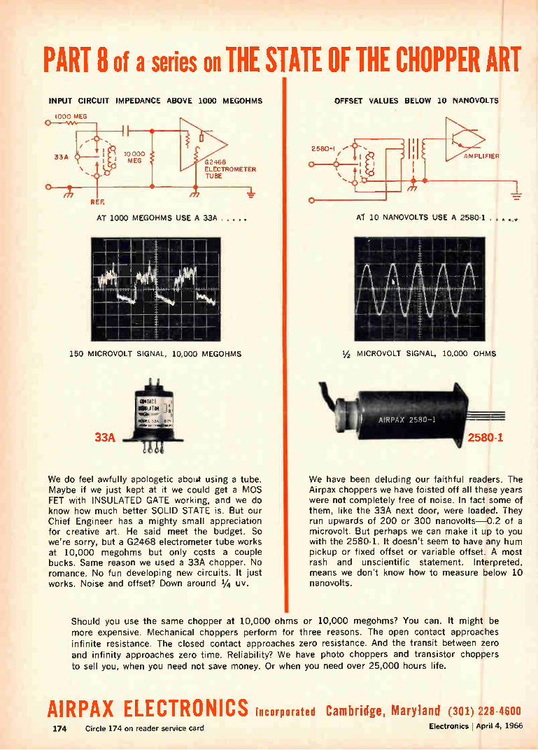
PART 8 of a series on THE STATE OF THE CHOPPER ART INPUT CIRCUIT IMPEDANCE ABOVE 1000 MEGOHMS
1000 MEG
33A 10000 MEG G2468
ELECTROMETER TUBE
REF.
AT 1000 MEGOHMS USE A 33A. • .
150 MICROVOLT SIGNAL, 10,000 MEGOHMS
33A
We do feel awfully apologetic about using a tube. Maybe if we just kept at it we could get a MOS FET with INSULATED GATE working, and we do know how much better SOLID STATE is. But our Chief Engineer has a mighty small appreciation for creative art. He said meet the budget. So we're sorry, but a G2468 electrometer tube works at 10,000 megohms but only costs a couple bucks. Same reason we used a 33A chopper. No romance. No fun developing new circuits. It just works. Noise and offset? Down around 1/4 uy.
o
OFFSET VALUES BELOW 10 NANOVOLTS
AMPLIFIER
Al 10 NANOVOLTS USE A 2580-1 .
1/2 MICROVOLT SIGNAL, 10,000 OHMS
AIRPAX 2580-1
We have been deluding our faithful readers. The Airpax choppers we have foisted off all these years were not completely free of noise. In fact some of them, like the 33A next door, were loaded. They run upwards of 200 or 300 nanovolts-0.2 of a microvolt. But perhaps we can make it up to you with the 2580-1. It doesn't seem to have any hum pickup or fixed offset or variable offset. A most rash and unscientific statement. Interpreted, means we don't know how to measure below 10 nanovolts.
Should you use the same chopper at 10,000 ohms or 10,000 megohms? You can. It might be more expensive. Mechanical choppers perform for three reasons. The open contact approaches infinite resistance. The closed contact approaches zero resistance. And the transit between zero and infinity approaches zero time. Reliability? We have photo choppers and transistor choppers to sell you, when you need not save money. Or when you need over 25,000 hours life.
AIRPAX ELECTRONICS incorporated Cambridge, Maryland (301) 228-4600
174 Circle 174 on reader service card Electronics 1 April 4, 1966
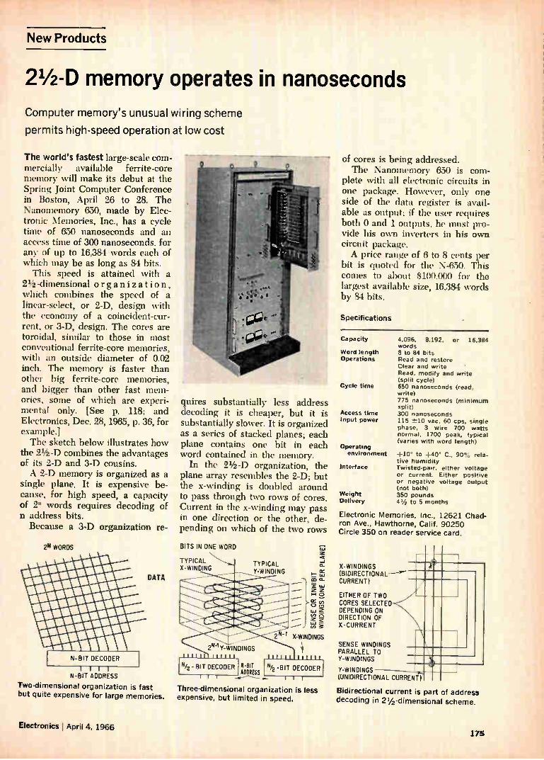
New Products
21/2 -D memory operates in nanoseconds
Computer memory's unusual wiring scheme
permits high-speed operation at low cost
The world's fastest large-scale com-mercially available ferrite-core memory will make its debut at the Spring Joint Computer Conference in Boston, April 26 to 28. The Nanomemory 650, made by Elec-tronic Memories, Inc., has a cycle time of 650 nanoseconds and an access time of 300 nanoseconds, for any of up to 16,384 words each of which may be as long as 84 bits.
This speed is attained with a 21/2 -dimensional organization, which combines the speed of a linear-select, or 2-D, design with the economy of a coincident-cur-rent, or 3-D, design. The cores are toroidal, similar to those in most conventional ferrite-core memories, with an outside diameter of 0.02 inch. The memory is faster than other big ferrite-core memories, and bigger than other fast mem-ories, some of which are experi-mental only. [See p. 118; and Electronics, Dec. 28, 1965, p. 36, for example.] The sketch below illustrates how
the 21/2 -D combines the advantages of its 2-D and 3-D cousins. A 2-D memory is organized as a
single plane. It is expensive be-cause, for high speed, a capacity of 2" words requires decoding of n address bits. Because a 3-D organization re-
2N WORDS
DATA
N-BIT DECODER
N-BIT ADDRESS
Two-dimensional organization is fast
but quite expensive for large memories.
quires substantially less address decoding it is cheaper, but it is substantially slower. It is organized as a series of stacked planes; each plane contains one bit in each word contained in the memory.
In the 21/2 -D organization, the plane array resembles the 2-D; but the x-winding is doubled around to pass through two rows of cores. Current in the x-winding may pass in one direction or the other, de-pending on which of the two rows
BITS IN ONE WORD
TYPICAL X-WINDING
TYPICAL Y-WINDING
II-BIT ADDRESS
_
111
-1
cc ¡el a
z Fi
,„ °
(II a
3
X-WINDINGS
Three-dimensional organization is less expensive, but limited in speed.
Weight Delivery
of cores is being addressed. The Nanomemory 650 is com-
plete with all electronic circuits in one package. However, only one side of the data register is avail-able as output; if the user requires both 0 and 1 outputs, he must pro-vide his own inverters in his own circuit package. A price range of 6 to 8 cents per
bit is quoted for the N-650. This comes to about $100,000 for the largest available size, 16,384 words by 84 bits.
Specifications
Capacity
Word length Operations
Cycle time
Access time input power
Operating environment +10° to +40° C.. 90% rela-
tive humidity Interface Twisted-pair, either voltage
or current. Either positive or negative voltage output (not both) 350 pounds 41/2 to 5 months
4,096, 8,192, or 16,384 words 8 to 84 bits Read and restore Clear and write Read, modify and write (split cycle) 650 nanoseconds (read, write) 775 nanoseconds (minimum split) 300 nanoseconds 115 -±10 vac, 60 cps, single phase, 3 wire 700 watts normal, 1700 peak, typical (varies with word length)
Electronic Memories, Inc., 12621 Chad-ron Ave., Hawthorne, Calif. 90250 Circle 350 on reader service card.
X-WINDINGS (BIDIRECTIONAL—e-CURRENT)
EITHER OF TWO CORES SELECTED DEPENDING ON DIRECTION OF X-CURRENT
SENSE WINDINGS PARALLEL TO Y-WINDINGS
Y-WINDINGS - (UNIDIRECTIONAL CURRENT)
Bidirectional current is part of address
decoding in 21/2 -dimensional scheme.
Electronics April 4, 1966 175
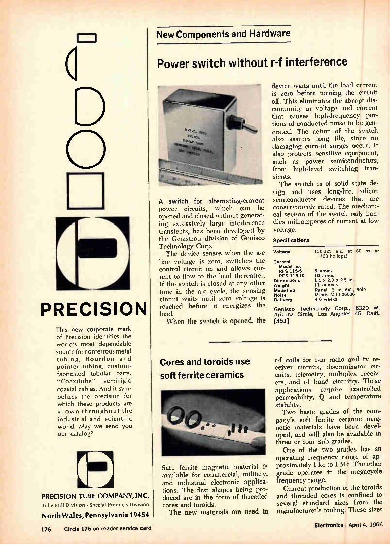
New Components and Hardware
o
PRECISION This new corporate mark of Precision identifies the world's most dependable source for nonferrous metal tubing, Bourdon and pointer tubing, custom-fabricated tubular parts, "Coaxitube" semirigid coaxial cables. And it sym-bolizes the precision for which these products are known throughout the industrial and scientific world. May we send you our catalog?
rr--o LL-=à
PRECISION TUBE COMPANY, INC.
Tube Mill Division • Special Products Division
North Wales, Pennsylvania 19454
Power switch without r-f interference
A switch for alternating-current power circuits, which can be opened and closed without generat-ing excessively large interference transients, has been developed by the Genistron division of Genisco Technology Corp. The device senses when the a-c
line voltage is zero, switches the control circuit on and allows cur-rent to flow to the load thereafter. If the switch is closed at any other time in the a-c cycle, the sensing circuit waits until zero voltage is reached before it energizes the load. When the switch is opened, the
device waits until the load current is zero before turning the circuit off. This eliminates the abrupt dis-continuity in voltage and current that causes high-frequency por-tions of conducted noise to be gen-erated. The action of the switch also assures long life, since no damaging current surges occur. It also protects sensitive equipment, such as power semiconductors, from high-level switching tran-sients. The switch is of solid state de-
sign and uses long-life, silicon semiconductor devices that are conservatively rated. The mechani-cal section of the switch only han-dles milliamperes of current at low voltage.
Specifications
Voltage 110-125 a-c, at 60 hz or 400 hz (cps)
Current Model no. RFS 115-5 RFS 115-10
Dimensions Weight Mounting Noise Delivery
5 amps 10 amps 1.5 x 2.8 x 2.5 in. 11 ounces Panel. 11, in. dia., hole Meets Mil-1-26600 4-6 weeks
Genisco Technology Corp., 6320 W. Arizona Circle, Los Angeles 45, Calif. [351]
Cores and toroids use
soft ferrite ceramics
Safe ferrite magnetic material is available for commercial, military, and industrial electronic applica-tions. The first shapes being pro-duced are in the form of threaded cores and toroids. The new materials are used in
r-f coils for f-m radio and tv re-ceiver circuits, discriminator cir-cuits, telemetry, multiplex receiv-ers, and i-f band circuitry. These applications require controlled permeability, Q and temperature stability. Two basic grades of the com-
pany's soft ferrite ceramic mag-netic materials have been devel-oped, and will also be available in three or four sub-grades. One of the two grades has an
operating frequency range of ap-proximately 1 kc to 1 Mc. The other grade operates in the megacycle frequency range.
Current production of the toroids and threaded cores is confined to several standard sizes from the manufacturer's tooling. These sizes
176 Circle 176 on reader service card Electronics April 4, 1966
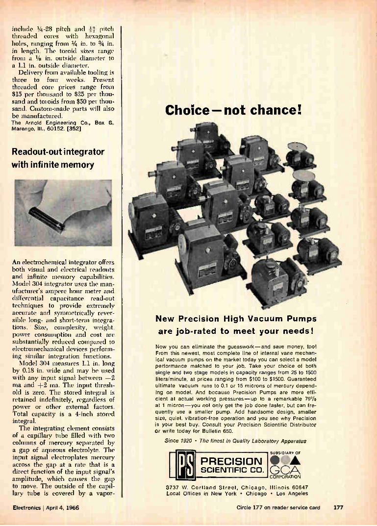
include 1/4 -28 pitch and VI pitch threaded cores with hexagonal holes, ranging from 1/4 in. to 3/4 in. in length. The toroid sizes range from a 1/4 in. outside diameter to a 1.1 in. outside diameter.
Delivery from available tooling is three to four weeks. Present threaded core prices range from $15 per thousand to $25 per thou-sand and toroids from $50 per thou-sand. Custom-made parts will also be manufactured. The Arnold Engineering Co., Box G, Marengo, III., 60152. [352]
Readout-out integrator
with infinite memory
An electrochemical integrator offers both visual and electrical readouts and infinite memory capabilities. Model 304 integrator uses the man-ufacturer's ampere hour meter and differential capacitance read-out techniques to provide extremely accurate and symmetrically rever-sible long- and short-term integra-tions. Size, complexity, weight, power consumption and cost are substantially reduced compared to electromechanical devices perform-ing similar integration functions. Model 304 measures 1.1 in. long
by 0.18 in. wide and may be used with any input signal between —2 ma and +2 ma. The input thresh-old is zero. The stored integral is retained indefinitely, regardless of power or other external factors. Total capacity is a 4-inch stored integral. The integrating element consists
of a capillary tube filled with two columns of mercury separated by a gap of aqueous electrolyte. The input signal electroplates mercury across the gap at a rate that is a direct function of the input signal's amplitude, which causes the gap to move. The outside of the capil-lary tube is covered by a vapor-
Choice not chance!
New Precision High Vacuum Pumps
are job-rated to meet your needs!
Now you can eliminate the guesswork—and save money, tool From this newest, most complete line of internai vane mechan-ical vacuum pumps on the market today you can select a model performance matched to your job. Take your choice of both single and two stage models in capacity ranges from 25 to 1500 liters/minute, at prices ranging from $100 to $1500. Guaranteed ultimate vacuum runs to 0.1 or 15 microns of mercury depend-ing on model. And because Precision Pumps are more effi-cient at actual working pressures—up to a remarkable 79% at 1 micron—you not only get the job done faster, but can f re-quently use a smaller pump. Add handsome design, smaller size, quiet, vibration-free operation and you see why Precision Is your best buy. Consult your Precision Scientific Distributor or write today for Bulletin 650.
Since 1920 • The finest in Quality Laboratory Apparatus
PS PRECISION SCIENTIFIC CO.
SUBSIDIARY OF
OfbA GCA CORPORATION
3737 W. Cortland Street, Chicago, Illinois 60647 Local Offices in New York • Chicago • Los Angeles
Electronics I April 4, 1966 Circle 177 on reader service card 177
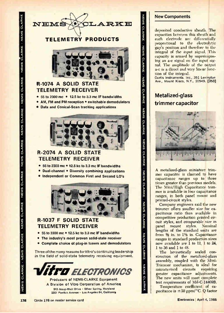
TELEMETRY PRODUCTS
tgow4WÇ•eqw di! Isv see> Wet
410. • "LeF 2,4_1
R-1074 A SOLID STATE TELEMETRY RECEIVER • 55 to 2300 mc • 12.5 kc to 3.3 mc IF bandwidths
• AM, FM and PM reception • switchable demodulators
• Data and Conical-Scan tracking applications
R-2074 A SOLID STATE TELEMETRY RECEIVER
• 55 to 2300 mc • 12.5 kc to 3.3 mc IF bandwidths
• Dual-channel • Diversity combining applications
• Independent or Common First and Second LO's
41 • 4,4* t,*
AL Ile
)1 :1111-1
R-1037 F SOLID STATE TELEMETRY RECEIVER
• 55 to 2300 mc • 12.5 kc to 3.3 mc IF bandwidths
• The industry's most proven solid-state receiver
• Complete choice of plug-in tuners and demodulators
Three of the many reasons for Vitro's continuing leadership in the field of solid-state telemetry receiving equipment.
ELECTRON/CS Producers of NEMS-CLARKE Equipment
A Division of Vitro Corporation of America 919 Jesup-Blair Drive • Sliver Spring, Maryland
2301 Pontius Avenue • Los Angeles 64, California
New Components
deposited conductive sheath. The capacities between this sheath and each electrode are differentially proportional to the electrolytic gap's position and therefore to the integral of the input signal. This capacity is sensed by superimpos-ing an a-c signal on the input sig-nal. The amplitude of the output a-c is a direct and very linear func-tion of the integral. Curtis Instruments, Inc., 351 Lexington Ave., Mount Kisco, N.Y., 10549. [353]
Metalized-glass
trimmer capacitor
J:4*
A metalized-glass miniature trim-mer capacitor is claimed to have capacitance ranges up to three times greater than previous models. The Mini/High Capacitance trim-mer is available in four capacitance ranges, in both panel mount and printed-circuit styles. Company engineers said the new
trimmer offers smaller size for ca-pacitance ratio than available in competitive production printed cir-cuit styles, and comparable size in panel mount styles. Nominal lengths of the standard units are from 1/2 in. to 1% in. Capacitance ranges in standard production sizes now available are 1 to 12, 1 to 24, 1 to 36 and 1 to 48. The hermetically sealed con-
struction of the metalized-glass assembly, coupled with the Mini-Trimmer mechanism, is ideal for miniaturized circuits requiring greater capacitance adjustments. The new units will meet complete test requirements of Mil-C-14409B.
Temperature coefficient of ca-pacitance is ±-50 ppm/ °C. Q factor
178 Circle 178 on reader service card Electronics I April 4, 1966
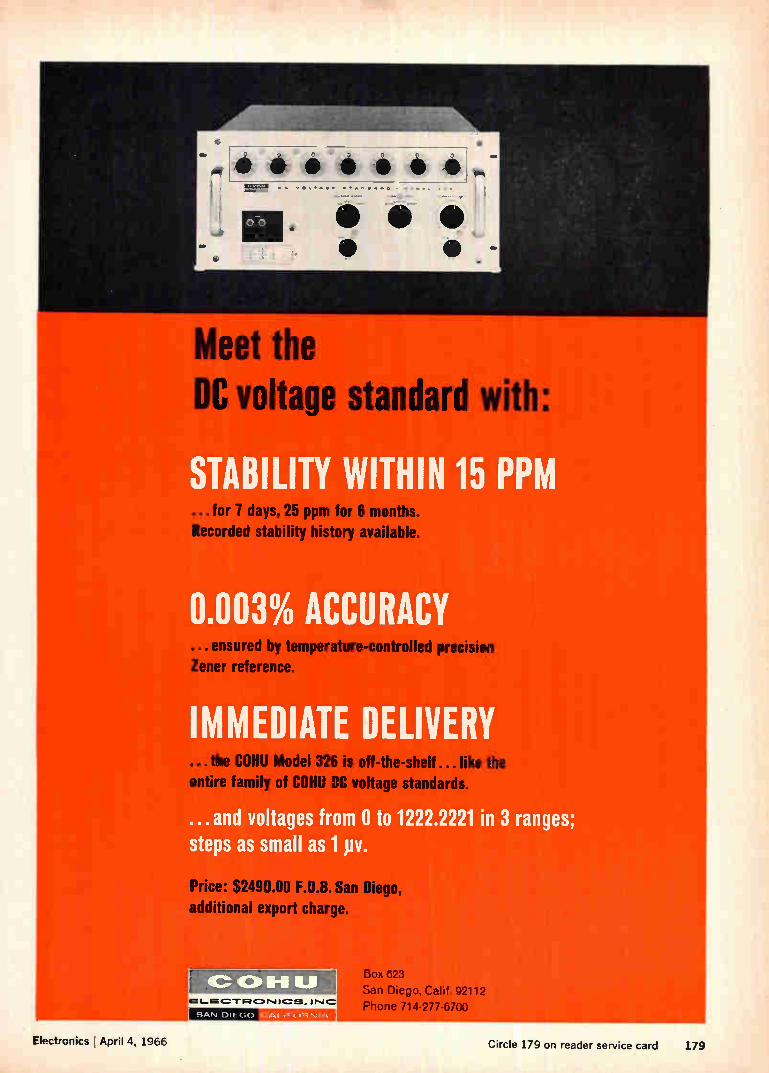
Meet the C voltage standard with:
STABILITY WITHIN 15 PPM ...for 7 days, 25 ppm for 6 months. Recorded stability history available.
0.003% ACCURACY ... ensured by temperature-controlled precision Zener reference.
IMMED E DRIVE e HU Model 326 is off-t e-s e ...like the
entire family of COHU DC voltage standards.
... and voltages from 0 to 1222.2221 in 3 ranges; steps as small as 1 pv.
Price: $2490.00 F.O.B. San Diego, additional export charge.
SAN DIE CIO
Box 623
San Diego, Calif. 92112
Phone 714-277-6700
Electronics April 4, 1966 Circle 179 on reader service card 179
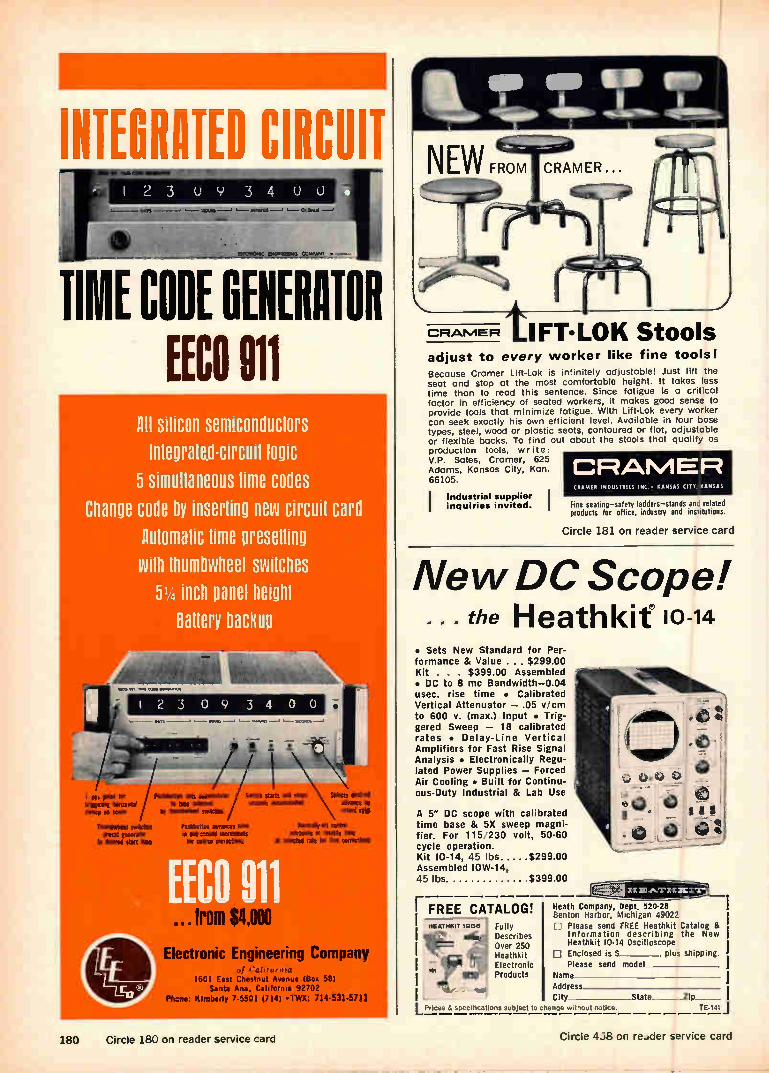
MIMED CIRCUIT
TIME CODE GEHEHNIOR (ECO 011
orp
AH silicon semiconductors Integratecircuit logic
5 simultaneous lime codes
Change cone by inserting new circuit card Automatic lime presetting with thumbwheel switches
514 inch panel height Battery backup
MA 1,11 SM. 0101. 011•••••/00.
I 2 3 0 9 3 4 0 0
I Hs fer triggenet bersreetel sweep ell SCAM
YhmEMMIIME smEtlyes preset (Coleatiy
to erne start ere
ten ••••011, SKONOS
¡In PestSittee sets accemoleter
te Om selected ley theadareel settees
Swdra starts ad stops sectors accorded«
eushbettes Meares ere r eirseceed eanerets be Pane correction
41111"Irro - ... m $4,000
Selects desired edema ite retard rate
Pleanallyall rate Meares r Mart His
it needed rite fie bee corrector
Electronic Engineering Company of Calif-0,11a
1601 East Chestnut Avenue (Box 58) Santa Ana, California 92702
Plane: Klmberly 7.5501 (714) •TWX: 714-531-5711
_J
CRAMER tIFT•LOK Stools adjust to every worker like fine tools! Because Cramer Lift-Lok is infinitely adjustable! Just lift the seat and stop at the most comfortable height. It takes less time than to read this sentence. Since fatigue is a critical factor in efficiency of seated workers, it makes good sense to provide tools that minimize fatigue. With Lift-Lok every worker can seek exactly his own efficient level. Available in four base types, steel, wood or plastic seats, contoured or flat, adjustable or flexible backs. To find out about the stools that qualify as production tools, write: V.P. Sales, Cramer, 625 Adams, Kansas City, Kan. 66105.
Industrial supplier inquiries invited.
CRAMER CRAMER INDUSTRIES INC, • KANSAS CITY, KANSAS
Fine seatinp-safety ladders-stands and related products for office, industry and institutions.
Circle 181 on reader servi:•e card
New DC Scope! • • • the Heathkit 10-14
• Sets New Standard for Per-formance & Value ... $299.00 Kit . . . $399.00 Assembled • DC to 8 mc Bandwidth-0.04 usec. rise time • Calibrated Vertical Attenuator — .05 v/cm to 600 V. (max.) Input • Trig-gered Sweep — 18 calibrated rates • Delay-Line Vertical Amplifiers for Fast Rise Signal Analysis • Electronically Regu-lated Power Supplies — Forced Air Cooling • Built for Continu-ous-Duty Industrial & Lab Use
A 5" DC scope with calibrated time base & 5X sweep magni-fier. For 115 230 volt, 50-60 cycle operation. Kit 10-14, 45 lbs $299.00 Assembled 10W-14, 45 lbs. $399.00
r FREE CATALOG! Fully Describes Over 250 Heathkit Electronic Products
x-x Avr x-1 xr
LPrices d specificatiOns subject to change without notice.
Heath Company, Dept, 520-28 Benton Harbor, Michigan 49022 1-1 Please send FREE Heathkit Catalog &
Information describing the New Heathkit 10-14 Oscilloscope Enclosed is $ , plus shipping.
Please send model Name Address City state zip
TE-141
180 Circle 180 on reader service card Circle 4j8 on re_.der service card
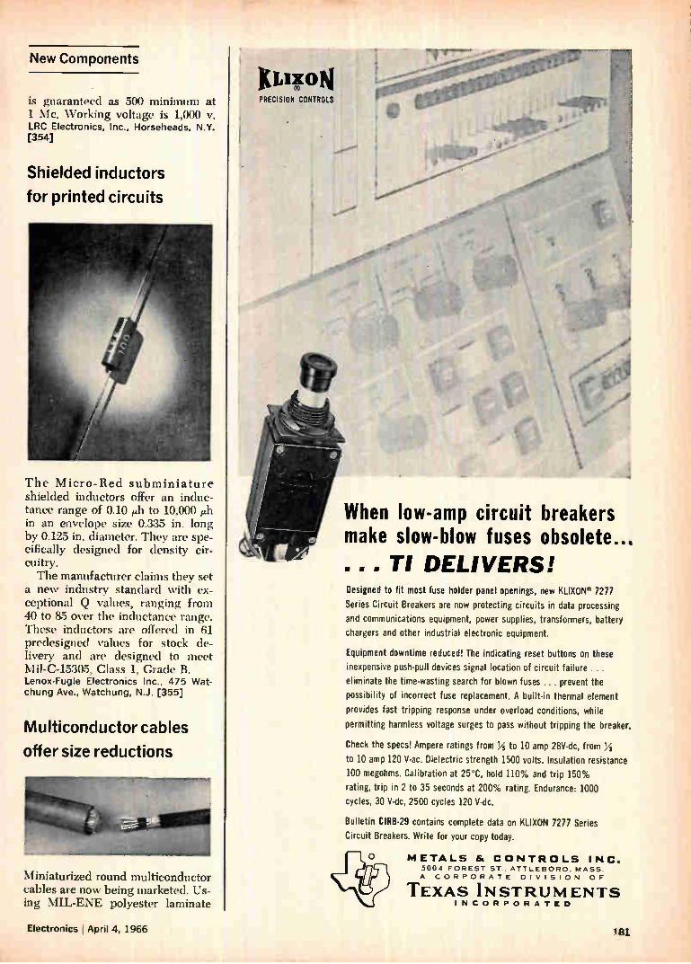
New Components
is guaranteed as 500 minimum at 1 Me. Working voltage is 1,000 v. LRC Electronics, Inc., Horseheads, N.Y. [354]
Shielded inductors
for printed circuits
The Micro-Red subminiature shielded inductors offer an induc-tance range of 0.10 ith to 10,000 1111 in an envelope size 0.335 in. long
by 0.125 in. diameter. They are spe-cifically designed for density cir-cuitry. The manufacturer claims they set
a new industry standard with ex-ceptional Q values, ranging from 40 to 85 over the inductance range. These inductors are offered in 61 predesigned ‘•alues for stock de-livery and are designed to meet Mil-C-15305, Class 1, Grade B. Lenox-Fugle Electronics Inc., 475 Wat-chung Ave., Watchung, N.J. [355]
Multiconductor cables
offer size reductions
Miniaturized round multiconductor cables are now being marketed. Us-ing MIL-ENE polyester laminate
KLIICON PRECISION CONTROLS
When low-amp circuit breakers make slow-blow fuses obsolete... . . . TI DELIVERS! Designed to fit most fuse holder panel openings, new KLIXON" 7277
Series Circuit Breakers are now protecting circuits in data processing
and communications equipment, power supplies, transformers, battery
chargers and other industrial electronic equipment.
Equipment downtime reduced! The indicating reset buttons on these
inexpensive push-pull devices signal location of circuit failure ... eliminate the time-wasting search for blown fuses ... prevent the
possibility of incorrect fuse replacement. A built-in thermal element provides fast tripping response under overload conditions, while
permitting harmless voltage surges to pass without tripping the breaker.
Check the specs! Ampere ratings from /t 5 to 10 amp 28V-dc, from 1/2
to 10 amp 120 V-ac. Dielectric strength 1500 volts. Insulation resistance
100 megohms. Calibration at 25°C, hold 110% and trip 150%
rating, trip in 2 to 35 seconds at 200% rating. Endurance: 1000
cycles, 30 V-dc, 2500 cycles 120 V-dc.
Bulletin CIRB-29 contains complete data on KLIXON 7277 Series Circuit Breakers. Write for your copy today.
,re METALS & CONTROLS INC. 5004 FOREST ST.. ATTLEBORO. MASS. A CORPORATE DIVISION OF
TEXAS INSTRUMENTS INCORPORATED
Electronics April 4, 1966 181
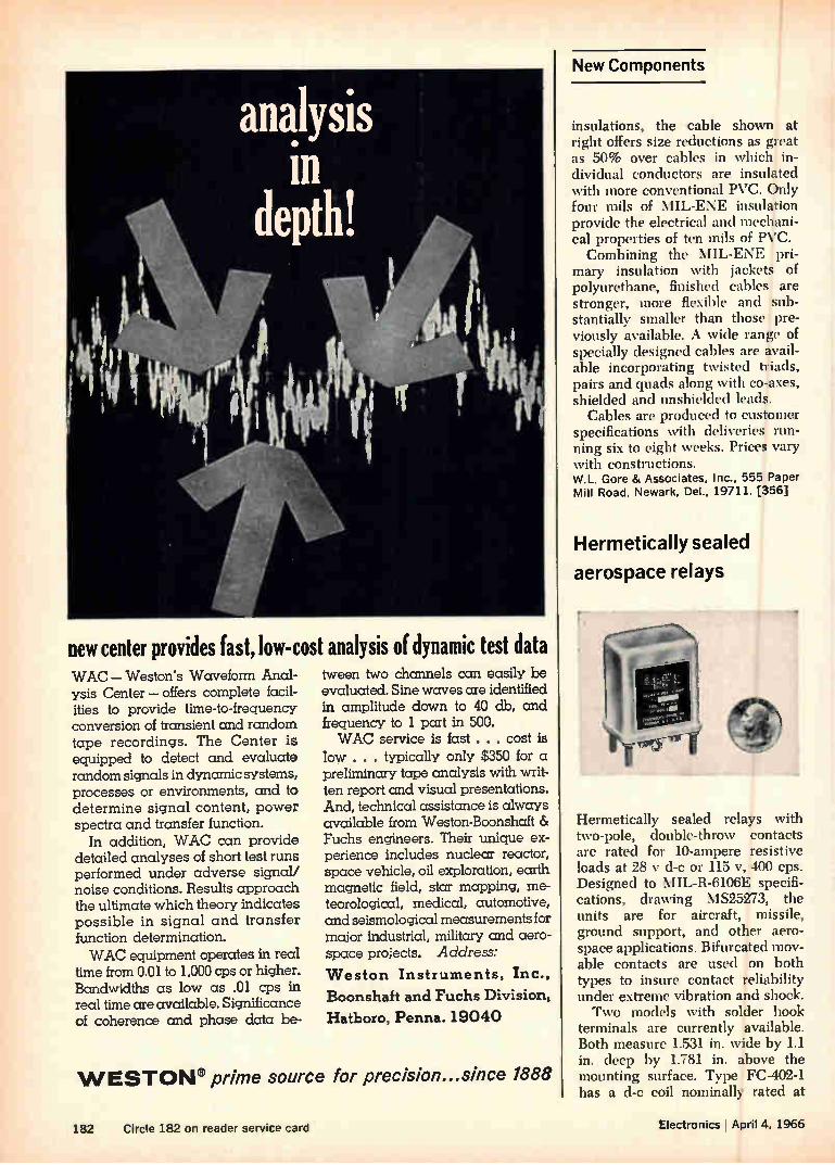
new center provides fast, low-cost analysis of dynamic test data WAC — Weston's Waveform Anal-ysis Center — offers complete facil-ities to provide time-to-frequency conversion of transient and random tape recordings. The Center is equipped to detect and evaluate random signals in dynamic systems, processes or environments, and to determine signal content, power spectra and transfer function.
In addition, WAC can provide detailed analyses of short test runs performed under adverse signal/ noise conditions. Results approach the ultimate which theory indicates possible in signal and transfer function determination. WAC equipment operates in real
time from 0.01 to 1,000 cps or higher. Bandwidths as low as .01 cps in real time are available. Significance of coherence and phase data be-
tween two chcmnels can easily be evaluated. Sine waves are identified in amplitude down to 40 db, and frequency to 1 part in 500. WAC service is fast . . . cost is
low . . . typically only $350 for a preliminary tape analysis with writ-ten report and visual presentations. And, technical assistance is always available from Weston-Boonshaft & Fuchs engineers. Their unique ex-perience includes nuclear reactor, space vehicle, oil exploration, earth magnetic field, star mapping, me-teorological, medical, automotive, and seismological measurements for major industrial, military and aero-space projects. Address:
Weston Instruments, Inc.,
Boonshaft and Fuchs Division,
Hatboro, Penna. 19040
WESTON® prime source for precision...since 1888
New Components
insulations, the cable shown at right offers size reductions as great as 50% over cables in which in-dividual conductors are insulated with more conventional PVC. Only four mils of MIL-ENE insulation provide the electrical and mechani-cal properties of ten mils of PVC. Combining the MIL-ENE pri-
mary insulation with jackets of polyurethane, finished cables are stronger, more flexible and sub-stantially smaller than those pre-viously available. A wide range of specially designed cables are avail-able incorporating twisted triads, pairs and quads along with co-axes, shielded and unshielded leads.
Cables are produced to customer specifications with deliveries run-ning six to eight weeks. Prices vary with constructions. W.L. Gore & Associates, Inc., 555 Paper Mill Road, Newark, Del., 19711. [356]
Hermetically sealed
aerospace relays
Hermetically sealed relays with two-pole, double-throw contacts are rated for 10-ampere resistive loads at 28 y d-c or 115 NY, 400 cps. Designed to MIL-R-6106E specifi-cations, drawing \ 1825273, the units are for aircraft, missile, ground support, and other aero-space applications. Bifurcated mov-able contacts are used on both types to insure contact reliability under extreme vibration and shock. Two models with solder hook
terminals are currently available. Both measure 1.531 in. wide by 1.1 in. deep by 1.781 in. above the mounting surface. Type FC-402-1 has a d-c coil nominally rated at
182 Circle 182 on reader service card Electronics I April 4, 1966
If you ever wished for a versatile,
easy-to-work-with dielectric FILM,
with all the electrical properties,
environmental resistance and unsurpassed reliability
of Du Pont TEFLON
What are you waiting for? Mail this coupon!
BETTER THINGS FOR BETTER LIVING . . CI-EM S7RY
TEFLON® FEP fluorocarbon film
Du Pont Company, Room 3871 Wilmington, Delaware 19898
Please send me complete information on Du Pont TEFLON FEP fluorocar-bon film. I am particularly interested in evaluating this film for the follow-ing area (s) of application:
flexible, single and multilayer printed circuits
o laminated, flexible, flat cable insulation
o high-temperature, high-dielectric-strength insulation
Other application
Name
Title
Company
Address;
City
State ip
Business Phone
Electronics I April 4, 1966 Circle 183 on reader service card 183

New Components
28 v., 0.25 amp. The FC-402-2 has a self-contained rectifier for a-c coil operation at 115 v, 400 cps, 0.07 ampere.
Both relays are available on an approximate six-week delivery basis. Prices are in the $14 range for types with d-c coils, $20 for a-c operated types. Struthers-Dunn, Inc., Pitman, N.J., 08071. [357]
Military quality
glass capacitors
wif-4 I Fr NEW VARACTOR POWER OUTPUT...
MOTOROLA POWER VARACTORS AT THESE DISTRIBUTORS... NOW!
EASTERN ALABAMA, Huntsville • 2310 Bob Wallace Ave , s.w. Electronic Wholesalers • 534-2461 ALABAMA, Huntsville • 8100 Memorial Parkway. S.W. Gulf Semiconductors • 881-7777 CONNECTICUT, Hamden • 60 Connolly Parkway Creme, Electronics • 288-7771 0.C., Washington • 2345 Sherman Ave., N.W Electronic Wholesalers • NU 3-5200 FLORIDA, Miami • 7495 N.W. 48th St Gulf Semiconductors •887.6541 FLORIDA, Orlando • 2049 W Central Blvd. Powell/Crescent Electronics • 123-8586 GEORGIA, Atlanta • 1135 Chattahoochee Ave., N.W Jackson Electronic • 355-2223 MARYLAND, Baltimore • 3004 'W,Ikens Ave. Electronic Wholesalers • WI 5.3400 MASSACHUSETTS, Cambridge • 71 Pearl St. R&D Electronics Supply • 864.0400 MASSACHUSETTS, Newton • 320 Needham St Cramer Electronics • WO 9-7700 NEW JERSEY, Moorestown • Pleasant Valley Ave. Angus, Inc. • 235-1900 NEW YORK, Buffalo • 916 Main St. Summit Distributors • TT 4-3450 NEW YORK, Elmhurst. Queens • 80-02 51St Ave. Cramer/Esco • CR 8-4000 NEW YORK, New York • 160 Varick St. .. Milgray Electronics • YU 9.1600 NEW YORK, Syracuse • The Pickard Bldg., E. Molloy Rd. Eastern Semiconductor Sales • 154-9241 NEW YORK. Westbury, L.I. Schweber Electronics • ED 4-7414 NORTH CAROLINA. Winston-Salem • 938 Burke St. . .. ....... . Electronic Wholesalers • PA 5.6711 PENNSYLVANIA. Philadelphia • 701 Arch St. . Radio Electric Service Co. • WA 5.6900
CENTRAL ILLINOIS, Chicago • 100 N. Western Ave ILLINOIS, Chicago • 223 W. Madison St. ILLINOIS, Chicago • 5700 W. North Ave IOWA, Cedar Rapids • 618 First St., N.W. KANSAS, Kansas City • 2707 West 43rd St.
Allied Electronics • HA 1.6800 Newark Electronics • ST 2-2944
Semiconductor Specialists • NA 2-8860 Deeco • 365-7551
Precision Electronic Devices Co. • AD 6-4343 MICHIGAN, Dearborn Heights • 20203 Ann Arbor Trail SemicRoanddioucstpoecr Siapeltcieiaslicsots :• BR 2-4212 LU 4-5901 MICHIGAN, Detroit • 12775 Lyndon Ave. MINNESOTA. Minneapolis • 730 East 38th St. Allied Electronics • TA 7.5401 MINNESOTA, Minneapolis • 601 West 66th St. Semiconductor Specialists • UN 6-3435 MISSOURI, St. Louis • 6154 Jefferson Ave. Semiconductor Specialists, Inc. • 1A 1-8866 OHIO, Cincinnati • 10 Knollcrest Dr. Sheridan Sales • 761-5432 OHIO, Cleveland • 5403 Prospect Ave Pioneer-Standard Electronics • 432-0010 OHIO, Dayton • 2975 Far Hills Ave. Allied Electronics • 298.9831 TEXAS, Dallas • 2642 Andjon Dr. Sterling Electronics • FL 1.9921 TEXAS, Garland • 326 Kirby St. Hall-Mark Electronics • BR 6-8531 TEXAS, Houston • 8000 Westglen Hall-Mark Electronics • SU 1.0011 TEXAS. Houston • 1420 Hutchins Lenert Co. • CA 4-2663
ARIZONA, Phoenix • 1741 No 28th Ave. CALIFORNIA, Inglewood • 399 S. Isis Ave. CALIFORNIA, Los Angeles • 10912 W. Washington Blvd. CALIFORNIA, Los Angeles • 5645 E. Washington Blvd. CALIFORNIA. Mountain View • 2288 Charleston Road CALIFORNIA, Mountain View • 340 Middlefield Rd. CALIFORNIA, Oakland • 140 11th St. CALIFORNIA, San Diego • 8137 Engineer Rd. CALIFORNIA. San Diego • 4618 Santa Fe COLORADO. Denver • 1200 Stout St. NEW MEXICO, Alamogordo • 811 First St. NEW MEXICO, Albuquerque • 6405 Ai-orna Rd.. S.E. UTAH, Salt Lake City • 133 W. Third So. WASHINGTON, Seattle • 516 First Ave., No
WESTERN Hamilton Electro of Ariz. • 272.2601
Liberty Electronics • OR 8.8111 Hamilton Electro Sales • UP 0.3300
K-Tronics • OV 5.5888 Omar Electronics • 961.3611
Hamilton Electro Sales-North • 961.7000 Elmer Electronics •TE 4.3311
Kierulff Electronics • BR 8.2112 San Delcor • 274-3131
Kierulff Electronics • TA 5-7033 Kierulff Electronics • 437.0370 Kierulff Electronics • 268.3901
W. H. Ointe Co. • 363-5821 Hamilton Electro • AT 2-3836
...
Low-cost glass capacitors meet or exceed all the performance require-ments of military specification MIL-C-11272. Type CYW-6 capac-itors are designed for tuned r-f and analog circuits; for signal generat-ing, shaping, and handling; and for critical applications requiring ex-ceptional stability and repeatabil-ity in addition to low drift and losses.
Capacitance range of the CYW-6 is from one through 560 pf at a voltage rating of 300 y d-c, per-mitting the capacitors to be used in either transistor or vacuum tube circuits. The injection-molded plas-tic case, which houses the same kind of glass capacitor element used in higher priced military-type CY units features tiny feet that raise the body of the case off the circuit board to effect more re-liable soldering and facilitate clean-ing of the board surface. The up-right mounting also contributes to higher efficiency in circuit packag-ing. Standard lead material is gold-plated dumet, which is both solder-
184 Electronics I Aptil 4, 1966
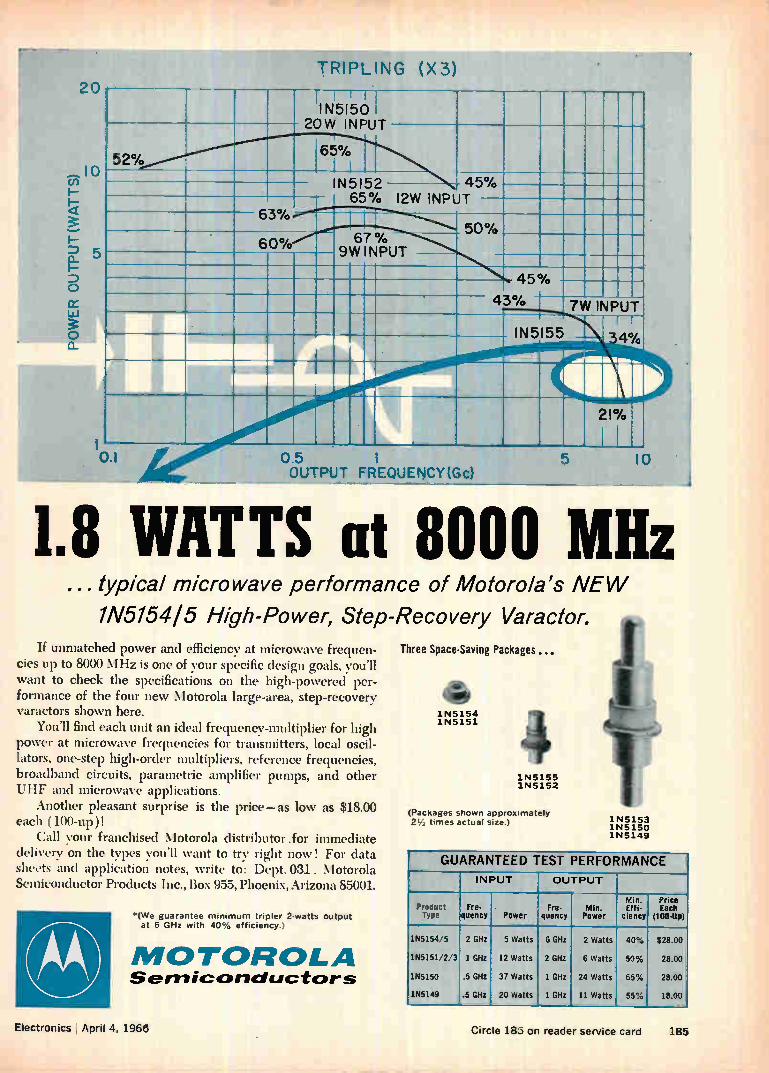
TRIPLING (X3) 20
IN5150 I 20W INPUT
52% 65%
IN5152 45% 65% I2W INPUT
I
67% 9W INPUT
50%
111111111h- 45%
43%
IN5155
7W INPUT
4%
01 0.5 OUTPUT FREQUENCY(Gc)
5 10
1.8 WATTS at 8000 MHz ...typical microwave performance of Motorola's NEW
1N5154 I 5 High-Power, Step-Recovery Varactor.
If unmatched power and efficiency at microwave frequen-cies up to 8000 MHz is one of your specific design goals, you'll want to check the specifications on the high-powered per-formance of the four new Motorola large-area, step-recovery varactors shown here.
You'll find each unit an ideal frequency-multiplier for high power at microwave frequencies for transmitters, local oscil-lators, one-step high-order multipliers, reference frequencies, broadband circuits, parametric amplifier pumps, and other UHF and microwave applications.
Another pleasant surprise is the price—as low as $18.00 each (100-up)!
Call your franchised Motorola distributor .for immediate delivery on the types you'll want to try right now! For data sheets and application notes, write to: Dept. 031 , Motorola Semiconductor Products Inc., Box 955, Phoenix, Arizona 85001.
'(We guarantee minimum tripler 2-watts output at 6 GHz with 40% efficiency.)
MOTOROLA Sem iconductors
Three Space-Saving Packages
4110,-1N5154 1N5151
1N5155 1N5152
(Packages shown approximately times actual size.) 1N5153
1 N 5150 1N5149
- GUARANTEED TEST PERFORMANCE INPUT OUTPUT
Product Type
Fre- quency Power
Fre- quency
Min. Power
Min. Effi-
ciency
Price Each
(100-Up)
155154/5
155151/2/3
155150
155149
2 GHz
I GHz
.5 GHz
.5 GHz
5 Watts
12 Watts
37 Watts
20 Watts
6 GHz
2 GHz
1 GHz
1 GHz
2 Watts
6 Watts
24 Watts
11 Watts
40%
50%
65%
55%
$28.00
28.00
28.00
18.00
Electronics April 4. 1968 Circle 183 on reader service card 185
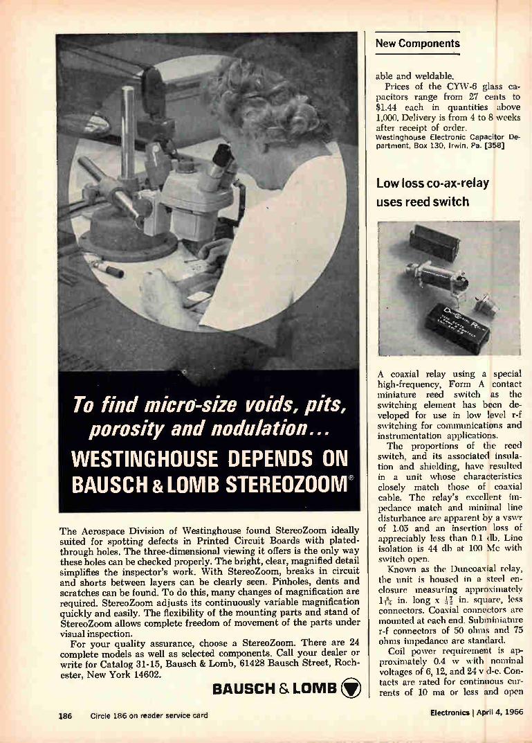
To find micro-size voids, pits, porosity and nodulation...
WESTINGHOUSE DEPENDS ON BAUSCH &LOMB STEREOZOOM
The Aerospace Division of Westinghouse found StereoZoom ideally suited for spotting defects in Printed Circuit Boards with plated-through holes. The three-dimensional viewing it offers is the only way these holes can be checked properly. The bright, clear, magnified detail simplifies the inspector's work. With StereoZoom, breaks in circuit and shorts between layers can be clearly seen. Pinholes, dents and scratches can be found. To do this, many changes of magnification are required. StereoZoom adjusts its continuously variable magnification quickly and easily. The flexibility of the mounting parts and stand of StereoZoom allows complete freedom of movement of the parts under visual inspection.
For your quality assurance, choose a StereoZoom. There are 24 complete models as well as selected components. Call your dealer or write for Catalog 31-15, Bausch & Lomb, 61428 Bausch Street, Roch-ester, New York 14602.
BAUSCH & LOMB
New Components
able and weldable. Prices of the CYW-6 glass ca-
pacitors range from 27 cents to $1.44 each in quantities above 1,000. Delivery is from 4 to 8 weeks after receipt of order. Westinghouse Electronic Capacitor De-partment, Box 130, Irwin, Pa. [358]
Low loss co-ax-relay
uses reed switch
A coaxial relay using a special high-frequency, Form A contact miniature reed switch as the switching element has been de-veloped for use in low level r-f switching for communications and instrumentation applications. The proportions of the reed
switch, and its associated insula-tion and shielding, have resulted in a unit whose characteristics closely match those of coaxial cable. The relay's excellent im-pedance match and minimal line disturbance are apparent by a vswr of 1.05 and an insertion loss of appreciably less than 0.1 db. Line isolation is 44 db at 100 Mc with switch open. Known as the Duncoaxial relay,
the unit is housed in a steel en-closure measuring approximately
in. long x U, in. square, less connectors. Coaxial connectors are mounted at each end. Subminiature r-f connectors of 50 ohms and 75 ohms impedance are standard.
Coil power requirement is ap-proximately 0.4 w with nominal voltages of 6, 12, and 24 y d-c. Con-tacts are rated for continuous cur-rents of 10 ma or less and open
186 Circle 186 on reader service card Electronics I April 4, 1966

Should you buy Signetics
new SP600 series dual in-line plug-in packages
just because they're low-priced
No, there are better reasons.
They contain multi-function DTL circuits, for one.
For another, the SP600 package is monolithic. A solid epoxy block encapsulates both the circuit chip and the leads connecting it to the external plug-in pins. Result: mechanical ruggedness and built-in vapor barrier protection for the circuit.The new SP600 series package has been tested and stressed to levels far in excess of those required by MIL-S-19500D and MIL-STD-750, even though it is intended for
SIGNETICS INTEGRATED CIRCUITS A subsidiary of Corning Glass Works,
811 East Argues Avenue, Sunnyvale, California Tel.: (408) 739-7700 TWX: (910) 737-9965
commercial applications. Handling and insertion ease are guaran-teed by 100 mil center-to-center pin spacing and 300 mils between rows conforming to widely accepted circuit board drill patterns. Me-chanical or hand insertion and high-volume flow soldering techniques can be used on all Signetics SP600 series circuits. For the other umpteen reasons, write for your free copy of our SP600A brochure.
Signetics SP600 series includes a J-K flip-flop,
three multiple DTL gate packages (dual, triple and quadruple
NAND/NOR), a quadruple gate-input
expander, and a dual DTL line driver/buffer element.
Electronics I April 4, 1966 Circle 187 on reader service card 187
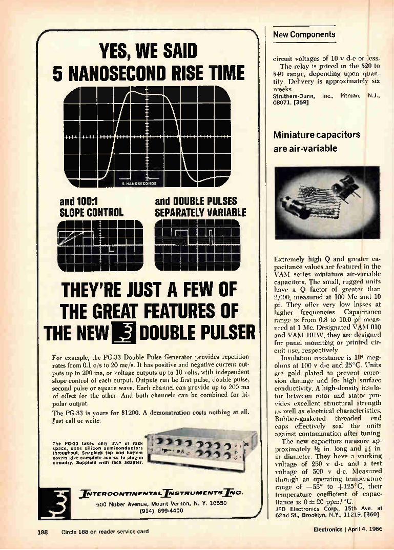
( YES, WE SAID
5 NANOSECOND RISE TIME IMICL911111 k
1111111111111111111101111111111111 111111111111111111111111111111111
11111111111111011111 El 5 NANOSECONDS MOW
and 100:1 SLOPE CONTROL
fileari11111111111111 nall111111•111111ma 11111111111111111111111113111111111111
and DOUBLE PULSES SEPARATELY VARIABLE 111111111111...M11
MINIM M11111111111111111 111111111111111111.1111111111111111111
THEY'RE JUST A FEW OF THE GREAT FEATURES OF
THE NEW _2 DOUBLE PULSER For example, the PG-33 Double Pulse Generator provides repetition rates from 0.1 e/s to 20 me/s. It has positive and negative current out-puts up to 200 ma, or voltage outputs up to 10 volts, with independent slope control of each output. Outputs can be first pulse, double pulse, second pulse or square wave. Each channel can provide up to 200 ma of offset for the other. And both channels can be combined for bi-polar output. The PG-33 is yours for $1200. A demonstration costs nothing at all. Just call or write.
The PG-33 takes only 312" of rack . 1› ,), space, uses silicon semiconductors - throughout. Snaploc) top and bottom covers give complete access to plug-in circuitry. Supplied with rack adapter.
- `111—, • mot e. • l oll
riellommiumena
11TERCONTINENTALIVSTRLIMENTSFIC.
500 Nuber Avenue, Mount Vernon, N. Y. 10550
(914) 699-4400
New Components
circuit voltages of 10 y d-c or less. The relay is priced in the $20 to
$40 range, depending upon quan-tity. Delivery is approximately six weeks. Struthers-Dunn, Inc., Pitman, N.J., 08071 [359]
Miniature capacitors
are air-variable
Extremely high Q and greater ca-pacitance values are featured in the VAM series miniature air-variable capacitors. The small, rugged units have a Q factor of greater than 2,000, measured at 100 Mc and 10 pf. They offer very low losses at higher frequencies. Capacitance range is from 0.8 to 10.0 pf meas-ured at 1 Mc. Designated VAM 010 and VAM 101W, they are designed for panel mounting or printed cir-cuit use, respectively.
Insulation resistance is 104 meg-ohms at 100 y d-c and 25°C. Units are gold plated to prevent corro-sion damage and for high surface conductivity. A high-density insula-tor between rotor and stator pro-vides excellent structural strength as well as electrical characteristics. Rubber-gasketed threaded end caps effectively seal the units against contamination after tuning. The new capacitors measure ap-
proximately 1/2 in. long and ¡I in. in diameter. They have a working voltage of 250 y d-c and a test voltage of 500 y d-c. Measured through an operating temperature range of —55° to +125°C, their temperature coefficient of capac-itance is 0 -± 20 ppm/ °C. JFD Electronics Corp., 15th Ave. at 62nd St., Brooklyn, N.Y., 11219. [360]
188 Circle 188 on reader service card Electronics I April 4, 1966
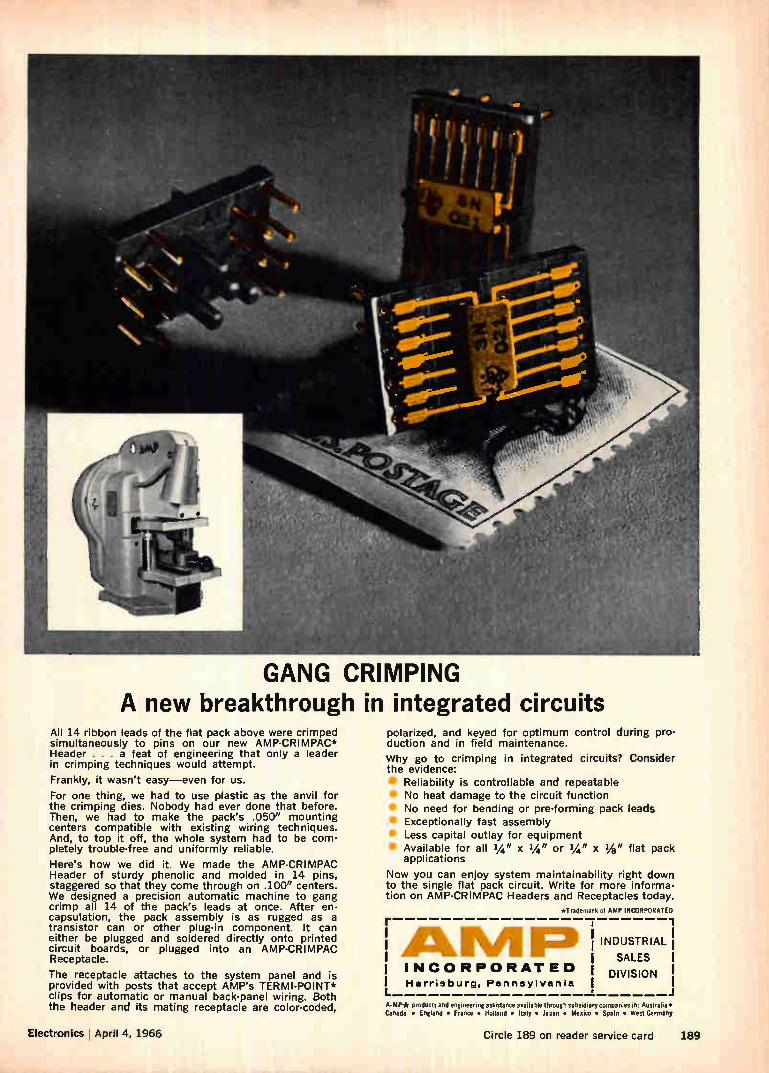
GANG CRIMPING A new breakthrough in integrated circuits
All 14 ribbon leads of the flat pack above were crimped simultaneously to pins on our new AMP-CRIMPAC* Header . . . a feat of engineering that only a leader in crimping techniques would attempt.
Frankly, it wasn't easy—even for us.
For one thing, we had to use plastic as the anvil for the crimping dies. Nobody had ever done that before. Then, we had to make the pack's .050" mounting centers compatible with existing wiring techniques. And, to top it off, the whole system had to be com-pletely trouble-free and uniformly reliable.
Here's how we did it. We made the AMP-CRIMPAC Header of sturdy phenolic and molded in 14 pins, staggered so that they come through on .100" centers. We designed a precision automatic machine to gang crimp all 14 of the pack's leads at once. After en-capsulation, the pack assembly is as rugged as a transistor can or other plug-in component. It can either be plugged and soldered directly onto printed circuit boards, or plugged into an AMP-CRIMPAC Receptacle.
The receptacle attaches to the system panel and is provided with posts that accept AMP's TERMI-POINT* clips for automatic or manual back-panel wiring. Both the header and its mating receptacle are color-coded,
polarized, and keyed for optimum control during pro-duction and in field maintenance.
Why go to crimping in integrated circuits? Consider the evidence:
Reliability is controllable and repeatable No heat damage to the circuit function No need for bending or pre-forming pack leads Exceptionally fast assembly Less capital outlay for equipment Available for all 1/4" x 1/4" or 1/4" x 1/8" flat pack applications
Now you can enjoy system maintainability right down to the single flat pack circuit. Write for more informa-tion on AMP-CRIMPAC Headers and Receptacles today.
ATrldernark of AMP INCORPORATED [ emu, ir , INCORPORATED I Harrisburg, Pennsylvania
INDUSTRIAL
SALES I
DIVISION !
A-MP* products and engineering assistance available through subsidiary companies in: Australia • Canada • England • France • Holland • Italy • Japan • Mexico • Spain • West Germany
Electronics April 4, 1966 Circle 189 on reader service card 189
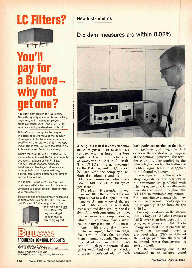
LC Filters?
pay for a Bulova— why not get one? You can't beat Bulova for LC Filters. No better quality made, no faster delivery anywhere, and—thanks to Bulova's technical capabilities—the price is the same as you'd pay elsewhere, or less!
Bulova's use of computer techniques in designing filters reduces the number of components to the minimum number possible. As a result, reliability is greater, initial cost is less. Delivery can start in as little as 4 weeks, faster if necessary.
What's more, all Bulova LC Filters can be manufactured to meet NASA requirements and latest revisions of Mil F-18327. "They" include lowpass, highpass, bandpass and bandreject filters as well as amplitude and phase equalizers, discriminators, tuned circuits and lumped constant delay lines.
In addition, Bulova's engineering staff is always available to consult with you on problems or design special filters to meet your requirements.
Bulova components have proven successful on such projects as Apollo, TFX, Sparrow, Bull Pup and LEM among others. Next
time, why don't yc_1.J try Bulova ? You may as well get the high quality you're paying for!
Dulowm FREQUENCY CONTROL PRODUCTS ELECTRONICS DIVISION OF BULOVA WATCH COMPANY, INC.
61-20 WOODSIDE AVENUE WOODSIDE, N.Y. 11377, (212) DE 5-6000
New Instruments
D-c dvm measures a-c within 0.02%
A plug-in a-c to d-c converter now makes it possible to measure a-c voltages with an integrating type digital voltmeter and achieve an accuracy within 0.02% of full scale. The DT-1404 plug-in, developed by the Data Technology Corp., can be used with the company's six-digit d-c voltmeter and also pro-vides common-mode noise rejec-tion of 140 decibels at 60 cycles per second. The plug-in is essentially a rec-
tifier and filter that convert the a-c input signal to a d-c signal propor-tional to the rms value of the a-c input. This signal is accurately measured and displayed by the d-c dvm. Although conceptually simple, the converter is a complex device, which the company claims over-comes many problems of a-c meas-urement with a digital voltmeter. The a-c input, which can range
from 1 volt to 1,000 volts, is applied to an attenuator circuit. The attenu-ator output is summed at the junc-tion of a high-gain operational am-plifier with feedback from diodes at the amplifier's output. Two feed-
back paths are needed so that both the positive and negative half cycles of the rectified output appear at the summing junction. The recti-fier output is also applied to the filter which smoothes the half-wave rectified signal before it is applied to the digital voltmeter. To compensate for the effects of
stray capacitance, the resistors in the attenuator are paralleled with trimmer capacitors. Glass dielectric capacitors are used throughout the DT-1404 to minimize any nonuni-form capacitance changes that may occur over the instrument's operat-ing frequency range from 50 cps to 10 kc. Leakage resistance in the attenu-
ator as high as 10'° ohms causes a 0.01% error in an instrument of this type, so engineers at Data Tech-nology mounted the attenuator re-sistors on terminals over a grounded plate. This established the leakage path from the terminal to ground, rather than across the resistor itself.
All the measuring circuits are contained in an isolated guard
190 Circle 190 on reader service card Electronics lApril 4, 1966
•

shield, which is the third wire of the input circuit. This provides the instrument with high common-mode noise rejection. A multiple-pole output filter provides suffi-cient ripple attenuation for stable readings. Although the plug-in is packaged
to fit the company's DVX-3I5 digi-tal voltmeter, it can be used sepa-rately wherever a a-e to d-c con-version is required because it contains its own power supply and shielding.
Specifications
Input Greater than one megohm impedance shunted by less than 20 pico-
farads Input voltage 1 y rms full scale to 1,000
range rms full scale in four ranges
Input 50 cps to 10 kc frequency
Linearity ±0.01% of reading -±0.01' of full scale relative to best zero-based straight line
Overall ±-0.02% of full scale accuracy
Output Push-pull, d-c output propor-tional to full wave average value of pure sine wave input, calibrated to indicate rms
Power 115 v, 60 cps, less than 5 va
Data Technology Corp., 2370 Charles-ton Rd., Mountain View, Calif. 94040 [361]
Coulometer presents
data in digital form
An electronic measuring instru-ment has been developed that dis-plays directly in coulombs. (A cou-lomb is one ampere-second.) The instrument is a refinement of an ampere-hour recorder and process controller made by the company for several years for the electroplating industry. The coulometer (or coulomb me-
ter) is a semiconductor device that
Ballantine High Voltage AC/DC Calibrator Model 421A • 111 • • •
Price: $650 a •
Portable
0-111 V dc
0-1110 V ac
400 or 1000 Hz, RMS or Peak-to-Peak
May be used with Optional Error Computer
NEW, Improved!
OUTPUT VOLTAGE
4 2 t
,itugutm.olimat
Accurately Calibrates to 0.15% Vm's, 'Scopes, Recorders...
(and other ac and dc voltage-sensing devices)
Ballantine's new Model 421A is an accurate source of dc or ac voltage that can be set precisely to any value desired up to 111 volts on dc or up to 1110 volts on ac. It's small, rugged, portable . . . enabling you to check with ease a wide range of instruments without loss of down time. You'll find it useful, too, as an accurate, stable source for measurements of gain or loss, and as a stable source for bridges or strain gauges.
The selected voltage is indicated digitally to four significant figures on each of six decade ranges. The voltage indicated may be dc, or it may be ac at 400 Hz or 1000 Hz, RMS or Peak-to-Peak.
Note, for example, the settings in the photó —42.35 volts RMS at 1000 Hz output. And with an accuracy that you can be sure is better than 0.15%. The receptacle on the lower right of the instrument is for high voltage outputs from 100 volts to 1110 volts at 400 Hz, RMS or Peak-to-Peak.
In addition to its greater voltage range on ac, the Model 421A has a lower source impedance on ac than the Model 421 it replaces. It also features a connection for an optional Model 2421 Error Computer that enables you to read calibration errors directly in percentages, speeding up your calibrations considerably.
Line voltage effects on the instrument are negligible. A -±10% line voltage change, for instance, causes less than a 0.05% change in output voltage.
Write for brochure giving many more details
BALLANTINE LABORATORIES INC. — Since 1932 —
Boonton, New Jersey com« WITH BALLANTINE FIRST FOR DC ANO AC ELECTRONIC VOLTMETERS ,AMMETERVOHMMETERS, REGARDLESS OF YOUR RE. OUIREMENTS. WE HAVE A LARGE LINE, WITH ADDITIONS EACH YEAR ALSO AC ,DC LINEAR CONVERTERS, AC/DC CALIBRATORS, WIDE BAND AMPLIFIERS, DIRECT-READING CAPACITANCE METERS, AND A LINE OF LABORATORY VOLTAGE STANDARDS FOR 0 TO 1,000 MHz.
Electronics I April 4, 1966 Circle 191 on reader service card 191
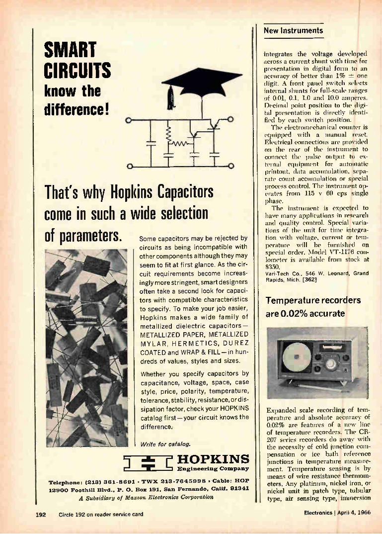
New Instruments
SMART CIRCUITS know the difference!
o TT TT o That's why Hopkins Capacitors come in such a wide selection of parameters. Some capacitors may be rejected by
circuits as being incompatible with other components although they may
seem to fit at first glance. As the cir-cuit requirements become increas-ingly more stringent, smart designers
often take a second look for capaci-tors with compatible characteristics to specify. To make your job easier, Hopkins makes a wide family of
metallized dielectric capacitors— METALLIZED PAPER, METALLIZED
MYLAR, HERMETICS, DUREZ
COATED and WRAP & FILL—in hun-dreds of values, styles and sizes.
Whether you specify capacitors by capacitance, voltage, space, case style, price, polarity, temperature,
tolerance, stability, resistance, or dis-
sipation factor, check your HOPKINS catalog first—your circuit knows the
difference.
Write for catalog.
Mar HOPKINS
Engineering Company
Telephone: (213) 361-8691 • TWX 213-7645998 • Cable: HOP
12900 Foothill Blvd., P. 0. Bo: 191, San Fernando, Calif. 91341
A Subsidiary of Maxson Electronics Corporation
integrates the voltage developed across a current shunt with time for presentation in digital form to an accuracy of better than 1% 74-- one digit. A front panel switch selects internal shunts for full-scale ranges of 0.01, 0.1, 1.0 and 10.0 amperes. Decimal point position to the digi-tal presentation is directly identi-fied by each switch position. The electromechanical counter is
equipped with a manual reset. Electrical connections are provided on the rear of the instrument to connect the pulse output to ex-ternal equipment for automatic printout, data accumulation, sepa-rate count accumulation or special process control. The instrument op-erates from 115 y 60 cps single phase. The instrument is expected to
have many applications in research and quality control. Special varia-tions of the unit for tune integra-tion with voltage, current or tem-perature will be furnished on
special order. Model VT-1176 con-lometer is available from stock at $350. Vari-Tech Co., 546 W. Leonard, Grand Rapids, Mich. [362]
Temperature recorders
are 0.02% accurate
Expanded scale recording of tem-perature and absolute accuracy of 0.02% are features of a new line of temperature recorders. The CR-207 series recorders do away with the necessity of cold junction com-pensation or ice bath reference junctions in temperature measure-ment. Temperature sensing is by means of wire resistance thermom-eters. Any platinum, nickel iron, or nickel unit in patch type, tubular type, air sensing type, immersion
192 Circle 192 on reader service card Electronics I April 4, 1966
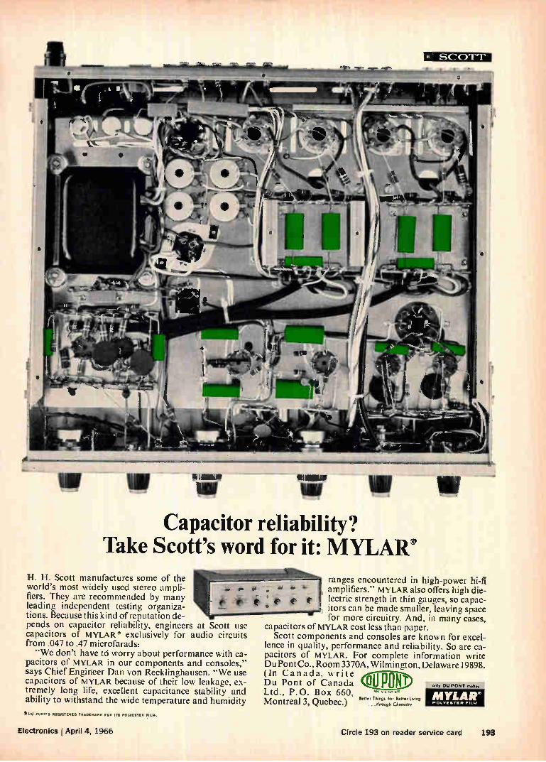
Capacitor reliability? Take Scott's word for it: MYLAR'
H. H. Scott manufactures some of the world's most widely used stereo ampli-fiers. They are recommended by many leading independent testing organiza-tions. Because this kind of reputation de-pends on capacitor reliability, engineers at Scott use capacitors of MYLAR* exclusively for audio circuits from .047 to .47 microfarads: "We don't have td worry about performance with ca-
pacitors of MYLAR in our components and consoles," says Chief Engineer Dah von Recklinghausen. "We use capacitors of MYLAR because of their low leakage, ex-tremely long life, excellent capacitance stability and ability to withstand the wide temperature and humidity
SCOTT-
ranges encountered in high-power hi-fi amplifiers." MYLAR also offers high die-lectric strength in thin gauges, so capac-itors can be made smaller, leaving space for more circuitry. And, in many cases,
capacitors of MYLAR cost less than paper. Scott components and consoles are known for excel-
lence in quality, performance and reliability. So are ca-pacitors of MYLAR. For complete information write DuPont Co., Room 3370A, Wilmington, Delaware 19898. (In Canada, write All noN Du Pont of Canada mu p Ltd., P.O. Box 660, Nis •
Better Things for Better Living
Montreal 3, Quebec.) Ihrot,gh Channel,
Mot) PONT'S REGISTERED TRADENNRE FOR ITS POLYESTER ESL...
Electronics April 4, 1966 Circle 193 on reader service card 193
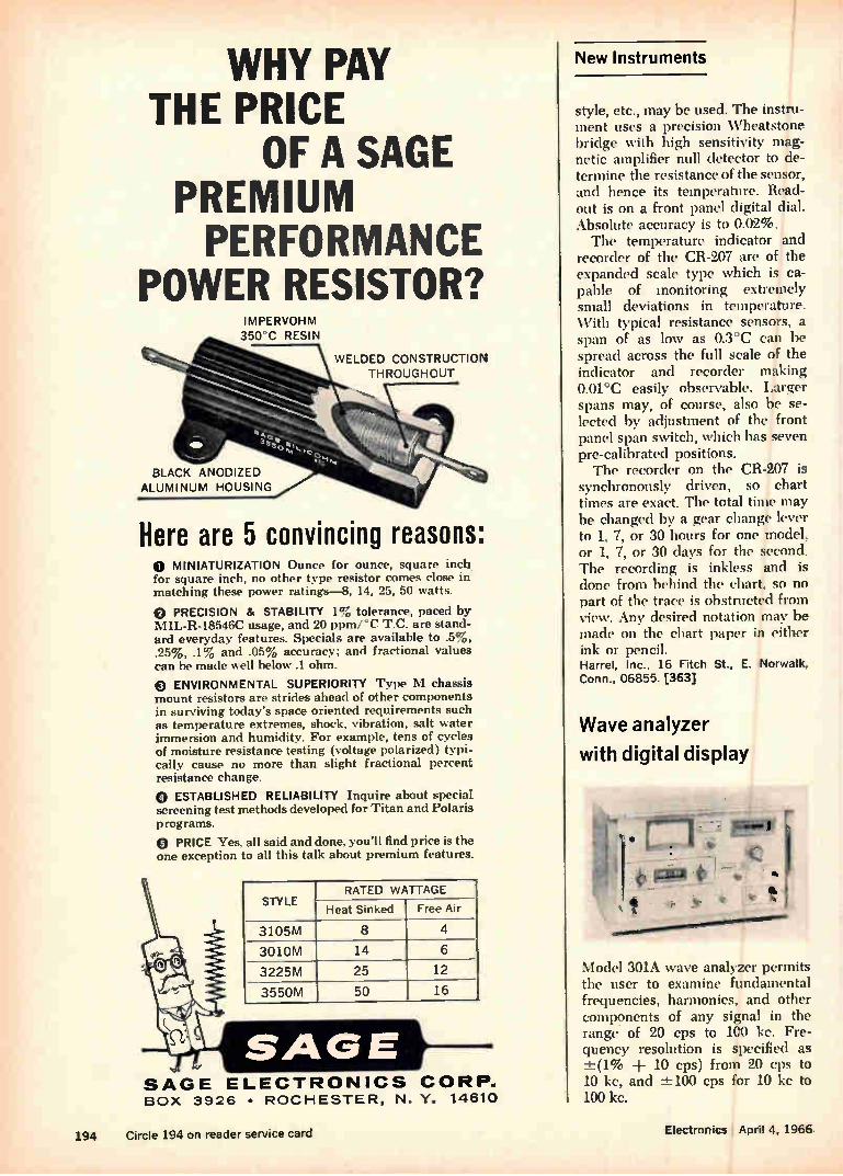
Here are 5 convincing reasons:
WHY PAY THE PRICE
OF A SAGE PREMIUM PERFORMANCE
POWER RESISTOR? IMPERVOHM 350°C RESIN
WELDED CONSTRUCTION THROUGHOUT
BLACK ANODIZED ALUMINUM HOUSING
O MINIATURIZATION Ounce for ounce, square inch for square inch, no other type resistor comes close in matching these power ratings-8, 14, 25, 50 watts.
(E) PRECISION & STABILITY 1% tolerance, paced by MIL-R-18546C usage, and 20 ppmrC T.C. are stand-ard everyday features. Specials are available to .5%, .25%, .1% and .05% accuracy; and fractional values can be made well below .1 ohm.
O ENVIRONMENTAL SUPERIORITY Type M chassis mount resistors are strides ahead of other components in surviving today's space oriented requirements such as temperature extremes, shock, vibration, salt water immersion and humidity. For example, tens of cycles of moisture resistance testing (voltage polarized) typi-cally cause no more than slight fractional percent resistance change.
O ESTABLISHED RELIABILITY Inquire about special screening test methods developed for Titan and Polaris programs.
(2) PRICE Yes, all said and done, you'll find price is the one exception to all this talk about premium features.
STYLE RATED WATTAGE
Heat Sinked Free Air
3105M 8 4
3010M 14 6
3225M 25 12
3550M 50 16
SAGE ELECTRONICS CORP.. BOX 3926 • ROCHESTER, N. Y. 14610
New Instruments
style, etc., may be used. The instru-ment uses a precision \Vheatstone bridge with high sensitivity mag-netic amplifier null detector to de-termine the resistance of the sensor, and hence its temperature. Read-out is on a front panel digital dial. Absolute accuracy is to 0.02%. The temperature indicator and
recorder of the CR-207 are of the expanded scale type which is ca-pable of monitoring extremely small deviations in temperature. With typical resistance sensors, a span of as low as 0.3°C can be spread across the full scale of the indicator and recorder making 0.01°C easily observable. Larger spans may, of course, also be se-lected by adjustment of the front panel span switch, which has seven pre-calibrated positions. The recorder on the CR-207 is
synchronously driven, so chart times are exact. The total time may be changed by a gear change lever to 1, 7, or 30 hours for one model, or 1, 7, or 30 days for the second. The recording is inkless and is done from behind the chart, so no part of the trace is obstructed from view. Any desired notation may be made on the chart paper in either ink or pencil. Harrel, Inc., 16 Fitch St., E. Norwalk, Conn., 06855. [363]
Wave analyzer
with digital display
Model 301A wave analyzer permits the user to examine fundamental frequencies, harmonics, and other components of any signal in the range. of 20 cps to 100 kc. Fre-quency resolution is specified as -±(1% 10 cps) from 20 cps to 10 kc, and ±-100 cps for 10 kc to 100 kc.
194 Circle 194 on reader service card Electronics April 4, 1966

The instrument contains a digital frequency display that is direct-reading in kilocycles. The five-digit display provides numerical values in 10-cps increments, with 2-cps interpolation marks. A tuner motor drives the instrument across the full range of 20 cps to 100 kc in ap-proximately 35 seconds. The 301A also contains provi-
sions for operation as a tracking signal generator or as a selective voltmeter with restored signal out-put. In the signal generator mode, the frequency of the output is the same as that to which the voltmeter is tuned. Frequency - response measure -
ments can be made by turning only one knob. Both voltmeter and sig-nal generator are automatically tuned to the same frequency. The output level of the generator is held constant within -±-0.5 db across the full frequency range. As a voltmeter with restored sig-
nal at the output (identical in fre-quency with the input signal), the 301A provides a filter effect to iso-late one signal out of a group, or a signal partly masked by noise, and amplifies it for greater resolution and measurement accuracy.
Full-scale voltage ranges cover from 30 i.tv to 300 v. The instrument also reads dbm directly on 600-ohm circuits at full-scale levels from +50 to —90 dbm, with ±0.5-db accuracy. Price is $1,995. Sierra/Philco, 3885 Bohannon Drive, Menlo Park, Calif., 94025. [364]
Pressure transducers
rated to 3,000 psi
A series of pressure transducers consists of five units with capabili-ties of 15, 100, 300, 1000 and 3000 psi. The 1281 series is designed for use in industries such as aerospace, petroleum, chemical, hydraulics and others. The pressure sensors operate on a variable inductance
Then Another Lens Honeycomb This Big
We Put 11 Incandescent Lamps
This Big
An 11-Message Film This Big
And a Viewing Screen This Big
Now, You Have the Smallest Rearm Projection Readout in the World!
It Displays Characters This Big.
In a Package This Big
(shown actual size')
All the versatility, readability, and reliability of our patented rear-projection readouts are now available in the world's tiniest theatre: the 3/4" H x W IEE Series 340. We've managed to fit everything but a pro-jectionist in there to give you a choice and clarity of message that no other type of readout can match.. regardless of size!
The tiny 340 uses film to project any message: num. bers, letters, words, symbols, colors. Anything you can put on film! You're not limited to crudely formed char. acters that look strange to the eye. Choose type styles that human-factors tests prove to be most readable!
Your message appears clearly and sharply on a single-plane screen. There's no visual hash or camouflage-netting effect from unlit filaments. The 340 may be tiny5 but your message appears big, up to an easily read %" in height!
HERE'S HOW IT WORKS: All IEE readouts are passive, nonmechani-cal devices built for long life. An input sig-
nal through the proper contact illuminates the desired lamp, projecting only the selected message through the lenses onto a non-glare viewing screen. This one-lamp-per-message concept eliminates character misreadings caused by partial failures.
/1 CLICK, IT'S IN
CLICK, IT'S OUT!
For quick, easy lamp replace. ment or change
-1 of message, just press the
front of the 340, pull the whole unit out! Permanently wired base remains in assembly!
SEND TODAY FOR COMPLETE INFORMATION
INDUSTRIAL ELECTRONICS ENGINEERS, INC. 7720 LEMONA AVE. • VAN NUYS, CALIFORNIA • PHONE: (213) 787-0311 • TWX (213) 781-8115
REPRESENTATIVES IN PRINCIPAL CITIES
Electronics I April 4, 1966 Circle 195 on reader service card 195
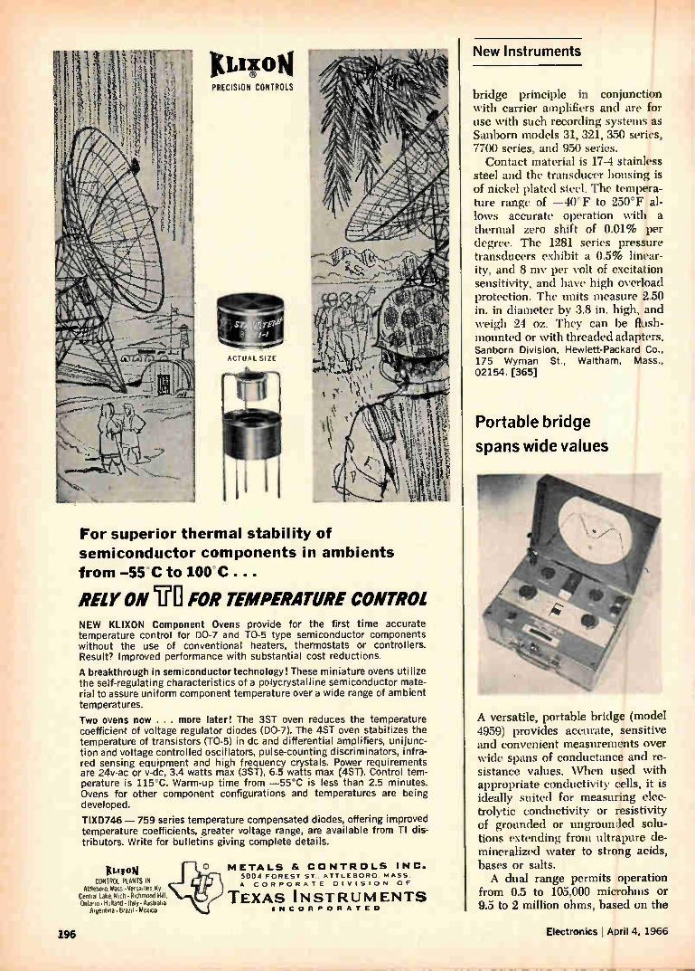
I/11C ON PRECISION CONTROLS
ACTUAL SIZE
For superior thermal stability of semiconductor components in ambients
from -55 C to 100 C
RELY ON UO FOR TEMPERATURE CONTROL NEW KLIXON Component Ovens provide for the first time accurate temperature control for DO-7 and TO-5 type semiconductor components without the use of conventional heaters, thermostats or controllers. Result? Improved performance with substantial cost reductions.
A breakthrough in semiconductor technology! These miniature ovens utilize the self-regulating characteristics of a polycrystalline semiconductor mate-rial to assure uniform component temperature over a wide range of ambient temperatures.
Two ovens now . . . more later! The 3ST oven reduces the temperature coefficient of voltage regulator diodes (D0-7). The 4ST oven stabilizes the temperature of transistors (T0-5) in dc and differential amplifiers, unijunc-tion and voltage control led oscillators, pulse-counting discriminators, infra-red sensing equipment and high frequency crystals. Power requirements are 24v-ac or v-dc, 3.4 watts max (3ST), 6.5 watts max (4ST). Control tem-perature is 115°C. Warm-up time from —55°C is less than 2.5 minutes. Ovens for other component configurations and temperatures are being developed.
TIXD746 — 759 series temperature compensated diodes, offering improved temperature coefficients, greater voltage range, are available from TI dis-tributors. Write for bulletins giving complete details.
XL11[014 CONTFt01. PLANTS IN
Attleboro.Mass•Versadles My Central Lake.Mich• Richmond Hill. Ontario•Holland•Italy•Australta
Argentina•Brazil•Mexico
METALS & CONTROLS INC. 5004 FOREST ST ATTLEBORO MASS.
A CORPORATE DIVISION OF
TEXAS INSTRUMENTS INCORPORATED
New Instruments
bridge principle in conjunction with carrier amplifiers and are for use with such recording systems as Sanborn models 31, 321, 350 series, 77(X) series, and 950 series.
Contact material is 17-4 stainless steel and the transducer housing is of nickel plated steel. The tempera-ture range of —40 F to 250°F al-lows accurate operation with a thermal zero shift of 0.01% per degree. The 1281 series pressure transducers exhibit a 0.5% linear-ity, and 8 mv per volt of excitation sensitivity, and have high overload protection. The units measure 2.50 in. in diameter by 3.8 in. high, and weigh 24 oz. They can be flush-mounted or with threaded adapters. Sanborn Division, Hewlett-Packard Co., 175 Wyman St., Waltham, Mass., 02154. [365]
Portable bridge
spans wide values
A versatile, portable bridge (model 4959) provides accurate, sensitive and convenient measurements over wide spans of conductance and re-sistance values. When used with appropriate conductivity cells, it is ideally suited for measuring elec-trolytic conductivity or resistivity of grounded or ungrounded solu-tions extending from ultrapure de-mineralized water to strong acids, bases or salts. A dual range permits operation
from 0.5 to 105,000 microhms or 9.5 to 2 million ohms, based on the
196 Electronics I April 4, 1966
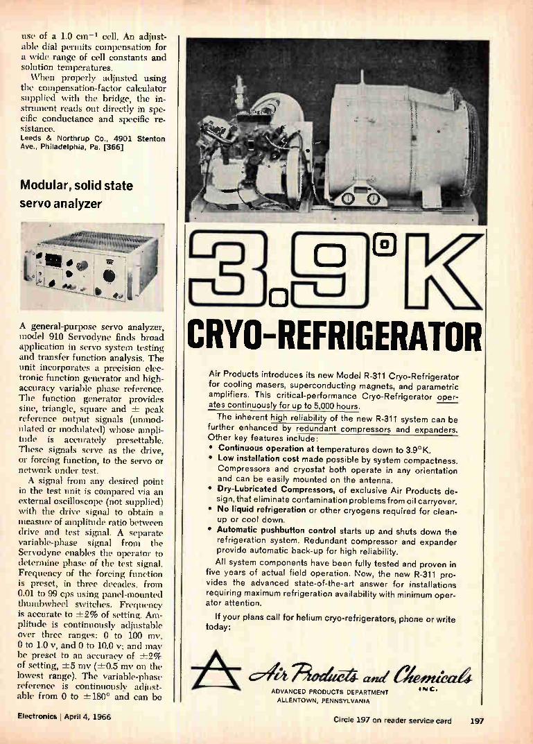
use of a 1.0 cm—' cell. An adjust-able dial permits compensation for a \'ide range of cell constants and solution temperatures. When properly adjusted using
the compensation-factor calculator supplied with the bridge, the in-strument reads out directly in spe-cific conductance and specific re-sistance. Leeds & Northrup Co., 4901 Stenton Ave., Philadelphia, Pa. [366]
Modular, solid state
servo analyzer
00e, t•401i ''''''
A general-purpose servo analyzer, model 910 Servodyne finds broad application in servo system testing and transfer function analysis. The unit incorporates a precision elec-tronic function generator and high-accuracy variable phase reference. The function generator provides sine, triangle, square and ± peak reference output signals (unmod-ulated or modulated) whose ampli-tude is accurately presettable. These signals serve as the drive, or forcing function, to the servo or network under test. A signal from any desired point
in the test unit is compared via an external oscilloscope (not supplied) with the drive signal to obtain a measure of amplitude ratio between drive and test signal. A separate variable-phase signal from the Servodyne enables the operator to determine phase of the test signal. Frequency of the forcing function is preset, in three decades, from 0.01 to 99 cps using panel-mounted thumbwheel switches. Frequency is accurate to ±2% of setting. Am-plitude is continuously adjustable over three ranges: 0 to 100 mv, 0 to 1.0 v, and 0 to 10.0 v; and may be preset to an accuracy of ±2% of setting, ±-5 mv (-± 0.5 mv on the lowest range). The variable-phase reference is continuously adjust-able from 0 to ±-180° and can be
CRYO-REFRIGERATOR Air Products introduces its new Model R-311 Cryo-Refrigerator for cooling masers, superconducting magnets, and parametric amplifiers. This critical-performance Cryo-Refrigerator oper-ates continuously for up to 5,000 hours.
The inherent high reliability of the new R-311 system can be further enhanced by redundant compressors and expanders. Other key features include: • Continuous operation at temperatures down to 3.9°K. • Low installation cost made possible by system compactness. Compressors and cryostat both operate in any orientation and can be easily mounted on the antenna.
• Dry-Lubricated Compressors, of exclusive Air Products de-sign, that eliminate contamination problems from oil carryover.
• No liquid refrigeration or other cryogens required for clean-up or cool down.
• Automatic pushbutton control starts up and shuts down the refrigeration system. Redundant compressor and expander provide automatic back-up for high reliability.
All system components have been fully tested and proven in five years of actual field operation. Now, the new R-311 pro-vides the advanced state-of-the-art answer for installations requiring maximum refrigeration availability with minimum oper-ator attention.
If your plans call for helium cryo-refrigerators, phone or write today:
ADVANCED PRODUCTS DEPARTMENT
ALLENTOWN, PENNSYLVANIA
I N C .
Electronics j April 4, 1966 Circle 197 on reader service card 197
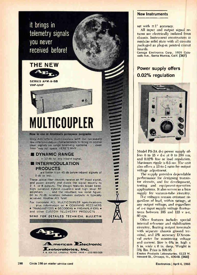
it brings in telemetry signals you never received before!
THE NEW
SERIES AFM-8-BB
VHF-UHF
MULTICOUPLER Now in use in America's aerospace programs
Only AEL offers multicouplers with the necessary low infermodulation characteristics to bring in crystal clear signals on range telemetry systems . , . even from 'way out space. HERE'S WHY ...
- 111 DYNAMIC RANGE 10 db for any inband signal,
111 INTERMODULATION PRODUCTS . are better than 45 db below inband signals of
O db or less.
These active filter devices receive an RF input signal, and power amplify and divide the signal equally to 2, 4, or 8 outputs. The design features broad band, high isolation hybrid couplers and high level RF amplifiers . . . and the resultant low noise figure. 60 to 70 db isolation between outputs is typically achieved. Another AEL first!
For complete AEL MULTICOUPLER specifications . . . plus information on • COMMAND RECEIVERS • TRANSMITTERS • DECODERS • PREAMPLIFIERS • and other CUSTOM TELEMETRY PRODUCTS . . .
SEND FOR DETAILED TECHNICAL BULLETIN
..ALmericara 3nlectronic
alborcitories, Inc. P. 0. 805 552. LANSDALE. PENNA. 19446 • (215) 822'2525
ossolle
wool mooll
me/ so.
mew
lea ono
we
•
New Instruments
set with ± 1° accuracy. All input and output signal re-
turns are electrically isolated from chassis. Instrument construction is modular solid state with all circuits packaged as plug-in printed circuit boards. Canoga Electronics Corp., 1805 Colo-rado Ave, Santa Monica, Calif. [367]
Power supply offers
0.02% regulation
Model PS-3A d-c power supply of-fers 0 to 25 y d-c at 0 to 200 ma; and 0.02% line or load regulation. Maximum ripple is 0.5 mv. The unit also offers a 12-to-1 ratio for output voltage adjustment. The supply provides dependable
performance for designing transis-tor circuits, and for development, testing and equipment-operation applications. It also serves as a bias supply for vacuum-tube circuitry. D-c voltages remain constant re-
gardless of load, within ratings, at any output voltage; and regardless of a-c input supply voltage fluctua-tions between 105 and 125 y a-c, 60 cps.
Other features include: special internal reference and stabilization circuitry, floating output terminals with separate chassis ground ter-minal, and 2% accuracy D'Arson-val meter for monitoring voltage and current. Size is 61/2 in. high x 5 in. wide x 6 in. deep. Weight is 31/2 lbs. Price is $99.95. Electro Products Laboratories, 6123 W. Howard St., Chicago, III., 60648. [368]
198 Circle 198 on reader service card Electronics I April 4, 1966
If you want to capture signals from way way out,
record them on the tape with total recall
MEMOREX PRECISION MAGNETIC TAPE
VISIT BOOTHS 420 & 430
NATIONAL TELEMETRY SHOW
When you put a reel of Memorex instrumentation tape on your transport, you can expect the most reliable perform-ance, both from the tape and from your recorder. Because Memorex coating formulations are highly uniform, you'll find fewer dropouts: because they are extremely durable, you'll find significantly less oxide shedding. and freedom from head build-up or gap smear. The result is multi-pass
stability of performance unequalled by any other tape.
If you write Memorex Corporation at 410 Memorex Park, Santa Clara, California 95052, we will send you instrumen-tation tape specification data and a bibliography of tech-nical information available without obligation from the Memorex library of reprints.
Memorex Branch Offices in New York, Philadelphia, Washington, Atlanta, Orlando, Dayton, Chicago, Detroit, Dallas, Los Angeles, San Francisco; Offices and Affiliates in London, Cologne, and Paris
Electronics I April 4, 1966 Circle 199 on reader service card 199
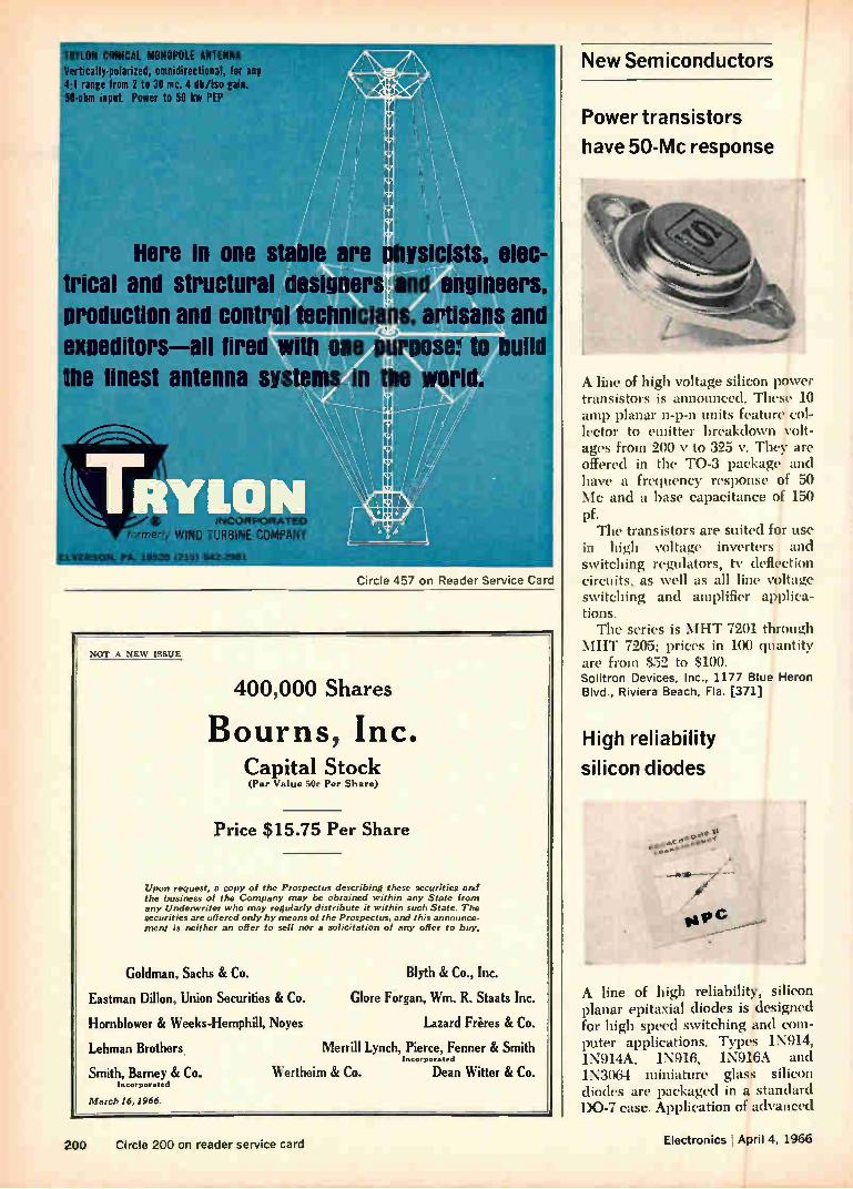
TRYLON CONICAL MONOPOLE ANTENNA #ertically-polarized, omnidirectional, for any !4•1 range from 2 to 30 mc. 4 dh/iso gain. 50-ohm input. Power to 50 kw PEP
Here in one stable ysicists, trical and structural designers and engineers, production and control technicians, artisans an expeditors—all tired with one purpose: to bull the finest antenna systems_Wiorld.
11
formerly WIND TURBINE COMPANY
ELVERSON. PA. 19520 (215) 942-2981
Circle 457 on Reader Service Card
NOT A NEW ISSUE
400,000 Shares
Bourns, Inc. Capital Stock (Par Value 50e Per Share)
Price $15.75 Per Share
Upon request, a copy of the Prospectus describing these securities and the business of the Company may be obtained within any State from any Underwriter who may regularly distribute it within such State. The securities are offered only by means of the Prospectus, and this announce-ment is neither an offer to sell nor a solicitation of any offer to b00%
Goldman, Sachs & Co.
Eastman Dillon, Union Securities & Co.
Hornblower & Weeks-Hemphill, Noyes
Lehman Brothers
Smith, Barney & Co. Incorporated
March 16, 1966.
Blyth & Co., Inc.
Clore Forgan, Wm. R. Staats Inc.
Lazard Frères & Co.
Merrill Lynch, Pierce, Fenner & Smith lncor pot ated
Wertheim & Co. Dean Witter & Co.
New Semiconductors
Power transistors
have 50-Mc response
A line of high voltage silicon power transistors is announced. These 10 amp planar n-p-n units feature col-lector to emitter breakdown volt-ages from 200 y to 325 v. They are offered in the TO-3 package and have a frequency response of 50 Mc and a base capacitance of 150
Pf• The transistors are suited for use
in high voltage inverters and switching regulators, tv deflection circuits, as well as all line voltage switching and amplifier applica-tions. The series is MHT 7201 through
MHT 7205; prices in 100 quantity are from $52 to $100. Solitron Devices, Inc., 1177 Blue Heron Blvd., Riviera Beach, Fla. [371]
High reliability
silicon diodes
A line of high reliability, silicon planar epitaxial diodes is designed for high speed switching and com-puter applications. Types 1N914, 1N914A, 1N916, 1N916A and 1N3064 miniature glass silicon diodes are packaged in a standard DO-7 case. Application of advanced
200 Circle 200 on reader service card Electronics I April 4, 1966
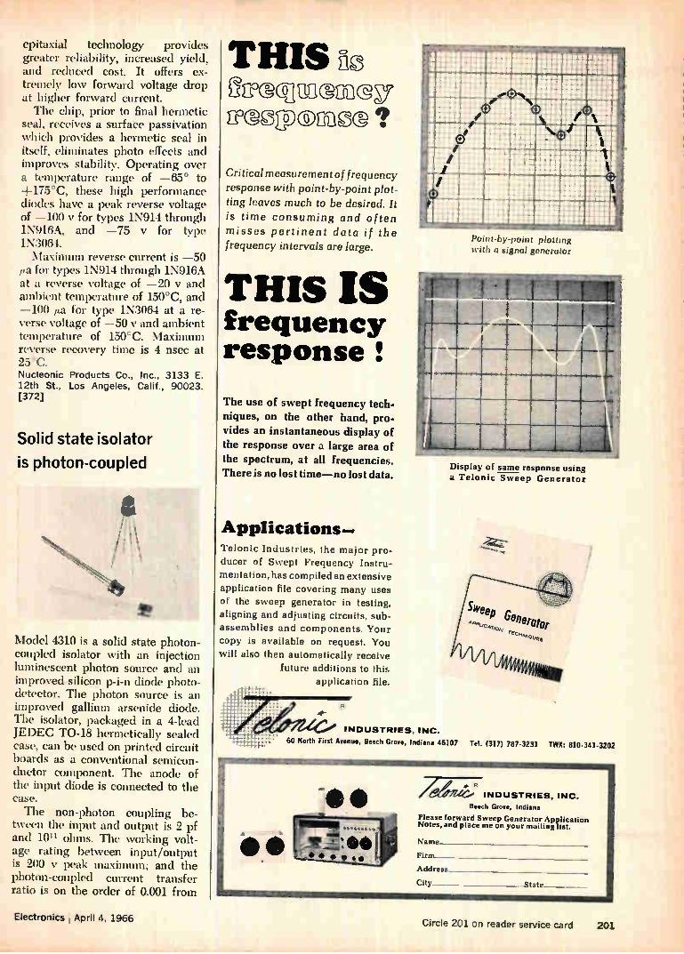
epitaxial technology provides greater reliability, increased yield, and reduced cost. It offers ex-tremely low forward voltage drop at higher forward current. The chip, prior to final hermetic
seal, receives a surface passivation which provides a hermetic seal in itself, eliminates photo effects and improves stability. Operating over a temperature range of —65° to +175°C, these high performance diodes have a peak reverse voltage of —100 y for types 1N914 through 1N916A, and —75 y for type 1N3064. Maximum reverse current is —50
pa for types 1N914 through 1N916A at a reverse voltage of —20 y and ambient temperature of 150°C, and —100 pa for type 1N3064 at a re-verse voltage of —50 y and ambient temperature of 150°C. Maximum reverse recovery time is 4 nsec at 2.5°C. Nucleonic Products Co., Inc., 3133 E. 12th St., Los Angeles, Calif., 90023. [372]
Solid state isolator
is photon-coupled
Model 4310 is a solid state photon-coupled isolator with an injection luminescent photon source and an improved silicon p-i-n diode photo-detector. The photon source is an improved gallium arsenide diode. The isolator, packaged in a 4-lead JEDEC TO-18 hermetically sealed case, can be used on printed circuit boards as a conventional semicon-ductor component. The anode of the input diode is connected to the case. The non-photon coupling be-
tween the input and output is 2 pf and 10" ohms. The working volt-age rating between input/output is 200 y peak maximum; and the photon-coupled current transfer ratio is on the order of 0.001 from
THIS no gincjumn@D? nolgogx)no@ ?
Critical measurement of frequency response with point-by-point plot-ting leaves much to be desired. It is time consuming and often
misses pertinent data if the frequency intervals are large.
THIS IS frequency response
The use of swept frequency tech-
niques, on the other hand, pro-
vides an instantaneous display of the response over a large area of
the spectrum, at all frequencies.
There is no lost time—no lost data.
Applications--Telonic Industries, the major pro-
ducer of Swept Frequency Instru-mentation, has compiled an extensive application file covering many uses of the sweep generator in testing, aligning and adjusting circuits, sub-assemblies and components. Your copy is available on request. You will also then automatically receive
future additions to this application file.
Point-by point ploWng with a signal generator
Display of saine response using
a Telonic Sweep Generator
INDUSTRIES, INC.
60 North First Avenue, Beech Grove, Indiana 46107 Tel. (317) 787-3231 TWX: 810-341-3202
AO. /eSuc. INDUSTRIES, INC. Beech Grove, Indiana
Please forward Sweep Generator Application Notes, and place me on your mailing list.
Name_
Firm_
Address__
City .State _
Electronks , April 4, 1966 Circle 201 on reader service card 201

lEnIGELDIAIIZZIP fused quartz tube used in Martin laser research
A practical demonstration of the potential of lasers in space navigation has been made with a doppler laser simulator by Martin-Orlando scientists. Shown pub-licly for the first time at the American Institute of Aero-nautics and Astronautics meeting, the doppler device uses a CW gas laser operating in the visible spectrum. The laboratory model shows precise resolution of target speed, either fast or slow, over a wide range. The capability of detecting velocities as low as one
millimeter per second makes the device particularly applicable for space rendezvous maneuvering systems. The optical doppler frequencies, being much higher
than those of microwave (radar) systems, permit the measurement of lower velocities, higher resolution in velocity measurement and, therefore, significantly greater accuracy. In addition, the narrow beamwidth of the laser provides maximum interception of the emitted energy by the target. This means that trans-
mission losses are small and longer ranges possible with less power.
Engelhard's Amersil Quartz Division pioneers the road
Martin-Orlando scientists forge ahead, and Engelhard paves the way for them. Amersil Quartz Division's fused quartz tube was built to the most exacting speci-
fications for use in the Martin laser.
The research facilities and extensive technical know-how of the Amersil Division are often called upon in such situations. In meeting the needs of industry for high-purity fused quartz, Engelhard scientists have transformed many experimental items into useful im-plements for sophisticated research. At their disposal are the finest casting, molding and drawing facilities in the industry. Write our technical services department today for further information on Amersil Fused Quartz.
339
202 Circle 202 on reader service card Electronics April 4, 1966
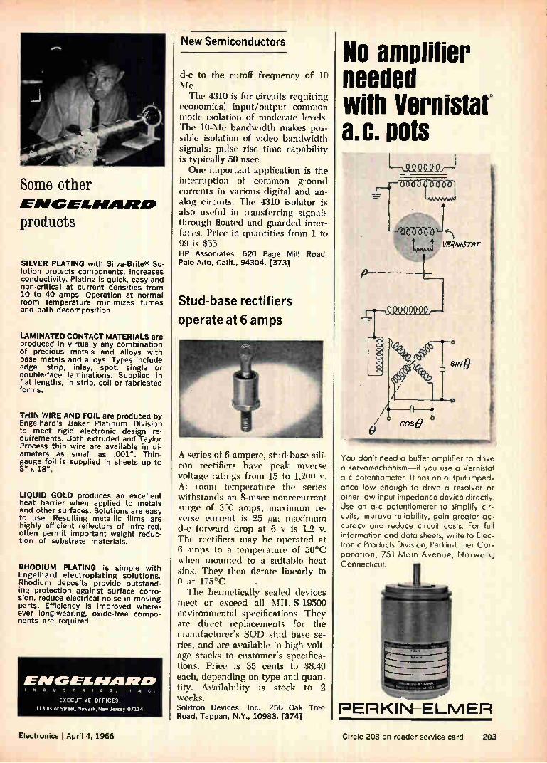
Some other ENGEL-MARE.
products
SILVER PLATING with Silva-Britee So-lution protects components, increases conductivity. Plating is quick, easy and non-critical at current densities from 10 to 40 amps. Operation at normal room temperature minimizes fumes and bath decomposition.
LAMINATED CONTACT MATERIALS are produced in virtually any combination of precious metals and alloys with base metals and alloys. Types include edge, strip, inlay, spot, single or double-face laminations. Supplied in flat lengths, in strip, coil or fabricated forms.
THIN WIRE AND FOIL are produced by Engelhard's Baker Platinum Division to meet rigid electronic design re-quirements. Both extruded and Taylor Process thin wire are available in di-ameters as small as .001". Thin-gauge foil is supplied in sheets up to 8" x 18".
LIQUID GOLD produces an excellent heat barrier when applied to metals and other surfaces. Solutions are easy to use. Resulting metallic films are highly efficient reflectors of infra-red, often permit important weight reduc-tion of substrate materials.
RHODIUM PLATING is simple with Engelhard electroplating solutions. Rhodium deposits provide outstand-ing protection against surface corro-sion, reduce electrical noise in moving parts. Efficiency is improved where-ever long-wearing, oxide-free compo-nents are required.
ENGEL/011RO INDUSTRIES. INC.
EXECUTIVE OFFICES:
113 Astor Street, Newark, New Jersey 07114
New Semiconductors
d-c to the cutoff frequency of 10 Mc. The 4310 is for circuits requiring
economical input/output common mode isolation of moderate levels. The 10-Mc bandwidth makes pos-sible isolation of video bandwidth signals; pulse rise time capability is typically 50 nsec. One important application is the
interruption of common ground currents in various digital and an-alog circuits. The 4310 isolator is also useful in transferring signals through floated and guarded inter-faces. Price in quantities from 1 to 99 is $55. HP Associates, 620 Page Mill Road, Palo Alto, Calif., 94304. [373]
Stud-base rectifiers
operate at 6 amps
A series of 6-ampere, stud-base sili-con rectifiers have peak inverse voltage ratings from 15 to 1,200 v. At room temperature the series withstands an 8-msec nonrecurrent surge of 300 amps; maximum re-verse current is 25 iza; maximum (l-c' forward drop at 6 y is 1.2 v. The rectifiers may be operated at 6 amps to a temperature of 50°C when mounted to a suitable heat sink. They then derate linearly to 0 at 175°C. The hermetically sealed devices
meet or exceed all MIL-S-19500 environmental specifications. They are direct replacements for the manufacturer's SOD stud base se-ries, and are available in high volt-age stacks to customer's specifica-tions. Price is 35 cents to $8.40 each, depending on type and quan-tity. Availability is stock to 2 weeks. Solitron Devices, Inc., 256 Oak Tree Road, Tappan, N.Y., 10983. [374]
No amplifier needed with verffistat a.c. Dots
.0,
Li VERN/STAT t
cose r""loulefflinuillimillM1111111111111•11111111111111mml
You don't need a buffer amplifier to drive o servomechanism—if you use a Vernistat a-c potentiometer. It has an output imped-ance low enough to drive a resolver or other low input impedance device directly. Use an a-c potentiometer to simplify cir-cuits, improve reliability, gain greater ac-curacy and reduce circuit costs. For full information and data sheets, write to Elec-tronic Products Division, Perkin-Elmer Cor-poration, 751 Main Avenue, Norwalk, Connecticut.
PERKIN ELMER
Electronics I April 4, 1966 Circle 203 on reader service card 203

workability (pre-production training)
WESTern PENNsylvania has a proved-in-use plan by which adaptable, productive people with a va-riety of industrial aptitudes will be trained in ad-vance for YOUR operation, usually at no cost to you. You can also save on labor-turnover costs in WESTern PENNsylvania where the "Voluntary Quit rate" is only one-third the national average. This workability and training program . . . plus 100% financing at low, low interest rates ... fair
tax climate .. . four-season liva-bility . . . give WESTern PENN-sylvania a top combination of plant-location values.
WEST PENN POWER an operating unit of ALLEGHENY POWER SYSTEM
Area Development Department, Room 663 WEST PENN POWER—Greensburg, Pa. 15602 Phone: 412-837-3000
In strict confidence. I'd like to know more about WESTern PENNsylvania's: L Pre-Production Training L. Financing
Plans n Fair Tax Climate D Industrial Properties and
Shell Buildings I 1 Please have your Plant Location Specialist call.
Name
Title
Company
Address
City State
Code Phone_ _
New Subassemblies and Systems
System power supplies
with fixed output
A series of fixed-output, d-c system power supplies, called Systematics, feature Mil-Spec construction, a completely field-repairable design, and integrated heat exchangers that eliminate the need for additional external heat sinks. Open, easy-access design is
based on all-silicon solid state cir-cuitry, with 90% of the components incorporated on one plug-in printed-circuit board that can be easily and quickly removed and re-placed by an identical unit in the event of damage to the power sup-ply. This feature permits field re-pair, eliminating high cost of com-plete replacement required when sealed or encapsulated units are damaged and must be discarded.
Completely self-contained and self-cooled, Systematics do not re-quire additional, space-consuming external heat sinks that add costs and labor to installation and often result in an inefficient thermal path that limits the life and efficiency of a sealed unit. All heat-sensitive components are mounted directly on high-efficiency heat sinks in the power supply for optimum heat transfer.
Systematics are available in 84 standard off-the-shelf models with fixed outputs spanning the output voltage range of 1 to 100 y at cur-rent ratings from 0.3 to 12 amps. All-silicon, transistor-regulated cir-cuitry maintains regulation at 0.025%, holds ripple and noise to 1 my rms maximum. Class F high-reliability, epoxy - encapsulated, low-loss transformers with elec-
trostatic shields are included in the circuitry which has been conser-vatively designed for optimum reliability without resorting to critically matched or selected semi-conductors.
All models feature special con-trol circuits to permit finite voltage adjustment within ±-10% of the rated fixed output by means of lock-ing type potentiometers accessible from the outside for screwdriver adjustment. Each model includes remote sensing capability and auto-matic electronic current limiting for protection against overloads and short circuits. Cover en-closures that permit removal of the power supply without demounting the enclosure from its installed position are optional.
Prices start at $89.50. Delivery is from stock. Perkin Electronics Corp, 345 Kansas St., El Segundo, Calif. [380]
Deflection amplifier
in modular package
Model DA 105 deflection amplifier is an all silicon, solid state mod-ular package featuring high deflec-tion performance characteristics at low cost. It is designed for appli-cation in any crt or storage tube display system employing magnetic deflection. The amplifier is capable of sup-
plying up to 12 amps of deflection current to a directly-coupled deflec-tion coil. The module comprises two identical channels of power amplification, one for X deflection and one for Y deflection. The new unit is a d-c coupled
operational-type difference ampli-
204 Circle 204 on reader service c^-4 Electronicsf April 4. 1966
fier. It features excellent linearity, wide bandwidth and stable opera-tion. Since the amplifier is d-c cou-pled throughout, it may be utilized in random point plotting or alpha-numeric deflection applications as well as for raster or other periodic scan formats. Centering, off-set, geometry correcting and other in-puts may be introduced with ease at the summing point of the differ-ence amplifier stage. The input of the model DA105
deflection amplifier is designed to be compatibly coupled to the out-put of the model SG415 sawtooth generator. The amplifier is also fully compatible with all other modular display systems compo-nents manufactured by the com-pany. Beta Instrument Corp., 377 Elliot St., Newton Upper Falls, Mass., 02164. [381]
Transducer modules
work with wattmeters
Prepackaged modules have been developed that enable panel meters or meter-relays to function as indi-cating or controlling wattmeters. The new wattmeter transducer modules are available in three basic types: single-phase; three-phase, three-wire; and three-phase, four-wire. The manufacturer furnishes spe-
cial panel meters and optical meter-relays for operation with the trans-ducer modules. Meters and trans-ducers are calibrated together. Me-ter movements are rated at 50 to 100 mv d-c. Standard ranges for 80-cycle
measurement begin with 0 to 500-w full scale for single-phase transducers, with a top range of 0 to 4,000 w. For three-phase, three-wire transducers, ranges go from
*An absolutely fictional word we dreamed up to drive home the extreme flexibility of Phelps
Dodge Electronics Miniature Coaxial Cable. While the best competitive cable lasted only 55 minutes on flexing test, ours was vibrated at resonance for 7 hours before the sheath cracked.
Construction consists of a silver plated Copper-weld inner conductor, a Teflon TFE dielectric and solid, flexible copper sheath. Available, from stock, in diameters of .070", .085" and .141", in lengths up to 200', special diameters can be built for your special needs.
Here's the answer for small cable requirements in low noise amplifiers, microwave transmission, high-speed computers and a wide range of instrument sheath applications. For very low attenuation across Gc band, ease of stripping and joining, low VSWR, no radiation, and high performance in evironmental extremes, think PDE Miniature Coaxial Cable. Write for fully descriptive Bulletin Mc, Issue 1,
PHELPS DODGE
ii ELECTRONIC PRODUCTS
NORTH HAVEN. CONNECTICUT
Electronics I April 4, 1966 Circle 205 on reader service card 205

KV/PV series qualified to NAS1599 for critical
environmental applications
• KV/PV intermates with MIL-C-26500 and MIL-C-26482 type connectors offering improved de-sign, reliability and performance characteristics.
• Upgrades systems to higher performance standards without costly investment or complete circuit design changes.
• Now in use throughout the industry in critical applications on such vital programs as Apollo and Minuteman.
• Features the universally-accepted "LITTLE CAESAR — m rear release contact assembly.
• Significant inventory cost savings accomplished through connector standardization.
NAS 1599 combines into one industry specification the best features of two existing military specifica-tions.The KV/PV Series provides superior reliability where it counts most...
POSITIVE CONTACT MATEABILITY
IMPROVED CONTACT STABILITY
STRONGER, SIMPLIFIED CONTACTS
Utilizing the same contacts, backshells, acces• sones, military crimping tool and free expendable insertion/extraction tool, both the KV and PV reduce costly inventories and lessen user assembly training time. The feature of intermateability sup-ports military and industry design needs and the economy aims of all government agencies.
For information on complete 1599 line, including hermetics and test plugs, write to: ITT Cannon Electric, 3208 Humboldt St., Los Angeles, Calif. A division of International Tele-phone and Telegraph Corp.
CANNON' PLUGS
ITT CANNON 206 Circle 206 on rear:le , service card Electronics April 4, 1966
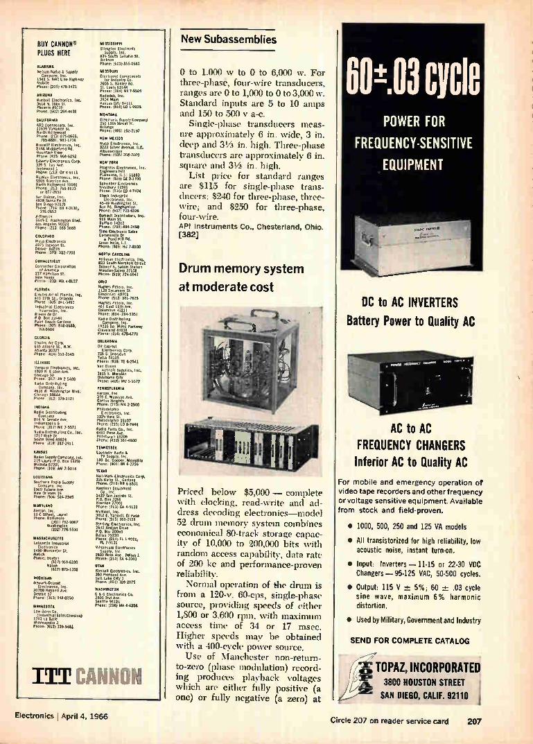
BUY CANNON" PLUGS HERE
ALABAMA Ne son Radio Supply Company, Inc.
1541 S. Belt Line HOPI, Mabel. Phone. (2051 479.1471
ARIZONA Knob.II Electronics, WC. 3614 N. 16th St. Ptolemy 85016 Phone: (602) 2644436
CALIFORNIA ABC Connectors. Inc. 11639 Vanowen St. North Hollywood Phone '213 875.0665,
7654181, 983.1738 KieruIll Electronics, Inc. 2484 Muldlefeeld Rd. Mountain View Phone (415: 9684292 Liberty Electronics Corp, 339 5 Isis Aye. Inglewood I Phone (213 OR 84111 Richley Electronics, Inc. 5505 Riverton Ave. North Hollywood 91601 Phone (213 7614133
or 877.2651 San De!nor, Inc. 4618 Santa He St. San Diego 92109 Phone e714 BR 4.3131,
276.2653 K.Tronics 5645 E Washengton Blvd. Los Angeles 90022 Phone .2(3 615.58811
COLORADO WA.° Electronics 4975 Jackson St. Denver 80216 Phone -303 322-7701
CONNECTICUT Connector CorporatIcel
of Amereca 137 Hametton St. New Haven Phone :203. MA 4-0127
FLORIDA Electro Alt of Florida, 410 27,0 St. Orlando Phone .306 241.5461 Industrial Electronns Assumtes, Inc.
Rivers:de Dr. P 0 Box 12444 Palm Beach Gardens Phone 405, 84846118, W48686
CEORCIA Electro Air Corp. 645 Antone St.. N.W. Atlanta 30325 Phone 404)351.3545
ILLINOIS Mermop Electronics, Inc. 4979 in Elston Ave. Chicago 30 Phone. 312 AV 2.5400 Radio Orstrebuteng
Company. lu. 4636 VI Washington Blvd. Chicago 60644 Phone 312 , 379-2121
INDIANA Radio Destnbuteng
81.io pany ir Senate Ave. Indmnapoles 6 Phone 3171 ME 7.5571 Radio Destrobutingee, loc. 1212 High St. South Bend 46624 Phone otir 287.2911
KANSAS Radio Supply Company log. 115 Laura (P.O. Box Ino) Wichita 67201 Phone 316 AM 7.5214
LOUISIANA Southern Radio Supply
Company, Inc 1909 Tulane Ave New Orleans 16 Phone: 404, 524.2345
MARYLANO hereon. Inc. 19 C Street, Laurel Phone. Baltimore
(301 , 792.9067 Washington
(202) 776.5590
MASSACHUSETTS teleyette Industrial
Electronics 1400 Worcester St. Natick Phone. Boston
(617) 9694100 Nateck
(617) 875.1356
MICNIGAN Newarle.Detret
Electronics, 20730 Hubbell Ave.
3, il) 548-0250
MINNESOTA Leo Bonn Co. IlnOustrul Sales OlvIslose)
1211 La Salle Minneapolis 3 Phone: (612)3394462
MISSISSIPPI Ellington Electronic
821. uecti, Inc ellatinst. Jackson Phone: (601) 355-0561
MISSOURI Electronic Components
for Industry Co. 2605 S. Hanley Rd. St. Louis 63144 Phone: (314) 141 7-5505 Radeolab, Inc. 3604 Main Kansas City 64111 PtIone, (816) 10 1-9935
MONTANA Electronic s000ly_C.Olai 250 I 1th Street W. Bellings Phone: (4061 292-2197
NEW MEXICO Waco Electronics. Inc. 3223 Silver Avenue, 4E. Albuquerque Phone: (505, 268.2409
NEW TORO Progress Electronics, leg. Engineers Hill Plainview, LI. 11803 Phone ;5161 GE 3.1700 Sclueber Electronics Westbury 11591 Phone. (516; ED 4.7474 Stack Industrial
Electronecs, Inc. 45.49 Washington St. Box 88, Binghamton Phone (607) 723.6326 Summit Destrébutors, Inc. 916 Main St. Buffalo 14202 Phone: (7161 844.3450 Time Electronic Sales Communety Dr
Pond Ht11 Rd. Great Nun. L I Phone: (516 HU 74100
NORTH CAROLINA Kirkman Electronics, Inc. 823 South Marshall Street Drawer K, Salem Station Wenston.Salern 27108 Phone: (9191 724-0541
OHIO Hughes Peters, Inc. 1ln Sycamore St. Cincinnati 45201 Phone: 15131 381-7625 Hughes Peters, Inc. 481 East 11th Ave Columbus 43211 Phone (614) 2944351 Radio Distributing Company, Inc.
18236 Se Moles Partnety Cleveland 44128 Phone- (2151 4754770
OKLAHOMA Oil Capitol
Electronics Corp. 708 S. Sheridan Tulsa 74115 Phone: :918 TE 6-2541 Van Dusen
/morsel Supplies, INC. 3805 S. Meriden Oklahoma City Phone: (405 MU 65577
PENNSYLVANIA 'tenon, Inc. 359 E. Madison Ave. Clittcin Ilmets Phone: (215, MA 2.2500 Philadelphia
Electronics, Inc. 1225 bene St. Philadelphia 19107 Phone: (2151 LO 8.7444 Radio Parts Co., Inc. 6401 Penn Ave Pettsburgh 15206 PAU.: 14121 3614600
TENNESSEE Lavender Radio
TV Supply. Inc 180 So. Cooper, Merneshit Phone: (901, BR 6.2756 TEXAS Hall-Mark Electronics Corp. 326 Kerby St., Garland Phooe (214: BR 64531 Harmon Equipment
Co.. Inc. 1422 San Jacinto St. P.O. Box 3268 Huston 77001 Plsone: (7131 CA 4.9131 Melicol, Inc. 3012 E. Tindall. El Puo Phone (9151 566.2936 Sterleng Electronics, Inc. 2642 AMID, Owe P.O. Box 20069 Dallas 75220 Phone (214) FL I 9921,
FL 79131 Wholesale Electronics
Supply, Inc. 2809 Ross Ave.. Dallas 1 Phone: (214) 16 4.3001
UTAN Kimball Electronics, Inc. 350 Merpont Ave Salt Lake City 1 Phone: (801) 328.2075
WASHINGTON C & G Electronics Co. 2600 2nd Ave. Seattle 98121 Phone. (206) MA 4-4354
ITT CANNON
New Subassemblies
0 to 1,000 w to 0 to 6,000 w. For three-phase, four-wire transducers, ranges are 0 to 1,000 to 0 to 3,000 w. Standard inputs are 5 to 10 amps and 150 to 500 y a-c.
Single-phase transducers meas-ure approximately 6 in. wide, 3 in. deep and 31/2 in. high. Three-phase transducers are approximately 6 in. square and 31/2 in. high.
List price for standard ranges are $115 for single-phase trans-ducers; $240 for three-phase, three-wire; and $250 for three-phase, four-wire. API Instruments Co., Chesterland, Ohio. [382]
Drum memory system
at moderate cost
Priced below $5,000 — complete with clocking, read-write and ad-dress decoding electronics—model 52 drum memory system combines economical 80-track storage capac-ity of 10,000 to 200,000 bits with random access capability, data rate of 200 kc and performance-proven reliability. Normal operation of the drum is
from a 120-v, 60-cps, single-phase source, providing speeds of either 1,800 or 3,600 rpm, with maximum access time of 34 or 17 msec. Higher speeds may be obtained with a 400-cycle power source. Use of Manchester non-return-
to-zero (phase modulation) record-ing produces playback voltages which are either fully positive (a one) or fully negative (a zero) at
0E03 cycle POWER FOR
FREQUENCY-SENSITIVE
EQUIPMENT
DC to AC INVERTERS
Battery Power to Quality AC
AC to AC
FREQUENCY CHANGERS Inferior AC to Quality AC
For mobile and emergency operation of video tape recorders and other frequency
or voltage sensitive equipment. Available from stock and field-proven.
• 1000, 500, 250 and 125 VA models
• All transistorized for high reliability, low acoustic noise, instant turn-on.
• Input: Inverters — 11-15 or 22-30 VDC Changers— 95-125 VAC, 50-500 cycles.
• Output: 115 V + 5%; 60 -4-- .03 cycle sine wave, maximum 6% harmonic distortion.
• Used by Military, Government and Industry
SEND FOR COMPLETE CATALOG
É
.ÉK. 3800 HOUSTON STREET
SAN DIEGO, CALIF. 92110
TOPAZ, INCORPORATED
Electronics , April 4, 1966 Circle 207 on reader service card 207

Take a look at our family...
POI-LAR-* CAPAC/Ire COVERS
yeti QUAL/TY
egaffee, ceedifs Foxes
Polyamide
Mica
Asbestos
FLEXALL" OIL- IMMERSED INSUL_
eri e â •
TEPAIINIAL STRIPS 111
We've got lots of daughters and they're
looking for dates. We can arrange a "wedding" to your specifications . . . quickly and with only a small dowry on
your part. If you see a member of our family you'd like to know better . call one of our "kinfolk" in your neighborhood (see column at right) or get in
touch with our "home" in Wheeling (Ill.).
'Registered trademark—DuPont Co. "Registered trademark—Precision Paper Tube Co.
rP eciere ion ,„
Paper Tube Company Divisions: Resinite • Buckeye Bobbin • Automation Devices 1033 S. Noel Ave., Wheeling, Ill. Phones: Chicago: 631-1445 • Long Distance: 312-537-4250, TWX: 312-537-5202
Wm/
208 Circle 208 on reader service card Electronics , April 4, 1966
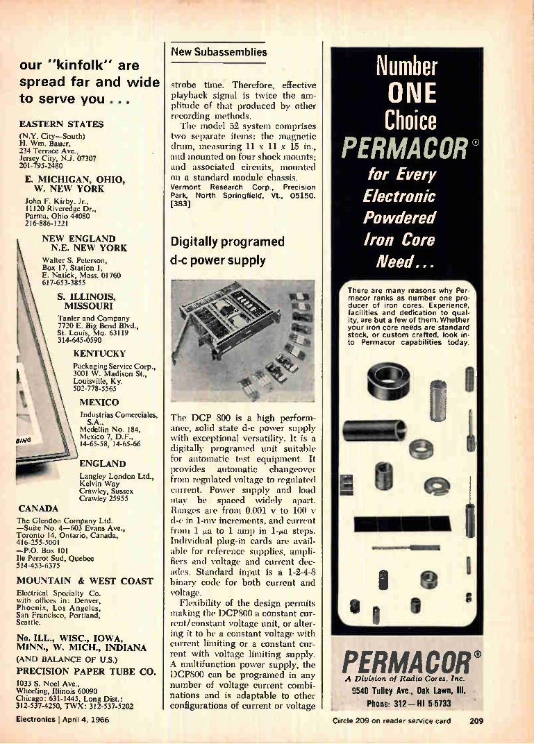
our "kinfolk" are spread far and wide to serve you ...
EASTERN STATES (N.Y. City—South) H. Wm. Bauer, 234 Terrace Ave., Jersey City, N.J. 07307 201-795-2480
E. MICHIGAN, OHIO, W. NEW YORK
John F. Kirby, Jr., 11120 Riveredge Dr., Parma, Ohio 44080 216-886-1221
CANADA
Bye
NEW ENGLAND N.E. NEW YORK
Walter S. Peterson, Box 17, Station 1, E. Natick, Mass. 01760 617-653-3855
S. ILLINOIS, MISSOURI
Tanler and Company 7720 E. Big Bend Blvd., St. Louis, Mo. 63119 314-645-0590
KENTUCKY Packaging Service Corp., 3001 W. Madison St., Louisville, Ky. 502-778-5565
MEXICO Industrias Comerciales,
S.A., Medellin No. 184, Mexico 7, D.F., 14-65-58, 14-65-66
ENGLAND Langley London Ltd., Kelvin Way Crawley, Sussex Crawley 25955
The Glendon Company Ltd. —Suite No. 4-603 Evans Ave., Toronto 14, Ontario, Canada, 416-255-5001 —P.O. Box 101 Ile Perrot Sud, Quebec 514-453-6375
MOUNTAIN & WEST COAST Electrical Specialty Co. with offices in: Denver, Phoenix, Los Angeles, San Francisco, Portland, Seattle.
No. ILL., WISC., IOWA, MINN., W. MICH., INDIANA (AND BALANCE OF U.S.) PRECISION PAPER TUBE CO. 1033 S. Noel Ave., Wheeling, Illinois 60090 Chicago: 631-1445, Long Dist.: 312-537-4250, TWX: 312-537-5202
Electronics I April 4, 1966
New Subassemblies
strobe time. Therefore, effective playback signal is twice the am-plitude of that produced by other recording methods. The model 52 system comprises
two separate items: the magnetic drum, measuring 11 x 11 x 15 in., and mounted on four shock mounts; and associated circuits, mounted on a standard module chassis. Vermont Research Corp., Precision Park, North Springfield, Vt., 05150. [383]
Digitally programed
d-c power supply
The DCP 800 is a high perform-ance, solid state d-c power supply with exceptional versatility. It is a digitally programed unit suitable for automatic test equipment. It provides automatic changeover from regulated voltage to regulated current. Power supply and load may be spaced widely apart. Ranges are from 0.001 y to 100 d-e in 1-my increments, and current from 1 ea to 1 amp in 1-ma steps. Individual plug-in cards are avail-able for reference supplies, ampli-fiers and voltage and current dec-ades. Standard input is a 1-2-4-8 binary code for both current and voltage.
Flexibility of the design permits making the DCP800 a constant cur-rent/constant voltage unit, or alter-ing it to be a constant voltage with current limiting or a constant cur-rent with voltage limiting supply. A multifunction power supply, the DCP800 can be programed in any number of voltage current combi-nations and is adaptable to other configurations of current or voltage
Number ONE Choice
PERMACOR® for Every Electronic Powdered Iron Core Need...
There are many reasons why Per-macor ranks as number one pro-ducer of iron cores. Experience, facilities and dedication to qual-ity, are but a few of them. Whether your iron core needs are standard stock, or custom crafted, look in-to Permacor capabilities today.
we
PERMACOR® A Division of Radio Cores, Inc.
9540 Tolley Ave., Oak Lawn, III.
Phone: 312 — HI 5-5733
Circle 209 on reader service card 209
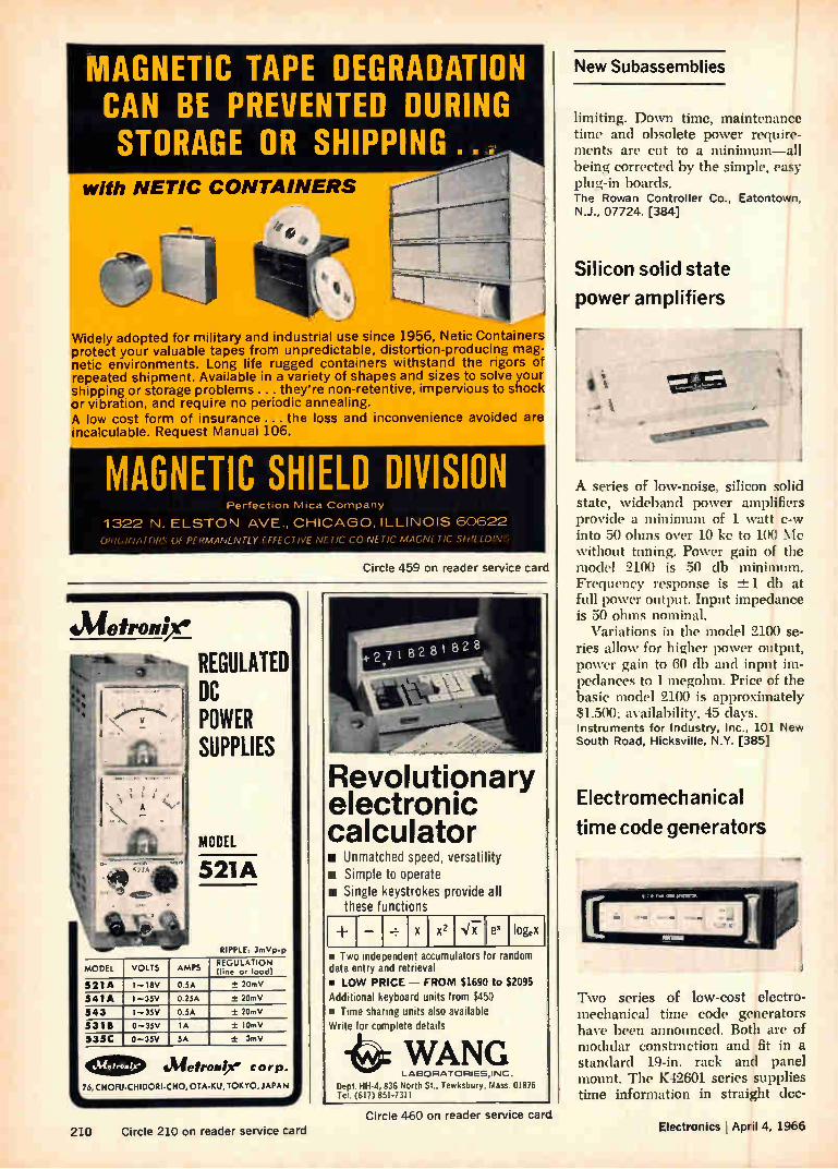
MODEL VOLTS
MAGNETIC TAPE DEGRADATION CAN BE PREVENTED DURING STORAGE OR SHIPPING...
with NETIC CONTAINERS
Widely adopted for military and industrial use since 1956, Netic Containers protect your valuable tapes from unpredictable, distortion-producing mag-netic environments. Long life rugged containers withstand the rigors of repeated shipment. Available in a variety of shapes and sizes to solve your shipping or storage problems ... they're non-retentive, impervious to shock or vibration, and require no periodic annealing. A low cost form of insurance ... the loss and inconvenience avoided are incalculable. Request Manual 106.
MAGNETIC SHIELD DIVISION Perfection Mica Company
1322 N. ELSTON AVE., CHICAGO, ILLINOIS 60622
OhIGINAIOltà Of PÍRMANENTLY f FFECI IVE NEIIC CO NEI IC MA(
Circle 459 on reader service card
Meironi/e
xx.,. • • 3 REGULATED
DC POWER SUPPLIES
MODEL
521A
RIPPLE: 3mVp.p
AMPS REGULATION (line or load)
521A I I8V 0.5A ± 20mV
541A I .-35V 0.25A + 2OrnV
543 I —35V 0.5A ± 20mV
5318
535C
0-35V IA + 10mV
0 —35V 5A + 3rnV
e=> Metroope Corp. 75, CHOFU-ClilDORI-CHO.0TA•KU, TOKYO, JAPAN
Revolutionary electronic calculator is Unmatched speed, versatility um Simple to operate • Single keystrokes provide all
these functions
x2 ,b7 ex loge • Two independent accumulators for random data entry and re rieval • LOW PRICE — FROM $1690 to $2095 Additional keyboard units from $450 • Time sharing units also available Write for complet details
WANG LABORATORIES,INC.
Dept. HH-4, 836 North St., Tewksbury, Mass. 01876 Tel. (617) 851-7311
New Subassemblies
limiting. Down time, maintenance time and obsolete power require-ments are cut to a minimum—all being corrected by the simple, easy plug-in boards. The Rowan Controller Co., Eatontown, N.J., 07724. [384]
Silicon solid state
power amplifiers
A series of low-noise, silicon solid state, ‘videband power amplifiers provide a minimum of 1 watt c-w into 30 ohms over 10 kc to loo Mc without tuning. Power gain of the model 2100 is 50 db minimum. Frequency response is -±1 db at full power output. Input impedance is 50 ohms nominal.
Variations in the model 2100 se-ries allow for hieer power output, power gain to 60 db and input im-pedances to 1 megohm. Price of the basic model 2100 is approximately $1.500: availability, 45 days. Instruments for Industry, Inc., 101 New South Road, Hicksville, N.Y. [385]
Electromechanical
time code generators
Two series of low-cost electro-mechanical time code generators have been announced. Both are of modular construction and fit in a standard 19-in, rack and panel mount. The K42601 series supplies time information in straight dec-
210 Circle 210 on reader service card
Circle 460 on reader service card Electronics April 4, 1966
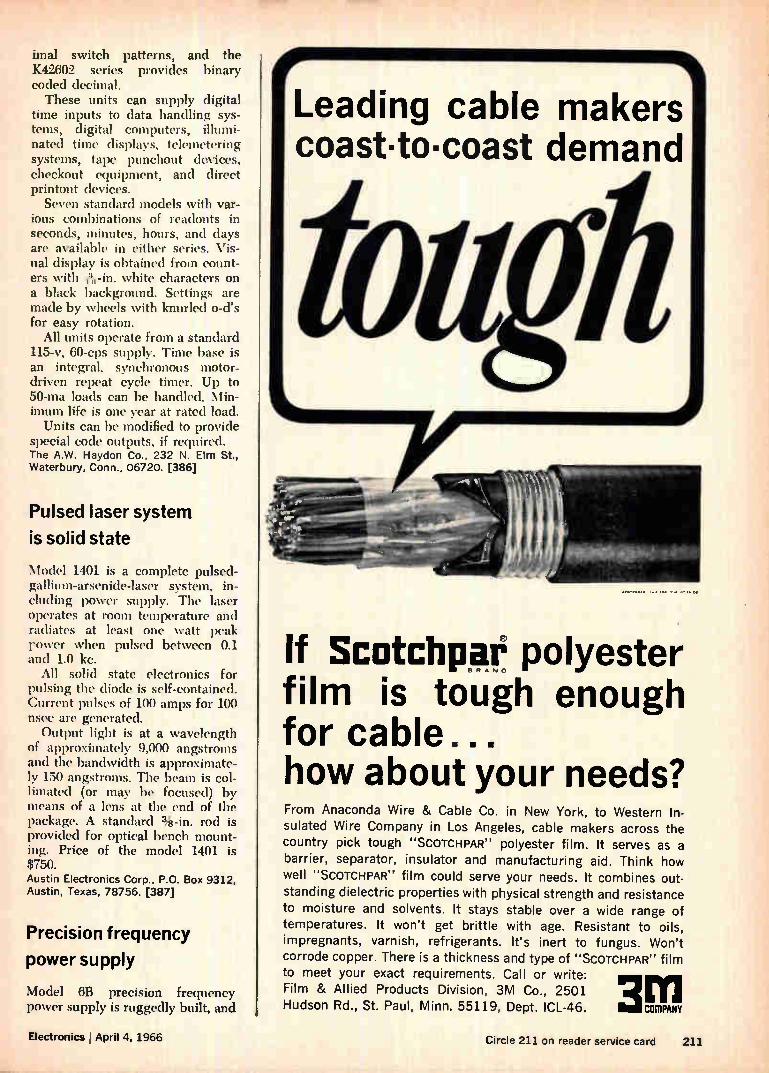
imal switch patterns, and the K42602 series provides binary coded decimal. These units can supply digital
time inputs to data handling sys-tems, digital computers, illumi-nated time displays, telemetering systems, tape punchout devices, checkout equipment, and direct printout devices.
Seven standard models with var-ious combinations of readouts in seconds, minutes, hours, and days are available in either series. Vis-ual display is obtained from count-ers with 13,1-in. white characters on a black background. Settings are made by wheels with knurled o-d's for easy rotation.
All units operate from a standard 115-v, 60-cps supply. Time base is an integral, synchronous motor-driven repeat cycle timer. Up to 50-ma loads can be handled. Min-imum life is one year at rated load.
Units can be modified to provide special code outputs, if required. The A.W. Haydon Co., 232 N. Elm St., Waterbury, Conn., 06720. [386]
Pulsed laser system
is solid state
Model 1401 is a complete pulsed-gallium-arsenide-laser system, in-chiding power supply. The laser operates at room temperature and radiates at least one watt peak rower when pulsed between 0.1 and 1.0 kc.
All solid state electronics for pulsing the diode is self-contained. Current pulses of 100 amps for 100 nsec are generated. Output light is at a wavelength
of approximately 9,000 angstroms and the bandwidth is approximate-ly 150 angstroms. The beam is col-limated (or may be focused) by means of a lens at the end of the package. A standard %-in, rod is provided for optical bench mount-ing. Price of the model 1401 is $750. Austin Electronics Corp., P.O. Box 9312, Austin, Texas, 78756. [387]
Precision frequency
power supply
Model 6B precision frequency power supply is ruggedly built, and
Leading cable makers coast•toicoast demand
If Scotchpaê polyester film is tough enough for cable... how about your needs? From Anaconda Wire & Cable Co. in New York, to Western In-
sulated Wire Company in Los Angeles, cable makers across the country pick tough "SCOTCHPAR" polyester film. It serves as a barrier, separator, insulator and manufacturing aid. Think how well "SCOTCHPAR" film could serve your needs. It combines out-standing dielectric properties with physical strength and resistance to moisture and solvents. It stays stable over a wide range of temperatures. It won't get brittle with age. Resistant to oils, impregnants, varnish, refrigerants. It's inert to fungus. Won't corrode copper. There is a thickness and type of "SCOTCHPAR" film to meet your exact requirements. Call or write: Film & Allied Products Division, 3M Co., 2501 Hudson Rd., St. Paul, Minn. 55119, Dept. ICL-46. 3 COMPANY
Electronics I April 4, 1966 Circle 211 on reader service card 211
BUSS SHIELDED FUSEHOLDERS1
. PREVENT RADIO FREQUENCY INTERFERENCE
For use where fuse and fuseholder could pick up radio frequen-cy radiation which interferes with circuit containing fuseholder
—or other nearby circuits.
Fuseholder accomplishes both shielding and grounding.
Available to take two sizes of fuses-1/4 x 11/4 " and 1/4 x 1" fuses.
Meet all requirements of both MIL-I-6181D and MIL-F-19207A.
Write for BUSS Bulletin SFH-12
INSIST ON MSS QUALITY
BUSSMANN MFG. DIVISION, McGraw• Edison Co., ST. LOUIS, MO. 63107
FUSETRON dual-element Fuses
slow blowing t or
• BUSS Bulletin SFB
"Slow blowing" fuses prevent needless out-ages by not opening on harmless overloads— yet provide safe, protection against short-circuits or dangerous overloads.
INSIST ONBUSS
QUALITY BUSSMANN MFG. DIVISION, McGraw•Edison Co., ST. LOUIS, MO. 63107
BUSS: The Complete Line of Fuses and .. Circle 212 on reader service card
COOL LIQUIDS
TO -23°C
ANYWHER BLUE NI ec»tacute ?tetee
.Patented ,
PORTABLE COOLING UNITS Compact, convenient, efficient method of obtaining
cooled liquids at exact temperature for direct testing
or recirculation to auxiliary equipment. New pat-ented principle permits rapid cycling . . . control to
within ±-0.15 -C. Compressor runs constantly . . .
lasts longer. Exclusive no-load starting avoids over-
load stopping and manual reset. Four models . . .
two capacities.
SEND FOR FULL INFORMATION
Clip ad to your signed letterhead for full details and low prices.
BLUE FA Etedtic eampaity 138th & Chatham Streets Blue Island, Illinois
Circle 212 on reader service card
Great editorial is something he takes to work
(What a climate for selling!)
Electronics A MeGraw-H111 Market-Dirertrd PublicatIon
LS luid Street. Neer York, N IL
212 Circle 461 on reader service card Electronics ' April 4 1966
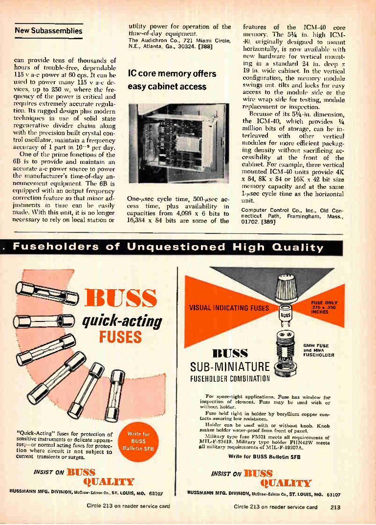
New Subassemblies
can provide tens of thousands of hours of trouble-free, dependable 115 y a-c power at 60 cps. It can be used to power many 115 y a-c de-vices, up to 250 w, where the fre-quency of the power is critical and requires extremely accurate regula-tion. Its rugged design plus modern techniques in use of solid state regenerative divider chains along with the precision built crystal con-trol oscillator, maintain a frequency accuracy of 1 part in 10-9 per day. One of the prime functions of the
6B is to provide and maintain an accurate a-c power source to power the manufacturer's time-of-day an-nouncement equipment. The 6B is equipped with an output frequency correction feature so that minor ad-justments in time can be easily made. With this unit, it is no longer necessary to rely on local station or
utility power for operation of the time-of-day equipment. The Audichron Co., 721 Miami Circle, N.E., Atlanta, Ga., 30324. [388]
IC core memory offers
easy cabinet access
One-sec cycle time, 500-psec ac-cess time, plus availability in capacities from 4,096 x 6 bits to 16,384 x 84 bits are some of the
features of the ICM-40 core menlory. The 51/4 in. high ICNI-40, originally designed to mount horizontally, is now available with new hardware for vertical mount-ing in a standard 24 in. deep x 19 in. wide cabinet. In the vertical configuration, the memory module swings out, tilts and locks for easy access to the module side or the wire wrap side for testing, module replacement or inspection.
Because of its 51/4 -in, dimension, the ICM-40, which provides 1/4 million bits of storage, can be in-terleaved with other vertical modules for more efficient packag-ing density without sacrificing ac-cessibility at the front of the cabinet. For example, three vertical mounted ICM-40 units provide 4K x 84, 8K x 84 or 18K x 42 bit size memory capacity and at the same 1-sec cycle time as the horizontal unit.
Computer Control Co., Inc., Old Con-necticut Path, Framingham, Mass., 01702. [389]
Fuseholders of Unquestioned High Quality
cia zi BUSS © quick-acting
FUSES
"Quick-Acting" fuses for protection of sensitive instruments or delicate appara-tus;—or normal acting fuses for protec-tion where circuit is not subject to current transients or surges.
INSIST ON BUSS QUALITY
BUSSMANN MFG. DIVISION, McCraw-Edison Co., ST. LOUIS, MO. 63107
VISUAL INDICATING FU
ISITSS SUB-MINIATURE FUSEHOLDER COMBINATION
FUSE ONLY .270 x .250 INCHES
GMW FUSE and HWA FUSEHOLDER
For space-tight applications. Fuse has window for inspection of element. Fuse may be used with or without holder.
Fuse held tight in holder by beryllium copper con-tacts assuring low resistance.
Holder can be used with or without knob. Knob makes holder water-proof from front of panel.
Military type fuse FM01 meets all requirements of MIL-F-23419. Military type holder FHN42W meets all military requirements of MIL-F-19207A.
Write for BUSS Bulletin SFB
INSIST ON BUSS QUALITY
BUSSMANN MFG. DIVISION, McGraw•Edison Co., ST. LOUIS, MO. 63107
Circle 213 on reader service card Circle 213 on reader service card 213
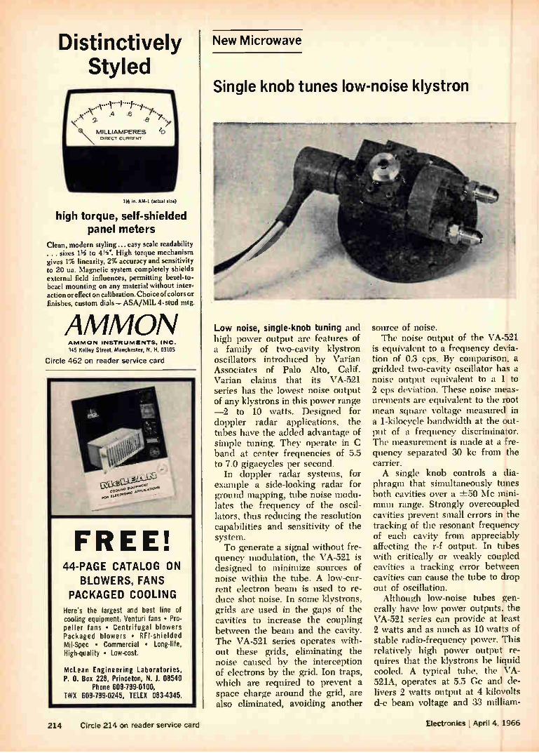
Distinctively Styled
• \ e 7.•
els\MILLIAMPERES 10 DRLCT CURRENT
in. AM-I (etunl sue)
high torque, self-shielded panel meters
Clean, modern styling... easy scale readability . . . sizes 1% to 4W. High torque mechanism gives I% linearity, 2% accuracy and sensitivity to 20 us. Magnetic system completely shields external field influences, permitting bezel-to-bezel mounting on any material without inter-action or effect on calibration. Choice of colors or finishes, custom dials—ASA/MIL 4-stud mtg.
AMMON AMMON INSTRUMENTS. INC.
145 Kelley Street, Manchester, N. H. 03105
Ci rcle 462 on reader service card
FREE! 44-PAGE CATALOG ON
BLOWERS, FANS PACKAGED COOLING
Here's the largest and best line of cooling equipment: Venturi fans • Pro-peller fans • Centrifugal blowers Packaged blowers • RFI-shielded Mil-Spec • Commercial • Long-life, High-quality • Low-cost.
McLean Engineering Laboratories, P. 0. Box 228, Princeton, N. J. 08540
Phone 609-799-0100, TWX 609-799-0245, TELEX 083-4345.
New Microwave
Single knob tunes low-noise klystron
Low noise, single-knob tuning and high power output are features of a family of two-cavity klystron oscillators introduced by Varian Associates of Palo Alto, Calif. Varian claims that its VA-521 series has the lowest noise output of any klystrons in this power range —2 to 10 watts. Designed for doppler radar applications, the tubes have the added advantage of simple tuning. They operate in C band at center frequencies of 5.5 to 7.0 gigacycles per second.
In doppler radar systems, for example a side-looking radar for ground mapping, tube noise modu-lates the frequency of the oscil-lators, thus reducing the resolution capabilities and sensitivity of the system. To generate a signal without fre-
quency modulation, the VA-521 is designed to minimize sources of noise within the tube. A low-cur-rent electron beam is used to re-duce shot noise. In some klystrons, grids are used in the gaps of the cavities to increase the coupling between the beam and the cavity. The VA-521 series operates with-out these grids, eliminating the noise caused by the interception of electrons by the grid. Ion traps, which are required to prevent a space charge around the grid, are also eliminated, avoiding another
source of noise. The noise output of the VA-521
is equivalent to a frequency devia-tion of 0.3 cps. By comparison, a gridded two-cavity oscillator has a noise output equivalent to a 1 to 2 cps deviation. These noise meas-urements are equivalent to the root mean square voltage measured in a 1-kilocycle bandwidth at the out-put of a frequency discriminator. The measurement is made at a fre-quency separated 30 kc from the carrier. A single knob controls a dia-
phragm that simultaneously tunes both cavities over a -1=50 Mc mini-mum range. Strongly overcoupled cavities prevent small errors in the tracking of the resonant frequency of each cavity from appreciably affecting the r-f output. In tubes with critically or weakly coupled cavities a tracking error between cavities can cause the tube to drop out of oscillation.
Although low-noise tubes gen-erally have low power outputs, the VA-521 series can provide at least 2 watts and as much as 10 watts of stable radio-frequency power. This relatively high power output re-quires that the klystrons be liquid cooled. A typical tube, the VA-521A, operates at 5.5 Cc and de-livers 2 watts output at 4 kilovolts d-c beam voltage and 33 milliam-
214 Circle 214 on reader service card Electronics l April 4, 1966
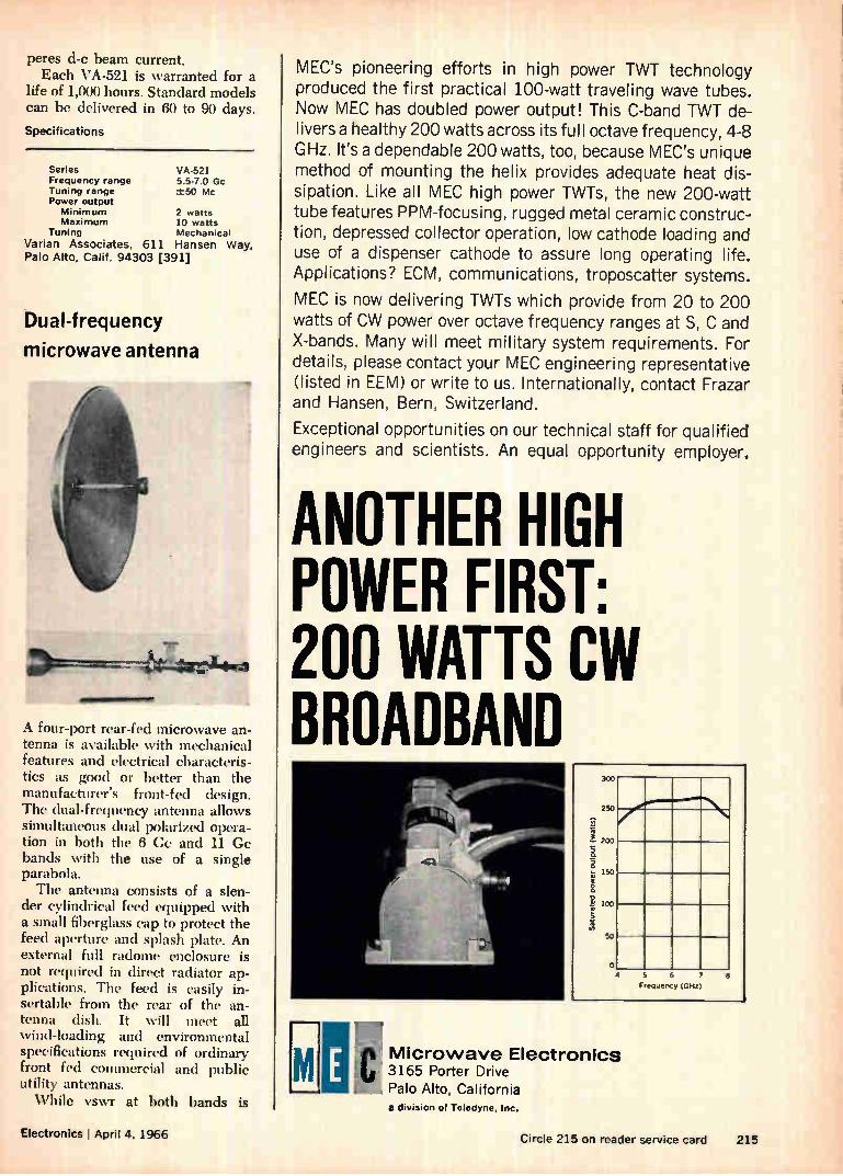
peres d-c beam current. Each VA-521 is warranted for a
life of 1,000 hours. Standard models can be delivered in 60 to 90 days.
Specifications
Series Frequency range Tuning range Power output Minimum Maximum
Tuning Varian Associates, 61 Palo Alto, Calif. 94303
VA-521 5.5-7.0 Gc -±-50 Mc
2 watts 10 watts Mechanical
1 Hansen Way, [391]
Dual-frequency
microwave antenna
VW.
•4>•'«ItiellifgeOl
A four-port rear-fed microwave an-tenna is available with mechanical features and electrical characteris-tics as good or better than the manufacturer's front-fed design. The dual-frequency antenna allows simultaneous dual polarized opera-tion in both the 6 Ge and 11 Ge bands with the use of a single parabola. The antenna consists of a slen-
der cylindrical feed equipped with a small fiberglass cap to protect the feed aperture and splash plate. An external full radome enclosure is not required in direct radiator ap-plications. The feed is easily in-sertable from the rear of the an-tenna dish. It will meet all wind-loading and environmental specifications required of ordinary front fed commercial and public utility antennas. While vswr at both bands is
MEC's pioneering efforts in high power TWT technology produced the first practical 100-watt traveling wave tubes. Now MEC has doubled power output! This C-band TWT de-livers a healthy 200 watts across its full octave frequency, 4-8 GHz. It's a dependable 200 watts, too, because MEC's unique method of mounting the helix provides adequate heat dis-sipation. Like all MEC high power TWTs, the new 200-watt tube features PPM-focusing, rugged metal ceramic construc-tion, depressed collector operation, low cathode loading and use of a dispenser cathode to assure long operating life. Applications? ECM, communications, troposcatter systems.
MEC is now delivering TWTs which provide from 20 to 200 watts of CW power over octave frequency ranges at S, C and X-bands. Many will meet military system requirements. For details, please contact your MEC engineering representative (listed in EEM) or write to us. Internationally, contact Frazar and Hansen, Bern, Switzerland.
Exceptional opportunities on our technical staff for qualified engineers and scientists. An equal opportunity employer.
ANOTHER HIGH POWER FIRST: 200 WATTS C141 BROADBAND
300
250
d.
200
¡150
100
2
50
o 4 5 6
F equency (GHz 8
..c Microwave ElectronicS ' 3165 Porter Drive
Palo Alto, California a division of Teledyne, Inc.
Electronics I April 4, 1966 Circle 215 on reader service card 215
YES, WE ARE INDEPENDENT! We Are The World's Leading Independent Maker of Nickel Cathodes.
Every cathode that we fabricate is for our cus-tomers. And we have two large plants that are producing a variety of cathodes including seam-less, Weldrawn, disc, lockseam and lapseam. Superior offers you cathodes in a wide choice
of materials for your most exacting requirement. We are pioneers in creating new designs and in developing and using new materials for improved performance. Do you have a copy of Superior Catalog No. 51?
Send for it today. Dept. 2500.
Supetior7i/be The big name in small tubing
NORRISTOWN, PA. 19404
West Coast: Pacific Tube Company. Los Angeles. California
Johnson 8. Hoffman Mfg. Corp., Carle Place, N. Y.—an affiliated company making precision metal stampings and deep-drawn parts
New Microwave
consistently being measured at
1..13, the manufacturer expects pro-duction units to run in the order of 1.15. Gabriel Electronics, division Maremont Corp., North St., Saco, Me. [392]
Uhf circulators
cover broad band
Uhf coaxial circulators cover a two-octave range from 250 Mc to 1 Cc with four units. The units provide excellent electrical characteristics over a minimum bandwidth of 33 1/2 %.
Typically, the model V25T has isolation of 17 db minimum, inser-tion loss of 0.6 db maximum, and vswr of 1.30 maximum over the frequency range of 250 to 350 Mc.
Price is available on request; delivery, 30 days after receipt of order. E & M Laboratories, 7419 Greenbush Ave., North Hollywood, Calif. [393]
Transmission-type
noise generator
TN-1
,
A miniature transmission-type, 90° E-plane noise generator, type TN-1, is designed for use from 8.5 to 9.6 Ge in systems where space and weight are at a premium. With low non-operating insertion loss and
216 Circle 216 on reader service card Electronics I April 4, 1966
Irgr.e4e1
vswr, it is intended for system use directly in the receiver line of X-band systems. The unit is especially suitable
for airborne and shipbome sys-tems that have limitations on avail-able drive power and which require rugged components with long oper-ating life. The thermionic, but still single-ended, cathode in the tube permits a two-lead construction for the complete noise generator while simultaneously providing a low tube drop with subsequent low operating power requirements.
Typical specifications include 900-v starting spike, nominal oper-ating voltage of 55 y at 100 ma current, excess noise ratio of 14.5
db with an operating vswr of 2.1 max, and a cold vswr of 1.25 max. Length along the waveguide axis is less than 2 in. and height of the tube holder section, perpen-dicular to the waveguide axis, is 4 in. The entire unit weighs only 4 oz. Signalite Inc., 1933 Heck Ave., Nep-tune, N.J. [394]
Pump tubes available
for masers, paramps
Reflex klystron oscillators, desig-nated the VA-254 series, serve as pump tubes for masers and para-metric amplifiers. Well-suited for airborne use, this durable reflex klystron delivers at least 150 mw into a matched load over its entire 1,000-Mc tuning range. Tubes are available for any specific center frequency between 18 and 26.5 Cc. Tuning is mechanical.
Hermetically sealed, the VA-2M oscillator not only operates at high altitude without pressurization, but it can also be cooled by liquid 1m-
SEE TOMORROW'S TECHNOLOGY-TODAY!
SIXTH INTERNATIONAL
INSTRUMENTS ELECTRONICS AUTOMATION EXHIBITION
OLYMPIA LONDON
ENGLAND
23-28 MAY 1966
The International Instruments, Electronics and Automation Exhibition is the technological show of the future—today. The most significant exhibition of the year, lEA focuses at Olympia the achievements of 800 international firms in the vanguard of scientific industrialisation. Catholic in scope, lEA ranges the whole field of instrument-ation, electronics and automation.
For your free Official Invitation Card and further details contact:
0E0 INDUSTRIAL EXHIBITIONS LIMITED 9 ARGYLL STREET LONDON W1 ENGLAND
Electronics April 4, 1966 Circle 217 on reader service card 217
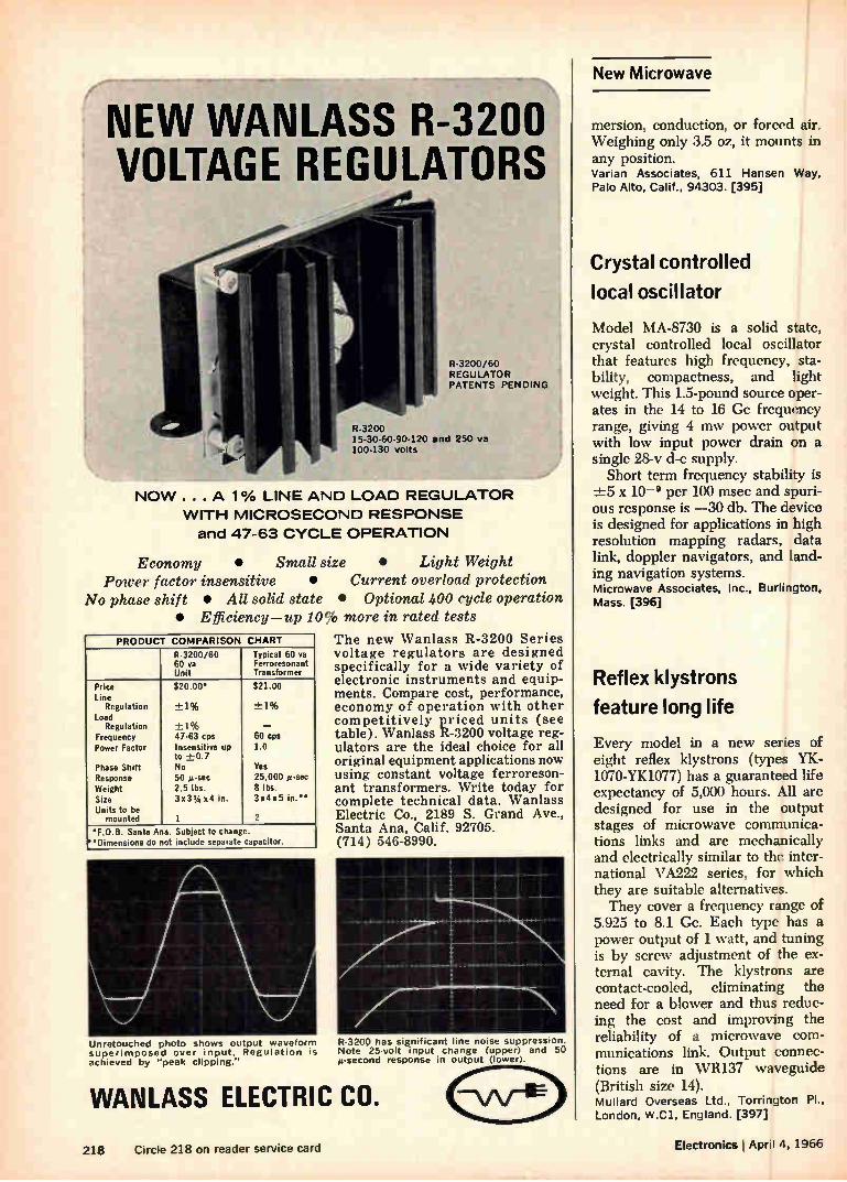
New Microwave
NEW WAN LASS R-3200 VOLTAGE REGULATORS
R-3200/60 REGULATOR PATENTS PENDING
R-3200 15-30-60-90-120 and 250 va 100-130 volts
NOW . . . A 1% LINE AND LOAD REGULATOR
WITH MICROSECOND RESPONSE
and 47-63 CYCLE OPERATION
Economy • Small size • Light Weight Power factor insensitive • Current overload protection
No phase shift • All solid state • Optional 400 cycle operation • Efficiency—up 10% more in rated tests
PRODUCT COMPARISON CHART
R-3200/60 60 va Unit
Typical 60 ea Ferroresonant Transformer
Price Line
Regulation Load
Regulation Frequency Power Factor
Phase Shift Response Weight Size Units to be
mounted
$20.00'
±1%
+1% 47-63 cps Insensitive up to +0.7 No 50 g-sec 2.5 lbs. 3x3 34 x4 in.
1
$21.00
-±-1%
— 60 cps 1.0
Yes 25,000 g-seo 8 lbs. 3x4x5 in."
2
'F.O.B. Santa Ana. Subject to change. "Dimensions do not include separate capacitor.
Unretouched photo shows output waveform superimposed over input. Regulation is achieved by "peak clipping."
The new Wanlass R-3200 Series voltage regulators are designed specifically for a wide variety of electronic instruments and equip-ments. Compare cost, performance, economy of operation with other competitively priced units (see table). Wanlass R-3200 voltage reg-ulators are the ideal choice for all original equipment applications now using constant voltage ferroreson-ant transformers. Write today for complete technical data. Wanlass Electric Co., 2189 S. Grand Ave., Santa Ana, Calif. 92705. (714) 546-8990.
R-3200 has significant line noise suppression. Note 25-volt input change (upper) and 50 g-second response in output (lower).
WANLASS ELECTRIC CO.
mersion, conduction, or forced air. Weighing only 3.5 oz, it mounts in any position. Varian Associates, 611 Hansen Way, Palo Alto, Calif., 94303. [395]
Crystal controlled
local oscillator
Model MA-8730 is a solid state, crystal controlled local oscillator that features high frequency, sta-bility, compactness, and light weight. This 1.5-pound source oper-ates in the 14 to 16 Gc frequency range, giving 4 mw power output with low input power drain on a single 28-v d-c supply.
Short term frequency stability is x 10-9 per 100 msec and spuri-
ous response is —30 db. The device is designed for applications in high resolution mapping radars, data link, doppler navigators, and land-ing navigation systems. Microwave Associates, Inc., Burlington, Mass. [396]
Reflex klystrons
feature long life
Every model in a new series of eight reflex klystrons (types YK-1070-YK1077) has a guaranteed life expectancy of 5,000 hours. All are designed for use in the output stages of microwave communica-tions links and are mechanically and electrically similar to the inter-national VA222 series, for which they are suitable alternatives. They cover a frequency range of
5.925 to 8.1 Cc. Each type has a power output of 1 watt, and tuning is by screw adjustment of the ex-ternal cavity. The klystrons are contact-cooled, eliminating the need for a blower and thus reduc-ing the cost and improving the reliability of a microwave com-munications link. Output connec-tions are in WR137 waveguide (British size 14). Mullard Overseas Ltd., Torrington Pl., London, W.C1, England. [397]
218 Circle 218 on reader service card Electronics I April 4, 1966
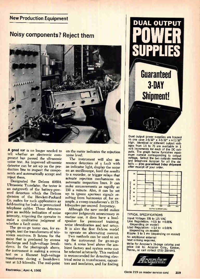
New Production Equipment
Noisy components? Reject them
A good ear is no longer needed to tell whether an electronic com-ponent has passed the ultrasonic noise test. An improved ultrasonic detector can be set up on the pro-duction line to inspect the compo-nents and automatically accept and reject them. Designated the Deleon 4950A
Ultrasonic Translator, the tester is an outgrowth of the battery-pow-ered detectors which the Deleon division of the Hewlett-Packard Co. makes for such applications as field-testing for leaks in pressurized telephone cables. Those detectors give an audible indication of noise intensity, requiring the operator to make a qualitative judgment of whether a fault exists. The go-no-go tester can, for ex-
ample, test the transformers of tele-vision receivers. It listens for the noise that is produced by corona discharge and high-voltage break-down. In the photograph above, the instrument is making a corona test on a filament high-voltage transformer during a breakdown test at 3.5 kilovolts. The mid-point
•
on the meter indicates the rejection noise level. The instrument will also an-
nounce detection of a fault with an indicator light, display the noise on an oscilloscope, feed the results to a recorder, or trigger relays that actuate rejection mechanisms on automatic inspection lines. It can make measurements as rapidly as 150 a minute. Also, it can be set up to ignore spurious signals re-sulting from harmonics of, for ex-ample, a sweep transformer's 15.75-kilocycles-per-second frequency. Although the new model makes
operator judgments unnecessary in routine use, it does have a loud-speaker for personnel training, noise identification and test setup. It is also the first Deleon model to operate on alternating current. Two methods can be used to set
up the instrument for go-no-go tests. A noise level above the am-bient factory and system noise can be selected arbitrarily. This method is recommended for detecting elec-trical noise in transformers, capaci-tors and insulators, and for finding
DUAL OUTPUT
POWER SUPPLIES
Guaranteed 3-DAY
Shipment!
Dual output power supplies are housed in one case 3-5/16" x 4-5/32" x 4-11/16" high. Identical or different output volt-ages from 1.5 to 75 are available in 1 volt increments for each of the DC out-puts. The graph below furnishes maxi-mum current corresponding to output voltage. Select the two outputs needed and telephone Acopian for all the de-tails — plus guaranteed 3-day shipment after receipt of your order.
output voltage (
volt
s DC )
75
60
50
40
30
20
10
1.5 100 200 300 400 5')J
OUTPUT CURRENT (MA 1
TYPICAL SPECIFICATIONS Input Voltage: 105 to 125 VAC Line Regulation: -L.:0.5 to 20.05% (depending on model)
Load Regulation: --=1.0 to ±-0.05% (depending on model)
Ripple: 5 to 1 mv (depending on model) No additional external heat sinking required.
Write for Acopian's 16-page catalog and price list to: Acopian Corp., Easton, Penna., or call collect (215) 258-5441.
ElectronicslApril 4, 1966 Circle 219 on reader service card 219
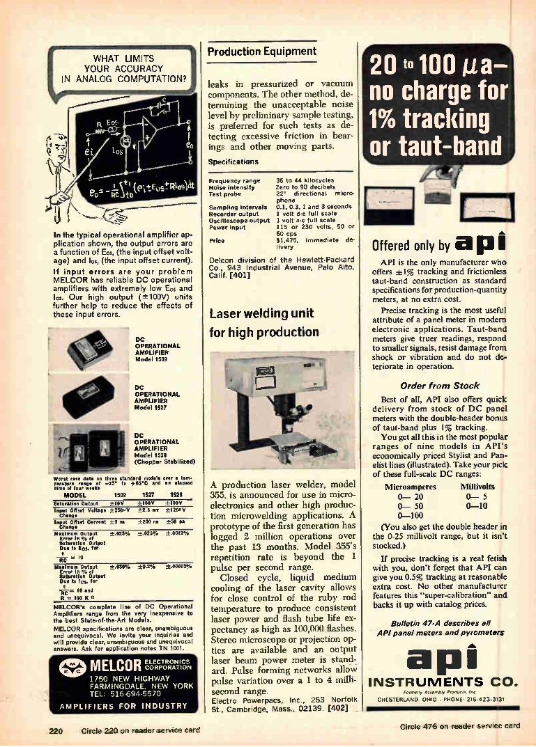
WHAT LIMITS YOUR ACCURACY
IN ANALOG COMPUTATION?
In the typical operational amplifier ap-plication shown, the output errors are a function of Ern, (the input offset volt-age) and los, (the input offset current).
If input errors are your problem MELCOR has reliable DC operational amplifiers with extremely low Eos and los. Our high output (±100V) units further help to reduce the effects of these input errors.
DC OPERATIONAL AMPLIFIER Model 1509
DC OPERATIONAL AMPLIFIER Model 1527
DC OPERATIONAL AMPLIFIER Model 1528 (Chopper Stabilized)
Worst ease data on three standard models over a tern• perature range of —25° to +85°C and an elapsed time of four weeks
MODEL 1509 1527 1528 Saturation Output —10V +100V +100V Input Offset Voltage +2500/ +2.3 mv +1204V Change
Input Offset Current +3 na :,-_200 na ±50 pa Change
Maxi mum Output +.025% -±.025% ±.00I2% Error in 0 ‘, of Saturation Output Duo to Eos, for
= ID Maximum Output +.030% +0.2%
Error in % of Saturation Output Due to los, for
w. In and
R = lOO K
MELCOR'e complete line of DC Operational Amplifiers range from the very inexpensive to the best State-of-the-Art Models.
MELCOR specifications are clear, unambiguous and unequivocal. We invite your inquiries and will provide clear, unambiguous and unequivocal answers. Ask for application notes TN 1001.
±.00005%
otID MELCOR 1750 NEW HIGHWAY FARMINGDALE, NEW YORK TEL: 516-694-5570
ELECTRONICS CORPORATION
AMPLIFIERS FOR INDUSTRY
Production Equipment
leaks in pressurized or vacuum components. The other method, de-termining the unacceptable noise level by preliminary sample testing, is preferred for such tests as de-tecting excessive friction in bear-ings and other moving parts.
Specifications
Frequency range Noise intensity Test probe
Sampling Intervals Recorder output Oscilloscope output Power input
Price
36 to 44 kilocycles Zero to 90 decibels 22° directional micro-phone 0.1, 0.3, 1 and 3 seconds 1 volt d-c full scale 1 volt a-c full scale 115 or 230 volts, 50 or 60 cps $1,475, immediate de-livery
Delcon division of the Hewlett-Packard Co., 943 Industrial Avenue, Palo Alto, Calif. [401]
Laser welding unit
for high production
A production laser welder, model 355, is announced for use in micro-electronics and other high produc-tion microwelding applications. A prototype of the first generation has logged 2 million operations over the past 13 months. Model 355's repetition rate is beyond the 1 pulse per second range.
Closed cycle, liquid medium cooling of the laser cavity allows for close control of the ruby rod temperature to produce consistent laser power and flash tube life ex-pectancy as high as 100,000 flashes. Stereo microscope or projection op-tics are available and an output laser beam power meter is stand-ard. Pulse forming networks allow pulse variation over a 1 to 4 milli-second range. Electro Powerpacs, Inc., 253 Norfolk St., Cambridge, Mass., 02139. [402]
20 to 100 no charge for 1% tracking or taut-band
.416.
Offered only by a p API is the only manufacturer who
offers ±1% tracking and frictionless taut-band construction as standard specifications for production-quantity meters, at no extra cost.
Precise tracking is the most useful attribute of a panel meter in modern electronic applications. Taut-band meters give truer readings, respond to smaller signals, resist damage from shock or vibration and do not de-teriorate in operation.
Order from Stock
Best of all, API also offers quick delivery from stock of DC panel meters with the double-header bonus of taut-band plus 1% tracking. You get all this in the most popular
ranges of nine models in API's economically priced Stylist and Pan-elist lines (illustrated). Take your pick of these full-scale DC ranges:
Microamperes Millivolts 0— 20 0-5 0— 50 0-10 0-100
(You also get the double header in the 0-25 millivolt range, but it isn't stocked.)
If precise tracking is a real fetish with you, don't forget that API can give you 0.5% tracking at reasonable extra cost. No other manufacturer features this "super-calibration" and backs it up with catalog prices.
Bulletin 47-A describes all API panel meters and pyrometers
api INSTRUMENTS CO.
Formerly Assembly Products. Inc
CHESTERLAND OHIO . PHONE 216.42 3-3131
220 Circle 220 on reader service card Circle 476 on reader service card
MCC -to be Sure POLYESTER FILM CAPACITORS
Type MXT.
o 4'7, FYI
Type MR..
I deed Flat Shape Capacitance
Range = 001 MFD to 41 MED Voltages 35v. 50v. 100v. 200v DC
In Plastic Tube Capacitance
Range 001 MEO to 22 MU Voltages 100v, 200v. 400v. 600v DC
e 1 Type MFK. dipped Flat Shane Non-Inductive Construction Capacitance
Range 01 MFO to 22 MFD Voltages 100v, 200v, 400v, 600v DC
METALLIZED POLYESTER FILM CAPACITORS
Type FNX—H MO( Wrapped Semioval
—11111M11111— Trioxy End Seal Capacitance Range 1 MID to 10 NH
Voltages 50v DC
SOLID TANTALUM CAPACITORS
Type TAS Sealed with Epoxy Resin
Caoacitance Range- 1 NU to 220 MFD
Voltages' 3v.6v.10v.15v.20v.25. Type TAX 35v OC MIL-C 26655A Hermetically Sealed
MATSUO ELECTRIC CO., LTD. HEAD OFFICE: 3-chome, Sennari-cho, Toyonakc-shi, Osalca,Japon.
Cable Address "NCC MATSUO" OSAKA
give. so more will live
HEART FUND Circle 475 on reader service card
Ampl. Motor Gearing Encoder
Generator _J
New Transicoil synchro-to-digital converter This particular servo package provides synchro-to-digital conversion of airborne test iata for telemetering to a ground station. Synchro input is fed to a size 8 control transformer which is nulled by an 11 motor generator driven from a transistorized servo amplifier. An 11-bit V-scan encoder is precision geared to the synchro and provides output in natural binary form. Careful Packaging design facilitates side-by-side stacking for multi-channel applications in a confined space. • Let Weston-Transicoil convert your system requirements into a sophisticated assembly .... test our response time!
PERFORMANCE: Input: 11.8V, 400 CPS, 3 wire synchro • Output: 11 bit natural binary from V-Scan encoder • Static Accuracy: ±2 bits it encoder • Dynamic Accuracy: 1° at 16 RPM • Slew Speed: 16 RPM • Power Required: 115V, 400 CPS, 15 watts; 28V d.c., 250 ma. Weight: 30 oz. • Size: 1.8 x 4.75 x 5.0°
Weston Instruments, Inc. Transicoil Division, Worcester, Pa. 19490.
WESTON' prime source for precision. • since 1888 .,iectronics April 4, 1966
Circle 221 on reader service card 221

Cramped for mace? Use Couch 1/7-size Relays
Space/weight problem? The new Couch 2X 1/7-size crystal can relay gives you tremendous savings in space and weight. 01" r— grid — plus many out-standing specs —al/in mi-crominiature. Thoroughly field-proven in electronics TI and space applications.
ACTUAL MU
2X (OPDT) IX (SPOT) 0.2" it 0.4" o 0.5" same
Contacts 0.5 amp (a. 30 VDC same
Coil Operating Power 100 mw 150 mw 70 mw 100 mw Coil Resistance 60 to 4000 ohms 125 to 4000 ohms Temperature —65°C to 125°C same Vibration 20 G same Shock 75 G same
Broad choice of terminals, coil resistances, mounting styles. Write for detailed data sheets.
MICCf0 ROTARY liftlYS e e OpunaiWy eul Stale* Sewed
COUCH ORDNANCE INC. 3 Arlington St., North Quincy. Mass. 02171, Area Code 617, CYpress 8-4147 • A subsidiary el S. H. COUCH COMPANY, INC.
New Books
Communications Basic Theory of Space Communications Frederick J. Tischer D. Van Nostrand Co., 463 pp., $11.75
Four disciplines make up the field of space communications: antennas and electromagnetics, plasma dy-namics, wave propagation, and communication techniques. The book is divided into these disci-plines. The author sets out to present
the basic theory of each of the dis-ciplines with special emphasis on high-frequency relationships. His discussion and analysis of the theory concerned with each disci-pline is generally clear. And yet the book has many failings.
In each of the four parts, entirely too much space is devoted to ele-mentary material which is readily available in previously published books. Many books have been written on antennas, electromag-netic theory, plasmas, propagation and communication theory that cover the subjects more extensively than Tischer does. Trischer's book would have been a much more val-uable contribution if it had picked up where these texts left off.
In each part, only the last one or two chapters truly concerns the field of space communications. The rest is foundation material. Never-theless the book does cover some important new areas in its discus-sion of space vehicle antennas (for example, low-noise antennas) and reentry communications. One serious fault is the lack
of simplified practical problems and their solutions. A book of this nature would be considerably more useful if it included design exam-ples. For example, the author might have presented the perform-ance goals for a particular space-craft antenna, discussed the var-ious problems, patterns, imped-ance considerations, etc., and then illustrated the design procedure with a step-by-step solution. A few problems, without solutions, are at the end of each chapter. The book is poorly edited and
has some errors in equations that are serious enough to raise ques-tions concerning the accuracy of
Portable SOLID STATE PHASE METER
MODEL PM-720
Provides exacting accuracy with compact portability at low price. Advantages: Light weight (5 lbs.)
...3%" height...Absolute panel meter accuracy of ± 1° or 2%...
External output relative accuracy of ± 0.20%... Equal accuracy for symmetrical waveforms of any shape...Two inputs can have amplitude differences of 1,000 to 1
without affecting phase reading... Direct phase angle readings between 0° and 360° without adjust-ments or phase shift insertion instruments. Price: $950.
For complete specifications write to:
R. H. DOW, MGR., AEROMETRICS,
AEROJET-GENERAL CORPORATION,
P. 0. Box 216-F5, SAN RAMON, CALIF.
AEROM ETR ICS
AEROJET GENERAL TIRE
GENERAL
222 Circle 222 on reader service card Circle 477 on reader service card
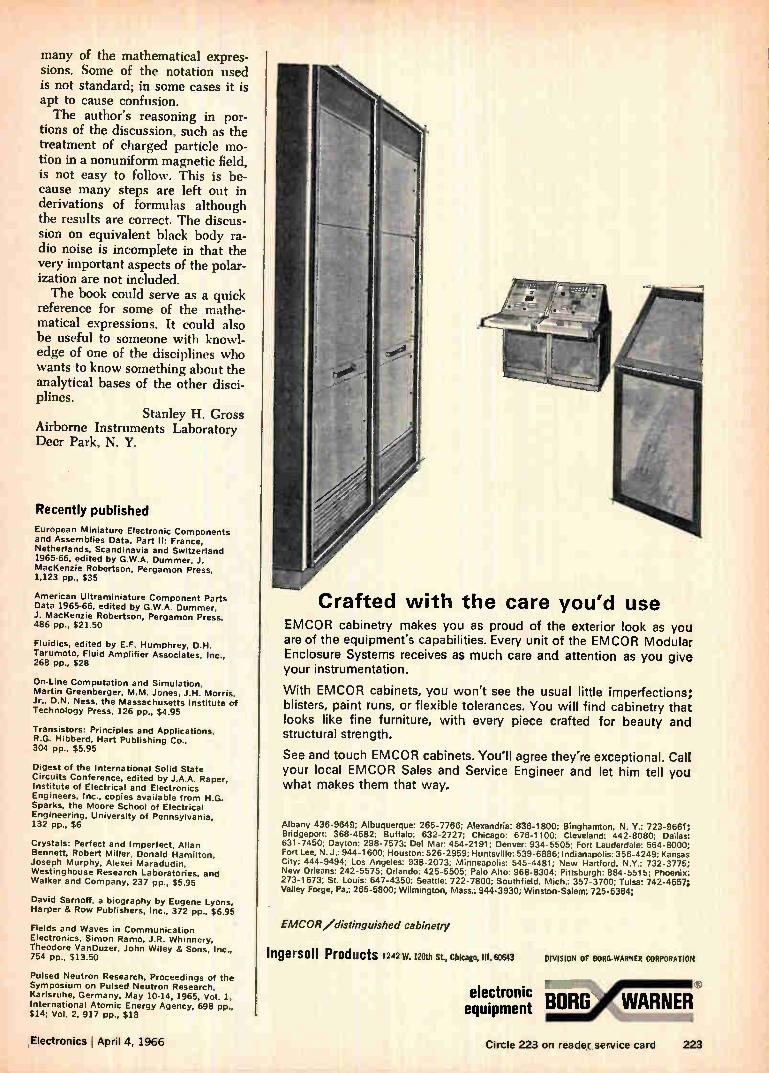
many of the mathematical expres-sions. Some of the notation used is not standard; in some cases it is apt to cause confusion. The author's reasoning in por-
tions of the discussion, such as the treatment of charged particle mo-tion in a nonuniform magnetic field, is not easy to follow. This is be-cause many steps are left out in derivations of formulas although the results are correct. The discus-sion on equivalent black body ra-dio noise is incomplete in that the very important aspects of the polar-ization are not included. The book could serve as a quick
reference for some of the mathe-matical expressions. It could also be useful to someone with knowl-edge of one of the disciplines who wants to know something about the analytical bases of the other disci-plines.
Stanley H. Gross Airborne Instruments Laboratory Deer Park, N. Y.
Recently published
European Miniature Electronic Components and Assemblies Data, Part II: France, Netherlands, Scandinavia and Switzerland 1965-66, edited by G.W.A. Dummer, J. MacKenzie Robertson, Pergamon Press, 1,123 pp., $35
American Ultraminiature Component Parts Data 1965-66, edited by G.W.A. Dummer, J. MacKenzie Robertson, Pergamon Press. 486 pp., $21.50
Fluidics, edited by E.F. Humphrey, D.H. Tarumoto, Fluid Amplifier Associates, Inc., 268 pp., $28
On-Line Computation and Simulation, Martin Greenberger, M.M. Jones, J.H. Morris, Jr., D.N. Ness, the Massachusetts Institute of Technology Press, 126 pp., $4.95
Transistors: Principles and Applications, R.G. Hibberd, Hart Publishing Co., 304 pp., $5.95
Digest of the International Solid State Circuits Conference, edited by J.A.A. Raper, Institute of Electrical and Electronics Engineers, Inc., copies available from H.G. Sparks, the Moore School of Electrical Engineering, University of Pennsylvania, 132 pp., $6
Crystals: Perfect and Imperfect, Allan Bennett, Robert Miller, Donald Hamilton, Joseph Murphy. Alexei Maradudin, Westinghouse Research Laboratories, and Walker and Company, 237 pp., $5.95
David Sarnoff, a biography by Eugene Lyons, Harper & Row Publishers, Inc., 372 pp., $6.95
Fields and Waves in Communication Electronics, Simon Ramo, J.R. Whinnery, Theodore VanDuzer, John Wiley & Sons, Inc., 754 pp., $13.50
Pulsed Neutron Research, Proceedings of the Symposium on Pulsed Neutron Research, Karlsruhe, Germany, May 10-14, 1965, Vol. 1, International Atomic Energy Agency, 698 pp., $14; Vol. 2, 917 pp., $18
re
• e_:.1
IC
Crafted with the care you'd use EMCOR cabinetry makes you as proud of the exterior look as you are of the equipment's capabilities. Every unit of the EMCOR Modular Enclosure Systems receives as much care and attention as you give your instrumentation.
With EMCOR cabinets, you won't see the usual little imperfections; blisters, paint runs, or flexible tolerances. You will find cabinetry that looks like fine furniture, with every piece crafted for beauty and structural strength.
See and touch EMCOR cabinets. You'll agree they're exceptional. Call your local EMCOR Sales and Service Engineer and let him tell you what makes them that way.
Albany 436-9649; Albuquerque: 265-7766; Alexandria: 836-1800; Binghamton, N. Y.: 723-9661; Bridgeport: 368-4582; Buffalo: 632-2727; Chicago: 676-1100; Cleveland: 442-8080; Dallas: 631-7450; Dayton: 298-7573; Del Mar: 454-2191; Denver: 934-5505; Fort Lauderdale: 564-8000; Fort Lee, N. J.: 944-1600; Houston: 526-2959; Huntsville: 539-6886; Indianapolis: 356-4249; Kansas City; 444-9494; Los Angeles: 938-2073; Minneapolis: 545-4481; New Hartford, N.Y.: 732-3775; New Orleans: 242-5575; Orlando: 425-5505; Palo Alto: 968-8304; Pittsburgh: 884-5515; Phoenix: 273-1673; St. Louis: 647-4350; Seattle: 722-7800; Southfield, Mich.: 357-3700; Tulsa: 742-4657; Valley Forge, Pa.: 265-5800; Wilmington, Mass.: 944-3930; Winston-Salem: 725-5384;
EMCOR /distinguished cabinetry
Ingersoll Products 1242 W. 120th St, Chicago, 111.60643
electronic equipment
DIVISION OF BORG-WARNER CORPORATION
BORO WARNER
,Electronics I April 4, 1966 Circle 223 on reader service card 223
Technical Abstracts
Complex integrated circuits
A systematic engineering approach to
complex arrays L. Vadasz, R. Nevala, W. Sander,
R. Seeds Fairchild Semiconductor division, Fairchild Camera & Instrument Corp.
Palo Alto, Calif.
The evaluation of silicon digital integrated circuits has been more rapid than expected. Semiconduc-tor-device manufacturers have al-ready started to develop very com-plex logic arrays. These arrays will be the equivalent of hundreds of logic gates. By putting hundreds of gates on
a single monolithic silicon chip re-liability is greatly improved, mak-ing complex logic arrays highly attractive to the military. However, to interest commercial and indus-trial users of integrated circuits, the semiconductor-device manufac-turer must add other inducements.
Two potential advantages are re-duced engineering time and low cost. A metal - oxide - semiconductor
chip having groups of a particular component pattern known as cells can provide both advantages. With the chip, a variety of complex logic circuits, such as memory systems, can be obtained by using various cell connection schemes. A few different combinations
could probably be used to form a cell. One such cell family which has been investigated includes six sections. These are a quad nand gate, a quad nor gate, a dual gated latch, a master slave flip flop, a dual exclusive-nor gate and a quad output driver. To minimize the over-all system-
design time the user should study the manufacturer's specifications for the integrated circuit and then supply the manufacturer with the logic specification for the subsys-tem in accordance with the manu-facturer's design limits. The man-ufacturer will then design the
masks and build, test and deliver the circuits. The work of the user is kept to a minimum and the over-all engineering time is reduced be-cause of the manufacturer's fa-miliarity with the integrated circuit.
Presented at the 1966 International Solid State Circuits Conference, Philadelphia, Feb. 9 to 11.
Fixed memory with E cores
Development of an E-core read-only
memory
P.S. Sidhu Ampex Corp., Culver City, Calif.
A read-only memory to hold con-trol information in a computer can be built of E cores. Inexpensive to build, fast and reliable, the mem-ory's manufacture can be easily automated and the design appears to impose no limit on its size. An E core is a piece of ferrite
material with three legs perpen-dicular to its main body, making it resemble the letter "E". If two E cores are placed leg to leg, the result is a two-aperture ferrite core. A wire passing through one of the
LETS YOU IN ON PRECISION RANDOM NOISE
VLF-UHF the latest in Heat Sink Extrusions
WAKEFIELD DISTRIBUTOR PRODUCTS CATALOG Your authorized WAKEFIELD Elec-tronic Distributor stocks a wide variety of Heat Sink Extrusions in 3 ft. ± 1/4" lengths. This catalog will give you the name of your nearest distributor and full prod-uct information: milliwatt to high power coolers, circuit board heat sinks, extrusions, thermal joint compound DELTA BOND 152 Thermally Conductive Adhesive.
FOR YOUR COPY, WRITE
WAKEFIELD ENGINEERING, INC. 139 FOUNDRY ST. WAKEFIELD, MASS. (617) 245.5900 • TWX 617.245-9213
• SERVO-STABILIZED OUTPUT: compensated for drift (3%.,er
temperature, line voltage, noise tube aging.
• STABILITY: 0.05 db after 11 msec warmup.
• ACCURACY: 0.1 db to 200 MHz.
• Model NS-LB: 100 Hz - 500 MHz. Output absolutely free of
line noise harmonic contamination at VLF. Only generator
on the market with precision VLF capability.
• Model NS-C: 1 MHz - 500 MHz.
• Model NS-Fi: 1 MHz - 2000 MHz.
Other products by ARI: Laboratory RF Measurements Equip-
ment, Precision Frequency and Timing Instrumentation.
AEROSPACE RESEARCH, INC.
130 Lincoln St., Boston, Mass. 02135
(617) 254-7200
224 Circle 224 on reader service card Circle 478 on reader service card
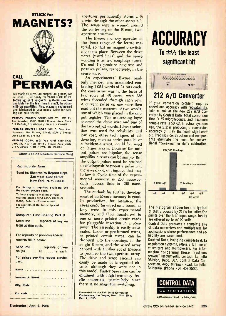
STUCK for
MAGNETS?
WERMAG We stock all sizes, all shapes, all grades, for all uses ... all ready for 24-HOUR DELIVERY. Including soft magnetic materials — now available for the first time in small, less-than-mill-run quantities. Also, magnets engineered and fabricated to your needs. Write for cata-log and data sheets.
PERMAG PACIFIC CORP. 5441 W. 104th St. Los Angeles, Calif. 90045 / Phones: Area Code 213 776-5656, 213 670-7060 / TWX: 213 670-0408
PERMAG CENTRAL CORP. 5301 D. Otto Ave. Rosemont, Des Plaines, Illinois 60018 / Phone: Area Code 312 678-1120
PERMAG CORP. 88-06 Van Wyck Expressway Jamaica, New York 11418 / Phone: Area Code 212 OLympia 7-1818 / TWX: 212 479-3654
Circle 473 on Readers Service Card
Reprint order form
Send to: Electronics Reprint Dept. 330 West 42nd Street New York, N. Y. 10036
For listing of reprints available the reader service card.
To help expedite mailing of your reprints please send cash, check or money order with your order.
For reprints of the latest special report:
Computer Time Sharing Part II
Send me reprints of key no
R-86 at 50e each.
For reprints of previous special
reports fill in below:
Send me reprints of key no.(s) at Ø each.
For prices see the reader service card.
Name
Number & Street
City, State
Zip code
apertures permanently stores a 0;
a wire through the other stores a 1. The sense wire is wound around the center leg of the E-core, two-aperture structure. The E-core memory operates in
the linear range of the ferrite ma-terial, so that no magnetic switch-ing takes place. Between the drive wires (word lines) and the sense winding is an a-c coupling; stored O's and l's produce negative and positive pulses, respectively, in the sense wire. An experimental E-core read-
only memory was assembled con-taining 1,024 words of 24 bits each; the core array was in the form of two rows of 48 cores, with 256 wires threaded through each row. A current pulse on one wire then read out the contents of two words, one of which was placed in the out-put register. The addressing logic selected the drive wire and one of the two output words. Linear selec-tion was used for reliability and low cost; other techniques of ad-dressing, such as series-parallel or coincident-current, could he used on larger arrays. Because the out-put pulses are bipolar, the sense amplifier circuits can be simple. But the output pulses must be strobed to distinguish between a pulse and the overshoot, or ringing, that may follow it. Cycle time of the experi-mental memory is 250 nanosec-onds; access time is 150 nano-seconds. The outlook for further develop-
ment of an E-core memory is good. In production, for instance, the cores could be wired on a board, as they were in this experimental memory, and then transferred to one or more printed-circuit cards for pluggable insertion in a com-puter. The assembly is easily auto-mated. Loose or pre-formed wires, or printed circuit wires, can be dropped into the openings in the single E-core, and the wired array capped with another set of E-cores to produce the two-aperture array. The drive and sense circuits can easily be made of integrated cir-cuits, although they were not in this model. Faster operation can be obtained with high-frequency fer-rite materials, particularly since there is no magnetic switching.
Presented at the Fall Joint Computer Conference. Las Vegas, Nev., Nov. 30 to Dec. 2. 1965.
ACCURACY To ±1/2 the least significant bit
••••• •11111.• agoorow•
-
00.000.00000occ
212 A/D Converter If your conversion problem requires speed and accuracy with repeatability, take a look at the new 212 A/O Con-verter by Control Data. Total conversion time is 15 microseconds, and maximum sample rate is 50 KC. In actual systems use, the 212 is producing a conversion accuracy of -±-1/2 the least significant bit. Precision construction and compon-ents eliminate the need for conven-tional "tweaking" or daily calibration.
237,505 Readings
TYPICAL 212 HISTOGRAM
5 Readings 2 Readings
0 +1 +2 +3
Bit error
The histogram shown here is typical of that produced by 212's for inflection points over the total input range. Inputs are offered up to ±-100 volts. Control Data produces a complete line of data converters and multiplexers for applications where performance and re-liability are paramount. Control Data, building complete data acquisition systems, offers a full line of converters and multiplexers. For infor-mation concerning these "systems proven" instruments, contact: La Jolla Division, Dept. 307, Control Data Cor-poration, 4455 Miramar Road, La Jolla, California. (Phone 714, 453-2500).
CONTROL DATA CORPORATION
4455 Miramar Road, La Jolla, Calif.
Electronics I April 4, 1966 Circle 225 on reader service card 225
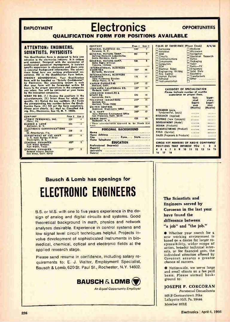
EMPLOYMENT Electronics OPPORTUNITIES
QUALIFICATION FORM FOR POSITIONS AVAILABLE
ATTENTION: ENGINEERS, SCIENTISTS, PHYSICISTS This Qualification Form is designed to help you advance in the electronics industry. It is unique and compact. Designed with the assistance of professional personnel management, it isolates specific experience in electronics and deals only in essential background information. The adver-tisers listed here are seeking professional ex-perience. Fill in the Qualification Form below.
STRICTLY CONFIDENTIAL: Your Qualification form will be handled as "Strictly Confidential" by Electronics. Our processing system is such that your form will be forwarded within 24 hours to the proper executives in the companies you select. You will be contacted at your home by the interested companies.
WHAT TO DO. (1.) Review the positions in the advertisements. (2.) Select those for which you qualify. (3.) Notice the key numbers. (4.) Circle the corresponding key number below the Quali-fication Form. (5.) Fill out the form completely. Please print clearly. (6.) Mail to, Classified Ad-vtg. Div., Electronics, Box 12, N. Y. 10036.
COMPANY Page .7 Key 4 ATOMIC PERSONNEL INC. 228 I—
Phila.. Pa. BAUSCH IL LOMB 228 2
Rochester. N. Y. ELECTRONIC COMMUNICATIONS INC. 228
St. Petersburgh. Fla. -- DEPARTMENT OF THE NAVY 227
U. S. Navy Bureau of Ships Washington, D. C.
GENERAL DYNAMICS Fort Worth Division Fort Worth, Texas
GENERAL DYNAMICS General Atomic Division San Diego. Calif. (02112
130*
213* e
COMPANY Page a Key It• GENERAL ELECTRIC CO. 218. 7
Syracuse. N. Y. GENERAL MOTORS CORP.
Defense Research Laboratories Santa Barabara. Calif.
GENERAL MOTORS CORP. Delco Radio Division Kokomo. Indiana
INTERNATIONAL BUSINESS MACH IN ES
Bethesda. Maryland INTERNATIONAL BUSINESS MACHINES 173 II Data Processing Division White Plains. N. Y.
KAISER ENGINEERS 214' 12 Oakland, Calif.
LOCKHEED CALIFORNIA CO. 12IP 13 Burbank. Calif.
LOCKHEED MISSILES & SPACE CO. 170 14
Sunnyvale. Calif. TELEDYNE INDUSTRIES
Geotech Div. Garland, Texas 75040
UNITED CONTROL 288* 16 Redmond. Washington 98052
U. S. NAVY 218* 17 Navy Overseas Employment 08144) San Francisco, Calif. 94102
XEROX CORP. 130 18 Rochester. N. Y.
• These advertisementa appeared In the Ma rch 21st is.sue.
227 8
138
184* 10
218* 15
PERSONAL BACKGROUND Nome Home Address City Zone. State Home Telephone
EDUCATION Professional Degree(s) Major(s) University Date(s,
FIELDS OF EXPERIENCE (Please Check) 4/4/66 Aerospace n Medicine Antennas Microwave ASW Navigation Circuits Operation Research
Optics Packaging Radar Radio—TV Simulators Solid State Telemetry Transformers Other
Communications Components Computers ECM Electron Tubes Engineering Writing Fire Control Human Factors Infrared Instrumentation
CATEGORY OF SPECIALIZATION Please Indicate number of months
experience on proper lines. Tech. nical Experi-
Super-visory Experi-
ence ence (Months) (Months
RESEARCH (pure, fundamental, basic)
RESEARCH (Applied)
SYSTEMS (New Concepts)
DEVELOPMENT (Model)
DESIGN (Products)
MANUFACTURING (Product)
FIELD Service)
SALES (Proposals & Products)
CIRCLE KEY NUMBERS OF ABOVE COMPANIES'
POSITIONS THAT INTEREST YOU 1 2 3
4 5 6 7 8 9 10 11 12 13 14 15
16 17 18
Bausch & Lomb has openings for
ELECTRONIC ENGINEERS B.S. or M.S. with one to five years experience in the de-
sign of analog and digital circuits and systems. Good
theoretical background in math, physics and network
analyses desirable. Experience in control systems and
low signal level circuit techniques helpful. Projects in-
volve development of sophisticated instruments in bio-
medical, chemical, optical and electronic fields at the
applied research stage.
Please send resume in confidence. including salary re-
quirements to: E. J. Walter, Employment Specialist,
Bausch & Lomb, 620 St. Paul St., Rochester, N.Y. 14602.
BAUSCH & LOMB An Equal Opportunity Employer
The Scientists and
Engineers served by
Corcoran in the last year
have found the
difference between
"a job" and "the job."
• Whether your search for a new working environment is based on a desire for larger re-sponsibility, wider scope of action, broader technical inter-ests, or for financial gain, the individual attention offered by Corcoran assures a greater chance of success.
• Nationwide, we serve large and small clients on a fee paid basis. Please airmail back-ground to:
JOSEPH P. CORCORAN Personnel Consultants
505 13 Germantown Pike Lafayette Hill, Pa. 19444
Member IEEE
226 Electronics' April 4, 1966
GM DEFENSE RESEARCH LABORATORIES In Beautiful Santa Barbara, Calif.
Electrical Engineers
Expanding activities in the field of Electrical power and propulsion for advanced Land. Ocean. and Lunar vehicles have created immediate openings for electrical engineers in-terested in the design, analysis and fabrication of:
Logic and Electronic Circuits
Power Inverters and Frequency Converters
Electrical Machines and Electro -Mechanical Devices
Feed Back Control Systems
Openings exist for recent BS, MS
and Ph.D. Graduates as well as sen-ior personnel with several years ex-perience. These positions offer an excellent opportunity to participate and advance in a rapidly growing technology in a stable corporate en-vironment.
GM Defense Research Laboratories is currently engaged in research pro-grams encompassing Sea, Land. Aerospace, and Lunar activities and can offer the advantage of a small laboratory (800 people), a fine professional staff, and the backing of a large corporation.
Please send resume to W. E. Wells and upon review, interviews will be arranged for qualified candidates.
GM DEFENSE RESEARCH LABORATORIES
GENERAL MOTORS CORP. Box T
Santa Barbara, Calif.
Ar, Equal Opporfonily Employer lif/P
•••••11111111‘
engineering management opportunities with
U.S. NAVY-BUREAU OF SHIPS In.
WARFARE The Navy's high-priority anti-submarine warfare
program, involving multi-million dollar contracts with industry, needs qualified engineers for program management involving research, development, test-ing, evaluation, procurement planning, production, installation and maintenance in these fields:
• SURFACE SHIP, VARIABLE DEPTH AND SUB-MARINE SONAR SYSTEMS
• UNDERWATER ACOUSTIC COMMUNICATIONS AND IFF SYSTEMS
•OCEANOGRAPHY• DIGITAL SIGNAL PROCESSING
• Transportable Underwater Ocean Area Surveillance Systems
.0 Acoustic Navigation And Mine Avoidance Equipments • Inshore Undersea Warfare Equipment • Mine And Torpedo Detection Sonar
• ASW Target Classification • Transducer Design • Non-Acoustic Detection of Submerged Submarines
• Display Engineering • Systems Analysis
AND OTHER FIELDS: NAVAL ARCHITECTURE; MARINE,
ELECTRICAL, ELECTRONIC, MECHANICAL ENGINEERING
IN—SHIPS DESIGN, CONSTRUCTION AND MAINTENANCE;
MACHINERY DESIGN; RADAR, COMMUNICATIONS, TEST EQUIPMENT, QUALITY ASSURANCE & RELIABILITY.
These positions, which are in Washington, D.C., involve travel and considerable contact with in-dustrial organizations. Degree in mechanical or electro/electrical engineering and related experi-ence desirable. Starting salaries range from $7,987 to$14,680 depending on experience. Most positions are at $10,619 and $12,510. Relocation expenses paid. These are career Civil Service positions with full benefits, regular salary increases. Send resume or SF-57 to:
Civilian Personnel Division Bureau of Ships, Code 263R-07 Department of the Navy, Room 2435 Washington, D.C. 20360 An Equal Opportunity Employer
Electronics April 4, 1966 227
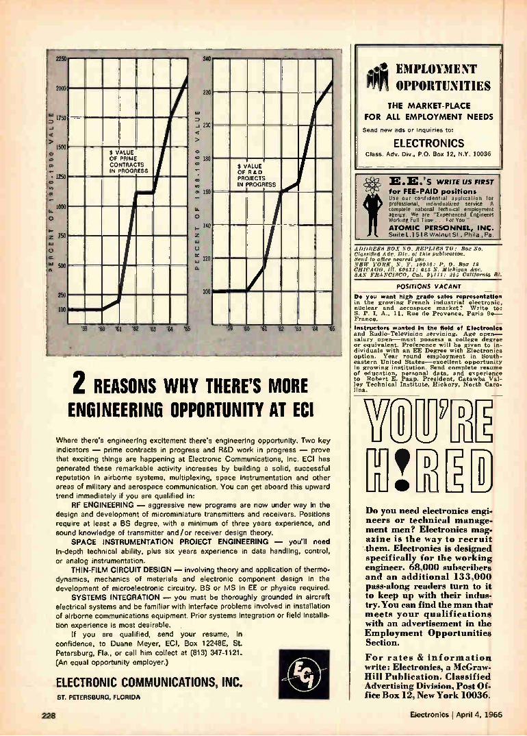
nil
000
750
500 $ VALUE OF PRIME CONTRACTS IN PROGRESS
250
000
750
500
250
100
'59 '60 '61 '62 '63 '64
220
0.1
200
o
e 180
co
C, 160
o 140
o
120
Q.
100
$ VALUE OF R&D PROJECTS IN PROGRESS
'65 '59 '60 '61 62 63 '&4 65
2 REASONS WHY THERE'S MORE ENGINEERING OPPORTUNITY AT ECI
Where there's engineering excitement there's engineering opportunity. Two key indicators — prime contracts in progress and R&D work in progress — prove that exciting things are happening at Electronic Communications, Inc. ECI has generated these remarkable activity increases by building a solid, successful reputation in airborne systems, multiplexing, space instrumentation and other areas of military and aerospace communication. You can get aboard this upward trend immediately if you are qualified in:
RF ENGINEERING — aggressive new programs are now under way in the design and development of microminiature transmitters and receivers. Positions require at least a BS degree, with a minimum of three years experience, and sound knowledge of transmitter and/or receiver design theory.
SPACE INSTRUMENTATION PROJECT ENGINEERING — you'll need in-depth technical ability, plus six years experience in data handling, control, or analog instrumentation.
THIN-FILM CIRCUIT DESIGN — involving theory and application of thermo-dynamics, mechanics of materials and electronic component design in the development of microelectronic circuitry. BS or MS in EE or physics required.
SYSTEMS INTEGRATION — you must be thoroughly grounded in aircraft electrical systems and be familiar with interface problems involved in installation of airborne communications equipment. Prior systems integration or field installa-
tion experience is most desirable. If you are qualified, send your resume, in
confidence, to Duane Meyer, Ed, Box 12248E, St. Petersburg, Fla., or call him collect at (813) 347-1121. (An equal opportunity employer.)
ELECTRONIC COMMUNICATIONS, INC. ST. PETERSBURG, FLORIDA
EMPLOYMENT Mr OPPORTUNITIES
THE MARKET-PLACE
FOR ALL EMPLOYMENT NEEDS
Send new ads or inquiries to:
ELECTRONICS Class. Adv. Div., P.O. Box 12, N.Y. 10036
E.E.'s WRITE US FIRST for FEE-PAID positions lise or confidential application for professional, individualized service A complete national technical employment agengy. We are "Experienced Engineers Working Full lime ..I or Ynu'
ATOMIC PERSONNEL, INC. Suite 1.1518 Walnut St , Philo , Pa.
.(1)i)REss It().1 REi.i.iEs To: Box No. Classified Adr. Dir, of this publication. Send to office nearest you. NEW YORK. N. Y. 10096: P. 0. Box 12 CHICAGO, 111. 60611: 645 N. Michigan Ave. SAN FRANCISCO, Cal. 94111: 255 California St.
POSITIONS VACANT _
Do you want high grade sales representation in the growing French industrial electronic. nuclear and aerospace market'? Write to: S. P. I. A., 11, Rue de Provence, Paris 9e— France.
Instructors wanted In the geld of Electronics and Radio-Television servicing. Age open— salary open—must possess a college degree or equivalent. Preference will be given to in-dividuals with an EE Degree with Electronics option. Year round employment in South-eastern United States—excellent opportunity in growing institution. Send complete resume of education, personal data, and experience to Robert E. Paap, President, Catawba Val-ley Technical Institute, Hickory, North Caro-lina.
Do you need electronics engi-neers or technical manage-ment men? Electronics mag-azine is the way to recruit them. Electronics is designed specifically for the working engineer. 68,000 subscribers and an additional 133,000 pass-along readers turn to it to keep up with their indus-try. You can find the man that meets your qualifications with an advertisement in the Employment Opportunities Section.
For rates & information write: Electronics, a McGraw-Hill Publication. Classified Advertising Division. Post Of-fice Box 12, New York 10036.
228 Electronics j April 4, 1966
SEARCHLIGHT SECTION
AUTOTRACK ANTENNA MOUNT
360 degree azimuth. 210 degree elevation sweep with better than 1 mil. accuracy. Missile velocity acceleration and stewing rates. AmplMyna and servo control. Will handle up to 20 ft. dish. Supplied complete with control chassis. In stock-Immediate delivery. Used world over by NASA. USAF'. TYPE 5IP-61 B. SCR-584. NIKE AJAX mounts also In ..ock plus several airborne trackers.
SCR 584 AUTOMATIC TRACKING RADARS Our 584s in like new condition, ready to go. and in stock for immediate delivery. Ideal for telemetry research and development, missile tracking, satellite tracking, balloon tracking. Used on Atlantic Missile Range. Pacific Missile Range. N.A.S.A. Wallops Island. A.B.M.A. Write us. Fully Desc. MIT Rad. Lab. Series, Vol. 1. rms. 207-210, 228. 284-286. Compl inst. Bk. avail. $25.00 each.
AN/GPG-1 SKYSWEEP TRACKER
3 can, automatic tracking radar system. Complete package with indicator system. Full target ac-quisition and automatic tracking. Input 115 volts 60 cycle. New. In stock for immediate delivery. Entire System 6' long. 3' wide. 10' high. Ideal for Infrared Tracker. Drone Tracker. Missile. Tracker, R. & D.
PULSE MODULATORS MIT MODEL 9 PULSER 1 MEGAWATT-HARD TUBE Output 25 kv 40 amp. Duty cycle, .002. Pulse lengths .25 to 2 microsec. Also .5 to 5 mIcrosee and 1 to 5 microsee. Use. 6C21, Input 115v 60 cycle AC. Mfr. GE. Complete with driver and high voltage power sup-ply. Ref: MIT Bad. Lab. Series, Vol. 5, ppe. 152-160.
2 MEGAWATT PULSER Output 30 kv at 70 amp. Duty cycle .001. Rep rates: 1 mIcroseo 000 pee. 1 or 2 msec 300 ptis. Uses 5948 hydrogen thyratron. Input 120/208 VAC 60 cycle. Mfr. GE. Complete with high voltage power supply.
MIT MODEL 3 PULSER Output: 144 kw (12 kv at 12 amp.) Duty ratio: .001 max. Pulse duration: .5, 1 and 2 microsec. Input: 115 y 400 to 2000 cps and 24 vdc. $325 ea. Full desc. Vol. 5. MIT Rad. Lab, serles, pg. 140.
250KW HARD TUBE PULSER Output 16 kv 16 amp, duty cycle .002. Pulses can be coded. Uses 5D21. 715C or 4P1160A. Input 116 • 80 cycle ac. lncl. H.V. owe supply $1200 ea.
200 KW LINE PULSER 16 KV 16A .25 microsee 4000 PPS. Duty .0012. 5C22 thvr. Input 115V 00 cy AC. $450 00.
MICROWAVE SYSTEMS
E-4 FIRE CONTROL SYSTEM Hughes Aircraft X Bead. Complete. In stock.
C-BAND RADAR 250 KW output, C-band, PPI Indicator, 5C22 thyra-tron modulator. Antenna hi gain parabolic section. Input 115 volte 60 cycle AC. complet. $2750.00.
300 TO 2400MC RF PKG. 300 to 2400 MC CW. Tuneable. Transmitter 10 to 30 Watts. Output. As new $475.
500W "L" BAND RADAR 500 kw 1220-1359 mes. 160 nautical mile march range P.P.I. and A Scopes. MTI. thynstron mod. 5J26 magnetron. Complete system.
PHILCO MICROWAVE LINKS C Band Microwave Link terminal bays and re-peater bays in stock. New $1500 each or $2500 per Dr.
100W 3CM. RADAR Complete 100 kw output airborne system with AMTI, 5C22 thyr. mod. 4J52 magnetron. PPI. 360 deg au sweet.. 60 deg. elev. sweet), gyro stabilizer, hl-gain rove. Complete with all plugs and cables.
M-33 AUTO-TRACK RADAR SYSTEM X band with plotting board, automatic range track-ing. etc. Complete with I megawatt acq. radar.
SEND FOR OUR NEW 8 PAGE CATALOG LIST-
ING THE LARGEST INVENTORY OF RADAR AND
MICROWAVE EQUIPMENT IN THE WORLD.
PPI CONSOLE Complete plan position Indicator, 10, with 115 volt 60 cy input pwr supply. Also mts. sy-nehro for RBI readout. Type AN/UPA-25. $1200.00 ea.
RADAR MAPPING CONSOLE Complete with 115 volt 60 cy AC pwr supply. Mir: IBM/Bendix. $1200.00 ea.
60MC I.F. SMC
Bandwidth, 130,11) gain. Sensitivity 95dbm. Uses eAK5's. 1 0.11.5. Mfr. Tosas Instr. Price ri5.00.
AIRPORT SURVEILLANCE RADAR General Electric type ASS-2. 500 KW, S Band, will detect even small light Acft at 250 miles. Compl system incl, standby equip. As-new.
3KW RCA PHONE & TELEG XMTR
2-30 MC. 10 Autotone channel. plus MO. Input 220 vac. 50/60 cycles.
MICROWAVE TUBES CM-710A CARCINOTRON 2400 to 3100 me tuneable. 200 watts CW output nom. Mfr: CSF. Govt. acq. cost $6000.00 Price $975.00.
1154 RCA T.W.T. 1.5 to 4.5 gc. L-S-C Rand. 10 milliwatts output. Wide band low level amp. u/w AN/ALQ-I9 Counter-measure Set. Govt. Acq. cost $4000.00 Price $250,00.
1161 RCA T.W.T. 1.9 to 4.1 gc: 1 watt output grid controlled. Wide Band medium par amp. Pulse or CW operation u/w AN/ALQ-19 Countermeasures Set. Govt. Acq. cost $4000.00 Price $250.00.
C BAND KLYSTRON 7125 to 7425 inc. Tuneable. 1 watt CW output. Mfr: Sylvania.
SMC-11A KLYSTRON 4640 in 4670 Inc. Amplifier-multiplier. 1 watt CNI7 output Req. 773 to 778 me driver. Mfr: Sperry,
SMX-32 KLYSTRON 9 to 10.5 kmc. Amplifier multiplier. 2 watts CW out-put. Req. 4500 to 5250 me driver. Mfr: Sperry. VA-800 KLYSTRON 1.7 to 2.4knic. Tuneable. 10 kw CW output. Mfr: Varian.
VA-1520 MAGNET For use with VA-800 $750.
VA-137 TWT .85 T 1.05 GC. 5 KW peak. 850 Watts Avg. 131111C Bandwidth.
HUGHES 302H BWO KU Bawl backward wave Ose.
RADAR AUTO.TRACK & TELEMETRY ANTENNA PEDESTALS 3 & 10 CSC SCR 584 AUTOTRACK RADARS. Ai 33 RADAR TPSED SEARCH. APS.45 TPSIOD HT. FINDERS. WX RADARS. FPN•32GCA. APS•10 APS•158 APS•27 (AMT)) SEARCH. • • APN•102 DOPPLER. DOZENS MORE CARCINOTRONS PEN'S. .25..5.1.2.3 6 MEGAWATT PULSE MODULATORS. CAVITIES PULSE TRANSFORMERS. IF STRIPS. WAVEGUIDE. BENDS 200 MC. 1 KMC. 3 KMC. 6 (MC. 9 Kt«. 24 (MC. RF PKGS.
RADIO RESEARCH INSTRUMENT CO. 550 5TH AVE., NEW YORK 36, N.Y. JU 6.4691
TEST EQUIPMENT For over 20 years specializing in top brands
only. Write for our latest listing. We buy complete Inventories.
ELECTRONIC SALES 1413 Howard Street, Chicago, Illinois 60626
Telephone ROgers Park 4-0600
CIRCLE 956 ON READER SERVICE CARD
FOR SALE Subminiature switches. 15,000 #E4-174 Control Co. of America SPDT-1.000,000 OPS. Min. Mechanical life 500.000 OPS. at 125/250 VAC. 21/2 AMPS. No reasonable offer refused.
EASY-UP, INC. 1006 State St., Racine, Wis.
CIRCLE 957 ON READER SERVICE CARD
TEST EQUIPMENT SPECIALS TEKTRONIX Pluipliplleads-Wide Band Calibrated Pre.
Tyne 53A-.05 v/cm-20 vim ten
Finvir.de 7.3à7(228 1"C".-12,.'"em .400A-.03-300V . .545 400C-.001-300V . 8125 #400B-.03-300V..505 #4000- .001-900V 4
MCS 8155 Your letterhead will bring a catalog of test equip. specials.
REX INDUSTRIAL ELECTRONICS 759-10th Ave., N. Y. 10019 737-1361
CIRCLE 958 ON READER SERVICE CARD
Color DIAL TELEPHONES $10.95 Factory rebuilt Western Electric Complete In white, beige, ivory, pink, green, or blue. If 4 prong plug la re-quired add $2.00. Fully guaran-teed. Write for free list. All shipments FOB.
SURPLUS SAVING CENTER Dept. E-1446 Waymart. Pa,
e'tej
CIRCLE 959 959 ON READER SERVICE CARD
Dre11111 TO BUYERS TURN TO THE SEARCHLIGHT SECTION IN ELECTRONICS
n LOULI
ELECTRON TUBES KLYSTRONS • AIR 14 TR • MAGNETRONS SUBMINIATURES • C.R.T. • T.W.T. • 5000-
6000 SERIES • SEND FOR NEW CATALOG A2 •
A & A ELECTRONICS CORP. 1063 PERRY ANNEX WHITTIER. CALIF.
696-7544
CIRCLE 952 ON READER SERVICE CAR
CASH REWARD ! ! YOU will be rewarded with cold, hard cash by selling us your new, used, excess or unwanted electronic equipment. WB WANT TO BUY YOUR: AN/ARN-21, AN/ARC-34, AN/ARC-52, -55, any ARN or ARC equipment, ID indicators, Military Type Test Equip-ment, Collins and Bendlx equip., instruments and In-strumentation. Tell us what you have-eolleet the reward!
J. J. CANDEE CO. Dept. E 2525 W. Burbank Blvd., Burbank, Calif. 91505
CIRCLE 953 ON READER SERVICE CARD
CIRCLE 954 ON READER SERVICE CARD
PROFESSIONAL SERVICES
GIBBS & HILL, Inc. Consulting Engineers
Systems Engineering Operations Research • Development Field Studies • Design • Procurement
Power • Transportation • Communications Water Simply • Waste Treatm ent
393 Seventh Avenue New York 1, N. T.
CIRCLE 951 ON READER SERVICE CARD
GET IT from GOODHEART: EVERYTHING UNCONDITIONALLY GUARANTEEDI
DOES LOW OR CHANGING LINE VOLTAGE ANNOY?
Featured thie issue are Line Voltage Regulators. They hold line to 115 or 118 y for inputs 95-130 v and for load changes 0 to full rating. Automatically! Erldires itre tuned saturating isolatingoer ;former,
but only 3%e harm. Rai are sores-system, rold- rz to 1%, have ZERO harm. S El are Electronic, hold to 0.1%, have max. 3c7c harm. Mnfrs are Sole. ReY-Oleo». General Radio, Sorenson, Superior Electric.
ALL AT LOW SURPLUS BARGAIN PRICES! • Items are SPECIAL VALUES! CV: 250 VA, $22.50. SOO VA. $37.50.
1 KVA, $69.50, 2 KVA (230v) $99.30 CUM: 230 VA, $29.30, 1 KVA, $89.50 EM: 6 KVA, 5279.30. (Includes G.R. u1570AL.) S, El: SOO VA, 399.30. 1 KVA, $129.50.
2KVA • 129.30. 2 KVA ••S•' $199.50. 2./2 KVA • 199.30. 3KVA $279.30. 5 KVA (230v) 3350.00. 10 KVA. 5593.00
MOW-POWER SIGNAL GENERATORS Can be used normally because they have accurately' calibrated attenuators & freq. calibration very low leakage, high stability. AM or CW. Additionally, the high power enables use to measure effectiveness of RF filters with atten. over 100 di, . . . to provide known radiation fields to measure eusceptance, leak-age, screen rooms. etc . . . to plot antenna radiation Patterns . . . to measure VSWR with a slotted line • . . etc. They can be considered as accurately-cali-brated AM/CW Transmitters!
VS-110a/U (Borg-Warner, Byron-Jackson, Rollin Model 20): 85 he to 40 me. Output across • 20 ohm external load (making a 10 ohm source impedance) is variable from 0.1 uy to 10 y AM or CW and for CW only, will put out up to 15 V at most freq. in its range. When we use a 50 ohm wattmeter as a load, we read from 10 to 12 watts. Vo la read on a panel meter. with step and variable atten. With book, fob Los Angeles....5995.00.
T54110a/u (Borg-Warner, Byron-Jackeon, Rollin Model 30-(•): Very similar to above except output designed for a 50 ohm load, and (req. range 41 to 400 me. We reed outputs (at high-level CW only) of 7 to 10 watts on a 50 ohm wattmeter used as a load. On AM/CW Low output use, puts out 10 y across SO ohms. Step and variable attenuators down to 0.1 uy. With book, fob Loa Angeles $1295.00
(Note: Lout factory price was $14,750 001)
SLAD (Rhode & itehawars: 275 to 2,750 me in 2 overlapping bands calibrated on long acale with readability of 1 part in 10,000 and accuracy of 2%. Max. power output into external 50 ohm load is more than 10 w from 275-500 me; more than 20 w from 500-1700 me; more than 5 w from 17n0-2400 me; more than 1 w from 2400-2750 mc. Output con-tinuously adjustable down to about 10 to the minus 10th w. CW or AM pulse at 1 kc 100% modulated. Overhauled and certified by the factory branch, with book. -Regular price is over $4000.00. From us. only.... .............. 81995.00 For other material see our last-month's ad and/or please write for your specific needs. We have a tre-mendous inventory of desirable equipment.
WE RENT TO YOU! WE BUY FROM YOU!
R. E. GOODHEART CO. INC. Box 1220-E, Beverly Hills, Calif. 90213
Phones: Area 213, office 272.3707, messages 275-3342
Electronics I April 4, 1966 CIRCLE 955 ON READER SERVICE CARD
229
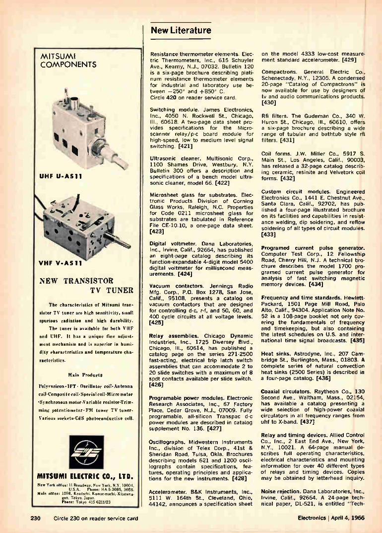
New Literature
MITSUMI COMPONENTS
UHF U-Ashl
\, .67. •
• t--C.
NEW TRANSISTOR TV TUNER
The characteristics of Mitsumi tran-
sistor TV tuner are high sensitivity, small
spurious radiation and high durability.
The tuner is available for both VIII'
and VHF. It has a unique fine adjust•
ment mechanism and is superior in humi-
dity characteristics and temperature cha-
racteristics.
Main Products
Polyvaricon•IFT • Oscillator coil. Antenna
coil 'Composite coil 'Special coil-Micro motor
Synchronous motor•Variable resistor-Trim-
ming potentiometer. FM tuner TV tuner•
Various sockets-CdS photoconductive cell.
MITSUMI ELECTRIC CO., LTD. New York office, I I Broadway. New York. N Y. 10001,
S A Phone: 11A 5 3085. 3086 M•in office; 1056. Koadachi. Komae.machi, Kitatama-
gun. Tokyo. Japan. Phone: Tokyo 415.6211/23
Resistance thermometer elements. Elec-tric Thermometers, Inc., 615 Schuyler Ave., Kearny, N.J., 07032. Bulletin 120 is a six-page brochure describing plati-num resistance thermometer elements for industrial and laboratory use be-tween —250' and +850 C. Circle 420 on reader service card.
Switching module. James Electronics, Inc., 4050 N. Rockwell St., Chicago, Ill., 60618. A two-page data sheet pro-vides specifications for the Micro-scanner relay/p-c board module for high-speed, low to medium level signal switching. [421]
Ultrasonic cleaner. Mu ltison ic Corp., 1100 Shames Drive, Westbury, N.Y. Bulletin 300 offers a description and specifications of a bench model ultra-sonic cleaner, model 66. [422]
Microsheet glass for substrates. Elec-tronic Products Division of Corning Glass Works, Raleigh, N.C. Properties for Code 0211 microsheet glass for substrates are tabulated in Reference File CE-10.10, a one-page data sheet. [423]
Digital voltmeter. Dana Laboratories, Inc., Irvine, Calif., 92664, has published an eight-page catalog describing its function-expandable 4-digit model 5400 digital voltmeter for millisecond meas-urements. [424]
Vacuum contactors. Jennings Radio Mfg. Corp., P.O. Box 1278, San Jose, Calif., 95108, presents a catalog on vacuum contactors that are designed for controlling d-c, r-f, and 50, 60, and 400 cycle circuits at all voltage levels. [425]
Relay assemblies. Chicago Dynamic Industries, Inc., 1725 Diversey Blvd., Chicago, III., 60614, has published a catalog page on the series 271-2500 fast-acting, electrical trip latch switch assemblies that can accommodate 2 to 20 slide switches with a maximum of 8 spdt contacts available per slide switch. [426]
Programable power modules. Electronic Research Associates, Inc., 67 Factory Place, Cedar Grove, N.J., 07009. Fully programable, all-silicon Transpac d-c power modules are described in catalog supplement No. 136. [427]
Oscillographs. Midwestern Instruments Inc., division of Telex Corp., 41st & Sheridan Road, Tulsa, Okla. Brochures describing models 621 and 1200 oscil-logra phs contain specifications, fea-tures, operating principles and applica-tions for the new instruments. [428]
Accelerometer. B&K Instruments, Inc., 5111 W. 164th St., Cleveland, Ohio, 44142, announces a specification sheet
on the model 4333 low-cost measure-ment standard accelerometer. [429]
Compactrons. General Electric Co., Schenectady, N.Y., 12305. A condensed 20-page "Catalog of Compactrons" is now available for use by designers of tv and audio communications products. [430]
Rfi filters. The Gudeman Co., 340 W. Huron St., Chicago, III., 60610, offers a six-page brochure describing a wide range of tubular and bathtub style rfi filters. [431]
Coil forms. J.W. Miller Co., 5917 S. Main St., Los Angeles, Calif., 90003, has released a 32-page catalog describ-ing ceramic, resinite and Velvetork coil forms. [432]
Custom circuit modules. Engineered Electronics Co., 1441 E. Chestnut Ave., Santa Clara, Calif., 92702, has pub-lished a four-page illustrated brochure on its facilities and capabilities in resist-ance welding, dip soldering, and reflow soldering of all types of circuit modules. [433]
Programed current pulse generator. Computer Test Corp., 12 Fellowship Road, Cherry Hill, N.J. A technical bro-chure describes the model 1700 pro-gramed current pulse generator for analysis of fast switching magnetic memory devices. [434]
Frequency and time standards. Hewlett-Packard, 1501 Page Mill Road, Palo Alto, Calif., 94304. Application Note No. 52 is a 108-page booklet not only cov-ering the fundamentals of frequency and timekeeping, but also containing the latest schedules on U.S. and inter-national time signal broadcasts. [435]
Heat sinks. Astrodyne, Inc., 207 Cam-bridge St., Burlington, Mass., 01803. A complete series of natural convection heat sinks (2500 Series) is described in a four-page catalog. [436]
Coaxial circulators. Raytheon Co., 130 Second Ave., Waltham, Mass., 02154, has available a catalog presenting a wide selection of high-power coaxial circulators in all frequency ranges from uhf to X-band. [437]
Relay and timing devices. Allied Control Co., Inc., 2 East End Ave., New York, N.Y., 10021. A 64-page manual de-scribes full operating characteristics. electrical characteristics and mounting information for over 40 different types of relays and timing devices. Copies may be obtained by letterhead inquiry.
Noise rejection. Dana Laboratories, Inc., Irvine. Calif., 92664. A 24-page tech-nical paper. DL-521, is entitled "Tech-
230 Circle 230 on reader service card Electronics i April 4, 1966
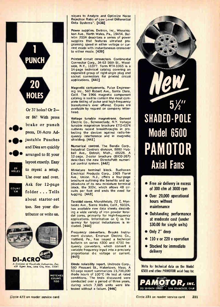
O•
O•
11•
20 HOLES
COUNT 'ENI
A Ihvision of lioudaille Industries. Inc. 459 Eighth Aye., Lake City, Min. 55041
Or 37 holes! Or 2—
or 86! With press
brake or punch
press, Di-Acro Ad-
justable Punches
and Dies are quickly
arranged to fit your
layout exactly. Easy
to repeat a setup.
Use over and over.
Ask for 12-page
folder . . . Tells
about starter-set
too. See your dis-
tributor or write us.
NOTCHES COUNT,
TOO
niques to Analyze and Optimize Noise Rejection Ratio of Low Level Differential Data Systems". [438]
Power supplies. Deltron, Inc., Wissahic-kon Ave., North Wales, Pa., 19454. Bul-letin 203A describes a series of power supplies that features ultrafast pro-graming speed in either voltage or cur-rent mode with instantaneous crossover to either mode. [439]
Printed circuit connectors. Continental Connector Corp., 34-63 56th St., Wood-side, N.Y., 11377. Form RTA-1065 is a 14-page technical catalog covering an expanded group of right-angle plug and socket connectors for printed circuit applications. [440]
Magnetic components. Pulse Engineer-ing Inc., 560 Robert Ave., Santa Clara, Calif. The 1966 magnetic component catalog is said to contain the most com-plete listing of pulse and high-frequency transformers ever offered. Copies are available by request on company letter-head.
Voltage tunable magnetrons. General Electric Co., Schenectady, N.Y. Voltage tunable magnetron brochure ETD-4374 outlines recent breakthroughs in pro-tecting the devices against radio-fre-quency interference and in magnetic shielding. [441]
Numerical control. The Bendix Corp., Industrial Controls division, 8880 Hub-bell Ave., Detroit, Mich., 48228. A 12-page, 2-color brochure (BICD-267) describes the new DirectaPath numeri-cal control system. [442]
Miniature terminal block. Buchanan Electrical Products Corp., 1065 Floral Ave., Union, N.J., offers a four-page brochure outlining the benefits and ap-plications of its new miniature terminal block, the 300V, which allows 48 cir-cuits per foot and ends the need for lugging. [443]
Toroidal cores. MicroMetals, 72 E. Mon-tecito Ave., Sierra Madre, Calif., 91024, has available new data sheets describ-ing a wide variety of iron powder toroi-dal cores, primarily for high-frequency applications. Information on Q vs fre-quency for typical inductances is in-cluded. [444]
Frequency converters. Brooks Instru-ment division, Emerson Electric Co., Hatfield, Pa., has issued a technical bulletin on series 4300 and 4700 fre-quency converters, which convert a variable frequency input into a precisely proportional d-c voltage or current. [445]
Diode reliability report. Unitrode Corp., 580 Pleasant St., Watertown, Mass. A 60-page report summarizes 15,700,000 diode hours of 100°C life test at rated conditions. The tests discussed were conducted over a period of three years,
during which 7,885 units were life-tested without a failure. [446]
tieW 5X"
SHADED-POLE Model 6500
PAMOTOR Axial Fans
• Free air delivery in excess of 300 cfm at 3000 rpm
• Over 20,000 operational hours without maintenance
e Outstanding performance at moderate cost (under $30.00 for single units)
• Only 2" deep
e 110 I/ or 220 y operation
• Stocked for immediate delivery
Write for technical data on the Model 6500 and other PAMOTOR axial fans to:
Circle 472 on reader service card Circle 231 on reader service card 231
Precision you can trust, because it's built in.
±50 ppm IC. 1/2% and 1% tolerances.
<0.5% load-lite eR guaranteed. Mil-R-10509E, Char. C.
New CORNING® NC-style Resistors. NC4-1/10 watt at 125 ° C., 49.9 ohms to 150K
NC5-1/8 watt at 125 ° C., 49.9 ohms to 499K
4111eM> ..•••••••••••••••••••••.
NC6-1/4 watt at 125' C., 49.9 ohms to 1 Meg.
True precision resistors with all the long-term reliability you've come to expect from CORNING glass-tin oxide film. And not just tested into some. Nor sorted out of many.
But precision that's built in ... in a continuous manufacturing process that provides the highest inherent reliability of any re-sistor made today. Here's how:
The tin oxide film is bonded molecularly to a glass cane sub-strate at red heat ... it isn't plastered on, or sputtered on.
Temperature coefficient of film and substrate match perfectly.
The substrate is chemically inert to the film. Once cooled, the film compares in hardness to high-carbon
tool steel ... you can't scrape it off. We make CORNING NC-styles with these materials and this
technique to guarantee you constant resistivity, constant quality ... precision that's built in.
Call your CORNING distributor for technical data and samples or send the coupon today. Evaluate the new NC-styles, and see how their built-in precision gives you new design confidence.
CORNING GLASS WORKS, 3913 Electronics Dr., Raleigh, N.C. Please send me new NC-style Resistors data and samples.
Name Title
Company
Address
City State Zip
CORNING ELECTRONICS
232 Circle 232 on reader service card Electronics 1 April 4, 1966
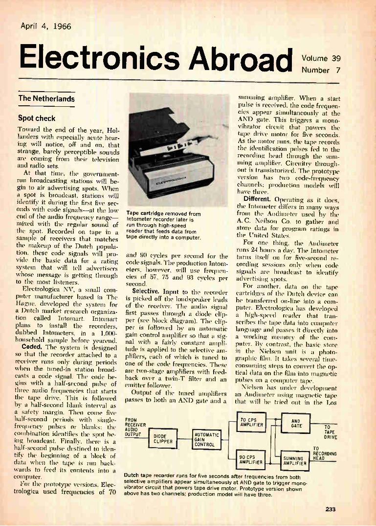
April 4, 1966
Electronics Abroad Volume 39
Number 7
The Netherlands
Spot check
Toward the end of the year, Hol-landers with especially acute hear-ing will notice, off and on, that strange, barely perceptible sounds are coming from their television and radio sets. At that time, the government-
run broadcasting stations will be-gin to air advertising spots. When a spot is broadcast, stations will identify it during the first five sec-onds with code signals—at the low end of the audio frequency range— mixed with the regular sound of the spot. Recorded on tape in a sample of receivers that matches the makeup of the Dutch popula-tion, these code signals will pro-vide the basic data for a rating system that will tell advertisers whose message is getting through to the most listeners.
Electrologica NV, a small com-puter manufacturer based in The Hague, developed the system for a Dutch market research organiza-tion called Intomart. Intomart plans to install the recorders, dubbed Intometers, in a 1.000-hot s ol d sample before yearend.
Coded. The system is designed so that the recorder attached to a receiver runs only during periods when the tuned-in station broad-casts a code signal. The code be-gins with a half-second pulse of three audio frequencies that starts the tape drive. This is followed by a half-second blank interval as a safety margin. Then come five half-second periods with single-frequency pulses or blanks: the combination identifies the spot be-ing broadcast. Finally, there is a half-second pulse destined to iden-tify the beginning of a bloc.k of data when the tape is run back-wards to feed its contents into a computer. For the prototype versions, Elec-
trologica used frequencies of 70
Tape cartridge removed from Intometer recorder later is run through high-speed reader that feeds data from tape directly into a computer.
and 90 cycles per second for the code signals. The production Intom-eters, however, will use frequen-cies of 57, 75 and 93 cycles per second.
Selective. Input to the recorder is picked off the loudspeaker leads of the receiver. The audio signal first passes through a diode clip-per (see block diagram). The clip-per is followed by an automatic gain control amplifier so that a sig-nal with a fairly constant ampli-tude is applied to the selective am-plifiers, each of which is tuned to one of the code frequencies. These are two-stage amplifiers with feed-back over a twin-T filter and an emitter follower. Output of the tuned amplifiers
passes to both an AND gate and a
FROM RECEIVER AUDIO OUTPUT DIODE
CLIPPER
AUTOMATIC GAIN CONTROL
summing amplifier. When a start pulse is received, the code frequen-cies appear simultaneously at the AND gate. This triggers a mono-vibrator circuit that powers the tape drive motor for five seconds. As the motor runs, the tape records the identification pulses fed to the recording head through the sum-ming amplifier. Circuitry through-out is transistorized. The prototype version has two code-frequency channels; production models will have three.
Different Operating as it does, the Intometer differs in many ways from the Audimeter used by the A. C. Neilson Co. to gather and store data for program ratings in the United States. For one thing, the Audimeter
runs 24 hours a day. The Intometer turns itself on for five-second re-cording sessions only when code signals are broadcast to identify advertising spots. For another, data on the tape
cartridges of the Dutch device can be transferred on-line into a com-puter. Electrologica has developed a high-speed reader that tran-scribes the tape data into computer language and passes it directly into a working memory of the com-puter. By contrast, the basic. store in the Nielsen unit is a photo-graphic film. It takes several time-consuming steps to convert the op-tical data on the film into magnetic pulses on a computer tape.
Nielsen has under development an Audimeter using magnetic. tape that will be tried out in the Los
70 CPS AMPLIFIER
90 CPS AMPLIFIER
AND GATE
SUMMING AMPLIFIER
TO TAPE DRIVE
TO RECORDING HEAD
Dutch tape recorder runs for five seconds after frequencies from both
selective amplifiers appear simultaneously at AND gate to trigger mono-vibrator circuit that powers tape drive motor. Prototype version shown above has two channels; production model will have three.
233
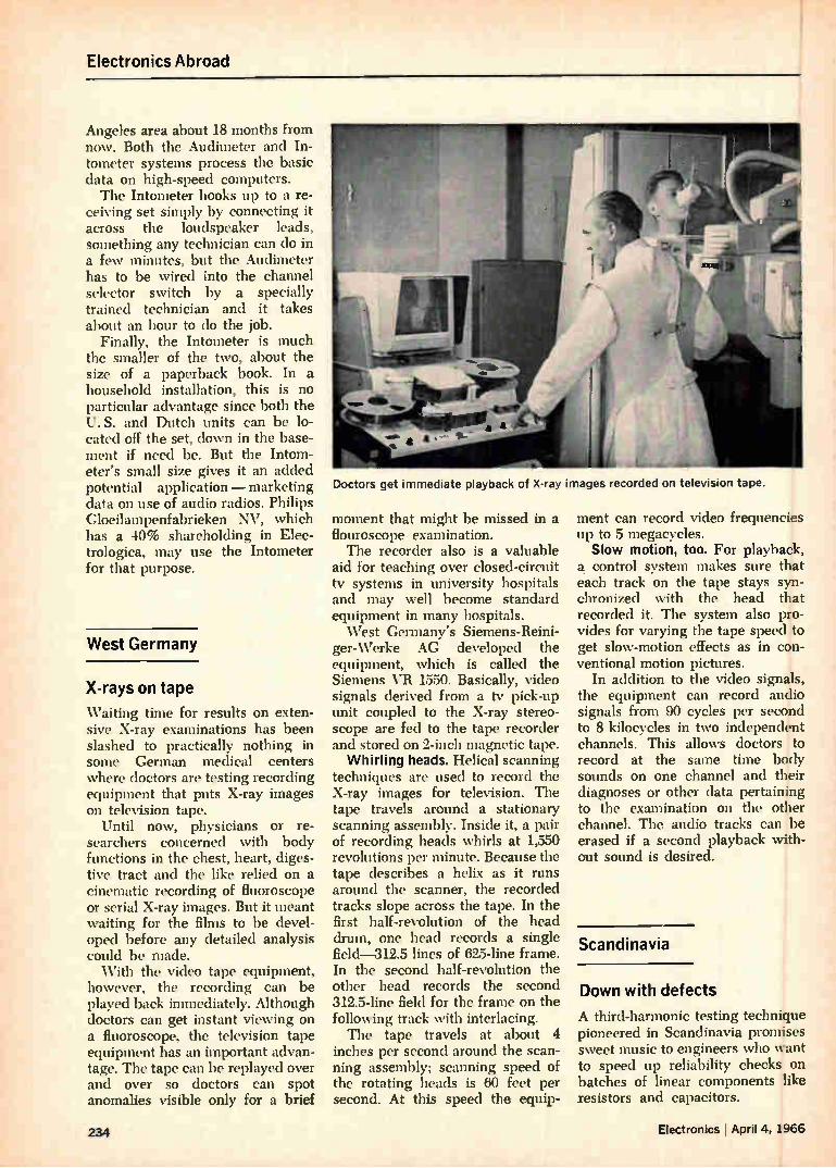
Electronics Abroad
Angeles area about 18 months from now. Both the Audimeter and In-tometer systems process the basic data on high-speed computers. The Intometer hooks up to a re-
ceiving set simply by connecting it across the loudspeaker leads, something any technician can do in a few minutes, but the Audimeter has to be wired into the channel selector switch by a specially trained technician and it takes about an hour to do the job.
Finally, the Intometer is much the smaller of the two, about the size of a paperback book. In a household installation, this is no particular advantage since both the U. S. and Dutch units can be lo-cated off the set, down in the base-ment if need be. But the Intom-eter's small size gives it an added potential application — marketing data on use of audio radios. Philips Gloeilampenfabrieken NV, which has a 40% shareholding in Elec-trologica, may use the Intometer for that purpose.
West Germany
X-rays on tape
Waiting time for results on exten-sive X-ray examinations has been slashed to practically nothing in some German medical centers where doctors are testing recording equipment that puts X-ray images on television tape.
Until now, physicians or re-searchers concerned with body functions in the chest, heart, diges-tive tract and the like relied on a cinematic recording of fluoroscope or serial X-ray images. But it meant waiting for the films to be devel-oped before any detailed analysis could be made. With the video tape equipment,
however, the recording can be played back immediately. Although doctors can get instant viewing on a fluoroscope, the television tape equipment has an important advan-tage. The tape can be replayed over and over so doctors can spot anomalies visible only for a brief
Doctors get immediate playback of X-ray images recorded on television tape.
moment that might be missed in a flouroscope examination. The recorder also is a valuable
aid for teaching over closed-circuit tv systems in university hospitals and may well become standard equipment in many hospitals. West Germany's Siemens-Reini-
ger-Werke AG developed the equipment, which is called the Siemens VR 1550. Basically, video signals derived from a tv pick-up unit coupled to the X-ray stereo-scope are fed to the tape recorder and stored on 2-inch magnetic tape.
Whirling heads. Helical scanning techniques are used to record the X-ray images for television. The tape travels around a stationary scanning assembly. Inside it, a pair of recording heads whirls at 1,550 revolutions per minute. Because the tape describes a helix as it runs around the scanner, the recorded tracks slope across the tape. In the first half-revolution of the head drum, one head records a single field-312.5 lines of 625-line frame. In the second half-revolution the other head records the second 312.5-line field for the frame on the following track with interlacing. The tape travels at about 4
inches per second around the scan-ning assembly; scanning speed of the rotating heads is 60 feet per second. At this speed the equip-
ment can record video frequencies up to 5 megacycles. Slow motion, too. For playback,
a, control system makes sure that each track on the tape stays syn-chronized with the head that recorded it. The system also pro-vides for varying the tape speed to get slow-motion effects as in con-ventional motion pictures.
In addition to the video signals, the equipment can record audio signals from 90 cycles per second to 8 kilocycles in two independent channels. This allows doctors to record at the same time body sounds on one channel and their diagnoses or other data pertaining to the examination on the other channel. The audio tracks can be erased if a second playback with-out sound is desired.
Scandinavia
Down with defects
A third-harmonic testing technique pioneered in Scandinavia promises sweet music to engineers who want to speed up reliability checks on batches of linear components like resistors and capacitors.
234 Electronics I April 4, 1966
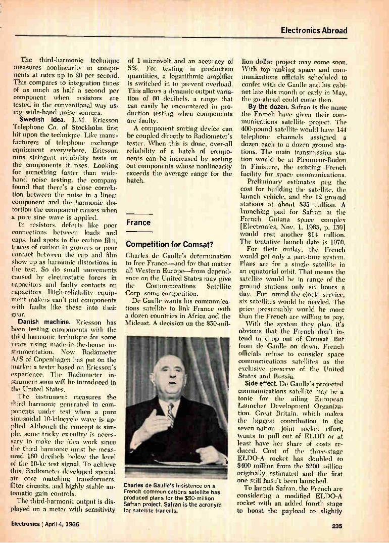
Electronics Abroad
The third-harmonic technique measures nonlinearity in compo-nents at rates up to 20 per second. This compares to integration times of as much as half a second per component when resistors are tested in the conventional way us-ing wide-band noise sources. Swedish idea. L.M. Ericsson
Telephone Co. of Stockholm first hit upon the technique. Like manu-facturers of telephone exchange equipment everywhere, Ericsson runs stringent reliability tests on the components it uses. Looking for something faster than wide-band noise testing, the company found that there's a close correla-tion between the noise in a linear component and the harmonic dis-tortion the component causes when a pure sine wave is applied.
In resistors, defects like poor connections between loads and caps, bad spots in the carbon film, traces of carbon in grooves or poor contact between the cap and film show up as harmonic distortions in the test. So do small movements caused by electrostatic forces in capacitors and faulty contacts on capacitors. High-reliability equip-ment makers can't put components with faults like these into their gear. Danish machine. Ericsson has
been testing components with the third-harmonic technique for some years using made-in-the-house in-strumentation. Now Radiometer A/ S of Copenhagen has put on the market a tester based on Ericsson's experience. The Radiometer in-strument soon will be introduced in the United States. The instrument measures the
third harmonic generated in com-ponents under test when a pure sinusoidal 10-kilocycle wave is ap-plied. Although the concept is sim-ple, some tricky circuitry is neces-sary to make the idea work since the third harmonic must be meas-ured 160 decibels below the level of the 10-ke test signal. To achieve this, Radiometer developed special air core matching transformers, filter circuits, and highly stable au-tomatic gain controls. The third-harmonic output is dis-
played on a meter with sensitivity
of 1 micnivolt and an accuracy of 5%. For testing in production quantities, a logarithmic amplifier is switched in to prevent overload. This allows a dynamic output varia-tion of 60 decibels, a range that can easily be encountered in pro-duction testing when components are faulty. A component sorting device can
be coupled directly to Radiometer's tester. When this is done, over-all reliability of a batch of compo-nents can be increased by sorting out components whose nonlinearity exceeds the average range for the batch.
France
Competition for Comsat?
Charles de Gaulle's determination to free France—and for that matter all Western Europe—from depend-ence on the United States may give the Communications Satellite Corp. some competition. De Gaulle wants his communica-
tions satellite to link France with a dozen countries in Africa and the Mideast. A decision on the $50-mil-
Charles de Gaulle's insistence on a French communications satellite has
produced plans for the $50-million Safran project. Safran is the acronym for satellite francais.
lion dollar project may come soon. With top-ranking space and com-munications officials scheduled to confer with de Gaulle and his cabi-net late this month or early in May, the go-ahead could come then. By the dozen. Safran is the name
the French have given their com-munications satellite project. The 400-pound satellite would have 144 telephone channels assigned a dozen each to a dozen ground sta-tions. The main transmission sta-tion would be at Pleumeur-Bodou in Finistere, the existing French facility for space communications.
Preliminary estimates peg the cost for building the satellite, the launch vehicle, and the 12 ground stations at about $35 million. A launching pad for Safran at the French Guiana space complex [Electronics, Nov. 1, 196.5, p. 159] would cost another $14 million. The tentative launch date is 1970. For their outlay, the French
would get only a part-time system. Plans are for a single satellite in an equatorial orbit. That means the satellite would be in range of the ground stations only six hours a day. For round-the-clock service, six satellites would be needed. The price presumably would be more than the French are willing to pay. With the system they plan, it's
obvious that the French don't in-tend to drop out of Comsat. But from de Gaulle on down. French officials refuse to consider space communications satellites as the exclusive preserve of the United States and Russia.
Side effect. De Gaulle's projected communications satellite may be a tonic for the ailing European Launcher Development Organiza-tion. Great Britain, which makes the biggest contribution to the seven-nation joint rocket effort, wants to pull out of ELDO or at least have her share of costs re-duced. Cost of the three-stage ELDO-A rocket has doubled to $400 million from the $200 million originally estimated and the first one still hasn't been launched. To launch Safran, the French are
considering a modified ELDO-A rocket with an added fourth stage to boost the payload to slightly
Electronics I April 4, 1966 236
Electronics Abroad
SOURCE... YOUR ELECTRONIC CRYSTALS
& MATERIALS HEADQUARTERS
LASER CRYSTALS and SYSTEMS • Gas Laser Systems & Components
• Solid State Laser Systems & Components
• Injection Laser Systems & Components
SEMI-CONDUCTOR SINGLE CRYSTALS and MATERIALS
• Germanium
• Silicon
• III-V Compounds
Gallium Arsenide, Antimonide
Indium Phosphide, Arsenide, Antimonide Custom Compounds of III-Vs
• II-VI Compounds Cadmium Sulfide, Selenide, Telluride Zinc Sulfide, Selenide, Telluride
Custom Compounds of ll -Vls
THERMAL ELECTRIC and MAGNETOTHERMOELECTRIC SINGLE CRYSTALS & MATERIALS • Bismuth, Antimony, Other Bismuth
Alloys
• Lead Telluride
• Cuprous Sulfide, Other Exotics
THIN FILM CHEMICALS and SUBSTRATES FOR CONTROLLED VACUUM DEPOSITION
• SEVAC' Grade Chemicals and Compounds
• Single Crystal Substrates of Metals Bromides
Oxides Iodides Chlorides Vacuum Exotic Compounds
*Trademark for vacuum deposition chemicals
For literature write Dept. EL-3
Ikea semi-elements, Saxonburg Blvd, Saxonburg, Pa .16056
Phone 412-352 1548
over 400 pounds. So there's a good chance France would agree to ease the British burden. The ELDO countries will meet next month to hash over future plans.
If ELDO fizzles, the French have in reserve a project to boost the lifting power of their own Diamant satellite launcher [Electronics, March 7, 1966, p. 302].
Great Britain
Uncoiled
For the upcoming generation of re-ceivers built around integrated cir-cuits, set makers want to do away with bulky coils, Gullivers in the Lilliputian world of thin films and silicon chips.
Researchers at Standard Tele-communications Laboratories Ltd. of Harlow, England, have come up with a thin-film IC filter design that points to the demise of coils in fre-quency-selective circuits for inter-mediate frequency amplifiers. Al-ready they've pushed their filters to frequencies as high as 10 mega-cycles and obtained response fac-tors (Q) of 20. H. T. Roettgers and P. Lemke,
who spearheaded the research work at STL, admit the Q is still too low for consumer receivers. But the pair thinks further design refinements would make their thin-film filter a practical component for receivers. First applications, though, will roost likely come in professional equipment to back up mechanical filters and selective stages of noise suppression circuits. Old hat. Filters without coils are
old hat at audio frequencies. The most commonly used circuit is the twin-T, six lumped resistance and capacitance components arranged in a bridge network. Above audio frequencies, however, twin-T filters start having troubles. Their re-sponse factors are not predictable. In feedback networks, the center frequency of the filter-amplifier combination shifts away from the center frequency of the filter itself,
cutting down its effectiveness. Roettgers and Lemke say their thin-film three-component filter with distributed resistance and capacity overcomes these drawbacks.
Actually, the theory of tapered distributed filters is not new. Re/ searchers at several American com4 panies have demonstrated the pos-sibility. But so far there's been little success at translating the theory into a device. The theory was veri-fied by simulating distributed re-sistance with impregnated paper paired with foil for the capacitive elements. Diffused R-C networks were tried but they failed because values of the diffused components couldn't be controlled closely enough.
Bell Telephone Laboratories, however, has a process—sputtered tantalum—that shows promise for high-frequency distributed filters. Already Bell Labs has designed a sputtered tantalum network for the audio-frequency notch filter in a telephone data set.
Armed. The thin-film filter de-veloped by STL has a series arm and a parallel arm. To make it, STL first deposits a distributed series-arm resistance and the par-allel-arm resistance on a glass sub-strate. Then follows a silicon mo-noxide layer to form the dielectric for the capacitor. Finally, a tapered metal top plate for the capacitor is deposited along with a connection between the plate and the parallel-arm resistor.
In a network like this, output voltage is a combination of the voltages across the two arms. Volt-age across the series arm varies with frequency. At the center fre-quency, real and imaginary compo-nents of the voltage vector in each arm are equal and opposite; this attenuates the center frequency.
For the filters, STL has plotted standard design curves to calculate the values of resistances and ca-pacitance needed to obtain the re-quired center frequency. It is in-versely proportional to the product of the RC values; the component tolerances determine the center-frequency accuracy. The amount of taper on the
series-arm resistance controls the Q
236 Circle 236 on reader service card Electronics I April 4, 1966

of the filter. Theoretically, infinite Q is possible but the maximum value obtained so far is about 20. Over-all Q value of the filter-ampli-fier combination also depends on the gain of the amplifier. To hold Q within 5%, for example, an am-plifier with a gain of 35 decibels would have to be stabilized to plus or minus one decibel.
Around the world
Japan. A laser radar—Japan's first—has been built at the In-stitute of Industrial Science of the University of Tokyo. Scientists there think it could be the fore-runner of collision-preventing equipment for high-speed trains and aircraft. Effective range of the laser is six miles and its beam width less than 1 milliradian. The ruby laser develops an output of 20 megawatts at a one-second repeti-tion rate.
Denmark. Storno, a Copenhagen-based maker of mobile communica-tions equipment, plans to tackle the United States market with a taxi-alarm system. The equipment automatically transmits five tones in sequence when the driver pushes an "emergency" button. The tone sequence rings an alarm at the base station and displays the taxi's identification number on a panel.
Switzerland. Wild-Heerbrugg, Ltd., has teamed up with the Ray-theon Co. to produce an automatic mapping system that scans a pair of stereo photographs and extracts profiles, contours and digital data. The equipment may find its way into applications for numerically controlled machine tool. It could translate the shape of an industrial model into digital data for NC milling machines.
Kuwait. The Marconi Co. of Great Britain has won a $2.8-mil-lion contract to build one of the world's most powerful broadcast-ing stations for the Kuwait govern-ment. The station will have three 750-kilowatt transmitters and cover the entire Middle East.
You just discovered how to build a 3.9 volt power supply from any DC source in minutes.
By using a super/reg® synthesized .zener diode, you make simple and quick the design of precision DC power supplies having .01% regula-tion and .5mv ripple.
Because typical super/reg imped-ances are 2 to 8 milliohms, lowest ever yet achieved.
Its unique "third" terminal lets you trim the output voltage a full -±-10% from nominal, with no derating or degradation. .01%/°C temperature compensa-
tion at high power levels; thermal stability 100-times greater than that of the standard zener.
Zener voltages from 3.9 to 56V. Full 3-ampere steady-state rating
up to 75 watts. A super/reg diode breaks the
zener barrier by means of its "syn-
thesized" construction: embodies a sensing bridge, operational amplifier, thermally compensated zener diode, in standard TO-36 case.
Looks, mounts like any other diode. Performance-proven reliability; patent pending design. Designed for MIL ap-plications.
Write or call for complete data and application bulletins. Semi-conductor Division, Trio
Laboratories, Inc., Plainview, L.I., N.Y. (516) 0V- 1-0400. TWX: (510) 221-1861.
511pel¡reg
SIMI-CONDUCTOR DIVISION or
-Q-Cricbl_ca '
01966. TRIO LABORATORIES. INC. • ORIGINAL CONCEPTS IN INSTRUMENTATION
This is the super/reg synthesized zener diode.
Electronics l April 4, 1966 Circle 237 on reader service card 237
Electronics advertisers April 4, 1966
▪ AMP Incorporated 189 Garceau, Hargrave & McCullough Inc.
API Instruments Company 220 George Z. Griswold
Acopian Corporation 219 Mort Barish Associates Inc.
Aerojet-General Corporation 222 D'Arcy Advertising Company
Aerospace Research 224 Sales Promotion Services
Airpax Electronics Inc. 174 Welch. Mirabile & Company Inc.
• Air Products & Chemical Inc. 197 Arthur Falconer Associates Corporation
Allen-Bradley Company 27. 28 The Fensholt Advertising Agency
Amelco Semiconductor 72 Sturges & Associates
• American Electronic Laboratories Inc. Benn Associates
• Ammon Instruments Inc. • Culver Advertising Inc. • Amperes Electronic Corporation
Sam Groden Incorporated Amphenol Borg Electronics
Corporation Ma rsteller Inc.
a Astrodata Inc. Bonfield Associates Inc.
• Automatic Electric Company 58 Tatham-Laird & Kudner Inc.
• Ballantine Laboratories Lang•Lawrence Advertising Inc.
• Bausch & Lomb Wolff Associates Inc.
Beckman Instruments Inc. Electronic Instruments Division Hixson & Jorgensen Inc.
Beckman Instruments Inc. Helipot Division Hixson & Jorgensen Inc.
Beckman Instruments Inc. Offner Division Hixson & Jorgensen Inc.
Bendix Corporation Montrose Division MacManus, John & Adams Inc.
• Bliley Electric Co. Barber & Drullard Inc.
• Blue M Electric Company South Suburban Advertising
The Borden Chemical Company, Mystik Tape Division Robert Conahay Incorporated
• Brush Instruments Div. of Clevite Corporation Carr Liggett Advertising Inc.
Bulova Electronics Division 190 Frank Best & Company Inc.
Burroughs Corporation 82 Conti Advertising Agency Inc.
• Bussmann Mfg. Co. Div. of McGraw-Edison Co. 212, 213 Henderson Advertising Company
191
186
Consolidated Electrodynamics Corp. 159 Hixson & Jorgensen Inc.
Control Data Instruments 225 Barnes-Champ Advertising
Corning Glass Works, Electronic Division 232 The Rumrill Company
Couch Ordnance Inc. 222 Culver Advertising Inc.
Cramer Industries 180 Potts Woodbury Inc.
• CTS Corporation 33 Burton Browne Advertising
DaImo Victor Company Pierce & Strain Advertising
a Delco Radio Division, General 198 Corporation
Campbell-Ewald Company 214 a Data Device Corporation
Conti Advertising 139 Di-Acro Corporation 231
Charles E. Brown Advertising Agency
Dow Corning Corporation 132 128, 129 Church and Guisewrite Adv. Inc.
a DuPont de Nemours & Company 15 Inc. E. I. 71, 183, 193
Batten, Barton. Durstine & Osborn Inc.
75
Motors 20. 21
163
Electro Instruments Inc. 77 Van Der Boom, McCarron Inc.
• Electronic Engineering Co. of California 180 Jansen Associates Inc.
Electronic Modules Corporation Ray Thompson & Associates
41 Emerson & Cuming Inc. Edwin F Hall
Engelhard Industries Inc. 131 Keyes Martin & Company
Erie Technological Products Inc. Altman Hall Associates Adv.
54
81
239
212
• Fairchild Instrumentation Faust/Day Inc.
• Fairchild Semiconductor Faust/Day Inc
The Formica Corporation Perry Brown Inc.
50 u Fork Standards Inc. K & A Incorporated
2nd Cover
si Carpenter Steel Company 56 Beaumont. Heller & Sperling Inc.
Cherry Electrical Products Corp. 134
K & A Incorporated Chuo Denki 44
Standard Advertising Inc. • Cinch Mfg. Company 55
Stral Advertising Company Inc. • Clevite Corporation Piezoelectric Div. 172
Carr Liggett Advertising Inc.
Cleveland Institute of Electronics 158 Rapp & Collins Div. of Foote. Cone & Belding
Cohu Electronics Inc. 179 Erwin Wasey, Ruthrauff & Ryan Inc.
Comcor Sub. of Astrodata Inc. 147 Marketing Directions
Communication Electronics Incorporated 78
Computer Control Company 61 Franklin P. Folts Incorporated
Consolidated Vacuum Corporation 17 Wolff Associates Inc.
▪ General Electric Company George R. Nelson Inc.
• General Electric Company George R. Nelson Inc.
▪ General Electric Company Ross Roy Inc Advertising
• General Motor Corporation, Delco Radio Div. H.L. Ross Advertising Inc.
General Radio Company K.E. Morang Company
Goldman Sachs & Company Doremus & Company
Gudebrod Bros. Silk & Co. Inc. Ramsdell Buckley & Company Inc.
140
240
202, 203
79
150
127
108
46
167, 168
14, 106, 107, 76
137
173
6
200
66
Hansen Mfg. Co. Inc. 164 Keller Crescent Company
• Heath Company 180 Advance Advertising Service Inc.
• Hewlett Packard Company 1, 43, 51, 133, 165 Lennen & Newell Inc.
• Hewlett Packard, Sanborn Division 2 Culver Advertising Inc.
Hoffman Electronics Corporation 145 Honeywell PMD 67
Batten, Barton. Durstine & Osborn Inc. Hopkins Engineering Co. 192
Philip Meany Company
Intercontinental Instruments Inc. Murray Heyert Associates
IRC, Inc. Gray & Rogers, Inc.
• I T & T, Cannon West, Weir & Bartel, Inc.
ABC OW.
tffl•mo ABP
p■••
• Hughes Aircraft Corp. Foote, Cone & Belding
• Hull Corporation The Michener Company
144
146
• lchizuka Optical Co., Ltd. 240 Matsushita Inc.
IBM 130 Benton & Bowles
Indiana General Corporation 135 Griswold & Eshleman Company
Industrial Electronic Engineers, Inc. 195 Gumpertz, Bentley & Dolan
Industrial Exhibitions Ltd. 217 Walkley Hodgson Ltd
• Ingersoll Products, Div. of Borg-Warner Corp. 223 Connor-Sager Associates, Inc.
Inland Controls, Inc., Sub. of Kollmorgen Corporation 45 S. Gunnar Myrbeck & Co.
188
53
206. 207
Johanson Manufacturing Corporation 166 Josephson. Cuffari & Company
Johnson Company, E.F. 142 Midland Associates, Inc.
Kay Electric Company Josephson, Cuffari & Co.
• Kepco, Inc. Weiss Advertising
• Leach Corporation Jay Chiat and Associates
• LEL, Inc. Snow & Depew. Incorporated
Lockheed Missiles & Space Co. McCann-Erickson, Inc.
60
22
143
160
170
Classified advertising F. J. Eberle, Business Mgr.
EMPLOYMENT OPPORTUNITIES 226-228
Equipment
(Used or Surplus New) For Sale 229
ADVERTISERS INDEX
A & A Electronics Corp. Atomic Personnel Inc.
Bausch & Lomb Candee Co., J.J. Corcoran, Joseph P. Easy-Up Inc. Electronic Communications Inc. Fishman Co., P. General Motors
Research Laboratories Goodheart Co., Inc.,R.E. Norman Electronic Sales Radio Research Instrument Co. Rex Industrial Electronics Surplus Saving Center U.S. Navy Bureau of Ships
229 228 226 229 226 229 228 229
227 229 229 229 229 229 227
• For more information on complete product line see advertisement in the latest Elec-tronics Buyers' Guide
D Advertisers in Overseas Advertising Section
Executive, editorial, circulation anti advertising offices: McGraw.Hill Building, 330 West 42nd Street, New York, N.Y.. 10036. Telephone (212) 971- 3333. Teletype TWX N.Y. 212 640-4646. Cable: McGrawhiu, N.Y. Officers of the McGraw.H.II Publications: Joseph H. Allen, President; Vice Presidents: J. Elton Tuohig, Operations; John R. Callahan). Editorial; Ervin E. DeGraft, Circulation; Donald C. McGraw, Jr.. Aivertising Sales; Angelo R. Venerian, Marketing. Officers of the Corporation: Donald C. McGraw, Chairman of the Board; Shelton Fisher. President; L. Keith Goodrich, Hugh J. Kelly and Robert E. Slaughter, Executive Vice Presidents; John J. Cooke, Vice President and Secretary; John L. McGraw. Treasure,. Title R registered U.S. Patent Office; 15 copyright 1966 by McGraw•Hill, Inc. All rights reserved, including the right to reproduce the contents of this publication, in whole or in part.
238 Electronics! April 4, 1966
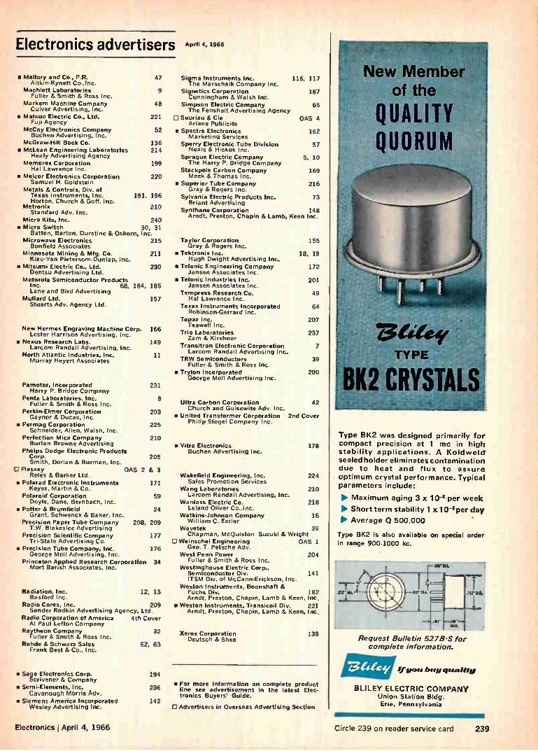
Electronics advertisers April 4, 1966
▪ Mallory and Co., P.R. Aitkin-Kynett Co.,Inc.
Machlett Laboratories Fuller & Smith & Ross Inc.
Markem Machine Company Culver Advertising, Inc.
g Matsuo Electric Co., Ltd. Fuji Agency
McCoy Electronics Company Buchen Advertising, Inc.
McGraw-Hill Book Co. g McLean Engineering Laboratories
Healy Advertising Agency Memorex Corporation
Hal Lawrence Inc. • Melcor Electronics Corporation
Samuel H. Goldstein Metals & Controls, Div. of
Texas Instruments, Inc. 181, 196 Horton, Church & Goff, Inc.
Metronix 210 Standard Adv. Inc.
Micro Kits, Inc. 240 • Micro Switch 30, 31
Batten, Barton, Durstine & Osborn, Inc. Microwave Electronics 215
Bonfield Associates Minnesota Mining & Mfg. Co. 211
Klau-Van Pietersom-Dunlap, Inc. • Mitsumi Electric Co., Ltd. 230
Dentsu Advertising Ltd. Motorola Semiconductor Products
Inc. 68, 184, 185 Lane and Bird Advertising
Mullard Ltd. 157 Stuarts Adv. Agency Ltd.
New Hermes Engraving Machine Corp. Lester Harrison Advertising, Inc.
▪ Nexus Research Labs. Larcom Randall Advertising, Inc.
North Atlantic Industries, Inc. Murray Heyert Associates
47 Sigma Instruments Inc. The Marschalk Company Inc.
9 Signetics Corporation Cunningham & Walsh Inc.
48
221
52
136 214
199
220
166
149
11
Pamotor, incorporated 231 Harry P. Bridge Company
Penta Laboratories, Inc. Fuller & Smith & Ross Inc.
Perkin-Elmer Corporation 203 Gaynor & Ducas, Inc.
• Permag Corporation 225 Schneider, Allen, Walsh, Inc.
Perfection Mica Company 210 Burton Browne Advertising
Phelps Dodge Electronic Products Corp. 205 Smith, Dorian & Burman, Inc.
Plessey OAS 2 & 3 Roles & Barker Ltd.
• Polarad Electronic Instruments 171 Keyes, Martin & Co.
Polaroid Corporation Doyle, Dane, Bernbach, Inc.
• Potter & Brumfield 24 Grant, Schwenck & Baker, Inc.
Precision Paper Tube Company 208, 209 T.W. Blakeslee Advertising
Precision Scientific Company Tri-State Advertising Co.
• Precision Tube Company, Inc. 176 George Moll Advertising, Inc.
Princeton Applied Research Corporation 34 Mort Barish Associates, Inc.
8
Radiation, Inc. 12, 13 Basford Inc.
Radio Cores, Inc. 209 Sander Rodkin Advertising Agency, Ltd.
Radio Corporation of America 4th Cover Al Paul Lefton Company
Raytheon Company 32 Fuller & Smith & Ross Inc.
Rohde & Schwarz Sales 62, 63 Frank Best & Co., Inc.
al Sage Electronics Corp. Scrivener & Company
• Semi-Elements, Inc. Cavanough Morris Adv.
• Siemens America Incorporated Wesley Advertising Inc.
194
236
142
Simpson Electric Company The Fensholt Advertising Agency
0 Souriau & Cie Ariane Publicite
• Spectra Electronics Marketing Services
Sperry Electronic Tube Division Neals & Hickok Inc.
Sprague Electric Company The Harry P. Bridge Company
Stackpole Carbon Company Meek & Thomas Inc.
• Superior Tube Company Gray & Rogers Inc.
Sylvania Electric Products Inc. 73 Briant Advertising
Synthane Corporation 148 Arndt, Preston, Chapin & Lamb, Keen Inc.
116, 117
187
65
OAS 4
162
57
5, 10
169
216
Taylor Corporation 155 Gray & Rogers Inc.
•Tektronix Inc. 18, 19 Hugh Dwight Advertising Inc.
• Telonic Engineering Company 172 Jansen Associates Inc.
• TeIonic Industries Inc. 201 Jansen Associates Inc.
Tempress Research Co. 49 Hal Lawrence Inc.
Texas Instruments Incorporated 64 Robinson-Gerrard Inc.
Topaz Inc. 207 Teawell Inc.
Trio Laboratories 237 Zam & Kirshner
Transitron Electronic Corporation 7 Larcom Randall Advertising Inc.
TRW Semiconductors 39 Fuller & Smith & Ross Inc.
is TryIon Incorporated 200 George Moll Advertising Inc.
Ultra Carbon Corporation 42 Church and Guisewite Adv. Inc.
a United Transformer Corporation 2nd Cover Philip Stogel Company Inc.
• Vitro Electronics 178 Buchen Advertising Inc.
Wakefield Engineering, Inc. 224 Sales Promotion Services
Wang Laboratories 210 59 Larcom Randall Advertising, Inc.
Wanlass Electric Co. 218 Leland Oliver Co.,Inc.
Watkins-Johnson Company 16 William C. Estler
Wavetek 29 177 Chapman, McQuiston Suzuki & Wright
C Weinschel Engineering OAS 1 Geo. T. Petsche Adv.
West Penn Power 204 Fuller & Smith & Ross Inc.
Westinghouse Electric Corp., Semiconductor Div. 141 ITSM Div. of McCann-Erickson, Inc.
Weston Instruments, Boonshaft & Fuchs Div. 182 Arndt, Preston, Chapin, Lamb & Keen, Inc.
• Weston Instruments, Transicoil Div. 221 Arndt, Preston, Chapin, Lamb & Keen, Inc •
Xerox Corporation 138 Deutsch & Shea
• For more information on complete product line see advertisement in the latest Elec-tronics Buyers' Guide.
CI Advertisers in Overseas Advertising Section
Type BK2 was designed primarily for
compact precision at 1 mc in high
stability applications. A Koldweld.
sealed holder eliminates contamination
due to heat and flux to assure optimum crystal performance. Typical
parameters include:
• Maximum aging 3 x 10⁴ per week
• Short term stability 1 x 10 -8per day
• Average Q 500,000
Type 81(2 is also available on special order
in range 900-1000 kc.
Request Bulletin 527B-S for complete information.
CZ: 1,1" gem buy quality
BLILEY ELECTRIC COMPANY Union Station Bldg. Erie, Pennsylvania
Electronics April 4, 1966 Circle 239 on reader service card 239
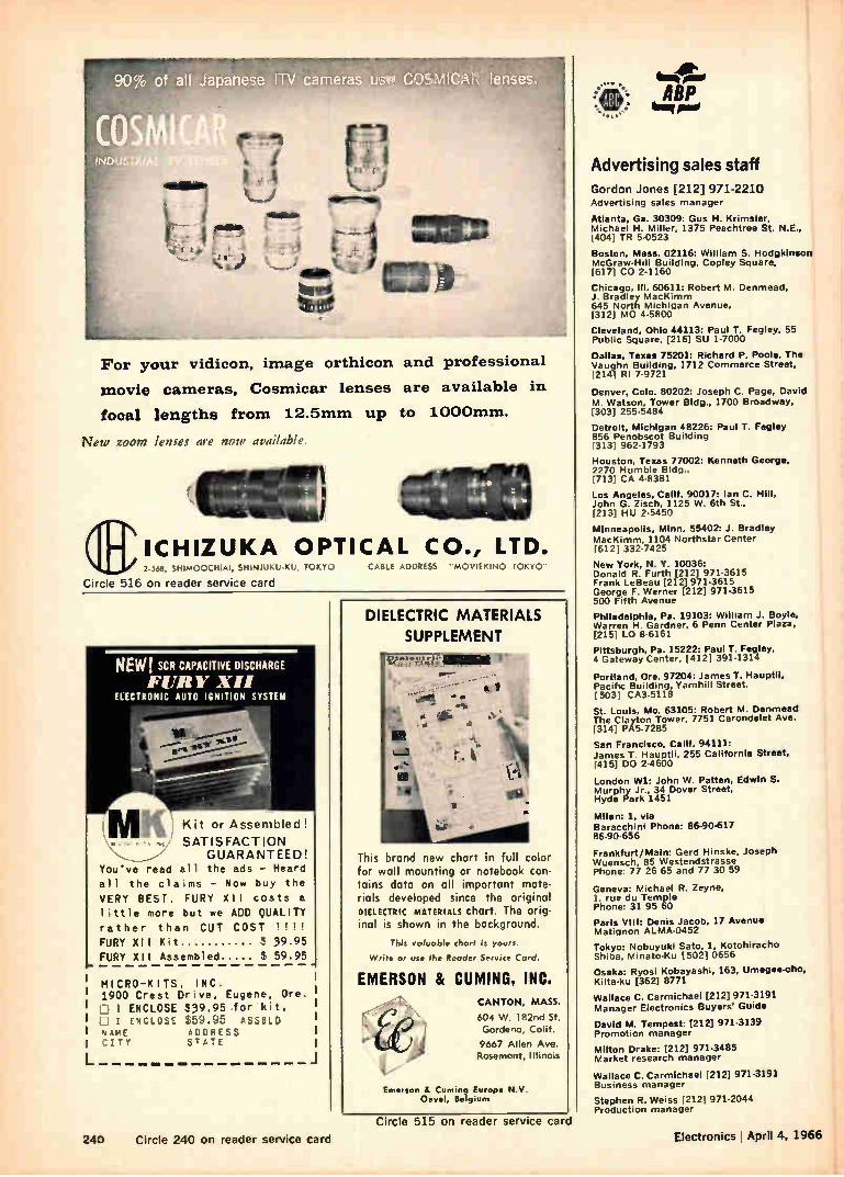
For your vidicon, image orthicon and professional
movie cameras, Cosmicar lenses are available in
focal lengths from 12.5mm up to 1000mm.
New zoom lenses are now available
qc CABLE ADDRESS "MOVIEKINO TOKYO" 2 568, SHIMOOCHIAI, SHINJUKU-KU, TOKYO
Circle 516 on reader service card
'earl
ICHIZUKA OPTICAL CO., LTD.
NEW! SCR CAPACITIVE DISCHARGE
ELECTRONIC AUTO IGNITION SYSTEM
; Kit or Assembled !
SATISFACTION GUARANTEED!
You've read all the ads - Heard
all the claims - Now buy the
VERY BEST. FURY XII costs a
little more but we ADD QUALITY
rather than CUT COST ! !!!
FURY XII Kit 39.95
FURY XII Assembled 59.95
MI CRO-K ITS, INC. 1900 Crest Drive, Eugene, Ore. L1 ENCLOSE $39.95 for kit.
D I ENCLOSE $59.:1.5 ASSeLD 'AME ADDRESS CITY STATE
DIELECTRIC MATERIALS
SUPPLEMENT
This brand new chart in full color for wall mounting or notebook con-tains data on all important mate-rials developed since the original DIELECTRIC MATERIALS chart. The orig-inal is shown in the background.
This valuable chart is yours.
Write or use the Reader Service Cord
EMERSON & CUMING, INC. CANTON, MASS.
604 W. 182nd St.
Gardena, Calif.
9667 Allen Ave. Rosemont, Illinois
Emerson 8. Corning Europe N.V Oevel, Belgium
ABP "'I Pine
Advertising sales staff
Gordon Jones [212] 971-2210 Advertising sales manager
Atlanta, Ga. 30309: Gus H. Krimsier, Michael H. Miller, 1375 Peachtree St. N.E., 14041 TR 5-0523
Boston, Mass. 02116: William S. Hodgkinson McGraw-Hill Building, Copley Square, [6171 CO 2-1160
Chicago, III. 60611: Robert M Denmead, J. Bradley MacKimm 645 North Michigan Avenue, [312] MO 4-5800
Cleveland, Ohio 44113: Paul T. Fegley. 55 Public Square, [216] SU 1-7000
Dallas, Texas 75201: Richard P. Poole. The Vaughn Building. 1712 Commerce Street, 1214] RI 7-9721
Denver, Colo. 80202: Joseph C. Page, David M. Watson, Tower Bldg., 1700 Broadway, [3031 255-5484
Detroit, Michigan 48226: Paul T. Fegley 856 Penobscot Building [313] 962-1793
Houston, Texas 77002: Kenneth George, 2270 Humble Bldg.. I713] CA 4-8381
Los Angeles, Calif. 90017: Ian C. Hill, John G. Zisch, 1125 W. 6th St.. 12131 HU 2-5450
Minneapolis, Minn. 55402: J. Bradley MacKimm, 1104 Northstar Center (6121 332.7425
New York, N. Y. 10036: Donald R. Furth [212] 971-3615 Frank LeBeau [212] 971-3615 George F. Werner [212] 971-3615 500 Fifth Avenue
Philadelphia, Pa. 19103: William J. Boyle, Warren H. Gardner. 6 Penn Center Plaza, [215] LO 8-6161
Pittsburgh, Pa. 15222: Paul T. Fegley, 4 Gateway Center, 14121 391-1314
Portland, Ore. 97204: James T. Hauptli, Pacific Building. Yamhill Street. 5031 CA3-5118
St. Louis, Mo. 63105: Robert M. Denmead The Clayton Tower, 7751 Carondelet Ave. r 314.1 PAS-7285
San Francisco, Calif. 94111: James T. Hauptli, 255 California Street. [4151 DO 2-4600
London Wl: John W. Patten, Edwin S. Murphy Jr., 34 Dover Street, Hyde Park 1451
Milan: 1, via Baracchini Phone: 86-90-617 86-90-656 Frankfurt/Main: Gerd Hinske. Joseph Wuensch, 85 Westendstrasse Phone: 77 26 65 and 77 30 59
Geneva: Michael R. Zeyne, 1. rue du Temple Phone: 31 95 60
Paris VIII: Denis Jacob, 17 Avenue Matignon ALMA-0452
Tokyo: Nobuyuki Sato, 1, Kotohiracho Shiba. Minato-Ku 1502] 0656
Osaka: Ryosi Kobayashi, 163, Umegee-cho, Kilta-ku [362] 8771
Wallace C. Carmichael [212] 971-3191 Manager Electronics Buyers' Guide
David M. Tempest: [212] 971-3139 Promotion manager
Milton Drake: [212] 971-3485 Market research manager
Wallace C. Carmichael 1212] 971-3191 Business manager
Stephen R. Weiss [2121 971-2044 Production manager
240 Circle 240 on reader service card
Circle 515 on reader service card Electronics ' April 4, 1966
April 4, 1966
Electronics reader service
Use these handy post cards
for more detailed information on: products advertised, new
products, new literature.
Circle the number on the Reader Serv-ice post card that' corresponds to the number at the bottom of the advertise-ment, new product item, or new liter-ature in which you are interested.
Please print clearly. All written in-formation must be legible to be effi-ciently processed.
If someone has beaten you to the post cards, you may obtain the needed information by writing directly to the manufacturer, or by sending your name and address, plus the Reader Service number, to Electronics Reader Service department.
All inquiries from outside the U.S. that cannot reach Electronics before the expiration dates noted on the Reader Service post card, must be mailed directly to the manufacturer. The manufacturer assumes all respon-sibilities for responding to inquiries. Electronics merely provides and clears requests for information from inquirer to manufacturer.
Correct amount of postage must be affixed for all mailings from outside the U.S.
To subscribe to or to renew Electronics
Fill in the "For Subscriptions" area on the card if you desire to subscribe to or rene* your present subscription to Electronics. Send no money. Elec-tronics will bill you at the address in-dicated on the Reader Service post card.
Multi-product advertisements For information on specific items in
multi-product advertisements which do not have a specific Reader Service num-ber indicated write directly to man-ufacturer for information on precise product in which you are interested.
Company
7 April 4, 1966 Card Expires June 4, 1966 14
Name title For Subscriptions Lj new 1 renewal
3 years $12.00
Address 11 1 year $6.00
1 20 39 58 77 96 115 134 153 2 21 40 59 78 97 116 135 154
3 22 41 60 79 98 117 136 155 4 23 42 61 80 99 118 137 156 5 24 43 62 81 100 119 138 157
6 25 44 63 82 101 120 139 158 7 26 45 64 83 102 121 140 159
8 27 46 65 84 103 122 141 160 9 28 47 66 85 104 123 142 161
10 29 48 67 86 105 124 143 162 11 30 49 68 87 106 125 144 163 12 31 50 69 88 107 126 145 164 13 32 51 70 89 108 127 146 165 14 33 52 71 90 109 128 147 166 15 34 53 72 91 110 129 148 167 16 35 54 73 92 111 130 149 168 17 36 55 74 93 112 131 150 169 18 37 56 75 94 113 132 151 170 19 38 57 76 95 114 133 152 171
172 191 173 192 174 193 175 194 176 195 177 196
178 197 179 198 180 199 181 200 182 201 183 202 184 203 185 204 186 205 187 206 188 207 189 208 190 209
210 229 211 230 212 231 213 232 214 233
215 234
216 235 217 236 218 237
219 238 220239 221 240 222 241 223 242 224 243 225 244 226 245 227 246 228 247
248 287 286 305 249 268 287 306 250 269 288 307 251 270 289 308 252 271 290 309 253 272 291 310
254 273 292 311
255 274 293 312 256 275 294 313 257 276 295 314 258 277 296 315 259 278 297 316 260 279 298 317 261 280 299 318 262 281 300 319 263 282 301 320 264 283 302 321 265 284 303 322
266 285 304 323
324 343 362 381 400 419 438 457 476 495 514 962 325 344 363 182 401 420 439 458 477 496 515 963 326 345 364 383 402 421 440 459 478 497 516 964 327 346 365 384 403 422 441 460 479 498 517 965 328 347 366 385 404 423 442 461 480 499 518 966 329 348 367 386 405 424 443 462 481 500 900 967 330 349 368 387 406 425 444 463 482 501 901 968 331 350 369 3E8 407 426 445 464 483 502 902 969
332 351 370 389 408 427 446 465 484 503 951 970 333 352 371 390 409 428 447 4E6 485 504 952 971 334 353 372 391 410 429 448 467 486 505 953 972 335 354 373 392 411 430 449 468 487 506 954 973 336 355 374 393 412 431 450 469 488 507 955 974 337 356 375 394 413 432 451 470 489 508 956 975 338 357 376 395 414 433 452 471 490 509 957 976 339 358 377 396 415 434 453 472 491 510 958 977 340 359 378 397 416 435 454 473 492 511 959 978 341 360 379 398 417 436 455 474 493 512 960 979 342 361 380 399 418 437 456 475 494 513 961 980
Business reply mail No postage stamp necessary if mailed in the United States
Postage will be paid by
Electronics
Reader service department
Box 444
Hightstown, N.J. 08520
First class Permit no. 42 Hightstown, N. J.
7 April 4, 1966 Card Expires June 4, 1966 14
Name title For Subscriptions 11 new renewal
Company E 3 years $12.00 Address IEi year $6.00
1 20 39 58 77 96 115 134 153 172 191 210 229 248 2 21 40 59 78 97 116 135 154 173 192 211 230 249 3 22 41 60 79 98 117 136 155 174 193 212 231 250 4 23 42 61 80 99 118 137 156 175 194 213 232 251 5 24 43 62 81 100 119 138 157 176 195 214 233 252 6 25 44 63 82 101 120 139 158 177 196 215 234 253
726 45 64 83 102 121 140 159 178 197 216 235 254 8 27 46 65 84 103 122 141 160 179 196 217 236 255 9 28 47 66 85 104 123 142 161 180 199 218 237 256 10 29 48 67 86 105 124 143 162 181 200 219 238 257 11 30 49 68 87 106 125 144 163 182 201 220 239 258
12 31 50 69 88 107 126 145 164 183 202 221 240 259 13 32 51 70 89 108 127 146 165 184 203 222 241 260 14 33 52 71 90 109 128 147 166 185 204 223 242 261
15 34 53 72 91 110 129 148 167 186 205 224 243 262 16 35 54 73 92 111 130 149 168 187 206 225 244 263 17 36 55 74 93 112 131 150 169 188 207 226 245 264
18 37 56 75 94 113 132 151 170 189 208 227 246 265
19 38 57 76 95 114 133 152 171 190 209 228 247 266
267 286 305 324 343 362 381 400 419 438 457 268 287 306 325 344 363 382 401 420 439 458
269 288 307 326 345 364 383 402 421 440 459 270 289 308 327 346 365 384 403 422 441 460
271 290 309 328 347 366 385 404 423 442 461 272 291 310 329 348 367 386 405 424 443 462 273 292 311 330 349 368 387 406 425 444 463 274 293 312 331 350 369 388 407 426 445 464
275 294 313 332 351 370 389 408 427 446 465 276 295 314 333 352 371 390 409 428 447 466 277 296 315 334 353 372 391 410 429 448 467 278 297 316 335 354 373 392 411 430 449 468 279 298 317 336 355 374 393 412 431 450 469
280 299 318 337 356 375 394 413 432 451 470 281 300 319 338 357 376 395 414 433 452 471 282 301 320339 358 377 396 415 434 453 472 283 302 321 340 359 378 397 416 435 454 473 284 303 322 341 360 379 398 417 436 455 474
285 304 323 342 361 380 399 418 437 456 475
476 495 477 496
478 497 479 498
480 499 481 500 482 501
483 502 484 503 951 970 485 504 952 971 486 505 953 972 487 506 954 973 488 507 955 974 489 508 956 975 490 509 957 976 491 510 958 977 492 511 959 978
493 512 960 979 494 513 961 960
514 962 515 963 516 964 517 9ES 518 966 900 967
901 968
902 969

Reprint service All Electronics editorial matter available in reprint form:
For reprints of special reports and feature articles see list on right side of this page. Send your order to Electronics Reprint Department at the address indicated. To expedite mailing of your order for single reprints please send cash, check or money order with your order.
Business reply mail No postage stamp necessary if mailed in the United States
Postage will be paid by
Electronics Reader service department Box 444 Hightstown, N. J. 08520
7
Bulk reprints of editorial matter can be ordered from cur-rent or past issues. The minimum quantity is 100 copies. The higher the quantity ordered, the more economical the cost per copy. Prices quoted on request.
First class
Permit no. 42
Hightstown, N. J.
April 4, 1966 Card Expires June 4, 1966
Name title
Company
Address
1 20 39 58 77
2 21 40 59 78 97
3 22 41 60 79 98 4 23 42 61 80 99
5 24 43 62 81 100
6 25 44 63 82 101
7 26 45 64 83 102
8 27 46 65 84 103
9 28 47 66 85 104
10 29 48 67 86 105
11 30 49 68 87 106
12 31 50 69 88 107
13 32 51 70 89 108
14 33 52 71 90 109
15 34 53 72 91 110
16 35 54 73 92 Ill 17 36 55 74 93 112
18 37 56 75 94 113
19 38 57 76 95 114
96 115 134
116 135
117 136
118 137
119 138
120 139
121 140
122 141
123 142
124 143
125 144
126 145
127 146
128 147
129 148
130 149
131 150 132 151
133 152
153 172 191 210 229 248 267
154 173 192 211 230 249 268 155 174 193 212 231 250 269
156 175 194 213 232 251 270 157 176 195 214 233 252 271
158 177 196 215 234 253 272
159 178 197 216 235 254 273
160 179 198 217 236 255 274
161 180 199 218 237 256 275
162 181 200 219 238 257 276
163 182 201 220 239 258 277
164 183 202 221 240 259 278
165 184 203 222 241 260 279
166 185 204 223 242 261 280
167 186 205 224 243 262 281
168 187 169 188
170 189
171 190
206 225 207 226
208 227
209 228
244 263 282 245 264 283
246 265 284
247 266 285
286 305 324 343 362
287 306 325 344 363
288 307 326 345 364
289 308 327 346 365
290 309 328 347 366
291 310 329 348 367
292 311 330 349 368
293 312 331 350 369
294 313 332 351 370
295 314 333 352 371
296 315
297 316
298 317
299 318
300 319
301 320 302 321
303 322
304 323
334 353
335 354 336 355
337 356
338 357
339 358 340 359
341 360
342 361
372
373
374
375
376 395 414
377 396 415 378 397 416
379 398 417
380 399 418
381 400
382 401
383 402
384 403
385 404
386 405
387 406
388 407
389 408
390 409
391 410
392 411
393 412
394 413
14
For Subscriptions
E new E renewal
[1] 3 years $12.00
7, 1 year $6.00
419 438
420 439
421 440
422 441
423 442 424 443
425 444
426 445
427 446
428 447
429 448
430 449
431 450
432 451
433 452
434 453 435 454
436 455
437 456
Business reply mail No postage stamp necessary if mailed in the United States
Postage will be paid by
Electronics
Reader service department
Box 444
Hightstown, N.J. 08520
457 476 495 514 962
458 477 496 515 963
459 478 497 516 964
460 479 498 517 965
461 480 499 518 966
462 481 500 900 967
463 482 501 901 968
464 483 502 902 969
465 484 503 951 970
466 485 504 952 971
467 486 505 953 972
468 487 506 954 973
469 488 507 955 974
470 489 508 956 975
471 490 509 957 976 472 491 510 958 977
473 492 511 959 978
474 493 512 960 979
475 494 513 961 980
a
First class
Permit no. 42
Hightstown, N. J.
To order reprints or for further informa-
tion, please write to: Electronics Reprint Department, 330 West 42nd Street, New
York, N.Y. 10036. Telephone: Area code 212 971-3140.
Prites for the below listed reprints unless otherwise specified are 1-10 copies 500 each; 11-24 copies 350 each; 25-99 copies 250 each; price for 100 or more is 200 each.
You may order any of the below listed reprints by key number.
Key no. R-87 The Packaging Revolution In Microelectronics (Parts IV, V and VI. 32 pages). $1.00
Key no. R-86 Computer Time Sharing Part II 12 pages.
Key no. R-85 U.S. Electronics Markets 1966 24 page forecast report with 6 page foldout chart.
Key no. R-84 European Electronics Markets 1966. 16 pages with 4 page foldout chart.
Key no. R-83 A Look At Japanese Electronics Technology 36 pages.
Key no. R-82 Computer Time Sharing Part I 20 pages
Key no. R-80 The Packaging Revolution In Microelectronics (Parts 1, II, and 111.32 pages). $1.00
Key no. R-79 MOS Integrated Circuits 12 pages.
Key no. R-78 The Overlay Transistor 15 pages.
Key no. R-77 Cold Cathode Tubes (3 part series, 28 pages).
Key no. R-76 Automated Trains: Who's On The Right Track? 16 pages.
Key no. R-75 Biotelemetry [2 Part series 16 pages].
Key no. R-74 UnijunctionTransistors, 24 pages.
Key no. R-68 Designing Against Space Radia-tion, 18 pages:
Key no. R-66 Field Effect Transistors, Part Ill 16 pages.
Key no. R-65 Field Effect Transistors, Part 11 24 pages
Key no. R-64 Field Effect Transistors, Part I 24 pages.
Key no. R-63 Silicon Power Transistors 8 pages. 250
Key no. R-61 Direct Digital Control in Indus-try, 24 pages.
Key no. R-60 Transistor Heat Dissipators, 32 pages.
Key no. R-31 1962 Electromagnetic Spectrum Chart, [22" x 30" foldout chart]. $1.00
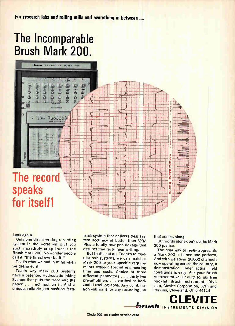
For research labs and rolling mills and everything in between...
The Incomparable Brush Mark 200.
brUSh I CORO ER MARK 200
The record speaks for itself!
Look again. Only one direct writing recording
system in the world will give you such incredibly crisp traces: the Brush Mark 200. No wonder people call it "the finest ever built!" That's what we had in mind when
we designed it. That's why Mark 200 Systems
have a patented Hydrostatic Inking System that puts the trace into the paper . . . not just on it. And a unique, reliable pen position feed-
back system that delivers total sys-tem accuracy of better than 1/2%! Plus a totally new pen linkage that assures true rectilinear writing. But that's not all. Thanks to mod-
ular sub-systems, we can match a Mark 200 to your specific require-ments without special engineering time and costs. Choice of three different penmotors . . . thirty-two pre-amplifiers . . . vertical or hori-zontal oscillographs. Any combina-tion you want for any recording job
that comes along. But words alone don't do the Mark
200 justice. The only way to really appreciate
a Mark 200 is to see one perform. And with well over 20,000 channels now operating across the country, a demonstration under actual field conditions is easy. Ask your Brush representative. Or write for our free booklet. Brush Instruments Divi-
sion, Clevite Corporation, 37th and Perkins, Cleveland, Ohio 44114.
CLEVITE brush INSTRUMENTS DIVISION
Circle 901 on reader service card

Simplify Circuits and Reduce Costs in New Microwave
Equipment with RCA «overlay" Transistors
1 .-.'...-te.le!.;"-g -
leiese'z--4. e'.
e ' ,4.13.;,-!, \ pied . ,
jit :tr;
r, i I y .
:111111Iniii isionnove!.....-fielgeem ii01110-' --
0
JIIIIIIIII
.. 4".
I
ji,7,•iiiiii„
;11112;ii
1::::::::::111111111:111:11"":1 iiiiitrimmionmo Jain
11111111iMMIMIIIIMISMium
MI 11110111100011111
I nail
a lde1:11:11111:11:11111:1
ommuma
111111111011 rim ii„...,ime..._.iiceet
0 0018
_111111
mum i____.....•
111111113.113110
Milani
nil
ion mon...lee.
HE
sou Mu
up
ileaudazing
oluiwom
¡Hi
sou II
...,
o IIII
•
Milli ii 1.
@ma ra; „mg our 8. :cut _ _o
ce. is.
_.
Ai.,. 78irdli .1.4, si --,--_, : .1: PelriLliiill111111uniliiiiintioluoulda Weiiiiiiiii;:1111i lileetil,e - --'• -- . '
ettP11111 V ' 100 4 I
POWER Cob
TYPE FREQ. Mc/s
OUTPUT WATTS
GAIN dB
Vcc
VOLTS pF
EFF. % PKG.
(Min) (Max.)
2N3375 400 3 5 28 8 40 TO-60
2N3733 400 10 4 28 15 45 TO-60
2N3866 400 1 10 28 3 45 TO-39
2N4012 1050 2.5 4 28 10 25 TO-60
As Much as 2.5 W Power Output With Power Gain at 1 Gc/s. RCA "overlay" technology extends transistor performance into the microwave region with greater power, gain, efficiency, and frequency capability.This
solid performance means you can design doubler, tripler, and quadrupler microwave stages with fewer
solid-state devices and less complex circuitry, reduc-
ing the cost of your equipment design while increas-
ing total circuit reliability. At microwave frequencies, RCA "overlay" transistors are your
best choice for functions such as frequency multiplication. Not only
do you get exceptional power gain, you also cut circuit costs by reducing the number of components needed. In the "overlay" de-
sign, the non-linear capacitance of the collector-to-base junction acts as a built-in varactor diode, thereby eliminating the diode as
TO-39 TO-60
well as the transistor amplifier previously needed.
Combine this inherent frequency multiplication capability with the frequency performance of "over-lay" and you have all the ingredients needed for an efficient oscillator frequency multiplier. RCA "over-
lay" transistors operated in oscillator-quadrupler
circuits have achieved outputs as high as 300 mW at
1.7 Gc/s. And "overlay" offers comparable design benefitsforstraight-through amplifiers and oscillators.
For more information on RCA "overlay" transistors at microwave
frequencies, consult your RCA Representative. For technical data
and a copy of a new application note "Frequency Multiplication Using 'overlay' Transistors" (SMA-40), write: RCA Commercial Engi-
neering, Section l-N-4-1, Harrison, N. J.
Also Available From Your RCA Distributor
RCA Electronic Components and Devices
The Most Trusted Name in Electronics
See "THE OVERLAY TRANSISTOR—The Challenge and The Answer," a new 76-mm color film. Available through your local RCA representative.
Circle 902 on reader service card
Related Documents


