1 PUMPS PACO® F9d.1- Level 1 4/06 Supercedes 5/00 PACOFLO 9000, LEVEL 1 INSTALLATION, OPERATION, AND MAINTENANCE MANUAL S/N: DATE:

Welcome message from author
This document is posted to help you gain knowledge. Please leave a comment to let me know what you think about it! Share it to your friends and learn new things together.
Transcript

1
PUMPSPACO®
F9d.1- Level 14/06Supercedes 5/00
PACOFLO 9000, LEVEL 1INSTALLATION, OPERATION,
AND MAINTENANCE MANUAL
S/N:
DATE:

2
F9d.1 - Level 14/06Supercedes 5/00
®PACOPUMPS
PACOFLO 9000, LEVEL 1
TABLE OF CONTENTS
1. Introductiona) Narrative 3b) Major System Components Drawings 4
2. Receipt & Installationa) Receipt, Storage and Moving of the System 5b) Mechanical Installation 6c) Electrical Installation 7d) Electrical Check Out 8e) Hydro-pneumatic Tank Installation 9
3. Start-upa) Start Up Check List 10b) Placing the System into Operation 11
4. Components & Featuresa) Motor Starters 13b) Trip Module 14c) Control System (PLC) 15d) Data Acquisition and Sensing Systems 16e) Sequencing Devices 17 f) Sequence Variations 18g) Alarm, Options and Other Features 19
5. Adjustments and Field Settingsa) Overview of Factory Settings 21b) Adjustment of Pressure Settings 22
6. Troubleshootinga) Electrical Troubleshooting 23
7. Appendixa). System Settings 28b). Panel and Pump Nameplate Information 29c). System Nameplate Information 30d). Diagrams
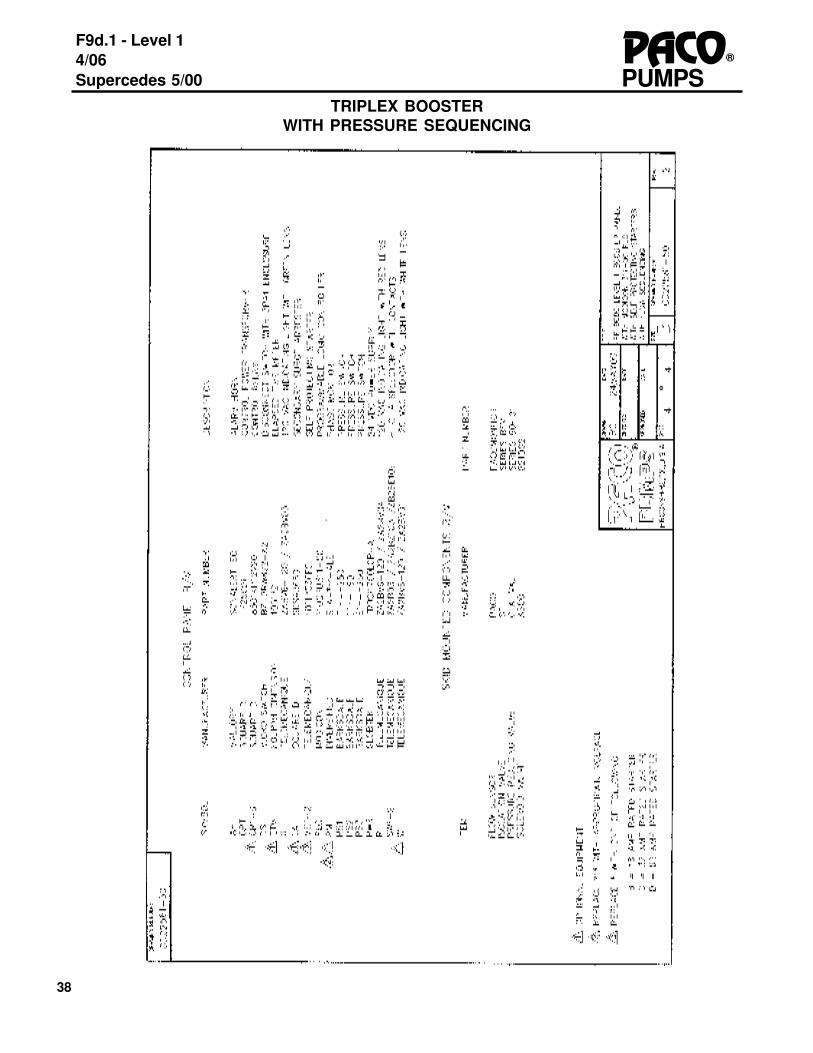
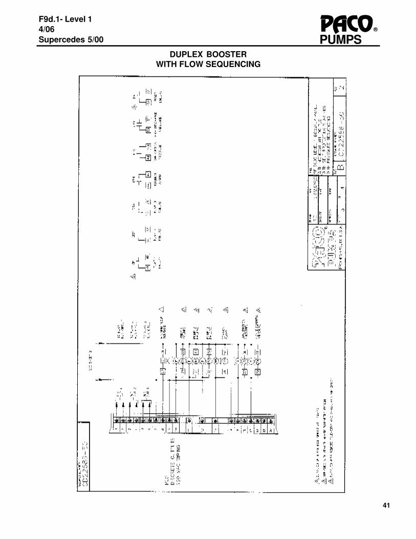
1. Triplex Booster, with Pressure Sequencing (4 pages) 312. Duplex Booster, with Pressure Sequencing (4 pages) 353. Triplex Booster, with Flow Sequencing (4 pages) 394. Duplex Booster, with Flow Sequencing (4 pages) 43
e). Pressure Reducing/Check Valve1. General 472. Operation Matrix 483. Recommendations & Requirements 494. Installation Start-up Continued 50
f). Blank pages for Notes 518. Index 539. Warranty 54
Attachments may include: Pump IOM, Sales and Service Centers Guide

3
PUMPSPACO®
F9d.1- Level 14/06Supercedes 5/00
The Pacoflo 9000, Level 1 booster system is a complete, factory assembled water booster system.The system operates with multiple pumps in parallel. The booster system's U.L. panel providescontrols for the system sequencing and alarm functions. The booster system takes water from asource and boosts the pressure for final use at the discharge of the unit. Pump sequencing isprovided with a wide range of devices and the exact configuration of the unit will depend on how theunit was ordered. The system comes complete, ready for installation and operation, and is in-tended to pump clean, fresh water.
This booster system has been fabricated and preset at the factory to the required system and flowspecifications. Final system adjustments may be required to place the system in operation. Thebooster system has been designed to operate over the range of pressures and flows as describedin Paco Pumps’ catalog and is built to the customer’s specifications and jobsite requirements.
This system will perform as set at the factory and will continue to provide satisfactory service whenproperly installed and maintained. Periodic maintenance is necessary for continuous trouble freeservice. Service assistance in maintaining the system can be provided by Paco’s factory trainedservice organizations. Service by unauthorized agencies should be avoided.
All PACO booster systems are identified with a system nameplate and individualized label, locatedon and in the control panel. A sample nameplate and label is included at the end of this IOM. Inaddition, the individual pumps have nameplates. When referring to this system, please includeall nameplate information.
With the nameplate and label information, spare or replacement parts can be easily identified andordered. All normally required parts are available in kit form, as shown in the replacement partsguide included in this IOM.
A form has been included near the end of the IOM for your use to fill out nameplate information thatcan be used when contacting our service representatives.
It is recommended that the system nameplate and label be immediately examined and informationcontained therein be immediately recorded on the forms in this IOM to insure proper identificationin the event of future nameplate or label damage.
THE ENTIRE CONTENTS OF THIS MANUAL SHOULD BE COMPLETELY READ BEFORE ANYINSTALLATION, OPERATION, OR MAINTENANCE.
INTRODUCTION
4
F9d.1 - Level 14/06Supercedes 5/00
®PACOPUMPS
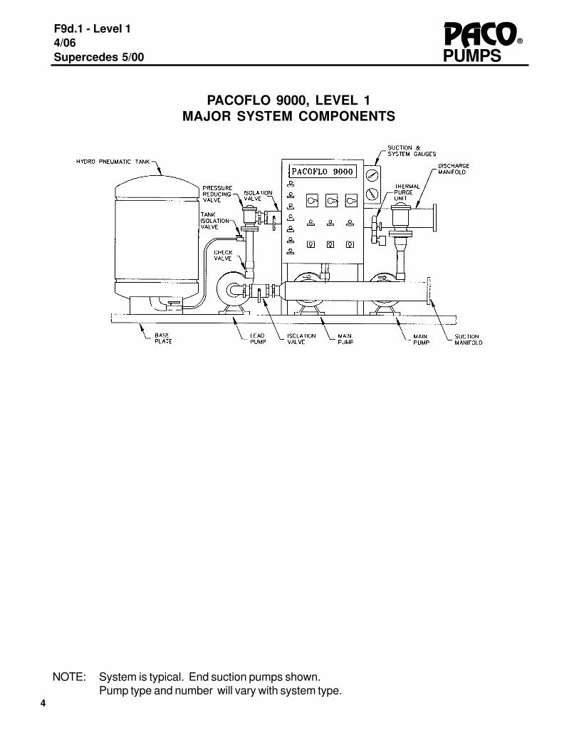
PACOFLO 9000, LEVEL 1MAJOR SYSTEM COMPONENTS
NOTE: System is typical. End suction pumps shown.Pump type and number will vary with system type.

5
PUMPSPACO®
F9d.1- Level 14/06Supercedes 5/00
RECEIPT OF SYSTEM
The booster system is to be inspected upon receipt for indications of possible transit damage. Ifthere is any damage, contact the freight carrier immediately and report any damage. File afreight claim directly and immediately with the freight carrier.
Inspect the entire system for components that may have loosened in the transporting of the sys-tem. Repair or tighten the affected components. Open the electrical panel door and inspect theinterior of the panel. Check all wires for tightness and all components to make sure they have notloosened nor been inadvertently disconnected.
STORAGE
The system must be stored indoors, out of the weather. Avoid any temperature extremes. Storagetemperatures should range from 40 degrees F to 104 degrees F.
Whether the system is stored at the final site of the booster system or at a separate site, the systemmust be loosely covered with a plastic or canvas cover. If the system may be exposed to moisture,the cover is to be moisture proof. Allowances should be made to allow for proper ventilation and aircirculation.
If the system will be exposed to dirt and dust before system startup, a plastic or canvas cover is tobe used to keep the system clean.
MOVING THE SYSTEM
This packaged system can be moved with a fork lift truck. The forks of the lift truck should beplaced under the side or end of the baseplate of the system. The system should be secured to thefork lift mast to prevent the system from shifting or falling from the forks.
Do not attach a sling or other type of convenience to any of the system components or move thesystem in any way through the system components. If a sling is used to move the system, the slingcan be placed under the base. Dollies or other wheeled devices can also be used to transport thesystem.
SYSTEM INSTALLATION
6
F9d.1 - Level 14/06Supercedes 5/00
®PACOPUMPS
MECHANICAL INSTALLATION
The site for the installation should be clean, level, and free from all debris.
Place the Pacoflo 9000, Level 1 booster system at the installation location and check for approxi-mate alignment with suction and discharge piping. Check the clearance between the electricalpanel door and any obstruction to make sure the distance is in compliance with the National Elec-tric Code, and any local codes. Correct any discrepancies.
Mark the location of the baseplate anchor bolt holes on the floor and install anchors in the floor. Install the anchorbolts and secure the baseplate using flat washers and lock washers under the bolt heads.
Use a level to level the booster system baseplate. Shim the base plate at the anchor bolt loca-tions until the level in various planes is satisfied at several points on the baseplate.
When the system has been leveled, apply grout to the base and completely fill in the spacebetween the baseplate and the floor. Allow the grouting to dry before attempting any connectionof the system piping. Without proper grouting, the booster system may be noisy and susceptibleto vibration.
CONNECTING THE SYSTEM TO THE BUILDING PIPING
Follow any local codes when making final connections of the system.
System Isolation valves must be provided at the connection points of the booster system suc-tion and discharge manifolds with the system piping. Flexible couplings can also be used, as speci-fied.
Flushing of the system prior to installation is required. Check the booster system manifolds tomake sure they are free of debris. Also check building piping for any obstructions or debris beforeconnecting the booster system to the building piping. Piping to the system must be free from obstruc-tions that will prevent proper flow to and from the system, or otherwise damage the system.
The building piping must be piped TO the manifolds of the booster system. Do not pipefrom the booster system to the building piping. Tighten all piping securely and adjust the final fittingsto the flanges or fitting of the system.
The booster system manifolds are not to be used as supports for the building piping. Supportsfor the building piping must be provided. Do not put stress on the booster system manifolds byusing them to "close up" any poor fit of the building piping to the booster system.
Good piping practices and proper fittings are required to prevent any air pockets from beingcreated in the piping from the supplied suction line.
Pipe the thermal purge valve to the floor drain or other type drain.
7
PUMPSPACO®
F9d.1- Level 14/06Supercedes 5/00
Electrical Safety.... Electrical circuits pose a potential danger. DO NOT attempt to connect anelectrical panel to the main power supply with out proper and complete electrical training in electri-cal safety and proper electrical maintenance skills. The following section is written to assist anEXPERIENCED AND QUALIFIED ELECTRICIAN in connecting the panel to the main power.
Use only electrical testing devices and protection equipment that have been verified as safe andreliable. All testing devices used to indicate voltage and current must be of known reliability. Do notuse a strange or untested electrical measuring device to troubleshoot or verify any electrical circuit.
The power to the panel must be connected in compliance with the National Electric Code (NEC)and any local codes. Voltage variations greater than 10% of the supply voltage or frequency varia-tions greater than 5% will cause poor performance and damage the electrical components of thesystem. Correct any variations of voltage or frequency before connection to the system.
The booster system nameplate, located on the upper left hand corner of the panel front, contains thecorrect voltage, phase, and frequency of the panel and Pacoflo 9000, Level 1 electrical compo-nents. The supply voltage, phase and frequency must match the panel nameplate information.Double check by checking the motor nameplates to verify the required voltage. If there is a discrep-ancy, contact PACO Pumps for assistance. Test the voltage at the branch circuit disconnectingdevice to verify the correct voltage before connecting the wires to the panel.
The wires coming to the system must be copper wire and correctly sized by the electrical con-tractor or engineer.
Make sure the booster system electrical panel disconnecting switch(es) and all H-O-A (HAND-OFF-AUTO) switches are in the OFF position before applying power to the panel.
ELECTRICAL INSTALLATION
8
F9d.1 - Level 14/06Supercedes 5/00
®PACOPUMPS
On systems equipped with self-protected starters, see the TRIP MODULE ADJUSTMENT sectionfor additional information.
Make sure all HAND-OFF-AUTO (H-O-A) switches are in the OFF position. Open the panel doorand use a voltage meter or other electrical instrument to verify that the incoming voltage matchesthe nameplate information. The voltage can be checked at the power distribution block or paneldisconnecting switch. If Voltage is not present, check the Branch Circuit disconnecting device tosee if the device is ON.
Inspect the panel for any abnormal conditions, loose wires, loose components, missing compo-nents, etc. Check the motor starters to see if the heaters have been installed on heater-type over-load relays, or that the amp settings are correct on adjustable overload relays. Correct heater sizes,trip module adjustments and/or overload adjustment are based on the motor’s nameplate FLAvalue.
If the motors are protected with fuses, make sure the fuses are present. If the fuses are not present,consult PACO Pumps for correct fuse sizing. If fuses are required to be installed, use an insulatedfuse installation tool. If the motors are protected with circuit breakers and the panel has a maindisconnect, make sure the breakers are in the "ON" position.
Make sure water is present at the suction side of the pumps and at the correct suction pressure(See page 7, Applying Water to the System). Close the panel door and turn on the panel maindisconnect(s) so that power is applied to the panel. If an alarm horn sounds, press the silence resetbutton to silence the horn. Momentarily move the HAND-OFF-AUTO switch to the HAND positionand back to OFF, and observe the rotation of each pump. Rotation is indicated by an arrow on thepump and is observed through the motor bracket opening. A chalk mark placed on the shaft endprior to energizing may prove a valuable aid in ease of observation. For vertical turbines, rotationshould be verified before by coupling pump to motor.
If the rotation is incorrect on all of the system pumps, change any two incoming panel wires on threephase systems. If one motor’s rotation is incorrect, change any two wires at the motor starter tocorrect the rotation. Single phase systems will require a change at the motor junction box, andinformation on these connections will be inside the junction box.
If the motor starter does not energize, check the circuit breaker or fuses and the overload reset onthe starter. Also check to make sure you have control voltage at the down stream side of the controlpower fuse(s).
ELECTRICAL CHECK OUT
9
PUMPSPACO®
F9d.1- Level 14/06Supercedes 5/00
HYDROCUMULATOR TANK
CAUTION
If a Hydrocumulator tank has been included as a part of this booster system, the tank requiresproper air charging before water pressure is applied. Damage to the tank bladder can occur ifwater under pressure is introduced into the tank with no air charge.
AIR CHARGE
The specific air charge will vary depending upon the tank manufacturer. When there are no instruc-tions provided with the tank, the recommended setting of the air charge pressure is 20 PSI belowthe system pressure. If the system pressure were 100 PSI, the tank air charge will be 100 - 20 = 80PSI.
Make sure the temperature of the tank is as close as possible to the ambient temperature beforemaking any pressure tests or readjustments.
Check the pressurizing stem for any obstructions or debris prior to checking the tank pressure oradding air to the tank. Check the air charge with a pressure gauge. Add or release air as required.Air can be added with a hand tire pump or with an air compressor. Do not over pressurize beyondthe tank nameplate maximum pressure. Damage to the tank internal bladder will result.
SYSTEM PRESSURE is defined as system boost pressure plus minimum suction pressure. Eachparticular system pressure value is listed in the booster system label.
After clearing all of the air from the system, and the system is working on automatic, open the tankisolation valve slowly to allow water to enter the tank. Gradually open the valve all the way.
TANK AIR CHARGE= System Pressure (PSI) minus 20 PSI.

10
F9d.1 - Level 14/06Supercedes 5/00
®PACOPUMPS
PACOFLO 9000, LEVEL 1 STARTUP CHECK LISTPRELIMINARY_____ 1. Confirm nameplate information._____ 2. If unit has a tank, air charge tank to system pressure (PSI) minus 20 PSI before apply-
ing any water pressure to booster system._____ 3. Fill system with water._____ 4. Bleed air at top of pumps, prv's, gauges and at pressure switches._____ 5. Bleed air from any other high point in the system._____ 6. Check pressure reading on suction gauge (make sure it's at minimum).
CAUTION:FINAL ELECTRICAL CONNECTIONS AND PANEL CHECKOUT SHOULD
BE MADE BY A QUALIFIED ELECTRICIAN!
ELECTRICAL_____ 7. Turn HOA switches to "OFF" position._____ 8. Check settings on trip modules inside panel._____ 9. Apply power to panel._____ 10. Check supply voltage to panel and verify correct voltage with nameplate data._____ 11. Close and secure panel door, (push "ALARM SILENCE" button if alarm is sounding)._____ 12. Bump each motor and verify proper pump rotation.
(on vertical turbine systems, check rotation before coupling pump to motor).
GETTING READY TO RUN_____ 13. When building is ready to accept water pressure, turn on pump #1 in "HAND" mode._____ 14. Open building fixtures to establish approximately 15-25 GPM flow._____ 15. Observe system pressure gauge, (check to see if pressure is as required)._____ 16. If incorrect, readjust PRV to desired pressure reading._____ 17. Check remaining pumps and PRV's in same manner.
SETTING SYSTEM & SUCTION PRESSURES TO PC_____ 18. Confirm pressure switches adjusted to correct pressure set point.
SYSTEM IS NOW READY FOR "AUTO" OPERATION_____ 19. Put all "HOA" switches in "AUTO" mode._____ 20. Open and close fixtures or valves in building to check flow switch settings and verify
"AUTO" operation of booster system. IF FURTHER DETAILS ARE REQUIRED,SEE F9d.2.
11
PUMPSPACO®
F9d.1- Level 14/06Supercedes 5/00
PLACING THE SYSTEM INTO OPERATION
APPLYING WATER TO THE SYSTEM
Before applying water to the booster system, close all of the isolation valves on the booster system.Slowly open the building suction shut off valve and allow water to fill the booster system suctionmanifold.
All air must be removed from the system. If all air is not removed from the system, improper opera-tion of the system will result, and possible permanent damage to the system may occur.
Loosen the suction pressure gauge line at the gauge and bleed all air. Retighten the connection.
Open the suction valve to each pump, one at a time, and observe for leaks. Report any leaksimmediately to Paco Pumps. Open a plug or other fittings at the top of each pump to discharge anyand all air from the pumps. Replace and retighten the fittings.
Loosen the discharge pressure gauge line at the gauge and bleed all air. Retighten connection.
Check the pressure gauge and determine that the suction pressure corresponds to the Paco-flo9000, Level 1 design settings, and falls between the minimum and maximum conditions indi-cated on the system label. This label is located on the interior of the electrical panel.
Check for leaks in the piping to the manifold and any leaks that may appear in the manifold. Repairany leaks in the building piping and report any leaks in the Pacoflo 9000, Level 1 immediately toPaco Pumps.
Open the discharge isolation valves at each pump. If the system has a PRV/pump, open the vent(nut) on each PRV and vent each line to remove all air. Bleed air for at least 30 minutes. Close thevent.
Open the building system valve. Check the building piping and repair all leaks.
SYSTEM CHECK OUT
For venting the system, open a valve at the top or extreme end to the piping system. Direct the valveto a drain or other sink that will take the expected water discharge. Place the lead pump motor inthe HAND position and run the pump until clear water is coming from the valve. Monitor the suctionpressure to make sure the pressure stays above the minimum acceptable value.
Close the valve used to vent the system and place all of the HAND-OFF-AUTO switches in the-AUTO position. Reset any alarms that may occur by pressing the ALARM-RESET button. Thesystem should stop after a no flow condition has existed for three minutes. (Note: Systems withouta no flow circuit will continue to run).

12
F9d.1 - Level 14/06Supercedes 5/00
®PACOPUMPS
Open a valve to discharge water from the building piping. The valve should be large enough tohandle total system flow. The booster system should restart when the system pressure has droppedbelow the set pressure. Close the valve and the system should shut down after three minutes. Openthe valve again and increase the flow until the first main pump starts. (Note: On a duplex system thesecond pump will start.) Continue to open the valve until the third pump starts. Close the valve andeach main pump will stop after a time delay. The lead pump will stop after three minutes
SETTING PRV’s
If the PRV (s) have been installed at the factory, they have been set to the system pressure. If asingle PRV will be added to the system at the jobsite, the PRV must be set to the required sys-tem pressure. Follow PRV instructions.
SUMMARY
When the system is completely checked out and properly adjusted, the system will be ready for use.If problems develop, check the sections in the manual that cover the problem area for solutions tothe problems.
13
PUMPSPACO®
F9d.1- Level 14/06Supercedes 5/00
The majority of Pacoflo 9000, Level 1 systems are equipped with state-of-the-art self protectedstarters. Check the control panel to determine whether self protected starters or separate starters/overload protection are present.
SELF PROTECTED STARTERS / TRIP MODULES
The self protected starter has a removable module called the "TRIP MODULE". This module isadjustable for both the motor overloads and motor short circuit protection. All settings have beenfactory set, and adjustment is not normally required.
MODULE TRIPPING PROBLEMS
Most module tripping problems occur when the motor is drawing more amps than its nameplatedFLA value. If the module continuously trips or if tripping is a problem, check the settings on the tripmodules, as well as the motor amperage draw.
TRIP MODULE ADJUSTMENTSOVER CURRENT DIAL
There are two dials on the front of the module. The left-hand dial is set for short circuit protection.The right-hand dial is set for motor overload protection.
The left-hand dial and the portion of the trip module controlled by its setting is similar to a MotorCircuit Protector (MCP). The dial is set to 13 times the motor nameplate FLA value. For example,a motor that has a FLA value of 10 amps has a correct dial setting of 130. Do not increase the dialsetting to more than 13 times the motor FLA value. If the dial can not be adjusted to the correctvalue, then the TRIP MODULE must be changed. Please contact a PACO Service Technician.
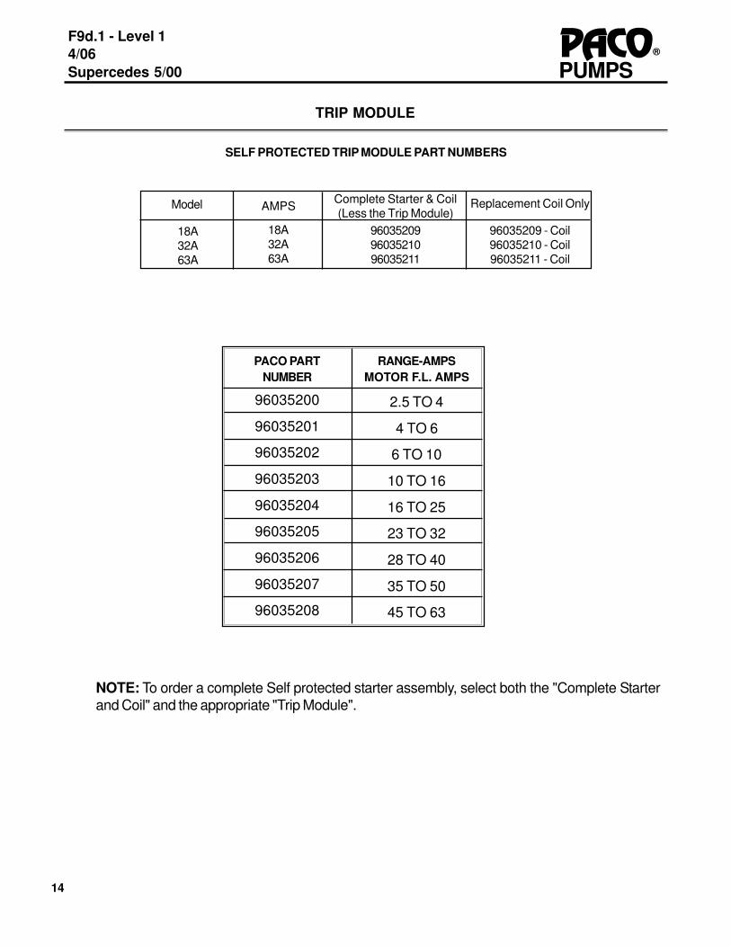
To order a new trip module, check the motor nameplate FL amps, and from the TRIP MODULEtable on page 10, determine the part number for the correct trip module.
OVERLOAD DIAL
The right-hand dial controls the motor overload part of the TRIP MODULE. On the trip module,check the setting of the dial on the right-hand side of the module and adjust the dial to the correctmotor nameplate FLA value. Do not increase the setting of the dial to more than 15 percentabove the motor nameplate FLA rating. If motors with a service factor other than 15% are used,do not exceed the motor nameplated FLA plus the nameplated service factors. If the range of thetrip module does not correspond to the nameplate amps, select trip module from the table onpage 10.
If nuisance tripping continues after the proper adjustments have been made, the switch point tobring on the next pump in the sequence needs to be checked. (If the motor is over amping at theswitch point, adjustment to the switch point is required). See the appropriate sequencing sectionfor check out and adjustment. If the trip module continues to trip after all of the preceding checkshave been made, the trip module may be defective.
MOTOR STARTERS
14
F9d.1 - Level 14/06Supercedes 5/00
®PACOPUMPS
NOTE: To order a complete Self protected starter assembly, select both the "Complete Starterand Coil" and the appropriate "Trip Module".
TRIP MODULE
SELF PROTECTED TRIP MODULE PART NUMBERS
PACO PARTNUMBER
96035200
96035201
96035202
96035203
96035204
96035205
96035206
96035207
96035208
2.5 TO 4
4 TO 6
6 TO 10
10 TO 16
16 TO 25
23 TO 32
28 TO 40
35 TO 50
45 TO 63
RANGE-AMPSMOTOR F.L. AMPS
Model
18A32A63A
18A32A63A
AMPS Complete Starter & Coil(Less the Trip Module)
960352099603521096035211
Replacement Coil Only
96035209 - Coil96035210 - Coil96035211 - Coil

15
PUMPSPACO®
F9d.1- Level 14/06Supercedes 5/00
All booster systems require some method of control for purposes of automating the system andsequencing the pumps. The Control System typically involves three steps, as follows:
1. Data Acquisition or “Sensing” of existing system conditions2. Processing of the input data.3. Control Signal Output and “Sequencing”.
It is important to note that a control system has both primary and secondary functions. The primaryfunction of a control system is to monitor, process and control pump sequencing in order to provideefficient automation of the pump system. A secondary, but equally important function is to monitor,process and control the system safety and protective operations.
PACOFLO 9000, LEVEL 1 booster systems are provided with a programmable logic controller(PLC) for purposes of controlling the booster system. A PLC is a control device which efficiently andeffectively processes incoming and outgoing data.
Like a computer, the PLC contains both hardware and software. The PLC is a solid-state micro-processor with data input and output capability, used specifically for control functions. The PLC isable to “read” incoming data from the sensors, process that data according to the programmingsoftware, and provide control signal output via relay contacts on the PLC.
The PLC is preprogrammed at the factory with a standardized control program (software) writtenspecifically for PACOFLO 9000, LEVEL 1 booster systems. All programs are thoroughly tested anddebugged. The standardized programs may be tailored for specific jobs by adding/removing pre-tested programming “modules” related to the available booster system options. The program is alsoloaded with specific, job related set-point data. Once complete, the finalized program is “flashed”into memory. The memory is non-volatile, which means that the programming data is not lost with aloss of power. Therefore, a back-up battery power source is not required to maintain programstorage.
Note that a back-up battery is not required and therefore not supplied with the booster system. A"Battery Low" LED will remain lit on the PLC as a result.
CONTROL SYSTEM (PLC)
16
F9d.1 - Level 14/06Supercedes 5/00
®PACOPUMPS
DATA ACQUISITION AND SENSING SYSTEMS
The PACOFLO 9000, LEVEL 1 booster system may use several methods of “Data Acquisition” tomonitor current conditions of the booster system. These methods are the “eyes and ears” of thebooster and are used to monitor and signal various conditions.
Pressure based Alarms & Functions:Level 1 boosters use pressure switches as the standard means of monitoring for given pressureconditions such as high system pressure alarm and low suction pressure alarm. Independent pres-sure switches are used for each condition to be monitored. In most cases, the pressure switchesprovide a single, discrete “close contact” signal upon initiation of condition. That signal maintains“closed” until the condition subsides.
Flow based Alarms & Functions:Level 1 boosters use a flow switch as the standard means of monitoring for given flow conditionssuch as “No Flow” condition. In most cases, flow switches provide a single, discrete “close contact”signal upon initiation of condition. That signal maintains “closed” until the condition subsides.
Sequencing Devices:Sequencing Devices are critical part of data acquisition. These devices serve a specific function,and are discussed in detail in the following section.
17
PUMPSPACO®
F9d.1- Level 14/06Supercedes 5/00
“Sequencing Device” is the term used to describe a sensing mechanism that is used specifically formonitoring and signaling the point of activation and sequencing of the pumps on the skid. This is theunit that indicates when it is appropriate to activate a pump, or if a pump is already running, toactivate an additional pump.
There are many methods to determine when it is appropriate to activate a pump. Common methodsinclude flow sensing, pressure sensing and current sensing. The PACOFLO 9000 Level 1uses aPressure Sensing Sequencing Device.
Pressure SensingPressure sensing is the standard sequencing indicator method for the PACOFLO 9000, LEVEL 1booster. Pressure sensing is accomplished by means of a pressure switch. This pressure switchmay be identical to other pressure switches used on the system to monitor the alarm conditions.
For pressure sensing, the pressure switch setting or ‘set point” is equal to the System Pressure.Upon a drop in pressure below System Pressure, the switch “closes contact” to indicate the condi-tion. This signal is then processed by the PLC, and based upon the programming, a pump may beactivated. Typically, when the pump activates, pressure is restored and the switch opens. Other-wise, if demand is very large, the pressure switch may remain closed, and the PLC may call toactivate an additional pump.
The sequence of pump activation may vary, and is discussed in the next section “Sequence Varia-tions”.
SEQUENCING DEVICES

18
F9d.1 - Level 14/06Supercedes 5/00
®PACOPUMPS
Common Sequence Variations
Redundant Sequence Variations
Pumps may be sequenced in many variations in order to meet demand (flow) requirements. For agiven demand, it may be possible to satisfy that demand by activating two pumps in parallel withinthe booster system. However, it may also be possible to satisfy that same demand by activating onelarge pump. Other demands may be satisfied with one small and one large pump. An effectivesequence variation allows for the minimum amount of “pumping power” to be activated, to meetsystem requirements. For instance, if demand can be satisfied by two 5HP pump, it is not efficientto activate a third 5 HP pump to meet that demand.
Sequence variations are typically described in terms of the number of sequencing steps or morecomprehensively in terms of percentage of total flow. Sequence variations are also dependent onthe original capacity split design of the pumps. Typically, the greater the number of steps, the betterchance of minimizing the “pumping power” for any given demand. Below is a table of capacity splitsand sequencing variations.
Capacity Split Sequencing Variation Pumps activated 50/50 Duplex 50%, 100% A, A+B 30/70 Duplex 30%, 100% A, A+B
30%, 70%, 100% A, B, A+B 20/40/40 Triplex 20%, 60%, 100% A, A+B, A+B+C
20%, 40%, 100% A, B, A+B+C20%, 40%, 60%, 80%, 100% A, B, A+B, B+C, A+B+C
There are many adaptations of the above sequencing variations as well, especially when capacitysplits are tailored for specific system demands. A 65/65 split will follow the same sequencing varia-tion as a 50/50 split.
In addition to those listed above, there are systems where pump capacity splits and sequencingvariations are designed for system redundancy, emergency back-up, or “over-capacity capability”.With these systems, the total flow of all pumps exceeds the total demand requirement of the system.This is done to provide additional “back-up” pumping, should one pump become inoperable. Belowis a table of capacity splits and sequencing variations for redundant systems.
Capacity Split Sequencing Variation Pumps Activated 50/50/50 Triplex 50%, 100%, A, A+B (C as backup) 30/70/70 Triplex 30%,100% A, A+B (C as backup)
30%, 70%, 100% A, B, A+B (C as backup)30/70/100 Triplex 30%, 100% A, A+B (C as backup)
30%, 70%, 100% A, B, A+B (C as backup)
SEQUENCE VARIATIONS
19
PUMPSPACO®
F9d.1- Level 14/06Supercedes 5/00
ALARM LIGHTS (Standard)Each alarm or shutdown condition indicated herein has an individual, labeled alarm light. Alarmlights will remain lit until the alarm condition is relieved.
AUDIBLE ALARM (Standard)The audible alarm is a high frequency solid state horn that will sound when an alarm conditionoccurs. The alarm can be silenced with the ALARM SILENCE button and will clear itself when allalarm conditions are corrected.
PUMP ALTERNATOR (Standard)The control system has two methods of alternating the main pumps. Primary alternation of the mainpumps occurs at the completion of every first stage cycle. Cycle completion is determined by a firststage start and subsequent stop after the mnimum run time. If additional stages are signaled to runand stop during the same cycle, the called main pump sequence will remain.
The control system also includes a timed method of main pump alternation. The alternation time isfactory set at 12 hours. Alternation time is initiated by a first stage start signal. If the alternation timeis completed before the end of the run cycle, main pumps alternate positions. If the run cycle iscompleted before the alternation time elapses, then the alternation time is reset and the main pumpsalternate based on cycle completion. Alternation will occur only if main pump H-O-A selectors arein the auto mode and no main pump failure has been sensed.
PUMP FAILURE PROTECTION AND ALARM (Standard)When a pump is called to run, controller monitors the motor starter auxiliary contact input for therespective pump as a confirmation that pump is running. Failure to receive signal within 2 secondsafter pump is called to run is interpreted as a pump failure. Controller locks out said pump from thepumping sequence and calls the next available pump to operate. Respective "Pump Failed" lightis illuminated. Manual reset required before pump is re-instated into pumping sequence.
LOW SUCTION PRESSURE (Shutdown and alarm Standard)If the suction pressure falls to preset minimum suction pressure value (as indicated on the panellabel), the low suction pressure light will be lit and the alarm will sound, after a delay of 10 seconds.The system will shut down and not run in the alarm condition. The alarm is self clearing when thesuction pressure returns to normal parameters.
LOW SUCTION LEVEL ( Shutdown and Alarm optional)When the level of the reservoir or tank drops below a set point (as determined by the placement ofthe float switch), the level switch closes and the system will shut down after a 10 second delay. Thecondition is indicated by a visible light and alarm horn. The system restarts when the reservoir ortank level rises above the set point and reopens the level switch. Electrical runslonger than 200 feetto the float switch may cause poor panel performance and should be avoided.
ALARMS, OPTIONS AND OTHER FEATURES

20
F9d.1 - Level 14/06Supercedes 5/00
®PACOPUMPS
THERMAL PURGE SYSTEMIf a pump continues to operate when flow (demand) is not present, the condition is called “deadheading the pump”. Pumps which “dead head” can build up heat within the pump case. Thesystem is equipped with a thermal purge system to prevent excessive build up of heat in the pumpfrom damaging the pump seal and system components. The thermal purge may be a thermal-mechanical valve or a thermostat & solenoid valve combination. Thermal purge systems may beprovided “one per pump” or “one per system” depending on the original ordering criteria.
TIMED SHUT-OFF (STANDARD WITH TANK)If a booster system is provided with a hydro-cumulator tank, the system is provided with a TimedShut-Off circuit as standard. This feature allows the booster system to shut off upon satisfying thesystem pressure requirements for a minimum of 10 minutes. After 10 minutes of operation, thesystem will shut off for energy savings, and allow pressure to be maintained by the hydro-cumulatortank. If demand (flow) remains, the system will reactivate upon reaching the Low Pressure Start setpoint. Systems which are supplied with a No-Flow Shut-off option, are not equipped with the TimedShut-Off feature. This feature is not provided on systems that do not have a hydro-cumulator orhydro-pneumatic tank, as those systems have no means of maintaining pressure while pumps arede-activated.
NO-FLOW SHUT-OFF (OPTIONAL WITH TANK)If a booster system is provided with a hydro-cumulator tank, the system may be equipped with anoptional No Flow Shut-off circuit instead of the standard Timed Shut-Off feature. When flow dimin-ishes below a set point, and system pressure is maintained, the No-Flow switch closes and aminimum run timer counts for 180 seconds before shutting off the pumps. If demand (flow) remains,the system will reactivate upon reaching the Low Pressure Start set point.
AUXILIARY ALARM CONTACTSAuxiliary alarm contacts are relays (“dry contacts”) which are paralleled with the alarm option.When the alarm option is activated, the relay closes and provides remote alarm indication.The customer will supply the correct voltage for the remote alarm option from the remote alarmindicating station.
PHASE FAILURE - LOW VOLTAGE FAILUREWhen the Phase failure/low voltage option is installed, the panel control power will be shutoff if a lowvoltage or phase failure condition exists. The low voltage or phase failure (or reversal) conditionmust be cleared before the system will restart.
HIGH SYSTEM PRESSSURE SHUTDOWN AND ALARM (OPTIONAL)When the system pressure reaches the maximum flange design rating of the system, the system isshut down and an alarm light and horn sound. A two second delay is provided to consider momen-tary high pressure spikes. The system requires a manual reset to restart. The system maximumdesign rating is the maximum pressure the system is designed to withstand on a continuous basis.Typically, these pressures are: 175 PSI, 250 PSI and 400 PSI, depending on installation design.

21
PUMPSPACO®
F9d.1- Level 14/06Supercedes 5/00
OVERVIEW OF FACTORY SETTINGS
PACOFLO 9000 Booster Systems are pre-programmed at the factory. Low Pressure Startsettings and Low Suction Pressure settings have been set according to specific job data suppliedto PACO at time of purchase. All pressure settings are field adjustable, as required for fine tuningpurposes. Pressure Setting Adjustment procedures are described in this manual under "Adjust-ment of Pressure Setting".
Time delay settings are programmed as necessary to protect the booster system and relatedcomponents. The timer settings indicated below have been found most appropriate to ensureproper system operation. Time delay settings are stored internally on the system PLC and requireservicing by a trained technician. Reprogramming and adjustment of the time delay settings isinadvisable, without direct factory assistance.
* Timed Shut-Off and No-Flow Shut-off are provided only with systems utilizing hydro-pneumatic orhydro-cumulator tanks.** Upon detection of No Flow condition, individual pump Minimum Run Timers define the time delayfor Shut Off.***Minimum Suction Pressure and System Pressure are values as defined by Customer at place-ment of Order.
Upon Correction
FEATURE Std/Opt.
TIME DELAY RESET
Timed Shut OffNo-Flow Shut OffLow Pressure StartMinimum Run Timer, lead pumpMinimum Run Timer, main pumps
Pump Failure AlarmLow Suction Pressure Alarm & Shutdown
Low Suction Level Alarm & ShutdownHigh System Pressure Alarm & ShutdownPhase reversal & low voltage Shutdown
SETTING
Upon maintained System PressureFlow of approx. 5 GPM10 PSI below System Pressure ***
Not ApplicableNot ApplicableUpon Failure to start10 PSI below MinimumSuction Pressure ***Upon close of float switch contactPressure rating of System componentsPhase loss, reversal, voltage dropof 10%
Std.*Opt.*Std.Std.Std.
Std.Std.
Opt.Opt.Opt.
10 MinutesDependent**2 Seconds
180 Seconds30 Seconds
2 Seconds10 Seconds
10 Seconds2 Seconds
Instantaneous
Not ApplicableNot ApplicableNot Applicable
Not ApplicableNot Applicable
ManualAutomatic
AutomaticManual
22
F9d.1 - Level 14/06Supercedes 5/00
®PACOPUMPS
The Pacoflow 9000, Level 1 booster system is equipped with pressure switches to monitor thesystem start setpoint as well as low suction and optional high discharge pressure conditions. Thepressure switches include set point adjusting nuts. Each switch is factory set for conditions pro-vided for the system; however, field adjustment may sometimes be necessary.
The system was tested under simulated pressure and flow conditions at the factory. If the on sitepressure conditions of the discharge (building side) or the suction (supply side) are different thanthe settings on a label on the interior of the panel door, then follow the instructions in the next para-graphs.
To set the pressure set points of the system, place the system into service as outlined in “PLACINGTHE SYSTEM INTO OPERATION”. Set the PRV’s. Insure that the suction pressure is at its designpoint or higher, and the discharge pressure is at the design point. The pressure set points can nowbe set.
HOW TO ADJUST THE PRESSURE SWITCH SETTINGS
Each pressure switch has a setpoint actuation nut with scaled dial. Turn the self locking adjustmentnut clockwise to raise and counterclockwise to lower the actuation point. All dials are calibrated forincreasing settings.
Capture pressure in the suction and discharge pressure lines to the gauges and pressure switchesby closing the gauge line isolation valves. Bleed excess pressure in the lines to attain the correctlow suction pressure and minimum system pressure readings on the respective gauges. Openpanel door open where the PLC input LEDs are visible. Apply control power to the PLC. Adjust thepressure switch actuation nut as necessary to the setting that will actuate the correct PLC inputLED; see system PLC drawings for input designation. When correct LED illuminates, correctsetpoint has been attained. No further adjustment is needed. Open isolation valves to resumenormal operation.
ADJUSTMENT OF PRESSURE SETTINGS
23
PUMPSPACO®
F9d.1- Level 14/06Supercedes 5/00
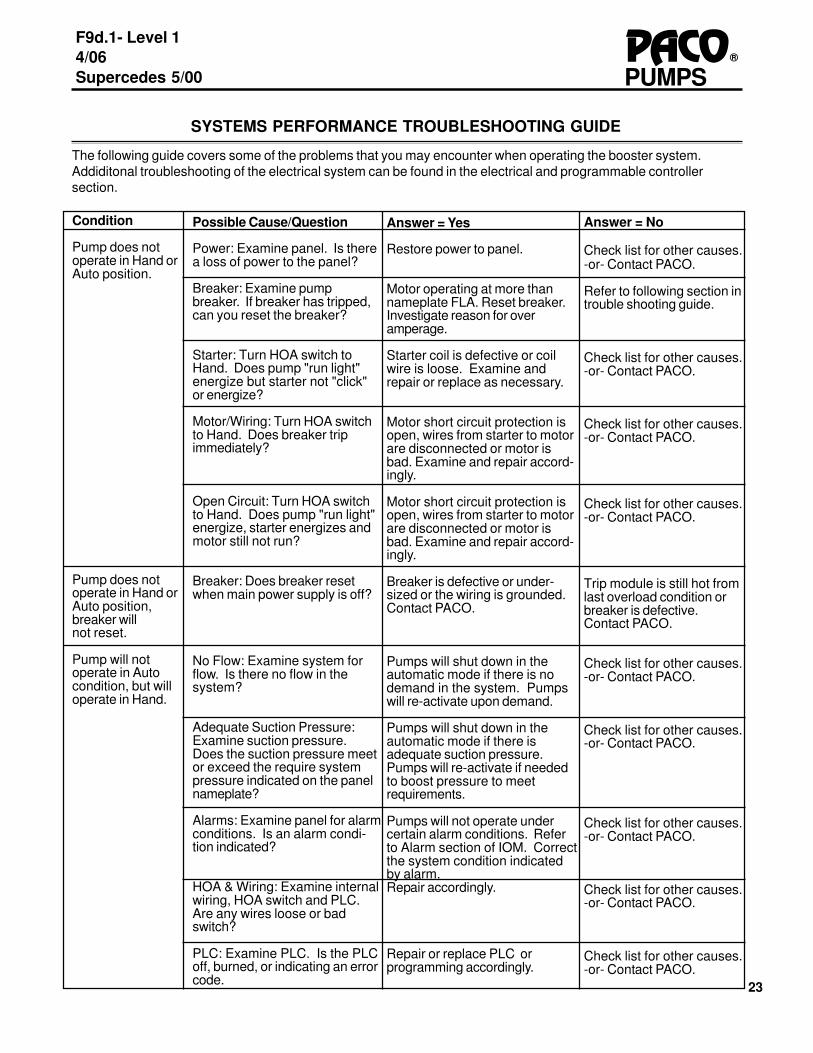
SYSTEMS PERFORMANCE TROUBLESHOOTING GUIDE
The following guide covers some of the problems that you may encounter when operating the booster system.Addiditonal troubleshooting of the electrical system can be found in the electrical and programmable controllersection.
Condition
Pump does notoperate in Hand orAuto position.
Pump does notoperate in Hand orAuto position,breaker willnot reset.
Pump will notoperate in Autocondition, but willoperate in Hand.
Possible Cause/Question
Power: Examine panel. Is therea loss of power to the panel?
Breaker: Examine pumpbreaker. If breaker has tripped,can you reset the breaker?
Starter: Turn HOA switch toHand. Does pump "run light"energize but starter not "click"or energize?
Motor/Wiring: Turn HOA switchto Hand. Does breaker tripimmediately?
Open Circuit: Turn HOA switchto Hand. Does pump "run light"energize, starter energizes andmotor still not run?
Breaker: Does breaker resetwhen main power supply is off?
No Flow: Examine system forflow. Is there no flow in thesystem?
Adequate Suction Pressure:Examine suction pressure.Does the suction pressure meetor exceed the require systempressure indicated on the panelnameplate?
Alarms: Examine panel for alarmconditions. Is an alarm condi-tion indicated?
HOA & Wiring: Examine internalwiring, HOA switch and PLC.Are any wires loose or badswitch?
PLC: Examine PLC. Is the PLCoff, burned, or indicating an errorcode.
Answer = Yes
Restore power to panel.
Motor operating at more thannameplate FLA. Reset breaker.Investigate reason for overamperage.
Starter coil is defective or coilwire is loose. Examine andrepair or replace as necessary.
Motor short circuit protection isopen, wires from starter to motorare disconnected or motor isbad. Examine and repair accord-ingly.
Motor short circuit protection isopen, wires from starter to motorare disconnected or motor isbad. Examine and repair accord-ingly.
Breaker is defective or under-sized or the wiring is grounded.Contact PACO.
Pumps will shut down in theautomatic mode if there is nodemand in the system. Pumpswill re-activate upon demand.
Pumps will shut down in theautomatic mode if there isadequate suction pressure.Pumps will re-activate if neededto boost pressure to meetrequirements.
Pumps will not operate undercertain alarm conditions. Referto Alarm section of IOM. Correctthe system condition indicatedby alarm.Repair accordingly.
Repair or replace PLC orprogramming accordingly.
Answer = No
Check list for other causes.-or- Contact PACO.
Refer to following section introuble shooting guide.
Check list for other causes.-or- Contact PACO.
Check list for other causes.-or- Contact PACO.
Check list for other causes.-or- Contact PACO.
Trip module is still hot fromlast overload condition orbreaker is defective.Contact PACO.
Check list for other causes.-or- Contact PACO.
Check list for other causes.-or- Contact PACO.
Check list for other causes.-or- Contact PACO.
Check list for other causes.-or- Contact PACO.
Check list for other causes.-or- Contact PACO.

24
F9d.1 - Level 14/06Supercedes 5/00
®PACOPUMPS
Condition
Pump Does Not Runin Auto but runs inHand.
Pump starts in Hand,but trips breakerperiodically.
Pumps Cycle Onand Off continuouslywith demand.
Pumps Cycle Onand Off continuouslywith NO demand.
Discharge pressureis too low.
Possible Cause/Question
Demand Is there a demandpresent?
Amperage: Check amperageof pump motor with ampmeter. Does amperageexceed motor nameplate?
Demand Is demand fluctuat-ing?
Discharge leakage: Close themain system discharge valveand allow system shutdown inautomatic mode. Doessystem stop cycling, andremain off?
Suction leakage: Close themain system discharge valve,allow system to charge upsystem pressue, close themain system suction valve andallow system to shutdown inautomatic mode. Doessystem stop cycling, andremain off?
Hydro-pneumatic Tank: Doesyour system have a hydro-pneumatic tank either on theskid or remotely located?
Improper Rotation: Inspectpumps to determine directionof rotation. Are the pumpsrotating in the wrong direction?
Air Bound. Crack open bleedfittings from top of piping,manifolds and pump volutes.Is there air in the piping?
Incorrect voltage: Use voltagemeter to verify that theincoming power supply. Isthe supply voltage differentthan that listed on the panel?
Isolation Valves: Examinevalves. Are the isolationvalves partially closed?
Answer = Yes
Pumps will not activate ifthere is no demand.
Motor is drawing excessiveamps. Contact PACO.
Pumps will activate anddeactivate to meet de-mand.
A demand still exists inthe system. Check forsystem leakage. Inspecthydrocumulator tank tomaximize drawdown duringlow flow. (see hydro-pneumatic tank trouble-shooting)
The check valves orchecking PRVs are notsealing. Pressure isleaking back to suctionside. Clean or replacecheck valves or checkingPRVs.
Refer to Tank troubleshoot-ing section of this manual.
Reverse any two leads onstarter of motors that haveincorrect rotation. If allmotors have incorrectrotation, reverse any twoleads on power supply topanel.
Vent pumps, manifolds,pressure regulating valvesand piping.
Panel voltage rating mustmatch supply voltage.Contact PACO
Open valves.
Answer = No
Check list for other causes.-or- Contact PACO.
The trip module is adjustedtoo low or is undersized.Adjust accordingly or contactPACO. Note: Amperage willfluctuate with flow.
Check list for other causes.-or- Contact PACO.
See "Suction leakage" below.
System set points are out ofrange, or fault in programming.Contact PACO.
Check list for other causes.-or- Contact PACO.
Check list for other causes.-or- Contact PACO.
Check list for other causes.-or- Contact PACO.
Check list for other causes.-or- Contact PACO.
Check list for other causes.-or- Contact PACO.

25
PUMPSPACO®
F9d.1- Level 14/06Supercedes 5/00
Condition
Dischargepressureis too high.
PRV not openingor too restrictive.
Possible Cause/Question
Exceeding Capacity:If equipped with flow meter, doesmeter reading exceed the ratedflow of the booster system?
If no flow meter is present, closethe main discharge valve andexamine the pressure gauge.Did the pressure increase?
Suction Pressure: Examinesuction pressure gauge. Is thesuction pressure less than theminimum suction pressureindicated on the panel?
Gauge: Remove gauge andexamine. Does gauge appeardefective?
PRV: Examine pressure up-stream of the pressure reducingvalves (PRV). Is upstreampressure adequate?
PRV: Is your system equipedwith one or more pressurereducing valves (PRV)?
Diaphragm: Is water leakingfrom vent hole?
Installation: Inspect PRV. Isvalve installed with flow in theopposite direction of the arrowon the valve?
Isolation valve: Inspect isolationvalves in pilot tubing. Are anyisolation valves closed?
Speed control valves: Inspectspeed control valves by openingfully and closing fully (return tooriginal setting). Was the valveclosed or frozen?
Failed pilot regulator.
Answer = Yes
Reduce the system demand orcontact PACO for options onincreasing the flow capacity ofthe system.
Reduce the system demand orcontact PACO for options onincreasing the flow capacity ofthe system.
Examine suction line for block-age, clogged strainers, partiallyclosed valves, restrictive PRVs.Correct as able or contact PACOfor options on increasing thebooster pressure of the system.
Replace gauge.
Refer to PRV troubleshootingsection of this manual.
Refer to PRV troubleshootingsection of this manual.
Diaphragm is ruptured. Replace.
Water flow should be in thedirection of the arrow. Reversevalve orientation.
PRV can not vent pressure.Open valve.
Clean or replace speed controlvalve, and reset the speedsetting.
Refer to PRV manual or contactPACO
Answer = No
Check list for other causes.-or- Contact PACO.
Check list for other causes.-or- Contact PACO.
Check list for other causes.-or- Contact PACO.
Check list for other causes.-or- Contact PACO.
Check list for other causes.-or- Contact PACO.
Check list for other causes.-or- Contact PACO.
Check list for other causes.-or- Contact PACO.
Check list for other causes.-or- Contact PACO.
Check list for other causes.-or- Contact PACO.
Check list for other causes.-or- Contact PACO.
Refer to PRV manual orcontact PACO

26
F9d.1 - Level 14/06Supercedes 5/00
®PACOPUMPS
Possible Cause/Question
Air Charge: Close isolation valveto hydropneumatic tank. Drainwater from tank. Check pressurewith gauge. SeeHydropneumatic tank section forsettings. Recharge to correct airpressure. Allow to set for 10minutes. Check air pressureagain. Has pressure fallen?
Alarm Conditions: Review thesystems conditions relating tothe specific alarm that hasactivated. Does the alarmcondition exist?
Alarm Setting: Review/adjustalarm settings as instructed inthis manual. Are settingscorrect?
Defective Switch: Manually testthe alarm indicator switch ortransducer. Does the switchfunction properly?
Defective Switch: Manually testthe alarm indicator switch ortransducer. Does the switchfunction properly?
Alarm Setting: Review/adjustalarm settings as instructed inthis manual. Are settingscorrect?
Time Delay: Verify time delaysetting for this alarm. Has thecondition existed continuouslyfor the entire delay cycle?
Wiring: Examine internal wiring,and PLC. Are any wires looseor bad switch?
Wiring. Inspect wiring. Is therea loose wiring connection?
Bulb: Remove wires to light andprovide external 120VAC powersource to light. Does lightenergize now?
Answer = Yes
Bladder is ruptured and must bereplaced. Contact PACO.
The system is designed toshutdown to protect systemcomponents. Restore properoperating conditions and resetalarm.
Check list for other causes.-or- Contact PACO.
Check list for other causes.-or- Contact PACO.
Check list for other causes.-or- Contact PACO.
Check list for other causes.-or- Contact PACO.
Check list for other causes.-or- Contact PACO.
Repair accordingly.
Repair wiring accordingly.
Wiring or PLC contact is bad.Contact PACO.
Answer = No
Open isolation valve to refilltank. Recheck systemoperation now that tankpressure setting has beenre-established.
System may have enteredan alarm condition earlierand now requires resetting.-Or- See other possiblecauses listed below.
Re-adjust switch settingsaccordingly.
Replace the switch/transducer.
Replace the switch/transducer.
Re-adjust switch settingsaccordingly.
A time delay is utilized withthis alarm to avoid inappro-priate shutdown due tocommon pressure fluctua-tions. System is operatingproperly.
Check list for other causes.-or- Contact PACO.
Continue to next step
Bulb or fixture is defective.Replace.

27
PUMPSPACO®
F9d.1- Level 14/06Supercedes 5/00
Condition
Horn will notsound when alarmcondition exists.
Horn will notsilence.
Remote alarm willnot work.
Possible Cause/Question
Wiring. Inspect wiring. Is therea loose wiring connection?
Horn. Remove wires to horn andprovide external 24VDC powersource to horn. Does horn soundnow?
Wiring. Inspect wiring. Is therea loose wiring connection?
Button: Apply a jumper acrossterminals of Silence button.Does horn stop now?
Relay:Inspect the relay, are thecontacts clear and does the coilcause the contacts to closewhen energized/
Wiring. Inspect wiring. Is therea loose wiring connection?
Remote Power: Is power supplyverified at remote location.
Answer = Yes
Repair wiring accordingly.
Wiring or PLC contact is bad.Contact PACO.
Repair wiring accordingly.
Silence button is defective.Replace.
Check list for other causes.-or- Contact PACO.
Repair wiring accordingly.
Check list for other causes.-or- Contact PACO.
Answer = No
Continue to next step
Horn is defective. Replace.
Continue to next step
Wiring or PLC contact isbad. Contact PACO.
Relay is defective, replaceaccordingly.
Continue to next step
Remote alarms oftenrequire separate powersupply. Restore power atremote location.
28
F9d.1 - Level 14/06Supercedes 5/00
®PACOPUMPS
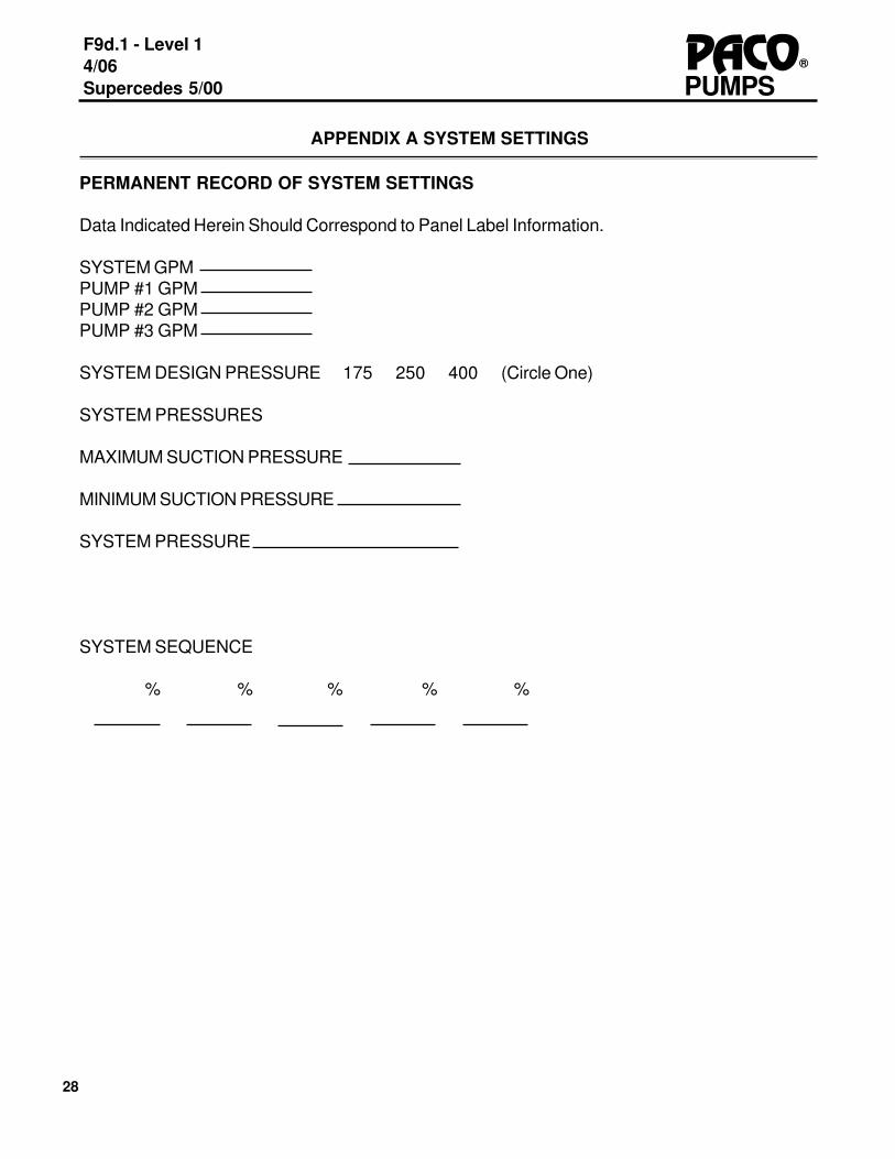
APPENDIX A SYSTEM SETTINGS
PERMANENT RECORD OF SYSTEM SETTINGS
Data Indicated Herein Should Correspond to Panel Label Information.
SYSTEM GPMPUMP #1 GPMPUMP #2 GPMPUMP #3 GPM
SYSTEM DESIGN PRESSURE 175 250 400 (Circle One)
SYSTEM PRESSURES
MAXIMUM SUCTION PRESSURE
MINIMUM SUCTION PRESSURE
SYSTEM PRESSURE
SYSTEM SEQUENCE
% % % % %
29
PUMPSPACO®
F9d.1- Level 14/06Supercedes 5/00
PACO® PUMPS
BROOKSHIRE, TX
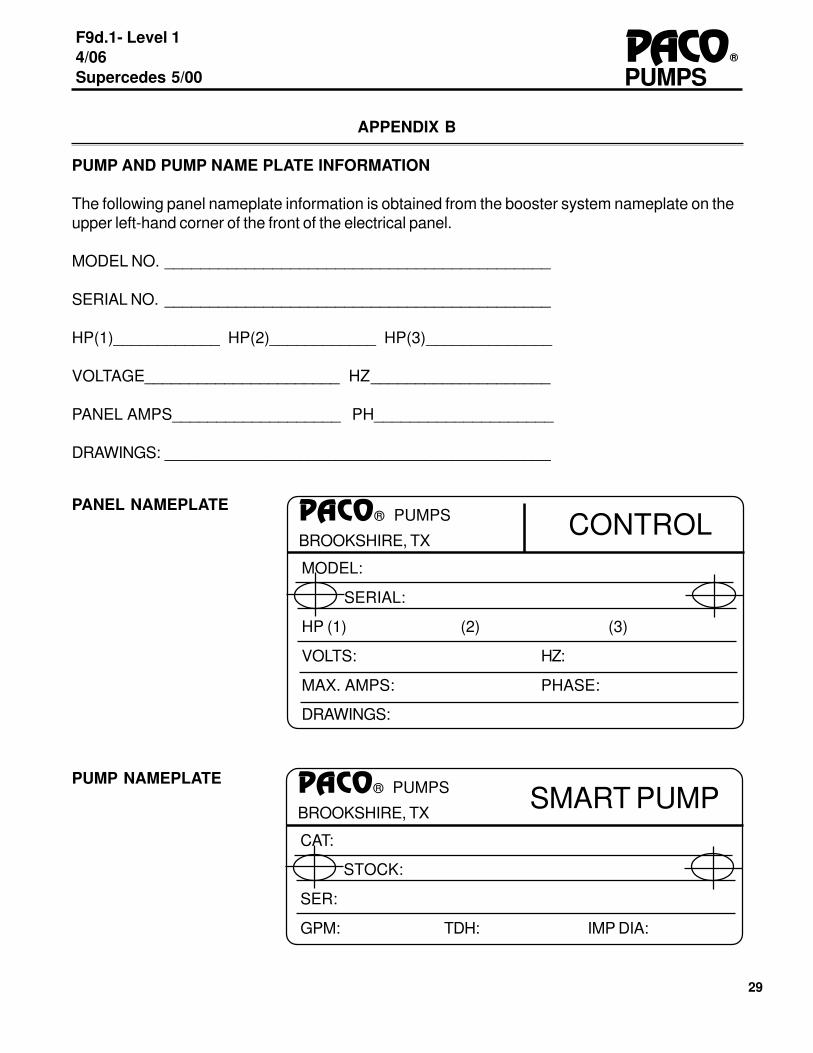
APPENDIX B
PUMP AND PUMP NAME PLATE INFORMATION
The following panel nameplate information is obtained from the booster system nameplate on theupper left-hand corner of the front of the electrical panel.
MODEL NO. ___________________________________________
SERIAL NO. ___________________________________________
HP(1)____________ HP(2)____________ HP(3)______________
VOLTAGE______________________ HZ____________________
PANEL AMPS___________________ PH____________________
DRAWINGS: ___________________________________________
MODEL:
SERIAL:
HP (1) (2) (3)
VOLTS: HZ:
MAX. AMPS: PHASE:
DRAWINGS:
PACO® PUMPS
BROOKSHIRE, TXCONTROL
PANEL NAMEPLATE
CAT:
STOCK:
SER:
GPM: TDH: IMP DIA:
PUMP NAMEPLATESMART PUMP
30
F9d.1 - Level 14/06Supercedes 5/00
®PACOPUMPS
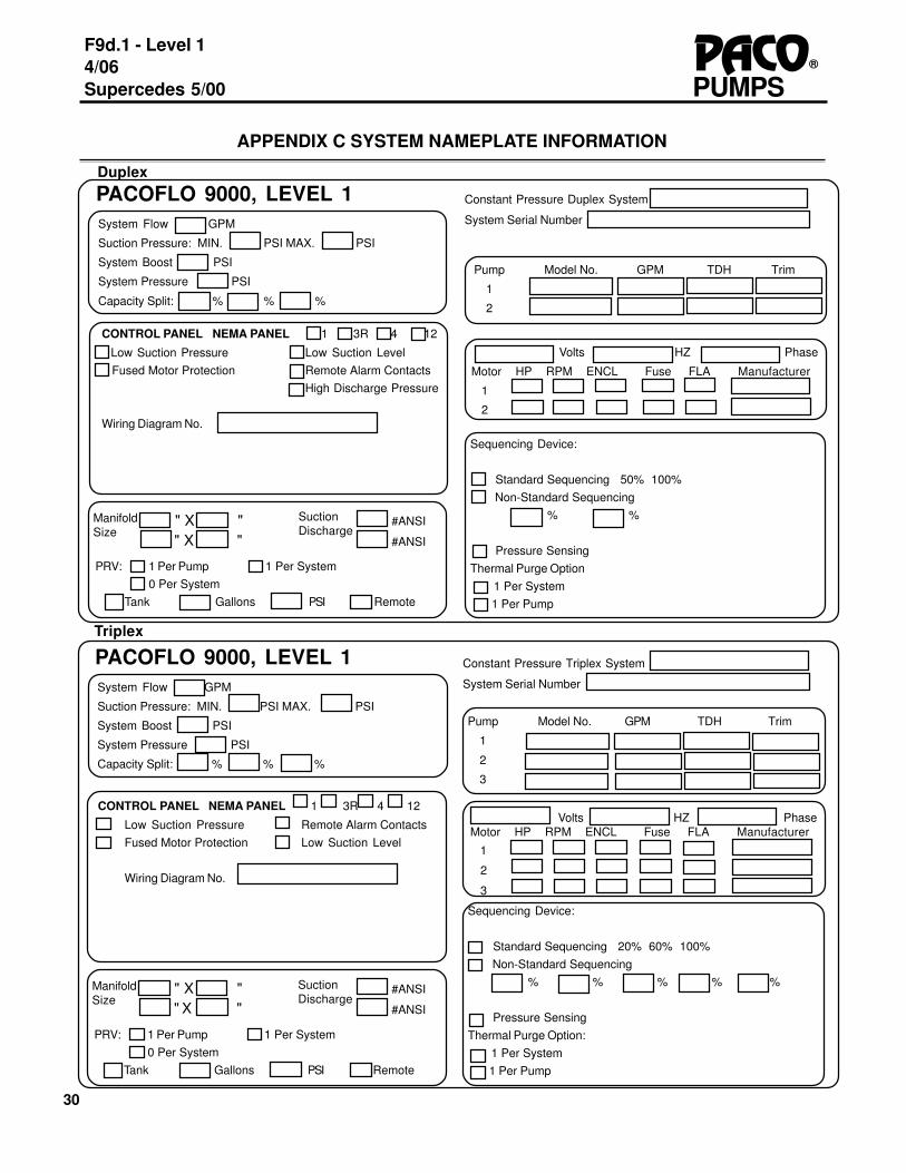
#ANSI
#ANSI
SuctionDischarge
Pump Model No. GPM TDH Trim
1
2
3
Volts HZ PhaseMotor HP RPM ENCL Fuse FLA Manufacturer
1
2
3
CONTROL PANEL NEMA PANEL 1 3R 4 12
Low Suction Pressure Remote Alarm ContactsFused Motor Protection Low Suction Level
Wiring Diagram No.
ManifoldSize
Sequencing Device:
Standard Sequencing 20% 60% 100% Non-Standard Sequencing
% % % % %
Pressure SensingThermal Purge Option: 1 Per System 1 Per Pump
System Flow GPM
Suction Pressure: MIN. PSI MAX. PSI
System Boost PSI
System Pressure PSI
Capacity Split: % % %
PACOFLO 9000, LEVEL 1Triplex
PRV: 1 Per Pump 1 Per System0 Per System
Tank Gallons PSI Remote
" X "" X "
Constant Pressure Triplex System
System Serial Number
CONTROL PANEL NEMA PANEL 1 3R 4 12
Low Suction Pressure Low Suction Level Fused Motor Protection Remote Alarm Contacts
High Discharge Pressure
Wiring Diagram No.
System Flow GPM
Suction Pressure: MIN. PSI MAX. PSI
System Boost PSI
System Pressure PSI
Capacity Split: % % %
PACOFLO 9000, LEVEL 1Duplex
Constant Pressure Duplex System
System Serial Number
#ANSI
#ANSI
SuctionDischarge
ManifoldSize
PRV: 1 Per Pump 1 Per System0 Per System
Tank Gallons PSI Remote
" X "" X "
Pump Model No. GPM TDH Trim
1
2
Volts HZ Phase
Motor HP RPM ENCL Fuse FLA Manufacturer
1
2
APPENDIX C SYSTEM NAMEPLATE INFORMATION
Sequencing Device:
Standard Sequencing 50% 100% Non-Standard Sequencing
% %
Pressure SensingThermal Purge Option 1 Per System 1 Per Pump

31
PUMPSPACO®
F9d.1- Level 14/06Supercedes 5/00
DUPLEX BOOSTERWITH PRESSURE SEQUENCING

32
F9d.1 - Level 14/06Supercedes 5/00
®PACOPUMPS
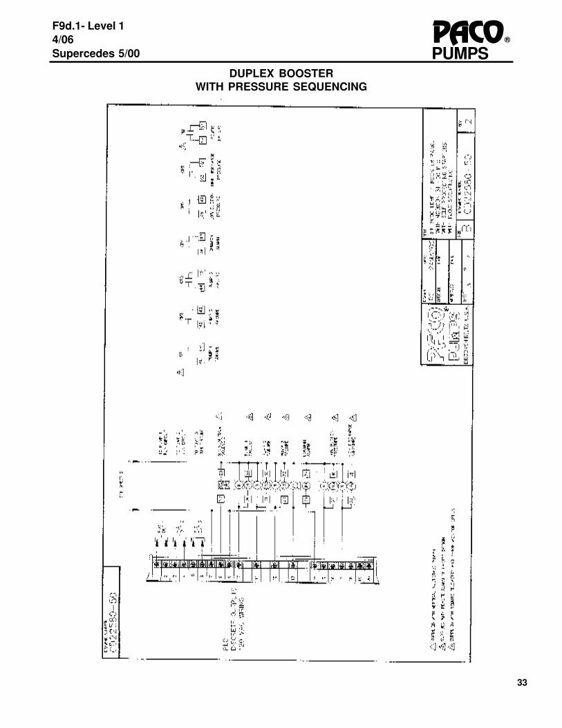
DUPLEX BOOSTERWITH PRESSURE SEQUENCING
33
PUMPSPACO®
F9d.1- Level 14/06Supercedes 5/00
DUPLEX BOOSTERWITH PRESSURE SEQUENCING
34
F9d.1 - Level 14/06Supercedes 5/00
®PACOPUMPS
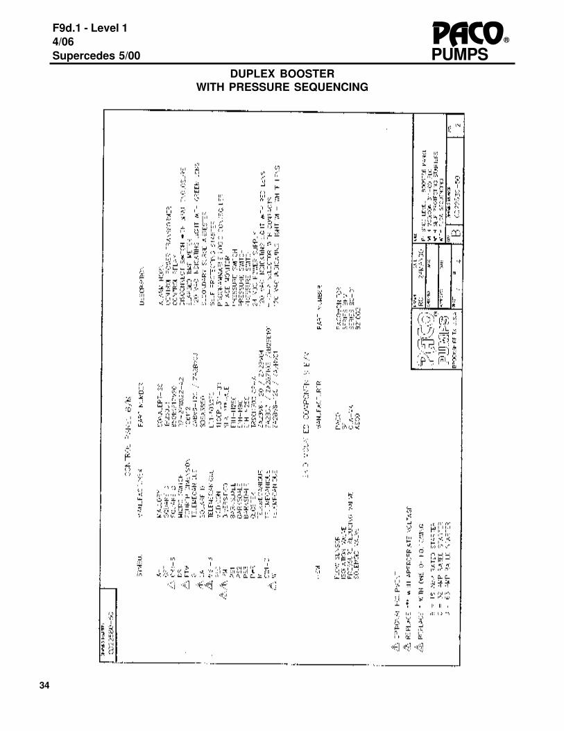
DUPLEX BOOSTERWITH PRESSURE SEQUENCING

35
PUMPSPACO®
F9d.1- Level 14/06Supercedes 5/00
TRIPLEX BOOSTERWITH PRESSURE SEQUENCING
36
F9d.1 - Level 14/06Supercedes 5/00
®PACOPUMPS
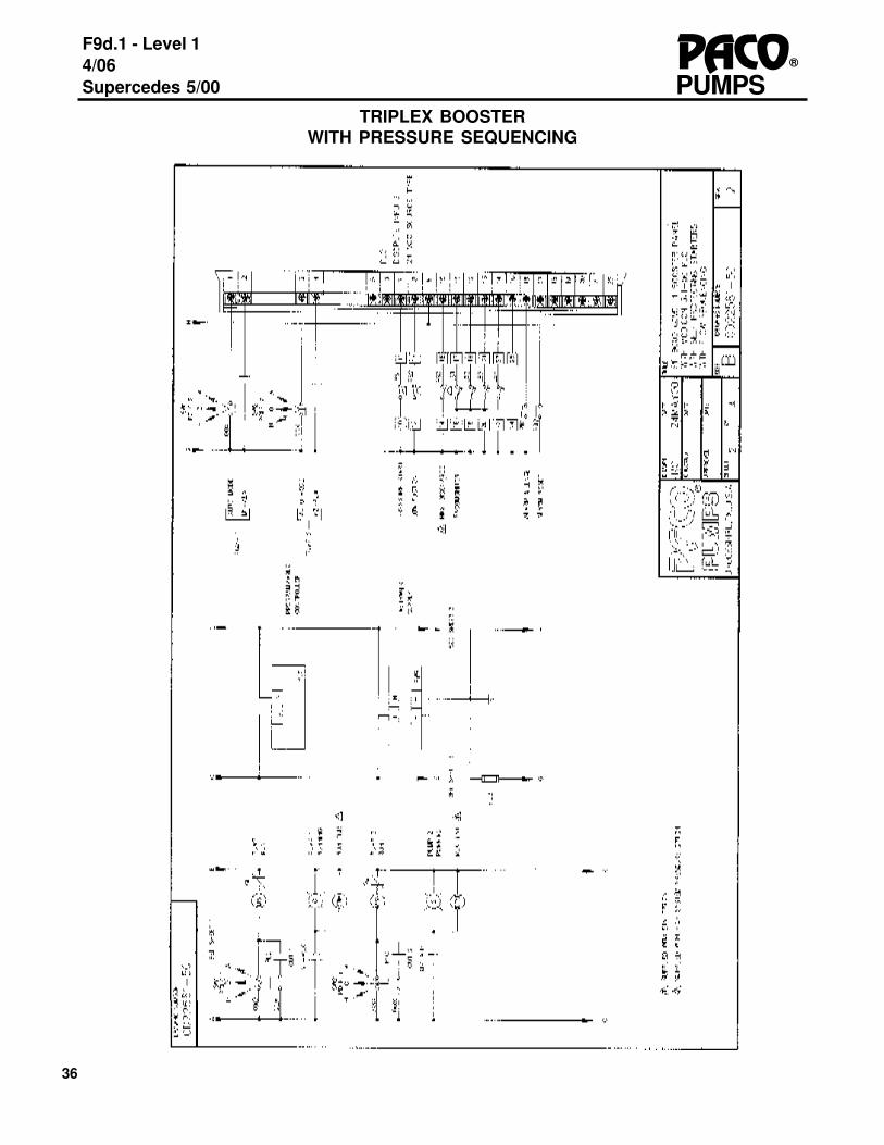
TRIPLEX BOOSTERWITH PRESSURE SEQUENCING
37
PUMPSPACO®
F9d.1- Level 14/06Supercedes 5/00
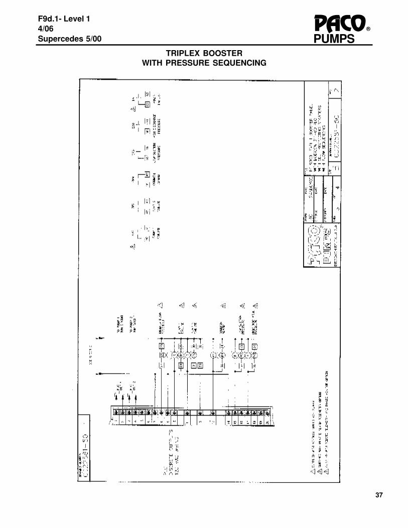
TRIPLEX BOOSTERWITH PRESSURE SEQUENCING
38
F9d.1 - Level 14/06Supercedes 5/00
®PACOPUMPS
TRIPLEX BOOSTERWITH PRESSURE SEQUENCING

39
PUMPSPACO®
F9d.1- Level 14/06Supercedes 5/00
DUPLEX BOOSTERWITH FLOW SEQUENCING

40
F9d.1 - Level 14/06Supercedes 5/00
®PACOPUMPS
DUPLEX BOOSTERWITH FLOW SEQUENCING
41
PUMPSPACO®
F9d.1- Level 14/06Supercedes 5/00
DUPLEX BOOSTERWITH FLOW SEQUENCING

42
F9d.1 - Level 14/06Supercedes 5/00
®PACOPUMPS
DUPLEX BOOSTERWITH FLOW SEQUENCING

43
PUMPSPACO®
F9d.1- Level 14/06Supercedes 5/00
TRIPLEX BOOSTERWITH FLOW SEQUENCING

44
F9d.1 - Level 14/06Supercedes 5/00
®PACOPUMPS
TRIPLEX BOOSTERWITH FLOW SEQUENCING

45
PUMPSPACO®
F9d.1- Level 14/06Supercedes 5/00
TRIPLEX BOOSTERWITH FLOW SEQUENCING

46
F9d.1 - Level 14/06Supercedes 5/00
®PACOPUMPS
TRIPLEX BOOSTERWITH FLOW SEQUENCING

47
PUMPSPACO®
F9d.1- Level 14/06Supercedes 5/00
WATTS/MUESO Automatic Control Valves are hydraulically operated, diaphragm actuated, pilot controlled, globe orangle valves of packless design. The stem assembly is the only moving part in the main valve and is guided top andbottom. Positive drip-tight closure is accomplished by a quad-ring or O-ring seat seal. The basic valve is available inCast Iron., Steel, and Aluminum in a variety of sizes, end connections, and options. Consult the WATTS/MUESCOfactory for further information.
FUNCTION
• REDUCES A HIGHER INLET PRESSURE TO A CONSTANT, LOWER, OUTLET \PRESSURE.
• CLOSES WHEN OUTLET/DOWNSTREAM PRESSURE EXCEEDS INLET/UPSTREAM PRESSURE.
APPENDIX E1 PRESSURE REDUCING/CHECK VALVE
OPERATION
FIGURE 115-3 PRESSURE REDUC-ING/CHECK VALVE is controlled by aPressure Reducing Control. The control isnormally open, held open by an adjustablespring to maintain a constant dischargepressure from the main valve.
As the downstream pressure (OUTLET)increases to the pressure reducing set-point, the Pressure Reducing Controlthrottles towards closed, restricting flowthrough the control tubing. This actionincreases pressure in the main valvecover chamber, modulating the main valvetowards closed an appropriate amount.Closing speed is regulated by an adjust-able needle valve.
As downstream pressure decreased, theReducing control throttles towards open,increasing the flow through he controltubing. This action decreases pressure inthe main valve cover chamber, modulatingthe main valve towards open an appropri-ate amount, maintaining the desired outletpressure. Opening speed is regulated byan adjustable flow control.
An integral check feature guards against reverseflow. When downstream pressure exceeds up-stream pressure, the main valve cover chamber isflooded, driving the valve closed.

48
F9d.1 - Level 14/06Supercedes 5/00
®PACOPUMPS
CLOSESFLOODS MAINVALVE COVER
DOWNSTREAMPRESSURE
>INLETPRESSURE
NO EFFECT PRESSUREINCREASED
< = Below> = Above
SCHEMATIC
á á á á
COMPONENTS1 Basic Valve2 Reducing Control*3 Check Valve4 Needle Valve-Adjustable Restriction Closing5 Flow Control-Adjustable Opening Speed
LOCATION OF ACCESSORIESL Limit SwitchP Position IndicatorX Isolation CocksY Y-StrainerFC Flo-Clean Strainer
Assembled valve will vary in appearance but willconform with drawing in regard to componentlocations and functions.
*Model number of the actual control used isdependent upon valve size and materials.
CHECK FUNCTION
THROTTLESTOWARDS
OPEN
LESSRESTRICTIVE
NO EFFECTDOWNSTREAMPRESSUREDECREASE<SET POINT
PRESSUREDECREASE áááá
THROTTLESTOWARDS
CLOSED
MORERESTRICTIVE
DOWNSTREAMPRESSUREINCREASE
>SET POINT
PRESSUREINCREASE
NO EFFECT
áá á á
PRESSURE REDUCING FUNCTION
SYSTEMSTATUS
REDUCINGCONTROL
MAIN VALVECOVER
CHAMBER
MAIN VALVEACTION
CHECKFEATURE
OPERATION MATRIX
This matrix of the operation illustrates the cause and effect sequence for proper functioning. Thediagram begins with the system status and ends with the main valve action
APPENDIX E-2

49
PUMPSPACO®
F9d.1- Level 14/06Supercedes 5/00
INSTALLATION/STARTUP
• Clear the line of lag and other debris.
• Install the valve so that the FLOW ARROW marked on the valve body matches flow through the line.
• Close upstream and downstream isolation valves.
• Open ball valves or isolation cocks in the control tubing, if the main valve is so equipped. Failure to openthese will prevent the valve from functioning properly.
• Install pressure gauge on main valve (downstream side port), or another downstream location in the sys-tem. Valves equipped with a 263 AP pilot have a 1/4" N.P.T. pressure gauge port in the pilot body.
• Proper sizing of the automatic control valve to hydraulic conditions is of paramont importance. Refer toSeries Brochure 115, Valve Sizing section.
SIZING
APPENDIX E-3
• As with all automatic control valves, isolation valvesshould installed in the line before and after the auto-matic control valve so that the valve may be isolatedfrom pressure for inline servicing. At tempts toservice the valve without isolation from pressure mayprove hazardous.
Should installation require the valve stem to be hori-zontal (cover pointed sideways), factory should beconsulted concerning valves of 6" and larger.
RECOMMENDATIONS & REQUIREMENTS
Angle ValveStem Horizontal
Globe ValveStem Horizontal

50
F9d.1 - Level 14/06Supercedes 5/00
®PACOPUMPS
INSTALLATION/START-UP CONTINUED
Start-up of an automatic controlvalve requires that properprocedures be followed. Timemust be allowed for the valve toreact to adjustments and thesystem to stabi l ize. Theobjective is to bring the valve intoservice in a controlled manner.
Step 1♦ Turn Pressure Reducing Control
adjustment screw counterclockwise (OUT), backing pressure offthe spring, Prventing possibleoverpressuring of the system.
Step 2♦ Back opening speed flow control
adjustment screw out one halfturn from closed. Back closingspeed needle valve adjustmentscrew out one and a half turnsfrom closed. Loosen a turb fittingat a valve highpoint to allowventing of air.
Step 3♦ Open upstream isolation valve
SLOWLY to a full open position toallow controlled filling of thevalve. Air is vented through theloosened fitting. Tighten fittingwhen liquid begins to vent.
Step 4♦ Open downstream isolation valve
partially to establish flow throughthe valve, observing downstreampressure change. If downstreampressure is outside the desiredpressure range, turn the Reduc-ing Control adjustment screwclockwise (IN) to increase, orcounterclockwise (OUT) todecrease,until pressure is nearthe desired setting.
Step5♦ Gradually open the downstream
isolation valve until full open.
Step6♦ Allow the system to stabilize.
Step 7♦ Fine-tune Pressure Reducing
Control adjustment to the set-point, as detailed in Step 4.
Step 8♦ Opening Speed Adjustment: The
opening speed flow controlallows free flow into the cover ofthe main valve.
♦ If recovery of pressure is slowupon increased downstreamdemand, turn the adjustmentscrew counterclockwise (OUT),increasing the rate of opening.
♦ If recovery of downstream pres-sure is too quick, as indicated bya rapid increase in pressure,possibly higher than the desiredset-point, turn the adjustmentscrew clockwise (IN), decreasingthe rate of opening.
Step 9♦ Closing Speed Adjustment: The
closing speed needle valveregulates the fluid pressure intothe main valve cover chamber,controlling the valve closingspeed. If the downstreampressure fluctuates slightlyabove the desired set-point turnthe adjustment screwcounterclockwise (OUT), in-creasing the rate of closing.
Step 10♦ No start-up is required for the
check feature.
REDUCING CONTROL
ADJUSTING SCREW
CHECK VALVE
ISOLATION COCKS
FLOW CONTROL - ADJ. OPENING SPEED
NEEDLE VALVE - ADJ. RESTRICTION-CLOSING
CHECK VALVE
Y-STRAINER
CLEAN OUT PORT
ISOLATION COCK
MAIN VALVE

51
PUMPSPACO®
F9d.1- Level 14/06Supercedes 5/00
INDEX
ALTERNATOR, 19
ADJUSTABLE OVERLOADS, 13ALARM OPTIONS AND OTHER OPTIONS,19, 20APPLYING WATER TO THE SYSTEM, 11AUDIBLE ALARM, 19AUXILIARY ALARM CONTACTS, 20PLC MEMORY, 15BOOSTER SYSTEM NAMEPLATE29 & 30BUILDING PIPING, 6
ELECTRICAL CHECK OUT, 8ELECTRICAL INSTALLATION, 7HYDROPNEUMATIC TANK INSTALLATION, 9SELF PROTECTED STARTER, 13
LOW SUCTION CONDITION, 19, 21LOW SUCTION CONDITION SHUT DOWNDELAY, 21
MECHANICAL INSTALLATION, 7MINIMUM RUN TIMES, 21MOVING THE SYSTEM, 5NO FLOW SHUT-OFF, 12, 20
OPTIONS, 19-21
PANEL INSPECTION, 7, 8, 10PANEL NAMEPLATE INFORMATION, 30PHASE FAILURE - LOW VOLTAGE FAILURE,20PLACING THE SYSTEM INTO OPERATION,10,11PRESSURE REDUCING VALVES, 47-50
PRESSURE SETTINGS, 22PRESSURE SEQUENCING, 17
RECEIPT OF SYSTEM, 5
SETTING PRESSURES, 22SETTING PRV'S, 50
STORAGE, 5
SYSTEM CHECK OUT, 8, 10SYSTEM PRESSURE, SETTING, 22SYSTEM TROUBLESHOOTING TABLES, 23-27SYSTEM SETTINGS, 28
THERMAL PURGE VALVE, 6, 20TIMER SETTINGS, 21TRIP MODULE ADJUSTMENTS, 13TRIP MODULE PART NUMBER, 14TROUBLESHOOTING, 23-27
52
F9d.1 - Level 14/06Supercedes 5/00
®PACOPUMPS
Terms And Conditions Of SaleSECTION 1: THE CONTRACTThe Contract shall be comprised of the following terms, together with such terms and conditions as are set forth inSeller’s written proposal or quotation (the “Quotation”), including any documents, drawings or specifications incorporatedtherein by reference, and any additional or different terms proposed in Buyer’s purchase order (the “Purchase Order”)that are accepted by Seller in writing, which together shall constitute the entire agreement between the parties, provided,however, that preprinted terms on Buyer’s purchase order or invoice shall not apply and Seller gives notice of objection tosuch terms. An offer by Seller in its Quotation that does not stipulate an acceptance date is not binding. This Contractshall be deemed to have been entered into upon written acknowledgment of the Purchase Order by an officer orauthorized representative of Seller, which may not be modified, supplemented, or waived except in a writing executed byan authorized representative of the party to be bound.SECTION 2: PRICEThe price quoted in the Quotation shall be the Purchase Price unless otherwise agreed in the Purchase Order. ThePurchase Price for equipment shall include packing for shipment. Field Services shall be provided at Seller’s standardrates. All other costs, including packing for storage, freight, insurance, taxes, customs duties and import/export fees, orany other item not specified in the Contract, shall be paid by Buyer unless separately stated in the Quotation and includedin the price quoted. Any sales, use, or other taxes and duties imposed on the transaction or the equipment supplied shallbe paid or reimbursed by Buyer.SECTION 3: PAYMENT TERMSPayment shall be due within 30 days of the date of Seller’s invoice in U.S. funds unless otherwise agreed. If Buyer doesnot observe the agreed dates of payment, Buyer shall pay interest to Seller on overdue amounts at a rate that is thehigher of: 9% per annum or a rate 5% in excess of the rate borne from time to time by new issues of six-month UnitedStates Treasury bills. Seller shall be entitled to issue its invoice for the Purchase Price for equipment upon the earlier ofshipment, or notice to Buyer that Seller is ready to ship, and for services, upon completion. If the Purchase Price exceeds$250,000 USD, Buyer shall pay the Purchase Price in Progress payments as follows: Fifteen percent (15%) uponsubmittal of general arrangement drawings, thirty five percent (35%) after receipt of first Bowl Casting, twenty percent(20%) after first case/bowl hydro test or bowl machining and thirty percent (30%) after notification of ready to ship.SECTION 4: ACCEPTANCE AND INSPECTIONAll equipment shall be finally inspected and accepted by Buyer within 14 days after delivery or such other period of timeas is agreed in the Purchase Order. Buyer shall make all claims (including claims for shortages), excepting only thoseprovided for under the warranty clause contained herein, in writing within such 14 day period or they are waived. Servicesshall be accepted upon completion. Buyer shall not revoke its acceptance. Buyer may reject the equipment only fordefects that substantially impair its value, and Buyer’s remedy for lesser defects shall be in accordance with Section 10,Warranty. If tests are made by Buyer to demonstrate the ability of the equipment to operate under the contract conditionsand to fulfill the warranties in Section 10, Buyer is to make all preparations and incur all expenses incidental to suchtests. Seller will have the right of representation at such tests at its expense, and the right to technically direct theoperation of the equipment during such tests, including requiring a preliminary run for adjustments.SECTION 5: TITLE AND RISK OF LOSSFull risk of loss (including transportation delays and losses) shall pass to Buyer upon delivery, regardless of whether titlehas passed to Buyer, transport is arranged or supervised by Seller, or start-up is carried out under the direction orsupervision of Seller. Delivery shall be ex works, INCOTERMS 2000. Loss or destruction of the equipment or injury ordamage to the equipment that occurs while the risk of such loss or damage is borne by Buyer does not relieve Buyer ofits obligation to pay Seller for the equipment.SECTION 6: PATENT OR TRADEMARK INFORMATIONIf the equipment sold hereunder is to be prepared or manufactured according to Buyer’s specifications, Buyer shallindemnify Seller and hold it harmless from any claims or liability for patent or trademark infringement on account of thesale of such goods.SECTION 7: CHANGESBuyer may request, in writing, changes in the design, drawings, specifications, shipping instructions, and shipmentschedules of the equipment. As promptly as practicable after receipt of such request, Seller will advise Buyer whatamendments to the Contract, if any, may be necessitated by such requested changes, including but not limited toamendment of the Purchase Price, specifications, shipment schedule, or date of delivery. Any changes agreed upon bythe parties shall be evidenced by a Change Order signed by both parties.SECTION 8: CANCELLATION OR TERMINATIONBuyer shall have the right to cancel the Contract upon 15 days’ prior written notice to Seller, and Seller shall stop itsperformance upon the receipt of such notice except as otherwise agreed with Buyer. If Buyer cancels the Contract, it shallpay: (a) the agreed unit price for equipment or components completed and delivered, (b) additional material and laborcosts incurred, and for engineering services supplied by Seller with respect to the canceled items, which shall becharged to Buyer at Seller’s rates in effect at the time of cancellation, but which shall not exceed the contract price forsuch items, and (c) such other costs and expenses, including cancellation charges under subcontracts, as Seller mayincur in connection with such cancellation or termination.

53
PUMPSPACO®
F9d.1- Level 14/06Supercedes 5/00
of quotation. Seller shall not be liable for any nonperformance, loss, damage, or delay due to war, riots, fire, flood, strikesor other labor difficulty, governmental actions, acts of God, acts of the Buyer or its customer, delays in transportation,inability to obtain necessary labor or materials from usual sources, or other causes beyond the reasonable control ofSeller. In the event of delay in performance due to any such cause, the date of delivery or time for completion will beextended to reflect the length of time lost by reason of such delay. Seller shall not be liable for any loss or damage toBuyer resulting from any delay in delivery.SECTION 10: WARRANTYSeller warrants that the equipment or services supplied will be free from defects in material, and workmanship for aperiod of 12 months from the date of initial operation of the equipment, or 18 months from the date of shipment,whichever shall first occur. In the case of spare or replacement parts manufactured by Seller, the warranty period shall befor a period of six months from shipment. Repairs shall be warranted for 12 months or, if the repair is performed underthis warranty, for the remainder of the original warranty period, whichever is less. Buyer shall report any claimed defect inwriting to Seller immediately upon discovery and in any event, within the warranty period. Seller shall, at its sole option,repair the equipment or furnish replacement equipment or parts thereof, at the original delivery point. Seller shall not beliable for costs of removal, reinstallation, or gaining access. If Buyer or others repair, replace, or adjust equipment orparts without Seller’s prior written approval, Seller is relieved of any further obligation to Buyer under this section withrespect to such equipment or parts. The repair or replacement of the equipment or spare or replacement parts by Sellerunder this section shall constitute Seller’s sole obligation and Buyer’s sole and exclusive remedy for all claims ofdefects. SELLER MAKES NO OTHER WARRANTY OR REPRESENTATION OF ANY KIND WITH RESPECT TO THEEQUIPMENT OR SERVICES OTHER THAN AS SPECIFIED IN THIS SECTION 10. ALL OTHER WARRANTIES, EXPRESSOR IMPLIED, INCLUDING BUT NOT LIMITED TO, THE IMPLIED WARRANTIES OF MERCHANTABILITY AND FITNESS FORA PARTICULAR PURPOSE, ARE HEREBY DISCLAIMED.For purposes of this Section, the equipment warranted shall not include equipment, parts, and work not manufactured orperformed by Seller. With respect to such equipment, parts, or work, Seller’s only obligation shall be to assign to Buyerany warranty provided to Seller by the manufacturer or supplier providing such equipment, parts or work.No equipment furnished by Seller shall be deemed to be defective by reason of normal wear and tear, failure to resisterosive or corrosive action of any fluid or gas, Buyer’s failure to properly store, install, operate or maintain the equipmentin accordance with good industry practices or specific recommendations of Seller, or Buyer’s failure to provide completeand accurate information to Seller concerning the operational application of the equipment.SECTION 11: TECHNICAL DOCUMENTSTechnical documents furnished by Seller to Buyer, such as drawings, descriptions, designs and the like, shall bedeemed provided to Buyer on a confidential basis, shall remain Seller’s exclusive property, shall not be provided in anyway to third parties, and shall only be used by Buyer for purposes of installation, operation and maintenance. Technicaldocuments submitted in connection with a Quotation that does not result in a Purchase Order shall be returned to Sellerupon request.SECTION 12: LIMITATION OF LIABILITYSeller shall in no event be liable for any consequential, incidental, indirect, special or punitive damages arising out of theContract, or out of any breach of any of its obligations hereunder, or out of any defect in, or failure of, or malfunction of theequipment, including but not limited to, claims based upon loss of use, lost profits or revenue, interest, lost goodwill,work stoppage, impairment of other equipment, environmental damage, nuclear incident, loss by reason of shutdown ornonoperation, increased expenses of operation, cost of purchase of replacement power or claims of Buyer or customersof Buyer for service interruption whether or not such loss or damage is based on contract, tort (including negligence andstrict liability) or otherwise.Seller’s maximum liability under this Contract shall not exceed the Purchase Order amount of the equipment or portionthereof upon which such liability is based. All such liability shall terminate upon the expiration of the warranty period, if notsooner terminated.SECTION 13: THIS COMPANY IS AN EQUAL OPPORTUNITY EMPLOYERThis agreement incorporates by reference applicable provisions and requirements of Executive Order 11246 and FARSection 52.222-26 (covering race, color, religion, sex and national origin); the Vietnam Era Veterans ReadjustmentAssistance Act of 1974 and FAR Section 52.222-35 (covering special disabled and Vietnam era veterans); and theRehabilitation Act of 1973 and FAR Section 52.222-36 (covering handicapped individuals). By acceptance of thisagreement Buyer certifies that it does not and will not maintain any facilities in a segregated manner, or permit itsemployees to perform their services at any location under its control where segregated facilities are maintained, andfurther that appropriate physical facilities are maintained for both sexes. Buyer agrees that it will obtain a similarcertificate prior to award of any nonexempt lower-tier subcontracts.SECTION 14: LAW AND ARBITRATIONThe Contract shall be governed by the law of the State of Texas. Any disputes arising out of this Contract shall be resolvedby informal mediation in any manner that the parties may agree within 45 days of written request for mediation by oneparty to the other. Any dispute that cannot be resolved through mediation shall be resolved by binding arbitrationconducted in English in Portland, Oregon under the Commercial Rules of the American Arbitration Association except asotherwise provided in this Section. The arbitration shall be conducted by three arbitrators chosen in accordance with saidRules. The arbitrators are not entitled to award damages in excess of compensatory damages. Judgment upon theaward may be entered in any court having jurisdiction.

54
F9d.1 - Level 14/06Supercedes 5/00
®PACOPUMPS
F9d.1© Grundfos CBS, Inc. 04-30-06
www.paco-pumps.comCheck our worldwide offices at
Related Documents