9,000---15,000 BTU/HR Thank you for choosing Soleus air conditioner. SOLEUS AIR CONDITIONERS SG-PTAC-15HPDA SG-PTAC-12HPDA SG-PTAC-09HPDA OWNER'S MANUAL Packaged Terminal Air Conditioner before operating the unit and keep it for consultation. For correct operation, please read this owner's manual carefully Packaged Terminal Air Conditioner/Heat Pump Model

Welcome message from author
This document is posted to help you gain knowledge. Please leave a comment to let me know what you think about it! Share it to your friends and learn new things together.
Transcript
9,000---15,000 BTU/HR
Thank you for choosing Soleus air conditioner.
SOLEUS AIR CONDITIONERS
SG-PTAC-15HPDASG-PTAC-12HPDASG-PTAC-09HPDA
OWNER'S MANUAL
Packaged Terminal Air Conditioner
before operating the unit and keep it for consultation.
For correct operation, please read this owner's manual carefully
Packaged Terminal Ai r Condi t ioner /Heat Pump
Model

......
■ ........................
■ ................................
■ ..............................
■ ........................
■ ........................
■ ............................
■ ....................
■ .............................
■ ................. ...........
■ .........................
■ .................................
Do not dispose this product as unsorted municipal waste. Collection of such waste separately for special treatment is necessary.
CONTENTS
This symbol stands for the items should be forbidden
This symbol stands for the items should be followed
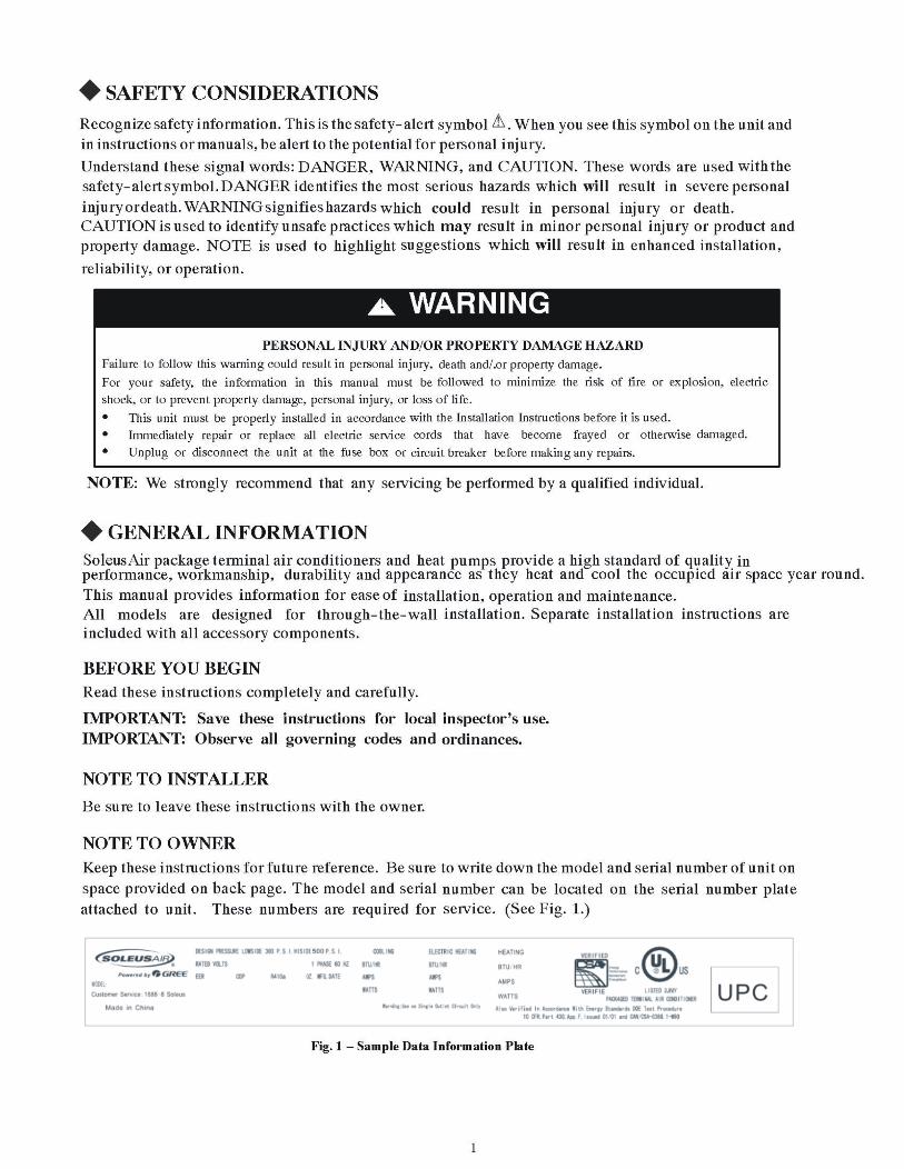
The figures in this manual may be different with the material objects, please refer to the material objects for reference.
SYSTEM CONFIGURATION
HOW TO CONNECT
SAFETY CONSIDERATIONS GENERAL INFORMATION
UNIT FEATURES
ELECTRICAL DATA
INSTALLATION
OPERATION
CARE AND CLEANING
PREVENTATIVE MAINTENANCE
TROUBLESHOOTING
........
LIMITED WARRANTY■ .............................
1
1
4
2
5
10
11
14
15
16
17
18

2
UNIT FEATURES
Fig. 2
This Premium unit has many exciting features whichare different than those found on standard PTACmodels. The owner must be familiar with thesefeatures in order to fully understand the operation andcapability of the unit.• Intelligence – Your Premium unit has an on boardcomputer that utilizes real timediagnostics toprolongthe life of your unit. There is an LED indicator on thecontrol board, behind the front panel, that will flashan error code if the unit has detected some kind offault condition. In many cases, the unit willautomatically clear the fault condition and continueoperating with no interruption. In some cases, thecondition cannot be cleared and the unit will require service. In those cases, an “Fx” failure mode will bedisplayed on the digital display. For a detailed list of all error codes and “Fx” conditions, see Table 6 --Status LED Indicator Definitions for further details.•Memory – Your Premium unit also has memory. If power is lost, all of the control settings (setpoint,mode, fan speed, on/off and configuration) are remembered. So when power is restored, the unit willstart back up in the mode (and configuration) it was in, when power was lost.• Premium Sound –The unit not only does it have2 fan motors and a tangential blower wheel foroptimum sound, the indoor fan will always run a minimum of 10 seconds before the compressor, tohelp reduce any compressor starting noise.• Random Compressor restart -- To help prevent power surges after a power outage (from many ofyour PTACs starting at the same time), the compressor is equipped with a 2:45 to 3:15 randomrestart delay feature. Whenever the unit is plugged in, or power has been restarted, a random compressorrestart will occur.• Compressor Protection -- To prevent short cycling of the compressor and maximize it’s life, there is arandom start--up delay of 3 minutes on the compressor and a minimum compressor run time of 3 minutes.•Automatic room freezeprotection – automatically will keep the temperature in the room from gettingtoo cold, where water pipes might freeze. If the unit is configured for the freeze protection feature to beactive (which is the default condition), thenwhenever power is supplied to the unit, if the unit sensestemperature below 40°F, the fan motor and electric heater are turned on and will warm the room to 50_F.If Freeze protection is not required, change the configuration switch to turn the feature off (seesection on unit configuration).• Automatic defrost protection (for heat pump models only) – When the outdoor temperature getstoo cold (approx. 35°F) and the unit can no longer effectively heat with the compressor, the unit willautomatically switch to electric heating. The unit will then heat with electric heat until the outsidetemperature rises enough (approx. 40°F), so the compressor can be used again.• Automatic Quick Warm--up (for heat pump models only) -- If the room temperature falls to 5°Fbelow the set point temperature, the reverse cycle heat is shut off and the electric strip heat is turned onfor one cycle, until heating is satisfied.•LED Indicator’s and Buttons -- The touch pad has buttons for MODE, FANSPEED, ON/OFF,SETPOINT UP and SETPOINT DOWN. It also has LEDs that correspond to the mode, fan speed andsetpoint operation, to indicate the unit’s status. The LEDs below the mode button, FAN, COOL, andHEAT, indicate what operating mode is active. The LEDs below the Fan button, Low, Med and Hi,indicate the fan speed that is selected. The LED located in the lower right corner is the unit On/Offstatus LED. If the unit is in ON mode, the LED will be green. If the unit is OFF, the LED will be red.•Configure Fan to Optimize Selected Application -- Unit can be optimized to selected application byconfiguring the fan to run in continuous mode or cycle on and off with the compressor and electricheater (can be different for both heating and cooling modes). In cycle mode, fan will continue to run aftercompressor or electric heater stops in order blow off any residual heat or cool left on coil.
Table 6—STATUS LED Indicator Definitions1 Indoor air temp sensor open/short 7---segment display ‘F1’, with STATUS light flash 1 time,off 2 seconds2 Indoor coil sensor open/short 7---segment display ‘F2’, with STATUS light flash 2 time,off 2 seconds3 Outdoor coil sensor open/short 7---segment display ‘F4’, with STATUS light flash 4 time,off 2 seconds4 Freeze Guard protection 7---segment display ‘FP’5 Thermostat wiring error STATUS light flash 9 times and off 3 sec, repeat6 Indoor coil high temp protection STATUS light flash 8 times and off 3 sec, repeat7 Defrost (heat pump type) STATUS light flash 7 times and off 3 sec, repeat8 Outdoor coil high temp protection STATUS light flash 6 times and off 3 sec, repeat9 Indoor coil freeze protection STATUS light flash 5 times and off 3 sec, repeat
NOTE: When status light is flashing, it will be ON for 0.5 seconds and OFF for another 0.5 seconds.
3
UNIT FEATURES CONTINUED
• Unit Configuration – There are many different configuration possibilities, through both dipswitchesand the digital keypad, that allow you to configure the unit for your exact application. See section onunit configuration formore details. Following are the configuration selections that havenot previouslybeenmentioned:• _F or _C – The unit can display in either _F or _C• Indoor Temperature Sensor Biasing – Optimize the room temperature sensor reading to your exactapplication (one for cooling and another for heating)..
•Emergency Heat (for Heat PumpOnly) –Disable the compressor during heating mode operation (heatonly with Electric Heat).• Display Setpoint OR Room Temperature -- The unit can be configured to display the roomtemperature OR setpoint only, during heating and cooling modes. See section on unit configuration formore details.• Limit the Setpoint Range -- The unit can be configured to limit the controlling setpoint range.Thedisplaywill always show the complete setpoint range, but the controlling setpoint will be limited to theconfiguredminimumandmaximumsetpointselected. See section on unit configuration for more details.
• Energy Management – Sometimes known as Front Desk Control, an input is provided so that the
unit can be manually disabled from a different location. If the unit detects 24vac on this input, it willautomatically turn itself off. If no voltage is detected on the input, the unit will run normally.

4
ELECTRICAL DATA
ELECTRICAL SHOCK HAZARDFailure to follow this warning could result in personal injury or death and/or property damageDO NOT alter cord or plug or use an extension cord.
! WARNING
POWER CONNECTION OPTIONSAppropriate power cord accessory kit is determined by the voltage, and amperage of the branch circuit.The unit does not come with a power cord (or hard wire kit). An accessory power cord kit mustbe ordered to connect the unit to the outlet. If the unit is to be hard wired, an accessory hard wire kitmust be ordered.IMPORTANT: For 265V units, if power cord accessory option is selected, the cord is only 18”long and must plug into the accessory electrical 265V subbase.Be sure that your outlet matches the appropriate blade configuration of the plug and that it is within reach ofthe service cord.All wiring, including installation of the receptacle, must be in accordance with the NEC and local codes,ordinances and regulations. National codes require the use of an arc fault or leakage current detectiondevice on all 208/230V power cords. Be sure to select the correct cord for your installation.ALL UNITSWire SizeUse recommended wire size given in Table 1 and install a single branch circuit. All wiring must complywith local and national codes. All units are designed to operate offONE single branch circuits only.NOTE: Use copper conductors only.
Table 1—SUGGESTED BRANCH CIRCUIT WIRE SIZES*NAMEPLATE AMPS AWG WIRE SIZE{
7.0 to 12 1412.1 to 16 1216.1 to 24 10
LEGENDAWG --- American Wire Gauge* Single circuit from main box.{ Based on copper wire at 60_C temperature rating.
Grounding
For safety and protection, the unit is grounded through the service cord plug or through separate groundwire provided on hard wired units. Be sure that the branch circuit or general purpose outlet is grounded.VOLTAGE SUPPLYCheck voltage supply at outlet. For satisfactory results, the voltage range must always be within theranges found on the data information plate.Cord--connected UnitsThe 250--v field supplied outlet must match the plug for the standard 208/230--v units and be within reachof the service cord. The standard cord--connected 265--v units require an accessory electrical subbasefor operation. Refer to Table 2 for proper receptacle and fuse type.Power Cord ProtectionThe power cord for 230/208v units provide power cord fire protection.Unit power automaticallydisconnects when unsafe conditions are detected. Power to the unit can be restored by pressing the resetbutton on plug head.Upon completion of unit installation for 230/208V models, an operational check should be performedusing the TEST/RESET buttons on the plug head.NOTE: The 265v models do not incorporate this feature as they require use of the electrical subbase accessory.
Table 2—RECEPTACLES AND FUSE TYPES -- 250, 265 VOLTS
RECEPTACLE
AMPS 15 20 30 15 20 30RATED VOLTS 250 250 250 265 265 265
TIME---DELAY TYPE FUSE(or HACR Circuit Breaker) 15 20* 30 15 20 30
LEGENDHACR --- Heating, Air Conditioning, Refrigeration* May be used fro 15---amp applications
5
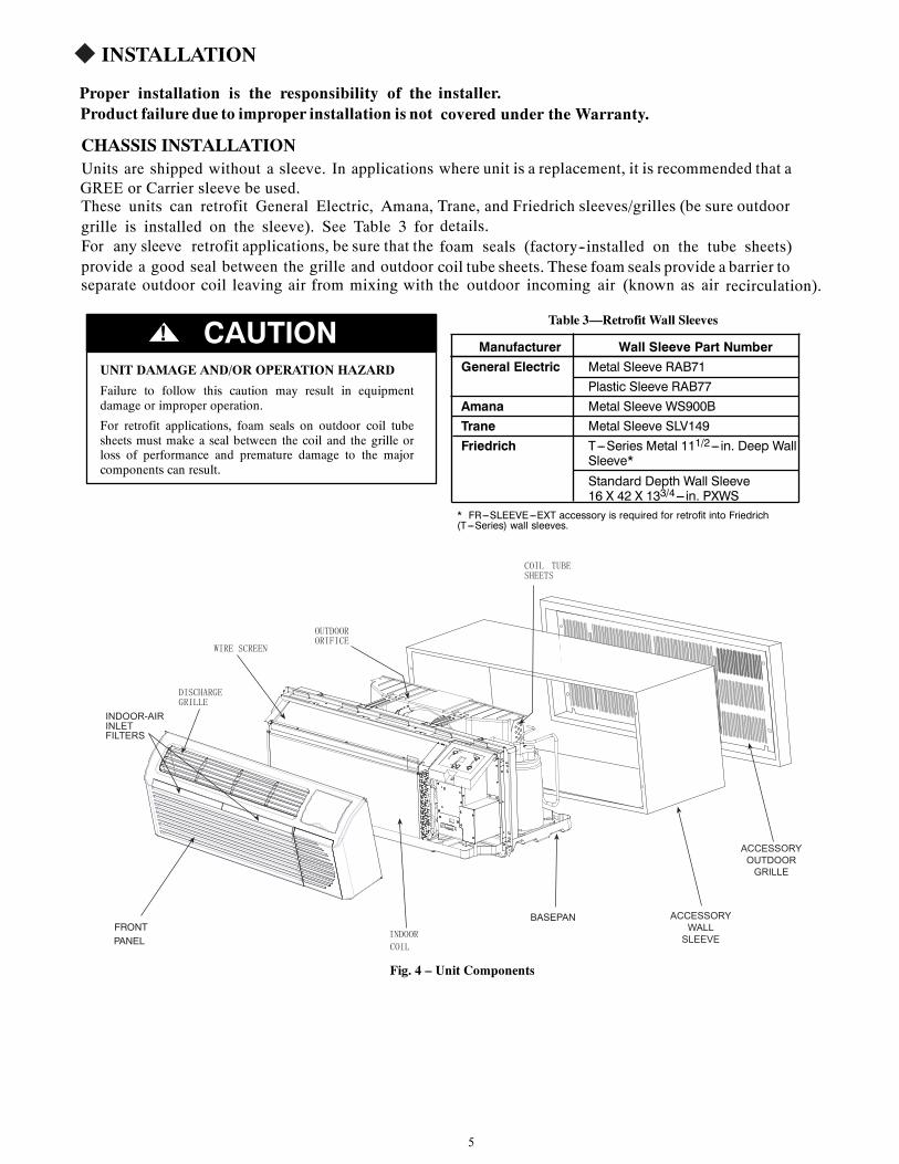
INSTALLATION
Proper installation is the responsibility of the installer.Product failure due to improper installation is not covered under the Warranty.
CHASSIS INSTALLATIONUnits are shipped without a sleeve. In applications where unit is a replacement, it is recommended that aGREE or Carrier sleeve be used.These units can retrofit General Electric, Amana, Trane, and Friedrich sleeves/grilles (be sure outdoorgrille is installed on the sleeve). See Table 3 for details.For any sleeve retrofit applications, be sure that the foam seals (factory--installed on the tube sheets)provide a good seal between the grille and outdoor coil tube sheets. These foam seals provide a barrier toseparate outdoor coil leaving air from mixing with the outdoor incoming air (known as air recirculation).
UNIT DAMAGE AND/OR OPERATION HAZARD
Failure to follow this caution may result in equipmentdamage or improper operation.
For retrofit applications, foam seals on outdoor coil tubesheets must make a seal between the coil and the grille orloss of performance and premature damage to the majorcomponents can result.
CAUTION!Table 3—Retrofit Wall Sleeves
Manufacturer Wall Sleeve Part NumberGeneral Electric Metal Sleeve RAB71
Plastic Sleeve RAB77Amana Metal Sleeve WS900BTrane Metal Sleeve SLV149Friedrich T---Series Metal 111/2--- in. Deep Wall
Sleeve*Standard Depth Wall Sleeve16 X 42 X 133/4--- in. PXWS
* FR---SLEEVE---EXT accessory is required for retrofit into Friedrich(T---Series) wall sleeves.
INDOOR
COIL
DISCHARGEGRILLE
WIRE SCREEN
OUTDOORORIFICE
COIL TUBESHEETS
INDOOR-AIRINLETFILTERS
ACCESSORYWALLSLEEVE
ACCESSORYOUTDOORGRILLE
Fig. 4 – Unit Components
FRONTPANEL
BASEPAN

6
RETRO FIT SLEEVE PREPARATIO N
IMPORTANT: Inspect wall sleeve thoroughly prior to installat ion. Manufacturer does notassum e responsibilit y for costs or damages due to defects in sleeve or for improper installation.
ELECTRI CAL SHOCK HAZARDFailure to follow this warning could result in personal injuryor death.
Disconnect all power to unit to avoid possible electrical shockduring installation.
! WARNING
Remove any existing foam baffles that are installed on competitive outdoor grille, if present. See Fig. 5.
GE Sleeves Only
GE Meta l Wall Sleeve -- See Fig. 6.
GE Plast ic Sleeve -- Remove bottom seal from plastic sleeve. See Fig. 7.
INSTALLATION OF A GREE OR CARRIER WALL SLEEVE USING A NON-GREE GRILLE
This application has become more common due to pre--manufactured windows with built--in grilles orrenovations where a GREE or Carrier sleeve is used with an existing non GREE-- grille.Use of a GREE or Carrier wall sleeve with a non--GREE grille requires installation of an Accessory Baffle Kit(see Fig. 8), which ensures a good seal between the unit and exterior grille to prevent air recirculation.Air recirculation is a large contributor to performance loss and premature damage to major components.
BAFFLES
Fig. 5 – Remove Existing Outdoor Grille Baffles onCompetitive Grille Fig. 6 – GE Metal Sleeve
Fig. 7 – Remove Bottom Seal From GE Plastic Sleeve Fig. 8 – Accessory Baffle Kit
GE metal sleeve is interchangeable with GREE wall sleeve .
Notes: GREE stamped grille is interchangeable with CARRIER'S.
Note: contact your units supplier to get the kit and it may be different from the shape showed above.
7
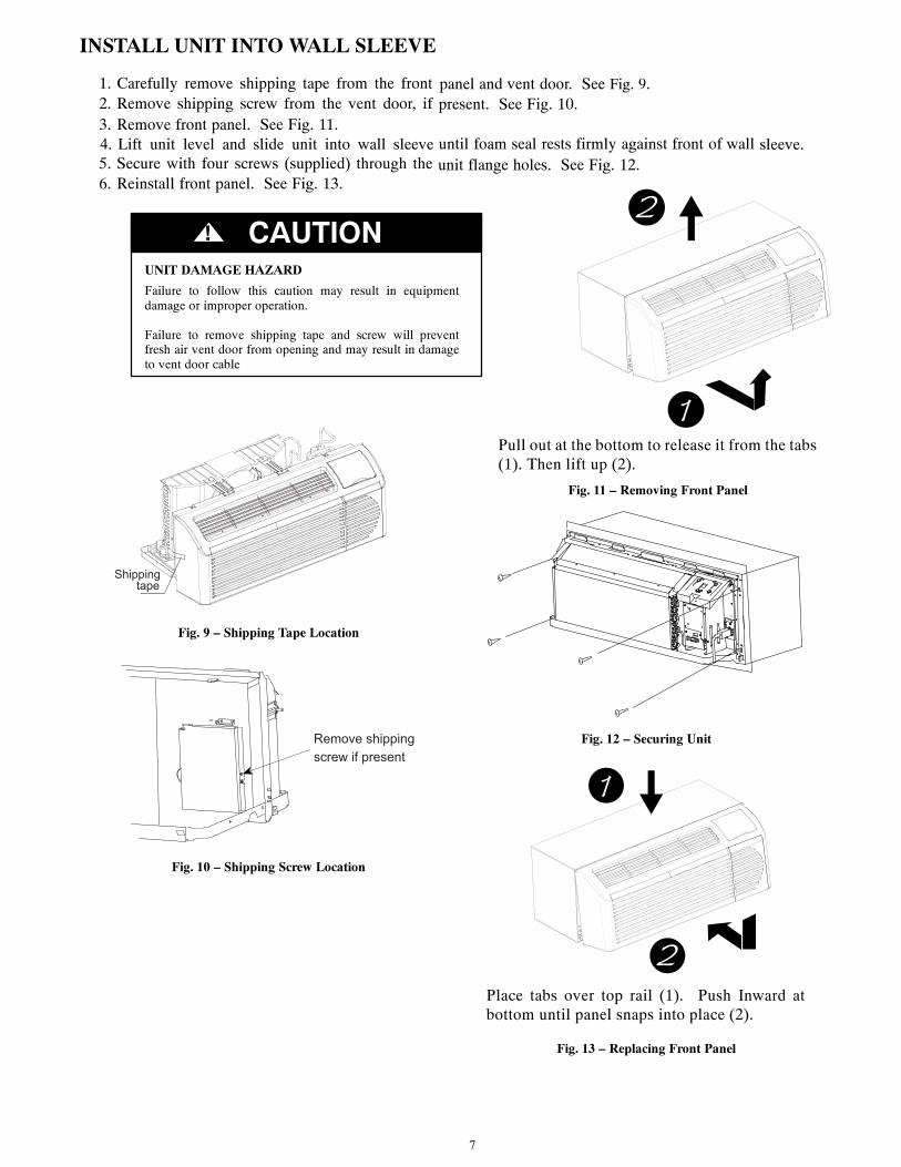
INSTALL UNIT INTO WALL SLEEVE
1. Carefully remove shipping tape from the front panel and vent door. See Fig. 9.2. Remove shipping screw from the vent door, if present. See Fig. 10.3. Remove front panel. See Fig. 11.4. Lift unit level and slide unit into wall sleeve until foam seal rests firmly against front of wall sleeve.5. Secure with four screws (supplied) through the unit flange holes. See Fig. 12.6. Reinstall front panel. See Fig. 13.
UNIT DAMAGE HAZARD
Failure to follow this caution may result in equipmentdamage or improper operation.
Failure to remove shipping tape and screw will preventfresh air vent door from opening and may result in damageto vent door cable
CAUTION!
Shippingtape
Fig. 9 – Shipping Tape Location
Remove shipping
screw if present
Fig. 10 – Shipping Screw Location
Pull out at the bottom to release it from the tabs(1). Then lift up (2).
Fig. 11 – Removing Front Panel
Fig. 12 – Securing Unit
Place tabs over top rail (1). Push Inward atbottom until panel snaps into place (2).
Fig. 13 – Replacing Front Panel

8
AUXILIARY CONTROLS
WALL THERMOSTAT TERMINAL
IMPORTANT: Only trained, qualified personnel should access electrical panel on unit and install
electrical accessories. Please contact your local electrical contractor, dealer, or distributor for
assistance.
Thermostat Wire Routing
Thermostat wire is field supplied. Recommended wire gauge is 18 to 20 gauge solid thermostat wire.
NOTE: It is recommended that extra wires are run to unit in case any are damaged during installation.
Thermostat wire should always be routed around or under, NEVER through, the wall sleeve. The wire
should then be routed behind the front panel to the easily accessible terminal connector.
THERMOSTAT WIRE ROUTING
(UNDER SLEEVE, BEHIND FRONT PANEL)
A07074
Fig. 22 – Proper Wire Routing Beneath Unit
Wiring Thermostat To UnitWire wall thermostat input as defined in Fig. 25.NOTE: Terminal connector can be removed and replaced to simplify the wiring.
NOTE: For heat pump models, anytime there is a second--stage call for heating from the wall
thermostat, the unit will automatically switch over to electric heating.
R W Y O Gh Gl C
A07073
Fig. 23 – Terminal Connector Removal and Replacement
Install Thermostat Wiring1. Check to be sure power to unit is disconnected.2. Pull terminal connector to remove
NOTE: Terminal connector can be removed and replaced to simplify thermostat wiring.
3. Connect wires from the thermostat to terminals on unit terminal connector.4. Reinstall terminal connector.5. Ensure that unit is cofigured for wall thermostat enable.6. Replace control panel label with wall thermostat label (included).7. Restore power to unit.
NOTE: Refer to thermostat installation instructions for details on installing wall thermostat.NOTE: For thermostats that have only one fan speed output (on or auto), the fan speed is determined by
how the terminal connector is wired. If Low fan is desired, wire the G output from the thermostat to GL
on the unit’s terminal block. If Hi fan is desired, wire the G output from the thermostat to GH on the unit’s
terminal block.NOTE: After proper installation, if your thermostat is not working properly, refer to the Trouble Shootingsection.

9
TERMINAL CONNECTIONSThe wall thermostat terminal block is located behind the front panel and is easily accessible on front of controlpanel.
STATUS LED
Wall Thermostat
Terminal Connections
Energy Management
Terminal Connections
A07088
Fig. 24
25
– Terminal Connector and Status LED Location
UNIT DAMAGE HAZARD
Failure to follow this caution may result in equipmentdamage or improper operation.
Improper wiring may damage unit electronics. Commonbusing is not permitted. Damage or erratic operation mayresult.
CAUTION!
R
Y
GH
GL
C
W
O
Common
Energy
Management
(24VAC in)
TYPICAL WALL THERMOSTAT
TERMINAL BLOCK
See Note 1
See Note 2
NOTES:1. Use terminal “O” for heat pump connection only.2. Terminal “C” (common) is typically only required for digitalthermostats.
A07076
TERMINAL DESIGNATION
R 24 VACW Electric HeatY CompressorO Reversing ValveGH High FanGL Low FanC Common
NOTE: Any illegal input combinations will be captured as thermostat wiringfailures and will light the STATUS LED indicator on main board(see Intelligent Self ---Checking Control section)
Fig. – Wiring Connections
ENERGY MANAGEMENT INPUT (FRONT DESK CONTROL)The controller can handle a switch signal from remote energy management input, called EM signal or front deskcontrol. Input must be 24VAC. If system receives a 24VAC signal, it will turn unit off; otherwise, the unit runs innormal control. This function will be disabled under Freeze Guard protection. See Fig. 24 25and Fig. forterminal connections.
INTELLIGENT SELF--CHECKING CONTROLYour GREE PTAC has a computer board that continuously checks key components of the unit to ensure they areoperating properly. Under normal operation, unit status indicator (STATUS, on main PCB), light is steadily ON.If there is a major problem, the unit will shut down and display a diagnostic failure code on the unit’s display. Ifit is only a minor failure and unit is correcting the fault by itself, the diagnostic code will be flashed on the statusLED that can easily be seen when the front panel is removed (see Fig. 24). Failure STATUS codes are defined inthe table below
Table 6—STATUS LED Indicator Definitions
1 Indoor air temp sensor open/short 7---segment display ‘F1’, with STATUS light flash 1 time,off 2 seconds2 Indoor coil sensor open/short 7---segment display ‘F2’, with STATUS light flash 2 time,off 2 seconds3 Outdoor coil sensor open/short 7---segment display ‘F4’, with STATUS light flash 4 time,off 2 seconds4 Freeze Guard protection 7---segment display ‘FP’5 Thermostat wiring error STATUS light flash 9 times and off 3 sec, repeat6 Indoor coil high temp protection STATUS light flash 8 times and off 3 sec, repeat7 Defrost (heat pump type) STATUS light flash 7 times and off 3 sec, repeat8 Outdoor coil high temp protection STATUS light flash 6 times and off 3 sec, repeat9 Indoor coil freeze protection STATUS light flash 5 times and off 3 sec, repeat
NOTE: When status light is flashing, it will be ON for 0.5 seconds and OFF for another 0.5 seconds.

HOW TO CONNECT
IMPORTANT: Please read following electrical safety data carefully.
! WARNINGELECTRICAL SHOCK AND/OR UNIT OPERATION AND DAMAGE HAZARD
Failure to follow this warning could result in personal injury or death and/or unit operation and damage.S Follow the National Electrical Code (NEC) or local codes and ordinances.
S For personal safety, this unit MUST BE properly grounded.S Protective devices (fuses or circuit breakers) acceptable for unit installations are specified on the nameplate of each unit.S Do not use an extension cord with this unit.S Aluminum building wiring may present special problems -- consult a qualified electrician.S When unit is in STOP position, there is still voltage to electrical controls.S Disconnect power to unit before servicing by:
1. Removing power cord (if it has one) from wall receptacle.2. Removing branch circuit fuses or turning circuit breakers off at panel.
1. Remove front panel. See Fig. 11.2. Remove junction box.S Remove junction box cover by removing three screws from front. Remove junction box by taking
out top, rear and side screws. See Fig. 14.3. Connect accessory power supply cord or hard wire connector to unit connector. See Fig. 15.S Units must be installed using the appropriate power supply kit. See Table 4 --POWER CONNECTION
CHART. These connections must be followed.4. Reinstall junction box and cover.S Use wire clamp to attach power cord to basepan. Secure with screws (included) See Fig. 16.S Relace junction box and cover with screws removed from Step 2. Tighten securely.5. Replace front panel. See Fig. 13.6. Connect power to unit.
Unit connector
Junction box cover Junction box
Fig. 14 – Junction Box Location
Accessory
Power Supply Cord
or Hard Wire
Fig. 15 – Power Connection
Wire clamp
Fig. 16 – Wire Clamp
Table 4—POWER CONNECTION CHART
30A 20A 15A
SG-PTAC-09HDPA NA*SG-PTAC-12HDPASG-PTAC-15HDPA
UNIT MODEL
* Using 30A on these units could result in damage to your unit.
PWRCORD-230V-30A
230/208 VOLT
PWRCORD-230V-30A
PWRCORD-230V-30A
CODE OF POWER SUPPLY KIT
10
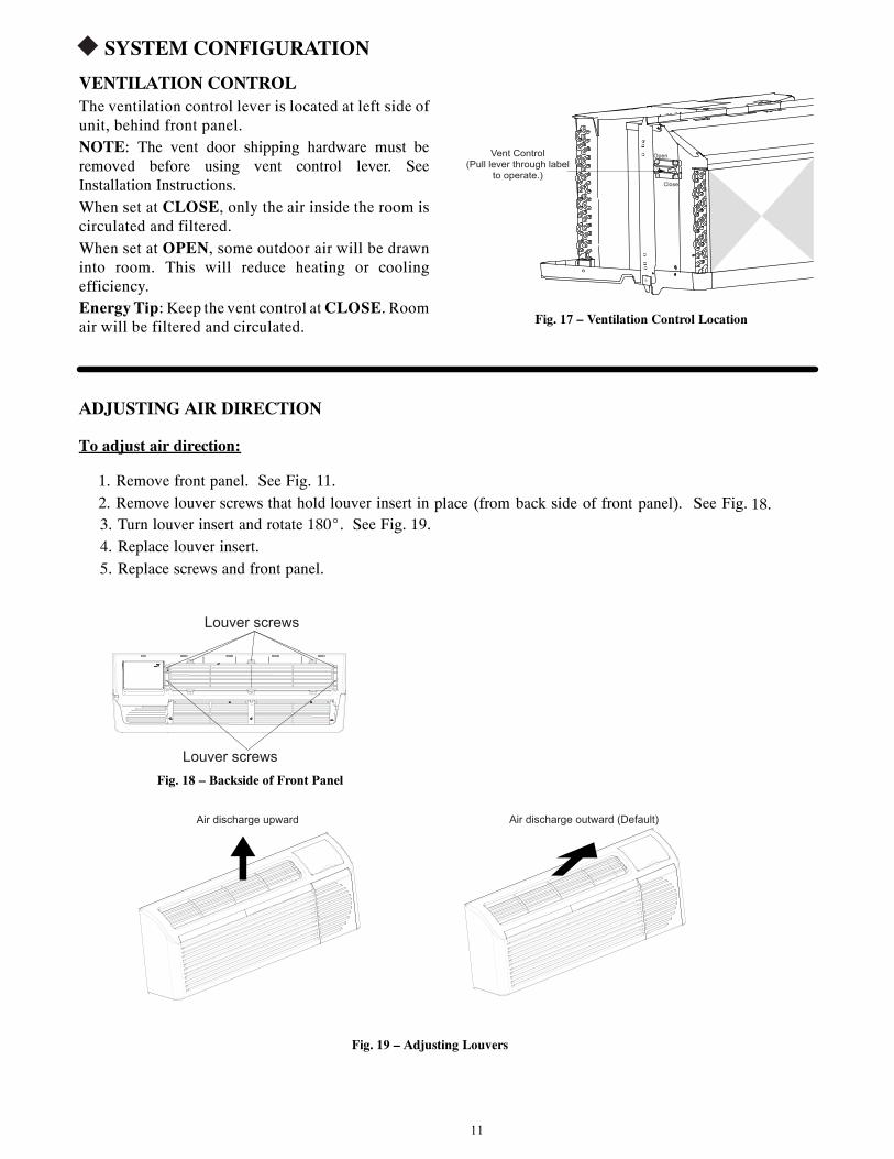
SYSTEM CONFIGURATION
VENTILATION CONTROLThe ventilation control lever is located at left side ofunit, behind front panel.NOTE: The vent door shipping hardware must beremoved before using vent control lever. SeeInstallation Instructions.When set at CLOSE, only the air inside the room iscirculated and filtered.When set at OPEN, some outdoor air will be drawninto room. This will reduce heating or coolingefficiency.EnergyTip: Keep the vent control atCLOSE. Roomair will be filtered and circulated.
Open
Close
Vent Control
(Pull lever through label
to operate.)
Fig. 17 – Ventilation Control Location
ADJUSTING AIR DIRECTION
To adjust air direction:
1. Remove front panel. See Fig. 11.2. Remove louver screws that hold louver insert in place (from back side of front panel). See Fig. 18.3. Turn louver insert and rotate 180_. See Fig. 19.4. Replace louver insert.5. Replace screws and front panel.
Louver screws
Louver screws Fig. 18 – Backside of Front Panel
Air discharge upward Air discharge outward (Default)
Fig. 19 – Adjusting Louvers
11
12
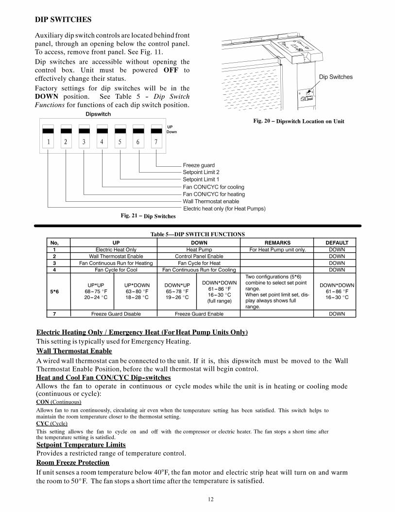
DIP SWITCHES
Auxiliary dip switch controls are located behind frontpanel, through an opening below the control panel.To access, remove front panel. See Fig. 11.Dip switches are accessible without opening thecontrol box. Unit must be powered OFF toeffectively change their status.Factory settings for dip switches will be in theDOWN position. See Table 5 -- Dip SwitchFunctions for functions of each dip switch position.
Dip Switches
Fig. 21 –
Dipswitch Location on Unit
Electric heat only (for Heat Pumps)
Wall Thermostat enable
Fan CON/CYC for heating
Fan CON/CYC for cooling
Setpoint Limit 1
Setpoint Limit 2
Freeze guard
Dipswitch
UP
Down
Electric Heating Only / Emergency Heat (ForHeat Pump Units Only)This setting is typically used for EmergencyHeating.Wall Thermostat EnableAwired wall thermostat can be connected to the unit. If it is, this dipswitch must be moved to the WallThermostat Enable Position, before the wall thermostat will begin control.Heat and Cool Fan CON/CYC Dip--switchesAllows the fan to operate in continuous or cycle modes while the unit is in heating or cooling mode(continuous or cycle):CON (Continuous)
Allows fan to run continuously, circulating air even when the temperature setting has been satisfied. This switch helps tomaintain the room temperature closer to the thermostat setting.CYC (Cycle)
This setting allows the fan to cycle on and off with the compressor or electric heater. The fan stops a short time afterthe temperature setting is satisfied.Setpoint Temperature LimitsProvides a restricted range of temperature control.Room Freeze ProtectionIf unit senses a room temperature below 40°F, the fan motor and electric strip heat will turn on and warmthe room to 50_F. The fan stops a short time after the temperature is satisfied.
A07070A07070
Fig. 20 –
Dip Switches
Table 5—DIP SWITCH FUNCTIONS
No, UP DOWN REMARKS DEFAULT1 Electric Heat Only Heat Pump For Heat Pump unit only. DOWN2 Wall Thermostat Enable Control Panel Enable DOWN3 Fan Continuous Run for Heating Fan Cycle for Heat DOWN4 Fan Cycle for Cool Fan Continuous Run for Cooling DOWN
5*6UP*UP68---75 _F20---24 _C
UP*DOWN63---80 _F18---28 _C
DOWN*UP65---78 _F19---26 _C
DOWN*DOWN61---86 _F16---30 _C(full range)
Two configurations (5*6)combine to select set pointrange.When set point limit set, dis-play always shows fullrange.
DOWN*DOWN61---86 _F16---30 _C
7 Freeze Guard Disable Freeze Guard Enable DOWN

13
KEYPAD CONFIGURATIONKeypad ConfigurationAllows further configuration of system to desired application. Changes do not take affect until power iscycled on the unit.To enter Keypad configurationCycle power to unit. Press and hold the Fan Speed Button and the COOLER button for 5 continuousseconds, within 30 seconds of the unit being powered up. If the unit has had power for more than 30continuous seconds, keypad configuration cannot be entered. When keypad configuration mode is firstentered, it will default to Fahrenheit/ Celsius Display Mode.To scroll through the Keypad Configuration OptionsPress and release the Fan Speed button. The stored value will be displayed.To modify configuration settingsPress and release the Setpoint Up or Setpoint Down buttons.To exit Keypad ConfigurationKeypad Configurationwill end on its own 30 seconds after the last button press or when the MODE buttonon the Keypad is pressed.Fahrenheit/ Celsius Display Switch:Change between degrees Fahrenheit and Celsius on the display. An “F” indicates Fahrenheit display and‘C’ indicates Celsius. Default is degrees “F”.Indoor Air Temperature Sensor Biasing forCooling mode:
Sometimes known as an anticipator, the air temperature sensor bias is used to adjust the room air temperaturereading when in cooling mode. (Not normally required.)Indoor Air Temperature Sensor Biasing forHeating mode:Sometimes known as an anticipator, the air temperature sensor bias is used to adjust the room airtemperature reading when in heating mode. (Not normally required.)Indoor Temperature Display:Changebetween showing setpoint only on the display during heating and cooling modes “SP” or displayingroom temperature during heating and cooling modes “AA”. “SP” mode is the default mode.
S If “SP” is selected, only the setpoint will be displayed during heating and cooling modes,regardless of what the real temperature is in the room.
S If “AA” mode is selected, the room temperature will be displayed during heating,cooling and fan only modes.— If the mode button has been changed to either heating or coolingmodes, setpoint will be displayed
for 10 seconds. After the 10 seconds, the room temperature will again be displayed.— If the on/off button is depressed (when the unit is off) and the last mode was either cooling or
heating mode, the setpoint will be displayed for 10 seconds before displaying room temperature.— During heating and cooling modes, if either the up or down setpoint key is depressed, the
display will show the setpoint until 10 seconds after the last up or down key press. Thenthe room temperature will be displayed again.
14
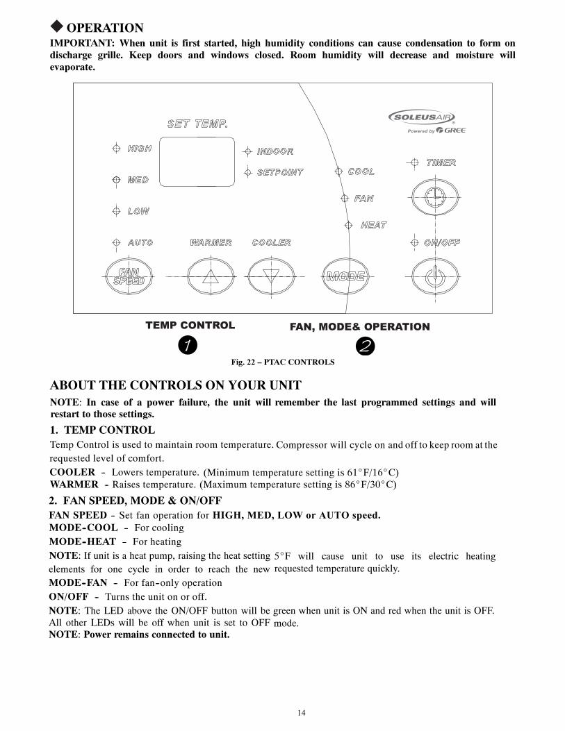
OPERATIONIMPORTANT: When unit is first started, high humidity conditions can cause condensation to form ondischarge grille. Keep doors and windows closed. Room humidity will decrease and moisture willevaporate.
TEMP CONTROL FAN, MODE& OPERATION
Fig. 22 – PTAC CONTROLS
ABOUT THE CONTROLS ON YOUR UNITNOTE: In case of a power failure, the unit will remember the last programmed settings and willrestart to those settings.
1. TEMP CONTROLTemp Control is used to maintain room temperature. Compressor will cycle on and off to keep room at therequested level of comfort.COOLER -- Lowers temperature. (Minimum temperature setting is 61_F/16_C)WARMER -- Raises temperature. (Maximum temperature setting is 86_F/30_C)
2. FAN SPEED, MODE & ON/OFFFAN SPEED -- Set fan operation for HIGH, MED, LOW or AUTO speed.MODE--COOL -- For coolingMODE--HEAT -- For heatingNOTE: If unit is a heat pump, raising the heat setting 5_F will cause unit to use its electric heatingelements for one cycle in order to reach the new requested temperature quickly.
MODE--FAN -- For fan--only operationON/OFF -- Turns the unit on or off.NOTE: The LED above the ON/OFF button will be green when unit is ON and red when the unit is OFF.All other LEDs will be off when unit is set to OFF mode.NOTE: Power remains connected to unit.
15
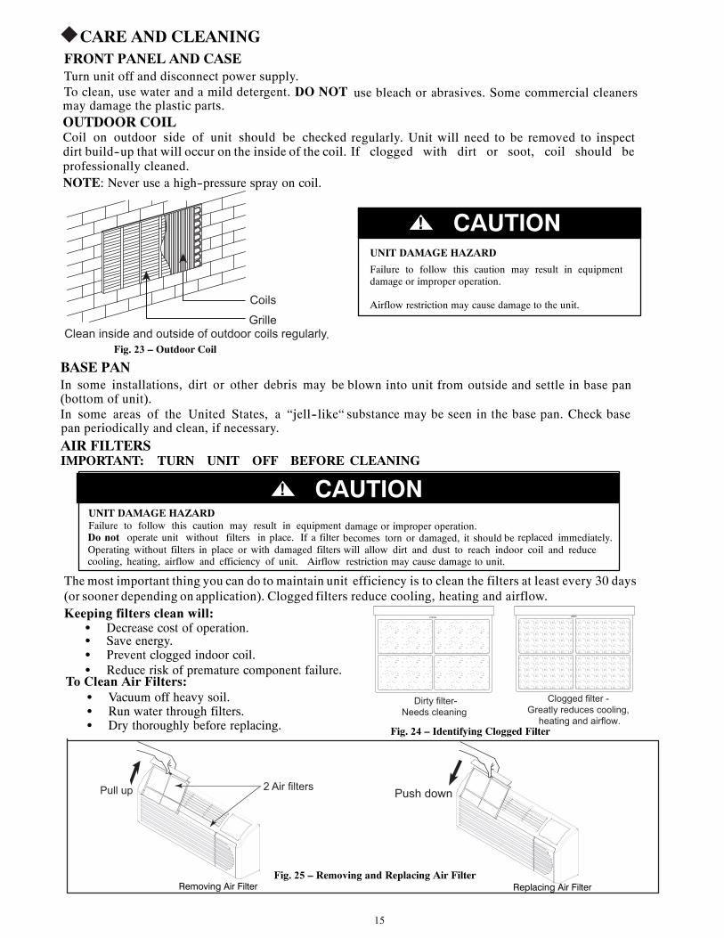
CARE AND CLEANINGFRONT PANEL AND CASETurn unit off and disconnect power supply.To clean, use water and a mild detergent. DO NOT use bleach or abrasives. Some commercial cleanersmay damage the plastic parts.OUTDOOR COILCoil on outdoor side of unit should be checked regularly. Unit will need to be removed to inspectdirt build--up that will occur on the inside of the coil. If clogged with dirt or soot, coil should beprofessionally cleaned.NOTE: Never use a high--pressure spray on coil.
Coils
Grille Clean inside and outside of outdoor coils regularly .
Fig. 23 – Outdoor Coil
UNIT DAMAGE HAZARD
Failure to follow this caution may result in equipmentdamage or improper operation.
Airflow restriction may cause damage to the unit.
CAUTION!
BASE PANIn some installations, dirt or other debris may be blown into unit from outside and settle in base pan(bottom of unit).In some areas of the United States, a “jell--like“ substance may be seen in the base pan. Check basepan periodically and clean, if necessary.
AIR FILTERSIMPORTANT: TURN UNIT OFF BEFORE CLEANING
UNIT DAMAGE HAZARDFailure to follow this caution may result in equipment damage or improper operation.Do not operate unit without filters in place. If a filter becomes torn or damaged, it should be replaced immediately.Operating without filters in place or with damaged filters will allow dirt and dust to reach indoor coil and reducecooling, heating, airflow and efficiency of unit. Airflow restriction may cause damage to unit.
CAUTION!
Dirty filter-
Needs cleaning
Clogged filter -
Greatly reduces cooling,
heating and airflow.Fig. 24 – Identifying Clogged Filter
Themost important thing you can do to maintain unit efficiency is to clean the filters at least every 30 days(or sooner depending on application). Clogged filters reduce cooling, heating and airflow.Keeping filters clean will:
S Decrease cost of operation.S Save energy.S Prevent clogged indoor coil.S Reduce risk of premature component failure.
To Clean Air Filters:S Vacuum off heavy soil.S Run water through filters.S Dry thoroughly before replacing.
2 Air filters Pull up Push down
Removing Air Filter Replacing Air FilterFig. 25 – Removing and Replacing Air Filter
PREVENTATIVE MAINTENANCEPreventative maintenance is essential to proper unit operation, efficiency and longevity.To ensure equipment operates properly, it must be properly maintained. Equipment operation should be checkedand verified several times during each year. During regular unit inspection and maintenance, follow theguidelines below:
S Clean both sides of outdoor coil. (Never use high pressure spray on coils.)S Clean basepan and outdoor vent filter.S Clean outdoor orifice and fan.S Clean indoor coil. (Never use high pressure spray on coils.)S Clean indoor fan, wire screen and front panel.S Clean or install new indoor--air inlet filter(s).S Clean wall sleeve and outdoor grille.S Inspect cord and receptacle.S Secure electrical connections.S Ensure front panel is properly mounted and not damaged.S Ensure wall sleeve is installed properly.S Ensure heat and cool cycles operate properly.
16
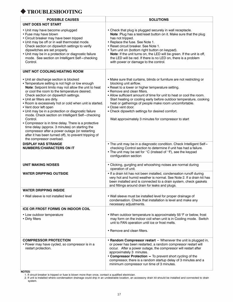
TROUBLESHOOTINGPOSSIBLE CAUSES SOLUTIONS
UNIT DOES NOT START
• Unit may have become unplugged• Fuse may have blown• Circuit breaker may have been trippedS Unit may be off or in wall thermostat mode.Check section on dipswitch settings to verifydipswitches are set properly.
• Unit may be in a protection or diagnostic failuremode. See section on Intelligent Self ---checkingControl.
• Check that plug is plugged securely in wall receptacle.Note :Plug has a test/reset button on it. Make sure that the plughas not tripped.
• Replace the fuse. See Note 1.• Reset circuit breaker. See Note 1.• Turn unit on (bottom right button on keypad).Note: If the unit turns on, the LED will be green. If the unit is off,the LED will be red. If there is no LED on, there is a problemwith power or damage to the control.
UNIT NOT COOLING/HEATING ROOM
S Unit air discharge section is blockedS Temperature setting is not high or low enoughNote: Setpoint limits may not allow the unit to heator cool the room to the temperature desired.Check section on dipswitch settings.
S Unit air filters are dirty.S Room is excessively hot or cold when unit is started.S Vent door left openS Unit may be in a protection or diagnostic failuremode. Check section on Intelligent Self ---checkingControl.
S Compressor is in time delay. There is a protectivetime delay (approx. 3 minutes) on starting thecompressor after a power outage (or restartingafter it has been turned off), to prevent tripping ofthe compressor overload.
S Make sure that curtains, blinds or furniture are not restricting orblocking unit airflow.
S Reset to a lower or higher temperature setting.S Remove and clean filters.S Allow sufficient amount of time for unit to heat or cool the room.Start heating or cooling early before outdoor temperature, cookingheat or gatherings of people make room uncomfortable.
S Close vent door.S Check dipswitch settings for desired comfort.
Wait approximately 3 minutes for compressor to start
DISPLAY HAS STRANGENUMBERS/CHARACTERS ON IT
• The unit may be in a diagnostic condition. Check Intelligent Self ---checking Control section to determine if unit has had a failure.
• The unit may be set for _C (instead of _F), see the keypadconfiguration section
UNIT MAKING NOISES • Clicking, gurgling and whooshing noises are normal duringoperation of unit.
WATER DRIPPING OUTSIDE • If a drain kit has not been installed, condensation runoff duringvery hot and humid weather is normal. See Note 2. If a drain kit hasbeen installed and is connected to a drain system, check gasketsand fittings around drain for leaks and plugs.
WATER DRIPPING INSIDE
•Wall sleeve is not installed level •Wall sleeve must be installed level for proper drainage ofcondensation. Check that installation is level and make anynecessary adjustments.
ICE OR FROST FORMS ON INDOOR COIL
• Low outdoor temperature• Dirty filters
•When outdoor temperature is approximately 55_F or below, frostmay form on the indoor coil when unit is in Cooling mode. Switchunit to FAN operation until ice or frost melts.
• Remove and clean filters.
COMPRESSOR PROTECTION• Power may have cycled, so compressor is in arestart protection.
• Random Compressor restart --- Whenever the unit is plugged in,or power has been restarted, a random compressor restart willoccur. After a power outage, the compressor will restart afterapproximately 3 minutes.• Compressor Protection --- To prevent short cycling of thecompressor, there is a random startup delay of 3 minutes and aminimum compressor run time of 3 minutes.
NOTES:1. If circuit breaker is tripped or fuse is blown more than once, contact a qualified electrician.2. If unit is installed where condensation drainage could drip in an undesirable location, an accessory drain kit should be installed and connected to drainsystem.
17
LIMITED WARRANTY
Soleus International Inc. warrants the accompanying Soleus Air SPTAC series Air Conditioner of defects in material and workmanship
for the applications specified in its operation instruction for the period of labor and parts specified below.
5 YEARS FOR COMPRESSOR 1 YEAR FOR OTHER COMPONENTS
This warranty shall not apply to broken or marred cabinets, accessories, knobs, filters or routine maintenance. This warranty does not apply to uncrating, setup, installation, removal of the product for repair or reinstallation of the product after repair.
This warranty does not apply to repairs or replacements necessitated by any cause beyond the control of Soleus International including, but not limited to, any malfunction, defect or failure caused by or resulting from unauthorized service or parts, improper maintenance, operation contrary to furnished instructions, shipping or transit accidents, modification or repair by the user, abuse, misuse, neglect, accident, incorrect power line voltage, fire, flood or other Acts of God, or normal wear and tear.
Warranty service must be performed by a qualified HVAC contractor. Soleus maintains a centralized service network to provide parts and assist in resolving service problems if difficulties are encountered. Soleus agrees to provide service information, sell repair parts and reimburse the dealer /servicer for parts and services in accordance with Soleus International’s Policies and Procedures.
SOLEUS INTERNATIONAL MAINTAINS THAT ALL WARRANTIES, INCLUDING IMPLIED WARRANTY OR MERCHANTABILITY ARE LIMITED TO THE TERMS AND CONDITIONS SPECIFIED ABOVE. SOLEUS INTERNATIONAL DISCLAIMS ANY LIBILITY FOR CONSEQUENTIAL OR INCIDENTAL DAMAGES AND IN NO EVENT SHALL SOLEUS INTERNATIONAL INC.’S LIABILITY EXCEED THE RETAIL VALUE OF THE AIR CONDITIONER.
This warranty covers only new products purchased from our authorized dealers or retailers. It does not cover used, salvaged, or refurbished products.
FOR CUSTOMER SERVICES, WARRANTY CLAIM AND PARTS PURCHASING, CONTACT:
20035 East Walnut Drive, North
Email: [email protected] Tel: 1-888-8 SOLEUS City of Industry, CA 917 89
Soleus International Inc.
Monday through Friday, 9:00 AM to 5:00 PM, PST Website: www.soleusair.com
(SG - PTAC - 09 / 12 / 15 HDPA) to be free
66129908453
Related Documents