PACKAGED GAS ELECTRIC KG Landmark ® Rooftop Units 60 HZ Bulletin No. 210552 July 2013 Supersedes June 2013 13 to 25 Tons Net Cooling Capacity − 152,000 to 270,000 Btuh Gas Input Heat Capacity − 260,000 to 480,000 Btuh MODEL NUMBER IDENTIFICATION K G A 240 S 4 B S 1 Y Brand/Family K = Landmark ® Unit Type G = Packaged Gas Heat w/ Electric Cooling Major Design Sequence A = 1st Generation Nominal Cooling Capacity - Tons 156 = 13 Tons 180 = 15 Tons 210 = 17.5 Tons 240 = 20 Tons 300 = 25 Tons Cooling Efficiency H = High Efficiency S = Standard Efficiency Refrigerant Type 4 = R-410A Heating Type S = Standard Gas Heat, 2 Stage M = Medium Gas Heat, 2 Stage H = High Gas Heat, 2 Stage Minor Design Sequence 1 = 1st Revision 2 = 2nd Revision 3 = 3rd Revision Voltage Y = 208/230V-3 phase-60hz G = 460V-3 phase-60hz J = 575V-3 phase-60hz ASHRAE 90.1 COMPLIANT PRODUCT SPECIFICATIONS Blower Type B = Belt Drive, Constant Air Volume (CAV) M = MSAV ® (Multi-Stage Air Volume) Supply Air Blower Option, Belt Drive

Welcome message from author
This document is posted to help you gain knowledge. Please leave a comment to let me know what you think about it! Share it to your friends and learn new things together.
Transcript

P A C K A G E D G A S E L E C T R I C
KGLandmark® Rooftop Units
60 HZBulletin No. 210552
July 2013Supersedes June 2013
13 to 25 TonsNet Cooling Capacity − 152,000 to 270,000 Btuh
Gas Input Heat Capacity − 260,000 to 480,000 Btuh
MODEL NUMBER IDENTIFICATION
K G A 240 S 4 B S 1 Y
Brand/Family K = Landmark®
Unit Type G = Packaged Gas Heat w/ Electric Cooling
Major Design Sequence A = 1st Generation
Nominal Cooling Capacity - Tons 156 = 13 Tons 180 = 15 Tons
210 = 17.5 Tons240 = 20 Tons300 = 25 Tons
Cooling EfficiencyH = High Efficiency
S = Standard Efficiency Refrigerant Type4 = R-410A
Heating TypeS = Standard Gas Heat, 2 StageM = Medium Gas Heat, 2 StageH = High Gas Heat, 2 Stage
Minor Design Sequence 1 = 1st Revision 2 = 2nd Revision3 = 3rd Revision
Voltage Y = 208/230V-3 phase-60hz G = 460V-3 phase-60hz J = 575V-3 phase-60hz
ASHRAE 90.1COMPLIANT
P R O D U C T S P E C I F I C AT I O N S
Blower TypeB = Belt Drive, Constant Air Volume (CAV) M = MSAV® (Multi-Stage Air Volume) Supply Air Blower Option, Belt Drive

Landmark®™ Packaged Gas / Electric 13 to 25 Ton / Page 2
FEATURES AND BENEFITS
Landmark® rooftop units from Lennox are the new standard for reliable, efficient rooftop units built for long-lastingperformance that can significantly improve indoor and outdoor environments. Landmark®™ rooftop units feature:
• Aluminized Steel Heat Exchanger With Inshot Burners - Life cycle tested.• R-410A Refrigerant - Environmentally friendly.• Scroll Compressors - Single speed scroll compressors are furnished on all models.• Lennox’ Environ™ Coil System - Smaller, lighter condenser coil.• Crankcase Heaters - Protect compressors from refrigerant liquid migration in the off cycle improving product
reliability.• High Pressure Switches - Protects compressor.• Isolated Compressor Compartment - Allows performance check during normal compressor operation without
disrupting airflow.• Independent Outdoor Fan Motor Mounts - Allows for easy and efficient service access without removing the top
panel.• Constant Air Volume (CAV) or MSAV® (Multi-Stage Air Volume) Supply Air Blower Option - Allows constant or
multi-staged air delivery.• Downflow Airflow - Horizontal airflow with optional horizontal curb.• Two Fork Lift Slots on Three Sides - Easy to pick up and transport units from almost any angle.• Corrosion-Resistant Removable, Drain Pan - Provides application flexibility, durability and improved serviceability.• Thermostatic Expansion Valves - Provide peak cooling performance across the entire application range.• MERV 8 or MERV 13 Filters - Available as field installed option, provide an enhanced level of indoor air quality, and
can help the building qualify for additional LEED credits.
B
C
D
F
G
E
H
LM
NO
H
J
K

Landmark®™ Packaged Gas / Electric 13 to 25 Ton / Page 3
FEATURES AND BENEFITS
APPROVALS
Efficiency rating CSA.Components bonded for grounding to meet safety standards for servicing required by UL, ULC and National and Canadian Electrical Codes.All models are certified in accordance with the ULE certification program, which is based on AHRI Standard 340/360-2007.All models are ASHRAE 90.1-2010 energy efficiency compliant and meet or exceed requirements of Section 6.8.MSAVmodels meet California Code of Regulations, Title 24 and ASHRAE 90.1-2010 Section 6.4.3.10 requirements for staged airflow.ISO 9001 Registered Manufacturing Quality System.
A
WARRANTY
Limited ten years aluminized heat exchanger, limited fifteen years optional stainless steel heat exchanger.Limited five years on compressors.Limited three years on the Lennox’ Environ™ Coil System.Limited one year all other covered components.
HEATING SYSTEM
Aluminized steel inshot burners, direct spark ignition, electronic flame sensor, combustion air inducer, redundant automatic dual stage gas valve with manual shut-off.
Heat ExchangerTubular construction, aluminized steel, life cycle tested.Optional Stainless Steel Heat Exchanger is required if mixed air temperature is below 45°F.
B
Electronic Pilot IgnitionElectronic spark igniter provides positive direct ignition of burners on each operating cycle. The system permits main gas valve to stay open only when the burners are proven to be lit. Should a loss of flame occur, the gas valve closes, shutting off the gas to the burners. Ignition module has LED to indicate status and aid in troubleshooting.Ignition control is factory installed in the controls section.
Limit ControlsFactory installed, redundant limit controls with fixed temperature setting. Heat limit controls protect heat exchanger and other components from overheating.
Safety SwitchesFlame roll-out switch, flame sensor and combustion air inducer proving switch protect system operation.
REQUIRED SELECTIONS
Gas Input Choice - Order one:Standard Gas Heat, 2 Stage (169,000/260,000 Btuh)Medium Gas Heat, 2 Stage (234,000/360,000 Btuh)High Gas Heat, 2 Stage (312,000/480,000 Btuh)
OPTIONS/ACCESSORIES
Factory InstalledStainless Steel Heat ExchangerRequired if mixed air temperature is below 45°F.Factory or Field InstalledLow Temperature Vestibule HeaterElectric heater automatically controls minimum temperature in gas burner compartment when temperature is below -40°F. CSA certified to allow operation of unit down to -60°F.Field InstalledBottom Gas Piping KitAllows bottom gas entry.
Contents
Accessory Dimensions . . . . . . . . . . . . . . . . . . . . . . . . . . .45Blower Data . . . . . . . . . . . . . . . . . . . . . . . . . . . . . . . . .30Dimensions . . . . . . . . . . . . . . . . . . . . . . . . . . . . . . . . .42Electrical Accessories. . . . . . . . . . . . . . . . . . . . . . . . . . . .38Electrical Data. . . . . . . . . . . . . . . . . . . . . . . . . . . . . . . .33Features And Benefits . . . . . . . . . . . . . . . . . . . . . . . . . . . 2High Altitude Derate . . . . . . . . . . . . . . . . . . . . . . . . . . . .20Model Number Identification . . . . . . . . . . . . . . . . . . . . . . . . 1Optional Conventional Temperature Control Systems . . . . . . . . . . .40Options / Accessories - High Efficiency Models. . . . . . . . . . . . . . .12Options / Accessories - Standard Efficiency Models . . . . . . . . . . . . 9Outdoor Sound Data . . . . . . . . . . . . . . . . . . . . . . . . . . . .40Ratings . . . . . . . . . . . . . . . . . . . . . . . . . . . . . . . . . . .21Specifications - Gas Heat . . . . . . . . . . . . . . . . . . . . . . . . . .20Specifications - High Efficiency Models . . . . . . . . . . . . . . . . . . .17Specifications - Standard Efficiency Models . . . . . . . . . . . . . . . .15Unit Clearances . . . . . . . . . . . . . . . . . . . . . . . . . . . . . . .39Weight Data . . . . . . . . . . . . . . . . . . . . . . . . . . . . . . . . .41

Landmark®™ Packaged Gas / Electric 13 to 25 Ton / Page 4
HEATING SYSTEM (CONTINUED)
Combustion Air Intake ExtensionsRecommended for use with existing flue extension kits in areas where high snow areas can block intake air. Order two kits.
LPG/Propane KitsConversion kit to field change over units from Natural Gas to LPG/Propane. Order two kits.
Vertical Vent Extension KitUse to exhaust flue gases vertically above unit. Required when unit vent is too close to fresh air intakes per building codes. The vent kit also prevents ice formation on intake louvers. Order two kits.Kit contains vent transition, vent tee, drain cap and installation hardware.NOTE - Straight vent pipes (4 in. B-Vent) and caps are not furnished and must be field supplied. Refer to kit instructions for additional information.
COOLING SYSTEM
Designed to maximize sensible and latent cooling performance at design conditions.System can operate from 30°F to 125°F without any additional controls.R-410A RefrigerantNon-chlorine based, ozone friendly, R-410A.Scroll CompressorsScroll compressors on all models for high performance, reliability and quiet operation.Resiliently mounted on rubber grommets for quiet operation.Compressor Crankcase HeatersProtect against refrigerant migration that can occur during low ambient operation.
C
Thermal Expansion Valves (High Efficiency Models) Assures optimal performance throughout the application range. Removable element head. Refrigerant Metering Orifice (Standard Efficiency Models) Accurately meters refrigerant in system. Refrigerant control is accomplished by exact sizing of refrigerant metering orifice.Filter/DriersHigh capacity filter/drier protects the system from dirt and moisture.High Pressure SwitchesProtects the compressor from overload conditions such as dirty condenser coils, blocked refrigerant flow, or loss of outdoor fan operation.FreezestatsProtects the evaporator coil from damaging ice build-up due to conditions such as low/no airflow, or low refrigerant charge.Lennox’ Environ™ Coil SystemCondenser coil features lightweight, all aluminum brazed fin construction.Constructed of three components: a flat extrusion tube, fins in-between the flat extrusion tube and two refrigerant manifolds.
D
E
F
Environ™Coil System Features:
• Improved heat transfer performance due to high primary surface area (flat tubes) versus secondary surface (fins).
• Smaller internal volume (reduced refrigerant charge).
• High durability (all aluminum construction).
• Fewer brazed joints.• Compact design (reduces unit
weight).• Easy maintenance/cleaning.• Face split design.Mounting brackets with rubber inserts secure coil to unit providing vibration dampening and corrosion protection.Angled design in cabinet helps protect coil from possible contact or hail damage.
Evaporator Coil Copper tube construction, enhanced rippled-edge aluminum fins, flared shoulder tubing connections, silver soldered construction for improved heat transfer. Factory leak tested. Cross row circuiting with rifled tubing optimizes both sensible and latent cooling capacity.Condensate Drain PanPlastic pan, sloped to meet drainage requirements of ASHRAE 62.1.Side or bottom drain connections.Outdoor Coil Fan MotorsThermal overload protected, totally enclosed, permanently lubricated ball bearings, shaft up, wire basket mount.Outdoor Coil FansPVC coated fan guard furnished.
REQUIRED SELECTIONS
Cooling CapacitySpecify nominal cooling capacity of the unit
G
FEATURES AND BENEFITS

Landmark®™ Packaged Gas / Electric 13 to 25 Ton / Page 5
OPTIONS/ACCESSORIES
Field InstalledCondensate Drain TrapAvailable in copper or PVC.Drain Pan Overflow SwitchMonitors condensate level in drain pan, shuts down unit if drain becomes clogged.Low Ambient ControlCycles the outdoor fans while allowing compressor operation in the cooling cycle. This intermittent fan operation allows the system to operate without icing the evaporator coil and losing capacity. Designed for use in ambient temperatures no lower than 0°F.
CABINET
ConstructionHeavy-gauge steel panels and full perimeter heavy-gauge galvanized steel base rail provides structural integrity for transportation, handling, and installation.Base rails have rigging holes.Three sides of the base rail have forklift slots.Raised edges around duct and power entry openings in the bottom of the unit provide additional protection against water entering the building.Airflow ChoiceUnits are available in downflow (vertical) or horizontal return air flow configuration.Horizontal air flow requires Horizontal Roof Curb.Horizontal Return Air Panel Kit is also required if converting a downflow configured unit to horizontal air flow.Power/Gas EntryElectrical and gas lines can be brought through the unit base or through horizontal access knock-outsExterior PanelsConstructed of heavy-gauge, galvanized steel with a two-layer enamel paint finish.InsulationAll panels adjacent to conditioned air are fully insulated with non-hygroscopic fiberglass insulation.Unit base is fully insulated. The insulation also serves as an air seal to the roof curb, eliminating the need to add a seal during installation.Access PanelsAccess panels are provided for the economizer/filter section, heating/blower section, and the compressor/controls section.
H
OPTIONS/ACCESSORIES
Factory InstalledCorrosion ProtectionA completely flexible immersed coating with an electrodeposited dry film process. (AST ElectroFin E-Coat) Meets Mil Spec MIL-P-53084, ASTM B117 Standard Method Salt Spray Testing.Indoor Corrosion Protection: - Coated coil - Painted blower housing - Painted indoor baseOutdoor Corrosion Protection: - Coated coil - Painted outdoor baseHinged Access PanelsHinged access panels for the filter section, the blower section and compressor/controls section.All hinged panels have seals and quarter-turn latching handles to provide a tight air and water seal.Field InstalledCoil GuardsPainted, galvanized steel wire guards to protect outdoor coil.Not used with Hail Guards.Hail GuardsConstructed of heavy gauge steel, painted to match cabinet, helps protect outdoor coils from hail damage.Not used with Coil Guards.
Horizontal Return Air Panel KitRequired for horizontal applications with Horizontal Roof Curb, contains panel with return air opening for field replacement of existing unit panel and panel to cover bottom return air opening in unit, see dimension drawings.
FEATURES AND BENEFITS

Landmark®™ Packaged Gas / Electric 13 to 25 Ton / Page 6
FEATURES AND BENEFITS
BLOWER
A wide selection of supply air blower options are available to meet a variety of airflow requirements.MotorOverload protected, equipped with ball bearings. Belt drive motors are offered on all models and are available in several different sizes to maximize air performance.Supply Air BlowerForward curved blades, double inlet, blower wheel is statically and dynamically balanced. Equipped with ball bearings and adjustable pulley (allows speed change),.Blower assembly slides out of unit for servicing.
REQUIRED SELECTIONS
Select Constant Air Volume (CAV) or MSAV® (Multi-Stage Air Volume) Supply Air Blower OptionOn Constant Air volume (CAV) models, the supply air blower will provide a constant volume of air.MSAV (Multi-Stage Air Volume) supply air bloweroption models utilize a Variable Frequency Drive (VFD) to stage the supply air blower airflow. The VFD alters the frequency and voltage of the power supply to the blower to control blower speed.The supply air blower has two speeds:1. Low speed for part-load cooling
operation. NOTE - Low speed is 66% of high speed.
2. High speed for full load cooling and all heat modes.
Full speed blower operation is set by adjusting the motor pulley to deliver the desired air volume.The ventilation speed is selectable between high and low speed.
I NOTE - Part load airflow in cooling mode on MSAV models should not be set below 220 cfm/nominal full load ton to reduce the risk of evaporator coil freeze-up.The VFD has an operational range of -40 to 125° F outdoor air ambient temperature. Lower operating costs are obtained when the blower is operated on lower speeds.MSAV Sequence of OperationVentilation speed is determined by the VENT SPEED switch setting on VFD control board (LO or HI).Blower operates in low speed for mechanical cooling (Y1).Blower operates in high speed for any other mode (free cooling, mechanical cooling Y1+Y2, and heating).Economizer damper minimum position is fully closed in unoccupied mode.In occupied mode, the economizer damper minimum position is determined by the setting of the two potentiometers on VFD control board.• LO SPD MIN POS potentiometer
sets the minimum position when blower is operating at low speed.
• HI SPD MIN POS potentiometer sets the minimum position when blower is operating at high speed.
Ordering InformationSpecify standard or high efficiency blower motor, motor horsepower and drive kit number when base unit is ordered, see Drive Kit Specifications Table.
OPTIONS/ACCESSORIES
Field InstalledVFD Manual Bypass KitVFD Manual Bypass Control is available as a kit for MSAV equipped models.The VFD Manual Bypass Control is a manual bypass and is enabled by re-configuring the wiring on the unit.
CONTROLS
Unit ControlAll control voltage is provided via a 24V (secondary) transformer with built-in circuit breaker protection.Heat/Cool Staging - Capable of up to 2 heat / 2 cool staging with a third party DDC control system or thermostat.Low Voltage Terminal Block - Provides screw terminal connections for thermostat or controller wiring.Night Setback Mode - Saves energy by closing outdoor air dampers and operating supply fan on thermostat demand only.
OPTIONS/ACCESSORIES
Field InstalledSmoke DetectorPhotoelectric type, installed in supply air section, return air section or both sections. Available with power board and single sensor (supply or return) or power board and two sensors (supply and return). Power board located in unit control compartment.Commercial Control SystemsL Connection® NetworkComplete building automation control system for single or multi-zone applications. Options include local interface, software for local or remote communication, and hardware for networking other control functions.See L Connection Network Product Specifications Bulletin for details.ThermostatsControl system and thermostat options, see page 40. Aftermarket unit controller options, see Options/Accessories table.
J

Landmark®™ Packaged Gas / Electric 13 to 25 Ton / Page 7
ELECTRICAL
All units include terminal block and fuse block in power entry junction box for single power entry application.
REQUIRED SELECTIONS
Voltage ChoiceSpecify when ordering base unit.
OPTIONS/ACCESSORIES
Factory or Field InstalledDisconnect SwitchAccessible from outside of unit, spring loaded weatherproof cover furnished.GFI Service Outlets (2)115V ground fault circuit interrupter (GFCI) type, non-powered, field-wired.Field InstalledGFI Weatherproof CoverSingle-gang cover.Heavy-duty UV-resistant polycarbonate case construction.Hinged base cover with gasket.Phase Monitor Phase monitor detects the phasing of incoming power. If the incoming power is out of phase or if any of the three phases are lost, an indicator LED on the phase monitor will turn red and the unit will not start. In normal operation with correct incoming power phasing, the LED will be green.NOTE - Phase Monitor is factory Installed in the control compartment on all units equipped with the MSAV® Supply Air Blower option.
K
INDOOR AIR QUALITY
Air FiltersDisposable 2 inch filters furnished as standard.
OPTIONS/ACCESSORIES
Field InstalledHealthy Climate® High Efficiency Air FiltersDisposable MERV 8 or MERV 13 (Minimum Efficiency Reporting Value based on ASHRAE 52.2) efficiency 2 inch pleated filters.Healthy Climate® UVC Germicidal Lamps
Germicidal lamps emit ultra-violet (UV-C) energy, which has been proven to be effective in reducing microbes such as viruses, bacteria, yeasts, and molds. This process either destroys the organism or controls its ability to reproduce.UV-C energy greatly reduces the growth and proliferation of mold and other bioaerosols (bacteria and viruses) on illuminated surfaces (particularly coil and drain pan).Lamps are field installed in the blower/evaporator coil section.All necessary hardware for installation is included.Lamps operate on 208/230V power supply. Step-down transformer must be field supplied when used with 460V and 575V rooftop units.Magnetic safety interlock terminates power when access panels are removed.Approved by ETL.Indoor Air Quality (CO2) SensorsMonitors CO2 levels, reports to the Unit Controller which adjusts economizer dampers as needed.
L
SERVICEABILITY
Designed to streamline general maintenance and decrease troubleshooting time.Marked & Color-Coded WiringAll electrical wiring is color-coded and marked to identify which components it is connecting.Electrical PlugsPositive connection electrical plugs are used to connect common accessories or maintenance parts for easy removal or installation.Access PanelsLarge access panels are provided for quick and easy access to maintenance areas.Blower AccessSupply air blower parts are located near the access door for easy servicing and adjustment.Thermal Expansion Valve AccessThermal expansion valves are located near the perimeter of the unit for easier access.Removable element head allows change out of element and bulb without removing the TXV.Coil CleaningSlab condenser coils provided for easier cleaning.Standard ComponentsA large number of common maintenance parts are standard throughout the entire range of sizes (3-25 tons), reducing the need to carry a lot of different parts to the job or maintain in inventory.Compressor CompartmentCompressors are located near the perimeter of the unit for easier access.Compressors are isolated from the condenser airflow allowing system operation checks to be done without changing the airflow across the outdoor coils.
FEATURES AND BENEFITS

Landmark®™ Packaged Gas / Electric 13 to 25 Ton / Page 8
ECONOMIZER/EXHAUST OPTIONS
Factory or Field InstalledEconomizer - Downflow or Horizontal With Outdoor Air HoodParallel gear-driven action return air and outdoor air dampers, plug-in connections to unit, nylon bearings, neoprene seals, 24-volt, fully-modulating, spring return motor, adjustable minimum damper position. Outdoor air hood with mist elimination filter is furnished.Single sensible control is furnished with economizer. Outdoor air temperature sensor enables economizer if the outdoor temperature is less than the setpoint of the control.Outdoor Air Hood is included when economizer is factory installed and is furnished with economizer when ordered for field installation.Single Economizer Enthalpy ControlEnthalpy sensor enables the economizer when the outdoor air enthalpy is below the configured setpoint.Field InstalledDifferential (Dual) Economizer Enthalpy ControlOrder two single, enthalpy control kits. One is field installed in the return air section, the other in the outdoor air section. Allows the economizer control board to select between outdoor air or return air, whichever has lower enthalpy.
Downflow Barometric Relief Dampers With Exhaust HoodAllow relief of excess air.Aluminum blade dampers prevent blow back and outdoor air infiltration during off cycle.Exhaust hood with bird screen is furnished.
M
N
Horizontal Barometric Relief Dampers With Exhaust HoodFor use when unit is configured for horizontal applications requiring an economizer.Allows relief of excess airAluminum blade dampers prevent blow back and outdoor air infiltration during off cycle.Field installed in return air duct.Exhaust hood with bird screen is furnished.Power Exhaust FanInstalls internal to unit for downflow applications only with economizer option. Provides exhaust air pressure relief. Interlocked to run when supply air blower is operating, fan runs when outdoor air dampers are 50% open (adjustable), motor is overload protected. Requires Economizer with Outdoor Air Hood and Downflow Barometric Relief Dampers. Dual fans are 20 in. diameter with 5 blades with (2) 1/3 hp motors.
OUTDOOR AIR OPTIONS
Factory or Field InstalledOutdoor Air Damper - Downflow or Horizontal With Air HoodLinked mechanical dampers, 0 to 25% (fixed) outdoor air adjustable, installs in unit. Includes outdoor air hood.Automatic model features fully modulating spring return damper motor with plug-in connection.Manual model features parallel blade, gear-driven dampers with adjustable fixed position.Outdoor Air Hood is included when damper is factory installed and is furnished with damper when ordered for field installation.
O
ROOF CURBS
Nailer strip furnished, mates to unit, US National Roofing Contractors Approved, shipped knocked down.
DownflowClip Curbs - Uses interlocking tabs to fasten corners together. No tools required.Standard Curbs - Curb corners fasten together with furnished hardware.Adjustable Pitched Curb - Curbs are regionally sourced. Dimensions will vary based upon the source. Contact your Lennox sales representative for a detailed cut sheet with applicable dimensions.
HorizontalConverts unit from downflow to horizontal (side) air flow, return air is on unit, supply air is on curb, see dimension drawings. Curbs for rooftop applications meet National Roofing Code requirements. Requires Horizontal Return Air Panel Kit. Available in 26, 30, 37 and 41 inch heights. Optional Insulation Kit is available to help prevent sweating.
CEILING DIFFUSERS
Ceiling Diffusers (Flush or Step-Down)Aluminum grilles, large center grille, insulated diffuser box with flanges, hanging rings furnished, interior transition (even air flow), internally sealed (prevents recirculation), adapts to T-bar ceiling grids or plaster ceilings.Transitions (Supply and Return)Used with diffusers, installs in roof curb, galvanized steel construction, flanges furnished for duct connection to diffusers, fully insulated.
OPTIONS / ACCESSORIES

Landmark®™ Packaged Gas / Electric 13 to 25 Ton / Page 9
OPTIONS / ACCESSORIES - STANDARD EFFICIENCY MODELS
Item Description Model Number
Catalog Number 180S 210S 240S 300S
COOLING SYSTEMCondensate Drain Trap PVC - C1TRAP20AD2 76W26 X X X X
Copper - C1TRAP10AD2 76W27 X X X XCorrosion Protection Factory O O O ODrain Pan Overflow Switch C1SNSR71FF1- 10C24 X X X XEfficiency Standard O O O OLow Ambient Control K1LOAM52C11 10T62 X
K1LOAM53C11 10T63 X K1LOAM53C21 10T64 X X
Refrigerant Type R-410A O O O OHEATING SYSTEMBottom Gas Piping Kit C1GPKT01C-1 85M31 X X X XCombustion Air Intake Extensions (order two) LTACAIK10/15 89L97 X X X XGas Heat Input Standard - 260,000 Btuh Factory O O O O
Medium - 360,000 Btuh Factory O O O OHigh - 480,000 Btuh Factory O O O O
Low Temperature Vestibule Heater 208/230V-3ph - C1LTVH10C-1Y 58W28 X X X X460V - C1LTVH10C-1G 58W29 X X X X575V - C1LTVH10C-1J 58W30 X X X X
LPG/Propane Conversion Kits (Order 2 kits)
Standard heat - LTALPGK-130 72M94 X X X XMedium heat - LTALPGK-180 72M95 X X X X
High heat - LTALPGK-240 72M96 X X X XStainless Steel Heat Exchanger Factory O O O OVertical Vent Extension Kit (Order two kits) C1EXTN20FF1 42W16 X X X XBLOWER - SUPPLY AIRBlower Option CAV (Constant Air Volume) Factory O O O O
MSAV (Multi-Stage Air Volume) Factory O O O OMotors - Constant Air Volume (CAV) Belt Drive (standard efficiency) - 3 hp Factory O O
Belt Drive (standard efficiency) - 5 hp Factory O O O OBelt Drive (standard efficiency) - 7.5 hp Factory O O O OBelt Drive (standard efficiency) - 10 hp Factory O O
Motors - MSAV® (Multi-Stage Air Volume) Belt Drive (standard efficiency) - 3 hp Factory O OBelt Drive (standard efficiency) - 5 hp Factory O O O O
Belt Drive (standard efficiency) - 7.5 hp Factory O O O OBelt Drive (standard efficiency) - 10 hp Factory O O
VFD Manual Bypass Kit (for MSAV equipped units)
3, 5 hp (208/230V) 3, 5, 7.5, 10 hp (460V and 575V)
KVFDB11C-1 90W52 X X X X
7.5 hp, 10 hp (208/230V) KVFDB10C-1 90W51 X X X XDrive KitsSee Blower Data Tables for usage and selection
Kit #1 535-725 rpm Factory O OKit #2 710-965 rpm Factory O OKit #3 685-856 rpm Factory O O O O
Kit #4 850-1045 rpm Factory O O O OKit #5 945-1185 rpm Factory O O O OKit #6 850-1045 rpm Factory O O O OKit #7 945-1185 rpm Factory O O O O
Kit #8 1045-1285 rpm Factory O O O OKit #10 1045-1285 rpm Factory O OKit #11 1135-1365 rpm Factory O O
CABINETCoil Guards E1GARD22C11 98W76 X X
E1GARD21C11 93W17 X XHail Guards E1GARD12C11 98W77 X X
E1GARD11C11 93W16 X XHinged Access Panels Factory O O O O
NOTE - Catalog and model numbers shown are for ordering field installed accessories. OX - Configure To Order (Factory Installed) or Field Installed O = Configure To Order (Factory Installed) X = Field Installed

Landmark®™ Packaged Gas / Electric 13 to 25 Ton / Page 10
OPTIONS / ACCESSORIES - STANDARD EFFICIENCY MODELS
Item Description Model Number
Catalog Number 180S 210S 240S 300S
CONTROLS
Commercial Controls L Connection® Building Automation System - - - X X X X
BACnet® KOCTRL31B-1 96W15 OX OX OX OXBACnet® Thermostat with Display KOSNSR01FF1 97W23 X X X XBACnet® Thermostat without Display KOSNSR00FF1 97W24 X X X XNovar® 2051 KOCTRL30B-1 96W12 OX OX OX OXPlenum Cable (75 ft.) KOMISC00FF1 97W25 X X X XSmoke Detector - Supply or Return (Power board and one sensor) C1SNSR44C-1 83W40 X X X X
Smoke Detector - Supply and Return (Power board and two sensors) C1SNSR43C-1 83W41 X X X X
ELECTRICALVoltage 60 hz 208/230V - 3 phase Factory O O O O
460V - 3 phase Factory O O O O575V - 3 phase Factory O O O O
Disconnect Switch (see Electric Heat Tables for usage)
80 amp - C1DISC080C-1 54W85 OX OX OX OX150 amp - C1DISC150C-1 54W86 OX OX OX OX250 amp - C1DISC250C-1 54W87 OX OX OX OX
GFI Service Outlets
15 amp non-powered, field-wired (208/230V, 460V only) LTAGFIK10/15 74M70 OX OX OX OX20 amp non-powered, field-wired (575V only) C1GFCI20FF1 67E01 X X X X
Weatherproof Cover for GFI C1GFCI99FF1 10C89 X X X X1 Phase Monitor C1PHZM01FF1- 10C25 X X X XINDOOR AIR QUALITYAir FiltersHealthy Climate® High Efficiency Air Filters 24 x 24 x 2 (Order 6 per unit)
MERV 8 - C1FLTR15C-1- 54W67 X X X XMERV 13 - C1FLTR40C-1- 52W40 X X X X
Replacement Media Filter With Metal Mesh Frame (includes non-pleated filter media)
C1FLTR30C-1- 44N61 X X X X
Indoor Air Quality (CO2) SensorsSensor - Wall-mount, off-white plastic cover with LCD display C0SNSR50AE1L 77N39 X X X XSensor - Wall-mount, off-white plastic cover, no display C0SNSR52AE1L 87N53 X X X XSensor - Black plastic case with LCD display, rated for plenum mounting
C0SNSR51AE1L 87N52 X X X X
Sensor - Wall-mount, black plastic case, no display, rated for plenum mounting
C0MISC19AE1 87N54 X X X X
CO2 Sensor Duct Mounting Kit - for downflow applications C0MISC19AE1- 85L43 X X X XAspiration Box - for duct mounting non-plenum rated CO2 sensors (87N53 or 77N39)
C0MISC16AE1- 90N43 X X X X
UVC Germicidal Light Kit2 Healthy Climate® UVC Light Kit (110/230V-1ph) C1UVCL10C-1 54W65 X X X XECONOMIZEREconomizerEconomizer - Downflow or Horizontal (Outdoor Air Hood furnished)
K1ECON20C-2 54W77 OX OX OX OX
Economizer ControlsDifferential Enthalpy Order 2 - C1SNSR64FF1 53W64 X X X XSingle Enthalpy C1SNSR64FF1 53W64 OX OX OX OXDownflow Barometric Relief DampersBarometric Relief Dampers with Exhaust Hood C1DAMP50C 54W78 OX OX OX OXHorizontal Barometric Relief DampersBarometric Relief Dampers with Exhaust Hood LAGEDH18/24 16K99 X X X X
1 Factory installed on all MSAV equipped units.2 Lamps operate on 110-230V single-phase power supply. Step-down transformer must be field supplied for field installation in 460V and 575V rooftop units (transformer
is furnished for factory installed light kits). Alternately, a separate 110V power supply may be used to directly power the UVC ballast(s)NOTE - Catalog and model numbers shown are for ordering field installed accessories. OX - Configure To Order (Factory Installed) or Field Installed O = Configure To Order (Factory Installed) X = Field Installed

Landmark®™ Packaged Gas / Electric 13 to 25 Ton / Page 11
OPTIONS / ACCESSORIES - STANDARD EFFICIENCY MODELS
Item Description Model Number
Catalog Number 180S 210S 240S 300S
OUTDOOR AIROutdoor Air DampersMotorized Dampers with Outdoor Air Hood K1DAMP20C-1 58W62 OX OX OX OXManual Dampers With Outdoor Air Hood C1DAMP10C-1 54W76 OX OX OX OXPOWER EXHAUST (downflow applications only)Standard Static 208/230V - C1PWRE11C-1Y 75W90 X X X X
460V - C1PWRE11C-1G 75W91 X X X X575V - C1PWRE11C-1J 75W92 X X X X
ROOF CURBS - DOWNFLOWClip Curb8 in. height C1CURB40CD1 26W32 X X X X14 in. height LARMF18/30S-14 33K44 X X X X18 in. height LARMF18/30S-18 33K45 X X X X24 in. height LARMF18/30S-24 33K46 X X X XStandard14 in. height LARMF18/36-14 16K87 X X X X24 in. height LARMF18/36-24 16K88 X X X XAdjustable Pitched Curb14 in. height L1CURB55C 43W26 X X X XROOF CURBS - HORIZONTAL (REQUIRES HORIZONTAL RETURN AIR PANEL KIT)Standard26 in. height - slab applications LARMFH18/24-26 97J33 X X X37 in. height - rooftop applications LARMFH18/24-37 38K53 X X X30 in. height - slab applications LARMFH30/36-30 33K79 X41 in. height - rooftop applications LARMFH30/36-41 38K54 XInsulation Kit For Standard Horizontal Curbsfor LARMFH18/24-26 C1INSU11C-1- 73K32 X X Xfor LARMFH18/24-37 C1INSU13C-1- 73K34 X X Xfor LARMFH30/36-30 C1INSU12C-1- 73K33 Xfor LARMFH30/36-41 C1INSU14C-1- 73K35 XHorizontal Return Air Panel KitRequired for Horizontal Applications with Roof Curb C1HRAP10C-1- 87M00 X X X XCEILING DIFFUSERSStep-Down - Order one RTD11-185 29G06 X
RTD11-275-R 29G07 X X XFlush - Order one FD11-185 29G10 X
FD11-275-R 29G11 X X XTransitions (Supply and Return) - Order one LASRT18 19K01 X
LASRT21/24 19K02 X X XNOTE - Catalog and model numbers shown are for ordering field installed accessories. OX - Configure To Order (Factory Installed) or Field Installed O = Configure To Order (Factory Installed) X = Field Installed

Landmark®™ Packaged Gas / Electric 13 to 25 Ton / Page 12
OPTIONS / ACCESSORIES - HIGH EFFICIENCY MODELS
Item Description Model Number
Catalog Number 156H 180H 210H 240H 300H
COOLING SYSTEMCondensate Drain Trap PVC - C1TRAP20AD2 76W26 X X X X X
Copper - C1TRAP10AD2 76W27 X X X X XCorrosion Protection Factory O O O O ODrain Pan Overflow Switch C1SNSR71FF1- 10C24 X X X X XEfficiency High O O O O OLow Ambient Control K1LOAM53C11 10T63 X
K1LOAM53C21 10T64 X X K1LOAM54C21 10T65 X X
Refrigerant Type R-410A O O O O OHEATING SYSTEMBottom Gas Piping Kit C1GPKT01C-1 85M31 X X X X XCombustion Air Intake Extensions (order two) LTACAIK10/15 89L97 X X X X XGas Heat Input Standard - 260,000 Btuh Factory O O O O O
Medium - 360,000 Btuh Factory O O O O OHigh - 480,000 Btuh Factory O O O O
Low Temperature Vestibule Heater 208/230V-3ph - C1LTVH10C-1Y 58W28 X X X X X460V - C1LTVH10C-1G 58W29 X X X X X575V - C1LTVH10C-1J 58W30 X X X X X
LPG/Propane Conversion Kits (Order 2 kits) Standard heat - LTALPGK-130 72M94 X X X X XMedium heat - LTALPGK-180 72M95 X X X X X
High heat - LTALPGK-240 72M96 X X X XStainless Steel Heat Exchanger Factory O O O O OVertical Vent Extension Kit (Order two kits) C1EXTN20FF1 42W16 X X X X XBLOWER - SUPPLY AIRBlower Option CAV (Constant Air Volume) Factory O O O O O
MSAV (Multi-Stage Air Volume) Factory O O O O OMotors - Constant Air Volume (CAV) Belt Drive (standard efficiency) - 2 hp Factory O
Belt Drive (standard efficiency) - 3 hp Factory O O OBelt Drive (standard efficiency) - 5 hp Factory O O O O O
Belt Drive (standard efficiency) - 7.5 hp Factory O O O OBelt Drive (standard efficiency) - 10 hp Factory O O
Motors - MSAV® (Multi-Stage Air Volume)
Belt Drive (high efficiency) - 2 hp Factory OBelt Drive (standard efficiency) - 3 hp Factory O O OBelt Drive (standard efficiency) - 5 hp Factory O O O O O
Belt Drive (standard efficiency) - 7.5 hp Factory O O O OBelt Drive (standard efficiency) - 10 hp Factory O O
VFD Manual Bypass Kit (for MSAV equipped units)
2, 3, 5 hp (208/230V) 2, 3, 5, 7.5, 10 hp (460V and 575V)
KVFDB11C-1 90W52 X X X X X
7.5 hp, 10 hp (208/230V) KVFDB10C-1 90W51 X X X XDrive KitsSee Blower Data Tables for usage and selection
Kit #1 535-725 rpm Factory O O OKit #2 710-965 rpm Factory O O OKit #3 685-856 rpm Factory O O O O O
Kit #4 850-1045 rpm Factory O O O O OKit #5 945-1185 rpm Factory O O O O OKit #6 850-1045 rpm Factory O O O OKit #7 945-1185 rpm Factory O O O O
Kit #8 1045-1285 rpm Factory O O O OKit #10 1045-1285 rpm Factory O OKit #11 1135-1365 rpm Factory O O
CABINETCoil Guards E1GARD22C11 98W76 X
E1GARD21C11 93W17 X X X XHail Guards E1GARD12C11 98W77 X
E1GARD11C11 93W16 X X X XHinged Access Panels Factory O O O O O
NOTE - Catalog and model numbers shown are for ordering field installed accessories. OX - Configure To Order (Factory Installed) or Field Installed O = Configure To Order (Factory Installed) X = Field Installed

Landmark®™ Packaged Gas / Electric 13 to 25 Ton / Page 13
OPTIONS / ACCESSORIES - HIGH EFFICIENCY MODELS
Item Description Model Number
Catalog Number 156H 180H 210H 240H 300H
CONTROLSCommercial Controls L Connection® Building Automation System - - - X X X X XBACnet® KOCTRL31B-1 96W15 OX OX OX OX OXBACnet® Thermostat with Display KOSNSR01FF1 97W23 X X X X XBACnet® Thermostat without Display KOSNSR00FF1 97W24 X X X X XNovar® 2051 KOCTRL30B-1 96W12 OX OX OX OX OXPlenum Cable (75 ft.) KOMISC00FF1 97W25 X X X X XSmoke Detector - Supply or Return (Power board and one sensor) C1SNSR44C-1 83W40 X X X X XSmoke Detector - Supply and Return (Power board and two sensors) C1SNSR43C-1 83W41 X X X X XELECTRICALVoltage 60 hz 208/230V - 3 phase Factory O O O O O
460V - 3 phase Factory O O O O O575V - 3 phase Factory O O O O O
Disconnect Switch (see Electric Heat Tables for usage)
80 amp - C1DISC080C-1 54W85 OX OX OX OX OX150 amp - C1DISC150C-1 54W86 OX OX OX OX OX250 amp - C1DISC250C-1 54W87 OX OX OX OX OX
GFI Service Outlets
15 amp non-powered, field-wired (208/230V, 460V only) LTAGFIK10/15 74M70 X OX OX OX OX20 amp non-powered, field-wired (575V only) C1GFCI20FF1 67E01 X X X X X
Weatherproof Cover for GFI C1GFCI99FF1 10C89 X X X X X1 Phase Monitor C1PHZM01FF1- 10C25 X X X X XINDOOR AIR QUALITYAir FiltersHealthy Climate® High Efficiency Air Filters 24 x 24 x 2 (Order 6 per unit)
MERV 8 - C1FLTR15C-1- 54W67 X X X X XMERV 13 - C1FLTR40C-1- 52W40 X X X X X
Replacement Media Filter With Metal Mesh Frame (includes non-pleated filter media)
C1FLTR30C-1- 44N61 X X X X X
Indoor Air Quality (CO2) SensorsSensor - Wall-mount, off-white plastic cover with LCD display C0SNSR50AE1L 77N39 X X X X XSensor - Wall-mount, off-white plastic cover, no display C0SNSR52AE1L 87N53 X X X X XSensor - Black plastic case with LCD display, rated for plenum mounting
C0SNSR51AE1L 87N52 X X X X X
Sensor - Wall-mount, black plastic case, no display, rated for plenum mounting
C0MISC19AE1 87N54 X X X X X
CO2 Sensor Duct Mounting Kit - for downflow applications C0MISC19AE1- 85L43 X X X X XAspiration Box - for duct mounting non-plenum rated CO2 sensors (87N53 or 77N39)
C0MISC16AE1- 90N43 X X X X X
UVC Germicidal Light Kit2 Healthy Climate® UVC Light Kit (110/230V-1ph) C1UVCL10C-1 54W65 X X X X XECONOMIZEREconomizer - Downflow or Horizontal (Outdoor Air Hood furnished)
K1ECON20C-2 54W77 OX OX OX OX OX
Economizer ControlsDifferential Enthalpy Order 2 - C1SNSR64FF1 53W64 X X X X XSingle Enthalpy C1SNSR64FF1 53W64 OX OX OX OX OXDownflow Barometric Relief DampersBarometric Relief Dampers with Exhaust Hood C1DAMP50C 54W78 OX OX OX OX OXHorizontal Barometric Relief DampersBarometric Relief Dampers with Exhaust Hood LAGEDH18/24 16K99 X X X X XOUTDOOR AIROutdoor Air DampersMotorized Dampers with Outdoor Air Hood K1DAMP20C-1 58W62 OX OX OX OX OXManual Dampers With Outdoor Air Hood C1DAMP10C-1 54W76 OX OX OX OX OXPOWER EXHAUST (downflow applications only)Standard Static 208/230V - C1PWRE11C-1Y 75W90 X X X X X
460V - C1PWRE11C-1G 75W91 X X X X X575V - C1PWRE11C-1J 75W92 X X X X X
1 Factory installed on all MSAV equipped units2 Lamps operate on 110-230V single-phase power supply. Step-down transformer must be field supplied for field installation in 460V and 575V rooftop units (transformer
is furnished for factory installed light kits). Alternately, a separate 110V power supply may be used to directly power the UVC ballast(s)NOTE - Catalog and model numbers shown are for ordering field installed accessories. OX - Configure To Order (Factory Installed) or Field Installed O = Configure To Order (Factory Installed) X = Field Installed
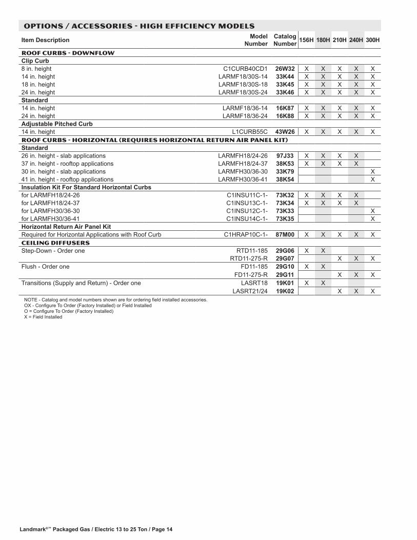
Landmark®™ Packaged Gas / Electric 13 to 25 Ton / Page 14
OPTIONS / ACCESSORIES - HIGH EFFICIENCY MODELS
Item Description Model Number
Catalog Number 156H 180H 210H 240H 300H
ROOF CURBS - DOWNFLOWClip Curb8 in. height C1CURB40CD1 26W32 X X X X X14 in. height LARMF18/30S-14 33K44 X X X X X18 in. height LARMF18/30S-18 33K45 X X X X X24 in. height LARMF18/30S-24 33K46 X X X X XStandard14 in. height LARMF18/36-14 16K87 X X X X X24 in. height LARMF18/36-24 16K88 X X X X XAdjustable Pitched Curb14 in. height L1CURB55C 43W26 X X X X XROOF CURBS - HORIZONTAL (REQUIRES HORIZONTAL RETURN AIR PANEL KIT)Standard26 in. height - slab applications LARMFH18/24-26 97J33 X X X X37 in. height - rooftop applications LARMFH18/24-37 38K53 X X X X30 in. height - slab applications LARMFH30/36-30 33K79 X41 in. height - rooftop applications LARMFH30/36-41 38K54 XInsulation Kit For Standard Horizontal Curbsfor LARMFH18/24-26 C1INSU11C-1- 73K32 X X X Xfor LARMFH18/24-37 C1INSU13C-1- 73K34 X X X Xfor LARMFH30/36-30 C1INSU12C-1- 73K33 Xfor LARMFH30/36-41 C1INSU14C-1- 73K35 XHorizontal Return Air Panel KitRequired for Horizontal Applications with Roof Curb C1HRAP10C-1- 87M00 X X X X XCEILING DIFFUSERSStep-Down - Order one RTD11-185 29G06 X X
RTD11-275-R 29G07 X X XFlush - Order one FD11-185 29G10 X X
FD11-275-R 29G11 X X XTransitions (Supply and Return) - Order one LASRT18 19K01 X X
LASRT21/24 19K02 X X XNOTE - Catalog and model numbers shown are for ordering field installed accessories. OX - Configure To Order (Factory Installed) or Field Installed O = Configure To Order (Factory Installed) X = Field Installed
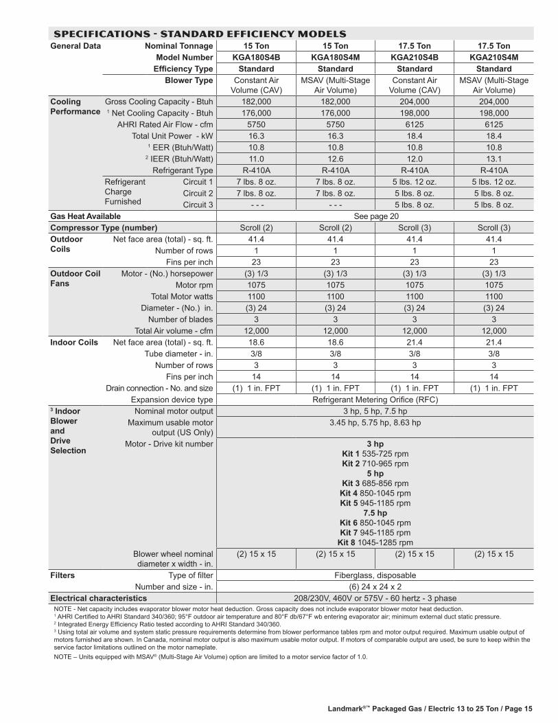
Landmark®™ Packaged Gas / Electric 13 to 25 Ton / Page 15
SPECIFICATIONS - STANDARD EFFICIENCY MODELSGeneral Data Nominal Tonnage 15 Ton 15 Ton 17.5 Ton 17.5 Ton
Model Number KGA180S4B KGA180S4M KGA210S4B KGA210S4MEfficiency Type Standard Standard Standard Standard
Blower Type Constant Air Volume (CAV)
MSAV (Multi-Stage Air Volume)
Constant Air Volume (CAV)
MSAV (Multi-Stage Air Volume)
Cooling Performance
Gross Cooling Capacity - Btuh 182,000 182,000 204,000 204,0001 Net Cooling Capacity - Btuh 176,000 176,000 198,000 198,000
AHRI Rated Air Flow - cfm 5750 5750 6125 6125Total Unit Power - kW 16.3 16.3 18.4 18.4
1 EER (Btuh/Watt) 10.8 10.8 10.8 10.82 IEER (Btuh/Watt) 11.0 12.6 12.0 13.1
Refrigerant Type R-410A R-410A R-410A R-410ARefrigerant Charge Furnished
Circuit 1 7 lbs. 8 oz. 7 lbs. 8 oz. 5 lbs. 12 oz. 5 lbs. 12 oz.Circuit 2 7 lbs. 8 oz. 7 lbs. 8 oz. 5 lbs. 8 oz. 5 lbs. 8 oz.Circuit 3 - - - - - - 5 lbs. 8 oz. 5 lbs. 8 oz.
Gas Heat Available See page 20Compressor Type (number) Scroll (2) Scroll (2) Scroll (3) Scroll (3)Outdoor Coils
Net face area (total) - sq. ft. 41.4 41.4 41.4 41.4Number of rows 1 1 1 1
Fins per inch 23 23 23 23Outdoor Coil Fans
Motor - (No.) horsepower (3) 1/3 (3) 1/3 (3) 1/3 (3) 1/3Motor rpm 1075 1075 1075 1075
Total Motor watts 1100 1100 1100 1100Diameter - (No.) in. (3) 24 (3) 24 (3) 24 (3) 24
Number of blades 3 3 3 3Total Air volume - cfm 12,000 12,000 12,000 12,000
Indoor Coils Net face area (total) - sq. ft. 18.6 18.6 21.4 21.4Tube diameter - in. 3/8 3/8 3/8 3/8
Number of rows 3 3 3 3Fins per inch 14 14 14 14
Drain connection - No. and size (1) 1 in. FPT (1) 1 in. FPT (1) 1 in. FPT (1) 1 in. FPTExpansion device type Refrigerant Metering Orifice (RFC)
3 Indoor Blower and Drive Selection
Nominal motor output 3 hp, 5 hp, 7.5 hpMaximum usable motor
output (US Only)3.45 hp, 5.75 hp, 8.63 hp
Motor - Drive kit number 3 hp Kit 1 535-725 rpm Kit 2 710-965 rpm
5 hp Kit 3 685-856 rpm Kit 4 850-1045 rpm Kit 5 945-1185 rpm
7.5 hp Kit 6 850-1045 rpm Kit 7 945-1185 rpm
Kit 8 1045-1285 rpmBlower wheel nominal diameter x width - in.
(2) 15 x 15 (2) 15 x 15 (2) 15 x 15 (2) 15 x 15
Filters Type of filter Fiberglass, disposableNumber and size - in. (6) 24 x 24 x 2
Electrical characteristics 208/230V, 460V or 575V - 60 hertz - 3 phaseNOTE - Net capacity includes evaporator blower motor heat deduction. Gross capacity does not include evaporator blower motor heat deduction. 1 AHRI Certified to AHRI Standard 340/360; 95°F outdoor air temperature and 80°F db/67°F wb entering evaporator air; minimum external duct static pressure. 2 Integrated Energy Efficiency Ratio tested according to AHRI Standard 340/360. 3 Using total air volume and system static pressure requirements determine from blower performance tables rpm and motor output required. Maximum usable output of motors furnished are shown. In Canada, nominal motor output is also maximum usable motor output. If motors of comparable output are used, be sure to keep within the service factor limitations outlined on the motor nameplate.NOTE – Units equipped with MSAV® (Multi-Stage Air Volume) option are limited to a motor service factor of 1.0.

Landmark®™ Packaged Gas / Electric 13 to 25 Ton / Page 16
SPECIFICATIONS - STANDARD EFFICIENCY MODELSGeneral Data Nominal Tonnage 20 Ton 20 Ton 25 Ton 25 Ton
Model Number KGA240S4B KGA240S4M KGA300S4B KGA300S4MEfficiency Type Standard Standard Standard Standard
Blower Type Constant Air Volume (CAV)
MSAV (Multi-Stage Air Volume)
Constant Air Volume (CAV)
MSAV (Multi-Stage Air Volume)
Cooling Performance
Gross Cooling Capacity - Btuh 238,000 238,000 282,000 282,0001 Net Cooling Capacity - Btuh 228,000 228,000 270,000 270,000
AHRI Rated Air Flow - cfm 7700 7700 8750 8750Total Unit Power - kW 21.1 21.1 27.0 27.0
1 EER (Btuh/Watt) 10.8 10.8 10.0 10.02 IEER (Btuh/Watt) 11.0 13.0 10.0 12.0
Refrigerant Type R-410A R-410A R-410A R-410ARefrigerant Charge Furnished
Circuit 1 7 lbs. 4 oz. 7 lbs. 4 oz. 7 lbs. 4 oz. 7 lbs. 4 oz.Circuit 2 7 lbs. 4 oz. 7 lbs. 4 oz. 7 lbs. 4 oz. 7 lbs. 4 oz.Circuit 3 6 lbs. 14 oz. 6 lbs. 14 oz. 6 lbs. 14 oz. 6 lbs. 14 oz.
Gas Heat Available See page 20Compressor Type (number) Scroll (3) Scroll (3) Scroll (3) Scroll (3)Outdoor Coils
Net face area (total) - sq. ft. 55.2 55.2 55.2 55.2Number of rows 1 1 1 1
Fins per inch 23 23 23 23Outdoor Coil Fans
Motor - (No.) horsepower (4) 1/3 (4) 1/3 (4) 1/3 (4) 1/3Motor rpm 1075 1075 1075 1075
Total Motor watts 1500 1500 1500 1500Diameter - (No.) in. (4) 24 (4) 24 (4) 24 (4) 24
Number of blades 3 3 3 3Total Air volume - cfm 16,000 16,000 16,000 16,000
Indoor Coils Net face area (total) - sq. ft. 21.4 21.4 21.4 21.4Tube diameter - in. 3/8 3/8 3/8 3/8
Number of rows 4 4 4 4Fins per inch 14 14 14 14
Drain connection - No. and size (1) 1 in. FPT (1) 1 in. FPT (1) 1 in. FPT (1) 1 in. FPTExpansion device type Refrigerant Metering Orifice (RFC)
3 Indoor Blower and Drive Selection
Nominal motor output 5 hp, 7.5 hp, 10 hpMaximum usable motor
output (US Only)5.75 hp, 8.62 hp, 11.5 hp
Motor - Drive kit number 5 hp Kit 3 685-856 rpm Kit 4 850-1045 rpm Kit 5 945-1185 rpm
7.5 hp Kit 6 850-1045 rpm Kit 7 945-1185 rpm
Kit 8 1045-1285 rpm 10 hp
Kit 7 945-1185 rpm Kit 10 1045-1285 rpm Kit 11 1135-1365 rpm
Blower wheel nominal diameter x width - in.
(2) 15 x 15 (2) 15 x 15 (2) 15 x 15 (2) 15 x 15
Filters Type of filter Fiberglass, disposableNumber and size - in. (6) 24 x 24 x 2
Electrical characteristics 208/230V, 460V or 575V - 60 hertz - 3 phaseNOTE - Net capacity includes evaporator blower motor heat deduction. Gross capacity does not include evaporator blower motor heat deduction. 1 AHRI Certified to AHRI Standard 340/360; 95°F outdoor air temperature and 80°F db/67°F wb entering evaporator air; minimum external duct static pressure. 2 Integrated Energy Efficiency Ratio tested according to AHRI Standard 340/360. 3 Using total air volume and system static pressure requirements determine from blower performance tables rpm and motor output required. Maximum usable output of motors furnished are shown. In Canada, nominal motor output is also maximum usable motor output. If motors of comparable output are used, be sure to keep within the service factor limitations outlined on the motor nameplate.NOTE – Units equipped with MSAV® (Multi-Stage Air Volume) option are limited to a motor service factor of 1.0.

Landmark®™ Packaged Gas / Electric 13 to 25 Ton / Page 17
SPECIFICATIONS - HIGH EFFICIENCY MODELSGeneral Data Nominal Tonnage 13 Ton 13 Ton 15 Ton 15 Ton
Model Number KGA156H4B KGA156H4M KGA180H4B KGA180H4MEfficiency Type High High High High
Blower Type Constant Air Volume (CAV)
MSAV (Multi-Stage Air Volume)
Constant Air Volume (CAV)
MSAV (Multi-Stage Air Volume)
Cooling Performance
Gross Cooling Capacity - Btuh 156,000 156,000 176,000 176,0001 Net Cooling Capacity - Btuh 152,000 152,000 172,000 172,000
AHRI Rated Air Flow - cfm 5200 5200 5250 5250Total Unit Power - kW 12.7 12.7 14.3 14.3
1 EER (Btuh/Watt) 12.0 12.0 12.0 12.02 IEER (Btuh/Watt) 13.6 14.1 13.5 13.7
Refrigerant Type R-410A R-410A R-410A R-410ARefrigerant Charge Furnished
Circuit 1 5 lbs. 12 oz. 5 lbs. 12 oz. 6 lbs. 0 oz. 6 lbs. 0 oz.Circuit 2 5 lbs. 6 oz. 5 lbs. 6 oz. 5 lbs. 10 oz. 5 lbs. 10 oz.Circuit 3 5 lbs. 10 oz. 5 lbs. 10 oz. 5 lbs. 14 oz. 5 lbs. 14 oz.
Gas Heat Available See page 20Compressor Type (number) Scroll (3) Scroll (3) Scroll (3) Scroll (3)Outdoor Coils
Net face area (total) - sq. ft. 41.4 41.4 55.2 55.2Number of rows 1 1 1 1
Fins per inch 23 23 23 23Outdoor Coil Fans
Motor - (No.) horsepower (3) 1/3 (3) 1/3 (4) 1/3 (4) 1/3Motor rpm 1075 1075 1075 1075
Total Motor watts 1100 1100 1500 1500Diameter - (No.) in. (3) 24 (3) 24 (4) 24 (4) 24
Number of blades 3 3 3 3Total Air volume - cfm 12,000 12,000 16,000 16,000
Indoor Coils Net face area (total) - sq. ft. 21.4 21.4 21.4 21.4Tube diameter - in. 3/8 3/8 3/8 3/8
Number of rows 3 3 3 3Fins per inch 14 14 14 14
Drain connection - No. and size (1) 1 in. FPT (1) 1 in. FPT (1) 1 in. FPT (1) 1 in. FPTExpansion device type Balanced port TXV, removable head
3 Indoor Blower and Drive Selection
Nominal motor output 2 hp, 3 hp, 5 hp 3 hp, 5 hp, 7.5 hpMaximum usable motor
output (US Only)2.3 hp, 3.45 hp, 5.75 hp 3.45 hp, 5.75 hp, 8.62 hp
Motor - Drive kit number 2 hp Kit 1 535-725 rpm Kit 2 710-965 rpm
3 hp Kit 1 535-725 rpm Kit 2 710-965 rpm
5 hp Kit 3 685-856 rpm Kit 4 850-1045 rpm Kit 5 945-1185 rpm
3 hp Kit 1 535-725 rpm Kit 2 710-965 rpm
5 hp Kit 3 685-856 rpm Kit 4 850-1045 rpm Kit 5 945-1185 rpm
7.5 hp Kit 6 850-1045 rpm Kit 7 945-1185 rpm
Kit 8 1045-1285 rpmBlower wheel nominal diameter x width - in.
(2) 15 x 15 (2) 15 x 15 (2) 15 x 15 (2) 15 x 15
Filters Type of filter Fiberglass, disposableNumber and size - in. (6) 24 x 24 x 2
Electrical characteristics 208/230V, 460V or 575V - 60 hertz - 3 phaseNOTE - Net capacity includes evaporator blower motor heat deduction. Gross capacity does not include evaporator blower motor heat deduction. 1 AHRI Certified to AHRI Standard 340/360; 95°F outdoor air temperature and 80°F db/67°F wb entering evaporator air; minimum external duct static pressure. 2 Integrated Energy Efficiency Ratio tested according to AHRI Standard 340/360. 3 Using total air volume and system static pressure requirements determine from blower performance tables rpm and motor output required. Maximum usable output of motors furnished are shown. In Canada, nominal motor output is also maximum usable motor output. If motors of comparable output are used, be sure to keep within the service factor limitations outlined on the motor nameplate.NOTE – Units equipped with MSAV® (Multi-Stage Air Volume) option are limited to a motor service factor of 1.0.

Landmark®™ Packaged Gas / Electric 13 to 25 Ton / Page 18
SPECIFICATIONS - high EFFICIENCY MODELSGeneral Data Nominal Tonnage 17.5 Ton 17.5 Ton 20 Ton 20 Ton
Model Number KGA210H4B KGA210H4M KGA240H4B KGA240H4MEfficiency Type High High High High
Blower Type Constant Air Volume (CAV)
MSAV (Multi-Stage Air Volume)
Constant Air Volume (CAV)
MSAV (Multi-Stage Air Volume)
Cooling Performance
Gross Cooling Capacity - Btuh 204,000 204,000 238,000 238,0001 Net Cooling Capacity - Btuh 198,000 198,000 230,000 230,000
AHRI Rated Air Flow - cfm 6125 6125 6400 6400Total Unit Power - kW 16.5 16.5 19.2 19.2
1 EER (Btuh/Watt) 12.0 12.0 12.0 12.02 IEER (Btuh/Watt) 13.0 14.0 13.2 14.5
Refrigerant Type R-410A R-410A R-410A R-410ARefrigerant Charge Furnished
Circuit 1 6 lbs. 12 oz. 6 lbs. 12 oz. 6 lbs. 4 oz. 6 lbs. 4 oz.Circuit 2 6 lbs. 14 oz. 6 lbs. 14 oz. 6 lbs. 2 oz. 6 lbs. 2 oz.Circuit 3 6 lbs. 14 oz. 6 lbs. 14 oz. 5 lbs. 14 oz. 5 lbs. 14 oz.Circuit 4 - - - - - - 5 lbs. 6 oz. 5 lbs. 6 oz.
Gas Heat Available See page 20Compressor Type (number) Scroll (3) Scroll (3) Scroll (4) Scroll (4)Outdoor Coils
Net face area (total) - sq. ft. 55.2 55.2 55.2 55.2Number of rows 1 1 1 1
Fins per inch 23 23 23 23Outdoor Coil Fans
Motor - (No.) horsepower (6) 1/3 (6) 1/3 (6) 1/3 (6) 1/3Motor rpm 1075 1075 1075 1075
Total Motor watts 1950 1950 1950 1950Diameter - (No.) in. (6) 24 (6) 24 (6) 24 (6) 24
Number of blades 3 3 3 3Total Air volume - cfm 20,000 20,000 20,000 20,000
Indoor Coils Net face area (total) - sq. ft. 21.4 21.4 21.4 21.4Tube diameter - in. 3/8 3/8 3/8 3/8
Number of rows 4 4 4 4Fins per inch 14 14 14 14
Drain connection - No. and size (1) 1 in. FPT (1) 1 in. FPT (1) 1 in. FPT (1) 1 in. FPTExpansion device type Balanced port TXV, removable head
3 Indoor Blower and Drive Selection
Nominal motor output 3 hp, 5 hp, 7.5 hp 5 hp, 7.5 hp, 10hpMaximum usable motor
output (US Only)3.45 hp, 5.75 hp, 8.62 hp 5.75 hp, 8.62 hp, 11.5 hp
Motor - Drive kit number 3 hp Kit 1 535-725 rpm Kit 2 710-965 rpm
5 hp Kit 3 685-856 rpm Kit 4 850-1045 rpm Kit 5 945-1185 rpm
7.5 hp Kit 6 850-1045 rpm Kit 7 945-1185 rpm
Kit 8 1045-1285 rpm
5 hp Kit 3 685-856 rpm Kit 4 850-1045 rpm Kit 5 945-1185 rpm
7.5 hp Kit 6 850-1045 rpm Kit 7 945-1185 rpm
Kit 8 1045-1285 rpm 10 hp
Kit 7 945-1185 rpm Kit 10 1045-1285 rpm Kit 11 1135-1365 rpm
Blower wheel nominal diameter x width - in.
(2) 15 x 15 (2) 15 x 15 (2) 15 x 15 (2) 15 x 15
Filters Type of filter Fiberglass, disposableNumber and size - in. (6) 24 x 24 x 2
Electrical characteristics 208/230V, 460V or 575V - 60 hertz - 3 phaseNOTE - Net capacity includes evaporator blower motor heat deduction. Gross capacity does not include evaporator blower motor heat deduction. 1 AHRI Certified to AHRI Standard 340/360; 95°F outdoor air temperature and 80°F db/67°F wb entering evaporator air; minimum external duct static pressure. 2 Integrated Energy Efficiency Ratio tested according to AHRI Standard 340/360. 3 Using total air volume and system static pressure requirements determine from blower performance tables rpm and motor output required. Maximum usable output of motors furnished are shown. In Canada, nominal motor output is also maximum usable motor output. If motors of comparable output are used, be sure to keep within the service factor limitations outlined on the motor nameplate.NOTE – Units equipped with MSAV® (Multi-Stage Air Volume) option are limited to a motor service factor of 1.0.

Landmark®™ Packaged Gas / Electric 13 to 25 Ton / Page 19
SPECIFICATIONS - high EFFICIENCY MODELSGeneral Data Nominal Tonnage 25 Ton 25 Ton
Model Number KGA300H4B KGA300H4MEfficiency Type High High
Blower Type Constant Air Volume (CAV)
MSAV (Multi-Stage Air Volume)
Cooling Performance
Gross Cooling Capacity - Btuh 282,000 282,0001 Net Cooling Capacity - Btuh 270,000 270,000
AHRI Rated Air Flow - cfm 8400 8400Total Unit Power - kW 25.7 25.7
1 EER (Btuh/Watt) 10.5 10.52 IEER (Btuh/Watt) 10.9 13.8
Refrigerant Type R-410A R-410ARefrigerant Charge Furnished
Circuit 1 6 lbs. 8 oz. 6 lbs. 8 oz. Circuit 2 6 lbs. 6 oz. 6 lbs. 6 oz. Circuit 3 6 lbs. 6 oz. 6lbs. 6 oz.Circuit 4 5 lbs. 14 oz. 5 lbs. 14 oz.
Gas Heat Available See page 20Compressor Type (number) Scroll (4) Scroll (4)Outdoor Coils
Net face area (total) - sq. ft. 55.2 55.2Number of rows 1 1
Fins per inch 23 23Outdoor Coil Fans
Motor - (No.) horsepower (6) 1/3 (6) 1/3Motor rpm 1075 1075
Total Motor watts 1950 1950Diameter - (No.) in. (6) 24 (6) 24
Number of blades 3 3Total Air volume - cfm 20,000 20,000
Indoor Coils Net face area (total) - sq. ft. 21.4 21.4Tube diameter - in. 3/8 3/8
Number of rows 4 4Fins per inch 14 14
Drain connection - No. and size (1) 1 in. FPT (1) 1 in. FPTExpansion device type Balanced port TXV, removable head
3 Indoor Blower and Drive Selection
Nominal motor output 5 hp, 7.5 hp, 10 hpMaximum usable motor
output (US Only)5.75 hp, 8.62 hp, 11.5 hp
Motor - Drive kit number 5 hp Kit 3 685-856 rpm
Kit 4 850-1045 rpm Kit 5 945-1185 rpm
7.5 hp Kit 6 850-1045 rpm Kit 7 945-1185 rpm
Kit 8 1045-1285 rpm 10 hp
Kit 7 945-1185 rpm Kit 10 1045-1285 rpm Kit 11 1135-1365 rpm
Blower wheel nominal diameter x width - in.
(2) 15 x 15 (2) 15 x 15
Filters Type of filter Fiberglass, disposableNumber and size - in. (6) 24 x 24 x 2
Electrical characteristics 208/230V, 460V or 575V - 60 hertz - 3 phaseNOTE - Net capacity includes evaporator blower motor heat deduction. Gross capacity does not include evaporator blower motor heat deduction. 1 AHRI Certified to AHRI Standard 340/360; 95°F outdoor air temperature and 80°F db/67°F wb entering evaporator air; minimum external duct static pressure. 2 Integrated Energy Efficiency Ratio tested according to AHRI Standard 340/360. 3 Using total air volume and system static pressure requirements determine from blower performance tables rpm and motor output required. Maximum usable output of motors furnished are shown. In Canada, nominal motor output is also maximum usable motor output. If motors of comparable output are used, be sure to keep within the service factor limitations outlined on the motor nameplate.NOTE – Units equipped with MSAV® (Multi-Stage Air Volume) option are limited to a motor service factor of 1.0.

Landmark®™ Packaged Gas / Electric 13 to 25 Ton / Page 20
HIGH ALTITUDE DERATE Units may be installed at altitudes up to 2000 feet above sea level without any modification.At altitudes above 2000 feet, units must be derated to match gas manifold pressures shown in table below.At altitudes above 2000 feet unit must be derated to match gas manifold pressures shown in the table below.NOTE − This is the only permissible derate for these units.
Gas Heat Type
Altitude - ft. Gas Manifold Pressure - in. w.g. Input Rate Natural Gas or LPG/Propane - Btuh
Natural Gas LPG/Propane Gas First Stage Second Stage
Standard 2001 - 4500 3.4 9.6 169,000 249,000
Medium 2001 - 4500 3.4 9.6 234,000 345,000
High 2001 - 4500 3.4 9.6 312,000 460,000
SPECIFICATIONS - GAS HEATUsage Data Model Number KGA156
KGA180 KGA210 KGA240 KGA300
KGA180 KGA210 KGA240 KGA300
Heat Input Type Standard (S) Medium (M) High (H)
Number of Gas Heat Stages 2 2 2
Gas Heating Performance
Input - Btuh First Stage 169,000 234,000 312,000
Second Stage 260,000 360,000 480,000
Output - Btuh First Stage - - - - - - - - -
Second Stage 208,000 288,000 384,000
Temperature Rise Range - °F 15 - 45 30 - 60 40 - 70
Thermal Efficiency 80.0% 80.0% 80.0%
Gas Supply Connections 1 in. npt 1 in. npt 1 in. npt
Recommended Gas Supply Pressure - in. w.g.
Natural 7 7 7
LPG/Propane 11 11 11
Landmark®™ Packaged Gas / Electric 13 to 25 Ton / Page 21
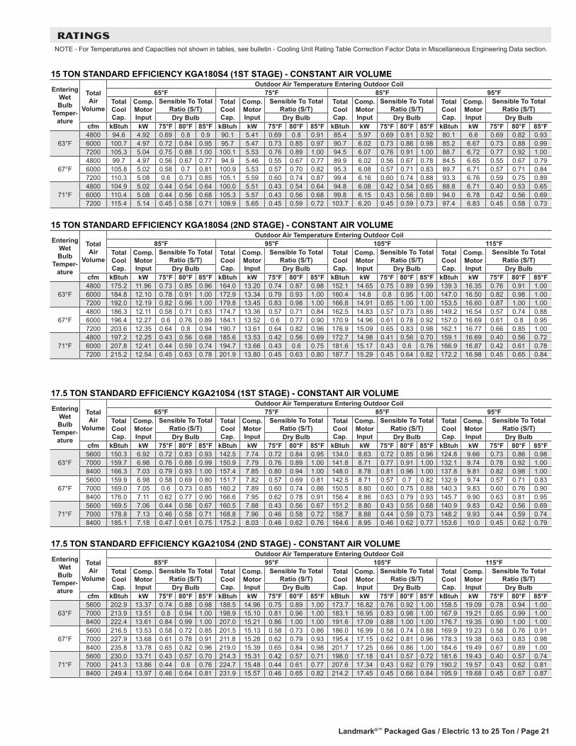
RATINGSNOTE - For Temperatures and Capacities not shown in tables, see bulletin - Cooling Unit Rating Table Correction Factor Data in Miscellaneous Engineering Data section.
17.5 TON STANDARD EFFICIENCY KGA210S4 (1ST STAGE) - CONSTANT AIR VOLUME
Entering Wet Bulb
Temper-ature
Total Air
Volume
Outdoor Air Temperature Entering Outdoor Coil65°F 75°F 85°F 95°F
Total Cool Cap.
Comp. Motor Input
Sensible To Total Ratio (S/T)
Total Cool Cap.
Comp. Motor Input
Sensible To Total Ratio (S/T)
Total Cool Cap.
Comp. Motor Input
Sensible To Total Ratio (S/T)
Total Cool Cap.
Comp. Motor Input
Sensible To Total Ratio (S/T)
Dry Bulb Dry Bulb Dry Bulb Dry Bulbcfm kBtuh kW 75°F 80°F 85°F kBtuh kW 75°F 80°F 85°F kBtuh kW 75°F 80°F 85°F kBtuh kW 75°F 80°F 85°F
63°F5600 150.3 6.92 0.72 0.83 0.93 142.5 7.74 0.72 0.84 0.95 134.0 8.63 0.72 0.85 0.96 124.8 9.66 0.73 0.86 0.987000 159.7 6.98 0.76 0.88 0.99 150.9 7.79 0.76 0.89 1.00 141.8 8.71 0.77 0.91 1.00 132.1 9.74 0.78 0.92 1.008400 166.3 7.03 0.79 0.93 1.00 157.4 7.85 0.80 0.94 1.00 148.0 8.78 0.81 0.96 1.00 137.8 9.81 0.82 0.98 1.00
67°F5600 159.9 6.98 0.58 0.69 0.80 151.7 7.82 0.57 0.69 0.81 142.5 8.71 0.57 0.7 0.82 132.9 9.74 0.57 0.71 0.837000 169.0 7.05 0.6 0.73 0.85 160.2 7.89 0.60 0.74 0.86 150.5 8.80 0.60 0.75 0.88 140.3 9.83 0.60 0.76 0.908400 176.0 7.11 0.62 0.77 0.90 166.6 7.95 0.62 0.78 0.91 156.4 8.86 0.63 0.79 0.93 145.7 9.90 0.63 0.81 0.95
71°F5600 169.5 7.06 0.44 0.56 0.67 160.5 7.88 0.43 0.56 0.67 151.2 8.80 0.43 0.55 0.68 140.9 9.83 0.42 0.56 0.697000 178.8 7.13 0.46 0.58 0.71 168.8 7.96 0.46 0.58 0.72 158.7 8.88 0.44 0.59 0.73 148.2 9.93 0.44 0.59 0.748400 185.1 7.18 0.47 0.61 0.75 175.2 8.03 0.46 0.62 0.76 164.6 8.95 0.46 0.62 0.77 153.6 10.0 0.45 0.62 0.79
17.5 TON STANDARD EFFICIENCY KGA210S4 (2ND STAGE) - CONSTANT AIR VOLUME
Entering Wet Bulb
Temper-ature
Total Air
Volume
Outdoor Air Temperature Entering Outdoor Coil85°F 95°F 105°F 115°F
Total Cool Cap.
Comp. Motor Input
Sensible To Total Ratio (S/T)
Total Cool Cap.
Comp. Motor Input
Sensible To Total Ratio (S/T)
Total Cool Cap.
Comp. Motor Input
Sensible To Total Ratio (S/T)
Total Cool Cap.
Comp. Motor Input
Sensible To Total Ratio (S/T)
Dry Bulb Dry Bulb Dry Bulb Dry Bulbcfm kBtuh kW 75°F 80°F 85°F kBtuh kW 75°F 80°F 85°F kBtuh kW 75°F 80°F 85°F kBtuh kW 75°F 80°F 85°F
63°F5600 202.9 13.37 0.74 0.88 0.98 188.5 14.96 0.75 0.89 1.00 173.7 16.82 0.76 0.92 1.00 158.5 19.09 0.78 0.94 1.007000 213.9 13.51 0.8 0.94 1.00 198.9 15.10 0.81 0.96 1.00 183.1 16.95 0.83 0.98 1.00 167.9 19.21 0.85 0.99 1.008400 222.4 13.61 0.84 0.99 1.00 207.0 15.21 0.86 1.00 1.00 191.6 17.09 0.88 1.00 1.00 176.7 19.35 0.90 1.00 1.00
67°F5600 216.5 13.53 0.58 0.72 0.85 201.5 15.13 0.58 0.73 0.86 186.0 16.99 0.58 0.74 0.88 169.9 19.23 0.58 0.76 0.917000 227.9 13.68 0.61 0.78 0.91 211.8 15.28 0.62 0.79 0.93 195.4 17.15 0.62 0.81 0.96 178.3 19.38 0.63 0.83 0.988400 235.8 13.78 0.65 0.82 0.96 219.0 15.39 0.65 0.84 0.98 201.7 17.25 0.66 0.86 1.00 184.6 19.49 0.67 0.89 1.00
71°F5600 230.0 13.71 0.43 0.57 0.70 214.3 15.31 0.42 0.57 0.71 198.0 17.18 0.41 0.57 0.72 181.6 19.43 0.40 0.57 0.747000 241.3 13.86 0.44 0.6 0.76 224.7 15.48 0.44 0.61 0.77 207.6 17.34 0.43 0.62 0.79 190.2 19.57 0.43 0.62 0.818400 249.4 13.97 0.46 0.64 0.81 231.9 15.57 0.46 0.65 0.82 214.2 17.45 0.45 0.66 0.84 195.9 19.68 0.45 0.67 0.87
15 TON STANDARD EFFICIENCY KGA180S4 (1ST STAGE) - CONSTANT AIR VOLUME
Entering Wet Bulb
Temper-ature
Total Air
Volume
Outdoor Air Temperature Entering Outdoor Coil65°F 75°F 85°F 95°F
Total Cool Cap.
Comp. Motor Input
Sensible To Total Ratio (S/T)
Total Cool Cap.
Comp. Motor Input
Sensible To Total Ratio (S/T)
Total Cool Cap.
Comp. Motor Input
Sensible To Total Ratio (S/T)
Total Cool Cap.
Comp. Motor Input
Sensible To Total Ratio (S/T)
Dry Bulb Dry Bulb Dry Bulb Dry Bulbcfm kBtuh kW 75°F 80°F 85°F kBtuh kW 75°F 80°F 85°F kBtuh kW 75°F 80°F 85°F kBtuh kW 75°F 80°F 85°F
63°F4800 94.6 4.92 0.69 0.8 0.9 90.1 5.41 0.69 0.8 0.91 85.4 5.97 0.69 0.81 0.92 80.1 6.6 0.69 0.82 0.936000 100.7 4.97 0.72 0.84 0.95 95.7 5.47 0.73 0.85 0.97 90.7 6.02 0.73 0.86 0.98 85.2 6.67 0.73 0.88 0.997200 105.3 5.04 0.75 0.88 1.00 100.1 5.53 0.76 0.89 1.00 94.5 6.07 0.76 0.91 1.00 88.7 6.72 0.77 0.92 1.00
67°F4800 99.7 4.97 0.56 0.67 0.77 94.9 5.46 0.55 0.67 0.77 89.9 6.02 0.56 0.67 0.78 84.5 6.65 0.55 0.67 0.796000 105.8 5.02 0.58 0.7 0.81 100.9 5.53 0.57 0.70 0.82 95.3 6.08 0.57 0.71 0.83 89.7 6.71 0.57 0.71 0.847200 110.3 5.08 0.6 0.73 0.85 105.1 5.59 0.60 0.74 0.87 99.4 6.16 0.60 0.74 0.88 93.3 6.76 0.59 0.75 0.89
71°F4800 104.9 5.02 0.44 0.54 0.64 100.0 5.51 0.43 0.54 0.64 94.8 6.08 0.42 0.54 0.65 88.8 6.71 0.40 0.53 0.656000 110.4 5.08 0.44 0.56 0.68 105.3 5.57 0.43 0.56 0.68 99.8 6.15 0.43 0.56 0.69 94.0 6.78 0.42 0.56 0.697200 115.4 5.14 0.45 0.58 0.71 109.9 5.65 0.45 0.59 0.72 103.7 6.20 0.45 0.59 0.73 97.4 6.83 0.45 0.58 0.73
15 TON STANDARD EFFICIENCY KGA180S4 (2ND STAGE) - CONSTANT AIR VOLUME
Entering Wet Bulb
Temper-ature
Total Air
Volume
Outdoor Air Temperature Entering Outdoor Coil85°F 95°F 105°F 115°F
Total Cool Cap.
Comp. Motor Input
Sensible To Total Ratio (S/T)
Total Cool Cap.
Comp. Motor Input
Sensible To Total Ratio (S/T)
Total Cool Cap.
Comp. Motor Input
Sensible To Total Ratio (S/T)
Total Cool Cap.
Comp. Motor Input
Sensible To Total Ratio (S/T)
Dry Bulb Dry Bulb Dry Bulb Dry Bulbcfm kBtuh kW 75°F 80°F 85°F kBtuh kW 75°F 80°F 85°F kBtuh kW 75°F 80°F 85°F kBtuh kW 75°F 80°F 85°F
63°F4800 175.2 11.96 0.73 0.85 0.96 164.0 13.20 0.74 0.87 0.98 152.1 14.65 0.75 0.89 0.99 139.3 16.35 0.76 0.91 1.006000 184.8 12.10 0.78 0.91 1.00 172.9 13.34 0.79 0.93 1.00 160.4 14.8 0.8 0.95 1.00 147.0 16.50 0.82 0.98 1.007200 192.0 12.19 0.82 0.96 1.00 179.8 13.45 0.83 0.98 1.00 166.8 14.91 0.85 1.00 1.00 153.5 16.60 0.87 1.00 1.00
67°F4800 186.3 12.11 0.58 0.71 0.83 174.7 13.36 0.57 0.71 0.84 162.5 14.83 0.57 0.73 0.86 149.2 16.54 0.57 0.74 0.886000 196.4 12.27 0.6 0.76 0.89 184.1 13.52 0.6 0.77 0.90 170.9 14.96 0.61 0.78 0.92 157.0 16.69 0.61 0.8 0.957200 203.6 12.35 0.64 0.8 0.94 190.7 13.61 0.64 0.82 0.96 176.9 15.09 0.65 0.83 0.98 162.1 16.77 0.66 0.85 1.00
71°F4800 197.2 12.25 0.43 0.56 0.68 185.6 13.53 0.42 0.56 0.69 172.7 14.98 0.41 0.56 0.70 159.1 16.69 0.40 0.56 0.726000 207.8 12.41 0.44 0.59 0.74 194.7 13.66 0.43 0.6 0.75 181.6 15.17 0.43 0.6 0.76 166.9 16.87 0.42 0.61 0.787200 215.2 12.54 0.45 0.63 0.78 201.9 13.80 0.45 0.63 0.80 187.7 15.29 0.45 0.64 0.82 172.2 16.98 0.45 0.65 0.84
Landmark®™ Packaged Gas / Electric 13 to 25 Ton / Page 22
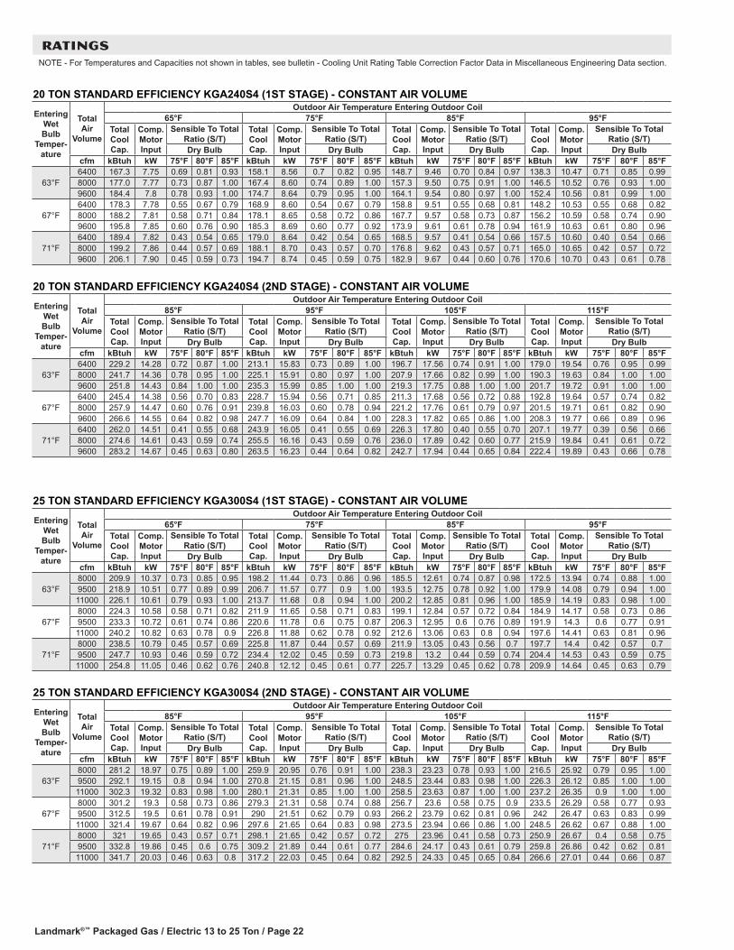
RATINGSNOTE - For Temperatures and Capacities not shown in tables, see bulletin - Cooling Unit Rating Table Correction Factor Data in Miscellaneous Engineering Data section.
25 TON STANDARD EFFICIENCY KGA300S4 (1ST STAGE) - CONSTANT AIR VOLUME
Entering Wet Bulb
Temper-ature
Total Air
Volume
Outdoor Air Temperature Entering Outdoor Coil65°F 75°F 85°F 95°F
Total Cool Cap.
Comp. Motor Input
Sensible To Total Ratio (S/T)
Total Cool Cap.
Comp. Motor Input
Sensible To Total Ratio (S/T)
Total Cool Cap.
Comp. Motor Input
Sensible To Total Ratio (S/T)
Total Cool Cap.
Comp. Motor Input
Sensible To Total Ratio (S/T)
Dry Bulb Dry Bulb Dry Bulb Dry Bulbcfm kBtuh kW 75°F 80°F 85°F kBtuh kW 75°F 80°F 85°F kBtuh kW 75°F 80°F 85°F kBtuh kW 75°F 80°F 85°F
63°F8000 209.9 10.37 0.73 0.85 0.95 198.2 11.44 0.73 0.86 0.96 185.5 12.61 0.74 0.87 0.98 172.5 13.94 0.74 0.88 1.009500 218.9 10.51 0.77 0.89 0.99 206.7 11.57 0.77 0.9 1.00 193.5 12.75 0.78 0.92 1.00 179.9 14.08 0.79 0.94 1.0011000 226.1 10.61 0.79 0.93 1.00 213.7 11.68 0.8 0.94 1.00 200.2 12.85 0.81 0.96 1.00 185.9 14.19 0.83 0.98 1.00
67°F8000 224.3 10.58 0.58 0.71 0.82 211.9 11.65 0.58 0.71 0.83 199.1 12.84 0.57 0.72 0.84 184.9 14.17 0.58 0.73 0.869500 233.3 10.72 0.61 0.74 0.86 220.6 11.78 0.6 0.75 0.87 206.3 12.95 0.6 0.76 0.89 191.9 14.3 0.6 0.77 0.9111000 240.2 10.82 0.63 0.78 0.9 226.8 11.88 0.62 0.78 0.92 212.6 13.06 0.63 0.8 0.94 197.6 14.41 0.63 0.81 0.96
71°F8000 238.5 10.79 0.45 0.57 0.69 225.8 11.87 0.44 0.57 0.69 211.9 13.05 0.43 0.56 0.7 197.7 14.4 0.42 0.57 0.79500 247.7 10.93 0.46 0.59 0.72 234.4 12.02 0.45 0.59 0.73 219.8 13.2 0.44 0.59 0.74 204.4 14.53 0.43 0.59 0.7511000 254.8 11.05 0.46 0.62 0.76 240.8 12.12 0.45 0.61 0.77 225.7 13.29 0.45 0.62 0.78 209.9 14.64 0.45 0.63 0.79
25 TON STANDARD EFFICIENCY KGA300S4 (2ND STAGE) - CONSTANT AIR VOLUME
Entering Wet Bulb
Temper-ature
Total Air
Volume
Outdoor Air Temperature Entering Outdoor Coil85°F 95°F 105°F 115°F
Total Cool Cap.
Comp. Motor Input
Sensible To Total Ratio (S/T)
Total Cool Cap.
Comp. Motor Input
Sensible To Total Ratio (S/T)
Total Cool Cap.
Comp. Motor Input
Sensible To Total Ratio (S/T)
Total Cool Cap.
Comp. Motor Input
Sensible To Total Ratio (S/T)
Dry Bulb Dry Bulb Dry Bulb Dry Bulbcfm kBtuh kW 75°F 80°F 85°F kBtuh kW 75°F 80°F 85°F kBtuh kW 75°F 80°F 85°F kBtuh kW 75°F 80°F 85°F
63°F8000 281.2 18.97 0.75 0.89 1.00 259.9 20.95 0.76 0.91 1.00 238.3 23.23 0.78 0.93 1.00 216.5 25.92 0.79 0.95 1.009500 292.1 19.15 0.8 0.94 1.00 270.8 21.15 0.81 0.96 1.00 248.5 23.44 0.83 0.98 1.00 226.3 26.12 0.85 1.00 1.0011000 302.3 19.32 0.83 0.98 1.00 280.1 21.31 0.85 1.00 1.00 258.5 23.63 0.87 1.00 1.00 237.2 26.35 0.9 1.00 1.00
67°F8000 301.2 19.3 0.58 0.73 0.86 279.3 21.31 0.58 0.74 0.88 256.7 23.6 0.58 0.75 0.9 233.5 26.29 0.58 0.77 0.939500 312.5 19.5 0.61 0.78 0.91 290 21.51 0.62 0.79 0.93 266.2 23.79 0.62 0.81 0.96 242 26.47 0.63 0.83 0.9911000 321.4 19.67 0.64 0.82 0.96 297.6 21.65 0.64 0.83 0.98 273.5 23.94 0.66 0.86 1.00 248.5 26.62 0.67 0.88 1.00
71°F8000 321 19.65 0.43 0.57 0.71 298.1 21.65 0.42 0.57 0.72 275 23.96 0.41 0.58 0.73 250.9 26.67 0.4 0.58 0.759500 332.8 19.86 0.45 0.6 0.75 309.2 21.89 0.44 0.61 0.77 284.6 24.17 0.43 0.61 0.79 259.8 26.86 0.42 0.62 0.8111000 341.7 20.03 0.46 0.63 0.8 317.2 22.03 0.45 0.64 0.82 292.5 24.33 0.45 0.65 0.84 266.6 27.01 0.44 0.66 0.87
20 TON STANDARD EFFICIENCY KGA240S4 (1ST STAGE) - CONSTANT AIR VOLUME
Entering Wet Bulb
Temper-ature
Total Air
Volume
Outdoor Air Temperature Entering Outdoor Coil65°F 75°F 85°F 95°F
Total Cool Cap.
Comp. Motor Input
Sensible To Total Ratio (S/T)
Total Cool Cap.
Comp. Motor Input
Sensible To Total Ratio (S/T)
Total Cool Cap.
Comp. Motor Input
Sensible To Total Ratio (S/T)
Total Cool Cap.
Comp. Motor Input
Sensible To Total Ratio (S/T)
Dry Bulb Dry Bulb Dry Bulb Dry Bulbcfm kBtuh kW 75°F 80°F 85°F kBtuh kW 75°F 80°F 85°F kBtuh kW 75°F 80°F 85°F kBtuh kW 75°F 80°F 85°F
63°F6400 167.3 7.75 0.69 0.81 0.93 158.1 8.56 0.7 0.82 0.95 148.7 9.46 0.70 0.84 0.97 138.3 10.47 0.71 0.85 0.998000 177.0 7.77 0.73 0.87 1.00 167.4 8.60 0.74 0.89 1.00 157.3 9.50 0.75 0.91 1.00 146.5 10.52 0.76 0.93 1.009600 184.4 7.8 0.78 0.93 1.00 174.7 8.64 0.79 0.95 1.00 164.1 9.54 0.80 0.97 1.00 152.4 10.56 0.81 0.99 1.00
67°F6400 178.3 7.78 0.55 0.67 0.79 168.9 8.60 0.54 0.67 0.79 158.8 9.51 0.55 0.68 0.81 148.2 10.53 0.55 0.68 0.828000 188.2 7.81 0.58 0.71 0.84 178.1 8.65 0.58 0.72 0.86 167.7 9.57 0.58 0.73 0.87 156.2 10.59 0.58 0.74 0.909600 195.8 7.85 0.60 0.76 0.90 185.3 8.69 0.60 0.77 0.92 173.9 9.61 0.61 0.78 0.94 161.9 10.63 0.61 0.80 0.96
71°F6400 189.4 7.82 0.43 0.54 0.65 179.0 8.64 0.42 0.54 0.65 168.5 9.57 0.41 0.54 0.66 157.5 10.60 0.40 0.54 0.668000 199.2 7.86 0.44 0.57 0.69 188.1 8.70 0.43 0.57 0.70 176.8 9.62 0.43 0.57 0.71 165.0 10.65 0.42 0.57 0.729600 206.1 7.90 0.45 0.59 0.73 194.7 8.74 0.45 0.59 0.75 182.9 9.67 0.44 0.60 0.76 170.6 10.70 0.43 0.61 0.78
20 TON STANDARD EFFICIENCY KGA240S4 (2ND STAGE) - CONSTANT AIR VOLUME
Entering Wet Bulb
Temper-ature
Total Air
Volume
Outdoor Air Temperature Entering Outdoor Coil85°F 95°F 105°F 115°F
Total Cool Cap.
Comp. Motor Input
Sensible To Total Ratio (S/T)
Total Cool Cap.
Comp. Motor Input
Sensible To Total Ratio (S/T)
Total Cool Cap.
Comp. Motor Input
Sensible To Total Ratio (S/T)
Total Cool Cap.
Comp. Motor Input
Sensible To Total Ratio (S/T)
Dry Bulb Dry Bulb Dry Bulb Dry Bulbcfm kBtuh kW 75°F 80°F 85°F kBtuh kW 75°F 80°F 85°F kBtuh kW 75°F 80°F 85°F kBtuh kW 75°F 80°F 85°F
63°F6400 229.2 14.28 0.72 0.87 1.00 213.1 15.83 0.73 0.89 1.00 196.7 17.56 0.74 0.91 1.00 179.0 19.54 0.76 0.95 0.998000 241.7 14.36 0.78 0.95 1.00 225.1 15.91 0.80 0.97 1.00 207.9 17.66 0.82 0.99 1.00 190.3 19.63 0.84 1.00 1.009600 251.8 14.43 0.84 1.00 1.00 235.3 15.99 0.85 1.00 1.00 219.3 17.75 0.88 1.00 1.00 201.7 19.72 0.91 1.00 1.00
67°F6400 245.4 14.38 0.56 0.70 0.83 228.7 15.94 0.56 0.71 0.85 211.3 17.68 0.56 0.72 0.88 192.8 19.64 0.57 0.74 0.828000 257.9 14.47 0.60 0.76 0.91 239.8 16.03 0.60 0.78 0.94 221.2 17.76 0.61 0.79 0.97 201.5 19.71 0.61 0.82 0.909600 266.6 14.55 0.64 0.82 0.98 247.7 16.09 0.64 0.84 1.00 228.3 17.82 0.65 0.86 1.00 208.3 19.77 0.66 0.89 0.96
71°F6400 262.0 14.51 0.41 0.55 0.68 243.9 16.05 0.41 0.55 0.69 226.3 17.80 0.40 0.55 0.70 207.1 19.77 0.39 0.56 0.668000 274.6 14.61 0.43 0.59 0.74 255.5 16.16 0.43 0.59 0.76 236.0 17.89 0.42 0.60 0.77 215.9 19.84 0.41 0.61 0.729600 283.2 14.67 0.45 0.63 0.80 263.5 16.23 0.44 0.64 0.82 242.7 17.94 0.44 0.65 0.84 222.4 19.89 0.43 0.66 0.78
Landmark®™ Packaged Gas / Electric 13 to 25 Ton / Page 23
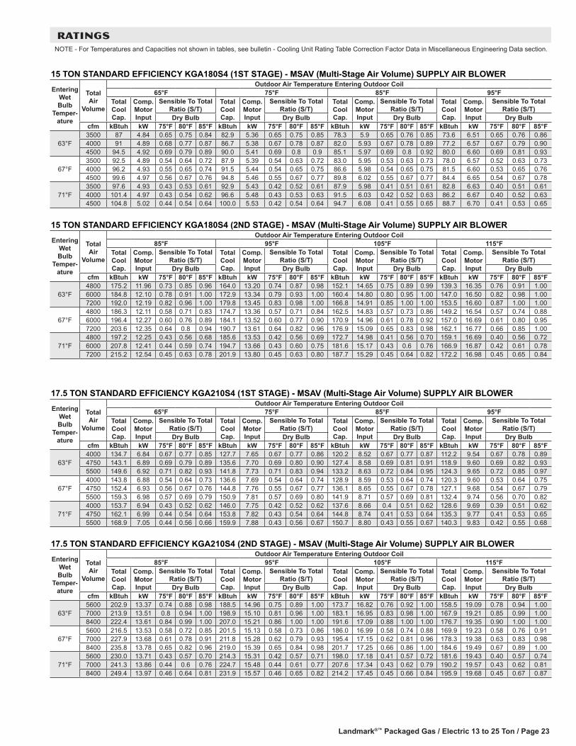
RATINGSNOTE - For Temperatures and Capacities not shown in tables, see bulletin - Cooling Unit Rating Table Correction Factor Data in Miscellaneous Engineering Data section.
17.5 TON STANDARD EFFICIENCY KGA210S4 (2ND STAGE) - MSAV (Multi-Stage Air Volume) SUPPLY AIR BLOWER
Entering Wet Bulb
Temper-ature
Total Air
Volume
Outdoor Air Temperature Entering Outdoor Coil85°F 95°F 105°F 115°F
Total Cool Cap.
Comp. Motor Input
Sensible To Total Ratio (S/T)
Total Cool Cap.
Comp. Motor Input
Sensible To Total Ratio (S/T)
Total Cool Cap.
Comp. Motor Input
Sensible To Total Ratio (S/T)
Total Cool Cap.
Comp. Motor Input
Sensible To Total Ratio (S/T)
Dry Bulb Dry Bulb Dry Bulb Dry Bulbcfm kBtuh kW 75°F 80°F 85°F kBtuh kW 75°F 80°F 85°F kBtuh kW 75°F 80°F 85°F kBtuh kW 75°F 80°F 85°F
63°F5600 202.9 13.37 0.74 0.88 0.98 188.5 14.96 0.75 0.89 1.00 173.7 16.82 0.76 0.92 1.00 158.5 19.09 0.78 0.94 1.007000 213.9 13.51 0.8 0.94 1.00 198.9 15.10 0.81 0.96 1.00 183.1 16.95 0.83 0.98 1.00 167.9 19.21 0.85 0.99 1.008400 222.4 13.61 0.84 0.99 1.00 207.0 15.21 0.86 1.00 1.00 191.6 17.09 0.88 1.00 1.00 176.7 19.35 0.90 1.00 1.00
67°F5600 216.5 13.53 0.58 0.72 0.85 201.5 15.13 0.58 0.73 0.86 186.0 16.99 0.58 0.74 0.88 169.9 19.23 0.58 0.76 0.917000 227.9 13.68 0.61 0.78 0.91 211.8 15.28 0.62 0.79 0.93 195.4 17.15 0.62 0.81 0.96 178.3 19.38 0.63 0.83 0.988400 235.8 13.78 0.65 0.82 0.96 219.0 15.39 0.65 0.84 0.98 201.7 17.25 0.66 0.86 1.00 184.6 19.49 0.67 0.89 1.00
71°F5600 230.0 13.71 0.43 0.57 0.70 214.3 15.31 0.42 0.57 0.71 198.0 17.18 0.41 0.57 0.72 181.6 19.43 0.40 0.57 0.747000 241.3 13.86 0.44 0.6 0.76 224.7 15.48 0.44 0.61 0.77 207.6 17.34 0.43 0.62 0.79 190.2 19.57 0.43 0.62 0.818400 249.4 13.97 0.46 0.64 0.81 231.9 15.57 0.46 0.65 0.82 214.2 17.45 0.45 0.66 0.84 195.9 19.68 0.45 0.67 0.87
15 TON STANDARD EFFICIENCY KGA180S4 (2ND STAGE) - MSAV (Multi-Stage Air Volume) SUPPLY AIR BLOWER
Entering Wet Bulb
Temper-ature
Total Air
Volume
Outdoor Air Temperature Entering Outdoor Coil85°F 95°F 105°F 115°F
Total Cool Cap.
Comp. Motor Input
Sensible To Total Ratio (S/T)
Total Cool Cap.
Comp. Motor Input
Sensible To Total Ratio (S/T)
Total Cool Cap.
Comp. Motor Input
Sensible To Total Ratio (S/T)
Total Cool Cap.
Comp. Motor Input
Sensible To Total Ratio (S/T)
Dry Bulb Dry Bulb Dry Bulb Dry Bulbcfm kBtuh kW 75°F 80°F 85°F kBtuh kW 75°F 80°F 85°F kBtuh kW 75°F 80°F 85°F kBtuh kW 75°F 80°F 85°F
63°F4800 175.2 11.96 0.73 0.85 0.96 164.0 13.20 0.74 0.87 0.98 152.1 14.65 0.75 0.89 0.99 139.3 16.35 0.76 0.91 1.006000 184.8 12.10 0.78 0.91 1.00 172.9 13.34 0.79 0.93 1.00 160.4 14.80 0.80 0.95 1.00 147.0 16.50 0.82 0.98 1.007200 192.0 12.19 0.82 0.96 1.00 179.8 13.45 0.83 0.98 1.00 166.8 14.91 0.85 1.00 1.00 153.5 16.60 0.87 1.00 1.00
67°F4800 186.3 12.11 0.58 0.71 0.83 174.7 13.36 0.57 0.71 0.84 162.5 14.83 0.57 0.73 0.86 149.2 16.54 0.57 0.74 0.886000 196.4 12.27 0.60 0.76 0.89 184.1 13.52 0.60 0.77 0.90 170.9 14.96 0.61 0.78 0.92 157.0 16.69 0.61 0.80 0.957200 203.6 12.35 0.64 0.8 0.94 190.7 13.61 0.64 0.82 0.96 176.9 15.09 0.65 0.83 0.98 162.1 16.77 0.66 0.85 1.00
71°F4800 197.2 12.25 0.43 0.56 0.68 185.6 13.53 0.42 0.56 0.69 172.7 14.98 0.41 0.56 0.70 159.1 16.69 0.40 0.56 0.726000 207.8 12.41 0.44 0.59 0.74 194.7 13.66 0.43 0.60 0.75 181.6 15.17 0.43 0.6 0.76 166.9 16.87 0.42 0.61 0.787200 215.2 12.54 0.45 0.63 0.78 201.9 13.80 0.45 0.63 0.80 187.7 15.29 0.45 0.64 0.82 172.2 16.98 0.45 0.65 0.84
17.5 TON STANDARD EFFICIENCY KGA210S4 (1ST STAGE) - MSAV (Multi-Stage Air Volume) SUPPLY AIR BLOWER
Entering Wet Bulb
Temper-ature
Total Air
Volume
Outdoor Air Temperature Entering Outdoor Coil65°F 75°F 85°F 95°F
Total Cool Cap.
Comp. Motor Input
Sensible To Total Ratio (S/T)
Total Cool Cap.
Comp. Motor Input
Sensible To Total Ratio (S/T)
Total Cool Cap.
Comp. Motor Input
Sensible To Total Ratio (S/T)
Total Cool Cap.
Comp. Motor Input
Sensible To Total Ratio (S/T)
Dry Bulb Dry Bulb Dry Bulb Dry Bulbcfm kBtuh kW 75°F 80°F 85°F kBtuh kW 75°F 80°F 85°F kBtuh kW 75°F 80°F 85°F kBtuh kW 75°F 80°F 85°F
63°F4000 134.7 6.84 0.67 0.77 0.85 127.7 7.65 0.67 0.77 0.86 120.2 8.52 0.67 0.77 0.87 112.2 9.54 0.67 0.78 0.894750 143.1 6.89 0.69 0.79 0.89 135.6 7.70 0.69 0.80 0.90 127.4 8.58 0.69 0.81 0.91 118.9 9.60 0.69 0.82 0.935500 149.6 6.92 0.71 0.82 0.93 141.8 7.73 0.71 0.83 0.94 133.2 8.63 0.72 0.84 0.95 124.3 9.65 0.72 0.85 0.97
67°F4000 143.8 6.88 0.54 0.64 0.73 136.6 7.69 0.54 0.64 0.74 128.9 8.59 0.53 0.64 0.74 120.3 9.60 0.53 0.64 0.754750 152.4 6.93 0.56 0.67 0.76 144.8 7.76 0.55 0.67 0.77 136.1 8.65 0.55 0.67 0.78 127.1 9.68 0.54 0.67 0.795500 159.3 6.98 0.57 0.69 0.79 150.9 7.81 0.57 0.69 0.80 141.9 8.71 0.57 0.69 0.81 132.4 9.74 0.56 0.70 0.82
71°F4000 153.7 6.94 0.43 0.52 0.62 146.0 7.75 0.42 0.52 0.62 137.6 8.66 0.4 0.51 0.62 128.6 9.69 0.39 0.51 0.624750 162.1 6.99 0.44 0.54 0.64 153.8 7.82 0.43 0.54 0.64 144.8 8.74 0.41 0.53 0.64 135.3 9.77 0.41 0.53 0.655500 168.9 7.05 0.44 0.56 0.66 159.9 7.88 0.43 0.56 0.67 150.7 8.80 0.43 0.55 0.67 140.3 9.83 0.42 0.55 0.68
15 TON STANDARD EFFICIENCY KGA180S4 (1ST STAGE) - MSAV (Multi-Stage Air Volume) SUPPLY AIR BLOWER
Entering Wet Bulb
Temper-ature
Total Air
Volume
Outdoor Air Temperature Entering Outdoor Coil65°F 75°F 85°F 95°F
Total Cool Cap.
Comp. Motor Input
Sensible To Total Ratio (S/T)
Total Cool Cap.
Comp. Motor Input
Sensible To Total Ratio (S/T)
Total Cool Cap.
Comp. Motor Input
Sensible To Total Ratio (S/T)
Total Cool Cap.
Comp. Motor Input
Sensible To Total Ratio (S/T)
Dry Bulb Dry Bulb Dry Bulb Dry Bulbcfm kBtuh kW 75°F 80°F 85°F kBtuh kW 75°F 80°F 85°F kBtuh kW 75°F 80°F 85°F kBtuh kW 75°F 80°F 85°F
63°F3500 87 4.84 0.65 0.75 0.84 82.9 5.36 0.65 0.75 0.85 78.3 5.9 0.65 0.76 0.85 73.6 6.51 0.65 0.76 0.864000 91 4.89 0.68 0.77 0.87 86.7 5.38 0.67 0.78 0.87 82.0 5.93 0.67 0.78 0.89 77.2 6.57 0.67 0.79 0.904500 94.5 4.92 0.69 0.79 0.89 90.0 5.41 0.69 0.8 0.9 85.1 5.97 0.69 0.8 0.92 80.0 6.60 0.69 0.81 0.93
67°F3500 92.5 4.89 0.54 0.64 0.72 87.9 5.39 0.54 0.63 0.72 83.0 5.95 0.53 0.63 0.73 78.0 6.57 0.52 0.63 0.734000 96.2 4.93 0.55 0.65 0.74 91.5 5.44 0.54 0.65 0.75 86.6 5.98 0.54 0.65 0.75 81.5 6.60 0.53 0.65 0.764500 99.6 4.97 0.56 0.67 0.76 94.8 5.46 0.55 0.67 0.77 89.8 6.02 0.55 0.67 0.77 84.4 6.65 0.54 0.67 0.78
71°F3500 97.6 4.93 0.43 0.53 0.61 92.9 5.43 0.42 0.52 0.61 87.9 5.98 0.41 0.51 0.61 82.8 6.63 0.40 0.51 0.614000 101.4 4.97 0.43 0.54 0.62 96.6 5.48 0.43 0.53 0.63 91.5 6.03 0.42 0.52 0.63 86.2 6.67 0.40 0.52 0.634500 104.8 5.02 0.44 0.54 0.64 100.0 5.53 0.42 0.54 0.64 94.7 6.08 0.41 0.55 0.65 88.7 6.70 0.41 0.53 0.65

Landmark®™ Packaged Gas / Electric 13 to 25 Ton / Page 24
RATINGSNOTE - For Temperatures and Capacities not shown in tables, see bulletin - Cooling Unit Rating Table Correction Factor Data in Miscellaneous Engineering Data section.
25 TON STANDARD EFFICIENCY KGA300S4 (1ST STAGE) - MSAV (Multi-Stage Air Volume) SUPPLY AIR BLOWER
Entering Wet Bulb
Temper-ature
Total Air
Volume
Outdoor Air Temperature Entering Outdoor Coil65°F 75°F 85°F 95°F
Total Cool Cap.
Comp. Motor Input
Sensible To Total Ratio (S/T)
Total Cool Cap.
Comp. Motor Input
Sensible To Total Ratio (S/T)
Total Cool Cap.
Comp. Motor Input
Sensible To Total Ratio (S/T)
Total Cool Cap.
Comp. Motor Input
Sensible To Total Ratio (S/T)
Dry Bulb Dry Bulb Dry Bulb Dry Bulbcfm kBtuh kW 75°F 80°F 85°F kBtuh kW 75°F 80°F 85°F kBtuh kW 75°F 80°F 85°F kBtuh kW 75°F 80°F 85°F
63°F5750 191.1 10.16 0.68 0.78 0.87 180.6 11.22 0.68 0.78 0.88 169.1 12.4 0.68 0.79 0.89 156.8 13.74 0.68 0.8 0.916750 201.2 10.28 0.7 0.81 0.91 189.8 11.36 0.7 0.82 0.92 177.6 12.54 0.71 0.83 0.94 164.5 13.86 0.71 0.84 0.967750 209 10.4 0.72 0.84 0.95 197.2 11.46 0.73 0.85 0.96 184.4 12.65 0.73 0.86 0.98 171.1 13.98 0.74 0.88 1.00
67°F5750 204.7 10.33 0.55 0.65 0.75 193.8 11.41 0.54 0.65 0.75 181.8 12.6 0.54 0.65 0.76 169.3 13.95 0.53 0.66 0.776750 215.1 10.49 0.56 0.68 0.78 203.5 11.56 0.56 0.68 0.79 190.7 12.76 0.56 0.68 0.8 177.2 14.09 0.55 0.69 0.817750 223.3 10.61 0.58 0.7 0.81 211.1 11.68 0.58 0.71 0.82 197.7 12.86 0.57 0.71 0.83 183.6 14.21 0.57 0.72 0.85
71°F5750 218.4 10.53 0.43 0.53 0.63 207 11.61 0.42 0.53 0.63 194.6 12.81 0.41 0.52 0.63 181.3 14.16 0.4 0.52 0.636750 229.2 10.7 0.44 0.55 0.66 217 11.77 0.43 0.55 0.66 203.7 12.97 0.42 0.54 0.66 189.7 14.33 0.41 0.54 0.677750 237.4 10.83 0.45 0.57 0.68 224.8 11.91 0.44 0.56 0.69 211.1 13.1 0.43 0.56 0.69 196.5 14.45 0.42 0.56 0.7
25 TON STANDARD EFFICIENCY KGA300S4 (2ND STAGE) - MSAV (Multi-Stage Air Volume) SUPPLY AIR BLOWER
Entering Wet Bulb
Temper-ature
Total Air
Volume
Outdoor Air Temperature Entering Outdoor Coil85°F 95°F 105°F 115°F
Total Cool Cap.
Comp. Motor Input
Sensible To Total Ratio (S/T)
Total Cool Cap.
Comp. Motor Input
Sensible To Total Ratio (S/T)
Total Cool Cap.
Comp. Motor Input
Sensible To Total Ratio (S/T)
Total Cool Cap.
Comp. Motor Input
Sensible To Total Ratio (S/T)
Dry Bulb Dry Bulb Dry Bulb Dry Bulbcfm kBtuh kW 75°F 80°F 85°F kBtuh kW 75°F 80°F 85°F kBtuh kW 75°F 80°F 85°F kBtuh kW 75°F 80°F 85°F
63°F8000 281.2 18.97 0.75 0.89 1.00 259.9 20.95 0.76 0.91 1.00 238.3 23.23 0.78 0.93 1.00 216.5 25.92 0.79 0.95 1.009500 292.1 19.15 0.8 0.94 1.00 270.8 21.15 0.81 0.96 1.00 248.5 23.44 0.83 0.98 1.00 226.3 26.12 0.85 1.00 1.0011000 302.3 19.32 0.83 0.98 1.00 280.1 21.31 0.85 1.00 1.00 258.5 23.63 0.87 1.00 1.00 237.2 26.35 0.9 1.00 1.00
67°F8000 301.2 19.3 0.58 0.73 0.86 279.3 21.31 0.58 0.74 0.88 256.7 23.6 0.58 0.75 0.9 233.5 26.29 0.58 0.77 0.939500 312.5 19.5 0.61 0.78 0.91 290 21.51 0.62 0.79 0.93 266.2 23.79 0.62 0.81 0.96 242 26.47 0.63 0.83 0.9911000 321.4 19.67 0.64 0.82 0.96 297.6 21.65 0.64 0.83 0.98 273.5 23.94 0.66 0.86 1.00 248.5 26.62 0.67 0.88 1.00
71°F8000 321 19.65 0.43 0.57 0.71 298.1 21.65 0.42 0.57 0.72 275 23.96 0.41 0.58 0.73 250.9 26.67 0.4 0.58 0.759500 332.8 19.86 0.45 0.6 0.75 309.2 21.89 0.44 0.61 0.77 284.6 24.17 0.43 0.61 0.79 259.8 26.86 0.42 0.62 0.8111000 341.7 20.03 0.46 0.63 0.8 317.2 22.03 0.45 0.64 0.82 292.5 24.33 0.45 0.65 0.84 266.6 27.01 0.44 0.66 0.87
20 TON STANDARD EFFICIENCY KGA240S4 (1ST STAGE) - MSAV (Multi-Stage Air Volume) SUPPLY AIR BLOWER
Entering Wet Bulb
Temper-ature
Total Air
Volume
Outdoor Air Temperature Entering Outdoor Coil65°F 75°F 85°F 95°F
Total Cool Cap.
Comp. Motor Input
Sensible To Total Ratio (S/T)
Total Cool Cap.
Comp. Motor Input
Sensible To Total Ratio (S/T)
Total Cool Cap.
Comp. Motor Input
Sensible To Total Ratio (S/T)
Total Cool Cap.
Comp. Motor Input
Sensible To Total Ratio (S/T)
Dry Bulb Dry Bulb Dry Bulb Dry Bulbcfm kBtuh kW 75°F 80°F 85°F kBtuh kW 75°F 80°F 85°F kBtuh kW 75°F 80°F 85°F kBtuh kW 75°F 80°F 85°F
63°F4500 150.3 7.71 0.64 0.75 0.84 142.4 8.51 0.64 0.75 0.85 133.8 9.39 0.64 0.75 0.87 125.0 10.40 0.64 0.76 0.885500 161.0 7.74 0.67 0.79 0.90 152.4 8.54 0.67 0.79 0.91 143.0 9.43 0.67 0.80 0.92 133.3 10.44 0.68 0.81 0.946500 169.0 7.75 0.70 0.82 0.94 159.8 8.56 0.71 0.84 0.96 149.9 9.46 0.70 0.85 0.98 139.7 10.48 0.71 0.86 0.99
67°F4500 161.1 7.73 0.53 0.62 0.71 152.8 8.54 0.52 0.62 0.72 144.0 9.43 0.51 0.62 0.72 134.5 10.44 0.50 0.62 0.735500 171.9 7.76 0.54 0.65 0.75 162.8 8.58 0.54 0.65 0.76 153.3 9.49 0.53 0.65 0.77 142.9 10.49 0.53 0.66 0.786500 179.8 7.79 0.56 0.67 0.79 170.4 8.62 0.55 0.68 0.80 160.2 9.52 0.55 0.68 0.81 149.4 10.54 0.55 0.69 0.83
71°F4500 172.7 7.76 0.42 0.51 0.60 164.0 8.58 0.40 0.50 0.60 154.3 9.48 0.39 0.50 0.59 144.2 10.51 0.38 0.49 0.595500 183.1 7.80 0.42 0.53 0.63 173.4 8.63 0.41 0.52 0.63 163.2 9.53 0.41 0.52 0.63 152.3 10.55 0.39 0.51 0.636500 191.0 7.83 0.43 0.54 0.65 180.4 8.66 0.42 0.54 0.66 169.9 9.57 0.41 0.54 0.67 158.6 10.60 0.41 0.54 0.67
20 TON STANDARD EFFICIENCY KGA240S4 (2ND STAGE) - MSAV (Multi-Stage Air Volume) SUPPLY AIR BLOWER
Entering Wet Bulb
Temper-ature
Total Air
Volume
Outdoor Air Temperature Entering Outdoor Coil85°F 95°F 105°F 115°F
Total Cool Cap.
Comp. Motor Input
Sensible To Total Ratio (S/T)
Total Cool Cap.
Comp. Motor Input
Sensible To Total Ratio (S/T)
Total Cool Cap.
Comp. Motor Input
Sensible To Total Ratio (S/T)
Total Cool Cap.
Comp. Motor Input
Sensible To Total Ratio (S/T)
Dry Bulb Dry Bulb Dry Bulb Dry Bulbcfm kBtuh kW 75°F 80°F 85°F kBtuh kW 75°F 80°F 85°F kBtuh kW 75°F 80°F 85°F kBtuh kW 75°F 80°F 85°F
63°F6400 229.2 14.28 0.72 0.87 1.00 213.1 15.83 0.73 0.89 1.00 196.7 17.56 0.74 0.91 1.00 179.0 19.54 0.76 0.95 0.998000 241.7 14.36 0.78 0.95 1.00 225.1 15.91 0.80 0.97 1.00 207.9 17.66 0.82 0.99 1.00 190.3 19.63 0.84 1.00 1.009600 251.8 14.43 0.84 1.00 1.00 235.3 15.99 0.85 1.00 1.00 219.3 17.75 0.88 1.00 1.00 201.7 19.72 0.91 1.00 1.00
67°F6400 245.4 14.38 0.56 0.70 0.83 228.7 15.94 0.56 0.71 0.85 211.3 17.68 0.56 0.72 0.88 192.8 19.64 0.57 0.74 0.828000 257.9 14.47 0.60 0.76 0.91 239.8 16.03 0.60 0.78 0.94 221.2 17.76 0.61 0.79 0.97 201.5 19.71 0.61 0.82 0.909600 266.6 14.55 0.64 0.82 0.98 247.7 16.09 0.64 0.84 1.00 228.3 17.82 0.65 0.86 1.00 208.3 19.77 0.66 0.89 0.96
71°F6400 262.0 14.51 0.41 0.55 0.68 243.9 16.05 0.41 0.55 0.69 226.3 17.80 0.40 0.55 0.70 207.1 19.77 0.39 0.56 0.668000 274.6 14.61 0.43 0.59 0.74 255.5 16.16 0.43 0.59 0.76 236.0 17.89 0.42 0.60 0.77 215.9 19.84 0.41 0.61 0.729600 283.2 14.67 0.45 0.63 0.80 263.5 16.23 0.44 0.64 0.82 242.7 17.94 0.44 0.65 0.84 222.4 19.89 0.43 0.66 0.78

Landmark®™ Packaged Gas / Electric 13 to 25 Ton / Page 25
RATINGSNOTE - For Temperatures and Capacities not shown in tables, see bulletin - Cooling Unit Rating Table Correction Factor Data in Miscellaneous Engineering Data section.
15 TON HIGH EFFICIENCY KGA180H4 (1ST STAGE) - CONSTANT AIR VOLUME
Entering Wet Bulb
Temper-ature
Total Air
Volume
Outdoor Air Temperature Entering Outdoor Coil65°F 75°F 85°F 95°F
Total Cool Cap.
Comp. Motor Input
Sensible To Total Ratio (S/T)
Total Cool Cap.
Comp. Motor Input
Sensible To Total Ratio (S/T)
Total Cool Cap.
Comp. Motor Input
Sensible To Total Ratio (S/T)
Total Cool Cap.
Comp. Motor Input
Sensible To Total Ratio (S/T)
Dry Bulb Dry Bulb Dry Bulb Dry Bulbcfm kBtuh kW 75°F 80°F 85°F kBtuh kW 75°F 80°F 85°F kBtuh kW 75°F 80°F 85°F kBtuh kW 75°F 80°F 85°F
63°F4800 127.8 5.04 0.70 0.82 0.93 120.4 5.79 0.7 0.82 0.94 112.8 6.62 0.70 0.83 0.96 104.8 7.53 0.70 0.85 0.986000 136.3 5.05 0.74 0.87 0.99 128.3 5.81 0.75 0.88 1.00 120.1 6.64 0.75 0.90 1.00 111.6 7.56 0.76 0.92 1.007200 142.4 5.05 0.78 0.92 1.00 134.1 5.82 0.79 0.94 1.00 125.4 6.66 0.80 0.96 1.00 116.7 7.58 0.81 0.98 1.00
67°F4800 136.5 5.05 0.56 0.68 0.79 129.0 5.81 0.55 0.68 0.79 121.1 6.65 0.55 0.68 0.80 112.8 7.56 0.54 0.68 0.816000 145.4 5.06 0.59 0.72 0.84 137.2 5.83 0.58 0.72 0.85 128.8 6.67 0.58 0.73 0.86 120.1 7.60 0.58 0.74 0.887200 151.9 5.06 0.61 0.76 0.89 143.3 5.84 0.61 0.77 0.91 134.5 6.69 0.61 0.78 0.93 125.3 7.62 0.61 0.79 0.95
71°F4800 145.1 5.06 0.44 0.55 0.65 137.2 5.83 0.42 0.54 0.65 129.2 6.67 0.41 0.54 0.66 120.6 7.60 0.40 0.53 0.666000 154.3 5.07 0.45 0.57 0.70 145.9 5.85 0.43 0.57 0.70 137.2 6.70 0.42 0.57 0.71 128.1 7.63 0.41 0.57 0.717200 161.0 5.08 0.46 0.6 0.74 152.3 5.86 0.44 0.6 0.74 143.1 6.72 0.44 0.6 0.76 133.6 7.66 0.43 0.61 0.77
15 TON HIGH EFFICIENCY KGA180H4 (2ND STAGE) - CONSTANT AIR VOLUME
Entering Wet Bulb
Temper-ature
Total Air
Volume
Outdoor Air Temperature Entering Outdoor Coil85°F 95°F 105°F 115°F
Total Cool Cap.
Comp. Motor Input
Sensible To Total Ratio (S/T)
Total Cool Cap.
Comp. Motor Input
Sensible To Total Ratio (S/T)
Total Cool Cap.
Comp. Motor Input
Sensible To Total Ratio (S/T)
Total Cool Cap.
Comp. Motor Input
Sensible To Total Ratio (S/T)
Dry Bulb Dry Bulb Dry Bulb Dry Bulbcfm kBtuh kW 75°F 80°F 85°F kBtuh kW 75°F 80°F 85°F kBtuh kW 75°F 80°F 85°F kBtuh kW 75°F 80°F 85°F
63°F4800 172.5 9.96 0.71 0.85 0.99 160.1 11.32 0.71 0.87 1.00 146.8 12.83 0.72 0.90 1.00 132.7 14.51 0.74 0.93 1.006000 182.6 9.99 0.77 0.93 1.00 169.5 11.37 0.78 0.95 1.00 155.7 12.89 0.79 0.98 1.00 141.3 14.57 0.81 1.00 1.007200 190.3 10.02 0.82 0.99 1.00 177.3 11.41 0.83 1.00 1.00 164.3 12.94 0.86 1.00 1.00 150.5 14.64 0.89 1.00 1.00
67°F4800 185.0 10.00 0.55 0.69 0.82 172.1 11.38 0.55 0.69 0.84 158.6 12.90 0.54 0.70 0.86 144.0 14.59 0.54 0.72 0.896000 195.8 10.04 0.58 0.74 0.90 182.1 11.43 0.58 0.76 0.92 167.5 12.96 0.59 0.77 0.95 152.2 14.65 0.59 0.79 0.987200 203.7 10.07 0.62 0.8 0.97 189.3 11.46 0.62 0.81 0.99 173.9 13.00 0.63 0.84 1.00 157.8 14.69 0.63 0.86 1.00
71°F4800 197.2 10.04 0.41 0.54 0.67 183.9 11.43 0.39 0.54 0.67 169.9 12.97 0.38 0.53 0.68 155.0 14.67 0.36 0.53 0.696000 208.4 10.09 0.42 0.58 0.72 194.2 11.48 0.41 0.58 0.73 179.4 13.03 0.4 0.58 0.75 163.3 14.73 0.38 0.59 0.777200 216.6 10.12 0.43 0.61 0.78 201.8 11.52 0.42 0.62 0.79 186.2 13.07 0.42 0.62 0.81 169.7 14.78 0.41 0.63 0.84
13 TON HIGH EFFICIENCY KGA156H4 (1ST STAGE) - CONSTANT AIR VOLUME
Entering Wet Bulb
Temper-ature
Total Air
Volume
Outdoor Air Temperature Entering Outdoor Coil65°F 75°F 85°F 95°F
Total Cool Cap.
Comp. Motor Input
Sensible To Total Ratio (S/T)
Total Cool Cap.
Comp. Motor Input
Sensible To Total Ratio (S/T)
Total Cool Cap.
Comp. Motor Input
Sensible To Total Ratio (S/T)
Total Cool Cap.
Comp. Motor Input
Sensible To Total Ratio (S/T)
Dry Bulb Dry Bulb Dry Bulb Dry Bulbcfm kBtuh kW 75°F 80°F 85°F kBtuh kW 75°F 80°F 85°F kBtuh kW 75°F 80°F 85°F kBtuh kW 75°F 80°F 85°F
63°F4160 110.6 4.68 0.67 0.80 0.93 103.7 5.30 0.68 0.81 0.95 96.4 5.97 0.68 0.82 0.97 88.8 6.74 0.68 0.84 0.995200 117.9 4.73 0.72 0.87 0.99 110.4 5.34 0.72 0.88 1.00 102.7 6.01 0.73 0.90 1.00 94.7 6.78 0.74 0.93 1.006240 123.1 4.77 0.76 0.93 1.00 115.4 5.38 0.77 0.95 1.00 107.5 6.05 0.79 0.97 1.00 99.3 6.81 0.80 0.99 1.00
67°F4160 118.4 4.73 0.54 0.65 0.77 111.2 5.34 0.53 0.65 0.78 103.8 6.02 0.52 0.66 0.79 96.0 6.79 0.52 0.66 0.805200 126.0 4.79 0.57 0.70 0.83 118.4 5.39 0.56 0.70 0.85 110.5 6.07 0.56 0.71 0.86 102.2 6.83 0.56 0.72 0.896240 131.7 4.83 0.59 0.74 0.90 123.6 5.43 0.59 0.75 0.91 115.4 6.11 0.59 0.76 0.94 106.7 6.87 0.59 0.78 0.96
71°F4160 126.1 4.78 0.42 0.53 0.63 118.8 5.39 0.40 0.52 0.63 111.2 6.07 0.39 0.52 0.63 103.1 6.84 0.37 0.51 0.645200 134.1 4.84 0.43 0.55 0.67 126.1 5.45 0.41 0.55 0.68 118.0 6.13 0.4 0.55 0.69 109.6 6.89 0.39 0.55 0.706240 140.0 4.88 0.44 0.58 0.72 131.7 5.49 0.42 0.58 0.73 123.3 6.17 0.42 0.59 0.74 114.3 6.93 0.40 0.59 0.76
13 TON HIGH EFFICIENCY KGA156H4 (2ND STAGE) - CONSTANT AIR VOLUME
Entering Wet Bulb
Temper-ature
Total Air
Volume
Outdoor Air Temperature Entering Outdoor Coil85°F 95°F 105°F 115°F
Total Cool Cap.
Comp. Motor Input
Sensible To Total Ratio (S/T)
Total Cool Cap.
Comp. Motor Input
Sensible To Total Ratio (S/T)
Total Cool Cap.
Comp. Motor Input
Sensible To Total Ratio (S/T)
Total Cool Cap.
Comp. Motor Input
Sensible To Total Ratio (S/T)
Dry Bulb Dry Bulb Dry Bulb Dry Bulbcfm kBtuh kW 75°F 80°F 85°F kBtuh kW 75°F 80°F 85°F kBtuh kW 75°F 80°F 85°F kBtuh kW 75°F 80°F 85°F
63°F4160 148.1 9.05 0.70 0.85 0.99 136.5 10.20 0.71 0.87 1.00 124.5 11.51 0.72 0.9 1.00 112.1 13.01 0.73 0.93 1.005200 157.1 9.11 0.76 0.94 1.00 145.1 10.26 0.77 0.96 1.00 132.6 11.57 0.79 0.99 1.00 120.5 13.08 0.81 1.00 1.006240 164.5 9.17 0.82 0.99 1.00 152.7 10.32 0.83 1.00 1.00 141.1 11.64 0.86 1.00 1.00 129.1 13.15 0.89 1.00 1.00
67°F4160 159.3 9.13 0.54 0.68 0.82 147.4 10.28 0.54 0.69 0.84 135.3 11.59 0.53 0.70 0.86 122.4 13.09 0.53 0.71 0.895200 169.0 9.20 0.58 0.74 0.90 156.5 10.35 0.58 0.75 0.92 143.4 11.66 0.58 0.77 0.95 129.8 13.16 0.58 0.79 0.986240 175.9 9.25 0.61 0.80 0.97 162.7 10.40 0.62 0.81 0.99 149.1 11.71 0.62 0.83 1.00 135.2 13.2 0.63 0.86 1.00
71°F4160 170.4 9.21 0.40 0.53 0.66 158.1 10.36 0.38 0.53 0.66 145.8 11.68 0.37 0.53 0.67 132.6 13.18 0.35 0.52 0.695200 180.5 9.29 0.41 0.57 0.72 167.6 10.44 0.41 0.57 0.73 154.2 11.75 0.39 0.57 0.74 140.5 13.25 0.37 0.58 0.766240 187.9 9.35 0.43 0.61 0.77 174.4 10.50 0.42 0.61 0.79 160.4 11.81 0.41 0.61 0.81 146.2 13.31 0.40 0.62 0.84
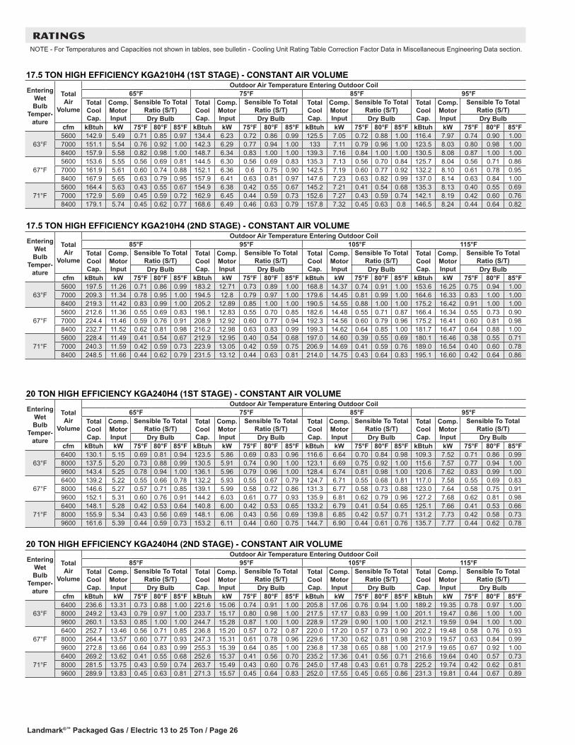
Landmark®™ Packaged Gas / Electric 13 to 25 Ton / Page 26
RATINGSNOTE - For Temperatures and Capacities not shown in tables, see bulletin - Cooling Unit Rating Table Correction Factor Data in Miscellaneous Engineering Data section.
20 TON HIGH EFFICIENCY KGA240H4 (1ST STAGE) - CONSTANT AIR VOLUME
Entering Wet Bulb
Temper-ature
Total Air
Volume
Outdoor Air Temperature Entering Outdoor Coil65°F 75°F 85°F 95°F
Total Cool Cap.
Comp. Motor Input
Sensible To Total Ratio (S/T)
Total Cool Cap.
Comp. Motor Input
Sensible To Total Ratio (S/T)
Total Cool Cap.
Comp. Motor Input
Sensible To Total Ratio (S/T)
Total Cool Cap.
Comp. Motor Input
Sensible To Total Ratio (S/T)
Dry Bulb Dry Bulb Dry Bulb Dry Bulbcfm kBtuh kW 75°F 80°F 85°F kBtuh kW 75°F 80°F 85°F kBtuh kW 75°F 80°F 85°F kBtuh kW 75°F 80°F 85°F
63°F6400 130.1 5.15 0.69 0.81 0.94 123.5 5.86 0.69 0.83 0.96 116.6 6.64 0.70 0.84 0.98 109.3 7.52 0.71 0.86 0.998000 137.5 5.20 0.73 0.88 0.99 130.5 5.91 0.74 0.90 1.00 123.1 6.69 0.75 0.92 1.00 115.6 7.57 0.77 0.94 1.009600 143.4 5.25 0.78 0.94 1.00 136.1 5.96 0.79 0.96 1.00 128.4 6.74 0.81 0.98 1.00 120.6 7.62 0.83 0.99 1.00
67°F6400 139.2 5.22 0.55 0.66 0.78 132.2 5.93 0.55 0.67 0.79 124.7 6.71 0.55 0.68 0.81 117.0 7.58 0.55 0.69 0.838000 146.6 5.27 0.57 0.71 0.85 139.1 5.99 0.58 0.72 0.86 131.3 6.77 0.58 0.73 0.88 123.0 7.64 0.58 0.75 0.919600 152.1 5.31 0.60 0.76 0.91 144.2 6.03 0.61 0.77 0.93 135.9 6.81 0.62 0.79 0.96 127.2 7.68 0.62 0.81 0.98
71°F6400 148.1 5.28 0.42 0.53 0.64 140.8 6.00 0.42 0.53 0.65 133.2 6.79 0.41 0.54 0.65 125.1 7.66 0.41 0.53 0.668000 155.9 5.34 0.43 0.56 0.69 148.1 6.06 0.43 0.56 0.69 139.8 6.85 0.42 0.57 0.71 131.2 7.73 0.42 0.58 0.739600 161.6 5.39 0.44 0.59 0.73 153.2 6.11 0.44 0.60 0.75 144.7 6.90 0.44 0.61 0.76 135.7 7.77 0.44 0.62 0.78
20 TON HIGH EFFICIENCY KGA240H4 (2ND STAGE) - CONSTANT AIR VOLUME
Entering Wet Bulb
Temper-ature
Total Air
Volume
Outdoor Air Temperature Entering Outdoor Coil85°F 95°F 105°F 115°F
Total Cool Cap.
Comp. Motor Input
Sensible To Total Ratio (S/T)
Total Cool Cap.
Comp. Motor Input
Sensible To Total Ratio (S/T)
Total Cool Cap.
Comp. Motor Input
Sensible To Total Ratio (S/T)
Total Cool Cap.
Comp. Motor Input
Sensible To Total Ratio (S/T)
Dry Bulb Dry Bulb Dry Bulb Dry Bulbcfm kBtuh kW 75°F 80°F 85°F kBtuh kW 75°F 80°F 85°F kBtuh kW 75°F 80°F 85°F kBtuh kW 75°F 80°F 85°F
63°F6400 236.6 13.31 0.73 0.88 1.00 221.6 15.06 0.74 0.91 1.00 205.8 17.06 0.76 0.94 1.00 189.2 19.35 0.78 0.97 1.008000 249.2 13.43 0.79 0.97 1.00 233.7 15.17 0.80 0.98 1.00 217.5 17.17 0.83 0.99 1.00 201.1 19.47 0.86 1.00 1.009600 260.1 13.53 0.85 1.00 1.00 244.7 15.28 0.87 1.00 1.00 228.9 17.29 0.90 1.00 1.00 212.1 19.59 0.94 1.00 1.00
67°F6400 252.7 13.46 0.56 0.71 0.85 236.8 15.20 0.57 0.72 0.87 220.0 17.20 0.57 0.73 0.90 202.2 19.48 0.58 0.76 0.938000 264.4 13.57 0.60 0.77 0.93 247.3 15.31 0.61 0.78 0.96 229.6 17.30 0.62 0.81 0.98 210.9 19.57 0.63 0.84 0.999600 272.8 13.66 0.64 0.83 0.99 255.3 15.39 0.64 0.85 1.00 236.8 17.38 0.65 0.88 1.00 217.9 19.65 0.67 0.92 1.00
71°F6400 269.2 13.62 0.41 0.55 0.68 252.6 15.37 0.41 0.56 0.70 235.2 17.36 0.41 0.56 0.71 216.6 19.64 0.40 0.57 0.738000 281.5 13.75 0.43 0.59 0.74 263.7 15.49 0.43 0.60 0.76 245.0 17.48 0.43 0.61 0.78 225.2 19.74 0.42 0.62 0.819600 289.9 13.83 0.45 0.63 0.81 271.3 15.57 0.45 0.64 0.83 252.0 17.55 0.45 0.65 0.86 231.3 19.81 0.44 0.67 0.89
17.5 TON HIGH EFFICIENCY KGA210H4 (1ST STAGE) - CONSTANT AIR VOLUME
Entering Wet Bulb
Temper-ature
Total Air
Volume
Outdoor Air Temperature Entering Outdoor Coil65°F 75°F 85°F 95°F
Total Cool Cap.
Comp. Motor Input
Sensible To Total Ratio (S/T)
Total Cool Cap.
Comp. Motor Input
Sensible To Total Ratio (S/T)
Total Cool Cap.
Comp. Motor Input
Sensible To Total Ratio (S/T)
Total Cool Cap.
Comp. Motor Input
Sensible To Total Ratio (S/T)
Dry Bulb Dry Bulb Dry Bulb Dry Bulbcfm kBtuh kW 75°F 80°F 85°F kBtuh kW 75°F 80°F 85°F kBtuh kW 75°F 80°F 85°F kBtuh kW 75°F 80°F 85°F
63°F5600 142.9 5.49 0.71 0.85 0.97 134.4 6.23 0.72 0.86 0.99 125.5 7.05 0.72 0.88 1.00 116.4 7.97 0.74 0.90 1.007000 151.1 5.54 0.76 0.92 1.00 142.3 6.29 0.77 0.94 1.00 133 7.11 0.79 0.96 1.00 123.5 8.03 0.80 0.98 1.008400 157.9 5.58 0.82 0.98 1.00 148.7 6.34 0.83 1.00 1.00 139.3 7.16 0.84 1.00 1.00 130.5 8.08 0.87 1.00 1.00
67°F5600 153.6 5.55 0.56 0.69 0.81 144.5 6.30 0.56 0.69 0.83 135.3 7.13 0.56 0.70 0.84 125.7 8.04 0.56 0.71 0.867000 161.9 5.61 0.60 0.74 0.88 152.1 6.36 0.6 0.75 0.90 142.5 7.19 0.60 0.77 0.92 132.2 8.10 0.61 0.78 0.958400 167.9 5.65 0.63 0.79 0.95 157.9 6.41 0.63 0.81 0.97 147.6 7.23 0.63 0.82 0.99 137.0 8.14 0.63 0.84 1.00
71°F5600 164.4 5.63 0.43 0.55 0.67 154.9 6.38 0.42 0.55 0.67 145.2 7.21 0.41 0.54 0.68 135.3 8.13 0.40 0.55 0.697000 172.9 5.69 0.45 0.59 0.72 162.9 6.45 0.44 0.59 0.73 152.6 7.27 0.43 0.59 0.74 142.1 8.19 0.42 0.60 0.768400 179.1 5.74 0.45 0.62 0.77 168.6 6.49 0.46 0.63 0.79 157.8 7.32 0.45 0.63 0.8 146.5 8.24 0.44 0.64 0.82
17.5 TON HIGH EFFICIENCY KGA210H4 (2ND STAGE) - CONSTANT AIR VOLUME
Entering Wet Bulb
Temper-ature
Total Air
Volume
Outdoor Air Temperature Entering Outdoor Coil85°F 95°F 105°F 115°F
Total Cool Cap.
Comp. Motor Input
Sensible To Total Ratio (S/T)
Total Cool Cap.
Comp. Motor Input
Sensible To Total Ratio (S/T)
Total Cool Cap.
Comp. Motor Input
Sensible To Total Ratio (S/T)
Total Cool Cap.
Comp. Motor Input
Sensible To Total Ratio (S/T)
Dry Bulb Dry Bulb Dry Bulb Dry Bulbcfm kBtuh kW 75°F 80°F 85°F kBtuh kW 75°F 80°F 85°F kBtuh kW 75°F 80°F 85°F kBtuh kW 75°F 80°F 85°F
63°F5600 197.5 11.26 0.71 0.86 0.99 183.2 12.71 0.73 0.89 1.00 168.8 14.37 0.74 0.91 1.00 153.6 16.25 0.75 0.94 1.007000 209.3 11.34 0.78 0.95 1.00 194.5 12.8 0.79 0.97 1.00 179.6 14.45 0.81 0.99 1.00 164.6 16.33 0.83 1.00 1.008400 219.3 11.42 0.83 0.99 1.00 205.2 12.89 0.85 1.00 1.00 190.5 14.55 0.88 1.00 1.00 175.2 16.42 0.91 1.00 1.00
67°F5600 212.6 11.36 0.55 0.69 0.83 198.1 12.83 0.55 0.70 0.85 182.6 14.48 0.55 0.71 0.87 166.4 16.34 0.55 0.73 0.907000 224.4 11.46 0.59 0.76 0.91 208.9 12.92 0.60 0.77 0.94 192.3 14.56 0.60 0.79 0.96 175.2 16.41 0.60 0.81 0.988400 232.7 11.52 0.62 0.81 0.98 216.2 12.98 0.63 0.83 0.99 199.3 14.62 0.64 0.85 1.00 181.7 16.47 0.64 0.88 1.00
71°F5600 228.4 11.49 0.41 0.54 0.67 212.9 12.95 0.40 0.54 0.68 197.0 14.60 0.39 0.55 0.69 180.1 16.46 0.38 0.55 0.717000 240.3 11.59 0.42 0.59 0.73 223.9 13.05 0.42 0.59 0.75 206.9 14.69 0.41 0.59 0.76 189.0 16.54 0.40 0.60 0.788400 248.5 11.66 0.44 0.62 0.79 231.5 13.12 0.44 0.63 0.81 214.0 14.75 0.43 0.64 0.83 195.1 16.60 0.42 0.64 0.86

Landmark®™ Packaged Gas / Electric 13 to 25 Ton / Page 27
RATINGSNOTE - For Temperatures and Capacities not shown in tables, see bulletin - Cooling Unit Rating Table Correction Factor Data in Miscellaneous Engineering Data section.
25 TON HIGH EFFICIENCY KGA300H4 (1ST STAGE) - CONSTANT AIR VOLUME
Entering Wet Bulb
Temper-ature
Total Air
Volume
Outdoor Air Temperature Entering Outdoor Coil65°F 75°F 85°F 95°F
Total Cool Cap.
Comp. Motor Input
Sensible To Total Ratio (S/T)
Total Cool Cap.
Comp. Motor Input
Sensible To Total Ratio (S/T)
Total Cool Cap.
Comp. Motor Input
Sensible To Total Ratio (S/T)
Total Cool Cap.
Comp. Motor Input
Sensible To Total Ratio (S/T)
Dry Bulb Dry Bulb Dry Bulb Dry Bulbcfm kBtuh kW 75°F 80°F 85°F kBtuh kW 75°F 80°F 85°F kBtuh kW 75°F 80°F 85°F kBtuh kW 75°F 80°F 85°F
63°F8000 151.1 6.82 0.69 0.81 0.93 144.0 7.68 0.70 0.82 0.95 136.5 8.64 0.70 0.84 0.96 128.5 9.72 0.71 0.86 0.989500 157.6 6.88 0.72 0.86 0.98 150.1 7.74 0.73 0.87 0.99 142.3 8.70 0.74 0.89 0.99 134.0 9.79 0.75 0.91 1.0011000 163.2 6.94 0.75 0.90 1.00 155.2 7.80 0.76 0.92 1.00 147.3 8.76 0.78 0.94 1.00 138.7 9.85 0.80 0.96 1.00
67°F8000 161.2 6.92 0.55 0.67 0.78 153.7 7.78 0.55 0.67 0.79 145.9 8.74 0.56 0.68 0.80 137.3 9.83 0.56 0.69 0.829500 168.0 6.99 0.57 0.70 0.82 160.0 7.85 0.58 0.71 0.84 151.7 8.81 0.57 0.72 0.86 142.7 9.90 0.58 0.73 0.8811000 173.4 7.05 0.59 0.73 0.87 164.9 7.91 0.59 0.74 0.89 156.0 8.87 0.60 0.75 0.91 146.8 9.96 0.61 0.77 0.93
71°F8000 171.3 7.02 0.43 0.54 0.64 163.6 7.89 0.42 0.54 0.65 155.3 8.86 0.42 0.54 0.66 146.4 9.95 0.42 0.54 0.679500 178.3 7.10 0.44 0.55 0.67 170.0 7.97 0.43 0.56 0.68 161.3 8.94 0.43 0.57 0.69 151.9 10.03 0.43 0.57 0.7111000 183.8 7.16 0.44 0.58 0.71 175.1 8.03 0.44 0.58 0.71 165.9 8.99 0.44 0.59 0.73 156.2 10.09 0.44 0.60 0.75
25 TON HIGH EFFICIENCY KGA300H4 (2ND STAGE) - CONSTANT AIR VOLUME
Entering Wet Bulb
Temper-ature
Total Air
Volume
Outdoor Air Temperature Entering Outdoor Coil85°F 95°F 105°F 115°F
Total Cool Cap.
Comp. Motor Input
Sensible To Total Ratio (S/T)
Total Cool Cap.
Comp. Motor Input
Sensible To Total Ratio (S/T)
Total Cool Cap.
Comp. Motor Input
Sensible To Total Ratio (S/T)
Total Cool Cap.
Comp. Motor Input
Sensible To Total Ratio (S/T)
Dry Bulb Dry Bulb Dry Bulb Dry Bulbcfm kBtuh kW 75°F 80°F 85°F kBtuh kW 75°F 80°F 85°F kBtuh kW 75°F 80°F 85°F kBtuh kW 75°F 80°F 85°F
63°F8000 277.0 17.49 0.74 0.89 1.00 260.5 19.68 0.75 0.91 1.00 243.6 22.20 0.77 0.93 1.00 225.6 25.14 0.79 0.97 1.009500 288.0 17.62 0.78 0.94 1.00 270.9 19.81 0.80 0.97 1.00 253.2 22.34 0.82 0.99 1.00 235.0 25.27 0.85 1.00 1.0011000 296.4 17.74 0.82 0.99 1.00 280.0 19.94 0.84 1.00 1.00 262.2 22.47 0.87 1.00 1.00 244.7 25.43 0.90 1.00 1.00
67°F8000 295.2 17.72 0.57 0.71 0.85 278.0 19.91 0.58 0.73 0.87 259.8 22.44 0.59 0.74 0.90 240.0 25.36 0.60 0.76 0.939500 305.8 17.86 0.60 0.76 0.91 287.4 20.05 0.61 0.77 0.94 268.4 22.57 0.62 0.80 0.97 247.8 25.49 0.63 0.82 0.9911000 313.6 17.96 0.62 0.80 0.97 294.7 20.16 0.64 0.82 0.99 274.7 22.67 0.65 0.85 1.00 253.4 25.57 0.66 0.88 1.00
71°F8000 313.8 17.97 0.43 0.56 0.69 295.5 20.16 0.42 0.57 0.70 276.5 22.70 0.42 0.57 0.72 256.1 25.62 0.42 0.59 0.749500 324.4 18.11 0.44 0.59 0.73 305.4 20.31 0.44 0.6 0.75 285.3 22.84 0.44 0.61 0.77 264.1 25.76 0.44 0.62 0.8011000 332.6 18.24 0.45 0.62 0.78 313.0 20.43 0.45 0.63 0.80 292.1 22.95 0.45 0.64 0.83 269.8 25.85 0.45 0.66 0.85
13 TON HIGH EFFICIENCY KGA156H4 (2ND STAGE) - MSAV (Multi-Stage Air Volume) SUPPLY AIR BLOWER
Entering Wet Bulb
Temper-ature
Total Air
Volume
Outdoor Air Temperature Entering Outdoor Coil85°F 95°F 105°F 115°F
Total Cool Cap.
Comp. Motor Input
Sensible To Total Ratio (S/T)
Total Cool Cap.
Comp. Motor Input
Sensible To Total Ratio (S/T)
Total Cool Cap.
Comp. Motor Input
Sensible To Total Ratio (S/T)
Total Cool Cap.
Comp. Motor Input
Sensible To Total Ratio (S/T)
Dry Bulb Dry Bulb Dry Bulb Dry Bulbcfm kBtuh kW 75°F 80°F 85°F kBtuh kW 75°F 80°F 85°F kBtuh kW 75°F 80°F 85°F kBtuh kW 75°F 80°F 85°F
63°F4160 148.1 9.05 0.70 0.85 0.99 136.5 10.20 0.71 0.87 1.00 124.5 11.51 0.72 0.9 1.00 112.1 13.01 0.73 0.93 1.005200 157.1 9.11 0.76 0.94 1.00 145.1 10.26 0.77 0.96 1.00 132.6 11.57 0.79 0.99 1.00 120.5 13.08 0.81 1.00 1.006240 164.5 9.17 0.82 0.99 1.00 152.7 10.32 0.83 1.00 1.00 141.1 11.64 0.86 1.00 1.00 129.1 13.15 0.89 1.00 1.00
67°F4160 159.3 9.13 0.54 0.68 0.82 147.4 10.28 0.54 0.69 0.84 135.3 11.59 0.53 0.70 0.86 122.4 13.09 0.53 0.71 0.895200 169.0 9.20 0.58 0.74 0.90 156.5 10.35 0.58 0.75 0.92 143.4 11.66 0.58 0.77 0.95 129.8 13.16 0.58 0.79 0.986240 175.9 9.25 0.61 0.80 0.97 162.7 10.40 0.62 0.81 0.99 149.1 11.71 0.62 0.83 1.00 135.2 13.20 0.63 0.86 1.00
71°F4160 170.4 9.21 0.40 0.53 0.66 158.1 10.36 0.38 0.53 0.66 145.8 11.68 0.37 0.53 0.67 132.6 13.18 0.35 0.52 0.695200 180.5 9.29 0.41 0.57 0.72 167.6 10.44 0.41 0.57 0.73 154.2 11.75 0.39 0.57 0.74 140.5 13.25 0.37 0.58 0.766240 187.9 9.35 0.43 0.61 0.77 174.4 10.50 0.42 0.61 0.79 160.4 11.81 0.41 0.61 0.81 146.2 13.31 0.40 0.62 0.84
13 TON HIGH EFFICIENCY KGA156H4 (1ST STAGE) - MSAV (Multi-Stage Air Volume) SUPPLY AIR BLOWER
Entering Wet Bulb
Temper-ature
Total Air
Volume
Outdoor Air Temperature Entering Outdoor Coil65°F 75°F 85°F 95°F
Total Cool Cap.
Comp. Motor Input
Sensible To Total Ratio (S/T)
Total Cool Cap.
Comp. Motor Input
Sensible To Total Ratio (S/T)
Total Cool Cap.
Comp. Motor Input
Sensible To Total Ratio (S/T)
Total Cool Cap.
Comp. Motor Input
Sensible To Total Ratio (S/T)
Dry Bulb Dry Bulb Dry Bulb Dry Bulbcfm kBtuh kW 75°F 80°F 85°F kBtuh kW 75°F 80°F 85°F kBtuh kW 75°F 80°F 85°F kBtuh kW 75°F 80°F 85°F
63°F3000 101.3 4.50 0.67 0.77 0.86 95.0 5.11 0.67 0.77 0.87 88.4 5.78 0.66 0.78 0.88 81.4 6.53 0.66 0.78 0.903500 107.4 4.53 0.69 0.8 0.9 100.7 5.14 0.69 0.80 0.91 93.7 5.81 0.69 0.81 0.93 86.4 6.56 0.69 0.82 0.944000 112.3 4.56 0.71 0.83 0.94 105.3 5.16 0.71 0.83 0.95 98.0 5.83 0.71 0.85 0.97 90.4 6.58 0.72 0.86 0.99
67°F3000 108.8 4.54 0.54 0.65 0.74 102.3 5.15 0.53 0.64 0.74 95.5 5.81 0.52 0.64 0.74 88.3 6.57 0.51 0.64 0.753500 115.1 4.57 0.56 0.67 0.77 108.2 5.18 0.55 0.67 0.77 101.0 5.84 0.54 0.67 0.78 93.5 6.59 0.53 0.67 0.794000 120.3 4.60 0.57 0.69 0.80 113.1 5.21 0.57 0.69 0.80 105.5 5.87 0.56 0.69 0.81 97.7 6.62 0.55 0.70 0.83
71°F3000 116.1 4.57 0.43 0.53 0.62 109.4 5.18 0.41 0.52 0.62 102.4 5.85 0.4 0.51 0.61 95.1 6.60 0.38 0.50 0.613500 122.7 4.61 0.44 0.54 0.65 115.6 5.22 0.42 0.54 0.65 108.2 5.88 0.41 0.53 0.64 100.5 6.63 0.39 0.52 0.654000 128.1 4.64 0.44 0.56 0.67 120.7 5.25 0.43 0.55 0.67 113.0 5.91 0.42 0.55 0.67 104.9 6.66 0.40 0.54 0.68

Landmark®™ Packaged Gas / Electric 13 to 25 Ton / Page 28
RATINGSNOTE - For Temperatures and Capacities not shown in tables, see bulletin - Cooling Unit Rating Table Correction Factor Data in Miscellaneous Engineering Data section.
15 TON HIGH EFFICIENCY KGA180H4 (2ND STAGE) - MSAV (Multi-Stage Air Volume) SUPPLY AIR BLOWER
Entering Wet Bulb
Temper-ature
Total Air
Volume
Outdoor Air Temperature Entering Outdoor Coil85°F 95°F 105°F 115°F
Total Cool Cap.
Comp. Motor Input
Sensible To Total Ratio (S/T)
Total Cool Cap.
Comp. Motor Input
Sensible To Total Ratio (S/T)
Total Cool Cap.
Comp. Motor Input
Sensible To Total Ratio (S/T)
Total Cool Cap.
Comp. Motor Input
Sensible To Total Ratio (S/T)
Dry Bulb Dry Bulb Dry Bulb Dry Bulbcfm kBtuh kW 75°F 80°F 85°F kBtuh kW 75°F 80°F 85°F kBtuh kW 75°F 80°F 85°F kBtuh kW 75°F 80°F 85°F
63°F4800 172.5 9.96 0.71 0.85 0.99 160.1 11.32 0.71 0.87 1.00 146.8 12.83 0.72 0.90 1.00 132.7 14.51 0.74 0.93 1.006000 182.6 9.99 0.77 0.93 1.00 169.5 11.37 0.78 0.95 1.00 155.7 12.89 0.79 0.98 1.00 141.3 14.57 0.81 1.00 1.007200 190.3 10.02 0.82 0.99 1.00 177.3 11.41 0.83 1.00 1.00 164.3 12.94 0.86 1.00 1.00 150.5 14.64 0.89 1.00 1.00
67°F4800 185.0 10.00 0.55 0.69 0.82 172.1 11.38 0.55 0.69 0.84 158.6 12.90 0.54 0.70 0.86 144.0 14.59 0.54 0.72 0.896000 195.8 10.04 0.58 0.74 0.90 182.1 11.43 0.58 0.76 0.92 167.5 12.96 0.59 0.77 0.95 152.2 14.65 0.59 0.79 0.987200 203.7 10.07 0.62 0.80 0.97 189.3 11.46 0.62 0.81 0.99 173.9 13.00 0.63 0.84 1.00 157.8 14.69 0.63 0.86 1.00
71°F4800 197.2 10.04 0.41 0.54 0.67 183.9 11.43 0.39 0.54 0.67 169.9 12.97 0.38 0.53 0.68 155.0 14.67 0.36 0.53 0.696000 208.4 10.09 0.42 0.58 0.72 194.2 11.48 0.41 0.58 0.73 179.4 13.03 0.4 0.58 0.75 163.3 14.73 0.38 0.59 0.777200 216.6 10.12 0.43 0.61 0.78 201.8 11.52 0.42 0.62 0.79 186.2 13.07 0.42 0.62 0.81 169.7 14.78 0.41 0.63 0.84
15 TON HIGH EFFICIENCY KGA180H4 (1ST STAGE) - MSAV (Multi-Stage Air Volume) SUPPLY AIR BLOWER
Entering Wet Bulb
Temper-ature
Total Air
Volume
Outdoor Air Temperature Entering Outdoor Coil65°F 75°F 85°F 95°F
Total Cool Cap.
Comp. Motor Input
Sensible To Total Ratio (S/T)
Total Cool Cap.
Comp. Motor Input
Sensible To Total Ratio (S/T)
Total Cool Cap.
Comp. Motor Input
Sensible To Total Ratio (S/T)
Total Cool Cap.
Comp. Motor Input
Sensible To Total Ratio (S/T)
Dry Bulb Dry Bulb Dry Bulb Dry Bulbcfm kBtuh kW 75°F 80°F 85°F kBtuh kW 75°F 80°F 85°F kBtuh kW 75°F 80°F 85°F kBtuh kW 75°F 80°F 85°F
63°F3500 117.6 5.01 0.66 0.76 0.85 110.9 5.76 0.66 0.76 0.86 103.9 6.57 0.65 0.76 0.87 96.6 7.47 0.65 0.77 0.884000 123.6 5.02 0.68 0.78 0.88 116.6 5.77 0.67 0.79 0.89 109.3 6.59 0.67 0.79 0.91 101.6 7.49 0.67 0.80 0.924500 128.7 5.02 0.69 0.81 0.91 121.3 5.78 0.69 0.81 0.93 113.8 6.60 0.69 0.82 0.94 105.7 7.51 0.70 0.83 0.96
67°F3500 126.1 5.02 0.54 0.63 0.73 119.1 5.77 0.53 0.63 0.73 112.0 6.59 0.52 0.63 0.73 104.3 7.50 0.51 0.63 0.744000 132.3 5.03 0.55 0.65 0.75 125.1 5.78 0.54 0.65 0.76 117.5 6.61 0.53 0.65 0.76 109.6 7.52 0.52 0.65 0.774500 137.6 5.03 0.56 0.67 0.78 130.0 5.80 0.55 0.67 0.78 122.1 6.63 0.55 0.67 0.79 113.9 7.54 0.54 0.68 0.80
71°F3500 134.4 5.03 0.42 0.52 0.61 127.2 5.79 0.41 0.51 0.61 119.7 6.62 0.40 0.50 0.61 112.0 7.53 0.38 0.49 0.604000 140.9 5.03 0.43 0.53 0.63 133.3 5.80 0.42 0.53 0.63 125.5 6.64 0.40 0.52 0.63 117.3 7.55 0.39 0.51 0.634500 146.3 5.04 0.43 0.54 0.65 138.5 5.81 0.42 0.54 0.65 130.3 6.65 0.41 0.53 0.65 121.8 7.57 0.40 0.53 0.65
17.5 TON HIGH EFFICIENCY KGA210H4 (1ST STAGE) - MSAV (Multi-Stage Air Volume) SUPPLY AIR BLOWER
Entering Wet Bulb
Temper-ature
Total Air
Volume
Outdoor Air Temperature Entering Outdoor Coil65°F 75°F 85°F 95°F
Total Cool Cap.
Comp. Motor Input
Sensible To Total Ratio (S/T)
Total Cool Cap.
Comp. Motor Input
Sensible To Total Ratio (S/T)
Total Cool Cap.
Comp. Motor Input
Sensible To Total Ratio (S/T)
Total Cool Cap.
Comp. Motor Input
Sensible To Total Ratio (S/T)
Dry Bulb Dry Bulb Dry Bulb Dry Bulbcfm kBtuh kW 75°F 80°F 85°F kBtuh kW 75°F 80°F 85°F kBtuh kW 75°F 80°F 85°F kBtuh kW 75°F 80°F 85°F
63°F4000 132.5 5.42 0.67 0.78 0.89 124.8 6.17 0.67 0.78 0.90 116.7 6.99 0.66 0.79 0.91 108.3 7.91 0.67 0.80 0.934750 140.2 5.46 0.69 0.82 0.93 131.8 6.21 0.70 0.83 0.95 123.3 7.04 0.70 0.84 0.97 114.2 7.96 0.70 0.86 0.995500 146.1 5.50 0.72 0.86 0.98 137.3 6.25 0.73 0.87 0.99 128.4 7.07 0.73 0.89 1.00 119.1 7.99 0.75 0.91 1.00
67°F4000 143.1 5.48 0.54 0.64 0.75 134.9 6.23 0.53 0.64 0.75 126.4 7.05 0.52 0.64 0.76 117.6 7.98 0.52 0.64 0.774750 150.9 5.52 0.55 0.67 0.78 142.3 6.28 0.55 0.67 0.79 133.3 7.10 0.54 0.68 0.81 123.7 8.03 0.54 0.68 0.825500 157.2 5.56 0.57 0.70 0.82 147.9 6.32 0.57 0.70 0.84 138.6 7.15 0.57 0.71 0.85 128.5 8.06 0.57 0.72 0.87
71°F4000 153.5 5.54 0.42 0.52 0.62 145.1 6.29 0.41 0.52 0.62 136.3 7.12 0.40 0.51 0.62 126.9 8.05 0.38 0.50 0.624750 161.7 5.59 0.43 0.54 0.65 152.6 6.35 0.42 0.54 0.65 143.3 7.18 0.41 0.53 0.66 133.3 8.10 0.39 0.53 0.665500 168.2 5.63 0.43 0.56 0.68 158.5 6.39 0.42 0.56 0.68 148.9 7.22 0.41 0.56 0.69 138.7 8.15 0.41 0.56 0.70
17.5 TON HIGH EFFICIENCY KGA210H4 (2ND STAGE) - MSAV (Multi-Stage Air Volume) SUPPLY AIR BLOWER
Entering Wet Bulb
Temper-ature
Total Air
Volume
Outdoor Air Temperature Entering Outdoor Coil85°F 95°F 105°F 115°F
Total Cool Cap.
Comp. Motor Input
Sensible To Total Ratio (S/T)
Total Cool Cap.
Comp. Motor Input
Sensible To Total Ratio (S/T)
Total Cool Cap.
Comp. Motor Input
Sensible To Total Ratio (S/T)
Total Cool Cap.
Comp. Motor Input
Sensible To Total Ratio (S/T)
Dry Bulb Dry Bulb Dry Bulb Dry Bulbcfm kBtuh kW 75°F 80°F 85°F kBtuh kW 75°F 80°F 85°F kBtuh kW 75°F 80°F 85°F kBtuh kW 75°F 80°F 85°F
63°F5600 197.5 11.26 0.71 0.86 0.99 183.2 12.71 0.73 0.89 1.00 168.8 14.37 0.74 0.91 1.00 153.6 16.25 0.75 0.94 1.007000 209.3 11.34 0.78 0.95 1.00 194.5 12.80 0.79 0.97 1.00 179.6 14.45 0.81 0.99 1.00 164.6 16.33 0.83 1.00 1.008400 219.3 11.42 0.83 0.99 1.00 205.2 12.89 0.85 1.00 1.00 190.5 14.55 0.88 1.00 1.00 175.2 16.42 0.91 1.00 1.00
67°F5600 212.6 11.36 0.55 0.69 0.83 198.1 12.83 0.55 0.70 0.85 182.6 14.48 0.55 0.71 0.87 166.4 16.34 0.55 0.73 0.907000 224.4 11.46 0.59 0.76 0.91 208.9 12.92 0.60 0.77 0.94 192.3 14.56 0.60 0.79 0.96 175.2 16.41 0.60 0.81 0.988400 232.7 11.52 0.62 0.81 0.98 216.2 12.98 0.63 0.83 0.99 199.3 14.62 0.64 0.85 1.00 181.7 16.47 0.64 0.88 1.00
71°F5600 228.4 11.49 0.41 0.54 0.67 212.9 12.95 0.40 0.54 0.68 197.0 14.60 0.39 0.55 0.69 180.1 16.46 0.38 0.55 0.717000 240.3 11.59 0.42 0.59 0.73 223.9 13.05 0.42 0.59 0.75 206.9 14.69 0.41 0.59 0.76 189.0 16.54 0.40 0.60 0.788400 248.5 11.66 0.44 0.62 0.79 231.5 13.12 0.44 0.63 0.81 214.0 14.75 0.43 0.64 0.83 195.1 16.60 0.42 0.64 0.86

Landmark®™ Packaged Gas / Electric 13 to 25 Ton / Page 29
RATINGSNOTE - For Temperatures and Capacities not shown in tables, see bulletin - Cooling Unit Rating Table Correction Factor Data in Miscellaneous Engineering Data section.
20 TON HIGH EFFICIENCY KGA240H4 (1ST STAGE) - MSAV (Multi-Stage Air Volume) SUPPLY AIR BLOWER
Entering Wet Bulb
Temper-ature
Total Air
Volume
Outdoor Air Temperature Entering Outdoor Coil65°F 75°F 85°F 95°F
Total Cool Cap.
Comp. Motor Input
Sensible To Total Ratio (S/T)
Total Cool Cap.
Comp. Motor Input
Sensible To Total Ratio (S/T)
Total Cool Cap.
Comp. Motor Input
Sensible To Total Ratio (S/T)
Total Cool Cap.
Comp. Motor Input
Sensible To Total Ratio (S/T)
Dry Bulb Dry Bulb Dry Bulb Dry Bulbcfm kBtuh kW 75°F 80°F 85°F kBtuh kW 75°F 80°F 85°F kBtuh kW 75°F 80°F 85°F kBtuh kW 75°F 80°F 85°F
63°F4500 117.1 5.20 0.66 0.75 0.85 111.5 5.97 0.66 0.76 0.86 105.5 6.80 0.66 0.77 0.87 99.20 7.72 0.66 0.78 0.895500 125.0 5.22 0.68 0.80 0.90 118.9 5.99 0.69 0.80 0.92 112.4 6.83 0.69 0.81 0.93 105.6 7.76 0.69 0.83 0.956500 131.1 5.23 0.71 0.83 0.95 124.5 6.01 0.71 0.84 0.97 117.7 6.86 0.72 0.86 0.98 110.6 7.79 0.73 0.88 0.99
67°F4500 125.7 5.22 0.53 0.63 0.72 119.8 5.99 0.53 0.63 0.73 113.5 6.83 0.52 0.63 0.73 106.9 7.77 0.52 0.63 0.745500 133.9 5.24 0.55 0.66 0.76 127.5 6.02 0.55 0.66 0.77 120.8 6.87 0.54 0.67 0.78 113.7 7.81 0.55 0.67 0.796500 140.2 5.25 0.57 0.69 0.80 133.4 6.04 0.57 0.69 0.81 126.3 6.90 0.56 0.70 0.83 118.6 7.84 0.56 0.71 0.84
71°F4500 134.2 5.24 0.42 0.51 0.60 128.2 6.02 0.41 0.51 0.61 121.6 6.87 0.41 0.51 0.61 114.6 7.81 0.40 0.50 0.615500 142.9 5.26 0.43 0.53 0.63 136.1 6.05 0.42 0.53 0.64 129.2 6.91 0.41 0.53 0.64 121.7 7.86 0.41 0.53 0.656500 149.4 5.27 0.43 0.55 0.66 142.4 6.07 0.43 0.55 0.67 134.8 6.94 0.43 0.55 0.67 126.8 7.89 0.42 0.55 0.68
20 TON HIGH EFFICIENCY KGA240H4 (2ND STAGE) - MSAV (Multi-Stage Air Volume) SUPPLY AIR BLOWER
Entering Wet Bulb
Temper-ature
Total Air
Volume
Outdoor Air Temperature Entering Outdoor Coil85°F 95°F 105°F 115°F
Total Cool Cap.
Comp. Motor Input
Sensible To Total Ratio (S/T)
Total Cool Cap.
Comp. Motor Input
Sensible To Total Ratio (S/T)
Total Cool Cap.
Comp. Motor Input
Sensible To Total Ratio (S/T)
Total Cool Cap.
Comp. Motor Input
Sensible To Total Ratio (S/T)
Dry Bulb Dry Bulb Dry Bulb Dry Bulbcfm kBtuh kW 75°F 80°F 85°F kBtuh kW 75°F 80°F 85°F kBtuh kW 75°F 80°F 85°F kBtuh kW 75°F 80°F 85°F
63°F6400 236.6 13.31 0.73 0.88 1.00 221.6 15.06 0.74 0.91 1.00 205.8 17.06 0.76 0.94 1.00 189.2 19.35 0.78 0.97 1.008000 249.2 13.43 0.79 0.97 1.00 233.7 15.17 0.80 0.98 1.00 217.5 17.17 0.83 0.99 1.00 201.1 19.47 0.86 1.00 1.009600 260.1 13.53 0.85 1.00 1.00 244.7 15.28 0.87 1.00 1.00 228.9 17.29 0.90 1.00 1.00 212.1 19.59 0.94 1.00 1.00
67°F6400 252.7 13.46 0.56 0.71 0.85 236.8 15.20 0.57 0.72 0.87 220.0 17.20 0.57 0.73 0.90 202.2 19.48 0.58 0.76 0.938000 264.4 13.57 0.60 0.77 0.93 247.3 15.31 0.61 0.78 0.96 229.6 17.30 0.62 0.81 0.98 210.9 19.57 0.63 0.84 0.999600 272.8 13.66 0.64 0.83 0.99 255.3 15.39 0.64 0.85 1.00 236.8 17.38 0.65 0.88 1.00 217.9 19.65 0.67 0.92 1.00
71°F6400 269.2 13.62 0.41 0.55 0.68 252.6 15.37 0.41 0.56 0.70 235.2 17.36 0.41 0.56 0.71 216.6 19.64 0.40 0.57 0.738000 281.5 13.75 0.43 0.59 0.74 263.7 15.49 0.43 0.60 0.76 245.0 17.48 0.43 0.61 0.78 225.2 19.74 0.42 0.62 0.819600 289.9 13.83 0.45 0.63 0.81 271.3 15.57 0.45 0.64 0.83 252.0 17.55 0.45 0.65 0.86 231.3 19.81 0.44 0.67 0.89
25 TON HIGH EFFICIENCY KGA300H4 (1ST STAGE) - MSAV (Multi-Stage Air Volume) SUPPLY AIR BLOWER
Entering Wet Bulb
Temper-ature
Total Air
Volume
Outdoor Air Temperature Entering Outdoor Coil65°F 75°F 85°F 95°F
Total Cool Cap.
Comp. Motor Input
Sensible To Total Ratio (S/T)
Total Cool Cap.
Comp. Motor Input
Sensible To Total Ratio (S/T)
Total Cool Cap.
Comp. Motor Input
Sensible To Total Ratio (S/T)
Total Cool Cap.
Comp. Motor Input
Sensible To Total Ratio (S/T)
Dry Bulb Dry Bulb Dry Bulb Dry Bulbcfm kBtuh kW 75°F 80°F 85°F kBtuh kW 75°F 80°F 85°F kBtuh kW 75°F 80°F 85°F kBtuh kW 75°F 80°F 85°F
63°F5750 141.5 6.58 0.66 0.76 0.86 135.2 7.42 0.66 0.77 0.88 128.3 8.37 0.67 0.78 0.89 121.3 9.44 0.67 0.79 0.916750 148.5 6.64 0.68 0.79 0.9 141.5 7.48 0.69 0.81 0.92 134.5 8.42 0.69 0.82 0.94 126.7 9.50 0.70 0.83 0.967750 154.1 6.69 0.70 0.83 0.94 146.9 7.53 0.71 0.84 0.96 139.2 8.47 0.72 0.85 0.98 131.3 9.55 0.73 0.87 0.99
67°F5750 151.2 6.66 0.53 0.63 0.73 144.4 7.51 0.54 0.64 0.74 137.5 8.45 0.53 0.64 0.75 129.9 9.54 0.53 0.65 0.766750 158.7 6.73 0.55 0.66 0.76 151.4 7.57 0.55 0.66 0.77 143.9 8.52 0.55 0.67 0.78 135.7 9.59 0.55 0.68 0.807750 164.5 6.79 0.56 0.68 0.79 156.8 7.63 0.56 0.68 0.80 148.8 8.58 0.56 0.69 0.82 140.3 9.65 0.57 0.71 0.84
71°F5750 160.9 6.75 0.42 0.52 0.61 154.0 7.60 0.42 0.52 0.61 146.5 8.55 0.41 0.52 0.62 138.5 9.63 0.41 0.52 0.626750 168.8 6.82 0.43 0.53 0.63 161.0 7.68 0.42 0.53 0.64 153.2 8.63 0.42 0.53 0.64 144.5 9.71 0.42 0.53 0.657750 174.7 6.89 0.43 0.55 0.66 166.6 7.74 0.43 0.55 0.66 158.4 8.69 0.42 0.55 0.67 149.4 9.77 0.42 0.55 0.68
25 TON HIGH EFFICIENCY KGA300H4 (2ND STAGE) - MSAV (Multi-Stage Air Volume) SUPPLY AIR BLOWER
Entering Wet Bulb
Temper-ature
Total Air
Volume
Outdoor Air Temperature Entering Outdoor Coil85°F 95°F 105°F 115°F
Total Cool Cap.
Comp. Motor Input
Sensible To Total Ratio (S/T)
Total Cool Cap.
Comp. Motor Input
Sensible To Total Ratio (S/T)
Total Cool Cap.
Comp. Motor Input
Sensible To Total Ratio (S/T)
Total Cool Cap.
Comp. Motor Input
Sensible To Total Ratio (S/T)
Dry Bulb Dry Bulb Dry Bulb Dry Bulbcfm kBtuh kW 75°F 80°F 85°F kBtuh kW 75°F 80°F 85°F kBtuh kW 75°F 80°F 85°F kBtuh kW 75°F 80°F 85°F
63°F8000 277.0 17.49 0.74 0.89 1.00 260.5 19.68 0.75 0.91 1.00 243.6 22.20 0.77 0.93 1.00 225.6 25.14 0.79 0.97 1.009500 288.0 17.62 0.78 0.94 1.00 270.9 19.81 0.80 0.97 1.00 253.2 22.34 0.82 0.99 1.00 235.0 25.27 0.85 1.00 1.0011000 296.4 17.74 0.82 0.99 1.00 280.0 19.94 0.84 1.00 1.00 262.2 22.47 0.87 1.00 1.00 244.7 25.43 0.90 1.00 1.00
67°F8000 295.2 17.72 0.57 0.71 0.85 278.0 19.91 0.58 0.73 0.87 259.8 22.44 0.59 0.74 0.90 240.0 25.36 0.60 0.76 0.939500 305.8 17.86 0.60 0.76 0.91 287.4 20.05 0.61 0.77 0.94 268.4 22.57 0.62 0.80 0.97 247.8 25.49 0.63 0.82 0.9911000 313.6 17.96 0.62 0.80 0.97 294.7 20.16 0.64 0.82 0.99 274.7 22.67 0.65 0.85 1.00 253.4 25.57 0.66 0.88 1.00
71°F8000 313.8 17.97 0.43 0.56 0.69 295.5 20.16 0.42 0.57 0.70 276.5 22.70 0.42 0.57 0.72 256.1 25.62 0.42 0.59 0.749500 324.4 18.11 0.44 0.59 0.73 305.4 20.31 0.44 0.60 0.75 285.3 22.84 0.44 0.61 0.77 264.1 25.76 0.44 0.62 0.8011000 332.6 18.24 0.45 0.62 0.78 313.0 20.43 0.45 0.63 0.80 292.1 22.95 0.45 0.64 0.83 269.8 25.85 0.45 0.66 0.85

Landmark®™ Packaged Gas / Electric 13 to 25 Ton / Page 30
BLO
WE
R D
ATA
BLO
WE
R T
AB
LE IN
CLU
DE
S R
ES
ISTA
NC
E F
OR
BA
SE
UN
IT O
NLY
WIT
H D
RY
IND
OO
R C
OIL
& A
IR F
ILTE
RS
IN P
LAC
E
FOR
ALL
UN
ITS
AD
D:
1 - W
et in
door
coi
l air
resi
stan
ce o
f sel
ecte
d un
it.
2 - A
ny fa
ctor
y in
stal
led
optio
ns a
ir re
sist
ance
(ele
ctric
hea
t, ec
onom
izer
, etc
.) 3
- Any
fiel
d in
stal
led
acce
ssor
ies
air r
esis
tanc
e (e
lect
ric h
eat,
duct
resi
stan
ce, d
iffus
er, e
tc.)
Then
det
erm
ine
from
blo
wer
tabl
e bl
ower
mot
or o
utpu
t and
driv
e re
quire
d.
See
pag
e 31
for w
et c
oil a
nd o
ptio
n/ac
cess
ory
air r
esis
tanc
e da
ta.
See
pag
e 31
for f
acto
ry in
stal
led
driv
e ki
t spe
cific
atio
ns.
MIN
IMU
M A
IR V
OLU
ME
REQ
UIR
ED F
OR
DIF
FER
ENT
GA
S H
EAT
SIZE
SS
tand
ard
(S) a
nd M
ediu
m H
eat (
M) -
450
0 cf
m m
inim
um
Hig
h H
eat (
H) -
512
5 cf
m m
inim
umA
ir Vo
lum
e cf
m
TOTA
L ST
ATIC
PR
ESSU
RE
- Inc
hes
Wat
er G
auge
(Pa)
0.20
0.40
0.60
0.80
1.00
1.20
1.40
1.60
1.80
2.00
2.20
2.40
2.60
RPM
BH
PR
PMB
HP
RPM
BH
PR
PMB
HP
RPM
BH
PR
PMB
HP
RPM
BH
PR
PMB
HP
RPM
BH
PR
PMB
HP
RPM
BH
PR
PMB
HP
RPM
BH
P27
5038
50.
3050
50.
5060
00.
7068
00.
9075
51.
1082
01.
30- -
-- -
-- -
-- -
-- -
-- -
-- -
-- -
-- -
-- -
-- -
-- -
-- -
-- -
-30
0039
50.
3551
50.
5561
00.
7568
51.
0076
01.
2082
51.
4588
51.
70- -
-- -
-- -
-- -
-- -
-- -
-- -
-- -
-- -
-- -
-- -
-- -
-32
5040
50.
4052
00.
6061
50.
8569
51.
1076
51.
3083
01.
6089
01.
8595
02.
10- -
-- -
-- -
-- -
-- -
-- -
-- -
-- -
-- -
-- -
-35
0041
50.
4553
00.
7062
00.
9570
01.
2077
51.
4584
01.
7090
02.
0095
52.
2510
052.
55- -
-- -
-- -
-- -
-- -
-- -
-- -
-- -
-37
5042
50.
5054
00.
7563
01.
0571
01.
3078
01.
6084
51.
8590
52.
1596
02.
4510
102.
7010
603.
0011
103.
30- -
-- -
-- -
-- -
-40
0043
50.
5554
50.
8563
51.
1071
51.
4078
51.
7085
02.
0091
02.
3096
52.
6010
202.
9010
703.
2511
153.
5511
603.
8512
054.
1542
5044
50.
6055
50.
9064
51.
2572
51.
5579
51.
8585
52.
1591
52.
4597
02.
8010
253.
1010
753.
4511
203.
7511
654.
1012
104.
4545
0045
50.
7056
51.
0065
51.
3573
01.
6580
02.
0086
52.
3592
52.
6598
03.
0010
303.
3010
803.
6511
304.
0511
754.
3512
154.
7047
5047
00.
7557
51.
1066
01.
4574
01.
8081
02.
1587
02.
5093
02.
8598
53.
2010
403.
5510
853.
9011
354.
2511
804.
6512
255.
0050
0048
00.
8558
51.
2567
01.
6075
01.
9581
52.
3088
02.
7094
03.
0599
53.
4010
453.
8010
954.
1511
404.
5011
854.
9012
305.
3052
5049
50.
9559
51.
3568
01.
7075
52.
1082
52.
5089
02.
9094
53.
2510
003.
6510
504.
0011
004.
4011
504.
8011
955.
2012
355.
6055
0050
51.
0560
51.
4569
01.
8576
52.
2583
52.
6589
53.
0595
53.
4510
103.
8510
604.
2511
104.
7011
555.
1012
005.
5012
405.
9057
5052
01.
1561
51.
6070
02.
0077
52.
4584
02.
8590
53.
2596
03.
6510
154.
1010
654.
5011
154.
9511
605.
3512
055.
8012
506.
2560
0053
01.
3063
01.
7571
02.
1578
52.
6085
03.
0591
03.
4597
03.
9010
254.
3510
754.
8011
205.
2011
705.
6512
156.
1012
556.
5562
5054
51.
4064
01.
9072
02.
3579
52.
8086
03.
2592
03.
7097
54.
1510
304.
6010
805.
0511
305.
5011
755.
9512
206.
4512
656.
9065
0056
01.
5565
02.
0573
02.
5080
53.
0087
03.
4593
03.
9598
54.
4010
404.
8510
905.
3511
405.
8511
856.
3012
256.
7512
707.
2567
5057
01.
7066
52.
2074
52.
7081
53.
2088
03.
7094
04.
2099
54.
6510
455.
1010
955.
6011
456.
1011
906.
6012
357.
1012
757.
6070
0058
51.
8567
52.
3575
52.
9082
53.
4089
03.
9595
04.
4510
054.
9510
555.
4011
055.
9511
556.
4512
006.
9512
407.
4512
858.
0072
5060
02.
0069
02.
6076
53.
1083
53.
6590
04.
1595
54.
6510
155.
2510
655.
7511
156.
2511
606.
7512
057.
3012
507.
8512
908.
3575
0061
52.
2070
02.
7577
53.
3084
53.
8591
04.
4596
54.
9510
205.
5010
756.
0511
256.
6011
707.
1512
157.
6512
608.
2513
008.
7577
5063
02.
4071
53.
0079
03.
5585
54.
1092
04.
7097
55.
2510
305.
8010
806.
3511
306.
9011
807.
5012
258.
0512
658.
6013
059.
1580
0064
02.
5572
53.
2080
03.
8086
54.
3593
04.
9598
55.
5010
406.
1010
906.
7011
407.
2511
857.
8512
308.
4012
759.
0013
159.
6082
5065
52.
8074
03.
4081
04.
0088
04.
6594
05.
2599
55.
8510
506.
4511
007.
0511
507.
6511
958.
2512
408.
8512
809.
4013
2510
.05
8500
670
3.00
750
3.65
825
4.30
890
4.90
950
5.55
1005
6.15
1060
6.80
1110
7.40
1160
8.05
1205
8.65
1250
9.25
1290
9.85
1330
10.4
587
5068
53.
2576
53.
9083
54.
5590
05.
2096
05.
8510
156.
4510
707.
1511
207.
7511
658.
3512
159.
0512
559.
6513
0010
.30
1340
10.9
090
0070
03.
5078
04.
2085
04.
8591
05.
5097
06.
1510
256.
8010
807.
5011
308.
1511
758.
7512
209.
4012
6510
.10
1310
10.8
013
5011
.40
9250
715
3.75
790
4.45
860
5.15
925
5.85
985
6.55
1040
7.20
1090
7.85
1140
8.55
1185
9.20
1230
9.85
1275
10.5
513
1511
.20
- - -
- - -
9500
730
4.00
805
4.75
875
5.45
935
6.15
995
6.90
1050
7.60
1100
8.25
1150
8.95
1195
9.60
1240
10.3
012
8511
.05
- - -
- - -
- - -
- - -
9750
745
4.30
820
5.05
885
5.75
950
6.55
1005
7.20
1060
7.95
1110
8.65
1160
9.40
1205
10.0
512
5010
.80
1295
11.5
0- -
-- -
-- -
-- -
-10
,000
760
4.60
835
5.40
900
6.15
960
6.85
1015
7.60
1070
8.35
1120
9.05
1170
9.80
1215
10.5
012
6011
.25
- - -
- - -
- - -
- - -
- - -
- - -
10,2
5077
54.
9084
55.
6591
06.
4597
07.
2010
308.
0010
808.
7511
359.
5511
8010
.25
1225
11.0
0- -
-- -
-- -
-- -
-- -
-- -
-- -
-- -
-10
,500
790
5.20
860
6.00
925
6.85
985
7.65
1040
8.40
1095
9.20
1145
10.0
011
9010
.70
1235
11.4
5- -
-- -
-- -
-- -
-- -
-- -
-- -
-- -
-10
,750
805
5.55
875
6.40
940
7.25
1000
8.05
1055
8.85
1105
9.65
1155
10.4
512
0011
.20
- - -
- - -
- - -
- - -
- - -
- - -
- - -
- - -
- - -
- - -
11,0
0082
05.
9089
06.
8095
07.
6010
108.
4510
659.
3011
1510
.05
1165
10.9
0- -
-- -
-- -
-- -
-- -
-- -
-- -
-- -
-- -
-- -
-- -
-- -
-

Landmark®™ Packaged Gas / Electric 13 to 25 Ton / Page 31
BLOWER DATAFACTORY INSTALLED BELT DRIVE KIT SPECIFICATIONS
Motor Efficiency Nominal hp Maximum hp Drive Kit Number RPM Range
Standard or High 2 2.30 1 535 - 725Standard or High 2 2.30 2 710 - 965Standard 3 3.45 1 535 - 725Standard 3 3.45 2 710 - 965Standard 5 5.75 3 685 - 856Standard 5 5.75 4 850 - 1045Standard 5 5.75 5 945 - 1185Standard 7.5 8.63 6 850 - 1045Standard 7.5 8.63 7 945 - 1185Standard 7.5 8.63 8 1045 - 1285Standard 10 11.50 7 945 - 1185Standard 10 11.50 10 1045 - 1285Standard 10 11.50 11 1135 - 1365
NOTE - Using total air volume and system static pressure requirements determine from blower performance tables rpm and motor output required. Maximum usable output of motors furnished are shown. In Canada, nominal motor output is also maximum usable motor output. If motors of comparable output are used, be sure to keep within the service factor limitations outlined on the motor nameplate. NOTE – Units equipped with MSAV® (Multi-Stage Air Volume) option are limited to a motor service factor of 1.0.
FACTORY INSTALLED OPTIONS/FIELD INSTALLED ACCESSORY AIR RESISTANCE - in. w.g.
Air Volume cfm
Wet Indoor Coil Gas Heat Exchanger
Economizer
Filters Horizontal Roof Curb
180S156H 180H 210S
210H 240H 240S 300H 300S
Standard Heat
Medium Heat
High Heat MERV 8 MERV 13
156H 180H 180S 210H 210S 240H 240S
300H 300S
2750 0.01 0.01 0.02 0.02 0.04 0.05 - 0.01 0.03 0.03 -3000 0.01 0.01 0.02 0.03 0.04 0.05 - 0.01 0.03 0.04 -3250 0.02 0.01 0.03 0.03 0.05 0.06 - 0.01 0.04 0.04 0.013500 0.02 0.01 0.03 0.03 0.05 0.06 - 0.01 0.04 0.05 0.013750 0.02 0.01 0.03 0.04 0.06 0.07 - 0.01 0.04 0.05 0.014000 0.02 0.02 0.04 0.04 0.06 0.07 - 0.01 0.04 0.06 0.024250 0.02 0.02 0.04 0.04 0.06 0.08 - 0.01 0.05 0.07 0.024500 0.02 0.02 0.05 0.05 0.07 0.09 - 0.01 0.05 0.07 0.024750 0.02 0.02 0.05 0.05 0.08 0.10 - 0.02 0.05 0.08 0.035000 0.03 0.02 0.05 0.05 0.09 0.11 - 0.02 0.06 0.08 0.035250 0.03 0.02 0.06 0.06 0.10 0.12 - 0.02 0.06 0.09 0.045500 0.03 0.02 0.07 0.06 0.10 0.13 - 0.02 0.06 0.10 0.045750 0.03 0.03 0.07 0.06 0.11 0.14 - 0.02 0.07 0.11 0.056000 0.04 0.03 0.08 0.07 0.12 0.15 - 0.03 0.07 0.11 0.066250 0.04 0.03 0.08 0.07 0.12 0.16 0.01 0.03 0.07 0.12 0.076500 0.04 0.03 0.09 0.08 0.13 0.17 0.02 0.03 0.08 0.13 0.086750 0.05 0.04 0.10 0.08 0.14 0.18 0.03 0.03 0.08 0.14 0.087000 0.05 0.04 0.10 0.09 0.15 0.19 0.04 0.04 0.08 0.15 0.097250 0.06 0.04 0.11 0.09 0.16 0.20 0.05 0.04 0.09 0.16 0.107500 0.06 0.05 0.12 0.10 0.17 0.21 0.06 0.04 0.09 0.17 0.118000 0.07 0.05 0.13 0.11 0.19 0.24 0.09 0.05 0.10 0.19 0.138500 0.08 0.06 0.15 0.12 0.20 0.26 0.11 0.05 0.10 0.21 0.159000 0.09 0.07 0.16 0.13 0.23 0.29 0.14 0.06 0.11 0.24 0.179500 0.10 0.08 0.18 0.14 0.25 0.32 0.16 0.07 0.12 0.26 0.1910000 0.11 0.08 0.20 0.16 0.27 0.35 0.19 0.07 0.12 0.29 0.2110500 0.12 0.09 0.22 0.17 0.30 0.38 0.22 0.08 0.13 0.31 0.2411000 0.14 0.11 0.24 0.18 0.31 0.40 0.25 0.09 0.14 0.34 0.27
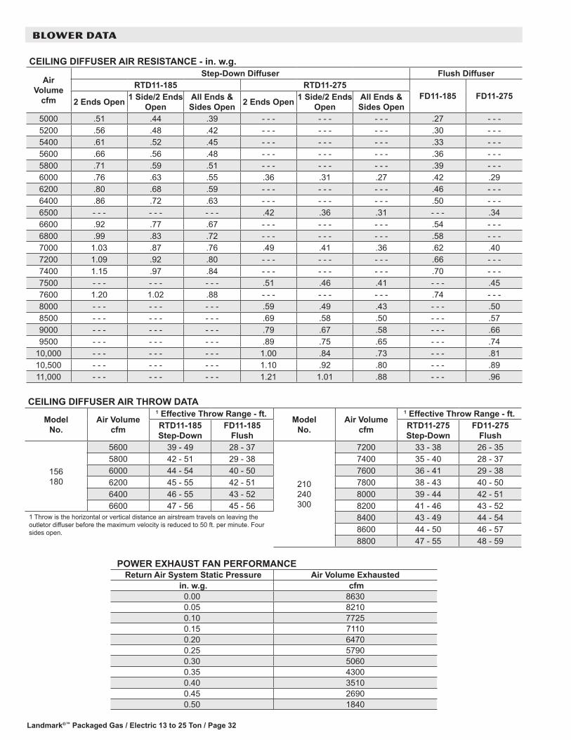
Landmark®™ Packaged Gas / Electric 13 to 25 Ton / Page 32
BLOWER DATA
POWER EXHAUST FAN PERFORMANCE Return Air System Static Pressure Air Volume Exhausted
in. w.g. cfm 0.00 86300.05 82100.10 77250.15 71100.20 64700.25 57900.30 50600.35 43000.40 35100.45 26900.50 1840
CEILING DIFFUSER AIR THROW DATA
Model No.
Air Volume cfm
1 Effective Throw Range - ft.Model
No.Air Volume
cfm
1 Effective Throw Range - ft.RTD11-185 Step-Down
FD11-185 Flush
RTD11-275 Step-Down
FD11-275 Flush
156 180
5600 39 - 49 28 - 37
210 240 300
7200 33 - 38 26 - 355800 42 - 51 29 - 38 7400 35 - 40 28 - 376000 44 - 54 40 - 50 7600 36 - 41 29 - 386200 45 - 55 42 - 51 7800 38 - 43 40 - 506400 46 - 55 43 - 52 8000 39 - 44 42 - 516600 47 - 56 45 - 56 8200 41 - 46 43 - 52
1 Throw is the horizontal or vertical distance an airstream travels on leaving the outletor diffuser before the maximum velocity is reduced to 50 ft. per minute. Four sides open.
8400 43 - 49 44 - 548600 44 - 50 46 - 578800 47 - 55 48 - 59
CEILING DIFFUSER AIR RESISTANCE - in. w.g.
Air Volume
cfm
Step-Down Diffuser Flush DiffuserRTD11-185 RTD11-275
FD11-185 FD11-2752 Ends Open 1 Side/2 Ends
OpenAll Ends & Sides Open 2 Ends Open 1 Side/2 Ends
OpenAll Ends & Sides Open
5000 .51 .44 .39 - - - - - - - - - .27 - - -5200 .56 .48 .42 - - - - - - - - - .30 - - -5400 .61 .52 .45 - - - - - - - - - .33 - - -5600 .66 .56 .48 - - - - - - - - - .36 - - -5800 .71 .59 .51 - - - - - - - - - .39 - - -6000 .76 .63 .55 .36 .31 .27 .42 .296200 .80 .68 .59 - - - - - - - - - .46 - - -6400 .86 .72 .63 - - - - - - - - - .50 - - -6500 - - - - - - - - - .42 .36 .31 - - - .346600 .92 .77 .67 - - - - - - - - - .54 - - -6800 .99 .83 .72 - - - - - - - - - .58 - - -7000 1.03 .87 .76 .49 .41 .36 .62 .407200 1.09 .92 .80 - - - - - - - - - .66 - - -7400 1.15 .97 .84 - - - - - - - - - .70 - - -7500 - - - - - - - - - .51 .46 .41 - - - .457600 1.20 1.02 .88 - - - - - - - - - .74 - - -8000 - - - - - - - - - .59 .49 .43 - - - .508500 - - - - - - - - - .69 .58 .50 - - - .579000 - - - - - - - - - .79 .67 .58 - - - .669500 - - - - - - - - - .89 .75 .65 - - - .74
10,000 - - - - - - - - - 1.00 .84 .73 - - - .8110,500 - - - - - - - - - 1.10 .92 .80 - - - .8911,000 - - - - - - - - - 1.21 1.01 .88 - - - .96

Landmark®™ Packaged Gas / Electric 13 to 25 Ton / Page 33
ELECTRICAL DATA15 TON STANDARD EFFICIENCY KGA180S41 Voltage - 60hz 208/230V - 3 Ph 460V - 3 Ph 575V - 3 PhCompressor 1 Rated Load Amps 25 12.2 9
Locked Rotor Amps 164 100 78Compressor 2 Rated Load Amps 25 12.2 9
Locked Rotor Amps 164 100 78Outdoor FanMotors (3)
Full Load Amps 2.4 1.3 1(total) (7.2) (3.9) (3)
Power Exhaust(2) 0.33 HP
Full Load Amps 2.4 1.3 1(total) (4.8) (2.6) (2)
Service Outlet 115V GFI (amps) 15 15 20Indoor BlowerMotor
Horsepower 3 5 7.5 3 5 7.5 3 5 7.5Full Load Amps 10.6 16.7 24.2 4.8 7.6 11 3.9 6.1 9
2 MaximumOvercurrentProtection
Unit Only 90 100 110 45 50 50 35 35 40With (2) 0.33 HP
Power Exhaust100 100 110 50 50 50 35 40 40
3 MinimumCircuitAmpacity
Unit Only 75 81 88 37 39 43 28 30 33With (2) 0.33 HP
Power Exhaust79 85 93 39 42 45 30 32 35
NOTE - All units have a minimum Short Circuit Current Rating (SCCR) of 5000 amps.1 Extremes of operating range are plus and minus 10% of line voltage. 2 HACR type breaker or fuse. 3 Refer to National or Canadian Electrical Code manual to determine wire, fuse and disconnect size requirements.
17.5 TON STANDARD EFFICIENCY KGA210S41 Voltage - 60hz 208/230V - 3 Ph 460V - 3 Ph 575V - 3 PhCompressor 1 Rated Load Amps 19.6 8.2 6.6
Locked Rotor Amps 136 66.1 55.3Compressor 2 Rated Load Amps 19.6 8.2 6.6
Locked Rotor Amps 136 66.1 55.3Compressor 3 Rated Load Amps 19.6 8.2 6.6
Locked Rotor Amps 136 66.1 55.3Outdoor FanMotors (3)
Full Load Amps 2.4 1.3 1(total) (7.2) (3.9) (3)
Power Exhaust(2) 0.33 HP
Full Load Amps 2.4 1.3 1(total) (4.8) (2.6) (2)
Service Outlet 115V GFI (amps) 15 15 20Indoor BlowerMotor
Horsepower 3 5 7.5 3 5 7.5 3 5 7.5Full Load Amps 10.6 16.7 24.2 4.8 7.6 11 3.9 6.1 9
2 MaximumOvercurrentProtection
Unit Only 100 100 110 40 45 50 30 35 40With (2) 0.33 HP
Power Exhaust100 110 125 45 45 50 35 35 45
3 MinimumCircuitAmpacity
Unit Only 82 88 97 36 39 43 29 31 35With (2) 0.33 HP
Power Exhaust87 93 102 38 41 45 31 33 37
NOTE - All units have a minimum Short Circuit Current Rating (SCCR) of 5000 amps.1 Extremes of operating range are plus and minus 10% of line voltage. 2 HACR type breaker or fuse. 3 Refer to National or Canadian Electrical Code manual to determine wire, fuse and disconnect size requirements.
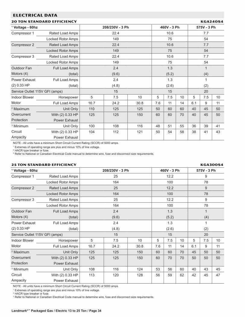
Landmark®™ Packaged Gas / Electric 13 to 25 Ton / Page 34
ELECTRICAL DATA20 TON STANDARD EFFICIENCY KGA240S41 Voltage - 60hz 208/230V - 3 Ph 460V - 3 Ph 575V - 3 PhCompressor 1 Rated Load Amps 22.4 10.6 7.7
Locked Rotor Amps 149 75 54Compressor 2 Rated Load Amps 22.4 10.6 7.7
Locked Rotor Amps 149 75 54Compressor 3 Rated Load Amps 22.4 10.6 7.7
Locked Rotor Amps 149 75 54Outdoor FanMotors (4)
Full Load Amps 2.4 1.3 1(total) (9.6) (5.2) (4)
Power Exhaust(2) 0.33 HP
Full Load Amps 2.4 1.3 1(total) (4.8) (2.6) (2)
Service Outlet 115V GFI (amps) 15 15 20Indoor BlowerMotor
Horsepower 5 7.5 10 5 7.5 10 5 7.5 10Full Load Amps 16.7 24.2 30.8 7.6 11 14 6.1 9 11
2 MaximumOvercurrentProtection
Unit Only 110 125 125 50 60 60 40 45 50With (2) 0.33 HP
Power Exhaust125 125 150 60 60 70 40 45 50
3 MinimumCircuitAmpacity
Unit Only 100 108 116 48 51 55 36 39 41With (2) 0.33 HP
Power Exhaust104 112 121 50 54 58 38 41 43
NOTE - All units have a minimum Short Circuit Current Rating (SCCR) of 5000 amps.1 Extremes of operating range are plus and minus 10% of line voltage. 2 HACR type breaker or fuse. 3 Refer to National or Canadian Electrical Code manual to determine wire, fuse and disconnect size requirements.
25 TON STANDARD EFFICIENCY KGA300S41 Voltage - 60hz 208/230V - 3 Ph 460V - 3 Ph 575V - 3 PhCompressor 1 Rated Load Amps 25 12.2 9
Locked Rotor Amps 164 100 78Compressor 2 Rated Load Amps 25 12.2 9
Locked Rotor Amps 164 100 78Compressor 3 Rated Load Amps 25 12.2 9
Locked Rotor Amps 164 100 78Outdoor FanMotors (4)
Full Load Amps 2.4 1.3 1(total) (9.6) (5.2) (4)
Power Exhaust(2) 0.33 HP
Full Load Amps 2.4 1.3 1(total) (4.8) (2.6) (2)
Service Outlet 115V GFI (amps) 15 15 20Indoor BlowerMotor
Horsepower 5 7.5 10 5 7.5 10 5 7.5 10Full Load Amps 16.7 24.2 30.8 7.6 11 14 6.1 9 11
2 MaximumOvercurrentProtection
Unit Only 125 125 150 60 60 70 45 50 50With (2) 0.33 HP
Power Exhaust125 125 150 60 70 70 50 50 50
3 MinimumCircuitAmpacity
Unit Only 108 116 124 53 56 60 40 43 45With (2) 0.33 HP
Power Exhaust113 120 128 56 59 62 42 45 47
NOTE - All units have a minimum Short Circuit Current Rating (SCCR) of 5000 amps.1 Extremes of operating range are plus and minus 10% of line voltage. 2 HACR type breaker or fuse. 3 Refer to National or Canadian Electrical Code manual to determine wire, fuse and disconnect size requirements.

Landmark®™ Packaged Gas / Electric 13 to 25 Ton / Page 35
ELECTRICAL13 TON high EFFICIENCY KgA156H41 Voltage - 60hz 208/230V - 3 Ph 460V - 3 Ph 575V - 3 PhCompressor 1 Rated Load Amps 14.5 6.3 6
Locked Rotor Amps 98 55 41Compressor 2 Rated Load Amps 14.5 6.3 6
Locked Rotor Amps 98 55 41Compressor 3 Rated Load Amps 14.5 6.3 6
Locked Rotor Amps 98 55 41Outdoor FanMotors (3)
Full Load Amps 2.4 1.3 1(total) (7.2) (3.9) (3)
Power Exhaust(2) 0.33 HP
Full Load Amps 2.4 1.3 1(total) (4.8) (2.6) (2)
Service Outlet 115V GFI (amps) 15 15 20Indoor BlowerMotor
Horsepower 2 3 5 2 3 5 2 3 5Full Load Amps 7.5 10.6 16.7 3.4 4.8 7.6 2.7 3.9 6.1
2 MaximumOvercurrentProtection
Unit Only 70 70 80 30 35 35 30 30 30With (2) 0.33 HP
Power Exhaust80 80 90 35 35 40 30 30 35
3 MinimumCircuitAmpacity
Unit Only 62 65 72 28 30 33 26 27 29With (2) 0.33 HP
Power Exhaust67 70 77 31 32 35 28 29 31
NOTE - All units have a minimum Short Circuit Current Rating (SCCR) of 5000 amps.1 Extremes of operating range are plus and minus 10% of line voltage. 2 HACR type breaker or fuse. 3 Refer to National or Canadian Electrical Code manual to determine wire, fuse and disconnect size requirements.
15 TON high EFFICIENCY KgA180H41 Voltage - 60hz 208/230V - 3 Ph 460V - 3 Ph 575V - 3 PhCompressor 1 Rated Load Amps 13.5 8 5
Locked Rotor Amps 109 59 40Compressor 2 Rated Load Amps 13.5 8 5
Locked Rotor Amps 109 59 40Compressor 3 Rated Load Amps 13.5 8 5
Locked Rotor Amps 109 59 40Outdoor FanMotors (4)
Full Load Amps 2.4 1.3 1(total) (9.6) (5.2) (4)
Power Exhaust(2) 0.33 HP
Full Load Amps 2.4 1.3 1(total) (4.8) (2.6) (2)
Service Outlet 115V GFI (amps) 15 15 20Indoor BlowerMotor
Horsepower 3 5 7.5 3 5 7.5 3 5 7.5Full Load Amps 10.6 16.7 24.2 4.8 7.6 11 3.9 6.1 9
2 MaximumOvercurrentProtection
Unit Only 70 80 100 40 45 50 25 30 35With (2) 0.33 HP
Power Exhaust80 90 100 45 45 50 30 30 40
3 MinimumCircuitAmpacity
Unit Only 65 71 81 36 39 43 25 27 31With (2) 0.33 HP
Power Exhaust69 76 86 39 42 46 27 29 33
NOTE - All units have a minimum Short Circuit Current Rating (SCCR) of 5000 amps.1 Extremes of operating range are plus and minus 10% of line voltage. 2 HACR type breaker or fuse. 3 Refer to National or Canadian Electrical Code manual to determine wire, fuse and disconnect size requirements.

Landmark®™ Packaged Gas / Electric 13 to 25 Ton / Page 36
ELECTRICAL17.5 TON high EFFICIENCY KgA210H41 Voltage - 60hz 208/230V - 3 Ph 460V - 3 Ph 575V - 3 PhCompressor 1 Rated Load Amps 15.6 7.8 5.8
Locked Rotor Amps 110 52 38.9Compressor 2 Rated Load Amps 15.6 7.8 5.8
Locked Rotor Amps 110 52 38.9Compressor 3 Rated Load Amps 19.6 8.2 6.6
Locked Rotor Amps 136 66.1 55.3Outdoor FanMotors (6)
Full Load Amps 2.4 1.3 1(total) (14.4) (7.8) (6)
Power Exhaust(2) 0.33 HP
Full Load Amps 2.4 1.3 1(total) (4.8) (2.6) (2)
Service Outlet 115V GFI (amps) 15 15 20Indoor BlowerMotor
Horsepower 3 5 7.5 3 5 7.5 3 5 7.5Full Load Amps 10.6 16.7 24.2 4.8 7.6 11 3.9 6.1 9
2 MaximumOvercurrentProtection
Unit Only 100 100 110 45 45 50 35 35 40With (2) 0.33 HP
Power Exhaust100 110 110 45 50 50 35 40 45
3 MinimumCircuitAmpacity
Unit Only 81 87 96 39 42 46 30 32 36With (2) 0.33 HP
Power Exhaust86 92 101 42 44 48 32 34 38
NOTE - All units have a minimum Short Circuit Current Rating (SCCR) of 5000 amps.1 Extremes of operating range are plus and minus 10% of line voltage. 2 HACR type breaker or fuse. 3 Refer to National or Canadian Electrical Code manual to determine wire, fuse and disconnect size requirements.
20 TON high EFFICIENCY KgA240H41 Voltage - 60hz 208/230V - 3 Ph 460V - 3 Ph 575V - 3 PhCompressor 1 Rated Load Amps 13.5 8 5
Locked Rotor Amps 109 59 40Compressor 2 Rated Load Amps 13.5 8 5
Locked Rotor Amps 109 59 40Compressor 3 Rated Load Amps 13.5 8 5
Locked Rotor Amps 109 59 40Compressor 4 Rated Load Amps 13.5 8 5
Locked Rotor Amps 109 59 40Outdoor FanMotors (6)
Full Load Amps 2.4 1.3 1(total) (14.4) (7.8) (6)
Power Exhaust(2) 0.33 HP
Full Load Amps 2.4 1.3 1(total) (4.8) (2.6) (2)
Service Outlet 115V GFI (amps) 15 15 20Indoor BlowerMotor
Horsepower 5 7.5 10 5 7.5 10 5 7.5 10Full Load Amps 16.7 24.2 30.8 7.6 11 14 6.1 9 11
2 MaximumOvercurrentProtection
Unit Only 100 110 125 50 60 70 35 45 50With (2) 0.33 HP
Power Exhaust110 125 125 60 60 70 40 45 50
3 MinimumCircuitAmpacity
Unit Only 90 99 107 50 54 58 34 38 40With (2) 0.33 HP
Power Exhaust95 104 112 53 57 60 36 40 42
NOTE - All units have a minimum Short Circuit Current Rating (SCCR) of 5000 amps.1 Extremes of operating range are plus and minus 10% of line voltage. 2 HACR type breaker or fuse. 3 Refer to National or Canadian Electrical Code manual to determine wire, fuse and disconnect size requirements.
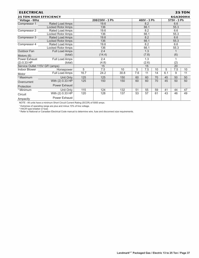
Landmark®™ Packaged Gas / Electric 13 to 25 Ton / Page 37
ELECTRICAL 25 TON25 TON high EFFICIENCY KgA300H41 Voltage - 60hz 208/230V - 3 Ph 460V - 3 Ph 575V - 3 PhCompressor 1 Rated Load Amps 19.6 8.2 6.6
Locked Rotor Amps 136 66.1 55.3Compressor 2 Rated Load Amps 19.6 8.2 6.6
Locked Rotor Amps 136 66.1 55.3Compressor 3 Rated Load Amps 19.6 8.2 6.6
Locked Rotor Amps 136 66.1 55.3Compressor 4 Rated Load Amps 19.6 8.2 6.6
Locked Rotor Amps 136 66.1 55.3Outdoor FanMotors (6)
Full Load Amps 2.4 1.3 1(total) (14.4) (7.8) (6)
Power Exhaust (2) 0.33 HP
Full Load Amps 2.4 1.3 1(total) (4.8) (2.6) (2)
Service Outlet 115V GFI (amps) 15 15 20Indoor BlowerMotor
Horsepower 5 7.5 10 5 7.5 10 5 7.5 10Full Load Amps 16.7 24.2 30.8 7.6 11 14 6.1 9 11
2 MaximumOvercurrentProtection
Unit Only 125 125 150 60 60 70 45 50 50With (2) 0.33 HP
Power Exhaust125 150 150 60 60 70 45 50 50
3 MinimumCircuitAmpacity
Unit Only 115 124 132 51 55 59 41 44 47With (2) 0.33 HP
Power Exhaust120 128 137 53 57 61 43 46 49
NOTE - All units have a minimum Short Circuit Current Rating (SCCR) of 5000 amps.1 Extremes of operating range are plus and minus 10% of line voltage. 2 HACR type breaker or fuse. 3 Refer to National or Canadian Electrical Code manual to determine wire, fuse and disconnect size requirements.

Landmark®™ Packaged Gas / Electric 13 to 25 Ton / Page 38
ELECTRICAL ACCESSORIESDISCONNECTS - Standard efficiency
Voltage 208V 240V 208V 240V 208V 240V 480V 480V 480V 600V 600V 600VModel No. KGA180S4
Blower Motor HP 3 5 7.5 3 5 7.5 3 5 7.5Unit Only 54W91 54W91 54W92 54W92 54W92 54W92 54W91 54W91 54W91 54W91 54W91 54W91
Unit w/ Power Exhaust 54W92 54W92 54W92 54W92 54W92 54W92 54W91 54W91 54W91 54W91 54W91 54W91Model No. KGA210S4
Blower Motor HP 3 5 7.5 3 5 7.5 3 5 7.5Unit Only 54W92 54W92 54W92 54W92 54W92 54W92 54W91 54W91 54W91 54W91 54W91 54W91
Unit w/ Power Exhaust 54W92 54W92 54W92 54W92 54W92 54W92 54W91 54W91 54W91 54W91 54W91 54W91Model No. KGA240S4
Blower Motor HP 5 7.5 10 5 7.5 10 5 7.5 10Unit Only 54W92 54W92 54W92 54W92 54W92 54W92 54W91 54W91 54W91 54W91 54W91 54W91
Unit w/ Power Exhaust 54W92 54W92 54W92 54W92 54W92 54W92 54W91 54W91 54W91 54W91 54W91 54W91Model No. KGA300S4
Blower Motor HP 5 7.5 10 5 7.5 10 5 7.5 10Unit Only 54W92 54W92 54W92 54W92 54W92 54W92 54W91 54W91 54W91 54W91 54W91 54W91
Unit w/ Power Exhaust 54W92 54W92 54W92 54W92 54W92 54W92 54W91 54W91 54W91 54W91 54W91 54W91
ELECTRICAL ACCESSORIESDISCONNECTS - High efficiency
Voltage 208V 240V 208V 240V 208V 240V 480V 480V 480V 600V 600V 600VModel No. KGA156H4
Blower Motor HP 2 3 5 2 3 5 2 3 5Unit Only 54W88 54W88 54W88 54W88 54W88 54W88 54W88 54W88 54W88 54W88 54W88 54W88
Unit w/ Power Exhaust 54W88 54W88 54W88 54W88 54W89 54W89 54W88 54W88 54W88 54W88 54W88 54W88Model No. KGA180H4
Blower Motor HP 3 5 7.5 3 5 7.5 3 5 7.5Unit Only 54W88 54W88 54W88 54W88 54W89 54W89 54W88 54W88 54W88 54W88 54W88 54W88
Unit w/ Power Exhaust 54W88 54W88 54W89 54W89 54W89 54W89 54W88 54W88 54W88 54W88 54W88 54W88Model No. KGA210H4
Blower Motor HP 3 5 7.5 3 5 7.5 3 5 7.5Unit Only 54W89 54W89 54W89 54W89 54W89 54W89 54W88 54W88 54W88 54W88 54W88 54W88
Unit w/ Power Exhaust 54W89 54W89 54W89 54W89 54W89 54W89 54W88 54W88 54W88 54W88 54W88 54W88Model No. KGA240H4
Blower Motor HP 5 7.5 10 5 7.5 10 5 7.5 10Unit Only 54W89 54W89 54W89 54W89 54W89 54W89 54W88 54W88 54W88 54W88 54W88 54W88
Unit w/ Power Exhaust 54W89 54W89 54W89 54W89 54W89 54W89 54W88 54W88 54W88 54W88 54W88 54W88Model No. KGA300H4
Blower Motor HP 5 7.5 10 5 7.5 10 5 7.5 10Unit Only 54W89 54W89 54W89 54W89 54W89 54W89 54W88 54W88 54W88 54W88 54W88 54W88
Unit w/ Power Exhaust 54W89 54W89 54W89 54W89 54W89 54W89 54W88 54W88 54W88 54W88 54W88 54W88

Landmark®™ Packaged Gas / Electric 13 to 25 Ton / Page 39
UNIT CLEARANCES - INCHES (MM)
1 Unit ClearanceA B C D Top
Clearancein. mm in. mm in. mm in. mmService Clearance 60 1524 36 914 36 914 66 1676
UnobstructedClearance to Combustibles 36 914 1 25 1 25 1 25Minimum Operation Clearance 45 1143 36 914 36 914 41 1041NOTE - Entire perimeter of unit base requires support when elevated above the mounting surface.1 Service Clearance - Required for removal of serviceable parts. Clearance to Combustibles - Required clearance to combustible material. Minimum Operation Clearance - Required clearance for proper unit operation.
Note: 180H, 240S, 300S sizes shown
Unit With Economizer
D
OUTDOORAIR HOOD
B
C
A
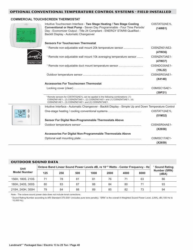
Landmark®™ Packaged Gas / Electric 13 to 25 Ton / Page 40
OPTIONAL CONVENTIONAL TEMPERATURE CONTROL SYSTEMS - FIELD INSTALLED
COMMERCIAL TOUCHSCREEN THERMOSTATIntuitive Touchscreen Interface - Two Stage Heating / Two Stage Cooling Conventional or Heat Pump - Seven Day Programmable - Four Time Periods/Day - Economizer Output - Title 24 Compliant - ENERGY STAR® Qualified - Backlit Display - Automatic Changeover
C0STAT02AE1L(14W81)
Sensors For Touchscreen Thermostat1 Remote non-adjustable wall mount 20k temperature sensor ......................... C0SNZN01AE2-
(47W36)1 Remote non-adjustable wall mount 10k averaging temperature sensor ........ C0SNZN73AE1-
(47W37)1 Remote non-adjustable duct mount temperature sensor ............................... C0SNDC00AE1-
(19L22)Outdoor temperature sensor ............................................................................ C0SNSR03AE1-
(X4148)Accessories For Touchscreen Thermostat
Locking cover (clear) ........................................................................................ C0MISC15AE1-(39P21)
1 Remote sensors for C0STAT02AE1L can be applied in the following combinations: (1) C0SNZN01AE1-, (2) C0SNZN73AE1-, (2) C0SNZN01AE1- and (1) C0SNZN73AE1-, (4) C0SNZN01AE1-, (3) C0SNZN01AE1- and (2) C0SNZN73AE1.
Intuitive Interface - Automatic Changeover - Backlit Display - Simple Up and Down Temperature ControlOne-stage heating / cooling conventional systems .......................................... C0STAT12AE1L
(51M32)Sensor For Digital Non-Programmable Thermostats AboveOutdoor temperature sensor ............................................................................ C0SNSR04AE1-
(X2658)Accessories For Digital Non-Programmable Thermostats AboveOptional wall mounting plate ............................................................................ C0MISC17AE1-
(X2659)
OUTDOOR SOUND DATA
Unit Model Number
Octave Band Linear Sound Power Levels dB, re 10-12 Watts - Center Frequency - Hz 1 Sound Rating Number (SRN)
(dBA)125 250 500 1000 2000 4000 8000
156H, 180S, 210S 71 78 81 81 76 71 63 86
180H, 240S, 300S 80 83 87 88 84 80 71 93
210H, 240H, 300H 79 84 88 89 85 82 73 94
Note - The octave sound power data does not include tonal corrections.1 Sound Rating Number according to ARI Standard 370-2001 (includes pure tone penalty). “SRN” is the overall A-Weighted Sound Power Level, (LWA), dB (100 Hz to
10,000 Hz).

Landmark®™ Packaged Gas / Electric 13 to 25 Ton / Page 41
OPTIONS / ACCESSORIES
DescriptionShipping Weight
lbs. kgCEILING DIFFUSERSStep-Down
RTD11-185 392 178RTD11-275 403 183
FlushFD11-185 289 131FD11-275 363 165
Transitions LASRT18 80 36
LASRT21/24 75 34ECONOMIZER / OUTDOOR AIR / EXHAUSTEconomizerEconomizer Dampers K1ECON20C-1 86 39Barometric Relief Dampers (downflow) C1DAMP50C 30 14Barometric Relief Dampers (horizontal) LAGEDH18/24 20 9Outdoor Air DampersOutdoor Air Damper Section (downflow) - Automatic E1DAMP20C-1 52 24Outdoor Air Damper Section (downflow) - Manual C1DAMP10C-1 49 22Outdoor Air Damper Hood (downflow) 65 29Power Exhaust 62 28GAS HEAT EXCHANGER (NET WEIGHT)
Medium Heat (adder over standard heat) 18 8High Heat (adder over standard heat) 64 29
MSAV (MULTI-STAGE AIR VOLUME) SUPPLY AIR BLOWER OPTIONVariable Frequency Drive (VFD) and associated components 10 5ROOF CURBS - CLIP CURBDownflow8 in. height C1CURB40CD1 132 6014 in. height LARMF18/30S-14 164 7418 in. height LARMF18/30S-18 187 8524 in. height LARMF18/30S-24 222 101ROOF CURBS - STANDARDDownflow14 in. height LARMF18/36-14 160 7324 in. height LARMF18/36-24 220 100Horizontal26 in. height LARMFH18/24-26 420 19137 in. height LARMFH18/24-37 580 26330 in. height LARMFH30/36-30 445 20241 in. height LARMFH30/36-41 725 329PACKAGINGLTL Packaging (less than truck load) 310 141
WEIGHT DATA
Model Number Net Shipping Model Number Net Shippinglbs. kg lbs. kg lbs. kg lbs. kg
156H Base Unit 1935 878 2135 968 180S Base Unit 1790 812 1990 903156H Max. Unit 2205 1000 2405 1091 180S Max. Unit 2115 959 2315 1050180H Base Unit 2115 959 2315 1050 210S Base Unit 1935 878 2135 968180H Max. Unit 2400 1089 2600 1179 210S Max. Unit 2260 1025 2460 1116210H Base Unit 2240 1016 2440 1107 240S Base Unit 2180 989 2380 1080210H Max. Unit 2525 1145 2725 1236 240S Max. Unit 2505 1136 2705 1227240H Base Unit 2325 1055 2525 1145 300S Base Unit 2180 989 2380 1080240H Max. Unit 2610 1184 2810 1275 300S Max. Unit 2505 1136 2705 1227300H Base Unit 2430 1102 2630 1193300H Max. Unit 2715 1232 2915 1322

Landmark®™ Packaged Gas / Electric 13 to 25 Ton / Page 42
4-1/4 (108)
BOTTOM POWER/GAS ENTRY5 X 8 inches (127 X 203 mm)
BOTTOM SUPPLYAIR OPENINGS
BOTTOM RETURNAIR OPENING
28(711)
28(711)
4(102)
4(102)
12-3/8(314)
12-3/8(314)
20 (508) 20 (508)
15 (381)60-1/2 (1537)
AA BB
CCDD
CENTER OFGRAVITY
EE
FF
TOP VIEW
4-1/2(114)
END VIEW
90-1/8(2289)
28-3/4(730)
5-3/8(137)
3-1/4(83)
54-1/4(1378)
51(1295)
91-1/8 (2315)BASE
8-1/4(210)
10-1/4(260)
4(102)
SIDE ELECTRICAL
INLETS
GAS SUPPLY INLET(For Bottom
Gas Supply Only)CONDENSATE
GAS SUPPLY OUTLET(For Bottom
Gas Supply Only)
DRAIN
SIDE VIEW
FORKLIFT SLOTS(Front and Left Side Only)
LIFTING HOLES(For Rigging
Front and Back)107-3/4 (2737)
BASE
106-1/2(2705)
FLUEOUT LET
ALTERNATE (THRU THE BASE)CONDENSATE DRAIN LOCATION
1-5/8 in. (41 mm) Diameter
18 (457)
28-3/8(721)
5-5/8 (143)
DIMENSIONS - INCHES (MM) kga156h, kga180s, kga210s
Model No.
CORNER WEIGHTS CENTER OF GRAVITYAA BB CC DD EE FF
Base Max. Base Max. Base Max. Base Max. Base Max. Base Max.lbs. kg lbs. kg lbs. kg lbs. kg lbs. kg lbs. kg lbs. kg lbs. kg in. mm in. mm in. mm in. mm
156H 473 215 586 266 367 167 447 203 483 219 510 232 612 278 663 301 47-1/4 1200 46 3/4 1187 39 1/2 1003 42 3/4 1086180S 425 193 547 249 361 164 439 200 461 210 503 229 543 247 626 284 49 1/2 1257 48 1219 40 1016 42 1/2 1080210S 450 204 573 261 379 172 456 207 506 230 545 248 601 273 685 312 49 1/4 1251 47 3/4 1213 39 991 41 1/2 1054Base Unit - The unit with NO INTERNAL OPTIONS.Max. Unit - The unit with ALL INTERNAL OPTIONS Installed. (Economizer, Standard Static Power Exhaust Fans, Controls, etc.). Does not include accessories external to unit or high static power exhaust.

Landmark®™ Packaged Gas / Electric 13 to 25 Ton / Page 43
BOTTOM POWER/GAS ENTRY5 X 8 inches (127 X 203 mm)
BOTTOM SUPPLYAIR OPENINGS
BOTTOM RETURNAIR OPENING
28(711)
28(711)
20 (508)
15 (381)60-1/2 (1537)
AA BB
CCDD
CENTER OFGRAVITY
EE
FF
TOP VIEW
4-1/2(114)
20 (508)
FLUE
SIDE VIEW
FORKLIFT SLOTS(Front and Left Side Only)
132-5/8(3369)
LIFTING HOLES(For Rigging
Front and Back)25-3/8(645)
107-3/4 (2737)BASE
OUTLET
END VIEW
90-1/8(2289)
28-3/4(730)
5-3/8(137)
3-1/4(83)
54-1/4(1378)
51(1295)
91-1/8 (2315)BASE
8-1/4(210)
10-1/4(260)
4(102)
SIDE ELECTRICAL
INLETS
GAS SUPPLY INLET(For Bottom
Gas Supply Only)CONDENSATE
GAS SUPPLY OUTLET(For Bottom
Gas Supply Only)
DRAIN
4-1/4 (108)
4(102)
4(102)
12-3/8(314)
12-3/8(314)
ALTERNATE (THRU THE BASE)CONDENSATE DRAIN LOCATION
1-5/8 in. (41 mm) Diameter
18 (457)
28-3/8(721)
5-5/8 (143)
DIMENSIONS - INCHES (MM) kga180h, kga240s, kga300s
Model No.
CORNER WEIGHTS CENTER OF GRAVITYAA BB CC DD EE FF
Base Max. Base Max. Base Max. Base Max. Base Max. Base Max.lbs. kg lbs. kg lbs. kg lbs. kg lbs. kg lbs. kg lbs. kg lbs. kg in. mm in. mm in. mm in. mm
180H 487 221 597 272 423 192 505 229 569 259 599 272 636 289 699 318 50 3/4 1289 49 3/4 1264 39 1/4 997 42 1067240S 456 207 573 261 429 195 506 230 628 285 668 304 667 303 758 344 51 1/4 1327 50 1/2 1283 37 940 39 1/4 997300S 456 207 573 261 429 195 506 230 628 285 668 304 667 303 758 344 52 1/4 1327 50 1/2 1283 37 940 39 1/4 997Base Unit - The unit with NO INTERNAL OPTIONS.Max. Unit - The unit with ALL INTERNAL OPTIONS Installed. (Economizer, Standard Static Power Exhaust Fans, Controls, etc.). Does not include accessories external to unit or high static power exhaust.
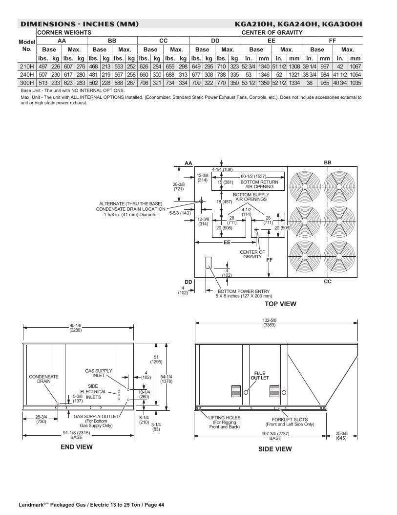
Landmark®™ Packaged Gas / Electric 13 to 25 Ton / Page 44
DIMENSIONS - INCHES (MM) kga210h, kga240h, kga300h
Model No.
CORNER WEIGHTS CENTER OF GRAVITYAA BB CC DD EE FF
Base Max. Base Max. Base Max. Base Max. Base Max. Base Max.lbs. kg lbs. kg lbs. kg lbs. kg lbs. kg lbs. kg lbs. kg lbs. kg in. mm in. mm in. mm in. mm
210H 497 226 607 276 468 213 553 252 626 284 655 298 649 295 710 323 52 3/4 1340 51 1/2 1308 39 1/4 997 42 1067240H 507 230 617 280 481 219 567 258 660 300 688 313 677 308 738 335 53 1346 52 1321 38 3/4 984 41 1/2 1054300H 513 233 623 283 502 228 588 267 706 321 734 334 709 322 770 350 53 1/2 1359 52 1/2 1334 38 965 40 3/4 1035Base Unit - The unit with NO INTERNAL OPTIONS.Max. Unit - The unit with ALL INTERNAL OPTIONS Installed. (Economizer, Standard Static Power Exhaust Fans, Controls, etc.). Does not include accessories external to unit or high static power exhaust.
4-1/4 (108)12-3/8(314)
(314)12-3/8
4(102)
BOTTOM SUPPLYAIR OPENINGS
BOTTOM RETURNAIR OPENING
28(711)
28(711)
20 (508)
15 (381)60-1/2 (1537)
AA BB
CCDD
CENTER OFGRAVITY
EE
FF
TOP VIEW
4-1/2(114)
20 (508)
BOTTOM POWER ENTRY5 X 8 inches (127 X 203 mm)
4(102)
END VIEW
90-1/8(2289)
28-3/4(730)
5-3/8(137)
3-1/4(83)
54-1/4(1378)
51(1295)
91-1/8 (2315)BASE
8-1/4(210)
10-1/4(260)
4(102)CONDENSATE
DRAINSIDE
ELECTRICALINLETS
GAS SUPPLYINLET
GAS SUPPLY OUTLET(For Bottom
Gas Supply Only)
FLUEOUT LET
SIDE VIEW
FORKLIFT SLOTS(Front and Left Side Only)
132-5/8(3369)
LIFTING HOLES(For Rigging
Front and Back)25-3/8(645)
107-3/4 (2737)BASE
FLUEOUT LET
ALTERNATE (THRU THE BASE)CONDENSATE DRAIN LOCATION
1-5/8 in. (41 mm) Diameter
18 (457)
28-3/8(721)
5-5/8 (143)

Landmark®™ Packaged Gas / Electric 13 to 25 Ton / Page 45
ACCESSORY DIMENSIONS - INCHES (MM)
16(406)
FRONT VIEW SIDE VIEW
31−5/8 (803)
14-1/2(368)
1 13(330)
6-1/2(165)1 29−1/2 (749)
NOTE − Two furnished per order no. 1 NOTE − Opening size required in return air duct.
HORIZONTAL BAROMETRIC RELIEF DAMPERS(Field installed in horizontal return air duct adjacent to unit)
1 OPTIONALSTANDARD STATICPOWER EXHAUST
FANS HOOD(Field Installed)
(Downflow Applications only)
OPTIONAL OUTDOOR AIR HOOD DETAILWITH STANDARD STATIC POWER EXHAUST FANS
OPTIONALOUTDOOR AIR HOOD
(Field Installed)Required with Economizer
or Outdoor Air Damper

Landmark®™ Packaged Gas / Electric 13 to 25 Ton / Page 46
ACCESSORY DIMENSIONS - INCHES (MM)
CLIP CURB − DOUBLE DUCT OPENING
TYPICAL FLASHING DETAIL FOR ROOF CURB
ROOF CURB(Extends around entire
perimeter of unit)
FIBERGLASSINSULATION
(Furnished)COUNTER FLASHING(Field Supplied)
BASE BOTTOM
RIGID INSULATION(Field Supplied)
ROOFINGMATERIAL
CANT STRIP(Field Supplied)
PACKAGEDUNIT
NAILER STRIP(Furnished)
8−1/4(210)
8−1/4(210)
8 (203)14 (356)18 (457)24 (610)
61-1/2(1562)
CURBRETURN AIR
OPENING
61-1/2(1562)
81-1/2(2070)
17 (432)
21 (533)
16 (406)
86−1/4(2191)
82−5/8(2099)
1−13/16(46)
102-1/8(2594)
98-1/2(2502)
1−13/16(46)
DETAIL ROOF CURB
8 (203)14 (356)18 (457)24 (610)
FACTORY INSTALLEDPERIMETER WOODNAILER STRIP
1−13/16(46)
1−13/16(46)
1/2 (13)
CURBSUPPLY AIR
OPENING
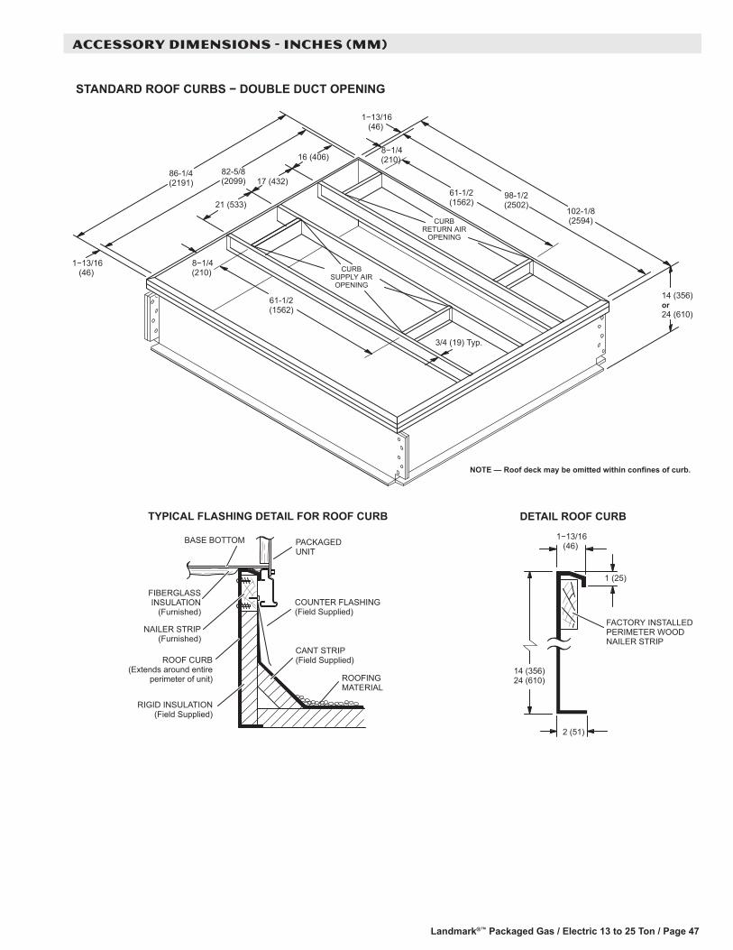
Landmark®™ Packaged Gas / Electric 13 to 25 Ton / Page 47
ACCESSORY DIMENSIONS - INCHES (MM)
STANDARD ROOF CURBS − DOUBLE DUCT OPENING
TYPICAL FLASHING DETAIL FOR ROOF CURB
ROOF CURB(Extends around entire
perimeter of unit)
FIBERGLASSINSULATION
(Furnished)COUNTER FLASHING(Field Supplied)
BASE BOTTOM
RIGID INSULATION(Field Supplied)
ROOFINGMATERIAL
CANT STRIP(Field Supplied)
PACKAGEDUNIT
NAILER STRIP(Furnished)
CURBSUPPLY AIR
OPENING
8−1/4(210)
1−13/16(46)
DETAIL ROOF CURB
14 (356)24 (610)
1 (25)
FACTORY INSTALLEDPERIMETER WOODNAILER STRIP
2 (51)
8−1/4(210)
17 (432)
21 (533)
16 (406)
102-1/8(2594)
61-1/2(1562)
98-1/2(2502)
86-1/4(2191)
82-5/8(2099)
3/4 (19) Typ.
14 (356)or24 (610)
CURBRETURN AIR
OPENING
1−13/16(46)
61-1/2(1562)
1−13/16(46)

Landmark®™ Packaged Gas / Electric 13 to 25 Ton / Page 48
ACCESSORY DIMENSIONS - INCHES (MM)
ROOF CURBS WITH SUPPLY & RETURN AIR TRANSITIONS FOR CEILING DIFFUSERS
LASRT SUPPLY TRANSITION
LASRT RETURN TRANSITION
RETURN AIROPENING
SUPPLY AIROPENINGS
TOP VIEW
54(1372)
69-1/4 (1759)
3/4(19) Typ.
4-1/2(114)
SUPPORTANGLE
(Furnished withTransitions)
B
A
B
69-1/4(1759)
2(51)
8 (203)
26-1/2(673)
1-1/2(38) Typ.
TRANSITION DETAIL
A
AB
TRANSITION OPENING SIZES
Model A BModelNumber inch mm inch mmLASRT18 18 457 36 914
LASRT21/24 24 610 48 1219
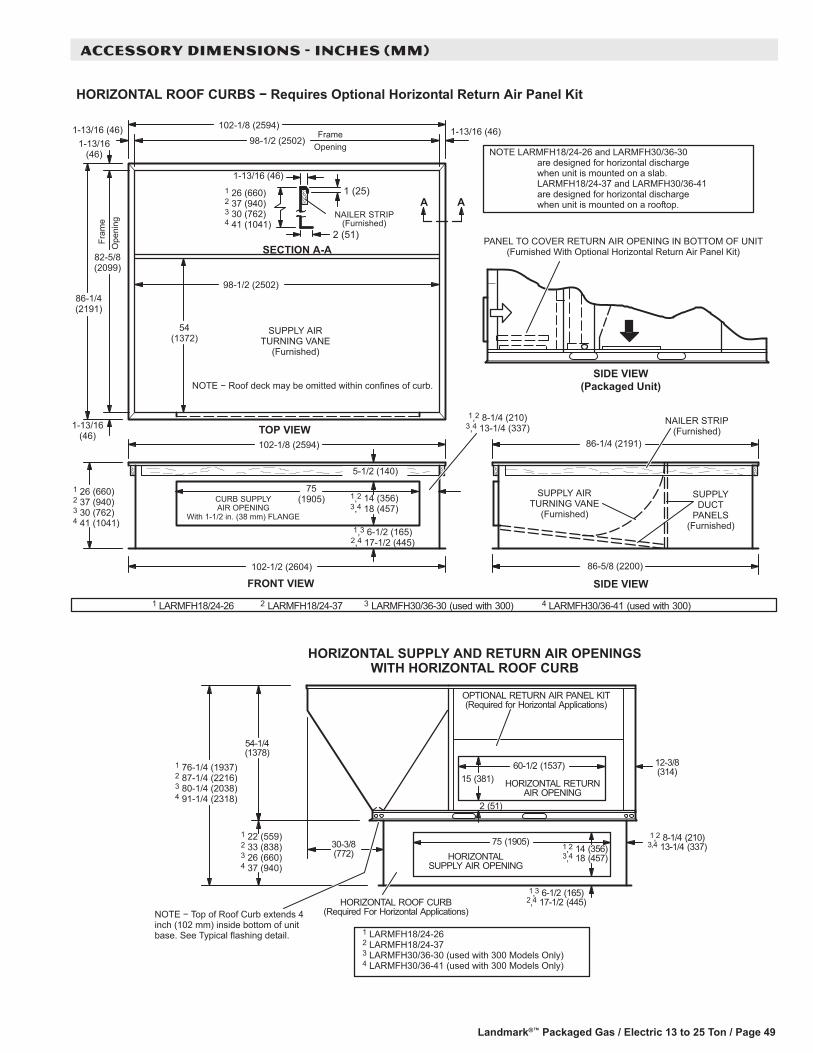
Landmark®™ Packaged Gas / Electric 13 to 25 Ton / Page 49
ACCESSORY DIMENSIONS - INCHES (MM)
HORIZONTAL ROOF CURBS − Requires Optional Horizontal Return Air Panel Kit
PANEL TO COVER RETURN AIR OPENING IN BOTTOM OF UNIT(Furnished With Optional Horizontal Return Air Panel Kit)
SIDE VIEW(Packaged Unit)
SIDE VIEW86-5/8 (2200)
NAILER STRIP(Furnished)
SUPPLYDUCT
PANELS(Furnished)
SUPPLY AIRTURNING VANE
(Furnished)
86-1/4 (2191)
1 26 (660)2 37 (940)3 30 (762)4 41 (1041)
102-1/8 (2594)
TOP VIEW
Fram
eO
peni
ng
FrameOpening
54(1372)
98-1/2 (2502)
82-5/8(2099)
98-1/2 (2502)
1 (25)
2 (51)SECTION A-A
1-13/16 (46)
NAILER STRIP(Furnished)
A
NOTE − Roof deck may be omitted within confines of curb.
SUPPLY AIRTURNING VANE
(Furnished)
1-13/16(46)
1-13/16(46)
1-13/16 (46)1-13/16 (46)
A
86-1/4(2191)
HORIZONTALSUPPLY AIR OPENING
HORIZONTAL ROOF CURB(Required For Horizontal Applications)
1,2 8-1/4 (210)3,4 13-1/4 (337)75 (1905)
HORIZONTAL RETURNAIR OPENING
12-3/8(314)
15 (381)60-1/2 (1537)
2 (51)
54-1/4(1378)
NOTE − Top of Roof Curb extends 4inch (102 mm) inside bottom of unitbase. See Typical flashing detail.
OPTIONAL RETURN AIR PANEL KIT(Required for Horizontal Applications)
1,3 6-1/2 (165)2,4 17-1/2 (445)
1 22 (559)2 33 (838)3 26 (660)4 37 (940)
1 76-1/4 (1937)2 87-1/4 (2216)3 80-1/4 (2038)4 91-1/4 (2318)
1,2 14 (356)3,4 18 (457)
30-3/8(772)
HORIZONTAL SUPPLY AND RETURN AIR OPENINGSWITH HORIZONTAL ROOF CURB
1 LARMFH18/24-26 2 LARMFH18/24-373 LARMFH30/36-30 (used with 300 Models Only)4 LARMFH30/36-41 (used with 300 Models Only)
1 LARMFH18/24-26 2 LARMFH18/24-37 3 LARMFH30/36-30 (used with 300) 4 LARMFH30/36-41 (used with 300)
NOTE LARMFH18/24-26 and LARMFH30/36-30are designed for horizontal dischargewhen unit is mounted on a slab.LARMFH18/24-37 and LARMFH30/36-41are designed for horizontal dischargewhen unit is mounted on a rooftop.
1,2 14 (356)3,4 18 (457)
102-1/2 (2604)
CURB SUPPLYAIR OPENING
With 1-1/2 in. (38 mm) FLANGE
75(1905)
5-1/2 (140)
102-1/8 (2594)
1,2 8-1/4 (210)3,4 13-1/4 (337)
1,3 6-1/2 (165)2,4 17-1/2 (445)
1 26 (660)2 37 (940)3 30 (762)4 41 (1041)
FRONT VIEW

Landmark®™ Packaged Gas / Electric 13 to 25 Ton / Page 50
ACCESSORY DIMENSIONS - INCHES (MM)
COMBINATION CEILING SUPPLY AND RETURN DIFFUSERSRESUFFID GNILIEC HSULFRESUFFID GNILIEC NWOD-PETS
L
A
C
HJG
FE
B
M
N
K
DG
2 (51)
A
C
HJG
FE
B
K
DG
2 (51)
Model Number RTD11-185 RTD11-275A in. 47-5/8 59-5/8
mm 1210 1514B in. 47-5/8 59-5/8
mm 1210 1514C in. 24-5/8 30-5/8
mm 625 778D in. 45-1/2 57-1/2
mm 1156 1461E in. 45-1/2 57-1/2
mm 1156 1461F in. 4-1/2 4-1/2
mm 114 114G in. 18 24
mm 457 610H in. 2-1/2 2-1/2
mm 64 64J in. 36 48
mm 914 1219K in. 4-3/4 4-3/4
mm 121 121L in. 45-1/2 57-1/2
mm 1156 1461M in. 45-1/2 57-1/2
mm 1156 1461N in. 10-1/8 11-1/8
mm 257 283Duct Size in. 18 x 36 24 x 48
mm 457 x 914 610 x 1219
Model Number FD11-185 FD11-275A in. 47-5/8 59-5/8
mm 1210 1514B in. 47-5/8 59-5/8
mm 1210 1514C in. 29-1/4 35-1/4
mm 743 895D in. 45 57
mm 1143 1148E in. 45 57
mm 1143 1448F in. 4-1/2 4-1/2
mm 114 114G in. 18 24
mm 457 610H in. 2-1/4 2-1/4
mm 57 57J in. 36 48
mm 914 1219K in. 4-1/2 4-1/2
mm 114 114Duct Size in. 18 x 36 24 x 48
mm 457 x 914 610 x 1219

REVISIONS
Section Description
Document Added Crankcase Heaters to Features.
Options/Accessories Updated Low Ambient Controls for high and standard efficiency models.
NOTE - Due to Lennox’ ongoing commitment to quality, Specifications, Ratings and Dimensions subject to change without notice and without incurring liability. Improper installation, adjustment, alteration, service or maintenance can cause property damage or personal injury. Installation and service must be performed by a qualified installer and servicing agency. ©2013 Lennox Industries, Inc.
Visit us at www.lennox.com
For the latest technical information, www.lennoxcommercial.com
Contact us at 1-800-4-LENNOX
Related Documents