Pack 1

Welcome message from author
This document is posted to help you gain knowledge. Please leave a comment to let me know what you think about it! Share it to your friends and learn new things together.
Transcript

Pack 1

Editorial and design by Continuo Creative, 39-41 North Road, London N7 9DP.Published in the UK by De Agostini UK Ltd, Battersea Studios 2, 82 Silverthorne Road, London SW8 3HE. Published in the USA by De Agostini Publishing USA, Inc.,121 E. Calhoun Street, Woodstock, IL 60098.All rights reserved © 2018
Warning: Not suitable for children under the age of 14. This product is not a toy and is not designed or intended for use in play. Items may vary from those shown.
STAGE PAGE1 Luggage compartment lid 3
2 The right front wheel 7
3 The engine compartment lid 11
4 Exhaust system and engine covers 15
5 Driver’s seat back and headrest 19

3
STEP BY STEP
Stage 1: Luggage compartment lid
In this first stage, you fit the handle and lock to the front luggage compartment lid – one of the most characteristic features of the Volkswagen Beetle. The handle and the lock are mounted
using the two screws provided.
PARTS
1-1 Luggage compartment lid
1-2 Handle1-3 Lock1-4 Headlights1-5 Catch1-6 SP01 screws
1-1 1-2 1-3 1-5
1-4 1-6
SCREWSPARTS DIAGRAM
In each issue, the screws required for the assembly of the different parts are supplied in packets marked with ‘SP’ or ‘SD’ (to differentiate the screws used for plastic parts and the diecast metal parts respectively), followed by a number to identify their size.The packet will also include one or more additional screws – dependingon how many are being used – as a spare, in case you lose any of these small fixings.
1-1
1-4
1-2
1-3
1-5 1-6
1-4
NOTE: The appearance of the parts you receive may be slightly different from the parts pictured in these pages.

4
VW BEETLE 1303 CABRIOLET
STEP 1-AThe handle (1-2) and the lock (1-3) go on opposite sides of the luggage compartment lid, but fit together this way round, so that the lugs of the handle fit into the holes of the lock. The catch (1-5) fits underneath the lock, this way round, and the parts are all fixed together with SP01 screws.
STEP 1-BStart by inserting the lugs of the
handle into the holes in the front of the lid, with the thinnest part of the
handle pointing upwards.
STEP 1-CPress the handle firmly into place.
1-2
1-3
1-5

5
STEP BY STEP
STEP 1-DThen fit the lock inside the lid, so that the holes in the lock fit over the lugs of the handle.
STEP 1-EDrive an SP01 screw through the
upper hole in the lock and into the lug in the handle.
STEP 1-FFit the catch onto the lock using Step 1-A as a reference for which way round it goes, then drive an SP01 screw through the catch and the lock into the lug in the handle.
STEP 1-GKeep the two headlights safely
for use at a later stage.
6
VW BEETLE 1303 CABRIOLET
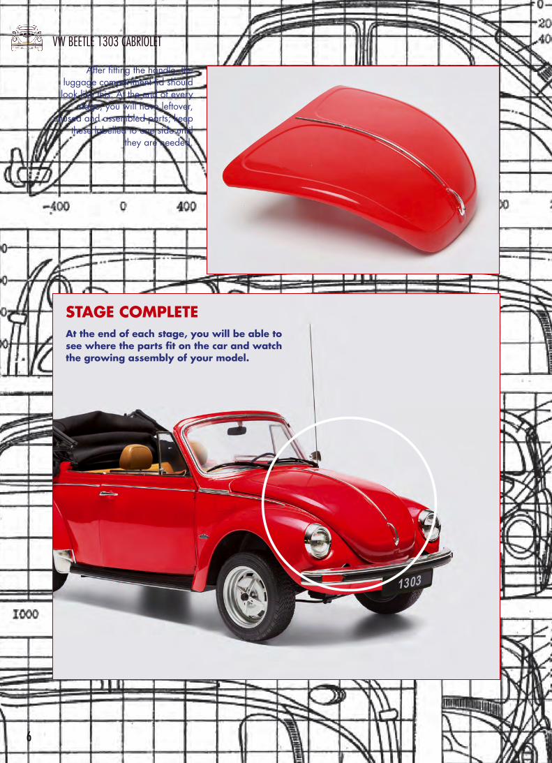
After fitting the handle, the luggage compartment lid should look like this. At the end of every
stage, you will have leftover, unused and assembled parts; keep
these labelled to one side until they are needed.
At the end of each stage, you will be able to see where the parts fit on the car and watch the growing assembly of your model.
STAGE COMPLETE

7
STEP BY STEP
Stage 2: The right front wheel
In this stage, you assemble the right front wheel of your VW Beetle, together with the front disc brake and the VW badge that fits in the centre of the hub cap.
PARTS
2-1 Wheel2-2 Tyre2-3 Brake disc2-4 Brake backplate2-5 Steering knuckle2-6 Brake caliper2-7 VW badge2-8 SD02 screws2-9 SD01 screws2-10 Screwdriver
2-2
2-10
2-3 2-4 2-5 2-6 2-7 2-8
2-1
2-9
TIP
To make it easier to fit the tyre onto the rim, gently warm the tyre with a hair dryer. There is no need to get it very hot. Thanks to the quality of the material from which it is moulded, the tyre softens quite easily.
2-5 2-6
2-42-3
2-2
2-1
2-8
2-7
2-9
PARTS DIAGRAM
NOTE: The appearance of the parts you receive may be slightly different from the parts pictured in these pages.

8
VW BEETLE 1303 CABRIOLET
STEP 2-ASoften the tyre (2-2) as shown in the Tip box, then insert the solid portion around the rim of the wheel (2-1) into one side of the tyre.
STEP 2-BGo round the tyre, working it over the rim.
STEP 2-CCheck that the tyre beads are perfectly seated on the rim all the way round.
STEP 2-DNote: The flange of the brake backplate (2-4)has two pins on either side of the central hole. These pins fit into the indicated holes on the steering knuckle (2-5) and are arranged asymmetrically so that the backplate fits in a set position on the steering knuckle.
STEP 2-EThe backplate and steering knuckle should look like this after assembly.
STEP 2-FFit the brake disc (2-3) by inserting the axle of the steering knuckle through the central hole.

9
STEP BY STEP
STEP 2-GFit the caliper over the brake disc and the recessed
portion of the backplate.
STEP 2-HScrew the two lugs of the caliper to the two holes in the steering knuckle using two SD01 screws.
STEP 2-JThe centre of the brake disc has a single slot into which the tab shown in Step 2-I fits. (The four outer slots fit the four long flanges in the wheel.)
STEP 2-IThe inner side of the wheel has a tab on one side of the hub. This is designed to lock into a slot in the brake disc.
STEP 2-KFit the wheel so that the spindle of the steering knuckle goes through the central hole and the tabs lock into the slots in the brake disc.

10
VW BEETLE 1303 CABRIOLET
STEP 2-LFix the wheel to the spindle with a flanged SD02 screw. If you hold the steering knuckle, it should now be possible to spin the wheel and the brake disc together, just as on the real car.
STEP 2-MFit the VW badge into the hole in the centre of the wheel, and press it firmly into place.
That completes the assembly of the right front wheel.
STAGE COMPLETE
This is the position of the wheel when the car is completed.

11
STEP BY STEP
Stage 3: The engine compartment lid
The engine compartment lid is another characteristic feature of the VW Beetle. The model part is already fitted with the handle, lock and badge. This stage covers the
installation of the number plate and number plate light housing. The bumper provided will be fitted later on, and you also have a set of stickers to customise the registration number.
PARTS
3-1 Engine compartment lid
3-2 Number plate light housing3-3 Central vent3-4 Number plate3-5 Bumper3-6 SP03 screws3-7 SD03 screws3-8 SP02 screws3-9 Stickers
PARTS DIAGRAM
3-1
3-2
3-8
3-83-7
3-3
PARTS TO RETAIN
The bumper (3-5), stickers (3-9) used to customise the registration, and the screws (3-6) will not be used until later on. Keep them somewhere safe and take care not to lose them.
3-5
3-5
3-4
3-1 3-2 3-3 3-4
3-6 3-7 3-8 3-9
NOTE: The appearance of the parts you receive may be slightly different from the parts pictured in these pages.
12
VW BEETLE 1303 CABRIOLET
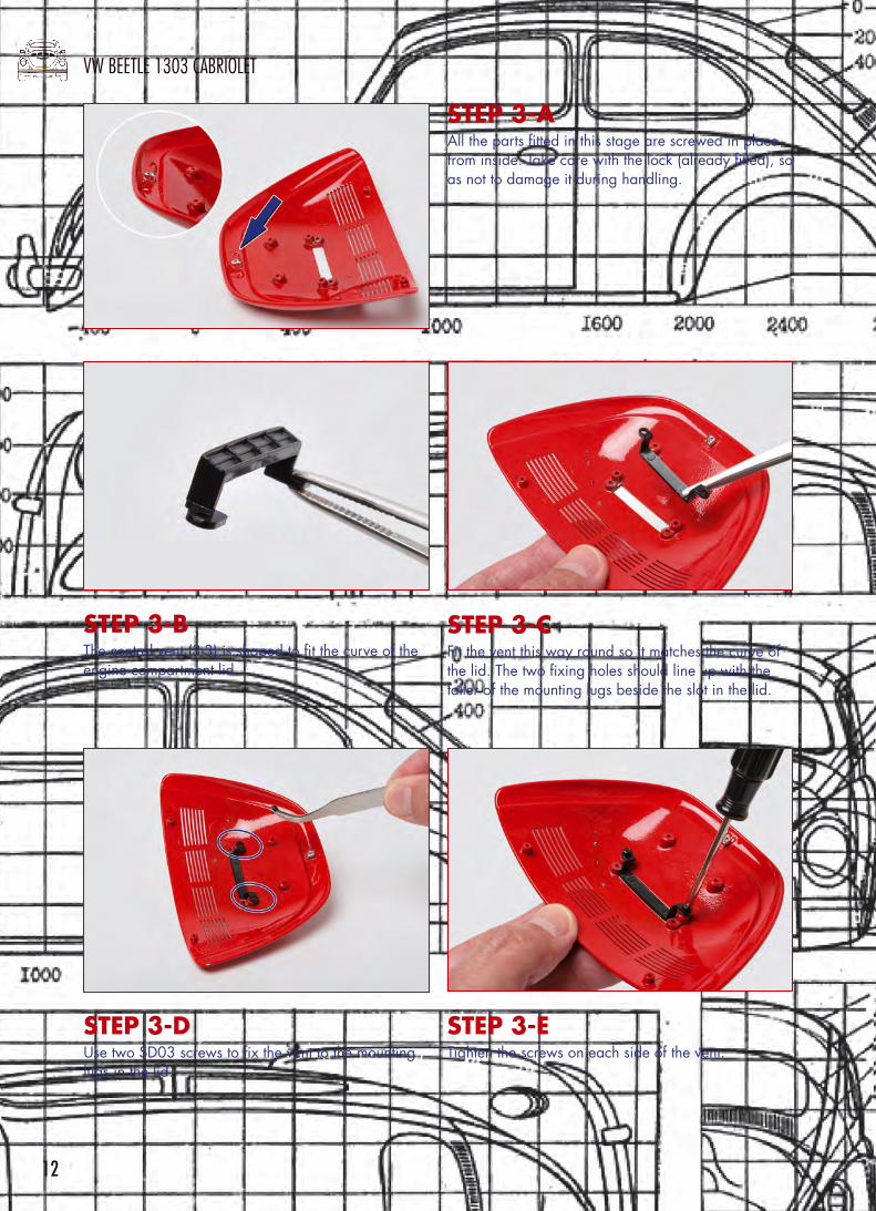
STEP 3-AAll the parts fitted in this stage are screwed in place from inside. Take care with the lock (already fitted), so as not to damage it during handling.
STEP 3-DUse two SD03 screws to fix the vent to the mounting lugs in the lid.
STEP 3-ETighten the screws on each side of the vent.
STEP 3-BThe central vent (3-3) is shaped to fit the curve of the engine compartment lid.
STEP 3-CFit the vent this way round so it matches the curve of the lid. The two fixing holes should line up with the taller of the mounting lugs beside the slot in the lid.

13
STEP BY STEP
STEP 3-JThe number plate has angled fixing lugs. Make sure these are aligned the right way round, as shown.
STEP 3-FTake the light housing and fit it over the slot in the engine compartment lid, aligning the lugs on each side with the holes in the lid.
STEP 3-HUse two SP02 screws to fix the housing to the mounting lugs in the lid.
STEP 3-GPress the light housing into place so it fits flush.
STEP 3-ITighten the screws on each side of the vent.

14
VW BEETLE 1303 CABRIOLET
STEP 3-KPress the number plate into place.
STEP 3-LFix the number plate in place with two SP02 screws.
The engine compartment lid should now look like this.
STAGE COMPLETE

15
STEP BY STEP
Stage 4: Exhaust systemand engine covers
This stage involves the assembly of the exhaust system of the Volkswagen Beetle, together with the tinware that fits under the engine. The exhaust system, with its pair of heat exchangers are
typical of the unconventional mechanical design of the vehicle.
PARTS
4-1 Left heat exchanger4-2 Right heat
exchanger4-3 Silencer4-4 Exhaust cover4-5 Bellhousing and
under cylinder cover4-6 SP05 screws4-7 SP04 screws
4-1 4-2 4-4 4-5
4-3
4-6 4-7
HEAT EXCHANGERS AND DIRECTION OF TRAVEL
Whenever the step-by-step instructions refer to ‘right’ or ‘left’ side, this always refers to the direction of travel of the car. The heat exchangers (4-1 and 4-2) are mirror images of each other. To ensure they fit properly into the exhaust silencer (4-3), be sure to check which side is which.
direction of travel
4-7
4-74-4
4-6
4-1
PARTS DIAGRAM
4-5
4-6
4-3
4-24-1 4-2
NOTE: The appearance of the parts you receive may be slightly different from the parts pictured in these pages.
16
VW BEETLE 1303 CABRIOLET
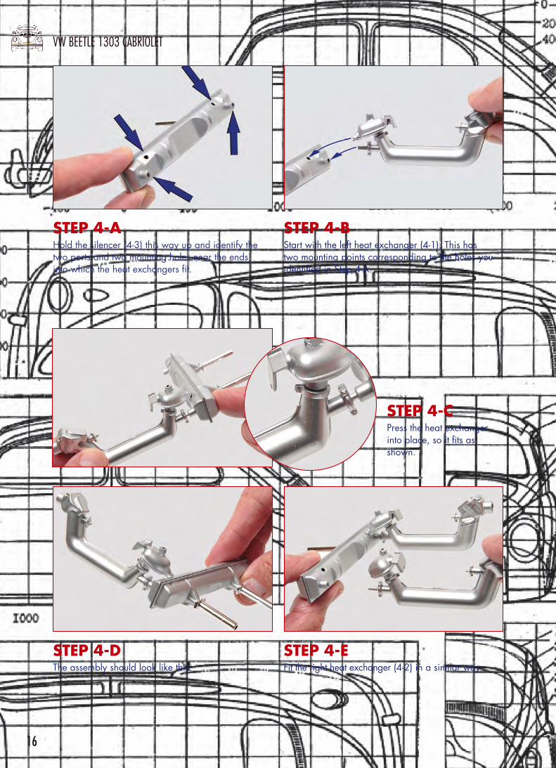
STEP 4-AHold the silencer (4-3) this way up and identify the two ports and two mounting holes near the ends, into which the heat exchangers fit.
STEP 4-DThe assembly should look like this.
STEP 4-BStart with the left heat exchanger (4-1). This has two mounting points corresponding to the holes you identified in Step 4-A.
STEP 4-EFit the right heat exchanger (4-2) in a similar way.
STEP 4-CPress the heat exchanger into place, so it fits as shown.

17
STEP BY STEP
STEP 4-GJoin the parts with two SP05 screws in the holes indicated in Step 4-F.
STEP 4-IPosition the assembly over the heat exchangers like this, so that the mounting points match up with the two lugs on top of the heat exchangers.
STEP 4-HIdentify the two mounting points shown, which are circular recesses with flats on each side.
STEP 4-JPress the parts together and fit two SP04 screws into the mounting holes.
STEP 4-FAlign the two engine covers as shown, so the upper part fits onto the mounting holes indicated.

18
VW BEETLE 1303 CABRIOLET
The finished assembly should look like this.STEP 4-KTighten the screws to secure the covers to the heat exchangers.
STAGE COMPLETE

19
STEP BY STEP
Stage 5: Driver’s seat back
and headrestStart the assembly of the driver’s seat by fitting the headrest to the seat back. The
soft upholstery materials are represented by realistically textured materials with an accurate stitching pattern.
PARTS
5-1 Driver’s seat back5-2 Headrest5-3 Seat adjustment
handle5-4 Headrest mountings
5-1 5-2 5-3 5-4
MODELLING TOOLSPARTS DIAGRAM
Assembling the Beetle requires few extra materials and tools.The most useful tool is a screwdriver, and different ones will be provided as they are needed to assemble the model parts, but you may find it useful to supplement them with another set of different sizes. You will also find it convenient to have a craft knife for removing small burrs and helping to accurately position small parts and apply glue.
5-2
5-1
5-4
5-3
Screwdrivers
Craft knivesNOTE: The appearance of the parts you receive may be slightly different from the parts pictured in these pages.

20
VW BEETLE 1303 CABRIOLET
STEP 5-AThe left side of the driver’s seat back (5-1) has a hole for mounting the handle (5-3). The hole is D-shaped to ensure that the handle fits the right way up.
STEP 5-BAlign the handle like this.
STEP 5-CPress the handle into position.
STEP 5-DAlign one of the headrest mountings with one of the holes in the top of the seat back. It fits this way round.

21
STEP BY STEP
STEP 5-EPress the headrest mounting into position.
STEP 5-FRepeat the previous steps to fit the second headrest mounting.
STEP 5-GThe legs of the headrest (5-2) have tips that will lock them into the supports while leaving the headrest free to slide up and down.
STEP 5-HFit the legs of the headrest into the holes in the mountings.

22
VW BEETLE 1303 CABRIOLET
At the end of this stage, the seat back assembly should look like this.
STAGE COMPLETE
STEP 5-IPress the headrest into place.
Related Documents