Motherboard P5VD2-VM/ P5V-VM SE DH

Welcome message from author
This document is posted to help you gain knowledge. Please leave a comment to let me know what you think about it! Share it to your friends and learn new things together.
Transcript
Mot
herb
oard
P5VD2-VM/P5V-VM SE DH
ii
Copyright © 2006 ASUSTeK COMPUTER INC. All Rights Reserved.No part of this manual, including the products and software described in it, may be reproduced, transmitted, transcribed, stored in a retrieval system, or translated into any language in any form or by any means, except documentation kept by the purchaser for backup purposes, without the express written permission of ASUSTeK COMPUTER INC. (“ASUS”).Product warranty or service will not be extended if: (1) the product is repaired, modified or altered, unless such repair, modification of alteration is authorized in writing by ASUS; or (2) the serial number of the product is defaced or missing.ASUS PROVIDES THIS MANUAL “AS IS” WITHOUT WARRANTY OF ANY KIND, EITHER EXPRESS OR IMPLIED, INCLUDING BUT NOT LIMITED TO THE IMPLIED WARRANTIES OR CONDITIONS OF MERCHANTABILITY OR FITNESS FOR A PARTICULAR PURPOSE. IN NO EVENT SHALL ASUS, ITS DIRECTORS, OFFICERS, EMPLOYEES OR AGENTS BE LIABLE FOR ANY INDIRECT, SPECIAL, INCIDENTAL, OR CONSEQUENTIAL DAMAGES (INCLUDING DAMAGES FOR LOSS OF PROFITS, LOSS OF BUSINESS, LOSS OF USE OR DATA, INTERRUPTION OF BUSINESS AND THE LIKE), EVEN IF ASUS HAS BEEN ADVISED OF THE POSSIBILITY OF SUCH DAMAGES ARISING FROM ANY DEFECT OR ERROR IN THIS MANUAL OR PRODUCT.SPECIFICATIONS AND INFORMATION CONTAINED IN THIS MANUAL ARE FURNISHED FOR INFORMATIONAL USE ONLY, AND ARE SUBJECT TO CHANGE AT ANY TIME WITHOUT NOTICE, AND SHOULD NOT BE CONSTRUED AS A COMMITMENT BY ASUS. ASUS ASSUMES NO RESPONSIBILITY OR LIABILITY FOR ANY ERRORS OR INACCURACIES THAT MAY APPEAR IN THIS MANUAL, INCLUDING THE PRODUCTS AND SOFTWARE DESCRIBED IN IT.Products and corporate names appearing in this manual may or may not be registered trademarks or copyrights of their respective companies, and are used only for identification or explanation and to the owners’ benefit, without intent to infringe.
E2832
First Edition V1 October 2006
iii
Contents
Notices ......................................................................................................... viSafety information ..................................................................................... viiAbout this guide ....................................................................................... viiiP5VD2-VM/P5V-VM SE DH specifications summary ................................. x
Chapter 1: Product introduction1.1 Welcome! ...................................................................................... 1-21.2 Package contents ......................................................................... 1-21.3 Special features ............................................................................ 1-2
1.3.1 Product highlights ........................................................... 1-21.3.2 Innovative ASUS features .............................................. 1-41.3.3 ASUS Digital Home for P5V-VM SE DH special features ........................................................................... 1-5
1.4 Before you proceed ..................................................................... 1-71.5 Motherboard overview ................................................................. 1-8
1.5.1 Placement direction ........................................................ 1-81.5.2 Screw holes .................................................................... 1-81.5.3 Motherboard layout ......................................................... 1-9
1.6 Central Processing Unit (CPU) ................................................. 1-101.6.1 Installling the CPU ........................................................ 1-101.6.2 Installling the CPU heatsink and fan ............................. 1-131.6.3 Uninstalling the CPU heatsink and fan ......................... 1-15
1.7 System memory ......................................................................... 1-171.7.1 Overview ....................................................................... 1-171.7.2 Memory configurations .................................................. 1-171.7.3 Installing a DIMM .......................................................... 1-201.7.4 Removing a DIMM ........................................................ 1-20
1.8 Expansion slots .......................................................................... 1-211.8.1 Installing an expansion card ......................................... 1-211.8.2 Configuring an expansion card ..................................... 1-211.8.3 Interrupt assignments ................................................... 1-221.8.4 PCI slots ........................................................................ 1-231.8.5 PCI Express x1 slot ....................................................... 1-231.8.6 PCI Express x16 slot ..................................................... 1-23
1.9 Jumpers ...................................................................................... 1-24
iv
Contents
1.10 Connectors ................................................................................. 1-271.10.1 Rear panel connectors .................................................. 1-271.10.2 Internal connectors ....................................................... 1-29
Chapter 2: BIOS setup2.1 Managing and updating your BIOS ............................................ 2-2
2.1.1 ASUS Update utility ........................................................ 2-22.1.2 Creating a bootable floppy disk ....................................... 2-52.1.3 ASUS EZ Flash 2 utility ................................................... 2-62.1.4 Updating the BIOS .......................................................... 2-72.1.5 ASUS CrashFree BIOS 2 utility ...................................... 2-9
2.2 BIOS setup program .................................................................. 2-112.2.1 BIOS menu screen ........................................................ 2-122.2.2 Menu bar ....................................................................... 2-122.2.3 Legend bar .................................................................... 2-132.2.4 Menu items ................................................................... 2-132.2.5 Sub-menu items ............................................................ 2-132.2.6 Configuration fields ....................................................... 2-132.2.7 Pop-up window ............................................................. 2-142.2.8 General help ................................................................. 2-14
2.3 Main menu .................................................................................. 2-152.3.1 System Time ................................................................ 2-152.3.2 System Date ................................................................ 2-152.3.3 Legacy Diskette A ......................................................... 2-152.3.4 Primary and Secondary IDE Master/Slave ................... 2-162.3.5 SATA 1/2 ....................................................................... 2-182.3.6 HDD SMART Monitoring ............................................... 2-192.3.7 Installed Memory .......................................................... 2-192.3.8 Usable Memory ............................................................ 2-19
2.4 Advanced menu ......................................................................... 2-202.4.1 CPU Configuration ........................................................ 2-202.4.2 Chipset ......................................................................... 2-212.4.3 PCIPnP ......................................................................... 2-232.4.4 Onboard Devices Configuration .................................... 2-252.4.5 USB Configuration ........................................................ 2-27
v
Contents
2.5 Power menu ................................................................................ 2-282.5.1 ACPI Suspend Type ...................................................... 2-282.5.2 ACPI APIC Support ....................................................... 2-282.5.3 APM Configuration ........................................................ 2-282.5.4 Hardware Monitor ......................................................... 2-31
2.6 Boot menu .................................................................................. 2-332.6.1 Boot Device Priority ...................................................... 2-332.6.2 Removable Drives ......................................................... 2-332.6.3 Hard Disk Drives ........................................................... 2-342.6.4 Boot Settings Configuration ......................................... 2-342.6.5 Security ......................................................................... 2-36
2.7 Tools menu ................................................................................. 2-382.7.1 ASUS EZ Flash 2 .......................................................... 2-38
2.8 Exit menu .................................................................................... 2-39
Chapter 3: Software support 3.1 Installing an operating system ................................................... 3-23.2 Support CD information .............................................................. 3-2
3.2.1 Running the support CD ................................................. 3-23.2.2 Drivers menu ................................................................... 3-33.2.3 Utilities menu .................................................................. 3-43.2.4 Make Disk menu ............................................................. 3-53.2.5 Manuals menu ................................................................ 3-53.2.6 ASUS Contact information .............................................. 3-6
3.3 RAID configurations .................................................................... 3-73.3.1 Installing hard disks ........................................................ 3-83.3.2 JMicron® RAID Configuration ........................................ 3-12
3.4 Creating a RAID driver disk ....................................................... 3-20
vi
Notices
Federal Communications Commission StatementThis device complies with Part 15 of the FCC Rules. Operation is subject to the following two conditions:• This device may not cause harmful interference, and• This device must accept any interference received including interference that
may cause undesired operation.
This equipment has been tested and found to comply with the limits for a Class B digital device, pursuant to Part 15 of the FCC Rules. These limits are designed to provide reasonable protection against harmful interference in a residential installation. This equipment generates, uses and can radiate radio frequency energy and, if not installed and used in accordance with manufacturer’s instructions, may cause harmful interference to radio communications. However, there is no guarantee that interference will not occur in a particular installation. If this equipment does cause harmful interference to radio or television reception, which can be determined by turning the equipment off and on, the user is encouraged to try to correct the interference by one or more of the following measures:• Reorient or relocate the receiving antenna.• Increase the separation between the equipment and receiver.• Connect the equipment to an outlet on a circuit different from that to which the
receiver is connected.• Consult the dealer or an experienced radio/TV technician for help.
Canadian Department of Communications StatementThis digital apparatus does not exceed the Class B limits for radio noise emissions from digital apparatus set out in the Radio Interference Regulations of the Canadian Department of Communications.
This class B digital apparatus complies with Canadian ICES-003.
The use of shielded cables for connection of the monitor to the graphics card is required to assure compliance with FCC regulations. Changes or modifications to this unit not expressly approved by the party responsible for compliance could void the user’s authority to operate this equipment.
vii
Safety information
Electrical safety
• To prevent electrical shock hazard, disconnect the power cable from the electrical outlet before relocating the system.
• When adding or removing devices to or from the system, ensure that the power cables for the devices are unplugged before the signal cables are connected. If possible, disconnect all power cables from the existing system before you add a device.
• Before connecting or removing signal cables from the motherboard, ensure that all power cables are unplugged.
• Seek professional assistance before using an adapter or extension cord. These devices could interrupt the grounding circuit.
• Make sure that your power supply is set to the correct voltage in your area. If you are not sure about the voltage of the electrical outlet you are using, contact your local power company.
• If the power supply is broken, do not try to fix it by yourself. Contact a qualified service technician or your retailer.
Operation safety• Before installing the motherboard and adding devices on it, carefully read all
the manuals that came with the package.• Before using the product, make sure all cables are correctly connected and the
power cables are not damaged. If you detect any damage, contact your dealer immediately.
• To avoid short circuits, keep paper clips, screws, and staples away from connectors, slots, sockets and circuitry.
• Avoid dust, humidity, and temperature extremes. Do not place the product in any area where it may become wet.
• Place the product on a stable surface.• If you encounter technical problems with the product, contact a qualified
service technician or your retailer.
This symbol of the crossed out wheeled bin indicates that the product (electrical and electronic equipment) should not be placed in municipal waste. Please check local regulations for disposal of electronic products.
viii
About this guide
This user guide contains the information you need when installing and configuring the motherboard.
How this guide is organizedThis manual contains the following parts:
• Chapter 1: Product introductionThis chapter describes the features of the motherboard and the new technology it supports. This chapter also lists the hardware setup procedures that you have to perform when installing system components. It includes description of the jumpers and connectors on the motherboard.
• Chapter 2: BIOS setupThis chapter tells how to change system settings through the BIOS Setup menus. Detailed descriptions of the BIOS parameters are also provided.
• Chapter 3: Software supportThis chapter describes the contents of the support CD that comes with the motherboard package.
Where to find more informationRefer to the following sources for additional information and for product and software updates.
1. ASUS websitesThe ASUS website provides updated information on ASUS hardware and software products. Refer to the ASUS contact information.
2. Optional documentationYour product package may include optional documentation, such as warranty flyers, that may have been added by your dealer. These documents are not part of the standard package.
ix
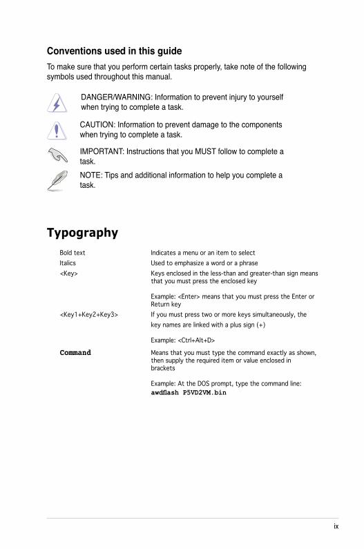
Conventions used in this guideTo make sure that you perform certain tasks properly, take note of the following symbols used throughout this manual.
Typography
DANGER/WARNING: Information to prevent injury to yourself when trying to complete a task.
CAUTION: Information to prevent damage to the components when trying to complete a task.
NOTE: Tips and additional information to help you complete a task.
IMPORTANT: Instructions that you MUST follow to complete a task.
Bold text Indicates a menu or an item to selectItalics Used to emphasize a word or a phrase<Key> Keys enclosed in the less-than and greater-than sign means that you must press the enclosed key Example: <Enter> means that you must press the Enter or Return key<Key1+Key2+Key3> If you must press two or more keys simultaneously, the key names are linked with a plus sign (+) Example: <Ctrl+Alt+D>
Command Means that you must type the command exactly as shown, then supply the required item or value enclosed in brackets Example: At the DOS prompt, type the command line: awdflash P5VD2VM.bin
x
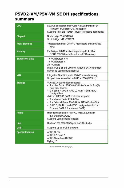
P5VD2-VM/P5V-VM SE DH specifications summary
CPU LGA775 socket for Intel® Core™2 Duo/Pentium® D/ Pentium® 4/Celeron® D CPU support Supports Intel EIST/EM64T/Hyper-Threading Technology
Chipset Northbridge: VIA P4M900 Southbridge: VIA VT8237A
Front side bus 1066(support Intel® CoreTM 2 Processors only)/800/533 MHz
Memory 2 x 240-pin DIMM sockets support up to 4 GB of DDR2 667/533 unbufferred non-ECC memory
Expansion slots 1 x PCI Express x16 1 x PCI Express x1 2 x PCI slots (Note: PCI-E x1 and JMicron JMB363 SATA controller cannot be used simultaneously)
VGA Integrated Graphics, up to 256MB shared memory Support max. resolution to 2048 x 1536 (@75Hz)
Storage VIA 8237A Southbridge supports: - 2 x Ultra DMA 133/100/66/33 interfaces for four(4) hard disk devices - 2 x Serial ATA with RAID 0, RAID 1, and JBOD configuration JMicron JMB363 SATA controller supports: - 1 x Internal Serial ATA 3 Gb/s - 1 x External Serial ATA 3 Gb/s (SATA On-the-Go) - RAID 0, RAID 1, and JBOD configuration (by 1 x External SATA & 1 x Internal SATA)
Audio High definition audio, ADI® AD1986A SoundMax 5.1-channel CODEC Supports Jack-sensing function
LAN Realtek® RTL8110SC Gigabit LAN Controller USB Supports up to 8 USB 2.0 ports Special features ASUS Q-Fan
ASUS EZ Flash 2 ASUS CrashFree BIOS 2 MyLogo™
(continued on the next page)
xi
P5VD2-VM/P5V-VM SE DH specifications summary
(continued on the next page)
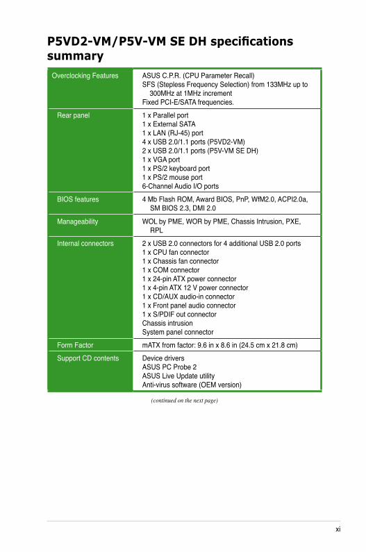
Overclocking Features ASUS C.P.R. (CPU Parameter Recall) SFS (Stepless Frequency Selection) from 133MHz up to 300MHz at 1MHz increment Fixed PCI-E/SATA frequencies.
Rear panel 1 x Parallel port 1 x External SATA 1 x LAN (RJ-45) port 4 x USB 2.0/1.1 ports (P5VD2-VM) 2 x USB 2.0/1.1 ports (P5V-VM SE DH) 1 x VGA port 1 x PS/2 keyboard port 1 x PS/2 mouse port 6-Channel Audio I/O ports
BIOS features 4 Mb Flash ROM, Award BIOS, PnP, WfM2.0, ACPI2.0a, SM BIOS 2.3, DMI 2.0
Manageability WOL by PME, WOR by PME, Chassis Intrusion, PXE, RPL
Internal connectors 2 x USB 2.0 connectors for 4 additional USB 2.0 ports 1 x CPU fan connector 1 x Chassis fan connector 1 x COM connector 1 x 24-pin ATX power connector 1 x 4-pin ATX 12 V power connector 1 x CD/AUX audio-in connector 1 x Front panel audio connector 1 x S/PDIF out connector Chassis intrusion System panel connector
Form Factor mATX from factor: 9.6 in x 8.6 in (24.5 cm x 21.8 cm)Support CD contents Device drivers
ASUS PC Probe 2 ASUS Live Update utility Anti-virus software (OEM version)
xii
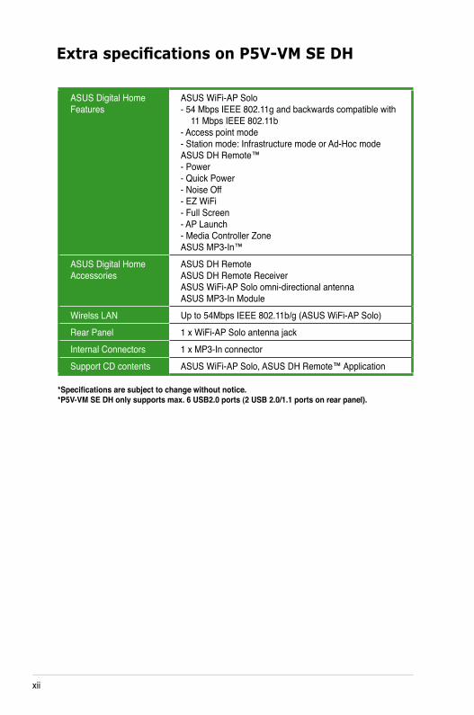
Extra specifications on P5V-VM SE DH
*Specifications are subject to change without notice.*P5V-VM SE DH only supports max. 6 USB2.0 ports (2 USB 2.0/1.1 ports on rear panel).
ASUS Digital Home Features
ASUS WiFi-AP Solo - 54 Mbps IEEE 802.11g and backwards compatible with 11 Mbps IEEE 802.11b - Access point mode - Station mode: Infrastructure mode or Ad-Hoc mode ASUS DH Remote™ - Power - Quick Power - Noise Off - EZ WiFi - Full Screen - AP Launch - Media Controller Zone ASUS MP3-In™
ASUS Digital Home Accessories
ASUS DH Remote ASUS DH Remote Receiver ASUS WiFi-AP Solo omni-directional antenna ASUS MP3-In Module
Wirelss LAN Up to 54Mbps IEEE 802.11b/g (ASUS WiFi-AP Solo)Rear Panel 1 x WiFi-AP Solo antenna jackInternal Connectors 1 x MP3-In connectorSupport CD contents ASUS WiFi-AP Solo, ASUS DH Remote™ Application
ASUS P5VD2-VM/P5V-VM SE DH 1-1
1Product introduction
This chapter describes the motherboard features and the new technologies it supports.
1-2 Chapter 1: Product introduction
1.1 Welcome!Thank you for buying an ASUS® P5VD2-VM/P5V-VM SE DH motherboard!
The motherboard delivers a host of new features and latest technologies, making it another standout in the long line of ASUS quality motherboards!
Before you start installing the motherboard, and hardware devices on it, check the items in your package with the list below.
If any of the above items is damaged or missing, contact your retailer.
1.3 Special features
1.3.1 Product highlights
Latest processor technology The motherboard comes with a 775-pin surface mount Land Grid Array (LGA) socket designed for the Intel® processor in the 775-land package. The motherboard supports the Intel® Pentium® D processor with 1066/800/533 MHz Front Side Bus (FSB). The motherboard also supports the Intel® Hyper-Threading Technology. See page 1-10 for details.
1.2 Package contentsCheck your motherboard package for the following items.
Motherboard ASUS P5VD2-VM/P5V-VM SE DH motherboardCables 1 x Serial ATA power cable 1 x Serial ATA signal cable 1 x Ultra DMA 133/100/66 cables 1 x Floppy disk drive cableAccessories I/O shield ASUS DH Remote (only for P5V-VM SE DH) ASUS DH Remote Receiver (only for P5V-VM SE DH) ASUS WiFi-AP Solo omni-directional antenna (only for P5V-VM SE DH) ASUS MP3-In Module (only for P5V-VM SE DH)Application CD ASUS motherboard support CDDocumentation User guide
ASUS P5VD2-VM/P5V-VM SE DH 1-3
Intel® 65nm Dual-Core CPU support This motherboard supports Intel® Pentium® D/Pentium® 4/Celeron® D dual-core processors built on the 65-nanometer (nm) process technology with copper interconnect. Dual-core processors contain two physical CPU cores with dedicated L2 caches to meet demands for more powerful processing. Intel®’s 65nm process is the most advanced chip manufacturing technology, delivering breakthrough performance, enhanced media experience, and low power consumption. Intel® 65nm dual-core processors utilize the latest package technologies for a thinner, lighter design without compromising performance. This motherboard also supports Intel® next generation Core™2 Duo CPU. This motherboard supports the latest Intel® Core™2 processors in LGA775 package. With new Intel® Core™ microarchitecture technology and 1066/800 MHz FSB, Intel® Core™2 processor is one of the most powerful and enrgy-efficient CPUs in the world.
PCI Express™ interface The motherboard fully supports PCI Express, the latest I/O interconnect technology that speeds up the PCI bus. PCI Express features point-to-point serial interconnections between devices and allows higher clockspeeds by carrying data in packets. This high speed interface is software compatible with existing PCI specifications.
Serial ATA 3Gb/s technology and SATA-On-The-Go The motherboard built with JMicron JMB363 SATA controller supports the next-generation hard drives based on the Serial ATA (SATA) 3Gb/s storage specification, delivering enhanced scalability and doubling the bus bandwidth for high-speed data retrieval and saves. The external SATA port located at the back I/O provides smart setup and hot-plug functions. Easily backup photos, videos and other entertainment contents on external devices. See pages 1-28 and 1-31 for details.
Dual RAID solution The onboard VIA VT8237A chipset allows RAID 0, RAID 1, and JBOD configuration for two SATA connectors, and JMicron JMB363 SATA controller also supports RAID 0, RAID 1, and JBOD.
1-4 Chapter 1: Product introduction
S/PDIF digital sound ready The motherboard supports the S/PDIF Out function through the S/PDIF interface at midboard. The S/PDIF technology turns your computer into a high-end entertainment system with digital connectivity to powerful audio and speaker systems. See page 1-32 for details.
6-channel high definition audio Enjoy high-end sound quality on your PC! The onboard 6-channel HD audio (High Definition Audio, previously codenamed Azalia) CODEC enables high-quality 192 KHz/ 24-bit audio output and jack-sensing feature! With CODEC, 6-channel audio ports, and S/PDIF interfaces, you can connect your computer to home theater decoders to produce crystal-clear digital audio.
Gigabit LAN solution The motherboard comes with a Gigabit LAN controllers to provide the total solution for your networking needs. These network controllers use the PCI segment to provide data bandwidth for your wired or wireless Internet, LAN, and file sharing requirements.
1.3.2 Innovative ASUS features
CrashFree BIOS 2 This feature allows you to restore the original BIOS data from the support CD in case when the BIOS codes and data are corrupted. This protection eliminates the need to buy a replacement ROM chip. See details on page 2-9.
USB 2.0 technology The motherboard implements the Universal Serial Bus (USB) 2.0 specification, dramatically increasing the connection speed from the 12 Mbps bandwidth on USB 1.1 to a fast 480 Mbps on USB 2.0. USB 2.0 is backward compatible with USB 1.1. See pages 1-25 and 1-34 for details.

ASUS P5VD2-VM/P5V-VM SE DH 1-5
ASUS Q-Fan technology The ASUS Q-Fan technology smartly adjusts the CPU fan speed according to the system loading to ensure quiet, cool, and efficient operation.
ASUS EZ Flash 2 EZ Flash 2 is a user-friendly BIOS update utility. Simply press the predefined hotkey to launch the utility and update the BIOS without entering the OS. Update your BIOS easily without preparing a bootable diskette or using an OS-based flash utility. See page 2-38 for details.
C.P.R. (CPU Parameter Recall) The C.P.R. feature of the motherboard BIOS allows automatic re-setting to the BIOS default settings in case the system hangs due to overclocking. When the system hangs due to overclocking, C.P.R. eliminates the need to open the system chassis and clear the RTC data. Simply shut down and reboot the system, and the BIOS automatically restores the CPU default setting for each parameter.
1.3.3 ASUS Digital Home for P5V-VM SE DH special features
ASUS WiFi-AP Solo (Only for P5V-VM SE DH) The ASUS WiFi-AP Solo allows a new level of versitility for your PC, enabling it to create a complete wireless home network in either AP or wirelesss client mode. Users will be able to play LAN games, connecting to the Internet, access and share printers, and use Skype from anywhere within range. The ASUS WiFi-AP Solo can provide these functions even when the PC is in sleep mode, so users can use Skype as a true replacement for tradition long distance telephone service. WiFi-AP Solo is an on-board feature, which means that users will save the extra WiFi-AP cost.
1-6 Chapter 1: Product introduction
ASUS DH Remote™ (Only for P5V-VM SE DH) The ASUS DH Remote™ is a convenient PC remote controller that gives users unprecedented control over their PCs from the comfort of their couches. With the touch of a button, users can instantly operate the following functions:
Power: Turns the computer on/off. Quick Power: Puts the computer quickly into sleep mode. Noise Off: Reduces the noise coming from the computer. EZ WiFi: Puts the computer quickly into sleep mode but allowing
WiFi-AP Solo to still operate. Full Screen: Puts the media application into full screen. AP Launch: Launches the media application. Media Control Zone: Controls the media application.
ASUS MP3-In™ (Only for P5V-VM SE DH) A convenient interface between computers and MP3 players, the ASUS MP3-In™ feature enables MP3 players to connect to PC speakers even when the PC power is off, which means that users can enjoy the sound quality from PC speakers without additional stereo equipment cost. Please refer page 1-35 and ASUS MP3-In™ quick installation guide for details.
ASUS P5VD2-VM/P5V-VM SE DH 1-7
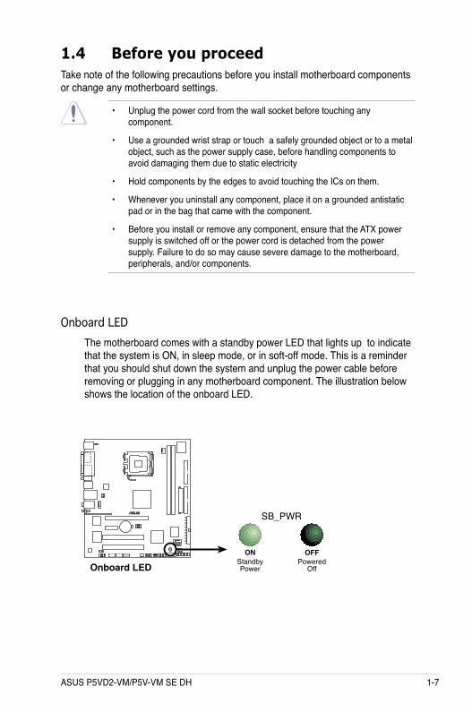
Onboard LEDThe motherboard comes with a standby power LED that lights up to indicate that the system is ON, in sleep mode, or in soft-off mode. This is a reminder that you should shut down the system and unplug the power cable before removing or plugging in any motherboard component. The illustration below shows the location of the onboard LED.
1.4 Before you proceedTake note of the following precautions before you install motherboard components or change any motherboard settings.
• Unplug the power cord from the wall socket before touching any component.
• Use a grounded wrist strap or touch a safely grounded object or to a metal object, such as the power supply case, before handling components to avoid damaging them due to static electricity
• Hold components by the edges to avoid touching the ICs on them.
• Whenever you uninstall any component, place it on a grounded antistatic pad or in the bag that came with the component.
• Before you install or remove any component, ensure that the ATX power supply is switched off or the power cord is detached from the power supply. Failure to do so may cause severe damage to the motherboard, peripherals, and/or components.
®
Onboard LED
SB_PWR
ONStandbyPower
OFFPowered
Off
1-8 Chapter 1: Product introduction
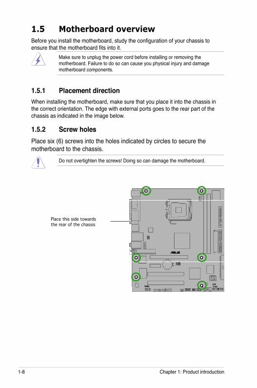
1.5 Motherboard overviewBefore you install the motherboard, study the configuration of your chassis to ensure that the motherboard fits into it.
Make sure to unplug the power cord before installing or removing the motherboard. Failure to do so can cause you physical injury and damage motherboard components.
Do not overtighten the screws! Doing so can damage the motherboard.
1.5.1 Placement directionWhen installing the motherboard, make sure that you place it into the chassis in the correct orientation. The edge with external ports goes to the rear part of the chassis as indicated in the image below.
1.5.2 Screw holesPlace six (6) screws into the holes indicated by circles to secure the motherboard to the chassis.
Place this side towards the rear of the chassis
ASUS P5VD2-VM/P5V-VM SE DH 1-9
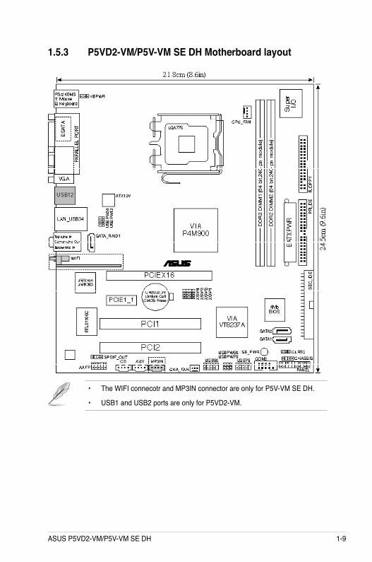
1.5.3 P5VD2-VM/P5V-VM SE DH Motherboard layout
• The WIFI connecotr and MP3IN connector are only for P5V-VM SE DH.
• USB1 and USB2 ports are only for P5VD2-VM.
1-10 Chapter 1: Product introduction
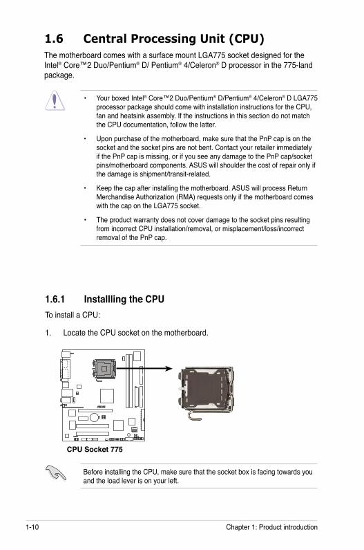
1.6.1 Installling the CPUTo install a CPU:
1. Locate the CPU socket on the motherboard.
1.6 Central Processing Unit (CPU)The motherboard comes with a surface mount LGA775 socket designed for the Intel® Core™2 Duo/Pentium® D/ Pentium® 4/Celeron® D processor in the 775-land package.
• Your boxed Intel® Core™2 Duo/Pentium® D/Pentium® 4/Celeron® D LGA775 processor package should come with installation instructions for the CPU, fan and heatsink assembly. If the instructions in this section do not match the CPU documentation, follow the latter.
• Upon purchase of the motherboard, make sure that the PnP cap is on the socket and the socket pins are not bent. Contact your retailer immediately if the PnP cap is missing, or if you see any damage to the PnP cap/socket pins/motherboard components. ASUS will shoulder the cost of repair only if the damage is shipment/transit-related.
• Keep the cap after installing the motherboard. ASUS will process Return Merchandise Authorization (RMA) requests only if the motherboard comes with the cap on the LGA775 socket.
• The product warranty does not cover damage to the socket pins resulting from incorrect CPU installation/removal, or misplacement/loss/incorrect removal of the PnP cap.
Before installing the CPU, make sure that the socket box is facing towards you and the load lever is on your left.
®
CPU Socket 775
ASUS P5VD2-VM/P5V-VM SE DH 1-11
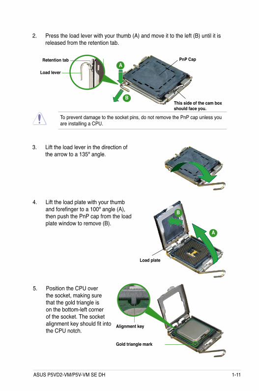
3. Lift the load lever in the direction of the arrow to a 135º angle.
4. Lift the load plate with your thumb and forefinger to a 100º angle (A), then push the PnP cap from the load plate window to remove (B).
To prevent damage to the socket pins, do not remove the PnP cap unless you are installing a CPU.
5. Position the CPU over the socket, making sure that the gold triangle is on the bottom-left corner of the socket. The socket alignment key should fit into the CPU notch.
2. Press the load lever with your thumb (A) and move it to the left (B) until it is released from the retention tab.
Retention tab
Load lever
This side of the cam box should face you.
PnP CapA
B
Load plate
A
B
Alignment key
Gold triangle mark
1-12 Chapter 1: Product introduction
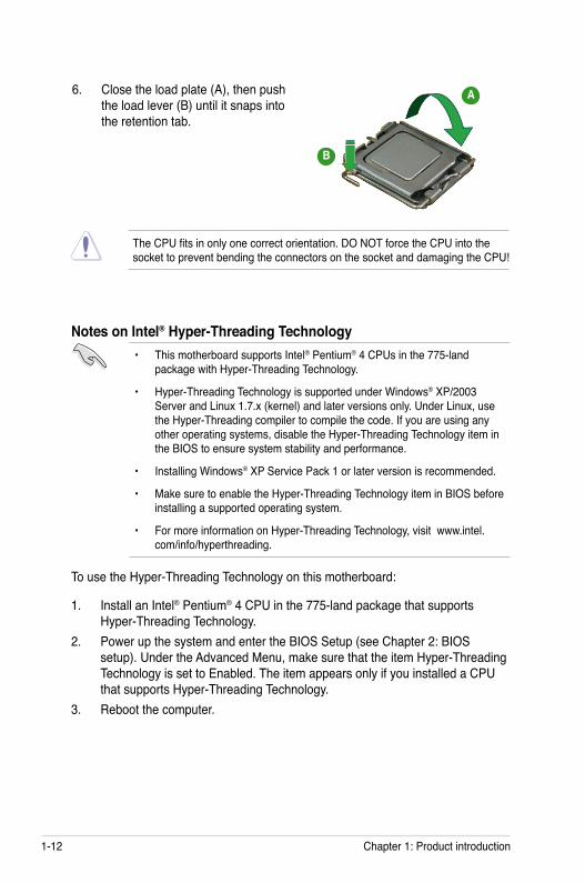
The CPU fits in only one correct orientation. DO NOT force the CPU into the socket to prevent bending the connectors on the socket and damaging the CPU!
6. Close the load plate (A), then push the load lever (B) until it snaps into the retention tab.
Notes on Intel® Hyper-Threading Technology• This motherboard supports Intel® Pentium® 4 CPUs in the 775-land
package with Hyper-Threading Technology.
• Hyper-Threading Technology is supported under Windows® XP/2003 Server and Linux 1.7.x (kernel) and later versions only. Under Linux, use the Hyper-Threading compiler to compile the code. If you are using any other operating systems, disable the Hyper-Threading Technology item in the BIOS to ensure system stability and performance.
• Installing Windows® XP Service Pack 1 or later version is recommended.
• Make sure to enable the Hyper-Threading Technology item in BIOS before installing a supported operating system.
• For more information on Hyper-Threading Technology, visit www.intel.com/info/hyperthreading.
To use the Hyper-Threading Technology on this motherboard:
1. Install an Intel® Pentium® 4 CPU in the 775-land package that supports Hyper-Threading Technology.
2. Power up the system and enter the BIOS Setup (see Chapter 2: BIOS setup). Under the Advanced Menu, make sure that the item Hyper-Threading Technology is set to Enabled. The item appears only if you installed a CPU that supports Hyper-Threading Technology.
3. Reboot the computer.
A
B
ASUS P5VD2-VM/P5V-VM SE DH 1-13
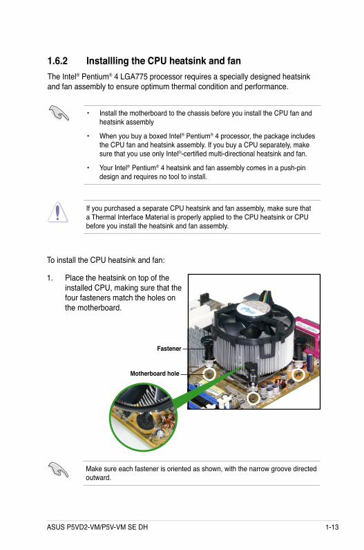
1.6.2 Installling the CPU heatsink and fanThe Intel® Pentium® 4 LGA775 processor requires a specially designed heatsink and fan assembly to ensure optimum thermal condition and performance.
• Install the motherboard to the chassis before you install the CPU fan and heatsink assembly
• When you buy a boxed Intel® Pentium® 4 processor, the package includes the CPU fan and heatsink assembly. If you buy a CPU separately, make sure that you use only Intel®-certified multi-directional heatsink and fan.
• Your Intel® Pentium® 4 heatsink and fan assembly comes in a push-pin design and requires no tool to install.
If you purchased a separate CPU heatsink and fan assembly, make sure that a Thermal Interface Material is properly applied to the CPU heatsink or CPU before you install the heatsink and fan assembly.
To install the CPU heatsink and fan:
1. Place the heatsink on top of the installed CPU, making sure that the four fasteners match the holes on the motherboard.
Fastener
Motherboard hole
Make sure each fastener is oriented as shown, with the narrow groove directed outward.
1-14 Chapter 1: Product introduction
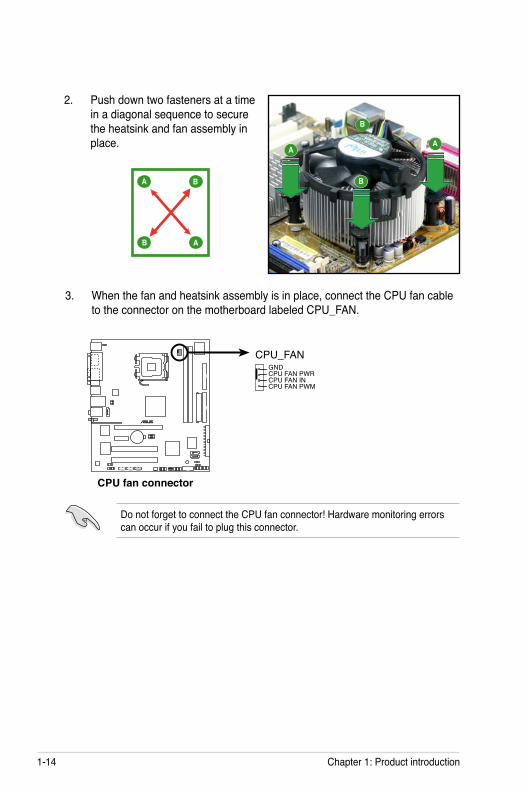
Do not forget to connect the CPU fan connector! Hardware monitoring errors can occur if you fail to plug this connector.
3. When the fan and heatsink assembly is in place, connect the CPU fan cable to the connector on the motherboard labeled CPU_FAN.
®
CPU fan connector
CPU_FANGNDCPU FAN PWRCPU FAN INCPU FAN PWM
2. Push down two fasteners at a time in a diagonal sequence to secure the heatsink and fan assembly in place.
A
A B
B
A
B
B
A
ASUS P5VD2-VM/P5V-VM SE DH 1-15
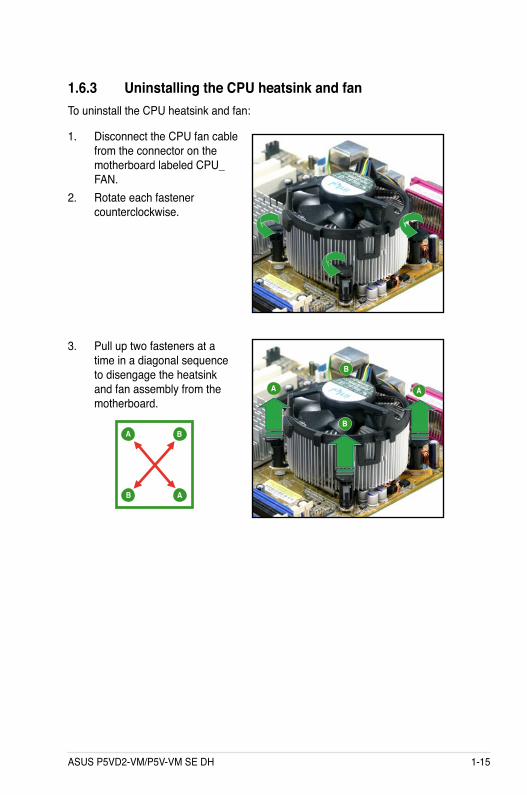
1.6.3 Uninstalling the CPU heatsink and fanTo uninstall the CPU heatsink and fan:
1. Disconnect the CPU fan cable from the connector on the motherboard labeled CPU_FAN.
2. Rotate each fastener counterclockwise.
3. Pull up two fasteners at a time in a diagonal sequence to disengage the heatsink and fan assembly from the motherboard.
A
A B
B
AA
B
B
1-16 Chapter 1: Product introduction
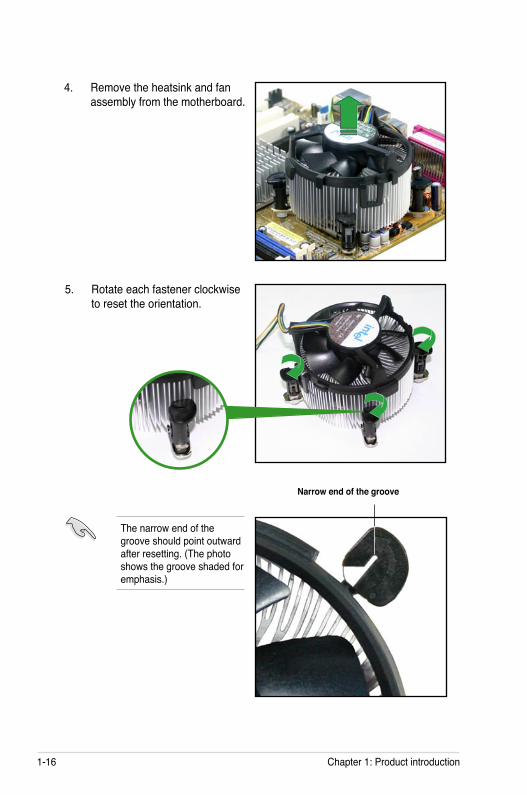
4. Remove the heatsink and fan assembly from the motherboard.
5. Rotate each fastener clockwise to reset the orientation.
The narrow end of the groove should point outward after resetting. (The photo shows the groove shaded for emphasis.)
Narrow end of the groove
ASUS P5VD2-VM/P5V-VM SE DH 1-17
1.7 System memory
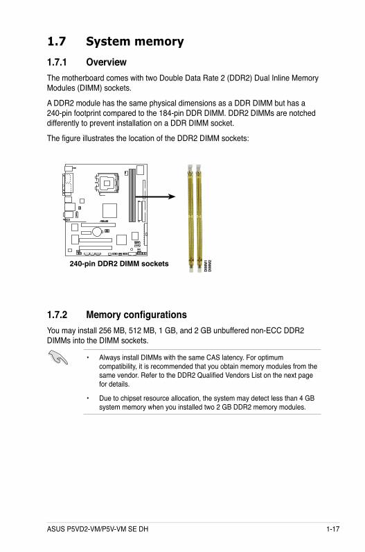
1.7.1 OverviewThe motherboard comes with two Double Data Rate 2 (DDR2) Dual Inline Memory Modules (DIMM) sockets.
A DDR2 module has the same physical dimensions as a DDR DIMM but has a 240-pin footprint compared to the 184-pin DDR DIMM. DDR2 DIMMs are notched differently to prevent installation on a DDR DIMM socket.
The figure illustrates the location of the DDR2 DIMM sockets:
1.7.2 Memory configurationsYou may install 256 MB, 512 MB, 1 GB, and 2 GB unbuffered non-ECC DDR2 DIMMs into the DIMM sockets.
• Always install DIMMs with the same CAS latency. For optimum compatibility, it is recommended that you obtain memory modules from the same vendor. Refer to the DDR2 Qualified Vendors List on the next page for details.
• Due to chipset resource allocation, the system may detect less than 4 GB system memory when you installed two 2 GB DDR2 memory modules.
®
240-pin DDR2 DIMM sockets
DIM
M1
DIM
M2
1-18 Chapter 1: Product introduction
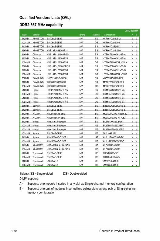
Qualified Vendors Lists (QVL) DDR2-667 MHz capability
DIMM support Size Vendor Model Brand Side(s) Component A B512MB KINGSTON E5108AE-6E-E N/A SS KVR667D2N5/512 V V1024MB KINGSTON E5108AE-6E-E N/A DS KVR667D2N5/1G V V512MB KINGSTON E5108AE-6E-E N/A SS KVR667D2E5/512 V V256MB KINGSTON HYB18T256800AF3 N/A SS KVR667D2N5/256 V V256MB Qimonda HYB18T512160AF-3S N/A SS HYS64T32000HU-3S-A V V512MB Qimonda HYB18T512800AF3S N/A SS HYS64T64000HU-3S-A V V1024MB Qimonda HYB18T512800AF3S N/A DS HYS64T128020HU-3S-A V V256MB Qimonda HYB18T5121608BF-3S N/A SS HYS64T32000HU-3S-B V V512MB Qimonda HYB18T512800BF3S N/A SS HYS64T64000HU-3S-B V V1024MB Qimonda HYB18T512800BF3S N/A DS HYS64T128020HU-3S-B V V256MB SAMSUNG K4T51163QC-ZCE6 N/A SS M378T3354CZ0-CE6 V V512MB SAMSUNG ZCE6K4T51083QC N/A SS M378T6553CZ0-CE6 V V1024MB SAMSUNG ZCE6K4T51083QC N/A DS M378T2953CZ0-CE6 V V512MB Hynix HY5PS12821AFP-Y5 N/A SS HYMP564U64AP8-Y5 V V1024MB Hynix HY5PS12821AFP-Y5 N/A DS HYMP512U64AP8-Y5 V V512MB Hynix HY5PS12821AFP-Y4 N/A DS HYMP564U64AP8-Y4 V V1024MB Hynix HY5PS12821AFP-Y4 N/A DS HYMP512U64AP8-Y4 V V256MB ELPIDA E2508AB-6E-E N/A SS EBE25UC8ABFA-6E-E V V512MB ELPIDA E5108AE-6E-E N/A SS EBE51UD8AEFA-6E-E V V512MB A-DATA AD29608A8B-3EG N/A SS M20AD5Q3H3163J1C52 V V512MB A-DATA AD29608A8A-3EG N/A SS M20AD5G3H316I1C52 V V512MB crucial Heat-Sink Package N/A SS BL6464AA663.8FD V V1024MB crucial Heat-Sink Package N/A DS BL12864AA663.16FD V V1024MB crucial Heat-Sink Package N/A DS BL12864AL664.16FD V V1024MB Apacer E5108AE-6E-E N/A DS 78.01092.420 V V512MB Apacer AM4B5708GQJS7E N/A SS AU512E667C5KBGC V V1024MB Apacer AM4B5708GQJS7E N/A DS AU01GE667C5KBGC V V512MB KINGMAX KKEA88B4LAUG-29DX N/A SS KLCC28F-A8KB5 V V1024MB KINGMAX KKEA88B4LAUG-29DX N/A DS KLCD48F-A8KB5 V V512MB Transcend E5108AE-6E-E N/A SS TS64MLQ64V6J V V1024MB Transcend E5108AE-6E-E N/A DS TS128MLQ64V6J V V512MB Transcend J12Q3AB-6 N/A SS JM367Q643A-6 V V1024MB Transcend J12Q3AB-6 N/A DS JM388Q643A-6 V V
Side(s): SS - Single-sided DS - Double-sidedDIMM support:A - Supports one module inserted in any slot as Single-channel memory configurationB - Supports one pair of modules inserted into yellow slots as one pair of Single-channel
memory configuration
ASUS P5VD2-VM/P5V-VM SE DH 1-19
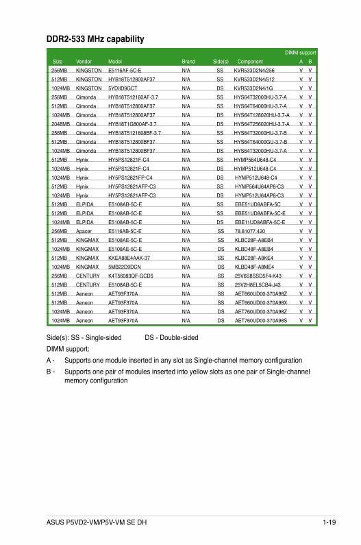
DDR2-533 MHz capability DIMM support Size Vendor Model Brand Side(s) Component A B256MB KINGSTON E5116AF-5C-E N/A SS KVR533D2N4/256 V V512MB KINGSTON HYB18T512800AF37 N/A SS KVR533D2N4/512 V V1024MB KINGSTON 5YDIID9GCT N/A DS KVR533D2N4/1G V V256MB Qimonda HYB18T512160AF-3.7 N/A SS HYS64T32000HU-3.7-A V V512MB Qimonda HYB18T512800AF37 N/A SS HYS64T64000HU-3.7-A V V1024MB Qimonda HYB18T512800AF37 N/A DS HYS64T128020HU-3.7-A V V2048MB Qimonda HYB18T1G800AF-3.7 N/A DS HYS64T256020HU-3.7-A V V256MB Qimonda HYB18T5121608BF-3.7 N/A SS HYS64T32000HU-3.7-B V V512MB Qimonda HYB18T512800BF37 N/A SS HYS64T64000GU-3.7-B V V1024MB Qimonda HYB18T512800BF37 N/A DS HYS64T32000HU-3.7-A V V512MB Hynix HY5PS12821F-C4 N/A SS HYMP564U648-C4 V V1024MB Hynix HY5PS12821F-C4 N/A DS HYMP512U648-C4 V V1024MB Hynix HY5PS12821FP-C4 N/A DS HYMP512U648-C4 V V512MB Hynix HY5PS12821AFP-C3 N/A SS HYMP564U64AP8-C3 V V1024MB Hynix HY5PS12821AFP-C3 N/A DS HYMP512U64AP8-C3 V V512MB ELPIDA E5108AB-5C-E N/A SS EBE51UD8ABFA-5C V V512MB ELPIDA E5108AB-5C-E N/A SS EBE51UD8ABFA-5C-E V V1024MB ELPIDA E5108AB-5C-E N/A DS EBE11UD8ABFA-5C-E V V256MB Apacer E5116AB-5C-E N/A SS 78.81077.420 V V512MB KINGMAX E5108AE-5C-E N/A SS KLBC28F-A8EB4 V V1024MB KINGMAX E5108AE-5C-E N/A DS KLBD48F-A8EB4 V V512MB KINGMAX KKEA88E4AAK-37 N/A SS KLBC28F-A8KE4 V V1024MB KINGMAX 5MB22D9DCN N/A DS KLBD48F-A8ME4 V V256MB CENTURY K4T56083QF-GCD5 N/A SS 25V6S8SSD5F4-K43 V V512MB CENTURY E5108AB-5C-E N/A SS 25V2H8EL5CB4-J43 V V512MB Aeneon AET93F370A N/A SS AET660UD00-370A98Z V V512MB Aeneon AET93F370A N/A SS AET660UD00-370A98X V V1024MB Aeneon AET93F370A N/A DS AET760UD00-370A98Z V V1024MB Aeneon AET93F370A N/A DS AET760UD00-370A98S V V
Side(s): SS - Single-sided DS - Double-sidedDIMM support:A - Supports one module inserted in any slot as Single-channel memory configurationB - Supports one pair of modules inserted into yellow slots as one pair of Single-channel
memory configuration
1-20 Chapter 1: Product introduction
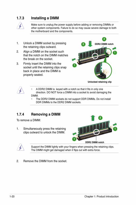
1.7.3 Installing a DIMM
1. Unlock a DIMM socket by pressing the retaining clips outward.
2. Align a DIMM on the socket such that the notch on the DIMM matches the break on the socket.
3. Firmly insert the DIMM into the socket until the retaining clips snap back in place and the DIMM is properly seated.
Make sure to unplug the power supply before adding or removing DIMMs or other system components. Failure to do so may cause severe damage to both the motherboard and the components.
Unlocked retaining clip
DDR2 DIMM notch
1.7.4 Removing a DIMMTo remove a DIMM:
1. Simultaneously press the retaining clips outward to unlock the DIMM.
2. Remove the DIMM from the socket.
Support the DIMM lightly with your fingers when pressing the retaining clips. The DIMM might get damaged when it flips out with extra force.
DDR2 DIMM notch
1
• A DDR2 DIMM is keyed with a notch so that it fits in only one direction. DO NOT force a DIMM into a socket to avoid damaging the DIMM. • The DDR2 DIMM sockets do not support DDR DIMMs. Do not install DDR DIMMs to the DDR2 DIMM sockets.
3
2
1
1
2
1
1
ASUS P5VD2-MX/P5V-VM DH 1-21
1.8 Expansion slotsIn the future, you may need to install expansion cards. The following sub-sections describe the slots and the expansion cards that they support.
1.8.1 Installing an expansion cardTo install an expansion card:
1. Before installing the expansion card, read the documentation that came with it and make the necessary hardware settings for the card.
2. Remove the system unit cover (if your motherboard is already installed in a chassis).
3. Remove the bracket opposite the slot that you intend to use. Keep the screw for later use.
4. Align the card connector with the slot and press firmly until the card is completely seated on the slot.
5. Secure the card to the chassis with the screw you removed earlier.6. Replace the system cover.
1.8.2 Configuring an expansion cardAfter installing the expansion card, configure it by adjusting the software settings.
1. Turn on the system and change the necessary BIOS settings, if any. See Chapter 2 for information on BIOS setup.
2. Assign an IRQ to the card. Refer to the tables on the next page.3. Install the software drivers for the expansion card.
Make sure to unplug the power cord before adding or removing expansion cards. Failure to do so may cause you physical injury and damage motherboard components.
1-22 Chapter 1: Product introduction
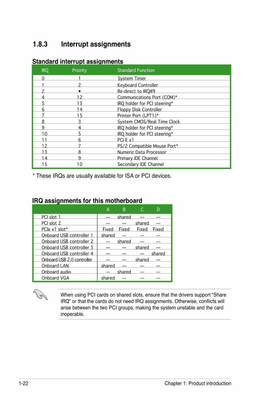
1.8.3 Interrupt assignments
Standard interrupt assignmentsIRQ Priority Standard Function0 1 System Timer1 2 Keyboard Controller2 • Re-direct to IRQ#94 12 Communications Port (COM)* 5 13 IRQ holder for PCI steering*6 14 Floppy Disk Controller 7 15 Printer Port (LPT1)*8 3 System CMOS/Real Time Clock9 4 IRQ holder for PCI steering*10 5 IRQ holder for PCI steering*11 6 PCI-E x112 7 PS/2 Compatible Mouse Port*13 8 Numeric Data Processor14 9 Primary IDE Channel 15 10 Secondary IDE Channel
* These IRQs are usually available for ISA or PCI devices.
When using PCI cards on shared slots, ensure that the drivers support “Share IRQ” or that the cards do not need IRQ assignments. Otherwise, conflicts will arise between the two PCI groups, making the system unstable and the card inoperable.
IRQ assignments for this motherboard A B C D
PCI slot 1 — shared — —PCI slot 2 — — shared —PCIe x1 slot* Fixed Fixed Fixed FixedOnboard USB controller 1 shared — — —Onboard USB controller 2 — shared — —Onboard USB controller 3 — — shared —Onboard USB controller 4 — — — sharedOnboard USB 2.0 controller — — shared —Onboard LAN shared — — —Onboard audio — shared — —Onboard VGA shared — — —
ASUS P5VD2-MX/P5V-VM DH 1-23
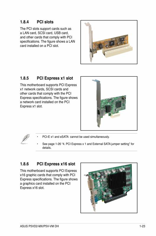
1.8.4 PCI slotsThe PCI slots support cards such as a LAN card, SCSI card, USB card, and other cards that comply with PCI specifications. The figure shows a LAN card installed on a PCI slot.
1.8.5 PCI Express x1 slotThis motherboard supports PCI Express x1 network cards, SCSI cards and other cards that comply with the PCI Express specifications. The figure shows a network card installed on the PCI Express x1 slot.
1.8.6 PCI Express x16 slotThis motherboard supports PCI Express x16 graphic cards that comply with PCI Express specifications. The figure shows a graphics card installed on the PCI Express x16 slot.
• PCI-E x1 and eSATA cannot be used simultaneously.
• See page 1-26 “4. PCI Express x 1 and External SATA jumper setting” for details.
1-24 Chapter 1: Product introduction
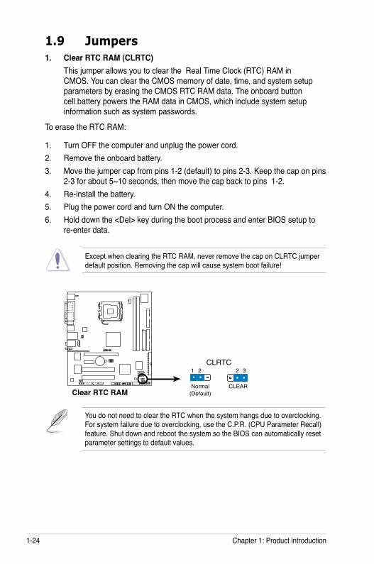
1.9 Jumpers1. Clear RTC RAM (CLRTC)
This jumper allows you to clear the Real Time Clock (RTC) RAM in CMOS. You can clear the CMOS memory of date, time, and system setup parameters by erasing the CMOS RTC RAM data. The onboard button cell battery powers the RAM data in CMOS, which include system setup information such as system passwords.
To erase the RTC RAM:
1. Turn OFF the computer and unplug the power cord.2. Remove the onboard battery.3. Move the jumper cap from pins 1-2 (default) to pins 2-3. Keep the cap on pins
2-3 for about 5~10 seconds, then move the cap back to pins 1-2.4. Re-install the battery.5. Plug the power cord and turn ON the computer.6. Hold down the <Del> key during the boot process and enter BIOS setup to
re-enter data.
Except when clearing the RTC RAM, never remove the cap on CLRTC jumper default position. Removing the cap will cause system boot failure!
®
Clear RTC RAM
CLRTC
Normal CLEAR(Default)
1 2 2 3
You do not need to clear the RTC when the system hangs due to overclocking. For system failure due to overclocking, use the C.P.R. (CPU Parameter Recall) feature. Shut down and reboot the system so the BIOS can automatically reset parameter settings to default values.
ASUS P5VD2-MX/P5V-VM DH 1-25
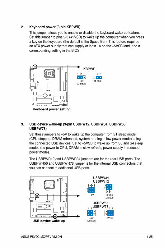
2. Keyboard power (3-pin KBPWR)This jumper allows you to enable or disable the keyboard wake-up feature. Set this jumper to pins 2-3 (+5VSB) to wake up the computer when you press a key on the keyboard (the default is the Space Bar). This feature requires an ATX power supply that can supply at least 1A on the +5VSB lead, and a corresponding setting in the BIOS.
3. USB device wake-up (3-pin USBPW12, USBPW34, USBPW56, USBPW78)Set these jumpers to +5V to wake up the computer from S1 sleep mode (CPU stopped, DRAM refreshed, system running in low power mode) using the connected USB devices. Set to +5VSB to wake up from S3 and S4 sleep modes (no power to CPU, DRAM in slow refresh, power supply in reduced power mode).
The USBPWR12 and USBPWR34 jumpers are for the rear USB ports. The USBPWR56 and USBPWR78 jumper is for the internal USB connectors that you can connect to additional USB ports.
®
Keyboard power setting
(Default)+5V +5VSB
KBPWR2 31 2
®
USB device wake-up
USBPW56USBPW78
USBPW34USBPW12
322
1+5V
(Default)+5VSB
3221
+5V(Default)
+5VSB
1-26 Chapter 1: Product introduction
• The USB device wake-up feature requires a power supply that can provide 500mA on the +5VSB lead for each USB port; otherwise, the system would not power up.
• The total current consumed must NOT exceed the power supply capability (+5VSB) whether under normal condition or in sleep mode.
• USB1 and USB2 ports are only for P5VD2-VM.• For P5V-VM SE DH, USBPW12 jumper controls Wifi-AP Solo. Do not
change the setting.
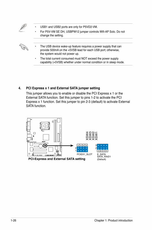
4. PCI Express x 1 and External SATA jumper settingThis jumper allows you to enable or disable the PCI Express x 1 or the External SATA function. Set this jumper to pins 1-2 to activate the PCI Express x 1 function. Set this jumper to pin 2-3 (default) to activate External SATA function.
®
PCI-Express and External SATA setting
XSW
4XS
W3
XSW
2XS
W1
PCIEX1_SLOT
(Default)
21
E_SATA,SATA_RAID1
23
ASUS P5VD2-MX/P5V-VM DH 1-27
1
13 9
2 3 45
6
11 1012
87
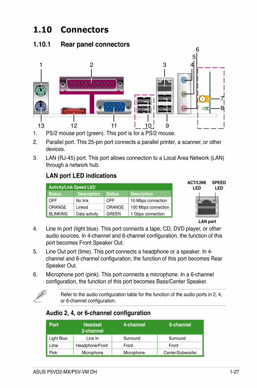
1. PS/2 mouse port (green). This port is for a PS/2 mouse.2. Parallel port. This 25-pin port connects a parallel printer, a scanner, or other
devices.3. LAN (RJ-45) port. This port allows connection to a Local Area Network (LAN)
through a network hub.
4. Line In port (light blue). This port connects a tape, CD, DVD player, or other audio sources. In 4-channel and 6-channel configuration, the function of this port becomes Front Speaker Out.
5. Line Out port (lime). This port connects a headphone or a speaker. In 4-channel and 6-channel configuration, the function of this port becomes Rear Speaker Out.
6. Microphone port (pink). This port connects a microphone. In a 6-channel configuration, the function of this port becomes Bass/Center Speaker.
Refer to the audio configuration table for the function of the audio ports in 2, 4, or 6-channel configuration.
Activity/Link Speed LEDStatus Description Status DescriptionOFF No link OFF 10 Mbps connectionORANGE Linked ORANGE 100 Mbps connectionBLINKING Data activity GREEN 1 Gbps connection
LAN port LED indications
LAN port
SPEED LED
ACT/LINK LED
Audio 2, 4, or 6-channel configurationPort Headset
2-channel4-channel 6-channel
Light Blue Line In Surround SurroundLime Headphone/Front Front FrontPink Microphone Microphone Center/Subwoofer
1.10 Connectors
1.10.1 Rear panel connectors
1-28 Chapter 1: Product introduction
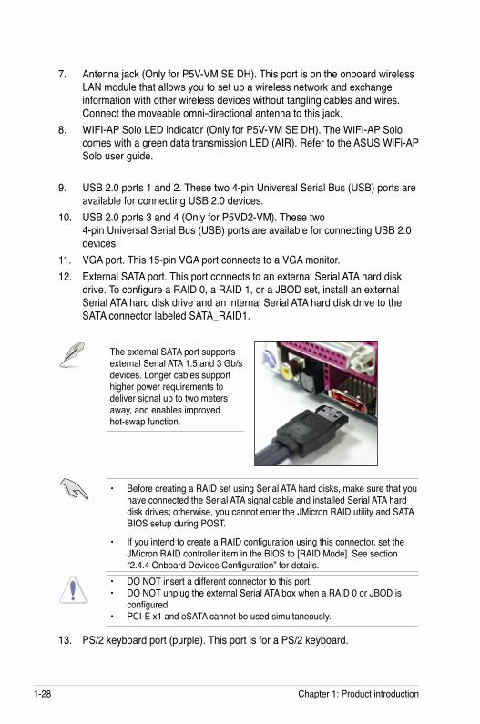
9. USB 2.0 ports 1 and 2. These two 4-pin Universal Serial Bus (USB) ports are available for connecting USB 2.0 devices.
10. USB 2.0 ports 3 and 4 (Only for P5VD2-VM). These two 4-pin Universal Serial Bus (USB) ports are available for connecting USB 2.0 devices.
11. VGA port. This 15-pin VGA port connects to a VGA monitor.12. External SATA port. This port connects to an external Serial ATA hard disk
drive. To configure a RAID 0, a RAID 1, or a JBOD set, install an external Serial ATA hard disk drive and an internal Serial ATA hard disk drive to the SATA connector labeled SATA_RAID1.
7. Antenna jack (Only for P5V-VM SE DH). This port is on the onboard wireless LAN module that allows you to set up a wireless network and exchange information with other wireless devices without tangling cables and wires. Connect the moveable omni-directional antenna to this jack.
8. WIFI-AP Solo LED indicator (Only for P5V-VM SE DH). The WIFI-AP Solo comes with a green data transmission LED (AIR). Refer to the ASUS WiFi-AP Solo user guide.
13. PS/2 keyboard port (purple). This port is for a PS/2 keyboard.
The external SATA port supports external Serial ATA 1.5 and 3 Gb/s devices. Longer cables support higher power requirements to deliver signal up to two meters away, and enables improved hot-swap function.
• DO NOT insert a different connector to this port. • DO NOT unplug the external Serial ATA box when a RAID 0 or JBOD is configured. • PCI-E x1 and eSATA cannot be used simultaneously.
• Before creating a RAID set using Serial ATA hard disks, make sure that you have connected the Serial ATA signal cable and installed Serial ATA hard disk drives; otherwise, you cannot enter the JMicron RAID utility and SATA BIOS setup during POST.
• If you intend to create a RAID configuration using this connector, set the JMicron RAID controller item in the BIOS to [RAID Mode]. See section “2.4.4 Onboard Devices Configuration” for details.
ASUS P5VD2-MX/P5V-VM DH 1-29
1.10.2 Internal connectors
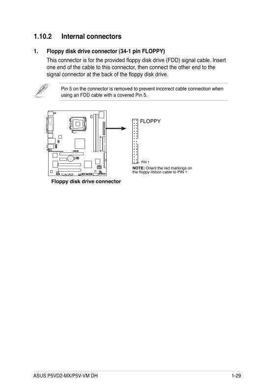
1. Floppy disk drive connector (34-1 pin FLOPPY)This connector is for the provided floppy disk drive (FDD) signal cable. Insert one end of the cable to this connector, then connect the other end to the signal connector at the back of the floppy disk drive.
Pin 5 on the connector is removed to prevent incorrect cable connection when using an FDD cable with a covered Pin 5.
®
NOTE: Orient the red markings onthe floppy ribbon cable to PIN 1.
Floppy disk drive connector
FLOPPY
PIN 1
1-30 Chapter 1: Product introduction
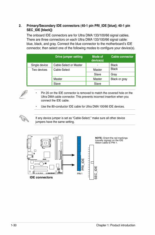
2. Primary/Secondary IDE connectors (40-1 pin PRI_IDE [blue]; 40-1 pin SEC_IDE [black])The onboard IDE connectors are for Ultra DMA 133/100/66 signal cables. There are three connectors on each Ultra DMA 133/100/66 signal cable: blue, black, and gray. Connect the blue connector to the motherboard’s IDE connector, then select one of the following modes to configure your device(s).
• Pin 20 on the IDE connector is removed to match the covered hole on the Ultra DMA cable connector. This prevents incorrect insertion when you connect the IDE cable.
• Use the 80-conductor IDE cable for Ultra DMA 100/66 IDE devices.
®
IDE connectors
NOTE: Orient the red markings(usually zigzag) on the IDEribbon cable to PIN 1.
SEC
_ID
E
PIN 1
PRI_
IDE
If any device jumper is set as “Cable-Select,” make sure all other device jumpers have the same setting.
Drive jumper setting Mode of device(s)
Cable connector
Single device Cable-Select or Master - BlackTwo devices Cable-Select Master Black
Slave GrayMaster Master Black or graySlave Slave
ASUS P5VD2-VM/P5V-VM SE DH 1-31
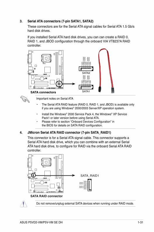
3. Serial ATA connectors (7-pin SATA1, SATA2)These connectors are for the Serial ATA signal cables for Serial ATA 1.5 Gb/s hard disk drives.
If you installed Serial ATA hard disk drives, you can can create a RAID 0, RAID 1, and JBOD configuration through the onboard VIA VT8237A RAID controller.
Important notes on Serial ATA
• The Serial ATA RAID feature (RAID 0, RAID 1, and JBOD) is available only if you are using Windows® 2000/2003 Server/XP operation system.
• Install the Windows® 2000 Service Pack 4, the Windows® XP Service Pack1 or later version before using Serial ATA. • Please refer to section “Onboard Devices Configuration” in the BIOS for details on SATA RAID configuration.
®
SATA connectors
GND
RSATA_TXP1RSATA_TXN1
GND
RSATA_RXP1RSATA_RXN1
GND
SATA1
GND
RSATA_TXP2RSATA_TXN2
GND
RSATA_RXP2RSATA_RXN2
GND
SATA2
4. JMicron Serial ATA RAID connector (7-pin SATA_RAID1)This connector is for a Serial ATA signal cable. This connector supports a Serial ATA hard disk drive, which you can combine with an external Serial ATA hard disk drive, to configure for RAID via the onboard Serial ATA RAID controller.
®
SATA RAID connector
SATA_RAID1GND
RSATA_TXP2RSATA_TXN2
GNDRSATA_RXP2RSATA_RXN2
GND
Do not remove/unplug external SATA devices when running under RAID mode.
1-32 Chapter 1: Product introduction
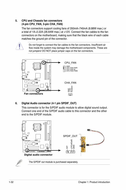
5. CPU and Chassis fan connectors (4-pin CPU_FAN, 3-pin CHA_FAN)The fan connectors support cooling fans of 350mA~740mA (8.88W max.) or a total of 1A~2.22A (26.64W max.) at +12V. Connect the fan cables to the fan connectors on the motherboard, making sure that the black wire of each cable matches the ground pin of the connector.
6. Digital Audio connector (4-1 pin SPDIF_OUT)This connector is for the S/PDIF audio module to allow digital sound output. Connect one end of the S/PDIF audio cable to this connector and the other end to the S/PDIF module.
The S/PDIF out module is purchased separately.
Do not forget to connect the fan cables to the fan connectors. Insufficient air flow inside the system may damage the motherboard components. These are not jumpers! DO NOT place jumper caps on the fan connectors.
®
Fan connectors
CPU_FAN
CHA_FAN
GN
D
Rot
atio
n+1
2V
GNDCPU FAN PWRCPU FAN INCPU FAN PWM
®
Digital audio connector
+5V
SPDIFO
UT
GN
D
SPDIF_OUT
ASUS P5VD2-VM/P5V-VM SE DH 1-33
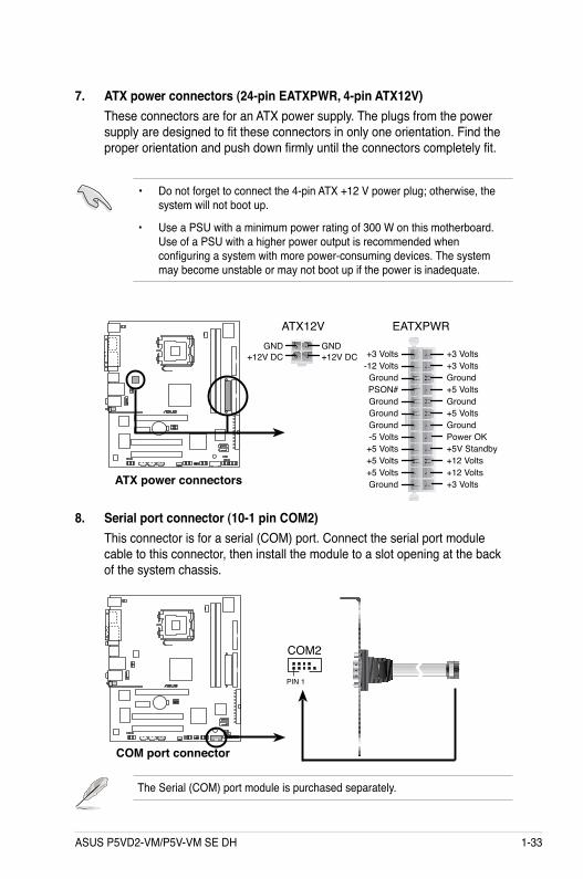
7. ATX power connectors (24-pin EATXPWR, 4-pin ATX12V)These connectors are for an ATX power supply. The plugs from the power supply are designed to fit these connectors in only one orientation. Find the proper orientation and push down firmly until the connectors completely fit.
• Do not forget to connect the 4-pin ATX +12 V power plug; otherwise, the system will not boot up.
• Use a PSU with a minimum power rating of 300 W on this motherboard. Use of a PSU with a higher power output is recommended when configuring a system with more power-consuming devices. The system may become unstable or may not boot up if the power is inadequate.
8. Serial port connector (10-1 pin COM2)This connector is for a serial (COM) port. Connect the serial port module cable to this connector, then install the module to a slot opening at the back of the system chassis.
The Serial (COM) port module is purchased separately.
®
ATX power connectors
EATXPWRATX12V
+12V DCGND
+12V DCGND
+3 Volts+3 VoltsGround+5 Volts
+5 VoltsGround
GroundPower OK+5V Standby+12 Volts
-5 Volts
+5 Volts
+3 Volts-12 VoltsGround
GroundGroundPSON#
Ground
+5 Volts
+12 Volts+3 Volts
+5 VoltsGround
®
COM port connector
PIN 1
COM2
1-34 Chapter 1: Product introduction
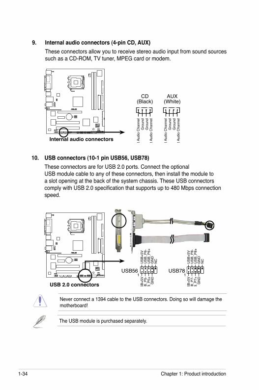
9. Internal audio connectors (4-pin CD, AUX)These connectors allow you to receive stereo audio input from sound sources such as a CD-ROM, TV tuner, MPEG card or modem.
10. USB connectors (10-1 pin USB56, USB78)These connectors are for USB 2.0 ports. Connect the optional USB module cable to any of these connectors, then install the module to a slot opening at the back of the system chassis. These USB connectors comply with USB 2.0 specification that supports up to 480 Mbps connection speed.
Never connect a 1394 cable to the USB connectors. Doing so will damage the motherboard!
The USB module is purchased separately.
®
Internal audio connectors
CD(Black)
AUX(White)
Rig
ht A
udio
Cha
nnel
Left
Audi
o C
hann
elG
roun
dG
roun
d
Rig
ht A
udio
Cha
nnel
Left
Audi
o C
hann
elG
roun
dG
roun
d
®
USB 2.0 connectors
USB56
USB
+5V
USB
_P6-
USB
_P6+
GN
DN
C
USB
+5V
USB
_P5-
USB
_P5+
GN
D
1USB78
USB
+5V
USB
_P8-
USB
_P8+
GN
DN
C
USB
+5V
USB
_P7-
USB
_P7+
GN
D
1
ASUS P5VD2-VM/P5V-VM SE DH 1-35
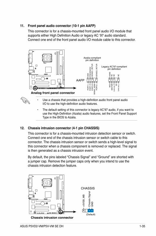
11. Front panel audio connector (10-1 pin AAFP)This connector is for a chassis-mounted front panel audio I/O module that supports either High Definition Audio or legacy AC ‘97 audio standard. Connect one end of the front panel audio I/O module cable to this connector.
• Use a chassis that provides a high-definition audio front panel audio I/O to use the high-definition audio features.
• The default setting of this connector is legacy AC’97 audio, if you want to use the High-Definition (Azalia) audio features, set the Front Panel Support Type in the BIOS to Azalia.
12. Chassis intrusion connector (4-1 pin CHASSIS)This connector is for a chassis-mounted intrusion detection sensor or switch. Connect one end of the chassis intrusion sensor or switch cable to this connector. The chassis intrusion sensor or switch sends a high-level signal to this connector when a chassis component is removed or replaced. The signal is then generated as a chassis intrusion event.
By default, the pins labeled “Chassis Signal” and “Ground” are shorted with a jumper cap. Remove the jumper caps only when you intend to use the chassis intrusion detection feature.
®
Chassis intrusion connector
CHASSIS
+5VS
B_M
B
Cha
ssis
Sig
nal
GN
D
(Default)
®
Analog front panel connector
AAFP
Legacy AC’97-compliantpin definition
NC
MIC
2
Line
out
_R
Line
out
_L
NC
NC
MIC
PWR
NC
AGN
D
PORT
1 R
SEN
SE2_
RET
UR
PORT
1 L
PORT
2 R
PORT
2 L
SEN
SE1_
RET
UR
SEN
SE_S
END
PRES
ENC
E#G
ND
Azalia-compliantpin definition
1-36 Chapter 1: Product introduction
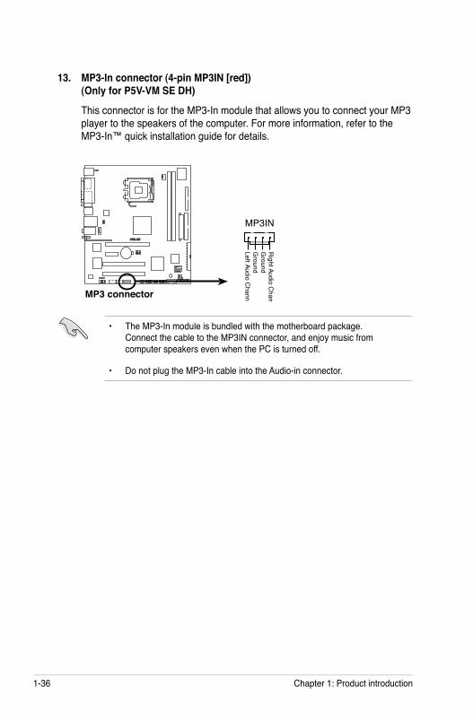
13. MP3-In connector (4-pin MP3IN [red]) (Only for P5V-VM SE DH)
This connector is for the MP3-In module that allows you to connect your MP3 player to the speakers of the computer. For more information, refer to the MP3-In™ quick installation guide for details.
®
MP3 connector
MP3IN
Right Audio C
hannel
Left Audio Channel
Ground
Ground
• The MP3-In module is bundled with the motherboard package. Connect the cable to the MP3IN connector, and enjoy music from computer speakers even when the PC is turned off.
• Do not plug the MP3-In cable into the Audio-in connector.
ASUS P5VD2-VM/P5V-VM SE DH 1-37
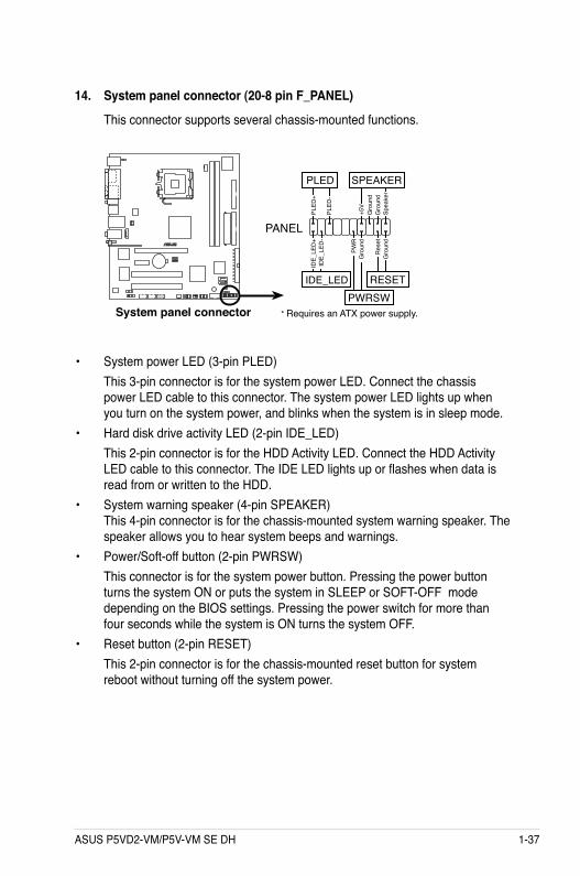
14. System panel connector (20-8 pin F_PANEL)
This connector supports several chassis-mounted functions.
• System power LED (3-pin PLED) This 3-pin connector is for the system power LED. Connect the chassis
power LED cable to this connector. The system power LED lights up when you turn on the system power, and blinks when the system is in sleep mode.
• Hard disk drive activity LED (2-pin IDE_LED) This 2-pin connector is for the HDD Activity LED. Connect the HDD Activity
LED cable to this connector. The IDE LED lights up or flashes when data is read from or written to the HDD.
• System warning speaker (4-pin SPEAKER) This 4-pin connector is for the chassis-mounted system warning speaker. The speaker allows you to hear system beeps and warnings.
• Power/Soft-off button (2-pin PWRSW) This connector is for the system power button. Pressing the power button
turns the system ON or puts the system in SLEEP or SOFT-OFF mode depending on the BIOS settings. Pressing the power switch for more than four seconds while the system is ON turns the system OFF.
• Reset button (2-pin RESET) This 2-pin connector is for the chassis-mounted reset button for system
reboot without turning off the system power.
®
System panel connector * Requires an ATX power supply.
PANEL
PLED
-
PWR
+5V
Spea
ker
Gro
und
RESET
Gro
und
Res
etG
roun
dG
roun
d
PWRSWPL
ED+
IDE_
LED
-ID
E_LE
D+
IDE_LED
PLED SPEAKER

1-38 Chapter 1: Product introduction
ASUS P5VD2-VM/P5V-VM SE DH 2-1
2BIOS setup
This chapter tells how to change the system settings through the BIOS Setup menus. Detailed descriptions of the BIOS parameters are also provided.
2-2 Chapter 2: BIOS setup
2.1 Managing and updating your BIOSThe following utilities allow you to manage and update the motherboard Basic Input/Output System (BIOS) setup.
1. ASUS Update (Updates the BIOS in Windows® environment.) 2. ASUS EZ Flash 2(Updates the BIOS using a floppy disk/USB flash disk or
the motherboard support CD.)3. Award BIOS Flash Utility (Updates the BIOS in DOS mode using a bootable
floppy disk.)4. ASUS CrashFree BIOS 2 (Updates the BIOS using a bootable floppy disk or
the motherboard support CD when the BIOS file fails or gets corrupted.)
Refer to the corresponding sections for details on these utilities.
Save a copy of the original motherboard BIOS file to a bootable floppy disk in case you need to restore the BIOS in the future. Copy the original motherboard BIOS using the ASUS Update or Award BIOS Flash utilities.
Installing ASUS UpdateTo install ASUS Update:
1. Place the support CD in the optical drive. The Drivers menu appears. 2. Click the Utilities tab, then click Install ASUS Update VX.XX.XX. See page
3-4 for the Utilities screen menu.3. The ASUS Update utility is copied to your system.
2.1.1 ASUS Update utilityThe ASUS Update is a utility that allows you to manage, save, and update the motherboard BIOS in Windows® environment. The ASUS Update utility allows you to:
• Save the current BIOS file • Download the latest BIOS file from the Internet • Update the BIOS from an updated BIOS file • Update the BIOS directly from the Internet, and • View the BIOS version information.
This utility is available in the support CD that comes with the motherboard package.
ASUS Update requires an Internet connection either through a network or an Internet Service Provider (ISP).
Quit all Windows® applications before you update the BIOS using this utility.
ASUS P5VD2-VM/P5V-VM SE DH 2-3
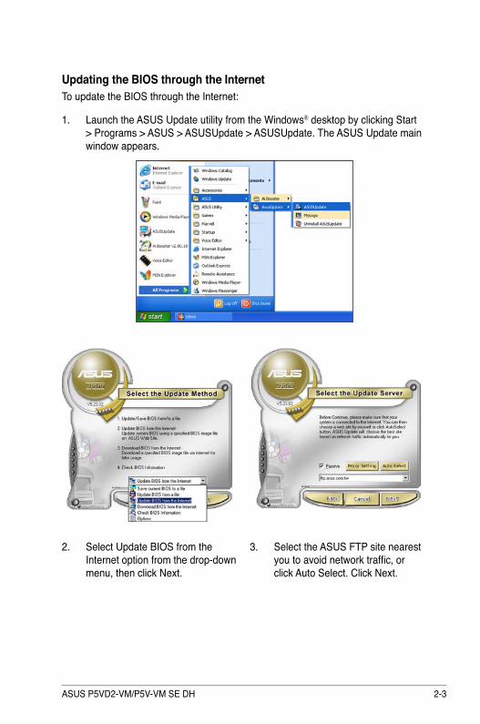
3. Select the ASUS FTP site nearest you to avoid network traffic, or click Auto Select. Click Next.
Updating the BIOS through the InternetTo update the BIOS through the Internet:
1. Launch the ASUS Update utility from the Windows® desktop by clicking Start > Programs > ASUS > ASUSUpdate > ASUSUpdate. The ASUS Update main window appears.
2. Select Update BIOS from the Internet option from the drop-down menu, then click Next.
2-4 Chapter 2: BIOS setup
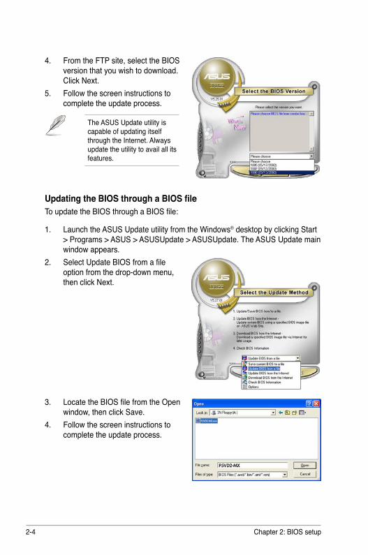
Updating the BIOS through a BIOS fileTo update the BIOS through a BIOS file:
1. Launch the ASUS Update utility from the Windows® desktop by clicking Start > Programs > ASUS > ASUSUpdate > ASUSUpdate. The ASUS Update main window appears.
2. Select Update BIOS from a file option from the drop-down menu, then click Next.
4. From the FTP site, select the BIOS version that you wish to download. Click Next.
5. Follow the screen instructions to complete the update process.
The ASUS Update utility is capable of updating itself through the Internet. Always update the utility to avail all its features.
3. Locate the BIOS file from the Open window, then click Save.
4. Follow the screen instructions to complete the update process.
ASUS P5VD2-VM/P5V-VM SE DH 2-5
2.1.2 Creating a bootable floppy disk1. Do either one of the following to create a bootable floppy disk.
DOS environmenta. Insert a 1.44MB floppy disk into the drive.b. At the DOS prompt, type format A:/S then press <Enter>.Windows® XP environmenta. Insert a 1.44 MB floppy disk to the floppy disk drive. b. Click Start from the Windows® desktop, then select My Computer.c. Select the 3 1/2 Floppy Drive icon.d. Click File from the menu, then select Format. A Format 3 1/2 Floppy Disk
window appears.e. Select Create an MS-DOS startup disk from the format options field, then
click Start.Windows® 2000 environment
To create a set of boot disks for Windows® 2000:a. Insert a formatted, high density 1.44 MB floppy disk into the drive.b. Insert the Windows® 2000 CD to the optical drive.c. Click Start, then select Run.d. From the Open field, type D:\bootdisk\makeboot a:
assuming that D: is your optical drive.e. Press <Enter>, then follow screen instructions to continue.
2. Copy the original or the latest motherboard BIOS file to the bootable floppy disk.
2-6 Chapter 2: BIOS setup
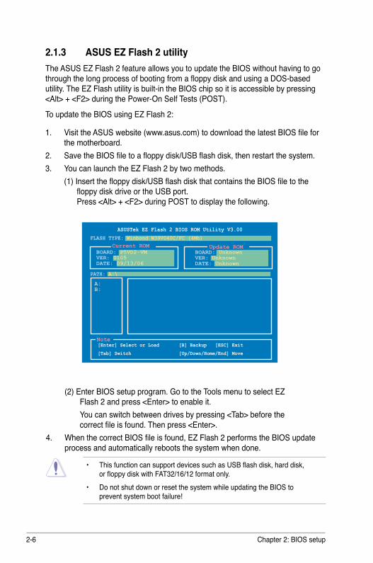
2.1.3 ASUS EZ Flash 2 utilityThe ASUS EZ Flash 2 feature allows you to update the BIOS without having to go through the long process of booting from a floppy disk and using a DOS-based utility. The EZ Flash utility is built-in the BIOS chip so it is accessible by pressing <Alt> + <F2> during the Power-On Self Tests (POST).
To update the BIOS using EZ Flash 2:
1. Visit the ASUS website (www.asus.com) to download the latest BIOS file for the motherboard.
2. Save the BIOS file to a floppy disk/USB flash disk, then restart the system.3. You can launch the EZ Flash 2 by two methods. (1) Insert the floppy disk/USB flash disk that contains the BIOS file to the
floppy disk drive or the USB port. Press <Alt> + <F2> during POST to display the following.
• This function can support devices such as USB flash disk, hard disk, or floppy disk with FAT32/16/12 format only. • Do not shut down or reset the system while updating the BIOS to prevent system boot failure!
(2) Enter BIOS setup program. Go to the Tools menu to select EZ Flash 2 and press <Enter> to enable it.
You can switch between drives by pressing <Tab> before the correct file is found. Then press <Enter>.
4. When the correct BIOS file is found, EZ Flash 2 performs the BIOS update process and automatically reboots the system when done.
ASUSTek EZ Flash 2 BIOS ROM Utility V3.00
Current ROM Update ROM
A:B:
Note [Enter] Select or Load [B] Backup [ESC] Exit
[Tab] Switch [Up/Down/Home/End] Move
FLASH TYPE: Winbond W39V040C/FC (4Mb)
PATH: A:\
BOARD: P5VD2-VMVER: 0105DATE: 09/13/06
BOARD: UnknownVER: UnknownDATE: Unknown
ASUS P5VD2-VM/P5V-VM SE DH 2-7
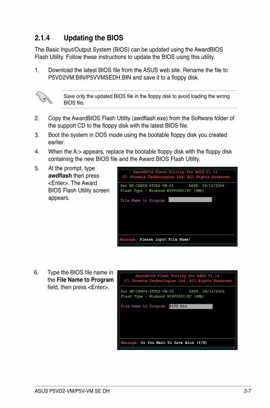
2.1.4 Updating the BIOSThe Basic Input/Output System (BIOS) can be updated using the AwardBIOS Flash Utility. Follow these instructions to update the BIOS using this utility.
1. Download the latest BIOS file from the ASUS web site. Rename the file to P5VD2VM.BIN/P5VVMSEDH.BIN and save it to a floppy disk.
Save only the updated BIOS file in the floppy disk to avoid loading the wrong BIOS file.
2. Copy the AwardBIOS Flash Utility (awdflash.exe) from the Software folder of the support CD to the floppy disk with the latest BIOS file.
3. Boot the system in DOS mode using the bootable floppy disk you created earlier.
4. When the A:> appears, replace the bootable floppy disk with the floppy disk containing the new BIOS file and the Award BIOS Flash Utility.
5. At the prompt, type awdflash then press <Enter>. The Award BIOS Flash Utility screen appears.
AwardBIOS Flash Utility for ASUS V1.14(C) Phoenix Technologies Ltd. All Rights Reserved
Message: Please input File Name!
For NF-CK804-P5VD2-VM-00 DATE: 09/13/2006Flash Type - Winbond W39V040C/FC (4Mb)
File Name to Program:
AwardBIOS Flash Utility for ASUS V1.14(C) Phoenix Technologies Ltd. All Rights Reserved
For NF-CK804-P5VD2-VM-00 DATE: 09/13/2006Flash Type - Winbond W39V040C/FC (4Mb)
File Name to Program: 0105.bin
Message: Do You Want To Save Bios (Y/N)
6. Type the BIOS file name in the File Name to Program field, then press <Enter>.
2-8 Chapter 2: BIOS setup
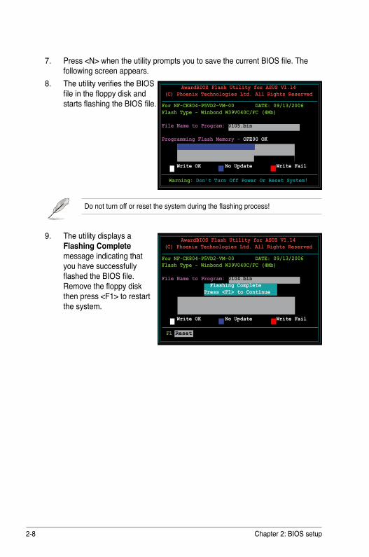
7. Press <N> when the utility prompts you to save the current BIOS file. The following screen appears.
8. The utility verifies the BIOS file in the floppy disk and starts flashing the BIOS file.
Do not turn off or reset the system during the flashing process!
AwardBIOS Flash Utility for ASUS V1.14(C) Phoenix Technologies Ltd. All Rights Reserved
Warning: Don’t Turn Off Power Or Reset System!
9. The utility displays a Flashing Complete message indicating that you have successfully flashed the BIOS file. Remove the floppy disk then press <F1> to restart the system.
AwardBIOS Flash Utility for ASUS V1.14(C) Phoenix Technologies Ltd. All Rights Reserved
F1 Reset
For NF-CK804-P5VD2-VM-00 DATE: 09/13/2006 Flash Type - Winbond W39V040C/FC (4Mb)
File Name to Program: 0104.bin Flashing Complete Press <F1> to Continue
Write OK No Update Write Fail
For NF-CK804-P5VD2-VM-00 DATE: 09/13/2006Flash Type - Winbond W39V040C/FC (4Mb)
File Name to Program: 0105.bin Programming Flash Memory - OFE00 OK
Write OK No Update Write Fail
ASUS P5VD2-VM/P5V-VM SE DH 2-9
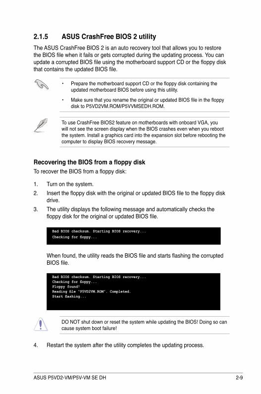
2.1.5 ASUS CrashFree BIOS 2 utilityThe ASUS CrashFree BIOS 2 is an auto recovery tool that allows you to restore the BIOS file when it fails or gets corrupted during the updating process. You can update a corrupted BIOS file using the motherboard support CD or the floppy disk that contains the updated BIOS file.
Recovering the BIOS from a floppy diskTo recover the BIOS from a floppy disk:
1. Turn on the system.2. Insert the floppy disk with the original or updated BIOS file to the floppy disk
drive.3. The utility displays the following message and automatically checks the
floppy disk for the original or updated BIOS file.
Bad BIOS checksum. Starting BIOS recovery...Checking for floppy...
4. Restart the system after the utility completes the updating process.
Bad BIOS checksum. Starting BIOS recovery...Checking for floppy...Floppy found!Reading file “P5VD2VM.ROM”. Completed.Start flashing...
When found, the utility reads the BIOS file and starts flashing the corrupted BIOS file.
DO NOT shut down or reset the system while updating the BIOS! Doing so can cause system boot failure!
• Prepare the motherboard support CD or the floppy disk containing the updated motherboard BIOS before using this utility.
• Make sure that you rename the original or updated BIOS file in the floppy disk to P5VD2VM.ROM/P5VVMSEDH.ROM.
To use CrashFree BIOS2 feature on motherboards with onboard VGA, you will not see the screen display when the BIOS crashes even when you reboot the system. Install a graphics card into the expansion slot before rebooting the computer to display BIOS recovery message.
2-10 Chapter 2: BIOS setup
The recovered BIOS may not be the latest BIOS version for this motherboard. Visit the ASUS website (www.asus.com) to download the latest BIOS file.
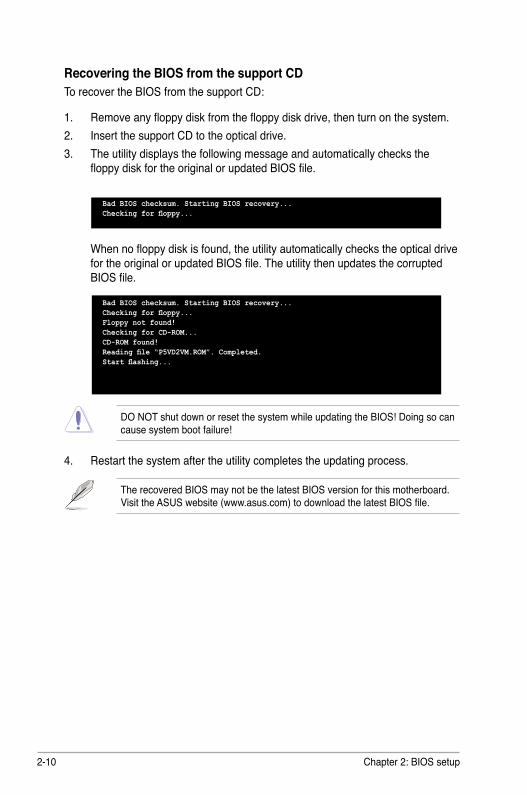
Recovering the BIOS from the support CDTo recover the BIOS from the support CD:
1. Remove any floppy disk from the floppy disk drive, then turn on the system.2. Insert the support CD to the optical drive.3. The utility displays the following message and automatically checks the
floppy disk for the original or updated BIOS file.
4. Restart the system after the utility completes the updating process.
DO NOT shut down or reset the system while updating the BIOS! Doing so can cause system boot failure!
Bad BIOS checksum. Starting BIOS recovery...Checking for floppy...Floppy not found!Checking for CD-ROM...CD-ROM found!Reading file “P5VD2VM.ROM”. Completed.Start flashing...
When no floppy disk is found, the utility automatically checks the optical drive for the original or updated BIOS file. The utility then updates the corrupted BIOS file.
Bad BIOS checksum. Starting BIOS recovery...Checking for floppy...
ASUS P5VD2-VM/P5V-VM SE DH 2-11
2.2 BIOS setup programThis motherboard supports a programmable firmware chip that you can update using the provided utility described in section “2.1 Managing and updating your BIOS.”
Use the BIOS Setup program when you are installing a motherboard, reconfiguring your system, or prompted to “Run Setup”. This section explains how to configure your system using this utility.
Even if you are not prompted to use the Setup program, you can change the configuration of your computer in the future. For example, you can enable the security password feature or change the power management settings. This requires you to reconfigure your system using the BIOS Setup program so that the computer can recognize these changes and record them in the CMOS RAM of the firmware hub.
The firmware hub on the motherboard stores the Setup utility. When you start up the computer, the system provides you with the opportunity to run this program. Press <Del> during the Power-On Self-Test (POST) to enter the Setup utility; otherwise, POST continues with its test routines.
If you wish to enter Setup after POST, restart the system by pressing <Ctrl+Alt+Delete>, or by pressing the reset button on the system chassis. You can also restart by turning the system off and then back on. Do this last option only if the first two failed.
The Setup program is designed to make it as easy to use as possible. Being a menu-driven program, it lets you scroll through the various sub-menus and make your selections from the available options using the navigation keys.
• The default BIOS settings for this motherboard apply for most conditions to ensure optimum performance. If the system becomes unstable after changing any BIOS settings, load the default settings to ensure system compatibility and stability. Select the Load Default Settings item under the Exit Menu. See section “2.8 Exit Menu.”
• The BIOS setup screens shown in this section are for reference purposes only, and may not exactly match what you see on your screen.
• Visit the ASUS website (www.asus.com) to download the latest BIOS file for this motherboard and .
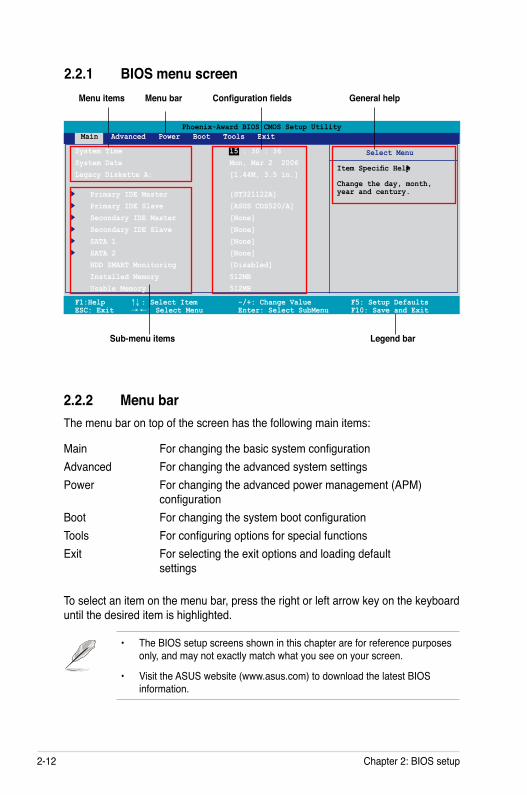
2-12 Chapter 2: BIOS setup
2.2.1 BIOS menu screen
Select Menu
Item Specific Help
Change the day, month, year and century.
Legend bar
General helpMenu bar
Sub-menu items
Configuration fieldsMenu items
Phoenix-Award BIOS CMOS Setup Utility Main Advanced Power Boot Tools Exit
F1:Help ↑↓ : Select Item -/+: Change Value F5: Setup Defaults ESC: Exit → ←: Select Menu Enter: Select SubMenu F10: Save and Exit
System Time 15 : 30 : 36System Date Mon, Mar 2 2006 Legacy Diskette A: [1.44M, 3.5 in.] Primary IDE Master [ST321122A] Primary IDE Slave [ASUS CDS520/A] Secondary IDE Master [None] Secondary IDE Slave [None] SATA 1 [None] SATA 2 [None] HDD SMART Monitoring [Disabled] Installed Memory 512MB Usable Memory 512MB
2.2.2 Menu barThe menu bar on top of the screen has the following main items:
Main For changing the basic system configurationAdvanced For changing the advanced system settingsPower For changing the advanced power management (APM)
configurationBoot For changing the system boot configurationTools For configuring options for special functionsExit For selecting the exit options and loading default
settings
To select an item on the menu bar, press the right or left arrow key on the keyboard until the desired item is highlighted.
• The BIOS setup screens shown in this chapter are for reference purposes only, and may not exactly match what you see on your screen.
• Visit the ASUS website (www.asus.com) to download the latest BIOS information.
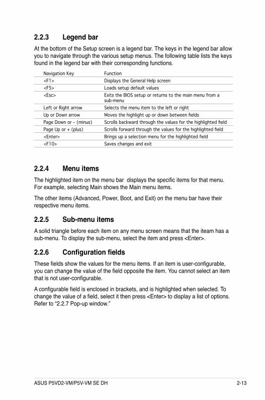
ASUS P5VD2-VM/P5V-VM SE DH 2-13
2.2.4 Menu itemsThe highlighted item on the menu bar displays the specific items for that menu. For example, selecting Main shows the Main menu items.
The other items (Advanced, Power, Boot, and Exit) on the menu bar have their respective menu items.
2.2.5 Sub-menu itemsA solid triangle before each item on any menu screen means that the iteam has a sub-menu. To display the sub-menu, select the item and press <Enter>.
2.2.6 Configuration fieldsThese fields show the values for the menu items. If an item is user-configurable, you can change the value of the field opposite the item. You cannot select an item that is not user-configurable.
A configurable field is enclosed in brackets, and is highlighted when selected. To change the value of a field, select it then press <Enter> to display a list of options. Refer to “2.2.7 Pop-up window.”
2.2.3 Legend barAt the bottom of the Setup screen is a legend bar. The keys in the legend bar allow you to navigate through the various setup menus. The following table lists the keys found in the legend bar with their corresponding functions.
Navigation Key Function<F1> Displays the General Help screen<F5> Loads setup default values<Esc> Exits the BIOS setup or returns to the main menu from a sub-menuLeft or Right arrow Selects the menu item to the left or right Up or Down arrow Moves the highlight up or down between fields Page Down or – (minus) Scrolls backward through the values for the highlighted fieldPage Up or + (plus) Scrolls forward through the values for the highlighted field<Enter> Brings up a selection menu for the highlighted field <F10> Saves changes and exit
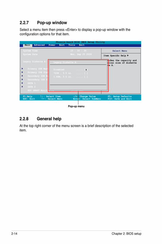
2-14 Chapter 2: BIOS setup
2.2.7 Pop-up windowSelect a menu item then press <Enter> to display a pop-up window with the configuration options for that item.
F1:Help ↑↓ : Select Item -/+: Change Value F5: Setup Defaults ESC: Exit →←: Select Menu Enter: Select SubMenu F10: Save and Exit
Phoenix-Award BIOS CMOS Setup Utility Main Advanced Power Boot Tools Exit
Select Menu
Item Specific Help
Specifies the capacity and physical size of diskette drive A.
System Time 15 : 30 : 36System Date Mon, Sep 25 2006 Legacy Diskette A: [1.44M, 3.5 in.
Primary IDE Master [ST321122A] Primary IDE Slave [ASUS CDS520/A] Secondary IDE Master [None] Secondary IDE Slave [None] SATA 1 [None] SATA 2 [None] HDD SMART Monitoring [Disabled]
2.2.8 General helpAt the top right corner of the menu screen is a brief description of the selected item.
Legacy Diskette A:
Disabled ..... [ ]720K , 3.5 in. ..... [ ]1.44M, 3.5 in. ..... [ ]
Pop-up menu
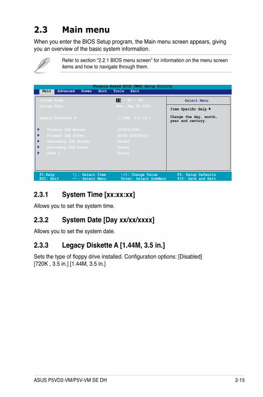
ASUS P5VD2-VM/P5V-VM SE DH 2-15
F1:Help ↑↓ : Select Item -/+: Change Value F5: Setup Defaults ESC: Exit →←: Select Menu Enter: Select SubMenu F10: Save and Exit
Phoenix-Award BIOS CMOS Setup Utility Main Advanced Power Boot Tools Exit
Select Menu
Item Specific Help
Change the day, month, year and century.
System Time 15 : 30 : 36System Date Mon, Sep 25 2006
Legacy Diskette A: [1.44M, 3.5 in.]
Primary IDE Master [ST321122A] Primary IDE Slave [ASUS CDS520/A] Secondary IDE Master [None] Secondary IDE Slave [None] SATA 1 [None]
2.3 Main menuWhen you enter the BIOS Setup program, the Main menu screen appears, giving you an overview of the basic system information.
Refer to section “2.2.1 BIOS menu screen” for information on the menu screen items and how to navigate through them.
2.3.1 System Time [xx:xx:xx]Allows you to set the system time.
2.3.2 System Date [Day xx/xx/xxxx]Allows you to set the system date.
2.3.3 Legacy Diskette A [1.44M, 3.5 in.]Sets the type of floppy drive installed. Configuration options: [Disabled] [720K , 3.5 in.] [1.44M, 3.5 in.]
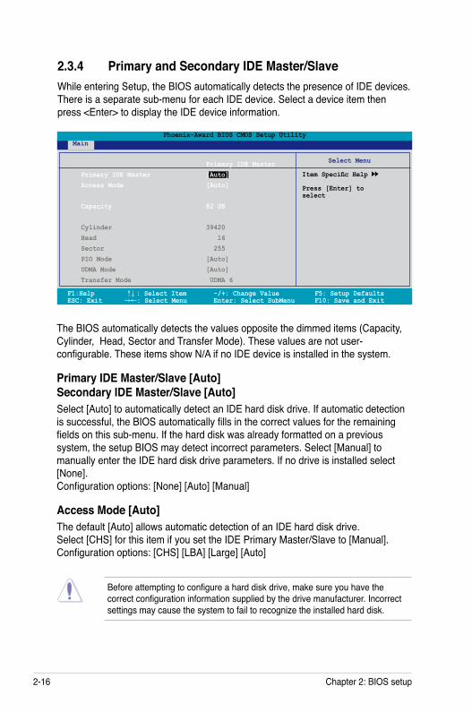
2-16 Chapter 2: BIOS setup
2.3.4 Primary and Secondary IDE Master/SlaveWhile entering Setup, the BIOS automatically detects the presence of IDE devices. There is a separate sub-menu for each IDE device. Select a device item then press <Enter> to display the IDE device information.
Before attempting to configure a hard disk drive, make sure you have the correct configuration information supplied by the drive manufacturer. Incorrect settings may cause the system to fail to recognize the installed hard disk.
The BIOS automatically detects the values opposite the dimmed items (Capacity, Cylinder, Head, Sector and Transfer Mode). These values are not user-configurable. These items show N/A if no IDE device is installed in the system.
Primary IDE Master/Slave [Auto] Secondary IDE Master/Slave [Auto]Select [Auto] to automatically detect an IDE hard disk drive. If automatic detection is successful, the BIOS automatically fills in the correct values for the remaining fields on this sub-menu. If the hard disk was already formatted on a previous system, the setup BIOS may detect incorrect parameters. Select [Manual] to manually enter the IDE hard disk drive parameters. If no drive is installed select [None]. Configuration options: [None] [Auto] [Manual]
Access Mode [Auto]The default [Auto] allows automatic detection of an IDE hard disk drive. Select [CHS] for this item if you set the IDE Primary Master/Slave to [Manual]. Configuration options: [CHS] [LBA] [Large] [Auto]
F1:Help ↑↓ : Select Item -/+: Change Value F5: Setup Defaults ESC: Exit →←: Select Menu Enter: Select SubMenu F10: Save and Exit
Phoenix-Award BIOS CMOS Setup Utility Main
Select Menu
Item Specific Help
Press [Enter] toselect
Primary IDE Master Primary IDE Master [Auto] Access Mode [Auto] Capacity 82 GB
Cylinder 39420 Head 16 Sector 255 PIO Mode [Auto] UDMA Mode [Auto] Transfer Mode UDMA 6
ASUS P5VD2-VM/P5V-VM SE DH 2-17
CapacityDisplays the auto-detected hard disk capacity. This item is not configurable.
CylinderShows the number of the hard disk cylinders. This item is not configurable.
HeadShows the number of the hard disk read/write heads. This item is not configurable.
SectorShows the number of sectors per track. This item is not configurable.
PIO Mode [Auto]Sets the PIO mode for the IDE device. Configuration options: [Auto] [Mode 0] [Mode 1] [Mode 2] [Mode 3] [Mode 4]
UDMA Mode [Auto]Disables or sets the UDMA mode. Configuration options: [Disabled] [Auto]
Transfer ModeShows the Transfer mode. This item is not configurable.
After entering the IDE hard disk drive information into BIOS, use a disk utility, such as FDISK, to partition and format new IDE hard disk drives. This is necessary so that you can write or read data from the hard disk. Make sure to set the partition of the Primary IDE hard disk drives to active.
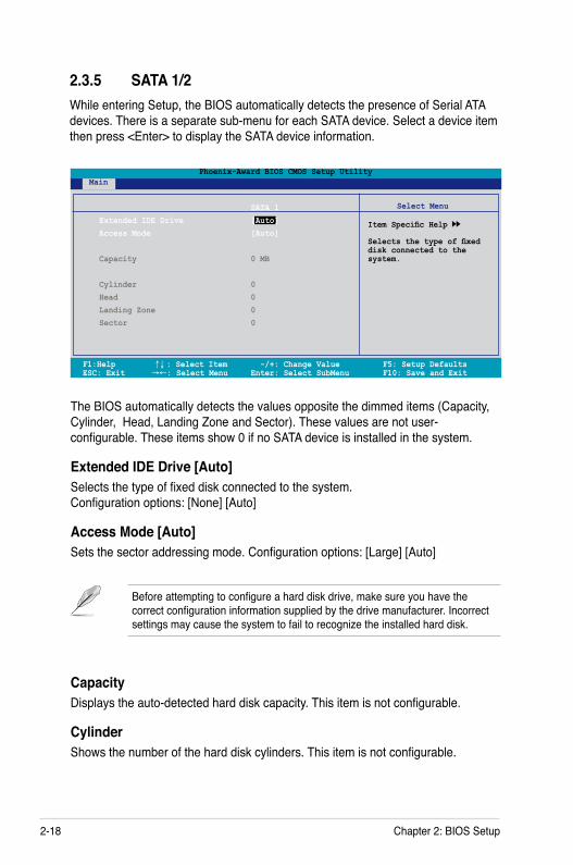
2-18 Chapter 2: BIOS Setup
2.3.5 SATA 1/2While entering Setup, the BIOS automatically detects the presence of Serial ATA devices. There is a separate sub-menu for each SATA device. Select a device item then press <Enter> to display the SATA device information.
The BIOS automatically detects the values opposite the dimmed items (Capacity, Cylinder, Head, Landing Zone and Sector). These values are not user-configurable. These items show 0 if no SATA device is installed in the system.
Extended IDE Drive [Auto]Selects the type of fixed disk connected to the system. Configuration options: [None] [Auto]
Access Mode [Auto]Sets the sector addressing mode. Configuration options: [Large] [Auto]
F1:Help ↑↓ : Select Item -/+: Change Value F5: Setup Defaults ESC: Exit →←: Select Menu Enter: Select SubMenu F10: Save and Exit
Phoenix-Award BIOS CMOS Setup Utility Main
Select Menu
Item Specific Help
Selects the type of fixed disk connected to the system.
SATA 1 Extended IDE Drive [Auto] Access Mode [Auto]
Capacity 0 MB
Cylinder 0 Head 0 Landing Zone 0 Sector 0
Before attempting to configure a hard disk drive, make sure you have the correct configuration information supplied by the drive manufacturer. Incorrect settings may cause the system to fail to recognize the installed hard disk.
CapacityDisplays the auto-detected hard disk capacity. This item is not configurable.
CylinderShows the number of the hard disk cylinders. This item is not configurable.
ASUS P5VD2-VM/P5V-VM SE DH 2-19
HeadShows the number of the hard disk read/write heads. This item is not configurable.
Landing ZoneShows the number of landing zone per track. This item is not configurable.
SectorShows the number of sectors per track. This item is not configurable.
After entering the IDE hard disk drive information into BIOS, use a disk utility, such as FDISK, to partition and format new IDE hard disk drives. This is necessary so that you can write or read data from the hard disk. Make sure to set the partition of the Primary IDE hard disk drives to active.
2.3.6 HDD SMART Monitoring [Disabled]Allows you to enable or disable the HDD Self-Monitoring Analysis and Reporting Technology (SMART) feature. Configuration options: [Disabled] [Enabled]
2.3.7 Installed Memory [xxx MB]Shows the size of installed memory.
2.3.8 Usable Memory [XXX MB]Shows the size of usable memory.
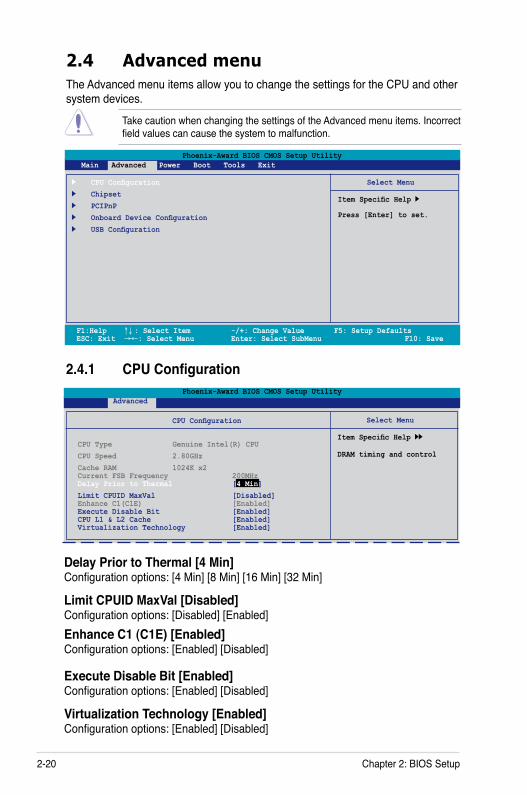
2-20 Chapter 2: BIOS Setup
Phoenix-Award BIOS CMOS Setup Utility Main Advanced Power Boot Tools Exit
Select Menu
Item Specific Help
Press [Enter] to set.
CPU Configuration Chipset PCIPnP Onboard Device Configuration USB Configuration
2.4 Advanced menuThe Advanced menu items allow you to change the settings for the CPU and other system devices.
Take caution when changing the settings of the Advanced menu items. Incorrect field values can cause the system to malfunction.
F1:Help ↑↓ : Select Item -/+: Change Value F5: Setup Defaults ESC: Exit →←: Select Menu Enter: Select SubMenu F10: Save
2.4.1 CPU Configuration
Select Menu
Item Specific Help
DRAM timing and control
Phoenix-Award BIOS CMOS Setup Utility Advanced
CPU Configuration
CPU Type Genuine Intel(R) CPU CPU Speed 2.80GHzCache RAM 1024K x2 Current FSB Frequency 200MHz Delay Prior to Thermal [4 Min] Limit CPUID MaxVal [Disabled] Enhance C1(C1E) [Enabled] Execute Disable Bit [Enabled] CPU L1 & L2 Cache [Enabled] Virtualization Technology [Enabled]
Delay Prior to Thermal [4 Min] Configuration options: [4 Min] [8 Min] [16 Min] [32 Min]
Limit CPUID MaxVal [Disabled] Configuration options: [Disabled] [Enabled] Enhance C1 (C1E) [Enabled] Configuration options: [Enabled] [Disabled]
Execute Disable Bit [Enabled] Configuration options: [Enabled] [Disabled]
Virtualization Technology [Enabled] Configuration options: [Enabled] [Disabled]
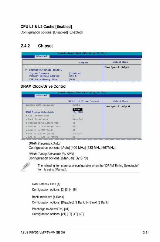
ASUS P5VD2-VM/P5V-VM SE DH 2-21
CPU L1 & L2 Cache [Enabled]Configuration options: [Disabled] [Enabled]
Select Menu
Item Specific Help
Phoenix-Award BIOS CMOS Setup Utility Advanced
Chipset DRAM Clock/Drive Control Frequency/Voltage control Top Performance [Disabled] Primary Display Adapter [PCI-E] VGA Share Memory Size [64M]
2.4.2 Chipset
DRAM Clock/Drive Control
Select Menu
Item Specific Help
Phoenix-Award BIOS CMOS Setup Utility Advanced
DRAM Clock/Drive Control Current DRAM Frequency 200MHz DRAM Frequency DRAM Timing Selectable [By SPD]x CAS Latency Time 4 x Bank Interleave Disabledx Precharge to Active(Trp) 4Tx Active to Precharge(Tras) 07T x Active to CMD(Trcd) 4Tx REF to ACT/REF(Trfc) 20T/21Tx ACT(0) to ACT(1) (TRRD) 3T
Auto
DRAM Frequency [Auto]Configuration options: [Auto] [400 MHz] [533 MHz][667MHz]DRAM Timing Selectable [By SPD]Configuration options: [Manual] [By SPD]
The following items are user-configurable when the “DRAM Timing Selectable” item is set to [Manual].
CAS Latency Time [4]Configuration options: [2] [3] [4] [5]
Bank Interleave [4 Bank] Configuration options: [Disabled] [2 Bank] [4 Bank] [8 Bank] Precharge to Active(Trp) [3T] Configuration options: [2T] [3T] [4T] [5T]
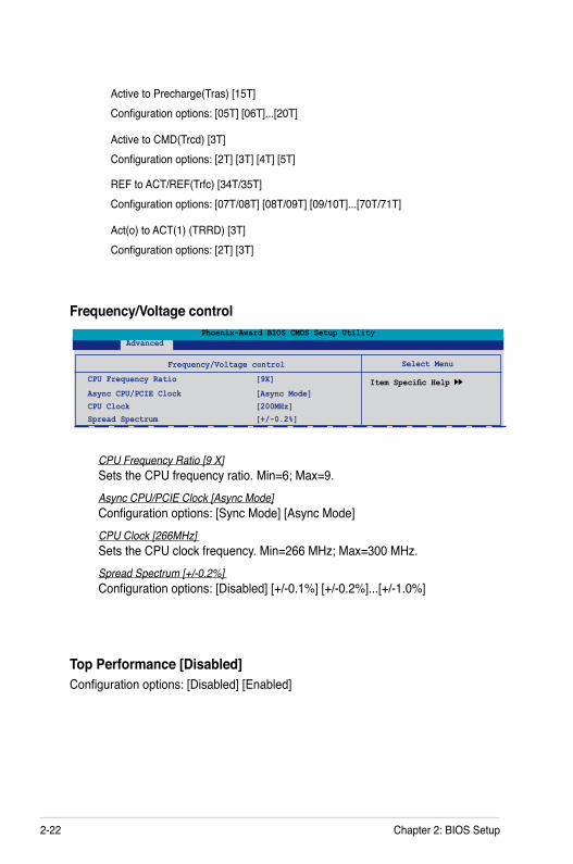
2-22 Chapter 2: BIOS Setup
Frequency/Voltage control
Select Menu
Item Specific Help
Phoenix-Award BIOS CMOS Setup Utility Advanced
Frequency/Voltage control
CPU Frequency Ratio [9X]
Async CPU/PCIE Clock [Async Mode] CPU Clock [200MHz]Spread Spectrum [+/-0.2%]
CPU Frequency Ratio [9 X]Sets the CPU frequency ratio. Min=6; Max=9.Async CPU/PCIE Clock [Async Mode]Configuration options: [Sync Mode] [Async Mode]CPU Clock [266MHz] Sets the CPU clock frequency. Min=266 MHz; Max=300 MHz.Spread Spectrum [+/-0.2%] Configuration options: [Disabled] [+/-0.1%] [+/-0.2%]...[+/-1.0%]
REF to ACT/REF(Trfc) [34T/35T] Configuration options: [07T/08T] [08T/09T] [09/10T]...[70T/71T]
Act(o) to ACT(1) (TRRD) [3T] Configuration options: [2T] [3T]
Active to Precharge(Tras) [15T] Configuration options: [05T] [06T]...[20T]
Active to CMD(Trcd) [3T] Configuration options: [2T] [3T] [4T] [5T]
Top Performance [Disabled]Configuration options: [Disabled] [Enabled]
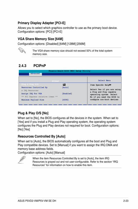
ASUS P5VD2-VM/P5V-VM SE DH 2-23
VGA Share Memory Size [64M]Configuration options: [Disabled] [64M] [128M] [256M]
Primary Display Adapter [PCI-E]Allows you to select which graphics controller to use as the primary boot device. Configuration options: [PCI] [PCI-E]
Select Menu
Item Specific Help
Select Yes if you are using a Plug and Play capable operating system Select No if you need the BIOS to configure non-boot devices
PCIPnPPlug & Play O/S [No]Resources Controlled By [Auto]x IRQ ResourcesAssign IRQ For VGA [Enabled] ** PCI Express relative itmes **Maximum Payload Size [4096]
Phoenix-Award BIOS CMOS Setup Utility Advanced
2.4.3 PCIPnP
Plug & Play O/S [No]When set to [No], the BIOS configures all the devices in the system. When set to [Yes] and if you install a Plug and Play operating system, the operating system configures the Plug and Play devices not required for boot. Configuration options: [No] [Yes]
Resources Controlled By [Auto] When set to [Auto], the BIOS automatically configures all the boot and Plug and Play compatible devices. Set to [Manual] if you want to assign the IRQ DMA and memory base address fields. Configuration options: [Auto] [Manual]
When the item Resources Controlled By is set to [Auto], the item IRQ Resources is grayed out and not user-configurable. Refer to the section “IRQ Resources” for information on how to enable this item.
The VGA share memory size should not exceed 50% of the total system memory size.
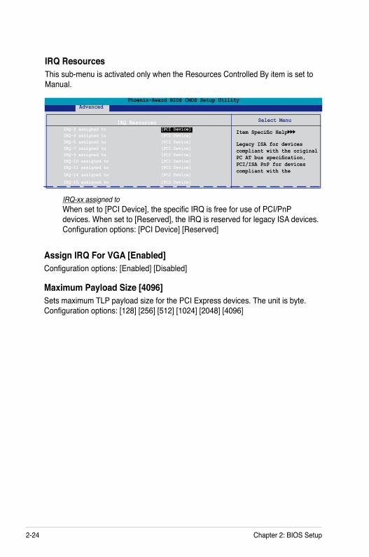
2-24 Chapter 2: BIOS Setup
Maximum Payload Size [4096]Sets maximum TLP payload size for the PCI Express devices. The unit is byte. Configuration options: [128] [256] [512] [1024] [2048] [4096]
Assign IRQ For VGA [Enabled]Configuration options: [Enabled] [Disabled]
IRQ ResourcesThis sub-menu is activated only when the Resources Controlled By item is set to Manual.
Select Menu
Item Specific Help
Legacy ISA for devices compliant with the original PC AT bus specification, PCI/ISA PnP for devices compliant with the
IRQ Resources IRQ-3 assigned to [PCI Device] IRQ-4 assigned to [PCI Device] IRQ-5 assigned to [PCI Device] IRQ-7 assigned to [PCI Device] IRQ-9 assigned to [PCI Device] IRQ-10 assigned to [PCI Device] IRQ-11 assigned to [PCI Device]
IRQ-14 assigned to [PCI Device]
IRQ-15 assigned to [PCI Device]
Phoenix-Award BIOS CMOS Setup Utility Advanced
IRQ-xx assigned toWhen set to [PCI Device], the specific IRQ is free for use of PCI/PnP devices. When set to [Reserved], the IRQ is reserved for legacy ISA devices. Configuration options: [PCI Device] [Reserved]
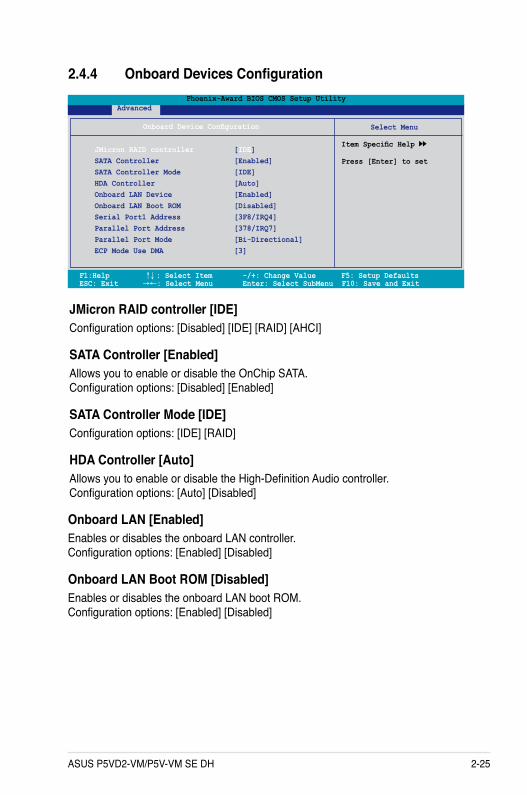
ASUS P5VD2-VM/P5V-VM SE DH 2-25
F1:Help ↑↓ : Select Item -/+: Change Value F5: Setup Defaults ESC: Exit →←: Select Menu Enter: Select SubMenu F10: Save and Exit
Select Menu
Item Specific Help
Press [Enter] to set
Onboard Device Configuration
JMicron RAID controller [IDE] SATA Controller [Enabled] SATA Controller Mode [IDE] HDA Controller [Auto] Onboard LAN Device [Enabled] Onboard LAN Boot ROM [Disabled] Serial Port1 Address [3F8/IRQ4] Parallel Port Address [378/IRQ7] Parallel Port Mode [Bi-Directional] ECP Mode Use DMA [3]
Phoenix-Award BIOS CMOS Setup Utility Advanced
2.4.4 Onboard Devices Configuration
JMicron RAID controller [IDE]Configuration options: [Disabled] [IDE] [RAID] [AHCI]
SATA Controller [Enabled]Allows you to enable or disable the OnChip SATA. Configuration options: [Disabled] [Enabled]
SATA Controller Mode [IDE]Configuration options: [IDE] [RAID]
HDA Controller [Auto]Allows you to enable or disable the High-Definition Audio controller. Configuration options: [Auto] [Disabled]
Onboard LAN [Enabled]Enables or disables the onboard LAN controller. Configuration options: [Enabled] [Disabled]
Onboard LAN Boot ROM [Disabled]Enables or disables the onboard LAN boot ROM. Configuration options: [Enabled] [Disabled]
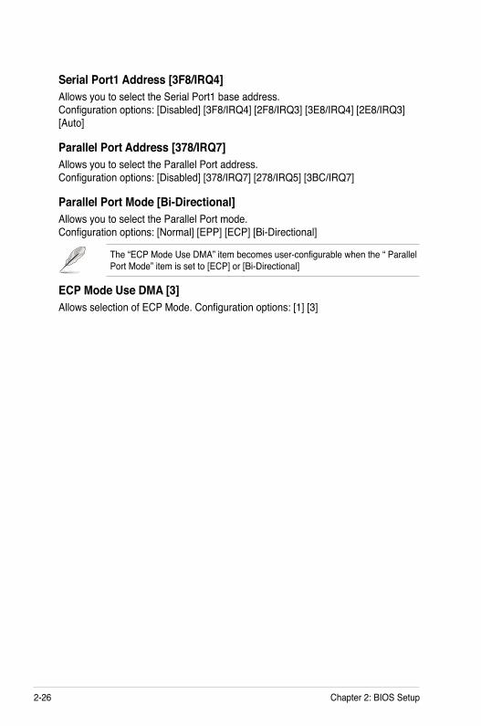
2-26 Chapter 2: BIOS Setup
Serial Port1 Address [3F8/IRQ4]Allows you to select the Serial Port1 base address. Configuration options: [Disabled] [3F8/IRQ4] [2F8/IRQ3] [3E8/IRQ4] [2E8/IRQ3] [Auto]
Parallel Port Address [378/IRQ7]Allows you to select the Parallel Port address. Configuration options: [Disabled] [378/IRQ7] [278/IRQ5] [3BC/IRQ7]
Parallel Port Mode [Bi-Directional]Allows you to select the Parallel Port mode. Configuration options: [Normal] [EPP] [ECP] [Bi-Directional]
The “ECP Mode Use DMA” item becomes user-configurable when the “ Parallel Port Mode” item is set to [ECP] or [Bi-Directional]
ECP Mode Use DMA [3]Allows selection of ECP Mode. Configuration options: [1] [3]
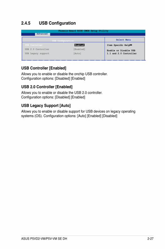
ASUS P5VD2-VM/P5V-VM SE DH 2-27
Select Menu
Item Specific Help
Enable or Disable USB 1.1 and 2.0 Controller
Phoenix-Award BIOS CMOS Setup Utility Advanced
USB Configuration
USB Contoller [Enabled]
USB 2.0 Controller [Enabled]
USB Legacy support [Auto]
2.4.5 USB Configuration
USB Controller [Enabled]Allows you to enable or disable the onchip USB controller. Configuration options: [Disabled] [Enabled]
USB 2.0 Controller [Enabled]Allows you to enable or disable the USB 2.0 controller. Configuration options: [Disabled] [Enabled]
USB Legacy Support [Auto]Allows you to enable or disable support for USB devices on legacy operating systems (OS). Configuration options: [Auto] [Enabled] [Disabled]
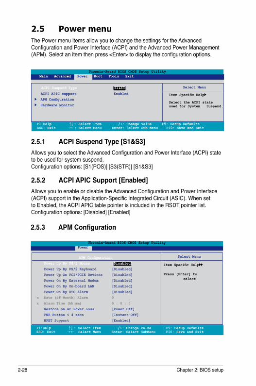
2-28 Chapter 2: BIOS setup
2.5 Power menuThe Power menu items allow you to change the settings for the Advanced Configuration and Power Interface (ACPI) and the Advanced Power Management (APM). Select an item then press <Enter> to display the configuration options.
Select Menu
Item Specific Help
Select the ACPI state used for System Suspend.
F1:Help ↑↓ : Select Item -/+: Change Value F5: Setup Defaults ESC: Exit →←: Select Menu Enter: Select Sub-menu F10: Save and Exit
Phoenix-Award BIOS CMOS Setup Utility Main Advanced Power Boot Tools Exit
ACPI APIC support Enabled APM Configuration Hardware Monitor
ACPI Suspend Type [S1&S3]
2.5.1 ACPI Suspend Type [S1&S3]Allows you to select the Advanced Configuration and Power Interface (ACPI) state to be used for system suspend. Configuration options: [S1(POS)] [S3(STR)] [S1&S3]
2.5.2 ACPI APIC Support [Enabled]Allows you to enable or disable the Advanced Configuration and Power Interface (ACPI) support in the Application-Specific Integrated Circuit (ASIC). When set to Enabled, the ACPI APIC table pointer is included in the RSDT pointer list. Configuration options: [Disabled] [Enabled]
2.5.3 APM Configuration
Select Menu
Item Specific Help
Press [Enter] to select
APM Configuration Power Up By PS/2 Mouse [Disabled] Power Up By PS/2 Keyboard [Disabled] Power Up On PCI/PCIE Devices [Disabled] Power On By External Modem [Disabled] Power On By On-board LAN [Disabled] Power On by RTC Alarm [Disabled]x Date (of Month) Alarm 0 x Alarm Time (hh:mm) 0 : 0 : 0 Restore on AC Power Loss [Power Off] PWR Button < 4 secs [Instant-Off] HPET Support [Enabled]
Phoenix-Award BIOS CMOS Setup Utility Power
F1:Help ↑↓ : Select Item -/+: Change Value F5: Setup Defaults ESC: Exit →←: Select Menu Enter: Select SubMenu F10: Save and Exit
ASUS P5VD2-VM/P5V-VM SE DH 2-29
Power Up On PCI/PCIE Devices [Disabled]Allows you to enable or disable the PME to wake up from S5 by PCI/PsCIE devices & NV Onboard LAN. Configuration options: [Disabled] [Enabled]
Power On By PS/2 Mouse [Disabled]When set to [Enabled], this parameter allows you to use the PS/2 mouse to turn on the system. This feature requires an ATX power supply that provides at least 1A on the +5VSB lead. Configuration options: [Disabled] [Double Click]
Power On By PS/2 Keyboard [Disabled]Allows you to disable the Power On by PS/2 keyboard function or set specific keys on the PS/2 keyboard to turn on the system. This feature requires an ATX power supply that provides at least 1A on the +5VSB lead. Configuration options: [Disabled] [Space Bar] [Ctrl-ESC] [Power Key]
Power On By External Modem [Disabled]This allows either settings of [Enabled] or [Disabled] for powering up the computer when the external modem receives a call while the computer is in Soft-off mode. Configuration options: [Disabled] [Enabled]
The computer cannot receive or transmit data until the computer and applications are fully running. Thus, connection cannot be made on the first try. Turning an external modem off and then back on while the computer is off causes an initialization string that turns the system power on.
Power On By On-board LAN [Disabled]Allows you to enable or disable the Wake Up On LAN function. Configuration options: [Disabled] [Enabled]
Power On By RTC Alarm [Disabled]Allows you to enable or disable RTC to generate a wake event. When this item is set to Enabled, the items Date of Month Alarm and Time (hh:mm:ss) Alarm items become user-configurable with set values. Configuration options: [Disabled] [Enabled]
Date of Month Alarm [0]To set the date of alarm, highlight this item and press <Enter> to display the Date of Month Alarm pop-up menu. Key-in a value within the specified range then press <Enter>. Configuration options: [Min=0] [Max=31]
The items Date of Month Alarm and Alarm Time become user-configurable only when the item Power On By RTC Alarm is enabled.
2-30 Chapter 2: BIOS setup
Alarm Time (hh:mm) To set the time of alarm:
1. Highlight this item and press <Enter> to display a pop-up menu for the hour field.2. Key-in a value (Min=0, Max=23), then press <Enter>.3. Press <TAB> to move to the minutes field then press <Enter>.4. Key-in a minute value (Min=0, Max=59), then press <Enter>.5. Press <TAB> to move to the seconds field then press <Enter>.6. Key-in a value (Min=0, Max=59), then press <Enter>.
Restore on AC Power Loss [Power Off]Allows you to enable or disable the Restore on AC Power Loss function. Configuration options: [Power Off] [Power On] [Last State]
PWR Button < 4 secs [Instant-Off]Allows you to set the event after the power button is pressed for more than 4 seconds. Configuration options: [Suspend] [Instant-Off]
HPET Support [Enabled]Allows you to enable or disable the HPET Support. Configuration options: [Enabled] [Disabled]
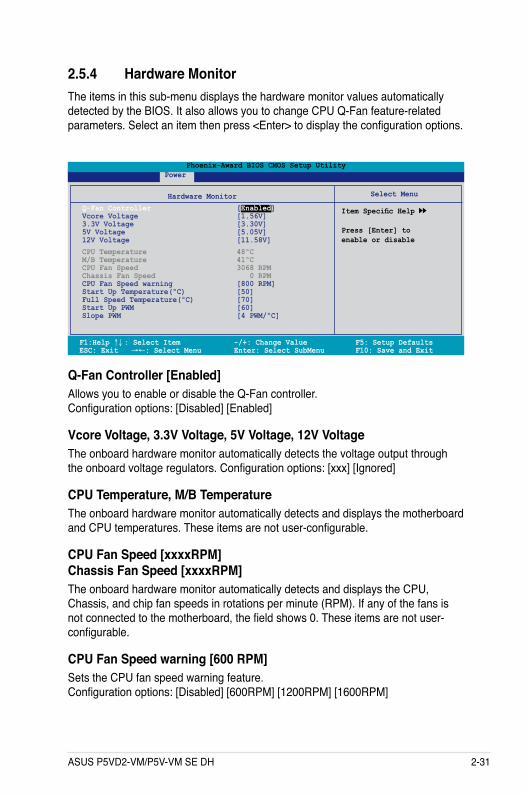
ASUS P5VD2-VM/P5V-VM SE DH 2-31
2.5.4 Hardware MonitorThe items in this sub-menu displays the hardware monitor values automatically detected by the BIOS. It also allows you to change CPU Q-Fan feature-related parameters. Select an item then press <Enter> to display the configuration options.
Q-Fan Controller [Enabled]Allows you to enable or disable the Q-Fan controller. Configuration options: [Disabled] [Enabled]
Vcore Voltage, 3.3V Voltage, 5V Voltage, 12V Voltage The onboard hardware monitor automatically detects the voltage output through the onboard voltage regulators. Configuration options: [xxx] [Ignored]
CPU Temperature, M/B TemperatureThe onboard hardware monitor automatically detects and displays the motherboard and CPU temperatures. These items are not user-configurable.
CPU Fan Speed [xxxxRPM] Chassis Fan Speed [xxxxRPM]The onboard hardware monitor automatically detects and displays the CPU, Chassis, and chip fan speeds in rotations per minute (RPM). If any of the fans is not connected to the motherboard, the field shows 0. These items are not user-configurable.
CPU Fan Speed warning [600 RPM] Sets the CPU fan speed warning feature. Configuration options: [Disabled] [600RPM] [1200RPM] [1600RPM]
F1:Help ↑↓ : Select Item -/+: Change Value F5: Setup Defaults ESC: Exit →←: Select Menu Enter: Select SubMenu F10: Save and Exit
Select Menu
Item Specific Help
Press [Enter] toenable or disable
Hardware MonitorQ-Fan Controller [Enabled] Vcore Voltage [1.56V] 3.3V Voltage [3.30V] 5V Voltage [5.05V] 12V Voltage [11.58V]CPU Temperature 48ºC M/B Temperature 41ºC CPU Fan Speed 3068 RPM Chassis Fan Speed 0 RPM CPU Fan Speed warning [800 RPM] Start Up Temperature(ºC) [50] Full Speed Temperature(ºC) [70] Start Up PWM [60] Slope PWM [4 PWM/ºC]
Phoenix-Award BIOS CMOS Setup Utility Power
2-32 Chapter 2: BIOS setup
Start Up Temperature(ºC) [50] Fan will start up when the temperature is over the set value. Configuration options: [Min=0] [Max=100]
Full Speed Temperature(ºC) [70] Fan will run at full speed when the temperature is over the set value. Configuration options: [Min=0] [Max=100]
Start Up PWM [80] Sets the PWM value when the fan starts up. Configuration options: [Min=0] [Max=127]
Slope PWM [4 PWM/ºC] Sets the PWM value when the temperature increases one value. Configuration options: [0 PWM/ºC] [1 PWM/ºC] [2 PWM/ºC] [4 PWM/ºC] [8 PWM/ºC] [16 PWM/ºC] [32 PWM/ºC] [64 PWM/ºC]
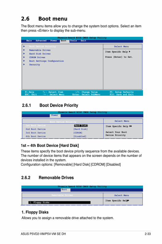
ASUS P5VD2-VM/P5V-VM SE DH 2-33
1st ~ 4th Boot Device [Hard Disk]These items specify the boot device priority sequence from the available devices. The number of device items that appears on the screen depends on the number of devices installed in the system. Configuration options: [Removable] [Hard Disk] [CDROM] [Disabled]
2.6 Boot menuThe Boot menu items allow you to change the system boot options. Select an item then press <Enter> to display the sub-menu.
Phoenix-Award BIOS CMOS Setup Utility Main Advanced Power Boot Tools Exit
Select Menu
Item Specific Help
Press [Enter] to Set.
Boot Device Priority Removable Drives Hard Disk Drives CDROM Drives Boot Settings Configuration Security
F1:Help ↑↓ : Select Item -/+: Change Value F5: Setup Defaults ESC: Exit →←: Select Menu Enter: Select SubMenu F10: Save and Exit
2.6.1 Boot Device Priority
Select Menu
Item Specific Help
Select Your BootDevice Priority
Boot Device Priority1st Boot Device [Hard Disk]2nd Boot Device [Hard Disk]3rd Boot Device [CDROM]4th Boot Device [Disabled]
Phoenix-Award BIOS CMOS Setup Utility Power
2.6.2 Removable Drives
1. Floppy DisksAllows you to assign a removable drive attached to the system.
Select Menu
Item Specific Help
Removable Drives
1. Floppy Disks
Phoenix-Award BIOS CMOS Setup Utility Boot
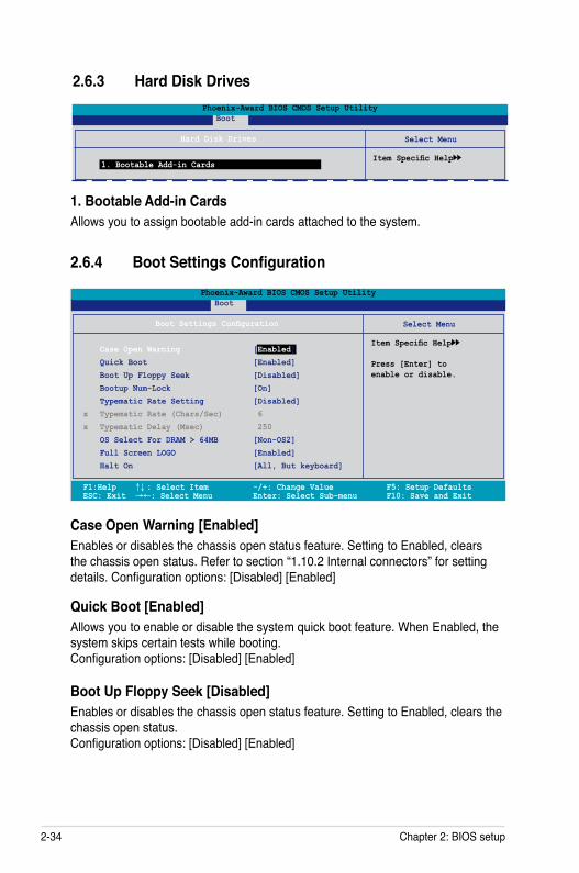
2-34 Chapter 2: BIOS setup
Case Open Warning [Enabled]Enables or disables the chassis open status feature. Setting to Enabled, clears the chassis open status. Refer to section “1.10.2 Internal connectors” for setting details. Configuration options: [Disabled] [Enabled]
Quick Boot [Enabled]Allows you to enable or disable the system quick boot feature. When Enabled, the system skips certain tests while booting. Configuration options: [Disabled] [Enabled]
Boot Up Floppy Seek [Disabled]Enables or disables the chassis open status feature. Setting to Enabled, clears the chassis open status. Configuration options: [Disabled] [Enabled]
1. Bootable Add-in Cards Allows you to assign bootable add-in cards attached to the system.
2.6.4 Boot Settings Configuration
F1:Help ↑↓ : Select Item -/+: Change Value F5: Setup Defaults ESC: Exit →←: Select Menu Enter: Select Sub-menu F10: Save and Exit
Select Menu
Item Specific Help
Press [Enter] toenable or disable.
Boot Settings Configuration
Case Open Warning [Enabled] Quick Boot [Enabled] Boot Up Floppy Seek [Disabled] Bootup Num-Lock [On] Typematic Rate Setting [Disabled]x Typematic Rate (Chars/Sec) 6x Typematic Delay (Msec) 250 OS Select For DRAM > 64MB [Non-OS2] Full Screen LOGO [Enabled] Halt On [All, But keyboard]
Phoenix-Award BIOS CMOS Setup Utility Boot
2.6.3 Hard Disk Drives
Select Menu
Item Specific Help
Hard Disk Drives
1. Bootable Add-in Cards
Phoenix-Award BIOS CMOS Setup Utility Boot
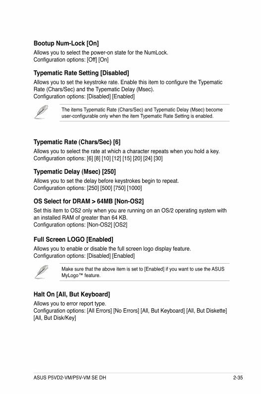
ASUS P5VD2-VM/P5V-VM SE DH 2-35
Typematic Rate (Chars/Sec) [6]Allows you to select the rate at which a character repeats when you hold a key. Configuration options: [6] [8] [10] [12] [15] [20] [24] [30]
Typematic Delay (Msec) [250]Allows you to set the delay before keystrokes begin to repeat. Configuration options: [250] [500] [750] [1000]
OS Select for DRAM > 64MB [Non-OS2]Set this item to OS2 only when you are running on an OS/2 operating system with an installed RAM of greater than 64 KB. Configuration options: [Non-OS2] [OS2]
Bootup Num-Lock [On]Allows you to select the power-on state for the NumLock. Configuration options: [Off] [On]
Typematic Rate Setting [Disabled]Allows you to set the keystroke rate. Enable this item to configure the Typematic Rate (Chars/Sec) and the Typematic Delay (Msec). Configuration options: [Disabled] [Enabled]
The items Typematic Rate (Chars/Sec) and Typematic Delay (Msec) become user-configurable only when the item Typematic Rate Setting is enabled.
Full Screen LOGO [Enabled]Allows you to enable or disable the full screen logo display feature. Configuration options: [Disabled] [Enabled]
Make sure that the above item is set to [Enabled] if you want to use the ASUS MyLogo™ feature.
Halt On [All, But Keyboard]Allows you to error report type. Configuration options: [All Errors] [No Errors] [All, But Keyboard] [All, But Diskette] [All, But Disk/Key]
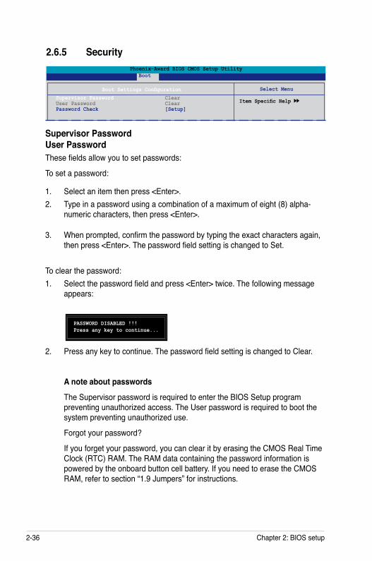
2-36 Chapter 2: BIOS setup
2. Press any key to continue. The password field setting is changed to Clear.
A note about passwords
The Supervisor password is required to enter the BIOS Setup program preventing unauthorized access. The User password is required to boot the system preventing unauthorized use.
Forgot your password?
If you forget your password, you can clear it by erasing the CMOS Real Time Clock (RTC) RAM. The RAM data containing the password information is powered by the onboard button cell battery. If you need to erase the CMOS RAM, refer to section “1.9 Jumpers” for instructions.
2.6.5 Security
Select Menu
Item Specific Help
Boot Settings ConfigurationSupervisor Password Clear User Password Clear Password Check [Setup]
Phoenix-Award BIOS CMOS Setup Utility Boot
PASSWORD DISABLED !!!Press any key to continue...
Supervisor Password User PasswordThese fields allow you to set passwords:
To set a password:
1. Select an item then press <Enter>.2. Type in a password using a combination of a maximum of eight (8) alpha-
numeric characters, then press <Enter>.
3. When prompted, confirm the password by typing the exact characters again, then press <Enter>. The password field setting is changed to Set.
To clear the password:1. Select the password field and press <Enter> twice. The following message
appears:
ASUS P5VD2-VM/P5V-VM SE DH 2-37
Password CheckThis field requires you to enter the password before entering the BIOS setup or the system. Select [Setup] to require the password before entering the BIOS Setup. Select [System] to require the password before entering the system. Configuration options: [Setup] [System]
2-38 Chapter 2: BIOS setup
2.7 Tools menu
2.7.1 ASUS EZ Flash 2Allows you to run ASUS EZ Flash 2. When you press <Enter>, a confirmation message appears. Use the left/right arrow key to select between [Yes] or [No], then press <Enter> to confirm your choice.
ASUSTek EZ Flash 2 BIOS ROM Utility V3.00
Current ROM Update ROM
A:B:
Note [Enter] Select or Load [B] Backup [ESC] Exit
[Tab] Switch [Up/Down/Home/End] Move
FLASH TYPE: Winbond W39V040C/FC (4Mb)
PATH: A:\
BOARD: P5VD2-VMVER: 0105DATE: 09/13/06
BOARD: UnknownVER: UnknownDATE: Unknown
The model name may differ.
Select Menu
Item Specific Help
ASUS EZ Flash 2
F1:Help ↑↓ : Select Item -/+: Change Value F5: Setup Defaults ESC: Exit →←: Select Menu Enter: Select Sub-menu F10: Save and Exit
Phoenix-Award BIOS CMOS Setup Utility Main Advanced Power Boot Tools Exit
ASUS P5VD2-VM/P5V-VM SE DH 2-39
Phoenix-Award BIOS CMOS Setup Utility Main Advanced Power Boot Tools Exit
Select Menu
Item Specific Help
This option save datato CMOS and exitingthe setup menu.
Exit & Save Changes Exit & Discard Changes Load Setup Default Discard Changes
F1:Help ↑↓ : Select Item -/+: Change Value F5: Setup Defaults ESC: Exit →←: Select Menu Enter: Select Sub-menu F10: Save and Exit
2.8 Exit menuThe Exit menu items allow you to load the optimal or failsafe default values for the BIOS items, and save or discard your changes to the BIOS items.
Exit & Save ChangesOnce you are finished making your selections, choose this option from the Exit menu to ensure the values you selected are saved to the CMOS RAM. An onboard backup battery sustains the CMOS RAM so it stays on even when the PC is turned off. When you select this option, a confirmation window appears. Select YES to save changes and exit.
Pressing <Esc> does not immediately exit this menu. Select one of the options from this menu or <F10> from the legend bar to exit.
Exit & Discard ChangesSelect this option only if you do not want to save the changes that you made to the Setup program. If you made changes to fields other than System Date, System Time, and Password, the BIOS asks for a confirmation before exiting.
If you attempt to exit the Setup program without saving your changes, the program prompts you with a message asking if you want to save your changes before exiting. Press <Enter> to save the changes while exiting.
2-40 Chapter 2: BIOS setup
Load Setup Defaults This option allows you to load the default values for each of the parameters on the Setup menus. When you select this option or if you press <F5>, a confirmation window appears. Select YES to load default values. Select Exit & Save Changes or make other changes before saving the values to the non-volatile RAM.
Discard ChangesThis option allows you to discard the selections you made and restore the previously saved values. After selecting this option, a confirmation appears. Select YES to discard any changes and load the previously saved values.
ASUS P5VD2-VM/P5V-VM SE DH 3-1
3Software support
This chapter describes the contents of the support CD that comes with the motherboard package.
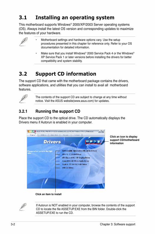
3-2 Chapter 3: Software support
If Autorun is NOT enabled in your computer, browse the contents of the support CD to locate the file ASSETUP.EXE from the BIN folder. Double-click the ASSETUP.EXE to run the CD.
Click an item to install
3.1 Installing an operating systemThis motherboard supports Windows® 2000/XP/2003 Server operating systems (OS). Always install the latest OS version and corresponding updates to maximize the features of your hardware.
3.2 Support CD informationThe support CD that came with the motherboard package contains the drivers, software applications, and utilities that you can install to avail all motherboard features.
3.2.1 Running the support CDPlace the support CD to the optical drive. The CD automatically displays the Drivers menu if Autorun is enabled in your computer.
• Motherboard settings and hardware options vary. Use the setup procedures presented in this chapter for reference only. Refer to your OS documentation for detailed information.
• Make sure that you install Windows® 2000 Service Pack 4 or the Windows® XP Service Pack 1 or later versions before installing the drivers for better compatibility and system stability.
The contents of the support CD are subject to change at any time without notice. Visit the ASUS website(www.asus.com) for updates.
Click an icon to display support CD/motherboard information
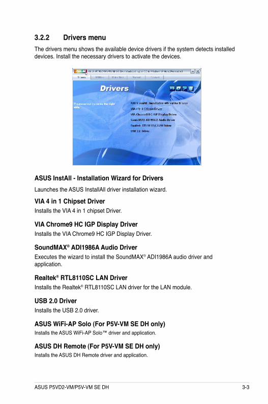
ASUS P5VD2-VM/P5V-VM SE DH 3-3
3.2.2 Drivers menuThe drivers menu shows the available device drivers if the system detects installed devices. Install the necessary drivers to activate the devices.
ASUS InstAll - Installation Wizard for DriversLaunches the ASUS InstallAll driver installation wizard.
VIA 4 in 1 Chipset DriverInstalls the VIA 4 in 1 chipset Driver.
VIA Chrome9 HC IGP Display DriverInstalls the VIA Chrome9 HC IGP Display Driver.
SoundMAX® ADI1986A Audio DriverExecutes the wizard to install the SoundMAX® ADI1986A audio driver and application.
Realtek® RTL8110SC LAN DriverInstalls the Realtek® RTL8110SC LAN driver for the LAN module.
USB 2.0 DriverInstalls the USB 2.0 driver.
ASUS WiFi-AP Solo (For P5V-VM SE DH only)Installs the ASUS WiFi-AP Solo™ driver and application.
ASUS DH Remote (For P5V-VM SE DH only)Installs the ASUS DH Remote driver and application.
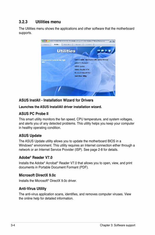
3-4 Chapter 3: Software support
3.2.3 Utilities menuThe Utilities menu shows the applications and other software that the motherboard supports.
ASUS InstAll - Installation Wizard for DriversLaunches the ASUS InstallAll driver installation wizard.
ASUS PC Probe IIThis smart utility monitors the fan speed, CPU temperature, and system voltages, and alerts you of any detected problems. This utility helps you keep your computer in healthy operating condition.
ASUS Update The ASUS Update utility allows you to update the motherboard BIOS in a Windows® environment. This utility requires an Internet connection either through a network or an Internet Service Provider (ISP). See page 2-8 for details.
Adobe® Reader V7.0Installs the Adobe® Acrobat® Reader V7.0 that allows you to open, view, and print documents in Portable Document Formant (PDF).
Microsoft DirectX 9.0c Installs the Microsoft® DirectX 9.0c driver.
Anti-Virus UtilityThe anti-virus application scans, identifies, and removes computer viruses. View the online help for detailed information.
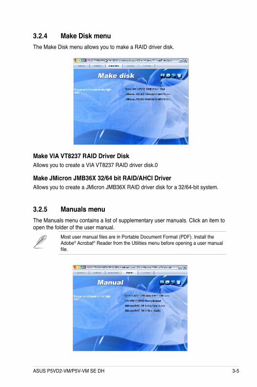
ASUS P5VD2-VM/P5V-VM SE DH 3-5
3.2.4 Make Disk menuThe Make Disk menu allows you to make a RAID driver disk.
Make VIA VT8237 RAID Driver DiskAllows you to create a VIA VT8237 RAID driver disk.0
Make JMicron JMB36X 32/64 bit RAID/AHCI DriverAllows you to create a JMicron JMB36X RAID driver disk for a 32/64-bit system.
3.2.5 Manuals menuThe Manuals menu contains a list of supplementary user manuals. Click an item to open the folder of the user manual.
Most user manual files are in Portable Document Format (PDF). Install the Adobe® Acrobat® Reader from the Utilities menu before opening a user manual file.
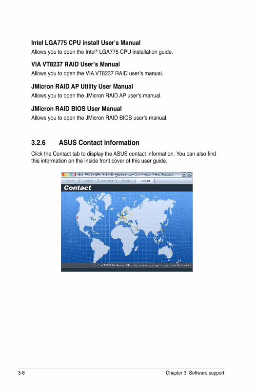
3-6 Chapter 3: Software support
3.2.6 ASUS Contact informationClick the Contact tab to display the ASUS contact information. You can also find this information on the inside front cover of this user guide.
VIA VT8237 RAID User’s ManualAllows you to open the VIA VT8237 RAID user’s manual.
JMicron RAID AP Utility User ManualAllows you to open the JMicron RAID AP user’s manual.
JMicron RAID BIOS User ManualAllows you to open the JMicron RAID BIOS user’s manual.
Intel LGA775 CPU install User’s ManualAllows you to open the Intel® LGA775 CPU installation guide.
ASUS P5VD2-VM/P5V-VM SE DH 3-7
3.3 RAID configurationsThe motherboard supports the following RAID configurations.
RAID 0 (Data striping) optimizes two identical hard disk drives to read and write data in parallel, interleaved stacks. Two hard disks perform the same work as a single drive but at a sustained data transfer rate, double that of a single disk alone, thus improving data access and storage. Use of two new identical hard disk drives is required for this setup.
RAID 1 (Data mirroring) copies and maintains an identical image of data from one drive to a second drive. If one drive fails, the disk array management software directs all applications to the surviving drive as it contains a complete copy of the data in the other drive. This RAID configuration provides data protection and increases fault tolerance to the entire system. Use two new drives or use an existing drive and a new drive for this setup. The new drive must be of the same size or larger than the existing drive.
JBOD (Spanning) stands for Just a Bunch of Disks and refers to hard disk drives that are not yet configured as a RAID set. This configuration stores the same data redundantly on multiple disks that appear as a single disk on the operating system. Spanning does not deliver any advantage over using separate disks independently and does not provide fault tolerance or other RAID performance benefits.
3-8 Chapter 3: Software support
3.3.1 Installing hard disksThe motherboard supports RAID function on Serial ATA hard disk drives. For optimal performance, install identical drives of the same model and capacity when creating a disk array.
Installing Serial ATA (SATA) hard disksTo install the SATA hard disks for a RAID configuration:
1. Install the SATA hard disks into the drive bays.2. Connect the SATA signal cables.3. Connect a SATA power cable to the power connector on each drive.
If you want to boot the system from a hard disk drive included in a RAID set, copy first the RAID driver from the support CD to a floppy disk before you install an operating system to a selected hard disk drive. Refer to section “3.4 Creating a RAID driver disk” for details.
Refer to the RAID controllers user manual in the motherboard support CD for detailed information on RAID configurations. See section “3.2.5 Manuals menu”.
Entering VIA Tech RAID BIOS Utility1. Boot-up your computer. 2. During POST, press <Tab> to enter VIA RAID configuration utility.
The following menu options will appear.
The RAID BIOS information on the setup screen shown below is for reference only. What you see on your screen may not exactly match what is shown here.
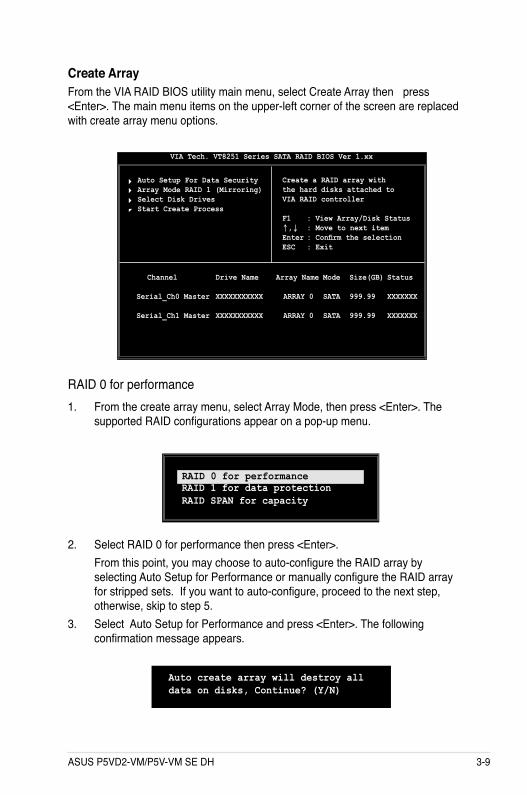
ASUS P5VD2-VM/P5V-VM SE DH 3-9
Create Array From the VIA RAID BIOS utility main menu, select Create Array then press <Enter>. The main menu items on the upper-left corner of the screen are replaced with create array menu options.
RAID 0 for performance 1. From the create array menu, select Array Mode, then press <Enter>. The
supported RAID configurations appear on a pop-up menu.
2. Select RAID 0 for performance then press <Enter>. From this point, you may choose to auto-configure the RAID array by
selecting Auto Setup for Performance or manually configure the RAID array for stripped sets. If you want to auto-configure, proceed to the next step, otherwise, skip to step 5.
3. Select Auto Setup for Performance and press <Enter>. The following confirmation message appears.
Auto create array will destroy all data on disks, Continue? (Y/N)
Auto Setup For Data Security Array Mode RAID 1 (Mirroring) Select Disk Drives Start Create Process
VIA Tech. VT8251 Series SATA RAID BIOS Ver 1.xx
Create a RAID array withthe hard disks attached toVIA RAID controller
F1 : View Array/Disk Status↑,↓ : Move to next itemEnter : Confirm the selectionESC : Exit
Channel Drive Name Array Name Mode Size(GB) Status
Serial_Ch0 Master XXXXXXXXXXX ARRAY 0 SATA 999.99 XXXXXXX
Serial_Ch1 Master XXXXXXXXXXX ARRAY 0 SATA 999.99 XXXXXXX
RAID 1 for data protection RAID SPAN for capacity
RAID 0 for performance
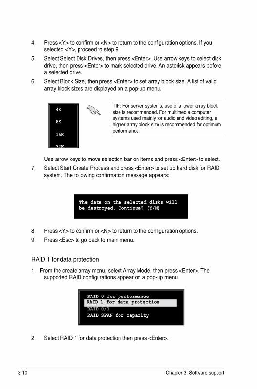
3-10 Chapter 3: Software support
Use arrow keys to move selection bar on items and press <Enter> to select.7. Select Start Create Process and press <Enter> to set up hard disk for RAID
system. The following confirmation message appears:
8. Press <Y> to confirm or <N> to return to the configuration options. 9. Press <Esc> to go back to main menu.
RAID 1 for data protection1. From the create array menu, select Array Mode, then press <Enter>. The
supported RAID configurations appear on a pop-up menu.
The data on the selected disks will be destroyed. Continue? (Y/N)
4K 8K 16K 32K
RAID 0 for performance RAID 1 for data protection RAID 0/1 RAID SPAN for capacity
RAID 1 for data protection
TIP: For server systems, use of a lower array block size is recommended. For multimedia computer systems used mainly for audio and video editing, a higher array block size is recommended for optimum performance.
4. Press <Y> to confirm or <N> to return to the configuration options. If you selected <Y>, proceed to step 9.
5. Select Select Disk Drives, then press <Enter>. Use arrow keys to select disk drive, then press <Enter> to mark selected drive. An asterisk appears before a selected drive.
6. Select Block Size, then press <Enter> to set array block size. A list of valid array block sizes are displayed on a pop-up menu.
2. Select RAID 1 for data protection then press <Enter>.
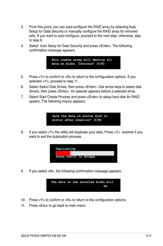
ASUS P5VD2-VM/P5V-VM SE DH 3-11
8. If you select <Y> the utility will duplicate your data. Press <Y> anytime if you want to exit the duplication process.
3. From this point, you can auto-configure the RAID array by selecting Auto Setup for Data Security or manually configure the RAID array for mirrored sets. If you want to auto-configure, proceed to the next step, otherwise, skip to step 6.
4. Select Auto Setup for Data Security and press <Enter>. The following confirmation message appears.
The data on the selected disks will be
10. Press <Y> to confirm or <N> to return to the configuration options. 11. Press <Esc> to go back to main menu.
Auto create array will destroy all data on disks, Continue? (Y/N)
5. Press <Y> to confirm or <N> to return to the configuration options. If you selected <Y>, proceed to step 11.
6. Select Select Disk Drives, then press <Enter>. Use arrow keys to select disk drive/s, then press <Enter>. An asterisk appears before a selected drive.
7. Select Start Create Process and press <Enter> to setup hard disk for RAID system. The following inquiry appears:
Save the data on source disk to mirror after creation? (Y/N)
Duplicating... RAID 1 for data protection Press Yes(Y) to Escape
9. If you select <N>, the following confirmation message appears.
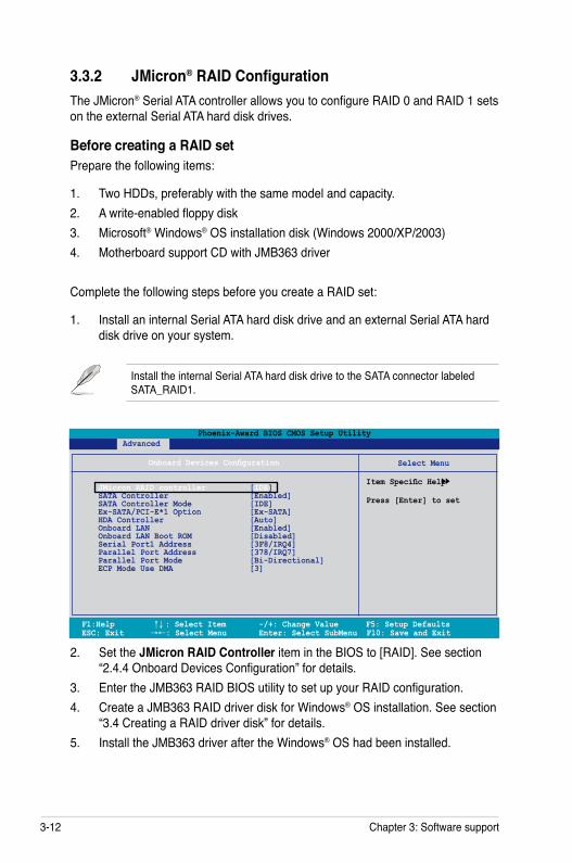
3-12 Chapter 3: Software support
3.3.2 JMicron® RAID ConfigurationThe JMicron® Serial ATA controller allows you to configure RAID 0 and RAID 1 sets on the external Serial ATA hard disk drives.
Before creating a RAID setPrepare the following items:
1. Two HDDs, preferably with the same model and capacity. 2. A write-enabled floppy disk3. Microsoft® Windows® OS installation disk (Windows 2000/XP/2003)4. Motherboard support CD with JMB363 driver
Complete the following steps before you create a RAID set:
1. Install an internal Serial ATA hard disk drive and an external Serial ATA hard disk drive on your system.
Install the internal Serial ATA hard disk drive to the SATA connector labeled SATA_RAID1.
2. Set the JMicron RAID Controller item in the BIOS to [RAID]. See section “2.4.4 Onboard Devices Configuration” for details.
3. Enter the JMB363 RAID BIOS utility to set up your RAID configuration.4. Create a JMB363 RAID driver disk for Windows® OS installation. See section
“3.4 Creating a RAID driver disk” for details.5. Install the JMB363 driver after the Windows® OS had been installed.
F1:Help ↑↓ : Select Item -/+: Change Value F5: Setup Defaults ESC: Exit →←: Select Menu Enter: Select SubMenu F10: Save and Exit
Select Menu
Item Specific Help
Press [Enter] to set
Onboard Devices Configuration
JMicron RAID controller [IDE] SATA Controller [Enabled] SATA Controller Mode [IDE] Ex-SATA/PCI-E*1 Option [Ex-SATA] HDA Controller [Auto] Onboard LAN [Enabled] Onboard LAN Boot ROM [Disabled] Serial Port1 Address [3F8/IRQ4] Parallel Port Address [378/IRQ7] Parallel Port Mode [Bi-Directional] ECP Mode Use DMA [3]
Phoenix-Award BIOS CMOS Setup Utility Advanced
ASUS P5VD2-VM/P5V-VM SE DH 3-13
Entering the JMB363 RAID BIOS utility1. During POST, press <Ctrl-J> to enter the JBM363 RAID BIOS menu.
2. The main JMB363 RAID BIOS menu appears. 3. Use the arrow keys to move the color bar and navigate through the items.
Creating a RAID set1. In the main JMB363 RAID BIOS menu, highlight Create RAID Disk Drive
using the up/down arrow key then press <Enter>.
JMicron Technology Corp. PCI-to-SATA II/IDE RAID Controller BIOS v0.97Copyright (C) 2004-2005 JMicron Technology http://www. jmicron.com
HDD0 : HDS722516VLSA80 164 GB Non-RAID HDD1 : HDS722516DLA380 164 GB Non-RAID
Press <Ctrl-J> to enter RAID Setup Utility...
[Main Menu]Create RAID Disk Drive Delete RAID Disk Drive Revert HDD to Non-RAID Repair Mirror Conflict
Save and Exit Setup Exit Without Saving
JMicron Technology Corp. PCI-to-SATA II/IDE RAID Controller BIOS v0.97
[ TAB]-Switch Window [↑↓]-Select Item [ENTER]-Action [ESC]-Exit
[Hard Disk Drive List] Model Name Capacity Type/Status HDD0: HDS722516VLSA80 164 GB Non-RAID HDD1: HDS722516DLA380 164 GB Non-RAID
[RAID Disk Drive List]
[Main Menu]Create RAID Disk Drive Delete RAID Disk Drive Revert HDD to Non-RAID Repair Mirror ConflictSave and Exit Setup Exit Without Saving
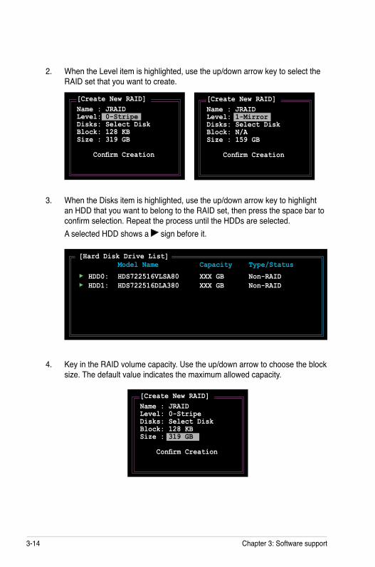
3-14 Chapter 3: Software support
2. When the Level item is highlighted, use the up/down arrow key to select the RAID set that you want to create.
3. When the Disks item is highlighted, use the up/down arrow key to highlight an HDD that you want to belong to the RAID set, then press the space bar to confirm selection. Repeat the process until the HDDs are selected.
A selected HDD shows a sign before it.
4. Key in the RAID volume capacity. Use the up/down arrow to choose the block size. The default value indicates the maximum allowed capacity.
[Create New RAID]Name : JRAID Level: 0-Stripe Disks: Select Disk Block: 128 KB Size : 319 GB Confirm Creation
[Create New RAID]Name : JRAID Level: 1-Mirror Disks: Select Disk Block: N/A Size : 159 GB Confirm Creation
[Hard Disk Drive List] Model Name Capacity Type/Status
HDD0: HDS722516VLSA80 XXX GB Non-RAID HDD1: HDS722516DLA380 XXX GB Non-RAID
[Create New RAID]Name : JRAID Level: 0-Stripe Disks: Select Disk Block: 128 KB Size : 319 GB Confirm Creation

ASUS P5VD2-VM/P5V-VM SE DH 3-15
5. When done, press <Enter> to confirm the creation of the RAID set. A dialogue box appears to confirm the action. Press <Y> to confirm; otherwise, press <N>.
Pressing <Y> deletes all the data in the HDDs.
6. The following screen appears, displaying the relevant information about the RAID set you created.
[RAID Disk Drive List] Model Name RAID Level Capacity Status Members(HDDx)RDD0: JRAID 0-Stripe XXX GB Normal 01
JMicron Technology Corp. PCI-to-SATA II/IDE RAID Controller BIOS v0.97
[Hard Disk Drive List] Model Name Capacity Type/Status HDD0: HDS722516VLSA80 164 GB Non-RAID HDD1: HDS722516DLA380 164 GB Non-RAID
[RAID Disk Drive List]
[Create New RAID]Name: JRAID Level: 0-Stripe Disks: Select Disk Block: 128 KB Size : 319 GB Confirm Creation
Create RAID on the selected HDD (Y/N)? Y
[ TAB]-Switch Window [↑↓]-Select Item [ENTER]-Action [ESC]-Exit
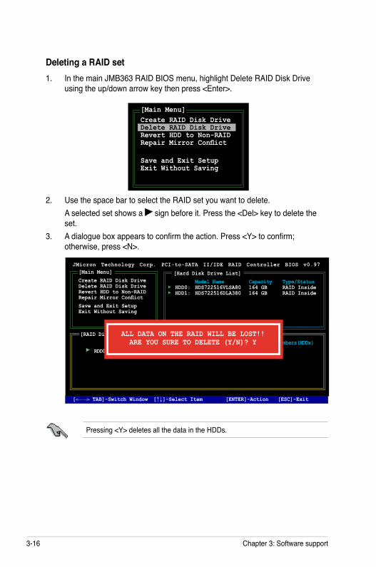
3-16 Chapter 3: Software support
Deleting a RAID set1. In the main JMB363 RAID BIOS menu, highlight Delete RAID Disk Drive
using the up/down arrow key then press <Enter>.
2. Use the space bar to select the RAID set you want to delete. A selected set shows a sign before it. Press the <Del> key to delete the
set.3. A dialogue box appears to confirm the action. Press <Y> to confirm;
otherwise, press <N>.
Pressing <Y> deletes all the data in the HDDs.
[Main Menu]Create RAID Disk Drive Delete RAID Disk Drive Revert HDD to Non-RAID Repair Mirror Conflict
Save and Exit Setup Exit Without Saving
JMicron Technology Corp. PCI-to-SATA II/IDE RAID Controller BIOS v0.97
[Hard Disk Drive List] Model Name Capacity Type/Status HDD0: HDS722516VLSA80 164 GB RAID Inside HDD1: HDS722516DLA380 164 GB RAID Inside
[RAID Disk Drive List] Model Name RAID Level Capacity Status Members(HDDx) RDD0: JRAID 0-Stripe XXX GB Normal 01
[Main Menu]Create RAID Disk Drive Delete RAID Disk Drive Revert HDD to Non-RAID Repair Mirror ConflictSave and Exit Setup Exit Without Saving
ALL DATA ON THE RAID WILL BE LOST!!ARE YOU SURE TO DELETE (Y/N)? Y
[ TAB]-Switch Window [↑↓]-Select Item [ENTER]-Action [ESC]-Exit
Resetting disks to non-RAID
To reset disks to non-RAID:1. In the main JMB363 RAID BIOS menu, highlight Revert HDD to non-RAID
using the up/down arrow key then press <Enter>.
2. Use the space bar to select the HDD that you want to reset to non-RAID. A selected HDD shows a sign before it. 3. A dialogue box appears to confirm the action. Press <Y> to confirm;
otherwise, press <N>.
[Main Menu]Create RAID Disk Drive Delete RAID Disk Drive Revert HDD to Non-RAID Repair Mirror Conflict
Save and Exit Setup Exit Without Saving
Pressing <Y> deletes all the data in the HDD.
An HDD that has been previously configured as part of another RAID set in another platform is called a broken RAID HDD. When you install a broken RAID HDD, you cannot select this HDD when configuring a RAID set through the JMB363 utility.
If you still want to use this broken RAID HDD as part of the RAID set configured through the JMB363, you may do so by resetting the disk to non-RAID. You will, however, lose all data and previous RAID configurations.
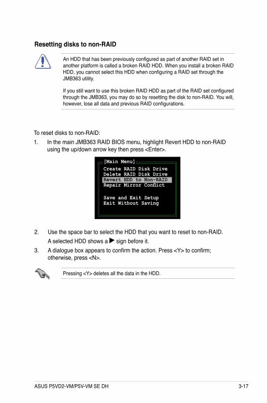
ASUS P5VD2-VM/P5V-VM SE DH 3-17
Deleting a RAID set1. In the main JMB363 RAID BIOS menu, highlight Delete RAID Disk Drive
using the up/down arrow key then press <Enter>.
2. Use the space bar to select the RAID set you want to delete. A selected set shows a sign before it. Press the <Del> key to delete the
set.3. A dialogue box appears to confirm the action. Press <Y> to confirm;
otherwise, press <N>.
Pressing <Y> deletes all the data in the HDDs.
[Main Menu]Create RAID Disk Drive Delete RAID Disk Drive Revert HDD to Non-RAID Repair Mirror Conflict
Save and Exit Setup Exit Without Saving
JMicron Technology Corp. PCI-to-SATA II/IDE RAID Controller BIOS v0.97
[Hard Disk Drive List] Model Name Capacity Type/Status HDD0: HDS722516VLSA80 164 GB RAID Inside HDD1: HDS722516DLA380 164 GB RAID Inside
[RAID Disk Drive List] Model Name RAID Level Capacity Status Members(HDDx) RDD0: JRAID 0-Stripe XXX GB Normal 01
[Main Menu]Create RAID Disk Drive Delete RAID Disk Drive Revert HDD to Non-RAID Repair Mirror ConflictSave and Exit Setup Exit Without Saving
ALL DATA ON THE RAID WILL BE LOST!!ARE YOU SURE TO DELETE (Y/N)? Y
[ TAB]-Switch Window [↑↓]-Select Item [ENTER]-Action [ESC]-Exit
Resetting disks to non-RAID
To reset disks to non-RAID:1. In the main JMB363 RAID BIOS menu, highlight Revert HDD to non-RAID
using the up/down arrow key then press <Enter>.
2. Use the space bar to select the HDD that you want to reset to non-RAID. A selected HDD shows a sign before it. 3. A dialogue box appears to confirm the action. Press <Y> to confirm;
otherwise, press <N>.
[Main Menu]Create RAID Disk Drive Delete RAID Disk Drive Revert HDD to Non-RAID Repair Mirror Conflict
Save and Exit Setup Exit Without Saving
Pressing <Y> deletes all the data in the HDD.
An HDD that has been previously configured as part of another RAID set in another platform is called a broken RAID HDD. When you install a broken RAID HDD, you cannot select this HDD when configuring a RAID set through the JMB363 utility.
If you still want to use this broken RAID HDD as part of the RAID set configured through the JMB363, you may do so by resetting the disk to non-RAID. You will, however, lose all data and previous RAID configurations.
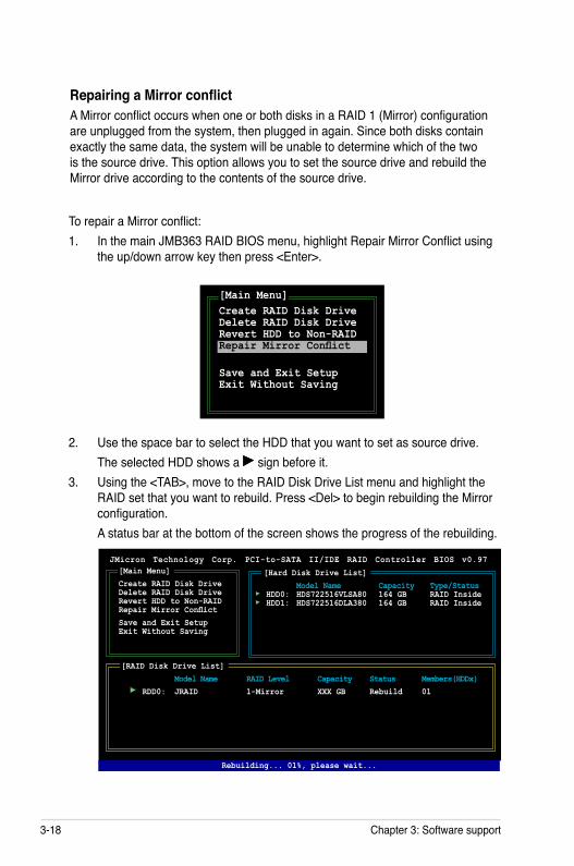
3-18 Chapter 3: Software support
Repairing a Mirror conflictA Mirror conflict occurs when one or both disks in a RAID 1 (Mirror) configuration are unplugged from the system, then plugged in again. Since both disks contain exactly the same data, the system will be unable to determine which of the two is the source drive. This option allows you to set the source drive and rebuild the Mirror drive according to the contents of the source drive.
To repair a Mirror conflict:1. In the main JMB363 RAID BIOS menu, highlight Repair Mirror Conflict using
the up/down arrow key then press <Enter>.
2. Use the space bar to select the HDD that you want to set as source drive. The selected HDD shows a sign before it. 3. Using the <TAB>, move to the RAID Disk Drive List menu and highlight the
RAID set that you want to rebuild. Press <Del> to begin rebuilding the Mirror configuration.
A status bar at the bottom of the screen shows the progress of the rebuilding.
[Main Menu]Create RAID Disk Drive Delete RAID Disk Drive Revert HDD to Non-RAID Repair Mirror Conflict
Save and Exit Setup Exit Without Saving
JMicron Technology Corp. PCI-to-SATA II/IDE RAID Controller BIOS v0.97
[Hard Disk Drive List] Model Name Capacity Type/Status HDD0: HDS722516VLSA80 164 GB RAID Inside HDD1: HDS722516DLA380 164 GB RAID Inside
[RAID Disk Drive List] Model Name RAID Level Capacity Status Members(HDDx) RDD0: JRAID 1-Mirror XXX GB Rebuild 01
[Main Menu]Create RAID Disk Drive Delete RAID Disk Drive Revert HDD to Non-RAID Repair Mirror ConflictSave and Exit Setup Exit Without Saving
Rebuilding... 01%, please wait...
ASUS P5VD2-VM/P5V-VM SE DH 3-19
Saving the settings and exiting setupWhen you have finished, highlight Save & Exit Setup using the up/down arrow key then press <Enter> to save the current RAID configuration and exit the JMB363 RAID BOS utility.
A dialogue box appears to confirm the action. Press <Y> to confirm; otherwise, press <N> to return to the JMB RAID BIOS menu.
3-20 Chapter 3: Software support
3.4 Creating a RAID driver diskA floppy disk with the RAID driver is required when installing Windows® 2000/XP operating system on a hard disk drive that is included in a RAID set.
To create a VIA RAID driver disk:
1. Place the motherboard support CD into the CD-ROM drive.2. When the Make disk menu appears, click Make VIA VT8237 RAID Driver
Disk to create a VIA VT8237 RAID driver disk Or Browse the contents of the support CD to locate the driver disk utility and go
to \Drivers\VIA 4 in 1 Chipset Driver for the VIA RAID driver disk utility
3 Insert floppy disk to floppy disk drive.4. Follow succeeding screen information to complete process.5. Write-protect the floppy disk to avoid computer virus infection.
Refer to section “3.2.2 Drivers menu” for details.
To install the RAID driver:
1. During the OS installation, the system prompts you to press the F6 key to install third-party SCSI or RAID driver.
2. Press <F6> then insert the floppy disk with RAID driver into the floppy disk drive.
3. Follow the succeeding screen instructions to complete the installation.
To create a JMicron RAID driver disk:
1. Place the motherboard support CD into the CD-ROM drive.2. When the Make disk menu appears, click Make JMicron JMB36X 32/64 bit
RAID/AHCI Driver to create a JMicron JMB363 RAID driver disk.3 Insert floppy disk to floppy disk drive.4. Follow succeeding screen information to complete process.5. Write-protect the floppy disk to avoid computer virus infection.
Related Documents
![CICADA - USENIX · 1 vm 2 vm 3 vm 4 vm 5vm 6 vm 7 vm 8 vm 9 vm 2 vm 3 vm 4 vm 5 vm 6 vm 7 vm 8 vm 9 vm 1 rigid application (similar to VOC [1]) vm 1 vm 2 vm 3 vm 4 vm 5vm 6 vm 7 vm](https://static.cupdf.com/doc/110x72/5f3ade2be7477529602b0cb3/cicada-usenix-1-vm-2-vm-3-vm-4-vm-5vm-6-vm-7-vm-8-vm-9-vm-2-vm-3-vm-4-vm-5-vm.jpg)