Catalogue 9127005082GB-ul Stainless steel pneumatic cylinders Series P1S According to ISO

Welcome message from author
This document is posted to help you gain knowledge. Please leave a comment to let me know what you think about it! Share it to your friends and learn new things together.
Transcript

Catalogue 9127005082GB-ul
Stainless steelpneumatic cylindersSeries P1SAccording to ISO

4
P1S Cylinders
Smooth, hygienicexterior design.
Ø80-Ø125, ISO 6431
Fixed end-cushioningfor the Ø10-Ø25.Adjustable pneumaticcushioning for theØ20-Ø25.
Magnetic pistonas standard.
Ø10-Ø25, ISO 6432
Adjustable pneumaticcushioning for theØ32-Ø125.Mechanically securedcushioning screws.
White food-adaptedgrease.
Installation dimensionsaccording toISO 6431/6432
External seals offluorocarbonrubber
Ø32-Ø63, ISO 6431
Stainless steel cylindersParker Pneumatic‘s range of stainless steel cylinders has beenspecially designed for use in difficult environments. Hygienicdesign, external seals of fluorianted rubber and prelubricationwith our food-industry-approved grease according to USDA-H1make the cylinders particularly suitable for food industry use.
All cylinders have magnetic pistons for proximity positionsensing. Fixing dimensions to ISO 6431/6432 simplify installationand make the cylinders physically interchangeable throughoutthe world.
ISO 6432The cylinders are available in two versions. One with fixed end-cushioning and is available in 10, 12, 16, 20 and 25 mm diame-ters. A single-acting version with spring return in the negativedirection, is available in the same diameters.
One version has adjustable pneumatic end-cushioning and isavailable in 20 and 25 mm diameters.
ISO 6431-cylindersThe ISO cylinders are double-acting round cylinders with severaltypes of cylinder mountings as standard. The cylinders are avail-able in 32 to 125 mm diameters, incorporating adjustable end-cushioning. As with the ISO 6432 it is designed to comply withhygiene requirements in accordance with the EU Machine Direc-tive.
The cylinder can be dismantled to facilitate service and main-tenance.
= Products suitable for the food industry.

5
P1S Cylinders
Double acting Ø10-Ø25, fixed end-cushioning
Double acting Ø20-Ø25, adjustable end-cushioning
Double acting Ø10-Ø25, through piston rod
Single acting Ø10-Ø25, spring return
Stainless steel constructionThe cylinders are made for use in particularly demanding envi-ronments. The piston rod, cylinder tube and end covers are all ofstainless steel.
Effective end-cushioningA version of ISO 6432 Ø10-Ø25 incorporates fixed end-cushion-ing, while the cylinders Ø20-Ø125 have pneumatic end-cushion-ing with adjusting screws for exact setting, permitting heavierloads and higher speeds for short cycle times.
Smooth external designThe end covers have no recesses or other grooves that couldcollect dirt or liquid. Cleaning is easy and effective.
Dry operationParticular attention has been paid to the design of the cylinders‘scraper rings, piston rod bearings and piston rod seals. Self-lubricating materials permit regular washing/degreasing of thepiston rod. This is important in applications where hygiene andcleaning must be of high standard.
Proximity position sensingAll cylinders in normal temperature design are fitted with a mag-net for proximity position sensing. Electronic type sensors andreed switches are available. They are supplied with either flyinglead or cable plug connector.
Complete range of mountingsA complete range of stainless steel mounting accessories withISO dimensions is available.
VariantsIn addition to the basic design, several standard variants ofthese stainless steel cylinders are available to fulfill more de-manding requirements in terms of performance and environmen-tal conditions:
Cylinders with special stroke lengthsCylinders with extended piston rodsThrough piston rods (not Ø32-Ø63)Single-acting cylinders with spring return, (Ø10-Ø25)High-temperature versions for operation in temperature rangeØ10 to Ø16 mm from -10 °C to +120 °C (not magnetic pistons)Ø20 to Ø125 mm from -10 °C to +150 °C (not magnetic pistons)Low-temperature versions for operation in temperature rangefrom -40 °C to +60 °C (not magnetic pistons, not Ø32-Ø63)Cylinders with different mounts (Ø32-Ø125)
Double acting Ø32-Ø63
Double acting Ø80-Ø125
Double acting Ø80-Ø125, through piston rod

6
P1S, ISO 6432 Cylinders Ø10 - Ø25
Main data: P1S-S, ISO 6432
Cylinder Cylinder Piston rod Total mass Air Conn.designation bore area bore area thread at 0 mm addition consump- thread
stroke per 10 tionmm stroke
mm cm2 mm cm2 kg kg litres
Double acting with fixed end-cushioning
P1S-S 010 D 10 0,78 4 0,13 M4 0,04 0,003 0,0100 1) M5P1S-S 012 D 12 1,13 6 0,28 M6 0,07 0,004 0,0139 1) M5P1S-S 016 D 16 2,01 6 0,28 M6 0,09 0,005 0,0262 1) M5P1S-S 020 D 20 3,14 8 0,50 M8 0,18 0,007 0,0405 1) G1/8P1S-S 025 D 25 4,91 10 0,78 M10x1,25 0,25 0,011 0,0633 1) G1/8
Double acting with adjustable end-cushioning
P1S-S 020 M 20 3,14 8 0,50 M8 0,18 0,007 0,0405 1) G1/8P1S-S 025 M 25 4,91 10 0,78 M10x1,25 0,25 0,011 0,0633 1) G1/8
Single acting:
P1S-S 010 SS 10 0,78 4 0,13 M4 0,04 0,003 0,0055 1) M5P1S-S 012 SS 12 1,13 6 0,28 M6 0,08 0,004 0,0079 1) M5P1S-S 016 SS 16 2,01 6 0,28 M6 0,10 0,005 0,0141 1) M5P1S-S 020 SS 20 3,14 8 0,50 M8 0,18 0,007 0,0220 1) G1/8P1S-S 025 SS 25 4,91 10 0,78 M10x1,25 0,26 0,011 0,0344 1) G1/8
1)Free air consumption per 10 mm stroke length for a double stroke at 600 kPa (6 bar)
Cylinder forcesIndicated cylinder forces are theoretical and should be reduced according to the working conditions.
Cylinder Cylinder Theoretical cylinder forcedesignation bore at 600 kPa (6 bar)
exp. stroke retraction strokemm N N
Double acting
P1S-S 010 D 10 47 39P1S-S 012 D 12 67 50P1S-S 016 D 16 120 103P1S-S 020 D 20 188 158P1S-S 025 D 25 294 247
P1S-S 020 M 20 188 158P1S-S 025 M 25 294 247
Additional dataWorking pressure max 1000 kPa (10 bar)Working temperature max +80 °C
min – 20 °C
High-temperature version max +150 °Cmin – 10 °C
Low-temperture version max +60 °Cmin – 40 °C
Prelubricated, further lubrication is not normally necessary.If additional lubrication is introduced it must be continued.
Cylinder Theoretical cylinder forcedesignation at 600 kPa (6 bar)
expanding stroke spring retractionNmax Nmin Nmax Nmin
Single acting
P1S-S 010 SS - 10 38 36 11 9P1S-S 010 SS - 15 38 36 11 9P1S-S 010 SS - 25 39 36 11 8P1S-S 010 SS - 40 38 34 13 9P1S-S 010 SS - 50 39 34 13 8P1S-S 010 SS - 80 39 34 13 8
P1S-S 012 SS - 10 53 51 16 14P1S-S 012 SS - 15 53 51 16 14P1S-S 012 SS - 25 55 51 16 12P1S-S 012 SS - 40 52 48 19 15P1S-S 012 SS - 50 53 48 19 14P1S-S 012 SS - 80 55 48 19 12
P1S-S 016 SS - 10 102 99 21 18P1S-S 016 SS - 15 103 99 21 17P1S-S 016 SS - 25 105 99 21 15P1S-S 016 SS - 40 106 95 25 14P1S-S 016 SS - 50 108 95 25 12P1S-S 016 SS - 80 107 95 25 13
P1S-S 020 SS - 10 163 161 27 25P1S-S 020 SS - 15 164 161 27 24P1S-S 020 SS - 25 167 161 27 21P1S-S 020 SS - 40 166 159 29 22P1S-S 020 SS - 50 168 159 29 20P1S-S 020 SS - 80 170 161 27 18
P1S-S 025 SS - 10 256 253 41 38P1S-S 025 SS - 15 258 253 41 36P1S-S 025 SS - 25 262 253 41 32P1S-S 025 SS - 40 261 250 44 33P1S-S 025 SS - 50 264 250 44 30P1S-S 025 SS - 80 264 251 43 30

7
P1S, ISO 6432 Cylinders Ø10 - Ø25
Cushioning diagramUse the diagram below to determine the necessary size of cylin-der to provide the requisite cushioning performance. The maxi-mum cushioning performance, as indicated in the diagram, isbased on the following assumptions:
- Low load, i.e. low pressure drop across the piston - Steady-state piston speed - Correctly adjusted cushioning screw
The load is the sum of the internal and external friction, togetherwith any gravity forces. At high relative loading it is recommend-ed that, for a given speed, the load should be reduced by a fac-tor of 2.5, or that, for a given mass, the speed should be re-duced by a factor of 1.5. These factors apply in relation to themaximum performance as shown in the diagram.
Fixed end-cushioning
Speed [m/s]
Material specification Ø10-Ø25Piston rod Stainless steel, DIN X 10 CrNiS 18 9Piston rod seal Fluorocarbon rubber FPMPiston rod bearing Multilayer PTFE/steelEnd covers Stainless steel, DIN X 10 CrNiS 18 9O-ring, internal NBRCylinder barrel Stainless steel, DIN X 5 CrNi 18 10Piston, complete NBR/steelMagnet holder Thermoplastic elastomerMagnet Plastic-coated magnetic materialReturn spring Surface-treated steelCushioning screw Stainless steel, DIN X 10 CrNiS 18 9
Variants Ø10-Ø25:Low-temperature version, type L
Piston rod seal NBRPiston, complete NBR/steel
High-temperature version, type F
Piston rod seal Fluorocarbon rubber, FPMPiston complete, Ø10-Ø16 HNBR/steelPiston complete, Ø20-Ø25 FPM/steel
Cylinders completely free from Teflon and copper, type N:
Piston rod bearing PA plastic
Mass [kg]
Adjustable pneumatic end-cushioning
Speed [m/s]
Mass [kg]
0,1
0,2
0,3
0,5
0,81,01,2
1,62,0
0,1 0,2 0,3 0,5 0,8 1,0 2 3 5 8 10 15 20
Ø10
Ø12
Ø16
Ø20
Ø25
30
0,3 0,5 0,8 1 1,5 2 3 4 5 8 10 15 20 300,2
0,3
0,4
0,5
0,8
1,0
1,5
2,0
2,53,0
Ø25
Ø20

8
P1S, ISO 6432 Cylinders Ø10 - Ø25
Order key
Stroke in mm
E.g. 0025 = 25 mmFor standard stroke lengthand max length, see tablebelow
P 1 S – S 0 1 6 M S – 0 0 2 5
Cylinder type/Function
M Double acting, adjustable cushioningØ20 - Ø25Not for sealing material type F and L
D Double acting, fixed cushioningØ10 - Ø25
F Double acting, adjustable cushioning,through piston rod, Ø20 - Ø25Not for sealing material type F and L
K Double acting, fixed cushioning,through piston rod, Ø10 - Ø25
H Double acting, adjustable cushioning,through piston rod (hollow),Ø20 - Ø25, max stroke 125 mmNot for sealing material type F and L
P Double acting, fixed cushioning,through piston rod (hollow),Ø20 - Ø25, max stroke 125 mm
S Single acting, fixed cushioning, springreturn for retract stroke, Ø10 - Ø25
Sealing material
S Standard,-20 °C to +80 °CMagnetic piston
F High temperature,-10 °C to +120 °CØ10 - Ø16 mm-10 °C to +150 °CØ20 - Ø25 mmNon magnetic piston
L Low temperature,-40 °C to +60 °CNon magnetic piston
N Free from teflon andcopper. Standard sealings,-20 °C to +60 °CMagnetic piston
Cylinder version
SSSSS Standard cylinder acc. toCylinder type/Function
Cylinder boremm
010
012
016
020
025
Stroke length
Cylinder Cylinder Standard stroke length in mm Non standard stroke lengthdesignation bore 10 15 20 25* 30 40 50* 80* 100* 125* 160* 200* 250* 320* 400* 500*
Double acting with fixed end-cushioning:
P1S-S 010 D 10 • • • • • • • • • •P1S-S 012 D 12 • • • • • • • • • • • •P1S-S 016 D 16 • • • • • • • • • • • •P1S-S 020 D 20 • • • • • • • • • • • • • •P1S-S 025 D 25 • • • • • • • • • • • • • •Double acting with adjustable end-cushioning:
P1S-S 020 M 20 • • • • • • • • • • • • • • •P1S-S 025 M 25 • • • • • • • • • • • • • • •Single acting:
P1S-S 010 SS 10 • • • • • •P1S-S 012 SS 12 • • • • • •P1S-S 016 SS 16 • • • • • •P1S-S 020 SS 20 • • • • • •P1S-S 025 SS 25 • • • • • •*Standard stroke length in mm according to ISO 4393

9
P1S, ISO 6432 Cylinders Ø10 - Ø25
AM
ZJ
XC
L
BF
ØB
E
ØC
D
AF
WHPSW
ØK
K
ØB
E
EW
C
H
EEAF
ØK
K
ØB
E
Dimensions
Cyl. bore AM 0/-2 BE AF BF C CDH9 EE EW H KK L SW WH±1,2mm mm mm mm mm mm mm mm mm mm mm
10 12 M12x1,25 12 10 14 4 M5 8 19 M4 6 – 1612 16 M16x1,5 18 13 18 6 M5 12 19 M6 9 5 2216 16 M16x1,5 18 13 18 6 M5 12 19 M6 9 5 2220 20 M22x1,5 20 14 24 8 G1/8 16 29 M8 12 7 2425 22 M22x1,5 22 14 28 8 G1/8 16 32 M10x1,25 12 9 28
Double acting cylindersCyl. bore XC ZJ Pmm mm mm mm
10 64 + stroke 84 + stroke 46 + stroke12 75 + stroke 99 + stroke 48 + stroke16 82 + stroke 104 + stroke 53 + stroke20 95 + stroke 125 + stroke 67 + stroke25 104 + stroke 132 + stroke 68 + stroke
Single acting with spring return, type SSStroke/ 10 15 25 40 50 80 10 15 25 40 50 80 10 15 25 40 50 80Cyl. bore XC XC XC XC XC XC ZJ ZJ ZJ ZJ ZJ ZJ P P P P P Pmm mm mm mm mm mm mm mm mm mm mm mm mm mm mm mm mm mm mm
10 74 79 89 126 136 174 94 99 109 146 156 194 56 61 71 108 118 15612 85 90 100 132 142 185 109 114 124 156 166 209 58 63 73 105 115 15816 92 97 107 122 132 184 114 119 129 144 154 206 63 68 78 93 103 15520 105 110 120 135 145 191 135 140 150 165 175 221 77 82 92 107 117 16325 114 119 129 144 154 201 142 147 157 172 182 229 78 83 93 108 118 165
Length tolerances ±1 mmStroke length tolerances +1,5/0 mm
Cylinders are supplied complete with mounting and adjusting nuts.Cylinders with through piston rod are supplied complete with twoadjusting nuts and one mounting nut.
Refer to order code when ordering cylindersSee Order key on page 8
WH + stroke

10
P1S, ISO 6432 Mountings
Flange-MF8 Intended for fixed attachment of the cylinder. The flange isdesigned for mounting on the front or rear end-covers.
Material:Stainless steel, DIN X 10 CrNiS 18 9
Cylinder A B C D E FØ mm mm mm mm mm mm mm
10 4,5 30 40 22 3 1312-16 5,5 40 52 30 4 1820 6,6 50 66 40 5 1925 6,6 50 66 40 5 23
Foot-MS3 Intended for fixed attachement of the cylinder. The bracketis designed for mounting on the front or rear end-covers.
Material:Stainless steel, DIN X 10 CrNiS 18 9
Cylinder A B C D E F G H IØ mm mm mm mm mm mm mm mm mm mm
10 4,5 16 25 35 3 24 26 16 1112-16 5,5 20 32 42 4 32 32,5 20 1420 6,5 25 40 54 5 36 45 25 1725 6,5 25 40 54 5 40 45 25 17
Cover trunnion Intended for articulated mounting of the cylinder. Theflange is designed for mounting on the front or rear end-covers.
Material:Stainless steel, DIN X 10 CrNiS 18 9
Cylinder A B h14 C D E e9 F G HØ mm mm mm mm mm mm mm mm mm
10 12,5 26 38 20 8 4 6 1012-16 16,5 38 58 25 10 6 8 1420 22,5 46 66 30 10 6 8 1625 22,5 46 66 30 10 6 8 20
Mounting nut Intended for fixed mounting of the cylinder.Cylinders are supplied complete with one mounting nut.
Material:Stainless steel, DIN X 5 CrNi 18 10
Cylinder A B CØ mm mm mm
10 16 3 M12x1,2512-16 20 4 M16x1,5020-25 27 5 M22x1,50
Cylinder mountingsType Description Cyl. bore Weight Order code
∅ mm kg
10 0,012 P1S-4CMB12-16 0,025 P1S-4DMB20-25 0,045 P1S-4HMB
10 0,020 P1S-4CMF12-16 0,040 P1S-4DMF20-25 0,080 P1S-4HMF
10 0,014 P1A-4CMJ12-16 0,033 P1A-4DMJ20-25 0,037 P1A-4HMJ
10 0,009 912738511112-16 0,018 912738511220-25 0,042 9127385113
D
C
G
E B
A
I
F
H
E F
A
D
B
C
ØA
D E ØF
BC
G H
A
B
C

11
P1S, ISO 6432 MountingsCylinder mountingsType Description Cyl. bore Weight Order code
∅ mm kg
Clevis bracket Intended for articulated mounting of the cylinder. Suppliedwith shaft for mounting on the rear end cover.
Material:Bracket: stainless steel, DIN X 5 CrNi 18 10Pin: tempered stainless steel, DIN X 20 Cr 13Locking rings: stainless steel, DIN X 5 CrNi 18 10
Cylinder A B C D E F G H I JØ mm mm mm mm mm mm mm mm mm ° °
10 4,5 13 8 24 12,5 20 65,3 5 160 1712 5,5 18 12 27 15 25 73 7 170 1516 5,5 18 12 27 15 25 80 7 170 1520 6,5 24 16 30 20 32 91 10 165 1025 6,5 24 16 30 20 32 100 10 165 10S=stroke
Clevis According to ISO 8140Intended for articulated mounting of the cylinder. Thismounting is adjustable in the axial direction. Supplied com-plete with pin.
Material:Stainless steel, DIN X 5 CrNi 18 10
Cylinder A B C D E F G H I JØ mm mm mm mm mm mm mm mm mm mm
10 4 M4 2,2 8 8 5 16 4 22 212-16 6 M6 3,2 12 12 7 24 6 31 320 8 M8 4 16 16 10 32 8 40,5 3,525 10 M10x1,25 5 20 20 12 40 10 49 3
Swivel rod eye According to ISO 8139Intended for articulated mounting of the cylinder. Thismounting is adjustable in the axial direction.
Material:Swivel rod eye: stainless steel, DIN X 5 CrNi 18 10Ball: hardened stainless steel, DIN X 5 CrNi 18 10
Cylinder A B C D E F G H I J K LØ mm mm mm mm mm mm mm mm mm mm mm mm
10 5 M4 2,2 8 10 9 27 6 8 33 9 212-16 6 M6 3,2 9 10 10 30 6,8 9 38,5 11 1,520 8 M8 4 12 12 12 36 9 12 46 14 225 10 M10x1,25 5 14 14 14 43 10,5 15 52,5 17 2,5
Rod nut Intended for fixed mounting on the piston rod. Cylinders aresupplied complete with one rod nut. (cylinders with throughpiston rod are supplied with two rod nuts.)
Material:Stainless steel, DIN X 5 CrNi 18 10
Cylinder D F EØ mm mm mm
10 M4 7 2,212-16 M6 10 3,220 M8 13 425 M10x1,25 17 5
10 0,020 P1S-4CMT12-16 0,040 P1S-4DMT20-25 0,080 P1S-4HMT
10 0,007 P1S-4CRD12-16 0,022 P1S-4DRD20 0,045 P1S-4HRD25 0,095 P1S-4JRD
10 0,017 P1S-4CRT12-16 0,025 P1S-4DRT20 0,045 P1S-4HRT25 0,085 P1S-4JRT
10 0,001 912738512112-16 0,002 912738512220 0,005 912738512325 0,007 9126725404
I±J
D
C G
E F
A
H DB
A
J±LC G
I E F
B H D
A
C
BH
D
EF
J
G + S
I
E
F
D

12
P1S, ISO 6432 Sensors
Reed switch sensorsThe reed switch sensors incorporate a well-proven, universal-voltage,compact reed switch element, making them suitable for a wide range ofapplications. They can work with electronic control systems or conven-tional relay systems. No environment is too severe.
Technical dataDesign ReedOutput MakingVoltage range, P1A-2XRL 110 VAC/VDCVoltage range, P1A-2XSH 60 VAC/VDCMax voltage drop 2,8 VMax load current 180 mAMax breaking power (resistive) 10 WMin actuating distance 5 mmHysteresis 2 mmRepeatability accuracy ±0,2 mmMax on/off switching frequency 500 HzMax on/off switching time 1 msEncapsulation, P1A-2XRL IP 67Encapsulation, P1A-2XSH IP 65Temperature range –30 °C to +80 °CIndication LEDShock resistance 30 gMaterial, housing Nylon 66Material, mould EpoxyCable PVC 2x0,2 mm2
Cable incl. female part connector PVC 2x0,2 mm2
Mounting Mounting yokeMaterial, mounting Stainless steelMaterial, screw Stainless steelConnector Diam. 8 mm snap on
Ordering data
Order code Cylinder Output Cable Weightbore mm length kg
Reed sensors
P1A-2XRL 10-25 making 3 m 0,055P1A-2XSH 10-25 making * 0,002
Mountngs for sensors
P1A-2CCB 10 0,002P1A-2DCB 12 0,0025P1A-2FCB 16 0,003P1A-2HCB 20 0,004P1A-2JCB 25 0,005
Cable for sensors
9126344341** 3 m 0,0559126344342** 10 m 0,175
*) Cable shall be ordered separately.**) Cable including female part connector, for sensor.
Reed sensor symbol
Electronic sensorsThese sensors are of solid-state type, with no moving parts. Short-circuitand transient protection is incorporated as standard. The integral elec-tronics make these sensors suitable for applications with very highswitching frequencies.
Technical dataDesign Hall elementOutput PNP resp. NPN, N.O.Voltage range 10-30 VDCMax permissible ripple 10%Max voltage drop ≤0,5 V at 100 mAMax load current, P1A-2XMK, LK 150 mAP1A-2XHK, EK, JH, FH 100 mAMax breaking power (resistive) 6 WInternal consumption <30 mA at 30 VMin actuating distance 5 mmHysteresis 1,1 - 1,3 mmRepeatability accuracy ±0,1 mmMax on/off switching frequency 1 kHzMax on/off switching time 0,8/3,0 µsEncapsulation, P1A-2XJH, FH IP 65Encapsulation, P1A-2XHK, EK, MK, LK IP 67Temperature range –10 °C to +60 °CIndication LEDShock resistance 40 gMaterial, housing Polyamid 11Material, mould EpoxyCable PVC 3x0,15 mm2
Cable incl. female part connector PVC 3x0,15 mm2
Connector Diam. 8 mm snap onMounting Mounting yokeMaterial, mounting Acetal/Stainless steelMaterial, screw Stainless steel
Ordering data
Order code Cylinder Output Cable Weightbore mm length kg
Electronic sensors
P1A-2XMK, 90° 10-25 PNP, N.O. 2 m 0,040P1A-2XLK, 90° 10-25 NPN, N.O. 2 m 0,040P1A-2XHK 10-25 PNP, N.O. 2 m 0,010P1A-2XEK 10-25 NPN, N.O. 2 m 0,010P1A-2XJH 10-25 PNP, N.O. * 0,015P1A-2XFH 10-25 NPN, N.O. * 0,015
Mountngs for sensors
P1A-2CCC 10 0,005P1A-2DCC 12 0,005P1A-2FCC 16 0,008P1A-2HCC 20 0,008P1A-2JCC 25 0,010
Cable for sensors
9126344341** 3 m 0,0559126344342** 10 m 0,175
Electronic sensor symbol
Brown
Blue
Blue Brown
BlueBrown
Black Black
Black
Red
White White
Black
Red
P1A-2XHK,P1A-2XJH P1A-2XEK, P1A-2XFH
P1A-2XMK P1A-2XLK
13
P1S, ISO 6432 Sensors
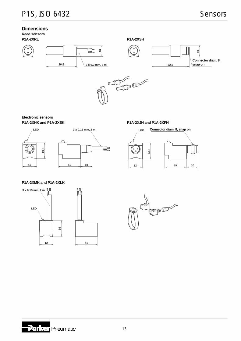
DimensionsReed sensorsP1A-2XRL P1A-2XSH
Electronic sensorsP1A-2XHK and P1A-2XEK P1A-2XJH and P1A-2XFH
P1A-2XMK and P1A-2XLK
LED
12
13,8
19 10
3 x 0,15 mm, 2 m LED
12
13,8
19 10
LED
14
12 19
3 x 0,15 mm, 2 m
26,5 2 x 0,2 mm, 3 m
10
32,5
10
Connector diam. 8,snap on
Connector diam. 8, snap on

Pneumatic
Service and Replacement Parts
P1S Stainless Steel Cylinders, ISO6432
Non-repairable, replace complete cylinder
Piston Rod Clevis and Swivel Rod End
Bore Size Piston Rod Clevis Swivel Rod Eye
10mm P1S-4CRD P1S-4CRT
12mm
16mmP1S-4DRD P1S-4DRT
20mm P1S-4HRD P1S-4HRT
25mm P1S-4JRD P1S-4JRT

14
P1S, ISO 6431 Cylinders Ø32 - Ø125
Main data: ISO 6431
Cylinder Cylinder Piston rod Cushio- Total mass Moving mass Air Conn.designation bore area diam. area thread ning at addition at addition consump- thread
distance 0 mm per 10 0 mm per 10 tionstroke mm stroke stroke mm stroke
mm cm2 mm cm2 mm kg kg kg kg litres
P1S-• 032 M 32 8,0 12 1,1 M10x1,25 15 0,59 0,026 0,10 0,009 0,105 1) G1/8P1S-• 040 M 40 12,6 16 2,0 M12x1,25 18 0,99 0,036 0,19 0,016 0,162 1) G1/4P1S-• 050 M 50 19,6 20 3,1 M16x1,5 19 1,63 0,057 0,32 0,024 0,253 1) G1/4P1S-• 063 M 63 31,2 20 3,1 M16x1,5 22 2,75 0,065 0,36 0,024 0,414 1) G3/8
P1S-• 080 M 80 50,3 25 4,9 M20x1,5 24 5,09 0,099 1,11 0,039 0,669 1) G3/8P1S-• 100 M 100 78,5 25 4,9 M20x1,5 29 8,68 0,115 1,41 0,039 1,043 1) G1/2P1S-• 125 M 125 122,7 32 8,0 M27x2 32 15,31 0,174 2,90 0,063 1,662 1) G1/2
1)Free air consumption per 10 mm stroke length for a double stroke at 600 kPa (6 bar)
Cylinder forcesIndicated cylinder forces are theoretical and should be reduced in rela-tion to working conditions.
Cylinder Theoretical cylinder forcedesignation at 600 kPa (6 bar)
exp. stroke return strokeN N
P1S-• 032 M 480 415P1S-• 040 M 754 633P1S-• 050 M 1180 990P1S-• 063 M 1870 1680
P1S-• 080 M 3016 2721P1S-• 100 M 4712 4417P1S-• 125 M 7363 6880
Additional dataWorking pressure max 10 barWorking temperature max +80 °C
min – 20 °C
High-temperature version max +150 °Cmin – 10 °C
Low-temperature version max +40 °CØ80 - Ø125 min – 40 °C
Prelubricated, further lubrication is not normally necessary.If additional lubrication is introduced it must be continued.
Cushioning diagramUse the diagram below to determine the necessary size of cylinder toprovide the requisite cushioning performance. The maximum cushioningperformance, as indicated in the diagram, is based on the following as-sumptions:
– Low load, i.e. low pressure drop across the piston – Steady-state piston speed – Correctly adjusted cushioning screw
The load is the sum of the internal and external friction, together with anygravity forces. At high relative loading it is recommended that, for a giv-en speed, the load should be reduced by a factor of 2.5, or that, for agiven mass, the speed should be reduced by a factor of 1.5. These fac-tors apply in relation to the maximum performance as shown in the dia-gram.
Speed [m/s]
Mass [kg]
1 2 3 5 10 20 30 50 100 200 500 10003000,1
0,2
0,3
0,5
1,0
2,0
3,0
5,0
Ø32 Ø40 Ø50Ø63
Ø80Ø100
Ø125

15
P1S, ISO 6431 Cylinders Ø32 - Ø125
Order key
Stroke in mm
E.g. 0025 = 25 mmFor standard stroke lengthand max length, see tablebelow
P 1 S – D 0 3 2 M S – 0 0 2 5
Cylinder version
A Trunnion pegs in front endcover, only Ø80 - Ø125
B Trunnion pegs in rear endcover, only Ø80 - Ø125
C Threaded front end
D Threaded front end +4 mounting holes in rearend cover
E 4 mounting holes in frontend cover, only Ø80 - Ø125
F 4 mounting holes in rearend cover
J 2 mounting holes in front endcover, only Ø80 - Ø125
K 2 mounting holes in rearend cover
L 4 mounting holes in front andrear end cover,only Ø80 - Ø125
M 4 mounting holes in front and2 in rear end cover,only Ø80 - Ø125
Q 2 mounting holes in front and4 in rear end cover,only Ø80 - Ø125
V 2 mounting holes in front andrear end cover,only Ø80 - Ø125
Cylinder boremm
032
040
050
063
080
100
125
Stroke length
Cylinder Cylinder Standard stroke length in mm according to ISO 4393 Non standard stroke lengthdesignation bore 25 50 80 100 125 160 200 250 320 400 500
P1S-• 032M 32 • • • • • • • • • • •P1S-• 040M 40 • • • • • • • • • • •P1S-• 050M 50 • • • • • • • • • • •P1S-• 063M 63 • • • • • • • • • • •P1S-• 080M 80 • • • • • • • • • • •P1S-• 100M 100 • • • • • • • • • • •P1S-• 125M 125 • • • • • • • • • • •
Sealing material
S Standard,-20 °C to +80 °CMagnetic piston
F High temperature,-10 °C to +150 °CNon magnetic piston
L Low temperature,-40 °C to +60 °CNon magnetic pistononly Ø80 - Ø125
Q Stainless steel scraperfor piston rod-20 °C to +80 °CMagnetic pistononly Ø80 - Ø125
Cylinder type/Function
M Double acting,adjustablecushioning
F Double acting,adjustablecushioning,through piston rod,only Ø80 - Ø125
Ø32 - Ø63 Ø80 - Ø125Cylinder version Cylinder versionK J, K, M, Q, V
16
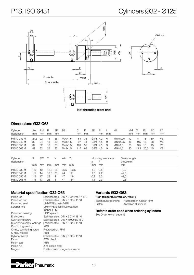
P1S, ISO 6431 Cylinders Ø32 - Ø125
Dimensions Ø32-Ø63
Cylinder AA AM B BF BE C D EE F I KK MM O PL RD RTdesignation mm mm mm mm mm mm mm mm mm mm mm mm mm
P1S-D 032 M 24,5 22 15 25 M30x1,5 88 36 G1/8 4,2 6 M10x1,25 12 8 13 30 M5P1S-D 040 M 30 24 18 30 M38x1,5 97 44 G1/4 4,5 9 M12x1,25 16 9,5 15 38 M6P1S-D 050 M 39 32 18 33 M45x1,5 101 55 G1/4 4,5 9 M16x1,5 20 9,5 15 45 M6P1S-D 063 M 49 32 25 33 M45x1,5 117 68 G3/8 4,5 9 M16x1,5 20 13,3 20,5 45 M8
Cylinder S SW T V WH ZJ Mounting tolerances Stroke lengthdesignation x f 0-500 mm
mm mm mm mm mm mm mm mm mm
P1S-D 032 M 1,5 10 12,2 26 35,5 123,5 1,2 2,5 +2,0P1S-D 040 M 1,5 14 16,5 35 44 141 1,0 2,2 +2,0P1S-D 050 M 1,5 17 22 41 47 148 0,9 2,3 +2,0P1S-D 063 M 1,5 17 26 41 47 164 1,4 2,3 +2,5
Material specification Ø32-Ø63Piston rod Stainless steel, DIN X 2 CrNiMo 17 13 2Piston rod nut Stainless steel, DIN X 5 CrNi 18 10Piston rod seal UHMWPE-plastic/NBRScraper ring UHMWPE-plastic/fluorocarbon
rubber, FPMPiston rod bearing HDPE-plasticEnd covers Stainless steel, DIN X 5 CrNi 18 10Cushioning screw Stainless steel, DIN X 10 CrNiS 18 9Cushioning screw lockings Stainless steel, DIN X 5 CrNi 18 10Cushioning sealing NBRO-ring, cushioning screw Fluorocarbon, FPMO-ring, internal NBRCylinder barrel Stainless steel, DIN X 5 CrNi 18 10Piston POM plasticPiston seal NBRPiston nut Zinc plated steelMagnet Plastic-coated magnetic material
Variants Ø32-Ø63:High-temperature version, type F:
Sealings/scraper ring Fluorocarbon rubber, FPMPiston Anodized aluminium
Refer to order code when ordering cylindersSee Order key on page 15
ØB
EE
T
PL F
BF
WH±f
AM
SW
I
O
ØR
DØ
KK
ØM
M
ØB
E
ØV
ØD
ØRT (4x)
S
AA
AA
Not threaded front end
C + stroke
ZJ ±x + stroke

17
P1S, ISO 6431 Cylinders Ø32 - Ø125
Dimensions Ø80-Ø125
Cylinder AA AM B BE C D EE F KK I J MM N PL Qdesignation mm mm mm mm mm mm mm mm mm mm mm mm
P1S-• 080 M 46 40 50 M50x1,5 141 86 G3/8 4 M20x1,5 10 24,5 25 84 12,5 40P1S-• 100 M 60 40 50 M50x1,5 158 106 G1/2 4 M20x1,5 8 30 25 104 15,5 49,5P1S-• 125 M 76 54 60 M60x2 183 132 G1/2 4 M27x2 13 30 32 129 15,5 62,5
Cylinder RT SW TC TO T1 UT VD WH XG X3 ZJ ZM Mounting tol. Stroke lengthdesignation x f 0-500 mm
mm mm mm mm mm mm mm mm mm mm mm mm mm mm
P1S-• 080 M M8 21 98 20 25 125 19 37 49,5 165,5 178 215 1,5 2,5 +2,5P1S-• 100 M M10 21 109 25 32 152 19 35 50,5 177,5 193 228 1,5 2,5 +2,5P1S-• 125 M M12 27 134 25 32 177 24 47 63 214 230 277 2,0 2,5 +4,0
Material specification Ø80-Ø125Piston rod Stainless steel, DIN X 2 CrNiMo 17 13 2Piston rod nut Stainless steel, DIN X 5 CrNi 18 10Piston rod seal FPMScraper ring PTFEPiston rod bearing Multilayer PTFE and steelEnd covers Stainless steel, DIN X 5 CrNi 18 10Cushioning screw Stainless steel, DIN X 10 CrNiS 18 9Cushioning sealing NBRO-ring, cushioning screw Fluorocarbon, FPMO-ring, internal NBRCylinder barrel Stainless steel, DIN X 5 CrNi 18 10Piston Anodized aluminiumPiston seal NBRPiston bearing UHMWPE-plasticPiston nut Zinc-plated steelMagnetic band Rubber-coated magnetic material
Variants Ø80-Ø125:Low-temperature version, type L:
Sealings/scraper ring NBR/PTFE
High-temperature version, type F:
Sealings/scraper ring Fluorocarbon rubber, FPM/PTFE
Cylinders with steel scraper ring, type Q:
Sealings/scraper ring NBR/Stainless steel
Refer to order code when ordering cylindersSee Order key on page 15
ØN
PL VD
WH±f
AM
J
EE I SW
ØK
K
ØM
M
ØB
ØD
Q
XGTC
UT
ØTO
ØT
1
F
ØB
E
AA
Q
ØRT (4x)
AA
Through piston rod Basic cylinder
Trunnion pegs on front or rear end cover Threaded front end Mounting holes in the end covers
C + stroke
ZJ ±x + stroke
WH ±f + stroke
ZM + 2 x stroke
XJ + stroke

18
P1S, ISO 6431 MountingsCylinder mountings Ø32 - Ø63Type Description Cyl. bore Weight Order code
∅ mm kg
Clevis bracket MP4 Intended for articulated mounting of the cylinder versionsD, F or K. The bracket is mounted at the rear end cover andis supplied complete with shaft, mounting screw and O-ringfor a clean joint between end cover and bracket.
Material:Stainless steel, DIN X 5 CrNi 18 10
Cylinder A B C D E F G H I J K LØ mm mm mm mm mm mm mm mm mm mm mm mm mm
32 35,5 20 33 26 15 10 10 4,5 18,5 25 142 5,540 43,5 24 35 28 17 12 12 4 19 30 160 6,550 54,5 26 39 32 17 12 13 4,5 22 39 170 6,563 67,5 34 47 40 22 16 17 6 26 49 190 8,6S = Stroke
Mounting nut Intended for fixed mounting of the cylinder via the neck.
Material: stainless steel, DIN X 5 CrNi 18 10
Cylinder A B CØ mm mm mm
32 36 8 M30x1,540 46 10 M38x1,550 55 10 M45x1,563 55 10 M45x1,5
32 0,09 P1S-4KME40 0,12 P1S-4LME50 0,19 P1S-4MME63 0,34 P1S-4NME
32 0,03 912729440140 0,06 912729440250-63 0,08 9127294403
32 0,01 912672540440 0,01 912672540550-63 0,02 912672540680-100 0,04 0261109921125 0,10 0261109922
G
JØ
L
IH
K + S
EDCA
BØ
F H
9/e8
C
A
B
C
A
B
Cylinder mountings Ø32-Ø125Type Description Cyl. bore Weight Order code
Ø mm kg
Rod nut Intended for fixed mounting on the piston rod. Cylinders aresupplied complete with one rod nut. (cylinders with throughpiston rods are supplied with two rod nuts.)
Material:Stainless steel, DIN X 5 CrNi 18 10
Cylinder A B CØ mm mm mm
32 17 5 M10x1,2540 19 6 M12x1,2550 24 8 M16x1,563 24 8 M16x1,580 30 10 M20x1,5
100 30 10 M20x1,5125 41 13,5 M27x2

19
P1S, ISO 6431 Mountings
Cylinder mountings Ø32 - Ø125Type Description Cyl. bore Weight Order code
∅ mm kg
Swivel rod eye According to ISO 8139Intended for articulated mounting of the cylinder. Thismounting is adjustable in the axial direction.
Materal:Swivel rod eye: stainless steel, DIN X 5 CrNi 18 10Ball: hardened stainless steel, DIN X 5 CrNi 18 10
Cyl. A Bmin Bmax C D E F G H I K L MØ mm mm mm mm mm mm mm mm mm mm mm mm
32 28 50 55 10 15 43 14 15 14 10,5 17 M10x1,25 24°40 32 56 62 12 17 50 16 22 16 12 19 M12x1,25 24°50 42 72 80 16 22 64 21 28 21 15 22 M16x1,5 30°63 42 72 80 16 22 64 21 28 21 15 22 M16x1,5 30°80 50 87 97 20 26 77 25 33 25 18 32 M20x1,5 30°
100 50 87 97 20 26 77 25 33 25 18 32 M20x1,5 30°125 70 123,5 137 30 36 110 35 51 37 25 41 M27x2 30°
Clevis According to ISO 8140Intended for articulated mounting of the cylinder. Thismounting is adjustable in the axial direction. Supplied com-plete with pin.
Material:Clevis: stainless steel, DIN X 10 CrNiS 18 9Pin: stainless steel, DIN X 5 CrNi 18 10Locking rings according to DIN 471
Cylinder A Bmin Bmax C D E F G H IØ mm mm mm mm mm mm mm mm mm mm
32 20 46 52 10 20 40 12 28 10 M10x1,2540 24 54 60 12 24 48 19 32 12 M12x1,2550 32 72 80 16 32 64 25 42 16 M16x1,563 32 72 80 16 32 64 25 42 16 M16x1,580 40 90 100 20 40 80 32 50 20 M20x1,5
100 40 90 100 20 40 80 32 50 20 M20x1,5125 55 123,5 137 30 54 110 45 72 30 M27x2
32 0,08 P1S-4JRT40 0,12 P1S-4LRT50-63 0,25 P1S-4MRT80-100 0,46 P1S-4PRT125 1,28 P1S-4RRT
32 0,09 P1S-4JRD40 0,15 P1S-4LRD50-63 0,35 P1S-4MRD80-100 0,75 P1S-4PRD125 2,10 P1S-4RRD
K ØC H9
A
B
L
M
G DE F
I H
G D
E F
M
I HL
K
B
ØC H9
A
D
E F
I H A G
B
A
ØC H8/e8
ØC H8/e8
B
A
I
D
E F
H A G

20
P1S, ISO 6431 MountingsCylinder mountingsType Description Cyl. bore Weight Order code
∅ mm kg
Flange MF1/MF2 Intended for fixed attachment of cylinder version D, E, F, L,M or Q. The flange is designed for mounting on the front orrear end covers.
Material:Stainless steel, DIN X 5 CrNiMo 17 13 3
Cylinder A FB E R TF TG1 UF MF I1 W ZB ZFØ mm mm mm mm mm mm mm mm mm mm mm mm mm
80 50,2 12 86 63 126 46 150 12 6 25 178 190100 51 14 106 75 150 60 170 12 6 23 193 205125 61 16 132 90 180 76 205 15 8 32 230 245S = Stroke
Clevis bracket MP4 Intended for articulated mounting of cylinder versionsD, F, L or Q. The bracket is mounted on the rear end coverand is supplied complete with shaft, mounting screw andO-ring for a clean joint between end cover and bracket.
Material:Bracket: stainless steel, DIN X 5 CrNi 18 10Pin: stainless steel, DIN X 5 CrNiMo 17 13 3
Cylinder A B C D E F G H I J K L MØ mm mm mm mm mm mm mm mm mm mm mm mm mm mm
80 80 30 57 50 16 16 15 12 32 46 210 8,6 9100 103 42 67 60 20 20 21 12 37 60 230 10,6 12125 127 50 77 70 25 25 25 15 45 76 275 12,6 15S = Stroke
Mounting nut Intended for fixed mounting on the front end cover of cylin-ders according to cylinder version C or D.
Material:Stainless steel, DIN X 5 CrNi 18 10
Cylinder A B C D EØ mm mm mm mm mm
80 70 11 M50x1,5 6 2,5100 70 11 M50x1,5 6 2,5125 80 11 M60x2 7 3
80 0,97 P1S-4PMB100 1,42 P1S-4QMB125 1,55 P1S-4RMB
D
E
B
C A
EDCØA
J
JØ
F H
9/h7
K + S
ØL
M x 45°
B
G IH
UFØA ØFB(4x)
TF
E R
❑T
G1
MF MF
I1W
ZB + S
ZF + S
80 0,78 P1S-4PME100 1,42 P1S-4QME125 2,06 P1S-4RME
80-100 0,16 9126461304125 0,19 9126461305

21
P1S, ISO 6431 MountingsCylinder mountingsType Description Cyl. bore Weight Order code
∅ mm kg
Bearing bracket Intended for articulated mounting of the cylinder. Thefor trunnion pegs trunnion pegs are factory mounted on the front or rear end
cover and are combined with bearing brackets. Supplied inpairs.
Material:Bearing brackets: stainless steel, DIN X 5 CrNi 18 10Journal bearing: stainless steel,DIN X 5 CrNiMo 17 13 3/PTFE
Cylinder A B1 B2 B3 B4 d1 d2 H1 H2 H3 LØ mm mm mm mm mm mm mm mm mm mm mm mm
80 60 90 28 15 15,5 20 11 58 37 12 34,5100-125 76 106 30 20 17,5 25 13 70 45 15 40
Cylinder E F L1 L2 TMØ mm mm mm mm mm mm
80 154 129 49,5 165,5 98100 169 144 50,5 177,5 109125 194 169 63 214 134S = Stroke
Combinated mounting Intended for articulated mounting of cylinder versions D, F,MP2/MP4 L or Q. The unit is mounted on the rear end cover and is
combined with bearing brackets MP2 and is supplied com-plete with shaft, mounting screw and O-ring for a clean jointbetween end cover and bracket.
Material:Bearing brackets: stainless steel, DIN X 5 CrNi 18 10Journal bearing: stainless steel,Journal bearing: DIN X 5 CrNiMo 17 13 3/PTFEBracket: stainless steel, DIN X 5 CrNi 18 10Pin: stainless steel, DIN X 5 CrNiMo 17 13 3
Cylinder A B C CD d3 E FL L TG1 XA XDØ mm mm mm mm mm mm mm mm mm mm mm mm
80 12 64 82 16 9 74 32 20 46 242 210100 12 74 98 20 11 90 37 25 60 267 230125 15 90 118 25 13 110 45 30 76 320 275S = Stroke
80 0,90 P1S-4PMW100-125 1,30 P1S-4QMW
LØd1
L
Ød2
H3
H2 H
1
B2
AB1
B4
B3
L1L + S
TM
FE
ØCD
AFL L
A
BXD + S
XA + S
❑TG1
C
❑E
Ød3
80 1,29 P1S-4PML100 2,33 P1S-4QML125 3,30 P1S-4RML

22
P1S, ISO 6431 Sensors
Reed switch sensorsThe reed switch sensors incorporate a well-proven, universal-voltage,compact reed switch element, making them suitable for a wide range ofapplications. They can work with electronic control systems or conven-tional relay systems. No environment is too severe.
Technical dataSpecification SR-D, 3 m
SR-D, 10 mSRC-D
Design ReedOutput MakingVoltage range, SR-D 10-250 VAC/VDCVoltage range, SRC-D 10-60 VAC/75 VDCVoltage drop max 2,2 VLoad currant max 0,5 A
min 2 mABreaking power (resistive) max 30/20 VA/WActuating distance min 15 mmHysteresis 1 mmRepeatability accuracy ±0,1 mmOn/off switching frequency max 500 HzOn switching time max 0,6 msOff switching time max 0,05 msEncapsulation IP 67Temperature range –25 °C to +80 °CIndication LED, yellowMaterial housing PEIMaterial mould EpoxyCable PVC 2x0,25 mm2
Weight cable excl. connector 28 g/mWeight connector 1,8 gWeight sensor incl. male part connector 5,8 gMounting Mounting yokeMaterial mounting Anodised aluminiumMaterial, screw Stainless steelConnector Diam. 8 mm, snap on
Ordering data
Order code Cylinder Output Cable Weightbore mm lenght kg
Reed sensors
SR-D 32-125 making 3 m 0,088SR-D 32-125 making 10 m 0,284SRC-D 32-125 making * 0,006
Mountings for sensors
9126344381 32-63 0,0209126344382 80-125 0,025
*) Cable shall be ordered separately.**) Cable including female part connector, for sensor.
Reed sensor symbol
Electronic sensorsThese sensors are of solid-state type, with no moving parts. Short-circuitand transient protection is incorporated as standard. The integral elec-tronics make these sensors suitable for applications with very highswitching frequencies.
Technical dataSpecification SI-D, 3 m
SI-D, 10 mSIC-D
Design Hall elementOutput PNP, N. O.Voltage range 10-30 VDCPermissible ripple max 5%Voltage drop max 1,6 VLoad currant max 200 mABreaking power (resistive) max 6 WCapacitive load max 0,33 µFInternal consumption 10 mAActuating distance min 6 mmHysteresis 0,8 mmRepeatability accuracy ±0,01 mmOn/off switching frequency max 500 HzOn switching time max 0,8 msOff switching time max 0,04 msEncapsulation IP 67Temperature range –25 °C to +80 °CIndication LED, gulMaterial housing PEIMaterial mould EpoxyCable PVC 3x0,25 mm2
Weight cable excl. connector 28 g/mWeight connector 1,8 gWeight sensor incl. male part connector 6 gConnector Diam. 8 mm, snap onMounting Mounting yokeMaterial mounting Anodised aluminiumMaterial, screw Stainless steel
Ordering data
Order code Cylinder Output Cable Weightbore mm lenght kg
Electronic sensors
SI-D 32-125 PNP, N.O. 3 m 0,088SI-D 32-125 PNP, N.O. 10 m 0,284SIC-D 32-125 PNP, N.O. * 0,006
Cable for sensors
9126344341** PVC 3 m 0,0869126344342** PVC 10 m 0,2829126344343** Superflex PVC 3 m 0,0869126344344** Superflex PVC 10 m 0,2829126344345** PUR 3 m 0,0869126344346** PUR 10 m 0,282
Electronic sensor symbol
Brown
Blue
Blue
Black
Brown

23
P1S, ISO 6431 Sensors
Electronic sensors for ISO 6431These sensors are of solid-state type, with no moving parts. Short-circuitand transient protection is incorporated as standard. The integral elec-tronics make these sensors suitable for applications with very highswitching frequencies.
Technical dataSpecification P1S-2XJHDesign Hall elementOutput PNP, N.O.Permissible ripple 10-30 VDCMax rippel max 15%Voltage drop ≤2,5 VLoad current ≤200 mABreaking power (resistive) max 5 WInternal consumption max 10 mAActuating distance min 3,5 mmHysteresis 0,7 mmRepeatability accuracy ±0,6 mmOn/off switching frequency max 1 kHzOn/off switching time max <0,5/20-50 msEncapsulation IP 67Temperaturomre range –25 °C to +70 °CIndication LEDShock resistance 40 gMaterial housing Stainles steelCable PUR 3x0.25 mm2
Weight cable excl. connector 24 g/mWeight sensor incl. male part connector 13 gWeight connector 4 gConnector M8 connectorMounting Mounting yokeMaterial mounting Stainless steel
fluorocarbon rubber
Ordering data
Order code Cylinder Output Cable Weightbore mm lenght kg
Electronic sensors
P1S-2XJH 32-125 PNP, N.O. * 0,025
Mountings for sensors
P1S-2KCC 32 0,015P1S-2LCC 40 0,015P1S-2MCC 50 0,015P1S-2NCC 63 0,015P1S-2PCC 80 0,015P1S-2QCC 100 0,015P1S-2RCC 125 0,015
Cable for sensors
9126454822 ** 3 m 0,076
*) Cable shall be ordered separately.**) Cable including female part connector, for sensor.
Electronic sensor symbol
DimensionsReed and electronic sensors SR-D, SRC-D, SI-D, SIC-D
for ISO 6431
Ø36 - Ø 132
20
8
2,5
15
40
7,5
12 20,5
32
2.515°
M8
Ø10
8
25.7
7.1
7.8
10
35
8
1715
3 Blue
4 Black
1 Brown
Electronic sensors P1S-2XJH
for ISO 6431

Pneumatic
Service and Replacement Parts
P1S Stainless Steel Cylinders, ISO6431
Part Number Bore Repair Kit(Standard * = S)
Repair Kit(High Temperature * = F)
P1S-D032M*-XXXX 32mm 9121659195 9121720595
P1S-D040M*-XXXX 40mm 9121659196 9121720596
P1S-D050M*-XXXX 50mm 9121659197 9121720597
P1S-D063M*-XXXX 63mm 9121659198 9121720598
P1S-D080M*-XXXX 80mm 9121718905 9121718925
P1S-D100M*-XXXX 100mm 9121718906 9121718926
P1S-D125M*-XXXX 125mm 9121718907 9121718927
Assembly Tools
Bore Size Assembly Sleeve Tightening Pins GreaseStandard
GreaseHigh Temp.
32mm 9127289101 9127289105
40mm 9127289102
50mm 91272891039127289106
63mm 9127289104
80mm 91272891119127289107
100mm 9127289112
125mm 91272891139127289108
9127394541 9127394521
Related Documents