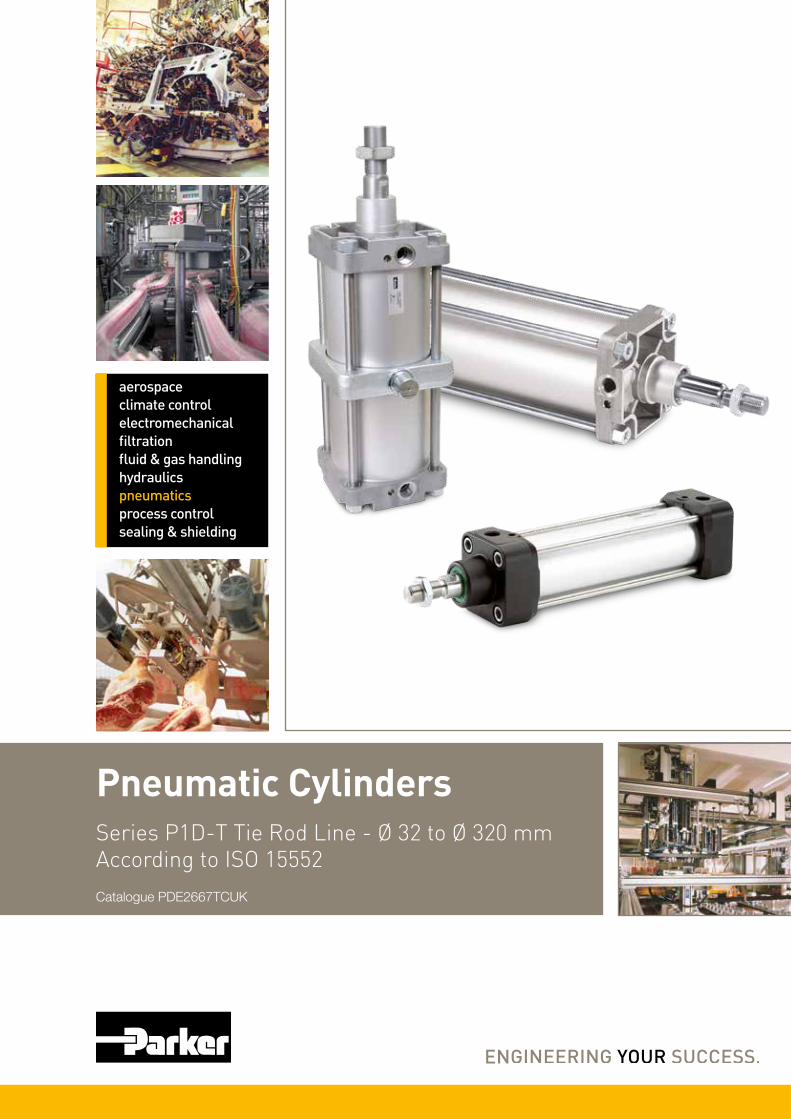
Pneumatic Cylinders aerospace climate control electromechanical filtration fluid & gas handling hydraulics pneumatics process control sealing & shielding Series P1D-T Tie Rod Line - Ø 32 to Ø 320 mm According to ISO 15552 Catalogue PDE2667TCUK

Welcome message from author
This document is posted to help you gain knowledge. Please leave a comment to let me know what you think about it! Share it to your friends and learn new things together.
Transcript
Pneumatic Cylinders
aerospaceclimate control electromechanicalfiltrationfluid & gas handlinghydraulicspneumaticsprocess controlsealing & shielding
Series P1D-T Tie Rod Line - Ø 32 to Ø 320 mmAccording to ISO 15552Catalogue PDE2667TCUK

2
Parker Hannifin CorporationPneumatic Division - Europe
PDE2667TCUK
P1D-T Pneumatic ISO Cylinders - Ø 32 - Ø 320 mm
SALE CONDITIONSThe items described in this document are available for sale by Parker Hannifin Corporation, its subsidiaries or its authorized distributors. Any sale contract entered into by Parker will be governed by the provisions stated in Parker’s standard terms and conditions of sale (copy available upon request).
WARNING
FAILURE OR IMPROPER SELECTION OR IMPROPER USE OF THE PRODUCTS AND/OR SYSTEMS DESCRIBED HEREIN OR RELATED ITEMS CAN CAUSE DEATH, PERSONAL INJURY ANDPROPERTY DAMAGE.This document and other information from Parker Hannifin Corporation, its subsidiaries and authorized distributors provide product and/or system options for further investigation by users having technical expertise. It is important that you analyze all aspects of your application and review the information concerning the product or system in the current product catalog. Due to the variety of operating conditions and applications for these products or systems, the user, through its own analysis and testing, is solely responsible for making the final selection of the products and systems and assuring that all performance, safety and warning requirements of the application are met. The products described herein, including without limitation, product features, specifications, designs, availability and pricing, are subject to change by Parker Hannifin Corporation and its subsidiaries at any time without notice.
NoteAll technical data in this catalogue are typical data only.Air quality is essential for maximum cylinder service life (see ISO 8573).
ImportantBefore attempting any external or internal work on the cylinder or any connected components, make sure the cylinder is vented and dis connect the air supply in order to ensure isolation of the air supply.

3
Parker Hannifin CorporationPneumatic Division - Europe
PDE2667TCUK
P1D-T Pneumatic ISO Cylinders - Ø 32 - Ø 320 mm
Contents page
P1D-T – ISO 15552 Cylinder Range ................................................................4
Cylinder forces, double acting variants ............................................................6
Main data : P1D-T ..........................................................................................6
Cushioning characteristics ...............................................................................7
Guide for selecting tubing ..........................................................................8 - 9
General technical data ..................................................................................10
Operating and environmental data ................................................................10
Material specification - Bores Ø 32 to Ø 125 mm ..........................................10
Material specification - Bores Ø 160, Ø 200 and Ø 250 mm ..........................11
Material specification - Bores Ø 320 mm .......................................................12
Order key code - Basic Cylinder ....................................................................13
Order key code - Cylinder with Intermediate trunnion .....................................14
Order key code - Extended piston rod ...........................................................14
Order key code - Piston rod in alternative materials ........................................15
Order key code - Through piston rod .............................................................15
Order key code - 3 and 4 position cylinders ...................................................16
Order key code - Tandem cylinders ...............................................................16
Standard strokes - Bores Ø 32 to Ø 125 mm - Standard temperature ............17
Dimensions - Bores Ø 32 to Ø 125 mm - Standard temperature ...................18
Standard strokes - Bores Ø 32 to Ø 125 mm - High / low temperature ..........19
Dimensions - Bores Ø 32 to Ø 125 mm - High / low temperature ..................20
Dimensions - 3 and 4 position cylinders .........................................................21
Order key code - Bores Ø 32 to Ø 125 mm ...................................................22
Standard strokes - Bores Ø 160 to Ø 320 mm ...............................................23
Dimensions - Bores Ø 160 to Ø 320 mm ......................................................24
Order key code - Bores Ø 160 to Ø 320 mm .................................................25
Rod guidance modules ...........................................................................26 - 29
Cylinder mountings ................................................................................30 - 36
Piston rod mountings .............................................................................37 - 38
Accessories ..................................................................................................39
Sensors .................................................................................................40 - 43
P1D Seal kits Ø 32 - Ø 125 mm ....................................................................44
Seal kits Ø 160 - Ø 250 mm .........................................................................45
Seal kits - Ø 320 mm ....................................................................................46
Order code key - Spare parts ........................................................................48
Specifying air quality .....................................................................................49
4
Parker Hannifin CorporationPneumatic Division - Europe
PDE2667TCUK
P1D-T Pneumatic ISO Cylinders - Ø 32 - Ø 320 mm
Design variants
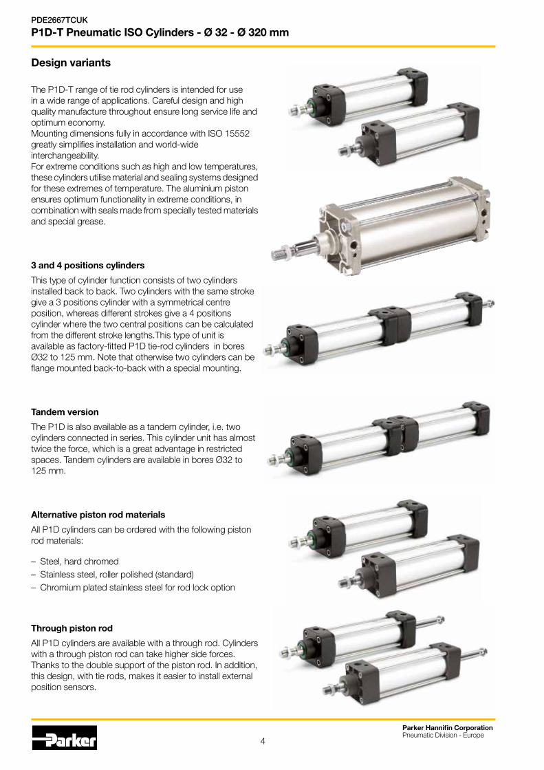
The P1D-T range of tie rod cylinders is intended for use in a wide range of applications. Careful design and high quality manufacture throughout ensure long service life and optimum economy.Mounting dimensions fully in accordance with ISO 15552greatly simplifies installation and world-wideinterchangeability.For extreme conditions such as high and low temperatures,these cylinders utilise material and sealing systems designedfor these extremes of temperature. The aluminium piston ensures optimum functionality in extreme conditions, incombination with seals made from specially tested materialsand special grease.
3 and 4 positions cylinders
This type of cylinder function consists of two cylinders installed back to back. Two cylinders with the same stroke give a 3 positions cylinder with a symmetrical centre position, whereas different strokes give a 4 positions cylinder where the two central positions can be calculated from the different stroke lengths.This type of unit is available as factory-fitted P1D tie-rod cylinders in bores Ø32 to 125 mm. Note that otherwise two cylinders can be flange mounted back-to-back with a special mounting.
Tandem version
The P1D is also available as a tandem cylinder, i.e. two cylinders connected in series. This cylinder unit has almost twice the force, which is a great advantage in restrictedspaces. Tandem cylinders are available in bores Ø32 to 125 mm.
Alternative piston rod materials
All P1D cylinders can be ordered with the following piston rod materials:
– Steel, hard chromed – Stainless steel, roller polished (standard)– Chromium plated stainless steel for rod lock option
Through piston rod
All P1D cylinders are available with a through rod. Cylinders with a through piston rod can take higher side forces. Thanks to the double support of the piston rod. In addition, this design, with tie rods, makes it easier to install external position sensors.

5
Standard cylinders P1D-T, ISO 15552bores Ø32 - Ø320 mm
Global product range
The P1D-T range of cylinders is intended for use in a wide range of applications.Careful design and high quality manufacture throughout ensure long service life and optimum economy.Mounting dimensions fully in accordance with ISO 15552 greatly simplifies installation and world-wide interchangeability.
Features
• Bore sizes Ø32 - Ø320 mm
• Stroke lengths 5 - 2800mm. (32-125)
• Stroke lengths 10 - 2000mm. (160-320)
• Magnetic piston as standard
• Adjustable cushioning as standard
• Special versions on request
• ATEX version (160-320)
Parker Hannifin CorporationPneumatic Division - Europe
PDE2667TCUK
P1D-T Pneumatic ISO Cylinders - Ø 32 - Ø 320 mm
Zinc plated steelend cover nuts as standard
Zinc plated pistonrod nut included asstandard
Metal-polymerpiston rod bearing
PUR seals bores 32-125NBR seals bores 160-320
Metalliccushioning piston
Aluminiumend covers
Adjustablecushioning
Stainless steel cushion screwsbores 32-125Brass cushionscrews bores 160-320
Magnetic pistonas standardAnodised barrelStainless steel
tie rods
Stainless steel piston rod as standard

6
Note!Select a theoretical force 50-100% larger than the force required
+ = Outward stroke- = Return stroke
Cylinder forces, double acting variants
Total mass including moving parts
Cylinder Total mass (kg) Total mass (kg) designation at 0 mm stroke Supplement per 10 mm stroke
P1D-T032••XXXX1) 0,55 0,023P1D-T040••XXXX1) 0,80 0,033P1D-T050••XXXX1) 1,20 0,048P1D-T063••XXXX1) 1,73 0,051P1D-T080••XXXX1) 2,45 0,075P1D-T100••XXXX1) 4,00 0,084P1D-T125••XXXX1) 6,87 0,138P1D-T160••XXXX1) 10,45 0,205P1D-T200••XXXX1) 17,80 0,220P1D-T250••XXXX1) 31,00 0,40P1D-T320••XXXX1) 60,00 0,60
Main data: P1D-T Cylinder Cylinder Piston rod Piston rod Cushioning Consumption2) Connection designation bore area dia. area thread length litre thread mm cm2 mm cm2 mm
P1D-T032••XXXX1) 32 8,0 12 1,1 M10x1,25 17 0,105 G1/8P1D-T040••XXXX1) 40 12,6 16 2,0 M12x1,25 19 0,162 G1/4P1D-T050••XXXX1) 50 19,6 20 3,1 M16x1,5 20 0,253 G1/4P1D-T063••XXXX1) 63 31,2 20 3,1 M16x1,5 23 0,414 G3/8P1D-T080••XXXX1) 80 50,3 25 4,9 M20x1,5 23 0,669 G3/8P1D-T100••XXXX1) 100 78,5 25 4,9 M20x1,5 27 1,043 G1/2P1D-T125••XXXX1) 125 122,7 32 8,0 M27x2 30 1,662 G1/2P1D-T160••XXXX1) 160 201,0 40 12,6 M36x2 52 2,815 G3/4P1D-T200••XXXX1) 200 314,2 40 19,6 M36x2 52 4,398 G3/4P1D-T250••XXXX1) 250 490,9 50 19,6 M42x2 52 6,872 G1P1D-T320••XXXX1) 320 804,3 63 31,2 M48x2 50 11,259 G1
1) XXXX = stroke 2) Free air consumption per 10 mm stroke for a double stroke at 6 bar
Mass moving parts only (for cushioning calculation)
Cylinder Mass moving parts (kg) designation at 0 mm stroke Supplement per 10 mm stroke
P1D-T032••XXXX1) 0,13 0,009P1D-T040••XXXX1) 0,24 0,016P1D-T050••XXXX1) 0,42 0,025P1D-T063••XXXX1) 0,50 0,025P1D-T080••XXXX1) 0,90 0,039P1D-T100••XXXX1) 1,10 0,039P1D-T125••XXXX1) 2,34 0,063P1D-T160••XXXX1) x xP1D-T200••XXXX1) x xP1D-T250••XXXX1) x xP1D-T320••XXXX1) x x
Cyl. bore/ Stroke Piston area Max theoretical force in N (bar)pist. rod mm cm 2 1,0 2,0 3,0 4,0 5,0 6,0 7,0 8,0 9,0 10,0
32/12 + 8,0 80 161 241 322 402 483 563 643 724 804 - 6,9 69 138 207 276 346 415 484 553 622 691
40/16 + 12,6 126 251 377 503 628 754 880 1005 1131 1257 - 10,6 106 212 318 424 530 636 742 848 954 1060
50/20 + 19,6 196 393 589 785 982 1178 1374 1571 1767 1963 - 16,5 165 330 495 660 825 990 1155 1319 1484 1649
63/20 + 31,2 312 623 935 1247 1559 1870 2182 2494 2806 3117 - 28,0 280 561 841 1121 1402 1682 1962 2242 2523 2803
80/25 + 50,3 503 1005 1508 2011 2513 3016 3519 4021 4524 5027 - 45,4 454 907 1361 1814 2268 2721 3175 3629 4082 4536
100/25 + 78,5 785 1571 2356 3142 3927 4712 5498 6283 7069 7854 - 73,6 736 1473 2209 2945 3682 4418 5154 5890 6627 7363
125/32 + 122,7 1227 2454 3682 4909 6136 7363 8590 9817 11045 12272 - 114,7 1147 2294 3440 4587 5734 6881 8027 9174 10321 11468
160/40 + 201,0 2010 4019 6029 8038 10048 12058 14067 16077 18086 20096 - 188,4 1884 3768 5652 7536 9420 11304 13188 15072 16956 18840
200/40 + 314,2 3142 6283 9425 12566 15708 18850 21991 25133 28274 31416 - 294,5 2945 5891 8836 11781 14727 17672 20617 23562 26508 29453
250/50 + 490,9 4909 9818 14726 19635 24544 29453 34362 39270 44179 49088 - 471,3 4713 9425 14138 18850 23563 28275 32988 37700 42413 47125
320/63 + 804,25 8043 16085 24128 32170 40213 48255 56298 64340 72383 80425 - 773,1 7731 15462 23192 30923 38654 46385 54116 61846 69577 77308
Parker Hannifin CorporationPneumatic Division - Europe
PDE2667TCUK
P1D-T Pneumatic ISO Cylinders - Ø 32 - Ø 320 mm
7
Parker Hannifin CorporationPneumatic Division - Europe
PDE2667TCUK
P1D-T Pneumatic ISO Cylinders - Ø 32 - Ø 320 mm
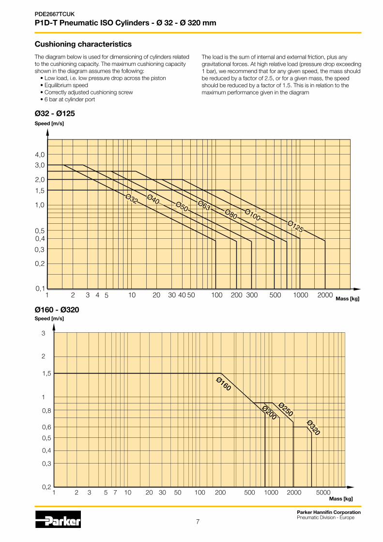
Cushioning characteristics
The load is the sum of internal and external friction, plus any gravitational forces. At high relative load (pressure drop exceeding 1 bar), we recommend that for any given speed, the mass should be reduced by a factor of 2.5, or for a given mass, the speed should be reduced by a factor of 1.5. This is in relation to the maximum performance given in the diagram
4,03,0
2,0
1,5
1,0
0,50,4
0,3
0,2
0,11 2 3 4 5 10 20 30 40 50 100 200 300 500 1000 2000
Ø32 Ø40 Ø50Ø63 Ø80
Ø100Ø125
Speed [m/s]
Mass [kg]
The diagram below is used for dimensioning of cylinders related to the cushioning capacity. The maximum cushioning capacity shown in the diagram assumes the following:
• Low load, i.e. low pressure drop across the piston• Equilibrium speed • Correctly adjusted cushioning screw • 6 bar at cylinder port
Speed [m/s]
Mass [kg]21 3 75 10 20 30 10050 200 500 1000 2000 5000
0,2
0,3
0,4
0,5
0,6
0,8
1
1,5
2
3
Ø320
Ø250Ø200
Ø160
Ø160 - Ø320
Ø32 - Ø125
4,03,0
2,0
1,5
1,0
0,50,4
0,3
0,2
0,11 2 3 4 5 10 20 30 40 50 100 200 300 500 1000 2000
Ø32 Ø40 Ø50Ø63 Ø80
Ø100Ø125
4,0
3,0
2,0
1,5
1,0
0,5
0,4
0,3
0,2
0,1 1
23
45
1020
3040
5010
020
030
050
010
0020
00
Ø32
Ø40
Ø50
Ø63
Ø80
Ø10
0Ø
125

8
Parker Hannifin CorporationPneumatic Division - Europe
PDE2667TCUK
P1D-T Pneumatic ISO Cylinders - Ø 32 - Ø 320 mm
Guide for selecting suitable tubingThe selection of the correct size of tubing is often based on experience, with no great thought to optimizing energy efficiency and cylinder velocity. This is usually acceptable, but making a rough calculation can result in worthwhile economic gains.
The following is the basic principle:1. The primary line to the working valve could be over sized (this
does not cause any extra air consumption and consequently does not create any extra costs in operation).
2. The tubes between the valve and the cylinder should, however, be optimized according to the principle that an insufficient bore throttles the flow and thus limits the cylinder speed, while an oversized pipe creates a dead volume which increases the air consumption and filling time.
The chart below is intended to help when selecting the correct size of tube to use between the valve and the cylinder.
The following prerequisites apply:The cylinder load should be about 50% of the theoretical force (= normal load). A lower load gives a higher velocity and vice versa. The tube size is selected as a function of the cylinder bore, the desired cylinder velocity and the tube length between the valve and the cylinder.
If you want to use the capacity of the valve to its maximum, and obtain maximum speed, the tubing should be chosen so that they at least correspond with the equivalent restriction diameter (see description below), so that the tubing does not restrict the total flow. This means that a short tubing must have at least the equivalent restriction diameter. If the tubing is longer, choose it from the table below. Straight fittings should be chosen for highest flow rates. (Elbow and banjo fittings cause restriction.)
1) The “equivalent throttling bore“ is a long throttle (for example a tube) or a series of throttles (for example, through a valve) converted to a short throttle which gives a corresponding flow rate. This should not be confused with the “orifice“ which is sometimes specified for valves. The value for the orifice does not normally take account of the fact that the valve contains a number of throttles.
2) Qn is a measure of the valve flow capacity, with flow measured in litre per minute (l/min) at 6 bar(e) supply pressure and 1 bar pressure drop across the valve.
Cylinder Ø [mm]
Equivalent throttling bore 1) Tube ØOut./ØInt. [mm]
Length of tubing [m]Cylinder speed [m/s]0,2 0,5 0,8 1,1 1,4 0 1 2 3 4 5 6 7 8 9 10
1
2
3
4
5
6
7
8
9
10
11
Ø10Ø16Ø20Ø25Ø32Ø40Ø50
Ø63
Ø80
Ø100
Ø125
Ø160
Ø200
14/11–/12
–/13
–/14
–/15
–/16
12/10
10/8
8/6
6/45/34/2,7
200
400
800
1000
1200
14001600
1800200022002400
3000
4000
2800
3200340036003800
2600
4
3
2
1
Air flow Qn [Nl/min]
Ø250Ø320
onrequest

9
Parker Hannifin CorporationPneumatic Division - Europe
PDE2667TCUK
P1D-T Pneumatic ISO Cylinders - Ø 32 - Ø 320 mm
Example 1 : Which tube diameter should be used?A 50 mm bore cylinder is to be operated at 0.5 m/s. The tube length between the valve and cylinder is 2 m. In the diagram we follow the line from 50 mm bore to 0.5 m/s and get an “equivalent throttling bore“ of approximately 4 mm. We continue out to the right in the chart and intersect the line for a 2 m tube between the curves for 4 mm (6/4 tube) and 6 mm(8/6 tube). This means that a 6/4 tube throttles the velocity somewhat, while an 8/6 tube is a little too large. We select the 8/6 tube to obtain full cylinder velocity.
Example 2 : What cylinder velocity will be obtained?A 80 mm bore cylinder will be used, connected by 8 m 12/10 tube to a valve with Qn 1200 Nl/min. What cylinder velocity will we get? We refer to the diagram and follow the line from 8 mm tube length up to the curve for 12/10 tube. From there, we go horizontally to the curve for the Ø80 cylinder. We find that the velocity will be about 0.5 m/s.
Example 3 : What is the minimum inner diameter and maximum lenght of tube?For a application a 125 mm bore cylinder will be used. Maximum velocity of piston rod is 0.5 m/s. The cylinder will be controlled by a valve with Qn 3200 Nl/min. What diameter of tube can be used and what is maximum lenght of tube.We refer to the diagram. We start at the left side of the diagram cylinder Ø125. We follow the line until the intersection with the velocity line of 0.5 m/s. From here we draw a horizontal line in the diagram. This line shows us we need an equivalent throttling bore of approximately 10 mm. Following this line horizontally we cross a few intersections. These intersections shows us the minimum inner diameter (rightside diagram) in combination with the maximum length of tube (bottomside diagram).
For example: Intersection one: When a tube (14/11) will be used, the maximum length of tube is 0.7 meter. Intersection two: When a tube (—/13) will be used, the maximum length of tube is 3.7 meter. Intersection three: When a tube (—/14) will be used, the maximum length of tube is 6 meter.
Example 4 : Determining tube size and cylinder velocity with a particular cylinder and valve?For an application using a 40 mm bore cylinder with a valve with Qn=800 Nl/min. The distance between the cylinder and valve has been set to 5 m.Tube dimension: What tube bore should be selected to obtain the maximum cylinder velocity? Start at pipe length 5 m, follow the line up to the intersection with 800 Nl/min. Select the next largest tube diameter, in this case Ø10/8 mm.Cylinder velocity: What maximum cylinder velocity will be obtained? Follow the line for 800 Nl/min to the left until it intersects with the line for the Ø40 mm cylinder. In this example, the speed is just above 1.1 m/s.
Valve series with respective flows in Nl/minute
Valve series Qn in Nl/Min
Interface PS1 120
Moduflex Size 1 - Double 4/2 single solenoid 165
Adex A05 173
H Series Micro - Single 5/3 APB 228
Moduflex Size 1 - Single or Double 3/2 235
H Series Micro - Double 3/2 276
H Series Micro - Single 5/2 282
Moduflex Size 1 - Single 4/2 310
ISOMAX DX02 378
H Series ISO HB 390
Moduflex Size 2 - Single or Double 3/2 440
PVL-B stackable inline valve 540
Adex A12 560
ISOMAX DX01 588
Viking Xtrem P2LAX - G1/8" 660
Moduflex Size 2 - Single 4/2 800
H Series ISO HA 918
ISOMAX DX1 & DX Rail 1032
PVL-C stackable inline valve 1100
H Series ISO H1 1248
Viking Xtrem P2LBX - G1/4" 1290
ISOMAX DX2 & DX Rail 2298
Viking Xtrem P2LCX - G3/8" 2460
H Series ISO H2 2520
Viking Xtrem P2LDX - G1/2" 2658
ISOMAX DX3 & DX Rail 3840
H Series ISO H3 5022
10
Parker Hannifin CorporationPneumatic Division - Europe
PDE2667TCUK
P1D-T Pneumatic ISO Cylinders - Ø 32 - Ø 320 mm
General technical data
Product type Standard cylinder according to ISO 15552Bore size 32 - 125 mmStroke length 10 - 2800 mmVersions Double actingCushioning Adjustable air cushioningPosition sensing Proximity sensor in temperature range -25oC to +80oCInstallation P1D cylinder and piston rod mountingsMounting position Any
Operating and environmental data
Operating medium For best possible service life and trouble-free operation dry, filtered compressed air to ISO 8573-1:2010 quality class 3.4.3 should be used. This specifies a dew point of +3oC for indoor operation (a lower dew point should be selected for minus temperature operation and we recommend the use of an inline dryer) and is in line with the air quality from most standard compressors with a standard filter.
Operating pressure 0,5 bar to 10 bar Hydraulic version : 2 bar to 10 bar
Ambient temperature High temp version : -10oC to +150oC Standard temp version : -20oC to +80oC Low temp version : -40oC to +80oC Metal scraper version : -30oC to +80oC
Pre-lubricated Further lubrication is normally not necessary. If additional lubrication is introduced it must be continued.
Oil used for hydraulic version Hydraulic oil type HLP (DIN 51524, ISO 11158). Viscosity by 40oC: 32 mm2/s (cst). Example: Shell Tellus 32 or equal.
Corrosion resistance High resistance to corrosion and chemicals. Materials and surface treatment have been selected for industrial applications where solvents and detergents are frequently used.
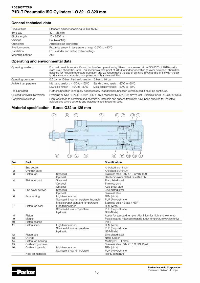
Material specification - Bores Ø32 to 125 mm
4 6 1 2 11 10 15 1
3 14 7 16 8 9 13 12 5
Pos Part Specification
1 End covers Anodised aluminium 2 Cylinder barrel Anodised aluminium 3 Piston rod Standard Stainless steel, DIN X 10 CrNiS 18 9 Optional Hard chromium plated Fe 490-2 FN 4 Piston rod nut Standard Zinc plated steel Optional Stainless steel Optional Acid-proof steel 5 End cover screws Standard Zinc plated steel Optional Stainless steel 6 Scraper ring High temperature FPM (Viton) Standard & low temperature, hydraulic PUR (Polyurethane) Metal scraper standard temperature Stainless steel / Brass / NBR 7 Piston rod seal High temperature FPM (Viton) Standard & low temperature PUR (Polyurethane) Hydraulic NBR(Nitrile) 8 Piston Acetal for standard temp or Aluminium for high and low temp 9 Magnet Plastic coated magnetic material (Low temperature version only) 10 Piston bearing PTFE 11 Piston seals High temperature FPM (Viton) Standard & low temperature PUR (Polyurethane) Hydraulic NBR(Nitrile) 12 Piston bolt Zinc plated steel 13 O-rings Nitrile rubber 14 Piston rod bearing Multilayer PTFE/steel 15 Cushioning screws Stainless steel, DIN X 10 CrNiS 18 n9 16 Cushioning seals High temperature FPM (Viton) Standard & low temperature PUR (Polyurethane) Note on materials RoHS compliant

11
Parker Hannifin CorporationPneumatic Division - Europe
PDE2667TCUK
P1D-T Pneumatic ISO Cylinders - Ø 32 - Ø 320 mm
Operating and environmental dataOperating mediumFor best possible service life and trouble-free operation dry, filtered compressed air to ISO 8573-1:2010 quality class 3.4.3 should be used. This specifies a dew point of +3oC for indoor operation (a lower dew point should be selected for outdoor operation) and is in line with the air quality from most standard compressors with a standard filter.
Operating pressure 1,0 bar to 10 bar
Ambient temperature -20oC to +80oC Standard version (High temp version on request)
Pre-lubricated Further lubrication is normally not necessary. If additional lubrication is introduced it must be continued.
Corrosion resistance High resistance to corrosion and chemicals. Materials and surface treatment have been selected for industrial applications where solvents and detergents are frequently used.
General technical data
Product type Standard cylinder according to ISO 15552
Bore size 160 - 320 mm
Stroke length 10-2000 mm
Versions Double acting
Cushioning Adjustable air cushioning
Position sensing Proximity sensor in temperature range -25°C to +80°C
Installation P1D cylinder and piston rod mountings
Mounting position Any
Material specification - Bores Ø 160, Ø 200 and Ø 250 mm
Pos Part Specification
1 Front cover Aluminium 2 Rear cover Aluminium 3 Cylinder barrel Anodised aluminium 4 Piston rod Standard Stainless steel 1.4104 (X12CrMoS17) Option Chrome plated steel 1.5217 (20MnV6) 5 Piston rod nut Zinc plated steel 6 Cushioning sleeve Aluminium 7 Piston seal Standard NBR 8 Magnet Magnet foil 9 Washer Zinc plated steel 10 Piston nut Zinc plated steel 11 Tie rod High alloyed steel 1.4104 (X12CrMoS17) 12 Tie rod nut Zinc plated steel 13 Cushioning screw Brass 14 Cushioning O ring Standard NBR 15 Retaining clip Spring steel 16 O ring Standard NBR 17 Rod bearing Metal-polymer material 18 Rod seal Standard NBR 19 Cushion seal Standard NBR
4
618
11 10
1 316
9 1212
17 19 7 6 16 2
8 1319
X
5
5
1513
14
X

12
Parker Hannifin CorporationPneumatic Division - Europe
PDE2667TCUK
P1D-T Pneumatic ISO Cylinders - Ø 32 - Ø 320 mm
Material specification - Bore Ø 320 mm
Pos Part Specification
1 Rear cover Aluminium
2 Front cover Aluminium
3 Piston Aluminium
4 Piston rod Standard Stainless steel 1.4021 (X20Cr13)
Option Chrome plated steel 1.5217 (20MnV6)
5 Cylinder barrel Anodised aluminium
6 Tie rod nut Standard Zinc plated steel
Option Stainless steel 1.4301 (X5CrNi18-10)
7 Cushioning screw Brass + Stainless steel
8 Cushioning tube Anodised aluminium
9 Cushioning female thread Anodised aluminium
10 Cushioning seal Standard PU
Option FKM
11 O ring Standard NBR
Option FKM
12 Rod seal Standard PU + HYTREL
Option FKM + PTFE + Bronze
13 Rod bearing Metal + Polymer composite
14 Tie rod Standard Stainless steel, 1.4301 (X5CrNi18-10)
15 Piston rod nut Standard Zinc plated steel
Option Stainless steel 1.4301 (X5CrNi18-10)
16 Piston seals Standard PU
Option FKM
17 Magnet Plasto - Ferrite
18 Piston bearing PTFE + Bronze
19 Piston O-ring Standard NBR
Option FKM
4
6
18 11 116
3
10
12
17
19 7
6
2
8
13
9
5
15
16
14
11
10
3

13
Parker Hannifin CorporationPneumatic Division - Europe
PDE2667TCUK
P1D-T Pneumatic ISO Cylinders - Ø 32 - Ø 125 mm
The simple and complete order code keyThe P1D order key is based on the same principles as itspredecessors, the P1C and P1E. This makes it easy to identify and order all common cylinder versions. The change-over from our previous cylinder ranges to the equivalent P1D cylinders is logical and simple. As far as possible, the same symbols as for P1C and P1E have been retained for the same functions. Most of the common cylinder types in the P1D family have a 15-digit order number.
Many of our complete working units (with factory-fitted cylinder mountings, sensors etc.) are defined by a 20-digit order number. There is only one single order key for P1D, which thus contains the 15-digit order numbers for the most common cylinder types and 20-digit order numbers for cylinders with more functions. Remember that there are always 15 or 20 positions in the order number – never any figure in between.
Examples Standard, double acting cylinder Standard cylinder with standard scraper ring (PUR), standard piston rod material (stainless steel) and standard temperature range.
P1D-T032MS-0160
22) If stainless steel end cover screws are selected, the piston rod nuts is also supplied in stainless steel.
Stroke (mm)
e.g. 0100 = 100 mm
Optional stroke lengths up to 2800 mm. Standard strokes see table.
Cylinder version
T Tie rod
Cylinder bore mm
032
040
050
063
080
100
125
160
200
250
320
1 2 3 4 5 6 7 8 9 10 11 12 13 14 15
P 1 D - T 0 3 2 M S - 0 1 0 0
Note: see the model codes for possible combination of options with bore sizes.
Piston rod material Seals
Sta
inle
ss s
teel
Chr
omiu
m-p
late
d st
eel
Chr
om.-
pl. s
tain
less
ste
el
S C RStandard -20 °C to +80 °C
End cover screws Function
Standard Stainlesssteel 22)
Std
scr
aper
Met
al s
crap
er
Std
scr
aper
Met
al s
crap
er
M Q A S Double acting
F R G TDouble actingthrough rod

14
Parker Hannifin CorporationPneumatic Division - Europe
PDE2667TCUK
P1D-T Pneumatic ISO Cylinders - Ø 32 - Ø 125 mm
For XV position > 999 mm consult your local sales support
1 2 3 4 5 6 7 8 9 10 11 12 13 14 15 16 17 18 19 20
P 1 D - T 0 4 0 M S - 0 3 2 0 N G 1 2 3
Extended piston rod All cylinders in the P1D family can be ordered with extended piston rod, for all piston rod materials. To make it possible to combine piston rod extension with all the functions and proper-ties in the P1D system, the three positions which normally specify
Example of an extended piston rod P1D-TK45MS-0200 P1D cylinder, bore 32 mm, with a 45 mm extended piston rod.
cylinder bore are used to specify both bore and extension. When ordering a P1D cylinder with extended piston rod, specify this as below.
Piston rod extension
E.g. KR5 = Cylinder bore 32 mm with piston rod extension = 255 mm
01-99 1-99 N0-N9 220-229
A0-A9 100-109 P0-P9 230-239
B0-B9 110-119 Q0-Q9 240-249
C0-C9 120-129 R0-R9 250-259
D0-D9 130-139 S0-S9 260-269
E0-E9 140-149 T0-T9 270-279
F0-F9 150-159 U0-U9 280-289
G0-G9 160-169 V0-V9 290-299
H0-H9 170-179 W0-W9 300-309
J0-J9 180-189 X0-X9 310-319
K0-K9 190-199 Y0-Y9 320-329
L0-L9 200-209 Z0-Z9 330-339
M0-M9 210-219 Longer on request
Cylinder bore mm
K 32
L 40
M 50
N 63
P 80
Q 100
R 125
S 160
T 200
V 250
W 320
The maximum extended piston rod length that can be specified by the order key is 339 mm. If a longer extended piston rod is needed please consult your local sales support.
By changing from 032 to KR5, the cylinder has been given a 255 mm extended piston rod. At the same time, the cylinder can be specified with all function s and properties in the other digits.
1 2 3 4 5 6 7 8 9 10 11 12 13 14 15
P 1 D - T K R 5 M S - 0 3 2 0
Cylinder mountings
90° 0° 90° 0 shaft square to, 0° = shaft in line with ports 5)
G 7 Trunnion MT4, optional pos. (XV-meas. pos. 18-20) 7)
5) Shaft or pivots square to or in line with the cylinder ports.
7) For XV-measure (from the piston rod thread according to ISO to the centre of the pivots) stated in mm in positions 18-20
There are two different types of intermediate trunnion in the P1D family . An intermediate trunnion placed at an optional location of the cylinder, or a flange mounted intermediate trunnion on the front or rear end cover that fits all P1D cylinders.
P1D cylinders with intermediate trunnionThe intermediate trunnion is available among the cylindermountings in position 17. If G or 7 appears in position 17, the position of the intermediate trunnion should be specified as a three-digit measurement in positions 18-20.

15
Parker Hannifin CorporationPneumatic Division - Europe
PDE2667TCUK
P1D-T Pneumatic ISO Cylinders - Ø 32 - Ø 125 mm
Piston rod in alternative materials P1D has a polished stainless steel piston rod as standard. If you want a different material and/or surface treatment, please order this in combination with seal material in position 10.
Example of piston rod material P1D-T032MS-0100 P1D cylinder, bore 32 mm, with stainless steel piston rod (standard)
Piston rod nuts are supplied in zinc plated steel as standard. If an alternative material is used, the piston rod nut is always supplied in the same material.
1 2 3 4 5 6 7 8 9 10 11 12 13 14 15
P 1 D - T 0 3 2 M S - 0 1 0 0
Piston rod material Seals
Sta
inle
ss s
teel
Chr
omiu
m-p
late
d st
eel
Chr
om.-
pl. s
tain
less
ste
el
S C R Standard -20 °C to +80 °C
Through piston rod All P1D cylinders can be ordered with a through piston rod. Order this design in position 9 in combination with the scraper ring system as below.
Example of through piston rod P1D-T032FS-0100 P1D cylinder, bore 32 mm, with through piston rod.
Note: see the model codes for possible combination of options with bore sizes.
1 2 3 4 5 6 7 8 9 10 11 12 13 14 15
P 1 D - T 0 3 2 F S - 0 1 0 0
End cover screws Function
Standard Stainlesssteel 22)
Std
scr
aper
Met
al s
crap
er 23
)
Std
scr
aper
Met
al s
crap
er 23
)
M Q A S Double acting
F R G TDouble actingthrough rod
Note: see the model codes for possible combination of options with bore sizes.

16
Parker Hannifin CorporationPneumatic Division - Europe
PDE2667TCUK
P1D-T Pneumatic ISO Cylinders - Ø 32 - Ø 125 mm
3 and 4 positions Tie Rod cylinders Factory-fitted 3 and 4 positions cylinders can be ordered.
Through going tie-rods fix the two cylinders into a compact unit.
Example of 3 and 4 positions cylinders P1D-T0322S-0200 P1D Tie-Rod cylinder with 3 position with strokes 200 mm.
P1D-T0802S-0200N0250 P1D Tie-Rod cylinder with 4 position design with strokes 200 mm and 250 mm.
Equal strokes – 3 positions cylinders Specify letter T in position 5 (P1D-T) and number 2 in position 9 (if standard scraper ring)
Unequal stroke – 4 positions cylinders Specify letter T in position 5 (P1D-T) and number 2 in position 9 (if standard scraper ring) Specify the shortest stroke in the ordinary positions 12, 13, 14, 15 and the longest stroke in positions 17, 18, 19, 20.
Tandem Tie Rod cylinders The P1D-T are available in tandem design i.e. two cylinders in series, for almost double force. Order with the letter C in position 9 (if standard scraper ring).
Order Key Code
1 2 3 4 5 6 7 8 9 10 11 12 13 14 15 16 17 18 19 20
P 1 D - T 0 8 0 2 S - 0 2 0 0 N 0 2 5 0
1 2 3 4 5 6 7 8 9 10 11 12 13 14 15
P 1 D - T 0 4 0 C S - 0 3 2 0
End cover screws Function
Standard Stainlesssteel
Std
scr
aper
Met
al s
crap
er
Std
scr
aper
Met
al s
crap
er
M Q A S Double acting
F R G T Double acting through rod
2 4 - - 3 and 4 position cylinders
C J - - Tandem
End cover screws Function
Standard Stainlesssteel
Std
scr
aper
Met
al s
crap
er
Std
scr
aper
Met
al s
crap
er
M Q A S Double acting
F R G T Double acting through rod
2 4 - - 3 and 4 position cylinders
C J - - Tandem
Note: see the model codes for possible combination of options with bore sizes.
Note: see the model codes for possible combination of options with bore sizes.

17
Parker Hannifin CorporationPneumatic Division - Europe
PDE2667TCUK
P1D-T Pneumatic ISO Cylinders - Ø 32 - Ø 125 mm
Cyl. bore Stroke Order code mm mm
80 25 P1D-T080MS-0025Conn. G3/8 40 P1D-T080MS-0040 50 P1D-T080MS-0050 80 P1D-T080MS-0080 100 P1D-T080MS-0100 125 P1D-T080MS-0125 160 P1D-T080MS-0160 200 P1D-T080MS-0200 250 P1D-T080MS-0250 320 P1D-T080MS-0320 400 P1D-T080MS-0400 500 P1D-T080MS-0500
100 25 P1D-T100MS-0025Conn. G1/2 40 P1D-T100MS-0040 50 P1D-T100MS-0050 80 P1D-T100MS-0080 100 P1D-T100MS-0100 125 P1D-T100MS-0125 160 P1D-T100MS-0160 200 P1D-T100MS-0200 250 P1D-T100MS-0250 320 P1D-T100MS-0320 400 P1D-T100MS-0400 500 P1D-T100MS-0500
125 25 P1D-T125MS-0025Conn. G1/2 40 P1D-T125MS-0040 50 P1D-T125MS-0050 80 P1D-T125MS-0080 100 P1D-T125MS-0100 125 P1D-T125MS-0125 160 P1D-T125MS-0160 200 P1D-T125MS-0200 250 P1D-T125MS-0250 320 P1D-T125MS-0320 400 P1D-T125MS-0400 500 P1D-T125MS-0500
The cylinders are supplied complete with one zinc plated steel piston rod nut.
Double acting with stainless steel piston rod
• Bore sizes Ø 32 - Ø 125 mm
• Stroke lengths 5 - 2800 mm
• Magnetic piston as standard
• Adjustable cushioning as standard
• Standard temperature range
Cyl. bore Stroke Order code mm mm
32 25 P1D-T032MS-0025Conn. G1/8 40 P1D-T032MS-0040 50 P1D-T032MS-0050 80 P1D-T032MS-0080 100 P1D-T032MS-0100 125 P1D-T032MS-0125 160 P1D-T032MS-0160 200 P1D-T032MS-0200 250 P1D-T032MS-0250 320 P1D-T032MS-0320 400 P1D-T032MS-0400 500 P1D-T032MS-0500
40 25 P1D-T040MS-0025Conn. G1/4 40 P1D-T040MS-0040 50 P1D-T040MS-0050 80 P1D-T040MS-0080 100 P1D-T040MS-0100 125 P1D-T040MS-0125 160 P1D-T040MS-0160 200 P1D-T040MS-0200 250 P1D-T040MS-0250 320 P1D-T040MS-0320 400 P1D-T040MS-0400 500 P1D-T040MS-0500
50 25 P1D-T050MS-0025Conn. G1/4 40 P1D-T050MS-0040 50 P1D-T050MS-0050 80 P1D-T050MS-0080 100 P1D-T050MS-0100 125 P1D-T050MS-0125 160 P1D-T050MS-0160 200 P1D-T050MS-0200 250 P1D-T050MS-0250 320 P1D-T050MS-0320 400 P1D-T050MS-0400 500 P1D-T050MS-0500
63 25 P1D-T063MS-0025Conn. G3/8 40 P1D-T063MS-0040 50 P1D-T063MS-0050 80 P1D-T063MS-0080 100 P1D-T063MS-0100 125 P1D-T063MS-0125 160 P1D-T063MS-0160 200 P1D-T063MS-0200 250 P1D-T063MS-0250 320 P1D-T063MS-0320 400 P1D-T063MS-0400 500 P1D-T063MS-0500
SOIP1D-T Standard temperature, magnetic piston
18
Parker Hannifin CorporationPneumatic Division - Europe
PDE2667TCUK
P1D-T Pneumatic ISO Cylinders - Ø 32 - Ø 125 mm
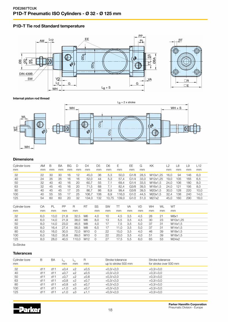
P1D-T Tie rod Standard temperature
AM
ØB
ØD
KK
VD
G
WH
L2
L12
ØD
5
ØD
6
PP
PL
SS
TT Ø
BA
VAG
L8 + S
RT
R
E
DIN 439B
SW
EE
Internal piston rod threadL9 + 2 x stroke
Dimensions
Cylinder bore AM B BA BG D D4 D5 D6 E EE G KK L2 L8 L9 L12 mm mm mm mm mm mm mm mm mm mm mm mm mm mm mm mm
32 22 30 30 16 12 45,0 36 5,3 50,0 G1/8 28,5 M10x1,25 16,0 94 146 6,0 40 24 35 35 16 16 52,0 44 5,3 57,4 G1/4 33,0 M12x1,25 19,0 105 165 6,5 50 32 40 40 16 20 60,7 55 7,1 69,4 G1/4 33,5 M16x1,5 24,0 106 180 8,0 63 32 45 45 16 20 71,5 68 7,1 82,4 G3/8 39,5 M16x1,5 24,0 121 195 8,0 80 40 45 45 17 25 86,7 86 8,9 99,4 G3/8 39,5 M20x1,5 30,0 128 220 10,0 100 40 55 55 17 25 106,7 106 8,9 116,0 G1/2 44,5 M20x1,5 32,4 138 240 14,0 125 54 60 60 20 32 134,0 132 10,75 139,0 G1/2 51,0 M27x2 45,0 160 290 18,0
Cylinder bore OA PL PP R RT SS SW TT VA VD WH WL WT mm mm mm mm mm mm mm mm mm mm mm mm mm
32 6,0 13,0 21,8 32,5 M6 4,0 10 4,5 3,5 4,5 26 21 M8x1 40 6,0 14,0 21,9 38,0 M6 8,0 13 5,5 3,5 4,5 30 23 M10x1,25 50 8,0 14,0 23,0 46,5 M8 4,0 17 7,5 3,5 5,0 37 31 M14x1,5 63 8,0 16,4 27,4 56,5 M8 6,5 17 11,0 3,5 5,0 37 31 M14x1,5 80 6,0 16,0 30,5 72,0 M10 0 22 15,0 3,5 4,0 46 39 M18x1,5100 6,0 18,0 35,8 89,0 M10 0 22 20,0 3,5 4,0 51 39 M18x1,5125 8,0 28,0 40,5 110,0 M12 0 27 17,5 5,5 6,0 65 53 M24x2
S=Stroke
Tolerances
Cylinder bore B BA L8 L9 R Stroke tolerance Stroke tolerance mm mm mm mm up to stroke 500 mm for stroke over 500 mm
32 d11 d11 ±0,4 ±2 ±0,5 +0,3/+2,0 +0,3/+3,0 40 d11 d11 ±0,7 ±2 ±0,5 +0,3/+2,0 +0,3/+3,0 50 d11 d11 ±0,7 ±2 ±0,6 +0,3/+2,0 +0,3/+3,0 63 d11 d11 ±0,8 ±2 ±0,7 +0,3/+2,0 +0,3/+3,0 80 d11 d11 ±0,8 ±3 ±0,7 +0,3/+2,0 +0,3/+3,0100 d11 d11 ±1,0 ±3 ±0,7 +0,3/+2,0 +0,3/+3,0125 d11 d11 ±1,0 ±3 ±1,1 +0,3/+2,0 +0,3/+3,0

19
Parker Hannifin CorporationPneumatic Division - Europe
PDE2667TCUK
P1D-T Pneumatic ISO Cylinders - Ø 32 - Ø 125 mm
Cyl. bore Stroke Order code mm mm
80 25 P1D-T080MF-0025Conn. G3/8 40 P1D-T080MF-0040 50 P1D-T080MF-0050 80 P1D-T080MF-0080 100 P1D-T080MF-0100 125 P1D-T080MF-0125 160 P1D-T080MF-0160 200 P1D-T080MF-0200 250 P1D-T080MF-0250 320 P1D-T080MF-0320 400 P1D-T080MF-0400 500 P1D-T080MF-0500
100 25 P1D-T100MF-0025Conn. G1/2 40 P1D-T100MF-0040 50 P1D-T100MF-0050 80 P1D-T100MF-0080 100 P1D-T100MF-0100 125 P1D-T100MF-0125 160 P1D-T100MF-0160 200 P1D-T100MF-0200 250 P1D-T100MF-0250 320 P1D-T100MF-0320 400 P1D-T100MF-0400 500 P1D-T100MF-0500
125 25 P1D-T125MF-0025Conn. G1/2 40 P1D-T125MF-0040 50 P1D-T125MF-0050 80 P1D-T125MF-0080 100 P1D-T125MF-0100 125 P1D-T125MF-0125 160 P1D-T125MF-0160 200 P1D-T125MF-0200 250 P1D-T125MF-0250 320 P1D-T125MF-0320 400 P1D-T125MF-0400 500 P1D-T125MF-0500
The cylinders are supplied complete with one zinc plated steel piston rod nut.
Double acting with stainless steel piston rod
• Bore sizes Ø 32 - Ø 125 mm
• Stroke lengths 5 - 2800 mm
• Magnetic piston as standard
• Adjustable cushioning as standard
• Low & High temperature versions
• Metal scraper version
Cyl. bore Stroke Order code mm mm
32 25 P1D-T032MF-0025Conn. G1/8 40 P1D-T032MF-0040 50 P1D-T032MF-0050 80 P1D-T032MF-0080 100 P1D-T032MF-0100 125 P1D-T032MF-0125 160 P1D-T032MF-0160 200 P1D-T032MF-0200 250 P1D-T032MF-0250 320 P1D-T032MF-0320 400 P1D-T032MF-0400 500 P1D-T032MF-0500
40 25 P1D-T040MF-0025Conn. G1/4 40 P1D-T040MF-0040 50 P1D-T040MF-0050 80 P1D-T040MF-0080 100 P1D-T040MF-0100 125 P1D-T040MF-0125 160 P1D-T040MF-0160 200 P1D-T040MF-0200 250 P1D-T040MF-0250 320 P1D-T040MF-0320 400 P1D-T040MF-0400 500 P1D-T040MF-0500
50 25 P1D-T050MF-0025Conn. G1/4 40 P1D-T050MF-0040 50 P1D-T050MF-0050 80 P1D-T050MF-0080 100 P1D-T050MF-0100 125 P1D-T050MF-0125 160 P1D-T050MF-0160 200 P1D-T050MF-0200 250 P1D-T050MF-0250 320 P1D-T050MF-0320 400 P1D-T050MF-0400 500 P1D-T050MF-0500
63 25 P1D-T063MF-0025Conn. G3/8 40 P1D-T063MF-0040 50 P1D-T063MF-0050 80 P1D-T063MF-0080 100 P1D-T063MF-0100 125 P1D-T063MF-0125 160 P1D-T063MF-0160 200 P1D-T063MF-0200 250 P1D-T063MF-0250 320 P1D-T063MF-0320 400 P1D-T063MF-0400 500 P1D-T063MF-0500
SOIP1D-T High temperature, no magnetic piston *
HighTemperature
+150°C
LowTemperature
-40°C
Note: * Change MF to ML for low temperature range magnetic piston, QC for standard temp with metal scraper

20
Parker Hannifin CorporationPneumatic Division - Europe
PDE2667TCUK
P1D-T Pneumatic ISO Cylinders - Ø 32 - Ø 125 mm
P1D-T High, low temp, hydraulic and metal scraper options
DimensionsCylinder bore AM B BA BG D D4 D5 D6 E EE G KK L2 L8 L9 L12 mm mm mm mm mm mm mm mm mm mm mm mm mm mm mm mm
32 22 30 30 16 12 45,0 36,0 5,3 48,0 G1/8 28,5 M10x1,25 16,8 94 146 6,0 40 24 35 35 16 16 52,0 44,0 5,3 53,5 G1/4 33,0 M12x1,25 19,0 105 165 6,5 50 32 40 40 16 20 60,7 55,0 7,1 65,2 G1/4 33,5 M16x1,5 24,0 106 180 8,0 63 32 45 45 16 20 71,5 68,0 7,1 75,5 G3/8 39,5 M16x1,5 24,3 121 195 8,0 80 40 45 45 17 25 86,7 86,0 8,9 95,0 G3/8 39,5 M20x1,5 30,0 128 220 10,0 100 40 55 55 17 25 106,7 106,0 8,9 114,0 G1/2 44,5 M20x1,5 34,0 138 240 14,0 125 54 60 60 20 32 134,0 132,0 10,75 139,0 G1/2 51,0 M27x2 45,0 160 290 18,0
Cylinder bore OA PL PP R RT SS SW TT VA VD WH WL WT mm mm mm mm mm mm mm mm mm mm mm
32 6,0 14,0 24,2 32,5 M6 5,5 10 4,2 3,5 4,5 26 21 M8x1 40 6,0 16,0 27,5 38,0 M6 8,0 13 5,5 3,5 4,5 30 23 M10x1,25 50 8,0 14,0 29,3 46,5 M8 9,0 17 7,5 3,5 4,5 37 31 M14x1,5 63 8,0 16,6 30,8 56,5 M8 6,5 17 10,0 3,5 4,5 37 31 M14x1,5 80 6,0 16,8 33,5 72,0 M10 0 22 11,5 3,5 4,5 46 39 M18x1,5100 6,0 20,5 37,5 89,0 M10 0 22 14,5 3,5 4,5 51 39 M18x1,5125 8,0 23,3 45,8 110,0 M12 0 27 15,0 5,5 6,5 65 53 M24x2
S=Stroke
TolerancesCylinder bore B BA L8 L9 R Stroke tolerance Stroke tolerance mm mm mm mm up to stroke 500 mm for stroke over 500 mm
32 d11 d11 ±0,4 ±2 ±0,5 +0,3/+2,0 +0,3/+3,0 40 d11 d11 ±0,7 ±2 ±0,5 +0,3/+2,0 +0,3/+3,0 50 d11 d11 ±0,7 ±2 ±0,6 +0,3/+2,0 +0,3/+3,0 63 d11 d11 ±0,8 ±2 ±0,7 +0,3/+2,0 +0,3/+3,0 80 d11 d11 ±0,8 ±3 ±0,7 +0,3/+2,0 +0,3/+3,0100 d11 d11 ±1,0 ±3 ±0,7 +0,3/+2,0 +0,3/+3,0125 d11 d11 ±1,0 ±3 ±1,1 +0,3/+2,0 +0,3/+3,0
L8 + Stroke
Internal piston rod thread
L9 + 2 x stroke

21
Parker Hannifin CorporationPneumatic Division - Europe
PDE2667TCUK
P1D-T Pneumatic ISO Cylinders - Ø 32 - Ø 125 mm
3 and 4 positions cylinders This type of cylinder function consists of two cylinders installed back to back. Two cylinders with the same stroke give a 3 positions cylinder with a symmetrical centre position, whereas different strokes give a 4 positions cylinder where the two central positions can be calculated from the different stroke lengths. 3 and 4 positions cylinders can be ordered in two ways.
Factory-fittedTie-rod P1D cylinders are completed at the factory and are joined together as one unit by special tie-rods, see position 9 in the order key.
Installation kitThere is an installation kit for cylinder bores 32 – 100 mm which makes it possible to join any two P1D cylinders together at any time, to make a 3 or 4 positions cylinders.
Tandem versionThe P1D is also available as a tandem cylinder, i.e. two cylinders connected in series. This cylinder unit has almost twice the force, which is a great advantage in restricted spaces.Tandem cylinders are available as tie-rod cylinders, P1D-T, in all bores Ø 32-125 mm.
Cyl. E TG ØFB MF A ØBA Weight Order code bore Kg mm mm mm mm mm mm mm
32 50 32,5 6,5 5 16 30 0,060 P1E-6KB0 40 60 38,0 6,5 5 16 35 0,078 P1E-6LB0 50 66 46,5 8,5 6 20 40 0,162 P1E-6MB0 63 80 56,5 8,5 6 20 45 0,194 P1E-6NB0 80 100 72,0 10,5 8 25 45 0,450 P1E-6PB0100 118 89,0 10,5 8 25 55 0,672 P1E-6QB0
Tandem: C + stroke 1 + stroke 2
Cylinder C WA bore. mm mm mm
32 221.5 7.5 40 247.5 7.5 50 256.5 7.5 63 286.5 7.5 80 309.5 7.5 100 334.5 7.5 125 396.5 11.5
WA
3 positions: B + 2 x stroke (mm)4 positions: B + Stroke 1 + Stroke 2 (mm)
Cylinder B 2 x VA bore. mm mm mm
32 247 7 40 277 7 50 293 7 63 323 7 80 355 7 100 385 7 125 461 11
2 x VA

22
Parker Hannifin CorporationPneumatic Division - Europe
PDE2667TCUK
P1D-T Pneumatic ISO Cylinders - Ø 32 - Ø 125 mm Order Key Code
Order Key Code (Model code with 20 digits used only for the trunnion , female thread on the piston rod or to specify second cylinder stroke)
Order no Cylinder bore = Standard stroke (mm) = Stroke to special order XXXX = Stroke (mm) 25 50 80 100 125 160 200 250 320 400 500 600 700 800 2800
P1D-T
P1D-T032**-XXXX 32P1D-T040**-XXXX 40P1D-T050**-XXXX 50P1D-T063**-XXXX 63P1D-T080**-XXXX 80P1D-T100**-XXXX 100P1D-T125**-XXXX 125
4 6-7-8
Stroke (mm) e.g. 0100 = 100 mm
Optional stroke lengths up to 2800 mm.Standard strokes see table below
12-13-14-15
17-18-19-20
Intermediate trunnion
90O 0O Pivots Vs Air Ports
G 7 Trunnion MT4, optional pos. (XV-meas. digits 18-19-20)
Standard strokes Standard strokes for all P1D-T cylinders comply with ISO 4393.Non standard strokes up to 2800 mm.
10
3) -30°C for low temperature version, not available for high temp.
1) In combination with metal scraper2) Piston made of acetal. for high, low temp piston
made of aluminium
15 digit order code 20 digit order code1 2 3 4 5 6 7 8 9 10 11 12 13 14 15 16 17 18 19 20
P 1 D - T 0 3 2 M F - 0 1 0 0 N G 1 2 3
Cylinder bore mm
032
040
050
063
080
100
125
9
End cover screws FunctionStandard Stainless
steel
M Q A S Double acting
F R G TDouble acting through rod
2 4 - -3 and 4 position cylinders
C J - - Tandem
Std
scr
aper
Met
al s
crap
er3
Met
al s
crap
er3
Std
scr
aper
N and stroke of the second cylinder if diffrent otherwise use 15 digits model code
Cylinder type
-Standard with cushioning and magnetic piston
FStandard with cushioning without magnetic piston
WStandard with cushioningwith magnet piston (only for high temp)
Piston rod material Seals
Sta
inle
ss s
teel
Chr
omiu
m-p
late
d st
eel 1)
Chr
om.-
pl. s
tain
less
ste
el 1)
S C RStandard temperature-20°C to +80°C. 2)
F G -
High temperature-10°C to +150°C. No magnetic function, keep - symbol in digit 4
L K -Low temperature -40°C to +80°C.
23
Parker Hannifin CorporationPneumatic Division - Europe
PDE2667TCUK
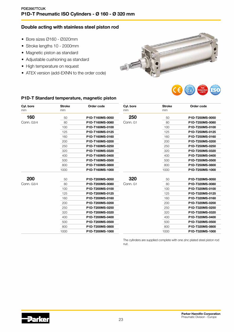
P1D-T Pneumatic ISO Cylinders - Ø 160 - Ø 320 mm
• Bore sizes Ø160 - Ø320mm
• Stroke lengths 10 - 2000mm
• Magnetic piston as standard
• Adjustable cushioning as standard
• High temperature on request
• ATEX version (add-EXNN to the order code)
Double acting with stainless steel piston rod
The cylinders are supplied complete with one zinc plated steel piston rod nut.
Cyl. bore Stroke Order code mm mm
160 50 P1D-T160MS-0050
Conn. G3/4 80 P1D-T160MS-0080
100 P1D-T160MS-0100
125 P1D-T160MS-0125
160 P1D-T160MS-0160
200 P1D-T160MS-0200
250 P1D-T160MS-0250
320 P1D-T160MS-0320
400 P1D-T160MS-0400
500 P1D-T160MS-0500
800 P1D-T160MS-0800
1000 P1D-T160MS-1000
200 50 P1D-T200MS-0050
Conn. G3/4 80 P1D-T200MS-0080
100 P1D-T200MS-0100
125 P1D-T200MS-0125
160 P1D-T200MS-0160
200 P1D-T200MS-0200
250 P1D-T200MS-0250
320 P1D-T200MS-0320
400 P1D-T200MS-0400
500 P1D-T200MS-0500
800 P1D-T200MS-0800
1000 P1D-T200MS-1000
Cyl. bore Stroke Order code mm mm
250 50 P1D-T250MS-0050
Conn. G1 80 P1D-T250MS-0080
100 P1D-T250MS-0100
125 P1D-T250MS-0125
160 P1D-T250MS-0160
200 P1D-T250MS-0200
250 P1D-T250MS-0250
320 P1D-T250MS-0320
400 P1D-T250MS-0400
500 P1D-T250MS-0500
800 P1D-T250MS-0800
1000 P1D-T250MS-1000
320 50 P1D-T320MS-0050
Conn. G1 80 P1D-T320MS-0080
100 P1D-T320MS-0100
125 P1D-T320MS-0125
160 P1D-T320MS-0160
200 P1D-T320MS-0200
250 P1D-T320MS-0250
320 P1D-T320MS-0320
400 P1D-T320MS-0400
500 P1D-T320MS-0500
800 P1D-T320MS-0800
1000 P1D-T320MS-1000
P1D-T Standard temperature, magnetic piston
HighTemperature
+150°C SOI

24
Parker Hannifin CorporationPneumatic Division - Europe
PDE2667TCUK
P1D-T Pneumatic ISO Cylinders - Ø 160 - Ø 320 mm
Cushion screw
l8 + Stroke
F1 + Stroke
P1D-T Tie rod
Note *: for bore size 320mm, front air port is on the bottom of the axis of the cylinder and the cushioning screw on the top
*Port in rodcover for Ø320 is below to the center axis!
Dimensions (mm) standard temperature
Cyl. Ø A ØBd11 ØD7E E1 F1
+ Stroke
F3 J1
max.
l2 l8+ Stroke
EE KK MM PL RT SW TG VA WH
160 72 65 33 180 45 130 11 23 50 180 G3/4 M36x2 40 25 M16 36 140 6 80
200 72 75 33 220 45 130 15 23 60 180 G3/4 M36x2 40 25 M16 36 175 6 95
250 84 90 40 280 64 136 21 27 70 200 G1 M42x2 50 32 M20 46 220 10 105
320 96 110 - 340 56 164 –20*/20 28 89,5 220 G1 M48x2 63 28 M24 55 270 10 120
Tolerances
Cylinder bore l8 TG Stroke tolerance Stroke tolerance mm mm mm up to stroke 500 mm for stroke over 500 mm
160 ±1,1 ±1,1 +0,3/+2,0 +0,3/+3,0
200 ±1,6 ±1,1 +0,3/+2,0 +0,3/+3,0
250 ±1,6 ±1,5 +0,3/+2,0 +0,3/+3,0
320 ±2,2 ±1,5 +0,3/+2,0 +0,3/+3,0
Dimensions (mm) high temperature
Cyl. Ø A ØBd11 ØD7E E1 F1
+ Stroke
F3 J1
max.
l2 l8+ Stroke
EE KK MM PL RT SW TG VA WH
160 72 65 - 186 47 133 13.5 23 55 180 G3/4 M36x2 40 23.5 M16 36 140 6 80
200 72 75 - 220 47 133 13.5 23 65 180 G3/4 M36x2 40 23.5 M16 36 175 6 95
250 84 90 - 270 51 149 14 27 69 200 G1 M42x2 50 25.5 M20 46 220 10 107
320 96 110 - 340 56 164 20 28 82 220 G1 M48x2 63 28 M24 55 270 10 120
25
Parker Hannifin CorporationPneumatic Division - Europe
PDE2667TCUK
P1D-T Pneumatic ISO Cylinders - Ø160 - Ø320 mm Order Key Code
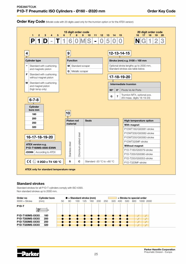
Order Key Code (Model code with 20 digits used only for the trunnion option or for the ATEX version)
6-7-8
Stroke (mm) e.g. 0100 = 100 mm
Optional stroke lengths up to 2000 mm.Standard strokes see table below.
12-13-14-15
Cylinder type
- Standard with cushioning and magnetic piston
F Standard with cushioning without magnet piston
W Standard with cushioning and magnet piston (high temp only)
4
Function
M Standard scraper
Q Metallic scraper
9
10
ATEX version e.g. P1D-T160MS-0500-EXNN
-EXNN According to ATEX
II 2GD c T4 120 °C
Cylinder bore mm
160
200
250
320
Standard strokes Standard strokes for all P1D-T cylinders comply with ISO 4393.Non standard strokes up to 2000 mm.
Order no Cylinder bore = Standard stroke (mm) = Stroke to special order XXXX = Stroke (mm) 50 80 100 125 160 200 250 320 400 500 800 1000 2000
P1D-T
P1D-T160MS-XXXX 160P1D-T200MS-XXXX 200P1D-T250MS-XXXX 250P1D-T320MS-XXXX 320
16-17-18-19-20
17-18-19-20
15 digit order code 20 digit order code1 2 3 4 5 6 7 8 9 10 11 12 13 14 15 16 17 18 19 20
P 1 D - T 1 6 0 M S - 0 5 0 0 N G 1 2 3
Piston rod material
Seals
Sta
inle
ss s
teel
Chr
omiu
m-p
late
d st
eel
S C Standard -20 °C to +80 °C
Intermediate trunnion
90° 0° Pivots Vs Air Ports
G 7Trunnion MT4, optional pos. (XV-meas. digits 18-19-20)
High temperature option
With magnet
P1DWT160/G50081-stroke
P1DWT200/G50082-stroke
P1DWT250/G50083-stroke
P1DWT320MF-stroke
Without magnet
P1D-T160/G50079-stroke
P1D-T200/G50080-stroke
P1D-T250/G50053-stroke
P1D-T320MF-stroke
ATEX only for standard temperature range

26
Parker Hannifin CorporationPneumatic Division - Europe
PDE2667TCUK
P1D-T Pneumatic ISO Cylinders - Ø 32 - Ø 125 mm Rod Guidance Modules
P1D with rod guidance modulesThe P1D series cylinders can be equipped with an external guiding device to prevent the piston rod from turning. The factory fitted guide gives a guided piston movement and enables the cylinder to take up turning moments on the piston rod, as well as greater transverse forces. The rod guidance is available with plain bearings or linear ball bearings and with H or U style. The bracket, which has pre-drilled mounting holes, is connected to the piston rod by means of a flexo coupling, which prevents the build-up of stresses in the cylinder. Guidance modules are available for bores from 32 to 100 mm, and standard stroke lengths from 25 to 250 mm. Special stroke lengths up to 500 mm can also be obtained.
Technical dataLoad See diagram on next pageWorking temperature –20 °C to +80 °C
Material specificationsBody Anodised aluminiumGuide bars, H style Stainless steel for ball bearing chrome plated for plain bearingFront plate Anodised aluminiumGuide bars, U style Stainless steelFront plate Zinc-plated steelBearings Plain bearings Linear ball bearings
Order code key for rod guidance modules
Bore size mm
K 32
L 40
M 50
N 63
P 80
Q 100
Cylinder version
E ISO cylinders
P 1 E - 4 K R H - 0 1 0 0
Guide module type
H H style, ball bearings
J H style, plain bearings
K U style, plain bearings
Stroke length (mm)
Same as for the cylinder e.g. 0100 = 100 mm.
Flange compatible with3D product range.
Self aligning adaptorfor ISO cylinder pistonrod.
Cylinder mountingconforms to ISO 6431and DIN 24335standard
Lubrication points.
Anti-rotation achieved by 4 integral bearings. Choice of linear ball bearings or plain PTFE coated bearings
Aluminium body provides 3 mounting faces.
Guide bars:Ball bearing versionsstainless steel.Plain bearing versionhard chrome plated.
Ball bearings are greased for life, for extra protection external wiper seals are fitted on each face of the unit.
Installation on P1D cylinders should have a pisron rod WH dimensions as shown in the chart below
Cyl. dim Piston rod extension mm WH mm
32 26
40 30
50 37
63 37
80 46
100 51

27
Parker Hannifin CorporationPneumatic Division - Europe
PDE2667TCUK
P1D-T Pneumatic ISO Cylinders - Ø 32 - Ø 125 mm Rod Guidance Modules
Technical information 'H style'
Maximum permissible torque (Nm)
Stroke (mm)
Maximum permissible torque (Nm)
Stroke (mm)
F
L
Formula:
C(Nm) = F(N) x L(m)
Load (kg)
Stroke (mm)
Maximum load carried
Stroke (mm)
Deflection (mm)
Maximum deflection/max load Maximum deflection/max load
Stroke (mm)
Maximum load carriedLoad (kg)
Stroke (mm)
Deflection (mm)
C
f
A2 / 2
A2
Graphs established atmid point of stroke
A2 / 2
A2
C
Graphs established atmid point of stroke
Rod guide with ball bearingsRod guide with plain bearings
60
1
2
3
45
10
15
20
304050
025
5080
125160
200250
320400
500
Ø80 & 100
Ø63Ø50
Ø40
Ø32
60
0,5
1
2
345
10
15
20
30
4050
025
5080
125160
200250
320400
500
Ø80 & 100
Ø63Ø50
Ø40
Ø32
025
5080
125160
200250
320400
500
Ø40 & 63 & 100Ø50 & 80
Ø32
0,2
0,1
0,4
0,60,8
1,5
3,0
6,0
8,0
10,0
025
5080
125160
200250
320400
500
Ø63 & 100
Ø50 & 80Ø32 & 40
0,2
0,4
0,6
0,8
1,0
1,2
1,4
025
5080 125
160200
250320
400100500
Ø100Ø80
Ø63Ø50Ø40 Ø322
468
10
15
20
25
30
35
40
025
5080 125
160200
250320
400100500
Ø100
Ø80
Ø63Ø50Ø40Ø322
468
10
15
20
25
30
35
40
45
50
55
Torque (Nm)
Torque (Nm)

28
Rod Guidance Modules
B4
2 x Ø6H7
B1A1
B5
B4
B3
B2
A2
B4
P1 P2
D5
ØD
1Ø
D2
E1
B6B4L2 B7
C3
C2
H2L5 ***L4
*
G1
R1
ØC
1R2
N1 **
L1 + S
L3 + S
P3
B4
H1
B8
ØF1
D5 depth T
H style guidance modules
Dimensions (mm)
Cyl. bore A1 A2 B1 B2 B3 B4 B5 B6 B7 B8 ØC1 C2 C3 ØD1 ØD2 D5 mm mm mm mm mm mm mm mm mm mm mm mm mm mm mm mm mm
32 50 97 45 90 78 32,5 50 4,2 12 61 12 73,5 50 6,6 11 M6 40 58 115 54 110 84 38,0 54 11,0 12 69 16 86,5 58 6,6 11 M6 50 70 137 63 130 100 46,5 72 18,8 15 85 20 103,5 70 8,4 15 M8 63 85 152 80 145 105 56,5 82 15,0 15 100 20 118,5 83 8,4 15 M8 80 105 189 100 180 130 72,0 106 21,0 20 130 25 147,0 102 10,5 18 M10100 130 213 120 200 150 89,0 131 24,5 20 150 25 171,5 125 10,5 18 M10
Cyl. bore E1 Ø F1+0,1/0 G1 L1 L2 L3 L4 L5 N1 P1
±1 P2±1 P3 R1 R2 W
mm mm mm mm mm mm mm mm mm mm mm mm mm mm mm mm
32 7 30 17 150 120 15 71 64 17 36 31 40 M6 11 5 40 7 35 24 170 130 25 71 74 17 36 36 44 M6 11 6 50 9 40 27 197 150 24 79 89 24 42 44 50 M8 16 8 63 9 45 27 222 180 24 109 89 24 58 44 60 M8 16 8 80 11 45 32 247 200 24 113 110 30 50 52 70 M10 16 10100 11 55 32 267 220 24 128 115 30 49 51 70 M10 16 10
Cyl. bore H1±0,05 H2 T Weight at 0 mm stroke Supplement weight per 10 mm stroke
mm mm mm mm kg kg
32 81 11,7 12 0,970 0,018 40 99 8,0 12 1,550 0,032 50 119 4,2 16 2,560 0,050 63 132 13,0 16 3,570 0,050 80 166 15,0 20 6,530 0,078100 190 20,5 20 8,760 0,078
S = Stroke length
* 6 hole Ø6 H7, depth 10+1/0
** Hexagon profile*** Min adjustment=0, max.=W
Parker Hannifin CorporationPneumatic Division - Europe
PDE2667TCUK
P1D-T Pneumatic ISO Cylinders - Ø 32 - Ø 125 mm

29
Rod Guidance Modules
B4
B4
2 x Ø6H7
B1A1
B5
B4
B4
B3
B2
A2
L3 + S
L1 + S
L2
B6B4
N1**
G1
B7H2
L4 L5***
C2
C3
ØF1H1
R1
ØC
1
ØD
1
ØD
2
D5
R2
E2
*
Dimensions (mm)
Cyl. bore. A1 A2 B1 B2 B3 B4 B5 B6 B7 C1 C2 C3 D1 D2 D5 mm mm mm mm mm mm mm mm mm mm mm mm mm mm mm mm
32 50 97 45 90 78 32,5 50 18,0 12 12 74 50 6,6 11 M6 40 58 115 54 110 84 38,0 54 15,5 12 16 87 58 6,6 11 M6 50 70 137 63 130 100 46,5 72 19,5 15 20 104 70 9,0 15 M8 63 85 152 80 145 105 56,5 82 29,5 15 20 119 85 9,0 15 M8 80 105 189 100 180 130 72,0 106 39,0 20 25 148 105 11,0 18 M10100 130 213 120 200 150 89,0 131 53,5 20 25 172 130 11,0 18 M10
Cyl. bore. E1 E2 Ø F1+0,1/0 G1 L1 L2 L3 L4 L5 N1 R1 R2 H1
±0,05 H2 W*** mm mm mm mm mm mm mm mm mm mm mm mm mm mm mm mm
32 10 6,5 30 30 133 72 14 44 75 13 M6 11 61 1,75 5 40 10 6,5 35 36 149 84 12 51 86 15 M8 12 69 3,50 5 50 13 9,0 40 42 175 100 12 60 103 22 M8 12 85 3,75 5 63 13 9,0 45 42 190 115 12 75 103 22 M8 12 100 1,25 5 80 16 11,0 45 49 238 162 0 112 126 27 M10 16 130 3,00 6100 16 11,0 55 49 249 167 6 112 131 27 M10 16 150 8,50 6
Cyl. bore Weight at 0 mm stroke Supplement weight per 10 mm stroke mm kg kg
32 0,970 0,018 40 1,550 0,315 50 2,560 0,493 63 3,570 0,493 80 6,530 0,770100 8,760 0,770
S = Stroke length
* 6 hole Ø6 H7, depth 10+1/0
** Width of jaw*** Min adjustment=0, max.=W
12 x D5 depth E1
U style guidance modules
Parker Hannifin CorporationPneumatic Division - Europe
PDE2667TCUK
P1D-T Pneumatic ISO Cylinders - Ø 32 - Ø 125 mm
30
Mountings
14
1312
11
10
8
7
6
54
3
2
1
11
10
7
5
21
10
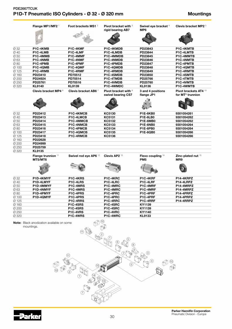
Flange trunnion 11 Swivel rod eye AP6 12 Clevis AP2 13 Flexo coupling 14 Zinc-plated nut 15
MT5/MT6 PM5 MR9
Ø 32 P1D-4KMYF P1C-4KRS P1C-4KRC P1C-4KRF P14-4KRPZ Ø 40 P1D-4LMYF P1C-4LRS P1C-4LRC P1C-4LRF P14-4LRPZØ 50 P1D-4MMYF P1C-4MRS P1C-4MRC P1C-4MRF P14-4MRPZØ 63 P1D-4NMYF P1C-4MRS P1C-4MRC P1C-4MRF P14-4MRPZØ 80 P1D-4PMYF P1C-4PRS P1C-4PRC P1C-4PRF P14-4PRPZØ 100 P1D-4QMYF P1C-4PRS P1C-4PRC P1C-4PRF P14-4PRPZØ 125 P1C-4RRS P1C-4RRC P1C-4RRF P14-4RRPZØ 160 P1C-4SRS P1C-4SRC KY1139Ø 200 P1C-4SRS P1C-4SRC KY1139Ø 250 P1C-4VRS P1C-4VRC KY1140Ø 320 P1C-4WRS P1C-4WRC KL9133
Clevis bracket MP4 6 Clevis bracket AB6 7 Pivot bracket with 8 3 and 4 positions Pivot brackets AT4 10
swivel bearing CS7 flange JP1 for MT* trunnion
Ø 32 PD23412 P1C-4KMCB KC5130 P1E-6KB0 9301054261Ø 40 PD23413 P1C-4LMCB KC5131 P1E-6LB0 9301054262Ø 50 PD23414 P1C-4MMCB KC5132 P1E-6MB0 9301054262Ø 63 PD23415 P1C-4NMCB KC5133 P1E-6NB0 9301054264Ø 80 PD23416 P1C-4PMCB KC5134 P1E-6PB0 9301054264Ø 100 PD23417 P1C-4QMCB KC5135 P1E-6QB0 9301054266Ø 125 PD23418 P1C-4RMCB KC5136 9301054266Ø 160 PD22628 Ø 200 PD24999 Ø 250 PD25759 Ø 320 KL9135
Flange MF1/MF2 1 Foot brackets MS1 2 Pivot bracket with 3 Swivel eye bracket 4 Clevis bracket MP2 5
rigid bearing AB7 MP6
Ø 32 P1C-4KMB P1C-4KMF P1C-4KMDB PD23843 P1C-4KMTB Ø 40 P1C-4LMB P1C-4LMF P1C-4LMDB PD23844 P1C-4LMTBØ 50 P1C-4MMB P1C-4MMF P1C-4MMDB PD23845 P1C-4MMTBØ 63 P1C-4NMB P1C-4NMF P1C-4NMDB PD23846 P1C-4NMTBØ 80 P1C-4PMB P1C-4PMF P1C-4PMDB PD23847 P1C-4PMTBØ 100 P1C-4QMB P1C-4QMF P1C-4QMDB PD23848 P1C-4QMTBØ 125 P1C-4RMB P1C-4RMF P1C-4RMDB PD23849 P1C-4RMTBØ 160 PD23410 PD70512 P1C-4SMDB PD23850 P1C-4SMTBØ 200 PD24924 PD70514 P1C-4TMDB PD25766 P1C-4TMTBØ 250 PD25761 PD70516 P1C-4VMDB PD25760 P1C-4VMTBØ 320 KL9140 KL9139 P1C-4WMDC KL9136 P1C-4WMTB
15
Note: Black anodization available on some mountings.
Parker Hannifin CorporationPneumatic Division - Europe
PDE2667TCUK
P1D-T Pneumatic ISO Cylinders - Ø 32 - Ø 320 mm
Cylinder mountings
31
Parker Hannifin CorporationPneumatic Division - Europe
PDE2667TCUK
P1D-T Pneumatic ISO Cylinders - Ø 32 - Ø 320 mm
1
2
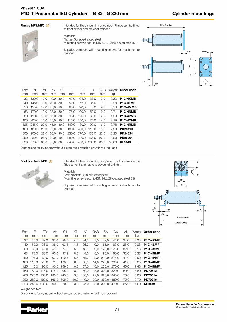
Flange MF1/MF2 Intended for fixed mounting of cylinder. Flange can be fitted to front or rear end cover of cylinder. Materials Flange: Surface-treated steel Mounting screws acc. to DIN 6912: Zinc-plated steel 8.8 Supplied complete with mounting screws for attachment to cylinder.
Foot brackets MS1 Intended for fixed mounting of cylinder. Foot bracket can be fitted to front and rear end covers of cylinder. Material: Foot bracket: Surface treated steel Mounting screws acc. to DIN 912: Zinc-plated steel 8.8 Supplied complete with mounting screws for attachment to cylinder.
SA+Stroke
XA+Stroke
ZF + Stroke
Boremm
ZFmm
MFmm
Wmm
UFmm
Emm
TFmm
Rmm
ØFBmm
Weightkg
Order code
32 130,0 10,0 16,0 80,0 45,0 64,0 32,0 7,0 0,23 P1C-4KMB40 145,0 10,0 20,0 80,0 52,0 72,0 36,0 9,0 0,28 P1C-4LMB50 155,0 12,0 25,0 80,0 65,0 90,0 45,0 9,0 0,53 P1C-4MMB63 170,0 12,0 25,0 80,0 75,0 100,0 50,0 9,0 0,71 P1C-4NMB80 190,0 16,0 30,0 80,0 95,0 126,0 63,0 12,0 1,59 P1C-4PMB
100 205,0 16,0 35,0 80,0 115,0 150,0 75,0 14,0 2,19 P1C-4QMB125 245,0 20,0 45,0 80,0 140,0 180,0 90,0 16,0 3,78 P1C-4RMB160 180,0 20,0 60,0 80,0 180,0 230,0 115,0 18,0 7,20 PD23410200 300,0 25,0 70,0 80,0 220,0 270,0 135,0 22,0 12,20 PD24924250 330,0 25,0 80,0 80,0 280,0 330,0 165,0 26,0 19,20 PD25761320 370,0 30,0 90,0 80,0 340,0 400,0 200,0 33,0 38,00 KL9140
Dimensions for cylinders without piston rod protusion or with rod lock unit
Weight per item
Boremm
Emm
TRmm
AHmm
G1mm
ATmm
A2mm
ØABmm
SAmm
XAmm
AUmm
Weightkg
Order code
32 45,0 32,0 32,0 56,0 4,5 34,0 7,0 142,0 144,0 24,0 0,06 P1C-4KMF40 52,0 36,0 36,0 62,8 4,5 36,0 9,0 161,0 163,0 28,0 0,08 P1C-4LMF50 65,0 45,0 45,0 77,6 5,5 45,0 9,0 170,0 175,0 32,0 0,16 P1C-4MMF63 75,0 50,0 50,0 87,8 5,5 45,0 9,0 185,0 190,0 32,0 0,25 P1C-4NMF80 95,0 63,0 63,0 110,5 6,5 55,0 12,0 210,0 215,0 41,0 0,50 P1C-4PMF
100 115,0 75,0 71,0 128,0 6,5 56,0 14,0 220,0 230,0 41,0 0,85 P1C-4QMF125 140,0 90,0 90,0 159,5 8,0 67,0 16,0 250,0 270,0 45,0 1,48 P1C-4RMF160 180,0 115,0 115,0 205,0 8,0 80,0 18,0 300,0 320,0 60,0 3,80 PD70512200 220,0 135,0 135,0 245,0 9,0 100,0 22,0 320,0 345,0 70,0 5,00 PD70514250 280,0 165,0 165,0 305,0 10,0 110,0 26,0 350,0 380,0 75,0 9,70 PD70516320 340,0 200,0 200,0 370,0 23,0 125,0 33,0 390,0 470,0 85,0 17,00 KL9139
Dimensions for cylinders without piston rod protusion or with rod lock unit

Cylinder mountings
32
Parker Hannifin CorporationPneumatic Division - Europe
PDE2667TCUK
P1D-T Pneumatic ISO Cylinders - Ø 32 - Ø 320 mm
4
3
Dimensions for cylinders without piston rod protusion or with rod lock unit
Swivel eye bracket MP6 Intended for use together with clevis bracket GA Material: Bracket: Aluminium Swivel bearing acc. to DIN 648K: Hardened steel Supplied complete with mounting screws for attachment to cylinder.
Pivot bracket with Intended for flexible mounting of cylinder. The rigid bearing AB7 pivot bracket can be combined with clevis bracket MP2.
Material: Pivot bracket: Aluminium Bearing: Sintered oil-bronze bushing
XN+Stroke
Boremm
R1mm
ØCX H7mm
G1mm
CAmm
H6mm
G2mm
G3mm
EMmm
I3mm
Ød2mm
I5mm
ØS5mm
K1mm
K2mm
Weightkg
Order codeNotanodised
Order codeBlackanodised
32 10,0 10,0 21,0 32,0 8,0 18,0 31,0 25,5 10,0 - - 6,6 38,0 51,0 0,06 - P1C-4KMD
40 11,0 12,0 24,0 36,0 10,0 22,0 35,0 27,0 15,0 - - 6,6 41,0 54,0 0,08 - P1C-4LMD
50 13,0 12,0 33,0 45,0 12,0 30,0 45,0 31,0 16,0 - - 9,0 50,0 65,0 0,15 - P1C-4MMD
63 15,0 16,0 37,0 50,0 12,0 35,0 50,0 39,0 16,0 - - 9,0 52,0 67,0 0,20 - P1C-4NMD
80 15,0 16,0 47,0 63,0 14,0 40,0 60,0 49,0 20,0 - - 11,0 66,0 86,0 0,33 - P1C-4PMD
100 19,0 20,0 55,0 71,0 15,0 50,0 70,0 59,0 20,0 - - 11,0 76,0 96,0 0,49 - P1C-4QMD
125 22,5 25,0 70,0 90,0 20,0 60,0 90,0 69,0 30,0 - - 14,0 94,0 124,0 1,02 - P1C-4RMD
160 31,5 30,0 97,0 115,0 25,0 88,0 126,0 90,0 36,0 20,0 4,0 14,0 118,0 156,0 6,50 P1C-4SMDB -
200 31,5 30,0 105,0 135,0 30,0 90,0 130,0 90,0 40,0 26,0 4,0 18,0 122,0 162,0 8,00 P1C-4TMDB -
250 40,0 40,0 128,0 165,0 35,0 110,0 160,0 110,0 45,0 33,0 4,5 22,0 150,0 200,0 13,50 P1C-4VMDB -
320 45,0 45,0 150,0 200,0 40,0 122,0 186,0 120,0 55,0 - - 26,0 170,0 234,0 21,90 P1C-4WMDC -
Boremm
EXmm
XNmm
H8mm
H4mm
MSmm
ØCX H7mm
Weightkg
Order codeNotanodised
Order codeBlackanodised
32 14,0 142,0 10,0 12,0 16,0 10,0 0,10 - P1C-4KMSA40 16,0 160,0 10,0 15,0 21,0 12,0 0,11 - P1C-4LMSA50 16,0 170,0 11,0 16,0 23,0 12,0 0,20 - P1C-4MMSA63 21,0 190,0 11,0 21,0 27,0 16,0 0,27 - P1C-4NMSA80 21,0 210,0 15,0 21,0 29,0 16,0 0,52 - P1C-4PMSA
100 25,0 230,0 16,0 25,0 34,0 20,0 0,72 - P1C-4QMSA125 31,0 275,0 20,0 30,0 40,0 25,0 1,53 - P1C-4RMSA160 37,0 315,0 20,0 35,0 48,0 30,0 2,60 PD23850 -200 43,0 335,0 24,0 36,0 47,0 30,0 11,30 PD25766 -250 49,0 375,0 28,0 42,0 53,0 40,0 19,00 PD25760 -320 60,0 420,0 30,0 50,0 63,0 45,0 30,30 KL9136 -
G1 EMR1
l3
K1
K2
ØS5
l 5
Ød2
G2G3
CA
H6

Cylinder mountings
33
Parker Hannifin CorporationPneumatic Division - Europe
PDE2667TCUK
P1D-T Pneumatic ISO Cylinders - Ø 32 - Ø 320 mm
6
5
Clevis bracket MP4 Intended for flexible mounting of cylinder. Clevis bracket MP4 can be combined with clevis bracket MP2. Material: Clevis bracket: Aluminium Mounting screws acc. to DIN 912: Zinc-plated steel 8.8 Supplied complete with mounting screws for attachment to cylinder .
XD+Stroke
Clevis bracket MP2 Intended for flexible mounting of cylinder. Clevis bracket MP2 can be combined with clevis bracket MP4. Material: Clevis bracket: Aluminium Pin: Surface hardened steel Circlips according to DIN 471: Spring steel Mounting screws acc. to DIN 912: Zinc-plated steel 8.8 Supplied complete with mounting screws for attachment to cylinder .
XD+Stroke
Boremm
ELmm
XDmm
ØCD H9mm
CB H14mm
UBmm
H8mm
Lmm
MRmm
Weightkg
Order codeNot
anodised
Order codeBlack
anodised
32 53,0 142,0 10,0 26,0 45,0 10,0 12,0 11,0 0,08 - P1C-4KMT40 60,0 160,0 12,0 28,0 52,0 10,0 15,0 13,0 0,11 - P1C-4LMT50 68,0 170,0 12,0 32,0 60,0 11,0 16,0 18,0 0,14 - P1C-4MMT63 78,0 190,0 16,0 40,0 70,0 11,0 21,0 18,0 0,29 - P1C-4NMT80 98,0 210,0 16,0 50,0 90,0 15,0 21,0 22,0 0,36 - P1C-4PMT
100 118,0 230,0 20,0 60,0 110,0 16,0 25,0 22,0 0,64 - P1C-4QMT125 139,0 275,0 25,0 70,0 130,0 20,0 30,0 30,0 1,17 - P1C-4RMT160 172,0 315,0 30,0 90,0 170,0 20,0 35,0 30,0 2,60 P1C-4SMTB -200 172,0 335,0 30,0 90,0 170,0 25,0 35,0 31,0 4,10 P1C-4TMTB -250 280,0 375,0 40,0 110,0 200,0 25,0 45,0 41,0 7,10 P1C-4VMTB -320 340,0 420,0 45,0 120,0 220,0 30,0 50,0 54,0 31,0 P1C-4WMTB -
Boremm
EWmm
XDmm
H8mm
Lmm
MRmm
ØCDmm
Weightkg
Order codeNot
anodised
Order codeBlack
anodised
32 26,0 142,0 10,0 12,0 11,0 10,0 0,09 - P1C-4KME
40 28,0 160,0 10,0 15,0 13,0 12,0 0,13 - P1C-4LME
50 32,0 170,0 11,0 16,0 18,0 12,0 0,17 - P1C-4MME
63 40,0 190,0 11,0 21,0 18,0 16,0 0,36 - P1C-4NME
80 50,0 210,0 15,0 21,0 22,0 16,0 0,58 - P1C-4PME
100 60,0 230,0 16,0 25,0 22,0 20,0 0,89 - P1C-4QME
125 70,0 275,0 20,0 30,0 30,0 25,0 1,75 - P1C-4RME
160 90,0 315,0 20,0 35,0 30,0 30,0 2,70 PD22628 -
200 90,0 335,0 25,0 35,0 31,0 30,0 4,20 PD24999 -
250 110,0 375,0 25,0 45,0 41,0 40,0 15,70 PD25759 -
320 120,0 420,0 30,0 50,0 46,0 45,0 33,00 KL9135 -
Dimensions for cylinders without piston rod protusion or with rod lock unit
Dimensions for cylinders without piston rod protusion or with rod lock unit

Cylinder mountings
34
Parker Hannifin CorporationPneumatic Division - Europe
PDE2667TCUK
P1D-T Pneumatic ISO Cylinders - Ø 32 - Ø 320 mm
7
8
Clevis bracket AB6 Intended for flexible mounting of cylinder. Clevis bracket GA can be combined with pivot bracket with swivel bearing, swivel eye bracket and swivel rod eye. Material: Clevis bracket: Aluminium Pin: Surface hardened steel Locking pin: Spring steel Circlips according to DIN 471: Spring steel Mounting screws acc. to DIN 912: Zinc-plated steel 8.8 Supplied complete with mounting screws for attachment to cylinder .
Pivot bracket with Intended for use together with clevis bracket GA.swivel bearing CS7
Material: Pivot bracket: Surface-treated steel Swivel bearing acc. to DIN 648K: Hardened steel
Boremm
Cmm
B2mm
B1mm
B3mm
Tmm
Emm
ØCNmm
L1mm
FLmm
L2mm
R1mm
R2mm
Lmm
XDmm
Weightkg
Order codeBlackanodised
32 41 34 14 3,3 3 45 10 11,5 22 5,5 11 17 12 142 0,09 P1C-4KMCA
40 48 40 16 4,3 4 55 12 12,0 25 5,5 13 20 15 160 0,13 P1C-4LMCA
50 54 45 21 4,3 4 65 16 14,0 27 6,5 18 22 17 170 0,17 P1C-4MMCA
63 60 51 21 4,3 4 75 16 14,0 32 6,5 18 25 20 190 0,36 P1C-4NMCA
80 75 65 25 4,3 4 95 20 16,0 36 10,0 22 30 20 210 0,58 P1C-4PMCA
100 85 75 25 4,3 4 115 20 16,0 41 10,0 22 32 25 230 0,89 P1C-4QMCA
125 110 97 37 6,3 6 140 30 24,0 50 10,0 30 42 30 275 1,75 P1C-4RMCA
Boremm
ENmm
EUmm
Zmm
ØS5mm
K1mm
K2mm
ERmm
G1mm
ØCNmm
CHmm
H6mm
G2mm
G3mm
Weightkg
Order codeBlackanodised
32 14 10,5 4° 6,6 38 51 16 21 10 32 10 18 31 0,18 P1C-4KMA
40 16 12,0 4° 6,6 41 54 18 24 12 36 10 22 35 0,25 P1C-4LMA
50 21 15,0 4° 9,0 50 65 21 33 16 45 12 30 45 0,47 P1C-4MMA
63 21 15,0 4° 9,0 52 67 23 37 16 50 12 35 50 0,57 P1C-4NMA
80 25 18,0 4° 11,0 66 86 28 47 20 63 14 40 60 1,05 P1C-4PMA
100 25 18,0 4° 11,0 76 96 30 55 20 71 15 50 70 1,42 P1C-4QMA
125 37 25,0 4° 14,0 94 124 40 70 30 90 20 60 90 3,10 P1C-4RMA
Dimensions for cylinders without piston rod protusion or with rod lock unit
XD + Stroke

Cylinder mountings
35
Parker Hannifin CorporationPneumatic Division - Europe
PDE2667TCUK
P1D-T Pneumatic ISO Cylinders - Ø 32 - Ø 320 mm
3 and 4 positions flange Mounting kit for back to back mounted cylinders, JP1 3 and 4 positions cylinders. Material: Mounting: Aluminium Mounting screws: Zinc-plated steel 8.8
Boremm
Emm
TGmm
ØFBmm
MFmm
Amm
ØBAmm
Weightkg
Order code
32 50 32,5 6,5 5 16 30 0,06 P1E-6KB0
40 60 38,0 6,5 5 16 35 0,078 P1E-6LB0
50 66 46,5 8,5 6 20 40 0,162 P1E-6MB0
63 80 56,5 8,5 6 20 45 0,194 P1E-6NB0
80 100 72,0 10,5 8 25 45 0,45 P1E-6PB0
100 118 89,0 10,5 8 25 55 0,672 P1E-6QB0
Pivot brackets AT4for MT* trunnion
Bore B1 B2 A C d1 d2 H1 H2 fx45° Weight Order code H13 min kg mm mm mm mm mm mm mm mm mm mm
32 46 18,0 32 10,5 12 6,6 30 15 1,0 0,04* 9301054261
40 55 21,0 36 12,0 16 9,0 36 18 1,6 0,07* 9301054262
50 55 21,0 36 12,0 16 9,0 36 18 1,6 0,07* 9301054262
63 65 23,0 42 13,0 20 11,0 40 20 1,6 0,12* 9301054264
80 65 23,0 42 13,0 20 11,0 40 20 1,6 0,12* 9301054264
100 75 28,5 50 16,0 25 14,0 50 25 2,0 0,21* 9301054266
125 75 28,5 50 16,0 25 14,0 50 25 2,0 0,21* 9301054266
* Weight per item.
10 Intended for use together with the trunnion MT4. Material Pivot bracket: Surface-treated aluminium Bearing acc. to DIN 1850 C: Sintered oil-bronze bushing Supplied in pairs.

Cylinder mountings
36
Parker Hannifin CorporationPneumatic Division - Europe
PDE2667TCUK
P1D-T Pneumatic ISO Cylinders - Ø 32 - Ø 320 mm
11Flange trunnion Intended for articulated mounting of cylinder. This trunnion MT5/MT6 can be flange mounted on the front or rear end cover of all P1D cylinders. Individual trunnions have order code as shown to the right. Material: Trunnion: zinc plated steel Screws: zinc plated steel, 8.8 Delivered complete with mounting screws for attachment to the cylinder
Intermediate trunnion The trunnion is MT4 for P1D-T factory-fitted at an optionalMT4 location specified by the XV-measure - Combined with pivot brackets AT4.
Material: Trunnion: Zinc plated steel Trunnion with optional location
The trunnion for the P1D-T is ordered with letter G in position 17 and desired XV-measure (3-digit measure in mm) in positions 18-20. e.g. P1D-T160MS-0500NG300
Boremm
TMh14mm
TLh14mm
ØTDe9
mm
Rmm
UWmm
L1mm
XV1
mmXV2
mmWeight
kgOrder code
32 50 12 12 1,0 46 14 19,5 127,0 0,17 P1D-4KMYF
40 63 16 16 1,6 59 19 21,0 144,0 0,43 P1D-4LMYF
50 75 16 16 1,6 69 19 28,0 152,5 0,55 P1D-4MMYF
63 90 20 20 1,6 84 24 25,5 170,0 1,10 P1D-4NMYF
80 110 20 20 1,6 102 24 34,5 186,0 1,66 P1D-4PMYF
100 132 25 25 2,0 125 29 37,0 203,5 3,00 P1D-4QMYF
XV min
XVstd+ 1/2 Stroke
XVcal+ Stroke
XV2 + Stroke
Important: If the cylinder is ordered with a piston rod protusion (WH dimension), please add this extra length to XVmin, XVstd and XVmax.
0° toports90° to
ports
Bore TK TL TM ØTD UWh14 h14 e9
mm mm mm mm mm mm
32 15 12 50 12 4640 20 16 63 16 5950 20 16 75 16 6963 25 20 90 20 8480 25 20 110 20 102100 30 25 132 25 125125 32 25 160 25 155160 40 32 200 32 190200 40 32 250 32 240250 50 40 320 40 296320 65 50 400 50
XV min XV std XV cal WeightP1D-T
mm mm mm kg
62 73 84 0.1373 83 92 0.3181 90 100 0.3789 98 106 0.6998 110 122 0.89111 120 130 1.58132 145 158 2.60145 170 195 6.10160 185 210 8.10194 205 216 14.80210 230 251 16.00
Please note: If the cylinder is ordered with a piston rod protusion (WH dimension), please add this extra length to XV1 and XV2.
160 48 32 200 32 190200 48 32 250 32 240250 60 40 320 40 296320 65 50 400 50
151 170 189 6.10166 185 204 8.10188 207 226 14.80210 230 251 16.00
High temp version

37
Parker Hannifin CorporationPneumatic Division - Europe
PDE2667TCUK
P1D-T Pneumatic ISO Cylinders - Ø 32 - Ø 320 mm Piston rod mountings
13
12Swivel rod eye AP6 Swivel rod eye for articulated mounting of cylinder. Swivel rod eye can be combined with clevis bracket GA. Maintenance-free. Material:
According to ISO 8140
Clevis AP2 Material for P1C order codes: Clevis, clip: Galvanized steel Pin: Hardened steel Material for P1S order codes: Clevis, clip: Stainless steel Pin: Stainless steel Material for KY order codes: Clevis, clip: Galvanized steel Pin: Steel
According to ISO 8139
Boremm
Amm
B min
mmB max
mmCEmm
ØCNH9mm
ENh12mm
ERmm
KKmm
LE min
mmN
mmO
mmZ
mmWeight
kgOrder code Order code
Stainless steel
32 20 48,0 55 43 10 14 14 M10x1,25 15 17 10,5 12° 0,08 P1C-4KRS P1S-4JRT
40 22 56,0 62 50 12 16 16 M12x1,25 17 19 12,0 12° 0,12 P1C-4LRS P1S-4LRT
50 28 72,0 80 64 16 21 21 M16x1,5 22 22 15,0 15° 0,25 P1C-4MRS P1S-4MRT
63 28 72,0 80 64 16 21 21 M16x1,5 22 22 15,0 15° 0,25 P1C-4MRS P1S-4MRT
80 33 87,0 97 77 20 25 25 M20x1,5 26 32 18,0 15° 0,46 P1C-4PRS P1S-4PRT
100 33 87,0 97 77 20 25 25 M20x1,5 26 32 18,0 15° 0,46 P1C-4PRS P1S-4PRT
125 51 123,5 137 110 30 37 35 M27x2 36 41 25,0 15° 1,28 P1C-4RRS P1S-4RRT
160 56 125 35 43 40 M36x2 41 50 28,0 1,60 P1C-4SRS -
200 56 125 35 43 40 M36x2 41 50 28,0 1,60 P1C-4SRS -
250 60 142 40 49 45 M42x2 46 55 33,0 3,50 P1C-4VRS -
320 65 160 50 60 58 M48x2 59 65 45,0 5,20 P1C-4WRS -
Boremm
Amm
B min
mmB max
mmCEmm
CKh11/e9
mm
CLmm
CMmm
ERmm
KKmm
LEmm
Omm
Weightkg
Order code Order codeStainlesssteel
32 20 45,0 52 40 10 20 10 16 M10x1,25 20 28,0 0,09 P1C-4KRC P1S-4JRD
40 24 54,0 60 48 12 24 12 19 M12x1,25 24 32,0 0,15 P1C-4LRC P1S-4LRD
50 32 72,0 80 64 16 32 16 25 M16x1,5 32 41,5 0,35 P1C-4MRC P1S-4MRD
63 32 72,0 80 64 16 32 16 25 M16x1,5 32 41,5 0,35 P1C-4MRC P1S-4MRD
80 40 90,0 100 80 20 40 20 32 M20x1,5 40 50,0 0,75 P1C-4PRC P1S-4PRD
100 40 90,0 100 80 20 40 20 32 M20x1,5 40 50,0 0,75 P1C-4PRC P1S-4PRD
125 56 123,5 137 110 30 55 30 45 M27x2 54 72,0 2,10 P1C-4RRC P1S-4RRD
160 72 144 35 70 36 M36x2 72 2,90 P1C-4SRC -
200 72 144 35 70 36 M36x2 72 2,90 P1C-4SRC -
250 84 168 40 85 40 M42x2 84 6,00 P1C-4VRC -
320 96 192 50 90 50 M48x2 96 7,90 P1C-4WRC -
Swivel rod eye: Zinc-plated steelSwivel bearing according to DIN 648K: Hardened steel
Swivel rod eye: Stainless steelSwivel bearing according to DIN 648K: Hardened steel

38
Parker Hannifin CorporationPneumatic Division - Europe
PDE2667TCUK
P1D-T Pneumatic ISO Cylinders - Ø 32 - Ø 320 mm Piston rod mountings
14
15Nut MR9 Intended for fixed mounting of accessories to the piston rod. Material: Zinc-plated steel All P1D cylinders are delivred with a zinc-plated steel piston rod nut, except P1D Ultra Clean, which is delivered with a stainless steel piston rod nut instead.
Stainless steel nut MR9 Intended for fixed mounting of accessories to the piston rod. Material: Stainless steel A2 All P1D cylinders are delivred with a zinc-plated steel piston rod nut, exceptP1D-C delivered with a stainless steel piston rod nut instead.
Acid-proof nut MR9 Intended for fixed mounting of accessories to the piston rod. Material: Acid-proof steel A4 Cylinders with acid-proof piston rod are supplied with nut of acid-proof steel
Flexo coupling PM5 Flexo coupling for articulated mounting of piston rod. Flexo fitting is intended to take up axial angle errors within a range of ±4°. Material Flexo coupling, nut: Zinc-plated steel Supplied complete with galvanized adjustment nut.
* Supplied as pack of 10 off** Weight per item
According to DIN 439 B
Boremm
KKmm
Bmm
Cmm
Dmm
Emm
ØFmm
SW1mm
SW2mm
SW3mm
SW4mm
SW5mm
Weightkg
Order code
32 M10x1,25 20 23 73 31 21,0 12 30 30 19 17 0,21 P1C-4KRF
40 M12x1,25 24 23 77 31 21,0 12 30 30 19 19 0,22 P1C-4LRF
50 M16x1,5 32 32 108 45 33,5 19 41 41 30 24 0,67 P1C-4MRF
63 M16x1,5 32 32 108 45 33,5 19 41 41 30 24 0,67 P1C-4MRF
80 M20x1,5 40 42 122 56 33,5 19 41 41 30 30 0,72 P1C-4PRF
100 M20x1,5 40 42 122 56 33,5 19 41 41 30 30 0,72 P1C-4PRF
125 M27x2 54 48 147 51 39,0 24 55 55 32 41 1,80 P1C-4RRF
160 M36x2 72 50 241 110 56,0 36 75 75 50 55 5,10 KY1139
200 M36x2 72 50 241 110 56,0 36 75 75 50 55 5,10 KY1139
250 M42x2 82 88 271 120 - 36 80 80 60 65 7,90 KY1140
320 M48x2 82 88 271 120 - 42 80 80 60 75 7,90 KY9133
Nut Stainless steel nut Acid-proof nut
Boremm
Amm
Bmm
Cmm
Weightkg
Order code Order code Order code
32 17 5,0 M10x1,25 0,007 P14-4KRPZ P14-4KRPS P14-4KRPX40 19 6,0 M12x1,25 0,010 P14-4LRPZ P14-4LRPS P14-4LRPX50 24 8,0 M16x1,5 0,021 P14-4MRPZ P14-4MRPS P14-4MRPX63 24 8,0 M16x1,5 0,021 P14-4MRPZ P14-4MRPS P14-4MRPX80 30 10,0 M20x1,5 0,040 P14-4PRPZ P14-4PRPS P14-4PRPX
100 30 10,0 M20x1,5 0,040 P14-4PRPZ P14-4PRPS P14-4PRPX125 41 13,5 M27x2 0,100 P14-4RRPZ P14-4RRPS P14-4RRPX
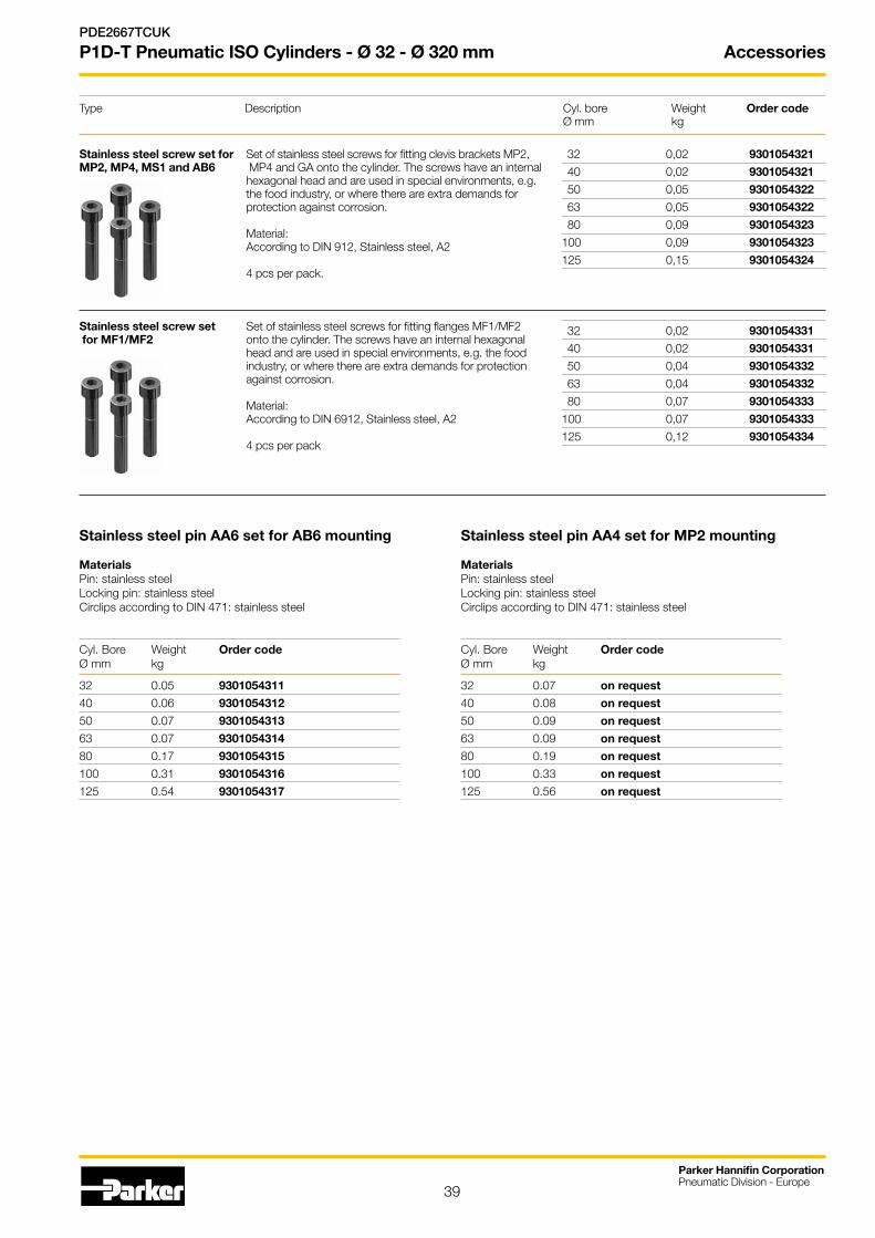
39
Parker Hannifin CorporationPneumatic Division - Europe
PDE2667TCUK
P1D-T Pneumatic ISO Cylinders - Ø 32 - Ø 320 mm Accessories
Type Description Cyl. bore Weight Order code Ø mm kg
Stainless steel pin AA6 set for AB6 mounting
MaterialsPin: stainless steelLocking pin: stainless steelCirclips according to DIN 471: stainless steel
Cyl. Bore Weight Order codeØ mm kg
32 0.05 9301054311
40 0.06 9301054312
50 0.07 9301054313
63 0.07 9301054314
80 0.17 9301054315
100 0.31 9301054316
125 0.54 9301054317
Stainless steel pin AA4 set for MP2 mounting
MaterialsPin: stainless steelLocking pin: stainless steelCirclips according to DIN 471: stainless steel
Cyl. Bore Weight Order codeØ mm kg
32 0.07 on request
40 0.08 on request
50 0.09 on request
63 0.09 on request
80 0.19 on request
100 0.33 on request
125 0.56 on request
32 0,02 9301054321
40 0,02 9301054321
50 0,05 9301054322
63 0,05 9301054322
80 0,09 9301054323
100 0,09 9301054323
125 0,15 9301054324
32 0,02 9301054331
40 0,02 9301054331
50 0,04 9301054332
63 0,04 9301054332
80 0,07 9301054333
100 0,07 9301054333
125 0,12 9301054334
Stainless steel screw set for Set of stainless steel screws for fitting clevis brackets MP2,MP2, MP4, MS1 and AB6 MP4 and GA onto the cylinder. The screws have an internal
hexagonal head and are used in special environments, e.g. the food industry, or where there are extra demands for protection against corrosion. Material: According to DIN 912, Stainless steel, A2 4 pcs per pack.
Stainless steel screw set Set of stainless steel screws for fitting flanges MF1/MF2 for MF1/MF2 onto the cylinder. The screws have an internal hexagonal
head and are used in special environments, e.g. the food industry, or where there are extra demands for protection against corrosion. Material: According to DIN 6912, Stainless steel, A2 4 pcs per pack
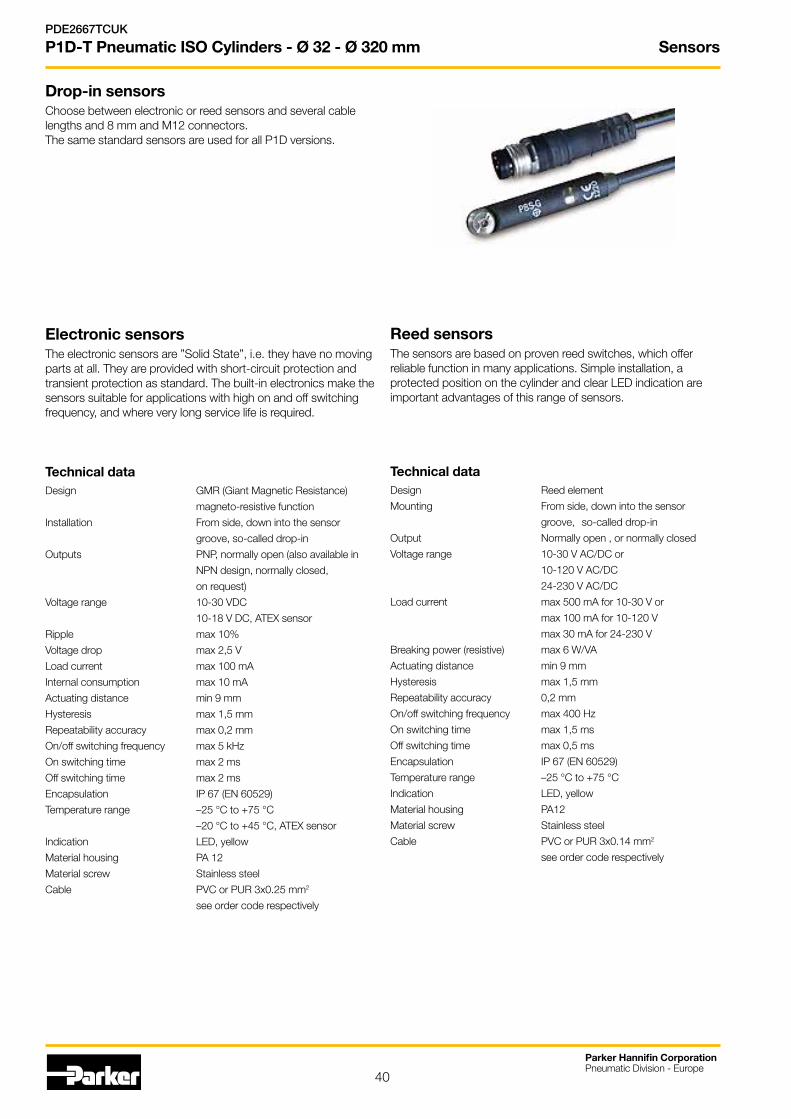
Sensors
40
Parker Hannifin CorporationPneumatic Division - Europe
PDE2667TCUK
P1D-T Pneumatic ISO Cylinders - Ø 32 - Ø 320 mm
Drop-in sensors Choose between electronic or reed sensors and several cable lengths and 8 mm and M12 con nectors.The same standard sensors are used for all P1D versions.
Electronic sensors The electronic sensors are ”Solid State”, i.e. they have no moving parts at all. They are provided with short-circuit protection and transient protection as standard. The built-in electronics make the sensors suitable for applications with high on and off switching frequency, and where very long service life is required.
Technical dataDesign GMR (Giant Magnetic Resistance)
magneto-resistive function
Installation From side, down into the sensor
groove, so-called drop-in
Outputs PNP, normally open (also available in
NPN design, normally closed,
on request)
Voltage range 10-30 VDC
10-18 V DC, ATEX sensor
Ripple max 10%
Voltage drop max 2,5 V
Load current max 100 mA
Internal consumption max 10 mA
Actuating distance min 9 mm
Hysteresis max 1,5 mm
Repeatability accuracy max 0,2 mm
On/off switching frequency max 5 kHz
On switching time max 2 ms
Off switching time max 2 ms
Encapsulation IP 67 (EN 60529)
Temperature range –25 °C to +75 °C
–20 °C to +45 °C, ATEX sensor
Indication LED, yellow
Material housing PA 12
Material screw Stainless steel
Cable PVC or PUR 3x0.25 mm2
see order code respectively
Reed sensors The sensors are based on proven reed switches, which offer reliable function in many applications. Simple installation, a protected position on the cylinder and clear LED indication are important advantages of this range of sensors.
Technical dataDesign Reed element
Mounting From side, down into the sensor
groove, so-called drop-in
Output Normally open , or normally closed
Voltage range 10-30 V AC/DC or
10-120 V AC/DC
24-230 V AC/DC
Load current max 500 mA for 10-30 V or
max 100 mA for 10-120 V
max 30 mA for 24-230 V
Breaking power (resistive) max 6 W/VA
Actuating distance min 9 mm
Hysteresis max 1,5 mm
Repeatability accuracy 0,2 mm
On/off switching frequency max 400 Hz
On switching time max 1,5 ms
Off switching time max 0,5 ms
Encapsulation IP 67 (EN 60529)
Temperature range –25 °C to +75 °C
Indication LED, yellow
Material housing PA12
Material screw Stainless steel
Cable PVC or PUR 3x0.14 mm2
see order code respectively

Sensors
41
Parker Hannifin CorporationPneumatic Division - Europe
PDE2667TCUK
P1D-T Pneumatic ISO Cylinders - Ø 32 - Ø 320 mm
Sensors
Brown
Black
Blue
+(–) V AC/DC
Signal
–(+) V AC/DC
Brown
Black
Blue
Brown
Blue
P8S-GRFLX / P8S-GRFLX2
+(–) V AC/DC
Signal–(+) V AC/DC
M8 M12
+V DC
Signal
– V DC+ V DC
Signal– V DC
M8 M12
Electronic sensors Reed sensors
P8S-GCFPX
Brown
Blue
Dimensions Sensor mounting - P1D-T 32 - 100 mm
Order code
PD48955
Sensor mounting - P1D-T 125 - 320 mm
Order code
PD48956
34
20
6
48,5
24,5
8
24
Sensors
42
Parker Hannifin CorporationPneumatic Division - Europe
PDE2667TCUK
P1D-T Pneumatic ISO Cylinders - Ø 32 - Ø 320 mm
Connecting cables with one connectorThe cables have an integral snap-in female connector.
Ordering data
Output/function Cable/connector Weight Order code kg
Electronic sensors , 10-30 V DC
PNP type, normally open 0,27 m PUR-cable and 8 mm snap-in male connector 0,007 P8S-GPSHX
PNP type, normally open 0,27 m PUR-cable and M12 screw male connector 0,015 P8S-GPMHX
PNP type, normally open 3 m PVC-cable without connector 0,030 P8S-GPFLX
PNP type, normally open 10 m PVC-cable without connector 0,110 P8S-GPFTX
Reed sensors , 10-30 V AC/DC
Normally open 0,27 m PUR-cable and 8 mm snap-in male connector 0,007 P8S-GSSHX
Normally open 0,27 m PUR-cable and M12 screw male connector 0,015 P8S-GSMHX
Normally open 3 m PVC-cable without connector 0,030 P8S-GSFLX
Normally open 10 m PVC-cable without connector 0,110 P8S-GSFTX
Normally closed 5m PVC-cable without connector 2) 0,050 P8S-GCFPX
Reed sensors, 10-120 V AC/DC
Normally open 3 m PVC-cable without connector 0,030 P8S-GRFLX
Reed sensorer, 24-230 V AC/DC
Normally open 3 m PVC-cable without connector 0,030 P8S-GRFLX2
2) Without LED
Adapter for tie-rod design
Description Weight Order code kg
Double jointed adapter for cylinder P1D-T cylinder bore Ø32 to Ø100 mm 0,07 PD48955
Double jointed adapter for cylinder P1D-T cylinder bore Ø125 to Ø320 mm 0,07 PD48956
Type of cable Cable/connector Weight Order code kg
Cables for sensors, complete with one female connector
Cable, Flex PVC 3 m, 8 mm Snap-in connector 0,07 9126344341
Cable, Flex PVC 10 m, 8 mm Snap-in connector 0,21 9126344342
Cable, Polyurethane 3 m, 8 mm Snap-in connector 0,01 9126344345
Cable, Polyurethane 10 m, 8 mm Snap-in connector 0,20 9126344346
Cable, Polyurethane 5 m, M12 screw connector 0,07 9126344348
Cable, Polyurethane 10 m, M12 screw connector 0,20 9126344349
Technical data
Operating voltage max. 32 V AC/DC
Operating current per contact max. 4 A
Connection cross section 0.25...0.5mm2 (conductor diameter min 0.1mm)
Protection IP65 and IP67 when plugged and screwed down (EN 60529)
Temperature range -25...+85 °C
Male connectors for connecting cablesCable connectors for producing your own connecting cables. The connectors can be quickly attached to the cable without special tools. Only the outer sheath of the cable is removed. The connectors are available for M8 and M12 screw connectors and meet protection class IP 65.
Connector Weight Order code kg
M8 screw connector 0,017 P8CS0803J
M12 screw connector 0,022 P8CS1204J
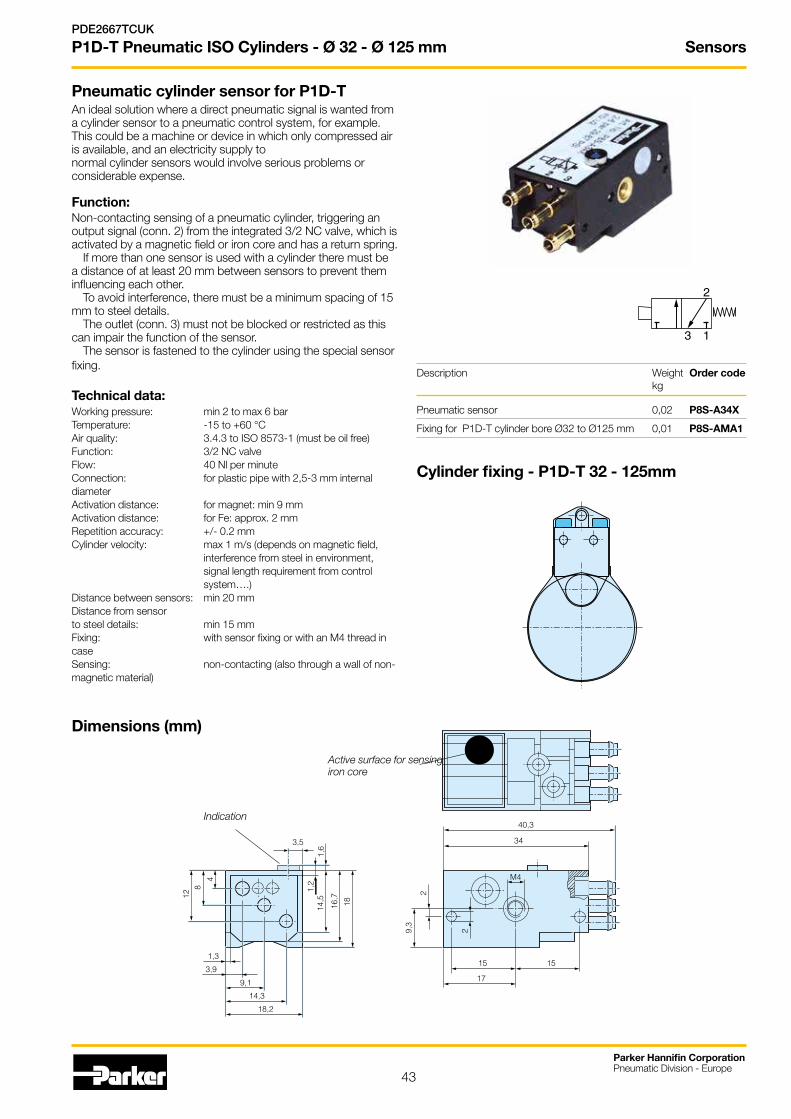
Sensors
43
Parker Hannifin CorporationPneumatic Division - Europe
PDE2667TCUK
P1D-T Pneumatic ISO Cylinders - Ø 32 - Ø 125 mm
Pneumatic cylinder sensor for P1D-TAn ideal solution where a direct pneumatic signal is wanted from a cylinder sensor to a pneumatic control system, for example. This could be a machine or device in which only compressed air is available, and an electricity supply to normal cylinder sensors would involve serious problems or considerable expense.
Function:Non-contacting sensing of a pneumatic cylinder, triggering an output signal (conn. 2) from the integrated 3/2 NC valve, which is activated by a magnetic field or iron core and has a return spring.
If more than one sensor is used with a cylinder there must be a distance of at least 20 mm between sensors to prevent them influencing each other.
To avoid interference, there must be a minimum spacing of 15 mm to steel details.
The outlet (conn. 3) must not be blocked or restricted as this can impair the function of the sensor.
The sensor is fastened to the cylinder using the special sensor fixing.
Technical data:Working pressure: min 2 to max 6 barTemperature: -15 to +60 °CAir quality: 3.4.3 to ISO 8573-1 (must be oil free)Function: 3/2 NC valveFlow: 40 Nl per minuteConnection: for plastic pipe with 2,5-3 mm internal diameterActivation distance: for magnet: min 9 mmActivation distance: for Fe: approx. 2 mmRepetition accuracy: +/- 0.2 mmCylinder velocity: max 1 m/s (depends on magnetic field, interference from steel in environment, signal length requirement from control system….)Distance between sensors: min 20 mmDistance from sensor to steel details: min 15 mmFixing: with sensor fixing or with an M4 thread in caseSensing: non-contacting (also through a wall of non-magnetic material)
Description Weight Order code kg
Pneumatic sensor 0,02 P8S-A34X
Fixing for P1D-T cylinder bore Ø32 to Ø125 mm 0,01 P8S-AMA1
13
2
Cylinder fixing - P1D-T 32 - 125mm
Dimensions (mm)
Active surface for sensing iron core
Indication40,3
34
15 15
17
M4
29,3
2
3,5
1,2
14,5
1,6
16,7
18
4
812
1,3
3,9
9,1
14,3
18,2
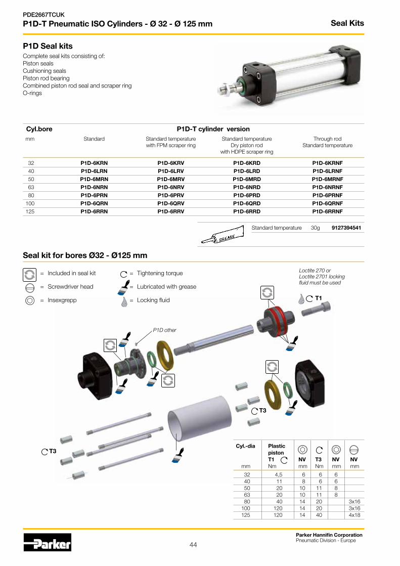
44
Parker Hannifin CorporationPneumatic Division - Europe
PDE2667TCUK
P1D-T Pneumatic ISO Cylinders - Ø 32 - Ø 125 mm
T1
T3
Loctite 270 or Loctite 2701 locking fluid must be used
T3
P1D other
Seal Kits
P1D Seal kitsComplete seal kits consisting of:Piston sealsCushioning seals Piston rod bearing Combined piston rod seal and scraper ring O-rings
Cyl.bore P1D-T cylinder version
mm Standard Standard temperature Standard temperature Through rod with FPM scraper ring Dry piston rod Standard temperature with HDPE scraper ring
32 P1D-6KRN P1D-6KRV P1D-6KRD P1D-6KRNF
40 P1D-6LRN P1D-6LRV P1D-6LRD P1D-6LRNF
50 P1D-6MRN P1D-6MRV P1D-6MRD P1D-6MRNF
63 P1D-6NRN P1D-6NRV P1D-6NRD P1D-6NRNF
80 P1D-6PRN P1D-6PRV P1D-6PRD P1D-6PRNF
100 P1D-6QRN P1D-6QRV P1D-6QRD P1D-6QRNF
125 P1D-6RRN P1D-6RRV P1D-6RRD P1D-6RRNF
Standard temperature 30g 9127394541
Seal kit for bores Ø32 - Ø125 mm
= Included in seal kit = Tightening torque
= Screwdriver head = Lubricated with grease
= Insexgrepp = Locking fluid
Cyl.-dia Plastic piston T1 NV T3 NV NV mm Nm mm Nm mm mm
32 4,5 6 6 6 40 11 8 6 6 50 20 10 11 8 63 20 10 11 8 80 40 14 20 3x16 100 120 14 20 3x16 125 120 14 40 4x18
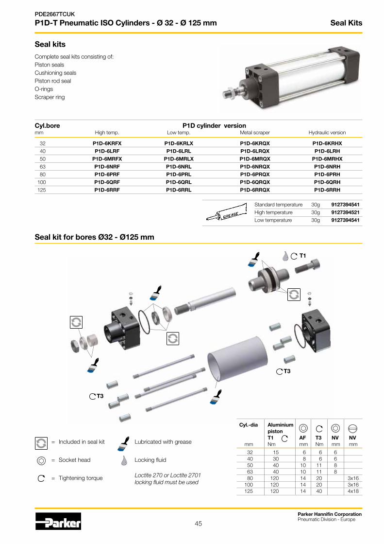
45
Seal Kits
Parker Hannifin CorporationPneumatic Division - Europe
PDE2667TCUK
P1D-T Pneumatic ISO Cylinders - Ø 32 - Ø 125 mm
T1
T3
= Included in seal kit Lubricated with grease
= Socket head Locking fluid
= Tightening torque
Seal kit for bores Ø32 - Ø125 mm
Loctite 270 or Loctite 2701 locking fluid must be used
Cyl.bore P1D cylinder version mm High temp. Low temp. Metal scraper Hydraulic version
32 P1D-6KRFX P1D-6KRLX P1D-6KRQX P1D-6KRHX
40 P1D-6LRF P1D-6LRL P1D-6LRQX P1D-6LRH
50 P1D-6MRFX P1D-6MRLX P1D-6MRQX P1D-6MRHX
63 P1D-6NRF P1D-6NRL P1D-6NRQX P1D-6NRH
80 P1D-6PRF P1D-6PRL P1D-6PRQX P1D-6PRH
100 P1D-6QRF P1D-6QRL P1D-6QRQX P1D-6QRH
125 P1D-6RRF P1D-6RRL P1D-6RRQX P1D-6RRH
Seal kits
Complete seal kits consisting of:Piston sealsCushioning seals Piston rod seal O-ringsScraper ring
Standard temperature 30g 9127394541
High temperature 30g 9127394521
Low temperature 30g 9127394541
Cyl.-dia Aluminium piston T1 AF T3 NV NV mm Nm mm Nm mm mm
32 15 6 6 6 40 30 8 6 6 50 40 10 11 8 63 40 10 11 8 80 120 14 20 3x16 100 120 14 20 3x16 125 120 14 40 4x18
T3

46
Seal Kits
Parker Hannifin CorporationPneumatic Division - Europe
PDE2667TCUK
P1D-T Pneumatic ISO Cylinders - Ø 160 - Ø 250 mm
Seal kit for bores Ø 160 - Ø 250 mm
Cyl.-dia Plastic piston T1 NV T2 NV mm Nm mm Nm mm
160 100 30 85 27 200 100 30 95 27 250 120 36 140 41
Seal KitsComplete seal kits consisting of:Piston completeCushioning seals Piston rod bearing Scraper ringPiston rod seal O-rings
Material specification, see page 11
Cyl.bore Through rod mm Standard temperature
160 P1D-6SRNF
200 P1D-6TRNF
250 P1D-6VRNF
T1
T2
= Included in seal kit = Lubricated with grease
= Socket head = Locking fluid
= Tightening torque = Nut A/F
Loctite LT638 locking fluid must be used
Cyl.boremm
Standard High temp.Only for cylinders with PN P1D-Txxx/G...
160 PD23013 P1D-6S/G90010
200 PD25006 P1D-6T/G90011
250 PD25872 P1D-6V/G90012Standard 4 g tube KL8220
High temperature 4 g tube KL8220Note: high temp seal kits for cylinders with PN P1D-TxxxMF-stroke are no longer available.

47
Seal Kits
Parker Hannifin CorporationPneumatic Division - Europe
PDE2667TCUK
P1D-T Pneumatic ISO Cylinders - Ø 320 mm
Standard 4g tube KL8220
High temperature 4g tube KL8220
Cyl.bore Standard High Temp. mm
320 KL7339 KL7340
Seal kit for bore Ø 320 mm
Cyl.-dia Piston T1 NV T2 NV mm Nm mm Nm mm
320 250 30 200 41
Seal KitsComplete seal kits consisting of:Piston completeCushioning seals Piston rod bearing Scraper ringPiston rod seal O-rings
Material specification, see page 12
Cyl.bore Through rod mm Standard temperature
320 P1D-6WRNF
= Included in seal kit = Lubricated with grease
= Socket head = Locking fluid
= Tightening torque = Nut A/F
Loctite LT638 locking fluid must be used
T1
T2

48
Parker Hannifin CorporationPneumatic Division - Europe
PDE2667TCUK
P1D-T Pneumatic ISO Cylinders - Ø 32 - Ø 320 mm Spare Parts
Cylinder dia. mm
032
040
050
063
080
100
125
160
200
250
320
Stroke** (mm) e.g. 0100 = 100 mm
Any stroke up to max. 2800 mm.
** When ordering piston rods for cylinders with an extended piston rod, add together the stroke and the extension in the order key. For example, a cylinder with stroke 100 mm and a piston rod extension of 25 mm is ordered with 0125 in the order number.
Order code key, spare parts
Piston rod
Cylinder barrel
8 Spare parts
* 2 piston rod pieces delivered in one set if through rod option selected
Tie rods
1 2 3 4 5 6 7 8 9 10 11 12 13 14 15
P 1 D - 8 0 3 2 D G - 0 1 0 0
Piston rod*
D Standard external thread
G Standard internal thread
H Through rod ext. threads
J Through rod int. threads
Cylinder barrel
B Cylindrical (for tie rod)
Tie rod
T Tie rod (order 4 for a cylinder)
Piston rod
Cylinder barrel
Tie rods
Piston rod
G Stainless steel
H Hard-chromium plated
J Acid-resistant steel
K Chromium plated stainless
Cylinder barrel
A Aluminium
Tie rod
V Stainless steel
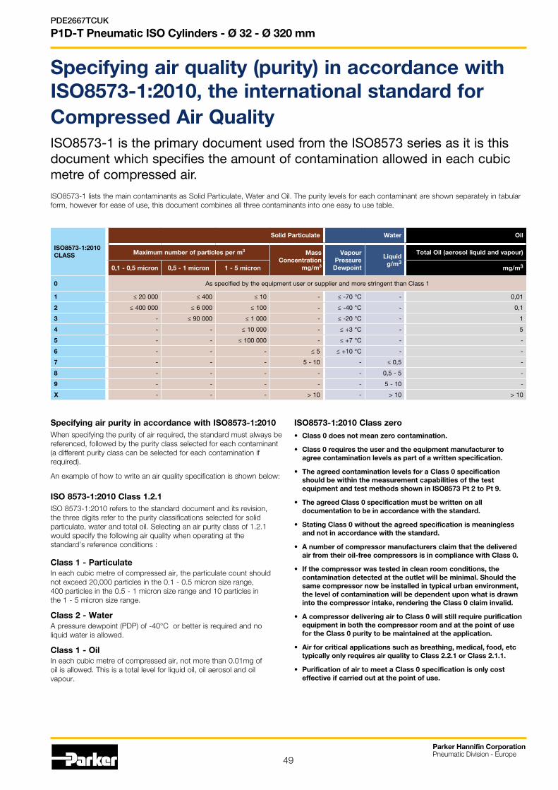
49
Specifying air quality (purity) in accordance with ISO8573-1:2010, the international standard for Compressed Air QualityISO8573-1 is the primary document used from the ISO8573 series as it is this document which specifies the amount of contamination allowed in each cubic metre of compressed air.
ISO8573-1 lists the main contaminants as Solid Particulate, Water and Oil. The purity levels for each contaminant are shown separately in tabular form, however for ease of use, this document combines all three contaminants into one easy to use table.
ISO8573-1:2010 CLASS
Solid Particulate Water Oil
Maximum number of particles per m3 MassConcentration
mg/m3
Vapour Pressure
Dewpoint
Liquid g/m3
Total Oil (aerosol liquid and vapour)
0,1 - 0,5 micron 0,5 - 1 micron 1 - 5 micron mg/m3
0 As specified by the equipment user or supplier and more stringent than Class 1
1 ≤ 20 000 ≤ 400 ≤ 10 - ≤ -70 °C - 0,01
2 ≤ 400 000 ≤ 6 000 ≤ 100 - ≤ -40 °C - 0,1
3 - ≤ 90 000 ≤ 1 000 - ≤ -20 °C - 1
4 - - ≤ 10 000 - ≤ +3 °C - 5
5 - - ≤ 100 000 - ≤ +7 °C - -
6 - - - ≤ 5 ≤ +10 °C - -
7 - - - 5 - 10 - ≤ 0,5 -
8 - - - - - 0,5 - 5 -
9 - - - - - 5 - 10 -
X - - - > 10 - > 10 > 10
Specifying air purity in accordance with ISO8573-1:2010When specifying the purity of air required, the standard must always be referenced, followed by the purity class selected for each contaminant (a different purity class can be selected for each contamination if required).
An example of how to write an air quality specification is shown below:
ISO 8573-1:2010 Class 1.2.1ISO 8573-1:2010 refers to the standard document and its revision, the three digits refer to the purity classifications selected for solid particulate, water and total oil. Selecting an air purity class of 1.2.1 would specify the following air quality when operating at the standard’s reference conditions :
Class 1 - ParticulateIn each cubic metre of compressed air, the particulate count should not exceed 20,000 particles in the 0.1 - 0.5 micron size range, 400 particles in the 0.5 - 1 micron size range and 10 particles in the 1 - 5 micron size range.
Class 2 - WaterA pressure dewpoint (PDP) of -40°C or better is required and no liquid water is allowed.
Class 1 - OilIn each cubic metre of compressed air, not more than 0.01mg of oil is allowed. This is a total level for liquid oil, oil aerosol and oil vapour.
ISO8573-1:2010 Class zero • Class 0 does not mean zero contamination.
• Class 0 requires the user and the equipment manufacturer to agree contamination levels as part of a written specification.
• The agreed contamination levels for a Class 0 specification should be within the measurement capabilities of the test equipment and test methods shown in ISO8573 Pt 2 to Pt 9.
• The agreed Class 0 specification must be written on all documentation to be in accordance with the standard.
• Stating Class 0 without the agreed specification is meaningless and not in accordance with the standard.
• A number of compressor manufacturers claim that the delivered air from their oil-free compressors is in compliance with Class 0.
• If the compressor was tested in clean room conditions, the contamination detected at the outlet will be minimal. Should the same compressor now be installed in typical urban environment, the level of contamination will be dependent upon what is drawn into the compressor intake, rendering the Class 0 claim invalid.
• A compressor delivering air to Class 0 will still require purification equipment in both the compressor room and at the point of use for the Class 0 purity to be maintained at the application.
• Air for critical applications such as breathing, medical, food, etc typically only requires air quality to Class 2.2.1 or Class 2.1.1.
• Purification of air to meet a Class 0 specification is only cost effective if carried out at the point of use.
Parker Hannifin CorporationPneumatic Division - Europe
PDE2667TCUK
P1D-T Pneumatic ISO Cylinders - Ø 32 - Ø 320 mm

50
Parker Hannifin CorporationPneumatic Division - Europe
PDE2667TCUK
P1D-T Pneumatic ISO Cylinders - Ø 32 - Ø 125 mm

51
Parker Hannifin CorporationPneumatic Division - Europe
PDE2667TCUK
P1D-T Pneumatic ISO Cylinders - Ø 32 - Ø 320 mm

Your local authorized Parker distributor
Catalogue PDE2667TCUK - V11 - May 2017© 2017 Parker Hannifin Corporation. All rights reserved.
Parker Hannifin Ltd. Tachbrook Park DriveTachbrook Park, Warwick, CV34 6TUUnited Kingdom Tel.: +44 (0) 1926 317 878 Fax: +44 (0) 1926 317 [email protected]
Europe, Middle East, AfricaAE – United Arab Emirates, Dubai Tel: +971 4 8127100 [email protected]
AT – Austria, Wiener Neustadt Tel: +43 (0)2622 23501-0 [email protected]
AT – Eastern Europe, Wiener Neustadt Tel: +43 (0)2622 23501 900 [email protected]
AZ – Azerbaijan, Baku Tel: +994 50 2233 458 [email protected]
BE/LU – Belgium, Nivelles Tel: +32 (0)67 280 900 [email protected]
BG – Bulgaria, Sofia Tel: +359 2 980 1344 [email protected]
BY – Belarus, Minsk Tel: +48 (0)22 573 24 00 [email protected]
CH – Switzerland, Etoy Tel: +41 (0)21 821 87 00 [email protected]
CZ – Czech Republic, Klecany Tel: +420 284 083 111 [email protected]
DE – Germany, Kaarst Tel: +49 (0)2131 4016 0 [email protected]
DK – Denmark, Ballerup Tel: +45 43 56 04 00 [email protected]
ES – Spain, Madrid Tel: +34 902 330 001 [email protected]
FI – Finland, Vantaa Tel: +358 (0)20 753 2500 [email protected]
FR – France, Contamine s/Arve Tel: +33 (0)4 50 25 80 25 [email protected]
GR – Greece, Athens Tel: +30 210 933 6450 [email protected]
HU – Hungary, Budaörs Tel: +36 23 885 470 [email protected]
IE – Ireland, Dublin Tel: +353 (0)1 466 6370 [email protected]
IL – Israel Tel: +39 02 45 19 21 [email protected]
IT – Italy, Corsico (MI) Tel: +39 02 45 19 21 [email protected]
KZ – Kazakhstan, Almaty Tel: +7 7273 561 000 [email protected]
NL – The Netherlands, Oldenzaal Tel: +31 (0)541 585 000 [email protected]
NO – Norway, Asker Tel: +47 66 75 34 00 [email protected]
PL – Poland, Warsaw Tel: +48 (0)22 573 24 00 [email protected]
PT – Portugal Tel: +351 22 999 7360 [email protected]
RO – Romania, Bucharest Tel: +40 21 252 1382 [email protected]
RU – Russia, Moscow Tel: +7 495 645-2156 [email protected]
SE – Sweden, Spånga Tel: +46 (0)8 59 79 50 00 [email protected]
SL – Slovenia, Novo Mesto Tel: +386 7 337 6650 [email protected]
TR – Turkey, Istanbul Tel: +90 216 4997081 [email protected]
UA – Ukraine, Kiev Tel: +48 (0)22 573 24 00 [email protected]
UK – United Kingdom, Warwick Tel: +44 (0)1926 317 878 [email protected]
ZA – South Africa, Kempton Park Tel: +27 (0)11 961 0700 [email protected]
North AmericaCA – Canada, Milton, Ontario Tel: +1 905 693 3000
US – USA, Cleveland Tel: +1 216 896 3000
Asia PacificAU – Australia, Castle Hill Tel: +61 (0)2-9634 7777
CN – China, Shanghai Tel: +86 21 2899 5000
HK – Hong Kong Tel: +852 2428 8008
IN – India, Mumbai Tel: +91 22 6513 7081-85
JP – Japan, Tokyo Tel: +81 (0)3 6408 3901
KR – South Korea, Seoul Tel: +82 2 559 0400
MY – Malaysia, Shah Alam Tel: +60 3 7849 0800
NZ – New Zealand, Mt Wellington Tel: +64 9 574 1744
SG – Singapore Tel: +65 6887 6300
TH – Thailand, Bangkok Tel: +662 186 7000
TW – Taiwan, Taipei Tel: +886 2 2298 8987
South AmericaAR – Argentina, Buenos Aires Tel: +54 3327 44 4129
BR – Brazil, Sao Jose dos Campos Tel: +55 800 727 5374
CL – Chile, Santiago Tel: +56 2 623 1216
MX – Mexico, Toluca Tel: +52 72 2275 4200
Parker Worldwide
European Product Information Centre
Free phone: 00 800 27 27 5374
(from AT, BE, CH, CZ, DE, DK, EE, ES, FI,
FR, IE, IL, IS, IT, LU, MT, NL, NO, PL, PT, RU,
SE, SK, UK, ZA)
Related Documents