A Plan for the Development of Superconducting Undulator Prototypes for LCLS-II and Future FELS P. Emma, …for the SCU R&D collaboration: ANL, LBNL, SLAC August 28, 2014 P. Emma, N. Holtkamp, H.-D. Nuhn, SLAC C. Doose, J. Fuerst, Q. Hasse, Y. Ivanyushenkov, M. Kasa, G. Pile, E. Trakhtenberg, E. Gluskin, ANL D. Arbelaez, J. Corlett, S. Myers, S. Prestemon, R. Schlueter, LBNL

P. Emma, …for the SCU R&D collaboration: ANL, LBNL, SLAC August 28, 2014 P. Emma, N. Holtkamp, H.-D. Nuhn, SLAC C. Doose, J. Fuerst, Q. Hasse, Y. Ivanyushenkov,
Dec 31, 2015
Welcome message from author
This document is posted to help you gain knowledge. Please leave a comment to let me know what you think about it! Share it to your friends and learn new things together.
Transcript

A Plan for the Development of Superconducting Undulator Prototypes for
LCLS-II and Future FELSP. Emma,
…for the SCU R&D collaboration: ANL, LBNL, SLACAugust 28, 2014
P. Emma, N. Holtkamp, H.-D. Nuhn, SLACC. Doose, J. Fuerst, Q. Hasse, Y. Ivanyushenkov, M. Kasa, G. Pile, E. Trakhtenberg, E. Gluskin, ANLD. Arbelaez, J. Corlett, S. Myers, S. Prestemon, R. Schlueter, LBNL

Kicking the Can Down the Road (SCU’s)…
Proposed by E. Gluskin & N. Vinokurov in 1999 for LCLS-I “not ready for SCU” (15 yrs ago!)
Propose to re-design LCLS-II undulator and greatly improve performance (1 TW & 7 keV)?
SCU’s operating in ANKA (2005) & APS (2013) right now
Greatest un-tapped potential available for FEL performance

Superconducting Undulator Motivation
Higher magnetic fields allow superior FEL performance.No permanent-magnetic material to be damaged by radiation longer life & smaller gaps.Reduced (?) resistive wakefield with cold bore (preliminary).Much lower vacuum pressure, which limits gas scattering.Smaller footprint and simpler K-control thantypical, massive adjustable-gap PMU.Easily oriented for vertical polarization*.
Advantages of an SCU:
SCU’s need practical development…
* Vertical polarization allows efficient x-ray transport in horizontal deflections

SCU’s Provide Much Higher Fields than PMUs
5-mm vac. gap for all (7.3-mm mag. gap)In-Vac same vac. gap (5.3-mm mag. gap)
Nb 3Sn
PMU
NbTi
In-Vac. PMU
SCU much higher field for given period and gap
LCLS-II PMU:lu = 26 mmBpk = 1.0 Tgm = 7.3 mm
LCLS-II SCU
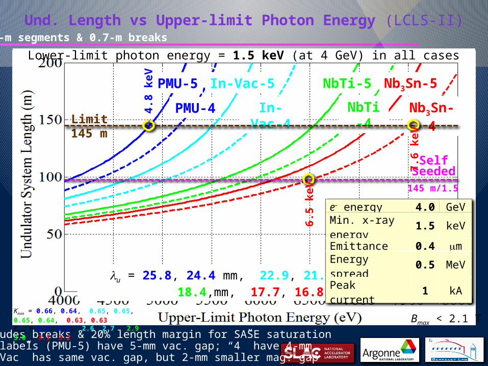
Und. Length vs Upper-limit Photon Energy (LCLS-II)
In-Vac-5In-Vac-5 NbTi-5In-Vac-5 NbTi-5 Nb3Sn-5
PMU-4 In-Vac-4 NbTi-4 Nb3Sn-4
In-Vac-5 NbTi-5 Nb3Sn-5
Limit145 m
PMU-5
SelfSeeded
145 m/1.5
lu = 25.8, 24.4 mm, 22.9, 21.3 mm, 19.3, 18.4,mm, 17.7, 16.8 mm
7.6
keV
4.8
keV
Includes breaks & 20% length margin for SASE saturation“5” labels (PMU-5) have 5-mm vac. gap; “4” have 4-mm“In-Vac” has same vac. gap, but 2-mm smaller mag. gap
6.5
keV
Lower-limit photon energy = 1.5 keV (at 4 GeV) in all cases
e- energy 4.0 GeVMin. x-ray energy 1.5 keVEmittance 0.4 mmEnergy spread 0.5 MeVPeak current 1 kA
Kmin = 0.66, 0.64, 0.65, 0.65, 0.65, 0.64, 0.63, 0.63Kmax = 2.4, 2.5, 2.6, 2.7, 2.9, 3.0, 3.1, 3.2
2-m segments & 0.7-m breaks
Bmax < 2.1 T

SC-LinacHXUCu-LinacSCUswitch120 Hz
1 MHz SXU
4 GeV (1 MHz)3-15 GeV (120 Hz)
“TW-FEL” with SCU & Cu-Linac (LCLS-II)
C. Emma, C. Pellegrini, Z. Huang
Und. tech. Nb3Sn -Vac. full gap 4 mmPhoton energy 4 keVe- Energy 6.6 GeVEmittance 0.4 mmPeak current 4 kA
Step-wise tapered undulators (20%)
1.6 TW (4 keV)
Self-seeding monochromator
Choose und. segment length (2 m) similar to gain length (1 m) to maximize peak power
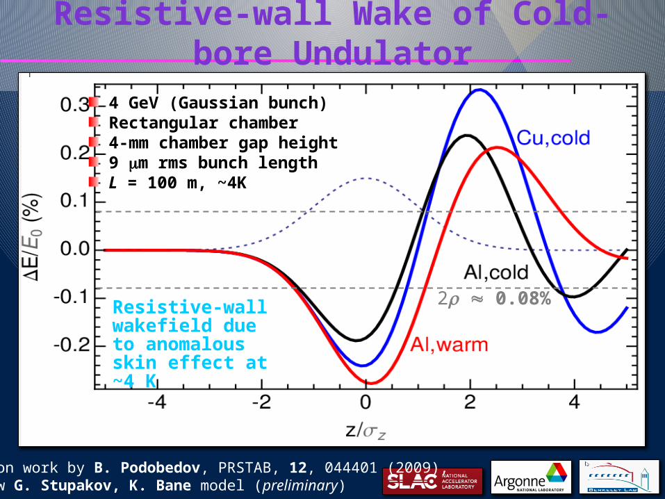
Resistive-wall Wake of Cold-bore Undulator
4 GeV (Gaussian bunch)Rectangular chamber4-mm chamber gap height9 mm rms bunch lengthL = 100 m, ~4K
Resistive-wall wakefield due to anomalous skin effect at ~4 K
2r 0.08%
Based on work by B. Podobedov, PRSTAB, 12, 044401 (2009),and new G. Stupakov, K. Bane model (preliminary)

SCU R&D Plan
ANL…Build 2-m test cryostat (existing design)Build & test 1.5-m long NbTi prototype und. (lu 21 mm)
LBNL…Build & test 1.5-m long Nb3Sn prototype und. (lu 19 mm)
Develop meas. & tuning schemes (small tuning cryostat)
All Labs…Develop field measurement and correction techniquesDemonstrate predicted field, field quality, end corrections, and cold-mass integration into cryostatDevelop conceptual design for full-length SCU in LCLS-II
Goal: By July 2015, deliver 2 fully functional, 1.5-m long, SCU prototypes meeting LCLS-II HXU spec’s

Nb3Sn
6-period prototype (Nb3Sn) built at LBNL in 2006 - reached 97% of current (lu = 14.5 mm).
IEEE Trans. on App. Supercon., Vol. 17, No. 2, June 2007 , pp. 1243-1246.
Prototype Magnet - LBNL
Wire Pocket (8×7)
0.6-mm diam. wire,60-mm braid
insulation
lu = 19 mm
Bpk = 1.86 T
Nb3Sn to NbTi joints at end of undulator
Electron Beam
gm = 8 mm
8×7
DesignPoint
8×5
8×9
(Nb3Sn)
On-Axis Field
Peak ConductorField
Load LinesCriticalCurrent, Ic
Nb3Sn
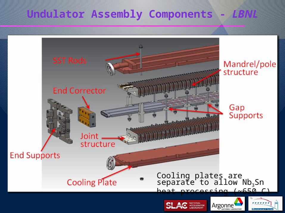
Undulator Assembly Components - LBNL
Cooling plates are separate to allow Nb3Sn heat processing (~650 C)

SCU Tape Phase Correction Scheme - LBNL
heaterswitches
S. Prestemon, D. Arbelaez, LBNL
single turn correction coils
current(< 100 A)
Single-turn correction coils placed on each side of vacuum chamber
Needs demoMay not be necessary?

Prototype Magnet - ANL (NbTi)
NbTi
lu = 21 mm
Bpk = 1.66 Te-
gm = 8 mm
Wire pocket (53 turns)
0.7-mm diam. Supercon NbTi SC wire
Load Lines
PeakCond.Field
On-Axis Field
Ic curve
745 A @3.8 T
(1.66 T,600 A,@80% Ic)
(3.35 T@80% Ic)
Short test cores to verify tolerancesand recent 1.1-m SCU1 now powered
Lower risk, but less field
Recent, very
encouraging
SCU1 results!
(not shown)

End-coil Winding Scheme - ANL
15/15 15/38 53energized by main supply (600 A)energized by separate supply (70 A)
End-Terminations and Field Correctors
“SCU” being wound on bench
shows 11 complete coil packages
Tolerance: 40 G-cm
0 , 51, 100 Amp (Measurements)
winding pack front faceFully wound 1.1-m half-magnet
Precision cores &
precision winding!

ANL 2-m Cryostat (to test both magnets)
Existing 2-m cryostat (4K) at APS• Experience with SCU’s at APS• Each magnet to be tested in this cryostat
2-m longcryostat;4 cryo-coolers;Loss-free He system
magnet &beam pipe
100-lLHevessel
4 cryo-coolers

SCU System Concept for LCLS-II HXU
Joel Fuerst, ANL
0.5-m cold breaks2-m long segments (+quad+BPM+PS)lu = 17-19 mm, Vacuum gap = 4-5 mm5-m cryostats500-W cryo-plant at 4 K

Summary
SCU technology promises a potential leap in FEL performance – needs development nowLCLS-II HXU can be extended to 7+ keV (1 MHz) and 1 TW (120 Hz) using the same SCUR&D is underway – re-baseline of LCLS-II is possible, but depends on R&D and LCLS-II project schedule
SC-LinacHXUCu-Linac
1 MHz,1 - 7+ keV
120 Hz,1 - 25 keV,1 TW (4 keV)
SCU
or
switch
0.2-1.3 keV
120 Hz
1 MHz SXU
P.E., N. Holtkamp, H.-D. Nuhn, SLAC;C. Doose, J. Fuerst, Q. Hasse, Y. Ivanyushenkov, M. Kasa, G. Pile, E. Trakhtenberg, E. Gluskin, ANL;D. Arbelaez, J. Corlett, S. Myers, S. Prestemon, R. Schlueter, LBNL
Thanks to the SCU team:
Related Documents


