ADVANCED PROPFAN ANALYS IS FOq rHE FAMILY OF COMMUTE3 AIRPLANES p/(;? 7- #2 / -0 2 c> tj * ’3 #G** dL7’04/ PHE3AREE FOR: NASA GRANT NGT-@Qff PREPARED BY: GERALD A. SWIFT TEAM LEADER: TEAM MEMBERS: UN I VERS I TY OF KANSAS AE 794 DESIGN TEAM MAY 1987 TOM CREIGBTON RAPHAEL HADDAD LOU I S HENDR I CH DOUG HENSLSY LOUISE MGRGAN MARK RUSSELL GERALD SIVIFT FACULTY ADVISOR: DR. JAN ROSKAM (HASA-CR-182566) ADVANCED PROPPAU AIALY SIS 188-19460 FOB THE FAHILY OP COflJnUTEB AIRPLAHES [Kansas Univ.), 66 p CSCL 21E Unclas 63/07 0128711 https://ntrs.nasa.gov/search.jsp?R=19880010084 2018-06-03T08:09:09+00:00Z

Welcome message from author
This document is posted to help you gain knowledge. Please leave a comment to let me know what you think about it! Share it to your friends and learn new things together.
Transcript

ADVANCED PROPFAN ANALYS IS FOq rHE FAMILY OF COMMUTE3 A I R P L A N E S
p/(;? 7- #2 / -0 2 c> t j * ’3 # G * * dL7’04/ PHE3AREE F O R : NASA GRANT NGT-@Qff
PREPARED B Y : GERALD A . SWIFT
TEAM LEADER:
TEAM MEMBERS:
UN I VERS I T Y OF KANSAS AE 7 9 4 D E S I G N TEAM MAY 1 9 8 7
TOM CREIGBTON
RAPHAEL HADDAD LOU I S HENDR I CH DOUG HENSLSY LOUISE MGRGAN MARK R U S S E L L GERALD SIVIFT
FACULTY ADVISOR: DR. JAN ROSKAM
(HASA-CR-182566) ADVANCED PROPPAU A I A L Y SIS 188-19460 FOB THE FAHILY OP COflJnUTEB AIRPLAHES [Kansas Univ.) , 66 p CSCL 21E
Unclas 63/07 0128711
https://ntrs.nasa.gov/search.jsp?R=19880010084 2018-06-03T08:09:09+00:00Z

ADVANCED PROPFAN ANALYS IS FOR THE FAMILY OF COMMUTER AIRPLANES
PREPARED FOR : NASA GRANT N G T - 8 8 8 1
PREPARED B Y : GERALD A . SWIFT
UN I VERS I Ti' OF KANSAS AE 7 9 0 9 E S I G N TEAM MAY 1 9 8 7
TEAM LEADER:
TEAM MEMBERS :
TOM CREIGHTON
RAPHAEL HADDAD L O U I S HENDRICH DOUG HENSLEY L O U I S E MORGAN MARK R U S S E L L GERALD S W I F T
FACULTY A D V I S O R : D R . JAN ROSKAM

Table of Contents
Table o f Symbols
1 . Introduction
2. Propulsion S y s t e m Selection
2.1. V 2 5 0 0 High Bypass Ratio SuperFan
2.2. General Electric Unducted Fan ( U D F )
2.3. Contra-Rotating Integrated Shrouded P r o p f a n (CRISP)
2.4. Pratt/Whitney-Allison 578-DX Demonstrator Propfan
2.5. Propulsion System Selected
3. Propeller Design and Performance
4. Engine Design and Performance
4.1. Design Specifications
4.2. Engine Component Description
4.2.1. Inlet 4.2.2. Compressors 4.2.3. Axial Combustor 4.2.4. Turbines 4.2.5. Nozzle
4.3. Engine Accessories
4.4. Engine Outline Drawing
4.5. G e a r b o x Design
4 . 6 . Installed Performance
4.7. Weight
4 . 8 . costs
Page
iv
1
2
2
3
4
4
5
6
9
9
18
18 11 12 1 3 1 3
1 5
1 5
1 5
19
19
19
5. Integration and Commonality . 42

6. Noise
6.1. Sources
6.2. Noise Characteristics
6.3. Cabin Noise Reduction
7. Conclusions and Recommendations
7.1. Conclusions
7.2. Recornmendat ions
8. References
4 8
4 8
4 8
5 1
6 8
6ff
6 8
61
i i i

Table o f Symbols
Symbol
A BPR C / D
CDo d b
e G R
DProP
Kfsp Kosc L n ac
Ne Nt Pavl Preq ROC R P M sfc ShP TSFC We WF Wfs W g b W n wosc WProP
M
a
n P e
n N E T
A n
AMADS AWST ,
C R HP L P
Definition
Aspect ratio Bypass ratio Clearance between fuselage and
Zero-lift drag coefficient Decibels Pr ope 1'1 er d i ame t e r Oswald's efficiency factor Gearing ratio Specific fuel weight Oil system constant Nacelle length Mach number Number of engines Number o f fuel tanks Power available Power required Rate o f climb Rotational speed Specific fuel consumption Shaft horsepower Thrust specific fuel consumption E n g i ne w e i g h t F u e 1 weight Fuel system weight Ge ar bo x w e i gh t Nacelle weight Oil system weight Propeller weight
propeller
Greek
Angle of attack Net efficiency Prope 1 1 er e f f ic i ency Sideline angle Sweep angle Pi
Ac r o n yms
Dimens ion
hP hp fPm r P m lb/hp/br hp Ib/hp/hr Ibs l b s lbs Ibs Ibs lbs lbs
degrees -_--- -_--- degrees degrees 3.1416
Aircraft mounted accessories drive system Aviation Week and Space Technology Counter-rotation High pressure Low pressure
i v

1 . lntroductiop
This report is the fifth in a series o f seven dealing with the design of a family of commuter airplanes for N A S A Grant NGT-8001. The main emphasis behind the family of commuters is to achieve high commonality over a broad spectrum of passenger ranges ( 2 5 to 100 passengers). This could allow for a cooperation between an airline and airframe manufacturer that could revolutionize the commuter market. This report focuses on the propulsion system incorporated throughout the proposed family.
Advanced propfans have been selected to be used throughout the family of commuters. These propulsion systems offer a 25-28% fuel savings over comparably sized turbofans operating in t h e 1990’s. The engines used in this study are derivatives o f the,
PD436-11 NASA CR-168115 Turboprop Engines Allison G a s Turbine Division
The engines will be mounted in aft pylons extending from the tailcone sections. The family of commuters concept requires two versions of this engine be used:
( 1 ) 5,500 shp engine ( 2 ) 11,000 shp engine
The technology included in these propulsion systems is verifiable in the late 1980’s and is appropriate for production in the mid-199B’s.
Chapter 2 provides a brief study of the. propulsion systems available for the family o f commuters and justifies the selection o f the advanced turboprops.
Chapters 3 and 4 deal with propeller and engine designs and performance. In Chapter 5, these designs are integrated and examined.
Chapter 6 addresses noise considerations and constraints due to propfan installation.
1 -

2. Propulsion- S y s t e m Selection
I
/
The family of commuters will incorporate a propulsion system appropriate for production by the mid-1990’s. Currently, several engine concepts are being proposed by leading propulsion manufacturers which also meet this timeframe. The following is a brief summary of some o f the recent designs which are applicable to the family of commuters.
2.1. V2500 High Bypass Ratio SuperFan
This concept, shown in Figure 1 , has been proposed by International Aero Engines. The following are some o f the engine characteristics:
Diameter: 108 - 118 inches (9 - 10 feet) Bypass Ratio: 18-20:l Thrust: 25,000 - 30,000 pounds
Although engine testing began in 1985, a number o f test failures and incidents have occurred. The engine’s specific fuel consumption is predicted to be comparable to unducted propfans: however, the program is experiencing difficulty. According to Aviation Week and Space Technology (April 13, 1 9 8 7 ) . Airbus has decided to cancel its proposal for incorporating the SuperFan o n the n e w A 3 4 0 ’ s .
International Aero Engines’ V2500 SupcrFan ultrahigh bypass ratio engine rated at 30,000 Ib. thrust has been selected to power the A340. Cutaway drawing shows the engine’s latest configuration. CFM International also is considering offering a 30,000-lb.-thrust version of its CFM56 engine for the A340. Range of the A340-300 with V2500 Superfans is estimated at 7.000 naut. mi. with a payload of 295 passengers and luggage (nwasr July 7. 1986. p. 26).
+ Figure 1. International Aero Engines’ V2500 SuperFan.
2

2 . 2 . General Electric Unducted F a n ( U D F )
This concept is shown in Figure 2 . A s o f April 1 8 8 7 , the UDF had undergone 42 hours o f flight tests and 58 hours o f ground tests. The following is a brief summary of the UDF:
* 25% decrease in fuel consumption over the best turbofans of the 1 9 9 0 ' s
* 2 1 , 0 # 0 - 2 5 , 0 0 0 lb. thrust powerplant
* Designed to cruise at Mach 0.72, 3 5 , @ 0 0 feet
* Scheduled to be used on the Boeing 7 3 7 and MD-88
* Expecting initial deliveries by 1 9 9 2
* Predicting a 6,000 engine market
* Carbon fiber composite blades w i t h nickel alloy leading edges
* Counterweight-base blade overspeed protection system w h i c h automatically increases blade pitch to prevent overspeeds if control actuation is lost.
G E N E R A L @ ELECTRIC u.s.4.
~
Unducld FM EIIQLM (UW'")
Figure 2 . General Electric Unducted F a n Engine.
3

.ORIGINAL PAGE IS ,OF POOR QUALITX
2 3 Contra-Rotat ing I n t e - g ~ a t e d - S h r o u d e d - P r g p f a n - ~ C R I S P _ L
lhis concept. shown in Figure 3 , is currently being studied b y Motoren- u n d Turbinen-Union ( M T U I o f West Germany. Some of its characteristics are a s follows:
* B y l ~ a s s r a t i o of 28-38:l
* Shroud can be used f o r noise damping and blade containment
:k C a n n o t obtain specific fuel consumption o f an unducted p r o p f a n
* S h r o u d d r a g needs to be worked out
Figure 3 . MTU Contra-Rotating Integrated Shrouded Propfan.
2 . 3 . Pr at ~ C W I J t ney_-Al 1 i son_578-DX--Demons t r ator Propf an
This design w i l l be tested on a demonstrator MD-80 this y e a r . This engine is basically the proof-of-concept version of t h e e n g i n e s incorpoi'ated i n the K.U. Family of Commuters. The lollowing are some o f t h e design's characteristics:
* 1 0 . 4 B c I s h p demonstrator engine
'* Two 11.6 f t . diameter. 6-blade p r o p f a n s designed by Hamilton S t a n d a r d
* R ~ ~ J ; ~ s . s I a t i o o f 35-40:l
4

* Electronic engine flow
* Compression system variable geometry blades
* Expected gearbox efficiency of 99% with mean time between unscheduled removals IMTBURl to be 30,000 hrs. (compared to 8 . 0 0 0 hrs. with old technology).
* Engine exhausts circumferentially around the engine upstream of the propfan plane
* A hub exhaust concept is being examined
* Expect a production engine development program in 1988.
2.5. Propulsion S y s t e m Selected
The propulsion system selected for the family o f commuters w a s unducted propfans taken from the Advanced Propfan Engine Technology ( A P E T l report by Allison Gas Turbine Division (Reference 7). The main reasons why the propfan was chosen over the other concepts suggested are as follows:
1. In ungeared systems, the fan and turbine are directly connected and run at the same speed. The result is that fan speed is too l o w to achieve optimum propulsfve efficiency. However, this loss m a y be compensated for by the weight savings achieved by gearbox elimination. (AWST April 1 3 , 1987)
2. A geared system allows an engine’s propfan to be mounted at the front of the engine in a tractor configuration, o r at the rear o f the engine f o r a pusher configuration; something that can’t be done in a gearless system. ( A W S T April 1 3 , 1987)
3. The APET concept can be designed for various applications over a range o f 6,000 to 18,000 shp. It is not known i f the GE UDF concept has proposed entering into the lower horsepower market .
5

~ 3. Propeller Design and Performance
Counter-rotating propfans based on Reference 8 were chosen for the family o f commuters. Single rotating propfans were studied, but counter-rotat i o n offered the following advantages (based on propfans o f similar horsepower, t i p speed, and loading):
* Counter-rotation delivers 7.9% more total thrust at 7.5% less thrust specific fuel consumption (TSFC) in a maximum climb configuration to 0.7 Mach, 3 5 , 0 0 0 ft.
* Counter-rotation operates at 7.6% less TSFC at 0.7 Mach, 35.888 ft.
T h e geometries of the propfans chosen f o r the two e n g i n e ’ configurations are given in Table 1.
Table 1. Propfan Geometries.
5,5fl0 shp engine: 1 2 0 inch diameter fan 1 1 , B 0 0 shp engine: 172 inch diameter fan
Counter Rotation Blades = 12 ( 6 x 6 ) Disk Spacing = 0.18D Activity Factor = 1 8 0
Aft Tip S w e e p = 40 degrees Tip Speed = 7 5 8 fps Max. Nacelle Diameter - B.25D Integrated Camber = 8.31
Table 2 lists the counter-rotation propfans’ performance summary. Figure 4 shows h o w the efficiency f o r the various designs compare at Mach = 0.78, 3 8 , 8 0 0 f t . . Table 3 provides a weight summary o f the counter-rotation blades.
6

Table 2. Counter-Rotation Performance Summary.
3 6
5 8
7 5
188
1 3 , 5 1 9 18 . Q 2 3 , 2 4 1 1 8 . 8 3 2 , 4 5 8 1 8 . 1
1 4 , 3 9 2 1 8 . 8 2 3 . 9 6 3 1 8 . 8 3 3 , 8 8 6 18 . 0
1 8 , 6 1 2 1 4 . 3 2 7 . 9 3 3 1 4 . 3 3 6 , 0 2 8 1 4 . 3
1 8 , 6 1 2 1 4 . 3 2 7 , 9 3 3 1 4 . 3 3 6 , 82'8 1 4 . 3
3 5 . 1 0 3 2 . 4 1 2 4 . 5 8 8 8
4 3 . 8 2 3 9 . 6 3 3 8 . 1 6 8 9
4 1 . 9 2 3 8 . 6 1 2 9 . 3 8 8 9
4 1 . 9 2 3 8 . 6 1 2 9 . 3 8 8 9
ALTITUDE - 10'668
I 1 (35.000 FT) 84
2s I 7 5 5 0 36 IOo
82 160 240 320 400 480 S 6 0 64 0 720 800 880
COWER LOADING, K W / M 2
I I I I I I I I I I 20 30 40 so 60 70 80 BO 100 1 1 0
POWER LOADING. S H P / F T ~
EFFICIENCY AT MACH - 0.70, STD. DAY (NASA cR-1bt258)
Figure 4. Propfan Efficiencies at Cruise.
7
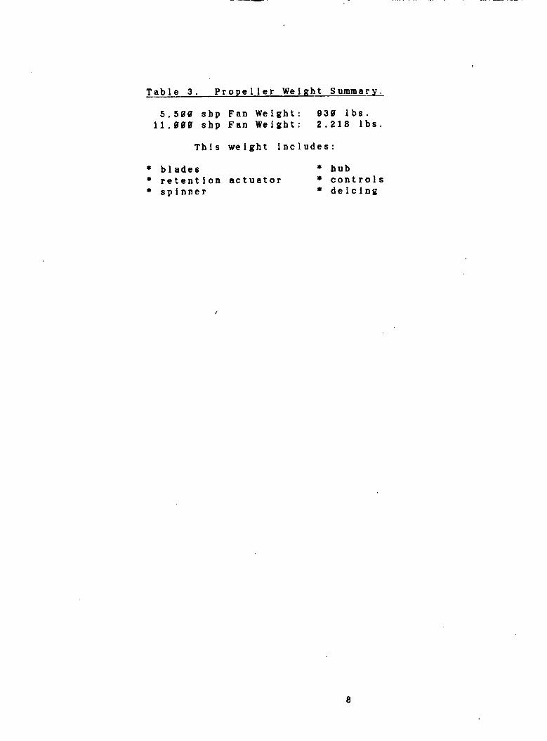
Table 3. Propeller Weight Summar&
5,500 s h p Fan Weight: 930 l b s . 1 1 , 0 0 0 shp F a n Weight: 2 , 2 1 8 I b s .
This we ight includes:
* blades * h u b * retent ion actuator * controls * spinner * deicing
8

4. Engine Design and Performance
Two engine cores were developed for the family of commuters: a 5,500 shp core and an 1 1 , 0 8 0 shp core. This was the best way to meet the performance requirements over the broad spectrum o f power settings required for the family. Each airplane has two aft-mounted engines due to commonality considerations. Their power configurations are given in Table 4.
Table 4. Power Configurations for the Family of Commuters.
Ai r p 1 ane Engines
25 Passenger 36 Passenger 5 0 Passenger 75 Passenger
1 8 8 Passenger
2 x 5,580 shp -- derated 38% 2 x 5 , 5 0 8 shp -- derated 20% 2 x 5 , 5 @ 0 shp 2 x ll,@88 shp 2 x 1 1 , 8 0 8 shp
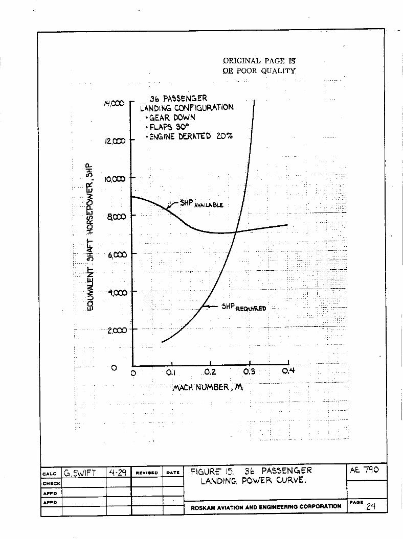
The 2 5 and 36 passenger engines were derated for stability and control reasons. However, they still meet all performance requirements (including a 3,000 fpm rate o f climb at s e a level).
The information in this chapter is based o n data in Reference 7. The overall engine design, performance, weight and cost are addressed.
4.1. Des ign Speci f Icat Ions
The engines selected are PD436-11 turboprop engines presented in Reference 7 . The design specifications of these engines are outlined in Table 5.
Table 5. Design Specifications o f the APET PD436-11 Turboprop Engines.
S i z e - shp Overall Pressure Ratio Turbine Temperature - O F
C ompressor Turbine Number o f Stages:
LP Compressor HP Compressor LP Turbine HP Turbine Power Turbine
5,580 32.5:l 2 2 8 8 cruise 2 5 8 0 takeoff Axial/Axial HP/LP/Power
1 1 , 0 0 0 32.5:l 2 2 8 8 crufse 2 5 0 8 takeoff Axial/Axial HP/ LP/ P owe r
F i g u r e 5 s h o w s the engine general arrangement drawing.
9

HP turbine- Pbwar turbino- ringledago I ILP turbine-
Di f fmr/amhtor- revmrm flow diffuler,
W
Figure 5. PD436-11 Engine General Arrangement ( N A S A CR-168115).
4.2. Engine Component Description
The following is a brief description o f the engine inlet, compressors, combustor, turbines, and nozzle.
4.2.1. Inlet
The inlets w e r e sized by assuming the total pressure remains constant from inlet to compressor face. A t o t a l pressure recovery coefficient of 0.6 was assumed. Table 6 gives the preliminary design specifications o f the inlet.
Engine - shp 5,500 Compressor face diameter - in. 17.6 Compressor inlet area - sq. in. 265 Inlet area - s q , in. 1 6 7 Inlet diameter - in. 14.6 Inlet length - in. 24.6
1 3 , 0 0 U 24.9 446 281 18.9 34.6
10

4.2.2. C o m p r e ssors
Figure 6 gives a schematic of the low pressure (LP) axial compressor for t h e PD436-11 engines. The design goals o f the LP compressor are as follows:
* corrected f l o w = 8.8 lb/sec * pressure ratio = 8.55:l * adiabatic efficiency = 86.7% * polytropic efficiency = 90% * bub/tip ratio = 8.52
Figure 7 shows the PD436-11 high pressure (HP) axial compressor. The design goals are as follows:
* corrected flow = 8.8 lb/sec * pressure r a t i o = 3.8:1 * adiabatic efficiency = 85.7% * polytropic efficiency = 88.1% * hub/tip r a t i o = 0.74
Figure 6 , PD436-11 Low Pressure Axial Compressor ( N A S A CR-168115).
1 1
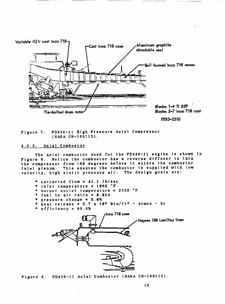
Figure 7 . PD436-11 High Pressure Axial Compressor ( N A S A CR-168115).
4.2.3. Axial Combustor
The axial combustor used for the PD436-11 engine is shown i n Figure 8. Notice the combustor h a s a reverse diffuser to turn the compressor flow 180 degrees before i t enters the combustor inlet plenum. This ensures' the combustor is supplied w i t h l o w velocity, high static pressure air. The design goals are:
* corrected f l o w = 43.1 lb/sec * inlet temperature = 1060 "F * burner outlet temperature = 2558 OF * fuel to a i r ratio = 8.024 * pressure change = 5.1% * heat release = 5.7 x 10⁶ Btu/ftS - atmos - hr * efficiency = 99.9%
Hopes 188 Lomilloy liner
Figure 8. PD436-11 Axial Combustor ( N A S A CR-168115).
1 2
Var eioble IGV cast lnco 718 st lnco 718 cose Aluminum graphite
Roll formed lnco 718 wries
Blades 1-4 Ti 829 ' Blodar 5-7 lnco 718 cost
TE83-2210

4.2.4. Turbines
The PD436-11 has high pressure, low pressure, and power turbine sections which run the high pressure compressor. l o w pressure compressor, and propfan respectively. Table 7 outlines their aerodynamic design point conditions for 9.72 Mach, 3 2 , 0 8 8 ft.
Table 7. -.Turbine Aerodynamic Design Points.
0.72 Mach, 3 2 , 8 0 8 ft.
H i g h Pressure Turbine
Single stage 2 2 8 8 Turbine inlet temperature -OF
Turbine inlet total pressure - psia 173.7 Rotational speed - rpm 2 7 8 8 Expansion ratio 2.31 Goal ef f i c i ency 0. 8 7 8
L o w Pressure Turbine
Single s t a g e T u r b i n e . inlet temperature - O F 1 7 6 8 Turbine inlet total pressure - psi'a 7 5 . 0 Roatational speed - rpm 1 7 , 5 8 0 Expansion ratio 2.42 Goal efficiency 0.882
Power Turbine
Three stages Turbine inlet temperature -OF 1 3 8 4 Turbine inlet total pressure - psia 31.8 Rotational speed - rpm 1 0 , 7 5 0
Goal efficiency 0.915 Expansion ratio 5.93
T h e high and l o w pressure turbine blades are air cooled. F i g u r e 9 shows a schematic o f each of the turbine sections.
4.2.5. Nozzle
The nozzles for this design will be annular. The exhaust g a s e s will be mixed w i t h the a i r f l o w ahead o f the propfan plane of rotation. The m a i n reason for this selection is i t allows the exhaust to pass outside the gearbox without increasing nacelle diameter. I t is proposed that t h e following exhaust areas will be required:
5 , 5 0 0 shp engine: 178 sq. in. 11,000 shp engine: 358 s q . in.
1 3

lnao 718 case.
k R e n i 95 wheel
a) Low Pressure Turbine b) High Pressure Turbine
'In- 718 wheel
c ) Power Turbine
F i g u r e 9. PD436-11 Turbine Sections ( N A S A CR-168115).
14

4.3. Engine Accessor ies
The PD436-11 engine is designed to accommodate the engine and aircraft accessories outlined in Table 8.
Table 8. Engine and Aircraft Accessories.
Accessories driven by the power section gearbox:
* fuel module * starter * oil pump * air/oil separator * permanent magnet generator
Accessories driven by the propfan gearbox:
* o i l pump * prop brake * prop regulator * aircraft alternator. * two aircraft bydraulic pumps * aircraft mounted accessories drive system (AMADS)
The propfan propulsion system utilizes a full authority digital electronic control.
4.4. Engine Outline Drawing
Figures 10 and 11 present the outline drawings f o r the PD436-11 5 , 5 6 8 shp and 1 1 , 8 0 0 shp engines respectively. These layouts differ from those proposed in Reference 2 ; the gearbox has been placed behind the engine core to allow f o r a pusher conf i gur at ion.
4.5. Gearbox Design
The counter-rotation gearboxes were designed to provide a gearing ratio of approximately 8.1. The power section rotational speed will be 10,750 rpm and tbe propfan rotational speed will be approximately 1 3 3 0 rpm. Efficiencies of 98.8% to 99.3% are estimated for the gearboxes at take-off conditions.
The gearboxes sbown in Figures 1 U and 11 resemble those proposed for single rotation configurations. The counter rotation designs are slightly longer but m o r e compact. Figure 1 2 is an example. The actual gearbox design is yet to be determined. For preliminary design purposes, the larger gearbox was chosen to ensure the gearbox space required is provided f o r in t h e layout; therefore, there is a good possibility the nacelle diameter could be reduced with advanced gearbox technology. Weight and costs may also be reduced.
1 5

OIL WMP
F i g u r e 10. 5 , 5 8 8 s h p PD436-11 Derivative Outline Drawing.
1 6

cu5TOlnss B U €
FU€L MODULE
F i g u r e 1 1 .
- 84.07
OUTPUT TUNG€
11,000 s h p PD436-11 Derivative Outline Drawing.
1 7

Figure 12. Counter-Rotation Gearbox ( N A S A CR-168115).
1 8

4.6. Installed Performance
Tables 9 - 1 3 summarize the installed performance characteristics o f the family of commuters. Figures 13 - 22 are the related graphs. T h e 25 and 36 passenger engines were derated 30% and 20% respectively for stability and control reasons. Derating may be achieved by providing a throttle regulator in the electronic engine controls. The cockpit layout will not be altered. An advantage to derating the 25 and 36 passenger engines is that their service life will be increased. Table 14 is a short summary of the design.point performances.
4.7. Weight
Tables 15 - 19 provide a component breakdown o f the engine weights. Figure 23 locates tbe propulsion system center o f gravity.
4.13. costs
The proposed costs for the propulsion system are given in Table 20.
1 9

Table 9. 2 5 Passenger Installed Performance Summary.
INSTALLED POWER FOR
25.88 PASS. THE
INPUTS :
T . O . Weight: Fuel Weight: Wing Area:
DRAG POLAR:
Landing Cdo: 1.61E-81 l/(p)Ae: 3.08E-02
POWER AVAILABLE:
At S e a Level:
28,586.88 l b s . 3,767.90 l b s .
592.00 sq. f t .
8.10 1,121.27 8.20 3,347.34 8.38 18,282.86 1.40 23,967.35
At 18,900 ft.:
u. 20 685.49
8.40 1,525.99 8.50 2,676.18
8.38 884.28
7,618.75 6.857.65 6,176.73 6,341.62
5,316.41 5,426.34 5,579.78 5,772.91
Climb 1.29E-02 3.89E-82
Cruise 1.293-02 3.89B-82
At 311.6188 ft.:
Speed Preq-cr P a v l - c r . (kts) ( s h p ) ( ShP) ..............................
0.50 1,562.96 3.849.28 8.61 2,388.96 4,128.68 8.78 3,381.65 4,231.66 8.75 4,064.68 4,339.29 8.88 4,858.64 4,451.51

. .
Pt, 030
O O
12,000
0. I 0.2 03 0.q
. . .
:ALC G.SWIFT 4-29 RCVISCD DATE
:we)(
. . . . . . . . . .- I ' ..' '
A€ 790 F\GURE Is. 25 PASSENGER LANDING POWER CURVE.
25 PASSENGER
i LAND \NC CONF GURATION .GEAR DOWN *FLAPS 30"
. *ENG\NE DERATED 307,
LCCD
LCCO
, . . . . .
--- m
21 CAOC '
ROSKAM AVIATION AND ENGINEERING CORPORATION
. . . . . . . . . . . . . . . . . . . . . . . . . . . .- .. ... . . . . . . . . . . / ... . . . .
. . . I I I 1
. . . . . . . ............... . ..i . . . . . . . . . . . . . . . . . . . . . . . . . . . . . .
. . . ........... . .
. .
. . . . . . . . . . . . . . . . . .
AP?D
A W D i I 2 2 PAOC
ROSKAM AVIATION AND ENGINEERING CORPORAnON 1 I I I I I I

.-
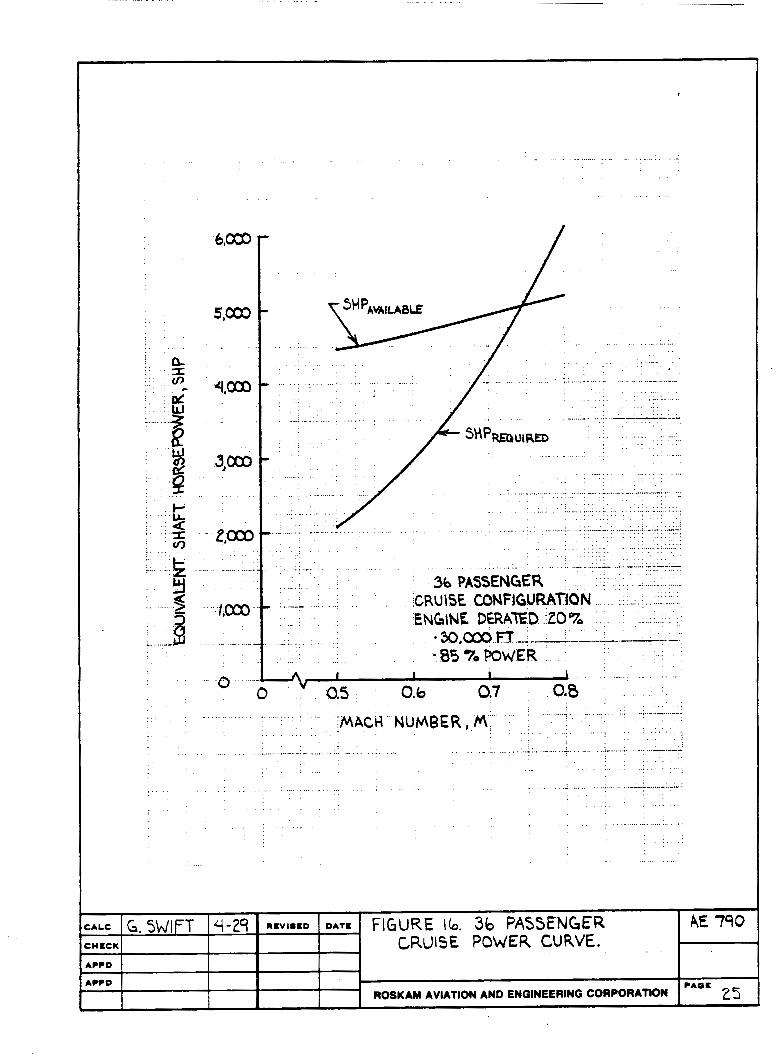
Table 10. 36 Passenger Instal led Performance Summary.
INSTALLED POWER FOR
36.88 PASS. THE
INPUTS :
T . O . Weight: Fuel Weight: Wing Area:
DRAG POLAR:
LandSng Cdo: 1.69E-81 l/(pi)Ae: 3.88E-02
POWER AVAILABLE:
At S e a Level:
35,954.80 l b s . 5,620.08 lbs.
592.00 sq. ft.
0.10 1,581.95 8.20 3,710.71 0.30 18,908.61 8.40 25,213.27
At 10.080 ft.:
0.20 1,835.19 0.30 1 , 2 2 0 . 0 9 0.40 1,985.19 0.50 3.393.29
8,850.00’ 7,037.11 7,175.48 7 366.89
6,176.32 6,303.97 6,482.16 6,706.44
C1 imb 1.60E-02 3.09E-42
Cruise 1.68E-02 3.89E-82
At 39,080 ft.:
Speed Preq-cr Pavl-cr ( k t s ) . ( s h p ) ( S h P ) ..............................
8.58 2,876.93 4,472.46 0.68 2,969.21 4,680.79 0.70 4,293.14 4,916.611 0.75 5,133.61 5,841.61 0.80 6,102.79 5,171.91
23
Q. ’ ‘X fn -
- .
_. .........
. -
I I I 1 . ̂ . - -.
. . .
. . . . . . .
. . .
ORIGINAL PAGE rs S F POOR QUALITY
I 34 PASSENGER
LANDING CONFlGURATiON *GEAR DOWN *FLAPS 30’
i0,cm
. . . . . . . . . . . . . . . . . . . . . . . . . . .
. . . . ........ . . . . . . . . . .
. : . . . .
. .
. . . . . . . . . . . . . .
. . . . . . . . . . . . . . . . . . . . . .
. . . . . . . . . . . . .
. .
. . . .
- . . . f . . . . . . . . . . . . . . . . . ..:.. .
0
. . . . . . . . . . . . . . . . . . . .
:*LC G. SWIFT 4-29 REVImED DATE FIGURE Ib. 36 PASSENGER A€ 790 WECK CRUISE POWER CURVE. W?D - W?O
- P A 0 E 25 ROSKAM AVIATION AND ENGINEERING CORPORAflON
. . . . . . .
. . . . . . . . . . > /.. . . . . . . . - ; 1 . . . . . : ............ .
- - .
3b PASSENGER . --- CRUISE CONF1GURATION
ENGtNE DERATED -20% '3o,cOoT_T ___-.__.._- --- -85 70 POWER
h I I I 1 0,s 0.b 0.7 Q0
. . . . . . . . . . . . . . ~. .............. . . . . . . . . . . . . . . . . . . . . . . . . . . . . . . . . .
. . . . . . . . . . . . . . . . . . . . . . . . . .:MACH. NUMBER, f l : . . . .
: . . . . . . . .......... ......... . . . . . ......... ..... . . . . . . . . . . . . . . . . . . . . . . . . . . . . . -- .- . . .
. . ..: ...+.. --- . .
. . . . . . . . . . . . . . . . . .
... . . . . . . . . . . . . . . . .i ................ . . . . . . . . . . . . . . . . . . . . . . . . . . . . . . .
. . . . .
. . . . . .
. . . .

Table 1 1 . 5 8 Passenger Installed Performance Summary.
INSTALLED P O W E R F O R
5 8 . 8 8 PASS. THE
INPUTS :
T.O. Weight: Fuel Weight: W i n g Area:
D R A G POLAR:
. Landing Cdo: 2.83E-81 I/( pi ) Ae: 3.08E-02
P O W E R AVAI LABLE :
At S e a Level:
43,141.08 lbs. 6,913.88 lbs.
592.00 sq. f t .
8.18 2.184.58 8.28 4,597.66 8.30 13,191.87 0.48 38,342.16
At 10,888 ft.:
0 . 2 8 1,399.48 8.38 3,449.78 8.48 2.138.64 8 . 5 8 3,464.52
18,828. 88 8,604.24 8,773.27 9,887.38
7,552.16 7,788.19 7,925.97 8,288. 18
C 1 imb 1.56E-82 3.89E-02
C r u i s e 1.56E-82 3.0QE-02
A t 3 8 , U B B ft.:
Speed Preq-cr Pavl-cr (kt61 b h p ) (ShP) ..............................
9.50 2,342.68 5,469.68 8.68 3,159.71 5.724.30 0 . 7 8 4,412.72 6,812.51 8.75 5,217.85 6,165.28 9.88 6,148.76 6,324.56
26

...
....
....
....
-..
XLC G SLJlFT 4-29 R E V I ~ C D DATE FlGURF 17. 5 0 PASSENGER . _ _ ;HECK LANDING POWER CURVE, W ? D
*CCD ---
ROSKAM AVIATION AND ENGINEERING CORPORAMN
- .
AE 790
pAOc 21
-0
ORIGINAL PAGE IS OF POOR QUALITY;
50 PASSENCm
*GEAR DOWN *RAPS 30'
LANDING CDNFIGUWnON
. -
- .
...
. . . . I
. . . . . . . . . . . . .
............. . ._ . . . . . . . . . . . . . . . . . . . . . . .
. -- .---. --- . . . .
. . . . . . . . . . . . . . . . . . . .
. . . . ................. -... . . . . . . . . - :/ . . . ........... . . . . . .
. . . . . . . .
. . . . . . . . . .
. . . . . . . . . - . . . . . . . . . . . . . . . . . . . . . . . . . . .
. . . . .
I L . .
. . . O;l : . '.0,2 : 019.. i . ,014 ; . . . . . i . . .....
. . . . . . . . . . . . . . _.

CALC G.SWIFT 4-24 IIEVIOCD DATE
CHECK
AE. 790 FIGURE 18. 50 PASSENGER CRU\SE P W E R CURVE.
A??D
ACCD ROSKAM AVIATION AND ENGINEERING CORPORATION
?*OE 28
/ 5 . m . . . . . . . . . -.
. . . . ..... .- .- . . .
~ ............... . . . . . . . . . . . . . . . . . . .
. . . . . - . . . . . . .
. . . . . . .~ . . . . .
... . . . . . . . . . . . . . . . . . . . . . . .
4,030
/ ' I - - , - , i . - : ' . . :/
................ . . . . . . . . . . . . . .
. .
. . . -. .
. . . . . . . . . . ............ ....... . . . . . . . . . . . . . . . . . . . ... . . . . . . . . . . . . . . . . . . . . . . . . . . . ...... .....-. - ........ : . . .
. . . . . . . . .
. . . . . . . . . . . . . . . . . . . . . . . . ... ...........
- 2,ooo
. - 56 PASSEN CtER CRUl $E CONF\G WAXON
. . ... .........
A 4 I I 1 " 0 " . 0.5 . O,b 0.7 0.8 .n
-. -. .- .- - . .^ . - ' W C H N O M E R , M _ . .
. . . . . . . . . . . . . . . . . . . . . . . . . . . . . . . . . . . . . . . . .- ......... . . . . . . . . . . . . . . . . . . . . . . . . .- . . . . . . .
. . . . . . . . ....................... ....... . . . .
. . . . . . . . . . . . .
. . . . . . . . . . . . . . . . . . . . . .
.. .. .- . . . . . .-

Table 12. 75 Passenger Installed Performance Summary.
INSTALLED P O W E R FOR
75.08 PASS. . THE
INPUTS :
T.O. Weight: Fuel Weight: W i n g Area:
DRAG P O L A R :
Landing Cdo: 2.22E-Dl l/(pi)Ae: 2.41E-82
POWER AVAILABLE:
At S e a Level:
71,419.81 lbs. 11,240.00 lbs. 1.182.08 sq. f t .
0.18 2,859.46 21,655.80 0.20 9,101.37 17,223.49 1.38 28,238.88 17,561.54 8.48 65,923.77 18.029.61
At 18.888 ft.:
C 1 imb 1.39E-82 2.53E-82
Cruise 1.39E-02 2.538-02
At 3 0 , 0 8 0 ft.:
Speed Preq-cr Pavl-cr (kts) ( ShP) ( s h p ) ---------_-_-__----___________
0.58 3,528.58 10,934.35 8.68 5,881.96 11,463.61 1.78 7,388.16 12,840.82 8.75 8,849.92 12,345.57 0.81 10,534.43 12,664.12
0 . 2 8 1,697.82 15,119.33 1.38 2,851.14 15.431.38 8.40 3,394.54 15,866.94 0.58 5,846.76 16,415.19
29

e . o :I
.
CALC G.!jLJ\FT 4-29 R=VI*SD DATE FIGURE 19. 75 PASSENGER CHECK LANDING POUER CURVE. A W D
A??D ---
ROSKAM AVIATION AND ENQINEERING CORPORATION
... i-
: - 2
U 2
:. y
.f3
AE 740
3 0 ? A 0 1
...........
.24,000 _ . _ . . .
- 12,000
. . . . . . . .
. . . .
4,000
h
. . . . . . . . .- ..
I 75 PASSENGER
*GEAR DOWN - FLAPS W
LAN DI Mi CONF\GUR ATON
I
I I - . . ....................
" 0 0,I . 062 0.3 0.4
' 'MACH NUMBER . . . . . . . . . . . . . . . . . . . . . . . . . .
, _ . . . . . . . . . . . . . . . . . . . 'M' ' '
. .
............................ . . . . . . . . . .
. . . . . . . . . . . . . . . . . .. .....- . . . .

.-. - .
. '857. POWER
. . . . .
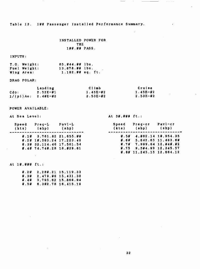
Table 13. 188 Passenger Instal led Performance Summary.
INSTALLED POWER FOR THE
100.08 PASS.
INPUTS :
T.O. Weight: 85,844.08 lbs. Fuel Weight: 13,878.80 lbs. Wing Area: 1.182.00 sq. ft.
DRAG POLAR:
Landing Cdo: 2.523-01 l/(pi)Ae: 2.48E-82
POWER AVA I LABLE :
At Sea Level:
8.18 3,761.82 21,655.08 0.28 18,563.24 17,223.49 8.38 32,124.46 17,561.54 0.40 74,740.28 18,829.61
Climb 1.45E-02 2.53E-82
Cruise 1.45E-02 2.53E-82
A t 30,080 ft.:
Speed Preq-cr Pavl-cr (kts) (shp) ( s h p ) ..............................
8.50 4,882.14 10,954.35 8.68 5,642.65 11,463.60 9.78 7,999.64 12,848.82 8.75 9,504.99 12,345.57 0.88 11,245.15 12,664.12
0.28 2,288.21 15,119.33 8.38 2,479.08 15,431.38 0.40 3,795.62 15,866.94 0.58 6,382.78 16,415.19
32

. ... , ..-.
*?PO
*C?D
-- , M , o b b . .. . . .
. . . ... . . ... . .... -
--- ?*OS
ROSKAM AVIATION AND ENGINEERING CORPORAnON 33
. . . .
A
I PASSEEJGER LAN DI NC CONFICM ATION
*GEAR W N
..
I . . I
. . ..
... .- , . . . . . . . .
. .. .-
t I I . - . --

t (L d 5 m
_ _ .....
. . . . ...
..
. . . . . -. . .
. . . . . .......... . . . .
I ......................
0.7 : . 0.8 . . . . . . . ER . ~ . . . . . . . . . . ......................
I . . . . . . , . . . . . . . . . . . . . . _ _ _ _ ..........................................
. .
. . . . . . . . i
. . . i
. . . . . . . . . . . . . . . . . . . . . . . . . . . . . . . . . .
. . . . . . . . . . . . . . . . . . . . . . . . ... . . . . . . . . . . . . . . . . . . . . . . . . . . . . . . . . . . . .
. . . . . . . . . .

Table 1 4 . Design Point Performances.
R.O.C. A I t i t ude M a c h SFC PREQ P A V ft. lb/hp/hr hp hP fPm . . . . . . . . . . . . . . . . . . . . . . . . . . . . . . . . . . . . . . . . . . . . . . . . . . . . . . . . . . . . . . . .
2 5 Passenger Configuration (Derated 3 0 % )
0 1 0 , 0 0 0 3 0 . 0 0 0
0 1 0 , 0 0 0 3 0 , 0 0 0
0 1 0 , 0 0 0 3 0 , 0 0 0
0 1 8 . 0 0 0 3 0 , 0 0 0
0 1 0 , 0 0 0 3 0 , 0 0 0
0 . 2 0 . 4 1 1 3 , 3 4 7 6 , 0 5 8 3 , 1 3 8 0 . 4 0 . 3 9 8 1 , 5 2 6 5 , 5 8 0 . 4 . 6 9 3 0 . 7 0 . 3 6 1 3 , 3 8 2 4 , 2 3 2 9 8 4
1 . 2 0 . 4 0 . 7
3 6 Passenger Configuration (Derated 2 0 % )
0 . 4 1 1 3 , 7 1 1 7 , 0 3 7 3 , 0 5 3 0 . 3 9 8 1 , 9 8 5 6 , 4 8 2 4 , 1 2 8 0 . 3 6 1 4 , 2 9 3 4 , 9 1 7 5 7 3
5 0 Passenger Configuration
0 . 2 0 . 4 1 1 4 , 5 9 8 8 , 6 0 4 3 , 0 6 4 0 . 4 0 . 3 9 0 2 , 1 3 1 7 , 9 2 6 4 , 4 3 3 0 . 7 0 . 3 6 1 4 , 4 1 3 6 , 0 1 3 1 , 2 2 4
7 5 Passenger Configuration
0 . 2 0 . 4 1 1 9 , 1 0 1 1 7 , 2 2 3 3 , 7 5 3 0 . 4 8 . 3 9 0 3 , 3 9 5 1 5 , 8 6 7 5 , 7 6 3 0 . 7 0 . 3 6 1 7 , 3 8 8 1 2 , 0 4 0 2 , 1 5 0
100 Passenger Configuration
0 . 2 0 . 4 1 1 1 0 , 5 6 3 1 7 , 2 2 3 2 , 5 8 4 0 . 4 9 . 3 9 9 3 , 7 9 6 1 5 . 8 6 7 4 , 6 8 4
0 . 3 6 1 8 , 0 0 0 1 2 , 0 4 0 1 , 5 6 8 0 . 7
3 5
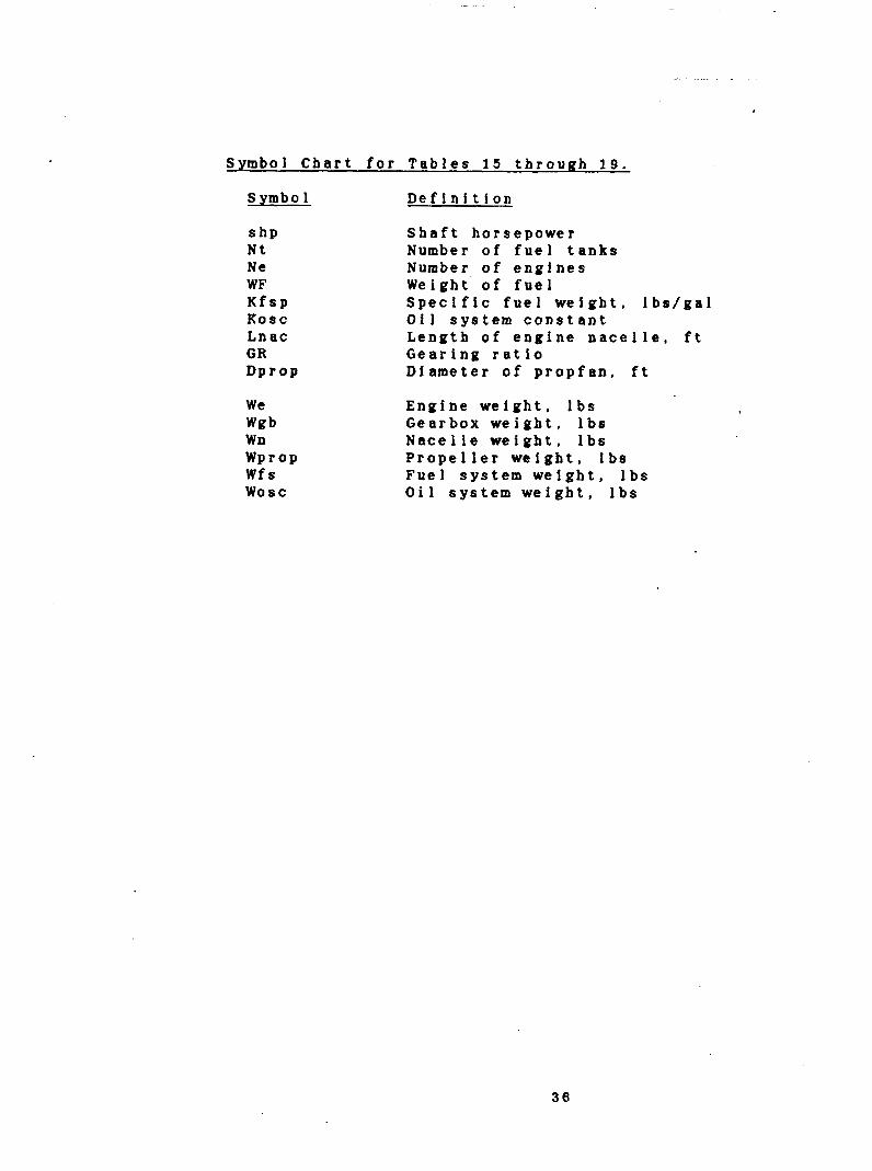
S y m b o l C h a r t f o r T a b l e s 1 5 t h r o u g h 1 9 .
Symbo 1 D e f i n i t i o n
S h P N t N e WF K f s p Kosc L n a c GR D P r o P
We Wgb Wn WProP W f s wosc
S h a f t h o r s e p o w e r Number o f f u e l t a n k s Number o f e n g i n e s W e i g h t ' o f f u e l S p e c i f i c f u e l w e i g h t , l b s / g a l O i l s y s t e m c o n s t a n t L e n g t h o f e n g i n e n a c e l l e , f t G e a r i n g r a t i o D i a m e t e r o f p r o p f a n , f t
E n g i n e w e i g h t , I b s G e a r b o x w e i g h t , l b s N a c e l l e w e i g h t , l b s P r o p e l l e r w e i g h t , l b s F u e l s y s t e m w e l g h t , lbs O i l s y s t e m w e i g h t , l b s
36

Table 1 5 . 2 5 Passenger Engine Installation Weights.
Data: shp: 5 , 5 8 0 . Q 0 Nt: 2 . 88 Kfsp: 5.87 K o s c : 0 . 4 7 Lnac: 1 7 . 8 3
We : Wgb: W n : Wprop: Wfs: wosc:
8 8 5 . 4 8 2 6 5 . 5 8 7 4 4 . 6 2 8 4 5 . 8 0 4 2 2 . 5 8 1 1 2 . 7 6
Ne: WF : GR : Dprop:
Wpwr : 5 , 8 5 6 . 5 3
Table 1 6 . 3 6 Passenger Engine Installation Weights.
2 . 0 8 3 , 7 6 7 . 0 8
8 . 9 9 1Q.88
Data: s b p : 5 , 5 8 8 . 8 8 Nt: 2 . PB Kfsp: 5 . 8 7 Kosc: 8 . 9 7 Lnac: 1 7 . 8 3
We : Wgb: W n : Wprop: Wfs: wosc:
8 8 5 . 4 8 2 6 5 . 5 8 7 4 4 . 6 2 8 4 5 . BQ 4 4 8 . 6 0 1 1 2 . 7 6
Ne : 2.QQ WF : 5 , 6 2 8 . 8 8 GR : 8 . 9 9 Dprop: 10. 0 Q
Wpwr : 5 , 8 8 2 . 5 5
3 7

Table 1 7 . 5 0 Passenger Engine Installation Weights.
Data: shp: 5 , 5 8 8 . 88 Nt: 2 . M 0 Kfsp: 5 . 8 7 Kosc: 0 . 0 7 Lnac: 1 7 . 8 3
W e : Wgb: W n : Wprop: Wfs: wosc:
8 8 5 . 4 0 2 6 5 . 5 8 7 4 4 . 6 2 8 4 5 . 80 4 6 3 . 7 7 1 1 2 . 7 6
Ne: WF : GR : Dprop:
Wpwr : 5 , 8 9 7 . 7 2
2 . 0 u 6 , 9 3 9 . 88
8 . 9 9 1 8 . 1 8
Table 18. 7 5 P a s s e n g e r Engine Installation Weights.
Data: shp: 11,188.88 N t : 3 . 8 0 Kfsp: 5 . 8 7 Kosc: 8 . 8 7 Lnac: 2 3 . 3 3
W e : 1.622.81 Wgb: 7 5 1 . 1 6 W n : 1 , 3 9 6 . 1 8 Wprop: 2 , 2 1 5 . 0 8 Wfs: 6 4 1 . 8 1 w o s c : 227.08
Ne : 2 . 8 0 WF : 1 1 , 2 4 0 . 8 9 GR : 8 . 9 9 Dprop: 1 4 . 3 3
Wpwr : 1 2 . 8 3 7 . 6 8
3 8

Table 19. 100 Passenger Engine Installation Weights.
D a t a : s h p : 1 1 , 8 8 0 . 8 0 Nt: 3. 88 K f s p : 5.87 Kosc: 8.97 Lnac: 23.33
We : 1,622.01 Wgb: 751.16 Wn: 1,396.18 Wprop: 2,215. 80 Wfs: 665.22 w o s c : 227.88
Ne : 2.00 1 3 , 8 7 8 . 0 0 WF :
GR : 8.99 D p r o p : 14.33
Wpwr: 12,861.81
38

C.G. 7
F l g u r e 23. P r o p u l s i o n S y s t e m s Centers o f Gravity.
4 8

Table 20. 'Propulsion System Costs Summary.
Propeller Cost Estimation ( N A S A CR-165499)
5 , 5 8 0 s h p derivative: $339.781 per engine 11,088 shp derivative: $667,590 per engine
Engine Cost Estimation ( N A S A CR-168115)
5,500 shp PD436-11 derivative: $1,183,241 per engine 1 1 , 0 0 0 s h p PD436-11 derivative: $2,861,143 per engine
* * For a detailed cost breakdown, see Reference 4 * *
4 1

- 5. Integration and Commonality
Aft mounted engines were the best way to achieve commonality throughout the family of commuters. T h i s ’ c h o i c e was made not from an engine point of view, but from a configuration and handling qualities perspective. For each aircraft, the tailcones, empennage, and w i n g torque boxes are the same. Therefore, engine placement and numbers had to be the same throughout the family. The twin body configurations still use the same pylon-fuselage mounts as all single body configurations. Consequently, the tail cone frames will need to be sized t o support the 11,000 shp engines and subsequent loading. Figure 2 4 illustrates the general layout o f the family.
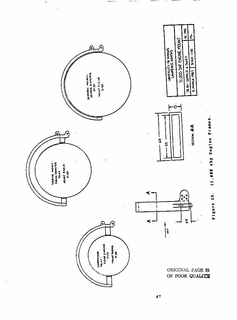
Figures 27 and 28 s h o w the 5,500 shp and 1 1 . 0 g 0 shp engine installation layouts. The fuselage-pylon attachment points are 66 inches apart throughout due to the tailcone frame spacing o f 22 inches. The layouts vary slightly due to:
( 1 ) the engine attachment points are at different spacings for the two engines,
( 2 ) the fuselage-to-blade t i p clearance for both layouts is 0.20 times the fan diameter. This ratio is dependent on both acoustic and stability constraints.
Figures 27 and 28 s h o w the conceptual frames f o r the two engines. These frames will facilitate both engine removability and accessibility.
Additional restraints have been made on the design dut t o the propfan installation. They are as follows:
1 . Redundant empennage control cables bad to be routed along separate lines to protect against loss of control due to blade penet r at ion.
2. The cabin aft pressure bulkhead is located forward of the blades‘ plane o f rotation t o prevent the possibility of rupture due to blade separation.
3. Additional structure (and weight) bas been added to the tailcone and empennage surfaces to protect against sonic fatigue and to enhance noise reduction in the passenger cabin. This topic will be discussed in more detail in the following chapter.
4 2
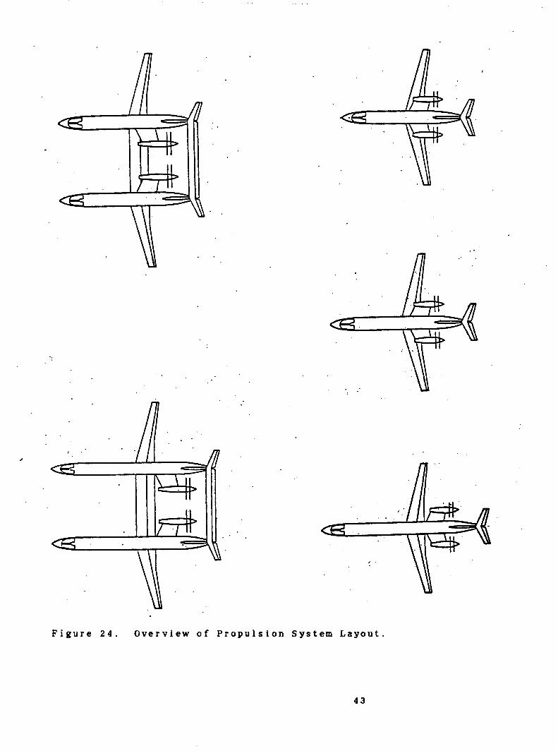
F i g u r e 2 4 . Overview o f Pr o p u l s i o n S y s t e m L a y o u t .
4 3

/
c 0 .1
Y 8 CI
I
6 Y Q)
c LI
a2 c .c(
m 5: w PI c (I)
B rn m m
m cu
a2 CI 7 M
ra .LI
4 4

t-
h
0 +
li
4 5

a
4 6
CI su 0, E
M C w SL
. c P
.L.
ORIGINAL PAGE IS OF POOR QUA4334
4 7

6. Noise-
The major disadvantage o f counter-rotation propfans over advanced turbofans is in the area of noise. This chapter addresses counter-rotation noise sources, characteristics, and methods for reduction.
6.1. Sources
Counter-rotation propfans have several mechanisms from which noise is generated. Figure 29 provides a general overview. During l o w speeds at high power settings such as at take-off and climb, the high blade loadings are the chief contributor to noise. The propeller wake and vortices generated by the upstream propeller interact with the downstream propeller causing fluctuations in loading and generating higher noise levels. '
Figure 30 illustrates this. Also, high angles o f attack cause uneven blade loadings on the propfan plane. During cruise the blade loading is reduced but t i p M a c h numbers are greatly increased. Propfan t i p speeds m a y reach as high as Mach 1.1 to 1.2 (Reference 10) and the abrupt pressure differences caused by the shock waves create high noise levels. The propfan is relatively quiet during descent w h e n blade loading and tip speeds are low.
Other sources o f propfan noise include basically ins t a1 1 at ion effects:
* non-uniform f l o w from fuselage or engine nacelle boundary 1 aye r s ep ar at i o n ,
* slipstream turbulence from the engine pylon or from the wings at high angles of attack,
* e x h a u s t f l o w passing through the propeller hubs.
6.2. No i se Character i s t i cs
Counter-rotation noise levels are typically 1 5 to 20 d b higher than single rotation levels. Even more, counter-rotation directivity patterns s h o w higher noise levels over a wider area. Figure 31 illustrates this. Consequently, a larger section of the fuselage both fore and aft o f the propfan plane are exposed to higher noise levels with counter-rotation propellers.
I t was mentioned that during l o w speed operation, angle of attack effects propfan noise levels. Figure 32 shows the significance o f this. Although this figure is f o r single rotation, the trends for counter-rotation will be similar. Therefore, f o r a 18 degree increase in angle of attack, a 5 to 7 d b increase in noise in the plane of rotation can be expected. This may increase in front o f the propeller plane.
4 8

J 0
. . . .
i
4 9

Upstream
Wake inter& with Qlmstream propeller
Upstream
U) Wake interxtbn .
Propeller lip Ilorlex f
6) vortex interKtim
F i g u r e 30. Propfan Noise Sources due to Blade Interaction. ( N A S A TM-87099)
50

At cruise a 155 to 1 6 0 db noise level can be expected on the fuselage surface in the propeller plane. This is shown in Figure 3 3 . These high noise levels can be expected to remain as far as 3 0 degrees in front and 20 degrees aft of the propeller plane. Therefore, the tailcone for the family of commuters will have to be designed radically different than the fuselage sections due to acoustic impingement effects.
6.3. Cabin Noise Reduction
The aft pressure bulkheads throughout the entire family are located at the aft pylon mount as shown in Figure 34. This location is just over 40 degrees fn front o f the propeller plane o f rotation. F r o m Figure 3 3 , airborne noise drops b e l o w 145 d b at this location. Therefore, the aft mount design has an advantage in cabin noise reduction due to engine placement.
The tailcone section will have to be structurally designed to withstand the high level, long duration acoustic fatigue levels. Reference 18 stated that the MD-80 is typically exposed to 1 2 0 db f o r 2 , 0 0 0 hours over its nominal '75,000-hour lifetime; however, the MD-SIX (proposed counter-rotation version) may be exposed to 1 5 0 d b for 5 0 , 0 0 8 hours. This indicates large structural weight penalties. Table 21 gives the proposed 'acoustic weight penalties f o r the 5 , 5 8 0 shp and 1 1 , 0 0 0 shp engines based o n methods given in Reference 8. However, McDonnel Douglas claims that current technology m a y reduce the figures given in Table 21 by 75 percent ( A W S T April 1 3 , 1987).
Table 21. Acoustic Weight Penalties.
Noise Level on Tailcone in Propfan Plane: 155 d b Clearance Between Propeller ,and Fuselage: 0.20 F a n Diameter
5.500 shp Acoustic Weight Penalty: 2 , 2 0 0 lbs/airplane 11,000 shp Acoustic Weight Penalty: 5 , 2 0 0 lbs/airplane
T o understand the methods used to reduce cabin noise, the paths along which noise enters the cabin must be examined. Figure 35 illustrates these paths. They are:
( 1 ) from the propfan through the air to the tailcone and along the structure into the cabin,
( 2 ) from mechanical vibration through the engine pylon into the fuse 1 age,
( 3 ) from the propellers through the air directly to the cabin skin.
5 1

Comparison of OML-Directivity of . Single and Counterrotating .Rotors
I I I 1 I I I
Figure 31. Comparison of S i n g l e and Counter-Rotation Directivity Pat terns.
5 2

9
F i g u r e 32. Effect of Angle of Attack on Flyover Noise for a S i n g l e R otation Configuration. ( C o m p l i m e n t s of NASA-Lewis)
5 3

SPL .. AT
BLADE PASS I NG
FREQUENCY,
nB ,
170
CR NOISE DIRECTIVITY AT M=,72 CRUISE
100% SPEED, 0,3 D I A , SIDELINE 8x6 WIND TUNNEL
160
150
l4C
13(
40
0 F1-A.1 *
0 Fl-A3
A F7-A7 . .
. .
I . ' . - I I I . . . . .I ._
. . . . . .
69 . ; 80 100 ' 120 AWGLE, DEGa
140. ' . .
F i g u r e 33. Counter-Rotation Cruise Noise Levels. (Compliments of NASA-Lewis)
5 4

L7.0
Figure 34. Aft Pressure Bulkhead Location f o r the Family of Commuters.
5 5

CABIN
n n n
VIBRATION /
F i g u r e 3 5 . T r a n s m i s s i o n P a t h s of C a b i n Noise.
5 6

There are several methods proposed that are currently being studied to reduce cabin interior noise.
1 . Double wall fuselage design is the method traditionally proposed. Figure 36 is an illustration.
2. Rubber backed adhesive metal foll lining is currently being studied by McDonnel Douglas to damp out high frequencies.
3. Tuned vibration absorbing weights located in the fuselage or engine structure m a y reduce noise. For example, the DC-9 used tuned mechanical absorbers in the engine mounts to reduce noise to acceptable levels.
Acoustic weight treatment does have its limitations. F i g u r e 38 shows this conceptually. There comes some point during the addition of acoustic weight treatment when the added noise reduction is not effective compared to the increase in weight. This is due to structural borne noise.
Environmental noise levels are currently being analyzed in flight testing. O n e o f the purposes of the current N A S A Propfan Test Assessment (PTA) and GE UDF demonstrator aircraft 1 s to prove that the advanced propulsion systems will meet FAR 36 noise
airborne noise. They are: . limitations. There are methods that can be used to reduce
( 1 ) reduce blade loading by increasing fan diameter.
(2) reduce diameter o f the second blade r o w in the counter rotation configuration. As shown in Figure 39, this would take the blades out o f the vortex f l o w of the upstream propellers.
(3) m o v e the exhaust from in front o f the propfan plane of rotation. Hub exhaust considerations have been examined.
The M a y 1 9 8 7 issue o f Aerospace America stated that "Flight testing of the General Electric's advanced fan propulsion system confirmed that results of model tests agree with full scale results. Wind tunnel data s h o w that the uaducted fan performs better than federal noise regulations require." Therefore, i t has been assumed that the noise requirements f o r the K . U . F a m i l y o f Commuters will meet FAR 36 requirements.
5 7

r INTERIOR T R I M PANEL
r FIBERGLASS
r VIBRATION I SO IATOR
r AIR GAP (OR LOW DENSITY FIBERG
-DAMPING MATER1
-OUTER SKIN
LASS)
lA L
DOUBLE WALL CONCEPT USES OPTIMUM COMBINATION OF MASS, DENSITY, STIFFNESS, AND' DAMPING
Figure 36. Double Wall Fuselage Design Concept. (Compliments of NASA-Lewis)
5 8

ACOUSTIC TREAf MENT EFFECT
ACTUAL
THEORETICAL * b db / D o u b \ \ ~ Mass
TREATMENT WEGHT (LOG)
Figure 37. Acoustic Weight Treatment Effectiveness.
Figure 38. Downstream Bladerow Diameter Reduction.
5 9

7. Conclusions and Recommendations
---__- 7 . 1 . Conclusio&s
1. Two engine cores, both derivatives o f the APET PD436-11 designs, were needed for the family of commuters: a 5,508 shp core for the 2 5 , 3 6 , and 5 0 passenger configurations and an 1 1 , 0 0 0 shp core for the 75 and 100 passenger configurations.
2. Counter-rotating propfans were chosen f o r propulsion. The counter-rotation propfan for the 5,500 shp core has a diameter of 1 2 0 inches: the counter-rotation propfan for the 11,000 s h p core has a diameter o f 172 inches.
3. The 25 and 36 passenger engine cores have been derated 3 8 and 2 0 percent respectively due to stability and performance considerations. This will increase the service life of these engine cores.
4 . From preliminary results of current unducted fan demonstrator flight testing, i t is predicted that propfans will meet and possibly exceed F A R 36 noise requirements. Cabin interior noise Ievels are yet to be determined.
5. The MD91-X Demonstrator Airplane is basically the proof o f concept for the K.U. proposal. The MD91-X has similar configuration and engine integration as the K.U. design.' Flight testing is scheduled to begin later this year.
6. Aft mounted propfans allowed the family o f commuters to achieve a high degree of commonality especially in w i n g torque box, fuselage tailcone, and control system designs.
7.2. Recommendat ions
1 . Inlet and nozzle designs were sized using preliminary methods. M o r e detail is needed in this area. A hub exhaust concept should also be studied.
2. T h e gearbox design can be enhanced with recent technology. S i n c e the K . U . design began in August o f 1986, great strides have been m a d e in this area and will continue with the proposed demonstrator engines.
3. Currently, there is no clear-cut methodology for predicting propfan noise. With the current demonstrator airplanes, data will be available for numerical acoustical analysis of the proposed propfan design.
4. Acoustic treatment weight can be reduced with n e w technology. McDonnel Douglas has proposed 75% weight reductions over methods proposed four years ago.
6 U

- 8. References
1 . University of Kansas A E 79B Design Team; Class I D esigns of -- a Family of Commuter Airplanes; University of Kansas, 1986.
2 . Mornan. L.K.. University o f Kansas A E 79B Design Team; A - - . Cost Analysis f o r the Implementation of Commonality in the Family of Commuter Airplanes: University of Kansas, April, 1987.
3. University of Kansas A E 790 Design Team; A Class I 1 Weight Assessment f o r the Implementatio-qpf Commonality an Preliminary Structural Designs f o r the Family o f Commuter Airplanes; University o f Kansas, 1987.
4. University o f Kansas A E 7 9 0 Design Team: Class I 1 D esign Update for the Family of Commuter Airplanes; University o f Kansas, 1987.
5. Russell, M., and Haddad, R., University o f Kansas AE 7 9 6 Design Team; Presentation of Structural Component Designs f o r the Family o f Commuter Airplanes; University o f Kansas, 1987.
6. Hensley, D., University of Kansas A E 7 9 0 Design Team: Flight Control Design and Handling Quality Commonality by Seperate Surface Stability Augmentation for the Family of Commuter Airplanes; University of Kansas, 1987.
APET) 7. Anderson, R.D., Advanced Propfan Engine Technology ( Definition Study, Single and Counter-Rotation Gearbox/Pitch Change Mechanism, Allison Gas Turbine Division, July 1085. (NASA CR-168115)
8. Weisbrich, A.L., Godston, J . , and Bradley, E., Technology and Benefits o f Aircraft Counter Rotation Propellers, Hamilton Standard, Pratt and Whitney, Lockheed-Georgia, December 1982. ( N A S A CR-168258)
9. Roskam. J., A i r p l a n e Design Part VI: Preliminary Calculation o f Aerodynamic, Thrust and Power Characteristics, Roskam Aviation and Engineering Corporation, Rt. 4, Box 274, Ottawa, Kansas 66067, 1985.
10. Aviation W e e k and Space Technology, April 1 3 , 1987, p p . 52-93.
11. Dittmar, J . H . . S o m e Design Philosophy for Reducing the -- Community Noise o f AAvanced Counter-Rotation Propellers, NASA-Lewis Research Center, Cleveland, Ohio, August 1985. ( N A S A TM-87899)
61
Related Documents