The Spektrum trademark is used with permission of Bachmann Industries, Inc. Specifications Wingspan: ......................................................... 58.25 in (1480mm) Length: ................................................................ 50.4 in (1281mm) Wing Area: ................................................626 sq in (40.38 sq dm) .................................................. 648 sq in (41.81 sq dm) w/droops Weight: ........................................................... 6.5–7 lb (2.9–3.2 kg) Radio: ........................................................... 4-channel w/5 servos Engine: .................................................................... Evolution® TPS P-51 PTS Mustang Mk II Assembly Manual

Welcome message from author
This document is posted to help you gain knowledge. Please leave a comment to let me know what you think about it! Share it to your friends and learn new things together.
Transcript

The Spektrum trademark is used with permission of Bachmann Industries, Inc.
SpecificationsWingspan: ......................................................... 58.25 in (1480mm)Length: ................................................................ 50.4 in (1281mm)Wing Area: ................................................626 sq in (40.38 sq dm) .................................................. 648 sq in (41.81 sq dm) w/droopsWeight: ........................................................... 6.5–7 lb (2.9–3.2 kg)Radio: ...........................................................4-channel w/5 servosEngine: .................................................................... Evolution® TPS
P-51 PTS Mustang Mk IIAssembly Manual

*All replacement parts do not come with any radio gear. These items must be purchased separately.
2 Hangar 9 P-51 PTS Mk II Assembly Manual
Table of ContentsContents of Kit and Parts Layout ...........................................2Using the Manual ...................................................................3UltraCote® Covering Colors ..................................................3Before Starting Assembly ......................................................3Radio and Power Systems Requirements ..............................3Field Equipment Required ......................................................3Optional Field Equipment .......................................................3Additional Required Tools and Adhesives ..............................3Optional Tools and Adhesives for Flap Installation ................3FS One ...................................................................................3Important Information Regarding Warranty Information .......3Section 1: Charging your Receiver Battery ............................4Section 2: Installing the Landing Gear ...................................5Section 3: Installing the Tail Surfaces ....................................6Section 4: Installing the Propeller ..........................................8Section 5: Attaching the Wing .............................................10Section 6: Your Spektrum DX6i Radio System ....................12Section 7: Transmitter Battery Installation ...........................13Section 8: Digital Trims ........................................................14Section 9: Low Battery Alarm ..............................................14Section 10: Trainer ...............................................................14Section 11: Binding ..............................................................14Section 12: Mode 2 vs Mode 1 ............................................16Section 13: Centering the Control Surfaces .........................17Section 14: Checking the Control Surface Directions ..........19Section 15: Checking the Control Throw Amounts ..............21Section 16: Adjusting the Throttle .......................................22Section 17: Balancing Your P-51 PTS ..................................23Section 18: How to Range Test the DX6i .............................24Section 19: Flight Preparations ............................................25Section 20: Starting and Adjusting the Evolution Engine .....25Section 21: Maintaining Your P-51 PTS Mustang ................27Section 22: Progressing With Your Flying Skills ..................28Section 23: Adding a Flap Servo ..........................................30Safety Do’s and Don’ts for Pilots .........................................35Daily Flight Checks ...............................................................35Glossary of Terms ................................................................36Safety, Precautions and Warnings .......................................36Warranty Information ...........................................................37Instructions for Disposal of WEEE by
Users in the European Union .........................................382008 Official Academy of
Model Aeronautics Safety Code .....................................39
Replacement Parts1. HAN4426 Fuselage with Hatch and Canopy2. HAN4427 Left Wing Panel3. HAN4428 Right Wing Panel4. HAN4429 Tail Set with Tail Wheel Assembly5. HAN4430 Fuselage Hatch and Canopy6. HAN4431 Landing Gear with wheels7. HAN4432 Anodized Wing Tube8. HAN4433 Painted Cowl with Engine Cutout9. HAN4435 Painted Pilot Figure10. HAN4709 Tail Wheel Set11. HAN2835 Wing Droops12. HAN2830 Painted Canopy Frame13. HAN2839 2.75-inch Spinner 3 Blade14. EVOE100P Evolution Power System Propeller15. HAN4437 Exhaust detail with screws16. EVOE100 Evolution Trainer Power System17. SPM6600 DX6i 6-Channel without Servos MD2 SPM66001 DX6i 6-Channel without Servos MD118. HAN4438 Wheels 3
1/2-inch 8 spoke
Items Not ShownHAN2479 Fuel Tank 11 ozHAN40M Engine MountHAN4436 DecalsHAN4434 Pushrod SetHANR300 RTF Standard Replacement ServoSPM9530 3-Wire SwitchSPMB1500NM 4.8-volt 1500mAh Ni-MH Battery
A variety of 150mAh wall charger with transmitter adapters are available. Please verify the correct part number with the source of your P-51 Mustang.SPM9526, SPM9526UK, SPM9526EU or SPM9526AUOne additional Amazin’ Grace decal. Not available separately.
116
17
15
6
2
3
4
59 12
7
8
13
14
18
11
10
11
Contents of Kit and Parts Layout

The Spektrum trademark is used with permission of Bachmann Industries, Inc.
3Hangar 9 P-51 PTS Mk II Assembly Manual
Using the Manual
This manual is divided into sections to help make assembly easier to understand, and to provide breaks between each major section. In addition, check boxes have been placed next to each step to keep track of each step completed. Steps with a single box () are performed once, while steps with two boxes () indicate that the step will require repeating, such as for a right or left wing panel, two servos, etc. Remember to take your time and follow the directions.You will also find an included instructional DVD that will guide you through the preparation of your model and compliments this manual. It is recommended to watch the instructional DVD before beginning the assembly of your model.
UltraCote® Covering Colors• Black HANU874• White HANU870• Silver HANU881• Cub Yellow HANU884• True Red HANU866• Olive Drab HANU904
Before Starting Assembly
Before beginning the assembly of your P-51 PTS Mustang, remove each part from its bag for inspection. Closely inspect the fuselage, wing panels, rudder and stabilizer for damage. If you find any damaged or missing parts, contact the place of purchase.If you find any wrinkles in the covering, use a heat gun or covering iron to remove them. Use caution while working around areas where the colors overlap to prevent separating the colors.
HAN100 – Heat Gun
HAN150 – Covering Glove
HAN101 – Sealing Iron
HAN141 – Sealing Iron Sock
Radio and Power Systems Requirements
Spektrum Radio System• DX6i (included)• SPM6600 DX6i 6-Channel w/o Servos MD2• SPM66001 DX6i 6-Channel w/o Servos MD1
Power System• Evolution Trainer Power System (EVOE100)
Red spinner available separately (included)
Optional for Flap System• JR SPORT ST-47 Standard Servo (JSP20050) (2)• Y-Harness, Heavy Duty (JRPA135)
Field Equipment Required• Fuel (15% recommended)• Propeller (EVOE100P) included• Long Reach Glow Plug Wrench (HAN2510)• Metered Glow Driver w/Ni-Cd & Charger (HAN7101)• 2-Cycle Sport Plug (EVOGP1)• Manual Fuel Pump (HAN118)
Optional Field Equipment• Selfstick weights, 6 oz (HAN3626)• PowerPro 12V Starter (HAN161)• 12V 7Ah Sealed Battery (HAN102)• Power Panel (HAN106)• Blue Block After Run Oil (EVOX1000)• Cleaner and towels
Additional Required Tools and Adhesives
• Phillips screwdriver: #1, #2 • Pencil• Felt-tipped pen • Box wrench: 7/16-inch• Flat blade screwdriver • Nut driver: 7/32-inch• Hex wrench: 3/32-inch, 2.5mm
Optional Tools and Adhesives for Flap Installation
• Pencil • 6-minute epoxy• Drill • Sandpaper• Phillips screwdriver: #1 • Thin CA• Mixing cups • Mixing sticks• Hobby knife w/#11 blade • Side cutters• Drill bit: 1/16-inch (1.5mm)
FS One
With FS One (HANS2008) you get more than photorealistic fields, gorgeous skies and realistic-looking aircraft. You get incredibly advanced aerodynamic modeling that simulates every possible aspect of real-world flight.The first Hangar Pack (HANS4010) will add even more aircraft to FS One. This latest edition includes ten new planes and helis from your favorite brands, including Hangar 9, E-flite and Align. You’ll be able to fly aircraft that are only available on FS One such as the T-REX, Blade CX2, Blade CP Pro, Hangar 9 P-51 and F-22 PTS. And as always, with the Hangar Pack, you still get all the same great features that you did with the original aircraft.
HANS2008 HANS4010
Important Information Regarding Warranty Information
Please read our Warranty and Liability Limitations section on Page 32 before building this product. If you as the purchaser or user are not prepared to accept the liability associated with the use of this Product, you are advised to return this Product immediately in new and unused condition to the place of purchase.

4 Hangar 9 P-51 PTS Mk II Assembly Manual
Section 1: Charging your Receiver Battery
Items required• Fuselage assembly • Charger
Before flying your P-51 Mustang PTS, you will need to charge the receiver battery for 12–14 hours prior to use.Although the radio system may work as shipped, the receiver battery is not fully charged and flying your model without charging will result in the loss of communication between the transmitter and receiver. This situation will cause the loss of your aircraft.You can elect to charge the batteries at this time, or begin the assembly of your aircraft. Please make sure to take the time to fully charge the batteries before checking the control throws and before every flying session.
Step 1Remove the canopy from the fuselage by sliding the canopy hatch pin forward and lifting up the rear of the canopy hatch. The hatch has tabs at the front that insert into the fuselage to keep the front of the hatch down in flight.
Step 2Plug the battery charger into a suitable outlet or power strip to power the charger.
Note: A transmitter adapter has been included and attached to the charger as shipped. This adapter will need to be removed before charging the receiver battery.
Step 3Connect the battery charger to the lead exiting the switch harness labeled CHARGE. Allow the charger to charge the battery for 10–12 hours before flying your model.
Hint: Prior to flying your model, connect the charger and charge the receiver pack. This routine will guarantee a charge on the receiver battery for your flying session. Use care not to overcharge the receiver pack by leaving the charger on longer than the recommended 10–12 hours.

5Hangar 9 P-51 PTS Mk II Assembly Manual
Section 2: Installing the Landing Gear
Items Required• Wing panel (left and right) • Landing gear strap (4)• Main landing gear (left and right)• #4 x 1/2-inch sheet metal screw (8)• Phillips screwdriver: #2
Step 1Locate the left landing gear strut. Slide the strut into position on the bottom of the wing. The wheel will be towards the leading edge (front) of the wing when installed correctly. Press the landing gear into the groove of the landing gear mount.
Step 2Locate two landing gear straps and four #4 x 1/2-inch sheet metal screws. Use a #2 Phillips screwdriver to attach the landing gear straps using the screws. Tighten the landing gear straps until they pull the landing gear into the groove, flush with the bottom of the wing.
Hint: Starting the screw partially in the landing gear strap will help in getting the screw started in the pre-drilled holes near the landing gear.

6 Hangar 9 P-51 PTS Mk II Assembly Manual
Note: Use care not to over-tighten the screws and damage the landing gear mount.
Step 3Repeat Steps 1 and 2 to install the right landing gear strut.
Section 3: Installing the Tail Surfaces
Items Required• Fuselage • Stabilizer/elevator• Nut driver: 7/32-inch or adjustable wrench
Step 1Locate the stabilizer/elevator assembly. Locate the fuselage assembly and use a 7/32-inch nut driver to remove the nuts and washers from the threaded rods on the bottom of the fuselage.
Step 2Remove the clevises from the control horn. To remove the clevis, carefully slide the clevis retainer off of the clevis so it can be opened. Use a flat blade screwdriver to open the clevis and remove it from the control horn. Carefully remove the rudder/fin assembly from the fuselage.
7Hangar 9 P-51 PTS Mk II Assembly Manual
Note: The fuselage fairing is not glued in place. Make sure to keep the fairing in position when installing the stabilizer. The photo below illustrates the fairing being separated from the vertical fin for clarity of the part.
Step 3Position the stabilizer/elevator assembly so the control horn will face down, away from the fin. The threaded rods from the rudder/fin assembly will slide into the two holes in the stabilizer. The fuselage fairing is in position on the fin as it is installed on the fuselage for shipping.
Step 4Slide the stabilizer/fin assembly back into position on the fuselage. The stabilizer will rest tightly against the fuselage, and the fin will rest snug against the top of the stabilizer.
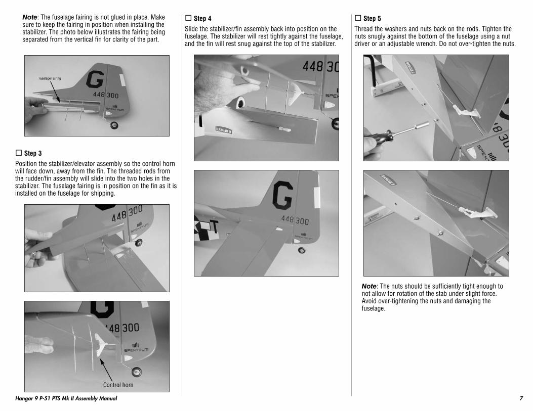
Step 5Thread the washers and nuts back on the rods. Tighten the nuts snugly against the bottom of the fuselage using a nut driver or an adjustable wrench. Do not over-tighten the nuts.
Note: The nuts should be sufficiently tight enough to not allow for rotation of the stab under slight force. Avoid over-tightening the nuts and damaging the fuselage.
8 Hangar 9 P-51 PTS Mk II Assembly Manual
Section 4: Installing the Propeller
Items required• Fuselage assembly • Propeller• Spinner• 3mm x 16mm sheet metal socket head screw (3)• Exhaust stack, right and left• #2 x 5/16-inch wood screw (4)• Box wrench: 7/16-inch• Hex driver: 2.5mm• Phillips screwdriver: #1
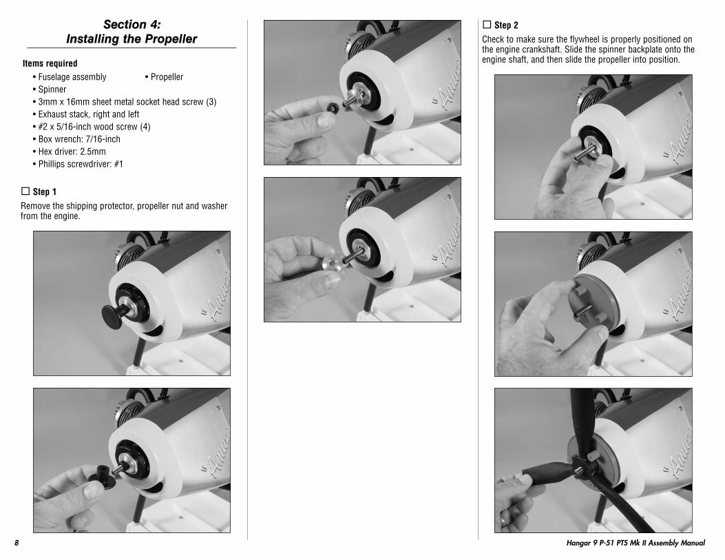
Step 1Remove the shipping protector, propeller nut and washer from the engine.
Step 2Check to make sure the flywheel is properly positioned on the engine crankshaft. Slide the spinner backplate onto the engine shaft, and then slide the propeller into position.

9Hangar 9 P-51 PTS Mk II Assembly Manual
Step 3Slide the washer and thread the nut onto the engine shaft. Rotate the propeller clockwise so it is resting against the lugs of the spinner backplate. Use a 7/16-inch box end wrench to tighten the propeller nut. Never use pliers, as the nut will not be tight enough, and could come loose.
Note: It is suggested to read the engine instructions included with your P-51 PTS Mustang at this time to learn more on the care and operation of your Evolution engine.
Step 4Locate the three #4 x 5/8-inch sheet metal socket head screws. Position the spinner cone onto the spinner backplate, making sure it keys into the backplate. Use the screws and a 2.5mm or 3/32-inch ball driver or hex wrench to secure the spinner cone to the backplate.

10 Hangar 9 P-51 PTS Mk II Assembly Manual
Step 5Use a #1 Phillips screwdriver to attach the exhaust stacks to the fuselage using the four #2 x 5/16-inch wood screws.
Note: The exhaust stack for the right side of the model is shorter than the left. This is necessary to clear the muffler.
Hint: Starting the screw partially in the exhaust stack will help in getting the screw started in the pre-drilled holes in the cowling and fuselage.
Section 5: Attaching the Wing
Items required• Wing panel (right and left) • Hex wrench: 3/32-inch• Fuselage assembly • Wing tube• #4 washer (2) • #4 lock washer (2)• 4-40 x 1-inch socket head screw (2)
Step 1Locate the aluminum wing tube. Slide the wing tube into the wing tube socket in one of the wing panels. There is a stop inside the wing, so don’t force the tube further into the wing than it will easily slide.

11Hangar 9 P-51 PTS Mk II Assembly Manual
Step 2Locate the aileron Y-harness inside the fuselage. Make sure one end of the harness exits the right side of the fuselage and one exits the left side of the fuselage.
Step 3Slide the wing tube and wing panel into the socket in the fuselage. Plug the lead for the aileron servo in the wing into the extension extending out of the fuselage. Guide the alignment pins in the wing into the holes in the fuselage then slide tight against the fuselage.
Step 4Locate the 4-40 x 1-inch socket head screw, #4 washer and #4 lock washer. Slide the lock washer onto the screw, then slide the washer onto the screw.

12 Hangar 9 P-51 PTS Mk II Assembly Manual
Step 5Use the screws and a 3/32-inch ball driver or hex wrench to secure the wing to the fuselage. If the screw does not go in easily, you may need to double-check that the wing is tight against the fuselage.
Step 6You can now slide the remaining wing panel onto the wing tube. Plug the aileron extension from the aileron servo into the Y-harness in the fuselage then slide the wing tight against the fuselage. Repeat Step 5 and 6 to secure the wing panel to the fuselage.
Section 6: Your Spektrum DX6i Radio System
Use the following image to familiarize yourself with the Spektrum DX6i transmitter. For more information you should always refer to the User Guide included with this model that references the transmitter.
Antenna
Rudder Dual Rate
Mix/Throttle Hold
Aileron Dual Rate
Throttle Cut
Roller
Aileron/ElevatorStick
Elevator Trim
Aileron Trim
On/Off Switch
Rudder Trim
Throttle Trim
Throttle/RudderStick
Flap/Gyro
Elevator Dual Rate
Gear/Flight Mode
Trainer/Bind
Handle
Mode 2 Transmitter

13Hangar 9 P-51 PTS Mk II Assembly Manual
Antenna
Rudder Dual Rate
Mix/Throttle Hold
Aileron Dual Rate
Throttle Cut
Roller
Aileron/ThrottleStick
ThrottleTrim
Aileron Trim
On/Off Switch
Rudder Trim
Elevator Trim
Elevator/RudderStick
Flap/Gyro
Elevator Dual Rate
Gear/Flight Mode
Trainer/Bind
Handle
Mode 1 Transmitter
Your Spektrum DX6i radio will come from the factory pre-programmed with the basic setup for your P-51 Mustang PTS. You should not need to adjust any of the programming of the radio before flying.
Section 7: Transmitter Battery Installation
The DX6i transmitter requires 4 AA batteries:
Remove the battery door and install the included 4 AA batteries, noting the polarity of each corresponds with the diagram in the battery holder. Replace the battery door.
Optional Ni-Cd or Ni-MH 1.2 volt AA rechargeable batteries (Spektrum 1500mAh Ni-MH AA (4 Pack) (SPM9525)) can also be used. A charge jack is located on the left side of the transmitter for convenient recharging. You will need to connect the transmitter adapter to the charger before it can be plugged into the transmitter charge jack.

14 Hangar 9 P-51 PTS Mk II Assembly Manual
Section 8: Digital Trims
The DX6i employs digital trim levers on aileron, elevator, throttle, and rudder. The ADT (Advanced Digital Trim) feature is designed to automatically store the selected trim values for each model. When a different model is selected, the previously stored trim positions for that model are automatically returned to their previous settings.Visual trim positions are displayed on the main screen. The trims feature dual speed scrolling. Holding the trim lever for an extended time will cause the trim rate of change to increase.
Reduce photo to 13.5%
P-51 PTS
5.8V
MDL1
DN12:34Throttle Trim Elevator Trim
Rudder Trim Aileron Trim
Section 9: Low Battery Alarm
When the battery voltage drops below 4.7 volts an alarm will sound and the voltage LEDs will flash. If flying you should land immediately.
Section 10: Trainer
The DX6i offers a Trainer function that allows the transmitter to operate as a master or slave. The trainer switch is located on the back left of the transmitter. When using the trainer function, plug the trainer cord (SPM6805) into the trainer port in both the master (controlling) and the slave (training) transmitters. The master transmitter must have the power turned on and the slave transmitter must have the power turned off.
Note: The DX6i trainer system is compatible with all JR and Spektrum transmitters.
MASteR
The DX6i transmitter can be used as a master but the slave transmitter must have the same programming (i.e. reverse switch positions) as the master.
SlAve
When using the DX6i transmitter as a slave with another DX6i, it’s necessary to match all the reverse switch positions.
Section 11: Binding
Binding is the process of teaching the receiver the specific code of the transmitter so it will connect to that specific transmitter which it is bound to. The transmitter and receiver for your P-51 PTS Mustang have already been bound, but this section has been included as reference. You will not need to bind the transmitter and receiver for your P-51 PTS Mustang.
Items required• Phillips screwdriver: #1 • Bind plug
Step 1Use a #1 Phillips screwdriver to remove the four screws that hold the receiver hatch in the fuselage. Slide the hatch rearward and turn it slightly so it can be removed from the fuselage.

15Hangar 9 P-51 PTS Mk II Assembly Manual
Step 2Remove the foam padding to expose the main receiver.
Step 3Unplug the lead from the switch harness that connects to the battery/bind port of the receiver. Plug the lead from the switch harness into the aileron lead coming from the receiver at this time.
Step 4Plug the bind plug included with the radio system into the battery/bind port of the receiver.
Step 5Turn on the receiver switch. Note that the LEDs on both receivers should be flashing, indicating that the receiver is ready to bind.
16 Hangar 9 P-51 PTS Mk II Assembly Manual
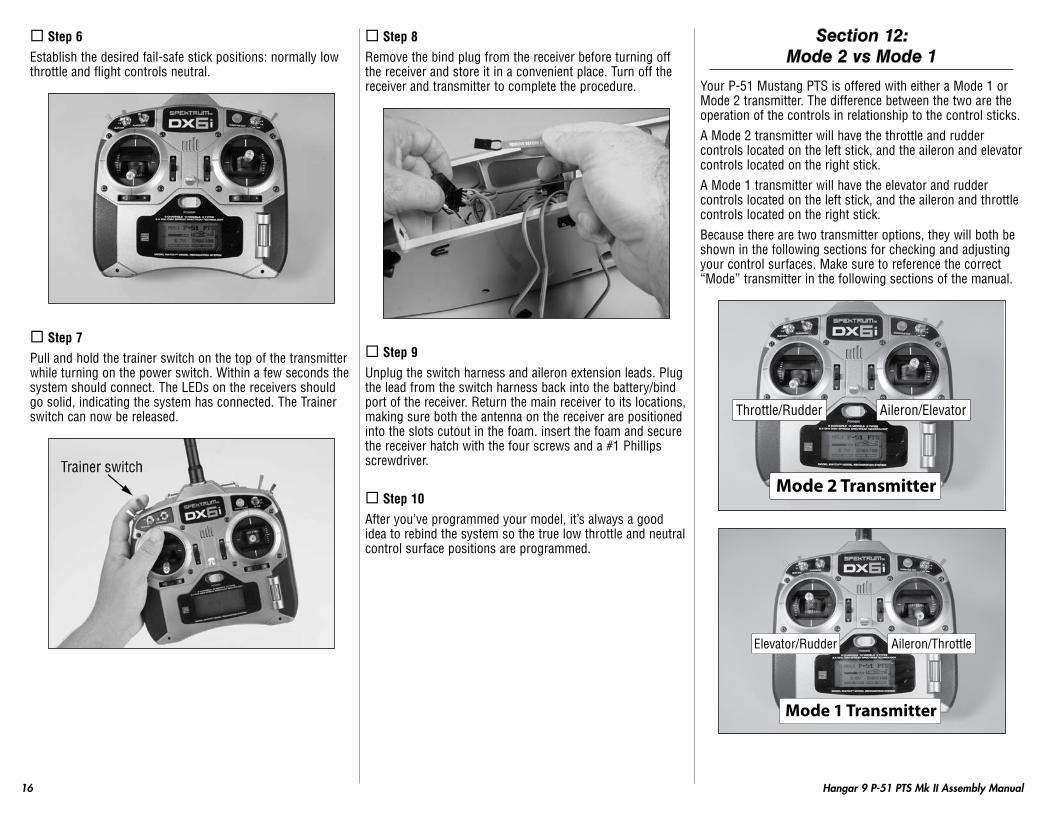
Step 6Establish the desired fail-safe stick positions: normally low throttle and flight controls neutral.
Step 7Pull and hold the trainer switch on the top of the transmitter while turning on the power switch. Within a few seconds the system should connect. The LEDs on the receivers should go solid, indicating the system has connected. The Trainer switch can now be released.
Step 8Remove the bind plug from the receiver before turning off the receiver and store it in a convenient place. Turn off the receiver and transmitter to complete the procedure.
Step 9Unplug the switch harness and aileron extension leads. Plug the lead from the switch harness back into the battery/bind port of the receiver. Return the main receiver to its locations, making sure both the antenna on the receiver are positioned into the slots cutout in the foam. insert the foam and secure the receiver hatch with the four screws and a #1 Phillips screwdriver.
Step 10After you’ve programmed your model, it’s always a good idea to rebind the system so the true low throttle and neutral control surface positions are programmed.
Section 12: Mode 2 vs Mode 1
Your P-51 Mustang PTS is offered with either a Mode 1 or Mode 2 transmitter. The difference between the two are the operation of the controls in relationship to the control sticks.A Mode 2 transmitter will have the throttle and rudder controls located on the left stick, and the aileron and elevator controls located on the right stick.A Mode 1 transmitter will have the elevator and rudder controls located on the left stick, and the aileron and throttle controls located on the right stick.Because there are two transmitter options, they will both be shown in the following sections for checking and adjusting your control surfaces. Make sure to reference the correct “Mode” transmitter in the following sections of the manual.
Aileron/ElevatorThrottle/Rudder
Mode 2 Transmitter
Mode 1 Transmitter
Aileron/ThrottleElevator/Rudder

17Hangar 9 P-51 PTS Mk II Assembly Manual
Section 13: Centering the Control Surfaces
tools required• Flat blade screwdriver
How to remove the clevis from a control surfaceIf may be necessary to remove the clevises from the control horns to center the control surfaces. To remove the clevis, carefully slide the clevis retainer off of the clevis so it can be opened. Use a flat blade screwdriver to open the clevis and remove it from the control horn.
AileronsRemove the packing foam from the aileron control horns. Check to make sure the clevis is located in the outer hole of the control horn. If not, slide the clevis retainer forward, disconnect the clevis, connect it in the correct location.
AileronTrim
Mode 2 Transmitter
AileronTrim
Mode 1 Transmitter
Turn on the radio system. Center the trim lever for the ailerons on the transmitter. If not aligned, remove the clevis from the control horn and thread in or out as needed to allow the aileron to align with the wing tip. Reinstall the clevis to the outer hole of the control horn and then slide the clevis. Slide the clevis retainer onto the clevis to secure its location.
18 Hangar 9 P-51 PTS Mk II Assembly Manual
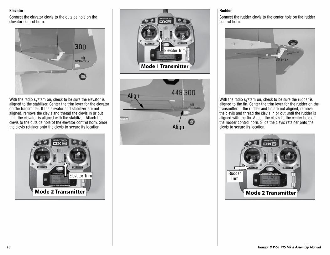
elevatorConnect the elevator clevis to the outside hole on the elevator control horn.
With the radio system on, check to be sure the elevator is aligned to the stabilizer. Center the trim lever for the elevator on the transmitter. If the elevator and stabilizer are not aligned, remove the clevis and thread the clevis in or out until the elevator is aligned with the stabilizer. Attach the clevis to the outside hole of the elevator control horn. Slide the clevis retainer onto the clevis to secure its location.
Elevator Trim
Mode 2 Transmitter
Mode 1 Transmitter
Elevator Trim
RudderConnect the rudder clevis to the center hole on the rudder control horn.
With the radio system on, check to be sure the rudder is aligned to the fin. Center the trim lever for the rudder on the transmitter. If the rudder and fin are not aligned, remove the clevis and thread the clevis in or out until the rudder is aligned with the fin. Attach the clevis to the center hole of the rudder control horn. Slide the clevis retainer onto the clevis to secure its location.
RudderTrim
Mode 2 Transmitter

19Hangar 9 P-51 PTS Mk II Assembly Manual
Mode 1 Transmitter
RudderTrim
Section 14: Checking the Control
Surface Directions
RIGHt AIleRON
Turn on the transmitter, then the receiver. Move the aileron control stick to the right, which is the input for a right turn. The right aileron will move up, and the left aileron will move down. If not, check the radio instructions on how to reverse the direction electronically at the transmitter.
Mode 2 Transmitter
Mode 1 Transmitter
leFt AIleRON
With the radio system still on, move the aileron control stick to the left, which is the input for a left turn. The left aileron will move up, and the right aileron will move down. If not, check the radio instructions on how to reverse the direction electronically at the transmitter.
Mode 2 Transmitter
Mode 1 Transmitter
20 Hangar 9 P-51 PTS Mk II Assembly Manual
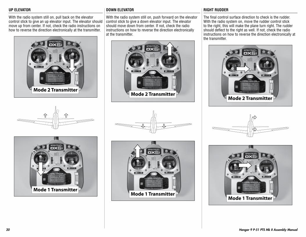
UP elevAtOR
With the radio system still on, pull back on the elevator control stick to give an up elevator input. The elevator should move up from center. If not, check the radio instructions on how to reverse the direction electronically at the transmitter.
Mode 2 Transmitter
Mode 1 Transmitter
DOwN elevAtOR
With the radio system still on, push forward on the elevator control stick to give a down elevator input. The elevator should move down from center. If not, check the radio instructions on how to reverse the direction electronically at the transmitter.
Mode 2 Transmitter
Mode 1 Transmitter
RIGHt RUDDeR
The final control surface direction to check is the rudder. With the radio system on, move the rudder control stick to the right, this will make the plane turn right. The rudder should deflect to the right as well. If not, check the radio instructions on how to reverse the direction electronically at the transmitter.
Mode 2 Transmitter
Mode 1 Transmitter

21Hangar 9 P-51 PTS Mk II Assembly Manual
leFt RUDDeR
Move the rudder control stick to the left, this will make the plane turn left. The rudder should deflect to the left as well. If not, check the radio instructions on how to reverse the direction electronically at the transmitter.
Mode 2 Transmitter
Mode 1 Transmitter
Section 15: Checking the Control Throw Amounts
The Dual Rate switch allows for aileron, elevator and rudder rates. When the Dual Rate switch is in the upper position, 100% travel is achieved on the aileron, elevator or rudder channel. When the switch is in the lower position, a reduced amount of travel is achieved on the aileron, elevator or rudder channel. This is useful allowing the aircraft to have a high control rate (switch in the “HI” position) for aggressive maneuvers and a low control rate (switch in “LO” position) for smooth, precise maneuvers. The switches are labeled to their particular function.
High Rate
Low Rate
After checking that the controls are moving in the correct directions, the amount of the control movement must be checked. By moving the control stick of each surface to its full deflection, you will measure the amount the surface has moved. By holding a ruler next to the surface and establishing a reference, use the radio to make the surface move and compare the measurements to those shown.
AIleRON HIGH RAte
AIleRON lOw RAte
elevAtOR HIGH RAte
elevAtOR lOw RAte

22 Hangar 9 P-51 PTS Mk II Assembly Manual
RUDDeR HIGH RAte
RUDDeR lOw RAte
Hint: Place your ruler on a solid surface, rather than holding it in the air, to take measurements. This will guarantee your ruler is not moving. If the ruler is moving you will get inaccurate readings.
Note: If you can borrow a throw gauge that measures in degrees, the amounts are:
• Elevator: 14 degrees instead of 1/2-inch (13mm)
• Rudder: 14 degrees instead of 7/8-inch (22mm)
• Ailerons: 12 degrees instead of 5/16-inch (8mm)
If the throws of the control surfaces are not moving the amounts as described, you may need to change the Travel Adjustment setting in the radio. To do so, read the section in the radio manual on programming.Please note where the dimensions are measured from the following points:The ailerons are measured as close to the wing tip as possible.The elevators are measured at the widest point, which is close to the fuselage.The rudder is measured at the bottom, which is the widest point of the rudder.
IMPORtANt
You will need to set the flap position based on your skill level before flying your P-51 PtS Mustang.
the positioning of the flaps is described in Section 20: Progressing with Your Flying Skills,
located on Page 25 of this manual.
Section 16: Adjusting the Throttle
With the radio system on, move the trim lever and throttle control stick towards the bottom of the transmitter. Look into the carburetor to check that the barrel is closed.
Mode 2 Transmitter
Mode 1 Transmitter
Move the trim lever up towards the top of the transmitter. The barrel in the carburetor should have an opening of around 1/16-inch (1.5mm).

23Hangar 9 P-51 PTS Mk II Assembly Manual
Mode 2 Transmitter
Mode 1 Transmitter
Move the throttle stick towards the top of the transmitter. The carburetor will now be in the fully open position.
Mode 2 Transmitter
Mode 1 Transmitter
If the throttle is not operating as described, you may need to change the Travel Adjustment setting in the radio. To do so, read the section in the radio manual on programming the radio.
Note: Once all the radio adjustments are complete, remember to turn off both the receiver and the transmitter.
Section 17: Balancing Your P-51 PTS
In order for your P-51 PTS Mustang to fly correctly, you will need to check the balance of the plane. This is done by supporting the aircraft either using your fingers, or by using a balancing stand. Not checking the balance can result in an aircraft that is difficult to fly, which can lead to the possibility of crashing your model.
Marking the Balance PointThe first step in balancing your P-51 PTS Mustang is to mark the location for the balance point. Measure back 3
3/4-inch (95mm) against the fuselage to the very front edge of the wing, which is where the wing plugs into the fuselage. Mark the location on both sides of the fuselage using a felt-tipped pen to mark the balance location.
lifting the Model and ObservationsThe P-51 PTS Mustang is balanced using either your fingers or a balancing stand. The stand in the photo was made from a dowel rod and a flat piece of wood. The dowel was cut down and holes drilled in the wood, then the dowel plugged into the wood. Use pencil erasers to prevent the ends of the dowel from damaging your wing. Place or lift the airplane so it is supported at the marks made in the previous step. The plane will rest level when balanced correctly. If not, self stick weights must be added to correct any balancing problems.

24 Hangar 9 P-51 PTS Mk II Assembly Manual
Balanced Correctly
Nose Heavy – Add weight to tail
tail Heavy – Add weight to Nose
Adding weights to Correct the BalanceDue to manufacturing differences, it is possible that the P-51 PTS Mustang may not be balanced properly. Weights can be added to either the tail or the nose of your P-51 PTS Mustang if it does not balance properly. Stick-on weights are the easiest to use, and come in sizes that are easily placed on your plane. Add just enough weight as necessary to balance your plane. Once the weight has been added, make sure it is secure and will not fall off in flight.
Note: The balance point of your P-51 PTS Mustang can vary 1/4-inch (6mm) forward or rearward without causing any problems. If your plane is only slightly out of balance, try placing the balancing stand towards the nose or tail by this 1/4-inch (6mm) and recheck the balance. If it looks good and sits level, then you’re good to go!
Section 18: How to Range Test the DX6i
Before each flying session, and especially with a new model, it is important to perform a range check. The DX6i incorporates a range testing system which, when placed in the RANGE CHECK program and the trainer switch is activated and held, reduces the output power, allowing a range check.To enter the Range Check mode, hold the roller down then turn on the power switch. Use the roller to scroll to Range Check then press the roller to enter the Range Check mode. Pulling the trainer switch forward will reduce the output power of the transmitter to properly perform the range check of your model.
Reduce photo to 13.5%
RANGE CHECK
CHECK INH
List
Reduce photo to 13.5%
RANGE CHECK
CHECK ACT
List
25Hangar 9 P-51 PTS Mk II Assembly Manual
RANGe teStING tHe DX6I
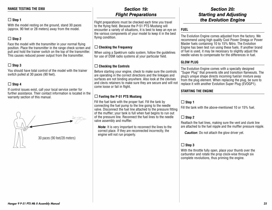
Step 1With the model resting on the ground, stand 30 paces (approx. 90 feet or 28 meters) away from the model.
Step 2Face the model with the transmitter in your normal flying position. Place the transmitter in the range check screen and pull and hold the trainer switch on the top of the transmitter. This causes reduced power output from the transmitter.
Step 3You should have total control of the model with the trainer switch pulled at 30 paces (90 feet).
Step 4If control issues exist, call your local service center for further assistance. Their contact information is located in the warranty section of this manual.
30 paces (90 feet/28 meters)
Section 19: Flight Preparations
Flight preparations must be checked each time you travel to the flying field. Because the P-51 PTS Mustang will encounter a variety of situations, it is best to keep an eye on the various components of your model to keep it in the best flying condition.
Checking the FrequencyWhen using a Spektrum radio system, follow the guidelines for use of DSM radio systems at your particular field.
Checking the ControlsBefore starting your engine, check to make sure the controls are operating in the correct directions and the linkages and surfaces are not binding anywhere. Also look at the clevises and clevis retainers to make sure they are secure and will not come loose or fail in flight.
Fueling the P-51 PtS MustangFill the fuel tank with the proper fuel. Fill the tank by connecting the fuel pump to the line going to the needle valve. Disconnect the fuel line attached to the pressure fitting of the muffler; your tank is full when fuel begins to run out of the pressure line. Reconnect the fuel lines to the needle valve assembly and muffler.
Note: It is very important to reconnect the lines to the correct place. If they are reconnected incorrectly, the engine will not run properly.
Section 20: Starting and Adjusting the Evolution Engine
FUel
The Evolution Engine comes adjusted from the factory. We recommend using high quality Cool Power Omega or Power Master fuels containing 10 to 15% Nitro. The Evolution Engine has been test run using these fuels. If another brand of fuel is used, it may be necessary to slightly adjust the needle valves to compensate for the differences in fuel.
GlOw PlUG
The Evolution Engine comes with a specially designed “Super Plug” that prevents idle and transition flameouts. The plug’s unique shape directs incoming fuel/air mixture away from the plug element. When replacing the plug, be sure to replace it with another Evolution Super Plug (EVOGP1).
StARtING tHe eNGINe
Step 1Fill the tank with the above-mentioned 10 or 15% fuel.
Step 2Reattach the fuel lines, making sure the vent and clunk line are attached to the fuel nipple and the muffler pressure nipple.
Caution: Do not attach the glow driver yet.
Step 3With the throttle fully open, place your thumb over the carburetor and rotate the prop clock-wise through six complete revolutions, thus priming the engine.

26 Hangar 9 P-51 PTS Mk II Assembly Manual
Step 4Close the throttle to the idle position and have a helper hold your airplane.
Step 5Attach the glow driver.
Step 6Turn the engine over using an electric starter. The engine should fire within seconds of applying the starter.
Step 7Allow the engine to idle for 30 seconds. Adjust the throttle trim if necessary to achieve a constant slow idle.
Step 8With the glow driver still attached and a helper securely holding the airplane, advance the throttle smoothly to full throttle. The engine will transition to full rpm.
Step 9Reduce the throttle to idle and remove the glow driver.
NeeDle lIMIteRS
In some conditions: Due to high altitudes, extreme temperatures, etc., it may be necessary to slightly adjust the idle and high-speed needle valves. The high- and low-speed needles have limiters that prevent over-adjustment.
If your engine starts from the above procedure, but won’t reliably continue to run with the glow driver removed, follow the steps below.
Low-Speed Needle AdjustmentHigh-Speed Needle Adjustment
The needle valves come preset from the factory. Extreme conditions may require some minor adjustments. Note that the needle adjustment
range is limited, preventing adjustment beyond the practical range.
SteP 1: HIGH-SPeeD NeeDle ADjUStMeNt
With the engine running, advance the throttle to full throttle while a helper securely holds your airplane. Carefully pinch and release the fuel line to temporarily restrict the fuel flow.
Caution: Do not reach over the propeller while the engine is running.
Correct: If the high-speed needle adjustment is correct, the engine will increase rpm slightly (about 300 rpm) and then die.Too Rich: If the engine increases a lot (1,000 rpm or greater), the high-speed needle is too rich and must be leaned or turned clockwise.Too Lean: If the engine doesn’t increase rpm and simply dies, the high-speed needle is lean and must be richened or turned counterclockwise.
SteP 2: lOw-SPeeD NeeDle ADjUStMeNt
The low-speed or idle needle valve, included with the SetRight™ assembly, is preadjusted at the factory for best performance. It may be necessary to fine-tune the low-speed adjustment using the following procedure:
Step 1Start the engine and let it warm up, prior to attempting any adjustments. Make sure that the high-speed adjustment process is complete before attempting to adjust the low-speed needle valve.
Step 2Close the throttle slowly. You will adjust the low-speed needle setting by rotating the SetRight adjustment bar clockwise to lean the engine and counterclockwise to richen the engine.
Caution: Do not attempt to adjust the low-speed needle valve while the engine is running.
Step 3The fuel mixture should be adjusted as follows: The fuel mixture is too rich if, when opening the throttle rapidly, the engine emits smoke and “stutters” or “stumbles.” Correct this by rotating the SetRight adjustment bar clockwise in small increments. Continue this process until the engine transitions smoothly from low rpm idle to high rpm without hesitation upon opening the throttle rapidly.
Step 4The fuel mixture may be too lean if the engine stops at the lowest idle position or it stops when the throttle is rapidly opened from the idle position. Correct this by rotating the SetRight adjustment bar counterclockwise in small increments until the engine transitions smoothly without hesitation upon opening the throttle rapidly from idle.

27Hangar 9 P-51 PTS Mk II Assembly Manual
tROUBleSHOOtING GUIDe
engine won’t Fire• Glow starter not charged
- Charge glow starter• Glow plug burnt out
- Replace glow plug• No fuel is getting to the carburetor
- Check tank, fuel lines reversed• The starter is reversed
- Reverse the polarity on the starter cables
engine Quits Repeatedly• Needles need adjusting
- See adjustment procedure• Bad or old fuel
- Replace with fresh fuel• Worn out glow plug
- Replace with new EVOGP1 2 & 4 Stroke Super Plug
engine Runs Inconsistently• Hole in fuel line
- Replace fuel line• Bad or old fuel
- Replace with fresh fuel
eNGINe MAINteNANCe
After each flying session:
Step 1Fully drain the fuel from the tank.
Step 2Start the engine and run it until the fuel is completely run out of the engine.
Step 3Try starting the engine three more times or until it will no longer fire. This gets all the fuel out of the engine.At the end of each flying session, several drops (about 10) of after run oil (Evolution Engine’s Blue Block Rust Inhibitor, EVOX1000) should be applied into the carburetor, and the engine should be turned over for a few seconds with the starter. This will prevent rust and corrosion.
Section 21: Maintaining Your P-51 PTS Mustang
The following is a check list that you should follow every time you have completed a flying session with your P-51 Mustang PTS. Doing so will keep your aircraft in the best flying condition.
Clean UpAfter a long flying session with your P-51 PTS Mustang, you will want to clean it up before loading it into your vehicle to head home. Use a cleaner such as Windex or 409 and a paper towel to wipe down the exterior of your plane, removing the fuel residue. Remember, a clean plane will last longer since the fuel won’t be allowed to soak into any exposed wood.
Checking the PropellerCheck to make sure the propeller is tightly secured to the engine. If not, remove the spinner and use a crescent wrench to tighten it back down. If you have had any not so great landings, you will want to inspect the propeller for any damage. Small nicks and scratches can quickly become fractures, causing the propeller to be unsafe for flight. Always carry a few spare propellers so a damaged propeller can be replaced at the field, increasing your flying time per trip to the field.
Checking the ClevisesInspect the aileron, elevator and rudder clevises to make sure they are connected and in good working order. If you find a clevis that is showing signs of wear or is broken, replace it with a new clevis. Also check the nylon connectors at the servo for any wear or damage. If they look worn or in bad shape, replace them as well.
28 Hangar 9 P-51 PTS Mk II Assembly Manual
Checking the Control HornsInspect the control horns to make sure they have not crushed the wood of the control surface. If so, remove the control horn screws to remove the control horn. Place 2–3 drops of thin CA into each of the screw holes. In addition, use a T-pin to poke small holes in the covering in the area where the control horn mounts, then saturate the area with thin CA. This will harden the wood and give the control horns a solid surface to be mounted to.
Checking the wheel CollarsCheck the setscrews on the wheel collars for the main and tail wheel to make sure they are not loose. Use a 1.5mm hex wrench to tighten the setscrews. It is suggested if they loosen frequently to remove them, apply threadlock to the setscrews, then secure the wheel collars back into position. The threadlock and hex wrench are included in the kit for this purpose.
Check the Muffler BoltsUse a 2.5mm hex wrench to make sure the bolts holding the muffler onto the engine are tight and have not vibrated loose during flight.
Check the engine Mount BoltsRemove the spinner and propeller from the engine. Remove the exhaust stacks from the fuselage, and then remove the cowling from the fuselage. Remove the muffler from the engine, and then use a Phillips screwdriver to make sure the four bolts securing the engine to the mount are tight.
Section 22: Progressing With Your Flying Skills
Required tools and Adhesives• Flat blade screwdriver
The P-51 PTS Mustang is a special trainer plane in that it will allow you to go from learning the basics of flight all the way up to performing aerobatics without upgrading or purchasing a new plane. As you learn to fly and become ready for a little more challenge, the P-51 PTS Mustang will grow with you.
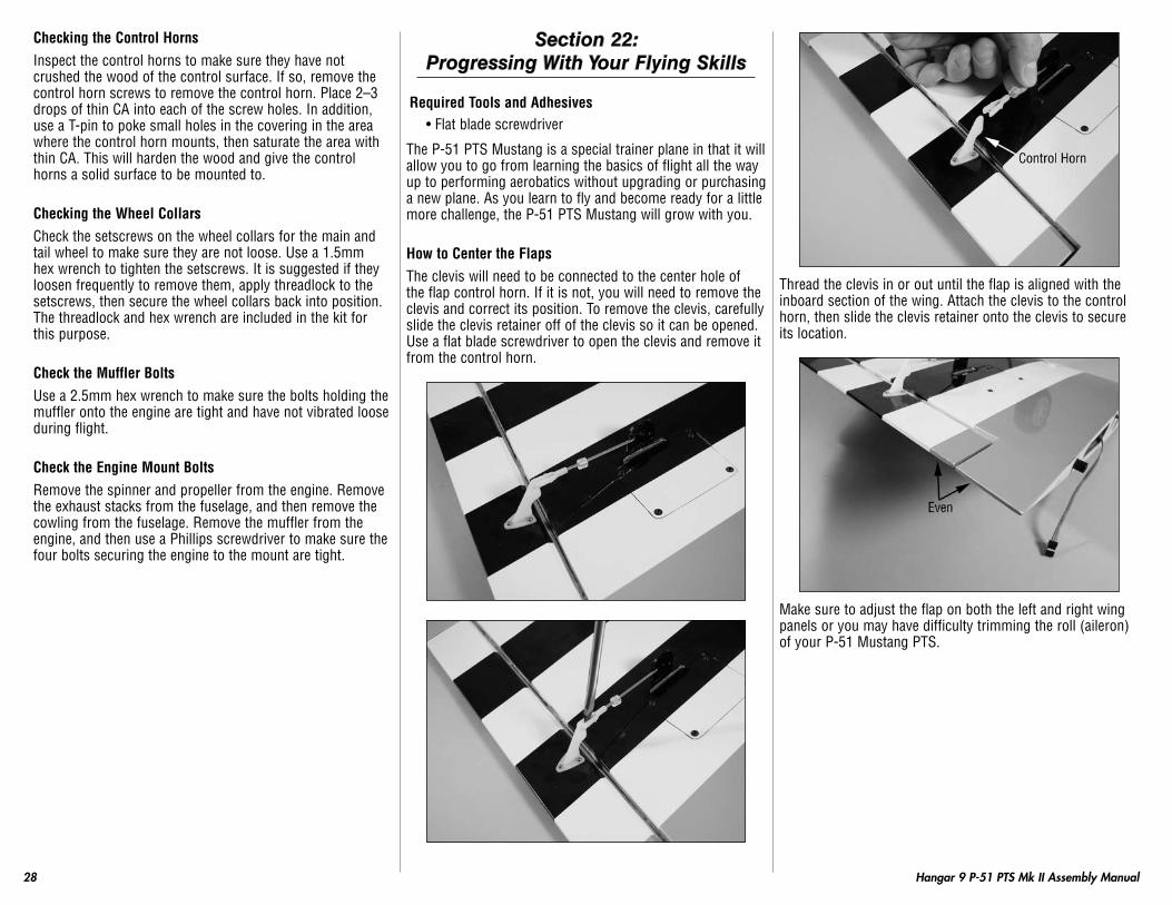
How to Center the FlapsThe clevis will need to be connected to the center hole of the flap control horn. If it is not, you will need to remove the clevis and correct its position. To remove the clevis, carefully slide the clevis retainer off of the clevis so it can be opened. Use a flat blade screwdriver to open the clevis and remove it from the control horn.
Thread the clevis in or out until the flap is aligned with the inboard section of the wing. Attach the clevis to the control horn, then slide the clevis retainer onto the clevis to secure its location.
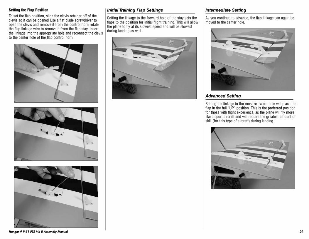
Make sure to adjust the flap on both the left and right wing panels or you may have difficulty trimming the roll (aileron) of your P-51 Mustang PTS.
29Hangar 9 P-51 PTS Mk II Assembly Manual
Setting the Flap PositionTo set the flap position, slide the clevis retainer off of the clevis so it can be opened Use a flat blade screwdriver to open the clevis and remove it from the control horn rotate the flap linkage wire to remove it from the flap stay. Insert the linkage into the appropriate hole and reconnect the clevis to the center hole of the flap control horn.
Initial Training Flap Settings
Setting the linkage to the forward hole of the stay sets the flaps to the position for initial flight training. This will allow the plane to fly at its slowest speed and will be slowest during landing as well.
Intermediate Setting
As you continue to advance, the flap linkage can again be moved to the center hole.
Advanced Setting
Setting the linkage in the most rearward hole will place the flap in the full “UP” position. This is the preferred position for those with flight experience, as the plane will fly more like a sport aircraft and will require the greatest amount of skill (for this type of aircraft) during landing.

30 Hangar 9 P-51 PTS Mk II Assembly Manual
Once the flaps have been set, slide the clevis retainer onto the clevis to keep the clevis from opening accidentally.
GraduateOnce you are comfortable soloing your P-51 PTS Mustang in this configuration, you’re ready to graduate to advanced flight and aerobatics. The last step is to remove the clear anti-spin NACA Droops. This is done by simply removing the clear tape on the top and bottom that holds them in place on the wing. With the Droops removed, your P-51 PTS Mustang is now an all-out aerobatic warbird. Have your instructor nearby for the first few flights. The P-51 PTS Mustang will now descend more quickly and land faster like a sport model. In the air, you can now do a variety of aerobatics such as rolls, loops, spins and snap rolls.The droops are held on with clear tape. Simply pulling the tape will allow you to remove the droops. Save the wing droops in case you may want to use them for training a budding fellow pilot in the future.
Hint: The glue residue from the clear tape can be removed with isopropyl alcohol or CA accelerator or paint thinner. Always test solvents in an inconspicuous place to make sure they will not damage the covering of your model.
After you have graduated from the Progressing Training System and are enjoying your P-51 PTS Mustang in its aerobatic mode, you can take it even a step further and add functional flaps. To do this, you’ll need to purchase two additional servos from your local hobby shop such as the JR SPORT ST-47 servo and a Y-harness. Then, simply remove the cover over the flap servo in the bottom of the wing and install the servos. Hook up the linkages to the servos following the directions and you have a scale P-51 PTS Mustang complete with functioning landing flaps.
Section 23: Adding a Flap Servo
Required Parts• Wing panel (right and left)• Servo mounting block (4)• Servo w/hardware (2)
Required tools and Adhesives• Pencil • 6-minute epoxy• Drill • Sandpaper• Phillips screwdriver: #1 • Thin CA• Mixing cups • Mixing sticks• Drill bit: 1/16-inch (1.5mm) • Hobby knife w/#11 blade• Side cutters
Step 1Slide the clevis retainer off of the clevis so it can be opened. Use a flat blade screwdriver to open the clevis and remove it from the flap control horn. Rotate the linkage wire and remove it from the flap stay. Set the linkage aside until later.
31Hangar 9 P-51 PTS Mk II Assembly Manual
Step 2Use a #1 Phillips screwdriver to remove the servo cover from the wing. Set the screws with the linkage for later use.
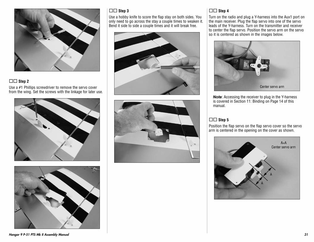
Step 3Use a hobby knife to score the flap stay on both sides. You only need to go across the stay a couple times to weaken it. Bend it side to side a couple times and it will break free.
Step 4Turn on the radio and plug a Y-harness into the Aux1 port on the main receiver. Plug the flap servo into one of the servo leads of the Y-harness. Turn on the transmitter and receiver to center the flap servo. Position the servo arm on the servo so it is centered as shown in the images below.
Note: Accessing the receiver to plug in the Y-harness is covered in Section 11: Binding on Page 14 of this manual.
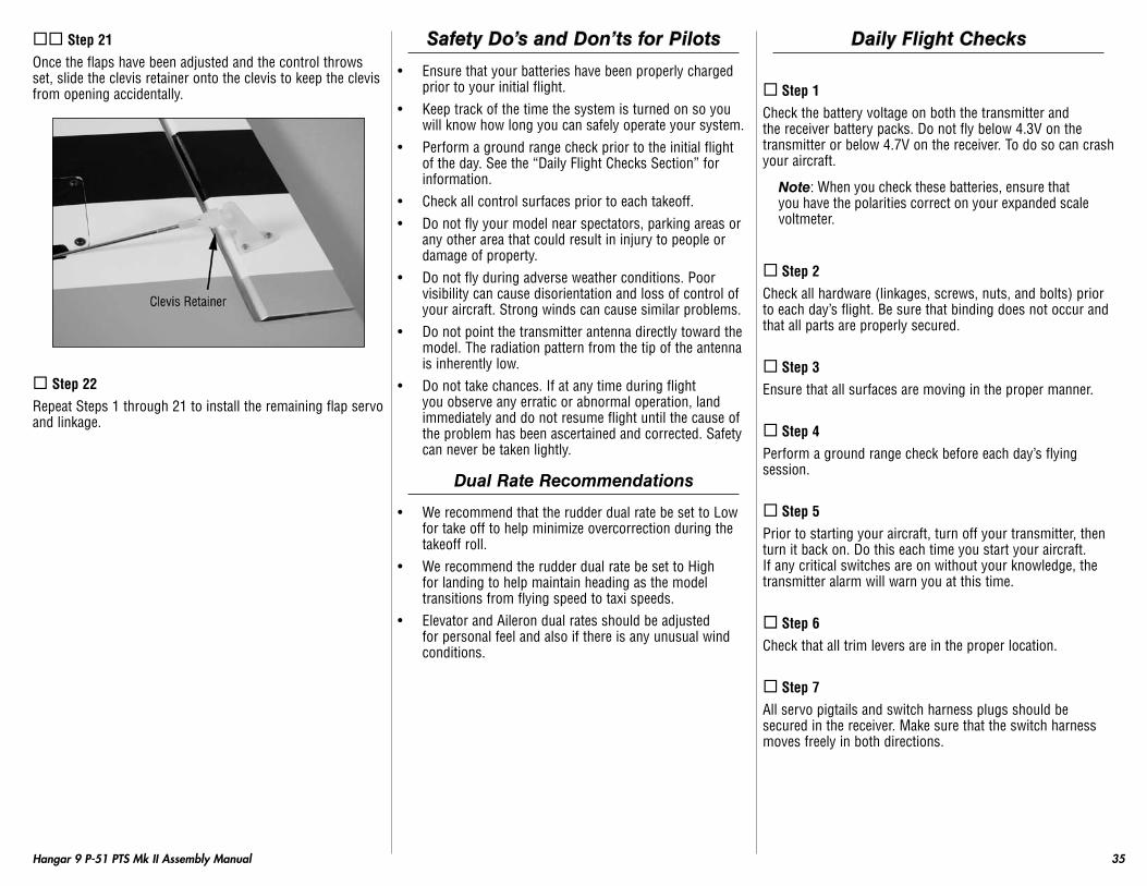
Step 5Position the flap servo on the flap servo cover so the servo arm is centered in the opening on the cover as shown.

32 Hangar 9 P-51 PTS Mk II Assembly Manual
Step 6Check that the edge of the servo horn is in line with the edge of the servo cover.
Step 7Use a pencil to mark the position of the servo on the flap servo cover.
Step 8Use sandpaper to roughen the ends of the four servo mounting blocks. Doing so will allow the epoxy applied to them in the next step a better surface to adhere to.
Step 9Use 6-minute epoxy to secure the servo mounting blocks on the servo hatch.
Step 10Position the servo between the blocks. Leave a small gap between the servo and hatch to prevent the transfer of vibration from the airframe into the servo. Use a pencil to transfer the locations for the servo mounting screws onto the servo mounting blocks.
Step 11Use a drill and 1/16-inch (1.5mm) drill bit to drill the four holes for the servo mounting screws.

33Hangar 9 P-51 PTS Mk II Assembly Manual
Step 12Apply 2–3 drops of thin CA into the holes to harden the surrounding wood. This provides a hard surface for the screws, making them more secure when installed.
Step 13Attach the servo to the servo mounting blocks using the screws provided with the servo and a #1 Phillips screwdriver.
Step 14Remove the servo horn using a #1 Phillips screwdriver and trim away any unused arms from the servo horn with side cutters. Once complete reinstall the servo horn using a #1 Phillips screwdriver. Use a pin drill and 5/64-inch (2mm) drill bit to enlarge the hole 1/2-inch (13mm) from the center of the servo arm as shown.
Step 15Insert the flap servo lead into the same opening inside the wing that the aileron servo lead passes through.
Step 16Guide the flap servo lead out of the end of the wing. We used a piece of tape on the flap servo lead to make sure it is not confused with the aileron servo lead when attaching the wing to the fuselage.
Step 17Secure the servo hatch to the wing using the four 2mm x 10mm self tapping screws and a #1 Phillips screwdriver.

34 Hangar 9 P-51 PTS Mk II Assembly Manual
Step 18Insert the flap linkage into the outer hole you enlarged earlier. Rotate the linkage to face toward the flap control horn.
Step 19Attach the clevis to the flap control horn center hole. Plug the flap servo lead into the servo leads on the Y-harness. Turn on the transmitter and receiver. Position the flap switch to the “NORM” position as shown. With the radio in the programming mode for FLAPS, adjust the percentage using the Rolling Selector to set the “UP” position of the flap so it is aligned with the trailing edge of the wing.
Reduce photo to 13.5%
FLAPSFLAP ELEV
NORM≤ 0 0LAND 0 0
List
Step 20With the radio system still on, position the flap switch to the “LAND” position as shown. With the radio still in the programming mode for FLAPS, adjust the percentage using the Rolling Selector to set the “LAND” position of the flap so there is a measurement of 1-inch (25mm) as shown in the image below.
Reduce photo to 13.5%
FLAPSFLAP ELEV
NORM 0 0LAND≤ 0 0
List
35Hangar 9 P-51 PTS Mk II Assembly Manual
Step 21Once the flaps have been adjusted and the control throws set, slide the clevis retainer onto the clevis to keep the clevis from opening accidentally.
Step 22Repeat Steps 1 through 21 to install the remaining flap servo and linkage.
Safety Do’s and Don’ts for Pilots
• Ensure that your batteries have been properly charged prior to your initial flight.
• Keep track of the time the system is turned on so you will know how long you can safely operate your system.
• Perform a ground range check prior to the initial flight of the day. See the “Daily Flight Checks Section” for information.
• Check all control surfaces prior to each takeoff.• Do not fly your model near spectators, parking areas or
any other area that could result in injury to people or damage of property.
• Do not fly during adverse weather conditions. Poor visibility can cause disorientation and loss of control of your aircraft. Strong winds can cause similar problems.
• Do not point the transmitter antenna directly toward the model. The radiation pattern from the tip of the antenna is inherently low.
• Do not take chances. If at any time during flight you observe any erratic or abnormal operation, land immediately and do not resume flight until the cause of the problem has been ascertained and corrected. Safety can never be taken lightly.
Dual Rate Recommendations
• We recommend that the rudder dual rate be set to Low for take off to help minimize overcorrection during the takeoff roll.
• We recommend the rudder dual rate be set to High for landing to help maintain heading as the model transitions from flying speed to taxi speeds.
• Elevator and Aileron dual rates should be adjusted for personal feel and also if there is any unusual wind conditions.
Daily Flight Checks
Step 1Check the battery voltage on both the transmitter and the receiver battery packs. Do not fly below 4.3V on the transmitter or below 4.7V on the receiver. To do so can crash your aircraft.
Note: When you check these batteries, ensure that you have the polarities correct on your expanded scale voltmeter.
Step 2Check all hardware (linkages, screws, nuts, and bolts) prior to each day’s flight. Be sure that binding does not occur and that all parts are properly secured.
Step 3Ensure that all surfaces are moving in the proper manner.
Step 4Perform a ground range check before each day’s flying session.
Step 5Prior to starting your aircraft, turn off your transmitter, then turn it back on. Do this each time you start your aircraft. If any critical switches are on without your knowledge, the transmitter alarm will warn you at this time.
Step 6Check that all trim levers are in the proper location.
Step 7All servo pigtails and switch harness plugs should be secured in the receiver. Make sure that the switch harness moves freely in both directions.

36 Hangar 9 P-51 PTS Mk II Assembly Manual
Glossary of Terms
• Ailerons: Each side of this airplane has a hinged control surface (aileron), located on the trailing edge of the wing. Move the aileron stick on the transmitter left, the left aileron moves up and the right aileron moves down. Moving the left aileron up causes more drag and less lift, causing the left wing to drop down. When the right aileron moves down, more lift is created, causing the right wing to rise. This interaction causes the airplane to turn or roll to the left. Perform the opposite actions, and the airplane will roll to the right..
• Clevis: The clevis connects the wire end of the pushrod to the control horn of the control surface. A small clip, the clevis has fine threads so that you can adjust the length of the pushrod.
• Control Horn: This arm connects the control surface to the clevis and pushrod.
• Dihedral: The degree of angle (V-shaped bend) at which the wings intersect the fuselage is called dihedral. More dihedral gives an airplane more aerodynamic stability. Some sailplanes and trainer planes with large dihedral dispense with ailerons and use only the rudder to control the roll and yaw.
• Elevator: The hinged control surface on the back of the stabilizer that moves to control the airplane’s pitch axis. Pulling the transmitter’s control stick toward the bottom of the transmitter moves the elevator upward, and the airplane begins to climb. Push the control stick forward, and the airplane begins to dive.
• Fuselage: The main body of an airplane.• Hinge: Flexible pieces used to connect the control surface
to the flying surface. All hinges must be glued properly and securely to prevent the airplane from crashing.
• Horizontal Stabilizer: The horizontal flying surface of the tail gives the airplane stability while in flight.
• Leading Edge: The front of a flying surface.• Main Landing Gear: The wheel and gear assembly the
airplane uses to land. It is attached to the bottom of the fuselage.
• Pitch Axis: The horizontal plane on which the airplane’s nose is raised or lowered. By moving the elevator, you can raise the airplane’s nose above the pitch axis (climb) or lower it below the pitch axis (dive).
• Pushrod: The rigid mechanism that transfers movement from the servo to the control surface.
• Roll Axis: The horizontal plane on which the airplane’s wings are raised or lowered. By adjusting the ailerons, you can drop a wing tip below the roll axis and cause the airplane to bank or roll.
• Rudder: The hinged control surface on the vertical stabilizer that controls the airplane’s yaw. Moving the rudder to the left causes the airplane to yaw left; moving the rudder to the right causes it to yaw right.
• Servo: The servo transforms your transmitter commands into physical adjustments of the airplane.
• Servo Output Arm: A removable arm or wheel that connects the servo to the pushrod (also called servo horn).
• Spinner: Term describing the nose cone that covers the propeller hub.
• Threadlock: A liquid that solidifies; used to prevent screws from loosening due to vibration.
• Torque Rods: Inserted into the ailerons, these rigid wire rods run along the wing’s trailing edge, then bend downward and connect to the pushrod.
• Vertical Stabilizer: The vertical flying surface of the tail gives an airplane stability while in flight.
• Wheel Collar: The round retaining piece that anchors wheels in place on the wheel axle.
• Wing: The lifting surface of an airplane.• Yaw Axis: The vertical plane through which the airplane’s
nose rotates as it yaws to the left or to the right. The rudder controls the yaw axis.
Safety, Precautions and WarningsAs the user of this product, you are solely responsible for operating it in a manner that does not endanger yourself and others or result in damage to the product or the property of others.Carefully follow the directions and warnings for this and any optional support equipment (chargers, rechargeable battery packs, etc.) that you use.This model is controlled by a radio signal that is subject to interference from many sources outside your control. This interference can cause momentary loss of control so it is necessary to always keep a safe distance in all directions around your model, as this margin will help to avoid collisions or injury.• Always operate your model in an open area away from
cars, traffic or people.• Avoid operating your model in the street where injury or
damage can occur.• Never operate the model out into the street or populated
areas for any reason.• Never operate your model with low transmitter batteries.• Carefully follow the directions and warnings for this and
any optional support equipment (chargers, rechargeable battery packs, etc.) that you use.
• Keep all chemicals, small parts and anything electrical out of the reach of children.
• Moisture causes damage to electronics. Avoid water exposure to all equipment not specifically designed and protected for this purpose.

37Hangar 9 P-51 PTS Mk II Assembly Manual
Warranty Information
Warranty Period
Horizon Hobby, Inc., (Horizon) warranties that the Products purchased (the “Product”) will be free from defects in materials and workmanship at the date of purchase by the Purchaser.
Limited Warranty
(a) This warranty is limited to the original Purchaser (“Purchaser”) and is not transferable. REPAIR OR REPLACEMENT AS PROVIDED UNDER THIS WARRANTY IS THE EXCLUSIVE REMEDY OF THE PURCHASER. This warranty covers only those Products purchased from an authorized Horizon dealer. Third party transactions are not covered by this warranty. Proof of purchase is required for warranty claims. Further, Horizon reserves the right to change or modify this warranty without notice and disclaims all other warranties, express or implied.(b) Limitations- HORIZON MAKES NO WARRANTY OR REPRESENTATION, EXPRESS OR IMPLIED, ABOUT NON-INFRINGEMENT, MERCHANTABILITY OR FITNESS FOR A PARTICULAR PURPOSE OF THE PRODUCT. THE PURCHASER ACKNOWLEDGES THAT THEY ALONE HAVE DETERMINED THAT THE PRODUCT WILL SUITABLY MEET THE REQUIREMENTS OF THE PURCHASER’S INTENDED USE.(c) Purchaser Remedy- Horizon’s sole obligation hereunder shall be that Horizon will, at its option, (i) repair or (ii) replace, any Product determined by Horizon to be defective. In the event of a defect, these are the Purchaser’s exclusive remedies. Horizon reserves the right to inspect any and all equipment involved in a warranty claim. Repair or replacement decisions are at the sole discretion of Horizon. This warranty does not cover cosmetic damage or damage due to acts of God, accident, misuse, abuse, negligence, commercial use, or modification of or to any part of the Product. This warranty does not cover damage due to improper installation, operation, maintenance, or attempted repair by anyone other than Horizon. Return of any goods by Purchaser must be approved in writing by Horizon before shipment.
Damage Limits
HORIZON SHALL NOT BE LIABLE FOR SPECIAL, INDIRECT OR CONSEQUENTIAL DAMAGES, LOSS OF PROFITS OR PRODUCTION OR COMMERCIAL LOSS IN ANY WAY CONNECTED WITH THE PRODUCT, WHETHER SUCH CLAIM IS BASED IN CONTRACT, WARRANTY, NEGLIGENCE, OR STRICT LIABILITY. Further, in no event shall the liability of Horizon exceed the individual price of the Product on which liability is asserted. As Horizon has no control over use, setup, final assembly, modification or misuse, no liability shall be assumed nor accepted for any resulting damage or injury. By the act of use, setup or assembly, the user accepts all resulting liability.If you as the Purchaser or user are not prepared to accept the liability associated with the use of this Product, you are advised to return this Product immediately in new and unused condition to the place of purchase.Law: These Terms are governed by Illinois law (without regard to conflict of law principals).
Safety Precautions
This is a sophisticated hobby Product and not a toy. It must be operated with caution and common sense and requires some basic mechanical ability. Failure to operate this Product in a safe and responsible manner could result in injury or damage to the Product or other property. This Product is not intended for use by children without direct adult supervision. The Product manual contains instructions for safety, operation and maintenance. It is essential to read and follow all the instructions and warnings in the manual, prior to assembly, setup or use, in order to operate correctly and avoid damage or injury.
Questions, Assistance, and Repairs
Your local hobby store and/or place of purchase cannot provide warranty support or repair. Once assembly, setup or use of the Product has been started, you must contact Horizon directly. This will enable Horizon to better answer your questions and service you in the event that you may need any assistance. For questions or assistance, please direct your email to [email protected], or call 877.504.0233 toll free to speak to a service technician.
Inspection or Repairs
If this Product needs to be inspected or repaired, please call for a Return Merchandise Authorization (RMA). Pack the Product securely using a shipping carton. Please note that original boxes may be included, but are not designed to withstand the rigors of shipping without additional protection. Ship via a carrier that provides tracking and insurance for lost or damaged parcels, as Horizon is not responsible for merchandise until it arrives and is accepted at our facility. A Service Repair Request is available at www.horizonhobby.com on the “Support” tab. If you do not have internet access, please include a letter with your complete name, street address, email address and phone number where you can be reached during business days, your RMA number, a list of the included items, method of payment for any non-warranty expenses and a brief summary of the problem. Your original sales receipt must also be included for warranty consideration. Be sure your name, address, and RMA number are clearly written on the outside of the shipping carton.
Warranty Inspection and Repairs
To receive warranty service, you must include your original sales receipt verifying the proof-of-purchase date. Provided warranty conditions have been met, your Product will be repaired or replaced free of charge. Repair or replacement decisions are at the sole discretion of Horizon Hobby.

38 Hangar 9 P-51 PTS Mk II Assembly Manual
Non-Warranty Repairs
Should your repair not be covered by warranty the repair will be completed and payment will be required without notification or estimate of the expense unless the expense exceeds 50% of the retail purchase cost. By submitting the item for repair you are agreeing to payment of the repair without notification. Repair estimates are available upon request. You must include this request with your repair. Non-warranty repair estimates will be billed a minimum of ½ hour of labor. In addition you will be billed for return freight. Please advise us of your preferred method of payment. Horizon accepts money orders and cashiers checks, as well as Visa, MasterCard, American Express, and Discover cards.If you choose to pay by credit card, please include your credit card number and expiration date. Any repair left unpaid or unclaimed after 90 days will be considered abandoned and will be disposed of accordingly. Please note: non-warranty repair is only available on electronics and model engines.
United States:Electronics and engines requiring inspection or repair should be shipped to the following address:
Horizon Service Center 4105 Fieldstone Road
Champaign, Illinois 61822All other Products requiring warranty inspection or repair should be shipped to the following address:
Horizon Product Support 4105 Fieldstone Road
Champaign, Illinois 61822
Please call 877-504-0233 or e-mail us at [email protected] with any questions or
concerns regarding this product or warranty.
United Kingdom:Electronics and engines requiring inspection or repair should be shipped to the following address:
Horizon Hobby UK Units 1-4 Ployters Rd
Staple Tye Harlow, Essex
CM18 7NS United Kingdom
Please call +44 (0) 1279 641 097 or e-mail us at [email protected] with any questions or concerns
regarding this product or warranty.
Germany:Electronics and engines requiring inspection or repair should be shipped to the following address:
Horizon Technischer Service Hamburger Strasse 10
25335 Elmshorn Germany
Please call +49 4121 46199 66 or e-mail us at [email protected] with any questions or concerns
regarding this product or warranty.
Instructions for Disposal of WEEE by Users in the European Union
This product must not be disposed of with other waste. Instead, it is the user’s responsibility to dispose of their waste equipment by handing it over to a designated collection point for the recycling of waste electrical and electronic equipment. The separate collection and recycling of your waste equipment at the time of disposal will help to conserve natural resources and ensure that it is recycled in a manner that protects human health and the environment. For more information about where you can drop off your waste equipment for recycling, please contact your local city office, your household waste disposal service or where you purchased the product.
The associated regulatory agencies of the following countries recognize the noted certifications for this product as authorized for sale and use:
UK DE DK NO SE
FI EE LV LT PL
CZ SK HU RO SI
AT IT ES PT IE
NL LU MT CY GR
39Hangar 9 P-51 PTS Mk II Assembly Manual
2008 Official Academy of Model Aeronautics Safety Code
GeNeRAl1. A model aircraft shall be defined as a non-human-
carrying device capable of sustained flight in the atmosphere. It shall not exceed limitations established in this code and is intended to be used exclusively for recreational or competition activity.
2. The maximum takeoff weight of a model aircraft, including fuel, is 55 pounds, except for those flown under the AMA Experimental Aircraft Rules.
3. I will abide by this Safety Code and all rules established for the flying site I use. I will not willfully fly my model aircraft in a reckless and/or dangerous manner.
4. I will not fly my model aircraft in sanctioned events, air shows, or model demonstrations until it has been proven airworthy.
5. I will not fly my model aircraft higher than approximately 400 feet above ground level, when within three (3) miles of an airport without notifying the airport operator. I will yield the right-of-way and avoid flying in the proximity of full-scale aircraft, utilizing a spotter when appropriate.
6. I will not fly my model aircraft unless it is identified with my name and address, or AMA number, inside or affixed to the outside of the model aircraft. This does not apply to model aircraft flown indoors.
7. I will not operate model aircraft with metal-blade propellers or with gaseous boosts (other than air), nor will I operate model aircraft with fuels containing tetranitromethane or hydrazine.
8. I will not operate model aircraft carrying pyrotechnic devices which explode burn, or propel a projectile of any kind. Exceptions include Free Flight fuses or devices that burn producing smoke and are securely attached to the model aircraft during flight. Rocket motors up to a G-series size may be used, provided they remain firmly attached to the model aircraft during flight. Model rockets may be flown in accordance with the National Model Rocketry Safety Code; however, they may not be launched from model aircraft. Officially designated AMAAir Show Teams (AST) are authorized to use devices and practices
as defined within the Air Show Advisory Committee Document.
9. I will not operate my model aircraft while under the influence of alcohol or within eight (8) hours of having consumed alcohol.
10. I will not operate my model aircraft while using any drug which could adversely affect my ability to safely control my model aircraft.
11. Children under six (6) years old are only allowed on a flightline or in a flight area as a pilot or while under flight instruction.
12. When and where required by rule, helmets must be properly worn and fastened. They must be OSHA, DOT, ANSI, SNELL or NOCSAE approved or comply with comparable standards.
RADIO CONtROl1. All model flying shall be conducted in a manner to
avoid over flight of unprotected people.2. I will have completed a successful radio equipment
ground-range check before the first flight of a new or repaired model aircraft.
3. I will not fly my model aircraft in the presence of spectators until I become a proficient flier, unless I am assisted by an experienced pilot.
4. At all flying sites a line must be established, in front of which all flying takes place. Only personnel associated with flying the model aircraft are allowed at or in front of the line. In the case of airshows demonstrations straight line must be established. An area away from the line must be maintained for spectators. Intentional flying behind the line is prohibited.
5. I will operate my model aircraft using only radio-control frequencies currently allowed by the Federal Communications Commission (FCC). Only individuals properly licensed by the FCC are authorized to operate equipment on Amateur Band frequencies.
6. I will not knowingly operate my model aircraft within three (3) miles of any preexisting flying site without a frequency-management agreement. A frequencymanagement agreement may be an allocation of frequencies for each site, a day-use agreement between sites, or testing which determines that no interference exists. A frequency-management agreement may exist between two or more AMA chartered clubs, AMA clubs and individual AMA members, or individual AMA members. Frequency-
management agreements, including an interference test report if the agreement indicates no interference exists, will be signed by all parties and copies provided to AMA Headquarters.
7. With the exception of events flown under official AMA rules, no powered model may be flown outdoors closer than 25 feet to any individual, except for the pilot and located at the flightline.
8. Under no circumstances may a pilot or other person touch a model aircraft in flight while it is still under power, except to divert it from striking an individual.
9. Radio-controlled night flying is limited to low-performance model aircraft (less than 100 mph). The model aircraft must be equipped with a lighting system which clearly defines the aircraft’s attitude and direction at all times.
10. The operator of a radio-controlled model aircraft shall control it during the entire flight, maintaining visual contact without enhancement other than by corrective lenses that are prescribed for the pilot. No model aircraft shall be equipped with devices which allow it to be flown to a selected location which is beyond the visual range of the pilot.

12849
© 2008 Horizon Hobby, Inc. 4105 Fieldstone Road
Champaign, Illinois 61822 (877) 504-0233
horizonhobby.com Hangar9.com
Related Documents