P-04-85 Svensk Kärnbränslehantering AB Swedish Nuclear Fuel and Waste Management Co Box 5864 SE-102 40 Stockholm Sweden Tel 08-459 84 00 +46 8 459 84 00 Fax 08-661 57 19 +46 8 661 57 19 Forsmark site investigation Drilling of a flushing water well, HFM13, two groundwater monitoring wells in solid bedrock, HFM14-15, and one groundwater monitoring well in soil, SFM0058, at and close to drilling site DS5 Lars-Åke Claesson, Mirab Mineral Resurser AB Göran Nilsson, GNC AB May 2004

Welcome message from author
This document is posted to help you gain knowledge. Please leave a comment to let me know what you think about it! Share it to your friends and learn new things together.
Transcript

P-04-85
Svensk Kärnbränslehantering ABSwedish Nuclear Fueland Waste Management CoBox 5864SE-102 40 Stockholm SwedenTel 08-459 84 00
+46 8 459 84 00Fax 08-661 57 19
+46 8 661 57 19
Forsmark site investigation
Drilling of a flushing water well, HFM13,two groundwater monitoring wells in solidbedrock, HFM14-15, and one groundwatermonitoring well in soil, SFM0058, at andclose to drilling site DS5
Lars-Åke Claesson, Mirab Mineral Resurser AB
Göran Nilsson, GNC AB
May 2004

ISSN 1651-4416
SKB P-04-85
Forsmark site investigation
Drilling of a flushing water well, HFM13,two groundwater monitoring wells in solidbedrock, HFM14-15, and one groundwatermonitoring well in soil, SFM0058, at andclose to drilling site DS5
Lars-Åke Claesson, Mirab Mineral Resurser AB
Göran Nilsson, GNC AB
May 2004
Keywords: AP PF 400-03-67, AP PF 400-03-68, AP PF 400-03-82,Field note no 194, 195 and 206, Percussion drilling, Monitoring well, Soil,Fractured bedrock, DS5.
This report concerns a study which was conducted for SKB. The conclusionsand viewpoints presented in the report are those of the authors and do notnecessarily coincide with those of the client.
A pdf version of this document can be downloaded from www.skb.se

Summary
A percussion drilled borehole, HFM13, was inclined towards a NNW-SSE striking lineament c 300 m SSW of drilling site DS5. The primary aim was to study the lithological/structural and hydraulic character of the lineament but also to investigate if the shallow, flat-lying, water-bearing structures earlier observed at drilling sites DS1 and DS4 are connected. Due to that a high water inflow and a favourable quality was received, this borehole later became the flushing water well for the deep core drilling at DS5.
Borehole HFM13, which was drilled during the period September 18th to 30th, 2003, is 175.60 m long, inclined 59 degrees from the horizontal plane and has a diameter of c140 mm. A fracture at 101 m yielded 51 L/min, and another fracture at 152 m gave 15 L/min. Finally, an inflow of c 400 L/min was recorded from a fracture zone at 162 m.
Another three boreholes, HFM14, HFM14B and HFM15, were percussion drilled in the immediate vicinity of the planned deep core borehole KFM05A at drilling site DS5. These boreholes were primarily drilled to examine the extension versus depth of the increased fracture frequency observed on the outcropping bedrock, after uncovering it from the soil layer. After concluded investigations, boreholes HFM14 and HFM15 will be used as monitoring wells for registration of the groundwater level in the bedrock. Boreholes HFM14 and HFM15 are cased 6 m down into the bedrock. In order to preserve the possibility to observe an open fracture zone at approximately 3 m depth, a short extra percussion drilled borehole (Ø 180 mm), denominated HFM14B, was drilled to 4.00 m borehole length close to HFM14.
Borehole HFM14, drilled during October 6th to 9th, 2003, and borehole HFM15, drilled between October 13th and 15th, 2003, are 150.40 m respectively 99.50 m long. They are inclined 60 respectively 44 degrees from the horizontal plane and were both drilled with the diameter c140 mm. Both boreholes penetrate highly fractured, but not water yielding rock to –10 m (vertical depth below the uncovered rock surface). Thereafter, they intersect low-fractured rock to –40 m, continue in highly fractured, now water yielding rock down to –60 m, then in highly fractured rock without water inflow to –90 m. HFM14 and HFM15 both end in very low-fractured rock.
Also a percussion drilled borehole in soil, SFM0058, was drilled at DS5 for monitoring the groundwater level and for groundwater sampling. The borehole, which was drilled on November 27th, 2003, is vertical and 4.40 m deep.
A lineament is striking WSW-ENE about 125 m north of drilling site DS5. If the structures indicated by boreholes HFM14–15 as well as in outcrops at the drilling site have any connection with the lineament is still uncertain.
Sammanfattning
Ett hammarborrhål, HFM13, riktades mot ett lineament i nordnordvästlig riktning ca 300 m sydsydväst om borrplats BP5 (DS5 i engelsk text). Huvudsyftet med borrhålet var att studera den geologiska och hydrauliska karaktären hos lineamentet, men även att undersöka om de vattenförande, ytliga och flacka vattenförande strukturer som tidigare observerats vid borrplatserna BP1 och BP4, är sammanhängande. Eftersom HFM13 visade sig ha hög vattenkapacitet och gynnsam vattenkvalitet, valdes detta borrhål senare till spolvattenbrunn för borrningen av det djupa kärnborrhålet KFM05A på borrplats BP5.
HFM13, som borrades under perioden 18:e till 30:e september 2003, är 175,60 m långt och ansatt ca 59° mot horisontalplanet. Diametern är ca 140 mm. En vattenförande spricka vid 101 m gav 51 L/min och en annan vid 152 m ca 15 L/min. Slutligen uppmättes ett inflöde på ca 400 L/min från en spricka vid 162 m.
I omedelbar närhet till det planerade djupborrhålet KFM05A borrades ytterligare tre hammarborrhål, HFM14, HFM14B och HFM15. Det primära syftet med dessa var att undersöka djupgåendet av den starkt uppkrossade berggrund som observerats vid borr-plats BP5 efter att bergytan frilagts från ett tjockt moräntäcke. Efter undersökningarna kommer HFM14 och HFM15 att användas som moniteringsbrunnar för registrering av grundvattennivån i berggrunden. Borrhålen HFM14 och HFM15 är foderrörsbeklädda sex meter ner i berggrunden. I syfte att möjliggöra fortsatta studier av en öppen sprickzon på ca tre meters djup borrades hammarborrhål HFM14B (Ø 180 mm) till 4,00 m och med foderrör endast ett kort stycke under bergytan.
Borrningen av HFM14 pågick mellan 6:e och 9:e oktober 2003, medan HFM15 borrades mellan 13:e och 15:e oktober 2003. Hålen är 150,40 m respektive 99,50 m långa, ansatta 60° respektive 44° mot horisontalplanet och är borrade med diametern 140 mm. Båda borrhålen genomkorsar kraftigt uppsprucken, men ej vattenförande berggrund till –10 m (vertikalt djup från den frilagda berggrundsytan) och penetrerar därefter ett parti med låg sprickighet till –40 m. Därefter kommer åter starkt uppsprucket berg, nu med vatteninflöden ner till ca –60 m, sedan rikligt uppsprucket berg utan vattenförande zoner till –90 m. Både HFM14 och HFM15 avslutas i berg med mycket låg sprickighet.
Även ett jordborrhål, SFM0058, borrades på borrplats BP5 för monitering av grund-vattennivån i jordlagren och för grundvattenprovtagning. Hålet borrades den 27:e november 2003, är vertikalt och 4,40 m djupt.
Ett lineament stryker i VSV-ONO ca 125 m norr om borrplats BP5. Om de strukturer som indikerats i borrhålen HFM14–15 liksom i bergytan på borrplatsen har något samband med detta lineament är fortfarande osäkert.

5
Contents
1 Introduction 7
2 Objective and scope 11
3 Equipment 133.1 Drilling equipment 143.2 Gap injection technique and equipment 143.3 Equipment for deviation measurements 153.4 Equipment for measurements and sampling during drilling 15
4 Execution 174.1 Preparations 174.2 Mobilization 174.3 Drilling and measurements during drilling of boreholes HFM13 and HFM14 18
4.3.1 Drilling through the overburden 184.3.2 Gap injection 194.3.3 Percussion drilling in solid rock 194.3.4 Sampling and measurements during drilling 19
4.4 Drilling and measurements during drilling of borehole HFM15 204.4.1 Drilling through the overburden 204.4.2 Gap injection 214.4.3 Percussion drilling in solid rock 214.4.4 Sampling and measurements during drilling 21
4.5 Finishing off work – HFM13, 14 and 15 214.6 Performance of soil borehole SFM0058 22
4.6.1 Drilling and sampling during drilling 224.6.2 Installation of well screen and screen filter 234.6.3 Finishing off work 23
4.7 Data handling 234.8 Environmental control 244.9 Nonconformities 24
5 Results 255.1 Design of the percussion drilled borehole 25
5.1.1 Percussion drilled boreholes HFM13, HFM14, HFM15 and HFM14B 255.1.2 Soil borehole SFM0058 30
5.3 Well Cad presentations 315.4 Hydrogeologi 38
5.4.1 Observations during drilling 38
6 References 43

7
1 Introduction
SKB performs site investigations to locate a deep repository for high level radioactive waste /1/. The investigations are performed in two Swedish municipalities: Östhammar and Oskarshamn. The investigation area in Östhammar is situated close to the nuclear power plant at Forsmark /2/, see Figure 1-1.
Drilling is one important activity performed within the scope of the site investigations rendering geoscientific characterization of the bedrock down to and beyond repository depth possible. Three main types of boreholes are produced: core drilled boreholes, percussion drilled boreholes in bedrock, and boreholes drilled through unconsolidated soil. The initial phase of the investigations includes drilling of three, c 1000 m deep boreholes within the candidate area, at drilling sites DS1, DS2 and DS3, see Figure 1-1. These boreholes were succeeded by a fourth 1000 m borehole, starting at drilling site DS4 outside the candidate area, and inclined towards this. A fifth 1000 m borehole, KFM05A, has recently been finished at drilling site DS5 (Figure 1-1). The collaring point of the borehole and its projection on the ground surface is depicted in Figure 1-2. The results from drilling KFM05A will be presented in /3/.
Figure 1-1. The investigation area at Forsmark including the candidate area selected for more detailed investigations. Drilling sites DS1-5 are marked with blue dots.

8
All mentioned drilling sites also incorporate percussion drilled boreholes in bedrock and in soil. During the continued investigations, several additional drilling sites for deep core drilled boreholes will be established. Some of the drilling sites will surve as the collaring point for two or several deep or semi-deep (500–700 m) boreholes.
Besides the core drilled borehole, two percussion boreholes in solid rock, HFM14 and HFM15, with the depths 150.50 m respectively 99.50 m, as well as a 4.40 m long soil borehole, SFM0058, were drilled at drilling site DS5 (Figure 1-2). HFM14 and HFM15 were cased to 6 m below the rock surface. In order to make continued investigations possible of an open fracture zone about 3 m below the rock surface, a short borehole, HFM14B, was percussion drilled quite close to HFM14. Borehole HFM14B, which is only 3.20 m long, is supplied with a casing witch reaches only a couple of decimetres below the ground rock surface.
Nearby the drilling site, another percussion borehole in bedrock, HFM13, with the length 175.60 m was drilled, primarily for investigation of a NNW-SSE striking lineament as well as of presumed flat-dipping water-bearing structures between drilling sites DS1, 4 and 5 (Figures 1-2 and 2-1). Borehole HFM19 (also shown in Figure 1-2), was drilled on a lineament and will be reported together with boreholes HFM11–12 and HFM17–19 in /8/.
Figure 1-2. Borehole locations at and nearby drilling site DS5. The projections of inclined bore-holes on the horizontal plane at the ground level (top of casing) are shown. Roads are shown as red lines. Remarks about borehole HFM14B are given in Section 4.9, “Nonconformities” and in Chaper 5, Section 5.1, “Design of percussion drilled boreholes”.

9
In the present report, performance of and results from drilling of HFM13, HFM14, HFM14B, HFM15, and SFM0058, are presented. The report also treats investigations made during and immediately after drilling.
The drilling operations were performed during the period Sept 18th, 2003, to Oct 15th, 2003, by Sven Andersson in Uppsala AB, with support from SKB-personnel regarding measurements and tests during drilling. A Nemek 407 RE percussion drilling machine operated by a one-man drill crew was engaged for the commission.
The operations associated with drilling of boreholes HFM13, HFM14 and HFM15 were performed in compliance with Activity Plans AP PF 400-03-67, Version 1.0 (HFM13), AP PF 400-03-68, Version 1.0 (HFM14 and SFM0058), and AP PF 400-03-82, Version 1.0 (HFM15). AP PF 400-03-67 and AP PF 400-03-82 refer to SKB MD 610.003, Version 1.0 (Method Description for Percussion Drilling), while AP PF 400-03-68 refers to both SKB MD 610.003 and SKB MD 630.003, Version 1.0 (Method Description for Soil Drilling). The Activity Plans and Method Descriptions are SKB internal controlling documents.

11
2 Objective and scope
When drilling many of the deep cored boreholes at the SKB site investigations, a so called telescopic drilling technique is applied. This implies that the upper 100 m of the borehole are percussion drilled with a large diameter (≥ 200 mm), whereas the borehole section 100–1000 m is core drilled with a diameter of approximately 76–77 mm. Core drilling consumes relatively large amounts of flushing water, which is conducted through the drill string and drill bit for the double purpose of cooling the drill bit and for transportation of drill cuttings from the borehole bottom to the ground surface. The quality demands of the flushing water are high at the SKB site investigations. Groundwater from a water well drilled in the bedrock close to the cored borehole beeing drilled is preferred.
During drilling, an air-lift pump is installed in the upper, large-diameter part of the telescopic borehole in order to enhance the recovery of flushing water and drill cuttings. During the entire core drilling period (comprising about three months when drilling a 1000 m borehole) the air-lift pumping and, to a lesser extent, the injection of flushing water, affects the groundwater levels and, possibly, the groundwater-chemical composition near the deep borehole. To enable observation of groundwater level fluctuations in the bedrock and soil aquifers due to the deep drilling operations, monitoring wells are drilled. These wells may also be used for groundwater sampling.
Besides serving as flushing water wells and/or monitoring wells, all percussion drilled boreholes are used for lithological, structural and hydraulic characterization of the penetrated soil and rock volumes. These multiple objectives applied also for the boreholes described in this report.
Borehole HFM13 was primarily produced for investigations of a lineament striking NNW-SSO between drilling sites DS1 and DS4, see Figure 2-1, as well as of shallow and flat-lying water-bearing structures earlier observed at these two drilling sites. The latter structures may possibly be connected with each other. HFM13, yielding c 400 L/min at the maximum draw-down, was later assessed as a water well suitable for supply of the flushing water needed for drilling the deep cored borehole KFM05A at drilling site DS5. After drilling of KFM05A, the borehole will serve as a monitoring well, enabling long-term observation of groundwater levels and groundwater-chemical composition.
The objective of HFM15 was to investigate the extension versus depth of the fractured bedrock observed when drilling site DS5 was excavated and the bedrock un-covered from soil, prior to the drilling operations. Also borehole HFM14, situated close to HFM15 but striking in a slightly different direction, was aimed at investigating the fractured rock at DS5. However, the borehole was also initially intended as the flushing water well when core drilling KFM05A, but failed in that respect due to a too limited water yielding capacity. After the fracture investigations, both HFM14 and HFM15 will serve as monitoring wells. As mentioned in Chapter 1, the short borehole HFM14B, which is supplied with only a very short casing, was drilled to enable investigations of a shallow open fracture, which in both HFM14 and 15 is covered by the casing pipe.
Boreholes HFM13–14 are of so called SKB chemical type, implying that they are prioritized for hydrogeochemical and bacteriological investigations. A practical consequence of this is, that all DTH (Down The Hole)-equipment used during and/or after drilling must undergo severe cleaning procedures, see Section 4.1.

12
The soil borehole SFM0058 was drilled primarily for environmental control (of groundwater levels in the soil layer and of groundwater quality) during the drilling activities at DS5.
One criterion for detailed siting of the monitoring wells HFM14, HFM15 and SFM0058 was to locate them within the expected radius of influence of groundwater-level drawdown due to air-lift pumping during drilling in KFM05A.
Monitoring during the percussion and core drilling in KFM05A is primarily part of the environmental control program for these drilling operations. Data acquired later, during long-term monitoring of undisturbed conditions, will be part of the characterization of the groundwater conditions of the soil layer and the shallow part of the bedrock.
Figure 2-1. Lineaments in the area between the drilling sites DS1 (KFM01A and KFM01B), DS4 (KFM04A and KFM04B) and DS5 (KFM05A). Roads are shown as yellow lines. Tommy Karlberg after Pitkänen & Isaksson /4/.
13
3 Equipment
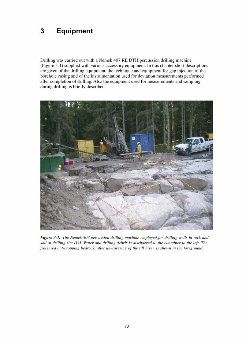
Drilling was carried out with a Nemek 407 RE DTH percussion drilling machine (Figure 3-1) supplied with various accessory equipment. In this chapter short descriptions are given of the drilling equipment, the technique and equipment for gap injection of the borehole casing and of the instrumentation used for deviation measurements performed after completion of drilling. Also the equipment used for measurements and sampling during drilling is briefly described.
Figure 3-1. The Nemek 407 percussion drilling machine employed for drilling wells in rock and soil at drilling site DS5. Water and drilling debris is discharged to the container to the left. The fractured out-cropping bedrock, after un-covering of the till layer, is shown in the foreground.

14
3.1 Drilling equipmentThe drilling machine is equipped with separate engines for transportation and power supplies. Water and drill cuttings were discharged from the borehole by an Atlas-Copco XRVS 455 Md 27 bars diesel compressor. The DTH drill hammer was of type Secoroc 5", operated by a Driconeq 76 mm pipe string. All DTH-equipment was cleaned with a Kärcher HDS 1195 high-capacity steam cleaner.
3.2 Gap injection technique and equipmentIn order to prevent surface water and shallow groundwater to infiltrate into deeper parts of the borehole, the normal procedure is to grout the gap between the borehole wall and the casing pipe with cement. The cement application may be performed by different technical approaches and with different equipment. Two variants are illustrated in Figure 3-2.
Of the boreholes discussed in this report, grouting was made only in HFM13, where the borehole packer technique was applied. No cement injections were made in boreholes HFM14 and HFM15, because the increased fracturing of the bedrock entailed a high risk of filling the entire borehole with cement, which would make borehole measurements impossible.
Figure 3-2. Gap injection technique. In order to grout the gap between the borehole wall and the casing pipe, different techniques may be applied. To the left, filling up a cement-water mixture with a flexible hose is shown. To the right, injection is performed through a borehole packer.
Gap injection
> 10 mLow fractured rock
Overburden
Fragmented rock
Cement plug
Gap injectionthrough packer
CementPressureCement

15
3.3 Equipment for deviation measurementsDeviation measurements in HFM13, HFM14 and HFM15 were performed with a Reflex EZ-shot (magnetic) equipment. Azimuth and dip were measured every third metre. The coordinates for the collaring point and the measured values from the EZ-shot instrument were used for calculating the coordinates for every measured point along the borehole.
3.4 Equipment for measurements and sampling during drilling
Flow measurements during drilling were conducted using measuring vessels of different sizes and a stop watch. Measurements of drilling penetration rate were accomplished with a carpenter’s rule and a stop watch.
Samples of soil and drill cuttings were collected in sampling pots and groundwater in small bottles. A field measuring devise, Kemotron 802, was used for measurements of electrical conductivity of the groundwater.

17
4 Execution
The Method Description for Percussion Drilling, SKB MD 610.003, includes the following items:
• preparations,
• mobilization, including lining up the machine and measuring the position,
• drilling, measurements, and sampling during drilling,
• finishing off work,
• deviation measurements,
• data handling,
• environmental control.
The performance according to the above items is presented in Sections 4.1–4.8. Section 4.9, finally, describes nonconformities to plan.
4.1 PreparationsThe preparation stage included the Contractor’s service and function control of his equipment. The machinery was obliged to be supplied with fuel, oil and grease exclusively of the types stated in SKB MD 600.006, Version 1.0 (Method Instruction for Chemical Products and Materials). Finally, part of the equipment was cleaned in accordance with SKB MD 600.004, Version 1.0 (Method Instruction for Cleaning Borehole Equipment and certain Ground-based Equipment) at level two, used for SKB boreholes of chemical type (the remaining part of the equipment was cleaned on-site). The Method Instructions are SKB internal controlling documents.
For the borehole in soil, SFM0058, the well screen and riser pipes of HDPE-material (High Density PolyEthylene) were delivered in tight-fitting packages. Before delivery to the drilling site, the pipes etc had been treated by acid leaching followed by washing with deionized water, see procedure in /4/, Section 4.1. At the drilling site, the screen and pipes were further prepared by steam-cleaning.
4.2 MobilizationMobilization onto and at the site started with transport of drilling and accessory equipment to the drilling site. The mobilization also comprised preparation of the drilling site, on-site cleaning of all DTH-equipment at level two according to SKB MD 600.004, lining up the machine and final function control.

18
4.3 Drilling and measurements during drilling of boreholes HFM13 and HFM14
4.3.1 Drilling through the overburden
In normal Swedish terrain, the rock surface is often covered with a more or less thick stratum of unconsolidated rock material, e.g. till. The procedure of drilling a percussion borehole may in this case be divided in three drilling sequences: 1) drilling and casing driving through the overburden and fragmented rock, 2) drilling and continued casing driving a distance into fresh, low-fractured rock, and 3) continued drilling in solid rock. The bedrock where boreholes HFM13 and HFM14 are situated is till covered, and hence drilling was performed according to these sequences. Figure 4-1 schematically illustrates the different steps carried out.
Drilling through the overburden may be accomplished by using different technical approaches. For drilling HFM13 and HFM14, so called Ejector NO-X technique was applied. The prefix “ejector” indicates that the discharge channels for the flushing medium, in this case compressed air, are constructed in such a way that the exposure of the penetrated layers to the flushing medium is reduced, compared to conventional systems. Thereby, contamination with oxygen and compressor oil, which is part of compressed air (although compressor oil at a very low content), is limited.
The NO-X system represents a method for concentric drilling and casing driving through the overburden. A circular pilot bit, attached to a DTH-hammer shank, and with large internal flushing holes and external flushing grooves, is connected to a symmetrical ring bit (reamer) with an internal bayonet coupling, cf Figure 4-1. The pilot bit and the ring bit are both rotating clockwise, thereby drilling a borehole with a diameter large enough to let the casing easily slip down into the reamed borehole. The ring bit is rotating freely against the casing shoe, which is welded to the lower end of the casing. The casing is non-rotating during drilling.
Figure 4-1. The different steps included in the performance of the percussion drilled boreholes HFM13–14. Cement grouting of the casing was performed only in HFM13. Schematic diagram.
~ 100 m
~ 10 m
O 219-254mmy
O 160 mmi(O 168 mm)y
O 190-210 mm
0 - level
Percussiondrilling140 mmdiameter
Gap injection
of the casing
Installationof stainlesssteel casing
and taking outthe NO-X casing
Percussiondrilling190 mmdiameter
Lifting theNO-X drill-pipe and drillbit
Drilling 235 to 266 mm
diameter bore-hole using theNO-X principle
Soil cover
Fragmentedrock
Low fractured rock
NO-X

19
Drilling through the overburden of boreholes HFM13–14 basically followed the principles for the Ejector-NO-X system. However, the method was to some extent applied in a non-conventional manner. During drilling of a borehole with the diameter 235 mm, a temporary steel casing with an outer diameter of 219 mm was driven through the till overburden and through fragmented rock a short distance into relatively fresh, solid rock, see Figure 4-1 (sequence 1 above). The drilling pipes with the drill hammer and pilot bit were then retrieved from the borehole. A percussion drill bit was lowered into the borehole inside the temporary casing, and a borehole with a diameter of approximately 190 mm was drilled to 14.90 m in HFM13 respectively 6.00 m in HFM14 into high-quality, low-fractured rock. Again the drilling pipes, drill hammer and drill bit were retrieved, whereupon a stainless steel casing with the external/internal diameter 168/160 mm was installed in the borehole in 3 m lengths, which were successively welded together (sequence 2).
4.3.2 Gap injection
When the casing string had been firmly installed in borehole HFM13, the narrow gap between the borehole wall and the outer wall of the casing was grouted with a cement/water-mixture according to the borehole packer technique illustrated in Figure 3-2. However, since the upper part of borehole HFM14 was reamed after the borehole was drilled to full length (see Section 4.3.3), no cement injection was made in this borehole.
4.3.3 Percussion drilling in solid rock
After the casing was set (according to different approaches for HFM13 respectively HFM14), drilling could continue and was now performed to the full borehole length with conventional percussion drilling (sequence 3 above). The diameter of the drill bit was measured before start of drilling. A new drill bit has a diameter of 140 mm, which will also (approximately) be the diameter of the borehole, see Figure 4-1. However, a diameter decrease of about 1 mm/100 m drilling length is to be expected when drilling in the rock types prevailing in the Forsmark area. For boreholes deeper then 100 m, the drill bit normally has to be grinded. Borehole slimmer than 134 mm are normally not permitted.
The upper part of borehole HFM14 was reamed and cased to 6 m after the borehole was drilled to the full length, because the fracture zone at approximately 3 m depth turned out to be unstable.
4.3.4 Sampling and measurements during drilling
During drilling, a sampling and measurement program was performed, which included:
• Collecting one soil sample per metre drilling length. Analysis and results are reported in /5/.
• Collecting one sample per 3 m drilling length of drill cuttings from the bedrock (Figure 4-2). Each sample consists of three individual samples collected at every metre borehole length, stored in a plastic box marked with a sample number. As far as possible, mixing of the three individual samples was avoided. A first description of the material was made on-site, including the mineral content and rock structure, which provided a preliminary classification of the rock type. These samples were later examined more thoroughly and interpreted together with a BIPS-log (so called Boremap-mapping) /6/.
• Measurements of the penetration rate (one measurement per 20 cm drilling length). The time needed for the drill bit to sink 20 cm was recorded manually in a paper record.

20
• Performing one observation of groundwater flow (if any) and water colour per 20 cm drilling length and a measurement of the flow rate at each major flow change observed. The measured values were noted in a paper record.
• Measurements of the electrical conductivity (EC) of the groundwater (if any) at every 3 m drilling length (noted in a paper record).
• Deviation measurements after completion of drilling.
The results from the third and fourth items were used as supporting data for the Boremap-mapping mentioned above. The fifth item gave on-site information about hydraulic and hydrogeochemical characteristics of the penetrated aquifer.
4.4 Drilling and measurements during drilling of borehole HFM15
4.4.1 Drilling through the overburden
For drilling through the overburden and six metres into solid bedrock, so called TUBEX technique (an ODEX-variant) was applied (Figure 4-3). TUBEX is a system for simultaneous drilling and casing driving. The method is based on a pilot bit and an eccentric reamer, which produces a borehole slightly larger than the external diameter of the casing. This enables the casing tube to follow the drill bit down the hole. In the Ejector-TUBEX system like in the Ejektor-NO-X-system, the design of the discharge channels for the flushing medium, in this case compressed air, is such that the oxygen and oil contamination of the penetrated soil layers is reduced, compared to conventional systems.
Figure 4-2. Sampling of one sample per 3 m drilling length of drill cuttings from the bedrock.

21
4.4.2 Gap injection
No injection was made.
4.4.3 Percussion drilling in solid rock
After the casing was set, drilling could continue and was now performed to the full borehole length with conventional percussion drilling. Before start of drilling, the diameter of the drill bit was measured.
4.4.4 Sampling and measurements during drilling
An identical programme for sampling and measurements during and immediately after drilling as for boreholes HFM13 and HFM14 was applied for HFM15.
4.5 Finishing off work – HFM13, 14 and 15Finishing off work included rinsing of the borehole from drill cuttings by a “blow out” with the compressor at maximum capacity during 30 minutes. The recovery of the groundwater table after rinsing was recorded, enabling a preliminary evaluation of hydraulic parameters. The drill pipes were then retrieved from the hole, and the diameter of the drill bit was measured. A deviation survey of the borehole completed the measurement programme during and immediately after drilling. The borehole was secured by a stainless steel lockable cap (Figure 4-4), mounted on the casing. Finally, the equipment was removed, the site cleaned and a joint inspection made by representatives from SKB and the Contractor, to ensure that the site had been satisfactorily restored.
Figure 4-3. The different steps included in the performance of the percussion drilled borehole HFM15. Schematic diagram.
~ 100 m
Soil
Fracturedrock
Solid rock
3-9 m
ODEXCasingO 168 mmy
Stainless drill-shoe left in hole
ODEX
ODEXdrilling
O 187 mm
Recovery ofrods and drillbit
Percussion drilling
O 140 mm
Gap injectionbetweem
casing/borehole wall
0 - level

22
4.6 Performance of soil borehole SFM00584.6.1 Drilling and sampling during drilling
Drilling through the overburden was performed using a variant of the TUBEX-system, called Ejector-TUBEX, see Section 4.4.1. During drilling, a temporary steel casing with the dimension 168 mm external and 160 mm internal diameter was simultaneously driven through the soil. When solid rock was indicated, drilling was continued almost one metre further, to ensure that the bedrock surface had been reached and not only compact till or a large boulder.
During drilling, a sampling and measurement program was carried out, which included:
• One soil sample per metre. Analysis and results are reported in /5/.
Figure 4-4. After drilling and sampling, each borehole was secured by a stainless steel lockable cap, mounted on top of the casing flange.

23
• One sample of drill cuttings from the bedrock. Rock samples collected during drilling of monitoring wells in soil will be analysed and the results reported within the scope of the Activity Plan AP PF 400-03-74, Version 1.0 (SKB internal controlling document).
• One observation of groundwater flow (if any) and water colour per 20 cm and a measurement of the flow rate at each major flow change observed.
• Measurement of the electrical conductivity (EC) of the sampled groundwater (if any) at each 3 m.
The results from the last two items, preserved as field records, were used exclusively for the on-site decision of the design of the well screen and filter installation in each borehole.
4.6.2 Installation of well screen and screen filter
At completion of drilling, the temporary casing was driven approximately one metre into the bedrock. The results observed during drilling regarding soil depth and type, groundwater inflow etc were analysed on-site, and a decision was made about the design of the borehole installation. The well screen and screen filter were then assembled and the assembling documented. The installation was performed according to the design illustrated in Chapter 5.
The first part of the installation was to fill up a suitable amount of filter sand in the borehole, in order to cover the bedrock. The screen, connected to the riser pipes, was then descended in the borehole all the way down to the sand bed, where it was centralized in the borehole. During simultaneous lifting of the steel casing, the space between the plastic pipe and the inner casing wall was filled up with filter sand. In order to prevent surface water to infiltrate along the borehole, a bentonite sealing was installed at an appropriate level in the borehole. In the actual monitoring well, dry bentonite pellets were used. However, also bentonite slurry may be suitable for this purpose.
4.6.3 Finishing off work
After installation of the screen, sand filter and sealing, the temporary casing was retrieved and the monitoring well secured with a stainless steel protective casing, which was driven a short distance into the ground around the upper part of the HDPE riser pipe. The casing was then moulded firmly to the ground. Supplied with a lockable stainless steel cover, this construction offers an effective protection against damage of the monitoring well.
Finally, the drilling machine was removed, the site cleaned, and a joint inspection of the drilling site made by SKB and the Contractor.
4.7 Data handlingMinutes with the following headlines: Activities, Cleaning of equipment, Drilling, Borehole, Percussion drilling penetration rate, Deliverance of field material and Discrepancy report were collected by the Activity Leader, who made a control of the information, and had it stored in the SKB database SICADA /7/.

24
4.8 Environmental controlA programme according to SKB’s routine for environmental control was complied with throughout the activity. A checklist was filled in and signed by the Activity Leader and was finally filed in the SKB archive.
4.9 NonconformitiesTo enable performance of borehole measurements in HFM14 according to Activity Plan AP PF 400-03-68, a deviation was made. It appeared necessary to stabilize the borehole by a steel casing to 6.00 m to prevent outfall from the borehole wall. In order to preserve the possibility to observe and investigate an open fracture encountered at approximately 3 m depth, a short additional percussion drilled borehole (Ø 180 mm), denominated HFM14B, was drilled to 3.20 m borehole length close to HFM14, see Figure 1-2.
Also another nonconformity with Activity Plan AP PF 400-03-68 was associated with the performance of HFM14. The borehole was drilled to the full depth before it was reamed in the upper part and cased. Normally, the operations follow the sequence described in Figures 4-1 or 4-3.

25
5 Results
All data were stored in the SICADA database for Forsmark under field note no 194 (HFM13), 195 (HFM14–14B) respectively 206 (HFM15) /7/.
Below, a summary of the data acquired is presented.
5.1 Design of the percussion drilled borehole5.1.1 Percussion drilled boreholes HFM13, HFM14, HFM15 and HFM14B
Administrative, geometric, and technical data for the percussion drilled boreholes HFM13–15 are presented in Table 5-1 and for HFM14B in Table 5-2. The technical design of each borehole is illustrated in Figures 5-1, 5-2 and 5-3.
Table 5-1. Administrative, geometric and technical data for boreholes HFM13–15.
Parameter HFM13 HFM14 HFM 15
Drilling period From 2003-09-18 to 2003-10-02
From 2003-10-06 to 2003-10-09
From 2003-10-13 to 2003-10-15
Borehole inclination (collaring point)
–58.85° (– = downwards) –59.81° (– = downwards) –43.70° (– = downwards)
Borehole bearing 51.19° 331.75° 314.31°
Borehole length 175.60 m 150.50 m 99.50 m
Borehole diameter From 0.00 m to 4.40 m: 0.235 m
From 4.40 m to 14.90 m: 0.189 m
From 14.90 m to 175.60 m: decreasing from 0.139 m to 0.135 m
From 0.00 m to 3.10 m: 0.235 m
From 3.10 m to 6.00 m: 0.189 m
From 6.00 m to 150.50 m: decreasing from 0.138 m to 0.136 m
From 0.00 m to 6.00 m: 0.176 m
From 6.00 m to 99.50 m: 0.139 m
Casing length 14.90 m 6.00 m 6.00 m
Casing diameter Øo/Øi = 168 mm/160 mm to 14.90 m
Øo/Øi = 168 mm/146 mm between 14.88 and 14.90 m
Øo/Øi = 168 mm/160 mm to 6.00 m
Øo/Øi = 168 mm/146 mm between 5.98 and 6.00 m
Øo/Øi = 168 mm/160 mm to 6.00 m
Øo/Øi = 168 mm/146 mm between 5.98 and 6.00 m
Drill bit diameter Start of drilling: 0.139 m End of drilling: 0.135 m
Start of drilling: 0.138 m End of drilling: 0.136 m
Start of drilling: 0.139 m End of drilling: 0.139 m
Collaring point coordi-nates (system RT90 2.5 gon V
/RHB70)
Northing: 6699093.68 m Easting: 1631474.40 m Elevation: 5.69 m.a.s.l.
Northing: 6699313.14 m Easting: 1631734.59 m Elevation: 3.91 m.a.s.l.
Northing: 6699312.44 m Easting: 1631733.08 m Elevation: 3.88 m.a.s.l.

26
Table 5-2. Administrative, geometric and technical data for borehole HFM14B.
Parameter HFM14B
Drilling period From 2003-11-25 to 2003-11-26
Borehole inclination (collaring point) –89.00° (– = downwards)
Borehole bearing 32.97°
Borehole length 4.00 m
Borehole diameter From 0.00 m to 4.00 m: 0.180 m
Collaring point coordinates (system RT90 2.5 gon V
/RHB70)
Northing: 6699316.37 m
Easting: 1631731.26 m
Elevation: 3.91 m.a.s.l.

27
Figure 5-1. Technical data for borehole HFM13.
North
0.168 m
0.189 m
0.139 m
Technical dataBorehole HFM13
Northing:
Easting:
Elevation:
Drilling start date:
Drilling stop date:
Drilling reference point
Drilling period
6699093.68 (m),
(m),5 (m.a.s.l.),
2003-09-18
2003-10-02
RT90 2,5 gon V 0:-15
1631474.40 RT90 2,5 gon V 0:-15.69 RHB 70
0.135 m
0.160 m
51.19o
-58.85o
17
5.6
0m
14
.90
m
16
0.9
0m

28
Figure 5-2. Technical data for borehole HMF14.
North
0.168m
0.189m
0.138m
Technical dataBorehole HFM14
Northing:
Easting:
Elevation:
Drilling start date:
Drilling stop date:
Drilling reference point
Drilling period
6699313.14 (m),(m),
3 (m.a.s.l.),
2003-10-062003-10-09
RT90 2,5 gon V 0:-151631734.59 RT90 2,5 gon V 0:-15
.91 RHB 70
0.136 m
0.160 m
331.75o
-59.81o
15
0.5
0m
6.0
0m
14
4.5
0m

29
Figure 5-3. Technical data for borehole HMF15.
North
0.168m
0.176m
0.139m
Technical dataBorehole HFM15
Northing:
Easting:
Elevation:
Drilling start date:
Drilling stop date:
Drilling reference point
Drilling period
6699312.44 (m),
(m),3 (m.a.s.l.),
2003-10-13
2003-10-15
RT90 2,5 gon V 0:-15
1631733.08 RT90 2,5 gon V 0:-15.88 RHB 70
0.139 m
0.160 m
314.31o
-43.70o
99
.50
m
6.0
0m
93
.50
m

30
5.1.2 Soil borehole SFM0058
The design of the groundwater monitoring well SFM0058 is illustrated in Figure 5-4. Table 5-3 displays the geometric characteristics of the well.
Table 5-3. Geometric data for groundwater monitoring well SFM0058.
Drillhole ID Inclination Northing Easting Elevation m.a.s.l. (top of HDPE-pipe)
Total depth from ground level (m)
Screen length (m)
Screen pipe length inclu-ding a well screen (m)
Screen pipe diameter (Øo/Øi, mm)
SFM0058 90° 6699349.27 1631739.76 3.55 4.40 1.00 4.75 90/72
Figure 5-4. The groundwater monitoring well installation in borehole SFM0058.
0,00 m
0,50 m
1,00 m
1,50 m
2,00 m
2,50 m
3,00 m
3,50 m
4,00 m
4,50 m
O = 193,7 mm (borehole)
Filled with mixture of approx. 13,5 litre of fine sand and approx. 13,5 litre of bentonite (0,15 - 1,12 m)
Reference point
6.00 m
(m), RT90 2.5 gon V 0:-15(m),
3 (m), RHB 70 RT90 2.5 gon V 0:-15
6699349.271631739.76
.55
Northing:Easting:Elevation:
Reference point
Stainless steel protection pipe Oo = 168 mm
Stainless steel cover
Moulding
SFM0058Date: 2003-11-27
Filled with approx. 74 litre coarse sand (1,12 - 3,50 m)
Filled with approx. 38 litre of coarse sand (3,50 - 4,40 m)
Filled with approx. 5 litre offine sand (0,00 - 0,15 m)
Bedrock (fragmented) at 3,50 m below surface
Coarse sand(1-3 mm)
Fine sand(B70)
Bentonitevolclay(SG40)
Mixture ofbentonite
and fine sand
Oo/ = 90/72 mm (riser pipe)Oi
Total length of well screen and riser pipe = 4,75 m
Oo/Oi = 90/72 mm (well screen)

31
5.2 Consumables in HFM13, HFM14 and HFM15The amount of oil products consumed in each borehole during drilling, and grout used for gap injection of the respective casings is reported in Tables 5-4 and 5-5. The cement was of a low alkalic type, consisting of microsilica (920-D) and white cement (Aalborg Portland CEM I, 52.5N).
Regarding contamination risks, albeit some amounts of hammer oil and compressor oil reach the borehole, they are, on the other hand, continuously retrieved due to the permanent air flushing during drilling. After completion of drilling, only minor residues of the products remain in the borehole.
Table 5-4. Oil consumption.
Borehole ID Hammer oil Compressor oil Preem Hydra 46 Schuman 46
HFM13 8 L Not detected
HFM14 4 L Not detected
HFM15 3 L Not detected
Table 5-5. Consumption of cement grout.
Borehole ID Casing length Cement volume Grouting method (Aalborg Portland Cement/microsilica)
HFM13 14.90 m 125/55 kg Packer technique
HFM14 6.00 m 0 kg No injection made
HFM15 6.00 m 0 kg No injection made
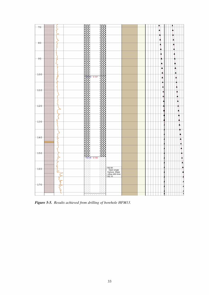
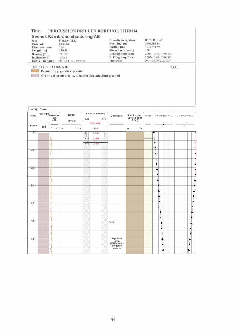
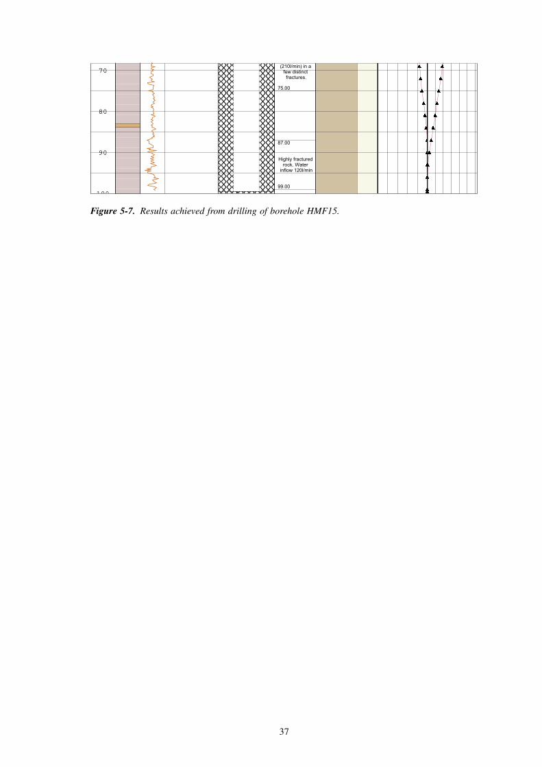
5.3 Well Cad presentationsTechnical as well as geoscientific results achieved during drilling are presented in the so called Well Cad plots in Figures 5-5, 5-6 and 5-7.
The deviation measurements made in boreholes HFM13, HFM14 and HFM15 (Figures 5-5, 5-6 and 5-7) indicate moderate deviations.
The end (bottom) point of HFM13 deviates approximately 2.3 m downwards and 9.6 m to the right compared to an imagined straight line following the dip and strike of the borehole collaring point (inclination –58.85° and bearing 51.19°). The corresponding values for borehole HFM14 are 1.2 m downwards and 13.2 m to the left, compared to a straight line with the inclination –59.27° and bearing 330.33°. Finally, borehole HFM15 deviates approximately 0.6 m downwards and 5.7 m to the left compared to a straight line with the dip and strike –43.70° respectively bearing 314.31°.

32
Pegmatite, pegmatitic granite
Granite to granodiorite, metamorphic, medium-grained
Soil
SOIL
Svensk Kärnbränslehantering ABCoordinate System RT90-RHB70
Length [m] 175.60
Title PERCUSSION DRILLED BOREHOLE HFM13
Diameter [mm] 135
Elevation [m.a.s.l.] 5.69
Inclination [°] -58.85
Borehole HFM13
Site FORSMARK
Northing [m] 6699093.68
Easting [m] 1631474.40
Date of mapping 2004-04-22 13:30:00
ROCKTYPE FORSMARK
Script Name
Bearing [°] 51.19
Plot Date 2004-04-26 21:00:40
Drilling Stop Date 2003-10-02 17:00:00
Drilling Start Date 2003-09-18 12:30:00
Depth
1m:500m
Rock TypePenetration
rate(s/20)
0 90
Deltaqi
(m**3/s)
0 0.0008
Borehole Geometry
0.15 0.15
S<-Deviation->N W<-Deviation->ETotal fracturesOpen + Sealed
(fr/1m)
0 10
Crush
Soil
Comments
Hole Diam
Depth
0
10
20
30
40
50
60
0.235
0.189
0.139
0
4.40
14.90
33
Figure 5-5. Results achieved from drilling of borehole HFM13.
70
80
90
100
110
120
130
140
150
160
170
0.137
0.135
101.00
152.35
162.00
162.10
Open single fracture. Water inflow 400 l/min
34
Pegmatite, pegmatitic granite
Granite to granodiorite, metamorphic, medium-grained
SOIL
Svensk Kärnbränslehantering ABCoordinate System RT90-RHB70
Length [m] 150.50
Title PERCUSSION DRILLED BOREHOLE HFM14
Diameter [mm] 136
Elevation [m.a.s.l.] 3.91
Inclination [°] -59.81
Borehole HFM14
Site FORSMARK
Northing [m] 6699313.14
Easting [m] 1631734.59
Date of mapping 2004-04-22 13:58:00
ROCKTYPE FORSMARK
Script Name
Bearing [°] 331.75
Plot Date 2004-05-05 21:00:37
Drilling Stop Date 2003-10-09 15:00:00
Drilling Start Date 2003-10-06 14:00:00
Depth
1m:500m
Rock TypePenetration
rate(s/20)
0 110
Deltaqi
(m**3/s)
0 0.0008
S<-Deviation->N W<-Deviation->ETotal fracturesOpen + Sealed
(fr/1m)
0 10
Crush
Soil
CommentsBorehole Geometry
0.15 0.15
Hole Diam
Depth
0
10
20
30
40
50
60
50.00
High water inflow
(500l/min) in a few distinct fractures.
0.235
0.189
0.138
0
3.10
6.00

35
Figure 5-6. Results achieved from drilling of borehole HMF14.
70
80
90
100
110
120
130
140
150
75.00
89.00
104.00
Highly fractured rock. Water
inflow 100l/min
0.136101.30

36
Pegmatite, pegmatitic granite
Granite to granodiorite, metamorphic, medium-grained
Soil
SOIL
Svensk Kärnbränslehantering ABCoordinate System RT90-RHB70
Length [m] 99.50
Title PERCUSSION DRILLED BOREHOLE HFM15
Elevation [m.a.s.l.] 3.88
Diameter [mm] 139
Borehole HFM15
Inclination [°] -43.70
Site FORSMARK
Northing [m] 6699312.44
Easting [m] 1631733.08
Date of mapping 2004-04-22 15:35:00
ROCKTYPE FORSMARK
Script Name
Drilling Stop Date 2003-10-15 11:00:00
Plot Date 2004-04-26 21:00:40
Bearing [°] 314.31 Drilling Start Date 2003-10-13 12:00:00
Depth
1m:500m
Rock TypePenetration
rate(s/20)
0 50
Deltaqi
(m**3/s)
0 0.0008
Borehole Geometry
0.15 0.15
S<-Deviation->N W<-Deviation->ETotal fracturesOpen + Sealed
(fr/1m)
0 10
Crush
Soil
Comments
Hole Diam
Depth
0
10
20
30
40
50
60
0.176
0.139
0
6.00
52.00
63.00
Open single fractures.
Water inflow 90 l/min
63.00
High water inflow
37
70
80
90
100
75.00
(210l/min) in a few distinct fractures.
87.00
99.00
Highly fractured rock. Water
inflow 120l/min
Page 2
Figure 5-7. Results achieved from drilling of borehole HMF15.

38
5.4 Hydrogeologi5.4.1 Observations during drilling
No measurable inflow of groundwater was observed in the upper part of borehole HFM13 (Figure 5-8), although the drilling debris was clammy with damp. During drilling stop at 101 m, groundwater recharged into the borehole and flushed out at drilling re-start the morning after. The first measurement of electrical conductivity (EC) was performed at 152 m drilling length and resulted in the value 200 mS/m, indicating a shallow (non-saline) inflow of groundwater. When reaching the water-yielding fracture at 162 m, EC increased to 1300 mS/m which is a normal value for the groundwater at this depth in the Forsmark candidate area.
In borehole HFM14 (Figure 5-9), no inflow was observed above c 51 m borehole length. The first inflow (200 L/min) at 51 m corresponded to an EC-value of 280 mS/m. A stepwise increasing water inflow in section 51–66 m caused decreasing EC-values, indicating shal-low water inflows. From 69 m, where the accumulated water inflow exceeded 500 L/min, the increasing EC-values indicate semi deep conditions. The apperent drop in accumulated groundwater inflow versus drilling length between c 105 m and 135 m is probably due to drill-technical problems.
Similar results as shown from HFM14 were observed in borehole HFM15, see Figure 5-10. The first inflow encountered (15 L/min) was observed at 54 m and displayed an EC-value of 160 mS/m, indicating shallow groundwater. The EC-value has increased to 330 mS/m at 63 m and then remains relatively constant, although there is a stepwise increase of the accumulated waterflow up to 420 L/min. The results indicate semi-deep conditions from 63 m to the full borehole length.
HFM13
0
200
400
600
800
1000
1200
1400
150 180
Length [m]
[d
no
clE
m/
Sm
]
0
50
100
150
200
250
300
350
400
450
500
100500
]ni
m/L[
wolf r
eta
w m
uc
cA
Electrical conductivity Accumulated water flow
Figure 5-8. Electrical conductivity and accumulated groundwater inflow versus drilling length in HFM13.

39
Figure 5-9. Electrical conductivity and accumulated groundwater inflow versus drilling length in HFM14.
Figure 5-10. Electrical conductivity and water flow versus length in HFM15.
0
100
200
300
400
500
600
700
50 70 90 110 130 150 170
Length [m]
]m/
Sm[
dn
ocl
E
0
100
200
300
400
500
600
403020100
]ni
m/L[
wolf r
eta
w m
uc
cA
HFM14
Electrical conductivity Accumulated water flow

40
5.4.2 Hydraulic responsesWhen drilling the two percussion boreholes HFM14 and HFM15 at DS5, significant hydraulic responses were observed in HFM13, see Figure 5-11. As the distance between DS5 and HFM13 is about 300 m, the quick responses indicate that the three percussion boreholes penetrate the same highly permeable and flat-lying fracture zone.
Figure 5-12 illustrates a tentative, simplified interpretation of the structural conditions in the shallow part of the bedrock at drilling site DS5. An alternative interpretation is that the fractured parts of borehole HFM14 and HFM15 are connected with the lineament striking 125 m northwest of the drilling site, cf Figure 5-12.
Figure 5-11. Hydraulic responses in HFM13 when drilling HFM14 and HFM15.
HMS PFPLOT TIME :04/03/04 13:44:42PLOT FILE :HFM13No DST Adjustment
month-day10-06 7 8 9 10 11 12 13 14 15 16
START :03/10/06 00:00:00 INTERVAL: All readings STOP :03/10/16 00:00:00
-5
-4
-3
-2
-1
0
1
BH95 HFM13:1
masl
LAST CALIBRATION03/11/11 00:00:00
Drilling of HFM14, 3-101 m
Drilling of HFM14, 101-150 m
Drilling of HFM15, 6-99 m

41
Figure 5-12. Tentative, simplified interpretation of the structural conditions in the shallow part of the bedrock at drilling site DS5. Water-bearing fractures are illustrated with blue schlieren and sections with hight penetration rate during drilling (although not water-yielding) with black schlieren.
90 L/min
210 L/min 200 L/min
500 L/min
15 L/min
20
40
60
80
100
20
40
60
80
100
120
140
Lineament
0
10
20
30
40
50
60
70
80
90
140 130 120 110 100 90 80 70 60 50 40 30 20 10 0
0
10
20
30
40
50
60
70
80
90
100
110
120
130
140
100
110
120
130
140
HFM14
HFM15
HFM14
HFM15
Outcrop
Plan view North
Vertical section
Highly fractured rock, glacial effects
Low fracture frequency, single “dry”, often subhorizontal fractures
High water inflow in a few distinct fractures, sections with high fracture frequency
High fracture frequency,low permeability
Very good rock, low fracturefrequency, low permeability
HFM14B
HFM14B

43
6 References
/1/ SKB, 2001. Site investigations. Investigation methods and general execution programme. SKB TR-01-29, Svensk Kärnbränslehantering AB.
/2/ SKB, 2001. Execution programme for the initial site investigations at Forsmark. SKB P-02-03, Svensk Kärnbränslehantering AB.
/3/ SKB, 2004. Claesson, L-Å & Nilsson, G. Forsmark site investigation. Drilling of the telescopic borehole KFM05A at drilling site DS5. SKB P-report in progress. Svensk Kärnbränslehantering AB.
/4/ SKB, 2003. Claesson, L-Å & Nilsson, G. Forsmark site investigation. Drilling of groundwater monitoring wells SFM0001–SFM0003 in soil at drilling site DS1. SKB P-03-13, Svensk Kärnbränslehantering AB.
/5/ SKB, 2003. Sohlenius, G. & Rudmark, L. Forsmark site investigation. Mapping of unconsolidated Quaternary deposits 2002–2003. Stratigraphical and analytical data. SKB P-03-14.
/6/ SKB, 2004. Nordman, C. Forsmark. Boremap mapping of percussion boreholes HFM13–15 and HFM19. SKB P-report in progress. Svensk Kärnbränslehantering AB.
/7/ SICADA. Field Note Nos.: Forsmark 194, 195 and 206.
/8/ SKB 2004. Claesson, L-Å & Nilsson, G. Forsmark site investigation. Drilling of five percussion boreholes, HFM11–12 and HFM 17–19, on different lineaments. SKB P-report in progress. Svensk Kärnbränslehantering AB.
Related Documents