Gas Analysis Installation and Operation Instructions Original instructions Oxygen Flue Gas Analyzer BA 2000 BE550012 11/2018 Bühler Technologies GmbH, Harkortstr. 29, D-40880 Ratingen Tel. +49 (0) 21 02 / 49 89-0, Fax: +49 (0) 21 02 / 49 89-20 E-Mail: [email protected] Internet: www.buehler-technologies.com

Welcome message from author
This document is posted to help you gain knowledge. Please leave a comment to let me know what you think about it! Share it to your friends and learn new things together.
Transcript

Gas Analysis
Installation and Operation Instructions
Original instructions
Oxygen Flue Gas Analyzer
BA 2000
BE55001211/2018
Bühler Technologies GmbH, Harkortstr. 29, D-40880 RatingenTel. +49 (0) 21 02 / 49 89-0, Fax: +49 (0) 21 02 / 49 89-20
E-Mail: [email protected]: www.buehler-technologies.com
Bühler Technologies GmbH, Harkortstr. 29, D-40880 RatingenTel. +49 (0) 21 02 / 49 89-0, Fax: +49 (0) 21 02 / 49 89-20Internet: www.buehler-technologies.comE-Mail: [email protected]
Read this instruction carefully prior to installation and/or use. Pay at-tention particularly to all advises and safety instructions to prevent in-juries. Bühler Technologies can not be held responsible for misusingthe product or unreliable function due to unauthorised modifications.
All rights reserved. Bühler Technologies GmbH 2019
Document informationDocument No...........................................................BE550012Version...........................................................................11/2018

BA 2000
Contents1 Introduction..................................................................................................................................................................................................................... 2
1.1 Intended Use......................................................................................................................................................................................................... 21.2 Type Plate............................................................................................................................................................................................................... 21.3 Ordering instructions ........................................................................................................................................................................................ 21.4 Scope of delivery .................................................................................................................................................................................................. 3
2 Safety instructions......................................................................................................................................................................................................... 42.1 Important notices................................................................................................................................................................................................ 42.2 General hazard warnings ................................................................................................................................................................................. 4
3 Transport and storage .................................................................................................................................................................................................. 6
4 Installation and connection ........................................................................................................................................................................................ 74.1 Installation ............................................................................................................................................................................................................ 74.2 Connecting the gas lines ................................................................................................................................................................................... 7
4.2.1 Connecting instrument air for the injector .................................................................................................................................. 74.2.2 Required instrument air pressure.................................................................................................................................................. 84.2.3 Operating the injector with a pump ............................................................................................................................................. 84.2.4 Connecting test gas ............................................................................................................................................................................ 84.2.5 Installing a separate sample gas recovery ................................................................................................................................... 8
4.3 Electrical connections ........................................................................................................................................................................................ 84.3.1 Probe ....................................................................................................................................................................................................... 94.3.2 ZrO2 sensor............................................................................................................................................................................................ 94.3.3 Power supply and outputs................................................................................................................................................................ 9
5 Initial operation............................................................................................................................................................................................................ 105.1 Calibration........................................................................................................................................................................................................... 10
5.1.1 Introduction to calibration .............................................................................................................................................................. 105.1.2 1-point calibration .............................................................................................................................................................................. 105.1.3 2-point calibration ............................................................................................................................................................................. 10
6 Operation and Control................................................................................................................................................................................................. 116.1 ZrO2 sensor function......................................................................................................................................................................................... 116.2 Using the controller ........................................................................................................................................................................................... 11
6.2.1 Use of menu functions....................................................................................................................................................................... 116.2.2 Detailed description of the operational principle .................................................................................................................... 126.2.3 Menu navigation overview.............................................................................................................................................................. 136.2.4 Description of menu functions ...................................................................................................................................................... 13
7 Maintenance and repair ............................................................................................................................................................................................. 157.1 General warnings............................................................................................................................................................................................... 157.2 Replacing the microfuse................................................................................................................................................................................... 157.3 Maintaining the filter element ...................................................................................................................................................................... 15
7.3.1 Outlet filter........................................................................................................................................................................................... 167.3.2 Inlet filter .............................................................................................................................................................................................. 16
8 Service and repair.......................................................................................................................................................................................................... 178.1 Troubleshooting ................................................................................................................................................................................................. 178.2 List of spare parts and consumables: .......................................................................................................................................................... 18
9 Disposal ........................................................................................................................................................................................................................... 19
10 Appendix......................................................................................................................................................................................................................... 2010.1 Technical Data................................................................................................................................................................................................... 2010.2 Connection Diagram ....................................................................................................................................................................................... 2010.3 Drawings.............................................................................................................................................................................................................. 21
11 Attached documents ................................................................................................................................................................................................... 24
iBühler Technologies GmbHBE550012 ◦ 11/2018
BA 2000
1 Introduction
1.1 Intended UseThe oxygen flue gas analyzer BA 2000 is intended for ‘quasi in situ’ measurement of the oxygen concentration in combustionprocesses. The ZrO2 sensor is installed inside a self-regulating probe which is heated to approx. 180 °C (356 °F) to prevent con-densation. The injector built into the filter housing continuously supplies the ZrO2 sensor with fresh process gas through a quickand easy to replace filter element and then returns it to the process. The potentiometric ZrO2 sensor in the BA 2000 provides ac-curate, extremely fast measurements. No reference gas needed for operation.
In addition to the BA 2000 base version we also offer the special versions BA 2000-MF (separate sample gas recovery) andBA 2000-SE (separated electronics up to approx. 15 m).
Please note the drawing in the appendix and check whether the technical data specified match the application parameters be-fore installing the analyzer. Further verify all contents are complete.
Please note the specific values of the analyzer when connecting, and the correct versions when ordering spare parts.
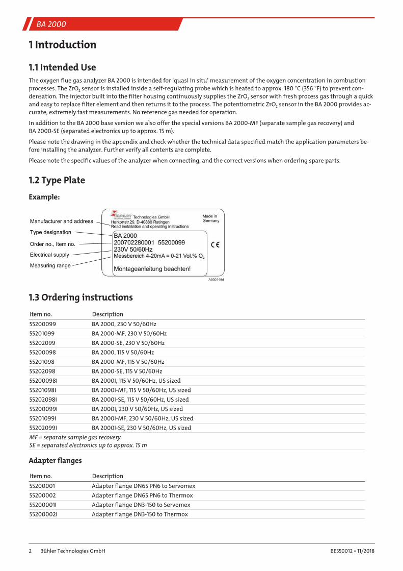
1.2 Type Plate
Example:
Manufacturer and address
Type designation
Electrical supply
Measuring range
Order no., Item no.
1.3 Ordering instructions
Item no. Description55200099 BA 2000, 230 V 50/60Hz55201099 BA 2000-MF, 230 V 50/60Hz55202099 BA 2000-SE, 230 V 50/60Hz55200098 BA 2000, 115 V 50/60Hz55201098 BA 2000-MF, 115 V 50/60Hz55202098 BA 2000-SE, 115 V 50/60Hz55200098I BA 2000I, 115 V 50/60Hz, US sized55201098I BA 2000I-MF, 115 V 50/60Hz, US sized55202098I BA 2000I-SE, 115 V 50/60Hz, US sized55200099I BA 2000I, 230 V 50/60Hz, US sized55201099I BA 2000I-MF, 230 V 50/60Hz, US sized55202099I BA 2000I-SE, 230 V 50/60Hz, US sizedMF = separate sample gas recoverySE = separated electronics up to approx. 15 m
Adapter flanges
Item no. Description55200001 Adapter flange DN65 PN6 to Servomex55200002 Adapter flange DN65 PN6 to Thermox55200001I Adapter flange DN3-150 to Servomex55200002I Adapter flange DN3-150 to Thermox
2 Bühler Technologies GmbH BE550012 ◦ 11/2018
BA 2000
1.4 Scope of delivery– 1x oxygen flue gas analyzer
– 1x flange seal and screws
– 1x product documentation
The analyzer may come with different factory installed accessories depending on the order:
– outlet filter (required for operation!)
– sampling tube or inlet filter
– sampling tube/inlet filter extension
– adapter flange
– pump (if instrument air not available)
– digital display
This accessory, as well as separate accessories included, are listed as separate line items in the order.
3Bühler Technologies GmbHBE550012 ◦ 11/2018
BA 2000
2 Safety instructions
2.1 Important noticesPlease particularly note the following analyser instructions:
– Always transport the equipment diligently and carefully. Strong impact and shock may damage the measuring cells in theanalyser or shorten their life!
– Avoid condensation inside the equipment, as the measurement system could be damaged and become defective. If thesample gas contains condensable components, the analyser must have suitable upstream sample gas conditioning. Our cus-tomer service will gladly help you select a system.
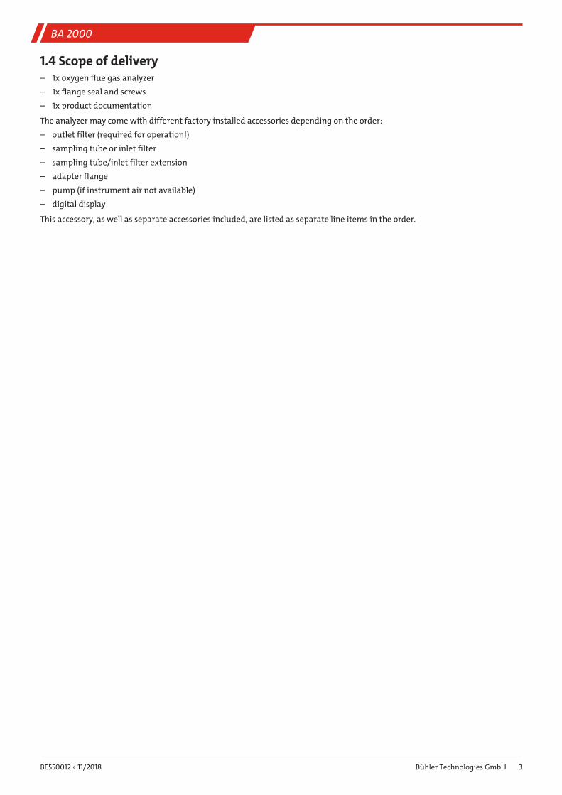
Signal words for warnings
DANGERSignal word for an imminent danger with high risk, resulting in severe injuries or death if not avoided.
WARNINGSignal word for a hazardous situation with medium risk, possibly resulting in severe injuries or death if notavoided.
CAUTIONSignal word for a hazardous situation with low risk, resulting in damaged to the device or the property orminor or medium injuries if not avoided.
NOTICESignal word for important information to the product.
Warning signsIn this manual, the following warning signs are used:
Warning against hazardous situations General notice
Warning against electrical voltage Disconnect from mains
Warning against respiration of toxic gases Wear respirator
Warning against acid and corrosive substances Wear eye/face protection
Warning against potentially explosive atmospheres Wear protection gloves
Warning against hot surface
2.2 General hazard warningsThe equipment must be installed by a professional familiar with the safety requirements and risks.
Be sure to observe the safety regulations and generally applicable rules of technology relevant for the installation site. Preventmalfunctions and avoid personal injuries and property damage.
The operator of the system must ensure:– Safety notices and operating instructions are available and observed,
– The respective national accident prevention regulations are observed,
– The permissible data and operational conditions are maintained,
– Safety guards are used and mandatory maintenance is performed,
– Legal regulations are observed during disposal.
4 Bühler Technologies GmbH BE550012 ◦ 11/2018
BA 2000
Maintenance, RepairPlease note during maintenance and repairs:
– Repairs to the unit must be performed by Bühler authorised personnel.
– Only perform conversion-, maintenance or installation work described in these operating and installation instructions.
– Always use genuine spare parts.
Always observe the applicable safety and operating regulations in the respective country of use when performing any type ofmaintenance.
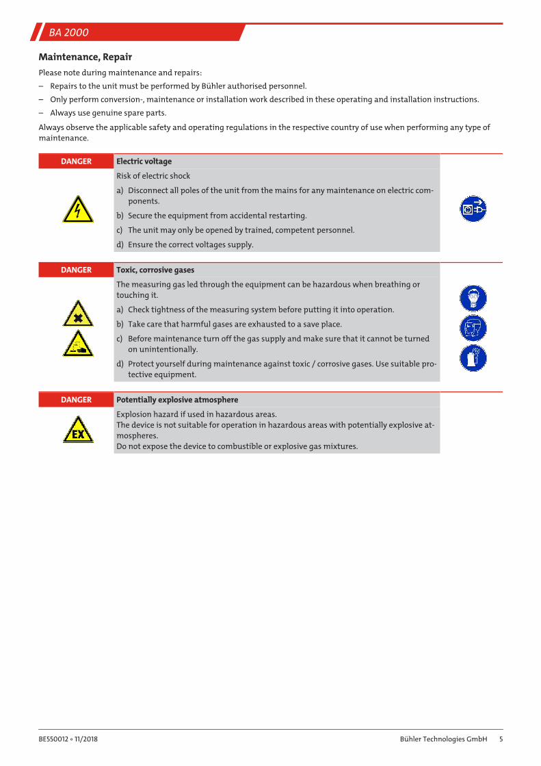
DANGER Electric voltage
Risk of electric shock
a) Disconnect all poles of the unit from the mains for any maintenance on electric com-ponents.
b) Secure the equipment from accidental restarting.
c) The unit may only be opened by trained, competent personnel.
d) Ensure the correct voltages supply.
DANGER Toxic, corrosive gases
The measuring gas led through the equipment can be hazardous when breathing ortouching it.
a) Check tightness of the measuring system before putting it into operation.
b) Take care that harmful gases are exhausted to a save place.
c) Before maintenance turn off the gas supply and make sure that it cannot be turnedon unintentionally.
d) Protect yourself during maintenance against toxic / corrosive gases. Use suitable pro-tective equipment.
DANGER Potentially explosive atmosphere
Explosion hazard if used in hazardous areas.The device is not suitable for operation in hazardous areas with potentially explosive at-mospheres.Do not expose the device to combustible or explosive gas mixtures.
5Bühler Technologies GmbHBE550012 ◦ 11/2018

BA 2000
3 Transport and storageTransportThis device is sensitive to shock and vibration. Therefore, where possible, transport in the original packaging or large, sturdypackaging with at least 3 layers of cardboard, plastic or aluminium sheet. Line the inside of the packaging with padding at least10 cm thick on all sides.
The device should be marked fragile for shipping.
StorageDuring extended periods of non-use, protect the analyzer against moisture and heat.
The analyzer must be stored in a covered, dry location free from vibration and dust, at a temperature between –20 °C and +60 °C(-4 °F to 140 °F).
6 Bühler Technologies GmbH BE550012 ◦ 11/2018
BA 2000
4 Installation and connection
4.1 InstallationThe analyzer is intended for flange mounting. The installation location and position are determined by the specific applicationfactors. If necessary, the connection piece should be slightly tilted toward the centre of the channel. The installation site shouldbe protected from the weather.
In addition, adequate and safe access for installation and future maintenance work should be provided. Particularly note theuninstalled size of the sampling tube!
The outlet filter, inlet filter (optional) and the sampling tube (optional) are included in the package and must be installed priorto use.
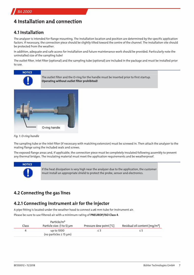
NOTICE
The outlet filter and the O-ring for the handle must be inserted prior to first startup.Operating without outlet filter prohibited!
O-ring handle
Fig. 1: O-ring handle
The sampling tube or the inlet filter (if necessary with matching extension) must be screwed in. Then attach the analyzer to themating flange using the included seals and screws.
The exposed flange areas and, if applicable, the connection piece must be completely insulated following assembly to preventany thermal bridges. The insulating material must meet the application requirements and be weatherproof.
NOTICE
If the heat dissipation is very high near the analyzer due to the application, the customermust install an appropriate shield to protect the probe, sensor and electronics.
4.2 Connecting the gas lines
4.2.1 Connecting instrument air for the injectorA pipe fitting is located under the weather hood to connect a ø6 mm tube for instrument air.
Please be sure to use filtered air with a minimum rating of PNEUROP/ISO Class 4.
ClassParticle/m³
Particle size: (1 to 5) μm Pressure dew point [°C] Residual oil content [mg/m³]4 up to 1000
(no particles ≥ 15 μm)≤ 3 ≤ 5
7Bühler Technologies GmbHBE550012 ◦ 11/2018
BA 2000
4.2.2 Required instrument air pressureThe response time of the analyzer varies by the pressure of the instrument air used for the injector. The attached data sheet con-tains diagrams which show the t90 times based on the volume flow and instrument air pressure.
As seen in the diagrams, as the instrument air pressure rises (or the volume flow increases, respectively) the response time t90 ofthe analyzer becomes faster.
However, there are some drawbacks to a fast response time:
– increased wear on the ZrO2 sensor (sample gas is taken in via the sensor)
– rising operating cost due to high usage of compressed air
– risk of sample gas taken in and recovered sample gas/instrument air mixture mixing
We therefore recommend a pressure setting of max. 0.5 bar (7.25 psi) for instrument air (measured with injector running).
4.2.3 Operating the injector with a pumpWhen operating the injector with a pump instead of instrument air, the air taken in by the pump must meet the same require-ments as instrument air.
We again recommend a pressure setting of max. 0.5 bar (7.25 psi) on the pressure end of the pump (measured with injector run-ning).
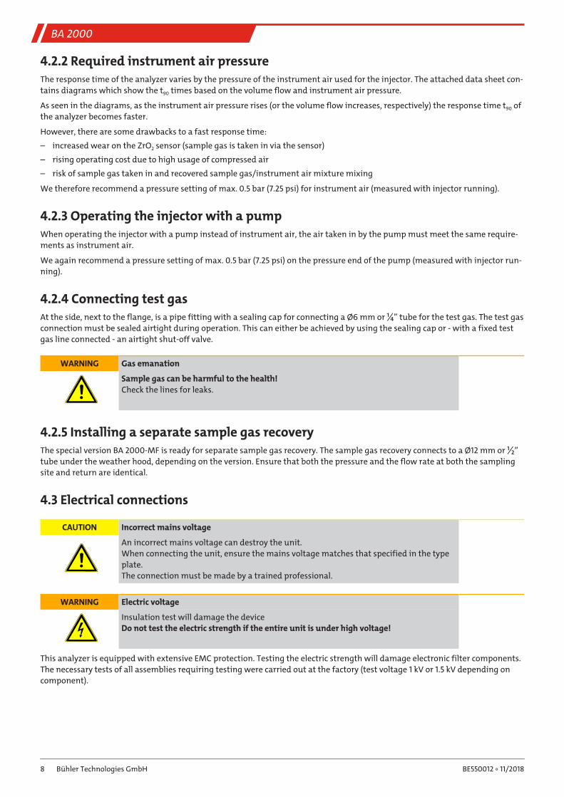
4.2.4 Connecting test gasAt the side, next to the flange, is a pipe fitting with a sealing cap for connecting a Ø6 mm or ¼” tube for the test gas. The test gasconnection must be sealed airtight during operation. This can either be achieved by using the sealing cap or - with a fixed testgas line connected - an airtight shut-off valve.
WARNING Gas emanation
Sample gas can be harmful to the health!Check the lines for leaks.
4.2.5 Installing a separate sample gas recoveryThe special version BA 2000-MF is ready for separate sample gas recovery. The sample gas recovery connects to a Ø12 mm or ½”tube under the weather hood, depending on the version. Ensure that both the pressure and the flow rate at both the samplingsite and return are identical.
4.3 Electrical connections
CAUTION Incorrect mains voltage
An incorrect mains voltage can destroy the unit.When connecting the unit, ensure the mains voltage matches that specified in the typeplate.The connection must be made by a trained professional.
WARNING Electric voltage
Insulation test will damage the deviceDo not test the electric strength if the entire unit is under high voltage!
This analyzer is equipped with extensive EMC protection. Testing the electric strength will damage electronic filter components.The necessary tests of all assemblies requiring testing were carried out at the factory (test voltage 1 kV or 1.5 kV depending oncomponent).
8 Bühler Technologies GmbH BE550012 ◦ 11/2018

BA 2000
4.3.1 ProbeThe probe contains self-regulating heating elements. It comes with two cubic plugs per EN 175301-803. One plug is for the powersupply, the other is the alarm output. The power supply is already connected to the electronics. Connect the alarm output perthe terminal diagram (see appendix). The plugs are configured so they cannot be reversed. For safety reasons this configurationmust not be modified.
4.3.2 ZrO2 sensorThe sensor comes with a 5-pin M12 connector and is already connected to the electronics.
4.3.3 Power supply and outputsInside the electronics housing is a terminal block for connecting the mains supply, the alarm output, and the mA signal. The con-nection to the included terminal blocks is shown in the connection diagram in the appendix. The plugs can be removed fromtheir sockets for this purpose and reinserted after wiring. The pin assignment is also printed onto the board.
9Bühler Technologies GmbHBE550012 ◦ 11/2018
BA 2000
5 Initial operation
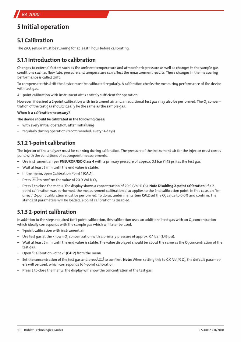
5.1 CalibrationThe ZrO2 sensor must be running for at least 1 hour before calibrating.
5.1.1 Introduction to calibrationChanges to external factors such as the ambient temperature and atmospheric pressure as well as changes in the sample gasconditions such as flow fate, pressure and temperature can affect the measurement results. These changes in the measuringperformance is called drift.
To compensate this drift the device must be calibrated regularly. A calibration checks the measuring performance of the devicewith test gas.
A 1-point calibration with instrument air is entirely sufficient for operation.
However, if desired a 2-point calibration with instrument air and an additional test gas may also be performed. The O2 concen-tration of the test gas should ideally be the same as the sample gas.
When is a calibration necessary?
The device should be calibrated in the following cases:
– with every initial operation, after initialising
– regularly during operation (recommended: every 14 days)
5.1.2 1-point calibrationThe injector of the analyzer must be running during calibration. The pressure of the instrument air for the injector must corres-pond with the conditions of subsequent measurements.
– Use instrument air per PNEUROP/ISO Class 4 with a primary pressure of approx. 0.1 bar (1.45 psi) as the test gas.
– Wait at least 5 min until the end value is stable.
– In the menu, open Calibration Point 1 (CAL1).
– Press to confirm the value of 20.9 Vol.% O2.
– Press E to close the menu. The display shows a concentration of 20.9 (Vol.% O2). Note Disabling 2-point calibration: If a 2-point calibration was performed, the measurement calibration also applies to the 2nd calibration point. In this case, an “in-direct” 2-point calibration must be performed. To do so, under menu item CAL2 set the O2 value to 0.0% and confirm. Thestandard parameters will be loaded, 2-point calibration is disabled.
5.1.3 2-point calibrationIn addition to the steps required for 1-point calibration, this calibration uses an additional test gas with an O2 concentrationwhich ideally corresponds with the sample gas which will later be used.
– 1-point calibration with instrument air
– Use test gas at the known O2 concentration with a primary pressure of approx. 0.1 bar (1.45 psi).
– Wait at least 5 min until the end value is stable. The value displayed should be about the same as the O2 concentration of thetest gas.
– Open “Calibration Point 2” (CAL2) from the menu.
– Set the concentration of the test gas and press to confirm. Note: When setting this to 0.0 Vol.% O2, the default paramet-ers will be used, which corresponds to 1-point calibration.
– Press E to close the menu. The display will show the concentration of the test gas.
10 Bühler Technologies GmbH BE550012 ◦ 11/2018
BA 2000
6 Operation and Control
NOTICE
The device must not be operated beyond its specifications.
6.1 ZrO2 sensor function
CAUTION Hot surface
Risk of burnsWith the sensor installed, the sensor tube can be up to 650 °C (1202 °F).
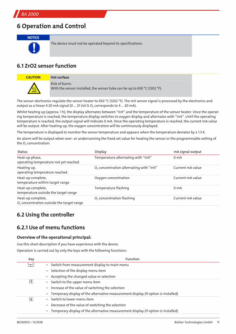
The sensor electronics regulate the sensor heater to 650 °C (1202 °F). The mV sensor signal is processed by the electronics andoutput as a linear 4 20 mA signal (0 … 21 Vol.% O2 corresponds to 4 … 20 mA).
Whilst heating up (approx. 1 h), the display alternates between “init” and the temperature of the sensor heater. Once the operat-ing temperature is reached, the temperature display switches to oxygen display and alternates with “init”. Until the operatingtemperature is reached, the output signal will indicate 0 mA. Once the operating temperature is reached, the current mA valuewill be output. After heating up, the oxygen concentration will be continuously displayed.
The temperature is displayed to monitor the sensor temperature and appears when the temperature deviates by ± 1.5 K.
An alarm will be output when over- or underrunning the fixed set value for heating the sensor or the programmable setting ofthe O2 concentration.
Status Display mA signal outputHeat-up phase,operating temperature not yet reached
Temperature alternating with “init” 0 mA
Heating up,operating temperature reached
O2 concentration alternating with “init” Current mA value
Heat-up complete,temperature within target range
Oxygen concentration Current mA value
Heat-up complete,temperature outside the target range
Temperature flashing 0 mA
Heat-up complete,O2 concentration outside the target range
O2 concentration flashing Current mA value
6.2 Using the controller
6.2.1 Use of menu functions
Overview of the operational principal:Use this short description if you have experience with the device.
Operation is carried out by only the keys with the following functions:
Key Function– Switch from measurement display to main menu
– Selection of the display menu item
– Accepting the changed value or selection– Switch to the upper menu item
– Increase of the value of switching the selection
– Temporary display of the alternative measurement display (if option is installed)– Switch to lower menu item
– Decrease of the value of switching the selection
– Temporary display of the alternative measurement display (if option is installed)
11Bühler Technologies GmbHBE550012 ◦ 11/2018
BA 2000
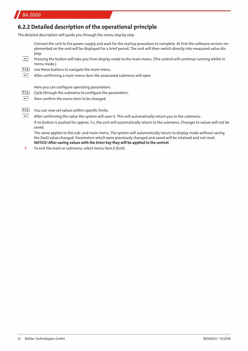
6.2.2 Detailed description of the operational principleThe detailed description will guide you through the menu step by step.
Connect the unit to the power supply and wait for the startup procedure to complete. At first the software version im-plemented on the unit will be displayed for a brief period. The unit will then switch directly into measured value dis-play.Pressing the button will take you from display mode to the main menu. (The control will continue running whilst inmenu mode.)Use these buttons to navigate the main menu.After confirming a main menu item the associated submenu will open
Here you can configure operating parameters:Cycle through the submenu to configure the parameters,then confirm the menu item to be changed.
You can now set values within specific limits.After confirming the value the system will save it. This will automatically return you to the submenu.If no button is pushed for approx. 5 s, the unit will automatically return to the submenu. Changes to values will not besaved.The same applies to the sub- and main menu. The system will automatically return to display mode without savingthe (last) value changed. Parameters which were previously changed and saved will be retained and not reset. NOTICE! After saving values with the Enter key they will be applied to the control.
E To exit the main or submenu, select menu item E (Exit).
12 Bühler Technologies GmbH BE550012 ◦ 11/2018
BA 2000
6.2.3 Menu navigation overview
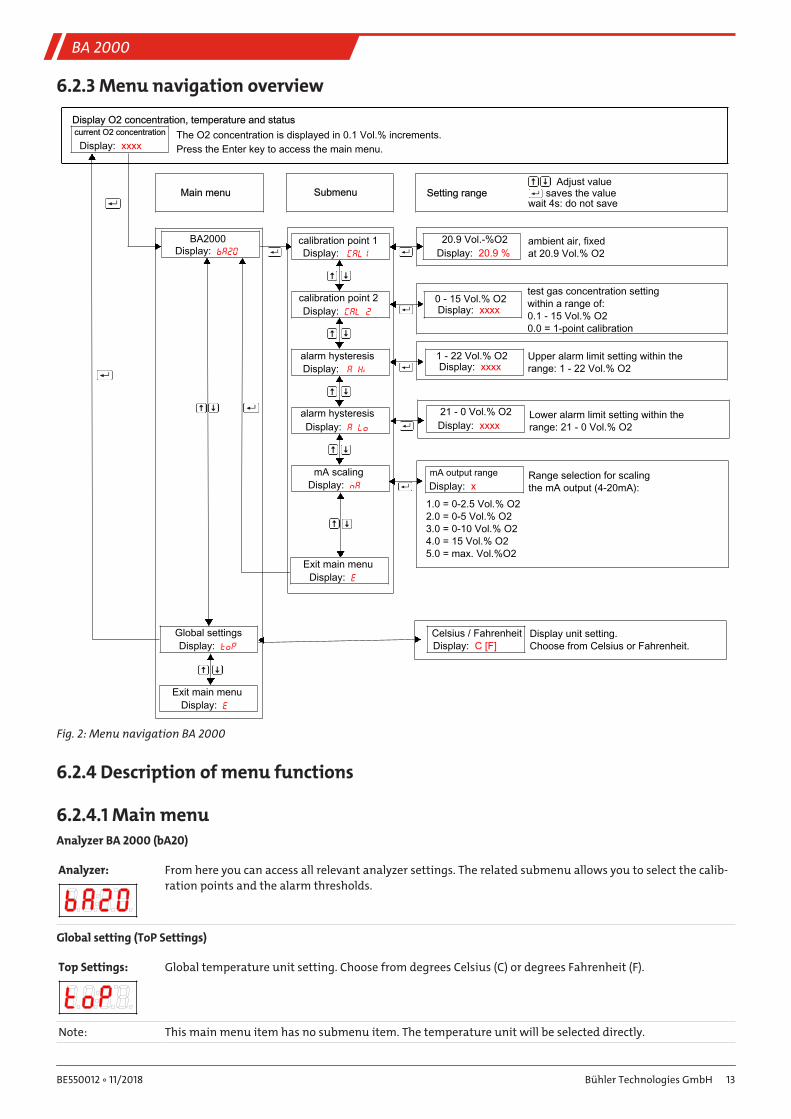
The O2 concentration is displayed in 0.1 Vol.% increments. Press the Enter key to access the main menu.
saves the valueAdjust value
wait 4s: do not save
____ ____
Display O2 concentration, temperature and status
Main menu Submenu Setting range
ambient air, fixed at 20.9 Vol.% O2
test gas concentration settingwithin a range of:0.1 - 15 Vol.% O20.0 = 1-point calibration
xxxxDisplay:current O2 concentration
bA20Display:BA2000
CAL1Display:calibration point 1
20.9 %Display:20.9 Vol.-%O2
nADisplay:mA scaling
toPDisplay:Global settings
EDisplay:Exit main menu
CAL 2Display:calibration point 2
A HiDisplay:alarm hysteresis
A LoDisplay:alarm hysteresis
EDisplay:Exit main menu
xxxxDisplay:0 - 15 Vol.% O2
Upper alarm limit setting within therange: 1 - 22 Vol.% O2xxxxDisplay:
1 - 22 Vol.% O2
Lower alarm limit setting within therange: 21 - 0 Vol.% O2xxxxDisplay:
21 - 0 Vol.% O2
Range selection for scaling the mA output (4-20mA):xDisplay:
mA output range
Display unit setting.Choose from Celsius or Fahrenheit.C [F]Display:
Celsius / Fahrenheit
1.0 = 0-2.5 Vol.% O22.0 = 0-5 Vol.% O23.0 = 0-10 Vol.% O24.0 = 15 Vol.% O25.0 = max. Vol.%O2
Fig. 2: Menu navigation BA 2000
6.2.4 Description of menu functions
6.2.4.1 Main menuAnalyzer BA 2000 (bA20)
Analyzer: From here you can access all relevant analyzer settings. The related submenu allows you to select the calib-ration points and the alarm thresholds.
Global setting (ToP Settings)
Top Settings: Global temperature unit setting. Choose from degrees Celsius (C) or degrees Fahrenheit (F).
Note: This main menu item has no submenu item. The temperature unit will be selected directly.
13Bühler Technologies GmbHBE550012 ◦ 11/2018
BA 2000
Exit Main Menu
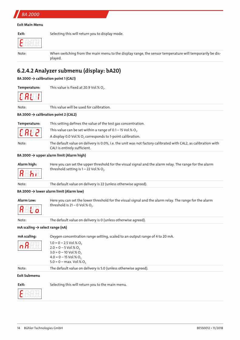
Exit: Selecting this will return you to display mode.
Note: When switching from the main menu to the display range, the sensor temperature will temporarily be dis-played.
6.2.4.2 Analyzer submenu (display: bA20)BA 2000 → calibration point 1 (CAL1)
Temperature: This value is fixed at 20.9 Vol.% O2.
Note: This value will be used for calibration.
BA 2000 → calibration point 2 (CAL2)
Temperature: This setting defines the value of the test gas concentration.
This value can be set within a range of 0.1 – 15 Vol.% O2.
A display 0.0 Vol.% O2 corresponds to 1-point calibration.
Note: The default value on delivery is 0.0%, i.e. the unit was not factory calibrated with CAL2, as calibration withCAL1 is entirely sufficient.
BA 2000 → upper alarm limit (Alarm high)
Alarm high: Here you can set the upper threshold for the visual signal and the alarm relay. The range for the alarmthreshold setting is 1 – 22 Vol.% O2.
Note: The default value on delivery is 22 (unless otherwise agreed).
BA 2000 → lower alarm limit (Alarm low)
Alarm Low: Here you can set the lower threshold for the visual signal and the alarm relay. The range for the alarmthreshold is 21 – 0 Vol.% O2.
Note: The default value on delivery is 0 (unless otherwise agreed).
mA scaling → select range (nA)
mA scaling: Oxygen concentration range setting, scaled to an output range of 4 to 20 mA.
1.0 = 0 – 2.5 Vol.% O2
2.0 = 0 – 5 Vol.% O2,
3.0 = 0 – 10 Vol.% O2
4.0 = 0 – 15 Vol.% O2,
5.0 = 0 – max. Vol.% O2
Note: The default value on delivery is 5.0 (unless otherwise agreed).
Exit Submenu
Exit: Selecting this will return you to the main menu.
14 Bühler Technologies GmbH BE550012 ◦ 11/2018
BA 2000
7 Maintenance and repair
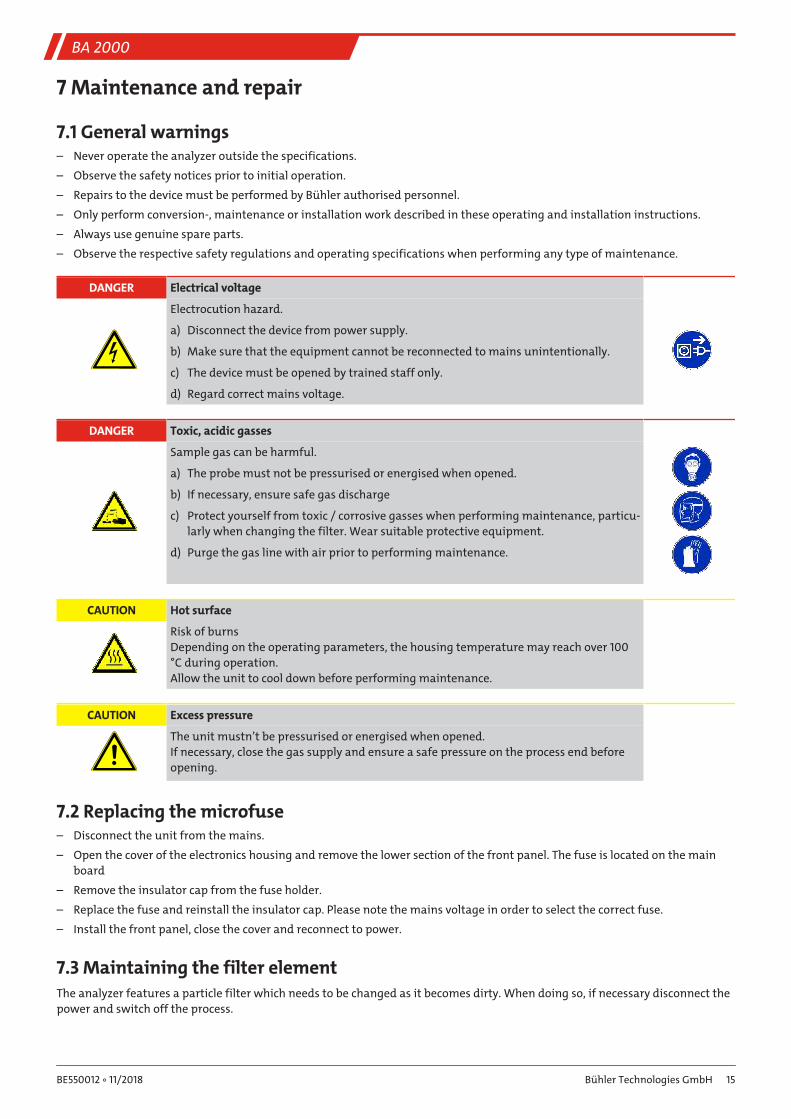
7.1 General warnings– Never operate the analyzer outside the specifications.
– Observe the safety notices prior to initial operation.
– Repairs to the device must be performed by Bühler authorised personnel.
– Only perform conversion-, maintenance or installation work described in these operating and installation instructions.
– Always use genuine spare parts.
– Observe the respective safety regulations and operating specifications when performing any type of maintenance.
DANGER Electrical voltage
Electrocution hazard.
a) Disconnect the device from power supply.
b) Make sure that the equipment cannot be reconnected to mains unintentionally.
c) The device must be opened by trained staff only.
d) Regard correct mains voltage.
DANGER Toxic, acidic gasses
Sample gas can be harmful.
a) The probe must not be pressurised or energised when opened.
b) If necessary, ensure safe gas discharge
c) Protect yourself from toxic / corrosive gasses when performing maintenance, particu-larly when changing the filter. Wear suitable protective equipment.
d) Purge the gas line with air prior to performing maintenance.
CAUTION Hot surface
Risk of burnsDepending on the operating parameters, the housing temperature may reach over 100°C during operation.Allow the unit to cool down before performing maintenance.
CAUTION Excess pressure
The unit mustn’t be pressurised or energised when opened.If necessary, close the gas supply and ensure a safe pressure on the process end beforeopening.
7.2 Replacing the microfuse– Disconnect the unit from the mains.
– Open the cover of the electronics housing and remove the lower section of the front panel. The fuse is located on the mainboard
– Remove the insulator cap from the fuse holder.
– Replace the fuse and reinstall the insulator cap. Please note the mains voltage in order to select the correct fuse.
– Install the front panel, close the cover and reconnect to power.
7.3 Maintaining the filter elementThe analyzer features a particle filter which needs to be changed as it becomes dirty. When doing so, if necessary disconnect thepower and switch off the process.
15Bühler Technologies GmbHBE550012 ◦ 11/2018
BA 2000
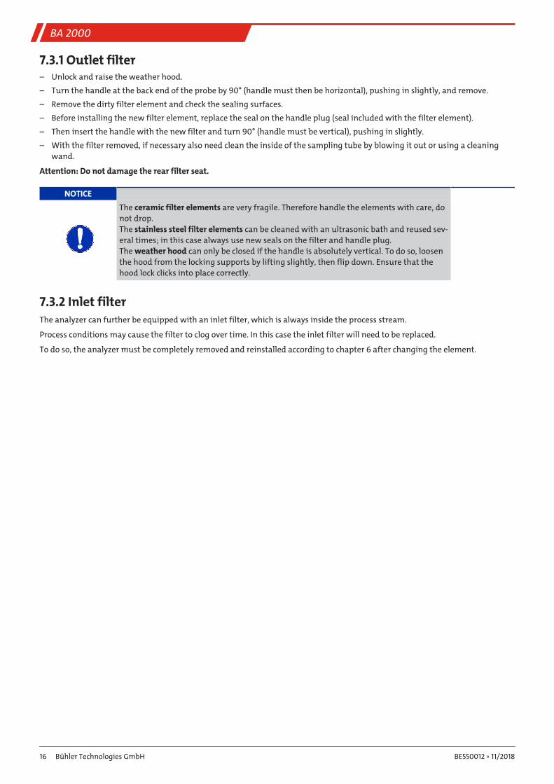
7.3.1 Outlet filter– Unlock and raise the weather hood.
– Turn the handle at the back end of the probe by 90° (handle must then be horizontal), pushing in slightly, and remove.
– Remove the dirty filter element and check the sealing surfaces.
– Before installing the new filter element, replace the seal on the handle plug (seal included with the filter element).
– Then insert the handle with the new filter and turn 90° (handle must be vertical), pushing in slightly.
– With the filter removed, if necessary also need clean the inside of the sampling tube by blowing it out or using a cleaningwand.
Attention: Do not damage the rear filter seat.
NOTICE
The ceramic filter elements are very fragile. Therefore handle the elements with care, donot drop.The stainless steel filter elements can be cleaned with an ultrasonic bath and reused sev-eral times; in this case always use new seals on the filter and handle plug.The weather hood can only be closed if the handle is absolutely vertical. To do so, loosenthe hood from the locking supports by lifting slightly, then flip down. Ensure that thehood lock clicks into place correctly.
7.3.2 Inlet filterThe analyzer can further be equipped with an inlet filter, which is always inside the process stream.
Process conditions may cause the filter to clog over time. In this case the inlet filter will need to be replaced.
To do so, the analyzer must be completely removed and reinstalled according to chapter 6 after changing the element.
16 Bühler Technologies GmbH BE550012 ◦ 11/2018
BA 2000
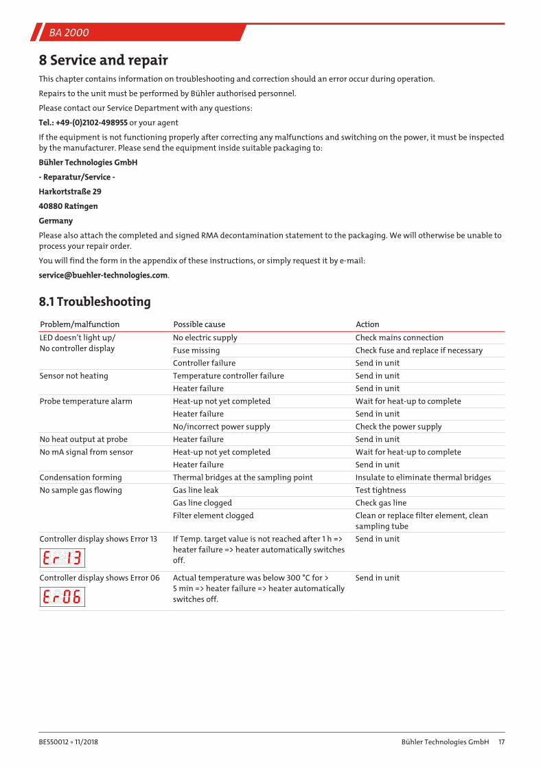
8 Service and repairThis chapter contains information on troubleshooting and correction should an error occur during operation.
Repairs to the unit must be performed by Bühler authorised personnel.
Please contact our Service Department with any questions:
Tel.: +49-(0)2102-498955 or your agent
If the equipment is not functioning properly after correcting any malfunctions and switching on the power, it must be inspectedby the manufacturer. Please send the equipment inside suitable packaging to:
Bühler Technologies GmbH
- Reparatur/Service -
Harkortstraße 29
40880 Ratingen
Germany
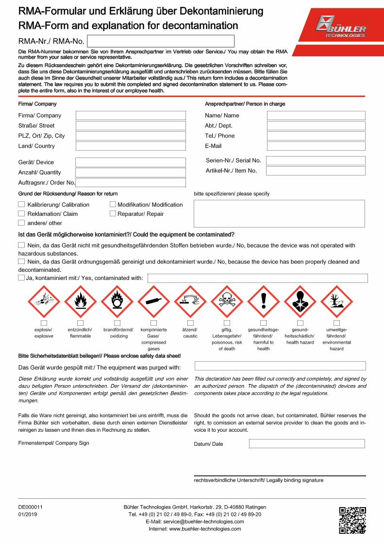
Please also attach the completed and signed RMA decontamination statement to the packaging. We will otherwise be unable toprocess your repair order.
You will find the form in the appendix of these instructions, or simply request it by e-mail:
8.1 Troubleshooting
Problem/malfunction Possible cause ActionLED doesn’t light up/No controller display
No electric supply Check mains connectionFuse missing Check fuse and replace if necessaryController failure Send in unit
Sensor not heating Temperature controller failure Send in unitHeater failure Send in unit
Probe temperature alarm Heat-up not yet completed Wait for heat-up to completeHeater failure Send in unitNo/incorrect power supply Check the power supply
No heat output at probe Heater failure Send in unitNo mA signal from sensor Heat-up not yet completed Wait for heat-up to complete
Heater failure Send in unitCondensation forming Thermal bridges at the sampling point Insulate to eliminate thermal bridgesNo sample gas flowing Gas line leak Test tightness
Gas line clogged Check gas lineFilter element clogged Clean or replace filter element, clean
sampling tubeController display shows Error 13 If Temp. target value is not reached after 1 h =>
heater failure => heater automatically switchesoff.
Send in unit
Controller display shows Error 06 Actual temperature was below 300 °C for > 5 min => heater failure => heater automaticallyswitches off.
Send in unit
17Bühler Technologies GmbHBE550012 ◦ 11/2018
BA 2000
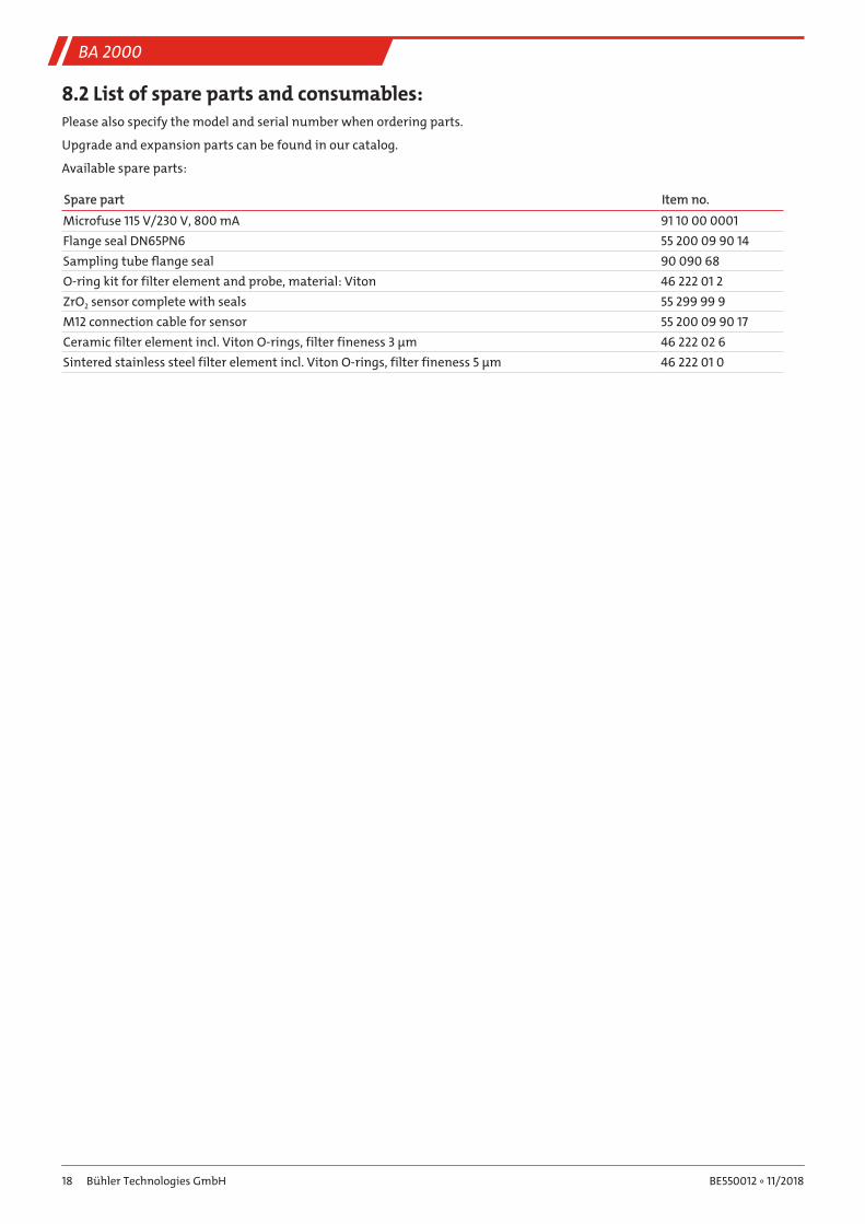
8.2 List of spare parts and consumables:Please also specify the model and serial number when ordering parts.
Upgrade and expansion parts can be found in our catalog.
Available spare parts:
Spare part Item no.Microfuse 115 V/230 V, 800 mA 91 10 00 0001Flange seal DN65PN6 55 200 09 90 14Sampling tube flange seal 90 090 68O-ring kit for filter element and probe, material: Viton 46 222 01 2ZrO2 sensor complete with seals 55 299 99 9M12 connection cable for sensor 55 200 09 90 17Ceramic filter element incl. Viton O-rings, filter fineness 3 µm 46 222 02 6Sintered stainless steel filter element incl. Viton O-rings, filter fineness 5 µm 46 222 01 0
18 Bühler Technologies GmbH BE550012 ◦ 11/2018

BA 2000
9 DisposalDispose of parts so as not to endanger the health or environment. Follow the laws in the country of use for disposing of elec-tronic components and devices during disposal.
19Bühler Technologies GmbHBE550012 ◦ 11/2018
BA 2000
10 Appendix
10.1 Technical Data
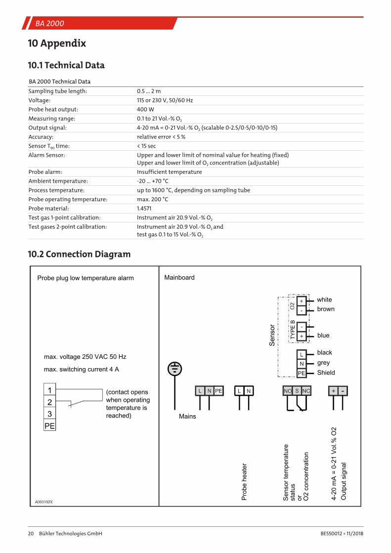
BA 2000 Technical DataSampling tube length: 0.5 ... 2 mVoltage: 115 or 230 V, 50/60 HzProbe heat output: 400 WMeasuring range: 0.1 to 21 Vol.-% O2
Output signal: 4-20 mA = 0-21 Vol.-% O2 (scalable 0-2.5/0-5/0-10/0-15)Accuracy: relative error < 5 %Sensor T90 time: < 15 secAlarm Sensor: Upper and lower limit of nominal value for heating (fixed)
Upper and lower limit of O2 concentration (adjustable)Probe alarm: Insufficient temperatureAmbient temperature: -20 … +70 °CProcess temperature: up to 1600 °C, depending on sampling tubeProbe operating temperature: max. 200 °CProbe material: 1.4571Test gas 1-point calibration: Instrument air 20.9 Vol.-% O2
Test gases 2-point calibration: Instrument air 20.9 Vol.-% O2 andtest gas 0.1 to 15 Vol.-% O2
10.2 Connection Diagram
Probe plug low temperature alarm Mainboard
whitebrown
blue
blackgreyShield
max. voltage 250 VAC 50 Hz
max. switching current 4 A
(contact openswhen operatingtemperature isreached) Mains
Prob
e he
ater
4-20
mA
= 0-
21 V
ol.%
O2
Out
put s
igna
l
Sens
or
TYPE
BSe
nsor
tem
pera
ture
st
atus
or
O2
conc
entra
tion
20 Bühler Technologies GmbH BE550012 ◦ 11/2018
BA 2000
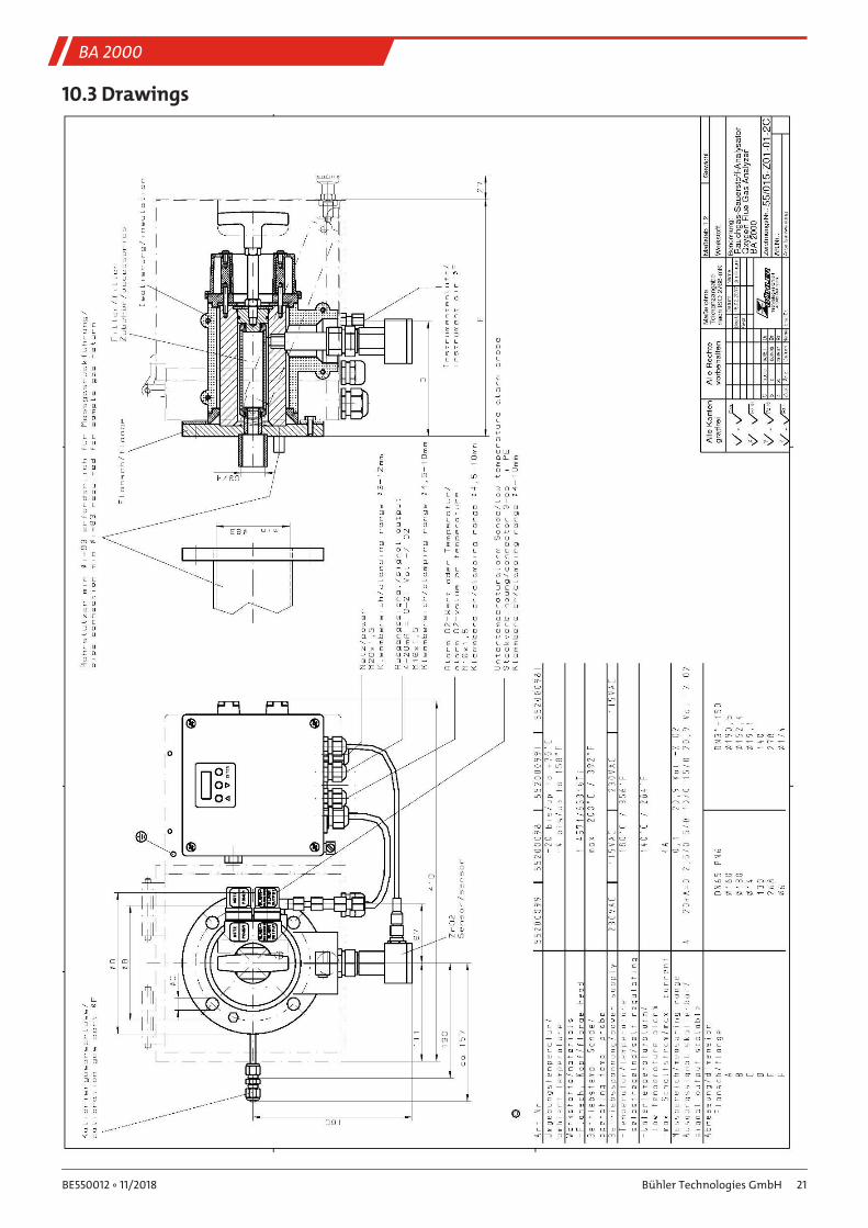
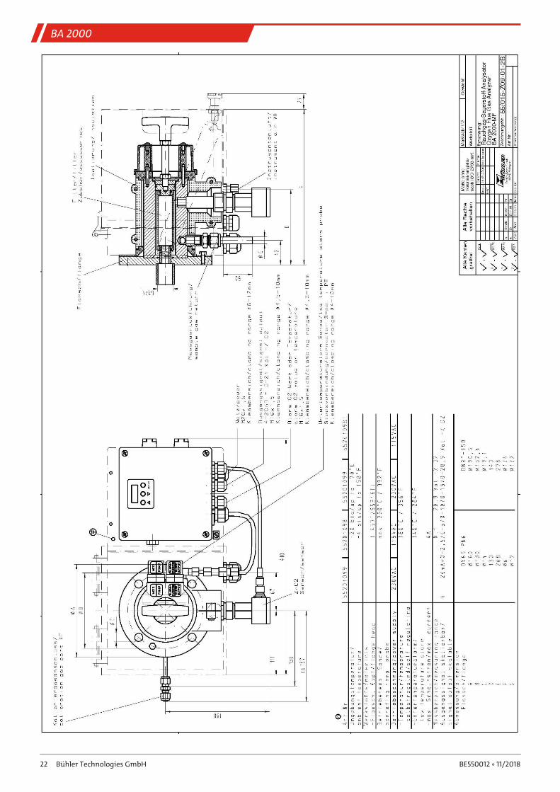
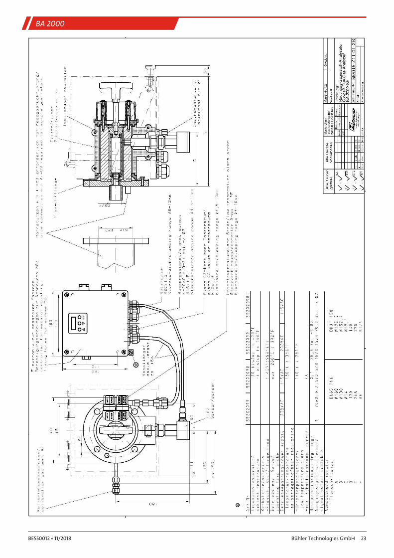
10.3 Drawings
21Bühler Technologies GmbHBE550012 ◦ 11/2018
BA 2000
22 Bühler Technologies GmbH BE550012 ◦ 11/2018
BA 2000
23Bühler Technologies GmbHBE550012 ◦ 11/2018

BA 2000
11 Attached documents– Declaration of Conformity KX550010
– RMA - Decontamination Statement
24 Bühler Technologies GmbH BE550012 ◦ 11/2018
Related Documents