Oxide films in laser additive manufactured Inconel 718 Y.N. Zhang a,b , X. Cao a,⇑ , P. Wanjara a , M. Medraj b a National Research Council Canada – Aerospace, 5145 Decelles Avenue, Montreal, Quebec H3T 2B2, Canada b Department of Mechanical Engineering, Concordia University, 1455 de Maisonneuve Blvd. W., Montreal, Quebec H3G 1M8, Canada Received 14 June 2013; received in revised form 22 July 2013; accepted 23 July 2013 Available online 15 August 2013 Abstract A continuous-wave 5 kW fiber laser welding system was used in conduction mode to deposit Inconel Ò alloy 718 (IN718) by employing filler wire on as-serviced IN718 parent material (PM) substrates. The direct laser deposited (DLD) coupons and as-serviced IN718 PM were then evaluated through tensile testing. To understand the failure mechanisms, the tensile fracture surfaces of the as-serviced IN718 PM, DLD and DLD-PM samples were analyzed using scanning electron microscopy. The fracture surfaces revealed the presence of both Al 2 O 3 and Cr 2 O 3 films, although the latter was reasoned to be the main oxide in IN718. Both the experimental observations and ther- modynamic analysis indicated that oxidation of some alloying elements in IN718 cannot be completely avoided during manufacturing, whether in the liquid state under vacuum (for casting, the electron beam melting, welding and/or deposition) or with inert gas protection (for welding or laser deposition). The exposed surface of the oxide film on the fracture surface has poor wetting with the metal and thus can constitute a lack of bonding or a crack with either the metal and/or another non-wetted side of the oxide film. On the other hand, the wetted face of the oxide film has good atom-to-atom contact with the metal and may nucleate some intermetallic compounds, such as Laves, Ni 3 Nb-d, Nb-rich MC and c 0 compounds. The potential of their nucleation on Cr 2 O 3 was assessed using planar disregistry. Coherent planes were found between these intermetallics and Cr 2 O 3 . Ó 2013 Crown Copyright and Acta Materialia Inc. Published by Elsevier Ltd. All rights reserved. Keywords: Laser deposition; Superalloy; Oxide; Intermetallic compound; Additive manufacturing 1. Introduction Inconel Ò 718 (IN718) is a precipitation-hardenable Ni– Fe-based superalloy widely used in gas turbines, rocket motors, spacecraft, nuclear reactors, pumps and tooling due to its excellent combination of corrosion and oxidation resistance, tensile and creep properties, and good weldabil- ity due to microstructural stability and resistance to strain- age cracking at elevated temperatures up to 650 °C [1–3]. As the major strengthening mechanism of IN718, age- hardening or strengthening is mainly attributed to the pre- cipitation of the nanoscale lens-like disc-shaped c 00 -Ni 3 Nb with an ordered body-centered tetragonal (bct) DO22 crys- tal structure, and the nanoscale cubic or spherically shaped coherent c 0 -Ni 3 (Ti, Al) with an ordered face-centered cubic (fcc) L12 crystal structure [4,5]. Laser additive manufacturing has become an emerging manufacturing and remanufacturing (repair) technique for aerospace materials such as IN718 [1,6–8]. To date, however, limited data on the metallurgical and mechanical properties of IN718 manufactured using a high-power con- tinuous-wave fiber laser are available to substantiate the suitability of this technology for additive manufacturing and repair of aerospace components. In our earlier research [9], the metallurgy of laser-deposited IN718 was studied. It was found that high-integrity IN718 multibead and multilayer deposits can be manufactured with no visi- ble pores, but with only some minor weld metal liquation cracking, which denoted the good potential of using fiber laser deposition technology to manufacture and repair superalloy components. To further verify the effectiveness 1359-6454/$36.00 Ó 2013 Crown Copyright and Acta Materialia Inc. Published by Elsevier Ltd. All rights reserved. http://dx.doi.org/10.1016/j.actamat.2013.07.039 ⇑ Corresponding author at: National Research Council Canada – Aerospace, 5145 Decelles Avenue, Montreal, Quebec H3T 2B2, Canada. Tel.: +1 514 283 9047. E-mail address: [email protected] (X. Cao). www.elsevier.com/locate/actamat Available online at www.sciencedirect.com ScienceDirect Acta Materialia 61 (2013) 6562–6576

Welcome message from author
This document is posted to help you gain knowledge. Please leave a comment to let me know what you think about it! Share it to your friends and learn new things together.
Transcript
Available online at www.sciencedirect.com
www.elsevier.com/locate/actamat
ScienceDirect
Acta Materialia 61 (2013) 6562–6576
Oxide films in laser additive manufactured Inconel 718
Y.N. Zhang a,b, X. Cao a,⇑, P. Wanjara a, M. Medraj b
a National Research Council Canada – Aerospace, 5145 Decelles Avenue, Montreal, Quebec H3T 2B2, Canadab Department of Mechanical Engineering, Concordia University, 1455 de Maisonneuve Blvd. W., Montreal, Quebec H3G 1M8, Canada
Received 14 June 2013; received in revised form 22 July 2013; accepted 23 July 2013Available online 15 August 2013
Abstract
A continuous-wave 5 kW fiber laser welding system was used in conduction mode to deposit Inconel� alloy 718 (IN718) by employingfiller wire on as-serviced IN718 parent material (PM) substrates. The direct laser deposited (DLD) coupons and as-serviced IN718 PMwere then evaluated through tensile testing. To understand the failure mechanisms, the tensile fracture surfaces of the as-serviced IN718PM, DLD and DLD-PM samples were analyzed using scanning electron microscopy. The fracture surfaces revealed the presence of bothAl2O3 and Cr2O3 films, although the latter was reasoned to be the main oxide in IN718. Both the experimental observations and ther-modynamic analysis indicated that oxidation of some alloying elements in IN718 cannot be completely avoided during manufacturing,whether in the liquid state under vacuum (for casting, the electron beam melting, welding and/or deposition) or with inert gas protection(for welding or laser deposition). The exposed surface of the oxide film on the fracture surface has poor wetting with the metal and thuscan constitute a lack of bonding or a crack with either the metal and/or another non-wetted side of the oxide film. On the other hand, thewetted face of the oxide film has good atom-to-atom contact with the metal and may nucleate some intermetallic compounds, such asLaves, Ni3Nb-d, Nb-rich MC and c0 compounds. The potential of their nucleation on Cr2O3 was assessed using planar disregistry.Coherent planes were found between these intermetallics and Cr2O3.� 2013 Crown Copyright and Acta Materialia Inc. Published by Elsevier Ltd. All rights reserved.
Keywords: Laser deposition; Superalloy; Oxide; Intermetallic compound; Additive manufacturing
1. Introduction
Inconel� 718 (IN718) is a precipitation-hardenable Ni–Fe-based superalloy widely used in gas turbines, rocketmotors, spacecraft, nuclear reactors, pumps and toolingdue to its excellent combination of corrosion and oxidationresistance, tensile and creep properties, and good weldabil-ity due to microstructural stability and resistance to strain-age cracking at elevated temperatures up to 650 �C [1–3].As the major strengthening mechanism of IN718, age-hardening or strengthening is mainly attributed to the pre-cipitation of the nanoscale lens-like disc-shaped c00-Ni3Nbwith an ordered body-centered tetragonal (bct) DO22 crys-
1359-6454/$36.00 � 2013 Crown Copyright and Acta Materialia Inc. Publishe
http://dx.doi.org/10.1016/j.actamat.2013.07.039
⇑ Corresponding author at: National Research Council Canada –Aerospace, 5145 Decelles Avenue, Montreal, Quebec H3T 2B2, Canada.Tel.: +1 514 283 9047.
E-mail address: [email protected] (X. Cao).
tal structure, and the nanoscale cubic or spherically shapedcoherent c0-Ni3(Ti, Al) with an ordered face-centered cubic(fcc) L12 crystal structure [4,5].
Laser additive manufacturing has become an emergingmanufacturing and remanufacturing (repair) techniquefor aerospace materials such as IN718 [1,6–8]. To date,however, limited data on the metallurgical and mechanicalproperties of IN718 manufactured using a high-power con-tinuous-wave fiber laser are available to substantiate thesuitability of this technology for additive manufacturingand repair of aerospace components. In our earlierresearch [9], the metallurgy of laser-deposited IN718 wasstudied. It was found that high-integrity IN718 multibeadand multilayer deposits can be manufactured with no visi-ble pores, but with only some minor weld metal liquationcracking, which denoted the good potential of using fiberlaser deposition technology to manufacture and repairsuperalloy components. To further verify the effectiveness
d by Elsevier Ltd. All rights reserved.

Fig. 1. Schematic diagram showing the laser additive manufacturingsetup.
Y.N. Zhang et al. / Acta Materialia 61 (2013) 6562–6576 6563
of the direct laser deposition process for the repair ofIN718 components, extensive mechanical property testing,including hardness (Vickers, Brinell and Rockwell), tensile(room and elevated temperatures), creep, time-for-rupture(smooth and notched samples), and fatigue, were systemat-ically evaluated and compared for both the direct laserdeposited (DLD) IN718 and the as-serviced IN718 parentmaterial (PM) (NB: the term “as-serviced” refers to thesamples extracted from a scraped component that hadexperienced long-term service in industry). In the presentwork, to understand the failure mechanisms, the fracturesurfaces of selected tensile samples were systematicallyexamined and analyzed using scanning electron microscopy(SEM). The attributes of commonly observed oxide filmsare dealt with in detail.
2. Experimental
The PM substrates were extracted directly from ascrapped IN718 aerospace component that had a nominalcomposition as indicated in Table 1. Although the detailsof the manufacturing process for the IN718 aerospace com-ponent were not disclosed, it may be reasonably assumedthat the alloy was processed through casting and forgingapproaches followed by a standard solutioning and agingheat treatment prior to “normal” long-term service. Hence,this condition of the IN718 PM substrates is hereafterreferred to as “as-serviced”.
Laser deposition was conducted on the as-servicedIN718 PM substrate using an IPG Photonics 5 kW contin-uous-wave solid-state Yb-fiber laser system (YLR-5000)equipped with an ABB robot. A collimation lens of150 mm, a focal lens of 250 mm and a fiber diameter of600 lm were employed to produce a nominal focusing spotdiameter of �1.0 mm. In this study, a positive defocusingdistance of +12 mm was used to obtain a laser power den-sity of �2 � 104 W cm�2. The laser head was inclined 2–3�both along the lateral side and from the vertical positiontowards the cladding direction to avoid any damage tothe equipment from reflection of the laser beam. The fiberlaser beam with a wavelength of about 1.07 lm was posi-tioned on the top surface of the deposits. To protect themolten metal during deposition, the clad zone was shieldedusing two streams of Ar gas flow. One stream of Ar at aflow rate of 30 cfh (2.36 � 10�4 m3 s�1) was directedtowards the cladding direction at an angle of 18–20� tothe deposit surface, while the other was directed oppositeto the cladding direction at a flow rate of 20 cfh(1.57 � 10�4 m3 s�1). The IN718 filler wire, supplied by
Table 1Nominal chemical composition of IN718 parent metal and filler wire (wt.%).
Ni Cr Fe Co Nb Mo
As-serviced IN718 50–55 17–21 Bal. 1.0 4.75–5.50 2.8Filler wire 52 18 19 1 5 3
Note: Individual values represent the upper limits.
Haynes International Inc., was �0.89 mm in diameterand had a nominal composition as given in Table 1. TheIN718 filler wire was axially fed from the cladding directionat an inclination angle of 30� from the top surface of thedeposit where interception with the incident laser beamoccurred. Fig. 1 schematically shows the setup of the laseradditive manufacturing system used in this study. It is note-worthy that each layer was deposited along a single clad-ding direction on the as-serviced IN718 PM substrates tomanufacture two coupon types for mechanical propertytesting: (1) DLD IN718 (i.e. 100% direct laser depositedIN718) and (2) DLD-PM (i.e. 50% DLD IN718 and 50%as-serviced IN718 PM).
After laser deposition, the DLD and DLD-PM couponswere solution treated and aged. The solution heat treat-ment was carried out in vacuum at a temperature of954 �C (1750 ± 25 �F) for 1 h in the presence of inert Argas and then cooled down (with Ar) at a minimum rateof 30 �F min�1 to a temperature of 538 �C (1000 �F) fol-lowed by rapid cooling in Ar. The aging consisted of thefollowing steps: heating up to 732 �C (1350 ± 25 �F), soak-ing for 8 h, furnace cooling under Ar to 599 �C(1110 ± 25 �F) and holding for 8 h, and finally Arquenching.
Standard tensile samples with a gauge length of16.26 mm (0.640 ± 0.005 in.) and a diameter of 4.06 mm(0.160 ± 0.003 in.) were machined in accordance withASTM-E8-04 from the as-serviced IN718 PM, DLD andDLD-PM coupons. Room-temperature tensile testing wasconducted at a strain rate of 8.3 � 10�5 s�1 before the yieldpoint and 8.3 � 10�4 s�1 after yielding using a UnitedSFM-30 system. To understand the failure mechanismsoccurring as a result of the tensile deformation, the fracture
Ti Al C Mn Si B Cu
0–3.30 0.35 0.20–0.80 0.08 0.35 0.35 0.06 0.30.9 0.5 0.05 0.35 0.35 0.009 0.1
6564 Y.N. Zhang et al. / Acta Materialia 61 (2013) 6562–6576
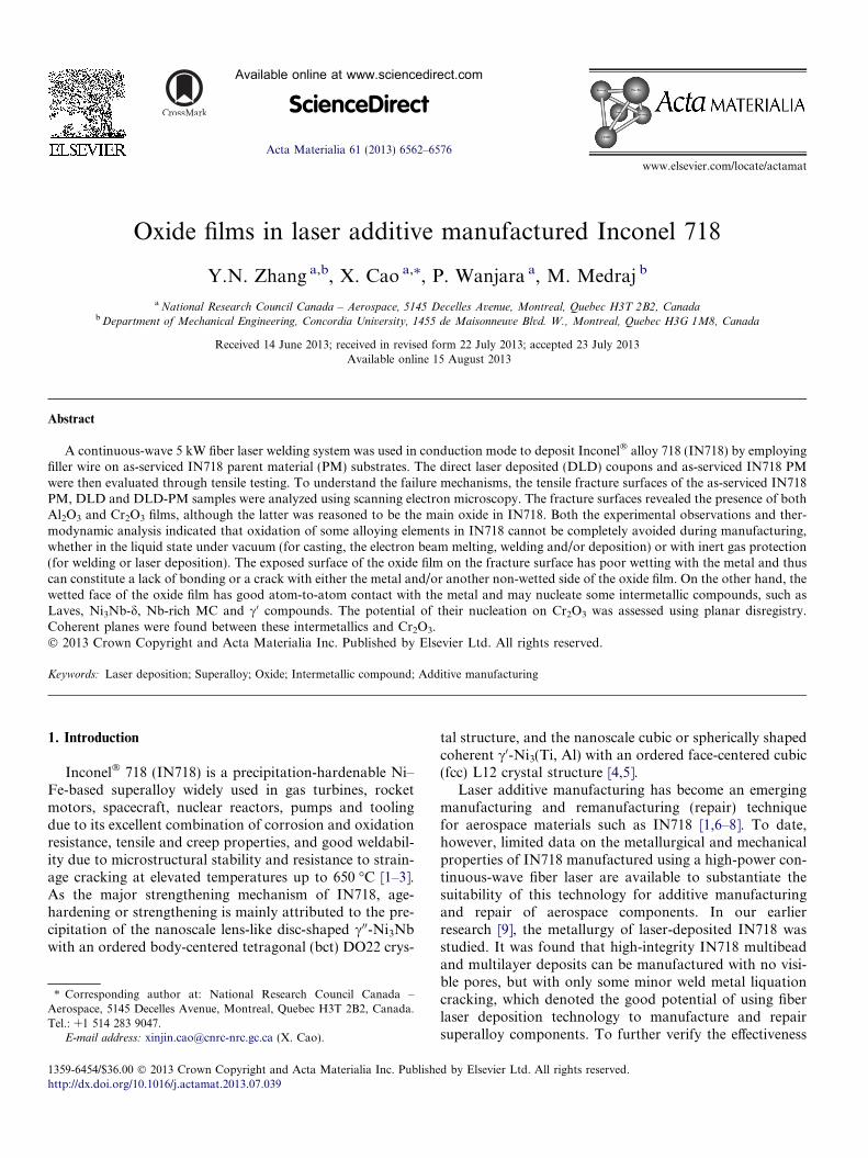
surfaces of some selected tensile samples were systemati-cally examined using secondary electron imaging (SEI)and backscattered electron imaging (BSEI) with a HitachiS-3400N scanning electron microscope. Energy-dispersiveX-ray spectroscopy (EDS) was also used to characterizethe chemical composition of the phases. The present paperreports on the detailed characteristics of the oxide films, asobserved on the fracture surfaces of the IN718 samples(DLD, PM and DLD-PM). To further confirm the pres-ence of the oxide films, two tensile samples (one each forthe PM and DLD) were manually fractured for SEMobservations. The two tensile samples were cut to approx-imately 1/3 in. in diameter using a band saw, held in a viseand then manually bent until fracture. This procedure wasperformed carefully to completely avoid any possible dam-age to the oxide films that may be present on the fracturesurfaces.
Fig. 2. SEI and BSEI of the butterfly Al2O3 bifilms on the (a and b) mating framagnification SEI and BSEI of (b) are given in (c–f).
3. Results and discussion
In this work, the fracture surfaces were taken from thetensile tested DLD, DLD-PM and as-serviced IN718 PM,as well as the manually fractured DLD and as-servicedIN718 PM tensile samples. It is noteworthy that as allthe DLD-PM tensile samples failed in the DLD section,when reference to the DLD fracture surfaces are presentedin the following sections, the samples were extracted fromeither the DLD or DLD-PM coupons.
3.1. Identification of oxide films
Fig. 2a and b displays a butterfly oxide bifilm, which issymmetrically present on the mating fracture surfaces thatwere taken from one manually fractured DLD tensile sam-ple. Fig. 2c–f shows high-magnification observations of the
cture surfaces of a DLD tensile sample that was manually fractured. High-

Fig. 3. EDS spectra from spot analyses at points (a) A and (b) B in Fig. 2e.
Table 2EDS analyses of the oxide film in Fig. 2.
Spot O Al Ti Cr Fe Ni Nb Mo Total
A 45.00 49.64 2.43 0.73 0.58 1.79 – – 100Ave� 48 ± 2 45 ± 3 1.6 ± 0.6 1.0 ± 0.2 0.9 ± 0.3 1.8 ± 0.6 0.4 ± 0.1 0.3 ± 0.1 100
Ave�: Average values of spots B, C and D in Fig. 2e.
Y.N. Zhang et al. / Acta Materialia 61 (2013) 6562–6576 6565
fracture surface given in Fig. 2b. This film appears dark inSEI mode but is gray under BSEI and has a length of�0.2 mm. Spot analyses using EDS on the film surface(Fig. 2e) exhibited significantly intensive peaks for the ele-ments Al and O (Fig. 3). Table 2 lists the compositionaldetails obtained from several EDS spot analyses performedon the film shown in Fig. 2e (NB: all compositionsobtained from SEM-EDS analyses are in wt.% unless indi-cated otherwise). Both the EDS spectrums (Fig. 3) and thespot analysis data (Table 2) suggest that this inclusion iscomposed primarily of Al and O, i.e. on average about48 wt.% O and 45 wt.% Al (corresponding to 60 at.% Oand 38 at.% Al). The chemistry of the film correspondsremarkably well to the ideal composition of Al2O3, i.e.60 at.% O and 40 at.% Al, and indicates that this bifilmhas a sufficiently large thickness to permit accurate chemi-cal compositional analysis via EDS. Therefore, this alu-mina bifilm is most likely from the filler wire that wasused to manufacture the DLD coupons; as such, this bifilmformed during primary melting of IN718, and hence is usu-ally referred to as old oxide film [10]. Its occurrence will beclarified further in the section that examines the thermody-namics of its formation.
Fig. 4 shows an oxide film on the mating fracturesurfaces of a DLD coupon that was tensile tested.
The excellent symmetry of the matrix grains is clearlyobserved on the mating fracture surfaces. Unlike thesymmetric butterfly Al2O3 bifilm shown previously inFig. 2, this oxide film is visible only on one of the frac-tured surfaces (Fig. 4a, c and e), but a typical dendriticstructure is observed on the mating surface (Fig. 4b, dand f). The size of the oxide film, �30 lm, is small.Spot analyses using EDS on the film surface revealedsignificant peaks for the elements Ni, Cr, Fe, Nb andMo (Fig. 5). Table 3 lists the compositional detailstaken from several EDS spot analyses performed onthe film surface (Fig. 4e). As compared to the c-matrix,the presence of high oxygen and chromium peaks sug-gests that this film is Cr2O3. Fig. 6 gives further evi-dence for the typical presence of Cr2O3 films in DLDIN718. Spot analysis results obtained on this film areshown in Fig. 7 and Table 3. The oxide film can beclearly distinguished from the matrix, and exhibits typi-cal cup-like depressions or dimples that occur frommicrovoid coalescence. The size of the Cr2O3 filmrevealed in Fig. 6 is up to 50 lm in length. It has beenconsidered that such oxide films present in the DLDsamples are formed during the laser additive manufac-turing process and thus termed as new oxide films[10]. Due to the use of high-purity shielding gas and

Fig. 4. SEI of the Cr2O3 film on the (a and b) mating fracture surfaces of a DLD coupon that was tensile tested. High-magnification SEI of (a) is given in(c) and (e). High-magnification SEI of (b) is given in (d) and (f).
Fig. 5. EDS spectrum from a spot analysis at point E in Fig. 4e.
6566 Y.N. Zhang et al. / Acta Materialia 61 (2013) 6562–6576
a rapid cooling rate (�971 K s�1), as experienced inlaser deposition [9], the fractional area of these oxide
films within the tensile fracture surface was observedto be very low, usually <1%.
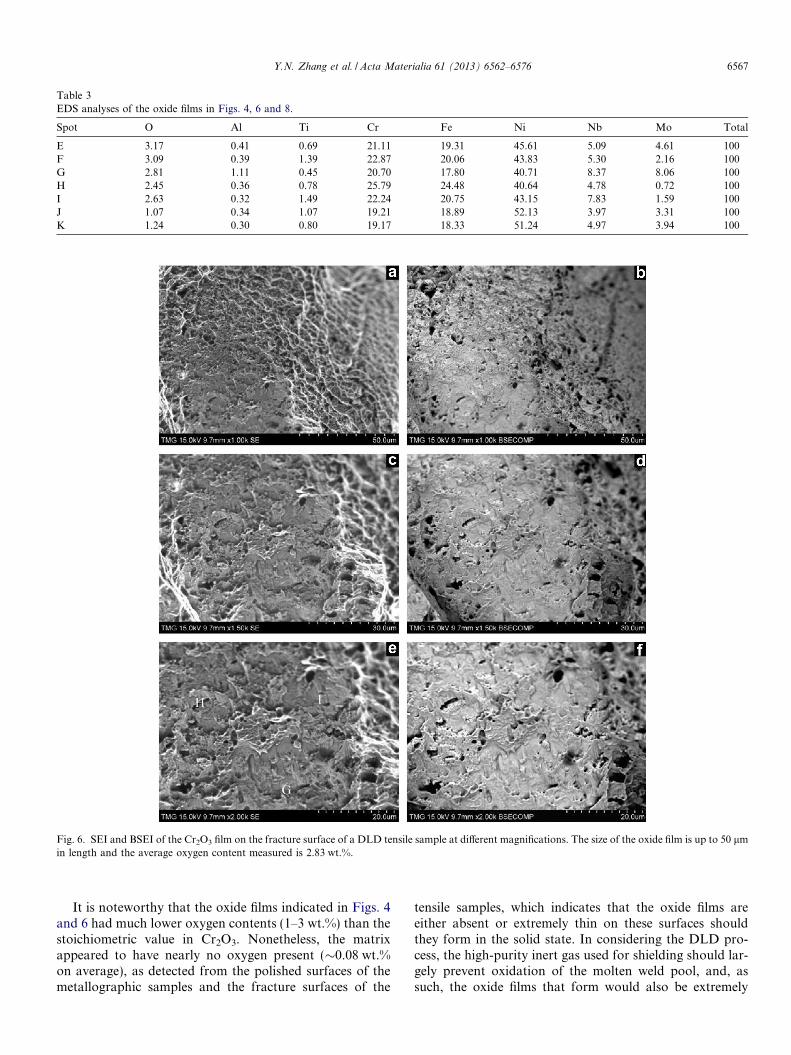
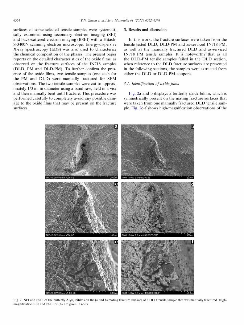
Table 3EDS analyses of the oxide films in Figs. 4, 6 and 8.
Spot O Al Ti Cr Fe Ni Nb Mo Total
E 3.17 0.41 0.69 21.11 19.31 45.61 5.09 4.61 100F 3.09 0.39 1.39 22.87 20.06 43.83 5.30 2.16 100G 2.81 1.11 0.45 20.70 17.80 40.71 8.37 8.06 100H 2.45 0.36 0.78 25.79 24.48 40.64 4.78 0.72 100I 2.63 0.32 1.49 22.24 20.75 43.15 7.83 1.59 100J 1.07 0.34 1.07 19.21 18.89 52.13 3.97 3.31 100K 1.24 0.30 0.80 19.17 18.33 51.24 4.97 3.94 100
Fig. 6. SEI and BSEI of the Cr2O3 film on the fracture surface of a DLD tensile sample at different magnifications. The size of the oxide film is up to 50 lmin length and the average oxygen content measured is 2.83 wt.%.
Y.N. Zhang et al. / Acta Materialia 61 (2013) 6562–6576 6567
It is noteworthy that the oxide films indicated in Figs. 4and 6 had much lower oxygen contents (1–3 wt.%) than thestoichiometric value in Cr2O3. Nonetheless, the matrixappeared to have nearly no oxygen present (�0.08 wt.%on average), as detected from the polished surfaces of themetallographic samples and the fracture surfaces of the
tensile samples, which indicates that the oxide films areeither absent or extremely thin on these surfaces shouldthey form in the solid state. In considering the DLD pro-cess, the high-purity inert gas used for shielding should lar-gely prevent oxidation of the molten weld pool, and, assuch, the oxide films that form would also be extremely

Fig. 7. EDS spectrum from a spot analysis at point G in Fig. 6e.
Fig. 8. SEI and BSEI of the Cr2O3 film on the tensile fracture surface of as-serviced IN718 PM at different magnifications. The size of the oxide film is upto 20 lm in length and the average oxygen content measured is 1.2 wt.%.
6568 Y.N. Zhang et al. / Acta Materialia 61 (2013) 6562–6576
thin, but are certainly thicker than those formed in thesolid state. Therefore, the spot analysis performed by usingEDS on the oxides in the DLD tensile samples to quantifythe surface chemical composition is inevitably affected bycontributions to the X-ray spectra that are derived fromthe matrix regions under the oxide film, which thenexplains the relatively low oxygen level measured (Table 3)as compared to that in stoichiometric Cr2O3. The forma-tion of the Cr2O3 films (or new oxides) will be clarifiedfrom a thermodynamics point of view later.
The presence of oxide films was also observed in the as-serviced IN718 PM, as demonstrated in Fig. 8. The fracturesurface of the as-serviced IN718 PM clearly reveals typicaldimples and the possible presence of oxide films. Spot anal-
yses using EDS on the film surfaces indicates intensivepeaks for Ni, Cr, Fe, Nb and Mo, as illustrated in Fig. 9.A small oxygen peak is also present in the EDS spectrum.Table 3 lists the compositional details from EDS spot anal-yses performed on the film shown in Fig. 8e. These resultsconfirm the presence of Cr2O3 films in the as-servicedIN718. Compared to the oxides observed in the DLD cou-pons, the oxygen and chromium contents in the as-servicedIN718 PM are even lower. For example, the average oxy-gen content is about 1.2 wt.% in the as-serviced IN718PM but roughly 2.83 wt.% in the DLD IN718. The loweroxygen and chromium contents measured for the oxide filmin the as-serviced IN718 PM may be attributed to its con-siderably thinner and smaller size (relative to that in DLD

Fig. 9. EDS spectrum from a spot analysis at points (a) J and (b) K in Fig. 8c.
Y.N. Zhang et al. / Acta Materialia 61 (2013) 6562–6576 6569
IN718); as such, a greater contribution to the X-ray spec-trum is derived from matrix region under this thinner oxidefilm, which then manifests lower oxygen and chromiumlevels. The presence of the oxide film in the as-servicedIN718 PM can be reasoned from its thermomechanicalprocessing history, as discussed in the following paragraph.
The processing route for the as-serviced IN718 PM wasmost likely casting followed by forging. In consideration ofthis thermomechanical processing history, the formation ofthe oxide films probably occurred during casting (e.g. dur-ing ingot pouring in vacuum) as observed by Campbell andhis collaborators [11,12]. In particular, they identified thatthese films in the Ni-based superalloys are, in all likelihood,aluminum and chromium oxides. Due to the extremely lowoxygen partial pressure in vacuum, the thickness of theoxide films formed during vacuum casting is extremelythin, typically a few nanometers. However, during turbu-lent pouring of Ni-based alloys, even in vacuum, the oxidefilms formed can still be entrained into the casting [11,12].Clearly, these entrained oxide films formed during turbu-lent casting undergo significant deformation during theensuing plastic deformation processing at elevated temper-atures, such as forging, rolling or extruding; and thus theseentrained oxide films may become tightly closed, partiallybroken or fragmented into particles as solid inclusions.As a consequence, it is expected that these residual oxidesare small in quantity and size. This has been clearly con-firmed by quantifying the oxide films on the fracture sur-faces of the as-serviced IN718 PM, as shown in Fig. 8,where the area per cent of the oxide film is much less than1%. For an extreme condition, it was reported that up to90% of the fracture surface of the castings can be covered
by oxide films [11,12]. In the present work, the size of theoxide film in the as-serviced IN718 PM is up to 20 lm inlength but less than 5 lm in width (Fig. 8), which is muchsmaller than that obtained in the DLD IN718 fabricatedusing filler wire addition. For the as-serviced IN718 PM,it can be postulated that the original size of the oxides inthe as-cast condition is probably larger and fragmentation,caused by plastic deformation (forging) after ingot casting,would then markedly reduce their size.
3.2. Thermodynamics of oxide formation
As shown in Table 1, Ni-based superalloy 718 has acomplex alloy chemistry, consisting mainly of Ni, Cr, Fe,Ti, Al, Nb and Mo. As indicated in the Ellingham diagram[13,14] (Fig. 10), these elements have a strong tendency tooxidize, leading to the possible formation of NiO, TiO2,FeO, Cr2O3 and Al2O3 in Ni-based superalloys. However,the Gibbs energy variations indicate that Al2O3 is the moststable oxide of the five, Cr2O3 the second, and NiO theleast. From this thermodynamic consideration, Al2O3 isexpected to be the most plausible oxide to form and existin Ni-based superalloy 718. In the present work, this is sup-ported by the finding of an old oxide that was identified asAl2O3 in the DLD sample. It was hypothesized that this oldoxide was a remnant of the IN718 filler wire that containedonly 0.5 wt.% Al. This finding is further supported by thework of Rashid and Campbell, which reported the presenceof Al2O3 in a Ni-based turbine blade containing 3.0 wt.%Al cast in vacuum [11]. However, it appears that Cr2O3 isthe main oxide that forms during laser additive manufac-turing of IN718, which can be reasoned on the basis of

Fig. 10. Ellingham diagram [13,14].
Table 4Equilibrium partial pressures of oxygen at the melting points.
Elements Melting point(�C)
Equilibrium partial pressures of oxygen(atm)
Ni 1453 10�5
Fe 1536 10�10
Ti 1667 10�10
Cr 1857 10�12
Al 660 10�58
6570 Y.N. Zhang et al. / Acta Materialia 61 (2013) 6562–6576
its kinetics of formation. Specifically, the oxidation ten-dency of chromium, though lower than that of aluminum,is stronger than that of Ni, Ti and Fe. This, combined withthe higher chromium content of �20 wt.% in the as-ser-viced IN718 PM or IN718 filler wire, provides the12 wt.% Cr required to form Cr2O3 in binary Ni–Cr alloys[13]. Hence, though thermodynamically Cr2O3 is the sec-ond plausible oxide that may form in IN718, as illustratedby the Ellingham diagram (Fig. 10), kinetically Cr2O3 is theprimary oxide that forms. This is well evidenced, in thiswork, by the typical presence of the Cr2O3 films in theDLD samples as well as its less prominent occurrence inthe as-serviced IN718 PM.
To completely avoid the oxidation of the alloying con-stituents in Ni-based superalloys, the equilibrium partialpressure of oxygen at the melting point of each elementmust be lower than the levels listed in Table 4, which wereobtained from Fig. 10. Table 5 lists the typical shieldinggases widely used in welding or additive manufacturing.In this work, industrial grade 4 Ar gas was used to shieldthe molten weld pool during the laser deposition process.As the oxygen concentration in the Ar shielding gas isabout 3 ppm (3 � 10�6 atm), much higher than the thresh-old values for the oxidation of Al, Cr, Fe and Ti (Table 4),there is a significant possibility that some elements may
oxidize during laser deposition. To avoid the oxidation ofthese elements, a shielding gas of higher grade and purityis recommended, but may have a limited effect in prevent-ing the oxidation of Al, Cr, Fe and Ti in Ni-based superal-loys considering that the oxygen partial pressure for grade1 Ar gas is 0.2 ppm (2 � 10�7 atm). Therefore, the oxida-tion of some alloying elements in Ni-based superalloys can-not be completely avoided by using industrial-grade inertAr gas during laser deposition processing. In comparison,the typical vacuum pressures of 10�4–10�5 torr (10�7–10�8 atm) for electron beam welding and 10�4–10�6 torr(10�7–10�9 atm) for the vacuum casting of Ni-based super-alloys have been widely used [13]; their corresponding oxy-gen partial pressures of 2 � 10�8–2 � 10�9 atm and

Table 5Industrial specification for the shielding gas of argon used in this work.
Shielding gas ID no. Molecular weight Density Boiling point Hazard class
Ar UN 1006 39.95 1.67 kg m�3 �186 �C (1 atm) 2.2
Industrial grade 1 2 3 4 5
Purity (vol.%) 99.9999% 99.9995% 99.999% 99.998% 99.996%
Impurity contents (ppm) CO + CO2 < 0.1 CO < 0.1 CO < 1 H2O < 5 H2O < 10H2 < 0.1 CO2 < 0.5 CO2 < 1 O2 < 3 O2 < 5H2O < 0.5 H2 < 0.1 H2O < 3 THC < 1 THC < 2aO2 < 0.2 H2O < 0.5 O2 < 2 N2 < 10 N2 < 20bTHC < 0.1 O2 < 0.5 THC < 0.5
THC < 0.1 N2 < 5N2 < 0.5
a 1 ppm O2 in shielding gas of Ar = 1.17 � 10�6 atm � 10�6 atm.b THC, total hydrocarbons.
Y.N. Zhang et al. / Acta Materialia 61 (2013) 6562–6576 6571
2 � 10�8–2 � 10�10 atm are still higher than the oxidationthresholds for Al, Cr, Fe and Ti in Ni-based superalloys.Thus in reality, oxidation of these alloying elements canonly be mitigated but not be eliminated during manufac-turing, whether in the liquid state under vacuum (for cast-ing, and electron beam melting, welding and/or deposition)or inert gas protection (for welding or laser deposition).
In addition to oxygen molecules existing in the inertshielding gas, other impurities such as moisture and carbonoxides can also cause the oxidation of some active alloyingelements. Furthermore, in the case of turbulent flow, airmay be entrained into the shielding gas and thus may causeoxidation. The flow state in lamellar or turbulent modescan be estimated using the Reynolds number, Re [15].For flow in a pipe of diameter D, laminar flow usuallyoccurs when Re < 2300 and turbulent flow occurs whenRe > 4000. In the interval 2300 < Re < 4000, referred toas “transition” flow, both laminar and turbulent flowsare possible and there is some dependence on other factorssuch as pipe roughness and flow uniformity [15]. The Rey-nolds number, Re is calculated as follows:
Re ¼ qudl; ð1Þ
where q is the density of the fluid, u is the mean velocity ofthe fluid, d is the diameter of the pipe and l is the dynamicviscosity of the fluid. For the inert Ar gas shielding condi-tions in this work, q = 1.67 kg m�3 at 20 �C,l = 2.23 � 10�5 kg m�1 s�1 at 20 �C, u = 0.000236 m3 s�1
(30 cfh) and d = 0.017 m. Re is approximately 0.3. Afterthe shielding gas flows out of the tube, the Re would beeven lower than this estimated value. Hence, as the Re isconsiderably lower than the threshold value of 2300, lami-nar flow is expected for the flow of the shielding gas duringthe laser deposition process in this work. In other words,oxygen in the air is unlikely to be entrained into the shield-ing gas. During the additive manufacturing process, there-fore, the oxidation of the alloying elements is mainly due tothe high partial pressure of oxygen and impurity contentcontained in the shielding gas. During conduction-mode la-
ser deposition, oxidation most likely appears on the surfaceof the melted droplets of the filler wire and/or the depositedmetal. With progressive layer-by-layer deposition, oxidefilms will be increasingly “entrapped” into the finalcomponent.
3.3. Nucleation of intermetallics on oxide films
Oxide films usually have two sides, i.e. wetted and non-wetted (dry) [10–12]. The dry side of the oxide film is incontact with atmospheric air, dilute air (in vacuum) orshielding gas, and thus is not wetted with the liquid metal.However, the other side of the oxide film is in contactwith the liquid metal and thus has good atom-to-atomcontact between the oxide film and the solidifying phases.On the tensile fracture surfaces, the exposed side of theoxide film is its dry side, as was observed and displayedin this work. In contrast, the wetted side of the oxide filmis in good contact with the liquid metal and may serve asa nucleation site for some intermetallic compounds, asconfirmed in cast Al–Si and Al–Cu alloys where someFe-rich intermetallics can be clearly observed throughthe thin oxide films [16–22]. The occurrence of a similarphenomenon for Ni-based superalloys, as revealed inFigs. 11–13, is especially interesting. The nucleation ofLaves, globular Ni3Nb-d, Nb-rich MC and c0 phases isnoticed on the wetted sides of the thin Cr2O3 films.EDS analyses were used to identify these intermetalliccompounds (Figs. 14 and 15) by determining their chem-ical composition, which is listed in Tables 6–8. In Ni-based superalloys, the oxide film overlying the carbideswas also reported by Campbell and co-workers [11,12].It is interesting to note that these intermetallic compounds(Laves, Ni3Nb-d, Nb-rich MC and c0 phases) are alleutectic products and thus are located at the interdendriticregions or grain boundaries (with the exception of the c0
phase that can also precipitate within the c matrix). Theinterdendritic regions and grain boundaries are alsoloaded with oxide films [10] that then serve as potential

Fig. 11. Nucleation of the Laves phase on the wetted sides of the oxide films: fracture surfaces of a DLD coupon that was (a) tensile tested and (b–d)manually fractured.
Fig. 12. (a) SEI and (b) BSEI of the fracture surface that reveal the nucleation of globular Ni3Nb-d and Nb-rich MC particles on the wetted side of anoxide film in as-serviced IN718 PM.
6572 Y.N. Zhang et al. / Acta Materialia 61 (2013) 6562–6576
substrates for the nucleation of the intermetallic phases.These intermetallic compounds can thus be observedthrough these new oxide films due to their extremely smallthickness (in nanometers or even much less as discussedabove). In contrast, some intermetallic crystals are clearlyvisible through the thick old oxide (Al2O3) in Fig. 2e andf, but EDS analysis reveals only the presence of Al2O3
due to its larger thickness. Moreover, as shown inFig. 13, the c0 phase can be observed in SEI (Fig. 13a)but is invisible in BSEI (Fig. 13b) at a high voltage of15 kV. However, the c0 particles become visible in bothSEI (Fig. 13c) and BSEI (Fig. 13d) at a low voltage of5 kV. A low accelerating voltage (<5 kV) results in theoccurrence of more scattering events at the specimen sur-
face, which enhances the contrast [23], and thus the c0
particles can be observed in BSEI.To further confirmthe effectiveness of Cr2O3 films in nucleating such inter-metallics as Laves, Ni3Nb-d, Nb-rich MC and c0 phases,the planar disregistry d is calculated in this study. Themismatch of the structures is not a unique factor control-ling the favorability of nucleation, because the electronicnature of the crystal bonds of the two phases is alsoimportant. However, there is no doubt that good registrybetween the crystal structures is crucial, and it is also theonly factor that can easily be assessed quantitatively todate. This calculation was therefore carried out at thispoint as a preliminary assessment of a possible nucleationpotential. The planar disregistry is expressed as [24]:
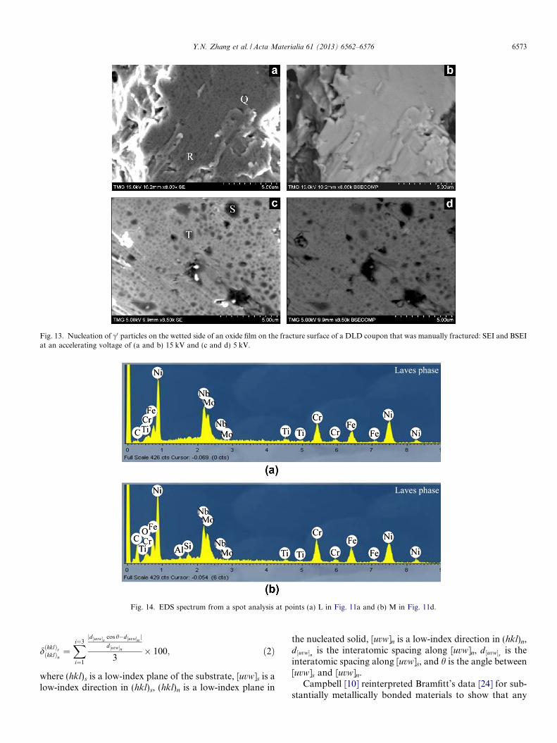
Fig. 13. Nucleation of c0 particles on the wetted side of an oxide film on the fracture surface of a DLD coupon that was manually fractured: SEI and BSEIat an accelerating voltage of (a and b) 15 kV and (c and d) 5 kV.
Fig. 14. EDS spectrum from a spot analysis at points (a) L in Fig. 11a and (b) M in Fig. 11d.
Y.N. Zhang et al. / Acta Materialia 61 (2013) 6562–6576 6573
dðhklÞsðhklÞn¼Xi¼3
i¼1
jd ½uvw�s cos h�d ½uvw�n jd ½uvw�n
3� 100; ð2Þ
where (hkl)s is a low-index plane of the substrate, [uvw]s is alow-index direction in (hkl)s, (hkl)n is a low-index plane in
the nucleated solid, [uvw]n is a low-index direction in (hkl)n,d ½uvw�n is the interatomic spacing along [uvw]n, d ½uvw�s is theinteratomic spacing along [uvw]s, and h is the angle between[uvw]s and [uvw]n.
Campbell [10] reinterpreted Bramfitt’s data [24] for sub-stantially metallically bonded materials to show that any
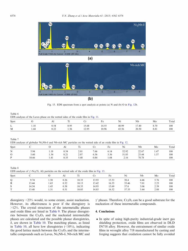
Fig. 15. EDS spectrum from a spot analysis at points (a) N and (b) O in Fig. 12b.
Table 6EDS analyses of the Laves phase on the wetted sides of the oxide film in Fig. 11.
Spot O Al Ti Cr Fe Ni Nb Mo Total
L 1.18 0.54 0.95 15.68 14.55 40.99 17.40 8.70 100M 1.44 0.22 1.56 12.95 10.96 43.56 20.50 8.81 100
Table 7EDS analyses of globular Ni3Nb-d and Nb-rich MC particles on the wetted side of an oxide film in Fig. 12.
Spot C O Al Ti Cr Fe Ni Nb Mo Total
N 5.94 1.18 0.54 2.01 7.66 6.14 52.92 22.67 1.47 100O 5.60 1.34 0.21 2.07 6.56 5.56 51.85 25.44 1.57 100P 10.66 1.41 0.35 5.48 0.84 1.04 2.16 78.78 – 100
Table 8EDS analyses of c0-Ni3(Ti, Al) particles on the wetted side of the oxide film in Fig. 13.
Spot C O Al Ti Cr Fe Ni Nb Mo Total
Q 9.74 1.50 0.26 10.33 13.93 15.53 38.4 4.46 5.76 100R 13.44 1.65 0.32 10.13 13.42 16.35 35.46 7.01 2.23 100S 14.54 1.45 0.38 10.35 14.93 15.69 37.0 3.06 2.59 100T 13.48 1.31 0.31 10.05 14.85 16.32 37.35 3.44 2.88 100
6574 Y.N. Zhang et al. / Acta Materialia 61 (2013) 6562–6576
disregistry <23% would, to some extent, assist nucleation.However, its effectiveness is poor if the disregistry is>12%. The crystal structures of the intermetallic phasesand oxide films are listed in Table 9. The planar disregist-ries between the Cr2O3 and the nucleated intermetallicphases are calculated and the possible planar disregistries,d, are shown in Table 10. The matching planes, as listedin Table 10, all have low disregistries (<10%), indicatingthe good lattice match between the Cr2O3 and the interme-tallic compounds such as Laves, Ni3Nb-d, Nb-rich MC and
c0 phases. Therefore, Cr2O3 can be a good substrate for thenucleation of these intermetallic compounds.
4. Conclusions
� In spite of using high-purity industrial-grade inert gasshielding protection, oxide films are observed in DLDIN718 alloy. However, the entrainment of similar oxidefilms in wrought alloy 718 manufactured by casting andforging suggests that oxidation cannot be fully avoided

Table 9Crystal structures of the intermetallic phases and oxides.
Phase Crystal structure Prototype Space group Lattice parameters and angles Ref.
(a) (b) (c) c (deg)
Laves phase Hexagonal MgZn2 P63/mmc (194) 0.4840 0.4840 0.7895 120 [25]Nb-rich MC (NbC) Cubic NaCl Fm-3m (225) 0.4470 0.4470 0.4470 90 [26]Ni3Nb-d Orthorhombic Cu3Ti Pmmn O2 (59) 0.5114 0.4244 0.4530 90 [27]Ni3(Ti, Al)-c0 Cubic Cu3Au Pm-3m (221) 0.3567 0.3567 0.3567 90 [28]Ni3Nb-c00 Tetragonal TiAl3 I4/mmm (139) 0.3620 0.3620 0.7410 90 [29]Cr2O3 Trigonal Al2O3 R-3c h (167) 0.4962 0.4962 1.3597 120 [30]
Table 10Planar disregistries between Cr2O3 and nucleated intermetallic phases.
Substrates and phases Match planes [uvw]s [uvtw]n d ½uvw�s (nm) d ½uvtw�n (nm) h (deg) d (%)
Cr2O3 and Lave phase (0001)s//(0001)n ½�1 0 1 0� ½�1 0 1 0� 0.8594 0.8383 0 2.52½�2 1 1 0� ½�2 1 1 0� 0.4962 0.4840 0½�1 2 �1 0� ½�1 2 �1 0� 0.4962 0.4840 0
Cr2O3 and Nb-rich MC (0001)s//(100)n ½�1 0 1 0� [011] 0.8594 0.6322 45 8.63½�2 1 1 0� [001] 0.4962 0.4470 0½�1 2 �1 0� [010] 0.4962 0.4470 0
Cr2O3 and Ni3Nb-d (0001)s//(100)n ½�1 0 1 0� [011] 0.8594 0.6207 45 9.52½�2 1 1 0� [001] 0.4962 0.4530 0½�1 2 �1 0� [010] 0.4962 0.4244 0
Cr2O3 and Ni3Nb-d (0001)s//(010)n ½�1 0 1 0� [110] 0.8594 0.6647 45 9.22½�2 1 1 0� [100] 0.4962 0.5114 0½�1 2 �1 0� [001] 0.4962 0.4530 0
Cr2O3 and c0 (0001)n//(111)s ½�1 0 1 0� ½�2 1 1� 0.8594 0.8737 0 4.37½�2 1 1 0� ½�1 0 1� 0.4962 0.5044 0½�1 2 �1 0� ½�1 1 0� 0.4962 0.5044 0
Y.N. Zhang et al. / Acta Materialia 61 (2013) 6562–6576 6575
for the Ni-based superalloy when it is processed in theliquid state either in vacuum (for casting, welding orelectron beam deposition) or under inert gas protection(for welding or laser additive manufacturing).� Both Al2O3 and Cr2O3 films are observed but the latter
is the main oxide for IN718. The oxide film in contactwith dilute air (in vacuum casting or welding) or inertgas (in welding or additive manufacturing) is dry andthus has poor wetting with the liquid metal. It will thusconstitute a lack of bonding or a crack with the metal oroxide film itself.� The oxide film in contact with the metal is wetted and
thus has good atom-to-atom contact. The wetted sideof the Cr2O3 film can also nucleate intermetallic com-pounds such as Laves, Ni3Nb-d, Nb-rich MC and c0
phases.� The possibility of nucleating Laves, Ni3Nb-d, Nb-rich
MC and c0 phases on Cr2O3 was theoretically confirmedusing planar disregistry; suitable low-index match planescould be obtained for the intermetallics, such as Laves,Ni3Nb-d, Nb-rich MC and c0 phases, with Cr2O3.
Acknowledgements
The authors are grateful to X. Pelletier and E. Poirierfor the preparation of the laser-deposited specimens and
technical support for metallography preparation. Greatthanks are due to Prof. J. Campbell at the University ofBirmingham for his invaluable comments, particularly withthe identification of the oxide films.
References
[1] Dupont JN, Lippold JC, Kiser SD. Welding metallurgy andweldability of nickel-base alloys. New York: John Wiley; 2009.
[2] Pollock TM, Tin S. J Propul Power 2006;22:361.[3] Cornu D, Gouhier D, Richard I, Bobin V, Boudot C, Gaudin JP,
et al. Weld Int 1995;9:802.[4] Oblak M, Paulonis DF, Duvall DS. Metall Mater Trans B
1974;5:143.[5] Cozar R, Pineau A. Metall Mater Trans B 1973;4:47.[6] Qi H, Azer M, Ritter A. Metall Mater Trans A 2009;40A:2410.[7] Baufeld B. J Mater Eng Perform 2011;21:1416.[8] Blackwell PL. J Mater Process Technol 2005;170:240.[9] Zhang YN, Cao X, Wanjara P. Int J Adv Manuf Technol 2013.
http://dx.doi.org/10.1007/s00170-013-5171-y.[10] Campbell J. Casting. Oxford: Butterworth-Heinemann; 1991.[11] Rashid AKMB, Campbell J. Metall Mater Trans A 2004;35A:2063.[12] Campbell J, Tiryakioglu M. Metall Mater Trans A 2012;43B:902.[13] Reed RC. The superalloys: fundamentals and applications
book. Cambridge: Cambridge University Press; 2008.[14] <http://www.doitpoms.ac.uk/tlplib/ellingham_diagrams>, Univer-
sity of Cambridge.[15] Reynolds O. Philos Trans R Soc London 1883;174:935.[16] Cao X, Campbell J. Metall Mater Trans A 2003;34A:1409.[17] Cao X, Campbell J. Metall Mater Trans A 2004;35A:1425.[18] Cao X, Campbell J. Int J Cast Met Res 2000;13:175.

6576 Y.N. Zhang et al. / Acta Materialia 61 (2013) 6562–6576
[19] Cao X, Campbell J. Int J Cast Met Res 2003;15:595.[20] Cao X, Campbell J. In: Venetti AC, editor. Prog Mater Sci; 2007.[21] Liu K, Cao X, Chen X-G. J Mater Sci 2012;47:4290.[22] Liu K, Cao X, Chen X-G. Metall Mater Trans A 2013;44:682.[23] Richards RG, Owen GR, Gwynm I. Scan Microsc 1999;13:55.[24] Bramfitt BL. Metall Trans 1970;1:1987.[25] Wada H, Hada M, Shiga M, Nakamura Y. J Phys Soc Jpn
1990;59:701.
[26] Dubitskii GA, Kytin VG, Blank VD, Buga SG, Semenova EE,Serebryanaya NR, et al. Z Naturforsch B 2006;61:1541.
[27] Fang T, Kennedy SJ, Quan L, Hicks TJ. J Phys Condens Matter1992;4:2405.
[28] Shee SK, Pradhan SK, De M. J Alloys Compd 1998;265:249.[29] Kaufman A, Hoffman NJ, Lipson H. Scripta Mater 1969;3:715.[30] Baster M, Bouree F, Kowalska A, Latacz Z. J Alloys Compd
2000;296:1.
Related Documents