09/14/16 PN 96438 v.4.0 PowerPack ® System Stinger ® System 2005 & Later GM 8.1L Class-A W-24 Chassis Motorhomes THIS MANUAL IS FOR USE WITH SYSTEMS 49548, 49562, 49563, 49579 & 49580 Gale Banks Engineering 546 Duggan Avenue • Azusa, CA 91702 (626) 969-9600 • Fax (626) 334-1743 Product Information & Sales: (888) 635-4565 Customer Support: (888) 839-5600 Installation Support: (888) 839-2700 bankspower.com ©2016 Gale Banks Engineering Owner’sManual with Installation Instructions

Welcome message from author
This document is posted to help you gain knowledge. Please leave a comment to let me know what you think about it! Share it to your friends and learn new things together.
Transcript

09/14/16 PN 96438 v.4.0
PowerPack® SystemStinger® System 2005 & Later GM 8.1L Class-AW-24 Chassis Motorhomes
THIS MANUAL IS FOR USE WITH SYSTEMS
49548, 49562, 49563, 49579 & 49580
Gale Banks Engineering 546 Duggan Avenue • Azusa, CA 91702 (626) 969-9600 • Fax (626) 334-1743
Product Information & Sales: (888) 635-4565Customer Support: (888) 839-5600 Installation Support: (888) 839-2700
bankspower.com
©2016 Gale Banks Engineering
Owner’sManualwith Installation Instructions

2 96438 v.4.0
Dear Customer,
If you have any questions concerning the installation of your Banks System, please call our Technical Service Hotline at (888) 839-2700 between 7:00 am and 5:00 pm (PT). If you have any questions relating to shipping or billing, please contact our Customer Service Department at (888) 839-5600.
Thank you.
1. For ease of installation of your Banks PowerPack system, familiarize yourself with the procedure by reading the entire manual before starting work. This manual contains 16 pages of copy, illustrations and parts listing. If any pages are missing from this manual please call Gale Banks Engineering immediately for a replacement.
2. The exploded view of the PowerPack assembly (page 4-5) provides only general guidance. Refer to each step and section diagram in this manual for proper instruction.
3. Throughout this manual, the leftside of the motorhomerefers to the driver’s side, and the right-side to the passenger’s side.
4. Banks Power systems are designed to fit Chevy 8.1L Workhorse Class-A motorhome chassis. Due to differences in coach layouts, it maybe necessary to relocate or modify some coach or Banks system components to accommodate installation of the Banks Power system.
5. Disconnect the ground cable from the battery before beginning work. If there are two batteries, disconnect both.
6. Route and tie wires and hoses a minimum of 6 inches away from exhaust heat, moving parts and sharp edges. Clearance of 8 inches or more is recommended where possible.
7. During installation, keep the work area clean. If foreign debris is transferred to any Banks system component, clean it thoroughly before installing.
NOTE: If installing the Stinger system proceed to Step 21.
8. The front of your motorhome should be raised a minimum of 5-6 inches to allow the installation of Banks TorqueTube® exhaust manifolds. If you have access to a hoist, the motorhomecan be elevated and the front wheels removed for easiest access.
9. When raising the vehicle, support it on properly weight-rated safety stands, ramps or a commercial hoist. Follow the manufacturer’s safety precautions. Take care to balance the motorhome to prevent it from slipping or falling. When using ramps, be sure the front wheels are centered squarely on the topsides; put the transmission in park; set the hand brake; and place blocks behind the rear wheels.
CAUTION! Do not use floor jacks to support the motorhomewhile working under it. Do not raise the motorhomeonto concrete blocks, masonry or any other item not intended specifically for this use.
NOTIFICATION! The Banks Ram-Air Filter comes pre-oiled and no oiling is necessary for initial installation. Service the Ram-Air filter as specified in the Cleaning and Oiling the Banks Ram-Air Filter Section of this manual.
General Installation Practices
96438 v.4.0 3
1. With the motorhome safely raised, ground wire(s) disconnected, and precautions in place, remove the factory exhaust system.
2. To provide better access to the manifolds remove the front wheels from the motorhome. If the motorhome is equipped with inner front fender shields, remove them for improved access.
NOTE: Before removing the lug nuts, make sure a capable torque wrench is available to tighten the lug nuts to the manufacturer’s torque specifications
3. Locate the oxygen sensors in the exhaust headpipes on each side of the engine, forward of the catalytic converters. Unplug the connectors and unscrew the oxygen sensors, keeping track of the left and right sensors. Be careful not to touch or contaminate the sensor.
4. Remove the factory hardware on the front 2-bolt headpipe flanges. Remove the hardware on 3-bolt flanges on the exhaust manifolds / headpipe assemblies. Remove the headpipes from the exhaust manifolds.
NOTE: Whenever possible, it is recommended that the catalytic converters be inspected. Restricted or damaged catalytic converters can impede performance of your Banks PowerPack.
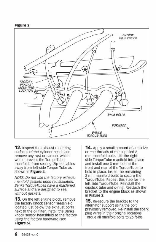
5. Remove the engine oil dipstick by unbolting the bracket from the alternator support and the engine block (see Figure 2). Remove the dipstick and dipstick tube by pulling and twisting upward. If the dipstick tube o-ring is stuck inside the hole in the engine block, remove it and place it back onto the dipstick tube. Retain all hardware for reassembly.
6. Remove the spark-plug wires and the spark plugs from both sides of the
engine. Note their original locations so they can be properly reinstalled.
7. Remove the nuts holding the spark-plug wire heatshields to the exhaust manifold studs. Remove the heatshields.
8. With a wrench or socket, back the exhaust manifold nuts at least one turn away from the manifolds. Use a #7 female torx socket to unscrew each stud from the head. If this tool is not available use a 7⁄32 socket. Take out the studs so the exhaust manifolds can be removed.
9. CAUTION: Make sure all ground cables are removed from vehicle’s battery(s). Remove the starter wire battery cable from the starter motor. Remove the factory starter cable from the starter and install the 90-degree terminal end of the supplied starter extension cable (red) onto the starter motor and tighten the retaining nut. Remove the factory ground cable from the starter and install the supplied ground extension cable (black) to the starter.
10. Route the starter extension cables (red & black) forward under the motor mount. Attach a supplied heat wrap to the extension cables. Zip-tie the extension cables and heat wrap to the factory motorhome wire harness. Route the extension cables inside the frame rail (see Figure 3).
11. Slide the 4-inch length of heat shrink over the extension cables, such that the red heat shrink is on the red cable and black heat shrink on black cable. Attach the extension to the correct factory starter cable using (1) 5⁄16-18 x 1⁄2” bolt, (1) 5⁄16-18 crimplock nut, and (1) 5⁄16 washer per cable. Slide the heat shrink over the connection and heat with a heat gun until the heat shrink tightly conforms to the connection. Make sure the connection is completely covered.
Installation Instructions
4 96438 v.4.0
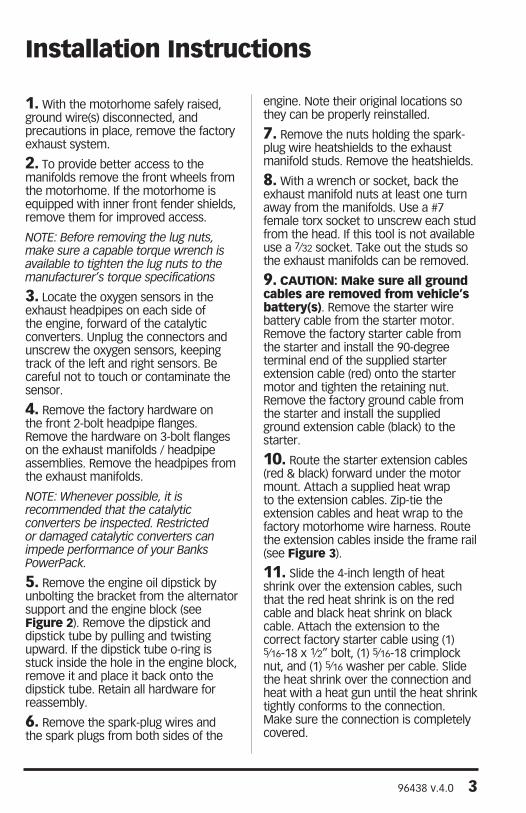
Item# Description Qty P/N1 TorqueTube, Driver Side 1 536912 TorqueTube, Pass Side 1 536923 Conical Seal 2 931614 Head Pipe, Driver Side 1 536935 Head Pipe, Pass Side 1 536946 Knock Sensor Heatshield 1 261257 Heat Shield Blanket (6”x7”) 2 260008 Heat Shield Blanket (3”x16”) 2 260049 Cable Ties 16 2601310 Ground Cable Extension 1 6218111 Starter Cable Extension 1 6218012 2-Bolt Gasket 4 9370213 Air filter 1 4102214 Crossover Pipe 1 5365515 Muffler Inlet 1 5365616 Dynaflow Muffler 1 5368517 Upper Tailpipe (D/S) 1 5366118 Lower Tailpipe Extension (D/S) 1 5366119 Tailpipe Tip 1 5238420 Frame Mount Muffler Hanger 1 5365721 Frame Mount Tailpipe Hanger (D/S) 1 5365922 Universal Exhaust Hanger 1 5219323 Upper Tailpipe (P/S) 1 5366324 Lower Tailpipe Extension (P/S) 1 5366425 Frame Mount Tailpipe Hanger (P/S) 1 53662
Figure 1
General Assembly
96438 v.4.0 5
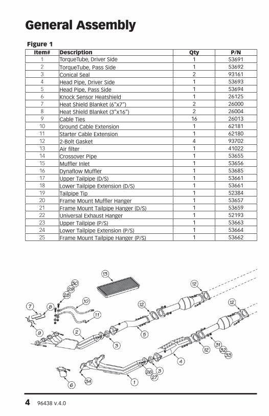
Item# Description Qty P/N26 3⁄8”-16 x 1.75” Bolt 4 9143027 3⁄8” Washer, SAE Flat 4 9140228 5⁄16-24 x 1/2” Bolt 2 9125029 5⁄16” Washer, SAE Flat 2 9120130 5⁄16”-24 Nut, Flexlock 2 9121731 7⁄16”-20 x 1.5” Bolt 8 9162932 7⁄16” Washer, SAE Flat 16 9160233 7⁄16”-20 Nut, CrimpLock 8 9161934 8mm-1.25 x 25mm Bolt 19 9180935 3⁄8-16 Nut, Crimplock 1 9141636 12mm X 1.75X 40, Bolt 2 9187037 12mm X 1.75 X 40, Nut 2 9187138 1⁄2” Washer, SAE Flat 4 91902
Item# Description Qty P/N39 Exhaust Clamp, 3” 2 5246540 Exhaust Clamp, 3.5” 1 5246841 Exhaust Clamp, 4” 2 5247642 Cable Ties, 11” 10 6200243 Banks, Urocal 3 96010
6 96438 v.4.0
12. Inspect the exhaust mounting surfaces of the cylinder heads and remove any rust or carbon, which would prevent the TorqueTube manifolds from sealing. Zip-tie cables away from left-side Torque Tube as shown in Figure 4.
NOTE: Do not use the factory exhaust manifold gaskets upon reinstallation. Banks TorqueTubes have a machined surface and are designed to seal without gaskets.
13. On the left engine block, remove the factory knock sensor heatshield located just below the exhaust ports next to the oil filter. Install the Banks knock sensor heatshield to the factory using the factory hardware (see Figure 5).
14. Apply a small amount of antiseize on the threads of the supplied 8 mm manifold bolts. Lift the right side TorqueTube manifold into place and install one 8 mm bolt at the front and rear of the TorqueTube to hold in place. Install the remaining 8 mm manifold bolts to secure the TorqueTube. Repeat this step for the left side TorqueTube. Reinstall the dipstick tube and o-ring. Reattach the bracket to the engine block as shown in Figure 2.
15. Re-secure the bracket to the alternator support using the bolt previously removed. Re-install the spark plug wires in their original locations. Torque all manifold bolts to 26 ft-lbs.
FACTORYBRACKET
MOUNTINGLOCATION
ENGINEOIL DIPSTICK
8MM BOLTS
FORWARD
BANKSTORQUE-TUBE
Figure 2

96438 v.4.0 7
16. Place a conical seal in the flare on the Banks right side headpipe. Attach the headpipe to the right-side TorqueTube manifold using (2) 3⁄8-16 x 1 3⁄4-inch bolts and (2) 3⁄8 SAE washers provided. Tighten the bolts just enough to hold the headpipe in place. Repeat for left side headpipe.
17. Insert the 2-bolt gasket onto the rear of right side headpipe. Attach the rear of the headpipe and 2-bolt flange to the catalytic converter inlet. Connect using (2) 7⁄16-20 x 11⁄2” bolts, (2) crimplock nuts, and (4) 7⁄16 SAE washers. Repeat for left side headpipe.
18. Tighten the bolts on the 2-bolt flange on the back of the head pipe, then at the front. Torque 7⁄16” Hardware to 48 ft-lbs.
19. Apply a small amount of antiseize to the threads of the oxygen sensors previously removed.
CAUTION: Make sure no anti-seize gets on the tip of the oxygen sensor. This will damage the sensor.
Install the oxygen sensors in the headpipe making sure they are in their original locations. Zip ties may need to be removed and new zip ties added to properly position the oxygen sensor cables.
HEATSHRINK
BANKS STARTER &GROUND EXTENSION
ENGINEMOUNT
TRANS COOLER LINES
HEAT WRAP
VEHICLEWIRE HARNESS
BELT
PULLEY
ENGINEOIL PAN
FORWARD
BANKSTORQUE TUBE
STARTER
Figure 3

8 96438 v.4.0
Figure 5
Figure 4
96438 v.4.0 9
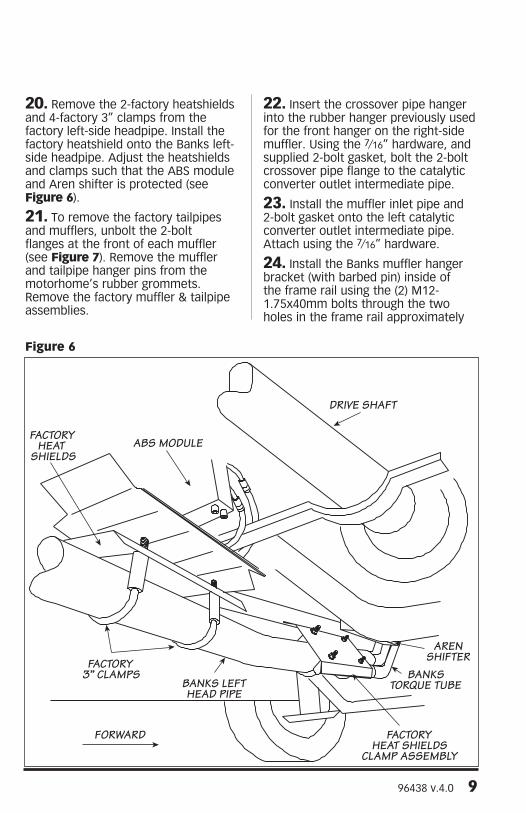
20. Remove the 2-factory heatshields and 4-factory 3” clamps from the factory left-side headpipe. Install the factory heatshield onto the Banks left-side headpipe. Adjust the heatshields and clamps such that the ABS module and Aren shifter is protected (see Figure 6).
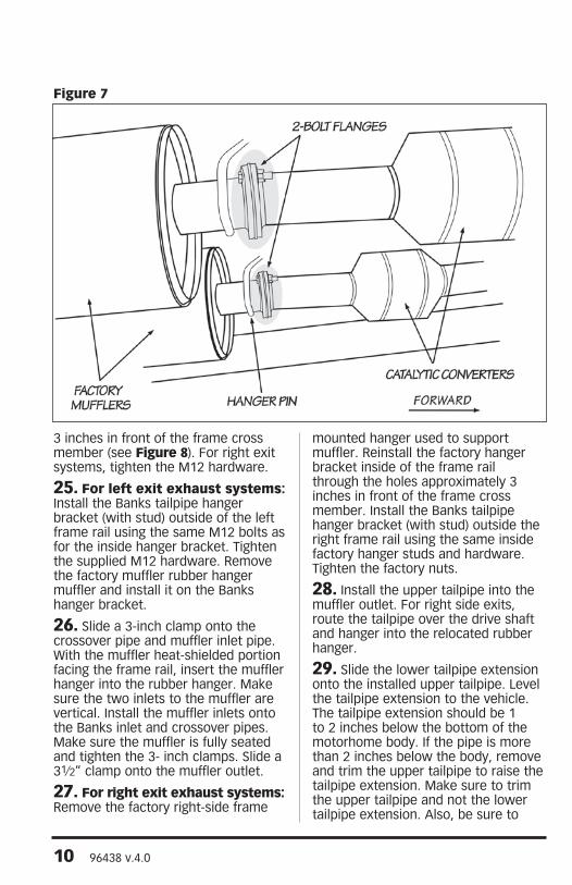
21. To remove the factory tailpipes and mufflers, unbolt the 2-bolt flanges at the front of each muffler (see Figure 7). Remove the muffler and tailpipe hanger pins from the motorhome’s rubber grommets. Remove the factory muffler & tailpipe assemblies.
22. Insert the crossover pipe hanger into the rubber hanger previously used for the front hanger on the right-side muffler. Using the 7⁄16” hardware, and supplied 2-bolt gasket, bolt the 2-bolt crossover pipe flange to the catalytic converter outlet intermediate pipe.
23. Install the muffler inlet pipe and 2-bolt gasket onto the left catalytic converter outlet intermediate pipe. Attach using the 7⁄16” hardware.
24. Install the Banks muffler hanger bracket (with barbed pin) inside of the frame rail using the (2) M12-1.75x40mm bolts through the two holes in the frame rail approximately
FACTORYHEAT
SHIELDS
FACTORY3” CLAMPS
FORWARD
BANKS LEFTHEAD PIPE
FACTORYHEAT SHIELDS
CLAMP ASSEMBLY
BANKSTORQUE TUBE
DRIVE SHAFT
ABS MODULE
ARENSHIFTER
Figure 6
10 96438 v.4.0
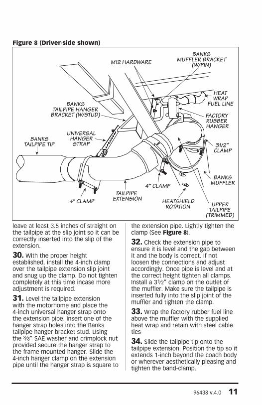
3 inches in front of the frame cross member (see Figure 8). For right exit systems, tighten the M12 hardware.
25. For left exit exhaust systems: Install the Banks tailpipe hanger bracket (with stud) outside of the left frame rail using the same M12 bolts as for the inside hanger bracket. Tighten the supplied M12 hardware. Remove the factory muffler rubber hanger muffler and install it on the Banks hanger bracket.
26. Slide a 3-inch clamp onto the crossover pipe and muffler inlet pipe. With the muffler heat-shielded portion facing the frame rail, insert the muffler hanger into the rubber hanger. Make sure the two inlets to the muffler are vertical. Install the muffler inlets onto the Banks inlet and crossover pipes. Make sure the muffler is fully seated and tighten the 3- inch clamps. Slide a 31⁄2” clamp onto the muffler outlet.
27. For right exit exhaust systems: Remove the factory right-side frame
mounted hanger used to support muffler. Reinstall the factory hanger bracket inside of the frame rail through the holes approximately 3 inches in front of the frame cross member. Install the Banks tailpipe hanger bracket (with stud) outside the right frame rail using the same inside factory hanger studs and hardware. Tighten the factory nuts.
28. Install the upper tailpipe into the muffler outlet. For right side exits, route the tailpipe over the drive shaft and hanger into the relocated rubber hanger.
29. Slide the lower tailpipe extension onto the installed upper tailpipe. Level the tailpipe extension to the vehicle. The tailpipe extension should be 1 to 2 inches below the bottom of the motorhome body. If the pipe is more than 2 inches below the body, remove and trim the upper tailpipe to raise the tailpipe extension. Make sure to trim the upper tailpipe and not the lower tailpipe extension. Also, be sure to
Figure 7
96438 v.4.0 11
leave at least 3.5 inches of straight on the tailpipe at the slip joint so it can be correctly inserted into the slip of the extension.
30. With the proper height established, install the 4-inch clamp over the tailpipe extension slip joint and snug up the clamp. Do not tighten completely at this time incase more adjustment is required.
31. Level the tailpipe extension with the motorhome and place the 4-inch universal hanger strap onto the extension pipe. Insert one of the hanger strap holes into the Banks tailpipe hanger bracket stud. Using the 3⁄8” SAE washer and crimplock nut provided secure the hanger strap to the frame mounted hanger. Slide the 4-inch hanger clamp on the extension pipe until the hanger strap is square to
the extension pipe. Lightly tighten the clamp (See Figure 8).
32. Check the extension pipe to ensure it is level and the gap between it and the body is correct. If not loosen the connections and adjust accordingly. Once pipe is level and at the correct height tighten all clamps. Install a 31⁄2” clamp on the outlet of the muffler. Make sure the tailpipe is inserted fully into the slip joint of the muffler and tighten the clamp.
33. Wrap the factory rubber fuel line above the muffler with the supplied heat wrap and retain with steel cable ties
34. Slide the tailpipe tip onto the tailpipe extension. Position the tip so it extends 1-inch beyond the coach body or wherever aesthetically pleasing and tighten the band-clamp.
BANKSTAILPIPE TIP
4“ CLAMPTAILPIPE
EXTENSION
4“ CLAMP
HEATSHIELDROTATION UPPER
TAILPIPE(TRIMMED)
31/2” CLAMP
BANKSMUFFLER
HEATWRAP
FUEL LINE
FACTORYRUBBER HANGER
BANKSMUFFLER BRACKET
(W/PIN)M12 HARDWARE
BANKSTAILPIPE HANGER
BRACKET (W/STUD)
UNIVERSALHANGERSTRAP
Figure 8 (Driver-side shown)
12 96438 v.4.0
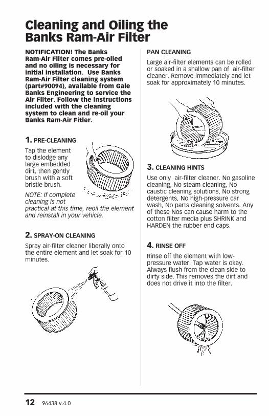
NOTIFICATION! The Banks Ram-Air Filter comes pre-oiled and no oiling is necessary for initial installation. Use Banks Ram-Air Filter cleaning system (part#90094), available from Gale Banks Engineering to service the Air Filter. Follow the instructions included with the cleaning system to clean and re-oil your Banks Ram-Air Fitler.
1. PRE-CLEANING
Tap the element to dislodge any large embedded dirt, then gently brush with a soft bristle brush.
NOTE: If complete cleaning is not practical at this time, reoil the element and reinstall in your vehicle.
2. SPRAY-ON CLEANING
Spray air-filter cleaner liberally onto the entire element and let soak for 10 minutes.
PAN CLEANING
Large air-filter elements can be rolled or soaked in a shallow pan of air-filter cleaner. Remove immediately and let soak for approximately 10 minutes.
3. CLEANING HINTS
Use only air-filter cleaner. No gasoline cleaning, No steam cleaning, No caustic cleaning solutions, No strong detergents, No high-pressure car wash, No parts cleaning solvents. Any of these Nos can cause harm to the cotton filter media plus SHRINK and HARDEN the rubber end caps.
4. RINSE OFF
Rinse off the element with low-pressure water. Tap water is okay. Always flush from the clean side to dirty side. This removes the dirt and does not drive it into the filter.
Cleaning and Oiling the Banks Ram-Air Filter

96438 v.4.0 13
5. DRYING HINTS
Always dry naturally. After rinsing, shake off all excess water and let the element dry naturally.
DO NOT USE COMPRESSED AIR – DO NOT USE OPEN FLAME – DO NOT USE HEAT DRYERS!
EXCESS HEAT WILL SHRINK THE COTTON FILTER MEDIA. COMPRESSED AIR WILL BLOW HOLES IN THE ELEMENT.
6. AEROSOL OILING
After cleaning air filter always reoil before using. Spray Banks Ram-Air filter oil down into each pleat with one pass per pleat. Wait 10 minutes and re-oil any white spots still showing.
7. OILING HINTS
Never use a Banks Ram-Air filter without oil (the filter will not stop the dirt without the oil). Use only air filter oil. Air-filter oil is a compound of mineral and animal oil blended with special polymers to form a very efficient tack barrier. Red dye is added to show just where you have applied the oil. Eventually the red color will fade but the oil will remain and filter the air. NEVER USE Automatic Transmission Fluid. NEVER USE Motor Oil. NEVER USE Diesel Fuel. NEVER USE WD40, LPS, or other light-weight oils.
8. REINSTALL
Reinstall your Banks Ram-Air filter element with proper care. Make sure the element seats properly in the filter case. Install the cover making sure it’s in the right position. Tighten all the nuts, bolts, screws or clips to factory specifications.
9. DO NOT DISCARD
Affix the “Do Not Discard” sticker to the filter case (included with every Banks replacement element). Make sure you put the sticker in a highly visible place to alert your mechanic not to discard.
10. PERFORMANCE HINTS
Service every 50-100,000 miles on street-driven applications. Service more often in offroad or heavy-dust conditions. If an air-filter restriction gauge is installed, then change the element when the air-filter restriction reaches 18”/H2O.
CAUTION! Extremely fine dust from agriculture or offroad use will pull the oil from the element. Frequent reoiling of the element’s clean side might be required. Completely service when practicable. For extra protection use an air-filter sealing grease on rubber ends of the element. Service only with air-filter cleaner and air-filter oil.

14 96438 v.4.0
Notes

96438 v.4.0 15
Notes

Gale Banks Engineering 546 Duggan Avenue • Azusa, CA 91702 (626) 969-9600 • Fax (626) 334-1743
Product Information & Sales: (888) 635-4565Customer Support: (888) 839-5600 Installation Support: (888) 839-2700
bankspower.com
Related Documents