Universal Solar Solutions LLC. P.O. Box 646 Fredonia, AZ 86022 801.597.0276 http://www.Universal-Solar-Solutions.Com 1 Index………………………………………………....……..1 Parts Included…………………………………..………2 Materials Needed……………………………….…….3 Pre Installation Check List………………….……...4 Mounting Procedures…………………………..……5 Mounting pictures………………………….……..…..6 Wiring Pictures…………………………………..………7 Installation Instructions………………………..…8-9 Wiring directions…………………………….……….10 Wiring Diagram…………………………………...…..11 Battery wiring………………….………………….……12 Solar panel wiring………………………………..…..13 MC solar panel wiring diagram…………………14 Appliance Consumption Worksheet……..….15 Additional Resources………………………….…….16 Solar Seeker's Owner's Manual…………………17 Solar Seeker Operation Manual………………..18 Solar Seeker Maintenance……………………….19 Solar Seeker Warranty………………………..……20 Safeguards and notes……………………….……..21 FOR INFORMATION: WWW.Universal-Solar-Solutions.Com SolarSeeker INSTALLATION & OWNERS MANUAL INSTALLATION & OWNERS MANUAL RV SolarSeeker

Welcome message from author
This document is posted to help you gain knowledge. Please leave a comment to let me know what you think about it! Share it to your friends and learn new things together.
Transcript
Universal Solar Solutions LLC.P.O. Box 646
Fredonia, AZ 86022801.597.0276
http://www.Universal-Solar-Solutions.Com 1
Index………………………………………………....……..1
Parts Included…………………………………..………2
Materials Needed……………………………….…….3
Pre Installation Check List………………….……...4
Mounting Procedures…………………………..……5
Mounting pictures………………………….……..…..6
Wiring Pictures…………………………………..………7
Installation Instructions………………………..…8-9
Wiring directions…………………………….……….10
Wiring Diagram…………………………………...…..11
Battery wiring………………….………………….……12
Solar panel wiring………………………………..…..13
MC solar panel wiring diagram…………………14
Appliance Consumption Worksheet……..….15
Additional Resources………………………….…….16
Solar Seeker's Owner's Manual…………………17
Solar Seeker Operation Manual………………..18
Solar Seeker Maintenance……………………….19
Solar Seeker Warranty………………………..……20
Safeguards and notes……………………….……..21
FOR INFORMATION: WWW.Universal-Solar-Solutions.Com
SolarSeeker INSTALLATION & OWNERS MANUAL INSTALLATION & OWNERS MANUALRV SolarSeeker

SolarSeeker INSTALLATION & OWNERS MANUAL INSTALLATION & OWNERS MANUALRV SolarSeeker
FOR INFORMATION: WWW.Universal-Solar-Solutions.Com
Parts Included
Stainless Steel Frame Rotating Motor Strobe Light
Riser Motor
Lighted Toggle Switch
Materials Needed
5/8” Hole Saw Drill Felt Marker
Safety Glasses Ratchet 7/16” Socket
Tape Measure Solderless Terminals Wire Stripper/Crimper
3SOLARSEEKER : INSTALLATION & OWNERS MANUAL2
2-140 WattSolar Panels
24 Amp MPPTSolar Controller
Manufactures Varry
16 each 1/4” X 2.5”Toggle bolts
Electronics Box
3000 Watt Pure SineWave Inverter
Lap SealantButyal Ruber
2 RemoteTransmitters
3/4” Wire LoomWith Wire ties

SolarSeeker INSTALLATION & OWNERS MANUAL INSTALLATION & OWNERS MANUALRV SolarSeeker
FOR INFORMATION: WWW.Universal-Solar-Solutions.Com
1
1
1
1
1
1
1
1
Pre Installation Checklist
Determine the mounting area. Find an area of the RV where there is a minimum of 39” from center for clearance.
Clean the area throughly remove any dirt or oils from the surface.
Attach the rotating motor to the base plate using the provided bolts.
Attach the solar panels to the Solar Seeker frame. The panels should be centered on the mounting rails. You may need to drill holes to have the panels match up to the mounting rails.
Mount the strobe light to the solar panel frame. You will need to drill holes to mount the light.
Connect the RED wire from the strobe light to the GRAY wire located on the top of the plate.
Wire the solar panels to the SunSeeker’s top plate. The Hot (+) wire will hook to the RED wire on the top of the plate.
Attach the BLACK (-) wire of the solar panel to the GROUND post screw.
Important SafeguardsTo reduce the risk of fire, electric shock and/or injury to persons, basic safety precautions should always be followed when using electrical appliances, including the following:
1. READ ALL INSTRUCTIONS BEFORE USING the Sun Seeker.2. The Sun Seeker is NOT A TOY. It is to be used by Adults ONLY.3. Turn the Sun Seeker OFF and lower the system when you plan to travel.4. NEVER push more than ONE button on the transmitter at a time. 6. Do not operate more appliances than the inverter can handle. 7. Return this appliance only to the nearest Authorized Service Center for examination,
repair, or adjustment.
Mounting Procedures
1. Find an area on the roof that has a clearance of 39” from center. (Most vents and sun roofs will clear) You will have a clearance of 4 ½” where the Solar Seeker will ride over sun roofs and vents. (See Photo 1)
2. Be sure to clean the surface thoroughly before attaching the mounting plate. 3. For best results try to find the studs on the roof. If you are unable to find the studs don't
worry because the Butterfly anchors will lock up against the roof's plywood.4. Place the base plate down and use it as a guide to drill the holes. Lay the base plate
lengthwise (front to rear). (See Photo 2) 5. Mark All the holes in the base plate on the roof.6. Remove the base plate and drill 3/8” holes where the marks are.7. Place bolt of Butterfly anchors through holes in base plate and screw Butterfly anchors
to the bolts8. Coat the bottom of the base plate with the Lap Sealant. (Make sure the base is clean
and dry)9. Place the base plate over the holes and slide the Butterfly anchors all the way down.10. Tighten the Butterfly bolts down tight. 11. Allow to dry for 12 hours.12. Place the top plate of the Solar Seeker on the shaft, make sure to tape the limit switch
so it is depressed, not doing this could break the limit switch, and bolt down.13.Run the wires down the refrigerator or bathroom vent to the controller & battery box. 14.See “Wiring Diagram” for instructions for the wiring.
34 ”
Photo 1: Area on Roof Needed Photo 2: Placement Example
5SOLARSEEKER : INSTALLATION & OWNERS MANUAL4
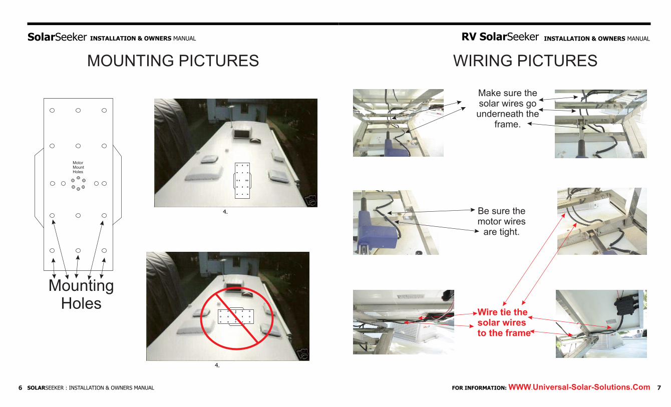
MOUNTING PICTURES
MotorMountHoles
MountingHoles
WIRING PICTURES
Make sure the solar wires go
underneath theframe.
Be sure the motor wires
are tight.
Wire tie the solar wires to the frame
SOLARSEEKER : INSTALLATION & OWNERS MANUAL FOR INFORMATION: WWW.Universal-Solar-Solutions.Com 76
SolarSeeker INSTALLATION & OWNERS MANUAL INSTALLATION & OWNERS MANUALRV SolarSeeker
Base Plate
1.2.3.4.
Base Plate
1.2.3.4.
98
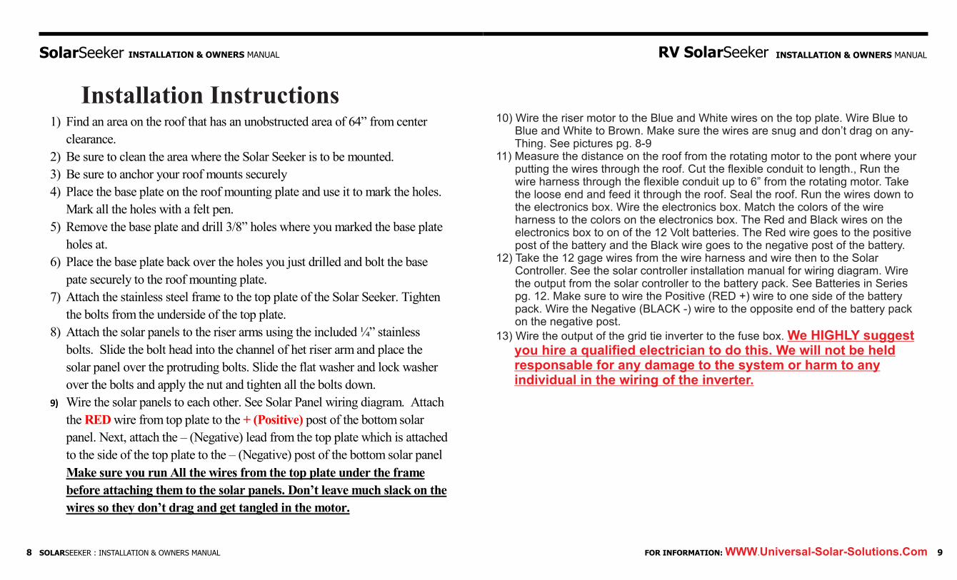
Installation Instructions1) Find an area on the roof that has an unobstructed area of 64” from center
clearance.
2) Be sure to clean the area where the Solar Seeker is to be mounted.
3) Be sure to anchor your roof mounts securely
4) Place the base plate on the roof mounting plate and use it to mark the holes.
Mark all the holes with a felt pen.
5) Remove the base plate and drill 3/8” holes where you marked the base plate
holes at.
6) Place the base plate back over the holes you just drilled and bolt the base
pate securely to the roof mounting plate.
7) Attach the stainless steel frame to the top plate of the Solar Seeker. Tighten
the bolts from the underside of the top plate.
8) Attach the solar panels to the riser arms using the included ¼” stainless
bolts. Slide the bolt head into the channel of het riser arm and place the
solar panel over the protruding bolts. Slide the flat washer and lock washer
over the bolts and apply the nut and tighten all the bolts down.
9) Wire the solar panels to each other. See Solar Panel wiring diagram. Attach
the RED wire from top plate to the + (Positive) post of the bottom solar
panel. Next, attach the – (Negative) lead from the top plate which is attached
to the side of the top plate to the – (Negative) post of the bottom solar panel
Make sure you run All the wires from the top plate under the frame
before attaching them to the solar panels. Don’t leave much slack on the
wires so they don’t drag and get tangled in the motor.
10) Wire the riser motor to the Blue and White wires on the top plate. Wire Blue to Blue and White to Brown. Make sure the wires are snug and don’t drag on any- Thing. See pictures pg. 8-911) Measure the distance on the roof from the rotating motor to the pont where your putting the wires through the roof. Cut the flexible conduit to length., Run the wire harness through the flexible conduit up to 6” from the rotating motor. Take the loose end and feed it through the roof. Seal the roof. Run the wires down to the electronics box. Wire the electronics box. Match the colors of the wire harness to the colors on the electronics box. The Red and Black wires on the electronics box to on of the 12 Volt batteries. The Red wire goes to the positive post of the battery and the Black wire goes to the negative post of the battery. 12) Take the 12 gage wires from the wire harness and wire then to the Solar Controller. See the solar controller installation manual for wiring diagram. Wire the output from the solar controller to the battery pack. See Batteries in Series pg. 12. Make sure to wire the Positive (RED +) wire to one side of the battery pack. Wire the Negative (BLACK -) wire to the opposite end of the battery pack on the negative post.
13) Wire the output of the grid tie inverter to the fuse box. We HIGHLY suggest you hire a qualified electrician to do this. We will not be held responsable for any damage to the system or harm to any individual in the wiring of the inverter.
FOR INFORMATION: WWW.Universal-Solar-Solutions.ComSOLARSEEKER : INSTALLATION & OWNERS MANUAL
SolarSeeker INSTALLATION & OWNERS MANUAL INSTALLATION & OWNERS MANUALRV SolarSeeker
Ground Screw10 Gage Black Wire
Gray18 Gage
Red10 Gage
Blue12 Gage
White12 Gage
Attach to strobe light’s red wire
Attach to riser motor’s blue wire
Attach to riser motor’s white wire
Attach to solar panel’s positive lead
Attach to solar panel’snegative lead
Top Mounting Plate
Orange Wire Switch Post 2
Yellow Wire Switch Post 4
Brown Wire Battery Hot +
White Wire Motor Up
Blue Wire Motor Down
Gray Wire toSwitch for Strobe Light
Red WireSolar Hot
Black WireSolar Ground
ElectronicsBox
MPPT SolarController
BatteryPack
-+
30AFuse
Inverter-
+
SolarSeeker INSTALLATION & OWNERS MANUAL INSTALLATION & OWNERS MANUALRV SolarSeeker
10 11FOR INFORMATION: WWW.Universal-Solar-Solutions.Com
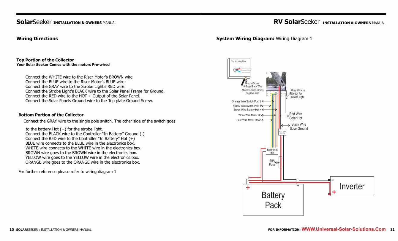
Wiring Directions
Top Portion of the CollectorYour Solar Seeker Comes with the motors Pre-wired
Connect the WHITE wire to the Riser Motor's BROWN wireConnect the BLUE wire to the Riser Motor's BLUE wire.Connect the GRAY wire to the Strobe Light's RED wire.Connect the Strobe Light's BLACK wire to the Solar Panel Frame for Ground.Connect the RED wire to the HOT + Output of the Solar Panel. Connect the Solar Panels Ground wire to the Top plate Ground Screw.
Bottom Portion of the Collector
Connect the GRAY wire to the single pole switch. The other side of the switch goes
to the battery Hot (+) for the strobe light.Connect the BLACK wire to the Controller “In Battery” Ground (-)Connect the RED wire to the Controller “In Battery” Hot (+) BLUE wire connects to the BLUE wire in the electronics box.WHITE wire connects to the WHITE wire in the electronics box.BROWN wire goes to the BROWN wire in the electronics box.YELLOW wire goes to the YELLOW wire in the electronics box.ORANGE wire goes to the ORANGE wire in the electronics box.
For further reference please refer to wiring diagram 1
System Wiring Diagram: Wiring Diagram 1
SOLARSEEKER : INSTALLATION & OWNERS MANUAL

SolarSeeker INSTALLATION & OWNERS MANUAL INSTALLATION & OWNERS MANUALRV SolarSeeker
12 13FOR INFORMATION: WWW.Universal-Solar-Solutions.Com
Battery Wiring Diagram
Battery Pack using Six (6) 6 volt batteries in series and parallel. The total output is 12 volts. This configuration will give you maximum amount of power.
Solar Panel Wiring DiagramWire the panels together in Parallel, Positive to Positive and Negative to Negative. Connect the wires to the Junction box as show in the picture. Wire the Solar Seeker Red wire (+) from the top mounting plate to the bottom Junction Box, + to + and run a Negative wire from the bottom Junction Box to the Solar Seeker Top mounting plate on the side to the Ground Screw.
SOLARSEEKER : INSTALLATION & OWNERS MANUAL

SolarSeeker INSTALLATION & OWNERS MANUAL INSTALLATION & OWNERS MANUALRV SolarSeeker
FOR INFORMATION: WWW.Universal-Solar-Solutions.Com
MC Connector Wiring Diagram
1. Connect the Positive Lead from one panel to the Positive Lead of the other panel. 2. Connect the Positive Lead from the top plate to the Positive Leads of the solar panels3. Connect the Negative Lead from one panel to the Negative Lead of the other panel. 4. Connect the Negative Lead to the side of the top mounting plate on the ground screw
Appliance Consumption Worksheet
Approx.Current Hours/Day Amp Hours (amps@12volts) Consumed
Appliance LightsIncandescent 1 bulb (25 watt) 2 X ______ = ______ 1 bulb (50 watt) 4 X ______ = ______ Quartz halogen (25 watt) 2 X ______ = ______Fluorescent 1 tube (15 watt) 1 X ______ = ______ 2 tubes (30 watt) 1.6 X ______ = ______
Entertainment9-in color TV 3 X ______ = ______ 12-in B&W TV 1.1 X ______ = ______ CB receiver 0.5 X ______ = ______ Stereo am/fm 1 X ______ = ______ Satellite receiver 2 X ______ = ______
Cooling/Heating500 cfm fan 1.2 X ______ = ______ 750 cfm fan 2.5 X ______ = ______ 1000 cfm fan 5 X ______ = ______ 750 cfm fan 2.5 X ______ = ______ Forced-air furnace 5-8 X ______ = ______ Vent & range hood fan 2 X ______ = ______ RV water pump 8 X ______ = ______ DC compressor refrig 6 X ______ = ______ 3-way frig on 12 V 35 X ______ = ________________________ ______ X ______ = ________________________ ______ X ______ = ______Microwave oven 125 X ______ = ______ Blender 15 X ______ = ______ Computer 4 X ______ = ______ 13-in color TV 7 X ______ = ______ B/I vacuum 100 X ______ = ______Electric broom 60 X ______ = ______Hair drier 1200w 95 X ______ = ______Satellite receiver 3 X ______ = ______
Total amp hours used per day = ______
15SOLARSEEKER : INSTALLATION & OWNERS MANUAL14

We would like to thank you for THE SOLAR SEEKER IS NOT DESIGNED TO
purchasing our Solar Seeker. This RUN YOUR REFRIGERATOR OR WATER
system will give you years of trouble HEATER ON ELECTRIC THESE APPLIANCES
free service. The finest care has SHOULD BE RUN ON PROPANE.
gone into producing the Solar Seeker.
By using the Solar Seeker you will be
able to operate most if not all your
appliances in your RV.
EXTREMELY IMPORTANT
NEVER TRAVEL WITH YOUR SOLAR SEEKER
IN THE RAISED POSITION. NEVER TRAVEL
FASTER THAN 75 MPH. DOING THE ABOVE
WILL VOID THE WARRANTY.
OWNERS MANUAL
1716
RV SolarSeeker
Additional Resources:Universal Solar Solutions web site. Our web site will provide you with information on operation, sales and repair ofthe Solar Seeker.Solar Rebates Nationwide:This resource will provide you with all the solar rebates for your particular area. Both State and Federal.
Azimuth and Elevation:This web site will provide you with the Latitude and Longitude of the sun in your current location. This is especially helpful to determine the exact position of the sun to aim your Solar Seeker.
http://www.Universal-Solar-Solutions.com
http://www.dsireusa.org
http://www.jgiesen.de/asimuth/index.html
SOLARSEEKER : INSTALLATION & OWNERS MANUAL
SolarSeeker INSTALLATION & OWNERS MANUAL INSTALLATION & OWNERS MANUALRV SolarSeeker
FOR INFORMATION: WWW.Universal-Solar-Solutions.Com
SolarSeeker INSTALLATION & OWNERS MANUAL INSTALLATION & OWNERS MANUALRV SolarSeeker
FOR INFORMATION: WWW.Universal-Solar-Solutions.Com
Operating the SolarSeeker
To operate the Solar Seeker upon arrival of your destination:
1) Take out your remote transmitter.2) Aim the transmitter towards the Solar Seeker.3) Push the “ON” button (located on your electronics box) 4) Using your remote, push the “Up” Button on the transmitter to raise the Solar Seeker to
the desired position. Just angle the panels to the sun's position in the sky. 5) Using your remote, push the “Rotate” Button to align to the sun. 6) That's it. Your system is ready to pull in the maximum amount of sun possible.
The Solar Seeker system will withstand winds up to 50 MPH. If you encounter winds higher than that your system may spin out of position. If this occurs simply take out your remote and push the “Rotate” button to realign the solar panels.
When you're ready to pack up and travel make sure to lower the Solar Seeker. Simply use your remote and lower the Solar Seeker all the way down to the locked down position. The Solar Seeker should be positioned where the strobe light is facing to the rear of your RV. Then turn your system “OFF” (located on your electronics box) The Solar Seeker is now locked down for travel.
The Solar Seeker is virtually maintenance free. Because the system passes electric current through a brass collector system there may come a time when these connections become oxidized. The system is coated with a corrosion preventive at the factory that will last a very long time. However after a long time of use you may find that the Solar Seeker will not respond as well as it should. If this happens all that you need to do is take the corrosive preventative (Included) and spread in over the collector ring, located under the top plate on the Solar Seeker.
This can be done by yourself or any qualified service technician. We also recommend that you clean your solar panels once in a while. This can be done by putting a duster or rag on the end of a telescoping pole and cleaning the panels without having to get on the roof of your rig.
SolarSeeker Maintenance:
Both motors are sealed units and don't ever need any maintenance. The stainless steel will last a life time with no maintenance.
Lost Remote BatteryIN THE EVENT YOU LOOSE YOUR REMOTE OR THE BATTERY DIES. There are 4 buttons on the electronics box to lower, raise or rotate the solar panels. If you happen to loose your remote or the battery in your remote dies while your camping, all you need to do, when you're ready to leave, is push the “Down” button until the panels are completely lowered. If the battery is dead then just replace it. Or if it's lost, then give us a call and you can purchase another remote transmitter.
CautionNever push more than one button on your transmitter at a time. Also never have any of the stationary buttons on the electronics box pushed in and press a button on the transmitter. This will overload the remote and blow the inline fuse.
SecurityThere is a strobe light included with your system. This is used for security or emergencies. In the event that you have an emergency all you need to do is turn on the strobe light and notify the emergency personal to look for the strobe light and they will be able to locate you much faster possibly saving a life. Also, if you have any problems on the road and need to pull over turn your strobe light on to notify oncoming traffic of your emergency.
19SOLARSEEKER : INSTALLATION & OWNERS MANUAL18
SolarSeeker INSTALLATION & OWNERS MANUAL INSTALLATION & OWNERS MANUALRV SolarSeeker
FOR INFORMATION: WWW.Universal-Solar-Solutions.Com
Notes About the SolarSeeker________________________________________
_________________________________________________________________
_________________________________________________________________
_________________________________________________________________
_________________________________________________________________
_________________________________________________________________
_________________________________________________________________
_________________________________________________________________
_________________________________________________________________
_________________________________________________________________
_________________________________________________________________
_________________________________________________________________
_________________________________________________________________
_________________________________________________________________
21SOLARSEEKER : INSTALLATION & OWNERS MANUAL20
Limited Warranty: Universal Solar Solutions LLC. (the "Company") warrants that its Solar Seeker (the "Product")
(a) will perform substantially in accordance with the accompanying written materials for a period
of One (1) year from the date of receipt and (b) that the medium on which the product is
contained will be free from defects in materials and workmanship under normal use and service
for a period of one (1) year. In the event applicable law imposes any implied warranties, the
implied warranty period is limited to ninety (90) days from the date of receipt. Some
jurisdictions do not allow such limitations on duration of an implied warranty, so the above
limitation may not apply to you.
Customer Remedies: The Company's and its suppliers' entire liability and your exclusive
remedy shall be, at the company's option, either (a) return of the price paid for the product, or (b)
repair or replacement of the product that does not meet this Limited Warranty and which is
returned to the Company with a copy of your receipt. This Limited Warranty is void if failure of
the Product has resulted from accident, abuse, or misapplication. Any replacement Product will
be warranted for the remainder of the original warranty period or thirty (30) days, which ever is
longer.
NO OTHER WARRANTIES. TO THE MAXIMUM EXTENT PERMITTED BY
APPLICABLE LAW, THE COMPANY AND ITS SUPPLIERS DISCLAIM ALL OTHER
WARRANTIES, EITHER EXPRESS OR IMPLIED, INCLUDING, BUT NOT LIMITED
TO IMPLIED WARRANTIES OF MERCHANTABILITY AND FITNESS FOR A
PARTICULAR PURPOSE, WITH REGARD TO THE PRODUCT AND ANY RELATED
OR ACCOMPANYING WRITTEN MATERIALS.
This warranty is void if this product is misused, used in an improper environment, overloaded,
opened, abused, altered in any manner, not used under norm al operating conditions, or not in
accordance with any labels or instructions. There are no other implied warranties of any kind.
The company is not liable for incidental, indirect, consequential damages, special, including
without limitation, damage to, or loss of use of, any equipment.
Related Documents