MG2000 ™ Speedometer IS0209 rev. B ecr#5668 08/2005 Owner’s Manual

Welcome message from author
This document is posted to help you gain knowledge. Please leave a comment to let me know what you think about it! Share it to your friends and learn new things together.
Transcript

MG2000™ Speedometer
IS0209 rev. B ecr#5668 08/2005
Owner’s Manual

12/19/2005
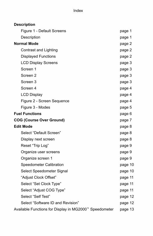
Index
Description
Figure 1 - Default Screens page 1
Description page 1
Normal Mode page 2
Contrast and Lighting page 2
Displayed Functions page 2
LCD Display Screens page 3
Screen 1 page 3
Screen 2 page 3
Screen 3 page 3
Screen 4 page 4
LCD Display page 4
Figure 2 - Screen Sequence page 4
Figure 3 - Modes page 5
Fuel Functions page 6
COG (Course Over Ground) page 7
Edit Mode page 8
Select “Default Screen” page 8
Display next screen page 8
Reset “Trip Log” page 9
Organize user screens page 9
Organize screen 1 page 9
Speedometer Calibration page 10
Select Speedometer Signal page 10
“Adjust Clock Offset” page 11
Select “Set Clock Type” page 11
Select “Adjust COG Type” page 11
Select “Self Test” page 12
Select “Software ID and Revision” page 12
Available Functions for Display in MG2000™ Speedometer page 13

Page 1
MG2000 Speedometer ManualThe MG2000™ Speedometer combines the features of a speedometer and several digital instruments into one unit:
• The MG2000™ Speedometer is analog in appearance but is driven by a stepper motor for digital accuracy.
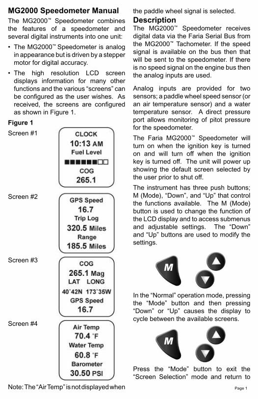
• The high resolution LCD screen displays information for many other functions and the various “screens” can be configured as the user wishes. As received, the screens are configured as shown in Figure 1.
Figure 1
Screen #1
Screen #2
Screen #3
Screen #4
Note: The “Air Temp” is not displayed when
the paddle wheel signal is selected. DescriptionThe MG2000™ Speedometer receives digital data via the Faria Serial Bus from the MG2000™ Tachometer. If the speed signal is available on the bus then that will be sent to the speedometer. If there is no speed signal on the engine bus then the analog inputs are used.
Analog inputs are provided for two sensors; a paddle wheel speed sensor (or an air temperature sensor) and a water temperature sensor. A direct pressure port allows monitoring of pitot pressure for the speedometer.
The Faria MG2000™ Speedometer will turn on when the ignition key is turned on and will turn off when the ignition key is turned off. The unit will power up showing the default screen selected by the user prior to shut off.
The instrument has three push buttons; M (Mode), “Down”, and “Up” that control the functions available. The M (Mode) button is used to change the function of the LCD display and to access submenus and adjustable settings. The “Down” and “Up” buttons are used to modify the settings.
In the “Normal” operation mode, pressing the “Mode” button and then pressing “Down” or “Up” causes the display to cycle between the available screens.
Press the “Mode” button to exit the “Screen Selection” mode and return to
Page 2
turned on, the unit enters a “Self Test” mode. The screen will display “The Self Test Mode Is In Operation” for 10 seconds. The warning lights and back lights will flash.
When this is complete, the user selected “Default” screen will appear.
Note: The information below applies to the MG2000™ Speedometer as if received with no user changes to the screen selections.
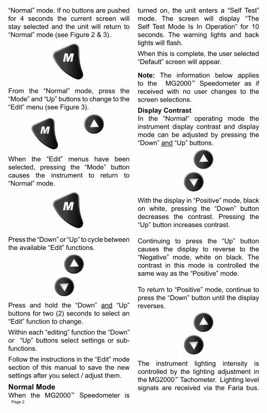
Display ContrastIn the “Normal“ operating mode the instrument display contrast and display mode can be adjusted by pressing the “Down” and “Up” buttons.
With the display in “Positive” mode, black on white, pressing the “Down” button decreases the contrast. Pressing the “Up” button increases contrast.
Continuing to press the “Up” button causes the display to reverse to the “Negative” mode, white on black. The contrast in this mode is controlled the same way as the “Positive” mode.
To return to “Positive” mode, continue to press the “Down” button until the display reverses.
The instrument lighting intensity is controlled by the lighting adjustment in the MG2000™ Tachometer. Lighting level signals are received via the Faria bus.
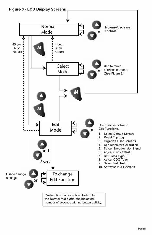
“Normal” mode. If no buttons are pushed for 4 seconds the current screen will stay selected and the unit will return to “Normal” mode (see Figure 2 & 3).
From the “Normal” mode, press the “Mode” and “Up” buttons to change to the “Edit” menu (see Figure 3).
When the “Edit” menus have been selected, pressing the “Mode” button causes the instrument to return to “Normal” mode.
Press the “Down” or “Up” to cycle between the available “Edit” functions.
Press and hold the “Down” and “Up” buttons for two (2) seconds to select an “Edit” function to change.
Within each “editing” function the “Down” or “Up” buttons select settings or sub-functions.
Follow the instructions in the “Edit” mode section of this manual to save the new settings after you select / adjust them.
Normal ModeWhen the MG2000™ Speedometer is
Page 3
Displayed Functions
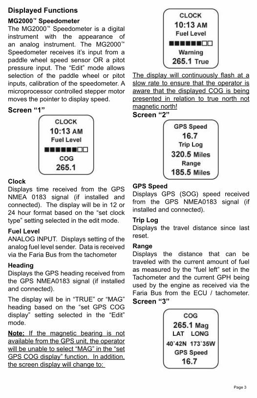
MG2000™ SpeedometerThe MG2000™ Speedometer is a digital instrument with the appearance of an analog instrument. The MG2000™ Speedometer receives it’s input from a paddle wheel speed sensor OR a pitot pressure input. The “Edit” mode allows selection of the paddle wheel or pitot inputs, calibration of the speedometer. A microprocessor controlled stepper motor moves the pointer to display speed.
Screen “1”
ClockDisplays time received from the GPS NMEA 0183 signal (if installed and connected). The display will be in 12 or 24 hour format based on the “set clock type” setting selected in the edit mode.
Fuel LevelANALOG INPUT. Displays setting of the analog fuel level sender. Data is received via the Faria Bus from the tachometer
HeadingDisplays the GPS heading received from the GPS NMEA0183 signal (if installed and connected).
The display will be in “TRUE” or “MAG” heading based on the “set GPS COG display” setting selected in the “Edit” mode.
Note: If the magnetic bearing is not available from the GPS unit, the operator will be unable to select “MAG” in the “set GPS COG display” function. In addition, the screen display will change to:
The display will continuously flash at a slow rate to ensure that the operator is aware that the displayed COG is being presented in relation to true north not magnetic north!Screen “2”
GPS SpeedDisplays GPS (SOG) speed received from the GPS NMEA0183 signal (if installed and connected).
Trip LogDisplays the travel distance since last reset.
RangeDisplays the distance that can be traveled with the current amount of fuel as measured by the “fuel left” set in the Tachometer and the current GPH being used by the engine as received via the Faria Bus from the ECU / tachometer.Screen “3”

Page 4
HeadingDisplays the GPS heading received from the GPS NMEA0183 signal (if installed and connected). The display will be in “TRUE” or “MAG” heading based on the “SET GPS COG DISPLAY” setting selected in the edit mode.
Note: If magnetic bearing is not available from the GPS unit, the operator will be unable to select “MAG” in the “set GPS COG display” function. In addition, the screen display will change to:
The display will continuously flash at a slow rate to ensure that the operator is aware that the displayed COG is being presented in relation to true north not magnetic north!
Lat LongDisplays the GPS latitude and longitude of the current location received from the GPS NMEA0183 signal (if installed and connected).
GPS SpeedDisplays GPS Speed Over Ground (SOG) speed.
Screen “4”
Air TempANALOG INPUT. Displays current air temperature.
Water Temp
From bus or an Analog input. Displays current water temperature.
ClockDisplays time received from the GPS NMEA0183 signal (if installed and connected). The display will be in 12 or 24 hour format based on the “set clock type” setting selected in the edit mode.
LCD Display Screens:In the “Normal mode, press the “Mode” button once to enter screen “Select” mode,
Use the “Up” or “Down” buttons to move between screens.
Figure 2
Screen “1”Default
Screen “2”
Screen “3”
Screen “4”
Page 5
Normal Mode
Increase/decreasecontrast
Use to move between screens.(See Figure 2)
EditMode
To changeEdit Function
Use to move between Edit Functions.
4 sec.Auto
Return
40 sec.Auto
Return
and
or
or
or
or
2 sec.
Use to changesettings.
SelectMode
1. Select Default Screen2. Reset Trip Log3. Organize User Screens4. Speedometer Calibration5. Select Speedometer Signal6. Adjust Clock Offset7. Set Clock Type8. Adjust COG Type9. Select Self Test10. Software Id & Revision
Dashed lines indicate Auto Return to the Normal Mode after the indicated number of seconds with no button activity.
Figure 3 - LCD Display Screens

Page 6
Fuel FunctionsFuel Level SenderThis display is the equivalent of a standard fuel gauge and should be used as the reference for the fuel remaining.
Each filled block represents 1/8 of a tank and when the fuel tank is empty only empty blocks will be displayed. For best accuracy, the fuel level sender should be calibrated as described in the MG2000™
Tachometer manual.
Manual settingsThe “Fuel Left” and “Range” display values are dependant on accurately setting the values for “Fuel Tank Size” and either “Fuel Tank Full” or “Amount of Fuel” in the MG2000™ Tachometer.
“Fuel Left” is calculated based on the amount of fuel entered in these settings (the amount of fuel the operator indicates is in the fuel tank) and the fuel flow of the engine. “Range” is calculated based on “Fuel Left”, fuel flow, and current speed
Fuel Level Sender
Speedometer
�����������������������������������������
������������
�������������
�������������
��
���� ������
Page 7
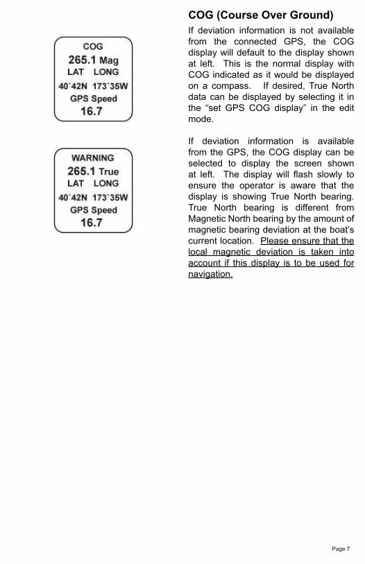
COG (Course Over Ground)If deviation information is not available from the connected GPS, the COG display will default to the display shown at left. This is the normal display with COG indicated as it would be displayed on a compass. If desired, True North data can be displayed by selecting it in the “set GPS COG display” in the edit mode.
If deviation information is available from the GPS, the COG display can be selected to display the screen shown at left. The display will flash slowly to ensure the operator is aware that the display is showing True North bearing. True North bearing is different from Magnetic North bearing by the amount of magnetic bearing deviation at the boat’s current location. Please ensure that the local magnetic deviation is taken into account if this display is to be used for navigation.
Page 8
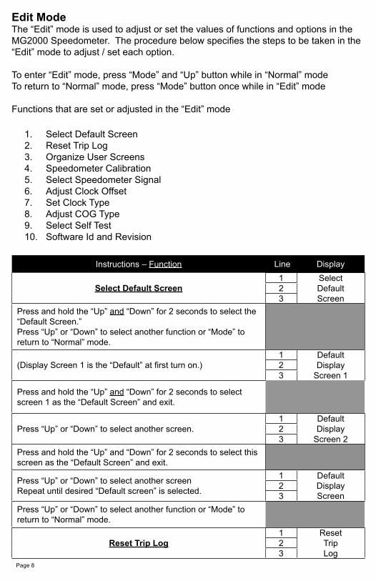
Edit ModeThe “Edit” mode is used to adjust or set the values of functions and options in the MG2000 Speedometer. The procedure below specifies the steps to be taken in the “Edit” mode to adjust / set each option.
To enter “Edit” mode, press “Mode” and “Up” button while in “Normal” modeTo return to “Normal” mode, press “Mode” button once while in “Edit” mode
Functions that are set or adjusted in the “Edit” mode
1. Select Default Screen2. Reset Trip Log3. Organize User Screens4. Speedometer Calibration5. Select Speedometer Signal6. Adjust Clock Offset7. Set Clock Type8. Adjust COG Type9. Select Self Test10. Software Id and Revision
Instructions – Function Line Display
Select Default Screen1 Select
DefaultScreen
23
Press and hold the “Up” and “Down” for 2 seconds to select the “Default Screen.”Press “Up” or “Down” to select another function or “Mode” to return to “Normal” mode.
(Display Screen 1 is the “Default” at first turn on.)1 Default
DisplayScreen 1
23
Press and hold the “Up” and “Down” for 2 seconds to select screen 1 as the “Default Screen” and exit.
Press “Up” or “Down” to select another screen.1 Default
DisplayScreen 2
23
Press and hold the “Up” and “Down” for 2 seconds to select this screen as the “Default Screen” and exit.
Press “Up” or “Down” to select another screenRepeat until desired “Default screen” is selected.
1 Default2 Display3 Screen
Press “Up” or “Down” to select another function or “Mode” to return to “Normal” mode.
Reset Trip Log1 Reset
TripLog
23
Page 9
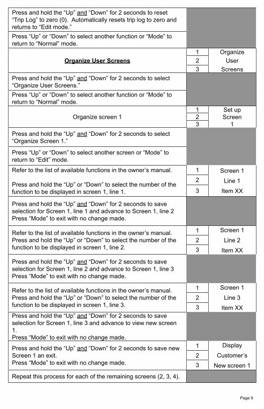
Press and hold the “Up” and “Down” for 2 seconds to reset “Trip Log” to zero (0). Automatically resets trip log to zero and returns to “Edit mode.”
Press “Up” or “Down” to select another function or “Mode” to return to “Normal” mode.
Organize User Screens
1 Organize
User
Screens
2
3
Press and hold the “Up” and “Down” for 2 seconds to select “Organize User Screens.”
Press “Up” or “Down” to select another function or “Mode” to return to “Normal” mode.
Organize screen 11 Set up
Screen1
23
Press and hold the “Up” and “Down” for 2 seconds to select “Organize Screen 1.”
Press “Up” or “Down” to select another screen or “Mode” to return to “Edit” mode.
Refer to the list of available functions in the owner’s manual.
Press and hold the “Up” or “Down” to select the number of the function to be displayed in screen 1, line 1.
1 Screen 1
Line 1
Item XX
2
3
Press and hold the “Up” and “Down” for 2 seconds to save selection for Screen 1, line 1 and advance to Screen 1, line 2Press “Mode” to exit with no change made.
Refer to the list of available functions in the owner’s manual. Press and hold the “Up” or “Down” to select the number of the function to be displayed in screen 1, line 2.
1 Screen 1
Line 2
Item XX
2
3
Press and hold the “Up” and “Down” for 2 seconds to save selection for Screen 1, line 2 and advance to Screen 1, line 3Press “Mode” to exit with no change made.
Refer to the list of available functions in the owner’s manual. Press and hold the “Up” or “Down” to select the number of the function to be displayed in screen 1, line 3.
1 Screen 1
Line 3
Item XX
2
3Press and hold the “Up” and “Down” for 2 seconds to save selection for Screen 1, line 3 and advance to view new screen 1.Press “Mode” to exit with no change made.
Press and hold the “Up” and “Down” for 2 seconds to save new Screen 1 an exit. Press “Mode” to exit with no change made.
1 Display
Customer’s
New screen 1
2
3
Repeat this process for each of the remaining screens (2, 3, 4).
Page 10
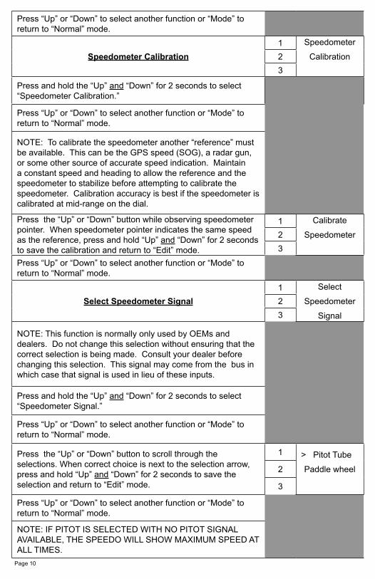
Press “Up” or “Down” to select another function or “Mode” to return to “Normal” mode.
Speedometer Calibration
1 Speedometer
Calibration2
3
Press and hold the “Up” and “Down” for 2 seconds to select “Speedometer Calibration.”
Press “Up” or “Down” to select another function or “Mode” to return to “Normal” mode.
NOTE: To calibrate the speedometer another “reference” must be available. This can be the GPS speed (SOG), a radar gun, or some other source of accurate speed indication. Maintain a constant speed and heading to allow the reference and the speedometer to stabilize before attempting to calibrate the speedometer. Calibration accuracy is best if the speedometer is calibrated at mid-range on the dial.
Press the “Up” or “Down” button while observing speedometer pointer. When speedometer pointer indicates the same speed as the reference, press and hold “Up” and “Down” for 2 seconds to save the calibration and return to “Edit” mode.
1 Calibrate
Speedometer2
3
Press “Up” or “Down” to select another function or “Mode” to return to “Normal” mode.
Select Speedometer Signal
1 Select
Speedometer
Signal
2
3
NOTE: This function is normally only used by OEMs and dealers. Do not change this selection without ensuring that the correct selection is being made. Consult your dealer before changing this selection. This signal may come from the bus in which case that signal is used in lieu of these inputs.
Press and hold the “Up” and “Down” for 2 seconds to select “Speedometer Signal.”
Press “Up” or “Down” to select another function or “Mode” to return to “Normal” mode.
Press the “Up” or “Down” button to scroll through the selections. When correct choice is next to the selection arrow, press and hold “Up” and “Down” for 2 seconds to save the selection and return to “Edit” mode.
1 > Pitot Tube
Paddle wheel2
3
Press “Up” or “Down” to select another function or “Mode” to return to “Normal” mode.
NOTE: IF PITOT IS SELECTED WITH NO PITOT SIGNAL AVAILABLE, THE SPEEDO WILL SHOW MAXIMUM SPEED AT ALL TIMES.
Page 11
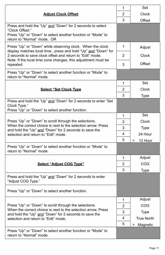
Adjust Clock Offset
1 Set
Clock
Offset
2
3
Press and hold the “Up” and “Down” for 2 seconds to select “Clock Offset.”Press “Up” or “Down” to select another function or “Mode” to return to “Normal” mode. OR
Press “Up” or “Down” while observing clock. When the clock display matches local time , press and hold “Up” and “Down” for 2 seconds to save clock offset and return to “Edit” mode.Note: If the local time zone changes, this adjustment must be repeated.
1 Adjust
Clock
Offset
2
3
Press “Up” or “Down” to select another function or “Mode” to return to “Normal” mode.
Select “Set Clock Type
1 Set
Clock
Type
2
3
Press and hold the “Up” and “Down” for 2 seconds to enter “Set Clock Type.” Press “Up” or “Down” to select another function.
Press “Up” or “Down” to scroll through the selections.When the correct choice is next to the selection arrow. Press and hold the “Up” and “Down” for 2 seconds to save the selection and return to “Edit” mode.
1 Set
Clock
Type
24 Hour
> 12 Hour
2
3
4
5
Press “Up” or “Down” to select another function or “Mode” to return to “Normal” mode.
Select “Adjust COG Type”
1 Adjust
COG
Type
2
3
Press and hold the “Up” and “Down” for 2 seconds to enter “Adjust COG Type.”
Press “Up” or “Down” to select another function.
Press “Up” or “Down” to scroll through the selections.When the correct choice is next to the selection arrow, Press and hold the “Up” and “Down” for 2 seconds to save the selection and return to “Edit” mode.
1 Adjust
COG
Type
True North
> Magnetic
2
3
4
5
Press “Up” or “Down” to select another function or “Mode” to return to “Normal” mode.
Page 12
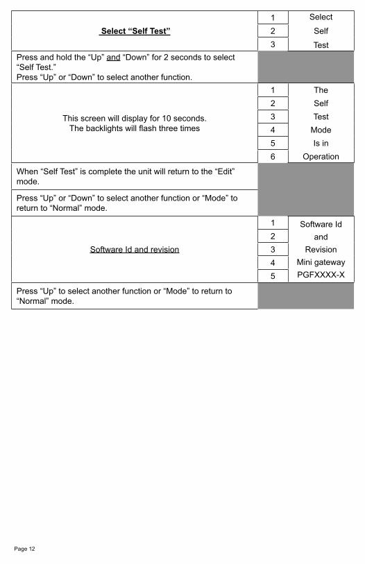
Select “Self Test”
1 Select
Self
Test
2
3
Press and hold the “Up” and “Down” for 2 seconds to select “Self Test.”Press “Up” or “Down” to select another function.
This screen will display for 10 seconds.The backlights will flash three times
1 The
Self
Test
Mode
Is in
Operation
2
3
4
5
6
When “Self Test” is complete the unit will return to the “Edit” mode.
Press “Up” or “Down” to select another function or “Mode” to return to “Normal” mode.
Software Id and revision
1 Software Id
and
Revision
Mini gateway
PGFXXXX-X
2
3
4
5
Press “Up” to select another function or “Mode” to return to “Normal” mode.

Available Functions for Display in MG2000 Speedometer Screens
The functions listed below can be displayed in the user configured screens. All of the functions may not be available in your installation. If a function is selected for display and that function does not appear on the screen, the function does not exist in this installation. A function is selected for display by selecting it’s number from the list below.
1. Clock2. COG (Course Over Ground)3. GPS Speed4. LAT & LONG5. Fuel Level6. Barometer7. Air Temperature (Analog input to MG2000 Speedometer from air temp
sender)8. Water Temperature (from bus)9. Trip 10. Odometer11. Range
Page 13

Notes:


Copyright 2005 by the Thomas G. Faria Corporation, Uncasville CT No part of this publication may be reproduced in any form, in an electronic retrieval system or otherwise, withoutthe prior written permission of the company.
Faria® is the trademark of the Thomas G. Faria Corporation
Related Documents