OWNER'S MANUAL Operation Maintenance Specifications All information in this Owner's Manual is current at the time of publica- tion. However, HYUNDAI reserves the right to make changes at any time so that our policy of continual product improvement may be carried out. This manual applies to all models of this vehicle and includes descrip- tions and explanations of optional as well as standard equipment. As a result, you may find material in this manual that does not apply to your specific vehicle. Please note that some models are equipped with Right-Hand Drive (RHD). The explanations and illustrations for some operations in RHD models are opposite of those written in this manual.

Welcome message from author
This document is posted to help you gain knowledge. Please leave a comment to let me know what you think about it! Share it to your friends and learn new things together.
Transcript
OOWWNNEERR''SS MMAANNUUAALLOOppeerraattiioonnMMaaiinntteennaanncceeSSppeecciiffiiccaattiioonnss
All information in this Owner's Manual is current at the time of publica-tion. However, HYUNDAI reserves the right to make changes at any timeso that our policy of continual product improvement may be carried out.
This manual applies to all models of this vehicle and includes descrip-tions and explanations of optional as well as standard equipment.As a result, you may find material in this manual that does not apply toyour specific vehicle.
Please note that some models are equipped with Right-Hand Drive(RHD). The explanations and illustrations for some operations in RHDmodels are opposite of those written in this manual.
F2
Your HYUNDAI should not be modified in any way. Such modifications may adversely affectthe performance, safety or durability of your HYUNDAI and may, in addition, violate condi-tions of the limited warranties covering the vehicle. Certain modifications may also be in vio-lation of regulations established by the Department of Transportation and other governmentagencies in your country.
Your vehicle is equipped with electronic fuel injection and other electronic components. It ispossible for an improperly installed/adjusted two-way radio or cellular telephone to adverselyaffect electronic systems. For this reason, we recommend that you carefully follow the radiomanufacturer's instructions or consult your HYUNDAI dealer for precautionary measures orspecial instructions if you choose to install one of these devices.
CAUTION: MODIFICATIONS TO YOUR HYUNDAI
TWO-WAY RADIO OR CELLULAR TELEPHONE INSTALLATION
F3
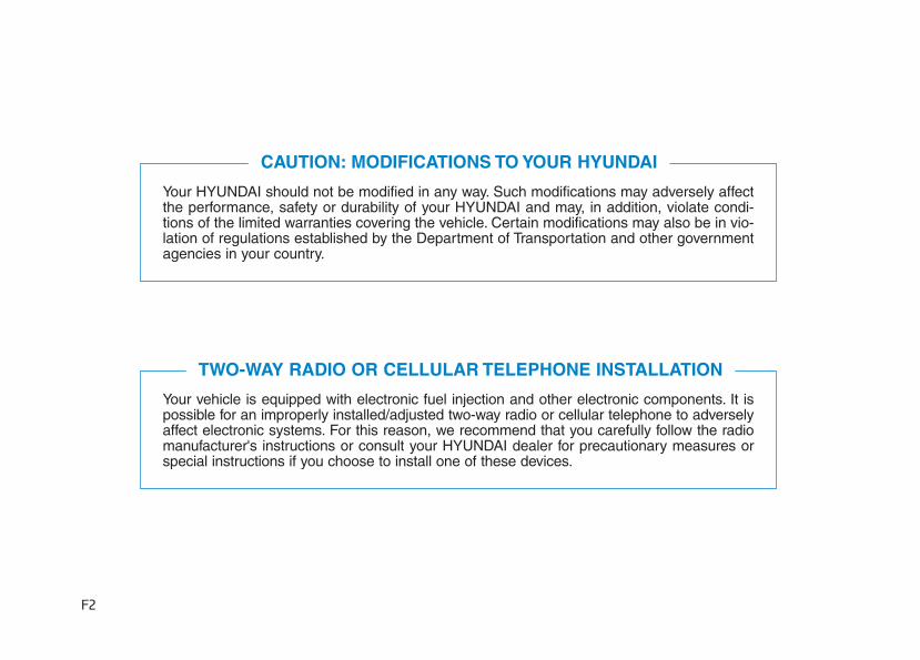
This manual includes information titled as DANGER, WARNING, CAUTION and NOTICE.These titles indicate the following:
SAFETY AND VEHICLE DAMAGE WARNING
DANGER indicates a hazardous situa-tion which, if not avoided, will resultin death or serious injury.
DANGER
WARNING indicates a hazardous situ-ation which, if not avoided, couldresult in death or serious injury.
CAUTION indicates a hazardous situa-tion which, if not avoided, could resultin minor or moderate injury.
CAUTION
NOTICE indicates a situation which, if notavoided, could result in vehicle damage.
NOTICEWARNING
F4
FOREWORD
Congratulations, and thank you for choosing HYUNDAI.We are pleased to welcome you to the growing number of dis-tinguished people who drive HYUNDAIS.We are very proud of the advanced engineering and high-quality construc-tion of each HYUNDAI we build.Your Owner’s Manual will introduce you to the features and operation of your new HYUNDAI. To become familiar withyour new HYUNDAI, so that you can fully enjoy it, read this Owner’s Manual carefully before driving your new vehicle.This manual contains important safety information and instructions intended to familiarize you with your vehicle’s con-trols and safety features so you can safely operate your vehicle.This manual also contains information on maintenance designed to enhance safe operation of the vehicle. It is rec-ommended that all service and maintenance on your car be performed by an authorized HYUNDAI dealer. HYUNDAIdealers are prepared to provide high-quality service, maintenance and any other assistance that may be required.This Owner’s Manual should be considered a permanent part of your vehicle, and should be kept in the vehicle soyou can refer to it at any time. The manual should stay with the vehicle if you sell it to provide the next owner withimportant operating, safety and maintenance information.
HYUNDAI MOTOR COMPANY
Copyright 2016 HYUNDAI Motor Company. All rights reserved. No part of this publication may be reproduced, storedin any retrieval system or transmitted in any form or by any means without the prior written permission of HYUNDAIMotor Company.
Severe engine and transmission damage may result from the use of poor quality fuels and lubricants thatdo not meet HYUNDAI specifications. You must always use high quality fuels and lubricants that meet thespecifications listed on Page 8-7 in the Vehicle Specifications section of the Owner's Manual.
CAUTION
We want to help you get the greatestpossible driving pleasure from yourvehicle. Your Owner’s Manual canassist you in many ways. We strong-ly recommend that you read theentire manual. In order to minimizethe chance of death or injury, youmust read the WARNING and CAU-TION sections in the manual.Illustrations complement the wordsin this manual to best explain how toenjoy your vehicle. By reading yourmanual, you will learn about fea-tures, important safety information,and driving tips under various roadconditions.The general layout of the manual isprovided in the Table of Contents.Use the index when looking for aspecific area or subject; it has analphabetical listing of all informationin your manual.Sections: This manual has eightchapters plus an index. Each chapterbegins with a brief list of contents soyou can tell at a glance if that sectionhas the information you want.
Your safety, and the safety of others,is very important. This Owner'sManual provides you with many safe-ty precautions and operating proce-dures. This information alerts you topotential hazards that may hurt youor others, as well as damage to yourvehicle.Safety messages found on vehiclelabels and in this manual describethese hazards and what to do toavoid or reduce the risks.Warnings and instructions containedin this manual are for your safety.Failure to follow safety warnings andinstructions can lead to serious injuryor death.
Throughout this manual DANGER,WARNING, CAUTION, NOTICE andthe SAFETY ALERT SYMBOL willbe used.
This is the safety alert sym-bol. It is used to alert you topotential physical injury haz-ards. Obey all safety mes-sages that follow this symbolto avoid possible injury ordeath. The safety alert sym-bol precedes the signal wordsDANGER, WARNING andCAUTION.
HHOOWW TTOO UUSSEE TTHHIISS MMAANNUUAALL SSAAFFEETTYY MMEESSSSAAGGEESS
F5
Introduction
DANGER indicates a hazardoussituation which, if not avoided,will result in death or seriousinjury.
DANGER
WARNING indicates a hazardoussituation which, if not avoided,could result in death or seriousinjury.
WARNING
F6
Introduction
NOTICE indicates a situationwhich, if not avoided, could resultin vehicle damage.
Gasoline engine UnleadedFor Europe
For the optimal vehicle performance,we recommend you use unleadedgasoline which has an octane rating ofRON (Research Octane Number) 95 /AKI (Anti Knock Index) 91 or higher.You may use unleaded gasoline withan octane rating of RON 91-94 / AKI87-90 but it may result in slight per-formance reduction of the vehicle. (Donot use methanol blended fuels)
Except Europe
Your new vehicle is designed to useonly unleaded fuel having an OctaneRating of RON (Research OctaneNumber) 91 / AKI (Anti-Knock Index)87 or higher. (Do not use methanolblended fuels)
Your new vehicle is designed toobtain maximum performance withUNLEADED FUEL, as well as mini-mize exhaust emissions and sparkplug fouling.
NOTICE
• Do not "top off" after the noz-zle automatically shuts offwhen refueling.
• Always check that the fuel capis installed securely to pre-vent fuel spillage in the eventof an accident.
WARNING
NEVER USE LEADED FUEL.Theuse of leaded fuel is detrimentalto the catalytic converter andwill damage the engine controlsystem’s oxygen sensor andaffect emission control.Never add any fuel systemcleaning agents to the fuel tankother than what has been speci-fied (We recommend that youconsult an authorized HYUNDAIdealer for details.)
CAUTION
CAUTION indicates a hazardoussituation which, if not avoided,could result in minor or moder-ate injury.
CAUTION
FFUUEELL RREEQQUUIIRREEMMEENNTTSS
F7
Introduction
Leaded (if equipped)For some countries, your vehicle isdesigned to use leaded gasoline.When you are going to use leadedgasoline, we recommend that youask an authorized HYUNDAI dealer.Octane rating of leaded gasoline issame with unleaded one.
Gasoline containing alcohol andmethanolGasohol, a mixture of gasoline andethanol (also known as grain alco-hol), and gasoline or gasohol con-taining methanol (also known aswood alcohol) are being marketedalong with or instead of leaded orunleaded gasoline.Do not use gasohol containing morethan 10% ethanol, and do not usegasoline or gasohol containing anymethanol. Either of these fuels maycause drivability problems and dam-age to the fuel system, engine controlsystem and emission control system.Discontinue using gasohol of anykind if drivability problems occur.
Vehicle damage or driveability prob-lems may not be covered by themanufacturer’s warranty if they resultfrom the use of:1. Gasohol containing more than
10% ethanol.2. Gasoline or gasohol containing
methanol.3. Leaded fuel or leaded gasohol.
Other fuelsUsing fuel additives such as:- Silicone fuel additive- MMT (Magnanese, Mn) fuel additive- Ferrocene (iron-based) fuel additive- Other metallic-based fuel additives
may result in cylinder misfire, pooracceleration, engine stalling, dam-age to the catalyst, or abnormal cor-rosion, and may cause damage tothe engine resulting in a reduction inthe overall life of the powertrain.
Damage to the fuel system or per-formance problem caused by theuse of these fuels may not be cov-ered by your New Vehicle LimitedWarranty.
NOTICE
Never use gasohol which con-tains methanol. Discontinueuse of any gasohol productwhich impairs drivability.
CAUTION
F8
Introduction
Use of MTBEHYUNDAI recommends avoidingfuels containing MTBE (MethylTertiary Butyl Ether) over 15.0% vol.(Oxygen Content 2.7% weight) inyour vehicle.Fuel containing MTBE over 15.0%vol. (Oxygen Content 2.7% weight)may reduce vehicle performance andproduce vapor lock or hard starting.
Do not use methanolFuels containing methanol (woodalcohol) should not be used in yourvehicle. This type of fuel can reducevehicle performance and damagecomponents of the fuel system, enginecontrol system and emission controlsystem.
Fuel AdditivesHYUNDAI recommends that you useunleaded gasoline which has anoctane rating of RON (ResearchOctane Number) 95 / AKI (Anti KnockIndex) 91 or higher (for Europe) orOctane Rating of RON (ResearchOctane Number) 91 / AKI (Anti-KnockIndex) 87 or higher (except Europe).For customers who do not use goodquality gasolines including fuel addi-tives regularly, and have problemsstarting or the engine does not runsmoothly, one bottle of additives addedto the fuel tank at every 15,000km (forEurope) / 10,000km (except Europe).Additives are available from yourauthorized HYUNDAI dealer alongwith information on how to use them.Do not mix other additives.
Operation in foreign countriesIf you are going to drive your vehiclein another country, be sure to:• Observe all regulations regarding
registration and insurance.• Determine that acceptable fuel is
available.
Your New Vehicle LimitedWarranty may not cover dam-age to the fuel system and anyperformance problems that arecaused by the use of fuels con-taining methanol or fuels con-taining MTBE (Methyl TertiaryButyl Ether) over 15.0% vol.(Oxygen Content 2.7% weight.)
CAUTION
Diesel engineDiesel fuelDiesel engine must be operated onlyon commercially available diesel fuelthat complies with EN 590 or compa-rable standard. (EN stands for"European Norm"). Do not usemarine diesel fuel, heating oils, ornon-approved fuel additives, as thiswill increase wear and cause dam-age to the engine and fuel system.The use of non-approved fuels and /or fuel additives will result in a limita-tion of your warranty rights.Diesel fuel of above cetane 51 isused in your vehicle. If two types ofdiesel fuel are available, use summeror winter fuel properly according tothe following temperature conditions.• Above -5°C (23°F) ... Summer type
diesel fuel.• Below -5°C (23°F) ... Winter type
diesel fuel.
Watch the fuel level in the tank verycarefully : If the engine stops throughfuel failure, the circuits must be com-pletely purged to permit restarting.
Biodiesel Commercially supplied Diesel blendsof no more than 7% biodiesel, com-monly known as "B7 Diesel" may beused in your vehicle if Biodiesel meetsEN 14214 or equivalent specifications.(EN stands for "European Norm").Theuse of biofuels exceeding 7% madefrom rapeseed methyl ester (RME),fatty acid methyl ester (FAME), veg-etable oil methyl ester (VME) etc. ormixing diesel exceeding 7% withbiodiesel will cause increased wear ordamage to the engine and fuel sys-tem. Repair or replacement of worn ordamaged components due to the useof non approved fuels will not be cov-ered by the manufactures warranty.
F9
Introduction
Do not let any gasoline or waterenter the tank. This would makeit necessary to drain it out andto bleed the lines to avoid jam-ming the injection pump anddamaging the engine.
CAUTION
It is recommended to use theregulated automotive dieselfuel for diesel vehicle equippedwith the DPF system.If you use diesel fuel includinghigh sulfur (more than 50 ppmsulfur) and unspecified addi-tives, it can cause the DPF sys-tem to be damaged and whitesmoke can be emitted.
CAUTION
• Never use any fuel, whetherdiesel, B7 biodiesel or other-wise, that fails to meet the lat-est petroleum industry speci-fication.
• Never use any fuel additivesor treatments that are not rec-ommended or approved bythe vehicle manufacturer.
CAUTION
F10
Introduction
This vehicle should not be modified.Modification of your vehicle couldaffect its performance, safety ordurability and may even violate gov-ernmental safety and emissions reg-ulations.In addition, damage or performanceproblems resulting from any modifi-cation may not be covered underwarranty.• If you use unauthorized electronic
devices, it may cause the vehicle tooperate abnormally, wire damage,battery discharge and fire. For yoursafety, do not use unauthorizedelectronic devices.
By following a few simple precautionsfor the first 1,000 km (600 miles) youmay add to the performance, econo-my and life of your vehicle.• Do not race the engine.• While driving, keep your engine
speed (rpm, or revolutions perminute) between 2,000 rpm and4,000 rpm.
• Do not maintain a single speed forlong periods of time, either fast orslow.Varying engine speed is need-ed to properly break-in the engine.
• Avoid hard stops, except in emer-gencies, to allow the brakes to seatproperly.
• Don't tow a trailer during the first2,000 km (1,200 miles) of operation.
HYUNDAI promotes an environmen-tally sound treatment for end of lifevehicles and offers to take back yourHYUNDAI end of life vehicles inaccordance with the European Union(EU) End of Life Vehicles Directive.
You can get detailed informationfrom your national HYUNDAI home-page.
VVEEHHIICCLLEE BBRREEAAKK--IINNPPRROOCCEESSSS
VVEEHHIICCLLEE MMOODDIIFFIICCAATTIIOONNSS RREETTUURRNNIINNGG UUSSEEDD VVEEHHIICCLLEESS((FFOORR EEUURROOPPEE))
1
2
3
4
5
6
7
8
I
Your vehicle at a glance
Safety system of your vehicle
Convenient features of your vehicle
Multimedia System
Driving your vehicle
What to do in an emergency
Maintenance
Specifications & Consumer information
Index
TABLE OF CONTENTS
F11
Your vehicle at a glance
1
Your vehicle at a glance
1Exterior overview (I) .............................................1-2Exterior overview (II) ............................................1-3Interior overview....................................................1-4Instrument panel overview (I)..............................1-5Instrument panel overview (II).............................1-6Engine compartment .............................................1-7
1-2
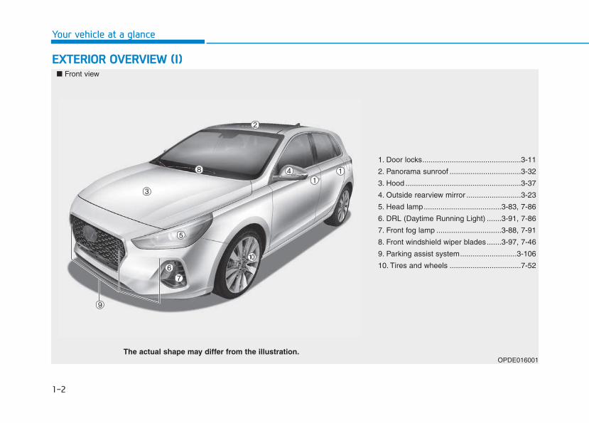
EEXXTTEERRIIOORR OOVVEERRVVIIEEWW ((II))
Your vehicle at a glance
1. Door locks...............................................3-11
2. Panorama sunroof ..................................3-32
3. Hood .......................................................3-37
4. Outside rearview mirror ..........................3-23
5. Head lamp.....................................3-83, 7-86
6. DRL (Daytime Running Light) .......3-91, 7-86
7. Front fog lamp ...............................3-88, 7-91
8. Front windshield wiper blades.......3-97, 7-46
9. Parking assist system...........................3-106
10. Tires and wheels ..................................7-52
OPDE016001
■ Front view
The actual shape may differ from the illustration.
1-3
Your vehicle at a glance
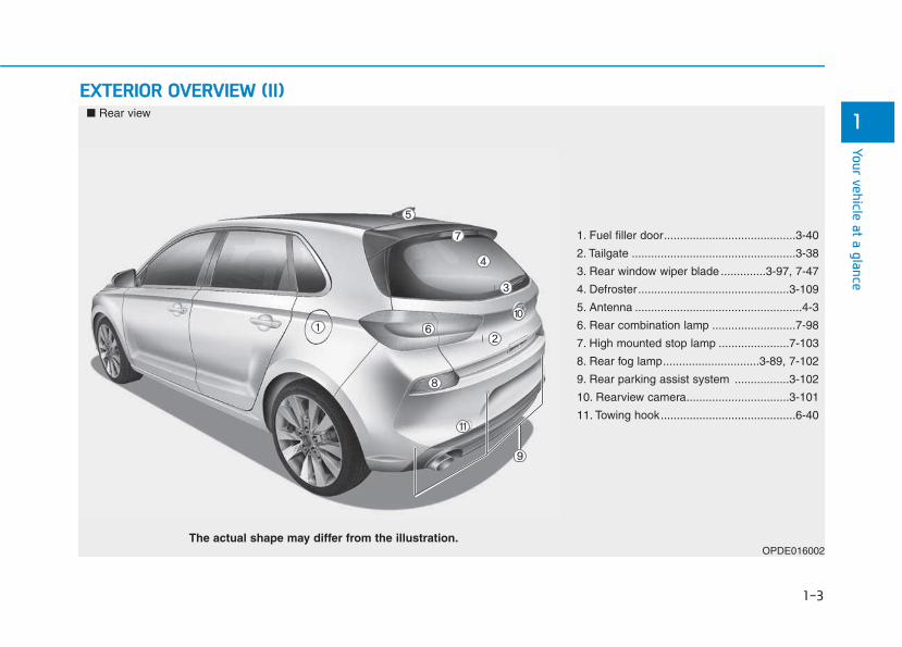
EEXXTTEERRIIOORR OOVVEERRVVIIEEWW ((IIII))
1
1. Fuel filler door.........................................3-40
2. Tailgate ...................................................3-38
3. Rear window wiper blade ..............3-97, 7-47
4. Defroster...............................................3-109
5. Antenna ....................................................4-3
6. Rear combination lamp ..........................7-98
7. High mounted stop lamp ......................7-103
8. Rear fog lamp..............................3-89, 7-102
9. Rear parking assist system .................3-102
10. Rearview camera................................3-101
11. Towing hook..........................................6-40
OPDE016002
■ Rear view
The actual shape may differ from the illustration.
1-4
Your vehicle at a glance
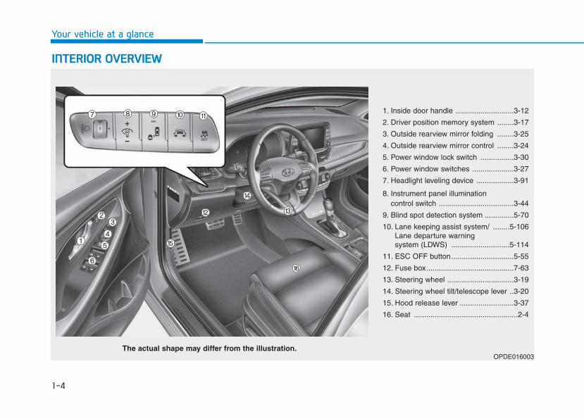
IINNTTEERRIIOORR OOVVEERRVVIIEEWW
1. Inside door handle ............................3-12
2. Driver position memory system ........3-17
3. Outside rearview mirror folding ........3-25
4. Outside rearview mirror control ........3-24
5. Power window lock switch ................3-30
6. Power window switches ....................3-27
7. Headlight leveling device ..................3-91
8. Instrument panel illumination control switch ....................................3-44
9. Blind spot detection system ..............5-70
10. Lane keeping assist system/ ........5-106Lane departure warning system (LDWS) ............................5-114
11. ESC OFF button..............................5-55
12. Fuse box..........................................7-63
13. Steering wheel ................................3-19
14. Steering wheel tilt/telescope lever ..3-20
15. Hood release lever ..........................3-37
16. Seat ..................................................2-4
OPDE016003The actual shape may differ from the illustration.
1-5
Your vehicle at a glance
1IINNSSTTRRUUMMEENNTT PPAANNEELL OOVVEERRVVIIEEWW ((II))
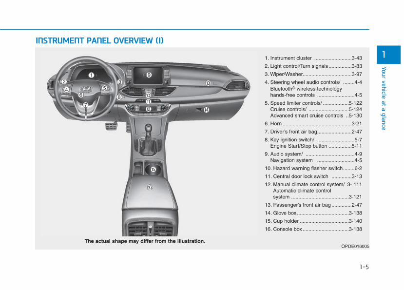
1. Instrument cluster ..........................3-43
2. Light control/Turn signals ................3-83
3. Wiper/Washer..................................3-97
4. Steering wheel audio controls/ ........4-4Bluetooth® wireless technology hands-free controls ..........................4-5
5. Speed limiter controls/ ..................5-122Cruise controls/ ............................5-124Advanced smart cruise controls ..5-130
6. Horn ................................................3-21
7. Driver’s front air bag........................2-47
8. Key ignition switch/ ..........................5-7Engine Start/Stop button ................5-11
9. Audio system/ ..................................4-9Navigation system ..........................4-5
10. Hazard warning flasher switch........6-2
11. Central door lock switch ..............3-13
12. Manual climate control system/ 3- 111Automatic climate control system ........................................3-121
13. Passenger’s front air bag ..............2-47
14. Glove box ....................................3-138
15. Cup holder ..................................3-140
16. Console box ................................3-138
OPDE016005The actual shape may differ from the illustration.
1-6
IINNSSTTRRUUMMEENNTT PPAANNEELL OOVVEERRVVIIEEWW ((IIII))
Your vehicle at a glance
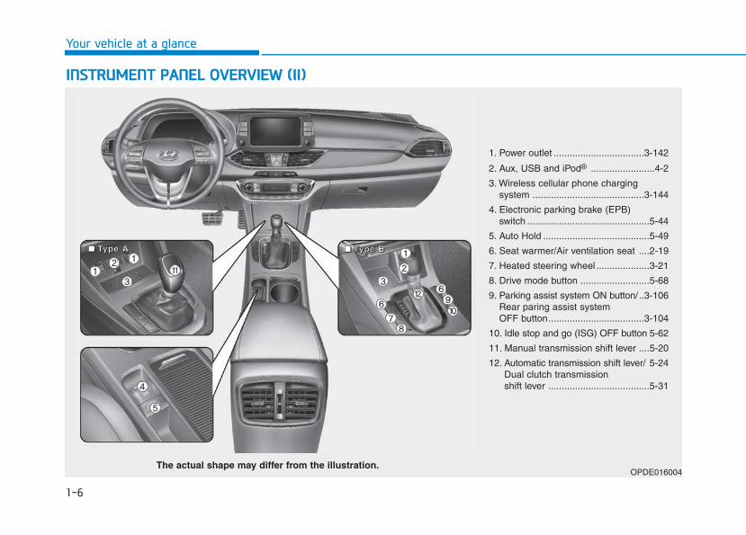
1. Power outlet ..................................3-142
2. Aux, USB and iPod® ........................4-2
3. Wireless cellular phone charging system ..........................................3-144
4. Electronic parking brake (EPB) switch ..............................................5-44
5. Auto Hold ........................................5-49
6. Seat warmer/Air ventilation seat ....2-19
7. Heated steering wheel ....................3-21
8. Drive mode button ..........................5-68
9. Parking assist system ON button/ ..3-106Rear paring assist system OFF button....................................3-104
10. Idle stop and go (ISG) OFF button 5-62
11. Manual transmission shift lever ....5-20
12. Automatic transmission shift lever/ 5-24Dual clutch transmission shift lever ......................................5-31
OPDE016004The actual shape may differ from the illustration.
■■■■ TTTTyyyyppppeeee AAAA ■■■■ TTTTyyyyppppeeee BBBB
1-7
Your vehicle at a glance
1EENNGGIINNEE CCOOMMPPAARRTTMMEENNTT
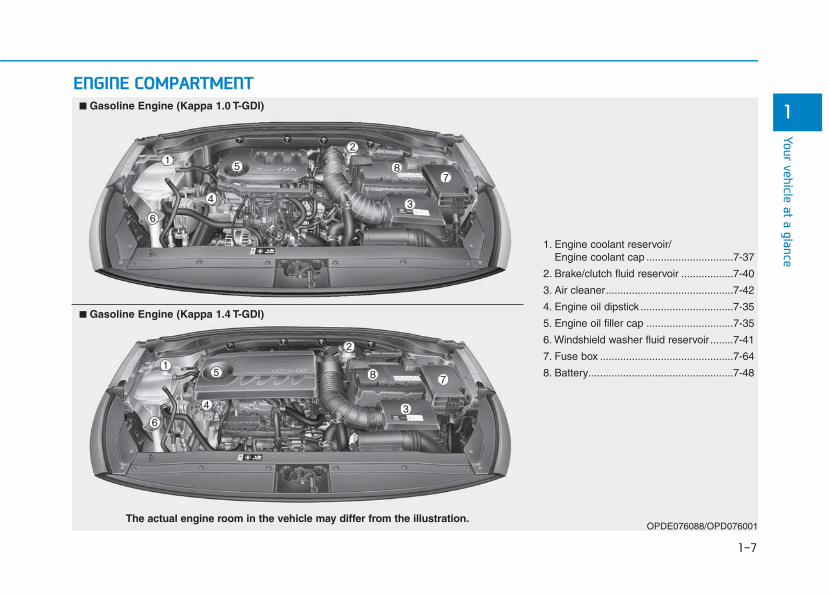
1. Engine coolant reservoir/Engine coolant cap ..............................7-37
2. Brake/clutch fluid reservoir ..................7-40
3. Air cleaner............................................7-42
4. Engine oil dipstick ................................7-35
5. Engine oil filler cap ..............................7-35
6. Windshield washer fluid reservoir ........7-41
7. Fuse box ..............................................7-64
8. Battery..................................................7-48
OPDE076088/OPD076001The actual engine room in the vehicle may differ from the illustration.
■■ Gasoline Engine (Kappa 1.0 T-GDI)
■■ Gasoline Engine (Kappa 1.4 T-GDI)
1-8
Your vehicle at a glance
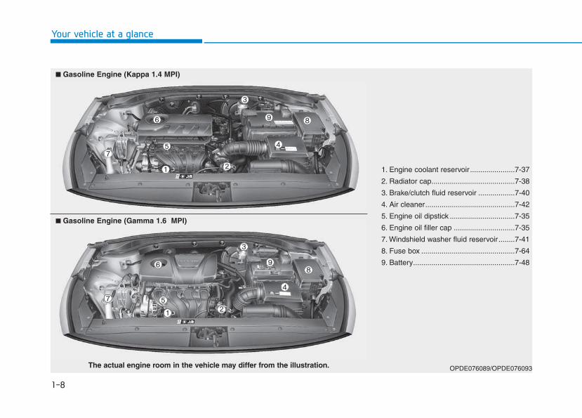
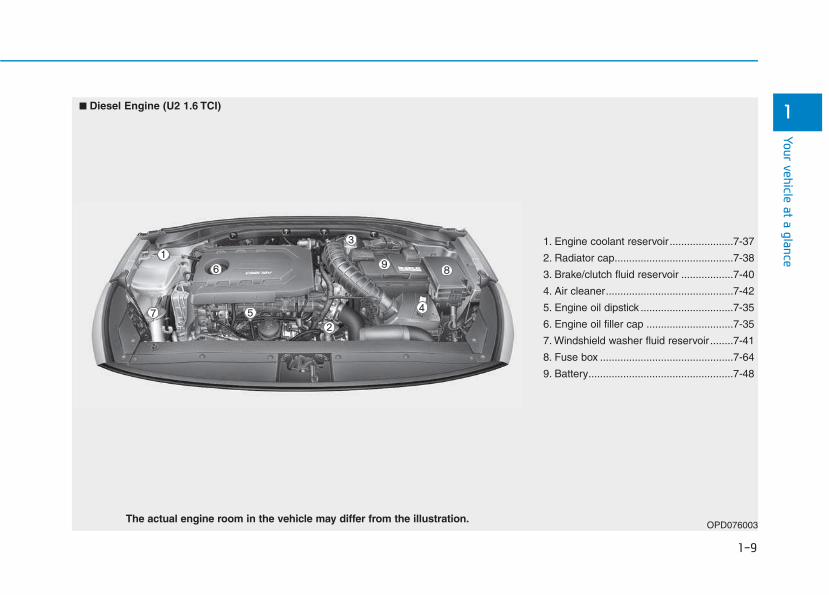
1. Engine coolant reservoir......................7-37
2. Radiator cap.........................................7-38
3. Brake/clutch fluid reservoir ..................7-40
4. Air cleaner............................................7-42
5. Engine oil dipstick ................................7-35
6. Engine oil filler cap ..............................7-35
7. Windshield washer fluid reservoir ........7-41
8. Fuse box ..............................................7-64
9. Battery..................................................7-48
OPDE076089/OPDE076093The actual engine room in the vehicle may differ from the illustration.
■■ Gasoline Engine (Kappa 1.4 MPI)
■■ Gasoline Engine (Gamma 1.6 MPI)
1-9
Your vehicle at a glance
1
1. Engine coolant reservoir......................7-37
2. Radiator cap.........................................7-38
3. Brake/clutch fluid reservoir ..................7-40
4. Air cleaner............................................7-42
5. Engine oil dipstick ................................7-35
6. Engine oil filler cap ..............................7-35
7. Windshield washer fluid reservoir ........7-41
8. Fuse box ..............................................7-64
9. Battery..................................................7-48
OPD076003The actual engine room in the vehicle may differ from the illustration.
■■ Diesel Engine (U2 1.6 TCI)
Safety system of your vehicle
2Important safety precautions .............................2-2
Always wear your seat belt ..........................................2-2Restrain all children .........................................................2-2Air bag hazards ................................................................2-2Driver distraction .............................................................2-2Control your speed ..........................................................2-3Keep your vehicle in safe condition ............................2-3
Seats ........................................................................2-4Safety precautions ..........................................................2-5Front seats..........................................................................2-6Rear seats .........................................................................2-12Headrest ...........................................................................2-15Seat warmers and air ventilation seats.....................2-19
Seat belts .............................................................2-22Seat belt safety precautions ......................................2-22Seat belt warning light .................................................2-23Seat belt restraint system ...........................................2-25Additional seat belt safety precautions ...................2-31Care of seat belts ..........................................................2-33
Child restraint system (CRS) .............................2-34Our recommendation:Children always in the rear 2-34Selecting a Child Restraint System (CRS) ................2-35Installing a Child Restraint System (CRS)..................2-37
Air bag - supplemental restraint system ........2-45Where are the air bags? ..............................................2-47How does the air bags system operate? .................2-52What to expect after an air bag inflates ................2-56Why didn't my air bag go off in a collision? ...........2-57SRS care ...........................................................................2-62Additional safety precautions .....................................2-63Air bag warning labels ..................................................2-63
This chapter provides you with important information about how to protect yourself and your passengers.It explains how to properly use your seats and seat belts, and how your air bags work.Additionally, this chapter explains how to properly restrain infants and children in your vehicle.
2-2
You will find many safety precautionsand recommendations throughoutthis section, and throughout this man-ual.The safety precautions in this sec-tion are among the most important.
Always wear your seat belt A seat belt is your best protection inall types of accidents. Air bags aredesigned to supplement seat belts,not replace them. So even thoughyour vehicle is equipped with air bags,ALWAYS make sure you and yourpassengers wear your seat belts, andwear them properly.
Restrain all children All children under age 13 should ridein your vehicle properly restrained ina rear seat, not the front seat. Infantsand small children should berestrained in an appropriate ChildRestraint System. Larger childrenshould use a booster seat with thelap/shoulder belt until they can usethe seat belt properly without abooster seat.
Air bag hazards While air bags can save lives, theycan also cause serious or fatalinjuries to occupants who sit tooclose to them, or who are not prop-erly restrained. Infants, young chil-dren, and short adults are at thegreatest risk of being injured by aninflating air bag. Follow all instruc-tions and warnings in this manual.
Driver distraction Driver distraction presents a seriousand potentially deadly danger, espe-cially for inexperienced drivers. Safetyshould be the first concern whenbehind the wheel and drivers need tobe aware of the wide array of potentialdistractions, such as drowsiness,reaching for objects, eating, personalgrooming, other passengers, andusing cellular phones.Drivers can become distracted whenthey take their eyes and attention offthe road or their hands off the wheelto focus on activities other than driv-ing. To reduce your risk of distractionand an accident:• ALWAYS set up your mobile devices
(i.e., MP3 players, phones, naviga-tion units, etc.) when your vehicle isparked or safely stopped.
• ONLY use your mobile device whenallowed by laws and conditions per-mit safe use. NEVER text or emailwhile driving. Most countries havelaws prohibiting drivers from texting.Some countries and cities also pro-hibit drivers from using handheldphones.
IIMMPPOORRTTAANNTT SSAAFFEETTYY PPRREECCAAUUTTIIOONNSS
Safety system of your vehicle
2-3
Safety system of your vehicle
• NEVER let the use of a mobile devicedistract you from driving. You have aresponsibility to your passengers andothers on the road to always drivesafely, with your hands on the wheelas well as your eyes and attention onthe road.
Control your speed Excessive speed is a major factor incrash injuries and deaths. Generally,the higher the speed, the greater therisk, but serious injuries can alsooccur at lower speeds. Never drivefaster than is safe for current condi-tions, regardless of the maximumspeed posted.
Keep your vehicle in safe condi-tion Having a tire blowout or a mechanicalfailure can be extremely hazardous. Toreduce the possibility of such prob-lems, check your tire pressures andcondition frequently, and perform allregularly scheduled maintenance.
2
2-4
SSEEAATTSS
Safety system of your vehicle
OPDE036001
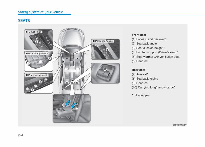
Front seat(1) Forward and backward
(2) Seatback angle
(3) Seat cushion height *
(4) Lumbar support (Driver’s seat)*
(5) Seat warmer*/Air ventilation seat*
(6) Headrest
Rear seat(7) Armrest*
(8) Seatback folding
(9) Headrest
(10) Carrying long/narrow cargo*
* : if equipped
■ Driver’s side
■ Manual adjustment
■ Power adjustment
■ Passenger's side
To reduce the risk of seriousinjury or death from an inflatingair bag, take the following pre-cautions:• Adjust the driver’s seat as far
to the rear as possible main-taining the ability to control ofthe vehicle.
• Adjust the front passenger seatas far to the rear as possible.
(Continued)
WARNING
(Continued)• Hold the steering wheel by the
rim with hands at the 9 o’clockand 3 o’clock positions to min-imize the risk of injuries toyour hands and arms.
• NEVER place anything or any-one between the air bag.
• Do not allow the front passen-ger to place feet or legs on thedashboard to minimize the riskof leg injuries.
2-5
Safety system of your vehicle
2
Safety precautions Adjusting the seats so that you are sit-ting in a safe, comfortable positionplays an important role in driver andpassenger safety together with theseat belts and air bags in an accident.
Air bags You can take steps to reduce the riskof being injured by an inflating airbag. Sitting too close to an air baggreatly increases the risk of injury inthe event the air bag inflates. Moveyour seat as far back as possiblefrom front air bags, while still main-taining control of the vehicle.
Do not use a cushion that reducesfriction between the seat and thepassenger.The passenger's hipsmay slide under the lap portionof the seat belt during an acci-dent or a sudden stop.Serious or fatal internal injuriescould result because the seatbelt cannot operate properly.
WARNING
2-6
Safety system of your vehicle
Seat beltsAlways fasten your seat belt beforestarting any trip.At all times, passengers should situpright and be properly restrained.Infants and small children must berestrained in appropriate Child RestraintSystems.Children who have outgrown abooster seat and adults must berestrained using the seat belts.
Front seatsThe front seat can be adjusted byusing the control lever (or knob) orswitches located on the outside of theseat cushion. Before driving, adjustthe seat to the proper position so thatyou can easily control the steeringwheel, foot pedals and controls on theinstrument panel.
Take the following precautionswhen adjusting your seat belt:• NEVER use one seat belt for
more than one occupant.• Always position the seatback
upright with the lap portion ofthe seat belt snug and lowacross the hips.
• NEVER allow children or smallinfants to ride in a passenger’slap.
(Continued)
(Continued)• Do not route the seat belt
across your neck, across sharpedges, or reroute the shoulderstrap away from your body.
• Do not allow the seat belt tobecome caught or jammed.
WARNING Take the following precautionswhen adjusting your seat:• NEVER attempt to adjust the
seat while the vehicle is mov-ing. The seat could respondwith unexpected movementand may cause loss of vehiclecontrol resulting in an acci-dent.
• Do not place anything underthe front seats. Loose objectsin the driver’s foot area couldinterfere with the operation ofthe foot pedals, causing anaccident.
(Continued)
WARNING
2-7
Safety system of your vehicle
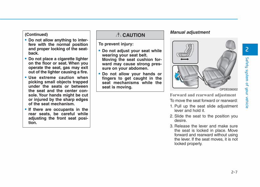
Manual adjustment
Forward and rearward adjustment
To move the seat forward or rearward:1. Pull up the seat slide adjustment
lever and hold it.2. Slide the seat to the position you
desire.3. Release the lever and make sure
the seat is locked in place. Moveforward and rearward without usingthe lever. If the seat moves, it is notlocked properly.
2To prevent injury:
• Do not adjust your seat whilewearing your seat belt.Moving the seat cushion for-ward may cause strong pres-sure on your abdomen.
• Do not allow your hands orfingers to get caught in theseat mechanisms while theseat is moving.
CAUTION(Continued)• Do not allow anything to inter-
fere with the normal positionand proper locking of the seat-back.
• Do not place a cigarette lighteron the floor or seat. When youoperate the seat, gas may exitout of the lighter causing a fire.
• Use extreme caution whenpicking small objects trappedunder the seats or betweenthe seat and the center con-sole. Your hands might be cutor injured by the sharp edgesof the seat mechanism.
• If there are occupants in therear seats, be careful whileadjusting the front seat posi-tion.
OPDE036002
2-8
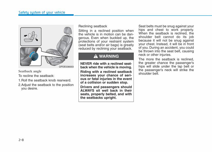
Seatback angle
To recline the seatback:1.Roll the seatback knob rearward.2.Adjust the seatback to the position
you desire.
Reclining seatback Sitting in a reclined position whenthe vehicle is in motion can be dan-gerous. Even when buckled up, theprotections of your restraint system(seat belts and/or air bags) is greatlyreduced by reclining your seatback.
Seat belts must be snug against yourhips and chest to work properly.When the seatback is reclined, theshoulder belt cannot do its jobbecause it will not be snug againstyour chest. Instead, it will be in frontof you. During an accident, you couldbe thrown into the seat belt, causingneck or other injuries.The more the seatback is reclined,the greater chance the passenger’ships will slide under the lap belt orthe passenger’s neck will strike theshoulder belt.
Safety system of your vehicle
OPDE036003NEVER ride with a reclined seat-back when the vehicle is moving.Riding with a reclined seatbackincreases your chance of seri-ous or fatal injuries in the eventof a collision or sudden stop.Drivers and passengers shouldALWAYS sit well back in theirseats, properly belted, and withthe seatbacks upright.
WARNING
2-9
Safety system of your vehicle
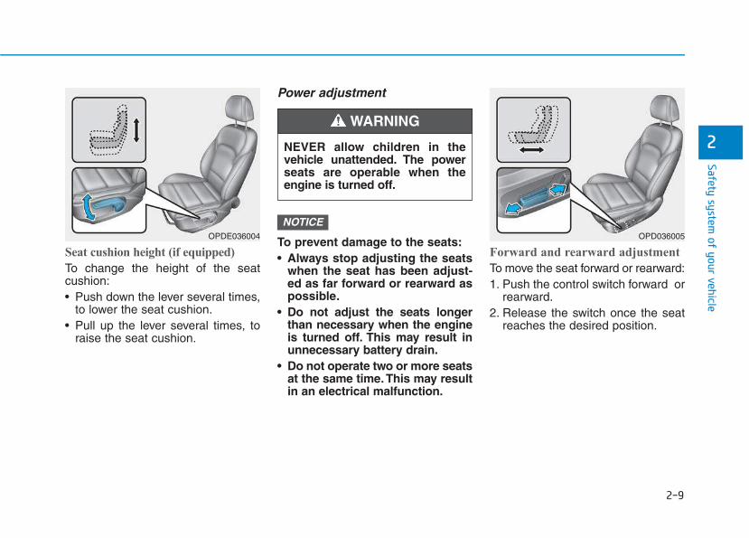
Seat cushion height (if equipped)
To change the height of the seatcushion:• Push down the lever several times,
to lower the seat cushion.• Pull up the lever several times, to
raise the seat cushion.
Power adjustment
To prevent damage to the seats:• Always stop adjusting the seats
when the seat has been adjust-ed as far forward or rearward aspossible.
• Do not adjust the seats longerthan necessary when the engineis turned off. This may result inunnecessary battery drain.
• Do not operate two or more seatsat the same time. This may resultin an electrical malfunction.
Forward and rearward adjustment
To move the seat forward or rearward:1. Push the control switch forward or
rearward.2. Release the switch once the seat
reaches the desired position.
NOTICE
2
OPDE036004
NEVER allow children in thevehicle unattended. The powerseats are operable when theengine is turned off.
WARNING
OPD036005
2-10
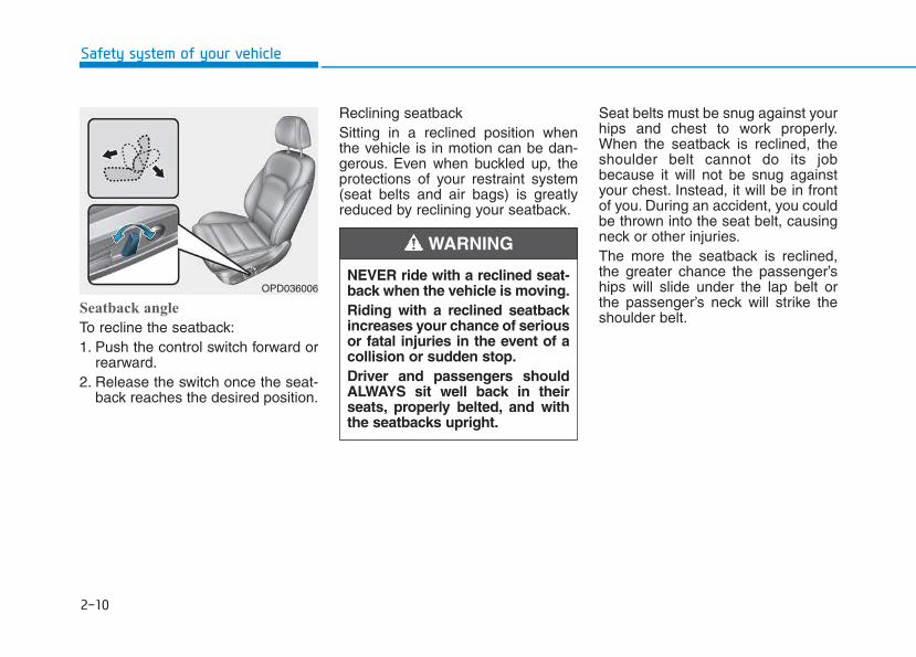
Seatback angle
To recline the seatback:1. Push the control switch forward or
rearward.2. Release the switch once the seat-
back reaches the desired position.
Reclining seatback Sitting in a reclined position whenthe vehicle is in motion can be dan-gerous. Even when buckled up, theprotections of your restraint system(seat belts and air bags) is greatlyreduced by reclining your seatback.
Seat belts must be snug against yourhips and chest to work properly.When the seatback is reclined, theshoulder belt cannot do its jobbecause it will not be snug againstyour chest. Instead, it will be in frontof you. During an accident, you couldbe thrown into the seat belt, causingneck or other injuries.The more the seatback is reclined,the greater chance the passenger’ships will slide under the lap belt orthe passenger’s neck will strike theshoulder belt.
Safety system of your vehicle
NEVER ride with a reclined seat-back when the vehicle is moving.Riding with a reclined seatbackincreases your chance of seriousor fatal injuries in the event of acollision or sudden stop.Driver and passengers shouldALWAYS sit well back in theirseats, properly belted, and withthe seatbacks upright.
WARNING
OPD036006
2-11
Safety system of your vehicle
2
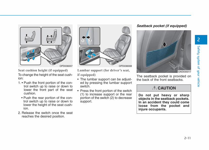
Seat cushion height (if equipped)
To change the height of the seat cush-ion:1. • Push the front portion of the con-
trol switch up to raise or down tolower the front part of the seatcushion.
• Push the rear portion of the con-trol switch up to raise or down tolower the height of the seat cush-ion.
2. Release the switch once the seatreaches the desired position.
Lumbar support (for driver’s seat,
if equipped)
• The lumbar support can be adjust-ed by pressing the lumbar supportswitch.
• Press the front portion of the switch(1) to increase support or the rearportion of the switch (2) to decreasesupport.
Seatback pocket (if equipped)
The seatback pocket is provided onthe back of the front seatbacks.
OPD036007 OPD036008
OAD035017
Do not put heavy or sharpobjects in the seatback pockets.In an accident they could comeloose from the pocket andinjure occupants.
CAUTION
2-12
Safety system of your vehicle
Rear seats
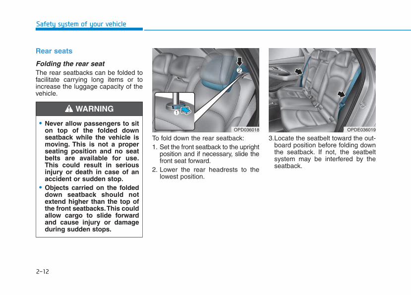
Folding the rear seat The rear seatbacks can be folded tofacilitate carrying long items or toincrease the luggage capacity of thevehicle.
To fold down the rear seatback:1. Set the front seatback to the upright
position and if necessary, slide thefront seat forward.
2. Lower the rear headrests to thelowest position.
3.Locate the seatbelt toward the out-board position before folding downthe seatback. If not, the seatbeltsystem may be interfered by theseatback.
• Never allow passengers to siton top of the folded downseatback while the vehicle ismoving. This is not a properseating position and no seatbelts are available for use.This could result in seriousinjury or death in case of anaccident or sudden stop.
• Objects carried on the foldeddown seatback should notextend higher than the top ofthe front seatbacks.This couldallow cargo to slide forwardand cause injury or damageduring sudden stops.
WARNING
OPD036018 OPDE036019
2-13
Safety system of your vehicle
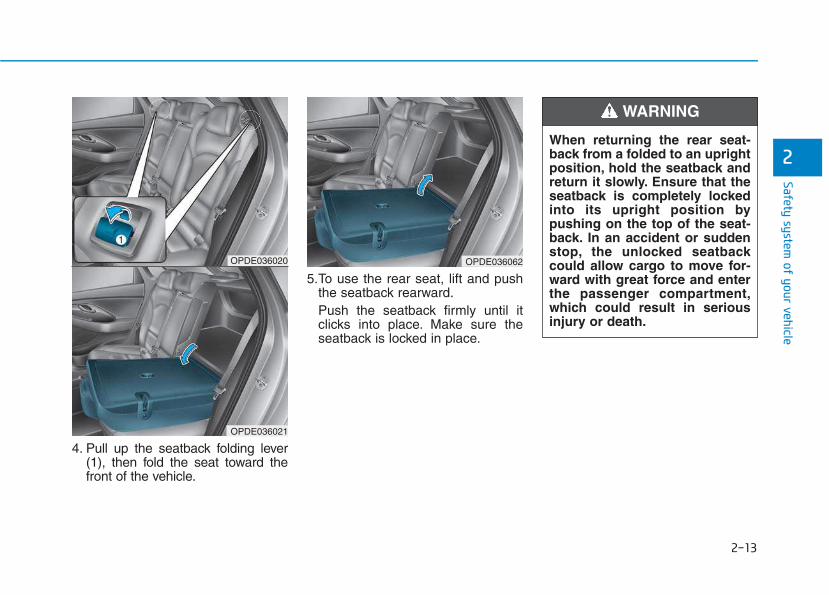
4. Pull up the seatback folding lever(1), then fold the seat toward thefront of the vehicle.
5.To use the rear seat, lift and pushthe seatback rearward.Push the seatback firmly until itclicks into place. Make sure theseatback is locked in place.
2
OPDE036062OPDE036020
OPDE036021
When returning the rear seat-back from a folded to an uprightposition, hold the seatback andreturn it slowly. Ensure that theseatback is completely lockedinto its upright position bypushing on the top of the seat-back. In an accident or suddenstop, the unlocked seatbackcould allow cargo to move for-ward with great force and enterthe passenger compartment,which could result in seriousinjury or death.
WARNING
2-14
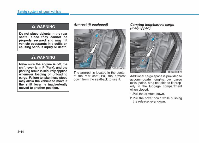
Armrest (if equipped)
The armrest is located in the centerof the rear seat. Pull the armrestdown from the seatback to use it.
Carrying long/narrow cargo (if equipped)
Additional cargo space is provided toaccommodate long/narrow cargo(skis, poles, etc.) not able to fit prop-erly in the luggage compartmentwhen closed.1.Pull the armrest down.2.Pull the cover down while pushing
the release lever down.
Safety system of your vehicle
Do not place objects in the rearseats, since they cannot beproperly secured and may hitvehicle occupants in a collisioncausing serious injury or death.
WARNING
Make sure the engine is off, theshift lever is in P (Park), and theparking brake is securely appliedwhenever loading or unloadingcargo. Failure to take these stepsmay allow the vehicle to move ifthe shift lever is inadvertentlymoved to another position.
WARNING
OPDE036022
OPDE036072
2-15
Safety system of your vehicle
2
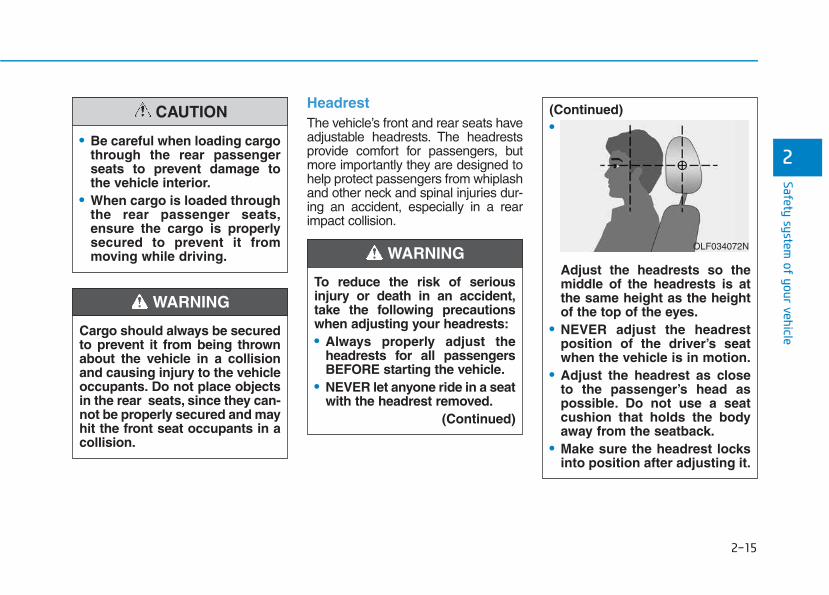
Headrest The vehicle’s front and rear seats haveadjustable headrests. The headrestsprovide comfort for passengers, butmore importantly they are designed tohelp protect passengers from whiplashand other neck and spinal injuries dur-ing an accident, especially in a rearimpact collision.
To reduce the risk of seriousinjury or death in an accident,take the following precautionswhen adjusting your headrests:• Always properly adjust the
headrests for all passengersBEFORE starting the vehicle.
• NEVER let anyone ride in a seatwith the headrest removed.
(Continued)
(Continued)•
Adjust the headrests so themiddle of the headrests is atthe same height as the heightof the top of the eyes.
• NEVER adjust the headrestposition of the driver’s seatwhen the vehicle is in motion.
• Adjust the headrest as closeto the passenger’s head aspossible. Do not use a seatcushion that holds the bodyaway from the seatback.
• Make sure the headrest locksinto position after adjusting it.
WARNING OLF034072N
Cargo should always be securedto prevent it from being thrownabout the vehicle in a collisionand causing injury to the vehicleoccupants. Do not place objectsin the rear seats, since they can-not be properly secured and mayhit the front seat occupants in acollision.
WARNING
• Be careful when loading cargothrough the rear passengerseats to prevent damage tothe vehicle interior.
• When cargo is loaded throughthe rear passenger seats,ensure the cargo is properlysecured to prevent it frommoving while driving.
CAUTION
2-16
Safety system of your vehicle
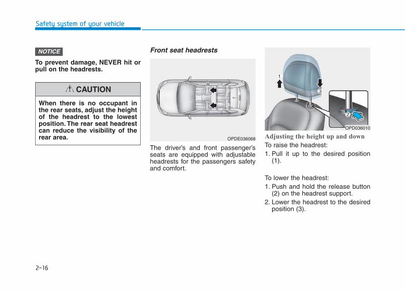
To prevent damage, NEVER hit orpull on the headrests.
Front seat headrests
The driver’s and front passenger’sseats are equipped with adjustableheadrests for the passengers safetyand comfort.
Adjusting the height up and down
To raise the headrest:1. Pull it up to the desired position
(1).
To lower the headrest:1. Push and hold the release button
(2) on the headrest support.2. Lower the headrest to the desired
position (3).
NOTICE
OPDE036068
OPD036010
When there is no occupant inthe rear seats, adjust the heightof the headrest to the lowestposition. The rear seat headrestcan reduce the visibility of therear area.
CAUTION
2-17
Safety system of your vehicle
2
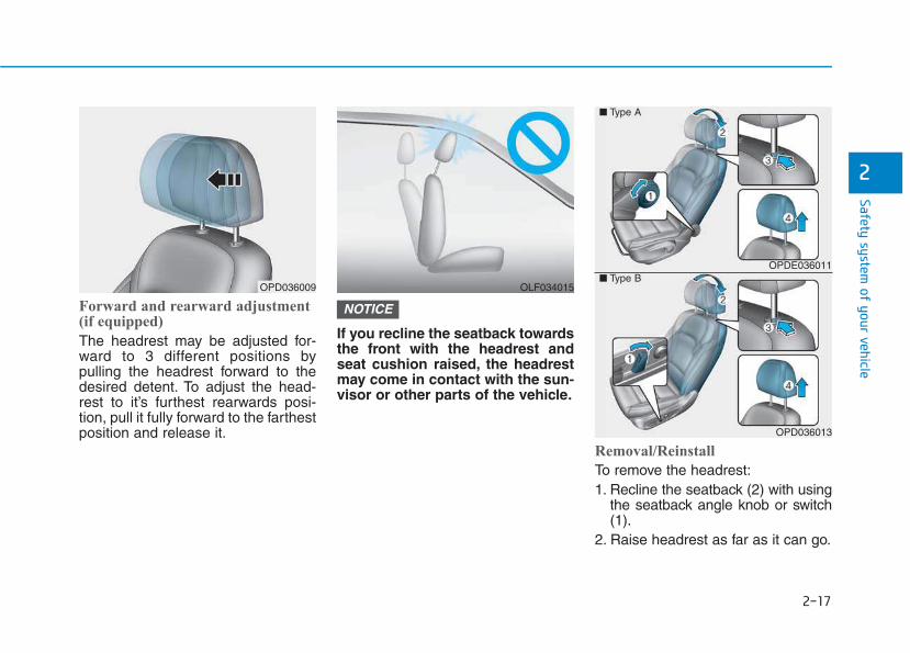
Forward and rearward adjustment(if equipped)
The headrest may be adjusted for-ward to 3 different positions bypulling the headrest forward to thedesired detent. To adjust the head-rest to it’s furthest rearwards posi-tion, pull it fully forward to the farthestposition and release it.
If you recline the seatback towardsthe front with the headrest andseat cushion raised, the headrestmay come in contact with the sun-visor or other parts of the vehicle.
Removal/Reinstall
To remove the headrest:1. Recline the seatback (2) with using
the seatback angle knob or switch(1).
2. Raise headrest as far as it can go.
NOTICE
OPDE036011
OPD036013
■ Type A
■ Type BOLF034015OPD036009
2-18
Safety system of your vehicle
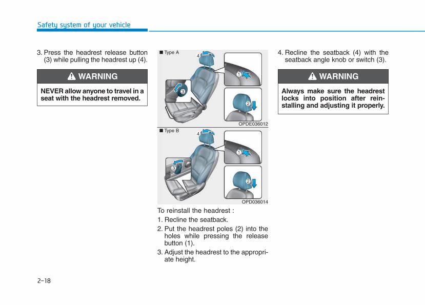
3. Press the headrest release button(3) while pulling the headrest up (4).
To reinstall the headrest :1. Recline the seatback.2. Put the headrest poles (2) into the
holes while pressing the releasebutton (1).
3. Adjust the headrest to the appropri-ate height.
4. Recline the seatback (4) with theseatback angle knob or switch (3).
Always make sure the headrestlocks into position after rein-stalling and adjusting it properly.
WARNING
OPDE036012
OPD036014
■ Type A
■ Type B
NEVER allow anyone to travel in aseat with the headrest removed.
WARNING
2-19
Safety system of your vehicle
2
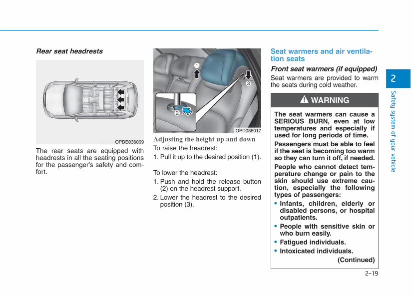
Rear seat headrests
The rear seats are equipped withheadrests in all the seating positionsfor the passenger’s safety and com-fort.
Adjusting the height up and down
To raise the headrest:1. Pull it up to the desired position (1).
To lower the headrest:1. Push and hold the release button
(2) on the headrest support.2. Lower the headrest to the desired
position (3).
Seat warmers and air ventila-tion seatsFront seat warmers (if equipped) Seat warmers are provided to warmthe seats during cold weather.
The seat warmers can cause aSERIOUS BURN, even at lowtemperatures and especially ifused for long periods of time.Passengers must be able to feelif the seat is becoming too warmso they can turn it off, if needed.People who cannot detect tem-perature change or pain to theskin should use extreme cau-tion, especially the followingtypes of passengers:• Infants, children, elderly or
disabled persons, or hospitaloutpatients.
• People with sensitive skin orwho burn easily.
• Fatigued individuals.• Intoxicated individuals.
(Continued)
WARNING
OPD036017
OPDE036069
2-20
Safety system of your vehicle
To prevent damage to the seatwarmers and seats:• Never use a solvent such as
paint thinner, benzene, alcoholor gasoline to clean the seats.
• Do not place heavy or sharpobjects on seats equipped withseat warmers.
• Do not change the seat cover. Itmay damage the seat warmer.
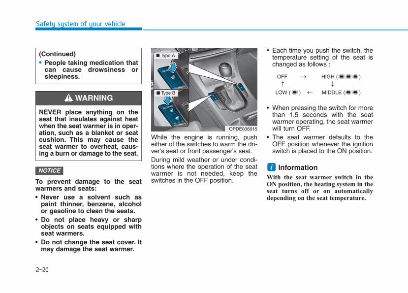
While the engine is running, pusheither of the switches to warm the dri-ver's seat or front passenger's seat.During mild weather or under condi-tions where the operation of the seatwarmer is not needed, keep theswitches in the OFF position.
• Each time you push the switch, thetemperature setting of the seat ischanged as follows :
• When pressing the switch for morethan 1.5 seconds with the seatwarmer operating, the seat warmerwill turn OFF.
• The seat warmer defaults to theOFF position whenever the ignitionswitch is placed to the ON position.
Information With the seat warmer switch in theON position, the heating system in theseat turns off or on automaticallydepending on the seat temperature.
iNOTICE
OPDE036015
■ Type A
■ Type B
OFF HIGH ( )
LOW ( ) MIDDLE ( )
→
→
→
→
(Continued)• People taking medication that
can cause drowsiness orsleepiness.
NEVER place anything on theseat that insulates against heatwhen the seat warmer is in oper-ation, such as a blanket or seatcushion. This may cause theseat warmer to overheat, caus-ing a burn or damage to the seat.
WARNING
2-21
Safety system of your vehicle
2
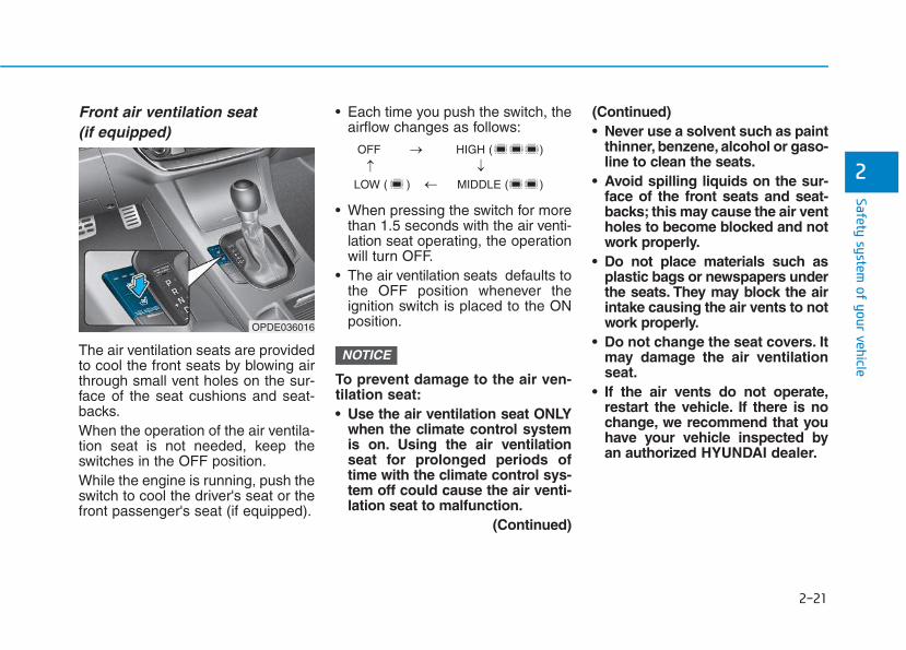
Front air ventilation seat(if equipped)
The air ventilation seats are providedto cool the front seats by blowing airthrough small vent holes on the sur-face of the seat cushions and seat-backs.When the operation of the air ventila-tion seat is not needed, keep theswitches in the OFF position.While the engine is running, push theswitch to cool the driver's seat or thefront passenger's seat (if equipped).
• Each time you push the switch, theairflow changes as follows:
• When pressing the switch for morethan 1.5 seconds with the air venti-lation seat operating, the operationwill turn OFF.
• The air ventilation seats defaults tothe OFF position whenever theignition switch is placed to the ONposition.
To prevent damage to the air ven-tilation seat:• Use the air ventilation seat ONLY
when the climate control systemis on. Using the air ventilationseat for prolonged periods oftime with the climate control sys-tem off could cause the air venti-lation seat to malfunction.
(Continued)
(Continued)• Never use a solvent such as paint
thinner, benzene, alcohol or gaso-line to clean the seats.
• Avoid spilling liquids on the sur-face of the front seats and seat-backs; this may cause the air ventholes to become blocked and notwork properly.
• Do not place materials such asplastic bags or newspapers underthe seats. They may block the airintake causing the air vents to notwork properly.
• Do not change the seat covers. Itmay damage the air ventilationseat.
• If the air vents do not operate,restart the vehicle. If there is nochange, we recommend that youhave your vehicle inspected byan authorized HYUNDAI dealer.
NOTICE
OFF HIGH ( )
LOW ( ) MIDDLE ( )
→
→
→
→
OPDE036016
2-22
Safety system of your vehicle
This section describes how to use theseat belts properly. It also describessome of the things not to do whenusing seat belts.
Seat belt safety precautions Always fasten your seat belt andmake sure all passengers have fas-tened their seat belts before startingany trip. Air bags are designed tosupplement the seat belt as an addi-tional safety device, but they are not asubstitute. Most countries require alloccupants of a vehicle to wear seatbelts.
SSEEAATT BBEELLTTSS
Seat belts must be used by ALLpassengers whenever the vehi-cle is moving.Take the followingprecautions when adjusting andwearing seat belts:• Children under the age of 13
should be properly restrainedin the rear seats.
• Never allow children to ride inthe front passenger seat, unlessthe air bag is deactivated. If achild is seated in the front pas-senger seat, move the seat asfar back as possible and prop-erly restrain them in the seat.
• NEVER allow an infant or childto be carried on an occupant’slap.
• NEVER ride with the seatbackreclined when the vehicle ismoving.
• Do not allow children to sharea seat or seat belt.
(Continued)
WARNING (Continued)• Do not wear the shoulder belt
under your arm or behind yourback.
• Never wear a seat belt overfragile objects. If there is a sud-den stop or impact, the seatbelt can damage it.
• Do not use the seat belt if it istwisted. A twisted seat beltwill not protect you properlyin an accident.
• Do not use a seat belt if thewebbing or hardware is dam-aged.
• Do not latch the seat belt intothe buckles of other seats.
• NEVER unfasten the seat beltwhile driving. This may causeloss of vehicle control result-ing in an accident.
• Make sure there is nothing inthe buckle interfering with theseat belt latch mechanism.This may prevent the seat beltfrom fastening securely.
(Continued)
2-23
Safety system of your vehicle
2
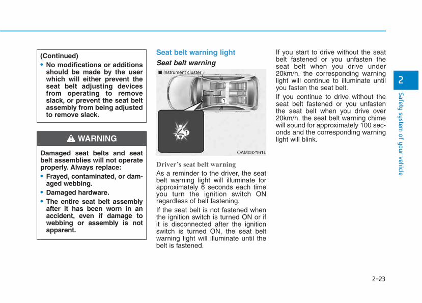
Seat belt warning light Seat belt warning
Driver’s seat belt warning
As a reminder to the driver, the seatbelt warning light will illuminate forapproximately 6 seconds each timeyou turn the ignition switch ONregardless of belt fastening.If the seat belt is not fastened whenthe ignition switch is turned ON or ifit is disconnected after the ignitionswitch is turned ON, the seat beltwarning light will illuminate until thebelt is fastened.
If you start to drive without the seatbelt fastened or you unfasten theseat belt when you drive under20km/h, the corresponding warninglight will continue to illuminate untilyou fasten the seat belt.If you continue to drive without theseat belt fastened or you unfastenthe seat belt when you drive over20km/h, the seat belt warning chimewill sound for approximately 100 sec-onds and the corresponding warninglight will blink.
Damaged seat belts and seatbelt assemblies will not operateproperly. Always replace:• Frayed, contaminated, or dam-
aged webbing.• Damaged hardware.• The entire seat belt assembly
after it has been worn in anaccident, even if damage towebbing or assembly is notapparent.
WARNING
(Continued)• No modifications or additions
should be made by the userwhich will either prevent theseat belt adjusting devicesfrom operating to removeslack, or prevent the seat beltassembly from being adjustedto remove slack.
OAM032161L
■ Instrument cluster
2-24
Safety system of your vehicle
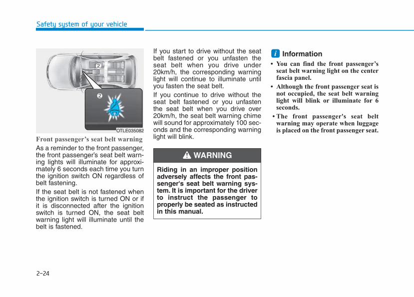
Front passenger’s seat belt warning
As a reminder to the front passenger,the front passenger’s seat belt warn-ing lights will illuminate for approxi-mately 6 seconds each time you turnthe ignition switch ON regardless ofbelt fastening.If the seat belt is not fastened whenthe ignition switch is turned ON or ifit is disconnected after the ignitionswitch is turned ON, the seat beltwarning light will illuminate until thebelt is fastened.
If you start to drive without the seatbelt fastened or you unfasten theseat belt when you drive under20km/h, the corresponding warninglight will continue to illuminate untilyou fasten the seat belt.If you continue to drive without theseat belt fastened or you unfastenthe seat belt when you drive over20km/h, the seat belt warning chimewill sound for approximately 100 sec-onds and the corresponding warninglight will blink.
Information • You can find the front passenger’s
seat belt warning light on the centerfascia panel.
• Although the front passenger seat isnot occupied, the seat belt warninglight will blink or illuminate for 6seconds.
• The front passenger's seat beltwarning may operate when luggageis placed on the front passenger seat.
i
Riding in an improper positionadversely affects the front pas-senger's seat belt warning sys-tem. It is important for the driverto instruct the passenger toproperly be seated as instructedin this manual.
WARNING
OTLE035082
2-25
Safety system of your vehicle
2
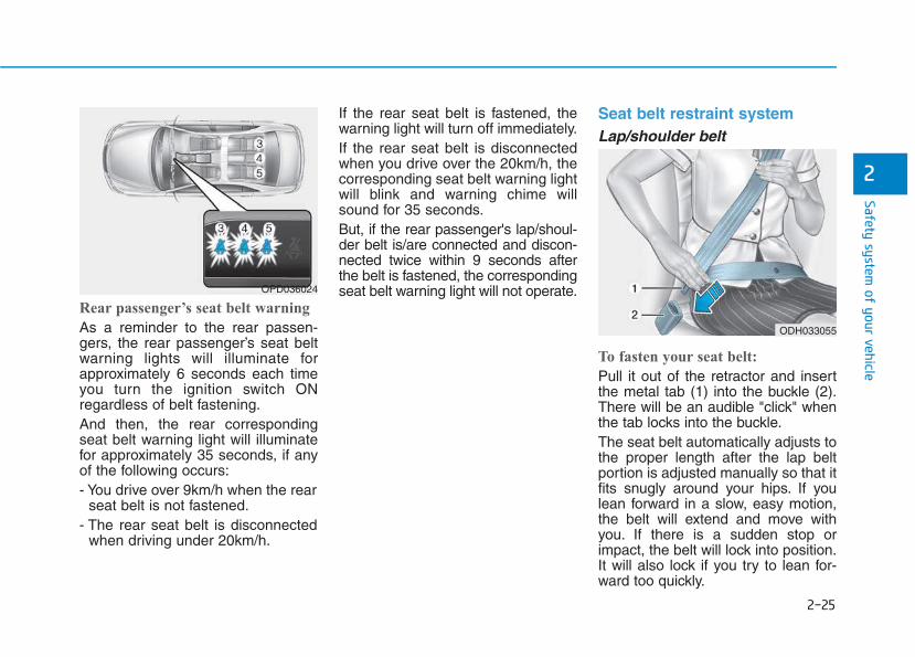
Rear passenger’s seat belt warning
As a reminder to the rear passen-gers, the rear passenger’s seat beltwarning lights will illuminate forapproximately 6 seconds each timeyou turn the ignition switch ONregardless of belt fastening.And then, the rear correspondingseat belt warning light will illuminatefor approximately 35 seconds, if anyof the following occurs:- You drive over 9km/h when the rear
seat belt is not fastened.- The rear seat belt is disconnected
when driving under 20km/h.
If the rear seat belt is fastened, thewarning light will turn off immediately.If the rear seat belt is disconnectedwhen you drive over the 20km/h, thecorresponding seat belt warning lightwill blink and warning chime willsound for 35 seconds.But, if the rear passenger's lap/shoul-der belt is/are connected and discon-nected twice within 9 seconds afterthe belt is fastened, the correspondingseat belt warning light will not operate.
Seat belt restraint system Lap/shoulder belt
To fasten your seat belt:
Pull it out of the retractor and insertthe metal tab (1) into the buckle (2).There will be an audible "click" whenthe tab locks into the buckle.The seat belt automatically adjusts tothe proper length after the lap beltportion is adjusted manually so that itfits snugly around your hips. If youlean forward in a slow, easy motion,the belt will extend and move withyou. If there is a sudden stop orimpact, the belt will lock into position.It will also lock if you try to lean for-ward too quickly.
OPD036024
ODH033055
2-26
Safety system of your vehicle
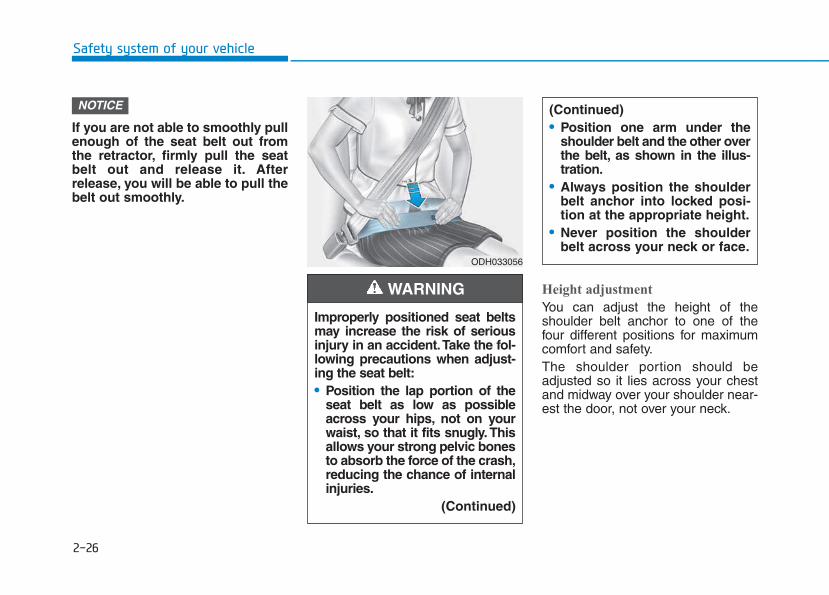
If you are not able to smoothly pullenough of the seat belt out fromthe retractor, firmly pull the seatbelt out and release it. Afterrelease, you will be able to pull thebelt out smoothly.
Height adjustment
You can adjust the height of theshoulder belt anchor to one of thefour different positions for maximumcomfort and safety.The shoulder portion should beadjusted so it lies across your chestand midway over your shoulder near-est the door, not over your neck.
NOTICE
ODH033056
Improperly positioned seat beltsmay increase the risk of seriousinjury in an accident.Take the fol-lowing precautions when adjust-ing the seat belt:• Position the lap portion of the
seat belt as low as possibleacross your hips, not on yourwaist, so that it fits snugly. Thisallows your strong pelvic bonesto absorb the force of the crash,reducing the chance of internalinjuries.
(Continued)
WARNING
(Continued)• Position one arm under the
shoulder belt and the other overthe belt, as shown in the illus-tration.
• Always position the shoulderbelt anchor into locked posi-tion at the appropriate height.
• Never position the shoulderbelt across your neck or face.
2-27
Safety system of your vehicle
2
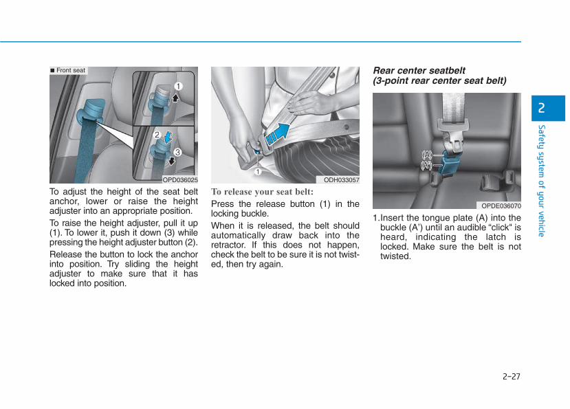
To adjust the height of the seat beltanchor, lower or raise the heightadjuster into an appropriate position.To raise the height adjuster, pull it up(1). To lower it, push it down (3) whilepressing the height adjuster button (2).Release the button to lock the anchorinto position. Try sliding the heightadjuster to make sure that it haslocked into position.
To release your seat belt:
Press the release button (1) in thelocking buckle.When it is released, the belt shouldautomatically draw back into theretractor. If this does not happen,check the belt to be sure it is not twist-ed, then try again.
Rear center seatbelt (3-point rear center seat belt)
1.Insert the tongue plate (A) into thebuckle (A’) until an audible “click" isheard, indicating the latch islocked. Make sure the belt is nottwisted.
OPD036025
■ Front seat
ODH033057
OPDE036070
2-28
Safety system of your vehicle
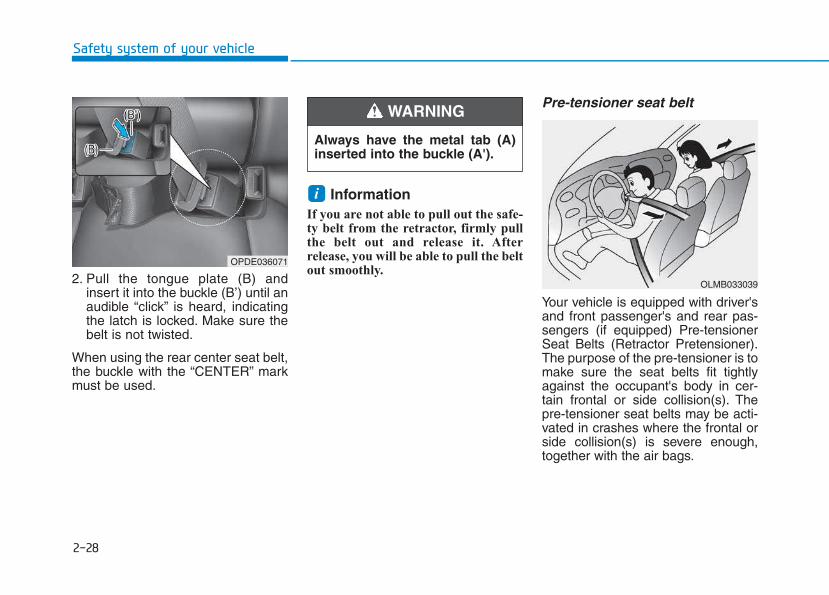
2. Pull the tongue plate (B) andinsert it into the buckle (B’) until anaudible “click” is heard, indicatingthe latch is locked. Make sure thebelt is not twisted.
When using the rear center seat belt,the buckle with the “CENTER” markmust be used.
Information If you are not able to pull out the safe-ty belt from the retractor, firmly pullthe belt out and release it. Afterrelease, you will be able to pull the beltout smoothly.
Pre-tensioner seat belt
Your vehicle is equipped with driver'sand front passenger's and rear pas-sengers (if equipped) Pre-tensionerSeat Belts (Retractor Pretensioner).The purpose of the pre-tensioner is tomake sure the seat belts fit tightlyagainst the occupant's body in cer-tain frontal or side collision(s). Thepre-tensioner seat belts may be acti-vated in crashes where the frontal orside collision(s) is severe enough,together with the air bags.
i
OLMB033039
OPDE036071
Always have the metal tab (A)inserted into the buckle (A').
WARNING
2-29
Safety system of your vehicle
2
When the vehicle stops suddenly, orif the occupant tries to lean forwardtoo quickly, the seat belt retractor willlock into position. In certain frontalcollisions, the pre-tensioner will acti-vate and pull the seat belt into tightercontact against the occupant's body.If the system senses excessive tensionon the driver or passenger's seat beltwhen the pre-tensioner system acti-vates, the load limiter inside the retrac-tor pre-tensioner will release some ofthe pressure on the affected seat belt.
Do not touch the pre-tensionerseat belt assemblies for severalminutes after they have beenactivated. When the pre-ten-sioner seat belt mechanismdeploys during a collision, thepre-tensioner can become hotand can burn you.
WARNING
Body work on the front area ofthe vehicle may damage thepre-tensioner seat belt system.Therefore, we recommend thesystem to be serviced by anauthorized HYUNDAI dealer.
CAUTION
• Always wear your seat belt andsit properly in your seat.
• Do not use the seat belt if it isloose or twisted. A loose ortwisted seat belt will not pro-tect you properly in an acci-dent.
• Do not place anything near thebuckle. This may adverselyaffect the buckle and cause itto function improperly.
• Always replace your pre-ten-sioners after activation or anaccident.
• NEVER inspect, service, repairor replace the pre-tensionersyourself. This must be done byan authorized HYUNDAI dealer.
• Do not hit the seat belt assem-blies.
WARNING
2-30
Safety system of your vehicle
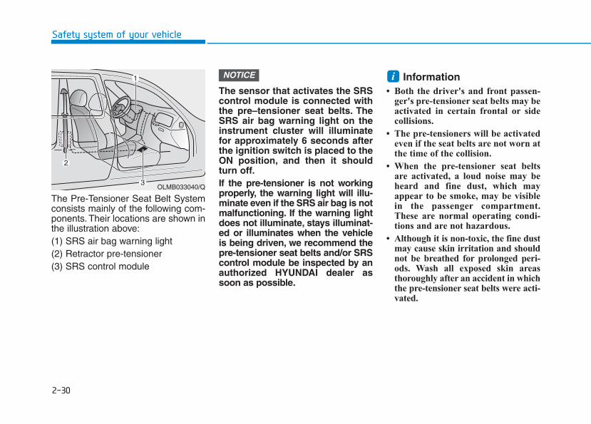
The Pre-Tensioner Seat Belt Systemconsists mainly of the following com-ponents. Their locations are shown inthe illustration above:(1) SRS air bag warning light(2) Retractor pre-tensioner (3) SRS control module
The sensor that activates the SRScontrol module is connected withthe pre–tensioner seat belts. TheSRS air bag warning light on theinstrument cluster will illuminatefor approximately 6 seconds afterthe ignition switch is placed to theON position, and then it shouldturn off.If the pre-tensioner is not workingproperly, the warning light will illu-minate even if the SRS air bag is notmalfunctioning. If the warning lightdoes not illuminate, stays illuminat-ed or illuminates when the vehicleis being driven, we recommend thepre-tensioner seat belts and/or SRScontrol module be inspected by anauthorized HYUNDAI dealer assoon as possible.
Information • Both the driver's and front passen-
ger's pre-tensioner seat belts may beactivated in certain frontal or sidecollisions.
• The pre-tensioners will be activatedeven if the seat belts are not worn atthe time of the collision.
• When the pre-tensioner seat beltsare activated, a loud noise may beheard and fine dust, which mayappear to be smoke, may be visiblein the passenger compartment.These are normal operating condi-tions and are not hazardous.
• Although it is non-toxic, the fine dustmay cause skin irritation and shouldnot be breathed for prolonged peri-ods. Wash all exposed skin areasthoroughly after an accident in whichthe pre-tensioner seat belts were acti-vated.
iNOTICE
OLMB033040/Q
2-31
Safety system of your vehicle
2
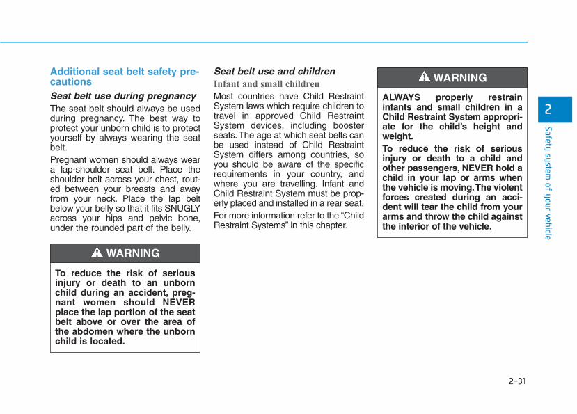
Additional seat belt safety pre-cautions Seat belt use during pregnancy The seat belt should always be usedduring pregnancy. The best way toprotect your unborn child is to protectyourself by always wearing the seatbelt.Pregnant women should always weara lap-shoulder seat belt. Place theshoulder belt across your chest, rout-ed between your breasts and awayfrom your neck. Place the lap beltbelow your belly so that it fits SNUGLYacross your hips and pelvic bone,under the rounded part of the belly.
Seat belt use and children Infant and small children
Most countries have Child RestraintSystem laws which require children totravel in approved Child RestraintSystem devices, including boosterseats.The age at which seat belts canbe used instead of Child RestraintSystem differs among countries, soyou should be aware of the specificrequirements in your country, andwhere you are travelling. Infant andChild Restraint System must be prop-erly placed and installed in a rear seat.For more information refer to the “ChildRestraint Systems” in this chapter.
ALWAYS properly restraininfants and small children in aChild Restraint System appropri-ate for the child’s height andweight.To reduce the risk of seriousinjury or death to a child andother passengers, NEVER hold achild in your lap or arms whenthe vehicle is moving.The violentforces created during an acci-dent will tear the child from yourarms and throw the child againstthe interior of the vehicle.
WARNING
To reduce the risk of seriousinjury or death to an unbornchild during an accident, preg-nant women should NEVERplace the lap portion of the seatbelt above or over the area ofthe abdomen where the unbornchild is located.
WARNING
2-32
Safety system of your vehicle
Small children are best protectedfrom injury in an accident when prop-erly restrained in the rear seat by aChild Restraint System that meetsthe requirements of the SafetyStandards of your country. Beforebuying any Child Restraint System,make sure that it has a label certify-ing that it meets Safety Standard ofyour country. The Child RestraintSystem must be appropriate for yourchild's height and weight. Check thelabel on the Child Restraint Systemfor this information. Refer to “ChildRestraint Systems” in this chapter.
Larger children
Children under age 13 and who aretoo large for a booster seat shouldalways occupy the rear seat and usethe available lap/shoulder belts. Aseat belt should lie across the upperthighs and be snug across the shoul-der and chest to restrain the childsafely. Check belt fit periodically. Achild's squirming could put the beltout of position. In the event of an acci-dent, children are afforded the bestsafety restrained by a proper ChildRestraint System in the rear seats.If a larger child over age 13 must beseated in the front seat, the childmust be securely restrained by theavailable lap/shoulder belt and theseat should be placed in the rear-most position.If the shoulder belt portion slightlytouches the child’s neck or face, tryplacing the child closer to the centerof the vehicle. If the shoulder belt stilltouches their face or neck, they needto be returned to an appropriatebooster seat in the rear seat.
• Always make sure larger chil-dren’s seat belts are worn andproperly adjusted.
• NEVER allow the shoulderbelt to contact the child’sneck or face.
• Do not allow more than onechild to use a single seat belt.
WARNING
2-33
Safety system of your vehicle
2
Seat belt use and injured peopleA seat belt should be used when aninjured person is being transported.Consult a physician for specific rec-ommendations.
One person per belt Two people (including children) shouldnever attempt to use a single seat belt.This could increase the severity ofinjuries in case of an accident.
Do not lie down Sitting in a reclined position whenthe vehicle is in motion can be dan-gerous. Even when buckled up, theprotections of your restraint system(seat belts and/or air bags) is greatlyreduced by reclining your seatback.Seat belts must be snug against yourhips and chest to work properly.During an accident, you could bethrown into the seat belt, causingneck or other injuries.
The more the seat back is reclined,the greater the chance for the pas-senger's hips to slide under the lapbelt or the passenger's neck to strikethe shoulder belt.
Care of seat belts Seat belt systems should never bedisassembled or modified. In addi-tion, care should be taken to assurethat seat belts and belt hardware arenot damaged by seat hinges, doorsor other abuse.
Periodic inspectionAll seat belts should be inspectedperiodically for wear or damage ofany kind. Any damaged parts shouldbe replaced as soon as possible.
Keep belts clean and dry Seat belts should be kept clean anddry. If belts become dirty, they can becleaned by using a mild soap solutionand warm water. Bleach, dye, strongdetergents or abrasives should not beused because they may damage andweaken the fabric.
• NEVER ride with a reclinedseatback when the vehicle ismoving.
• Riding with a reclined seatbackincreases your chance of seri-ous or fatal injuries in the eventof a collision or sudden stop.
• Driver and passengers shouldalways sit well back in theirseats, properly belted, and withthe seatbacks upright.
WARNING
2-34
When to replace seat belts The entire seat belt assembly orassemblies should be replaced if thevehicle has been involved in an acci-dent. This should be done even if nodamage is visible.We recommend thatyou consult an authorized HYUNDAIdealer.
Our recommendation:Children always in the rear
Children under age 13 should alwaysride in the rear seats and mustalways be properly restrained to min-imize the risk of injury in an accident,sudden stop or sudden maneuver.According to accident statistics, chil-dren are safer when properlyrestrained in the rear seats than inthe front seat. Children too large for aChild Restraint System must use theseat belts provided.
Most countries have regulationswhich require children to travel inapproved Child Restraint Systems.The laws governing the age orheight/weight restrictions at whichseat belts can be used instead ofChild Restraint System differsamong countries, so you should beaware of the specific requirements inyour country, and where you are trav-elling.Child Restraint Systems must beproperly installed in the vehicle seat.Always use a commercially availableChild Restraint System that meetsthe requirements of your country.
Safety system of your vehicle
CCHHIILLDD RREESSTTRRAAIINNTT SSYYSSTTEEMM((CCRRSS))
Always properly restrain childrenin the vehicle. Children of all agesare safer when riding in the rearseats. Never place a rearward-facing Child Restraint System onthe front passenger seat, unlessthe air bag is deactivated.
WARNING
2-35
Safety system of your vehicle
2
Child Restraint System (CRS) Infants and younger children must berestrained in an appropriate rear-ward-facing or forward-facing CRSthat has first been properly securedto the seat of the vehicle. Read andcomply with the instructions forinstallation and use provided by themanufacturer of the Child RestraintSystem.
Selecting a Child RestraintSystem (CRS) When selecting a Child RestraintSystem for your child, always:• Make sure the Child Restraint
System has a label certifying that itmeets applicable Safety Standardsof your country.A Child Restraint System may onlybe installed if it was approved inaccordance with the requirements ofECE-R44 or ECE-R129.
• Select a Child Restraint Systembased on your child’s height andweight. The required label or theinstructions for use typically pro-vide this information.
• Select a Child Restraint Systemthat fits the vehicle seating positionwhere it will be used.
• Read and comply with the warn-ings and instructions for installationand use provided with the ChildRestraint System.
Child Restraint System types There are three main types of ChildRestraint Systems: rearward-facing,forward-facing and booster ChildRestraint Systems.They are classified according to thechild’s age, height and weight.
• Always follow the Child RestraintSystem manufacturer’s instruc-tions for installation and use.
• Always properly restrain yourchild in the Child RestraintSystem.
• Do not use an infant carrier ora child safety seat that “hooks”over a seatback, it may not pro-vide adequate protection in anaccident.
• After an accident, we recom-mend a HYUNDAI dealer tocheck the Child RestraintSystem, seat belts, ISOFIXanchorages and top-tetheranchorages.
WARNING
2-36
Safety system of your vehicle
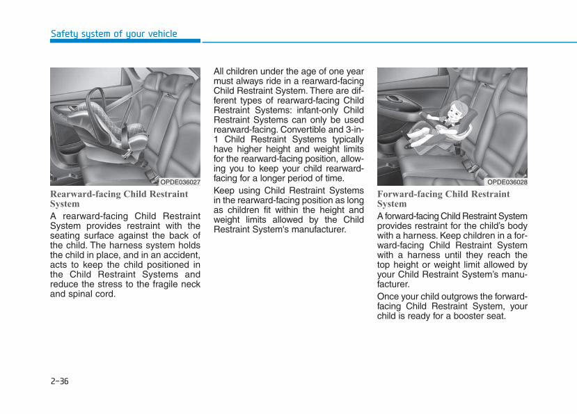
Rearward-facing Child RestraintSystem
A rearward-facing Child RestraintSystem provides restraint with theseating surface against the back ofthe child. The harness system holdsthe child in place, and in an accident,acts to keep the child positioned inthe Child Restraint Systems andreduce the stress to the fragile neckand spinal cord.
All children under the age of one yearmust always ride in a rearward-facingChild Restraint System. There are dif-ferent types of rearward-facing ChildRestraint Systems: infant-only ChildRestraint Systems can only be usedrearward-facing. Convertible and 3-in-1 Child Restraint Systems typicallyhave higher height and weight limitsfor the rearward-facing position, allow-ing you to keep your child rearward-facing for a longer period of time.Keep using Child Restraint Systemsin the rearward-facing position as longas children fit within the height andweight limits allowed by the ChildRestraint System's manufacturer.
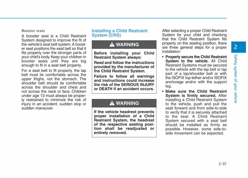
Forward-facing Child RestraintSystem
A forward-facing Child Restraint Systemprovides restraint for the child’s bodywith a harness. Keep children in a for-ward-facing Child Restraint Systemwith a harness until they reach thetop height or weight limit allowed byyour Child Restraint System’s manu-facturer.Once your child outgrows the forward-facing Child Restraint System, yourchild is ready for a booster seat.
OPDE036028OPDE036027
2-37
Safety system of your vehicle
2
Booster seats
A booster seat is a Child RestraintSystem designed to improve the fit ofthe vehicle’s seat belt system. A boost-er seat positions the seat belt so that itfits properly over the stronger parts ofyour child’s body. Keep your children inbooster seats until they are bigenough to fit in a seat belt properly.For a seat belt to fit properly, the lapbelt must lie comfortable across theupper thighs, not the stomach. Theshoulder belt should lie comfortableacross the shoulder and chest andnot across the neck or face. Childrenunder age 13 must always be proper-ly restrained to minimize the risk ofinjury in an accident, sudden stop orsudden maneuver.
Installing a Child RestraintSystem (CRS)
After selecting a proper Child RestraintSystem for your child and checkingthat the Child Restraint System fitsproperly on the seating position, thereare three general steps for a properinstallation:• Properly secure the Child Restraint
System to the vehicle. All ChildRestraint Systems must be securedto the vehicle with the lap belt or lappart of a lap/shoulder belt or withthe ISOFIX top-tether and/or ISOFIXanchorage and/or with the supportleg.
• Make sure the Child RestraintSystem is firmly secured. Afterinstalling a Child Restraint Systemto the vehicle, push and pull theseat forward and from side-to-sideto verify that it is securely attachedto the seat. A Child RestraintSystem secured with a seat beltshould be installed as firmly aspossible. However, some side-to-side movement can be expected.
Before installing your ChildRestraint System always:Read and follow the instructionsprovided by the manufacturer ofthe Child Restraint System.Failure to follow all warningsand instructions could increasethe risk of the SERIOUS INJURYor DEATH if an accident occurs.
WARNING
If the vehicle headrest preventsproper installation of a ChildRestraint System, the headrestof the respective seating posi-tion shall be readjusted orentirely removed.
WARNING
2-38
Safety system of your vehicle
When installing a Child RestraintSystem, adjust the vehicle seat andseatback (up and down, forward andrearward) so that your child fits inthe Child Restraint System in a con-fortable manner.
• Secure the child in the ChildRestraint System. Make sure thechild is properly strapped in theChild Restraint System accordingto the Child Restraint System man-ufacturer’s instructions.
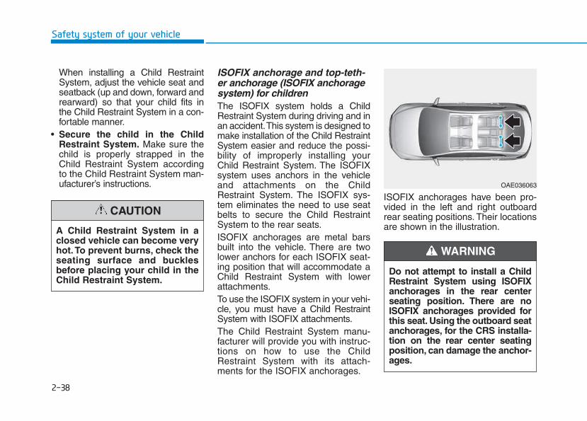
ISOFIX anchorage and top-teth-er anchorage (ISOFIX anchoragesystem) for children The ISOFIX system holds a ChildRestraint System during driving and inan accident.This system is designed tomake installation of the Child RestraintSystem easier and reduce the possi-bility of improperly installing yourChild Restraint System. The ISOFIXsystem uses anchors in the vehicleand attachments on the ChildRestraint System. The ISOFIX sys-tem eliminates the need to use seatbelts to secure the Child RestraintSystem to the rear seats.ISOFIX anchorages are metal barsbuilt into the vehicle. There are twolower anchors for each ISOFIX seat-ing position that will accommodate aChild Restraint System with lowerattachments.To use the ISOFIX system in your vehi-cle, you must have a Child RestraintSystem with ISOFIX attachments.The Child Restraint System manu-facturer will provide you with instruc-tions on how to use the ChildRestraint System with its attach-ments for the ISOFIX anchorages.
ISOFIX anchorages have been pro-vided in the left and right outboardrear seating positions. Their locationsare shown in the illustration.A Child Restraint System in a
closed vehicle can become veryhot. To prevent burns, check theseating surface and bucklesbefore placing your child in theChild Restraint System.
CAUTION
OAE036063
Do not attempt to install a ChildRestraint System using ISOFIXanchorages in the rear centerseating position. There are noISOFIX anchorages provided forthis seat. Using the outboard seatanchorages, for the CRS installa-tion on the rear center seatingposition, can damage the anchor-ages.
WARNING
2-39
Safety system of your vehicle
2
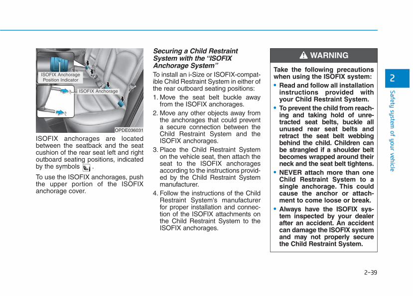
ISOFIX anchorages are locatedbetween the seatback and the seatcushion of the rear seat left and rightoutboard seating positions, indicatedby the symbols .
To use the ISOFIX anchorages, pushthe upper portion of the ISOFIXanchorage cover.
Securing a Child RestraintSystem with the “ISOFIXAnchorage System”To install an i-Size or ISOFIX-compat-ible Child Restraint System in either ofthe rear outboard seating positions:1. Move the seat belt buckle away
from the ISOFIX anchorages.2. Move any other objects away from
the anchorages that could preventa secure connection between theChild Restraint System and theISOFIX anchorages.
3. Place the Child Restraint Systemon the vehicle seat, then attach theseat to the ISOFIX anchoragesaccording to the instructions provid-ed by the Child Restraint Systemmanufacturer.
4. Follow the instructions of the ChildRestraint System's manufacturerfor proper installation and connec-tion of the ISOFIX attachments onthe Child Restraint System to theISOFIX anchorages.
OPDE036031
ISOFIX AnchoragePosition Indicator
ISOFIX Anchorage
Take the following precautionswhen using the ISOFIX system:• Read and follow all installation
instructions provided withyour Child Restraint System.
• To prevent the child from reach-ing and taking hold of unre-tracted seat belts, buckle allunused rear seat belts andretract the seat belt webbingbehind the child. Children canbe strangled if a shoulder beltbecomes wrapped around theirneck and the seat belt tightens.
• NEVER attach more than oneChild Restraint System to asingle anchorage. This couldcause the anchor or attach-ment to come loose or break.
• Always have the ISOFIX sys-tem inspected by your dealerafter an accident. An accidentcan damage the ISOFIX systemand may not properly securethe Child Restraint System.
WARNING
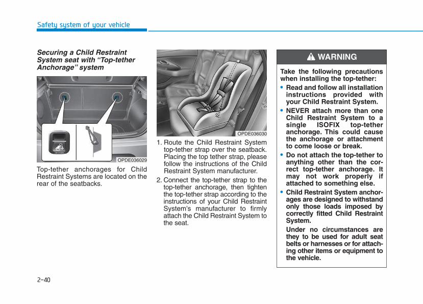
2-40
Safety system of your vehicle
Securing a Child RestraintSystem seat with “Top-tetherAnchorage” system
Top-tether anchorages for ChildRestraint Systems are located on therear of the seatbacks.
1. Route the Child Restraint Systemtop-tether strap over the seatback.Placing the top tether strap, pleasefollow the instructions of the ChildRestraint System manufacturer.
2. Connect the top-tether strap to thetop-tether anchorage, then tightenthe top-tether strap according to theinstructions of your Child RestraintSystem's manufacturer to firmlyattach the Child Restraint System tothe seat.
OPDE036029
OPDE036030
Take the following precautionswhen installing the top-tether:• Read and follow all installation
instructions provided withyour Child Restraint System.
• NEVER attach more than oneChild Restraint System to asingle ISOFIX top-tetheranchorage. This could causethe anchorage or attachmentto come loose or break.
• Do not attach the top-tether toanything other than the cor-rect top-tether anchorage. Itmay not work properly ifattached to something else.
• Child Restraint System anchor-ages are designed to withstandonly those loads imposed bycorrectly fitted Child RestraintSystem.Under no circumstances arethey to be used for adult seatbelts or harnesses or for attach-ing other items or equipment tothe vehicle.
WARNING
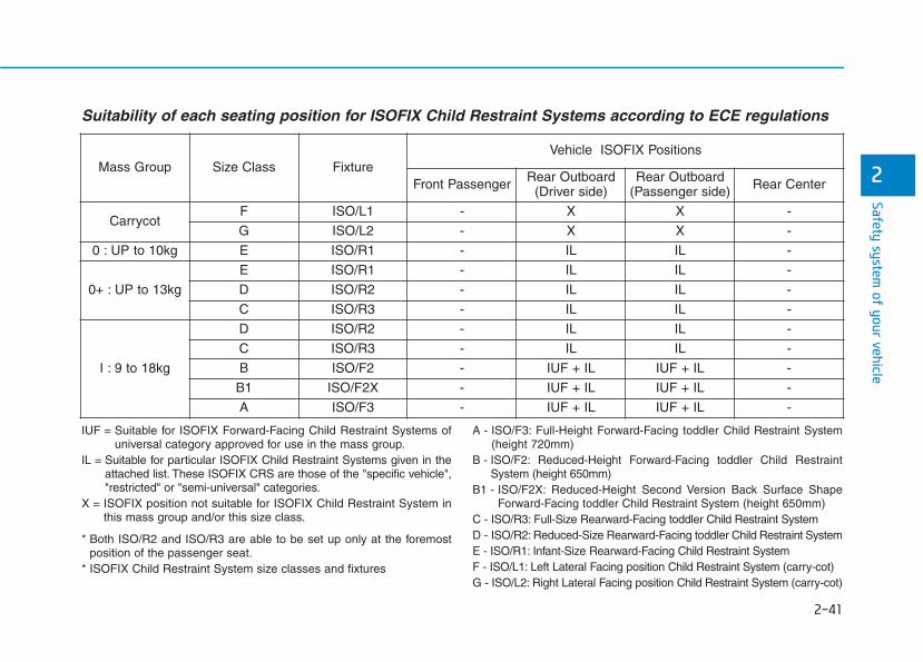
2-41
Safety system of your vehicle
2
Suitability of each seating position for ISOFIX Child Restraint Systems according to ECE regulations
IUF = Suitable for ISOFIX Forward-Facing Child Restraint Systems ofuniversal category approved for use in the mass group.
IL = Suitable for particular ISOFIX Child Restraint Systems given in theattached list. These ISOFIX CRS are those of the "specific vehicle","restricted" or "semi-universal" categories.
X = ISOFIX position not suitable for ISOFIX Child Restraint System inthis mass group and/or this size class.
* Both ISO/R2 and ISO/R3 are able to be set up only at the foremostposition of the passenger seat.
* ISOFIX Child Restraint System size classes and fixtures
A - ISO/F3: Full-Height Forward-Facing toddler Child Restraint System(height 720mm)
B - ISO/F2: Reduced-Height Forward-Facing toddler Child RestraintSystem (height 650mm)
B1 - ISO/F2X: Reduced-Height Second Version Back Surface ShapeForward-Facing toddler Child Restraint System (height 650mm)
C - ISO/R3: Full-Size Rearward-Facing toddler Child Restraint SystemD - ISO/R2: Reduced-Size Rearward-Facing toddler Child Restraint SystemE - ISO/R1: Infant-Size Rearward-Facing Child Restraint SystemF - ISO/L1: Left Lateral Facing position Child Restraint System (carry-cot)G - ISO/L2: Right Lateral Facing position Child Restraint System (carry-cot)
Mass Group Size Class FixtureVehicle ISOFIX Positions
Front Passenger Rear Outboard(Driver side)
Rear Outboard(Passenger side) Rear Center
CarrycotF ISO/L1 - X X -
G ISO/L2 - X X -
0 : UP to 10kg E ISO/R1 - IL IL -
0+ : UP to 13kg
E ISO/R1 - IL IL -
D ISO/R2 - IL IL -
C ISO/R3 - IL IL -
I : 9 to 18kg
D ISO/R2 - IL IL -
C ISO/R3 - IL IL -
B ISO/F2 - IUF + IL IUF + IL -
B1 ISO/F2X - IUF + IL IUF + IL -
A ISO/F3 - IUF + IL IUF + IL -
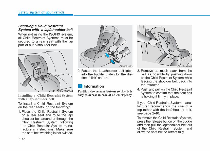
2-42
Safety system of your vehicle
Securing a Child RestraintSystem with a lap/shoulder beltWhen not using the ISOFIX system,all Child Restraint Systems must besecured to a rear seat with the lappart of a lap/shoulder belt.
Installing a Child Restraint Systemwith a lap/shoulder belt
To install a Child Restraint Systemon the rear seats, do the following:1. Place the Child Restraint System
on a rear seat and route the lap/shoulder belt around or through theChild Restraint System, followingthe Child Restraint System manu-facturer’s instructions. Make surethe seat belt webbing is not twisted.
2. Fasten the lap/shoulder belt latchinto the buckle. Listen for the dis-tinct “click” sound.
InformationPosition the release button so that it iseasy to access in case of an emergency.
3. Remove as much slack from thebelt as possible by pushing downon the Child Restraint System whilefeeding the shoulder belt back intothe retractor.
4. Push and pull on the Child RestraintSystem to confirm that the seat beltis holding it firmly in place.
If your Child Restraint System manu-facturer recommends the use of atop-tether with the lap/shoulder belt,see page 2-40.To remove the Child Restraint System,press the release button on the buckleand then pull the lap/shoulder belt outof the Child Restraint System andallow the seat belt to retract fully.
iOLMB033044
ODH033063 OLMB033046
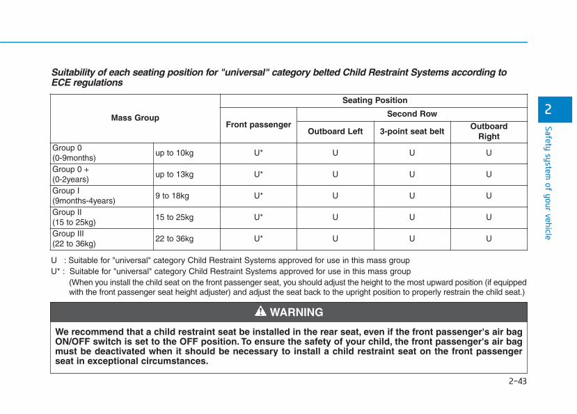
2-43
Safety system of your vehicle
2
Suitability of each seating position for "universal" category belted Child Restraint Systems according toECE regulations
U : Suitable for "universal" category Child Restraint Systems approved for use in this mass groupU* : Suitable for "universal" category Child Restraint Systems approved for use in this mass group
(When you install the child seat on the front passenger seat, you should adjust the height to the most upward position (if equippedwith the front passenger seat height adjuster) and adjust the seat back to the upright position to properly restrain the child seat.)
Mass Group
Seating Position
Front passengerSecond Row
Outboard Left 3-point seat beltOutboard
RightGroup 0(0-9months)
up to 10kg U* U U U
Group 0 + (0-2years)
up to 13kg U* U U U
Group I (9months-4years)
9 to 18kg U* U U U
Group II (15 to 25kg)
15 to 25kg U* U U U
Group III (22 to 36kg)
22 to 36kg U* U U U
We recommend that a child restraint seat be installed in the rear seat, even if the front passenger's air bagON/OFF switch is set to the OFF position. To ensure the safety of your child, the front passenger's air bagmust be deactivated when it should be necessary to install a child restraint seat on the front passengerseat in exceptional circumstances.
WARNING
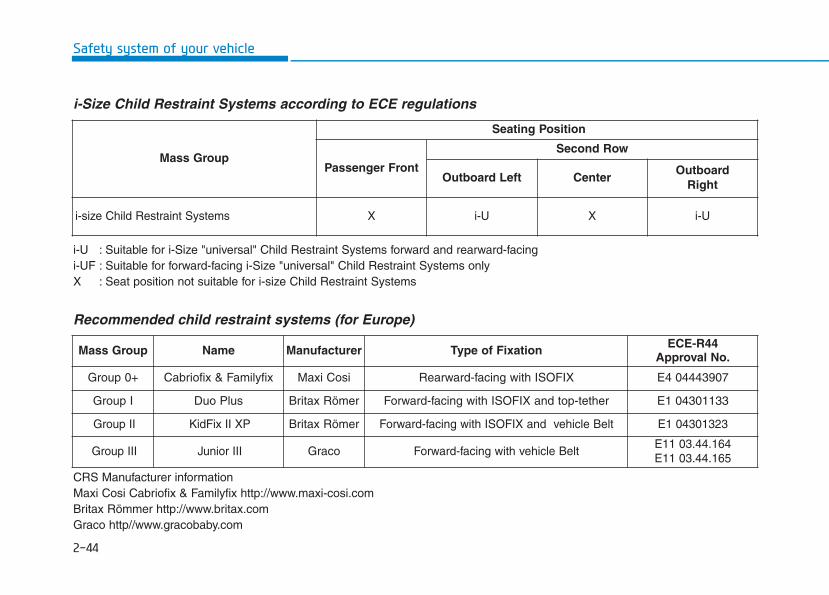
2-44
Safety system of your vehicle
i-Size Child Restraint Systems according to ECE regulations
i-U : Suitable for i-Size "universal" Child Restraint Systems forward and rearward-facingi-UF : Suitable for forward-facing i-Size "universal" Child Restraint Systems onlyX : Seat position not suitable for i-size Child Restraint Systems
Mass Group
Seating Position
Passenger Front
Second Row
Outboard Left Center Outboard
Right
i-size Child Restraint Systems X i-U X i-U
Recommended child restraint systems (for Europe)
CRS Manufacturer informationMaxi Cosi Cabriofix & Familyfix http://www.maxi-cosi.comBritax Römmer http://www.britax.comGraco http//www.gracobaby.com
Mass Group Name Manufacturer Type of Fixation ECE-R44Approval No.
Group 0+ Cabriofix & Familyfix Maxi Cosi Rearward-facing with ISOFIX E4 04443907
Group I Duo Plus Britax Römer Forward-facing with ISOFIX and top-tether E1 04301133
Group II KidFix II XP Britax Römer Forward-facing with ISOFIX and vehicle Belt E1 04301323
Group III Junior III Graco Forward-facing with vehicle BeltE11 03.44.164 E11 03.44.165
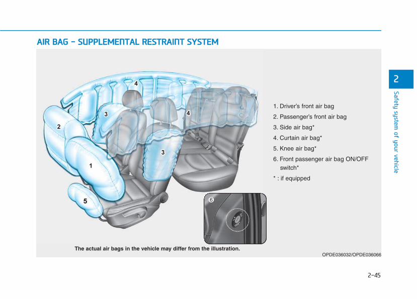
2-45
Safety system of your vehicle
2
AAIIRR BBAAGG -- SSUUPPPPLLEEMMEENNTTAALL RREESSTTRRAAIINNTT SSYYSSTTEEMM
OPDE036032/OPDE036066The actual air bags in the vehicle may differ from the illustration.
1. Driver’s front air bag
2. Passenger’s front air bag
3. Side air bag*
4. Curtain air bag*
5. Knee air bag*
6. Front passenger air bag ON/OFFswitch*
* : if equipped
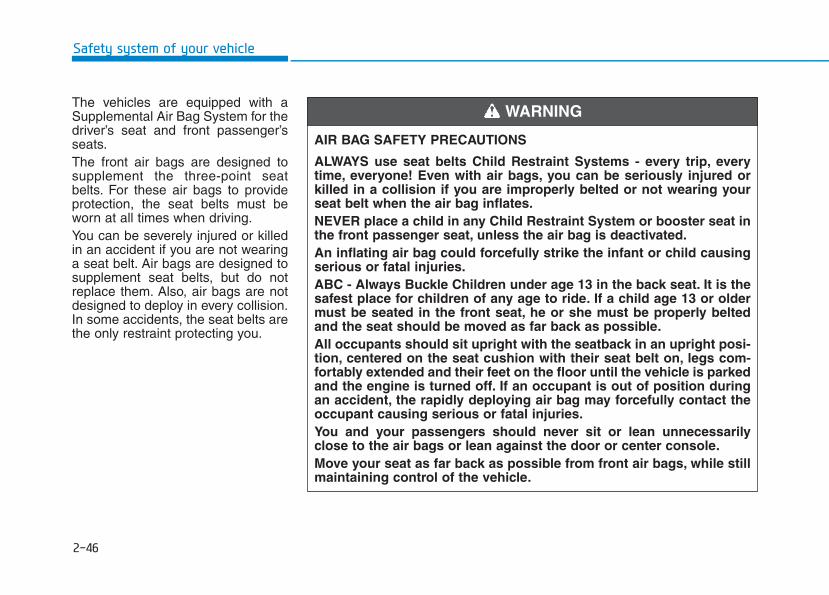
2-46
Safety system of your vehicle
The vehicles are equipped with aSupplemental Air Bag System for thedriver’s seat and front passenger’sseats.The front air bags are designed tosupplement the three-point seatbelts. For these air bags to provideprotection, the seat belts must beworn at all times when driving.You can be severely injured or killedin an accident if you are not wearinga seat belt. Air bags are designed tosupplement seat belts, but do notreplace them. Also, air bags are notdesigned to deploy in every collision.In some accidents, the seat belts arethe only restraint protecting you.
AIR BAG SAFETY PRECAUTIONS
ALWAYS use seat belts Child Restraint Systems - every trip, everytime, everyone! Even with air bags, you can be seriously injured orkilled in a collision if you are improperly belted or not wearing yourseat belt when the air bag inflates.NEVER place a child in any Child Restraint System or booster seat inthe front passenger seat, unless the air bag is deactivated.An inflating air bag could forcefully strike the infant or child causingserious or fatal injuries.ABC - Always Buckle Children under age 13 in the back seat. It is thesafest place for children of any age to ride. If a child age 13 or oldermust be seated in the front seat, he or she must be properly beltedand the seat should be moved as far back as possible.All occupants should sit upright with the seatback in an upright posi-tion, centered on the seat cushion with their seat belt on, legs com-fortably extended and their feet on the floor until the vehicle is parkedand the engine is turned off. If an occupant is out of position duringan accident, the rapidly deploying air bag may forcefully contact theoccupant causing serious or fatal injuries.You and your passengers should never sit or lean unnecessarilyclose to the air bags or lean against the door or center console.Move your seat as far back as possible from front air bags, while stillmaintaining control of the vehicle.
WARNING
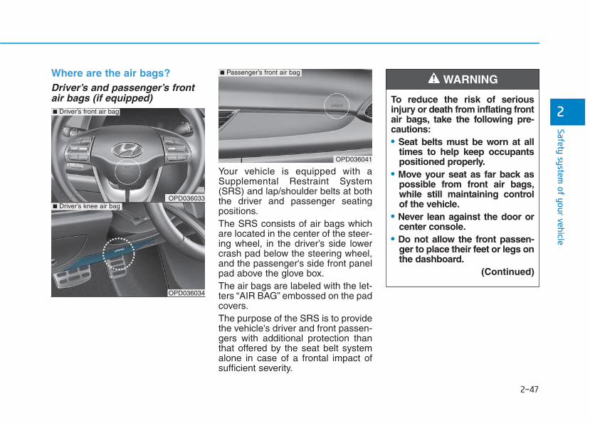
2-47
Safety system of your vehicle
2
Where are the air bags? Driver’s and passenger’s frontair bags (if equipped)
Your vehicle is equipped with aSupplemental Restraint System(SRS) and lap/shoulder belts at boththe driver and passenger seatingpositions.The SRS consists of air bags whichare located in the center of the steer-ing wheel, in the driver’s side lowercrash pad below the steering wheel,and the passenger's side front panelpad above the glove box.The air bags are labeled with the let-ters “AIR BAG” embossed on the padcovers.The purpose of the SRS is to providethe vehicle's driver and front passen-gers with additional protection thanthat offered by the seat belt systemalone in case of a frontal impact ofsufficient severity.
To reduce the risk of seriousinjury or death from inflating frontair bags, take the following pre-cautions:• Seat belts must be worn at all
times to help keep occupantspositioned properly.
• Move your seat as far back aspossible from front air bags,while still maintaining controlof the vehicle.
• Never lean against the door orcenter console.
• Do not allow the front passen-ger to place their feet or legs onthe dashboard.
(Continued)
WARNING
OPD036033
OPD036034
■ Driver’s knee air bag
OPD036041
■ Passenger’s front air bag
■ Driver’s front air bag
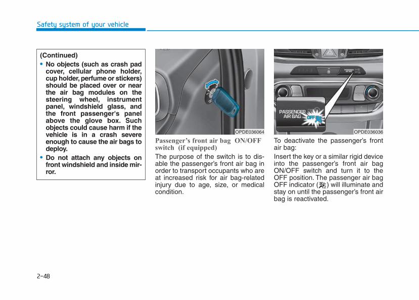
2-48
Safety system of your vehicle
Passenger’s front air bag ON/OFFswitch (if equipped)
The purpose of the switch is to dis-able the passenger’s front air bag inorder to transport occupants who areat increased risk for air bag-relatedinjury due to age, size, or medicalcondition.
To deactivate the passenger’s frontair bag:Insert the key or a similar rigid deviceinto the passenger’s front air bagON/OFF switch and turn it to theOFF position. The passenger air bagOFF indicator ( ) will illuminate andstay on until the passenger’s front airbag is reactivated.
OPDE036064 OPDE036036
(Continued)• No objects (such as crash pad
cover, cellular phone holder,cup holder, perfume or stickers)should be placed over or nearthe air bag modules on thesteering wheel, instrumentpanel, windshield glass, andthe front passenger's panelabove the glove box. Suchobjects could cause harm if thevehicle is in a crash severeenough to cause the air bags todeploy.
• Do not attach any objects onfront windshield and inside mir-ror.
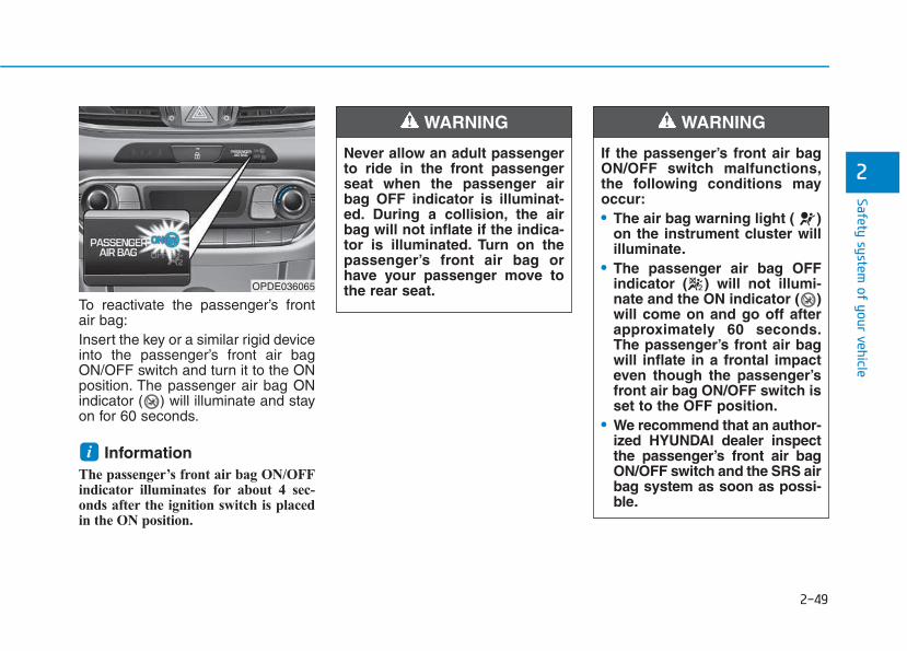
2-49
Safety system of your vehicle
2
To reactivate the passenger’s frontair bag:Insert the key or a similar rigid deviceinto the passenger’s front air bagON/OFF switch and turn it to the ONposition. The passenger air bag ONindicator ( ) will illuminate and stayon for 60 seconds.
Information The passenger’s front air bag ON/OFFindicator illuminates for about 4 sec-onds after the ignition switch is placedin the ON position.
i
Never allow an adult passengerto ride in the front passengerseat when the passenger airbag OFF indicator is illuminat-ed. During a collision, the airbag will not inflate if the indica-tor is illuminated. Turn on thepassenger’s front air bag orhave your passenger move tothe rear seat.
WARNING
If the passenger’s front air bagON/OFF switch malfunctions,the following conditions mayoccur:• The air bag warning light ( )
on the instrument cluster willilluminate.
• The passenger air bag OFFindicator ( ) will not illumi-nate and the ON indicator ( )will come on and go off afterapproximately 60 seconds.The passenger’s front air bagwill inflate in a frontal impacteven though the passenger’sfront air bag ON/OFF switch isset to the OFF position.
• We recommend that an author-ized HYUNDAI dealer inspectthe passenger’s front air bagON/OFF switch and the SRS airbag system as soon as possi-ble.
WARNING
OPDE036065
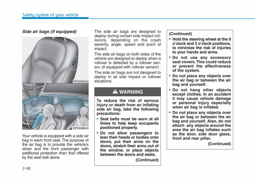
2-50
Safety system of your vehicle
Side air bags (if equipped)
Your vehicle is equipped with a side airbag in each front seat. The purpose ofthe air bag is to provide the vehicle’sdriver and the front passenger withadditional protection than that offeredby the seat belt alone.
The side air bags are designed todeploy during certain side impact col-lisions, depending on the crashseverity, angle, speed and point ofimpact.The side air bags on both sides of thevehicle are designed to deploy when arollover is detected by a rollover sen-sor. (if equipped with rollover sensor)The side air bags are not designed todeploy in all side impact or rolloversituations.
(Continued)• Hold the steering wheel at the 9
o’clock and 3 o’clock positions,to minimize the risk of injuriesto your hands and arms.
• Do not use any accessoryseat covers.This could reduceor prevent the effectivenessof the system.
• Do not place any objects overthe air bag or between the airbag and yourself.
• Do not hang other objectsexcept clothes. In an accidentit may cause vehicle damageor personal injury especiallywhen air bag is inflated.
• Do not place any objects overthe air bag or between the airbag and yourself. Also, do notattach any objects around thearea the air bag inflates suchas the door, side door glass,front and rear pillar.
(Continued)
To reduce the risk of seriousinjury or death from an inflatingside air bag, take the followingprecautions:• Seat belts must be worn at all
times to help keep occupantspositioned properly.
• Do not allow passengers tolean their heads or bodies ontodoors, put their arms on thedoors, stretch their arms out ofthe window, or place objectsbetween the doors and seats.
(Continued)
WARNING
OPD036042
OPD036043
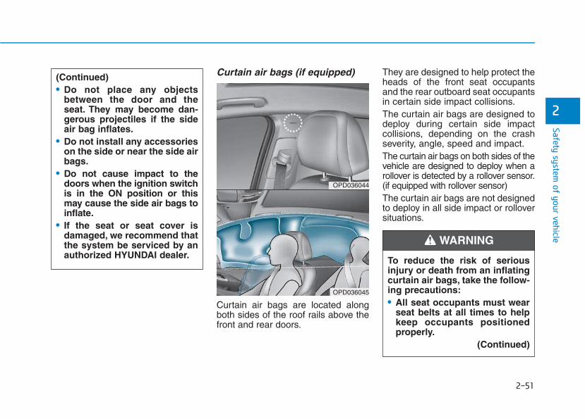
2-51
Safety system of your vehicle
2
Curtain air bags (if equipped)
Curtain air bags are located alongboth sides of the roof rails above thefront and rear doors.
They are designed to help protect theheads of the front seat occupantsand the rear outboard seat occupantsin certain side impact collisions.The curtain air bags are designed todeploy during certain side impactcollisions, depending on the crashseverity, angle, speed and impact.The curtain air bags on both sides of thevehicle are designed to deploy when arollover is detected by a rollover sensor.(if equipped with rollover sensor)The curtain air bags are not designedto deploy in all side impact or rolloversituations.
OPD036044
OPD036045
(Continued)• Do not place any objects
between the door and theseat. They may become dan-gerous projectiles if the sideair bag inflates.
• Do not install any accessorieson the side or near the side airbags.
• Do not cause impact to thedoors when the ignition switchis in the ON position or thismay cause the side air bags toinflate.
• If the seat or seat cover isdamaged, we recommend thatthe system be serviced by anauthorized HYUNDAI dealer. To reduce the risk of serious
injury or death from an inflatingcurtain air bags, take the follow-ing precautions:• All seat occupants must wear
seat belts at all times to helpkeep occupants positionedproperly.
(Continued)
WARNING
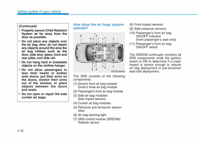
2-52
Safety system of your vehicle
How does the air bags systemoperate?
The SRS consists of the followingcomponents:(1) Driver's front air bag module/
Driver’s knee air bag module(2) Passenger's front air bag module(3) Side air bag modules/
Side impact sensors(4) Curtain air bag modules(5) Retractor pre-tensioner assem-
blies(6) Air bag warning light(7) SRS control module (SRSCM)/
Rollover sensor
(8) Front impact sensors(9) Side pressure sensors(10) Passenger’s front air bag
ON/OFF indicator (front passenger's seat only)
(11) Passenger’s front air bagON/OFF switch
The SRSCM continually monitors allSRS components while the ignitionswitch is ON to determine if a crashimpact is severe enough to requireair bag deployment or pre-tensionerseat belt deployment.OPDE036063
(Continued)• Properly secure Child Restraint
System as far away from thedoor as possible.
• Do not place any objects overthe air bag. Also, do not attachany objects around the area theair bag inflates such as thedoor, side door glass, front andrear pillar, roof side rail.
• Do not hang hard or breakableobjects on the clothes hanger.
• Do not allow passengers tolean their heads or bodiesonto doors, put their arms onthe doors, stretch their armsout of the window, or placeobjects between the doorsand seats.
• Do not open or repair the sidecurtain air bags.
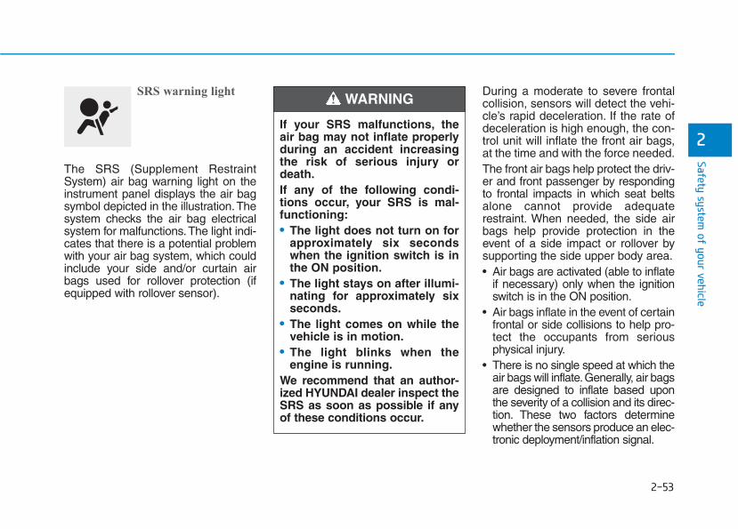
2-53
Safety system of your vehicle
2
SRS warning light
The SRS (Supplement RestraintSystem) air bag warning light on theinstrument panel displays the air bagsymbol depicted in the illustration.Thesystem checks the air bag electricalsystem for malfunctions.The light indi-cates that there is a potential problemwith your air bag system, which couldinclude your side and/or curtain airbags used for rollover protection (ifequipped with rollover sensor).
During a moderate to severe frontalcollision, sensors will detect the vehi-cle’s rapid deceleration. If the rate ofdeceleration is high enough, the con-trol unit will inflate the front air bags,at the time and with the force needed.The front air bags help protect the driv-er and front passenger by respondingto frontal impacts in which seat beltsalone cannot provide adequaterestraint. When needed, the side airbags help provide protection in theevent of a side impact or rollover bysupporting the side upper body area.• Air bags are activated (able to inflate
if necessary) only when the ignitionswitch is in the ON position.
• Air bags inflate in the event of certainfrontal or side collisions to help pro-tect the occupants from seriousphysical injury.
• There is no single speed at which theair bags will inflate.Generally, air bagsare designed to inflate based uponthe severity of a collision and its direc-tion. These two factors determinewhether the sensors produce an elec-tronic deployment/inflation signal.
If your SRS malfunctions, theair bag may not inflate properlyduring an accident increasingthe risk of serious injury ordeath.If any of the following condi-tions occur, your SRS is mal-functioning:• The light does not turn on for
approximately six secondswhen the ignition switch is inthe ON position.
• The light stays on after illumi-nating for approximately sixseconds.
• The light comes on while thevehicle is in motion.
• The light blinks when theengine is running.
We recommend that an author-ized HYUNDAI dealer inspect theSRS as soon as possible if anyof these conditions occur.
WARNING
2-54
Safety system of your vehicle
• Air bag deployment depends on anumber of factors including vehiclespeed, angles of impact and thedensity and stiffness of the vehiclesor objects which your vehicleimpacts during a collision. Thedetermining factors are not limitedto those mentioned above.
• The front air bags will completelyinflate and deflate in an instant. It isvirtually impossible for you to seethe air bags inflate during an acci-dent. It is much more likely that youwill simply see the deflated air bagshanging out of their storage com-partments after the collision.
• In addition to inflating in seriousside collisions, vehicles equippedwith a rollover sensor, side and/orcurtain air bags will inflate if thesensing system detects a rollover.When a rollover is detected, curtainair bags will remain inflated longerto help provide protection from ejec-tion, especially when used in con-junction with the seat belts. (ifequipped with a rollover sensor)
• To help provide protection, the airbags must inflate rapidly.The speedof air bag inflation is a consequenceof extremely short time in which toinflate the air bag between theoccupant and the vehicle structuresbefore the occupant impacts thosestructures. This speed of inflationreduces the risk of serious or life-threatening injuries and is thus anecessary part of air bag design.However, the rapid air bag inflationcan also cause injuries which caninclude facial abrasions, bruisesand broken bones because theinflation speed also causes the airbags to expand with a great deal offorce.
• There are even circumstancesunder which contact with the airbag can cause fatal injuries, espe-cially if the occupant is positionedexcessively close to the air bag.
You can take steps to reduce the riskof being injured by an inflating airbag. The greatest risk is sitting tooclose to the air bag. An air bag needsspace to inflate. It is recommendedthat drivers sit as far as possiblebetween the center of the steeringwheel and the chest while still main-taining control of the vehicle.
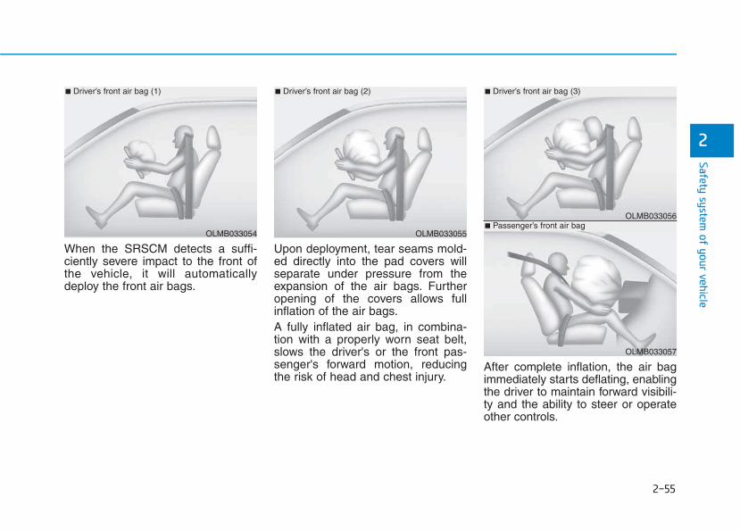
2-55
Safety system of your vehicle
2
When the SRSCM detects a suffi-ciently severe impact to the front ofthe vehicle, it will automaticallydeploy the front air bags.
Upon deployment, tear seams mold-ed directly into the pad covers willseparate under pressure from theexpansion of the air bags. Furtheropening of the covers allows fullinflation of the air bags.A fully inflated air bag, in combina-tion with a properly worn seat belt,slows the driver's or the front pas-senger's forward motion, reducingthe risk of head and chest injury.
After complete inflation, the air bagimmediately starts deflating, enablingthe driver to maintain forward visibili-ty and the ability to steer or operateother controls.
OLMB033055
■ Driver’s front air bag (2)
OLMB033056
■ Driver’s front air bag (3)
OLMB033057
■ Passenger’s front air bagOLMB033054
■ Driver’s front air bag (1)
2-56
Safety system of your vehicle
What to expect after an air baginflates After a frontal or side air bag inflates,it will deflate very quickly. Air baginflation will not prevent the driverfrom seeing out of the windshield orbeing able to steer. Curtain air bagsmay remain partially inflated forsome time after they deploy.
Noise and smoke from inflatingair bag When the air bags inflate, they makea loud noise and may produce smokeand powder in the air inside of thevehicle. This is normal and is a resultof the ignition of the air bag inflator.After the air bag inflates, you may feelsubstantial discomfort in breathingbecause of the contact of your chestwith both the seat belt and the airbag, as well as from breathing thesmoke and powder. The powder mayaggravate asthma for some people. Ifyou experience breathing problemsafter an air bag deployment, seekmedical attention immediately.Though the smoke and powder arenontoxic, they may cause irritation tothe skin, eyes, nose, throat, etc. If thisis the case, wash and rinse with coldwater immediately and seek medicalattention if the symptoms persist.
After an air bag inflates, takethe following precautions:• Open your windows and doors
as soon as possible afterimpact to reduce prolongedexposure to the smoke andpowder released by the inflat-ing air bag.
• Do not touch the air bag stor-age area’s internal compo-nents immediately after an airbag has inflated. The partsthat come into contact with aninflating air bag may be veryhot.
• Always wash exposed skinareas thoroughly with coldwater and mild soap.
• We recommend that an author-ized HYUNDAI dealer replacethe air bag immediately afterdeployment. Air bags aredesigned to be used only once.
WARNING
To prevent objects from becom-ing dangerous projectiles whenthe passenger's air bag inflates:• Do not install or place any
objects (drink holder, CD hold-er, stickers, etc.) on the frontpassenger's panel above theglove box where the passen-ger's air bag is located.
• Do not install a container ofliquid air freshener near theinstrument cluster or on theinstrument panel surface.
WARNING
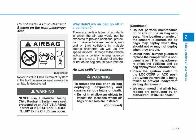
2-57
Safety system of your vehicle
2
Do not install a Child RestraintSystem on the front passengerseat
Never install a Child Restraint Systemin the front passenger seat, unless theair bag is deactivated
Why didn't my air bag go off ina collision?There are certain types of accidentsin which the air bag would not beexpected to provide additional protec-tion. These include rear impacts, sec-ond or third collisions in multipleimpact accidents, as well as lowspeed impacts. Damage to the vehicleindicates a collision energy absorp-tion, and is not an indicator of whetheror not an air bag should have inflated.
Air bag collision sensors OYDESA2042
NEVER use a rearward facingChild Restraint System on a seatprotected by an ACTIVE AIRBAGin front of it, DEATH or SERIOUSINJURY to the CHILD can occur.
WARNING
To reduce the risk of an air bagdeploying unexpectedly andcausing serious injury or death:• Do not hit or allow any objects to
impact the locations where airbags or sensors are installed.
(Continued)
WARNING
(Continued)• Do not perform maintenance
on or around the air bag sen-sors. If the location or angle ofthe sensors is altered, the airbags may deploy when theyshould not or may not deploywhen they should.
• Do not install bumper guards orreplace the bumper with a non-genuine part.This may adverse-ly affect the collision and airbag deployment performance.
• Place the ignition switch tothe LOCK/OFF or ACC posi-tion, when the vehicle is beingtowed to prevent inadvertentair bag deployment.
• We recommend that all air bagrepairs are conducted by anauthorized HYUNDAI dealer.
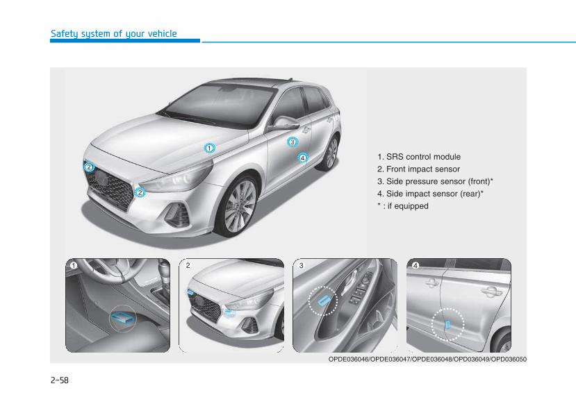
2-58
Safety system of your vehicle
1. SRS control module
2. Front impact sensor
3. Side pressure sensor (front)*
4. Side impact sensor (rear)*
* : if equipped
OPDE036046/OPDE036047/OPDE036048/OPD036049/OPD036050
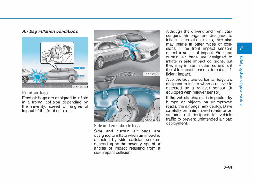
2-59
Safety system of your vehicle
2
Air bag inflation conditions
Front air bags
Front air bags are designed to inflatein a frontal collision depending onthe severity, speed or angles ofimpact of the front collision.
Side and curtain air bags
Side and curtain air bags aredesigned to inflate when an impact isdetected by side collision sensorsdepending on the severity, speed orangles of impact resulting from aside impact collision.
Although the driver’s and front pas-senger’s air bags are designed toinflate in frontal collisions, they alsomay inflate in other types of colli-sions if the front impact sensorsdetect a sufficient impact. Side andcurtain air bags are designed toinflate in side impact collisions, butthey may inflate in other collisions ifthe side impact sensors detect a suf-ficient impact.Also, the side and curtain air bags aredesigned to inflate when a rollover isdetected by a rollover sensor. (ifequipped with rollover sensor)If the vehicle chassis is impacted bybumps or objects on unimprovedroads, the air bags may deploy. Drivecarefully on unimproved roads or onsurfaces not designed for vehicletraffic to prevent unintended air bagdeployment.
OPD036052
OPD036053
OPD036051
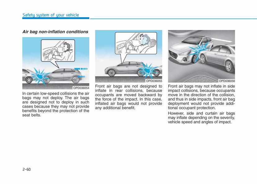
2-60
Safety system of your vehicle
Air bag non-inflation conditions
In certain low-speed collisions the airbags may not deploy. The air bagsare designed not to deploy in suchcases because they may not providebenefits beyond the protection of theseat belts.
Front air bags are not designed toinflate in rear collisions, becauseoccupants are moved backward bythe force of the impact. In this case,inflated air bags would not provideany additional benefit.
Front air bags may not inflate in sideimpact collisions, because occupantsmove in the direction of the collision,and thus in side impacts, front air bagdeployment would not provide addi-tional occupant protection.However, side and curtain air bagsmay inflate depending on the severity,vehicle speed and angles of impact.
OPD036055
OPD036054
OPD036056
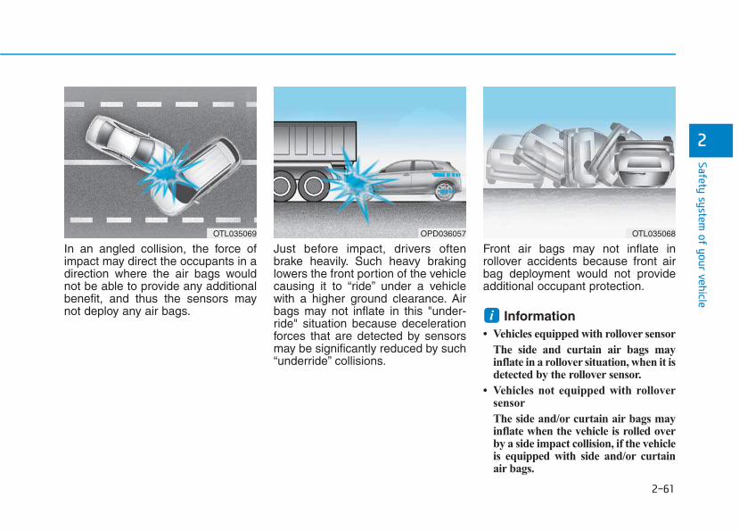
2-61
Safety system of your vehicle
2
In an angled collision, the force ofimpact may direct the occupants in adirection where the air bags wouldnot be able to provide any additionalbenefit, and thus the sensors maynot deploy any air bags.
Just before impact, drivers oftenbrake heavily. Such heavy brakinglowers the front portion of the vehiclecausing it to “ride” under a vehiclewith a higher ground clearance. Airbags may not inflate in this "under-ride" situation because decelerationforces that are detected by sensorsmay be significantly reduced by such“underride” collisions.
Front air bags may not inflate inrollover accidents because front airbag deployment would not provideadditional occupant protection.
Information • Vehicles equipped with rollover sensor
The side and curtain air bags mayinflate in a rollover situation, when it isdetected by the rollover sensor.
• Vehicles not equipped with rolloversensor
The side and/or curtain air bags mayinflate when the vehicle is rolled overby a side impact collision, if the vehicleis equipped with side and/or curtainair bags.
i
OTL035069 OPD036057 OTL035068
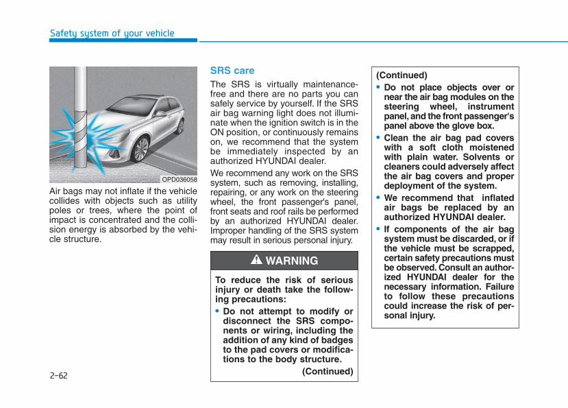
2-62
Safety system of your vehicle
Air bags may not inflate if the vehiclecollides with objects such as utilitypoles or trees, where the point ofimpact is concentrated and the colli-sion energy is absorbed by the vehi-cle structure.
SRS care The SRS is virtually maintenance-free and there are no parts you cansafely service by yourself. If the SRSair bag warning light does not illumi-nate when the ignition switch is in theON position, or continuously remainson, we recommend that the systembe immediately inspected by anauthorized HYUNDAI dealer.We recommend any work on the SRSsystem, such as removing, installing,repairing, or any work on the steeringwheel, the front passenger's panel,front seats and roof rails be performedby an authorized HYUNDAI dealer.Improper handling of the SRS systemmay result in serious personal injury.
OPD036058
To reduce the risk of seriousinjury or death take the follow-ing precautions:• Do not attempt to modify or
disconnect the SRS compo-nents or wiring, including theaddition of any kind of badgesto the pad covers or modifica-tions to the body structure.
(Continued)
WARNING
(Continued)• Do not place objects over or
near the air bag modules on thesteering wheel, instrumentpanel, and the front passenger'spanel above the glove box.
• Clean the air bag pad coverswith a soft cloth moistenedwith plain water. Solvents orcleaners could adversely affectthe air bag covers and properdeployment of the system.
• We recommend that inflatedair bags be replaced by anauthorized HYUNDAI dealer.
• If components of the air bagsystem must be discarded, or ifthe vehicle must be scrapped,certain safety precautions mustbe observed. Consult an author-ized HYUNDAI dealer for thenecessary information. Failureto follow these precautionscould increase the risk of per-sonal injury.
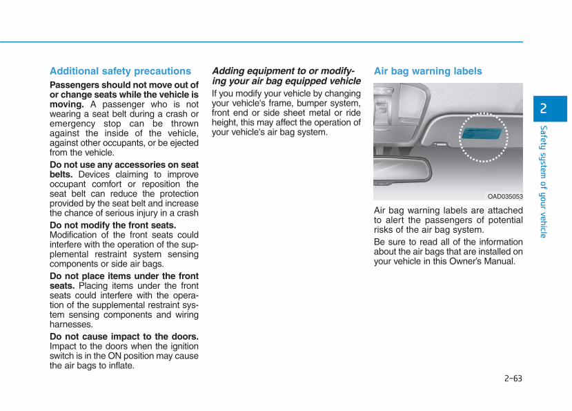
2-63
Safety system of your vehicle
2
Additional safety precautions Passengers should not move out ofor change seats while the vehicle ismoving. A passenger who is notwearing a seat belt during a crash oremergency stop can be thrownagainst the inside of the vehicle,against other occupants, or be ejectedfrom the vehicle.Do not use any accessories on seatbelts. Devices claiming to improveoccupant comfort or reposition theseat belt can reduce the protectionprovided by the seat belt and increasethe chance of serious injury in a crashDo not modify the front seats.Modification of the front seats couldinterfere with the operation of the sup-plemental restraint system sensingcomponents or side air bags.Do not place items under the frontseats. Placing items under the frontseats could interfere with the opera-tion of the supplemental restraint sys-tem sensing components and wiringharnesses.Do not cause impact to the doors.Impact to the doors when the ignitionswitch is in the ON position may causethe air bags to inflate.
Adding equipment to or modify-ing your air bag equipped vehicleIf you modify your vehicle by changingyour vehicle's frame, bumper system,front end or side sheet metal or rideheight, this may affect the operation ofyour vehicle's air bag system.
Air bag warning labels
Air bag warning labels are attachedto alert the passengers of potentialrisks of the air bag system.Be sure to read all of the informationabout the air bags that are installed onyour vehicle in this Owner’s Manual.
OAD035053
Convenient features of your vehicle
Accessing your vehicle .........................................3-3Remote key.........................................................................3-3Smart key ............................................................................3-6Immobilizer system .........................................................3-10
DOOR LOCKS ........................................................3-11Operating door locks from outside the vehicle ......3-11Operating door locks from inside the vehicle .........3-12Auto door lock/unlock features..................................3-14Child-protector rear door locks..................................3-15
Theft-alarm system.............................................3-16Driver position memory system.........................3-17
Storing memory positions.............................................3-17Recalling memory positions..........................................3-17Easy access function .....................................................3-18
Steering wheel......................................................3-19Electric power steering (EPS)......................................3-19Tilt steering / Telescope steering...............................3-20Heated steering wheel...................................................3-21Horn....................................................................................3-21
Mirrors...................................................................3-22Inside rearview mirror....................................................3-22Outside rearview mirror ................................................3-23Reverse parking aid function.......................................3-26
Windows ................................................................3-27Power windows................................................................3-27Manual windows..............................................................3-31
Panorama sunroof ...............................................3-32Sunshade...........................................................................3-33Sliding the sunroof .........................................................3-33Tilting the sunroof..........................................................3-34Closing the sunroof ........................................................3-34Resetting the sunroof....................................................3-35Sunroof open warning...................................................3-36
Exterior features .................................................3-37Hood ...................................................................................3-37Tailgate...............................................................................3-38Fuel filler door .................................................................3-40
Instrument cluster................................................3-43Instrument cluster control ............................................3-44Gauges and meters.........................................................3-45Transmission shift indicator .........................................3-48Manual transmission shift indicator...........................3-48Warning and indicator lights ........................................3-51LCD display messages....................................................3-65
LCD Display...........................................................3-71LCD display control.........................................................3-71LCD modes ........................................................................3-72
Trip computer .......................................................3-79Trip modes ........................................................................3-79
Light .......................................................................3-83Exterior lights ..................................................................3-83Static bending light.........................................................3-92Welcome system..............................................................3-92
3
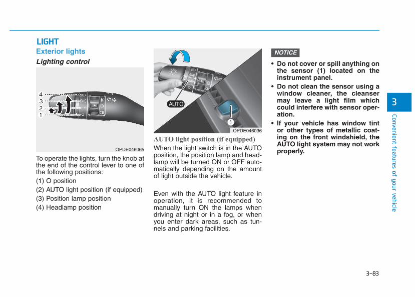
3-83
Convenient features of your vehicle
3
Exterior lightsLighting control
To operate the lights, turn the knob atthe end of the control lever to one ofthe following positions:(1) O position(2) AUTO light position (if equipped)(3) Position lamp position(4) Headlamp position
AUTO light position (if equipped)
When the light switch is in the AUTOposition, the position lamp and head-lamp will be turned ON or OFF auto-matically depending on the amountof light outside the vehicle.
Even with the AUTO light feature inoperation, it is recommended tomanually turn ON the lamps whendriving at night or in a fog, or whenyou enter dark areas, such as tun-nels and parking facilities.
• Do not cover or spill anything onthe sensor (1) located on theinstrument panel.
• Do not clean the sensor using awindow cleaner, the cleansermay leave a light film whichcould interfere with sensor oper-ation.
• If your vehicle has window tintor other types of metallic coat-ing on the front windshield, theAUTO light system may not workproperly.
NOTICE
LLIIGGHHTT
OPDE046036
OPDE046065
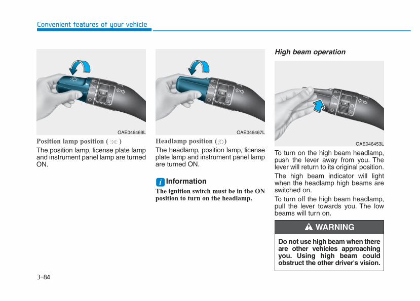
3-84
Convenient features of your vehicle
Position lamp position ( )
The position lamp, license plate lampand instrument panel lamp are turnedON.
Headlamp position ( )
The headlamp, position lamp, licenseplate lamp and instrument panel lampare turned ON.
Information The ignition switch must be in the ONposition to turn on the headlamp.
High beam operation
To turn on the high beam headlamp,push the lever away from you. Thelever will return to its original position.The high beam indicator will lightwhen the headlamp high beams areswitched on.To turn off the high beam headlamp,pull the lever towards you. The lowbeams will turn on.
i
OAE046469L OAE046467L
OAE046453L
Do not use high beam when thereare other vehicles approachingyou. Using high beam couldobstruct the other driver's vision.
WARNING
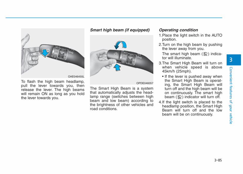
3-85
Convenient features of your vehicle
To flash the high beam headlamp,pull the lever towards you, thenrelease the lever. The high beamswill remain ON as long as you holdthe lever towards you.
Smart high beam (if equipped)
The Smart High Beam is a systemthat automatically adjusts the head-lamp range (switches between highbeam and low beam) according tothe brightness of other vehicles androad conditions.
Operating condition1.Place the light switch in the AUTO
position.2.Turn on the high beam by pushing
the lever away from you.The smart high beam ( ) indica-tor will illuminate.
3.The Smart High Beam will turn onwhen vehicle speed is above45km/h (25mph).• If the lever is pushed away when
the Smart High Beam is operat-ing, the Smart High Beam willturn off and the high beam will beon continuously. The smart highbeam ( ) indicator will turn off.
4.If the light switch is placed to theheadlamp position, the Smart HighBeam will turn off and the lowbeam will be on continuously.
3
OAE046455L
OPDE046057
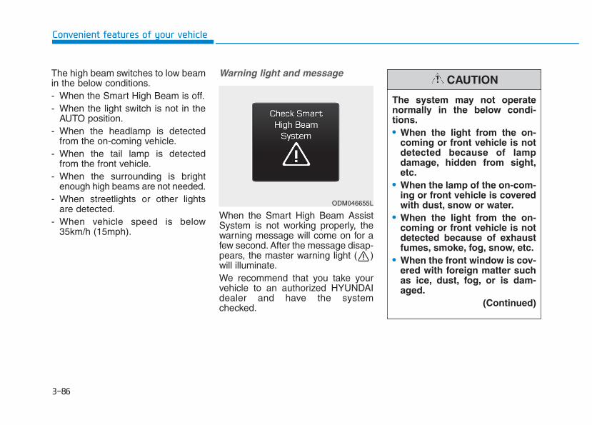
3-86
The high beam switches to low beamin the below conditions.- When the Smart High Beam is off.- When the light switch is not in the
AUTO position.- When the headlamp is detected
from the on-coming vehicle.- When the tail lamp is detected
from the front vehicle.- When the surrounding is bright
enough high beams are not needed.- When streetlights or other lights
are detected.- When vehicle speed is below
35km/h (15mph).
Warning light and message
When the Smart High Beam AssistSystem is not working properly, thewarning message will come on for afew second. After the message disap-pears, the master warning light ( )will illuminate.We recommend that you take yourvehicle to an authorized HYUNDAIdealer and have the systemchecked.
Convenient features of your vehicle
ODM046655L
The system may not operatenormally in the below condi-tions.• When the light from the on-
coming or front vehicle is notdetected because of lampdamage, hidden from sight,etc.
• When the lamp of the on-com-ing or front vehicle is coveredwith dust, snow or water.
• When the light from the on-coming or front vehicle is notdetected because of exhaustfumes, smoke, fog, snow, etc.
• When the front window is cov-ered with foreign matter suchas ice, dust, fog, or is dam-aged.
(Continued)
CAUTION
3-87
Convenient features of your vehicle
3
(Continued)• When there is a similar
shaped lamp with the frontvehicle’s lamps.
• When it is hard to seebecause of fog, heavy rain orsnow.
• When the headlamp is notrepaired or replaced at anauthorized dealer.
• When headlamp aiming is notproperly adjusted.
• When driving on a narrowwinding road or rough road.
• When driving downhill oruphill.
• When only part of the vehiclein front is visible on a cross-road or on a corner.
• When there is a traffic light,reflecting sign, flashing signor mirror.
• When the road conditions arebad such as being wet or cov-ered with snow.
(Continued)
(Continued)• When the front vehicle’s head-
lamps are off but the foglamps on.
• When a vehicle suddenlyappears from a around a cor-ner.
• When the vehicle is tilted froma flat tyre or being towed.
• When the LDWS (Lane DepartureWarning System) or LKAS (LaneKeeping Assist System) warninglight illuminates. (if equipped)
• Do not place any accessories,stickers or tint the windshield.
• Have the windshield glassreplaced by an authoriseddealer.
• Do not remove or impact relat-ed parts of the Smart HighBeam system.
• Be careful that water doesn’tget into the Smart High Beamunit.
• Do not place objects on theinstrument panel that reflectlight such as mirrors, whitepaper, etc. The system maymalfunction if sunlight isreflected.
• At times, the Smart HighBeam system may not workproperly, always check theroad conditions for your safe-ty. When the system does notoperate normally, manuallychange between the highbeam and low beam.
WARNING
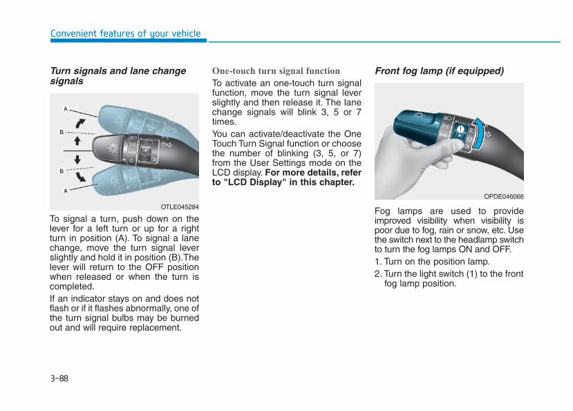
3-88
Convenient features of your vehicle
Turn signals and lane changesignals
To signal a turn, push down on thelever for a left turn or up for a rightturn in position (A). To signal a lanechange, move the turn signal leverslightly and hold it in position (B).Thelever will return to the OFF positionwhen released or when the turn iscompleted.If an indicator stays on and does notflash or if it flashes abnormally, one ofthe turn signal bulbs may be burnedout and will require replacement.
One-touch turn signal function
To activate an one-touch turn signalfunction, move the turn signal leverslightly and then release it. The lanechange signals will blink 3, 5 or 7times.You can activate/deactivate the OneTouch Turn Signal function or choosethe number of blinking (3, 5, or 7)from the User Settings mode on theLCD display. For more details, referto "LCD Display" in this chapter.
Front fog lamp (if equipped)
Fog lamps are used to provideimproved visibility when visibility ispoor due to fog, rain or snow, etc. Usethe switch next to the headlamp switchto turn the fog lamps ON and OFF.1. Turn on the position lamp.2. Turn the light switch (1) to the front
fog lamp position.
OPDE046066
OTLE045284
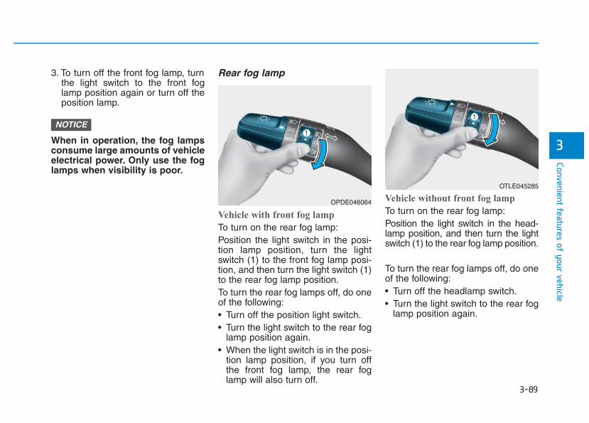
3-89
Convenient features of your vehicle
3
3. To turn off the front fog lamp, turnthe light switch to the front foglamp position again or turn off theposition lamp.
When in operation, the fog lampsconsume large amounts of vehicleelectrical power. Only use the foglamps when visibility is poor.
Rear fog lamp
Vehicle with front fog lamp
To turn on the rear fog lamp:Position the light switch in the posi-tion lamp position, turn the lightswitch (1) to the front fog lamp posi-tion, and then turn the light switch (1)to the rear fog lamp position.To turn the rear fog lamps off, do oneof the following:• Turn off the position light switch.• Turn the light switch to the rear fog
lamp position again.• When the light switch is in the posi-
tion lamp position, if you turn offthe front fog lamp, the rear foglamp will also turn off.
Vehicle without front fog lamp
To turn on the rear fog lamp:Position the light switch in the head-lamp position, and then turn the lightswitch (1) to the rear fog lamp position.
To turn the rear fog lamps off, do oneof the following:• Turn off the headlamp switch.• Turn the light switch to the rear fog
lamp position again.
NOTICE
OTLE045285
OPDE046064
3-90
Convenient features of your vehicle
Battery saver functionThe purpose of this feature is to pre-vent the battery from being dis-charged. The system automaticallyturns off the position lamp when thedriver turns the engine off and opensthe driver-side door.With this feature, the position lampswill turn off automatically if the driverparks on the side of road at night.If necessary, to keep the lamps onwhen the engine is turned off, performthe following:1) Open the driver-side door.2) Turn the position lamps OFF and
ON again using the light switch onthe steering column.
Headlamp delay function (if equipped)If you place the ignition switch to theACC or OFF position with the head-lamps ON, the headlamps (and/orposition lamps) remain on for about 5minutes. However, with the engine off ifthe driver’s door is opened and closed,the headlamps (and/or position lamps)are turned off after 15 seconds.The headlamps (and/or positionlamps) can be turned off by pressingthe lock button on the remote key orsmart key twice or turning the lightswitch to the OFF or AUTO position.However, if you turn the light switchto the AUTO position when it is darkoutside, the headlamps will not beturned off.You can activate or deactivate theHeadlamp Delay function from theUser Settings mode on the LCD dis-play. For more details, refer to"LCD Display" in this chapter.
If the driver gets out of the vehiclethrough other doors (except dri-ver's door), the battery saver func-tion does not operate and theheadlamp delay function does notturn off automatically. Therefore, Itcauses the battery to be dis-charged. In this case, make sure toturn off the lamp before getting outof the vehicle.
NOTICE
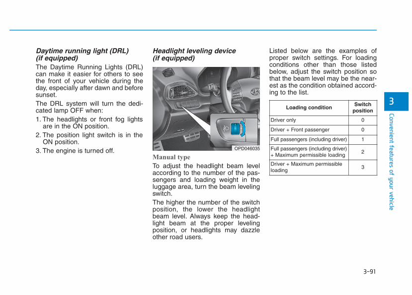
3-91
Convenient features of your vehicle
3
Daytime running light (DRL) (if equipped)The Daytime Running Lights (DRL)can make it easier for others to seethe front of your vehicle during theday, especially after dawn and beforesunset.The DRL system will turn the dedi-cated lamp OFF when:1. The headlights or front fog lights
are in the ON position.2. The position light switch is in the
ON position.3. The engine is turned off.
Headlight leveling device (if equipped)
Manual type
To adjust the headlight beam levelaccording to the number of the pas-sengers and loading weight in theluggage area, turn the beam levelingswitch.The higher the number of the switchposition, the lower the headlightbeam level. Always keep the head-light beam at the proper levelingposition, or headlights may dazzleother road users.
Listed below are the examples ofproper switch settings. For loadingconditions other than those listedbelow, adjust the switch position sothat the beam level may be the near-est as the condition obtained accord-ing to the list.
OPD046035
Loading conditionSwitch
position
Driver only 0
Driver + Front passenger 0
Full passengers (including driver) 1
Full passengers (including driver)+ Maximum permissible loading
2
Driver + Maximum permissibleloading
3
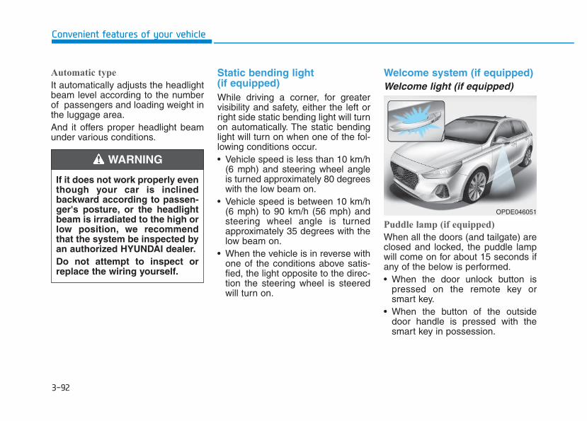
3-92
Automatic type
It automatically adjusts the headlightbeam level according to the numberof passengers and loading weight inthe luggage area.And it offers proper headlight beamunder various conditions.
Static bending light (if equipped)While driving a corner, for greatervisibility and safety, either the left orright side static bending light will turnon automatically. The static bendinglight will turn on when one of the fol-lowing conditions occur.• Vehicle speed is less than 10 km/h
(6 mph) and steering wheel angleis turned approximately 80 degreeswith the low beam on.
• Vehicle speed is between 10 km/h(6 mph) to 90 km/h (56 mph) andsteering wheel angle is turnedapproximately 35 degrees with thelow beam on.
• When the vehicle is in reverse withone of the conditions above satis-fied, the light opposite to the direc-tion the steering wheel is steeredwill turn on.
Welcome system (if equipped)Welcome light (if equipped)
Puddle lamp (if equipped)
When all the doors (and tailgate) areclosed and locked, the puddle lampwill come on for about 15 seconds ifany of the below is performed.• When the door unlock button is
pressed on the remote key orsmart key.
• When the button of the outsidedoor handle is pressed with thesmart key in possession.
Convenient features of your vehicle
If it does not work properly eventhough your car is inclinedbackward according to passen-ger's posture, or the headlightbeam is irradiated to the high orlow position, we recommendthat the system be inspected byan authorized HYUNDAI dealer.Do not attempt to inspect orreplace the wiring yourself.
WARNING
OPDE046051
3-93
Convenient features of your vehicle
Door handle lamp (if equipped)
When all the doors (and tailgate) areclosed and locked, the door handlelamp will come on for about 15 sec-onds if any of the below is performed.• When the door unlock button is
pressed on the remote key orsmart key.
• When the button of the outsidedoor handle is pressed with thesmart key in possession.
Headlamp and position lamp
When the headlamp (lamp switch inthe headlamp or AUTO position) is onand all doors (and tailgate) are lockedand closed, the position lamp andheadlamp will come on for 15 secondsif/or any of the below is performed.• When the door unlock button is
pressed on the remote key orsmart key.
At this time, if you press the door lockor unlock button, the position lamp andheadlamp will turn off immediately.
You can activate or deactivate theWelcome Light from the UserSettings mode on the LCD display.For more details, refer to "LCDDisplay" in this chapter.
Interior lampWhen the interior lamp switch is inthe DOOR position and all doors (andtailgate) are closed and locked, theroom lamp will come on for 30 sec-onds if any of the below is performed.• When the door unlock button is
pressed on the remote key orsmart key.
• When the button of the outsidedoor handle is pressed with thesmart key in possession.
At this time, if you press the door lockor unlock button, the room lamp willturn off immediately.
Interior lights
Do not use the interior lights forextended periods when the engineis turned off or the battery will dis-charge.
Interior lamp AUTO cutThe interior lamps will automaticallygo off approximately 20 minutes afterthe engine is turned off and thedoors closed. If a door is opened, thelamp will go off 40 minutes after theengine is turned off. If the doors arelocked and the vehicle enters thearmed stage of the theft alarm sys-tem, the lamps will go off five sec-onds later.
NOTICE
3
Do not use the interior lightswhen driving in the dark.The inte-rior lights may obscure your viewand cause an accident.
WARNING
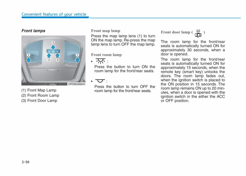
3-94
Convenient features of your vehicle
Front lamps
(1) Front Map Lamp(2) Front Room Lamp(3) Front Door Lamp
Front map lamp
Press the map lamp lens (1) to turnON the map lamp. Re-press the maplamp lens to turn OFF the map lamp.
Front room lamp
• :Press the button to turn ON theroom lamp for the front/rear seats.
• :Press the button to turn OFF theroom lamp for the front/rear seats.
Front door lamp ( )
The room lamp for the front/rearseats is automatically turned ON forapproximately 30 seconds, when adoor is opened.The room lamp for the front/rearseats is automatically turned ON forapproximately 15 seconds, when theremote key (smart key) unlocks thedoors. The room lamp fades out,when the ignition switch is placed tothe ON position in 15 seconds. Theroom lamp remains ON up to 20 min-utes, when a door is opened with theignition switch in the either the ACCor OFF position.
OPDE046041
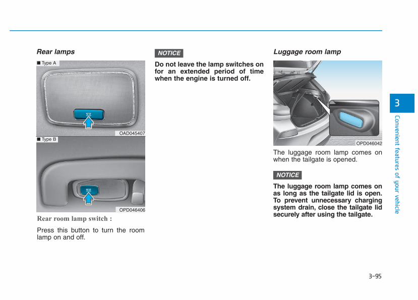
3-95
Convenient features of your vehicle
3
Rear lamps
Do not leave the lamp switches onfor an extended period of timewhen the engine is turned off.
Luggage room lamp
The luggage room lamp comes onwhen the tailgate is opened.
The luggage room lamp comes onas long as the tailgate lid is open.To prevent unnecessary chargingsystem drain, close the tailgate lidsecurely after using the tailgate.
NOTICE
NOTICE
OPD046042
Rear room lamp switch :
Press this button to turn the roomlamp on and off.
OAD045407
OPD046406
■ Type A
■ Type B
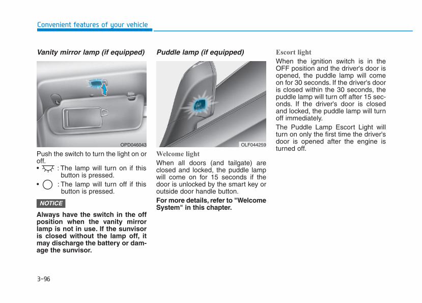
3-96
Convenient features of your vehicle
Vanity mirror lamp (if equipped)
Push the switch to turn the light on oroff.• : The lamp will turn on if this
button is pressed.• : The lamp will turn off if this
button is pressed.
Always have the switch in the offposition when the vanity mirrorlamp is not in use. If the sunvisoris closed without the lamp off, itmay discharge the battery or dam-age the sunvisor.
Puddle lamp (if equipped)
Welcome light
When all doors (and tailgate) areclosed and locked, the puddle lampwill come on for 15 seconds if thedoor is unlocked by the smart key oroutside door handle button.For more details, refer to "WelcomeSystem" in this chapter.
Escort light
When the ignition switch is in theOFF position and the driver's door isopened, the puddle lamp will comeon for 30 seconds. If the driver's dooris closed within the 30 seconds, thepuddle lamp will turn off after 15 sec-onds. If the driver's door is closedand locked, the puddle lamp will turnoff immediately.The Puddle Lamp Escort Light willturn on only the first time the driver'sdoor is opened after the engine isturned off.
NOTICE
OPD046043 OLF044259
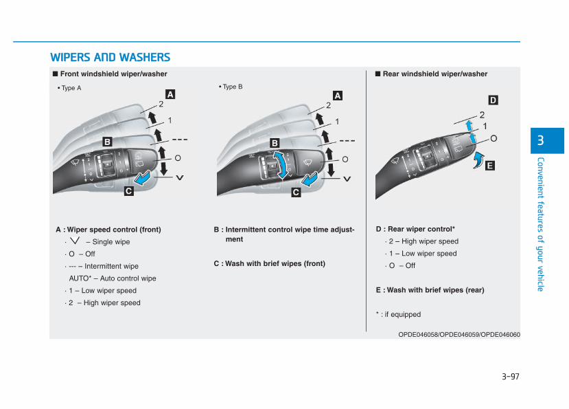
3-97
Convenient features of your vehicle
WWIIPPEERRSS AANNDD WWAASSHHEERRSS
3
■ Front windshield wiper/washer ■ Rear windshield wiper/washer
OPDE046058/OPDE046059/OPDE046060
• Type A • Type B
A : Wiper speed control (front)
· – Single wipe
· O – Off
· --- – Intermittent wipe
AUTO* – Auto control wipe
· 1 – Low wiper speed
· 2 – High wiper speed
B : Intermittent control wipe time adjust-ment
C : Wash with brief wipes (front)
D : Rear wiper control*
· 2 – High wiper speed
· 1 – Low wiper speed
· O – Off
E : Wash with brief wipes (rear)
* : if equipped
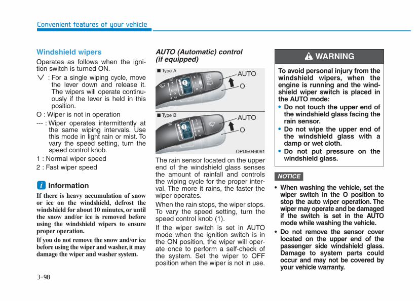
3-98
Convenient features of your vehicle
Windshield wipers Operates as follows when the igni-tion switch is turned ON.
: For a single wiping cycle, movethe lever down and release it.The wipers will operate continu-ously if the lever is held in thisposition.
O : Wiper is not in operation --- : Wiper operates intermittently at
the same wiping intervals. Usethis mode in light rain or mist. Tovary the speed setting, turn thespeed control knob.
1 : Normal wiper speed 2 : Fast wiper speed
Information If there is heavy accumulation of snowor ice on the windshield, defrost thewindshield for about 10 minutes, or untilthe snow and/or ice is removed beforeusing the windshield wipers to ensureproper operation.
If you do not remove the snow and/or icebefore using the wiper and washer, it maydamage the wiper and washer system.
AUTO (Automatic) control (if equipped)
The rain sensor located on the upperend of the windshield glass sensesthe amount of rainfall and controlsthe wiping cycle for the proper inter-val. The more it rains, the faster thewiper operates.When the rain stops, the wiper stops.To vary the speed setting, turn thespeed control knob (1).If the wiper switch is set in AUTOmode when the ignition switch is inthe ON position, the wiper will oper-ate once to perform a self-check ofthe system. Set the wiper to OFFposition when the wiper is not in use.
• When washing the vehicle, set thewiper switch in the O position tostop the auto wiper operation. Thewiper may operate and be damagedif the switch is set in the AUTOmode while washing the vehicle.
• Do not remove the sensor coverlocated on the upper end of thepassenger side windshield glass.Damage to system parts couldoccur and may not be covered byyour vehicle warranty.
NOTICE
i
OPDE046061
To avoid personal injury from thewindshield wipers, when theengine is running and the wind-shield wiper switch is placed inthe AUTO mode:• Do not touch the upper end of
the windshield glass facing therain sensor.
• Do not wipe the upper end ofthe windshield glass with adamp or wet cloth.
• Do not put pressure on thewindshield glass.
WARNING
■ Type A
■ Type B
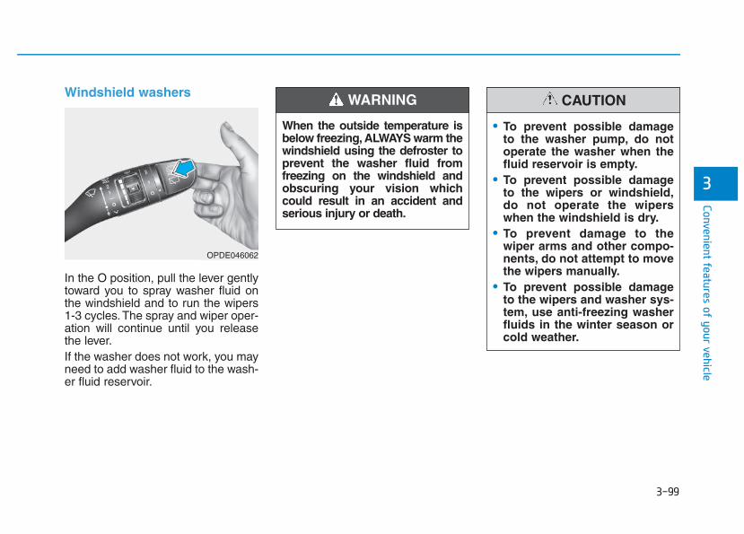
3-99
Convenient features of your vehicle
3
Windshield washers
In the O position, pull the lever gentlytoward you to spray washer fluid onthe windshield and to run the wipers1-3 cycles.The spray and wiper oper-ation will continue until you releasethe lever.If the washer does not work, you mayneed to add washer fluid to the wash-er fluid reservoir.
When the outside temperature isbelow freezing, ALWAYS warm thewindshield using the defroster toprevent the washer fluid fromfreezing on the windshield andobscuring your vision whichcould result in an accident andserious injury or death.
WARNING
• To prevent possible damageto the washer pump, do notoperate the washer when thefluid reservoir is empty.
• To prevent possible damageto the wipers or windshield,do not operate the wiperswhen the windshield is dry.
• To prevent damage to thewiper arms and other compo-nents, do not attempt to movethe wipers manually.
• To prevent possible damageto the wipers and washer sys-tem, use anti-freezing washerfluids in the winter season orcold weather.
CAUTION
OPDE046062
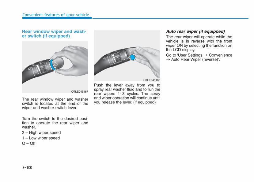
3-100
Convenient features of your vehicle
Rear window wiper and wash-er switch (if equipped)
The rear window wiper and washerswitch is located at the end of thewiper and washer switch lever.
Turn the switch to the desired posi-tion to operate the rear wiper andwasher.2 – High wiper speed1 – Low wiper speed O – Off
Push the lever away from you tospray rear washer fluid and to run therear wipers 1~3 cycles. The sprayand wiper operation will continue untilyou release the lever. (if equipped)
Auto rear wiper (if equipped)The rear wiper will operate while thevehicle is in reverse with the frontwiper ON by selecting the function onthe LCD display.Go to ‘User Settings → Convenience→ Auto Rear Wiper (reverse)’.
OTLE045167
OTLE045168
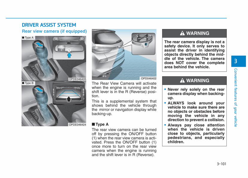
3-101
Convenient features of your vehicle
3
DDRRIIVVEERR AASSSSIISSTT SSYYSSTTEEMM
The Rear View Camera will activatewhen the engine is running and theshift lever is in the R (Reverse) posi-tion.This is a supplemental system thatshows behind the vehicle throughthe mirror or navigation display whilebacking-up.
■■ Type AThe rear view camera can be turnedoff by pressing the ON/OFF button(1) when the rear view camera is acti-vated. Press the ON/OFF button (1)once more to turn on the rear viewcamera when the engine is runningand the shift lever is in R (Reverse).
The rear camera display is not asafety device. It only serves toassist the driver in identifyingobjects directly behind the mid-dle of the vehicle. The cameradoes NOT cover the completearea behind the vehicle.
WARNING
OPDE046405
OPDE046424
OPD046402
■ Type A
■ Type B
Rear view camera (if equipped)
• Never rely solely on the rearcamera display when backing-up.
• ALWAYS look around yourvehicle to make sure there areno objects or obstacles beforemoving the vehicle in anydirection to prevent a collision.
• Always pay close attentionwhen the vehicle is drivenclose to objects, particularlypedestrians, and especiallychildren.
WARNING
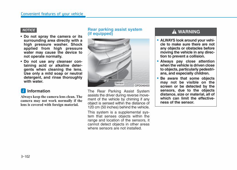
3-102
Convenient features of your vehicle
• Do not spray the camera or itssurrounding area directly with ahigh pressure washer. Shockapplied from high pressurewater may cause the device tonot operate normally.
• Do not use any cleanser con-taining acid or alkaline deter-gents when cleaning the lens.Use only a mild soap or neutraldetergent, and rinse thoroughlywith water.
Information Always keep the camera lens clean. Thecamera may not work normally if thelens is covered with foreign material.
Rear parking assist system(if equipped)
The Rear Parking Assist Systemassists the driver during reverse move-ment of the vehicle by chiming if anyobject is sensed within the distance of120 cm (50 inches) behind the vehicle.This system is a supplemental sys-tem that senses objects within therange and location of the sensors, itcannot detect objects in other areaswhere sensors are not installed.
i
NOTICE
OPD046400Sensor
• ALWAYS look around your vehi-cle to make sure there are notany objects or obstacles beforemoving the vehicle in any direc-tion to prevent a collision.
• Always pay close attentionwhen the vehicle is driven closeto objects, particularly pedestri-ans, and especially children.
• Be aware that some objectsmay not be visible on thescreen or be detected by thesensors, due to the objectsdistance, size or material, all ofwhich can limit the effective-ness of the sensor.
WARNING
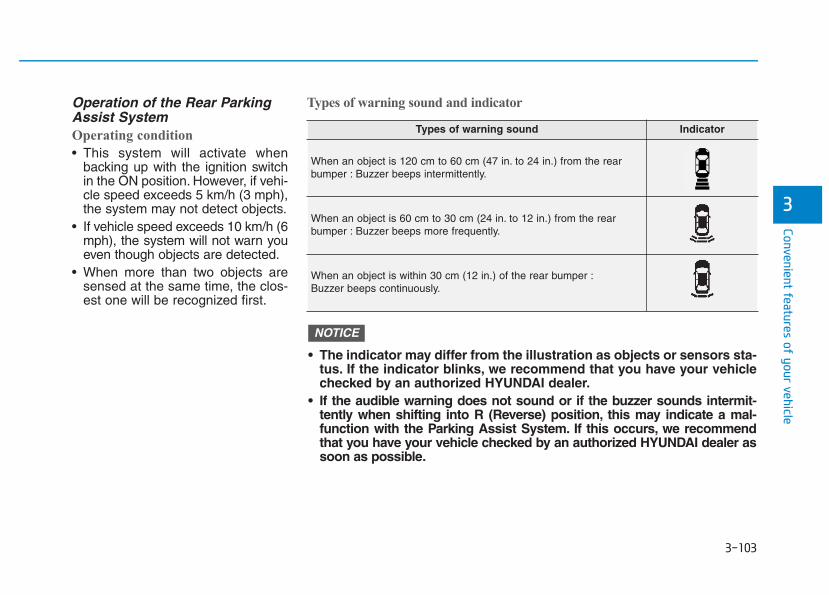
3-103
Convenient features of your vehicle
3
Operation of the Rear ParkingAssist SystemOperating condition
• This system will activate whenbacking up with the ignition switchin the ON position. However, if vehi-cle speed exceeds 5 km/h (3 mph),the system may not detect objects.
• If vehicle speed exceeds 10 km/h (6mph), the system will not warn youeven though objects are detected.
• When more than two objects aresensed at the same time, the clos-est one will be recognized first.
Types of warning sound and indicator
Types of warning sound Indicator
When an object is 120 cm to 60 cm (47 in. to 24 in.) from the rearbumper : Buzzer beeps intermittently.
When an object is 60 cm to 30 cm (24 in. to 12 in.) from the rearbumper : Buzzer beeps more frequently.
When an object is within 30 cm (12 in.) of the rear bumper :Buzzer beeps continuously.
• The indicator may differ from the illustration as objects or sensors sta-tus. If the indicator blinks, we recommend that you have your vehiclechecked by an authorized HYUNDAI dealer.
• If the audible warning does not sound or if the buzzer sounds intermit-tently when shifting into R (Reverse) position, this may indicate a mal-function with the Parking Assist System. If this occurs, we recommendthat you have your vehicle checked by an authorized HYUNDAI dealer assoon as possible.
NOTICE
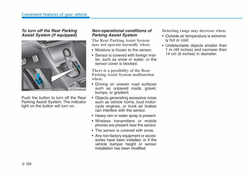
3-104
Convenient features of your vehicle
To turn off the Rear ParkingAssist System (if equipped)
Push the button to turn off the RearParking Assist System. The indicatorlight on the button will turn on.
Non-operational conditions ofParking Assist SystemThe Rear Parking Assist Systemmay not operate normally when:
• Moisture is frozen to the sensor.• Sensor is covered with foreign mat-
ter, such as snow or water, or thesensor cover is blocked.
There is a possibility of the RearParking Assist System malfunctionwhen:
• Driving on uneven road surfacessuch as unpaved roads, gravel,bumps, or gradient.
• Objects generating excessive noisesuch as vehicle horns, loud motor-cycle engines, or truck air brakescan interfere with the sensor.
• Heavy rain or water spray is present.• Wireless transmitters or mobile
phones are present near the sensor.• The sensor is covered with snow.• Any non-factory equipment or acces-
sories have been installed, or if thevehicle bumper height or sensorinstallation has been modified.
Detecting range may decrease when:
• Outside air temperature is extreme-ly hot or cold.
• Undetectable objects smaller than1 m (40 inches) and narrower than14 cm (6 inches) in diameter.
OPDE046429
3-105
Convenient features of your vehicle
3
The following objects may not berecognized by the sensor:
• Sharp or slim objects such asropes, chains or small poles.
• Objects, which tend to absorb sen-sor frequency such as clothes,spongy material or snow.
Rear parking assist system pre-cautions• The rear parking assist system may
not sound consistently depending onthe speed and shapes of the objectsdetected.
• The rear parking assist system maymalfunction if the vehicle bumperheight or sensor installation hasbeen modified or damaged. Anynon-factory installed equipment oraccessories may also interfere withthe sensor performance.
• The sensor may not recognizeobjects less than 30 cm (11 in.) fromthe sensor, or it may sense an incor-rect distance. Use caution.
• When the sensor is frozen or stainedwith snow, dirt, or water, the sensormay be inoperative until the stainsare removed using a soft cloth.
• Do not push, scratch or strike thesensor with any hard objects thatcould damage the surface of thesensor. Sensor damage could occur.
• Do not spray the sensors or its sur-rounding area directly with a highpressure washer. Shock appliedfrom high pressure water may causethe device to not operate normally.
Your new vehicle warranty doesnot cover any accidents or dam-age to the vehicle or injuries toits occupants related to a RearParking Assist System. Alwaysdrive safely and cautiously.
WARNING
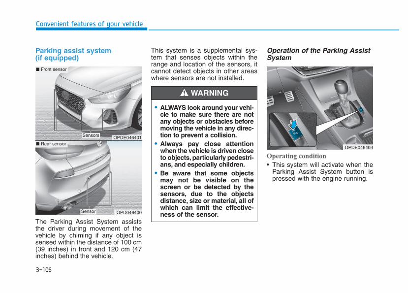
3-106
Convenient features of your vehicle
Parking assist system (if equipped)
The Parking Assist System assiststhe driver during movement of thevehicle by chiming if any object issensed within the distance of 100 cm(39 inches) in front and 120 cm (47inches) behind the vehicle.
This system is a supplemental sys-tem that senses objects within therange and location of the sensors, itcannot detect objects in other areaswhere sensors are not installed.
Operation of the Parking AssistSystem
Operating condition
• This system will activate when theParking Assist System button ispressed with the engine running.
• ALWAYS look around your vehi-cle to make sure there are notany objects or obstacles beforemoving the vehicle in any direc-tion to prevent a collision.
• Always pay close attentionwhen the vehicle is driven closeto objects, particularly pedestri-ans, and especially children.
• Be aware that some objectsmay not be visible on thescreen or be detected by thesensors, due to the objectsdistance, size or material, all ofwhich can limit the effective-ness of the sensor.
WARNING
OPDE046401
OPD046400
■ Front sensor
■ Rear sensor
Sensors
Sensor
OPDE046403
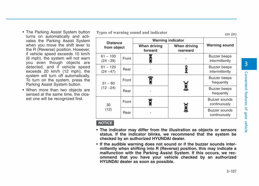
3-107
Convenient features of your vehicle
3
• The Parking Assist System buttonturns on automatically and acti-vates the Parking Assist Systemwhen you move the shift lever tothe R (Reverse) position. However,if vehicle speed exceeds 10 km/h(6 mph), the system will not warnyou even though objects aredetected, and if vehicle speedexceeds 20 km/h (12 mph), thesystem will turn off automatically.To turn on the system, press theParking Assist System button.
• When more than two objects aresensed at the same time, the clos-est one will be recognized first.
• The indicator may differ from the illustration as objects or sensorsstatus. If the indicator blinks, we recommend that the system bechecked by an authorized HYUNDAI dealer.
• If the audible warning does not sound or if the buzzer sounds inter-mittently when shifting into R (Reverse) position, this may indicate amalfunction with the Parking Assist System. If this occurs, we rec-ommend that you have your vehicle checked by an authorizedHYUNDAI dealer as soon as possible.
NOTICE
Distance from object
Warning indicatorWarning soundWhen driving
forwardWhen driving
rearward
61 ~ 100(24 ~39)
Front -Buzzer beeps intermittently
61 ~ 120(24 ~47)
Rear -Buzzer beeps intermittently
31 ~ 60(12 ~24)
FrontBuzzer beeps
frequently
Rear -Buzzer beeps
frequently
30 (12)
FrontBuzzer sounds continuously
Rear -Buzzer sounds continuously
Types of warning sound and indicator cm (in)
3-108
Convenient features of your vehicle
Non-operational conditions ofParking Assist SystemParking Assist System may notoperate normally when:
• Moisture is frozen to the sensor.• Sensor is covered with foreign mat-
ter, such as snow or water, or thesensor cover is blocked.
There is a possibility of ParkingAssist System malfunction when:
• Driving on uneven road surfacessuch as unpaved roads, gravel,bumps, or gradient.
• Objects generating excessive noisesuch as vehicle horns, loud motor-cycle engines, or truck air brakescan interfere with the sensor.
• Heavy rain or water spray is present.• Wireless transmitters or mobile
phones are present near the sensor.• The sensor is covered with snow.• Any non-factory equipment or
accessories have been installed, orif the vehicle bumper height or sen-sor installation has been modified.
Detecting range may decrease when:
• Outside air temperature isextremely hot or cold.
• Undetectable objects smaller than1 m and narrower than 14 cm indiameter.
The following objects may not berecognized by the sensor:
• Sharp or slim objects such asropes, chains or small poles.
• Objects, which tend to absorb sen-sor frequency such as clothes,spongy material or snow.
Parking assist system precau-tions• The parking assist system may not
sound consistently depending on thespeed and shapes of the objectsdetected.
• The parking assist system may mal-function if the vehicle bumper heightor sensor installation has been mod-ified or damaged. Any non-factoryinstalled equipment or accessoriesmay also interfere with the sensorperformance.
• The sensor may not recognizeobjects less than 30 cm (11 in.) fromthe sensor, or it may sense an incor-rect distance. Use caution.
• When the sensor is frozen or stainedwith snow, dirt, or water, the sensormay be inoperative until the stainsare removed using a soft cloth.
• Do not push, scratch or strike thesensor. Sensor damage could occur.
• Do not spray the sensors or its sur-rounding area directly with a highpressure washer. Shock appliedfrom high pressure water may causethe device to not operate normally.
Your new vehicle warranty doesnot cover any accidents or dam-age to the vehicle or injuries toits occupants related to aParking Assist System. Alwaysdrive safely and cautiously.
WARNING
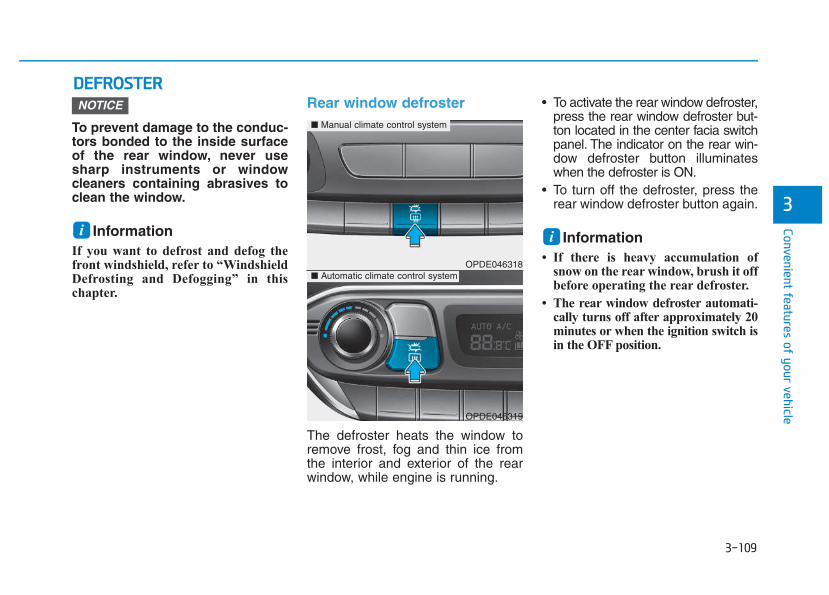
3-109
Convenient features of your vehicle
3
DDEEFFRROOSSTTEERR
To prevent damage to the conduc-tors bonded to the inside surfaceof the rear window, never usesharp instruments or windowcleaners containing abrasives toclean the window.
Information If you want to defrost and defog thefront windshield, refer to “WindshieldDefrosting and Defogging” in thischapter.
Rear window defroster
The defroster heats the window toremove frost, fog and thin ice fromthe interior and exterior of the rearwindow, while engine is running.
• To activate the rear window defroster,press the rear window defroster but-ton located in the center facia switchpanel. The indicator on the rear win-dow defroster button illuminateswhen the defroster is ON.
• To turn off the defroster, press therear window defroster button again.
Information • If there is heavy accumulation of
snow on the rear window, brush it offbefore operating the rear defroster.
• The rear window defroster automati-cally turns off after approximately 20minutes or when the ignition switch isin the OFF position.
NOTICE
i iOPDE046318
OPDE046319
■ Manual climate control system
■ Automatic climate control system
3-110
Convenient features of your vehicle
Outside mirror defroster (if equipped)If your vehicle is equipped with theoutside mirror defrosters, they willoperate at the same time you turn onthe rear window defroster.
Front wiper deicer (if equipped)If your vehicle is equipped with thewiper deicer, it will operate at thesame time you turn on the rear win-dow defroster.
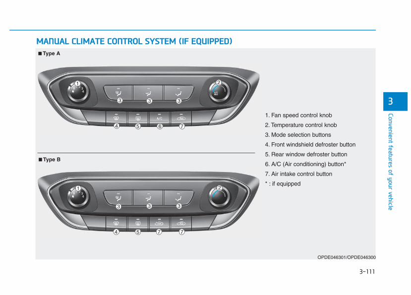
3-111
Convenient features of your vehicle
3
MMAANNUUAALL CCLLIIMMAATTEE CCOONNTTRROOLL SSYYSSTTEEMM ((IIFF EEQQUUIIPPPPEEDD))
OPDE046301/OPDE046300
1. Fan speed control knob
2. Temperature control knob
3. Mode selection buttons
4. Front windshield defroster button
5. Rear window defroster button
6. A/C (Air conditioning) button*
7. Air intake control button
* : if equipped
■■ Type A
■■ Type B
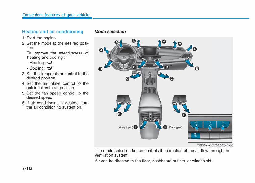
3-112
Convenient features of your vehicle
Heating and air conditioning1. Start the engine.2. Set the mode to the desired posi-
tion.To improve the effectiveness ofheating and cooling :- Heating:- Cooling:
3. Set the temperature control to thedesired position.
4. Set the air intake control to theoutside (fresh) air position.
5. Set the fan speed control to thedesired speed.
6. If air conditioning is desired, turnthe air conditioning system on.
Mode selection
(if equipped)(if equipped)
OPDE046307/OPDE046306
The mode selection button controls the direction of the air flow through theventilation system.Air can be directed to the floor, dashboard outlets, or windshield.
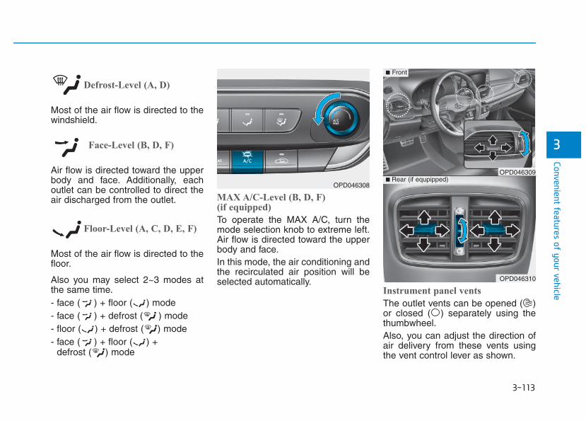
3-113
Convenient features of your vehicle
3
Defrost-Level (A, D)
Most of the air flow is directed to thewindshield.
Face-Level (B, D, F)
Air flow is directed toward the upperbody and face. Additionally, eachoutlet can be controlled to direct theair discharged from the outlet.
Floor-Level (A, C, D, E, F)
Most of the air flow is directed to thefloor.
Also you may select 2~3 modes atthe same time.- face ( ) + floor ( ) mode- face ( ) + defrost ( ) mode- floor ( ) + defrost ( ) mode- face ( ) + floor ( ) +
defrost ( ) mode
MAX A/C-Level (B, D, F) (if equipped)
To operate the MAX A/C, turn themode selection knob to extreme left.Air flow is directed toward the upperbody and face.In this mode, the air conditioning andthe recirculated air position will beselected automatically.
Instrument panel vents
The outlet vents can be opened ( )or closed ( ) separately using thethumbwheel.Also, you can adjust the direction ofair delivery from these vents usingthe vent control lever as shown.
OPD046308
OPD046310
■ Rear (if equpipped)
■ Front
OPD046309
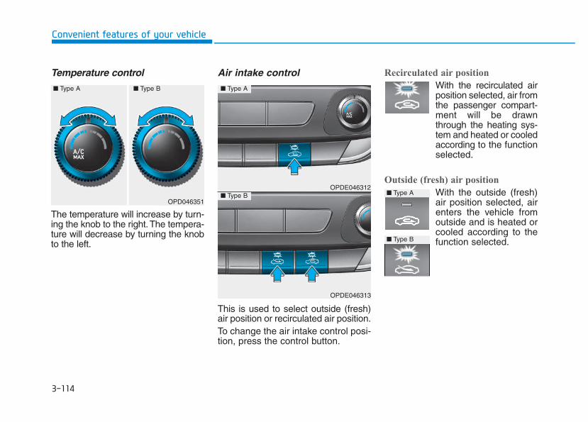
3-114
Convenient features of your vehicle
Temperature control
The temperature will increase by turn-ing the knob to the right.The tempera-ture will decrease by turning the knobto the left.
Air intake control
This is used to select outside (fresh)air position or recirculated air position.To change the air intake control posi-tion, press the control button.
Recirculated air position
With the recirculated airposition selected, air fromthe passenger compart-ment will be drawnthrough the heating sys-tem and heated or cooledaccording to the functionselected.
Outside (fresh) air position
With the outside (fresh)air position selected, airenters the vehicle fromoutside and is heated orcooled according to thefunction selected.
OPD046351
OPDE046312
OPDE046313
■ Type A
■ Type B ■ Type A
■ Type B
■ Type A ■ Type B
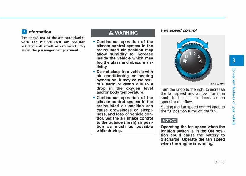
3-115
Convenient features of your vehicle
3
Information Prolonged use of the air conditioningwith the recirculated air positionselected will result in excessively dryair in the passenger compartment.
Fan speed control
Turn the knob to the right to increasethe fan speed and airflow. Turn theknob to the left to decrease fanspeed and airflow.Setting the fan speed control knob tothe “0” position turns off the fan.
Operating the fan speed when theignition switch is in the ON posi-tion could cause the battery todischarge. Operate the fan speedwhen the engine is running.
NOTICE
i
• Continuous operation of theclimate control system in therecirculated air position mayallow humidity to increaseinside the vehicle which mayfog the glass and obscure vis-ibility.
• Do not sleep in a vehicle withair conditioning or heatingsystem on. It may cause seri-ous harm or death due to adrop in the oxygen leveland/or body temperature.
• Continuous operation of theclimate control system in therecirculated air position cancause drowsiness or sleepi-ness, and loss of vehicle con-trol. Set the air intake controlto the outside (fresh) air posi-tion as much as possiblewhile driving.
WARNING
OPD046311
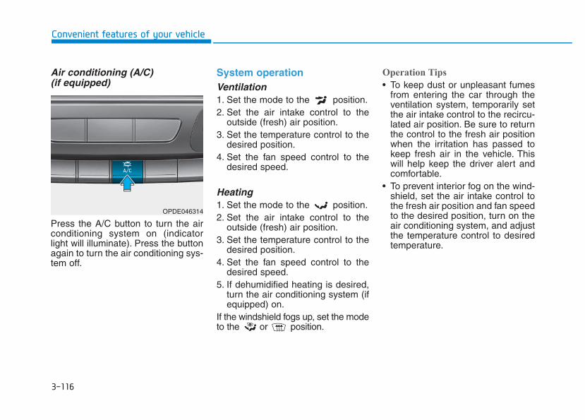
3-116
Convenient features of your vehicle
Air conditioning (A/C) (if equipped)
Press the A/C button to turn the airconditioning system on (indicatorlight will illuminate). Press the buttonagain to turn the air conditioning sys-tem off.
System operationVentilation1. Set the mode to the position.2. Set the air intake control to the
outside (fresh) air position.3. Set the temperature control to the
desired position.4. Set the fan speed control to the
desired speed.
Heating1. Set the mode to the position.2. Set the air intake control to the
outside (fresh) air position.3. Set the temperature control to the
desired position.4. Set the fan speed control to the
desired speed.5. If dehumidified heating is desired,
turn the air conditioning system (ifequipped) on.
If the windshield fogs up, set the modeto the or position.
Operation Tips
• To keep dust or unpleasant fumesfrom entering the car through theventilation system, temporarily setthe air intake control to the recircu-lated air position. Be sure to returnthe control to the fresh air positionwhen the irritation has passed tokeep fresh air in the vehicle. Thiswill help keep the driver alert andcomfortable.
• To prevent interior fog on the wind-shield, set the air intake control tothe fresh air position and fan speedto the desired position, turn on theair conditioning system, and adjustthe temperature control to desiredtemperature.
OPDE046314
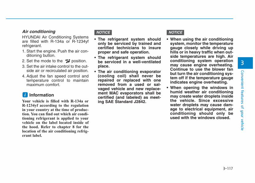
3-117
Convenient features of your vehicle
3
Air conditioningHYUNDAI Air Conditioning Systemsare filled with R-134a or R-1234yfrefrigerant.1. Start the engine. Push the air con-
ditioning button.2. Set the mode to the position.3. Set the air intake control to the out-
side air or recirculated air position.4. Adjust the fan speed control and
temperature control to maintainmaximum comfort.
Information Your vehicle is filled with R-134a orR-1234yf according to the regulationin your country at the time of produc-tion. You can find out which air condi-tioning refrigerant is applied to yourvehicle on the label located inside ofthe hood. Refer to chapter 8 for thelocation of the air conditioning refrig-erant label.
• The refrigerant system shouldonly be serviced by trained andcertified technicians to insureproper and safe operation.
• The refrigerant system shouldbe serviced in a well-ventilatedplace.
• The air conditioning evaporator(cooling coil) shall never berepaired or replaced with oneremoved from a used or sal-vaged vehicle and new replace-ment MAC evaporators shall becertified (and labeled) as meet-ing SAE Standard J2842.
• When using the air conditioningsystem, monitor the temperaturegauge closely while driving uphills or in heavy traffic when out-side temperatures are high. Airconditioning system operationmay cause engine overheating.Continue to use the blower fanbut turn the air conditioning sys-tem off if the temperature gaugeindicates engine overheating.
• When opening the windows inhumid weather air conditioningmay create water droplets insidethe vehicle. Since excessivewater droplets may cause dam-age to electrical equipment, airconditioning should only beused with the windows closed.
NOTICENOTICE
i
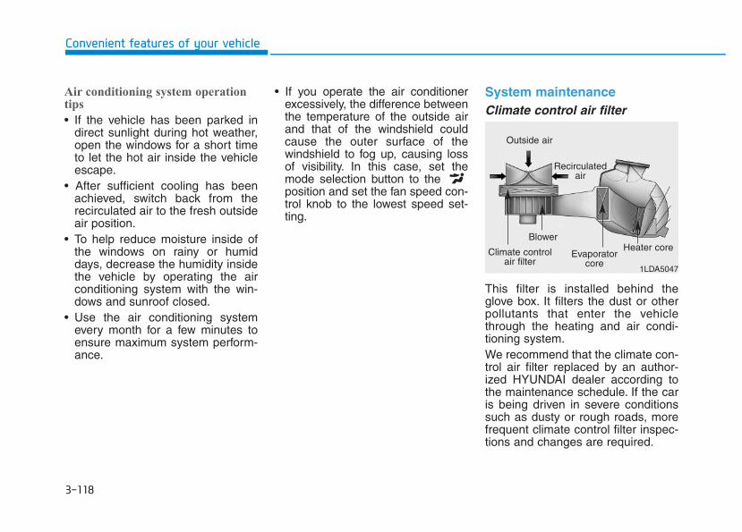
3-118
Convenient features of your vehicle
Air conditioning system operationtips
• If the vehicle has been parked indirect sunlight during hot weather,open the windows for a short timeto let the hot air inside the vehicleescape.
• After sufficient cooling has beenachieved, switch back from therecirculated air to the fresh outsideair position.
• To help reduce moisture inside ofthe windows on rainy or humiddays, decrease the humidity insidethe vehicle by operating the airconditioning system with the win-dows and sunroof closed.
• Use the air conditioning systemevery month for a few minutes toensure maximum system perform-ance.
• If you operate the air conditionerexcessively, the difference betweenthe temperature of the outside airand that of the windshield couldcause the outer surface of thewindshield to fog up, causing lossof visibility. In this case, set themode selection button to the position and set the fan speed con-trol knob to the lowest speed set-ting.
System maintenanceClimate control air filter
This filter is installed behind theglove box. It filters the dust or otherpollutants that enter the vehiclethrough the heating and air condi-tioning system.We recommend that the climate con-trol air filter replaced by an author-ized HYUNDAI dealer according tothe maintenance schedule. If the caris being driven in severe conditionssuch as dusty or rough roads, morefrequent climate control filter inspec-tions and changes are required.
1LDA5047
Outside air
Recirculatedair
Climate controlair filter
Blower
Evaporatorcore
Heater core
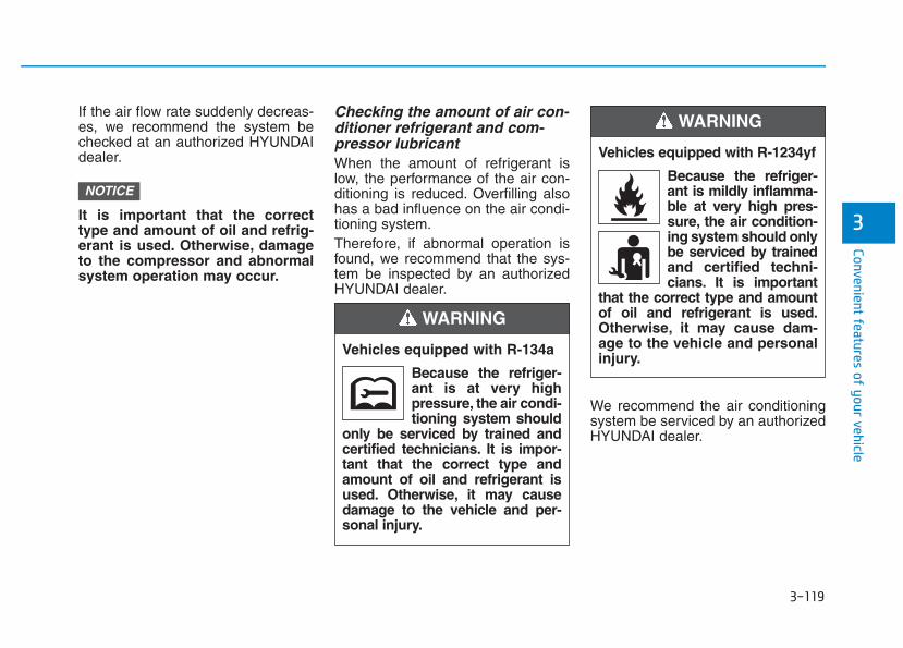
3-119
Convenient features of your vehicle
3
If the air flow rate suddenly decreas-es, we recommend the system bechecked at an authorized HYUNDAIdealer.
It is important that the correcttype and amount of oil and refrig-erant is used. Otherwise, damageto the compressor and abnormalsystem operation may occur.
Checking the amount of air con-ditioner refrigerant and com-pressor lubricantWhen the amount of refrigerant islow, the performance of the air con-ditioning is reduced. Overfilling alsohas a bad influence on the air condi-tioning system.Therefore, if abnormal operation isfound, we recommend that the sys-tem be inspected by an authorizedHYUNDAI dealer.
We recommend the air conditioningsystem be serviced by an authorizedHYUNDAI dealer.
NOTICE
Vehicles equipped with R-134a
Because the refriger-ant is at very highpressure, the air condi-tioning system should
only be serviced by trained andcertified technicians. It is impor-tant that the correct type andamount of oil and refrigerant isused. Otherwise, it may causedamage to the vehicle and per-sonal injury.
WARNING
Vehicles equipped with R-1234yf
Because the refriger-ant is mildly inflamma-ble at very high pres-sure, the air condition-ing system should onlybe serviced by trainedand certified techni-cians. It is important
that the correct type and amountof oil and refrigerant is used.Otherwise, it may cause dam-age to the vehicle and personalinjury.
WARNING
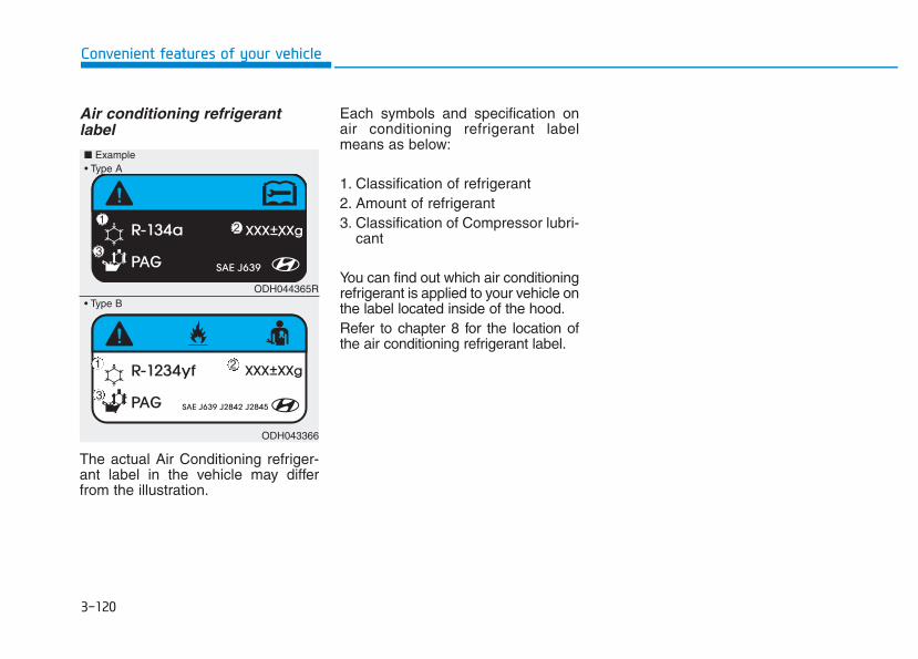
3-120
Convenient features of your vehicle
Air conditioning refrigerantlabel
The actual Air Conditioning refriger-ant label in the vehicle may differfrom the illustration.
Each symbols and specification onair conditioning refrigerant labelmeans as below:
1. Classification of refrigerant2. Amount of refrigerant3. Classification of Compressor lubri-
cant
You can find out which air conditioningrefrigerant is applied to your vehicle onthe label located inside of the hood.Refer to chapter 8 for the location ofthe air conditioning refrigerant label.
ODH044365R
ODH043366
■ Example
• Type B
• Type A
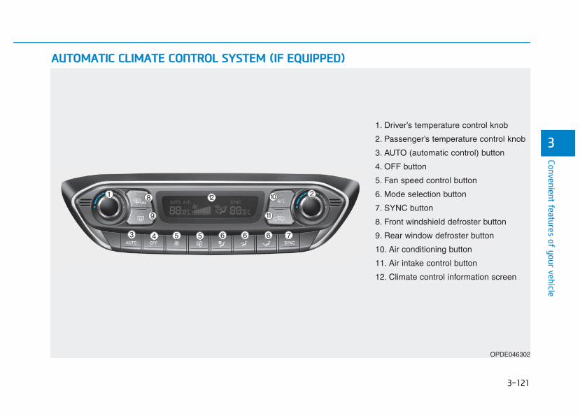
3-121
Convenient features of your vehicle
3
AAUUTTOOMMAATTIICC CCLLIIMMAATTEE CCOONNTTRROOLL SSYYSSTTEEMM ((IIFF EEQQUUIIPPPPEEDD))
OPDE046302
1. Driver’s temperature control knob
2. Passenger’s temperature control knob
3. AUTO (automatic control) button
4. OFF button
5. Fan speed control button
6. Mode selection button
7. SYNC button
8. Front windshield defroster button
9. Rear window defroster button
10. Air conditioning button
11. Air intake control button
12. Climate control information screen
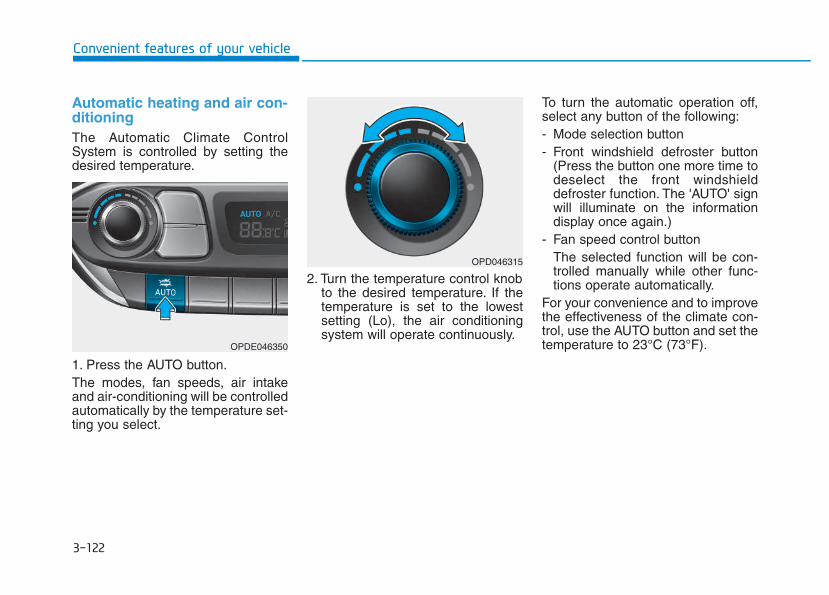
3-122
Convenient features of your vehicle
Automatic heating and air con-ditioningThe Automatic Climate ControlSystem is controlled by setting thedesired temperature.
1. Press the AUTO button.The modes, fan speeds, air intakeand air-conditioning will be controlledautomatically by the temperature set-ting you select.
2. Turn the temperature control knobto the desired temperature. If thetemperature is set to the lowestsetting (Lo), the air conditioningsystem will operate continuously.
To turn the automatic operation off,select any button of the following:- Mode selection button- Front windshield defroster button
(Press the button one more time todeselect the front windshielddefroster function. The 'AUTO' signwill illuminate on the informationdisplay once again.)
- Fan speed control buttonThe selected function will be con-trolled manually while other func-tions operate automatically.
For your convenience and to improvethe effectiveness of the climate con-trol, use the AUTO button and set thetemperature to 23°C (73°F).OPDE046350
OPD046315
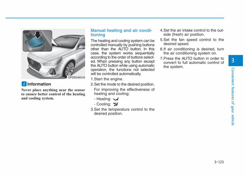
3-123
Convenient features of your vehicle
3
Information Never place anything near the sensorto ensure better control of the heatingand cooling system.
Manual heating and air condi-tioningThe heating and cooling system can becontrolled manually by pushing buttonsother than the AUTO button. In thiscase, the system works sequentiallyaccording to the order of buttons select-ed. When pressing any button exceptthe AUTO button while using automaticoperation, the functions not selectedwill be controlled automatically.1.Start the engine.2.Set the mode to the desired position.
For improving the effectiveness ofheating and cooling;- Heating:- Cooling:
3.Set the temperature control to thedesired position.
4.Set the air intake control to the out-side (fresh) air position.
5.Set the fan speed control to thedesired speed.
6.If air conditioning is desired, turnthe air conditioning system on.
7.Press the AUTO button in order toconvert to full automatic control ofthe system.
iOPDE046316
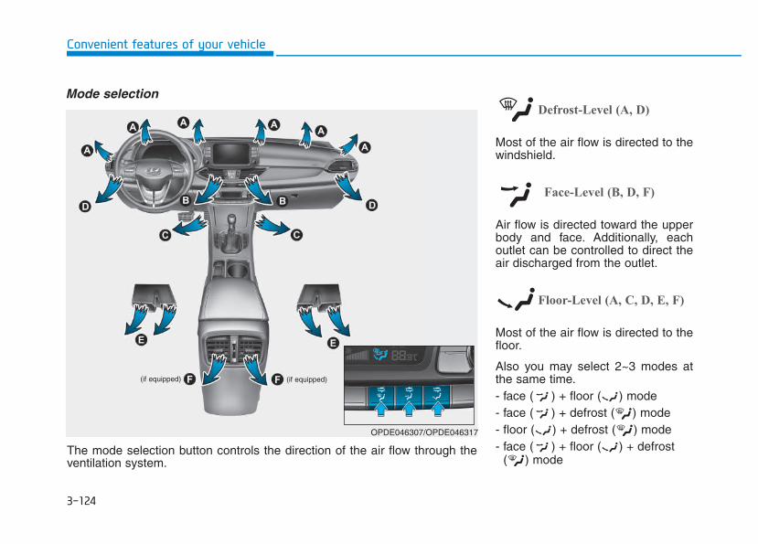
3-124
Convenient features of your vehicle
Mode selectionDefrost-Level (A, D)
Most of the air flow is directed to thewindshield.
Face-Level (B, D, F)
Air flow is directed toward the upperbody and face. Additionally, eachoutlet can be controlled to direct theair discharged from the outlet.
Floor-Level (A, C, D, E, F)
Most of the air flow is directed to thefloor.
Also you may select 2~3 modes atthe same time.- face ( ) + floor ( ) mode- face ( ) + defrost ( ) mode- floor ( ) + defrost ( ) mode- face ( ) + floor ( ) + defrost
( ) mode
(if equipped)(if equipped)
OPDE046307/OPDE046317
The mode selection button controls the direction of the air flow through theventilation system.
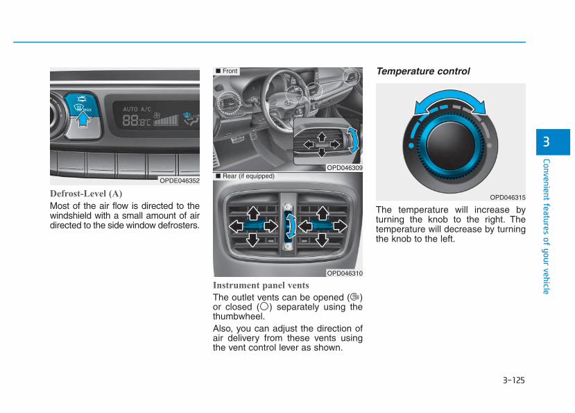
3-125
Convenient features of your vehicle
3
Defrost-Level (A)
Most of the air flow is directed to thewindshield with a small amount of airdirected to the side window defrosters.
Instrument panel vents
The outlet vents can be opened ( )or closed ( ) separately using thethumbwheel.Also, you can adjust the direction ofair delivery from these vents usingthe vent control lever as shown.
Temperature control
The temperature will increase byturning the knob to the right. Thetemperature will decrease by turningthe knob to the left.
OPDE046352
OPD046309
OPD046310
■ Front
■ Rear (if equipped)
OPD046315
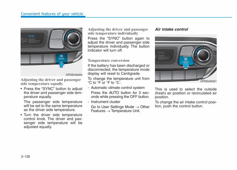
3-126
Convenient features of your vehicle
Adjusting the driver and passengerside temperature equally
• Press the “SYNC” button to adjustthe driver and passenger side tem-perature equally.The passenger side temperaturewill be set to the same temperatureas the driver side temperature.
• Turn the driver side temperaturecontrol knob. The driver and pas-senger side temperature will beadjusted equally.
Adjusting the driver and passengerside temperature individually
Press the “SYNC” button again toadjust the driver and passenger sidetemperature individually. The buttonindicator will turn off.
Temperature conversion
If the battery has been discharged ordisconnected, the temperature modedisplay will reset to Centigrade.To change the temperature unit from°C to °F or °F to °C :- Automatic climate control system
Press the AUTO button for 3 sec-onds while pressing the OFF button.
- Instrument clusterGo to User Settings Mode → OtherFeatures → Temperature Unit.
Air intake control
This is used to select the outside(fresh) air position or recirculated airposition.To change the air intake control posi-tion, push the control button.
OPDE046320
OPDE046321
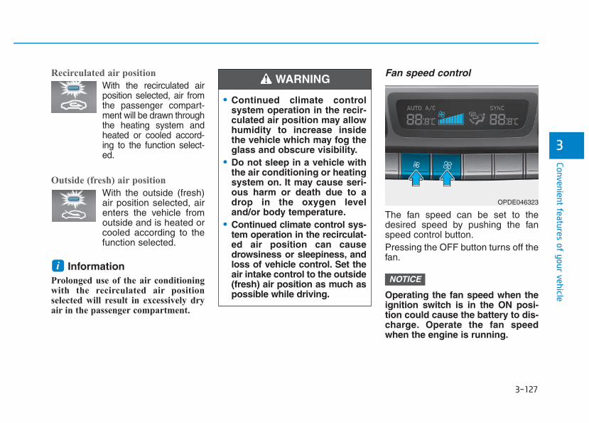
3-127
Convenient features of your vehicle
3
Recirculated air position
With the recirculated airposition selected, air fromthe passenger compart-ment will be drawn throughthe heating system andheated or cooled accord-ing to the function select-ed.
Outside (fresh) air position
With the outside (fresh)air position selected, airenters the vehicle fromoutside and is heated orcooled according to thefunction selected.
Information Prolonged use of the air conditioningwith the recirculated air positionselected will result in excessively dryair in the passenger compartment.
Fan speed control
The fan speed can be set to thedesired speed by pushing the fanspeed control button.Pressing the OFF button turns off thefan.
Operating the fan speed when theignition switch is in the ON posi-tion could cause the battery to dis-charge. Operate the fan speedwhen the engine is running.
NOTICEi
• Continued climate controlsystem operation in the recir-culated air position may allowhumidity to increase insidethe vehicle which may fog theglass and obscure visibility.
• Do not sleep in a vehicle withthe air conditioning or heatingsystem on. It may cause seri-ous harm or death due to adrop in the oxygen leveland/or body temperature.
• Continued climate control sys-tem operation in the recirculat-ed air position can causedrowsiness or sleepiness, andloss of vehicle control. Set theair intake control to the outside(fresh) air position as much aspossible while driving.
WARNING
OPDE046323
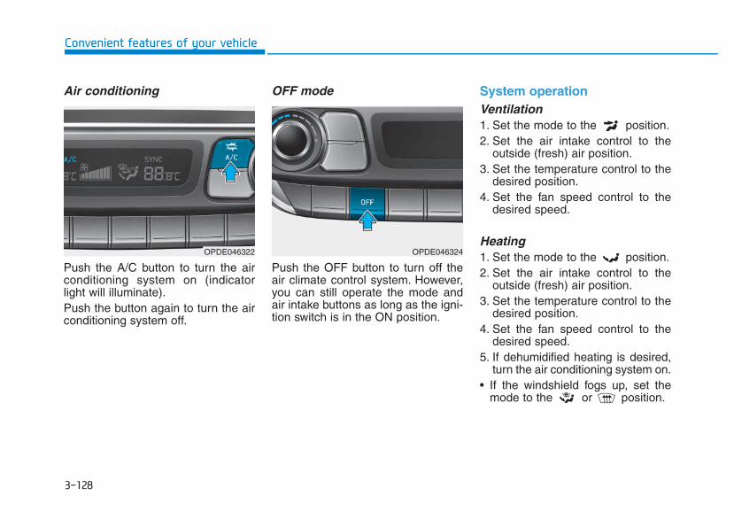
3-128
Convenient features of your vehicle
Air conditioning
Push the A/C button to turn the airconditioning system on (indicatorlight will illuminate).Push the button again to turn the airconditioning system off.
OFF mode
Push the OFF button to turn off theair climate control system. However,you can still operate the mode andair intake buttons as long as the igni-tion switch is in the ON position.
System operationVentilation1. Set the mode to the position.2. Set the air intake control to the
outside (fresh) air position.3. Set the temperature control to the
desired position.4. Set the fan speed control to the
desired speed.
Heating1. Set the mode to the position.2. Set the air intake control to the
outside (fresh) air position.3. Set the temperature control to the
desired position.4. Set the fan speed control to the
desired speed.5. If dehumidified heating is desired,
turn the air conditioning system on.• If the windshield fogs up, set the
mode to the or position.
OPDE046322 OPDE046324
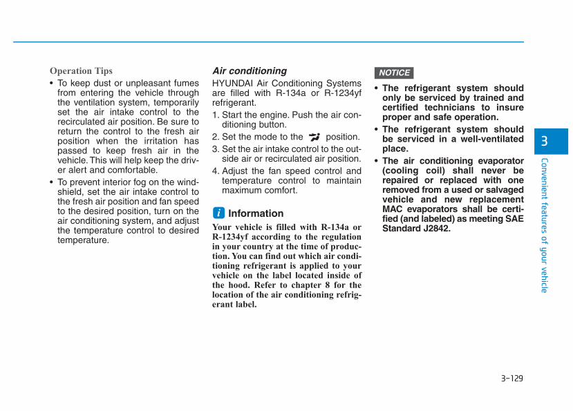
3-129
Convenient features of your vehicle
3
Operation Tips
• To keep dust or unpleasant fumesfrom entering the vehicle throughthe ventilation system, temporarilyset the air intake control to therecirculated air position. Be sure toreturn the control to the fresh airposition when the irritation haspassed to keep fresh air in thevehicle. This will help keep the driv-er alert and comfortable.
• To prevent interior fog on the wind-shield, set the air intake control tothe fresh air position and fan speedto the desired position, turn on theair conditioning system, and adjustthe temperature control to desiredtemperature.
Air conditioningHYUNDAI Air Conditioning Systemsare filled with R-134a or R-1234yfrefrigerant.1. Start the engine. Push the air con-
ditioning button.2. Set the mode to the position.3. Set the air intake control to the out-
side air or recirculated air position.4. Adjust the fan speed control and
temperature control to maintainmaximum comfort.
Information Your vehicle is filled with R-134a orR-1234yf according to the regulationin your country at the time of produc-tion. You can find out which air condi-tioning refrigerant is applied to yourvehicle on the label located inside ofthe hood. Refer to chapter 8 for thelocation of the air conditioning refrig-erant label.
• The refrigerant system shouldonly be serviced by trained andcertified technicians to insureproper and safe operation.
• The refrigerant system shouldbe serviced in a well-ventilatedplace.
• The air conditioning evaporator(cooling coil) shall never berepaired or replaced with oneremoved from a used or salvagedvehicle and new replacementMAC evaporators shall be certi-fied (and labeled) as meeting SAEStandard J2842.
NOTICE
i
3-130
Convenient features of your vehicle
• When using the air conditioningsystem, monitor the temperaturegauge closely while driving uphills or in heavy traffic when out-side temperatures are high. Airconditioning system operationmay cause engine overheating.Continue to use the blower fanbut turn the air conditioning sys-tem off if the temperature gaugeindicates engine overheating.
• When opening the windows inhumid weather air conditioningmay create water droplets insidethe vehicle. Since excessivewater droplets may cause dam-age to electrical equipment, airconditioning should only beused with the windows closed.
Air conditioning system operationtips
• If the vehicle has been parked indirect sunlight during hot weather,open the windows for a short timeto let the hot air inside the vehicleescape.
• After sufficient cooling has beenachieved, switch back from therecirculated air to the fresh outsideair position.
• To help reduce moisture inside ofthe windows on rainy or humiddays, decrease the humidity insidethe vehicle by operating the airconditioning system with the win-dows and sunroof closed.
• Use the air conditioning systemevery month for a few minutes toensure maximum system perform-ance.
• If you operate the air conditionerexcessively, the difference betweenthe temperature of the outside airand that of the windshield couldcause the outer surface of thewindshield to fog up, causing lossof visibility. In this case, set themode selection button to the position and set the fan speed con-trol knob to the lowest speed set-ting.
NOTICE
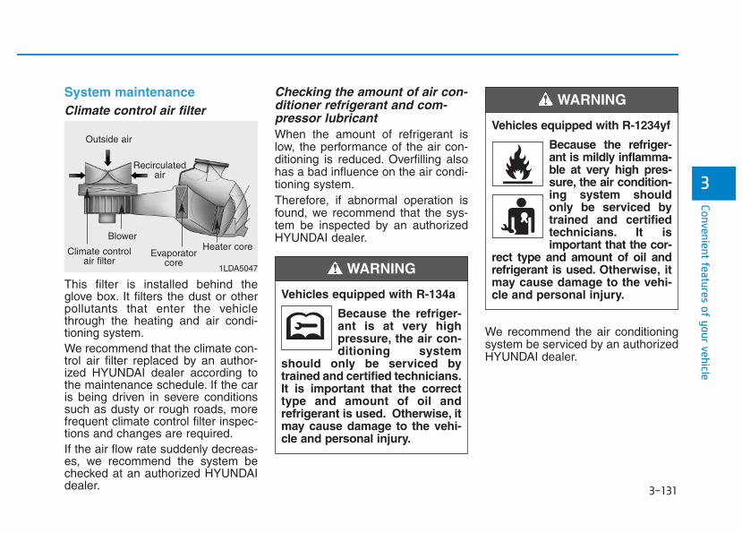
3-131
Convenient features of your vehicle
3
System maintenanceClimate control air filter
This filter is installed behind theglove box. It filters the dust or otherpollutants that enter the vehiclethrough the heating and air condi-tioning system.We recommend that the climate con-trol air filter replaced by an author-ized HYUNDAI dealer according tothe maintenance schedule. If the caris being driven in severe conditionssuch as dusty or rough roads, morefrequent climate control filter inspec-tions and changes are required.If the air flow rate suddenly decreas-es, we recommend the system bechecked at an authorized HYUNDAIdealer.
Checking the amount of air con-ditioner refrigerant and com-pressor lubricantWhen the amount of refrigerant islow, the performance of the air con-ditioning is reduced. Overfilling alsohas a bad influence on the air condi-tioning system.Therefore, if abnormal operation isfound, we recommend that the sys-tem be inspected by an authorizedHYUNDAI dealer.
We recommend the air conditioningsystem be serviced by an authorizedHYUNDAI dealer.
1LDA5047
Outside air
Recirculatedair
Climate controlair filter
Blower
Evaporatorcore
Heater core
Vehicles equipped with R-134a
Because the refriger-ant is at very highpressure, the air con-ditioning system
should only be serviced bytrained and certified technicians.It is important that the correcttype and amount of oil andrefrigerant is used. Otherwise, itmay cause damage to the vehi-cle and personal injury.
WARNING
Vehicles equipped with R-1234yf
Because the refriger-ant is mildly inflamma-ble at very high pres-sure, the air condition-ing system shouldonly be serviced bytrained and certifiedtechnicians. It isimportant that the cor-
rect type and amount of oil andrefrigerant is used. Otherwise, itmay cause damage to the vehi-cle and personal injury.
WARNING
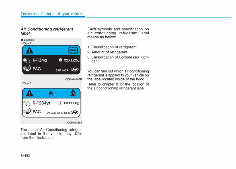
3-132
Convenient features of your vehicle
Air Conditioning refrigerantlabel
The actual Air Conditioning refriger-ant label in the vehicle may differfrom the illustration.
Each symbols and specification onair conditioning refrigerant labelmeans as below:
1. Classification of refrigerant2. Amount of refrigerant3. Classification of Compressor lubri-
cant
You can find out which air conditioningrefrigerant is applied to your vehicle onthe label located inside of the hood.Refer to chapter 8 for the location ofthe air conditioning refrigerant label.
ODH044365R
ODH043366
■ Example
• Type B
• Type A
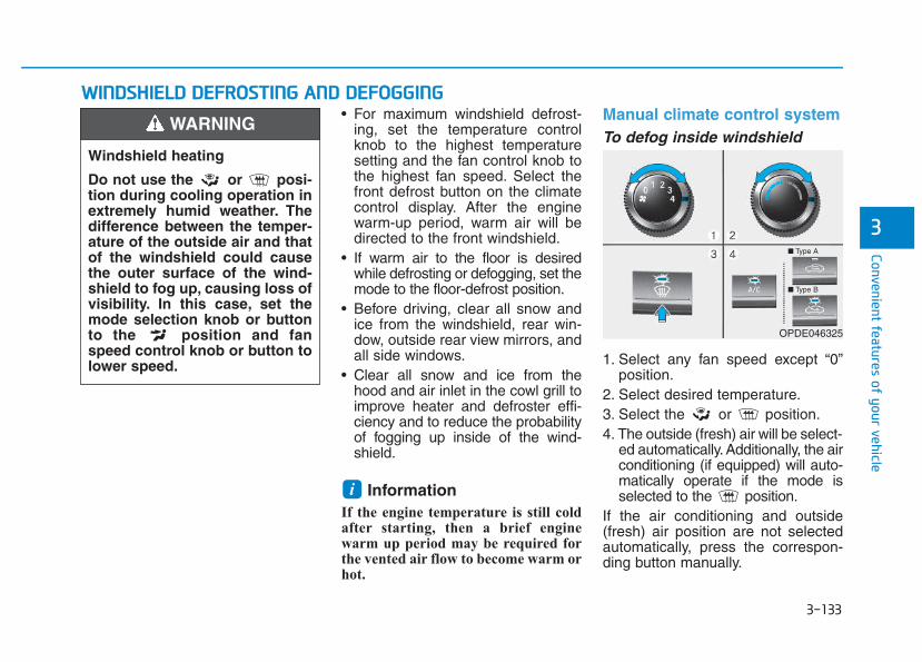
3-133
Convenient features of your vehicle
• For maximum windshield defrost-ing, set the temperature controlknob to the highest temperaturesetting and the fan control knob tothe highest fan speed. Select thefront defrost button on the climatecontrol display. After the enginewarm-up period, warm air will bedirected to the front windshield.
• If warm air to the floor is desiredwhile defrosting or defogging, set themode to the floor-defrost position.
• Before driving, clear all snow andice from the windshield, rear win-dow, outside rear view mirrors, andall side windows.
• Clear all snow and ice from thehood and air inlet in the cowl grill toimprove heater and defroster effi-ciency and to reduce the probabilityof fogging up inside of the wind-shield.
Information If the engine temperature is still coldafter starting, then a brief enginewarm up period may be required forthe vented air flow to become warm orhot.
Manual climate control systemTo defog inside windshield
1. Select any fan speed except “0”position.
2. Select desired temperature.3. Select the or position.4. The outside (fresh) air will be select-
ed automatically. Additionally, the airconditioning (if equipped) will auto-matically operate if the mode isselected to the position.
If the air conditioning and outside(fresh) air position are not selectedautomatically, press the correspon-ding button manually.
i
WWIINNDDSSHHIIEELLDD DDEEFFRROOSSTTIINNGG AANNDD DDEEFFOOGGGGIINNGG
3
Windshield heating
Do not use the or posi-tion during cooling operation inextremely humid weather. Thedifference between the temper-ature of the outside air and thatof the windshield could causethe outer surface of the wind-shield to fog up, causing loss ofvisibility. In this case, set themode selection knob or buttonto the position and fanspeed control knob or button tolower speed.
WARNING
■ Type A
■ Type B
OPDE046325
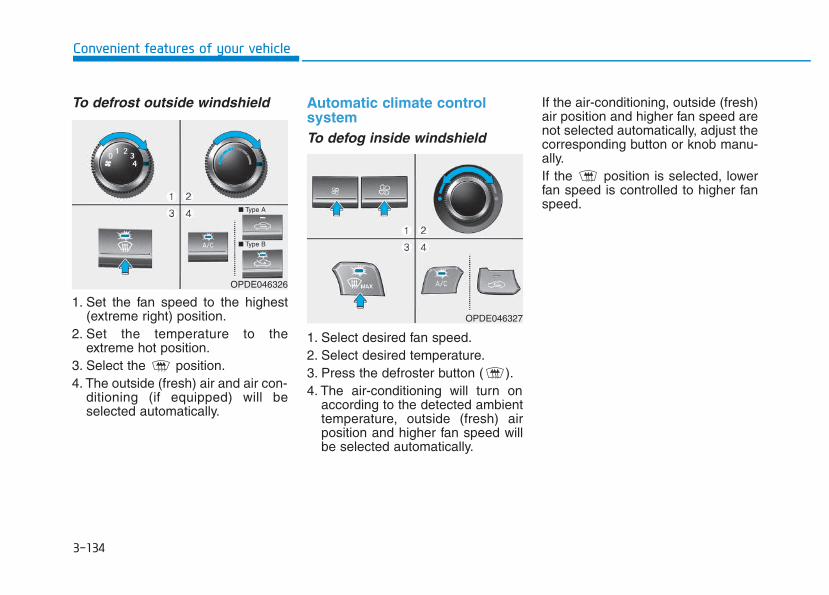
3-134
Convenient features of your vehicle
To defrost outside windshield
1. Set the fan speed to the highest(extreme right) position.
2. Set the temperature to theextreme hot position.
3. Select the position.4. The outside (fresh) air and air con-
ditioning (if equipped) will beselected automatically.
Automatic climate control systemTo defog inside windshield
1. Select desired fan speed.2. Select desired temperature.3. Press the defroster button ( ).4. The air-conditioning will turn on
according to the detected ambienttemperature, outside (fresh) airposition and higher fan speed willbe selected automatically.
If the air-conditioning, outside (fresh)air position and higher fan speed arenot selected automatically, adjust thecorresponding button or knob manu-ally.If the position is selected, lowerfan speed is controlled to higher fanspeed.
OPDE046326
OPDE046327
■ Type A
■ Type B
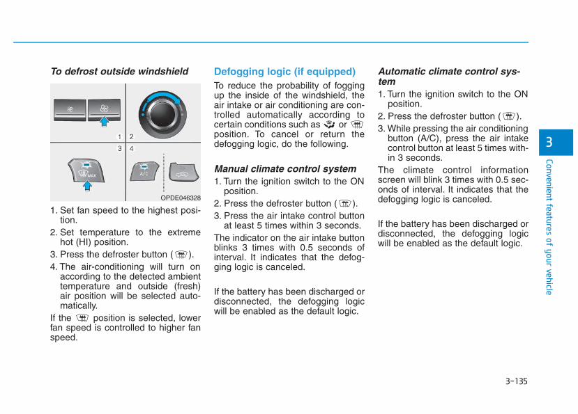
3-135
Convenient features of your vehicle
3
To defrost outside windshield
1. Set fan speed to the highest posi-tion.
2. Set temperature to the extremehot (HI) position.
3. Press the defroster button ( ).4. The air-conditioning will turn on
according to the detected ambienttemperature and outside (fresh)air position will be selected auto-matically.
If the position is selected, lowerfan speed is controlled to higher fanspeed.
Defogging logic (if equipped)To reduce the probability of foggingup the inside of the windshield, theair intake or air conditioning are con-trolled automatically according tocertain conditions such as or position. To cancel or return thedefogging logic, do the following.
Manual climate control system1. Turn the ignition switch to the ON
position.2. Press the defroster button ( ).3. Press the air intake control button
at least 5 times within 3 seconds.The indicator on the air intake buttonblinks 3 times with 0.5 seconds ofinterval. It indicates that the defog-ging logic is canceled.
If the battery has been discharged ordisconnected, the defogging logicwill be enabled as the default logic.
Automatic climate control sys-tem1. Turn the ignition switch to the ON
position.2. Press the defroster button ( ).3. While pressing the air conditioning
button (A/C), press the air intakecontrol button at least 5 times with-in 3 seconds.
The climate control informationscreen will blink 3 times with 0.5 sec-onds of interval. It indicates that thedefogging logic is canceled.
If the battery has been discharged ordisconnected, the defogging logicwill be enabled as the default logic.
OPDE046328
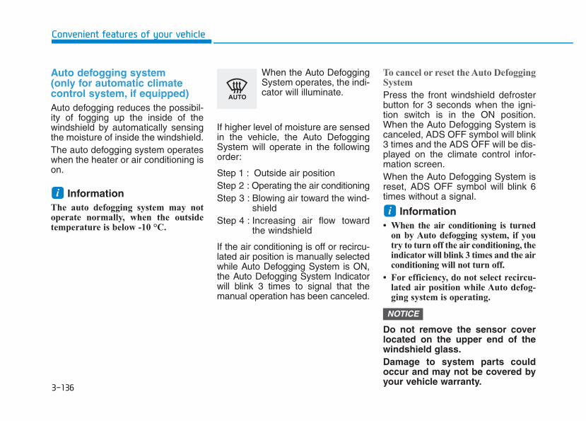
3-136
Convenient features of your vehicle
Auto defogging system (only for automatic climate control system, if equipped)Auto defogging reduces the possibil-ity of fogging up the inside of thewindshield by automatically sensingthe moisture of inside the windshield.The auto defogging system operateswhen the heater or air conditioning ison.
Information The auto defogging system may notoperate normally, when the outsidetemperature is below -10 °C.
When the Auto DefoggingSystem operates, the indi-cator will illuminate.
If higher level of moisture are sensedin the vehicle, the Auto DefoggingSystem will operate in the followingorder:
Step 1 : Outside air positionStep 2 : Operating the air conditioningStep 3 : Blowing air toward the wind-
shieldStep 4 : Increasing air flow toward
the windshield
If the air conditioning is off or recircu-lated air position is manually selectedwhile Auto Defogging System is ON,the Auto Defogging System Indicatorwill blink 3 times to signal that themanual operation has been canceled.
To cancel or reset the Auto DefoggingSystem
Press the front windshield defrosterbutton for 3 seconds when the igni-tion switch is in the ON position.When the Auto Defogging System iscanceled, ADS OFF symbol will blink3 times and the ADS OFF will be dis-played on the climate control infor-mation screen.When the Auto Defogging System isreset, ADS OFF symbol will blink 6times without a signal.
Information • When the air conditioning is turned
on by Auto defogging system, if youtry to turn off the air conditioning, theindicator will blink 3 times and the airconditioning will not turn off.
• For efficiency, do not select recircu-lated air position while Auto defog-ging system is operating.
Do not remove the sensor coverlocated on the upper end of thewindshield glass.Damage to system parts couldoccur and may not be covered byyour vehicle warranty.
NOTICE
ii
3-137
Convenient features of your vehicle
CCLLIIMMAATTEE CCOONNTTRROOLL AADDDDIITTIIOONNAALL FFEEAATTUURREESS
3
Cluster ionizer (if equipped)When the ignition switch is in the ONposition, the clean air function turnson automatically.Also, the clean air function turns offautomatically, when the ignitionswitch is in the OFF position.
Automatic ventilation (if equipped)When the ignition switch is in the ONposition or when the engine is run-ning and the outside temperature islow, the automatic ventilation featurewill activate if the recirculated airintake position is selected for morethan 30 minutes while A/C is on. Inthis condition, the air intake positionwill automatically switch to the out-side (fresh) air position.
To cancel or set the AutomaticVentilation
When the air conditioning system ison, select Face Level mode andpress the recirculated air positionbutton for three seconds.When the automatic ventilation is set,the air intake control button (recircu-lated air position) indicator will blink 6times. When canceled, the air intakecontrol button (recirculated air posi-tion) indicator will blink 3 times.
Sunroof inside air recirculation(if equipped)When the heater or air conditioningsystem is on with the sunroof opened,the outside (fresh) air position will beautomatically selected. At this time, ifyou press the recirculated air positionbutton, the recirculated air positionwill be selected but will change backto the outside (fresh) air position after3 minutes.When the sunroof is closed, the airintake position will return to the orig-inal position that was selected.
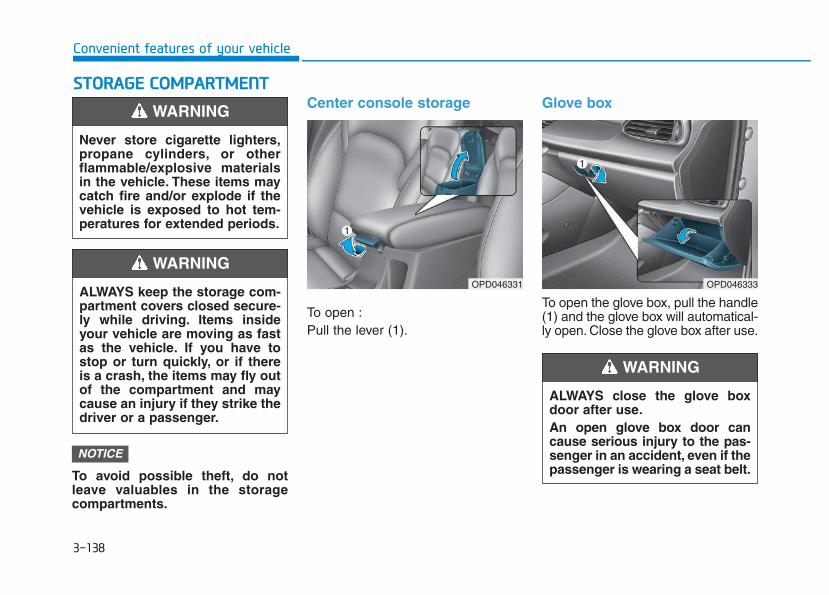
3-138
Convenient features of your vehicle
SSTTOORRAAGGEE CCOOMMPPAARRTTMMEENNTT
To avoid possible theft, do notleave valuables in the storagecompartments.
Center console storage
To open :Pull the lever (1).
Glove box
To open the glove box, pull the handle(1) and the glove box will automatical-ly open. Close the glove box after use.
NOTICE
Never store cigarette lighters,propane cylinders, or otherflammable/explosive materialsin the vehicle. These items maycatch fire and/or explode if thevehicle is exposed to hot tem-peratures for extended periods.
WARNING
ALWAYS keep the storage com-partment covers closed secure-ly while driving. Items insideyour vehicle are moving as fastas the vehicle. If you have tostop or turn quickly, or if thereis a crash, the items may fly outof the compartment and maycause an injury if they strike thedriver or a passenger.
WARNING OPD046331
ALWAYS close the glove boxdoor after use.An open glove box door cancause serious injury to the pas-senger in an accident, even if thepassenger is wearing a seat belt.
WARNING
OPD046333
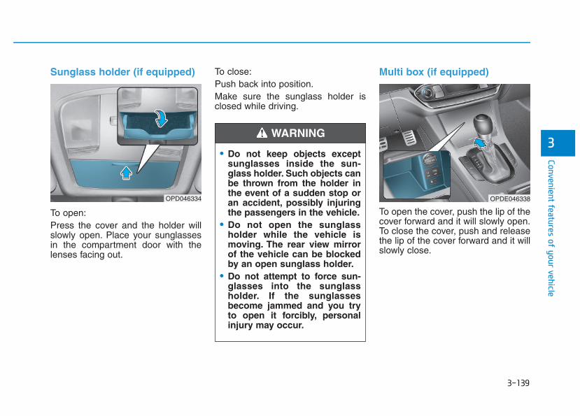
3-139
Convenient features of your vehicle
3
Sunglass holder (if equipped)
To open:Press the cover and the holder willslowly open. Place your sunglassesin the compartment door with thelenses facing out.
To close:Push back into position.Make sure the sunglass holder isclosed while driving.
Multi box (if equipped)
To open the cover, push the lip of thecover forward and it will slowly open.To close the cover, push and releasethe lip of the cover forward and it willslowly close.
OPD046334
• Do not keep objects exceptsunglasses inside the sun-glass holder. Such objects canbe thrown from the holder inthe event of a sudden stop oran accident, possibly injuringthe passengers in the vehicle.
• Do not open the sunglassholder while the vehicle ismoving. The rear view mirrorof the vehicle can be blockedby an open sunglass holder.
• Do not attempt to force sun-glasses into the sunglassholder. If the sunglassesbecome jammed and you tryto open it forcibly, personalinjury may occur.
WARNING
OPDE046338
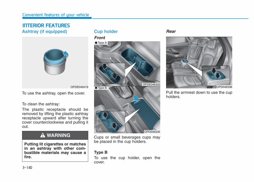
3-140
Convenient features of your vehicle
IINNTTEERRIIOORR FFEEAATTUURREESS Ashtray (if equipped)
To use the ashtray, open the cover.
To clean the ashtray:The plastic receptacle should beremoved by lifting the plastic ashtrayreceptacle upward after turning thecover counterclockwise and pulling itout.
Cup holderFront
Cups or small beverages cups maybe placed in the cup holders.
Type BTo use the cup holder, open thecover.
Rear
Pull the armrest down to use the cupholders.
OPDE046419
Putting lit cigarettes or matchesin an ashtray with other com-bustible materials may cause afire.
WARNING
OPDE046420
OPD046335
■ Type A
■ Type B OPD046336
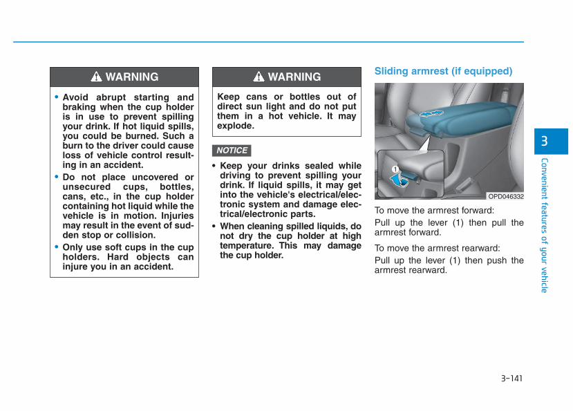
3-141
Convenient features of your vehicle
3
• Keep your drinks sealed whiledriving to prevent spilling yourdrink. If liquid spills, it may getinto the vehicle's electrical/elec-tronic system and damage elec-trical/electronic parts.
• When cleaning spilled liquids, donot dry the cup holder at hightemperature. This may damagethe cup holder.
Sliding armrest (if equipped)
To move the armrest forward:Pull up the lever (1) then pull thearmrest forward.
To move the armrest rearward:Pull up the lever (1) then push thearmrest rearward.
NOTICE
• Avoid abrupt starting andbraking when the cup holderis in use to prevent spillingyour drink. If hot liquid spills,you could be burned. Such aburn to the driver could causeloss of vehicle control result-ing in an accident.
• Do not place uncovered orunsecured cups, bottles,cans, etc., in the cup holdercontaining hot liquid while thevehicle is in motion. Injuriesmay result in the event of sud-den stop or collision.
• Only use soft cups in the cupholders. Hard objects caninjure you in an accident.
WARNING
Keep cans or bottles out ofdirect sun light and do not putthem in a hot vehicle. It mayexplode.
WARNING
OPD046332
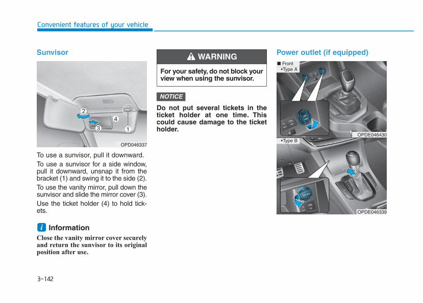
3-142
Convenient features of your vehicle
Sunvisor
To use a sunvisor, pull it downward.To use a sunvisor for a side window,pull it downward, unsnap it from thebracket (1) and swing it to the side (2).To use the vanity mirror, pull down thesunvisor and slide the mirror cover (3).Use the ticket holder (4) to hold tick-ets.
Information Close the vanity mirror cover securelyand return the sunvisor to its originalposition after use.
Do not put several tickets in theticket holder at one time. Thiscould cause damage to the ticketholder.
Power outlet (if equipped)
NOTICE
i
For your safety, do not block yourview when using the sunvisor.
WARNING
OPDE046339
■ Front
OPDE046430
OPD046337
• Type A
• Type B
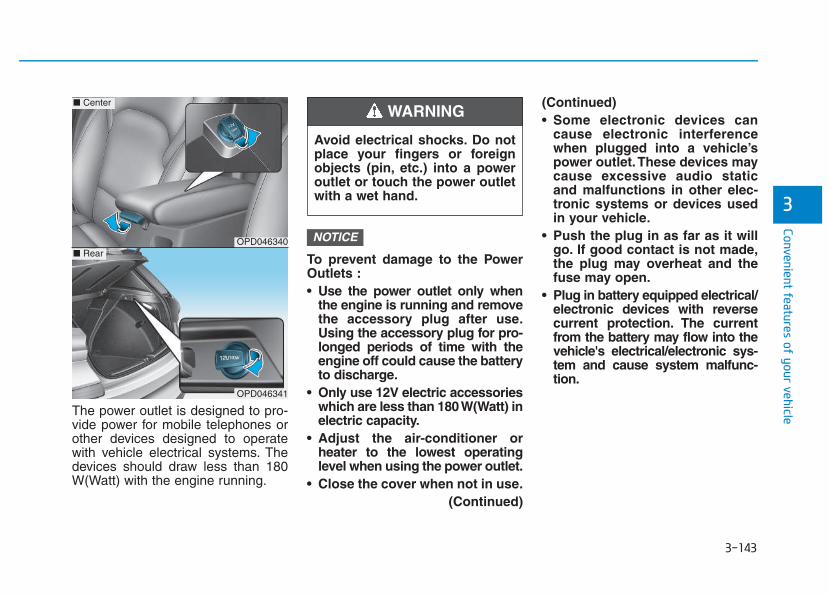
3-143
Convenient features of your vehicle
3
The power outlet is designed to pro-vide power for mobile telephones orother devices designed to operatewith vehicle electrical systems. Thedevices should draw less than 180W(Watt) with the engine running.
To prevent damage to the PowerOutlets :• Use the power outlet only when
the engine is running and removethe accessory plug after use.Using the accessory plug for pro-longed periods of time with theengine off could cause the batteryto discharge.
• Only use 12V electric accessorieswhich are less than 180 W(Watt) inelectric capacity.
• Adjust the air-conditioner orheater to the lowest operatinglevel when using the power outlet.
• Close the cover when not in use.(Continued)
(Continued)• Some electronic devices can
cause electronic interferencewhen plugged into a vehicle’spower outlet.These devices maycause excessive audio staticand malfunctions in other elec-tronic systems or devices usedin your vehicle.
• Push the plug in as far as it willgo. If good contact is not made,the plug may overheat and thefuse may open.
• Plug in battery equipped electrical/electronic devices with reversecurrent protection. The currentfrom the battery may flow into thevehicle's electrical/electronic sys-tem and cause system malfunc-tion.
NOTICE
Avoid electrical shocks. Do notplace your fingers or foreignobjects (pin, etc.) into a poweroutlet or touch the power outletwith a wet hand.
WARNING
OPD046340
■ Center
OPD046341
■ Rear
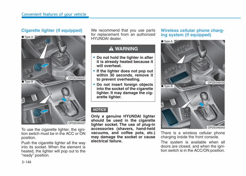
3-144
Convenient features of your vehicle
Cigarette lighter (if equipped)
To use the cigarette lighter, the igni-tion switch must be in the ACC or ONposition.Push the cigarette lighter all the wayinto its socket. When the element isheated, the lighter will pop out to the“ready” position.
We recommend that you use partsfor replacement from an authorizedHYUNDAI dealer.
Only a genuine HYUNDAI lightershould be used in the cigarettelighter socket. The use of plug-inaccessories (shavers, hand-heldvacuums, and coffee pots, etc.)may damage the socket or causeelectrical failure.
Wireless cellular phone charg-ing system (if equipped)
There is a wireless cellular phonecharging inside the front console.The system is available when alldoors are closed, and when the igni-tion switch is in the ACC/ON position.
NOTICE
• Do not hold the lighter in afterit is already heated because itwill overheat.
• If the lighter does not pop outwithin 30 seconds, remove itto prevent overheating.
• Do not insert foreign objectsinto the socket of the cigarettelighter. It may damage the cig-arette lighter.
WARNING
OPDE046431
OPDE046427
■ Type A
■ Type B OPDE046432
OPDE046342
■ Type A
■ Type B
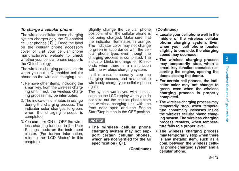
3-145
Convenient features of your vehicle
To charge a cellular phone The wireless cellular phone chargingsystem charges only the Qi-enabledcellular phones ( ). Read the labelon the cellular phone accessorycover or visit your cellular phonemanufacturer’s website to checkwhether your cellular phone supportsthe Qi technology.The wireless charging process startswhen you put a Qi-enabled cellularphone on the wireless charging unit.
1. Remove other items, including thesmart key, from the wireless charg-ing unit. If not, the wireless charg-ing process may be interrupted.
2. The indicator illuminates in orangeduring the charging process. Theindicator color changes to green,when the charging process iscompleted.
3. You can turn ON or OFF the wire-less charging function in the UserSettings mode on the instrumentcluster. (For further information,refer to the “LCD Modes” in thischapter.)
Slightly change the cellular phoneposition, when the cellular phone isnot being charged. Make sure thatthe indicator illuminates in orange.The indicator color may not changeto green in accordance with the cel-lular phone type, even though thecharging process is completed. Theindicator blinks in orange for 10 sec-onds when there is a malfunctionwith the wireless charging system.In this case, temporarily stop thecharging process, and re-attempt towirelessly charge your cellular phoneagain.The system warns you with a mes-sage on the LCD display when you donot take out the cellular phone fromthe wireless charging unit with thefront door open and the EngineStart/Stop button in the OFF position.
• The wireless cellular phonecharging system may not sup-port certain cellular phones,which are not verified for the Qispecification ( ).
(Continued)
(Continued)• Locate your cell phone well in the
middle of the wireless cellularphone charging system. Evenwhen your cell phone locatesslightly to one side, the chargingspeed may decrease.
• The wireless charging processmay temporarily stop, when asmart key function operates (i.e.starting the engine, opening thedoors, closing the doors).
• For certain cell phones, the indi-cator color may not change togreen, even when the wirelesscharging process is properlycompleted.
• The wireless charging process maytemporarily stop, when tempera-ture abnormally increases insidethe wireless cellular phone charg-ing system. The wireless chargingprocess restarts, when tempera-ture falls to a proper level.
• The wireless charging processmay temporarily stop when thereis any metallic item, such as acoin, between the wireless cellu-lar phone charging system and acellular phone.
NOTICE
3
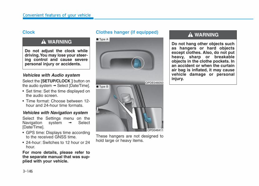
3-146
Clock
Vehicles with Audio systemSelect the [SETUP/CLOCK ] button onthe audio system ➟ Select [Date/Time].• Set time: Set the time displayed on
the audio screen.• Time format: Choose between 12-
hour and 24-hour time formats.
Vehicles with Navigation systemSelect the Settings menu on theNavigation system ➟ Select[Date/Time].• GPS time: Displays time according
to the received GNSS time.• 24-hour: Switches to 12 hour or 24
hour.For more details, please refer tothe separate manual that was sup-plied with your vehicle.
Clothes hanger (if equipped)
These hangers are not designed tohold large or heavy items.
Convenient features of your vehicle
Do not adjust the clock whiledriving.You may lose your steer-ing control and cause severepersonal injury or accidents.
WARNING
OPD046411
■ Type A
■ Type BOPDE046050
Do not hang other objects suchas hangers or hard objectsexcept clothes. Also, do not putheavy, sharp or breakableobjects in the clothe pockets. Inan accident or when the curtainair bag is inflated, it may causevehicle damage or personalinjury.
WARNING
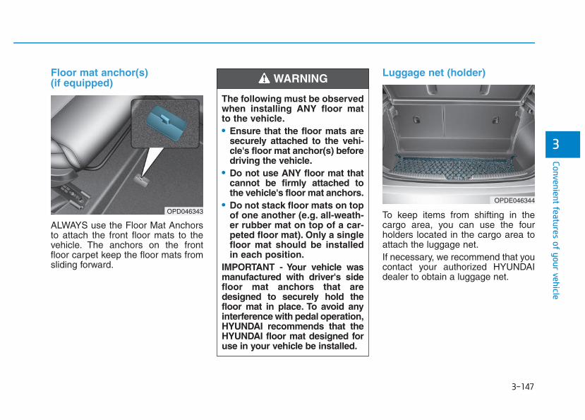
3-147
Convenient features of your vehicle
3
Floor mat anchor(s) (if equipped)
ALWAYS use the Floor Mat Anchorsto attach the front floor mats to thevehicle. The anchors on the frontfloor carpet keep the floor mats fromsliding forward.
Luggage net (holder)
To keep items from shifting in thecargo area, you can use the fourholders located in the cargo area toattach the luggage net.If necessary, we recommend that youcontact your authorized HYUNDAIdealer to obtain a luggage net.
OPDE046344
OPD046343
The following must be observedwhen installing ANY floor matto the vehicle.• Ensure that the floor mats are
securely attached to the vehi-cle's floor mat anchor(s) beforedriving the vehicle.
• Do not use ANY floor mat thatcannot be firmly attached tothe vehicle's floor mat anchors.
• Do not stack floor mats on topof one another (e.g. all-weath-er rubber mat on top of a car-peted floor mat). Only a singlefloor mat should be installedin each position.
IMPORTANT - Your vehicle wasmanufactured with driver's sidefloor mat anchors that aredesigned to securely hold thefloor mat in place. To avoid anyinterference with pedal operation,HYUNDAI recommends that theHYUNDAI floor mat designed foruse in your vehicle be installed.
WARNING
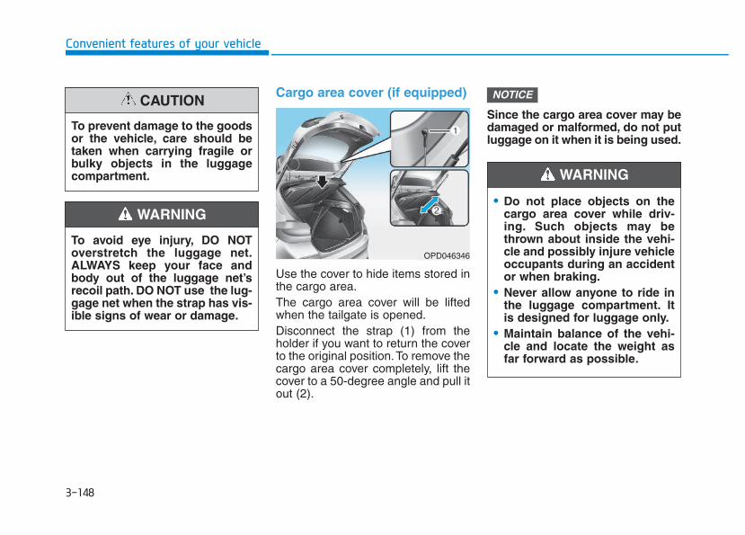
3-148
Convenient features of your vehicle
Cargo area cover (if equipped)
Use the cover to hide items stored inthe cargo area.The cargo area cover will be liftedwhen the tailgate is opened.Disconnect the strap (1) from theholder if you want to return the coverto the original position.To remove thecargo area cover completely, lift thecover to a 50-degree angle and pull itout (2).
Since the cargo area cover may bedamaged or malformed, do not putluggage on it when it is being used.
NOTICE
To avoid eye injury, DO NOToverstretch the luggage net.ALWAYS keep your face andbody out of the luggage net’srecoil path. DO NOT use the lug-gage net when the strap has vis-ible signs of wear or damage.
WARNING
To prevent damage to the goodsor the vehicle, care should betaken when carrying fragile orbulky objects in the luggagecompartment.
CAUTION
OPD046346
• Do not place objects on thecargo area cover while driv-ing. Such objects may bethrown about inside the vehi-cle and possibly injure vehicleoccupants during an accidentor when braking.
• Never allow anyone to ride inthe luggage compartment. Itis designed for luggage only.
• Maintain balance of the vehi-cle and locate the weight asfar forward as possible.
WARNING
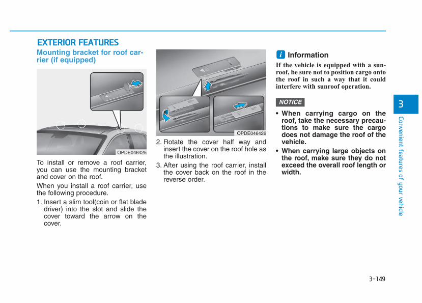
3-149
Convenient features of your vehicle
Mounting bracket for roof car-rier (if equipped)
To install or remove a roof carrier,you can use the mounting bracketand cover on the roof.When you install a roof carrier, usethe following procedure.1. Insert a slim tool(coin or flat blade
driver) into the slot and slide thecover toward the arrow on thecover.
2. Rotate the cover half way andinsert the cover on the roof hole asthe illustration.
3. After using the roof carrier, installthe cover back on the roof in thereverse order.
Information If the vehicle is equipped with a sun-roof, be sure not to position cargo ontothe roof in such a way that it couldinterfere with sunroof operation.
• When carrying cargo on theroof, take the necessary precau-tions to make sure the cargodoes not damage the roof of thevehicle.
• When carrying large objects onthe roof, make sure they do notexceed the overall roof length orwidth.
NOTICE
iEEXXTTEERRIIOORR FFEEAATTUURREESS
3
OPDE046425
OPDE046426
Interior lights....................................................................3-93Wipers and washers ............................................3-97
Windshield wipers ..........................................................3-98Windshield washers .......................................................3-99Rear window wiper and washer switch ..................3-100
Driver assist system ..........................................3-101Rear view camera ........................................................3-101Rear parking assist system ........................................3-102Parking assist system .................................................3-106
Defroster.............................................................3-109Rear window defroster ...............................................3-109
Manual climate control system........................3-111Heating and air conditioning......................................3-112System operation..........................................................3-116System maintenance ....................................................3-118
Automatic climate control system...................3-121Automatic heating and air conditioning..................3-122Manual heating and air conditioning.......................3-123System operation..........................................................3-128System maintenance ....................................................3-131
Windshield defrosting and defogging ............3-133Manual climate control system .................................3-133Automatic climate control system ............................3-134Defogging logic ............................................................3-135Auto defogging system (only for automatic climate control system) .........3-136
Climate control additional features.................3-137Cluster ionizer ..............................................................3-137Automatic ventilation ..................................................3-137To cancel or set the automatic ventilation ............3-137Sunroof inside air recirculation ...............................3-137
Storage compartment........................................3-138Center console storage ...............................................3-138Glove box ........................................................................3-138Sunglass holder ............................................................3-139Multi box ........................................................................3-139
Interior features ...............................................3-140Ashtray ...........................................................................3-140Cup holder.......................................................................3-140Sliding armrest .............................................................3-141Sunvisor...........................................................................3-142Power outlet .................................................................3-142Cigarette lighter ...........................................................3-144Wireless cellular phone charging system ..............3-144Clock.................................................................................3-146Clothes hanger .............................................................3-146Floor mat anchor(s) ....................................................3-147Luggage net (holder) ...................................................3-147Cargo area cover .........................................................3-148
Exterior features ...............................................3-149Mounting bracket for roof carrier ..........................3-149
3
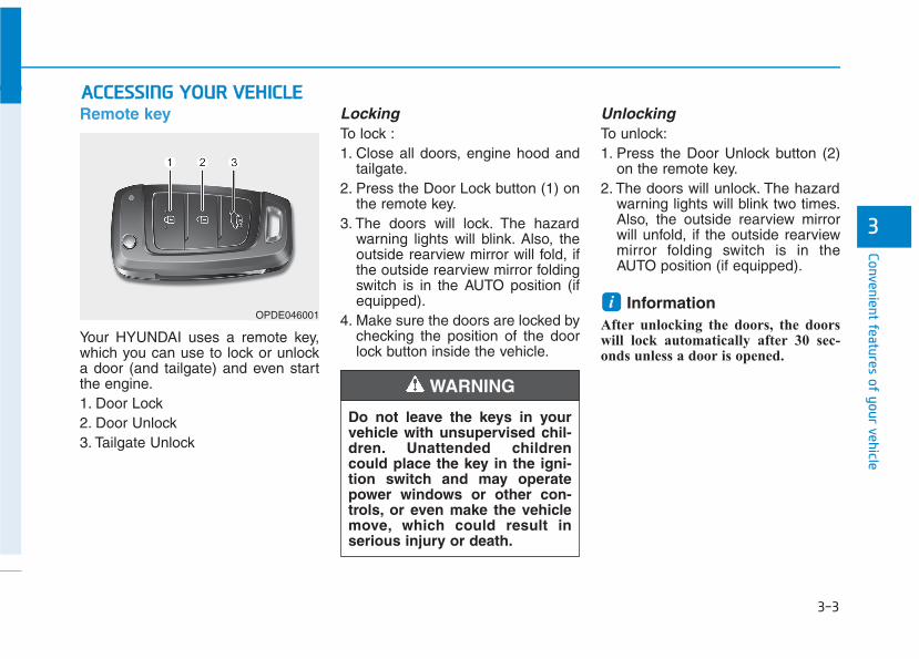
3-3
Convenient features of your vehicle
3
Remote key
Your HYUNDAI uses a remote key,which you can use to lock or unlocka door (and tailgate) and even startthe engine.1. Door Lock 2. Door Unlock3. Tailgate Unlock
LockingTo lock :1. Close all doors, engine hood and
tailgate.2. Press the Door Lock button (1) on
the remote key.3. The doors will lock. The hazard
warning lights will blink. Also, theoutside rearview mirror will fold, ifthe outside rearview mirror foldingswitch is in the AUTO position (ifequipped).
4. Make sure the doors are locked bychecking the position of the doorlock button inside the vehicle.
UnlockingTo unlock:1. Press the Door Unlock button (2)
on the remote key.2. The doors will unlock. The hazard
warning lights will blink two times.Also, the outside rearview mirrorwill unfold, if the outside rearviewmirror folding switch is in theAUTO position (if equipped).
Information After unlocking the doors, the doorswill lock automatically after 30 sec-onds unless a door is opened.
i
AACCCCEESSSSIINNGG YYOOUURR VVEEHHIICCLLEE
Do not leave the keys in yourvehicle with unsupervised chil-dren. Unattended childrencould place the key in the igni-tion switch and may operatepower windows or other con-trols, or even make the vehiclemove, which could result inserious injury or death.
WARNING
OPDE046001
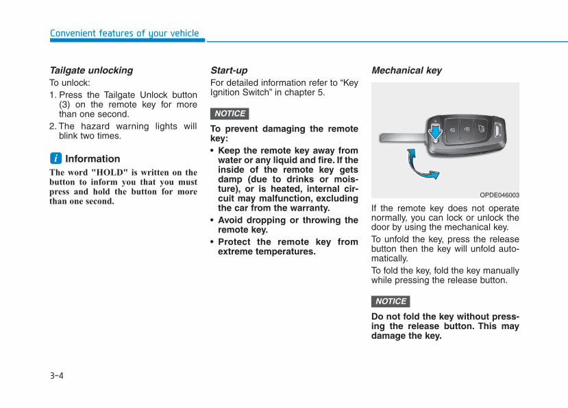
3-4
Convenient features of your vehicle
Tailgate unlockingTo unlock:1. Press the Tailgate Unlock button
(3) on the remote key for morethan one second.
2. The hazard warning lights willblink two times.
Information The word "HOLD" is written on thebutton to inform you that you mustpress and hold the button for morethan one second.
Start-up For detailed information refer to “KeyIgnition Switch” in chapter 5.
To prevent damaging the remotekey:• Keep the remote key away from
water or any liquid and fire. If theinside of the remote key getsdamp (due to drinks or mois-ture), or is heated, internal cir-cuit may malfunction, excludingthe car from the warranty.
• Avoid dropping or throwing theremote key.
• Protect the remote key fromextreme temperatures.
Mechanical key
If the remote key does not operatenormally, you can lock or unlock thedoor by using the mechanical key.To unfold the key, press the releasebutton then the key will unfold auto-matically.To fold the key, fold the key manuallywhile pressing the release button.
Do not fold the key without press-ing the release button. This maydamage the key.
NOTICE
NOTICE
i
OPDE046003
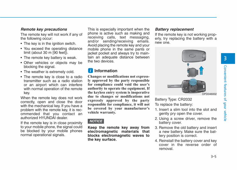
3-5
Convenient features of your vehicle
3
Remote key precautionsThe remote key will not work if any ofthe following occur:• The key is in the ignition switch.• You exceed the operating distance
limit (about 30 m [90 feet]).• The remote key battery is weak.• Other vehicles or objects may be
blocking the signal.• The weather is extremely cold.• The remote key is close to a radio
transmitter such as a radio stationor an airport which can interferewith normal operation of the remotekey.
When the remote key does not workcorrectly, open and close the doorwith the mechanical key. If you have aproblem with the remote key, it is rec-ommended that you contact anauthorized HYUNDAI dealer.If the remote key is in close proximityto your mobile phone, the signal couldbe blocked by your mobile phonesnormal operational signals.
This is especially important when thephone is active such as making andreceiving calls, text messaging,and/or sending/receiving emails.Avoid placing the remote key and yourmobile phone in the same pants orjacket pocket and always try to main-tain an adequate distance betweenthe two devices.
Information Changes or modifications not express-ly approved by the party responsiblefor compliance could void the user’sauthority to operate the equipment. Ifthe keyless entry system is inoperativedue to changes or modifications notexpressly approved by the partyresponsible for compliance, it will notbe covered by your manufacturer’svehicle warranty.
Keep the remote key away fromelectromagnetic materials thatblocks electromagnetic waves tothe key surface.
Battery replacement If the remote key is not working prop-erly, try replacing the battery with anew one.
Battery Type: CR2032To replace the battery:1. Insert a slim tool into the slot and
gently pry open the cover.2. Using a screw driver, remove the
battery cover.3. Remove the old battery and insert
a new battery. Make sure the bat-tery position is correct.
4. Reinstall the battery cover and keycover in the reverse order ofremoval.
NOTICE
i
OPD046002
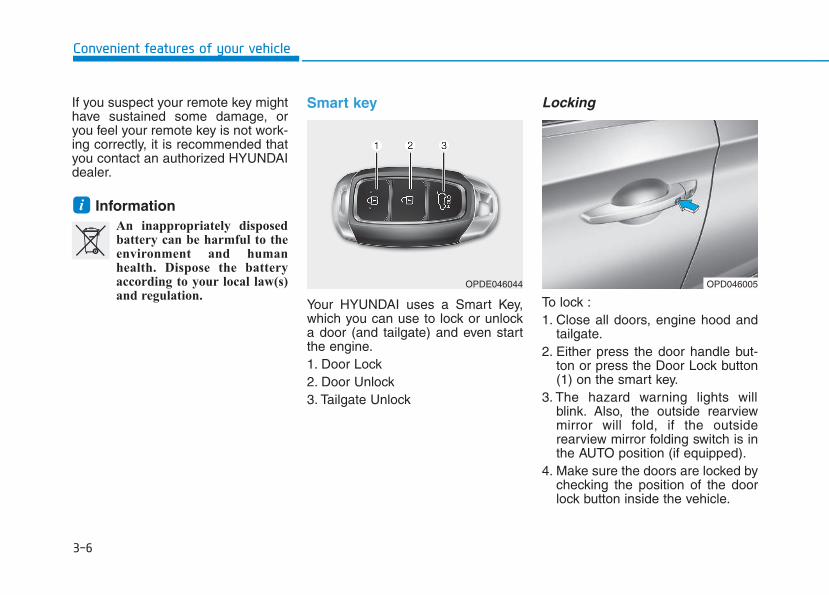
3-6
Convenient features of your vehicle
If you suspect your remote key mighthave sustained some damage, oryou feel your remote key is not work-ing correctly, it is recommended thatyou contact an authorized HYUNDAIdealer.
Information An inappropriately disposedbattery can be harmful to theenvironment and humanhealth. Dispose the batteryaccording to your local law(s)and regulation.
Smart key
Your HYUNDAI uses a Smart Key,which you can use to lock or unlocka door (and tailgate) and even startthe engine.1. Door Lock 2. Door Unlock3. Tailgate Unlock
Locking
To lock :1. Close all doors, engine hood and
tailgate.2. Either press the door handle but-
ton or press the Door Lock button(1) on the smart key.
3. The hazard warning lights willblink. Also, the outside rearviewmirror will fold, if the outsiderearview mirror folding switch is inthe AUTO position (if equipped).
4. Make sure the doors are locked bychecking the position of the doorlock button inside the vehicle.
i
OPDE046044 OPD046005
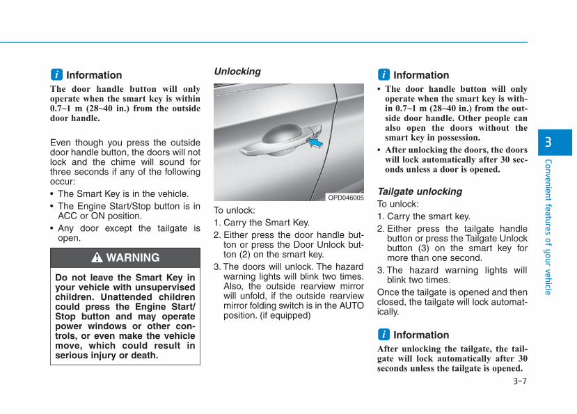
3-7
Convenient features of your vehicle
3
Information The door handle button will onlyoperate when the smart key is within0.7~1 m (28~40 in.) from the outsidedoor handle.
Even though you press the outsidedoor handle button, the doors will notlock and the chime will sound forthree seconds if any of the followingoccur:• The Smart Key is in the vehicle.• The Engine Start/Stop button is in
ACC or ON position.• Any door except the tailgate is
open.
Unlocking
To unlock:1. Carry the Smart Key.2. Either press the door handle but-
ton or press the Door Unlock but-ton (2) on the smart key.
3. The doors will unlock. The hazardwarning lights will blink two times.Also, the outside rearview mirrorwill unfold, if the outside rearviewmirror folding switch is in the AUTOposition. (if equipped)
Information • The door handle button will only
operate when the smart key is with-in 0.7~1 m (28~40 in.) from the out-side door handle. Other people canalso open the doors without thesmart key in possession.
• After unlocking the doors, the doorswill lock automatically after 30 sec-onds unless a door is opened.
Tailgate unlocking To unlock:1. Carry the smart key.2. Either press the tailgate handle
button or press the Tailgate Unlockbutton (3) on the smart key formore than one second.
3. The hazard warning lights willblink two times.
Once the tailgate is opened and thenclosed, the tailgate will lock automat-ically.
Information After unlocking the tailgate, the tail-gate will lock automatically after 30seconds unless the tailgate is opened.
i
ii
Do not leave the Smart Key inyour vehicle with unsupervisedchildren. Unattended childrencould press the Engine Start/Stop button and may operatepower windows or other con-trols, or even make the vehiclemove, which could result inserious injury or death.
WARNING
OPD046005
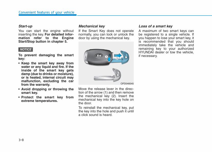
3-8
Convenient features of your vehicle
Start-upYou can start the engine withoutinserting the key. For detailed infor-mation refer to the EngineStart/Stop button in chapter 5.
To prevent damaging the smartkey:• Keep the smart key away from
water or any liquid and fire. If theinside of the smart key getsdamp (due to drinks or moisture),or is heated, internal circuit maymalfunction, excluding the carfrom the warranty.
• Avoid dropping or throwing thesmart key.
• Protect the smart key fromextreme temperatures.
Mechanical key If the Smart Key does not operatenormally, you can lock or unlock thedoor by using the mechanical key.
Move the release lever in the direc-tion of the arrow (1) and then removethe mechanical key (2). Insert themechanical key into the key hole onthe door.To reinstall the mechanical key, putthe key into the hole and push it untila click sound is heard.
Loss of a smart key A maximum of two smart keys canbe registered to a single vehicle. Ifyou happen to lose your smart key, itis recommended that you shouldimmediately take the vehicle andremaining key to your authorizedHYUNDAI dealer or tow the vehicle,if necessary.
NOTICE
OPD046045
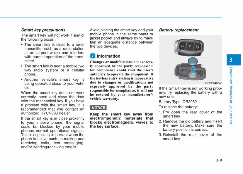
3-9
Convenient features of your vehicle
3
Smart key precautionsThe smart key will not work if any ofthe following occur:• The smart key is close to a radio
transmitter such as a radio stationor an airport which can interferewith normal operation of the trans-mitter.
• The smart key is near a mobile twoway radio system or a cellularphone.
• Another vehicle’s smart key isbeing operated close to your vehi-cle.
When the smart key does not workcorrectly, open and close the doorwith the mechanical key. If you havea problem with the smart key, it isrecommended that you contact anauthorized HYUNDAI dealer.If the smart key is in close proximityto your mobile phone, the signalcould be blocked by your mobilephones normal operational signals.This is especially important when thephone is active such as making andreceiving calls, text messaging,and/or sending/receiving emails.
Avoid placing the smart key and yourmobile phone in the same pants orjacket pocket and always try to main-tain an adequate distance betweenthe two devices.
Information Changes or modifications not express-ly approved by the party responsiblefor compliance could void the user’sauthority to operate the equipment. Ifthe keyless entry system is inoperativedue to changes or modifications notexpressly approved by the partyresponsible for compliance, it will notbe covered by your manufacturer’svehicle warranty.
Keep the smart key away fromelectromagnetic materials thatblocks electromagnetic waves tothe key surface.
Battery replacement
If the Smart Key is not working prop-erly, try replacing the battery with anew one.Battery Type: CR2032To replace the battery:1. Pry open the rear cover of the
smart key.2. Remove the old battery and insert
the new battery. Make sure thebattery position is correct.
3. Reinstall the rear cover of thesmart key.
NOTICE
i
OPDE046046
3-10
Convenient features of your vehicle
If you suspect your smart key mighthave sustained some damage, oryou feel your smart key is not work-ing correctly, it is recommended thatyou contact an authorized HYUNDAIdealer.
Information An inappropriately disposedbattery can be harmful to theenvironment and human health.Dispose the battery according toyour local law(s) and regulation.
Immobilizer system (if equipped)The immobilizer system protects yourvehicle from theft. If an improperlycoded key (or other device) is used,the engine’s fuel system is disabled.When the ignition switch is placed inthe ON position, the immobilizer sys-tem indicator should come on briefly,then go off. If the indicator starts toblink, the system does not recognizethe coding of the key.Place the ignition switch to theLOCK/OFF position, then place theignition switch to the ON positionagain.The system may not recognize yourkey’s coding if another immobilizerkey or other metal object (i.e., keychain) is near the key. The enginemay not start because the metal mayinterrupt the transponder signal fromtransmitting normally.If the system repeatedly does notrecognize the coding of the key, it isrecommended that you contact yourHYUNDAI dealer.
Do not attempt to alter this system oradd other devices to it. Electricalproblems could result that may makeyour vehicle inoperable.
The transponder in your key is animportant part of the immobilizersystem. It is designed to giveyears of trouble-free service, how-ever you should avoid exposure tomoisture, static electricity andrough handling. Immobilizer sys-tem malfunction could occur.
NOTICE
i In order to prevent theft of yourvehicle, do not leave spare keysanywhere in your vehicle. Yourimmobilizer password is a cus-tomer unique password andshould be kept confidential.
WARNING
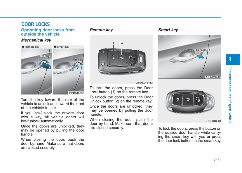
3-11
Convenient features of your vehicle
3
Operating door locks fromoutside the vehicle Mechanical key
Turn the key toward the rear of thevehicle to unlock and toward the frontof the vehicle to lock.If you lock/unlock the driver's doorwith a key, all vehicle doors willlock/unlock automatically.Once the doors are unlocked, theymay be opened by pulling the doorhandle.When closing the door, push thedoor by hand. Make sure that doorsare closed securely.
Remote key
To lock the doors, press the DoorLock button (1) on the remote key.To unlock the doors, press the DoorUnlock button (2) on the remote key.Once the doors are unlocked, theymay be opened by pulling the doorhandle.When closing the door, push thedoor by hand. Make sure that doorsare closed securely.
Smart key
To lock the doors, press the button onthe outside door handle while carry-ing the smart key with you or pressthe door lock button on the smart key.
DDOOOORR LLOOCCKKSS
OPDE046413
OPD046006
LLLLoooocccckkkk LLLLoooocccckkkk
UUUUnnnnlllloooocccckkkkUUUUnnnnlllloooocccckkkk
■ Remote key ■ Smart key
OPD046005
OPDE046004
LLLLoooocccckkkk //// UUUUnnnnlllloooocccckkkk
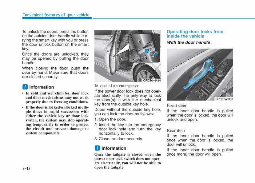
3-12
Convenient features of your vehicle
To unlock the doors, press the buttonon the outside door handle while car-rying the smart key with you or pressthe door unlock button on the smartkey.Once the doors are unlocked, theymay be opened by pulling the doorhandle.When closing the door, push thedoor by hand. Make sure that doorsare closed securely.
Information • In cold and wet climates, door lock
and door mechanisms may not workproperly due to freezing conditions.
• If the door is locked/unlocked multi-ple times in rapid succession witheither the vehicle key or door lockswitch, the system may stop operat-ing temporarily in order to protectthe circuit and prevent damage tosystem components.
In case of an emergency
If the power door lock does not oper-ate electrically, the only way to lockthe door(s) is with the mechanicalkey from the outside key hole.Doors without the outside key hole,you can lock the door as follows:1. Open the door.2. Insert the key into the emergency
door lock hole and turn the keyhorizontally to lock.
3. Close the door securely.
Information Once the tailgate is closed when thepower door lock switch does not oper-ate electrically, you will not be able toopen the tailgate.
Operating door locks frominside the vehicle With the door handle
Front door
If the inner door handle is pulledwhen the door is locked, the door willunlock and open.
Rear door
If the inner door handle is pulledonce when the door is locked, thedoor will unlock.If the inner door handle is pulledonce more, the door will open.
i
i
OPDE046007
OPDE046414
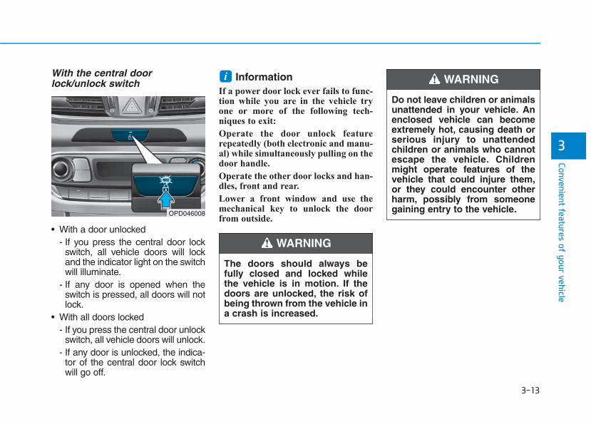
3-13
Convenient features of your vehicle
3
With the central doorlock/unlock switch
• With a door unlocked- If you press the central door lock
switch, all vehicle doors will lockand the indicator light on the switchwill illuminate.
- If any door is opened when theswitch is pressed, all doors will notlock.
• With all doors locked - If you press the central door unlock
switch, all vehicle doors will unlock.- If any door is unlocked, the indica-
tor of the central door lock switchwill go off.
Information If a power door lock ever fails to func-tion while you are in the vehicle tryone or more of the following tech-niques to exit:
Operate the door unlock featurerepeatedly (both electronic and manu-al) while simultaneously pulling on thedoor handle.
Operate the other door locks and han-dles, front and rear.
Lower a front window and use themechanical key to unlock the doorfrom outside.
i
OPD046008
The doors should always befully closed and locked whilethe vehicle is in motion. If thedoors are unlocked, the risk ofbeing thrown from the vehicle ina crash is increased.
WARNING
Do not leave children or animalsunattended in your vehicle. Anenclosed vehicle can becomeextremely hot, causing death orserious injury to unattendedchildren or animals who cannotescape the vehicle. Childrenmight operate features of thevehicle that could injure them,or they could encounter otherharm, possibly from someonegaining entry to the vehicle.
WARNING
3-14
Convenient features of your vehicle
Auto door lock/unlock features Impact sensing door unlocksystem (if equipped)All doors will be automaticallyunlocked when an impact causes theair bags to deploy.
Speed sensing door lock system(if equipped)All doors will be automatically lockedwhen vehicle speed exceeds 15km/h (9 mph).
You can activate or deactivate theAuto Door Lock/Unlock features fromthe User Settings mode on the LCDdisplay. For more details, refer to"LCD Display" in this chapter.
Leaving your vehicle unlockedincreases the potential risk toyou or others from someonehiding in your vehicle.
To secure your vehicle, whiledepressing the brake, move theshift lever to the P (Park) posi-tion (for automatic transmis-sion/dual clutch transmission)or first gear or R (Reverse, formanual transmission), engagethe parking brake, and place theignition switch in the LOCK/OFFposition, close all windows,lock all doors, and always takethe key with you.
WARNING
Opening a door when somethingis approaching may cause dam-age or injury. Be careful whenopening doors and watch forvehicles, motorcycles, bicyclesor pedestrians approaching thevehicle in the path of the door.
WARNING
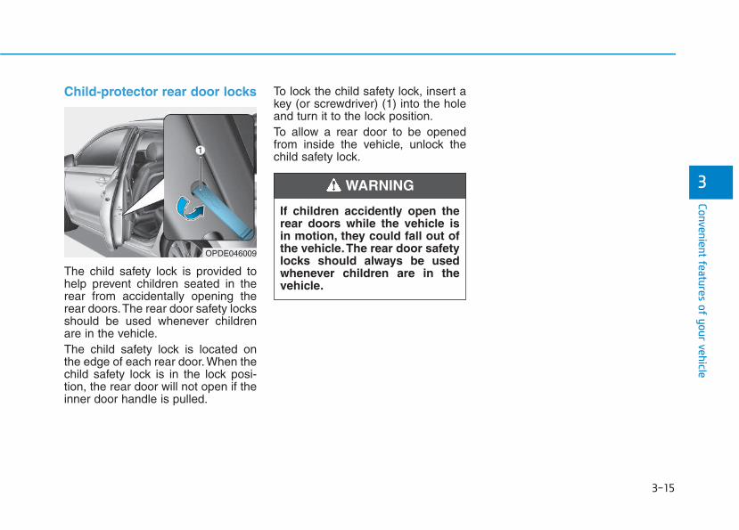
3-15
Convenient features of your vehicle
3
Child-protector rear door locks
The child safety lock is provided tohelp prevent children seated in therear from accidentally opening therear doors.The rear door safety locksshould be used whenever childrenare in the vehicle.The child safety lock is located onthe edge of each rear door. When thechild safety lock is in the lock posi-tion, the rear door will not open if theinner door handle is pulled.
To lock the child safety lock, insert akey (or screwdriver) (1) into the holeand turn it to the lock position.To allow a rear door to be openedfrom inside the vehicle, unlock thechild safety lock.
OPDE046009
If children accidently open therear doors while the vehicle isin motion, they could fall out ofthe vehicle.The rear door safetylocks should always be usedwhenever children are in thevehicle.
WARNING
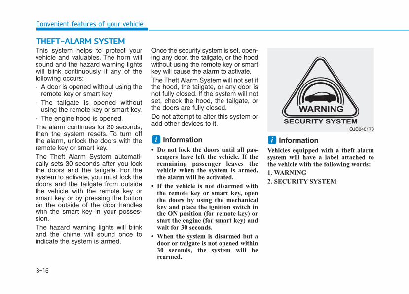
3-16
Convenient features of your vehicle
This system helps to protect yourvehicle and valuables. The horn willsound and the hazard warning lightswill blink continuously if any of thefollowing occurs:- A door is opened without using the
remote key or smart key.- The tailgate is opened without
using the remote key or smart key.- The engine hood is opened.The alarm continues for 30 seconds,then the system resets. To turn offthe alarm, unlock the doors with theremote key or smart key.The Theft Alarm System automati-cally sets 30 seconds after you lockthe doors and the tailgate. For thesystem to activate, you must lock thedoors and the tailgate from outsidethe vehicle with the remote key orsmart key or by pressing the buttonon the outside of the door handleswith the smart key in your posses-sion.The hazard warning lights will blinkand the chime will sound once toindicate the system is armed.
Once the security system is set, open-ing any door, the tailgate, or the hoodwithout using the remote key or smartkey will cause the alarm to activate.The Theft Alarm System will not set ifthe hood, the tailgate, or any door isnot fully closed. If the system will notset, check the hood, the tailgate, orthe doors are fully closed.Do not attempt to alter this system oradd other devices to it.
Information • Do not lock the doors until all pas-
sengers have left the vehicle. If theremaining passenger leaves thevehicle when the system is armed,the alarm will be activated.
• If the vehicle is not disarmed withthe remote key or smart key, openthe doors by using the mechanicalkey and place the ignition switch inthe ON position (for remote key) orstart the engine (for smart key) andwait for 30 seconds.
• When the system is disarmed but adoor or tailgate is not opened within30 seconds, the system will berearmed.
Information Vehicles equipped with a theft alarmsystem will have a label attached tothe vehicle with the following words:
1. WARNING
2. SECURITY SYSTEM
ii
TTHHEEFFTT--AALLAARRMM SSYYSSTTEEMM
OJC040170
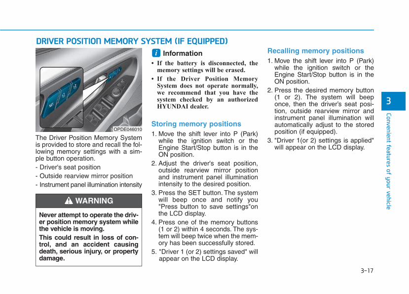
3-17
Convenient features of your vehicle
3
The Driver Position Memory Systemis provided to store and recall the fol-lowing memory settings with a sim-ple button operation.- Driver's seat position- Outside rearview mirror position- Instrument panel illumination intensity
Information • If the battery is disconnected, the
memory settings will be erased.
• If the Driver Position MemorySystem does not operate normally,we recommend that you have thesystem checked by an authorizedHYUNDAI dealer.
Storing memory positions1. Move the shift lever into P (Park)
while the ignition switch or theEngine Start/Stop button is in theON position.
2. Adjust the driver's seat position,outside rearview mirror positionand instrument panel illuminationintensity to the desired position.
3. Press the SET button. The systemwill beep once and notify you"Press button to save settings"onthe LCD display.
4. Press one of the memory buttons(1 or 2) within 4 seconds. The sys-tem will beep twice when the mem-ory has been successfully stored.
5. "Driver 1 (or 2) settings saved" willappear on the LCD display.
Recalling memory positions1. Move the shift lever into P (Park)
while the ignition switch or theEngine Start/Stop button is in theON position.
2. Press the desired memory button(1 or 2). The system will beeponce, then the driver’s seat posi-tion, outside rearview mirror andinstrument panel illumination willautomatically adjust to the storedposition (if equipped).
3. "Driver 1(or 2) settings is applied"will appear on the LCD display.
iDDRRIIVVEERR PPOOSSIITTIIOONN MMEEMMOORRYY SSYYSSTTEEMM ((IIFF EEQQUUIIPPPPEEDD))
OPDE046010
Never attempt to operate the driv-er position memory system whilethe vehicle is moving.This could result in loss of con-trol, and an accident causingdeath, serious injury, or propertydamage.
WARNING
3-18
Convenient features of your vehicle
Information • While recalling the "1" memory
position, pressing the SET or 1 but-ton temporarily stops the adjust-ment of the recalled memory posi-tion. Pressing the 2 button recallsthe "2" memory position.
• While recalling the "2" memoryposition, pressing the SET or 2 but-ton temporarily stops the adjust-ment of the recalled memory posi-tion. Pressing the 1 button recallsthe "1" memory position.
• While recalling the stored positions,pressing one of the control buttonsfor the driver's seat, outsiderearview mirror, or instrumentpanel illumination will cause themovement of that component to stopand move in the direction that thecontrol button is pressed.
Easy access function (if equipped)The system will move the driver'sseat automatically as follows:The shift lever is in P (Park)• Without smart key system
- It will move the driver’s seat rear-ward when the ignition key isremoved and the driver’s door isopened.
- It will move the driver’s seat forwardwhen the ignition key is inserted.
• With smart key system- It will move the driver’s seat rear-
ward when the Engine Start/Stopbutton is in the OFF position andthe driver’s door is opened.
- It will move the driver’s seat for-ward when the vehicle is turnedON or the driver’s door is closedwith the smart key with you.
You can activate or deactivate theEasy Access Function from the UserSettings mode on the LCD display.For more details, refer to "LCDDisplay" in this chapter.
i
Driver should be cautious whenusing this function to assure noinjury to passenger or child onthe back seat. In case of emer-gency the driver has to stopmovement of front seat (wheneasy access feature is activat-ed) by pressing SET button orany of the driver seat controlswitches.
CAUTION
3-19
Convenient features of your vehicle
3
Electric power steering (EPS)The system assists you with steeringthe vehicle. If the engine is off or ifthe power steering system becomesinoperative, the vehicle may still besteered, but it will require increasedsteering effort.Also, the steering effort becomesheavier as the vehicle’s speedincreases and becomes lighter asthe vehicle’s speed decreases forbetter control of the steering wheel.Should you notice any change in theeffort required to steer during normalvehicle operation, we recommendthat the system be checked by anauthorized HYUNDAI dealer.
• If the Electric Power SteeringSystem does not operate nor-mally, the warning light ( ) willilluminate or blink on the instru-ment cluster. The steering wheelmay become difficult to controlor operate. Take your vehicle toan authorized HYUNDAI dealerand have the system checked assoon as possible.
• When abnormality is detected inthe electric power steering sys-tem, to prevent a deadly acci-dent, the steering assist functionwill stop. At this time, the warn-ing light turns on or blinks onthe cluster. The steering wheelmay become difficult to controlor operate. Have your vehiclechecked immediately, after mov-ing the vehicle to a safe zone.
Information The following symptoms may occurduring normal vehicle operation:
• The steering effort may be highimmediately after placing the igni-tion switch button in the ON posi-tion.
This happens as the system per-forms the EPS system diagnostics.When the diagnostics is completed,the steering wheel will return to itsnormal condition.
• A click noise may be heard from theEPS relay after the ignition switch isplaced to the ON or LOCK/OFFposition.
• Motor noise may be heard when thevehicle is at a stop or at a low driv-ing speed.
• When you operate the steeringwheel in low temperature, abnormalnoise may occur. If temperaturerises, the noise will disappear. Thisis a normal condition.
(Continued)
iNOTICE
SSTTEEEERRIINNGG WWHHEEEELL
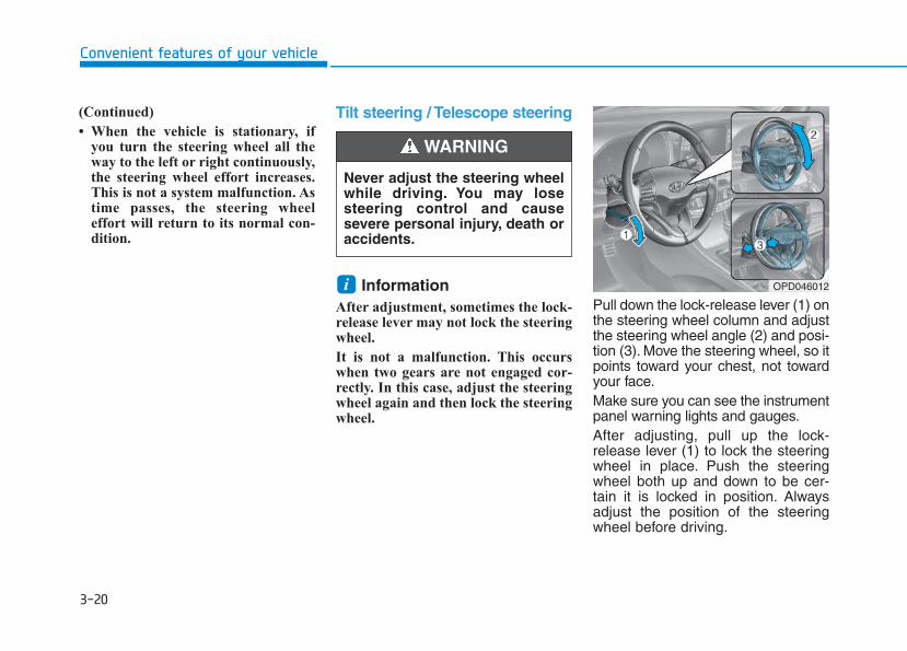
3-20
Convenient features of your vehicle
(Continued)
• When the vehicle is stationary, ifyou turn the steering wheel all theway to the left or right continuously,the steering wheel effort increases.This is not a system malfunction. Astime passes, the steering wheeleffort will return to its normal con-dition.
Tilt steering / Telescope steering
Information After adjustment, sometimes the lock-release lever may not lock the steeringwheel.
It is not a malfunction. This occurswhen two gears are not engaged cor-rectly. In this case, adjust the steeringwheel again and then lock the steeringwheel.
Pull down the lock-release lever (1) onthe steering wheel column and adjustthe steering wheel angle (2) and posi-tion (3). Move the steering wheel, so itpoints toward your chest, not towardyour face.Make sure you can see the instrumentpanel warning lights and gauges.After adjusting, pull up the lock-release lever (1) to lock the steeringwheel in place. Push the steeringwheel both up and down to be cer-tain it is locked in position. Alwaysadjust the position of the steeringwheel before driving.
i
Never adjust the steering wheelwhile driving. You may losesteering control and causesevere personal injury, death oraccidents.
WARNING
OPD046012
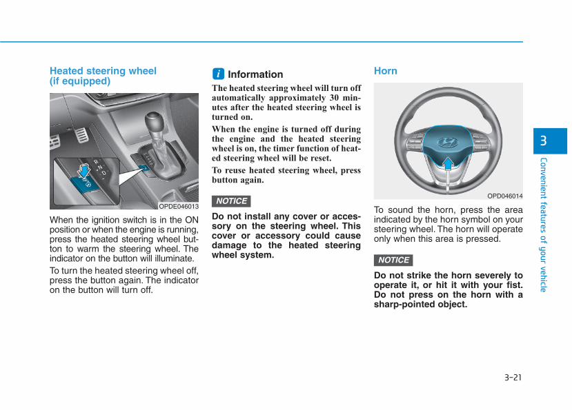
3-21
Convenient features of your vehicle
3
Heated steering wheel (if equipped)
When the ignition switch is in the ONposition or when the engine is running,press the heated steering wheel but-ton to warm the steering wheel. Theindicator on the button will illuminate.To turn the heated steering wheel off,press the button again. The indicatoron the button will turn off.
Information The heated steering wheel will turn offautomatically approximately 30 min-utes after the heated steering wheel isturned on.
When the engine is turned off duringthe engine and the heated steeringwheel is on, the timer function of heat-ed steering wheel will be reset.
To reuse heated steering wheel, pressbutton again.
Do not install any cover or acces-sory on the steering wheel. Thiscover or accessory could causedamage to the heated steeringwheel system.
Horn
To sound the horn, press the areaindicated by the horn symbol on yoursteering wheel. The horn will operateonly when this area is pressed.
Do not strike the horn severely tooperate it, or hit it with your fist.Do not press on the horn with asharp-pointed object.
NOTICE
NOTICE
i
OPD046014
OPDE046013
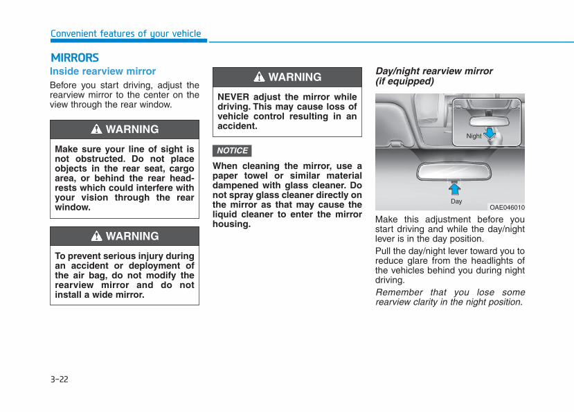
3-22
Convenient features of your vehicle
Inside rearview mirrorBefore you start driving, adjust therearview mirror to the center on theview through the rear window.
When cleaning the mirror, use apaper towel or similar materialdampened with glass cleaner. Donot spray glass cleaner directly onthe mirror as that may cause theliquid cleaner to enter the mirrorhousing.
Day/night rearview mirror (if equipped)
Make this adjustment before youstart driving and while the day/nightlever is in the day position.Pull the day/night lever toward you toreduce glare from the headlights ofthe vehicles behind you during nightdriving.Remember that you lose somerearview clarity in the night position.
NOTICE
NEVER adjust the mirror whiledriving. This may cause loss ofvehicle control resulting in anaccident.
WARNING
OAE046010Day
Night
MMIIRRRROORRSS
Make sure your line of sight isnot obstructed. Do not placeobjects in the rear seat, cargoarea, or behind the rear head-rests which could interfere withyour vision through the rearwindow.
WARNING
To prevent serious injury duringan accident or deployment ofthe air bag, do not modify therearview mirror and do notinstall a wide mirror.
WARNING
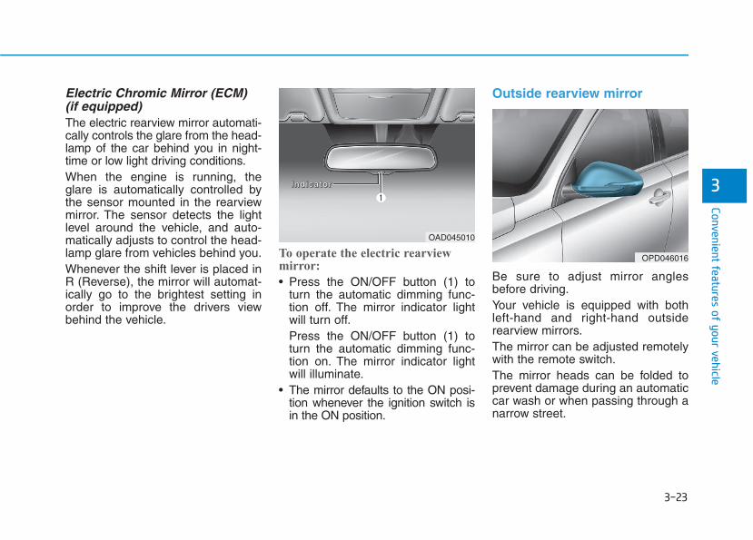
3-23
Convenient features of your vehicle
3
Electric Chromic Mirror (ECM) (if equipped)The electric rearview mirror automati-cally controls the glare from the head-lamp of the car behind you in night-time or low light driving conditions.When the engine is running, theglare is automatically controlled bythe sensor mounted in the rearviewmirror. The sensor detects the lightlevel around the vehicle, and auto-matically adjusts to control the head-lamp glare from vehicles behind you.Whenever the shift lever is placed inR (Reverse), the mirror will automat-ically go to the brightest setting inorder to improve the drivers viewbehind the vehicle.
To operate the electric rearviewmirror:
• Press the ON/OFF button (1) toturn the automatic dimming func-tion off. The mirror indicator lightwill turn off.Press the ON/OFF button (1) toturn the automatic dimming func-tion on. The mirror indicator lightwill illuminate.
• The mirror defaults to the ON posi-tion whenever the ignition switch isin the ON position.
Outside rearview mirror
Be sure to adjust mirror anglesbefore driving.Your vehicle is equipped with bothleft-hand and right-hand outsiderearview mirrors.The mirror can be adjusted remotelywith the remote switch.The mirror heads can be folded toprevent damage during an automaticcar wash or when passing through anarrow street.
OAD045010
OPD046016
IIIInnnnddddiiii ccccaaaattttoooorrrr
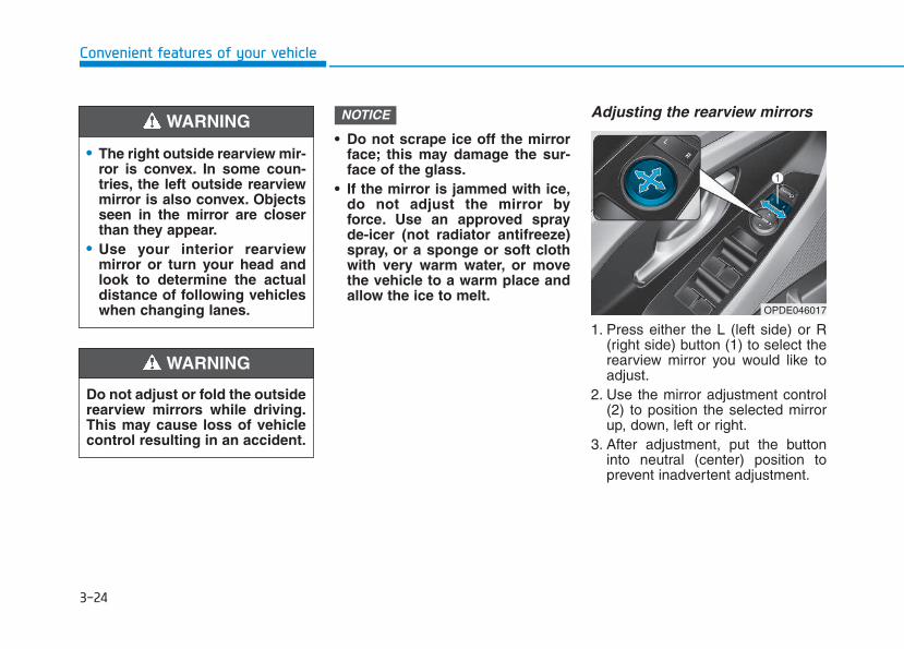
3-24
Convenient features of your vehicle
• Do not scrape ice off the mirrorface; this may damage the sur-face of the glass.
• If the mirror is jammed with ice,do not adjust the mirror byforce. Use an approved sprayde-icer (not radiator antifreeze)spray, or a sponge or soft clothwith very warm water, or movethe vehicle to a warm place andallow the ice to melt.
Adjusting the rearview mirrors
1. Press either the L (left side) or R(right side) button (1) to select therearview mirror you would like toadjust.
2. Use the mirror adjustment control(2) to position the selected mirrorup, down, left or right.
3. After adjustment, put the buttoninto neutral (center) position toprevent inadvertent adjustment.
NOTICE
OPDE046017
• The right outside rearview mir-ror is convex. In some coun-tries, the left outside rearviewmirror is also convex. Objectsseen in the mirror are closerthan they appear.
• Use your interior rearviewmirror or turn your head andlook to determine the actualdistance of following vehicleswhen changing lanes.
WARNING
Do not adjust or fold the outsiderearview mirrors while driving.This may cause loss of vehiclecontrol resulting in an accident.
WARNING
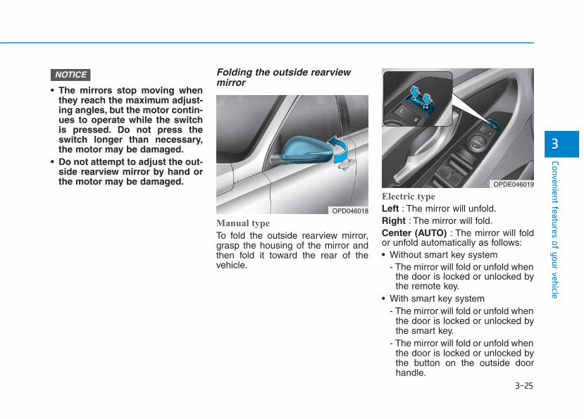
3-25
Convenient features of your vehicle
3
• The mirrors stop moving whenthey reach the maximum adjust-ing angles, but the motor contin-ues to operate while the switchis pressed. Do not press theswitch longer than necessary,the motor may be damaged.
• Do not attempt to adjust the out-side rearview mirror by hand orthe motor may be damaged.
Folding the outside rearviewmirror
Manual type
To fold the outside rearview mirror,grasp the housing of the mirror andthen fold it toward the rear of thevehicle.
Electric type
Left : The mirror will unfold.Right : The mirror will fold.Center (AUTO) : The mirror will foldor unfold automatically as follows:• Without smart key system
- The mirror will fold or unfold whenthe door is locked or unlocked bythe remote key.
• With smart key system- The mirror will fold or unfold when
the door is locked or unlocked bythe smart key.
- The mirror will fold or unfold whenthe door is locked or unlocked bythe button on the outside doorhandle.
NOTICE
OPD046018
OPDE046019
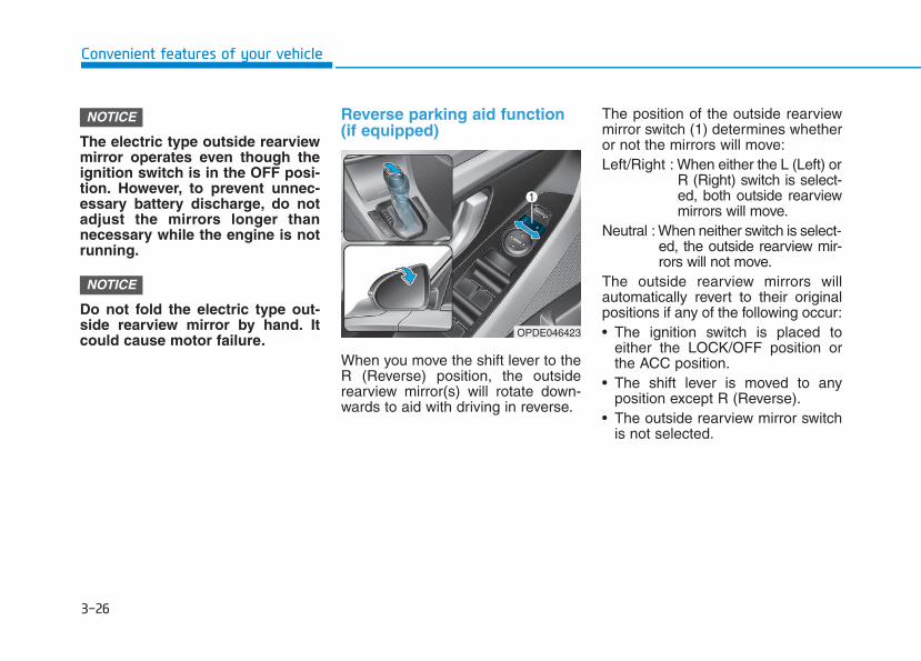
3-26
The electric type outside rearviewmirror operates even though theignition switch is in the OFF posi-tion. However, to prevent unnec-essary battery discharge, do notadjust the mirrors longer thannecessary while the engine is notrunning.
Do not fold the electric type out-side rearview mirror by hand. Itcould cause motor failure.
Reverse parking aid function(if equipped)
When you move the shift lever to theR (Reverse) position, the outsiderearview mirror(s) will rotate down-wards to aid with driving in reverse.
The position of the outside rearviewmirror switch (1) determines whetheror not the mirrors will move:Left/Right : When either the L (Left) or
R (Right) switch is select-ed, both outside rearviewmirrors will move.
Neutral : When neither switch is select-ed, the outside rearview mir-rors will not move.
The outside rearview mirrors willautomatically revert to their originalpositions if any of the following occur:• The ignition switch is placed to
either the LOCK/OFF position orthe ACC position.
• The shift lever is moved to anyposition except R (Reverse).
• The outside rearview mirror switchis not selected.
NOTICE
NOTICE
Convenient features of your vehicle
OPDE046423
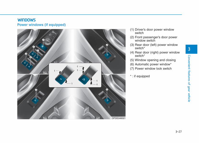
3-27
Convenient features of your vehicle
3
Power windows (if equipped)(1) Driver’s door power window
switch(2) Front passenger’s door power
window switch(3) Rear door (left) power window
switch*(4) Rear door (right) power window
switch*(5) Window opening and closing(6) Automatic power window*(7) Power window lock switch
* : if equipped
WWIINNDDOOWWSS
OPDE046021
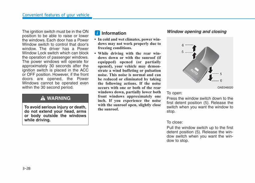
3-28
Convenient features of your vehicle
The ignition switch must be in the ONposition to be able to raise or lowerthe windows. Each door has a PowerWindow switch to control that door'swindow. The driver has a PowerWindow Lock switch which can blockthe operation of passenger windows.The power windows will operate forapproximately 30 seconds after theignition switch is placed in the ACCor OFF position. However, if the frontdoors are opened, the PowerWindows cannot be operated evenwithin the 30 second period.
Information • In cold and wet climates, power win-
dows may not work properly due tofreezing conditions.
• While driving with the rear win-dows down or with the sunroof (ifequipped) opened (or partiallyopened), your vehicle may demon-strate a wind buffeting or pulsationnoise. This noise is normal and canbe reduced or eliminated by takingthe following actions. If the noiseoccurs with one or both of the rearwindows down, partially lower bothfront windows approximately oneinch. If you experience the noisewith the sunroof open, slightly closethe sunroof.
Window opening and closing
To open:Press the window switch down to thefirst detent position (5). Release theswitch when you want the window tostop.
To close:Pull the window switch up to the firstdetent position (5). Release the win-dow switch when you want the win-dow to stop.
i
To avoid serious injury or death,do not extend your head, armsor body outside the windowswhile driving.
WARNING
OAE046020
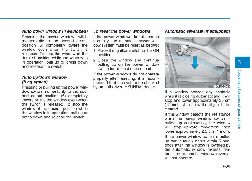
3-29
Convenient features of your vehicle
3
Auto down window (if equipped) Pressing the power window switchmomentarily to the second detentposition (6) completely lowers thewindow even when the switch isreleased. To stop the window at thedesired position while the window isin operation, pull up or press downand release the switch.
Auto up/down window (if equipped)Pressing or pulling up the power win-dow switch momentarily to the sec-ond detent position (6) completelylowers or lifts the window even whenthe switch is released. To stop thewindow at the desired position whilethe window is in operation, pull up orpress down and release the switch.
To reset the power windowsIf the power windows do not operatenormally, the automatic power win-dow system must be reset as follows:1. Place the ignition switch to the ON
position.2. Close the window and continue
pulling up on the power windowswitch for at least one second.
If the power windows do not operateproperly after resetting, it is recom-mended that the system be checkedby an authorized HYUNDAI dealer.
Automatic reversal (if equipped)
If a window senses any obstaclewhile it is closing automatically, it willstop and lower approximately 30 cm(12 inches) to allow the object to becleared.If the window detects the resistancewhile the power window switch ispulled up continuously, the windowwill stop upward movement thenlower approximately 2.5 cm (1 inch).If the power window switch is pulledup continuously again within 5 sec-onds after the window is lowered bythe automatic window reversal fea-ture, the automatic window reversalwill not operate.
OLF044032
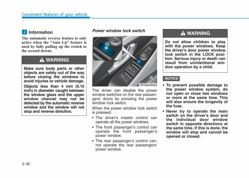
3-30
Convenient features of your vehicle
Information The automatic reverse feature is onlyactive when the “Auto Up” feature isused by fully pulling up the switch tothe second detent.
Power window lock switch
The driver can disable the powerwindow switches on the rear passen-gers' doors by pressing the powerwindow lock switch.When the power window lock switchis pressed:• The driver's master control can
operate all the power windows.• The front passenger's control can
operate the front passenger'spower window.
• The rear passenger's control can-not operate the rear passengers'power window.
• To prevent possible damage tothe power window system, donot open or close two windowsor more at the same time. Thiswill also ensure the longevity ofthe fuse.
• Never try to operate the mainswitch on the driver's door andthe individual door windowswitch in opposite directions atthe same time. If this is done, thewindow will stop and cannot beopened or closed.
NOTICE
i
Make sure body parts or otherobjects are safely out of the waybefore closing the windows toavoid injuries or vehicle damage.Objects less than 4 mm (0.16inch) in diameter caught betweenthe window glass and the upperwindow channel may not bedetected by the automatic reversewindow and the window will notstop and reverse direction.
WARNING
Do not allow children to playwith the power windows. Keepthe driver’s door power windowlock switch in the LOCK posi-tion. Serious injury or death canresult from unintentional win-dow operation by a child.
WARNING
OPDE046023
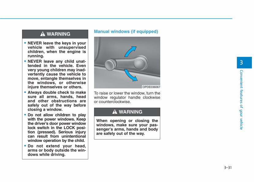
3-31
Convenient features of your vehicle
3
Manual windows (if equipped)
To raise or lower the window, turn thewindow regulator handle clockwiseor counterclockwise.
• NEVER leave the keys in yourvehicle with unsupervisedchildren, when the engine isrunning.
• NEVER leave any child unat-tended in the vehicle. Evenvery young children may inad-vertently cause the vehicle tomove, entangle themselves inthe windows, or otherwiseinjure themselves or others.
• Always double check to makesure all arms, hands, headand other obstructions aresafely out of the way beforeclosing a window.
• Do not allow children to playwith the power windows. Keepthe driver’s door power windowlock switch in the LOCK posi-tion (pressed). Serious injurycan result from unintentionalwindow operation by the child.
• Do not extend your head,arms or body outside the win-dows while driving.
WARNING
When opening or closing thewindows, make sure your pas-senger's arms, hands and bodyare safely out of the way.
WARNING
OPDE036067
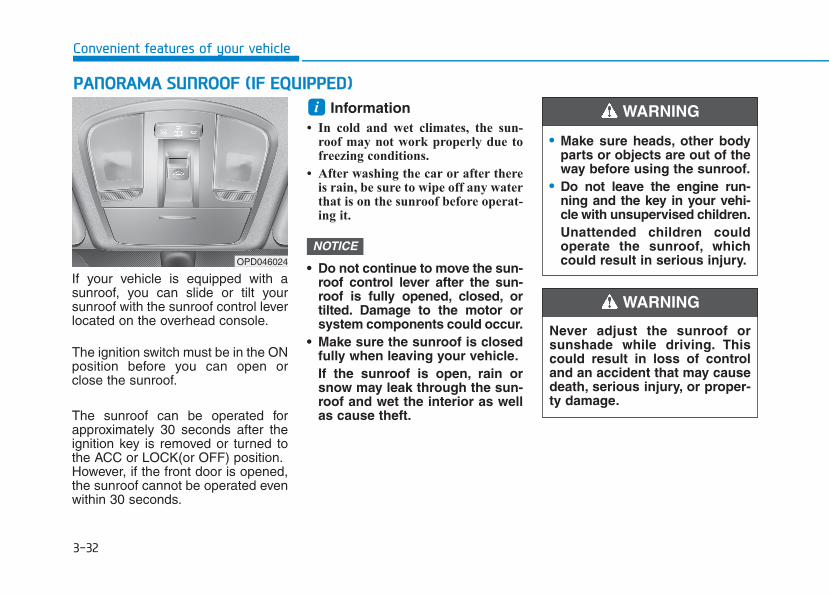
3-32
Convenient features of your vehicle
If your vehicle is equipped with asunroof, you can slide or tilt yoursunroof with the sunroof control leverlocated on the overhead console.
The ignition switch must be in the ONposition before you can open orclose the sunroof.
The sunroof can be operated forapproximately 30 seconds after theignition key is removed or turned tothe ACC or LOCK(or OFF) position.However, if the front door is opened,the sunroof cannot be operated evenwithin 30 seconds.
Information • In cold and wet climates, the sun-
roof may not work properly due tofreezing conditions.
• After washing the car or after thereis rain, be sure to wipe off any waterthat is on the sunroof before operat-ing it.
• Do not continue to move the sun-roof control lever after the sun-roof is fully opened, closed, ortilted. Damage to the motor orsystem components could occur.
• Make sure the sunroof is closedfully when leaving your vehicle.If the sunroof is open, rain orsnow may leak through the sun-roof and wet the interior as wellas cause theft.
NOTICE
iPPAANNOORRAAMMAA SSUUNNRROOOOFF ((IIFF EEQQUUIIPPPPEEDD))
• Make sure heads, other bodyparts or objects are out of theway before using the sunroof.
• Do not leave the engine run-ning and the key in your vehi-cle with unsupervised children.Unattended children couldoperate the sunroof, whichcould result in serious injury.
WARNING
OPD046024
Never adjust the sunroof orsunshade while driving. Thiscould result in loss of controland an accident that may causedeath, serious injury, or proper-ty damage.
WARNING
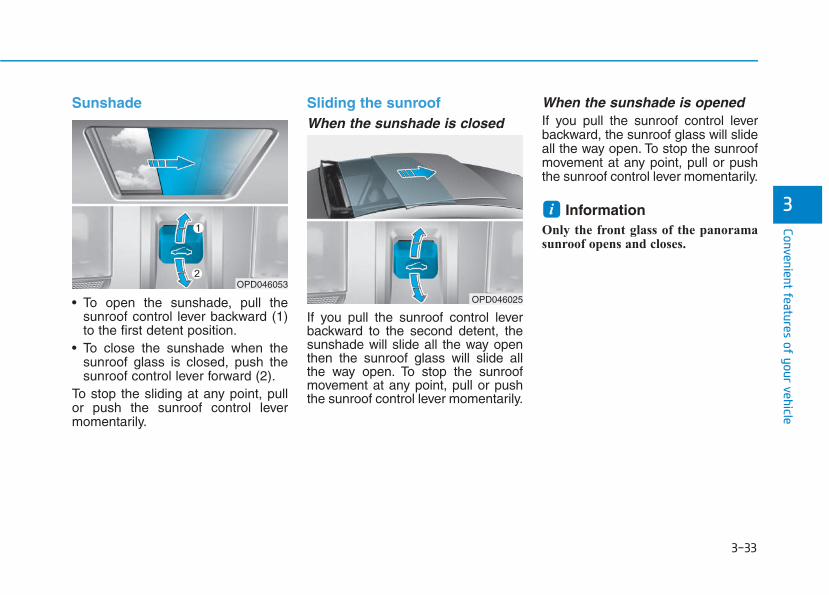
3-33
Convenient features of your vehicle
3
Sunshade
• To open the sunshade, pull thesunroof control lever backward (1)to the first detent position.
• To close the sunshade when thesunroof glass is closed, push thesunroof control lever forward (2).
To stop the sliding at any point, pullor push the sunroof control levermomentarily.
Sliding the sunroof When the sunshade is closed
If you pull the sunroof control leverbackward to the second detent, thesunshade will slide all the way openthen the sunroof glass will slide allthe way open. To stop the sunroofmovement at any point, pull or pushthe sunroof control lever momentarily.
When the sunshade is openedIf you pull the sunroof control leverbackward, the sunroof glass will slideall the way open. To stop the sunroofmovement at any point, pull or pushthe sunroof control lever momentarily.
Information Only the front glass of the panoramasunroof opens and closes.
i
OPD046053
OPD046025
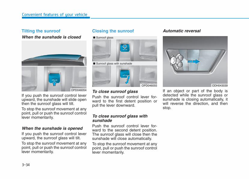
3-34
Convenient features of your vehicle
Tilting the sunroof When the sunshade is closed
If you push the sunroof control leverupward, the sunshade will slide openthen the sunroof glass will tilt.To stop the sunroof movement at anypoint, pull or push the sunroof controllever momentarily.
When the sunshade is openedIf you push the sunroof control leverupward, the sunroof glass will tilt.To stop the sunroof movement at anypoint, pull or push the sunroof controllever momentarily.
Closing the sunroof
To close sunroof glass Push the sunroof control lever for-ward to the first detent position orpull the lever downward.
To close sunroof glass withsunshade Push the sunroof control lever for-ward to the second detent position.The sunroof glass will close then thesunshade will close automatically.To stop the sunroof movement at anypoint, pull or push the sunroof controllever momentarily.
Automatic reversal
If an object or part of the body isdetected while the sunroof glass orsunshade is closing automatically, itwill reverse the direction, and thenstop.
OPD046054
ODH043039OPD046055
■ Sunroof glass
■ Sunroof glass with sunshade
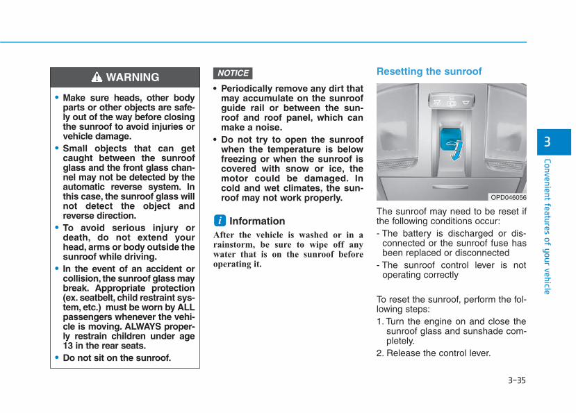
3-35
Convenient features of your vehicle
3
• Periodically remove any dirt thatmay accumulate on the sunroofguide rail or between the sun-roof and roof panel, which canmake a noise.
• Do not try to open the sunroofwhen the temperature is belowfreezing or when the sunroof iscovered with snow or ice, themotor could be damaged. Incold and wet climates, the sun-roof may not work properly.
Information After the vehicle is washed or in arainstorm, be sure to wipe off anywater that is on the sunroof beforeoperating it.
Resetting the sunroof
The sunroof may need to be reset ifthe following conditions occur:- The battery is discharged or dis-
connected or the sunroof fuse hasbeen replaced or disconnected
- The sunroof control lever is notoperating correctly
To reset the sunroof, perform the fol-lowing steps:1. Turn the engine on and close the
sunroof glass and sunshade com-pletely.
2. Release the control lever.
i
NOTICE
• Make sure heads, other bodyparts or other objects are safe-ly out of the way before closingthe sunroof to avoid injuries orvehicle damage.
• Small objects that can getcaught between the sunroofglass and the front glass chan-nel may not be detected by theautomatic reverse system. Inthis case, the sunroof glass willnot detect the object andreverse direction.
• To avoid serious injury ordeath, do not extend yourhead, arms or body outside thesunroof while driving.
• In the event of an accident orcollision, the sunroof glass maybreak. Appropriate protection(ex. seatbelt, child restraint sys-tem, etc.) must be worn by ALLpassengers whenever the vehi-cle is moving. ALWAYS proper-ly restrain children under age13 in the rear seats.
• Do not sit on the sunroof.
WARNING
OPD046056
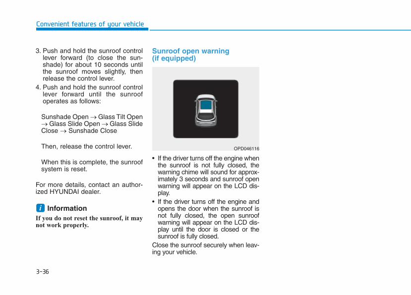
3-36
Convenient features of your vehicle
3. Push and hold the sunroof controllever forward (to close the sun-shade) for about 10 seconds untilthe sunroof moves slightly, thenrelease the control lever.
4. Push and hold the sunroof controllever forward until the sunroofoperates as follows:
Sunshade Open → Glass Tilt Open→ Glass Slide Open → Glass SlideClose → Sunshade Close
Then, release the control lever.
When this is complete, the sunroofsystem is reset.
For more details, contact an author-ized HYUNDAI dealer.
Information If you do not reset the sunroof, it maynot work properly.
Sunroof open warning(if equipped)
• If the driver turns off the engine whenthe sunroof is not fully closed, thewarning chime will sound for approx-imately 3 seconds and sunroof openwarning will appear on the LCD dis-play.
• If the driver turns off the engine andopens the door when the sunroof isnot fully closed, the open sunroofwarning will appear on the LCD dis-play until the door is closed or thesunroof is fully closed.
Close the sunroof securely when leav-ing your vehicle.
i
OPD046116
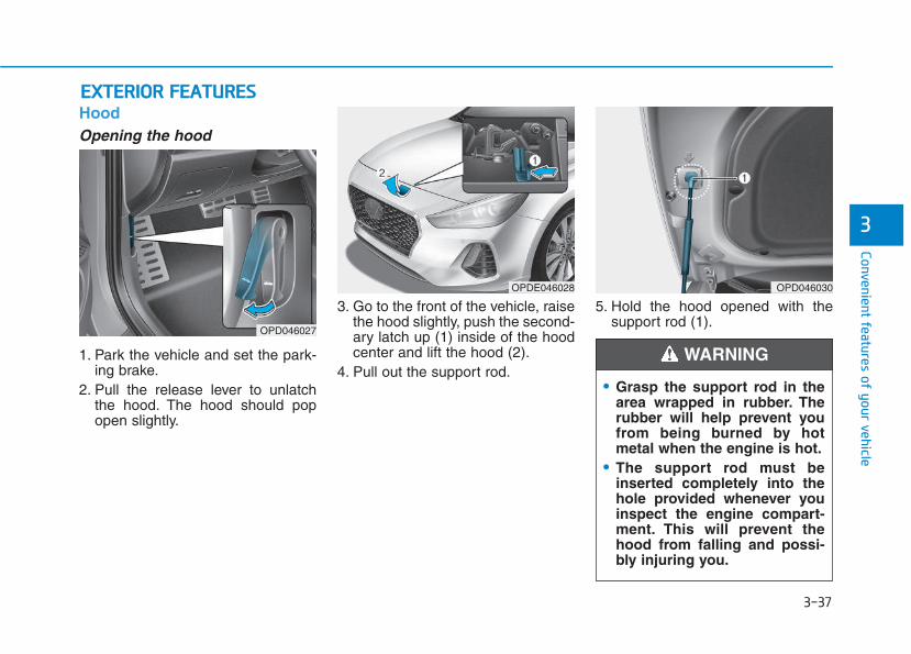
3-37
Convenient features of your vehicle
3
EEXXTTEERRIIOORR FFEEAATTUURREESSHoodOpening the hood
1. Park the vehicle and set the park-ing brake.
2. Pull the release lever to unlatchthe hood. The hood should popopen slightly.
3. Go to the front of the vehicle, raisethe hood slightly, push the second-ary latch up (1) inside of the hoodcenter and lift the hood (2).
4. Pull out the support rod.
5. Hold the hood opened with thesupport rod (1).
OPD046027
OPDE046028
• Grasp the support rod in thearea wrapped in rubber. Therubber will help prevent youfrom being burned by hotmetal when the engine is hot.
• The support rod must beinserted completely into thehole provided whenever youinspect the engine compart-ment. This will prevent thehood from falling and possi-bly injuring you.
WARNING
OPD046030
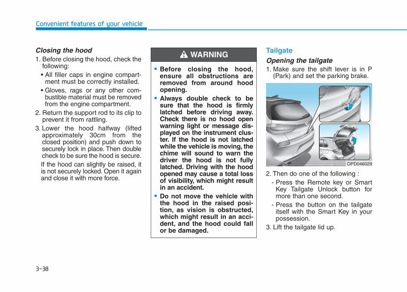
3-38
Convenient features of your vehicle
Closing the hood1. Before closing the hood, check the
following:• All filler caps in engine compart-
ment must be correctly installed.• Gloves, rags or any other com-
bustible material must be removedfrom the engine compartment.
2. Return the support rod to its clip toprevent it from rattling.
3. Lower the hood halfway (liftedapproximately 30cm from theclosed position) and push down tosecurely lock in place. Then doublecheck to be sure the hood is secure.If the hood can slightly be raised, itis not securely locked. Open it againand close it with more force.
TailgateOpening the tailgate1. Make sure the shift lever is in P
(Park) and set the parking brake.
2. Then do one of the following :- Press the Remote key or Smart
Key Tailgate Unlock button formore than one second.
- Press the button on the tailgateitself with the Smart Key in yourpossession.
3. Lift the tailgate lid up.
• Before closing the hood,ensure all obstructions areremoved from around hoodopening.
• Always double check to besure that the hood is firmlylatched before driving away.Check there is no hood openwarning light or message dis-played on the instrument clus-ter. If the hood is not latchedwhile the vehicle is moving, thechime will sound to warn thedriver the hood is not fullylatched. Driving with the hoodopened may cause a total lossof visibility, which might resultin an accident.
• Do not move the vehicle withthe hood in the raised posi-tion, as vision is obstructed,which might result in an acci-dent, and the hood could fallor be damaged.
WARNING
OPD046029
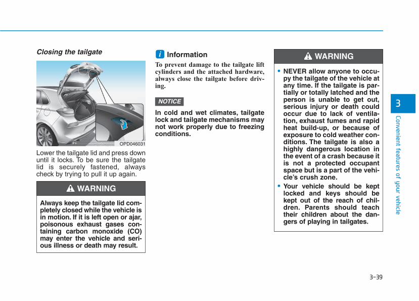
3-39
Convenient features of your vehicle
3
Closing the tailgate
Lower the tailgate lid and press downuntil it locks. To be sure the tailgatelid is securely fastened, alwayscheck by trying to pull it up again.
Information To prevent damage to the tailgate liftcylinders and the attached hardware,always close the tailgate before driv-ing.
In cold and wet climates, tailgatelock and tailgate mechanisms maynot work properly due to freezingconditions.
NOTICE
i
Always keep the tailgate lid com-pletely closed while the vehicle isin motion. If it is left open or ajar,poisonous exhaust gases con-taining carbon monoxide (CO)may enter the vehicle and seri-ous illness or death may result.
WARNING
OPD046031
• NEVER allow anyone to occu-py the tailgate of the vehicle atany time. If the tailgate is par-tially or totally latched and theperson is unable to get out,serious injury or death couldoccur due to lack of ventila-tion, exhaust fumes and rapidheat build-up, or because ofexposure to cold weather con-ditions. The tailgate is also ahighly dangerous location inthe event of a crash because itis not a protected occupantspace but is a part of the vehi-cle’s crush zone.
• Your vehicle should be keptlocked and keys should bekept out of the reach of chil-dren. Parents should teachtheir children about the dan-gers of playing in tailgates.
WARNING
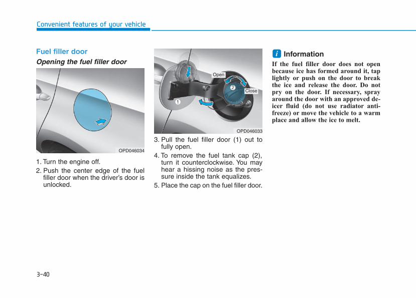
3-40
Convenient features of your vehicle
Fuel filler doorOpening the fuel filler door
1. Turn the engine off.2. Push the center edge of the fuel
filler door when the driver’s door isunlocked.
3. Pull the fuel filler door (1) out tofully open.
4. To remove the fuel tank cap (2),turn it counterclockwise. You mayhear a hissing noise as the pres-sure inside the tank equalizes.
5. Place the cap on the fuel filler door.
Information If the fuel filler door does not openbecause ice has formed around it, taplightly or push on the door to breakthe ice and release the door. Do notpry on the door. If necessary, sprayaround the door with an approved de-icer fluid (do not use radiator anti-freeze) or move the vehicle to a warmplace and allow the ice to melt.
i
OPD046034
OPD046033
Open
Close
3-41
Convenient features of your vehicle
3
Closing the fuel filler door1. To install the fuel tank cap, turn it
clockwise until it “clicks” one time.2. Close the fuel filler door until it is
latched securely.
Gasoline is highly flammableand explosive. Failure to followthese guidelines may result inSERIOUS INJURY or DEATH:• Read and follow all warnings
posted at the gas station.• Before refueling, note the
location of the EmergencyGasoline Shut-Off, if available,at the gas station.
• Before touching the fuel noz-zle, you should eliminate thepotential build-up of staticelectricity by touching a metalpart of the vehicle, a safe dis-tance away from the fuel fillerneck, nozzle, or other gassource, with your bare hand.
(Continued)
WARNING
(Continued)• When refueling, always move
the shift lever to the P (Park)position (for automatic transmis-sion/ dual clutch transmission)or first gear or R (Reverse, formanual transmission), set theparking brake, and place theignition switch to the LOCK/OFFposition. Sparks produced byelectrical components related tothe engine can ignite fuel vaporscausing a fire.
• When using an approvedportable fuel container, be sureto place the container on theground prior to refueling. Staticelectricity discharge from thecontainer can ignite fuel vaporscausing a fire. Once refuelinghas begun, contact betweenyour bare hand and the vehicleshould be maintained until thefilling is complete.
(Continued)
(Continued)• Do not use cellular phones
while refueling. Electric cur-rent and/or electronic interfer-ence from cellular phones canpotentially ignite fuel vaporsand cause a fire.
• Do not get back into a vehicleonce you have begun refuel-ing. You can generate a build-up of static electricity by touch-ing, rubbing or sliding againstany item or fabric capable ofproducing static electricity.Static electricity discharge canignite fuel vapors causing afire. If you must re-enter thevehicle, you should once againeliminate potentially danger-ous static electricity dischargeby touching a metal part of thevehicle, away from the fuel fillerneck, nozzle or other gasolinesource, with your bare hand.
(Continued)
3-42
Convenient features of your vehicle
Information Make sure to refuel your vehicleaccording to the "Fuel Requirements"suggested in the Introduction chapter.
• Do not spill fuel on the exteriorsurfaces of the vehicle. Any typeof fuel spilled on painted sur-faces may damage the paint.
• If the fuel filler cap requiresreplacement, use only a genuineHYUNDAI cap or the equivalentspecified for your vehicle. Anincorrect fuel filler cap canresult in a serious malfunctionof the fuel system or emissioncontrol system.
NOTICE
i(Continued)• Use only approved portable
plastic fuel containers designedto carry and store gasoline.
• Do not use matches or alighter and do not smoke orleave a lit cigarette in yourvehicle while at a gas station,especially during refueling.
• Do not over-fill or top-off yourvehicle tank, which can causegasoline spillage.
• If a fire breaks out during refu-eling, leave the vicinity of thevehicle, and immediately con-tact the manager of the gasstation and then contact thelocal fire department. Followany safety instructions theyprovide.
(Continued)
(Continued)• If pressurized fuel sprays out,
it can cover your clothes orskin and thus subject you tothe risk of fire and burns.Always remove the fuel capcarefully and slowly. If the capis venting fuel or if you hear ahissing sound, wait until thecondition stops before com-pletely removing the cap.
• Always check that the fuel capis installed securely to preventfuel spillage in the event of anaccident.
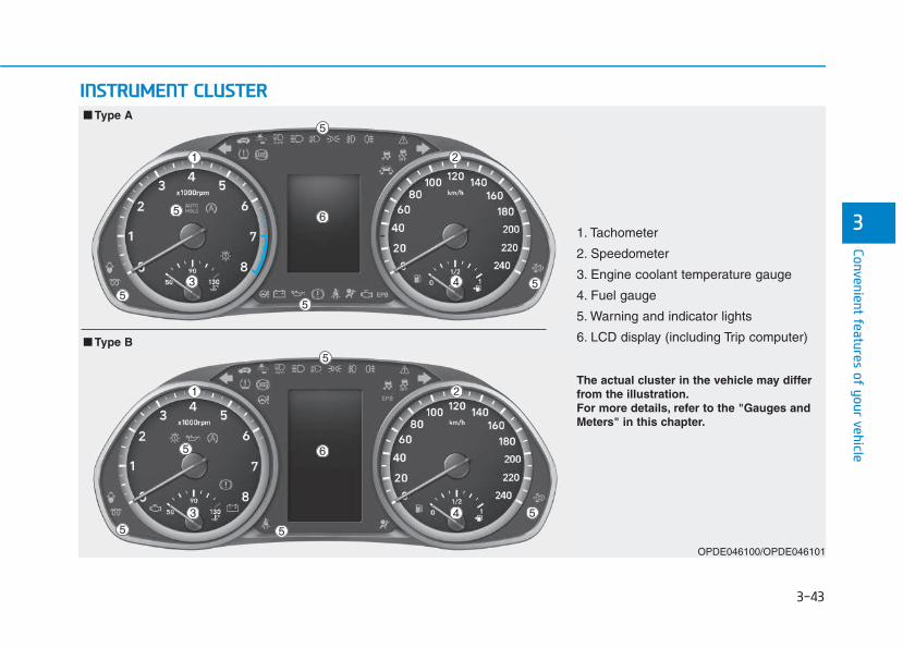
3-43
Convenient features of your vehicle
31. Tachometer
2. Speedometer
3. Engine coolant temperature gauge
4. Fuel gauge
5. Warning and indicator lights
6. LCD display (including Trip computer)
OPDE046100/OPDE046101
■■ Type B
■■ Type A
IINNSSTTRRUUMMEENNTT CCLLUUSSTTEERR
The actual cluster in the vehicle may differfrom the illustration.For more details, refer to the "Gauges andMeters" in this chapter.
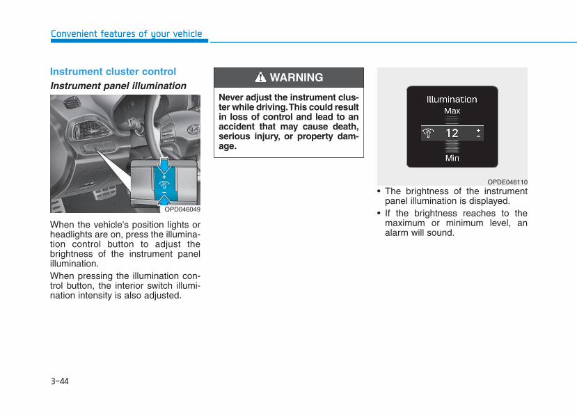
3-44
Convenient features of your vehicle
Instrument cluster controlInstrument panel illumination
When the vehicle's position lights orheadlights are on, press the illumina-tion control button to adjust thebrightness of the instrument panelillumination.When pressing the illumination con-trol button, the interior switch illumi-nation intensity is also adjusted.
• The brightness of the instrumentpanel illumination is displayed.
• If the brightness reaches to themaximum or minimum level, analarm will sound.
Never adjust the instrument clus-ter while driving.This could resultin loss of control and lead to anaccident that may cause death,serious injury, or property dam-age.
WARNING
OPDE046110
OPD046049
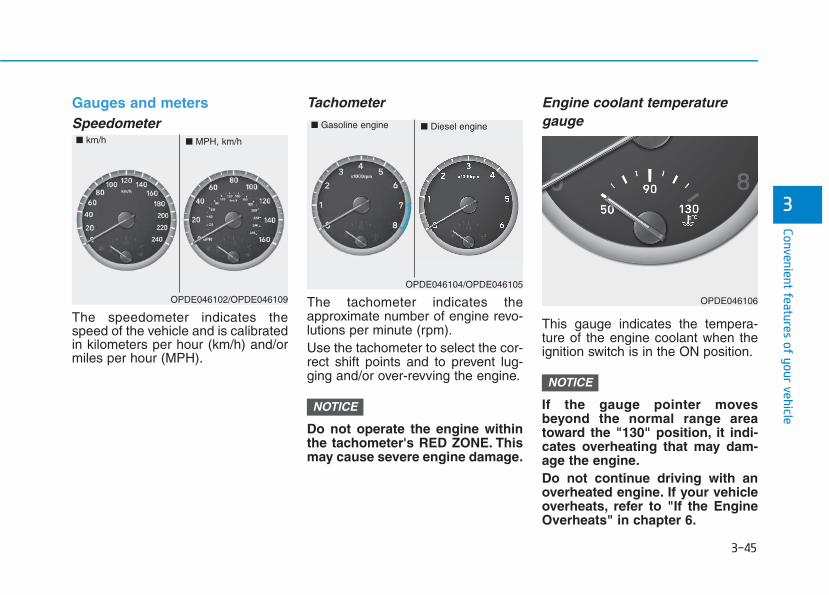
3-45
Convenient features of your vehicle
3
Gauges and metersSpeedometer
The speedometer indicates thespeed of the vehicle and is calibratedin kilometers per hour (km/h) and/ormiles per hour (MPH).
Tachometer
The tachometer indicates theapproximate number of engine revo-lutions per minute (rpm).Use the tachometer to select the cor-rect shift points and to prevent lug-ging and/or over-revving the engine.
Do not operate the engine withinthe tachometer's RED ZONE. Thismay cause severe engine damage.
Engine coolant temperaturegauge
This gauge indicates the tempera-ture of the engine coolant when theignition switch is in the ON position.
If the gauge pointer movesbeyond the normal range areatoward the "130" position, it indi-cates overheating that may dam-age the engine.Do not continue driving with anoverheated engine. If your vehicleoverheats, refer to "If the EngineOverheats" in chapter 6.
NOTICE
NOTICE
OPDE046102/OPDE046109
■ MPH, km/h■ km/h
OPDE046104/OPDE046105
■ Diesel engine■ Gasoline engine
OPDE046106
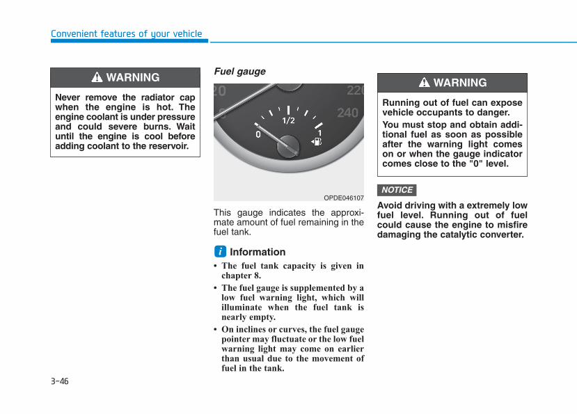
3-46
Convenient features of your vehicle
Fuel gauge
This gauge indicates the approxi-mate amount of fuel remaining in thefuel tank.
Information • The fuel tank capacity is given in
chapter 8.
• The fuel gauge is supplemented by alow fuel warning light, which willilluminate when the fuel tank isnearly empty.
• On inclines or curves, the fuel gaugepointer may fluctuate or the low fuelwarning light may come on earlierthan usual due to the movement offuel in the tank.
Avoid driving with a extremely lowfuel level. Running out of fuelcould cause the engine to misfiredamaging the catalytic converter.
NOTICE
i
Never remove the radiator capwhen the engine is hot. Theengine coolant is under pressureand could severe burns. Waituntil the engine is cool beforeadding coolant to the reservoir.
WARNING
Running out of fuel can exposevehicle occupants to danger.You must stop and obtain addi-tional fuel as soon as possibleafter the warning light comeson or when the gauge indicatorcomes close to the "0" level.
WARNING
OPDE046107
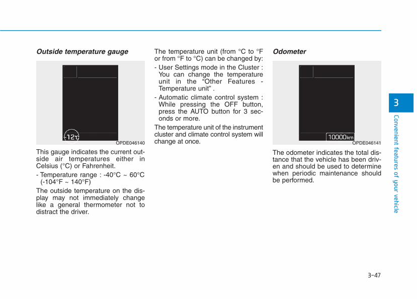
3-47
Convenient features of your vehicle
3
Outside temperature gauge
This gauge indicates the current out-side air temperatures either inCelsius (°C) or Fahrenheit.- Temperature range : -40°C ~ 60°C
(-104°F ~ 140°F)The outside temperature on the dis-play may not immediately changelike a general thermometer not todistract the driver.
The temperature unit (from °C to °For from °F to °C) can be changed by:- User Settings mode in the Cluster :
You can change the temperatureunit in the “Other Features -Temperature unit” .
- Automatic climate control system :While pressing the OFF button,press the AUTO button for 3 sec-onds or more.
The temperature unit of the instrumentcluster and climate control system willchange at once.
Odometer
The odometer indicates the total dis-tance that the vehicle has been driv-en and should be used to determinewhen periodic maintenance shouldbe performed.
OPDE046140 OPDE046141
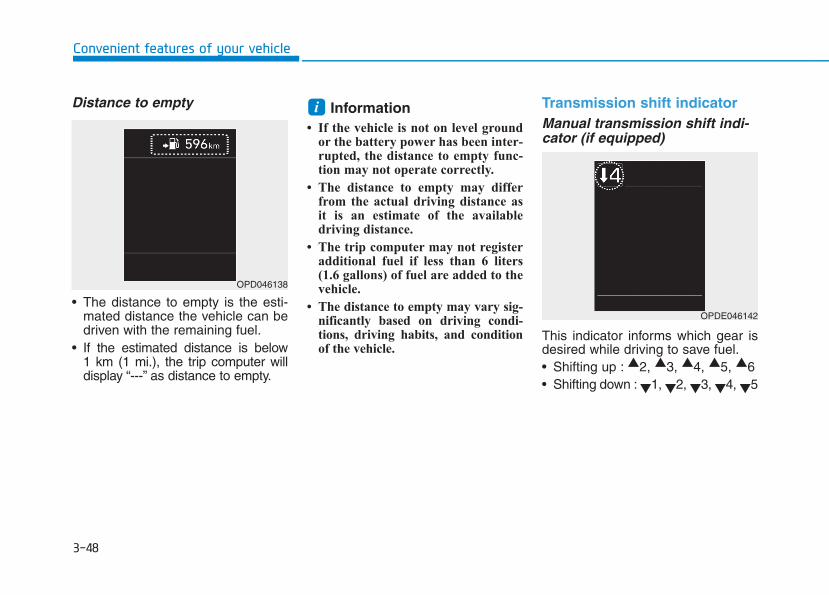
3-48
Convenient features of your vehicle
Distance to empty
• The distance to empty is the esti-mated distance the vehicle can bedriven with the remaining fuel.
• If the estimated distance is below1 km (1 mi.), the trip computer willdisplay “---” as distance to empty.
Information • If the vehicle is not on level ground
or the battery power has been inter-rupted, the distance to empty func-tion may not operate correctly.
• The distance to empty may differfrom the actual driving distance asit is an estimate of the availabledriving distance.
• The trip computer may not registeradditional fuel if less than 6 liters(1.6 gallons) of fuel are added to thevehicle.
• The distance to empty may vary sig-nificantly based on driving condi-tions, driving habits, and conditionof the vehicle.
Transmission shift indicatorManual transmission shift indi-cator (if equipped)
This indicator informs which gear isdesired while driving to save fuel.• Shifting up : ▲2, ▲3, ▲4, ▲5, ▲6• Shifting down : ▼1, ▼2, ▼3, ▼4, ▼5
i
OPD046138
OPDE046142
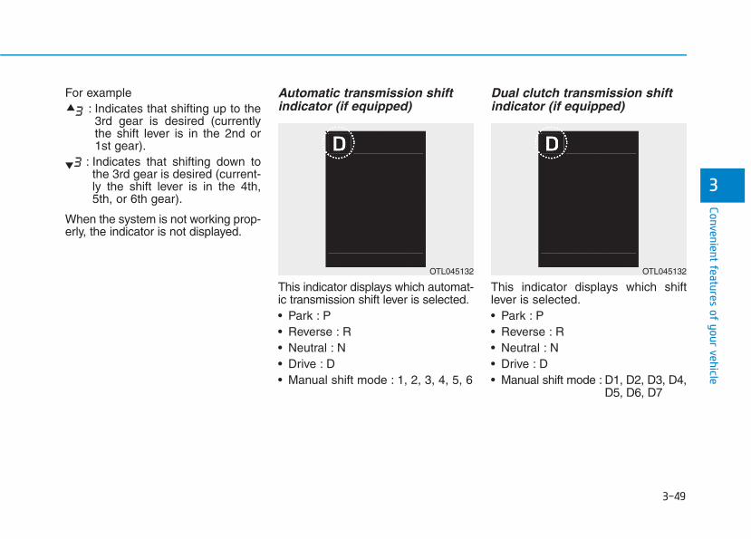
3-49
Convenient features of your vehicle
3
For example: Indicates that shifting up to the3rd gear is desired (currentlythe shift lever is in the 2nd or1st gear).
: Indicates that shifting down tothe 3rd gear is desired (current-ly the shift lever is in the 4th,5th, or 6th gear).
When the system is not working prop-erly, the indicator is not displayed.
Automatic transmission shiftindicator (if equipped)
This indicator displays which automat-ic transmission shift lever is selected.• Park : P• Reverse : R• Neutral : N• Drive : D• Manual shift mode : 1, 2, 3, 4, 5, 6
Dual clutch transmission shiftindicator (if equipped)
This indicator displays which shiftlever is selected.• Park : P• Reverse : R• Neutral : N• Drive : D• Manual shift mode : D1, D2, D3, D4,
D5, D6, D7
OTL045132OTL045132
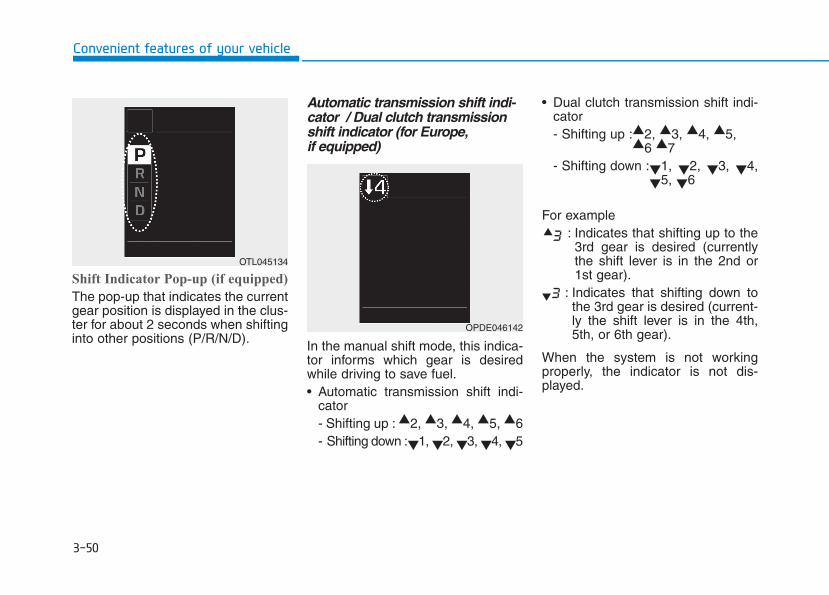
3-50
Convenient features of your vehicle
Shift Indicator Pop-up (if equipped)
The pop-up that indicates the currentgear position is displayed in the clus-ter for about 2 seconds when shiftinginto other positions (P/R/N/D).
Automatic transmission shift indi-cator / Dual clutch transmissionshift indicator (for Europe,if equipped)
In the manual shift mode, this indica-tor informs which gear is desiredwhile driving to save fuel.• Automatic transmission shift indi-
cator- Shifting up : ▲2, ▲3, ▲4, ▲5, ▲6- Shifting down :▼1, ▼2, ▼3, ▼4, ▼5
• Dual clutch transmission shift indi-cator- Shifting up :▲2, ▲3, ▲4, ▲5,
▲6 ▲7- Shifting down :▼1, ▼2, ▼3, ▼4,
▼5, ▼6
For example: Indicates that shifting up to the3rd gear is desired (currentlythe shift lever is in the 2nd or1st gear).
: Indicates that shifting down tothe 3rd gear is desired (current-ly the shift lever is in the 4th,5th, or 6th gear).
When the system is not workingproperly, the indicator is not dis-played.
OTL045134
OPDE046142
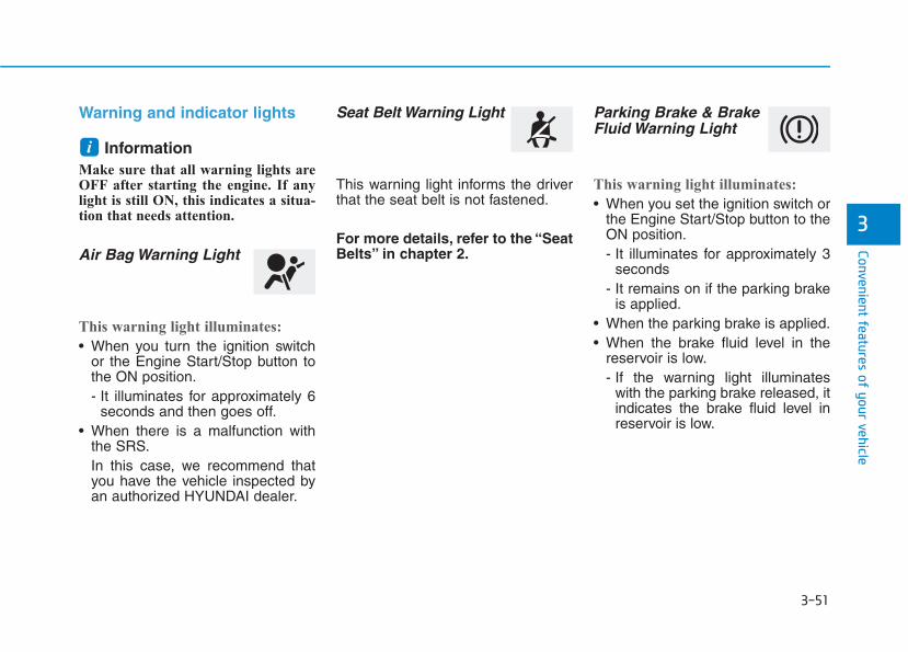
3-51
Convenient features of your vehicle
3
Warning and indicator lights
Information Make sure that all warning lights areOFF after starting the engine. If anylight is still ON, this indicates a situa-tion that needs attention.
Air Bag Warning Light
This warning light illuminates:
• When you turn the ignition switchor the Engine Start/Stop button tothe ON position.- It illuminates for approximately 6
seconds and then goes off.• When there is a malfunction with
the SRS.In this case, we recommend thatyou have the vehicle inspected byan authorized HYUNDAI dealer.
Seat Belt Warning Light
This warning light informs the driverthat the seat belt is not fastened.
For more details, refer to the “SeatBelts” in chapter 2.
Parking Brake & BrakeFluid Warning Light
This warning light illuminates:
• When you set the ignition switch orthe Engine Start/Stop button to theON position.- It illuminates for approximately 3
seconds- It remains on if the parking brake
is applied.• When the parking brake is applied.• When the brake fluid level in the
reservoir is low.- If the warning light illuminates
with the parking brake released, itindicates the brake fluid level inreservoir is low.
i
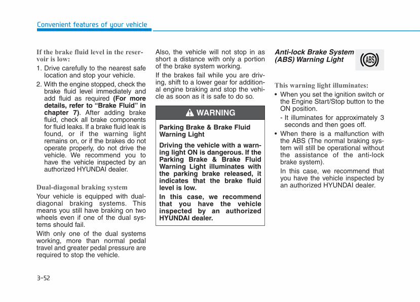
3-52
Convenient features of your vehicle
If the brake fluid level in the reser-voir is low:
1. Drive carefully to the nearest safelocation and stop your vehicle.
2. With the engine stopped, check thebrake fluid level immediately andadd fluid as required (For moredetails, refer to “Brake Fluid” inchapter 7). After adding brakefluid, check all brake componentsfor fluid leaks. If a brake fluid leak isfound, or if the warning lightremains on, or if the brakes do notoperate properly, do not drive thevehicle. We recommend you tohave the vehicle inspected by anauthorized HYUNDAI dealer.
Dual-diagonal braking system
Your vehicle is equipped with dual-diagonal braking systems. Thismeans you still have braking on twowheels even if one of the dual sys-tems should fail.With only one of the dual systemsworking, more than normal pedaltravel and greater pedal pressure arerequired to stop the vehicle.
Also, the vehicle will not stop in asshort a distance with only a portionof the brake system working.If the brakes fail while you are driv-ing, shift to a lower gear for addition-al engine braking and stop the vehi-cle as soon as it is safe to do so.
Anti-lock Brake System(ABS) Warning Light
This warning light illuminates:
• When you set the ignition switch orthe Engine Start/Stop button to theON position.- It illuminates for approximately 3
seconds and then goes off.• When there is a malfunction with
the ABS (The normal braking sys-tem will still be operational withoutthe assistance of the anti-lockbrake system).In this case, we recommend thatyou have the vehicle inspected byan authorized HYUNDAI dealer.
Parking Brake & Brake FluidWarning Light
Driving the vehicle with a warn-ing light ON is dangerous. If theParking Brake & Brake FluidWarning Light illuminates withthe parking brake released, itindicates that the brake fluidlevel is low.In this case, we recommendthat you have the vehicleinspected by an authorizedHYUNDAI dealer.
WARNING
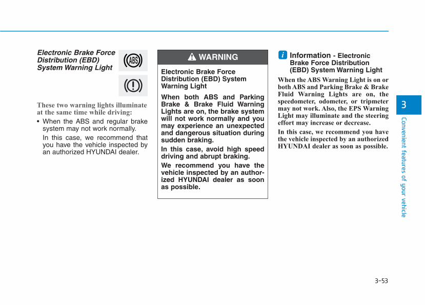
3-53
Convenient features of your vehicle
3
Electronic Brake ForceDistribution (EBD)System Warning Light
These two warning lights illuminateat the same time while driving:
• When the ABS and regular brakesystem may not work normally.In this case, we recommend thatyou have the vehicle inspected byan authorized HYUNDAI dealer.
Information - ElectronicBrake Force Distribution(EBD) System Warning Light
When the ABS Warning Light is on orboth ABS and Parking Brake & BrakeFluid Warning Lights are on, thespeedometer, odometer, or tripmetermay not work. Also, the EPS WarningLight may illuminate and the steeringeffort may increase or decrease.
In this case, we recommend you havethe vehicle inspected by an authorizedHYUNDAI dealer as soon as possible.
i
Electronic Brake ForceDistribution (EBD) SystemWarning Light
When both ABS and ParkingBrake & Brake Fluid WarningLights are on, the brake systemwill not work normally and youmay experience an unexpectedand dangerous situation duringsudden braking.In this case, avoid high speeddriving and abrupt braking.We recommend you have thevehicle inspected by an author-ized HYUNDAI dealer as soonas possible.
WARNING
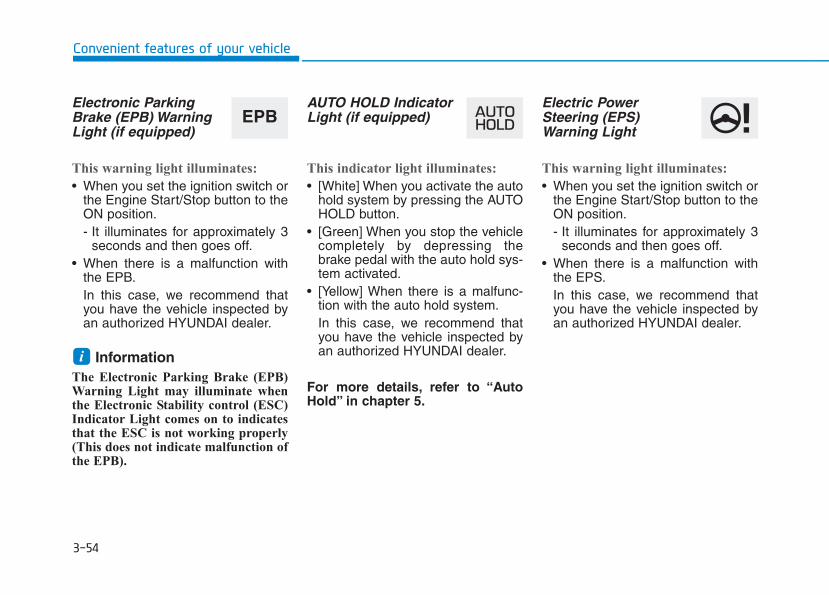
3-54
Convenient features of your vehicle
Electronic ParkingBrake (EPB) WarningLight (if equipped)
This warning light illuminates:
• When you set the ignition switch orthe Engine Start/Stop button to theON position.- It illuminates for approximately 3
seconds and then goes off.• When there is a malfunction with
the EPB.In this case, we recommend thatyou have the vehicle inspected byan authorized HYUNDAI dealer.
Information The Electronic Parking Brake (EPB)Warning Light may illuminate whenthe Electronic Stability control (ESC)Indicator Light comes on to indicatesthat the ESC is not working properly(This does not indicate malfunction ofthe EPB).
AUTO HOLD IndicatorLight (if equipped)
This indicator light illuminates:
• [White] When you activate the autohold system by pressing the AUTOHOLD button.
• [Green] When you stop the vehiclecompletely by depressing thebrake pedal with the auto hold sys-tem activated.
• [Yellow] When there is a malfunc-tion with the auto hold system.In this case, we recommend thatyou have the vehicle inspected byan authorized HYUNDAI dealer.
For more details, refer to “AutoHold” in chapter 5.
Electric PowerSteering (EPS)Warning Light
This warning light illuminates:
• When you set the ignition switch orthe Engine Start/Stop button to theON position.- It illuminates for approximately 3
seconds and then goes off.• When there is a malfunction with
the EPS.In this case, we recommend thatyou have the vehicle inspected byan authorized HYUNDAI dealer.
i
EPB
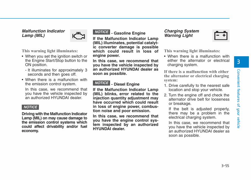
3-55
Convenient features of your vehicle
3
Malfunction IndicatorLamp (MIL)
This warning light illuminates:
• When you set the ignition switch orthe Engine Start/Stop button to theON position.- It illuminates for approximately 3
seconds and then goes off.• When there is a malfunction with
the emission control system.In this case, we recommend thatyou have the vehicle inspected byan authorized HYUNDAI dealer.
Driving with the Malfunction IndicatorLamp (MIL) on may cause damage tothe emission control systems whichcould affect drivability and/or fueleconomy.
- Gasoline EngineIf the Malfunction Indicator Lamp(MIL) illuminates, potential catalyt-ic converter damage is possiblewhich could result in loss ofengine power.In this case, we recommend thatyou have the vehicle inspected byan authorized HYUNDAI dealer assoon as possible.
- Diesel EngineIf the Malfunction Indicator Lamp(MIL) blinks, error related to theinjection quantity adjustment mayhave occurred which could resultin loss of engine power, combus-tion noise and poor emission.In this case, we recommend thatyou have the engine control sys-tem inspected by an authorizedHYUNDAI dealer.
Charging SystemWarning Light
This warning light illuminates:
• When there is a malfunction witheither the alternator or electricalcharging system.
If there is a malfunction with eitherthe alternator or electrical chargingsystem:
1. Drive carefully to the nearest safelocation and stop your vehicle.
2. Turn the engine off and check thealternator drive belt for loosenessor breakage.If the belt is adjusted properly,there may be a problem in theelectrical charging system.In this case, we recommend thatyou have the vehicle inspected byan authorized HYUNDAI dealer assoon as possible.
NOTICE
NOTICE
NOTICE
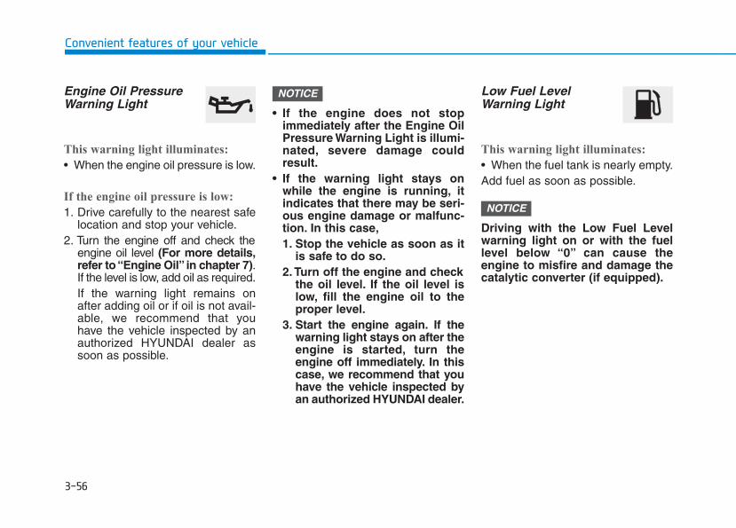
3-56
Convenient features of your vehicle
Engine Oil PressureWarning Light
This warning light illuminates:
• When the engine oil pressure is low.
If the engine oil pressure is low:
1. Drive carefully to the nearest safelocation and stop your vehicle.
2. Turn the engine off and check theengine oil level (For more details,refer to “Engine Oil” in chapter 7).If the level is low, add oil as required.If the warning light remains onafter adding oil or if oil is not avail-able, we recommend that youhave the vehicle inspected by anauthorized HYUNDAI dealer assoon as possible.
• If the engine does not stopimmediately after the Engine OilPressure Warning Light is illumi-nated, severe damage couldresult.
• If the warning light stays onwhile the engine is running, itindicates that there may be seri-ous engine damage or malfunc-tion. In this case,1. Stop the vehicle as soon as it
is safe to do so.2. Turn off the engine and check
the oil level. If the oil level islow, fill the engine oil to theproper level.
3. Start the engine again. If thewarning light stays on after theengine is started, turn theengine off immediately. In thiscase, we recommend that youhave the vehicle inspected byan authorized HYUNDAI dealer.
Low Fuel LevelWarning Light
This warning light illuminates:
• When the fuel tank is nearly empty.Add fuel as soon as possible.
Driving with the Low Fuel Levelwarning light on or with the fuellevel below “0” can cause theengine to misfire and damage thecatalytic converter (if equipped).
NOTICE
NOTICE
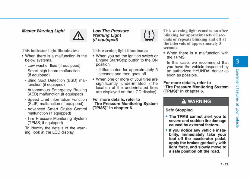
3-57
Convenient features of your vehicle
3
Master Warning Light
This indicator light illuminates:
• When there is a malfunction in thebelow systems.- Low washer fluid (if equipped)- Smart high beam malfunction
(if equipped)- Blind Spot Detection (BSD) mal-
function (if equipped)- Autonomous Emergency Braking
(AEB) malfunction (if equipped)- Speed Limit Information Function
(SLIF) malfunction (if equipped)- Advanced Smart Cruise Control
malfunction (if equipped)- Tire Pressure Monitoring System
(TPMS, if equipped)To identify the details of the warn-ing, look at the LCD display.
Low Tire PressureWarning Light (if equipped)
This warning light illuminates:
• When you set the ignition switch orEngine Start/Stop button to the ONposition.- It illuminates for approximately 3
seconds and then goes off.• When one or more of your tires are
significantly underinflated (Thelocation of the underinflated tiresare displayed on the LCD display).
For more details, refer to “Tire Pressure Monitoring System(TPMS)” in chapter 6.
This warning light remains on afterblinking for approximately 60 sec-onds or repeats blinking and off atthe intervals of approximately 3seconds:
• When there is a malfunction withthe TPMS.In this case, we recommend thatyou have the vehicle inspected byan authorized HYUNDAI dealer assoon as possible.
For more details, refer to “Tire Pressure Monitoring System(TPMS)” in chapter 6.
Safe Stopping
• The TPMS cannot alert you tosevere and sudden tire damagecaused by external factors.
• If you notice any vehicle insta-bility, immediately take yourfoot off the accelerator pedal,apply the brakes gradually withlight force, and slowly move toa safe position off the road.
WARNING
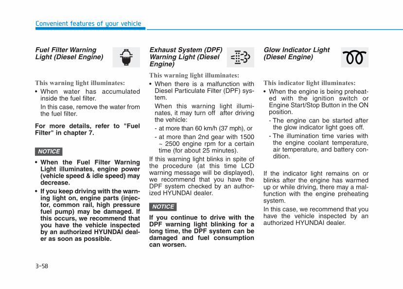
3-58
Convenient features of your vehicle
Fuel Filter WarningLight (Diesel Engine)
This warning light illuminates:
• When water has accumulatedinside the fuel filter.In this case, remove the water fromthe fuel filter.
For more details, refer to "FuelFilter" in chapter 7.
• When the Fuel Filter WarningLight illuminates, engine power(vehicle speed & idle speed) maydecrease.
• If you keep driving with the warn-ing light on, engine parts (injec-tor, common rail, high pressurefuel pump) may be damaged. Ifthis occurs, we recommend thatyou have the vehicle inspectedby an authorized HYUNDAI deal-er as soon as possible.
Exhaust System (DPF)Warning Light (DieselEngine)
This warning light illuminates:
• When there is a malfunction withDiesel Particulate Filter (DPF) sys-tem.When this warning light illumi-nates, it may turn off after drivingthe vehicle:- at more than 60 km/h (37 mph), or- at more than 2nd gear with 1500
~ 2500 engine rpm for a certaintime (for about 25 minutes).
If this warning light blinks in spite ofthe procedure (at this time LCDwarning message will be displayed),we recommend that you have theDPF system checked by an author-ized HYUNDAI dealer.
If you continue to drive with theDPF warning light blinking for along time, the DPF system can bedamaged and fuel consumptioncan worsen.
Glow Indicator Light(Diesel Engine)
This indicator light illuminates:
• When the engine is being preheat-ed with the ignition switch orEngine Start/Stop Button in the ONposition.- The engine can be started after
the glow indicator light goes off.- The illumination time varies with
the engine coolant temperature,air temperature, and battery con-dition.
If the indicator light remains on orblinks after the engine has warmedup or while driving, there may a mal-function with the engine preheatingsystem.In this case, we recommend that youhave the vehicle inspected by anauthorized HYUNDAI dealer.
NOTICE
NOTICE
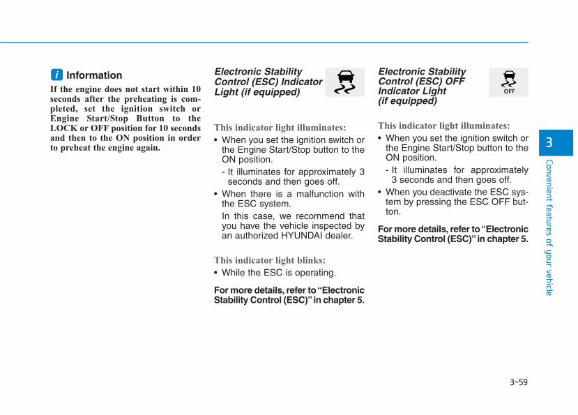
3-59
Convenient features of your vehicle
3
Information If the engine does not start within 10seconds after the preheating is com-pleted, set the ignition switch orEngine Start/Stop Button to theLOCK or OFF position for 10 secondsand then to the ON position in orderto preheat the engine again.
Electronic StabilityControl (ESC) IndicatorLight (if equipped)
This indicator light illuminates:
• When you set the ignition switch orthe Engine Start/Stop button to theON position.- It illuminates for approximately 3
seconds and then goes off.• When there is a malfunction with
the ESC system.In this case, we recommend thatyou have the vehicle inspected byan authorized HYUNDAI dealer.
This indicator light blinks:
• While the ESC is operating.
For more details, refer to “ElectronicStability Control (ESC)”in chapter 5.
Electronic StabilityControl (ESC) OFFIndicator Light (if equipped)
This indicator light illuminates:
• When you set the ignition switch orthe Engine Start/Stop button to theON position.- It illuminates for approximately
3 seconds and then goes off.• When you deactivate the ESC sys-
tem by pressing the ESC OFF but-ton.
For more details, refer to “ElectronicStability Control (ESC)”in chapter 5.
i
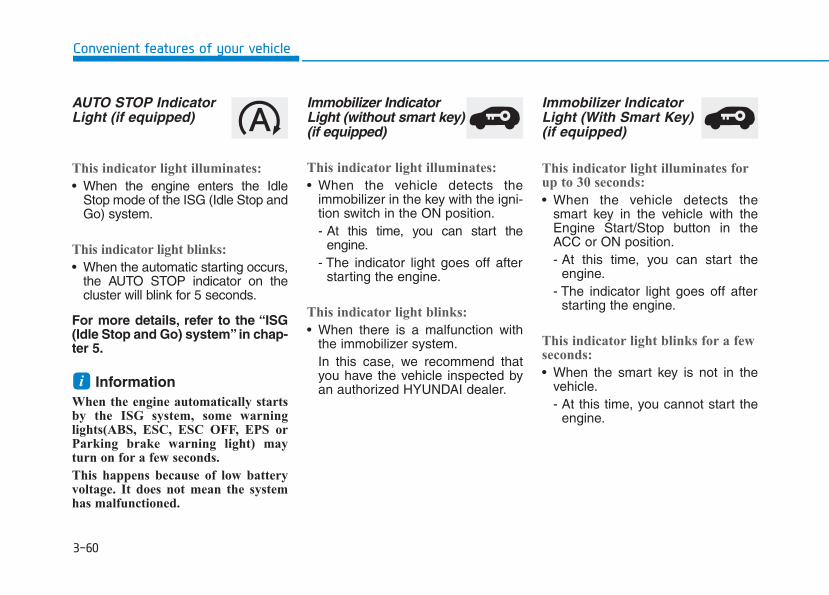
3-60
Convenient features of your vehicle
AUTO STOP IndicatorLight (if equipped)
This indicator light illuminates:
• When the engine enters the IdleStop mode of the ISG (Idle Stop andGo) system.
This indicator light blinks:
• When the automatic starting occurs,the AUTO STOP indicator on thecluster will blink for 5 seconds.
For more details, refer to the “ISG(Idle Stop and Go) system” in chap-ter 5.
Information When the engine automatically startsby the ISG system, some warninglights(ABS, ESC, ESC OFF, EPS orParking brake warning light) mayturn on for a few seconds.
This happens because of low batteryvoltage. It does not mean the systemhas malfunctioned.
Immobilizer IndicatorLight (without smart key)(if equipped)
This indicator light illuminates:
• When the vehicle detects theimmobilizer in the key with the igni-tion switch in the ON position.- At this time, you can start the
engine.- The indicator light goes off after
starting the engine.
This indicator light blinks:
• When there is a malfunction withthe immobilizer system.In this case, we recommend thatyou have the vehicle inspected byan authorized HYUNDAI dealer.
Immobilizer IndicatorLight (With Smart Key) (if equipped)
This indicator light illuminates forup to 30 seconds:
• When the vehicle detects thesmart key in the vehicle with theEngine Start/Stop button in theACC or ON position.- At this time, you can start the
engine.- The indicator light goes off after
starting the engine.
This indicator light blinks for a fewseconds:
• When the smart key is not in thevehicle.- At this time, you cannot start the
engine.
i
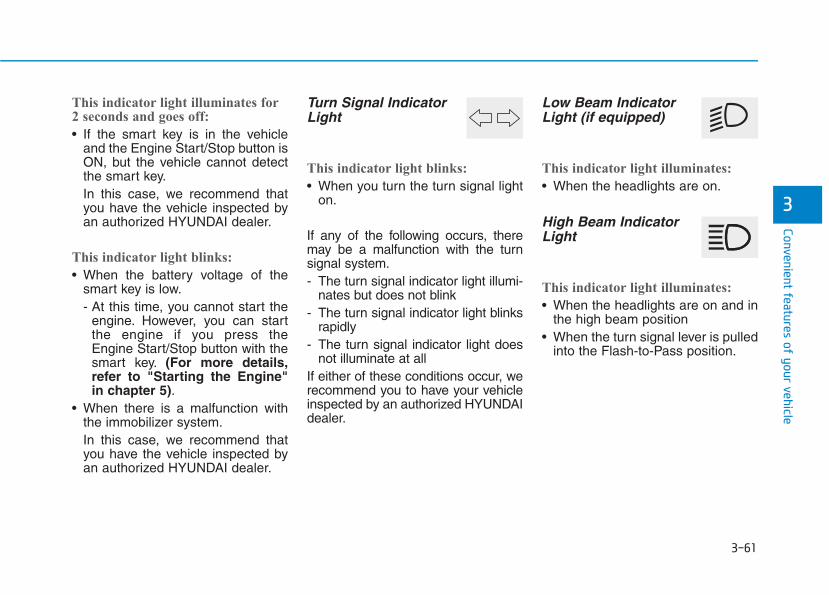
3-61
Convenient features of your vehicle
3
This indicator light illuminates for2 seconds and goes off:
• If the smart key is in the vehicleand the Engine Start/Stop button isON, but the vehicle cannot detectthe smart key.In this case, we recommend thatyou have the vehicle inspected byan authorized HYUNDAI dealer.
This indicator light blinks:
• When the battery voltage of thesmart key is low.- At this time, you cannot start the
engine. However, you can startthe engine if you press theEngine Start/Stop button with thesmart key. (For more details,refer to "Starting the Engine"in chapter 5).
• When there is a malfunction withthe immobilizer system.In this case, we recommend thatyou have the vehicle inspected byan authorized HYUNDAI dealer.
Turn Signal IndicatorLight
This indicator light blinks:
• When you turn the turn signal lighton.
If any of the following occurs, theremay be a malfunction with the turnsignal system.- The turn signal indicator light illumi-
nates but does not blink- The turn signal indicator light blinks
rapidly- The turn signal indicator light does
not illuminate at allIf either of these conditions occur, werecommend you to have your vehicleinspected by an authorized HYUNDAIdealer.
Low Beam IndicatorLight (if equipped)
This indicator light illuminates:
• When the headlights are on.
High Beam IndicatorLight
This indicator light illuminates:
• When the headlights are on and inthe high beam position
• When the turn signal lever is pulledinto the Flash-to-Pass position.
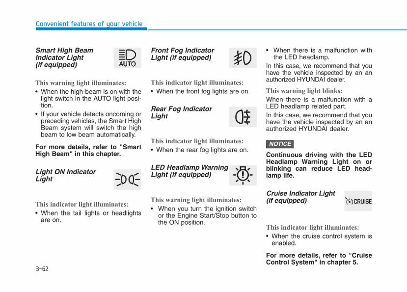
3-62
Convenient features of your vehicle
Smart High BeamIndicator Light(if equipped)
This warning light illuminates:
• When the high-beam is on with thelight switch in the AUTO light posi-tion.
• If your vehicle detects oncoming orpreceding vehicles, the Smart HighBeam system will switch the highbeam to low beam automatically.
For more details, refer to "SmartHigh Beam" in this chapter.
Light ON IndicatorLight
This indicator light illuminates:
• When the tail lights or headlightsare on.
Front Fog IndicatorLight (if equipped)
This indicator light illuminates:
• When the front fog lights are on.
Rear Fog IndicatorLight
This indicator light illuminates:
• When the rear fog lights are on.
LED Headlamp WarningLight (if equipped)
This warning light illuminates:
• When you turn the ignition switchor the Engine Start/Stop button tothe ON position.
• When there is a malfunction withthe LED headlamp.
In this case, we recommend that youhave the vehicle inspected by an anauthorized HYUNDAI dealer.
This warning light blinks:
When there is a malfunction with aLED headlamp related part.In this case, we recommend that youhave the vehicle inspected by an anauthorized HYUNDAI dealer.
Continuous driving with the LEDHeadlamp Warning Light on orblinking can reduce LED head-lamp life.
Cruise Indicator Light(if equipped)
This indicator light illuminates:
• When the cruise control system isenabled.
For more details, refer to "CruiseControl System" in chapter 5.
NOTICE
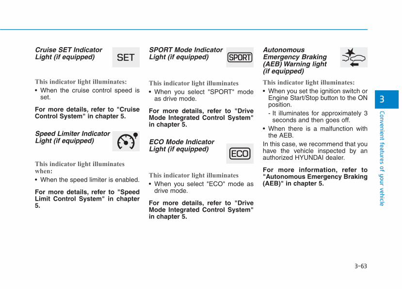
3-63
Convenient features of your vehicle
3
Cruise SET IndicatorLight (if equipped)
This indicator light illuminates:
• When the cruise control speed isset.
For more details, refer to "CruiseControl System" in chapter 5.
Speed Limiter IndicatorLight (if equipped)
This indicator light illuminateswhen:
• When the speed limiter is enabled.
For more details, refer to "SpeedLimit Control System" in chapter5.
SPORT Mode IndicatorLight (if equipped)
This indicator light illuminates
• When you select "SPORT" modeas drive mode.
For more details, refer to "DriveMode Integrated Control System"in chapter 5.
ECO Mode IndicatorLight (if equipped)
This indicator light illuminates
• When you select "ECO" mode asdrive mode.
For more details, refer to "DriveMode Integrated Control System"in chapter 5.
AutonomousEmergency Braking(AEB) Warning light (if equipped)
This indicator light illuminates:
• When you set the ignition switch orEngine Start/Stop button to the ONposition.- It illuminates for approximately 3
seconds and then goes off.• When there is a malfunction with
the AEB.In this case, we recommend that youhave the vehicle inspected by anauthorized HYUNDAI dealer.
For more information, refer to"Autonomous Emergency Braking(AEB)" in chapter 5.
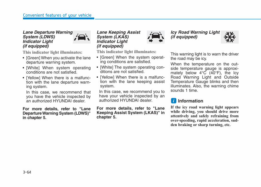
3-64
Convenient features of your vehicle
Lane Departure WarningSystem (LDWS)Indicator Light (if equipped)This indicator light illuminates:
• [Green] When you activate the lanedeparture warning system.
• [White] When system operatingconditions are not satisfied.
• [Yellow] When there is a malfunc-tion with the lane departure warn-ing system.In this case, we recommend thatyou have the vehicle inspected byan authorized HYUNDAI dealer.
For more details, refer to "LaneDeparture Warning System (LDWS)"in chapter 5.
Lane Keeping AssistSystem (LKAS)Indicator Light(if equipped)This indicator light illuminates:
• [Green] When the system operat-ing conditions are satisfied.
• [White] The system operating con-ditions are not satisfied.
• [Yellow] When there is a malfunc-tion with the lane keeping assistsystem.In this case, we recommend you tohave your vehicle inspected by anauthorized HYUNDAI dealer.
For more details, refer to "LaneKeeping Assist System (LKAS)" inchapter 5.
Icy Road Warning Light(if equipped)
This warning light is to warn the driverthe road may be icy.When the temperature on the out-side temperature gauge is approxi-mately below 4°C (40°F), the IcyRoad Warning Light and OutsideTemperature Gauge blinks and thenilluminates. Also, the warning chimesounds 1 time.
Information If the icy road warning light appearswhile driving, you should drive moreattentively and safely refraining fromover-speeding, rapid acceleration, sud-den braking or sharp turning, etc.
i
3-65
Convenient features of your vehicle
3
LCD display messages Shift to P (for smart key systemand automatic transmission/dual clutch transmission)This warning message is displayed ifyou try to turn off the engine withoutthe shift lever in P (Park) position.At this time, the Engine Start/Stopbutton turns to the ACC position (Ifyou press the Engine Start/Stop but-ton once more, it will turn to the ONposition).
Low Key Battery (for smart key system)This warning message is displayed ifthe battery of the smart key is dis-charged while changing the EngineStart/Stop button while changing tothe OFF position.
Press START button while turn-ing wheel (for smart key sys-tem)This warning message is displayed ifthe steering wheel does not unlocknormally when the Engine Start/Stopbutton is pressed.You should press the Engine Start/Stopbutton while turning the steering wheelright and left.
Steering wheel not locked(for smart key system)This warning message is displayed ifthe steering wheel is not locked whilethe Engine Start/Stop button changesto the OFF position.
Check Steering Wheel LockSystem (for smart key system)This warning message is displayed ifthe steering wheel does not lock nor-mally while the Engine Start/Stop but-ton changes to the OFF position.
Press brake pedal to start engine(for smart key system and auto-matic transmission/dual clutchtransmission)This warning message is displayed ifthe Engine Start/Stop button changesto the ACC position twice by pressingthe button repeatedly without depress-ing the brake pedal.You can start the vehicle by depressingthe brake pedal.
Press clutch pedal to startengine (for smart key systemand manual transmission)This warning message is displayed ifthe Engine Start/Stop button is in theACC position twice by pressing thebutton repeatedly without depressingthe clutch pedal.Depress the clutch pedal to start theengine.
3-66
Convenient features of your vehicle
Key not in vehicle(for smart key system)This warning message is displayed ifthe smart key is not in the vehiclewhen you press the Engine Start/Stopbutton.When attempting to start the vehiclealways have the smart key with you.
Key not detected (for smart key system)This warning message is displayed ifthe smart key is not detected when youpress the Engine Start/Stop button.
Press START button with key(for smart key system)This warning message is displayed ifyou press the Engine Start/Stop but-ton while the warning message “Keynot detected” is displayed.At this time, the immobilizer indicatorlight blinks.
Press START button again (for smart key system)This message is displayed if youwere unable to start the vehicle whenthe Engine Start/Stop button waspressed.If this occurs, attempt to start theengine by pressing the EngineStart/Stop button again.If the warning message appearseach time you press the EngineStart/Stop button, we recommendyou to have your vehicle inspectedby an authorized HYUNDAI dealer.
Check BRAKE SWITCH fuse (forsmart key system and automatictransmission/dual clutch trans-mission)
This warning message is displayed ifthe brake switch fuse is disconnected.You need to replace the fuse with anew one. If that is not possible, youcan start the engine by pressing theEngine Start/Stop button for 10 sec-onds in the ACC position.
Shift to P or N to start engine (forsmart key system and automatictransmission/dual clutch trans-mission)This warning message is displayed ifyou try to start the engine with theshift lever not in the P (Park) or N(Neutral) position.
Information You can start the engine with the shiftlever in the N (Neutral) position. But,for your safety, we recommend thatyou start the engine with the shiftlever in the P (Park) position.
i
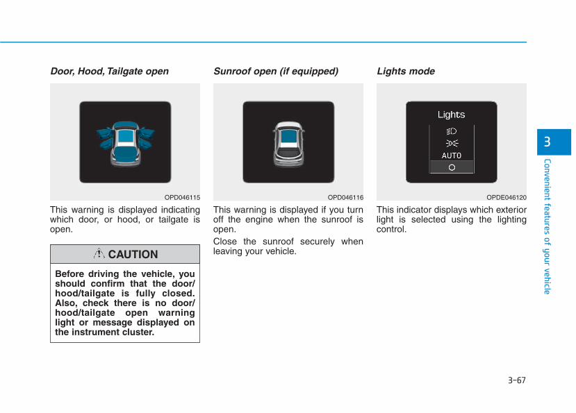
3-67
Convenient features of your vehicle
3
Door, Hood, Tailgate open
This warning is displayed indicatingwhich door, or hood, or tailgate isopen.
Sunroof open (if equipped)
This warning is displayed if you turnoff the engine when the sunroof isopen.Close the sunroof securely whenleaving your vehicle.
Lights mode
This indicator displays which exteriorlight is selected using the lightingcontrol.
Before driving the vehicle, youshould confirm that the door/hood/tailgate is fully closed.Also, check there is no door/hood/tailgate open warninglight or message displayed onthe instrument cluster.
CAUTION
OPD046115 OPD046116 OPDE046120
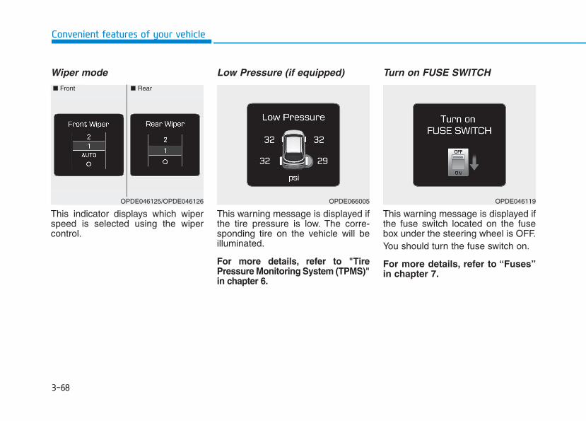
3-68
Convenient features of your vehicle
Wiper mode
This indicator displays which wiperspeed is selected using the wipercontrol.
Low Pressure (if equipped)
This warning message is displayed ifthe tire pressure is low. The corre-sponding tire on the vehicle will beilluminated.
For more details, refer to "TirePressure Monitoring System (TPMS)"in chapter 6.
Turn on FUSE SWITCH
This warning message is displayed ifthe fuse switch located on the fusebox under the steering wheel is OFF.You should turn the fuse switch on.
For more details, refer to “Fuses”in chapter 7.
OPDE046119OPDE066005OPDE046125/OPDE046126
■ Front ■ Rear
3-69
Convenient features of your vehicle
3
Heated Steering Wheel turnedoff (if equipped)This message is displayed if you turnoff the heated steering wheel.
For more details, refer to “HeatedSteering Wheel” in this chapter.
Low washer fluid (if equipped)This warning message is displayedif the washer fluid level in the reser-voir is nearly empty.Have the washer fluid reservoirrefilled.
Low fuelThis warning message is displayed ifthe fuel tank is almost out of fuel.When this message is displayed, thelow fuel level warning light in thecluster will come on.It is recommended to look for thenearest fueling station and refuel assoon as possible.Add fuel as soon as possible.
Engine has overheated (if equipped)This warning message is displayedwhen the engine coolant tempera-ture is above 120°C (248°F). Thismeans that the engine is overheatedand may be damaged.
If your vehicle is overheated, referto “Overheating” in chapter 6.
Check exhaust system(for Diesel engine)
This warning message is displayed ifthe DPF system has a malfunction.At this time, DPF warning light alsoblinks.In this case, we recommend that youhave the DPF system checked by anauthorized HYUNDAI dealer.
For more details, refer to “WarningLights” in this chapter.
Check headlight (if equipped)
This warning message is displayed ifthe headlamps are not operatingproperly. The headlamp bulb mayneed to be replaced.
Information Make sure to replace the burned outbulb with a new one of the same wattagerating.
Check headlamp LED(if equipped)This warning message is displayed ifthere is a problem with the LEDheadlamp. We recommend you tohave the vehicle inspected by anauthorized HYUNDAI dealer.
Check headlamp FAN(if equipped)This warning message is displayed ifthere is a problem with headlampfan. We recommend you to have thevehicle inspected by an authorizedHYUNDAI dealer.
i
3-70
Convenient features of your vehicle
Check smart high beam system(if equipped)This warning message is displayed ifthere is a problem with the SmartHigh Beam System. We recommendyou to have the vehicle inspected byan authorized HYUNDAI dealer.
For more information, refer to“Smart High Beam System” inchapter 3.
Check AEB system (if equipped)This warning message is displayed ifthere is a malfunction with theAutonomous Emergency Braking (AEB)system. We recommend that the vehi-cle be inspected by an authorizedHYUNDAI dealer.
For more details, refer to"Autonomous Emergency Braking(AEB) system" in chapter 5.
Check LDWS (if equipped)This warning message is displayed ifthere is a problem with the LaneDeparture Warning System (LDWS).We recommend you to have the vehi-cle inspected by an authorizedHYUNDAI dealer.
For more information, refer to“Lane Departure Warning System(LDWS)” in chapter 5.
Attention Alert Check System (if equipped)This warning message is displayed ifthere is a problem with the DriverAttention Alert System. We recom-mend you to have the vehicle inspect-ed by an authorized HYUNDAI dealer.
For more information, refer to“Driver Attention Alert (DAA)” inchapter 5.
Check BSD System (if equipped)This warning message is displayed ifthere is a problem with the Blind SpotDetection (BSD) system. We recom-mend that the vehicle be inspectedby an authorized HYUNDAI dealer.
For more information, refer to "BlindSpot Detection (BSD) System" inchapter 5.
Check LKAS (if equipped)This warning message is displayed ifthere is a problem with the LaneKeeping Assist System (LKAS). Werecommend you to have the vehicleinspected by an authorized HYUNDAIdealer.
For more information, refer to“Lane Keeping Assist System(LKAS)” in chapter 5.
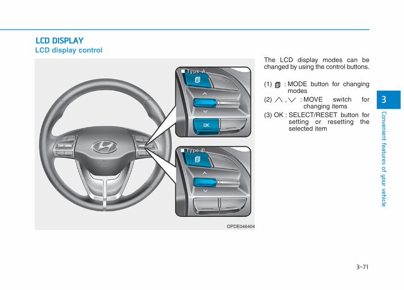
3-71
Convenient features of your vehicle
3
LCD display controlThe LCD display modes can bechanged by using the control buttons.
(1) : MODE button for changingmodes
(2) , : MOVE switch forchanging items
(3) OK : SELECT/RESET button forsetting or resetting theselected item
LLCCDD DDIISSPPLLAAYY
OPDE046404
■■■■ TTTTyyyyppppeeee AAAA
■■■■ TTTTyyyyppppeeee BBBB
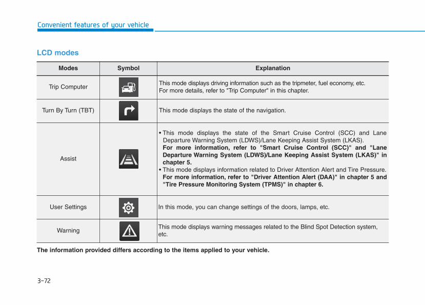
3-72
Convenient features of your vehicle
LCD modes
Modes Symbol Explanation
Trip Computer This mode displays driving information such as the tripmeter, fuel economy, etc.For more details, refer to "Trip Computer" in this chapter.
Turn By Turn (TBT) This mode displays the state of the navigation.
Assist
• This mode displays the state of the Smart Cruise Control (SCC) and LaneDeparture Warning System (LDWS)/Lane Keeping Assist System (LKAS).For more information, refer to "Smart Cruise Control (SCC)" and "LaneDeparture Warning System (LDWS)/Lane Keeping Assist System (LKAS)" inchapter 5.
• This mode displays information related to Driver Attention Alert and Tire Pressure.For more information, refer to "Driver Attention Alert (DAA)" in chapter 5 and"Tire Pressure Monitoring System (TPMS)" in chapter 6.
User Settings In this mode, you can change settings of the doors, lamps, etc.
WarningThis mode displays warning messages related to the Blind Spot Detection system,etc.
The information provided differs according to the items applied to your vehicle.
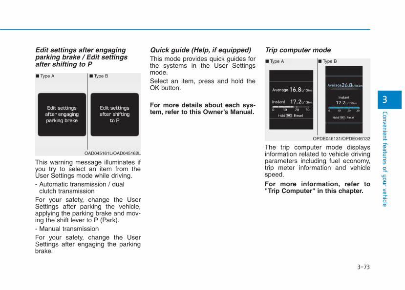
3-73
Convenient features of your vehicle
3
Edit settings after engaging parking brake / Edit settingsafter shifting to P
This warning message illuminates ifyou try to select an item from theUser Settings mode while driving.- Automatic transmission / dual
clutch transmissionFor your safety, change the UserSettings after parking the vehicle,applying the parking brake and mov-ing the shift lever to P (Park).- Manual transmissionFor your safety, change the UserSettings after engaging the parkingbrake.
Quick guide (Help, if equipped)This mode provides quick guides forthe systems in the User Settingsmode.Select an item, press and hold theOK button.
For more details about each sys-tem, refer to this Owner’s Manual.
Trip computer mode
The trip computer mode displaysinformation related to vehicle drivingparameters including fuel economy,trip meter information and vehiclespeed.
For more information, refer to"Trip Computer" in this chapter.
OPDE046131/OPDE046132
■ Type A ■ Type B
OAD045161L/OAD045162L
■ Type A ■ Type B
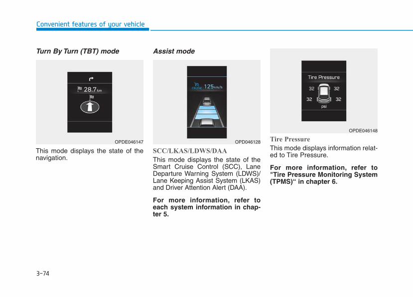
3-74
Convenient features of your vehicle
Turn By Turn (TBT) mode
This mode displays the state of thenavigation.
Assist mode
SCC/LKAS/LDWS/DAA
This mode displays the state of theSmart Cruise Control (SCC), LaneDeparture Warning System (LDWS)/Lane Keeping Assist System (LKAS)and Driver Attention Alert (DAA).
For more information, refer toeach system information in chap-ter 5.
Tire Pressure
This mode displays information relat-ed to Tire Pressure.
For more information, refer to"Tire Pressure Monitoring System(TPMS)“ in chapter 6.
OPDE046147 OPD046128
OPDE046148
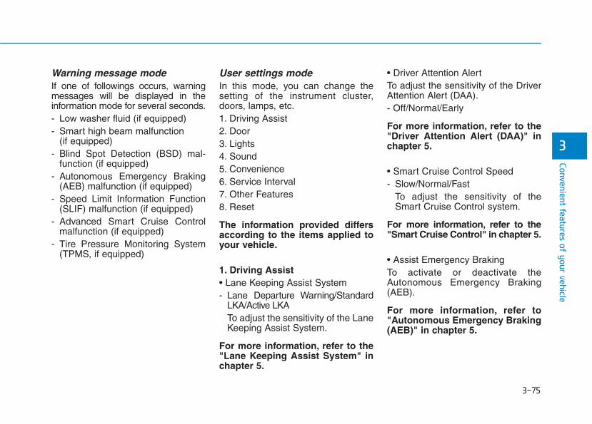
3-75
Convenient features of your vehicle
3
Warning message modeIf one of followings occurs, warningmessages will be displayed in theinformation mode for several seconds.- Low washer fluid (if equipped)- Smart high beam malfunction
(if equipped)- Blind Spot Detection (BSD) mal-
function (if equipped)- Autonomous Emergency Braking
(AEB) malfunction (if equipped)- Speed Limit Information Function
(SLIF) malfunction (if equipped)- Advanced Smart Cruise Control
malfunction (if equipped)- Tire Pressure Monitoring System
(TPMS, if equipped)
User settings modeIn this mode, you can change thesetting of the instrument cluster,doors, lamps, etc.1. Driving Assist2. Door3. Lights4. Sound5. Convenience 6. Service Interval7. Other Features8. Reset
The information provided differsaccording to the items applied toyour vehicle.
1. Driving Assist• Lane Keeping Assist System- Lane Departure Warning/Standard
LKA/Active LKATo adjust the sensitivity of the LaneKeeping Assist System.
For more information, refer to the"Lane Keeping Assist System" inchapter 5.
• Driver Attention AlertTo adjust the sensitivity of the DriverAttention Alert (DAA).- Off/Normal/Early
For more information, refer to the"Driver Attention Alert (DAA)" inchapter 5.
• Smart Cruise Control Speed- Slow/Normal/Fast
To adjust the sensitivity of theSmart Cruise Control system.
For more information, refer to the"Smart Cruise Control" in chapter 5.
• Assist Emergency BrakingTo activate or deactivate theAutonomous Emergency Braking(AEB).
For more information, refer to"Autonomous Emergency Braking(AEB)" in chapter 5.
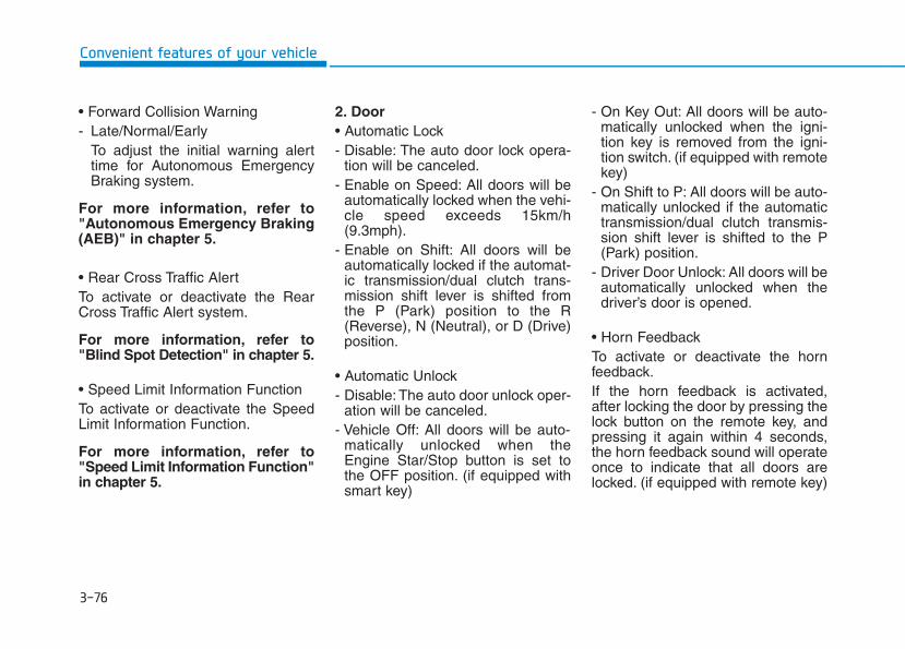
3-76
Convenient features of your vehicle
• Forward Collision Warning- Late/Normal/Early
To adjust the initial warning alerttime for Autonomous EmergencyBraking system.
For more information, refer to"Autonomous Emergency Braking(AEB)" in chapter 5.
• Rear Cross Traffic Alert To activate or deactivate the RearCross Traffic Alert system.
For more information, refer to"Blind Spot Detection" in chapter 5.
• Speed Limit Information FunctionTo activate or deactivate the SpeedLimit Information Function.
For more information, refer to"Speed Limit Information Function"in chapter 5.
2. Door• Automatic Lock- Disable: The auto door lock opera-
tion will be canceled.- Enable on Speed: All doors will be
automatically locked when the vehi-cle speed exceeds 15km/h(9.3mph).
- Enable on Shift: All doors will beautomatically locked if the automat-ic transmission/dual clutch trans-mission shift lever is shifted fromthe P (Park) position to the R(Reverse), N (Neutral), or D (Drive)position.
• Automatic Unlock- Disable: The auto door unlock oper-
ation will be canceled.- Vehicle Off: All doors will be auto-
matically unlocked when theEngine Star/Stop button is set tothe OFF position. (if equipped withsmart key)
- On Key Out: All doors will be auto-matically unlocked when the igni-tion key is removed from the igni-tion switch. (if equipped with remotekey)
- On Shift to P: All doors will be auto-matically unlocked if the automatictransmission/dual clutch transmis-sion shift lever is shifted to the P(Park) position.
- Driver Door Unlock: All doors will beautomatically unlocked when thedriver’s door is opened.
• Horn Feedback To activate or deactivate the hornfeedback.If the horn feedback is activated,after locking the door by pressing thelock button on the remote key, andpressing it again within 4 seconds,the horn feedback sound will operateonce to indicate that all doors arelocked. (if equipped with remote key)
3-77
Convenient features of your vehicle
3
3. Lights• One Touch Turn Signal- Off: The one touch turn signal func-
tion will be deactivated.- 3, 5, 7 Flashes: The turn signal indi-
cator will blink 3, 5, or 7 times whenthe turn signal lever is moved slightly.
For more information, refer to"Light" in this chapter.
• Head Lamp DelayTo activate or deactivate the head-lamp delay function.For more information, refer to"Light" in this chapter
• Welcome LightTo activate or deactivate the wel-come light function.
For more information, refer to"Light" in this chapter.
4. Sound• Park Assist System Volume- Softer/Louder
To adjust the Park Assist Systemvolume.
• Blind Spot Detection SoundTo activate or deactivate the BlindSpot Detection sound.
For more information, refer to"Blind Spot Detection" in chapter 5.
• Welcome SoundTo activate or deactivate the wel-come sound.
5. Convenience• Seat Easy Access - Off: The seat easy access function
is deactivated.- Normal/Extended: When you turn
off the engine, the driver's seat willautomatically move rearward short(Normal) or long (Extended) for youto enter or exit the vehicle morecomfortably.
For more information, refer to"Driver Position Memory System"in this chapter.
• Wireless Charging SystemTo activate or deactivate the wirelesscharging system in the front seat.For more information, refer to"Wireless Charging System" inthis chapter.
• Wiper/Lights DisplayTo activate or deactivate the Wiper/Light mode.When activated, the LCD displayshows the selected Wiper/Lightmode whenever you changed themode.
• Auto Rear Wiper (reverse)To activate or deactivate the rearwiper while the vehicle is in reversewith the front wiper ON.
• Gear Position Pop-upTo activate or deactivate the gearposition pop-up.
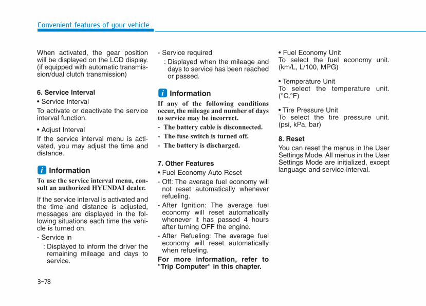
3-78
Convenient features of your vehicle
When activated, the gear positionwill be displayed on the LCD display.(if equipped with automatic transmis-sion/dual clutch transmission)
6. Service Interval• Service IntervalTo activate or deactivate the serviceinterval function.
• Adjust IntervalIf the service interval menu is acti-vated, you may adjust the time anddistance.
Information To use the service interval menu, con-sult an authorized HYUNDAI dealer.
If the service interval is activated andthe time and distance is adjusted,messages are displayed in the fol-lowing situations each time the vehi-cle is turned on.- Service in
: Displayed to inform the driver theremaining mileage and days toservice.
- Service required: Displayed when the mileage anddays to service has been reachedor passed.
Information If any of the following conditionsoccur, the mileage and number of daysto service may be incorrect.
- The battery cable is disconnected.
- The fuse switch is turned off.
- The battery is discharged.
7. Other Features• Fuel Economy Auto Reset- Off: The average fuel economy will
not reset automatically wheneverrefueling.
- After Ignition: The average fueleconomy will reset automaticallywhenever it has passed 4 hoursafter turning OFF the engine.
- After Refueling: The average fueleconomy will reset automaticallywhen refueling.
For more information, refer to"Trip Computer" in this chapter.
• Fuel Economy UnitTo select the fuel economy unit.(km/L, L/100, MPG)
• Temperature UnitTo select the temperature unit.(°C,°F)
• Tire Pressure UnitTo select the tire pressure unit.(psi, kPa, bar)
8. ResetYou can reset the menus in the UserSettings Mode. All menus in the UserSettings Mode are initialized, exceptlanguage and service interval.
i
i
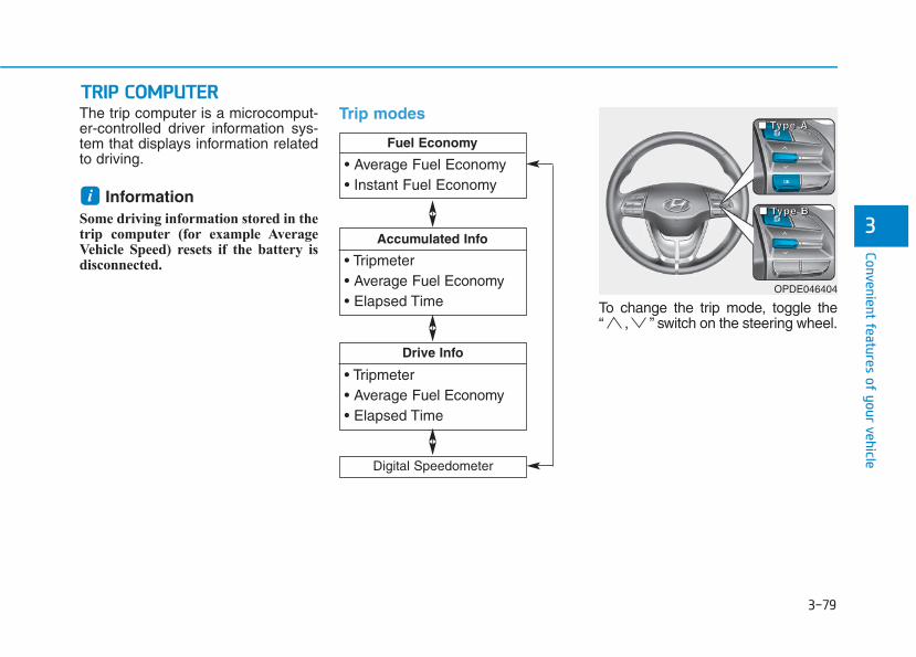
3-79
Convenient features of your vehicle
3
The trip computer is a microcomput-er-controlled driver information sys-tem that displays information relatedto driving.
Information Some driving information stored in thetrip computer (for example AverageVehicle Speed) resets if the battery isdisconnected.
Trip modes
To change the trip mode, toggle the“ , ” switch on the steering wheel.
i
TTRRIIPP CCOOMMPPUUTTEERR
• Tripmeter• Average Fuel Economy• Elapsed Time
Drive Info
• Tripmeter• Average Fuel Economy• Elapsed Time
Accumulated Info
• Average Fuel Economy• Instant Fuel Economy
Fuel Economy
Digital Speedometer
OPDE046404
■■■■ TTTTyyyyppppeeee AAAA
■■■■ TTTTyyyyppppeeee BBBB
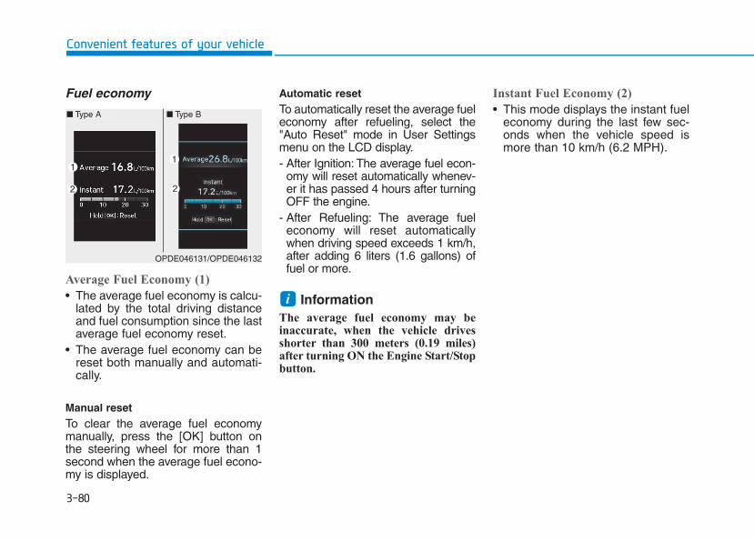
3-80
Convenient features of your vehicle
Fuel economy
Average Fuel Economy (1)
• The average fuel economy is calcu-lated by the total driving distanceand fuel consumption since the lastaverage fuel economy reset.
• The average fuel economy can bereset both manually and automati-cally.
Manual resetTo clear the average fuel economymanually, press the [OK] button onthe steering wheel for more than 1second when the average fuel econo-my is displayed.
Automatic resetTo automatically reset the average fueleconomy after refueling, select the"Auto Reset" mode in User Settingsmenu on the LCD display.- After Ignition: The average fuel econ-
omy will reset automatically whenev-er it has passed 4 hours after turningOFF the engine.
- After Refueling: The average fueleconomy will reset automaticallywhen driving speed exceeds 1 km/h,after adding 6 liters (1.6 gallons) offuel or more.
Information The average fuel economy may beinaccurate, when the vehicle drivesshorter than 300 meters (0.19 miles)after turning ON the Engine Start/Stopbutton.
Instant Fuel Economy (2)
• This mode displays the instant fueleconomy during the last few sec-onds when the vehicle speed ismore than 10 km/h (6.2 MPH).
i
OPDE046131/OPDE046132
■ Type A ■ Type B
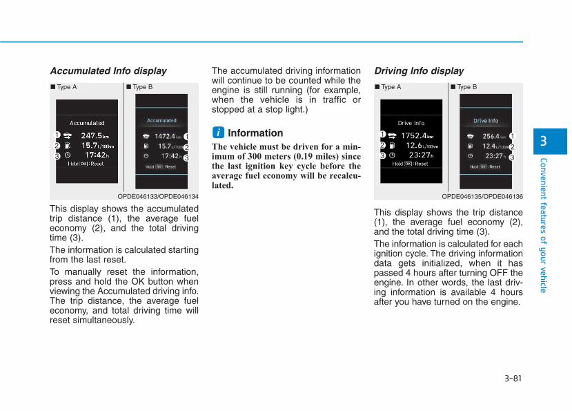
3-81
Convenient features of your vehicle
3
Accumulated Info display
This display shows the accumulatedtrip distance (1), the average fueleconomy (2), and the total drivingtime (3).The information is calculated startingfrom the last reset.To manually reset the information,press and hold the OK button whenviewing the Accumulated driving info.The trip distance, the average fueleconomy, and total driving time willreset simultaneously.
The accumulated driving informationwill continue to be counted while theengine is still running (for example,when the vehicle is in traffic orstopped at a stop light.)
Information The vehicle must be driven for a min-imum of 300 meters (0.19 miles) sincethe last ignition key cycle before theaverage fuel economy will be recalcu-lated.
Driving Info display
This display shows the trip distance(1), the average fuel economy (2),and the total driving time (3).The information is calculated for eachignition cycle. The driving informationdata gets initialized, when it haspassed 4 hours after turning OFF theengine. In other words, the last driv-ing information is available 4 hoursafter you have turned on the engine.
i
OPDE046133/OPDE046134
■ Type A ■ Type B
OPDE046135/OPDE046136
■ Type A ■ Type B
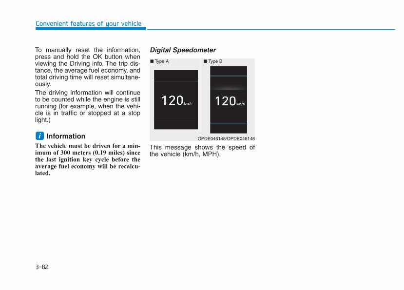
3-82
Convenient features of your vehicle
To manually reset the information,press and hold the OK button whenviewing the Driving info. The trip dis-tance, the average fuel economy, andtotal driving time will reset simultane-ously.The driving information will continueto be counted while the engine is stillrunning (for example, when the vehi-cle is in traffic or stopped at a stoplight.)
Information The vehicle must be driven for a min-imum of 300 meters (0.19 miles) sincethe last ignition key cycle before theaverage fuel economy will be recalcu-lated.
Digital Speedometer
This message shows the speed ofthe vehicle (km/h, MPH).
i OPDE046145/OPDE046146
■ Type A ■ Type B
Multimedia System
Multimedia system.................................................4-2AUX, USB and iPod®® port ...............................................4-2Antenna ...............................................................................4-3Steering wheel audio control .........................................4-4Bluetooth®® Wireless Technology hands-free ..........4-5Audio / Video / Navigation system (AVN) ..................4-5How vehicle radio works .................................................4-5
Audio (without touch screen) ..............................4-9Feature of your audio ...................................................4-10Radio...................................................................................4-19Media..................................................................................4-21Phone .................................................................................4-32Setup ..................................................................................4-40
Audio (with touch screen)..................................4-42Feature of your audio ...................................................4-43Radio .................................................................................4-48Media..................................................................................4-51Phone .................................................................................4-62Setup ..................................................................................4-70
Declaration of conformity ..................................4-72CE for EU ..........................................................................4-72
4
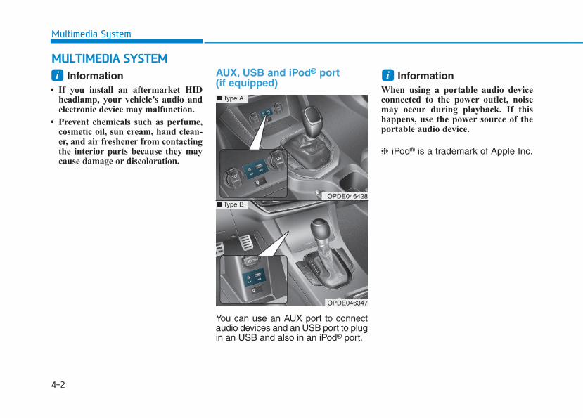
4-2
Multimedia System
Information • If you install an aftermarket HID
headlamp, your vehicle’s audio andelectronic device may malfunction.
• Prevent chemicals such as perfume,cosmetic oil, sun cream, hand clean-er, and air freshener from contactingthe interior parts because they maycause damage or discoloration.
AUX, USB and iPod® port (if equipped)
You can use an AUX port to connectaudio devices and an USB port to plugin an USB and also in an iPod® port.
Information When using a portable audio deviceconnected to the power outlet, noisemay occur during playback. If thishappens, use the power source of theportable audio device.
❈ iPod® is a trademark of Apple Inc.
iiMMUULLTTIIMMEEDDIIAA SSYYSSTTEEMM
OPDE046428
OPDE046347
■ Type A
■ Type B
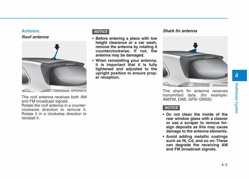
4-3
Multim
edia System
4
AntennaRoof antenna
The roof antenna receives both AMand FM broadcast signals.Rotate the roof antenna in a counter-clockwise direction to remove it.Rotate it in a clockwise direction toreinstall it.
• Before entering a place with lowheight clearance or a car wash,remove the antenna by rotating itcounterclockwise. If not, theantenna may be damaged.
• When reinstalling your antenna,it is important that it is fullytightened and adjusted to theupright position to ensure prop-er reception.
Shark fin antenna
The shark fin antenna receivestransmitted data. (for example:AM/FM, DAB, GPS/ GNSS)
• Do not clean the inside of therear window glass with a cleaneror use a scraper to remove for-eign deposits as this may causedamage to the antenna elements.
• Avoid adding metallic coatingssuch as Ni, Cd, and so on. Thesecan degrade the receiving AMand FM broadcast signals.
NOTICE
NOTICE
OPD046412
OPD046345
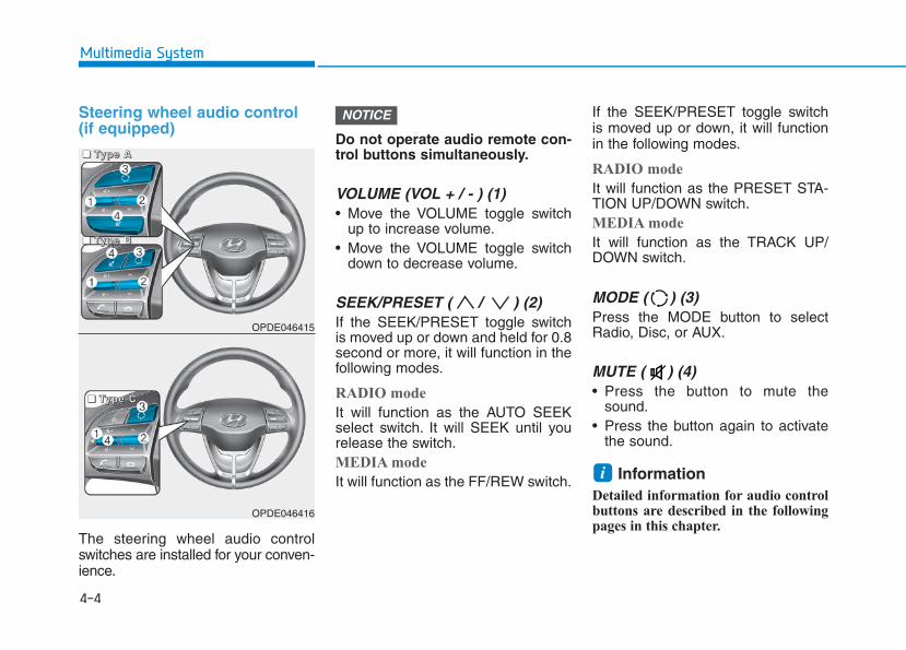
Steering wheel audio control (if equipped)
The steering wheel audio controlswitches are installed for your conven-ience.
Do not operate audio remote con-trol buttons simultaneously.
VOLUME (VOL + / - ) (1)• Move the VOLUME toggle switch
up to increase volume.• Move the VOLUME toggle switch
down to decrease volume.
SEEK/PRESET ( / ) (2)If the SEEK/PRESET toggle switchis moved up or down and held for 0.8second or more, it will function in thefollowing modes.
RADIO mode
It will function as the AUTO SEEKselect switch. It will SEEK until yourelease the switch.MEDIA mode
It will function as the FF/REW switch.
If the SEEK/PRESET toggle switchis moved up or down, it will functionin the following modes.
RADIO mode
It will function as the PRESET STA-TION UP/DOWN switch.MEDIA mode
It will function as the TRACK UP/DOWN switch.
MODE ( ) (3)Press the MODE button to selectRadio, Disc, or AUX.
MUTE ( ) (4) • Press the button to mute the
sound.• Press the button again to activate
the sound.
Information Detailed information for audio controlbuttons are described in the followingpages in this chapter.
i
NOTICE
OPDE046415
OPDE046416
4-4
Multimedia System
■■■■ TTTTyyyyppppeeee AAAA
■■■■ TTTTyyyyppppeeee CCCC
■■■■ TTTTyyyyppppeeee BBBB
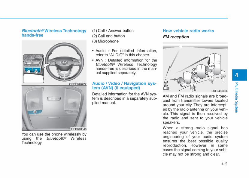
Bluetooth® Wireless Technologyhands-free
You can use the phone wirelessly byusing the Bluetooth® WirelessTechnology.
(1) Call / Answer button(2) Call end button(3) Microphone
• Audio : For detailed information,refer to “AUDIO” in this chapter.
• AVN : Detailed information for theBluetooth® Wireless Technologyhands-free is described in the man-ual supplied separately.
Audio / Video / Navigation sys-tem (AVN) (if equipped)Detailed information for the AVN sys-tem is described in a separately sup-plied manual.
How vehicle radio worksFM reception
AM and FM radio signals are broad-cast from transmitter towers locatedaround your city. They are intercept-ed by the radio antenna on your vehi-cle. This signal is then received bythe radio and sent to your vehiclespeakers.When a strong radio signal hasreached your vehicle, the preciseengineering of your audio systemensures the best possible qualityreproduction. However, in somecases the signal coming to your vehi-cle may not be strong and clear.
OJF045308L
OPDE046422
OPD046348
4-5
Multim
edia System
4
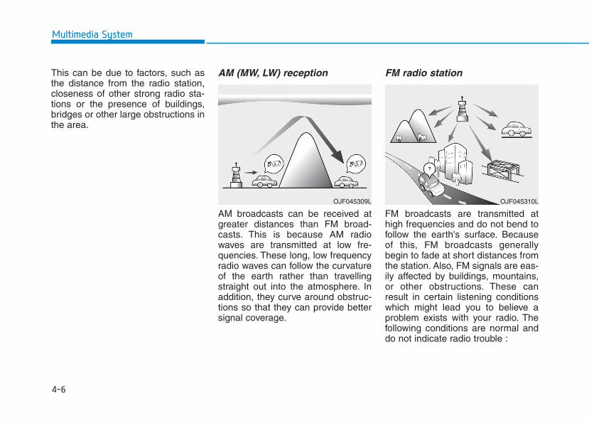
4-6
Multimedia System
This can be due to factors, such asthe distance from the radio station,closeness of other strong radio sta-tions or the presence of buildings,bridges or other large obstructions inthe area.
AM (MW, LW) reception
AM broadcasts can be received atgreater distances than FM broad-casts. This is because AM radiowaves are transmitted at low fre-quencies. These long, low frequencyradio waves can follow the curvatureof the earth rather than travellingstraight out into the atmosphere. Inaddition, they curve around obstruc-tions so that they can provide bettersignal coverage.
FM radio station
FM broadcasts are transmitted athigh frequencies and do not bend tofollow the earth's surface. Becauseof this, FM broadcasts generallybegin to fade at short distances fromthe station. Also, FM signals are eas-ily affected by buildings, mountains,or other obstructions. These canresult in certain listening conditionswhich might lead you to believe aproblem exists with your radio. Thefollowing conditions are normal anddo not indicate radio trouble :
OJF045310LOJF045309L
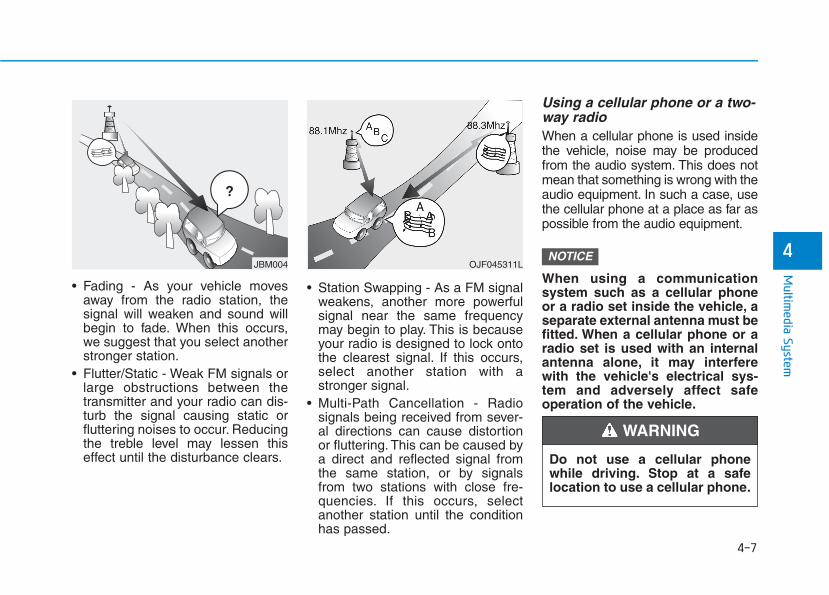
4-7
Multim
edia System
4
• Fading - As your vehicle movesaway from the radio station, thesignal will weaken and sound willbegin to fade. When this occurs,we suggest that you select anotherstronger station.
• Flutter/Static - Weak FM signals orlarge obstructions between thetransmitter and your radio can dis-turb the signal causing static orfluttering noises to occur. Reducingthe treble level may lessen thiseffect until the disturbance clears.
• Station Swapping - As a FM signalweakens, another more powerfulsignal near the same frequencymay begin to play. This is becauseyour radio is designed to lock ontothe clearest signal. If this occurs,select another station with astronger signal.
• Multi-Path Cancellation - Radiosignals being received from sever-al directions can cause distortionor fluttering. This can be caused bya direct and reflected signal fromthe same station, or by signalsfrom two stations with close fre-quencies. If this occurs, selectanother station until the conditionhas passed.
Using a cellular phone or a two-way radio When a cellular phone is used insidethe vehicle, noise may be producedfrom the audio system. This does notmean that something is wrong with theaudio equipment. In such a case, usethe cellular phone at a place as far aspossible from the audio equipment.
When using a communicationsystem such as a cellular phoneor a radio set inside the vehicle, aseparate external antenna must befitted. When a cellular phone or aradio set is used with an internalantenna alone, it may interferewith the vehicle's electrical sys-tem and adversely affect safeoperation of the vehicle.
NOTICEOJF045311L
¢ ¢ ¢
JBM004
Do not use a cellular phonewhile driving. Stop at a safelocation to use a cellular phone.
WARNING
4-8
Multimedia System
iPod®
iPod® is a registered trademark of Apple Inc.
Bluetooth® Wireless TechnologyThe Bluetooth® word mark and logos are registeredtrademarks owned by Bluetooth SIG, Inc. and any use ofsuch marks by HYUNDAI is under license.Other trademarks and trade names are those of theirrespective owners.
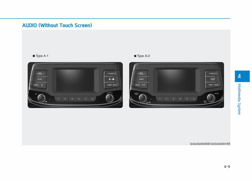
4-9
Multim
edia System
4
AAUUDDIIOO ((WWiitthhoouutt TToouucchh SSccrreeeenn))
G4G4G0000EE/G4G4G0001EE
■ Type A-1 ■ Type A-2
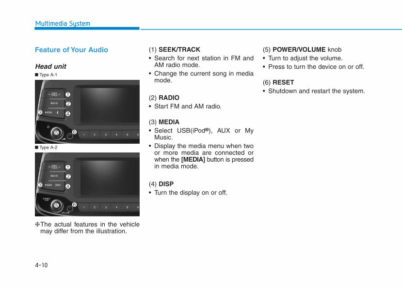
4-10
Multimedia System
Feature of Your Audio
Head unit
❈The actual features in the vehiclemay differ from the illustration.
(1) SEEK/TRACK• Search for next station in FM and
AM radio mode.• Change the current song in media
mode.
(2) RADIO• Start FM and AM radio.
(3) MEDIA• Select USB(iPod®), AUX or My
Music.• Display the media menu when two
or more media are connected orwhen the [MEDIA] button is pressedin media mode.
(4) DISP• Turn the display on or off.
(5) POWER/VOLUME knob • Turn to adjust the volume.• Press to turn the device on or off.
(6) RESET• Shutdown and restart the system.
■ Type A-2
■ Type A-1
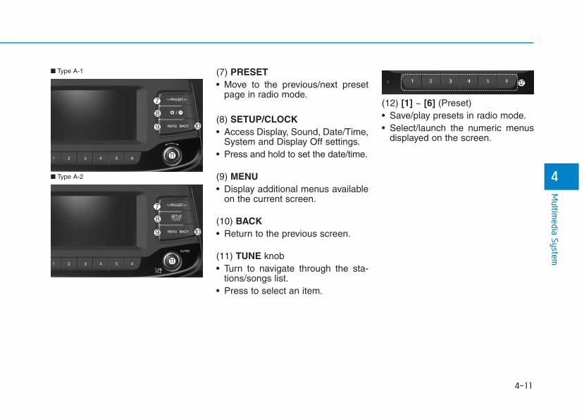
4-11
Multim
edia System
4
(7) PRESET• Move to the previous/next preset
page in radio mode.
(8) SETUP/CLOCK• Access Display, Sound, Date/Time,
System and Display Off settings.• Press and hold to set the date/time.
(9) MENU• Display additional menus available
on the current screen.
(10) BACK• Return to the previous screen.
(11) TUNE knob • Turn to navigate through the sta-
tions/songs list.• Press to select an item.
(12) [1] ~ [6] (Preset)• Save/play presets in radio mode.• Select/launch the numeric menus
displayed on the screen.
■ Type A-2
■ Type A-1
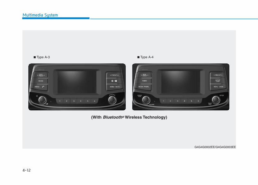
4-12
Multimedia System
G4G4G0002EE/G4G4G0003EE
(With Bluetooth® Wireless Technology)
■ Type A-3 ■ Type A-4
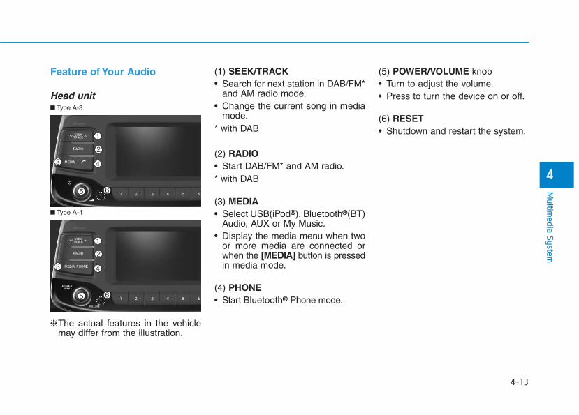
4-13
Multim
edia System
4
Feature of Your Audio
Head unit
❈The actual features in the vehiclemay differ from the illustration.
(1) SEEK/TRACK• Search for next station in DAB/FM*
and AM radio mode.• Change the current song in media
mode.* with DAB
(2) RADIO• Start DAB/FM* and AM radio.* with DAB
(3) MEDIA• Select USB(iPod®), Bluetooth®(BT)
Audio, AUX or My Music.• Display the media menu when two
or more media are connected orwhen the [MEDIA] button is pressedin media mode.
(4) PHONE• Start Bluetooth® Phone mode.
(5) POWER/VOLUME knob • Turn to adjust the volume.• Press to turn the device on or off.
(6) RESET• Shutdown and restart the system.
■ Type A-4
■ Type A-3
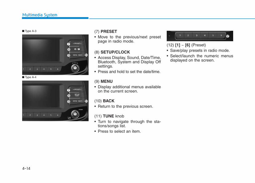
(7) PRESET• Move to the previous/next preset
page in radio mode.
(8) SETUP/CLOCK• Access Display, Sound, Date/Time,
Bluetooth, System and Display Offsettings.
• Press and hold to set the date/time.
(9) MENU• Display additional menus available
on the current screen.
(10) BACK• Return to the previous screen.
(11) TUNE knob • Turn to navigate through the sta-
tions/songs list.• Press to select an item.
(12) [1] ~ [6] (Preset)• Save/play presets in radio mode.• Select/launch the numeric menus
displayed on the screen.
■ Type A-4
■ Type A-3
4-14
Multimedia System
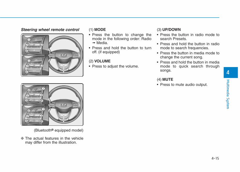
4-15
Multim
edia System
4
Steering wheel remote control
(Bluetooth® equipped model)
❈ The actual features in the vehiclemay differ from the illustration.
(1) MODE• Press the button to change the
mode in the following order: Radio➟ Media.
• Press and hold the button to turnoff. (if equipped)
(2) VOLUME• Press to adjust the volume.
(3) UP/DOWN• Press the button in radio mode to
search Presets.• Press and hold the button in radio
mode to search frequencies.• Press the button in media mode to
change the current song.• Press and hold the button in media
mode to quick search throughsongs.
(4) MUTE• Press to mute audio output.
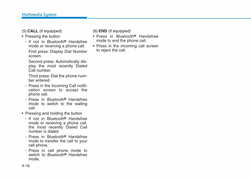
(5) CALL (if equipped)• Pressing the button
- If not in Bluetooth® Handsfreemode or receiving a phone call.First press: Display Dial Numberscreen.Second press: Automatically dis-play the most recently DialedCall number.Third press: Dial the phone num-ber entered.
- Press in the Incoming Call notifi-cation screen to accept thephone call.
- Press in Bluetooth® Handsfreemode to switch to the waitingcall.
• Pressing and holding the button- If not in Bluetooth® Handsfree
mode or receiving a phone call,the most recently Dialed Callnumber is dialed.
- Press in Bluetooth® Handsfreemode to transfer the call to yourcell phone.
- Press in cell phone mode toswitch to Bluetooth® Handsfreemode.
(6) END (if equipped)• Press in Bluetooth® Handsfree
mode to end the phone call.• Press in the incoming call screen
to reject the call.
4-16
Multimedia System
4-17
Multim
edia System
4
• Do not stare at the screenwhile driving. Staring at thescreen for prolonged periodsof time could lead to trafficaccidents.
• Do not disassemble, assem-ble, or modify the audio sys-tem. Such acts could result inaccidents, fire, or electricshock.
• Using the phone while drivingmay lead to a lack of attentionof traffic conditions andincrease the likelihood ofaccidents. Use the phone fea-ture after parking the vehicle.
• Heed caution not to spill wateror introduce foreign objectsinto the device. Such actscould lead to smoke, fire, orproduct malfunction.
(Continued)
WARNING (Continued)• Please refrain from use if the
screen is blank or no soundcan be heard as these signsmay indicate product mal-function. Continued use insuch conditions could lead toaccidents (fires, electricshock) or product malfunc-tions.
• Do not touch the antenna dur-ing thunder or lightening assuch acts may lead to light-ning induced electric shock.
• Do not stop or park in park-ing-restricted areas to operatethe product. Such acts couldlead to traffic accidents.
• Use the system with the vehi-cle ignition turned on.Prolonged use with the igni-tion turned off could result inbattery discharge.
Driving while distracted canresult in a loss of vehicle con-trol that may lead to an acci-dent, severe personal injury,and death. The driver’s primaryresponsibility is in the safe andlegal operation of a vehicle, anduse of any handheld devices,other equipment, or vehicle sys-tems which take the driver’seyes, attention and focus awayfrom the safe operation of avehicle or which are not permis-sible by law should never beused during operation of thevehicle.
WARNING
4-18
Multimedia System
• Operating the device while driv-ing could lead to accidents dueto a lack of attention to externalsurroundings. First park thevehicle before operating thedevice.
• Adjust the volume to levels thatallow the driver to hear soundsfrom outside of the vehicle.Driving in a state where externalsounds cannot be heard maylead to accidents.
• Pay attention to the volume set-ting when turning the device on.A sudden output of extreme vol-ume upon turning the device oncould lead to hearing impair-ment. (Adjust the volume to asuitable levels before turning offthe device.)
• If you want to change the positionof device installation, pleaseinquire with your place of pur-chase or service maintenancecenter. Technical expertise isrequired to install or disassem-ble the device.
(Continued)
(Continued)• Turn on the car ignition before
using this device. Do not oper-ate the audio system for longperiods of time with the ignitionturned off as such operationsmay lead to battery discharge.
• Do not subject the device tosevere shock or impact. Directpressure onto the front side ofthe monitor may cause damageto the LCD or touch screen.
• When cleaning the device, makesure to turn off the device anduse a dry and smooth cloth.Never use tough materials,chemical cloths, or solvents(alcohol, benzene, thinners,etc.). As such materials maydamage the device panel orcause color/quality deteriora-tion.
• Do not place beverages close tothe audio system. Spilling bever-ages may lead to system mal-function.
• In case of product malfunction,please contact your place of pur-chase or After Service center.
(Continued)
(Continued)• Placing the audio system within
an electromagnetic environmentmay result in noise interference.
NOTICE
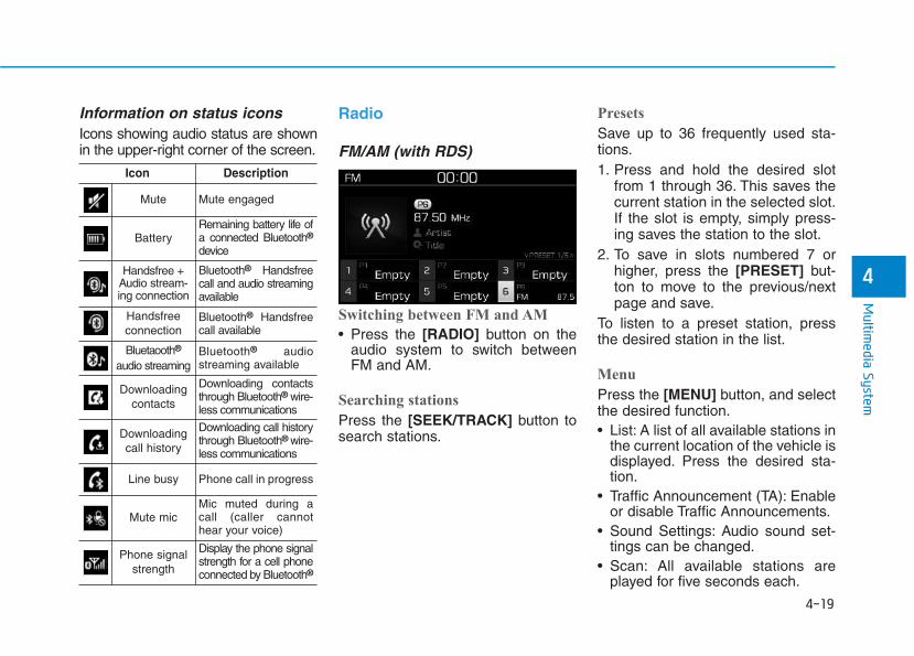
4-19
Multim
edia System
4
Information on status iconsIcons showing audio status are shownin the upper-right corner of the screen.
Radio
FM/AM (with RDS)
Switching between FM and AM
• Press the [RADIO] button on theaudio system to switch betweenFM and AM.
Searching stations
Press the [SEEK/TRACK] button tosearch stations.
Presets
Save up to 36 frequently used sta-tions.1. Press and hold the desired slot
from 1 through 36. This saves thecurrent station in the selected slot.If the slot is empty, simply press-ing saves the station to the slot.
2. To save in slots numbered 7 orhigher, press the [PRESET] but-ton to move to the previous/nextpage and save.
To listen to a preset station, pressthe desired station in the list.
Menu
Press the [MENU] button, and selectthe desired function.• List: A list of all available stations in
the current location of the vehicle isdisplayed. Press the desired sta-tion.
• Traffic Announcement (TA): Enableor disable Traffic Announcements.
• Sound Settings: Audio sound set-tings can be changed.
• Scan: All available stations areplayed for five seconds each.
Icon Description
Mute Mute engaged
BatteryRemaining battery life ofa connected Bluetooth®
device
Handsfree +Audio stream-ing connection
Bluetooth® Handsfreecall and audio streamingavailable
Handsfreeconnection
Bluetooth® Handsfreecall available
Bluetaooth®
audio streamingBluetooth® audiostreaming available
Downloadingcontacts
Downloading contactsthrough Bluetooth® wire-less communications
Downloading call history
Downloading call historythrough Bluetooth® wire-less communications
Line busy Phone call in progress
Mute micMic muted during acall (caller cannothear your voice)
Phone signalstrength
Display the phone signalstrength for a cell phoneconnected by Bluetooth®
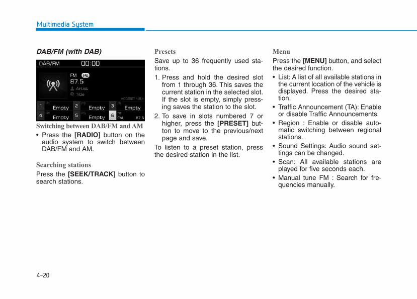
4-20
Multimedia System
DAB/FM (with DAB)
Switching between DAB/FM and AM
• Press the [RADIO] button on theaudio system to switch betweenDAB/FM and AM.
Searching stations
Press the [SEEK/TRACK] button tosearch stations.
Presets
Save up to 36 frequently used sta-tions.1. Press and hold the desired slot
from 1 through 36. This saves thecurrent station in the selected slot.If the slot is empty, simply press-ing saves the station to the slot.
2. To save in slots numbered 7 orhigher, press the [PRESET] but-ton to move to the previous/nextpage and save.
To listen to a preset station, pressthe desired station in the list.
Menu
Press the [MENU] button, and selectthe desired function.• List: A list of all available stations in
the current location of the vehicle isdisplayed. Press the desired sta-tion.
• Traffic Announcement (TA): Enableor disable Traffic Announcements.
• Region : Enable or disable auto-matic switching between regionalstations.
• Sound Settings: Audio sound set-tings can be changed.
• Scan: All available stations areplayed for five seconds each.
• Manual tune FM : Search for fre-quencies manually.
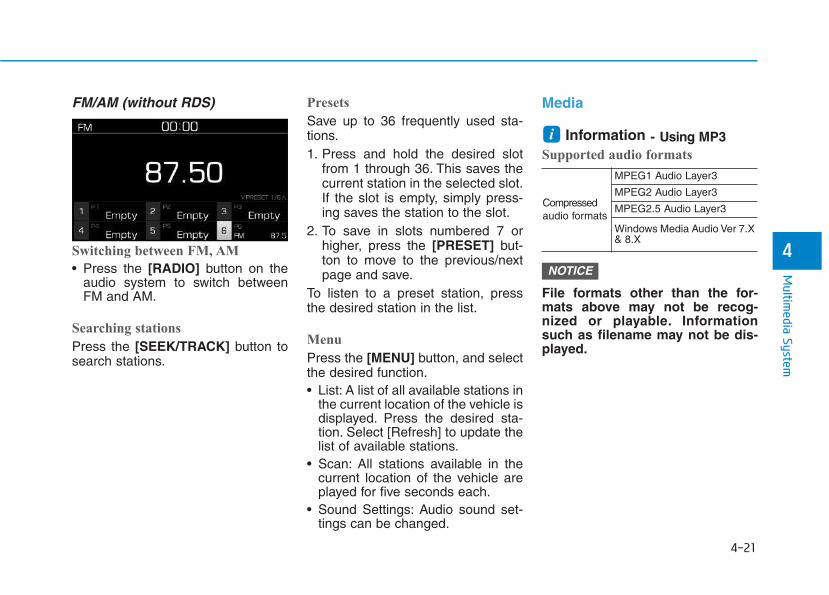
4-21
Multim
edia System
4
FM/AM (without RDS)
Switching between FM, AM
• Press the [RADIO] button on theaudio system to switch betweenFM and AM.
Searching stations
Press the [SEEK/TRACK] button tosearch stations.
Presets
Save up to 36 frequently used sta-tions.1. Press and hold the desired slot
from 1 through 36. This saves thecurrent station in the selected slot.If the slot is empty, simply press-ing saves the station to the slot.
2. To save in slots numbered 7 orhigher, press the [PRESET] but-ton to move to the previous/nextpage and save.
To listen to a preset station, pressthe desired station in the list.
Menu
Press the [MENU] button, and selectthe desired function.• List: A list of all available stations in
the current location of the vehicle isdisplayed. Press the desired sta-tion. Select [Refresh] to update thelist of available stations.
• Scan: All stations available in thecurrent location of the vehicle areplayed for five seconds each.
• Sound Settings: Audio sound set-tings can be changed.
Media
Information - Using MP3Supported audio formats
File formats other than the for-mats above may not be recog-nized or playable. Informationsuch as filename may not be dis-played.
NOTICE
i
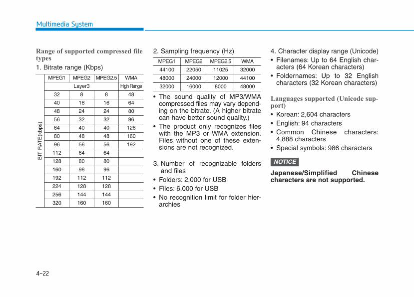
4-22
Multimedia System
Range of supported compressed filetypes
1. Bitrate range (Kbps)
2. Sampling frequency (Hz)
• The sound quality of MP3/WMAcompressed files may vary depend-ing on the bitrate. (A higher bitratecan have better sound quality.)
• The product only recognizes fileswith the MP3 or WMA extension.Files without one of these exten-sions are not recognized.
3. Number of recognizable foldersand files
• Folders: 2,000 for USB• Files: 6,000 for USB• No recognition limit for folder hier-
archies
4. Character display range (Unicode)• Filenames: Up to 64 English char-
acters (64 Korean characters)• Foldernames: Up to 32 English
characters (32 Korean characters)
Languages supported (Unicode sup-port)
• Korean: 2,604 characters• English: 94 characters• Common Chinese characters:
4,888 characters• Special symbols: 986 characters
Japanese/Simplified Chinesecharacters are not supported.
NOTICE
4-23
Multim
edia System
4
Information- Using the USB Devices
• Starting the vehicle while a USBdevice is connected can damage thedevice. Please disconnect USBdevices before starting the vehicle.
• Starting the vehicle or stopping theengine while an external USB deviceis connected can result in failure ofthe external USB device to operate.
• Be cautious of static electricity whenconnecting/disconnecting externalUSB devices.
• An encrypted MP3 player is not rec-ognized when connected as an exter-nal device.
• External USB devices may not berecognized, depending on the stateof the external USB device.
• Only products with byte/sectors for-matted at 4 KB or lower are recog-nized.
• Only USB devices in FAT12/16/32format are recognized; NTFS andExFAT file systems are not recog-nized.
• Some USB devices are not recog-nized due to compatibility issues.
(Continued)
(Continued)
• Do not touch the USB connections.
• Connecting and disconnecting USBdevices rapidly over a short periodof time can cause equipment failure.
• Abnormal sounds may be audiblewhen the USB device is disconnect-ed.
• Turn the audio off before connectingor disconnecting external USBdevices.
• Recognition may take longerdepending on the type, capacity orfile format of the external USBdevice. This is not a product mal-function.
• Use of USB devices for purposesother than playing music files is pro-hibited.
• Image display and video playbackare not supported.
• Use of USB accessories, includingcharge and heat though the USB I/F,can lead to reduced product per-formance or malfunctions. Do notuse USB devices or accessories forthese purposes.
(Continued)
(Continued)
• Use of aftermarket USB hubs andextension cables can result in thevehicle’s audio system failing to rec-ognize your USB device. Connectthe USB device directly to the multi-media port of your vehicle.
• When using high-capacity USBdevices with logical drive divisions,only files saved on the highest levellogical drive can be played.
If applications are loaded on a USBdrive, file playback may fail.
• Some MP3 players, cell phones, dig-ital cameras, etc. (USB devices thatare not recognized as mobile stor-age) may not operate normallywhen connected.
• USB charging may not be supportedby some mobile devices.
• Operation is guaranteed only forstandard (Metal Cover Type) USBMemory drives.
• Operation of HDD, CF, SD andmemory stick devices is not guaran-teed.
(Continued)
i
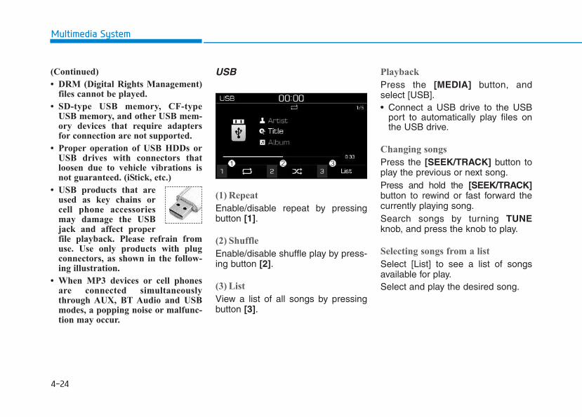
4-24
Multimedia System
(Continued)
• DRM (Digital Rights Management)files cannot be played.
• SD-type USB memory, CF-typeUSB memory, and other USB mem-ory devices that require adaptersfor connection are not supported.
• Proper operation of USB HDDs orUSB drives with connectors thatloosen due to vehicle vibrations isnot guaranteed. (iStick, etc.)
• USB products that areused as key chains orcell phone accessoriesmay damage the USBjack and affect properfile playback. Please refrain fromuse. Use only products with plugconnectors, as shown in the follow-ing illustration.
• When MP3 devices or cell phonesare connected simultaneouslythrough AUX, BT Audio and USBmodes, a popping noise or malfunc-tion may occur.
USB
(1) Repeat
Enable/disable repeat by pressingbutton [1].
(2) Shuffle
Enable/disable shuffle play by press-ing button [2].
(3) List
View a list of all songs by pressingbutton [3].
Playback
Press the [MEDIA] button, andselect [USB].• Connect a USB drive to the USB
port to automatically play files onthe USB drive.
Changing songs
Press the [SEEK/TRACK] button toplay the previous or next song.Press and hold the [SEEK/TRACK]button to rewind or fast forward thecurrently playing song.Search songs by turning TUNEknob, and press the knob to play.
Selecting songs from a list
Select [List] to see a list of songsavailable for play.Select and play the desired song.
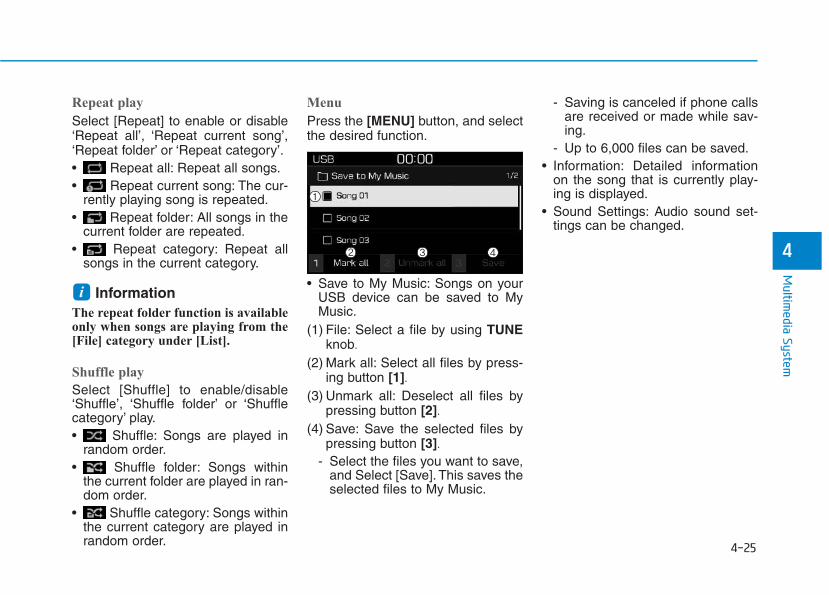
4-25
Multim
edia System
4
Repeat play
Select [Repeat] to enable or disable‘Repeat all’, ‘Repeat current song’,‘Repeat folder’ or ‘Repeat category’.• Repeat all: Repeat all songs.• Repeat current song: The cur-
rently playing song is repeated.• Repeat folder: All songs in the
current folder are repeated.• Repeat category: Repeat all
songs in the current category.
InformationThe repeat folder function is availableonly when songs are playing from the[File] category under [List].
Shuffle play
Select [Shuffle] to enable/disable‘Shuffle’, ‘Shuffle folder’ or ‘Shufflecategory’ play.• Shuffle: Songs are played in
random order.• Shuffle folder: Songs within
the current folder are played in ran-dom order.
• Shuffle category: Songs withinthe current category are played inrandom order.
Menu
Press the [MENU] button, and selectthe desired function.
• Save to My Music: Songs on yourUSB device can be saved to MyMusic.
(1) File: Select a file by using TUNEknob.
(2) Mark all: Select all files by press-ing button [1].
(3) Unmark all: Deselect all files bypressing button [2].
(4) Save: Save the selected files bypressing button [3].
- Select the files you want to save,and Select [Save]. This saves theselected files to My Music.
- Saving is canceled if phone callsare received or made while sav-ing.
- Up to 6,000 files can be saved.• Information: Detailed information
on the song that is currently play-ing is displayed.
• Sound Settings: Audio sound set-tings can be changed.
i
4-26
Multimedia System
Information- Using the iPod® Devices
• To use the audio system’s iPod® con-trol function, use the dedicatedcable provided with your iPod®.
• Connecting the iPod® to the vehicleduring play may result in a loudnoise that lasts about one to two sec-onds. Connect the iPod® to the vehi-cle after stopping or pausing play.
• Connect the iPod® with the vehiclein the ACC ON state to begin charg-ing.
• When connecting the iPod® cable,be sure to fully push the cable intothe port.
• When EQ effects are enabled simul-taneously on external devices, suchas iPod®s and the audio system, theEQ effects may overlap, causingsound quality deterioration or dis-tortion. Deactivate the EQ functionfor all external devices, if possible.
• Noise may occur when your iPod®
or the AUX port is connected.Disconnect and store separatelywhen not in use.
(Continued)
(Continued)
• There may be noise if the audio sys-tem is used with an iPod® or AUXexternal device connected to thepower jack. In these cases, discon-nect the iPod® or external devicefrom the power jack.
• Play may be interrupted, or devicemalfunctions may occur dependingon the characteristics of youriPod®/iPhone®.
• Play may fail if your iPhone® is con-nected through both Bluetooth® andUSB. In this case, select Dock con-nector or Bluetooth® on youriPhone® to change the sound outputsettings.
• If your software version does notsupport the communication proto-col or your iPod® is not recognizeddue to device failure, anomalies ordefects, iPod® mode cannot be used.
• iPod® nano (5th generation) devicesmay not be recognized if the batteryis low. Charge sufficiently beforeuse.
(Continued)
(Continued)
• The search and song play order inthe iPod® device may be differentfrom the search order in the audiosystem.
• If the iPod® has failed due to aninternal defect, please reset theiPod® (consult your iPod® manual).
• Depending on the software version,the iPod® may fail to sync with thesystem. If the media is removed ordisconnected before recognition, theprevious mode may not be restored(iPad® cannot be charged).
• Cables other than the 1-meter cableprovided with iPod®/iPhone® prod-ucts may not be recognized.
• When other music apps are used onyour iPod®, the system sync func-tion may fail due to malfunction ofthe iPod® application.
i
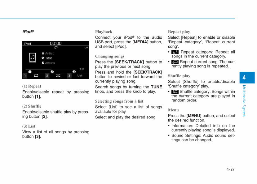
4-27
Multim
edia System
4
iPod®
(1) Repeat
Enable/disable repeat by pressingbutton [1].
(2) Shuffle
Enable/disable shuffle play by press-ing button [2].
(3) List
View a list of all songs by pressingbutton [3].
Playback
Connect your iPod® to the audioUSB port, press the [MEDIA] button,and select [iPod].
Changing songs
Press the [SEEK/TRACK] button toplay the previous or next song.Press and hold the [SEEK/TRACK]button to rewind or fast forward thecurrently playing song.Search songs by turning the TUNEknob, and press the knob to play.
Selecting songs from a list
Select [List] to see a list of songsavailable for play.Select and play the desired song.
Repeat play
Select [Repeat] to enable or disable‘Repeat category’, ‘Repeat currentsong’.• Repeat category: Repeat all
songs in the current category.• Repeat current song: The cur-
rently playing song is repeated.
Shuffle play
Select [Shuffle] to enable/disable‘Shuffle category’ play.• Shuffle category: Songs within
the current category are played inrandom order.
Menu
Press the [MENU] button, and selectthe desired function.• Information: Detailed info on the
currently playing song is displayed.• Sound Settings: Audio sound set-
tings can be changed.
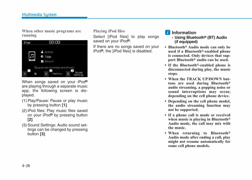
4-28
Multimedia System
When other music programs arerunning
When songs saved on your iPod®
are playing through a separate musicapp, the following screen is dis-played.(1) Play/Pause: Pause or play music
by pressing button [1].(2) iPod files: Play music files saved
on your iPod® by pressing button[2].
(3) Sound Settings: Audio sound set-tings can be changed by pressingbutton [3].
Playing iPod files
Select [iPod files] to play songssaved on your iPod®.If there are no songs saved on youriPod®, the [iPod files] is disabled.
Information- Using Bluetooth® (BT) Audio
(if equipped)• Bluetooth® Audio mode can only be
used if a Bluetooth®-enabled phoneis connected. Only devices that sup-port Bluetooth® audio can be used.
• If the Bluetooth®-enabled phone isdisconnected during play, the musicstops.
• When the TRACK UP/DOWN but-tons are used during Bluetooth®
audio streaming, a popping noise orsound interruptions may occur,depending on the cell phone device.
• Depending on the cell phone model,the audio streaming function maynot be supported.
• If a phone call is made or receivedwhen music is playing in Bluetooth®
Audio mode, the call may mix withthe music.
• When returning to Bluetooth®
Audio mode after ending a call, playmight not resume automatically forsome cell phone models.
i
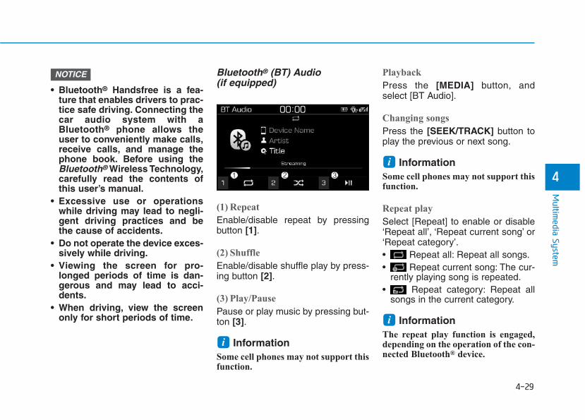
4-29
Multim
edia System
4
• Bluetooth® Handsfree is a fea-ture that enables drivers to prac-tice safe driving. Connecting thecar audio system with aBluetooth® phone allows theuser to conveniently make calls,receive calls, and manage thephone book. Before using theBluetooth® Wireless Technology,carefully read the contents ofthis user’s manual.
• Excessive use or operationswhile driving may lead to negli-gent driving practices and bethe cause of accidents.
• Do not operate the device exces-sively while driving.
• Viewing the screen for pro-longed periods of time is dan-gerous and may lead to acci-dents.
• When driving, view the screenonly for short periods of time.
Bluetooth® (BT) Audio(if equipped)
(1) Repeat
Enable/disable repeat by pressingbutton [1].
(2) Shuffle
Enable/disable shuffle play by press-ing button [2].
(3) Play/Pause
Pause or play music by pressing but-ton [3].
InformationSome cell phones may not support thisfunction.
Playback
Press the [MEDIA] button, andselect [BT Audio].
Changing songs
Press the [SEEK/TRACK] button toplay the previous or next song.
InformationSome cell phones may not support thisfunction.
Repeat play
Select [Repeat] to enable or disable‘Repeat all’, ‘Repeat current song’ or‘Repeat category’.• Repeat all: Repeat all songs.• Repeat current song: The cur-
rently playing song is repeated.• Repeat category: Repeat all
songs in the current category.
InformationThe repeat play function is engaged,depending on the operation of the con-nected Bluetooth® device.
i
i
i
NOTICE
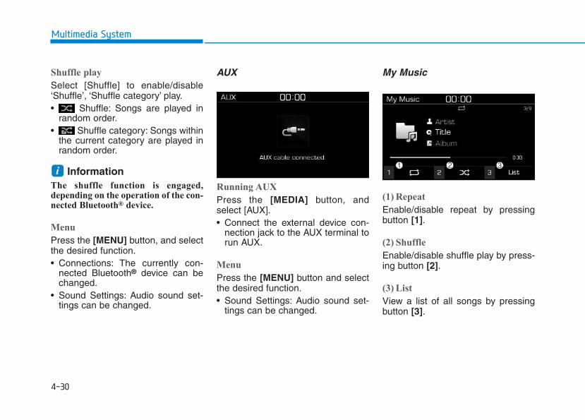
4-30
Multimedia System
Shuffle play
Select [Shuffle] to enable/disable‘Shuffle’, ‘Shuffle category’ play.• Shuffle: Songs are played in
random order.• Shuffle category: Songs within
the current category are played inrandom order.
InformationThe shuffle function is engaged,depending on the operation of the con-nected Bluetooth® device.
Menu
Press the [MENU] button, and selectthe desired function.• Connections: The currently con-
nected Bluetooth® device can bechanged.
• Sound Settings: Audio sound set-tings can be changed.
AUX
Running AUX
Press the [MEDIA] button, andselect [AUX].• Connect the external device con-
nection jack to the AUX terminal torun AUX.
Menu
Press the [MENU] button and selectthe desired function.• Sound Settings: Audio sound set-
tings can be changed.
My Music
(1) Repeat
Enable/disable repeat by pressingbutton [1].
(2) Shuffle
Enable/disable shuffle play by press-ing button [2].
(3) List
View a list of all songs by pressingbutton [3].
i
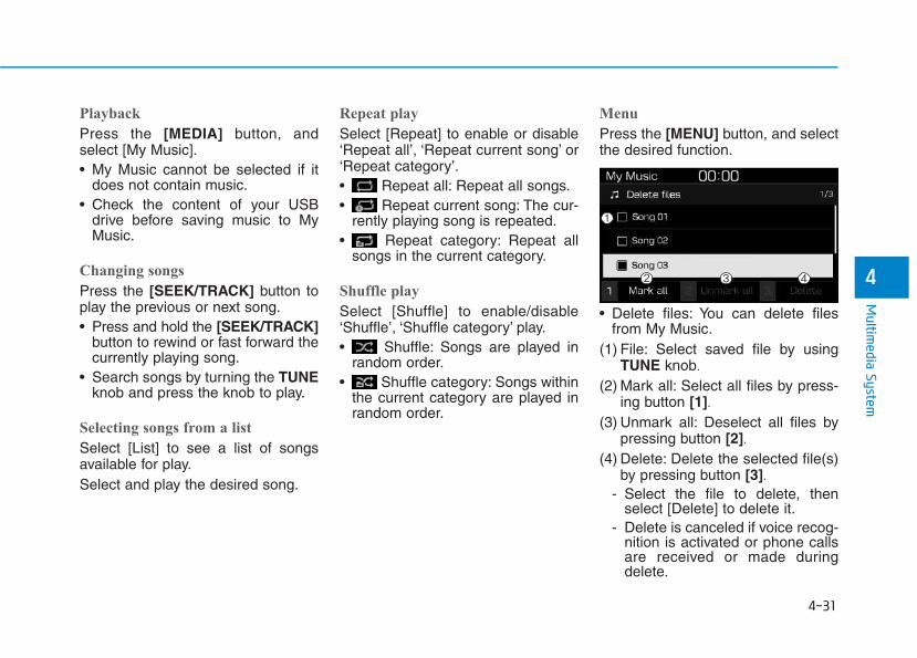
4-31
Multim
edia System
4
Playback
Press the [MEDIA] button, andselect [My Music].• My Music cannot be selected if it
does not contain music.• Check the content of your USB
drive before saving music to MyMusic.
Changing songs
Press the [SEEK/TRACK] button toplay the previous or next song.• Press and hold the [SEEK/TRACK]
button to rewind or fast forward thecurrently playing song.
• Search songs by turning the TUNEknob and press the knob to play.
Selecting songs from a list
Select [List] to see a list of songsavailable for play.Select and play the desired song.
Repeat play
Select [Repeat] to enable or disable‘Repeat all’, ‘Repeat current song’ or‘Repeat category’.• Repeat all: Repeat all songs.• Repeat current song: The cur-
rently playing song is repeated.• Repeat category: Repeat all
songs in the current category.
Shuffle play
Select [Shuffle] to enable/disable‘Shuffle’, ‘Shuffle category’ play.• Shuffle: Songs are played in
random order.• Shuffle category: Songs within
the current category are played inrandom order.
Menu
Press the [MENU] button, and selectthe desired function.
• Delete files: You can delete filesfrom My Music.
(1) File: Select saved file by usingTUNE knob.
(2) Mark all: Select all files by press-ing button [1].
(3) Unmark all: Deselect all files bypressing button [2].
(4) Delete: Delete the selected file(s)by pressing button [3].
- Select the file to delete, thenselect [Delete] to delete it.
- Delete is canceled if voice recog-nition is activated or phone callsare received or made duringdelete.
4-32
Multimedia System
• Add to Playlist: Frequently playedsongs can be paired in a [Playlist].- Songs can be played from the
[Playlist].• Information: Detailed info on the
currently playing song is displayed.• Sound Settings: Audio sound set-
tings can be changed.
Delete from playlist
When a song in the playlist is play-ing, press the [MENU] button andselect [Delete from playlist].Select the song to delete, then select[Delete].
Phone (if equipped)
Information- Using Bluetooth® (BT) Phone
• Bluetooth® is a near-field wirelessnetworking technology that uses the2.4 GHz frequency to connect vari-ous devices within a certain distancewirelessly.
• The technology is used in PCs,peripherals, Bluetooth® phones,tablet PCs, household appliancesand automobiles. Devices support-ing Bluetooth® can exchange data athigh speeds without physical cableconnections.
• Bluetooth® Handsfree devicesenable convenient access to phonefunctions through cell phonesequipped with Bluetooth®.
• Some Bluetooth® devices may not besupported by the Bluetooth®
Handsfree function.
(Continued)
(Continued)
• When Bluetooth® is connected andcalls are attempted through a con-nected cell phone from outside thevehicle, the call is connectedthrough the Bluetooth® Handsfreefunction of the vehicle.
• Please be sure to disconnect theBluetooth® Handsfree functionthrough your Bluetooth® device orthe audio screen.
• The Bluetooth® Handsfree functionhelps drivers to drive safely. By con-necting a Bluetooth®-enabled phoneto the vehicle’s audio system, phonecalls can be made and receivedthrough the audio system and con-tacts can be managed. Consult theuser manual before use.
• Excessive manipulation of controlswhile driving, making it difficult topay attention to the road ahead, canlead to accidents. Do not operate thedevice excessively while driving.
• Looking at the screen for a pro-longed time increases the risk ofaccidents. Keep time spent lookingat the screen to a minimum.
i
4-33
Multim
edia System
4
Precautions when connectingBluetooth® devices
• The vehicle supports the followingBluetooth® functions. SomeBluetooth® devices may not sup-port some functions.1) Bluetooth® Handsfree phone
calls2) Operations during a call
(Private, Switch, Mic Vol. con-trols)
3) Download call history saved tothe Bluetooth® device
4) Download contacts saved to theBluetooth® device
5) Automatic contacts/call historydownload when Bluetooth® isconnected
6) Automatic Bluetooth® deviceconnection when the vehicle isstarted
7) Bluetooth® audio streamingplayback
• Before connecting the audio sys-tem to your device, make sure yourdevice supports Bluetooth®.
• Even if your device supportsBluetooth®, a Bluetooth® connec-tion cannot be established if thedevice’s Bluetooth® function isswitched off. Search and connectwith the Bluetooth® functionenabled.
• Pair or connect Bluetooth® devicesto the audio system with the vehi-cle at a standstill.
• If a Bluetooth® connection is lostdue to abnormal conditions while aBluetooth® device is connected(communication range exceeded,device power OFF, communicationerrors, etc.), the disconnectedBluetooth® device is searched forand automatically reconnected.
• If you want to disable theBluetooth® device auto-connectfunction, turn the Bluetooth® func-tion OFF on your device. Consultthe user manuals for individualdevices to see whether Bluetooth®
is supported.• Handsfree call quality and volume
may vary depending on the type ofBluetooth® device.
• Some Bluetooth® devices are sub-ject to intermittent Bluetooth® con-nection failures. In this case, usethe following method.1) Turn the Bluetooth® function off
on your Bluetooth® device ➟Turn it on and try again.
2) Delete the paired device fromboth the audio system andBluetooth® device, then pairagain.
3) Power down your Bluetooth®
device ➟ Turn it on and tryagain.
4) Completely remove the batteryfrom your Bluetooth® device;reinsert it, reboot, and attemptconnection.
5) Restart the vehicle and reat-tempt connection.
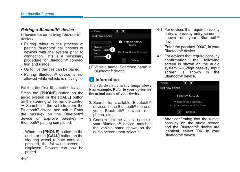
4-34
Multimedia System
Pairing a Bluetooth® deviceInformation on pairing Bluetooth®
devices
• Pairing refers to the process ofpairing Bluetooth® cell phones ordevices with the system prior toconnection. This is a necessaryprocedure for Bluetooth® connec-tion and usage.
• Up to five devices can be paired.• Pairing Bluetooth® device is not
allowed while vehicle is moving.
Pairing the first Bluetooth® device
Press the [PHONE] button on theaudio system or the [CALL] buttonon the steering wheel remote control➟ Search for the vehicle from theBluetooth® device, and pair ➟ Enterthe passkey on the Bluetooth®
device or approve passkey ➟Bluetooth® pairing completed.
1. When the [PHONE] button on theaudio or the [CALL] button on thesteering wheel remote control ispressed, the following screen isdisplayed. Devices can now bepaired.
(1) Vehicle name: Searched name inBluetooth® device.
InformationThe vehicle name in the image aboveis an example. Refer to your device forthe actual name of your device.
2. Search for available Bluetooth®
devices in the Bluetooth® menu ofyour Bluetooth® device (cellphone, etc.).
3. Confirm that the vehicle name inyour Bluetooth® device matchesthe vehicle name shown on theaudio screen, then select it.
4-1. For devices that require passkeyentry, a passkey entry screen isshown on your Bluetooth®
device.- Enter the passkey ‘0000’, in your
Bluetooth® device.4-2. For devices that require passkey
confirmation, the followingscreen is shown on the audiosystem. A 6-digit passkey inputscreen is shown in theBluetooth® device.
- After confirming that the 6-digitpasskey on the audio screenand the Bluetooth® device areidentical, select [OK] in yourBluetooth® device.
i
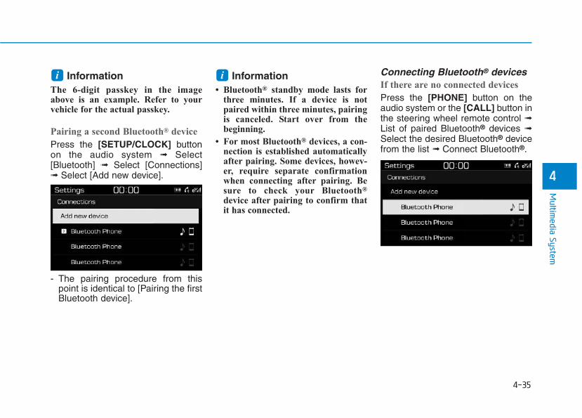
4-35
Multim
edia System
4
InformationThe 6-digit passkey in the imageabove is an example. Refer to yourvehicle for the actual passkey.
Pairing a second Bluetooth® device
Press the [SETUP/CLOCK] buttonon the audio system ➟ Select[Bluetooth] ➟ Select [Connections]➟ Select [Add new device].
- The pairing procedure from thispoint is identical to [Pairing the firstBluetooth device].
Information• Bluetooth® standby mode lasts for
three minutes. If a device is notpaired within three minutes, pairingis canceled. Start over from thebeginning.
• For most Bluetooth® devices, a con-nection is established automaticallyafter pairing. Some devices, howev-er, require separate confirmationwhen connecting after pairing. Besure to check your Bluetooth®
device after pairing to confirm thatit has connected.
Connecting Bluetooth® devicesIf there are no connected devices
Press the [PHONE] button on theaudio system or the [CALL] button inthe steering wheel remote control ➟List of paired Bluetooth® devices ➟Select the desired Bluetooth® devicefrom the list ➟ Connect Bluetooth®.
ii
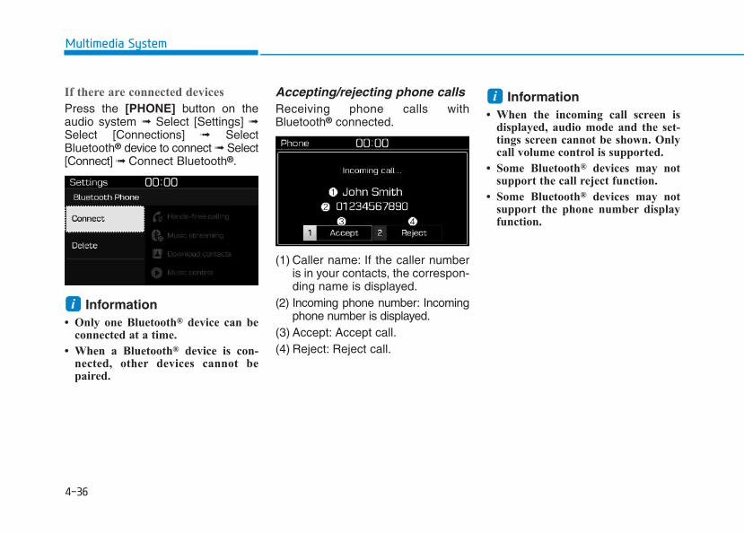
4-36
Multimedia System
If there are connected devices
Press the [PHONE] button on theaudio system ➟ Select [Settings] ➟Select [Connections] ➟ SelectBluetooth® device to connect ➟ Select[Connect] ➟ Connect Bluetooth®.
Information• Only one Bluetooth® device can be
connected at a time.
• When a Bluetooth® device is con-nected, other devices cannot bepaired.
Accepting/rejecting phone callsReceiving phone calls withBluetooth® connected.
(1) Caller name: If the caller numberis in your contacts, the correspon-ding name is displayed.
(2) Incoming phone number: Incomingphone number is displayed.
(3) Accept: Accept call.(4) Reject: Reject call.
Information• When the incoming call screen is
displayed, audio mode and the set-tings screen cannot be shown. Onlycall volume control is supported.
• Some Bluetooth® devices may notsupport the call reject function.
• Some Bluetooth® devices may notsupport the phone number displayfunction.
i
i
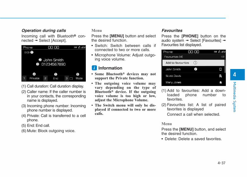
4-37
Multim
edia System
4
Operation during calls Incoming call with Bluetooth® con-nected ➟ Select [Accept].
(1) Call duration: Call duration display.(2) Caller name: If the caller number is
in your contacts, the correspondingname is displayed.
(3) Incoming phone number: Incomingphone number is displayed.
(4) Private: Call is transferred to a cellphone.
(5) End: End call.(6) Mute: Block outgoing voice.
Menu
Press the [MENU] button and selectthe desired function.• Switch: Switch between calls if
connected to two or more calls.• Microphone Volume: Adjust outgo-
ing voice volume.
Information• Some Bluetooth® devices may not
support the Private function.
• The outgoing voice volume mayvary depending on the type ofBluetooth® device. If the outgoingvoice volume is too high or low,adjust the Microphone Volume.
• The Switch menu will only be dis-played if connected to two or morecalls.
FavouritesPress the [PHONE] button on theaudio system ➟ Select [Favourites] ➟Favourites list displayed.
(1) Add to favourites: Add a down-loaded phone number tofavorites.
(2) Favourites list: A list of pairedfavorites is displayedConnect a call when selected.
Menu
Press the [MENU] button, and selectthe desired function.• Delete: Delete a saved favorites.
i
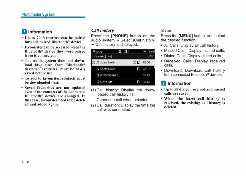
Information• Up to 20 favourites can be paired
for each paired Bluetooth® device.
• Favourites can be accessed when theBluetooth® device they were pairedfrom is connected.
• The audio system does not down-load favourites from Bluetooth®
devices. Favourites must be newlysaved before use.
• To add to favourites, contacts mustbe downloaded first.
• Saved favourites are not updatedeven if the contacts of the connectedBluetooth® device are changed. Inthis case, favourites need to be delet-ed and added again.
Call historyPress the [PHONE] button on theaudio system ➟ Select [Call history]➟ Call history is displayed.
(1) Call history: Display the down-loaded call history list.Connect a call when selected.
(2) Call duration: Display the time thecall was connected.
Menu
Press the [MENU] button, and selectthe desired function.• All Calls: Display all call history.• Missed Calls: Display missed calls.• Dialed Calls: Display dialed calls.• Received Calls: Display received
calls.• Download: Download call history
from connected Bluetooth® devices.
Information• Up to 50 dialed, received and missed
calls are saved.
• When the latest call history isreceived, the existing call history isdeleted.
i
i
4-38
Multimedia System
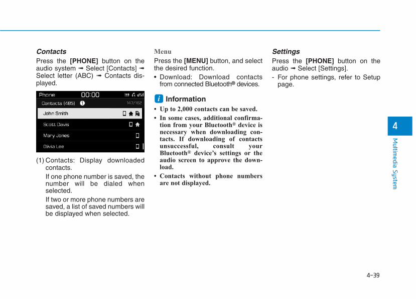
ContactsPress the [PHONE] button on theaudio system ➟ Select [Contacts] ➟Select letter (ABC) ➟ Contacts dis-played.
(1) Contacts: Display downloadedcontacts.If one phone number is saved, thenumber will be dialed whenselected.If two or more phone numbers aresaved, a list of saved numbers willbe displayed when selected.
Menu
Press the [MENU] button, and selectthe desired function.• Download: Download contacts
from connected Bluetooth® devices.
Information• Up to 2,000 contacts can be saved.
• In some cases, additional confirma-tion from your Bluetooth® device isnecessary when downloading con-tacts. If downloading of contactsunsuccessful, consult yourBluetooth® device’s settings or theaudio screen to approve the down-load.
• Contacts without phone numbersare not displayed.
SettingsPress the [PHONE] button on theaudio ➟ Select [Settings].- For phone settings, refer to Setup
page.
i
4-39
Multim
edia System
4
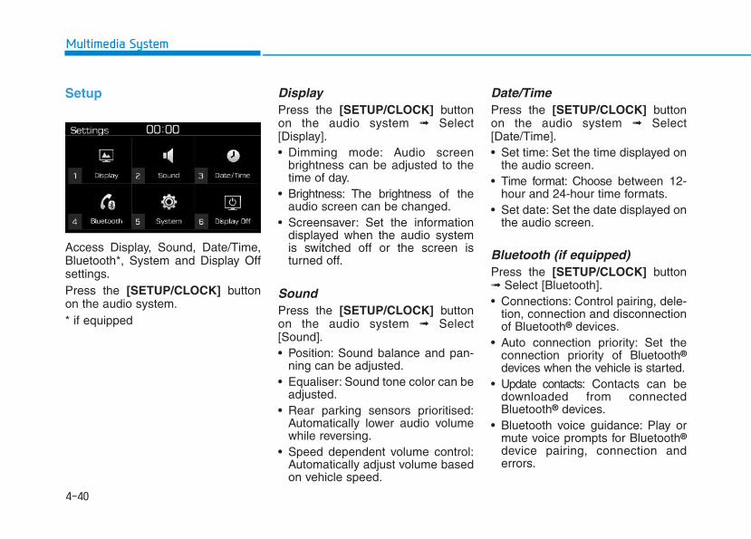
4-40
Multimedia System
Setup
Access Display, Sound, Date/Time,Bluetooth*, System and Display Offsettings.Press the [SETUP/CLOCK] buttonon the audio system.* if equipped
Display Press the [SETUP/CLOCK] buttonon the audio system ➟ Select[Display].• Dimming mode: Audio screen
brightness can be adjusted to thetime of day.
• Brightness: The brightness of theaudio screen can be changed.
• Screensaver: Set the informationdisplayed when the audio systemis switched off or the screen isturned off.
SoundPress the [SETUP/CLOCK] buttonon the audio system ➟ Select[Sound].• Position: Sound balance and pan-
ning can be adjusted.• Equaliser: Sound tone color can be
adjusted.• Rear parking sensors prioritised:
Automatically lower audio volumewhile reversing.
• Speed dependent volume control:Automatically adjust volume basedon vehicle speed.
Date/TimePress the [SETUP/CLOCK] buttonon the audio system ➟ Select[Date/Time].• Set time: Set the time displayed on
the audio screen.• Time format: Choose between 12-
hour and 24-hour time formats.• Set date: Set the date displayed on
the audio screen.
Bluetooth (if equipped)Press the [SETUP/CLOCK] button➟ Select [Bluetooth].• Connections: Control pairing, dele-
tion, connection and disconnectionof Bluetooth® devices.
• Auto connection priority: Set theconnection priority of Bluetooth®
devices when the vehicle is started.• Update contacts: Contacts can be
downloaded from connectedBluetooth® devices.
• Bluetooth voice guidance: Play ormute voice prompts for Bluetooth®
device pairing, connection anderrors.
4-41
Multim
edia System
4
Information• When paired devices are deleted,
the call history and contacts of thedevice saved to the audio system aredeleted.
• For Bluetooth® connections withlow connection priority, some timemay be required for the connectionto be established.
• Contacts can be downloaded onlyfrom the currently connectedBluetooth® device.
• If no Bluetooth® device is connected,the Download Contacts button isdisabled.
• If the language setting is Slovakian,Hungarian or Korean, Bluetoothvoice guidance is not supported.
SystemPress the [SETUP/CLOCK] buttonon the audio system ➟ Select[System].• Memory information: View My
Music memory usage.• Language: Change the user lan-
guage.• Default: Reset the audio system.
InformationThe system resets to the default val-ues, and all saved data and settingsare lost.
Display OffTo prevent glare, the screen can beturned off with the audio system inoperation.Press the [SETUP/CLOCK] buttonon the audio system ➟ Select[Display Off].
InformationUse ‘Screensaver’ to set the informa-tion to be displayed when the screen isturned off.
i
i
i
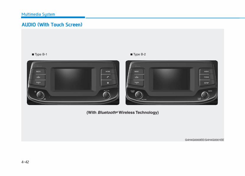
4-42
Multimedia System
■ Type B-1 ■ Type B-2
AAUUDDIIOO ((WWiitthh TToouucchh SSccrreeeenn))
G4H4G0000EE/G4H4G0001EE
(With Bluetooth® Wireless Technology)
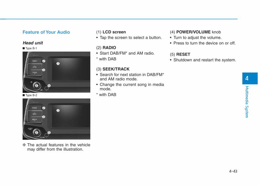
4-43
Multim
edia System
4
Feature of Your Audio
Head unit
❈ The actual features in the vehiclemay differ from the illustration.
(1) LCD screen• Tap the screen to select a button.
(2) RADIO• Start DAB/FM* and AM radio.* with DAB
(3) SEEK/TRACK• Search for next station in DAB/FM*
and AM radio mode.• Change the current song in media
mode.* with DAB
(4) POWER/VOLUME knob • Turn to adjust the volume.• Press to turn the device on or off.
(5) RESET• Shutdown and restart the system.
■ Type B-2
■ Type B-1
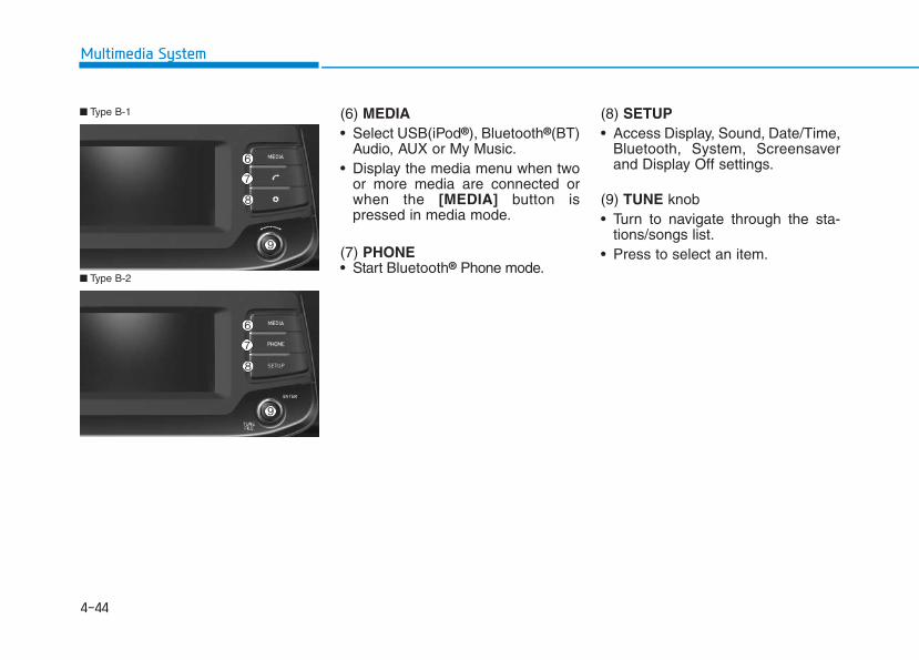
4-44
Multimedia System
(6) MEDIA• Select USB(iPod®), Bluetooth®(BT)
Audio, AUX or My Music.• Display the media menu when two
or more media are connected orwhen the [MEDIA] button ispressed in media mode.
(7) PHONE• Start Bluetooth® Phone mode.
(8) SETUP• Access Display, Sound, Date/Time,
Bluetooth, System, Screensaverand Display Off settings.
(9) TUNE knob • Turn to navigate through the sta-
tions/songs list.• Press to select an item.
■ Type B-2
■ Type B-1
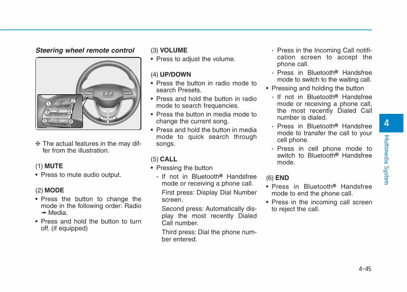
4-45
Multim
edia System
4
Steering wheel remote control
❈ The actual features in the may dif-fer from the illustration.
(1) MUTE• Press to mute audio output.
(2) MODE• Press the button to change the
mode in the following order: Radio➟ Media.
• Press and hold the button to turnoff. (if equipped)
(3) VOLUME• Press to adjust the volume.
(4) UP/DOWN• Press the button in radio mode to
search Presets.• Press and hold the button in radio
mode to search frequencies.• Press the button in media mode to
change the current song.• Press and hold the button in media
mode to quick search throughsongs.
(5) CALL• Pressing the button
- If not in Bluetooth® Handsfreemode or receiving a phone call.First press: Display Dial Numberscreen.Second press: Automatically dis-play the most recently DialedCall number.Third press: Dial the phone num-ber entered.
- Press in the Incoming Call notifi-cation screen to accept thephone call.
- Press in Bluetooth® Handsfreemode to switch to the waiting call.
• Pressing and holding the button- If not in Bluetooth® Handsfree
mode or receiving a phone call,the most recently Dialed Callnumber is dialed.
- Press in Bluetooth® Handsfreemode to transfer the call to yourcell phone.
- Press in cell phone mode toswitch to Bluetooth® Handsfreemode.
(6) END• Press in Bluetooth® Handsfree
mode to end the phone call.• Press in the incoming call screen
to reject the call.
4-46
Multimedia System
• Do not stare at the screenwhile driving. Staring at thescreen for prolonged periodsof time could lead to trafficaccidents.
• Do not disassemble, assem-ble, or modify the audio sys-tem. Such acts could result inaccidents, fire, or electricshock.
• Using the phone while drivingmay lead to a lack of attentionof traffic conditions andincrease the likelihood ofaccidents. Use the phone fea-ture after parking the vehicle.
• Heed caution not to spill wateror introduce foreign objectsinto the device. Such actscould lead to smoke, fire, orproduct malfunction.
(Continued)
WARNING (Continued)• Please refrain from use if the
screen is blank or no soundcan be heard as these signsmay indicate product malfunc-tion. Continued use in suchconditions could lead to acci-dents (fires, electric shock) orproduct malfunctions.
• Do not touch the antenna dur-ing thunder or lightening assuch acts may lead to light-ning induced electric shock.
• Do not stop or park in park-ing-restricted areas to operatethe product. Such acts couldlead to traffic accidents.
• Use the system with the vehi-cle ignition turned on.Prolonged use with the igni-tion turned off could result inbattery discharge.
Driving while distracted canresult in a loss of vehicle con-trol that may lead to an acci-dent, severe personal injury,and death. The driver’s primaryresponsibility is in the safe andlegal operation of a vehicle, anduse of any handheld devices,other equipment, or vehicle sys-tems which take the driver’seyes, attention and focus awayfrom the safe operation of avehicle or which are not permis-sible by law should never beused during operation of thevehicle.
WARNING
4-47
Multim
edia System
4
• Operating the device while driv-ing could lead to accidents dueto a lack of attention to externalsurroundings. First park thevehicle before operating thedevice.
• Adjust the volume to levels thatallow the driver to hear soundsfrom outside of the vehicle.Driving in a state where externalsounds cannot be heard maylead to accidents.
• Pay attention to the volume set-ting when turning the device on.A sudden output of extreme vol-ume upon turning the device oncould lead to hearing impair-ment. (Adjust the volume to asuitable levels before turning offthe device.)
• If you want to change the posi-tion of device installation,please inquire with your place ofpurchase or service mainte-nance center. Technical expert-ise is required to install or dis-assemble the device.
(Continued)
(Continued)• Turn on the car ignition before
using this device. Do not oper-ate the audio system for longperiods of time with the ignitionturned off as such operationsmay lead to battery discharge.
• Do not subject the device tosevere shock or impact. Directpressure onto the front side ofthe monitor may cause damageto the LCD or touch screen.
• When cleaning the device, makesure to turn off the device anduse a dry and smooth cloth.Never use tough materials,chemical cloths, or solvents(alcohol, benzene, thinners,etc.). As such materials maydamage the device panel orcause color/quality deterioration
• Do not place beverages close tothe audio system. Spilling bever-ages may lead to system mal-function.
(Continued)
(Continued)• In case of product malfunction,
please contact your place of pur-chase or After Service center.
• Placing the audio system withinan electromagnetic environmentmay result in noise interference.
NOTICE
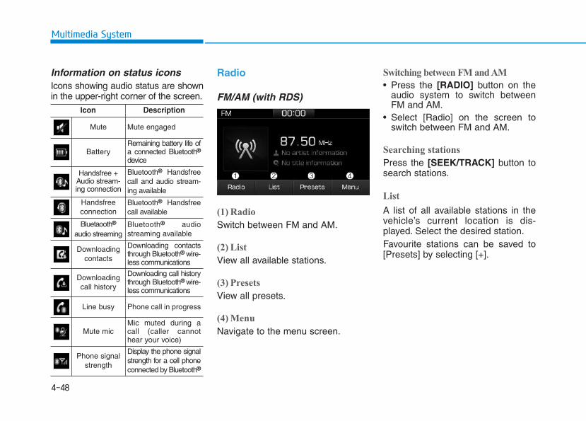
4-48
Multimedia System
Information on status iconsIcons showing audio status are shownin the upper-right corner of the screen.
Radio
FM/AM (with RDS)
(1) Radio
Switch between FM and AM.
(2) List
View all available stations.
(3) Presets
View all presets.
(4) Menu
Navigate to the menu screen.
Switching between FM and AM
• Press the [RADIO] button on theaudio system to switch betweenFM and AM.
• Select [Radio] on the screen toswitch between FM and AM.
Searching stations
Press the [SEEK/TRACK] button tosearch stations.
List
A list of all available stations in thevehicle’s current location is dis-played. Select the desired station.Favourite stations can be saved to[Presets] by selecting [+].
Icon Description
Mute Mute engaged
BatteryRemaining battery life ofa connected Bluetooth®
device
Handsfree +Audio stream-ing connection
Bluetooth® Handsfreecall and audio stream-ing available
Handsfreeconnection
Bluetooth® Handsfreecall available
Bluetaooth®
audio streamingBluetooth® audiostreaming available
Downloadingcontacts
Downloading contactsthrough Bluetooth® wire-less communications
Downloading call history
Downloading call historythrough Bluetooth® wire-less communications
Line busy Phone call in progress
Mute micMic muted during acall (caller cannothear your voice)
Phone signalstrength
Display the phone signalstrength for a cell phoneconnected by Bluetooth®
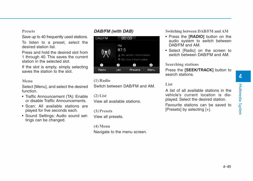
4-49
Multim
edia System
4
Presets
Save up to 40 frequently used stations.To listen to a preset, select thedesired station list.Press and hold the desired slot from1 through 40. This saves the currentstation in the selected slot.If the slot is empty, simply selectingsaves the station to the slot.
Menu
Select [Menu], and select the desiredfunction.• Traffic Announcement (TA): Enable
or disable Traffic Announcements.• Scan: All available stations are
played for five seconds each.• Sound Settings: Audio sound set-
tings can be changed.
DAB/FM (with DAB)
(1) Radio
Switch between DAB/FM and AM.
(2) List
View all available stations.
(3) Presets
View all presets.
(4) Menu
Navigate to the menu screen.
Switching between DAB/FM and AM
• Press the [RADIO] button on theaudio system to switch betweenDAB/FM and AM.
• Select [Radio] on the screen toswitch between DAB/FM and AM.
Searching stations
Press the [SEEK/TRACK] button tosearch stations.
List
A list of all available stations in thevehicle’s current location is dis-played. Select the desired station.Favourite stations can be saved to[Presets] by selecting [+].
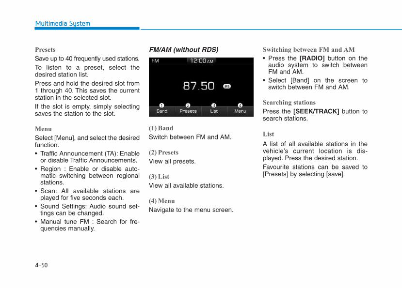
4-50
Multimedia System
Presets
Save up to 40 frequently used stations.To listen to a preset, select thedesired station list.Press and hold the desired slot from1 through 40. This saves the currentstation in the selected slot.If the slot is empty, simply selectingsaves the station to the slot.
Menu
Select [Menu], and select the desiredfunction.• Traffic Announcement (TA): Enable
or disable Traffic Announcements.• Region : Enable or disable auto-
matic switching between regionalstations.
• Scan: All available stations areplayed for five seconds each.
• Sound Settings: Audio sound set-tings can be changed.
• Manual tune FM : Search for fre-quencies manually.
FM/AM (without RDS)
(1) Band
Switch between FM and AM.
(2) Presets
View all presets.
(3) List
View all available stations.
(4) Menu
Navigate to the menu screen.
Switching between FM and AM
• Press the [RADIO] button on theaudio system to switch betweenFM and AM.
• Select [Band] on the screen toswitch between FM and AM.
Searching stations
Press the [SEEK/TRACK] button tosearch stations.
List
A list of all available stations in thevehicle’s current location is dis-played. Press the desired station.Favourite stations can be saved to[Presets] by selecting [save].
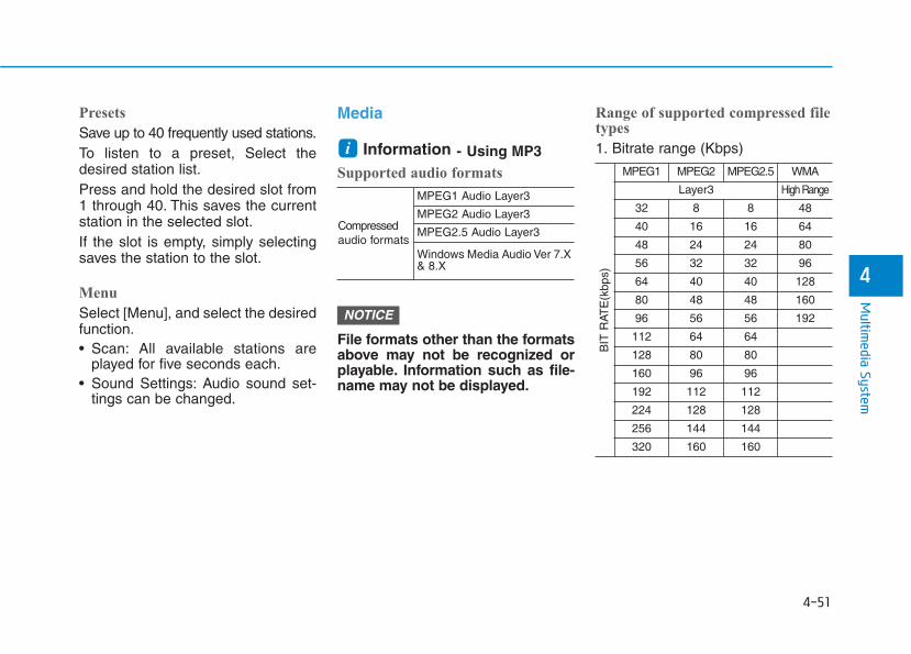
4-51
Multim
edia System
4
Presets
Save up to 40 frequently used stations.To listen to a preset, Select thedesired station list.Press and hold the desired slot from1 through 40. This saves the currentstation in the selected slot.If the slot is empty, simply selectingsaves the station to the slot.
Menu
Select [Menu], and select the desiredfunction.• Scan: All available stations are
played for five seconds each.• Sound Settings: Audio sound set-
tings can be changed.
Media
Information - Using MP3Supported audio formats
File formats other than the formatsabove may not be recognized orplayable. Information such as file-name may not be displayed.
Range of supported compressed filetypes
1. Bitrate range (Kbps)
NOTICE
i
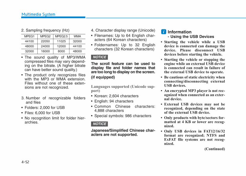
4-52
Multimedia System
2. Sampling frequency (Hz)
• The sound quality of MP3/WMAcompressed files may vary depend-ing on the bitrate. (A higher bitratecan have better sound quality.)
• The product only recognizes fileswith the MP3 or WMA extension.Files without one of these exten-sions are not recognized.
3. Number of recognizable foldersand files
• Folders: 2,000 for USB• Files: 6,000 for USB• No recognition limit for folder hier-
archies.
4. Character display range (Unicode)• Filenames: Up to 64 English char-
acters (64 Korean characters)• Foldernames: Up to 32 English
characters (32 Korean characters)
The scroll feature can be used todisplay file and folder names thatare too long to display on the screen.(if equipped)
Languages supported (Unicode sup-port)
• Korean: 2,604 characters• English: 94 characters• Common Chinese characters:
4,888 characters• Special symbols: 986 characters
Japanese/Simplified Chinese char-acters are not supported.
Information- Using the USB Devices
• Starting the vehicle while a USBdevice is connected can damage thedevice. Please disconnect USBdevices before starting the vehicle.
• Starting the vehicle or stopping theengine while an external USB deviceis connected can result in failure ofthe external USB device to operate.
• Be cautious of static electricity whenconnecting/disconnecting externalUSB devices.
• An encrypted MP3 player is not rec-ognized when connected as an exter-nal device.
• External USB devices may not berecognized, depending on the stateof the external USB device.
• Only products with byte/sectors for-matted at 4 KB or lower are recog-nized.
• Only USB devices in FAT12/16/32format are recognized; NTFS andExFAT file systems are not recog-nized.
(Continued)
i
NOTICE
NOTICE
4-53
Multim
edia System
4
(Continued)
• Some USB devices are not recog-nized due to compatibility issues.
• Do not touch the USB connections.
• Connecting and disconnecting USBdevices rapidly over a short periodof time can cause equipment failure.
• Abnormal sounds may be audiblewhen the USB device is disconnected.
• Turn the audio off before connectingor disconnecting external USBdevices.
• Recognition may take longerdepending on the type, capacity orfile format of the external USBdevice. This is not a product mal-function.
• Use of USB devices for purposesother than playing music files is pro-hibited.
• Image display and video playbackare not supported.
(Continued)
(Continued)
• Use of USB accessories, includingcharge and heat though the USB I/F,can lead to reduced product per-formance or malfunctions. Do notuse USB devices or accessories forthese purposes.
• Use of aftermarket USB hubs andextension cables can result in thevehicle’s audio system failing to rec-ognize your USB device. Connectthe USB device directly to the multi-media port of your vehicle.
• When using high-capacity USBdevices with logical drive divisions,only files saved on the highest levellogical drive can be played.
If applications are loaded on a USBdrive, file playback may fail.
• Some MP3 players, cell phones, dig-ital cameras, etc. (USB devices thatare not recognized as mobile stor-age) may not operate normallywhen connected.
• USB charging may not be supportedby some mobile devices.
(Continued)
(Continued)
• Operation is guaranteed only forstandard (Metal Cover Type) USBMemory drives.
• Operation of HDD, CF, SD and mem-ory stick devices is not guaranteed.
• DRM (Digital Rights Management)files cannot be played.
• SD-type USB memory, CF-typeUSB memory, and other USB mem-ory devices that require adaptersfor connection are not supported.
• Proper operation of USB HDDs orUSB drives with connectors thatloosen due to vehicle vibrations isnot guaranteed. (iStick, etc.)
• USB products that areused as key chains orcell phone accessoriesmay damage the USBjack and affect properfile playback. Please refrain fromuse. Use only products with plugconnectors, as shown in the follow-ing illustration.
• When MP3 devices or cell phones areconnected simultaneously throughAUX, BT Audio and USB modes, apopping noise or malfunction mayoccur.
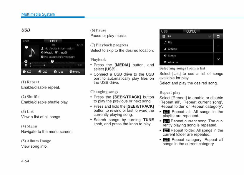
4-54
Multimedia System
USB
(1) Repeat
Enable/disable repeat.
(2) Shuffle
Enable/disable shuffle play.
(3) List
View a list of all songs.
(4) Menu
Navigate to the menu screen.
(5) Album Image
View song info.
(6) Pause
Pause or play music.
(7) Playback progress
Select to skip to the desired location.
Playback
• Press the [MEDIA] button, andselect [USB].
• Connect a USB drive to the USBport to automatically play files onthe USB drive.
Changing songs
• Press the [SEEK/TRACK] buttonto play the previous or next song.
• Press and hold the [SEEK/TRACK]button to rewind or fast forward thecurrently playing song.
• Search songs by turning TUNEknob, and press the knob to play.
Selecting songs from a list
Select [List] to see a list of songsavailable for play.Select and play the desired song.
Repeat play
Select [Repeat] to enable or disable‘Repeat all’, ‘Repeat current song’,‘Repeat folder’ or ‘Repeat category’.• Repeat all: All songs in the
playlist are repeated.• Repeat current song: The cur-
rently playing song is repeated.• Repeat folder: All songs in the
current folder are repeated.• Repeat category: Repeat all
songs in the current category.
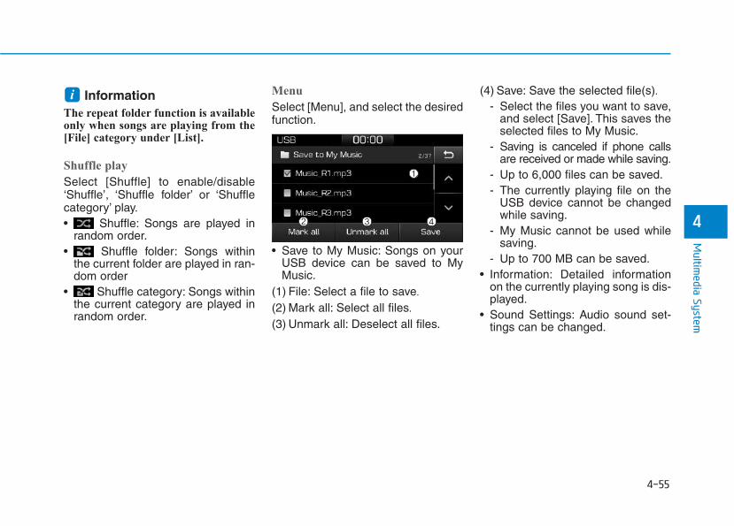
4-55
Multim
edia System
4
InformationThe repeat folder function is availableonly when songs are playing from the[File] category under [List].
Shuffle play
Select [Shuffle] to enable/disable‘Shuffle’, ‘Shuffle folder’ or ‘Shufflecategory’ play.• Shuffle: Songs are played in
random order.• Shuffle folder: Songs within
the current folder are played in ran-dom order
• Shuffle category: Songs withinthe current category are played inrandom order.
Menu
Select [Menu], and select the desiredfunction.
• Save to My Music: Songs on yourUSB device can be saved to MyMusic.
(1) File: Select a file to save.
(2) Mark all: Select all files.
(3) Unmark all: Deselect all files.
(4) Save: Save the selected file(s).- Select the files you want to save,
and select [Save]. This saves theselected files to My Music.
- Saving is canceled if phone callsare received or made while saving.
- Up to 6,000 files can be saved.- The currently playing file on the
USB device cannot be changedwhile saving.
- My Music cannot be used whilesaving.
- Up to 700 MB can be saved.• Information: Detailed information
on the currently playing song is dis-played.
• Sound Settings: Audio sound set-tings can be changed.
i
4-56
Multimedia System
Information- Using the iPod® Devices
• To use the audio system’s iPod® con-trol function, use the dedicatedcable provided with your iPod®.
• Connecting the iPod® to the vehicleduring play may result in a loudnoise that lasts about one to two sec-onds. Connect the iPod® to the vehi-cle after stopping or pausing play.
• Connect the iPod® with the vehicle inthe ACC ON state to begin charging.
• When connecting the iPod® cable,be sure to fully push the cable intothe port.
• When EQ effects are enabled simul-taneously on external devices, suchas iPod®s and the audio system, theEQ effects may overlap, causingsound quality deterioration or dis-tortion. Deactivate the EQ functionfor all external devices, if possible.
• Noise may occur when your iPod®
or the AUX port is connected.Disconnect and store separatelywhen not in use.
(Continued)
(Continued)
• There may be noise if the audio sys-tem is used with an iPod® or AUXexternal device connected to thepower jack. In these cases, discon-nect the iPod® or external devicefrom the power jack.
• Play may be interrupted, or devicemalfunctions may occur dependingon the characteristics of youriPod®/iPhone®.
• Play may fail if your iPhone® is con-nected through both Bluetooth® andUSB. In this case, select Dock con-nector or Bluetooth® on youriPhone® to change the sound outputsettings.
• If your software version does notsupport the communication proto-col or your iPod® is not recognizeddue to device failure, anomalies ordefects, iPod® mode cannot be used.
• iPod® nano (5th generation) devicesmay not be recognized if the batteryis low. Charge sufficiently before use.
(Continued)
(Continued)
• The search and song play order inthe iPod® device may be differentfrom the search order in the audiosystem.
• If the iPod® has failed due to aninternal defect, please reset theiPod® (consult your iPod® manual).
• Depending on the software version,the iPod® may fail to sync with thesystem. If the media is removed ordisconnected before recognition, theprevious mode may not be restored(iPad® cannot be charged).
• Cables other than the 1-meter cableprovided with iPod®/iPhone® prod-ucts may not be recognized.
• When other music apps are used onyour iPod®, the system sync func-tion may fail due to malfunction ofthe iPod® application.
i
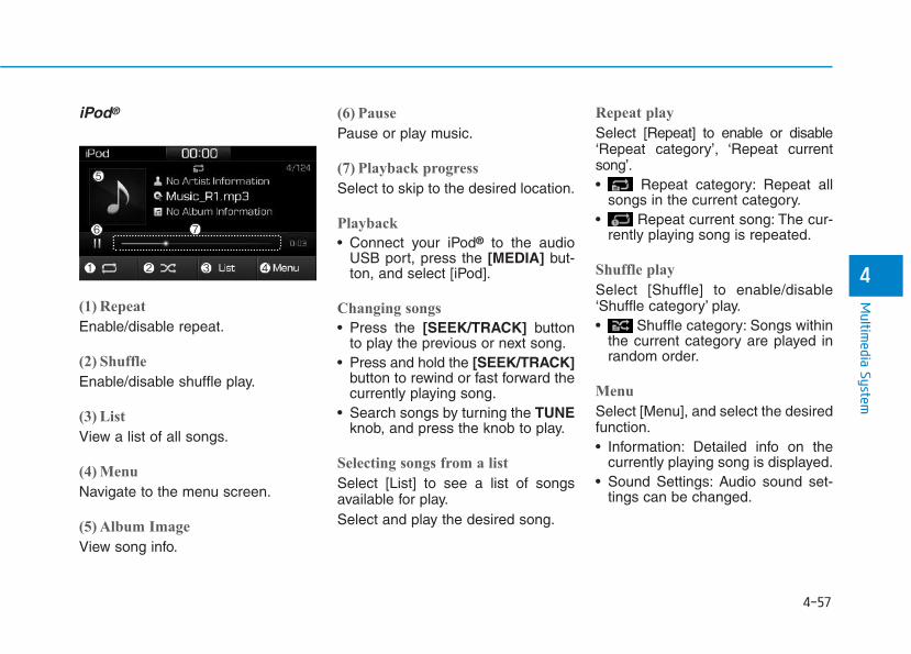
4-57
Multim
edia System
4
iPod®
(1) Repeat
Enable/disable repeat.
(2) Shuffle
Enable/disable shuffle play.
(3) List
View a list of all songs.
(4) Menu
Navigate to the menu screen.
(5) Album Image
View song info.
(6) Pause
Pause or play music.
(7) Playback progress
Select to skip to the desired location.
Playback
• Connect your iPod® to the audioUSB port, press the [MEDIA] but-ton, and select [iPod].
Changing songs
• Press the [SEEK/TRACK] buttonto play the previous or next song.
• Press and hold the [SEEK/TRACK]button to rewind or fast forward thecurrently playing song.
• Search songs by turning the TUNEknob, and press the knob to play.
Selecting songs from a list
Select [List] to see a list of songsavailable for play.Select and play the desired song.
Repeat play
Select [Repeat] to enable or disable‘Repeat category’, ‘Repeat currentsong’.• Repeat category: Repeat all
songs in the current category.• Repeat current song: The cur-
rently playing song is repeated.
Shuffle play
Select [Shuffle] to enable/disable‘Shuffle category’ play.• Shuffle category: Songs within
the current category are played inrandom order.
Menu
Select [Menu], and select the desiredfunction.• Information: Detailed info on the
currently playing song is displayed.• Sound Settings: Audio sound set-
tings can be changed.
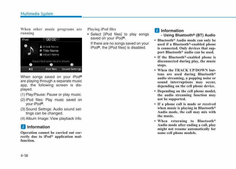
4-58
Multimedia System
When other music programs arerunning
When songs saved on your iPod®
are playing through a separate musicapp, the following screen is dis-played.(1) Play/Pause: Pause or play music.
(2) iPod files: Play music saved onyour iPod®.
(3) Sound Settngs: Audio sound set-tings can be changed.
(4) Album Image: View playback info.
Information Operation cannot be carried out cor-rectly due to iPod® application mal-function.
Playing iPod files
• Select [iPod files] to play songssaved on your iPod®.If there are no songs saved on youriPod®, the [iPod files] is disabled.
Information- Using Bluetooth® (BT) Audio
• Bluetooth® Audio mode can only beused if a Bluetooth®-enabled phoneis connected. Only devices that sup-port Bluetooth® audio can be used.
• If the Bluetooth®-enabled phone isdisconnected during play, the musicstops.
• When the TRACK UP/DOWN but-tons are used during Bluetooth®
audio streaming, a popping noise orsound interruptions may occur,depending on the cell phone device.
• Depending on the cell phone model,the audio streaming function maynot be supported.
• If a phone call is made or receivedwhen music is playing in Bluetooth®
Audio mode, the call may mix withthe music.
• When returning to Bluetooth®
Audio mode after ending a call, playmight not resume automatically forsome cell phone models.
i
i
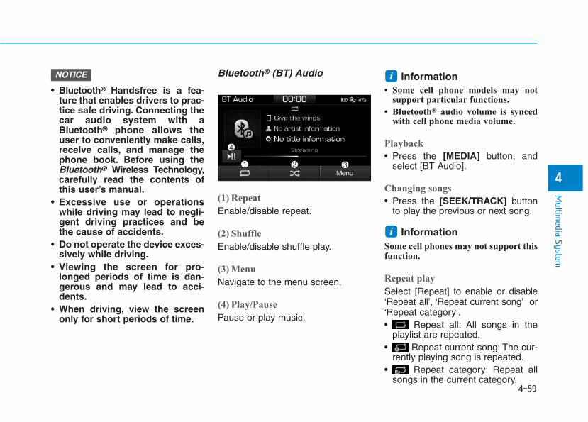
4-59
Multim
edia System
4
• Bluetooth® Handsfree is a fea-ture that enables drivers to prac-tice safe driving. Connecting thecar audio system with aBluetooth® phone allows theuser to conveniently make calls,receive calls, and manage thephone book. Before using theBluetooth® Wireless Technology,carefully read the contents ofthis user’s manual.
• Excessive use or operationswhile driving may lead to negli-gent driving practices and bethe cause of accidents.
• Do not operate the device exces-sively while driving.
• Viewing the screen for pro-longed periods of time is dan-gerous and may lead to acci-dents.
• When driving, view the screenonly for short periods of time.
Bluetooth® (BT) Audio
(1) Repeat
Enable/disable repeat.
(2) Shuffle
Enable/disable shuffle play.
(3) Menu
Navigate to the menu screen.
(4) Play/Pause
Pause or play music.
Information • Some cell phone models may not
support particular functions.
• Bluetooth® audio volume is syncedwith cell phone media volume.
Playback
• Press the [MEDIA] button, andselect [BT Audio].
Changing songs
• Press the [SEEK/TRACK] buttonto play the previous or next song.
Information Some cell phones may not support thisfunction.
Repeat play
Select [Repeat] to enable or disable‘Repeat all’, ‘Repeat current song’ or‘Repeat category’.• Repeat all: All songs in the
playlist are repeated.• Repeat current song: The cur-
rently playing song is repeated.• Repeat category: Repeat all
songs in the current category.
i
iNOTICE
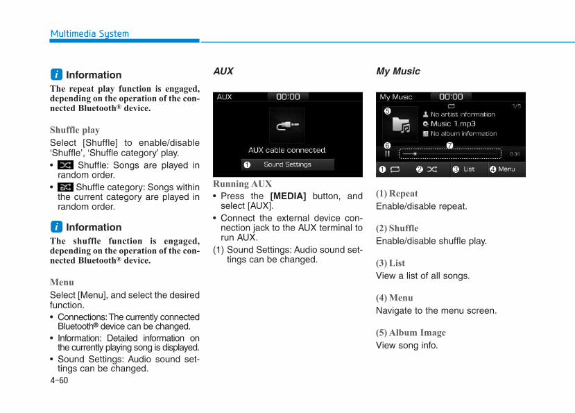
4-60
Multimedia System
Information The repeat play function is engaged,depending on the operation of the con-nected Bluetooth® device.
Shuffle play
Select [Shuffle] to enable/disable‘Shuffle’, ‘Shuffle category’ play.• Shuffle: Songs are played in
random order.• Shuffle category: Songs within
the current category are played inrandom order.
Information The shuffle function is engaged,depending on the operation of the con-nected Bluetooth® device.
Menu
Select [Menu], and select the desiredfunction.• Connections:The currently connected
Bluetooth® device can be changed.• Information: Detailed information on
the currently playing song is displayed.• Sound Settings: Audio sound set-
tings can be changed.
AUX
Running AUX
• Press the [MEDIA] button, andselect [AUX].
• Connect the external device con-nection jack to the AUX terminal torun AUX.
(1) Sound Settings: Audio sound set-tings can be changed.
My Music
(1) Repeat
Enable/disable repeat.
(2) Shuffle
Enable/disable shuffle play.
(3) List
View a list of all songs.
(4) Menu
Navigate to the menu screen.
(5) Album Image
View song info.
i
i
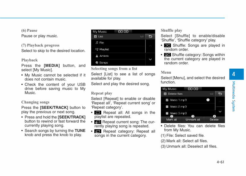
4-61
Multim
edia System
4
(6) Pause
Pause or play music.
(7) Playback progress
Select to skip to the desired location.
Playback
Press the [MEDIA] button, andselect [My Music].• My Music cannot be selected if it
does not contain music.• Check the content of your USB
drive before saving music to MyMusic.
Changing songs
Press the [SEEK/TRACK] button toplay the previous or next song.• Press and hold the [SEEK/TRACK]
button to rewind or fast forward thecurrently playing song.
• Search songs by turning the TUNEknob and press the knob to play.
Selecting songs from a list
Select [List] to see a list of songsavailable for play.Select and play the desired song.
Repeat play
Select [Repeat] to enable or disable‘Repeat all’, ‘Repeat current song’ or‘Repeat category’.• Repeat all: All songs in the
playlist are repeated.• Repeat current song: The cur-
rently playing song is repeated.• Repeat category: Repeat all
songs in the current category.
Shuffle play
Select [Shuffle] to enable/disable‘Shuffle’, ‘Shuffle category’ play.• Shuffle: Songs are played in
random order.• Shuffle category: Songs within
the current category are played inrandom order.
Menu
Select [Menu], and select the desiredfunction.
• Delete files: You can delete filesfrom My Music.
(1) File: Select saved file.
(2) Mark all: Select all files.(3) Unmark all: Deselect all files.
4-62
Multimedia System
(4) Delete: Delete the selected file(s).- Select the file to delete, then
select [Delete] to delete it.- Delete is canceled if phone calls
are received or made duringdelete.
• Add to playlist: Frequently playedsongs can be paired in a [Playlist].- Songs can be played from the
[Playlist].• Information: Detailed info on the
currently playing song is displayed.• Sound Settings: Audio sound set-
tings can be changed.
Delete from playlist
When a song in the playlist is play-ing, select [Menu] and select [Deletefrom playlist].Select the song to delete, then select[Delete].
Phone
Information - Using Bluetooth® (BT) Phone
• Bluetooth® is a near-field wirelessnetworking technology that uses the2.4 GHz frequency to connect vari-ous devices within a certain distancewirelessly.
• The technology is used in PCs,peripherals, Bluetooth® phones,tablet PCs, household appliancesand automobiles. Devices support-ing Bluetooth® can exchange data athigh speeds without physical cableconnections.
• Bluetooth® Handsfree devices enableconvenient access to phone functionsthrough cell phones equipped withBluetooth®.
• Some Bluetooth® devices may notbe supported by the Bluetooth®
Handsfree function.
(Continued)
(Continued)
• When Bluetooth® is connected andcalls are attempted through a con-nected cell phone from outside thevehicle, the call is connectedthrough the Bluetooth® Handsfreefunction of the vehicle.
• Please be sure to disconnect theBluetooth® Handsfree function throughyour Bluetooth® device or the audioscreen.
i
4-63
Multim
edia System
4
Safety precautions
• The Bluetooth® Handsfree functionhelps drivers to drive safely. Byconnecting a Bluetooth®-enabledphone to the vehicle’s audio sys-tem, phone calls can be made andreceived through the audio systemand contacts can be managed.Consult the user manual beforeuse.
• Excessive manipulation of controlswhile driving, making it difficult topay attention to the road ahead,can lead to accidents. Do not oper-ate the device excessively whiledriving.
• Looking at the screen for a pro-longed time increases the risk ofaccidents. Keep time spent lookingat the screen to a minimum.
Precautions when connectingBluetooth® devices
• The vehicle supports the followingBluetooth® functions. SomeBluetooth® devices may not sup-port some functions.1) Bluetooth® Handsfree phone calls2) Operations during a call
(Private, Switch, Mic Vol. con-trols)
3) Download call history saved tothe Bluetooth® device
4) Download contacts saved to theBluetooth® device
5) Automatic contacts/call historydownload when Bluetooth® isconnected
6) Automatic Bluetooth® deviceconnection when the vehicle isstarted
7) Bluetooth® audio streaming play-back
• Before connecting the audio sys-tem to your device, make sure yourdevice supports Bluetooth®.
• Even if your device supportsBluetooth®, a Bluetooth® connec-tion cannot be established if thedevice’s Bluetooth® function isswitched off. Search and connectwith the Bluetooth® functionenabled.
• Pair or connect Bluetooth® devicesto the audio system with the vehi-cle at a standstill.
• If a Bluetooth® connection is lostdue to abnormal conditions while aBluetooth® device is connected(communication range exceeded,device power OFF, communicationerrors, etc.), the disconnectedBluetooth® device is searched forand automatically reconnected.
• If you want to disable theBluetooth® device auto-connectfunction, turn the Bluetooth® func-tion OFF on your device. Consultthe user manuals for individualdevices to see whether Bluetooth®
is supported.• Handsfree call quality and volume
may vary depending on the type ofBluetooth® device.
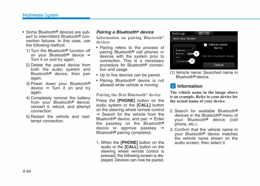
4-64
Multimedia System
• Some Bluetooth® devices are sub-ject to intermittent Bluetooth® con-nection failures. In this case, usethe following method.1) Turn the Bluetooth® function off
on your Bluetooth® device ➟Turn it on and try again.
2) Delete the paired device fromboth the audio system andBluetooth® device, then pairagain.
3) Power down your Bluetooth®
device ➟ Turn it on and tryagain.
4) Completely remove the batteryfrom your Bluetooth® device;reinsert it, reboot, and attemptconnection.
5) Restart the vehicle and reat-tempt connection.
Pairing a Bluetooth® deviceInformation on pairing Bluetooth®
devices
• Pairing refers to the process ofpairing Bluetooth® cell phones ordevices with the system prior toconnection. This is a necessaryprocedure for Bluetooth® connec-tion and usage.
• Up to five devices can be paired.• Pairing Bluetooth® device is not
allowed while vehicle is moving.
Pairing the first Bluetooth® device
Press the [PHONE] button on theaudio system or the [CALL] buttonon the steering wheel remote control➟ Search for the vehicle from theBluetooth® device, and pair ➟ Enterthe passkey on the Bluetooth®
device or approve passkey ➟Bluetooth® pairing completed.
1. When the [PHONE] button on theaudio or the [CALL] button on thesteering wheel remote control ispressed, the following screen is dis-played. Devices can now be paired.
(1) Vehicle name: Searched name inBluetooth® device.
Information The vehicle name in the image aboveis an example. Refer to your device forthe actual name of your device.
2. Search for available Bluetooth®
devices in the Bluetooth® menu ofyour Bluetooth® device (cellphone, etc.).
3. Confirm that the vehicle name inyour Bluetooth® device matchesthe vehicle name shown on theaudio screen, then select it.
i
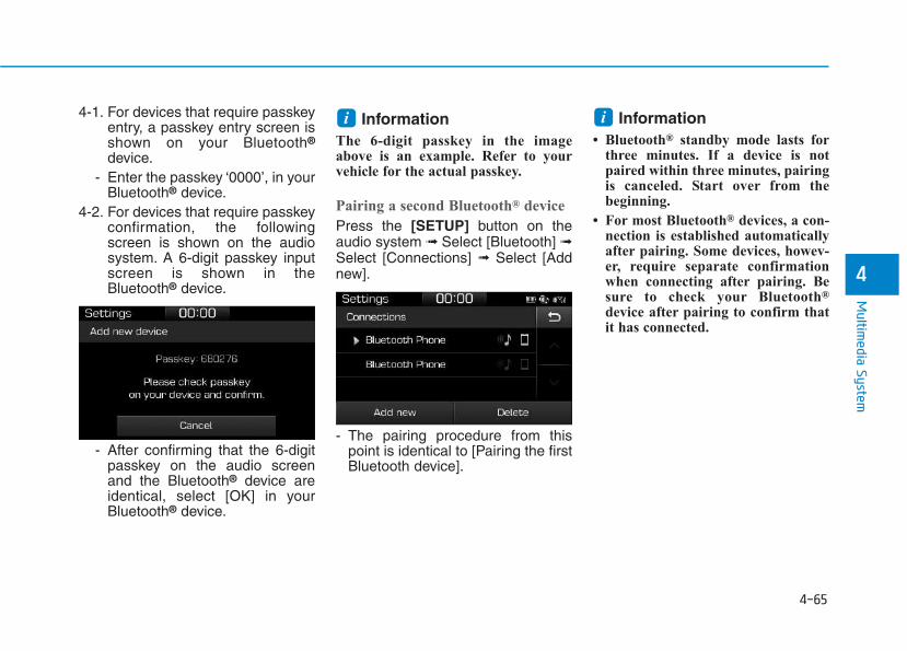
4-65
Multim
edia System
4
4-1. For devices that require passkeyentry, a passkey entry screen isshown on your Bluetooth®
device.- Enter the passkey ‘0000’, in your
Bluetooth® device.4-2. For devices that require passkey
confirmation, the followingscreen is shown on the audiosystem. A 6-digit passkey inputscreen is shown in theBluetooth® device.
- After confirming that the 6-digitpasskey on the audio screenand the Bluetooth® device areidentical, select [OK] in yourBluetooth® device.
Information The 6-digit passkey in the imageabove is an example. Refer to yourvehicle for the actual passkey.
Pairing a second Bluetooth® device
Press the [SETUP] button on theaudio system ➟ Select [Bluetooth] ➟Select [Connections] ➟ Select [Addnew].
- The pairing procedure from thispoint is identical to [Pairing the firstBluetooth device].
Information• Bluetooth® standby mode lasts for
three minutes. If a device is notpaired within three minutes, pairingis canceled. Start over from thebeginning.
• For most Bluetooth® devices, a con-nection is established automaticallyafter pairing. Some devices, howev-er, require separate confirmationwhen connecting after pairing. Besure to check your Bluetooth®
device after pairing to confirm thatit has connected.
ii
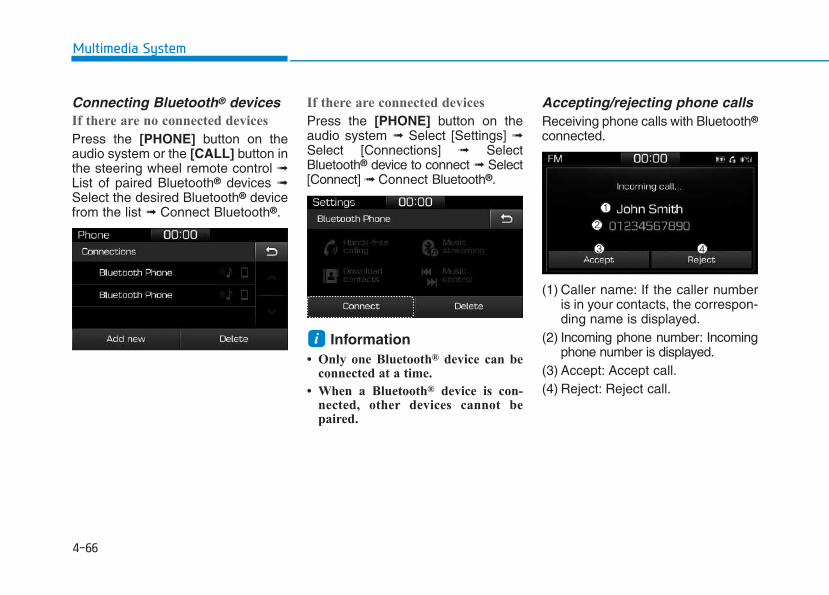
4-66
Multimedia System
Connecting Bluetooth® devicesIf there are no connected devices
Press the [PHONE] button on theaudio system or the [CALL] button inthe steering wheel remote control ➟List of paired Bluetooth® devices ➟Select the desired Bluetooth® devicefrom the list ➟ Connect Bluetooth®.
If there are connected devices
Press the [PHONE] button on theaudio system ➟ Select [Settings] ➟Select [Connections] ➟ SelectBluetooth® device to connect ➟ Select[Connect] ➟ Connect Bluetooth®.
Information• Only one Bluetooth® device can be
connected at a time.
• When a Bluetooth® device is con-nected, other devices cannot bepaired.
Accepting/rejecting phone callsReceiving phone calls with Bluetooth®
connected.
(1) Caller name: If the caller numberis in your contacts, the correspon-ding name is displayed.
(2) Incoming phone number: Incomingphone number is displayed.
(3) Accept: Accept call.(4) Reject: Reject call.
i
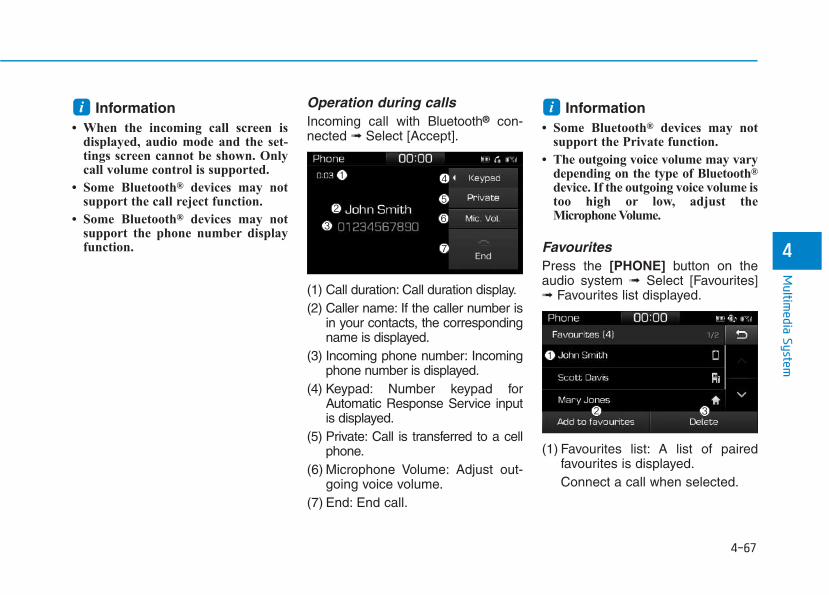
4-67
Multim
edia System
4
Information• When the incoming call screen is
displayed, audio mode and the set-tings screen cannot be shown. Onlycall volume control is supported.
• Some Bluetooth® devices may notsupport the call reject function.
• Some Bluetooth® devices may notsupport the phone number displayfunction.
Operation during calls Incoming call with Bluetooth® con-nected ➟ Select [Accept].
(1) Call duration: Call duration display.(2) Caller name: If the caller number is
in your contacts, the correspondingname is displayed.
(3) Incoming phone number: Incomingphone number is displayed.
(4) Keypad: Number keypad forAutomatic Response Service inputis displayed.
(5) Private: Call is transferred to a cellphone.
(6) Microphone Volume: Adjust out-going voice volume.
(7) End: End call.
Information• Some Bluetooth® devices may not
support the Private function.
• The outgoing voice volume may varydepending on the type of Bluetooth®
device. If the outgoing voice volume istoo high or low, adjust theMicrophone Volume.
FavouritesPress the [PHONE] button on theaudio system ➟ Select [Favourites]➟ Favourites list displayed.
(1) Favourites list: A list of pairedfavourites is displayed.Connect a call when selected.
ii
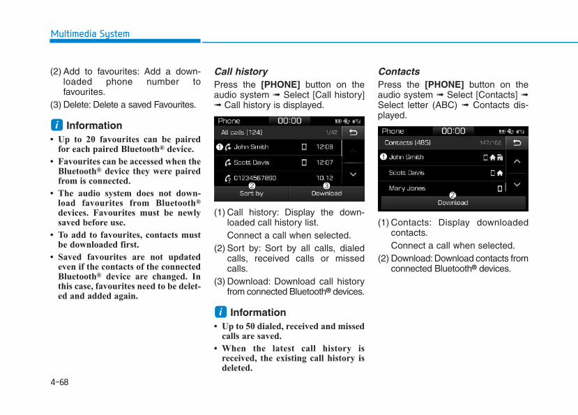
4-68
Multimedia System
(2) Add to favourites: Add a down-loaded phone number tofavourites.
(3) Delete: Delete a saved Favourites.
Information• Up to 20 favourites can be paired
for each paired Bluetooth® device.
• Favourites can be accessed when theBluetooth® device they were pairedfrom is connected.
• The audio system does not down-load favourites from Bluetooth®
devices. Favourites must be newlysaved before use.
• To add to favourites, contacts mustbe downloaded first.
• Saved favourites are not updatedeven if the contacts of the connectedBluetooth® device are changed. Inthis case, favourites need to be delet-ed and added again.
Call historyPress the [PHONE] button on theaudio system ➟ Select [Call history]➟ Call history is displayed.
(1) Call history: Display the down-loaded call history list.Connect a call when selected.
(2) Sort by: Sort by all calls, dialedcalls, received calls or missedcalls.
(3) Download: Download call historyfrom connected Bluetooth® devices.
Information• Up to 50 dialed, received and missed
calls are saved.
• When the latest call history isreceived, the existing call history isdeleted.
ContactsPress the [PHONE] button on theaudio system ➟ Select [Contacts] ➟Select letter (ABC) ➟ Contacts dis-played.
(1) Contacts: Display downloadedcontacts.Connect a call when selected.
(2) Download: Download contacts fromconnected Bluetooth® devices.
i
i
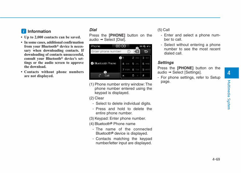
4-69
Multim
edia System
4
Information• Up to 2,000 contacts can be saved.
• In some cases, additional confirmationfrom your Bluetooth® device is neces-sary when downloading contacts. Ifdownloading of contacts unsuccessful,consult your Bluetooth® device’s set-tings or the audio screen to approvethe download.
• Contacts without phone numbersare not displayed.
DialPress the [PHONE] button on theaudio ➟ Select [Dial].
(1) Phone number entry window: Thephone number entered using thekeypad is displayed.
(2) Clear- Select to delete individual digits.- Press and hold to delete the
entire phone number.(3) Keypad: Enter phone number.(4) Bluetooth® Phone name
- The name of the connectedBluetooth® device is displayed.
- Contacts matching the keypadnumber/letter input are displayed.
(5) Call- Enter and select a phone num-
ber to call.- Select without entering a phone
number to see the most recentdialed call.
SettingsPress the [PHONE] button on theaudio ➟ Select [Settings].- For phone settings, refer to Setup
page.
i
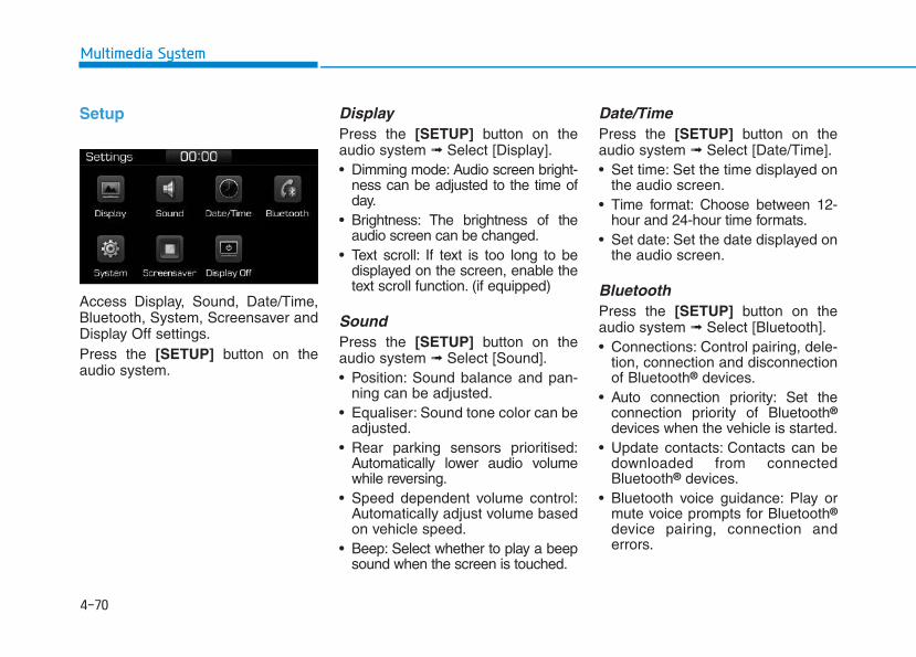
4-70
Multimedia System
Setup
Access Display, Sound, Date/Time,Bluetooth, System, Screensaver andDisplay Off settings.Press the [SETUP] button on theaudio system.
Display Press the [SETUP] button on theaudio system ➟ Select [Display].• Dimming mode: Audio screen bright-
ness can be adjusted to the time ofday.
• Brightness: The brightness of theaudio screen can be changed.
• Text scroll: If text is too long to bedisplayed on the screen, enable thetext scroll function. (if equipped)
Sound Press the [SETUP] button on theaudio system ➟ Select [Sound].• Position: Sound balance and pan-
ning can be adjusted.• Equaliser: Sound tone color can be
adjusted.• Rear parking sensors prioritised:
Automatically lower audio volumewhile reversing.
• Speed dependent volume control:Automatically adjust volume basedon vehicle speed.
• Beep: Select whether to play a beepsound when the screen is touched.
Date/TimePress the [SETUP] button on theaudio system ➟ Select [Date/Time].• Set time: Set the time displayed on
the audio screen.• Time format: Choose between 12-
hour and 24-hour time formats.• Set date: Set the date displayed on
the audio screen.
BluetoothPress the [SETUP] button on theaudio system ➟ Select [Bluetooth].• Connections: Control pairing, dele-
tion, connection and disconnectionof Bluetooth® devices.
• Auto connection priority: Set theconnection priority of Bluetooth®
devices when the vehicle is started.• Update contacts: Contacts can be
downloaded from connectedBluetooth® devices.
• Bluetooth voice guidance: Play ormute voice prompts for Bluetooth®
device pairing, connection anderrors.
4-71
Multim
edia System
4
Information• When paired devices are deleted,
the call history and contacts of thedevice saved to the audio system aredeleted.
• For Bluetooth® connections withlow connection priority, some timemay be required for the connectionto be established.
• Contacts can be downloaded onlyfrom the currently connectedBluetooth® device.
• If no Bluetooth® device is connected,the Download Contacts button isdisabled.
• If the language setting is Slovakian,Hungarian or Korean, Bluetoothvoice guidance is not supported.
SystemPress the [SETUP] button on theaudio system ➟ Select [System].• Memory information: View My
Music memory usage.• Language: Change the user lan-
guage.• Default: Reset the audio system.
InformationThe system resets to the default val-ues, and all saved data and settingsare lost.
ScreensaverSet the information displayed whenthe audio system is switched off orthe screen is turned off.Press the [SETUP] button on theaudio system ➟ Select [Screensaver].• Analogue: An analog clock is dis-
played.• Digital: A digital clock is displayed.• None: No information is displayed.
Display OffTo prevent glare, the screen can beturned off with the audio system inoperation.Press the [SETUP] button on theaudio system ➟ Select [Display Off].
InformationUse ‘Screensaver’ to set the informa-tion to be displayed when the screen isturned off.
i
i
i
4-72
Multimedia System
DDeeccllaarraattiioonn ooff CCoonnffoorrmmiittyyCE for EU
Driving your vehicle
Before driving.........................................................5-5Before entering the vehicle ...........................................5-5Before starting...................................................................5-5
Ignition switch ........................................................5-7Key ignition switch............................................................5-7Engine Start/Stop button..............................................5-11
Manual transmission............................................5-20Manual transmission operation ...................................5-20Good driving practices ...................................................5-22
Automatic transmission.......................................5-24Automatic transmission operation ..............................5-24Parking...............................................................................5-29Good driving practices ...................................................5-29
Dual clutch transmission.....................................5-31Dual clutch transmission operation ............................5-31Parking...............................................................................5-39Good driving practices ...................................................5-39
Braking system.....................................................5-41Power brakes ...................................................................5-41Disc brakes wear indicator ...........................................5-42Parking brake (Hand type) ...........................................5-42Electronic Parking Brake (EPB)...................................5-44AUTO HOLD ......................................................................5-49Anti-lock Brake System (ABS) ....................................5-53
Electronic Stability Control (ESC)................................5-55Vehicle Stability Management......................................5-58Hill-Start Assist Control (HAC) ....................................5-60Emergency Stop Signal (ESS) ......................................5-60Good braking practices..................................................5-61
ISG (Idle Stop and Go) system...........................5-62To activate the ISG system...........................................5-62To deactivate the ISG system ......................................5-66ISG system malfunction.................................................5-66The battery sensor deactivation.................................5-67
Drive mode integrated control system .............5-68Blind Spot Detection System (BSD) ..................5-70
BSD (Blind Spot Detection) / LCA (Lane Change Assist).............................................5-71RCTA (Rear Cross Traffic Alert) ..................................5-74Limitations of the system .............................................5-77
Autonomous Emergency Braking (AEB) - Sensor fusion type...........................................5-78
System setting and activation......................................5-78AEB warning message and system control..............5-80AEB sensor .......................................................................5-82System malfunction........................................................5-84Limitations of the system .............................................5-85
5
5
Autonomous Emergency Braking (AEB) - Camera type ......................................................5-90
System setting and activation......................................5-90AEB warning message and system control..............5-92AEB sensor .......................................................................5-94System malfunction........................................................5-95Limitations of the system .............................................5-97
Speed Limit Information Function (SLIF) .......5-101System setting and activation ...................................5-102Display .............................................................................5-102Limitations of the system ...........................................5-104
Lane Keeping Assist System (LKAS)...............5-106LKAS operation..............................................................5-107Warning light and message ........................................5-111LKAS function change.................................................5-112Limitations of the System...........................................5-113
Lane Departure Warning System (LDWS)......5-114LDWS operation ............................................................5-115Warning light and message ........................................5-116Limitations of the system ...........................................5-116
Driver Attention Alert System (DAA)..............5-118System setting and activation ...................................5-118Resetting the system ...................................................5-119System standby .............................................................5-120System malfunction......................................................5-120
Speed limit control system ...............................5-122Speed Limit Control operation...................................5-122
Cruise control .....................................................5-124Cruise Control operation .............................................5-124
Advanced smart cruise control system ..........5-130Smart Cruise Control speed........................................5-132Smart Cruise Control Vehicle-to-Vehicle Distance...........................................................................5-136Sensor to detect distance to the vehicle ahead...5-139To adjust the sensitivity of Smart Cruise Control ....................................................5-141To convert to Cruise Control mode ..........................5-141Limitations of the system ...........................................5-142
Special driving conditions.................................5-147Hazardous driving conditions ....................................5-147Rocking the vehicle ......................................................5-147Smooth cornering .........................................................5-148Driving at night..............................................................5-148Driving in the rain .........................................................5-148Driving in flooded areas..............................................5-149Highway driving.............................................................5-149Reducing the risk of a rollover .................................5-150
Winter driving.....................................................5-151Snow or icy conditions................................................5-151Winter Precautions.......................................................5-153
Trailer towing (for europe) ..............................5-156If you decide to pull a trailer?...................................5-157Trailer towing equipment ............................................5-160Driving with a trailer ....................................................5-161Maintenance when towing a trailer.........................5-165
Vehicle weight ....................................................5-166Overloading ....................................................................5-166
5
5-4
Driving your vehicle
Carbon monoxide (CO) gas is toxic. Breathing CO can cause unconsciousness and death.Engine exhaust contains carbon monoxide which cannot be seen or smelled.
Do not inhale engine exhaust.If at any time you smell engine exhaust inside the vehicle, open the windows immediately. Exposure to CO can causeunconsciousness and death by asphyxiation.
Be sure the exhaust system does not leak.The exhaust system should be checked whenever the vehicle is raised to change the oil or for any other purpose. Ifyou hear a change in the sound of the exhaust or if you drive over something that strikes the underneath side of thevehicle, we recommend that the exhaust system be checked as soon as possible by an authorized HYUNDAI dealer.
Do not run the engine in an enclosed area.Letting the engine idle in your garage, even with the garage door open, is a hazardous practice. Run the engine onlylong enough to start the engine and to move the vehicle out of the garage.
Avoid idling the engine for prolonged periods with people inside the vehicle.If it is necessary to idle the engine for a prolonged period with people inside the vehicle, be sure to do so only in anopen area with the air intake set at "Fresh" and fan control set to high so fresh air is drawn into the interior.
Keep the air intakes clear.To assure proper operation of the ventilation system, keep the ventilation air intakes located in front of the windshieldclear of snow, ice, leaves, or other obstructions.
If you must drive with the tailgate open:Close all windows.Open instrument panel air vents.Set the air intake control at "Fresh", the air flow control at "Floor" or "Face", and the fan control set to high.
WARNING
5-5
Driving your vehicle
5
Before entering the vehicle • Be sure all windows, outside mir-
ror(s), and outside lights are cleanand unobstructed.
• Remove frost, snow, or ice.• Visually check the tires for uneven
wear and damage.• Check under the vehicle for any
sign of leaks.• Be sure there are no obstacles
behind you if you intend to back up.
Before starting • Make sure the hood, the tailgate,
and the doors are securely closedand locked.
• Adjust the position of the seat andsteering wheel.
• Adjust the inside and outsiderearview mirrors.
• Verify all the lights work.• Fasten your seatbelt. Check that all
passengers have fastened theirseatbelts.
• Check the gauges and indicators inthe instrument panel and the mes-sages on the instrument displaywhen the ignition switch is in theON position.
• Check that any items you are car-rying are stored properly or fas-tened down securely.
BBEEFFOORREE DDRRIIVVIINNGG
To reduce the risk of SERIOUSINJURY or DEATH, take the fol-lowing precautions:• ALWAYS wear your seat belt.
All passengers must be prop-erly belted whenever the vehi-cle is moving. For more infor-mation, refer to "Seat Belts" inchapter 2.
• Always drive defensively.Assume other drivers or pedes-trians may be careless andmake mistakes.
• Stay focused on the task ofdriving. Driver distraction cancause accidents.
• Leave plenty of space betweenyou and the vehicle in front ofyou.
WARNING
5-6
Driving your vehicle
NEVER drink or take drugs anddrive.Drinking or taking drugs anddriving is dangerous and mayresult in an accident and SERI-OUS INJURY or DEATH.Drunk driving is the numberone contributor to the highwaydeath toll each year. Even asmall amount of alcohol willaffect your reflexes, percep-tions and judgment. Just onedrink can reduce your ability torespond to changing conditionsand emergencies and your reac-tion time gets worse with eachadditional drink.Driving while under the influ-ence of drugs is as dangerousor more dangerous than drivingunder the influence of alcohol.
(Continued)
WARNING (Continued)You are much more likely to havea serious accident if you drink ortake drugs and drive. If you aredrinking or taking drugs, don'tdrive. Do not ride with a driverwho has been drinking or takingdrugs. Choose a designated driv-er or call a taxi.
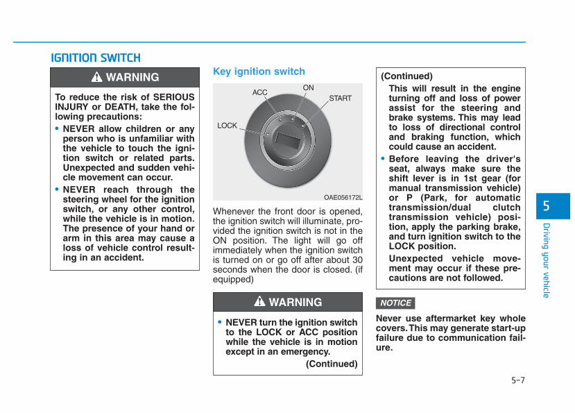
5-7
Driving your vehicle
5
IIGGNNIITTIIOONN SSWWIITTCCHH Key ignition switch
Whenever the front door is opened,the ignition switch will illuminate, pro-vided the ignition switch is not in theON position. The light will go offimmediately when the ignition switchis turned on or go off after about 30seconds when the door is closed. (ifequipped)
Never use aftermarket key wholecovers.This may generate start-upfailure due to communication fail-ure.
NOTICE
• NEVER turn the ignition switchto the LOCK or ACC positionwhile the vehicle is in motionexcept in an emergency.
(Continued)
(Continued)This will result in the engineturning off and loss of powerassist for the steering andbrake systems. This may leadto loss of directional controland braking function, whichcould cause an accident.
• Before leaving the driver'sseat, always make sure theshift lever is in 1st gear (formanual transmission vehicle)or P (Park, for automatictransmission/dual clutchtransmission vehicle) posi-tion, apply the parking brake,and turn ignition switch to theLOCK position.Unexpected vehicle move-ment may occur if these pre-cautions are not followed.
WARNING
To reduce the risk of SERIOUSINJURY or DEATH, take the fol-lowing precautions:• NEVER allow children or any
person who is unfamiliar withthe vehicle to touch the igni-tion switch or related parts.Unexpected and sudden vehi-cle movement can occur.
• NEVER reach through thesteering wheel for the ignitionswitch, or any other control,while the vehicle is in motion.The presence of your hand orarm in this area may cause aloss of vehicle control result-ing in an accident.
WARNING
OAE056172L
LOCK
ACCON
START
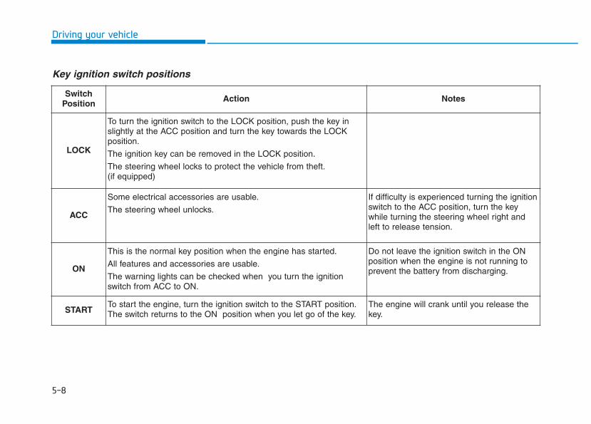
5-8
Driving your vehicle
Key ignition switch positions
SwitchPosition Action Notes
LOCK
To turn the ignition switch to the LOCK position, push the key inslightly at the ACC position and turn the key towards the LOCKposition.
The ignition key can be removed in the LOCK position.
The steering wheel locks to protect the vehicle from theft.(if equipped)
ACC
Some electrical accessories are usable.
The steering wheel unlocks.
If difficulty is experienced turning the ignitionswitch to the ACC position, turn the keywhile turning the steering wheel right andleft to release tension.
ON
This is the normal key position when the engine has started.
All features and accessories are usable.
The warning lights can be checked when you turn the ignitionswitch from ACC to ON.
Do not leave the ignition switch in the ONposition when the engine is not running toprevent the battery from discharging.
STARTTo start the engine, turn the ignition switch to the START position.The switch returns to the ON position when you let go of the key.
The engine will crank until you release thekey.
5-9
Driving your vehicle
5
Starting the engine Starting the gasoline engine
Vehicle with manual transmission:1. Make sure the parking brake is
applied.2. Make sure the shift lever is in neu-
tral.3. Depress the clutch and brake ped-
als.4. Turn the ignition switch to the
START position. Hold the key(maximum of 10 seconds) until theengine starts and release it.
Vehicle with automatic transmis-sion/dual clutch transmission:1. Make sure the parking brake is
applied.2. Make sure the shift lever is in P
(Park).3. Depress the brake pedal.4. Turn the ignition switch to the
START position. Hold the key(maximum of 10 seconds) until theengine starts and release it.
Information• Do not wait for the engine to warm
up while the vehicle remains station-ary.
Start driving at moderate enginespeeds. (Steep accelerating anddecelerating should be avoided.)
• Always start the vehicle with yourfoot on the brake pedal. Do notdepress the accelerator while start-ing the vehicle. Do not race theengine while warming it up.
i
• Always wear appropriateshoes when operating yourvehicle. Unsuitable shoes,such as high heels, ski boots,sandals, flip-flops, etc., mayinterfere with your ability touse the brake, accelerator andclutch pedals.
• Do not start the vehicle with theaccelerator pedal depressed.The vehicle can move and leadto an accident.
• Wait until the engine rpm isnormal. The vehicle may sud-denly move if the brake padelis released when the rpm ishigh.
WARNING
5-10
Driving your vehicle
Starting the diesel engine
To start the diesel engine when theengine is cold, it has to be pre-heat-ed before starting the engine andthen have to be warmed up beforestarting to drive.Vehicle with manual transmission:1. Make sure the parking brake is
applied.2. Make sure the shift lever is in neu-
tral.3. Depress the clutch and brake ped-
als.4. Turn the ignition switch to the ON
position to pre-heat the engine.The glow indicator light ( ) willilluminate.
5. When the glow indicator light ( )goes out, turn the key ignitionswitch to the START position. Holdthe key (maximum of 10 seconds)until the engine starts and releaseit.
Vehicle with dual clutch transmis-sion:1. Make sure the parking brake is
applied.2. Make sure the shift lever is in P
(Park).3. Depress the brake pedal.4. Turn the ignition switch to the ON
position to pre-heat the engine.The glow indicator light ( ) willilluminate.
5. When the glow indicator light ( )goes out, turn the key ignitionswitch to the START position. Holdthe key (maximum of 10 seconds)until the engine starts and releaseit.
If the engine does not start within10 seconds after preheating iscompleted, turn the ignitionswitch once more to the LOCKposition and wait for 10 seconds.Then turn the ignition switch tothe ON position in order to pre-heat the engine again.
Starting and stopping the enginefor turbocharger intercooler
1. Do not race or accelerate theengine immediately after startingthe engine.If the engine is cold, idle for sever-al seconds before sufficient lubri-cation is ensured in the turbocharger unit.
2. After high speed or extended driv-ing that requires heavy engineload, idle the engine about 1minute before turning the engineoff.This idle time will allow the tur-bocharger to cool prior to shuttingthe engine off.
Do not turn off the engine immedi-ately after it has been subjected toa heavy load. Doing so may causesevere damage to the engine orturbo charger unit.
NOTICENOTICE
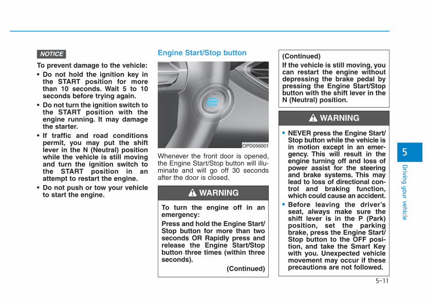
5-11
Driving your vehicle
5
To prevent damage to the vehicle:• Do not hold the ignition key in
the START position for morethan 10 seconds. Wait 5 to 10seconds before trying again.
• Do not turn the ignition switch tothe START position with theengine running. It may damagethe starter.
• If traffic and road conditionspermit, you may put the shiftlever in the N (Neutral) positionwhile the vehicle is still movingand turn the ignition switch tothe START position in anattempt to restart the engine.
• Do not push or tow your vehicleto start the engine.
Engine Start/Stop button
Whenever the front door is opened,the Engine Start/Stop button will illu-minate and will go off 30 secondsafter the door is closed.
NOTICE
OPD056001
To turn the engine off in anemergency:Press and hold the Engine Start/Stop button for more than twoseconds OR Rapidly press andrelease the Engine Start/Stopbutton three times (within threeseconds).
(Continued)
(Continued)If the vehicle is still moving, youcan restart the engine withoutdepressing the brake pedal bypressing the Engine Start/Stopbutton with the shift lever in theN (Neutral) position.
WARNING
• NEVER press the Engine Start/Stop button while the vehicle isin motion except in an emer-gency. This will result in theengine turning off and loss ofpower assist for the steeringand brake systems. This maylead to loss of directional con-trol and braking function,which could cause an accident.
• Before leaving the driver’sseat, always make sure theshift lever is in the P (Park)position, set the parkingbrake, press the Engine Start/Stop button to the OFF posi-tion, and take the Smart Keywith you. Unexpected vehiclemovement may occur if theseprecautions are not followed.
WARNING
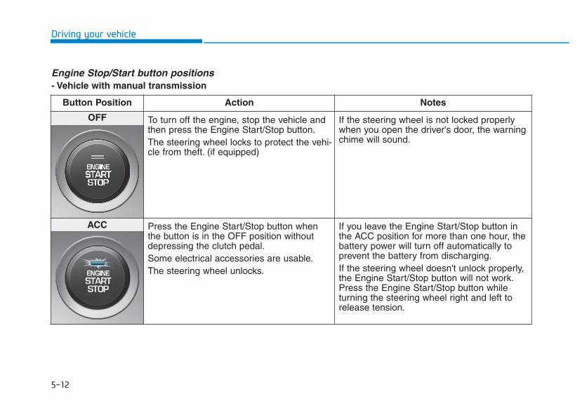
5-12
Driving your vehicle
Engine Stop/Start button positions - Vehicle with manual transmission
Button Position Action Notes
OFF To turn off the engine, stop the vehicle andthen press the Engine Start/Stop button.The steering wheel locks to protect the vehi-cle from theft. (if equipped)
If the steering wheel is not locked properlywhen you open the driver's door, the warningchime will sound.
ACC Press the Engine Start/Stop button whenthe button is in the OFF position withoutdepressing the clutch pedal.Some electrical accessories are usable.The steering wheel unlocks.
If you leave the Engine Start/Stop button inthe ACC position for more than one hour, thebattery power will turn off automatically toprevent the battery from discharging.If the steering wheel doesn't unlock properly,the Engine Start/Stop button will not work.Press the Engine Start/Stop button whileturning the steering wheel right and left torelease tension.
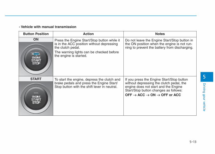
5-13
Driving your vehicle
5
- Vehicle with manual transmission
Button Position Action Notes
ON Press the Engine Start/Stop button while itis in the ACC position without depressingthe clutch pedal.The warning lights can be checked beforethe engine is started.
Do not leave the Engine Start/Stop button inthe ON position when the engine is not run-ning to prevent the battery from discharging.
START To start the engine, depress the clutch andbrake pedals and press the Engine Start/Stop button with the shift lever in neutral.
If you press the Engine Start/Stop buttonwithout depressing the clutch pedal, theengine does not start and the EngineStart/Stop button changes as follows:OFF →→ ACC →→ ON →→ OFF or ACC
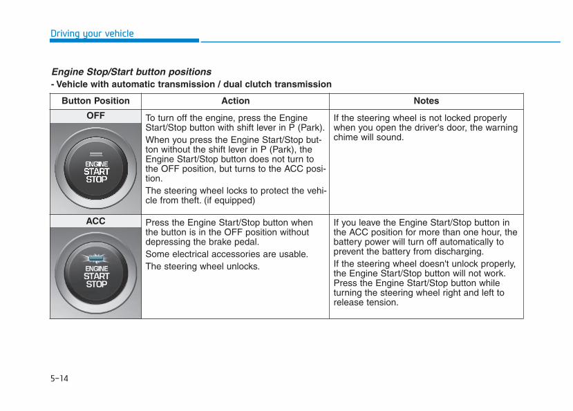
5-14
Driving your vehicle
Engine Stop/Start button positions - Vehicle with automatic transmission / dual clutch transmission
Button Position Action Notes
OFF To turn off the engine, press the EngineStart/Stop button with shift lever in P (Park).When you press the Engine Start/Stop but-ton without the shift lever in P (Park), theEngine Start/Stop button does not turn tothe OFF position, but turns to the ACC posi-tion.The steering wheel locks to protect the vehi-cle from theft. (if equipped)
If the steering wheel is not locked properlywhen you open the driver's door, the warningchime will sound.
ACC Press the Engine Start/Stop button whenthe button is in the OFF position withoutdepressing the brake pedal.Some electrical accessories are usable.The steering wheel unlocks.
If you leave the Engine Start/Stop button inthe ACC position for more than one hour, thebattery power will turn off automatically toprevent the battery from discharging.If the steering wheel doesn't unlock properly,the Engine Start/Stop button will not work.Press the Engine Start/Stop button whileturning the steering wheel right and left torelease tension.
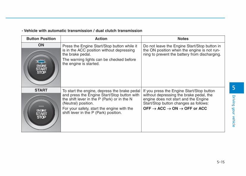
5-15
Driving your vehicle
5
- Vehicle with automatic transmission / dual clutch transmission
Button Position Action Notes
ON Press the Engine Start/Stop button while itis in the ACC position without depressingthe brake pedal.The warning lights can be checked beforethe engine is started.
Do not leave the Engine Start/Stop button inthe ON position when the engine is not run-ning to prevent the battery from discharging.
START To start the engine, depress the brake pedaland press the Engine Start/Stop button withthe shift lever in the P (Park) or in the N(Neutral) position.For your safety, start the engine with theshift lever in the P (Park) position.
If you press the Engine Start/Stop buttonwithout depressing the brake pedal, theengine does not start and the EngineStart/Stop button changes as follows:OFF →→ ACC →→ ON →→ OFF or ACC
5-16
Driving your vehicle
Starting the engine Information • The engine will start by pressing the
Engine Start/Stop button, only whenthe smart key is in the vehicle.
• Even if the smart key is in the vehi-cle, if it is far away from the driver,the engine may not start.
• When the Engine Start/Stop buttonis in the ACC or ON position, if anydoor is open, the system checks forthe smart key. If the smart key is notin the vehicle, the " " indicatorwill blink and the warning "Key notin vehicle" will come on, and if alldoors are closed, the chime will alsosound for about 5 seconds. Keep thesmart key in the vehicle when usingthe ACC position or if the vehicleengine is ON.
Starting the gasoline engine
Vehicle with manual transmission:1. Always carry the smart key with
you.2. Make sure the parking brake is
applied.3. Make sure the shift lever is in neu-
tral.4. Depress the clutch and brake ped-
als.5. Press the Engine Start/Stop but-
ton.
Vehicle with automatic transmission/dual clutch transmission:1. Always carry the smart key with
you.2. Make sure the parking brake is
applied.3. Make sure the shift lever is in P
(Park).4. Depress the brake pedal.5 Press the Engine Start/Stop but-
ton.
i
• Always wear appropriateshoes when operating yourvehicle. Unsuitable shoes,such as high heels, ski boots,sandals, flip-flops, etc., mayinterfere with your ability touse the brake, accelerator andclutch pedals.
• Do not start the vehicle with theaccelerator pedal depressed.The vehicle can move and leadto an accident.
• Wait until the engine rpm isnormal. The vehicle may sud-denly move if the brake pedalis released when the rpm ishigh.
WARNING
5-17
Driving your vehicle
5
Information • Do not wait for the engine to warm
up while the vehicle remains station-ary.
Start driving at moderate enginespeeds. (Steep accelerating anddecelerating should be avoided.)
• Always start the vehicle with yourfoot on the brake pedal. Do notdepress the accelerator while start-ing the vehicle. Do not race theengine while warming it up.
Starting the diesel engine
To start the diesel engine when theengine is cold, it has to be pre-heat-ed before starting the engine andthen have to be warmed up beforestarting to drive.Vehicle with manual transmission:1. Always carry the smart key with
you.2. Make sure the parking brake is
applied.3. Make sure the shift lever is in neu-
tral.4. Depress the clutch and brake
pedal.5. Press the Engine Start/Stop but-
ton.6. Continue depressing the brake
pedal until the glow indicator light( ) goes out.
7. When the glow indicator light ( )goes out, the engine will start.
Vehicle with dual clutch transmis-sion:1. Always carry the smart key with
you.2. Make sure the parking brake is
applied.3. Make sure the shift lever is in P
(Park).4. Depress the brake pedal.5. Press the Engine Start/Stop but-
ton.6. Continue depressing the brake
pedal until the glow indicator light( ) goes out.
7. When the glow indicator light ( )goes out, the engine will start.
Information If the Engine Start/Stop button ispressed while the engine is pre-heat-ing, the engine may start.
i
i
5-18
Driving your vehicle
Starting and stopping the enginefor turbocharger intercooler
1. Do not race or accelerate theengine immediately after startingthe engine.If the engine is cold, idle for sever-al seconds before sufficient lubri-cation is ensured in the turbocharger unit.
2. After high speed or extended driv-ing that requires heavy engineload, idle the engine about 1minute before turning the engineoff. This idle time will allow the tur-bocharger to cool prior to shuttingthe engine off.
Do not turn off the engine immedi-ately after it has been subjected toa heavy load. Doing so may causesevere damage to the engine orturbo charger unit.
To prevent damage to the vehicle:• If the engine stalls while you are
in motion, do not attempt tomove the shift lever to the P(Park) position.If traffic and road conditionspermit, you may put the shiftlever in the N (Neutral) positionwhile the vehicle is still movingand press the Engine Start/Stopbutton in an attempt to restartthe engine.
• Do not push or tow your vehicleto start the engine.
To prevent damage to the vehicle:Do not press the Engine Start/Stop button for more than 10 sec-onds except when the stop lampfuse is blown.When the stop lamp fuse is blown,you can't start the engine normal-ly. Replace the fuse with a newone. If you are not able to replacethe fuse, you can start the engineby pressing and holding theEngine Start/Stop button for 10seconds with the Engine Start/Stop button in the ACC position.For your safety always depress thebrake and/or clutch pedal beforestarting the engine.
NOTICENOTICE
NOTICE
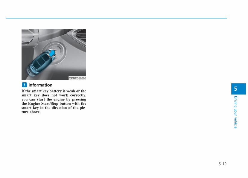
5-19
Driving your vehicle
5Information
If the smart key battery is weak or thesmart key does not work correctly,you can start the engine by pressingthe Engine Start/Stop button with thesmart key in the direction of the pic-ture above.
iOPDE056005
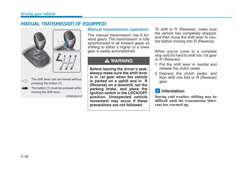
5-20
Driving your vehicle
Manual transmission operation The manual transmission has 6 for-ward gears. The transmission is fullysynchronized in all forward gears soshifting to either a higher or a lowergear is easily accomplished.
To shift to R (Reverse), make surethe vehicle has completely stopped,and then move the shift lever to neu-tral before moving into R (Reverse).
When you've come to a completestop and it's hard to shift into 1st gearor R (Reverse):1. Put the shift lever in neutral and
release the clutch pedal.2. Depress the clutch pedal, and
then shift into first or R (Reverse)gear.
Information During cold weather, shifting may bedifficult until the transmission lubri-cant has warmed up.
i
MMAANNUUAALL TTRRAANNSSMMIISSSSIIOONN ((IIFF EEQQUUIIPPPPEEDD))
Before leaving the driver's seat,always make sure the shift leveris in 1st gear when the vehicleis parked on a uphill and in R(Reverse) on a downhill, set theparking brake, and place theignition switch in the LOCK/OFFposition. Unexpected vehiclemovement may occur if theseprecautions are not followed.
WARNING
OPDE056107
The shift lever can be moved withoutpressing the button (1).
The button (1) must be pressed whilemoving the shift lever.
5-21
Driving your vehicle
5
Using the clutch The clutch pedal should bedepressed all the way to the floorbefore:- Starting the engine
The engine will not start withoutdepressing the clutch pedal.
- Shifting
When releasing the clutch pedal,release it slowly. The clutch pedalshould always be released whiledriving.
To prevent unnecessary wear ordamage to the clutch:• Do not rest your foot on the
clutch pedal while driving.• Do not hold the vehicle with the
clutch on an incline, while wait-ing for the traffic light, etc.
• Always depress the clutch pedaldown fully to prevent noise ordamage.
• Do not start with the 2nd (sec-ond) gear engaged except whenyou start on a slippery road.
DownshiftingDownshift when you must slow downin heavy traffic or drive up a steep hillto prevent engine load.Also, downshifting reduces thechance of stalling and can acceleratewhen you need to increase yourspeed again.When the vehicle is going downhill,downshifting helps maintain safespeed by providing brake power fromthe engine and enables less wear onthe brakes.
NOTICE
5-22
Driving your vehicle
To prevent damage to the engine,clutch and transmission:• When downshifting from 5th
gear to 4th gear, be careful notto inadvertently push the shiftlever sideways engaging the 2ndgear. A drastic downshift maycause the engine speed toincrease to the point thetachometer will enter the red-zone.
• Do not downshift more than twogear at a time or downshift thegear when the engine is runningat high speed (5,000 RPM orhigher). Such a downshiftingmay damage the engine, clutchand the transmission.
Good driving practices • Never take the vehicle out of gear
and coast down a hill. This isextremely dangerous.
• Don't "ride" the brakes. This cancause the brakes and related partsto overheat and malfunction.When you are driving down a longhill, slow down and shift to a lowergear. Engine braking will help slowdown the vehicle.
• Slow down before shifting to alower gear. This will help avoidover-revving the engine, which cancause damage.
• Slow down when you encountercross winds. This gives you muchbetter control of your vehicle.
• Be sure the vehicle is completelystopped before you shift into R(Reverse) to prevent damage tothe transmission.
• Exercise extreme caution whendriving on a slippery surface. Beespecially careful when braking,accelerating or shifting gears. On aslippery surface, an abrupt changein vehicle speed can cause thedrive wheels to lose traction andmay cause loss of vehicle controlresulting in an accident
NOTICE
Do not use the engine brake(shifting from a higher gear tolower gear) rapidly on slipperyroads. The vehicle may slipcausing an accident.
WARNING
5-23
Driving your vehicle
5
To reduce the risk of SERIOUSINJURY or DEATH:• ALWAYS wear your seatbelt.
In a collision, an unbeltedoccupant is significantly morelikely to be seriously injuredor killed than a properly belt-ed occupant.
• Avoid high speeds when cor-nering or turning.
• Do not make quick steeringwheel movements, such assharp lane changes or fast,sharp turns.
• The risk of rollover is greatlyincreased if you lose controlof your vehicle at highwayspeeds.
• Loss of control often occurs iftwo or more wheels drop offthe roadway and the driverover steers to reenter theroadway.
(Continued)
WARNING (Continued)• In the event your vehicle
leaves the roadway, do notsteer sharply. Instead, slowdown before pulling back intothe travel lanes.
• HYUNDAI recommends youfollow all posted speed limits.
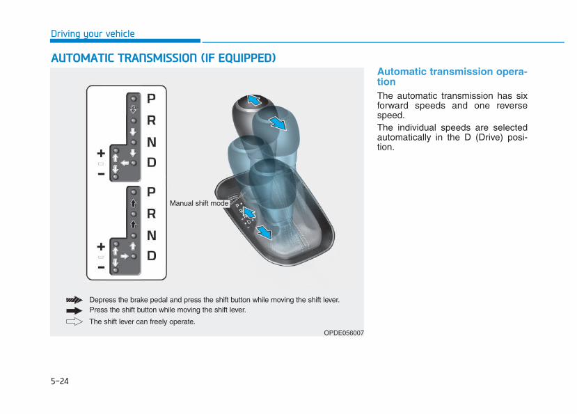
5-24
Driving your vehicle
Automatic transmission opera-tion The automatic transmission has sixforward speeds and one reversespeed.The individual speeds are selectedautomatically in the D (Drive) posi-tion.
AAUUTTOOMMAATTIICC TTRRAANNSSMMIISSSSIIOONN ((IIFF EEQQUUIIPPPPEEDD))
OPDE056007
The shift lever can freely operate.
Depress the brake pedal and press the shift button while moving the shift lever.Press the shift button while moving the shift lever.
Manual shift mode
5-25
Driving your vehicle
5
Transmission rangesThe indicator in the instrument clus-ter displays the shift lever positionwhen the ignition switch is in the ONposition.
P (Park)
Always come to a complete stopbefore shifting into P (Park).To shift from P (Park), you mustdepress firmly on the brake pedaland make sure your foot is off theaccelerator pedal.If you have done all of the aboveand still cannot shift the lever out ofP (Park), see "Shift-Lock Release"in this chapter.The shift lever must be in P (Park)before turning the engine off. R (Reverse)
Use this position to drive the vehiclebackward.
Always come to a complete stopbefore shifting into or out of R(Reverse); you may damage thetransmission if you shift into R(Reverse) while the vehicle is inmotion.
NOTICE
To reduce the risk of seriousinjury or death:• ALWAYS check the surround-
ing areas near your vehicle forpeople, especially children,before shifting a vehicle intoD (Drive) or R (Reverse).
• Before leaving the driver'sseat, always make sure theshift lever is in the P (Park)position, then set the parkingbrake, and place the ignitionswitch in the LOCK/OFF posi-tion. Unexpected and suddenvehicle movement can occurif these precautions are notfollowed.
• Do not use the engine brake(shifting from a high gear tolower gear) rapidly on slip-pery roads. The vehicle mayslip causing an accident.
WARNING
• Shifting into P (Park) while thevehicle is in motion maycause you to lose control ofthe vehicle.
• After the vehicle has stopped,always make sure the shiftlever is in P (Park), apply theparking brake, and turn theengine off.
• When parking on an incline,block the wheels to preventthe vehicle from rolling down.
• Do not use the P (Park) posi-tion in place of the parkingbrake.
WARNING
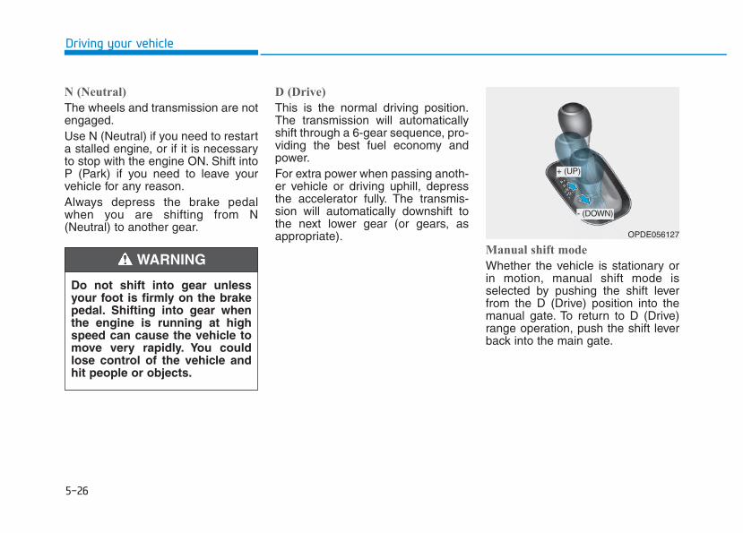
5-26
Driving your vehicle
N (Neutral)
The wheels and transmission are notengaged.Use N (Neutral) if you need to restarta stalled engine, or if it is necessaryto stop with the engine ON. Shift intoP (Park) if you need to leave yourvehicle for any reason.Always depress the brake pedalwhen you are shifting from N(Neutral) to another gear.
D (Drive)
This is the normal driving position.The transmission will automaticallyshift through a 6-gear sequence, pro-viding the best fuel economy andpower.For extra power when passing anoth-er vehicle or driving uphill, depressthe accelerator fully. The transmis-sion will automatically downshift tothe next lower gear (or gears, asappropriate).
Manual shift mode
Whether the vehicle is stationary orin motion, manual shift mode isselected by pushing the shift leverfrom the D (Drive) position into themanual gate. To return to D (Drive)range operation, push the shift leverback into the main gate.
Do not shift into gear unlessyour foot is firmly on the brakepedal. Shifting into gear whenthe engine is running at highspeed can cause the vehicle tomove very rapidly. You couldlose control of the vehicle andhit people or objects.
WARNING
OPDE056127
+ (UP)
- (DOWN)
5-27
Driving your vehicle
5
In manual shift mode, moving theshift lever backwards and forwardswill allow you to select the desiredrange of gears for the current drivingconditions.+ (Up) : Push the lever forward once
to shift up one gear.- (Down) : Pull the lever backwards
once to shift down onegear.
Information • Only the six forward gears can be
selected. To reverse or park thevehicle, move the shift lever to the R(Reverse) or P (Park) position asrequired.
• Downshifts are made automaticallywhen the vehicle slows down. Whenthe vehicle stops, 1st gear is auto-matically selected.
• When the engine rpm approachesthe red zone the transmission willupshift automatically.
(Continued)
(Continued)
• If the driver presses the lever to + (Up) or - (Down) position, thetransmission may not make therequested gear change if the nextgear is outside of the allowableengine rpm range. The driver mustexecute upshifts in accordance withroad conditions, taking care to keepthe engine rpms below the red zone.
• When driving on a slippery road,push the shift lever forward into the+ (Up) position. This causes thetransmission to shift into the 2ndgear which is better for smooth driv-ing on a slippery road. Push the shiftlever to the - (Down) side to shiftback to the 1st gear.
i
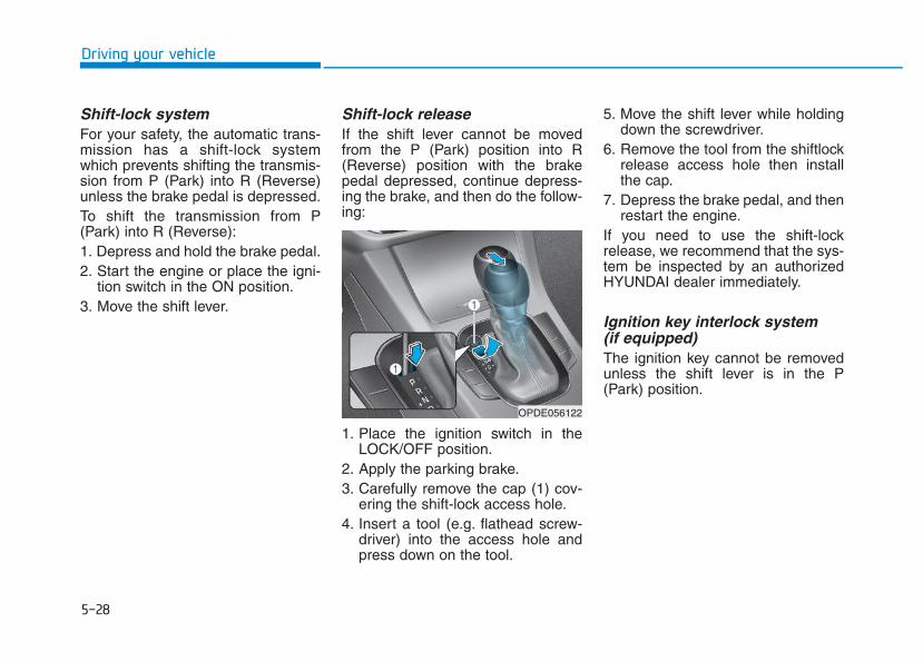
5-28
Driving your vehicle
Shift-lock system For your safety, the automatic trans-mission has a shift-lock systemwhich prevents shifting the transmis-sion from P (Park) into R (Reverse)unless the brake pedal is depressed.To shift the transmission from P(Park) into R (Reverse):1. Depress and hold the brake pedal.2. Start the engine or place the igni-
tion switch in the ON position.3. Move the shift lever.
Shift-lock releaseIf the shift lever cannot be movedfrom the P (Park) position into R(Reverse) position with the brakepedal depressed, continue depress-ing the brake, and then do the follow-ing:
1. Place the ignition switch in theLOCK/OFF position.
2. Apply the parking brake.3. Carefully remove the cap (1) cov-
ering the shift-lock access hole.4. Insert a tool (e.g. flathead screw-
driver) into the access hole andpress down on the tool.
5. Move the shift lever while holdingdown the screwdriver.
6. Remove the tool from the shiftlockrelease access hole then installthe cap.
7. Depress the brake pedal, and thenrestart the engine.
If you need to use the shift-lockrelease, we recommend that the sys-tem be inspected by an authorizedHYUNDAI dealer immediately.
Ignition key interlock system (if equipped) The ignition key cannot be removedunless the shift lever is in the P(Park) position.
OPDE056122
5-29
Driving your vehicle
5
ParkingAlways come to a complete stop andcontinue to depress the brake pedal.Move the shift lever into the P (Park)position, apply the parking brake,and place the ignition switch in theLOCK/OFF position. Take the Keywith you when exiting the vehicle.
Good driving practices • Never move the shift lever from P
(Park) or N (Neutral) to any otherposition with the accelerator pedaldepressed.
• Never move the shift lever into P(Park) when the vehicle is inmotion.Be sure the vehicle is completelystopped before you attempt to shiftinto R (Reverse) or D (Drive).
• Do not move the shift lever to N(Neutral) when driving. Doing somay result in an accident becauseof a loss of engine braking and thetransmission could be damaged.
• Do not drive with your foot restingon the brake pedal. Even light, butconsistent pedal pressure canresult in the brakes overheating,brake wear and possibly evenbrake failure.
• When driving in manual shift mode,slow down before shifting to alower gear. Otherwise, the lowergear may not be engaged if theengine rpms are outside of theallowable range.
• Always apply the parking brakewhen leaving the vehicle. Do notdepend on placing the transmis-sion in P (Park) to keep the vehiclefrom moving.
• Exercise extreme caution whendriving on a slippery surface. Beespecially careful when braking,accelerating or shifting gears. On aslippery surface, an abrupt changein vehicle speed can cause thedrive wheels to lose traction andmay cause loss of vehicle controlresulting in an accident
• Optimum vehicle performance andeconomy is obtained by smoothlydepressing and releasing theaccelerator.
When you stay in the vehiclewith the engine running, becareful not to depress the accel-erator pedal for a long period oftime. The engine or exhaustsystem may overheat and starta fire.The exhaust gas and theexhaust system are very hot.Keep away from the exhaustsystem components.Do not stop or park over flam-mable materials, such as drygrass, paper or leaves. Theymay ignite and cause a fire.
WARNING
5-30
Driving your vehicle
Information - KickdownMechanism (if equipped)
Use the kickdown mechanism formaximum acceleration. Depress theaccelerator pedal beyond the pressurepoint. The automatic transmission willshift to a lower gear depending on theengine speed.
i
(Continued)• In the event your vehicle
leaves the roadway, do notsteer sharply. Instead, slowdown before pulling back intothe travel lanes.
• HYUNDAI recommends youfollow all posted speed limits.
To reduce the risk of SERIOUSINJURY or DEATH:• ALWAYS wear your seatbelt.
In a collision, an unbeltedoccupant is significantly morelikely to be seriously injuredor killed than a properly belt-ed occupant.
• Avoid high speeds when cor-nering or turning.
• Do not make quick steeringwheel movements, such assharp lane changes or fast,sharp turns.
• The risk of rollover is greatlyincreased if you lose controlof your vehicle at highwayspeeds.
• Loss of control often occurs iftwo or more wheels drop offthe roadway and the driverover steers to reenter theroadway.
(Continued)
WARNING
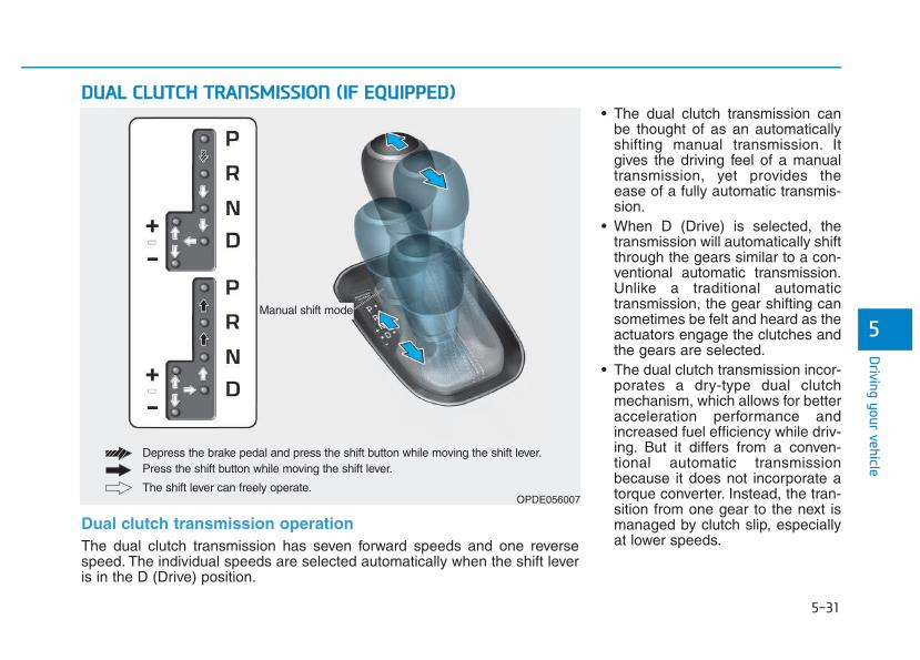
5-31
Driving your vehicle
5
• The dual clutch transmission canbe thought of as an automaticallyshifting manual transmission. Itgives the driving feel of a manualtransmission, yet provides theease of a fully automatic transmis-sion.
• When D (Drive) is selected, thetransmission will automatically shiftthrough the gears similar to a con-ventional automatic transmission.Unlike a traditional automatictransmission, the gear shifting cansometimes be felt and heard as theactuators engage the clutches andthe gears are selected.
• The dual clutch transmission incor-porates a dry-type dual clutchmechanism, which allows for betteracceleration performance andincreased fuel efficiency while driv-ing. But it differs from a conven-tional automatic transmissionbecause it does not incorporate atorque converter. Instead, the tran-sition from one gear to the next ismanaged by clutch slip, especiallyat lower speeds.
DDUUAALL CCLLUUTTCCHH TTRRAANNSSMMIISSSSIIOONN ((IIFF EEQQUUIIPPPPEEDD))
OPDE056007The shift lever can freely operate.
Depress the brake pedal and press the shift button while moving the shift lever.Press the shift button while moving the shift lever.
Manual shift mode
Dual clutch transmission operation The dual clutch transmission has seven forward speeds and one reversespeed. The individual speeds are selected automatically when the shift leveris in the D (Drive) position.
5-32
Driving your vehicle
As a result, shifts are sometimesmore noticeable, and a light vibra-tion can be felt as the transmissionshaft speed is matched with theengine shaft speed. This is a nor-mal condition of the dual clutchtransmission.
• The dry-type clutch transferstorque more directly and providesa direct-drive feeling which mayfeel different from a conventionalautomatic transmission. This maybe more noticeable when launch-ing the vehicle from a stop or whentraveling at low, stop-and-go vehi-cle speeds.
• When rapidly accelerating from alower vehicle speed, the enginerpm may increase dramatically asa result of clutch slip as the dualclutch transmission selects the cor-rect gear. This is a normal condi-tion.
• When accelerating from a stop onan incline, press the acceleratorsmoothly and gradually to avoidany shudder feeling or jerkiness.
• When traveling at a lower vehiclespeed, if you release the accelera-tor pedal quickly, you may feelengine braking before the trans-mission changes gears. Thisengine braking feeling is similar tooperating a manual transmission atlow speed.
• When driving downhill, you maywish to move the gear shift lever toManual Shift mode and downshiftto a lower gear in order to controlyour speed without using the brakepedal excessively.
• When you turn the engine on andoff, you may hear clicking soundsas the system goes through a self-test. This is a normal sound for thedual clutch transmission.
• During the first 1,500 km (1000miles), you may feel that the vehi-cle may not be smooth when accel-erating at low speed. During thisbreak-in period, the shift qualityand performance of your new vehi-cle is continuously optimized.
To reduce the risk of seriousinjury or death:• ALWAYS check the surround-
ing areas near your vehicle forpeople, especially children,before shifting a vehicle intoD (Drive) or R (Reverse).
• Before leaving the driver'sseat, always make sure theshift lever is in the P (Park)position, then set the parkingbrake, and place the ignitionswitch in the LOCK/OFF posi-tion. Unexpected and suddenvehicle movement can occurif these precautions are notfollowed.
• Do not use aggressive enginebraking (shifting from a high-er gear to a lower gear) onslippery roads. This couldcause the tires to slip and mayresult in an accident.
WARNING
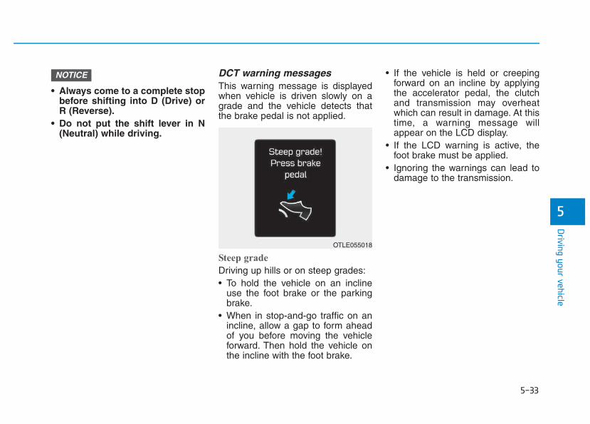
5-33
Driving your vehicle
5
• Always come to a complete stopbefore shifting into D (Drive) orR (Reverse).
• Do not put the shift lever in N(Neutral) while driving.
DCT warning messagesThis warning message is displayedwhen vehicle is driven slowly on agrade and the vehicle detects thatthe brake pedal is not applied.
Steep grade
Driving up hills or on steep grades:• To hold the vehicle on an incline
use the foot brake or the parkingbrake.
• When in stop-and-go traffic on anincline, allow a gap to form aheadof you before moving the vehicleforward. Then hold the vehicle onthe incline with the foot brake.
• If the vehicle is held or creepingforward on an incline by applyingthe accelerator pedal, the clutchand transmission may overheatwhich can result in damage. At thistime, a warning message willappear on the LCD display.
• If the LCD warning is active, thefoot brake must be applied.
• Ignoring the warnings can lead todamage to the transmission.
NOTICE
OTLE055018
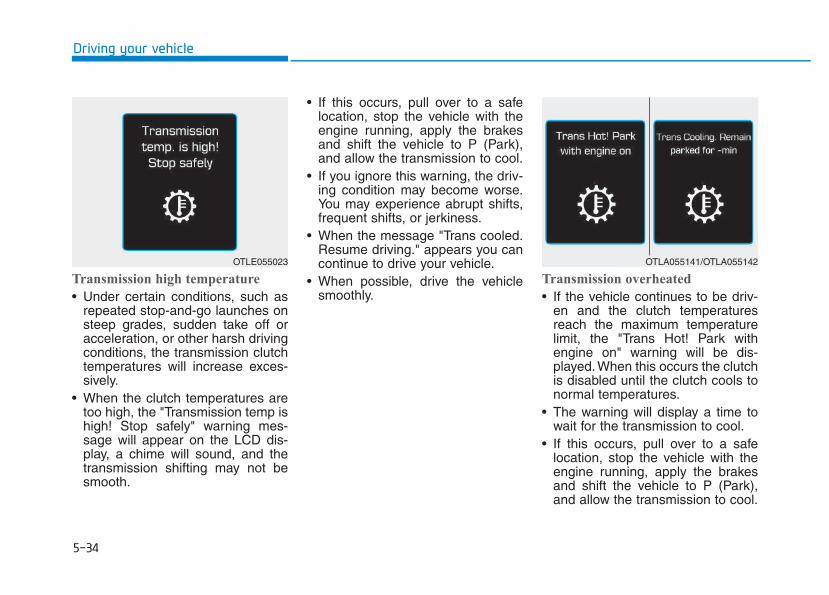
5-34
Driving your vehicle
Transmission high temperature
• Under certain conditions, such asrepeated stop-and-go launches onsteep grades, sudden take off oracceleration, or other harsh drivingconditions, the transmission clutchtemperatures will increase exces-sively.
• When the clutch temperatures aretoo high, the "Transmission temp ishigh! Stop safely" warning mes-sage will appear on the LCD dis-play, a chime will sound, and thetransmission shifting may not besmooth.
• If this occurs, pull over to a safelocation, stop the vehicle with theengine running, apply the brakesand shift the vehicle to P (Park),and allow the transmission to cool.
• If you ignore this warning, the driv-ing condition may become worse.You may experience abrupt shifts,frequent shifts, or jerkiness.
• When the message "Trans cooled.Resume driving." appears you cancontinue to drive your vehicle.
• When possible, drive the vehiclesmoothly.
Transmission overheated
• If the vehicle continues to be driv-en and the clutch temperaturesreach the maximum temperaturelimit, the "Trans Hot! Park withengine on" warning will be dis-played. When this occurs the clutchis disabled until the clutch cools tonormal temperatures.
• The warning will display a time towait for the transmission to cool.
• If this occurs, pull over to a safelocation, stop the vehicle with theengine running, apply the brakesand shift the vehicle to P (Park),and allow the transmission to cool.
OTLE055023 OTLA055141/OTLA055142
5-35
Driving your vehicle
5
• When the message "Trans cooled.Resume driving." appears you cancontinue to drive your vehicle
• When possible, drive the vehiclesmoothly.
If any of the warning messages inthe LCD display continue to blink, foryour safety, we recommend you con-tact an authorized HYUNDAI dealerand have the system checked.
Transmission rangesThe indicator in the instrument clus-ter displays the shift lever positionwhen the ignition switch is in the ONposition.
P (Park)
Always come to a complete stopbefore shifting into P (Park).To shift from P (Park), you mustdepress firmly on the brake pedaland make sure your foot is off theaccelerator pedal.If you have done all of the aboveand still cannot shift the lever outof P (Park), see "Shift-LockRelease" in this chapter.The shift lever must be in P (Park)before turning the engine off.
• Shifting into P (Park) while thevehicle is in motion maycause you to lose control ofthe vehicle.
• After the vehicle has stopped,always make sure the shiftlever is in P (Park), apply theparking brake, and turn theengine off.
• Do not use the P (Park) posi-tion in place of the parkingbrake.
WARNING
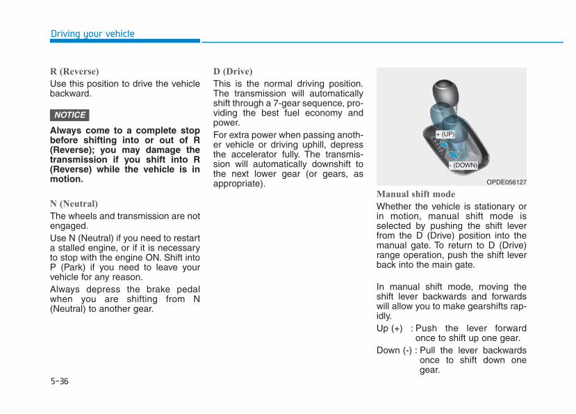
5-36
Driving your vehicle
R (Reverse)
Use this position to drive the vehiclebackward.
Always come to a complete stopbefore shifting into or out of R(Reverse); you may damage thetransmission if you shift into R(Reverse) while the vehicle is inmotion.
N (Neutral)
The wheels and transmission are notengaged.Use N (Neutral) if you need to restarta stalled engine, or if it is necessaryto stop with the engine ON. Shift intoP (Park) if you need to leave yourvehicle for any reason.Always depress the brake pedalwhen you are shifting from N(Neutral) to another gear.
D (Drive)
This is the normal driving position.The transmission will automaticallyshift through a 7-gear sequence, pro-viding the best fuel economy andpower.For extra power when passing anoth-er vehicle or driving uphill, depressthe accelerator fully. The transmis-sion will automatically downshift tothe next lower gear (or gears, asappropriate).
Manual shift mode
Whether the vehicle is stationary orin motion, manual shift mode isselected by pushing the shift leverfrom the D (Drive) position into themanual gate. To return to D (Drive)range operation, push the shift leverback into the main gate.
In manual shift mode, moving theshift lever backwards and forwardswill allow you to make gearshifts rap-idly.Up (+) : Push the lever forward
once to shift up one gear.Down (-) : Pull the lever backwards
once to shift down onegear.
NOTICE
OPDE056127
+ (UP)
- (DOWN)
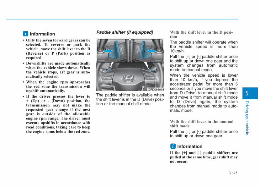
5-37
Driving your vehicle
5
Information • Only the seven forward gears can be
selected. To reverse or park thevehicle, move the shift lever to the R(Reverse) or P (Park) position asrequired.
• Downshifts are made automaticallywhen the vehicle slows down. Whenthe vehicle stops, 1st gear is auto-matically selected.
• When the engine rpm approachesthe red zone the transmission willupshift automatically.
• If the driver presses the lever to + (Up) or - (Down) position, thetransmission may not make therequested gear change if the nextgear is outside of the allowableengine rpm range. The driver mustexecute upshifts in accordance withroad conditions, taking care to keepthe engine rpms below the red zone.
Paddle shifter (if equipped)
The paddle shifter is available whenthe shift lever is in the D (Drive) posi-tion or the manual shift mode.
With the shift lever in the D posi-tion
The paddle shifter will operate whenthe vehicle speed is more than10km/h.Pull the [+] or [-] paddle shifter onceto shift up or down one gear and thesystem changes from automaticmode to manual mode.When the vehicle speed is lowerthan 10 km/h, if you depress theaccelerator pedal for more than 5seconds or if you move the shift leverfrom D (Drive) to manual shift modeand move it from manual shift modeto D (Drive) again, the systemchanges from manual mode to auto-matic mode.
With the shift lever in the manualshift mode
Pull the [+] or [-] paddle shifter onceto shift up or down one gear.
Information If the [+] and [-] paddle shifters arepulled at the same time, gear shift maynot occur.
i
i
OPD056015
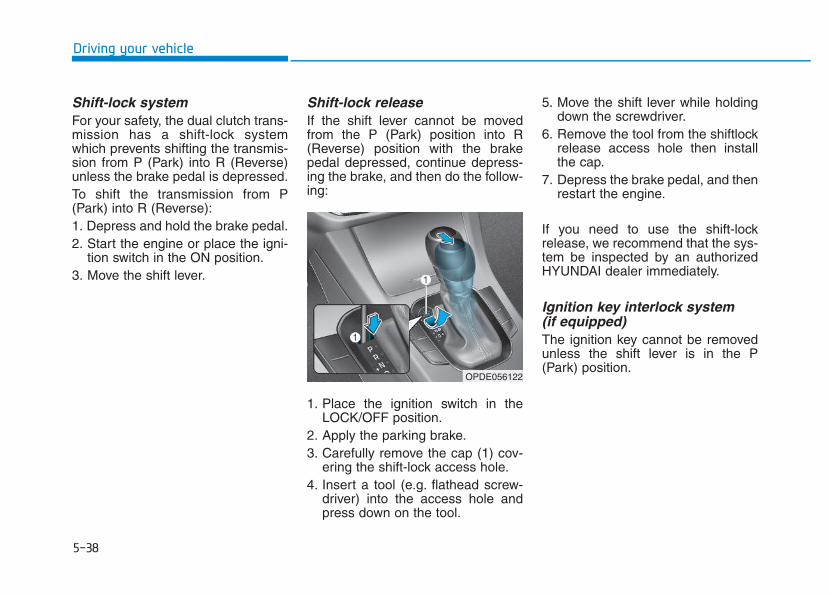
5-38
Driving your vehicle
Shift-lock system For your safety, the dual clutch trans-mission has a shift-lock systemwhich prevents shifting the transmis-sion from P (Park) into R (Reverse)unless the brake pedal is depressed.To shift the transmission from P(Park) into R (Reverse):1. Depress and hold the brake pedal.2. Start the engine or place the igni-
tion switch in the ON position.3. Move the shift lever.
Shift-lock releaseIf the shift lever cannot be movedfrom the P (Park) position into R(Reverse) position with the brakepedal depressed, continue depress-ing the brake, and then do the follow-ing:
1. Place the ignition switch in theLOCK/OFF position.
2. Apply the parking brake.3. Carefully remove the cap (1) cov-
ering the shift-lock access hole.4. Insert a tool (e.g. flathead screw-
driver) into the access hole andpress down on the tool.
5. Move the shift lever while holdingdown the screwdriver.
6. Remove the tool from the shiftlockrelease access hole then installthe cap.
7. Depress the brake pedal, and thenrestart the engine.
If you need to use the shift-lockrelease, we recommend that the sys-tem be inspected by an authorizedHYUNDAI dealer immediately.
Ignition key interlock system (if equipped)The ignition key cannot be removedunless the shift lever is in the P(Park) position.
OPDE056122

5-39
Driving your vehicle
5
ParkingAlways come to a complete stop andcontinue to depress the brake pedal.Move the shift lever into the P (Park)position, apply the parking brake,and place the ignition switch in theLOCK/OFF position. Take the Keywith you when exiting the vehicle.
Good driving practices • Never move the shift lever from P
(Park) or N (Neutral) to any otherposition with the accelerator pedaldepressed.
• Never move the shift lever into P(Park) when the vehicle is inmotion.Be sure the vehicle is completelystopped before you attempt to shiftinto R (Reverse) or D (Drive).
• Do not move the shift lever to N(Neutral) when driving. Doing somay result in an accident becauseof a loss of engine braking and thetransmission could be damaged.
• Do not drive with your foot restingon the brake pedal. Even light, butconsistent pedal pressure canresult in the brakes overheating,brake wear and possibly evenbrake failure.
• When driving in manual shift mode,slow down before shifting to alower gear. Otherwise, the lowergear may not be engaged if theengine rpms are outside of theallowable range.
• Always apply the parking brakewhen leaving the vehicle. Do notdepend on placing the transmis-sion in P (Park) to keep the vehiclefrom moving.
• Exercise extreme caution whendriving on a slippery surface. Beespecially careful when braking,accelerating or shifting gears. On aslippery surface, an abrupt changein vehicle speed can cause thedrive wheels to lose traction andmay cause loss of vehicle controlresulting in an accident.
• Optimum vehicle performance andeconomy is obtained by smoothlydepressing and releasing theaccelerator.
When you stay in the vehiclewith the engine running, becareful not to depress the accel-erator pedal for a long period oftime. The engine or exhaustsystem may overheat and starta fire.The exhaust gas and theexhaust system are very hot.Keep away from the exhaustsystem components.Do not stop or park over flam-mable materials, such as drygrass, paper or leaves. Theymay ignite and cause a fire.
WARNING

5-40
Driving your vehicle
Information - KickdownMechanism (if equipped)
Use the kickdown mechanism formaximum acceleration. Depress theaccelerator pedal beyond the pressurepoint. The automatic transmission willshift to a lower gear depending on theengine speed.
i
To reduce the risk of SERIOUSINJURY or DEATH:• ALWAYS wear your seatbelt.
In a collision, an unbeltedoccupant is significantly morelikely to be seriously injuredor killed than a properly belt-ed occupant.
• Avoid high speeds when cor-nering or turning.
• Do not make quick steeringwheel movements, such assharp lane changes or fast,sharp turns.
• The risk of rollover is greatlyincreased if you lose controlof your vehicle at highwayspeeds.
• Loss of control often occurs iftwo or more wheels drop offthe roadway and the driverover steers to reenter theroadway.
(Continued)
(Continued)• In the event your vehicle
leaves the roadway, do notsteer sharply. Instead, slowdown before pulling back intothe travel lanes.
• HYUNDAI recommends youfollow all posted speed limits.
WARNING
5-41
Driving your vehicle
5
Power brakes Your vehicle has power-assistedbrakes that adjust automaticallythrough normal usage.If the engine is not running or isturned off while driving, the powerassist for the brakes will not work.You can still stop your vehicle byapplying greater force to the brakepedal than typical. The stopping dis-tance, however, will be longer thanwith power brakes.When the engine is not running, thereserve brake power is partiallydepleted each time the brake pedalis applied. Do not pump the brakepedal when the power assist hasbeen interrupted.Pump the brake pedal only whennecessary to maintain steering con-trol on slippery surfaces.
BBRRAAKKIINNGG SSYYSSTTEEMM
Take the following precautions:• Do not drive with your foot
resting on the brake pedal.This will create abnormal highbrake temperatures, exces-sive brake lining and padwear, and increased stoppingdistances.
• When descending a long orsteep hill, shift to a lower gearand avoid continuous applica-tion of the brakes. Applyingthe brakes continuously willcause the brakes to overheatand could result in a tempo-rary loss of braking perform-ance.
(Continued)
(Continued)• Wet brakes may impair the
vehicle's ability to safely slowdown; the vehicle may alsopull to one side when thebrakes are applied. Applyingthe brakes lightly will indicatewhether they have beenaffected in this way. Alwaystest your brakes in this fash-ion after driving through deepwater. To dry the brakes, light-ly tap the brake pedal to heatup the brakes while maintain-ing a safe forward speed untilbrake performance returns tonormal. Avoid driving at highspeeds until the brakes func-tion correctly.
WARNING
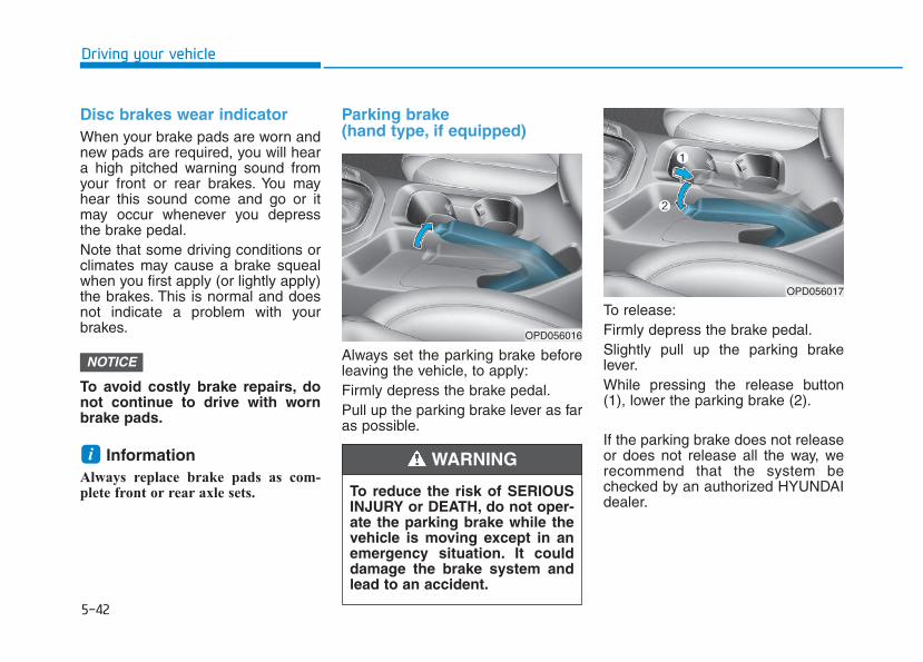
5-42
Driving your vehicle
Disc brakes wear indicator When your brake pads are worn andnew pads are required, you will heara high pitched warning sound fromyour front or rear brakes. You mayhear this sound come and go or itmay occur whenever you depressthe brake pedal.Note that some driving conditions orclimates may cause a brake squealwhen you first apply (or lightly apply)the brakes. This is normal and doesnot indicate a problem with yourbrakes.
To avoid costly brake repairs, donot continue to drive with wornbrake pads.
Information Always replace brake pads as com-plete front or rear axle sets.
Parking brake (hand type, if equipped)
Always set the parking brake beforeleaving the vehicle, to apply:Firmly depress the brake pedal.Pull up the parking brake lever as faras possible.
To release:Firmly depress the brake pedal.Slightly pull up the parking brakelever.While pressing the release button(1), lower the parking brake (2).
If the parking brake does not releaseor does not release all the way, werecommend that the system bechecked by an authorized HYUNDAIdealer.
i
NOTICE
To reduce the risk of SERIOUSINJURY or DEATH, do not oper-ate the parking brake while thevehicle is moving except in anemergency situation. It coulddamage the brake system andlead to an accident.
WARNING
OPD056016
OPD056017
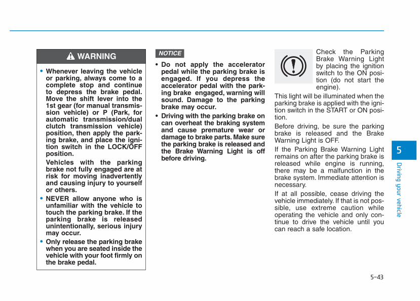
5-43
Driving your vehicle
5
• Do not apply the acceleratorpedal while the parking brake isengaged. If you depress theaccelerator pedal with the park-ing brake engaged, warning willsound. Damage to the parkingbrake may occur.
• Driving with the parking brake oncan overheat the braking systemand cause premature wear ordamage to brake parts. Make surethe parking brake is released andthe Brake Warning Light is offbefore driving.
Check the ParkingBrake Warning Lightby placing the ignitionswitch to the ON posi-tion (do not start theengine).
This light will be illuminated when theparking brake is applied with the igni-tion switch in the START or ON posi-tion.Before driving, be sure the parkingbrake is released and the BrakeWarning Light is OFF.If the Parking Brake Warning Lightremains on after the parking brake isreleased while engine is running,there may be a malfunction in thebrake system. Immediate attention isnecessary.If at all possible, cease driving thevehicle immediately. If that is not pos-sible, use extreme caution whileoperating the vehicle and only con-tinue to drive the vehicle until youcan reach a safe location.
NOTICE
• Whenever leaving the vehicleor parking, always come to acomplete stop and continueto depress the brake pedal.Move the shift lever into the1st gear (for manual transmis-sion vehicle) or P (Park, forautomatic transmission/dualclutch transmission vehicle)position, then apply the park-ing brake, and place the igni-tion switch in the LOCK/OFFposition.Vehicles with the parkingbrake not fully engaged are atrisk for moving inadvertentlyand causing injury to yourselfor others.
• NEVER allow anyone who isunfamiliar with the vehicle totouch the parking brake. If theparking brake is releasedunintentionally, serious injurymay occur.
• Only release the parking brakewhen you are seated inside thevehicle with your foot firmly onthe brake pedal.
WARNING
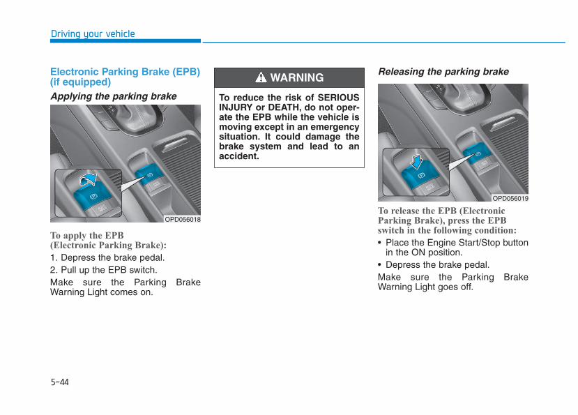
5-44
Driving your vehicle
Electronic Parking Brake (EPB)(if equipped)Applying the parking brake
To apply the EPB (Electronic Parking Brake):
1. Depress the brake pedal.2. Pull up the EPB switch.Make sure the Parking BrakeWarning Light comes on.
Releasing the parking brake
To release the EPB (ElectronicParking Brake), press the EPBswitch in the following condition:
• Place the Engine Start/Stop buttonin the ON position.
• Depress the brake pedal.Make sure the Parking BrakeWarning Light goes off.
OPD056018
To reduce the risk of SERIOUSINJURY or DEATH, do not oper-ate the EPB while the vehicle ismoving except in an emergencysituation. It could damage thebrake system and lead to anaccident.
WARNING
OPD056019
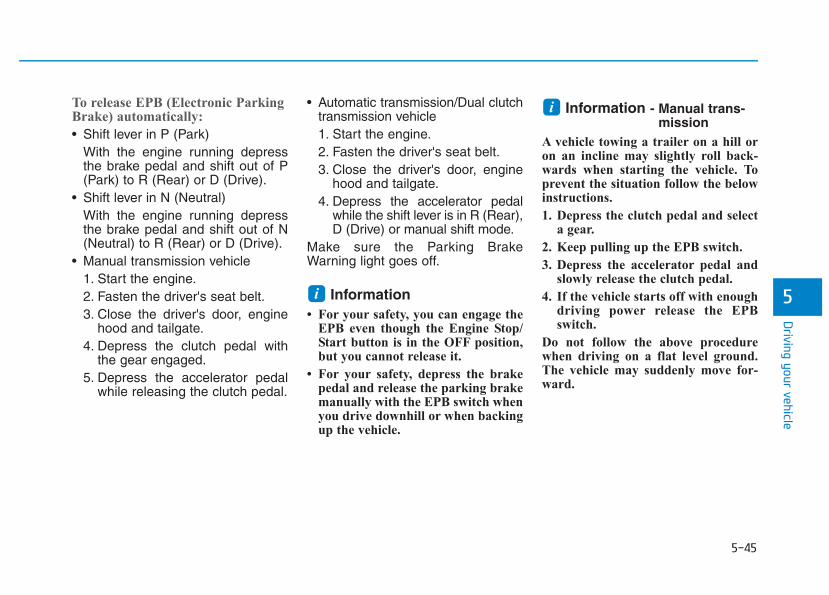
5-45
Driving your vehicle
5
To release EPB (Electronic ParkingBrake) automatically:
• Shift lever in P (Park)With the engine running depressthe brake pedal and shift out of P(Park) to R (Rear) or D (Drive).
• Shift lever in N (Neutral)With the engine running depressthe brake pedal and shift out of N(Neutral) to R (Rear) or D (Drive).
• Manual transmission vehicle1. Start the engine.2. Fasten the driver's seat belt.3. Close the driver's door, engine
hood and tailgate.4. Depress the clutch pedal with
the gear engaged.5. Depress the accelerator pedal
while releasing the clutch pedal.
• Automatic transmission/Dual clutchtransmission vehicle1. Start the engine.2. Fasten the driver's seat belt.3. Close the driver's door, engine
hood and tailgate.4. Depress the accelerator pedal
while the shift lever is in R (Rear),D (Drive) or manual shift mode.
Make sure the Parking BrakeWarning light goes off.
Information • For your safety, you can engage the
EPB even though the Engine Stop/Start button is in the OFF position,but you cannot release it.
• For your safety, depress the brakepedal and release the parking brakemanually with the EPB switch whenyou drive downhill or when backingup the vehicle.
Information - Manual trans-mission
A vehicle towing a trailer on a hill oron an incline may slightly roll back-wards when starting the vehicle. Toprevent the situation follow the belowinstructions.
1. Depress the clutch pedal and selecta gear.
2. Keep pulling up the EPB switch.
3. Depress the accelerator pedal andslowly release the clutch pedal.
4. If the vehicle starts off with enoughdriving power release the EPBswitch.
Do not follow the above procedurewhen driving on a flat level ground.The vehicle may suddenly move for-ward.
i
i
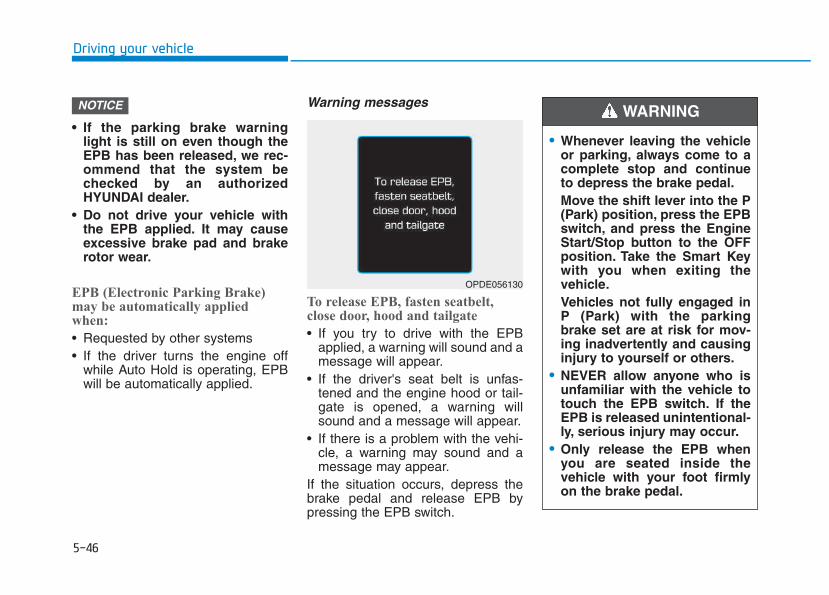
5-46
Driving your vehicle
• If the parking brake warninglight is still on even though theEPB has been released, we rec-ommend that the system bechecked by an authorizedHYUNDAI dealer.
• Do not drive your vehicle withthe EPB applied. It may causeexcessive brake pad and brakerotor wear.
EPB (Electronic Parking Brake)may be automatically appliedwhen:
• Requested by other systems• If the driver turns the engine off
while Auto Hold is operating, EPBwill be automatically applied.
Warning messages
To release EPB, fasten seatbelt,close door, hood and tailgate
• If you try to drive with the EPBapplied, a warning will sound and amessage will appear.
• If the driver's seat belt is unfas-tened and the engine hood or tail-gate is opened, a warning willsound and a message will appear.
• If there is a problem with the vehi-cle, a warning may sound and amessage may appear.
If the situation occurs, depress thebrake pedal and release EPB bypressing the EPB switch.
NOTICE
OPDE056130
• Whenever leaving the vehicleor parking, always come to acomplete stop and continueto depress the brake pedal.Move the shift lever into the P(Park) position, press the EPBswitch, and press the EngineStart/Stop button to the OFFposition. Take the Smart Keywith you when exiting thevehicle.Vehicles not fully engaged inP (Park) with the parkingbrake set are at risk for mov-ing inadvertently and causinginjury to yourself or others.
• NEVER allow anyone who isunfamiliar with the vehicle totouch the EPB switch. If theEPB is released unintentional-ly, serious injury may occur.
• Only release the EPB whenyou are seated inside thevehicle with your foot firmlyon the brake pedal.
WARNING
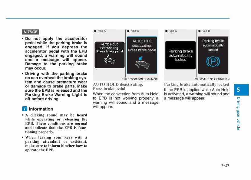
5-47
Driving your vehicle
5
• Do not apply the acceleratorpedal while the parking brake isengaged. If you depress theaccelerator pedal with the EPBengaged, a warning will soundand a message will appear.Damage to the parking brakemay occur.
• Driving with the parking brakeon can overheat the braking sys-tem and cause premature wearor damage to brake parts. Makesure the EPB is released and theParking Brake Warning Light isoff before driving.
Information • A clicking sound may be heard
while operating or releasing theEPB. These conditions are normaland indicate that the EPB is func-tioning properly.
• When leaving your keys with aparking attendant or assistant,make sure to inform him/her how tooperate the EPB.
AUTO HOLD deactivating.Press brake pedal
When the conversion from Auto Holdto EPB is not working properly awarning will sound and a messagewill appear.
Parking brake automatically locked
If the EPB is applied while Auto Holdis activated, a warning will sound anda message will appear.
i
NOTICE ■ Type A ■ Type B
OTLE055028/OLFH044408L
■ Type A ■ Type B
OLF054131N/OLF044411N
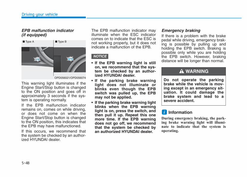
5-48
Driving your vehicle
EPB malfunction indicator (if equipped)
This warning light illuminates if theEngine Start/Stop button is changedto the ON position and goes off inapproximately 3 seconds if the sys-tem is operating normally.If the EPB malfunction indicatorremains on, comes on while driving,or does not come on when theEngine Start/Stop button is changedto the ON position, this indicates thatthe EPB may have malfunctioned.If this occurs, we recommend thatthe system be checked by an author-ized HYUNDAI dealer.
The EPB malfunction indicator mayilluminate when the ESC indicatorcomes on to indicate that the ESC isnot working properly, but it does notindicate a malfunction of the EPB.
• If the EPB warning light is stillon, we recommend that the sys-tem be checked by an author-ized HYUNDAI dealer.
• If the parking brake warninglight does not illuminate orblinks even though the EPBswitch was pulled up, the EPBmay not be applied.
• If the parking brake warning lightblinks when the EPB warninglight is on, press the switch, andthen pull it up. Repeat this onemore time. If the EPB warningdoes not go off, we recommendthat the system be checked byan authorized HYUNDAI dealer.
Emergency brakingIf there is a problem with the brakepedal while driving, emergency brak-ing is possible by pulling up andholding the EPB switch. Braking ispossible only while you are holdingthe EPB switch. However, brakingdistance will be longer than normal.
Information During emergency braking, the park-ing brake warning light will illumi-nate to indicate that the system isoperating.
i
NOTICE
■ Type A ■ Type B
OPD056021/OPD056074Do not operate the parkingbrake while the vehicle is mov-ing except in an emergency sit-uation. It could damage thebrake system and lead to asevere accident.
WARNING
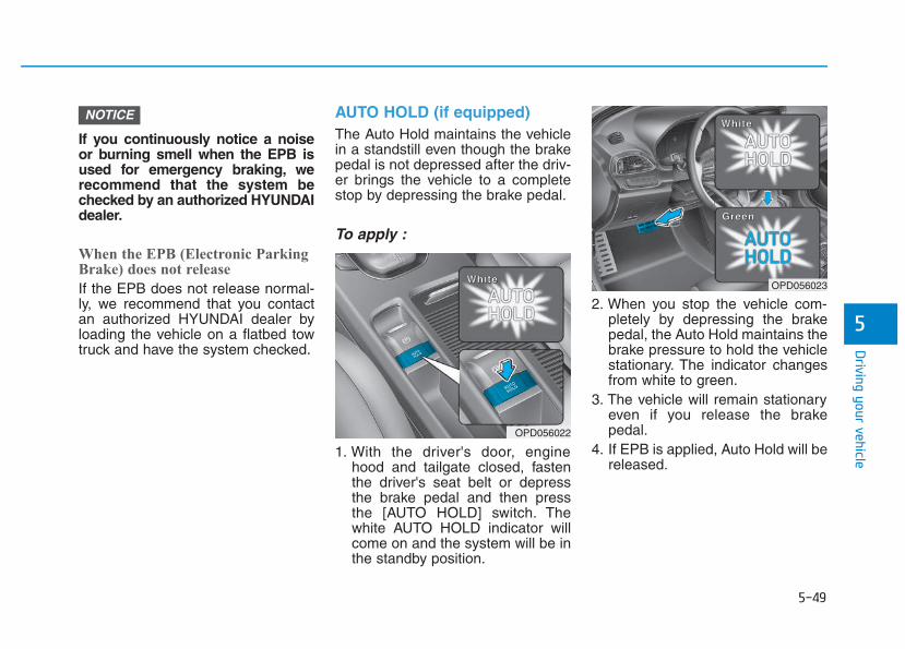
5-49
Driving your vehicle
5
If you continuously notice a noiseor burning smell when the EPB isused for emergency braking, werecommend that the system bechecked by an authorized HYUNDAIdealer.
When the EPB (Electronic ParkingBrake) does not release
If the EPB does not release normal-ly, we recommend that you contactan authorized HYUNDAI dealer byloading the vehicle on a flatbed towtruck and have the system checked.
AUTO HOLD (if equipped)The Auto Hold maintains the vehiclein a standstill even though the brakepedal is not depressed after the driv-er brings the vehicle to a completestop by depressing the brake pedal.
To apply :
1. With the driver's door, enginehood and tailgate closed, fastenthe driver's seat belt or depressthe brake pedal and then pressthe [AUTO HOLD] switch. Thewhite AUTO HOLD indicator willcome on and the system will be inthe standby position.
2. When you stop the vehicle com-pletely by depressing the brakepedal, the Auto Hold maintains thebrake pressure to hold the vehiclestationary. The indicator changesfrom white to green.
3. The vehicle will remain stationaryeven if you release the brakepedal.
4. If EPB is applied, Auto Hold will bereleased.
NOTICE
OPD056022
WWWWhhhhiiii tttteeeeOPD056023
WWWWhhhhiiii tttteeee
GGGGrrrreeeeeeeennnn
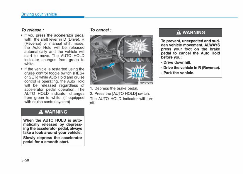
5-50
Driving your vehicle
To release :• If you press the accelerator pedal
with the shift lever in D (Drive), R(Reverse) or manual shift mode,the Auto Hold will be releasedautomatically and the vehicle willstart to move. The AUTO HOLDindicator changes from green towhite.
• If the vehicle is restarted using thecruise control toggle switch (RES+or SET-) while Auto Hold and cruisecontrol is operating, the Auto Holdwill be released regardless ofaccelerator pedal operation. TheAUTO HOLD indicator changesfrom green to white. (if equippedwith cruise control system)
To cancel :
1. Depress the brake pedal.2. Press the [AUTO HOLD] switch.The AUTO HOLD indicator will turnoff.
When the AUTO HOLD is auto-matically released by depress-ing the accelerator pedal, alwaystake a look around your vehicle.Slowly depress the acceleratorpedal for a smooth start.
WARNING
OPD05024
LLLLiiiigggghhhhtttt ooooffff ffff To prevent, unexpected and sud-den vehicle movement, ALWAYSpress your foot on the brakepedal to cancel the Auto Holdbefore you:- Drive downhill.- Drive the vehicle in R (Reverse).- Park the vehicle.
WARNING
5-51
Driving your vehicle
5
Information • The Auto Hold does not operate
when:
- The driver's seat belt is unfastenedand driver's door is opened
- The engine hood is opened
- The shift lever is in P (Park) or R(Reverse)
- The EPB is applied
• For your safety, the Auto Hold auto-matically switches to EPB when:
- The driver's seat belt is unfastenedand driver's door is opened
- The engine hood is opened with theshift lever is in D (Drive)
- The vehicle stops for more than 10minutes
- The vehicle stands on a steep slope
- The vehicle moves several times
(Continued)
(Continued)
In these cases, the parking brakewarning light comes on, the AUTOHOLD indicator changes fromgreen to white, and a warning soundand a message will appear to informyou that EPB has been automatical-ly engaged. Before driving off again,press foot brake pedal, check thesurrounding area near your vehicleand release parking brake manuallywith the EPB switch.
• If the AUTO HOLD indicator changesto yellow, the Auto Hold is not workingproperly. We recommend that youcontact an authorized HYUNDAIdealer.
• While operating Auto Hold, you mayhear mechanical noise. However, it isnormal operating noise.
If there is a malfunction with thedriver's door or engine hood opendetection system, the Auto Holdmay not work properly.We recommend that you contactan authorized HYUNDAI dealer.
NOTICE
i
• Depress the accelerator pedalslowly when you start thevehicle.
• For your safety, cancel theAuto Hold when you drivedownhill, back up the vehicleor park the vehicle.
WARNING
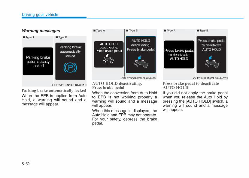
5-52
Driving your vehicle
Warning messages
Parking brake automatically locked
When the EPB is applied from AutoHold, a warning will sound and amessage will appear.
AUTO HOLD deactivating.Press brake pedal
When the conversion from Auto Holdto EPB is not working properly awarning will sound and a messagewill appear.When this message is displayed, theAuto Hold and EPB may not operate.For your safety, depress the brakepedal.
Press brake pedal to deactivateAUTO HOLD
If you did not apply the brake pedalwhen you release the Auto Hold bypressing the [AUTO HOLD] switch, awarning will sound and a messagewill appear.
■ Type A ■ Type B
OLF054131N/OLF044411N
■ Type A ■ Type B
OTLE055028/OLFH044408L
■ Type A ■ Type B
OLF054127N/OLF044407N
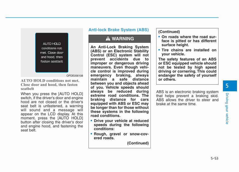
5-53
Driving your vehicle
5AUTO HOLD conditions not met.Close door and hood, then fastenseatbelt
When you press the [AUTO HOLD]switch, if the driver's door and enginehood are not closed or the driver'sseat belt is unfastened, a warningwill sound and a message willappear on the LCD display. At thismoment, press the [AUTO HOLD]button after closing the driver's doorand engine hood, and fastening theseat belt.
Anti-lock Brake System (ABS)
ABS is an electronic braking systemthat helps prevent a braking skid.ABS allows the driver to steer andbrake at the same time.
An Anti-Lock Braking System(ABS) or an Electronic StabilityControl (ESC) system will notprevent accidents due toimproper or dangerous drivingmaneuvers. Even though vehi-cle control is improved duringemergency braking, alwaysmaintain a safe distancebetween you and objects aheadof you. Vehicle speeds shouldalways be reduced duringextreme road conditions. Thebraking distance for carsequipped with ABS or ESC maybe longer than for those withoutthese systems in the followingroad conditions.• Drive your vehicle at reduced
speeds during the followingconditions:
• Rough, gravel or snow-cov-ered roads.
(Continued)
WARNING
OPDE056108
(Continued)• On roads where the road sur-
face is pitted or has differentsurface height.
• Tire chains are installed onyour vehicle.
The safety features of an ABSor ESC equipped vehicle shouldnot be tested by high speeddriving or cornering. This couldendanger the safety of yourselfor others.
5-54
Driving your vehicle
Using ABS To obtain the maximum benefit fromyour ABS in an emergency situation,do not attempt to modulate yourbrake pressure and do not try topump your brakes. Depress yourbrake pedal as hard as possible.When you apply your brakes underconditions which may lock thewheels, you may hear sounds fromthe brakes, or feel a correspondingsensation in the brake pedal. This isnormal and it means your ABS isactive.ABS does not reduce the time or dis-tance it takes to stop the vehicle.Always maintain a safe distance fromthe vehicle in front of you.ABS will not prevent a skid thatresults from sudden changes indirection, such as trying to take acorner too fast or making a suddenlane change. Always drive at a safespeed for the road and weather con-ditions.
ABS cannot prevent a loss of stabili-ty. Always steer moderately whenbraking hard. Severe or sharp steer-ing wheel movement can still causeyour vehicle to veer into oncomingtraffic or off the road.On loose or uneven road surfaces,operation of the anti-lock brake sys-tem may result in a longer stoppingdistance than for vehicles equippedwith a conventional brake system.The ABS warning light ( ) will stayon for several seconds after theEngine Start/Stop button is in the ONposition. During that time, the ABSwill go through self-diagnosis and thelight will go off if everything is nor-mal. If the light stays on, you mayhave a problem with your ABS. Werecommend that you contact anauthorized HYUNDAI dealer as soonas possible.
When you drive on a road havingpoor traction, such as an icy road,and apply your brakes continu-ously, the ABS will be active con-tinuously and the ABS warninglight ( ) may illuminate. Pullyour car over to a safe place andturn the engine off.Restart the engine. If the ABSwarning light is off, then your ABSsystem is normal.Otherwise, you may have a prob-lem with your ABS system. Werecommend that you contact anauthorized HYUNDAI dealer assoon as possible.
NOTICE
If the ABS warning light ( ) ison and stays on, you may havea problem with the ABS. Yourpower brakes will work normal-ly. To reduce the risk of seriousinjury or death, we recommendthat you contact your HYUNDAIdealer as soon as possible.
WARNING
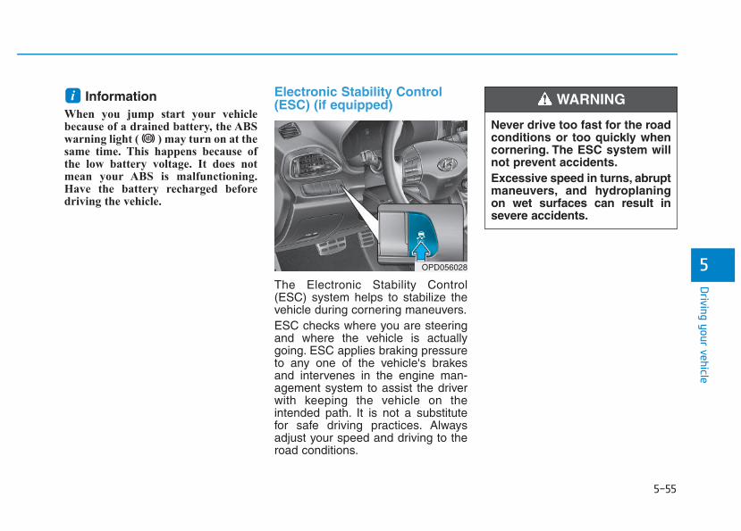
5-55
Driving your vehicle
5
Information When you jump start your vehiclebecause of a drained battery, the ABSwarning light ( ) may turn on at thesame time. This happens because ofthe low battery voltage. It does notmean your ABS is malfunctioning.Have the battery recharged beforedriving the vehicle.
Electronic Stability Control(ESC) (if equipped)
The Electronic Stability Control(ESC) system helps to stabilize thevehicle during cornering maneuvers.ESC checks where you are steeringand where the vehicle is actuallygoing. ESC applies braking pressureto any one of the vehicle's brakesand intervenes in the engine man-agement system to assist the driverwith keeping the vehicle on theintended path. It is not a substitutefor safe driving practices. Alwaysadjust your speed and driving to theroad conditions.
i
OPD056028
Never drive too fast for the roadconditions or too quickly whencornering. The ESC system willnot prevent accidents.Excessive speed in turns, abruptmaneuvers, and hydroplaningon wet surfaces can result insevere accidents.
WARNING
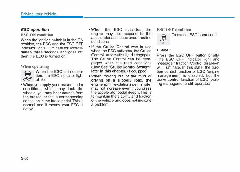
5-56
Driving your vehicle
ESC operation ESC ON condition
When the ignition switch is in the ONposition, the ESC and the ESC OFFindicator lights illuminate for approxi-mately three seconds and goes off,then the ESC is turned on.
When operating
When the ESC is in opera-tion, the ESC indicator lightblinks:
• When you apply your brakes underconditions which may lock thewheels, you may hear sounds fromthe brakes, or feel a correspondingsensation in the brake pedal.This isnormal and it means your ESC isactive.
• When the ESC activates, theengine may not respond to theaccelerator as it does under routineconditions.
• If the Cruise Control was in usewhen the ESC activates, the CruiseControl automatically disengages.The Cruise Control can be reen-gaged when the road conditionsallow. See "Cruise Control System"later in this chapter. (if equipped)
• When moving out of the mud ordriving on a slippery road, theengine rpm (revolutions per minute)may not increase even if you pressthe accelerator pedal deeply.This isto maintain the stability and tractionof the vehicle and does not indicatea problem.
ESC OFF condition
To cancel ESC operation :
• State 1Press the ESC OFF button briefly.The ESC OFF indicator light andmessage "Traction Control disabled"will illuminate. In this state, the trac-tion control function of ESC (enginemanagement) is disabled, but thebrake control function of ESC (brak-ing management) still operates.
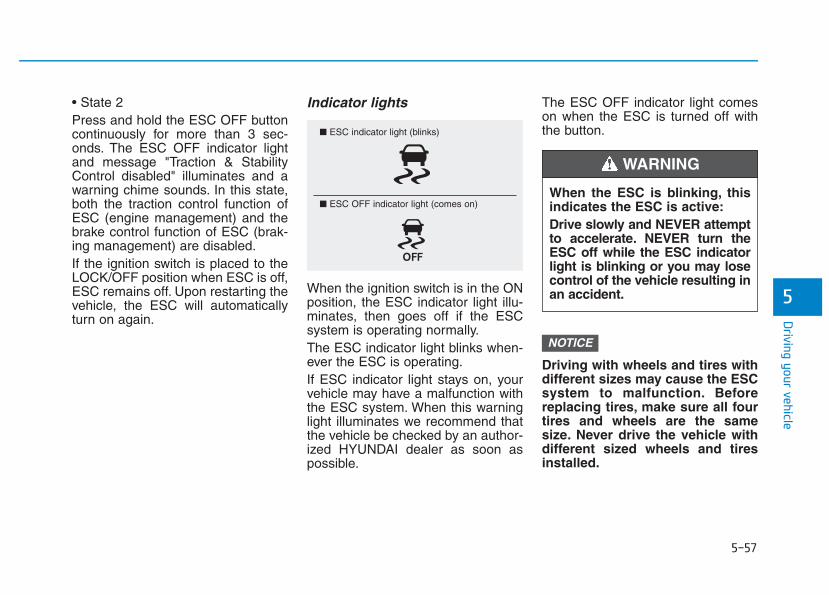
5-57
Driving your vehicle
5
• State 2Press and hold the ESC OFF buttoncontinuously for more than 3 sec-onds. The ESC OFF indicator lightand message "Traction & StabilityControl disabled" illuminates and awarning chime sounds. In this state,both the traction control function ofESC (engine management) and thebrake control function of ESC (brak-ing management) are disabled.If the ignition switch is placed to theLOCK/OFF position when ESC is off,ESC remains off. Upon restarting thevehicle, the ESC will automaticallyturn on again.
Indicator lights
When the ignition switch is in the ONposition, the ESC indicator light illu-minates, then goes off if the ESCsystem is operating normally.The ESC indicator light blinks when-ever the ESC is operating.If ESC indicator light stays on, yourvehicle may have a malfunction withthe ESC system. When this warninglight illuminates we recommend thatthe vehicle be checked by an author-ized HYUNDAI dealer as soon aspossible.
The ESC OFF indicator light comeson when the ESC is turned off withthe button.
Driving with wheels and tires withdifferent sizes may cause the ESCsystem to malfunction. Beforereplacing tires, make sure all fourtires and wheels are the samesize. Never drive the vehicle withdifferent sized wheels and tiresinstalled.
NOTICE
■ ESC indicator light (blinks)
■ ESC OFF indicator light (comes on)When the ESC is blinking, thisindicates the ESC is active:Drive slowly and NEVER attemptto accelerate. NEVER turn theESC off while the ESC indicatorlight is blinking or you may losecontrol of the vehicle resulting inan accident.
WARNING
5-58
Driving your vehicle
ESC OFF usage When Driving
The ESC OFF mode should only beused briefly to help free the vehicle ifstuck in snow or mud by temporarilystopping operation of the ESC tomaintain wheel torque.To turn ESC off while driving, pressthe ESC OFF button while driving ona flat road surface.
To prevent damage to the trans-mission:• Do not allow wheel(s) of one
axle to spin excessively whilethe ESC, ABS, and parking brakewarning lights are displayed.The repairs would not be cov-ered by the vehicle warranty.Reduce engine power and donot spin the wheel(s) excessive-ly while these lights are dis-played.
• When operating the vehicle on adynamometer, make sure theESC is turned off (ESC OFF lightilluminated).
Information Turning the ESC off does not affectABS or standard brake system opera-tion.
Vehicle Stability Management(if equipped) The Vehicle Stability Management(VSM) is a function of the ElectronicStability Control (ESC) system. Ithelps ensure the vehicle stays stablewhen accelerating or braking sud-denly on wet, slippery and roughroads where traction over the fourtires can suddenly become uneven.
i
NOTICE
Take the following precautionswhen using the Vehicle StabilityManagement (VSM):• ALWAYS check the speed and
the distance to the vehicleahead. The VSM is not a sub-stitute for safe driving prac-tices.
• Never drive too fast for theroad conditions.The VSM sys-tem will not prevent acci-dents. Excessive speed in badweather, slippery and unevenroads can result in severeaccidents.
WARNING
5-59
Driving your vehicle
5
VSM operationVSM ON condition
The VSM operates when:• The Electronic Stability Control
(ESC) is on.• Vehicle speed is approximately
above 15 km/h (9 mph) on curveroads.
• Vehicle speed is approximatelyabove 20 km/h (12 mph) when thevehicle is braking on rough roads.
When operating
When you apply your brakes underconditions which may activate theESC, you may hear sounds from thebrakes, or feel a corresponding sen-sation in the brake pedal. This is nor-mal and it means your VSM is active.
Information The VSM does not operate when:
• Driving on a banked road such asgradient or incline.
• Driving rearward.
• ESC OFF indicator light is on.
• EPS (Electric power steering) warninglight ( ) is on or blinks.
Driving with wheels and tires withdifferent sizes may cause the VSMsystem to malfunction. Beforereplacing tires, make sure all fourtires and wheels are the samesize. Never drive the vehicle withdifferent sized tires and wheelsinstalled.
NOTICE
i
If ESC indicator light ( ) orEPS warning light ( ) staysor blinks, your vehicle may havea malfunction with the VSM sys-tem.When the warning light illu-minates we recommend that thevehicle be checked by anauthorized HYUNDAI dealer assoon as possible.
WARNING
5-60
Driving your vehicle
Hill-Start Assist Control (HAC)(if equipped) The Hill-Start Assist Control (HAC)helps prevent the vehicle from rollingbackwards when starting a vehiclefrom a stop on a hill. The systemoperates the brakes automatically forapproximately 2 seconds and releas-es the brake after 2 seconds or whenthe accelerator pedal is depressed.
Information • The HAC does not operate when the
shift lever is in P (Park) or N(Neutral)
• The HAC activates even when theESC (Electronic Stability Control) isoff. However, it does not activate,when the ESC does not normallyoperate.
Emergency Stop Signal (ESS)(if equipped)The Emergency Stop Signal systemalerts the driver behind by blinkingthe stop lights, while sharply andseverely braking.The system is activated when:• The vehicle suddenly stops. (The
deceleration power exceeds 7 m/s2,and the driving speed exceeds 55km/h (34 mph).)
• The ABS is activated and the driv-ing speed exceeds 55 km/h (34mph).
The hazard warning flasher automat-ically turns ON after blinking the stoplights, when the driving speeds isdecelerated under 40 km/h (25 mph),when the ABS is deactivated, andwhen the sudden braking situation isover.
The hazard warning flasher turnsOFF, when the driving speed exceeds10 km/h (6 mph) after a completestop. The hazard warning flasherturns OFF, when the vehicle drives ata low speed for a certain period oftime. The driver can manually turnOFF the hazard warning flasher bypressing the button.
Information The Emergency Stop Signal (ESS) sys-tem will not activate, when the hazardwarning flasher already blinks.
i
i
Always be ready to depress theaccelerator pedal when startingoff on a incline. The HAC acti-vates only for approximately 2seconds.
WARNING
5-61
Driving your vehicle
5
Good braking practices Wet brakes can be dangerous! Thebrakes may get wet if the vehicle isdriven through standing water or if itis washed. Your vehicle will not stopas quickly if the brakes are wet. Wetbrakes may cause the vehicle to pullto one side.To dry the brakes, apply the brakeslightly until the braking action returnsto normal, taking care to keep thevehicle under control at all times. Ifthe braking action does not return tonormal, stop as soon as it is safe todo so and we recommend that youcall an authorized HYUNDAI dealerfor assistance.DO NOT drive with your foot restingon the brake pedal. Even light, butconstant pedal pressure can result inthe brakes overheating, brake wear,and possibly even brake failure.
If a tire goes flat while you are driv-ing, apply the brakes gently andkeep the vehicle pointed straightahead while you slow down. Whenyou are moving slowly enough for itto be safe to do so, pull off the roadand stop in a safe location.Keep your foot firmly on the brakepedal when the vehicle is stopped toprevent the vehicle from rolling for-ward.
Whenever leaving the vehicle orparking, always come to a com-plete stop and continue todepress the brake pedal. Movethe shift lever into the P (Park)position, then apply the parkingbrake, and place the ignitionswitch in the LOCK/OFF posi-tion.Vehicles parked with the park-ing brake not applied or notfully engaged may roll inadver-tently and may cause injury tothe driver and others. ALWAYSapply the parking brake beforeexiting the vehicle.
WARNING
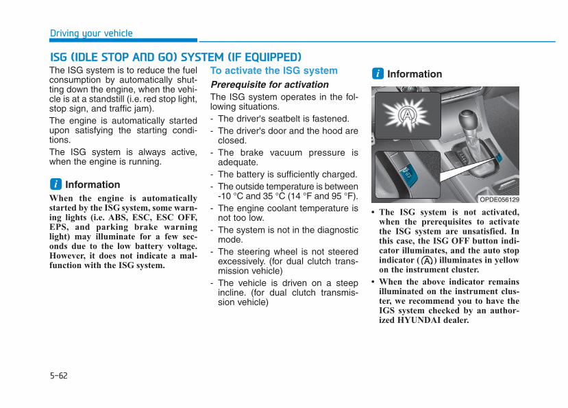
5-62
Driving your vehicle
The ISG system is to reduce the fuelconsumption by automatically shut-ting down the engine, when the vehi-cle is at a standstill (i.e. red stop light,stop sign, and traffic jam).The engine is automatically startedupon satisfying the starting condi-tions.The ISG system is always active,when the engine is running.
Information When the engine is automaticallystarted by the ISG system, some warn-ing lights (i.e. ABS, ESC, ESC OFF,EPS, and parking brake warninglight) may illuminate for a few sec-onds due to the low battery voltage.However, it does not indicate a mal-function with the ISG system.
To activate the ISG systemPrerequisite for activation The ISG system operates in the fol-lowing situations.- The driver's seatbelt is fastened.- The driver's door and the hood are
closed.- The brake vacuum pressure is
adequate.- The battery is sufficiently charged.- The outside temperature is between
-10 °C and 35 °C (14 °F and 95 °F).- The engine coolant temperature is
not too low.- The system is not in the diagnostic
mode.- The steering wheel is not steered
excessively. (for dual clutch trans-mission vehicle)
- The vehicle is driven on a steepincline. (for dual clutch transmis-sion vehicle)
Information
• The ISG system is not activated,when the prerequisites to activatethe ISG system are unsatisfied. Inthis case, the ISG OFF button indi-cator illuminates, and the auto stopindicator ( ) illuminates in yellowon the instrument cluster.
• When the above indicator remainsilluminated on the instrument clus-ter, we recommend you to have theIGS system checked by an author-ized HYUNDAI dealer.
i
i
IISSGG ((IIDDLLEE SSTTOOPP AANNDD GGOO)) SSYYSSTTEEMM ((IIFF EEQQUUIIPPPPEEDD))
OPDE056129
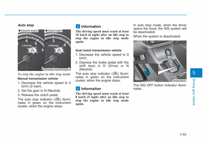
5-63
Driving your vehicle
5
Auto stop
To stop the engine in idle stop mode
Manual transmission vehicle1. Decrease the vehicle speed to 5
km/h (3 mph).2. Set the gear in N (Neutral).3. Release the clutch pedal.The auto stop indicator ( ) illumi-nates in green on the instrumentcluster, when the engine stops.
Information The driving speed must reach at least10 km/h (6 mph) after an idle stop tostop the engine in idle stop modeagain.
Dual clutch transmission vehicle1. Decrease the vehicle speed to 0
km/h.2. Depress the brake pedal with the
shift lever in D (Drive) or N(Neutral).
The auto stop indicator ( ) illumi-nates in green on the instrumentcluster, when the engine stops.
Information The driving speed must reach at least8 km/h (5 mph) after an idle stop tostop the engine in idle stop modeagain.
In auto stop mode, when the driveropens the hood, the ISG system willbe deactivated.When the system is deactivated:
The ISG OFF button indicator illumi-nates.i
i
OPDE056031
■ Gasoline engine ■ Diesel engine
OPDE056109/OPD056075
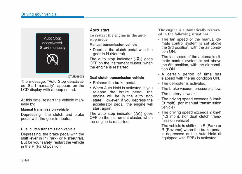
5-64
Driving your vehicle
The message, "Auto Stop deactivat-ed. Start manually", appears on theLCD display with a beep sound.
At this time, restart the vehicle man-ually by:Manual transmission vehicleDepressing the clutch and brakepedal with the gear in neutral.
Dual clutch transmission vehicleDepressing the brake pedal with theshift lever in P (Park) or N (Neutral).But for your safety, restart the vehiclein the P (Park) position.
Auto startTo restart the engine in the autostop mode
Manual transmission vehicle• Depress the clutch pedal with the
gear in N (Neutral).The auto stop indicator ( ) goesOFF on the instrument cluster, whenthe engine is restarted.
Dual clutch transmission vehicle• Release the brake pedal.• When Auto Hold is activated, if you
release the brake pedal, theengine will be in the auto stopstate. However, if you depress theaccelerator pedal, the engine willstart again.
The auto stop indicator ( ) goesOFF on the instrument cluster, whenthe engine is restarted.
The engine is automatically restart-ed in the following situations.
- The fan speed of the manual cli-mate control system is set abovethe 3rd position, with the air condi-tion ON.
- The fan speed of the automatic cli-mate control system is set abovethe 6th position, with the air condi-tion ON.
- A certain period of time haselapsed with the air condition ON.
- The defroster is activated.- The brake vacuum pressure is low.- The battery is weak.- The driving speed exceeds 5 km/h
(3 mph). (for manual transmissionvehicle)
- The driving speed exceeds 2 km/h(1.2 mph). (for dual clutch trans-mission vehicle)
- The vehicle is shifted to P (Park) orR (Reverse) when the brake pedalis depressed or the Auto Hold (ifequipped with EPB) is activated.
OTLE055036
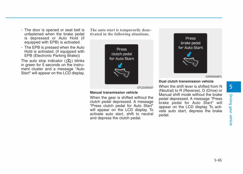
5-65
Driving your vehicle
5
- The door is opened or seat belt isunfastened when the brake pedalis depressed or Auto Hold (ifequipped with EPB) is activated.
- The EPB is pressed when the AutoHold is activated. (if equipped withEPB (Electronic Parking Brake))
The auto stop indicator ( ) blinksin green for 5 seconds on the instru-ment cluster and a message "AutoStart" will appear on the LCD display.
The auto start is temporarily deac-tivated in the following situations.
Manual transmission vehicleWhen the gear is shifted without theclutch pedal depressed. A message"Press clutch pedal for Auto Start"will appear on the LCD display. Toactivate auto start, shift to neutraland depress the clutch pedal.
Dual clutch transmission vehicleWhen the shift lever is shifted from N(Neutral) to R (Reverse), D (Drive) orManual shift mode without the brakepedal depressed. A message "Pressbrake pedal for Auto Start" willappear on the LCD display. To acti-vate auto start, depress the brakepedal.
OTLE055037
OAD055087L
5-66
To deactivate the ISG system • Press the ISG OFF button to deac-
tivate the ISG system. Then, theISG OFF button indicator illumi-nates, and the message "AutoStop System Off" appears on theLCD display.
• Press the ISG OFF button again toreactivate the ISG system. Then,the ISG OFF button indicator turnsOFF.
ISG system malfunctionThe ISG system may not operate:
When there is a malfunction with theISG sensors or the ISG system.
The followings occur, when there isa malfunction with the ISG system:
• The auto stop indicator ( ) willblink in yellow on the instrumentcluster.
• The light on the ISG OFF buttonwill illuminate.
Information • When you cannot turn OFF the ISG
OFF button indicator by pressing theISG OFF button, or when the mal-function with the ISG system per-sists, we recommend you to contactan authorized HYUNDAI dealer.
• You can turn off the ISG OFF but-ton indicator by driving over 80km/h (50 mph) for up to 2 hourswith the fan speed below the 2ndposition. If the ISG OFF buttonindicator remains ON, we recom-mend you to contact an authorizedHYUNDAI dealer.
i
Driving your vehicle
When the engine is in auto stopmode, the engine may restart.Before leaving the vehicle orchecking the engine compart-ment, stop the engine by plac-ing the ignition switch to theLOCK/OFF position or remov-ing the ignition key.
WARNING
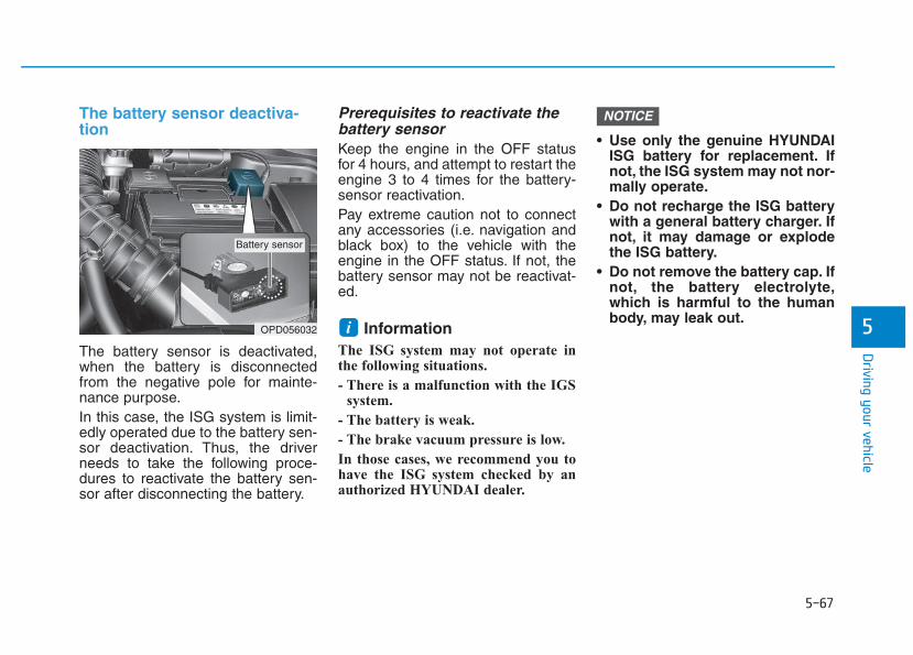
5-67
Driving your vehicle
5
The battery sensor deactiva-tion
The battery sensor is deactivated,when the battery is disconnectedfrom the negative pole for mainte-nance purpose.In this case, the ISG system is limit-edly operated due to the battery sen-sor deactivation. Thus, the driverneeds to take the following proce-dures to reactivate the battery sen-sor after disconnecting the battery.
Prerequisites to reactivate thebattery sensorKeep the engine in the OFF statusfor 4 hours, and attempt to restart theengine 3 to 4 times for the battery-sensor reactivation.Pay extreme caution not to connectany accessories (i.e. navigation andblack box) to the vehicle with theengine in the OFF status. If not, thebattery sensor may not be reactivat-ed.
Information The ISG system may not operate inthe following situations.
- There is a malfunction with the IGSsystem.
- The battery is weak.
- The brake vacuum pressure is low.
In those cases, we recommend you tohave the ISG system checked by anauthorized HYUNDAI dealer.
• Use only the genuine HYUNDAIISG battery for replacement. Ifnot, the ISG system may not nor-mally operate.
• Do not recharge the ISG batterywith a general battery charger. Ifnot, it may damage or explodethe ISG battery.
• Do not remove the battery cap. Ifnot, the battery electrolyte,which is harmful to the humanbody, may leak out.
NOTICE
iOPD056032
Battery sensor
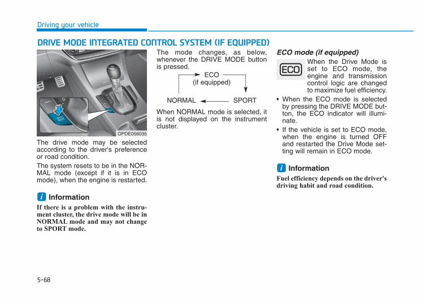
5-68
Driving your vehicle
DDRRIIVVEE MMOODDEE IINNTTEEGGRRAATTEEDD CCOONNTTRROOLL SSYYSSTTEEMM ((IIFF EEQQUUIIPPPPEEDD))
The drive mode may be selectedaccording to the driver's preferenceor road condition.The system resets to be in the NOR-MAL mode (except if it is in ECOmode), when the engine is restarted.
Information If there is a problem with the instru-ment cluster, the drive mode will be inNORMAL mode and may not changeto SPORT mode.
The mode changes, as below,whenever the DRIVE MODE buttonis pressed.
When NORMAL mode is selected, itis not displayed on the instrumentcluster.
ECO mode (if equipped)When the Drive Mode isset to ECO mode, theengine and transmissioncontrol logic are changedto maximize fuel efficiency.
• When the ECO mode is selectedby pressing the DRIVE MODE but-ton, the ECO indicator will illumi-nate.
• If the vehicle is set to ECO mode,when the engine is turned OFFand restarted the Drive Mode set-ting will remain in ECO mode.
Information Fuel efficiency depends on the driver'sdriving habit and road condition.
i
i
OPDE056035
ECO(if equipped)
NORMAL SPORT
5-69
Driving your vehicle
5
When ECO mode is activated:• The acceleration response may be
slightly reduced as the acceleratorpedal is depressed moderately.
• The air conditioner performancemay be limited.
• The shift pattern of the automatictransmission may change.
• The engine noise may get louder.
The above situations are normalconditions when ECO mode is acti-vated to improve fuel efficiency.
Limitation of ECO mode opera-tion:If the following conditions occur whileECO mode is operating, the systemoperation is limited even thoughthere is no change in ECO indicator.• When the coolant temperature is
low:The system will be limited untilengine performance becomes nor-mal.
• When driving up a hill:The system will be limited to gainpower when driving uphill becauseengine torque is restricted.
• When driving the vehicle with theautomatic transmission or the dualclutch transmission gear shift leverin manual shift mode:The system will be limited accord-ing to the shift location.
• When the accelerator pedal isdeeply depressed for a few seconds:The system will be limited, judgingthat the driver wants to speed up.
SPORT modeSPORT mode managesthe driving dynamics byautomatically adjusting thesteering effort, the engineand transmission controllogic for enhanced driverperformance.
• When SPORT mode is selected bypressing the DRIVE MODE button,the SPORT indicator will illuminate.
• Whenever the engine is restarted,the Drive Mode will revert back toNORMAL mode. If SPORT mode isdesired, re-select SPORT modefrom the DRIVE MODE button.
• When SPORT mode is activated:- The engine rpm will tend to remain
raised over a certain length of timeeven after releasing the accelerator
- Upshifts are delayed when accel-erating
Information In SPORT mode, the fuel efficiencymay decrease.
i
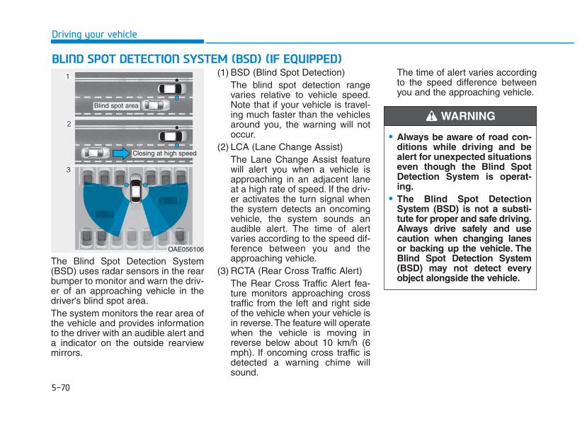
5-70
Driving your vehicle
The Blind Spot Detection System(BSD) uses radar sensors in the rearbumper to monitor and warn the driv-er of an approaching vehicle in thedriver's blind spot area.The system monitors the rear area ofthe vehicle and provides informationto the driver with an audible alert anda indicator on the outside rearviewmirrors.
(1) BSD (Blind Spot Detection)The blind spot detection rangevaries relative to vehicle speed.Note that if your vehicle is travel-ing much faster than the vehiclesaround you, the warning will notoccur.
(2) LCA (Lane Change Assist)The Lane Change Assist featurewill alert you when a vehicle isapproaching in an adjacent laneat a high rate of speed. If the driv-er activates the turn signal whenthe system detects an oncomingvehicle, the system sounds anaudible alert. The time of alertvaries according to the speed dif-ference between you and theapproaching vehicle.
(3) RCTA (Rear Cross Traffic Alert)The Rear Cross Traffic Alert fea-ture monitors approaching crosstraffic from the left and right sideof the vehicle when your vehicle isin reverse.The feature will operatewhen the vehicle is moving inreverse below about 10 km/h (6mph). If oncoming cross traffic isdetected a warning chime willsound.
The time of alert varies accordingto the speed difference betweenyou and the approaching vehicle.
BBLLIINNDD SSPPOOTT DDEETTEECCTTIIOONN SSYYSSTTEEMM ((BBSSDD)) ((IIFF EEQQUUIIPPPPEEDD))
OAE056106
Blind spot area
Closing at high speed
• Always be aware of road con-ditions while driving and bealert for unexpected situationseven though the Blind SpotDetection System is operat-ing.
• The Blind Spot DetectionSystem (BSD) is not a substi-tute for proper and safe driving.Always drive safely and usecaution when changing lanesor backing up the vehicle. TheBlind Spot Detection System(BSD) may not detect everyobject alongside the vehicle.
WARNING
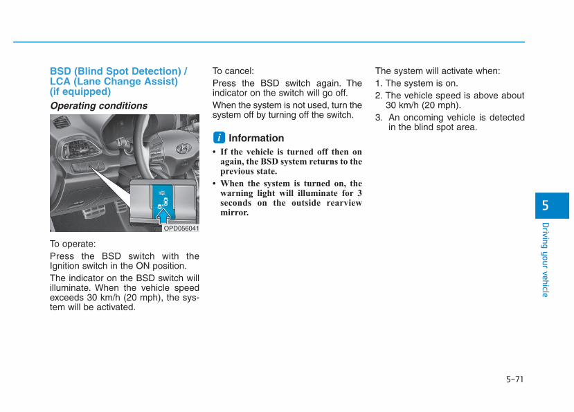
5-71
Driving your vehicle
5
BSD (Blind Spot Detection) /LCA (Lane Change Assist) (if equipped)Operating conditions
To operate:Press the BSD switch with theIgnition switch in the ON position.The indicator on the BSD switch willilluminate. When the vehicle speedexceeds 30 km/h (20 mph), the sys-tem will be activated.
To cancel:Press the BSD switch again. Theindicator on the switch will go off.When the system is not used, turn thesystem off by turning off the switch.
Information • If the vehicle is turned off then on
again, the BSD system returns to theprevious state.
• When the system is turned on, thewarning light will illuminate for 3seconds on the outside rearviewmirror.
The system will activate when:1. The system is on.2. The vehicle speed is above about
30 km/h (20 mph).3. An oncoming vehicle is detected
in the blind spot area.i
OPD056041
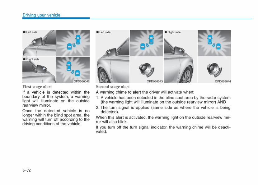
5-72
Driving your vehicle
First stage alert
If a vehicle is detected within theboundary of the system, a warninglight will illuminate on the outsiderearview mirror.Once the detected vehicle is nolonger within the blind spot area, thewarning will turn off according to thedriving conditions of the vehicle.
OPD056042
■ Left side
■ Right side
OPD056043
■ Left side
OPD056044
■ Right side
Second stage alert
A warning chime to alert the driver will activate when:1. A vehicle has been detected in the blind spot area by the radar system
(the warning light will illuminate on the outside rearview mirror) AND2. The turn signal is applied (same side as where the vehicle is being
detected).When this alert is activated, the warning light on the outside rearview mir-ror will also blink.If you turn off the turn signal indicator, the warning chime will be deacti-vated.
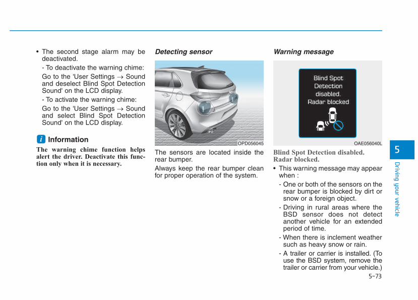
5-73
Driving your vehicle
5
• The second stage alarm may bedeactivated.- To deactivate the warning chime:Go to the 'User Settings → Soundand deselect Blind Spot DetectionSound' on the LCD display.- To activate the warning chime:Go to the 'User Settings → Soundand select Blind Spot DetectionSound' on the LCD display.
InformationThe warning chime function helpsalert the driver. Deactivate this func-tion only when it is necessary.
Detecting sensor
The sensors are located inside therear bumper.Always keep the rear bumper cleanfor proper operation of the system.
Warning message
Blind Spot Detection disabled.Radar blocked.
• This warning message may appearwhen :- One or both of the sensors on the
rear bumper is blocked by dirt orsnow or a foreign object.
- Driving in rural areas where theBSD sensor does not detectanother vehicle for an extendedperiod of time.
- When there is inclement weathersuch as heavy snow or rain.
- A trailer or carrier is installed. (Touse the BSD system, remove thetrailer or carrier from your vehicle.)
iOPD056045 OAE056040L
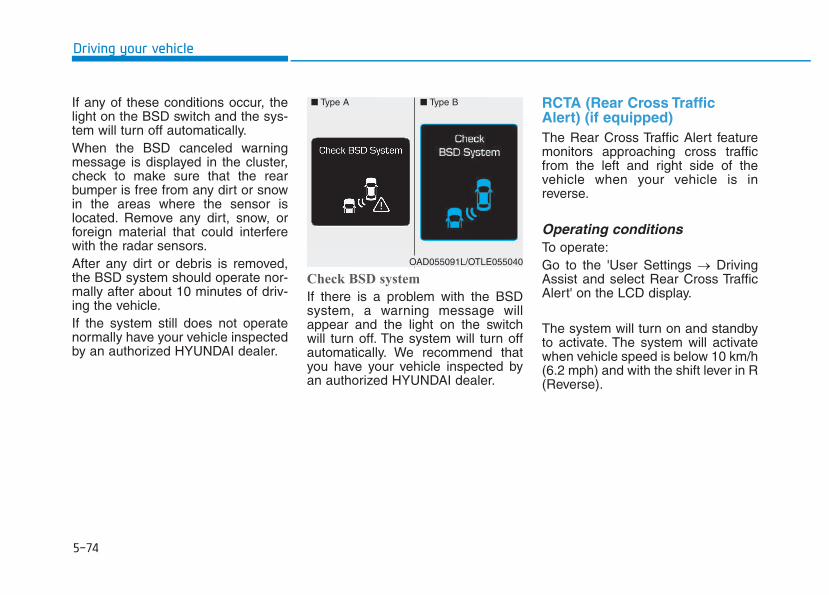
5-74
Driving your vehicle
If any of these conditions occur, thelight on the BSD switch and the sys-tem will turn off automatically.When the BSD canceled warningmessage is displayed in the cluster,check to make sure that the rearbumper is free from any dirt or snowin the areas where the sensor islocated. Remove any dirt, snow, orforeign material that could interferewith the radar sensors.After any dirt or debris is removed,the BSD system should operate nor-mally after about 10 minutes of driv-ing the vehicle.If the system still does not operatenormally have your vehicle inspectedby an authorized HYUNDAI dealer.
Check BSD system
If there is a problem with the BSDsystem, a warning message willappear and the light on the switchwill turn off. The system will turn offautomatically. We recommend thatyou have your vehicle inspected byan authorized HYUNDAI dealer.
RCTA (Rear Cross TrafficAlert) (if equipped)The Rear Cross Traffic Alert featuremonitors approaching cross trafficfrom the left and right side of thevehicle when your vehicle is inreverse.
Operating conditionsTo operate:Go to the 'User Settings → DrivingAssist and select Rear Cross TrafficAlert' on the LCD display.
The system will turn on and standbyto activate. The system will activatewhen vehicle speed is below 10 km/h(6.2 mph) and with the shift lever in R(Reverse).
■ Type A ■ Type B
OAD055091L/OTLE055040
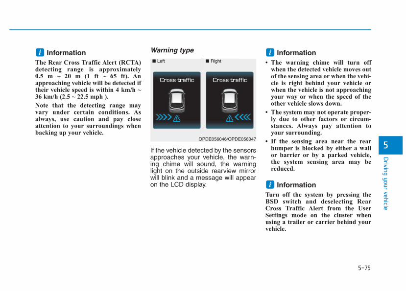
5-75
Driving your vehicle
5
Information The Rear Cross Traffic Alert (RCTA)detecting range is approximately 0.5 m ~ 20 m (1 ft ~ 65 ft). Anapproaching vehicle will be detected iftheir vehicle speed is within 4 km/h ~36 km/h (2.5 ~ 22.5 mph ).
Note that the detecting range mayvary under certain conditions. Asalways, use caution and pay closeattention to your surroundings whenbacking up your vehicle.
Warning type
If the vehicle detected by the sensorsapproaches your vehicle, the warn-ing chime will sound, the warninglight on the outside rearview mirrorwill blink and a message will appearon the LCD display.
Information • The warning chime will turn off
when the detected vehicle moves outof the sensing area or when the vehi-cle is right behind your vehicle orwhen the vehicle is not approachingyour way or when the speed of theother vehicle slows down.
• The system may not operate proper-ly due to other factors or circum-stances. Always pay attention toyour surrounding.
• If the sensing area near the rearbumper is blocked by either a wallor barrier or by a parked vehicle,the system sensing area may bereduced.
Information Turn off the system by pressing theBSD switch and deselecting RearCross Traffic Alert from the UserSettings mode on the cluster whenusing a trailer or carrier behind yourvehicle.
i
ii■ Left ■ Right
OPDE056046/OPDE056047
5-76
Driving your vehicle
• The system may not work prop-erly when the bumper has beendamaged, or if the rear bumperhas been replaced or repaired.
• The sensing range differs some-what according to the width ofthe road. When the road is nar-row, the system may detectother vehicles in the next laneOr when the road is wide, thesystem may not detect othervehicles in the next lane.
• The system may turn off due tostrong electromagnetic waves.
Non-operating conditionThe BSD indicator on the outer sideview mirror may not illuminateproperly when:
• The outside rearview mirror hous-ing is damaged.
• The mirror is covered with dirt,snow, or debris.
• The window is covered with dirt,snow, or debris.
• The window is tinted.
NOTICE
(Continued)• The Blind Spot Detection
System (BSD) and Rear CrossTraffic Alert (RCTA) are not asubstitute for proper and safedriving practices. Alwaysdrive safely and use cautionwhen changing lanes or back-ing up your vehicle. The BlindSpot Detection System (BSD)may not detect every objectalongside the vehicle.
• The warning light on the out-side rearview mirror will illu-minate whenever a vehicle isdetected at the rear side bythe system.To avoid accidents, do notfocus only on the warninglight and neglect to see thesurrounding of the vehicle.
• Drive safely even though thevehicle is equipped with aBlind Spot Detection System(BSD) and Rear Cross TrafficAlert (RCTA). Do not solelyrely on the system but checkyour surrounding beforechanging lanes or backing thevehicle up.The system may not alert thedriver in some conditions soalways check your surround-ings while driving.
(Continued)
WARNING
5-77
Driving your vehicle
5
Limitations of the systemThe driver must be cautious in thebelow situations, because the sys-tem may not detect other vehicles orobjects in certain circumstances.
• The vehicle drives on a curvedroad or through a tollgate.
• The vehicle is turning left or right ata crossroad.
• The sensor is polluted with rain,snow, mud, etc.
• The rear bumper where the sensoris located is covered with a foreignobject such as a bumper sticker, abumper guard, a bike rack, etc.
• The rear bumper is damaged, orthe sensor is out of the originaldefault position.
• The vehicle height gets lower orhigher due to heavy loading in theluggage compartment, abnormaltire pressure, etc.
• The vehicle drives in inclementweather such as heavy rain orsnow.
• There is a fixed object near thevehicle, such as a guardrail, per-son, animal, etc.
• The vehicle is driven near areascontaining metal substances suchas a construction zone, railroad,etc.
• A big vehicle is near such as a busor truck.
• A motorcycle or bicycle is near.• A flat trailer is near.• If the vehicle has started at the
same time as the vehicle next toyou and has accelerated.
• When the other vehicle passes at avery fast speed.
• While changing lanes.• While going down or up a steep
road where the height of the lane isdifferent.
• When the other vehicle approach-es very close.
• When a trailer or carrier isinstalled.
• When the temperature near therear bumper area is high or low.
• When the sensors are blocked byother vehicles, walls or parking-lotpillars.
• When the detected vehicle alsomoves back, as your vehicle drivesback.
• If there are small objects in thedetecting area such as a shoppingcart or a baby stroller.
• If there is a low height vehicle suchas a sports car.
• When other vehicles are close toyour vehicle.
• When the vehicle in the next lanemoves two lanes away from youOR when the vehicle two lanesaway moves to the next lane fromyou.
• When driving through a narrowroad with many trees or bushes.
• When driving through a large areawith few cars or structures around,such as a desert, rural area, etc.
• When driving on wet surface.
5-78
Driving your vehicle
The Autonomous EmergencyBraking (AEB) system is designed todetect and monitor the vehicle aheador detect a pedestrian (if equipped)in the roadway through radar signalsand camera recognition to warn thedriver that a collision is imminent,and if necessary, apply emergencybraking.
System setting and activationSystem setting• The driver can activate the AEB by
placing the ignition switch to theON position and by selecting:'User Settings → Driving Assist →Assist Emergency Braking'
The AEB deactivates, when the driv-er cancels the system setting.
The warning light illumi-nates on the LCD display,when you cancel the AEBsystem. The driver can
monitor the AEB ON/OFF status onthe LCD display. Also, the warninglight illuminates when the ESC(Electronic Stability Control) isturned off (Traction & Stability controldisabled.) If the warning lightremains ON when the AEB is acti-vated, we recommend you to havethe system checked by an authorizedHYUNDAI dealer.
AAUUTTOONNOOMMOOUUSS EEMMEERRGGEENNCCYY BBRRAAKKIINNGG ((AAEEBB)) -- SSEENNSSOORR FFUUSSIIOONN TTYYPPEE ((FFRROONNTT RRAADDAARR ++ FFRROONNTT CCAAMMEERRAA)) ((IIFF EEQQUUIIPPPPEEDD))
Take the following precautionswhen using the AutonomousEmergency Braking (AEB):• This system is only a supple-
mental system and it is notintended to, nor does itreplace the need for extremecare and attention of the driv-er. The sensing range andobjects detectable by the sen-sors are limited. Pay attentionto the road conditions at alltimes.
• NEVER drive too fast in accor-dance with the road condi-tions or while cornering.
• Always drive cautiously toprevent unexpected and sud-den situations from occur-ring. AEB does not stop thevehicle completely and is nota collision avoidance system.
WARNING

5-79
Driving your vehicle
5
• The driver can select the initial warn-ing activation time on the LCD dis-play.Go to the 'User Settings → DrivingAssist → Forward Collision Warning→ Late/Normal/Early'.
The options for the initial ForwardCollision Warning includes the fol-lowing:- Early:
When this condition is selected,the initial Forward CollisionWarning is activated earlier thannormal. This setting maximizes theamount of distance between thevehicle or pedestrian ahead beforethe initial warning occurs.Even though, 'Early' is selected ifthe front vehicle suddenly stopsthe initial warning activation timemay not seem fast.
- Normal:When this condition is selected,the initial Forward CollisionWarning is activated normally. Thissetting allows for a nominalamount of distance between thevehicle or pedestrian ahead beforethe initial warning occurs.
- Late:When this condition is selected,the initial Forward CollisionWarning is activated later than nor-mal. This setting reduces theamount of distance between thevehicle or pedestrian ahead beforethe initial warning occurs.Select 'Late' when traffic is lightand when driving speed is slow.
Prerequisite for activationThe AEB gets ready to be activated,when the AEB is selected on theLCD display, and when the followingprerequisites are satisfied.- The ESC (Electronic Stability
Control) is on.- Vehicle speed is over 10 km/h (6
mph). (The AEB is only activatedwithin a certain speed range.)
- The system detects a pedestrianor a vehicle in front, which may col-lide with your vehicle. (The AEBmay not be activated or may sounda warning alarm in accordancewith the driving situation or vehiclecondition.)

5-80
Driving your vehicle
AEB warning message andsystem controlThe AEB produces warning mes-sages and warning alarms in accor-dance with the collision risk levels,such as abrupt stopping of the vehi-cle in front, insufficient braking dis-tance, or pedestrian detection. Also,it controls the brakes in accordancewith the collision risk levels.The driver can select the initial warn-ing activation time in the UserSettings in the LCD display. Theoptions for the initial ForwardCollision Warning include Early,Normal or Late initial warning time.
Forward Warning (1st warning)
This initial warning message appearson the LCD display with a warningchime.
• Completely stop the vehicleon a safe location beforeoperating the switch on thesteering wheel to activate/deactivate the AEB system.
• The AEB automatically acti-vates upon placing the EngineStart/Stop button to the ONposition. The driver can deac-tivate the AEB by cancelingthe system setting on the LCDdisplay.
• The AEB automatically deacti-vates upon canceling the ESC(Electronic Stability Control).When the ESC is canceled,the AEB cannot be activatedon the LCD display.
WARNING
OPDE056036

5-81
Driving your vehicle
5
Collision Warning (2nd warning)
This warning message appears onthe LCD display with a warningchime. Additionally, some vehiclesystem intervention occurs by theengine management system to helpdecelerate the vehicle.
- Your vehicle speed may deceler-ate moderately.
- The AEB system limitedly con-trols the brakes to preemptivelymitigate impact in a collision.
Emergency braking (3rd warning)
This warning message appears onthe LCD display with a warningchime.Additionally, some vehicle systemintervention occurs by the enginemanagement system to help decel-erate the vehicle.
- The AEB system limitedly con-trols the brakes to preemptivelymitigate impact in a collision. Thebrake control is maximized justbefore a collision.
Brake operation• In an urgent situation, the braking
system enters into the ready statusfor prompt reaction against the dri-ver's depressing the brake pedal.
• The AEB provides additional brak-ing power for optimum braking per-formance, when the driverdepresses the brake pedal.
• The braking control is automatical-ly deactivated, when the driversharply depresses the acceleratorpedal, or when the driver abruptlyoperates the steering wheel.
• The AEB brake control is automat-ically canceled, when risk factorsdisappear.
OPDE056038
OPDE056037
The driver should always useextreme caution while operatingthe vehicle, whether or not thereis a warning message or alarmfrom the AEB system.
CAUTION
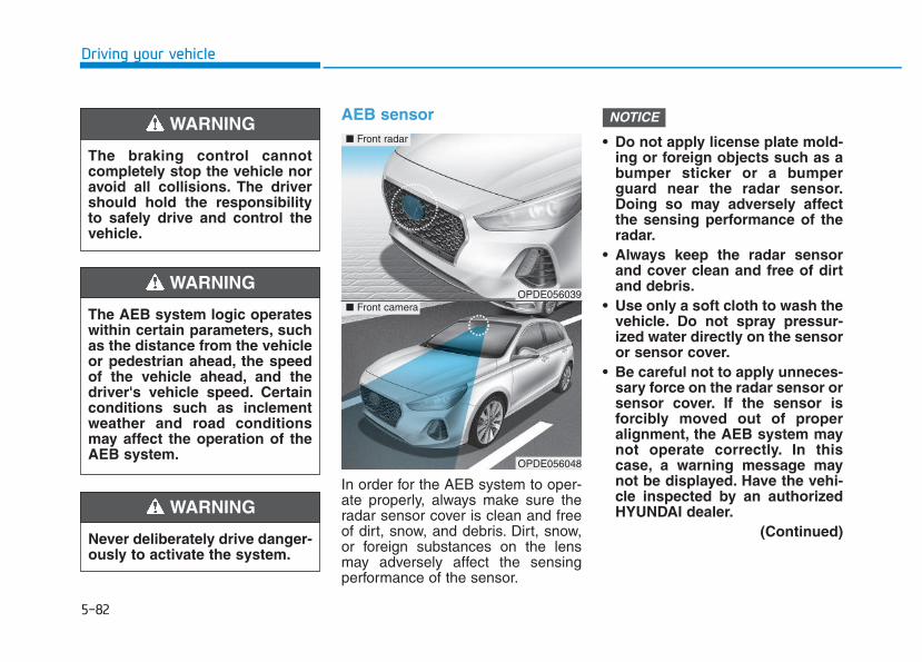
5-82
Driving your vehicle
AEB sensor
In order for the AEB system to oper-ate properly, always make sure theradar sensor cover is clean and freeof dirt, snow, and debris. Dirt, snow,or foreign substances on the lensmay adversely affect the sensingperformance of the sensor.
• Do not apply license plate mold-ing or foreign objects such as abumper sticker or a bumperguard near the radar sensor.Doing so may adversely affectthe sensing performance of theradar.
• Always keep the radar sensorand cover clean and free of dirtand debris.
• Use only a soft cloth to wash thevehicle. Do not spray pressur-ized water directly on the sensoror sensor cover.
• Be careful not to apply unneces-sary force on the radar sensor orsensor cover. If the sensor isforcibly moved out of properalignment, the AEB system maynot operate correctly. In thiscase, a warning message maynot be displayed. Have the vehi-cle inspected by an authorizedHYUNDAI dealer.
(Continued)
NOTICE
The braking control cannotcompletely stop the vehicle noravoid all collisions. The drivershould hold the responsibilityto safely drive and control thevehicle.
WARNING
Never deliberately drive danger-ously to activate the system.
WARNING
The AEB system logic operateswithin certain parameters, suchas the distance from the vehicleor pedestrian ahead, the speedof the vehicle ahead, and thedriver's vehicle speed. Certainconditions such as inclementweather and road conditionsmay affect the operation of theAEB system.
WARNING OPDE056039
OPDE056048
■ Front radar
■ Front camera
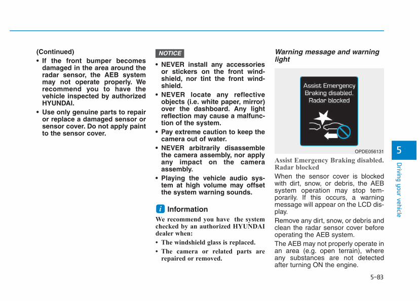
5-83
Driving your vehicle
5
(Continued)• If the front bumper becomes
damaged in the area around theradar sensor, the AEB systemmay not operate properly. Werecommend you to have thevehicle inspected by authorizedHYUNDAI.
• Use only genuine parts to repairor replace a damaged sensor orsensor cover. Do not apply paintto the sensor cover.
• NEVER install any accessoriesor stickers on the front wind-shield, nor tint the front wind-shield.
• NEVER locate any reflectiveobjects (i.e. white paper, mirror)over the dashboard. Any lightreflection may cause a malfunc-tion of the system.
• Pay extreme caution to keep thecamera out of water.
• NEVER arbitrarily disassemblethe camera assembly, nor applyany impact on the cameraassembly.
• Playing the vehicle audio sys-tem at high volume may offsetthe system warning sounds.
InformationWe recommend you have the systemchecked by an authorized HYUNDAIdealer when:
• The windshield glass is replaced.
• The camera or related parts arerepaired or removed.
Warning message and warninglight
Assist Emergency Braking disabled.Radar blocked
When the sensor cover is blockedwith dirt, snow, or debris, the AEBsystem operation may stop tem-porarily. If this occurs, a warningmessage will appear on the LCD dis-play.Remove any dirt, snow, or debris andclean the radar sensor cover beforeoperating the AEB system.The AEB may not properly operate inan area (e.g. open terrain), whereany substances are not detectedafter turning ON the engine.
i
NOTICE
OPDE056131
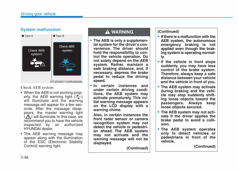
5-84
Driving your vehicle
System malfunction
Check AEB system
• When the AEB is not working prop-erly, the AEB warning light ( )will illuminate and the warningmessage will appear for a few sec-onds. After the message disap-pears, the master warning light( ) will illuminate. In this case, werecommend you to have the vehicleinspected by an authorizedHYUNDAI dealer.
• The AEB warning message mayappear along with the illuminationof the ESC (Electronic StabilityControl) warning light.
• The AEB is only a supplemen-tal system for the driver's con-venience. The driver shouldhold the responsibility to con-trol the vehicle operation. Donot solely depend on the AEBsystem. Rather, maintain asafe braking distance, and, ifnecessary, depress the brakepedal to reduce the drivingspeed.
• In certain instances andunder certain driving condi-tions, the AEB system mayactivate prematurely. This ini-tial warning message appearson the LCD display with awarning chime.Also, in certain instances thefront radar sensor or camerarecognition system may notdetect the vehicle or pedestri-an ahead. The AEB systemmay not activate and thewarning message will not bedisplayed.
(Continued)
(Continued)• If there is a malfunction with the
AEB system, the autonomousemergency braking is notapplied even though the brak-ing system is operating normal-ly.
• If the vehicle in front stopssuddenly, you may have lesscontrol of the brake system.Therefore, always keep a safedistance between your vehicleand the vehicle in front of you.
• The AEB system may activateduring braking and the vehi-cle may stop suddenly shift-ing loose objects toward thepassengers. Always keeploose objects secured.
• The AEB system may not acti-vate if the driver applies thebrake pedal to avoid a colli-sion.
• The AEB system operatesonly to detect vehicles orpedestrians in front of thevehicle.
(Continued)
WARNING ■ Type A ■ Type B
OTLE055071/OAE056038L
5-85
Driving your vehicle
5
Limitations of the systemThe Autonomous Emergency Braking(AEB) system is designed to monitorthe vehicle ahead or a pedestrian inthe roadway through radar signalsand camera recognition to warn thedriver that a collision is imminent, andif necessary, apply emergency brak-ing.In certain situations, the radar sen-sor or the camera may not be able todetect the vehicle or pedestrianahead. In these cases, the AEB sys-tem may not operate normally. Thedriver must pay careful attention inthe following situations where theAEB operation may be limited.
Detecting vehiclesThe sensor may be limited when:• The radar sensor or camera is
blocked with a foreign object ordebris
• Inclement weather such as heavyrain or snow obscures the field ofview of the radar sensor or camera
• There is interference by electro-magnetic waves
• There is severe irregular reflectionfrom the radar sensor
• The radar/camera sensor recogni-tion is limited
• The vehicle in front is too small tobe detected (for example a motor-cycle or a bicycle, etc.)
• The vehicle in front is an oversizevehicle or trailer that is too big tobe detected by the camera recog-nition system (for example a tractortrailer, etc.)
• The driver's field of view is not wellilluminated (either too dark or toomuch reflection or too much back-light that obscures the field of view)
(Continued)The AEB system does notoperate when the vehicle is inreverse.The AEB system is notdesigned to detect otherobjects on the road such asanimals.The AEB system does notdetect vehicles in the oppo-site lane.The AEB system does notdetect cross traffic vehiclesthat are approaching.The AEB system cannotdetect the driver approachingthe side view of a parked vehi-cle (for example on a deadend street.)In these cases, you mustmaintain a safe braking dis-tance, and if necessary,depress the brake pedal toreduce the driving speed inorder to maintain a safe dis-tance.
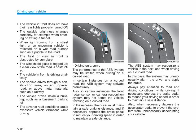
5-86
Driving your vehicle
• The vehicle in front does not havetheir rear lights properly turned ON
• The outside brightness changessuddenly, for example when enter-ing or exiting a tunnel
• When light coming from a streetlight or an oncoming vehicle isreflected on a wet road surfacesuch as a puddle in the road
• The field of view in front isobstructed by sun glare
• The windshield glass is fogged up;a clear view of the road is obstruct-ed
• The vehicle in front is driving errat-ically
• The vehicle drives through a con-struction area, on an unpavedroad, or above metal materials,such as a railway
• The vehicle drives inside a build-ing, such as a basement parkinglot
• The adverse road conditions causeexcessive vehicle vibrations whiledriving
- Driving on a curveThe performance of the AEB systemmay be limited when driving on acurved road.In certain instances on a curvedroad, the AEB system may activateprematurely.Also, in certain instances the frontradar sensor or camera recognitionsystem may not detect the vehicletraveling on a curved road.In these cases, the driver must main-tain a safe braking distance, and ifnecessary, depress the brake pedalto reduce your driving speed in orderto maintain a safe distance.
The AEB system may recognize avehicle in the next lane when drivingon a curved road.In this case, the system may unnec-essarily alarm the driver and applythe brake.Always pay attention to road anddriving conditions, while driving. Ifnecessary, depress the brake pedalto reduce your driving speed in orderto maintain a safe distance.Also, when necessary depress theaccelerator pedal to prevent the sys-tem from unnecessarily deceleratingyour vehicle.
OAE056100 OAE056101
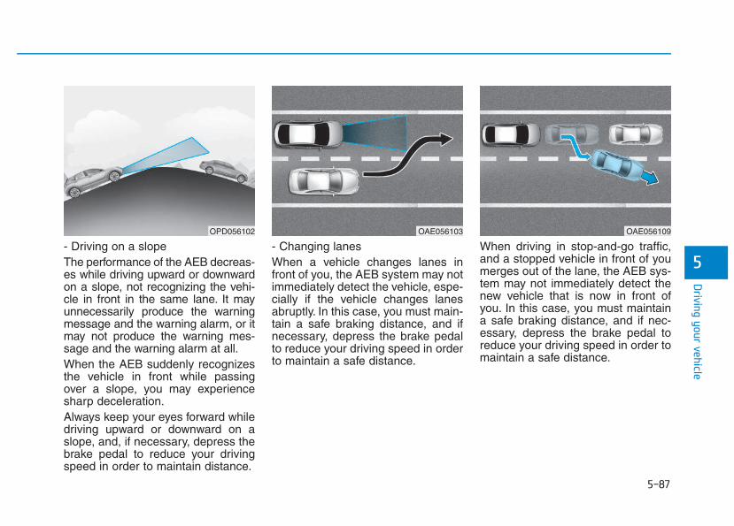
5-87
Driving your vehicle
5- Driving on a slopeThe performance of the AEB decreas-es while driving upward or downwardon a slope, not recognizing the vehi-cle in front in the same lane. It mayunnecessarily produce the warningmessage and the warning alarm, or itmay not produce the warning mes-sage and the warning alarm at all.When the AEB suddenly recognizesthe vehicle in front while passingover a slope, you may experiencesharp deceleration.Always keep your eyes forward whiledriving upward or downward on aslope, and, if necessary, depress thebrake pedal to reduce your drivingspeed in order to maintain distance.
- Changing lanesWhen a vehicle changes lanes infront of you, the AEB system may notimmediately detect the vehicle, espe-cially if the vehicle changes lanesabruptly. In this case, you must main-tain a safe braking distance, and ifnecessary, depress the brake pedalto reduce your driving speed in orderto maintain a safe distance.
When driving in stop-and-go traffic,and a stopped vehicle in front of youmerges out of the lane, the AEB sys-tem may not immediately detect thenew vehicle that is now in front ofyou. In this case, you must maintaina safe braking distance, and if nec-essary, depress the brake pedal toreduce your driving speed in order tomaintain a safe distance.
OPD056102 OAE056103 OAE056109
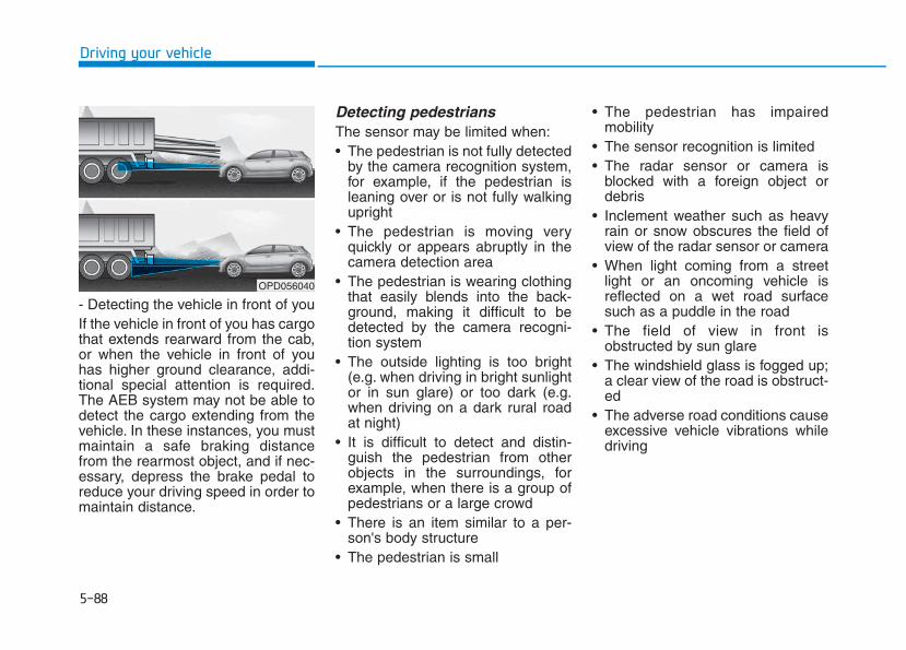
5-88
Driving your vehicle
- Detecting the vehicle in front of youIf the vehicle in front of you has cargothat extends rearward from the cab,or when the vehicle in front of youhas higher ground clearance, addi-tional special attention is required.The AEB system may not be able todetect the cargo extending from thevehicle. In these instances, you mustmaintain a safe braking distancefrom the rearmost object, and if nec-essary, depress the brake pedal toreduce your driving speed in order tomaintain distance.
Detecting pedestriansThe sensor may be limited when:• The pedestrian is not fully detected
by the camera recognition system,for example, if the pedestrian isleaning over or is not fully walkingupright
• The pedestrian is moving veryquickly or appears abruptly in thecamera detection area
• The pedestrian is wearing clothingthat easily blends into the back-ground, making it difficult to bedetected by the camera recogni-tion system
• The outside lighting is too bright(e.g. when driving in bright sunlightor in sun glare) or too dark (e.g.when driving on a dark rural roadat night)
• It is difficult to detect and distin-guish the pedestrian from otherobjects in the surroundings, forexample, when there is a group ofpedestrians or a large crowd
• There is an item similar to a per-son's body structure
• The pedestrian is small
• The pedestrian has impairedmobility
• The sensor recognition is limited• The radar sensor or camera is
blocked with a foreign object ordebris
• Inclement weather such as heavyrain or snow obscures the field ofview of the radar sensor or camera
• When light coming from a streetlight or an oncoming vehicle isreflected on a wet road surfacesuch as a puddle in the road
• The field of view in front isobstructed by sun glare
• The windshield glass is fogged up;a clear view of the road is obstruct-ed
• The adverse road conditions causeexcessive vehicle vibrations whiledriving
OPD056040
5-89
Driving your vehicle
5
Information In some instances, the AEB systemmay be cancelled when subjected toelectromagnetic interference.
i
• Do not use the AutonomousEmergency Braking systemwhen towing a vehicle.Application of the AEB sys-tem while towing mayadversely affect the safety ofyour vehicle or the towingvehicle.
• Use extreme caution when thevehicle in front of you hascargo that extends rearwardfrom the cab, or when thevehicle in front of you hashigher ground clearance.
• The AEB system is designedto detect and monitor thevehicle ahead or detect apedestrian in the roadwaythrough radar signals andcamera recognition. It is notdesigned to detect bicycles,motorcycles, or smallerwheeled objects such as lug-gage bags, shopping carts, orstrollers.
(Continued)
WARNING (Continued)• Never try to test the operation
of the AEB system. Doing somay cause severe injury ordeath.
5-90
Driving your vehicle
The Autonomous EmergencyBraking (AEB) system is designed todetect and monitor the vehicle aheadin the roadway through camerarecognition to warn the driver that acollision is imminent, and if neces-sary, apply emergency braking.
System setting and activationSystem setting• The driver can activate the AEB by
placing the ignition switch to theON position and by selecting:'User Settings → Driving Assist →Assist Emergency Braking'
The AEB deactivates, when the driv-er cancels the system setting.
The warning light illumi-nates on the LCD display,when you cancel the AEBsystem. The driver can
monitor the AEB ON/OFF status onthe LCD display. Also, the warninglight illuminates when the ESC(Electronic Stability Control) isturned off (Traction & Stability controldisabled.) If the warning lightremains ON when the AEB is acti-vated, we recommend you to havethe system checked by an authorizedHYUNDAI dealer.
AAUUTTOONNOOMMOOUUSS EEMMEERRGGEENNCCYY BBRRAAKKIINNGG ((AAEEBB)) -- CCAAMMEERRAA TTYYPPEE ((IIFF EEQQUUIIPPPPEEDD))
Take the following precautionswhen using the AutonomousEmergency Braking (AEB):• This system is only a supple-
mental system and it is notintended to, nor does itreplace the need for extremecare and attention of the driv-er. The sensing range andobjects detectable by the sen-sors are limited. Pay attentionto the road conditions at alltimes.
• NEVER drive too fast in accor-dance with the road condi-tions or while cornering.
• Always drive cautiously toprevent unexpected and sud-den situations from occur-ring. AEB does not stop thevehicle completely and is nota collision avoidance system.
WARNING
5-91
Driving your vehicle
5
• The driver can select the initial warn-ing activation time on the LCD dis-play.Go to the 'User Settings → DrivingAssist → Forward Collision Warning→ Late/Normal/Early'.
The options for the initial ForwardCollision Warning includes the fol-lowing:- Early:
When this condition is selected,the initial Forward CollisionWarning is activated earlier thannormal. This setting maximizes theamount of distance between thevehicle ahead before the initialwarning occurs.Even though, 'Early' is selected ifthe front vehicle suddenly stopsthe initial warning activation timemay not seem fast.
- Normal:When this condition is selected,the initial Forward CollisionWarning is activated normally. Thissetting allows for a nominalamount of distance between thevehicle ahead before the initialwarning occurs.
- Late:When this condition is selected,the initial Forward CollisionWarning is activated later than nor-mal. This setting reduces theamount of distance between thevehicle ahead before the initialwarning occurs.Select 'Late' when traffic is lightand when driving speed is slow.
Prerequisite for activationThe AEB gets ready to be activated,when the AEB is selected on theLCD display, and when the followingprerequisites are satisfied.- The ESC (Electronic Stability
Control) is on.- Vehicle speed is over 10 km/h (6
mph). (The AEB is only activatedwithin a certain speed range.)
- The system detects vehicle infront, which may collide with yourvehicle. (The AEB may not be acti-vated or may sound a warningalarm in accordance with the driv-ing situation or vehicle condition.)
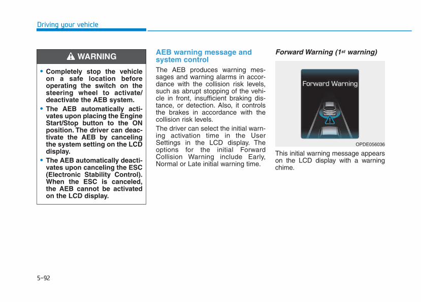
5-92
Driving your vehicle
AEB warning message andsystem controlThe AEB produces warning mes-sages and warning alarms in accor-dance with the collision risk levels,such as abrupt stopping of the vehi-cle in front, insufficient braking dis-tance, or detection. Also, it controlsthe brakes in accordance with thecollision risk levels.The driver can select the initial warn-ing activation time in the UserSettings in the LCD display. Theoptions for the initial ForwardCollision Warning include Early,Normal or Late initial warning time.
Forward Warning (1st warning)
This initial warning message appearson the LCD display with a warningchime.
• Completely stop the vehicleon a safe location beforeoperating the switch on thesteering wheel to activate/deactivate the AEB system.
• The AEB automatically acti-vates upon placing the EngineStart/Stop button to the ONposition. The driver can deac-tivate the AEB by cancelingthe system setting on the LCDdisplay.
• The AEB automatically deacti-vates upon canceling the ESC(Electronic Stability Control).When the ESC is canceled,the AEB cannot be activatedon the LCD display.
WARNING
OPDE056036
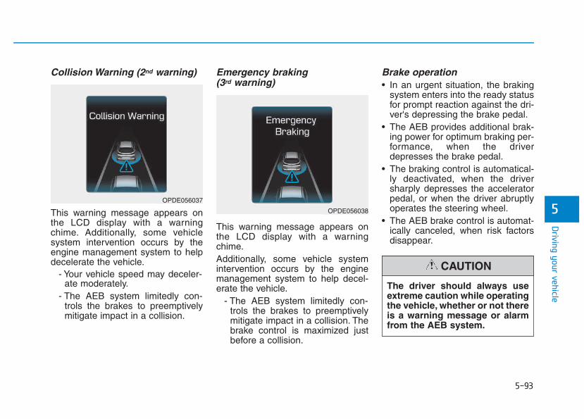
5-93
Driving your vehicle
5
Collision Warning (2nd warning)
This warning message appears onthe LCD display with a warningchime. Additionally, some vehiclesystem intervention occurs by theengine management system to helpdecelerate the vehicle.
- Your vehicle speed may deceler-ate moderately.
- The AEB system limitedly con-trols the brakes to preemptivelymitigate impact in a collision.
Emergency braking (3rd warning)
This warning message appears onthe LCD display with a warningchime.Additionally, some vehicle systemintervention occurs by the enginemanagement system to help decel-erate the vehicle.
- The AEB system limitedly con-trols the brakes to preemptivelymitigate impact in a collision. Thebrake control is maximized justbefore a collision.
Brake operation• In an urgent situation, the braking
system enters into the ready statusfor prompt reaction against the dri-ver's depressing the brake pedal.
• The AEB provides additional brak-ing power for optimum braking per-formance, when the driverdepresses the brake pedal.
• The braking control is automatical-ly deactivated, when the driversharply depresses the acceleratorpedal, or when the driver abruptlyoperates the steering wheel.
• The AEB brake control is automat-ically canceled, when risk factorsdisappear.
OPDE056038
OPDE056037
The driver should always useextreme caution while operatingthe vehicle, whether or not thereis a warning message or alarmfrom the AEB system.
CAUTION
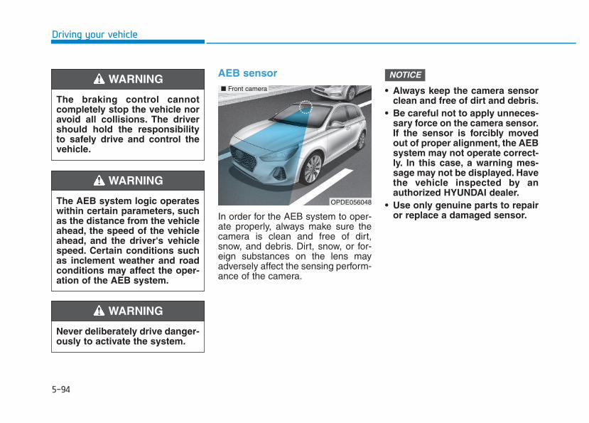
5-94
Driving your vehicle
AEB sensor
In order for the AEB system to oper-ate properly, always make sure thecamera is clean and free of dirt,snow, and debris. Dirt, snow, or for-eign substances on the lens mayadversely affect the sensing perform-ance of the camera.
• Always keep the camera sensorclean and free of dirt and debris.
• Be careful not to apply unneces-sary force on the camera sensor.If the sensor is forcibly movedout of proper alignment, the AEBsystem may not operate correct-ly. In this case, a warning mes-sage may not be displayed. Havethe vehicle inspected by anauthorized HYUNDAI dealer.
• Use only genuine parts to repairor replace a damaged sensor.
NOTICE
The braking control cannotcompletely stop the vehicle noravoid all collisions. The drivershould hold the responsibilityto safely drive and control thevehicle.
WARNING
Never deliberately drive danger-ously to activate the system.
WARNING
The AEB system logic operateswithin certain parameters, suchas the distance from the vehicleahead, the speed of the vehicleahead, and the driver's vehiclespeed. Certain conditions suchas inclement weather and roadconditions may affect the oper-ation of the AEB system.
WARNING
OPDE056048
■ Front camera
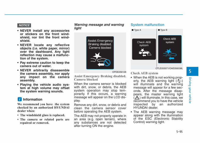
5-95
Driving your vehicle
5
• NEVER install any accessoriesor stickers on the front wind-shield, nor tint the front wind-shield.
• NEVER locate any reflectiveobjects (i.e. white paper, mirror)over the dashboard. Any lightreflection may cause a malfunc-tion of the system.
• Pay extreme caution to keep thecamera out of water.
• NEVER arbitrarily disassemblethe camera assembly, nor applyany impact on the cameraassembly.
• Playing the vehicle audio sys-tem at high volume may offsetthe system warning sounds.
InformationWe recommend you have the systemchecked by an authorized HYUNDAIdealer when:
• The windshield glass is replaced.
• The camera or related parts arerepaired or removed.
Warning message and warninglight
Assist Emergency Braking disabled.Camera blocked
When the camera sensor is blockedwith dirt, snow, or debris, the AEBsystem operation may stop tem-porarily. If this occurs, a warningmessage will appear on the LCD dis-play.Remove any dirt, snow, or debris andclean the camera sensor coverbefore operating the AEB system.The AEB may not properly operate inan area (e.g. open terrain), whereany substances are not detectedafter turning ON the engine.
System malfunction
Check AEB system
• When the AEB is not working prop-erly, the AEB warning light ( )will illuminate and the warningmessage will appear for a few sec-onds. After the message disap-pears, the master warning light( ) will illuminate. In this case, werecommend you to have the vehicleinspected by an authorizedHYUNDAI dealer.
• The AEB warning message mayappear along with the illuminationof the ESC (Electronic StabilityControl) warning light.
i
NOTICE
■ Type A ■ Type B
OTLE055071/OAE056038L
OPDE056128
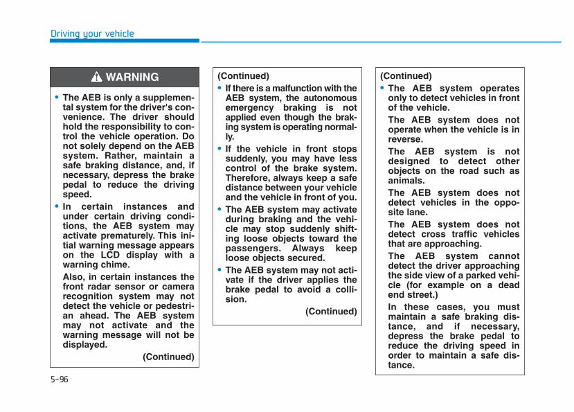
5-96
Driving your vehicle
• The AEB is only a supplemen-tal system for the driver's con-venience. The driver shouldhold the responsibility to con-trol the vehicle operation. Donot solely depend on the AEBsystem. Rather, maintain asafe braking distance, and, ifnecessary, depress the brakepedal to reduce the drivingspeed.
• In certain instances andunder certain driving condi-tions, the AEB system mayactivate prematurely. This ini-tial warning message appearson the LCD display with awarning chime.Also, in certain instances thefront radar sensor or camerarecognition system may notdetect the vehicle or pedestri-an ahead. The AEB systemmay not activate and thewarning message will not bedisplayed.
(Continued)
(Continued)• If there is a malfunction with the
AEB system, the autonomousemergency braking is notapplied even though the brak-ing system is operating normal-ly.
• If the vehicle in front stopssuddenly, you may have lesscontrol of the brake system.Therefore, always keep a safedistance between your vehicleand the vehicle in front of you.
• The AEB system may activateduring braking and the vehi-cle may stop suddenly shift-ing loose objects toward thepassengers. Always keeploose objects secured.
• The AEB system may not acti-vate if the driver applies thebrake pedal to avoid a colli-sion.
(Continued)
WARNING (Continued)• The AEB system operates
only to detect vehicles in frontof the vehicle.The AEB system does notoperate when the vehicle is inreverse.The AEB system is notdesigned to detect otherobjects on the road such asanimals.The AEB system does notdetect vehicles in the oppo-site lane.The AEB system does notdetect cross traffic vehiclesthat are approaching.The AEB system cannotdetect the driver approachingthe side view of a parked vehi-cle (for example on a deadend street.)In these cases, you mustmaintain a safe braking dis-tance, and if necessary,depress the brake pedal toreduce the driving speed inorder to maintain a safe dis-tance.
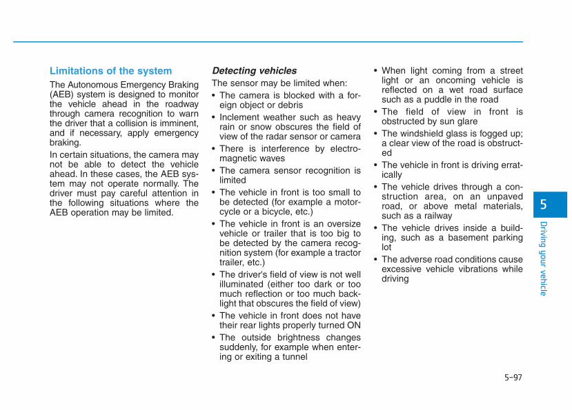
5-97
Driving your vehicle
5
Limitations of the systemThe Autonomous Emergency Braking(AEB) system is designed to monitorthe vehicle ahead in the roadwaythrough camera recognition to warnthe driver that a collision is imminent,and if necessary, apply emergencybraking.In certain situations, the camera maynot be able to detect the vehicleahead. In these cases, the AEB sys-tem may not operate normally. Thedriver must pay careful attention inthe following situations where theAEB operation may be limited.
Detecting vehiclesThe sensor may be limited when:• The camera is blocked with a for-
eign object or debris• Inclement weather such as heavy
rain or snow obscures the field ofview of the radar sensor or camera
• There is interference by electro-magnetic waves
• The camera sensor recognition islimited
• The vehicle in front is too small tobe detected (for example a motor-cycle or a bicycle, etc.)
• The vehicle in front is an oversizevehicle or trailer that is too big tobe detected by the camera recog-nition system (for example a tractortrailer, etc.)
• The driver's field of view is not wellilluminated (either too dark or toomuch reflection or too much back-light that obscures the field of view)
• The vehicle in front does not havetheir rear lights properly turned ON
• The outside brightness changessuddenly, for example when enter-ing or exiting a tunnel
• When light coming from a streetlight or an oncoming vehicle isreflected on a wet road surfacesuch as a puddle in the road
• The field of view in front isobstructed by sun glare
• The windshield glass is fogged up;a clear view of the road is obstruct-ed
• The vehicle in front is driving errat-ically
• The vehicle drives through a con-struction area, on an unpavedroad, or above metal materials,such as a railway
• The vehicle drives inside a build-ing, such as a basement parkinglot
• The adverse road conditions causeexcessive vehicle vibrations whiledriving
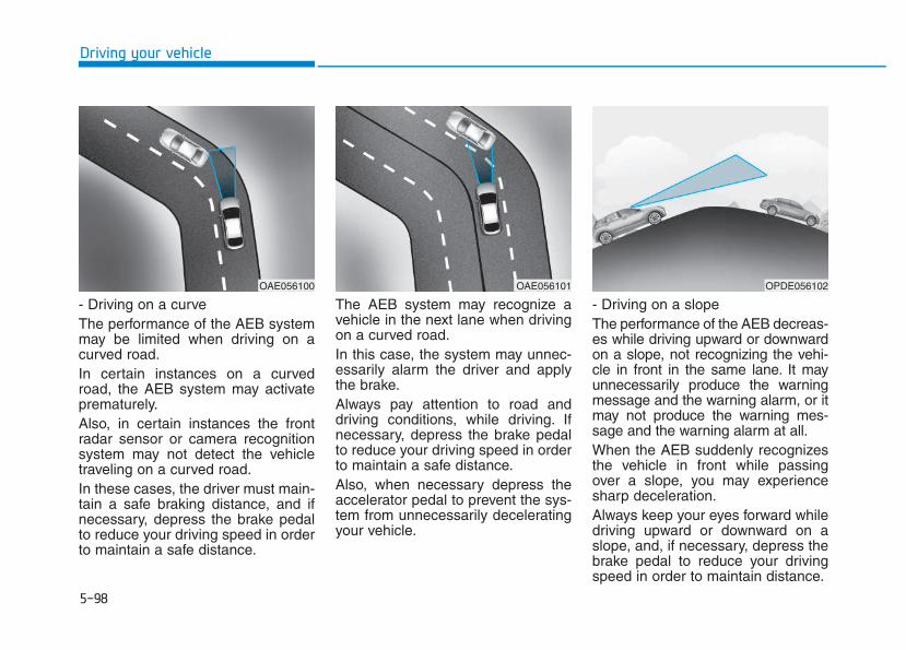
5-98
Driving your vehicle
- Driving on a curveThe performance of the AEB systemmay be limited when driving on acurved road.In certain instances on a curvedroad, the AEB system may activateprematurely.Also, in certain instances the frontradar sensor or camera recognitionsystem may not detect the vehicletraveling on a curved road.In these cases, the driver must main-tain a safe braking distance, and ifnecessary, depress the brake pedalto reduce your driving speed in orderto maintain a safe distance.
The AEB system may recognize avehicle in the next lane when drivingon a curved road.In this case, the system may unnec-essarily alarm the driver and applythe brake.Always pay attention to road anddriving conditions, while driving. Ifnecessary, depress the brake pedalto reduce your driving speed in orderto maintain a safe distance.Also, when necessary depress theaccelerator pedal to prevent the sys-tem from unnecessarily deceleratingyour vehicle.
- Driving on a slopeThe performance of the AEB decreas-es while driving upward or downwardon a slope, not recognizing the vehi-cle in front in the same lane. It mayunnecessarily produce the warningmessage and the warning alarm, or itmay not produce the warning mes-sage and the warning alarm at all.When the AEB suddenly recognizesthe vehicle in front while passingover a slope, you may experiencesharp deceleration.Always keep your eyes forward whiledriving upward or downward on aslope, and, if necessary, depress thebrake pedal to reduce your drivingspeed in order to maintain distance.
OAE056100 OAE056101 OPDE056102
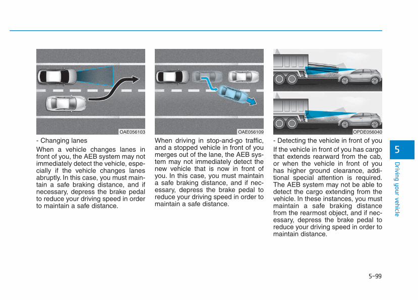
5-99
Driving your vehicle
5- Changing lanesWhen a vehicle changes lanes infront of you, the AEB system may notimmediately detect the vehicle, espe-cially if the vehicle changes lanesabruptly. In this case, you must main-tain a safe braking distance, and ifnecessary, depress the brake pedalto reduce your driving speed in orderto maintain a safe distance.
When driving in stop-and-go traffic,and a stopped vehicle in front of youmerges out of the lane, the AEB sys-tem may not immediately detect thenew vehicle that is now in front ofyou. In this case, you must maintaina safe braking distance, and if nec-essary, depress the brake pedal toreduce your driving speed in order tomaintain a safe distance.
- Detecting the vehicle in front of youIf the vehicle in front of you has cargothat extends rearward from the cab,or when the vehicle in front of youhas higher ground clearance, addi-tional special attention is required.The AEB system may not be able todetect the cargo extending from thevehicle. In these instances, you mustmaintain a safe braking distancefrom the rearmost object, and if nec-essary, depress the brake pedal toreduce your driving speed in order tomaintain distance.
OAE056103 OAE056109 OPDE056040
5-100
Driving your vehicle
Information In some instances, the AEB systemmay be cancelled when subjected toelectromagnetic interference.
i
• Do not use the AutonomousEmergency Braking systemwhen towing a vehicle.Application of the AEB sys-tem while towing mayadversely affect the safety ofyour vehicle or the towingvehicle.
• Use extreme caution when thevehicle in front of you hascargo that extends rearwardfrom the cab, or when thevehicle in front of you hashigher ground clearance.
• The AEB system is designedto detect and monitor thevehicle ahead in the roadwaythrough camera recognition. Itis not designed to detect bicy-cles, motorcycles, or smallerwheeled objects such as lug-gage bags, shopping carts, orstrollers.
• Never try to test the operationof the AEB system. Doing somay cause severe injury ordeath.
WARNING
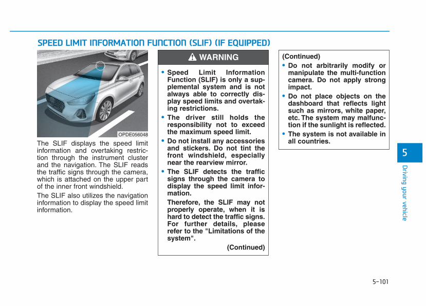
5-101
Driving your vehicle
5The SLIF displays the speed limitinformation and overtaking restric-tion through the instrument clusterand the navigation. The SLIF readsthe traffic signs through the camera,which is attached on the upper partof the inner front windshield.The SLIF also utilizes the navigationinformation to display the speed limitinformation.
SSPPEEEEDD LLIIMMIITT IINNFFOORRMMAATTIIOONN FFUUNNCCTTIIOONN ((SSLLIIFF)) ((IIFF EEQQUUIIPPPPEEDD))(Continued)• Do not arbitrarily modify or
manipulate the multi-functioncamera. Do not apply strongimpact.
• Do not place objects on thedashboard that reflects lightsuch as mirrors, white paper,etc. The system may malfunc-tion if the sunlight is reflected.
• The system is not available inall countries.
OPDE056048
• Speed Limit InformationFunction (SLIF) is only a sup-plemental system and is notalways able to correctly dis-play speed limits and overtak-ing restrictions.
• The driver still holds theresponsibility not to exceedthe maximum speed limit.
• Do not install any accessoriesand stickers. Do not tint thefront windshield, especiallynear the rearview mirror.
• The SLIF detects the trafficsigns through the camera todisplay the speed limit infor-mation.Therefore, the SLIF may notproperly operate, when it ishard to detect the traffic signs.For further details, pleaserefer to the "Limitations of thesystem".
(Continued)
WARNING
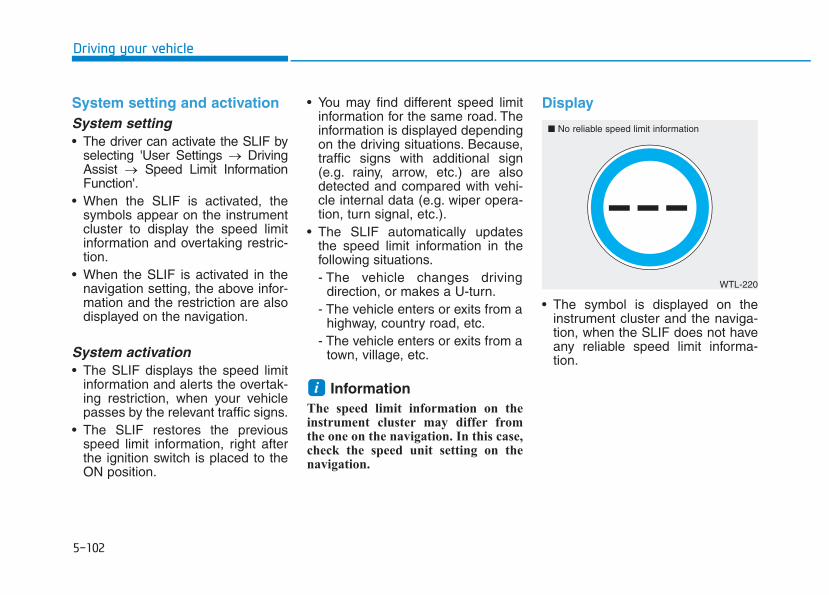
5-102
Driving your vehicle
System setting and activationSystem setting• The driver can activate the SLIF by
selecting 'User Settings → DrivingAssist → Speed Limit InformationFunction'.
• When the SLIF is activated, thesymbols appear on the instrumentcluster to display the speed limitinformation and overtaking restric-tion.
• When the SLIF is activated in thenavigation setting, the above infor-mation and the restriction are alsodisplayed on the navigation.
System activation• The SLIF displays the speed limit
information and alerts the overtak-ing restriction, when your vehiclepasses by the relevant traffic signs.
• The SLIF restores the previousspeed limit information, right afterthe ignition switch is placed to theON position.
• You may find different speed limitinformation for the same road. Theinformation is displayed dependingon the driving situations. Because,traffic signs with additional sign(e.g. rainy, arrow, etc.) are alsodetected and compared with vehi-cle internal data (e.g. wiper opera-tion, turn signal, etc.).
• The SLIF automatically updatesthe speed limit information in thefollowing situations.- The vehicle changes driving
direction, or makes a U-turn.- The vehicle enters or exits from a
highway, country road, etc.- The vehicle enters or exits from a
town, village, etc.
Information The speed limit information on theinstrument cluster may differ fromthe one on the navigation. In this case,check the speed unit setting on thenavigation.
Display
• The symbol is displayed on theinstrument cluster and the naviga-tion, when the SLIF does not haveany reliable speed limit informa-tion.
i
WTL-220
■ No reliable speed limit information
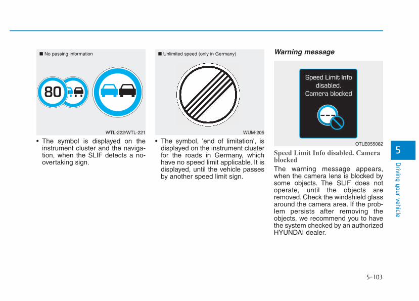
5-103
Driving your vehicle
5• The symbol is displayed on the
instrument cluster and the naviga-tion, when the SLIF detects a no-overtaking sign.
• The symbol, 'end of limitation', isdisplayed on the instrument clusterfor the roads in Germany, whichhave no speed limit applicable. It isdisplayed, until the vehicle passesby another speed limit sign.
Warning message
Speed Limit Info disabled. Camerablocked
The warning message appears,when the camera lens is blocked bysome objects. The SLIF does notoperate, until the objects areremoved. Check the windshield glassaround the camera area. If the prob-lem persists after removing theobjects, we recommend you to havethe system checked by an authorizedHYUNDAI dealer.
WTL-222/WTL-221
■ No passing information
WUM-205
■ Unlimited speed (only in Germany)
OTLE055082
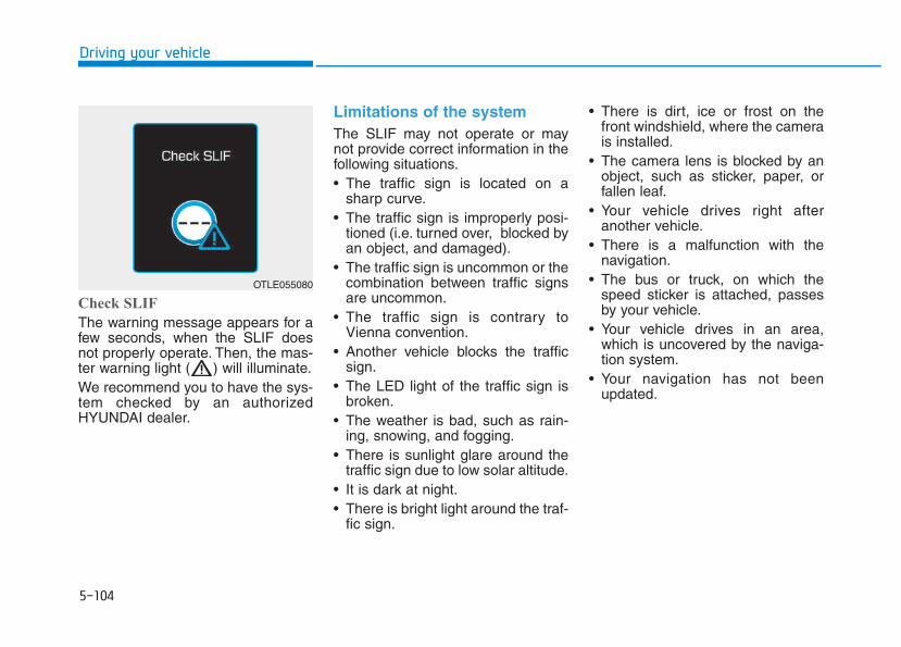
5-104
Driving your vehicle
Check SLIF
The warning message appears for afew seconds, when the SLIF doesnot properly operate. Then, the mas-ter warning light ( ) will illuminate.We recommend you to have the sys-tem checked by an authorizedHYUNDAI dealer.
Limitations of the system The SLIF may not operate or maynot provide correct information in thefollowing situations.• The traffic sign is located on a
sharp curve.• The traffic sign is improperly posi-
tioned (i.e. turned over, blocked byan object, and damaged).
• The traffic sign is uncommon or thecombination between traffic signsare uncommon.
• The traffic sign is contrary toVienna convention.
• Another vehicle blocks the trafficsign.
• The LED light of the traffic sign isbroken.
• The weather is bad, such as rain-ing, snowing, and fogging.
• There is sunlight glare around thetraffic sign due to low solar altitude.
• It is dark at night.• There is bright light around the traf-
fic sign.
• There is dirt, ice or frost on thefront windshield, where the camerais installed.
• The camera lens is blocked by anobject, such as sticker, paper, orfallen leaf.
• Your vehicle drives right afteranother vehicle.
• There is a malfunction with thenavigation.
• The bus or truck, on which thespeed sticker is attached, passesby your vehicle.
• Your vehicle drives in an area,which is uncovered by the naviga-tion system.
• Your navigation has not beenupdated.
OTLE055080
5-105
Driving your vehicle
5
The driver must be cautious in the fol-lowing situations. The SLIF may notassist the driver and may not proper-ly operate.
• Do not attach anything, such assticker, on the front windshield,where the camera is installed. Itmay adversely affect the SLIF andcause a malfunction with the SLIF.
• Do not place any objects, whichhave reflective surface, such as amirror and white paper, on thedashboard.
• Do not arbitrarily modify or manipu-late the camera, such as touchingthe lens and unscrewing the cam-era unit.
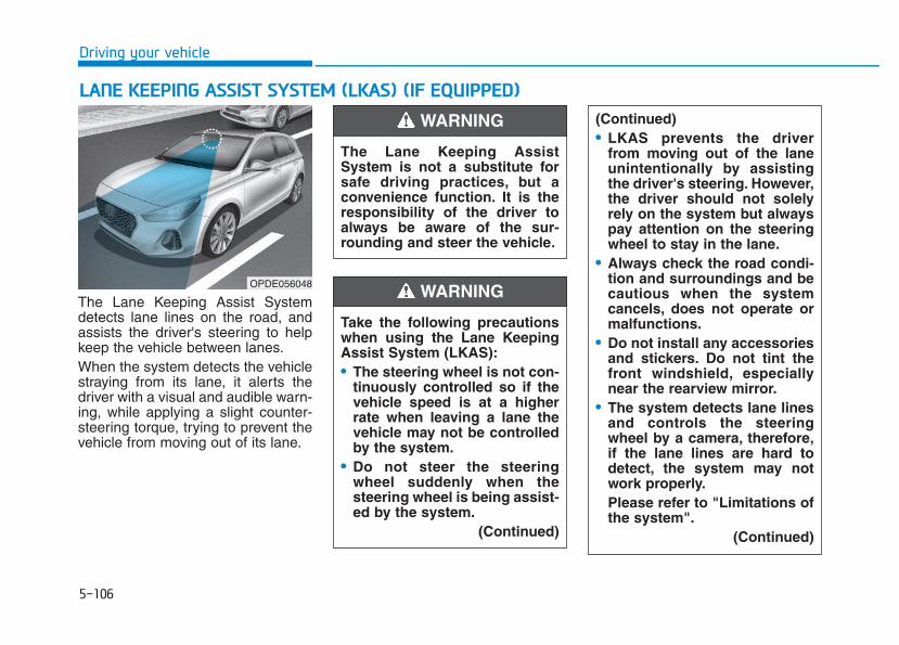
5-106
Driving your vehicle
The Lane Keeping Assist Systemdetects lane lines on the road, andassists the driver's steering to helpkeep the vehicle between lanes.When the system detects the vehiclestraying from its lane, it alerts thedriver with a visual and audible warn-ing, while applying a slight counter-steering torque, trying to prevent thevehicle from moving out of its lane.
LLAANNEE KKEEEEPPIINNGG AASSSSIISSTT SSYYSSTTEEMM ((LLKKAASS)) ((IIFF EEQQUUIIPPPPEEDD))
OPDE056048
The Lane Keeping AssistSystem is not a substitute forsafe driving practices, but aconvenience function. It is theresponsibility of the driver toalways be aware of the sur-rounding and steer the vehicle.
WARNING
Take the following precautionswhen using the Lane KeepingAssist System (LKAS):• The steering wheel is not con-
tinuously controlled so if thevehicle speed is at a higherrate when leaving a lane thevehicle may not be controlledby the system.
• Do not steer the steeringwheel suddenly when thesteering wheel is being assist-ed by the system.
(Continued)
WARNING
(Continued)• LKAS prevents the driver
from moving out of the laneunintentionally by assistingthe driver's steering. However,the driver should not solelyrely on the system but alwayspay attention on the steeringwheel to stay in the lane.
• Always check the road condi-tion and surroundings and becautious when the systemcancels, does not operate ormalfunctions.
• Do not install any accessoriesand stickers. Do not tint thefront windshield, especiallynear the rearview mirror.
• The system detects lane linesand controls the steeringwheel by a camera, therefore,if the lane lines are hard todetect, the system may notwork properly.Please refer to "Limitations ofthe system".
(Continued)
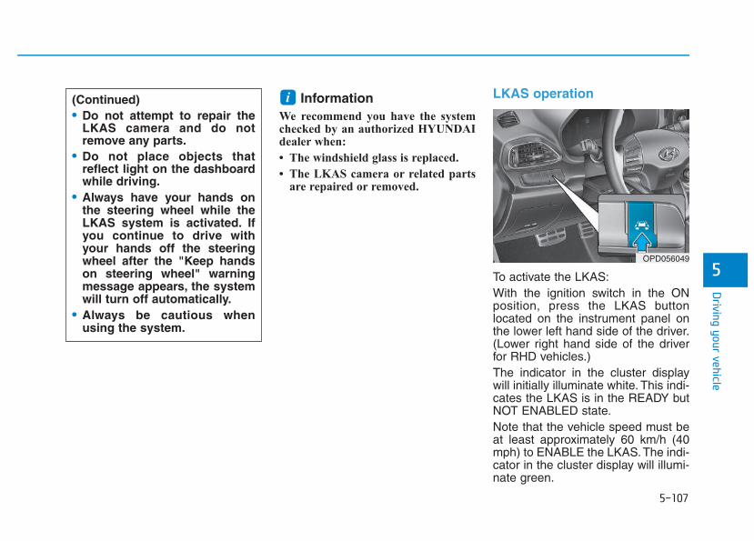
5-107
Driving your vehicle
5
Information We recommend you have the systemchecked by an authorized HYUNDAIdealer when:
• The windshield glass is replaced.
• The LKAS camera or related partsare repaired or removed.
LKAS operation
To activate the LKAS:With the ignition switch in the ONposition, press the LKAS buttonlocated on the instrument panel onthe lower left hand side of the driver.(Lower right hand side of the driverfor RHD vehicles.)The indicator in the cluster displaywill initially illuminate white. This indi-cates the LKAS is in the READY butNOT ENABLED state.Note that the vehicle speed must beat least approximately 60 km/h (40mph) to ENABLE the LKAS.The indi-cator in the cluster display will illumi-nate green.
i(Continued)• Do not attempt to repair the
LKAS camera and do notremove any parts.
• Do not place objects thatreflect light on the dashboardwhile driving.
• Always have your hands onthe steering wheel while theLKAS system is activated. Ifyou continue to drive withyour hands off the steeringwheel after the "Keep handson steering wheel" warningmessage appears, the systemwill turn off automatically.
• Always be cautious whenusing the system.
OPD056049
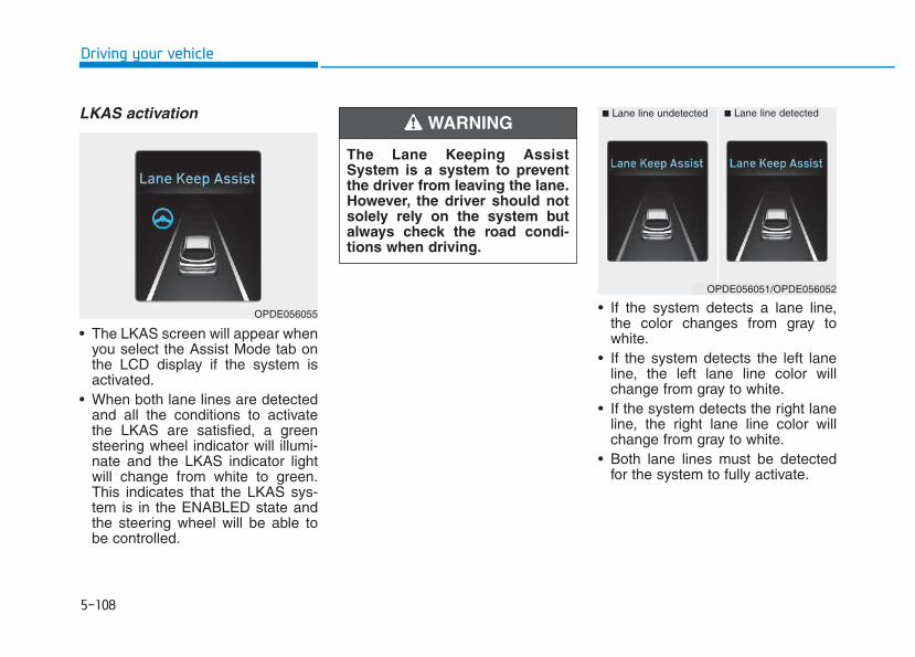
5-108
Driving your vehicle
LKAS activation
• The LKAS screen will appear whenyou select the Assist Mode tab onthe LCD display if the system isactivated.
• When both lane lines are detectedand all the conditions to activatethe LKAS are satisfied, a greensteering wheel indicator will illumi-nate and the LKAS indicator lightwill change from white to green.This indicates that the LKAS sys-tem is in the ENABLED state andthe steering wheel will be able tobe controlled.
• If the system detects a lane line,the color changes from gray towhite.
• If the system detects the left laneline, the left lane line color willchange from gray to white.
• If the system detects the right laneline, the right lane line color willchange from gray to white.
• Both lane lines must be detectedfor the system to fully activate.
OPDE056055
The Lane Keeping AssistSystem is a system to preventthe driver from leaving the lane.However, the driver should notsolely rely on the system butalways check the road condi-tions when driving.
WARNING ■ Lane line undetected ■ Lane line detected
OPDE056051/OPDE056052
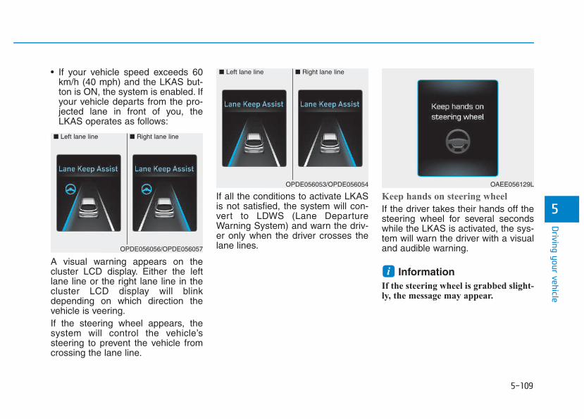
5-109
Driving your vehicle
5
• If your vehicle speed exceeds 60km/h (40 mph) and the LKAS but-ton is ON, the system is enabled. Ifyour vehicle departs from the pro-jected lane in front of you, theLKAS operates as follows:
A visual warning appears on thecluster LCD display. Either the leftlane line or the right lane line in thecluster LCD display will blinkdepending on which direction thevehicle is veering.If the steering wheel appears, thesystem will control the vehicle’ssteering to prevent the vehicle fromcrossing the lane line.
If all the conditions to activate LKASis not satisfied, the system will con-vert to LDWS (Lane DepartureWarning System) and warn the driv-er only when the driver crosses thelane lines.
Keep hands on steering wheel
If the driver takes their hands off thesteering wheel for several secondswhile the LKAS is activated, the sys-tem will warn the driver with a visualand audible warning.
Information If the steering wheel is grabbed slight-ly, the message may appear.
i
OAEE056129L
■ Left lane line ■ Right lane line
OPDE056053/OPDE056054
■ Left lane line ■ Right lane line
OPDE056056/OPDE056057
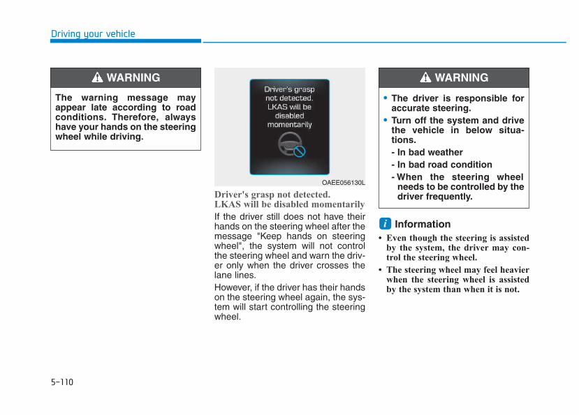
5-110
Driving your vehicle
Driver's grasp not detected.LKAS will be disabled momentarily
If the driver still does not have theirhands on the steering wheel after themessage "Keep hands on steeringwheel", the system will not controlthe steering wheel and warn the driv-er only when the driver crosses thelane lines.However, if the driver has their handson the steering wheel again, the sys-tem will start controlling the steeringwheel.
Information • Even though the steering is assisted
by the system, the driver may con-trol the steering wheel.
• The steering wheel may feel heavierwhen the steering wheel is assistedby the system than when it is not.
i
• The driver is responsible foraccurate steering.
• Turn off the system and drivethe vehicle in below situa-tions.- In bad weather- In bad road condition- When the steering wheel
needs to be controlled by thedriver frequently.
WARNING
The warning message mayappear late according to roadconditions. Therefore, alwayshave your hands on the steeringwheel while driving.
WARNING
OAEE056130L
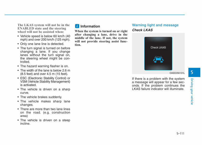
5-111
Driving your vehicle
5
The LKAS system will not be in theENABLED state and the steeringwheel will not be assisted when:
• Vehicle speed is below 60 km/h (40mph) and over 200 km/h (125 mph).
• Only one lane line is detected.• The turn signal is turned on before
changing a lane. If you changelanes without the turn signal on,the steering wheel might be con-trolled.
• The hazard warning flasher is on.• The width of the lane is below 2.6 m
(8.5 feet) and over 4.5 m (15 feet).• ESC (Electronic Stability Control) or
VSM (Vehicle Stability Management)is activated.
• The vehicle is driven on a sharpcurve.
• The vehicle brakes suddenly.• The vehicle makes sharp lane
changes.• There are more than two lane lines
on the road. (e.g. constructionarea)
• The vehicle is driven on a steepincline.
Information When the system is turned on or rightafter changing a lane, drive in themiddle of the lane. If not, the systemwill not provide steering assist func-tion.
Warning light and messageCheck LKAS
If there is a problem with the systema message will appear for a few sec-onds. If the problem continues theLKAS failure indicator will illuminate.
i
OAEE056131L
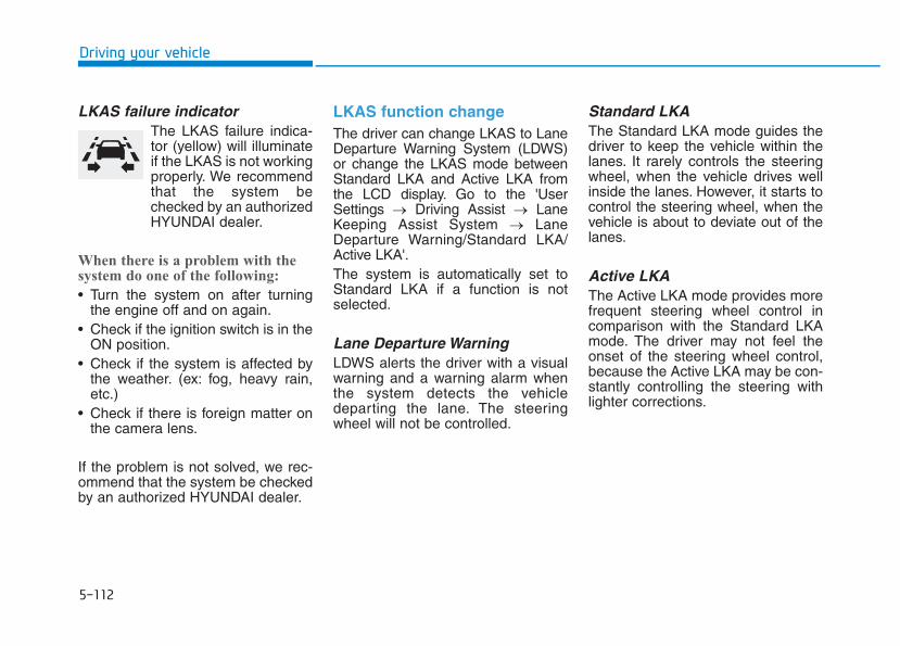
5-112
Driving your vehicle
LKAS failure indicatorThe LKAS failure indica-tor (yellow) will illuminateif the LKAS is not workingproperly. We recommendthat the system bechecked by an authorizedHYUNDAI dealer.
When there is a problem with thesystem do one of the following:
• Turn the system on after turningthe engine off and on again.
• Check if the ignition switch is in theON position.
• Check if the system is affected bythe weather. (ex: fog, heavy rain,etc.)
• Check if there is foreign matter onthe camera lens.
If the problem is not solved, we rec-ommend that the system be checkedby an authorized HYUNDAI dealer.
LKAS function change The driver can change LKAS to LaneDeparture Warning System (LDWS)or change the LKAS mode betweenStandard LKA and Active LKA fromthe LCD display. Go to the 'UserSettings → Driving Assist → LaneKeeping Assist System → LaneDeparture Warning/Standard LKA/Active LKA'.The system is automatically set toStandard LKA if a function is notselected.
Lane Departure WarningLDWS alerts the driver with a visualwarning and a warning alarm whenthe system detects the vehicledeparting the lane. The steeringwheel will not be controlled.
Standard LKAThe Standard LKA mode guides thedriver to keep the vehicle within thelanes. It rarely controls the steeringwheel, when the vehicle drives wellinside the lanes. However, it starts tocontrol the steering wheel, when thevehicle is about to deviate out of thelanes.
Active LKAThe Active LKA mode provides morefrequent steering wheel control incomparison with the Standard LKAmode. The driver may not feel theonset of the steering wheel control,because the Active LKA may be con-stantly controlling the steering withlighter corrections.
5-113
Driving your vehicle
5
Limitations of the SystemThe LKAS may operate prematurelyeven if the vehicle does not departfrom the intended lane, OR, theLKAS may not warn you if the vehicleleaves the intended lane under thefollowing circumstances:• The lanes ahead are not visible
due to rain, snow, water on theroad, damaged or stained roadsurface, or other factors.
• The brightness outside changessuddenly such as when entering orexiting a tunnel.
• The brightness outside is too lowsuch as when the headlamps arenot on at night or the vehicle isgoing through a tunnel.
• The surrounding of the inside rearview mirror temperature is highdue to direct sunlight.
• It is difficult to distinguish the lanemarking from the road surface orthe lane marking is faded or notclearly marked.
• Driving on a steep grade, over ahill, or when driving on a curvedroad.
• When light coming from a streetlight or an oncoming vehicle isreflected on a wet road surfacesuch as a puddle in the road.
• The windshield or the LKAS cam-era lens is blocked with dirt ordebris.
• The field of view in front isobstructed by sun glare.
• The lanes are incomplete or thearea is in a construction zone.
• There are more than two lane lineson the road in front of you.
• The lane line is merged or divided.(e.g. tollgate)
• The lane number increases ordecreases or the lane marker arecrossing complicatedly.
• The lane line in a tunnel is stainedwith oil.
• The lane markings are not clearlyvisible from the road.
• The shadow is on the lane markerby a median strip, trees, etc.
• The lane width is too wide or toonarrow. See previous page.
• The windshield glass is fogged up;a clear view of the road is obstruct-ed.
• There are markings on the roadsurface that look like a lane linethat is inadvertently being detectedby the camera.
• There is a boundary structure inthe roadway such as a concretebarrier, guardrail and reflector postthat is inadvertently being detectedby the camera.
• There is not enough distancebetween you and the vehicle infront to be able to detect the laneline or the vehicle ahead is drivingon the lane line.
• The adverse road conditions causeexcessive vehicle vibrations whiledriving.
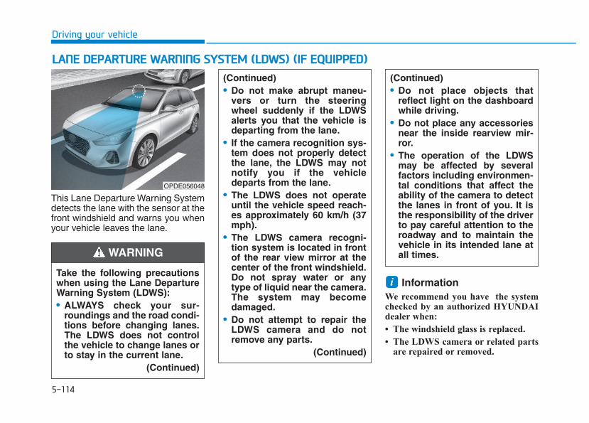
5-114
Driving your vehicle
This Lane Departure Warning Systemdetects the lane with the sensor at thefront windshield and warns you whenyour vehicle leaves the lane.
InformationWe recommend you have the systemchecked by an authorized HYUNDAIdealer when:
• The windshield glass is replaced.
• The LDWS camera or related partsare repaired or removed.
i
LLAANNEE DDEEPPAARRTTUURREE WWAARRNNIINNGG SSYYSSTTEEMM ((LLDDWWSS)) ((IIFF EEQQUUIIPPPPEEDD))
Take the following precautionswhen using the Lane DepartureWarning System (LDWS):• ALWAYS check your sur-
roundings and the road condi-tions before changing lanes.The LDWS does not controlthe vehicle to change lanes orto stay in the current lane.
(Continued)
(Continued)• Do not make abrupt maneu-
vers or turn the steeringwheel suddenly if the LDWSalerts you that the vehicle isdeparting from the lane.
• If the camera recognition sys-tem does not properly detectthe lane, the LDWS may notnotify you if the vehicledeparts from the lane.
• The LDWS does not operateuntil the vehicle speed reach-es approximately 60 km/h (37mph).
• The LDWS camera recogni-tion system is located in frontof the rear view mirror at thecenter of the front windshield.Do not spray water or anytype of liquid near the camera.The system may becomedamaged.
• Do not attempt to repair theLDWS camera and do notremove any parts.
(Continued)
(Continued)• Do not place objects that
reflect light on the dashboardwhile driving.
• Do not place any accessoriesnear the inside rearview mir-ror.
• The operation of the LDWSmay be affected by severalfactors including environmen-tal conditions that affect theability of the camera to detectthe lanes in front of you. It isthe responsibility of the driverto pay careful attention to theroadway and to maintain thevehicle in its intended lane atall times.WARNING
OPDE056048
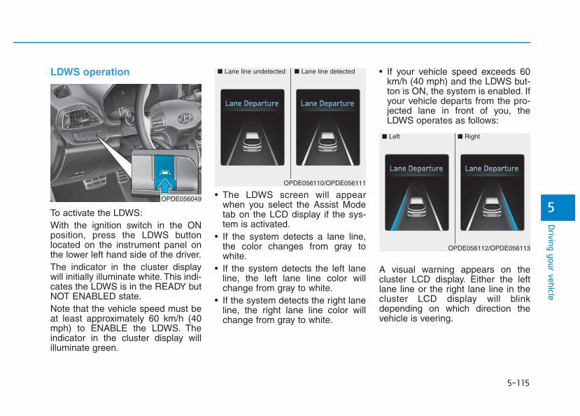
5-115
Driving your vehicle
5
LDWS operation
To activate the LDWS:With the ignition switch in the ONposition, press the LDWS buttonlocated on the instrument panel onthe lower left hand side of the driver.The indicator in the cluster displaywill initially illuminate white. This indi-cates the LDWS is in the READY butNOT ENABLED state.Note that the vehicle speed must beat least approximately 60 km/h (40mph) to ENABLE the LDWS. Theindicator in the cluster display willilluminate green.
• The LDWS screen will appearwhen you select the Assist Modetab on the LCD display if the sys-tem is activated.
• If the system detects a lane line,the color changes from gray towhite.
• If the system detects the left laneline, the left lane line color willchange from gray to white.
• If the system detects the right laneline, the right lane line color willchange from gray to white.
• If your vehicle speed exceeds 60km/h (40 mph) and the LDWS but-ton is ON, the system is enabled. Ifyour vehicle departs from the pro-jected lane in front of you, theLDWS operates as follows:
A visual warning appears on thecluster LCD display. Either the leftlane line or the right lane line in thecluster LCD display will blinkdepending on which direction thevehicle is veering.
■ Lane line detected■ Lane line undetected
OPDE056110/OPDE056111
OPDE056049
■ Left ■ Right
OPDE056112/OPDE056113
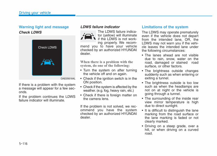
5-116
Driving your vehicle
Warning light and messageCheck LDWS
If there is a problem with the systema message will appear for a few sec-onds.If the problem continues the LDWSfailure indicator will illuminate.
LDWS failure indicatorThe LDWS failure indica-tor (yellow) will illuminateif the LDWS is not work-ing properly. We recom-
mend you to have your vehiclechecked by an authorized HYUNDAIdealer.
When there is a problem with thesystem, do one of the following:
• Turn the system on after turningthe vehicle off and on again.
• Check if the ignition switch is in theON position.
• Check if the system is affected by theweather. (e.g. fog, heavy rain, etc.)
• Check if there is foreign matter onthe camera lens.
If the problem is not solved, we rec-ommend you have the systemchecked by an authorized HYUNDAIdealer.
Limitations of the systemThe LDWS may operate prematurelyeven if the vehicle does not departfrom the intended lane, OR, theLDWS may not warn you if the vehi-cle leaves the intended lane underthe following circumstances:• The lanes ahead are not visible
due to rain, snow, water on theroad, damaged or stained roadsurface, or other factors.
• The brightness outside changessuddenly such as when entering orexiting a tunnel.
• The brightness outside is too lowsuch as when the headlamps arenot on at night or the vehicle isgoing through a tunnel.
• The surrounding of the inside rearview mirror temperature is highdue to direct sunlight.
• It is difficult to distinguish the lanemarking from the road surface orthe lane marking is faded or notclearly marked.
• Driving on a steep grade, over ahill, or when driving on a curvedroad.
OAE056164L
5-117
Driving your vehicle
5
• When light coming from a streetlight or an oncoming vehicle isreflected on a wet road surfacesuch as a puddle in the road.
• The windshield or the LDWS cam-era lens is blocked with dirt ordebris.
• The field of view in front isobstructed by sun glare.
• The lanes are incomplete or thearea is in a construction zone.
• There are more than two lane lineson the road in front of you.
• The lane line is merged or divided.(e.g. tollgate)
• The lane number increases ordecreases or the lane marker arecrossing complicatedly.
• The lane line in a tunnel is stainedwith oil.
• The lane markings are not clearlyvisible from the road.
• The lane width is too wide or toonarrow.
• The shadow is on the lane markerby a median strip, trees, etc.
• The windshield glass is fogged up;a clear view of the road is obstruct-ed.
• There are markings on the roadsurface that look like a lane linethat is inadvertently being detectedby the camera.
• There is a boundary structure inthe roadway such as a concretebarrier, guardrail and reflector postthat is inadvertently being detectedby the camera.
• There is not enough distancebetween you and the vehicle infront to be able to detect the laneline or the vehicle ahead is drivingon the lane line.
• The adverse road conditions causeexcessive vehicle vibrations whiledriving.
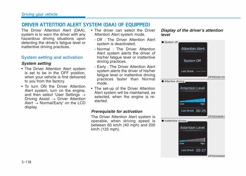
5-118
Driving your vehicle
The Driver Attention Alert (DAA),system is to warn the driver with anyhazardous driving situations upondetecting the driver's fatigue level orinattentive driving practices.
System setting and activationSystem setting• The Driver Attention Alert system
is set to be in the OFF position,when your vehicle is first deliveredto you from the factory.
• To turn ON the Driver AttentionAlert system, turn on the engine,and then select 'User Settings →Driving Assist → Driver AttentionAlert → Normal/Early' on the LCDdisplay.
• The driver can select the DriverAttention Alert system mode.- Off : The Driver Attention Alert
system is deactivated.- Normal : The Driver Attention
Alert system alerts the driver ofhis/her fatigue level or inattentivedriving practices.
- Early : The Driver Attention Alertsystem alerts the driver of his/herfatigue level or inattentive drivingpractices faster than Normalmode.
• The set-up of the Driver AttentionAlert system will be maintained, asselected, when the engine is re-started.
Prerequisite for activationThe Driver Attention Alert system isoperable, when driving speed isbetween 60 km/h (40 mph) and 200km/h (125 mph).
Display of the driver's attentionlevel
DDRRIIVVEERR AATTTTEENNTTIIOONN AALLEERRTT SSYYSSTTEEMM ((DDAAAA)) ((IIFF EEQQUUIIPPPPEEDD))
OPDE056125
■ System off
OPDE056061
■ Attentive driving
OPDE056062
■ Inattentive driving
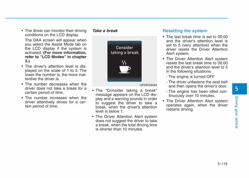
5-119
Driving your vehicle
5
• The driver can monitor their drivingconditions on the LCD display.The DAA screen will appear whenyou select the Assist Mode tab onthe LCD display if the system isactivated. (For more information,refer to "LCD Modes" in chapter3.)
• The driver's attention level is dis-played on the scale of 1 to 5. Thelower the number is, the more inat-tentive the driver is.
• The number decreases when thedriver does not take a break for acertain period of time.
• The number increases when thedriver attentively drives for a cer-tain period of time.
Take a break
• The "Consider taking a break"message appears on the LCD dis-play and a warning sounds in orderto suggest the driver to take abreak, when the driver’s attentionlevel is below 1.
• The Driver Attention Alert systemdoes not suggest the driver to takea break, when the total driving timeis shorter than 10 minutes.
Resetting the system • The last break time is set to 00:00
and the driver's attention level isset to 5 (very attentive) when thedriver resets the Driver AttentionAlert system.
• The Driver Attention Alert systemresets the last break time to 00:00and the driver's attention level to 5in the following situations.- The engine is turned OFF.- The driver unfastens the seat belt
and then opens the driver's door.- The engine has been idled con-
tinuously over 10 minutes.• The Driver Attention Alert system
operates again, when the driverrestarts driving.
OPDE056063
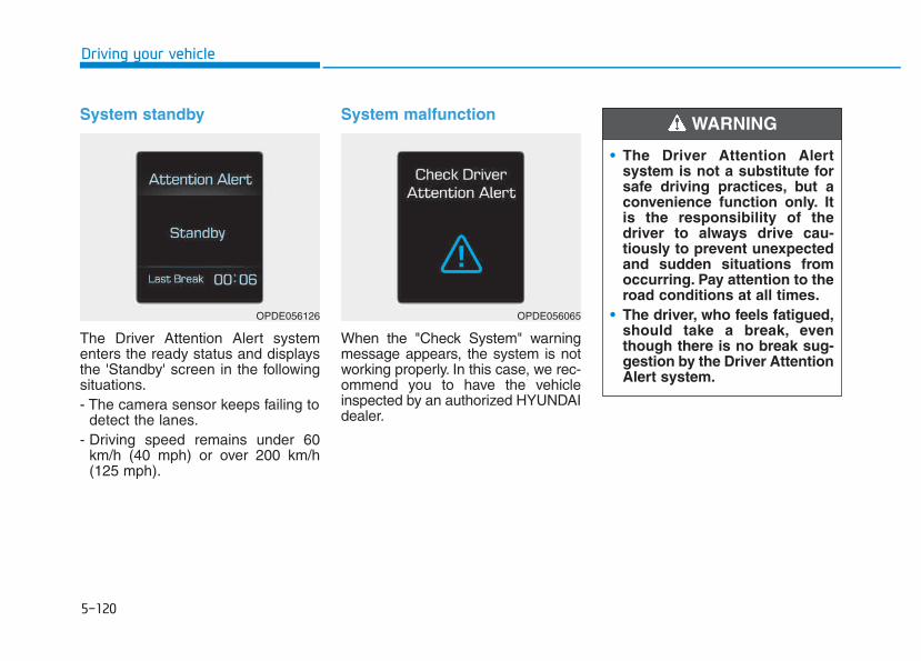
5-120
Driving your vehicle
System standby
The Driver Attention Alert systementers the ready status and displaysthe 'Standby' screen in the followingsituations.- The camera sensor keeps failing to
detect the lanes.- Driving speed remains under 60
km/h (40 mph) or over 200 km/h(125 mph).
System malfunction
When the "Check System" warningmessage appears, the system is notworking properly. In this case, we rec-ommend you to have the vehicleinspected by an authorized HYUNDAIdealer.
OPDE056126 OPDE056065
• The Driver Attention Alertsystem is not a substitute forsafe driving practices, but aconvenience function only. Itis the responsibility of thedriver to always drive cau-tiously to prevent unexpectedand sudden situations fromoccurring. Pay attention to theroad conditions at all times.
• The driver, who feels fatigued,should take a break, eventhough there is no break sug-gestion by the Driver AttentionAlert system.
WARNING
5-121
Driving your vehicle
5
The Driver Attention Alert systemutilizes the camera sensor on thefront windshield for its operation.To keep the camera sensor in thebest condition, you shouldobserve the followings:• NEVER install any accessories
or stickers on the front wind-shield, nor tint the front wind-shield.
• NEVER locate any reflectiveobjects (i.e. white paper, mirror)over the dashboard. Any lightreflection may cause a malfunc-tion of the Driver Attention Alert(DAA) system.
• Pay extreme caution to keep thecamera sensor out of water.
• NEVER arbitrarily disassemblethe camera assembly, nor applyany impact on the cameraassembly.
• Playing the vehicle audio sys-tem at high volume may offsetthe Driver Attention Alert sys-tem warning sounds.
NOTICE
The Driver Attention Alert sys-tem may not properly operatewith limited alerting in the fol-lowing situations:• The lane detection perform-
ance is limited. (For moreinformation, refer to "LaneKeeping Assist System(LKAS)" in this chapter.)
• The vehicle is violently drivenor is abruptly turned forobstacle avoidance (e.g. con-struction area, other vehicles,fallen objects, bumpy road).
• Forward drivability of thevehicle is severely under-mined (possibly due to widevariation in tire pressures,uneven tire wear-out, toe-in/toe-out alignment).
• The vehicle drives on a curvyroad.
• The vehicle drives on abumpy road.
(Continued)
CAUTION (Continued)• The vehicle drives through a
windy area.• The vehicle is controlled by
the following driving assistsystems:- Lane Keeping Assist System
(LKAS) - Autonomous Emergency
Braking (AEB) System
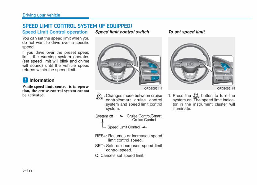
5-122
Driving your vehicle
Speed Limit Control operationYou can set the speed limit when youdo not want to drive over a specificspeed.If you drive over the preset speedlimit, the warning system operates(set speed limit will blink and chimewill sound) until the vehicle speedreturns within the speed limit.
InformationWhile speed limit control is in opera-tion, the cruise control system cannotbe activated.
Speed limit control switch
: Changes mode between cruisecontrol/smart cruise controlsystem and speed limit controlsystem.
RES+: Resumes or increases speedlimit control speed.
SET-: Sets or decreases speed limitcontrol speed.
O: Cancels set speed limit.
To set speed limit
1. Press the button to turn thesystem on. The speed limit indica-tor in the instrument cluster willilluminate.
i
SSPPEEEEDD LLIIMMIITT CCOONNTTRROOLL SSYYSSTTEEMM ((IIFF EEQQUUIIPPPPEEDD))
OPDE056114 OPDE056115
System off
Speed Limit Control
Cruise Control/SmartCruise Control
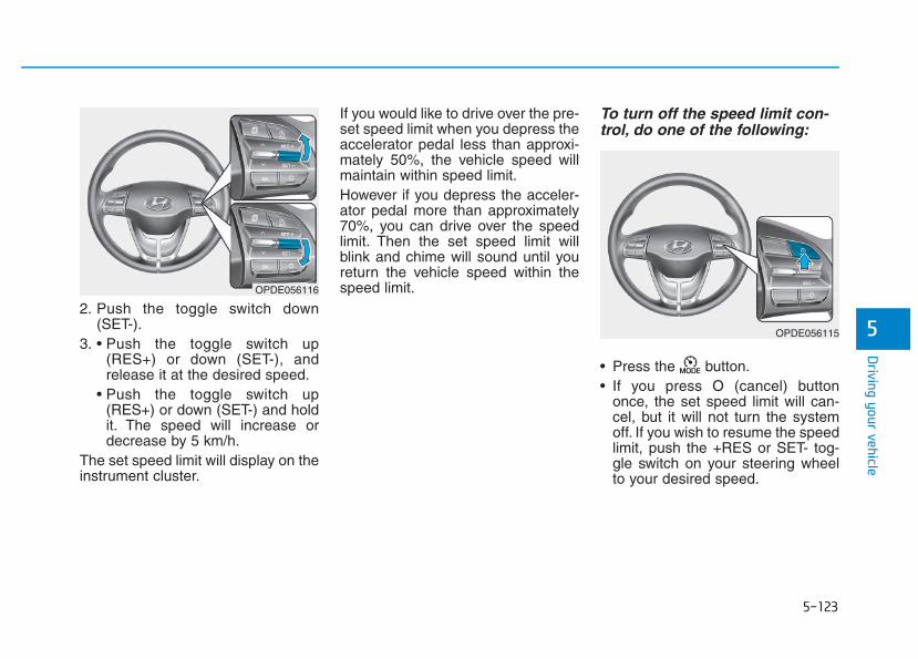
5-123
Driving your vehicle
52. Push the toggle switch down
(SET-).3. • Push the toggle switch up
(RES+) or down (SET-), andrelease it at the desired speed.
• Push the toggle switch up(RES+) or down (SET-) and holdit. The speed will increase ordecrease by 5 km/h.
The set speed limit will display on theinstrument cluster.
If you would like to drive over the pre-set speed limit when you depress theaccelerator pedal less than approxi-mately 50%, the vehicle speed willmaintain within speed limit.However if you depress the acceler-ator pedal more than approximately70%, you can drive over the speedlimit. Then the set speed limit willblink and chime will sound until youreturn the vehicle speed within thespeed limit.
To turn off the speed limit con-trol, do one of the following:
• Press the button.• If you press O (cancel) button
once, the set speed limit will can-cel, but it will not turn the systemoff. If you wish to resume the speedlimit, push the +RES or SET- tog-gle switch on your steering wheelto your desired speed.
OPDE056116
OPDE056115
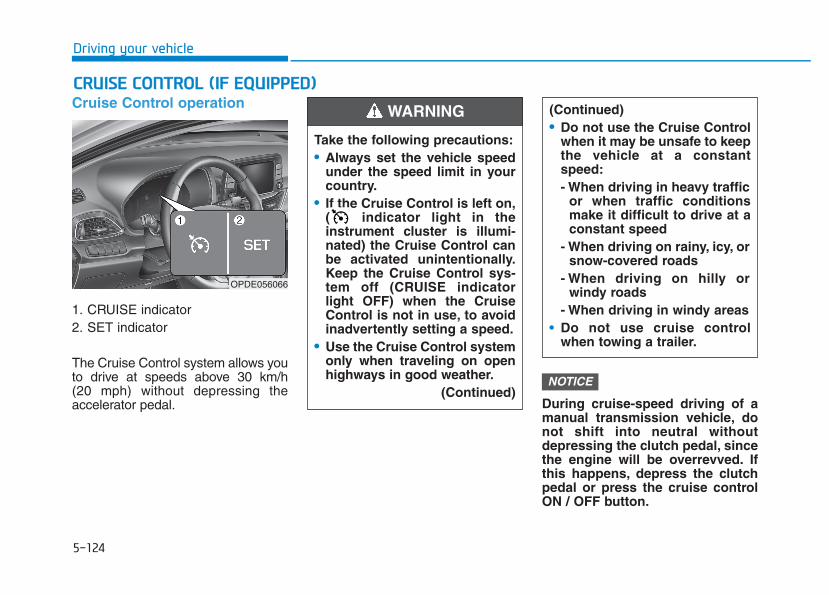
5-124
Driving your vehicle
Cruise Control operation
1. CRUISE indicator2. SET indicator
The Cruise Control system allows youto drive at speeds above 30 km/h (20 mph) without depressing theaccelerator pedal. During cruise-speed driving of a
manual transmission vehicle, donot shift into neutral withoutdepressing the clutch pedal, sincethe engine will be overrevved. Ifthis happens, depress the clutchpedal or press the cruise controlON / OFF button.
NOTICE
CCRRUUIISSEE CCOONNTTRROOLL ((IIFF EEQQUUIIPPPPEEDD))
Take the following precautions:• Always set the vehicle speed
under the speed limit in yourcountry.
• If the Cruise Control is left on,( indicator light in theinstrument cluster is illumi-nated) the Cruise Control canbe activated unintentionally.Keep the Cruise Control sys-tem off (CRUISE indicatorlight OFF) when the CruiseControl is not in use, to avoidinadvertently setting a speed.
• Use the Cruise Control systemonly when traveling on openhighways in good weather.
(Continued)
(Continued)• Do not use the Cruise Control
when it may be unsafe to keepthe vehicle at a constantspeed:- When driving in heavy traffic
or when traffic conditionsmake it difficult to drive at aconstant speed
- When driving on rainy, icy, orsnow-covered roads
- When driving on hilly orwindy roads
- When driving in windy areas• Do not use cruise control
when towing a trailer.
WARNING
OPDE056066
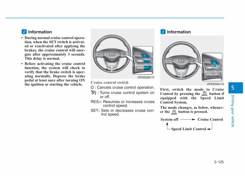
5-125
Driving your vehicle
5
Information• During normal cruise control opera-
tion, when the SET switch is activat-ed or reactivated after applying thebrakes, the cruise control will ener-gize after approximately 3 seconds.This delay is normal.
• Before activating the cruise controlfunction, the system will check toverify that the brake switch is oper-ating normally. Depress the brakepedal at least once after turning ONthe ignition or starting the vehicle.
Cruise control switch
O : Cancels cruise control operation.: Turns cruise control system onor off.
RES+: Resumes or increases cruisecontrol speed.
SET-: Sets or decreases cruise con-trol speed.
Information
First, switch the mode to CruiseControl by pressing the button ifequipped with the Speed LimitControl System.
The mode changes, as below, whenev-er the button is pressed.
ii
OPDE056115
System off Cruise Control
Speed Limit Control
OPDE056117
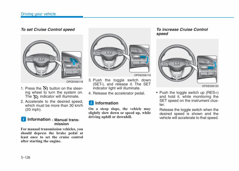
5-126
Driving your vehicle
To set Cruise Control speed
1. Press the button on the steer-ing wheel to turn the system on.The indicator will illuminate.
2. Accelerate to the desired speed,which must be more than 30 km/h(20 mph).
Information - Manual trans-mission
For manual transmission vehicles, youshould depress the brake pedal atleast once to set the cruise controlafter starting the engine.
3. Push the toggle switch down(SET-), and release it. The SETindicator light will illuminate.
4. Release the accelerator pedal.
Information On a steep slope, the vehicle mayslightly slow down or speed up, whiledriving uphill or downhill.
To increase Cruise Controlspeed
• Push the toggle switch up (RES+)and hold it, while monitoring theSET speed on the instrument clus-ter.Release the toggle switch when thedesired speed is shown and thevehicle will accelerate to that speed.
i
i
OPDE056118
OPDE056119
OPDE056120
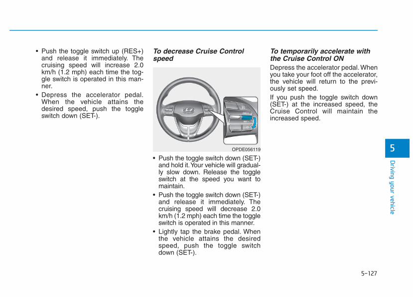
5-127
Driving your vehicle
5
• Push the toggle switch up (RES+)and release it immediately. Thecruising speed will increase 2.0km/h (1.2 mph) each time the tog-gle switch is operated in this man-ner.
• Depress the accelerator pedal.When the vehicle attains thedesired speed, push the toggleswitch down (SET-).
To decrease Cruise Controlspeed
• Push the toggle switch down (SET-)and hold it.Your vehicle will gradual-ly slow down. Release the toggleswitch at the speed you want tomaintain.
• Push the toggle switch down (SET-)and release it immediately. Thecruising speed will decrease 2.0km/h (1.2 mph) each time the toggleswitch is operated in this manner.
• Lightly tap the brake pedal. Whenthe vehicle attains the desiredspeed, push the toggle switchdown (SET-).
To temporarily accelerate withthe Cruise Control ON Depress the accelerator pedal. Whenyou take your foot off the accelerator,the vehicle will return to the previ-ously set speed.If you push the toggle switch down(SET-) at the increased speed, theCruise Control will maintain theincreased speed.
OPDE056119
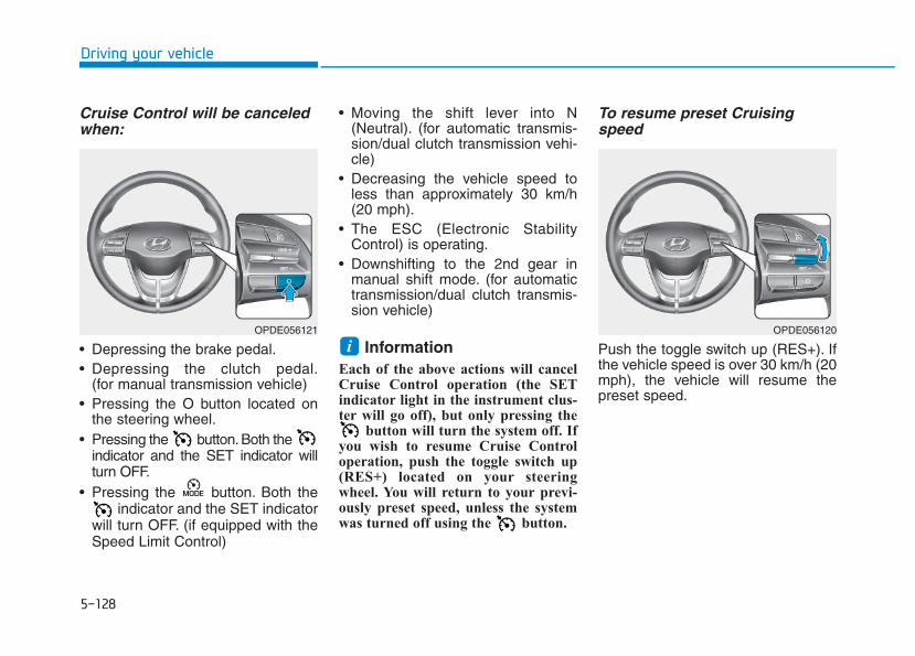
5-128
Driving your vehicle
Cruise Control will be canceledwhen:
• Depressing the brake pedal.• Depressing the clutch pedal.
(for manual transmission vehicle)• Pressing the O button located on
the steering wheel.• Pressing the button.Both the
indicator and the SET indicator willturn OFF.
• Pressing the button. Both theindicator and the SET indicator
will turn OFF. (if equipped with theSpeed Limit Control)
• Moving the shift lever into N(Neutral). (for automatic transmis-sion/dual clutch transmission vehi-cle)
• Decreasing the vehicle speed toless than approximately 30 km/h(20 mph).
• The ESC (Electronic StabilityControl) is operating.
• Downshifting to the 2nd gear inmanual shift mode. (for automatictransmission/dual clutch transmis-sion vehicle)
Information Each of the above actions will cancelCruise Control operation (the SETindicator light in the instrument clus-ter will go off), but only pressing the
button will turn the system off. Ifyou wish to resume Cruise Controloperation, push the toggle switch up(RES+) located on your steeringwheel. You will return to your previ-ously preset speed, unless the systemwas turned off using the button.
To resume preset Cruisingspeed
Push the toggle switch up (RES+). Ifthe vehicle speed is over 30 km/h (20mph), the vehicle will resume thepreset speed.
iOPDE056120OPDE056121
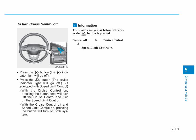
5-129
Driving your vehicle
5
To turn Cruise Control off
• Press the button (the indi-cator light will go off).
• Press the button (The cruiseindicator light will go off.). (ifequipped with Speed Limit Control)- With the Cruise Control on,
pressing the button once will turnOff the Cruise Control and turnon the Speed Limit Control.
- With the Cruise Control off andSpeed Limit Control on, pressingthe button will turn off both sys-tem.
InformationThe mode changes, as below, whenev-er the button is pressed.
i
System off Cruise Control
Speed Limit Control
OPDE056118
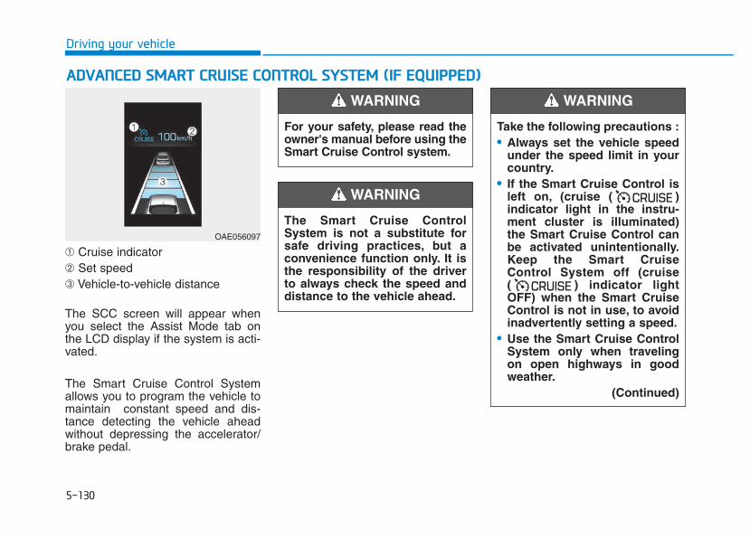
5-130
Driving your vehicle
➀ Cruise indicator➁ Set speed➂ Vehicle-to-vehicle distance
The SCC screen will appear whenyou select the Assist Mode tab onthe LCD display if the system is acti-vated.
The Smart Cruise Control Systemallows you to program the vehicle tomaintain constant speed and dis-tance detecting the vehicle aheadwithout depressing the accelerator/brake pedal.
AADDVVAANNCCEEDD SSMMAARRTT CCRRUUIISSEE CCOONNTTRROOLL SSYYSSTTEEMM ((IIFF EEQQUUIIPPPPEEDD))
For your safety, please read theowner's manual before using theSmart Cruise Control system.
WARNING
The Smart Cruise ControlSystem is not a substitute forsafe driving practices, but aconvenience function only. It isthe responsibility of the driverto always check the speed anddistance to the vehicle ahead.
WARNING
Take the following precautions :• Always set the vehicle speed
under the speed limit in yourcountry.
• If the Smart Cruise Control isleft on, (cruise ( )indicator light in the instru-ment cluster is illuminated)the Smart Cruise Control canbe activated unintentionally.Keep the Smart CruiseControl System off (cruise( ) indicator lightOFF) when the Smart CruiseControl is not in use, to avoidinadvertently setting a speed.
• Use the Smart Cruise ControlSystem only when travelingon open highways in goodweather.
(Continued)
WARNING
OAE056097
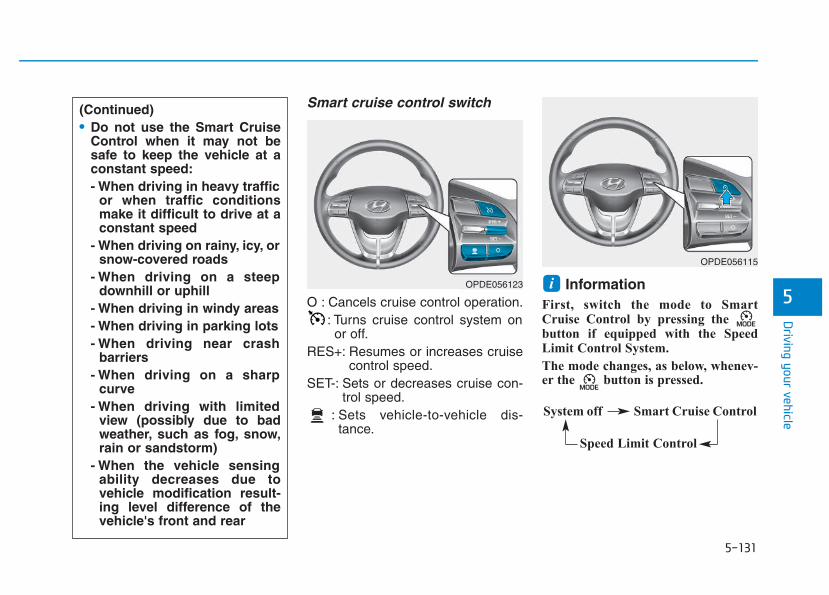
5-131
Driving your vehicle
5
Smart cruise control switch
O : Cancels cruise control operation.: Turns cruise control system onor off.
RES+: Resumes or increases cruisecontrol speed.
SET-: Sets or decreases cruise con-trol speed.
: Sets vehicle-to-vehicle dis-tance.
InformationFirst, switch the mode to SmartCruise Control by pressing the button if equipped with the SpeedLimit Control System.
The mode changes, as below, whenev-er the button is pressed.
i
(Continued)• Do not use the Smart Cruise
Control when it may not besafe to keep the vehicle at aconstant speed:- When driving in heavy traffic
or when traffic conditionsmake it difficult to drive at aconstant speed
- When driving on rainy, icy, orsnow-covered roads
- When driving on a steepdownhill or uphill
- When driving in windy areas- When driving in parking lots- When driving near crash
barriers- When driving on a sharp
curve- When driving with limited
view (possibly due to badweather, such as fog, snow,rain or sandstorm)
- When the vehicle sensingability decreases due tovehicle modification result-ing level difference of thevehicle's front and rear
OPDE056123
OPDE056115
System off Smart Cruise Control
Speed Limit Control
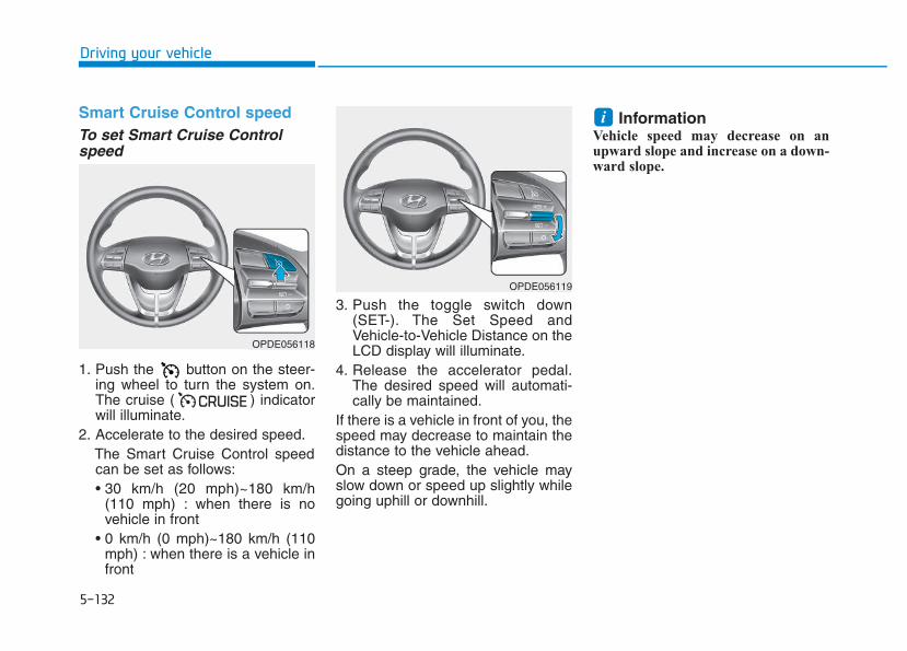
5-132
Driving your vehicle
Smart Cruise Control speedTo set Smart Cruise Controlspeed
1. Push the button on the steer-ing wheel to turn the system on.The cruise ( ) indicatorwill illuminate.
2. Accelerate to the desired speed.The Smart Cruise Control speedcan be set as follows:• 30 km/h (20 mph)~180 km/h
(110 mph) : when there is novehicle in front
• 0 km/h (0 mph)~180 km/h (110mph) : when there is a vehicle infront
3. Push the toggle switch down(SET-). The Set Speed andVehicle-to-Vehicle Distance on theLCD display will illuminate.
4. Release the accelerator pedal.The desired speed will automati-cally be maintained.
If there is a vehicle in front of you, thespeed may decrease to maintain thedistance to the vehicle ahead.On a steep grade, the vehicle mayslow down or speed up slightly whilegoing uphill or downhill.
InformationVehicle speed may decrease on anupward slope and increase on a down-ward slope.
i
OPDE056118
OPDE056119
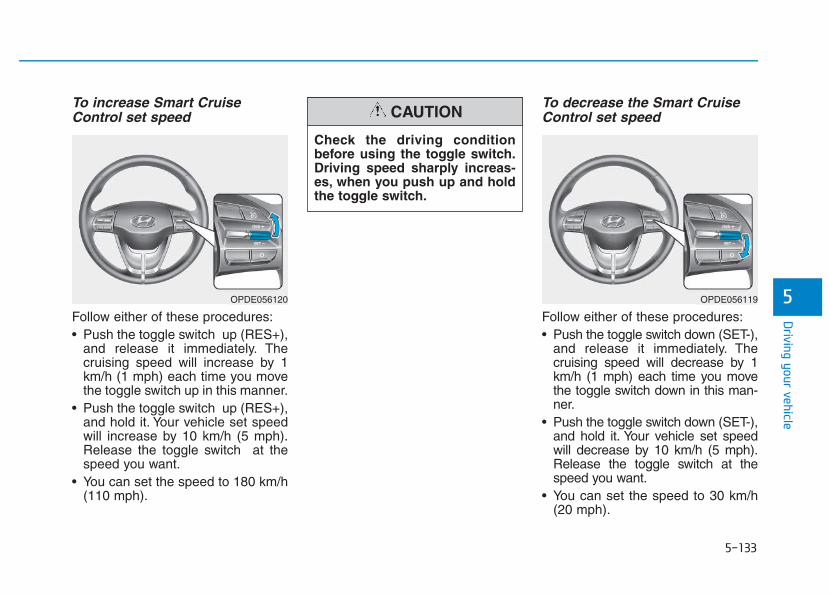
5-133
Driving your vehicle
5
To increase Smart CruiseControl set speed
Follow either of these procedures:• Push the toggle switch up (RES+),
and release it immediately. Thecruising speed will increase by 1km/h (1 mph) each time you movethe toggle switch up in this manner.
• Push the toggle switch up (RES+),and hold it. Your vehicle set speedwill increase by 10 km/h (5 mph).Release the toggle switch at thespeed you want.
• You can set the speed to 180 km/h(110 mph).
To decrease the Smart CruiseControl set speed
Follow either of these procedures:• Push the toggle switch down (SET-),
and release it immediately. Thecruising speed will decrease by 1km/h (1 mph) each time you movethe toggle switch down in this man-ner.
• Push the toggle switch down (SET-),and hold it. Your vehicle set speedwill decrease by 10 km/h (5 mph).Release the toggle switch at thespeed you want.
• You can set the speed to 30 km/h(20 mph).
OPDE056120
Check the driving conditionbefore using the toggle switch.Driving speed sharply increas-es, when you push up and holdthe toggle switch.
CAUTION
OPDE056119
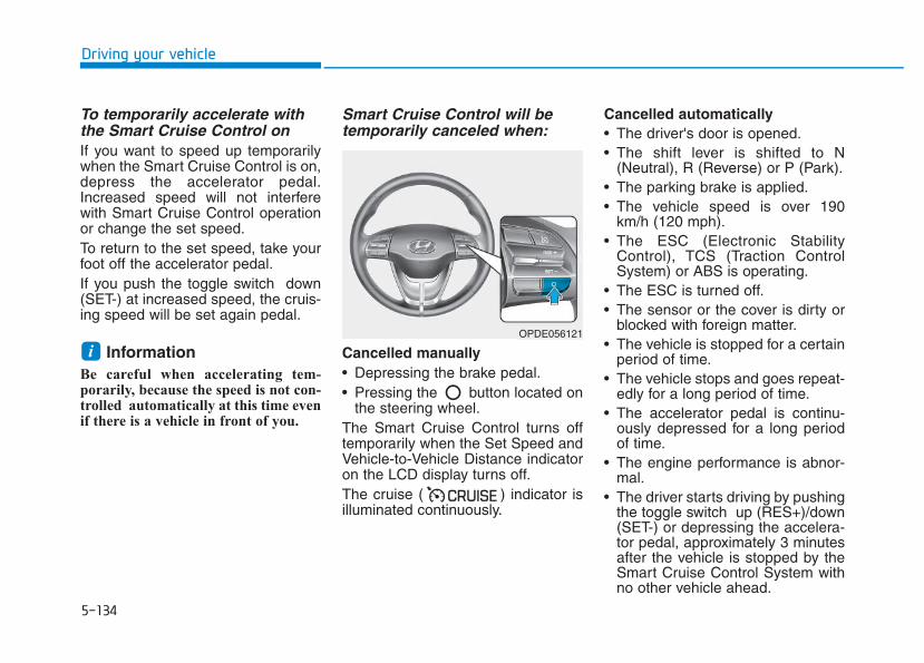
5-134
Driving your vehicle
To temporarily accelerate withthe Smart Cruise Control onIf you want to speed up temporarilywhen the Smart Cruise Control is on,depress the accelerator pedal.Increased speed will not interferewith Smart Cruise Control operationor change the set speed.To return to the set speed, take yourfoot off the accelerator pedal.If you push the toggle switch down(SET-) at increased speed, the cruis-ing speed will be set again pedal.
InformationBe careful when accelerating tem-porarily, because the speed is not con-trolled automatically at this time evenif there is a vehicle in front of you.
Smart Cruise Control will betemporarily canceled when:
Cancelled manually• Depressing the brake pedal.• Pressing the button located on
the steering wheel.The Smart Cruise Control turns offtemporarily when the Set Speed andVehicle-to-Vehicle Distance indicatoron the LCD display turns off.The cruise ( ) indicator isilluminated continuously.
Cancelled automatically• The driver's door is opened.• The shift lever is shifted to N
(Neutral), R (Reverse) or P (Park).• The parking brake is applied.• The vehicle speed is over 190
km/h (120 mph).• The ESC (Electronic Stability
Control), TCS (Traction ControlSystem) or ABS is operating.
• The ESC is turned off.• The sensor or the cover is dirty or
blocked with foreign matter.• The vehicle is stopped for a certain
period of time.• The vehicle stops and goes repeat-
edly for a long period of time.• The accelerator pedal is continu-
ously depressed for a long periodof time.
• The engine performance is abnor-mal.
• The driver starts driving by pushingthe toggle switch up (RES+)/down(SET-) or depressing the accelera-tor pedal, approximately 3 minutesafter the vehicle is stopped by theSmart Cruise Control System withno other vehicle ahead.
iOPDE056121
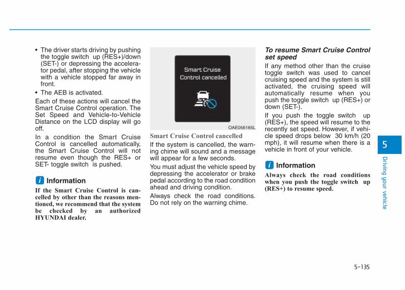
5-135
Driving your vehicle
5
• The driver starts driving by pushingthe toggle switch up (RES+)/down(SET-) or depressing the accelera-tor pedal, after stopping the vehiclewith a vehicle stopped far away infront.
• The AEB is activated.Each of these actions will cancel theSmart Cruise Control operation. TheSet Speed and Vehicle-to-VehicleDistance on the LCD display will gooff.In a condition the Smart CruiseControl is cancelled automatically,the Smart Cruise Control will notresume even though the RES+ orSET- toggle switch is pushed.
InformationIf the Smart Cruise Control is can-celled by other than the reasons men-tioned, we recommend that the systembe checked by an authorizedHYUNDAI dealer.
Smart Cruise Control cancelled
If the system is cancelled, the warn-ing chime will sound and a messagewill appear for a few seconds.You must adjust the vehicle speed bydepressing the accelerator or brakepedal according to the road conditionahead and driving condition.Always check the road conditions.Do not rely on the warning chime.
To resume Smart Cruise Controlset speedIf any method other than the cruisetoggle switch was used to cancelcruising speed and the system is stillactivated, the cruising speed willautomatically resume when youpush the toggle switch up (RES+) ordown (SET-).If you push the toggle switch up(RES+), the speed will resume to therecently set speed. However, if vehi-cle speed drops below 30 km/h (20mph), it will resume when there is avehicle in front of your vehicle.
InformationAlways check the road conditionswhen you push the toggle switch up(RES+) to resume speed.
i
i
OAE056165L
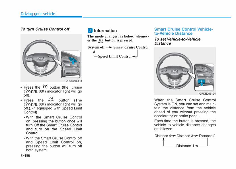
5-136
Driving your vehicle
To turn Cruise Control off
• Press the button (the cruise( ) indicator light will gooff).
• Press the button (The( ) indicator light will gooff.). (if equipped with Speed LimitControl)- With the Smart Cruise Control
on, pressing the button once willturn Off the Smart Cruise Controland turn on the Speed LimitControl.
- With the Smart Cruise Control offand Speed Limit Control on,pressing the button will turn offboth system.
InformationThe mode changes, as below, whenev-er the button is pressed.
Smart Cruise Control Vehicle-to-Vehicle DistanceTo set Vehicle-to-VehicleDistance
When the Smart Cruise ControlSystem is ON, you can set and main-tain the distance from the vehicleahead of you without pressing theaccelerator or brake pedal.Each time the button is pressed, thevehicle to vehicle distance changesas follows:
i
OPDE056118
System off Smart Cruise Control
Speed Limit Control
OPDE056124
Distance 4 Distance 3 Distance 2
Distance 1
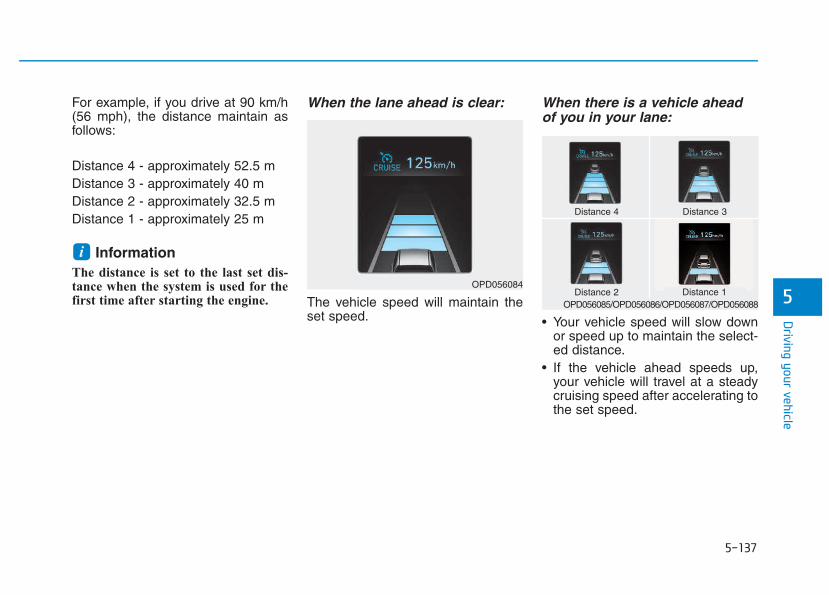
5-137
Driving your vehicle
5
For example, if you drive at 90 km/h(56 mph), the distance maintain asfollows:
Distance 4 - approximately 52.5 mDistance 3 - approximately 40 mDistance 2 - approximately 32.5 mDistance 1 - approximately 25 m
InformationThe distance is set to the last set dis-tance when the system is used for thefirst time after starting the engine.
When the lane ahead is clear:
The vehicle speed will maintain theset speed.
When there is a vehicle aheadof you in your lane:
• Your vehicle speed will slow downor speed up to maintain the select-ed distance.
• If the vehicle ahead speeds up,your vehicle will travel at a steadycruising speed after accelerating tothe set speed.
i
OPD056084
Distance 4 Distance 3
Distance 1Distance 2OPD056085/OPD056086/OPD056087/OPD056088
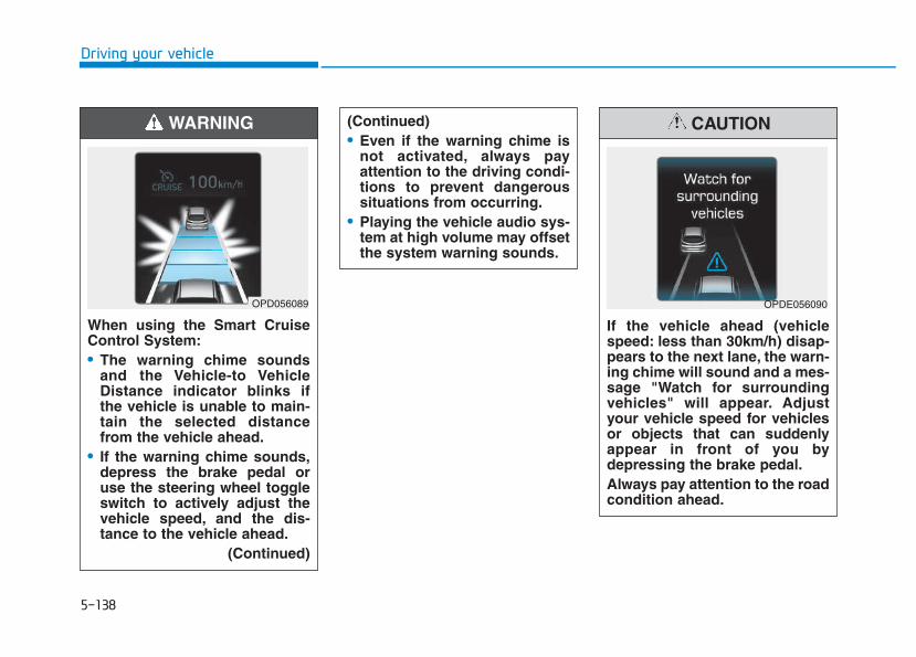
5-138
Driving your vehicle
When using the Smart CruiseControl System:• The warning chime sounds
and the Vehicle-to VehicleDistance indicator blinks ifthe vehicle is unable to main-tain the selected distancefrom the vehicle ahead.
• If the warning chime sounds,depress the brake pedal oruse the steering wheel toggleswitch to actively adjust thevehicle speed, and the dis-tance to the vehicle ahead.
(Continued)
(Continued)• Even if the warning chime is
not activated, always payattention to the driving condi-tions to prevent dangeroussituations from occurring.
• Playing the vehicle audio sys-tem at high volume may offsetthe system warning sounds.
WARNING
OPD056089
If the vehicle ahead (vehiclespeed: less than 30km/h) disap-pears to the next lane, the warn-ing chime will sound and a mes-sage "Watch for surroundingvehicles" will appear. Adjustyour vehicle speed for vehiclesor objects that can suddenlyappear in front of you bydepressing the brake pedal.Always pay attention to the roadcondition ahead.
CAUTION
OPDE056090
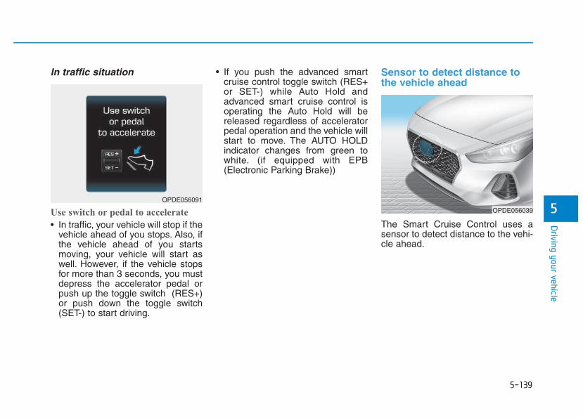
5-139
Driving your vehicle
5
In traffic situation
Use switch or pedal to accelerate
• In traffic, your vehicle will stop if thevehicle ahead of you stops. Also, ifthe vehicle ahead of you startsmoving, your vehicle will start aswell. However, if the vehicle stopsfor more than 3 seconds, you mustdepress the accelerator pedal orpush up the toggle switch (RES+)or push down the toggle switch(SET-) to start driving.
• If you push the advanced smartcruise control toggle switch (RES+or SET-) while Auto Hold andadvanced smart cruise control isoperating the Auto Hold will bereleased regardless of acceleratorpedal operation and the vehicle willstart to move. The AUTO HOLDindicator changes from green towhite. (if equipped with EPB(Electronic Parking Brake))
Sensor to detect distance tothe vehicle ahead
The Smart Cruise Control uses asensor to detect distance to the vehi-cle ahead.
OPDE056039
OPDE056091
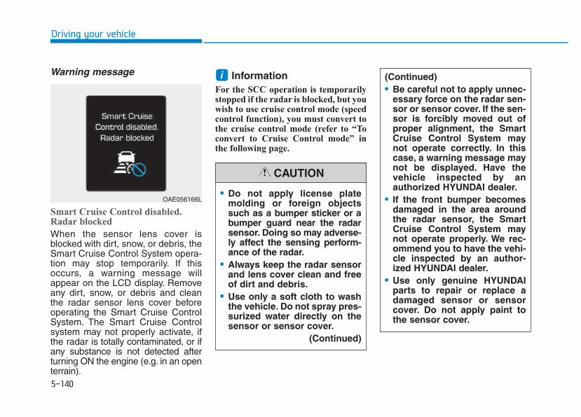
5-140
Driving your vehicle
Warning message
Smart Cruise Control disabled.Radar blocked
When the sensor lens cover isblocked with dirt, snow, or debris, theSmart Cruise Control System opera-tion may stop temporarily. If thisoccurs, a warning message willappear on the LCD display. Removeany dirt, snow, or debris and cleanthe radar sensor lens cover beforeoperating the Smart Cruise ControlSystem. The Smart Cruise Controlsystem may not properly activate, ifthe radar is totally contaminated, or ifany substance is not detected afterturning ON the engine (e.g. in an openterrain).
InformationFor the SCC operation is temporarilystopped if the radar is blocked, but youwish to use cruise control mode (speedcontrol function), you must convert tothe cruise control mode (refer to “Toconvert to Cruise Control mode” inthe following page.
i
OAE056166L
(Continued)• Be careful not to apply unnec-
essary force on the radar sen-sor or sensor cover. If the sen-sor is forcibly moved out ofproper alignment, the SmartCruise Control System maynot operate correctly. In thiscase, a warning message maynot be displayed. Have thevehicle inspected by anauthorized HYUNDAI dealer.
• If the front bumper becomesdamaged in the area aroundthe radar sensor, the SmartCruise Control System maynot operate properly. We rec-ommend you to have the vehi-cle inspected by an author-ized HYUNDAI dealer.
• Use only genuine HYUNDAIparts to repair or replace adamaged sensor or sensorcover. Do not apply paint tothe sensor cover.
• Do not apply license platemolding or foreign objectssuch as a bumper sticker or abumper guard near the radarsensor. Doing so may adverse-ly affect the sensing perform-ance of the radar.
• Always keep the radar sensorand lens cover clean and freeof dirt and debris.
• Use only a soft cloth to washthe vehicle. Do not spray pres-surized water directly on thesensor or sensor cover.
(Continued)
CAUTION
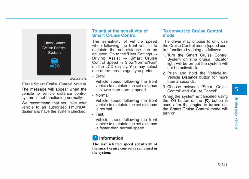
5-141
Driving your vehicle
5Check Smart Cruise Control System
The message will appear when thevehicle to vehicle distance controlsystem is not functioning normally.We recommend that you take yourvehicle to an authorized HYUNDAIdealer and have the system checked.
To adjust the sensitivity ofSmart Cruise Control The sensitivity of vehicle speedwhen following the front vehicle tomaintain the set distance can beadjusted. Go to the 'User Settings →Driving Assist → Smart CruiseControl Speed → Slow/Normal/Fast'on the LCD display. You may selectone of the three stages you prefer.- Slow:
Vehicle speed following the frontvehicle to maintain the set distanceis slower than normal speed.
- Normal:Vehicle speed following the frontvehicle to maintain the set distanceis normal.
- Fast:Vehicle speed following the frontvehicle to maintain the set distanceis faster than normal speed.
InformationThe last selected speed sensitivity ofthe smart cruise control is remained inthe system.
To convert to Cruise ControlmodeThe driver may choose to only usethe Cruise Control mode (speed con-trol function) by doing as follows:1. Turn the Smart Cruise Control
System on (the cruise indicatorlight will be on but the system willnot be activated).
2. Push and hold the Vehicle-to-Vehicle Distance button for morethan 2 seconds.
3. Choose between "Smart CruiseControl" and "Cruise Control".
When the system is canceled usingthe button or the button isused after the engine is turned on,the Smart Cruise Control mode willturn on.
i
OAE056167L
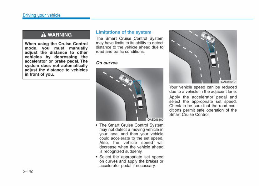
5-142
Driving your vehicle
Limitations of the systemThe Smart Cruise Control Systemmay have limits to its ability to detectdistance to the vehicle ahead due toroad and traffic conditions.
On curves
• The Smart Cruise Control Systemmay not detect a moving vehicle inyour lane, and then your vehiclecould accelerate to the set speed.Also, the vehicle speed willdecrease when the vehicle aheadis recognized suddenly.
• Select the appropriate set speedon curves and apply the brakes oraccelerator pedal if necessary.
Your vehicle speed can be reduceddue to a vehicle in the adjacent lane.Apply the accelerator pedal andselect the appropriate set speed.Check to be sure that the road con-ditions permit safe operation of theSmart Cruise Control.
OAE056101
OAE056100
When using the Cruise Controlmode, you must manuallyadjust the distance to othervehicles by depressing theaccelerator or brake pedal. Thesystem does not automaticallyadjust the distance to vehiclesin front of you.
WARNING
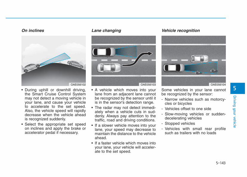
5-143
Driving your vehicle
5
On inclines
• During uphill or downhill driving,the Smart Cruise Control Systemmay not detect a moving vehicle inyour lane, and cause your vehicleto accelerate to the set speed.Also, the vehicle speed will rapidlydecrease when the vehicle aheadis recognized suddenly.
• Select the appropriate set speedon inclines and apply the brake oraccelerator pedal if necessary.
Lane changing
• A vehicle which moves into yourlane from an adjacent lane cannotbe recognized by the sensor until itis in the sensor's detection range.
• The radar may not detect immedi-ately when a vehicle cuts in sud-denly. Always pay attention to thetraffic, road and driving conditions.
• If a slower vehicle moves into yourlane, your speed may decrease tomaintain the distance to the vehicleahead.
• If a faster vehicle which moves intoyour lane, your vehicle will acceler-ate to the set speed.
Vehicle recognition
Some vehicles in your lane cannotbe recognized by the sensor:- Narrow vehicles such as motorcy-
cles or bicycles- Vehicles offset to one side- Slow-moving vehicles or sudden-
decelerating vehicles - Stopped vehicles- Vehicles with small rear profile
such as trailers with no loads
OAE056104OAE056103OAE056102
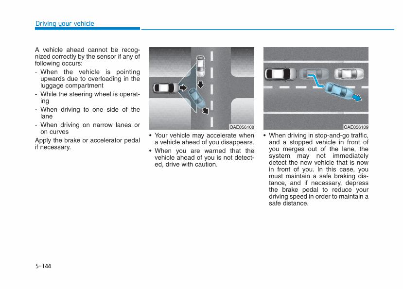
5-144
Driving your vehicle
A vehicle ahead cannot be recog-nized correctly by the sensor if any offollowing occurs:- When the vehicle is pointing
upwards due to overloading in theluggage compartment
- While the steering wheel is operat-ing
- When driving to one side of thelane
- When driving on narrow lanes oron curves
Apply the brake or accelerator pedalif necessary.
• Your vehicle may accelerate whena vehicle ahead of you disappears.
• When you are warned that thevehicle ahead of you is not detect-ed, drive with caution.
• When driving in stop-and-go traffic,and a stopped vehicle in front ofyou merges out of the lane, thesystem may not immediatelydetect the new vehicle that is nowin front of you. In this case, youmust maintain a safe braking dis-tance, and if necessary, depressthe brake pedal to reduce yourdriving speed in order to maintain asafe distance.
OAE056109OAE056108
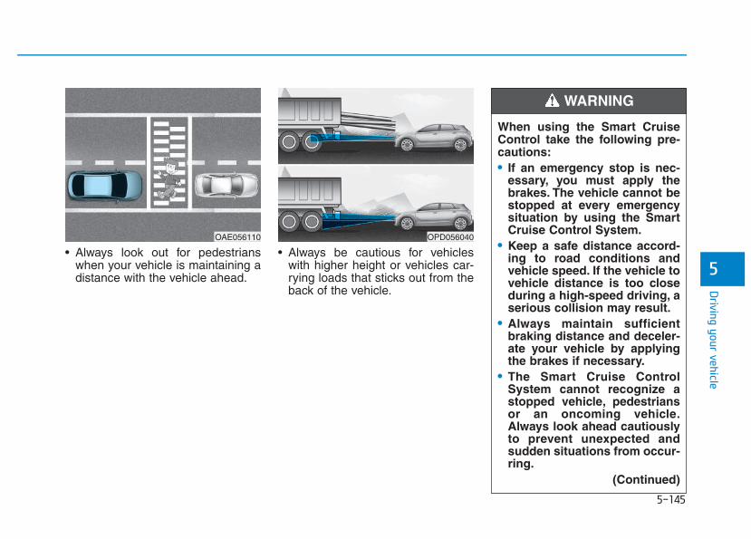
5-145
Driving your vehicle
5• Always look out for pedestrians
when your vehicle is maintaining adistance with the vehicle ahead.
• Always be cautious for vehicleswith higher height or vehicles car-rying loads that sticks out from theback of the vehicle.
When using the Smart CruiseControl take the following pre-cautions:• If an emergency stop is nec-
essary, you must apply thebrakes. The vehicle cannot bestopped at every emergencysituation by using the SmartCruise Control System.
• Keep a safe distance accord-ing to road conditions andvehicle speed. If the vehicle tovehicle distance is too closeduring a high-speed driving, aserious collision may result.
• Always maintain sufficientbraking distance and deceler-ate your vehicle by applyingthe brakes if necessary.
• The Smart Cruise ControlSystem cannot recognize astopped vehicle, pedestriansor an oncoming vehicle.Always look ahead cautiouslyto prevent unexpected andsudden situations from occur-ring.
(Continued)
WARNING
OPD056040OAE056110
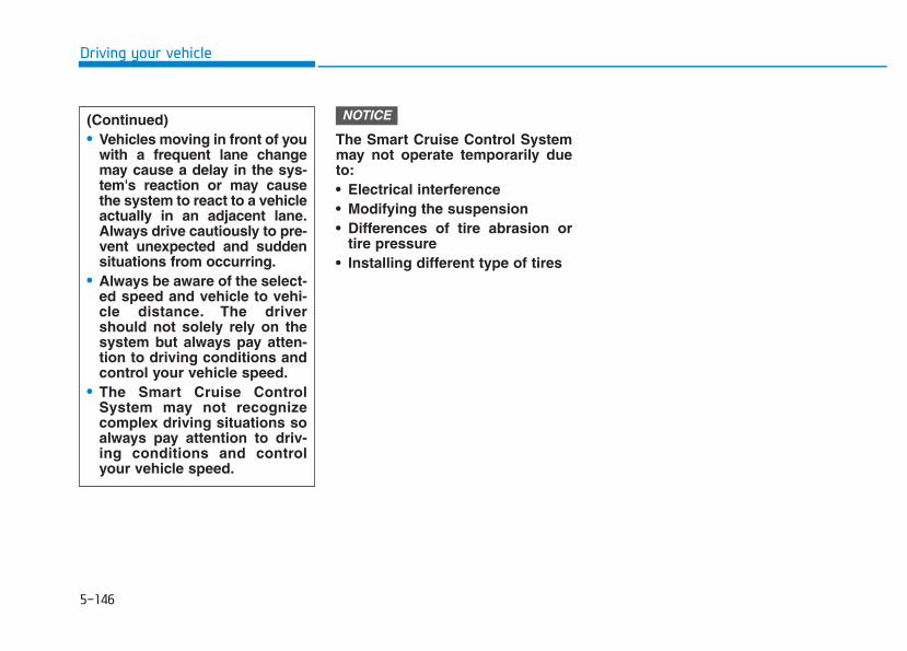
5-146
Driving your vehicle
The Smart Cruise Control Systemmay not operate temporarily dueto:• Electrical interference• Modifying the suspension• Differences of tire abrasion or
tire pressure • Installing different type of tires
NOTICE(Continued)• Vehicles moving in front of you
with a frequent lane changemay cause a delay in the sys-tem's reaction or may causethe system to react to a vehicleactually in an adjacent lane.Always drive cautiously to pre-vent unexpected and suddensituations from occurring.
• Always be aware of the select-ed speed and vehicle to vehi-cle distance. The drivershould not solely rely on thesystem but always pay atten-tion to driving conditions andcontrol your vehicle speed.
• The Smart Cruise ControlSystem may not recognizecomplex driving situations soalways pay attention to driv-ing conditions and controlyour vehicle speed.
5-147
Driving your vehicle
5
Hazardous driving conditionsWhen hazardous driving elementsare encountered such as water,snow, ice, mud and sand, take thebellow suggestions:• Drive cautiously and keep a longer
braking distance.• Avoid abrupt braking or steering.• When your vehicle is stuck in snow,
mud, or sand, use the secondgear. Accelerate slowly to avoidunnecessary wheel spinning.
• Put sand, rock salt, tire chains orother non-slip materials under thewheels to provide additional trac-tion while being stuck in ice, snow,or mud.
Rocking the vehicle If it is necessary to rock the vehicleto free it from snow, sand, or mud,first turn the steering wheel right andleft to clear the area around yourfront wheels. Then, shift back andforth between R (Reverse) and a for-ward gear.Try to avoid spinning the wheels, anddo not race the engine.To prevent transmission wear, waituntil the wheels stop spinning beforeshifting gears. Release the accelera-tor pedal while shifting, and presslightly on the accelerator pedal whilethe transmission is in gear. Slowlyspinning the wheels in forward andreverse directions causes a rockingmotion that may free the vehicle.
SSPPEECCIIAALL DDRRIIVVIINNGG CCOONNDDIITTIIOONNSS
Downshifting with an automatictransmission while driving onslippery surfaces can cause anaccident. The sudden change intire speed could cause the tiresto skid. Be careful when down-shifting on slippery surfaces.
WARNING
If the vehicle is stuck andexcessive wheel spin occurs,the temperature in the tires canincrease very quickly. If the tiresbecome damaged, a tire blowout or tire explosion can occur.This condition is dangerous -you and others may be injured.Do not attempt this procedure ifpeople or objects are anywherenear the vehicle.If you attempt to free the vehi-cle, the vehicle can overheatquickly, possibly causing anengine compartment fire orother damage.Try to avoid spin-ning the wheels as much aspossible to prevent overheatingof either the tires or the engine.DO NOT allow the vehicle tospin the wheels above 56 km/h(35 mph).
WARNING
5-148
Driving your vehicle
Information The ESC system (if equipped) must beturned OFF before rocking the vehi-cle.
If you are still stuck after rockingthe vehicle a few times, have thevehicle pulled out by a tow vehicleto avoid engine overheating, pos-sible damage to the transmission,and tire damage. See "Towing" inchapter 6.
Smooth corneringAvoid braking or gear changing incorners, especially when roads arewet. Ideally, corners should alwaysbe taken under gentle acceleration.
Driving at nightNight driving presents more hazardsthan driving in the daylight. Here aresome important tips to remember:• Slow down and keep more dis-
tance between you and other vehi-cles, as it may be more difficult tosee at night, especially in areaswhere there may not be any streetlights.
• Adjust your mirrors to reduce theglare from other driver's head-lamps.
• Keep your headlamps clean andproperly aimed. Dirty or improperlyaimed headlamps will make itmuch more difficult to see at night.
• Avoid staring directly at the head-lamps of oncoming vehicles. Youcould be temporarily blinded, and itwill take several seconds for youreyes to readjust to the darkness.
Driving in the rainRain and wet roads can make drivingdangerous. Here are a few things toconsider when driving in the rain oron slick pavement:• Slow down and allow extra follow-
ing distance. A heavy rainfallmakes it harder to see and increas-es the distance needed to stopyour vehicle.
• Turn OFF your Cruise Control. (ifequipped)
• Replace your windshield wiperblades when they show signs ofstreaking or missing areas on thewindshield.
• Be sure your tires have enoughtread. If your tires do not haveenough tread, making a quick stopon wet pavement can cause a skidand possibly lead to an accident.See "Tire Tread" in chapter 7.
• Turn on your headlamps to make iteasier for others to see you.
• Driving too fast through large pud-dles can affect your brakes. If youmust go through puddles, try todrive through them slowly.
NOTICE
i
5-149
Driving your vehicle
5
• If you believe your brakes may bewet, apply them lightly while driv-ing until normal braking operationreturns.
Hydroplaning If the road is wet enough and you aregoing fast enough, your vehicle mayhave little or no contact with the roadsurface and actually ride on thewater. The best advice is SLOWDOWN when the road is wet.
The risk of hydroplaning increas-es as the depth of tire treaddecreases, refer to "Tire Tread" inchapter 7.
Driving in flooded areasAvoid driving through flooded areasunless you are sure the water is nohigher than the bottom of the wheelhub. Drive through any water slowly.Allow adequate stopping distancebecause brake performance may bereduced.After driving through water, dry thebrakes by gently applying them sev-eral times while the vehicle is movingslowly.
Highway drivingTiresAdjust the tire inflation, as specified.Under-inflation may overheat ordamage the tires.Do not install worn-out or damagedtires, which may reduce traction orfail the braking operation.
Information Never over-inflate your tires above themaximum inflation pressure, as speci-fied on your tires.
Fuel, engine coolant and engineoilDriving at higher speeds on the high-way consumes more fuel and is lessefficient than driving at a slower,more moderate speed. Maintain amoderate speed in order to conservefuel when driving on the highway.Be sure to check both the enginecoolant level and the engine oilbefore driving.
Drive beltA loose or damaged drive belt mayoverheat the engine.
i
5-150
Driving your vehicle
Reducing the risk of a rolloverYour multi-purpose passenger vehi-cle is defined as a Sports UtilityVehicle (SUV). SUV’s have higherground clearance and a narrowertrack to make them capable of per-forming in a wide variety of off-roadapplications. The specific designcharacteristics give them a highercenter of gravity than ordinary vehi-cles making them more likely to rollover if you make abrupt turns. Utilityvehicles have a significantly higherrollover rate than other types of vehi-cles. Due to this risk, driver and pas-sengers are strongly recommendedto buckle their seat belts. In a rollovercrash, an unbelted person is signifi-cantly more likely to die than a per-son wearing a seat belt.There are steps that a driver canmake to reduce the risk of a rollover.If at all possible, avoid sharp turns orabrupt maneuvers, do not load yourvehicle with heavy cargo on the roof,and never modify your vehicle in anyway.
Utility vehicles have a signifi-cantly higher rollover rate thanother types of vehicles. To pre-vent rollovers or loss of control:• Take corners at slower speeds
than you would with a passen-ger vehicle.
• Avoid sharp turns and abruptmaneuvers.
• Do not modify your vehicle inany way that you would raisethe center of gravity.
• Keep tires properly inflated.• Do not carry heavy cargo on
the roof.
WARNING
In a rollover crash, an unbeltedperson is significantly morelikely to die than a person wear-ing a seat belt. Make sure allpassengers are wearing theirseat belts.
WARNING
5-151
Driving your vehicle
5
The severe weather conditions ofwinter quickly wear out tires andcause other problems. To minimizewinter driving problems, you shouldtake the following suggestions:
Information Information for Snow Tires and TireChains in the national language(Bulgarian, Hungarian, Icelandic,Polish) is provided in the Appendix.
Snow or icy conditionsYou need to keep sufficient distancebetween your vehicle and the vehiclein front of you.Apply the brakes gently. Speeding,rapid acceleration, sudden brakeapplications, and sharp turns arepotentially very hazardous practices.During deceleration, use enginebraking to the fullest extent. Suddenbrake applications on snowy or icyroads may cause skids to occur.To drive your vehicle in deep snow, itmay be necessary to use snow tiresor to install tire chains on your tires.Always carry emergency equipment.Some of the items you may want tocarry include tire chains, tow strapsor chains, a flashlight, emergencyflares, sand, a shovel, jumper cables,a window scraper, gloves, groundcloth, coveralls, a blanket, etc.
Snow tires
If you mount snow tires on your vehi-cle, make sure to use radial tires ofthe same size and load range as theoriginal tires. Mount snow tires on allfour wheels to balance your vehicle’shandling in all weather conditions.The traction provided by snow tireson dry roads may not be as high asyour vehicle's original equipmenttires. Check with the tire dealer formaximum speed recommendations.
Information Do not install studded tires without firstchecking local and municipal regula-tions for possible restrictions againsttheir use.
i
i
WWIINNTTEERR DDRRIIVVIINNGG
Snow tires should be equivalentin size and type to the vehicle'sstandard tires. Otherwise, thesafety and handling of your vehi-cle may be adversely affected.
WARNING
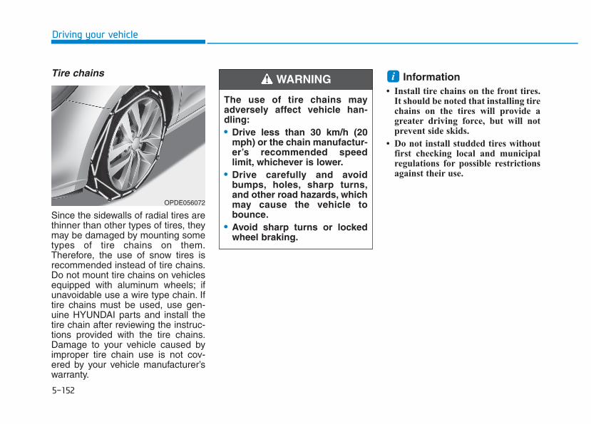
5-152
Driving your vehicle
Tire chains
Since the sidewalls of radial tires arethinner than other types of tires, theymay be damaged by mounting sometypes of tire chains on them.Therefore, the use of snow tires isrecommended instead of tire chains.Do not mount tire chains on vehiclesequipped with aluminum wheels; ifunavoidable use a wire type chain. Iftire chains must be used, use gen-uine HYUNDAI parts and install thetire chain after reviewing the instruc-tions provided with the tire chains.Damage to your vehicle caused byimproper tire chain use is not cov-ered by your vehicle manufacturer’swarranty.
Information • Install tire chains on the front tires.
It should be noted that installing tirechains on the tires will provide agreater driving force, but will notprevent side skids.
• Do not install studded tires withoutfirst checking local and municipalregulations for possible restrictionsagainst their use.
i
OPDE056072
The use of tire chains mayadversely affect vehicle han-dling:• Drive less than 30 km/h (20
mph) or the chain manufactur-er’s recommended speedlimit, whichever is lower.
• Drive carefully and avoidbumps, holes, sharp turns,and other road hazards, whichmay cause the vehicle tobounce.
• Avoid sharp turns or lockedwheel braking.
WARNING
5-153
Driving your vehicle
5
Chain Installation
When installing tire chains, follow themanufacturer's instructions andmount them as tightly possible. Driveslowly (less than 30 km/h (20 mph))with chains installed. If you hear thechains contacting the body or chas-sis, stop and tighten them. If they stillmake contact, slow down until thenoise stops. Remove the tire chainsas soon as you begin driving oncleared roads.When mounting snow chains, parkthe vehicle on level ground awayfrom traffic. Turn on the vehicleHazard Warning Flasher and place atriangular emergency warning devicebehind the vehicle (if available).Always place the vehicle in P (Park),apply the parking brake and turn offthe engine before installing snowchains.
When using tire chains:• Wrong size chains or improperly
installed chains can damageyour vehicle's brake lines, sus-pension, body and wheels.
• Use SAE “S”class or wire chains.• If you hear noise caused by
chains contacting the body,retighten the chain to preventcontact with the vehicle body.
• To prevent body damage, retight-en the chains after driving 0.5~1.0km (0.3~0.6 miles).
• Do not use tire chains on vehi-cles equipped with aluminumwheels. If unavoidable, use awire type chain.
• Use wire chains less than 12 mm(0.47 in) wide to prevent damageto the chain’s connection.
Winter PrecautionsUse high quality ethylene glycolcoolantYour vehicle is delivered with highquality ethylene glycol coolant in thecooling system. It is the only type ofcoolant that should be used becauseit helps prevent corrosion in the cool-ing system, lubricates the waterpump and prevents freezing. Be sureto replace or replenish your coolantin accordance with the maintenanceschedule in section 7. Before winter,have your coolant tested to assurethat its freezing point is sufficient forthe temperatures anticipated duringthe winter.
NOTICE
5-154
Driving your vehicle
Check battery and cablesThe winter temperature increasesthe battery consumption. Inspectthe battery and cables, as speci-fied in the chapter 7. The batterycharging level can be checked by anauthorized HYUNDAI dealer or in aservice station.
Change to "winter weight" oil ifnecessaryIn some regions during winter, it isrecommended to use the "winterweight" oil with lower viscosity. Forfurther information, refer to the chap-ter 8. When you are not sure about atype of winter weight oil, consult anauthorized HYUNDAI dealer.
Check spark plugs and ignitionsystemInspect the spark plugs, as speci-fied in the chapter 7. If necessary,replace them. Also check all ignitionwirings and components for anycracks, wear-out, and damage.
To prevent locks from freezingTo prevent the locks from beingfrozen, spray approved de-icing fluidor glycerin into key holes. When alock opening is already covered withice, spray approved de-icing fluidover the ice to remove it. When aninternal part of a lock freezes, try tothaw it with a heated key. Carefullyuse the heated key to avoid an injury.
Use approved window washeranti-freeze solution in systemTo prevent the window washer frombeing frozen, add authorized windowwasher anti-freeze solution, as spec-ified on the window washer contain-er. Window washer anti-freeze solu-tion is available from an authorizedHYUNDAI dealer, and so are themost vehicle accessory outlets. Donot use engine coolant or other typesof anti-freeze solution to prevent anydamage to the vehicle paint.
5-155
Driving your vehicle
5
Do not let your parking brakefreezeUnder some conditions your parkingbrake can freeze in the engagedposition. This is most likely to hap-pen when there is an accumulationof snow or ice around or near therear brakes or if the brakes are wet.When there is the risk that your park-ing brake may freeze, temporarilyapply it with the shift lever in P(Park). Also, block the rear wheels inadvance, so the vehicle may not roll.Then, release the parking brake.
Do not let ice and snow accumu-late underneathUnder some conditions, snow andice can build up under the fendersand interfere with the steering. Whendriving in such conditions during thesevere winter, you should checkunderneath the vehicle on a regularbasis, so that moving the frontwheels and the steering componentsis unblocked.
Carry emergency equipmentIn accordance with weather condi-tions, you should carry appropriateemergency equipment, while driving.Some of the items you may want tocarry include tire chains, tow strapsor chains, flashlight, emergencyflares, sand, shovel, jumper cables,window scraper, gloves, groundcloth, coveralls, blanket, etc.
Do not place objects or materialsin the engine compartmentPutting objects or materials in theengine compartment may cause anengine failure or combustion,because those may block the enginecooling. Such damage will not becovered by the manufacturer’s war-ranty.
5-156
Driving your vehicle
If you are considering to tow withyour vehicle, you should first checkwith your country's Department ofMotor Vehicles to determine legalrequirements. Since laws vary therequirements for towing trailers, cars,or other types of vehicles or appara-tus may differ. Ask an authorizedHYUNDAI dealer for further detailsbefore towing.Remember that trailering is differentthan just driving your vehicle by itself.Trailering means changes in han-dling, durability, and fuel economy.Successful, safe trailering requirescorrect equipment, and it has to beused properly. Damage to your vehi-cle caused by improper trailer towingis not covered by your vehicle manu-facturer’s warranty.
This section contains many time-tested, important trailering tips andsafety rules. Many of these areimportant for your safety and that ofyour passengers. Please read thissection carefully before you pull atrailer.
TTRRAAIILLEERR TTOOWWIINNGG ((FFOORR EEUURROOPPEE))
Take the following precautions:• If you don't use the correct
equipment and/or drive improp-erly, you can lose control of thevehicle when you are pulling atrailer. For example, if the traileris too heavy, the braking per-formance may be reduced. Youand your passengers could beseriously or fatally injured. Pulla trailer only if you have fol-lowed all the steps in this sec-tion.
• Before towing, make sure thetotal trailer weight, GCW(Gross Combination Weight),GVW (Gross Vehicle Weight),GAW (Gross Axle Weight) andtrailer tongue load are all with-in the limits.
• When you tow a trailer, makesure to turn off the ISG sys-tem.
WARNING
5-157
Driving your vehicle
5
Information - For Europe• The technically permissible maxi-
mum load on the rear axle(s) may beexceeded by not more than 15 %and the technically permissiblemaximum laden mass of the vehiclemay be exceeded by not more than10% or 100 kg (220.4 lbs), whichev-er value is lower. In this case, do notexceed 100 km/h (62.1 mph) forvehicle of category M1 or 80 km/h(49.7 mph) for vehicle of categoryN1.
• When a vehicle of category M1 istowing a trailer, the additional loadimposed at the trailer couplingdevice may cause the tire maximumload ratings to be exceeded, but notby more than 15%. In this case, donot exceed 100 km/h (62.1 mph) andincrease the tire inflation pressureby at least 0.2 bar.
If you decide to pull a trailer?Here are some important points ifyou decide to pull a trailer:• Consider using a sway control. You
can ask a trailer hitch dealer aboutsway control.
• Do not do any towing with yourvehicle during its first 2,000 km(1,200 miles) in order to allow theengine to properly break in. Failureto heed this caution may result inserious engine or transmissiondamage.
• When towing a trailer, be sure toconsult an authorized HYUNDAIdealer for further information onadditional requirements such as atowing kit, etc.
• Always drive your vehicle at a mod-erate speed (less than 100 km/h(60 mph)) or posted towing speedlimit.
• On a long uphill grade, do notexceed 70 km/h (45 mph) or theposted towing speed limit,whichever is lower.
• Carefully observe the weight andload limits provided in the followingpages.
i
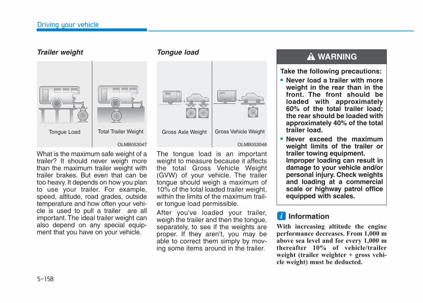
5-158
Driving your vehicle
Trailer weight
What is the maximum safe weight of atrailer? It should never weigh morethan the maximum trailer weight withtrailer brakes. But even that can betoo heavy. It depends on how you planto use your trailer. For example,speed, altitude, road grades, outsidetemperature and how often your vehi-cle is used to pull a trailer are allimportant. The ideal trailer weight canalso depend on any special equip-ment that you have on your vehicle.
Tongue load
The tongue load is an importantweight to measure because it affectsthe total Gross Vehicle Weight(GVW) of your vehicle. The trailertongue should weigh a maximum of10% of the total loaded trailer weight,within the limits of the maximum trail-er tongue load permissible.After you've loaded your trailer,weigh the trailer and then the tongue,separately, to see if the weights areproper. If they aren’t, you may beable to correct them simply by mov-ing some items around in the trailer.
Information With increasing altitude the engineperformance decreases. From 1,000 mabove sea level and for every 1,000 mthereafter 10% of vehicle/trailerweight (trailer weighter + gross vehi-cle weight) must be deducted.
i
Take the following precautions:• Never load a trailer with more
weight in the rear than in thefront. The front should beloaded with approximately60% of the total trailer load;the rear should be loaded withapproximately 40% of the totaltrailer load.
• Never exceed the maximumweight limits of the trailer ortrailer towing equipment.Improper loading can result indamage to your vehicle and/orpersonal injury. Check weightsand loading at a commercialscale or highway patrol officeequipped with scales.
WARNING
OLMB053048
Gross Axle Weight Gross Vehicle Weight
OLMB053047
Tongue Load Total Trailer Weight
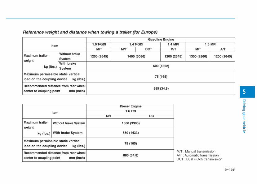
5-159
Driving your vehicle
5
M/T : Manual transmissionA/T : Automatic transmissionDCT : Dual clutch transmission
Item
Gasoline Engine1.0 T-GDI 1.4 T-GDI 1.4 MPI 1.6 MPI
M/T M/T DCT M/T M/T A/T
Maximum trailer
weight
kg (Ibs.)
Without brake
System1200 (2645) 1400 (3086) 1200 (2645) 1300 (2866) 1200 (2645)
With brake
System600 (1322)
Maximum permissible static vertical
load on the coupling device kg (Ibs.) 75 (165)
Recommended distance from rear wheel
center to coupling point mm (inch)885 (34.8)
Item
Diesel Engine1.6 TCI
M/T DCT
Maximum trailer
weight
kg (Ibs.)
Without brake System 1500 (3306)
With brake System 650 (1433)
Maximum permissible static vertical
load on the coupling device kg (Ibs.) 75 (165)
Recommended distance from rear wheel
center to coupling point mm (inch)885 (34.8)
Reference weight and distance when towing a trailer (for Europe)
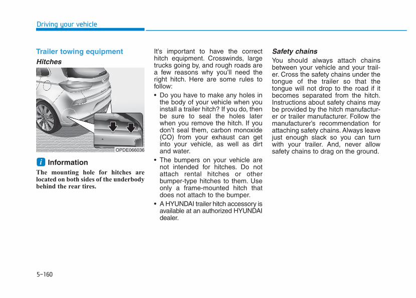
5-160
Driving your vehicle
Trailer towing equipmentHitches
Information The mounting hole for hitches arelocated on both sides of the underbodybehind the rear tires.
It's important to have the correcthitch equipment. Crosswinds, largetrucks going by, and rough roads area few reasons why you’ll need theright hitch. Here are some rules tofollow:• Do you have to make any holes in
the body of your vehicle when youinstall a trailer hitch? If you do, thenbe sure to seal the holes laterwhen you remove the hitch. If youdon’t seal them, carbon monoxide(CO) from your exhaust can getinto your vehicle, as well as dirtand water.
• The bumpers on your vehicle arenot intended for hitches. Do notattach rental hitches or otherbumper-type hitches to them. Useonly a frame-mounted hitch thatdoes not attach to the bumper.
• A HYUNDAI trailer hitch accessory isavailable at an authorized HYUNDAIdealer.
Safety chainsYou should always attach chainsbetween your vehicle and your trail-er. Cross the safety chains under thetongue of the trailer so that thetongue will not drop to the road if itbecomes separated from the hitch.Instructions about safety chains maybe provided by the hitch manufactur-er or trailer manufacturer. Follow themanufacturer’s recommendation forattaching safety chains. Always leavejust enough slack so you can turnwith your trailer. And, never allowsafety chains to drag on the ground.
iOPDE066036
5-161
Driving your vehicle
5
Trailer brakesIf your trailer is equipped with a brak-ing system, make sure it conformsyour country’s regulations and that itis properly installed and operatingcorrectly.If your trailer weighs more than themaximum trailer weight without trail-er brakes loaded, then it needs itsown brakes and they must be ade-quate. Be sure to read and follow theinstructions for the trailer brakes soyou’ll be able to install, adjust andmaintain them properly. Be sure notto tap into your vehicle's brake sys-tem.
Driving with a trailerTowing a trailer requires a certainamount of experience. Before settingout for the open road, you must getto know your trailer. Acquaint your-self with the feel of handling andbraking with the added weight of thetrailer. And always keep in mind thatthe vehicle you are driving is nowlonger and not nearly as responsiveas your vehicle is by itself.Before you start, check the trailerhitch and platform, safety chains,electrical connector(s), lights, tiresand brakes.During your trip, occasionally checkto be sure that the load is secure,and that the lights and trailer brakesare still working.
DistanceStay at least twice as far behind thevehicle ahead as you would whendriving your vehicle without a trailer.This can help you avoid situationsthat require heavy braking and sud-den turns.
PassingYou will need more passing distanceup ahead when you’re towing a trail-er. And, because of the increasedvehicle length, you’ll need to gomuch farther beyond the passedvehicle before you can return to yourlane.
Do not use a trailer with its ownbrakes unless you are absolute-ly certain that you have proper-ly set up the brake system. Thisis not a task for amateurs. Usean experienced, competent trail-er shop for this work.
WARNING
5-162
Driving your vehicle
Backing upHold the bottom of the steeringwheel with one hand. Then, to movethe trailer to the left, move your handto the left. To move the trailer to theright, move your hand to the right.Always back up slowly and, if possi-ble, have someone guide you.
Making turnsWhen you’re turning with a trailer,make wider turns than normal. Do thisso your trailer won’t strike soft shoul-ders, curbs, road signs, trees, or otherobjects. Avoid jerky or suddenmaneuvers. Signal well in advance.
Turn signalsWhen you tow a trailer, your vehiclehas to have a different turn signalflasher and extra wiring. The greenarrows on your instrument panel willflash whenever you signal a turn orlane change. Properly connected,the trailer lights will also flash to alertother drivers you’re about to turn,change lanes, or stop.When towing a trailer, the greenarrows on your instrument panel willflash for turns even if the bulbs onthe trailer are burned out. Thus, youmay think drivers behind you areseeing your signals when, in fact,they are not. It’s important to checkoccasionally to be sure the trailerbulbs are still working. You must alsocheck the lights every time you dis-connect and then reconnect thewires.
Do not connect a trailer lightingsystem directly to your vehi-cle’s lighting system. Use anapproved trailer wiring harness.Failure to do so could result indamage to the vehicle electricalsystem and/or personal injury.Consult an authorized HYUNDAIdealer for assistance.
WARNING
5-163
Driving your vehicle
5
Driving on hillsReduce speed and shift to a lowergear before you start down a long orsteep downgrade. If you don’t shiftdown, you might have to use yourbrakes so much that they would getoverheated and may not operate effi-ciently.On a long uphill grade, shift downand reduce your speed to around 70km/h (45 mph) to reduce the possi-bility of engine and transmissionoverheating.If your trailer weighs more than themaximum trailer weight without trail-er brakes and you have an automat-ic transmission/dual clutch transmis-sion, you should drive in D (Drive)when towing a trailer.Operating your vehicle in D (Drive)when towing a trailer will minimizeheat build-up and extend the life ofyour transmission.
To prevent engine and/or trans-mission overheating:• When towing a trailer on steep
grades (in excess of 6%) payclose attention to the enginecoolant temperature gauge toensure the engine does notoverheat. If the needle of thecoolant temperature gaugemoves towards "H" (HOT), pullover and stop as soon as it issafe to do so, and allow theengine to idle until it coolsdown.You may proceed once theengine has cooled sufficiently.
• If you tow a trailer with the max-imum gross vehicle weight andmaximum trailer weight, it cancause the engine or transmis-sion to overheat. When drivingin such conditions, allow theengine to idle until it coolsdown.You may proceed once theengine or transmission hascooled sufficiently.
(Continued)
(Continued)• You must decide your vehicle
speed according to trailer weightand uphill grade.
• Vehicles equipped with a dualclutch transmission when tow-ing a trailer on steep grades, theclutch in the transmission couldoverheat.When the clutch is overheated,the safe protection modeengages. If the safe protectionmode engages, the gear posi-tion indicator on the clusterblinks with a chime sound.At this time, a warning messagewill appear on the LCD displayand driving may not be smooth.If you ignore this warning, thedriving condition may becomeworse.To return to normal driving con-dition, stop the vehicle on a flatroad and apply the foot brake fora few minutes before driving off.
NOTICE
5-164
Driving your vehicle
Parking on hillsGenerally, if you have a trailerattached to your vehicle, you shouldnot park your vehicle on a hill.
However, if you ever have to parkyour trailer on a hill, here's how to doit:1. Pull the vehicle into the parking
space.Turn the steering wheel in thedirection of the curb (right if head-ed down hill, left if headed up hill).
2. Shift the vehicle to P (Park, forautomatic transmission/dualclutch transmission vehicle) orneutral (for manual transmissionvehicle).
3. Set the parking brake and shut offthe vehicle.
4. Place wheel chocks under thetrailer wheels on the down hill sideof the wheels.
5. Start the vehicle, hold the brakes,shift to neutral, release the park-ing brake and slowly release thebrakes until the trailer chocksabsorb the load.
6. Reapply the brakes and parkingbrakes.
7. Move the shift lever to P (Park, forautomatic transmission/dualclutch transmission vehicle) or 1stgear when the vehicle is parkedon a uphill grade and in R(Reverse) on a downhill (for man-ual transmission vehicle).
8. Shut off the vehicle and releasethe vehicle brakes but leave theparking brake set.
Ready to leave after parking ona hill1. With the shift lever to P (Park, for
automatic transmission/dual clutchtransmission vehicle) or neutral (formanual transmission vehicle),apply your brakes and hold thebrake pedal down while you:• Start your engine;• Shift into gear; and• Release the parking brake.
2. Slowly remove your foot from thebrake pedal.
3. Drive slowly until the trailer is clearof the chocks.
4. Stop and have someone pick upand store the chocks.
To prevent serious or fatalinjury:• Do not get out of the vehicle
without the parking brakefirmly set. If you have left theengine running, the vehiclecan move suddenly. You andothers could be seriously orfatally injured.
• Do not apply the acceleratorpedal to hold the vehicle onan uphill.
WARNING
5-165
Driving your vehicle
5
Maintenance when towing atrailerYour vehicle will need service moreoften when you regularly pull a trail-er. Important items to pay particularattention to include engine oil, auto-matic transmission fluid, axle lubri-cant and cooling system fluid. Brakecondition is another important item tofrequently check. If you’re trailering,it’s a good idea to review these itemsbefore you start your trip. Don’t forgetto also maintain your trailer andhitch. Follow the maintenance sched-ule that accompanied your trailer andcheck it periodically. Preferably, con-duct the check at the start of eachday’s driving. Most importantly, allhitch nuts and bolts should be tight.
To prevent vehicle damage:• Due to higher load during trailer
usage, overheating might occuron hot days or during uphill driv-ing. If the coolant gauge indi-cates over-heating, switch offthe air conditioner and stop thevehicle in a safe area to cooldown the engine.
• Do not switch off the enginewhile the coolant gauge indi-cates over-heating.(Keep the engine idle to cooldown the engine)
• When towing check automatictransmission fluid more fre-quently.
• If your vehicle is not equippedwith an air conditioner, youshould install a condenser fanto improve engine performancewhen towing a trailer.
NOTICE
Two labels on your driver’s door sillshow how much weight your vehiclewas designed to carry: the Tire andLoading Information Label and theCertification Label.Before loading your vehicle, familiar-ize yourself with the following termsfor determining your vehicle's weightratings, from the vehicle's specifica-tions and the Certification Label:
Base Curb WeightThis is the weight of the vehicle includ-ing a full tank of fuel and all standardequipment. It does not include pas-sengers, cargo, or optional equipment.
Vehicle Curb WeightThis is the weight of your new vehiclewhen you picked it up from your deal-er plus any aftermarket equipment.
Cargo WeightThis figure includes all weight addedto the Base Curb Weight, includingcargo and optional equipment.
GAW (Gross Axle Weight)This is the total weight placed oneach axle (front and rear) - includingvehicle curb weight and all payload.
GAWR (Gross Axle Weight Rating)This is the maximum allowableweight that can be carried by a singleaxle (front or rear). These numbersare shown on the Certification Label.The total load on each axle mustnever exceed its GAWR.
GVW (Gross Vehicle Weight)This is the Base Curb Weight plusactual Cargo Weight plus passen-gers.
GVWR (Gross Vehicle WeightRating)This is the maximum allowableweight of the fully loaded vehicle(including all options, equipment,passengers and cargo). The GVWRis shown on the Certification Labellocated on the driver’s door sill.
OverloadingVVEEHHIICCLLEE WWEEIIGGHHTT
The Gross Axle Weight Rating(GAWR) and the Gross VehicleWeight Rating (GVWR) for yourvehicle are on the CertificationLabel attached to the driver's(or front passenger’s) door.Exceeding these ratings cancause an accident or vehicledamage. You can calculate theweight of your load by weighingthe items (and people) beforeputting them in the vehicle. Becareful not to overload yourvehicle.
WARNING
Driving your vehicle
5-166
What to do in an emergency
Hazard warning flasher ........................................6-2In case of an emergency while driving ..............6-2
If the engine stalls while driving ...................................6-2If the engine stalls at a crossroad or crossing .........6-2If you have a flat tire while driving..............................6-3
If the engine will not start ...................................6-3If the engine doesn't turn over or turns over slowly...............................................................6-3If the engine turns over normally but doesn't start .......................................................................6-4
Jump starting .........................................................6-4If the engine overheats ........................................6-7Tire Pressure Monitoring System (TPMS).........6-8
Check tire pressure...........................................................6-8Tire pressure monitoring system ..................................6-9Low tire pressure telltale ..............................................6-10Low tire pressure position telltale and tire pressure telltale...............................................................6-10TPMS (Tire Pressure Monitoring System) malfunction indicator .....................................................6-12Changing a tire with TPMS...........................................6-12
If you have a flat tire (with spare tire)............6-15Jack and tools ..................................................................6-15Changing tires ..................................................................6-16Jack label...........................................................................6-21EC Declaration of conformity for Jack......................6-22
If you have a flat tire (with tire mobility kit)..6-23For 15, 16 inch tire .........................................................6-23For 17 inch tire ................................................................6-30
Towing ...................................................................6-39Towing service .................................................................6-39Removable towing hook ................................................6-40Emergency towing ..........................................................6-41
Emergency commodity ........................................6-43Fire extinguisher .............................................................6-43First aid kit........................................................................6-43Triangle reflector ............................................................6-43Tire pressure gauge .......................................................6-43
6
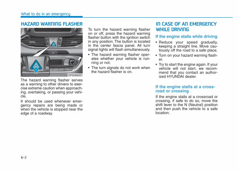
6-2
The hazard warning flasher servesas a warning to other drivers to exer-cise extreme caution when approach-ing, overtaking, or passing your vehi-cle.It should be used whenever emer-gency repairs are being made orwhen the vehicle is stopped near theedge of a roadway.
To turn the hazard warning flasheron or off, press the hazard warningflasher button with the ignition switchin any position. The button is locatedin the center fascia panel. All turnsignal lights will flash simultaneously.• The hazard warning flasher oper-
ates whether your vehicle is run-ning or not.
• The turn signals do not work whenthe hazard flasher is on.
If the engine stalls while driving• Reduce your speed gradually,
keeping a straight line. Move cau-tiously off the road to a safe place.
• Turn on your hazard warning flash-er.
• Try to start the engine again. If yourvehicle will not start, we recom-mend that you contact an author-ized HYUNDAI dealer.
If the engine stalls at a cross-road or crossing If the engine stalls at a crossroad orcrossing, if safe to do so, move theshift lever to the N (Neutral) positionand then push the vehicle to a safelocation.
HHAAZZAARRDD WWAARRNNIINNGG FFLLAASSHHEERR
What to do in an emergency
IINN CCAASSEE OOFF AANN EEMMEERRGGEENNCCYYWWHHIILLEE DDRRIIVVIINNGG
OPD066001
6-3
What to do in an em
ergency
If you have a flat tire whiledriving If a tire goes flat while you are driving:• Take your foot off the accelerator
pedal and let the vehicle slowdown while driving straight ahead.Do not apply the brakes immedi-ately or attempt to pull off the roadas this may cause loss of vehiclecontrol resulting in an accident.When the vehicle has slowed tosuch a speed that it is safe to doso, brake carefully and pull off theroad. Drive off the road as far aspossible and park on firm, levelground. If you are on a dividedhighway, do not park in the medianarea between the two traffic lanes.
• When the vehicle is stopped, pressthe hazard warning flasher button,move the shift lever into P (Park,for automatic transmission/dualclutch transmission vehicle) or neu-tral (for manual transmission vehi-cle), apply the parking brake, andplace the ignition switch in theLOCK/OFF position.
• Have all passengers get out of thevehicle. Be sure they all get out onthe side of the vehicle that is awayfrom traffic.
• When changing a flat tire, followthe instructions provided later inthis chapter.
If the engine doesn't turn overor turns over slowly • Be sure the shift lever is in N
(Neutral) or P (Park) if it is an auto-matic transmission/dual clutchtransmission vehicle. The enginestarts only when the shift lever is inN (Neutral) or P (Park).
• Check the battery connections tobe sure they are clean and tight.
• Turn on the interior light. If the lightdims or goes out when you operatethe starter, the battery is drained.
Do not push or pull the vehicle to startit. This could cause damage to yourvehicle. See instructions for "JumpStarting" provided in this chapter.
6
IIFF TTHHEE EENNGGIINNEE WWIILLLL NNOOTTSSTTAARRTT
Push or pull starting the vehiclemay cause the catalytic con-verter to overload which canlead to damage to the emissioncontrol system.
CAUTION
6-4
What to do in an emergency
If the engine turns over nor-mally but doesn’t start • Check the fuel level and add fuel if
necessary.If the engine still does not start, werecommend that you call an author-ized HYUNDAI dealer for assistance.
Jump starting can be dangerous ifdone incorrectly. Follow the jumpstarting procedure in this section toavoid serious injury or damage toyour vehicle. If in doubt about how toproperly jump start your vehicle, westrongly recommend that you have aservice technician or towing servicedo it for you.
JJUUMMPP SSTTAARRTTIINNGG
To prevent SERIOUS INJURY orDEATH to you or bystanders,always follow these precautionswhen working near or handlingthe battery:
Always read and followinstructions carefullywhen handling a battery.Wear eye protectiondesigned to protect theeyes from acid splashes.Keep all flames, sparks,or smoking materialsaway from the battery.
(Continued)
WARNING
(Continued)Hydrogen is alwayspresent in battery cells,is highly combustible,and may explode if ignit-ed.Keep batteries out ofreach of children.
Batteries contain sulfu-ric acid which is highlycorrosive. Do not allowacid to contact youreyes, skin or clothing.
If acid gets into your eyes, flushyour eyes with clean water for atleast 15 minutes and get imme-diate medical attention. If acidgets on your skin, thoroughlywash the area. If you feel pain ora burning sensation, get med-ical attention immediately.
(Continued)
6-5
What to do in an em
ergency
To prevent damage to your vehi-cle:• Only use a 12-volt power supply
(battery or jumper system) tojump start your vehicle.
• Do not attempt to jump startyour vehicle by push-starting.
InformationAn inappropriately disposedbattery can be harmful to theenvironment and humanhealth. Dispose the batteryaccording to your local law(s)or regulations.
Jump starting procedure 1. Position the vehicles close enough
that the jumper cables will reach,but do not allow the vehicles totouch.
2. Avoid fans or any moving parts inthe engine compartment at alltimes, even when the vehicles areturned off.
3. Turn off all electrical devices suchas radios, lights, air conditioning,etc. Put the vehicles in P (Park, forautomatic transmission/dualclutch transmission vehicle) orneutral (for manual transmissionvehicle), and set the parkingbrakes. Turn both vehicles OFF.
i
NOTICE
6
(Continued)• When lifting a plastic-cased
battery, excessive pressureon the case may cause batteryacid to leak. Lift with a batterycarrier or with your hands onopposite corners.
• Do not attempt to jump startyour vehicle if your battery isfrozen.
• NEVER attempt to rechargethe battery when the vehicle’sbattery cables are connectedto the battery.
• The electrical ignition systemworks with high voltage.NEVER touch these compo-nents with the engine runningor when the ignition switch isin the ON position.
• Do not allow the (+) and (-)jumper cables to touch. It maycause sparks.
• The battery may rupture orexplode when you jump startwith a low or frozen battery.
Pb
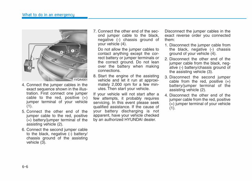
6-6
What to do in an emergency
4. Connect the jumper cables in theexact sequence shown in the illus-tration. First connect one jumpercable to the red, positive (+)jumper terminal of your vehicle(1).
5. Connect the other end of thejumper cable to the red, positive(+) battery/jumper terminal of theassisting vehicle (2).
6. Connect the second jumper cableto the black, negative (-) battery/chassis ground of the assistingvehicle (3).
7. Connect the other end of the sec-ond jumper cable to the black,negative (-) chassis ground ofyour vehicle (4).Do not allow the jumper cables tocontact anything except the cor-rect battery or jumper terminals orthe correct ground. Do not leanover the battery when makingconnections.
8. Start the engine of the assistingvehicle and let it run at approxi-mately 2,000 rpm for a few min-utes. Then start your vehicle.
If your vehicle will not start after afew attempts, it probably requiresservicing. In this event please seekqualified assistance. If the cause ofyour battery discharging is notapparent, have your vehicle checkedby an authorized HYUNDAI dealer.
Disconnect the jumper cables in theexact reverse order you connectedthem:1. Disconnect the jumper cable from
the black, negative (-) chassisground of your vehicle (4).
2. Disconnect the other end of thejumper cable from the black, neg-ative (-) battery/chassis ground ofthe assisting vehicle (3).
3. Disconnect the second jumpercable from the red, positive (+)battery/jumper terminal of theassisting vehicle (2).
4. Disconnect the other end of thejumper cable from the red, positive(+) jumper terminal of your vehicle(1).
1VQA4001
6-7
What to do in an em
ergency
6
If your temperature gauge indicatesoverheating, you experience a lossof power, or hear loud pinging orknocking, the engine may be over-heating. If this happens, you should:1. Pull off the road and stop as soon
as it is safe to do so.2. Place the shift lever in P (Park, for
automatic transmission/dual clutchtransmission vehicle) or neutral (formanual transmission/dual clutchtransmission vehicle) and set theparking brake. If the air condition-ing is ON, turn it OFF.
3. If engine coolant is running outunder the vehicle or steam is com-ing out from the hood, stop theengine. Do not open the hood untilthe coolant has stopped runningor the steaming has stopped. Ifthere is no visible loss of enginecoolant and no steam, leave theengine running and check to besure the engine cooling fan isoperating. If the fan is not running,turn the engine off.
4. Check for coolant leaking from theradiator, hoses or under the vehi-cle. (If the air conditioning had beenin use, it is normal for cold water tobe draining from it when you stop.)
5. If engine coolant is leaking out, stopthe engine immediately and we rec-ommend that you call an authorizedHYUNDAI dealer for assistance.
IIFF TTHHEE EENNGGIINNEE OOVVEERRHHEEAATTSS
While the engine isrunning, keep hands,clothing and toolsaway from the mov-ing parts such as thecooling fan and drivebelt to prevent seri-ous injury.
WARNING
NEVER remove theradiator cap or thedrain plug while theengine and radiatorare hot. Hot coolant
and steam may blow out underpressure, causing serious injury.Turn the engine off and waituntil the engine cools down.Use extreme care when remov-ing the radiator cap. Wrap athick towel around it, and turn itcounterclockwise slowly to thefirst stop. Step back while thepressure is released from thecooling system. When you aresure all the pressure has beenreleased, press down on thecap, using a thick towel, andcontinue turning counterclock-wise to remove it.
WARNING
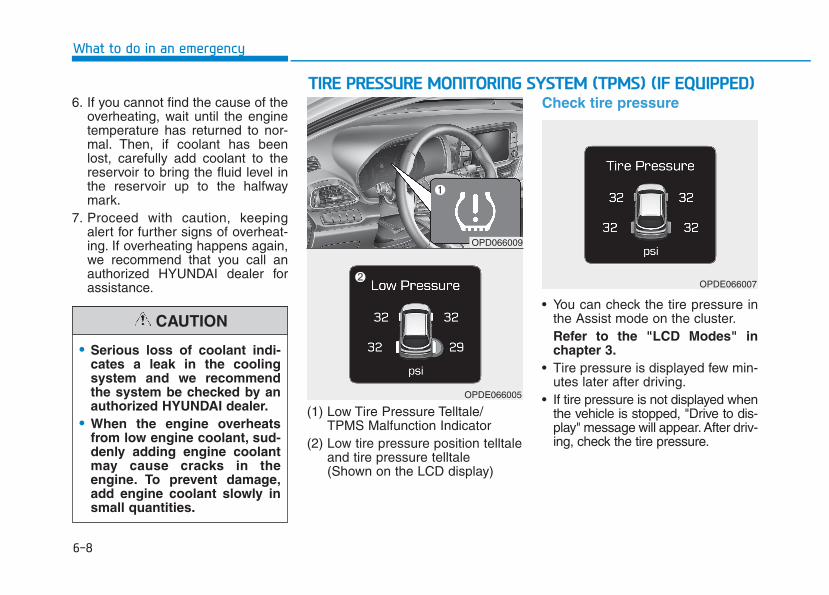
6-8
What to do in an emergency
6. If you cannot find the cause of theoverheating, wait until the enginetemperature has returned to nor-mal. Then, if coolant has beenlost, carefully add coolant to thereservoir to bring the fluid level inthe reservoir up to the halfwaymark.
7. Proceed with caution, keepingalert for further signs of overheat-ing. If overheating happens again,we recommend that you call anauthorized HYUNDAI dealer forassistance.
(1) Low Tire Pressure Telltale/TPMS Malfunction Indicator
(2) Low tire pressure position telltaleand tire pressure telltale (Shown on the LCD display)
Check tire pressure
• You can check the tire pressure inthe Assist mode on the cluster.Refer to the "LCD Modes" inchapter 3.
• Tire pressure is displayed few min-utes later after driving.
• If tire pressure is not displayed whenthe vehicle is stopped, "Drive to dis-play" message will appear. After driv-ing, check the tire pressure.
• Serious loss of coolant indi-cates a leak in the coolingsystem and we recommendthe system be checked by anauthorized HYUNDAI dealer.
• When the engine overheatsfrom low engine coolant, sud-denly adding engine coolantmay cause cracks in theengine. To prevent damage,add engine coolant slowly insmall quantities.
CAUTION
TTIIRREE PPRREESSSSUURREE MMOONNIITTOORRIINNGG SSYYSSTTEEMM ((TTPPMMSS)) ((IIFF EEQQUUIIPPPPEEDD))
OPD066009
OPDE066005
OPDE066007
6-9
What to do in an em
ergency
6
• The displayed tire pressure valuesmay differ from those measuredwith a tire pressure gauge.
• You can change the tire pressureunit in the User Settings mode onthe instrument cluster.- psi, kpa, bar (Refer to "LCD
Modes" in chapter 3).
Tire pressure monitoring sys-tem
Each tire, including the spare (if pro-vided), should be checked monthlywhen cold and inflated to the inflationpressure recommended by the vehi-cle manufacturer on the vehicle plac-ard or tire inflation pressure label. (Ifyour vehicle has tires of a differentsize than the size indicated on thevehicle placard or tire inflation pres-sure label, you should determine theproper tire inflation pressure forthose tires.)
As an added safety feature, yourvehicle has been equipped with a tirepressure monitoring system (TPMS)that illuminates a low tire pressuretelltale when one or more of yourtires is significantly under-inflated.Accordingly, when the low tire pres-sure telltale illuminates, you shouldstop and check your tires as soon aspossible, and inflate them to theproper pressure. Driving on a signifi-cantly under-inflated tire causes thetire to overheat and can lead to tirefailure. Under-inflation also reducesfuel efficiency and tire tread life, andmay affect the vehicle’s handling andstopping ability.Please note that the TPMS is not asubstitute for proper tire mainte-nance, and it is the driver’s responsi-bility to maintain correct tire pres-sure, even if under-inflation has notreached the level to trigger illumina-tion of the TPMS low tire pressuretelltale.
Over-inflation or under-inflationcan reduce tire life, adverselyaffect vehicle handling, andlead to sudden tire failure thatmay cause loss of vehicle con-trol resulting in an accident.
WARNING
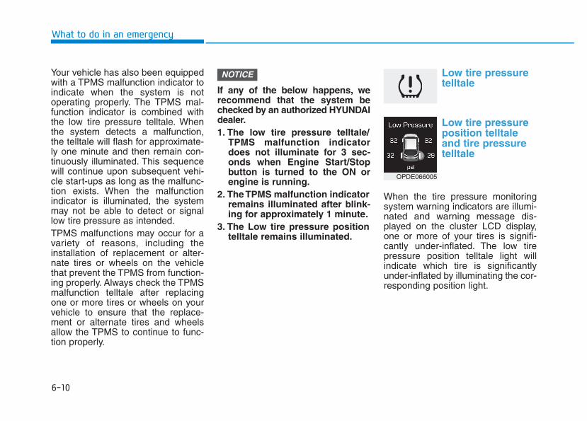
6-10
What to do in an emergency
Your vehicle has also been equippedwith a TPMS malfunction indicator toindicate when the system is notoperating properly. The TPMS mal-function indicator is combined withthe low tire pressure telltale. Whenthe system detects a malfunction,the telltale will flash for approximate-ly one minute and then remain con-tinuously illuminated. This sequencewill continue upon subsequent vehi-cle start-ups as long as the malfunc-tion exists. When the malfunctionindicator is illuminated, the systemmay not be able to detect or signallow tire pressure as intended.TPMS malfunctions may occur for avariety of reasons, including theinstallation of replacement or alter-nate tires or wheels on the vehiclethat prevent the TPMS from function-ing properly. Always check the TPMSmalfunction telltale after replacingone or more tires or wheels on yourvehicle to ensure that the replace-ment or alternate tires and wheelsallow the TPMS to continue to func-tion properly.
If any of the below happens, werecommend that the system bechecked by an authorized HYUNDAIdealer.1. The low tire pressure telltale/
TPMS malfunction indicatordoes not illuminate for 3 sec-onds when Engine Start/Stopbutton is turned to the ON orengine is running.
2. The TPMS malfunction indicatorremains illuminated after blink-ing for approximately 1 minute.
3. The Low tire pressure positiontelltale remains illuminated.
Low tire pressuretelltale
Low tire pressureposition telltaleand tire pressuretelltale
When the tire pressure monitoringsystem warning indicators are illumi-nated and warning message dis-played on the cluster LCD display,one or more of your tires is signifi-cantly under-inflated. The low tirepressure position telltale light willindicate which tire is significantlyunder-inflated by illuminating the cor-responding position light.
NOTICE
OPDE066005
6-11
What to do in an em
ergency
6
If either telltale illuminates, immedi-ately reduce your speed, avoid hardcornering and anticipate increasedstopping distances. You should stopand check your tires as soon as pos-sible. Inflate the tires to the properpressure as indicated on the vehi-cle’s placard or tire inflation pressurelabel located on the driver’s side cen-ter pillar outer panel. If you cannotreach a service station or if the tirecannot hold the newly added air,replace the low pressure tire with aspare tire.If you drive the vehicle for about 10minutes at speeds above 25 km/hafter replacing the low pressure tirewith the spare tire, the below willhappen:• The TPMS malfunction indicator
may blink for approximately 1 minuteand then remain continuously illumi-nated because the TPMS sensor isnot mounted on the spare wheel.
The spare tire is not equipped witha tire pressure sensor.
NOTICE
In winter or cold weather, the lowtire pressure telltale may illumi-nate if the tire pressure wasadjusted to the recommendedtire inflation pressure in warmweather. It does not mean yourTPMS is malfunctioning becausethe decreased temperature leadsto a lowering of tire pressure.When you drive your vehiclefrom a warm area to a cold areaor from a cold area to a warmarea, or the outside temperatureis higher or lower, you shouldcheck the tire inflation pressureand adjust the tires to the recom-mended tire inflation pressure.
CAUTION
Low pressure damage
Significantly low tire pressuremakes the vehicle unstable andcan contribute to loss of vehiclecontrol and increased brakingdistances.Continued driving on low pres-sure tires can cause the tires tooverheat and fail.
WARNING
6-12
What to do in an emergency
TPMS (Tire PressureMonitoring System)malfunction indicator
The TPMS malfunction indicator willilluminate after it blinks for approxi-mately one minute when there is aproblem with the Tire PressureMonitoring System.We recommend that the system bechecked by an authorized HYUNDAIdealer.
If there is a malfunction with theTPMS, the low tire pressure posi-tion telltale will not be displayedeven though the vehicle has anunder-inflated tire.
Changing a tire with TPMSIf you have a flat tire, the low TirePressure and Position telltales willcome on. We recommend that thesystem be checked by an authorizedHYUNDAI dealer.
Each wheel is equipped with a tirepressure sensor mounted inside thetire behind the valve stem. You mustuse TPMS specific wheels. It is rec-ommended that you have your tiresserviced by an authorized HYUNDAIdealer.
NOTICE
• The TPMS malfunction indicatormay blink for approximately 1minute and then remain contin-uously illuminated if the vehicleis moving around electric powersupply cables or radios trans-mitter such as at police stations,government and public offices,broadcasting stations, militaryinstallations, airports, or trans-mitting towers, etc. This caninterfere with normal operationof the Tire Pressure MonitoringSystem (TPMS).
• The TPMS malfunction indica-tor may blink for approximate-ly 1 minute and then remaincontinuously illuminated ifsnow chains are used or someseparate electronic devicessuch as notebook computer,mobile charger, remote starteror navigation etc., are used inthe vehicle.This can interfere with normaloperation of the Tire PressureMonitoring System (TPMS).
CAUTION
NEVER use a puncture-repair-ing agent to repair and/or inflatea low pressure tire. The tiresealant can damage the tirepressure sensor. If used, youwill have to replace the tirepressure sensor.
CAUTION
6-13
What to do in an em
ergency
6
If you drive the vehicle for about 10minutes at speeds above 25 km/hafter replacing the low pressure tirewith the spare tire, the below willhappen:• The TPMS malfunction indicator
may blink for approximately 1 minuteand then remain continuously illumi-nated because the TPMS sensor isnot mounted on the spare wheel.
You may not be able identify a lowtire by simply looking at it. Alwaysuse a good quality tire pressuregauge to measure the tire's inflationpressure. Please note that a tire thatis hot (from being driven) will have ahigher pressure measurement than atire that is cold (from sitting station-ary for at least 3 hour and driven lessthan 1.6 km (1 mile) during that 3hour period).Allow the tire to cool before measur-ing the inflation pressure. Always besure the tire is cold before inflating tothe recommended pressure.A cold tire means the vehicle hasbeen sitting for 3 hours and driven forless than 1.6 km (1 mile) in that 3hour period.
• The TPMS cannot alert you tosevere and sudden tire dam-age caused by external factorssuch as nails or road debris.
• If you feel any vehicle instabil-ity, immediately take your footoff the accelerator, apply thebrakes gradually and withlight force, and slowly move toa safe position off the road.
WARNING
6-14
What to do in an emergency
Tampering with, modifying, ordisabling the Tire PressureMonitoring System (TPMS) com-ponents may interfere with thesystem's ability to warn the driv-er of low tire pressure condi-tions and/or TPMS malfunctions.Tampering with, modifying, ordisabling the Tire PressureMonitoring System (TPMS) com-ponents may void the warrantyfor that portion of the vehicle.
WARNING
For EUROPE
• Do not modify the vehicle; itmay interfere with the TPMSfunction.
• The wheels on the market donot have a TPMS sensor.For your safety, we recom-mend that you use parts forreplacement from an author-ized HYUNDAI dealer.
• If you use the wheels on themarket, use a TPMS sensorapproved by a HYUNDAI deal-er. If your vehicle is notequipped with a TPMS sensoror TPMS does not work prop-erly, you may fail the periodicvehicle inspection conductedin your country.
(Continued)
(Continued)❈❈All vehicles sold in the
EUROPE market during belowperiod must be equipped withTPMS.- New model vehicle :
Nov. 1, 2012 ~- Current model vehicle :
Nov. 1, 2014~ (Based onvehicle registrations)
WARNING
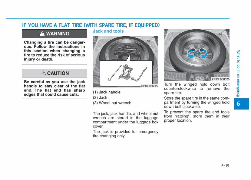
6-15
What to do in an em
ergency
6
Jack and tools
(1) Jack handle(2) Jack(3) Wheel nut wrench
The jack, jack handle, and wheel nutwrench are stored in the luggagecompartment under the luggage boxcover.The jack is provided for emergencytire changing only.
Turn the winged hold down boltcounterclockwise to remove thespare tire.Store the spare tire in the same com-partment by turning the winged holddown bolt clockwise.To prevent the spare tire and toolsfrom "rattling", store them in theirproper location.
IIFF YYOOUU HHAAVVEE AA FFLLAATT TTIIRREE ((WWIITTHH SSPPAARREE TTIIRREE,, IIFF EEQQUUIIPPPPEEDD))
OPDE066027
OPDE066028
Changing a tire can be danger-ous. Follow the instructions inthis section when changing atire to reduce the risk of seriousinjury or death.
WARNING
Be careful as you use the jackhandle to stay clear of the flatend. The flat end has sharpedges that could cause cuts.
CAUTION
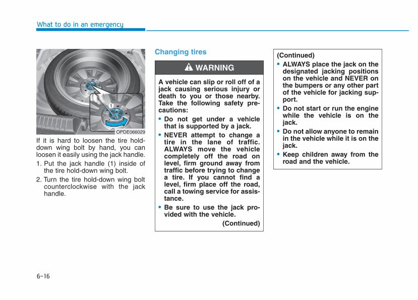
6-16
What to do in an emergency
If it is hard to loosen the tire hold-down wing bolt by hand, you canloosen it easily using the jack handle.1. Put the jack handle (1) inside of
the tire hold-down wing bolt.2. Turn the tire hold-down wing bolt
counterclockwise with the jackhandle.
Changing tires
A vehicle can slip or roll off of ajack causing serious injury ordeath to you or those nearby.Take the following safety pre-cautions:• Do not get under a vehicle
that is supported by a jack.• NEVER attempt to change a
tire in the lane of traffic.ALWAYS move the vehiclecompletely off the road onlevel, firm ground away fromtraffic before trying to changea tire. If you cannot find alevel, firm place off the road,call a towing service for assis-tance.
• Be sure to use the jack pro-vided with the vehicle.
(Continued)
WARNING
(Continued)• ALWAYS place the jack on the
designated jacking positionson the vehicle and NEVER onthe bumpers or any other partof the vehicle for jacking sup-port.
• Do not start or run the enginewhile the vehicle is on thejack.
• Do not allow anyone to remainin the vehicle while it is on thejack.
• Keep children away from theroad and the vehicle.
OPDE066029
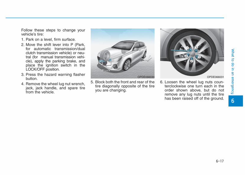
6-17
What to do in an em
ergency
6
Follow these steps to change yourvehicle’s tire:1. Park on a level, firm surface.2. Move the shift lever into P (Park,
for automatic transmission/dualclutch transmission vehicle) or neu-tral (for manual transmission vehi-cle), apply the parking brake, andplace the ignition switch in theLOCK/OFF position.
3. Press the hazard warning flasherbutton.
4. Remove the wheel lug nut wrench,jack, jack handle, and spare tirefrom the vehicle.
5. Block both the front and rear of thetire diagonally opposite of the tireyou are changing.
6. Loosen the wheel lug nuts coun-terclockwise one turn each in theorder shown above, but do notremove any lug nuts until the tirehas been raised off of the ground.
OPDE066030
BBBBlllloooocccckkkk
OPDE066031
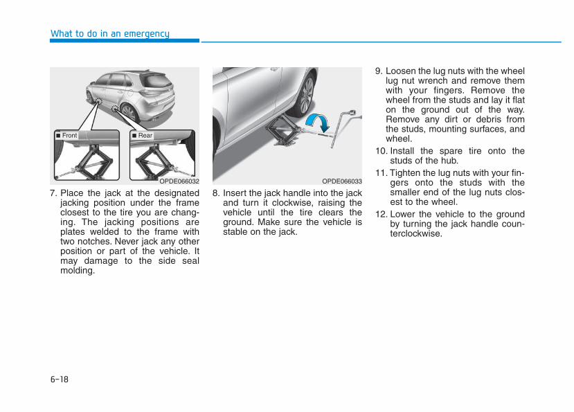
6-18
What to do in an emergency
7. Place the jack at the designatedjacking position under the frameclosest to the tire you are chang-ing. The jacking positions areplates welded to the frame withtwo notches. Never jack any otherposition or part of the vehicle. Itmay damage to the side sealmolding.
8. Insert the jack handle into the jackand turn it clockwise, raising thevehicle until the tire clears theground. Make sure the vehicle isstable on the jack.
9. Loosen the lug nuts with the wheellug nut wrench and remove themwith your fingers. Remove thewheel from the studs and lay it flaton the ground out of the way.Remove any dirt or debris fromthe studs, mounting surfaces, andwheel.
10. Install the spare tire onto thestuds of the hub.
11. Tighten the lug nuts with your fin-gers onto the studs with thesmaller end of the lug nuts clos-est to the wheel.
12. Lower the vehicle to the groundby turning the jack handle coun-terclockwise.
OPDE066033OPDE066032
■ Front ■ Rear
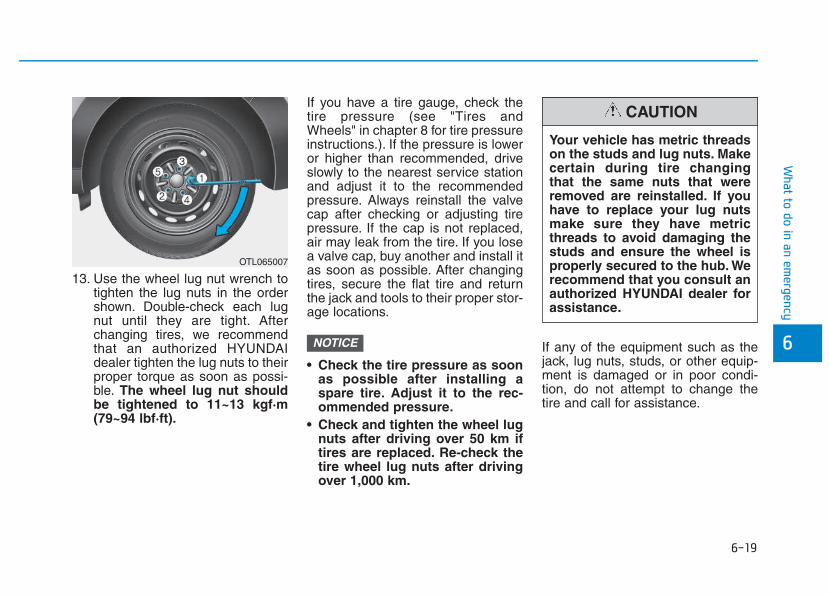
6-19
What to do in an em
ergency
6
13. Use the wheel lug nut wrench totighten the lug nuts in the ordershown. Double-check each lugnut until they are tight. Afterchanging tires, we recommendthat an authorized HYUNDAIdealer tighten the lug nuts to theirproper torque as soon as possi-ble. The wheel lug nut shouldbe tightened to 11~13 kgf·m(79~94 lbf·ft).
If you have a tire gauge, check thetire pressure (see "Tires andWheels" in chapter 8 for tire pressureinstructions.). If the pressure is loweror higher than recommended, driveslowly to the nearest service stationand adjust it to the recommendedpressure. Always reinstall the valvecap after checking or adjusting tirepressure. If the cap is not replaced,air may leak from the tire. If you losea valve cap, buy another and install itas soon as possible. After changingtires, secure the flat tire and returnthe jack and tools to their proper stor-age locations.
• Check the tire pressure as soonas possible after installing aspare tire. Adjust it to the rec-ommended pressure.
• Check and tighten the wheel lugnuts after driving over 50 km iftires are replaced. Re-check thetire wheel lug nuts after drivingover 1,000 km.
If any of the equipment such as thejack, lug nuts, studs, or other equip-ment is damaged or in poor condi-tion, do not attempt to change thetire and call for assistance.
NOTICE
OTL065007
Your vehicle has metric threadson the studs and lug nuts. Makecertain during tire changingthat the same nuts that wereremoved are reinstalled. If youhave to replace your lug nutsmake sure they have metricthreads to avoid damaging thestuds and ensure the wheel isproperly secured to the hub. Werecommend that you consult anauthorized HYUNDAI dealer forassistance.
CAUTION
6-20
What to do in an emergency
Use of compact spare tires (if equipped) Compact spare tires are designed foremergency use only. Drive carefullyon the compact spare tire andalways follow the safety precautions.
When driving with the compact sparetire mounted to your vehicle:• Check the tire pressure after
installing the compact spare tire.The compact spare tire should beinflated to 420 kPa (60 psi).
• Do not take this vehicle through anautomatic car wash while the com-pact spare tire is installed.
• Do not use the compact spare tireon any other vehicle because thistire has been designed especiallyfor your vehicle.
• The compact spare tire’s tread life isshorter than a regular tire. Inspectyour compact spare tire regularlyand replace worn compact sparetires with the same size and design,mounted on the same wheel.
• Do not use more than one compactspare tire at a time.
• Do not tow a trailer while the com-pact spare tire is installed.
When the original tire and wheelare repaired and reinstalled on thevehicle, the lug nut torque must beset correctly. The correct lug nuttightening torque is 11~13 kgf·m(79~94 lbf·ft).
NOTICE
To prevent compact spare tirefailure and loss of control pos-sibly resulting in an accident:• Use the compact spare tire
only in an emergency.• NEVER operate your vehicle
over 80 km/h (50 mph).• Do not exceed the vehicle’s
maximum load rating or theload carrying capacity shownon the sidewall of the com-pact spare tire.
• Do not use the compact sparetire continuously. Repair orreplace the original tire assoon as possible to avoid fail-ure of the compact spare tire.
WARNING
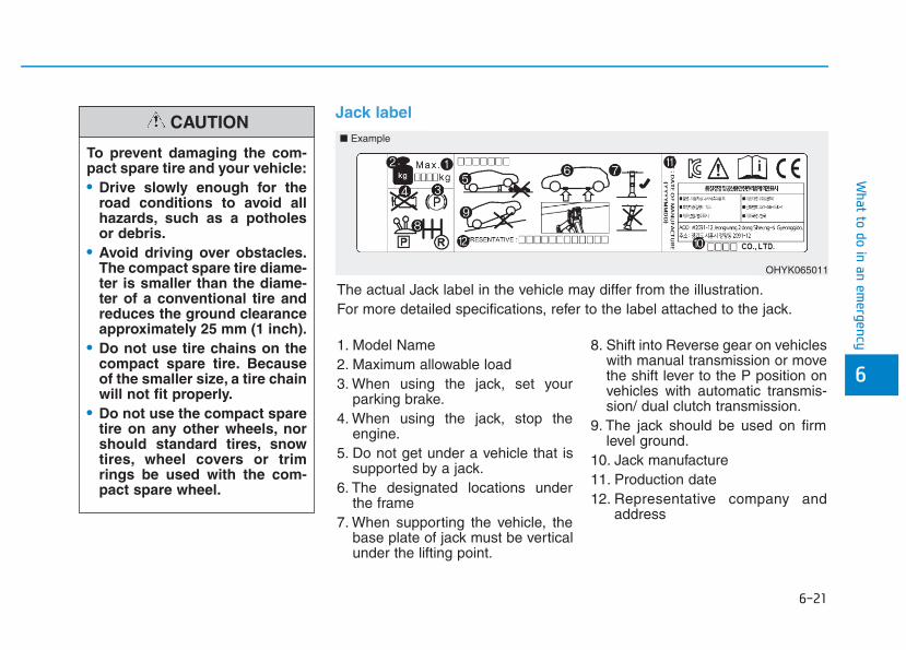
6-21
What to do in an em
ergency
6
Jack label
To prevent damaging the com-pact spare tire and your vehicle:• Drive slowly enough for the
road conditions to avoid allhazards, such as a potholesor debris.
• Avoid driving over obstacles.The compact spare tire diame-ter is smaller than the diame-ter of a conventional tire andreduces the ground clearanceapproximately 25 mm (1 inch).
• Do not use tire chains on thecompact spare tire. Becauseof the smaller size, a tire chainwill not fit properly.
• Do not use the compact sparetire on any other wheels, norshould standard tires, snowtires, wheel covers or trimrings be used with the com-pact spare wheel.
CAUTION■ Example
OHYK065011
1. Model Name2. Maximum allowable load3. When using the jack, set your
parking brake.4. When using the jack, stop the
engine.5. Do not get under a vehicle that is
supported by a jack.6. The designated locations under
the frame7. When supporting the vehicle, the
base plate of jack must be verticalunder the lifting point.
8. Shift into Reverse gear on vehicleswith manual transmission or movethe shift lever to the P position onvehicles with automatic transmis-sion/ dual clutch transmission.
9. The jack should be used on firmlevel ground.
10. Jack manufacture11. Production date12. Representative company and
address
The actual Jack label in the vehicle may differ from the illustration.For more detailed specifications, refer to the label attached to the jack.
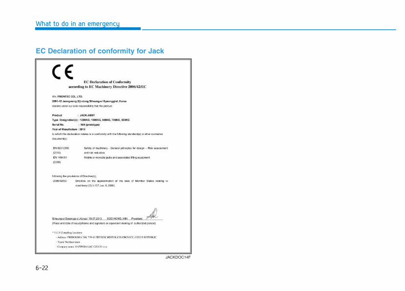
6-22
What to do in an emergency
JACKDOC14F
EC Declaration of conformity for Jack
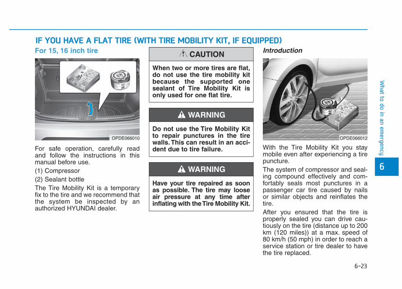
6-23
What to do in an em
ergency
6
For 15, 16 inch tire
For safe operation, carefully readand follow the instructions in thismanual before use.(1) Compressor(2) Sealant bottleThe Tire Mobility Kit is a temporaryfix to the tire and we recommend thatthe system be inspected by anauthorized HYUNDAI dealer.
Introduction
With the Tire Mobility Kit you staymobile even after experiencing a tirepuncture.The system of compressor and seal-ing compound effectively and com-fortably seals most punctures in apassenger car tire caused by nailsor similar objects and reinflates thetire.After you ensured that the tire isproperly sealed you can drive cau-tiously on the tire (distance up to 200km (120 miles)) at a max. speed of80 km/h (50 mph) in order to reach aservice station or tire dealer to havethe tire replaced.
IIFF YYOOUU HHAAVVEE AA FFLLAATT TTIIRREE ((WWIITTHH TTIIRREE MMOOBBIILLIITTYY KKIITT,, IIFF EEQQUUIIPPPPEEDD))
OPDE066010 OPDE066012
Do not use the Tire Mobility Kitto repair punctures in the tirewalls. This can result in an acci-dent due to tire failure.
WARNING
Have your tire repaired as soonas possible. The tire may looseair pressure at any time afterinflating with the Tire Mobility Kit.
WARNING
When two or more tires are flat,do not use the tire mobility kitbecause the supported onesealant of Tire Mobility Kit isonly used for one flat tire.
CAUTION
6-24
What to do in an emergency
It is possible that some tires, espe-cially with larger punctures or dam-age to the sidewall, cannot be sealedcompletely.Air pressure loss in the tire mayadversely affect tire performance.For this reason, you should avoidabrupt steering or other drivingmaneuvers, especially if the vehicleis heavily loaded or if a trailer is inuse.The Tire Mobility Kit is not designedor intended as a permanent tirerepair method and is to be used forone tire only. This instruction showsyou step by step how to temporarilyseal the puncture simply and reliably.Read the section "Notes on the safeuse of the Tire Mobility Kit".
Notes on the safe use of theTire Mobility Kit• Park your car at the side of the
road so that you can work with theTire Mobility Kit away from movingtraffic.
• To be sure your vehicle will notmove, even when you're on fairlylevel ground, always set your park-ing brake.
• Only use the Tire Mobility Kit forsealing/inflation passenger cartires. Only punctured areas locatedwithin the tread region of the tirecan be sealed using the tire mobil-ity kit.
• Do not use on motorcycles, bicy-cles or any other type of tires.
• When the tire and wheel are dam-aged, do not use Tire Mobility Kitfor your safety.
• Use of the Tire Mobility Kit may notbe effective for tire damage largerthan approximately 6 mm (0.24 in).If the tire cannot be made roadwor-thy with the Tire Mobility Kit, werecommend that you contact anauthorized HYUNDAI dealer.
• Do not use the Tire Mobility Kit if atire is severely damaged by drivingrun flat or with insufficient air pres-sure.
• Do not remove any foreign objectssuch as nails or screws that havepenetrated the tire.
• Provided the car is outdoors, leavethe engine running. Otherwiseoperating the compressor mayeventually drain the car battery.
• Never leave the Tire Mobility Kitunattended while it is being used.
• Do not leave the compressor run-ning for more than 10 min. at a timeor it may overheat.
• Do not use the Tire Mobility Kit ifthe ambient temperature is below -30°C (-22°F).
Do not use the TMK if a tire isseverely damaged by driving runflat or with insufficient air pres-sure.Only punctured areas locatedwithin the tread region of the tirecan be sealed using the TMK.
WARNING
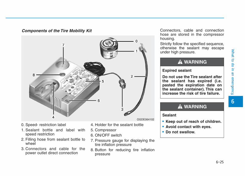
6-25
What to do in an em
ergency
6
0. Speed- restriction label1. Sealant bottle and label with
speed restriction2. Filling hose from sealant bottle to
wheel3. Connectors and cable for the
power outlet direct connection
4. Holder for the sealant bottle5. Compressor6. ON/OFF switch7. Pressure gauge for displaying the
tire inflation pressure8. Button for reducing tire inflation
pressure
Connectors, cable and connectionhose are stored in the compressorhousing.Strictly follow the specified sequence,otherwise the sealant may escapeunder high pressure.
Components of the Tire Mobility Kit
OGDE064102
Expired sealant
Do not use the Tire sealant afterthe sealant has expired (i.e.pasted the expiration date onthe sealant container). This canincrease the risk of tire failure.
WARNING
Sealant
• Keep out of reach of children.• Avoid contact with eyes.• Do not swallow.
WARNING
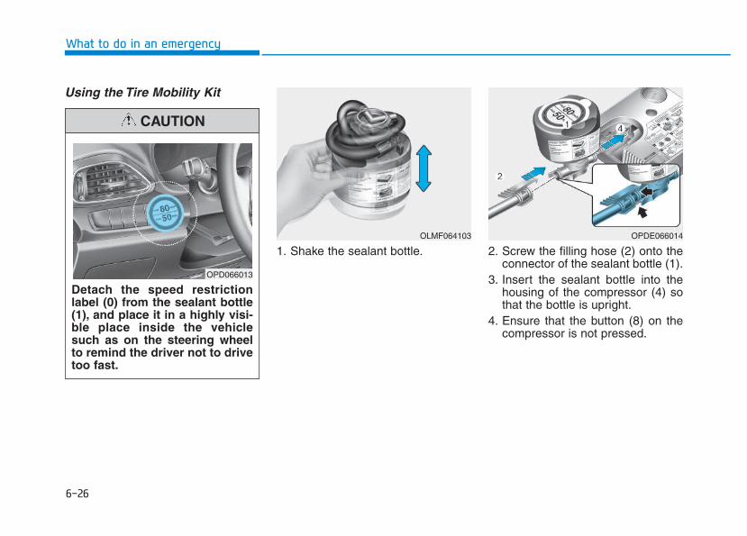
6-26
What to do in an emergency
Using the Tire Mobility Kit
1. Shake the sealant bottle. 2. Screw the filling hose (2) onto theconnector of the sealant bottle (1).
3. Insert the sealant bottle into thehousing of the compressor (4) sothat the bottle is upright.
4. Ensure that the button (8) on thecompressor is not pressed.
Detach the speed restrictionlabel (0) from the sealant bottle(1), and place it in a highly visi-ble place inside the vehiclesuch as on the steering wheelto remind the driver not to drivetoo fast.
CAUTION
OLMF064103 OPDE066014
OPD066013
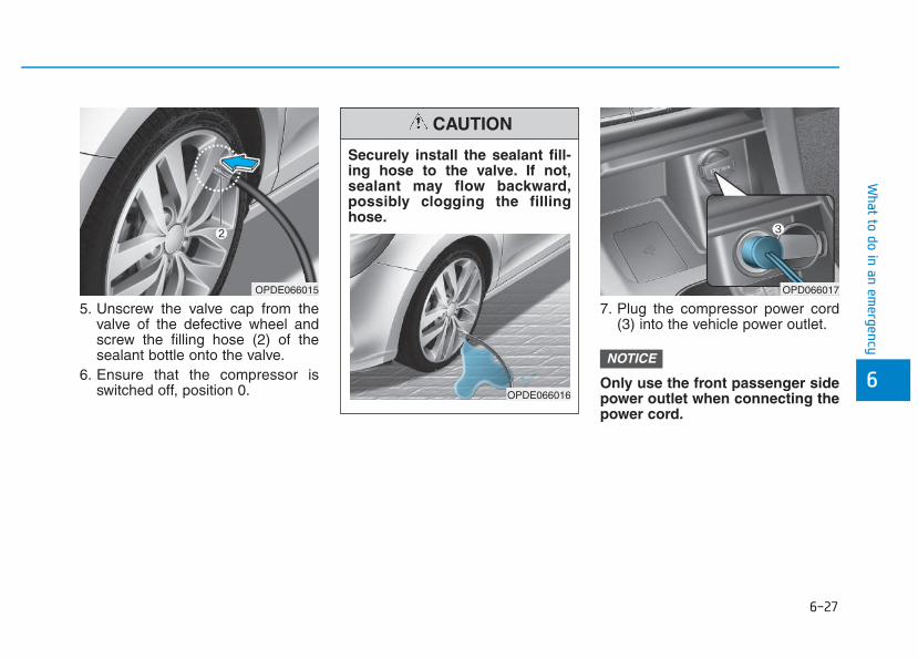
6-27
What to do in an em
ergency
6
5. Unscrew the valve cap from thevalve of the defective wheel andscrew the filling hose (2) of thesealant bottle onto the valve.
6. Ensure that the compressor isswitched off, position 0.
7. Plug the compressor power cord(3) into the vehicle power outlet.
Only use the front passenger sidepower outlet when connecting thepower cord.
NOTICE
OPD066017OPDE066015
Securely install the sealant fill-ing hose to the valve. If not,sealant may flow backward,possibly clogging the fillinghose.
CAUTION
OPDE066016
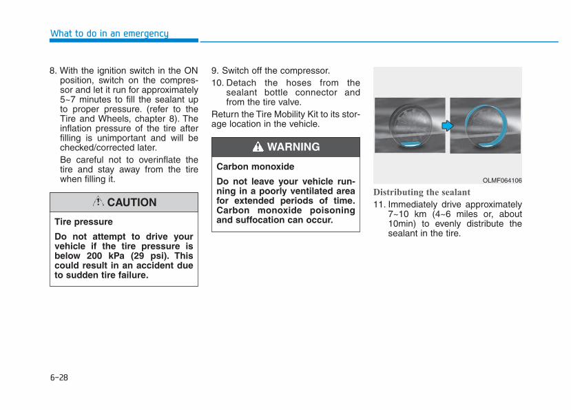
6-28
What to do in an emergency
8. With the ignition switch in the ONposition, switch on the compres-sor and let it run for approximately5~7 minutes to fill the sealant upto proper pressure. (refer to theTire and Wheels, chapter 8). Theinflation pressure of the tire afterfilling is unimportant and will bechecked/corrected later.Be careful not to overinflate thetire and stay away from the tirewhen filling it.
9. Switch off the compressor.10. Detach the hoses from the
sealant bottle connector andfrom the tire valve.
Return the Tire Mobility Kit to its stor-age location in the vehicle.
Distributing the sealant
11. Immediately drive approximately7~10 km (4~6 miles or, about10min) to evenly distribute thesealant in the tire.
Tire pressure
Do not attempt to drive yourvehicle if the tire pressure isbelow 200 kPa (29 psi). Thiscould result in an accident dueto sudden tire failure.
CAUTION
Carbon monoxide
Do not leave your vehicle run-ning in a poorly ventilated areafor extended periods of time.Carbon monoxide poisoningand suffocation can occur.
WARNING
OLMF064106
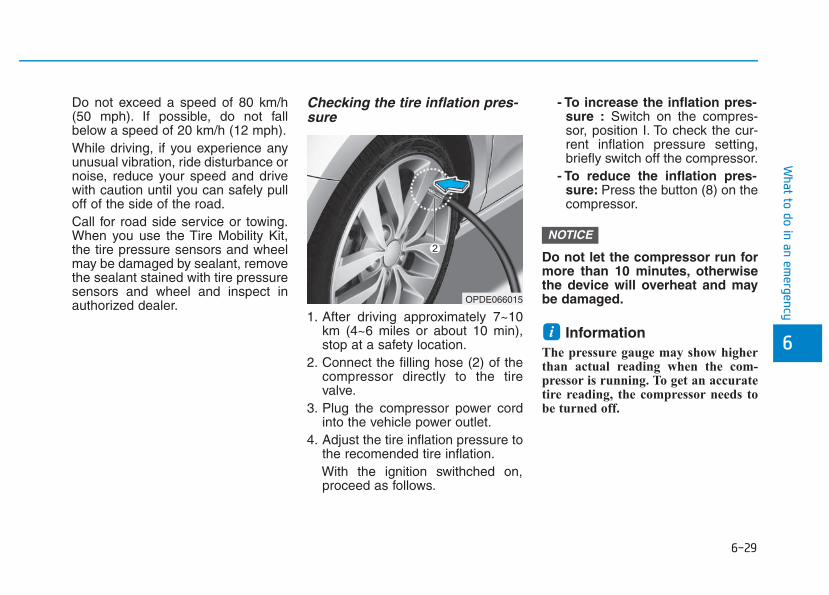
6-29
What to do in an em
ergency
6
Do not exceed a speed of 80 km/h(50 mph). If possible, do not fallbelow a speed of 20 km/h (12 mph).While driving, if you experience anyunusual vibration, ride disturbance ornoise, reduce your speed and drivewith caution until you can safely pulloff of the side of the road.Call for road side service or towing.When you use the Tire Mobility Kit,the tire pressure sensors and wheelmay be damaged by sealant, removethe sealant stained with tire pressuresensors and wheel and inspect inauthorized dealer.
Checking the tire inflation pres-sure
1. After driving approximately 7~10km (4~6 miles or about 10 min),stop at a safety location.
2. Connect the filling hose (2) of thecompressor directly to the tirevalve.
3. Plug the compressor power cordinto the vehicle power outlet.
4. Adjust the tire inflation pressure tothe recomended tire inflation.With the ignition swithched on,proceed as follows.
- To increase the inflation pres-sure : Switch on the compres-sor, position I. To check the cur-rent inflation pressure setting,briefly switch off the compressor.
- To reduce the inflation pres-sure: Press the button (8) on thecompressor.
Do not let the compressor run formore than 10 minutes, otherwisethe device will overheat and maybe damaged.
InformationThe pressure gauge may show higherthan actual reading when the com-pressor is running. To get an accuratetire reading, the compressor needs tobe turned off.
i
NOTICE
OPDE066015
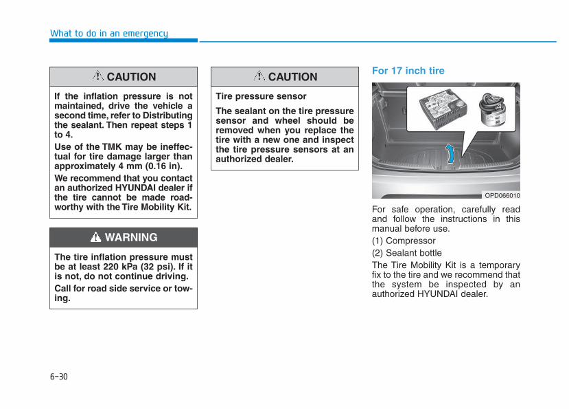
6-30
What to do in an emergency
For 17 inch tire
For safe operation, carefully readand follow the instructions in thismanual before use.(1) Compressor(2) Sealant bottleThe Tire Mobility Kit is a temporaryfix to the tire and we recommend thatthe system be inspected by anauthorized HYUNDAI dealer.
The tire inflation pressure mustbe at least 220 kPa (32 psi). If itis not, do not continue driving.Call for road side service or tow-ing.
WARNING
If the inflation pressure is notmaintained, drive the vehicle asecond time, refer to Distributingthe sealant. Then repeat steps 1to 4.Use of the TMK may be ineffec-tual for tire damage larger thanapproximately 4 mm (0.16 in).We recommend that you contactan authorized HYUNDAI dealer ifthe tire cannot be made road-worthy with the Tire Mobility Kit.
CAUTION
Tire pressure sensor
The sealant on the tire pressuresensor and wheel should beremoved when you replace thetire with a new one and inspectthe tire pressure sensors at anauthorized dealer.
CAUTION
OPD066010
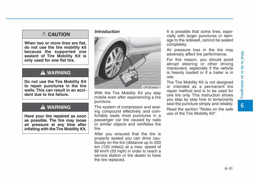
6-31
What to do in an em
ergency
Introduction
With the Tire Mobility Kit you staymobile even after experiencing a tirepuncture.The system of compressor and seal-ing compound effectively and com-fortably seals most punctures in apassenger car tire caused by nailsor similar objects and reinflates thetire.After you ensured that the tire isproperly sealed you can drive cau-tiously on the tire (distance up to 200km (120 miles)) at a max. speed of80 km/h (50 mph) in order to reach aservice station or tire dealer to havethe tire replaced.
It is possible that some tires, espe-cially with larger punctures or dam-age to the sidewall, cannot be sealedcompletely.Air pressure loss in the tire mayadversely affect tire performance.For this reason, you should avoidabrupt steering or other drivingmaneuvers, especially if the vehicleis heavily loaded or if a trailer is inuse.The Tire Mobility Kit is not designedor intended as a permanent tirerepair method and is to be used forone tire only. This instruction showsyou step by step how to temporarilyseal the puncture simply and reliably.Read the section "Notes on the safeuse of the Tire Mobility Kit".
6
OPDE066011
Do not use the Tire Mobility Kitto repair punctures in the tirewalls. This can result in an acci-dent due to tire failure.
WARNING
Have your tire repaired as soonas possible. The tire may looseair pressure at any time afterinflating with the Tire Mobility Kit.
WARNING
When two or more tires are flat,do not use the tire mobility kitbecause the supported onesealant of Tire Mobility Kit isonly used for one flat tire.
CAUTION
6-32
Notes on the safe use of theTire Mobility Kit• Park your car at the side of the
road so that you can work with theTire Mobility Kit away from movingtraffic.
• To be sure your vehicle will notmove, even when you're on fairlylevel ground, always set your park-ing brake.
• Only use the Tire Mobility Kit forsealing/inflation passenger cartires. Only punctured areas locatedwithin the tread region of the tirecan be sealed using the tire mobil-ity kit.
• Do not use on motorcycles, bicy-cles or any other type of tires.
• When the tire and wheel are dam-aged, do not use Tire Mobility Kitfor your safety.
• Use of the Tire Mobility Kit may notbe effective for tire damage largerthan approximately 6 mm (0.24 in).If the tire cannot be made roadwor-thy with the Tire Mobility Kit, werecommend that you contact anauthorized HYUNDAI dealer.
• Do not use the Tire Mobility Kit if atire is severely damaged by drivingrun flat or with insufficient air pres-sure.
• Do not remove any foreign objectssuch as nails or screws that havepenetrated the tire.
• Provided the car is outdoors, leavethe engine running. Otherwiseoperating the compressor mayeventually drain the car battery.
• Never leave the Tire Mobility Kitunattended while it is being used.
• Do not leave the compressor run-ning for more than 10 min. at a timeor it may overheat.
• Do not use the Tire Mobility Kit ifthe ambient temperature is below -30°C (-22°F).
What to do in an emergency
Do not use the TMK if a tire isseverely damaged by drivingrun flat or with insufficient airpressure.Only punctured areas locatedwithin the tread region of thetire can be sealed using theTMK.
WARNING
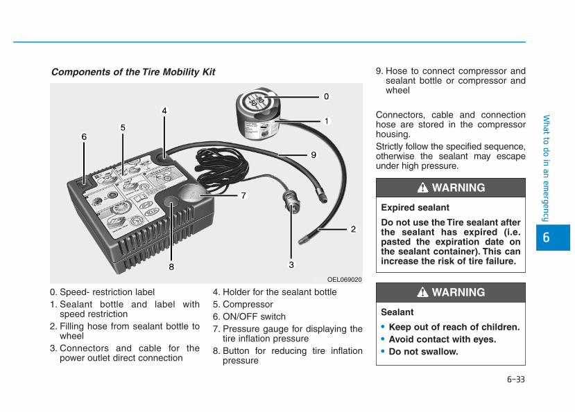
6-33
What to do in an em
ergency
0. Speed- restriction label1. Sealant bottle and label with
speed restriction2. Filling hose from sealant bottle to
wheel3. Connectors and cable for the
power outlet direct connection
4. Holder for the sealant bottle5. Compressor6. ON/OFF switch7. Pressure gauge for displaying the
tire inflation pressure8. Button for reducing tire inflation
pressure
9. Hose to connect compressor andsealant bottle or compressor andwheel
Connectors, cable and connectionhose are stored in the compressorhousing.Strictly follow the specified sequence,otherwise the sealant may escapeunder high pressure.
6
Components of the Tire Mobility Kit
OEL069020
Expired sealant
Do not use the Tire sealant afterthe sealant has expired (i.e.pasted the expiration date onthe sealant container). This canincrease the risk of tire failure.
WARNING
Sealant
• Keep out of reach of children.• Avoid contact with eyes.• Do not swallow.
WARNING
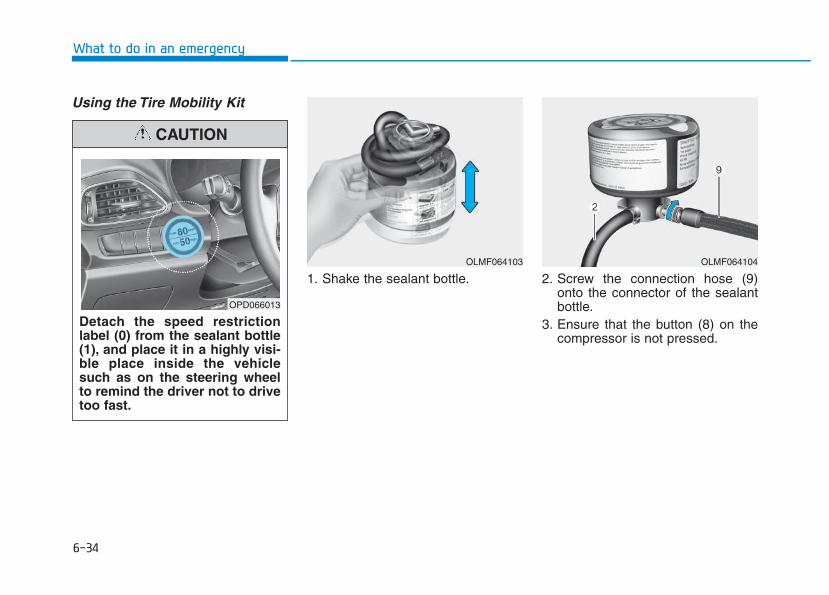
6-34
Using the Tire Mobility Kit
1. Shake the sealant bottle. 2. Screw the connection hose (9)onto the connector of the sealantbottle.
3. Ensure that the button (8) on thecompressor is not pressed.
What to do in an emergency
Detach the speed restrictionlabel (0) from the sealant bottle(1), and place it in a highly visi-ble place inside the vehiclesuch as on the steering wheelto remind the driver not to drivetoo fast.
CAUTION
OLMF064103 OLMF064104
OPD066013
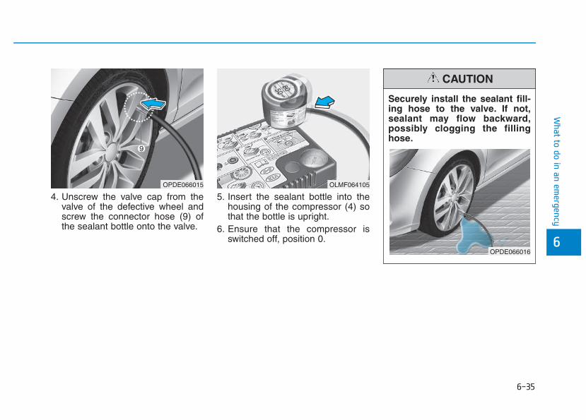
6-35
What to do in an em
ergency
4. Unscrew the valve cap from thevalve of the defective wheel andscrew the connector hose (9) ofthe sealant bottle onto the valve.
5. Insert the sealant bottle into thehousing of the compressor (4) sothat the bottle is upright.
6. Ensure that the compressor isswitched off, position 0. 6
OLMF064105
Securely install the sealant fill-ing hose to the valve. If not,sealant may flow backward,possibly clogging the fillinghose.
CAUTION
OPDE066016
OPDE066015
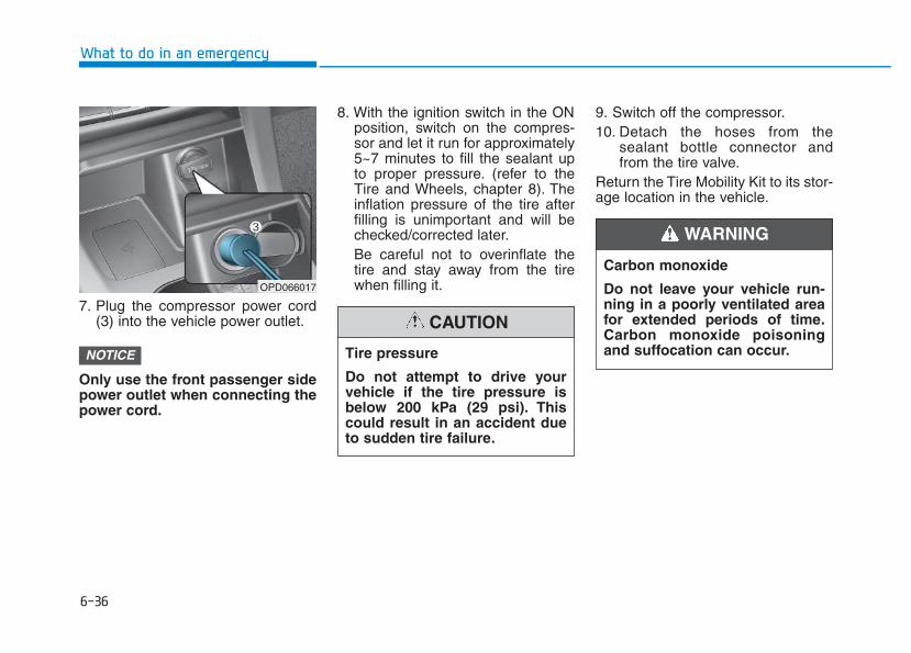
6-36
7. Plug the compressor power cord(3) into the vehicle power outlet.
Only use the front passenger sidepower outlet when connecting thepower cord.
8. With the ignition switch in the ONposition, switch on the compres-sor and let it run for approximately5~7 minutes to fill the sealant upto proper pressure. (refer to theTire and Wheels, chapter 8). Theinflation pressure of the tire afterfilling is unimportant and will bechecked/corrected later.Be careful not to overinflate thetire and stay away from the tirewhen filling it.
9. Switch off the compressor.10. Detach the hoses from the
sealant bottle connector andfrom the tire valve.
Return the Tire Mobility Kit to its stor-age location in the vehicle.
NOTICE
What to do in an emergency
OPD066017
Tire pressure
Do not attempt to drive yourvehicle if the tire pressure isbelow 200 kPa (29 psi). Thiscould result in an accident dueto sudden tire failure.
CAUTION
Carbon monoxide
Do not leave your vehicle run-ning in a poorly ventilated areafor extended periods of time.Carbon monoxide poisoningand suffocation can occur.
WARNING
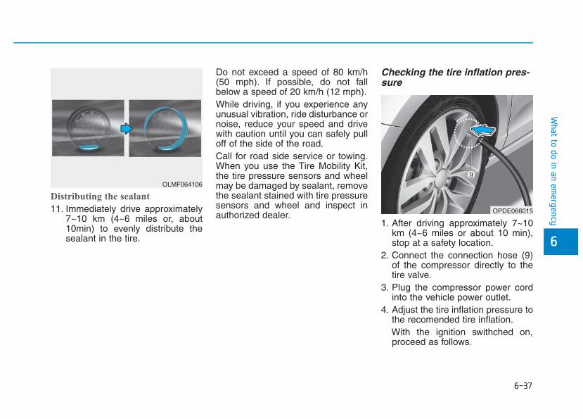
6-37
What to do in an em
ergency
Distributing the sealant
11. Immediately drive approximately7~10 km (4~6 miles or, about10min) to evenly distribute thesealant in the tire.
Do not exceed a speed of 80 km/h(50 mph). If possible, do not fallbelow a speed of 20 km/h (12 mph).While driving, if you experience anyunusual vibration, ride disturbance ornoise, reduce your speed and drivewith caution until you can safely pulloff of the side of the road.Call for road side service or towing.When you use the Tire Mobility Kit,the tire pressure sensors and wheelmay be damaged by sealant, removethe sealant stained with tire pressuresensors and wheel and inspect inauthorized dealer.
Checking the tire inflation pres-sure
1. After driving approximately 7~10km (4~6 miles or about 10 min),stop at a safety location.
2. Connect the connection hose (9)of the compressor directly to thetire valve.
3. Plug the compressor power cordinto the vehicle power outlet.
4. Adjust the tire inflation pressure tothe recomended tire inflation.With the ignition swithched on,proceed as follows.
6
OLMF064106
OPDE066015
6-38
- To increase the inflation pres-sure : Switch on the compres-sor, position I. To check the cur-rent inflation pressure setting,briefly switch off the compressor.
- To reduce the inflation pres-sure: Press the button (8) on thecompressor.
Do not let the compressor run formore than 10 minutes, otherwisethe device will overheat and maybe damaged.
InformationThe pressure gauge may show higherthan actual reading when the com-pressor is running. To get an accuratetire reading, the compressor needs tobe turned off.
i
NOTICE
What to do in an emergency
The tire inflation pressure mustbe at least 220 kPa (32 psi). If itis not, do not continue driving.Call for road side service or tow-ing.
WARNING
If the inflation pressure is notmaintained, drive the vehicle asecond time, refer to Distributingthe sealant. Then repeat steps 1to 4.Use of the TMK may be ineffec-tual for tire damage larger thanapproximately 4 mm (0.16 in).We recommend that you contactan authorized HYUNDAI dealer ifthe tire cannot be made road-worthy with the Tire Mobility Kit.
CAUTION
Tire pressure sensor
The sealant on the tire pressuresensor and wheel should beremoved when you replace thetire with a new one and inspectthe tire pressure sensors at anauthorized dealer.
CAUTION
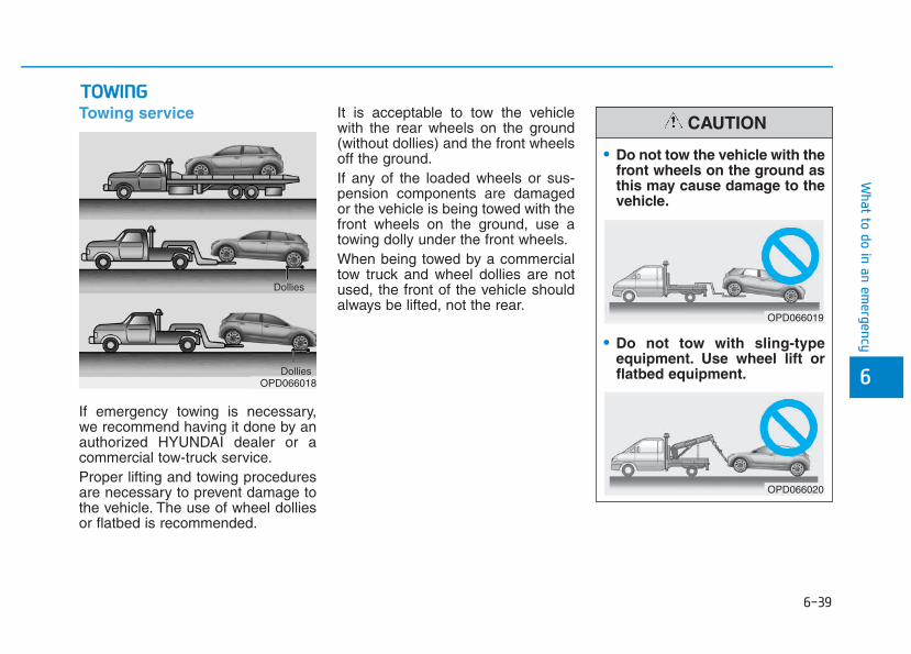
6-39
What to do in an em
ergency
6
Towing service
If emergency towing is necessary,we recommend having it done by anauthorized HYUNDAI dealer or acommercial tow-truck service.Proper lifting and towing proceduresare necessary to prevent damage tothe vehicle. The use of wheel dolliesor flatbed is recommended.
It is acceptable to tow the vehiclewith the rear wheels on the ground(without dollies) and the front wheelsoff the ground.If any of the loaded wheels or sus-pension components are damagedor the vehicle is being towed with thefront wheels on the ground, use atowing dolly under the front wheels.When being towed by a commercialtow truck and wheel dollies are notused, the front of the vehicle shouldalways be lifted, not the rear.
TTOOWWIINNGG
OPD066018Dollies
Dollies
• Do not tow the vehicle with thefront wheels on the ground asthis may cause damage to thevehicle.
• Do not tow with sling-typeequipment. Use wheel lift orflatbed equipment.
CAUTION
OPD066019
OPD066020
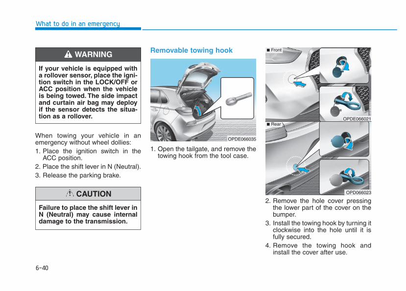
6-40
What to do in an emergency
When towing your vehicle in anemergency without wheel dollies:1. Place the ignition switch in the
ACC position.2. Place the shift lever in N (Neutral).3. Release the parking brake.
Removable towing hook
1. Open the tailgate, and remove thetowing hook from the tool case.
2. Remove the hole cover pressingthe lower part of the cover on thebumper.
3. Install the towing hook by turning itclockwise into the hole until it isfully secured.
4. Remove the towing hook andinstall the cover after use.
Failure to place the shift lever inN (Neutral) may cause internaldamage to the transmission.
CAUTION
OPDE066035
OPDE066021
OPD066023
■ Front
■ Rear
If your vehicle is equipped witha rollover sensor, place the igni-tion switch in the LOCK/OFF orACC position when the vehicleis being towed. The side impactand curtain air bag may deployif the sensor detects the situa-tion as a rollover.
WARNING
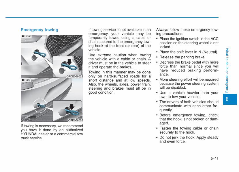
6-41
What to do in an em
ergency
6
Emergency towing
If towing is necessary, we recommendyou have it done by an authorizedHYUNDAI dealer or a commercial towtruck service.
If towing service is not available in anemergency, your vehicle may betemporarily towed using a cable orchain secured to the emergency tow-ing hook at the front (or rear) of thevehicle.Use extreme caution when towingthe vehicle with a cable or chain. Adriver must be in the vehicle to steerit and operate the brakes.Towing in this manner may be doneonly on hard-surfaced roads for ashort distance and at low speeds.Also, the wheels, axles, power train,steering and brakes must all be ingood condition.
Always follow these emergency tow-ing precautions:• Place the ignition switch in the ACC
position so the steering wheel is notlocked.
• Place the shift lever in N (Neutral).• Release the parking brake.• Depress the brake pedal with more
force than normal since you willhave reduced braking perform-ance.
• More steering effort will be requiredbecause the power steering systemwill be disabled.
• Use a vehicle heavier than yourown to tow your vehicle.
• The drivers of both vehicles shouldcommunicate with each other fre-quently.
• Before emergency towing, checkthat the hook is not broken or dam-aged.
• Fasten the towing cable or chainsecurely to the hook.
• Do not jerk the hook. Apply steadyand even force.
OPDE066022
OPD066026
■ Front
■ Rear
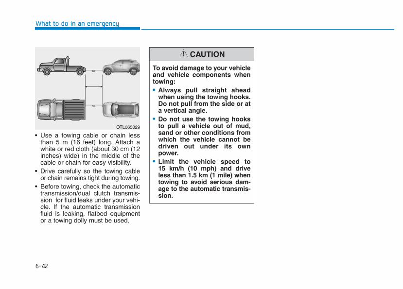
6-42
What to do in an emergency
• Use a towing cable or chain lessthan 5 m (16 feet) long. Attach awhite or red cloth (about 30 cm (12inches) wide) in the middle of thecable or chain for easy visibility.
• Drive carefully so the towing cableor chain remains tight during towing.
• Before towing, check the automatictransmission/dual clutch transmis-sion for fluid leaks under your vehi-cle. If the automatic transmissionfluid is leaking, flatbed equipmentor a towing dolly must be used.
To avoid damage to your vehicleand vehicle components whentowing:• Always pull straight ahead
when using the towing hooks.Do not pull from the side or ata vertical angle.
• Do not use the towing hooksto pull a vehicle out of mud,sand or other conditions fromwhich the vehicle cannot bedriven out under its ownpower.
• Limit the vehicle speed to 15 km/h (10 mph) and driveless than 1.5 km (1 mile) whentowing to avoid serious dam-age to the automatic transmis-sion.
CAUTION
OTL065029
6-43
What to do in an em
ergency
6
Your vehicle is equipped with emer-gency commodities to help yourespond to emergency situation.
Fire extinguisher If there is small fire and you know howto use the fire extinguisher, followthese steps carefully.1. Pull out the safety pin at the top of
the extinguisher that keeps the han-dle from being accidentally pressed.
2. Aim the nozzle towards the baseof the fire.
3. Stand approximately 2.5 m (8 ft)away from the fire and squeezethe handle to discharge the extin-guisher. If you release the handle,the discharge will stop.
4. Sweep the nozzle back and forthat the base of the fire. After the fireappears to be out, watch carefullysince it may re-ignite.
First aid kit Supplies for use in giving first aidsuch as scissors, bandage andadhesive tape, etc. are provided.
Triangle reflector
Place the triangle reflector on theroad to warn oncoming vehicles dur-ing emergencies, such as when thevehicle is parked by the roadside dueto problems.
Tire pressure gauge (if equipped) Tires normally lose some air in day-to-day use, and you may have to adda air periodically and usually it is nota sign of a leaking tire, but of normalwear. Always check tire pressurewhen the tires are cold because tirepressure increases with temperature.
To check the tire pressure, take thefollowing steps:1. Unscrew the inflation valve cap
that is located on the rim of thetire.
2. Press and hold the gauge againstthe tire valve. Some air will leak asyou begin and more will leak if youdon't press the gauge in firmly.
3. A firm non-leaking push will acti-vate the gauge.
4. Read the tire pressure on the gaugeto see whether the tire pressure islow or high.
5. Adjust the tire pressure to thespecified pressure. Refer to “Tiresand Wheels” in chapter 8.
6. Reinstall the inflation valve cap.
EEMMEERRGGEENNCCYY CCOOMMMMOODDIITTYY ((IIFF EEQQUUIIPPPPEEDD))
7
Maintenance
7
Maintenance
Engine compartment .............................................7-3Maintenance services ...........................................7-6
Owner's responsibility......................................................7-6Owner maintenance precautions ..................................7-6
Owner maintenance...............................................7-7Owner maintenance schedule........................................7-8
Scheduled maintenance services ......................7-10Normal Maintenance Schedule (Gasoline Engine, for Europe)......................................7-11Maintenance Under Severe Usage and Low Mileage Conditions (Gasoline Engine, for Europe)......................................7-14Normal Maintenance Schedule (Gasoline Engine, except Europe)...............................7-16Maintenance Under Severe Usage and Low Mileage Conditions (Gasoline Engine, except Europe)...............................7-20Normal Maintenance Schedule (Diesel Engine, for Europe) ..........................................7-22Maintenance Under Severe Usage and Low Mileage Conditions (Diesel Engine, for Europe) ..........................................7-25Normal Maintenance Schedule (Diesel Engine, except Europe)....................................7-27Maintenance Under Severe Usage and Low Mileage Conditions (Diesel Engine, except Europe)....................................7-30
Explanation of scheduled maintenance items.7-32Engine oil ..............................................................7-35
Checking the engine oil level .......................................7-35Checking the engine oil and filter ..............................7-36
Engine coolant......................................................7-37Checking the engine coolant level..............................7-37Changing the engine coolant .......................................7-39
Brake/clutch fluid................................................7-40Checking the brake/clutch fluid level........................7-40
Washer fluid .........................................................7-41Checking the washer fluid level ..................................7-41
Parking brake .......................................................7-41Checking the parking brake .........................................7-41
Fuel Filter (For Diesel)........................................7-42Draining water from fuel filter....................................7-42Fuel filter cartridge replacement................................7-42
Air cleaner ............................................................7-42Filter replacement...........................................................7-42
Climate control air filter .....................................7-44Filter inspection...............................................................7-44Filter replacement...........................................................7-44
Wiper blades .........................................................7-45Blade inspection ..............................................................7-45Blade replacement ..........................................................7-46
7
7
Battery...................................................................7-48For best battery service................................................7-49Battery capacity label ....................................................7-49Battery recharging .........................................................7-50Reset items .......................................................................7-51
Tires and wheels ..................................................7-52Tire care ............................................................................7-52Recommended cold tire inflation pressures.............7-53Check tire inflation pressure........................................7-54Tire rotation .....................................................................7-54Wheel alignment and tire balance ..............................7-55Tire replacement .............................................................7-56Wheel replacement .........................................................7-57Tire traction......................................................................7-57Tire maintenance ............................................................7-57Tire sidewall labeling......................................................7-57Low aspect ratio tires ....................................................7-61
Fuses......................................................................7-62Instrument panel fuse replacement ...........................7-63Engine compartment panel fuse replacement.........7-64Fuse/Relay panel description ......................................7-66
Light bulbs.............................................................7-85Headlamp, static bending lamp, position lamp, turn signal lamp and daytime running light bulb replacement ...................7-86Front fog lamp .................................................................7-91Headlamp and front fog lamp aiming (for Europe) ........................................................7-91Side repeater lamp replacement .................................7-97Rear combination lamp bulb replacement ................7-98Rear fog lamp ................................................................7-102High mounted stop lamp replacement.....................7-103License plate light bulb replacement .......................7-103Interior light bulb replacement..................................7-103
Appearance care................................................7-105Exterior care ..................................................................7-105Interior care ...................................................................7-110
Emission control system ...................................7-1111. Crankcase emission control system...................7-1112. Evaporative emission control system ................7-1113. Exhaust emission control system .......................7-112
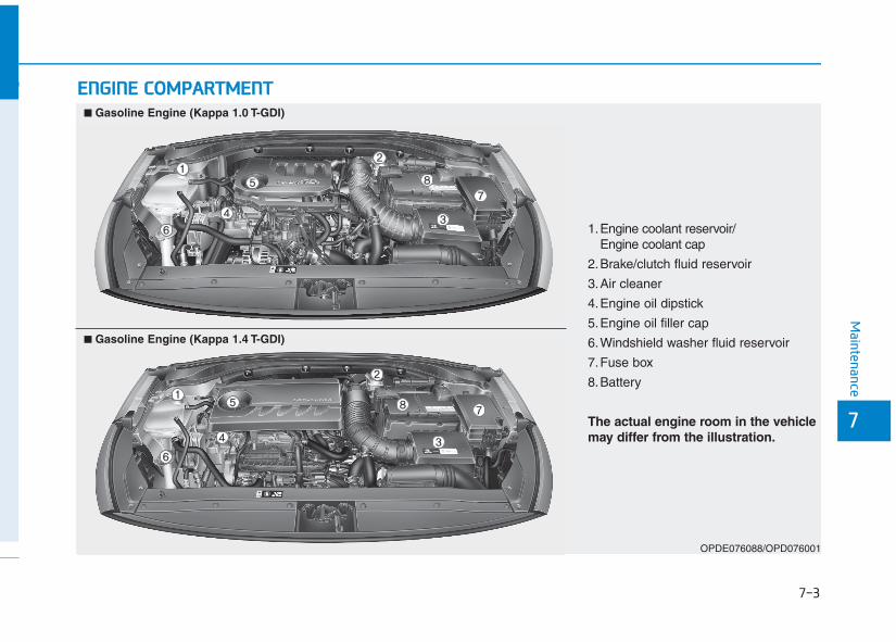
7-3
7
Maintenance
EENNGGIINNEE CCOOMMPPAARRTTMMEENNTT
1.Engine coolant reservoir/Engine coolant cap
2.Brake/clutch fluid reservoir
3.Air cleaner
4.Engine oil dipstick
5.Engine oil filler cap
6.Windshield washer fluid reservoir
7.Fuse box
8.Battery
The actual engine room in the vehiclemay differ from the illustration.
OPDE076088/OPD076001
■■ Gasoline Engine (Kappa 1.0 T-GDI)
■■ Gasoline Engine (Kappa 1.4 T-GDI)
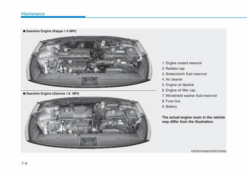
7-4
Maintenance
1. Engine coolant reservoir
2. Radiator cap
3. Brake/clutch fluid reservoir
4. Air cleaner
5. Engine oil dipstick
6. Engine oil filler cap
7. Windshield washer fluid reservoir
8. Fuse box
9. Battery
The actual engine room in the vehiclemay differ from the illustration.
OPDE076089/OPDE076093
■■ Gasoline Engine (Kappa 1.4 MPI)
■■ Gasoline Engine (Gamma 1.6 MPI)
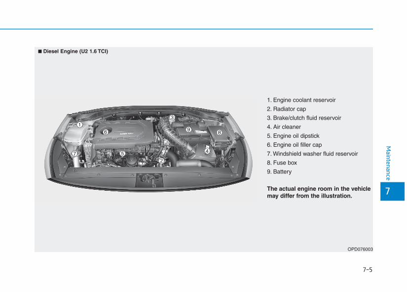
1. Engine coolant reservoir
2. Radiator cap
3. Brake/clutch fluid reservoir
4. Air cleaner
5. Engine oil dipstick
6. Engine oil filler cap
7. Windshield washer fluid reservoir
8. Fuse box
9. Battery
The actual engine room in the vehiclemay differ from the illustration.
OPD076003
■■ Diesel Engine (U2 1.6 TCI)
7-5
7
Maintenance
7-6
Maintenance
MMAAIINNTTEENNAANNCCEE SSEERRVVIICCEESSYou should exercise the utmost careto prevent damage to your vehicleand injury to yourself whenever per-forming any maintenance or inspec-tion procedures.We recommend you have your vehi-cle maintained and repaired by anauthorized HYUNDAI dealer. Anauthorized HYUNDAI dealer meetsHYUNDAI’s high service quality stan-dards and receives technical supportfrom HYUNDAI in order to provideyou with a high level of service satis-faction.
Owner’s responsibilityMaintenance service and record reten-tion are the owner’s responsibility.You should retain documents that showproper maintenance has been per-formed on your vehicle in accordancewith the scheduled maintenance serv-ice charts shown on the followingpages. You need this information toestablish your compliance with theservicing and maintenance require-ments of your vehicle warranties.
Detailed warranty information is pro-vided in your Service Passport.Repairs and adjustments required asa result of improper maintenance ora lack of required maintenance arenot covered.
Owner maintenance precautionsInadequate, incomplete or insufficientservicing may result in operationalproblems with your vehicle that couldlead to vehicle damage, an accident,or personal injury. This chapter pro-vides instructions only for the mainte-nance items that are easy to perform.Several procedures can be done onlyby an authorized HYUNDAI dealerwith special tools.Your vehicle should not be modified inany way. Such modifications mayadversely affect the performance,safety or durability of your vehicle andmay, in addition, violate conditions ofthe limited warranties covering thevehicle.
Improper owner maintenance dur-ing the warranty period may affectwarranty coverage. For details, readthe separate Service Passport pro-vided with the vehicle. If you'reunsure about any servicing or main-tenance procedure, we recommendthat the system be serviced by anauthorized HYUNDAI dealer.
NOTICE
7-7
7
Maintenance
OOWWNNEERR MMAAIINNTTEENNAANNCCEEThe following lists are vehicle checksand inspections that should be per-formed by the owner or an authorizedHYUNDAI dealer at the frequenciesindicated to help ensure safe, depend-able operation of your vehicle.Any adverse conditions should bebrought to the attention of your dealeras soon as possible.These Owner Maintenance vehiclechecks are generally not covered bywarranties and you may be chargedfor labor, parts and lubricants used.
Performing maintenance workon a vehicle can be dangerous.If you lack sufficient knowledgeand experience or the propertools and equipment to do thework, we recommend that thesystem be serviced by an author-ized HYUNDAI dealer. ALWAYSfollow these precautions forperforming maintenance work:• Park your vehicle on level
ground, move the shift leverinto the P (Park, for automatictransmission/dual clutch trans-mission vehicle) position, applythe parking brake, place theignition switch in theLOCK/OFF position.
(Continued)
WARNING (Continued)• Block the tires (front and back)
to prevent the vehicle frommoving.Remove loose clothing or jew-elry that can become entan-gled in moving parts.
• If you must run the engineduring maintenance, do soout doors or in an area withplenty of ventilation.
• Keep flames, sparks, or smok-ing materials away from thebattery and fuel-related parts.
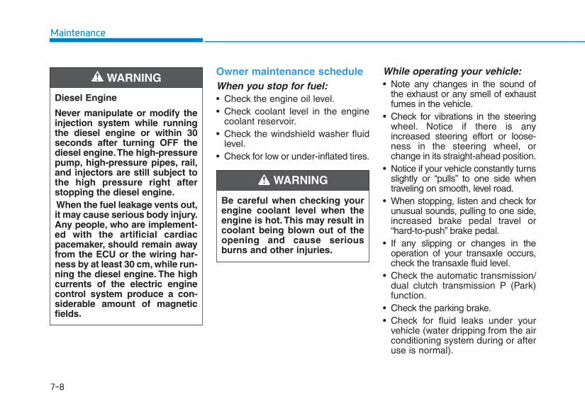
7-8
Maintenance
Owner maintenance scheduleWhen you stop for fuel:• Check the engine oil level.• Check coolant level in the engine
coolant reservoir.• Check the windshield washer fluid
level.• Check for low or under-inflated tires.
While operating your vehicle:• Note any changes in the sound of
the exhaust or any smell of exhaustfumes in the vehicle.
• Check for vibrations in the steeringwheel. Notice if there is anyincreased steering effort or loose-ness in the steering wheel, orchange in its straight-ahead position.
• Notice if your vehicle constantly turnsslightly or “pulls” to one side whentraveling on smooth, level road.
• When stopping, listen and check forunusual sounds, pulling to one side,increased brake pedal travel or“hard-to-push” brake pedal.
• If any slipping or changes in theoperation of your transaxle occurs,check the transaxle fluid level.
• Check the automatic transmission/dual clutch transmission P (Park)function.
• Check the parking brake.• Check for fluid leaks under your
vehicle (water dripping from the airconditioning system during or afteruse is normal).
Be careful when checking yourengine coolant level when theengine is hot. This may result incoolant being blown out of theopening and cause seriousburns and other injuries.
WARNING
Diesel Engine
Never manipulate or modify theinjection system while runningthe diesel engine or within 30seconds after turning OFF thediesel engine.The high-pressurepump, high-pressure pipes, rail,and injectors are still subject tothe high pressure right afterstopping the diesel engine.When the fuel leakage vents out,it may cause serious body injury.Any people, who are implement-ed with the artificial cardiacpacemaker, should remain awayfrom the ECU or the wiring har-ness by at least 30 cm, while run-ning the diesel engine. The highcurrents of the electric enginecontrol system produce a con-siderable amount of magneticfields.
WARNING
7-9
7
Maintenance
At least monthly:• Check coolant level in the engine
coolant reservoir.• Check the operation of all exterior
lights, including the stoplights, turnsignals and hazard warning flashers.
• Check the inflation pressures of alltires including the spare for tiresthat are worn, show uneven wear,or are damaged.
• Check for loose wheel lug nuts.
At least twice a year:(i.e., every Spring and Fall)• Check radiator, heater and air condi-
tioning hoses for leaks or damage.• Check windshield washer spray
and wiper operation. Clean wiperblades with clean cloth dampenedwith washer fluid.
• Check headlamp alignment.• Check muffler, exhaust pipes,
shields and clamps.• Check the seat belts for wear and
function.
At least once a year:• Clean body and door drain holes.• Lubricate door hinges and hood
hinges.• Lubricate door and hood locks and
latches.• Lubricate door rubber weather
strips.• Check the air conditioning system.• Inspect and lubricate automatic
transaxle linkage and controls.• Clean the battery and terminals.• Check the brake fluid level.
7-10
Maintenance
SSCCHHEEDDUULLEEDD MMAAIINNTTEENNAANNCCEE SSEERRVVIICCEESSFollow Normal Maintenance Schedule if the vehicle is usually operated where none of the following conditions apply.If any of the following conditions apply, you must follow the Maintenance Under Severe Usage Conditions.• Repeated driving short distance of less than 8 km (5 miles) in normal temperature or less than 16 km (10 miles) in
freezing temperature• Extensive engine idling or low speed driving for long distances• Driving on rough, dusty, muddy, unpaved, graveled or salt-spread roads• Driving in areas using salt or other corrosive materials or in very cold weather• Driving in heavy traffic area• Driving on uphill, downhill, or mountain road repeatedly• Towing a trailer or using a camper, or roof rack• Driving as a patrol car, taxi, other commercial use of vehicle towing• Driving over 170 km/h (106 mile/h)• Frequently driving in stop-and-go condition
If your vehicle is operated under the above conditions, you should inspect, replace or refill more frequently than thefollowing Normal Maintenance Schedule. After the periods or distance shown in the chart, continue to follow the pre-scribed maintenance intervals.
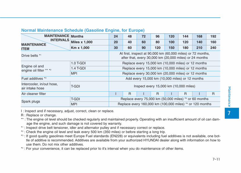
7-11
7
Maintenance
I : Inspect and if necessary, adjust, correct, clean or replace.R : Replace or change.** : The engine oil level should be checked regularly and maintained properly. Operating with an insufficient amount of oil can dam-
age the engine, and such damage is not covered by warranty.*1 : Inspect drive belt tensioner, idler and alternator pulley and if necessary correct or replace.*2 : Check the engine oil level and leak every 500 km (350 miles) or before starting a long trip.*3 : If good quality gasolines meet Europe Fuel standards (EN228) or equivalents including fuel additives is not available, one bot-
tle of additive is recommended. Additives are available from your authorized HYUNDAI dealer along with information on how touse them. Do not mix other additives.
*4 : For your convenience, it can be replaced prior to it's interval when you do maintenance of other items.
Normal Maintenance Schedule (Gasoline Engine, for Europe)Months 24 48 72 96 120 144 168 192
Miles x 1,000 20 40 60 80 100 120 140 160
Km x 1,000 30 60 90 120 150 180 210 240
Drive belts *1 At first, inspect at 90,000 km (60,000 miles) or 72 months,after that, every 30,000 km (20,000 miles) or 24 months
Engine oil and engine oil filter ** *2
1.0 T-GDI Replace every 15,000 km (10,000 miles) or 12 months
1.4 T-GDI Replace every 15,000 km (10,000 miles) or 12 months
MPI Replace every 30,000 km (20,000 miles) or 12 months
Fuel additives *3 Add every 15,000 km (10,000 miles) or 12 months
Intercooler, in/out hose, air intake hose T-GDI Inspect every 15,000 km (10,000 miles)
Air cleaner filter I R I R I R I R
Spark plugsT-GDI Replace every 75,000 km (50,000 miles) *4 or 60 months
MPI Replace every 160,000 km (100,000 miles) *4 or 120 months
MAINTENANCEINTERVALS
MAINTENANCEITEM
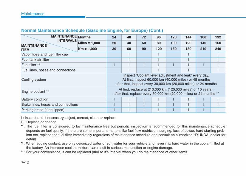
Maintenance
7-12
Normal Maintenance Schedule (Gasoline Engine, for Europe) (Cont.)Months 24 48 72 96 120 144 168 192
Miles x 1,000 20 40 60 80 100 120 140 160
Km x 1,000 30 60 90 120 150 180 210 240
Vapor hose and fuel filler cap I I I I
Fuel tank air filter I I I I
Fuel filter *5 I I I I I I I I
Fuel lines, hoses and connections I I I I
Cooling systemInspect “Coolant level adjustment and leak” every day.At first, inspect 60,000 km (40,000 miles) or 48 months
after that, inspect every 30,000 km (20,000 miles) or 24 months
Engine coolant *6 At first, replace at 210,000 km (120,000 miles) or 10 years :after that, replace every 30,000 km (20,000 miles) or 24 months *7
Battery condition I I I I I I I I
Brake lines, hoses and connections I I I I I I I I
Parking brake (if equipped) I I I I I I I I
MAINTENANCEINTERVALS
MAINTENANCEITEM
I : Inspect and if necessary, adjust, correct, clean or replace.R : Replace or change.*5 : The fuel filter is considered to be maintenance free but periodic inspection is recommended for this maintenance schedule
depends on fuel quality. If there are some important matters like fuel flow restriction, surging, loss of power, hard starting prob-lem etc, replace the fuel filter immediately regardless of maintenance schedule and consult an authorized HYUNDAI dealer fordetails.
*6 : When adding coolant, use only deionized water or soft water for your vehicle and never mix hard water in the coolant filled atthe factory. An improper coolant mixture can result in serious malfunction or engine damage.
*7 : For your convenience, it can be replaced prior to it's interval when you do maintenance of other items.
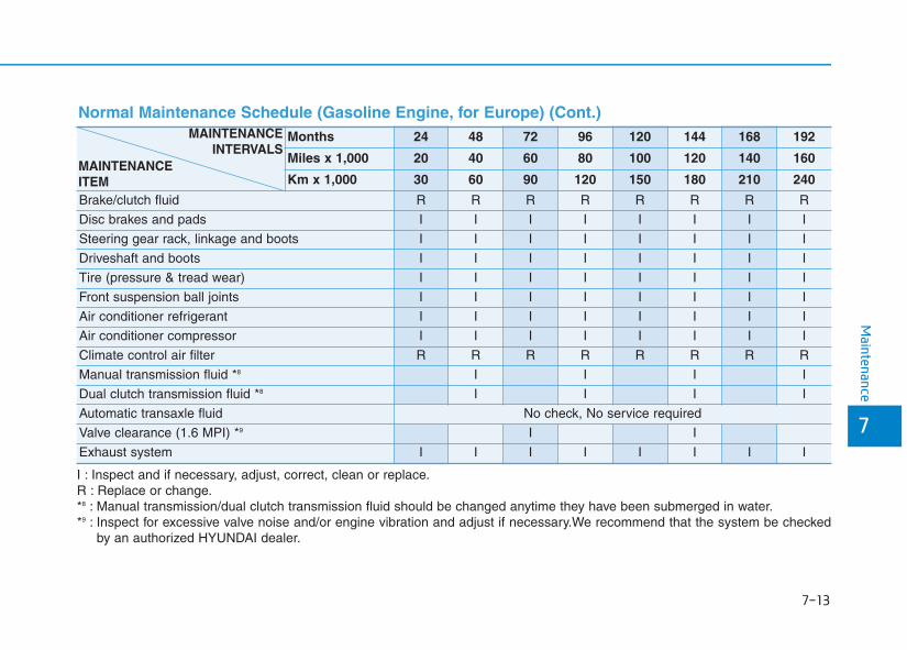
7-13
7
Maintenance
Normal Maintenance Schedule (Gasoline Engine, for Europe) (Cont.)
I : Inspect and if necessary, adjust, correct, clean or replace.R : Replace or change.*8 : Manual transmission/dual clutch transmission fluid should be changed anytime they have been submerged in water.*9 : Inspect for excessive valve noise and/or engine vibration and adjust if necessary.We recommend that the system be checked
by an authorized HYUNDAI dealer.
Months 24 48 72 96 120 144 168 192
Miles x 1,000 20 40 60 80 100 120 140 160
Km x 1,000 30 60 90 120 150 180 210 240
Brake/clutch fluid R R R R R R R R
Disc brakes and pads I I I I I I I I
Steering gear rack, linkage and boots I I I I I I I I
Driveshaft and boots I I I I I I I I
Tire (pressure & tread wear) I I I I I I I I
Front suspension ball joints I I I I I I I I
Air conditioner refrigerant I I I I I I I I
Air conditioner compressor I I I I I I I I
Climate control air filter R R R R R R R R
Manual transmission fluid *8 I I I I
Dual clutch transmission fluid *8 I I I I
Automatic transaxle fluid No check, No service required
Valve clearance (1.6 MPI) *9 I I
Exhaust system I I I I I I I I
MAINTENANCEINTERVALS
MAINTENANCEITEM
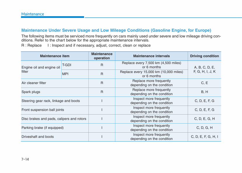
Maintenance
7-14
Maintenance Under Severe Usage and Low Mileage Conditions (Gasoline Engine, for Europe) The following items must be serviced more frequently on cars mainly used under severe and low mileage driving con-ditions. Refer to the chart below for the appropriate maintenance intervals.R : Replace I : Inspect and if necessary, adjust, correct, clean or replace
Maintenance itemMaintenance
operationMaintenance intervals Driving condition
Engine oil and engine oilfilter
T-GDI RReplace every 7,500 km (4,500 miles)
or 6 months A, B, C, D, E, F, G, H, I, J, K
MPI RReplace every 15,000 km (10,000 miles)
or 6 months
Air cleaner filter RReplace more frequently
depending on the conditionC, E
Spark plugs RReplace more frequently
depending on the conditionB, H
Steering gear rack, linkage and boots IInspect more frequently
depending on the conditionC, D, E, F, G
Front suspension ball joints IInspect more frequently
depending on the conditionC, D, E, F, G
Disc brakes and pads, calipers and rotors IInspect more frequently
depending on the conditionC, D, E, G, H
Parking brake (if equipped) IInspect more frequently
depending on the conditionC, D, G, H
Driveshaft and boots IInspect more frequently
depending on the conditionC, D, E, F, G, H, I
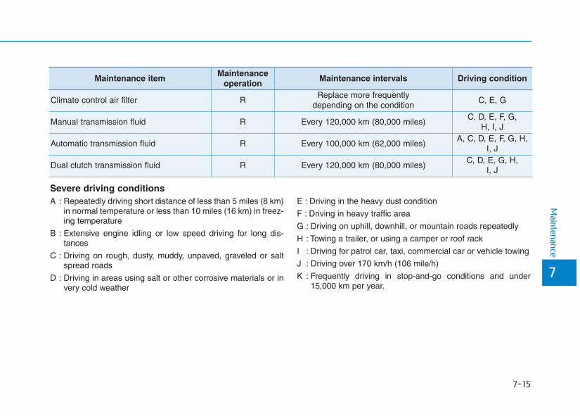
7-15
7
Maintenance
Severe driving conditionsA : Repeatedly driving short distance of less than 5 miles (8 km)
in normal temperature or less than 10 miles (16 km) in freez-ing temperature
B : Extensive engine idling or low speed driving for long dis-tances
C : Driving on rough, dusty, muddy, unpaved, graveled or saltspread roads
D : Driving in areas using salt or other corrosive materials or invery cold weather
E : Driving in the heavy dust condition
F : Driving in heavy traffic area
G : Driving on uphill, downhill, or mountain roads repeatedly
H : Towing a trailer, or using a camper or roof rack
I : Driving for patrol car, taxi, commercial car or vehicle towing
J : Driving over 170 km/h (106 mile/h)
K : Frequently driving in stop-and-go conditions and under15,000 km per year.
Maintenance itemMaintenance
operationMaintenance intervals Driving condition
Climate control air filter RReplace more frequently
depending on the conditionC, E, G
Manual transmission fluid R Every 120,000 km (80,000 miles)C, D, E, F, G,
H, I, J
Automatic transmission fluid R Every 100,000 km (62,000 miles)A, C, D, E, F, G, H,
I, J
Dual clutch transmission fluid R Every 120,000 km (80,000 miles)C, D, E, G, H,
I, J
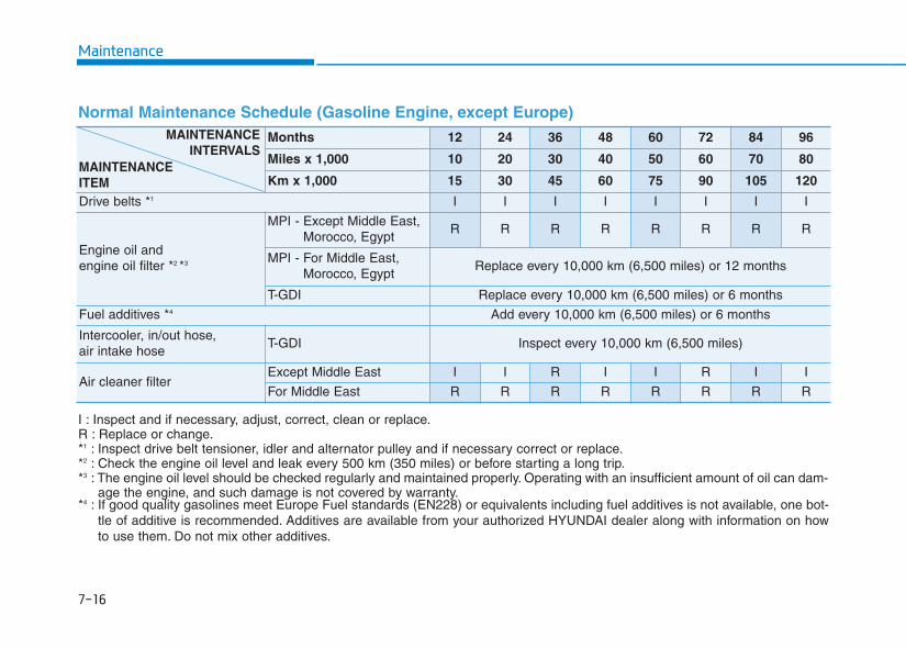
Maintenance
7-16
Normal Maintenance Schedule (Gasoline Engine, except Europe)
Months 12 24 36 48 60 72 84 96
Miles x 1,000 10 20 30 40 50 60 70 80
Km x 1,000 15 30 45 60 75 90 105 120
Drive belts *1 I I I I I I I I
Engine oil and engine oil filter *2 *3
MPI - Except Middle East,Morocco, Egypt
R R R R R R R R
MPI - For Middle East,Morocco, Egypt
Replace every 10,000 km (6,500 miles) or 12 months
T-GDI Replace every 10,000 km (6,500 miles) or 6 months
Fuel additives *4 Add every 10,000 km (6,500 miles) or 6 months
Intercooler, in/out hose, air intake hose
T-GDI Inspect every 10,000 km (6,500 miles)
Air cleaner filter Except Middle East I I R I I R I I
For Middle East R R R R R R R R
I : Inspect and if necessary, adjust, correct, clean or replace.R : Replace or change.*1 : Inspect drive belt tensioner, idler and alternator pulley and if necessary correct or replace.*2 : Check the engine oil level and leak every 500 km (350 miles) or before starting a long trip.*3 : The engine oil level should be checked regularly and maintained properly. Operating with an insufficient amount of oil can dam-
age the engine, and such damage is not covered by warranty.*4 : If good quality gasolines meet Europe Fuel standards (EN228) or equivalents including fuel additives is not available, one bot-
tle of additive is recommended. Additives are available from your authorized HYUNDAI dealer along with information on howto use them. Do not mix other additives.
MAINTENANCEINTERVALS
MAINTENANCEITEM
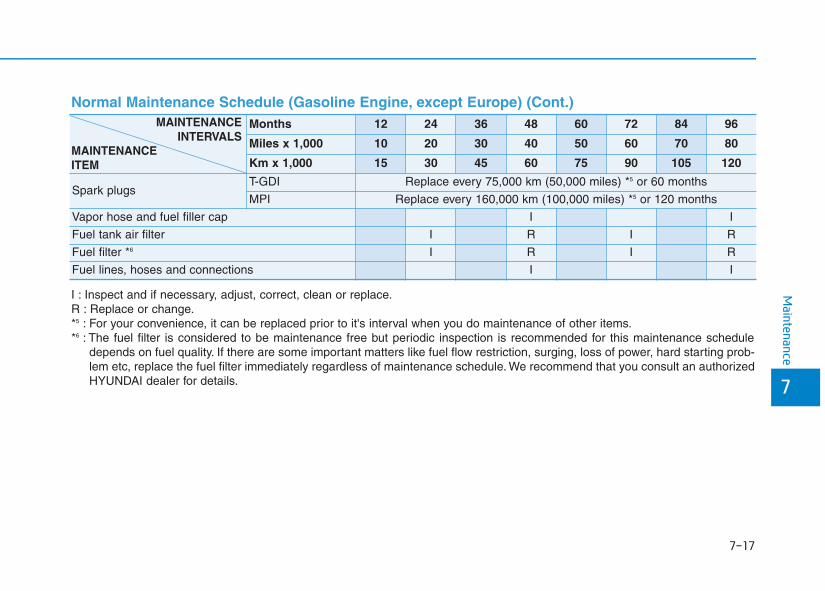
7-17
7
Maintenance
Months 12 24 36 48 60 72 84 96
Miles x 1,000 10 20 30 40 50 60 70 80
Km x 1,000 15 30 45 60 75 90 105 120
Spark plugsT-GDI Replace every 75,000 km (50,000 miles) *5 or 60 months
MPI Replace every 160,000 km (100,000 miles) *5 or 120 months
Vapor hose and fuel filler cap I I
Fuel tank air filter I R I R
Fuel filter *6 I R I R
Fuel lines, hoses and connections I I
Normal Maintenance Schedule (Gasoline Engine, except Europe) (Cont.) MAINTENANCE
INTERVALSMAINTENANCEITEM
I : Inspect and if necessary, adjust, correct, clean or replace.R : Replace or change.*5 : For your convenience, it can be replaced prior to it's interval when you do maintenance of other items.*6 : The fuel filter is considered to be maintenance free but periodic inspection is recommended for this maintenance schedule
depends on fuel quality. If there are some important matters like fuel flow restriction, surging, loss of power, hard starting prob-lem etc, replace the fuel filter immediately regardless of maintenance schedule. We recommend that you consult an authorizedHYUNDAI dealer for details.
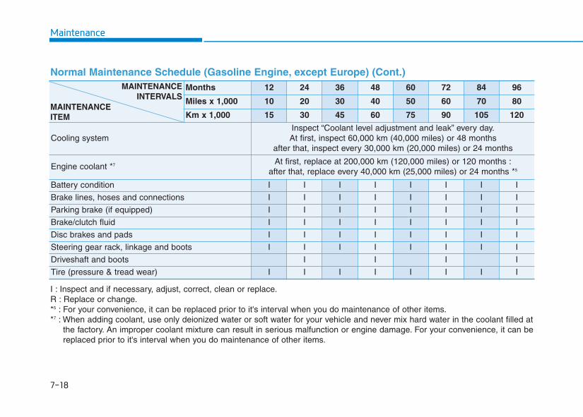
Maintenance
7-18
Normal Maintenance Schedule (Gasoline Engine, except Europe) (Cont.) Months 12 24 36 48 60 72 84 96
Miles x 1,000 10 20 30 40 50 60 70 80
Km x 1,000 15 30 45 60 75 90 105 120
Cooling systemInspect “Coolant level adjustment and leak” every day.At first, inspect 60,000 km (40,000 miles) or 48 months
after that, inspect every 30,000 km (20,000 miles) or 24 months
Engine coolant *7 At first, replace at 200,000 km (120,000 miles) or 120 months :after that, replace every 40,000 km (25,000 miles) or 24 months *5
Battery condition I I I I I I I I
Brake lines, hoses and connections I I I I I I I I
Parking brake (if equipped) I I I I I I I I
Brake/clutch fluid I I I I I I I I
Disc brakes and pads I I I I I I I I
Steering gear rack, linkage and boots I I I I I I I I
Driveshaft and boots I I I I
Tire (pressure & tread wear) I I I I I I I I
I : Inspect and if necessary, adjust, correct, clean or replace.R : Replace or change.*5 : For your convenience, it can be replaced prior to it's interval when you do maintenance of other items.*7 : When adding coolant, use only deionized water or soft water for your vehicle and never mix hard water in the coolant filled at
the factory. An improper coolant mixture can result in serious malfunction or engine damage. For your convenience, it can bereplaced prior to it's interval when you do maintenance of other items.
MAINTENANCEINTERVALS
MAINTENANCEITEM
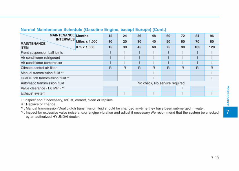
7-19
7
Maintenance
Normal Maintenance Schedule (Gasoline Engine, except Europe) (Cont.) Months 12 24 36 48 60 72 84 96
Miles x 1,000 10 20 30 40 50 60 70 80
Km x 1,000 15 30 45 60 75 90 105 120
Front suspension ball joints I I I I I I I I
Air conditioner refrigerant I I I I I I I I
Air conditioner compressor I I I I I I I I
Climate control air filter R R R R R R R R
Manual transmission fluid *8 I I
Dual clutch transmission fluid *8 I I
Automatic transmission fluid No check, No service required
Valve clearance (1.6 MPI) *9 I
Exhaust system I I I I
I : Inspect and if necessary, adjust, correct, clean or replace.R : Replace or change.*8 : Manual transmission/Dual clutch transmission fluid should be changed anytime they have been submerged in water.*9 : Inspect for excessive valve noise and/or engine vibration and adjust if necessary.We recommend that the system be checked
by an authorized HYUNDAI dealer.
MAINTENANCEINTERVALS
MAINTENANCEITEM
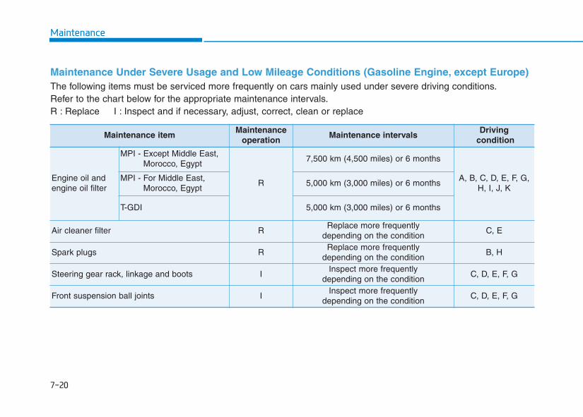
Maintenance
7-20
Maintenance Under Severe Usage and Low Mileage Conditions (Gasoline Engine, except Europe) The following items must be serviced more frequently on cars mainly used under severe driving conditions.Refer to the chart below for the appropriate maintenance intervals.R : Replace I : Inspect and if necessary, adjust, correct, clean or replace
Maintenance itemMaintenance
operationMaintenance intervals
Drivingcondition
Engine oil and engine oil filter
MPI - Except Middle East,Morocco, Egypt
R
7,500 km (4,500 miles) or 6 months
A, B, C, D, E, F, G,H, I, J, K
MPI - For Middle East,Morocco, Egypt
5,000 km (3,000 miles) or 6 months
T-GDI 5,000 km (3,000 miles) or 6 months
Air cleaner filter RReplace more frequently
depending on the conditionC, E
Spark plugs RReplace more frequently
depending on the conditionB, H
Steering gear rack, linkage and boots IInspect more frequently
depending on the conditionC, D, E, F, G
Front suspension ball joints IInspect more frequently
depending on the conditionC, D, E, F, G
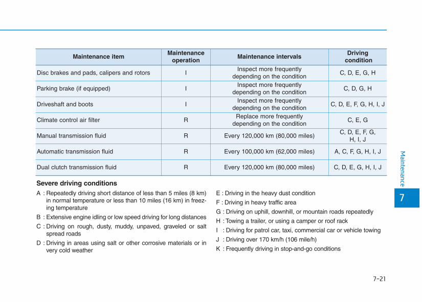
7-21
7
Maintenance
Maintenance itemMaintenance
operationMaintenance intervals
Drivingcondition
Disc brakes and pads, calipers and rotors IInspect more frequently
depending on the conditionC, D, E, G, H
Parking brake (if equipped) IInspect more frequently
depending on the conditionC, D, G, H
Driveshaft and boots IInspect more frequently
depending on the conditionC, D, E, F, G, H, I, J
Climate control air filter RReplace more frequently
depending on the conditionC, E, G
Manual transmission fluid R Every 120,000 km (80,000 miles)C, D, E, F, G,
H, I, J
Automatic transmission fluid R Every 100,000 km (62,000 miles) A, C, F, G, H, I, J
Dual clutch transmission fluid R Every 120,000 km (80,000 miles) C, D, E, G, H, I, J
Severe driving conditionsA : Repeatedly driving short distance of less than 5 miles (8 km)
in normal temperature or less than 10 miles (16 km) in freez-ing temperature
B : Extensive engine idling or low speed driving for long distances
C : Driving on rough, dusty, muddy, unpaved, graveled or saltspread roads
D : Driving in areas using salt or other corrosive materials or invery cold weather
E : Driving in the heavy dust condition
F : Driving in heavy traffic area
G : Driving on uphill, downhill, or mountain roads repeatedly
H : Towing a trailer, or using a camper or roof rack
I : Driving for patrol car, taxi, commercial car or vehicle towing
J : Driving over 170 km/h (106 mile/h)
K : Frequently driving in stop-and-go conditions
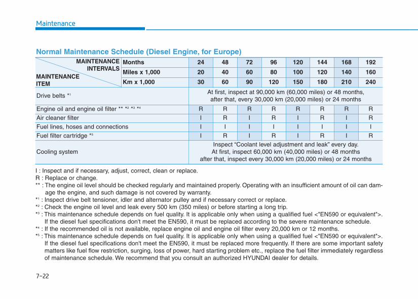
Maintenance
7-22
I : Inspect and if necessary, adjust, correct, clean or replace.R : Replace or change.** : The engine oil level should be checked regularly and maintained properly. Operating with an insufficient amount of oil can dam-
age the engine, and such damage is not covered by warranty.*1 : Inspect drive belt tensioner, idler and alternator pulley and if necessary correct or replace.*2 : Check the engine oil level and leak every 500 km (350 miles) or before starting a long trip.*3 : This maintenance schedule depends on fuel quality. It is applicable only when using a qualified fuel <"EN590 or equivalent">.
If the diesel fuel specifications don't meet the EN590, it must be replaced according to the severe maintenance schedule.*4 : If the recommended oil is not available, replace engine oil and engine oil filter every 20,000 km or 12 months.*5 : This maintenance schedule depends on fuel quality. It is applicable only when using a qualified fuel <"EN590 or equivalent">.
If the diesel fuel specifications don't meet the EN590, it must be replaced more frequently. If there are some important safetymatters like fuel flow restriction, surging, loss of power, hard starting problem etc., replace the fuel filter immediately regardlessof maintenance schedule. We recommend that you consult an authorized HYUNDAI dealer for details.
Normal Maintenance Schedule (Diesel Engine, for Europe)Months 24 48 72 96 120 144 168 192
Miles x 1,000 20 40 60 80 100 120 140 160
Km x 1,000 30 60 90 120 150 180 210 240
Drive belts *1 At first, inspect at 90,000 km (60,000 miles) or 48 months,after that, every 30,000 km (20,000 miles) or 24 months
Engine oil and engine oil filter ** *2 *3 *4 R R R R R R R R
Air cleaner filter I R I R I R I R
Fuel lines, hoses and connections I I I I I I I I
Fuel filter cartridge *5 I R I R I R I R
Cooling systemInspect “Coolant level adjustment and leak” every day.At first, inspect 60,000 km (40,000 miles) or 48 months
after that, inspect every 30,000 km (20,000 miles) or 24 months
MAINTENANCEINTERVALS
MAINTENANCEITEM
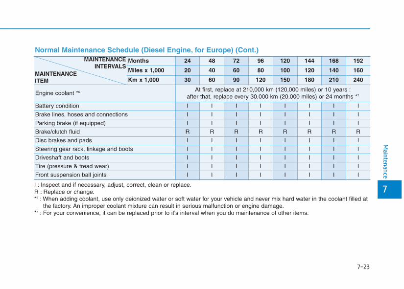
7-23
7
Maintenance
Normal Maintenance Schedule (Diesel Engine, for Europe) (Cont.)
I : Inspect and if necessary, adjust, correct, clean or replace.R : Replace or change.*6 : When adding coolant, use only deionized water or soft water for your vehicle and never mix hard water in the coolant filled at
the factory. An improper coolant mixture can result in serious malfunction or engine damage.*7 : For your convenience, it can be replaced prior to it's interval when you do maintenance of other items.
Months 24 48 72 96 120 144 168 192
Miles x 1,000 20 40 60 80 100 120 140 160
Km x 1,000 30 60 90 120 150 180 210 240
Engine coolant *6 At first, replace at 210,000 km (120,000 miles) or 10 years :after that, replace every 30,000 km (20,000 miles) or 24 months *7
Battery condition I I I I I I I I
Brake lines, hoses and connections I I I I I I I I
Parking brake (if equipped) I I I I I I I I
Brake/clutch fluid R R R R R R R R
Disc brakes and pads I I I I I I I I
Steering gear rack, linkage and boots I I I I I I I I
Driveshaft and boots I I I I I I I I
Tire (pressure & tread wear) I I I I I I I I
Front suspension ball joints I I I I I I I I
MAINTENANCEINTERVALS
MAINTENANCEITEM
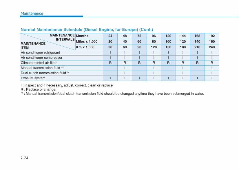
Maintenance
7-24
Normal Maintenance Schedule (Diesel Engine, for Europe) (Cont.)Months 24 48 72 96 120 144 168 192
Miles x 1,000 20 40 60 80 100 120 140 160
Km x 1,000 30 60 90 120 150 180 210 240
Air conditioner refrigerant I I I I I I I I
Air conditioner compressor I I I I I I I I
Climate control air filter R R R R R R R R
Manual transmission fluid *8 I I I I
Dual clutch transmission fluid *8 I I I I
Exhaust system I I I I I I I I
I : Inspect and if necessary, adjust, correct, clean or replace.R : Replace or change.*8 : Manual transmission/dual clutch transmission fluid should be changed anytime they have been submerged in water.
MAINTENANCEINTERVALS
MAINTENANCEITEM
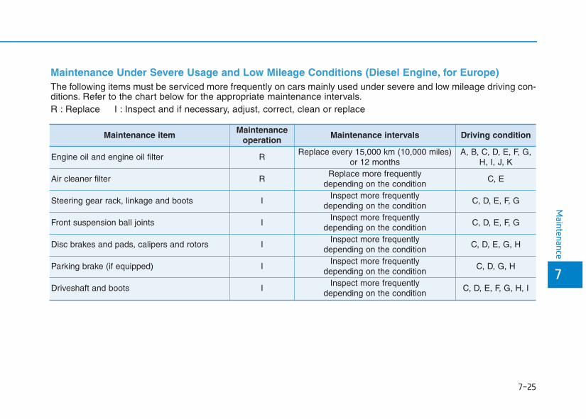
7-25
7
Maintenance
Maintenance Under Severe Usage and Low Mileage Conditions (Diesel Engine, for Europe) The following items must be serviced more frequently on cars mainly used under severe and low mileage driving con-ditions. Refer to the chart below for the appropriate maintenance intervals.R : Replace I : Inspect and if necessary, adjust, correct, clean or replace
Maintenance itemMaintenance
operationMaintenance intervals Driving condition
Engine oil and engine oil filter RReplace every 15,000 km (10,000 miles)
or 12 monthsA, B, C, D, E, F, G,
H, I, J, K
Air cleaner filter RReplace more frequently
depending on the conditionC, E
Steering gear rack, linkage and boots IInspect more frequently
depending on the conditionC, D, E, F, G
Front suspension ball joints IInspect more frequently
depending on the conditionC, D, E, F, G
Disc brakes and pads, calipers and rotors IInspect more frequently
depending on the conditionC, D, E, G, H
Parking brake (if equipped) IInspect more frequently
depending on the conditionC, D, G, H
Driveshaft and boots IInspect more frequently
depending on the conditionC, D, E, F, G, H, I
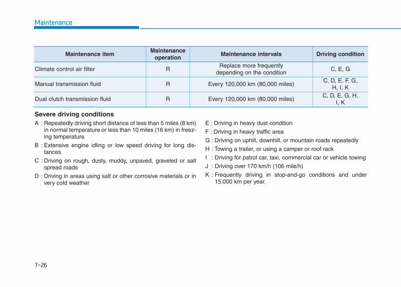
Maintenance
7-26
Severe driving conditionsA : Repeatedly driving short distance of less than 5 miles (8 km)
in normal temperature or less than 10 miles (16 km) in freez-ing temperature
B : Extensive engine idling or low speed driving for long dis-tances
C : Driving on rough, dusty, muddy, unpaved, graveled or saltspread roads
D : Driving in areas using salt or other corrosive materials or invery cold weather
E : Driving in heavy dust condition
F : Driving in heavy traffic area
G : Driving on uphill, downhill, or mountain roads repeatedly
H : Towing a trailer, or using a camper or roof rack
I : Driving for patrol car, taxi, commercial car or vehicle towing
J : Driving over 170 km/h (106 mile/h)
K : Frequently driving in stop-and-go conditions and under15,000 km per year.
Maintenance itemMaintenance
operationMaintenance intervals Driving condition
Climate control air filter RReplace more frequently
depending on the conditionC, E, G
Manual transmission fluid R Every 120,000 km (80,000 miles)C, D, E, F, G,
H, I, K
Dual clutch transmission fluid R Every 120,000 km (80,000 miles)C, D, E, G, H,
I, K
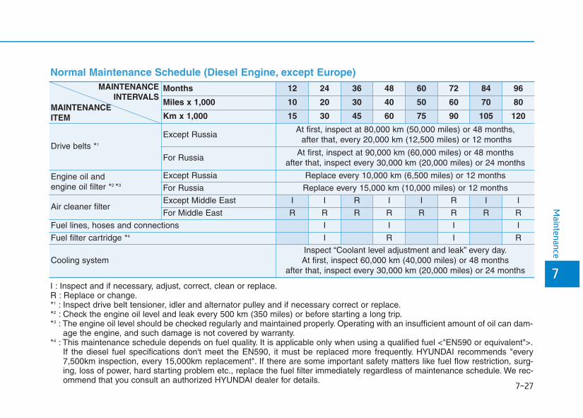
7-27
7
Maintenance
Normal Maintenance Schedule (Diesel Engine, except Europe)
Months 12 24 36 48 60 72 84 96
Miles x 1,000 10 20 30 40 50 60 70 80
Km x 1,000 15 30 45 60 75 90 105 120
Drive belts *1
Except RussiaAt first, inspect at 80,000 km (50,000 miles) or 48 months,
after that, every 20,000 km (12,500 miles) or 12 months
For RussiaAt first, inspect at 90,000 km (60,000 miles) or 48 months
after that, inspect every 30,000 km (20,000 miles) or 24 months
Engine oil and engine oil filter *2 *3
Except Russia Replace every 10,000 km (6,500 miles) or 12 months
For Russia Replace every 15,000 km (10,000 miles) or 12 months
Air cleaner filter Except Middle East I I R I I R I I
For Middle East R R R R R R R R
Fuel lines, hoses and connections I I I I
Fuel filter cartridge *4 I R I R
Cooling systemInspect “Coolant level adjustment and leak” every day.At first, inspect 60,000 km (40,000 miles) or 48 months
after that, inspect every 30,000 km (20,000 miles) or 24 months
I : Inspect and if necessary, adjust, correct, clean or replace.R : Replace or change.*1 : Inspect drive belt tensioner, idler and alternator pulley and if necessary correct or replace.*2 : Check the engine oil level and leak every 500 km (350 miles) or before starting a long trip.*3 : The engine oil level should be checked regularly and maintained properly. Operating with an insufficient amount of oil can dam-
age the engine, and such damage is not covered by warranty.*4 : This maintenance schedule depends on fuel quality. It is applicable only when using a qualified fuel <"EN590 or equivalent">.
If the diesel fuel specifications don't meet the EN590, it must be replaced more frequently. HYUNDAI recommends "every7,500km inspection, every 15,000km replacement". If there are some important safety matters like fuel flow restriction, surg-ing, loss of power, hard starting problem etc., replace the fuel filter immediately regardless of maintenance schedule. We rec-ommend that you consult an authorized HYUNDAI dealer for details.
MAINTENANCEINTERVALS
MAINTENANCEITEM
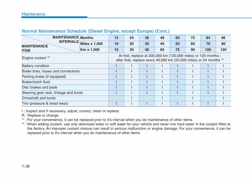
Maintenance
7-28
Normal Maintenance Schedule (Diesel Engine, except Europe) (Cont.) Months 12 24 36 48 60 72 84 96
Miles x 1,000 10 20 30 40 50 60 70 80
Km x 1,000 15 30 45 60 75 90 105 120
Engine coolant *6 At first, replace at 200,000 km (120,000 miles) or 120 months :after that, replace every 40,000 km (25,000 miles) or 24 months *5
Battery condition I I I I I I I I
Brake lines, hoses and connections I I I I I I I I
Parking brake (if equipped) I I I I I I I I
Brake/clutch fluid I I I I I I I I
Disc brakes and pads I I I I I I I I
Steering gear rack, linkage and boots I I I I I I I I
Driveshaft and boots I I I I
Tire (pressure & tread wear) I I I I I I I I
I : Inspect and if necessary, adjust, correct, clean or replace.R : Replace or change.*5 : For your convenience, it can be replaced prior to it's interval when you do maintenance of other items.*6 : When adding coolant, use only deionized water or soft water for your vehicle and never mix hard water in the coolant filled at
the factory. An improper coolant mixture can result in serious malfunction or engine damage. For your convenience, it can bereplaced prior to it's interval when you do maintenance of other items.
MAINTENANCEINTERVALS
MAINTENANCEITEM
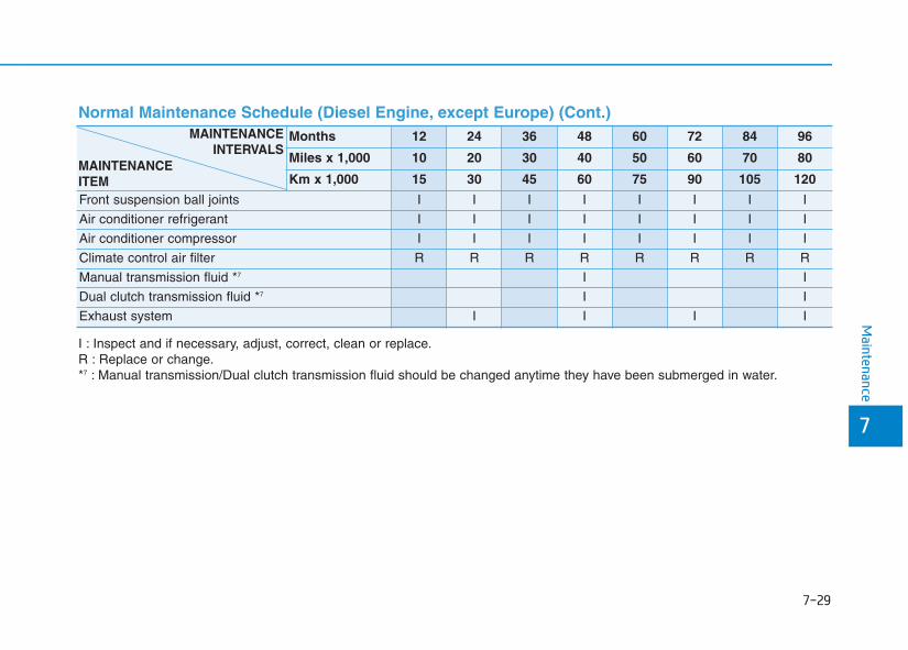
7-29
7
Maintenance
Normal Maintenance Schedule (Diesel Engine, except Europe) (Cont.) Months 12 24 36 48 60 72 84 96
Miles x 1,000 10 20 30 40 50 60 70 80
Km x 1,000 15 30 45 60 75 90 105 120
Front suspension ball joints I I I I I I I I
Air conditioner refrigerant I I I I I I I I
Air conditioner compressor I I I I I I I I
Climate control air filter R R R R R R R R
Manual transmission fluid *7 I I
Dual clutch transmission fluid *7 I I
Exhaust system I I I I
I : Inspect and if necessary, adjust, correct, clean or replace.R : Replace or change.*7 : Manual transmission/Dual clutch transmission fluid should be changed anytime they have been submerged in water.
MAINTENANCEINTERVALS
MAINTENANCEITEM
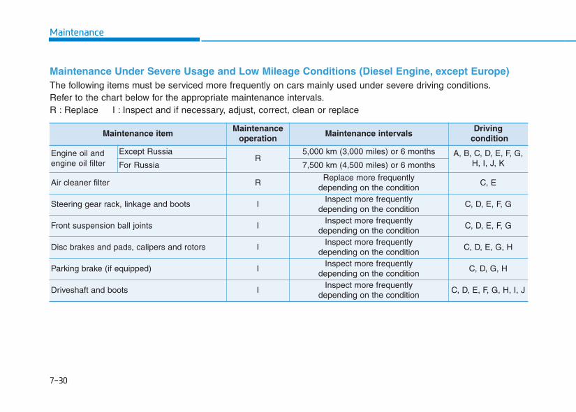
Maintenance
7-30
Maintenance Under Severe Usage and Low Mileage Conditions (Diesel Engine, except Europe) The following items must be serviced more frequently on cars mainly used under severe driving conditions.Refer to the chart below for the appropriate maintenance intervals.R : Replace I : Inspect and if necessary, adjust, correct, clean or replace
Maintenance itemMaintenance
operationMaintenance intervals
Drivingcondition
Engine oil and engine oil filter
Except RussiaR
5,000 km (3,000 miles) or 6 months A, B, C, D, E, F, G,H, I, J, KFor Russia 7,500 km (4,500 miles) or 6 months
Air cleaner filter RReplace more frequently
depending on the conditionC, E
Steering gear rack, linkage and boots IInspect more frequently
depending on the conditionC, D, E, F, G
Front suspension ball joints IInspect more frequently
depending on the conditionC, D, E, F, G
Disc brakes and pads, calipers and rotors IInspect more frequently
depending on the conditionC, D, E, G, H
Parking brake (if equipped) IInspect more frequently
depending on the conditionC, D, G, H
Driveshaft and boots IInspect more frequently
depending on the conditionC, D, E, F, G, H, I, J
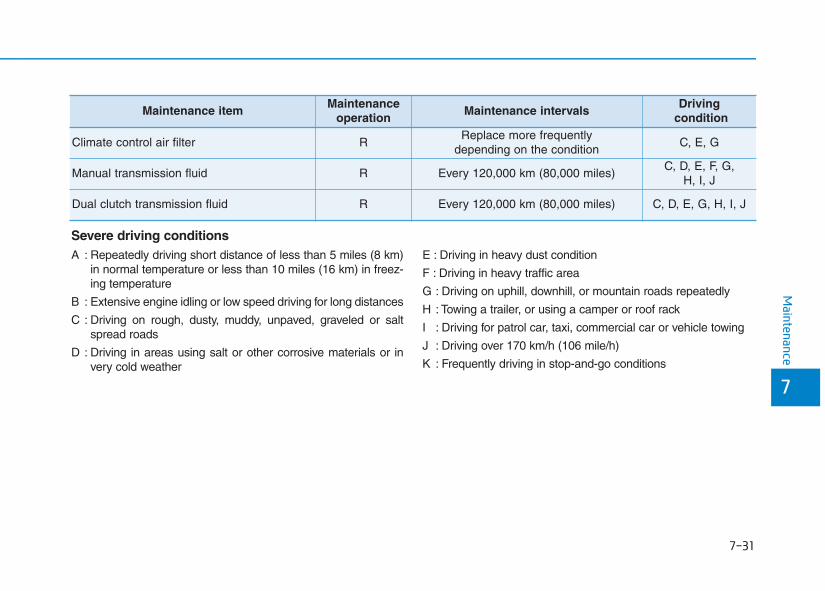
7-31
7
Maintenance
Maintenance itemMaintenance
operationMaintenance intervals
Drivingcondition
Climate control air filter RReplace more frequently
depending on the conditionC, E, G
Manual transmission fluid R Every 120,000 km (80,000 miles)C, D, E, F, G,
H, I, J
Dual clutch transmission fluid R Every 120,000 km (80,000 miles) C, D, E, G, H, I, J
Severe driving conditionsA : Repeatedly driving short distance of less than 5 miles (8 km)
in normal temperature or less than 10 miles (16 km) in freez-ing temperature
B : Extensive engine idling or low speed driving for long distances
C : Driving on rough, dusty, muddy, unpaved, graveled or saltspread roads
D : Driving in areas using salt or other corrosive materials or invery cold weather
E : Driving in heavy dust condition
F : Driving in heavy traffic area
G : Driving on uphill, downhill, or mountain roads repeatedly
H : Towing a trailer, or using a camper or roof rack
I : Driving for patrol car, taxi, commercial car or vehicle towing
J : Driving over 170 km/h (106 mile/h)
K : Frequently driving in stop-and-go conditions
7-32
Maintenance
EEXXPPLLAANNAATTIIOONN OOFF SSCCHHEEDDUULLEEDD MMAAIINNTTEENNAANNCCEE IITTEEMMSSEngine oil and filterThe engine oil and filter should bechanged at the intervals specified inthe maintenance schedule. If the caris being driven in severe conditions,more frequent oil and filter changesare required.
Drive beltsInspect all drive belts for evidence ofcuts, cracks, excessive wear or oilsaturation and replace if necessary.Drive belts should be checked peri-odically for proper tension andadjusted as necessary.
Fuel filter (cartridge)A clogged-up fuel filter may limit thevehicle driving speed, damage theemission system, and cause thehard starting. When a considerableamount of foreign substances areaccumulated in the fuel tank, the fuelfilter should be replaced.Upon installing a new fuel filter, oper-ate the diesel engine for several min-utes, and check the connections forany leakages. We recommend you tohave the fuel filter replaced by anauthorized HYUNDAI dealer.
Fuel lines, fuel hoses and con-nectionsCheck the fuel lines, fuel hoses andconnections for leakage and dam-age. We recommend that the fuellines, fuel hoses and connections bereplaced by an authorized HYUNDAIdealer.
Vapor hose and fuel filler capThe vapor hose and fuel filler capshould be inspected at those inter-vals specified in the maintenanceschedule. Make sure that a newvapor hose or fuel filler cap is cor-rectly replaced.
Vacuum crankcase ventilationhoses (if equipped)Inspect the surface of hoses for evi-dence of heat and/or mechanicaldamage. Hard and brittle rubber,cracking, tears, cuts, abrasions, andexcessive swelling indicate deterio-ration. Particular attention should bepaid to examine those hose surfacesnearest to high heat sources, suchas the exhaust manifold.Inspect the hose routing to assurethat the hoses do not come in con-tact with any heat source, sharpedges or moving component whichmight cause heat damage ormechanical wear. Inspect all hoseconnections, such as clamps andcouplings, to make sure they aresecure, and that no leaks are pres-ent. Hoses should be replacedimmediately if there is any evidenceof deterioration or damage.
When you are inspecting the belt,place the ignition switch to theLOCK/OFF or ACC position.
CAUTION
7-33
7
Maintenance
Air cleaner filterWe recommend that the air cleanerfilter be replaced by an authorizedHYUNDAI dealer.
Spark plugs(for Gasoline Engine)Make sure to install new spark plugsof the correct heat range.
Valve clearance (for Gasoline Engine)Inspect excessive valve noise and/orengine vibration and adjust if neces-sary. We recommend that the systembe serviced by an authorized HYUNDAIdealer.
Cooling systemCheck the cooling system parts,such as radiator, coolant reservoir,hoses and connections for leakageand damage. Replace any damagedparts.
Engine coolantThe coolant should be changed atthe intervals specified in the mainte-nance schedule.
Automatic transmission fluid(if equipped)Automatic transmission fluid shouldnot be checked under normal usageconditions.We recommend that the automatictransmission fluid changed by anauthorized HYUNDAI dealer accord-ing to the maintenance schedule.
Information Automatic transmission fluid color isbasically red.
As the vehicle is driven, the automatictransmission fluid will begin to lookdarker.
It is normal condition and you shouldnot judge the need to replace the fluidbased upon the changed color.
The use of a non-specified fluidcould result in transmission mal-function and failure.Use only specified automatictransmission fluid.(Refer to “Recommended lubri-cants and capacities” in chapter 8.)
Manual transmission fluid(if equipped)Inspect the manual transmissionfluid according to the maintenanceschedule.
NOTICE
i
Do not disconnect and inspectspark plugs when the engine ishot. You may burn yourself.
WARNING
7-34
Maintenance
Dual clutch transmission fluid(if equipped)Inspect the dual clutch transmissionfluid according to the maintenanceschedule.
Brake hoses and linesVisually check for proper installation,chafing, cracks, deterioration andany leakage. Replace any deteriorat-ed or damaged parts immediately.
Brake/Clutch fluid (if equipped)Check brake fluid level in the brakefluid reservoir. The level should bebetween “MIN” and “MAX” marks onthe side of the reservoir. Use onlyhydraulic brake fluid conforming toDOT 3 or DOT 4 specification.
Parking brakeInspect the parking brake systemincluding the parking brake lever andcables.
Brake pads, calipers androtorsCheck the pads for excessive wear,discs for run out and wear, andcalipers for fluid leakage.For more information on checkingthe pads or lining wear limit, refer tothe HYUNDAI web site.(http://service.hyundai-motor.com)
Suspension mounting boltsCheck the suspension connectionsfor looseness or damage. Retightento the specified torque.
Steering gear box, linkage &boots/lower arm ball jointWith the vehicle stopped and engineoff, check for excessive free-play inthe steering wheel.Check the linkage for bends or dam-age. Check the dust boots and balljoints for deterioration, cracks, ordamage. Replace any damagedparts.
Drive shafts and bootsCheck the drive shafts, boots andclamps for cracks, deterioration, ordamage. Replace any damagedparts and, if necessary, repack thegrease.
Air conditioning refrigerant/compressorCheck the air conditioning lines andconnections for leakage and dam-age.
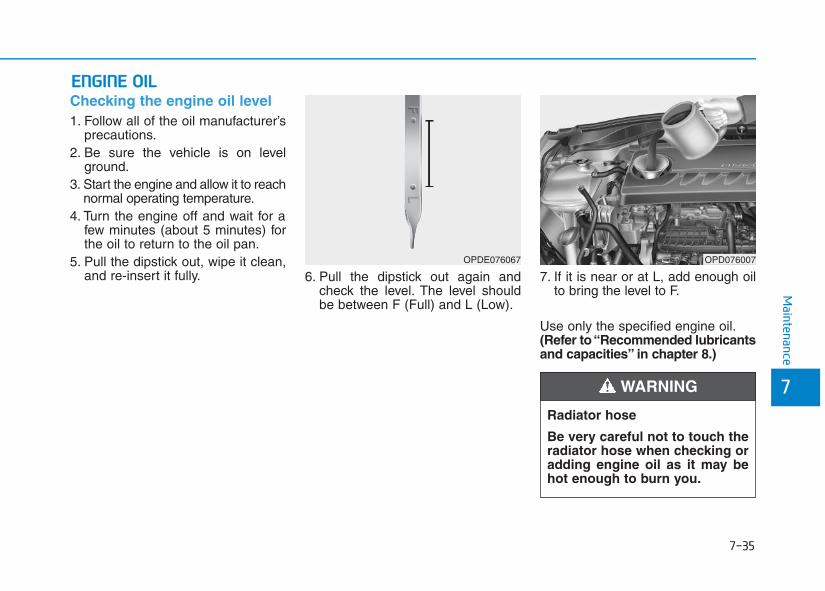
7-35
7
Maintenance
EENNGGIINNEE OOIILLChecking the engine oil level 1. Follow all of the oil manufacturer’s
precautions.2. Be sure the vehicle is on level
ground.3. Start the engine and allow it to reach
normal operating temperature.4. Turn the engine off and wait for a
few minutes (about 5 minutes) forthe oil to return to the oil pan.
5. Pull the dipstick out, wipe it clean,and re-insert it fully. 6. Pull the dipstick out again and
check the level. The level shouldbe between F (Full) and L (Low).
7. If it is near or at L, add enough oilto bring the level to F.
Use only the specified engine oil.(Refer to “Recommended lubricantsand capacities” in chapter 8.)
OPDE076067 OPD076007
Radiator hose
Be very careful not to touch theradiator hose when checking oradding engine oil as it may behot enough to burn you.
WARNING
7-36
Maintenance
To prevent damage to your engine:• Do not overfill with engine oil.
Add oil in small quantities andrecheck level to ensure engineis not overfilled.
• Do not spill engine oil whenadding or changing engine oil.Use a funnel to help prevent oilfrom being spilled on enginecomponents. Wipe off spilled oilimmediately.
Checking the engine oil and filter
We recommend that the engine oiland filter be replaced by an authorizedHYUNDAI dealer.
NOTICE
Used engine oil may cause irri-tation or cancer of the skin ifleft in contact with the skin forprolonged periods of time. Usedengine oil contains chemicalsthat have caused cancer in lab-oratory animals. Always protectyour skin by washing yourhands thoroughly with soapand warm water as soon as pos-sible after handling used oil.
WARNING
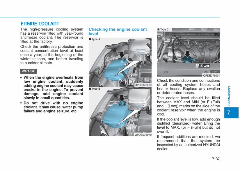
7-37
7
Maintenance
EENNGGIINNEE CCOOOOLLAANNTTThe high-pressure cooling systemhas a reservoir filled with year-roundantifreeze coolant. The reservoir isfilled at the factory.Check the antifreeze protection andcoolant concentration level at leastonce a year, at the beginning of thewinter season, and before travelingto a colder climate.
• When the engine overheats fromlow engine coolant, suddenlyadding engine coolant may causecracks in the engine. To preventdamage, add engine coolantslowly in small quantities.
• Do not drive with no enginecoolant. It may cause water pumpfailure and engine seizure, etc.
Checking the engine coolantlevel
Check the condition and connectionsof all cooling system hoses andheater hoses. Replace any swollenor deteriorated hoses.The coolant level should be filledbetween MAX and MIN (or F (Full)and L (Low)) marks on the side of thecoolant reservoir when the engine iscool.If the coolant level is low, add enoughdistilled (deionized) water. Bring thelevel to MAX, (or F (Full)) but do notoverfill.If frequent additions are required, werecommend that the system beinspected by an authorized HYUNDAIdealer.
NOTICE
OPDE076068
OPDE076070
■ Type A
■ Type B
OPDE076091
■ Type C
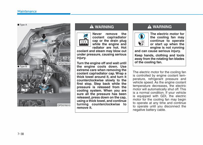
7-38
Maintenance
The electric motor for the cooling fanis controlled by engine coolant tem-perature, refrigerant pressure andvehicle speed. As the engine coolanttemperature decreases, the electricmotor will automatically shut off. Thisis a normal condition. If your vehicleis equipped with GDI, the electricmotor for the cooling fan may beginto operate at any time and continueto operate until you disconnect thenegative battery cable.
The electric motor forthe cooling fan maycontinue to operateor start up when theengine is not running
and can cause serious injury.Keep hands, clothing and toolsaway from the rotating fan bladesof the cooling fan.
WARNING
Never remove thecoolant cap/radiatorcap or the drain plugwhile the engine andradiator are hot. Hot
coolant and steam may blow outunder pressure, causing seriousinjury.
Turn the engine off and wait untilthe engine cools down. Useextreme care when removing thecoolant cap/radiator cap. Wrap athick towel around it, and turn itcounterclockwise slowly to thefirst stop. Step back while thepressure is released from thecooling system. When you aresure all the pressure has beenreleased, press down on the cap,using a thick towel, and continueturning counterclockwise toremove it.
WARNING
OPD076013
OPD076015
■ Type A
■ Type B
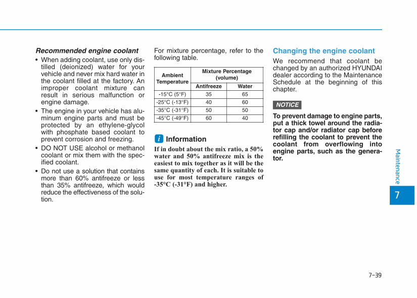
7-39
7
Maintenance
Recommended engine coolant• When adding coolant, use only dis-
tilled (deionized) water for yourvehicle and never mix hard water inthe coolant filled at the factory. Animproper coolant mixture canresult in serious malfunction orengine damage.
• The engine in your vehicle has alu-minum engine parts and must beprotected by an ethylene-glycolwith phosphate based coolant toprevent corrosion and freezing.
• DO NOT USE alcohol or methanolcoolant or mix them with the spec-ified coolant.
• Do not use a solution that containsmore than 60% antifreeze or lessthan 35% antifreeze, which wouldreduce the effectiveness of the solu-tion.
For mixture percentage, refer to thefollowing table.
InformationIf in doubt about the mix ratio, a 50%water and 50% antifreeze mix is theeasiest to mix together as it will be thesame quantity of each. It is suitable touse for most temperature ranges of -35°C (-31°F) and higher.
Changing the engine coolantWe recommend that coolant bechanged by an authorized HYUNDAIdealer according to the MaintenanceSchedule at the beginning of thischapter.
To prevent damage to engine parts,put a thick towel around the radia-tor cap and/or radiator cap beforerefilling the coolant to prevent thecoolant from overflowing intoengine parts, such as the genera-tor.
NOTICE
i
AmbientTemperature
Mixture Percentage (volume)
Antifreeze Water-15°C (5°F) 35 65
-25°C (-13°F) 40 60
-35°C (-31°F) 50 50
-45°C (-49°F) 60 40
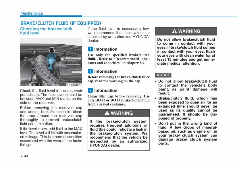
BBRRAAKKEE//CCLLUUTTCCHH FFLLUUIIDD ((IIFF EEQQUUIIPPPPEEDD))Checking the brake/clutchfluid level
Check the fluid level in the reservoirperiodically. The fluid level should bebetween MAX and MIN marks on theside of the reservoir.Before removing the reservoir capand adding brake/clutch fluid, cleanthe area around the reservoir capthoroughly to prevent brake/clutchfluid contamination.If the level is low, add fluid to the MAXlevel.The level will fall with accumulat-ed mileage. This is a normal conditionassociated with the wear of the brakelinings.
If the fluid level is excessively low, we recommend that the system bechecked by an authorized HYUNDAIdealer.
Information Use only the specified brake/clutchfluid. (Refer to “Recommended lubri-cants and capacities” in chapter 8.)
Information Before removing the brake/clutch fillercap, read the warning on the cap.
Information Clean filler cap before removing. Useonly DOT3 or DOT4 brake/clutch fluidfrom a sealed container.
• Do not allow brake/clutch fluidto contact the vehicle's bodypaint, as paint damage willresult.
• Brake/clutch fluid, which hasbeen exposed to open air for anextended time should never beused as its quality cannot beguaranteed. It should be dis-posed of properly.
• Don't put in the wrong kind offluid. A few drops of mineral-based oil, such as engine oil, inyour brake/ clutch system candamage brake/ clutch systemparts.
NOTICE
i
i
i
7-40
Maintenance
OPD076016
If the brake/clutch systemrequires frequent additions offluid this could indicate a leak inthe brake/clutch system. Werecommend that the vehicle beinspected by an authorizedHYUNDAI dealer.
WARNING
Do not allow brake/clutch fluidto come in contact with youreyes. If brake/clutch fluid comesin contact with your eyes, flushyour eyes with clean water for atleast 15 minutes and get imme-diate medical attention.
WARNING
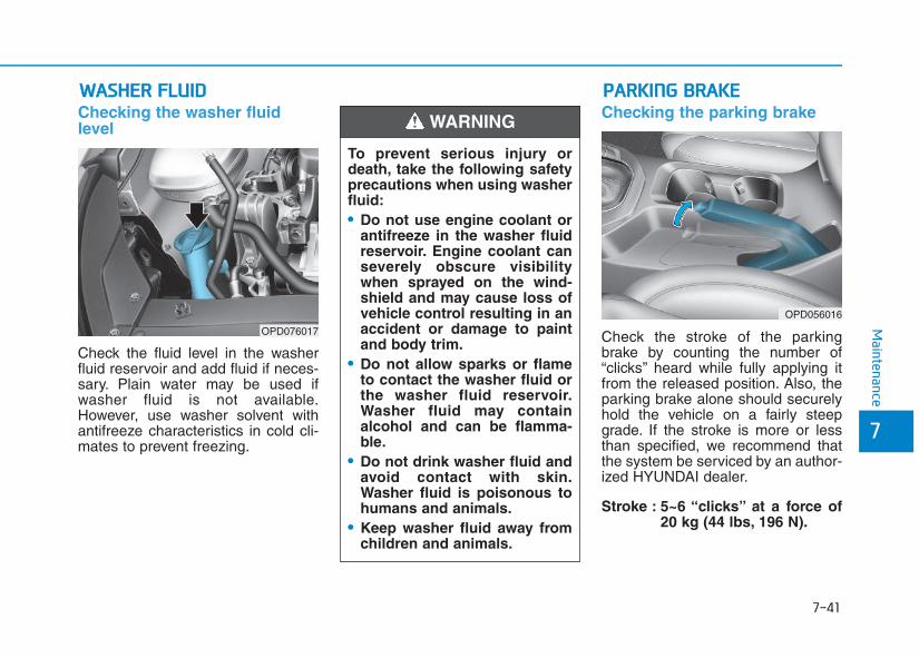
7-41
7
Maintenance
WWAASSHHEERR FFLLUUIIDDChecking the washer fluidlevel
Check the fluid level in the washerfluid reservoir and add fluid if neces-sary. Plain water may be used ifwasher fluid is not available.However, use washer solvent withantifreeze characteristics in cold cli-mates to prevent freezing.
Checking the parking brake
Check the stroke of the parkingbrake by counting the number of“clicks’’ heard while fully applying itfrom the released position. Also, theparking brake alone should securelyhold the vehicle on a fairly steepgrade. If the stroke is more or lessthan specified, we recommend thatthe system be serviced by an author-ized HYUNDAI dealer.
Stroke : 5~6 “clicks’’ at a force of 20 kg (44 lbs, 196 N).
OPD076017
PPAARRKKIINNGG BBRRAAKKEE
OPD056016
To prevent serious injury ordeath, take the following safetyprecautions when using washerfluid:• Do not use engine coolant or
antifreeze in the washer fluidreservoir. Engine coolant canseverely obscure visibilitywhen sprayed on the wind-shield and may cause loss ofvehicle control resulting in anaccident or damage to paintand body trim.
• Do not allow sparks or flameto contact the washer fluid orthe washer fluid reservoir.Washer fluid may containalcohol and can be flamma-ble.
• Do not drink washer fluid andavoid contact with skin.Washer fluid is poisonous tohumans and animals.
• Keep washer fluid away fromchildren and animals.
WARNING
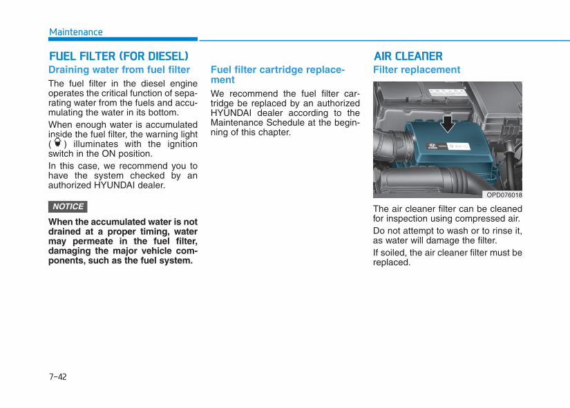
7-42
Maintenance
AAIIRR CCLLEEAANNEERRFFUUEELL FFIILLTTEERR ((FFOORR DDIIEESSEELL))Draining water from fuel filterThe fuel filter in the diesel engineoperates the critical function of sepa-rating water from the fuels and accu-mulating the water in its bottom.When enough water is accumulatedinside the fuel filter, the warning light( ) illuminates with the ignitionswitch in the ON position.In this case, we recommend you tohave the system checked by anauthorized HYUNDAI dealer.
When the accumulated water is notdrained at a proper timing, watermay permeate in the fuel filter,damaging the major vehicle com-ponents, such as the fuel system.
Fuel filter cartridge replace-mentWe recommend the fuel filter car-tridge be replaced by an authorizedHYUNDAI dealer according to theMaintenance Schedule at the begin-ning of this chapter.
Filter replacement
The air cleaner filter can be cleanedfor inspection using compressed air.Do not attempt to wash or to rinse it,as water will damage the filter.If soiled, the air cleaner filter must bereplaced.
NOTICEOPD076018
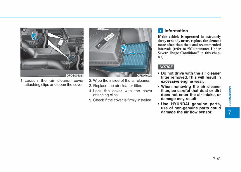
7-43
7
Maintenance
1. Loosen the air cleaner coverattaching clips and open the cover.
2. Wipe the inside of the air cleaner.3. Replace the air cleaner filter.4. Lock the cover with the cover
attaching clips.5. Check if the cover is firmly installed.
Information If the vehicle is operated in extremelydusty or sandy areas, replace the elementmore often than the usual recommendedintervals (refer to “Maintenance UnderSevere Usage Conditions” in this chap-ter).
• Do not drive with the air cleanerfilter removed. This will result inexcessive engine wear.
• When removing the air cleanerfilter, be careful that dust or dirtdoes not enter the air intake, ordamage may result.
• Use HYUNDAI genuine parts,use of non-genuine parts coulddamage the air flow sensor.
NOTICE
i
OPDE076021 OPD076022
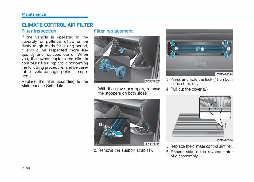
7-44
Maintenance
CCLLIIMMAATTEE CCOONNTTRROOLL AAIIRR FFIILLTTEERRFilter inspectionIf the vehicle is operated in theseverely air-polluted cities or ondusty rough roads for a long period,it should be inspected more fre-quently and replaced earlier. Whenyou, the owner, replace the climatecontrol air filter, replace it performingthe following procedure, and be care-ful to avoid damaging other compo-nents.Replace the filter according to theMaintenance Schedule.
Filter replacement
1. With the glove box open, removethe stoppers on both sides.
2. Remove the support strap (1).
3. Press and hold the lock (1) on bothsides of the cover.
4. Pull out the cover (2).
5. Replace the climate control air filter.6. Reassemble in the reverse order
of disassembly.
OPD076024
OPD076023
OPD076025
OPD076026
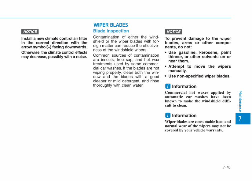
7-45
7
Maintenance
Install a new climate control air filterin the correct direction with thearrow symbol(↓↓) facing downwards.Otherwise, the climate control effectsmay decrease, possibly with a noise.
Blade inspectionContamination of either the wind-shield or the wiper blades with for-eign matter can reduce the effective-ness of the windshield wipers.Common sources of contaminationare insects, tree sap, and hot waxtreatments used by some commer-cial car washes. If the blades are notwiping properly, clean both the win-dow and the blades with a goodcleaner or mild detergent, and rinsethoroughly with clean water.
To prevent damage to the wiperblades, arms or other compo-nents, do not:• Use gasoline, kerosene, paint
thinner, or other solvents on ornear them.
• Attempt to move the wipersmanually.
• Use non-specified wiper blades.
Information Commercial hot waxes applied byautomatic car washes have beenknown to make the windshield diffi-cult to clean.
Information Wiper blades are consumable item andnormal wear of the wipers may not becovered by your vehicle warranty.
i
i
NOTICENOTICE
WWIIPPEERR BBLLAADDEESS
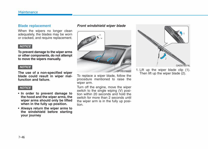
7-46
Maintenance
Blade replacement When the wipers no longer cleanadequately, the blades may be wornor cracked, and require replacement.
To prevent damage to the wiper armsor other components, do not attemptto move the wipers manually.
The use of a non-specified wiperblade could result in wiper mal-function and failure.
• In order to prevent damage tothe hood and the wiper arms, thewiper arms should only be liftedwhen in the fully up position.
• Always return the wiper arms tothe windshield before startingyour journey
Front windshield wiper blade
To replace a wiper blade, follow theprocedure mentioned to raise thewiper arm.Turn off the engine, move the wiperswitch to the single wiping (V) posi-tion within 20 seconds and hold theswitch for more than 2 seconds untilthe wiper arm is in the fully up posi-tion.
1. Lift up the wiper blade clip (1).Then lift up the wiper blade (2).
NOTICE
NOTICE
NOTICE
OPDE076027
OAD075074L
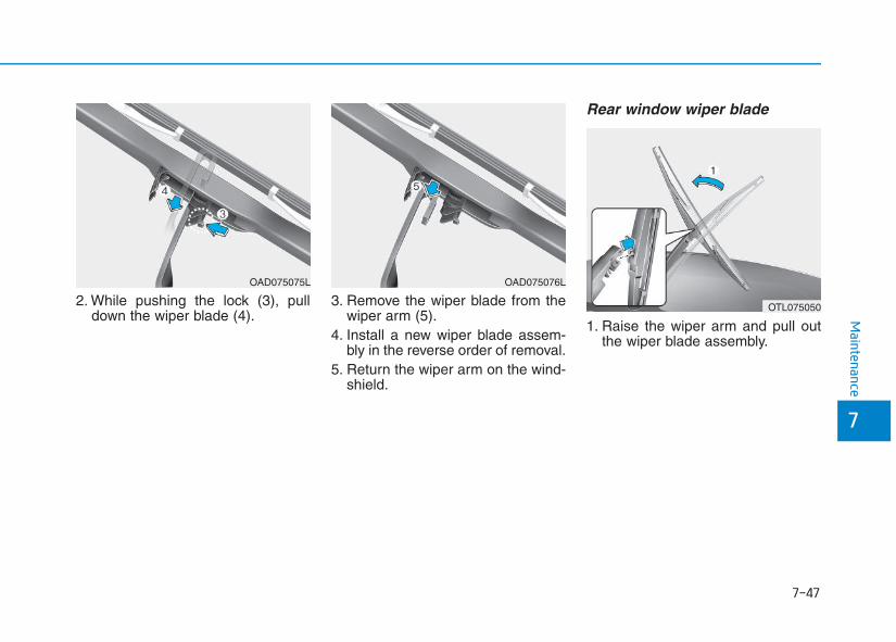
7-47
7
Maintenance
2. While pushing the lock (3), pulldown the wiper blade (4).
3. Remove the wiper blade from thewiper arm (5).
4. Install a new wiper blade assem-bly in the reverse order of removal.
5. Return the wiper arm on the wind-shield.
Rear window wiper blade
1. Raise the wiper arm and pull outthe wiper blade assembly.
OAD075075L OAD075076L
OTL075050
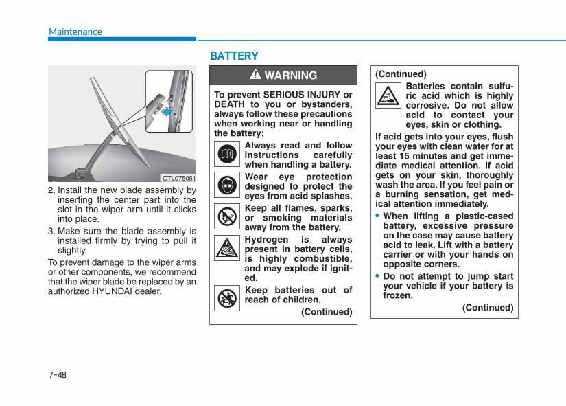
7-48
Maintenance
BBAATTTTEERRYY
2. Install the new blade assembly byinserting the center part into theslot in the wiper arm until it clicksinto place.
3. Make sure the blade assembly isinstalled firmly by trying to pull itslightly.
To prevent damage to the wiper armsor other components, we recommendthat the wiper blade be replaced by anauthorized HYUNDAI dealer.
OTL075051
To prevent SERIOUS INJURY orDEATH to you or bystanders,always follow these precautionswhen working near or handlingthe battery:
Always read and followinstructions carefullywhen handling a battery.Wear eye protectiondesigned to protect theeyes from acid splashes.Keep all flames, sparks,or smoking materialsaway from the battery.Hydrogen is alwayspresent in battery cells,is highly combustible,and may explode if ignit-ed.Keep batteries out ofreach of children.
(Continued)
WARNING (Continued)Batteries contain sulfu-ric acid which is highlycorrosive. Do not allowacid to contact youreyes, skin or clothing.
If acid gets into your eyes, flushyour eyes with clean water for atleast 15 minutes and get imme-diate medical attention. If acidgets on your skin, thoroughlywash the area. If you feel pain ora burning sensation, get med-ical attention immediately.• When lifting a plastic-cased
battery, excessive pressureon the case may cause batteryacid to leak. Lift with a batterycarrier or with your hands onopposite corners.
• Do not attempt to jump startyour vehicle if your battery isfrozen.
(Continued)
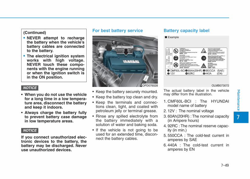
7-49
7
Maintenance
• When you do not use the vehiclefor a long time in a low tempera-ture area, disconnect the batteryand keep it indoors.
• Always charge the battery fullyto prevent battery case damagein low temperature areas.
If you connect unauthorized elec-tronic devices to the battery, thebattery may be discharged. Neveruse unauthorized devices.
For best battery service
• Keep the battery securely mounted.• Keep the battery top clean and dry.• Keep the terminals and connec-
tions clean, tight, and coated withpetroleum jelly or terminal grease.
• Rinse any spilled electrolyte fromthe battery immediately with asolution of water and baking soda.
• If the vehicle is not going to beused for an extended time, discon-nect the battery cables.
Battery capacity label
The actual battery label in the vehiclemay differ from the illustration.
1. CMF60L-BCI : The HYUNDAImodel name of battery
2. 12V : The nominal voltage3. 60Ah(20HR) : The nominal capacity
(in Ampere hours)4. 92RC : The nominal reserve capac-
ity (in min.)5. 550CCA : The cold-test current in
amperes by SAE6. 440A : The cold-test current in
amperes by EN
NOTICE
NOTICEOPD076028
(Continued)• NEVER attempt to recharge
the battery when the vehicle’sbattery cables are connectedto the battery.
• The electrical ignition systemworks with high voltage.NEVER touch these compo-nents with the engine runningor when the ignition switch isin the ON position.
OLMB073072
■ Example
7-50
Maintenance
Battery rechargingBy battery chargerYour vehicle has a maintenance-free,calcium-based battery.• If the battery becomes discharged
in a short time (because, for exam-ple, the headlights or interior lightswere left on while the vehicle wasnot in use), recharge it by slowcharging (trickle) for 10 hours.
• If the battery gradually dischargesbecause of high electric load whilethe vehicle is being used, rechargeit at 20-30A for two hours.
Always follow these instructionswhen recharging your vehicle’sbattery to avoid the risk of SERI-OUS INJURY or DEATH fromexplosions or acid burns:• Before performing mainte-
nance or recharging the bat-tery, turn off all accessoriesand place the Engine Start/Stop button to the OFF posi-tion.
• Keep all flames, sparks, orsmoking materials away fromthe battery.
• Always work outdoors or in anarea with plenty of ventilation.
• Wear eye protection whenchecking the battery duringcharging.
• The battery must be removedfrom the vehicle and placed ina well ventilated area.
(Continued)
WARNING (Continued)• Watch the battery during
charging, and stop or reducethe charging rate if the batterycells begin boiling violently.
• The negative battery cablemust be removed first andinstalled last when the batteryis disconnected. Disconnectthe battery charger in the fol-lowing order:(1) Turn off the battery charger
main switch.(2) Unhook the negative
clamp from the negativebattery terminal.
(3) Unhook the positive clampfrom the positive batteryterminal.
• Always use a genuine HYUNDAIapproved battery when youreplace the battery.
7-51
7
Maintenance
By jump starting After a jump start from a good bat-tery, drive the vehicle for 20-30 min-utes before it is shutoff. The vehiclemay not restart if you shut it offbefore the battery had a chance toadequately recharge. See “JumpStarting” in chapter 6 for more infor-mation on jump starting procedures.
Information An inappropriately disposedbattery can be harmful tothe environment and humanhealth.
Dispose the battery according to yourlocal law(s) or regulation.
Reset itemsItems should be reset after the bat-tery has been discharged or the bat-tery has been disconnected.• Auto up/down window• Sunroof• Trip computer• Climate control system• Driver position memory system• Clock• Audio system
i
AGM battery (if equipped)
• Absorbent Glass Matt (AGM)batteries are maintenance-free and we recommend thatthe AGM battery be servicedby an authorized HYUNDAIdealer. For charging yourAGM battery, use only fullyautomatic battery chargersthat are specially developedfor AGM batteries.
• When replacing the AGM bat-tery, we recommend that youuse parts for replacementfrom an authorized HYUNDAIdealer.
• Do not open or remove thecap on top of the battery. Thismay cause leaks of internalelectrolyte that could result insevere injury.
CAUTION
7-52
Maintenance
TTIIRREESS AANNDD WWHHEEEELLSS Tire careFor proper maintenance, safety, andmaximum fuel economy, you mustalways maintain recommended tireinflation pressures and stay within theload limits and weight distribution rec-ommended for your vehicle.
All specifications (sizes and pressures)can be found on a label attached to thedriver’s side center pillar.
(Continued)• Replace tires that are worn,
show uneven wear, or are dam-aged. Worn tires can causeloss of braking effectiveness,steering) control, or traction.
• ALWAYS replace tires with thesame size as each tire thatwas originally supplied withthis vehicle. Using tires andwheels other than the recom-mended sizes could causeunusual handling characteris-tics, poor vehicle control, ornegatively affect your vehi-cle’s Anti-Lock Brake System(ABS) resulting in a seriousaccident.
Tire failure may cause loss ofvehicle control resulting in anaccident. To reduce risk ofSERIOUS INJURY or DEATH,take the following precautions:• Inspect your tires monthly for
proper inflation as well aswear and damage.
• The recommended cold tirepressure for your vehicle canbe found in this manual and onthe tire label located on the dri-ver’s side center pillar. Alwaysuse a tire pressure gauge tomeasure tire pressure. Tireswith too much or too littlepressure wear unevenly caus-ing poor handling.
• Check the pressure of thespare every time you checkthe pressure of the other tireson your vehicle.
(Continued)
WARNING
OPD086007
7-53
7
Maintenance
Recommended cold tire infla-tion pressures All tire pressures (including thespare) should be checked when thetires are cold. “Cold tires” means thevehicle has not been driven for atleast three hours or driven less than1.6 km (one mile).Warm tires normally exceed recom-mended cold tire pressures by 28 to41 kPa (4 to 6 psi). Do not release airfrom warm tires to adjust the pres-sure or the tires will be under-inflat-ed. For recommended inflation pres-sure, refer to “Tire and Wheels” inchapter 8.
Recommended pressures mustbe maintained for the best ride,vehicle handling, and minimumtire wear.Over-inflation or under-inflationcan reduce tire life, adverselyaffect vehicle handling, andlead to sudden tire failure thatcould result in loss of vehiclecontrol resulting in an accident.Severe under-inflation can leadto severe heat build-up, causingblowouts, tread separation andother tire failures that can resultin the loss of vehicle controlresulting in an accident. Thisrisk is much higher on hot daysand when driving for long peri-ods at high speeds.
WARNING
• Under-inflation results inexcessive wear, poor handlingand reduced fuel economy.Wheel deformation is alsopossible. Keep your tire pres-sures at the proper levels. If atire frequently needs refilling,we recommend it be checkedby an authorized HYUNDAIdealer.
• Over-inflation produces aharsh ride, excessive wear atthe center of the tire tread,and a greater possibility ofdamage from road hazards.
CAUTION
7-54
Maintenance
Check tire inflation pressureCheck your tires, including the sparetire, once a month or more.
How to checkUse a good quality tire pressuregauge to check tire pressure. Youcan not tell if your tires are properlyinflated simply by looking at them.Radial tires may look properly inflat-ed when they are under-inflated.Remove the valve cap from the tirevalve stem. Press the tire gauge firm-ly onto the valve to get a pressuremeasurement. If the cold tire inflationpressure matches the recommendedpressure on the tire and loadinginformation label, no further adjust-ment is necessary. If the pressure islow, add air until you reach the rec-ommended pressure. Make sure toput the valve caps back on the valvestems. Without the valve cap, dirt ormoisture could get into the valvecore and cause air leakage. If a valvecap is missing, install a new one assoon as possible.
If you overfill the tire, release air bypushing on the metal stem in thecenter of the tire valve. Recheck thetire pressure with the tire gauge. Besure to put the valve caps back onthe valve stems. Without the valvecap, dirt or moisture could get intothe valve core and cause air leakage.If a valve cap is missing, install a newone as soon as possible.
Tire rotation To equalize tread wear, HYUNDAIrecommends that the tires be rotatedevery 12,000 km (7,500 miles) orsooner if irregular wear develops.During rotation, check the tires forcorrect balance.When rotating tires, check for unevenwear and damage. Abnormal wear isusually caused by incorrect tire pres-sure, improper wheel alignment, out-of-balance wheels, severe braking orsevere cornering. Look for bumps orbulges in the tread or side of tire.Replace the tire if you find either ofthese conditions. Replace the tire iffabric or cord is visible. After rotation,be sure to bring the front and rear tirepressures to specification and checklug nut tightness (proper torque is 11~13 kgf·m [79~94 lbf·ft]).
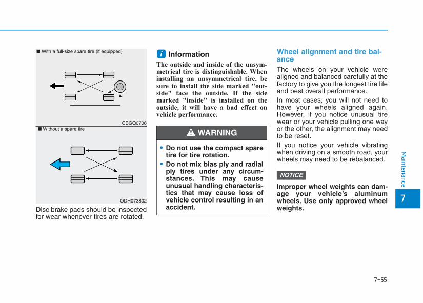
7-55
7
Maintenance
Disc brake pads should be inspectedfor wear whenever tires are rotated.
InformationThe outside and inside of the unsym-metrical tire is distinguishable. Wheninstalling an unsymmetrical tire, besure to install the side marked "out-side" face the outside. If the sidemarked "inside" is installed on theoutside, it will have a bad effect onvehicle performance.
Wheel alignment and tire bal-anceThe wheels on your vehicle werealigned and balanced carefully at thefactory to give you the longest tire lifeand best overall performance.In most cases, you will not need tohave your wheels aligned again.However, if you notice unusual tirewear or your vehicle pulling one wayor the other, the alignment may needto be reset.If you notice your vehicle vibratingwhen driving on a smooth road, yourwheels may need to be rebalanced.
Improper wheel weights can dam-age your vehicle’s aluminumwheels. Use only approved wheelweights.
NOTICE
i
CBGQ0706
ODH073802
■ With a full-size spare tire (if equipped)
■ Without a spare tire
• Do not use the compact sparetire for tire rotation.
• Do not mix bias ply and radialply tires under any circum-stances. This may causeunusual handling characteris-tics that may cause loss ofvehicle control resulting in anaccident.
WARNING
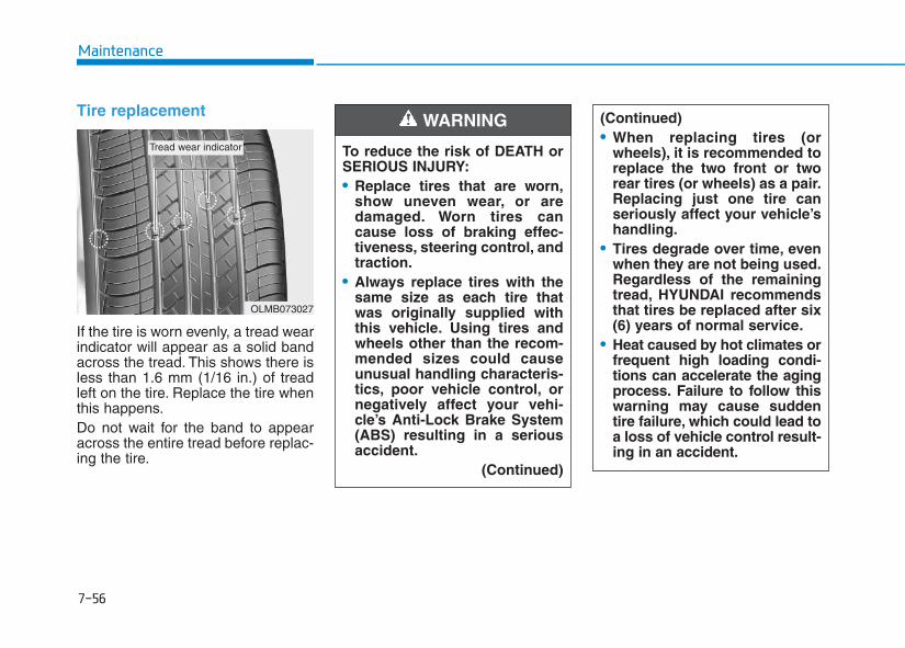
7-56
Maintenance
Tire replacement
If the tire is worn evenly, a tread wearindicator will appear as a solid bandacross the tread. This shows there isless than 1.6 mm (1/16 in.) of treadleft on the tire. Replace the tire whenthis happens.Do not wait for the band to appearacross the entire tread before replac-ing the tire.
OLMB073027
Tread wear indicator To reduce the risk of DEATH orSERIOUS INJURY:• Replace tires that are worn,
show uneven wear, or aredamaged. Worn tires cancause loss of braking effec-tiveness, steering control, andtraction.
• Always replace tires with thesame size as each tire thatwas originally supplied withthis vehicle. Using tires andwheels other than the recom-mended sizes could causeunusual handling characteris-tics, poor vehicle control, ornegatively affect your vehi-cle’s Anti-Lock Brake System(ABS) resulting in a seriousaccident.
(Continued)
WARNING (Continued)• When replacing tires (or
wheels), it is recommended toreplace the two front or tworear tires (or wheels) as a pair.Replacing just one tire canseriously affect your vehicle’shandling.
• Tires degrade over time, evenwhen they are not being used.Regardless of the remainingtread, HYUNDAI recommendsthat tires be replaced after six(6) years of normal service.
• Heat caused by hot climates orfrequent high loading condi-tions can accelerate the agingprocess. Failure to follow thiswarning may cause suddentire failure, which could lead toa loss of vehicle control result-ing in an accident.
7-57
7
Maintenance
Compact spare tire replacement(if equipped)A compact spare tire has a shortertread life than a regular size tire.Replace it when you can see thetread wear indicator bars on the tire.The replacement compact spare tireshould be the same size and designtire as the one provided with yournew vehicle and should be mountedon the same compact spare tirewheel. The compact spare tire is notdesigned to be mounted on a regularsize wheel, and the compact sparetire wheel is not designed for mount-ing a regular size tire.
Wheel replacementWhen replacing the metal wheels forany reason, make sure the newwheels are equivalent to the originalfactory units in diameter, rim widthand offset.
Tire traction Tire traction can be reduced if youdrive on worn tires, tires that areimproperly inflated or on slipperyroad surfaces. Tires should bereplaced when tread wear indicatorsappear. To reduce the possibility oflosing control, slow down wheneverthere is rain, snow or ice on the road.
Tire maintenanceIn addition to proper inflation, correctwheel alignment helps to decreasetire wear. If you find a tire is wornunevenly, have your dealer check thewheel alignment.When you have new tires installed,make sure they are balanced. Thiswill increase vehicle ride comfort andtire life. Additionally, a tire shouldalways be rebalanced if it is removedfrom the wheel.
Tire sidewall labelingThis information identifies anddescribes the fundamental charac-teristics of the tire and also providesthe tire identification number (TIN)for safety standard certification. TheTIN can be used to identify the tire incase of a recall.
The original tire should berepaired or replaced as soon aspossible to avoid failure of thespare and loss of vehicle controlresulting in an accident.The com-pact spare tire is for emergencyuse only. Do not operate yourvehicle over 80 km/h (50 mph)when using the compact sparetire.
WARNING
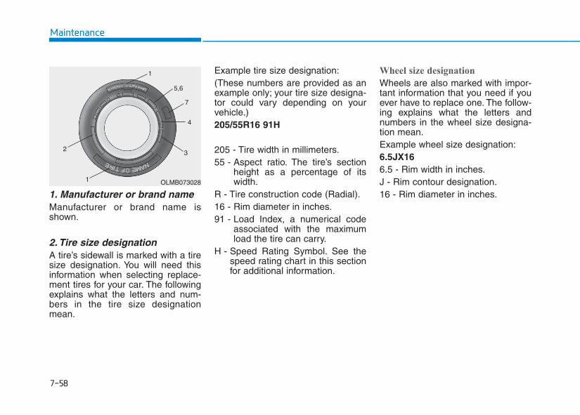
7-58
Maintenance
1. Manufacturer or brand name Manufacturer or brand name isshown.
2. Tire size designation A tire’s sidewall is marked with a tiresize designation. You will need thisinformation when selecting replace-ment tires for your car. The followingexplains what the letters and num-bers in the tire size designationmean.
Example tire size designation:(These numbers are provided as anexample only; your tire size designa-tor could vary depending on yourvehicle.)205/55R16 91H
205 - Tire width in millimeters.55 - Aspect ratio. The tire’s section
height as a percentage of itswidth.
R - Tire construction code (Radial).16 - Rim diameter in inches.91 - Load Index, a numerical code
associated with the maximumload the tire can carry.
H - Speed Rating Symbol. See thespeed rating chart in this sectionfor additional information.
Wheel size designation
Wheels are also marked with impor-tant information that you need if youever have to replace one. The follow-ing explains what the letters andnumbers in the wheel size designa-tion mean.Example wheel size designation:6.5JX166.5 - Rim width in inches.J - Rim contour designation.16 - Rim diameter in inches.
OLMB073028
1
1
23
4
5,6
7
7-59
7
Maintenance
Tire speed ratings
The chart below lists many of the dif-ferent speed ratings currently beingused for passenger car tires. Thespeed rating is part of the tire sizedesignation on the sidewall of thetire. This symbol corresponds to thattire’s designed maximum safe oper-ating speed.
3. Checking tire life (TIN : TireIdentification Number)
Any tires that are over six years old,based on the manufacturing date,(including the spare tire) should bereplaced by new ones. You can findthe manufacturing date on the tiresidewall (possibly on the inside of thewheel), displaying the DOT Code.The DOT Code is a series of num-bers on a tire consisting of numbersand English letters. The manufactur-ing date is designated by the last fourdigits (characters) of the DOT code.
DOT : XXXX XXXX OOOO
The front part of the DOT means aplant code number, tire size andtread pattern and the last four num-bers indicate week and year manu-factured.For example:DOT XXXX XXXX 1516 representsthat the tire was produced in the 15thweek of 2016.
4. Tire ply composition andmaterial
The number of layers or plies of rub-ber-coated fabric in the tire. Tiremanufacturers also must indicate thematerials in the tire, which includesteel, nylon, polyester, and others.The letter "R" means radial ply con-struction; the letter "D“ means diago-nal or bias ply construction; and theletter "B" means belted-bias ply con-struction.
5. Maximum permissible infla-tion pressure
This number is the greatest amountof air pressure that should be put inthe tire. Do not exceed the maximumpermissible inflation pressure. Referto the Tire and Loading Informationlabel for recommended inflationpressure.
SpeedRatingSymbol
Maximum Speed
S 180 km/h (112 mph)
T 190 km/h (118 mph)
H 210 km/h (130 mph)
V 240 km/h (149 mph)
W 270km/h (168mph)
Y 300km/h (186mph)
7-60
Maintenance
6. Maximum load ratingThis number indicates the maximumload in kilograms and pounds thatcan be carried by the tire. Whenreplacing the tires on the vehicle,always use a tire that has the sameload rating as the factory installedtire.
7. Uniform tire quality gradingQuality grades can be found whereapplicable on the tire sidewallbetween tread shoulder and maxi-mum section width.For example:TREAD wear 200TRACTION AATEMPERATURE A
Tread wear
The tread wear grade is a compara-tive rating based on the wear rate ofthe tire when tested under controlledconditions on a specified govern-ment test course. For example, a tiregraded 150 would wear one-and-a-half times (1½) as well on the gov-ernment course as a tire graded 100.The relative performance of tiresdepends upon the actual conditionsof their use, however, and maydepart significantly from the normdue to variations in driving habits,service practices and differences inroad characteristics and climate.These grades are molded on thesidewalls of passenger vehicle tires.The tires available as standard oroptional equipment on your vehiclemay vary with respect to grade.
Traction - AA, A, B & C
The traction grades, from highest tolowest, are AA, A, B and C. Thosegrades represent the tire’s ability tostop on wet pavement as measuredunder controlled conditions on spec-ified government test surfaces ofasphalt and concrete. A tire markedC may have poor traction perform-ance.
The traction grade assigned tothis tire is based on straight-ahead braking traction tests,and does not include accelera-tion, cornering, hydroplaning,or peak traction characteristics.
WARNING
7-61
7
Maintenance
Temperature - A, B & C
The temperature grades are A (thehighest), B and C representing thetire’s resistance to the generation ofheat and its ability to dissipate heatwhen tested under controlled condi-tions on a specified indoor laboratorytest wheel.Sustained high temperature cancause the material of the tire todegenerate and reduce tire life, andexcessive temperature can lead tosudden tire failure. Grades B and Arepresent higher levels of perform-ance on the laboratory test wheelthan the minimum required by law.
Low aspect ratio tiresA low aspect ratio tire, of which theaspect ratio is lower than 50, isdesigned for a sporty-look vehicle.The low aspect ratio is to optimizehandling and braking. Thus, it maybe uncomfortable to ride and it maygenerate noises, in comparison witha normal tire.
The temperature grade for thistire is established for a tire thatis properly inflated and notoverloaded. Excessive speed,under-inflation, over-inflation,or excessive loading, eitherseparately or in combination,can cause heat build-up andpossible sudden tire failure.This may cause loss of vehiclecontrol resulting in an accident.
WARNING
The side wall of a low aspectratio tire is shorter than the nor-mal one. Thus, the low-aspectwheel and tire are easily dam-aged. Follow the below instruc-tions.• When driving on a rough road
or driving off a road, be care-ful not to damage the tiresand wheels. After driving,inspect the tires and wheels.
• When passing over a pothole,speed bump, manhole, orcurb stone, slowly drive thevehicle not to damage thetires and wheels.
(Continued)
CAUTION
(Continued)• When there is an impact on a
tire, inspect the tire condition.Or, contact an authorizedHYUNDAI dealer.
• Inspect the tire condition andpressure every 3,000 km(1,800 miles) to prevent a tiredamage.
• It is difficult to recognize a tiredamage only with your eyes.When there is a slight hint of atire damage, check and replacethe tire to prevent the damagecaused by air leakage.
• When a tire is damaged whiledriving on a rough road, off aroad, or over obstacles, suchas a pothole, manhole, or curbstone, your warranty does notcover the damage.
• The tire information is speci-fied on the tire side wall.
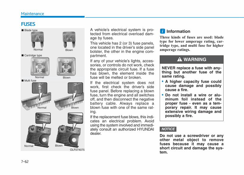
7-62
Maintenance
FFUUSSEESSA vehicle’s electrical system is pro-tected from electrical overload dam-age by fuses.This vehicle has 2 (or 3) fuse panels,one located in the driver’s side panelbolster, the other in the engine com-partment.If any of your vehicle’s lights, acces-sories, or controls do not work, checkthe appropriate circuit fuse. If a fusehas blown, the element inside thefuse will be melted or broken.If the electrical system does notwork, first check the driver’s sidefuse panel. Before replacing a blownfuse, turn the engine and all switchesoff, and then disconnect the negativebattery cable. Always replace ablown fuse with one of the same rat-ing.If the replacement fuse blows, this indi-cates an electrical problem. Avoidusing the system involved and immedi-ately consult an authorized HYUNDAIdealer.
InformationThree kinds of fuses are used: bladetype for lower amperage rating, car-tridge type, and multi fuse for higheramperage ratings.
Do not use a screwdriver or anyother metal object to removefuses because it may cause ashort circuit and damage the sys-tem.
NOTICE
i
Normal
■ Blade type
■ Cartridge type
Blown
Normal Blown
Normal Blown
OLF074075
NEVER replace a fuse with any-thing but another fuse of thesame rating.• A higher capacity fuse could
cause damage and possiblycause a fire.
• Do not install a wire or alu-minum foil instead of theproper fuse - even as a tem-porary repair. It may causeextensive wiring damage andpossibly a fire.
WARNING
Normal Blown■ Multi fuse
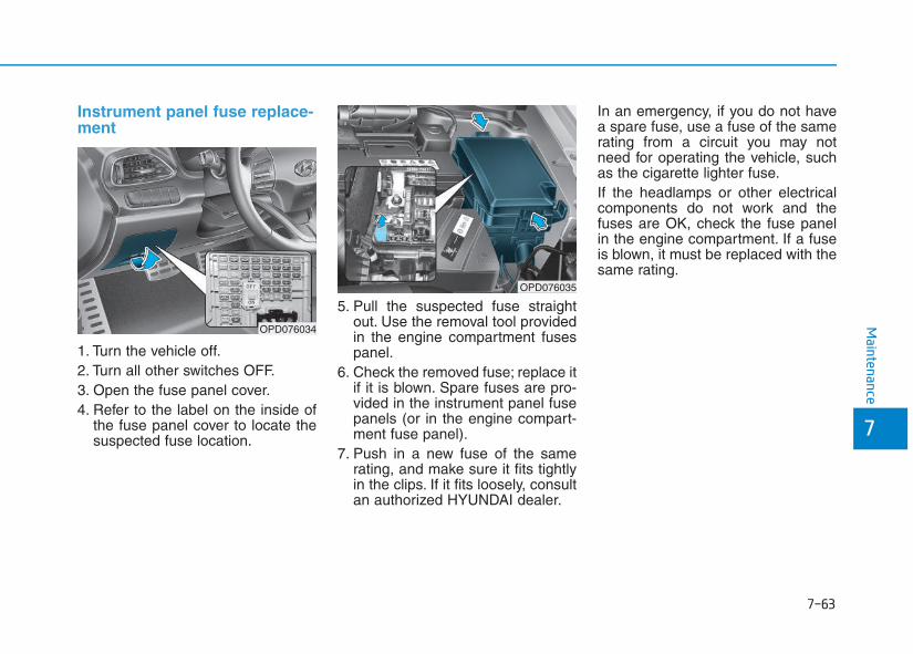
7-63
7
Maintenance
Instrument panel fuse replace-ment
1. Turn the vehicle off.2. Turn all other switches OFF.3. Open the fuse panel cover.4. Refer to the label on the inside of
the fuse panel cover to locate thesuspected fuse location.
5. Pull the suspected fuse straightout. Use the removal tool providedin the engine compartment fusespanel.
6. Check the removed fuse; replace itif it is blown. Spare fuses are pro-vided in the instrument panel fusepanels (or in the engine compart-ment fuse panel).
7. Push in a new fuse of the samerating, and make sure it fits tightlyin the clips. If it fits loosely, consultan authorized HYUNDAI dealer.
In an emergency, if you do not havea spare fuse, use a fuse of the samerating from a circuit you may notneed for operating the vehicle, suchas the cigarette lighter fuse.If the headlamps or other electricalcomponents do not work and thefuses are OK, check the fuse panelin the engine compartment. If a fuseis blown, it must be replaced with thesame rating.
OPD076034
OPD076035
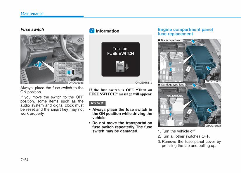
7-64
Maintenance
Fuse switch
Always, place the fuse switch to theON position.If you move the switch to the OFFposition, some items such as theaudio system and digital clock mustbe reset and the smart key may notwork properly.
Information
If the fuse switch is OFF, “Turn onFUSE SWITCH” message will appear.
• Always place the fuse switch inthe ON position while driving thevehicle.
• Do not move the transportationfuse switch repeatedly. The fuseswitch may be damaged.
Engine compartment panelfuse replacement
1. Turn the vehicle off.2. Turn all other switches OFF.3. Remove the fuse panel cover by
pressing the tap and pulling up.
NOTICE
i
OPD076036 OPDE046119 OPD076032
OPD076033
■ Blade type fuse
■ Cartridge type fuse
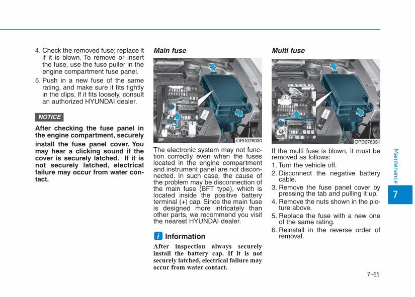
7-65
7
Maintenance
4. Check the removed fuse; replace itif it is blown. To remove or insertthe fuse, use the fuse puller in theengine compartment fuse panel.
5. Push in a new fuse of the samerating, and make sure it fits tightlyin the clips. If it fits loosely, consultan authorized HYUNDAI dealer.
After checking the fuse panel inthe engine compartment, securelyinstall the fuse panel cover. Youmay hear a clicking sound if thecover is securely latched. If it isnot securely latched, electricalfailure may occur from water con-tact.
Main fuse
The electronic system may not func-tion correctly even when the fuseslocated in the engine compartmentand instrument panel are not discon-nected. In such case, the cause ofthe problem may be disconnection ofthe main fuse (BFT type), which islocated inside the positive batteryterminal (+) cap. Since the main fuseis designed more intricately thanother parts, we recommend you visitthe nearest HYUNDAI dealer.
Information After inspection always securelyinstall the battery cap. If it is notsecurely latched, electrical failure mayoccur from water contact.
Multi fuse
If the multi fuse is blown, it must beremoved as follows:1. Turn the vehicle off.2. Disconnect the negative battery
cable.3. Remove the fuse panel cover by
pressing the tab and pulling it up.4. Remove the nuts shown in the pic-
ture above.5. Replace the fuse with a new one
of the same rating.6. Reinstall in the reverse order of
removal.i
NOTICE
OPD076030 OPD076031
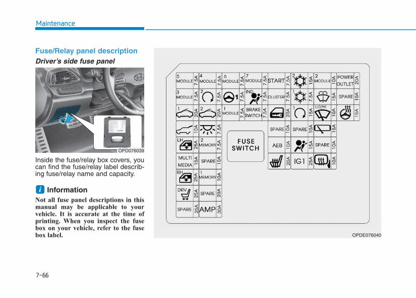
7-66
Maintenance
Fuse/Relay panel descriptionDriver’s side fuse panel
Inside the fuse/relay box covers, youcan find the fuse/relay label describ-ing fuse/relay name and capacity.
InformationNot all fuse panel descriptions in thismanual may be applicable to yourvehicle. It is accurate at the time ofprinting. When you inspect the fusebox on your vehicle, refer to the fusebox label.
i
OPD076039
OPDE076040
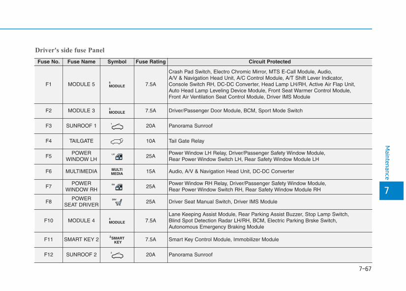
7-67
7
Maintenance
Driver's side fuse Panel
Fuse No. Fuse Name Symbol Fuse Rating Circuit Protected
F1 MODULE 5 MODULE5 7.5A
Crash Pad Switch, Electro Chromic Mirror, MTS E-Call Module, Audio, A/V & Navigation Head Unit, A/C Control Module, A/T Shift Lever Indicator, Console Switch RH, DC-DC Converter, Head Lamp LH/RH, Active Air Flap Unit, Auto Head Lamp Leveling Device Module, Front Seat Warmer Control Module, Front Air Ventilation Seat Control Module, Driver IMS Module
F2 MODULE 3 MODULE3 7.5A Driver/Passenger Door Module, BCM, Sport Mode Switch
F3 SUNROOF 1 1 20A Panorama Sunroof
F4 TAILGATE 10A Tail Gate Relay
F5POWER
WINDOW LHLH 25A
Power Window LH Relay, Driver/Passenger Safety Window Module, Rear Power Window Switch LH, Rear Safety Window Module LH
F6 MULTIMEDIA MULTIMEDIA 15A Audio, A/V & Navigation Head Unit, DC-DC Converter
F7POWER
WINDOW RHRH 25A
Power Window RH Relay, Driver/Passenger Safety Window Module, Rear Power Window Switch RH, Rear Safety Window Module RH
F8POWER
SEAT DRIVERDRV
25A Driver Seat Manual Switch, Driver IMS Module
F10 MODULE 4 MODULE4 7.5A
Lane Keeping Assist Module, Rear Parking Assist Buzzer, Stop Lamp Switch, Blind Spot Detection Radar LH/RH, BCM, Electric Parking Brske Switch, Autonomous Emergency Braking Module
F11 SMART KEY 2 SMARTKEY
27.5A Smart Key Control Module, Immobilizer Module
F12 SUNROOF 2 2 20A Panorama Sunroof
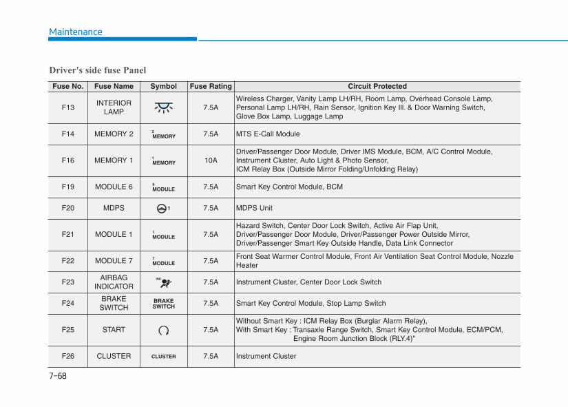
7-68
Maintenance
Driver's side fuse Panel
Fuse No. Fuse Name Symbol Fuse Rating Circuit Protected
F13INTERIOR
LAMP7.5A
Wireless Charger, Vanity Lamp LH/RH, Room Lamp, Overhead Console Lamp, Personal Lamp LH/RH, Rain Sensor, Ignition Key Ill. & Door Warning Switch, Glove Box Lamp, Luggage Lamp
F14 MEMORY 2 MEMORY2 7.5A MTS E-Call Module
F16 MEMORY 1 MEMORY1 10A
Driver/Passenger Door Module, Driver IMS Module, BCM, A/C Control Module, Instrument Cluster, Auto Light & Photo Sensor, ICM Relay Box (Outside Mirror Folding/Unfolding Relay)
F19 MODULE 6 MODULE6 7.5A Smart Key Control Module, BCM
F20 MDPS 1 7.5A MDPS Unit
F21 MODULE 1 MODULE1 7.5A
Hazard Switch, Center Door Lock Switch, Active Air Flap Unit, Driver/Passenger Door Module, Driver/Passenger Power Outside Mirror,Driver/Passenger Smart Key Outside Handle, Data Link Connector
F22 MODULE 7 MODULE7 7.5A
Front Seat Warmer Control Module, Front Air Ventilation Seat Control Module, NozzleHeater
F23AIRBAG
INDICATORIND
7.5A Instrument Cluster, Center Door Lock Switch
F24BRAKESWITCH
BRAKESWITCH 7.5A Smart Key Control Module, Stop Lamp Switch
F25 START 7.5AWithout Smart Key : ICM Relay Box (Burglar Alarm Relay),With Smart Key : Transaxle Range Switch, Smart Key Control Module, ECM/PCM,
Engine Room Junction Block (RLY.4)"
F26 CLUSTER CLUSTER 7.5A Instrument Cluster
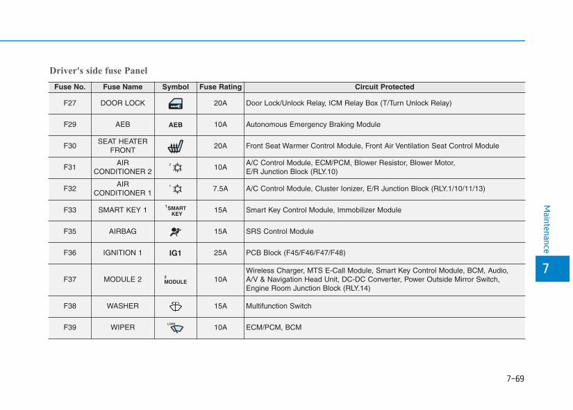
7-69
7
Maintenance
Driver's side fuse Panel
Fuse No. Fuse Name Symbol Fuse Rating Circuit Protected
F27 DOOR LOCK 20A Door Lock/Unlock Relay, ICM Relay Box (T/Turn Unlock Relay)
F29 AEB AEB 10A Autonomous Emergency Braking Module
F30SEAT HEATER
FRONT20A Front Seat Warmer Control Module, Front Air Ventilation Seat Control Module
F31AIR
CONDITIONER 22 10A
A/C Control Module, ECM/PCM, Blower Resistor, Blower Motor, E/R Junction Block (RLY.10)
F32AIR
CONDITIONER 11 7.5A A/C Control Module, Cluster Ionizer, E/R Junction Block (RLY.1/10/11/13)
F33 SMART KEY 1 SMARTKEY
115A Smart Key Control Module, Immobilizer Module
F35 AIRBAG 15A SRS Control Module
F36 IGNITION 1 IG1 25A PCB Block (F45/F46/F47/F48)
F37 MODULE 2 MODULE2 10A
Wireless Charger, MTS E-Call Module, Smart Key Control Module, BCM, Audio, A/V & Navigation Head Unit, DC-DC Converter, Power Outside Mirror Switch, Engine Room Junction Block (RLY.14)
F38 WASHER 15A Multifunction Switch
F39 WIPERLO/HI
10A ECM/PCM, BCM
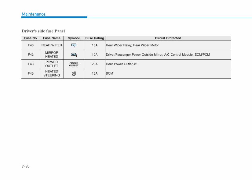
7-70
Maintenance
Driver's side fuse Panel
Fuse No. Fuse Name Symbol Fuse Rating Circuit Protected
F40 REAR WIPER 15A Rear Wiper Relay, Rear Wiper Motor
F42MIRROR HEATED
10A Driver/Passenger Power Outside Mirror, A/C Control Module, ECM/PCM
F43POWER OUTLET
POWEROUTLET 20A Rear Power Outlet #2
F45HEATED
STEERING15A BCM
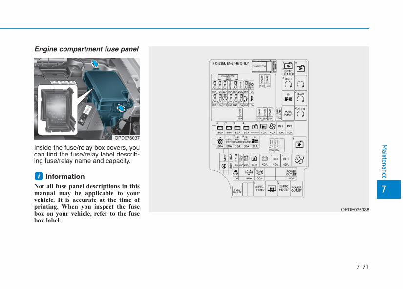
7-71
7
Maintenance
Engine compartment fuse panel
Inside the fuse/relay box covers, youcan find the fuse/relay label describ-ing fuse/relay name and capacity.
InformationNot all fuse panel descriptions in thismanual may be applicable to yourvehicle. It is accurate at the time ofprinting. When you inspect the fusebox on your vehicle, refer to the fusebox label.
i
OPD076037
OPDE076038
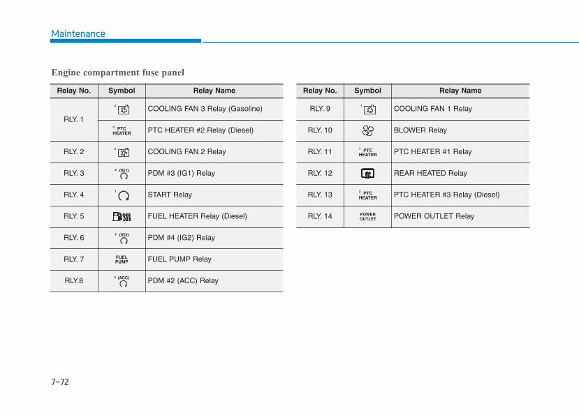
7-72
Maintenance
Engine compartment fuse panel
Relay No. Symbol Relay Name
RLY. 1
3 COOLING FAN 3 Relay (Gasoline)
PTCHEATER2
PTC HEATER #2 Relay (Diesel)
RLY. 2 2 COOLING FAN 2 Relay
RLY. 3 (IG1)3
PDM #3 (IG1) Relay
RLY. 41
START Relay
RLY. 5 FUEL HEATER Relay (Diesel)
RLY. 6 (IG2)4
PDM #4 (IG2) Relay
RLY. 7 FUELPUMP FUEL PUMP Relay
RLY.8 (ACC)2
PDM #2 (ACC) Relay
Relay No. Symbol Relay Name
RLY. 9 1 COOLING FAN 1 Relay
RLY. 10 BLOWER Relay
RLY. 11 PTCHEATER1
PTC HEATER #1 Relay
RLY. 12 REAR HEATED Relay
RLY. 13 PTCHEATER3
PTC HEATER #3 Relay (Diesel)
RLY. 14 POWEROUTLET POWER OUTLET Relay
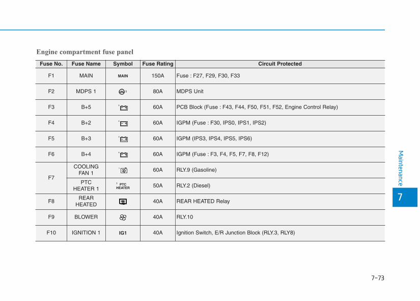
7-73
7
Maintenance
Engine compartment fuse panel
Fuse No. Fuse Name Symbol Fuse Rating Circuit Protected
F1 MAIN MAIN 150A Fuse : F27, F29, F30, F33
F2 MDPS 1 1 80A MDPS Unit
F3 B+5 5 60A PCB Block (Fuse : F43, F44, F50, F51, F52, Engine Control Relay)
F4 B+2 2 60A IGPM (Fuse : F30, IPS0, IPS1, IPS2)
F5 B+3 3 60A IGPM (IPS3, IPS4, IPS5, IPS6)
F6 B+4 4 60A IGPM (Fuse : F3, F4, F5, F7, F8, F12)
F7
COOLINGFAN 1
1 60A RLY.9 (Gasoline)
PTC HEATER 1
PTCHEATER1
50A RLY.2 (Diesel)
F8REAR
HEATED40A REAR HEATED Relay
F9 BLOWER 40A RLY.10
F10 IGNITION 1 IG1 40A Ignition Switch, E/R Junction Block (RLY.3, RLY8)
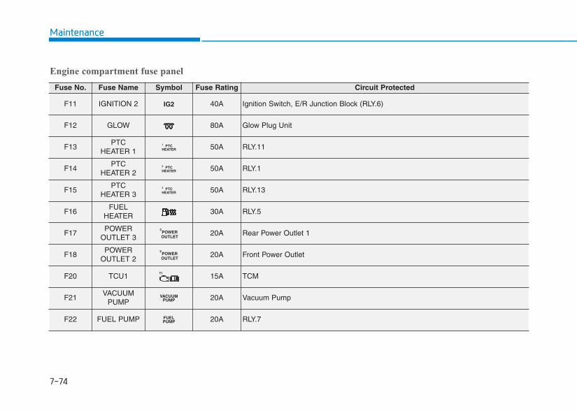
7-74
Maintenance
Engine compartment fuse panel
Fuse No. Fuse Name Symbol Fuse Rating Circuit Protected
F11 IGNITION 2 IG2 40A Ignition Switch, E/R Junction Block (RLY.6)
F12 GLOW 80A Glow Plug Unit
F13PTC
HEATER 1PTC
HEATER1 50A RLY.11
F14PTC
HEATER 2PTC
HEATER2 50A RLY.1
F15PTC
HEATER 3PTC
HEATER3 50A RLY.13
F16FUEL
HEATER30A RLY.5
F17POWER
OUTLET 3POWEROUTLET
3
20A Rear Power Outlet 1
F18POWER
OUTLET 2POWEROUTLET
2
20A Front Power Outlet
F20 TCU1T1
15A TCM
F21VACUUM
PUMPVACUUM
PUMP 20A Vacuum Pump
F22 FUEL PUMP FUELPUMP 20A RLY.7
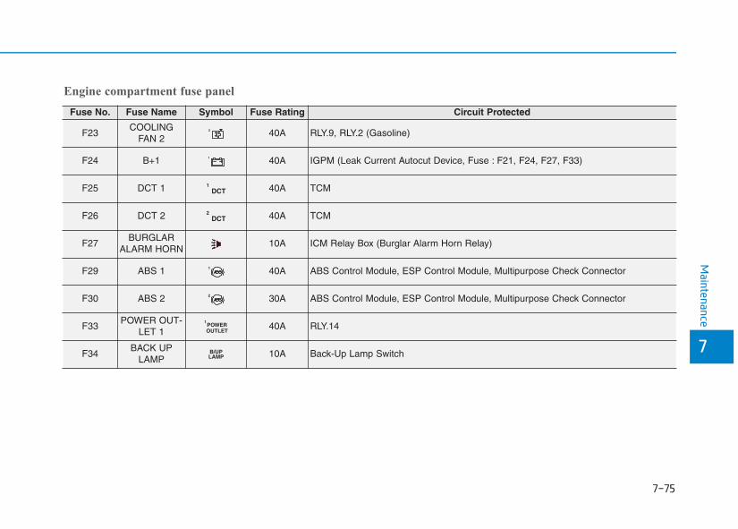
7-75
7
Maintenance
Engine compartment fuse panel
Fuse No. Fuse Name Symbol Fuse Rating Circuit Protected
F23COOLING
FAN 22 40A RLY.9, RLY.2 (Gasoline)
F24 B+1 1 40A IGPM (Leak Current Autocut Device, Fuse : F21, F24, F27, F33)
F25 DCT 1 DCT1 40A TCM
F26 DCT 2 DCT2 40A TCM
F27BURGLAR
ALARM HORN10A ICM Relay Box (Burglar Alarm Horn Relay)
F29 ABS 1 1 40A ABS Control Module, ESP Control Module, Multipurpose Check Connector
F30 ABS 2 2 30A ABS Control Module, ESP Control Module, Multipurpose Check Connector
F33POWER OUT-
LET 1POWEROUTLET
1
40A RLY.14
F34BACK UP
LAMPB/UPLAMP 10A Back-Up Lamp Switch
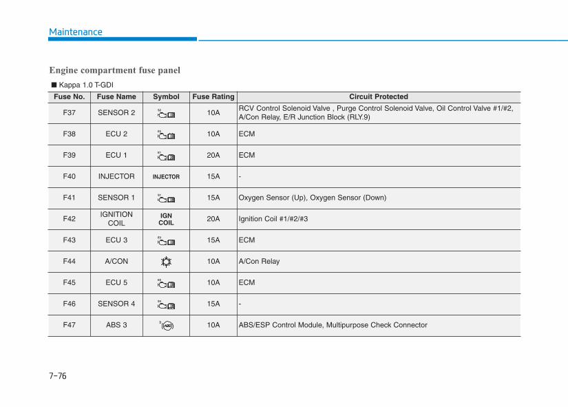
7-76
Maintenance
Fuse No. Fuse Name Symbol Fuse Rating Circuit Protected
F37 SENSOR 2 S2 10ARCV Control Solenoid Valve , Purge Control Solenoid Valve, Oil Control Valve #1/#2, A/Con Relay, E/R Junction Block (RLY.9)
F38 ECU 2 E2 10A ECM
F39 ECU 1 E1 20A ECM
F40 INJECTOR INJECTOR 15A -
F41 SENSOR 1 S1 15A Oxygen Sensor (Up), Oxygen Sensor (Down)
F42IGNITION
COILIGN
COIL 20A Ignition Coil #1/#2/#3
F43 ECU 3 E3 15A ECM
F44 A/CON 10A A/Con Relay
F45 ECU 5 E5 10A ECM
F46 SENSOR 4 S4 15A -
F47 ABS 3 3 10A ABS/ESP Control Module, Multipurpose Check Connector
Engine compartment fuse panel
■ Kappa 1.0 T-GDI
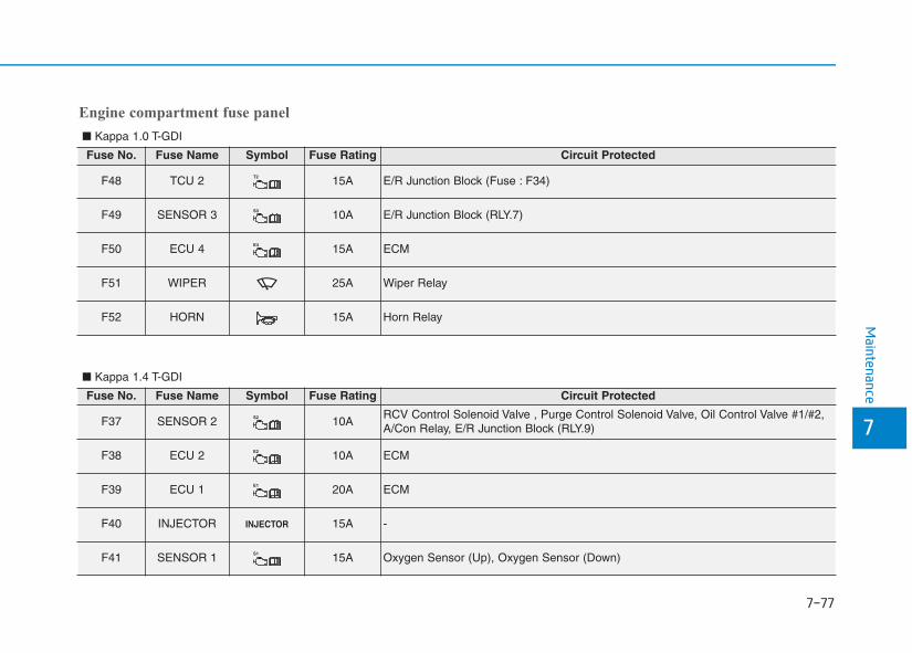
7-77
7
Maintenance
Fuse No. Fuse Name Symbol Fuse Rating Circuit Protected
F48 TCU 2 T2 15A E/R Junction Block (Fuse : F34)
F49 SENSOR 3 S3 10A E/R Junction Block (RLY.7)
F50 ECU 4 E4 15A ECM
F51 WIPER 25A Wiper Relay
F52 HORN 15A Horn Relay
Engine compartment fuse panel
■ Kappa 1.0 T-GDI
Fuse No. Fuse Name Symbol Fuse Rating Circuit Protected
F37 SENSOR 2 S2 10ARCV Control Solenoid Valve , Purge Control Solenoid Valve, Oil Control Valve #1/#2,A/Con Relay, E/R Junction Block (RLY.9)
F38 ECU 2 E2 10A ECM
F39 ECU 1 E1 20A ECM
F40 INJECTOR INJECTOR 15A -
F41 SENSOR 1 S1 15A Oxygen Sensor (Up), Oxygen Sensor (Down)
■ Kappa 1.4 T-GDI
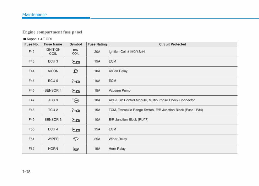
7-78
Maintenance
Fuse No. Fuse Name Symbol Fuse Rating Circuit Protected
F42IGNITION
COILIGN
COIL 20A Ignition Coil #1/#2/#3/#4
F43 ECU 3 E3 15A ECM
F44 A/CON 10A A/Con Relay
F45 ECU 5 E5 10A ECM
F46 SENSOR 4 S4 15A Vacuum Pump
F47 ABS 3 3 10A ABS/ESP Control Module, Multipurpose Check Connector
F48 TCU 2 T2 15A TCM, Transaxle Range Switch, E/R Junction Block (Fuse : F34)
F49 SENSOR 3 S3 10A E/R Junction Block (RLY.7)
F50 ECU 4 E4 15A ECM
F51 WIPER 25A Wiper Relay
F52 HORN 15A Horn Relay
Engine compartment fuse panel
■ Kappa 1.4 T-GDI
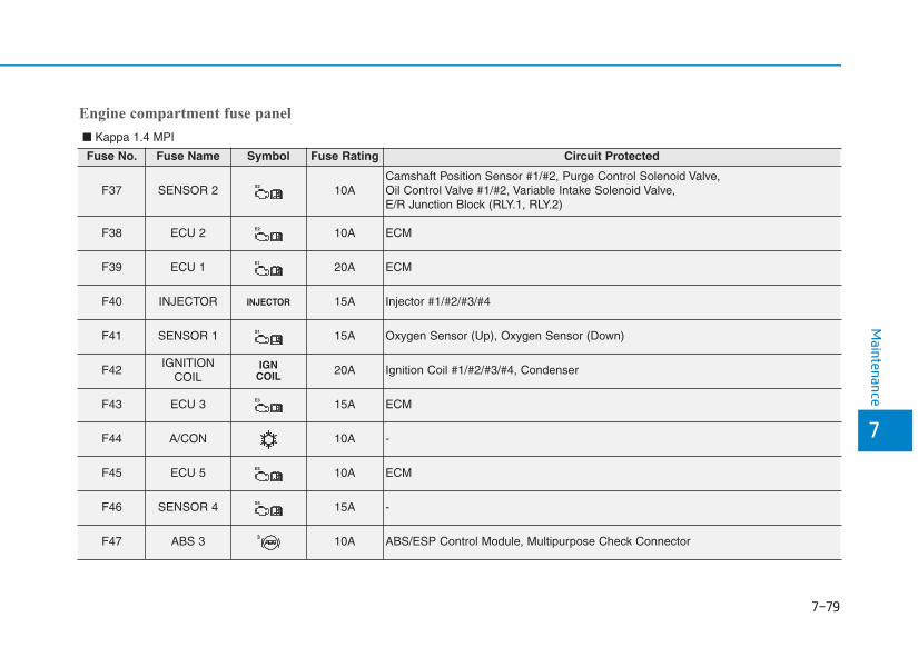
7-79
7
Maintenance
Engine compartment fuse panel
Fuse No. Fuse Name Symbol Fuse Rating Circuit Protected
F37 SENSOR 2 S2 10ACamshaft Position Sensor #1/#2, Purge Control Solenoid Valve, Oil Control Valve #1/#2, Variable Intake Solenoid Valve, E/R Junction Block (RLY.1, RLY.2)
F38 ECU 2 E2 10A ECM
F39 ECU 1 E1 20A ECM
F40 INJECTOR INJECTOR 15A Injector #1/#2/#3/#4
F41 SENSOR 1 S1 15A Oxygen Sensor (Up), Oxygen Sensor (Down)
F42IGNITION
COILIGN
COIL 20A Ignition Coil #1/#2/#3/#4, Condenser
F43 ECU 3 E3 15A ECM
F44 A/CON 10A -
F45 ECU 5 E5 10A ECM
F46 SENSOR 4 S4 15A -
F47 ABS 3 3 10A ABS/ESP Control Module, Multipurpose Check Connector
■ Kappa 1.4 MPI
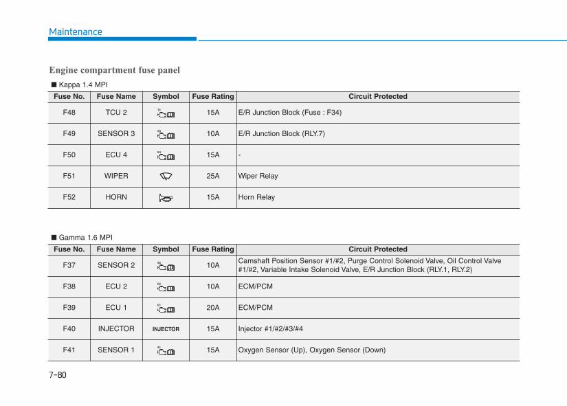
7-80
Maintenance
Engine compartment fuse panel
Fuse No. Fuse Name Symbol Fuse Rating Circuit Protected
F48 TCU 2 T2 15A E/R Junction Block (Fuse : F34)
F49 SENSOR 3 S3 10A E/R Junction Block (RLY.7)
F50 ECU 4 E4 15A -
F51 WIPER 25A Wiper Relay
F52 HORN 15A Horn Relay
■ Kappa 1.4 MPI
■ Gamma 1.6 MPI
Fuse No. Fuse Name Symbol Fuse Rating Circuit Protected
F37 SENSOR 2 S2 10ACamshaft Position Sensor #1/#2, Purge Control Solenoid Valve, Oil Control Valve#1/#2, Variable Intake Solenoid Valve, E/R Junction Block (RLY.1, RLY.2)
F38 ECU 2 E2 10A ECM/PCM
F39 ECU 1 E1 20A ECM/PCM
F40 INJECTOR INJECTOR 15A Injector #1/#2/#3/#4
F41 SENSOR 1 S1 15A Oxygen Sensor (Up), Oxygen Sensor (Down)
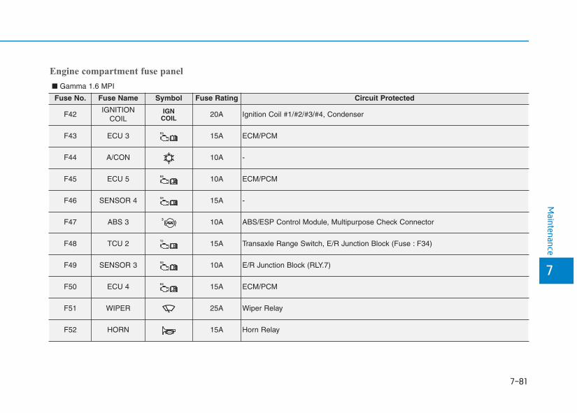
7-81
7
Maintenance
Engine compartment fuse panel
■ Gamma 1.6 MPI
Fuse No. Fuse Name Symbol Fuse Rating Circuit Protected
F42IGNITION
COILIGN
COIL 20A Ignition Coil #1/#2/#3/#4, Condenser
F43 ECU 3 E3 15A ECM/PCM
F44 A/CON 10A -
F45 ECU 5 E5 10A ECM/PCM
F46 SENSOR 4 S4 15A -
F47 ABS 3 3 10A ABS/ESP Control Module, Multipurpose Check Connector
F48 TCU 2 T2 15A Transaxle Range Switch, E/R Junction Block (Fuse : F34)
F49 SENSOR 3 S3 10A E/R Junction Block (RLY.7)
F50 ECU 4 E4 15A ECM/PCM
F51 WIPER 25A Wiper Relay
F52 HORN 15A Horn Relay
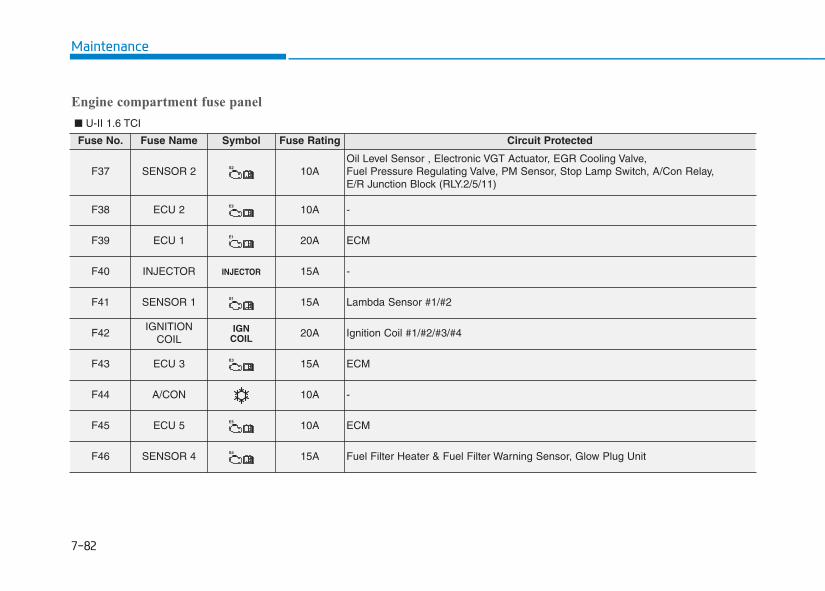
7-82
Maintenance
Fuse No. Fuse Name Symbol Fuse Rating Circuit Protected
F37 SENSOR 2 S2 10AOil Level Sensor , Electronic VGT Actuator, EGR Cooling Valve, Fuel Pressure Regulating Valve, PM Sensor, Stop Lamp Switch, A/Con Relay, E/R Junction Block (RLY.2/5/11)
F38 ECU 2 E2 10A -
F39 ECU 1 E1 20A ECM
F40 INJECTOR INJECTOR 15A -
F41 SENSOR 1 S1 15A Lambda Sensor #1/#2
F42IGNITION
COILIGN
COIL 20A Ignition Coil #1/#2/#3/#4
F43 ECU 3 E3 15A ECM
F44 A/CON 10A -
F45 ECU 5 E5 10A ECM
F46 SENSOR 4 S4 15A Fuel Filter Heater & Fuel Filter Warning Sensor, Glow Plug Unit
■ U-II 1.6 TCI
Engine compartment fuse panel
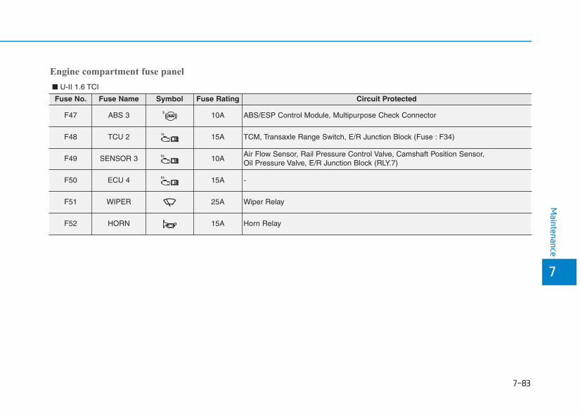
7-83
7
Maintenance
Fuse No. Fuse Name Symbol Fuse Rating Circuit Protected
F47 ABS 3 3 10A ABS/ESP Control Module, Multipurpose Check Connector
F48 TCU 2 T2 15A TCM, Transaxle Range Switch, E/R Junction Block (Fuse : F34)
F49 SENSOR 3 S3 10AAir Flow Sensor, Rail Pressure Control Valve, Camshaft Position Sensor, Oil Pressure Valve, E/R Junction Block (RLY.7)
F50 ECU 4 E4 15A -
F51 WIPER 25A Wiper Relay
F52 HORN 15A Horn Relay
Engine compartment fuse panel
■ U-II 1.6 TCI
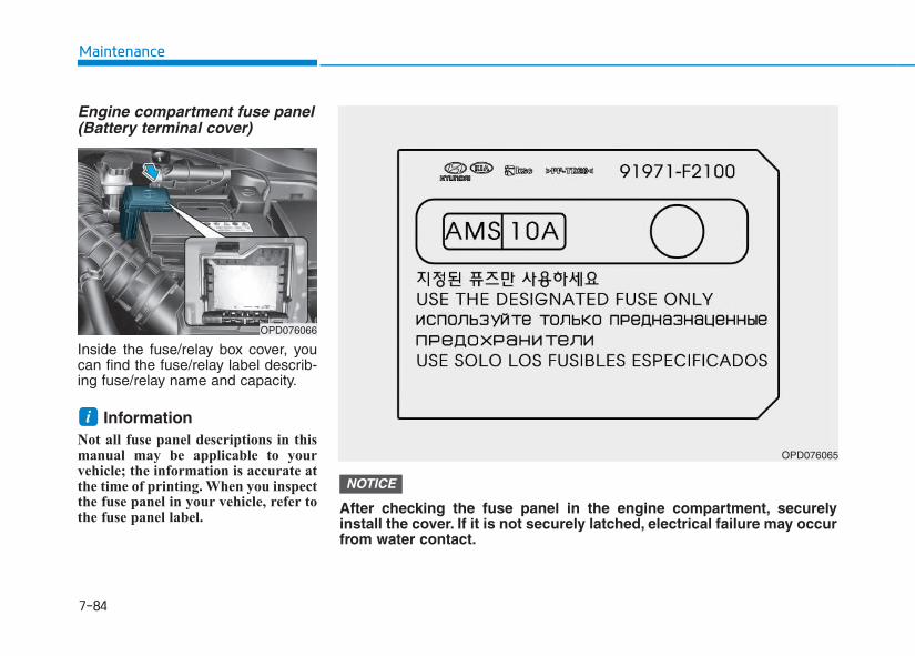
7-84
Maintenance
Engine compartment fuse panel(Battery terminal cover)
Inside the fuse/relay box cover, youcan find the fuse/relay label describ-ing fuse/relay name and capacity.
InformationNot all fuse panel descriptions in thismanual may be applicable to yourvehicle; the information is accurate atthe time of printing. When you inspectthe fuse panel in your vehicle, refer tothe fuse panel label.
i
OPD076066
OPD076065
After checking the fuse panel in the engine compartment, securelyinstall the cover. If it is not securely latched, electrical failure may occurfrom water contact.
NOTICE
7-85
7
Maintenance
LLIIGGHHTT BBUULLBBSSConsult an authorized HYUNDAIdealer to replace most vehicle lightbulbs. It is difficult to replace vehiclelight bulbs because other parts of thevehicle must be removed before youcan get to the bulb. This is especiallytrue for removing the headlampassembly to get to the bulb(s).Removing/installing the headlampassembly can result in damage tothe vehicle.
Be sure to replace the burned-outbulb with one of the same wattagerating. Otherwise, it may causedamage to the fuse or electricwiring system.
Information After heavy driving, rain or washing,headlamp and tail lamp lenses couldappear frosty. This condition is causedby the temperature difference betweenthe lamp inside and outside. This issimilar to the condensation on yourwindows inside your vehicle during therain and doesn’t indicate a problemwith your vehicle. If the water leaksinto the lamp bulb circuitry, we rec-ommend that the system be checkedby an authorized HYUNDAI dealer.
Information The headlamp aiming should be adjust-ed after an accident or after the head-lamp assembly is reinstalled at anauthorized HYUNDAI dealer.
Information - Traffic Change(for Europe)
The low beam light distribution isasymmetric. If you go abroad to a coun-try with opposite traffic direction, thisasymmetric part will dazzle oncomingcar driver. To prevent dazzle, ECE reg-ulation demand several technical solu-tions (ex. automatic change system,adhesive sheet, down aiming). Theseheadlamps are designed not to dazzleopposite drivers. So, you need notchange your headlamps in a countrywith opposite traffic direction.
i
i
i
NOTICE
Prior to working on the light,firmly apply the parking brake,ensure that the ignition switch isin the LOCK/OFF position andturn off the lights to avoid sud-den movement of the vehicle andburning your fingers or receivingan electric shock.
WARNING
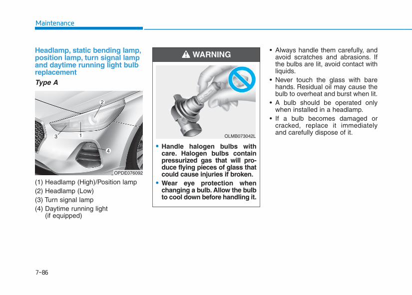
7-86
Maintenance
Headlamp, static bending lamp,position lamp, turn signal lampand daytime running light bulbreplacementType A
(1) Headlamp (High)/Position lamp(2) Headlamp (Low)(3) Turn signal lamp(4) Daytime running light
(if equipped)
• Always handle them carefully, andavoid scratches and abrasions. Ifthe bulbs are lit, avoid contact withliquids.
• Never touch the glass with barehands. Residual oil may cause thebulb to overheat and burst when lit.
• A bulb should be operated onlywhen installed in a headlamp.
• If a bulb becomes damaged orcracked, replace it immediatelyand carefully dispose of it.
OPDE076092
• Handle halogen bulbs withcare. Halogen bulbs containpressurized gas that will pro-duce flying pieces of glass thatcould cause injuries if broken.
• Wear eye protection whenchanging a bulb. Allow the bulbto cool down before handling it.
WARNING
OLMB073042L
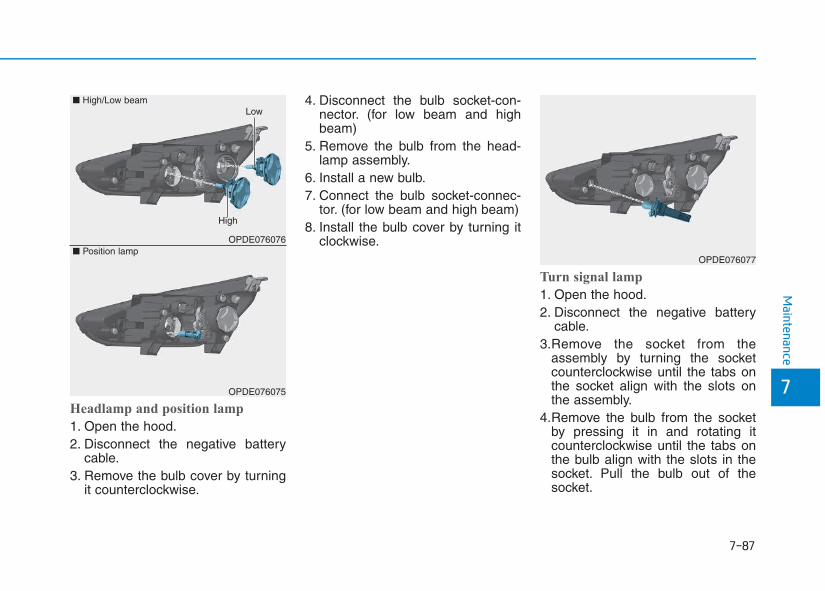
7-87
7
Maintenance
Headlamp and position lamp
1. Open the hood.2. Disconnect the negative battery
cable.3. Remove the bulb cover by turning
it counterclockwise.
4. Disconnect the bulb socket-con-nector. (for low beam and highbeam)
5. Remove the bulb from the head-lamp assembly.
6. Install a new bulb.7. Connect the bulb socket-connec-
tor. (for low beam and high beam)8. Install the bulb cover by turning it
clockwise.
Turn signal lamp
1. Open the hood.2. Disconnect the negative battery
cable.3.Remove the socket from the
assembly by turning the socketcounterclockwise until the tabs onthe socket align with the slots onthe assembly.
4.Remove the bulb from the socketby pressing it in and rotating itcounterclockwise until the tabs onthe bulb align with the slots in thesocket. Pull the bulb out of thesocket.
OPDE076076
OPDE076075
■ Position lamp
■ High/Low beam
High
Low
OPDE076077
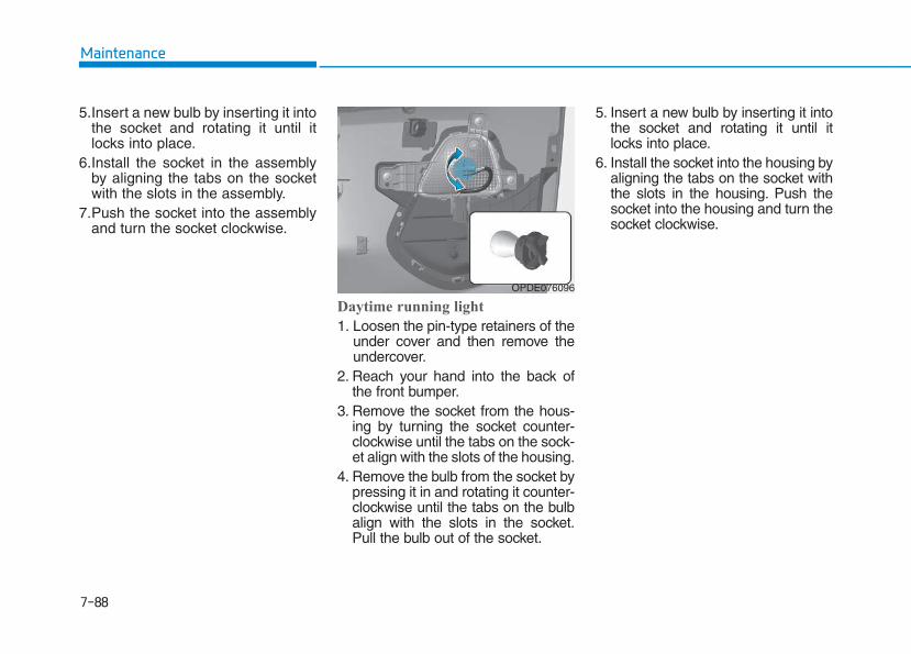
7-88
Maintenance
5.Insert a new bulb by inserting it intothe socket and rotating it until itlocks into place.
6.Install the socket in the assemblyby aligning the tabs on the socketwith the slots in the assembly.
7.Push the socket into the assemblyand turn the socket clockwise.
Daytime running light
1. Loosen the pin-type retainers of theunder cover and then remove theundercover.
2. Reach your hand into the back ofthe front bumper.
3. Remove the socket from the hous-ing by turning the socket counter-clockwise until the tabs on the sock-et align with the slots of the housing.
4. Remove the bulb from the socket bypressing it in and rotating it counter-clockwise until the tabs on the bulbalign with the slots in the socket.Pull the bulb out of the socket.
5. Insert a new bulb by inserting it intothe socket and rotating it until itlocks into place.
6. Install the socket into the housing byaligning the tabs on the socket withthe slots in the housing. Push thesocket into the housing and turn thesocket clockwise.
OPDE076096
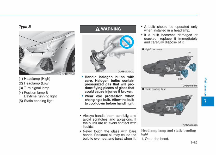
7-89
7
Maintenance
Type B
(1) Headlamp (High)(2) Headlamp (Low)(3) Turn signal lamp(4) Position lamp &
Daytime running light(5) Static bending light
• Always handle them carefully, andavoid scratches and abrasions. Ifthe bulbs are lit, avoid contact withliquids.
• Never touch the glass with barehands. Residual oil may cause thebulb to overheat and burst when lit.
• A bulb should be operated onlywhen installed in a headlamp.
• If a bulb becomes damaged orcracked, replace it immediatelyand carefully dispose of it.
Headlamp lamp and static bendinglight
1. Open the hood.
OPDE076076
■ High/Low beam
High
Low
OPDE076090
■ Static bending light
OPD076042• Handle halogen bulbs with
care. Halogen bulbs containpressurized gas that will pro-duce flying pieces of glass thatcould cause injuries if broken.
• Wear eye protection whenchanging a bulb. Allow the bulbto cool down before handling it.
WARNING
OLMB073042L
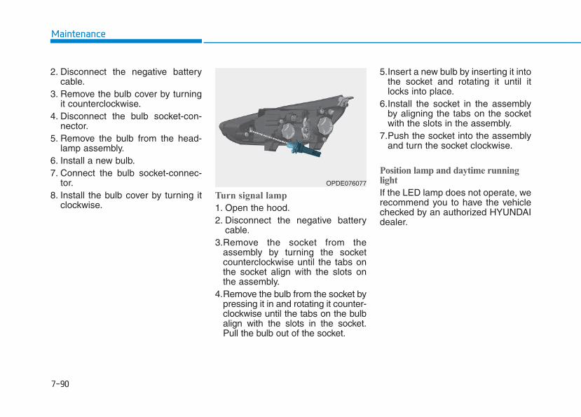
7-90
Maintenance
2. Disconnect the negative batterycable.
3. Remove the bulb cover by turningit counterclockwise.
4. Disconnect the bulb socket-con-nector.
5. Remove the bulb from the head-lamp assembly.
6. Install a new bulb.7. Connect the bulb socket-connec-
tor.8. Install the bulb cover by turning it
clockwise.Turn signal lamp
1. Open the hood.2. Disconnect the negative battery
cable.3.Remove the socket from the
assembly by turning the socketcounterclockwise until the tabs onthe socket align with the slots onthe assembly.
4.Remove the bulb from the socket bypressing it in and rotating it counter-clockwise until the tabs on the bulbalign with the slots in the socket.Pull the bulb out of the socket.
5.Insert a new bulb by inserting it intothe socket and rotating it until itlocks into place.
6.Install the socket in the assemblyby aligning the tabs on the socketwith the slots in the assembly.
7.Push the socket into the assemblyand turn the socket clockwise.
Position lamp and daytime runninglight
If the LED lamp does not operate, werecommend you to have the vehiclechecked by an authorized HYUNDAIdealer.
OPDE076077
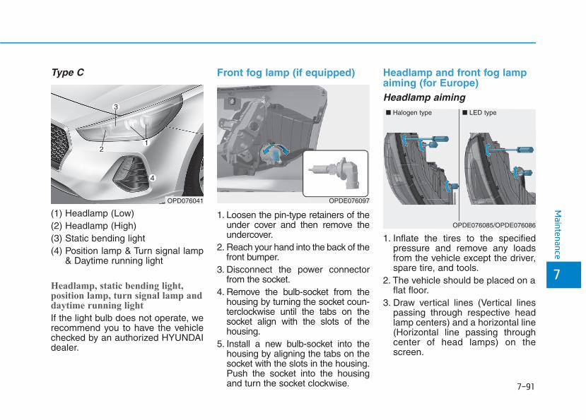
7-91
7
Maintenance
Type C
(1) Headlamp (Low)(2) Headlamp (High)(3) Static bending light(4) Position lamp & Turn signal lamp
& Daytime running light
Headlamp, static bending light,position lamp, turn signal lamp anddaytime running light
If the light bulb does not operate, werecommend you to have the vehiclechecked by an authorized HYUNDAIdealer.
Front fog lamp (if equipped)
1. Loosen the pin-type retainers of theunder cover and then remove theundercover.
2. Reach your hand into the back of thefront bumper.
3. Disconnect the power connectorfrom the socket.
4. Remove the bulb-socket from thehousing by turning the socket coun-terclockwise until the tabs on thesocket align with the slots of thehousing.
5. Install a new bulb-socket into thehousing by aligning the tabs on thesocket with the slots in the housing.Push the socket into the housingand turn the socket clockwise.
Headlamp and front fog lampaiming (for Europe)Headlamp aiming
1. Inflate the tires to the specifiedpressure and remove any loadsfrom the vehicle except the driver,spare tire, and tools.
2. The vehicle should be placed on aflat floor.
3. Draw vertical lines (Vertical linespassing through respective headlamp centers) and a horizontal line(Horizontal line passing throughcenter of head lamps) on thescreen.
OPDE076097
■ Halogen type ■ LED type
OPDE076085/OPDE076086
OPD076041
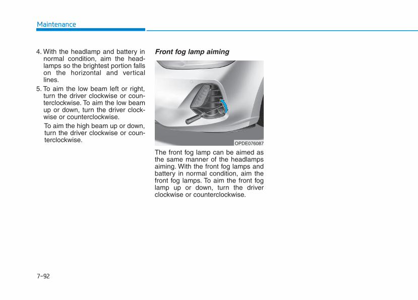
7-92
Maintenance
4. With the headlamp and battery innormal condition, aim the head-lamps so the brightest portion fallson the horizontal and verticallines.
5. To aim the low beam left or right,turn the driver clockwise or coun-terclockwise. To aim the low beamup or down, turn the driver clock-wise or counterclockwise.To aim the high beam up or down,turn the driver clockwise or coun-terclockwise.
Front fog lamp aiming
The front fog lamp can be aimed asthe same manner of the headlampsaiming. With the front fog lamps andbattery in normal condition, aim thefront fog lamps. To aim the front foglamp up or down, turn the driverclockwise or counterclockwise.
OPDE076087
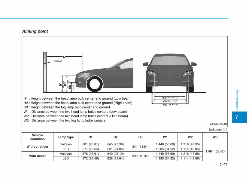
7-93
7
Maintenance
Unit: mm (in)
Aiming point
H1 : Height between the head lamp bulb center and ground (Low beam)H2 : Height between the head lamp bulb center and ground (High beam)H3 : Height between the fog lamp bulb center and groundW1 : Distance between the two head lamp bulbs centers (Low beam)W2 : Distance between the two head lamp bulbs centers (High beam)W3 : Distance between the two fog lamp bulbs centers
OPDE076081
Vehicle condition
Lamp type H1 H2 H3 W1 W2 W3
Without driverHalogen 681 (26.81) 645 (25.39)
344 (13.54)1,440 (56.69) 1,218 (47.95)
1,484 (58.42)LED 677 (26.65) 631 (24.84) 1,385 (54.52) 1,114 (43.85)
With driverHalogen 676 (26.61) 640 (25.19)
339 (13.34)1,440 (56.69) 1,218 (47.95)
LED 672 (26.45) 626 (24.64) 1,385 (54.52) 1,114 (43.85)
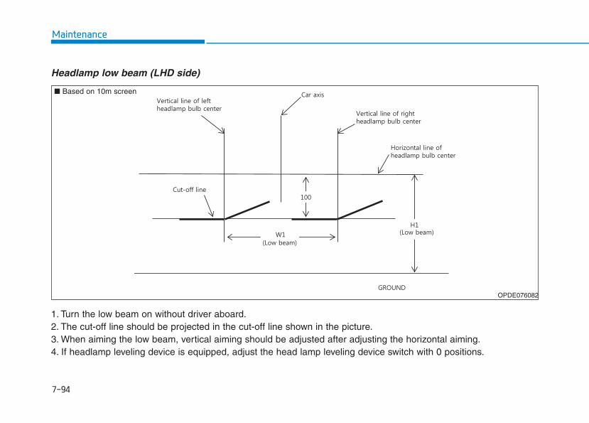
7-94
Maintenance
Headlamp low beam (LHD side)
1. Turn the low beam on without driver aboard.2. The cut-off line should be projected in the cut-off line shown in the picture.3. When aiming the low beam, vertical aiming should be adjusted after adjusting the horizontal aiming.4. If headlamp leveling device is equipped, adjust the head lamp leveling device switch with 0 positions.
OPDE076082
■ Based on 10m screen
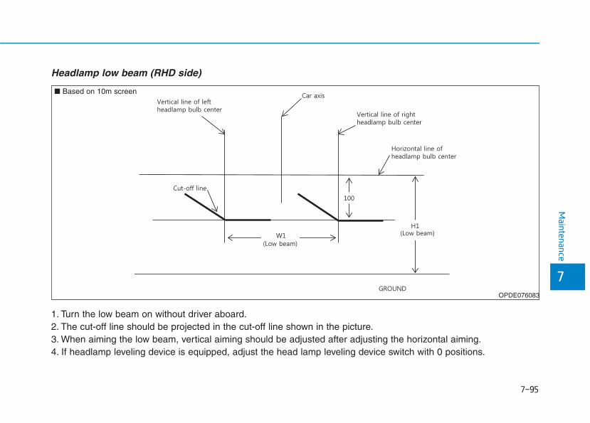
7-95
7
Maintenance
Headlamp low beam (RHD side)
1. Turn the low beam on without driver aboard.2. The cut-off line should be projected in the cut-off line shown in the picture.3. When aiming the low beam, vertical aiming should be adjusted after adjusting the horizontal aiming.4. If headlamp leveling device is equipped, adjust the head lamp leveling device switch with 0 positions.
OPDE076083
■ Based on 10m screen
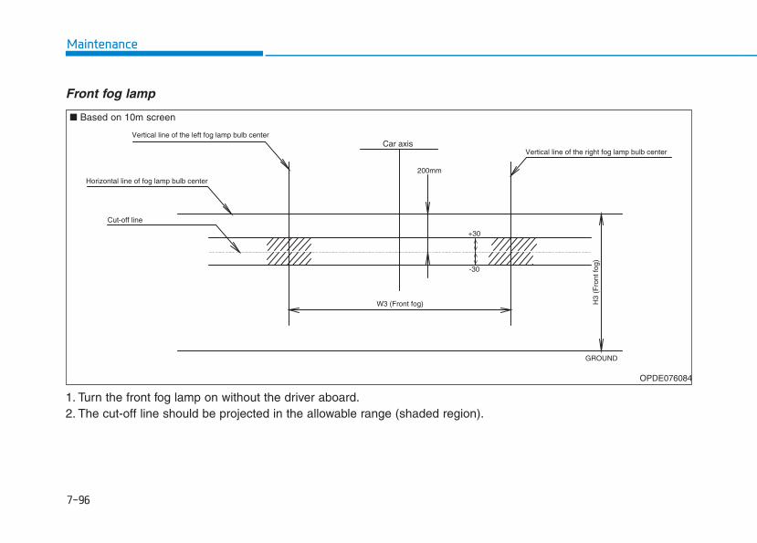
7-96
Maintenance
Front fog lamp
1. Turn the front fog lamp on without the driver aboard.2. The cut-off line should be projected in the allowable range (shaded region).
Vertical line of the left fog lamp bulb center
Vertical line of the right fog lamp bulb center
H3
(Fro
nt fo
g)
Car axis
200mm
+30
-30
Horizontal line of fog lamp bulb center
Cut-off line
W3 (Front fog)
GROUND
OPDE076084
■ Based on 10m screen
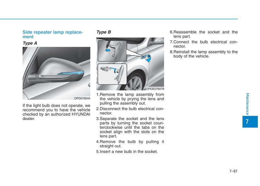
7-97
7
Maintenance
Side repeater lamp replace-ment Type A
If the light bulb does not operate, werecommend you to have the vehiclechecked by an authorized HYUNDAIdealer.
Type B
1.Remove the lamp assembly fromthe vehicle by prying the lens andpulling the assembly out.
2.Disconnect the bulb electrical con-nector.
3.Separate the socket and the lensparts by turning the socket coun-terclockwise until the tabs on thesocket align with the slots on thelens part.
4.Remove the bulb by pulling itstraight out.
5.Insert a new bulb in the socket.
6.Reassemble the socket and thelens part.
7.Connect the bulb electrical con-nector.
8.Reinstall the lamp assembly to thebody of the vehicle.
OPDE076079
OPD076044
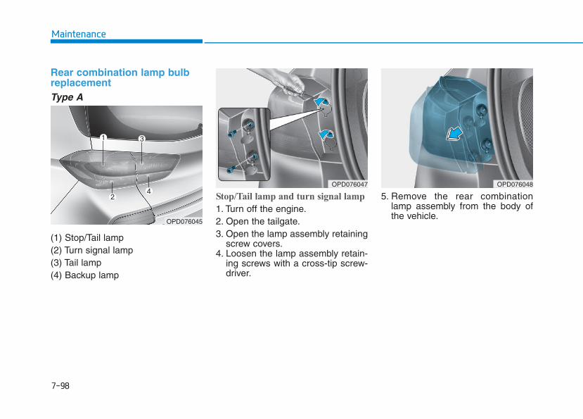
7-98
Maintenance
Rear combination lamp bulbreplacementType A
(1) Stop/Tail lamp(2) Turn signal lamp(3) Tail lamp(4) Backup lamp
Stop/Tail lamp and turn signal lamp
1. Turn off the engine.2. Open the tailgate.3. Open the lamp assembly retaining
screw covers.4. Loosen the lamp assembly retain-
ing screws with a cross-tip screw-driver.
5. Remove the rear combinationlamp assembly from the body ofthe vehicle.
OPD076048
OPD076045
OPD076047
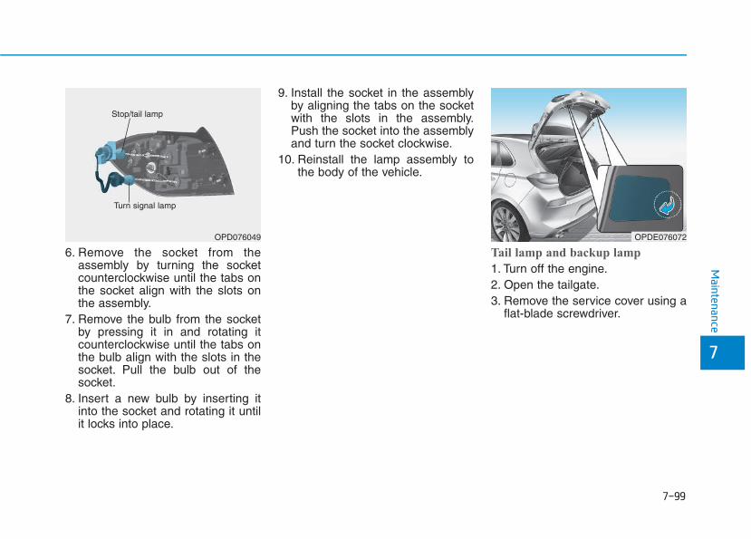
7-99
7
Maintenance
6. Remove the socket from theassembly by turning the socketcounterclockwise until the tabs onthe socket align with the slots onthe assembly.
7. Remove the bulb from the socketby pressing it in and rotating itcounterclockwise until the tabs onthe bulb align with the slots in thesocket. Pull the bulb out of thesocket.
8. Insert a new bulb by inserting itinto the socket and rotating it untilit locks into place.
9. Install the socket in the assemblyby aligning the tabs on the socketwith the slots in the assembly.Push the socket into the assemblyand turn the socket clockwise.
10. Reinstall the lamp assembly tothe body of the vehicle.
Tail lamp and backup lamp
1. Turn off the engine.2. Open the tailgate.3. Remove the service cover using a
flat-blade screwdriver.
OPD076049
Stop/tail lamp
Turn signal lamp
OPDE076072
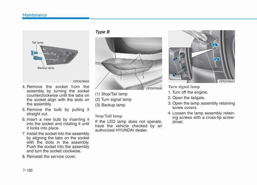
7-100
Maintenance
4. Remove the socket from theassembly by turning the socketcounterclockwise until the tabs onthe socket align with the slots onthe assembly.
5. Remove the bulb by pulling itstraight out.
6. Insert a new bulb by inserting itinto the socket and rotating it untilit locks into place.
7. Install the socket into the assemblyby aligning the tabs on the socketwith the slots in the assembly.Push the socket into the assemblyand turn the socket clockwise.
8. Reinstall the service cover.
Type B
(1) Stop/Tail lamp(2) Turn signal lamp(3) Backup lamp
Stop/Tail lamp
If the LED lamp does not operate,have the vehicle checked by anauthorized HYUNDAI dealer.
Turn signal lamp
1. Turn off the engine.2. Open the tailgate.3. Open the lamp assembly retaining
screw covers.4. Loosen the lamp assembly retain-
ing screws with a cross-tip screw-driver.
OPD076046
OPD076052
Backup lamp
Tail lamp
OPD076047
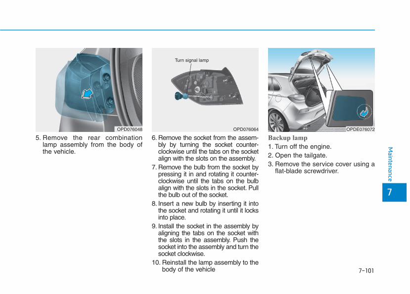
7-101
7
Maintenance
5. Remove the rear combinationlamp assembly from the body ofthe vehicle.
6. Remove the socket from the assem-bly by turning the socket counter-clockwise until the tabs on the socketalign with the slots on the assembly.
7. Remove the bulb from the socket bypressing it in and rotating it counter-clockwise until the tabs on the bulbalign with the slots in the socket. Pullthe bulb out of the socket.
8. Insert a new bulb by inserting it intothe socket and rotating it until it locksinto place.
9. Install the socket in the assembly byaligning the tabs on the socket withthe slots in the assembly. Push thesocket into the assembly and turn thesocket clockwise.
10. Reinstall the lamp assembly to thebody of the vehicle
Backup lamp
1. Turn off the engine.2. Open the tailgate.3. Remove the service cover using a
flat-blade screwdriver.
OPD076048 OPD076064
Turn signal lamp
OPDE076072
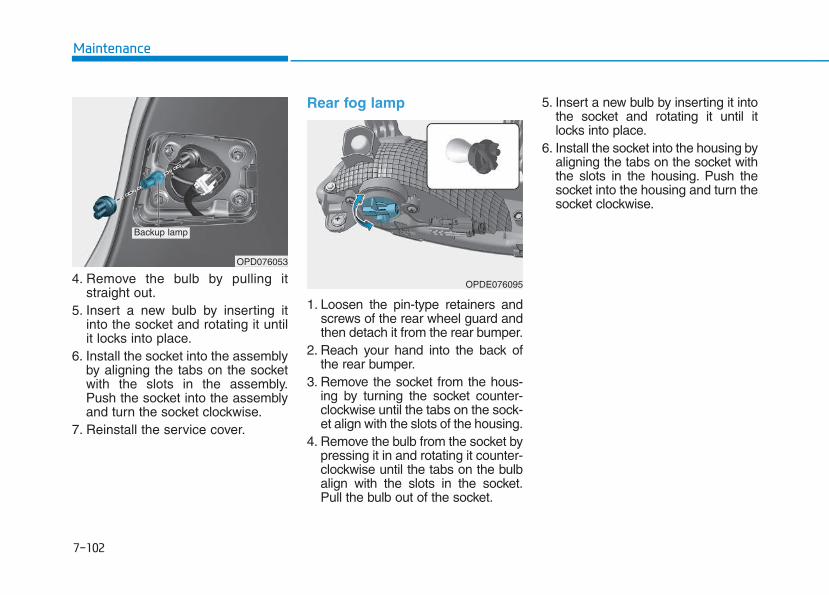
7-102
Maintenance
4. Remove the bulb by pulling itstraight out.
5. Insert a new bulb by inserting itinto the socket and rotating it untilit locks into place.
6. Install the socket into the assemblyby aligning the tabs on the socketwith the slots in the assembly.Push the socket into the assemblyand turn the socket clockwise.
7. Reinstall the service cover.
Rear fog lamp
1. Loosen the pin-type retainers andscrews of the rear wheel guard andthen detach it from the rear bumper.
2. Reach your hand into the back ofthe rear bumper.
3. Remove the socket from the hous-ing by turning the socket counter-clockwise until the tabs on the sock-et align with the slots of the housing.
4. Remove the bulb from the socket bypressing it in and rotating it counter-clockwise until the tabs on the bulbalign with the slots in the socket.Pull the bulb out of the socket.
5. Insert a new bulb by inserting it intothe socket and rotating it until itlocks into place.
6. Install the socket into the housing byaligning the tabs on the socket withthe slots in the housing. Push thesocket into the housing and turn thesocket clockwise.
OPD076053
Backup lamp
OPDE076095
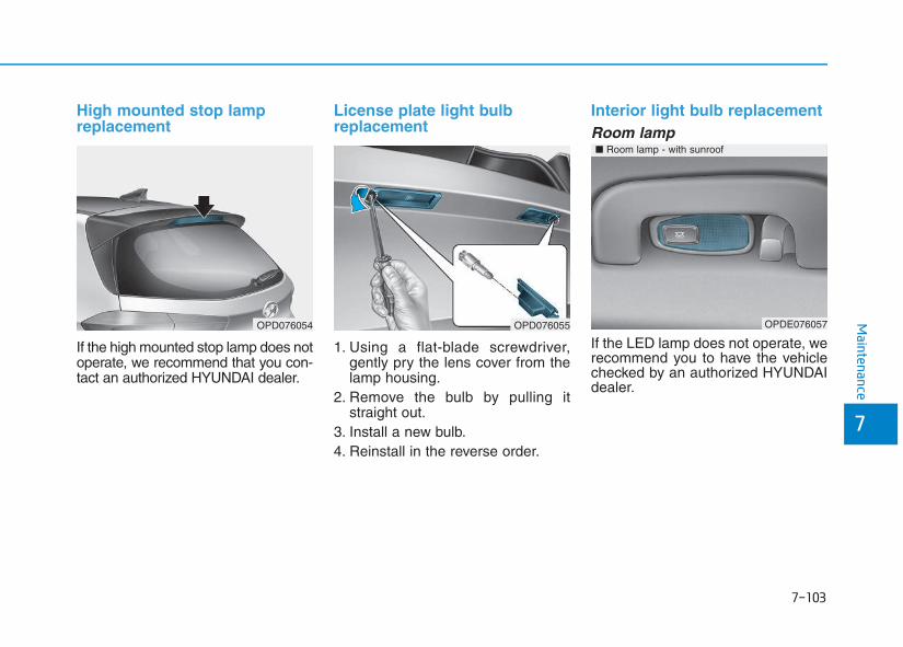
7-103
7
Maintenance
High mounted stop lampreplacement
If the high mounted stop lamp does notoperate, we recommend that you con-tact an authorized HYUNDAI dealer.
License plate light bulbreplacement
1. Using a flat-blade screwdriver,gently pry the lens cover from thelamp housing.
2. Remove the bulb by pulling itstraight out.
3. Install a new bulb.4. Reinstall in the reverse order.
Interior light bulb replacementRoom lamp
If the LED lamp does not operate, werecommend you to have the vehiclechecked by an authorized HYUNDAIdealer.
OPD076054 OPD076055 OPDE076057
■ Room lamp - with sunroof
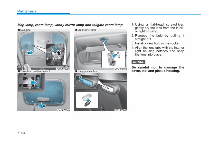
7-104
Maintenance
1. Using a flat-head screwdriver,gently pry the lens from the interi-or light housing.
2. Remove the bulb by pulling itstraight out.
3. Install a new bulb in the socket.4. Align the lens tabs with the interior
light housing notches and snapthe lens into place.
Be careful not to damage thecover, tab, and plastic housing.
NOTICE
■ Map lamp
OPD076056
OAD075045
■ Vanity mirror lamp
■ Luggage room lampOPD076063
OPD076059
■ Room lamp - without sunroof
Map lamp, room lamp, vanity mirror lamp and tailgate room lamp
7-105
7
Maintenance
AAPPPPEEAARRAANNCCEE CCAARREEExterior careExterior general caution It is very important to follow the labeldirections when using any chemicalcleaner or polish. Read all warningand caution statements that appearon the label.
Finish maintenanceWashing
To help protect your vehicle’s finishfrom rust and deterioration, wash itthoroughly and frequently at leastonce a month with lukewarm or coldwater.If you use your vehicle for off-roaddriving, you should wash it after eachoff-road trip. Pay special attention tothe removal of any accumulation ofsalt, dirt, mud, and other foreignmaterials. Make sure the drain holesin the lower edges of the doors androcker panels are kept clear andclean.
Insects, tar, tree sap, bird droppings,industrial pollution and similar depositscan damage your vehicle’s finish if notremoved immediately.Even prompt washing with plain watermay not completely remove all thesedeposits.A mild soap, safe for use on paintedsurfaces, may be used.After washing, rinse the vehicle thor-oughly with lukewarm or cold water.Do not allow soap to dry on the finish.
• Do not use strong soap, chemi-cal detergents or hot water, anddo not wash the vehicle in directsunlight or when the body of thevehicle is warm.
• Be careful when washing theside windows of your vehicle.Especially, with high-pressurewater, water may leak throughthe windows and wet the interior.
• To prevent damage to the plasticparts and lamps, do not cleanwith chemical solvents or strongdetergents.
High-pressure washing
• When using high-pressure washers,make sure to maintain sufficient dis-tance from the vehicle.Insufficient clearance or excessivepressure can lead to componentdamage or water penetration.
• Do not spray the camera, sensors orits surrounding area directly with ahigh pressure washer. Shockapplied from high pressure watermay cause the device to not operatenormally.
• Do not bring the nozzle tip close toboots (rubber or plastic covers) orconnectors as they may be dam-aged if they come into contact withhigh pressure water.
NOTICE
Wet brakes
After washing the vehicle, testthe brakes while driving slowlyto see if they have been affectedby water. If braking performanceis impaired, dry the brakes byapplying them lightly while main-taining a slow forward speed.
WARNING
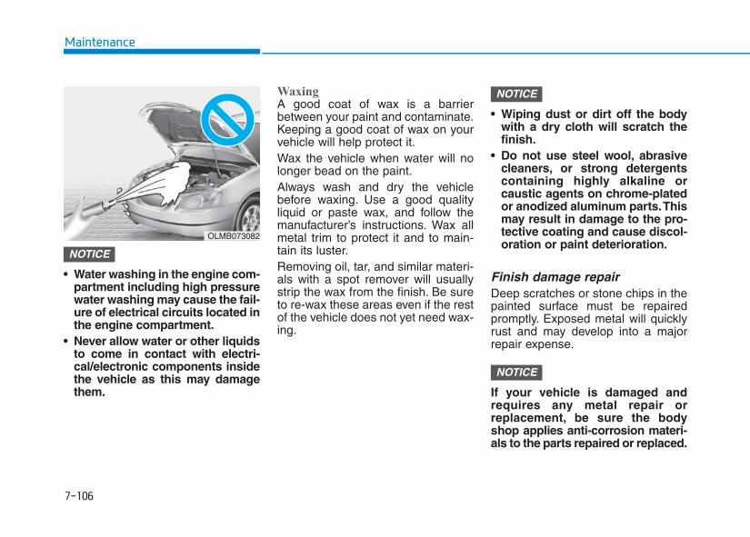
7-106
Maintenance
• Water washing in the engine com-partment including high pressurewater washing may cause the fail-ure of electrical circuits located inthe engine compartment.
• Never allow water or other liquidsto come in contact with electri-cal/electronic components insidethe vehicle as this may damagethem.
WaxingA good coat of wax is a barrierbetween your paint and contaminate.Keeping a good coat of wax on yourvehicle will help protect it.Wax the vehicle when water will nolonger bead on the paint.Always wash and dry the vehiclebefore waxing. Use a good qualityliquid or paste wax, and follow themanufacturer’s instructions. Wax allmetal trim to protect it and to main-tain its luster.Removing oil, tar, and similar materi-als with a spot remover will usuallystrip the wax from the finish. Be sureto re-wax these areas even if the restof the vehicle does not yet need wax-ing.
• Wiping dust or dirt off the bodywith a dry cloth will scratch thefinish.
• Do not use steel wool, abrasivecleaners, or strong detergentscontaining highly alkaline orcaustic agents on chrome-platedor anodized aluminum parts.Thismay result in damage to the pro-tective coating and cause discol-oration or paint deterioration.
Finish damage repair Deep scratches or stone chips in thepainted surface must be repairedpromptly. Exposed metal will quicklyrust and may develop into a majorrepair expense.
If your vehicle is damaged andrequires any metal repair orreplacement, be sure the bodyshop applies anti-corrosion materi-als to the parts repaired or replaced.
NOTICE
NOTICE
NOTICE
OLMB073082
7-107
7
Maintenance
Bright-metal maintenance• To remove road tar and insects,
use a tar remover, not a scraper orother sharp object.
• To protect the surfaces of bright-metal parts from corrosion, apply acoating of wax or chrome preser-vative and rub to a high luster.
• During winter weather or in coastalareas, cover the bright metal partswith a heavier coating of wax orpreservative. If necessary, coat theparts with non-corrosive petroleumjelly or other protective compound.
Underbody maintenanceCorrosive materials used for ice andsnow removal and dust control maycollect on the underbody. If thesematerials are not removed, acceler-ated rusting can occur on underbodyparts such as the fuel lines, frame,floor pan and exhaust system, eventhough they have been treated withrust protection.
Thoroughly flush the vehicle under-body and wheel openings with luke-warm or cold water once a month,after off-road driving and at the end ofeach winter. Pay special attention tothese areas because it is difficult tosee all the mud and dirt. It will domore harm than good to wet down theroad grime without removing it. Thelower edges of doors, rocker panels,and frame members have drain holesthat should not be allowed to clog withdirt; trapped water in these areas cancause rusting.
Aluminum wheel maintenance The aluminum wheels are coated witha clear protective finish.
• Do not use any abrasive cleaner,polishing compound, solvent,or wire brushes on aluminumwheels.
• Clean the wheel when it hascooled.
• Use only a mild soap or neutraldetergent, and rinse thoroughlywith water. Also, be sure to cleanthe wheels after driving on saltedroads.
• Do not wash the wheels with high-speed car wash brushes.
• Do not use any cleanser contain-ing acid or alkaline detergents.
NOTICE
After washing the vehicle, testthe brakes while driving slowlyto see if they have been affectedby water. If braking performanceis impaired, dry the brakes byapplying them lightly while main-taining a slow forward speed.
WARNING
7-108
Maintenance
Corrosion protectionProtecting your vehicle from corro-sion
By using the most advanced designand construction practices to combatcorrosion, we produces cars of thehighest quality. However, this is onlypart of the job. To achieve the long-term corrosion resistance your vehi-cle can deliver, the owner's coopera-tion and assistance is also required.
Common causes of corrosion
The most common causes of corro-sion on your car are:• Road salt, dirt and moisture that is
allowed to accumulate underneaththe car.
• Removal of paint or protective coat-ings by stones, gravel, abrasion orminor scrapes and dents whichleave unprotected metal exposed tocorrosion.
High-corrosion areas
If you live in an area where your caris regularly exposed to corrosivematerials, corrosion protection isparticularly important. Some of thecommon causes of accelerated cor-rosion are road salts, dust controlchemicals, ocean air and industrialpollution.
Moisture breeds corrosion
Moisture creates the conditions inwhich corrosion is most likely to occur.For example, corrosion is acceleratedby high humidity, particularly whentemperatures are just above freezing.In such conditions, the corrosivematerial is kept in contact with the carsurfaces by moisture that is slow toevaporate.Mud is particularly corrosive becauseit is slow to dry and holds moisture incontact with the vehicle. Although themud appears to be dry, it can stillretain the moisture and promote cor-rosion.
High temperatures can also acceler-ate corrosion of parts that are notproperly ventilated so the moisturecan be dispersed. For all these rea-sons, it is particularly important tokeep your car clean and free of mudor accumulations of other materials.This applies not only to the visible sur-faces but particularly to the undersideof the car.
To help prevent corrosion
You can help prevent corrosion fromgetting started by observing the fol-lowing:
7-109
7
Maintenance
Keep your car cleanThe best way to prevent corrosion isto keep your car clean and free ofcorrosive materials. Attention to theunderside of the car is particularlyimportant.
• If you live in a high-corrosion area— where road salts are used, nearthe ocean, areas with industrialpollution, acid rain, etc.—, youshould take extra care to preventcorrosion. In winter, hose off theunderside of your car at least oncea month and be sure to clean theunderside thoroughly when winteris over.
• When cleaning underneath the car,give particular attention to thecomponents under the fenders andother areas that are hidden fromview. Do a thorough job; just damp-ening the accumulated mud ratherthan washing it away will acceler-ate corrosion rather than preventit. Water under high pressure andsteam are particularly effective inremoving accumulated mud andcorrosive materials.
• When cleaning lower door panels,rocker panels and frame members,be sure that drain holes are keptopen so that moisture can escapeand not be trapped inside to accel-erate corrosion.
Keep your garage dryDon't park your car in a damp, poor-ly ventilated garage. This creates afavorable environment for corrosion.This is particularly true if you washyour car in the garage or drive it intothe garage when it is still wet or cov-ered with snow, ice or mud. Even aheated garage can contribute to cor-rosion unless it is well ventilated somoisture is dispersed.
Keep paint and trim in good conditionScratches or chips in the finishshould be covered with "touch-up"paint as soon as possible to reducethe possibility of corrosion. If baremetal is showing through, the atten-tion of a qualified body and paintshop is recommended.
Bird droppings : Bird droppings arehighly corrosive and may damagepainted surfaces in just a few hours.Always remove bird droppings assoon as possible.
Don't neglect the interiorMoisture can collect under the floormats and carpeting to cause corro-sion. Check under the mats periodi-cally to be sure the carpeting is dry.Use particular care if you carry fertil-izers, cleaning materials or chemi-cals in the car.These should be carried only inproper containers and any spills orleaks should be cleaned up, flushedwith clean water and thoroughlydried.
7-110
Maintenance
Interior careInterior general precautions Prevent chemicals such as perfume,cosmetic oil, sun cream, hand cleanerand air freshener from contacting theinterior parts because they maycause damage or discoloration. If theydo contact the interior parts, wipe themoff immediately.See the instructions that follow forthe proper way to clean vinyl.
Never allow water or other liquids tocome in contact with electrical/elec-tronic components inside the vehi-cle as this may damage them.
When cleaning leather products(steering wheel, seats etc.), useneutral detergents or low alcoholcontent solutions. If you use highalcohol content solutions or acid/alkaline detergents, the color ofthe leather may fade or the sur-face may get stripped off.
Cleaning the upholstery andinterior trim Vinyl
Remove dust and loose dirt fromvinyl with a whisk broom or vacuumcleaner. Clean vinyl surfaces with avinyl cleaner.
Fabric
Remove dust and loose dirt from fabricwith a whisk broom or vacuum cleaner.Clean with a mild soap solution recom-mended for upholstery or carpets.Remove fresh spots immediately witha fabric spot cleaner. If fresh spots donot receive immediate attention, thefabric can be stained and its color canbe affected. Also, its fire-resistant prop-erties can be reduced if the material isnot properly maintained.
Using anything but recommendedcleaners and procedures may affectthe fabric’s appearance and fire-resistant properties.
Cleaning the lap/shoulder beltwebbing Clean the belt webbing with any mildsoap solution recommended for clean-ing upholstery or carpet. Follow theinstructions provided with the soap. Donot bleach or re-dye the webbingbecause this may weaken it.
Cleaning the interior windowglass If the interior glass surfaces of thevehicle become fogged (that is, cov-ered with an oily, greasy or waxy film),they should be cleaned with glasscleaner. Follow the directions on theglass cleaner container.
Do not scrape or scratch the insideof the rear window.This may resultin damage to the rear windowdefroster grid.
NOTICE
NOTICE
NOTICE
NOTICE
7-111
7
Maintenance
EEMMIISSSSIIOONN CCOONNTTRROOLL SSYYSSTTEEMMThe emission control system of yourvehicle is covered by a written limitedwarranty. Please see the warrantyinformation contained in the ServicePassport in your vehicle.Your vehicle is equipped with anemission control system to meet allemission regulations.There are three emission controlsystems which are as follows.
(1) Crankcase emission control sys-tem
(2) Evaporative emission control sys-tem
(3) Exhaust emission control system
In order to assure the proper functionof the emission control systems, it isrecommended that you have your carinspected and maintained by anauthorized HYUNDAI dealer in accor-dance with the maintenance schedulein this manual.
1. Crankcase emission controlsystem
The positive crankcase ventilationsystem is employed to prevent airpollution caused by blow-by gasesbeing emitted from the crankcase.This system supplies fresh filtered airto the crankcase through the airintake hose. Inside the crankcase,the fresh air mixes with blow-bygases, which then pass through thePCV valve into the induction system.
2. Evaporative emission con-trol system
The Evaporative Emission ControlSystem is designed to prevent fuelvapors from escaping into the atmos-phere.
For the Inspection and MaintenanceTest (With Electronic Stability Control(ESC) system)• To prevent the vehicle from
misfiring during dynamome-ter testing, turn the ElectronicStability Control (ESC) sys-tem off by pressing the ESCswitch.
• After dynamometer testing iscompleted, turn the ESC sys-tem back on by pressing theESC switch again.
CAUTION
7-112
Maintenance
Engine exhaust gases containcarbon monoxide (CO). Thoughcolorless and odorless, it is dan-gerous and could be lethal ifinhaled. Follow the instructionsfollowing to avoid CO poisoning.
WARNING
CanisterFuel vapors generated inside the fueltank are absorbed and stored in theonboard canister. When the engine isrunning, the fuel vapors absorbed inthe canister are drawn into the surgetank through the purge control sole-noid valve.
Purge Control Solenoid Valve(PCSV)The purge control solenoid valve iscontrolled by the Engine ControlModule (ECM); when the enginecoolant temperature is low duringidling, the PCSV closes so that evap-orated fuel is not taken into theengine. After the engine warms-upduring ordinary driving, the PCSVopens to introduce evaporated fuel tothe engine.
3. Exhaust emission control system
The Exhaust Emission Control Systemis a highly effective system which con-trols exhaust emissions while main-taining good vehicle performance.
Vehicle modifications This vehicle should not be modified.Modification of your vehicle couldaffect its performance, safety ordurability and may even violate gov-ernmental safety and emissions reg-ulations.In addition, damage or performanceproblems resulting from any modifi-cation may not be covered underwarranty.• If you use unauthorized electronic
devices, it may cause the vehicle tooperate abnormally, wire damage,battery discharge and fire. For yoursafety, do not use unauthorizedelectronic devices.
Engine exhaust gas precautions (carbon monoxide) • Carbon monoxide can be present
with other exhaust fumes.Therefore,if you smell exhaust fumes of anykind inside your vehicle, have itinspected and repaired immediately.If you ever suspect exhaust fumesare coming into your vehicle, drive itonly with all the windows fully open.Have your vehicle checked andrepaired immediately.
7-113
7
Maintenance
• Do not operate the engine in con-fined or closed areas (such asgarages) any more than what isnecessary to move the vehicle in orout of the area.
• When the vehicle is stopped in anopen area for more than a shorttime with the engine running,adjust the ventilation system (asneeded) to draw outside air into thevehicle.
• Never sit in a parked or stoppedvehicle for any extended time withthe engine running.
• When the engine stalls or fails tostart, excessive attempts to restartthe engine may cause damage tothe emission control system.
Operating precautions for cat-alytic converters (if equipped)
Your vehicle is equipped with a cat-alytic converter emission controldevice.Therefore, the following precautionsmust be observed:• Use only UNLEADED FUEL for
gasoline engine.• Do not operate the vehicle when
there are signs of engine malfunc-tion, such as misfire or a noticeableloss of performance.
• Do not misuse or abuse theengine. Examples of misuse arecoasting with the engine off anddescending steep grades in gearwith the engine off.
• Do not operate the engine at highidle speed for extended periods (5minutes or more).
• A hot exhaust system canignite flammable items underyour vehicle. Do not park, idle,or drive the vehicle over ornear flammable objects, suchas dry grass, paper, leaves, etc.
• The exhaust system and cat-alytic system are very hot whilethe engine is running or imme-diately after the engine isturned off. Keep away from theexhaust system and catalytic,you may get burned.Also, do not remove the heatsink around the exhaust sys-tem, do not seal the bottom ofthe vehicle or do not coat thevehicle for corrosion control. Itmay present a fire risk undercertain conditions.
WARNING
7-114
Maintenance
• Do not modify or tamper with anypart of the engine or emission con-trol system. All inspections andadjustments must be made by anauthorized HYUNDAI dealer.
• Avoid driving with a very low fuellevel. If you run out of gasoline, itcould cause the engine to misfireand result in excessive loading ofthe catalytic converter.
Failure to observe these precautionscould result in damage to the catalyticconverter and to your vehicle.Additionally, such actions could voidyour warranties.
Diesel particulate filter (DPF) (if equipped) The Diesel Particulate Filter (DPF)system removes the soot in theexhaust gas.The DPF system automatically burns(or oxidizes) the accumulated soot inaccordance with the driving situa-tions, unlike a disposable air filter.In other words, the accumulated sootis automatically purged out by theengine control system and by the highexhaust-gas temperature at normal/high driving speeds.However, when the vehicle is continu-ally driven at repeated short distanceor driven at low speed for a long time,the accumulated soot may not beautomatically removed because of lowexhaust gas temperature. In this case,the accumulated soot is out of thedetection range, the soot oxidizationprocess does not occur, and theMalfunction Indicator Lamp ( )Illuminates.
The Malfunction Indicator Lamp (MIL)stops illuminating, when the drivingspeed exceeds 60 km/h (37mph), orwhen the engine rpm is between1,500 and 2,500 with the gear in the2nd position or above for approxi-mately 25 minutes.When the MIL continuously blinks orthe warning message “Check exhaustsystem” illuminates in the abovecases, we recommend you to have theDPF system checked by an author-ized HYUNDAI dealer.When the vehicle is continuously driv-en with the MIL flashing for an extend-ed period of time, it may damage theDPF system and lower the fuel econ-omy.
7-115
7
Maintenance
Lean NOx Trap (if equipped)The Lean NOx Trap (LNT) systemremoves the nitrogen oxide in theexhaust gas. The smell can occur inthe exhaust gas depending on thequality of the fuel and it can degradeNOx reduction performance, pleaseuse the regulated automotive dieselfuel.
Diesel Fuel (if equipped with DPF)
We recommend you to use onlythe regulated diesel fuels, whenyour vehicle is equipped withthe DPF system.When you use other diesel fuels,which is high in sulfurs (above50 ppm) or contains unspecifiedadditives, it may damage theDPF system and cause the whitesmoke emission.
CAUTION
8
Specifications & Consum
er information
8
Specifications & Consumer information
8
Dimensions ..............................................................8-2Engine......................................................................8-2Bulb wattage...........................................................8-3Tires and wheels ....................................................8-4Load and speed capacity tires (for europe)......8-5Air conditioning system ........................................8-6Vehicle weight and luggage volume....................8-6Recommended lubricants and capacities ...........8-7
Recommended engine oil (For Europe) .......................8-9Recommended SAE viscosity number ..........................8-9
Vehicle identification number (VIN)..................8-12Vehicle certification label ...................................8-12Tire specification and pressure label ...............8-13Engine number .....................................................8-13Air conditioner compressor label ......................8-14Refrigerant label ..................................................8-14Declaration of conformity ..................................8-14
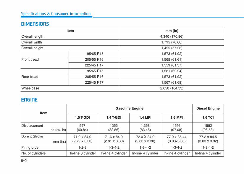
8-2
Specifications & Consumer information
DDIIMMEENNSSIIOONNSS
EENNGGIINNEE
Item mm (in)
Overall length 4,340 (170.86)
Overall width 1,795 (70.66)
Overall height 1,455 (57.28)
Front tread
195/65 R15 1,573 (61.92)
205/55 R16 1,565 (61.61)
225/45 R17 1,559 (61.37)
Rear tread
195/65 R15 1,581 (62.24)
205/55 R16 1,573 (61.92)
225/45 R17 1,567 (61.69)
Wheelbase 2,650 (104.33)
ItemGasoline Engine Diesel Engine
1.0 T-GDI 1.4 T-GDI 1.4 MPI 1.6 MPI 1.6 TCI
Displacementcc (cu. in)
997(60.84)
1353(82.56)
1,368(83.48)
1591(97.08)
1582(96.53)
Bore x Stroke
mm (in.)71.0 x 84.0
(2.79 x 3.30)71.6 x 84.0
(2.81 x 3.30)72.0 X 84.0(2.83 x 3.30)
77.0 x 85.44(3.03x3.06)
77.2 x 84.5(3.03 x 3.32)
Firing order 1-2-3 1-3-4-2 1-3-4-2 1-3-4-2 1-3-4-2
No. of cylinders In-line 3 cylinder In-line 4 cylinder In-line 4 cylinder In-line 4 cylinder In-line 4 cylinder
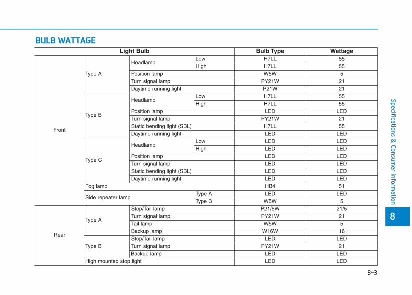
8
Specifications & Consum
er information
BBUULLBB WWAATTTTAAGGEELight Bulb Bulb Type Wattage
Front
Type A
HeadlampLow H7LL 55High H7LL 55
Position lamp W5W 5Turn signal lamp PY21W 21Daytime running light P21W 21
Type B
HeadlampLow H7LL 55High H7LL 55
Position lamp LED LEDTurn signal lamp PY21W 21Static bending light (SBL) H7LL 55Daytime running light LED LED
Type C
HeadlampLow LED LEDHigh LED LED
Position lamp LED LEDTurn signal lamp LED LEDStatic bending light (SBL) LED LEDDaytime running light LED LED
Fog lamp HB4 51
Side repeater lampType A LED LEDType B W5W 5
Rear
Type A
Stop/Tail lamp P21/5W 21/5Turn signal lamp PY21W 21Tail lamp W5W 5Backup lamp W16W 16
Type BStop/Tail lamp LED LEDTurn signal lamp PY21W 21Backup lamp LED LED
High mounted stop light LED LED
8-3
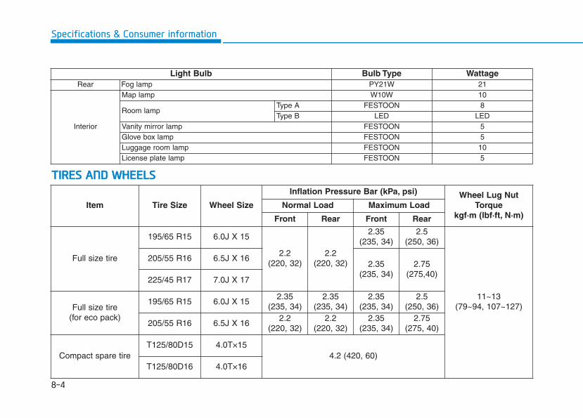
8-4
Specifications & Consumer information
Item Tire Size Wheel Size
Inflation Pressure Bar (kPa, psi) Wheel Lug NutTorque
kgf·m (lbf·ft, N·m)Normal Load Maximum Load
Front Rear Front Rear
Full size tire
195/65 R15 6.0J X 15
2.2 (220, 32)
2.2 (220, 32)
2.35 (235, 34)
2.5 (250, 36)
11~13(79~94, 107~127)
205/55 R16 6.5J X 162.35
(235, 34)2.75
(275,40)225/45 R17 7.0J X 17
Full size tire(for eco pack)
195/65 R15 6.0J X 152.35
(235, 34)2.35
(235, 34)2.35
(235, 34)2.5
(250, 36)
205/55 R16 6.5J X 162.2
(220, 32)2.2
(220, 32)2.35
(235, 34)2.75
(275, 40)
Compact spare tireT125/80D15 4.0T×15
4.2 (420, 60)T125/80D16 4.0T×16
TTIIRREESS AANNDD WWHHEEEELLSS
Light Bulb Bulb Type WattageRear Fog lamp PY21W 21
Interior
Map lamp W10W 10
Room lampType A FESTOON 8Type B LED LED
Vanity mirror lamp FESTOON 5Glove box lamp FESTOON 5Luggage room lamp FESTOON 10License plate lamp FESTOON 5
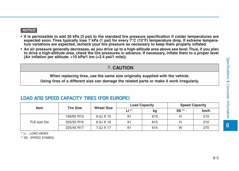
8-5
8
Specifications & Consum
er information
When replacing tires, use the same size originally supplied with the vehicle.Using tires of a different size can damage the related parts or make it work irregularly.
CAUTION
• It is permissible to add 20 kPa (3 psi) to the standard tire pressure specification if colder temperatures areexpected soon. Tires typically lose 7 kPa (1 psi) for every 7°C (12°F) temperature drop. If extreme tempera-ture variations are expected, recheck your tire pressure as necessary to keep them properly inflated.
• An air pressure generally decreases, as you drive up to a high-altitude area above sea level.Thus, if you planto drive a high-altitude area, check the tire pressures in advance. If necessary, inflate them to a proper level(Air inflation per altitude: +10 kPa/1 km (+2.4 psi/1 mile)).
NOTICE
*1 LI : LOAD INDEX*2 SS : SPEED SYMBOL
Item Tire Size Wheel SizeLoad Capacity Speed Capacity
LI *1 kg SS *2 km/h
Full size tire
195/65 R15 6.0J X 15 91 615 H 210
205/55 R16 6.5J X 16 91 615 H 210
225/45 R17 7.0J X 17 91 615 W 270
LLOOAADD AANNDD SSPPEEEEDD CCAAPPAACCIITTYY TTIIRREESS ((FFOORR EEUURROOPPEE))
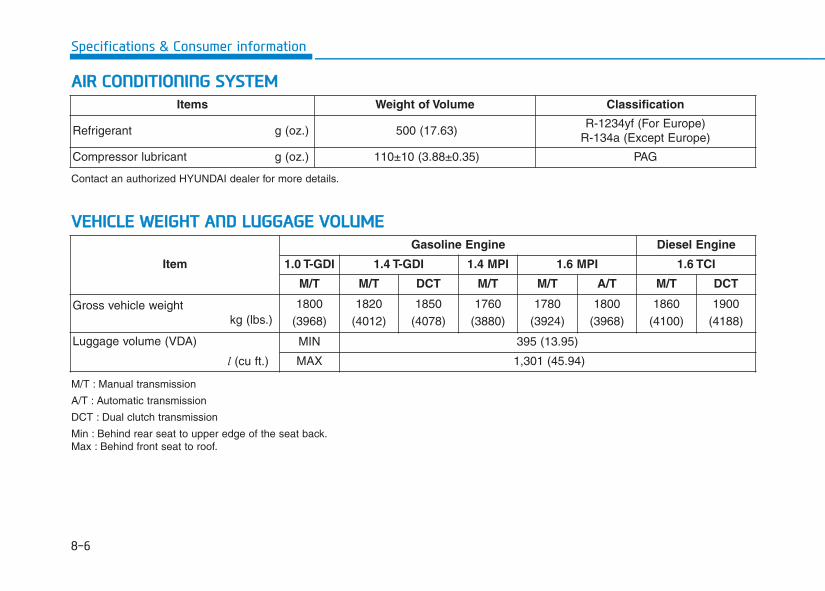
8-6
Specifications & Consumer information
AAIIRR CCOONNDDIITTIIOONNIINNGG SSYYSSTTEEMM
Item
Gasoline Engine Diesel Engine
1.0 T-GDI 1.4 T-GDI 1.4 MPI 1.6 MPI 1.6 TCI
M/T M/T DCT M/T M/T A/T M/T DCT
Gross vehicle weightkg (lbs.)
1800(3968)
1820(4012)
1850(4078)
1760(3880)
1780(3924)
1800(3968)
1860(4100)
1900(4188)
Luggage volume (VDA)
l (cu ft.)
MIN 395 (13.95)
MAX 1,301 (45.94)
VVEEHHIICCLLEE WWEEIIGGHHTT AANNDD LLUUGGGGAAGGEE VVOOLLUUMMEE
Items Weight of Volume Classification
Refrigerant g (oz.) 500 (17.63)R-1234yf (For Europe)
R-134a (Except Europe)
Compressor lubricant g (oz.) 110±10 (3.88±0.35) PAG
Contact an authorized HYUNDAI dealer for more details.
M/T : Manual transmission
A/T : Automatic transmission
DCT : Dual clutch transmission
Min : Behind rear seat to upper edge of the seat back.Max : Behind front seat to roof.
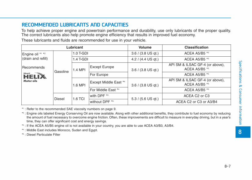
8-7
Specifications & Consum
er information
RREECCOOMMMMEENNDDEEDD LLUUBBRRIICCAANNTTSS AANNDD CCAAPPAACCIITTIIEESSTo help achieve proper engine and powertrain performance and durability, use only lubricants of the proper quality.The correct lubricants also help promote engine efficiency that results in improved fuel economy.These lubricants and fluids are recommended for use in your vehicle.
Lubricant Volume Classification
Engine oil *1 *2
(drain and refill)
RecommendsGasoline
1.0 T-GDI 3.6 l (3.8 US qt.) ACEA A5/B5 *3
1.4 T-GDI 4.2 l (4.4 US qt.) ACEA A5/B5 *3
1.4 MPIExcept Europe
3.6 l (3.8 US qt.)API SM & ILSAC GF-4 (or above),
ACEA A5/B5 *3
For Europe ACEA A5/B5 *3
1.6 MPIExcept Middle East *4
3.6 l (3.8 US qt.)API SM & ILSAC GF-4 (or above),
ACEA A5/B5 *3
For Middle East *4 ACEA A5/B5 *3
Diesel 1.6 TCIwith DPF *5
5.3 l (5.6 US qt.)ACEA C2 or C3
without DPF *5 ACEA C2 or C3 or A3/B4
8
*1 : Refer to the recommended SAE viscosity numbers on page 9.*2 : Engine oils labeled Energy Conserving Oil are now available. Along with other additional benefits, they contribute to fuel economy by reducing
the amount of fuel necessary to overcome engine friction. Often, these improvements are difficult to measure in everyday driving, but in a year’stime, they can offer significant cost and energy savings.
*3 : If the ACEA A5/B5 engine oil is not available in your country, you are able to use ACEA A3/B3, A3/B4.*4 : Middle East includes Morocco, Sudan and Egypt.*5 : Diesel Particulate Filter
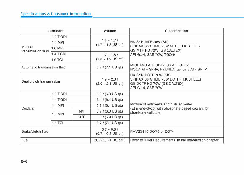
8-8
Specifications & Consumer information
Lubricant Volume Classification
Manual transmission fluid
1.0 T-GDI1.6 ~ 1.7 l
(1.7 ~ 1.8 US qt.)HK SYN MTF 70W (SK)SPIRAX S6 GHME 70W MTF (H.K.SHELL)GS MTF HD 70W (GS CALTEX)API GL-4, SAE 70W, TGO-9
1.4 MPI
1.6 MPI
1.4 T-GDI 1.7 ~ 1.8 l(1.8 ~ 1.9 US qt.)1.6 TCI
Automatic transmission fluid 6.7 l (7.1 US qt.)MICHANG ATF SP-IV, SK ATF SP-IV, NOCA ATF SP-IV, HYUNDAI genuine ATF SP-IV
Dual clutch transmission1.9 ~ 2.0 l
(2.0 ~ 2.1 US qt.)
HK SYN DCTF 70W (SK)SPIRAX S6 GHME 70W DCTF (H.K.SHELL)GS DCTF HD 70W (GS CALTEX)API GL-4, SAE 70W
Coolant
1.0 T-GDI 6.0 l (6.3 US qt.)
Mixture of antifreeze and distilled water(Ethylene-glycol with phosphate based coolant for aluminum radiator)
1.4 T-GDI 6.1 l (6.4 US qt.)
1.4 MPI 5.8 l (6.1 US qt.)
1.6 MPIM/T 5.7 l (6.0 US qt.)
A/T 5.6 l (5.9 US qt.)
1.6 TCI 6.7 l (7.1 US qt.)
Brake/clutch fluid0.7 ~ 0.8 l
(0.7 ~ 0.8 US qt.)FMVSS116 DOT-3 or DOT-4
Fuel 50 l (13.21 US gal.) Refer to “Fuel Requirements” in the Introduction chapter.
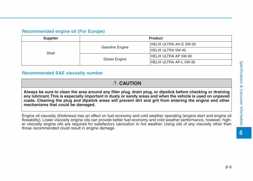
8-9
8
Specifications & Consum
er information
Recommended engine oil (For Europe)Supplier Product
Shell
Gasoline EngineHELIX ULTRA AH-E 5W-30
HELIX ULTRA 5W-40
Diesel EngineHELIX ULTRA AP 5W-30
HELIX ULTRA AP-L 5W-30
Always be sure to clean the area around any filler plug, drain plug, or dipstick before checking or drainingany lubricant.This is especially important in dusty or sandy areas and when the vehicle is used on unpavedroads. Cleaning the plug and dipstick areas will prevent dirt and grit from entering the engine and othermechanisms that could be damaged.
CAUTION
Recommended SAE viscosity number
Engine oil viscosity (thickness) has an effect on fuel economy and cold weather operating (engine start and engine oilflowability). Lower viscosity engine oils can provide better fuel economy and cold weather performance, however, high-er viscosity engine oils are required for satisfactory lubrication in hot weather. Using oils of any viscosity other thanthose recommended could result in engine damage.
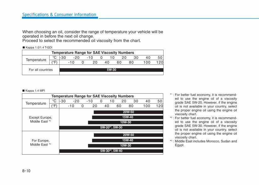
8-10
Specifications & Consumer information
When choosing an oil, consider the range of temperature your vehicle will beoperated in before the next oil change.Proceed to select the recommended oil viscosity from the chart.
Temperature Range for SAE Viscosity Numbers
Temperature°C(°F)
-30 -20 -10 0 10 20 30 40 50-10 0 20 40 60 80 100 120
For all countries 5W-30
■ Kappa 1.0/1.4 T-GDI
■ Kappa 1.4 MPI
Temperature Range for SAE Viscosity Numbers
Temperature°C(°F)
-30 -20 -10 0 10 20 30 40 50-10 0 20 40 60 80 100 120
20W-50
10W-30
15W-40
5W-30*2, 5W-40
20W-50
15W-40
10W-30
5W-20*1, 5W-30
Except Europe, Middle East *3
For Europe, Middle East *3
*1 : For better fuel economy, it is recommend-ed to use the engine oil of a viscositygrade SAE 5W-20. However, if the engineoil is not available in your country, selectthe proper engine oil using the engine oilviscosity chart.
*2 : For better fuel economy, it is recommend-ed to use the engine oil of a viscositygrade SAE 5W-30. However, if the engineoil is not available in your country, selectthe proper engine oil using the engine oilviscosity chart.
*3 : Middle East includes Morocco, Sudan andEgypt.
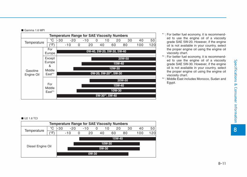
8-11
8
Specifications & Consum
er information
Temperature Range for SAE Viscosity Numbers
Temperature°C(°F)
-30 -20 -10 0 10 20 30 40 50-10 0 20 40 60 80 100 120
5W-30
15W-40
10W-30
0W-30
Diesel Engine Oil
■ U2 1.6 TCI
Temperature Range for SAE Viscosity Numbers
Temperature
GasolineEngine Oil
°C(°F)
-30 -20 -10 0 10 20 30 40 50-10 0 20 40 60 80 100 120
ForEurope
20W-50
10W-30
15W-40
5W-30*2, 5W-40
0W-40, 5W-20, 5W-30, 5W-40
20W-50
15W-40
10W-30
0W-20, 5W-20*1, 5W-30
ExceptEurope
& MiddleEast*3
ForMiddleEast*3
■ Gamma 1.6 MPI
*1 : For better fuel economy, it is recommend-ed to use the engine oil of a viscositygrade SAE 5W-20. However, if the engineoil is not available in your country, selectthe proper engine oil using the engine oilviscosity chart.
*2 : For better fuel economy, it is recommend-ed to use the engine oil of a viscositygrade SAE 5W-30. However, if the engineoil is not available in your country, selectthe proper engine oil using the engine oilviscosity chart.
*3 : Middle East includes Morocco, Sudan andEgypt.
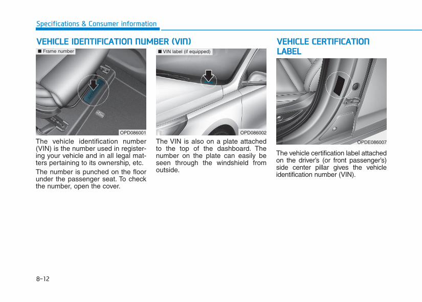
8-12
Specifications & Consumer information
The vehicle identification number(VIN) is the number used in register-ing your vehicle and in all legal mat-ters pertaining to its ownership, etc.The number is punched on the floorunder the passenger seat. To checkthe number, open the cover.
The VIN is also on a plate attachedto the top of the dashboard. Thenumber on the plate can easily beseen through the windshield fromoutside.
The vehicle certification label attachedon the driver’s (or front passenger’s)side center pillar gives the vehicleidentification number (VIN).
VVEEHHIICCLLEE IIDDEENNTTIIFFIICCAATTIIOONN NNUUMMBBEERR ((VVIINN)) VVEEHHIICCLLEE CCEERRTTIIFFIICCAATTIIOONNLLAABBEELL
OPD086002
■ VIN label (if equipped)
OPDE086007
OPD086001
■ Frame number
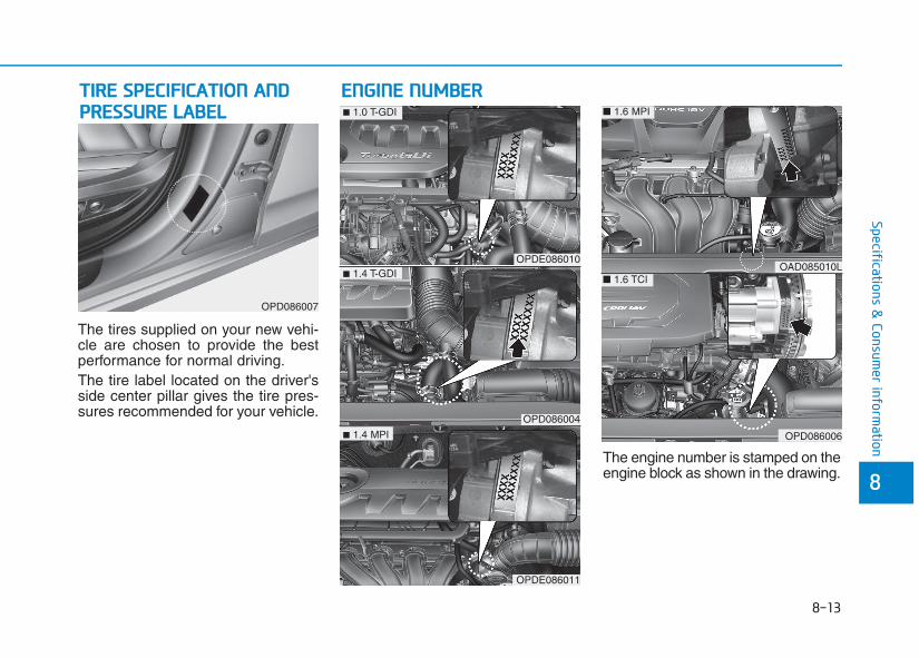
8-13
8
Specifications & Consum
er information
The tires supplied on your new vehi-cle are chosen to provide the bestperformance for normal driving.The tire label located on the driver'sside center pillar gives the tire pres-sures recommended for your vehicle.
TTIIRREE SSPPEECCIIFFIICCAATTIIOONN AANNDDPPRREESSSSUURREE LLAABBEELL
EENNGGIINNEE NNUUMMBBEERR
The engine number is stamped on theengine block as shown in the drawing.
OPD086007
OAD085010L
■ 1.6 MPI
OPD086006
■ 1.6 TCI
OPDE086010
OPD086004
OPDE086011
■ 1.4 T-GDI
■ 1.0 T-GDI
■ 1.4 MPI
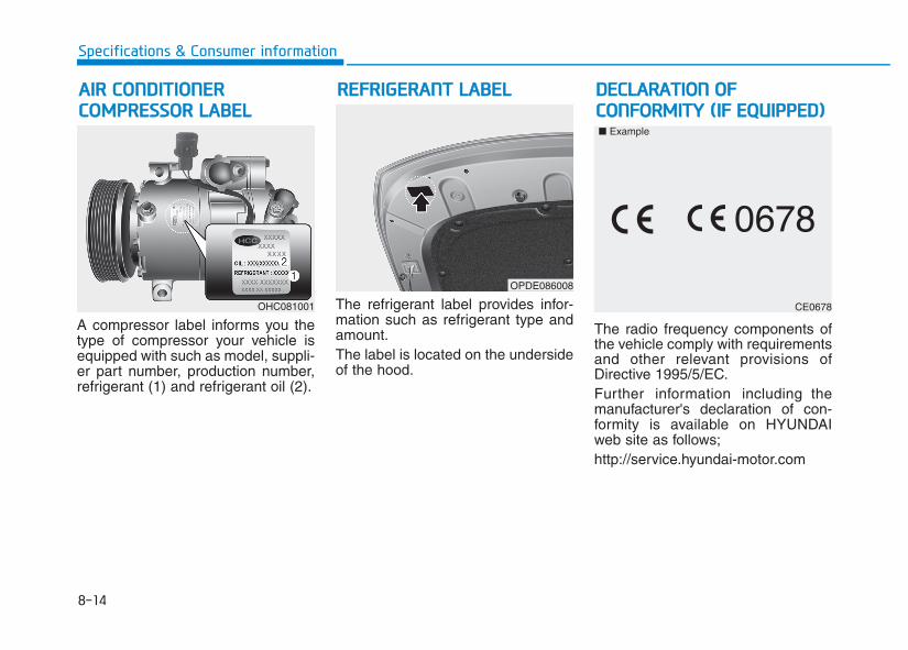
8-14
Specifications & Consumer information
A compressor label informs you thetype of compressor your vehicle isequipped with such as model, suppli-er part number, production number,refrigerant (1) and refrigerant oil (2).
The refrigerant label provides infor-mation such as refrigerant type andamount.The label is located on the undersideof the hood.
The radio frequency components ofthe vehicle comply with requirementsand other relevant provisions ofDirective 1995/5/EC.Further information including themanufacturer's declaration of con-formity is available on HYUNDAIweb site as follows;http://service.hyundai-motor.com
RREEFFRRIIGGEERRAANNTT LLAABBEELLAAIIRR CCOONNDDIITTIIOONNEERR CCOOMMPPRREESSSSOORR LLAABBEELL
OHC081001
OPDE086008
CE0678
■ Example
DDEECCLLAARRAATTIIOONN OOFF CCOONNFFOORRMMIITTYY ((IIFF EEQQUUIIPPPPEEDD))
A
Appendix
I
Appendix
A
Шофиране през зимата (Bulgarian)..................9-2Téli vezetés (Hungarian) .....................................9-6Vetrarakstur (Icelandic) .....................................9-10Jazda zimą (Polish)...........................................9-14
Тежките зимни атмосферни условиямогат да предизвикат по-голямоизносване и други проблеми. За дасведете до минимум проблемите,свързани с шофирането преззимата, следвайте препоръките по-долу:
Сняг или поледица
За да карате своето превозносредство при дълбока снежнапокривка може да се наложи даизползвате зимни гуми или дапоставите вериги върху тях. Ако санеоб ходими зимни гуми, трябвада изберете гуми със същияразмер и вид като тези наоригиналните гуми.
В противен случай това може дасе отрази неблагоприятно набезопасността и експлоатациятана Вашия автомобил. Освен товакарането с висока скорост,бързото ускорение, внезапнотонатискане на спирачки и резкитезавои крият сериозни опасности.
При забавяне на скоростта,използвайте доколкото евъзможно спирачките на двигателя. Внезапното натискане наспирачки на заснежена илизаледена настилка може дапредизвика занасяне. Трябва дапод държате достатъчнадистанция между автомобила,който се движи пред Вас, и Вашияавтомобил.
Освен това натискайте спирачкаталеко. Следва да се отбележи чеинсталирането на веригите върхугума та ще позволи прилаганетона по-голяма движеща сила, ноняма да предотврати занасянетовстрани.
Веригите за гуми не сапозволени във всички държави.Проверете норма тивнатауредба в своята страна предида поставите вериги за гуми.
К СВЕДЕНИЮ
ШОФИРАНЕ ПРЕЗ ЗИМАТА (BULGARIAN)
9-2
Appendix

Г уми за снягАко поставите гуми за сняг на свояавто- мобил се уверете, че това сарадиалнигуми със същия размер итоварен индекс като тези наоригиналните гуми. Поставете гумиза сняг на всичките четири колела,за да балансирате експлоатациятана своя автомобил във всякаквиатмос- ферни условия. Имайтепредвид, че тягата на гумите за снягвърху суха настилка не може дабъде толкова голяма колкото тазина оригиналните гуми. Следва дакарате внимателно, дори когатопътищата са почистени.Консултирайте се с доставчика нагуми за максималнатапрепоръчителна скорост.
Не монтирайте гуми с шипове,преди да сте проверилиместните, национални и общинскиразпоредби за възможни огра-ничения в тяхната употреба.
Вериги за гуми
Тъй като страниците нарадиалните гуми са по-тънки, темогат да се повредят, ако върхутях се монтират някои видовевери- ги за сняг. Ето защо сепрепоръчва изпол- зването нагуми за сняг, а не на вериги за сняг.Не поставяйте вериги върхуавтомо- били, чиито колела са салуминиеви джан- ти; веригите засняг могат да повредят колелата.Ако трябва да се използват веригиза сняг, използвайте телени веригис дебелина от поне 12 мм.
9-3
A
Appendix
Размер на гумите за сняг
Г умите за сняг следва да саравностойни по размер и тип натези на стандартните гуми наавтомобила. В противен случайтова може да се отразинеблагоприятно на безопасносттаи експлоатацията на Вашияавтомобил.
ОСТОРОЖНО
OPDE056072
Повредата на Вашия автомобилвследствие на непра- вилнатаупотреба на вериги за сняг не е вобхвата на гаранцията напроизводителя на Вашияавтомобил.
Поставяйте веригите винаги подве, на предните гуми. Обърнетевнимание, че поставянето навериги на гумите на автомобилаосигурява по-добра задвижващасила, но не предпазва отстранични поднасяния.
9-4
Appendix
• Уверете се, че размерът ивидът на веригите саправилните за Вашите гуми.Неправилните вериги за снягмогат да повредяткаросерията и окачването наавтомобила и този тип повредаможе да не е в обхвата напроизводствената гаранция заВашия автомобил. Също такакуките за свързване наверигите за сняг могат да сеповредят от намиращите се вконтакт с тях автомобилничасти, като това може дадоведе до разхлабването им.Уверете се, че веригите за снягса от клас S споредкласификацията наДружеството на автомобилнитеинженери (SAE).
(продолжение)
(продолжение)
• Винаги проверявайте даливериги- те са билипоставени правилно следкато изминете около 0,5 до 1км, за да се уверите вбезопасното им поставяне.Затегнете веригите или гипоставете отново, ако са серазхлабили.
ВНИМАНИЕ
Монтиране на вериги
Когато инсталирате веригите,следвайте инструкциите напроизводителя и ги затег- нетемаксимално. Карайте бавно синста- лирани вериги. Ако чуете, чеверигите са навлезли в контакт скаросерията или шасито, спрете иги затегнете. Ако те все още са вконтакт, намалете скоростта допреустановяване на контакта.Свалете веригите веднага, щомзапочнете да кара- те попочистените пътища.
9-5
A
Appendix
Поставяне на вериги
Когато поставите вериги засняг , пар- кирайте автомобилана равно място далеч отпътното движение. Включетеаварийните светлини ипоставете светлоотразителниятри- ъгълник зад автомобила,ако разпо- лагате с такъв.Винаги паркирайте автомобилав паркинг, дръпнете ръч-натаспирачка и изключете двигате-ля преди да поставите веригитеза сняг.
ОСТОРОЖНО
Вериги за гуми
• Използването на вериги можеда се отрази неблагоприятнона работата на Вашияавтомобил.
• Не надвишавайте пределнатаско- рост, препоръчана отпроизводителя, илискоростта от 30 км/ч, което епо- ниско.
• Карайте внимателно иизбягвайте неравности,дупки, резки завои и другиопасности на пътя, коитомогат да накарат автомобилада подскача.
• Избягвайте резките завои илиизпол- зването на спирачки,ако колелата са блокирани.
ОСТОРОЖНО
• Веригите с грешен размерили тези, които санеправилно инсталирани,могат да повредятспирачните накладки,окачването, каросерията иколелата.
• Спрете и затегнете веригитеповтор- но винаги, щом гичуете да удрят автомобила.
ВНИМАНИЕ
Télen a nehéz időjárási feltételeknagyobb elhasználódást és másproblémákat eredményezhetnek. Atéli vezetés problémáinakcsökkentése érdekében célszerűkövetnie a következő javaslatokat:
Havas vagy jeges útviszonyok
Mély hóban közlekedéshez szükséglehet téli gumiabroncsok használatáravagy kerekeire hólánc felszerelésére.Ha téli gumiabroncsokra vanszüksége, a gyárilag felszerelttelmegegyező méretű és típusúgumiabroncsot kell választani. Ennekfigyelmen kívül hagyása hátrányosanbefolyásolja gépkocsija biztonságát ésvezethetőségét. Ezen túlmenően anagy sebességű haladás, a hirtelengyorsítás, a hirtelen fékezés és agyors kanyarvétel nagyon veszélyesgyakorlat.Lassításkor a lehető legjobbanhasználja ki motorja fékhatását.Havas vagy jeges úton a hirtelenfékezés megcsúszást okozhat.Elegendően nagy követésitávolságot kell tartania sajátgépkocsija és az Ön előtt haladójármű között. Tehát óvatosanfékezzen. Jegyezze meg, hogyhólánc használatakor megnő ahajtóerő, de nem segít az oldalrakicsúszás elkerülésében.
A hólánc nem legális mindenországban. Ellenőrizze az Önországának törvényeit, mielőttfelszereli a hóláncot.
MEGJEGYZÉS
TTÉÉLLII VVEEZZEETTÉÉSS ((HHUUNNGGAARRIIAANN))
9-6
Appendix
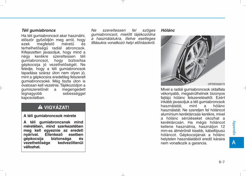
Téli gumiabroncs
Ha téli gumiabroncsot akar használni,először győződjön meg arról, hogyezek megfelelő méretű ésterhelhetőségű radiál abroncsok.Kifejezetten javasoljuk, hogy mind anégy kerékre szereltessen téligumiabroncsot, hogy biztosítsagépkocsija jó vezethetőségét. Nefeledje, hogy a téli gumiabroncsoktapadása száraz úton nem olyan jó,mint a gépkocsira eredetileg felszereltgumiabroncsoké. Még tiszta úton isóvatosan kell vezetnie.Tájékozódjon agumiszerelőnél a megengedettlegnagyobb sebességgelkapcsolatban.
Ne szereltessen fel szögesgumiabroncsot, mielőtt tájékozódnaa használatukra, illetve esetlegestiltásukra vonatkozó helyi előírásokról.
Hólánc
Mivel a radiál gumiabroncsok oldalfalavékonyabb, megsérülhetnek bizonyosfajtájú hólánc felszerelésétől. Ezértinkább javasoljuk a téli gumiabroncsokhasználatát, mint a hólánchasználatát. Ne szereljen fel hóláncotalumínium keréktárcsás kerékre, mivela hólánc sérüléseket okozhat akeréktárcsán. Ha mégis hóláncotkellene használnia, használjon 12mm-es átmérőnél kisebb, kábeltípusúhóláncot. Gépkocsijának a hólánchelytelen használatából eredő kárairanem vonatkozik a garancia.
9-7
A
Appendix
A téli gumiabroncsok mérete
A téli gumiabroncsnak mindméretében, mind szerkezetébenmeg kell egyeznie az eredetinyárival. Ellenkező esetbengépkocsija biztonsága ésvezethetősége kedvezőtlenülváltozhat.
VIGYÁZAT!
OPDE056072
A hóláncot mindig párban szerelje felaz első kerekekre. Fontosmegjegyezni, hogy a kerekekrefelszerelt hólánc nagyobb tapadóerőtbiztosít, azonban nem akadályozzameg a kicsúszást oldalra.
A hуlбnc felszerelйse
A hólánc felszerelésekor figyelmesenkövesse gyártójának utasításait, és alehető legfeszesebbre húzza meg aláncot. A felszerelt hólánccal lassanközlekedjen. Ha a lánc hozzáverődika karosszériához vagy az alvázhoz,álljon meg és feszítsen rajta. Ha mégmindig hozzáér, lassítson le annyira,hogy megszűnjön a kontaktus.Haladéktalanul távolítsa el aláncokat, amint tiszta útra ér.
9-8
Appendix
• Ügyeljen arra, hogy a hólánc agumiabroncsaihoz megfelelőméretű és típusú legyen. Anem megfelelő méretű hóláncmegrongálhatja gépkocsijakarosszériáját ésfelfüggesztéseit, és erre nemvonatkozik a gépkocsigaranciája. Ezenkívül ahólánc összekötő kapcsaimegsérülhetnek akarosszériához ütődéstől,amitől a hólánc meglazulhat,és leeshet a kerékről.Kizárólag az SAE szabványszerinti „S” osztályú hóláncothasználjon.
• 0,5 - 1km megtétele utánellenőrizze megfelelőelhelyezkedésüket abiztonságos felszerelésükérdekében. Ha meglazultak,húzza meg újra, vagy szereljefel ismét a hóláncokat.
FIGYELEM!
Hólánc felszerelése
Forgalomtól távol eső síkfelületen álljon félre. Kapcsoljabe a vészvillogót és tegyen kielakadásjelző háromszöget agépkocsi mögé. A hóláncfelszerelése előtt mindigkapcsolja P állásba asebességváltó választókarját,működtesse a rögzítőféket, majdállítsa le a motort.
VIGYÁZAT!
9-9
A
Appendix
Hólánc
• A hólánc használata jelentősenkorlátozza a gépkocsikezelhetőségét.
• Ne lépje túl a 30 km/hsebességet, vagy a hóláncgyártója által meghatározottmaximális sebességet. Mindig akettő közül alacsonyabb értékettartsa be.
• Vezessen óvatosan, kerülje abukkanókat, lyukakat, éleskanyarokat és az úton előfordulóegyéb veszélyforrásokat, melyeka gépkocsi erős berugózásátokozzák.
• Tartózkodjon az éleskanyarvételtől és a blokkolókerekekkel történő fékezéstől.
VIGYÁZAT!
• A nem megfelelő méretű vagyrosszul felszerelt hóláncmegrongálhatja gépkocsijaféktömlőit, felfüggesztéseit,karosszériáját és a kerekeit.
• Álljon meg és húzzafeszesebbre a hóláncokat, habeleütnek a gépkocsivalamelyik alkatrészébe.
FIGYELEM!
Akstur í þungri færð og vetrarveðrileiðir til aukins slits á ökutækinu ogskapar ýmis vandamál. Hægt er aðdraga úr erfiðleikum sem fylgjavetrarakstri ef farið er að þessumráðleggingum:
Akstur í snjó eða hálkuVið akstur í djúpum snjó kann að veranauðsynlegt að nota vetrarhjólbarðaeða setja keðjur á hjólbarðana.Reynist nauðsynlegt að notavetrarhjólbarða þarf að velja hjólbarðaaf sömu stærð og gerð og venjuleguhjólbarðarnir. Sé það ekki gert geturþað dregið úr öryggi og skertaksturseiginleika ökutækisins.Hraðakstur, skyndileg hröðun,nauðhemlun og krappar beygjur getaenn fremur falið í sér mikla hættu.Þegar dregið er úr hraða er ráðlegtað beita vélarhemlun sem kostur er.Við nauðhemlun á snævi þöktumeða hálum vegum getur ökutækiðhæglega runnið til. Nauðsynlegt erað halda hæfilegri fjarlægð á milliþíns ökutækis og ökutækisins fyrirframan. Alltaf ætti að beita hemlinummjúklega. Hafa ber í huga að efkeðjur eru settar á hjólbarða fæstaukinn drifkraftur en það hindrar þóekki að ökutækið renni til hliðanna.
Notkun snjókeðja er ólögleg ísumum ríkjum. Kynnið ykkurgildandi landslög áður en keðjureru settar upp.
ATHUGIÐ
VVEETTRRAARRAAKKSSTTUURR ((IICCEELLAANNDDIICC))
9-10
Appendix
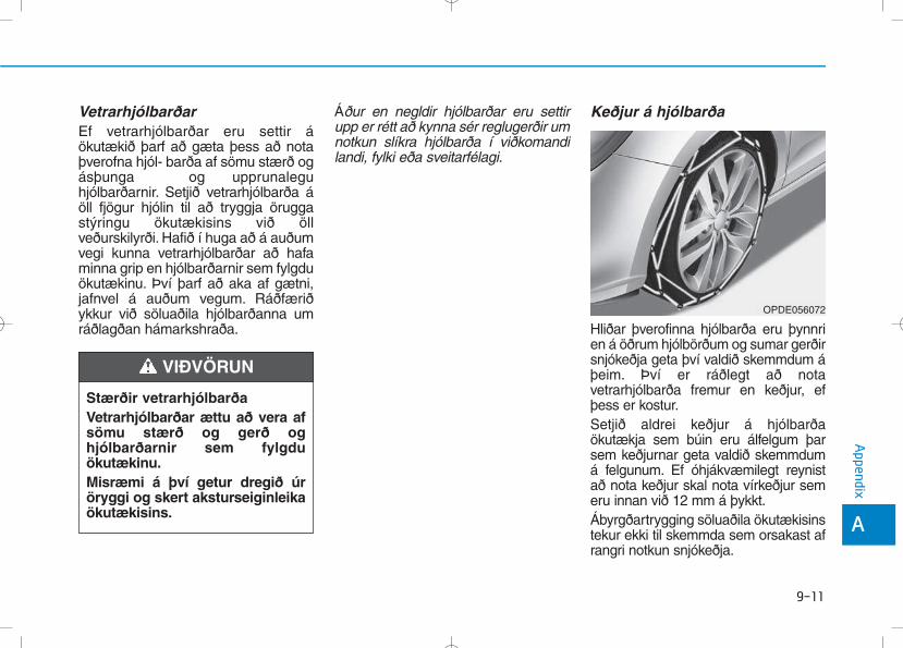
VetrarhjólbarðarEf vetrarhjólbarðar eru settir áökutækið þarf að gæta þess að notaþverofna hjól- barða af sömu stærð ogásþunga og upprunaleguhjólbarðarnir. Setjið vetrarhjólbarða áöll fjögur hjólin til að tryggja öruggastýringu ökutækisins við öllveðurskilyrði. Hafið í huga að á auðumvegi kunna vetrarhjólbarðar að hafaminna grip en hjólbarðarnir sem fylgduökutækinu. Því þarf að aka af gætni,jafnvel á auðum vegum. Ráðfæriðykkur við söluaðila hjólbarðanna umráðlagðan hámarkshraða.
Áður en negldir hjólbarðar eru settirupp er rétt að kynna sér reglugerðir umnotkun slíkra hjólbarða í viðkomandilandi, fylki eða sveitarfélagi.
Keðjur á hjólbarða
Hliðar þverofinna hjólbarða eru þynnrien á öðrum hjólbörðum og sumar gerðirsnjókeðja geta því valdið skemmdum áþeim. Því er ráðlegt að notavetrarhjólbarða fremur en keðjur, efþess er kostur.Setjið aldrei keðjur á hjólbarðaökutækja sem búin eru álfelgum þarsem keðjurnar geta valdið skemmdumá felgunum. Ef óhjákvæmilegt reynistað nota keðjur skal nota vírkeðjur semeru innan við 12 mm á þykkt.Ábyrgðartrygging söluaðila ökutækisinstekur ekki til skemmda sem orsakast afrangri notkun snjókeðja.
9-11
A
Appendix
Stærðir vetrarhjólbarðaVetrarhjólbarðar ættu að vera afsömu stærð og gerð oghjólbarðarnir sem fylgduökutækinu.Misræmi á því getur dregið úröryggi og skert aksturseiginleikaökutækisins.
VIÐVÖRUN
OPDE056072
9-12
Appendix
Aðeins skal setja keðjur á í pörum ogaðeins á framhjólbarðana. Hafa ber íhuga að ef keðjur eru settar áhjólbarða fæst aukinn drifkraftur. Þaðhindrar þó ekki að ökutækið renni tilhliðanna.
Uppsetning б keрjum
Þegar keðjur eru settar á skal fylgjaleiðbeiningum framleiðanda og herðakeðjurnar eins mikið og unnt er. Þegarkeðjur hafa verið settar á skal akahægt. Ef hljóð heyrist sem bendir til aðkeðjurnar séu í snertingu viðyfirbyggingu eða undirvagn er rétt aðnema staðar og herða keðjurnar. Efsnerting virðist enn eiga sér stað skalhægja aksturinn þar til hljóðið þagnar.Takið keðjurnar niður um leið ogkomið er á rudda og snjólausa vegi.
• Gætið þess að snjókeðjurnarséu af þeirri stærð og gerðsem hæfir hjólbörðunum.Notkun snjókeðja af rangrigerð getur valdið skemmdumá yfirbyggingu og fjöðrunökutækisins og kann að fallautan ábyrgðartryggingarsöluaðila ökutækisins. Þágeta festikrókar keðjannaskemmst vegan núnings viðíhluti ökutækisins ogsnjókeðjurnar losnað afhjólbarðanum. Gætið þess aðsnjókeðjurnar séu með SAE-vottun í S-flokki.
• Eftir um það bil 0,5-1 kmakstur skal ævinlega skoðakeðjurnar aftur til að tryggjaað þær hafi verið settar upp áréttan og öruggan hátt. Herðiðkeðjurnar eða setjið þær afturá ef þær hafa losnað.
VARÚÐ
9-13
A
Appendix
Uppsetning á keðjum
Þegar snjókeðjur eru settar uppskal leggja ökutækinu á sléttumfleti fjarri umferð. Kveikið áviðvörunarljósum ökutækisinsog setjið þríhyrningslagaviðvörunarskilti upp fyrir aftanökutækið, ef það er tiltækt.Hafið ökutækið ævinlega ístöðuhemli og drepið á vélinniáður en snjókeðjur eru settarupp.
VIÐVÖRUN
Keðjur á hjólbarða
• Notkun keðja getur skertaksturs- eiginleika ökutækisins.
• Akið ekki hraðar en 30 km/klst.eða samkvæmt ráðlögðumhámarkshraða framleiðandakeðjanna, hvort sem reynistlægra.
• Akið gætilega og sneiðið hjáþústum, holum, kröppumbeygjum og öðrum hættum áveginum, sem gætu valdiðhristingi ökutækisins.
• Forðist krappar beygjur eðalæsta hemlun.
VIÐVÖRUN
• Séu snjókeðjur af rangri stærðeða rangt upp settar geta þærvaldið skemmdum á hemlalögn,fjöðrun, yfirbyggingu og hjólumökutækisins.
• Hvenær sem hljóð bendir tilþess að keðjurnar sláist viðökutækið skal stöðva aksturog herða keðjurnar.
VARÚÐ
JAZDA ZIMĄ (POLISH)
9-14
Appendix
Surowe warunki pogodowe zimąpowodują większe zużycie pojazdu iinne problemy. Aby zminimalizowaćproblemy związane z jazdą w zimie,postępuj zgodnie z poniższymisugestiami:
Jazda w warunkachśniegowych i przy oblodzeniu
Aby prowadzić pojazd w głębokimśniegu, może okazać się niezbędneużycie opon zimowych lubzainstalowanie łańcuchówśniegowych. Jeśli potrzebne okażąsię opony zimowe, konieczne jestwybranie opon o rozmiarze i typieodpowiadających oponom, w jakiepojazd był pierwotnie wyposażony.Jeśli założone zostanąnieodpowiednie opony, będzie tomiało negatywny wpływ nabezpieczeństwo i prowadzeniepojazdu. Ponadto jazda z nadmiernąprędkością, gwałtowneprzyspieszanie, nagłe hamowanie iostre skręty będą stanowiłypotencjalnie bardzo dużeniebezpieczeństwo.Podczas zwalniania należy w pełniwykorzystać hamowanie silnikiem.Nagłe hamowanie na zaśnieżonejlub oblodzonej drodze możespowodować poślizg pojazdu.
Należy utrzymywać odpowiedniodstęp od pojazdu jadącego zprzodu. Hamulców należy używaćostrożnie. Należy pamiętać, żezałożenie łańcuchów śniegowychzapewni większą siłę napędową, alenie zapobiegnie ślizganiu się naboki.
Stosowanie łańcuchów śniegowychnie jest zgodne z prawem wewszystkich krajach. Przed założeniemłańcuchów śniegowych należysprawdzić przepisy danego kraju.
UWAGA
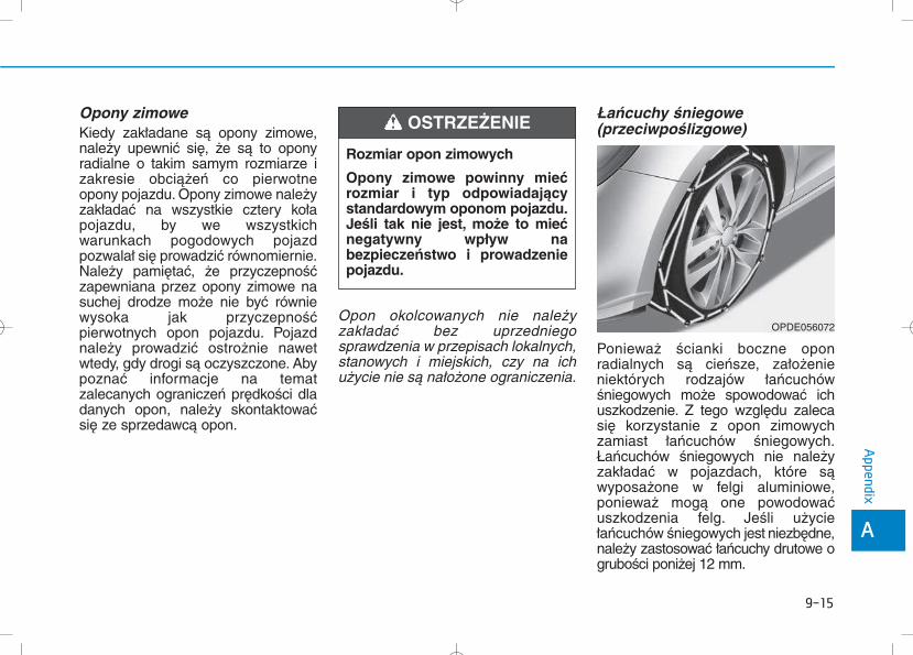
Opony zimowe
Kiedy zakładane są opony zimowe,należy upewnić się, że są to oponyradialne o takim samym rozmiarze izakresie obciążeń co pierwotneopony pojazdu. Opony zimowe należyzakładać na wszystkie cztery kołapojazdu, by we wszystkichwarunkach pogodowych pojazdpozwalał się prowadzić równomiernie.Należy pamiętać, że przyczepnośćzapewniana przez opony zimowe nasuchej drodze może nie być równiewysoka jak przyczepnośćpierwotnych opon pojazdu. Pojazdnależy prowadzić ostrożnie nawetwtedy, gdy drogi są oczyszczone. Abypoznać informacje na tematzalecanych ograniczeń prędkości dladanych opon, należy skontaktowaćsię ze sprzedawcą opon.
Opon okolcowanych nie należyzakładać bez uprzedniegosprawdzenia w przepisach lokalnych,stanowych i miejskich, czy na ichużycie nie są nałożone ograniczenia.
Łańcuchy śniegowe(przeciwpoślizgowe)
Ponieważ ścianki boczne oponradialnych są cieńsze, założenieniektórych rodzajów łańcuchówśniegowych może spowodować ichuszkodzenie. Z tego względu zalecasię korzystanie z opon zimowychzamiast łańcuchów śniegowych.Łańcuchów śniegowych nie należyzakładać w pojazdach, które sąwyposażone w felgi aluminiowe,ponieważ mogą one powodowaćuszkodzenia felg. Jeśli użyciełańcuchów śniegowych jest niezbędne,należy zastosować łańcuchy drutowe ogrubości poniżej 12 mm.
9-15
A
Appendix
Rozmiar opon zimowych
Opony zimowe powinny miećrozmiar i typ odpowiadającystandardowym oponom pojazdu.Jeśli tak nie jest, może to miećnegatywny wpływ nabezpieczeństwo i prowadzeniepojazdu.
OSTRZEŻENIE
OPDE056072
Uszkodzenia pojazdu spowodowaneużyciem niewłaściwych łańcuchówśniegowych nie jest objęte gwarancjąproducenta pojazdu.Łańcuchy na opony należy zakładaćjedynie parami i na przednichoponach. Należy pamiętać, żezałożenie łańcuchów na oponachzwiększy siłę napędową, ale niezapobiegnie poślizgowi bocznemu.
Zakіadanie іaсcuchуw њniegowych
Zakładając łańcuchy śniegowe należypostępować zgodnie z instrukcjamipodanymi przez producenta.Łańcuchy należy założyć tak ciasno,jak to tylko możliwe. Kiedy łańcuchy sąjuż założone, pojazd należy prowadzićpowoli. Jeśli dadzą się słyszeć dźwiękiświadczące o tym, że łańcuchy stykająsię z nadwoziem lub podwoziem,należy zatrzymać samochód izacisnąć je. Jeśli łańcuchy wciążstykają się z elementami pojazdu,należy zmniejszać prędkość, ażłańcuchy przestaną uderzać wsamochód. Łańcuchy należy zdjąć jaktylko rozpocznie się jazdę pooczyszczonej drodze.
9-16
Appendix
• Należy upewnić się, żełańcuchy śniegowe mająodpowiedni rozmiar i typ dlaopon pojazdu. Zastosowanieniewłaściwych łańcuchówśniegowych może spowodowaćuszkodzenie nadwozia orazzawieszenia, a zniszczeniapowstałe w ten sposób mogąnie być objęte gwarancjąproducenta pojazdu.
(Ciąg dalszy)
(Ciąg dalszy)
Ponadto, haczyki łączącełańcuchów śniegowych mogązostać zniszczone na skutekstykania się z elementamisamochodu, co możespowodować zsunięcie sięłańcuchów z opon. Należyupewnić się, że łańcuchyśniegowe są klasy “S” SAE iposiadają certyfikat.
• Po przejechaniu ok. 0,5 do 1km (0,3 do 0,6 mil), dlazachowania bezpieczeństwa,należy zawsze sprawdzić, czyłańcuchy śniegowe zostałypoprawnie założone. Jeśliłańcuchy poluzowały się,należy je zacisnąć lub założyćponownie.
OSTROŻNIE
9-17
A
Appendix
Zakładanie łańcuchówśniegowych
Aby założyć łańcuchy śniegowe,należy zatrzymać pojazd napłaskim podłożu, z dala od ruchudrogowego. Włączyć światłaawaryjne pojazdu i umieścić zanim trójkąt ostrzegawczy, jeślijest on dostępny. Zanimrozpocznie się instalowaniełańcuchów śniegowych dźwignięzmiany biegów należy zawszeumieścić w położeniu P (Postój),zaciągnąć hamulec postojowy iwyłączyć silnik.
OSTRZEŻENIE
Łańcuchy śniegowe
• Użycie łańcuchów śniegowychmoże mieć negatywny wpływna prowadzenie pojazdu.
• Pojazdu nie należy prowadzićszybciej niż 30 km/h (20 mil/h)lub z prędkością większą, niżzalecana przez producenta,którakolwiek z tych wartościokaże się mniejsza.
• Pojazd należy prowadzićostrożnie i unikać wybojów,dziur, ostrych skrętów i innychzagrożeń drogowych, któremogą powodowaćpodskakiwanie pojazdu.
• Należy unikać ostrychzakrętów lub hamowania zzablokowanymi kołami.
OSTRZEŻENIE
• Łańcuchy o niewłaściwymrozmiarze lub niepoprawniezałożone mogą uszkodzićlinki hamulcowe pojazdu,zawieszenie, nadwozie orazkoła.
• Za każdym razem, kiedy da sięusłyszeć, że łańcuchyuderzają w samochód, należyzatrzymać się i zacisnąć je.
OSTROŻNIE
Related Documents