• Owner's Manual CRAFTSMAN" 19.5 HP ELECTRIC START 42" MOWER AUTOMATIC LAWN TRACTOR Model No. 917.270920 • Safety • Assembly • Operation • Maintenance • Repair Parts CAUTION: Read and follow all Safety Rules and Instructions before operat- ing this equipment. For answers to your questions about this product, Call: 1-800-659-5917 Sears Craftsman Help Line 5 am - 5 pm, Mon - Sat Seam, Roebuck and Co., Hoffman Estates, II 60179 Visit our Craftsman website:www.sears.com/craftsman

Welcome message from author
This document is posted to help you gain knowledge. Please leave a comment to let me know what you think about it! Share it to your friends and learn new things together.
Transcript

•Owner's Manual
CRAFTSMAN"19.5 HPELECTRIC START42" MOWERAUTOMATICLAWN TRACTOR
Model No.917.270920
• Safety• Assembly• Operation• Maintenance• Repair Parts
CAUTION:
Read and follow all Safety Rulesand Instructionsbefore operat-ingthis equipment.
For answers to your questions
about this product, Call:
1-800-659-5917Sears Craftsman Help Line5 am - 5 pm, Mon - Sat
Seam, Roebuck and Co., Hoffman Estates, II 60179Visit our Craftsman website:www.sears.com/craftsman
Warr_Lnty "_....._...... : ...... ......i .................... 2Safety R=Jles. ...... :...... ......;...... .............. 2ProdUct Spec_ficatlons ........................... 5
Assembly ..... .?,.,._ ...... ,........................... 7Operation ....... '.............. _........................ 11Maintenance Schedule ;................... 178
Maintenance ....................................... 18Service and Adjustments .................... 22Storage ............................................... 29Troubleshooting ................................. 30Repair Parts ........................................ 34Parts Ordering ..................... Back Cover
LIMITED TWO YE_,R WARRANTY ON CRAFTSMAN RIDING EQUIPMENT
For two (2) years from the date of purchase, if this Craftsman Riding Equipment ismaintained, lubricated and tuned up according to the instructions in the owner'smanual, Sears will repair or replace, free of charge, any parts found to be defective inmaterial or workmanship.This Warranty does not cover:• Expendable items which become worn during normal use, such as blades, spark
plugs, air cleaners, belts, etc.• Tire replacement or repair caused by punctures from outside objects, such as nails,
thorns, stumps, or glass.• Repairs necessary because of operator abuse, negligence, improper storage or
accident or the failure to maintain the equipment according to the instructionscontained in the owner's manual.
• Riding equipment used for commercial or rental purposes.
LIMITED 90 DAY WARRANTY ON BATTERY
For ninety (90) days from date of purchase, if any battery included with this ridingequipment proves defective in material or workmanship and our testing determines thebattery will not hold a charge, Sears will replace the battery at no charge. In-homewarranty service on your Craftsman riding equipment is available at no charge for 30days from the date of purchase. Please contact your nearest service center. After 30days from the date of purchase, warranty service is available by taking your Craftsmanriding equipment to your nearest Sears Service Center. (In-home warranty service willstill be available after 30 days from the date of purchase but a standard trip charge willapply). This warranty applies only while this product is in the United States. ThisWarranty gives you specific legal rights, and you may alsohave other rights which mayvary from state to state.
SEARS, ROEBUCK AND CO., D/817 WA, HOFFMAN ESTATES, iL 60179
IMPORTANT" This cutting machine iscapable of amputating hands and feetand throwing objects. Failure to observethe following safety instructions couldresult in serious injury or death.GENERAL OPERATION
• Read, understand, and follow allinstructions in the manual and on the
machine before starting.• Only allow responsible adults, who are
familiar with the instructions, tooperate the machine.
• Clear the area of objects such asrocks, toys, wire, etc., which could bepicked up and thrown by the blade.
• Be sure the area is clear of otherpeople before mowing. Stop machineif anyone enters the area.
• Never carry passengers.• Do not mow in reverse unless abso-
lutely necessary. Always look downand behind before and while backing.
• Be aware of the mower dischargedirection and do not point it at anyone.Do not operate the mower withouteither the entire grass catcher or the
2 guard in place.
• Slow down before tuming.• Never leave a running machine
unattended. Always turn off blades, setparking brake, stop engine, andremove keys before dismounting.
• Tum off blades when not mowing.• Stop engine before removing grass
catcher or unclogging chute.• Mow only in daylight or good artificial
light.• Do not operate the machine while
under the influence of alcohol ordrugs.
• Watch for traffic when operating nearor crossing roadways.
• Use extra care when loading orunloading the machine into a trailer ortruck.
• Data indicates that operators, age 60years and above, are involved in alarge percentage of riding mower-related injuries. These operatorsshould evaluate their ability to operatethe riding mower safely enough toprotect themselves and others fromsenous injury.
SLOPE OPERATIONSlopes are a major factor related to loss-of-control and tipover accidents, whichcan result in severe injury or death. Allslopes require extra caution. If youcannot back up the slope or if you leeluneasy on it, do not mow it.DO:
• Mow up and down slopes, not across.• Remove obstacles such as rocks, tree
limbs, etc.• Watch for holes, ruts, or bumps.
Uneven terrain could overturn the
machine. Tall grass can hide ob-stacles.
• Use slow speed• Choose a low gearso that you will not have to stop or shiftwhile on the slope.
• Follow the manufacturer's recommen-dations for wheel weights or counter-weights to improve stability.
• Use extra care with grass catchers orother attachments. These can changethe stability of the machine.
• Keep all movement on the slopes slow
and gradual. Do not make suddenchanges in speed or direction.
• Avoid starting or stopping on a slope. Iftires lose traction, disengage the
blades and proceed slowly straightdown the slope.
DO NOT:
• Do not turn on slopes unless neces-sary, and then, tum slowly andgradually downhill, if possible.
• Do not mow near drop-offs, ditches, orembankments. The mower couldsuddenly tum over if a wheel is overthe edge of a cliff or ditch, or if an edgecaves in.
• Do not mow on wet grass. Reducedtraction could cause sliding.
• Do not try to stabilize the machine byputting your foot on the ground.
• Do not use grass catcher on steepslopes.
CHILDREN
Tragic accidents can occur if the operatoris not alert to the presence of children.Children are often attracted to themachine and the mowing activity. Neverassume that children will remain whereyou last saw them.• Keep children out of the mowing area
and under the watchful care of anotherresponsible adult.
• Be alert and turn machine off ifchildren enter the area.
• Before and when backing, look behindand down for small children.
• Never carry children. They may fall offand be seriously injured or interferewith safe machine operation.
• Never allow children to operate themachine.
• Use extra care when approachingblind comers, shrubs, trees, or otherobjects that may obscure vision.
SERVICE
• Use extra care in handling gasolineand other fuels. They are flammableand vapors are explosive.
Use only an approved container.Never remove gas cap or add fuelwith the engine running. Allowengine to cool before refueling. Donot smoke.Never refuel the machine indoors.Never store the machine or fuelcOntainer inside where there is anopen flame, such as a waterheater.
• Never run a machine inside a closed
3 area.
• Keepnuts and bolts, especiallybladeattachmentbolts, tight and keepequipment in good condition.
• Never tamper with safety devices.Check their proper operation regu-larly.
• Keep machine free of grass, leaves, orother debris build-up. Clean oil or fuelspillage. Allow machine to cool beforestoring.
• Stop and inspect the equipment if youstrike an object. Repair, if necessary,before restarting.
• Never make adjustments or repairswith the engine running.
• Grass catcher components are subjectto wear, damage, and deterioration,which could expose moving parts or al-low objects to be thrown. Frequentlycheck components and replace withmanufacturer's recommended parts,when necessary.
• Mower blades are sharp and can cut.Wrap the blade(s) or wear gloves, anduse extra caution when sewicing them.
• Check brake operation frequently. Ad-just and service as required.
• Be sure the area is clear of otherpeople before mowing. Stop machineif anyone enters the area.
• Never carry passengers or childreneven with the blades off.
• Do not mow in reverse unless abso-lutely necessary. Always |ook downand behind before and while backing.
• Never carry children: They may fall offand be seriously injured or interferewith safe machine operation.
• Keep children out of the mowing areaand under the watchful care of anotherresponsible adult.
• Be alert and turn machine off ifchildren enter the area.
• Before and when backing, look behindand down for small children.
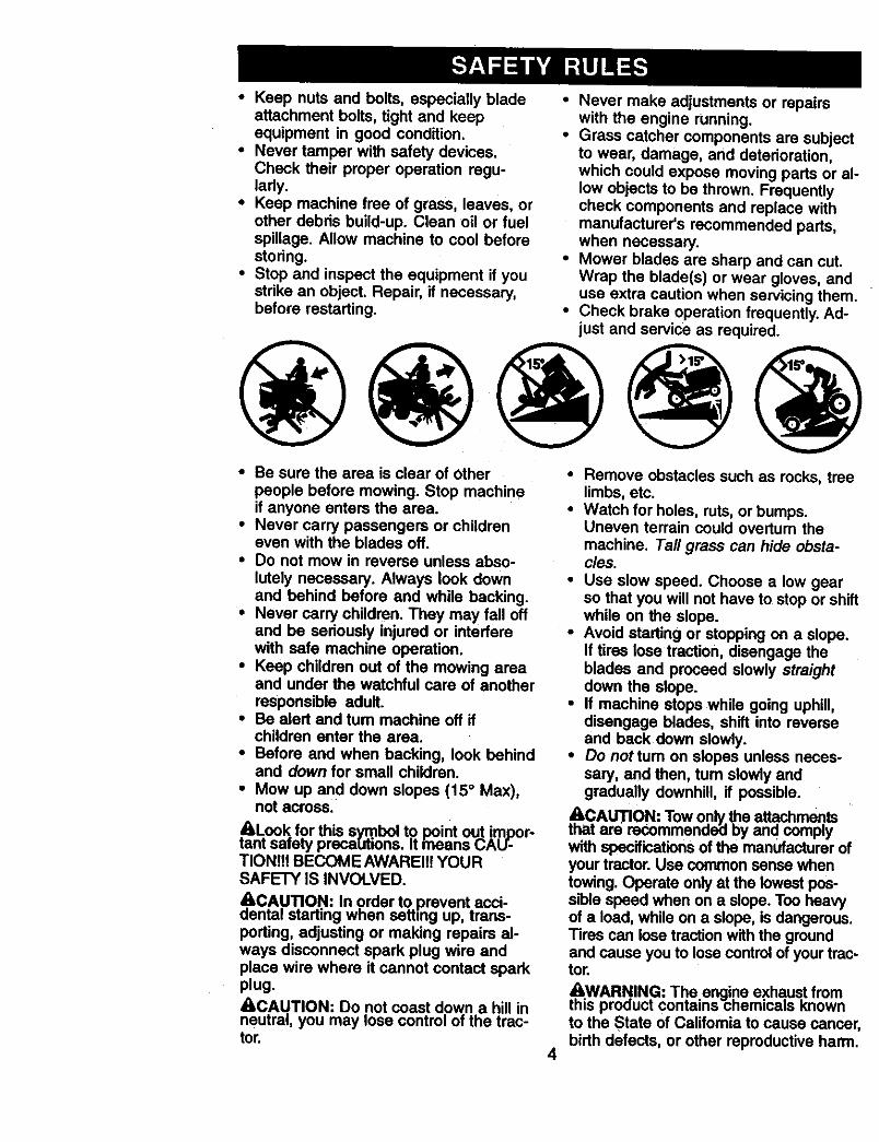
• Mow up and down slopes (15 ° Max),not across.
ALook for this symbol to point out impor-tant safety preca[Jtions. It fneans CAU-TIONItt BECOME AWAREII! YOURSAFETY IS INVOLVED.
c,AeCA.Ul_.IO.N:In order to.prevent.acci-nta=starting wnen setting up, trans-
porting, adjusting or making repairs al-ways disconnect spark plug wire andplace wire where it cannot contact sparkplug._kCAUTION: Do not coast down a hill inneutral, you may lose control of the trac-tor.
• Remove obstacles such as recks, treelimbs, etc.
• Watch for holes, ruts, or bumps.Uneven terrain could overturn themachine. Tall grass can hide obsta-cles.
• Use slow speed. Choose a low gearso that you will not have to stop or shiftwhile on the slope.
• Avoid starting or stopping on a slope.if tires Iosa traction, disengage theblades and proceed slowly straightdown the slope.
• If machine stops while going uphill,disengage blades, shift into reverseand back down slowly.
• Do not turn on slopes unless neces-sary, and then, tum slowly andgradually downhill, if possible.
tAhCAUTION: Tow o.nly_ atta._men.tsat are recommeno_a by aria comply
with specifications of the manufacturer ofyour tractor. Use common sense whentowing. Operate only at the lowest pos-sibio speed when on a slope. Too heavyof a load, while on a slope, is dangerous.Tires can lose traction with the groundand cause you to loss control of your trac-tor.
&WARN.IN.G: Th.e engi.ne exhaus.t fromthis pro<_uct contains chemicals Knownto the State of Califomia to cause cancer,birth defects, or other reproductive harm.
4
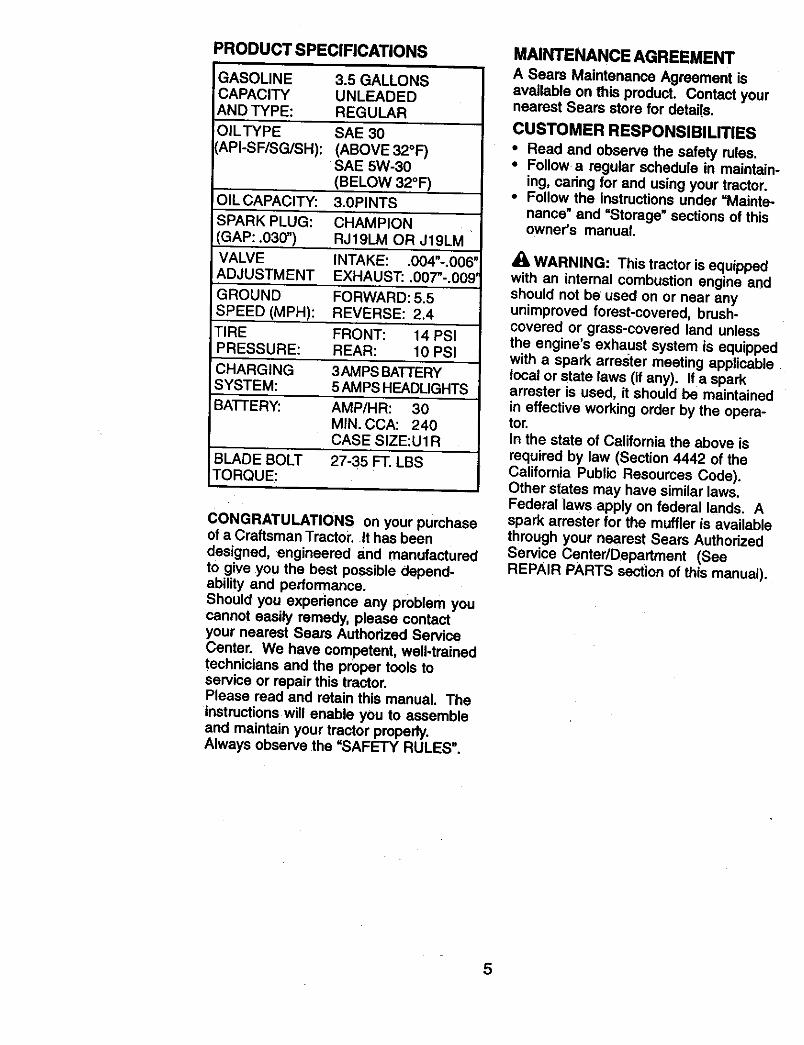
PRODUCT SPECIFICATIONS
GASOLINECAPACITYAND TYPE:
OILTYPEAPI-SF/SG/SH):
OIL CAPACITY:
SPARK PLUG:
GAP: .030")VALVEADJUSTMENT
GROUND
SPEED (MPH):
TIREPRESSURE:
CHARGINGSYSTEM:
BA'I-FERY:
BLADE BOLTTORQUE:
3.5 GALLONSUNLEADEDREGULAR
SAE 30
(ABOVE 32°F)SAE 5W-30
(BELOW 32°F)
3.0PINTS
CHAMPIONRJ19LM OR J19LM
INTAKE: .004"-.006"EXHAUST'..007"-.009'
FORWARD: 5.5REVERSE: 2.4
FRONT: 14 PSiREAR: 10 PSI
3AMPS BATTERY5 AMPS HEADLIGHTS
AMP/HR: 30MIN. CCA: 240CASE SIZE:U1R
27-35 FT. LBS
CONGRATULATIONS on your purchaseof a Craftsman Tractor. It has beendesigned, engineered and manufacturedto give you the best possible depend-ability and performance.Should you experience any problem youcannot easily remedy, please contactyour nearest Sears Authorized ServiceCenter. We have competent, well-trainedtechnicians and the proper tools toservice or repair this tractor.Please read and retain this manual. Theinstructions will enable you to assembleand maintain your tractor properly.Always observe the "SAFETY RULES".
MNNTENANCE AGREEMENT
A Sears Maintenance Agreement isavailable on this product. Contact yournearest Sears store for details.
CUSTOMER RESPONSIBILITIES
• Read and observe the safety rules.• Follow a regular schedule in maintain-
ing, caring for and using your tractor.• Follow the instructions under =Mainte-
nance" and =Storage" sections of thisowner's manual.
WARNING: This tractor is equippedwith an internal combustion engine andshould not be used on or near anyunimproved forest-covered, brush-covered or grass-covered land unlessthe engine's exhaust system is equippedwith a spark arrester meeting applicablelocal or state laws (if any). Ira sparkarrester is used, it should be maintainedin effective working order by the opera-tor.In the state of California the above is
required by law (Section 4442 of theCalifornia Public Resources Code).Other states may have similar laws.Federal laws apply on federal lands. Aspark attester for the muffler is availablethrough your nearest Sears AuthorizedService Center/Department (SeeREPAIR PARTS section of this manual).
5
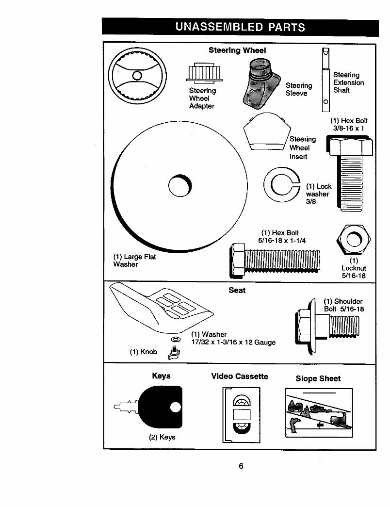
Steerlng Wheel t_ _ SteeringSteering ExtensionSleeve Shaft
Adapter
(1) Hex Bolt3/8-16 x 1
Wheel g
II (, 1 J _ _. /--/ (1) Lock
(_/)sLaregeF'at _ L_>lCk._t_
sher Seat
17/32 x 1-3/16 x 12 Gauge
(1) Knob
(1) ShoulderBolt 5/16-18
Keys
(2) Keys
Video Cassette
"-1
Slope Sheet
6
Your new tractor has been assembled at the factory with exception of those parts leftunassembled for shipping purposes. To ensure safe and proper operation of yourtractor all parts and hardware you assemble must be tightened securely. Use thecorrect tools as necessary to insure proper tightness.
TOOLS REQUIRED FOR ASSEMBLY
A socket wrench set will make assemblyeasier. Standard wrench sizes you needare listed below.
(1) 9/16" wrench (1) Pliers(2) 1/2" wrench (1) Utility knife(1) 3/4" socket with (1) Tire pressure
drive ratchet gaugeWhen right or left hand is mentioned inthis manual, it means, from your point ofview, when you are in the operatingposition (seated behind the steeringwheel).
TO REMOVE TRACTOR FROMCARTONUNPACK CARTON
• Remove all accessible loose parts andparts boxes from shipping carton.
• Cut, from top to bottom, along lines onall four corners of shipping carton, andlay panels flat.
• Check for any additional loose pads orboxes and remove.
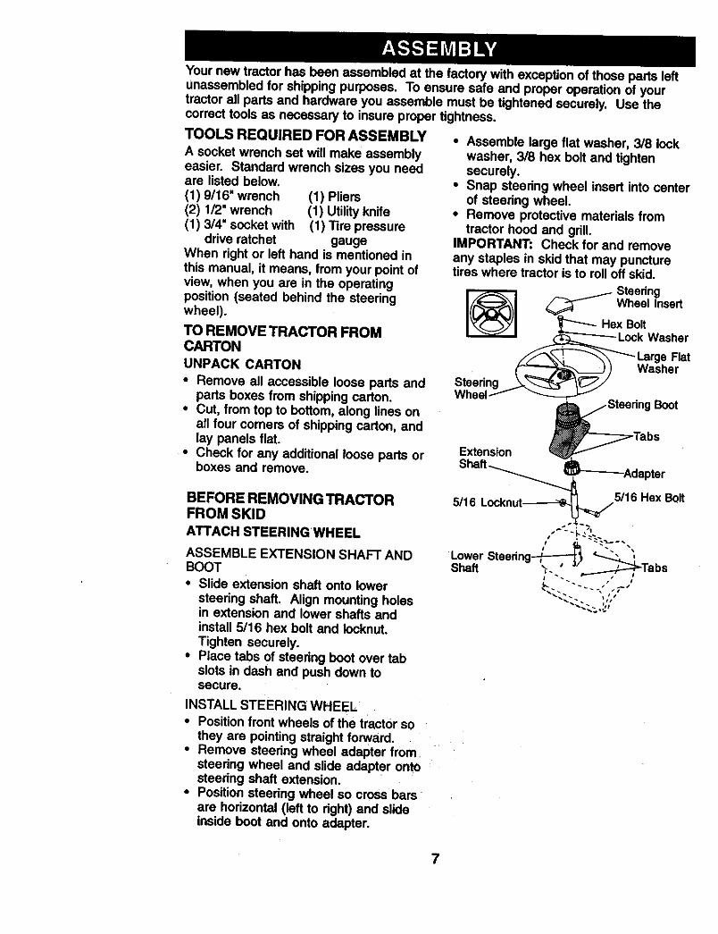
BEFORE REMOVING TRACTORFROM SKIDATTACH STEERING WHEEL
ASSEMBLE EXTENSION SHAFT ANDBOOT
• Slide extension shaft onto lowersteering shaft. Align mounting holesin extension and lower shafts andinstall 5/16 hex bolt and Iocknut.
Tighten securely.• Place tabs of steedng boot over tab
slots in dash and push down tosecure.
INSTALL STEERING WHEEL
• Position front wheels of the tractor so
they are pointing straight forward.• Remove steedng wheel adapter from
steedng wheel and slide adapter ontosteedng shaft extension.
• Position steedng wheel so cross barsare horizontal (left to dght) and slideinside boot and onto adapter.
• Assemble large flat washer, 3/8 lockwasher, 3/8 hex bolt and tightensecurely.
• Snap steering wheel insert into centerof steedng wheel.
• Remove protective materials fromtractor hood and grill.
IMPORTANT: Check for and removeany staples in skid that may puncturetires where tractor is to roll off skid.
7
HOWTO SETUPYOURTRACTORCHECK BA'n'ERY
• Lift hood to raised position.• If this battery is put into service after
month and year indicated on label(label located between terminals)charge battery for minimum of onehour at 6-10 amps. (See =BATTERY"in Maintenance section of this manual
for charging instructions).
Y "' " Label• .o'
:-::i..........
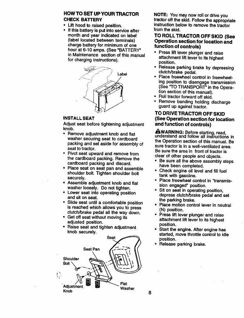
iNSTALL SEAT
Adjust seat before tightening adjustmentknob.
• Remove adjustment knob and flatwasher securing seat to cardboardpacking and set aside for assembly ofseat to tractor,
• Pivot seat upward and remove fromthe cardboard packing. Remove thecardboard packing and discard.
• Place seat on seat pan and assembleshoulder bolt. Tighten shoulder boltsecurely.
• Assemble adjustment knob and flatwasher loosely. Do not tighten,
• Lower seat into operating positionand sit on seat.
• Slide seat until a comfortable positionis reached which allows you to pressclutch/brake pedal all the way down.
• Get off seat without moving itsadjusted position.
• Raise seat and tighten adjustmentknob securely,
Seat
Seat Pan
NOTE: You may now rollor drive youtractor off the skid. Follow the appropriateinstructionbelow to remove the tractorfrom the skid.
TO ROLL TRACTOR OFF SKID (SeeOperation section for location and
function of controls)• Press lift lever plunger and raise
attachment lift lever to its highestposition.
• Release parking brake by depressingclutch/brake pedal.
• Place freewheel control in freewheel-
ing position to disengage transmission(See _'O TRANSPORT" in the Opera-tion section of this manual),
• Roll tractor forward off skid.
• Remove banding holding dischargeguard up against tractor.
TO DRIVE TRACTOR OFF SKID(See Operation section for locationand function of controls)
_kWARNING: Before starting, read,understand and follow all instructions in
the Operation section of this manual• Besure tractor is in a well-ventilated area•Be sure the area in front of tractor is
clear of other people and objects.• Be sure all the above assembly steps
have been completed.• Check engine oil level and fill fuel
tank with gasoline.• Place freewheel control in "transmis-
sion engaged" position.• Sit on seat in operating position,
depress clutch/brake pedal and setthe parking brake.
• Place motion control lever in neutral
(N) position.• Press lift lever plunger and raise
attachment lift lever to its highestposition.
• Start the engine. After engine hasstarted, move throttle control to idleposition.
• Release parking brake.
Shoulder
Flat'Adjustment WasherKnob 8
• Slowly move the motion control leverforward and slowly drive tractor offskid.
• Apply brake to stop tractor, set parkingbrake and place motion control leverin neutral position.
•Tum ignition key to "OFF" position.Continue with the instructions that follow.
CHECK TIRE PRESSURE
The tires on your tractor were overin-flated at the factory for shipping pur-poses. Correct tire pressure is importantfor best cutting performance.• Reduce tire pressure to PSI shown in
=PRODUCT SPECIFICATIONS"section of this manual.
CHECK DECK LEVELNESS
For best cutting results, mower housingshould be property leveled. See "I"OLEVEL MOWER HOUSING" in theService and Adjustments section of thismanual.CHECK FOR PROPER POSITIONOF ALL BELTS
See the figures that are shown forreplacing motion and mower blade drivebelts in the Service and Adjustmentssection of this manual. Verify that thebelts are routed correctly.CHECK BRAKE SYSTEMAfter you learn how to Operate yourtractor, check to see that the brake isproperly adjusted. See =TO ADJUSTBRAKE" in the Service and Adjustmentssection of this manual.
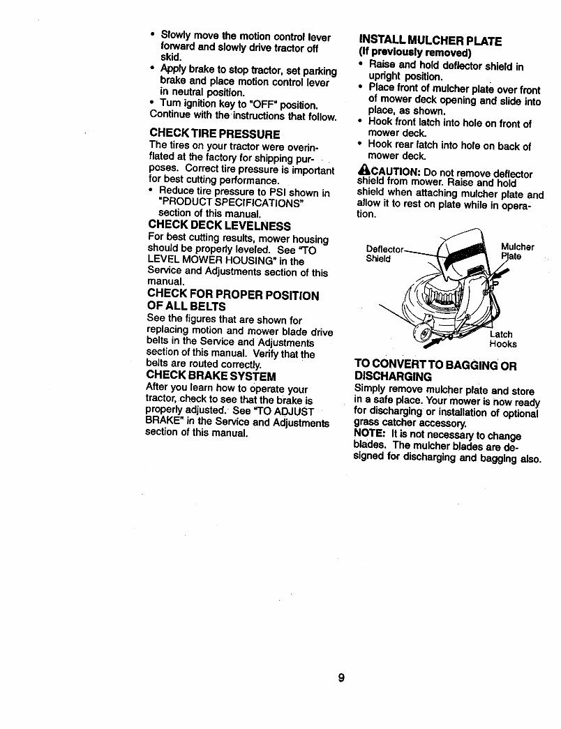
INSTALL MULCHER PLATE
(If previously removed)• Raise and hold deflector shield in
upright position.• Place front of mulcher plate over front
of mower deck opening and slide intoplace, as shown.
• Hook front latch into hole on front ofmower deck.
• Hook roar latch into hole on back ofmower deck.
,I_!ILCAUTION: Do not remove deflectorshield from mower. Raise and holdshield when attaching mulcher plate andallow it to rest on plate while in opera-tion.
Shield
Mulcher
LatchHooks
TO CONVERT TO BAGGING ORDISCHARGING
Simply remove mulcher plate and storein a safe place. Your mower is now readyfor discharging or installation of optionalgrass catcher accessory,NOTE: It is not necessary to changeblades. The mulcher blades are de-signed for discharging and bagging also.
9
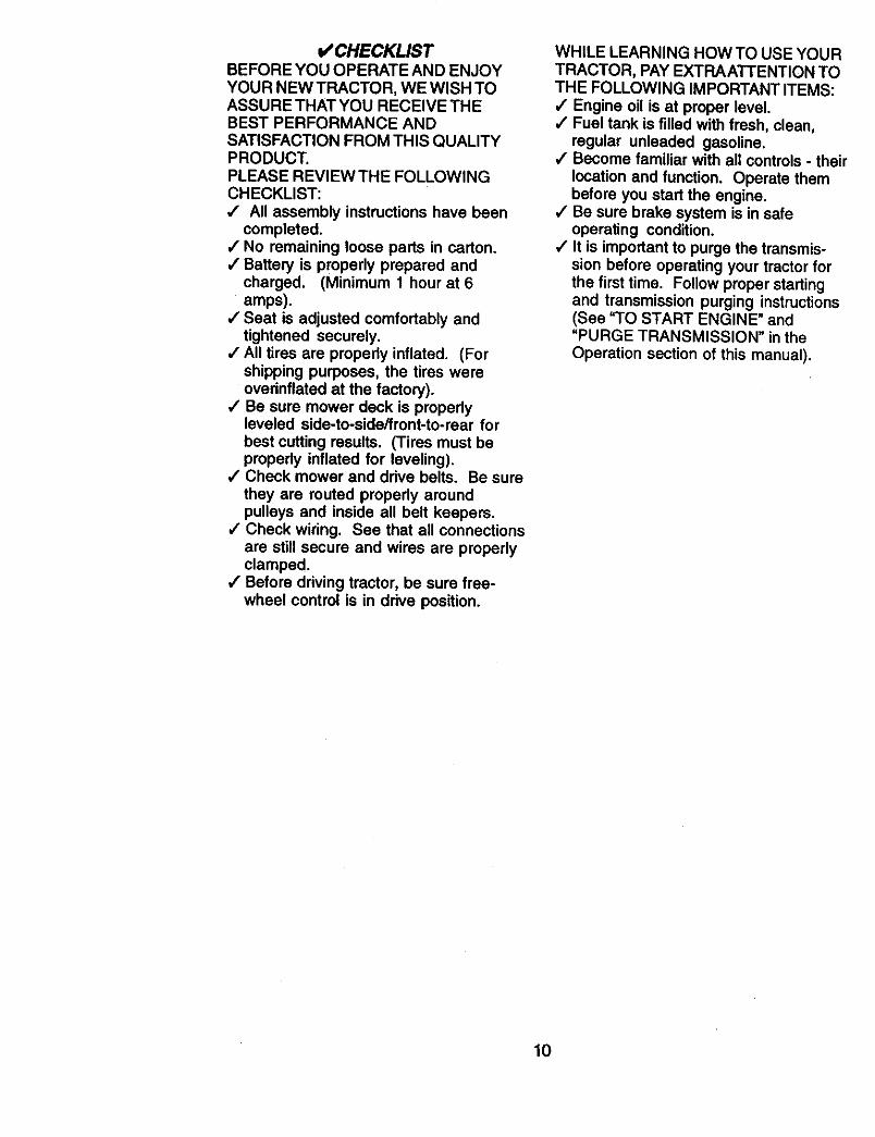
t/CHECKLISTBEFORE YOU OPERATE AND ENJOYYOUR NEW TRACTOR, WE WISH TOASSURE THAT YOU RECEIVE THEBEST PERFORMANCE ANDSATISFACTION FROM THIS QUALITYPRODUCT.PLEASE REVIEW THE FOLLOWINGCHECKLIST:,# All assembly instructions have been
completed.,/No remaining loose parts in carton.4 Battery is properly prepared and
charged. (Minimum 1 hour at 6amps).
4 Seat is adjusted comfortably andtightened securely.
/ All tires are properly inflated. (Forshipping purposes, the tires wereoverinflated at the factory).
/ Be sure mower deck is propedyleveled side-to-side/front-to-rear forbest cutting results. (Tires must beproperly inflated for leveling).
J Check mower and ddve belts. Be surethey are routed propedy aroundpulleys and inside all belt keepers.
4" Check wiring. See that all connectionsare still secure and wires are properlyclamped.
,/Before driving tractor, be sure free-wheel control is in ddve position.
WHILE LEARNING HOW TO USE YOURTRACTOR, PAY EXTRAATTENTION TOTHE FOLLOWING IMPORTANT ITEMS:,I Engine oil is at proper level.,/Fuel tank is filled with fresh, clean,
regular unleaded gasoline.,I Become familiar with all controls - their
location and function. Operate thembefore you start the engine.
4 Be sure brake system is in safeoperating condition.
4 It is important to purge the transmis-sion before operating your tractor forthe first time. Follow proper startingand transmission purging instructions(See "TO START ENGINE" and"PURGE TRANSMISSION" in theOperation section of this manual).
10
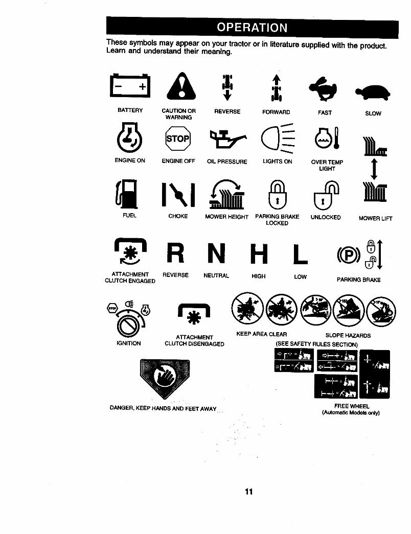
These symbols may appear on your tractor or in literature supplied with the product.Learn and understand their meaning.
BATTERY CAUTION OR REVERSE FORWARD FAST SLOWWARNING
ENG,NEONENG,NEOFFO.LPRESSUREL,G'SONO%T_.P
FUEL CHOKE MOWER HEIGHT PARKINGBRAKE UNLOCKED MOWER LIFTLOCKED
H LATTACHMENT REVERSE NEUTRAL HIGH LOW
CLUTCH ENGAGED PARKING BRAKE
ATFACHMENT KEEP AREA CLEAR SLOPE HAZARDS
IGNITION CLUTCH DISENGAGED (SEE SAFETY RULES SECTION)
DANGER, KEEP HANDS AND FEET AWAY•FREE WHEEL
(AutomaticModelsonly)
11
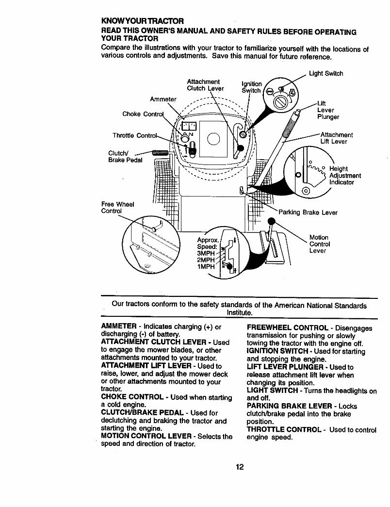
KNOWYOUR TRACTOR
READ THIS OWNER'S MANUAL AND SAFETY RULES BEFORE OPERATINGYOUR TRACTOR
Compare the iUustrationswith your tractor to familiarize yourself with the locations ofvarious controls and adjustments, Save this manual for future reference.
Attachment IgnitionClutch Lever
Light Switch
LeverChoke Plunger
Throttle
Clutch/Brake Pedal
Lift Lever
HeightAdjustmentIndicator
Free WheelControl g Brake Lever
MotionControlLever
Our tractors conform to the safety standards of the American National StandardsInstitute.
AMMETER - Indicates charging (+) ordischarging (-) of batten].ATTACHMENT CLUTCH LEVER - Used
to engage the mower blades, or otherattachments mounted to your tractor.ATTACHMENT MFT LEVER - Used toraise, lower, and adjust the mower deckor other atlachments mounted to yourtractor.
CHOKE CONTROL - Used when startinga cold engine.CLUTCWBRAKE PEDAL - Used for
declutching and braking the tractor andstarting the engine.MOTION CONTROL LEVER - Selects thespeed and direction of tractor.
FREEWHEEL CONTROL - Disengagestransmission for pushing or slowlytowing the tractor with the engine off.IGNITION SWITCH - Used for startingand stopping the engine.LIFT LEVER PLUNGER - Used torelease attachment lift lever when
changing its position.LIGHT SWITCH - Turns the headlights onand off.PARKING BRAKE LEVER - Locks
clutch/brake pedal into the brakeposition.THROTTLE CONTROL - Used to control
engine speed.
12
The operation of any tractor can result in foreign objects thrown intothe eyes, which can result in severe eye damage. Always wear safetyglasses or eye shields while operating your tractor or performing anyadjustments or repairs. We recommend a wide vision safety.maskover spectacles or standard safety glasses.
HOW TO USE YOUR TRACTOR
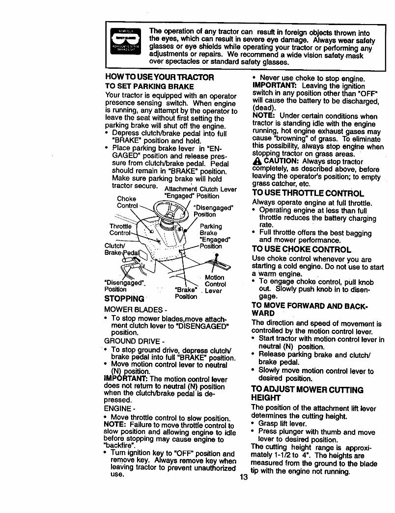
TO SET PARKING BRAKE
Your tractor is equipped with an operatorpresence sensing switch. When engineis running, any attempt by the operator toleave the seat without first setting theparking brake will Shut off the engine.• Depress clutch/brake pedal into full
=BRAKE" position and hold.• Place parking brake lever in "EN-
GAGED" position and release pres-sure from clutch/brake pedal. Pedalshould remain in =BRAKE" position.Make sure parking brake will holdtractor secure. Attachment Clutch Lever
Choke =Engaged" PositionControl __ =Disengaged"
___.__ PositionPark,ngControl---,L "_'_ \ ,,_-'_\\_ Brake ,
------_'_ _', \V/I EngagedClutch/ "_,"_ '_\'__-S_-__- -j.1--'_ Position
Brake_
. _ _ MotionDis.e.n ag ged". =.._1____. Control
Position "Brake . LeverSTOPPING Position
MOWER BLADES -
• To stop mower blades,move attach-ment clutch lever to =DISENGAGED"position.
GROUND DRIVE -
• To stop ground drive, depress clutch/brake pedal into full =BRAKE" position.
• Move motion control lever to neutral(N) position.
IMPORTANT: The motion control leverdoes not retum to neutral (N) positionwhen the clutch/brake pedal is de-pressed.ENGINE -
• Move throttle control to s!ow position.NOTE: Failure to move throttle control toslow position and allowing engine to idlebefore stopping may cause engine to=backfire".•Tum ignition key to =OFF" position and
remove key. Always remove key whenleaving tractor to prevent unauthorizeduse. 13
• Never use choke to stop engine.
IMPORTANT: Leaving the ignitionswitch in any posdion other than 'OFF'will cause the battery to be discharged,(dead).NOTE: Under certain conditions when
tractor is standing idle with the enginerunning, hot engine exhaust gases maycause =browning" of grass. To eliminatethis possibility, always stop engine whenstopping tractor on grass areas.
CAUTION: Always stop tractorcompletely, as described above, beforeleaving the operator's position; to emptygrass catcher, etc.TO USE THROI'FLE CONTROL
Always operate engine at full throttle.• Operating engine at less than full
throttle reduces the battery chargingrate.
• Full throttle offers the best baggingand mower performance.
TO USE CHOKE CONTROL
Use choke control whenever you arestarting a cold engine. Do not use to starta warm engine.• To engage choke control, pull knob
out. Slowly push knob in to disen-gage.
TO MOVE FORWARD AND BACK-WARD
The direction and speed of movement iscontrolled by the motion control lever.• Start tractor with motion control lever in
neutral (N) position.• Release parking brake and clutch/
brake pedal.• Slowly move motion control lever to
desired position.
TO ADJUST MOWER CUTFINGHEIGHT
The position of the attachment lift leverdetermines the cutting height.• Grasp lift lever.• Press plunger with thumb and move
lever to desired position.The cutting height range is approxi-mately 1-1/2 to 4". The heights aremeasured from the ground to the bladetip with the engine not running.
Theseheightsare approximateand mayvary depending upon soil conditions,height of grass and types of grass beingmowed.
• The average lawn should be cut toapproximately 2-1/2 inches during thecool season and to over 3 inchesduring hot months. For healthier andbetter looking lawns, mow often andafter moderate growth.
• For best cutting performance, grassover 6 inches in height should bemowed twice. Make the first cutrelatively high; the second to desiredheight.
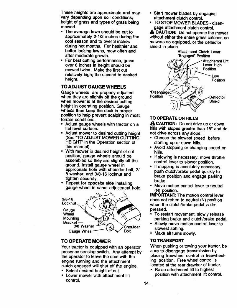
TO ADJUST GAUGE WHEELS
Gauge wheels are propedy adjustedwhen they are slightly off the groundwhen mower is at the desired cuttingheight in operating position. Gaugewheels then keep the deck in properposition to help prevent scalping in mostterrain conditions.• Adjust gauge wheels with tractor on a
flat level surface.
• Adjust mower to desired cutting height(See "TO ADJUST MOWER CUTTINGHEIGHT" in the Operation section ofthis manual).
• With mower in desired height of cutposition, gauge wheels should beassembled so they are slightly off theground. Install gauge wheel inappropdate hole with shoulder bolt, 3/8 washer, and 3/8-16 lecknut andtighten securely.
• Repeat for opposite side installinggauge wheel in same adjustment hole.
Locknut\
GaugeWheel _ _--'_ _lv,,_,Z_Mounting _ _ ' "_._Bracket_ _ _ f
3/8 Washer ShoulderGaug' Washe_'_ulderwheel
TO OPERATE MOWER
Your tractor is equipped with an operatorpresence sensing switch. Any attempt bythe operator to leave the seat with theengine running and the attachmentclutch engaged will shut off the engine.• Select desired height of cut.• Lower mower with attachment lift
control.
• Start mower blades by engagingattachment clutch control.
• TO STOP MOWER BLADES - disen-gage attachment clutch control.
A CAUTION.'. Do not operate the mowerwithout either the entire grass catcher, onmowers so equipped, or the deflectorshield in place.
AttachmentClutchLever"Engaged" Position
Lever HighPosition
uft
bLowPosition
PositionShield
TO OPERATE ON HILLS
_CAUTION: Do not drive up or downhills with slopes greater than 15° and donot drive across any slope.• Choose the slowest speed before
starting up or down hills.• Avoid stopping or changing speed on
hills.
• If slowing is necessary, move throttlecontrol lever to slower position.
• If stopping is absolutely necessary,push clutch/brake pedal quickly tobrake position and engage parkingbrake.
• Move motion control lever to neutral(N) position.
IMPORTANT: The motion control leverdoes not return to neutral (N) positionwhen the clutch/brake pedal is de-pressed.• To restart movement, slowly release
parking brake and clutch/brake pedal.• Slowly move motion control lever to
slowest setting.• Make all turns slowly.
TOTRANSPORT
When pushing or towing your tractor, besure to disengage transmission byplacing freewheel control in freewheel-ing position. Free wheel control islocated at the rear drawbar of tractor.
• Raise attachment lift to highestposition with attachment lift control.
14
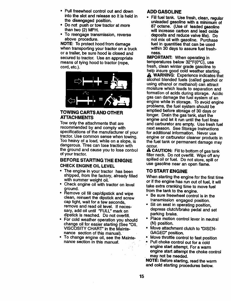
• Pull freewheel control out and downinto the slot and release so it is held inthe disengaged position.
• Do not push or tow tractor at morethan two (2) MPH.
• To reengage transmission, reverseabove procedure.
NOTE: To protect hood from damagewhen transporting your tractor on a truckor a trailer, be sure hood is closed andsecured to tractor. Use an appropriatemeans of tying hood to tractor (rope,cord, etc.).
TOWING CARTS AND OTHERATTACHMENTS
Tow only the attachments that arerecommended by and comply withspecifications of the manufacturer of yourtractor. Use common sense when towing.Too heavy of a load, while on a slope, isdangerous. Tires can lose traction withthe ground and cause you to lose controlof your tractor.
BEFORE STARTING THE ENIGNE
CHECK ENGINE OIL LEVEL
• The engine in your tractor has beenshipped, from the factory, already filledwith summer weight oil.
• Check engine oil with tractor on levelground.
• Remove oil fill cap/dipstick and wipeclean, reinsert the dipstick and screwcap tight, wait for a few seconds,remove and read oil level. If neces-sary, add oil until "FULL" mark ondipstick is reached. Do not overfill.
• For cold weather operation you shouldchange oil for easier starting (See =OILVISCOSITY CHART" in the Mainte-nance section of this manual).
• To change engine oil, see the Mainte-nance section in this manual.
ADD GASOLINE
• Fill fuel tank. Use fresh, clean, regularunleaded gasoline with a minimum of87 octane, (Use of leaded gasolinewill increase carbon and lead oxidedeposits and reduce valve life). Donot mix oil with gasoline. Purchasefuel in quantities that can be usedwithin 30 days to assure fuel fresh-ness.
IMPORTANT: When operating intemperatures below 32°F(0°C), usefresh, clean winter grade gasoline tohelp insure good cold weather starting.
WARNING: Experience indicates thatalcohol blended fuels (called gasohol orusing ethanol or methanol) can attractmoisture which leads to separation andformation of acids during storage. Acidicgas can damage the fuel system of anengine while in storage. To avoid engineproblems, the fuel system should beemptied before storage of 30 days orlonger. Drain the gas tank, start theengine and let it run until the fuel linesand carburetor are empty. Use fresh fuelnext season. See Storage Instructionsfor additional information. Never useengine or carburetor cleaner products inthe fuel tank or permanent damage mayOccur,
A CAUTION: Fill to bottom of gas tankfiller neck. Do not ovedill. Wipe off anyspilled oil or fuel. Do not store, spill oruse gasoline near an open flame.
TO START ENGINE
When starting the engine for the first timeor if the engine has run out of fuel, it willtake extra cranking time to move fuelfrom the tank to the engine.• Be sure freewheel control is in the
transmission engaged position.• Sit on seat in operating position,
depress clutch/brake pedal and setparking brake.
• Place motion control lever in neutral(N) position.
• Move attachment clutch to uDISEN-GAGED" position.
• Move throttle control to fast position,, Pull choke control out for a cold
engine start attempt. For a warmengine start attempt the choke controlmay not be needed.
NOTE: Before starting, read the warmand cold starting procedures below.
15

• Insert key into ignition and tum keyclockwise to =START" position andrelease key as soon as engine starts.Do not run starter continuously formore than fifteen seconds per minute.If the engine does not start afterseveral attempts, push choke controlin, wait a few minutes and try again. Ifengine still does not start, pull thechoke control out and retry.
WARM WEATHER STARTING (50 ° F andabove)
• When engine starts, slowly pushchoke control in until the enginebegins to run smoothly. If the enginestarts to run roughly, pull the chokecontrol out slightly for a few secondsand then continue to push the controlin slowly.
• The attachments and ground drive cannow be used. If the engine does notaccept the load, restart the engine andallow it to warm up for one minuteusing the choke as described above.
COLD WEATHER STARTING (50 ° F andbelow)
• When engine starts, slowly pushchoke control in until the enginebegins to run smoothly. Continue topush the choke control in small stepsallowing the engine to accept smallchanges in speed and load, until thechoke control is fully in. If the enginestarts to run roughly, pull the chokecontrol out slightly for a few secondsand then continue to push the controlin slowly. This may require an enginewarm-up period from several secondsto several minutes, depending on thetemperature.
AUTOMATIC TRANSMISSION WARM UP
• Before driving the unit in cold weather,
the transmission should be warmed upas follows:• Be sure the tractor is on level
ground.• Place the motion control lever in
neutral. Release the parking brakeand let the clutch/brokeslowly return to operating position.
• Allow one minute for transmission towarm up. This can be done duringthe engine warm up period.
• The attachments can be used duringthe engine warm-up period after thetransmission has been warmed upand may require the choke control bepulled out slightly.
NOTE: If at a high altitude (above 3000feet) or in cold temperatures (below 32F) the carburetor fuel mixture may needto be adjusted for best engine perfor-mance. See =TO ADJUST CARBURE-TOR _ in the Service and Adjustmentssection of this manual.
PURGE TRANSMISSION
CAUTION: Never engage or disen-gage freewheel lever while the engine isrunning.To ensure proper operation and perfor-mance, it is recommended that thetransmission be purged before operatingtractor for the first time. This procedurewill remove any trapped air reside thetransmission which may have developedduring shipping of your tractor.IMPORTANT: Should your transmissionrequire removal for service or replace-ment, it should be purged after reinstaila-tion before operating the tractor.• Place tractor safely on level surface
with engine off and parking brake set.• Disengage transmission by placing
freewheel control in freewheelingposition (See =TO TRANSPORT" inthis section of manual).
• Sitting in the tractor seat, start engine.Afterthe engine is running, movethrottle control to slow position. Withmotion control lever in neutral (N)position, slowly disengage clutch/brake pedal.
• Move motion control lever to fullforward position and hold for five (5)seconds. Move lever to full reverseposition and hold for five (5) seconds.Repeat this procedure three (3) times.
NOTE: During this procedure there willbe no movement of ddve wheels. The airis being removed from hydraulic drivesystem.• Move motion control lever to neutral
(N) position. Shut- off engine and setparking brake.
• Engage transmission by placingfreewheel control in driving position(See "TO TRANSPORT" in this sectionof manual).
16
• Sitting in the tractor seat, start engine.Alter the engine is running, movethrottle control to half (1/2) speed. Withmotion control lever in neutral (N)position, slowly disengage clutch/brake pedal.
• Slowly move motion control leverforward, alter the tractor movesapproximately five (5) feet, slowlymove motion control lever to reverseposition. After the tractor movesapproximately five (5) feet return themotion control lever to the neutral (N)position. Repeat this procedure withthe motion control lever three (3)times.
• Your tractor is now purged and nowready for normal operation.
MOWING TIPS
• Mower should be propedy leveled forbest mowing performance. See "TOLEVEL MOWER HOUSING" in theService and Adjustments section ofthis manual.
• The left hand side of mower should beused for tdmming.
• Drive so that clippings are dischargedonto the area that has been cut. Havethe cut area to the right of the tractor:This will result in a more even distribu-tion of clippings and more uniformcutting.
• When mowing large areas, start byturning to the right so that clippings willdischarge away from shrubs, fences,driveways, etc. Alter one or tworounds, mow in the opposite directionmaking left hand tums until finished.
• If grass is extremely tall, it should bemowed twice to reduce load andpossible fire hazard from driedclippings. Make first cut relativelyhigh; the second to the desired height.
• Do not mow grass when it is wet. Wetgrass will plug mower and leaveundesirable clumps. Allow grass todry before mowing.
• Always operate engine st full throttlewhen mowing to assure better mowingperformance and proper discharge ofmaterial. Regulate ground speed byselecting a low enough gear to givethe mower cutting performance as wellas the quality of cut desired.
• When operating attachments, select aground speed that will suit the terrainand give best performance of theattachment being used.
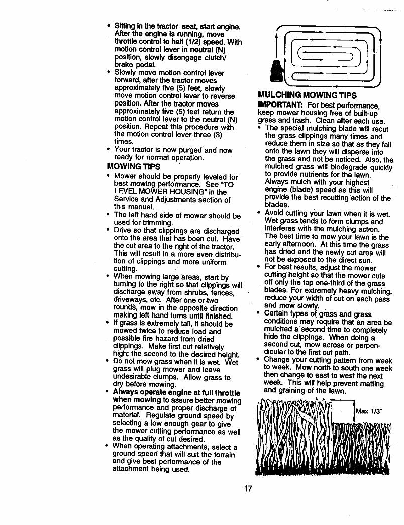
MULCHING MOWING TIPS
IMPORTANT: For best performance,keep mower housing free of built-upgrass and trash. Clean alter each use.• The special mulching blade will recut
the grass clippings many times andreduce them in size so that as they fallonto the lawn they will disperse intothe grass and not be noticed. Also, themulched grass will biodegrade quicklyto provide nutrients for the lawn.Always mulch With your highestengine (blade) speed as this willprovide the best recuttingaction of theblades.
• Avoid cutting your lawn when it is wet.Wet grass tends to form clumps andinterferes with the mulching action.The best time to mow your lawn is theearly afternoon. At this time the grasshas dried and the newly cut area willnot be exposed to the direct sun.
• For best results, adjust the mowercutting height so that the mower cutsoffonly the top one+thirdof the grassblades. For extremely heavy mulching,reduce your width of cut on each passand mow slowly.
• Certain types of grass and grassconditions may require that an area bemulched a second time to completelyhide the clippings. When doing asecond cut, mow across or perpen-dicular to the first cut path.
• Change your cutting pattern from weekto week. Mow north to south one weekthen change to east to west the nextweek. This will help prevent mattingand graining of the lawn.
,]++I I l ,
17
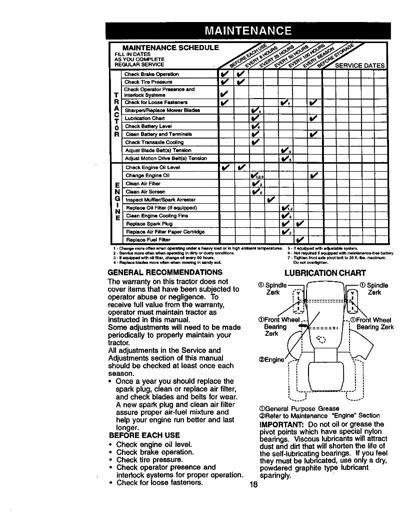
MAINTENANCE SCHEDULE . ._,_ _ _' _ _--FILL IN DATES
_ Bm_ O_mt_Check Tire Pressure _ _
Check Operator Presence andT InterlockSyatems I/R Check for Loose Fasteners I_ 1_7
A Sh'lpen/Replsce M°wer Blades _#'Lubdcation Chad
J T Check BatterY LevelR Clean Battery end Terminals (l_
Check Trar!_.axle Cooling V*
Adjust Blade Belt(s) Tension (l_s iAdjust Motion Odve Belt(s} Tension lldPs :
Check Engine Oil Level 14 / Id f
Change Engine Oil _: ll_
E Clean Air Filter
N Clean Air Screen
GI Inspect Muffler/Spark An'ester
ReplaCe Oil Finer (If equipped) ._:N Clean Engine Coo_ing Fins
Replace Spark Plug _
Replace Air Filter Paper Cartridge 1_2
Replace Fuel Filter
1* Change more often whenopefllitingi/41der• heavy load or WIhighambient teri!penttures. 5- Ifequipped wi_ adjustablesystem,2 - Service more often whenoperating indirty or dusty conditions, 6 - Not required ifequippedw_thmaintenance-freeho_eq_.3 - IfequiPPedwlth oil filter,change oil mm¢-/50 hour=. 7 - Tighten hornaxle pivotbolt to 35 ft..Ibs, maximum,4 - P_ blade=mrs olten w_m mowing insandy so#, Do no_oYirifghten.
GENERAL RECOMMENDATIONS
The warranty on this tractor does notcover items that have been subjected tooperator abuse or negligence. Toreceive full value from the warranty,operator must maintain tractor asinstructed in this manual.Some adjustments will need to be madeperiodically to properly maintain yourtractor.All adjustments in the Service andAdjustments section of this manualshould be checked at least once each
LUBRICATION CHART
(t) S - _) SpindleZerk Zerk
_)Front Wheel eelBearing Bearing ZerkZerk
_Engine /
season.• Once a year you should replace the
spark plug, clean or replace air filter,and check blades and belts for wear,A new spark plug and clean air filterassure proper air-fuel mixture andhelp your engine run better and lastlonger.
BEFORE EACH USE
• Check engine oil level.• Check brake operation.• Check tire pressure.• Check operator presence and
interlock systems for proper operation.• Check for loose fasteners.
,...J L ..
(DGeneral Purpose Grease_Refer to Maintenance =Engine" SectionIMPORTANT: Do not oil or grease thepivot points which have special nylonbearings. Viscous lubricants will attractdust and dirt that will shorten the life of
the self-lubricatin_l bearings. If you feelthey must be lubncated, use only a dry,powdered graphite type lubricantsparingly.
18
TRACTORAlways observe safety rules whenperforming any maintenance.BRAKE OPERA'nONIf tractor requires more than six (6) feetstopping distance at high speed ,nhighestgear, then brake must beadjusted. (See "TO ADJUST BRAKE" inthe Service and Adjustments section ofthis manual).TIRES• Maintain proper air pressure in all tires
(See "PRODUCT SPECIFICATIONS"section of this manual).
• Keep tires free of gasoline, oil, orinsect control chemicals which canharm rubber.
• Avoid stumps, stones, deep ruts, sharpobjects and other hazards that maycause tire damage.
NOTE: To seal tire punctures andprevent flat tires due to slow leaks, tiresealant may be purchased from yourlocal parts dealer. "13resealant alsoprevents tire dry rot and corrosion.OPERATOR PRESENCE SYSTEMBe sure operator presence and interlocksystems are working properly. If yourtractor does not function as described,repair the problem immediately.• The engine should not start unless the
clutch/brake pedal is fully depressedand attachement clutch control is inthe disengaged position.
° When the engine is running, anyattempt by the operator to leave theseat without first setting the parkingbrake should shut off the engine.
• When the engine is running and theattachment clutch is engaged, anyattempt by the operator to leave theseat should shut off the engine.
• The attachment clutch should neveroperate unless the operator is in theseat.
BLADE CAREFor best results mower blades must bekept sharp. Replace bent or damagedblades.BLADE REMOVAL
• Raise mower to highest pesition toallow access to blades.
• Remove hex bolt, lock washer and flatwasher securing blade.
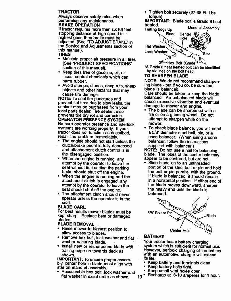
• Install new or resharpened blade withtrailing edge up towards deck asshown.
IMPORTANT: To ensure proper assem-bly, center hole in blade must align withstar on mandrel assembly.• Reassemble hex bolt, lock washer and
flat washer in exact order as shown.
• Tighten bolt securely (27-35 Ft. Lbs.torque).
IMPORTANT: Blade bolt is Grade 8 heattreated.Trailing Edge Up Mandrel Assembly
X_ Blade Center j_/_
Flat W..ashyr_...._-'__
• _---Hex Bolt (Grade)_Z-x_._•A Grade 8 heat treated bolt can be identified
by six lines on the bolt head.TO SHARPEN BLADE
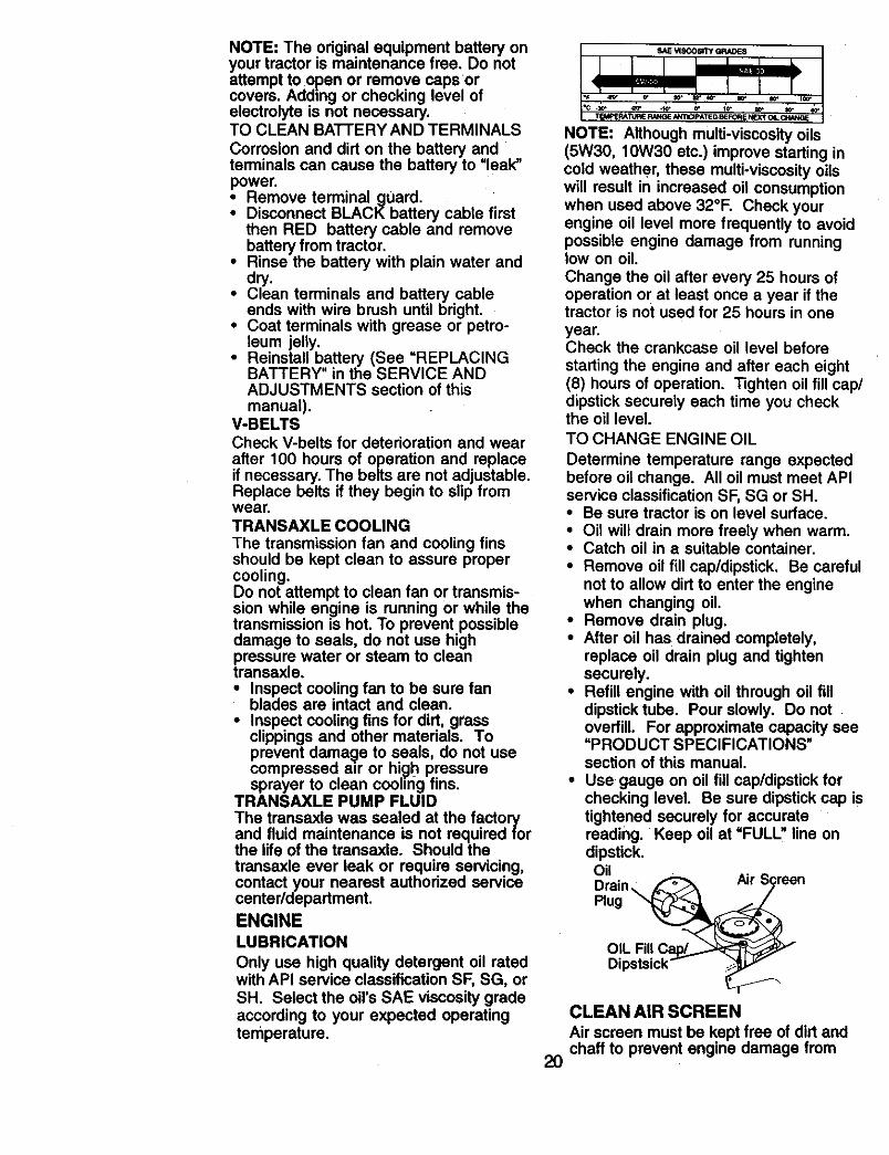
NOTE: We do not recommend sharpen-ing blade - but if you do, be sure theblade is balanced.Care should be taken to keep the bladebalanced. An unbalanced blade willcause excessive vibration and eventualdamage to mower and engine.• The blade can be sharpened with a
file or on a grinding wheel. Do notattempt to sharpen while on themower.
• To check blade balance, you will needa 518" diameter steel bolt, pin, or acone balancer. (When using a conebalancer, follow the instructionssupplied with balancer.)
NOTE: Do not use a nail for balancingblade. The lobes of the center hole mayappear to be centered, but are not.• Slide blade on to an unthreaded
portion of the steel bolt or pin and holdthe bolt or pin parallel with the ground.If blade is balanced, it should remainin a horizontal position. If either end ofthe blade moves downward, sharpenthe hea W end until the blade isbalanced.
5/8" " •
Center HoleBATTERYYour tractor has a battery chargingsystem which is sufficient for normal use.However, periodic charging of the batterywith an automotive charger will extendiLslife.
i eep battery and terminals clean.Keep battery bolts tight.Keep small vent holes open.
19 ° Recharge at 6-10 amperes for I hour.
NOTE:The originalequipmentbatteryonyour tractoris maintenancefree. Donotattemptto openor removecapsorcovers.Addingor checkinglevelofelectrolyteis not necessary.TOCLEANBATTERYANDTERMINALSCorrosionand dirt on the batteryandterminalscancausethe batteryto "leak"power.: Removeterminalguard.DisconnectBLACKbatterycablefirst
thenRED batterycable and removebatteryfrom tractor.
• Rinse the battery with plain water anddry.
• Clean terminals and battery cableends with wire brush until bright.
• Coat terminals with grease or petro-leum jelly.
• Reinstall b.attery (See =REPLACINGBATTERY in the SERVICE ANDADJUSTMENTS section of thismanual).
V-BELTSCheck V-belts for deterioration and wear
after 100 hours of operation and replaceif necessary. The belts are not adjustable.Replace belts if they begin to slip fromwear.TRANSAXLE COOLING
The transmission fan and cooling finsshould be kept clean to assure propercooling.Do not attempt to clean fan or transmis-sion while engine is running or while thetransmission is hot. To prevent possibledamage to seals, do not use highpressure water or steam to cleantransaxle.• Inspect cooling fan to be sure fan
blades are intact and clean.• Inspect cooling fins for dirt, grass
clippings and other materials. Toprevent damage to seals, do not usecompressed a=r or high pressuresprayer to clean cooling fins.
TRANSAXLE PUMP FLUIDThe transaxle was sealed at the factoryand fluid maintenance is not required forthe life of the transaxle. Should thetransaxle ever leak or require servicing,contact your nearest authorized servicecenter/department.ENGINELUBRICATION
Only use high quality detergent oil ratedwith API service classification SF, SG, orSH. Select the oil's SAE viscosity gradeaccording to your expected operatingtemperature.
_c ._
TEk_JE RA_dPJ£ RN, IG_E_mCI_ATIE D B_0_ E N_I_T Q4
NOTE: Although multi-viscosity oils(5W30, 10W30 etc.) improve starting incold weather, these multi-viscosity oilswill result in increased oil consumptionwhen used above 32°F. Check yourengine oil level more frequently to avoidpossible engine damage from runninglow on oil.
Change the oil after every 25 hours ofoperation or at least once a year it thetractor is not used for 25 hours in one
year.Check the crankcase oil level before
starting the engine and after each eight(8) hours of operation. Tighten oil fill cap/dipstick securely each time you checkthe oil level.
TO CHANGE ENGINE OIL
Determine temperature range expectedbefore oil change. All oil must meet APIservice classification SF, SG or SH.• Be sure tractor is on level surface.• Oil will drain more freely when warm.• Catch oil in a suitable container.
• Remove oil fill cap/dipstick. Be carefulnot to allow dirt to enter the enginewhen changing oil.
• Remove drain plug.• After oil has drained completely,
replace oil drain plug and tightensecurely.
• Refill engine with oil through oil filldipstick tube. Pour slowly. Do notoverfill. For approximate capacity see=PRODUCT SPECIFICATIONS"section of this manual.
• Use gauge on oil fill cap/dipstick forchecking level. Be sure dipstick cap istightened securely for accuratereading. Keep oil at =FULL" line ondipstick.OilDrainPlug
OIL
2O
CLEAN AIR SCREEN
Air screen must be kept free of dirt andchaff to prevent engine damage from
overheating. Cleanwitha wire brushorcompressedair to removedirtandstubbomdriedgum fibers.CLEAN AIR INTAKE/COOLINGAREASTo insure proper cooling, make sure thegrass screen, cooling fins, and otherextemal surfaces of the engine are keptclean at all times.Every 100 hours of operation (more oftenunder extremely dusty, dirty conditions),remove the blower housing and othercooling shrouds. Clean the cooling finsand external surfaces as necessary. Makesure the cooling shrouds are reinstalled.NOTE: Operating the engine with ablocked grass screen, dirty or pluggedcooling fins, and/or cooling shroudsremoved will cause engine damage due tooverheating.
AIR FILTER
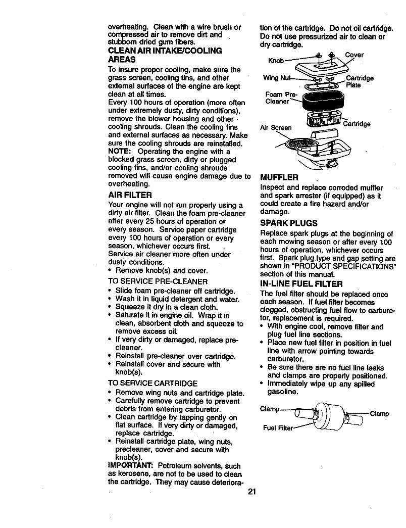
Your engine will not run propedy using adirty air filter. Clean the foam pre-cleanerafter every 25 hours of operation orevery season. Service paper cartridgeevery 100 hours of operation or everyseason, whichever occurs first.Service air cleaner more often under
dusty conditions.• Remove knob(s) and cover.
TO SERVICE PRE-CLEANER
• Slide foam pre-cleaner off cartridge.• Wash it in liquid detergent and water.• Squeeze it dry in a clean cloth.• Saturate it inengine oil. Wrap it in
clean, absorbent cloth and squeeze toremove excess oil.
• If very dirty or damaged, replace pre-cleaner,
• Reinstall pre-cleaner over cartridge.• Reinstall cover and secure with
knob(s).
TO SERVICE CARTRIDGE
• Remove wing nuts and cartridge plate.• Carefully remove cartridge to prevent
debris from entering carburetor.• Clean cartridge by tapping gently on
flat surface, if very dirty or damaged,replace cartridge.
• Reinstall cartridge plate, wing nuts,prscleaner, cover and secure withknob(s).
IMPORTANT: Petroleum solvents, suchas kerosene, are not to be used to cleanthe cartridge. They may cause deteriora-
tion of the cartridge. Do not oil cartridge.Do not use pressurized air to clean ordry cartridge.
Knob
Wing CartridgePlate
Foam Pre-
Air Screen
MUFFLER
Inspect and replace corroded mufflerand spark arrester (if equipped) as itcould create a fire hazard and/or
damage.
SPARK PLUGS
Replace spark plugs at the beginning ofeach mowing season or after every 100hours of operation, whichever occursfirst. Spark plug type and gap setting areshown in =PRODUCT SPECIFICATIONS"section of this manual.
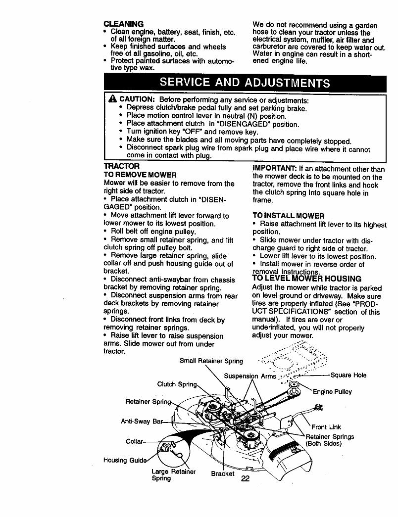
IN-LINE FUEL FILTER
The fuel filter should be replaced onceeach season. If fuel filter becomesclogged, obstructing fuel flow to carbure-tor, replacement is required.• With engine cool, remove filter and
plug fuel line sections.• Place new fuel filter in position in fuel
line with arrow pointing towardscarburetor.
• Be sure there are no fuel line leaksand clamps are properly positioned.
• Immediately wipe up any spilledgasoline.
21
CLEANING
Clean engine, battery, seat, finish, etc.of all foreign matter.Keep finished surfaces and wheelsfree of all gasoline, oil, etc.
• Protect painted surfaces with automo-tive type wax.
We do not recommend using a gardenhose to clean your tractor unless theelectrical system, muffler, air filter andcarburetor are covered to keep water out.Water in engine can result in a short-ened engine life.
_1_CAUTION: Before performing any service or adjustments:• Depress clutch/brake pedal fully and set parking brake.• Place motion control lever in neutral (N) position.• Place attachment clutch in =DISENGAGED" position.• Turn ignition key =OFF" and remove key.• Make sure the blades and all moving parts have completely stopped.• Disconnect spark plug wire from spark plug and place wire where it cannot
come in contact with plug.
TRACTORTO REMOVE MOWERMower will be easier to remove from the
right side of tractor.• Place attachment clutch in "DISEN-
GAGED" position.• Move attachment lift lever forward to
lower mower to its lowest position.• Roll belt off engine pulley.• Remove small retainer spring, and liftclutch spring off pulley bolt.• Remove large retainer spring, slidecollar oft and push housing guide out ofbracket.
• Disconnect anti-swaybar from chassisbracket by removing retainer spring•• Disconnect suspension arms from reardeck brackets by removing retainersprings.• Disconnect front links from deck byremoving retainer springs.• Raise lift lever to raise suspension
IMPORTANT: If an attachment other thanthe mower deck is to be mounted on the
tractor, remove the front links and hookthe clutch spring Into square hole inframe.
TO INSTALL MOWER• Raise attachment lift lever to its highestposition.• Slide mower under tractor with dis-charge guard to right side of tractor.• Lower lift lever to its lowest position.• Install mower in reverse order ofremoval instructions.TO LEVEL MOWER HOUSING
Adjust the mower while tractor is parkedon level ground or driveway. Make suretires are properly inflated (See "PROD-UCT SPECIFICATIONS" section of thismanual). If tires are over orunderinflated, you will not properlyadjust your mower.
Retainer S
Link
Sides)
Housing
Large Retainer BracketSpring 22
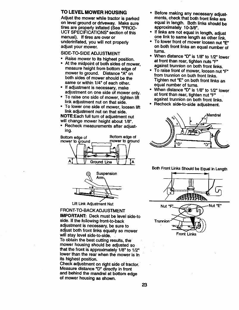
TO LEVEL MOWER HOUSINGAdjust the mower while tractor is parkedon level ground or driveway. Make suretires are properly inflated (See "PROD-UCT SPECIFICATIONS" section of this
manual). If tires are over orunderinflated, you will not propedyadjust your mower.
SIDE-TO-SIDE ADJUSTMENT
• Raise mower to its highest position.• At the midpoint of both sides of mower,
measure height from bottom edge ofmower to ground. Distance "A" onboth sides of mower should be thesame or within 1/4" of each other.
• If adjustment is necessary, makeadjustment on one side of mower only.
• To raise one side of mower, tighten liftlink adjustment nut on that side.
• To lower one side of mower, loosen liftlink adjustment nut on that side.
NOTE:Each full turn of adjustment nutwill change mower height about 1/8".• Recheck measurements after adjust-
ing.
Bottom edge of Bottom edge ofmower to nround mower to ground
=o__ Suspensi°n
Lift Link Adjustment Nut
FRONT-TO-BACK ADJUSTMENT
IMPORTANT: Deck must be level side-to
side. If the following front-to-backadjustment is necessary, be sure toadjust both front links equally so mowerwill stay level side-to-side.To obtain the best cutting results, themower housing should be adjusted sothat the front is approximately 1/8" to 1/2'lower than the rear when the mower is inits highest position.Check adjustment on right side of tractor.Measure distance "D" directly in frontand behind the mandrel at bottom edgeof mower housing as shown.
23
• Before making any necessary adjust-ments, check that both front links areequal in length. Both links should beapproximately 10-3/8".
• If links are not equal in length, adjustone link to same length as other link.
• To lower front of mower loosen nut "E"
on both front links an equal number ofturns.
• When distance "D" is 1/8" to 1/2" lowerat front than rear, tighten nuts =F"against trunnion on both front links.
• To raise front of mower, loosen nut "P'from trunnion on both front links.Tighten nut "E" on both front links anequal number of turns.
• When distance "D" is 1/8" to 1/2" lowerat front than rear, tighten nut "F"against trunnion on beth front links.
• Recheck side-to-side adjustment.
Both Front Links Should be Equal in Length
Nut
Front Links
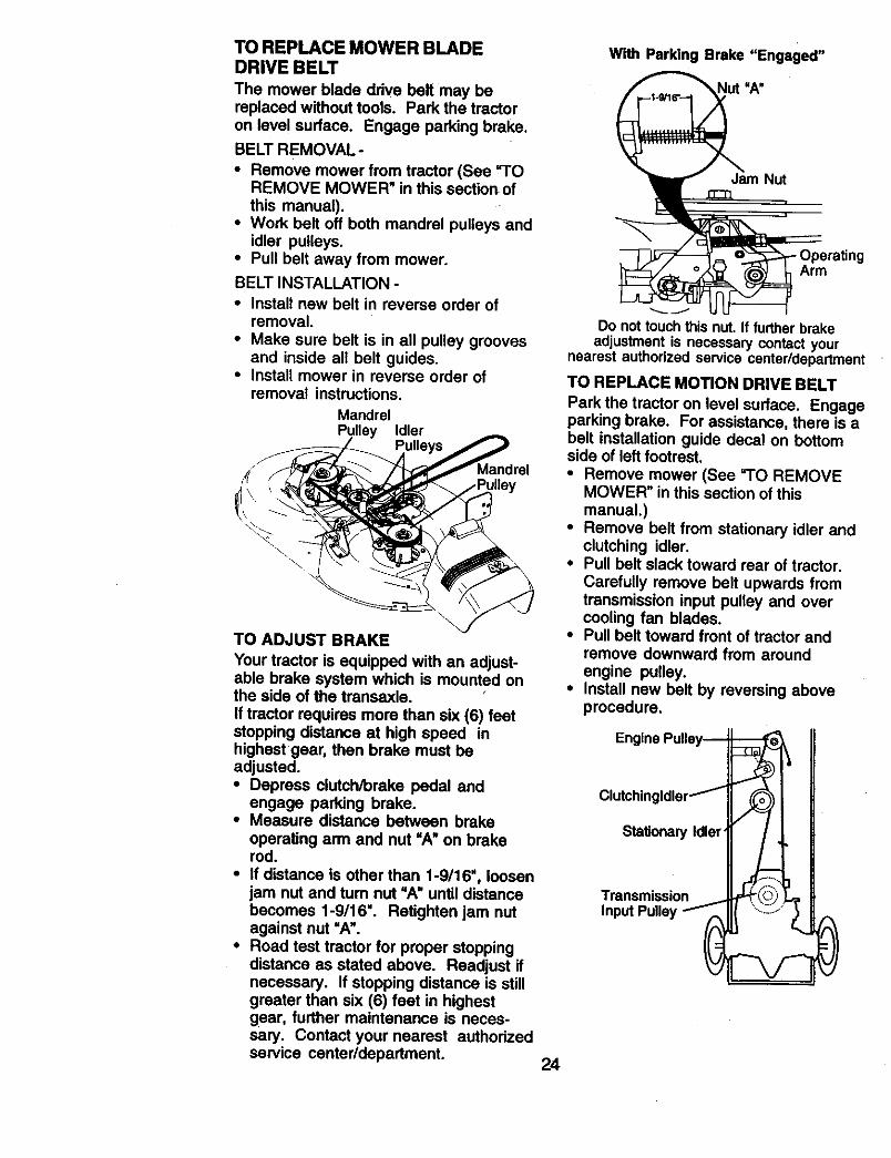
TO REPLACE MOWER BLADEDRIVE BELT
The mower blade drive belt may bereplaced without tools. Park the tractoron level surface. Engage parking brake.
BELT REMOVAL-
• Remove mower from tractor (See =TOREMOVE MOWER" in this section of
this manual).• Work belt off both mandrel pulleys and
idler pulleys.• Pull belt away from mower.
BELT INSTALLATION -
• Install new belt in reverse order ofremoval.
• Make sure belt is in all pulley groovesand inside ali belt guides.
• Install mower in reverse order ofremoval instructions.
MandrelPulley Idler
TO ADJUST BRAKE
Your tractor is equipped with an adjust-able brake system which is mounted onthe side of the transaxle.If tractor requires more than six (6) feetstopping distance at high speed inhighest gear, then brake must beadjusted.• Depress clutch/brake pedal and
engage parking brake.• Measure distance between brake
operating arm and nut "A" on brakerod.
• If distance is other than 1-9/16", loosen
iam nut and tum nut =A" until distancebecomes 1-9/16". Retighten jam nutagainst nut "A".
• Road test tractor for proper stoppingdistance as stated above. Readjust ifnecessary. If stopping distance is stillgreater than six (6) feet in highestgear, further maintenance is neces-sary. Contact your nearest authorizedservice center/department
With Parking Brake "Engaged"
Nut =A"
Jam Nut
Arm
Do not touch this nut. If further brakeadjustment is necessary contact your
nearest authodzed service center/department
TO REPLACE MOTION DRIVE BELT
Park the tractor on level surface. Engageparking brake. For assistance, there is abelt installation guide decal on bottomside of left footrest.• Remove mower (See rl'O REMOVE
MOWER" in this section of this
manual.)• Remove belt from stationary idler and
clutching idler.• Pull belt slack toward rear of tractor.
Carefully remove belt upwards fromtransmission input pulley and overcooling fan blades.
• Pull belt toward front of tractor andremove downward from around
engine pulley.• Install new belt by reversing above
procedure,
StalJonary Idler'
Transmission
24
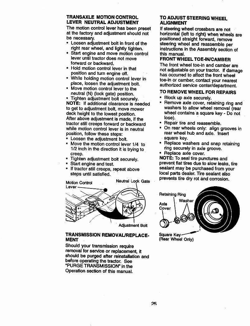
TRANSAXLE MOTION CONTROLLEVER NEUTRAL ADJUSTMENT
The motion control lever has been presetat the factory and adjustment should notbe necessary.
• Loosen adjustment bolt in front of theright rear wheel, and lightly tighten.
• Start engine and move motion controllever until tractor does not moveforward or backward.
• Hold motion control lever in thatposition and tum engine off.
• While holding motion control lever inplace, loosen the adjustment bolt.
• Move motion control lever to theneutral (N) (lock gate) position,
• Tighten adjustment bolt securely.NOTE: If additional clearance is needed
to get to adjustment bolt, move mowerdeck height to the lowest position.After above adjustment is made, if thetractor still creeps forward or backwardwhite motion control lever is in neutral
position, follow these steps:• Loosen the adjustment bolt.• Move the motion control lever 1/4 to
1/2 inch in the direction it is trying tocreep.
• Tighten adjustment bolt securely.• Start engine and test.• If tractor still creeps, repeat above
steps until satisfied.
Motion Control Neutral Lock Gate
TO ADJUST STEERING WHEELAUGNMENT
If steedng wheel crossbars are nothodzontal (left to right) whe n wheels arepositioned straight forward, removesteedng wheel and reassemble perinstructions in the Assembly section ofthis manual.FRONT WHEEL TOE-IN/CAMBER
The front wheel toe-in and camber arenot adjustable on your tractor. If damagehas occurred to affect the front wheeltoe-in or camber, contact your nearestauthorized service center/department.TO REMOVE WHEEL FOR REPAIRS
• Block up axle securely.• Remove axle cover, retaining ring and
washers to allow wheel removal (rearwheel contains a square key - Do notlose).
• Repair tire and reassemble.• On rear wheels only: align grooves in
rear wheel hub and axle. Insertsquare key.
• Replace washers and snap retainingring securely in axle groove.
• Replace axle cover.NOTE: Toseal tire punctures andprevent flattires due to slow leaks, tiresealant may be purchased from yourlocal parts dealer. _re sealant alsoprevents tire dry rot and corrosion.
Retaining Ring
WasherAxleCover
\Adjustment Bolt
TRANSMISSION REMOVAL/REPLACE-MENT
Should your transmission requireremoval for service or replacement, itshould be purged after retnsta||ation andbefore operating the tractor. See"PURGE TRANSMISSION" in theOperation section of this manual.
TO START ENGINE WITH A WEAKBA'n'ERY
CAUTION: Lead-acid batteriesgenerate explosive gases. Keep sparks,flame and smoking materials away frombatteries. Always wear eye protectionwhen around batteries.
If your battery is too weak to start theengine, it should be recharged. (See"BATTERY" in the MAINTENANCE
section of this manual).If "jumper cables" are used for emer-gency starting, follow this procedure:IMPORTANT: Your tractor is equippedwith a 12 volt negative grounded system.The other vehicle must also be a 12 volt
negative grounded system. Do not useyour tractor battery to start other vehicles.
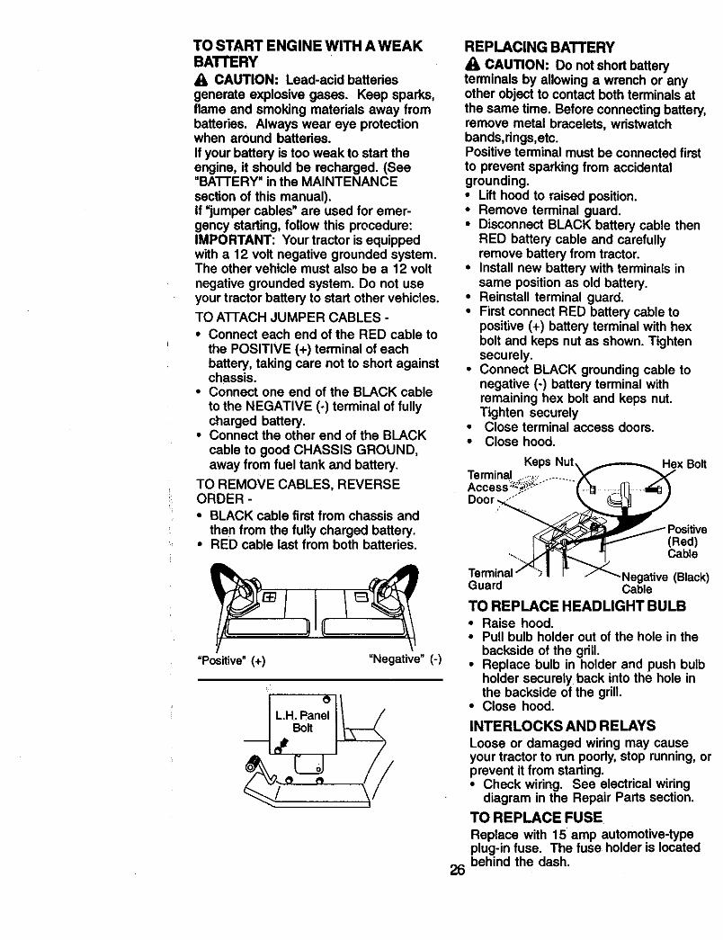
TO ATTACH JUMPER CABLES -
• Connect each end of the RED cable to
the POSITIVE (+) terminal of eachbattery, taking care not to short againstchassis.
• Connect one end of the BLACK cable
to the NEGATIVE (°) terminal of fullycharged battery.
• Connect the other end of the BLACK
cable to good CHASSIS GROUND,away from fuel tank and battery.
TO REMOVE CABLES, REVERSEORDER -
• BLACK cable first from chassis and
then from the fully charged battery.• RED cable last from both batteries.
"Positive" (+) "Negative" (-)
Bolt
REPLACING BATTERY
CAUTION: Do not short batteryterminals by allowing a wrench or anyother object to contact both terminals at
the same time. Before connecting battery,remove metal bracelets, wristwatchbands,rings,etc.Positive terminal must be connected first
to prevent sparking from accidentalgrounding.• Lift hood to raised position.• Remove terminal guard.• Disconnect BLACK battery cable then
RED battery cable and carefullyremove battery from tractor.
• Install new battery with terminals insame position as old battery.
• Reinstall terminal guard.• First connect RED battery cable to
positive (+) battery terminal with hexbolt and keps nut as shown. Tightensecurely.
• Connect BLACK grounding cable tonegative (-) battery terminal withremaining hex bolt and keps nut.Tighten securely
• Close terminal access doors.• Close hood.
Hex Bolt
(Red)Cable
26
.Negative (Black)Guard Cable
TO REPLACE HEADLIGHT BULB• Raise hood.• Pull bulb holder out of the hole in the
backside of the grill.• Replace bulb in holder and push bulb
holder securely back into the hole inthe backside of the grill.
• Close hood.
INTERLOCKS AND RELAYS
Loose or damaged wiring may causeyour tractor to run poorly, stop running, orprevent it from starting.• Check wiring. See electrical wiring
diagram in the Repair Parts section.
TO REPLACE FUSE
Replace with 15 amp automotive-typeplug-in fuse. The fuse holder is locatedbehind the dash.
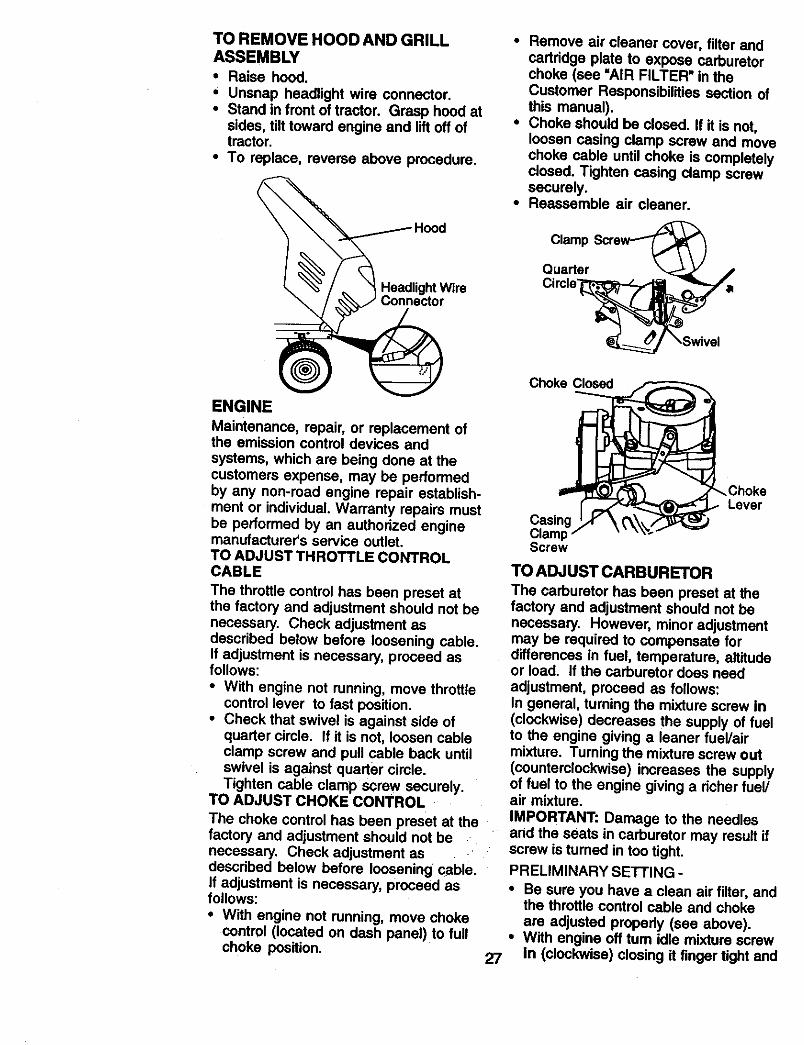
TO REMOVE HOOD AND GRILLASSEMBLY• Raise hood.• Unsnap headlight wire connector.• Stand in front of tractor. Grasp hood at
sides, tilt toward engine and lift off oftractor.
• To replace, reverse above procedure.
ENGINEMaintenance, repair, or replacement ofthe emission control devices andsystems, which are being done at thecustomers expense, may be performedby any non-toed engine repair establish-ment or individual. Warranty repairs mustbe performed by an authorized enginemanufacturer's service outlet.TO ADJUST THROTTLE CONTROLCABLE
The throttle control has been preset atthe factory and adjustment should not benecessary. Check adjustment asdescribed below before loosening cable.if adjustment is necessary, proceed asfollows:
• With engine not running, move threttlecontrol lever to fast position.
• Check that swivel is against side ofquarter circle. If it is not, loosen cableclamp screw and pull cable back untilswivel is against quarter circle.Tighten cable clamp screw securely.
TO ADJUST CHOKE CONTROL
The choke control has been preset at thefactory and adjustment should not benecessary. Check adjustment asdescribed below before loosening cable.if adjustment is necessary, proceed asfollows:• With engine not running, move choke
control (located on dash panel) to fullchoke position.
• Remove air cleaner cover, filter andcartridge plate to expose carburetorchoke (see "AIR FILTER" in theCustomer Responsibilities section ofthis manual).
• Choke should be closed. If it is not,loosen casing clamp screw and movechoke cable until choke is completelydosed. Tighten casing clamp screwsecurely.
• Reassemble air cleaner.
27
Clamp
Quarter
Choke Closed
ChokeLever
CasingClampScrew
TO ADJUST CARBURETORThe carburetor has been preset at thefactory and adjustment should not benecessary. However, minor adjustmentmay be required to compensate fordifferences in fuel, temperature, altitudeor load. If the carburetor does needadjustment, proceed as follows:In general, turning the mixture screw in(clockwise) decreases the supply of fuelto the engine giving a leaner fuel/airmixture. Turning the mixture screw out(counterclockwise) increases the supplyof fuel to the engine giving a richer fuel/air mixture.IMPORTANT: Damage to the needlesand the seats in carburetor may result ifscrew is turned in too tight.
PRELIMINARY SETTING -
• Be sure you have a clean air filter, andthe throttle control cable and chokeare adjusted properly (see above).
• With engine off tum idle mixture screwIn (clockwise) closing it finger tight and

then turn out (counterclockwise) 1-1/4to 1-1/2 turns.
FINAL SETTING -
• Start engine and allow to warm for fiveminutes. Make final adjustments withengine running and shift/motioncontrol lever in neutral (N) position.
• With throttle control lever in slow.
position, hold throttle lever against idlespeed screw and adjust idle speedscrew to obtain 1200 to 1400 RPM.
• While still holding throttle lever againstidle speed screw, turn idle mixturescrew In (clockwise) until enginebegins to die and then turn out(counterclockwise) until engine runsrough. Turn screw to a point midwaybetween those two positions.
• Continue to hold throttle lever againstidle speed screw and adjust idlespeed screw to obtain 900 to 1200RPM. Release throttle lever.
ACCELERATION TEST -• Move throffie control lever from slow to
fast position. If engine hesitates ordies, tum idle mixture screw out(counterclockwise) 1/8 turn. Repeattest and continue to adjust, if neces-sary, until engine acceleratessmoothly.
High speed stop is factory adjusted. Donot adjust - damage may result.IMPORTANT: Never tamper with theengine govemor, which is factory set forproper engine speed. Overspeeding theengine above the factory high speedSetting can be dangerous. If you think theengine-govemed high speed needsadjusting, contact your nearest autho-rized service center/department, whichhas proper equipment and experienco tomake any necessary adjustments.
Idle
Throttle
Idle MixtureScrew
Lever
qdle MixtureScrew
28
Immediately prepare your tractor forstorage at the end of the season or if thetractor will not be used for 30 days ormore.
CAUTION: Never store the tractorw=thgasoline in the tank inside abuilding where fumes may reach anopen flame or spark. Allow the engine tocool before storing in any enclosure.
TRACTORRemove mower from tractor for winterstorage. When mower is to be stored fora penod of time, clean it thoroughly,remove all dirt, grease, leaves, etc. Storein a c_ean, dry area.• Clean entire tractor(See "CLEANING"
in the Maintenance section of thismanual).
• Inspect and replace belts, if necessary(See belt replacement instructions inthe Service and Adjustments section ofthis manual).
• Lubricate as shown in the Mainte-nance section of this manual.
• Be sure that all nuts, bolts and screwsare securely fastened. Inspect movingparts for damage, breakage and wear.Replace if necessary.
• Touch up all rusted or chipped paintsurfaces; sand lightly before painting.
BA'I-FERY
• Fully charge the battery for storage.• After a period Oftime in storage,
battery may require recharging.• To help prevent corrosion and power
leakage during long pedods ofstorage, battery cables should bedisconnected and battery cleanedthoroughly (see "TO CLEAN BATTERYAND TERMINALS" in the Maintenancesection of this manual).
• After cleaning, leave cables discon-nected and place cables where theycannot come in contact with batteryterminals.
• If battery is removed from tractor forstorage, do not store battery directly onconcrete or damp surfaces.
ENGINEFUELSYSTEM
IMPORTANT: It is important to preventgum deposits trom forming in essentialfuel system parts such as carburetor, fuelfilter, fuel hose, or tank during storage.Also, experience indicates that alcoholblended fuels called gasohol or using
ethanol or methano!) can attract moistur(which leads to separation and formationof acids during storage. Acidic gas candamage the fuel system of an enginewhile in storage.• Drain the fuel tank.• Start the engine and let it run until the
fuel lines and carburetor are empty.• Never use engine or carburetor
cleaner products in the fuel tank orpermanent damage may occur.
• Use fresh fuel next season.NOTE: Fuel stabilizer is an acceptablealternative in minimizing the formation olfuel gum deposits during storage. Addstabilizer to gasoline in fuel tank orstorage container. Always follow the mixratio found on stabilizer container. Run
engine at least 10 minutes after addingstabilizer to allow the stabilizer to reachthe carburetor. Do not drain the gas tankand carburetor if using fuel stabilizer.ENGINE OIL
Drain oil (with engine warm) and replac_with clean engine oil. (See =ENGINE" inthe Maintenance section of this manual)CYUNDER(S)• Remove spark plug(s).• Pour one ounce of oil through spark
plug hole(s) into cylinder(s)_• Tum ignition key to "START" position
for a few seconds to distribute oil.• Replace with new spark plug(s).OTHER
• Do not store gasoline from one seaso=to another.
• Replace your gasoline can if your canstarts to rust. Rust and/or dirt in yourgasoline will cause problems.
• If possible, store your tractor indoorsand cover it to give protection fromdust and dirt.
• Cover your tractor with a suitableprotective cover that does not retainmoisture. Do not use plastic. Plasticcannot breathe which allows conden-sation to form and will cause yourtractor to rust.
IMPORTANT: Never cover tractor whileengine and exhaust areas are stillwarm.
29
TROUBLESHOOTING CHART
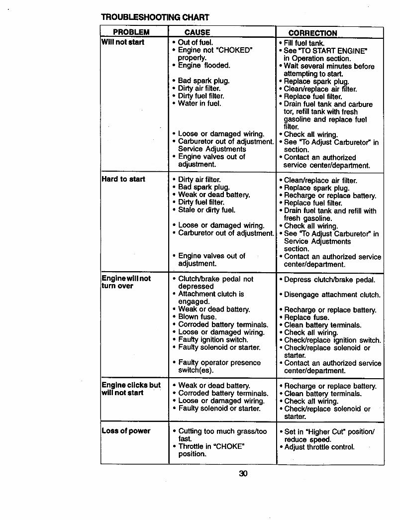
PROBLEM CAUSE CORRECTIONWill not start • Out of fuel;
• Engine not "CHOKED"propedy.
• Engine flooded.
Hard to start
Enginewill notturn over
Engine clicks butwill not start
Loss of power
• Bad spark plug.• Dirty air filter.• Dirty fuel filter.• Water in fuel.
• Loose or damaged wiring.• Carburetor out of adjustment.
Service Adjustments• Engine valves out of
adjustment.
• Dirty air filter.• Bad spark plug.• Weak or dead battery.• Dirty fuel filter.• Stale or dirty fuel.
• Loose or damaged wiring.• Carburetor out of adjustment.
• Engine valves out ofadjustment.
• Clutch/brake pedal notdepressed
• Attachment clutch isengaged.
• Weak or dead battery.• Blown fuse.
• Corroded battery terminals.• Loose or damaged wiring.• Faulty ignition switch.• Faulty solenoid or starter.
• Faulty operator presenceswitch(es).
• Weak or dead battery.• Corroded battery terminals.• Loose or damaged wiring.• Faulty solenoid or starter.
• Cutting too much grass/toofast.
• Throttle in =CHOKE"position.
• Fill fuel tank.• See "TO START ENGINE"
in Operation section.• Wait several minutes before
attempting to start.• Replace spark plug.• Clean/replace air filter.• Replace fuel filter.• Drain fuel tank and carbure
tor, refill tank with freshgasoline and replace fuelfilter.
• Check all wiring.• See "To Adjust Carburetor" in
section.• Contact an authorized
service center/department.
• Clean/replace air filter.• Replace spark plug.• Recharge or replace battery.• Replace fuel filter.• Drain fuel tank and refill with
fresh gasoline.• Check all wiring.• See "To Adjust Carburetor" in
Service Adjustmentssection.
• Contact an authorized servicecenter/department.
• Depress clutch/brake pedal.
• Disengage attachment clutch.
• Recharge or replace battery.• Replace fuse.• Clean battery terminals.• Check all wiring.• Check/replace ignition switch.• Check/replace solenoid or
starter.• Contact an authorized service
center/department.
• Recharge or replace battery.• Clean battery terminals.• Check all wiring.• Check/replace solenoid or
starter.
• Set in =Higher Cut" position/reduce speed.
• Adjust throttle control.
3O
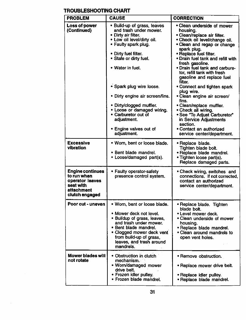
TROUBLESHOOTING CHART
PROBLEM
Loss of power(Continued)
Excessivevibration
Engine continuesto run whenoperator leavesseat withattachmentclutch engaged
Poorcut-uneven
Mowerblsdeswillnot rotate
CAUSE
• Build-up of grass, leavesand trash under mower.
• Dirty air filter.• Low oil level/dirty oil• Faulty spark plug.
• Dirty fuel filter.• Stale or dirty fuel.
• Water in fuel.
,; Spark plug wire loose.
• Dirty engine air screen/fins.
• Dirty/clogged muffler.• Loose or damaged widng.• Carburetor out of
adjustment.
• Engine valves out ofadjustment.
•Wom, bent or loose blade.
• Bent blade mandrel.• Loose/damaged part(s).
• Faulty operator-safetypresence control system,
• Wom, bent or loose blade.
• Mower deck not level.• Buildup of grass, leaves,
and trash under mower.• Bent blade mandrel.• Clogged mower deck vent
from build-up of grass,leaves, and trash aroundmandrels.
• Obstruction in clutchmechanism.
• Worn/damaged mowerdrive belt.
• Frozen idler pulley.• Frozen blade mandrel.
CORRECTION
• Clean underside of mowerhousing.
• Clean/replace air filter.• Check oil level/change oil.• Clean and regap or change
spark plug.• Replace fuel filter.• Drain fuel tank and refill with
fresh gasoline.• Drain fuel tank and carbure-
tor, refill tank with freshgasoline and replace fuelfilter.
• Connect and tighten sparkplug wire.
• Clean engine air screen/fins.
• Clean/replace muffler.• Check all widng.• See =To Adjust Carburetor"
in Service Adjustmentssection.
• Contact an authodzed
service center/department.
• Replace blade.Tighten blade bolt.
• Replace blade mandrel.• Tighten loose part(s).
Replace damaged parts.
• Check wiring, switches andconnections. If not correctedcontact an authorizedservice center/department.
• Replace blade. Tightenblade bolt.
• Level mower deck.• Clean underside of mower
housing.• Replace blade mandrel.• Clean around mandrels to
open vent holes.
• Remove obstruction.
• Replace mower ddve belt.
• Replace idler pulley.• Replace blade mandrel.
31
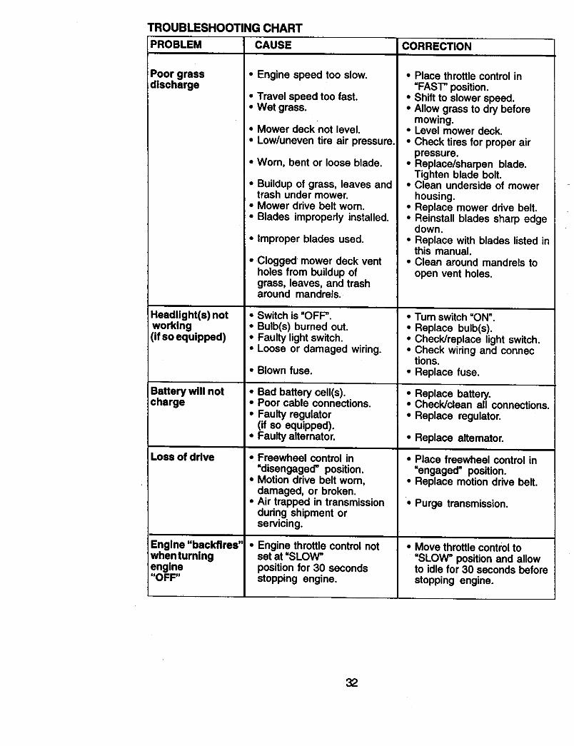
TROUBLESHOOTING CHART
PROBLEM
Poor grassdischarge
Headlight(s) notworking(if so equipped)
Battery will notcharge
Loss of drive
Engine "backfires"whenturningengine"OFF"
CAUSE
• Engine speed too slow.
• Travel speed too fast.• Wet grass.
• Mower deck not level.• Low/uneven tire air pressure.
•Wom, bent or loose blade.
• Buildup of grass, leaves andtrash under mower.
• Mower drive belt worn.• Blades improperly installed.
• Improper blades used.
• Clogged mower deck ventholes from buildup ofgrass, leaves, and trasharound mandrels.
• Switch is =OFF _.• Bulb(s) burned out.• Faulty light switch.• Loose or damaged wiring.
• Blown fuse.
• Bad battery celt(s).• Poor cable connections.• Faulty regulator
(if so equipped).• Faulty altemator.
• Freewheel control in=disengaged' position.
• Motion drive belt worn,damaged, or broken.
• Air trapped in transmissionduring shipment orservicing.
• Engine throttle control notset at =SLOW"position for 30 secondsstopping engine.
CORRECTION
• Place throttle control in=FAST" position.
• Shift to slower speed.• Allow grass to dry before
mowing.• Level mower deck.
• Check tires for proper airpressure.
• Replace/sharpen blade.Tighten blade bolt.
• Clean underside of mowerhousing.
• Replace mower drive belt.• Reinstall blades sharp edge
down.• Replace with blades listed in
this manual.• Clean around mandrels to
open vent holes.
• Turn switch =ON".• Replace bulb(s).• Check/replace light switch.• Check wiring and connec
tions.• Replace fuse.
• Replace battery.• Check/clean all connections.• Replace regulator.
• Replace altemator.
• Place freewheel control in=engaged" position.
• Replace motion drive belt.
• Purge transmission.
• Move throttle control to=SLOW" position and allowto idle for 30 seconds beforestopping engine.
32
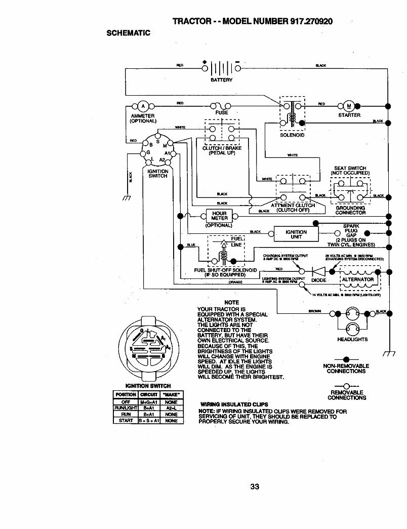
SCHEMATIC
TRACTOR - - MODEL NUMBER 917.270920
- tl111 +BATTERY
AMMETER(OPTIONAL)
IGNITIONSWITCH
iGNITION swrrcH
L ....... J
CLUTCH / BRAKE(PEDALUP)
BLACK
...... I
SOLENOID
WHmE
SEAT SWITCH
• (NOT OCCUPIED)i ........ 1
(
:_'UTCH" GROUNDING(CLUTCH OFF) CONNECTOR
(OPTIONAL) Q__ SPARK
. e_CK IGNITION _ PLUG= FUE-LI UNIT GAPi J 1W[_ ,PLUGS ON
FUEL SHUT-OFF SOLENOID REO
uama_ S_'mUoumur =ALTERNATOR• ORANGE $ NhIP_¢ e II_ RFtl ,,-_ DIODE I •
• t.. .........
" I _. "_'rs._ m,. e _o m_ _'s o_
NOTE IYOUR TRACTOR IS _ _ _ _.-,a,._,EQUIPPED WITH A SPECIAL ' _ALTERNATOR SYSTEM, I _'J J"n-lE UGHTS ARE NOT I _ ICONNECTED TO THE '_p o_BATTERY, BUT HAVE THEIROWN ELECTRICAL SOURCE. HEADLIGHTSBECAUSE OF THIS, THEBRIGH'INESS OF THE LIGHTS /,_WILL CHANGE wrn-I ENGINESPEED, AT IDLE THE UGHTSWILL DIM. AS THE ENGINE IS NON-REMOVABLESPEEDED UP, THE LIGHTS CONNECTIONSWILL BECOME THEIR BRIGHTEST.
OREMOVABLE
CONNECTIONSWIRING INSULATED CUPS
NOTE: IF WIRING INSULATED CUPS WERE REMOVED FORSERVICING OF UNIT, THEY SHOULD BE REPLACED TOPROPERLY SECURE YOUR WIRING.
33
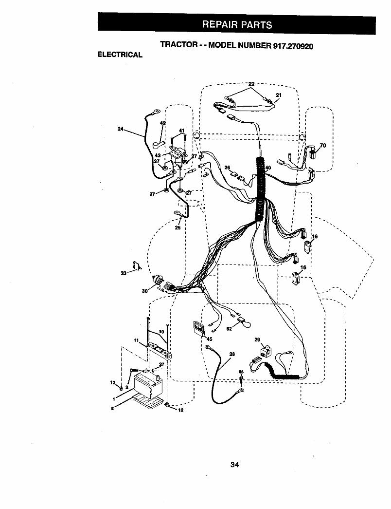
TRACTOR - - MODEL NUMBER 917.270920ELECTRICAL
41
I i
I i
\
I
I
I
I
r_
i
i
i
i
\\
34
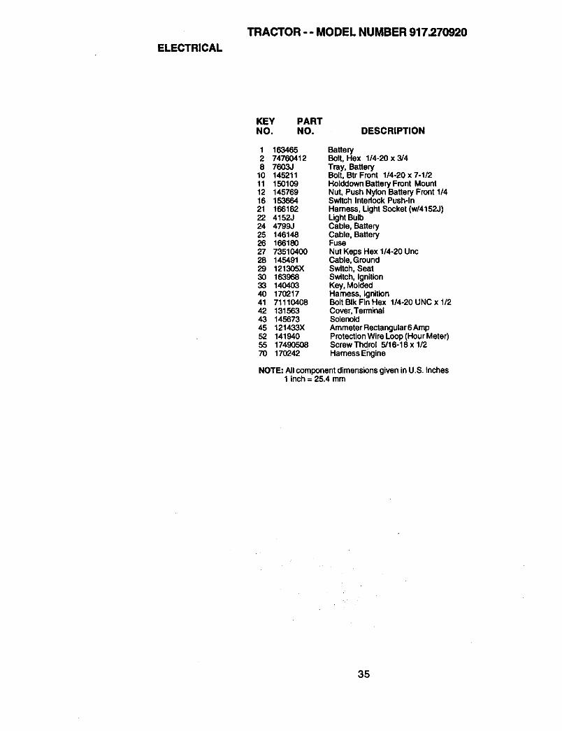
ELECTRICALTRACTOR - - MODEL NUMBER 917.270920
KEY PARTNO. NO. DESCRIPTION
1 163465 Battery2 74760412 Bolt, Hex 1/4-20x3/48 7603J Tray, Battery
10 145211 Bolt, Btr Front 1/4-20 x 7-1/211 150109 Holddown Battery Front Mount12 145769 Nut, Push Nylon Battery Front 1/416 153664 Switch Intedock Push-in21 166182 Harness, Light Socket (w/4152J)22 4152J Light Bulb24 4799J Cable, Battery25 146148 Cable, Battery26 166180 Fuse27 73510400 Nut Keps Hex 1/4-20 Unc28 145491 Cable, Ground29 121305X Switch, Seat30 163968 Switch, Ignition33 140403 Key, Molded40 170217 Harness, Ignition41 71110408 BoltBIkFinHex 1/4-20UNCx1/242 131563 Cover,Terminal43 145673 Solenoid45 121433X Ammeter Roctangular6 Amp52 141940 ProtectionWire Loop(Hour Meter)55 17490508 ScrewThdrol 5/16-18xl/270 170242 Harness Engine
NOTE: Allcomponent dimensionsgiven inU.S. inches1 inch = 25.4 mm
35
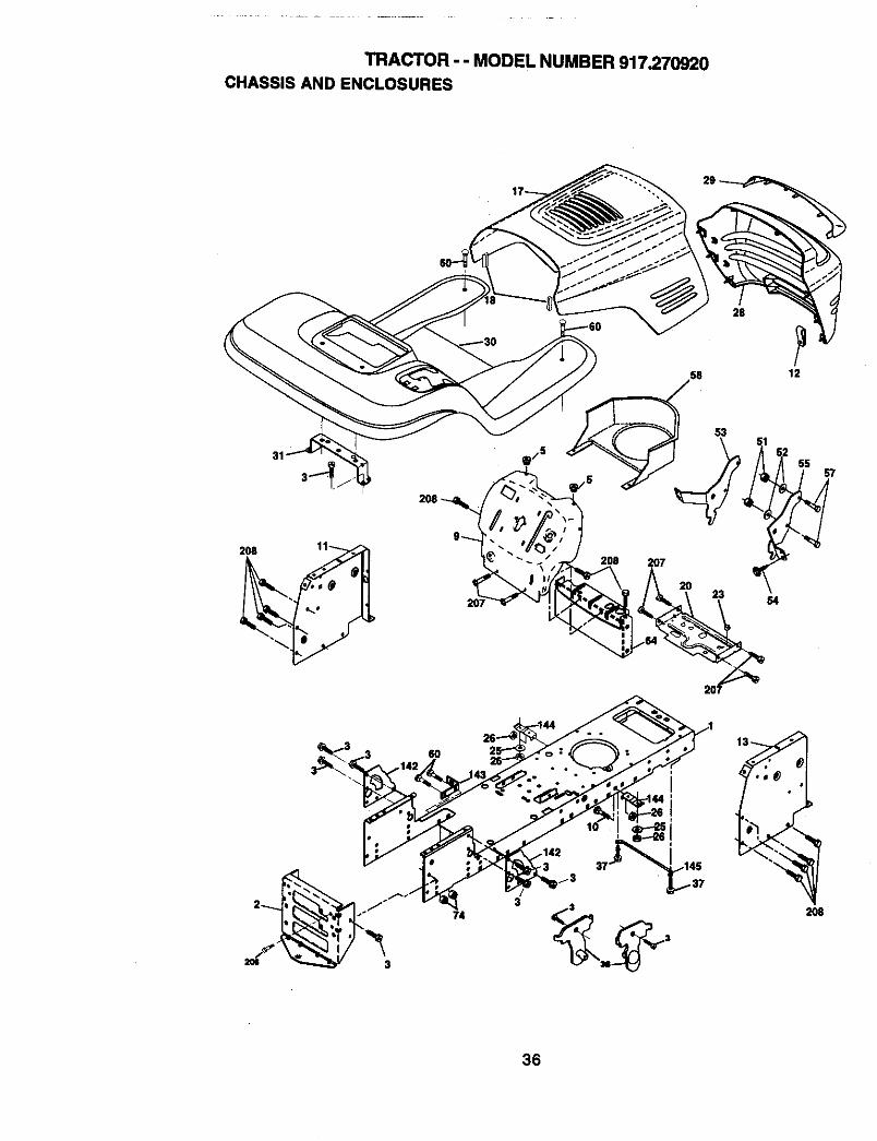
TRACTOR -- MODEL NUMBER 917.270920CHASSIS AND ENCLOSURES
28
,58 12
208
31
208 207
53
23 S4
55
374
3
36

TRACTOR - - MODEL NUMBER 917.270920CHASSISANDENCLOSURES
KEY PARTNO. NO. DESCRIPTION
1 1698302 1690613 170606125 1552729 168337X013
10 STD53371011 15592712 14566013 169117)(01017 144983)(55818 126938X20 15643723 124028X25 1913131226 STD54143728 166271X55829 155217)(59930 164918X55831 13997637 1749050838 16983451 7380040052 1909141653 14520154 16146455 14520257 STD55250758 14054760 7214060664 15479874 S'1_54143"/142 165867143 154966144 154207145 156524206 170165207 17670r'_6208 17670608-- 5479,}
ChassisDmwbarScrew 3/8-16 x3/4BumperHood/DashDashBolt, Carriage 3/8-16 x IPanel, Dash, LHClipTinnerman Grille P/LPanel, Dash, RHHoodAssemblyBumber HoodPlate Mtg Battery Fuel TankBushing, Snap, Nylon, Fuel LineWasher 13/32 x 13/16 x 12 GaugeLocknut, Hex, with Insert 3/8-16 UNCGrilleLens, GrilleFender/FootrestBracket, Fender/SupportScrew, Thdrol. 5/16-18 x 1/2 TYTPivot Bracket Assembly, LH, Mower, RearNut Lock W/Insert 1/4 o20 UNCWasher 9/32 X 7/3 X 16 Ga.Bracket Gdlle Pickoff LHScrew, Hex Wshd #8-18 x 7/8Bracket Grille Pickoff RHBolt FinHax 1/4 -20 UNC X.75Air DuctBolt Rdhd Sqnk 3/8-19 UNC x 3/4Dash LowerSTLTNutCmwnlock3/8-16 UNCPlate ReinforcementSTLTBracket Swaybar ChassisBracket Footrest STLTRod PivotChassis/HoodBoRShoulder5/16-18TTScrew Thdrol 5/t6-18 x 112Screw Thdml 3/8-16 x 1/2Plug Button
NOTE: Allcomponentdimensionsgiven inU.S. incttss1 inch= 25.4 mm
37
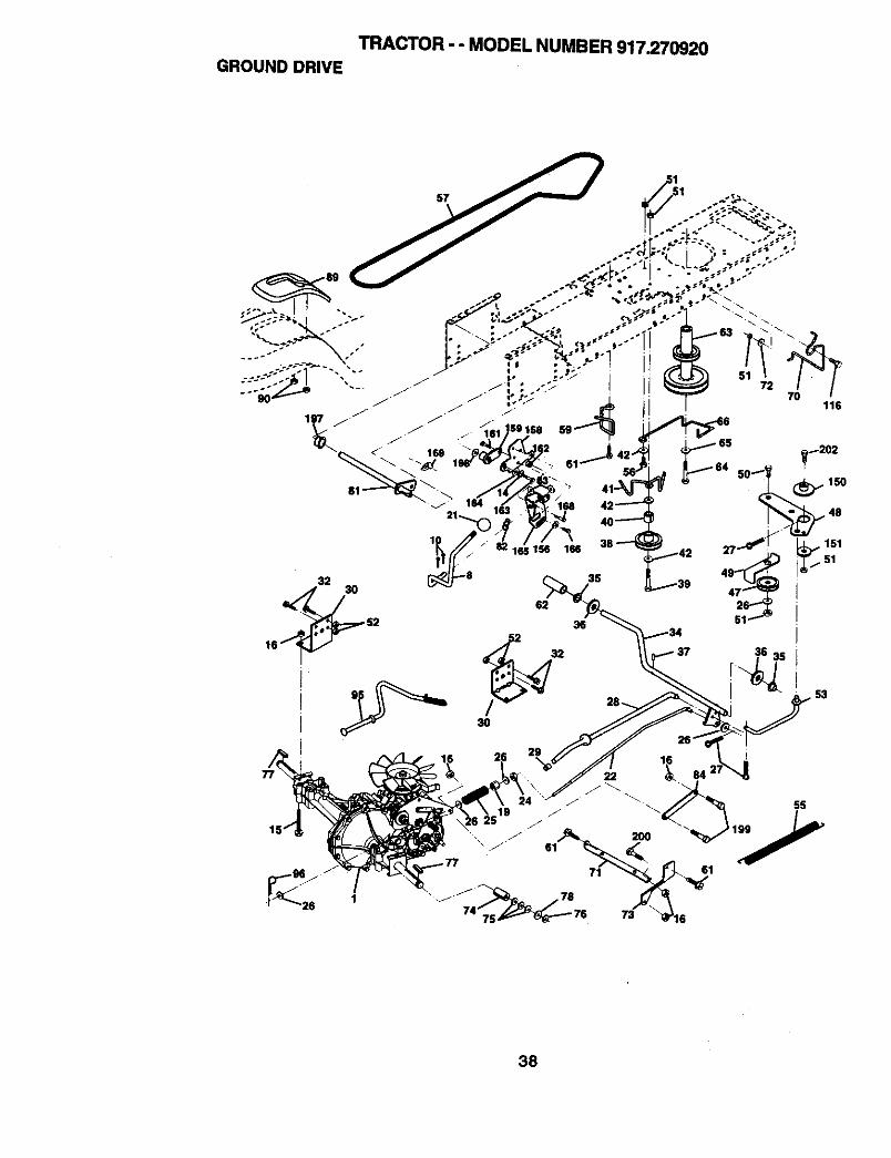
TRACTOR - - MODEL NUMBER 917.270920GROUND DRIVE
35
36
i
72
116
38
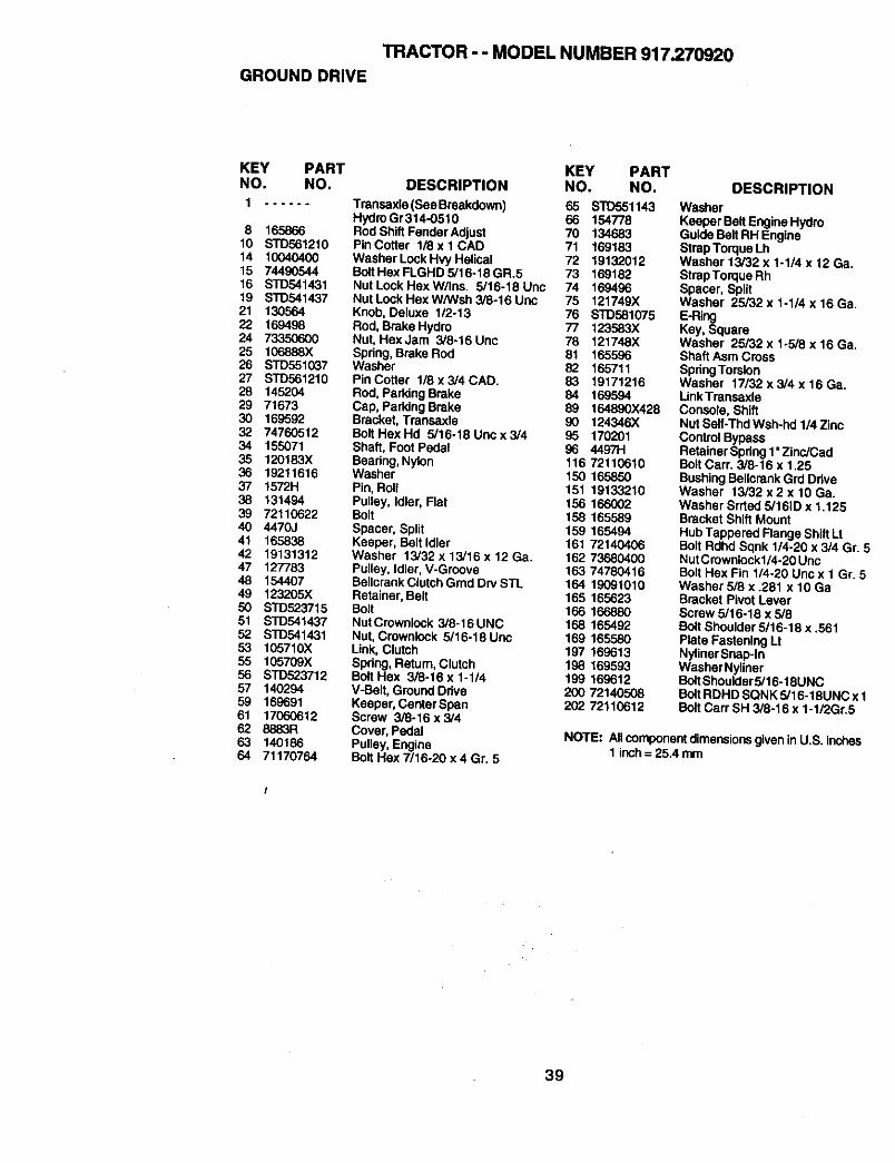
TRACTOR - - MODEL NUMBER 917.270920
GROUND DRIVE
KEY PART KEY PARTNO. NO. DESCRIPTION NO. NO.
1 ...... Transaxla(SeeBreakdown) 65 STD551143
8 16586610 STD56121014 1004040015 7449054416 STD54143119 STD54143721 13056422 16949824 7335060025 106888X26 STD55103727 STD56121028 14520429 7167330 16959232 7476051234 15507135 120183X36 1921161637 1572H38 13149439 7211062240 4470J41 16583842 1913131247 12778348 15440749 123205)(50 STD52371551 STD54143752 STD54143153 105710X55 105709X56 STD52371257 14029459 16969161 1706061262 8883R63 14018664 71170764
Hydro Gr314-0510 66 154778Rod Shift Fender Adjust 70 134683Pin Cotter 1/8 x 1 CAD 71 169183Washer Lock Hvy Helical 72 19132012BoltHex FLGHD 5/16-18 GR.5 73 169182NutLockHexW/Ins. 5/16-18Unc 74 169496Nut Lock Hax W/Wsh 3/8-16 Unc 75 121749XKnob, Deluxe 1/2-13 76 STD581075Rod, Brake Hydro 77 123583XNut, Hex Jam 3/8-16 Unc 78 121748XSpring, Brake Rod 81 165596Washer 82 165711Pin Cotter 1/8 x 3/4 CAD. 83 19171216Rod, Park|ng Brake 84 169594Cap, Parking Brake 89 164890X428Bracket, Transaxle 90 124346XBottHexHd 5/16-18Uncx3/4 95 170201Shaft, Foot Pedal 96 44971-1Beadng, Nylon 116 72110610Washer 150 165850Pin, Roll 151 19133210Pulley, Idler, Flat 156 166002Bolt 158 165589Spacer, Split 159 165494Keeper, Belt Idler 161 72140406Washer 13/32 x 13/16 x 12 Ga. 162 73680400Pulley, Idler, V-Groove 163 74780416BellcrankClutchGmd Drv STL 164 19091010Retainer, Belt 165 165623Bolt 166 166880NutCrownlock 3/8-16UNC 168 165492Nut, Crownlock 5/16-18 Unc 169 165580Link, Clutch 197 169613Spdng, Return,Clutch 198 169593Bolt Hex 3/8-16 x 1-1/4 199 169612V-Belt, Ground Ddve 200 72140508Keeper, Center Span 202 72110612Screw 3/8-16 x 3/4Cover, PedalPulley, EngineBolt Hax 7/16-20 x 4 Gr. 5
DESCRIPTIONWasherKeeper BeltEngine HydroGuide BeltRH EngineStrap Torque LhWasher 13/32 x 1-1/4 x 12 Ga.StrapTorque RhSpacer, SplitWasher 25/32 x 1-1/4 x 16 Ga.E-RingKay, SquareWasher 25/32 x 1.5/8 x 16 Ga.Shaft Asm CrossSpdngTorsionWasher 17/32 x 3/4 x 16 Ga.LinkTransaxleConsole, ShiftNut Self-Thd Wsh-hd 1/4 ZincContro_BypassRetainer Spdng1"Zinc/CadBolt Cam 3/8-16 x 1,25BushingBeUcrank Grd DdveWasher 13/32 x2 x 10 Ga.Washer Srrted 5/161D x 1.125Bracket Shift MountHub Tappered Flange Shift LtBolt Rdhd Sqnk 1/4-20 x 3/4 Gr. 5NutC rownlockl/4-20 UncBolt Hax Fin 1/4-20 Unc x 1 Gr. 6Washer 5/8 x .281 x 10 GaBracket Pivot LeverScrew 5/16-18 x 5/6Bolt Shoulder 5/16-18 x .561Plate Fastening LtNylinerSnap-InWasher NyUnerBoltShoulder5/16-t 6UNCBolt RDHD SQNK 5/16-18UNC x 1Bolt Cart SH 3/8-16 x 1-1/2Gr.5
NOTE: Allcomponentdimensionsgiven in U.S. inches1 inch= 25.4 mm
39
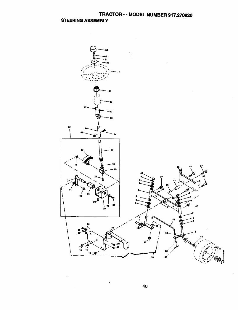
TRACTOR - - MODEL NUMBER 917.270920STEERING ASSEMBLY
_41
L
,,----_._43
" t
I44
40
47
/40
/
4O
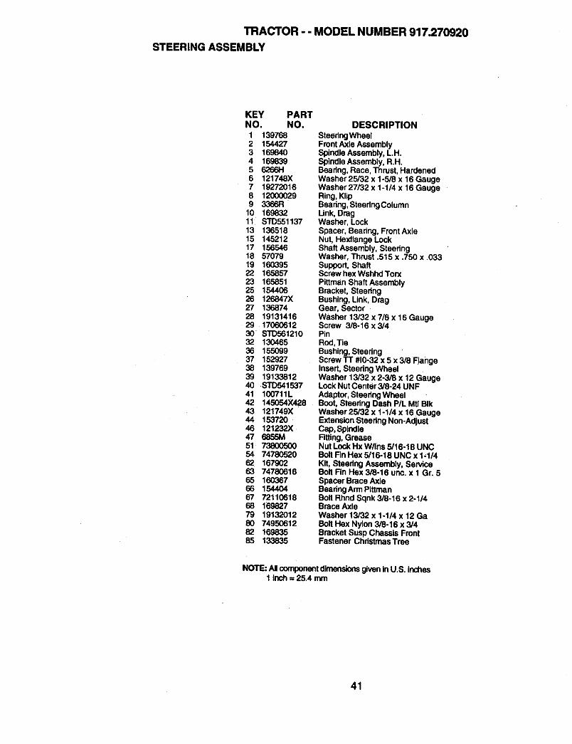
TRACTOR - - MODEL NUMBER 917.270920STEERING ASSEMBLY
KEY PARTNO. NO,1 1397682 1544273 1698404 1698395 6266116 121748X7 192720168 120000299 3366R
10 16983211 STD55113713 13651815 14521217 15654618 5707919 16039522 16585723 16585125 15440626 126847X27 13687428 1913141629 1706061230 STD56121032 13046536 15509937 15292738 13976939 1913381240 STD54153741 100711L42 145054X42843 121749X44 15372046 121232X47 6855M51 7380050054 7478052062 16790263 7478061665 16036766 1544O467 7211061868 16.982779 1913201280 7495061282 16983585 133835
DESCRIPTION
SteedngWheelFront Axle AssemblySpindle Assembly, LH.SpindleAssembly, R.H.Beadng, Race, Thrust, HardenedWasher 25/32 x 1-5/8 x 16 GaugeWasher 27/32 x 1-114 x 16 GaugeRing, KlipBeadng, SteedngColumnLink, DragWasher, LockSpacer, Beadng, FrontAxleNut, Hexflange LockShaft Assembly, SteedngWasher, Thrust .515 x .750 x .033Support, ShaftScrew hex Wshhd TorxPittman Shaft AssemblyBracket, SteedngBushing, Link, DragGear, SectorWasher 13/32 x 7/6 x 16 GaugeScrew 3/8-16 x 3/4PinRod, TieBushing, SteeringScrew TT #10-32 x 5 x 3/8 FlangeInsert, Steering WheelWasher 13/32 x 2-3/8 x 12 GaugeLock NutCenter 3/6,24 UNFAdaptor, Steedng WheelBoot, Steedng Dash P/L Mtl BIkWashar 25/32 x 1-1/4 x 16 GaugeExtensionSteedng Non-AdjustCap, SpindleRtting, GreaseNut Lock Hx W/Ins 5/16-18 UNCBolt Rn Hex 5/16-18 UNC x 1-1/4Kit, Steedng Assembly, ServiceBolt Fin Hex 3/8-16 unc. x I Gr. 5Spacer Brace AxleBeadng Arm PittmanBolt Rhnd Sqnk 3/8-16 x 2-1/4Brace AxleWasher 13/32 x 1-1/4 x 12 GaBolt Hex Nylon 3/8-16 x 3/4Bracket Susp Chassis FrontFastener ChristmasTree
NOTE: Allcomponentdimensionsgiven inU.S. inches1 Inch = 25.4 mm
41
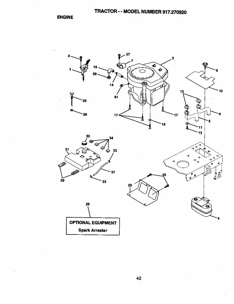
ENGINETRACTOR - - MODEL NUMBER 917.270920
32
39 _" 33
29
OPTIONAL EQUIPMENT ISpark Arrester
42
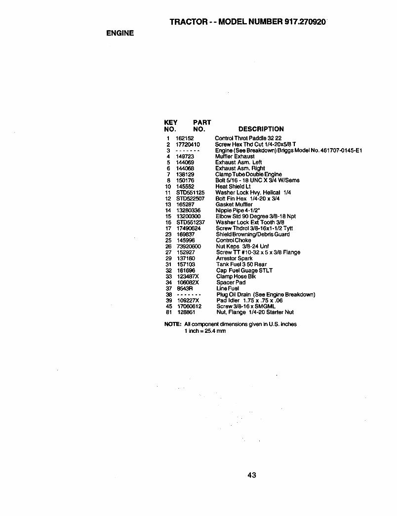
ENGINE
TRACTOR - - MODEL NUMBER 917.270920
KEY PARTNO. NO.
1 1621522 177204103 .......4 1497235 1440696 1440687 1381298 150176
10 14555211 STD55112512 S'I'D52250713 16528714 1328033615 1320030016 STD55123717 1749062423 16983725 14599626 7392060027 15292729 13718031 15710332 16169633 123487X34 106082X37 8543R38 .......
39 109227X45 1706061281 128861
DESCRIPTION
Control Throt Paddle 32 22Screw Hex Thd Cut 1/4-20x5/8 TEngine (See Breakdown) BriggsModel No. 461707-0145-E1Muffler ExhaustExhaust Asm. LeftExhaust Asm. RightClamp Tube Double EngineBolt 5/16 - 18 UNC X 3/4 W/SeresHeat Shield LtWasher Lock Hvy. Helical 1/4Bolt Fin Hex 1/4-20 x 3/4Gasket MufflerNipplePipe4-1/2"Elbow Std 90 Degree 3/8-18 NptWasher Lock Ext Tooth 3/8Screw Thdrol 3/8-16xl -1/2 TyttShieldBrowning/DebrisGuardControlChokeNut Keps 3/8-24 UntScrew "IT #10-32 x 5 x 3/8 FlangeArrestor SparkTank Fuel 3 50 HearCap Fuel Guage STLTClamp Hose BIkSpacer PadLineFuelPlugOil Drain (See Engine Breakdown)Pad Idler 1.75 x ,75 x .06Screw 3/8-16 x SMGMLNut, Flange 114-20 Starter Nut
NOTE: Allcomponentdimensionsgiven in U.S. inches1 inch= 25.4 mm
43
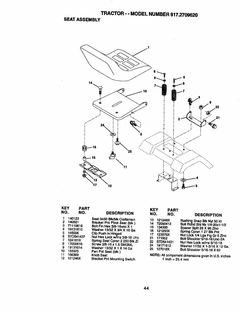
TRACTOR - - MODEL NUMBER 917.2709620SEAT ASSEMBLY
22
21
KEY PARTNO. NO.
1 1401232 1405513 711106164 191316105 145OO66 STD5414377 124181X8 170006169 19131614
10 15592511 16636912 121246X
KEY PARTDESCRIPTION NO. NO. DESCRIPTION
Seat 3450 BIk/blkCraftsmanBracket Pnt Pivot Seat (blk)BOttFin Hex 3/8-16unc X 1Washer 13/32 X 3/4 X 10 GaClipPush In HingedNut Hex Lock w/Ins 3/8-16 UnoSpring Seat Cprsn 2 250 BIk ZiScrew 3/8-16 x 1.5 SMGMLWasher 13/32 X 1 X 14 GaPan Pnt Seat (t_k)Knob SeatBracket Pnt MountingSwitch
13 121248X14 7205041215 13430016 121250X17 123976X21 17185222 STD54143124 1917191225 127018X
BushingSnap BIk Nyl 50 IdBolt Rdhd Sht Nk 1/4-20x1-1/2Spacer Split28 X 96 ZincSpring Cprsn 1 27 BIk PntNut Lock 1/4 Lge Fig Gr 5 ZincBolt Shoulder 5/16-18 Unc-2ANut Hex Lock w/Ins 5/16-18Washer 17/32 X 1-3/16 X 12 Ga.Bolt Shoulder 5/16-18 X 62
NOTE: All componentdimensionsgiven inU.S. inches1 inch = 25.4 mm
44
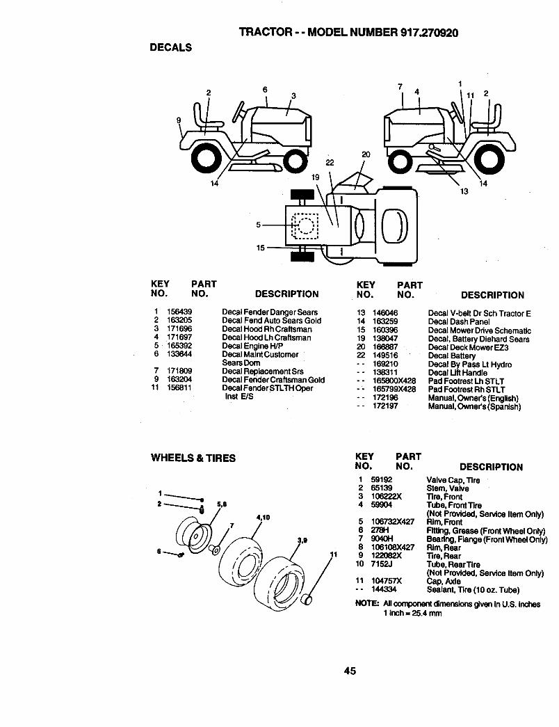
DECALS
TRACTOR - - MODEL NUMBER 917.270920
2 37
41
11 2
9
14
KEY PARTNO. NO.
1 1564392 1632053 1716964 1716975 1653926 133644
7 1718099 163204
11 156811
KEY PARTDESCRIPTION NO. NO.
Decal Fender Danger Sears 13 146046Decal Fend Auto Sears Gold 14 163259Decal Hood Rh Craftsman 15 160396Decal Hood Lh Craftsman 19 138047Decal Engine H/P 20 166887Decal MaintCustomer 22 149516SearsDoro - - 169210Decal Replacement Srs -- 138311Decal FeridarCraftsman Gold -- 165800)(428DecalFenderSTLTHOper - - 165799)(428Inst E/S - - 172196
-- 172197
1413
DESCRIPTION
Decal V-belt Dr Sch Tractor EDecal Dash PanelDecal MowerDdve SchematicDecal, Battery Diehard SearsDecal Deck M_wer EZ3Decal BatteryDecal By Pass Lt HydroDecal Uft HandlePad FootrestLh STLTPad FootrestRh STLTManual, OwneYs (English)Manual, Owner's(Spardsh)
WHEELS & TIRES
4,10
11
KEY PARTNO. NO. DESCRIPTION
1234
56789
10
11
59192 Valve Cap, Tire65139 Stem, Valve106222X Tire, Front59_04 Tube, FrontTire
(Not Provided, Service Item Only)106732X427 Rim, Front27811 Fitting, Grease (FrontWbeal Only)9040H Beadng, Flange (FrontWheal Only106106X427 Rim, Rear122O82X Tire, Rear7152J Tube, RearTire
(Not Provided, Service Item Only)104757X Cap, Axle144334 Sealant, Tire ('tOoz. Tube)
NOTE: Allcomponentdimensionsgiven In u.s, Inches1 inch = 25.4 taro
45
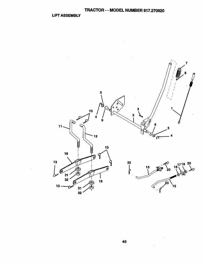
TRACTOR - - MODEL NUMBER 917.270920LIFTASSEMBLY
13
5
3
8
j! •
65
19
13
32
13
19
2O
15
46
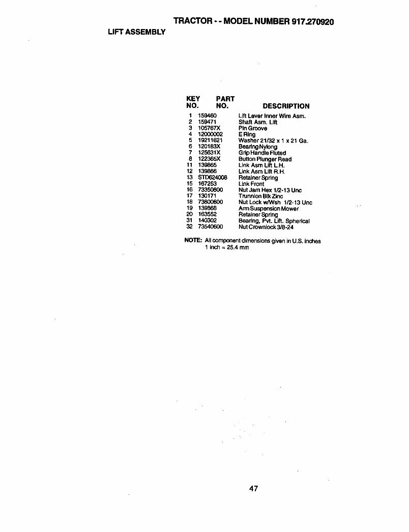
TRACTOR - - MODEL NUMBER 917.270920
LIFT ASSEMBLY
KEY PARTNO. NO. DESCRIPTION
1 159460 Lift Lever Inner Wire Asm.2 159471 Shaft Asm. Lift3 105767X PinGroove4 12000002 E Ring5 19211621 Washer21/32x1 x21 Ga.6 120183X BeadngNytong7 125631X GdpHandle Ruted8 122365X ButtonPlunger Read
11 139865 Link Asm Lift L.H.12 139866 Link Asm Lift R.H.13 $10624008 RetainerSpdng15 167253 LinkFront16 73350800 Nut Jam Hex 1/2.13 Unc17 130171 Trunnion BIk Zinc18 73800800 Nut Lock w/Wsh 1/2-13Unc19 139868 An'nSuspensionMower20 163552 RetainerSpdng31 140302 Beadng, Pvt. Lift. Spherical32 73540600 NutCrownlock3/8-24
NOTE: Allcomponentdimensionsgiven inU.S. inches1 inch= 25.4 mm
47
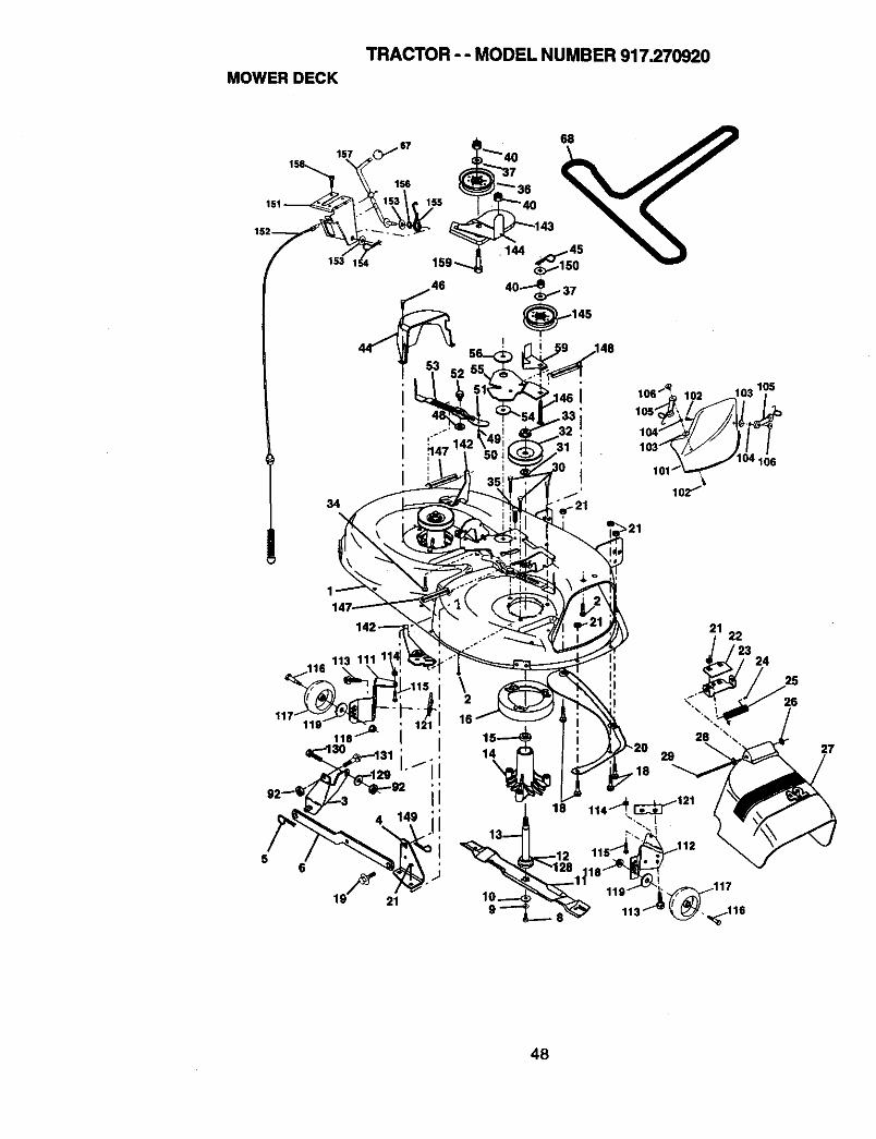
MOWER DECK
TRACTOR - - MODEL NUMBER 917.270920
'---..,_ ,. _T__,
153 I_4 i9,_
,148
>21
2122
24
16
1
18
26
27
48
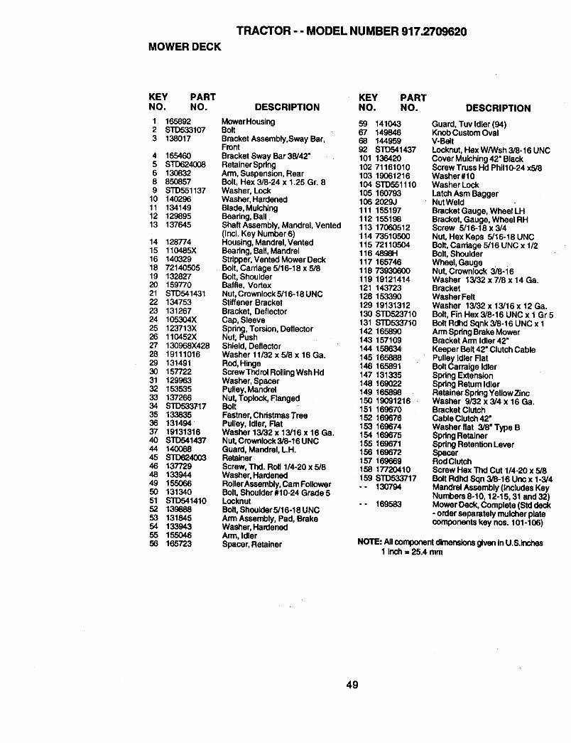
TRACTOR - - MODEL NUMBER 917.2709620MOWER DECK
KEY PART KEY PARTNO. NO. DESCRIPTION NO. NO.
1 165892 MowerHousing 59 1410432 STD533107 Bolt 67 1498463 138017 Bracket Assembly,Sway Bar, 68 144959
Front 92 STD5414374 165460 Bracket Sway Bar 38/42" 101 1364205 STD624008 RetainerSpring 102 711610106 130832 Arm, Suspension, Rear 103 190612168 850857 Boll Hex 3/8-24 x 1.25 Gr. 8 104 STD5611109 STD551137 Washer, Lock 105 160793
10 140296 Washer, Hardened 106 2029J11 134149 Blade,Mulching 111 15519712 129895 Beadng, Ball. 112 15519813 137645 ShaffAssembly, MandreI, Vented 113 17060512
(Incl. Key Number 6) 114 7351050014 128774 Housing,Mandrel,Vented 115 7211050415 110485)( Beadng, BalI,Mandrel 116 4896H16 140329 Stdpper, Vented MowerDeck 117 16574618 72140505 Bolt, Carriage 5/16-18 x 5/8 118 7393060019 132827 Bolt, Shoulder 119 1912141420 159770 Baffle, Vortex 121 14372321 STD541431 Nut, Crownlock5/16-18UNC 128 15339022 134753 Stiffener Bracket 129 1913131223 131267 Bracket, Deflector 130 STD52371024 105304X Cap, Sleeve 131 STD53371025 123713X Spdng, Torsion, Deflector 142 16589026 110452X Nut; Push 143 15710927 130968X428 Shield, Deflector 144 15863428 19111016 Washer 11/32 x 5/8 x 16 Ga. 145 16588829 131491 Rod, Hinge 146 16589130 157722 ScrawThdrolRoUingWshHd 147 13133531 129963 Washer, Spacer 148 16902232 153535 Pulley, Mandrel 149 16589833 137266 Nut, Toplock,Flanged 150 1909121634 STD533717 Bolt 151 16967035 133835 FaStner,ChdstmasTrse 152 16967636 131494 Pulley, Idler, Flat 153 16967437 19131316 Washer13i32x13/16x16Ga. 154 16967540 STD541437 Nut, Crownlock3/8-16UNC 155 16967144 140088 Guard, Mandrel, LH. 156 16967245 $10624003 Retainer 157 16966946 137729 Screw, Thd. Roll 1/4-20 x 5/8 158 1772041048 133944 Washer, Hardened 159 STD53371749 155066 RollerAssembly, CamFollower -- 13079450 131340 Bolt, Shoulder #10-24 Grade 551 $10541410 Locknut - - 16958352 139888 Bo_t,Shoulder5/16-18 UNC53 131845 Arm Assembly, Pad, Brake54 133943 Washer, Hardened55 155046 Arm, Idler56 165723 Spacer, Retainer
DESCRIPTION
Guard, Tuv Idler (94)Knob Custom OvalV-BeltLocknut, Hex W/Wsh 3/8-16 UNCCover Mulching42" BlackScrew Truss Hd Phil10-24 x5/8Washer#10Washer LockLatch Asm BaggerNutWeldBracket Gauge, Wheel LHBracket, Gauge, Wheel RHScrew 5/16-18 x 3/4Nut, Hex Keps 5/16-18 UNCBolt, Carriage 5/16 UNC x 1/2Bait, ShoulderWheel, GaugeNut, Crownlock 3/8-16Washer 13/32 x 7/8 x 14 Ga.BracketWasher FeltWasher 13/32 x 13/16 x 12 Ga.Bolt, Fin Hex 3/8-16 UNC x 1 Gr 5Bolt Rdhd Sqnk 3/8-16 UNC x 1Arm SpringBrake MowerBracket Arm Idler 42"Keeper Belt 42" Clutch CablePulley IdlerFlatBoltCarraige IdlerSpdng ExtensionSpdngReturn IdlerRetainer SpdngYellowZincWasher 9/32 x 3/4 x 16 Ga.Bracket ClutchCable Clutch42"Washerflat 3/8"Type BSpdngRetainerSpdngRetention LeverSpacerRodClutchScrew Hex Thd Cut 1/4-20 x 5/8Bolt Rdhd Sqn 3/8-16 Uno x 1-3/4Mandrel Assembly (Includes KeyNumbers 8-10, 12-15, 81 and 32)Mower Deck, Complete (Srddeck- order separately mulcherplatecomponents key nos. 101-106)
NOTE: Allcomponentdimensionsgiven inU.S.ioches1 Inch= 25.4 mm
49
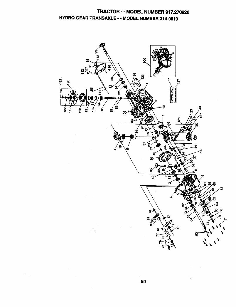
TRACTOR - - MODEL NUMBER 917_270920
HYDRO GEAR TRANSAXLE -. MODEL NUMBER 314-0510
\
50
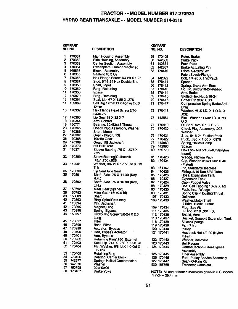
TRACTOR - - MODEL NUMBER 917.270920
HYDRO GEAR TRANSAXLE - - MODEL NUMBER 314-0510
KEYPART K]EYPARTNO. NO. DESCRIPTION NO. NO. DESCRIPTION
1 170351 Main Housing,Assembly 59 1704082 170352 Side Housing, Assembly 60 1428833 170353 Center Section, Assembly 61 1428814 170354 Swashplata,TrunionMachinsd 62 1428875 169898 Block - Assembly 63 1704106 170355 Sealant 10.50z7 170356 Hex Flange Screw 1/4-20 X 1.25 64 1428928 170357 Stud, 5/16-24 Hex Double End 65 1704119 170358 Shaft, Input 66 170412
10 170359 Ring-Retaining 67 17041311 170360 Spacer 68 17041412 169870 Ring-Retaining 69 17041513 170361 Seal, Lip .67 X 1.58 X .276 70 17041614 169869 Ball B_117mm Id X 40mm Od X 71 170417
12mm16 170362 HexFlangeHeadScrew5/16. 72 170418
24X0.7517 170363 Lip Seal 18 X 32 X 7 73 14288418 170364 Arm,Control19 150771 Bearing, 30x52x13Thrust 74 17041923 170365 Check PlugAssembly, Washer 75 17042024 170366 Shaft, Motor27 170367 Gear- Pinion, 13t 76 17042128 170368 10t/48t Gear 77 17042229 170369 Gear, 10t Jackshafl 78 14296930 170370 60t BullGear 79 14298031 170371 Sleeve Bearing.75 X 1.575 X 80 150778
.62532 170389 SleeveBeadng(Outboard) 81 170423
,75x1.750x.625 82 17042433 142991 Washer, 3/4 Id X 1-1/20d X .13
Thk 83 16116234 1703,90 Lip Seal Axla Seal 84 17042535 170391 Shaft, Axle .75 X 11.39 (Key, 85 170426
R.H.) 86 17042736 170392 Shaft, Axle .75 X 16.99 (Key, 87 170424
LH.) 88 17042937 150792 MiterGear(Splined) 90 17043038 150793 Miter Gear 15t (0.5 Id) 93 17043139 150809 Shaft 107 17043240 170393 Ring,SpiralRetaining 108 17043341 170394 Pin, Jackshaft42 170395 Magnet, Ring 109 17043443 170396 Spring, Bypass 111 17043544 150797 Hydro Mtg Screw3/8-24 X2.5 112 170436
Long 113 17043745 170397 Filter 116 17043846 170398 Base, Filter 119 17043947 170999 Actuator, Bypass 120 17044048 170400 Rod, Bypass Actuator 121 17044149 170401 Arm, Bypass50 170202 Retaining Ring .250 External 122 17044251 170403 Seal, Lip .741 X .250 X .250 Tc 123 17044352 170404 Flat Washer, 5/8 Id X 1.00d X 124 170444
.05 Thk53 170405 RetainingRing54 170406 Bearing, Center Block55 142977 Spring- Helical Compression56 142978 Washer57 150798 20w-50Oil58 170407 Brake Yoke
Rotor, BrakeBrake PuckPuck PlateBrake Actuating PinHfhcs 1/4-20x2 W/Patch,SpecialFlangeBolt, 1/4-20 X 1 W/PatchSpacerSpring, Brake Arm BiasSq. Hd. Bolt 5/16-24-RibbedArm, BrakeSlotted Hex Nut 5/16-24Cotter Pin 3/32 X 3/4CompressionSpringBrake Anti-DragWasher, Ht .5 I.D. X 10.D. X.032Flat - Washer 11/32 I.D. X 7/8O.DOil Seal .625 X 1.0 X .25Check Plug Assembly, .027,WasherStud, 5/16-24 FrictionPackPuck, .330 X 1,50 X .0975Spring,HelicaICompSpacerHex Lock Nut 5/16-24Unjf(NylonInsert)Wedge, Friction PackClip,Washer .316x1.5Ox.1046(Plated)Pin, Standard HeadlessFitting, 5/16 Sae 5/32 TubeHose, ExpansionTankExpansionTankCap - Poppet ValveBolt, Self Tapping 10-32 X 1/2Puck, Inner WedgeSpring Clip- HousingThrustDeflectorWashar,MotorShaft.711dx1.15edx.030thkPlug, Sae #6O-Ring .07 X .301 I.D.Shield, VentBracket, Support ExpansionTankSiliconSpongeFan, 7 In.PulleyHex Lock Nut 1/2-20 (NylonInsert)Washer, BellevillaBelt KeeporCenta rSection-Filter-BypassAssembly
125 170445 FilterAssembly126 170446 Fan - Pulley Service Assembly127 170447 Seal - O-Ring Kit900 166768 Trensaxle Complate
NOTE: All componentdimensions given inU.S. inches1 inch = 25.4 mm
51
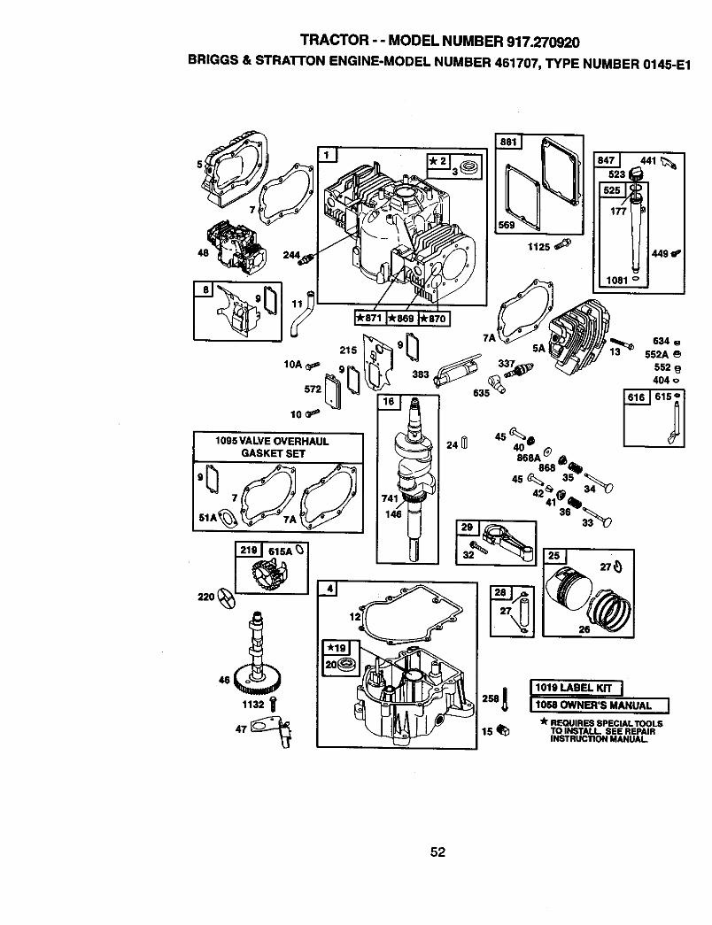
TRACTOR -- MODEL NUMBER 917.270920
BRIGGS & STRA'I-rON ENGINE-MODEL NUMBER 461707, TYPE NUMBER 0145-E1
1132
634 g552A
552404 o
11o.OWNER'S MANUAL I
"k REQUIRES SPECIAL TOOLS15 _ TO INSTALL SEE REPAIR
INSTRUCTION MANUAL
52
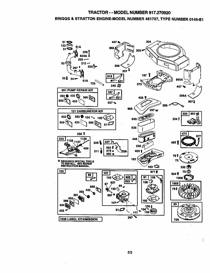
TRACTOR - - MODEL NUMBER 917.270920
BRIGGS & STRATTON ENGINE-MODEL NUMBER 461707, TYPE NUMBER 0145-E1
51
1221 51A
205634A o
20250_ 212 '-"
267 t 203_
53| 54+-
51A 725_
861 PUMP REPAIR KIT "1
/302• 432_ a00'_859_ 433 _
307 _
240_'
_01 425 '
527
9681
121 CARBURETOR KIT
432 6 3920104_ lO2_1 643<
535
250 V
_,,_1138 11:_6_,
,_2 i'689 211 aim:
"I m,,, Ilk REQUIRES SPEClALTOOLS
TO INSTALL, SEE REPAIRINSTRUCTION MANUAL.
304
11030LABEL KIT-EMISSION I
305
306A <
3o7L
267 "%
8O7•
53
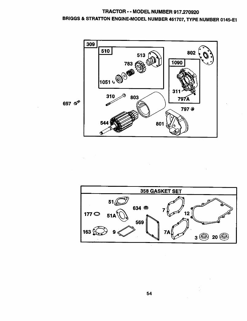
TRACTOR - - MODEL NUMBER 917.270920
BRIGGS & STRATTON ENGINE-MODEL NUMBER 461707, TYPE NUMBER 0145-E1
697 _#'
783
y 803
544 ;
513 802 (_)_
801
797 @
358 GASKET SET
634
ooo i
3@ 20@
54
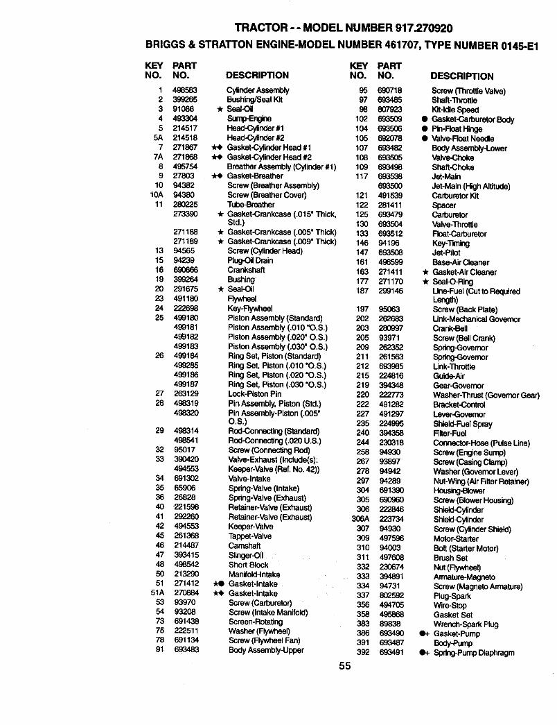
TRACTOR - - MODEL NUMBER 917.270920
BRIGGS & STRATTON ENGINE-MODEL NUMBER 461707, TYPE NUMBER 0145-E1
KEY PAFn" KEY PARTNO. NO. DESCRIPTION NO. NO. DESCRIPTION
1 498583 CylinderAssembly 95 690718 Screw('l'hmttleValve)2 399265 Bushing/SealKit 97 693485 Shaft-Throttle3 91086 "/__ 96 807923 Kit-IdleSpeed4 493304 SurnlPEnglne 102 69_509 • Gasket-CarburetorBody5 214517 Head-Cylindar#1 104 693506 • Pin-FloatHinge
5A 214518 Head-Cylinder#2 105 6g_078 • Valve-FleatNasdle7 271867 _ Gasket-CylinderHead #1 107 693482 BodyAseambly-Lower
7A 271868 _ Gasket-CylinderHead#2 108 693505 Valve-Choke8 495754 BreatherAssembly(Cytindar#1) 109 693498 Shaft-Choke9 27803 _ Gasket-Breather 117 693538 Jet-Main
10 94382 Screw (BreatherAssembly) 69_500 Jet-Main(High Altitude)IOA 94380 Screw(BraatherCover) 121 491539 CarburetorKit
11 280_25 Tube-Braethar 122 281411 Spacer273390 "k Gasket-Crankcase (.015" Thick, 125 693479 Carburetor
Std.) 130 693504 Valve-Throttle271188 -k Gasket-Crankcase (.005" Thick) 133 693512 Fleat-Carburetor
271189 "/r Gasket-Crankcase (.009" Thick) 146 94196 Key-Tinting13 94565 Screw(CylinderHead) 147 6935(]8 Jet-Pilot15 94239 Plug--OitDrain 161 496599 Base-AirCisaner16 690666 Crankshaft 163 271411 _r Gasket-AlrClaaner19 399264 Bushing 177 271170 * Seat-O-Ring20 291675 'Jr Seal-Oil 187 299146 Une-Fuel(CuttoRequlrad23 491180 Flywheel Length)24 222698 Key-Flywheel 197 95063 Screw (Back Plate)25 499180 PistonAssembly (Standard) 202 262683 Unk-Mechanical Governor
499181 PistonAssembly (.010 "O.S.) 203 280997 Crank-Bell499182 PistonAssembly (.020" O.S.) 205 93971 Screw (BallCrank)499183 PistonAssembly (.030" O.S.) 209 262352 Spdng-Govemor
26 499184 Ring Set, Piston(Standard) 211 261563 Spnng-Governor499285 Ring Set, Piston(.010 =O.S.) 212 693.985 Link-Throftla499186 Ring Set, Piston(.020 =O.S.) 215 224816 Guide-Air499187 Ring Set, Piston(.030 "O.S.) 219 394348 Gear-Governor
27 263129 Lock-PistonPin 220 222773 Washer-Thrust(GovernorGear)28 498319 Pin Assembly,Piston (Std.) 222 491282 Brackst-Control
498320 Pin Assembly-Piston(.005" 227 491297 Lever-GovernorO.S.) 235 224995 Shlald-FuelSpray
29 498314 Rud-Connecting(Standard) 240 394358 Fiiter-Fuel
498541 Rod-Connecting(.020 U.S.) 244 230318 Connector-Hose(PulseUne)32 95017 Screw (ConnectingRod) 258 94930 Screw (EngineSump)33 390420 Valve-Exhaust (Include(s): 267 93897 Screw (CasingClamp)
4945.53 Keeper-Valve(Ref. No.42)) 278 94942 Washer (GovernorLever)34 691302 Valve-Intake 297 94289 Nut-Wing(Air FilterRetainer)35 85906 Spring-Valve(Intake) 304 6913.90 I-_r36 26828 Spring-Valve(Exhaust) 305 690960 Screw (BlowerHousing)40 221596 Retainer-valve(Exhaust) 306 222846 Shisld-Cylinder41 292260 Retainer-Valve(Exhaust) 306A 223734 Shisld-Cylinder42 4945.53 Keeper-Valve 307 94930 Screw (CylinderShield)45 261368 Tappet-Valve 309 497596 Motor-Starter46 214487 Camshaft 310 94003 Bolt(Starter Motor)47 393415 Slinger-Oil 311 497608 BrushSet
48 498542 Short Block 332 230674 Nut(Fly,#neel)50 213290 Manifold-Intake 333 394891 An'nature-Magneto51 271412 ,ke Gasket-Intake 334 94731 Screw(MagnetoArmature)
51A 270884 ,k_ Gasket-Intake 337 802592 Plug-Spark53 93970 Screw (Carburetor) 356 494705 Wire-Stop54 93208 Screw (Intake Manifold) 358 495868 Gasket Set73 691438 Screen-Rotagng 383 89838 Wranch-SparkPlug75 222511 Washer (Flywheel) 386 693490 e+ Gasket-Pump78 691134 Screw (FlywheelFan) 391 693487 Body-Pump91 693483 BodyAssembly-Upper 392 693491 e+ Spring-Pump Diaphragm
55
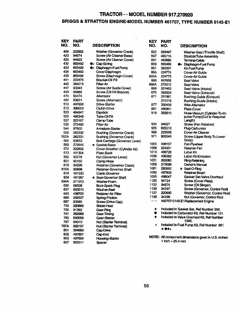
TRACTOR - - MODEL NUMBER 917.270920
BRIGGS & STRATTON ENGINE-MODEL NUMBER 461707, TYPE NUMBER 0145-E1
K]EY PART KEY PARTNO. NO. DESCRIPTION NO. NO. DESCR|PTION
404 223882 Washer (GovemorCrank) 822 693497 Washer-Seal ('rhrottleShaft)423 94674 Scraw (AirCleaner Base) 847 495715 DlpstiddTubeAssembly425 94823 Screw (Air ClaanerCover) 851 49_880 Te_432 693492 O+ Cap-Spring 859 693488 •+ Dia_Fuel Pump433 693489 qP_ Diaphragm-FuelPump 861 393397 Kit-FuelPump434 693493 Cover.Diaphragm 865 224774 Cover-AirGuide435 69_1494 Screw(DiaphragmCover) 865A 224775 Cover-Air Guide441 222875 Bracket-OilFill 868 497656 Seal-Valve445 394019 Filter-Air 868A 273312 Seal.Valve447 93343 Screw (AirGuide Cover} 869 261463 Seat-Valve (Intake)449 94882 Screw (Oil FillBracket) 870 262924 Seat-Valve (Exhaust)474 93474 Alternator 871 261961 Bushing-Guide(Exhaust)482 93621 Screw (Alternator) 231218 Bushing-Guide(intake)510 497606 Ddve-Starter 877 399456 Wire-Aitamator513 3.98003 Clutch-Drive 881 495901 Plate-Cover523 494947 Dipstick 918 393815 Hose-Vacuum(Cylinder-ToJm-525 495348 Tube-OitFdl pulsePump)(Cut to Required527 223167 Clamp-Tube Lang.)535 272480 Filter-Air 934 94627 Screw(Fan Retainer)544 97603 Armatare-Starter 955 693513 Plug-Carburetor552 262"332 Bushing(GovernorCrank) 968 225008 CovepAh'Cleaner
552A 262331 Bushing(GovernorCrank) 971 806540 Screw (UpperBodyTo Lower562 93853 Bolt-C=,rdage(GovernorLever) Body)569 272645 * Gasket-Base 1005 498157 Fan-Flywheel572 222892 Cover-Breather(Cytinder#2) 1006 224901 Retainer-Fan573 491304 Plate-Back 1019 496726 LabelKit
592 92278 Nut (GovernorLever) 1036 499382 LabelKit-Emission601 95162 Clamp-Hose 1051 _63080 Ring-Retelning615 94296 Retainer (GovernorCrank) 1058 273688 Owner'sManual
615A 93898 Retainer-GovernorSha/t 1081 280860 * Seal-O-Ring616 491530 Crank-Governor 1090 497605 Retainer-Brush634 491287 _ Seal-Governor Shaft 1095 496047 Gasket Bat-Valve Overhaul
634A 271013 Washer-Foam 1125 94724 Screw (Cover Plata)635 66538 Boot-SparkPlug 1132 94675 Screw (Oil Slinger)637 693510 Washer-Seal 1136 94297 Screw (Governor,Control Rod)643 496700 Retainer-AirFilter 1137 220680 Washer (Governor,ControlRod)689 262337 Spring-Friction 1138 94298 Nut(Govemor, CoetrolRod697 93585 Scraw (DdveCap) .... 460707-0145-E1ReplacumentF__ngine725 _ Shlaid-Heat726 91362 Gear-Ring .k Includedin Gasket Bat, Ref Number 358,741 262989 Gear-Traing • IncludedinCad_JratorKit,Ref Number121.783 693059 Gear-Staxter • IncludedinValueOverhaul lot, Ref Number797 94010 Nut (StarterTerndr_) 1095.
797A 693167 Nut (StarterTerminal) + Includedin Fuel Pump Kit,RefNumber 861"k••+
801 39486o Cap-Drive
802 497607 Cap-End NOTE: Allcomponentdimensionsgiven InU.S. inches803 497604 Housing-Starter 1 inch=25.4rnm807 693511 Spacer
56

57

58

SUGGESTED GUIDE FOR SIGHTING SLOPES FOR SAFE OPERATION
ONLY RIDE UP AND DOWN HILL,NOT ACROSS HILL
ol(D
IOperate your Tractor up and down the face of slopes (not I_qreaterthan 15°), never across the face. Make turns gradu- Iilly to prevent tipping or loss of control. Exercise extremecautlonwhen changing direction on slopes.

For in-home major brand repair service:Call 24 hoursa day, 7 days a week
1-800-4-MY-HOME s" (1-800-469-4663)Para pedir servicio de reparaci6n a domicilio
1-800-676-5811
In Canada for all your service and parts needs callAu Canada pour tout le service ou les pi_ces
1-800-665-4455
For the repair or replacement parts you need:Call 6 am - 11 pm CST, 7 days a week
PartsDirectsM1-800-366-PART (1-800-366-7278)
Para ordenar piezas con entrega a domicilio1-800-659-7084
For the location of a Sears Parts and Repair Centerin your area:
Call 24 hours a day, 7 days a week1-800-488-1222
For information on purchasing a Sears MaintenanceAgreement or to inquire about an existing Agreement:
Call 9 am - 5 pm, Monday - Saturday1-800-827-6655
8W/ SHome CentralsM
172196 11.08.99 RH Printed in U.S,A.
Related Documents