2022 OWNER’S MANUAL AND MAINTENANCE INFORMATION For your safety, read carefully and keep in this vehicle.

Welcome message from author
This document is posted to help you gain knowledge. Please leave a comment to let me know what you think about it! Share it to your friends and learn new things together.
Transcript

2022 OWNER’S MANUALAND MAINTENANCE INFORMATION
For your safety, read carefully and keep in this vehicle.
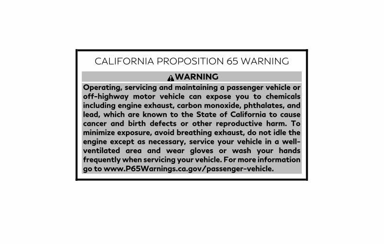
CALIFORNIA PROPOSITION 65 WARNING
WARNING
Operating, servicing and maintaining a passenger vehicle oroff-highway motor vehicle can expose you to chemicalsincluding engine exhaust, carbon monoxide, phthalates, andlead, which are known to the State of California to causecancer and birth defects or other reproductive harm. Tominimize exposure, avoid breathing exhaust, do not idle theengine except as necessary, service your vehicle in a well-ventilated area and wear gloves or wash your handsfrequentlywhen servicing your vehicle. Formore informationgo to www.P65Warnings.ca.gov/passenger-vehicle.
This manual was prepared to help you un-derstand the operation and maintenanceof your vehicle so that you may enjoy manymiles (kilometers) of driving pleasure.Please read through this manual beforeoperating your vehicle.A separate Warranty Information Book-let is included in your Owner’s literatureportfolio. The “Maintenance and sched-ules” section of this manual explains de-tails about maintaining and servicingyour vehicle. Always carry it with youwhen you take your vehicle to an INFINITIretailer. The Warranty Information Book-let contents provide complete informa-tion about all warranties covering thisvehicle, the requirements to keep thewarranties in effect as well as theINFINITI Roadside Assistance program.Additionally, a separate Customer Careand Lemon Law Information Booklet willexplain how to resolve any concerns youmay have with your vehicle, as well asclarify your rights under your state’slemon law.
In addition to factory-installed options,your vehicle may also be equipped withadditional accessories installed prior to de-livery. It is recommended that you visit anINFINITI retailer for details concerning theparticular accessories with which your ve-hicle is equipped. It is important that youfamiliarize yourself with all disclosures,warnings, cautions and instructions con-cerning proper use of such accessoriesprior to operating the vehicle and/or ac-cessory. It is recommended that you visitan INFINITI retailer for details concerningthe particular accessories with which yourvehicle is equipped.
Before driving your vehicle, please read thisOwner's Manual carefully. This will ensurefamiliarity with controls and maintenancerequirements, assisting you in the safe op-eration of your vehicle.
WARNING
IMPORTANT SAFETY INFORMATIONREMINDERS!Follow these important driving rules tohelp ensure a safe and comfortable tripfor you and your passengers!• NEVER drive under the influence of
alcohol or drugs.• ALWAYS observe posted speed limits
and never drive too fast for conditions.• ALWAYS give your full attention to
driving and avoid using vehicle fea-tures or taking other actions thatcould distract you.
• ALWAYS use your seat belts and ap-propriate child restraint systems.Pre-teen children should be seated inthe rear seat.
• ALWAYS provide information aboutthe proper use of vehicle safety fea-tures to all occupants of the vehicle.
• ALWAYS review this Owner’s Manualfor important safety information.
FOREWORD READ FIRST—THEN DRIVE SAFELY
For descriptions specified for all-wheeldrive models, an AWD mark is placed at thebeginning of the applicable sections/items.As with other vehicles with features foroff-road use, failure to operate all-wheeldrive models correctly may result in lossof control or an accident. For additionalinformation, see “Driving safety precau-tions” (P. 5-10).
ON-PAVEMENT AND OFF-ROAD DRIVINGThis vehicle will handle and maneuverdifferently from an ordinary passengercar because it has a higher center ofgravity for off-road use. As with othervehicles with features of this type, fail-ure to operate this vehicle correctly mayresult in loss of control or an accident.For additional information, see “On-pavement and off-road driving precau-tions” (P. 5-8), “Avoiding collision androll- over” (P. 5-9) and “Driving safetyprecautions” (P. 5-10).
MODIFICATION OF YOUR VEHICLEThis vehicle should not be modified.Modification could affect its perfor-mance, safety, emissions or durabilityand may even violate governmentalregulations. In addition, damage or per-formance problems resulting frommodifications may not be covered un-der INFINITI warranties.
WARNING
Installing an aftermarket On-Board Di-agnostic (OBD) plug-in device that usesthe port during normal driving, for ex-ample remote insurance companymonitoring, remote vehicle diagnos-tics, telematics or engine reprogram-ming, may cause interference or dam-age to vehicle systems. We do notrecommend or endorse the use of anyaftermarket OBD plug-in devices, un-less specifically approved by INFINITI.The vehicle warranty may not coverdamage caused by any aftermarketplug-in device.
This manual includes information for allfeatures and equipment available on thismodel. Features and equipment in your ve-hicle may vary depending on model, trimlevel, options selected, order, date of pro-duction, region or availability. Therefore,you may find information about features orequipment that are not included or in-stalled on your vehicle.All information, specifications and illustra-tions in this manual are those in effect atthe time of printing. INFINITI reserves theright to change specifications, perfor-mance, design or component supplierswithout notice and without obligation.From time to time, INFINITI may update orrevise this manual to provide Owners withthe most accurate information currentlyavailable. Please carefully read and retainwith this manual all revision updates sentto you by INFINITI to ensure you have ac-cess to accurate and up-to-date informa-tion regarding your vehicle. Current ver-sions of vehicle Owner's Manuals and anyupdates can also be found in the Ownersection of the INFINITI website at https://owners.infinitiusa.com/iowners/navigation/manualsAndGuides. If youhave questions concerning any informa-tion in your Owner's Manual, contactINFINITI Consumer Affairs. See the INFINITI
WHEN READING THE MANUAL
CUSTOMER CARE PROGRAM page in thisOwner’s Manual for contact information.
IMPORTANT INFORMATION ABOUTTHIS MANUALYou will see various symbols in this manual.They are used in the following ways:
WARNING
This is used to indicate the presence ofa hazard that could cause death or se-rious personal injury. To avoid or re-duce the risk, the procedures must befollowed precisely.
CAUTION
This is used to indicate the presence ofa hazard that could cause minor ormoderate personal injury or damage toyour vehicle. To avoid or reduce the risk,the procedures must be followedcarefully.
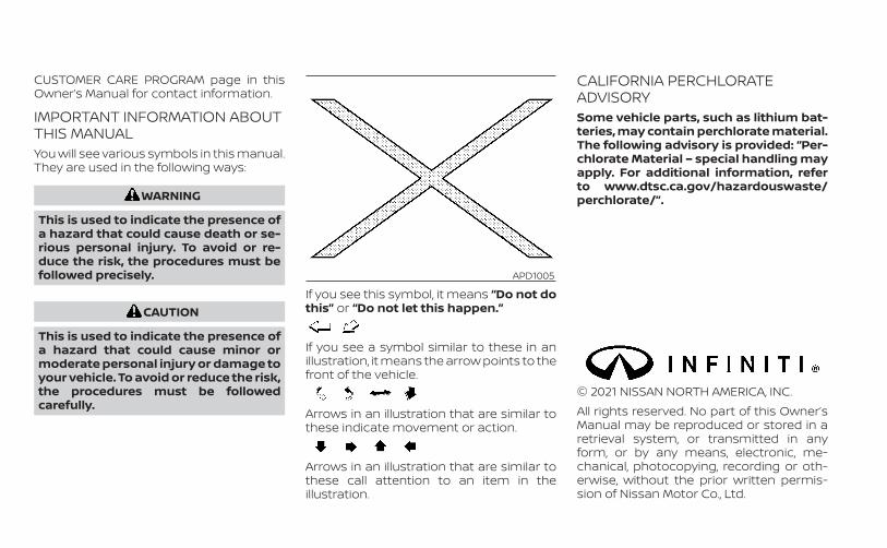
If you see this symbol, it means “Do not dothis” or “Do not let this happen.”
If you see a symbol similar to these in anillustration, it means the arrow points to thefront of the vehicle.
Arrows in an illustration that are similar tothese indicate movement or action.
Arrows in an illustration that are similar tothese call attention to an item in theillustration.
CALIFORNIA PERCHLORATEADVISORYSome vehicle parts, such as lithium bat-teries, may contain perchlorate material.The following advisory is provided: “Per-chlorate Material – special handling mayapply. For additional information, referto www.dtsc.ca.gov/hazardouswaste/perchlorate/”.
© 2021 NISSAN NORTH AMERICA, INC.All rights reserved. No part of this Owner’sManual may be reproduced or stored in aretrieval system, or transmitted in anyform, or by any means, electronic, me-chanical, photocopying, recording or oth-erwise, without the prior written permis-sion of Nissan Motor Co., Ltd.
APD1005

INFINITI CARES . . .Both INFINITI and your INFINITI retailer arededicated to serving all your automotiveneeds. Your satisfaction with your vehicleand your INFINITI retailer are our primaryconcerns. Your INFINITI retailer is alwaysavailable to assist you with all your auto-mobile sales and service needs.However, if there is something that yourINFINITI retailer cannot assist you with oryou would like to provide INFINITI directlywith comments or questions, please con-tact our (INFINITI’s) Consumer Affairs De-partment using our toll-free number:For U.S. customers
1-800-662-6200For Canadian customers
1-800-361-4792
The Consumer Affairs Department will askfor the following information:– Your name, address, and telephone
number– Vehicle identification number (on dash
panel)– Date of purchase– Current odometer reading– Your INFINITI retailer's name– Your comments or questionsOR
You can write to INFINITI with the informa-tion on the left at:For U.S. customers
INFINITI DivisionNissan North America, Inc.
Consumer Affairs DepartmentP.O. Box 685003Franklin, TN 37068-5003or via e-mail at:[email protected]
For Canadian customersINFINITI DivisionNissan Canada Inc.5290 Orbitor DriveMississauga, Ontario L4W 4Z5or via e-mail at:information.centre@nissancanada. com
If you prefer, visit us at:www.infinitiUSA.com (for U.S. customers)orwww.infiniti.ca (for Canadian customers)
We appreciate your interest in INFINITI and thank you for buying a quality INFINITI vehicle.
INFINITI CUSTOMER CARE PROGRAM

Table ofcontents
Illustrated table of contents
Safety-Seats, seat belts and supplemental restraint system
Instruments and controls
Pre-driving checks and adjustments
Monitor, climate, audio, phone and voice recognition systems
Starting and driving
In case of emergency
Appearance and care
Do-it-yourself
Maintenance and schedules
Technical and consumer information
Index
0
1
2
3
4
5
6
7
8
9
10
11


0 Illustrated table of contents
Air bags, seat belts and child restraints . . . . . . . . . . 0-2Exterior front . . . . . . . . . . . . . . . . . . . . . . . . . . . . . . . . . . . . 0-3Exterior rear . . . . . . . . . . . . . . . . . . . . . . . . . . . . . . . . . . . . . 0-4Passenger compartment . . . . . . . . . . . . . . . . . . . . . . . 0-5
Instrument panel . . . . . . . . . . . . . . . . . . . . . . . . . . . . . . . . 0-6Engine compartment check locations . . . . . . . . . . . 0-8Warning/indicator lights . . . . . . . . . . . . . . . . . . . . . . . . . 0-9

1. Rear seat manual fold flat lever (P. 1-5)2. Folding 2nd row bench (P. 1-5)3. Rear outboard seat belt with
pretensioner(s) (P. 1-11)4. Head restraints/headrests (P. 1-7)5. Front seat belt with pretensioner(s) and
shoulder height adjuster (P. 1-11, 1-43)6. Roof-mounted curtain side-impact and
rollover supplemental air bag (P. 1-43)7. Supplemental air bags (P. 1-43)8. Driver and front passenger supplemen-
tal knee air bags (P. 1-43)9. Front seats (P. 1-3)10. Occupant classification sensor
(weight sensor) (P. 1-43)11. Front seat-mounted side-impact
supplemental air bag (P. 1-43)12. LATCH (Lower Anchors and Tethers for
CHildren) (P. 1-25)13. 2nd row seat top tether strap anchor
(located on bottom of seatback) (P. 1-23)Refer to the page number indicated inparentheses for operating details.
LIC3786
AIR BAGS, SEAT BELTS AND CHILDRESTRAINTS
0-2 Illustrated table of contents

1. Engine hood (P. 3-23)2. Wiper and washer switch (P. 2-33)
Wiper blades (P. 8-18)3. Windshield (P. 8-18)4. Front camera (P. 5-33, 5-36, 5-41, 5-102,
5-55)5. Power windows (P. 2-63)6. Door locks (P. 3-4)
INFINITI Intelligent Key system (P. 3-6)Keys (P. 3-2)
7. Mirrors (P. 3-36)Side camera (if so equipped) (P. 4-11)
8. Tire pressure (P. 8-28)Flat tire (P. 6-3)Tire chains (P. 8-38)
9. Replacing bulbs (P. 8-26)Headlight switch (P. 2-37)Turn signal switch (P. 2-43)LED Daytime Running Lights (DRL)system (P. 2-42)
10. Fog light switch (P. 2-44)11. Sonar sensors (if so equipped) (P. 5-190)12. Front view camera (if so equipped)
(P. 4-11)See the page number indicated in paren-theses for operating details.
LII2674
EXTERIOR FRONT
Illustrated table of contents 0-3
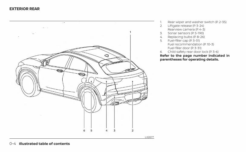
1. Rear wiper and washer switch (P. 2-35)2. Liftgate release (P. 3-24)
Rearview camera (P. 4-3)3. Sonar sensors (P. 5-190)4. Replacing bulbs (P. 8-26)5. Fuel-filler cap (P. 3-31)
Fuel recommendation (P. 10-3)Fuel-filler door (P. 3-31)
6. Child safety rear door lock (P. 3-6)Refer to the page number indicated inparentheses for operating details.
LII2677
EXTERIOR REAR
0-4 Illustrated table of contents
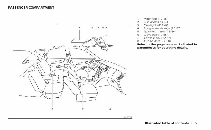
1. Moonroof (P. 2-65)2. Sun visors (P. 3-35)3. Map lights (P. 2-67)4. Sunglasses storage (P. 2-57)5. Rearview mirror (P. 3-36)6. Glove box (P. 2-56)7. Console box (P. 2-57)8. Cup holders (P. 2-58)Refer to the page number indicated inparentheses for operating details.
LII2678
PASSENGER COMPARTMENT
Illustrated table of contents 0-5

1. Vents (P. 4-32)2. Bluetooth® Hands-Free Phone System*
Steering wheel switch for audiocontrol*Center display multi-function controlbuttons*
3. High beam/turn signal switch (P. 2-43)Paddle shifters (P. 5-21)Trip reset switch (P. 2-5)
4. Driver supplemental air bag (P. 1-43)Horn (P. 1-43)
5. Meters and gauges (P. 2-4)Warning and indicator lights (P. 2-9)Vehicle information display (P. 2-19)
6. Wiper and washer switch (P. 2-33)Rear wiper and washer switch (P. 2-35)
7. Automatic heater and air conditioningcontrols (P. 4-33)Driver side climate controlled seatswitches (if so equipped) (P. 2-45)Driver side heated seat switches(if so equipped) (P. 2-46)
8. Upper and lower displays*Navigation system* (if so equipped)
9. Front passenger air bag status light(P. 1-53)
LII2682
INSTRUMENT PANEL
0-6 Illustrated table of contents
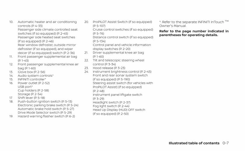
10. Automatic heater and air conditioningcontrols (P. 4-33)Passenger side climate controlled seatswitches (if so equipped) (P. 2-45)Passenger side heated seat switches(if so equipped) (P. 2-46)Rear window defroster, outside mirrordefroster (if so equipped), and wiperdeicer (if so equipped) switch (P. 2-36)
11. Front passenger supplemental air bag(P. 1-43)
12. Front passenger supplemental knee airbag (P. 1-60)
13. Glove box (P. 2-56)14. Audio system controls*15. INFINITI controller*16. Power outlet (P. 2-52)
USB port*Cup holders (P. 2-58)Storage (P. 2-54)
17. Shift lever (P. 5-18)18. Push-button ignition switch (P. 5-13)
Electronic parking brake switch (P. 5-24)Automatic brake hold switch (P. 5-27)Drive Mode Selector switch (P. 5-29)
19. Hazard warning flasher switch (P. 6-2)
20. ProPILOT Assist Switch (if so equipped)(P. 5-107)Cruise control switches (if so equipped)(P. 5-76)Distance control switch (if so equipped)(P. 5-134)Control panel and vehicle informationdisplay switches (P. 2-20)
21. Driver supplemental knee air bag(P. 1-60)
22. Tilt and telescopic steering wheelcontrol (P. 3-34)
23. Hood release (P. 3-23)24. Instrument brightness control (P. 2-43)
Front and rear sonar system switch(if so equipped) (P. 5-190)Steering assist switch (for vehicles withProPILOT Assist) (if so equipped)(P. 2-48)Instrument panel liftgate switch(P. 3-29)Headlight switch (P. 2-37)Fog light switch (P. 2-44)Head Up Display (HUD) OFF switch(if so equipped) (P. 2-50)
*: Refer to the separate INFINITI InTouch TM
Owner's Manual.Refer to the page number indicated inparentheses for operating details.
Illustrated table of contents 0-7
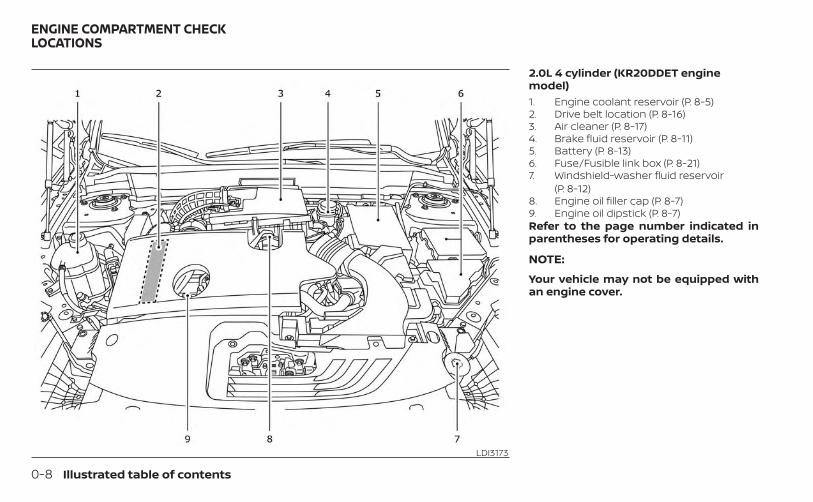
2.0L 4 cylinder (KR20DDET enginemodel)1. Engine coolant reservoir (P. 8-5)2. Drive belt location (P. 8-16)3. Air cleaner (P. 8-17)4. Brake fluid reservoir (P. 8-11)5. Battery (P. 8-13)6. Fuse/Fusible link box (P. 8-21)7. Windshield-washer fluid reservoir
(P. 8-12)8. Engine oil filler cap (P. 8-7)9. Engine oil dipstick (P. 8-7)Refer to the page number indicated inparentheses for operating details.
NOTE:
Your vehicle may not be equipped withan engine cover.
LDI3173
ENGINE COMPARTMENT CHECKLOCATIONS
0-8 Illustrated table of contents
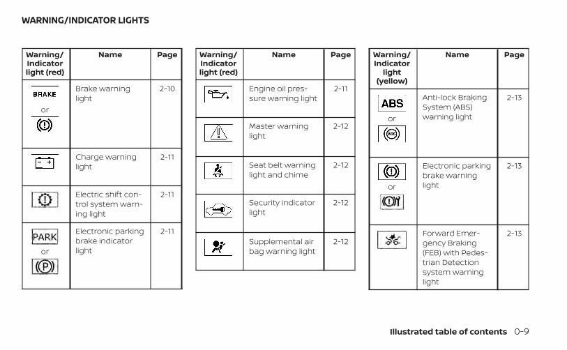
Warning/Indicatorlight (red)
Name Page
or
Brake warninglight
2-10
Charge warninglight
2-11
Electric shift con-trol system warn-ing light
2-11
or
Electronic parkingbrake indicatorlight
2-11
Warning/Indicatorlight (red)
Name Page
Engine oil pres-sure warning light
2-11
Master warninglight
2-12
Seat belt warninglight and chime
2-12
Security indicatorlight
2-12
Supplemental airbag warning light
2-12
Warning/Indicator
light(yellow)
Name Page
or
Anti-lock BrakingSystem (ABS)warning light
2-13
or
Electronic parkingbrake warninglight
2-13
Forward Emer-gency Braking(FEB) with Pedes-trian Detectionsystem warninglight
2-13
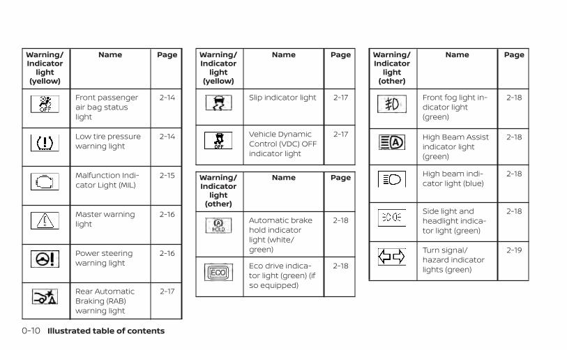
WARNING/INDICATOR LIGHTS
Illustrated table of contents 0-9
Warning/Indicator
light(yellow)
Name Page
Front passengerair bag statuslight
2-14
Low tire pressurewarning light
2-14
Malfunction Indi-cator Light (MIL)
2-15
Master warninglight
2-16
Power steeringwarning light
2-16
Rear AutomaticBraking (RAB)warning light
2-17
Warning/Indicator
light(yellow)
Name Page
Slip indicator light 2-17
Vehicle DynamicControl (VDC) OFFindicator light
2-17
Warning/Indicator
light(other)
Name Page
Automatic brakehold indicatorlight (white/green)
2-18
Eco drive indica-tor light (green) (ifso equipped)
2-18
Warning/Indicator
light(other)
Name Page
Front fog light in-dicator light(green)
2-18
High Beam Assistindicator light(green)
2-18
High beam indi-cator light (blue)
2-18
Side light andheadlight indica-tor light (green)
2-18
Turn signal/hazard indicatorlights (green)
2-19
0-10 Illustrated table of contents
1 Safety-Seats, seat belts andsupplemental restraint system
Seats . . . . . . . . . . . . . . . . . . . . . . . . . . . . . . . . . . . . . . . . . . . . 1-2Front power seat adjustment . . . . . . . . . . . . . . . . .1-3Rear bench seat adjustment . . . . . . . . . . . . . . . . . 1-5Armrests . . . . . . . . . . . . . . . . . . . . . . . . . . . . . . . . . . . . . 1-5Flexible seating . . . . . . . . . . . . . . . . . . . . . . . . . . . . . . . 1-6
Head restraints/headrests . . . . . . . . . . . . . . . . . . . . . . .1-7Adjustable head restraint/headrestcomponents . . . . . . . . . . . . . . . . . . . . . . . . . . . . . . . . . 1-8Non-adjustable head restraint/headrest components . . . . . . . . . . . . . . . . . . . . . . . 1-8Remove . . . . . . . . . . . . . . . . . . . . . . . . . . . . . . . . . . . . . . 1-9Install . . . . . . . . . . . . . . . . . . . . . . . . . . . . . . . . . . . . . . . . 1-9Adjust . . . . . . . . . . . . . . . . . . . . . . . . . . . . . . . . . . . . . . . .1-10
Seat belts . . . . . . . . . . . . . . . . . . . . . . . . . . . . . . . . . . . . . . . 1-11Precautions on seat belt usage. . . . . . . . . . . . . . . 1-11Seat belt warning light and chime . . . . . . . . . . . .1-14Injured persons . . . . . . . . . . . . . . . . . . . . . . . . . . . . . .1-14Pregnant women . . . . . . . . . . . . . . . . . . . . . . . . . . . .1-15Three-point type seat belt withretractor . . . . . . . . . . . . . . . . . . . . . . . . . . . . . . . . . . . . .1-15Seat belt extenders . . . . . . . . . . . . . . . . . . . . . . . . . .1-19Seat belt maintenance . . . . . . . . . . . . . . . . . . . . . . 1-20
Child safety . . . . . . . . . . . . . . . . . . . . . . . . . . . . . . . . . . . . 1-20Infants . . . . . . . . . . . . . . . . . . . . . . . . . . . . . . . . . . . . . . .1-21Small Children . . . . . . . . . . . . . . . . . . . . . . . . . . . . . . . .1-21Larger children . . . . . . . . . . . . . . . . . . . . . . . . . . . . . . .1-21
Child restraints . . . . . . . . . . . . . . . . . . . . . . . . . . . . . . . . . 1-23Precautions on child restraints . . . . . . . . . . . . . . 1-23LATCH (Lower Anchors and Tethers forCHildren) system . . . . . . . . . . . . . . . . . . . . . . . . . . . . 1-25Rear-facing child restraint installationusing LATCH . . . . . . . . . . . . . . . . . . . . . . . . . . . . . . . . 1-28Rear-facing child restraint installationusing the seat belts . . . . . . . . . . . . . . . . . . . . . . . . . 1-30Forward-facing child restraintinstallation using LATCH . . . . . . . . . . . . . . . . . . . . . 1-33Forward-facing child restraintinstallation using the seat belts . . . . . . . . . . . . . 1-35Booster seats . . . . . . . . . . . . . . . . . . . . . . . . . . . . . . . 1-39
Supplemental Restraint System (SRS) . . . . . . . . . . 1-43Precautions on SRS . . . . . . . . . . . . . . . . . . . . . . . . . 1-43Supplemental air bag warning labels . . . . . . . . 1-63Supplemental air bag warning light . . . . . . . . . 1-63
WARNING
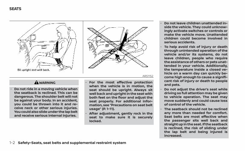
• Do not ride in a moving vehicle whenthe seatback is reclined. This can bedangerous. The shoulder belt will notbe against your body. In an accident,you could be thrown into it and re-ceive neck or other serious injuries.You could also slide under the lap beltand receive serious internal injuries.
• For the most effective protectionwhen the vehicle is in motion, theseat should be upright. Always sitwell back and upright in the seat withboth feet on the floor and adjust theseat properly. For additional infor-mation, see “Precautions on seat beltusage” (P. 1-11).
• After adjustment, gently rock in theseat to make sure it is securelylocked.
• Do not leave children unattended in-side the vehicle. They could unknow-ingly activate switches or controls ormake the vehicle move. Unattendedchildren could become involved inserious accidents.
• To help avoid risk of injury or deaththrough unintended operation of thevehicle and/or its systems, do notleave children, people who requirethe assistance of others or pets unat-tended in your vehicle. Additionally,the temperature inside a closed ve-hicle on a warm day can quickly be-come high enough to cause a signifi-cant risk of injury or death to peopleand pets.
• Do not adjust the driver’s seat whiledriving so full attention may be givento vehicle operation. The seat maymove suddenly and could cause lossof control of the vehicle.
• The seatback should not be reclinedany more than needed for comfort.Seat belts are most effective whenthe passenger sits well back andstraight up in the seat. If the seatbackis reclined, the risk of sliding underthe lap belt and being injured isincreased.
ARS1152
SEATS
1-2 Safety-Seats, seat belts and supplemental restraint system
CAUTION
When adjusting the seat positions, besure not to contact any moving parts toavoid possible injuries and/or damage.
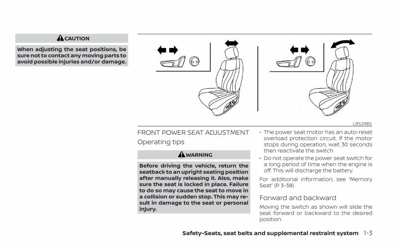
FRONT POWER SEAT ADJUSTMENTOperating tips
WARNING
Before driving the vehicle, return theseatback to an upright seating positionafter manually releasing it. Also, makesure the seat is locked in place. Failureto do so may cause the seat to move ina collision or sudden stop. This may re-sult in damage to the seat or personalinjury.
• The power seat motor has an auto-resetoverload protection circuit. If the motorstops during operation, wait 30 secondsthen reactivate the switch.
• Do not operate the power seat switch fora long period of time when the engine isoff. This will discharge the battery.
For additional information, see “MemorySeat” (P. 3-38).
Forward and backwardMoving the switch as shown will slide theseat forward or backward to the desiredposition.
LRS2985
Safety-Seats, seat belts and supplemental restraint system 1-3
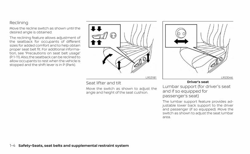
RecliningMove the recline switch as shown until thedesired angle is obtained.The reclining feature allows adjustment ofthe seatback for occupants of differentsizes for added comfort and to help obtainproper seat belt fit. For additional informa-tion, see “Precautions on seat belt usage”(P. 1-11). Also, the seatback can be reclined toallow occupants to rest when the vehicle isstopped and the shift lever is in P (Park).
Seat lifter and tiltMove the switch as shown to adjust theangle and height of the seat cushion.
Lumbar support (for driver's seatand if so equipped forpassenger’s seat)The lumbar support feature provides ad-justable lower back support to the driverand passenger (if so equipped). Move theswitch as shown to adjust the seat lumbararea.
LRS3181 LRS3046Driver’s seat
1-4 Safety-Seats, seat belts and supplemental restraint system

REAR BENCH SEAT ADJUSTMENTForward and backwardPull the center of the bar O1 up and hold itwhile you slide the seat forward or back-ward to the desired position. Release thebar to lock the seat in position.
RecliningTo recline the seatback, pull up on the leverO2 and lean back. To bring the seatbackforward, pull the lever O2 up and lean yourbody forward. Release the lever to lock theseatback in position.
The recline feature allows adjustment ofthe seatback for occupants of differentsizes for added comfort and to help obtainproper seat belt fit. For additional informa-tion, see “Precautions on seat belt usage”(P. 1-11). Also, the seatback can be reclined toallow occupants to rest when the vehicle isstopped and the shift lever is in P (Park).
WARNING
• After adjustment, gently rock in theseat to make sure it is securelylocked.
• Do not ride in a moving vehicle whenthe seatback is reclined. This can bedangerous. The shoulder belt will notbe against your body. In an accident,you could be thrown into it and re-ceive neck or other serious injuries.You could also slide under the lap beltand receive serious internal injuries.
• For the most effective protectionwhen the vehicle is in motion, theseat should be upright. Always sitwell back and upright in the seat andadjust the seat belt properly. For ad-ditional information, see “Precau-tions on seat belt usage” (P. 1-11).
ARMRESTSThe rear bench seat comes equipped withan armrest. Pull the armrest down asshown.
LRS2988 LRS3336
Safety-Seats, seat belts and supplemental restraint system 1-5

FLEXIBLE SEATINGWARNING
• Never allow anyone to ride in thecargo area or on the rear seats whenthey are in the fold-down position. Ina collision, people riding in these ar-eas without proper restraints aremore likely to be seriously injured orkilled.
• Do not allow people to ride in anyarea of your vehicle that is notequipped with seats and seat belts.Be sure everyone in your vehicle is ina seat and using a seat belt properly.
• Do not allow more than one personto use the same seat belt.
• Do not fold down the rear seats whenoccupants are in the rear seat area orany luggage is on the rear seats.– Make sure that the seat path is
clear before moving the seat.– Be careful not to allow hands or
feet to get caught or pinched inthe seat.
• Head restraints/headrests should beadjusted properly as they may pro-vide significant protection againstinjury in an accident. Always replaceand adjust them properly if they havebeen removed for any reason.
• If the head restraints/headrests areremoved for any reason, they shouldbe securely stored to prevent themfrom causing injury to passengers ordamage to the vehicle in case of sud-den braking or an accident.
• When returning the seatbacks to theupright position, be certain they arecompletely secured in the latchedposition. If they are not completelysecured, passengers may be injuredin an accident or sudden stop.
• Properly secure all cargo to help pre-vent it from sliding or shifting. Do notplace cargo higher than the seat-backs. In a sudden stop or collision,unsecured cargo could cause per-sonal injury.
Folding the rear bench seatTo fold the rear bench seat flat for maxi-mum cargo hauling:1. Make sure that the head restraints/
headrests are lowered. To remove thehead restraints/headrests, push andhold the lock knob while moving thehead restraints/headrests in an upwarddirection. Store the head restraints/headrests properly so they are not loosein the vehicle.
LRS3047Rear seat shown
1-6 Safety-Seats, seat belts and supplemental restraint system
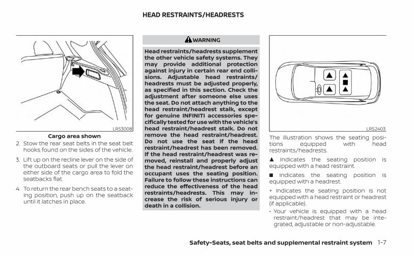
2. Stow the rear seat belts in the seat belthooks found on the sides of the vehicle.
3. Lift up on the recline lever on the side ofthe outboard seats or pull the lever oneither side of the cargo area to fold theseatbacks flat.
4. To return the rear bench seats to a seat-ing position, push up on the seatbackuntil it latches in place.
WARNING
Head restraints/headrests supplementthe other vehicle safety systems. Theymay provide additional protectionagainst injury in certain rear end colli-sions. Adjustable head restraints/headrests must be adjusted properly,as specified in this section. Check theadjustment after someone else usesthe seat. Do not attach anything to thehead restraint/headrest stalk, exceptfor genuine INFINITI accessories spe-cifically tested for use with the vehicle’shead restraint/headrest stalk. Do notremove the head restraint/headrest.Do not use the seat if the headrestraint/headrest has been removed.If the head restraint/headrest was re-moved, reinstall and properly adjustthe head restraint/headrest before anoccupant uses the seating position.Failure to follow these instructions canreduce the effectiveness of the headrestraints/headrests. This may in-crease the risk of serious injury ordeath in a collision.
The illustration shows the seating posi-tions equipped with headrestraints/headrests.� Indicates the seating position isequipped with a head restraint.� Indicates the seating position isequipped with a headrest.+ Indicates the seating position is notequipped with a head restraint or headrest(if applicable).• Your vehicle is equipped with a head
restraint/headrest that may be inte-grated, adjustable or non-adjustable.
LRS3008Cargo area shown
LRS2403
HEAD RESTRAINTS/HEADRESTS
Safety-Seats, seat belts and supplemental restraint system 1-7
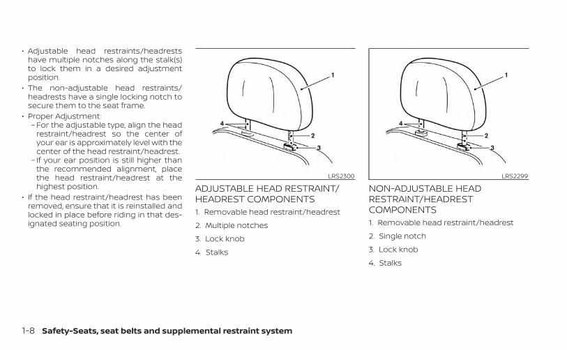
• Adjustable head restraints/headrestshave multiple notches along the stalk(s)to lock them in a desired adjustmentposition.
• The non-adjustable head restraints/headrests have a single locking notch tosecure them to the seat frame.
• Proper Adjustment:– For the adjustable type, align the head
restraint/headrest so the center ofyour ear is approximately level with thecenter of the head restraint/headrest.
– If your ear position is still higher thanthe recommended alignment, placethe head restraint/headrest at thehighest position.
• If the head restraint/headrest has beenremoved, ensure that it is reinstalled andlocked in place before riding in that des-ignated seating position.
ADJUSTABLE HEAD RESTRAINT/HEADREST COMPONENTS1. Removable head restraint/headrest
2. Multiple notches
3. Lock knob
4. Stalks
NON-ADJUSTABLE HEADRESTRAINT/HEADRESTCOMPONENTS1. Removable head restraint/headrest
2. Single notch
3. Lock knob
4. Stalks
LRS2300 LRS2299
1-8 Safety-Seats, seat belts and supplemental restraint system

REMOVEUse the following procedure to remove thehead restraint/headrest:1. Pull the head restraint/headrest up to
the highest position.
2. Push and hold the lock knob.
3. Remove the head restraint/headrestfrom the seat.
4. Store the head restraint/headrest prop-erly in a secure place so it is not loose inthe vehicle.
5. Reinstall and properly adjust the headrestraint/headrest before an occupantuses the seating position.
INSTALL1. Align the head restraint/headrest stalks
with the holes in the seat. Make sure thatthe head restraint/headrest is facing thecorrect direction. The stalk with thenotch (notches) O1 must be installed inthe hole with the lock knob O2 .
2. Push and hold the lock knob and pushthe head restraint/headrest down.
3. Properly adjust the head restraint/headrest before an occupant uses theseating position.
LRS2302 LRS2303
Safety-Seats, seat belts and supplemental restraint system 1-9
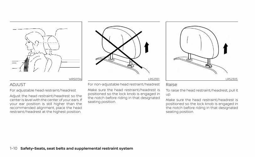
ADJUSTFor adjustable head restraint/headrestAdjust the head restraint/headrest so thecenter is level with the center of your ears. Ifyour ear position is still higher than therecommended alignment, place the headrestraint/headrest at the highest position.
For non-adjustable head restraint/headrestMake sure the head restraint/headrest ispositioned so the lock knob is engaged inthe notch before riding in that designatedseating position.
RaiseTo raise the head restraint/headrest, pull itup.Make sure the head restraint/headrest ispositioned so the lock knob is engaged inthe notch before riding in that designatedseating position.
WRS0134 LRS2351 LRS2305
1-10 Safety-Seats, seat belts and supplemental restraint system
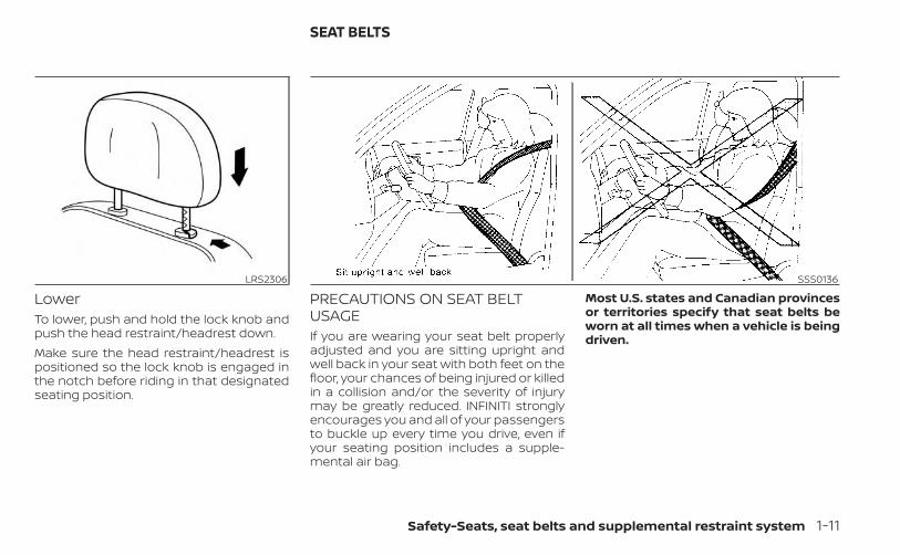
LowerTo lower, push and hold the lock knob andpush the head restraint/headrest down.Make sure the head restraint/headrest ispositioned so the lock knob is engaged inthe notch before riding in that designatedseating position.
PRECAUTIONS ON SEAT BELTUSAGEIf you are wearing your seat belt properlyadjusted and you are sitting upright andwell back in your seat with both feet on thefloor, your chances of being injured or killedin a collision and/or the severity of injurymay be greatly reduced. INFINITI stronglyencourages you and all of your passengersto buckle up every time you drive, even ifyour seating position includes a supple-mental air bag.
Most U.S. states and Canadian provincesor territories specify that seat belts beworn at all times when a vehicle is beingdriven.
LRS2306 SSS0136
SEAT BELTS
Safety-Seats, seat belts and supplemental restraint system 1-11

WARNING
• Every person who drives or rides inthis vehicle should use a seat belt atall times. Children should be in therear seats and in an appropriaterestraint.
WARNING
• The seat belt should be properly ad-justed to a snug fit. Failure to do somay reduce the effectiveness of theentire restraint system and increasethe chance or severity of injury in anaccident. Serious injury or death canoccur if the seat belt is not wornproperly.
SSS0134 SSS0016
1-12 Safety-Seats, seat belts and supplemental restraint system

WARNING
• Always route the shoulder belt overyour shoulder and across your chest.Never put the belt behind your back,under your arm or across your neck.The belt should be away from yourface and neck, but not falling off yourshoulder.
• Position the lap belt as low and snugas possible AROUND THE HIPS, NOTTHE WAIST. A lap belt worn too highcould increase the risk of internal in-juries in an accident.
• Be sure the seat belt tongue is se-curely fastened to the proper buckle.
• Do not wear the seat belt inside outor twisted. Doing so may reduce itseffectiveness.
• Do not allow more than one personto use the same seat belt.
• Never carry more people in the ve-hicle than there are seat belts.
• If the seat belt warning light glowscontinuously while the ignition isturned on with all doors closed andall seat belts fastened, it may indi-cate a malfunction in the system.Have the system checked. It is rec-ommended that you visit an INFINITIretailer for this service.
• No changes should be made to theseat belt system. For example, do notmodify the seat belt, add material, orinstall devices that may change theseat belt routing or tension. Doing somay affect the operation of the seatbelt system. Modifying or tamperingwith the seat belt system may resultin serious personal injury.
• Once a seat belt pretensioner(s) haveactivated, they cannot be reused andmust be replaced together with theretractor. It is recommended that youvisit an INFINITI retailer for thisservice.
• All seat belt assemblies, including re-tractors and attaching hardware,should be inspected after any colli-sion. It is recommended that you visitan INFINITI retailer for this service.INFINITI recommends that all seatbelt assemblies in use during a colli-sion be replaced unless the collisionwas minor and the belts show nodamage and continue to operateproperly. Seat belt assemblies not inuse during a collision should also beinspected and replaced if eitherdamage or improper operation isnoted.
• All child restraints and attachinghardware should be inspected afterany collision. Always follow the re-straint manufacturer's inspection in-structions and replacement recom-mendations. The child restraintsshould be replaced if they aredamaged.
SSS0014
Safety-Seats, seat belts and supplemental restraint system 1-13

SEAT BELT WARNING LIGHT ANDCHIMEThe driver and front passenger seat isequipped with an enhanced seat belt re-minder function. If your vehicle is equippedwith an enhanced seat belt reminder func-tion, a visual and audible alert will operate ifa driver or front passenger seat belt is un-buckled at speeds of approximately 9 mph(15 km/h) or more under the following con-ditions:• If the driver seat belt is not fastened.
• The front passenger’s seat belt is not fas-tened and the seat is occupied by a pas-senger for 7 seconds after the ignitionswitch is placed in the ON position.
• The front passenger’s seat belt is not fas-tened and objects or external force onthe passenger seat change the seat beltreminder classification to Occupied.
The seat belt warning light will flash underthe conditions shown above until the nec-essary seat belt is securely fastened.A warning chime will sound for approxi-mately 90 seconds or until one of the fol-lowing conditions is met:• The unbuckled front occupant’s seat belt
is securely fastened.• The seat belt reminder function in the
front passenger seat no longer detectsthat the front passenger seat is occupied.
• The ignition is turned off or the vehicle isplaced in P (Park).
The below situations could result in theseat belt reminder light being illuminatedand the chime sounding, even with no oc-cupant present in the passenger seat:• Heavy objects placed on the seat.• Someone pushing or pulling on the front
passenger seat.
• An object placed under the front passen-ger seat.
• An object placed between the seat cush-ion and center console or between theseat cushion and the door.
• An object hanging on the seat or placedin the seatback pocket.
• A child restraint or other object pressingagainst the rear of the seatback.
NOTE:
The rear seats are equipped with a seatbelt warning message in the vehicle in-formation display.For additional information, see “Vehicle In-formation Display” (P. 2-19).
INJURED PERSONSINFINITI recommends that injured personsuse seat belts. Check with your doctor forspecific recommendations.
LRS0786
1-14 Safety-Seats, seat belts and supplemental restraint system

PREGNANT WOMENINFINITI recommends that pregnantwomen use seat belts. The seat belt shouldbe worn snug and always position the lapbelt as low as possible around the hips, notthe waist. Place the shoulder belt over yourshoulder and across your chest. Never runthe lap/shoulder belt over your abdominalarea. Contact your doctor for specificrecommendations.
THREE-POINT TYPE SEAT BELTWITH RETRACTOR
WARNING
• Every person who drives or rides inthis vehicle should use a seat belt atall times. Children should be in therear seats and in an appropriaterestraint.
• Do not ride in a moving vehicle whenthe seatback is reclined. This can bedangerous. The shoulder belt will notbe against your body. In an accident,you could be thrown into it and re-ceive neck or other serious injuries.You could also slide under the lap beltand receive serious internal injuries.
• For the most effective protectionwhen the vehicle is in motion, theseat should be upright. Always sitwell back and upright in the seat withboth feet on the floor and adjust theseat belt properly.
• Do not allow children to play with theseat belts. Most seating positions areequipped with Automatic LockingRetractor (ALR) mode seat belts. Ifthe seat belt becomes wrappedaround a child’s neck with the ALRmode activated, the child can be se-riously injured or killed if the seat beltretracts and becomes tight. This canoccur even if the vehicle is parked.Unbuckle the seat belt to release thechild. If the seat belt cannot be un-buckled or is already unbuckled, re-lease the child by cutting the seatbelt with a suitable tool (such as aknife or scissors) to release the seatbelt.
Safety-Seats, seat belts and supplemental restraint system 1-15
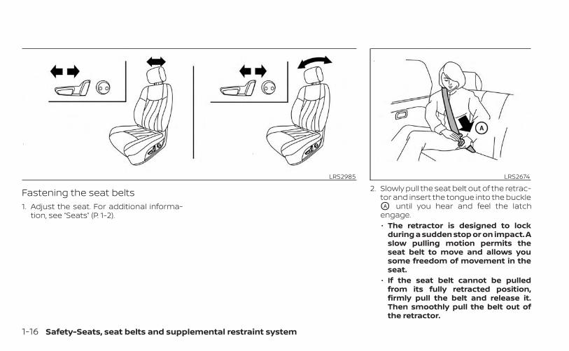
Fastening the seat belts1. Adjust the seat. For additional informa-
tion, see “Seats” (P. 1-2).
2. Slowly pull the seat belt out of the retrac-tor and insert the tongue into the buckleOA until you hear and feel the latchengage.• The retractor is designed to lock
during a sudden stop or on impact. Aslow pulling motion permits theseat belt to move and allows yousome freedom of movement in theseat.
• If the seat belt cannot be pulledfrom its fully retracted position,firmly pull the belt and release it.Then smoothly pull the belt out ofthe retractor.
LRS2985 LRS2674
1-16 Safety-Seats, seat belts and supplemental restraint system
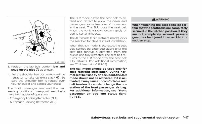
3. Position the lap belt portion low andsnug on the hips OB as shown.
4. Pull the shoulder belt portion toward theretractor to take up extra slack OC . Besure the shoulder belt is routed overyour shoulder and across your chest.
The front passenger seat and the rearseating positions three-point seat beltshave two modes of operation:• Emergency Locking Retractor (ELR)• Automatic Locking Retractor (ALR)
The ELR mode allows the seat belt to ex-tend and retract to allow the driver andpassengers some freedom of movementin the seat. The ELR locks the seat beltwhen the vehicle slows down rapidly orduring certain impacts.The ALR mode (child restraint mode) locksthe seat belt for child restraint installation.When the ALR mode is activated, the seatbelt cannot be extended again until theseat belt tongue is detached from thebuckle and fully retracted. The seat belt re-turns to the ELR mode after the seat beltfully retracts. For additional information,see “Child restraints” (P. 1-23).The ALR mode should be used only forchild restraint installation. During nor-mal seat belt use by an occupant, the ALRmode should not be activated. If it is ac-tivated, it may cause uncomfortable seatbelt tension. It can also change the op-eration of the front passenger air bag.For additional information, see “Frontpassenger air bag and status light”(P. 1-53).
WARNING
When fastening the seat belts, be cer-tain that the seatbacks are completelysecured in the latched position. If theyare not completely secured, passen-gers may be injured in an accident orsudden stop.
LRS2675
Safety-Seats, seat belts and supplemental restraint system 1-17
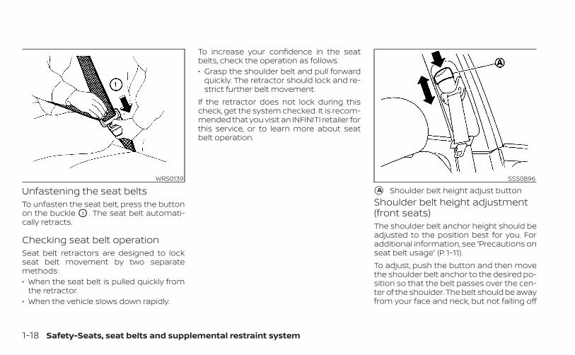
Unfastening the seat beltsTo unfasten the seat belt, press the buttonon the buckle O1 . The seat belt automati-cally retracts.
Checking seat belt operationSeat belt retractors are designed to lockseat belt movement by two separatemethods:• When the seat belt is pulled quickly from
the retractor.• When the vehicle slows down rapidly.
To increase your confidence in the seatbelts, check the operation as follows.• Grasp the shoulder belt and pull forward
quickly. The retractor should lock and re-strict further belt movement.
If the retractor does not lock during thischeck, get the system checked. It is recom-mended that you visit an INFINITI retailer forthis service, or to learn more about seatbelt operation.
Shoulder belt height adjustment(front seats)The shoulder belt anchor height should beadjusted to the position best for you. Foradditional information, see “Precautions onseat belt usage” (P. 1-11).To adjust, push the button and then movethe shoulder belt anchor to the desired po-sition so that the belt passes over the cen-ter of the shoulder. The belt should be awayfrom your face and neck, but not falling off
WRS0139 SSS0896
�A Shoulder belt height adjust button
1-18 Safety-Seats, seat belts and supplemental restraint system
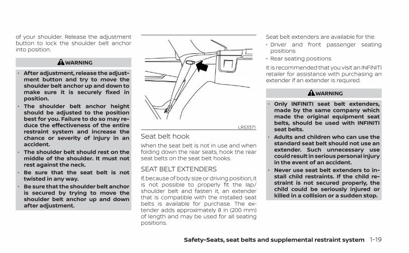
of your shoulder. Release the adjustmentbutton to lock the shoulder belt anchorinto position.
WARNING
• After adjustment, release the adjust-ment button and try to move theshoulder belt anchor up and down tomake sure it is securely fixed inposition.
• The shoulder belt anchor heightshould be adjusted to the positionbest for you. Failure to do so may re-duce the effectiveness of the entirerestraint system and increase thechance or severity of injury in anaccident.
• The shoulder belt should rest on themiddle of the shoulder. It must notrest against the neck.
• Be sure that the seat belt is nottwisted in any way.
• Be sure that the shoulder belt anchoris secured by trying to move theshoulder belt anchor up and downafter adjustment.
Seat belt hookWhen the seat belt is not in use and whenfolding down the rear seats, hook the rearseat belts on the seat belt hooks.
SEAT BELT EXTENDERSIf, because of body size or driving position, itis not possible to properly fit the lap/shoulder belt and fasten it, an extenderthat is compatible with the installed seatbelts is available for purchase. The ex-tender adds approximately 8 in (200 mm)of length and may be used for all seatingpositions.
Seat belt extenders are available for the:• Driver and front passenger seating
positions• Rear seating positionsIt is recommended that you visit an INFINITIretailer for assistance with purchasing anextender if an extender is required.
WARNING
• Only INFINITI seat belt extenders,made by the same company whichmade the original equipment seatbelts, should be used with INFINITIseat belts.
• Adults and children who can use thestandard seat belt should not use anextender. Such unnecessary usecould result in serious personal injuryin the event of an accident.
• Never use seat belt extenders to in-stall child restraints. If the child re-straint is not secured properly, thechild could be seriously injured orkilled in a collision or a sudden stop.
LRS3371
Safety-Seats, seat belts and supplemental restraint system 1-19

SEAT BELT MAINTENANCE• To clean the seat belt webbing, apply a
mild soap solution or any solution rec-ommended for cleaning upholstery orcarpet. Then wipe with a cloth and allowthe seat belts to dry in the shade. Do notallow the seat belts to retract until theyare completely dry.
• If dirt builds up in the shoulder beltguide of the seat belt anchors, the seatbelts may retract slowly. Wipe the shoul-der belt guide with a clean, dry cloth.
• Periodically check to see that the seatbelt and the metal components, suchas buckles, tongues, retractors, flexiblewires and anchors, work properly. If looseparts, deterioration, cuts or other dam-age on the webbing is found, the entireseat belt assembly should be replaced.
WARNING
Do not allow children to play with theseat belts. Most seating positions areequipped with Automatic Locking Re-tractor (ALR) mode seat belts. If the seatbelt becomes wrapped around a child’sneck with the ALR mode activated, thechild can be seriously injured or killed ifthe seat belt retracts and becomestight. This can occur even if the vehicleis parked. Unbuckle the seat belt to re-lease the child. If the seat belt cannotbe unbuckled or is already unbuckled,release the child by cutting the seatbelt with a suitable tool (such as a knifeor scissors) to release the seat belt.
Children need adults to help protectthem. They need to be properlyrestrained.In addition to the general information inthis manual, child safety information isavailable from many other sources, includ-ing doctors, teachers, government trafficsafety offices, and community organiza-tions. Every child is different, so be sure tolearn the best way to transport your child.
There are three basic types of child re-straint systems:• Rear-facing child restraint• Forward-facing child restraint• Booster seatThe proper restraint depends on the child'ssize. Generally, infants up to about 1 yearand less than 20 lbs. (9 kg) should be placedin rear-facing child restraints. Forward-facing child restraints are available for chil-dren who outgrow rear-facing child re-straints and are at least 1 year old. Boosterseats are used to help position a vehiclelap/shoulder belt on a child who can nolonger use a forward-facing child restraint.
WARNING
Infants and children need special pro-tection. The vehicle's seat belts maynot fit them properly. The shoulder beltmay come too close to the face or neck.The lap belt may not fit over their smallhip bones. In an accident, an improp-erly fitting seat belt could cause seriousor fatal injury. Always use appropriatechild restraints.
CHILD SAFETY
1-20 Safety-Seats, seat belts and supplemental restraint system
All U.S. states and Canadian provinces orterritories require the use of approved childrestraints for infants and small children. Foradditional information, see “Child re-straints” (P. 1-23).A child restraint may be secured in the ve-hicle by using either the LATCH (Lower An-chor and Tethers for CHildren) system orwith the vehicle seat belt. For additionalinformation, see “Child restraints” (P. 1-23).INFINITI recommends that all pre-teensand children be restrained in the rearseat. Studies show that children aresafer when properly restrained in therear seat than in the front seat.This is especially important becauseyour vehicle has a supplemental re-straint system (air bag system) for thefront passenger. For additional informa-tion, see “Supplemental Restraint Sys-tem (SRS)” (P. 1-43).
INFANTSInfants up to at least 1 year old should beplaced in a rear facing child restraint.INFINITI recommends that infants andsmall children be placed in child restraints.You should choose a child restraint that fitsyour vehicle and always follow the manu-facturer's instructions for installation anduse.
SMALL CHILDRENChildren that are over 1 year old and weighat least 9 kg (20 lbs.) should remain in arear-facing child restraint as long as pos-sible up to the height or weight limit of thechild restraint. Children who outgrow theheight or weight limit of the rear-facingchild restraint and are at least 1 year oldshould be secured in a forward-facing childrestraint with a harness. Refer to the manu-facturer’s instructions for minimum andmaximum weight and height recommen-dations. INFINITI recommends that smallchildren be placed in child restraints thatcomply with Federal Motor Vehicle SafetyStandards or Canadian Motor VehicleSafety Standards. You should choose achild restraint that fits your vehicle and al-ways follow the manufacturer’s instruc-tions for installation and use.
LARGER CHILDRENChildren should remain in a forward-facingchild restraint with a harness until theyreach the maximum height or weight limitallowed by the child restraintmanufacturer.Once a child outgrows the height or weightlimit of the harness-equipped forward-facing child restraint, INFINITI recommendsthat the child be placed in a commerciallyavailable booster seat to obtain properseat belt fit. For a seat belt to fit properly, thebooster seat should raise the child so thatthe shoulder belt is properly positionedacross the chest and the top, middle por-tion of the shoulder. The shoulder beltshould not cross the neck or face andshould not fall off the shoulder. The lap beltshould lie snugly across the lower hips orupper thighs, not the abdomen. A boosterseat can only be used in seating positionsthat have a three-point type seat belt. Thebooster seat should fit the vehicle seat andhave a label certifying that it complies withFederal Motor Vehicle Safety Standards orCanadian Motor Vehicle Safety Standards.
Safety-Seats, seat belts and supplemental restraint system 1-21
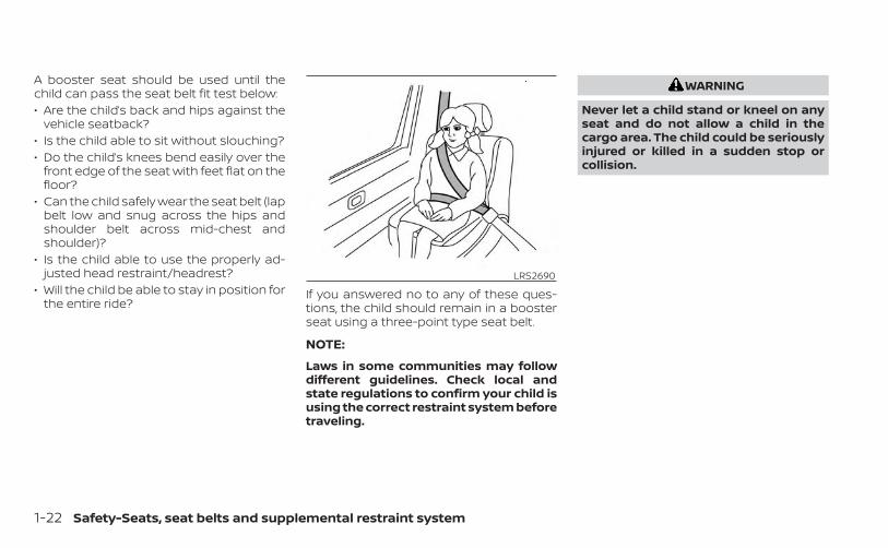
A booster seat should be used until thechild can pass the seat belt fit test below:• Are the child’s back and hips against the
vehicle seatback?• Is the child able to sit without slouching?• Do the child’s knees bend easily over the
front edge of the seat with feet flat on thefloor?
• Can the child safely wear the seat belt (lapbelt low and snug across the hips andshoulder belt across mid-chest andshoulder)?
• Is the child able to use the properly ad-justed head restraint/headrest?
• Will the child be able to stay in position forthe entire ride?
If you answered no to any of these ques-tions, the child should remain in a boosterseat using a three-point type seat belt.
NOTE:
Laws in some communities may followdifferent guidelines. Check local andstate regulations to confirm your child isusing the correct restraint system beforetraveling.
WARNING
Never let a child stand or kneel on anyseat and do not allow a child in thecargo area. The child could be seriouslyinjured or killed in a sudden stop orcollision.
LRS2690
1-22 Safety-Seats, seat belts and supplemental restraint system
PRECAUTIONS ON CHILDRESTRAINTS
WARNING
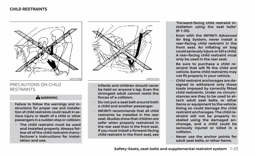
• Failure to follow the warnings and in-structions for proper use and installa-tion of child restraints could result in se-rious injury or death of a child or otherpassengers in a sudden stop or collision:– The child restraint must be used
and installed properly. Always fol-low all of the child restraint manu-facturer's instructions for instal-lation and use.
– Infants and children should neverbe held on anyone's lap. Even thestrongest adult cannot resist theforces of a collision.
– Do not put a seat belt around botha child and another passenger.
– INFINITI recommends that all childrestraints be installed in the rearseat. Studies show that children aresafer when properly restrained inthe rear seat than in the front seat.If you must install a forward-facingchild restraint in the front seat, see
“Forward-facing child restraint in-stallation using the seat belts”(P. 1-35).
– Even with the INFINITI AdvancedAir Bag System, never install arear-facing child restraint in thefront seat. An inflating air bagcould seriously injure or kill a child.A rear-facing child restraint mustonly be used in the rear seat.
– Be sure to purchase a child re-straint that will fit the child andvehicle. Some child restraints maynot fit properly in your vehicle.
– Child restraint anchorages are de-signed to withstand only thoseloads imposed by correctly fittedchild restraints. Under no circum-stances are they to be used to at-tach adult seat belts, or otheritems or equipment to the vehicle.Doing so could damage the childrestraint anchorages. The child re-straint will not be properly in-stalled using the damaged an-chorage, and a child could beseriously injured or killed in acollision.
– Never use the anchor points foradult seat belts, or other items.
ARS1098 WRS0256
CHILD RESTRAINTS
Safety-Seats, seat belts and supplemental restraint system 1-23
– A child restraint with a top tetherstrap should not be used in thefront passenger seat.
– Keep seatbacks as upright as pos-sible after fitting the childrestraint.
– Infants and children should al-ways be placed in an appropriatechild restraint while in the vehicle.
• When the child restraint is not in use,keep it secured with the LATCH sys-tem or a seat belt. In a sudden stop orcollision, loose objects can injure oc-cupants or damage the vehicle.
CAUTION
A child restraint in a closed vehicle canbecome very hot. Check the seatingsurface and buckles before placing achild in the child restraint.
This vehicle is equipped with a universalchild restraint anchor system, referred toas the LATCH (Lower Anchors and Tethersfor CHildren) system. Some child restraintsinclude rigid or webbing-mounted attach-ments that can be connected to these an-chors. For additional information, see“LATCH (Lower Anchors and Tethers forCHildren) system” (P. 1-25).If you do not have a LATCH compatiblechild restraint, the vehicle seat belts can beused.Several manufacturers offer child re-straints for infants and children of varioussizes. When selecting any child restraint,keep the following points in mind:• Choose only a restraint with a label certi-
fying that it complies with Federal MotorVehicle Safety Standard 213 or CanadianMotor Vehicle Safety Standard 213.
• Check the child restraint in your vehicle tobe sure it is compatible with the vehicle'sseat and seat belt system.
• If the child restraint is compatible withyour vehicle, place your child in the childrestraint and check the various adjust-ments to be sure the child restraint iscompatible with your child. Choose achild restraint that is designed for yourchild's height and weight. Always followall recommended procedures.
• If the combined weight of the child andchild restraint is less than 65 lbs. (29.5 kg),you may use either the LATCH anchors orthe seat belt to install the child restraint(not both at the same time).
• If the combined weight of the child andchild restraint is greater than 65 lbs. (29.5kg), use the vehicle's seat belt (not thelower anchors) to install the childrestraint.
• Be sure to follow the child restraintmanufacturer's instructions forinstallation.
All U.S. states and Canadian provinces orterritories require that infants and smallchildren be restrained in an approvedchild restraint at all times while the ve-hicle is being operated. Canadian law re-quires the top tether strap on forward-facing child restraints be secured to thedesignated anchor point on the vehicle.
1-24 Safety-Seats, seat belts and supplemental restraint system
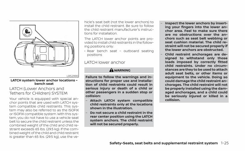
LATCH (Lower Anchors andTethers for CHildren) SYSTEMYour vehicle is equipped with special an-chor points that are used with LATCH sys-tem compatible child restraints. This sys-tem may also be referred to as the ISOFIXor ISOFIX compatible system. With this sys-tem, you do not have to use a vehicle seatbelt to secure the child restraint unless thecombined weight of the child and child re-straint exceeds 65 lbs. (29.5 kg). If the com-bined weight of the child and child restraintis greater than 65 lbs. (29.5 kg), use the ve-
hicle's seat belt (not the lower anchors) toinstall the child restraint. Be sure to followthe child restraint manufacturer's instruc-tions for installation.The LATCH lower anchor points are pro-vided to install child restraints in the follow-ing positions only:• Rear bench seat – outboard seating
positions
LATCH lower anchor
WARNING
Failure to follow the warnings and in-structions for proper use and installa-tion of child restraints could result inserious injury or death of a child orother passengers in a sudden stop orcollision:– Attach LATCH system compatible
child restraints only at the locationsshown in the illustration.
– Do not secure a child restraint in therear center position using the LATCHsystem anchors. The child restraintwill not be secured properly.
– Inspect the lower anchors by insert-ing your fingers into the lower an-chor area. Feel to make sure thereare no obstructions over the an-chors such as seat belt webbing orseat cushion material. The child re-straint will not be secured properly ifthe lower anchors are obstructed.
– Child restraint anchorages are de-signed to withstand only thoseloads imposed by correctly fittedchild restraints. Under no circum-stances are they to be used to attachadult seat belts, or other items orequipment to the vehicle. Doing socould damage the child restraint an-chorages. The child restraint will notbe properly installed using the dam-aged anchorages, and a child couldbe seriously injured or killed in acollision.
LRS2990LATCH system lower anchor locations -
bench seat
Safety-Seats, seat belts and supplemental restraint system 1-25
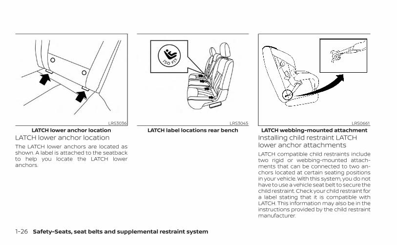
LATCH lower anchor locationThe LATCH lower anchors are located asshown. A label is attached to the seatbackto help you locate the LATCH loweranchors.
Installing child restraint LATCHlower anchor attachmentsLATCH compatible child restraints includetwo rigid or webbing-mounted attach-ments that can be connected to two an-chors located at certain seating positionsin your vehicle. With this system, you do nothave to use a vehicle seat belt to secure thechild restraint. Check your child restraint fora label stating that it is compatible withLATCH. This information may also be in theinstructions provided by the child restraintmanufacturer.
LRS3036LATCH lower anchor location
LRS3045LATCH label locations rear bench
LRS0661LATCH webbing-mounted attachment
1-26 Safety-Seats, seat belts and supplemental restraint system

When installing a child restraint, carefullyread and follow the instructions in thismanual and those supplied with the childrestraint.
Top tether strap child restraintWARNING
• Do not allow cargo to contact the toptether strap when it is attached tothe top tether anchor. Properly se-cure the cargo so it does not contactthe top tether strap. Cargo that is notproperly secured or cargo that con-tacts the top tether strap may dam-age it during a collision. Your childcould be seriously injured or killed ina collision if the top tether strap isdamaged.
• The child restraint top tether strapmay be damaged by contact with thetonneau cover or items in the cargoarea. Remove the tonneau cover (if soequipped) from the vehicle or secureit in the cargo area. Also secure anyitems in the cargo area. Your childcould be seriously injured or killed ina collision if the top tether strap isdamaged.
• Child restraint anchorages are de-signed to withstand only those loadsimposed by correctly fitted child re-straints. Under no circumstances arethey to be used for adult seat belts,harnesses or for attaching otheritems or equipment to the vehicle.Doing so could damage the child re-straint anchorages. The child re-straint will not be properly installedusing the damaged anchorage, and achild could be seriously injured orkilled in a collision.
LRS0662LATCH rigid-mounted attachment
Safety-Seats, seat belts and supplemental restraint system 1-27
Top tether anchor point locationsAnchor points are located in the followinglocations:• Rear bench on the bottom of the seat-
back in the seating positions shown.If you have any questions when installing atop tether strap, it is recommended thatyou visit an INFINITI retailer for this service.
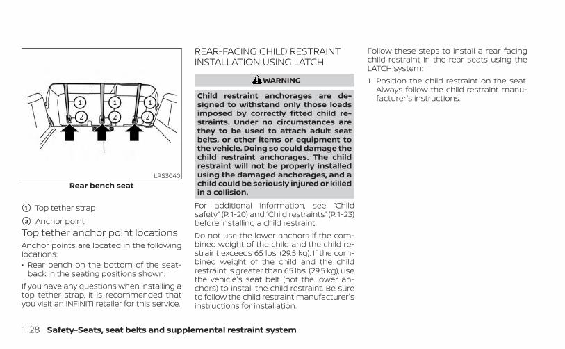
REAR-FACING CHILD RESTRAINTINSTALLATION USING LATCH
WARNING
Child restraint anchorages are de-signed to withstand only those loadsimposed by correctly fitted child re-straints. Under no circumstances arethey to be used to attach adult seatbelts, or other items or equipment tothe vehicle. Doing so could damage thechild restraint anchorages. The childrestraint will not be properly installedusing the damaged anchorages, and achild could be seriously injured or killedin a collision.
For additional information, see “Childsafety” (P. 1-20) and “Child restraints” (P. 1-23)before installing a child restraint.Do not use the lower anchors if the com-bined weight of the child and the child re-straint exceeds 65 lbs. (29.5 kg). If the com-bined weight of the child and the childrestraint is greater than 65 lbs. (29.5 kg), usethe vehicle's seat belt (not the lower an-chors) to install the child restraint. Be sureto follow the child restraint manufacturer'sinstructions for installation.
Follow these steps to install a rear-facingchild restraint in the rear seats using theLATCH system:1. Position the child restraint on the seat.
Always follow the child restraint manu-facturer's instructions.
LRS3040Rear bench seat
�1 Top tether strap
�2 Anchor point
1-28 Safety-Seats, seat belts and supplemental restraint system
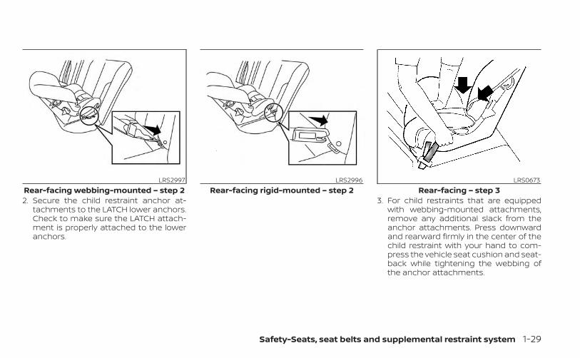
2. Secure the child restraint anchor at-tachments to the LATCH lower anchors.Check to make sure the LATCH attach-ment is properly attached to the loweranchors.
3. For child restraints that are equippedwith webbing-mounted attachments,remove any additional slack from theanchor attachments. Press downwardand rearward firmly in the center of thechild restraint with your hand to com-press the vehicle seat cushion and seat-back while tightening the webbing ofthe anchor attachments.
LRS2997Rear-facing webbing-mounted – step 2
LRS2996Rear-facing rigid-mounted – step 2
LRS0673Rear-facing – step 3
Safety-Seats, seat belts and supplemental restraint system 1-29
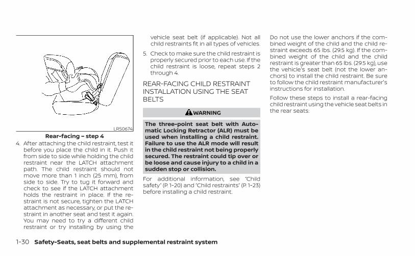
4. After attaching the child restraint, test itbefore you place the child in it. Push itfrom side to side while holding the childrestraint near the LATCH attachmentpath. The child restraint should notmove more than 1 inch (25 mm), fromside to side. Try to tug it forward andcheck to see if the LATCH attachmentholds the restraint in place. If the re-straint is not secure, tighten the LATCHattachment as necessary, or put the re-straint in another seat and test it again.You may need to try a different childrestraint or try installing by using the
vehicle seat belt (if applicable). Not allchild restraints fit in all types of vehicles.
5. Check to make sure the child restraint isproperly secured prior to each use. If thechild restraint is loose, repeat steps 2through 4.
REAR-FACING CHILD RESTRAINTINSTALLATION USING THE SEATBELTS
WARNING
The three-point seat belt with Auto-matic Locking Retractor (ALR) must beused when installing a child restraint.Failure to use the ALR mode will resultin the child restraint not being properlysecured. The restraint could tip over orbe loose and cause injury to a child in asudden stop or collision.
For additional information, see “Childsafety” (P. 1-20) and “Child restraints” (P. 1-23)before installing a child restraint.
Do not use the lower anchors if the com-bined weight of the child and the child re-straint exceeds 65 lbs. (29.5 kg). If the com-bined weight of the child and the childrestraint is greater than 65 lbs. (29.5 kg), usethe vehicle's seat belt (not the lower an-chors) to install the child restraint. Be sureto follow the child restraint manufacturer'sinstructions for installation.Follow these steps to install a rear-facingchild restraint using the vehicle seat belts inthe rear seats:
LRS0674Rear-facing – step 4
1-30 Safety-Seats, seat belts and supplemental restraint system
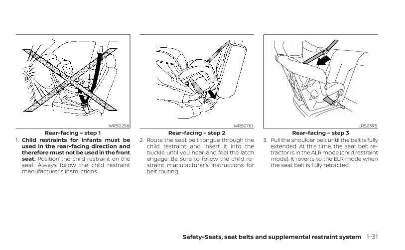
1. Child restraints for infants must beused in the rear-facing direction andtherefore must not be used in the frontseat. Position the child restraint on theseat. Always follow the child restraintmanufacturer’s instructions.
2. Route the seat belt tongue through thechild restraint and insert it into thebuckle until you hear and feel the latchengage. Be sure to follow the child re-straint manufacturer’s instructions forbelt routing.
3. Pull the shoulder belt until the belt is fullyextended. At this time, the seat belt re-tractor is in the ALR mode (child restraintmode). It reverts to the ELR mode whenthe seat belt is fully retracted.
WRS0256Rear-facing – step 1
WRS0761Rear-facing – step 2
LRS2395Rear-facing – step 3
Safety-Seats, seat belts and supplemental restraint system 1-31
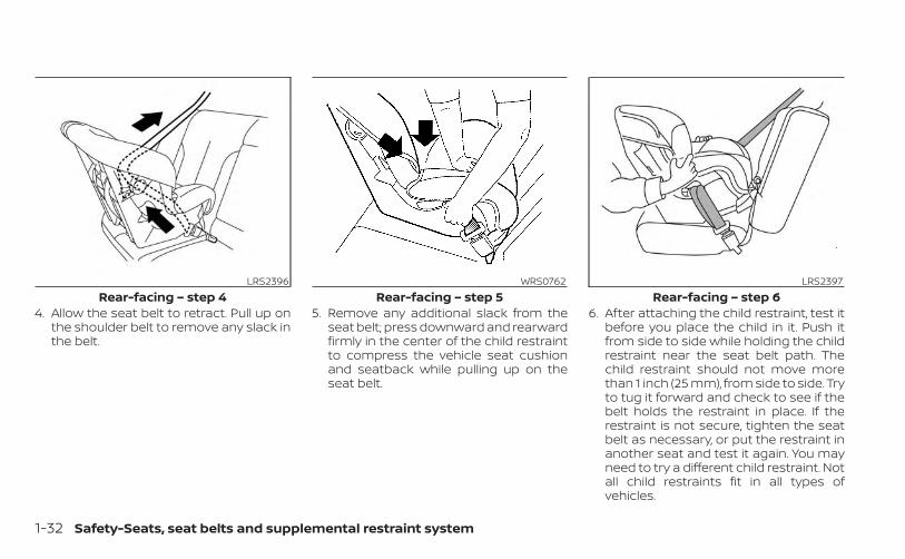
4. Allow the seat belt to retract. Pull up onthe shoulder belt to remove any slack inthe belt.
5. Remove any additional slack from theseat belt; press downward and rearwardfirmly in the center of the child restraintto compress the vehicle seat cushionand seatback while pulling up on theseat belt.
6. After attaching the child restraint, test itbefore you place the child in it. Push itfrom side to side while holding the childrestraint near the seat belt path. Thechild restraint should not move morethan 1 inch (25 mm), from side to side. Tryto tug it forward and check to see if thebelt holds the restraint in place. If therestraint is not secure, tighten the seatbelt as necessary, or put the restraint inanother seat and test it again. You mayneed to try a different child restraint. Notall child restraints fit in all types ofvehicles.
LRS2396Rear-facing – step 4
WRS0762Rear-facing – step 5
LRS2397Rear-facing – step 6
1-32 Safety-Seats, seat belts and supplemental restraint system
7. Check to make sure that the child re-straint is properly secured prior to eachuse. If the seat belt is not locked, repeatsteps 1 through 6.
After the child restraint is removed and theseat belt fully retracted, the ALR mode(child restraint mode) is canceled.
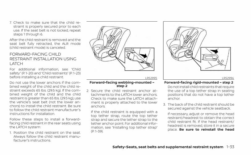
FORWARD-FACING CHILDRESTRAINT INSTALLATION USINGLATCHFor additional information, see “Childsafety” (P. 1-20) and “Child restraints” (P. 1-23)before installing a child restraint.Do not use the lower anchors if the com-bined weight of the child and the child re-straint exceeds 65 lbs. (29.5 kg). If the com-bined weight of the child and the childrestraint is greater than 65 lbs. (29.5 kg), usethe vehicle's seat belt (not the lower an-chors) to install the child restraint. Be sureto follow the child restraint manufacturer'sinstructions for installation.Follow these steps to install a forward-facing child restraint in the rear seats usingthe LATCH system:1. Position the child restraint on the seat.
Always follow the child restraint manu-facturer's instructions.
2. Secure the child restraint anchor at-tachments to the LATCH lower anchors.Check to make sure the LATCH attach-ment is properly attached to the loweranchors.If the child restraint is equipped with atop tether strap, route the top tetherstrap and secure the tether strap to thetether anchor point. For additional infor-mation, see “Installing top tether strap”(P. 1-39).
Do not install child restraints that requirethe use of a top tether strap in seatingpositions that do not have a top tetheranchor.
3. The back of the child restraint should besecured against the vehicle seatback.If necessary, adjust or remove the headrestraint/headrest to obtain the correctchild restraint fit. If the head restraint/headrest is removed, store it in a secureplace. Be sure to reinstall the head
LRS2995Forward-facing webbing-mounted –
step 2
LRS2994Forward-facing rigid-mounted – step 2
Safety-Seats, seat belts and supplemental restraint system 1-33
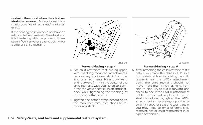
restraint/headrest when the child re-straint is removed. For additional infor-mation, see “Head restraints/headrests”(P. 1-7).If the seating position does not have anadjustable head restraint/headrest andit is interfering with the proper child re-straint fit, try another seating position ora different child restraint.
4. For child restraints that are equippedwith webbing-mounted attachments,remove any additional slack from theanchor attachments. Press downwardand rearward firmly in the center of thechild restraint with your knee to com-press the vehicle seat cushion and seat-back while tightening the webbing ofthe anchor attachments.
5. Tighten the tether strap according tothe manufacturer's instructions to re-move any slack.
6. After attaching the child restraint, test itbefore you place the child in it. Push itfrom side to side while holding the childrestraint near the LATCH attachmentpath. The child restraint should notmove more than 1 inch (25 mm), fromside to side. Try to tug it forward andcheck to see if the LATCH attachmentholds the restraint in place. If the re-straint is not secure, tighten the LATCHattachment as necessary, or put the re-straint in another seat and test it again.You may need to try a different childrestraint. Not all child restraints fit in alltypes of vehicles.
LRS0671Forward-facing – step 4
WRS0697Forward-facing – step 6
1-34 Safety-Seats, seat belts and supplemental restraint system
7. Check to make sure the child restraint isproperly secured prior to each use. If thechild restraint is loose, repeat steps 3through 6.
FORWARD-FACING CHILDRESTRAINT INSTALLATION USINGTHE SEAT BELTS
WARNING
The three-point seat belt with Auto-matic Locking Retractor (ALR) must beused when installing a child restraint.Failure to use the ALR mode will resultin the child restraint not being properlysecured. The restraint could tip over orbe loose and cause injury to a child in asudden stop or collision. Also, it canchange the operation of the front pas-senger air bag. For additional informa-tion, see “Front passenger air bag andstatus light” (P. 1-53).
For additional information, see “Childsafety” (P. 1-20) and “Child restraints” (P. 1-23)before installing a child restraint.Do not use the lower anchors if the com-bined weight of the child and the child re-straint exceeds 65 lbs. (29.5 kg). If the com-bined weight of the child and the childrestraint is greater than 65 lbs. (29.5 kg), usethe vehicle's seat belt (not the lower an-chors) to install the child restraint. Be sureto follow the child restraint manufacturer'sinstructions for installation.
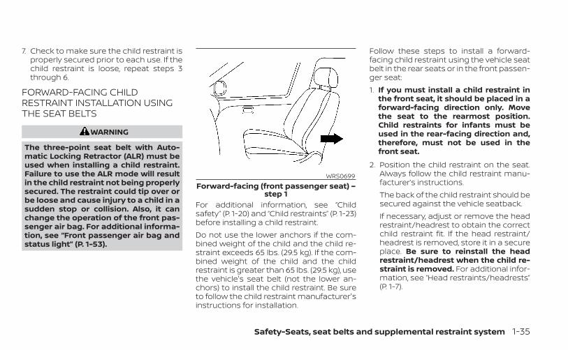
Follow these steps to install a forward-facing child restraint using the vehicle seatbelt in the rear seats or in the front passen-ger seat:1. If you must install a child restraint in
the front seat, it should be placed in aforward-facing direction only. Movethe seat to the rearmost position.Child restraints for infants must beused in the rear-facing direction and,therefore, must not be used in thefront seat.
2. Position the child restraint on the seat.Always follow the child restraint manu-facturer’s instructions.The back of the child restraint should besecured against the vehicle seatback.If necessary, adjust or remove the headrestraint/headrest to obtain the correctchild restraint fit. If the head restraint/headrest is removed, store it in a secureplace. Be sure to reinstall the headrestraint/headrest when the child re-straint is removed. For additional infor-mation, see “Head restraints/headrests”(P. 1-7).
WRS0699Forward-facing (front passenger seat) –
step 1
Safety-Seats, seat belts and supplemental restraint system 1-35
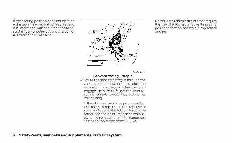
If the seating position does not have anadjustable head restraint/headrest andit is interfering with the proper child re-straint fit, try another seating position ora different child restraint.
3. Route the seat belt tongue through thechild restraint and insert it into thebuckle until you hear and feel the latchengage. Be sure to follow the child re-straint manufacturer’s instructions forbelt routing.If the child restraint is equipped with atop tether strap, route the top tetherstrap and secure the tether strap to thetether anchor point (rear seat installa-tion only). For additional information, see“Installing top tether strap” (P. 1-39).
Do not install child restraints that requirethe use of a top tether strap in seatingpositions that do not have a top tetheranchor.
WRS0680Forward-facing – step 3
1-36 Safety-Seats, seat belts and supplemental restraint system

4. Pull the shoulder belt until the belt is fullyextended. At this time, the seat belt re-tractor is in the ALR mode (child restraintmode). It reverts to ELR mode when theseat belt is fully retracted.
5. Allow the seat belt to retract. Pull up onthe shoulder belt to remove any slack inthe belt.
6. Remove any additional slack from theseat belt; press downward and rear-ward firmly in the center of the child re-straint with your knee to compress thevehicle seat cushion and seatback whilepulling up on the seat belt.
7. Tighten the tether strap according to themanufacturer's instructions to removeany slack.
LRS0667Forward-facing – step 4
LRS0668Forward-facing – step 5
WRS0681Forward-facing – step 6
Safety-Seats, seat belts and supplemental restraint system 1-37
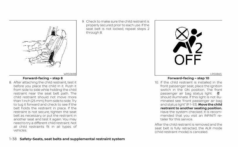
8. After attaching the child restraint, test itbefore you place the child in it. Push itfrom side to side while holding the childrestraint near the seat belt path. Thechild restraint should not move morethan 1 inch (25 mm), from side to side. Tryto tug it forward and check to see if thebelt holds the restraint in place. If therestraint is not secure, tighten the seatbelt as necessary, or put the restraint inanother seat and test it again. You mayneed to try a different child restraint. Notall child restraints fit in all types ofvehicles.
9. Check to make sure the child restraint isproperly secured prior to each use. If theseat belt is not locked, repeat steps 2through 8.
10. If the child restraint is installed in thefront passenger seat, place the ignitionswitch in the ON position. The frontpassenger air bag status lightshould illuminate. If this light is not illu-minated see “Front passenger air bagand status light” (P. 1-53). Move the childrestraint to another seating position.Have the system checked. It is recom-mended that you visit an INFINITI re-tailer for this service.
After the child restraint is removed and theseat belt is fully retracted, the ALR mode(child restraint mode) is canceled.
WRS0698Forward-facing – step 8
LRS0865Forward-facing – step 10
1-38 Safety-Seats, seat belts and supplemental restraint system
Installing top tether strapThe child restraint top tether strap must beused when installing the child restraint withseat belts.First, secure the child restraint with the seatbelt.
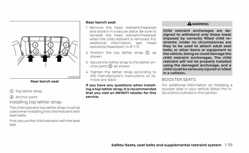
Rear bench seat1. Remove the head restraint/headrest
and store it in a secure place. Be sure toreinstall the head restraint/headrestwhen the child restraint is removed. Foradditional information, see “Headrestraints/headrests” in (P. 1-7).
2. Position the top tether strap O1 asshown.
3. Secure the tether strap to the tether an-chor point O2 as shown.
4. Tighten the tether strap according tothe manufacturer’s instructions to re-move any slack.
If you have any questions when install-ing a top tether strap, it is recommendedthat you visit an INFINITI retailer for thisservice.
WARNING
Child restraint anchorages are de-signed to withstand only those loadsimposed by correctly fitted child re-straints. Under no circumstances arethey to be used to attach adult seatbelts, or other items or equipment tothe vehicle. Doing so could damage thechild restraint anchorages. The childrestraint will not be properly installedusing the damaged anchorage, and achild could be seriously injured or killedin a collision.
BOOSTER SEATSFor additional information on installing abooster seat in your vehicle, follow the in-structions outlined in this section.
LRS3040Rear bench seat
�1 Top tether strap
�2 Anchor point
Safety-Seats, seat belts and supplemental restraint system 1-39
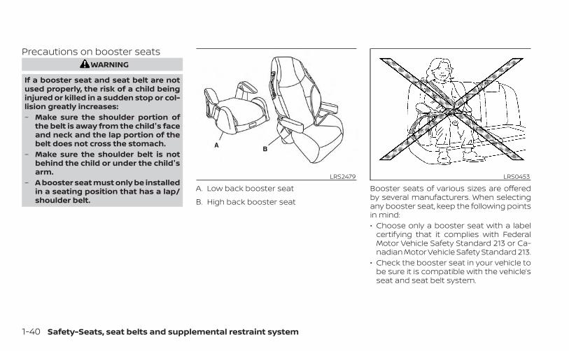
Precautions on booster seatsWARNING
If a booster seat and seat belt are notused properly, the risk of a child beinginjured or killed in a sudden stop or col-lision greatly increases:– Make sure the shoulder portion of
the belt is away from the child's faceand neck and the lap portion of thebelt does not cross the stomach.
– Make sure the shoulder belt is notbehind the child or under the child'sarm.
– A booster seat must only be installedin a seating position that has a lap/shoulder belt.
Booster seats of various sizes are offeredby several manufacturers. When selectingany booster seat, keep the following pointsin mind:• Choose only a booster seat with a label
certifying that it complies with FederalMotor Vehicle Safety Standard 213 or Ca-nadian Motor Vehicle Safety Standard 213.
• Check the booster seat in your vehicle tobe sure it is compatible with the vehicle’sseat and seat belt system.
LRS2479
A. Low back booster seat
B. High back booster seat
LRS0453
1-40 Safety-Seats, seat belts and supplemental restraint system

• Make sure the child’s head will be properlysupported by the booster seat or vehicleseat. The seatback must be at or abovethe center of the child’s ears. For example,if a low back booster seat is chosen, thevehicle seatback must be at or above thecenter of the child’s ears. If the seatback islower than the center of the child’s ears, ahigh back booster seat should be used.
• If the booster seat is compatible withyour vehicle, place the child in the boosterseat and check the various adjustmentsto be sure the booster seat is compatiblewith the child. Always follow all recom-mended procedures.
All U.S. states and Canadian provinces orterritories require that infants and smallchildren be restrained in an approvedchild restraint at all times while the ve-hicle is being operated.The instructions in this section apply tobooster seat installation in the rear seatsor the front passenger seat.
Booster seat installation
WARNING
To avoid injury to child, do not use thelap/shoulder belt in the AutomaticLocking Retractor (ALR) mode when us-ing a booster seat with the seat belts.
For additional information, see “Childsafety” (P. 1-20), “Child restraints” (P. 1-23) and“Booster seats” (P. 1-39) before installing achild restraint.Follow these steps to install a booster seatin the rear seats or in the front passengerseat:
1. If you must install a booster seat in thefront seat, move the seat to the rear-most position.
2. Position the booster seat on the seat.Only place it in a front-facing direction.Always follow the booster seat manu-facturer’s instructions.
LRS0464 WRS0699
Safety-Seats, seat belts and supplemental restraint system 1-41
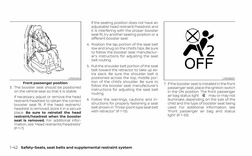
3. The booster seat should be positionedon the vehicle seat so that it is stable.If necessary, adjust or remove the headrestraint/headrest to obtain the correctbooster seat fit. If the head restraint/headrest is removed, store it in a secureplace. Be sure to reinstall the headrestraint/headrest when the boosterseat is removed. For additional infor-mation, see “Head restraints/headrests”(P. 1-7).
If the seating position does not have anadjustable head restraint/headrest andit is interfering with the proper boosterseat fit, try another seating position or adifferent booster seat.
4. Position the lap portion of the seat beltlow and snug on the child’s hips. Be sureto follow the booster seat manufactur-er’s instructions for adjusting the seatbelt routing.
5. Pull the shoulder belt portion of the seatbelt toward the retractor to take up ex-tra slack. Be sure the shoulder belt ispositioned across the top, middle por-tion of the child’s shoulder. Be sure tofollow the booster seat manufacturer’sinstructions for adjusting the seat beltrouting.
6. Follow the warnings, cautions and in-structions for properly fastening a seatbelt shown in “Three-point type seat beltwith retractor” (P. 1-15).
7. If the booster seat is installed in the frontpassenger seat, place the ignition switchin the ON position. The front passengerair bag status light may or may notilluminate, depending on the size of thechild and the type of booster seat beingused. For additional information, see“Front passenger air bag and statuslight” (P. 1-53).
LRS0454Front passenger position
LRS0865
1-42 Safety-Seats, seat belts and supplemental restraint system

PRECAUTIONS ON SRSThis SRS section contains important infor-mation concerning the following systems:• Driver and front passenger supplemental
front-impact air bag (INFINITI AdvancedAir Bag System)
• Front seat-mounted side-impact supple-mental air bag
• Roof-mounted curtain side-impact androllover supplemental air bag
• Driver and passenger supplemental kneeair bag
• Seat belt with pretensioner(s) (front andrear outboard seats)
Supplemental front-impact air bagsystemThe INFINITI Advanced Air Bag System canhelp cushion the impact force to the headand chest of the driver and front passengerin certain frontal collisions.Front seat-mounted side-impactsupplemental air bag systemThis system can help cushion the impactforce to the chest area of the driver andfront passenger in certain side-impact col-lisions. The side air bags are designed toinflate on the side where the vehicle isimpacted.
Roof-mounted curtain side-impact androllover supplemental air bag systemThis system can help cushion the impactforce to the head of occupants in front andrear outboard seating positions in certainside-impact or rollover collisions. In a sideimpact, the curtain air bags are designedto inflate on the side where the vehicle isimpacted. In a rollover, the curtain air bagsare designed to inflate and remain inflatedfor a short time.The SRS is designed to supplement thecrash protection provided by the driver andfront passenger seat belts and is not asubstitute for them. Seat belts should al-ways be correctly worn and the occupantseated a suitable distance away from thesteering wheel, instrument panel and doorfinishers. For additional information, see“Seat belts” (P. 1-11).Driver and front passenger supplemen-tal knee air bagsThis system can help cushion the impactforce to the driver’s and front passenger’sknees in certain collisions.
The SRS is designed to supplement thecrash protection provided by the driver andfront passenger seat belts and is not asubstitute for them. Seat belts should al-ways be correctly worn and the occupantseated a suitable distance away from thesteering wheel, instrument panel and doorfinishers. For additional information, see“Seat belts” (P. 1-11).The supplemental air bags operate onlywhen the ignition switch is placed in theON position.After placing the ignition switch in theON position, the supplemental air bagwarning light illuminates. The supple-mental air bag warning light will turn offafter about 7 seconds if the system isoperational.
SUPPLEMENTAL RESTRAINT SYSTEM(SRS)
Safety-Seats, seat belts and supplemental restraint system 1-43

WARNING
• The front air bags ordinarily will notinflate in the event of a side impact,rear impact, rollover, or lower sever-ity frontal collision. Always wear yourseat belts to help reduce the risk orseverity of injury in various kinds ofaccidents.
• The front passenger air bag and frontpassenger supplemental knee airbag will not inflate if the passengerair bag status light is lit. For addi-tional information, see “Front pas-senger air bag and status light”(P. 1-53).
• The seat belts and the front air bagsare most effective when you are sit-ting well back and upright in the seat.The front air bags inflate with greatforce. Even with the INFINITI Ad-vanced Air Bag System, if you are un-restrained, leaning forward, sittingsideways or out of position in anyway, you are at greater risk of injuryor death in a crash. You may also re-ceive serious or fatal injuries fromthe front air bag if you are up againstit when it inflates. Always sit backagainst the seatback and as far awayas practical from the steering wheelor instrument panel. Always properlyuse the seat belts.
• The driver and front passenger seatbelt buckles are equipped with sen-sors that detect if the seat belts arefastened. The INFINITI Advanced AirBag System monitors the severity ofa collision and seat belt usage theninflates the air bags as needed. Fail-ure to properly wear seat belts canincrease the risk or severity of injuryin an accident.
WRS0031
1-44 Safety-Seats, seat belts and supplemental restraint system
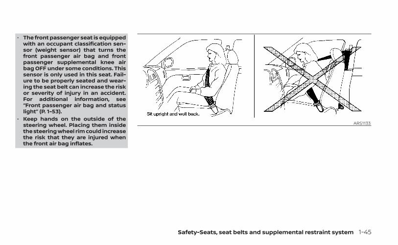
• The front passenger seat is equippedwith an occupant classification sen-sor (weight sensor) that turns thefront passenger air bag and frontpassenger supplemental knee airbag OFF under some conditions. Thissensor is only used in this seat. Fail-ure to be properly seated and wear-ing the seat belt can increase the riskor severity of injury in an accident.For additional information, see“Front passenger air bag and statuslight” (P. 1-53).
• Keep hands on the outside of thesteering wheel. Placing them insidethe steering wheel rim could increasethe risk that they are injured whenthe front air bag inflates.
ARS1133
Safety-Seats, seat belts and supplemental restraint system 1-45
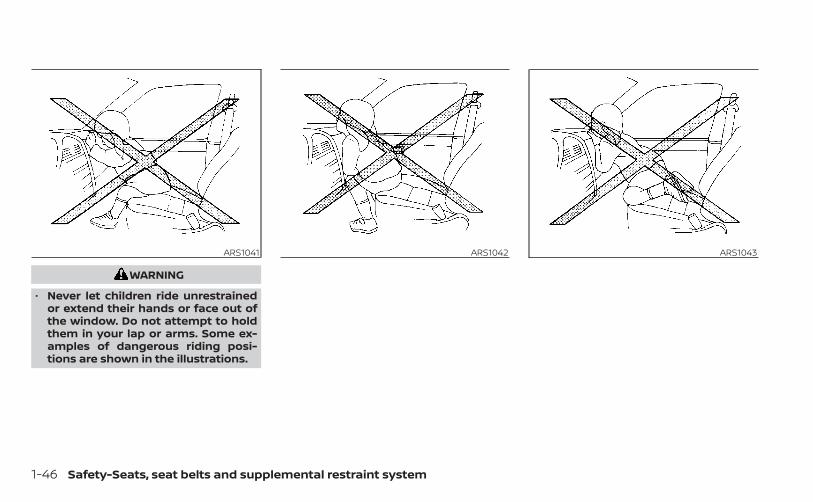
WARNING
• Never let children ride unrestrainedor extend their hands or face out ofthe window. Do not attempt to holdthem in your lap or arms. Some ex-amples of dangerous riding posi-tions are shown in the illustrations.
ARS1041 ARS1042 ARS1043
1-46 Safety-Seats, seat belts and supplemental restraint system
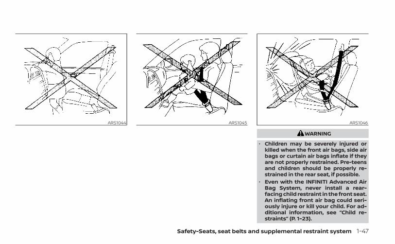
WARNING
• Children may be severely injured orkilled when the front air bags, side airbags or curtain air bags inflate if theyare not properly restrained. Pre-teensand children should be properly re-strained in the rear seat, if possible.
• Even with the INFINITI Advanced AirBag System, never install a rear-facing child restraint in the front seat.An inflating front air bag could seri-ously injure or kill your child. For ad-ditional information, see “Child re-straints” (P. 1-23).
ARS1044 ARS1045 ARS1046
Safety-Seats, seat belts and supplemental restraint system 1-47
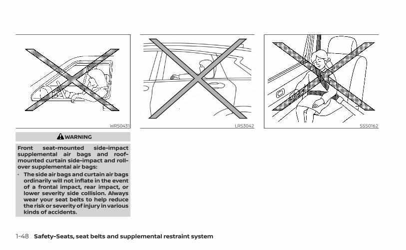
WARNING
Front seat-mounted side-impactsupplemental air bags and roof-mounted curtain side-impact and roll-over supplemental air bags:• The side air bags and curtain air bags
ordinarily will not inflate in the eventof a frontal impact, rear impact, orlower severity side collision. Alwayswear your seat belts to help reducethe risk or severity of injury in variouskinds of accidents.
WRS0431 LRS3042 SSS0162
1-48 Safety-Seats, seat belts and supplemental restraint system
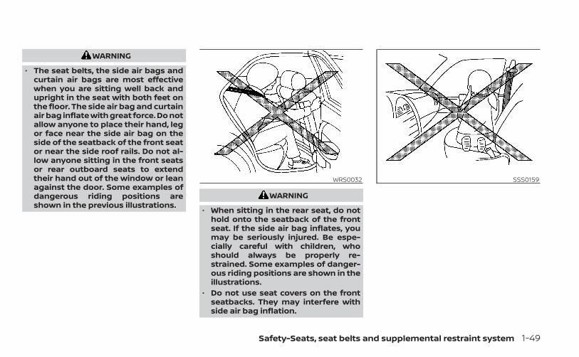
WARNING
• The seat belts, the side air bags andcurtain air bags are most effectivewhen you are sitting well back andupright in the seat with both feet onthe floor. The side air bag and curtainair bag inflate with great force. Do notallow anyone to place their hand, legor face near the side air bag on theside of the seatback of the front seator near the side roof rails. Do not al-low anyone sitting in the front seatsor rear outboard seats to extendtheir hand out of the window or leanagainst the door. Some examples ofdangerous riding positions areshown in the previous illustrations.
WARNING
• When sitting in the rear seat, do nothold onto the seatback of the frontseat. If the side air bag inflates, youmay be seriously injured. Be espe-cially careful with children, whoshould always be properly re-strained. Some examples of danger-ous riding positions are shown in theillustrations.
• Do not use seat covers on the frontseatbacks. They may interfere withside air bag inflation.
WRS0032 SSS0159
Safety-Seats, seat belts and supplemental restraint system 1-49

INFINITI Advanced Air Bag System(front seats)1. Supplemental front-impact air bag
modules
2. Air bag Control Unit (ACU)
3. Occupant classification sensor (weightsensor)
4. Front seat-mounted side-impactsupplemental air bag modules
5. Roof-mounted curtain side-impact androllover supplemental air bags
6. Roof-mounted curtain side-impact androllover supplemental air bag inflators
7. Satellite sensor (driver’s side shown; pas-senger side similar)
8. Seat belt with pretensioner(s) (front andrear outboard seats)
9. Pressure sensors in door (driver’s sideshown; front passenger side similar)
10. Driver and front passenger supple-mental knee air bag
11. Crash zone sensor
LRS3367
1-50 Safety-Seats, seat belts and supplemental restraint system

WARNING
To ensure proper operation of the pas-senger’s INFINITI Advanced Air Bag Sys-tem, please observe the followingitems.• Do not allow a passenger in the rear
seat to push or pull on the seatbackpocket.
• Do not place heavy loads heavierthan 9.1 lbs. (4 kg) on the seatback,head restraint/headrest or in theseatback pocket.
• Make sure that there is nothingpressing against the rear of the seat-back, such as a child restraint in-stalled in the rear seat or an objectstored on the floor.
• Make sure that there is no objectplaced under the front passengerseat.
• Make sure that there is no objectplaced between the seat cushion andthe center console or between theseat cushion and the door.
• If a forward-facing child restraint isinstalled in the front passenger seat,do not position the front passengerseat so the child restraint contactsthe instrument panel. If the child re-straint does contact the instrumentpanel, the system may determine theseat is occupied and the passengerair bag may deploy in a collision. Alsothe front passenger air bag statuslight may not illuminate. For addi-tional information, see “Child re-straints” (P. 1-23).
• Confirm the operating condition withthe front passenger air bag statuslight.
• If you notice that the front passengerair bag status light is not operatingas described in this section, get theoccupant classification systemchecked. It is recommended that youvisit an INFINITI retailer for thisservice.
• Until you have confirmed with a re-tailer that your passenger seat occu-pant classification system is workingproperly, position the occupants inthe rear seating positions.
• Do not position the front passengerseat so it contacts the rear seat. If thefront seat does contact the rear seat,the air bag system may determine asensor malfunction has occurredand the front passenger air bag sta-tus light may illuminate and thesupplemental air bag warning lightmay flash.
This vehicle is equipped with the INFINITIAdvanced Air Bag System for the driver andfront passenger seats. This system is de-signed to meet certification requirementsunder U.S. regulations. It is also permitted inCanada. All of the information, cautionsand warnings in this manual still applyand must be followed.The driver supplemental front-impact airbag is located in the center of the steeringwheel. The front passenger supplementalfront-impact air bag is mounted in thedashboard above the glove box. The frontair bags are designed to inflate in higherseverity frontal collisions, although theymay inflate if the forces in another type ofcollision are similar to those of a higherseverity frontal impact. They may not in-flate in certain frontal collisions. Vehicle
Safety-Seats, seat belts and supplemental restraint system 1-51

damage (or lack of it) is not always an indi-cation of proper front air bag systemoperation.The INFINITI Advanced Air Bag Systemmonitors information from the crash zonesensor, the Air bag Control Unit (ACU), seatbelt buckle sensor and occupant classifi-cation sensor (weight sensor). Inflator op-eration is based on the severity of a colli-sion and seat belt usage for the driver. Forthe front passenger, the occupant classifi-cation sensor is also monitored. Based oninformation from the sensor, only one frontair bag may inflate in a crash, depending onthe crash severity and whether the frontoccupants are belted or unbelted. Addi-tionally, the front passenger air bag andfront passenger supplemental knee airbag may be automatically turned off undersome conditions, depending on the weightdetected on the passenger seat and howthe seat belt is used. If the front passengerair bag and front passenger supplementalknee air bag are OFF, the front passengerair bag status light will be illuminated. Foradditional information, see “Front passen-ger air bag and status light” (P. 1-53). Onefront air bag inflating does not indicate im-proper performance of the system.
If you have any questions about your airbag system, it is recommended that youvisit an INFINITI retailer to obtain informa-tion about the system. If you are consider-ing modification of your vehicle due to adisability, you may also contact INFINITI.Contact information is contained in thefront of this Owner's Manual.When a front air bag inflates, a fairly loudnoise may be heard, followed by the re-lease of smoke. This smoke is not harmfuland does not indicate a fire. Care should betaken to not inhale it, as it may cause irrita-tion and choking. Those with a history of abreathing condition should get fresh airpromptly.Front air bags, along with the use of seatbelts, help to cushion the impact force onthe face and chest of the front occupants.They can help save lives and reduce seri-ous injuries. However, an inflating front airbag may cause facial abrasions or otherinjuries. Front air bags, other than the driverand front passenger supplemental kneeair bags, do not provide restraint to thelower body.
Even with INFINITI Advanced Air Bags, seatbelts should be correctly worn and thedriver and passenger seated upright as faras practical away from the steering wheelor instrument panel. The front air bags in-flate quickly in order to help protect thefront occupants. Because of this, the forceof the front air bag inflating can increasethe risk of injury if the occupant is too closeto, or is against, the front air bag moduleduring inflation.The front air bags deflate quickly after acollision.The front air bags operate only when theignition switch is placed in the ONposition.After placing the ignition switch in theON position, the supplemental air bagwarning light illuminates. The supple-mental air bag warning light will turn offafter about 7 seconds if the system isoperational.
1-52 Safety-Seats, seat belts and supplemental restraint system
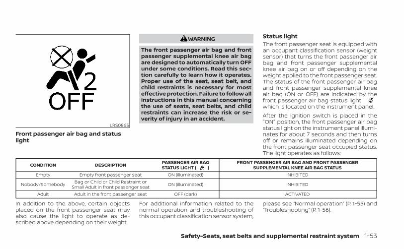
Front passenger air bag and statuslight
WARNING
The front passenger air bag and frontpassenger supplemental knee air bagare designed to automatically turn OFFunder some conditions. Read this sec-tion carefully to learn how it operates.Proper use of the seat, seat belt, andchild restraints is necessary for mosteffective protection. Failure to follow allinstructions in this manual concerningthe use of seats, seat belts, and childrestraints can increase the risk or se-verity of injury in an accident.
Status lightThe front passenger seat is equipped withan occupant classification sensor (weightsensor) that turns the front passenger airbag and front passenger supplementalknee air bag on or off depending on theweight applied to the front passenger seat.The status of the front passenger air bagand front passenger supplemental kneeair bag (ON or OFF) are indicated by thefront passenger air bag status lightwhich is located on the instrument panel.After the ignition switch is placed in the"ON" position, the front passenger air bagstatus light on the instrument panel illumi-nates for about 7 seconds and then turnsoff or remains illuminated depending onthe front passenger seat occupied status.The light operates as follows:
CONDITION DESCRIPTION PASSENGER AIR BAGSTATUS LIGHT ( )
FRONT PASSENGER AIR BAG AND FRONT PASSENGERSUPPLEMENTAL KNEE AIR BAG STATUS
Empty Empty front passenger seat ON (illuminated) INHIBITED
Nobody/Somebody Bag or Child or Child Restraint orSmall Adult in front passenger seat ON (illuminated) INHIBITED
Adult Adult in the front passenger seat OFF (dark) ACTIVATED
In addition to the above, certain objectsplaced on the front passenger seat mayalso cause the light to operate as de-scribed above depending on their weight.
For additional information related to thenormal operation and troubleshooting ofthis occupant classification sensor system,
please see “Normal operation” (P. 1-55) and“Troubleshooting” (P. 1-56).
LRS0865
Safety-Seats, seat belts and supplemental restraint system 1-53

Front passenger air bagThe front passenger air bag and front pas-senger supplemental knee air bag are de-signed to automatically turn OFF when thevehicle is operated under some conditionsas described below in accordance with U.S.regulations. If the front passenger air bagand front passenger supplemental kneeair bag are OFF, it will not inflate in a crash.The driver air bag and other air bags in yourvehicle are not part of this system.The purpose of the regulation is to helpreduce the risk of injury or death from aninflating air bag to certain front passengerseat occupants, such as children, by requir-ing the air bag to be automatically turnedOFF. Certain sensors are used to meet therequirements.The occupant classification sensor in thisvehicle is a weight sensor. It is designed todetect an occupant and objects on theseat by weight. For example, if a child is inthe front passenger seat, the INFINITI Ad-vanced Air Bag System is designed to turnthe front passenger air bag and front pas-senger supplemental knee air bag OFF inaccordance with the regulations. Also, if achild restraint of the type specified in theregulations is on the seat, its weight and
the child’s weight can be detected andcause the air bags to turn OFF.Front passenger seat adult occupants whoare properly seated and using the seat beltas outlined in this manual should notcause the front passenger air bag andfront passenger supplemental knee airbag to be automatically turned OFF. Forsmall adults it may be turned OFF, howeverif the occupant takes his/her weight off theseat cushion (for example, by not sittingupright, by sitting on an edge of the seat, orby otherwise being out of position), thiscould cause the sensor to turn the frontpassenger air bag and front passengersupplemental knee air bag OFF. Always besure to be seated and wearing the seat beltproperly for the most effective protectionby the seat belt and supplemental air bag.INFINITI recommends that pre-teens andchildren be properly restrained in a rearseat. INFINITI also recommends that ap-propriate child restraints and boosterseats be properly installed in a rear seat. Ifthis is not possible, the occupant classifica-tion sensor is designed to operate as de-scribed above to turn the front passengerair bag and front passenger supplementalknee air bag OFF for specified child re-straints as required by the regulations. Fail-
ing to properly secure child restraints andto use the ALR mode may allow the re-straint to tip or move in a collision or sud-den stop. This can also result in the frontpassenger air bag and front passengersupplemental knee air bag inflating in acrash instead of being OFF. For additionalinformation, see “Child restraints” (P. 1-23).If the front passenger seat is not occupied,the front passenger air bag and front pas-senger supplemental knee air bag are de-signed not to inflate in a crash. However,heavy objects placed on the seat could re-sult in air bag inflation, because of the ob-ject’s weight detected by the occupantclassification sensor. Other conditionscould also result in air bag inflation, such asif a child is standing on the seat, or if twochildren are on the seat, contrary to theinstructions in this manual. Always be surethat you and all vehicle occupants areseated and restrained properly.Using the front passenger air bag statuslight, you can monitor when the front pas-senger air bag and front passengersupplemental knee air bag are automati-cally turned OFF.
1-54 Safety-Seats, seat belts and supplemental restraint system

If an adult occupant is in the seat but thefront passenger air bag status light is illu-minated (indicating that the front passen-ger air bag and front passenger supple-mental knee air bag are OFF), it could bethat the person is a small adult, or is notsitting on the seat properly or not using theseat belt properly.If a child restraint must be used in the frontseat, the front passenger air bag statuslight may or may not be illuminated, de-pending on the size of the child and thetype of child restraint being used. If the airbag status light is not illuminated (indicat-ing that the front passenger air bag andfront passenger supplemental knee airbag might inflate in a crash), it could be thatthe child restraint or seat belt is not beingused properly. Make sure that the child re-straint is installed properly, the seat belt isused properly and the occupant is posi-tioned properly. If the air bag status light isstill not illuminated, reposition the occu-pant or child restraint in a rear seat.If the front passenger air bag status lightwill not illuminate even though you believethat the child restraint, the seat belts andthe occupant are properly positioned, it isrecommended that you take your vehicleto an INFINITI retailer. An INFINITI retailer
can check system status by using a specialtool. However, until you have confirmedwith a retailer that your air bag is workingproperly, reposition the occupant or childrestraint in a rear seat.The INFINITI Advanced Air Bag System andfront passenger air bag status light willtake a few seconds to register a change inthe front passenger seat status. This is nor-mal system operation and does not indi-cate a malfunction.If a malfunction occurs in the front passen-ger air bag system, the supplemental airbag warning light , located in the me-ter and gauges area of the instrumentpanel, will be illuminated (blinking orsteadily lit). Have the system checked. It isrecommended that you visit an INFINITI re-tailer for this service.Normal operationIn order for the occupant classificationsensor system to classify the front passen-ger based on weight, please follow the pre-cautions and steps outlined below:Precautions• Make sure that there are no objects
weighing over 9.1 lbs. (4 kg) hanging onthe seat or placed in the seatback pocket.
• Make sure that a child restraint or otherobject is not pressing against the rear ofthe seatback.
• Make sure that a rear passenger is notpushing or pulling on the back of the frontpassenger seat.
• Make sure that the front passenger seator seatback is not forced back against anobject on the seat or floor behind it.
• Make sure that there is no object placedunder the front passenger seat.
Steps1. Adjust the seat as outlined in the “Seats”
(P. 1-2) section of this manual. Sit upright,leaning against the seatback, and cen-tered on the seat cushion with your feetcomfortably extended to the floor.
2. Make sure there are no objects on yourlap.
3. Fasten the seat belt as outlined in the“Seat belts” (P. 1-11) section of thismanual. Front passenger seat beltbuckle status is monitored by the occu-pant classification system, and is usedas an input to determine occupancystatus. So, it is highly recommended thatthe front passenger fasten their seatbelt.
Safety-Seats, seat belts and supplemental restraint system 1-55
4. Remain in this position for 30 secondsallowing the system to classify the frontpassenger before the vehicle is put intomotion.
5. Ensure proper classification by checkingthe front passenger air bag status light.
NOTE:
This vehicle’s occupant classificationsensor system generally keeps the clas-sification locked during driving, so it isimportant that you confirm that thefront passenger is properly classifiedprior to driving. However, the occupantclassification sensor may recalculate theweight of the occupant under some con-ditions (both while driving and whenstopped), so front passenger seat occu-pants should continue to remain seatedas outlined above.TroubleshootingIf you think the front passenger air bagstatus light is incorrect:1. If the light is ON with an adult occupying
the front passenger seat:
• Occupant is a small adult — the air baglight is functioning as intended. The frontpassenger air bag and front passengersupplemental knee air bag aresuppressed.
However, if the occupant is not a smalladult, then this may be due to the followingconditions that may be interfering with theweight sensors:• Occupant is not sitting upright, leaning
against the seatback, and centered onthe seat cushion with his/her feet com-fortably extended to the floor.
• A child restraint or other object pressingagainst the rear of the seatback.
• A rear passenger pushing or pulling onthe back of the front passenger seat.
• Forcing the front seat or seatbackagainst an object on the seat or floor be-hind it.
• An object placed under the front passen-ger seat.
• An object placed between the seat cush-ion and center console or between theseat cushion and the door.
If the vehicle is moving, please come to astop when it is safe to do so. Check andcorrect any of the above conditions. Re-start the vehicle and wait 1 minute.
NOTE:
A system check will be performed duringwhich the front passenger air bag statuslight will remain lit for about 7 secondsinitially.If the light is still ON after this, the personshould be advised not to ride in the frontpassenger seat and the vehicle should bechecked as soon as possible. It is recom-mended that you visit an INFINITI retailer forthis service.2. If the light is OFF with a small adult, child
or child restraint occupying the frontpassenger seat.This may be due to the following condi-tions that may be interfering with theweight sensors:
• Small adult or child is not sitting upright,leaning against the seatback, and cen-tered on the seat cushion with his/herfeet comfortably extended to the floor.
• The child restraint is not properly in-stalled, as outlined in “Child restraints”(P. 1-23).
• An object weighing over 9.1 lbs. (4 kg)hanging on the seat or placed in the seat-back pocket.
1-56 Safety-Seats, seat belts and supplemental restraint system
• A child restraint or other object pressingagainst the rear of the seatback.
• A rear passenger pushing or pulling onthe back of the front passenger seat.
• Forcing the front seat or seatbackagainst an object on the seat or floor be-hind it.
• An object placed under the front passen-ger seat.
• An object placed between the seat cush-ion and center console.
If the vehicle is moving, please come to astop when it is safe to do so. Check andcorrect any of the above conditions. Re-start the vehicle and wait 1 minute.
NOTE:
A system check will be performed duringwhich the front passenger air bag statuslight will remain lit for about 7 secondsinitially.If the light is still OFF after this, the smalladult, child or child restraint should be re-positioned in the rear seat and the vehicleshould be checked as soon as possible. It isrecommended that you visit an INFINITI re-tailer for this service.
3. If the light is OFF with no front passengerand no objects on the front passengerseat, the vehicle should be checked. It isrecommended that you visit an INFINITIretailer as soon as possible.
Other supplemental front-impact airbag precautions
WARNING
• Do not place any objects on thesteering wheel pad or on the instru-ment panel. Also, do not place anyobjects between any occupant andthe steering wheel or instrumentpanel. Such objects may becomedangerous projectiles and cause in-jury if the front air bags inflate.
• Immediately after inflation, severalfront air bag system components willbe hot. Do not touch them; you mayseverely burn yourself.
• No unauthorized changes should bemade to any components or wiringof the supplemental air bag system.This is to prevent accidental inflationof the supplemental air bag or dam-age to the supplemental air bagsystem.
• Do not make unauthorized changesto your vehicle's electrical system,suspension system or front endstructure. This could affect properoperation of the front air bag system.
• Tampering with the front air bag sys-tem may result in serious personalinjury. Tampering includes changesto the steering wheel and the instru-ment panel assembly by placing ma-terial over the steering wheel padand above the instrument panel orby installing additional trim materialaround the air bag system.
• Removing or modifying the frontpassenger seat may affect the func-tion of the air bag system and resultin serious personal injury.
Safety-Seats, seat belts and supplemental restraint system 1-57

• Modifying or tampering with thefront passenger seat may result inserious personal injury. For example,do not change the front seats byplacing material on the seat cushionor by installing additional trim mate-rial, such as seat covers, on the seatthat are not specifically designed toassure proper air bag operation. Ad-ditionally, do not stow any objectsunder the front passenger seat or theseat cushion and seatback. Such ob-jects may interfere with the properoperation of the occupant classifica-tion sensor (weight sensor).
• No unauthorized changes should bemade to any components or wiringof the seat belt system. This may af-fect the front air bag system. Tam-pering with the seat belt system mayresult in serious personal injury.
• It is recommended that you visit anINFINITI retailer for work on andaround the front air bag. It is also rec-ommended that you visit an INFINITIretailer for installation of electricalequipment. The Supplemental Re-straint System (SRS) wiring har-nesses* should not be modified ordisconnected. Unauthorized electri-cal test equipment and probing de-vices should not be used on the airbag system.
• A cracked windshield should be re-placed immediately by a qualified re-pair facility. A cracked windshieldcould affect the function of thesupplemental air bag system.
*The SRS wiring harness connectors areyellow and orange for easyidentification.When selling your vehicle, we request thatyou inform the buyer about the front airbag system and guide the buyer to theappropriate sections in this Owner'sManual.
Front seat-mounted side-impactsupplemental air bag androof-mounted curtainside-impact and rolloversupplemental air bag systemsThe side air bags are located in the outsideof the seatback of the front seats. The cur-tain air bags are located in the side roofrails in both rows. All of the information,cautions and warnings in this manualapply and must be followed. The side airbags and curtain air bags are designed to
LRS2501
1-58 Safety-Seats, seat belts and supplemental restraint system
inflate in higher severity side collisions, al-though they may inflate if the forces in an-other type of collision are similar to those ofa higher severity impact. They are de-signed to inflate on the side where the ve-hicle is impacted. They may not inflate incertain side collisions.Curtain air bags are also designed to inflatein certain types of rollover collisions or nearrollovers. As a result, certain vehicle move-ments (for example, during severe off-roading) may cause the curtain air bags toinflate.Vehicle damage (or lack of it) is not alwaysan indication of proper side air bag andcurtain air bag operation.When the side air bags and curtain air bagsinflate, a fairly loud noise may be heard,followed by release of smoke. This smoke isnot harmful and does not indicate a fire.Care should be taken not to inhale it, as itmay cause irritation and choking. Thosewith a history of a breathing conditionshould get fresh air promptly.Side air bags, along with the use of seatbelts, help to cushion the impact force onthe chest of the front occupants. Curtainair bags help to cushion the impact force tothe head of occupants in the front and rear
outboard seating positions in all rows. Theycan help save lives and reduce serious in-juries. However, an inflating side air bag orcurtain air bag may cause abrasions orother injuries. Side air bags and curtain airbags do not provide restraint to the lowerbody.The seat belts should be correctly wornand the driver and front passenger seatedupright as far as practical away from theside air bag. Rear seat passengers shouldbe seated as far away as practical from thedoor finishers and side roof rails. The sideair bags and curtain air bags inflate quicklyin order to help protect the occupants. Be-cause of this, the force of the side air bagsand curtain air bags inflating can increasethe risk of injury if the occupant is too closeto, or is against, these air bag modules dur-ing inflation. The side air bag will deflatequickly after the collision is over.The curtain air bag will remain inflated for ashort time.The side air bags and curtain air bagsoperate only when the ignition switch isplaced in the ON position.After placing the ignition switch in theON position, the supplemental air bagwarning light illuminates. The supple-
mental air bag warning light will turn offafter about 7 seconds if the system isoperational.
WARNING
• Do not place any objects near theseatback of the front seats. Also, donot place any objects (an umbrella,bag, etc.) between the front door fin-isher and the front seat. Such objectsmay become dangerous projectilesand cause injury if a side air baginflates.
• Right after inflation, several side airbag and curtain air bag system com-ponents will be hot. Do not touchthem; you may severely burnyourself.
• No unauthorized changes should bemade to any components or wiringof the side air bag and curtain air bagsystems. This is to prevent damageto or accidental inflation of the sideair bag and curtain air bag systems.
• Do not make unauthorized changesto your vehicle's electrical system,suspension system or side panel.This could affect proper operation ofthe curtain air bag systems.
Safety-Seats, seat belts and supplemental restraint system 1-59

• Tampering with the side air bag sys-tem may result in serious personalinjury. For example, do not changethe front seats by placing materialnear the seatbacks or by installingadditional trim material, such as seatcovers, around the side air bag.
• It is recommended that you visit anINFINITI retailer for work on andaround the side air bag and curtainair bag. It is also recommended thatyou visit an INFINITI retailer for instal-lation of electrical equipment. TheSRS wiring harnesses* should not bemodified or disconnected. Unauthor-ized electrical test equipment andprobing devices should not be usedon the side air bag or curtain air bagsystems.
*The SRS wiring harness or connectorsare yellow or orange for easyidentification.When selling your vehicle, we request thatyou inform the buyer about the side airbags and curtain air bag system and guidethe buyer to the appropriate sections inthis Owner's Manual.
Driver and front passengersupplemental knee air bag
The knee air bag is located in the kneebolster, on the driver’s and passenger’sside. All of the information, cautions andwarnings in this manual apply and mustbe followed. The knee air bag is designedto inflate in higher severity frontal collisions,although it may inflate if the forces in an-other type of collision are similar to those ofa higher severity frontal impact. It may notinflate in certain collisions.Vehicle damage (or lack of it) is not alwaysan indication of proper knee air bagoperation.
LRS3279Driver’s side
LRS3280Passenger’s side
1-60 Safety-Seats, seat belts and supplemental restraint system
When the knee air bag inflates, a fairly loudnoise may be heard, followed by release ofsmoke. This smoke is not harmful anddoes not indicate a fire. Care should betaken not to inhale it, as it may cause irrita-tion and choking. Those with a history of abreathing condition should get fresh airpromptly.The knee air bag helps to cushion the im-pact force on the knees of the driver andpassenger. It can help reduce serious inju-ries. However, an inflating knee air bag maycause abrasions or other injuries. The kneeair bag provides restraint to the lower body.The knee air bag inflates quickly in order tohelp protect the occupants. Because ofthis, the force of the knee air bag inflatingcan increase the risk of injury if the occu-pant is too close to, or is against, this air bagmodule during inflation. The knee air bagwill deflate quickly after the collision is overOR the knee air bag will remain inflated fora short time.The knee air bag operates only when theignition switch is placed in the ONposition.
After placing the ignition switch in theON position, the supplemental air bagwarning light illuminates. The supple-mental air bag warning light will turn offafter about 7 seconds if the system isoperational.
WARNING
• Do not place any objects between theknee bolster and the driver’s or pas-senger’s seat. Such objects may be-come dangerous projectiles andcause injury if a knee air bag inflates.
• Right after inflation, the knee air bagsystem components will be hot. Donot touch them; you may severelyburn yourself.
• No unauthorized changes should bemade to any components or wiringof the knee air bag system. This is toprevent damage to or accidental in-flation of the knee air bag system.
• Do not make unauthorized changesto your vehicle's electrical system orsuspension system. This could affectproper operation of the knee air bagsystem.
• Tampering with the knee air bag sys-tem may result in serious personalinjury. For example, do not changethe driver knee bolster or install ad-ditional trim material around theknee air bag.
• It is recommended that you visit anINFINITI retailer for work on andaround the knee air bag. It is also rec-ommended that you visit an INFINITIretailer for installation of electricalequipment. The SRS wiring har-nesses* should not be modified ordisconnected. Unauthorized electri-cal test equipment and probing de-vices should not be used on the kneeair bag system.
*The SRS wiring harness or connectorsare yellow or orange for easyidentification.When selling your vehicle, we request thatyou inform the buyer about the knee airbag system and guide the buyer to theappropriate sections in this manual.
Safety-Seats, seat belts and supplemental restraint system 1-61

Seat belt with pretensioner(s)(front and rear outboard seats)
WARNING
• The pretensioner(s) cannot be re-used after activation. They must bereplaced together with the retractorand buckle as a unit.
• If the vehicle becomes involved in acollision but pretensioner(s) are notactivated, be sure to have the preten-sioner system checked and, if neces-sary, replaced. It is recommendedthat you visit an INFINITI retailer forthis service.
• No unauthorized changes should bemade to any components or wiringof the pretensioner system. This is toprevent damage to or accidental ac-tivation of the pretensioner(s). Tam-pering with the pretensioner systemmay result in serious personal injury.
• It is recommended that you visit anINFINITI retailer for work on andaround the pretensioner system. It isalso recommended that you visit anINFINITI retailer for installation ofelectrical equipment. Unauthorizedelectrical test equipment and prob-ing devices should not be used on thepretensioner system.
• If you need to dispose of the preten-sioner(s) or scrap the vehicle, it is rec-ommended that you visit an INFINITIretailer for this service. Incorrect dis-posal procedures could cause per-sonal injury.
The pretensioner system may activatewith the supplemental air bag system incertain types of collisions. Working with theseat belt retractor, the pretensioner(s) helptighten the seat belt when the vehicle be-comes involved in certain types of colli-sions, helping to restrain front and rear out-board seat occupants.The pretensioner(s) are encased within theseat belt retractor and to the seat belt an-chor affixed to the floor of the vehicle.These seat belts are used the same way asconventional seat belts.
When pretensioner(s) activate, smoke is re-leased and a loud noise may be heard. Thissmoke is not harmful and does not indi-cate a fire. Care should be taken not toinhale it, as it may cause irritation andchoking. Those with a history of a breath-ing condition should get fresh air promptly.After the pretensioner(s’) activation, loadlimiters allow the seat belt to release web-bing (if necessary) to reduce forces againstthe chest.The supplemental air bag warning light
is used to indicate malfunctions in thepretensioner system. For additional infor-mation, see "Supplemental air bag warninglight" (P. 1-63). If the operation of the supple-mental air bag warning light indicatesthere is a malfunction, have the systemchecked. It is recommended that you visitan INFINITI retailer for this service.When selling your vehicle, we request thatyou inform the buyer about the preten-sioner system and guide the buyer to theappropriate sections in this Owner'sManual.
1-62 Safety-Seats, seat belts and supplemental restraint system
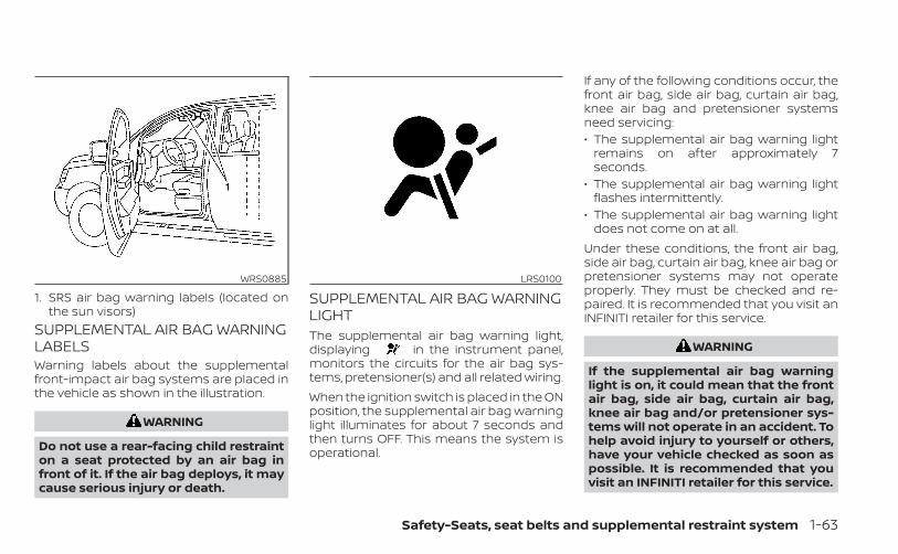
SUPPLEMENTAL AIR BAG WARNINGLABELSWarning labels about the supplementalfront-impact air bag systems are placed inthe vehicle as shown in the illustration.
WARNING
Do not use a rear-facing child restrainton a seat protected by an air bag infront of it. If the air bag deploys, it maycause serious injury or death.
SUPPLEMENTAL AIR BAG WARNINGLIGHTThe supplemental air bag warning light,displaying in the instrument panel,monitors the circuits for the air bag sys-tems, pretensioner(s) and all related wiring.When the ignition switch is placed in the ONposition, the supplemental air bag warninglight illuminates for about 7 seconds andthen turns OFF. This means the system isoperational.
If any of the following conditions occur, thefront air bag, side air bag, curtain air bag,knee air bag and pretensioner systemsneed servicing:• The supplemental air bag warning light
remains on after approximately 7seconds.
• The supplemental air bag warning lightflashes intermittently.
• The supplemental air bag warning lightdoes not come on at all.
Under these conditions, the front air bag,side air bag, curtain air bag, knee air bag orpretensioner systems may not operateproperly. They must be checked and re-paired. It is recommended that you visit anINFINITI retailer for this service.
WARNING
If the supplemental air bag warninglight is on, it could mean that the frontair bag, side air bag, curtain air bag,knee air bag and/or pretensioner sys-tems will not operate in an accident. Tohelp avoid injury to yourself or others,have your vehicle checked as soon aspossible. It is recommended that youvisit an INFINITI retailer for this service.
WRS0885
1. SRS air bag warning labels (located onthe sun visors)
LRS0100
Safety-Seats, seat belts and supplemental restraint system 1-63
Repair and replacementprocedureThe front air bags, side air bags, curtain airbags, knee air bags and pretensioner(s) aredesigned to inflate on a one-time-only ba-sis. As a reminder, unless it is damaged, thesupplemental air bag warning light re-mains illuminated after inflation has oc-curred. These systems should be repairedand/or replaced as soon as possible. It isrecommended that you visit an INFINITI re-tailer for this service.When maintenance work is required on thevehicle, the front air bags, side air bags,curtain air bags, knee air bags, pretension-er(s) and related parts should be pointedout to the person performing the mainte-nance. The ignition switch should alwaysbe in the LOCK position when working un-der the hood or inside the vehicle.
WARNING
• Once a front air bag, side air bag, cur-tain air bag or knee air bag has in-flated, the air bag module will notfunction again and must be replaced.Additionally, the activated preten-sioner(s) must also be replaced. Theair bag module and pretensioner(s)should be replaced. It is recom-mended that you visit an INFINITI re-tailer for this service. However, the airbag module and pretensioner(s) can-not be repaired.
• The front air bag, side air bag, curtainair bag, knee air bag systems and thepretensioner system should be in-spected if there is any damage to thefront end or side portion of the ve-hicle. It is recommended that youvisit an INFINITI retailer for thisservice.
• If you need to dispose of a supple-mental air bag or pretensioner sys-tems or scrap the vehicle, it is recom-mended that you visit an INFINITIretailer. Incorrect disposal proce-dures could cause personal injury.
• If there is an impact to your vehiclefrom any direction, your OccupantClassification Sensor (OCS) should bechecked to verify it is still functioningcorrectly. It is recommended that youvisit an INFINITI retailer for this ser-vice. The OCS should be checkedeven if no air bags deploy as a resultof the impact. Failure to verify properOCS function may result in an im-proper air bag deployment resultingin injury or death.
1-64 Safety-Seats, seat belts and supplemental restraint system

MEMO
Safety-Seats, seat belts and supplemental restraint system 1-65

2 Instruments and controls
Instrument panel . . . . . . . . . . . . . . . . . . . . . . . . . . . . . . . . 2-2Meters and gauges . . . . . . . . . . . . . . . . . . . . . . . . . . . . . 2-4
Speedometer and odometer . . . . . . . . . . . . . . . . . 2-4Tachometer . . . . . . . . . . . . . . . . . . . . . . . . . . . . . . . . . . 2-6Engine coolant temperature gauge . . . . . . . . . . 2-6Fuel gauge . . . . . . . . . . . . . . . . . . . . . . . . . . . . . . . . . . . 2-7Distance To Empty (DTE) . . . . . . . . . . . . . . . . . . . . . 2-7Variable Compression Turbo . . . . . . . . . . . . . . . . . 2-8
Warning lights, indicator lights and audiblereminders . . . . . . . . . . . . . . . . . . . . . . . . . . . . . . . . . . . . . . . 2-9
Checking lights . . . . . . . . . . . . . . . . . . . . . . . . . . . . . . 2-10Warning/Indicator lights (red) . . . . . . . . . . . . . . . 2-10Warning/Indicator lights (yellow) . . . . . . . . . . . . 2-13Warning/Indicator lights (other) . . . . . . . . . . . . . 2-18Audible reminders . . . . . . . . . . . . . . . . . . . . . . . . . . . 2-19
Vehicle information display . . . . . . . . . . . . . . . . . . . . . 2-19How to use the vehicle informationdisplay . . . . . . . . . . . . . . . . . . . . . . . . . . . . . . . . . . . . . . 2-20Startup display . . . . . . . . . . . . . . . . . . . . . . . . . . . . . . 2-20Resetting the trip computer . . . . . . . . . . . . . . . . . 2-21Tire Pressure Information(Display Settings) . . . . . . . . . . . . . . . . . . . . . . . . . . . . 2-21Oil control system . . . . . . . . . . . . . . . . . . . . . . . . . . . 2-21Vehicle information display warningsand indicators . . . . . . . . . . . . . . . . . . . . . . . . . . . . . . . 2-22
Security systems . . . . . . . . . . . . . . . . . . . . . . . . . . . . . . . 2-30
Vehicle security system . . . . . . . . . . . . . . . . . . . . . 2-30INFINITI Vehicle Immobilizer System . . . . . . . . . 2-31
Wiper and washer switch . . . . . . . . . . . . . . . . . . . . . . . 2-33Switch operation . . . . . . . . . . . . . . . . . . . . . . . . . . . . 2-33Rain-sensing auto wiper system(if so equipped) . . . . . . . . . . . . . . . . . . . . . . . . . . . . . . 2-34Rear switch operation . . . . . . . . . . . . . . . . . . . . . . . 2-35
Rear window defroster, outside mirrordefroster (if so equipped), and wiper deicer(if so equipped) switch . . . . . . . . . . . . . . . . . . . . . . . . . 2-36Headlight switch . . . . . . . . . . . . . . . . . . . . . . . . . . . . . . . 2-37
Headlight control switch . . . . . . . . . . . . . . . . . . . . 2-37LED Daytime Running Lights (DRL)system . . . . . . . . . . . . . . . . . . . . . . . . . . . . . . . . . . . . . . 2-42Instrument brightness control . . . . . . . . . . . . . . 2-43Turn signal switch . . . . . . . . . . . . . . . . . . . . . . . . . . . 2-43Fog light switch . . . . . . . . . . . . . . . . . . . . . . . . . . . . . 2-44
Horn . . . . . . . . . . . . . . . . . . . . . . . . . . . . . . . . . . . . . . . . . . . 2-45Climate controlled seat switches(if so equipped) . . . . . . . . . . . . . . . . . . . . . . . . . . . . . . . . . 2-45Heated seats (if so equipped) . . . . . . . . . . . . . . . . . . . 2-46Dynamic driver assistance switch(for vehicles without ProPILOT Assist)(if so equipped) . . . . . . . . . . . . . . . . . . . . . . . . . . . . . . . . . 2-47

Steering Assist switch (for vehicles withProPILOT Assist) (if so equipped) . . . . . . . . . . . . . . . . 2-48Front and rear sonar system switch(if so equipped) . . . . . . . . . . . . . . . . . . . . . . . . . . . . . . . . . 2-48Head Up Display (HUD) (if so equipped) . . . . . . . . . 2-49
How to use the HUD . . . . . . . . . . . . . . . . . . . . . . . . . 2-50Driver Assistance/Navigation linking . . . . . . . . 2-50
Emergency call (SOS) button . . . . . . . . . . . . . . . . . . . 2-51USB/iPod® charging ports . . . . . . . . . . . . . . . . . . . . . . 2-51Power outlets . . . . . . . . . . . . . . . . . . . . . . . . . . . . . . . . . . 2-52
12v outlets . . . . . . . . . . . . . . . . . . . . . . . . . . . . . . . . . . 2-52Extended storage switch . . . . . . . . . . . . . . . . . . . . . . . 2-53Storage . . . . . . . . . . . . . . . . . . . . . . . . . . . . . . . . . . . . . . . . 2-54
Front-door pockets . . . . . . . . . . . . . . . . . . . . . . . . . 2-54Seatback pockets . . . . . . . . . . . . . . . . . . . . . . . . . . . 2-55Front console lid . . . . . . . . . . . . . . . . . . . . . . . . . . . . 2-55Storage trays . . . . . . . . . . . . . . . . . . . . . . . . . . . . . . . . 2-56Glove box . . . . . . . . . . . . . . . . . . . . . . . . . . . . . . . . . . . 2-56Console box . . . . . . . . . . . . . . . . . . . . . . . . . . . . . . . . . 2-57Overhead sunglasses storage . . . . . . . . . . . . . . . 2-57Cup holders . . . . . . . . . . . . . . . . . . . . . . . . . . . . . . . . . 2-58Cargo area storage bin . . . . . . . . . . . . . . . . . . . . . . 2-59Luggage hooks . . . . . . . . . . . . . . . . . . . . . . . . . . . . . 2-60
Coat hooks . . . . . . . . . . . . . . . . . . . . . . . . . . . . . . . . . 2-60Roof rack . . . . . . . . . . . . . . . . . . . . . . . . . . . . . . . . . . . . 2-61Cargo cover (if so equipped) . . . . . . . . . . . . . . . . . 2-62
Windows . . . . . . . . . . . . . . . . . . . . . . . . . . . . . . . . . . . . . . . 2-63Power windows . . . . . . . . . . . . . . . . . . . . . . . . . . . . . 2-63
Moonroof (if so equipped) . . . . . . . . . . . . . . . . . . . . . . 2-65Power moonroof . . . . . . . . . . . . . . . . . . . . . . . . . . . . 2-65
Interior lights . . . . . . . . . . . . . . . . . . . . . . . . . . . . . . . . . . . 2-67Map lights . . . . . . . . . . . . . . . . . . . . . . . . . . . . . . . . . . .2-68Personal lights . . . . . . . . . . . . . . . . . . . . . . . . . . . . . .2-68Cargo light . . . . . . . . . . . . . . . . . . . . . . . . . . . . . . . . . .2-68
HomeLink® Universal Transceiver . . . . . . . . . . . . . . . 2-69Programming HomeLink® . . . . . . . . . . . . . . . . . . . 2-69Programming HomeLink® for Canadiancustomers and gate openers . . . . . . . . . . . . . . . 2-71Operating the HomeLink® UniversalTransceiver . . . . . . . . . . . . . . . . . . . . . . . . . . . . . . . . . . 2-72Programming trouble-diagnosis . . . . . . . . . . . . 2-72Clearing the programmed information . . . . . . 2-72Reprogramming a single HomeLink®button . . . . . . . . . . . . . . . . . . . . . . . . . . . . . . . . . . . . . . 2-72If your vehicle is stolen . . . . . . . . . . . . . . . . . . . . . . 2-73

1. Vents (P. 4-32)2. Bluetooth® Hands-Free Phone System*
Steering wheel switch for audio con-trol*Center display multi-function controlbuttons*
3. High beam/turn signal switch (P. 2-43)Paddle shifters (P. 5-21)Trip reset switch (P. 2-5)
4. Driver supplemental air bag (P. 1-43)Horn (P. 1-43)
5. Meters and gauges (P. 2-4)Warning and indicator lights (P. 2-9)Vehicle information display (P. 2-19)
6. Wiper and washer switch (P. 2-33)Rear wiper and washer switch (P. 2-35)
7. Automatic heater and air conditioningcontrols (P. 4-33)Driver side climate controlled seatswitches (if so equipped) (P. 2-45)Driver side heated seat switches(if so equipped) (P. 2-46)
8. Upper and lower displays*Navigation system* (if so equipped)
9. Front passenger air bag status light(P. 1-53)
LII2682
INSTRUMENT PANEL
2-2 Instruments and controls
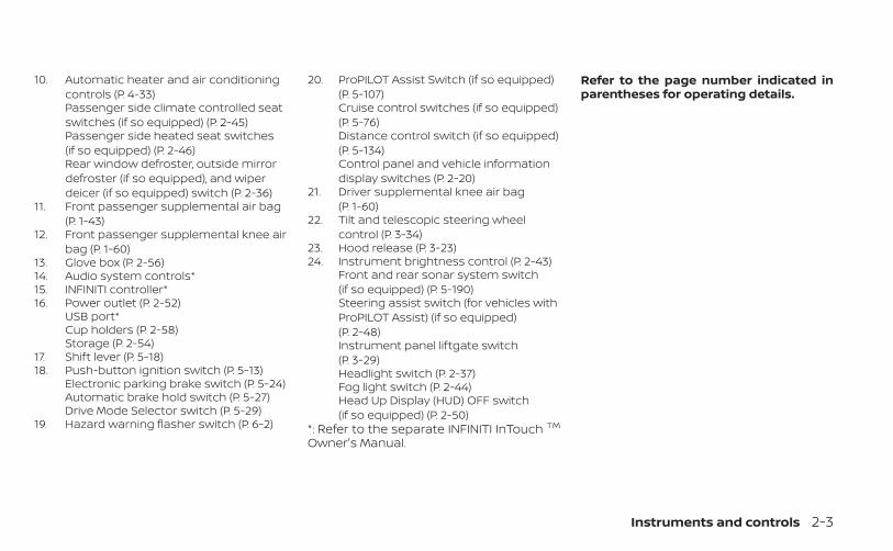
10. Automatic heater and air conditioningcontrols (P. 4-33)Passenger side climate controlled seatswitches (if so equipped) (P. 2-45)Passenger side heated seat switches(if so equipped) (P. 2-46)Rear window defroster, outside mirrordefroster (if so equipped), and wiperdeicer (if so equipped) switch (P. 2-36)
11. Front passenger supplemental air bag(P. 1-43)
12. Front passenger supplemental knee airbag (P. 1-60)
13. Glove box (P. 2-56)14. Audio system controls*15. INFINITI controller*16. Power outlet (P. 2-52)
USB port*Cup holders (P. 2-58)Storage (P. 2-54)
17. Shift lever (P. 5-18)18. Push-button ignition switch (P. 5-13)
Electronic parking brake switch (P. 5-24)Automatic brake hold switch (P. 5-27)Drive Mode Selector switch (P. 5-29)
19. Hazard warning flasher switch (P. 6-2)
20. ProPILOT Assist Switch (if so equipped)(P. 5-107)Cruise control switches (if so equipped)(P. 5-76)Distance control switch (if so equipped)(P. 5-134)Control panel and vehicle informationdisplay switches (P. 2-20)
21. Driver supplemental knee air bag(P. 1-60)
22. Tilt and telescopic steering wheelcontrol (P. 3-34)
23. Hood release (P. 3-23)24. Instrument brightness control (P. 2-43)
Front and rear sonar system switch(if so equipped) (P. 5-190)Steering assist switch (for vehicles withProPILOT Assist) (if so equipped)(P. 2-48)Instrument panel liftgate switch(P. 3-29)Headlight switch (P. 2-37)Fog light switch (P. 2-44)Head Up Display (HUD) OFF switch(if so equipped) (P. 2-50)
*: Refer to the separate INFINITI InTouch TM
Owner's Manual.
Refer to the page number indicated inparentheses for operating details.
Instruments and controls 2-3

1. Tachometer2. Warning and indicator lights3. Vehicle information display
OdometerTwin trip odometerTransmission position indicator
4. Speedometer5. Fuel gauge6. Engine coolant temperature gauge
SPEEDOMETER AND ODOMETERThis vehicle is equipped with a speedom-eter and odometer. The speedometer islocated on the right side of the meter clus-ter. The odometer is located within the ve-hicle information display.
LIC4174
METERS AND GAUGES
2-4 Instruments and controls
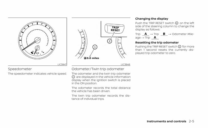
SpeedometerThe speedometer indicates vehicle speed.
Odometer/Twin trip odometerThe odometer and the twin trip odometerO1 are displayed in the vehicle informationdisplay when the ignition switch is placedin the ON position.The odometer records the total distancethe vehicle has been driven.The twin trip odometer records the dis-tance of individual trips.
Changing the displayPush the TRIP RESET switch O2 on the leftside of the steering column to change thedisplay as follows:Trip → Trip → Odometer Mile-age → Trip
Resetting the trip odometerPushing the TRIP RESET switch O2 for morethan 1 second resets the currently dis-played trip odometer to zero.
LIC3847 LIC3848
Instruments and controls 2-5

TACHOMETERThe tachometer indicates engine speed inrevolutions per minute (rpm). Do not revthe engine into the red zone O1 .
CAUTION
When engine speed approaches thered zone, reduce engine speed. Operat-ing the engine in the red zone maycause serious engine damage.
ENGINE COOLANT TEMPERATUREGAUGEThe gauge indicates the engine coolanttemperature. The engine coolant tempera-ture is within the normal range O1 whenthe gauge needle points within the zoneshown in the illustration.The engine coolant temperature varieswith the outside air temperature and driv-ing conditions.
CAUTION
If the gauge indicates coolant tem-perature near the hot (H) end of thenormal range, reduce vehicle speed todecrease temperature. If the gauge isover the normal range, stop the vehicleas soon as safely possible. If the engineis overheated, continued operation ofthe vehicle may seriously damage theengine. For additional information, see“If your vehicle overheats” (P. 6-7) forimmediate action required.
LIC3849 LIC3850
2-6 Instruments and controls

FUEL GAUGEThe gauge indicates the approximate fuellevel in the tank.The gauge may move slightly during brak-ing, turning, acceleration, or going up ordown hills.The gauge needle returns to 0 (Empty) af-ter the ignition switch is placed in the OFFposition.The low fuel warning comes on when theamount of fuel in the tank is getting low.
Refill the fuel tank once the Low Fuelwarning indicator in the vehicle informa-tion display illuminates as indicated by
Low Fuel.The indicates that the fuel-filler dooris located on the driver's side of the vehicle.
CAUTION
• If the vehicle runs out of fuel, theMalfunction Indicator Light (MIL) maycome on. Refuel as soon as possible.After a few driving trips. the lightshould turn off. If the light remains onafter a few driving trips, have the ve-hicle inspected. It is recommendedthat you visit an INFINITI retailer forthis service.
• For additional information, see “Mal-function Indicator Light (MIL)”(P. 2-15).
DISTANCE TO EMPTY (DTE)Displays the estimated distance the ve-hicle can be driven before refueling. Thevalue is calculated based on recent fueleconomy, the amount of fuel remaining inthe fuel tank, and the actual fuelconsumption.
Changes in driving patterns or conditionscan cause the DTE value to vary. As a result,the value displayed may differ from the ac-tual distance that can be driven.DTE display will change to “---” when thefuel level in the tank is getting low, prior tothe fuel gauge reaching 0 (Empty).
NOTE:• The DTE value after refill is estimated
based on recent fuel economy andamount of fuel added.
• If a small amount of fuel is added, orthe ignition is on during refueling, thedisplay may not be updated.
• Conditions that affect the fueleconomy will also affect the estimatedDTE value (city/highway driving, idletime, remote start time, terrain, sea-sonal weather, added vehicle weight,added deflectors, roof racks, etc.).
LIC3851
Instruments and controls 2-7
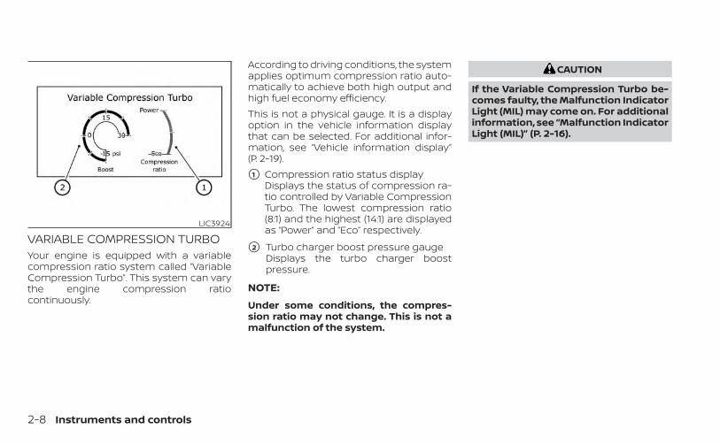
VARIABLE COMPRESSION TURBOYour engine is equipped with a variablecompression ratio system called “VariableCompression Turbo”. This system can varythe engine compression ratiocontinuously.
According to driving conditions, the systemapplies optimum compression ratio auto-matically to achieve both high output andhigh fuel economy efficiency.This is not a physical gauge. It is a displayoption in the vehicle information displaythat can be selected. For additional infor-mation, see “Vehicle information display”(P. 2-19).
�1 Compression ratio status displayDisplays the status of compression ra-tio controlled by Variable CompressionTurbo. The lowest compression ratio(8:1) and the highest (14:1) are displayedas “Power” and ”Eco” respectively.
�2 Turbo charger boost pressure gaugeDisplays the turbo charger boostpressure.
NOTE:
Under some conditions, the compres-sion ratio may not change. This is not amalfunction of the system.
CAUTION
If the Variable Compression Turbo be-comes faulty, the Malfunction IndicatorLight (MIL) may come on. For additionalinformation, see “Malfunction IndicatorLight (MIL)” (P. 2-16).
LIC3924
2-8 Instruments and controls
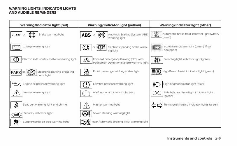
Warning/Indicator light (red) Warning/Indicator light (yellow) Warning/Indicator light (other)
or Brake warning light or Anti-lock Braking System (ABS)warning light
Automatic brake hold indicator light (white/green)
Charge warning light or Electronic parking brake warn-ing light
Eco drive indicator light (green) (if soequipped)
Electric shift control system warning light Forward Emergency Braking (FEB) withPedestrian Detection system warning light
Front fog light indicator light (green)
or Electronic parking brake indi-cator light
Front passenger air bag status light High Beam Assist indicator light (green)
Engine oil pressure warning light Low tire pressure warning light High beam indicator light (blue)
Master warning light Malfunction Indicator Light (MIL) Side light and headlight indicator light(green)
Seat belt warning light and chime Master warning light Turn signal/hazard indicator lights (green)
Security indicator light Power steering warning light
Supplemental air bag warning light Rear Automatic Braking (RAB) warning light
WARNING LIGHTS, INDICATOR LIGHTSAND AUDIBLE REMINDERS
Instruments and controls 2-9
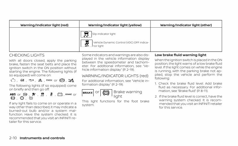
Warning/Indicator light (red) Warning/Indicator light (yellow) Warning/Indicator light (other)
Slip indicator light
Vehicle Dynamic Control (VDC) OFF indica-tor light
CHECKING LIGHTSWith all doors closed, apply the parkingbrake, fasten the seat belts and place theignition switch in the ON position withoutstarting the engine. The following lights (ifso equipped) will come on:
, , , , or ,The following lights (if so equipped) comeon briefly and then go off:
or , , , , , or, ,
If any light fails to come on or operate in away other than described, it may indicate aburned-out bulb and/or a system mal-function. Have the system checked. It isrecommended that you visit an INFINITI re-tailer for this service.
Some indicators and warnings are also dis-played in the vehicle information displaybetween the speedometer and tachom-eter. For additional information, see “Ve-hicle information display” (P. 2-19).
WARNING/INDICATOR LIGHTS (red)For additional information, see “Vehicle in-formation display” (P. 2-19).
or Brake warninglight
This light functions for the foot brakesystem.
Low brake fluid warning lightWhen the ignition switch is placed in the ONposition, the light warns of a low brake fluidlevel. If the light comes on while the engineis running, with the parking brake not ap-plied, stop the vehicle and perform thefollowing:1. Check the brake fluid level. Add brake
fluid as necessary. For additional infor-mation, see “Brake fluid” (P. 8-11).
2. If the brake fluid level is correct, have thewarning system checked. It is recom-mended that you visit an INFINITI retailerfor this service.
2-10 Instruments and controls
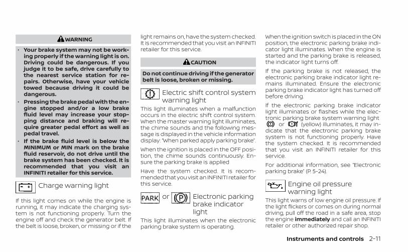
WARNING
• Your brake system may not be work-ing properly if the warning light is on.Driving could be dangerous. If youjudge it to be safe, drive carefully tothe nearest service station for re-pairs. Otherwise, have your vehicletowed because driving it could bedangerous.
• Pressing the brake pedal with the en-gine stopped and/or a low brakefluid level may increase your stop-ping distance and braking will re-quire greater pedal effort as well aspedal travel.
• If the brake fluid level is below theMINIMUM or MIN mark on the brakefluid reservoir, do not drive until thebrake system has been checked. It isrecommended that you visit anINFINITI retailer for this service.
Charge warning light
If this light comes on while the engine isrunning, it may indicate the charging sys-tem is not functioning properly. Turn theengine off and check the generator belt. Ifthe belt is loose, broken, or missing or if the
light remains on, have the system checked.It is recommended that you visit an INFINITIretailer for this service.
CAUTION
Do not continue driving if the generatorbelt is loose, broken or missing.
Electric shift control systemwarning light
This light illuminates when a malfunctionoccurs in the electric shift control system.When the master warning light illuminates,the chime sounds and the following mes-sage is displayed in the vehicle informationdisplay: “When parked apply parking brake”.When the ignition is placed in the OFF posi-tion, the chime sounds continuously. En-sure the parking brake is appliedHave the system checked. It is recom-mended that you visit an INFINITI retailer forthis service.
or Electronic parkingbrake indicatorlight
This light illuminates when the electronicparking brake system is operating.
When the ignition switch is placed in the ONposition, the electronic parking brake indi-cator light illuminates. When the engine isstarted and the parking brake is released,the indicator light turns off.If the parking brake is not released, theelectronic parking brake indicator light re-mains illuminated. Ensure the electronicparking brake indicator light has turned offbefore driving.If the electronic parking brake indicatorlight illuminates or flashes while the elec-tronic parking brake system warning light
or (yellow) illuminates, it may in-dicate that the electronic parking brakesystem is not functioning properly. Havethe system checked. It is recommendedthat you visit an INFINITI retailer for thisservice.For additional information, see “Electronicparking brake” (P. 5-24).
Engine oil pressurewarning light
This light warns of low engine oil pressure. Ifthe light flickers or comes on during normaldriving, pull off the road in a safe area, stopthe engine immediately and call an INFINITIretailer or other authorized repair shop.
Instruments and controls 2-11
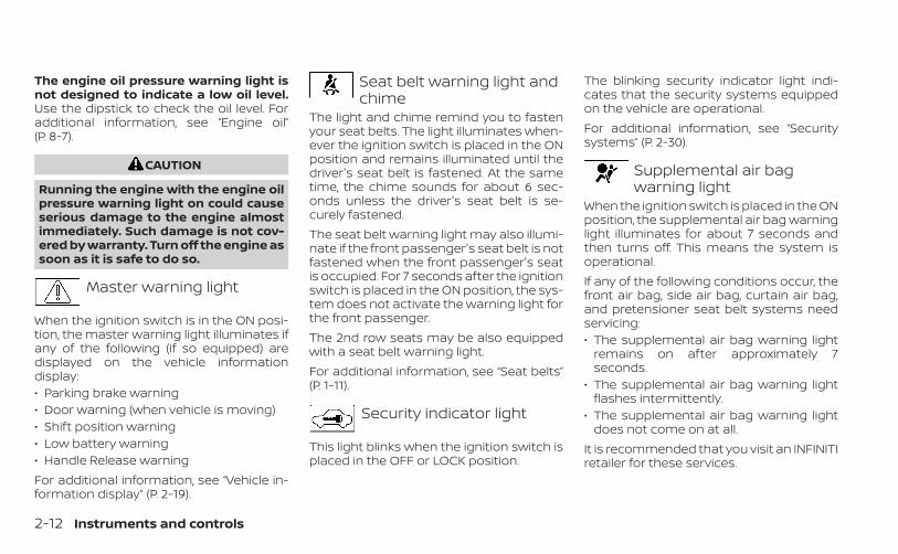
The engine oil pressure warning light isnot designed to indicate a low oil level.Use the dipstick to check the oil level. Foradditional information, see “Engine oil”(P. 8-7).
CAUTION
Running the engine with the engine oilpressure warning light on could causeserious damage to the engine almostimmediately. Such damage is not cov-ered by warranty. Turn off the engine assoon as it is safe to do so.
Master warning light
When the ignition switch is in the ON posi-tion, the master warning light illuminates ifany of the following (if so equipped) aredisplayed on the vehicle informationdisplay:• Parking brake warning• Door warning (when vehicle is moving)• Shift position warning• Low battery warning• Handle Release warningFor additional information, see “Vehicle in-formation display” (P. 2-19).
Seat belt warning light andchime
The light and chime remind you to fastenyour seat belts. The light illuminates when-ever the ignition switch is placed in the ONposition and remains illuminated until thedriver's seat belt is fastened. At the sametime, the chime sounds for about 6 sec-onds unless the driver's seat belt is se-curely fastened.The seat belt warning light may also illumi-nate if the front passenger's seat belt is notfastened when the front passenger's seatis occupied. For 7 seconds after the ignitionswitch is placed in the ON position, the sys-tem does not activate the warning light forthe front passenger.The 2nd row seats may be also equippedwith a seat belt warning light.For additional information, see “Seat belts”(P. 1-11).
Security indicator light
This light blinks when the ignition switch isplaced in the OFF or LOCK position.
The blinking security indicator light indi-cates that the security systems equippedon the vehicle are operational.For additional information, see “Securitysystems” (P. 2-30).
Supplemental air bagwarning light
When the ignition switch is placed in the ONposition, the supplemental air bag warninglight illuminates for about 7 seconds andthen turns off. This means the system isoperational.If any of the following conditions occur, thefront air bag, side air bag, curtain air bag,and pretensioner seat belt systems needservicing:• The supplemental air bag warning light
remains on after approximately 7seconds.
• The supplemental air bag warning lightflashes intermittently.
• The supplemental air bag warning lightdoes not come on at all.
It is recommended that you visit an INFINITIretailer for these services.
2-12 Instruments and controls
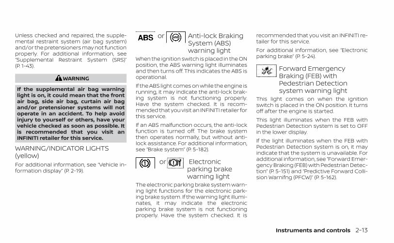
Unless checked and repaired, the supple-mental restraint system (air bag system)and/or the pretensioners may not functionproperly. For additional information, see“Supplemental Restraint System (SRS)”(P. 1-43).
WARNING
If the supplemental air bag warninglight is on, it could mean that the frontair bag, side air bag, curtain air bagand/or pretensioner systems will notoperate in an accident. To help avoidinjury to yourself or others, have yourvehicle checked as soon as possible. Itis recommended that you visit anINFINITI retailer for this service.
WARNING/INDICATOR LIGHTS(yellow)For additional information, see “Vehicle in-formation display” (P. 2-19).
or Anti-lock BrakingSystem (ABS)warning light
When the ignition switch is placed in the ONposition, the ABS warning light illuminatesand then turns off. This indicates the ABS isoperational.If the ABS light comes on while the engine isrunning, it may indicate the anti-lock brak-ing system is not functioning properly.Have the system checked. It is recom-mended that you visit an INFINITI retailer forthis service.If an ABS malfunction occurs, the anti-lockfunction is turned off. The brake systemthen operates normally, but without anti-lock assistance. For additional information,see “Brake system” (P. 5-182).
or Electronicparking brakewarning light
The electronic parking brake system warn-ing light functions for the electronic park-ing brake system. If the warning light illumi-nates, it may indicate the electronicparking brake system is not functioningproperly. Have the system checked. It is
recommended that you visit an INFINITI re-tailer for this service.For additional information, see “Electronicparking brake” (P. 5-24).
Forward EmergencyBraking (FEB) withPedestrian Detectionsystem warning light
This light comes on when the ignitionswitch is placed in the ON position. It turnsoff after the engine is started.This light illuminates when the FEB withPedestrian Detection system is set to OFFin the lower display.If the light illuminates when the FEB withPedestrian Detection system is on, it mayindicate that the system is unavailable. Foradditional information, see “Forward Emer-gency Braking (FEB) with Pedestrian Detec-tion” (P. 5-151) and “Predictive Forward Colli-sion Warnifng (PFCW)” (P. 5-162).
Instruments and controls 2-13
Front passenger air bagstatus light
The front passenger air bag status light willbe lit and the passenger front air bag will beoff depending on how the front passengerseat is being used.For additional information, see “Front pas-senger air bag and status light” (P. 1-53).
Low tire pressure warninglight
Your vehicle is equipped with a Tire Pres-sure Monitoring System (TPMS) that moni-tors the tire pressure of all tires.The low tire pressure warning light warnsof low tire pressure or indicates that theTPMS is not functioning properly.After the ignition switch is placed in the ONposition, this light illuminates for about 1second and turns off.Low tire pressure warningIf the vehicle is being driven with low tirepressure, the warning light will illumi-nate. A “Tire Pressure Low - Add Air”warning also appears in the vehicle in-formation display.
When the low tire pressure warning lightilluminates, you should stop and adjustthe tire pressure of all four tires to therecommended COLD tire pressure shownon the Tire and Loading Information la-bel located in the driver's door opening.The low tire pressure warning light doesnot automatically turn off when the tirepressure is adjusted. After the tire is in-flated to the recommended pressure,the vehicle must be driven at speedsabove 16 mph (25 km/h) to activate theTPMS and turn off the low tire pressurewarning light. Use a tire pressure gaugeto check the tire pressure.The “Tire Pressure Low - Add Air” warningappears each time the ignition switch isplaced in the ON position as long as the lowtire pressure warning light remainsilluminated.For additional information, see “Vehicle in-formation display” (P. 2-19) and “Tire Pres-sure Monitoring System (TPMS)” (P. 5-5) and(P. 6-3).TPMS malfunctionIf the TPMS is not functioning properly, thelow tire pressure warning light will flash forapproximately 1 minute when the ignitionswitch is placed in the ON position. The
light will remain on after 1 minute. Have thesystem checked. It is recommended thatyou visit an INFINITI retailer for this service.The "Tire Pressure Low — Add Air" warningdoes not appear if the low tire pressurewarning light illuminates to indicate aTPMS malfunction.For additional information, see “Tire Pres-sure Monitoring System (TPMS)” (P. 5-5) and“Tire pressure” (P. 8-28).
WARNING
• Radio waves could adversely affectelectric medical equipment. Thosewho use a pacemaker should contactthe electric medical equipmentmanufacturer for the possible influ-ences before use.
• If the light does not illuminate withthe ignition switch placed in the ONposition, have the vehicle checked assoon as possible. It is recommendedthat you visit an INFINITI retailer forthis service.
2-14 Instruments and controls
• If the light illuminates while driving,avoid sudden steering maneuvers orabrupt braking, reduce vehiclespeed, pull off the road to a safe loca-tion and stop the vehicle as soon aspossible. Driving with under-inflatedtires may permanently damage thetires and increase the likelihood oftire failure. Serious vehicle damagecould occur and may lead to an acci-dent and could result in serious per-sonal injury or death. Check the tirepressure for all four tires. Adjust thetire pressure to the recommendedCOLD tire pressure show on the Tireand Loading Information label lo-cated in the driver’s door opening toturn the low tire pressure warninglight OFF. If the light still illuminateswhile driving after adjusting the tirepressure, a tire may be flat or theTPMS may be malfunctioning. If youhave a flat tire, replace it with a re-placement tire as soon as possible. Ifno tire is flat and all tires are properlyinflated, have the vehicle checked. Itis recommended that you visit anINFINITI retailer for this service.
• When using a wheel without theTPMS such as the spare tire, the TPMSwill not function and the low tirepressure warning light will flash forapproximately 1 minute. The light willremain on after 1 minute. Have yourtires replaced and/or TPMS systemreset as soon as possible. It is recom-mended that you visit an INFINITI re-tailer for these services.
• Replacing tires with those not origi-nally specified by INFINITI could af-fect the proper operation of theTPMS.
CAUTION
• The TPMS is not a substitute for theregular tire pressure check. Be sureto check the tire pressure regularly.
• If the vehicle is being driven atspeeds of less than 16 mph (25 km/h),the TPMS may not operate correctly.
• Be sure to install the specified size oftires to the four wheels correctly.
Malfunction Indicator Light(MIL)
If this indicator light comes on steady orblinks while the engine is running, it mayindicate a potential emission controlmalfunction.The MIL may also come on steady if thefuel-filler cap is loose or missing, or if thevehicle runs out of fuel. Check to make surethe fuel-filler cap is installed and closedtightly, and that the vehicle has at least 3gallons (11.4 liters) of fuel in the fuel tank.After a few driving trips, the lightshould turn off if no other potential emis-sion control system malfunction exists.If this indicator light comes on steady for 20seconds and then blinks for 10 secondswhen the engine is not running, it indicatesthat the vehicle is not ready for an emissioncontrol system inspection/maintenancetest. For additional information, see “Readi-ness for Inspection/Maintenance (I/M) test”(P. 10-24).
Instruments and controls 2-15
OperationThe MIL will come on in one of two ways:• MIL on steady — An emission control sys-
tem malfunction has been detected.Check the fuel-filler cap. If the fuel-fillercap is loose or missing, tighten or installthe cap and continue to drive the vehicle.The light should turn off after a fewdriving trips. If the light does not turnoff after a few driving trips, have the ve-hicle checked. It is recommended thatyou visit an INFINITI retailer for this ser-vice. You do not need to have your vehicletowed to the retailer.
• MIL blinking — An engine misfire has beendetected which may damage the emis-sion control system. To reduce or avoidemission control system damage:– Do not drive at speeds above 45 mph
(72 km/h).– Avoid hard acceleration or
deceleration.– Avoid steep uphill grades.– If possible, reduce the amount of cargo
being hauled or towed.The MIL may stop blinking and come onsteady. Have the vehicle checked. It is rec-ommended that you visit an INFINITI re-tailer for this service. You do not need tohave your vehicle towed to the retailer.
CAUTION
Continued vehicle operation withouthaving the emission control systemchecked and repaired as necessarycould lead to poor driveability, reducedfuel economy, and possible damage tothe emission control system.
Master warning light
When the ignition switch is in the ON posi-tion, the master warning light illuminates ifany of the following (if so equipped) aredisplayed on the vehicle informationdisplay:• I-Key system warnings• Low washer fluid warning• Door/ liftgate open warning (when ve-
hicle is stopped)• Loose fuel cap warning• Low tire pressure warning• Flat tire warning• Transmission system warning• Headlight warning• Driver Attention Support system warning• Shipping mode warning• All Wheel Drive (AWD) system warning
• Adaptive Front lighting System (AFS)warning
• Driving Aids malfunction warning• Chassis Control System Error warning• Engine warningsFor additional information, see “Vehicle in-formation display” (P. 2-19).
Power steering warninglight
WARNING
• If the engine is not running or isturned off while driving, the powerassist for the steering will not work.Steering will be harder to operate.
• When the power steering warninglight illuminates with the engine run-ning, there will be no power assist forthe steering. You will still have controlof the vehicle, but the steering will beharder to operate. Have the powersteering system checked. It is recom-mended that you visit an INFINITI re-tailer for this service.
2-16 Instruments and controls

Models with Direct Adaptive Steering®:When the ignition switch is in the ON posi-tion, the power steering warning light illu-minates. After starting the engine, thepower steering warning light stays on for afew seconds and turns off. This indicatesthat Direct Adaptive Steering is operational.Drive the vehicle after the power steeringwarning light turns off.If the power steering warning light illumi-nates while driving, pull off the road to asafe location and stop the vehicle. If thepower steering warning light turns off, youcan drive again. If the power steering warn-ing light continues to illuminate, have theDirect Adaptive Steering checked. It is rec-ommended that you visit an INFINITI re-tailer for this service. For additional infor-mation, see “Power steering”. (P. 5-179).Models with electric power steering:When the ignition switch is in the ON posi-tion, the power steering warning light illu-minates. After starting the engine, thepower steering warning light turns off. Thisindicates the electric power steering isoperational.If the power steering warning light illumi-nates while the engine is running, it mayindicate the electric power steering is not
functioning properly and may need servic-ing. It is recommended that you have theelectric power steering checked by anINFINITI retailer.When the power steering warning light illu-minates with the engine running, thepower assist to the steering will cease op-eration but you will still have control of thevehicle. At this time, greater steering effortsare required to operate the steering wheel,especially in sharp turns and at low speeds.For additional information, see “Powersteering” (P. 5-179).
Rear Automatic Braking(RAB) warning light
This light comes on when the ignitionswitch is placed in the ON position. It turnsoff after the engine is started.This light illuminates when the RAB systemis turned off in the vehicle informationdisplay.If the light illuminates when the RAB sys-tem is on, it may indicate that the system isunavailable. For additional information, see“Rear Automatic Braking (RAB)” (P. 5-146).
Slip indicator light
This indicator light will blink when the VDCsystem is operating, thus alerting the driverto the fact that the road surface is slipperyand the vehicle is nearing its traction limits.You may feel or hear the system working;this is normal.The light will blink for a few seconds afterthe VDC system stops limiting wheel spin.The indicator light also comes onwhen you place the ignition switch in theON position. The light will turn off after aperiod of time if the system is operational. Ifthe light does not come on have the sys-tem checked. It is recommended that youvisit an INFINITI retailer for this service.
Vehicle Dynamic Control(VDC) OFF indicator light
This indicator light comes on when theVDC is turned off in the lower display. Thisindicates the VDC has been turned off.Turn the VDC on again by reactivating it inthe lower display, or restarting the engine.The system will be reactivated. For addi-tional information, see “Vehicle DynamicControl (VDC) system” (P. 5-184).
Instruments and controls 2-17

The VDC light also comes on when the ig-nition switch is placed in the ON position.The light will turn off after a period of time ifthe system is operational. If the light stayson or comes on along with the indica-tor light while you are driving, have the VDCsystem checked. It is recommended thatyou visit an INFINITI retailer for this service.
WARNING
VDC should remain on unless freeing avehicle from mud or snow.
While the VDC system is operating, youmight feel a slight vibration or hear the sys-tem working when starting the vehicle oraccelerating, but this is normal.
WARNING/INDICATOR LIGHTS(other)For additional information, see “Vehicle in-formation display” (P. 2-19).
Automatic brake holdindicator light (white/green)
This light illuminates to show the status ofthe automatic brake hold system.
When the automatic brake hold system ison standby, the indicator will illuminatewhite.When the automatic brake hold system isoperating, the indicator will illuminategreen.For additional information, see “Automaticbrake hold” (P. 5-26).
ECO drive indicator light(green) (if so equipped)
When the ECO mode has been selected,the ECO drive indicator light will illuminate,blink, or remain off depending on the accel-erator pedal operation. This is to help thedriver drive economically. For additional in-formation, see “ECO mode” (P. 5-31).
Front fog light indicatorlight (green)
The front fog light indicator light illumi-nates when the front fog lights are on. Foradditional information, see “Fog lightswitch” (P. 2-44).
High Beam Assist indicatorlight (green)
This indicator light illuminates when theheadlights come on while the headlightswitch is in the AUTO position with the highbeams selected. This indicates that thehigh beam assist is operational.For additional information, see “Headlightswitch” (P. 2-37).
High beam indicator light(blue)
This blue light comes on when the head-light high beams are on and goes out whenthe low beams are selected.The high beam indicator light also comeson when the passing signal is activated.
Side light and headlightindicator light (green)
The side light and headlight indicator lightilluminates when the side light or head-lights are on (not including daytime run-ning or signature lights). If the headlightswitch is in the AUTO position, the side lightand headlight indicator light will illuminatewhen the headlights turn on. For additionalinformation, see “Headlight switch” (P. 2-37).
2-18 Instruments and controls

Turn signal/hazardindicator lights
The appropriate light flashes when the turnsignal switch is activated.Both lights flash when the hazard switch isturned on.
AUDIBLE REMINDERS
Brake pad wear warningThe disc brake pads have audible wearwarnings. When a disc brake pad requiresreplacement, it makes a high pitchedscraping sound when the vehicle is in mo-tion, whether or not the brake pedal is de-pressed. Have the brakes checked as soonas possible if the warning sound is heard.
Key reminder chime (if soequipped)A chime sounds if the driver's door isopened while the ignition switch is placedin the OFF position or placed in the OFF orLOCK position with the key left in the ve-hicle. Make sure the ignition switch isplaced in the LOCK position, and take thekey with you when leaving the vehicle.
Light reminder chimeWith the ignition switch placed in the OFFposition, a chime sounds when the driver'sdoor is opened if the headlights or parkinglights are on.Turn the headlight control switch off beforeleaving the vehicle.
Intelligent Key door buzzer (if soequipped)The Intelligent Key door buzzer sounds ifany one of the following improper opera-tions is found.• The Intelligent Key is left inside the vehicle
when locking the doors.• The Intelligent Key is taken outside the
vehicle when operating the vehicle.When the buzzer sounds, be sure to checkboth the vehicle and the Intelligent Key Sys-tem. For additional information, see“INFINITI Intelligent Key” (P. 3-2).
The vehicle information display is locatedto the left of the speedometer. It displayssuch items as:• Trip computer information• Drive system warnings and settings (if so
equipped)• Cruise control system information (if so
equipped)• Intelligent Cruise Control (ICC) (if so
equipped) system information• Intelligent Key operation information• Indicators and warnings• Tire Pressure information• Compass
LIC4746
VEHICLE INFORMATION DISPLAY
Instruments and controls 2-19

• Audio• Fuel Economy• Driving Aids• Engine Oil• Chassis Control• Navigation (if so equipped)• ProPILOT Assist (if so equipped)• Traffic Sign Recognition (if so equipped)• Variable Compression Turbo• Other information
HOW TO USE THE VEHICLEINFORMATION DISPLAYThe vehicle information display can benavigated using the and buttonslocated on the steering wheel.1. and — select/enter the vehicle
information display menu itemsVehicle settings and features can be ad-justed in the lower display. For additionalinformation, refer to the separate INFINITIInTouch TM Owner’s Manual.
STARTUP DISPLAYWhen the vehicle in placed in the ON posi-tion the screens that display in the vehicleinformation include:• Active system status• Trip computer• Tire pressure information• Fuel economy• Warnings• Audio• Navigation (if so equipped)• Engine Oil• Speed• Intelligent Cruise Control (if so equipped)• Variable Compression Turbo• Chassis Control• Driving AidsWarnings will only display if there are anypresent. For additional information see,“Vehicle information display warnings andindicators” (P. 2-22).To control what items display in the vehicleinformation display, refer to the separateINFINITI InTouch TM Owner’s Manual
LIC3944
2-20 Instruments and controls
RESETTING THE TRIP COMPUTER1. Press the button until you reach the
trip computer mode.
2. Press the button again for morethan 1.5 seconds to reset average fuelconsumption, average speed, distanceto empty, and journey time.
TIRE PRESSURE INFORMATION(Display Settings)The tire pressure mode shows the pres-sure of all four tires while the vehicle isdriven.When the “Tire Pressure Low-Add Air” or“Flat Tire-Visit dealer” (if so equipped) warn-ing appears, the display can be switched tothe tire pressure mode by pushing theor switch on the steering wheel.The tire pressure unit can be changed inthe lower display.1. Touch the “Settings” key.
2. Select “Meter” and then select “TPMSsettings”.
For additional information, refer to theseparate INFINITI InTouch™ Owner’sManual.
NOTE:
After the ignition switch is placed in theON position, it may take a period of timefor the tire pressure to be displayedwhile the vehicle is driven. Depending onthe radio wave circumstance, tire pres-sure may not correctly be displayed.
OIL CONTROL SYSTEMEngine oil information informs the distanceto oil change. Never exceed one year or7500 miles (12000 km) between oil changeintervals.
Display whenignition is ON
Display timing Action Re-quired
Engine Oil Ser-vice due in xxxmiles
Remaining oillife is less than940 miles (1500km).
Plan to haveyour vehicleserviced.
Engine Oil Ser-vice due
Remaining oillife is 0 miles (0km).
Have your ve-hicle servicedwithin twoweeks or lessthan 500 miles(800 km).
The oil change interval cannot be adjustedmanually.
The distance to oil change interval is calcu-lated depending on the driving conditionsand set automatically by the oil controlsystem.
CAUTION
If the oil replacement indicator is dis-played, change the engine oil withintwo weeks or less than 500 miles (800km).Operating the vehicle with deterioratedoil can damage the engine.
To reset oil control system:1. Place the ignition switch in the “ON”
position.
2. Push the trip computer switchesand located on the right side of thesteering wheel to change the display.
3. Select the Engine Oil Service due in xxxmiles display.
4. Push and hold the or switchfor longer than 1 second. Hold until theremaining distance changes to – – –miles (km).
Instruments and controls 2-21

VEHICLE INFORMATION DISPLAYWARNINGS AND INDICATORSThe following messages may appear inyour vehicle information display.
Engine start operation forIntelligent Key system (ifI-Key battery level is low)
This indicator appears when the battery ofthe Intelligent Key is low and when the In-telligent Key system and the vehicle are notcommunicating normally.If this appears, touch the ignition switchwith the Intelligent Key while depressingthe brake pedal. For additional information,see “INFINITI Intelligent Key battery dis-charge” (P. 5-15).
Key Battery LowThis indicator appears when the IntelligentKey battery is running out of power.If this indicator appears, replace the bat-tery with a new one. For additional infor-mation, see “Battery replacement” (P. 8-24).
Key ID IncorrectThis warning appears when the ignitionswitch is placed in the OFF position and theIntelligent Key is not recognized by the sys-tem. You cannot start the engine with anunregistered key.For additional information, see “INFINITI In-telligent Key System” (P. 3-2).
Key System Error: SeeOwner’s Manual
After the ignition switch is placed in the ONposition, this warning appears for a periodof time and then turns off.The Key System Error message warns of amalfunction with the Intelligent Key sys-tem. If the warning appears while the en-gine is stopped, it may be impossible tostart the engine.If the warning appears while the engine isrunning, you can drive the vehicle. Howeverin these cases, have the system checked. Itis recommended that you visit an INFINITIretailer for this service.
No Key DetectedThis warning appears when the IntelligentKey is left outside the vehicle with the igni-tion switch in the ON position. Make surethe Intelligent Key is inside the vehicle.For additional information, see “INFINITI In-telligent Key System” (P. 3-2).AFS System Error: See Owner’sManualThis message may appear when the Adap-tive Front lighting System (AFS) encountersan error.For additional information, see AdaptiveFront lighting System (AFS) (P. 2-42).Chassis Control System Error: SeeOwner’s ManualThis warning appears if the chassis controlis not functioning properly. Have the sys-tem checked. It is recommended that youvisit an INFINITI retailer for this service.For additional information, see “ChassisControl” (P. 5-187).
2-22 Instruments and controls
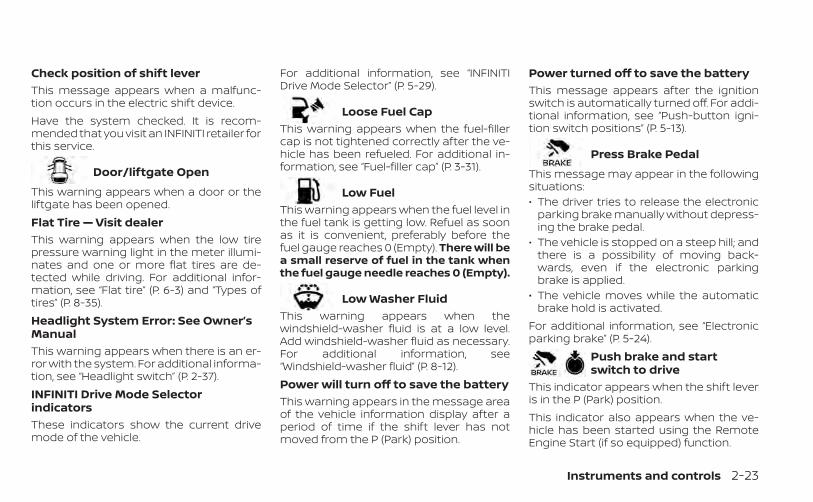
Check position of shift leverThis message appears when a malfunc-tion occurs in the electric shift device.Have the system checked. It is recom-mended that you visit an INFINITI retailer forthis service.
Door/liftgate Open
This warning appears when a door or theliftgate has been opened.Flat Tire — Visit dealerThis warning appears when the low tirepressure warning light in the meter illumi-nates and one or more flat tires are de-tected while driving. For additional infor-mation, see “Flat tire” (P. 6-3) and “Types oftires” (P. 8-35).Headlight System Error: See Owner’sManualThis warning appears when there is an er-ror with the system. For additional informa-tion, see “Headlight switch” (P. 2-37).INFINITI Drive Mode SelectorindicatorsThese indicators show the current drivemode of the vehicle.
For additional information, see “INFINITIDrive Mode Selector” (P. 5-29).
Loose Fuel CapThis warning appears when the fuel-fillercap is not tightened correctly after the ve-hicle has been refueled. For additional in-formation, see “Fuel-filler cap” (P. 3-31).
Low FuelThis warning appears when the fuel level inthe fuel tank is getting low. Refuel as soonas it is convenient, preferably before thefuel gauge reaches 0 (Empty). There will bea small reserve of fuel in the tank whenthe fuel gauge needle reaches 0 (Empty).
Low Washer FluidThis warning appears when thewindshield-washer fluid is at a low level.Add windshield-washer fluid as necessary.For additional information, see“Windshield-washer fluid” (P. 8-12).Power will turn off to save the batteryThis warning appears in the message areaof the vehicle information display after aperiod of time if the shift lever has notmoved from the P (Park) position.
Power turned off to save the batteryThis message appears after the ignitionswitch is automatically turned off. For addi-tional information, see “Push-button igni-tion switch positions” (P. 5-13).
Press Brake Pedal
This message may appear in the followingsituations:• The driver tries to release the electronic
parking brake manually without depress-ing the brake pedal.
• The vehicle is stopped on a steep hill; andthere is a possibility of moving back-wards, even if the electronic parkingbrake is applied.
• The vehicle moves while the automaticbrake hold is activated.
For additional information, see “Electronicparking brake” (P. 5-24).
Push brake and startswitch to drive
This indicator appears when the shift leveris in the P (Park) position.This indicator also appears when the ve-hicle has been started using the RemoteEngine Start (if so equipped) function.
Instruments and controls 2-23

This indicator means that the engine willstart by pushing the ignition switch withthe brake pedal depressed. You can startthe engine from any position of the ignitionswitch.
Push Ignition to OFFAfter the Push Ignition to OFF indicator ap-pears, the warning will appear if the ignitionswitch is placed in the AUTO ACC positionwhen the shift lever is moved to the P (Park)position.To turn off the Push warning, place the ig-nition switch in the ON position and then inthe LOCK position.
Rear seat belt reminderThis rear seat belt reminder appears afterstarting the engine.If any of the rear passenger seat belts arenot fastened, the seat belt icon appears inred to show which seat belt is not fastened.When a rear passenger’s seat belt hasbeen securely fastened, the color of thecorresponding seat belt icon will change.The warning will automatically turn off af-ter approximately 35 seconds.
A chime will sound one time and the rearseat belt warning will appear if a rear pas-senger’s seat belt is unfastened.
Release Parking Brake
This warning appears in the message areaof the vehicle information display when theparking brake is set and the vehicle isdriven.
Reminder: Turn OFFHeadlights
This warning appears when the headlightsare left in the ON position when exiting thevehicle. Place the headlight switch in theOFF or AUTO position. For additional infor-mation, see “Headlight switch” (P. 2-37).Shift system malfunction: Visit DealerThis message appears when a malfunc-tion occurs in the electric shift control sys-tem at 6 mph (10 km/h) or higher.Have the system checked. It is recom-mended that you visit an INFINITI retailer forthis service.
Shift to Park
This warning appears only when all the fol-lowing conditions are met:• The ignition switch is in the ON position.• The driver’s door is open.• Vehicle is stopped (or vehicle speed is
less than 1.8 mph (3 km/h).• Shift lever is in a position other than the P
(Park) position.If this warning appears, move the shift leverto the P position.
Shift to P range
This warning appears when the driver’sdoor is opened with the shift position inany position other than the P (Park)position.If this warning appears, move the shift leverto the P position.Shipping Mode On Push Storage FuseThis warning may appear if the extendedstorage switch is not pushed in. When thiswarning appears, push in the extendedstorage switch to turn off the warning. Foradditional information, see “Extended stor-age switch” (P. 2-53).
2-24 Instruments and controls
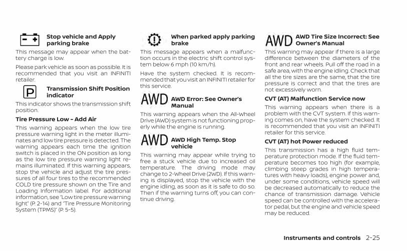
Stop vehicle and Applyparking brake
This message may appear when the bat-tery charge is low.Please park vehicle as soon as possible. It isrecommended that you visit an INFINITIretailer.
Transmission Shift Positionindicator
This indicator shows the transmission shiftposition.Tire Pressure Low - Add AirThis warning appears when the low tirepressure warning light in the meter illumi-nates and low tire pressure is detected. Thewarning appears each time the ignitionswitch is placed in the ON position as longas the low tire pressure warning light re-mains illuminated. If this warning appears,stop the vehicle and adjust the tire pres-sures of all four tires to the recommendedCOLD tire pressure shown on the Tire andLoading Information label. For additionalinformation, see “Low tire pressure warninglight” (P. 2-14) and “Tire Pressure MonitoringSystem (TPMS)” (P. 5-5).
When parked apply parkingbrake
This message appears when a malfunc-tion occurs in the electric shift control sys-tem below 6 mph (10 km/h).Have the system checked. It is recom-mended that you visit an INFINITI retailer forthis service.
AWD Error: See Owner’sManual
This warning appears when the All-WheelDrive (AWD) system is not functioning prop-erly while the engine is running.
AWD High Temp. Stopvehicle
This warning may appear while trying tofree a stuck vehicle due to increased oiltemperature. The driving mode maychange to 2-Wheel Drive (2WD). If this warn-ing is displayed, stop the vehicle with theengine idling, as soon as it is safe to do so.Then if the warning turns off, you can con-tinue driving.
AWD Tire Size Incorrect: SeeOwner’s Manual
This warning may appear if there is a largedifference between the diameters of thefront and rear wheels. Pull off the road in asafe area, with the engine idling. Check thatall the tire sizes are the same, that the tirepressure is correct and that the tires arenot excessively worn.CVT (AT) Malfunction Service nowThis warning appears when there is aproblem with the CVT system. If this warn-ing comes on, have the system checked. Itis recommended that you visit an INFINITIretailer for this service.CVT (AT) hot Power reducedThis transmission has a high fluid tem-perature protection mode. If the fluid tem-perature becomes too high (for example,climbing steep grades in high tempera-tures with heavy loads), engine power and,under some conditions, vehicle speed willbe decreased automatically to reduce thechance of transmission damage. Vehiclespeed can be controlled with the accelera-tor pedal, but the engine and vehicle speedmay be reduced.
Instruments and controls 2-25
WARNING
When the high fluid temperature pro-tection mode operation occurs, vehiclespeed may be gradually reduced. Thereduced speed may be lower thanother traffic, which could increase thechance of a collision. Be especiallycareful when driving. If necessary, pullto the side of the road at a safe placeand allow the transmission to return tonormal operation; or have it repaired ifnecessary.
Engine hot Power reducedThis engine has a high fluid temperatureprotection mode. If the fluid temperaturebecomes too high (for example, climbingsteep grades in high temperatures withheavy loads), engine power and, undersome conditions, vehicle speed will be de-creased automatically to reduce thechance of engine damage. Vehicle speedcan be controlled with the acceleratorpedal, but the engine and vehicle speedmay be reduced.
WARNING
When the high fluid temperature pro-tection mode operation occurs, vehiclespeed may be gradually reduced. Thereduced speed may be lower thanother traffic, which could increase thechance of a collision. Be especiallycareful when driving. If necessary, pullto the side of the road at a safe placeand allow the engine to return to nor-mal operation; or have it repaired ifnecessary.
Engine Malfunction: Power ReducedService nowThis warning appears when the engine isnot operating under normal conditions. Ifthis warning comes on, have the systemchecked. It is recommended that you visitan INFINITI retailer for this service.Engine Malfunction Service nowThis warning appears when there is aproblem with the engine. If this warningcomes on, have the system checked. It isrecommended that you visit an INFINITI re-tailer for this service.
Engine Stalled: Stop safelyThis message appears 30 seconds beforethe vehicle is shut down due to an abovenormal operating exhaust temperature.The Malfunction Indicator Light (MIL) andmalfunction warning (red) will illuminate.Have the system checked. It is recom-mended that you visit an INFINITI retailerimmediately for this service.Service CVT (AT) Power reducedThis transmission has a high fluid tem-perature protection mode. If the fluid tem-perature becomes too high (for example,climbing steep grades in high tempera-tures with heavy loads), engine power and,under some conditions, vehicle speed willbe decreased automatically to reduce thechance of transmission damage. Vehiclespeed can be controlled with the accelera-tor pedal, but the engine and vehicle speedmay be reduced.
2-26 Instruments and controls
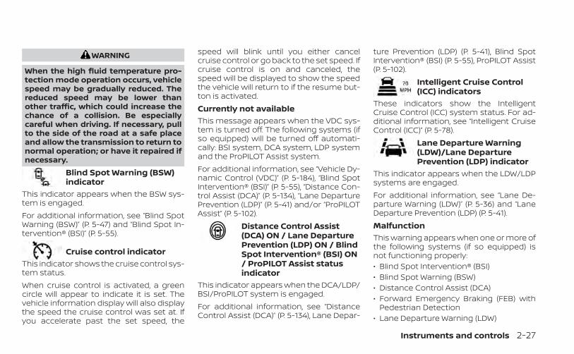
WARNING
When the high fluid temperature pro-tection mode operation occurs, vehiclespeed may be gradually reduced. Thereduced speed may be lower thanother traffic, which could increase thechance of a collision. Be especiallycareful when driving. If necessary, pullto the side of the road at a safe placeand allow the transmission to return tonormal operation; or have it repaired ifnecessary.
Blind Spot Warning (BSW)indicator
This indicator appears when the BSW sys-tem is engaged.For additional information, see “Blind SpotWarning (BSW)” (P. 5-47) and “Blind Spot In-tervention® (BSI)” (P. 5-55).
Cruise control indicatorThis indicator shows the cruise control sys-tem status.When cruise control is activated, a greencircle will appear to indicate it is set. Thevehicle information display will also displaythe speed the cruise control was set at. Ifyou accelerate past the set speed, the
speed will blink until you either cancelcruise control or go back to the set speed. Ifcruise control is on and canceled, thespeed will be displayed to show the speedthe vehicle will return to if the resume but-ton is activated.Currently not availableThis message appears when the VDC sys-tem is turned off. The following systems (ifso equipped) will be turned off automati-cally: BSI system, DCA system, LDP systemand the ProPILOT Assist system.For additional information, see “Vehicle Dy-namic Control (VDC)” (P. 5-184), “Blind SpotIntervention® (BSI)” (P. 5-55), “Distance Con-trol Assist (DCA)” (P. 5-134), “Lane DeparturePrevention (LDP)” (P. 5-41) and/or “ProPILOTAssist” (P. 5-102).
Distance Control Assist(DCA) ON / Lane DeparturePrevention (LDP) ON / BlindSpot Intervention® (BSI) ON/ ProPILOT Assist statusindicator
This indicator appears when the DCA/LDP/BSI/ProPILOT system is engaged.For additional information, see “DistanceControl Assist (DCA)” (P. 5-134), Lane Depar-
ture Prevention (LDP) (P. 5-41), Blind SpotIntervention® (BSI) (P. 5-55), ProPILOT Assist(P. 5-102).
Intelligent Cruise Control(ICC) indicators
These indicators show the IntelligentCruise Control (ICC) system status. For ad-ditional information, see “Intelligent CruiseControl (ICC)” (P. 5-78).
Lane Departure Warning(LDW)/Lane DeparturePrevention (LDP) indicator
This indicator appears when the LDW/LDPsystems are engaged.For additional information, see “Lane De-parture Warning (LDW)” (P. 5-36) and “LaneDeparture Prevention (LDP) (P. 5-41).MalfunctionThis warning appears when one or more ofthe following systems (if so equipped) isnot functioning properly:• Blind Spot Intervention® (BSI)• Blind Spot Warning (BSW)• Distance Control Assist (DCA)• Forward Emergency Braking (FEB) with
Pedestrian Detection• Lane Departure Warning (LDW)
Instruments and controls 2-27
• Lane Departure Prevention (LDP)• Predictive Forward Collision Warning
(PFCW)• ProPilot Assist• Rear Cross Traffic Alert (RCTA)• Traffic Sign Recognition (TSR)If one or more of these warning appears,have the system checked. It is recom-mended that you visit an INFINITI retailer forthis service.Not Available Bad WeatherThis message may appear when the Steer-ing Assist system is engaged.Under the following condition, the SteeringAssist system is automatically canceled:• When the wiper (HI) operatesThe system will be available when theabove condition no longer exists.Not Available Front Radar BlockedThis message appears when the DistanceControl Assist (DCA), Forward EmergencyBraking (FEB) with Pedestrian Detection, orPredictive Forward Collision Warning(PFCW) systems become unavailable be-cause the front radar is obstructed. For ad-ditional information, see “Distance ControlAssist (DCA)” (P. 5-134), “Forward Emergency
Braking (FEB) with Pedestrian Detection”(P. 5-151), or “Predictive Forward CollisionWarning (PFCW)” (P. 5-162).Not Available: High Camera TempThis message appears when the cameradetects an interior temperature of morethan 104°F (40°C).For additional information, see “Blind SpotIntervention® (BSI)” (P. 5-55) , “Lane Depar-ture Warning (LDW)” (P. 5-36), “Lane Depar-ture Prevention (LDP)” (P. 5-41) or “Traffic SignRecognition (TSR)” (P. 5-33).Not Available Poor Road ConditionsThis message may appear when the ProPI-LOT Assist system, the Blind Spot Interven-tion® (BSI) system, the Lane Departure Pre-vention (LDP) system or the DistanceControl Assist (DCA) system is engaged.Under the following conditions, the ProPI-LOT Assist system, the Blind Spot Interven-tion® (BSI) system, the Lane Departure Pre-vention (LDP) system, or the DistanceControl Assist (DCA) system, is automati-cally canceled:• When the VDC operates• When a wheel slipsThe above system cannot be used in somesituations (VDC operates and wheel slips).
Not Available Seat Belt NotFastened
This message may appear when the Intel-ligent Cruise Control (ICC) (with ProPILOTAssist) system is engaged.Under the following condition, the ICC (withProPILOT Assist) system is automaticallycanceled:• When the driver’s seat belt is not fastenedThe above system cannot be used whenthe driver’s seat belt is not fastened.Not Available Visibility is ImpairedThis message may appear when the Intel-ligent Cruise Control (ICC) (with ProPILOTAssist) system is engaged.Under the following conditions, The ICC(with ProPILOT Assist) system is automati-cally canceled:• The camera area of the windshield is
fogged up or covered with dirt, waterdrops, ice, snow, etc.
• Strong light, such as sunlight or highbeams from oncoming vehicles, enterthe front camera
The system will be available when theabove conditions no longer exist.
2-28 Instruments and controls
If the warning message continues to ap-pear, stop the vehicle in a safe location, turnthe engine off, and clean the windshield.
ProPILOT Assist indicatorsThese indicators show the ProPILOT Assistsystem status.For additional information, see “ProPILOTAssist” (P. 5-102).
Rear Automatic Braking(RAB) indicator
This indicator appears to indicate the sta-tus of the Rear Automatic Braking (RAB)system. For additional information, see“Rear Automatic Braking (RAB)” (P. 5-146).
Speed Limit Sign indicatorThis message may appear when the TrafficSign Recognition system is engaged.For additional information, see “Traffic SignRecognition (TSR)” (P. 5-33).
Steering Assist AlertThis message may appear when the Steer-ing Assist system is engaged.It will be displayed under the followingcondition:
• When not holding the steering wheel orwhen there is no steering wheeloperation
Please hold on the steering wheel immedi-ately. When the steering operation is de-tected, the warning turns off and the steer-ing assist function is automaticallyrestored.
Steering Assist NotAvailable: Cannot DetectLane
This message may appear when the Steer-ing Assist system is engaged.Under the following conditions, the Steer-ing Assist system is automaticallycanceled:• When lane markers in the traveling lane
cannot be correctly detected for a periodof time due to such items as a snow rut,reflection of light on a rainy day or severalunclear lane markers are present
If you want to use the Steering Assist sys-tem again, cancel the ProPILOT Assist sys-tem and set it again when lane markers areclearly visible.
Steering Assist statusThis indicator appears when the SteeringAssist system is engaged.For additional information, see “ProPILOTAssist” (P. 5-102).System fault See Owner’s ManualThis warning appears if there is a malfunc-tion in the Rear Automatic Braking (RAB)system. For additional information, see“Rear Automatic Braking (RAB)” (P. 5-146).Unavailable: Side Radar ObstructionThis message appears when one of thefollowing systems (if so equipped) be-comes unavailable because a radar block-age is detected.• Blind Spot Intervention® (BSI)• Blind Spot Warning (BSW)• Rear Cross Traffic Alert (RCTA)For additional information, see:• “Blind Spot Intervention® (BSI)” (P. 5-55)• “Blind Spot Warning (BSW)” (P. 5-47)• “Rear Cross Traffic Alert (RCTA)” (P. 5-68)
Instruments and controls 2-29
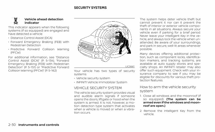
Vehicle ahead detectionindicator
This indicator appears when the followingsystems (if so equipped) are engaged andhave detected a vehicle:• Distance Control Assist (DCA)• Forward Emergency Braking (FEB) with
Pedestrian Detection• Predictive Forward Collision Warning
(PFCW)For additional information, see “DistanceControl Assist (DCA)” (P. 5-134), “ForwardEmergency Braking (FEB) with PedestrianDetection” (P. 5-151) or “Predictive ForwardCollision Warning (PFCW)” (P. 5-162) Your vehicle has two types of security
systems:• Vehicle security system• INFINITI Vehicle Immobilizer System
VEHICLE SECURITY SYSTEMThe vehicle security system provides visualand audible alarm signals if someoneopens the doors, liftgate or hood when thesystem is armed. It is not, however, a mo-tion detection type system that activateswhen a vehicle is moved or when a vibra-tion occurs.
The system helps deter vehicle theft butcannot prevent it nor can it prevent thetheft of interior or exterior vehicle compo-nents in all situations. Always secure yourvehicle even if parking for a brief period.Never leave your Intelligent Key in the ve-hicle, and always lock the vehicle when un-attended. Be aware of your surroundings,and park in secure, well-lit areas wheneverpossible.Many devices offering additional protec-tion, such as component locks, identifica-tion markers, and tracking systems, areavailable at auto supply stores and spe-cialty shops. An INFINITI retailer may alsooffer such equipment. Check with your in-surance company to see if you may beeligible for discounts for various theft pro-tection features.
How to arm the vehicle securitysystem1. Close all windows and the moonroof (if
so equipped). (The system can bearmed even if the windows and moon-roof are open.)
2. Remove the Intelligent Key from thevehicle.
LIC0661
SECURITY SYSTEMS
2-30 Instruments and controls
3. Close all doors, hood and liftgate. Lockall doors. The doors can be locked withthe Intelligent Key, door handle requestswitch, or power door lock switch.
4. Confirm that the security indicatorlight stays on for about 30 seconds. Thevehicle security system is now pre-armed. The vehicle security system willautomatically shift into the armedphase. The security light begins toflash once every three seconds. If duringthe pre-armed phase one of the follow-ing occurs, the system will not arm:
• Any door is unlocked with the IntelligentKey or door request switch.
• Ignition switch is placed in AUTO ACC orON position.
• Even when the driver and/or passen-gers are in the vehicle, the system willactivate with all the doors, hood andliftgate locked with the ignition switchplaced in the LOCK position. When plac-ing the ignition switch in the AUTO ACCor ON position, the system will bereleased.
Vehicle security system activationThe vehicle security system will give thefollowing alarm:• The turn signals blink and the horn
sounds intermittently.• The alarm automatically turns off after a
period of time. However, the alarm reacti-vates if the vehicle is tampered withagain. The alarm can be shut off by press-ing the button on the Intelligent Key.
The alarm is activated by:• Opening the door or liftgate without us-
ing the Intelligent Key (even if the door isunlocked by releasing the door insidelock switch).
How to stop an activated alarmThe alarm stops only by unlocking the driv-er’s door or the liftgate by pressing the
button on the Intelligent Key or push-ing the request switch on the driver's orpassenger's door with the Intelligent Key inrange of the door handle.
INFINITI VEHICLE IMMOBILIZERSYSTEMThe INFINITI Vehicle Immobilizer Systemwill not allow the engine to start without
the use of a registered INFINITI Vehicle Im-mobilizer System key.If the engine fails to start using a registeredINFINITI Vehicle Immobilizer System key (forexample, when interference is caused byanother INFINITI Vehicle Immobilizer Sys-tem key, an automated toll road device orautomatic payment device on the key ring),restart the engine using the followingprocedures:1. Leave the ignition switch in the ON posi-
tion for approximately 5 seconds.
2. Place the ignition switch in the OFF orLOCK position, and wait approximately10 seconds.
3. Repeat steps 1 and 2.
4. Restart the engine while holding the de-vice (which may have caused the inter-ference) separate from the registeredINFINITI Vehicle Immobilizer System key.
If the no start condition re-occurs, INFINITIrecommends placing the registeredINFINITI Vehicle Immobilizer System key ona separate key ring to avoid interferencefrom other devices.
Instruments and controls 2-31
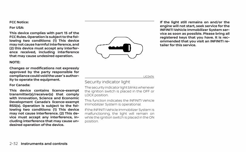
FCC Notice:For USA:This device complies with part 15 of theFCC Rules. Operation is subject to the fol-lowing two conditions: (1) This devicemay not cause harmful interference, and(2) this device must accept any interfer-ence received, including interferencethat may cause undesired operation.
NOTE:
Changes or modifications not expresslyapproved by the party responsible forcompliance could void the user's author-ity to operate the equipment.For Canada:This device contains licence-exempttransmitter(s)/receiver(s) that complywith Innovation, Science and EconomicDevelopment Canada’s licence-exemptRSS(s). Operation is subject to the fol-lowing two conditions: (1) This devicemay not cause interference. (2) This de-vice must accept any interference, in-cluding interference that may cause un-desired operation of the device.
Security indicator lightThe security indicator light blinks wheneverthe ignition switch is placed in the OFF orLOCK position.This function indicates the INFINITI VehicleImmobilizer System is operational.If the INFINITI Vehicle Immobilizer System ismalfunctioning, the light will remain onwhile the ignition switch is placed in the ONposition.
If the light still remains on and/or theengine will not start, seek service for theINFINITI Vehicle Immobilizer System ser-vice as soon as possible. Please bring allregistered keys that you have. It is rec-ommended that you visit an INFINITI re-tailer for this service.
LIC0474
2-32 Instruments and controls
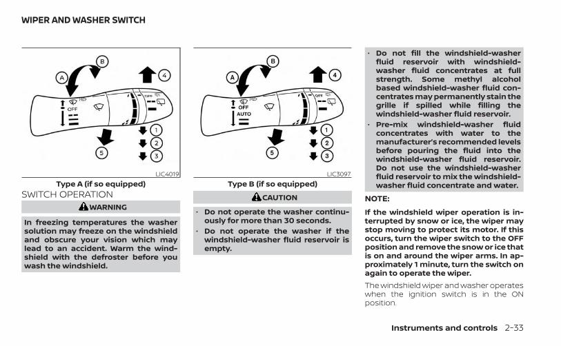
SWITCH OPERATIONWARNING
In freezing temperatures the washersolution may freeze on the windshieldand obscure your vision which maylead to an accident. Warm the wind-shield with the defroster before youwash the windshield.
CAUTION
• Do not operate the washer continu-ously for more than 30 seconds.
• Do not operate the washer if thewindshield-washer fluid reservoir isempty.
• Do not fill the windshield-washerfluid reservoir with windshield-washer fluid concentrates at fullstrength. Some methyl alcoholbased windshield-washer fluid con-centrates may permanently stain thegrille if spilled while filling thewindshield-washer fluid reservoir.
• Pre-mix windshield-washer fluidconcentrates with water to themanufacturer’s recommended levelsbefore pouring the fluid into thewindshield-washer fluid reservoir.Do not use the windshield-washerfluid reservoir to mix the windshield-washer fluid concentrate and water.
NOTE:
If the windshield wiper operation is in-terrupted by snow or ice, the wiper maystop moving to protect its motor. If thisoccurs, turn the wiper switch to the OFFposition and remove the snow or ice thatis on and around the wiper arms. In ap-proximately 1 minute, turn the switch onagain to operate the wiper.The windshield wiper and washer operateswhen the ignition switch is in the ONposition.
LIC4019Type A (if so equipped)
LIC3097Type B (if so equipped)
WIPER AND WASHER SWITCH
Instruments and controls 2-33
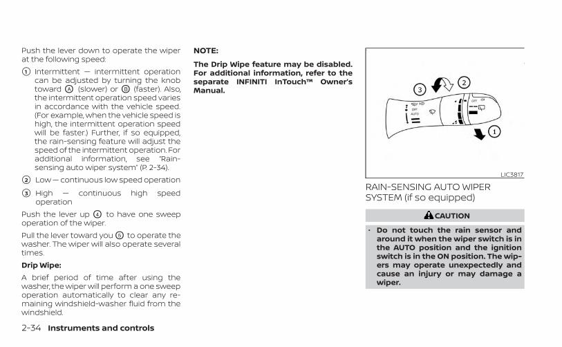
Push the lever down to operate the wiperat the following speed:
�1 Intermittent — intermittent operationcan be adjusted by turning the knobtoward OA (slower) or OB (faster). Also,the intermittent operation speed variesin accordance with the vehicle speed.(For example, when the vehicle speed ishigh, the intermittent operation speedwill be faster.) Further, if so equipped,the rain-sensing feature will adjust thespeed of the intermittent operation. Foradditional information, see “Rain-sensing auto wiper system” (P. 2-34).
�2 Low — continuous low speed operation
�3 High — continuous high speedoperation
Push the lever up O4 to have one sweepoperation of the wiper.Pull the lever toward you O5 to operate thewasher. The wiper will also operate severaltimes.Drip Wipe:A brief period of time after using thewasher, the wiper will perform a one sweepoperation automatically to clear any re-maining windshield-washer fluid from thewindshield.
NOTE:
The Drip Wipe feature may be disabled.For additional information, refer to theseparate INFINITI InTouch™ Owner’sManual.
RAIN-SENSING AUTO WIPERSYSTEM (if so equipped)
CAUTION
• Do not touch the rain sensor andaround it when the wiper switch is inthe AUTO position and the ignitionswitch is in the ON position. The wip-ers may operate unexpectedly andcause an injury or may damage awiper.
LIC3817
2-34 Instruments and controls
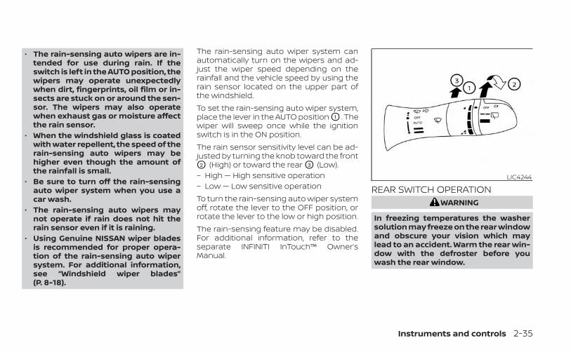
• The rain-sensing auto wipers are in-tended for use during rain. If theswitch is left in the AUTO position, thewipers may operate unexpectedlywhen dirt, fingerprints, oil film or in-sects are stuck on or around the sen-sor. The wipers may also operatewhen exhaust gas or moisture affectthe rain sensor.
• When the windshield glass is coatedwith water repellent, the speed of therain-sensing auto wipers may behigher even though the amount ofthe rainfall is small.
• Be sure to turn off the rain-sensingauto wiper system when you use acar wash.
• The rain-sensing auto wipers maynot operate if rain does not hit therain sensor even if it is raining.
• Using Genuine NISSAN wiper bladesis recommended for proper opera-tion of the rain-sensing auto wipersystem. For additional information,see “Windshield wiper blades”(P. 8-18).
The rain-sensing auto wiper system canautomatically turn on the wipers and ad-just the wiper speed depending on therainfall and the vehicle speed by using therain sensor located on the upper part ofthe windshield.To set the rain-sensing auto wiper system,place the lever in the AUTO position O1 . Thewiper will sweep once while the ignitionswitch is in the ON position.The rain sensor sensitivity level can be ad-justed by turning the knob toward the frontO2 (High) or toward the rear O3 (Low).– High — High sensitive operation– Low — Low sensitive operationTo turn the rain-sensing auto wiper systemoff, rotate the lever to the OFF position, orrotate the lever to the low or high position.The rain-sensing feature may be disabled.For additional information, refer to theseparate INFINITI InTouch™ Owner’sManual.
REAR SWITCH OPERATIONWARNING
In freezing temperatures the washersolution may freeze on the rear windowand obscure your vision which maylead to an accident. Warm the rear win-dow with the defroster before youwash the rear window.
LIC4244
Instruments and controls 2-35
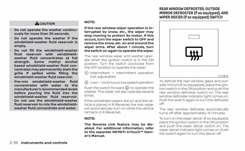
CAUTION
• Do not operate the washer continu-ously for more than 30 seconds.
• Do not operate the washer if thewindshield-washer fluid reservoir isempty.
• Do not fill the windshield-washerfluid reservoir with windshield-washer fluid concentrates at fullstrength. Some methyl alcoholbased windshield-washer fluid con-centrates may permanently stain thegrille if spilled while filling thewindshield-washer fluid reservoir.
• Pre-mix windshield-washer fluidconcentrates with water to themanufacturer’s recommended levelsbefore pouring the fluid into thewindshield-washer fluid reservoir.Do not use the windshield-washerfluid reservoir to mix the windshield-washer fluid concentrate and water.
NOTE:
If the rear window wiper operation is in-terrupted by snow, etc., the wiper maystop moving to protect its motor. If thisoccurs, turn the wiper switch to OFF andremove the snow, etc. on and around thewiper arms. After about 1 minute, turnthe switch on again to operate the wiper.The rear window wiper and washer oper-ate when the ignition switch is in the ONposition. Turn the switch clockwise fromthe OFF position to operate the wiper.
�1 Intermittent — intermittent operation(not adjustable)
�2 Low — continuous low speed operationPush the switch forward O3 to operate thewasher. The wiper will also operate severaltimes.If the windshield wipers are on and the ve-hicle is placed in R (Reverse) the rear wiperwill automatically turn on while the vehicleremains in R (Reverse).
NOTE:
The Reverse Link feature may be dis-abled. For additional information, referto the separate INFINITI InTouch™ Own-er’s Manual.
To defrost the rear window glass and out-side mirrors (if so equipped), place the igni-tion switch in the ON position and push therear window defroster switch on. The rearwindow defroster indicator light comes on.Push the switch again to turn the defrosteroff.The rear window defroster automaticallyturns off after approximately 15 minutes.To turn on the wiper deicer (if so equipped),place the ignition switch in the ON positionand push the wiper deicer switch on. Thewiper deicer indicator light comes on. Pushthe switch again to turn the deicer off.
LIC3816
REAR WINDOW DEFROSTER, OUTSIDEMIRROR DEFROSTER (if so equipped), ANDWIPER DEICER (if so equipped) SWITCH
2-36 Instruments and controls
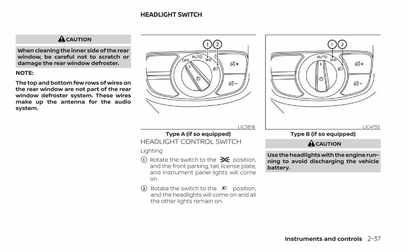
CAUTION
When cleaning the inner side of the rearwindow, be careful not to scratch ordamage the rear window defroster.
NOTE:
The top and bottom few rows of wires onthe rear window are not part of the rearwindow defroster system. These wiresmake up the antenna for the audiosystem.
HEADLIGHT CONTROL SWITCHLighting
�1 Rotate the switch to the position,and the front parking, tail, license plate,and instrument panel lights will comeon.
�2 Rotate the switch to the position,and the headlights will come on and allthe other lights remain on.
CAUTION
Use the headlights with the engine run-ning to avoid discharging the vehiclebattery.
LIC3818Type A (if so equipped)
LIC4755Type B (if so equipped)
HEADLIGHT SWITCH
Instruments and controls 2-37

Autolight systemThe autolight system allows the headlightsto turn on and off automatically. The auto-light system can:• Turn on the headlights, front parking, tail,
license plate and instrument panel lightsautomatically when it is dark.
• Turn off all the lights (except daytime run-ning lights) when it is light.
• Keep all the lights on for a period of timeafter you place the ignition switch in theOFF position and all doors are closed.
NOTE:Autolight activation sensitivity andthe time delay for autolight shutoffcan be adjusted. For additional infor-mation, refer to the separate INFINITIInTouch™ Owner’s Manual.To turn on the autolight system:1. Turn the headlight switch to the AUTO
position O1 .
2. Place the ignition switch in the ONposition.
3. The autolight system automaticallyturns the headlights on and off.
Initially, if the ignition switch is placed in theOFF position and a door is opened and leftopen, the headlights remain on for a periodof time. If another door is opened while theheadlights are on, then the timer is reset.The headlights will turn on automatically attwilight or in rainy weather (when the wind-shield wiper is operated continuously). Ifthe ignition switch is pushed to the OFFposition and one of the doors is openedand this condition continued, the head-lights remain on for 5 minutes.To turn the autolight system off, turn theswitch to the OFF (if so equipped), , or
position.
LIC3819Type A (if so equipped)
LIC4756Type B (if so equipped)
2-38 Instruments and controls
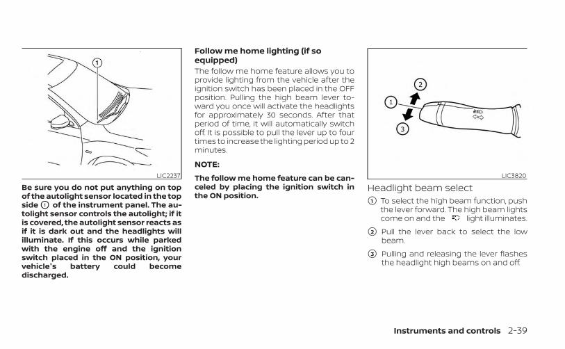
Be sure you do not put anything on topof the autolight sensor located in the topside O1 of the instrument panel. The au-tolight sensor controls the autolight; if itis covered, the autolight sensor reacts asif it is dark out and the headlights willilluminate. If this occurs while parkedwith the engine off and the ignitionswitch placed in the ON position, yourvehicle's battery could becomedischarged.
Follow me home lighting (if soequipped)The follow me home feature allows you toprovide lighting from the vehicle after theignition switch has been placed in the OFFposition. Pulling the high beam lever to-ward you once will activate the headlightsfor approximately 30 seconds. After thatperiod of time, it will automatically switchoff. It is possible to pull the lever up to fourtimes to increase the lighting period up to 2minutes.
NOTE:
The follow me home feature can be can-celed by placing the ignition switch inthe ON position.
Headlight beam select�1 To select the high beam function, push
the lever forward. The high beam lightscome on and the light illuminates.
�2 Pull the lever back to select the lowbeam.
�3 Pulling and releasing the lever flashesthe headlight high beams on and off.
LIC2237 LIC3820
Instruments and controls 2-39
High Beam AssistThe High Beam Assist system will operatewhen the vehicle is driven at speeds of ap-proximately 25 mph (40 km/h) and above. Ifan oncoming vehicle or leading vehicle ap-pears in front of your vehicle when theheadlight high beam is on, the headlightwill be switched to the low beamautomatically.
WARNING
• The High Beam Assist system is aconvenience but it is not a substitutefor safe driving operation. The drivershould remain alert at all times, en-sure safe driving practices andswitch the high beams and low beammanually when necessary.
• The high beam or low beam may notswitch automatically under the fol-lowing conditions. Switch the highbeam and low beam manually.– During bad weather (rain, fog,
snow, wind, etc.).– When a light source similar to a
headlight or tail light is in the vi-cinity of the vehicle.
– When the headlights of the on-coming vehicle or the leading ve-hicle are turned off, when the colorof the light is affected due to for-eign materials on the lights, orwhen the light beam is out ofposition.
– When there is a sudden, continu-ous change in brightness.
– When driving on a road thatpasses over rolling hills, or a roadthat has level differences.
– When driving on a road with manycurves.
– When a sign or mirror-like surfaceis reflecting intense light towardsthe front of the vehicle.
– When the container, etc. beingtowed by a leading vehicle is re-flecting intense light.
– When a headlight on your vehicleis damaged or dirty.
– When the vehicle is leaning at anangle due to a punctured tire, be-ing towed, etc.
• The timing of switching the lowbeam and high beam may changeunder the following situations.– The brightness of the headlights
of the oncoming vehicle or leadingvehicle.
– The movement and direction ofthe oncoming vehicle and theleading vehicle.
– When only one light on the on-coming vehicle or the leading ve-hicle is illuminated.
– When the oncoming vehicle or theleading vehicle is a two-wheeledvehicle.
– Road conditions (incline, curve,the road surface, etc.).
– The number of passengers andthe amount of luggage.
2-40 Instruments and controls

High Beam Assist operationTo activate the High Beam Assist system,turn the headlight switch to the AUTO po-sition O1 and push the lever forward O2
(high beam position). The High Beam Assistindicator light in the meter will illuminatewhile the headlights are turned on.If the High Beam Assist indicator light doesnot illuminate in the above condition, it mayindicate that the system is not functioningproperly. Have the system checked. It isrecommended that you visit an INFINITI re-tailer for this service.
When the vehicle speed lowers to less thanapproximately 16 mph (25 km/h), the head-light uses the low beam.To turn off the High Beam Assist system,turn the headlight switch to the posi-tion or select the low beam position byplacing the lever in the neutral position.
Ambient image sensor maintenanceThe ambient image sensor O1 for the HighBeam Assist system is located in front ofthe inside mirror. To maintain the properoperation of the High Beam Assist systemand prevent a system malfunction, be sureto observe the following:• Always keep the windshield clean.• Do not attach a sticker (including trans-
parent material) or install an accessorynear the ambient image sensor.
• Do not strike or damage the areasaround the ambient image sensor. Donot touch the sensor lens that is locatedon the ambient image sensor.
LIC3819 LIC3821 LIC4259
Instruments and controls 2-41

If the ambient image sensor is damageddue to an accident, it is recommended thatyou visit an INFINITI retailer.
Battery saver systemThe battery saver system automaticallyturns off the ignition after a period of timewhen the ignition switch is left in the AUTOACC or ON position.The battery saver system automaticallyturns off the following lights after a periodof time when the ignition switch is placed inthe OFF position and the doors are closed:• Headlights, when the headlight switch is
in the or position• Interior lights, when left in the ON position
CAUTION
Even though the battery saver featureautomatically turns off the headlightsafter a period of time, you should turnthe headlight switch to the OFF posi-tion when the engine is not running toavoid discharging the vehicle battery.
Adaptive Front lighting System(AFS) (if so equipped)The Adaptive Front lighting System (AFS)will automatically adjust the headlights(low beam) toward the turning direction toimprove the driver’s view. When the head-light switch is ON and the driver operatesthe steering wheel in a turn, the AFS systemwill be activated.The AFS will operate:• when the headlight switch is ON.• when the shift lever is in any position
other than P (Park) or R (Reverse).• when the vehicle is driven at above 16
mph (25 km/h) for the left-side headlight.Note that the right-side low beam head-light will swivel but the left side will notswivel when the vehicle is at a stop andthe steering wheel is turned. The vehiclemust attain a speed above 16 mph (25km/h) before AFS activates the left-sideheadlight.
AFS will also adjust the headlight to aproper axis automatically, depending onthe number of occupants in the vehicle, theload the vehicle is carrying and the roadconditions.
If the AFS OFF indicator blinks or the vehicleinformation display shows an AFS systemerror message after the ignition switch hasbeen pushed to the ON position, this mayindicate that the AFS is not functioningproperly. Have the system checked. It isrecommended you visit an INFINITI retailerfor this service. When the engine is started,the headlights will vibrate to check the sys-tem condition. This is not a malfunction.
Automatic headlight aimingcontrol (if so equipped)Your vehicle is equipped with an automaticheadlight levelling system. The headlightaxis is controlled automatically.INFINITI recommends that you consult thelocal regulations on the use of lights.
LED DAYTIME RUNNING LIGHTS(DRL) SYSTEMThe LED portion of the headlights auto-matically illuminate at 100% intensity whenthe engine is started and the parking brakereleased. The LED Daytime Running Lights(DRL) system operates with the headlightswitch in the OFF position. When you turnthe headlight switch to the positionfor full illumination, the LED lights switchfrom LED DRL system to the park function.
2-42 Instruments and controls

If the parking brake is applied before theengine is started, the LED DRL system doesnot illuminate. The LED DRL system illumi-nates when the parking brake is released.The LED DRL system will remain on until theignition switch is placed in the OFF position.It is necessary at dusk to turn the headlightswitch on for interior controls and switchesto illuminate, as those remain off while theswitch is in the OFF position.
WARNING
When the LED DRL system is active, taillights on your vehicle are not on. It isnecessary at dusk to turn on yourheadlights. Failure to do so could causean accident injuring yourself andothers.
INSTRUMENT BRIGHTNESSCONTROLPress the “+” button OA to increase thebrightness of instrument panel lights.Press the “-” button OB to decrease thebrightness of instrument panel lights.
TURN SIGNAL SWITCHTurn signal�1 Move the lever up or down to signal the
turning direction. When the turn is com-pleted, the turn signal cancelsautomatically.
Lane change signal�2 Move the lever up or down until the turn
signal begins to flash, but the leverdoes not latch, to signal a lane change.Hold the lever until the lane change iscompleted.
LIC4267 LIC3823
Instruments and controls 2-43

Move the lever up or down until the turnsignal begins to flash, but the lever doesnot latch, and release the lever. The turnsignal will automatically flash three times.Choose the appropriate method to signala lane change based on road and trafficconditions.
FOG LIGHT SWITCHTo turn the fog lights on, turn the headlightswitch to the position, then push thefog light switch on.To turn the fog lights on with the headlightswitch in the AUTO position, the headlightsmust be on, then push the fog light switchon.To turn the fog lights off, push the fog lightswitch again.
The headlights must be on and the lowbeams selected for the fog lights to oper-ate. The fog lights automatically turn offwhen the high beam headlights areselected.
LIC3824
2-44 Instruments and controls
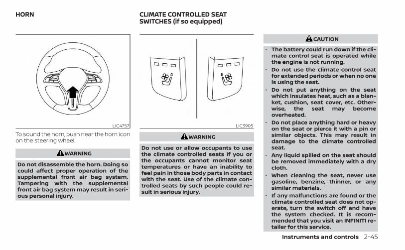
To sound the horn, push near the horn iconon the steering wheel.
WARNING
Do not disassemble the horn. Doing socould affect proper operation of thesupplemental front air bag system.Tampering with the supplementalfront air bag system may result in seri-ous personal injury.
WARNING
Do not use or allow occupants to usethe climate controlled seats if you orthe occupants cannot monitor seattemperatures or have an inability tofeel pain in those body parts in contactwith the seat. Use of the climate con-trolled seats by such people could re-sult in serious injury.
CAUTION
• The battery could run down if the cli-mate control seat is operated whilethe engine is not running.
• Do not use the climate control seatfor extended periods or when no oneis using the seat.
• Do not put anything on the seatwhich insulates heat, such as a blan-ket, cushion, seat cover, etc. Other-wise, the seat may becomeoverheated.
• Do not place anything hard or heavyon the seat or pierce it with a pin orsimilar objects. This may result indamage to the climate controlledseat.
• Any liquid spilled on the seat shouldbe removed immediately with a drycloth.
• When cleaning the seat, never usegasoline, benzine, thinner, or anysimilar materials.
• If any malfunctions are found or theclimate controlled seat does not op-erate, turn the switch off and havethe system checked. It is recom-mended that you visit an INFINITI re-tailer for this service.
LIC4757 LIC3905
HORN CLIMATE CONTROLLED SEATSWITCHES (if so equipped)
Instruments and controls 2-45
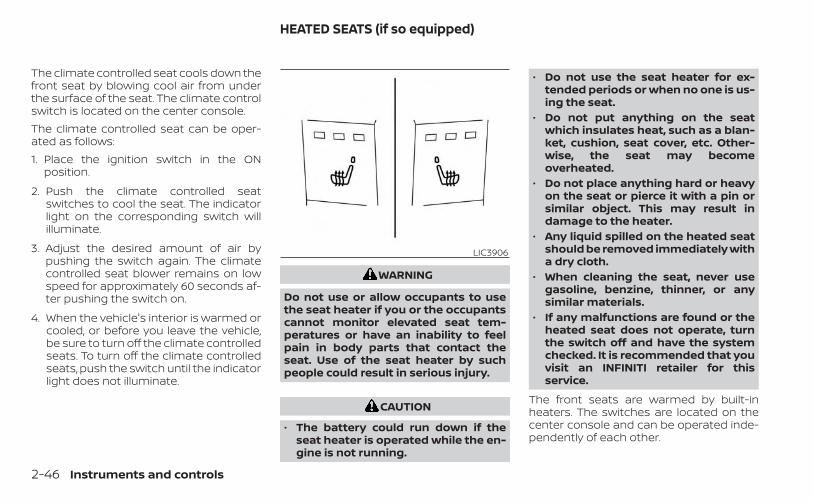
The climate controlled seat cools down thefront seat by blowing cool air from underthe surface of the seat. The climate controlswitch is located on the center console.The climate controlled seat can be oper-ated as follows:1. Place the ignition switch in the ON
position.
2. Push the climate controlled seatswitches to cool the seat. The indicatorlight on the corresponding switch willilluminate.
3. Adjust the desired amount of air bypushing the switch again. The climatecontrolled seat blower remains on lowspeed for approximately 60 seconds af-ter pushing the switch on.
4. When the vehicle's interior is warmed orcooled, or before you leave the vehicle,be sure to turn off the climate controlledseats. To turn off the climate controlledseats, push the switch until the indicatorlight does not illuminate.
WARNING
Do not use or allow occupants to usethe seat heater if you or the occupantscannot monitor elevated seat tem-peratures or have an inability to feelpain in body parts that contact theseat. Use of the seat heater by suchpeople could result in serious injury.
CAUTION
• The battery could run down if theseat heater is operated while the en-gine is not running.
• Do not use the seat heater for ex-tended periods or when no one is us-ing the seat.
• Do not put anything on the seatwhich insulates heat, such as a blan-ket, cushion, seat cover, etc. Other-wise, the seat may becomeoverheated.
• Do not place anything hard or heavyon the seat or pierce it with a pin orsimilar object. This may result indamage to the heater.
• Any liquid spilled on the heated seatshould be removed immediately witha dry cloth.
• When cleaning the seat, never usegasoline, benzine, thinner, or anysimilar materials.
• If any malfunctions are found or theheated seat does not operate, turnthe switch off and have the systemchecked. It is recommended that youvisit an INFINITI retailer for thisservice.
The front seats are warmed by built-inheaters. The switches are located on thecenter console and can be operated inde-pendently of each other.
LIC3906
HEATED SEATS (if so equipped)
2-46 Instruments and controls

1. Place the ignition switch in the ONposition.
2. Push the heated seat switch and selectthe desired heat range.
• For high heat, push the switch once.• For medium heat, push the switch twice.• For low heat, push the switch three times.• The indicator light will illuminate when
the heater is on.
3. To turn off the heater, push the heatedseat switch again. Make sure that theindicator light turns off.The heater is controlled by a controlmodule, automatically turning theheater on and off.The indicator light will remain on as longas the switch is on.When the seat is warmed, or before youleave the vehicle, be sure to turn theswitch off.
NOTE:
For additional information, see “Heaterand air conditioner (automatic)” (P. 4-33).
WARNING
When this switch is activated the fol-lowing systems (if so equipped) areturned off and will not work.• Distance Control Assist (DCA)• Blind Spot Intervention® (BSI)• Lane Departure Prevention (LDP)
The dynamic driver assistance switch isused to turn on and off the following sys-tems (Distance Control Assist (DCA) , BlindSpot Intervention® (BSI), and Lane Depar-ture Prevention (LDP)) that are activated (if
so equipped) using the settings menu inthe lower display.When the dynamic driver assistanceswitch is turned off, the indicator on theswitch is off. The indicator will also be off ifthe system is deactivated using the set-tings menu.The DCA system brakes and moves theaccelerator pedal upward according to thedistance from and the relative speed of thevehicle ahead to help assist the driver inmaintaining a following distance. For addi-tional information, see “Distance ControlAssist (DCA)” (P. 5-134).The BSI system helps alert the driver ofother vehicles in adjacent lanes whenchanging lanes, and helps assist the driverto return the vehicles to the center of thetraveling lane. For additional information,see “Blind Spot Intervention® (BSI)” (P. 5-55).The LDP system warns the driver with awarning indicator in the vehicle informa-tion display and a steering wheel vibration,and helps assist the driver to return thevehicle to the center of the traveling lane byapplying the brakes to the left or rightwheels individually (for a short period oftime). For additional information, see “LaneDeparture Prevention (LDP)” (P. 5-41).
LIC3828
DYNAMIC DRIVER ASSISTANCESWITCH (for vehicles withoutProPILOT Assist) (if so equipped)
Instruments and controls 2-47
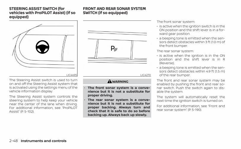
The Steering Assist switch is used to turnon and off the Steering Assist system thatis activated using the settings menu of thevehicle information display.The Steering Assist system controls thesteering system to help keep your vehiclenear the center of the lane when driving.For additional information, see “ProPILOTAssist” (P. 5-102).
WARNING
• The front sonar system is a conve-nience but it is not a substitute forproper driving.
• The rear sonar system is a conve-nience but it is not a substitute forproper backing. Always turn andcheck that it is safe to do so beforebacking up. Always back up slowly.
The front sonar system:• is active when the ignition switch is in the
ON position and the shift lever is in a for-ward gear position.
• a beeping tone is emitted when the sen-sors detect obstacles within 3 ft (1.0 m) ofthe front bumper.
The rear sonar system:• is active when the ignition is in the ON
position and the shift lever is in R(Reverse).
• a beeping tone is emitted when the sen-sors detect obstacles within 4.9 ft (1.5 m)of the rear bumper.
The front and rear sonar system may beenabled by pushing the front and rear so-nar switch. Push the switch again to dis-able the system.The system will automatically reset thenext time the ignition switch is turned on.For additional information, see “Front andrear sonar system” (P. 5-190).
LIC4495 LIC4270
STEERING ASSIST SWITCH (forvehicles with ProPILOT Assist) (if soequipped)
FRONT AND REAR SONAR SYSTEMSWITCH (if so equipped)
2-48 Instruments and controls
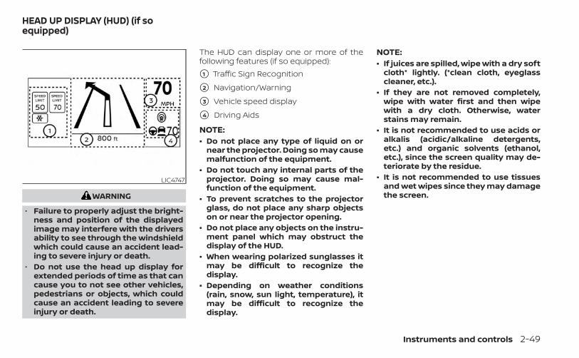
WARNING
• Failure to properly adjust the bright-ness and position of the displayedimage may interfere with the driversability to see through the windshieldwhich could cause an accident lead-ing to severe injury or death.
• Do not use the head up display forextended periods of time as that cancause you to not see other vehicles,pedestrians or objects, which couldcause an accident leading to severeinjury or death.
The HUD can display one or more of thefollowing features (if so equipped):
�1 Traffic Sign Recognition
�2 Navigation/Warning
�3 Vehicle speed display
�4 Driving Aids
NOTE:• Do not place any type of liquid on or
near the projector. Doing so may causemalfunction of the equipment.
• Do not touch any internal parts of theprojector. Doing so may cause mal-function of the equipment.
• To prevent scratches to the projectorglass, do not place any sharp objectson or near the projector opening.
• Do not place any objects on the instru-ment panel which may obstruct thedisplay of the HUD.
• When wearing polarized sunglasses itmay be difficult to recognize thedisplay.
• Depending on weather conditions(rain, snow, sun light, temperature), itmay be difficult to recognize thedisplay.
NOTE:• If juices are spilled, wipe with a dry soft
cloth* lightly. (*clean cloth, eyeglasscleaner, etc.).
• If they are not removed completely,wipe with water first and then wipewith a dry cloth. Otherwise, waterstains may remain.
• It is not recommended to use acids oralkalis (acidic/alkaline detergents,etc.) and organic solvents (ethanol,etc.), since the screen quality may de-teriorate by the residue.
• It is not recommended to use tissuesand wet wipes since they may damagethe screen.
LIC4747
HEAD UP DISPLAY (HUD) (if soequipped)
Instruments and controls 2-49
HOW TO USE THE HUDTo turn the HUD system on, push the HUDswitch. To turn the HUD off, push the switchagain.If the HUD system is turned off, it will remainoff even if the vehicle is restarted.To adjust the HUD settings when the sys-tem is on:1. Press the MENU button below the lower
display.
2. Touch the “Settings” key and then the“Head Up Display” key.
3. Adjust the positioning of the HUD on thewindshield by touching the arrows, andthe brightness by touching the bright-ness keys. To change what items areshown in the HUD, touch the “Displayitems” key. The following items (if soequipped) may be turned on or off:– Driving Aids– Navigation– Traffic Sign Recognition
NOTE:
The emergency information may appeareven if the display contents are turnedoff.
DRIVER ASSISTANCE/NAVIGATIONLINKINGThe HUD will display driver assistance andnavigation information.The driver assistance display will displaywarning situations for the following sys-tems:• FEB with Pedestrian Detection• LDW• PFCW• Hands-free warning (for vehicles with
ProPILOT Assist) (if so equipped)
The Navigation System linking display willdisplay the following items:• Arrows indicating turning direction• Distance to the next intersection
LIC3829
2-50 Instruments and controls
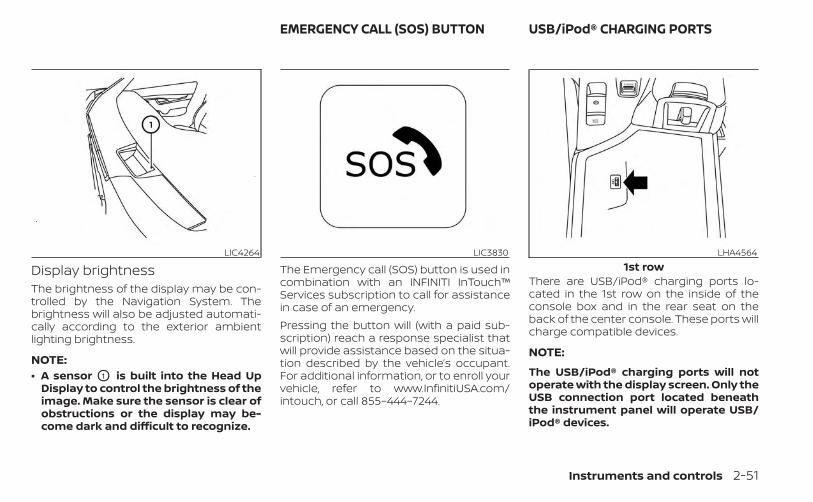
Display brightnessThe brightness of the display may be con-trolled by the Navigation System. Thebrightness will also be adjusted automati-cally according to the exterior ambientlighting brightness.
NOTE:• A sensor O1 is built into the Head Up
Display to control the brightness of theimage. Make sure the sensor is clear ofobstructions or the display may be-come dark and difficult to recognize.
The Emergency call (SOS) button is used incombination with an INFINITI InTouch™Services subscription to call for assistancein case of an emergency.Pressing the button will (with a paid sub-scription) reach a response specialist thatwill provide assistance based on the situa-tion described by the vehicle’s occupant.For additional information, or to enroll yourvehicle, refer to www.InfinitiUSA.com/intouch, or call 855–444–7244.
There are USB/iPod® charging ports lo-cated in the 1st row on the inside of theconsole box and in the rear seat on theback of the center console. These ports willcharge compatible devices.
NOTE:
The USB/iPod® charging ports will notoperate with the display screen. Only theUSB connection port located beneaththe instrument panel will operate USB/iPod® devices.
LIC4264 LIC3830 LHA45641st row
EMERGENCY CALL (SOS) BUTTON USB/iPod® CHARGING PORTS
Instruments and controls 2-51

12V OUTLETSThe power outlets are for powering electri-cal accessories such as cellular tele-phones. They are rated at 12 volt, 120W (10A)maximum.The instrument panel, rear console, andluggage area power outlets are poweredonly when the ignition switch is in the AUTOACC or ON position.
LHA4565Rear seat
LIC4260Instrument Panel
LIC3832Rear console
POWER OUTLETS
2-52 Instruments and controls

CAUTION
• The outlet and plug may be hot dur-ing or immediately after use.
• Only certain power outlets are de-signed for use with a cigarette lighterunit. Do not use any other power out-let for an accessory lighter. It is rec-ommended that you visit an INFINITIretailer for additional information.
• Do not use with accessories that ex-ceed a 12 volt, 120W (10A) power draw.
• Do not use double adapters or morethan one electrical accessory.
• Use power outlets with the enginerunning to avoid discharging the ve-hicle battery.
• Avoid using power outlets when theair conditioner, headlights or rearwindow defroster is on.
• Before inserting or disconnecting aplug, be sure the electrical accessorybeing used is turned off.
• Push the plug in as far as it will go. Ifgood contact is not made, the plugmay overheat or the internal tem-perature fuse may open.
• When not in use, be sure to close thecap. Do not allow water or any otherliquid to contact the outlet.
The extended storage switch is used whenshipping the vehicle. It is located in the fusepanel on the driver’s side of the instrumentpanel. If any electrical equipment does notoperate, ensure the extended storageswitch is pushed fully in place, as shown.To inspect the extended storage switch,ensure the ignition switch and headlightswitch are off, remove the fuse box coverOA using a suitable tool in combinationwith a cloth to avoid damaging the trim.
LIC3833Cargo Area
LIC3359
EXTENDED STORAGE SWITCH
Instruments and controls 2-53

FRONT-DOOR POCKETSLIC3266
OFF positionLIC3268
ON positionLIC3834
STORAGE
2-54 Instruments and controls

SEATBACK POCKETSThe seatback pockets may be located onthe back of the driver’s and/or passenger’sseats. The pockets can be used to storemaps.
WARNING
To ensure proper operation of the driv-er’s and/or front passenger's INFINITIAdvanced Air Bag System (if soequipped), please observe the follow-ing items:• Do not allow a passenger in the rear
seat to push or pull on the seatbackpocket or head restraint/head rest.
• Do not place heavy loads heavierthan 9.1 lbs. (4 kg) on the seatback,head restraint/head rest or in theseatback pocket.
FRONT CONSOLE LIDThe front console lid covers the front con-sole storage tray and the front cup holders.Slide the pocket lid towards the front of thevehicle to open.
LIC1328 LIC4550
Instruments and controls 2-55
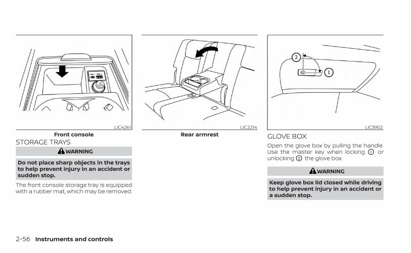
STORAGE TRAYSWARNING
Do not place sharp objects in the traysto help prevent injury in an accident orsudden stop.
The front console storage tray is equippedwith a rubber mat, which may be removed.
GLOVE BOXOpen the glove box by pulling the handle.Use the master key when locking O1 orunlocking O2 the glove box.
WARNING
Keep glove box lid closed while drivingto help prevent injury in an accident ora sudden stop.
LIC4261Front console
LIC2214Rear armrest
LIC3902
2-56 Instruments and controls
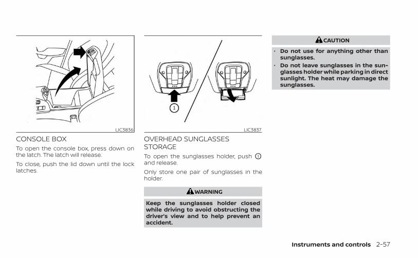
CONSOLE BOXTo open the console box, press down onthe latch. The latch will release.To close, push the lid down until the locklatches.
OVERHEAD SUNGLASSESSTORAGETo open the sunglasses holder, push O1
and release.Only store one pair of sunglasses in theholder.
WARNING
Keep the sunglasses holder closedwhile driving to avoid obstructing thedriver’s view and to help prevent anaccident.
CAUTION
• Do not use for anything other thansunglasses.
• Do not leave sunglasses in the sun-glasses holder while parking in directsunlight. The heat may damage thesunglasses.
LIC3836 LIC3837
Instruments and controls 2-57
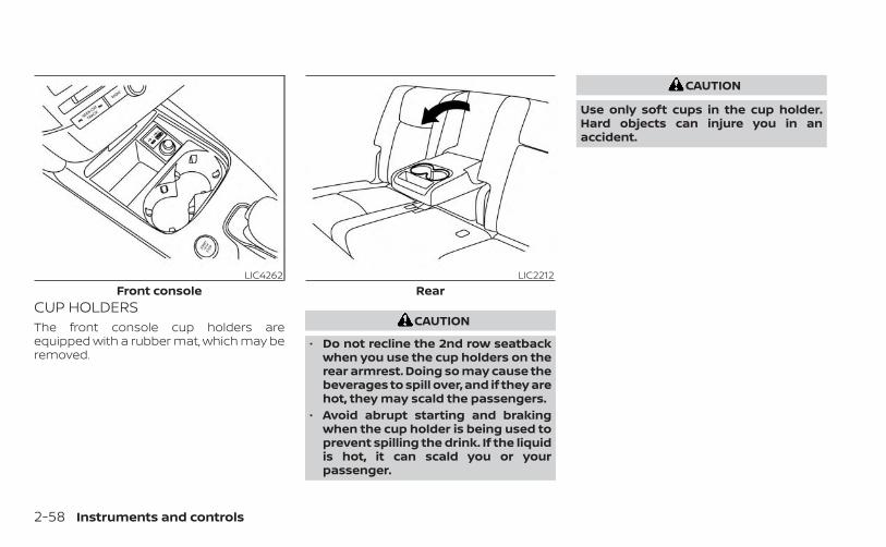
CUP HOLDERSThe front console cup holders areequipped with a rubber mat, which may beremoved.
CAUTION
• Do not recline the 2nd row seatbackwhen you use the cup holders on therear armrest. Doing so may cause thebeverages to spill over, and if they arehot, they may scald the passengers.
• Avoid abrupt starting and brakingwhen the cup holder is being used toprevent spilling the drink. If the liquidis hot, it can scald you or yourpassenger.
CAUTION
Use only soft cups in the cup holder.Hard objects can injure you in anaccident.
LIC4262Front console
LIC2212Rear
2-58 Instruments and controls
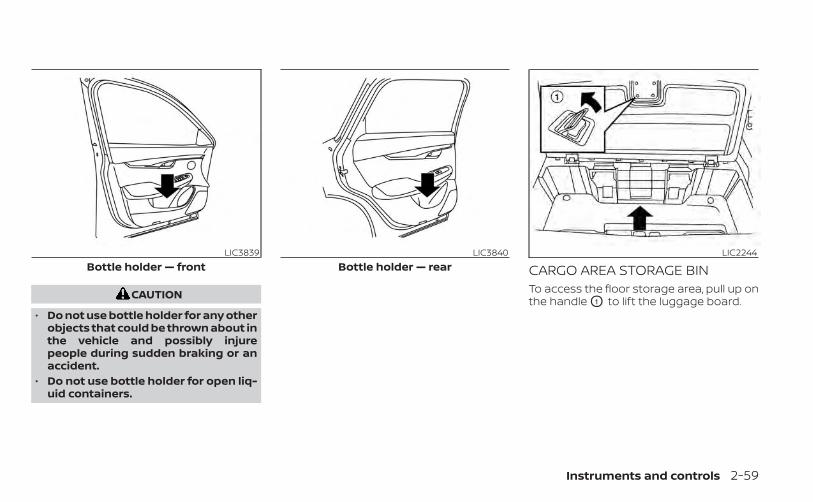
CAUTION
• Do not use bottle holder for any otherobjects that could be thrown about inthe vehicle and possibly injurepeople during sudden braking or anaccident.
• Do not use bottle holder for open liq-uid containers.
CARGO AREA STORAGE BINTo access the floor storage area, pull up onthe handle O1 to lift the luggage board.
LIC3839Bottle holder — front
LIC3840Bottle holder — rear
LIC2244
Instruments and controls 2-59
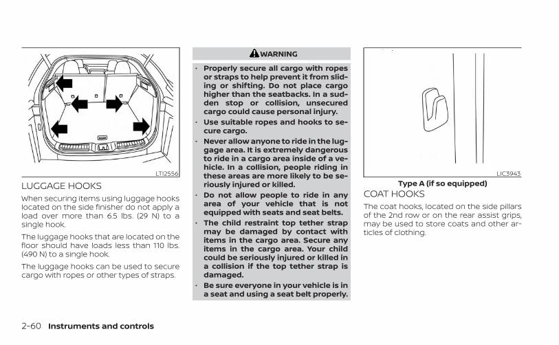
LUGGAGE HOOKSWhen securing items using luggage hookslocated on the side finisher do not apply aload over more than 6.5 lbs. (29 N) to asingle hook.The luggage hooks that are located on thefloor should have loads less than 110 lbs.(490 N) to a single hook.The luggage hooks can be used to securecargo with ropes or other types of straps.
WARNING
• Properly secure all cargo with ropesor straps to help prevent it from slid-ing or shifting. Do not place cargohigher than the seatbacks. In a sud-den stop or collision, unsecuredcargo could cause personal injury.
• Use suitable ropes and hooks to se-cure cargo.
• Never allow anyone to ride in the lug-gage area. It is extremely dangerousto ride in a cargo area inside of a ve-hicle. In a collision, people riding inthese areas are more likely to be se-riously injured or killed.
• Do not allow people to ride in anyarea of your vehicle that is notequipped with seats and seat belts.
• The child restraint top tether strapmay be damaged by contact withitems in the cargo area. Secure anyitems in the cargo area. Your childcould be seriously injured or killed ina collision if the top tether strap isdamaged.
• Be sure everyone in your vehicle is ina seat and using a seat belt properly.
COAT HOOKSThe coat hooks, located on the side pillarsof the 2nd row or on the rear assist grips,may be used to store coats and other ar-ticles of clothing.
LTI2556 LIC3943Type A (if so equipped)
2-60 Instruments and controls

CAUTION
Do not apply a total load of more than7.3 lbs. (3.3 kg) to the side pillar coathook or 33 lbs. (15 kg) to the rear assistgrip coat hook.
ROOF RACKWARNING
• Always install the crossbars onto theroof side rails before loading cargo ofany kind. Loading cargo directly ontothe roof side rails or the vehicle’s roofmay cause vehicle damage.
• Roof rack cross bars should be evenlydistributed.
• Do not exceed maximum roof rackcrossbars load capacity and alwaysdistribute the load uniformly.
• Heavy loading of the crossbars hasthe potential to affect the vehiclestability and handling during suddenor unusual handling maneuvers.
• Properly secure all cargo with ropesor straps to help prevent it from slid-ing or shifting. In a sudden stop orcollision, unsecured cargo couldcause personal injury.
• Drive extra carefully when the vehicleis loaded at or near the cargo carry-ing capacity, especially if the signifi-cant portion of that load is carried onthe crossbars.
CAUTION
• Use care when placing or removingitems from the roof rack. If you can-not comfortably lift the items ontothe roof rack from the ground, use aladder or a stool.
LIC4173Type B (if so equipped)
LIC4202
Instruments and controls 2-61
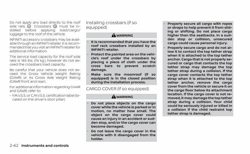
Do not apply any load directly to the roofside rails OA . Crossbars OB must be in-stalled before applying load/cargo/luggage to the roof of the vehicle.INFINITI accessory crossbars may be avail-able through an INFINITI retailer. It is recom-mended that you visit an INFINITI retailer foradditional information.The service load capacity for the roof siderails is 165 lbs. (74 kg.), however do not ex-ceed the crossbars load capacity.Be careful that your vehicle does not ex-ceed the Gross Vehicle Weight Rating(GVWR) or its Gross Axle Weight Rating(GAWR front and rear).For additional information regarding GVWRand GAWR, refer to:• F.M.V.S.S. or C.M.V.S.S. certification label (lo-
cated on the driver’s door pillar).
Installing crossbars (if soequipped)
WARNING
• It is recommended that you have theroof rack crossbars installed by anINFINITI retailer.
• Protect the painted area on the vehi-cle’s roof under the crossbars byplacing a piece of cloth under thecross bars to prevent scratchdamage.
• Make sure the moonroof (if soequipped) is in the closed positionduring the installation process.
CARGO COVER (if so equipped)
WARNING
• Do not place objects on the cargocover while the vehicle is parked or inmotion, no matter how small. Theobject on the cargo cover couldcause an injury in an accident or sud-den stop, and/or the cargo cover canbecome damaged.
• Do not leave the cargo cover in thevehicle with it disengaged from theholder.
• Properly secure all cargo with ropesor straps to help prevent it from slid-ing or shifting. Do not place cargohigher than the seatbacks. In a sud-den stop or collision, unsecuredcargo could cause personal injury.
• Properly secure cargo and do not al-low it to contact the top tether strapwhen it is attached to the top tetheranchor. Cargo that is not properly se-cured or cargo that contacts the toptether strap may damage the toptether strap during a collision. If thecargo cover contacts the top tetherstrap when it is attached to the toptether anchor, remove the cargocover from the vehicle or secure it onthe cargo floor below its attachmentlocation. If the cargo cover is not re-moved, it may damage the top tetherstrap during a collision. Your childcould be seriously injured or killed ina collision if the child restraint toptether strap is damaged.
2-62 Instruments and controls
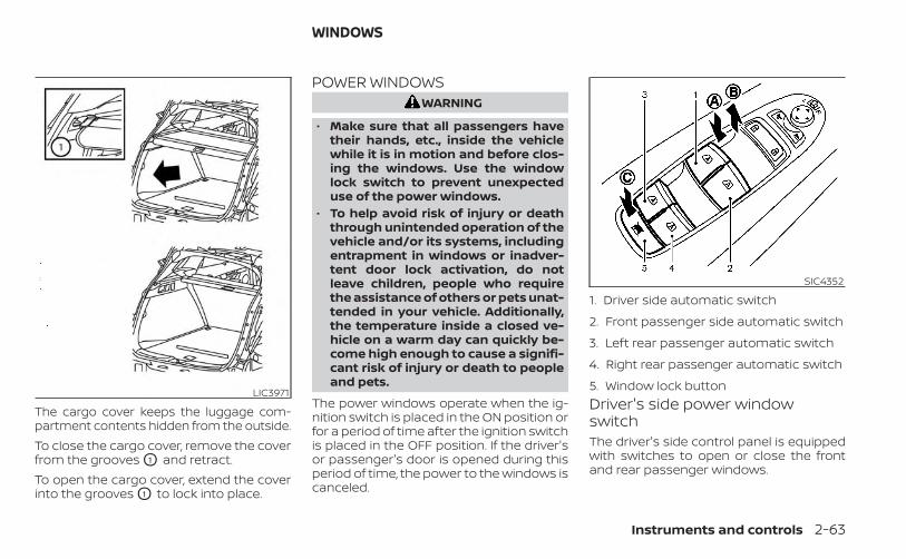
The cargo cover keeps the luggage com-partment contents hidden from the outside.To close the cargo cover, remove the coverfrom the grooves O1 and retract.To open the cargo cover, extend the coverinto the grooves O1 to lock into place.
POWER WINDOWSWARNING
• Make sure that all passengers havetheir hands, etc., inside the vehiclewhile it is in motion and before clos-ing the windows. Use the windowlock switch to prevent unexpecteduse of the power windows.
• To help avoid risk of injury or deaththrough unintended operation of thevehicle and/or its systems, includingentrapment in windows or inadver-tent door lock activation, do notleave children, people who requirethe assistance of others or pets unat-tended in your vehicle. Additionally,the temperature inside a closed ve-hicle on a warm day can quickly be-come high enough to cause a signifi-cant risk of injury or death to peopleand pets.
The power windows operate when the ig-nition switch is placed in the ON position orfor a period of time after the ignition switchis placed in the OFF position. If the driver'sor passenger's door is opened during thisperiod of time, the power to the windows iscanceled.
Driver's side power windowswitchThe driver's side control panel is equippedwith switches to open or close the frontand rear passenger windows.
LIC3971
SIC4352
1. Driver side automatic switch
2. Front passenger side automatic switch
3. Left rear passenger automatic switch
4. Right rear passenger automatic switch
5. Window lock button
WINDOWS
Instruments and controls 2-63
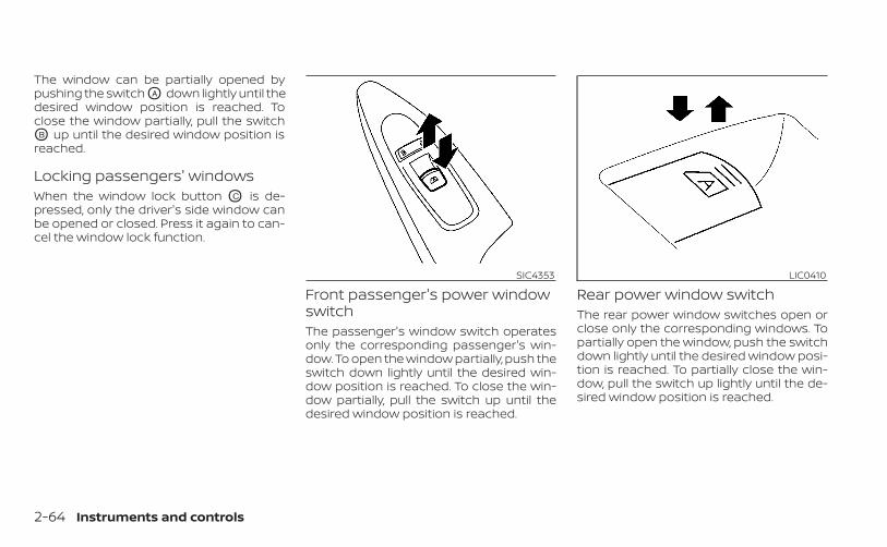
The window can be partially opened bypushing the switch OA down lightly until thedesired window position is reached. Toclose the window partially, pull the switchOB up until the desired window position isreached.
Locking passengers' windowsWhen the window lock button OC is de-pressed, only the driver's side window canbe opened or closed. Press it again to can-cel the window lock function.
Front passenger's power windowswitchThe passenger's window switch operatesonly the corresponding passenger's win-dow. To open the window partially, push theswitch down lightly until the desired win-dow position is reached. To close the win-dow partially, pull the switch up until thedesired window position is reached.
Rear power window switchThe rear power window switches open orclose only the corresponding windows. Topartially open the window, push the switchdown lightly until the desired window posi-tion is reached. To partially close the win-dow, pull the switch up lightly until the de-sired window position is reached.
SIC4353 LIC0410
2-64 Instruments and controls
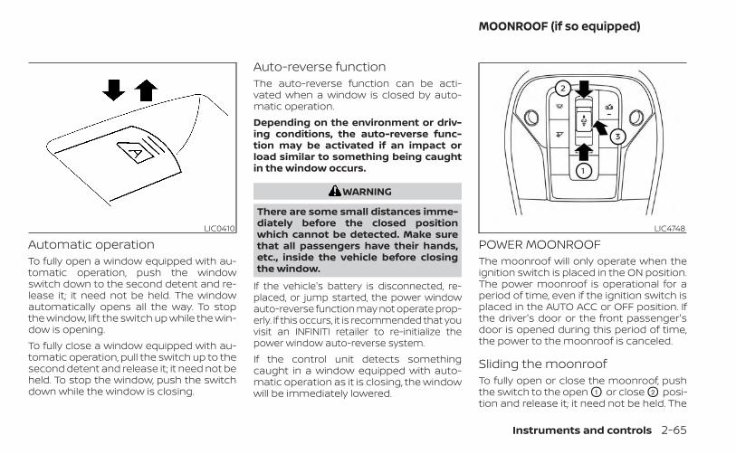
Automatic operationTo fully open a window equipped with au-tomatic operation, push the windowswitch down to the second detent and re-lease it; it need not be held. The windowautomatically opens all the way. To stopthe window, lift the switch up while the win-dow is opening.To fully close a window equipped with au-tomatic operation, pull the switch up to thesecond detent and release it; it need not beheld. To stop the window, push the switchdown while the window is closing.
Auto-reverse functionThe auto-reverse function can be acti-vated when a window is closed by auto-matic operation.Depending on the environment or driv-ing conditions, the auto-reverse func-tion may be activated if an impact orload similar to something being caughtin the window occurs.
WARNING
There are some small distances imme-diately before the closed positionwhich cannot be detected. Make surethat all passengers have their hands,etc., inside the vehicle before closingthe window.
If the vehicle's battery is disconnected, re-placed, or jump started, the power windowauto-reverse function may not operate prop-erly. If this occurs, it is recommended that youvisit an INFINITI retailer to re-initialize thepower window auto-reverse system.If the control unit detects somethingcaught in a window equipped with auto-matic operation as it is closing, the windowwill be immediately lowered.
POWER MOONROOFThe moonroof will only operate when theignition switch is placed in the ON position.The power moonroof is operational for aperiod of time, even if the ignition switch isplaced in the AUTO ACC or OFF position. Ifthe driver's door or the front passenger'sdoor is opened during this period of time,the power to the moonroof is canceled.
Sliding the moonroofTo fully open or close the moonroof, pushthe switch to the open O1 or close O2 posi-tion and release it; it need not be held. The
LIC0410 LIC4748
MOONROOF (if so equipped)
Instruments and controls 2-65
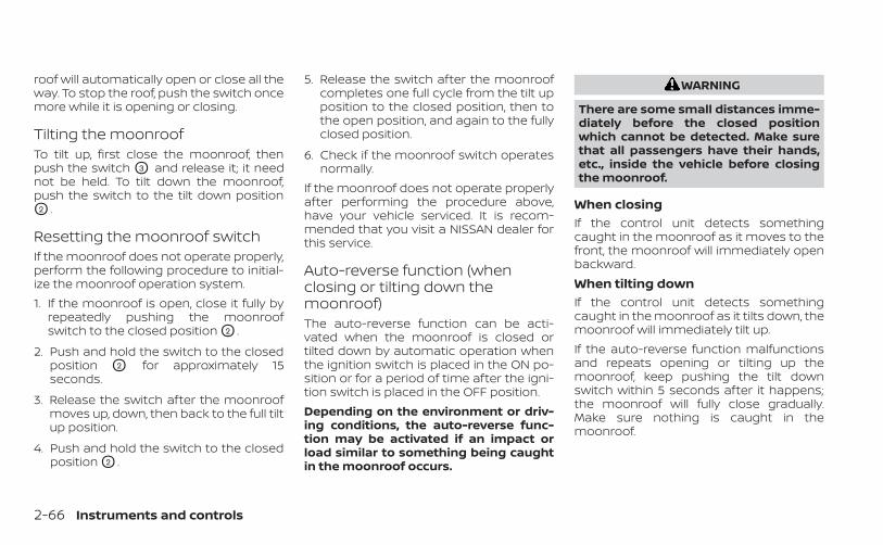
roof will automatically open or close all theway. To stop the roof, push the switch oncemore while it is opening or closing.
Tilting the moonroofTo tilt up, first close the moonroof, thenpush the switch O3 and release it; it neednot be held. To tilt down the moonroof,push the switch to the tilt down positionO2 .
Resetting the moonroof switchIf the moonroof does not operate properly,perform the following procedure to initial-ize the moonroof operation system.1. If the moonroof is open, close it fully by
repeatedly pushing the moonroofswitch to the closed position O2 .
2. Push and hold the switch to the closedposition O2 for approximately 15seconds.
3. Release the switch after the moonroofmoves up, down, then back to the full tiltup position.
4. Push and hold the switch to the closedposition O2 .
5. Release the switch after the moonroofcompletes one full cycle from the tilt upposition to the closed position, then tothe open position, and again to the fullyclosed position.
6. Check if the moonroof switch operatesnormally.
If the moonroof does not operate properlyafter performing the procedure above,have your vehicle serviced. It is recom-mended that you visit a NISSAN dealer forthis service.
Auto-reverse function (whenclosing or tilting down themoonroof)The auto-reverse function can be acti-vated when the moonroof is closed ortilted down by automatic operation whenthe ignition switch is placed in the ON po-sition or for a period of time after the igni-tion switch is placed in the OFF position.Depending on the environment or driv-ing conditions, the auto-reverse func-tion may be activated if an impact orload similar to something being caughtin the moonroof occurs.
WARNING
There are some small distances imme-diately before the closed positionwhich cannot be detected. Make surethat all passengers have their hands,etc., inside the vehicle before closingthe moonroof.
When closingIf the control unit detects somethingcaught in the moonroof as it moves to thefront, the moonroof will immediately openbackward.When tilting downIf the control unit detects somethingcaught in the moonroof as it tilts down, themoonroof will immediately tilt up.If the auto-reverse function malfunctionsand repeats opening or tilting up themoonroof, keep pushing the tilt downswitch within 5 seconds after it happens;the moonroof will fully close gradually.Make sure nothing is caught in themoonroof.
2-66 Instruments and controls

WARNING
• In an accident you could be thrownfrom the vehicle through an openmoonroof. Always use seat belts andchild restraints.
• Do not allow anyone to stand up orextend any portion of their body outof the moonroof opening while thevehicle is in motion or while themoonroof is closing.
CAUTION
• Remove water drops, snow, ice orsand from the moonroof beforeopening.
• Do not place heavy objects on themoonroof or surrounding area.
SunshadeOpen and close the sunshade by sliding itforward or backward.
If the moonroof does not closeHave your moonroof checked and re-paired. It is recommended that you visit aNISSAN dealer for this service.
The interior lights will automatically turn onand stay on for a period of time when:• The doors are unlocked by the Intelligent
Key, a key or the request switch while alldoors are closed and the ignition switchis in the OFF position.
• The doors and/or liftgate is opened.• The switch is individually pushed.When the ON switch O1 is pushed, the inte-rior lights illuminate.When the DOOR/OFF switch O2 is pushed,the interior lights do not illuminate unlessindividually pushed.
NOTE:
The footwell lights and step lights illumi-nate when the driver and passengerdoors are open regardless of the interiorlight switch position. These lights willturn off automatically after a period oftime while doors are open to prevent thebattery from becoming discharged.
CAUTION
Do not use for extended periods of timewith the engine stopped. This could re-sult in a discharged battery.
LIC3841
INTERIOR LIGHTS
Instruments and controls 2-67
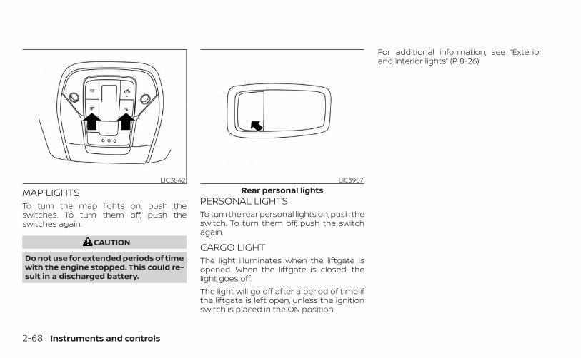
MAP LIGHTSTo turn the map lights on, push theswitches. To turn them off, push theswitches again.
CAUTION
Do not use for extended periods of timewith the engine stopped. This could re-sult in a discharged battery.
PERSONAL LIGHTSTo turn the rear personal lights on, push theswitch. To turn them off, push the switchagain.
CARGO LIGHTThe light illuminates when the liftgate isopened. When the liftgate is closed, thelight goes off.The light will go off after a period of time ifthe liftgate is left open, unless the ignitionswitch is placed in the ON position.
For additional information, see “Exteriorand interior lights” (P. 8-26).
LIC3842 LIC3907Rear personal lights
2-68 Instruments and controls
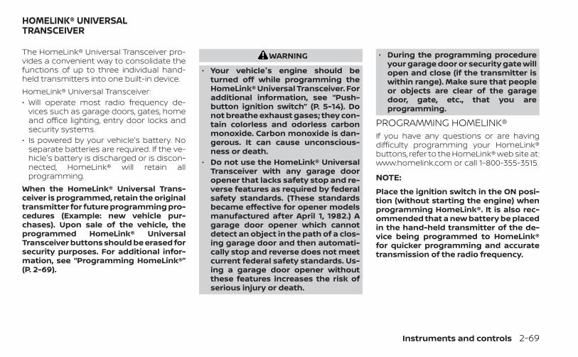
The HomeLink® Universal Transceiver pro-vides a convenient way to consolidate thefunctions of up to three individual hand-held transmitters into one built-in device.HomeLink® Universal Transceiver:• Will operate most radio frequency de-
vices such as garage doors, gates, homeand office lighting, entry door locks andsecurity systems.
• Is powered by your vehicle's battery. Noseparate batteries are required. If the ve-hicle's battery is discharged or is discon-nected, HomeLink® will retain allprogramming.
When the HomeLink® Universal Trans-ceiver is programmed, retain the originaltransmitter for future programming pro-cedures (Example: new vehicle pur-chases). Upon sale of the vehicle, theprogrammed HomeLink® UniversalTransceiver buttons should be erased forsecurity purposes. For additional infor-mation, see “Programming HomeLink®”(P. 2-69).
WARNING
• Your vehicle's engine should beturned off while programming theHomeLink® Universal Transceiver. Foradditional information, see “Push-button ignition switch” (P. 5-14). Donot breathe exhaust gases; they con-tain colorless and odorless carbonmonoxide. Carbon monoxide is dan-gerous. It can cause unconscious-ness or death.
• Do not use the HomeLink® UniversalTransceiver with any garage dooropener that lacks safety stop and re-verse features as required by federalsafety standards. (These standardsbecame effective for opener modelsmanufactured after April 1, 1982.) Agarage door opener which cannotdetect an object in the path of a clos-ing garage door and then automati-cally stop and reverse does not meetcurrent federal safety standards. Us-ing a garage door opener withoutthese features increases the risk ofserious injury or death.
• During the programming procedureyour garage door or security gate willopen and close (if the transmitter iswithin range). Make sure that peopleor objects are clear of the garagedoor, gate, etc., that you areprogramming.
PROGRAMMING HOMELINK®If you have any questions or are havingdifficulty programming your HomeLink®buttons, refer to the HomeLink® web site at:www.homelink.com or call 1-800-355-3515.
NOTE:
Place the ignition switch in the ON posi-tion (without starting the engine) whenprogramming HomeLink®. It is also rec-ommended that a new battery be placedin the hand-held transmitter of the de-vice being programmed to HomeLink®for quicker programming and accuratetransmission of the radio frequency.
HOMELINK® UNIVERSALTRANSCEIVER
Instruments and controls 2-69
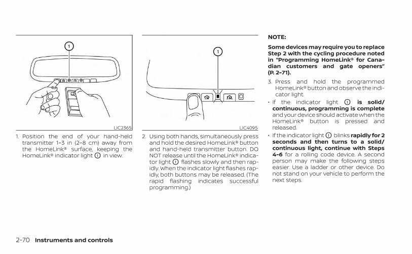
1. Position the end of your hand-heldtransmitter 1–3 in (2–8 cm) away fromthe HomeLink® surface, keeping theHomeLink® indicator light O1 in view.
2. Using both hands, simultaneously pressand hold the desired HomeLink® buttonand hand-held transmitter button. DONOT release until the HomeLink® indica-tor light O1 flashes slowly and then rap-idly. When the indicator light flashes rap-idly, both buttons may be released. (Therapid flashing indicates successfulprogramming.)
NOTE:
Some devices may require you to replaceStep 2 with the cycling procedure notedin “Programming HomeLink® for Cana-dian customers and gate openers”(P. 2-71).3. Press and hold the programmed
HomeLink® button and observe the indi-cator light.
• If the indicator light O1 is solid/continuous, programming is completeand your device should activate when theHomeLink® button is pressed andreleased.
• If the indicator light O1 blinks rapidly for 2seconds and then turns to a solid/continuous light, continue with Steps4-6 for a rolling code device. A secondperson may make the following stepseasier. Use a ladder or other device. Donot stand on your vehicle to perform thenext steps.
LIC2365 LIC4095
2-70 Instruments and controls

4. At the receiver located on the garagedoor opener motor in the garage, locatethe “learn” or “smart” button (the nameand color of the button may vary bymanufacturer but it is usually locatednear where the hanging antenna wire isattached to the unit). If there is difficultylocating the button, reference the ga-rage door opener’s manual.
5. Press and release the “learn” or “smart”button.
NOTE:Once the button is pressed, you have ap-proximately 30 seconds to initiate thenext step.
6. Return to the vehicle and firmly pressand hold the trained HomeLink® buttonfor 2 seconds and release. Repeat the“press/hold/release” sequence up tothree times to complete the trainingprocess. HomeLink® should now acti-vate your rolling code equipped device.
7. If you have any questions or are havingdifficulty programming your HomeLink®buttons, refer to the HomeLink® web siteat: www.homelink.com or call1-800-355-3515.
PROGRAMMING HOMELINK® FORCANADIAN CUSTOMERS AND GATEOPENERSCanadian radio-frequency laws requiretransmitter signals to “time-out” (or quit)after several seconds of transmission –which may not be long enough forHomeLink® to pick up the signal duringtraining. Similar to this Canadian law, someU.S. gate operators are designed to “tim-eout” in the same manner.If you live in Canada or you are having diffi-culties training a gate operator or garagedoor opener by using the “Training” proce-dures, replace “Programming HomeLink®”step 2 with the following:
NOTE:
When programming a garage dooropener, etc., unplug the device duringthe “cycling” process to prevent possibledamage to the garage door openercomponents.1. For additional information, see “Pro-
gramming HomeLink®” step 1, (P. 2-69).
2. Using both hands, simultaneously pressand hold the desired HomeLink® buttonand the hand-held transmitter button.During training, your hand-held trans-mitter may automatically stop transmit-ting. Continue to press and hold the de-sired HomeLink® button while you pressand re-press (“cycle”) your hand-heldtransmitter every 2 seconds until thefrequency signal has been learned. TheHomeLink® indicator light will flashslowly and then rapidly after severalseconds upon successful training. DONOT release until the HomeLink® indica-tor light flashes slowly and then rapidly.When the indicator light flashes rapidly,both buttons may be released. The rapidflashing indicates successful training.Proceed with “Programming HomeLink®”step 3 to complete.If the device was unplugged during theprogramming procedure, remember toplug it back in when programming iscompleted.
Instruments and controls 2-71

OPERATING THE HOMELINK®UNIVERSAL TRANSCEIVERThe HomeLink® Universal Transceiver, afterit is programmed, can be used to activatethe programmed device. To operate, sim-ply press and release the appropriate pro-grammed HomeLink® Universal Trans-ceiver button. The amber indicator light willilluminate while the signal is beingtransmitted.For convenience, the hand-held transmit-ter of the device may also be used at anytime.
PROGRAMMING TROUBLE-DIAGNOSISIf the HomeLink® does not quickly learn thehand-held transmitter information:• replace the hand-held transmitter bat-
teries with new batteries.• position the hand-held transmitter with
its battery area facing away from theHomeLink® surface.
• press and hold both the HomeLink® andhand-held transmitter buttons withoutinterruption.
• position the hand-held transmitter 1 - 3 in(2 - 8 cm) away from the HomeLink® sur-face. Hold the transmitter in that positionfor up to 15 seconds. If HomeLink® is notprogrammed within that time, try holdingthe transmitter in another position –keeping the indicator light in view at alltimes.
If you continue to have programming diffi-culties, please contact the INFINITI Con-sumer Affairs Department. The phonenumbers are located in the Foreword ofthis manual.
CLEARING THE PROGRAMMEDINFORMATIONThe following procedure clears the pro-grammed information from both buttons.Individual buttons cannot be cleared. How-ever, individual buttons can be repro-grammed. For additional information, see“Reprogramming a single HomeLink® but-ton” (P. 2-72).To clear all programming:1. Press and hold the two outer HomeLink®
buttons until the indicator light begins toflash in approximately 10 seconds. Donot hold for longer than 20 seconds.
2. Release both buttons.
HomeLink® is now in the programmingmode and can be programmed at anytime beginning with “ProgrammingHomeLink®” - Step 1 (P. 2-69).
REPROGRAMMING A SINGLEHOMELINK® BUTTONTo reprogram a HomeLink® UniversalTransceiver button, complete the following:1. Press and hold the desired HomeLink®
button. DO NOT release the button.
2. The indicator light will begin to flash af-ter 20 seconds. Without releasing theHomeLink® button, proceed with “Pro-gramming HomeLink®” - Step 1 (P. 2-69).
For questions or comments, contactHomeLink® at: www.homelink.com or1–800–355–3515 (except Mexico).The HomeLink® Universal Transceiver but-ton has now been reprogrammed. Thenew device can be activated by pressingthe HomeLink® button that was just pro-grammed. This procedure will not affectany other programmed HomeLink®buttons.
2-72 Instruments and controls
IF YOUR VEHICLE IS STOLENIf your vehicle is stolen, you should changethe codes of any non-rolling code devicethat has been programmed intoHomeLink®. Consult the Owner's Manual ofeach device or call the manufacturer ordealer of those devices for additionalinformation.When your vehicle is recovered, you willneed to reprogram the HomeLink® Uni-versal Transceiver with your new trans-mitter information.FCC Notice:For USA:This device complies with Part 15 of theFCC Rules. Operation is subject to the fol-lowing two conditions: (1) This devicemay not cause interference, and (2) thisdevice must accept any interference re-ceived, including interference that maycause undesired operation.
NOTE:
Changes or modifications not expresslyapproved by the party responsible forcompliance could void the user’s author-ity to operate the equipment.
For Canada:This device contains licence-exempttransmitter(s)/receiver(s) that complywith Innovation, Science and EconomicDevelopment Canada’s licence-exemptRSS(s). Operation is subject to the fol-lowing two conditions: (1) This devicemay not cause interference. (2) This de-vice must accept any interference, in-cluding interference that may cause un-desired operation of the device.
Instruments and controls 2-73

MEMO
2-74 Instruments and controls

3 Pre-driving checks and adjustments
Keys . . . . . . . . . . . . . . . . . . . . . . . . . . . . . . . . . . . . . . . . . . . . . 3-2INFINITI Intelligent Key . . . . . . . . . . . . . . . . . . . . . . . . 3-2INFINITI Vehicle Immobilizer Systemkeys . . . . . . . . . . . . . . . . . . . . . . . . . . . . . . . . . . . . . . . . . . 3-4
Doors . . . . . . . . . . . . . . . . . . . . . . . . . . . . . . . . . . . . . . . . . . . 3-4Locking with key . . . . . . . . . . . . . . . . . . . . . . . . . . . . . 3-5Locking with inside lock knob . . . . . . . . . . . . . . . . 3-5Locking with power door lock switch . . . . . . . . . 3-5Automatic door locks . . . . . . . . . . . . . . . . . . . . . . . . 3-6Child safety rear door lock . . . . . . . . . . . . . . . . . . . . 3-6
INFINITI Intelligent Key System . . . . . . . . . . . . . . . . . . . 3-6Operating range . . . . . . . . . . . . . . . . . . . . . . . . . . . . . 3-8Door locks/unlocks precaution . . . . . . . . . . . . . . . 3-9INFINITI Intelligent Key operation . . . . . . . . . . . . 3-10How to use the remote keyless entryfunction . . . . . . . . . . . . . . . . . . . . . . . . . . . . . . . . . . . . . 3-14Warning signals . . . . . . . . . . . . . . . . . . . . . . . . . . . . . 3-17Troubleshooting guide . . . . . . . . . . . . . . . . . . . . . . 3-18Log-in function . . . . . . . . . . . . . . . . . . . . . . . . . . . . . . 3-20
Remote Engine Start (if so equipped) . . . . . . . . . . . 3-20Remote Engine Start operating range . . . . . . . 3-21Remote starting the vehicle . . . . . . . . . . . . . . . . . 3-21Extending engine run time . . . . . . . . . . . . . . . . . . 3-22Canceling a Remote Engine Start . . . . . . . . . . . 3-22Conditions the Remote Engine Start willnot work . . . . . . . . . . . . . . . . . . . . . . . . . . . . . . . . . . . . 3-22
Hood . . . . . . . . . . . . . . . . . . . . . . . . . . . . . . . . . . . . . . . . . . . 3-23Liftgate . . . . . . . . . . . . . . . . . . . . . . . . . . . . . . . . . . . . . . . . 3-24
Operating the power liftgate . . . . . . . . . . . . . . . . 3-24Motion-Activated Liftgate(if so equipped) . . . . . . . . . . . . . . . . . . . . . . . . . . . . . . 3-27Power liftgate main switch . . . . . . . . . . . . . . . . . . 3-29Liftgate release . . . . . . . . . . . . . . . . . . . . . . . . . . . . . 3-29Liftgate position setting . . . . . . . . . . . . . . . . . . . . . 3-30
Fuel-filler door . . . . . . . . . . . . . . . . . . . . . . . . . . . . . . . . . . 3-31Opening the fuel-filler door . . . . . . . . . . . . . . . . . . 3-31Fuel-filler cap . . . . . . . . . . . . . . . . . . . . . . . . . . . . . . . . 3-31
Steering wheel . . . . . . . . . . . . . . . . . . . . . . . . . . . . . . . . . 3-33Manual operation (if so equipped) . . . . . . . . . . . 3-34Automatic operation (if so equipped) . . . . . . . . 3-34
Sun visors . . . . . . . . . . . . . . . . . . . . . . . . . . . . . . . . . . . . . . 3-35Vanity mirrors . . . . . . . . . . . . . . . . . . . . . . . . . . . . . . . 3-35Card holder . . . . . . . . . . . . . . . . . . . . . . . . . . . . . . . . . 3-36
Mirrors . . . . . . . . . . . . . . . . . . . . . . . . . . . . . . . . . . . . . . . . . 3-36Automatic anti-glare rearview mirror . . . . . . . . 3-36Outside mirrors . . . . . . . . . . . . . . . . . . . . . . . . . . . . . 3-37
Memory Seat (if so equipped) . . . . . . . . . . . . . . . . . . 3-38Memory storage function . . . . . . . . . . . . . . . . . . . 3-38Entry/exit function . . . . . . . . . . . . . . . . . . . . . . . . . . 3-39Setting memory function . . . . . . . . . . . . . . . . . . . 3-40System operation . . . . . . . . . . . . . . . . . . . . . . . . . . . 3-40
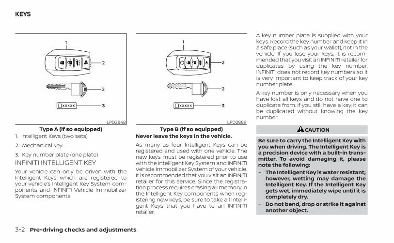
INFINITI INTELLIGENT KEYYour vehicle can only be driven with theIntelligent Keys which are registered toyour vehicle’s Intelligent Key System com-ponents and INFINITI Vehicle ImmobilizerSystem components.
Never leave the keys in the vehicle.As many as four Intelligent Keys can beregistered and used with one vehicle. Thenew keys must be registered prior to usewith the Intelligent Key System and INFINITIVehicle Immobilizer System of your vehicle.It is recommended that you visit an INFINITIretailer for this service. Since the registra-tion process requires erasing all memory inthe Intelligent Key components when reg-istering new keys, be sure to take all Intelli-gent Keys that you have to an INFINITIretailer.
A key number plate is supplied with yourkeys. Record the key number and keep it ina safe place (such as your wallet), not in thevehicle. If you lose your keys, it is recom-mended that you visit an INFINITI retailer forduplicates by using the key number.INFINITI does not record key numbers so itis very important to keep track of your keynumber plate.A key number is only necessary when youhave lost all keys and do not have one toduplicate from. If you still have a key, it canbe duplicated without knowing the keynumber.
CAUTION
Be sure to carry the Intelligent Key withyou when driving. The Intelligent Key isa precision device with a built-in trans-mitter. To avoid damaging it, pleasenote the following:– The Intelligent Key is water resistant;
however, wetting may damage theIntelligent Key. If the Intelligent Keygets wet, immediately wipe until it iscompletely dry.
– Do not bend, drop or strike it againstanother object.
LPD2848Type A (if so equipped)
1. Intelligent Keys (two sets)
2. Mechanical key
3. Key number plate (one plate)
LPD2889Type B (if so equipped)
KEYS
3-2 Pre-driving checks and adjustments
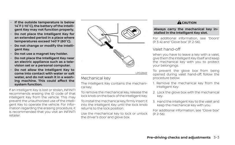
– If the outside temperature is below14°F (-10°C), the battery of the Intelli-gent Key may not function properly.
– Do not place the Intelligent Key foran extended period in a place wheretemperatures exceed 140°F (60°C).
– Do not change or modify the Intelli-gent Key.
– Do not use a magnet key holder.– Do not place the Intelligent Key near
an electric appliance such as a tele-vision set or a personal computer.
– Do not allow the Intelligent Key tocome into contact with water or saltwater, and do not wash it in a wash-ing machine. This could affect thesystem function.
If an Intelligent Key is lost or stolen, INFINITIrecommends erasing the ID code of thatIntelligent Key from the vehicle. This mayprevent the unauthorized use of the Intelli-gent Key to operate the vehicle. For infor-mation regarding the erasing procedure, itis recommended that you visit an INFINITIretailer.
Mechanical keyThe Intelligent Key contains the mechani-cal key.To remove the mechanical key, release thelock knob on the back of the Intelligent Key.To install the mechanical key, firmly insert itinto the Intelligent Key until the lock knobreturns to the lock position.Use the mechanical key to lock or unlockthe driver's door and glove box.
CAUTION
Always carry the mechanical key in-stalled in the Intelligent Key slot.
For additional information, see “Doors”(P. 3-4) and “Glove box” (P. 2-56).
Valet hand-offWhen you have to leave a key with a valet,give them the Intelligent Key itself and keepthe mechanical key with you to protectyour belongings.To prevent the glove box from beingopened during valet hand-off, follow theprocedure below.1. Remove the mechanical key from the
Intelligent Key.
2. Lock the glove box with the mechanicalkey.
3. Hand the Intelligent Key to the valet andkeep the mechanical key with you.
For additional information, see “Glove box”(P. 2-56).
LPD2849
Pre-driving checks and adjustments 3-3

INFINITI VEHICLE IMMOBILIZERSYSTEM KEYSAdditional or replacement keys:If you still have a key, the key number is notnecessary when you need extra INFINITI Ve-hicle Immobilizer System keys. Your existingkey can be duplicated without knowing thekey number. As many as four INFINITI VehicleImmobilizer System keys can be used withone vehicle. You should bring all INFINITI Ve-hicle Immobilizer System keys that you haveto the INFINITI retailer for registration. This isbecause the registration process will erasethe memory of all key codes previously reg-istered into the INFINITI Vehicle ImmobilizerSystem. After the registration process, thesecomponents will only recognize keys codedinto the INFINITI Vehicle Immobilizer Systemduring registration. Any key that is not givento the retailer at the time of registration willno longer be able to start your vehicle.
CAUTION
Do not allow the immobilizer systemkey, which contains an electrical tran-sponder, to come into contact with wa-ter or salt water. This could affect sys-tem function.
When the doors are locked using one of thefollowing methods, the doors cannot beopened using the inside or outside doorhandles. The doors must be unlocked toopen the doors.
WARNING
• Always have the doors locked whiledriving. Along with the use of seatbelts, this provides greater safety inthe event of an accident by helping toprevent persons from being thrownfrom the vehicle. This also helps keepchildren and others from uninten-tionally opening the doors, and willhelp keep out intruders.
• Before opening any door, always lookfor and avoid oncoming traffic.
• To help avoid risk of injury or deaththrough unintended operation of thevehicle and/or its systems, includingentrapment in windows or inadver-tent door lock activation, do notleave children, people who requirethe assistance of others or pets unat-tended in your vehicle. Additionally,the temperature inside a closed ve-hicle on a warm day can quickly be-come high enough to cause a signifi-cant risk of injury or death to peopleand pets.
DOORS
3-4 Pre-driving checks and adjustments

LOCKING WITH KEYTo lock the driver’s door using the me-chanical key, turn the key toward the frontof the vehicle O1 .To unlock the driver’s door using the me-chanical key, turn the key toward the rear ofthe vehicle O2 .
LOCKING WITH INSIDE LOCK KNOBTo lock the door without the key, move theinside lock knob to the lock position O1 ,then close the door.To unlock the door without the key, movethe inside lock knob to the unlock positionO2 .
LOCKING WITH POWER DOORLOCK SWITCHTo lock all the doors without a key, push thedoor lock switch (driver's or front passen-ger's side) to the lock position O1 . Whenlocking the door this way, be certain not toleave the key inside the vehicle.To unlock all the doors without a key, pushthe door lock switch (driver's or front pas-senger's side) to the unlock position O2 .
LPD2710Driver's door
LPD2714Inside lock
SPA2727
Pre-driving checks and adjustments 3-5
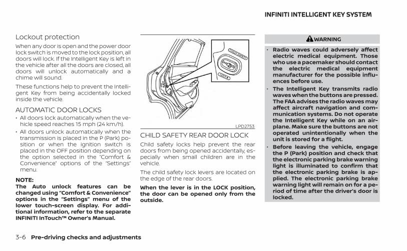
Lockout protectionWhen any door is open and the power doorlock switch is moved to the lock position, alldoors will lock. If the Intelligent Key is left inthe vehicle after all the doors are closed, alldoors will unlock automatically and achime will sound.These functions help to prevent the Intelli-gent Key from being accidentally lockedinside the vehicle.
AUTOMATIC DOOR LOCKS• All doors lock automatically when the ve-
hicle speed reaches 15 mph (24 km/h).• All doors unlock automatically when the
transmission is placed in the P (Park) po-sition or when the ignition switch isplaced in the OFF position depending onthe option selected in the “Comfort &Convenience” options of the “Settings”menu.
NOTE:The Auto unlock features can bechanged using “Comfort & Convenience”options in the “Settings” menu of thelower touch-screen display. For addi-tional information, refer to the separateINFINITI InTouch™ Owner’s Manual.
CHILD SAFETY REAR DOOR LOCKChild safety locks help prevent the reardoors from being opened accidentally, es-pecially when small children are in thevehicle.The child safety lock levers are located onthe edge of the rear doors.When the lever is in the LOCK position,the door can be opened only from theoutside.
WARNING
• Radio waves could adversely affectelectric medical equipment. Thosewho use a pacemaker should contactthe electric medical equipmentmanufacturer for the possible influ-ences before use.
• The Intelligent Key transmits radiowaves when the buttons are pressed.The FAA advises the radio waves mayaffect aircraft navigation and com-munication systems. Do not operatethe Intelligent Key while on an air-plane. Make sure the buttons are notoperated unintentionally when theunit is stored for a flight.
• Before leaving the vehicle, engagethe P (Park) position and check thatthe electronic parking brake warninglight is illuminated to confirm thatthe electronic parking brake is ap-plied. The electronic parking brakewarning light will remain on for a pe-riod of time after the driver’s door islocked.
LPD2753
INFINITI INTELLIGENT KEY SYSTEM
3-6 Pre-driving checks and adjustments
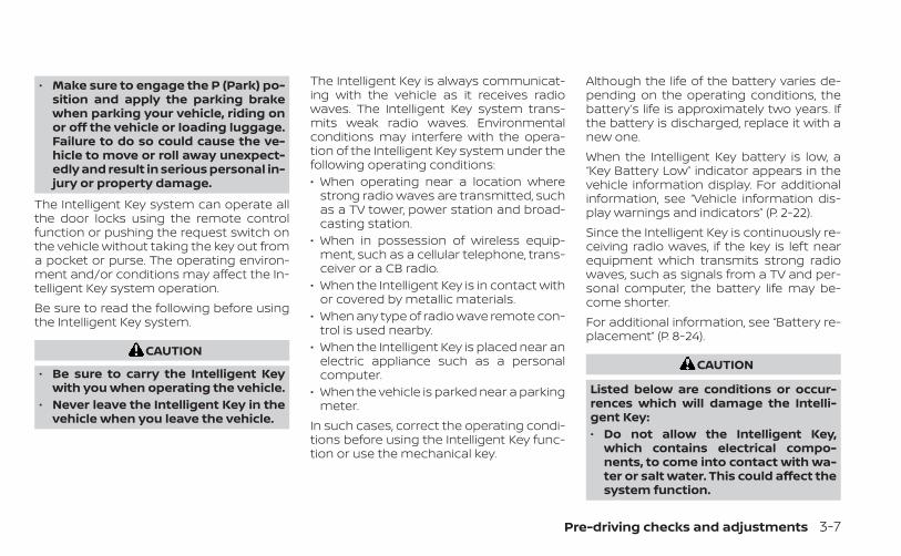
• Make sure to engage the P (Park) po-sition and apply the parking brakewhen parking your vehicle, riding onor off the vehicle or loading luggage.Failure to do so could cause the ve-hicle to move or roll away unexpect-edly and result in serious personal in-jury or property damage.
The Intelligent Key system can operate allthe door locks using the remote controlfunction or pushing the request switch onthe vehicle without taking the key out froma pocket or purse. The operating environ-ment and/or conditions may affect the In-telligent Key system operation.Be sure to read the following before usingthe Intelligent Key system.
CAUTION
• Be sure to carry the Intelligent Keywith you when operating the vehicle.
• Never leave the Intelligent Key in thevehicle when you leave the vehicle.
The Intelligent Key is always communicat-ing with the vehicle as it receives radiowaves. The Intelligent Key system trans-mits weak radio waves. Environmentalconditions may interfere with the opera-tion of the Intelligent Key system under thefollowing operating conditions:• When operating near a location where
strong radio waves are transmitted, suchas a TV tower, power station and broad-casting station.
• When in possession of wireless equip-ment, such as a cellular telephone, trans-ceiver or a CB radio.
• When the Intelligent Key is in contact withor covered by metallic materials.
• When any type of radio wave remote con-trol is used nearby.
• When the Intelligent Key is placed near anelectric appliance such as a personalcomputer.
• When the vehicle is parked near a parkingmeter.
In such cases, correct the operating condi-tions before using the Intelligent Key func-tion or use the mechanical key.
Although the life of the battery varies de-pending on the operating conditions, thebattery’s life is approximately two years. Ifthe battery is discharged, replace it with anew one.When the Intelligent Key battery is low, a“Key Battery Low” indicator appears in thevehicle information display. For additionalinformation, see “Vehicle information dis-play warnings and indicators” (P. 2-22).Since the Intelligent Key is continuously re-ceiving radio waves, if the key is left nearequipment which transmits strong radiowaves, such as signals from a TV and per-sonal computer, the battery life may be-come shorter.For additional information, see “Battery re-placement” (P. 8-24).
CAUTION
Listed below are conditions or occur-rences which will damage the Intelli-gent Key:• Do not allow the Intelligent Key,
which contains electrical compo-nents, to come into contact with wa-ter or salt water. This could affect thesystem function.
Pre-driving checks and adjustments 3-7

• Do not drop the Intelligent Key.• Do not strike the Intelligent Key
sharply against another object.• Do not change or modify the Intelli-
gent Key.• Wetting may damage the Intelligent
Key. If the Intelligent Key gets wet,immediately wipe until it is com-pletely dry.
• Do not place the Intelligent Key for anextended period in an area wheretemperatures exceed 140°F (60°C).
• Do not attach the Intelligent Key witha key holder that contains a magnet.
• Do not place the Intelligent Key nearequipment that produces a magneticfield, such as a TV, audio equipmentand personal computers.
If an Intelligent Key is lost or stolen, INFINITIrecommends erasing the ID code of thatIntelligent Key from the vehicle. This mayprevent the unauthorized use of the Intelli-gent Key to operate the vehicle. For infor-mation regarding the erasing procedure, itis recommended that you visit an INFINITIretailer.
OPERATING RANGEThe Intelligent Key functions can only beused when the Intelligent Key is within thespecified operating range from the doorhandle request switch or the one touchunlock sensor O1 .
When the Intelligent Key battery is dis-charged or strong radio waves are presentnear the operating location, the IntelligentKey operating range becomes narrower,and the Intelligent Key may not functionproperly.The operating range is within 31.5 in (80 cm)from each request switch or one touch un-lock sensor O1 .If the Intelligent Key is too close to the doorglass, handle or rear bumper, the requestswitches or the one touch unlock sensormay not function.If any of the front doors are recently closedand locked, you must wait 2 seconds be-fore you can unlock the door with the onetouch unlock sensor. Pulling the handlewithin 2 seconds of locking the door willallow you time to confirm that the door hasbeen locked without accidentally unlock-ing the door with the one touch unlocksensor.If you pull the door handle with your glovedhand, the one touch unlock sensor opera-tion may not function.
LPD2402
3-8 Pre-driving checks and adjustments
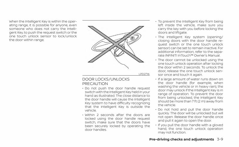
When the Intelligent Key is within the oper-ating range, it is possible for anyone, evensomeone who does not carry the Intelli-gent Key, to push the request switch or theone touch unlock sensor to lock/unlockthe door within range.
DOOR LOCKS/UNLOCKSPRECAUTION• Do not push the door handle request
switch with the Intelligent Key held in yourhand as illustrated. The close distance tothe door handle will cause the IntelligentKey system to have difficulty recognizingthat the Intelligent Key is outside thevehicle.
• Within 2 seconds after the doors arelocked using the door handle requestswitch, make sure that the doors havebeen securely locked by operating thedoor handles.
• To prevent the Intelligent Key from beingleft inside the vehicle, make sure youcarry the key with you before locking thedoors and liftgate.
• The Intelligent Key system (opening/closing doors with the door handle re-quest switch or the one touch unlocksensor) can be set to remain inactive. Foradditional information, refer to the sepa-rate INFINITI InTouch™ Owner’s Manual.
• The door cannot be unlocked using theone touch unlock operation after lockingthe door within 2 seconds. To unlock thedoor, release the one touch unlock sen-sor once and touch it again.
• If a large amount of water runs down onthe door handle (for example, whenwashing the vehicle or in heavy rain), thedoor may unlock if the Intelligent Key is inrange of operation. To prevent the doorfrom being unlocked, the Intelligent Keyshould be more than 7 ft (2 m) away fromthe vehicle.
• Do not hold and pull the door handlequickly. The door will be unlocked but willnot open. Release the door handle onceand pull it again to open the door.
• If you pull the door handle with a glovedhand, the one touch unlock operationmay not function.
LPD2716
Pre-driving checks and adjustments 3-9

INFINITI INTELLIGENT KEYOPERATIONYou can lock or unlock the doors withouttaking the Intelligent Key out of your pocketor bag.
When you carry the Intelligent Key with youand Selective Door Unlock is turned on us-ing “Comfort & Convenience” options in the“Settings” menu of the lower touch-screendisplay, you can unlock the correspondingdoor by touching the one-touch unlocksensor OB (driver’s or front passenger’s)within the range of operation. After touch-ing the one-touch unlock sensor, the doorhandle request switch OA (driver’s or frontpassenger’s) can be pushed to unlock alldoors.When Selective Door Unlock is turned off inthe “Comfort & Convenience” options of the“Settings” menu of the lower touch-screen
display and when carrying the IntelligentKey, you can unlock all doors by touching aone-touch unlock sensor OB within therange of operation.You can lock all doors by pushing the doorhandle request switch OA (driver’s or frontpassenger’s) once.
NOTE:
Selective Door Unlock can be changedusing “Comfort & Convenience” optionsin the “Settings” menu of the lowertouch-screen display. For additional in-formation, refer to the separate INFINITIInTouch™ Owner’s Manual.
LPD3144 LPD3146 LPD3145
3-10 Pre-driving checks and adjustments

Locking all doors and fuel-fillerdoor1. Place the ignition switch in the OFF posi-
tion and make sure you carry the Intelli-gent Key with you.
2. Close all doors.
3. Push the door handle request switch(driver’s or front passenger’s) OA whilecarrying the Intelligent Key with you.
4. All the doors, liftgate and fuel-filler doorwill lock.
5. The hazard indicator flashes twice andthe outside chime sounds twice.
NOTE:• The one-touch sensors and request
switches for all doors and liftgate canbe deactivated when the Lock/Unlockby Door Handle setting is switched toOFF in “Comfort & Convenience” op-tions of the “Settings” menu of thelower touch-screen display. For addi-tional information, refer to the sepa-rate INFINITI InTouch™ Owner’sManual.
• Doors will lock with the Intelligent Keywhile the ignition switch is placed inthe ON position.
• Doors will not lock by pushing the doorhandle request switch with the Intelli-gent Key inside the vehicle. However,when an Intelligent Key is inside thevehicle, doors can be locked with an-other registered Intelligent Key.
WARNING
After locking the doors using the re-quest switch, make sure that the doorshave been securely locked by operat-ing the door handles within two sec-onds of locking. Failure to follow theseinstructions may result in inadver-tently unlocking the doors, which maydecrease the safety and security ofyour vehicle.
LPD3150 LPD3146
Pre-driving checks and adjustments 3-11

CAUTION
• When locking the doors using the re-quest switch, make sure to have theIntelligent Key in your possessionbefore operating the request switchto prevent the Intelligent Key frombeing left in the vehicle.
• The request switch is operationalonly when the Intelligent Key hasbeen detected by the Intelligent Keysystem.
Lockout protectionTo prevent the Intelligent Key from beingaccidentally locked in the vehicle, lockoutprotection is equipped with the IntelligentKey system.When any door is open, the doors arelocked, and then the Intelligent Key is putinside the vehicle and all the doors areclosed; a chime will sound and the lock willautomatically unlock.
NOTE:
The doors may not lock when the Intelli-gent Key is in the same hand that is op-erating the request switch to lock thedoor. Put the Intelligent Key in a purse,pocket or your other hand.
CAUTION
The lockout protection may not func-tion under the following conditions:• When the Intelligent Key is placed on
top of the instrument panel.• When the Intelligent Key is placed in-
side the glove box or a storage bin.• When the Intelligent Key is placed in-
side the door pockets.• When the Intelligent Key is placed in-
side or near metallic materials.
Unlocking doors and fuel-fillerdoor1. Touch the one-touch unlock sensor OB
(driver’s or front passenger’s) while car-rying the Intelligent Key with you.
2. The door handle welcome lights illumi-nate, the hazard indicator lights flashonce and the vehicle beeps once.If Selective Door Unlock is turned on in“Vehicle Settings” of the lower touch-screen display, the corresponding doorwill unlock. If Selective Door Unlock isturned off, all doors will unlock.
LPD3145
3-12 Pre-driving checks and adjustments

3. If Selective Door Unlock is turned on in“Vehicle Settings” of the lower touch-screen display, push the door handle re-quest switch OA (driver’s or front pas-senger’s) within 1 minute.
4. The hazard indicator flashes once andthe vehicle beeps once again. All doors,liftgate and fuel-filler door will unlock.
NOTE:
The unlocking operation can be changed inSelective Door Unlock in the “Comfort & Con-venience” options of the “Settings” menu ofthe lower touch-screen display. For addi-tional information, refer to the separateINFINITI InTouch™ Owner’s Manual.All doors and the fuel-filler door will lockautomatically unless one of the followingoperations is performed within 1 minuteafter pushing the request switch or one-touch unlock operation while the doors arelocked.• Opening any door.• Pushing the ignition switch.During this 1–minute time period, if thebutton on the Intelligent Key is pushed, alldoors will be locked automatically after an-other 1 minute has passed.
NOTE:
The one-touch unlock sensor can be de-activated when the Touch Sensitive DoorSensor setting is switched to OFF in the“Comfort & Convenience” options of the“Settings” menu of the lower touch-screen display. For additional informa-tion, refer to the separate INFINITIInTouch™ Owner’s Manual.
If a door handle is pulled too quickly whileunlocking the doors using the one-touchunlock sensor, you may be unable to openthe door. Returning the door handle to itsoriginal position will allow you to open thedoor.
Using the interior lightsThe interior lights illuminate for a period oftime when a door is unlocked.The lights can be turned off without waitingby performing one of the followingoperations:• Placing the ignition switch in the ON
position.• Locking the doors with the Intelligent Key.• Switching the interior light switch to the
OFF position.For additional information, see “Interiorlights” (P. 2-67).
LPD3146
Pre-driving checks and adjustments 3-13
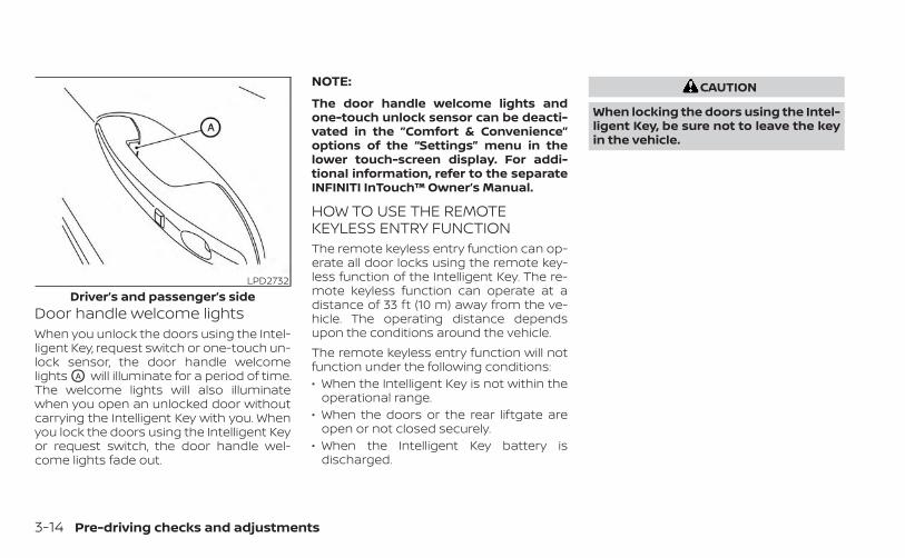
Door handle welcome lightsWhen you unlock the doors using the Intel-ligent Key, request switch or one-touch un-lock sensor, the door handle welcomelights OA will illuminate for a period of time.The welcome lights will also illuminatewhen you open an unlocked door withoutcarrying the Intelligent Key with you. Whenyou lock the doors using the Intelligent Keyor request switch, the door handle wel-come lights fade out.
NOTE:
The door handle welcome lights andone-touch unlock sensor can be deacti-vated in the ”Comfort & Convenience”options of the “Settings” menu in thelower touch-screen display. For addi-tional information, refer to the separateINFINITI InTouch™ Owner’s Manual.
HOW TO USE THE REMOTEKEYLESS ENTRY FUNCTIONThe remote keyless entry function can op-erate all door locks using the remote key-less function of the Intelligent Key. The re-mote keyless function can operate at adistance of 33 ft (10 m) away from the ve-hicle. The operating distance dependsupon the conditions around the vehicle.The remote keyless entry function will notfunction under the following conditions:• When the Intelligent Key is not within the
operational range.• When the doors or the rear liftgate are
open or not closed securely.• When the Intelligent Key battery is
discharged.
CAUTION
When locking the doors using the Intel-ligent Key, be sure not to leave the keyin the vehicle.
LPD2732Driver’s and passenger’s side
3-14 Pre-driving checks and adjustments

Type A (if so equipped)1. (lock) button
2. (unlock) button
3. (liftgate) button
4. (panic) button
Type B (if so equipped)1. (remote engine start)
2. (lock) button
3. (unlock) button
4. (liftgate) button
5. (panic) button
Locking doors1. Place the ignition switch in the LOCK
position.
2. Close all doors.
3. Press the button on the Intelli-gent Key.
4. The hazard indicator lights flash twiceand the horn beeps once.
5. All doors, liftgate and fuel-filler door willbe locked.
WARNING
After locking the doors using the Intel-ligent Key, be sure that the doors havebeen securely locked by operating thedoor handles within two seconds oflocking. Failure to follow these instruc-tions may result in inadvertently un-locking the doors, which may decreasethe safety and security of your vehicle.
LPD3701 LPD3702
Pre-driving checks and adjustments 3-15

Unlocking doors1. Press the button on the Intelligent
Key to unlock the driver’s door.
2. The hazard indicator lights flash onceand the driver’s door unlocks.
3. Press the button again within 1minute to unlock all doors.
NOTE:
The Selective Door Unlock feature can bechanged using the “Comfort & Conve-nience” options of the “Settings” menuon the lower touch-screen display. Foradditional information, refer to the sepa-rate INFINITI InTouch™ Owner’s Manual.All doors will be locked automatically un-less one of the following operations is per-formed within 1 minute after pressing the
button:• Opening any doors.• Pushing the ignition switch.
Using the interior lightsThe interior lights illuminate for a period oftime when a door is unlocked.The lights can be turned off without waitingby performing one of the followingoperations:• Placing the ignition switch in the ON
position.• Locking the doors with the Intelligent Key.• Switching the interior light switch to the
OFF position.For additional information, see “Interiorlights” (P. 2-67).
Opening windowsThe Intelligent Key allows you to simultane-ously open windows equipped with auto-matic operation.To open the windows, press and hold the
button on the Intelligent Key for lon-ger than 3 seconds after all doors areunlocked.The door windows will open while pressingthe button on the Intelligent Key.The door windows cannot be closed byusing the Intelligent Key.
Releasing the rear liftgateThe rear liftgate can be opened and closedby performing the following:• Press the button for longer than 1
second to open the rear liftgate.• Press the button again for longer
than 1 second to close the rear liftgate.When the button is pressed duringthe open or close process, the liftgate mo-tors will stop. When the button ispressed again for longer than 1 second theliftgate will reverse direction.
Using the panic alarmIf you are near your vehicle and feel threat-ened, you may activate the panic alarm tocall attention by pressing and holding the
button on the Intelligent Key for lon-ger than 0.5 seconds.The panic alarm and headlights will stay onfor a period of time.The panic alarm stops when:• It has run for a period of time, or• Any button is pressed on the Intelligent
Key.• The request switch on the driver or pas-
senger door is pushed and the IntelligentKey is in range of the door handle.
3-16 Pre-driving checks and adjustments
Answer back horn featureIf desired, the answer back horn featurecan be deactivated using the IntelligentKey. When it is deactivated and thebutton is pressed, the hazard indicatorlights flash twice. When the button ispressed, neither the hazard indicator lightsnor the horn operates.
NOTE:
If you change the answer back horn andlight flash feature with the IntelligentKey, the lower touch-screen display willshow the current mode after the ignitionswitch has been cycled from the OFF tothe ON position of the ”Comfort & Conve-nience” options of the “Settings” menu inthe lower touch-screen display can alsobe used to change the answer back hornmode between “Convenience” and “Se-curity” settings.
To deactivate: Press and hold theand buttons for at least 2 seconds.The hazard indicator lights will flash threetimes to confirm that the answer backhorn feature has been deactivated.To activate: Press and hold the and
buttons for at least 2 seconds oncemore.The hazard indicator lights will flash onceand the horn will sound once to confirmthat the horn beep feature has beenreactivated.Deactivating the horn beep feature doesnot silence the horn if the alarm istriggered.
WARNING SIGNALSTo help prevent the vehicle from movingunexpectedly by erroneous operation ofthe Intelligent Key or to help prevent thevehicle from being stolen, a chime orbuzzer sounds from inside and outside thevehicle and a warning is displayed in theinstrument panel.When a chime or beep sounds or a warningis displayed, be sure to check the vehicleand the Intelligent Key.For additional information, see “Trouble-shooting guide” (P. 3-18) and the separateINFINITI InTouch™ Owner’s Manual.
Pre-driving checks and adjustments 3-17
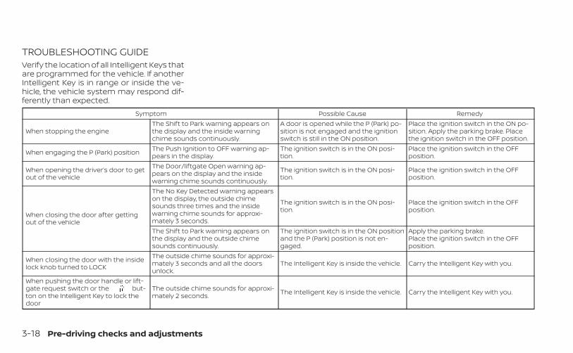
TROUBLESHOOTING GUIDEVerify the location of all Intelligent Keys thatare programmed for the vehicle. If anotherIntelligent Key is in range or inside the ve-hicle, the vehicle system may respond dif-ferently than expected.
Symptom Possible Cause Remedy
When stopping the engineThe Shift to Park warning appears onthe display and the inside warningchime sounds continuously.
A door is opened while the P (Park) po-sition is not engaged and the ignitionswitch is still in the ON position.
Place the ignition switch in the ON po-sition. Apply the parking brake. Placethe ignition switch in the OFF position.
When engaging the P (Park) position The Push Ignition to OFF warning ap-pears in the display.
The ignition switch is in the ON posi-tion.
Place the ignition switch in the OFFposition.
When opening the driver’s door to getout of the vehicle
The Door/liftgate Open warning ap-pears on the display and the insidewarning chime sounds continuously.
The ignition switch is in the ON posi-tion.
Place the ignition switch in the OFFposition.
When closing the door after gettingout of the vehicle
The No Key Detected warning appearson the display, the outside chimesounds three times and the insidewarning chime sounds for approxi-mately 3 seconds.
The ignition switch is in the ON posi-tion.
Place the ignition switch in the OFFposition.
The Shift to Park warning appears onthe display and the outside chimesounds continuously.
The ignition switch is in the ON positionand the P (Park) position is not en-gaged.
Apply the parking brake.Place the ignition switch in the OFFposition.
When closing the door with the insidelock knob turned to LOCK
The outside chime sounds for approxi-mately 3 seconds and all the doorsunlock.
The Intelligent Key is inside the vehicle. Carry the Intelligent Key with you.
When pushing the door handle or lift-gate request switch or the but-ton on the Intelligent Key to lock thedoor
The outside chime sounds for approxi-mately 2 seconds. The Intelligent Key is inside the vehicle. Carry the Intelligent Key with you.
3-18 Pre-driving checks and adjustments
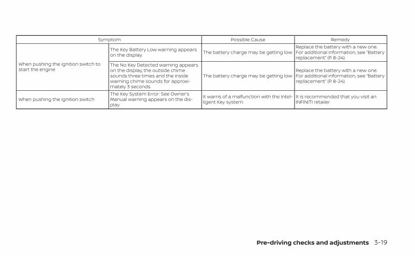
Symptom Possible Cause Remedy
When pushing the ignition switch tostart the engine
The Key Battery Low warning appearson the display. The battery charge may be getting low.
Replace the battery with a new one.For additional information, see “Batteryreplacement” (P. 8-24).
The No Key Detected warning appearson the display, the outside chimesounds three times and the insidewarning chime sounds for approxi-mately 3 seconds.
The battery charge may be getting low.Replace the battery with a new one.For additional information, see “Batteryreplacement” (P. 8-24).
When pushing the ignition switchThe Key System Error: See Owner’sManual warning appears on the dis-play.
It warns of a malfunction with the Intel-ligent Key system.
It is recommended that you visit anINFINITI retailer.
Pre-driving checks and adjustments 3-19

LOG-IN FUNCTIONAfter setting up the user information, thesystem will automatically recognize theuser upon turning on the vehicle.There will be a personalized welcomegreeting and screen prompt to log in.This feature allows four drivers to use theirown registration, drive mode, driving posi-tion, air conditioner, and auto settings andmemorizes these custom settings.The log-in user can be changed on thewelcome greeting screen or the User Listscreen. For additional information, refer tothe separate INFINITI InTouch™ Owner’sManual.The log-in function is linked to the followingfeatures:• Meter• Audio• Navigation system display• Navigation settings• Air conditioner• Memory seat (if so equipped)• Engine/transmission• Steering• Suspension (if so equipped)• Active trace control system
• Driver assistance except for the ForwardEmergency Braking (FEB) with PedestrianDetection system (if so equipped)
• Body Control Module (BCM)
The button will be on the INFINITIIntelligent Key if the vehicle has RemoteEngine Start. This feature allows the engineto start from outside the vehicle.Vehicles with an automatic climate controlsystem will default to either a heating orcooling mode depending on outside andcabin temperatures. For additional infor-mation, see “Remote Engine Start with In-telligent Climate Control” (P. 4-34).Laws in some local communities may re-strict or prohibit the use of Remote EngineStart, or the amount of time a parked ve-hicle engine may idle. For example, somelaws require a person using Remote Engine
LPD2995
REMOTE ENGINE START (if soequipped)
3-20 Pre-driving checks and adjustments
Start to have the vehicle in view or mayrestrict idling time except in freezing tem-peratures. Check local regulations for anyrequirements.Other conditions may affect the function ofthe Remote Engine Start feature. For addi-tional information, see “Conditions the Re-mote Engine Start will not work” (P. 3-22).Other conditions can affect the perfor-mance of the Intelligent Key transmitter.For additional information, see “INFINITI In-telligent Key system” (P. 3-6).
REMOTE ENGINE STARTOPERATING RANGE
WARNING
• To help avoid risk of injury or deaththrough unintended operation of thevehicle and/or its systems, includingentrapment in windows or inadver-tent door lock activation, do notleave children, people who requirethe assistance of others or pets unat-tended in your vehicle. Additionally,the temperature inside a closed ve-hicle on a warm day can quickly be-come high enough to cause a signifi-cant risk of injury or death to peopleand pets.
• Do not use Remote Engine Start inclosed spaces such as a garage. Donot breathe exhaust gases; they con-tain colorless and odorless carbonmonoxide. Carbon monoxide is dan-gerous. It can cause unconscious-ness or death.
CAUTION
When the Intelligent Key battery is dis-charged or other strong radio wavesources are present near the operatinglocation, the Intelligent Key operatingrange becomes narrower, and the Intel-ligent Key may not function properly.
The Remote Engine Start function can onlybe used when the Intelligent Key is withinthe specified operating range from thevehicle.The Remote Engine Start operating rangeis approximately 197 ft (60 m) from thevehicle.
REMOTE STARTING THE VEHICLETo use the Remote Engine Start featureperform the following:1. Aim the Intelligent Key at the vehicle.
2. Press the button to lock all doors.
3. Within 5 seconds press and hold thebutton until the turn signal lights
flash and the tail lamps turn on. If thevehicle is not within view press and holdthe button for at least 2 seconds.
The following events will occur when theengine starts:• The parking lights will turn on and remain
on as long as the engine is running.• The doors will be locked and the climate
control system may come on.• The engine will continue to run for 10 min-
utes. Repeat the steps to extend the timefor an additional 10 minutes. For addi-tional information, see “Extending enginerun time” (P. 3-22).
Press and hold the brake pedal whileswitching the ignition to the ON positionbefore driving. For additional information,see “Driving the vehicle” (P. 5-18).
Pre-driving checks and adjustments 3-21
EXTENDING ENGINE RUN TIMEThe Remote Engine Start feature can beextended one time by performing thesteps listed in “Remote starting the vehicle”in this section. Run time will be calculatedas follows:• The first 10–minute run time will start
when the Remote Engine Start function isperformed.
• The second 10 minutes will start immedi-ately when the Remote Engine Startfunction is performed again. For example,if the engine has been running for 5 min-utes, and 10 minutes are added, the en-gine will run for a total of 15 minutes.
• Extending engine run time will bring youto the two Remote Engine Start limit.
A maximum of two Remote Engine Starts,or a single start with an extension, are al-lowed between ignition cycles.The ignition switch must be cycled to theON position and then back to the OFF po-sition before the Remote Engine Start pro-cedure can be used again.
CANCELING A REMOTE ENGINESTARTTo cancel a Remote Engine Start, performone of the following:• Aim the Intelligent Key at the vehicle and
press until the parking lights turn off.• Turn on the hazard indicator flashers.• Cycle the ignition switch on and then off.• The extended engine run time has
expired.• The first 10–minute timer has expired.• The engine hood has been opened.• The vehicle is shifted out of P (Park).• The alarm sounds due to illegal entry into
the vehicle.• The ignition switch is pushed without an
Intelligent Key in the vehicle.• The ignition switch is pushed with an In-
telligent Key in the vehicle but the brakepedal is not depressed.
CONDITIONS THE REMOTE ENGINESTART WILL NOT WORKThe Remote Engine Start will not operate ifany of the following conditions are present:• The ignition switch is placed in the ON
position.
• The hood is not securely closed.• The hazard indicator lights are on.• The engine is still running. The engine
must be completely stopped. Wait atleast 6 seconds if the engine goes fromrunning to off. This is not applicable whenextending engine run time.
• The button is not pressed and heldfor at least 2 seconds.
• The button is not pressed and heldwithin 5 seconds of pressing the lockbutton.
• The brake is pressed.• The doors are not closed and locked.• The liftgate is open.• The Key System Error warning shows in
the vehicle information display.• The alarm sounds due to illegal entry into
the vehicle.• Two Remote Engine Starts, or a single
Remote Engine Start with an extension,have already been used.
• The vehicle is not in P (Park).• There is a detected registered key already
inside of the vehicle.
3-22 Pre-driving checks and adjustments

• The Remote Engine Start function hasbeen switched to the OFF position in the“Comfort & Convenience” options of the“Settings” menu of the lower touch-screen display. For additional informa-tion, refer to the separate INFINITIInTouch™ Owner’s Manual.
The Remote Engine Start may display awarning or indicator in the vehicle informa-tion display. For additional information, re-fer to the separate INFINITI InTouch™ Own-er’s Manual.
1. Pull the hood lock release handle O1 lo-cated below the driver side instrumentpanel. The hood will spring up slightly.
2. Push the lever at the front of the hood tothe side O2 as illustrated with your fin-gertips and raise the hood.
When closing the hood, lower it slowly andmake sure it locks into place.
WARNING
• Make sure the hood is completelyclosed and latched before driving.Failure to do so could cause the hoodto fly open and result in an accident.
• If you see steam or smoke comingfrom the engine compartment, toavoid injury do not open the hood.
LPD3142
HOOD
Pre-driving checks and adjustments 3-23
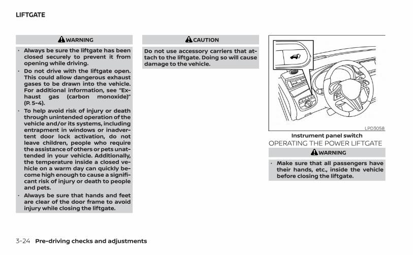
WARNING
• Always be sure the liftgate has beenclosed securely to prevent it fromopening while driving.
• Do not drive with the liftgate open.This could allow dangerous exhaustgases to be drawn into the vehicle.For additional information, see “Ex-haust gas (carbon monoxide)”(P. 5-4).
• To help avoid risk of injury or deaththrough unintended operation of thevehicle and/or its systems, includingentrapment in windows or inadver-tent door lock activation, do notleave children, people who requirethe assistance of others or pets unat-tended in your vehicle. Additionally,the temperature inside a closed ve-hicle on a warm day can quickly be-come high enough to cause a signifi-cant risk of injury or death to peopleand pets.
• Always be sure that hands and feetare clear of the door frame to avoidinjury while closing the liftgate.
CAUTION
Do not use accessory carriers that at-tach to the liftgate. Doing so will causedamage to the vehicle.
OPERATING THE POWER LIFTGATEWARNING
• Make sure that all passengers havetheir hands, etc., inside the vehiclebefore closing the liftgate.
LPD3058Instrument panel switch
LIFTGATE
3-24 Pre-driving checks and adjustments

• To help avoid risk of injury or deaththrough unintended operation of thevehicle and/or its systems, includingentrapment in windows or inadver-tent door lock activation, do notleave children, people who requirethe assistance of others or pets unat-tended in your vehicle. Additionally,the temperature inside a closed ve-hicle on a warm day can quickly be-come high enough to cause a signifi-cant risk of injury or death to peopleor pets.
NOTE:
To open, close or reverse the power lift-gate, engage the P (Park) position. Also,the power liftgate will not operate if thebattery voltage is low.
Power Open:The power liftgate automatically movesfrom the fully closed position to the fullyopen position in approximately 5 to 8 sec-onds. The power open feature can be acti-vated by the switch on the Intelligent Key,the instrument panel switch or the liftgateopener switch OA . A chime sounds to indi-cate the power open sequence has beenstarted.• When the vehicle is locked, the liftgate
can be opened by the instrument panelswitch, Intelligent Key and liftgate openerswitch OA (with the Intelligent Key in lift-gate operation range). The liftgate will in-dividually unlock and open. Once the lift-gate is closed, the vehicle will remainunlocked. To lock the liftgate, press the
button on the Intelligent Key.• To open the liftgate with the Intelligent
Key, hold the button for 1 second.• To open the liftgate with the instrument
panel switch, hold the button for 1second.
• To open the liftgate with the liftgateopener switch OA , the liftgate must beunlocked if the Intelligent Key is not inliftgate operation range.
LPD3182Liftgate opener switch
Pre-driving checks and adjustments 3-25
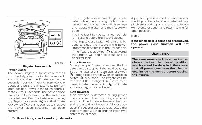
Power Close:The power liftgate automatically movesfrom the fully open position to the second-ary position. When the liftgate reaches thesecondary position, the cinching motor en-gages and pulls the liftgate to its primarylatch position. Power close takes approxi-mately 7 to 10 seconds. The power closefeature can be activated by the switch onthe Intelligent Key, the instrument panel,the liftgate close switch OB and the liftgatelock switch OC . A chime sounds to indicatethe power close sequence has beenstarted.
• If the liftgate opener switch OA is acti-vated while the cinching motor is en-gaged, the cinching motor will disengageand release the latch and the liftgate willopen.
• The Intelligent Key button must be heldfor 1 second before the liftgate closes.
• The liftgate close switch OB can only beused to close the liftgate if the powerliftgate main switch is in the ON position.
• If the liftgate lock switch OC is activatedthe liftgate will begin to close and alldoors will lock.
Stop - Reverse:During the open/close movement, the lift-gate can be stopped if the Intelligent Key,instrument panel or liftgate opener switchOA , liftgate close switch OB or liftgate lockswitch OC is pushed. The liftgate can bereversed if the Intelligent Key, instrumentpanel, liftgate opener switch OA or liftgatelock switch OC is pushed again.Auto Reverse:If an obstacle is detected during poweropen or power close, a warning chime willsound and the liftgate will reverse directionand return to the full open or full close po-sition. If a second obstacle is detected, theliftgate motion will stop and the liftgate willenter manual mode.
A pinch strip is mounted on each side ofthe liftgate. If an obstacle is detected by apinch strip during power close, the liftgatewill reverse direction and return to the fullopen position.
NOTE:
If the pinch strip is damaged or removed,the power close function will notoperate.
WARNING
There are some small distances imme-diately before the closed positionwhich cannot be detected. Make surethat all passengers have their hands,etc., inside the vehicle before closingthe liftgate.
LPD3184Liftgate close switch
3-26 Pre-driving checks and adjustments
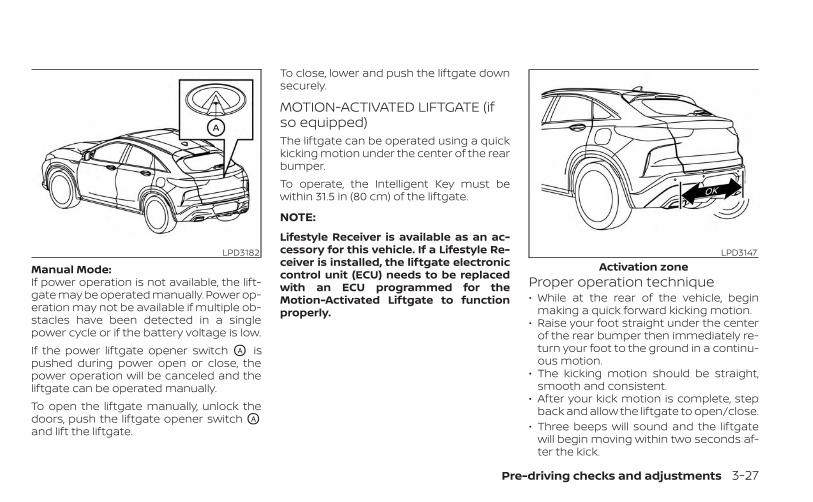
Manual Mode:If power operation is not available, the lift-gate may be operated manually. Power op-eration may not be available if multiple ob-stacles have been detected in a singlepower cycle or if the battery voltage is low.If the power liftgate opener switch OA ispushed during power open or close, thepower operation will be canceled and theliftgate can be operated manually.To open the liftgate manually, unlock thedoors, push the liftgate opener switch OA
and lift the liftgate.
To close, lower and push the liftgate downsecurely.
MOTION-ACTIVATED LIFTGATE (ifso equipped)The liftgate can be operated using a quickkicking motion under the center of the rearbumper.To operate, the Intelligent Key must bewithin 31.5 in (80 cm) of the liftgate.
NOTE:
Lifestyle Receiver is available as an ac-cessory for this vehicle. If a Lifestyle Re-ceiver is installed, the liftgate electroniccontrol unit (ECU) needs to be replacedwith an ECU programmed for theMotion-Activated Liftgate to functionproperly.
Proper operation technique• While at the rear of the vehicle, begin
making a quick forward kicking motion.• Raise your foot straight under the center
of the rear bumper then immediately re-turn your foot to the ground in a continu-ous motion.
• The kicking motion should be straight,smooth and consistent.
• After your kick motion is complete, stepback and allow the liftgate to open/close.
• Three beeps will sound and the liftgatewill begin moving within two seconds af-ter the kick.
LPD3182 LPD3147Activation zone
Pre-driving checks and adjustments 3-27
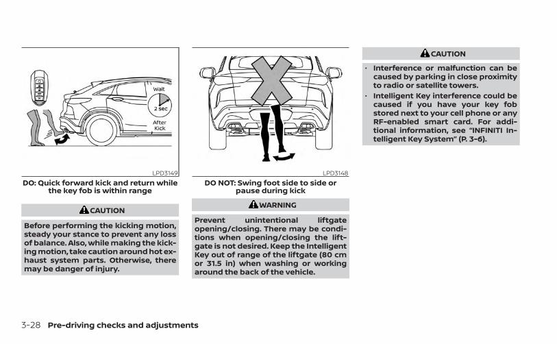
CAUTION
Before performing the kicking motion,steady your stance to prevent any lossof balance. Also, while making the kick-ing motion, take caution around hot ex-haust system parts. Otherwise, theremay be danger of injury.
WARNING
Prevent unintentional liftgateopening/closing. There may be condi-tions when opening/closing the lift-gate is not desired. Keep the IntelligentKey out of range of the liftgate (80 cmor 31.5 in) when washing or workingaround the back of the vehicle.
CAUTION
• Interference or malfunction can becaused by parking in close proximityto radio or satellite towers.
• Intelligent Key interference could becaused if you have your key fobstored next to your cell phone or anyRF-enabled smart card. For addi-tional information, see “INFINITI In-telligent Key System” (P. 3-6).
LPD3149DO: Quick forward kick and return while
the key fob is within range
LPD3148DO NOT: Swing foot side to side or
pause during kick
3-28 Pre-driving checks and adjustments

POWER LIFTGATE MAIN SWITCHThe power liftgate operation can be turnedON OA or OFF OB by the power liftgate mainswitch located in the glove box.When the power liftgate main switch ispushed to the OFF position, the power op-eration is not available by the power lift-gate switch or liftgate request switch onthe liftgate.Power operation is only available when thepower liftgate main switch is in the OFFposition by pressing the liftgate button onthe key fob.
Motion-Activated Liftgate (if so equipped)will not function when the power liftgatemain switch is in the OFF position.
LIFTGATE RELEASE
WARNING
• Always be sure the liftgate has beenclosed securely to prevent it fromopening while driving.
• Do not drive with the liftgate open.This could allow dangerous exhaustgases to be drawn into the vehicle.For additional information, see “Ex-haust gas (carbon monoxide)”(P. 5-4).
• To avoid personal injury, do not at-tempt to activate the power liftgateif one or both of the liftgate struts areremoved.
CAUTION
• If the power liftgate does not stayopen or if the liftgate unexpectedlycloses at any time while a continuouswarning chime sounds, do not oper-ate the liftgate. There may be a pres-sure loss in one or both of the liftgatestruts. It is recommended that youhave the liftgate inspected. It is rec-ommended that you visit an INFINITIretailer for this service.
• Do not activate the power liftgate ifone or both of the liftgate struts areremoved. Damage to the liftgate orpower liftgate mechanisms mayoccur.
• Keep the power liftgate main switch(if so equipped) in the OFF positionwhen washing or working aroundthe back of the vehicle (with Intelli-gent Key) to prevent inadvertentopening/closing.
LPD2723
Pre-driving checks and adjustments 3-29

Power liftgate releaseIf the liftgate cannot be opened with theinstrument panel switch, liftgate openerswitch or key fob due to a discharged bat-tery, follow these steps:1. Remove the cover OA on the inside of the
liftgate.
2. Move the lever OB as illustrated to openthe liftgate.
It is recommended that you visit an INFINITIretailer as soon as possible for repair.
LIFTGATE POSITION SETTINGThe liftgate can be set to open to a specificheight (garage mode) by performing thefollowing:1. Open the liftgate using the liftgate
opener switch or the Intelligent Key.
2. Pull the liftgate down and move to thedesired height position (the liftgate willhave some resistance when beingmanually adjusted).
3. Push and hold the power liftgate closeswitch located on the liftgate formore than 3 seconds or until two beepsare heard.
The liftgate will open to the selected posi-tion setting. To change the position of theliftgate, repeat steps 1-3.
LPD2749 LPD3183
3-30 Pre-driving checks and adjustments
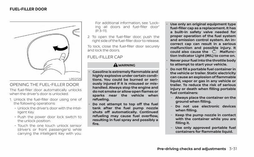
OPENING THE FUEL-FILLER DOORThe fuel-filler door automatically unlockswhen the driver's door is unlocked.1. Unlock the fuel-filler door using one of
the following operations:• Unlock the driver’s door with the Intel-
ligent Key.• Push the power door lock switch to
the unlock position.• Touch the one touch unlock sensor
(driver’s or front passenger’s) whilecarrying the Intelligent Key with you.
For additional information, see “Lock-ing all doors and fuel-filler door”(P. 3-11).
2. To open the fuel-filler door, push theright side of the fuel-filler door to release.
To lock, close the fuel-filler door securelyand lock the doors.
FUEL-FILLER CAP
WARNING
• Gasoline is extremely flammable andhighly explosive under certain condi-tions. You could be burned or seri-ously injured if it is misused or mis-handled. Always stop the engine anddo not smoke or allow open flames orsparks near the vehicle whenrefueling.
• Do not attempt to top off the fueltank after the fuel pump nozzleshuts off automatically. Continuedrefueling may cause fuel overflow,resulting in fuel spray and possibly afire.
• Use only an original equipment typefuel-filler cap as a replacement. It hasa built-in safety valve needed forproper operation of the fuel systemand emission control system. An in-correct cap can result in a seriousmalfunction and possible injury. Itcould also cause the Malfunc-tion Indicator Light (MIL) to come on.
• Never pour fuel into the throttle bodyto attempt to start your vehicle.
• Do not fill a portable fuel container inthe vehicle or trailer. Static electricitycan cause an explosion of flammableliquid, vapor or gas in any vehicle ortrailer. To reduce the risk of seriousinjury or death when filling portablefuel containers:– Always place the container on the
ground when filling.– Do not use electronic devices
when filling.– Keep the pump nozzle in contact
with the container while you arefilling it.
– Use only approved portable fuelcontainers for flammable liquid.
LPD2725
FUEL-FILLER DOOR
Pre-driving checks and adjustments 3-31
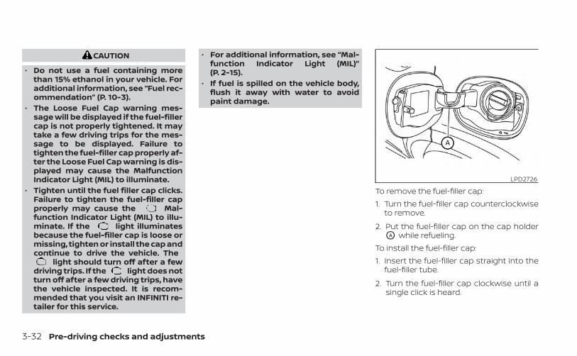
CAUTION
• Do not use a fuel containing morethan 15% ethanol in your vehicle. Foradditional information, see “Fuel rec-ommendation” (P. 10-3).
• The Loose Fuel Cap warning mes-sage will be displayed if the fuel-fillercap is not properly tightened. It maytake a few driving trips for the mes-sage to be displayed. Failure totighten the fuel-filler cap properly af-ter the Loose Fuel Cap warning is dis-played may cause the MalfunctionIndicator Light (MIL) to illuminate.
• Tighten until the fuel filler cap clicks.Failure to tighten the fuel-filler capproperly may cause the Mal-function Indicator Light (MIL) to illu-minate. If the light illuminatesbecause the fuel-filler cap is loose ormissing, tighten or install the cap andcontinue to drive the vehicle. The
light should turn off after a fewdriving trips. If the light does notturn off after a few driving trips, havethe vehicle inspected. It is recom-mended that you visit an INFINITI re-tailer for this service.
• For additional information, see “Mal-function Indicator Light (MIL)”(P. 2-15).
• If fuel is spilled on the vehicle body,flush it away with water to avoidpaint damage.
To remove the fuel-filler cap:1. Turn the fuel-filler cap counterclockwise
to remove.
2. Put the fuel-filler cap on the cap holderOA while refueling.
To install the fuel-filler cap:1. Insert the fuel-filler cap straight into the
fuel-filler tube.
2. Turn the fuel-filler cap clockwise until asingle click is heard.
LPD2726
3-32 Pre-driving checks and adjustments
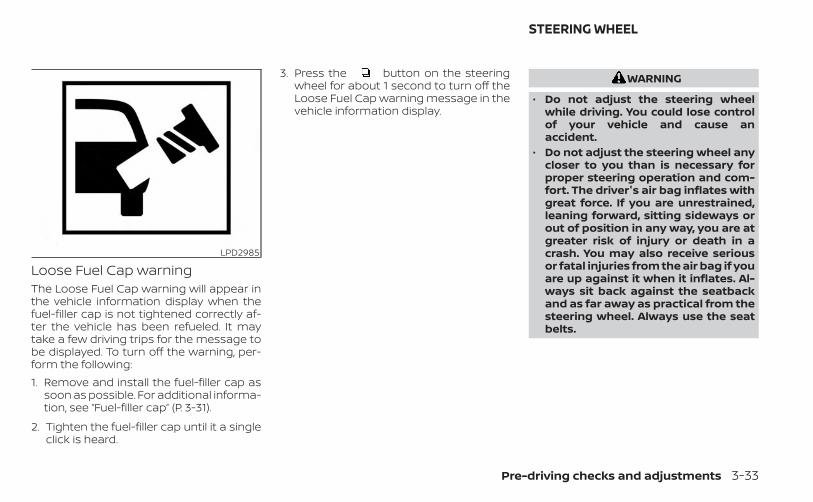
Loose Fuel Cap warningThe Loose Fuel Cap warning will appear inthe vehicle information display when thefuel-filler cap is not tightened correctly af-ter the vehicle has been refueled. It maytake a few driving trips for the message tobe displayed. To turn off the warning, per-form the following:1. Remove and install the fuel-filler cap as
soon as possible. For additional informa-tion, see “Fuel-filler cap” (P. 3-31).
2. Tighten the fuel-filler cap until it a singleclick is heard.
3. Press the button on the steeringwheel for about 1 second to turn off theLoose Fuel Cap warning message in thevehicle information display.
WARNING
• Do not adjust the steering wheelwhile driving. You could lose controlof your vehicle and cause anaccident.
• Do not adjust the steering wheel anycloser to you than is necessary forproper steering operation and com-fort. The driver's air bag inflates withgreat force. If you are unrestrained,leaning forward, sitting sideways orout of position in any way, you are atgreater risk of injury or death in acrash. You may also receive seriousor fatal injuries from the air bag if youare up against it when it inflates. Al-ways sit back against the seatbackand as far away as practical from thesteering wheel. Always use the seatbelts.
LPD2985
STEERING WHEEL
Pre-driving checks and adjustments 3-33
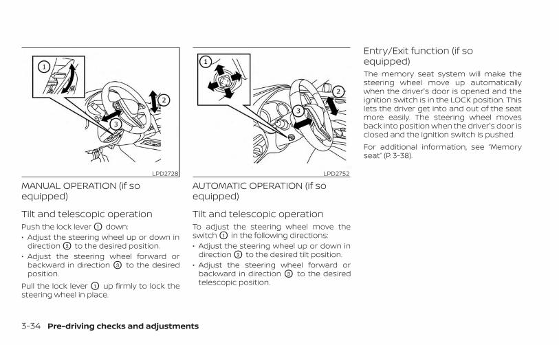
MANUAL OPERATION (if soequipped)
Tilt and telescopic operationPush the lock lever O1 down:• Adjust the steering wheel up or down in
direction O2 to the desired position.• Adjust the steering wheel forward or
backward in direction O3 to the desiredposition.
Pull the lock lever O1 up firmly to lock thesteering wheel in place.
AUTOMATIC OPERATION (if soequipped)
Tilt and telescopic operationTo adjust the steering wheel move theswitch O1 in the following directions:• Adjust the steering wheel up or down in
direction O2 to the desired tilt position.• Adjust the steering wheel forward or
backward in direction O3 to the desiredtelescopic position.
Entry/Exit function (if soequipped)The memory seat system will make thesteering wheel move up automaticallywhen the driver's door is opened and theignition switch is in the LOCK position. Thislets the driver get into and out of the seatmore easily. The steering wheel movesback into position when the driver's door isclosed and the ignition switch is pushed.For additional information, see “Memoryseat” (P. 3-38).
LPD2728 LPD2752
3-34 Pre-driving checks and adjustments

1. To block glare from the front, swingdown the sun visor O1 .
2. To block glare from the side, remove thesun visor from the center mount andswing the visor to the side O2 .
3. Slide the extension O3 sun visor in or outas needed.
CAUTION
• Do not store the sun visor before re-turning the extension to its originalposition.
• Do not pull the extension sun visorforcibly downward.
VANITY MIRRORSTo access the vanity mirror, pull the sunvisor down and flip open the mirror cover.The vanity mirror will illuminate when themirror cover is open.
WPD0344
LPD2583Driver’s and passenger’s side
SUN VISORS
Pre-driving checks and adjustments 3-35
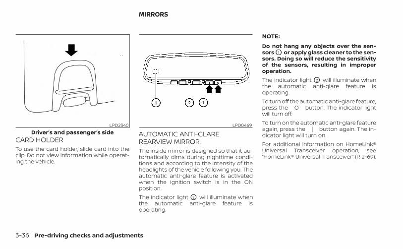
CARD HOLDERTo use the card holder, slide card into theclip. Do not view information while operat-ing the vehicle.
AUTOMATIC ANTI-GLAREREARVIEW MIRRORThe inside mirror is designed so that it au-tomatically dims during nighttime condi-tions and according to the intensity of theheadlights of the vehicle following you. Theautomatic anti-glare feature is activatedwhen the ignition switch is in the ONposition.The indicator light O2 will illuminate whenthe automatic anti-glare feature isoperating.
NOTE:
Do not hang any objects over the sen-sors O1 or apply glass cleaner to the sen-sors. Doing so will reduce the sensitivityof the sensors, resulting in improperoperation.The indicator light O2 will illuminate whenthe automatic anti-glare feature isoperating.To turn off the automatic anti-glare feature,press the O button. The indicator lightwill turn off.To turn on the automatic anti-glare featureagain, press the | button again. The in-dicator light will turn on.For additional information on HomeLink®Universal Transceiver operation, see“HomeLink® Universal Transceiver” (P. 2-69).
LPD2340Driver’s and passenger’s side
LPD0469
MIRRORS
3-36 Pre-driving checks and adjustments
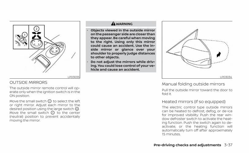
OUTSIDE MIRRORSThe outside mirror remote control will op-erate only when the ignition switch is in theON position.Move the small switch O1 to select the leftor right mirror. Adjust each mirror to thedesired position using the large switch O2 .Move the small switch O1 to the center(neutral) position to prevent accidentallymoving the mirror.
WARNING
• Objects viewed in the outside mirroron the passenger side are closer thanthey appear. Be careful when movingto the right. Using only this mirrorcould cause an accident. Use the in-side mirror or glance over yourshoulder to properly judge distancesto other objects.
• Do not adjust the mirrors while driv-ing. You could lose control of your ve-hicle and cause an accident.
Manual folding outside mirrorsPull the outside mirror toward the door tofold it.
Heated mirrors (if so equipped)The electric control type outside mirrorscan be heated to defrost, defog, or de-icefor improved visibility. Push the rear win-dow defroster switch to activate the heat-ing function. Push the switch again to de-activate, or the heating function willautomatically turn off after approximately15 minutes.
LPD3035 LPD3034
Pre-driving checks and adjustments 3-37
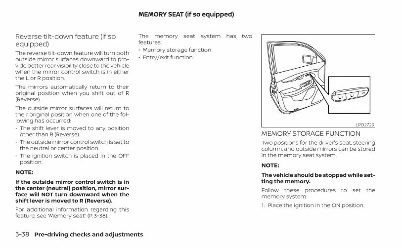
Reverse tilt-down feature (if soequipped)The reverse tilt-down feature will turn bothoutside mirror surfaces downward to pro-vide better rear visibility close to the vehiclewhen the mirror control switch is in eitherthe L or R position.The mirrors automatically return to theiroriginal position when you shift out of R(Reverse).The outside mirror surfaces will return totheir original position when one of the fol-lowing has occurred:• The shift lever is moved to any position
other than R (Reverse).• The outside mirror control switch is set to
the neutral or center position.• The ignition switch is placed in the OFF
position.
NOTE:
If the outside mirror control switch is inthe center (neutral) position, mirror sur-face will NOT turn downward when theshift lever is moved to R (Reverse).For additional information regarding thisfeature, see “Memory seat” (P. 3-38).
The memory seat system has twofeatures:• Memory storage function• Entry/exit function
MEMORY STORAGE FUNCTIONTwo positions for the driver's seat, steeringcolumn, and outside mirrors can be storedin the memory seat system.
NOTE:
The vehicle should be stopped while set-ting the memory.Follow these procedures to set thememory system.1. Place the ignition in the ON position.
LPD2729
MEMORY SEAT (if so equipped)
3-38 Pre-driving checks and adjustments
2. Adjust the driver's seat, steering column,and outside mirrors to the desired posi-tions by manually operating each ad-justing switch. For additional informa-tion, see “Seats” (P. 1-2), “Steering wheel”(P. 3-33) and “Outside mirrors” (P. 3-37).
3. Push the SET switch and, within 5 sec-onds, push the memory switch (1 or 2).
4. The indicator light for the pushedmemory switch will come on and stayon for approximately 5 seconds.
5. The chime will sound when the memoryis stored.
NOTE:
If a new memory position is stored in thesame memory switch, the previousmemory position will be overwritten bythe new stored position.
Confirming memory storage• Push the SET switch.• If a memory position has been stored in
the switch (1 or 2) then the indicator lightfor the respective switch will stay on forapproximately 5 seconds.
Linking log-in function to a storedmemory positionThe log-in function can be linked to astored memory position with the followingprocedure.1. Place the ignition switch in the ON posi-
tion while carrying the Intelligent Keythat was registered to the vehicle with alog-in function.
NOTE:Make sure the Intelligent Keys are farapart. Otherwise, the vehicle may detectthe wrong Intelligent Key.
2. Adjust the position of the driver’s seat,steering column and outside mirrors.For additional information, see “Seats”(P. 1-2), “Steering wheel” (P. 3-33) and “Out-side mirrors” (P. 3-37).
3. Place the ignition switch in the OFFposition.
The next time you log in (selecting the useron the display) after placing the ignitionswitch in the ON position while carrying theIntelligent Key, the system will automati-cally adjust to the memorized drivingposition.
For additional information, see the sepa-rate INFINITI InTouch™ Owner’s Manual and“Log-in function” (P. 3-20).
ENTRY/EXIT FUNCTIONThis system is designed so that the driver'sseat and steering column will automati-cally move when you the vehicle is en-gaged in the P (Park) position. This allowsthe driver to easily get in and out of thedriver’s seat.The driver’s seat will slide backward andthe steering column will move up when theignition is switched to OFF and the driver’sdoor is opened.The driver’s seat and steering wheel willreturn to the previous position when theignition is switched to ON.The entry/exit function can be adjusted orcanceled through the “Comfort & Conve-nience” options of the “Settings” menu inthe lower touch-screen display by per-forming the following:• Switch the Lift Steering upon Exit from ON
to OFF.• Switch the Slide Driver Seat Back on Exit
from ON to OFF.
Pre-driving checks and adjustments 3-39
For additional information, refer to theseparate INFINITI InTouch™ Owner’sManual.
Restarting the entry/exit functionIf the battery cable is disconnected, or if thefuse opens, the stored memory positionswill be lost and some of the functions willbe restricted:1. Drive the vehicle over 25 mph (40 km/h).OR2. Open and close the driver's door more
than two times with the ignition switchin the OFF position.
The entry/exit function should now workproperly.
SETTING MEMORY FUNCTIONThe position of the following settings canbe linked to the Intelligent Key and thememorized settings can be available foreach Intelligent Key.• Climate control system• Navigation system• Audio system
To use the memory function, set the cli-mate and audio systems to the driver'spreferred settings. Lock the doors with theIntelligent Key. Each Intelligent Key may beset with the driver's individual preferences.When a new Intelligent Key is used, “Con-nection with the key has been done” will bedisplayed on the vehicle information dis-play and the memorized settings areavailable.To engage the memorized settings, per-form the following:1. Carry the Intelligent Key that is linked to
the memorized settings.
2. Unlock the doors by pushing the driver’sdoor handle request switch or thebutton on the Intelligent Key.
3. Place the ignition switch in the ON posi-tion. The settings linked to the IntelligentKey will start.
For additional information on using the cli-mate control system, see “Heater and airconditioner (automatic)” (P. 4-33).For additional information on using thenavigation and audio systems, refer to theseparate INFINITI InTouch™ Owner’sManual.
SYSTEM OPERATIONThe memory seat system will not work orwill stop operating under the followingconditions:• When the vehicle speed is above 4 mph (7
km/h).• When any of the memory switches are
pushed while the memory seat system isoperating.
• When the switch for the driver’s seat andsteering column is pushed while thememory seat system is operating.
• When the seat has already been movedto the memorized position.
• When no seat position is stored in thememory switch.
• When the shift lever is moved from P(Park) to any other position.
The memory seat system can be adjustedand canceled. It is recommended you visitan INFINITI retailer for this service.
3-40 Pre-driving checks and adjustments
4 Monitor, climate, audio, phone andvoice recognition systems
INFINITI InTouchTM Owner’s Manual . . . . . . . . . . . . . . 4-2RearView Monitor (if so equipped) . . . . . . . . . . . . . . . 4-3
RearView Monitor system operation . . . . . . . . . . 4-4How to read the displayed lines . . . . . . . . . . . . . . 4-5Difference between predicted andactual distances . . . . . . . . . . . . . . . . . . . . . . . . . . . . . 4-5How to park with predicted courselines . . . . . . . . . . . . . . . . . . . . . . . . . . . . . . . . . . . . . . . . . . 4-7Adjusting the screen . . . . . . . . . . . . . . . . . . . . . . . . . 4-9How to turn on and off predictedcourse lines . . . . . . . . . . . . . . . . . . . . . . . . . . . . . . . . . . 4-9RearView Monitor system limitations . . . . . . . . . 4-9System maintenance . . . . . . . . . . . . . . . . . . . . . . . 4-10
Around View® Monitor (if so equipped) . . . . . . . . . . .4-11Around View® Monitor systemoperation . . . . . . . . . . . . . . . . . . . . . . . . . . . . . . . . . . . 4-12Difference between predicted andactual distances . . . . . . . . . . . . . . . . . . . . . . . . . . . . 4-16How to park with predicted courselines . . . . . . . . . . . . . . . . . . . . . . . . . . . . . . . . . . . . . . . . . 4-18How to switch the display . . . . . . . . . . . . . . . . . . . 4-19Around View® Monitor settings . . . . . . . . . . . . . . 4-20Adjusting the screen . . . . . . . . . . . . . . . . . . . . . . . . 4-21Around View® Monitor systemlimitations . . . . . . . . . . . . . . . . . . . . . . . . . . . . . . . . . . 4-21System maintenance . . . . . . . . . . . . . . . . . . . . . . . 4-23
Camera aiding sonar (parking sensor)(if so equipped) . . . . . . . . . . . . . . . . . . . . . . . . . . . . . . . . . 4-24
Sonar system operation . . . . . . . . . . . . . . . . . . . . . 4-24Turning on and off the sonar function . . . . . . . 4-25Sonar system limitations . . . . . . . . . . . . . . . . . . . . 4-26System temporarily unavailable . . . . . . . . . . . . . 4-26System maintenance . . . . . . . . . . . . . . . . . . . . . . . 4-26
Moving Object Detection (MOD)(if so equipped) . . . . . . . . . . . . . . . . . . . . . . . . . . . . . . . . . 4-27
MOD system operation . . . . . . . . . . . . . . . . . . . . . . 4-28Turning MOD on and off . . . . . . . . . . . . . . . . . . . . . 4-30MOD system limitations . . . . . . . . . . . . . . . . . . . . . 4-30System maintenance . . . . . . . . . . . . . . . . . . . . . . . 4-31
Vents . . . . . . . . . . . . . . . . . . . . . . . . . . . . . . . . . . . . . . . . . . 4-32Heater and air conditioner (automatic) . . . . . . . . . 4-33
Automatic operation . . . . . . . . . . . . . . . . . . . . . . . . 4-34Manual operation . . . . . . . . . . . . . . . . . . . . . . . . . . . 4-35Operating tips . . . . . . . . . . . . . . . . . . . . . . . . . . . . . . . 4-36CLIMATE setting screen . . . . . . . . . . . . . . . . . . . . . 4-37Rear climate control (if so equipped) . . . . . . . . 4-39
Heater and air conditioner settings(if so equipped) . . . . . . . . . . . . . . . . . . . . . . . . . . . . . . . . .4-40Servicing air conditioner . . . . . . . . . . . . . . . . . . . . . . . . 4-41Antenna. . . . . . . . . . . . . . . . . . . . . . . . . . . . . . . . . . . . . . . . 4-41Car phone or CB radio . . . . . . . . . . . . . . . . . . . . . . . . . . 4-42

Refer to the digital INFINITI InTouchTM Own-er’s manual using the QR code on thispage, or your printed INFINITI InTouchTM
Owner’s manual (if so equipped). Thismanual includes the following information:• INFINITI InTouchTM Services (if so
equipped)• Navigation system (if so equipped)• Audio system• Apple CarPlay®• Android AutoTM
• Bluetooth® Hands-Free Phone system• Viewing information• Other settings• Voice recognition• General system information
LHA5530
INFINITI INTOUCHTM OWNER’SMANUAL
4-2 Monitor, climate, audio, phone and voice recognition systems

1. Upper touch-screen display (upperdisplay)
2. Lower touch-screen display (lowerdisplay)
3. MENU button
4. button
LHA5414
REARVIEW MONITOR (if soequipped)
Monitor, climate, audio, phone and voice recognition systems 4-3

WARNING
• Failure to follow the warnings and in-structions for proper use of the Rear-View Monitor system could result inserious injury or death.
• RearView Monitor is a conveniencefeature and is not a substitute forproper backing. Always turn and lookout the windows and check mirrorsto be sure that it is safe to move be-fore operating the vehicle. Alwaysback up slowly.
• The system is designed as an aid tothe driver in showing large station-ary objects directly behind the ve-hicle, to help avoid damaging thevehicle.
• The distance guide line and the ve-hicle width line should be used as areference only when the vehicle is ona level paved surface. The distanceviewed on the monitor is for refer-ence only and may be different thanthe actual distance between the ve-hicle and displayed objects.
CAUTION
Do not scratch the camera lens whencleaning dirt or snow from the front ofthe camera.
The RearView Monitor system automati-cally shows a rear view of the vehicle in theupper touch-screen display (upper display)when the shift lever is shifted into the R(Reverse) position. When activating theRearView Monitor, the guide lines, the iconsand the messages may not be displayedimmediately. The radio can still be heardwhile the RearView Monitor is active.
To display the rear view, the RearView Moni-tor system uses a camera located justabove the vehicle’s license plate O1 .
REARVIEW MONITOR SYSTEMOPERATIONWith the engine running, move the shiftlever to the R (Reverse) position to operatethe RearView Monitor. When activating theRearView Monitor, the guide lines, the iconsand the messages may not be displayedimmediately.
LHA5415
4-4 Monitor, climate, audio, phone and voice recognition systems

HOW TO READ THE DISPLAYEDLINESGuiding lines which indicate the vehiclewidth and distances to objects with refer-ence to the vehicle body line OA are dis-played on the monitor.Distance guide linesIndicate distances from the vehicle body.• Red line O1 : approx. 1.5 ft (0.5 m)• Yellow line O2 : approx. 3 ft (1 m)• Green line O3 : approx. 7 ft (2 m)
Vehicle width guide lines O4
Indicate the vehicle width when backingup.Predicted course lines O5
Indicate the predicted course when back-ing up. The predicted course lines will bedisplayed on the monitor when the shiftlever is in the R (Reverse) position and thesteering wheel is turned. The predictedcourse lines will move depending on howmuch the steering wheel is turned and willnot be displayed while the steering wheel isin the straight-ahead position.The vehicle width guide lines and the widthof the predicted course lines are wider thanthe actual width and course.
DIFFERENCE BETWEEN PREDICTEDAND ACTUAL DISTANCESThe displayed guidelines and their loca-tions on the ground are for approximatereference only. Objects on uphill or downhillsurfaces or projecting objects will be actu-ally located at distances different fromthose displayed in the monitor relative tothe guidelines (refer to illustrations). Whenin doubt, turn around and view the objectsas you are backing up, or park and exit thevehicle to view the positioning of objectsbehind the vehicle.
LHA4805
Monitor, climate, audio, phone and voice recognition systems 4-5
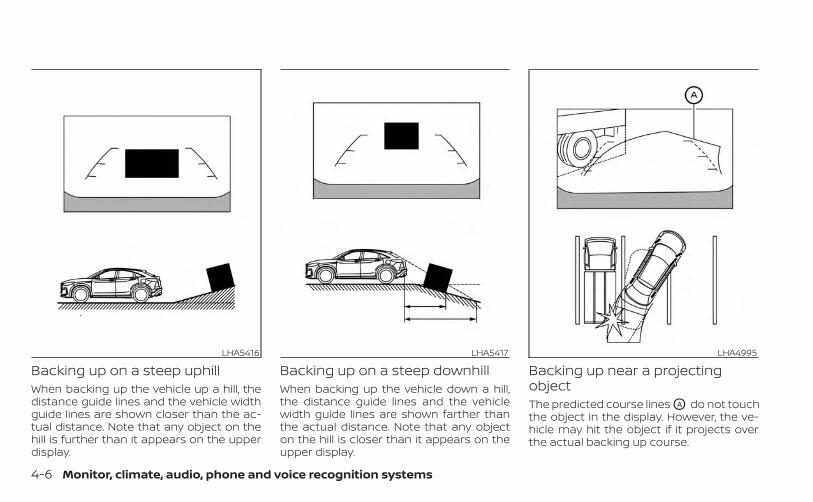
Backing up on a steep uphillWhen backing up the vehicle up a hill, thedistance guide lines and the vehicle widthguide lines are shown closer than the ac-tual distance. Note that any object on thehill is further than it appears on the upperdisplay.
Backing up on a steep downhillWhen backing up the vehicle down a hill,the distance guide lines and the vehiclewidth guide lines are shown farther thanthe actual distance. Note that any objecton the hill is closer than it appears on theupper display.
Backing up near a projectingobjectThe predicted course lines OA do not touchthe object in the display. However, the ve-hicle may hit the object if it projects overthe actual backing up course.
LHA5416 LHA5417 LHA4995
4-6 Monitor, climate, audio, phone and voice recognition systems
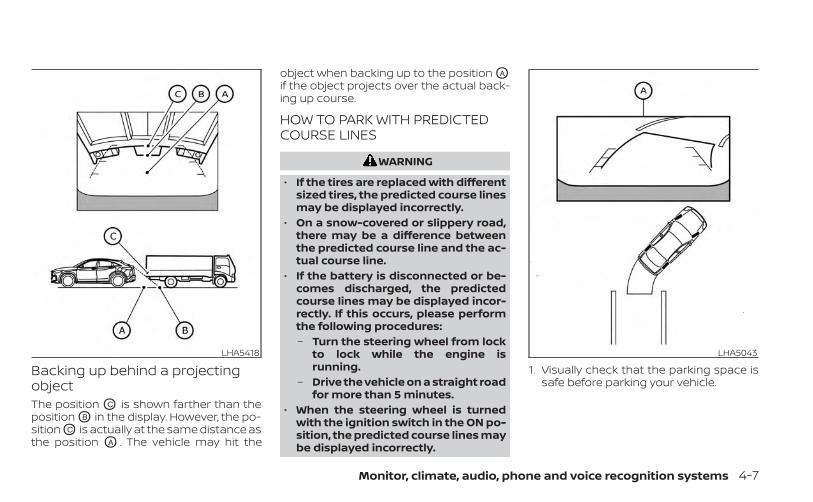
Backing up behind a projectingobjectThe position OC is shown farther than theposition OB in the display. However, the po-sition OC is actually at the same distance asthe position OA . The vehicle may hit the
object when backing up to the position OA
if the object projects over the actual back-ing up course.
HOW TO PARK WITH PREDICTEDCOURSE LINES
WARNING
• If the tires are replaced with differentsized tires, the predicted course linesmay be displayed incorrectly.
• On a snow-covered or slippery road,there may be a difference betweenthe predicted course line and the ac-tual course line.
• If the battery is disconnected or be-comes discharged, the predictedcourse lines may be displayed incor-rectly. If this occurs, please performthe following procedures:– Turn the steering wheel from lock
to lock while the engine isrunning.
– Drive the vehicle on a straight roadfor more than 5 minutes.
• When the steering wheel is turnedwith the ignition switch in the ON po-sition, the predicted course lines maybe displayed incorrectly.
1. Visually check that the parking space issafe before parking your vehicle.
LHA5418 LHA5043
Monitor, climate, audio, phone and voice recognition systems 4-7
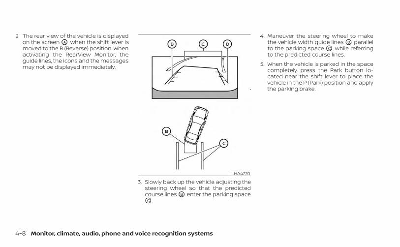
2. The rear view of the vehicle is displayedon the screen OA when the shift lever ismoved to the R (Reverse) position. Whenactivating the RearView Monitor, theguide lines, the icons and the messagesmay not be displayed immediately.
3. Slowly back up the vehicle adjusting thesteering wheel so that the predictedcourse lines OB enter the parking spaceOC .
4. Maneuver the steering wheel to makethe vehicle width guide lines OD parallelto the parking space OC while referringto the predicted course lines.
5. When the vehicle is parked in the spacecompletely, press the Park button lo-cated near the shift lever to place thevehicle in the P (Park) position and applythe parking brake.
LHA4770
4-8 Monitor, climate, audio, phone and voice recognition systems
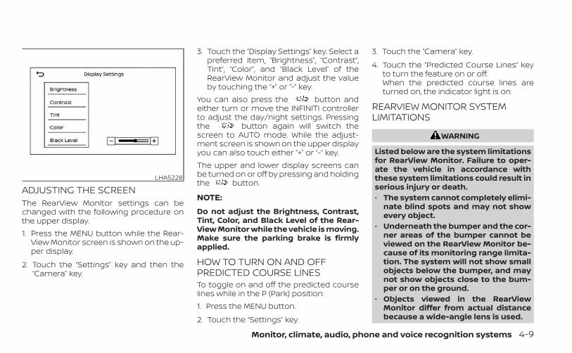
ADJUSTING THE SCREENThe RearView Monitor settings can bechanged with the following procedure onthe upper display.1. Press the MENU button while the Rear-
View Monitor screen is shown on the up-per display.
2. Touch the “Settings” key and then the“Camera” key.
3. Touch the “Display Settings” key. Select apreferred item, “Brightness”, “Contrast”,Tint”, “Color”, and “Black Level” of theRearView Monitor and adjust the valueby touching the “+” or “-” key.
You can also press the button andeither turn or move the INFINITI controllerto adjust the day/night settings. Pressingthe button again will switch thescreen to AUTO mode. While the adjust-ment screen is shown on the upper displayyou can also touch either “+” or “-” key.The upper and lower display screens canbe turned on or off by pressing and holdingthe button.
NOTE:
Do not adjust the Brightness, Contrast,Tint, Color, and Black Level of the Rear-View Monitor while the vehicle is moving.Make sure the parking brake is firmlyapplied.
HOW TO TURN ON AND OFFPREDICTED COURSE LINESTo toggle on and off the predicted courselines while in the P (Park) position:1. Press the MENU button.
2. Touch the “Settings” key.
3. Touch the “Camera” key.
4. Touch the “Predicted Course Lines” keyto turn the feature on or off.When the predicted course lines areturned on, the indicator light is on.
REARVIEW MONITOR SYSTEMLIMITATIONS
WARNING
Listed below are the system limitationsfor RearView Monitor. Failure to oper-ate the vehicle in accordance withthese system limitations could result inserious injury or death.• The system cannot completely elimi-
nate blind spots and may not showevery object.
• Underneath the bumper and the cor-ner areas of the bumper cannot beviewed on the RearView Monitor be-cause of its monitoring range limita-tion. The system will not show smallobjects below the bumper, and maynot show objects close to the bum-per or on the ground.
• Objects viewed in the RearViewMonitor differ from actual distancebecause a wide-angle lens is used.
LHA5228
Monitor, climate, audio, phone and voice recognition systems 4-9

• Objects in the RearView Monitor willappear visually opposite comparedto when viewed in the rearview andoutside mirrors.
• Use the displayed lines as a refer-ence. The lines are highly affected bythe number of occupants, fuel level,vehicle position, road conditions androad grade.
• Make sure that the liftgate is securelyclosed when backing up.
• Do not put anything on the rearviewcamera. The rearview camera is in-stalled above the license plate.
• When washing the vehicle with highpressure water, be sure not to spray itaround the camera. Otherwise, watermay enter the camera unit causingwater condensation on the lens, amalfunction, fire or an electric shock.
• Do not strike the camera. It is a preci-sion instrument. Otherwise, it maymalfunction or cause damage result-ing in a fire or an electric shock.
The following are operating limitations anddo not represent a system malfunction:• When the temperature is extremely high
or low, the screen may not clearly displayobjects.
• When strong light directly shines on thecamera, objects may not be displayedclearly.
• Vertical lines may be seen in objects onthe screen. This is due to strong reflectedlight from the bumper.
• The screen may flicker under fluorescentlight.
• The colors of objects on the RearViewMonitor may differ somewhat from theactual color of objects.
• Objects on the monitor may not be clearin a dark environment.
• There may be a delay when switchingbetween views.
• If dirt, rain or snow accumulate on thecamera, the RearView Monitor may notdisplay objects clearly. Clean the camera.
• Do not use wax on the camera lens. Wipeoff any wax with a clean cloth dampenedwith a diluted mild cleaning agent, thenwipe with a dry cloth.
SYSTEM MAINTENANCE
CAUTION
• Do not use alcohol, benzine or thin-ner to clean the camera. This willcause discoloration.
• Do not damage the camera as the moni-tor screen may be adversely affected.
If dirt, rain or snow accumulates on thecamera O1 , the RearView Monitor may notdisplay objects clearly. Clean the cameraby wiping it with a cloth dampened with adiluted mild cleaning agent and then wip-ing it with a dry cloth.
LHA5415
4-10 Monitor, climate, audio, phone and voice recognition systems
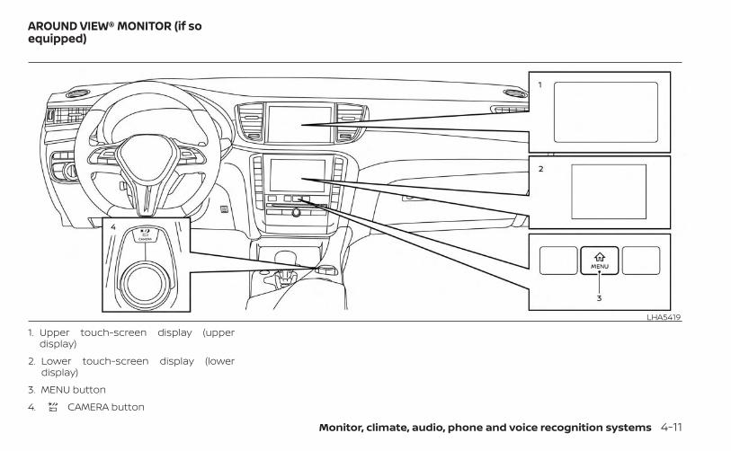
1. Upper touch-screen display (upperdisplay)
2. Lower touch-screen display (lowerdisplay)
3. MENU button
4. CAMERA button
LHA5419
AROUND VIEW® MONITOR (if soequipped)
Monitor, climate, audio, phone and voice recognition systems 4-11
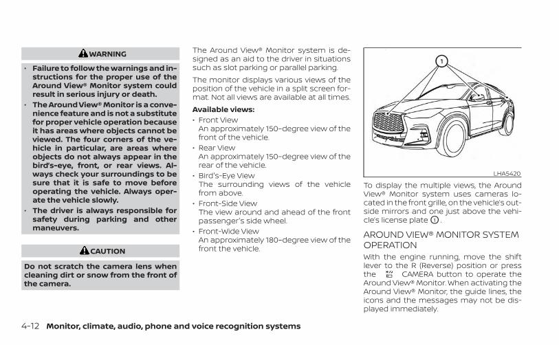
WARNING
• Failure to follow the warnings and in-structions for the proper use of theAround View® Monitor system couldresult in serious injury or death.
• The Around View® Monitor is a conve-nience feature and is not a substitutefor proper vehicle operation becauseit has areas where objects cannot beviewed. The four corners of the ve-hicle in particular, are areas whereobjects do not always appear in thebird’s-eye, front, or rear views. Al-ways check your surroundings to besure that it is safe to move beforeoperating the vehicle. Always oper-ate the vehicle slowly.
• The driver is always responsible forsafety during parking and othermaneuvers.
CAUTION
Do not scratch the camera lens whencleaning dirt or snow from the front ofthe camera.
The Around View® Monitor system is de-signed as an aid to the driver in situationssuch as slot parking or parallel parking.The monitor displays various views of theposition of the vehicle in a split screen for-mat. Not all views are available at all times.Available views:• Front View
An approximately 150–degree view of thefront of the vehicle.
• Rear ViewAn approximately 150–degree view of therear of the vehicle.
• Bird's-Eye ViewThe surrounding views of the vehiclefrom above.
• Front-Side ViewThe view around and ahead of the frontpassenger's side wheel.
• Front-Wide ViewAn approximately 180–degree view of thefront the vehicle.
To display the multiple views, the AroundView® Monitor system uses cameras lo-cated in the front grille, on the vehicle’s out-side mirrors and one just above the vehi-cle’s license plate O1 .
AROUND VIEW® MONITOR SYSTEMOPERATIONWith the engine running, move the shiftlever to the R (Reverse) position or pressthe CAMERA button to operate theAround View® Monitor. When activating theAround View® Monitor, the guide lines, theicons and the messages may not be dis-played immediately.
LHA5420
4-12 Monitor, climate, audio, phone and voice recognition systems

When the camera is first activated with thebird’s-eye view in the display, a red icon willflash on the upper display. This indicatesthat the sonar system is activated. For ad-ditional information on the front and rearsonar system, see “Front and rear sonarsystem” (P. 5-190).
Available views
WARNING
• The distance guide lines and the ve-hicle width lines should be used as areference only when the vehicle is ona paved, level surface. The apparentdistance viewed on the monitor maybe different than the actual distancebetween the vehicle and displayedobjects.
• Use the displayed lines and thebird’s-eye view as a reference. Thelines and the bird’s-eye view aregreatly affected by the number of oc-cupants, cargo, fuel level, vehicle po-sition, road condition and roadgrade.
• If the tires are replaced with differentsized tires, the predicted course linesand the bird's-eye view may be dis-played incorrectly.
• When driving the vehicle up a hill, ob-jects viewed in the monitor are fur-ther than they appear. When drivingthe vehicle down a hill, objectsviewed in the monitor are closer thanthey appear.
• Objects in the rear view will appearvisually opposite compared to whenviewed in the monitor and outsidemirrors.
• Use the mirrors or actually look toproperly judge distances to otherobjects.
• On a snow-covered or slippery road,there may be a difference betweenthe predicted course lines and theactual course line.
• The vehicle width and predictedcourse lines are wider than the actualwidth and course.
• The displayed lines will appearslightly off to the right, because therearview camera is not installed inthe rear center of the vehicle.
Front and rear viewGuiding lines that indicate the approximatevehicle width and distance to objects withreference to the vehicle body line OA aredisplayed on the monitor.Distance guide linesIndicate distances from the vehicle body:• Red line O1 : approximately 1.5 ft (0.5 m)• Yellow line O2 : approximately 3 ft (1 m)• Green line O3 : approximately 7 ft (2 m)• Green line O4 : approximately 10 ft (3 m) (if
so equipped)
SAA1840Front view
Monitor, climate, audio, phone and voice recognition systems 4-13

Vehicle width guide lines O5
Indicate the approximate vehicle widthwhen backing up.Predicted course lines O6
Indicate the predicted course when oper-ating the vehicle. The predicted courselines will be displayed on the monitor whenthe steering wheel is turned. The predictedcourse lines will move depending on howmuch the steering wheel is turned andmay not be displayed while the steeringwheel is in the straight-ahead position.
The front view will not be displayed whenthe vehicle speed is above 6 mph (10 km/h).
NOTE:
When the monitor displays the frontview and the steering wheel turns about90 degrees or less from the straight-ahead position, both the right and leftpredicted course lines O6 are displayed.When the steering wheel turns about 90degrees or more, a line is displayed onlyon the opposite side of the turn.
Bird’s-eye viewThe bird's-eye view shows the overheadview of the vehicle, which helps confirm thevehicle position and the predicted courseto a parking space.The vehicle icon O1 shows the position ofthe vehicle. Note that the apparent dis-tance between objects viewed in thebird's-eye view may differ somewhat fromthe actual distance to the vehicle.The areas that the cameras cannot coverO2 are indicated in black.
LHA4992Rear view
LHA4534Front view
4-14 Monitor, climate, audio, phone and voice recognition systems
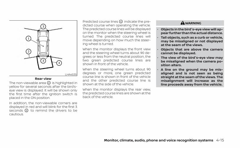
The non-viewable area O2 is highlighted inyellow for several seconds after the bird’s-eye view is displayed. It will be shown onlythe first time after the ignition switch isplaced in the ON position.In addition, the non-viewable corners aredisplayed in red and will blink for the first 3seconds O3 to remind the drivers to becautious.
Predicted course lines O4 indicate the pre-dicted course when operating the vehicle.The predicted course lines will be displayedon the monitor when the steering wheel isturned. The predicted course lines willmove depending on how much the steer-ing wheel is turned.When the monitor displays the front viewand the steering wheel turns about 90 de-grees or less from the neutral position, thetwo green predicted course lines areshown in front of the vehicle.When the steering wheel turns about 90degrees or more, one green predictedcourse line is shown in front of the vehicleand the other predicted course line isshown at the side of the vehicle.When the monitor displays the rear view,the predicted course lines are shown at theback of the vehicle.
WARNING
• Objects in the bird's-eye view will ap-pear further than the actual distance.
• Tall objects, such as a curb or vehicle,may be misaligned or not displayedat the seam of the views.
• Objects that are above the cameracannot be displayed.
• The view of the bird's-eye view maybe misaligned when the camera po-sition alters.
• A line on the ground may be mis-aligned and is not seen as beingstraight at the seam of the views. Themisalignment will increase as theline proceeds away from the vehicle.
LHA4535Rear view
Monitor, climate, audio, phone and voice recognition systems 4-15
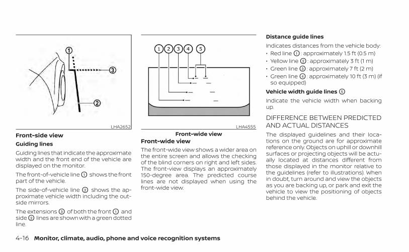
Front-side viewGuiding linesGuiding lines that indicate the approximatewidth and the front end of the vehicle aredisplayed on the monitor.The front-of-vehicle line O1 shows the frontpart of the vehicle.The side-of-vehicle line O2 shows the ap-proximate vehicle width including the out-side mirrors.The extensions O3 of both the front O1 andside O2 lines are shown with a green dottedline.
Front-wide viewThe front-wide view shows a wider area onthe entire screen and allows the checkingof the blind corners on right and left sides.The front-view displays an approximately150-degree area. The predicted courselines are not displayed when using thefront-wide view.
Distance guide linesIndicates distances from the vehicle body:• Red line O1 : approximately 1.5 ft (0.5 m)• Yellow line O2 : approximately 3 ft (1 m)• Green line O3 : approximately 7 ft (2 m)• Green line O4 : approximately 10 ft (3 m) (if
so equipped)Vehicle width guide lines O5
Indicate the vehicle width when backingup.
DIFFERENCE BETWEEN PREDICTEDAND ACTUAL DISTANCESThe displayed guidelines and their loca-tions on the ground are for approximatereference only. Objects on uphill or downhillsurfaces or projecting objects will be actu-ally located at distances different fromthose displayed in the monitor relative tothe guidelines (refer to illustrations). Whenin doubt, turn around and view the objectsas you are backing up, or park and exit thevehicle to view the positioning of objectsbehind the vehicle.
LHA2652 LHA4555Front-wide view
4-16 Monitor, climate, audio, phone and voice recognition systems

Backing up on a steep uphillWhen backing up the vehicle up a hill, thedistance guide lines and the vehicle widthguide lines are shown closer than the ac-tual distance. Note that any object on thehill is further than it appears on the upperdisplay.
Backing up on a steep downhillWhen backing up the vehicle down a hill,the distance guide lines and the vehiclewidth guide lines are shown farther thanthe actual distance. Note that any objecton the hill is closer than it appears on theupper display.
Backing up near a projectingobjectThe predicted course lines OA do not touchthe object in the display. However, the ve-hicle may hit the object if it projects overthe actual backing up course.
LHA5416 LHA5417 LHA4995
Monitor, climate, audio, phone and voice recognition systems 4-17
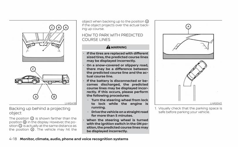
Backing up behind a projectingobjectThe position OC is shown farther than theposition OB in the display. However, the po-sition OC is actually at the same distance asthe position OA . The vehicle may hit the
object when backing up to the position OA
if the object projects over the actual back-ing up course.
HOW TO PARK WITH PREDICTEDCOURSE LINES
WARNING
• If the tires are replaced with differentsized tires, the predicted course linesmay be displayed incorrectly.
• On a snow-covered or slippery road,there may be a difference betweenthe predicted course line and the ac-tual course line.
• If the battery is disconnected or be-comes discharged, the predictedcourse lines may be displayed incor-rectly. If this occurs, please performthe following procedures:– Turn the steering wheel from lock
to lock while the engine isrunning.
– Drive the vehicle on a straight roadfor more than 5 minutes.
• When the steering wheel is turnedwith the ignition switch in the ON po-sition, the predicted course lines maybe displayed incorrectly.
1. Visually check that the parking space issafe before parking your vehicle.
LHA5418 LHA5043
4-18 Monitor, climate, audio, phone and voice recognition systems
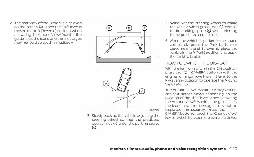
2. The rear view of the vehicle is displayedon the screen OA when the shift lever ismoved to the R (Reverse) position. Whenactivating the Around View® Monitor, theguide lines, the icons and the messagesmay not be displayed immediately.
3. Slowly back up the vehicle adjusting thesteering wheel so that the predictedcourse lines OB enter the parking spaceOC .
4. Maneuver the steering wheel to makethe vehicle width guide lines OD parallelto the parking space OC while referringto the predicted course lines.
5. When the vehicle is parked in the spacecompletely, press the Park button lo-cated near the shift lever to place thevehicle in the P (Park) position and applythe parking brake.
HOW TO SWITCH THE DISPLAYWith the ignition switch in the ON position,press the CAMERA button or with theengine running, move the shift lever to theR (Reverse) position to operate the AroundView® Monitor.The Around View® Monitor displays differ-ent split screen views depending on theposition of the shift lever. When activatingthe Around View® Monitor, the guide lines,the icons and the messages may not bedisplayed immediately. Press theCAMERA button or touch the “Change View”key to switch between the available views.
LHA4770
Monitor, climate, audio, phone and voice recognition systems 4-19
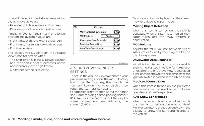
If the shift lever is in the R (Reverse) position,the available views are:• Rear view/bird’s-eye view split screen• Rear view/front-side view split screenIf the shift lever is in the P (Park) or D (Drive)position, the available views are:• Front view/bird’s-eye view split screen• Front view/front-side view split screen• Front-wide viewThe display will switch from the AroundView® Monitor screen when:• The shift lever is in the D (Drive) position
and the vehicle speed increases aboveapproximately 6 mph (10 km/h).
• A different screen is selected.AROUND VIEW® MONITORSETTINGSTo set up the Around View® Monitor to yourpreferred settings, press the MENU button,touch the “Settings” key, then touch the“Camera” key on the lower display thentouch the “Camera” key again.For additional information about the sonar,see “Camera aiding sonar (parking sensor)”(P. 4-24). For information about the displayscreen adjustment, see “Adjusting thescreen” (P. 4-21).
Designs and items displayed on the screenmay vary depending on model.Moving Object DetectionWhen this item is turned on, the MOD isactivated. When this item is turned off (indi-cator turns off), the MOD system isdeactivated.MOD VolumeAdjusts the MOD volume between “High”,“Medium” or “Low” by touching the key onthe display screen.Unviewable Area ReminderWith this item turned on, the non-viewablearea is highlighted in yellow for three sec-onds after the bird's-eye view is displayed.It will only be shown the first time after theignition switch is placed in the ON position.Predicted Course LinesWhen this item is turned on, the predictedcourse lines are displayed in the front view,rear view and bird's-eye view.Auto Show Sonar ImageWhen the sonar detects an object whilethis item is turned on, the Around View®Monitor will interrupt the current view in thedisplay to show the surrounding area ofthe vehicle.
LHA5460
4-20 Monitor, climate, audio, phone and voice recognition systems

ADJUSTING THE SCREENThe Around View® Monitor settings can bechanged with the following procedure onthe upper display.1. Press the MENU button.
2. Touch the “Settings” key and then the“Camera” key.
3. Touch the “Display Settings” key. Select apreferred item, “Brightness”, ”Contrast”,Tint”, “Color”, and “Black Level” of theAround View® Monitor and adjust thevalue by touching the “+” or “-” key.
You can also press and hold the CAM-ERA button and either turn or move theINFINITI controller to the left or the right toadjust the day/night settings. Pressing andholding the CAMERA button again willswitch the screen to AUTO mode. While theadjustment screen is shown on the upperor lower display you can also touch either“+” or “-” key.
NOTE:
Do not adjust the Brightness, Contrast,Tint, Color, and Black Level of the AroundView® Monitor while the vehicle is mov-ing. Make sure the parking brake is firmlyapplied.
AROUND VIEW® MONITOR SYSTEMLIMITATIONS
LHA5228
LHA5421
Monitor, climate, audio, phone and voice recognition systems 4-21
WARNING
Listed below are the system limitationsfor Around View® Monitor. Failure to op-erate the vehicle in accordance withthese system limitations could result inserious injury or death.• Do not use the Around View® Monitor
with the outside mirrors in the storedposition, and make sure that the lift-gate is securely closed when operat-ing the vehicle using the AroundView® Monitor.
• The apparent distance between ob-jects viewed on the Around View®Monitor differs from the actualdistance.
• The cameras are installed on thefront grille, the outside mirrors andabove the rear license plate. Do notput anything on the vehicle that cov-ers the cameras.
• When washing the vehicle with highpressure water, be sure not to spray itaround the cameras. Otherwise, wa-ter may enter the camera unit caus-ing water condensation on the lens, amalfunction, fire or an electric shock.
• Do not strike the cameras. They areprecision instruments. Doing socould cause a malfunction or causedamage resulting in a fire or an elec-tric shock.
There are some areas where the systemwill not show objects and the system doesnot warn of moving objects. When in thefront or rear view display, an object belowthe bumper or on the ground may not beviewed O1 . When in the bird’s-eye view, a tallobject near the seam O2 of the cameraviewing areas will not appear in themonitor.The following are operating limitations anddo not represent a system malfunction:• There may be a delay when switching
between views.• When the temperature is extremely high
or low, the screen may not display objectsclearly.
• When strong light directly shines on thecamera, objects may not be displayedclearly.
• The screen may flicker under fluorescentlight.
• The colors of objects on the AroundView® Monitor may differ somewhat fromthe actual color of objects.
• Objects on the Around View® Monitormay not be clear and the color of theobject may differ in a dark environment.
• There may be differences in sharpnessbetween each camera view of the bird's-eye view.
• Do not use wax on the camera lens. Wipeoff any wax with a clean cloth that hasbeen dampened with a diluted mildcleaning agent, then wipe with a drycloth.
4-22 Monitor, climate, audio, phone and voice recognition systems

System temporarily unavailableWhen the “!” icon is displayed on the screen,there are abnormal conditions in theAround View® Monitor. This will not hindernormal driving operation but the systemshould be inspected. It is recommendedthat you visit an INFINITI retailer for thisservice.
When the “[X]” icon is displayed on thescreen, the camera image may be receiv-ing temporary electronic disturbancesfrom surrounding devices. This will not hin-der normal driving operation but the sys-tem should be inspected. It is recom-mended that you visit an INFINITI retailer forthis service.
SYSTEM MAINTENANCE
CAUTION
• Do not use alcohol, benzine or thin-ner to clean the camera. This willcause discoloration.
• Do not damage the cameras as the moni-tor screen may be adversely affected.
If dirt, rain or snow accumulates on any ofthe cameras O1 , the Around View® Monitormay not display objects clearly. Clean thecamera by wiping with a cloth dampenedwith a diluted mild cleaning agent and thenwiping with a dry cloth.
LHA5236 LHA5237 LHA5420
Monitor, climate, audio, phone and voice recognition systems 4-23
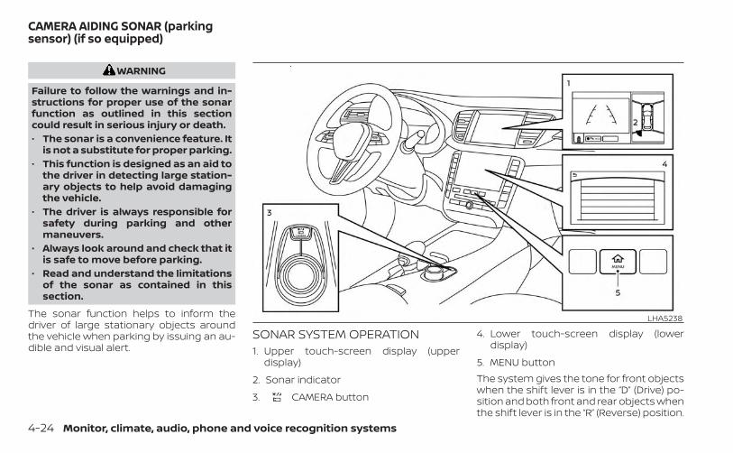
WARNING
Failure to follow the warnings and in-structions for proper use of the sonarfunction as outlined in this sectioncould result in serious injury or death.• The sonar is a convenience feature. It
is not a substitute for proper parking.• This function is designed as an aid to
the driver in detecting large station-ary objects to help avoid damagingthe vehicle.
• The driver is always responsible forsafety during parking and othermaneuvers.
• Always look around and check that itis safe to move before parking.
• Read and understand the limitationsof the sonar as contained in thissection.
The sonar function helps to inform thedriver of large stationary objects aroundthe vehicle when parking by issuing an au-dible and visual alert.
SONAR SYSTEM OPERATION1. Upper touch-screen display (upper
display)
2. Sonar indicator
3. CAMERA button
4. Lower touch-screen display (lowerdisplay)
5. MENU buttonThe system gives the tone for front objectswhen the shift lever is in the “D” (Drive) po-sition and both front and rear objects whenthe shift lever is in the “R” (Reverse) position.
LHA5238
CAMERA AIDING SONAR (parkingsensor) (if so equipped)
4-24 Monitor, climate, audio, phone and voice recognition systems
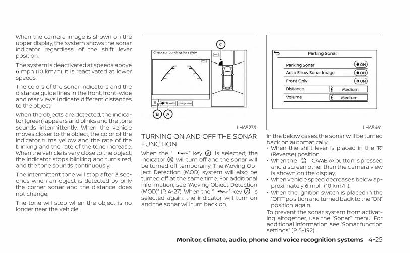
When the camera image is shown on theupper display, the system shows the sonarindicator regardless of the shift leverposition.The system is deactivated at speeds above6 mph (10 km/h). It is reactivated at lowerspeeds.The colors of the sonar indicators and thedistance guide lines in the front, front-wideand rear views indicate different distancesto the object.When the objects are detected, the indica-tor (green) appears and blinks and the tonesounds intermittently. When the vehiclemoves closer to the object, the color of theindicator turns yellow and the rate of theblinking and the rate of the tone increase.When the vehicle is very close to the object,the indicator stops blinking and turns red,and the tone sounds continuously.The intermittent tone will stop after 3 sec-onds when an object is detected by onlythe corner sonar and the distance doesnot change.The tone will stop when the object is nolonger near the vehicle.
TURNING ON AND OFF THE SONARFUNCTIONWhen the “ ” key OA is selected, theindicator OB will turn off and the sonar willbe turned off temporarily. The Moving Ob-ject Detection (MOD) system will also beturned off at the same time. For additionalinformation, see “Moving Object Detection(MOD)” (P. 4-27). When the “ ” key OA isselected again, the indicator will turn onand the sonar will turn back on.
In the below cases, the sonar will be turnedback on automatically:• When the shift lever is placed in the “R”
(Reverse) position.• When the CAMERA button is pressed
and a screen other than the camera viewis shown on the display.
• When vehicle speed decreases below ap-proximately 6 mph (10 km/h).
• When the ignition switch is placed in the“OFF” position and turned back to the “ON”position again.
To prevent the sonar system from activat-ing altogether, use the “Sonar” menu. Foradditional information, see “Sonar functionsettings” (P. 5-192).
LHA5239 LHA5461
Monitor, climate, audio, phone and voice recognition systems 4-25
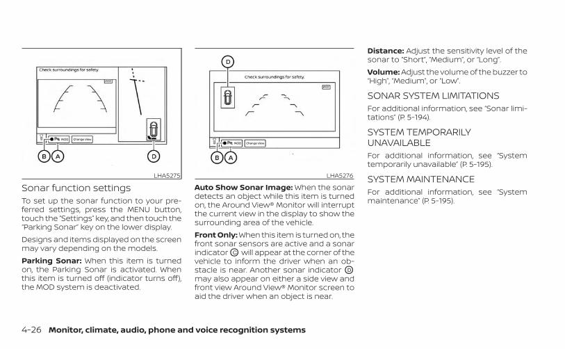
Sonar function settingsTo set up the sonar function to your pre-ferred settings, press the MENU button,touch the “Settings” key, and then touch the“Parking Sonar” key on the lower display.Designs and items displayed on the screenmay vary depending on the models.Parking Sonar: When this item is turnedon, the Parking Sonar is activated. Whenthis item is turned off (indicator turns off),the MOD system is deactivated.
Auto Show Sonar Image: When the sonardetects an object while this item is turnedon, the Around View® Monitor will interruptthe current view in the display to show thesurrounding area of the vehicle.Front Only: When this item is turned on, thefront sonar sensors are active and a sonarindicator OC will appear at the corner of thevehicle to inform the driver when an ob-stacle is near. Another sonar indicator OD
may also appear on either a side view andfront view Around View® Monitor screen toaid the driver when an object is near.
Distance: Adjust the sensitivity level of thesonar to “Short”, “Medium”, or “Long”.Volume: Adjust the volume of the buzzer to“High”, “Medium”, or “Low”.
SONAR SYSTEM LIMITATIONSFor additional information, see “Sonar limi-tations” (P. 5-194).
SYSTEM TEMPORARILYUNAVAILABLEFor additional information, see “Systemtemporarily unavailable” (P. 5-195).
SYSTEM MAINTENANCEFor additional information, see “Systemmaintenance” (P. 5-195).
LHA5275 LHA5276
4-26 Monitor, climate, audio, phone and voice recognition systems
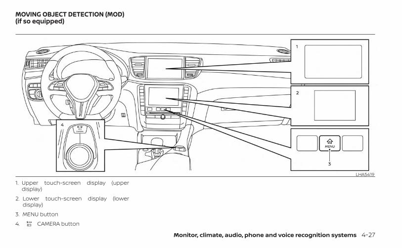
1. Upper touch-screen display (upperdisplay)
2. Lower touch-screen display (lowerdisplay)
3. MENU button
4. CAMERA button
LHA5419
MOVING OBJECT DETECTION (MOD)(if so equipped)
Monitor, climate, audio, phone and voice recognition systems 4-27

WARNING
• Failure to follow the warnings and in-structions for proper use of the Mov-ing Object Detection system couldresult in serious injury or death.
• The MOD system is not a substitutefor proper vehicle operation and isnot designed to prevent contact withobjects surrounding the vehicle.When maneuvering, always use theoutside mirrors and rearview mirrorand turn and check the surroundingsto ensure it is safe to maneuver.
• The system is deactivated at speedsabove 6 mph (10 km/h). It is reacti-vated at lower speeds.
• The MOD system is not designed todetect surrounding stationaryobjects.
The MOD system can inform the driver ofmoving objects near the vehicle whenbacking out of garages, maneuvering inparking lots and in other such instances.The MOD system detects moving objectsby using image processing technology onthe image shown in the display.
MOD SYSTEM OPERATIONThe MOD system will turn on automaticallyunder the following conditions:• When the shift lever is in the R (Reverse)
position. When activating the AroundView® Monitor, the guide lines, the iconsand the messages may not be displayedimmediately.
• When the CAMERA button is pressedto activate the camera view on thedisplay.
• When vehicle speed decreases below ap-proximately 6 mph (10 km/h) and thecamera screen is shown in the upperdisplay.
The MOD system operates in the followingconditions when the camera view isdisplayed:• When the shift lever is in the P (Park) or N
(Neutral) position and the vehicle isstopped, the MOD system detects mov-ing objects in the bird’s-eye view. TheMOD system will not operate if the out-side mirrors are moving in or out, in thestowed position, or if either front door isopened.
LHA5241Front and bird’s-eye views
4-28 Monitor, climate, audio, phone and voice recognition systems
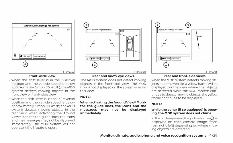
• When the shift lever is in the D (Drive)position and the vehicle speed is belowapproximately 6 mph (10 km/h), the MODsystem detects moving objects in thefront view or front-wide view.
• When the shift lever is in the R (Reverse)position and the vehicle speed is belowapproximately 6 mph (10 km/h), the MODsystem detects moving objects in therear view. When activating the AroundView® Monitor, the guide lines, the iconsand the messages may not be displayedimmediately. The MOD system will notoperate if the liftgate is open.
The MOD system does not detect movingobjects in the front-side view. The MODicon is not displayed on the screen when inthis view.
NOTE:
When activating the Around View® Moni-tor, the guide lines, the icons and themessages may not be displayedimmediately.
When the MOD system detects moving ob-jects near the vehicle, a yellow frame will bedisplayed on the view where the objectsare detected. While the MOD system con-tinues to detect moving objects, the yellowframe continues to be displayed.
NOTE:
While the sonar (if so equipped) is beep-ing, the MOD system does not chime.In the bird’s-eye view, the yellow frame O1 isdisplayed on each camera image (front,rear, right, left) depending on where mov-ing objects are detected.
LHA5242Front-wide view
LHA5290Rear and bird’s-eye views
LHA5291Rear and front-side views
Monitor, climate, audio, phone and voice recognition systems 4-29
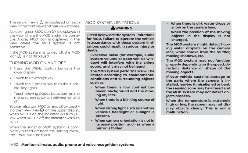
The yellow frame O2 is displayed on eachview in the front view and rear view modes.A blue or green MOD icon O3 is displayed inthe view where the MOD system is opera-tive. A gray MOD icon is displayed in theview where the MOD system is notoperative.If the MOD system is turned off, the MODicon O3 is not displayed.
TURNING MOD ON AND OFF1. Press the MENU button beneath the
lower display.
2. Touch the “Settings” key
3. Touch the “Camera’ key then the “Cam-era” key again.
4. Touch “Moving Object Detection” on themenu screen to switch between on andoff.
You can also turn MOD on and off by touch-ing the “ ” key O4 on the upper display.When MOD is on, the indicator will turn yel-low. When MOD is off, the indicator will turnblack.When the sonar or MOD system is com-pletely turned off from the setting menu,the “ ” will turn black.
MOD SYSTEM LIMITATIONSWARNING
Listed below are the system limitationsfor MOD. Failure to operate the vehiclein accordance with these system limi-tations could result in serious injury ordeath.• Excessive noise (for example, audio
system volume or open vehicle win-dow) will interfere with the chimesound, and it may not be heard.
• The MOD system performance will belimited according to environmentalconditions and surrounding objectssuch as:– When there is low contrast be-
tween background and the mov-ing objects.
– When there is a blinking source oflight.
– When strong light such as anothervehicle’s headlight or sunlight ispresent.
– When camera orientation is not inits usual position, such as when amirror is folded.
– When there is dirt, water drops orsnow on the camera lens.
– When the position of the movingobjects in the display is notchanged.
• The MOD system might detect flow-ing water droplets on the cameralens, white smoke from the muffler,moving shadows, etc.
• The MOD system may not functionproperly depending on the speed, di-rection, distance or shape of themoving objects.
• If your vehicle sustains damage tothe parts where the camera is in-stalled, leaving it misaligned or bent,the sensing zone may be altered andthe MOD system may not detect ob-jects properly.
• When the temperature is extremelyhigh or low, the screen may not dis-play objects clearly. This is not amalfunction.
4-30 Monitor, climate, audio, phone and voice recognition systems
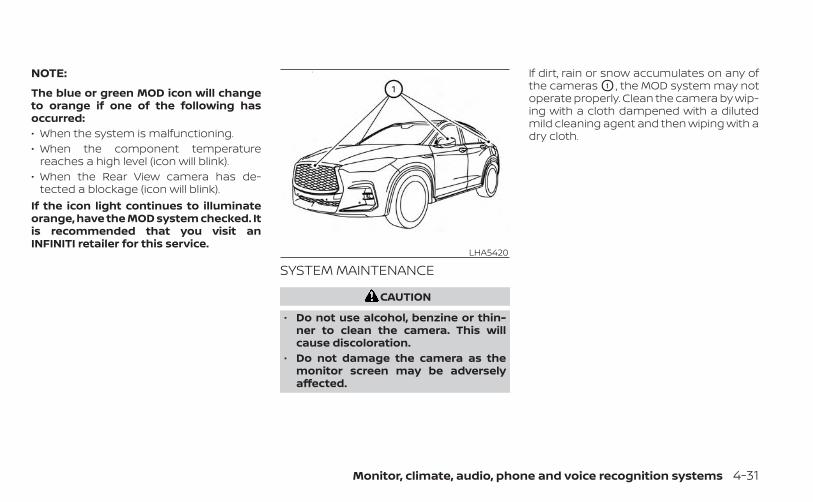
NOTE:
The blue or green MOD icon will changeto orange if one of the following hasoccurred:• When the system is malfunctioning.• When the component temperature
reaches a high level (icon will blink).• When the Rear View camera has de-
tected a blockage (icon will blink).If the icon light continues to illuminateorange, have the MOD system checked. Itis recommended that you visit anINFINITI retailer for this service.
SYSTEM MAINTENANCE
CAUTION
• Do not use alcohol, benzine or thin-ner to clean the camera. This willcause discoloration.
• Do not damage the camera as themonitor screen may be adverselyaffected.
If dirt, rain or snow accumulates on any ofthe cameras O1 , the MOD system may notoperate properly. Clean the camera by wip-ing with a cloth dampened with a dilutedmild cleaning agent and then wiping with adry cloth.
LHA5420
Monitor, climate, audio, phone and voice recognition systems 4-31
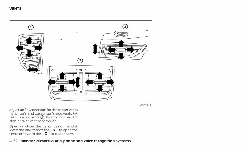
Adjust air flow direction for the center ventsO1 , driver’s and passenger's side vents O2 ,rear console vents O3 , by moving the ventslide and/or vent assemblies.Open or close the vents using the dial.Move the dial toward the to open thevents or toward the to close them.
LHA4575
VENTS
4-32 Monitor, climate, audio, phone and voice recognition systems
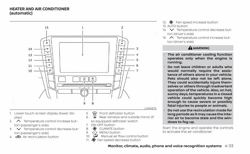
1. Lower touch-screen display (lower dis-play)
2. Temperature control increase but-ton (passenger’s side)
3. Temperature control decrease but-ton (passenger’s side)
4. Air recirculation button
5. Front defroster button6. Rear window and outside mirror (if
so equipped) defroster switch7. ON-OFF button8. CLIMATE button9. MENU button10. Manual air flow control button11. Fan speed decrease button
12. Fan speed increase button13. AUTO button14. Temperature control decrease but-
ton (driver’s side)15. Temperature control increase but-
ton (driver’s side)
WARNING
• The air conditioner cooling functionoperates only when the engine isrunning.
• Do not leave children or adults whowould normally require the assis-tance of others alone in your vehicle.Pets should also not be left alone.They could accidentally injure them-selves or others through inadvertentoperation of the vehicle. Also, on hot,sunny days, temperatures in a closedvehicle could quickly become highenough to cause severe or possiblyfatal injuries to people or animals.
• Do not use the recirculation mode forlong periods as it may cause the inte-rior air to become stale and the win-dows to fog up.
Start the engine and operate the controlsto activate the air conditioner.
LHA4574
HEATER AND AIR CONDITIONER(automatic)
Monitor, climate, audio, phone and voice recognition systems 4-33
NOTE:• Odors from inside and outside the ve-
hicle can build up in the air conditionerunit. Odor can enter the passengercompartment through the vents.
• When parking, set the heater and airconditioner controls to turn off air re-circulation to allow fresh air into thepassenger compartment. This shouldhelp reduce odors inside the vehicle
AUTOMATIC OPERATIONPress the AUTO button to set the auto-matic control mode that keeps the air dis-tribution, temperature and the fan speedautomatically.
Cooling and/or dehumidifiedheating (AUTO)This mode may be used all year round asthe system automatically works to keep aconstant temperature. Air flow distribution,air intake control, and fan speed are alsocontrolled automatically.1. Press the CLIMATE button on the
lower display menu. The CLIMATE screenwill display on the lower display.
2. Press the AUTO button on. (The indicatoron the button will illuminate and AUTOwill be displayed on the CLIMATE screen.)
3. Press the temperature con-trol buttons on the driver’s side to setthe desired temperature.
• The temperature of the passenger com-partment will be maintained automati-cally. Air flow distribution, air intake con-trol and fan speed are also controlledautomatically.
• A visible mist may be seen coming fromthe vents in hot, humid conditions as theair is cooled rapidly. This does not indicatea malfunction.
Dehumidified defrosting ordefogging1. Press the front defroster button on.
(The indicator light on the button willcome on.)
2. Operate the temperaturecontrol buttons to set the desiredtemperature.
• To quickly remove ice from the outside ofthe windows, use the fan speed con-trol button or the “ ” key to set the fanspeed to maximum.
• As soon as possible after the windshieldis clean, press the AUTO button to returnto the automatic mode.
• When the front defroster button ispressed, the air conditioner will automati-cally be turned on at outside tempera-tures approximately 32°F (0°C) to defogthe windshield. The air recirculate modeautomatically turns off, allowing outsideair to be drawn into the passenger com-partment to further improve the defog-ging performance.
Remote Engine Start withIntelligent Climate Control (if soequipped)Vehicles equipped with automatic climatecontrols and Remote Engine Start functionmay go into automatic heating or coolingmode when Remote Engine Start is acti-vated depending on outside and cabintemperatures. During this period, the cli-mate control display and buttons will beinoperable until the ignition switch isturned on. In Remote Engine Start defrost-ing mode, the rear window defroster,heated seat (if so equipped) and heatedsteering wheel (if so equipped) may be ac-tivated automatically. In Remote Engine
4-34 Monitor, climate, audio, phone and voice recognition systems

Start cooling mode, the climate controlledseat (if so equipped) may be activatedautomatically.
Voice Recognition logic (if soequipped)When the climate control system is on, thefan speed may be automatically loweredso that commands are more easily recog-nized. Fan speed can be adjusted using the
fan speed decrease and increasebuttons, if desired.
MANUAL OPERATION
Fan speed controlPress the fan speed increase andfan speed decrease buttons to manuallycontrol the fan speed. Fan speed can alsobe controlled by touching the “ ” or“ ” keys on the lower display.Press the AUTO button to return to auto-matic control of the fan speed.
Temperature controlPress the temperature controlbuttons up or down to set the desiredtemperature.
The temperature can be set within the fol-lowing range:• For U.S.: 60 to 90°F (16 to 32°C)• For Canada: 64 to 90°F (18 to 32°C)
Air recirculationPress the air recirculation button torecirculate interior air inside the vehicle.The indicator light on the button willcome on.The air recirculation cannot be activatedwhen the air conditioner is in the frontdefrosting mode.When the outside temperature exceeds70°F (21°C), the air conditioning system maydefault to air recirculation mode automati-cally to reduce overall power consumption.To exit air recirculation mode, deselect the
air recirculation button (indicator willturn off) to enter fresh air mode.
Automatic intake air controlIn the AUTO mode, the intake air will becontrolled automatically. To manually con-trol the intake air, press the air recircu-lation button. To return to the automaticcontrol mode, press and hold the airrecirculation button for about 2 seconds.
The indicator light will flash twice, and thenthe intake air will be controlledautomatically.
Air flow controlPress the button to manually controlair flow. Pressing the button repeatedly willcycle through the available modes and dis-play the corresponding icon on the lowerdisplay. Air flow can also be controlled bytouching the “ ” key on the lowerdisplay:
— Air flows from center and sidevents.
— Air flows from center and sidevents and foot outlets.
— Air flows mainly from foot out-lets.
— Air flows from defroster andfoot outlets.
To turn system offPress the ON-OFF button.
CLIMATE buttonPress the CLIMATE button to show theCLIMATE screen on the lower display.
Monitor, climate, audio, phone and voice recognition systems 4-35

Rear window and outside mirror(if so equipped) defroster switchFor additional information, see “Rear win-dow defroster, outside mirror defroster (ifso equipped), and wiper deicer (if soequipped) switch” (P. 2-36).
Heated seat switches (if soequipped)For additional information, see “Heatedseats (if so equipped)” (P. 2-46).
Climate controlled seat switches(if so equipped)For additional information, see “Climatecontrolled seat switches (if so equipped)”(P. 2-45).
OPERATING TIPSThe sensors, OA and OB on the instrumentpanel, help the system maintain a constanttemperature. Do not put anything on oraround these sensors.
• When the engine coolant temperatureand outside air temperature are low, theair may flow from defroster or foot outletsto initialize automatic heating mode. Thisis not a malfunction. After the coolanttemperature warms up, air will flow nor-mally from the foot outlets
• A visible mist may be seen coming fromthe ventilators in hot, humid conditionsas the air is cooled rapidly. This does notindicate a malfunction.
LHA4686
4-36 Monitor, climate, audio, phone and voice recognition systems

CLIMATE SETTING SCREENClimate control settings can be changedon the screen.Available setting items may vary depend-ing on models and specifications.Press the CLIMATE button on thelower display menu. The CLIMATE screenwill display on the lower display.
Heating (A/C off)The air conditioner does not activate in thismode. When you need to heat only, use thismode.1. Press the CLIMATE button.
2. If the Climate system is off, press theON-OFF button to turn the system on.
3. If the A/C indicator is on, touch the“ A/C” key to turn the A/C off.
4. Press the temperature con-trol buttons on the driver’s side to setthe desired temperature.
• When in AUTO mode, the temperature ofthe passenger compartment will bemaintained automatically. Air flow distri-bution and fan speed are also controlledautomatically.
• Do not set the temperature lower thanthe outside air temperature or the sys-tem may not work properly.
• This procedure is not recommended ifwindows fog up.
When the outside temperature decreasesto approximately 32°F (0°C), the A/C func-tion does not activate even if the A/Cindicator light illuminates.
Air conditioning (A/C)Touch the “ A/C” key to turn the A/Cmode on or off. Turn on the A/C mode foreffective cooling and dehumidifying. Whenthe A/C indicator light is on, the A/C modeis on.
Sync mode settingThe driver’s, passenger’s and rear (if soequipped) temperature setpoints can besynchronized using the “ SYNC” key onthe lower display. When the key is touched,temperature settings become synchro-nized and the SYNC indicator turns on.
LHA5299Type A (if so equipped)
LHA5457Type B (if so equipped)
Monitor, climate, audio, phone and voice recognition systems 4-37
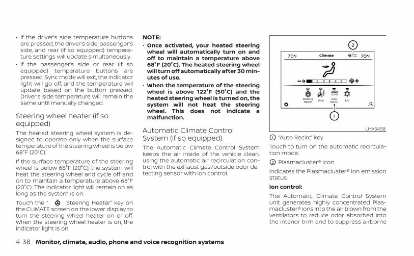
• If the driver’s side temperature buttonsare pressed, the driver’s side, passenger’sside, and rear (if so equipped) tempera-ture settings will update simultaneously.
• If the passenger’s side or rear (if soequipped) temperature buttons arepressed, Sync mode will exit, the indicatorlight will go off, and the temperature willupdate based on the button pressed.Driver’s side temperature will remain thesame until manually changed.
Steering wheel heater (if soequipped)The heated steering wheel system is de-signed to operate only when the surfacetemperature of the steering wheel is below68°F (20°C).If the surface temperature of the steeringwheel is below 68°F (20°C), the system willheat the steering wheel and cycle off andon to maintain a temperature above 68°F(20°C). The indicator light will remain on aslong as the system is on.Touch the “ Steering Heater” key onthe CLIMATE screen on the lower display toturn the steering wheel heater on or off.When the steering wheel heater is on, theindicator light is on.
NOTE:• Once activated, your heated steering
wheel will automatically turn on andoff to maintain a temperature above68°F (20°C). The heated steering wheelwill turn off automatically after 30 min-utes of use.
• When the temperature of the steeringwheel is above 122°F (50°C) and theheated steering wheel is turned on, thesystem will not heat the steeringwheel. This does not indicate amalfunction.
Automatic Climate ControlSystem (if so equipped)The Automatic Climate Control Systemkeeps the air inside of the vehicle clean,using the automatic air recirculation con-trol with the exhaust gas/outside odor de-tecting sensor with ion control.
O1 “Auto Recirc” keyTouch to turn on the automatic recircula-tion mode.
O2 Plasmacluster® iconIndicates the Plasmacluster® ion emissionstatus.Ion control:The Automatic Climate Control Systemunit generates highly concentrated Plas-macluster® ions into the air blown from theventilators to reduce odor absorbed intothe interior trim and to suppress airborne
LHA5458
4-38 Monitor, climate, audio, phone and voice recognition systems

bacteria. The high-density Plasmacluster®ions also have a proven skin moisture pre-serving effect.The Plasmacluster® icon on the CLIMATEscreen indicates the status of the Plasma-cluster® ion emission from the system andchanges with the amount of the air flow.Automatic air recirculation control withthe exhaust gas/outside odor detectionsensor:The Automatic Climate Control Systemcomes with an exhaust gas detection/outside odor sensor. When the automaticair circulation control is activated, the sen-sor detects odors outside the vehicle suchas pulp or chemicals, and exhaust such asgasoline or diesel. When such odors orgases are detected the display and thesystem automatically change from freshair mode to the recirculation mode.When the automatic air recirculation is on,for the first 5 minutes, the air recirculationmode is selected to prevent dust, dirt, andpollen from entering the vehicle and toclean the air inside of the vehicle.After 5 minutes, the sensor detects ex-haust gas and automatically alternatesbetween the air recirculation mode andthe fresh air mode.
The automatic air recirculation mode canbe activated under the followingconditions.• The air flow control is not in the front
defroster mode (the indicator light on thefront defroster button is turned off).
• The outside temperature is about 32°F(0°C) or more.
REAR CLIMATE CONTROL (if soequipped)1. Rear temperature display2. Rear temperature control in-
crease button3. Rear temperature control de-
crease buttonYou can adjust the climate control systemfor rear seat passengers using the buttonson the back of the console.Press the to increase the reartemperature.
LHA4582Rear temperature switch (if so
equipped)
Monitor, climate, audio, phone and voice recognition systems 4-39
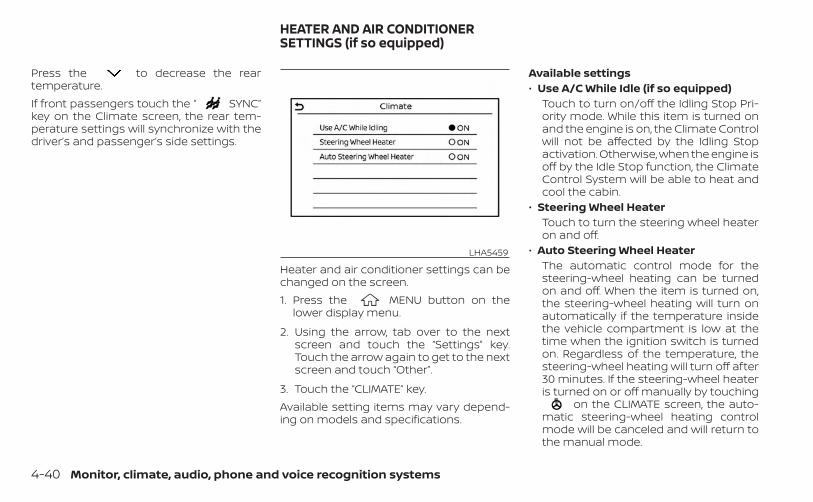
Press the to decrease the reartemperature.If front passengers touch the “ SYNC”key on the Climate screen, the rear tem-perature settings will synchronize with thedriver’s and passenger’s side settings.
Heater and air conditioner settings can bechanged on the screen.1. Press the MENU button on the
lower display menu.
2. Using the arrow, tab over to the nextscreen and touch the “Settings” key.Touch the arrow again to get to the nextscreen and touch “Other”.
3. Touch the “CLIMATE” key.Available setting items may vary depend-ing on models and specifications.
Available settings• Use A/C While Idle (if so equipped)
Touch to turn on/off the Idling Stop Pri-ority mode. While this item is turned onand the engine is on, the Climate Controlwill not be affected by the Idling Stopactivation. Otherwise, when the engine isoff by the Idle Stop function, the ClimateControl System will be able to heat andcool the cabin.
• Steering Wheel HeaterTouch to turn the steering wheel heateron and off.
• Auto Steering Wheel HeaterThe automatic control mode for thesteering-wheel heating can be turnedon and off. When the item is turned on,the steering-wheel heating will turn onautomatically if the temperature insidethe vehicle compartment is low at thetime when the ignition switch is turnedon. Regardless of the temperature, thesteering-wheel heating will turn off after30 minutes. If the steering-wheel heateris turned on or off manually by touching
on the CLIMATE screen, the auto-matic steering-wheel heating controlmode will be canceled and will return tothe manual mode.
LHA5459
HEATER AND AIR CONDITIONERSETTINGS (if so equipped)
4-40 Monitor, climate, audio, phone and voice recognition systems
–– If the surface temperature of thesteering-wheel is above the tempera-ture within which the system is de-signed to operate, the system will notheat the steering-wheel. This is not amalfunction.
The air conditioner system in your INFINITIvehicle is charged with a refrigerant de-signed with the environment in mind.This refrigerant does not harm theearth's ozone layer.Special charging equipment and lubricantis required when servicing your INFINITI airconditioner. Using improper refrigerants orlubricants will cause severe damage toyour air conditioner system. For additionalinformation, see “Air conditioner system re-frigerant and oil recommendations”(P. 10-7).It is recommended that you visit an INFINITIretailer for servicing your “environmentallyfriendly” air conditioning system.
WARNING
The air conditioner system contains re-frigerant under high pressure. To avoidpersonal injury, any air conditioner ser-vice should be done only by an experi-enced technician with properequipment.
The vehicle is equipped with a shark finantenna and an antenna pattern is printedinside the rear window.
CAUTION
• Do not place metalized film near therear window glass or attach anymetal parts to it. This may cause poorreception or noise.
• When cleaning the inside of the rearwindow, be careful not to scratch ordamage the rear window antenna.Lightly wipe along the antenna with adampened soft cloth.
SERVICING AIR CONDITIONER ANTENNA
Monitor, climate, audio, phone and voice recognition systems 4-41
When installing a CB, ham radio or carphone in your vehicle, be sure to observethe following precautions; otherwise, thenew equipment may adversely affect theengine control system and other electronicparts.
WARNING
• A cellular phone should not be usedfor any purpose while driving so fullattention may be given to vehicle op-eration. Some jurisdictions prohibitthe use of cellular phones whiledriving.
• If you must make a call while yourvehicle is in motion, the hands freecellular phone operational mode ishighly recommended. Exercise ex-treme caution at all times so full at-tention may be given to vehicleoperation.
• If you are unable to devote full atten-tion to vehicle operation while talk-ing on the phone, pull off the road toa safe location and stop your vehicle.
CAUTION
• Keep the antenna as far away as pos-sible from the electronic controlmodules.
• Keep the antenna wire more than 8 in(20 cm) away from the electroniccontrol system harnesses. Do notroute the antenna wire next to anyharness.
• Adjust the antenna standing-waveratio as recommended by themanufacturer.
• Connect the ground wire from the CBradio chassis to the body.
• For additional information, it is rec-ommended that you visit an INFINITIretailer for servicing.
CAR PHONE OR CB RADIO
4-42 Monitor, climate, audio, phone and voice recognition systems

MEMO
Monitor, climate, audio, phone and voice recognition systems 4-43
5 Starting and driving
Precautions when starting and driving . . . . . . . . . . 5-4Exhaust gas (carbon monoxide) . . . . . . . . . . . . . . 5-4Three-way catalyst . . . . . . . . . . . . . . . . . . . . . . . . . . . 5-4Tire Pressure Monitoring System(TPMS) . . . . . . . . . . . . . . . . . . . . . . . . . . . . . . . . . . . . . . . 5-5On-pavement and off-road drivingprecautions . . . . . . . . . . . . . . . . . . . . . . . . . . . . . . . . . . 5-8Avoiding collision and rollover . . . . . . . . . . . . . . . . 5-9Off-road recovery . . . . . . . . . . . . . . . . . . . . . . . . . . . . 5-9Rapid air pressure loss . . . . . . . . . . . . . . . . . . . . . . . 5-9Drinking alcohol/drugs and driving . . . . . . . . . . 5-10Driving safety precautions . . . . . . . . . . . . . . . . . . . 5-10Intelligent All-Wheel Drive (AWD) drivingsafety precautions (if so equipped) . . . . . . . . . . 5-12
Push-button ignition switch . . . . . . . . . . . . . . . . . . . . 5-13Operating range . . . . . . . . . . . . . . . . . . . . . . . . . . . . 5-14Push-button ignition switch positions . . . . . . . 5-14Emergency engine shut off . . . . . . . . . . . . . . . . . . 5-15INFINITI Intelligent Key batterydischarge . . . . . . . . . . . . . . . . . . . . . . . . . . . . . . . . . . . 5-15INFINITI Vehicle Immobilizer System . . . . . . . . . 5-16
Before starting the engine . . . . . . . . . . . . . . . . . . . . . 5-16Starting the engine . . . . . . . . . . . . . . . . . . . . . . . . . . . . . 5-17
Remote Engine Start (if so equipped) . . . . . . . . 5-18Driving the vehicle . . . . . . . . . . . . . . . . . . . . . . . . . . . . . . 5-18
Continuously Variable Transmission(CVT) . . . . . . . . . . . . . . . . . . . . . . . . . . . . . . . . . . . . . . . . 5-18
Electronic parking brake . . . . . . . . . . . . . . . . . . . . . . . 5-24Automatic operation . . . . . . . . . . . . . . . . . . . . . . . . 5-24Manual operation . . . . . . . . . . . . . . . . . . . . . . . . . . . 5-25
Automatic brake hold . . . . . . . . . . . . . . . . . . . . . . . . . . 5-26How to activate/deactivate theautomatic brake hold function . . . . . . . . . . . . . . 5-27How to use the automatic brake holdfunction . . . . . . . . . . . . . . . . . . . . . . . . . . . . . . . . . . . . . 5-28
INFINITI Drive Mode Selector . . . . . . . . . . . . . . . . . . . . 5-29Standard mode . . . . . . . . . . . . . . . . . . . . . . . . . . . . . 5-30Sport mode . . . . . . . . . . . . . . . . . . . . . . . . . . . . . . . . . 5-30Personal mode . . . . . . . . . . . . . . . . . . . . . . . . . . . . . . 5-30ECO mode . . . . . . . . . . . . . . . . . . . . . . . . . . . . . . . . . . 5-31
Traffic Sign Recognition (TSR) (if so equipped) . . . 5-33System operation . . . . . . . . . . . . . . . . . . . . . . . . . . . 5-34Turning the Traffic Sign Recognition(TSR) system on and off . . . . . . . . . . . . . . . . . . . . . 5-35System temporarily unavailable . . . . . . . . . . . . . 5-35System malfunction . . . . . . . . . . . . . . . . . . . . . . . . . 5-35System maintenance . . . . . . . . . . . . . . . . . . . . . . . 5-36
Lane Departure Warning (LDW) . . . . . . . . . . . . . . . . . 5-36LDW system operation . . . . . . . . . . . . . . . . . . . . . . 5-37How to enable/disable the LDW system . . . . . 5-38LDW system limitations . . . . . . . . . . . . . . . . . . . . . 5-39System temporarily unavailable . . . . . . . . . . . . . 5-40System malfunction . . . . . . . . . . . . . . . . . . . . . . . . . 5-40System maintenance . . . . . . . . . . . . . . . . . . . . . . . 5-40

Lane Departure Prevention (LDP)(if so equipped) . . . . . . . . . . . . . . . . . . . . . . . . . . . . . . . . . 5-41
LDP system operation . . . . . . . . . . . . . . . . . . . . . . . 5-42How to enable/disable the LDP system . . . . . 5-43LDP system limitations . . . . . . . . . . . . . . . . . . . . . . 5-44System temporarily unavailable . . . . . . . . . . . . . 5-45System malfunction . . . . . . . . . . . . . . . . . . . . . . . . . 5-46System maintenance . . . . . . . . . . . . . . . . . . . . . . . 5-46
Blind Spot Warning (BSW) . . . . . . . . . . . . . . . . . . . . . . . 5-47BSW system operation . . . . . . . . . . . . . . . . . . . . . .5-48How to enable/disable the BSW system . . . . . 5-49BSW system limitations . . . . . . . . . . . . . . . . . . . . . 5-50BSW driving situations . . . . . . . . . . . . . . . . . . . . . . . 5-51System temporarily unavailable . . . . . . . . . . . . . 5-53System maintenance . . . . . . . . . . . . . . . . . . . . . . . 5-54
Blind Spot Intervention® (BSI) (if so equipped) . . . 5-55BSI system operation . . . . . . . . . . . . . . . . . . . . . . . 5-57How to enable/disable the BSI system . . . . . . 5-59BSI system limitations . . . . . . . . . . . . . . . . . . . . . . .5-60BSI driving situations . . . . . . . . . . . . . . . . . . . . . . . . 5-61System temporarily unavailable . . . . . . . . . . . . . 5-66System malfunction . . . . . . . . . . . . . . . . . . . . . . . . . 5-66System maintenance . . . . . . . . . . . . . . . . . . . . . . . 5-66
Rear Cross Traffic Alert (RCTA) . . . . . . . . . . . . . . . . . .5-68RCTA system operation . . . . . . . . . . . . . . . . . . . . . 5-69
How to enable/disable the RCTAsystem . . . . . . . . . . . . . . . . . . . . . . . . . . . . . . . . . . . . . . 5-71RCTA system limitations . . . . . . . . . . . . . . . . . . . . . 5-72System temporarily unavailable . . . . . . . . . . . . . 5-74System maintenance . . . . . . . . . . . . . . . . . . . . . . . 5-75
Cruise control (if so equipped) . . . . . . . . . . . . . . . . . . 5-76Precautions on cruise control . . . . . . . . . . . . . . . 5-76Cruise control operations . . . . . . . . . . . . . . . . . . . 5-77
Intelligent Cruise Control (ICC) (for vehicleswithout ProPILOT Assist) (if so equipped) . . . . . . . 5-78
How to select the cruise control mode . . . . . .5-80Vehicle-to-vehicle distance controlmode . . . . . . . . . . . . . . . . . . . . . . . . . . . . . . . . . . . . . . .5-80Vehicle-to-vehicle distance controlmode operation . . . . . . . . . . . . . . . . . . . . . . . . . . . . . 5-81Vehicle-to-vehicle distance controlmode switches . . . . . . . . . . . . . . . . . . . . . . . . . . . . . 5-83Vehicle-to-vehicle distance controlmode limitations . . . . . . . . . . . . . . . . . . . . . . . . . . . .5-90System temporarily unavailable . . . . . . . . . . . . . 5-94System maintenance . . . . . . . . . . . . . . . . . . . . . . . 5-96Conventional (fixed speed) cruisecontrol mode . . . . . . . . . . . . . . . . . . . . . . . . . . . . . . . 5-97
ProPILOT Assist (if so equipped) . . . . . . . . . . . . . . . 5-102ProPILOT Assist system operation . . . . . . . . . . 5-104
Turning the conventional (fixed speed)cruise control mode on . . . . . . . . . . . . . . . . . . . . 5-107Operating ProPILOT Assist . . . . . . . . . . . . . . . . . . 5-107How to enable/disable the SteeringAssist . . . . . . . . . . . . . . . . . . . . . . . . . . . . . . . . . . . . . . 5-112Intelligent Cruise Control (ICC)(for vehicles with ProPILOT Assist) . . . . . . . . . . 5-113Steering Assist . . . . . . . . . . . . . . . . . . . . . . . . . . . . . 5-124Conventional (fixed speed) cruisecontrol mode . . . . . . . . . . . . . . . . . . . . . . . . . . . . . . 5-131
Distance Control Assist (DCA)(if so equipped) . . . . . . . . . . . . . . . . . . . . . . . . . . . . . . . . 5-134
DCA system operation . . . . . . . . . . . . . . . . . . . . . 5-136How to enable/disable the DCA system . . . . 5-139DCA system limitations . . . . . . . . . . . . . . . . . . . . 5-141DCA driving situations . . . . . . . . . . . . . . . . . . . . . . 5-142System temporarily unavailable . . . . . . . . . . . . 5-143System maintenance . . . . . . . . . . . . . . . . . . . . . . 5-145
Rear Automatic Braking (RAB) . . . . . . . . . . . . . . . . . 5-146RAB system operation . . . . . . . . . . . . . . . . . . . . . . 5-147Turning the RAB system on/off . . . . . . . . . . . . . 5-148RAB system limitations . . . . . . . . . . . . . . . . . . . . . 5-149System malfunction . . . . . . . . . . . . . . . . . . . . . . . . 5-150System maintenance . . . . . . . . . . . . . . . . . . . . . . 5-151
Forward Emergency Braking (FEB) withPedestrian Detection system . . . . . . . . . . . . . . . . . . 5-151
System operation . . . . . . . . . . . . . . . . . . . . . . . . . . 5-152Turning the FEB with PedestrianDetection system on/off . . . . . . . . . . . . . . . . . . . 5-154FEB with Pedestrian Detection systemlimitations . . . . . . . . . . . . . . . . . . . . . . . . . . . . . . . . . 5-155System temporarily unavailable . . . . . . . . . . . . 5-159System malfunction . . . . . . . . . . . . . . . . . . . . . . . . 5-160System maintenance . . . . . . . . . . . . . . . . . . . . . . 5-161
Predictive Forward Collision Warning (PFCW) . . . 5-162PFCW system operation . . . . . . . . . . . . . . . . . . . . 5-164Turning the PFCW system on/off . . . . . . . . . . . 5-165PFCW system limitations . . . . . . . . . . . . . . . . . . . 5-166System temporarily unavailable . . . . . . . . . . . . .5-171System malfunction . . . . . . . . . . . . . . . . . . . . . . . . 5-172System maintenance . . . . . . . . . . . . . . . . . . . . . . 5-172
Break-in schedule . . . . . . . . . . . . . . . . . . . . . . . . . . . . . 5-173Fuel efficient driving tips . . . . . . . . . . . . . . . . . . . . . . . 5-174Increasing fuel economy . . . . . . . . . . . . . . . . . . . . . . 5-175Intelligent All-Wheel Drive (AWD) . . . . . . . . . . . . . . . 5-175Parking/parking on hills . . . . . . . . . . . . . . . . . . . . . . . 5-178Power steering . . . . . . . . . . . . . . . . . . . . . . . . . . . . . . . . 5-179
Electric power steering type . . . . . . . . . . . . . . . . 5-179Direct Adaptive Steering® type . . . . . . . . . . . . . 5-180
Brake system . . . . . . . . . . . . . . . . . . . . . . . . . . . . . . . . . 5-182Brake precautions . . . . . . . . . . . . . . . . . . . . . . . . . . 5-182Anti-lock Braking System (ABS) . . . . . . . . . . . . . 5-182Brake Assist . . . . . . . . . . . . . . . . . . . . . . . . . . . . . . . . 5-184
Vehicle Dynamic Control (VDC) system . . . . . . . . 5-184Brake force distribution . . . . . . . . . . . . . . . . . . . . 5-186
Chassis Control . . . . . . . . . . . . . . . . . . . . . . . . . . . . . . . 5-187Active Trace Control . . . . . . . . . . . . . . . . . . . . . . . . 5-187Active Engine Brake . . . . . . . . . . . . . . . . . . . . . . . . 5-188Active Ride Control . . . . . . . . . . . . . . . . . . . . . . . . . 5-189
Hill start assist system . . . . . . . . . . . . . . . . . . . . . . . . 5-189Front and rear sonar system (if so equipped) . . 5-190
System operation . . . . . . . . . . . . . . . . . . . . . . . . . . 5-191Sonar function settings . . . . . . . . . . . . . . . . . . . . 5-192Turning on and off the sonar function . . . . . . 5-193
Sonar limitations . . . . . . . . . . . . . . . . . . . . . . . . . . . 5-194System temporarily unavailable . . . . . . . . . . . . 5-195System maintenance . . . . . . . . . . . . . . . . . . . . . . 5-195
Cold weather driving . . . . . . . . . . . . . . . . . . . . . . . . . . 5-196Freeing a frozen door lock . . . . . . . . . . . . . . . . . . 5-196Antifreeze . . . . . . . . . . . . . . . . . . . . . . . . . . . . . . . . . . 5-196Battery . . . . . . . . . . . . . . . . . . . . . . . . . . . . . . . . . . . . . 5-196Draining of coolant water . . . . . . . . . . . . . . . . . . 5-196Tire equipment . . . . . . . . . . . . . . . . . . . . . . . . . . . . . 5-196Special winter equipment . . . . . . . . . . . . . . . . . . 5-196Driving on snow or ice . . . . . . . . . . . . . . . . . . . . . . 5-196Engine block heater (if so equipped) . . . . . . . . 5-197
Active noise cancellation/Active soundenhancement . . . . . . . . . . . . . . . . . . . . . . . . . . . . . . . . . 5-198
Active noise cancellation . . . . . . . . . . . . . . . . . . . 5-198Active sound enhancement . . . . . . . . . . . . . . . . 5-198

WARNING
• Do not leave children or adults whowould normally require the assis-tance of others alone in your vehicle.Pets should also not be left alone.They could accidentally injure them-selves or others through inadvertentoperation of the vehicle. Also, on hot,sunny days, temperatures in a closedvehicle could quickly become highenough to cause severe or possiblyfatal injuries to people or animals.
• Properly secure all cargo with ropesor straps to help prevent it from slid-ing or shifting. Do not place cargohigher than the seatbacks. In a sud-den stop or collision, unsecuredcargo could cause personal injury.
EXHAUST GAS (carbon monoxide)
WARNING
• Do not breathe exhaust gases; theycontain colorless and odorless car-bon monoxide. Carbon monoxide isdangerous. It can cause uncon-sciousness or death.
• If you suspect that exhaust fumesare entering the vehicle, drive with allwindows fully open, and have the ve-hicle inspected immediately.
• Do not run the engine in closedspaces such as a garage.
• Do not park the vehicle with the en-gine running for any extended lengthof time.
• Keep the rear vent windows, lift-gates, doors and trunk lids (if soequipped) closed while driving, oth-erwise exhaust gases could bedrawn into the passenger compart-ment. If you must drive with one ofthese open, follow these precau-tions:1. Open all the windows.2. Set the air recirculation but-
ton to off and the fan control dialto high to circulate the air.
• If electrical wiring or other cable con-nections must pass to a trailerthrough the seal on the liftgate or thebody, follow the manufacturer's rec-ommendation to prevent carbonmonoxide entry into the vehicle.
• The exhaust system and body shouldbe inspected by a qualified mechanicwhenever:a. The vehicle is raised for service.b. You suspect that exhaust fumes
are entering into the passengercompartment.
c. You notice a change in the soundof the exhaust system.
d. You have had an accident involv-ing damage to the exhaust sys-tem, underbody, or rear of thevehicle.
THREE-WAY CATALYSTThe three-way catalyst is an emission con-trol device installed in the exhaust system.Exhaust gases in the three-way catalystare burned at high temperatures to helpreduce pollutants.
WARNING
• The exhaust gas and the exhaustsystem are very hot. Keep people,animals or flammable materialsaway from the exhaust systemcomponents.
PRECAUTIONS WHEN STARTING ANDDRIVING
5-4 Starting and driving

• Do not stop or park the vehicle overflammable materials such as drygrass, waste paper or rags. They mayignite and cause a fire.
CAUTION
• Do not use leaded gasoline. Depositsfrom leaded gasoline will seriouslyreduce the three-way catalyst's abil-ity to help reduce exhaust pollutants.
• Keep your engine tuned up. Malfunc-tions in the ignition, fuel injection, orelectrical systems can cause overrich fuel flow into the three-waycatalyst, causing it to overheat. Donot keep driving if the engine mis-fires, or if noticeable loss of perfor-mance or other unusual operatingconditions are detected. Have the ve-hicle inspected promptly. It is recom-mended that you visit an INFINITI re-tailer for this service.
• Avoid driving with an extremely lowfuel level. Running out of fuel couldcause the engine to misfire, damag-ing the three-way catalyst.
• Do not race the engine while warm-ing it up.
• Do not push or tow your vehicle tostart the engine.
TIRE PRESSURE MONITORINGSYSTEM (TPMS)Each tire, including the spare (if provided),should be checked monthly when cold andinflated to the inflation pressure recom-mended by the vehicle manufacturer onthe vehicle placard or tire inflation pressurelabel. (If your vehicle has tires of a differentsize than the size indicated on the vehicleplacard or tire inflation pressure label, youshould determine the proper tire inflationpressure for those tires.)As an added safety feature, your vehiclehas been equipped with a Tire PressureMonitoring System (TPMS) that illuminatesa low tire pressure telltale when one ormore of your tires is significantly under-inflated. Accordingly, when the low tirepressure telltale illuminates, you shouldstop and check all your tires as soon aspossible, and inflate them to the properpressure. Driving on a significantly under-inflated tire causes the tire to overheat andcan lead to tire failure. Under-inflation alsoreduces fuel efficiency and tire tread life,and may affect the vehicle’s handling andstopping ability.
Please note that the TPMS is not a substi-tute for proper tire maintenance, and it isthe driver’s responsibility to maintain cor-rect tire pressure, even if under-inflationhas not reached the level to trigger illumi-nation of the TPMS low tire pressure telltale.Your vehicle has also been equipped with aTPMS malfunction indicator to indicatewhen the system is not operating properly.The TPMS malfunction indicator is com-bined with the low tire pressure telltale.When the system detects a malfunction,the telltale will flash for approximately oneminute and then remain continuously illu-minated. This sequence will continue uponsubsequent vehicle start-ups as long asthe malfunction exists. When the malfunc-tion indicator is illuminated, the systemmay not be able to detect or signal low tirepressure as intended. TPMS malfunctionsmay occur for a variety of reasons, includ-ing the installation of replacement or alter-nate tires or wheels on the vehicle thatprevent the TPMS from functioning prop-erly. Always check the TPMS malfunctiontelltale after replacing one or more tires orwheels on your vehicle to ensure that thereplacement or alternate tires and wheelsallow the TPMS to continue to functionproperly.
Starting and driving 5-5

Additional information:• When using a wheel without the TPMS
such as the spare tire, the TPMS does notmonitor the tire pressure of the spare tire.
• The TPMS will activate only when the ve-hicle is driven at speeds above 16 mph (25km/h). Also, this system may not detect asudden drop in tire pressure (for example,a flat tire while driving).
• The low tire pressure warning light doesnot automatically turn off when the tirepressure is adjusted. After the tire is in-flated to the recommended pressure, thevehicle must be driven at speeds above16 mph (25 km/h) to activate the TPMSand turn off the low tire pressure warninglight. Use a tire pressure gauge to checkthe tire pressure.
• The “Tire Pressure Low — Add Air” warningappears in the vehicle information dis-play when the low tire pressure warninglight is illuminated and low tire pressure isdetected. The “Tire Pressure Low - AddAir” warning turns off when the low tirepressure warning light turns off.
• The “Tire Pressure Low — Add Air” warningappears each time the ignition switch isin the ON position as long as the low tirepressure warning light remainsilluminated.
• The “Tire Pressure Low — Add Air” warningdoes not appear if the low tire pressurewarning light illuminates to indicate aTPMS malfunction.
• Tire pressure rises and falls depending onthe heat caused by the vehicle’s opera-tion and the outside temperature. Do notreduce the tire pressure after driving be-cause the tire pressure rises after driving.Low outside temperature can lower thetemperature of the air inside the tirewhich can cause a lower tire inflationpressure. This may cause the low tirepressure warning light to illuminate. If thewarning light illuminates, check the tirepressure for all four tires.
• The Tire and Loading Information label islocated in the driver's door opening.
• You can also check the pressure of alltires (except the spare tire) on the vehicleinformation display screen. The order ofthe tire pressure figures displayed on thescreen corresponds with the actual orderof the tire position.
For additional information, see “Low tirepressure warning light” (P. 2-14) and “TirePressure Low — Add Air” (P. 2-25).
WARNING
• Radio waves could adversely affectelectric medical equipment. Thosewho use a pacemaker should contactthe electric medical equipmentmanufacturer for the possible influ-ences before use.
• If the low tire pressure warning lightilluminates while driving, avoid sud-den steering maneuvers or abruptbraking, reduce vehicle speed, pulloff the road to a safe location andstop the vehicle as soon as possible.Driving with under-inflated tires maypermanently damage the tires andincrease the likelihood of tire failure.Serious vehicle damage could occurand may lead to an accident andcould result in serious personal in-jury. Check the tire pressure for allfour tires. Adjust the tire pressure tothe recommended COLD tire pres-sure shown on the Tire and LoadingInformation label to turn the low tirepressure warning light off. If you havea flat tire, replace it with a replace-ment tire as soon as possible. (Foradditional information, see “Flat tire”(P. 6-3) for changing a flat tire.)
5-6 Starting and driving
• When using a wheel without theTPMS such as the spare tire, when aspare tire is mounted or a wheel isreplaced, tire pressure will not be in-dicated, the TPMS will not functionand the low tire pressure warninglight will flash for approximately 1minute. The light will remain on after1 minute. Have your tires replacedand/or TPMS system reset as soon aspossible. It is recommended that youvisit an INFINITI retailer for thisservice.
• Replacing tires with those not origi-nally specified by INFINITI could af-fect the proper operation of theTPMS.
• Do not inject any tire liquid or aerosoltire sealant into the tires, as this maycause a malfunction of the tire pres-sure sensors.
CAUTION
• The TPMS may not function properlywhen the wheels are equipped withtire chains or the wheels are buried insnow.
• Do not place metalized film or anymetal parts (antenna, etc.) on thewindows. This may cause poor re-ception of the signals from the tirepressure sensors, and the TPMS willnot function properly.
Some devices and transmitters may tem-porarily interfere with the operation of theTPMS and cause the low tire pressurewarning light to illuminate.Some examples are:• Facilities or electric devices using similar
radio frequencies are near the vehicle.• If a transmitter set to similar frequencies
is being used in or near the vehicle.• If a computer (or similar equipment) or a
DC/AC converter is being used in or nearthe vehicle.
The low tire pressure warning light mayilluminate in the following cases:• If the vehicle is equipped with a wheel and
tire without TPMS.• If the TPMS has been replaced and the ID
has not been registered.• If the wheel is not originally specified by
INFINITI.
FCC Notice:For USA:This device complies with Part 15 of theFCC Rules. Operation is subject to the fol-lowing two conditions: (1) This devicemay not cause harmful interference, and(2) this device must accept any interfer-ence received, including interferencethat may cause undesired operation.Note: Changes or modifications not ex-pressly approved by the party respon-sible for compliance could void the user’sauthority to operate the equipment.For Canada:This device contains licence-exempttransmitter(s)/receiver(s) that complywith Innovation, Science and EconomicDevelopment Canada’s licence-exemptRSS(s). Operation is subject to the fol-lowing two conditions: (1) This devicemay not cause interference. (2) This de-vice must accept any interference, in-cluding interference that may cause un-desired operation of the device.
Starting and driving 5-7

TPMS with Tire Inflation IndicatorWhen adding air to an under-inflated tire,the TPMS with Tire Inflation Indicator pro-vides visual and audible signals outside thevehicle to help you inflate the tires to therecommended COLD tire pressure.Vehicle set-up:1. Park the vehicle in a safe and level place.
2. Apply the parking brake and place theshift lever in the P (Park) position.
3. Place the ignition switch in the ON posi-tion. Do not start the engine.
Operation:1. Add air to the tire.
2. After a few seconds, the hazard indica-tors will start flashing.
3. When the designated pressure isreached, the horn beeps once and thehazard indicators stop flashing.
4. Perform the above steps for each tire.• If the tire is over-inflated more than
approximately 4 psi (30 kPa), the hornbeeps and the hazard indicators flashthree times. To correct the pressure,push the core of the valve stem on thetire briefly to release pressure. When
the pressure reaches the designatedpressure, the horn beeps once.
• If the hazard indicator does not flashwithin approximately 15 seconds afterstarting to inflate the tire, it indicatesthat the TPMS with Tire Inflation Indi-cator is not operating.
• The TPMS will not activate the TPMSwith Tire Inflation Indicator under thefollowing conditions:– If there is interference from an exter-
nal device or transmitter.– The air pressure from the inflation
device is not sufficient to inflate thetire.
– There is a malfunction in the TPMS.– There is a malfunction in the horn or
hazard indicators.– The identification code of the tire
pressure sensor is not registered tothe system.
– The battery of the tire pressure sen-sor is low.
• If the TPMS with Tire Inflation Indicatordoes not operate due to TPMS inter-ference, move the vehicle about 3 ft (1m) backward or forward and try again.
If the TPMS with Tire Inflation Indicator isnot working, use a tire pressure gauge.
ON-PAVEMENT AND OFF-ROADDRIVING PRECAUTIONSUtility vehicles have a significantlyhigher rollover rate than other types ofvehicles.They have higher ground clearance thanpassenger cars to make them capable ofperforming in a variety of on-pavementand off-road applications. This gives thema higher center of gravity than ordinary ve-hicles. An advantage of higher groundclearance is a better view of the road, allow-ing you to anticipate problems. However,they are not designed for cornering at thesame speeds as conventional 2-WheelDrive vehicles any more than low-slungsports cars are designed to perform satis-factorily under off-road conditions. If at allpossible, avoid sharp turns at high speeds.As with other vehicles of this type, failure tooperate this vehicle correctly may result inloss of control or vehicle rollover.In a rollover crash, an unbelted person issignificantly more likely to die than aperson wearing a seat belt.For additional information, see “Drivingsafety precautions” (P. 5-10).
5-8 Starting and driving
AVOIDING COLLISION ANDROLLOVER
WARNING
Failure to operate this vehicle in a safeand prudent manner may result in lossof control or an accident.
Be alert and drive defensively at all times.Obey all traffic regulations. Avoid excessivespeed, high speed cornering, or suddensteering maneuvers, because these drivingpractices could cause you to lose control ofyour vehicle.As with any vehicle, loss of control couldresult in a collision with other vehicles orobjects or cause the vehicle to roll over,particularly if the loss of control causesthe vehicle to slide sideways.Be attentive at all times, and avoid drivingwhen tired. Never drive when under the in-fluence of alcohol or drugs (including pre-scription or over-the-counter drugs whichmay cause drowsiness). Always wear yourseat belt as outlined in the “Safety – Seats,seat belts and supplemental restraint sys-tem” section of this manual, and also in-struct your passengers to do so.
Seat belts help reduce the risk of injury incollisions and rollovers.In a rollover crash, an unbelted person issignificantly more likely to die than aperson wearing a seat belt.
OFF-ROAD RECOVERYWhile driving, the right side or left sidewheels may unintentionally leave the roadsurface. If this occurs, maintain control ofthe vehicle by following the procedure be-low. Please note that this procedure is onlya general guide. The vehicle must be drivenas appropriate based on the conditions ofthe vehicle, road and traffic.1. Remain calm and do not overreact.
2. Do not apply the brakes.
3. Maintain a firm grip on the steeringwheel with both hands and try to hold astraight course.
4. When appropriate, slowly release the ac-celerator pedal to gradually slow thevehicle.
5. If there is nothing in the way, steer thevehicle to follow the road while vehiclespeed is reduced. Do not attempt todrive the vehicle back onto the road sur-face until vehicle speed is reduced.
6. When it is safe to do so, gradually turnthe steering wheel until both tires returnto the road surface. When all tires are onthe road surface, steer the vehicle tostay in the appropriate driving lane.• If you decide that it is not safe to return
the vehicle to the road surface basedon vehicle, road or traffic conditions,gradually slow the vehicle to a stop ina safe place off the road.
RAPID AIR PRESSURE LOSSRapid air pressure loss or a “blow-out” canoccur if the tire is punctured or is damageddue to hitting a curb or pothole. Rapid airpressure loss can also be caused by drivingon under-inflated tires.Rapid air pressure loss can affect the han-dling and stability of the vehicle, especiallyat highway speeds.Help prevent rapid air pressure loss bymaintaining the correct air pressure andvisually inspecting the tires for wear anddamage. For additional information, see“Wheels and tires” (P. 8-28). If a tire rapidlyloses air pressure or “blows-out” while driv-ing, maintain control of the vehicle by fol-lowing the procedure below. Please notethat this procedure is only a general guide.
Starting and driving 5-9

The vehicle must be driven as appropriatebased on the conditions of the vehicle, roadand traffic.
WARNING
The following actions can increase thechance of losing control of the vehicle ifthere is a sudden loss of tire air pres-sure. Losing control of the vehicle maycause a collision and result in personalinjury.• The vehicle generally moves or pulls
in the direction of the flat tire.• Do not rapidly apply the brakes.• Do not rapidly release the accelerator
pedal.• Do not rapidly turn the steering
wheel.
1. Remain calm and do not overreact.
2. Maintain a firm grip on the steeringwheel with both hands and try to hold astraight course.
3. When appropriate, slowly release the ac-celerator pedal to gradually slow thevehicle.
4. Gradually steer the vehicle to a safe lo-cation off the road and away from trafficif possible.
5. Lightly apply the brake pedal to gradu-ally stop the vehicle.
6. Turn on the hazard warning flashers andcontact a roadside emergency serviceto change the tire. For additional infor-mation, see “Flat tire” (P. 6-3).
DRINKING ALCOHOL/DRUGS ANDDRIVING
WARNING
Never drive under the influence of alco-hol or drugs. Alcohol in the blood-stream reduces coordination, delaysreaction time and impairs judgement.Driving after drinking alcohol increasesthe likelihood of being involved in anaccident injuring yourself and others.Additionally, if you are injured in an ac-cident, alcohol can increase the sever-ity of the injury.
INFINITI is committed to safe driving. How-ever, you must choose not to drive underthe influence of alcohol. Every year thou-sands of people are injured or killed inalcohol-related accidents. Although the lo-cal laws vary on what is considered to belegally intoxicated, the fact is that alcoholaffects all people differently and mostpeople underestimate the effects ofalcohol.Remember, drinking and driving don't mix!And that is true for drugs, too (over-the-counter, prescription, and illegal drugs).Don't drive if your ability to operate yourvehicle is impaired by alcohol, drugs, orsome other physical condition.
DRIVING SAFETY PRECAUTIONSYour INFINITI is designed for both normaland off-road use. However, avoid driving indeep water or mud as your INFINITI ismainly designed for leisure use, unlike aconventional off-road vehicle.Remember that 2-Wheel Drive (2WD) mod-els are less capable than All-Wheel Drive(AWD) models for rough road driving andextrication when stuck in deep snow ormud, or the like.
5-10 Starting and driving
Please observe the following precautions:WARNING
• Spinning the front wheels on slipperysurfaces may cause the AWD warn-ing message to display and the AWDsystem to automatically switch fromthe AWD to the 2WD mode. This couldreduce the traction.
• Drive carefully when off the road andavoid dangerous areas. Every personwho drives or rides in this vehicleshould be seated with their seat beltfastened. This will keep you and yourpassengers in position when drivingover rough terrain.
• Do not drive across steep slopes. In-stead drive either straight up orstraight down the slopes. Off-roadvehicles can tip over sideways muchmore easily than they can forward orbackward.
• Many hills are too steep for any ve-hicle. If you drive up them, you maystall. If you drive down them, you maynot be able to control your speed. Ifyou drive across them, you may rollover.
• Do not shift gears while driving ondownhill grades as this could causeloss of control of the vehicle.
• Stay alert when driving to the top of ahill. At the top there could be a drop-off or other hazard that could causean accident.
• If your engine stalls or you cannotmake it to the top of a steep hill,never attempt to turn around. Yourvehicle could tip or roll over. Alwaysback straight down in R (Reverse)gear and apply brakes to control yourspeed.
• Heavy braking going down a hillcould cause your brakes to overheatand fade, resulting in loss of controland an accident. Apply brakes lightlyand use a low gear to control yourspeed.
• Unsecured cargo can be thrownaround when driving over rough ter-rain. Properly secure all cargo so itwill not be thrown forward and causeinjury to you or your passengers.
• Secure heavy loads in the cargo areaas far forward and as low as possible.Do not equip the vehicle with tireslarger than specified in this manual.This could cause your vehicle to rollover.
• Do not grip the inside or spokes ofthe steering wheel when driving off-road. The steering wheel could movesuddenly and injure your hands. In-stead drive with your fingers andthumbs on the outside of the rim.
• Before operating the vehicle, ensurethat the driver and all passengershave their seat belts fastened.
• Always drive with the floor mats inplace as the floor may become hot.
• Lower your speed when encounter-ing strong crosswinds. With a highercenter of gravity, your INFINITI ismore affected by strong side winds.Slower speeds ensure better vehiclecontrol.
• Do not drive beyond the perfor-mance capability of the tires, evenwith AWD engaged.
Starting and driving 5-11
• For AWD equipped vehicles, do notattempt to raise two wheels off theground and shift the transmission toany drive or reverse position with theengine running. Doing so may resultin drivetrain damage or unexpectedvehicle movement which could resultin serious vehicle damage or per-sonal injury.
• Do not attempt to test an AWDequipped vehicle on a 2-wheel dyna-mometer (such as the dynamom-eters used by some states for emis-sions testing) or similar equipmenteven if the other two wheels areraised off the ground. Make sure youinform test facility personnel thatyour vehicle is equipped with AWDbefore it is placed on a dynamom-eter. Using the wrong test equipmentmay result in drivetrain damage orunexpected vehicle movementwhich could result in serious vehicledamage or personal injury.
• When a wheel is off the ground due toan unlevel surface, do not spin thewheel excessively.
• Accelerating quickly, sharp steeringmaneuvers or sudden braking maycause loss of control.
• If at all possible, avoid sharp turningmaneuvers, particularly at highspeeds. Your INFINITI vehicle has ahigher center of gravity than a pas-senger car. The vehicle is not de-signed for cornering at the samespeeds as passenger cars. Failure tooperate this vehicle correctly couldresult in loss of control and/or a roll-over accident.
• Always use tires of the same type,size, brand, construction (bias, bias-belted, or radial), and tread patternon all four wheels. Install tire chainson the front wheels when driving onslippery roads and drive carefully.
• Be sure to check the brakes immedi-ately after driving in mud or water.For additional information, see“Brake precautions” (P. 5-182).
• Avoid parking your vehicle on steephills. If you get out of the vehicle andit rolls forward, backward or side-ways, you could be injured.
• Whenever you drive off-road throughsand, mud or water as deep as thewheel hub, more frequent mainte-nance may be required. For addi-tional information, see “Additionalmaintenance items for severe oper-ating conditions” (P. 9-7).
INTELLIGENT ALL-WHEEL DRIVE(AWD) DRIVING SAFETYPRECAUTIONS (if so equipped)
WARNING
• Replacing tires with those not origi-nally specified by INFINITI could af-fect the proper operation of theTPMS.
• Always use tires of the same type,size, brand, construction (bias, bias-belted or radial), and tread pattern onall four wheels. Install tire chains onthe front wheels when driving onslippery roads and drive carefully.
• This vehicle is not designed for off-road (rough road) use. Do not drive onsandy or muddy roads that tires mayget stuck in.
5-12 Starting and driving
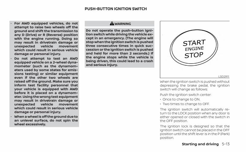
• For AWD equipped vehicles, do notattempt to raise two wheels off theground and shift the transmission toany D (Drive) or R (Reverse) positionwith the engine running. Doing somay result in drivetrain damage orunexpected vehicle movementwhich could result in serious vehicledamage or personal injury.
• Do not attempt to test an AWDequipped vehicle on a 2-wheel dyna-mometer (such as the dynamom-eters used by some states for emis-sions testing) or similar equipmenteven if the other two wheels areraised off the ground. Make sure youinform test facility personnel thatyour vehicle is equipped with AWDbefore it is placed on a dynamom-eter. Using the wrong test equipmentmay result in drivetrain damage orunexpected vehicle movementwhich could result in serious vehicledamage or personal injury.
• When a wheel is off the ground due toan unlevel surface, do not spin thewheel excessively.
WARNING
Do not operate the push-button igni-tion switch while driving the vehicle ex-cept in an emergency. (The engine willstop when the ignition switch is pushedthree consecutive times in quick suc-cession or the ignition switch is pushedand held for more than 2 seconds.) Ifthe engine stops while the vehicle isbeing driven, this could lead to a crashand serious injury.
When the ignition switch is pushed withoutdepressing the brake pedal, the ignitionswitch will change as follows:Push the ignition switch center:• Once to change to ON.• Two times to change to OFF.The ignition switch will automatically re-turn to the LOCK position when any door iseither opened or closed with the switch inthe OFF position.The ignition lock is designed so that theignition switch cannot be placed in the OFFposition until the shift lever is in the P (Park)position.
LSD2911
PUSH-BUTTON IGNITION SWITCH
Starting and driving 5-13
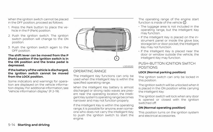
When the ignition switch cannot be placedin the OFF position, proceed as follows:1. Press the Park button to place the ve-
hicle in the P (Park) position.
2. Push the ignition switch. The ignitionswitch position will change to the ONposition.
3. Push the ignition switch again to theOFF position.
The shift lever can be moved from the P(Park) position if the ignition switch is inthe ON position and the brake pedal isdepressed.If the battery of the vehicle is discharged,the ignition switch cannot be movedfrom the LOCK position.Some indicators and warnings for opera-tion are displayed on the vehicle informa-tion display. For additional information, see“Vehicle information display” (P. 2-19).
OPERATING RANGEThe Intelligent Key functions can only beused when the Intelligent Key is within thespecified operating range.When the Intelligent Key battery is almostdischarged or strong radio waves are pres-ent near the operating location, the Intelli-gent Key system’s operating range becomesnarrower and may not function properly.If the Intelligent Key is within the operatingrange, it is possible for anyone, even some-one who does not carry the Intelligent Key,to push the ignition switch to start theengine.
The operating range of the engine startfunction is inside of the vehicle O1 .• The luggage area is not included in the
operating range, but the Intelligent Keymay function.
• If the Intelligent Key is placed on the in-strument panel or inside the glove box,storage bin or door pocket, the IntelligentKey may not function.
• If the Intelligent Key is placed near thedoor or window outside the vehicle, theIntelligent Key may function.
PUSH-BUTTON IGNITION SWITCHPOSITIONSLOCK (Normal parking position)The ignition switch can only be locked inthis position.The ignition switch will be unlocked when itis placed in the ON position while carryingthe Intelligent Key.The ignition switch will lock when any dooris opened or closed with the ignitionswitched off.ON (Normal operating position)This position turns on the ignition systemand electrical accessories.
LSD2020
5-14 Starting and driving

ON has a battery saver feature that willplace the ignition switch in the OFF posi-tion, if the vehicle is not running, after sometime under the following conditions:• All doors are closed.• The shift lever is in P (Park).The battery saver feature will be canceled ifany of the following occur:• Any door is opened.• The shift lever is moved out of the P (Park)
position.• The ignition switch changes position.
CAUTION
Do not leave the vehicle with the igni-tion switch in the ON position when theengine is not running for an extendedperiod. This can discharge the battery.
OFFThe ignition switch is in the OFF positionwhen the engine is turned off using theignition switch. No lights will illuminate onthe ignition switch.
AUTO ACCWith the vehicle in the P (Park) position, theIntelligent Key with you and the ignitionswitch placed from the ON position to theOFF position, the radio can still be used fora period of time, or until the driver’s door isopened.After a period of time, functions such asradio, navigation, and Bluetooth® Hands-Free Phone System may be restarted bypressing the POWER button/VOLUME con-trol knob or the key fob unlock button. Foradditional information, see the “Monitor, cli-mate, audio, phone and voice recognitionsystems” (P. 4-2).
EMERGENCY ENGINE SHUT OFFTo shut off the engine in an emergencysituation while driving, perform the follow-ing procedure:• Rapidly push the ignition switch three
consecutive times in less than 1.5 sec-onds, or
• Push and hold the ignition switch formore than 2 seconds.
INFINITI INTELLIGENT KEY BATTERYDISCHARGEIf the battery of the Intelligent Key is dis-charged or environmental conditions in-terfere with the Intelligent Key operation,start the engine according to the followingprocedure:1. Press the Park button to place the ve-
hicle in the P (Park) position.
2. Firmly apply the foot brake.
3. Touch the ignition switch with the Intel-ligent Key as illustrated. (A chime willsound.)
LSD3572
Starting and driving 5-15

4. Push the ignition switch while depress-ing the brake pedal within 10 secondsafter the chime sounds. The engine willstart.
After step 3 is performed, when the ignitionswitch is pushed without depressing thebrake pedal, the ignition switch position willchange to ON.
NOTE:• When the ignition switch is placed in
the ON position or the engine is startedby the above procedure, the IntelligentKey battery discharge indicator mayappear in the vehicle information dis-play even when the Intelligent Key isinside the vehicle. This is not a mal-function. To turn off the Intelligent Keybattery discharge indicator, touch theignition switch with the Intelligent Keyagain.
• If the Intelligent Key battery dischargeindicator appears, replace the batteryas soon as possible. For additional in-formation, see “Battery replacement”(P. 8-24).
INFINITI VEHICLE IMMOBILIZERSYSTEMThe INFINITI Vehicle Immobilizer Systemwill not allow the engine to start withoutthe use of the registered key.If the engine fails to start using the regis-tered key, it may be due to interferencecaused by another registered key, an auto-mated toll road device or automated pay-ment device on the key ring. Restart theengine using the following procedures:1. Leave the ignition switch in the ON posi-
tion for approximately 5 seconds.
2. Place the ignition switch in the OFF orLOCK position and wait approximately 5seconds.
3. Repeat steps 1 and 2.
4. Restart the engine while holding the de-vice (which may have caused the inter-ference) separate from the registeredkey.
If the no start condition re-occurs, INFINITIrecommends placing the registered key ona separate key ring to avoid interferencefrom other devices.
• Make sure the area around the vehicle isclear.
• Check fluid levels such as engine oil, cool-ant, brake fluid, and windshield-washerfluid as frequently as possible, or at leastwhenever you refuel.
• Check that all windows and lights areclean.
• Visually inspect tires for their appearanceand condition. Also check tires for properinflation.
• Check that all doors are closed.• Position seat and adjust head
restraints/headrests.• Adjust inside and outside mirrors.• Fasten seat belts and ask all passengers
to do likewise.• Check the operation of warning lights
when the ignition switch is placed in theON position. For additional information,see “Warning lights, indicator lights andaudible reminders” (P. 2-9)
BEFORE STARTING THE ENGINE
5-16 Starting and driving

1. Apply the parking brake.
2. Press the Park button to place the ve-hicle in P (Park) or move the shift lever toN (Neutral). P (Park) is recommended.The starter is designed not to operateif the shift lever is in any of the drivingpositions.
3. Push the ignition switch to the ON posi-tion. Depress the brake pedal and pushthe ignition switch to start the engine.To start the engine immediately, pushand release the ignition switch while de-pressing the brake pedal with the igni-tion switch in any position.• If the engine is very hard to start in
extremely cold weather or when re-starting, depress the acceleratorpedal a little (approximately 1/3 to thefloor) and while holding, crank the en-gine. Release the accelerator pedalwhen the engine starts.
• If the engine is very hard to start be-cause it is flooded, depress the accel-erator pedal all the way to the floorand hold it. Push the ignition switch tothe ON position to start cranking theengine. After 5 or 6 seconds, stopcranking by pushing the ignitionswitch to the LOCK position. After
cranking the engine, release the accel-erator pedal. Crank the engine withyour foot off the accelerator pedal bydepressing the brake pedal and push-ing the ignition switch to start the en-gine. If the engine starts, but fails torun, repeat the above procedure.
CAUTION
Do not operate the starter for morethan 15 seconds at a time. If the enginedoes not start, push the ignition switchto the OFF position and wait 10 secondsbefore cranking again, otherwise thestarter could be damaged.
4. Warm-up:Allow the engine to idle for at least 30seconds after starting. Do not race theengine while warming it up. Drive at amoderate speed for a short distancefirst, especially in cold weather. In coldweather, keep the engine running for aminimum of 2 - 3 minutes before shut-ting it off. Starting and stopping the en-gine over a short period of time maymake the vehicle more difficult to start.
5. To stop the engine, place the shift leverin the P (Park) position and push the ig-nition switch to the OFF position.
NOTE:Care should be taken to avoid situa-tions that can lead to potential batterydischarge and potential no-start con-ditions such as:1. Installation or extended use of elec-
tronic accessories that consume bat-tery power when the engine is notrunning (phone chargers, GPS, DVDplayers, etc.).
2. The vehicle is not driven regularlyand/or only driven short distances.
In these cases, the battery may need tobe charged to maintain battery health.
STARTING THE ENGINE
Starting and driving 5-17
REMOTE ENGINE START (if soequipped)Vehicles started with the Remote EngineStart require the ignition switch to beplaced in the ON position before the shiftlever can be moved from the P (Park) posi-tion. To place the ignition switch in the ONposition, follow these steps:1. Make sure that the Intelligent Key is on
you.
2. Apply the brake.
3. Push the ignition switch once to the ONposition.
For additional information, see “INFINITI In-telligent Key” (P. 3-2).
CONTINUOUSLY VARIABLETRANSMISSION (CVT)
WARNING
• Do not depress the accelerator pedalwhile shifting from P (Park) or N (Neu-tral) to R (Reverse), D (Drive), or M(Manual shift mode). Always depressthe brake pedal until shifting is com-pleted. Failure to do so could cause youto lose control and have an accident.
• Cold engine idle speed is high, so usecaution when shifting into a forwardor reverse gear before the engine haswarmed up.
• Do not downshift abruptly on slip-pery roads. This may cause a loss ofcontrol.
• Never shift to either the P (Park) or R(Reverse) position while the vehicle ismoving forward and P (Park) or D(Drive) position while the vehicle isreversing. This could cause an acci-dent or damage the transmission.
• Except in an emergency, do not shiftto the N (Neutral) position while driv-ing. Coasting with the transmissionin the N (Neutral) position may causeserious damage to the transmission.
CAUTION
• To avoid possible damage to your ve-hicle, when stopping the vehicle onan uphill grade, do not hold the ve-hicle by depressing the acceleratorpedal. The foot brake should be usedfor this purpose.
• Do not hang items on the shift lever.This may cause an accident due to asudden start.
The CVT in your vehicle is electronicallycontrolled to produce maximum powerand smooth operation.The recommended operating proceduresfor this transmission are shown on the fol-lowing pages. Follow these procedures formaximum vehicle performance and driv-ing enjoyment.Engine power may be automatically re-duced to protect the CVT if the enginespeed increases quickly when driving onslippery roads or while being tested onsome dynamometers.
DRIVING THE VEHICLE
5-18 Starting and driving

Starting the vehicle1. After starting the engine, fully depress
the foot brake pedal before moving theshift lever out of the P (Park) position.This Continuously Variable Transmis-sion is designed so that the foot brakepedal must be depressed before shift-ing from P (Park) to any driving posi-tion while the ignition switch is in theON position.The shift lever cannot be moved out ofthe P (Park) position and into any ofthe other positions if the ignitionswitch is placed in the OFF position.
2. Keep the foot brake pedal depressedand move the shift lever to a drivingposition.
3. Release the parking brake and footbrake pedal and then gradually start thevehicle in motion.
WARNING
• Do not depress the accelerator pedalwhile shifting from P (Park) or N (Neu-tral) to R (Reverse), D (Drive), or M(Manual shift mode). Always depressthe brake pedal until shifting is com-pleted. Failure to do so could causeyou to lose control and have anaccident.
• Cold engine idle speed is high, so usecaution when shifting into a forwardor reverse gear before the engine haswarmed up.
• Do not downshift abruptly on slip-pery roads. This may cause a loss ofcontrol.
• Never shift to either the P (Park) or R(Reverse) position while the vehicle ismoving forward and P (Park) or D(Drive) position while the vehicle isreversing. This could cause an acci-dent or damage the transmission.
CAUTION
• To avoid possible damage to your ve-hicle, when stopping the vehicle onan uphill grade, do not hold the ve-hicle by depressing the acceleratorpedal. The foot brake should be usedfor this purpose.
• Except in an emergency, do not shiftto the N (Neutral) position while driv-ing. Coasting with the transmissionin the N (Neutral) position may causeserious damage to the transmission.
• Do not hang items on the shift lever.This may cause an accident due to asudden start.
Starting and driving 5-19

Shifting
Press the shift lever button to shift
Shift without pressing the shift leverbutton
After starting the engine, fully depress thebrake pedal, press the shift lever buttonand move the shift lever from the P (Park)position to any of the desired shift posi-tions. Confirm that the vehicle is in the de-sired shift position by checking the shift
indicator located near the shift lever or thevehicle information display.
WARNING
Apply the electronic parking brake ifthe shift lever is in any position whilethe engine is not running. Failure to doso could cause the vehicle to move un-expectedly or roll away and result inserious personal injury or propertydamage.
CAUTION
• Use the P (Park), R (Reverse) or D(Drive) position only when the vehicleis completely stopped.
• After switching to the desired shiftposition, release your hand fromshift lever to let it return to the homeposition.
• Do not operate the shift lever whilethe accelerator pedal is depressed.This may cause a sudden start whichcould result in an accident.
• The following operations are not al-lowed because excessive forcewould be applied to the transmissionand this may result in damage to thevehicle:– Moving the shift lever to the R (Re-
verse) position when drivingforward.
– Moving the shift lever to the D(Drive) position when reversing.
If these operations are attempted, achime sounds and the vehicle shifts tothe N (Neutral) position.
P (Park)
CAUTION
• To prevent transmission damage,use the P (Park) position only whenthe vehicle is completely stopped.
• Do not slide the shift lever whilepressing the Park button. This maydamage the shift control system.
Use this position when the vehicle isparked or starting the engine. Always makesure that the vehicle is completely stoppedbefore pressing the Park button O1 to en-gage the P (Park) position. For maximumsafety, the brake pedal must be depressed
LSD4196
5-20 Starting and driving
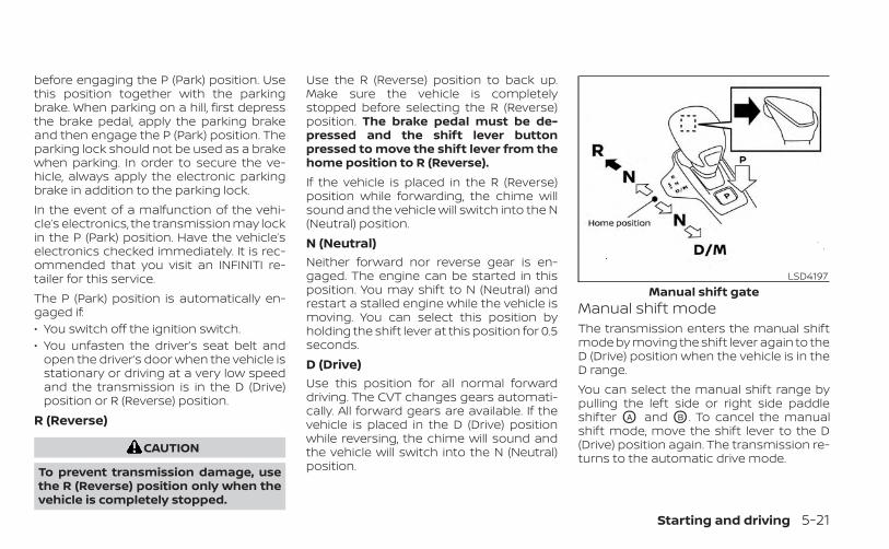
before engaging the P (Park) position. Usethis position together with the parkingbrake. When parking on a hill, first depressthe brake pedal, apply the parking brakeand then engage the P (Park) position. Theparking lock should not be used as a brakewhen parking. In order to secure the ve-hicle, always apply the electronic parkingbrake in addition to the parking lock.In the event of a malfunction of the vehi-cle’s electronics, the transmission may lockin the P (Park) position. Have the vehicle’selectronics checked immediately. It is rec-ommended that you visit an INFINITI re-tailer for this service.The P (Park) position is automatically en-gaged if:• You switch off the ignition switch.• You unfasten the driver’s seat belt and
open the driver’s door when the vehicle isstationary or driving at a very low speedand the transmission is in the D (Drive)position or R (Reverse) position.
R (Reverse)
CAUTION
To prevent transmission damage, usethe R (Reverse) position only when thevehicle is completely stopped.
Use the R (Reverse) position to back up.Make sure the vehicle is completelystopped before selecting the R (Reverse)position. The brake pedal must be de-pressed and the shift lever buttonpressed to move the shift lever from thehome position to R (Reverse).If the vehicle is placed in the R (Reverse)position while forwarding, the chime willsound and the vehicle will switch into the N(Neutral) position.N (Neutral)Neither forward nor reverse gear is en-gaged. The engine can be started in thisposition. You may shift to N (Neutral) andrestart a stalled engine while the vehicle ismoving. You can select this position byholding the shift lever at this position for 0.5seconds.D (Drive)Use this position for all normal forwarddriving. The CVT changes gears automati-cally. All forward gears are available. If thevehicle is placed in the D (Drive) positionwhile reversing, the chime will sound andthe vehicle will switch into the N (Neutral)position.
Manual shift modeThe transmission enters the manual shiftmode by moving the shift lever again to theD (Drive) position when the vehicle is in theD range.You can select the manual shift range bypulling the left side or right side paddleshifter OA and OB . To cancel the manualshift mode, move the shift lever to the D(Drive) position again. The transmission re-turns to the automatic drive mode.
LSD4197Manual shift gate
Starting and driving 5-21
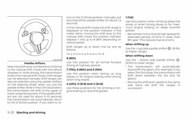
When the shift lever is shifted from D (Drive)to the manual shift mode with the vehiclestopped or while driving, the transmissionenters the manual shift mode. Shift rangescan be selected manually. Shift ranges canalso be selected using the paddle shifterson the steering wheel. When you pull thepaddle shifter while in the D (Drive) position,the transmission will shift to the upper orlower range temporarily. If the paddle shift-ers are not used for about 5–10 seconds,the transmission will automatically returnto the D (Drive) position. If you want to re-
turn to the D (Drive) position manually, pulland hold either paddle shifter for about 1.5seconds.In the manual shift mode, the shift range isdisplayed on the position indicator in themeter. When moving the shift lever to themanual shift mode, the position indicatordisplays 1 (1st) up to 8 (8th) depending onvehicle speed.Shift ranges up or down one by one asfollows:1⇔ 2 ⇔ 3 ⇔ 4 ⇔ 5 ⇔ 6 ⇔ 7⇔ 88 (8th)Use this position for all normal forwarddriving at highway speeds.7 (7th), 6 (6th) and 5 (5th)Use this position when driving up longslopes, or for engine braking when drivingdown long slopes.4 (4th), 3 (3rd) and 2 (2nd)Use these positions for hill climbing or en-gine braking on downhill grades.
1 (1st)Use this position when climbing steep hillsslowly or when driving slowly, or for maxi-mum engine braking on steep downhillgrades.• Remember not to drive at high speeds for
extended periods of time in lower than8th gear. This reduces fuel economy.
When shifting upUse the + (up) side paddle shifter OB . (Shiftsto higher range.)When shifting downUse the − (down) side paddle shifter OA .(Shifts to lower range.)• The transmission will automatically
downshift the gears. (For example, if youselect the 3rd range, the transmission willshift down between the 3rd and 1stgears.)
• Moving the shift lever rapidly to the sameside twice will shift the ranges insuccession.
LSD2914Paddle shifters
5-22 Starting and driving
When canceling the manual shift modeMove the shift lever to the D (Drive) positionto return the transmission to the normaldriving mode.• In the manual shift mode, the trans-
mission may not shift to the selectedgear. This helps maintain driving per-formance and reduces the chance ofvehicle damage or loss of control.
• When this situation occurs, the Con-tinuously Variable Transmission (CVT)position indicator will blink and thechime will sound.
• In the manual shift mode, the trans-mission may shift up automatically to ahigher range than selected if the en-gine speed is too high. When the ve-hicle speed decreases, the transmis-sion automatically shifts down andshifts to 1st gear before the vehiclecomes to a stop.
• CVT operation is limited to automaticdrive mode when CVT fluid temperatureis extremely low even if manual shiftmode is selected. This is not a malfunc-tion. When CVT fluid warms up, manualmode can be selected.
• When the CVT fluid temperature is high,the shift range may upshift in lower rpmthan usual. This is not a malfunction.
Accelerator downshift— in D (Drive) position —For passing or hill climbing, depress theaccelerator pedal to the floor. This shiftsthe transmission down into a lower gear,depending on the vehicle speed.
High fluid temperature protectionmodeThis transmission has a high fluid tem-perature protection mode. If the fluid tem-perature becomes too high (for example,when climbing steep grades in high tem-peratures with heavy loads), engine powerand, under some conditions, vehicle speedwill be decreased automatically to reducethe chance of transmission damage. Ve-hicle speed can be controlled with the ac-celerator pedal, but the engine and vehiclespeed may be limited.
Fail-safeWhen the fail-safe operation occurs, theContinuously Variable Transmission willnot be shifted into the selected drivingposition.If the vehicle is driven under extremeconditions, such as excessive wheelspinning and subsequent hard braking,
the fail-safe system may be activated.The Malfunction Indicator Light (MIL)may come on to indicate the fail-safemode is activated. For additional infor-mation, see “Malfunction Indicator Light(MIL)” (P. 2-15). This will occur even if allelectrical circuits are functioning prop-erly. In this case, place the ignition switchin the OFF position and wait for 10 sec-onds. Then place the ignition switchback in the ON position. The vehicleshould return to its normal operatingcondition. If it does not return to its nor-mal operating condition, have the trans-mission checked and repaired, if neces-sary. It is recommended that you visit anINFINITI retailer for this service.
WARNING
When the high fluid temperature pro-tection mode or fail-safe operation oc-curs, vehicle speed may be graduallyreduced. The reduced speed may belower than other traffic, which could in-crease the chance of a collision. Be es-pecially careful when driving. If neces-sary, pull to the side of the road at a safeplace and allow the transmission to re-turn to normal operation, or have it re-paired if necessary.
Starting and driving 5-23
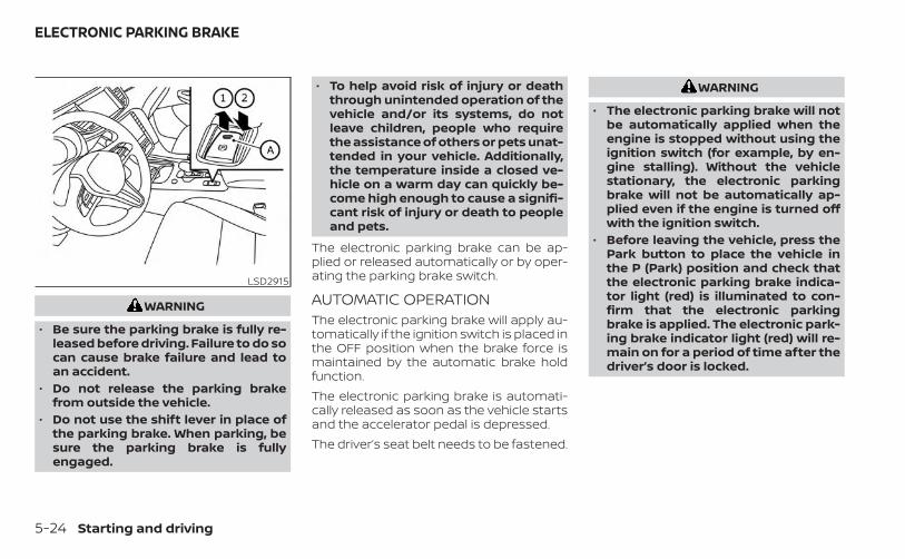
WARNING
• Be sure the parking brake is fully re-leased before driving. Failure to do socan cause brake failure and lead toan accident.
• Do not release the parking brakefrom outside the vehicle.
• Do not use the shift lever in place ofthe parking brake. When parking, besure the parking brake is fullyengaged.
• To help avoid risk of injury or deaththrough unintended operation of thevehicle and/or its systems, do notleave children, people who requirethe assistance of others or pets unat-tended in your vehicle. Additionally,the temperature inside a closed ve-hicle on a warm day can quickly be-come high enough to cause a signifi-cant risk of injury or death to peopleand pets.
The electronic parking brake can be ap-plied or released automatically or by oper-ating the parking brake switch.
AUTOMATIC OPERATIONThe electronic parking brake will apply au-tomatically if the ignition switch is placed inthe OFF position when the brake force ismaintained by the automatic brake holdfunction.The electronic parking brake is automati-cally released as soon as the vehicle startsand the accelerator pedal is depressed.The driver’s seat belt needs to be fastened.
WARNING
• The electronic parking brake will notbe automatically applied when theengine is stopped without using theignition switch (for example, by en-gine stalling). Without the vehiclestationary, the electronic parkingbrake will not be automatically ap-plied even if the engine is turned offwith the ignition switch.
• Before leaving the vehicle, press thePark button to place the vehicle inthe P (Park) position and check thatthe electronic parking brake indica-tor light (red) is illuminated to con-firm that the electronic parkingbrake is applied. The electronic park-ing brake indicator light (red) will re-main on for a period of time after thedriver’s door is locked.
LSD2915
ELECTRONIC PARKING BRAKE
5-24 Starting and driving
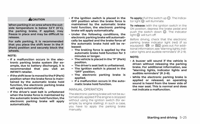
CAUTION
When parking in an area where the out-side temperature is below 32°F (0°C),the parking brake, if applied, mayfreeze in place and may be difficult torelease.For safe parking, it is recommendedthat you place the shift lever in the P(Park) position and securely block thewheels.
NOTE:• If a malfunction occurs in the elec-
tronic parking brake system (for ex-ample, due to battery discharge), it isrecommended that you visit anINFINITI retailer.
• If the shift lever is moved to the P (Park)position when the brake force is main-tained by the automatic brake holdfunction, the electronic parking brakewill apply automatically.
• If the driver’s seat belt is unfastenedwhen the brake force is maintained bythe automatic brake hold function, theelectronic parking brake will applyautomatically.
• If the ignition switch is placed in theOFF position when the brake force ismaintained by the automatic brakehold function, the electronic parkingbrake will apply automatically.
• Under the following conditions, theelectronic parking brake will automati-cally be applied and the brake force ofthe automatic brake hold will be re-leased:– The braking force is applied by the
automatic brake hold function for 3minutes or longer.
– The vehicle is placed in the “P” (Park)position.
– The driver’s seat belt is unfastened.– The ignition switch is placed in the
“OFF” position.– The electronic parking brake is
applied.– If a malfunction occurs in the auto-
matic brake hold function.
MANUAL OPERATIONThe electronic parking brake will not be au-tomatically applied if the engine is stoppedwithout using the ignition switch (for ex-ample, by engine stalling). In such a case,you have to apply the parking brakemanually.
To apply: Pull the switch up O1 . The indica-tor light OA will illuminate.To release: With the ignition switch in theON position, depress the brake pedal andpush the switch down O2 . The indicatorlight OA will turn off.Before driving, check that the electronicparking brake indicator light (red) (if soequipped) or goes out. For addi-tional information, see “Warning lights, indi-cator lights and audible reminders” (P. 2-9).
NOTE:• A buzzer will sound if the vehicle is
driven without releasing the parkingbrake. For additional information, see“Warning lights, indicator lights andaudible reminders” (P. 2-9).
• While the electronic parking brake isapplied or released, an operatingsound is heard from the lower side ofthe rear seat. This is normal and doesnot indicate a malfunction.
Starting and driving 5-25

• When the electronic parking brake isfrequently applied and released in ashort period of time, the parking brakemay not operate in order to prevent theparking brake system from overheat-ing. If this occurs, operate the elec-tronic parking brake switch again afterwaiting approximately 1 minute.
• If the electronic parking brake must beapplied while driving in an emergency,pull up and hold the parking brakeswitch. When you release the parkingbrake switch, the parking brake will bereleased.
• While pulling up the electronic parkingbrake switch during driving, the park-ing brake is applied and a chimesounds. The electronic parking brakeindicator light (red) in the meter and inthe parking brake switch illuminates.This does not indicate a malfunction.The electronic parking brake indicatorlight (red) in the meter and in the park-ing brake switch turns off when theparking brake is released.
• When pulling the electronic parkingbrake switch up with the ignitionswitch in the OFF or AUTO ACC position,the parking brake switch indicatorlight will continue to illuminate for ashort period of time.
The automatic brake hold function main-tains the braking force without the driverhaving to depress the brake pedal whenthe vehicle is stopped at a traffic light orintersection. As soon as the driver de-presses the accelerator pedal again, theautomatic brake hold function is deacti-vated and the braking force is released. Theoperating status of the automatic brakehold can be displayed on the vehicle infor-mation display.
WARNING
• The automatic brake hold function isnot designed to hold the vehicle on asteep hill or slippery road. Never usethe automatic brake hold when thevehicle is stopped on a steep hill orslippery road. Failure to do so maycause the vehicle to move.
• The automatic brake hold function isdesigned to operate on gradients be-tween —30% to +30%. Outside thisrange the system may not operate.The automatic brake hold warningmay appear in the Vehicle Informa-tion Display to request that the driverretake control by depressing thebrake pedal.
AUTOMATIC BRAKE HOLD
5-26 Starting and driving

• When the automatic brake hold func-tion is activated but fails to maintainthe vehicle at a standstill, depress thebrake pedal to stop the vehicle. If thevehicle unexpectedly moves due tooutside conditions, the chime maysound and automatic brake holdwarning may illuminate in the vehicleinformation display.
• Be sure to deactivate the automaticbrake hold function when using a carwash or towing your vehicle.
• Make sure to place the shift lever inthe P (Park) position and apply theparking brake when parking your ve-hicle, entering or exiting the vehicle,or loading luggage. Failure to do socould cause the vehicle to move orroll away unexpectedly and result inserious personal injury or propertydamage.
WARNING
• If any of the following conditions oc-cur, the automatic brake hold functionmay not function. Have the systemchecked promptly. It is recommendedthat you visit an INFINITI retailer forthis service. Failure to operate the ve-hicle in accordance with these condi-tions could cause the vehicle to moveor roll away unexpectedly and result inserious personal injury or propertydamage.– A warning message appears in the
vehicle information display.– The indicator light on the auto-
matic brake hold switch does notilluminate when the switch ispushed.
• The automatic brake hold functionwill not be activated if the Slip indica-tor light, electronic parking brakewarning light or master warning lightilluminate and the chassis controlsystem fault message appears in thevehicle information display.
• To maintain the braking force to keepthe vehicle to a standstill, a noisemay be heard. This is not amalfunction.
HOW TO ACTIVATE/DEACTIVATETHE AUTOMATIC BRAKE HOLDFUNCTIONFor additional information on activatingand deactivating the automatic brake holdfunction, refer to the instructions outlinedin this section.
How to activate the automaticbrake hold function1. With the ignition switch in the ON position,
push the automatic brake hold switch O1 .The indicator light on the automatic brakehold switch O2 illuminates.
LSD2916
Starting and driving 5-27
2. When the automatic brake hold functiongoes into standby, the automatic brakehold indicator light (white) illuminates.
To use the automatic brake hold function,the following conditions need to be met:• The driver’s seat belt is fastened.• The electronic parking brake is released.• The shift lever is not in the P (Park)
position.
NOTE:
The automatic brake hold function re-sets to OFF every time the ignitionswitch is switched from the ON positionto the OFF position.
How to deactivate the automaticbrake hold functionWhile the automatic brake hold function isactivated, push the automatic brake holdswitch to turn off the automatic brake holdindicator light and deactivate the auto-matic brake hold function. To deactivatethe automatic brake hold function whilethe brake force has been maintained bythe automatic brake hold function, depressthe brake pedal and push the automaticbrake hold switch.
WARNING
Make sure to firmly depress and holdthe brake pedal when turning off theautomatic brake hold function whilethe brake force is applied. When the au-tomatic brake hold function is deacti-vated, the brake force will be released.This could cause the vehicle to move orroll away unexpectedly. Failure to pre-vent the vehicle from rolling may resultin serious personal injury or propertydamage.
HOW TO USE THE AUTOMATICBRAKE HOLD FUNCTIONFor additional information on using the au-tomatic brake hold function, refer to theinstructions outlined in this section.
To maintain braking forceautomaticallyWith the automatic brake hold function ac-tivated and the automatic brake hold indi-cator light (white) illuminated on the meter,depress the braking pedal to stop the ve-hicle. The automatic brake hold indicatorilluminates green on the meter, and thebrake force is automatically applied with-out your foot depressed on the brake
pedal. While the brake hold is maintained,the automatic brake hold indicator light(green) illuminates on the meter.
To start the vehicle from astandstillWith the shift lever not in the P (Park) or N(Neutral) position, depress the acceleratorpedal while the brake force is maintained.The brake force will automatically be re-leased to restart the vehicle.The automatic brake hold indicator light(white) illuminates and the automaticbrake hold returns to standby.
ParkingWhen the shift lever is in the P (Park) posi-tion with the brake force maintained by theautomatic brake hold function, the parkingbrake will automatically be applied and thebrake force of the automatic brake hold willbe released. The automatic brake hold in-dicator light turns off. When the parkingbrake is applied with the brake force main-tained by the automatic brake hold func-tion, the brake force of the automatic brakehold will be released. The automatic brakehold indicator light turns off.
5-28 Starting and driving
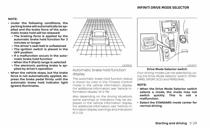
NOTE:• Under the following conditions, the
parking brake will automatically be ap-plied and the brake force of the auto-matic brake hold will be released:– The braking force is applied by the
automatic brake hold function for 3minutes or longer
– The driver's seat belt is unfastened– The ignition switch is placed in the
OFF position– If a malfunction occurs in the auto-
matic brake hold function– When the P (Park) range is selected– The electronic parking brake is ap-
plied by driver’s operation• When the vehicle stops, but the brake
force is not automatically applied, de-press the brake pedal firmly until theautomatic brake hold indicator light(green) illuminates.
Automatic brake hold functiondisplayThe automatic brake hold function statusis shown by color in the “Chassis Control”mode in the vehicle information display.For additional information, see “Vehicle in-formation display” (P. 2-19).Also depending on the driving situations,some warnings or indicators may be dis-played in the vehicle information display.For additional information, see “Vehicle in-formation display warnings and indicators”(P. 2-22)
Four driving modes can be selected by us-ing the Drive Mode Selector switch: STAN-DARD, SPORT, ECO and PERSONAL.
NOTE:• When the Drive Mode Selector switch
selects a mode, the mode may notswitch quickly. This is not amalfunction.
• Select the STANDARD mode center fornormal driving.
LSD3922 LSD2917Drive Mode Selector switch
INFINITI DRIVE MODE SELECTOR
Starting and driving 5-29
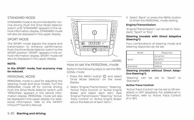
STANDARD MODESTANDARD mode is recommended for nor-mal driving. Push the Drive Mode Selectorswitch until “STANDARD” appears in the ve-hicle information display. STANDARD modewill also be displayed in the upper display.
SPORT MODEThe SPORT mode adjusts the engine andtransmission to enhance performance.Push the Drive Mode Selector switch to theSPORT position. “SPORT” appears in the ve-hicle information display. SPORT mode willalso be displayed in the upper display.
NOTE:
In the SPORT mode, fuel economy maybe reduced.
PERSONAL MODEPERSONAL mode is used for adjusting thesteering mode and drive modes. Turn thePERSONAL mode off for normal driving.Push the Drive Mode Selector switch until“PERSONAL” appears in the vehicle infor-mation display. PERSONAL mode will alsobe displayed in the upper display. For addi-tional information, refer to the INFINITIInTouch™ Owner’s Manual.
How to set the PERSONAL modePerform the following steps to set the PER-SONAL mode:1. Press the MENU button O1 and select
“Drive Mode Selector” on the lowerdisplay.
2. Select “Engine/Transmission,” “Steering,”“Active Trace Control” or “Active EngineBrake” and select each item. (See“Engine/Transmission,” “Steering,” “ActiveTrace Control” or “Active Engine Brake”about the feature of each item.)
3. Select “Back” or press the MENU buttonto finish the PERSONAL mode setting.
Engine/Transmission:“Engine/Transmission” can be set to “Stan-dard,” “Sport” or “Eco.”Steering (models with Direct AdaptiveSteering®):Four combinations of steering mode andsteering response can be set.
Mode Response
SportDynamic+DynamicDefault
Standard Default
Steering (models without Direct Adap-tive Steering®):“Steering” can be set to “Sport” or“Standard.”Active Trace Control:“Active Trace Control” can be set to ON (en-abled) or OFF (disabled). For additional in-formation, refer to “Active Trace Control”(P. 5-187).
LSD2982
5-30 Starting and driving
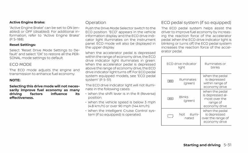
Active Engine Brake:“Active Engine Brake” can be set to ON (en-abled) or OFF (disabled). For additional in-formation, refer to “Active Engine Brake”(P. 5-188).Reset Settings:Select “Reset Drive Mode Settings to De-fault” and select “OK” to restore all the PER-SONAL mode settings to default.
ECO MODEThe ECO mode adjusts the engine andtransmission to enhance fuel economy.
NOTE:
Selecting this drive mode will not neces-sarily improve fuel economy as manydriving factors influence itseffectiveness.
OperationPush the Drive Mode Selector switch to theECO position. “ECO” appears in the vehicleinformation display and the ECO drive indi-cator light illuminates on the instrumentpanel. ECO mode will also be displayed inthe upper display.When the accelerator pedal is depressedwithin the range of economy drive, the ECOdrive indicator light illuminates in green.When the accelerator pedal is depressedabove the range of economy drive, the ECOdrive indicator light turns off. For ECO pedalsystem equipped models, see “ECO pedalsystem” (P. 5-31).The ECO drive indicator light will not illumi-nate in the following cases:• When the shift lever is in the R (Reverse)
position.• When the vehicle speed is below 3 mph
(4.8 km/h) or over 90 mph (144 km/h).• When the Intelligent Cruise Control sys-
tem (if so equipped) is operated.
ECO pedal system (if so equipped)The ECO pedal system helps assist thedriver to improve fuel economy by increas-ing the reaction force of the acceleratorpedal. When the ECO drive indicator light isblinking or turns off, the ECO pedal systemincreases the reaction force of the accel-erator pedal.
ECO drive indicatorlight
Illuminates orblinks
Illuminates(green)
When the pedalis depressed
within range ofeconomy drive
Blinks(green)
When the pedalis depressed al-most over the
range ofeconomy drive
Not illumi-nated
When the pedalis depressed
over the range ofeconomy drive
Starting and driving 5-31
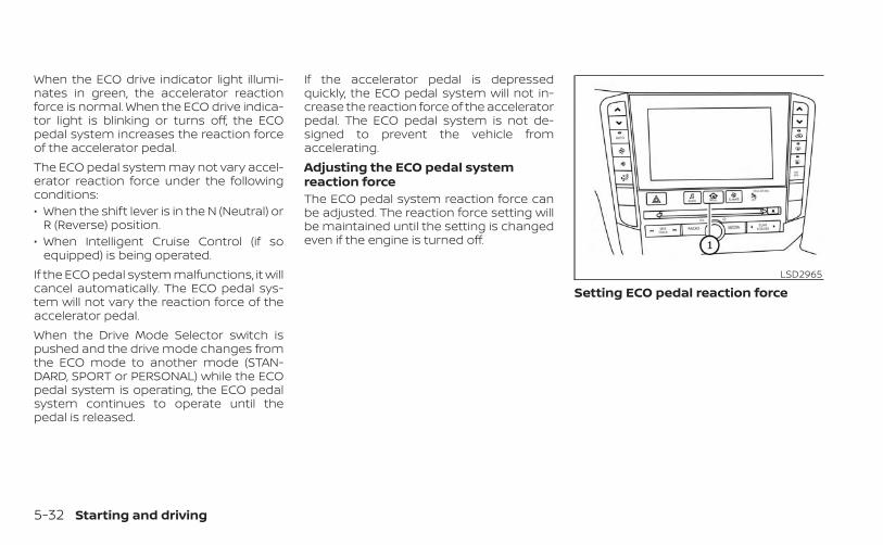
When the ECO drive indicator light illumi-nates in green, the accelerator reactionforce is normal. When the ECO drive indica-tor light is blinking or turns off, the ECOpedal system increases the reaction forceof the accelerator pedal.The ECO pedal system may not vary accel-erator reaction force under the followingconditions:• When the shift lever is in the N (Neutral) or
R (Reverse) position.• When Intelligent Cruise Control (if so
equipped) is being operated.If the ECO pedal system malfunctions, it willcancel automatically. The ECO pedal sys-tem will not vary the reaction force of theaccelerator pedal.When the Drive Mode Selector switch ispushed and the drive mode changes fromthe ECO mode to another mode (STAN-DARD, SPORT or PERSONAL) while the ECOpedal system is operating, the ECO pedalsystem continues to operate until thepedal is released.
If the accelerator pedal is depressedquickly, the ECO pedal system will not in-crease the reaction force of the acceleratorpedal. The ECO pedal system is not de-signed to prevent the vehicle fromaccelerating.Adjusting the ECO pedal systemreaction forceThe ECO pedal system reaction force canbe adjusted. The reaction force setting willbe maintained until the setting is changedeven if the engine is turned off.
Setting ECO pedal reaction forceLSD2965
5-32 Starting and driving

1. Press the MENU O1 button and select“Settings” in the lower display.
2. Select “Drive Mode Enhancement.”
3. Select “ECO Pedal” and then select either“OFF,” “Soft” or “Standard” in the lower dis-play. When the ECO pedal system isturned off, the accelerator will operatenormally.
The TSR system provides the driver withinformation about the most recently de-tected speed limit. The system capturesthe road sign information with the multi-sensing front camera unit O1 located onthe windshield in front of the inside rear-view mirror and displays the detectedsigns in the vehicle information display. Forvehicles equipped with a navigation sys-tem, the speed limit displayed is based on acombination of navigation system dataand live camera recognition. TSR informa-tion is always displayed at the top of the
LSD3574 LSD3934 LSD4091
TRAFFIC SIGN RECOGNITION (TSR) (ifso equipped)
Starting and driving 5-33
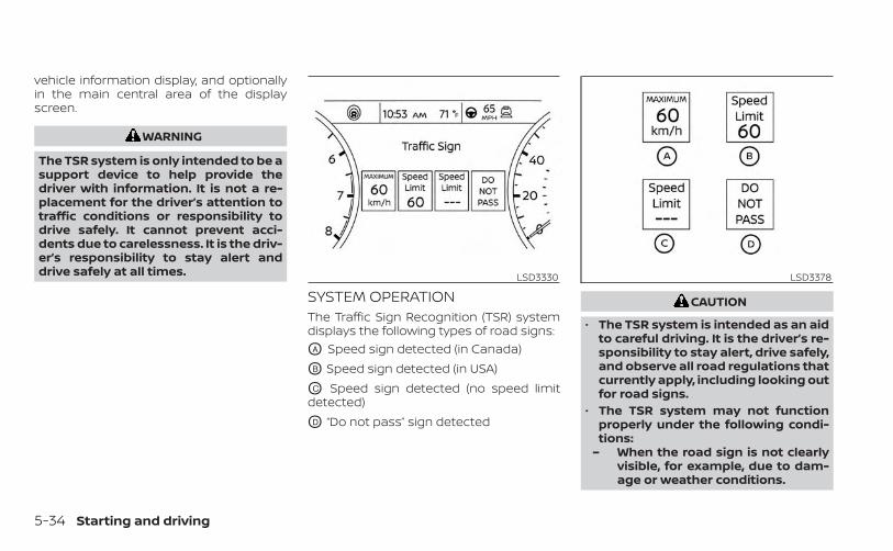
vehicle information display, and optionallyin the main central area of the displayscreen.
WARNING
The TSR system is only intended to be asupport device to help provide thedriver with information. It is not a re-placement for the driver’s attention totraffic conditions or responsibility todrive safely. It cannot prevent acci-dents due to carelessness. It is the driv-er’s responsibility to stay alert anddrive safely at all times.
SYSTEM OPERATIONThe Traffic Sign Recognition (TSR) systemdisplays the following types of road signs:OA Speed sign detected (in Canada)
OB Speed sign detected (in USA)
OC Speed sign detected (no speed limitdetected)
OD “Do not pass” sign detected
CAUTION
• The TSR system is intended as an aidto careful driving. It is the driver’s re-sponsibility to stay alert, drive safely,and observe all road regulations thatcurrently apply, including looking outfor road signs.
• The TSR system may not functionproperly under the following condi-tions:
– When the road sign is not clearlyvisible, for example, due to dam-age or weather conditions.
LSD3330 LSD3378
5-34 Starting and driving
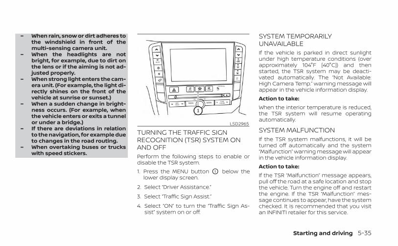
– When rain, snow or dirt adheres tothe windshield in front of themulti-sensing camera unit.
– When the headlights are notbright, for example, due to dirt onthe lens or if the aiming is not ad-justed properly.
– When strong light enters the cam-era unit. (For example, the light di-rectly shines on the front of thevehicle at sunrise or sunset.)
– When a sudden change in bright-ness occurs. (For example, whenthe vehicle enters or exits a tunnelor under a bridge.)
– If there are deviations in relationto the navigation, for example dueto changes in the road routing.
– When overtaking buses or truckswith speed stickers.
TURNING THE TRAFFIC SIGNRECOGNITION (TSR) SYSTEM ONAND OFFPerform the following steps to enable ordisable the TSR system.1. Press the MENU button O1 below the
lower display screen.
2. Select “Driver Assistance.”
3. Select “Traffic Sign Assist.”
4. Select “ON” to turn the “Traffic Sign As-sist” system on or off.
SYSTEM TEMPORARILYUNAVAILABLEIf the vehicle is parked in direct sunlightunder high temperature conditions (overapproximately 104°F [40°C]) and thenstarted, the TSR system may be deacti-vated automatically. The “Not Available:High Camera Temp.” warning message willappear in the vehicle information display.Action to take:When the interior temperature is reduced,the TSR system will resume operatingautomatically.
SYSTEM MALFUNCTIONIf the TSR system malfunctions, it will beturned off automatically and the system“Malfunction” warning message will appearin the vehicle information display.Action to take:If the TSR “Malfunction” message appears,pull off the road at a safe location and stopthe vehicle. Turn the engine off and restartthe engine. If the TSR “Malfunction” mes-sage continues to appear, have the systemchecked. It is recommended that you visitan INFINITI retailer for this service.
LSD2965
Starting and driving 5-35
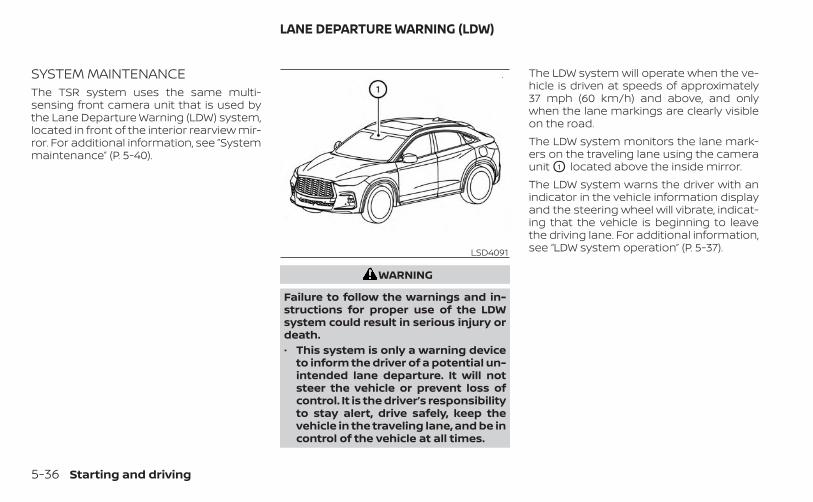
SYSTEM MAINTENANCEThe TSR system uses the same multi-sensing front camera unit that is used bythe Lane Departure Warning (LDW) system,located in front of the interior rearview mir-ror. For additional information, see ”Systemmaintenance” (P. 5-40).
WARNING
Failure to follow the warnings and in-structions for proper use of the LDWsystem could result in serious injury ordeath.• This system is only a warning device
to inform the driver of a potential un-intended lane departure. It will notsteer the vehicle or prevent loss ofcontrol. It is the driver’s responsibilityto stay alert, drive safely, keep thevehicle in the traveling lane, and be incontrol of the vehicle at all times.
The LDW system will operate when the ve-hicle is driven at speeds of approximately37 mph (60 km/h) and above, and onlywhen the lane markings are clearly visibleon the road.The LDW system monitors the lane mark-ers on the traveling lane using the cameraunit O1 located above the inside mirror.The LDW system warns the driver with anindicator in the vehicle information displayand the steering wheel will vibrate, indicat-ing that the vehicle is beginning to leavethe driving lane. For additional information,see “LDW system operation” (P. 5-37).LSD4091
LANE DEPARTURE WARNING (LDW)
5-36 Starting and driving
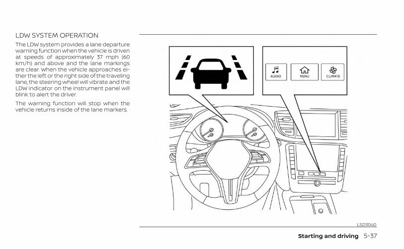
LDW SYSTEM OPERATIONThe LDW system provides a lane departurewarning function when the vehicle is drivenat speeds of approximately 37 mph (60km/h) and above and the lane markingsare clear. When the vehicle approaches ei-ther the left or the right side of the travelinglane, the steering wheel will vibrate and theLDW indicator on the instrument panel willblink to alert the driver.The warning function will stop when thevehicle returns inside of the lane markers.
LSD3040
Starting and driving 5-37

HOW TO ENABLE/DISABLE THELDW SYSTEMPerform the following steps to enable ordisable the LDW system:1. Press the MENU button below the lower
display screen.
2. Select “Driver Assistance.”
3. Select “Lane Assist.”
4. Select “ON” to turn the “Lane DepartureWarning” system on or off.
LSD4240
5-38 Starting and driving

LDW SYSTEM LIMITATIONSWARNING
Listed below are the system limitationsfor the LDW system. Failure to followthe warnings and instructions forproper use of the LDW system could re-sult in serious injury or death.• This system is only a warning device
to inform the driver of a potential un-intended lane departure. It will notsteer the vehicle or prevent loss ofcontrol. It is the driver’s responsibilityto stay alert, drive safely, keep thevehicle in the traveling lane, and be incontrol of the vehicle at all times.
• The system will not operate atspeeds below approximately 37 mph(60 km/h) or if it cannot detect lanemarkers.
• Do not use the LDW system under thefollowing conditions as it may notfunction properly:– During bad weather (rain, fog,
snow, etc.).– When driving on slippery roads,
such as on ice or snow.– When driving on winding or un-
even roads.
– When there is a lane closure due toroad repairs.
– When driving in a makeshift ortemporary lane.
– When driving on roads where thelane width is too narrow.
– When driving without normal tireconditions (for example, tire wear,low tire pressure, installation ofspare tire, tire chains, nonstan-dard wheels).
– When the vehicle is equipped withnon-original brake parts or sus-pension parts.
• The system may not function prop-erly under the following conditions:
– On roads where there are multipleparallel lane markers; lane mark-ers that are faded or not paintedclearly; yellow painted lane mark-ers; non-standard lane markers;or lane markers covered with wa-ter, dirt, snow, etc.
– On roads where the discontinuedlane markers are still detectable.
– On roads where there are sharpcurves.
– On roads where there are sharplycontrasting objects, such as shad-ows, snow, water, wheel ruts,seams or lines remaining afterroad repairs. (The LDW systemcould detect these items as lanemarkers.)
– On roads where the traveling lanemerges or separates.
– When the vehicle’s traveling direc-tion does not align with the lanemarker.
– When traveling close to the ve-hicle in front of you, which ob-structs the lane camera unit de-tection range.
– When rain, snow, dirt or an objectadheres to the windshield in frontof the lane camera unit.
– When the headlights are notbright due to dirt on the lens or ifthe aiming is not adjustedproperly.
– When strong light enters the lanecamera unit. (For example, thelight directly shines on the front ofthe vehicle at sunrise or sunset.)
– When a sudden change in bright-ness occurs. (For example, whenthe vehicle enters or exits a tunnelor under a bridge.)
Starting and driving 5-39

SYSTEM TEMPORARILYUNAVAILABLEIf the vehicle is parked in direct sunlightunder high temperature conditions (overapproximately 104°F [40°C]) and thenstarted, the LDW system may be deacti-vated automatically and the followingmessage will appear in the vehicle infor-mation display: “Not available: High CameraTemp.”When the interior temperature is reduced,the LDW system will resume operatingautomatically.The LDW system is not designed to warnunder the following conditions:• When you operate the lane change signal
and change traveling lanes in the direc-tion of the signal. (The LDW system willbecome operable again approximately 2seconds after the lane change signal isturned off.)
• When the vehicle speed lowers to lessthan approximately 37 mph (60 km/h).
After the above conditions have finishedand the necessary operating conditionsare satisfied, the LDW functions will resume.
SYSTEM MALFUNCTIONIf the LDW system malfunctions, it will can-cel automatically and “Malfunction” will ap-pear in the vehicle information display. If“Malfunction” appears in vehicle informa-tion display, pull off the road to a safe loca-tion and stop the vehicle. Place the shiftlever in the P (Park) position and ignitionswitch in the OFF position and restart theengine. If “Malfunction” continues to appearin vehicle information display, have the sys-tem checked. It is recommended that youvisit an INFINITI retailer for this service.
SYSTEM MAINTENANCEThe lane camera unit O1 for the LDW sys-tem is located above the inside mirror. Tokeep the proper operation of the LDW sys-tem and prevent a system malfunction, besure to observe the following:• Always keep the windshield clean.• Do not attach a sticker (including trans-
parent material) or install an accessorynear the camera unit.
LSD3075
5-40 Starting and driving
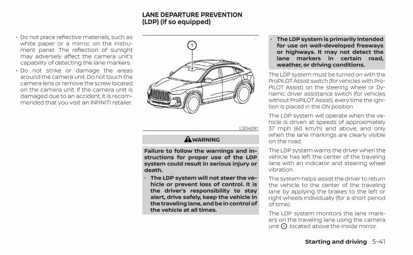
• Do not place reflective materials, such aswhite paper or a mirror, on the instru-ment panel. The reflection of sunlightmay adversely affect the camera unit’scapability of detecting the lane markers.
• Do not strike or damage the areasaround the camera unit. Do not touch thecamera lens or remove the screw locatedon the camera unit. If the camera unit isdamaged due to an accident, it is recom-mended that you visit an INFINITI retailer.
WARNING
Failure to follow the warnings and in-structions for proper use of the LDPsystem could result in serious injury ordeath.• The LDP system will not steer the ve-
hicle or prevent loss of control. It isthe driver’s responsibility to stayalert, drive safely, keep the vehicle inthe traveling lane, and be in control ofthe vehicle at all times.
• The LDP system is primarily intendedfor use on well-developed freewaysor highways. It may not detect thelane markers in certain road,weather, or driving conditions.
The LDP system must be turned on with theProPILOT Assist switch (for vehicles with Pro-PILOT Assist) on the steering wheel or Dy-namic driver assistance switch (for vehicleswithout ProPILOT Assist), every time the igni-tion is placed in the ON position.The LDP system will operate when the ve-hicle is driven at speeds of approximately37 mph (60 km/h) and above, and onlywhen the lane markings are clearly visibleon the road.The LDP system warns the driver when thevehicle has left the center of the travelinglane with an indicator and steering wheelvibration.The system helps assist the driver to returnthe vehicle to the center of the travelinglane by applying the brakes to the left orright wheels individually (for a short periodof time).The LDP system monitors the lane mark-ers on the traveling lane using the cameraunit O1 located above the inside mirror.
LSD4091
LANE DEPARTURE PREVENTION(LDP) (if so equipped)
Starting and driving 5-41
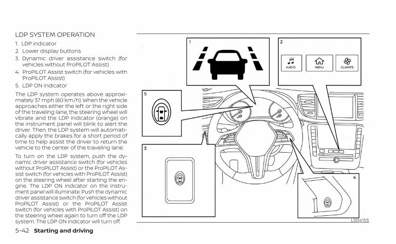
LDP SYSTEM OPERATION1. LDP indicator2. Lower display buttons3. Dynamic driver assistance switch (for
vehicles without ProPILOT Assist)4. ProPILOT Assist switch (for vehicles with
ProPILOT Assist)5. LDP ON indicatorThe LDP system operates above approxi-mately 37 mph (60 km/h). When the vehicleapproaches either the left or the right sideof the traveling lane, the steering wheel willvibrate and the LDP indicator (orange) onthe instrument panel will blink to alert thedriver. Then, the LDP system will automati-cally apply the brakes for a short period oftime to help assist the driver to return thevehicle to the center of the traveling lane.To turn on the LDP system, push the dy-namic driver assistance switch (for vehicleswithout ProPILOT Assist) or the ProPILOT As-sist switch (for vehicles with ProPILOT Assist)on the steering wheel after starting the en-gine. The LDP ON indicator on the instru-ment panel will illuminate. Push the dynamicdriver assistance switch (for vehicles withoutProPILOT Assist) or the ProPILOT Assistswitch (for vehicles with ProPILOT Assist) onthe steering wheel again to turn off the LDPsystem. The LDP ON indicator will turn off. LSD4153
5-42 Starting and driving

HOW TO ENABLE/DISABLE THELDP SYSTEMWhen the LDP system is enabled in thelower display, the system can be turned offtemporarily by pushing the dynamic driverassistance switch (for vehicles without Pro-PILOT Assist) or the ProPILOT Assist switch(for vehicles with ProPILOT Assist) on thesteering wheel.Perform the following steps to enable ordisable the LDP system.1. Press the MENU button below the lower
display screen.
2. Select “Driver Assistance.”
3. Select “Lane Assist.”
4. Select “ON” to turn the “Lane Interven-tion” system on or off.
NOTE:
Turning on the ProPILOT Assist system (ifso equipped) will turn on the DCA, LDPand BSI (if so equipped) systems at thesame time. If the LDP system is disabledin the settings menu, the LDP will auto-matically be turned on when the Steer-ing Assist system is active. For additionalinformation, see “ProPILOT Assist”(P. 5-102). LSD4240
Starting and driving 5-43

LDP SYSTEM LIMITATIONSWARNING
Listed below are the system limitationsfor the LDP system. Failure to follow thewarnings and instructions for properuse of the LDP system could result inserious injury or death.• The LDP system may activate if you
change lanes without first activatingyour turn signal or, for example, if aconstruction zone directs traffic tocross an existing lane marker. If thisoccurs you may need to apply correc-tive steering to complete your lanechange.
• Because the LDP may not activateunder the road, weather, and lanemarker conditions described in thissection, it may not activate everytime your vehicle begins to leave itslane and you will need to apply cor-rective steering.
• The LDP system will not operate atspeeds below approximately 37 mph(60 km/h) or if it cannot detect lanemarkers.
• When the LDP system is operating,avoid excessive or sudden steeringmaneuvers. Otherwise, you couldlose control of the vehicle.
• Do not use the LDP system under thefollowing conditions as it may notfunction properly:– During bad weather (rain, fog,
snow, etc.).– When driving on slippery roads,
such as on ice or snow.– When driving on winding or un-
even roads.– When there is a lane closure due to
road repairs.– When driving in a makeshift or
temporary lane.– When driving on roads where the
lane width is too narrow.– When driving without normal tire
conditions (for example, tire wear,low tire pressure, installation ofspare tire, tire chains, non-standard wheels).
– When the vehicle is equipped withnon-original brake parts or sus-pension parts.
• The system may not function prop-erly under the following conditions:
– On roads where there are multipleparallel lane markers; lane mark-ers that are faded or not paintedclearly; yellow painted lane mark-ers; non-standard lane markers;or lane markers covered with wa-ter, dirt, snow, etc.
– On roads where discontinued lanemarkers are still detectable.
– On roads where there are sharpcurves.
– On roads where there are sharplycontrasting objects, such as shad-ows, snow, water, wheel ruts,seams or lines remaining afterroad repairs. (The LDP systemcould detect these items as lanemarkers.)
– On roads where the traveling lanemerges or separates.
– When the vehicle’s traveling direc-tion does not align with the lanemarker.
– When traveling close to the ve-hicle in front of you, which ob-structs the lane camera unit de-tection range.
5-44 Starting and driving
– When rain, snow or dirt adheres tothe windshield in front of the lanecamera unit.
– When the headlights are notbright due to dirt on the lens or ifthe aiming is not adjustedproperly.
– When strong light enters the lanecamera unit. (For example, thelight directly shines on the front ofthe vehicle at sunrise or sunset.)
– When a sudden change in bright-ness occurs. (For example, whenthe vehicle enters or exits a tunnelor under a bridge.)
While the LDP system is operating, you mayhear a sound of brake operation. This isnormal and indicates that the LDP systemis operating properly.
SYSTEM TEMPORARILYUNAVAILABLECondition A:The warning and assist functions of theLDP system are not designed to work un-der the following conditions:
• When you operate the lane change signaland change the traveling lanes in the di-rection of the signal. (The LDP system willbe deactivated for approximately 2 sec-onds after the lane change signal isturned off.)
• When the vehicle speed lowers to lessthan approximately 37 mph (60 km/h).
After the above conditions have finishedand the necessary operating conditionsare satisfied, the warning and assist func-tions will resume.Condition B:The assist function of the LDP system is notdesigned to work under the following con-ditions (warning is still functional):• When the brake pedal is depressed.• When the steering wheel is turned as far
as necessary for the vehicle to changelanes.
• When the vehicle is accelerated duringLDP system operation.
• When the Intelligent Cruise Control (ICC)approach warning occurs.
• When the hazard warning flashers areoperated.
• When driving on a curve at high speed.
After the above conditions have finishedand the necessary operating conditionsare satisfied, the LDP system application ofthe brakes will resume.Condition C:If the following messages appear in thevehicle information display the LDP systemwill be turned off automatically:• “Not Available Poor Road Conditions”:
When the VDC system (except TractionControl System [TCS] function) or ABSoperates.
• “Currently not available”:When the VDC system is turned off.
Action to take:When the above conditions no longer exist,turn off the LDP system. Push the dynamicdriver assistance switch (for vehicles with-out ProPILOT Assist) or the ProPILOT Assistswitch (for vehicles with ProPILOT Assist) onthe steering wheel again to turn the LDPsystem back on.
Starting and driving 5-45
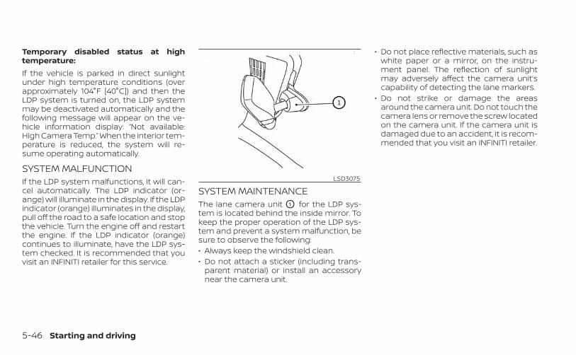
Temporary disabled status at hightemperature:If the vehicle is parked in direct sunlightunder high temperature conditions (overapproximately 104°F [40°C]) and then theLDP system is turned on, the LDP systemmay be deactivated automatically and thefollowing message will appear on the ve-hicle information display: “Not available:High Camera Temp.” When the interior tem-perature is reduced, the system will re-sume operating automatically.
SYSTEM MALFUNCTIONIf the LDP system malfunctions, it will can-cel automatically. The LDP indicator (or-ange) will illuminate in the display. If the LDPindicator (orange) illuminates in the display,pull off the road to a safe location and stopthe vehicle. Turn the engine off and restartthe engine. If the LDP indicator (orange)continues to illuminate, have the LDP sys-tem checked. It is recommended that youvisit an INFINITI retailer for this service.
SYSTEM MAINTENANCEThe lane camera unit O1 for the LDP sys-tem is located behind the inside mirror. Tokeep the proper operation of the LDP sys-tem and prevent a system malfunction, besure to observe the following:• Always keep the windshield clean.• Do not attach a sticker (including trans-
parent material) or install an accessorynear the camera unit.
• Do not place reflective materials, such aswhite paper or a mirror, on the instru-ment panel. The reflection of sunlightmay adversely affect the camera unit’scapability of detecting the lane markers.
• Do not strike or damage the areasaround the camera unit. Do not touch thecamera lens or remove the screw locatedon the camera unit. If the camera unit isdamaged due to an accident, it is recom-mended that you visit an INFINITI retailer.
LSD3075
5-46 Starting and driving

WARNING
Failure to follow the warnings and in-structions for proper use of the BSWsystem could result in serious injury ordeath.• The BSW system is not a replacement
for proper driving procedures and isnot designed to prevent contact withvehicles or objects. When changinglanes, always use the side and rearmirrors and turn and look in the di-rection your vehicle will move to en-sure it is safe to change lanes. Neverrely solely on the BSW system.
The BSW system helps alert the driver ofother vehicles in adjacent lanes whenchanging lanes.
The BSW system uses radar sensors O1
installed near the rear bumper to detectother vehicles in an adjacent lane.
The radar sensors can detect vehicles oneither side of your vehicle within the detec-tion zone shown as illustrated. This detec-tion zone starts from the outside mirror ofyour vehicle and extends approximately 10ft (3.0 m) behind the rear bumper, and ap-proximately 10 ft (3.0 m) sideways.
LSD4092 SSD1030Detection zone
BLIND SPOT WARNING (BSW)
Starting and driving 5-47

1. Side Indicator Light
2. BSW Indicator
BSW SYSTEM OPERATIONThe BSW system operates above approxi-mately 20 mph (32 km/h).If the radar sensors detect a vehicle in thedetection zone, the side indicator light O1
illuminates. If the turn signal is then acti-vated, the system chimes (twice) and theside indicator light flashes. The side indica-tor light continues to flash until the de-tected vehicle leaves the detection zone.The side indicator light illuminates for a fewseconds when the ignition switch is placedin the ON position.The brightness of the side indicator light isadjusted automatically depending on thebrightness of the ambient light.If a vehicle comes into the detection zoneafter the driver activates the turn signal,then only the side indicator light flashesand no chime sounds. For additional infor-mation, see “BSW driving situations” (P. 5-51).
LSD2921
5-48 Starting and driving
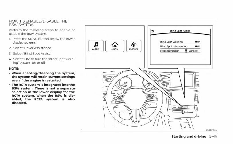
HOW TO ENABLE/DISABLE THEBSW SYSTEMPerform the following steps to enable ordisable the BSW system.1. Press the MENU button below the lower
display screen.
2. Select “Driver Assistance.”
3. Select “Blind Spot Assist.”
4. Select “ON” to turn the “Blind Spot Warn-ing” system on or off.
NOTE:• When enabling/disabling the system,
the system will retain current settingseven if the engine is restarted.
• The RCTA system is integrated into theBSW system. There is not a separateselection in the lower display for theRCTA system. When the BSW is dis-abled, the RCTA system is alsodisabled.
LSD3936
Starting and driving 5-49

BSW SYSTEM LIMITATIONSWARNING
Listed below are the system limitationsfor the BSW system. Failure to operatethe vehicle in accordance with thesesystem limitations could result in seri-ous injury or death.• The BSW system cannot detect all ve-
hicles under all conditions.• The radar sensors may not be able to
detect and activate BSW when cer-tain objects are present such as:– Pedestrian, bicycles, animals.– Vehicles such as motorcycles, low
height vehicles, or high groundclearance vehicles.
– Oncoming vehicles.– Vehicles remaining in the detec-
tion zone when you acceleratefrom a stop.
– A vehicle merging into an adjacentlane at a speed approximately thesame as your vehicle.
– A vehicle approaching rapidlyfrom behind.
– A vehicle which your vehicle over-takes rapidly.
– A vehicle that passes through thedetection zone quickly.
– When overtaking several vehiclesin a row, the vehicles after the firstvehicle may not be detected ifthey are traveling close together.
• The radar sensors’ detection zone isdesigned based on a standard lanewidth. When driving in a wider lane,the radar sensors may not detect ve-hicles in an adjacent lane. When driv-ing in a narrow lane, the radar sen-sors may detect vehicles driving twolanes away.
• The radar sensors are designed to ig-nore most stationary objects; how-ever, objects such as guardrails,walls, foliage and parked vehiclesmay occasionally be detected. This isa normal operation condition.
• The following conditions may reducethe ability of the radar to detect othervehicles:– Severe weather– Road spray– Ice/frost/snow/dirt build-up on
the vehicle
• Do not attach stickers (includingtransparent material), install acces-sories or apply additional paint nearthe radar sensors. These conditionsmay reduce the ability of the radar todetect other vehicles.
• Excessive noise (for example, audiosystem volume, open vehicle win-dow) will interfere with the chimesound, and it may not be heard.
5-50 Starting and driving

BSW DRIVING SITUATIONS
Indicator on
Indicator off
Indicator flashing
Another vehicle approachingfrom behindIllustration 1: The side indicator light illumi-nates if a vehicle enters the detection zonefrom behind in an adjacent lane.
NOTE:• The radar sensors may not detect ve-
hicles which are approaching rapidlyfrom behind.
Illustration 2: If the driver activates theturn signal when another vehicle is in thedetection zone, then the system chimes(twice) and the side indicator light flashes.
NOTE:• The radar sensors may not detect ve-
hicles which are approaching rapidlyfrom behind.
• If the driver activates the turn signalbefore a vehicle enters the detectionzone, the side indicator light will flashbut no chime will sound when theother vehicle is detected.
LSD2299Illustration 1 – Approaching from behind
LSD2300Illustration 2 – Approaching from behind
Starting and driving 5-51
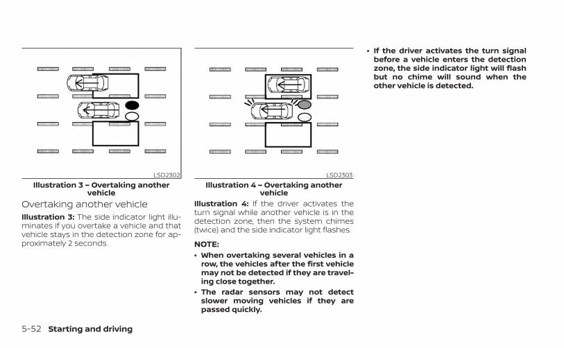
Overtaking another vehicleIllustration 3: The side indicator light illu-minates if you overtake a vehicle and thatvehicle stays in the detection zone for ap-proximately 2 seconds.
Illustration 4: If the driver activates theturn signal while another vehicle is in thedetection zone, then the system chimes(twice) and the side indicator light flashes.
NOTE:• When overtaking several vehicles in a
row, the vehicles after the first vehiclemay not be detected if they are travel-ing close together.
• The radar sensors may not detectslower moving vehicles if they arepassed quickly.
• If the driver activates the turn signalbefore a vehicle enters the detectionzone, the side indicator light will flashbut no chime will sound when theother vehicle is detected.
LSD2302Illustration 3 – Overtaking another
vehicle
LSD2303Illustration 4 – Overtaking another
vehicle
5-52 Starting and driving
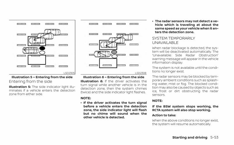
Entering from the sideIllustration 5: The side indicator light illu-minates if a vehicle enters the detectionzone from either side.
Illustration 6: If the driver activates theturn signal while another vehicle is in thedetection zone, then the system chimes(twice) and the side indicator light flashes.
NOTE:• If the driver activates the turn signal
before a vehicle enters the detectionzone, the side indicator light will flashbut no chime will sound when theother vehicle is detected.
• The radar sensors may not detect a ve-hicle which is traveling at about thesame speed as your vehicle when it en-ters the detection zone.
SYSTEM TEMPORARILYUNAVAILABLEWhen radar blockage is detected, the sys-tem will be deactivated automatically. The“Unavailable: Side Radar Obstruction”warning message will appear in the vehicleinformation display.The system is not available until the condi-tions no longer exist.The radar sensors may be blocked by tem-porary ambient conditions such as splash-ing water, mist or fog. The blocked condi-tion may also be caused by objects such asice, frost or dirt obstructing the radarsensors.
NOTE:
If the BSW system stops working, theRCTA system will also stop working.Action to take:When the above conditions no longer exist,the system will resume automatically.
LSD2305Illustration 5 – Entering from the side
LSD2308Illustration 6 – Entering from the side
Starting and driving 5-53
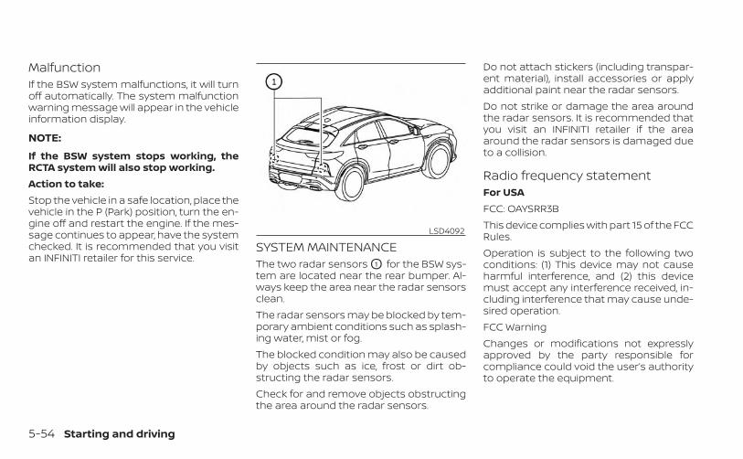
MalfunctionIf the BSW system malfunctions, it will turnoff automatically. The system malfunctionwarning message will appear in the vehicleinformation display.
NOTE:
If the BSW system stops working, theRCTA system will also stop working.Action to take:Stop the vehicle in a safe location, place thevehicle in the P (Park) position, turn the en-gine off and restart the engine. If the mes-sage continues to appear, have the systemchecked. It is recommended that you visitan INFINITI retailer for this service.
SYSTEM MAINTENANCEThe two radar sensors O1 for the BSW sys-tem are located near the rear bumper. Al-ways keep the area near the radar sensorsclean.The radar sensors may be blocked by tem-porary ambient conditions such as splash-ing water, mist or fog.The blocked condition may also be causedby objects such as ice, frost or dirt ob-structing the radar sensors.Check for and remove objects obstructingthe area around the radar sensors.
Do not attach stickers (including transpar-ent material), install accessories or applyadditional paint near the radar sensors.Do not strike or damage the area aroundthe radar sensors. It is recommended thatyou visit an INFINITI retailer if the areaaround the radar sensors is damaged dueto a collision.
Radio frequency statementFor USAFCC: OAYSRR3BThis device complies with part 15 of the FCCRules.Operation is subject to the following twoconditions: (1) This device may not causeharmful interference, and (2) this devicemust accept any interference received, in-cluding interference that may cause unde-sired operation.FCC WarningChanges or modifications not expresslyapproved by the party responsible forcompliance could void the user’s authorityto operate the equipment.
LSD4092
5-54 Starting and driving
For CanadaApplicable law: Canada 310This device contains licence-exempttransmitter(s)/receiver(s) that comply withInnovation, Science and Economic Develop-ment Canada’s licence-exempt RSS(s). Op-eration is subject to the following two condi-tions: (1) This device may not causeinterference. (2) This device must accept anyinterference, including interference that maycause undesired operation of the device.Radiofrequency radiation exposure infor-mation: This equipment complies with ra-diation exposure limits set forth for an un-controlled environment. This equipmentshould be installed and operated withminimum distance of 20 cm between theradiator and your body.L’émetteur/récepteur exempt de licencecontenu dans le présent appareil est con-forme aux CNR d’Innovation, Sciences etDéveloppement économique Canada ap-plicables aux appareils radio exempts delicence. L’exploitation est autorisée auxdeux conditions suivantes: (1) L’appareil nedoit pas produire de brouillage. (2)L’appareil doit accepter tout brouillage ra-dioélectrique subi, même si le brouillage
est susceptible d’en compromettre lefonctionnement.Informations sur l’exposition aux rayonne-ments radiofréquences: Cet équipementest conforme aux limites d’exposition auxrayonnements définies pour un environne-ment non contrôle. Cet équipement doitêtre installé et utilisé avec un minimum de20 cm de distance entre la source de ray-onnement et votre corps.
WARNING
Failure to follow the warnings and in-structions for proper use of the BSI sys-tem could result in serious injury ordeath.• The BSI system is not a replacement
for proper driving procedure and isnot designed to prevent contact withvehicles or objects. When changinglanes, always use the side and rearmirrors and turn and look in the di-rection you will move to ensure it issafe to change lanes. Never relysolely on the BSI system.
• There is a limitation to the detectioncapability of the radar or the sonar.Not every moving object or vehiclewill be detected. Using the BSI sys-tem under some road, ground, lanemarker, traffic or weather conditionscould lead to improper system op-eration. Always rely on your own op-eration to avoid accidents.
The BSI system helps alert the driver ofother vehicles in adjacent lanes whenchanging lanes and helps assist the driverto return the vehicle to the center of thetraveling lane.
BLIND SPOT INTERVENTION® (BSI) (ifso equipped)
Starting and driving 5-55

The BSI system uses radar sensors O2 in-stalled near the rear bumper to detectother vehicles in an adjacent lane. In addi-tion to the radar sensors, the BSI systemuses a camera O1 installed behind thewindshield to monitor the lane markers ofyour traveling lane.The radar sensors can detect vehicles oneither side of your vehicle within the detec-tion zone shown as illustrated. This detec-tion zone starts from the outside mirror ofyour vehicle and extends approximately 10ft (3.0 m) sideways.
LSD4093 SSD1030Detection zone
5-56 Starting and driving

BSI SYSTEM OPERATION1. Side indicator light
2. BSW indicator
3. BSI ON indicator
4. ProPILOT Assist switch (for vehicles withProPILOT Assist)
5. Dynamic driver assistance switch (forvehicles without ProPILOT Assist)
LSD4154
Starting and driving 5-57
The BSI system operates above approxi-mately 37mph (60 km/h).If the radar sensors detect a vehicle in thedetection zone, the side indicator light (1)illuminates. If the turn signal is then acti-vated, the system chimes (twice) and theside indicator light flashes. The side indica-tor light continues to flash until the de-tected vehicle leaves the detection zone.If the BSI system is on and your vehicleapproaches a lane marker while anothervehicle is in the detection zone, the systemchimes (three times) and the side indicatorlight flashes. The BSI system activates tohelp return the vehicle back to the center ofthe driving lane. The BSI system operatesregardless of turn signal usage.
NOTE:• BSI warning and system application
will only be activated if the side indica-tor light is already illuminated whenyour vehicle approaches a lane marker.If another vehicle comes into the de-tection zone after your vehicle hascrossed a lane marker, no BSI warningor system application will be activated.For additional information, see “BSIdriving situations” (P. 5-61 ).
• The BSI system is typically activatedearlier than the Lane Departure Pre-vention (LDP) system when your ve-hicle is approaching a lane marker.
The BSI system turns on when the ProPI-LOT Assist switch (for vehicles with ProPI-LOT Assist) on the steering wheel or Dy-namic driver assistance switch (forvehicles without ProPILOT Assist), is pushedwhen the “Blind Spot Intervention” is en-abled in the “Driver Assistance” menu in thelower display. The BSI ON indicator on theinstrument panel illuminates when the BSIsystem is turned on. The BSI system pro-vides a chime and turns on or flashes theside indicator light even if the BSW systemis off.
5-58 Starting and driving
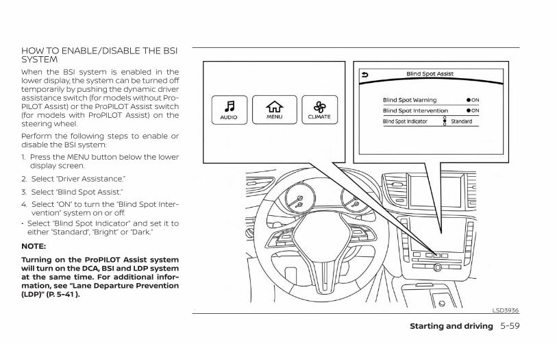
HOW TO ENABLE/DISABLE THE BSISYSTEMWhen the BSI system is enabled in thelower display, the system can be turned offtemporarily by pushing the dynamic driverassistance switch (for models without Pro-PILOT Assist) or the ProPILOT Assist switch(for models with ProPILOT Assist) on thesteering wheel.Perform the following steps to enable ordisable the BSI system:1. Press the MENU button below the lower
display screen.
2. Select “Driver Assistance.”
3. Select “Blind Spot Assist.”4. Select “ON” to turn the “Blind Spot Inter-
vention” system on or off.• Select “Blind Spot Indicator” and set it to
either “Standard”, “Bright” or “Dark.”
NOTE:
Turning on the ProPILOT Assist systemwill turn on the DCA, BSI and LDP systemat the same time. For additional infor-mation, see “Lane Departure Prevention(LDP)” (P. 5-41 ).
LSD3936
Starting and driving 5-59
BSI SYSTEM LIMITATIONSWARNING
Listed below are the system limitationsfor the BSI system. Failure to operatethe vehicle in accordance with thesesystem limitations could result in seri-ous injury or death.• The BSI system cannot detect all ve-
hicles under all conditions.• The radar sensors may not be able to
detect and activate BSI when certainobjects are present such as:– Pedestrians, bicycles, or animals.– Vehicles such as motorcycles, low
height vehicles, or high groundclearance vehicles.
– Vehicles remaining in the detec-tion zone when you acceleratefrom a stop. For additional infor-mation, see “BSI driving situa-tions” (P. 5-61
– Oncoming vehicles.– A vehicle merging into an adjacent
lane at a speed approximately thesame as your vehicle. For addi-tional information, see “BSI driv-ing situations” (P. 5-61
– A vehicle approaching rapidlyfrom behind. For additional infor-mation, see “BSI driving situa-tions” (P. 5-61
– A vehicle which your vehicle over-takes rapidly. For additional infor-mation, see “BSI driving situa-tions” (P. 5-61
– A vehicle that passes through thedetection zone quickly.
• The radar sensor’s detection zone isdesigned based on a standard lanewidth. When driving in a wider lane,the radar sensors may not detect ve-hicles in an adjacent lane. When driv-ing in a narrow lane, the radar sen-sors may detect vehicles driving twolanes away.
• The radar sensors are designed to ig-nore most stationary objects; how-ever, objects such as guardrails,walls, foliage and parked vehiclesmay occasionally be detected. This isa normal driving condition.
• The following conditions may reducethe ability of the radar to detect othervehicles:– Severe weather– Road spray
– Ice/frost/dirt build-up on thevehicle
• Do not attach stickers (includingtransparent material), install acces-sories or apply additional paint nearthe radar sensors. These conditionsmay reduce the ability of the radar todetect other vehicles.
• The camera may not detect lanemarkers in the following situationsand the BSI system may not operateproperly:– On roads where there are multiple
parallel lane markers; lane mark-ers that are faded or not paintedclearly; yellow painted lane mark-ers; non-standard lane markers;lane markers covered with water,dirt, snow, etc.
– On roads where discontinued lanemarkers are still detectable.
– On roads where there are sharpcurves.
– On roads where there are sharplycontrasting objects, such as shad-ows, snow, water, wheel ruts,seams or lines remaining afterroad repairs.
5-60 Starting and driving
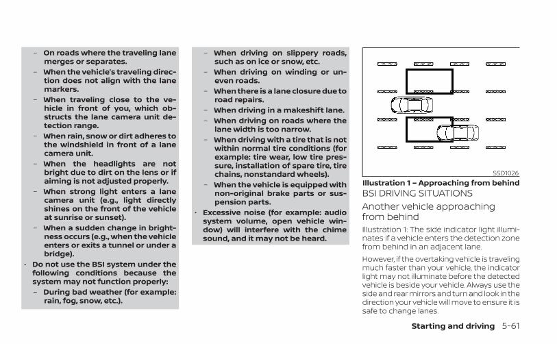
– On roads where the traveling lanemerges or separates.
– When the vehicle’s traveling direc-tion does not align with the lanemarkers.
– When traveling close to the ve-hicle in front of you, which ob-structs the lane camera unit de-tection range.
– When rain, snow or dirt adheres tothe windshield in front of a lanecamera unit.
– When the headlights are notbright due to dirt on the lens or ifaiming is not adjusted properly.
– When strong light enters a lanecamera unit (e.g., light directlyshines on the front of the vehicleat sunrise or sunset).
– When a sudden change in bright-ness occurs (e.g., when the vehicleenters or exits a tunnel or under abridge).
• Do not use the BSI system under thefollowing conditions because thesystem may not function properly:– During bad weather (for example:
rain, fog, snow, etc.).
– When driving on slippery roads,such as on ice or snow, etc.
– When driving on winding or un-even roads.
– When there is a lane closure due toroad repairs.
– When driving in a makeshift lane.– When driving on roads where the
lane width is too narrow.– When driving with a tire that is not
within normal tire conditions (forexample: tire wear, low tire pres-sure, installation of spare tire, tirechains, nonstandard wheels).
– When the vehicle is equipped withnon-original brake parts or sus-pension parts.
• Excessive noise (for example: audiosystem volume, open vehicle win-dow) will interfere with the chimesound, and it may not be heard.
BSI DRIVING SITUATIONSAnother vehicle approachingfrom behindIllustration 1: The side indicator light illumi-nates if a vehicle enters the detection zonefrom behind in an adjacent lane.However, if the overtaking vehicle is travelingmuch faster than your vehicle, the indicatorlight may not illuminate before the detectedvehicle is beside your vehicle. Always use theside and rear mirrors and turn and look in thedirection your vehicle will move to ensure it issafe to change lanes.
SSD1026Illustration 1 – Approaching from behind
Starting and driving 5-61
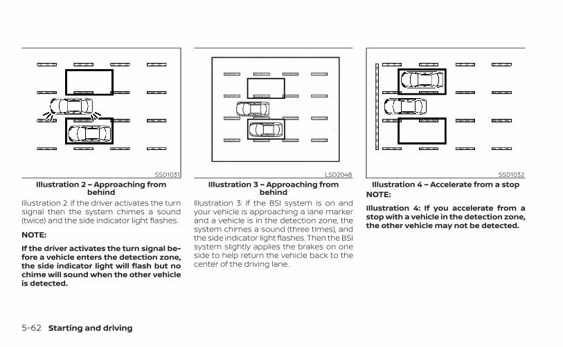
Illustration 2: If the driver activates the turnsignal then the system chimes a sound(twice) and the side indicator light flashes.
NOTE:
If the driver activates the turn signal be-fore a vehicle enters the detection zone,the side indicator light will flash but nochime will sound when the other vehicleis detected.
Illustration 3: If the BSI system is on andyour vehicle is approaching a lane markerand a vehicle is in the detection zone, thesystem chimes a sound (three times), andthe side indicator light flashes. Then the BSIsystem slightly applies the brakes on oneside to help return the vehicle back to thecenter of the driving lane.
NOTE:
Illustration 4: If you accelerate from astop with a vehicle in the detection zone,the other vehicle may not be detected.
SSD1031Illustration 2 – Approaching from
behind
LSD2048Illustration 3 – Approaching from
behind
SSD1032Illustration 4 – Accelerate from a stop
5-62 Starting and driving
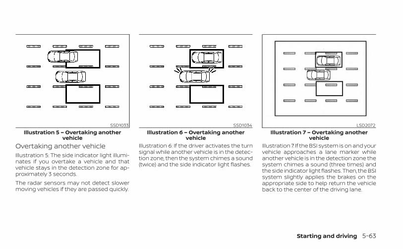
Overtaking another vehicleIllustration 5: The side indicator light illumi-nates if you overtake a vehicle and thatvehicle stays in the detection zone for ap-proximately 3 seconds.The radar sensors may not detect slowermoving vehicles if they are passed quickly.
Illustration 6: If the driver activates the turnsignal while another vehicle is in the detec-tion zone, then the system chimes a sound(twice) and the side indicator light flashes.
Illustration 7: If the BSI system is on and yourvehicle approaches a lane marker whileanother vehicle is in the detection zone thesystem chimes a sound (three times) andthe side indicator light flashes. Then, the BSIsystem slightly applies the brakes on theappropriate side to help return the vehicleback to the center of the driving lane.
SSD1033Illustration 5 – Overtaking another
vehicle
SSD1034Illustration 6 – Overtaking another
vehicle
LSD2072Illustration 7 – Overtaking another
vehicle
Starting and driving 5-63
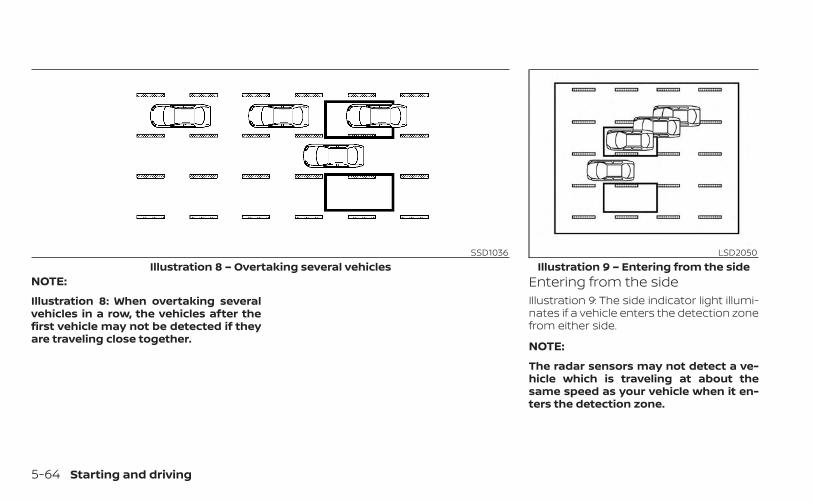
NOTE:
Illustration 8: When overtaking severalvehicles in a row, the vehicles after thefirst vehicle may not be detected if theyare traveling close together.
Entering from the sideIllustration 9: The side indicator light illumi-nates if a vehicle enters the detection zonefrom either side.
NOTE:
The radar sensors may not detect a ve-hicle which is traveling at about thesame speed as your vehicle when it en-ters the detection zone.
SSD1036Illustration 8 – Overtaking several vehicles
LSD2050Illustration 9 – Entering from the side
5-64 Starting and driving
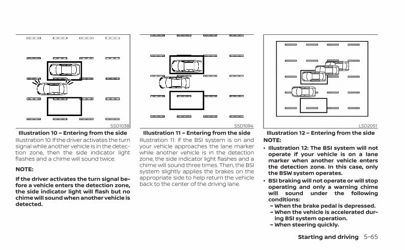
Illustration 10: If the driver activates the turnsignal while another vehicle is in the detec-tion zone, then the side indicator lightflashes and a chime will sound twice.
NOTE:
If the driver activates the turn signal be-fore a vehicle enters the detection zone,the side indicator light will flash but nochime will sound when another vehicle isdetected.
Illustration 11: If the BSI system is on andyour vehicle approaches the lane markerwhile another vehicle is in the detectionzone, the side indicator light flashes and achime will sound three times. Then, the BSIsystem slightly applies the brakes on theappropriate side to help return the vehicleback to the center of the driving lane.
NOTE:• Illustration 12: The BSI system will not
operate if your vehicle is on a lanemarker when another vehicle entersthe detection zone. In this case, onlythe BSW system operates.
• BSI braking will not operate or will stopoperating and only a warning chimewill sound under the followingconditions:– When the brake pedal is depressed.– When the vehicle is accelerated dur-
ing BSI system operation.– When steering quickly.
SSD1038Illustration 10 – Entering from the side
SSD1094Illustration 11 – Entering from the side
LSD2051Illustration 12 – Entering from the side
Starting and driving 5-65

– When the ICC, DCA, PFCW or FEB withPedestrian Detection warningssound.
– When the hazard warning flashersare operated.
– When driving on a curve at a highspeed.
SYSTEM TEMPORARILYUNAVAILABLEWhen any of the following messages ap-pear on the vehicle information display, achime will sound and the BSI system will beturned off automatically.• “Not Available Poor Road Conditions”:
When the VDC system (except tractioncontrol system function) or ABS operates.
• “Currently Not Available”:When the VDC system is turned off.
• “Not Available: High Camera Temp”:When the camera detects that the inte-rior temperature is high (over approxi-mately 104°F [40°C]).
• “Unavailable: Side Radar Obstruction”:When side radar blockage is detected.
Turn off the BSI system and turn it on againwhen the above conditions no longer exist.
SYSTEM MALFUNCTIONWhen the BSI system malfunctions, it will beturned off automatically, a chime will soundand the warning message will appear inthe vehicle information display.Action to take:Stop the vehicle in a safe location, place thevehicle in the P (Park) position, turn the en-gine off and restart the engine. If the warn-ing light (orange) continues to illuminate,have the system checked. It is recom-mended that you visit an INFINITI retailer forthis service.
SYSTEM MAINTENANCEThe lane camera unit O1 for the BSI systemis located above the inside mirror. The tworadar sensors O2 for the BSI system arelocated near the rear bumper. To keep theproper operation of the BSI system andprevent a system malfunction, be sure toobserve the following:• Always keep the windshield and the area
near the radar sensors clean.
LSD4093
5-66 Starting and driving
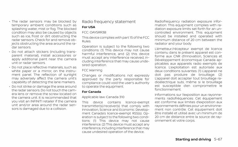
• The radar sensors may be blocked bytemporary ambient conditions such assplashing water, mist or fog. The blockedcondition may also be caused by objectssuch as ice, frost or dirt obstructing theradar sensors. Check for and remove ob-jects obstructing the area around the ra-dar sensors.
• Do not attach stickers (including trans-parent material), install accessories orapply additional paint near the cameraunit or radar sensors.
• Do not place reflective materials, such aswhite paper or a mirror, on the instru-ment panel. The reflection of sunlightmay adversely affect the camera unit’scapability of detecting the lane markers.
• Do not strike or damage the area aroundthe radar sensors. Do not touch the cam-era lens or remove the screw located onthe camera unit. It is recommended thatyou visit an INFINITI retailer if the cameraunit and/or area around the radar sen-sors is damaged due to a collision.
Radio frequency statementFor USAFCC: OAYSRR3BThis device complies with part 15 of the FCCRules.Operation is subject to the following twoconditions: (1) This device may not causeharmful interference, and (2) this devicemust accept any interference received, in-cluding interference that may cause unde-sired operation.FCC WarningChanges or modifications not expresslyapproved by the party responsible forcompliance could void the user’s authorityto operate the equipment.For CanadaApplicable law: Canada 310This device contains licence-exempttransmitter(s)/receiver(s) that comply withInnovation, Science and Economic Develop-ment Canada’s licence-exempt RSS(s). Op-eration is subject to the following two condi-tions: (1) This device may not causeinterference. (2) This device must accept anyinterference, including interference that maycause undesired operation of the device.
Radiofrequency radiation exposure infor-mation: This equipment complies with ra-diation exposure limits set forth for an un-controlled environment. This equipmentshould be installed and operated withminimum distance of 20 cm between theradiator and your body.L’émetteur/récepteur exempt de licencecontenu dans le présent appareil est con-forme aux CNR d’Innovation, Sciences etDéveloppement économique Canada ap-plicables aux appareils radio exempts delicence. L’exploitation est autorisée auxdeux conditions suivantes: (1) L’appareil nedoit pas produire de brouillage. (2)L’appareil doit accepter tout brouillage ra-dioélectrique subi, même si le brouillageest susceptible d’en compromettre lefonctionnement.Informations sur l’exposition aux rayonne-ments radiofréquences: Cet équipementest conforme aux limites d’exposition auxrayonnements définies pour un environne-ment non contrôle. Cet équipement doitêtre installé et utilisé avec un minimum de20 cm de distance entre la source de ray-onnement et votre corps.
Starting and driving 5-67
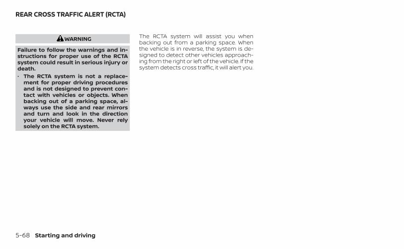
WARNING
Failure to follow the warnings and in-structions for proper use of the RCTAsystem could result in serious injury ordeath.• The RCTA system is not a replace-
ment for proper driving proceduresand is not designed to prevent con-tact with vehicles or objects. Whenbacking out of a parking space, al-ways use the side and rear mirrorsand turn and look in the directionyour vehicle will move. Never relysolely on the RCTA system.
The RCTA system will assist you whenbacking out from a parking space. Whenthe vehicle is in reverse, the system is de-signed to detect other vehicles approach-ing from the right or left of the vehicle. If thesystem detects cross traffic, it will alert you.
REAR CROSS TRAFFIC ALERT (RCTA)
5-68 Starting and driving

RCTA SYSTEM OPERATION1. Side indicator lightThe RCTA system can help alert the driverof an approaching vehicle when the driveris backing out of a parking space.When the shift position is in R (Reverse) andthe vehicle speed is less than approxi-mately 5 mph (8 km/h), the RCTA system isoperational.If the radar detects an approaching vehiclefrom either side, the system chimes (once)and the side indicator light flashes on theside the vehicle is approaching from.
LSD3608
Starting and driving 5-69
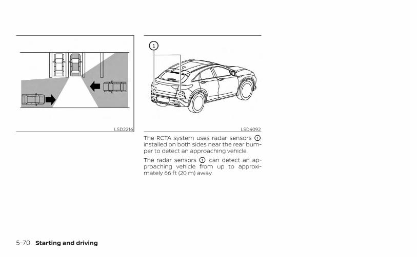
The RCTA system uses radar sensors O1
installed on both sides near the rear bum-per to detect an approaching vehicle.The radar sensors O1 can detect an ap-proaching vehicle from up to approxi-mately 66 ft (20 m) away.
LSD2216 LSD4092
5-70 Starting and driving
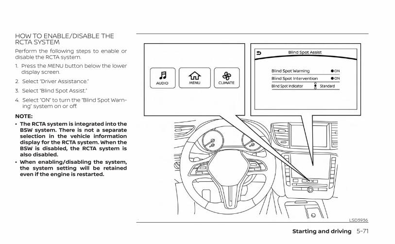
HOW TO ENABLE/DISABLE THERCTA SYSTEMPerform the following steps to enable ordisable the RCTA system.1. Press the MENU button below the lower
display screen.
2. Select “Driver Assistance.”
3. Select “Blind Spot Assist.”
4. Select “ON” to turn the “Blind Spot Warn-ing” system on or off.
NOTE:• The RCTA system is integrated into the
BSW system. There is not a separateselection in the vehicle informationdisplay for the RCTA system. When theBSW is disabled, the RCTA system isalso disabled.
• When enabling/disabling the system,the system setting will be retainedeven if the engine is restarted.
LSD3936
Starting and driving 5-71

RCTA SYSTEM LIMITATIONS WARNING
Listed below are the system limitationsfor the RCTA system. Failure to operatethe vehicle in accordance with thesesystem limitations could result in seri-ous injury or death.
• Always check surroundings and turnto check what is behind you beforebacking up. The radar sensors detectapproaching (moving) vehicles. Theradar sensors cannot detect everyobject such as:– Pedestrians, bicycles, motor-
cycles, animals or child-operatedtoy vehicles
– A vehicle that is passing at speedsgreater than approximately 19mph (30 km/h)
– A vehicle that is passing at speedslower than approximately 5 mph(8 km/h)
• The radar sensors may not detectapproaching vehicles in certain situ-ations:– Illustration OA : When a vehicle
parked next to you obstructs thebeam of the radar sensor.
– Illustration OB : When the vehicle isparked in an angled parkingspace.
– Illustration OC : When the vehicle isparked on inclined ground.
– Illustration OD : When an ap-proaching vehicle turns into yourvehicle's parking lot aisle.
LSD3195
5-72 Starting and driving

– Illustration OE : When the angleformed by your vehicle and ap-proaching vehicle is small.
• The following conditions may reducethe ability of the radar to detect othervehicles:– Severe weather– Road spray– Ice/frost/snow/dirt build-up on
the vehicle• Do not attach stickers (including
transparent material), install acces-sories or apply additional paint nearthe radar sensors. These conditionsmay reduce the ability of the radar todetect other vehicles.
• Excessive noise (e.g., audio systemvolume, open vehicle window) will in-terfere with the chime sound, and itmay not be heard.
NOTE:
In the case of several vehicles approach-ing in a row (Illustration 1) or in the oppo-site direction (Illustration 2), a chime maynot be sounded by the RCTA system af-ter the first vehicle passes the sensors.
LSD2043Illustration 1
LSD2044Illustration 2
Starting and driving 5-73
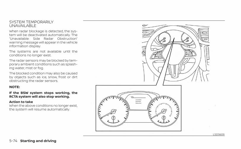
SYSTEM TEMPORARILYUNAVAILABLEWhen radar blockage is detected, the sys-tem will be deactivated automatically. The“Unavailable: Side Radar Obstruction”warning message will appear in the vehicleinformation display.The systems are not available until theconditions no longer exist.The radar sensors may be blocked by tem-porary ambient conditions such as splash-ing water, mist or fog.The blocked condition may also be causedby objects such as ice, snow, frost or dirtobstructing the radar sensors.
NOTE:
If the BSW system stops working, theRCTA system will also stop working.Action to takeWhen the above conditions no longer exist,the system will resume automatically.
LSD3609
5-74 Starting and driving

MalfunctionWhen the RCTA system malfunctions, it willturn off automatically. The system mal-function warning message will appear inthe vehicle information display.
NOTE:
If the BSW system stops working, theRCTA system will also stop working.Action to takeStop the vehicle in a safe location, place thevehicle in the P (Park) position, turn the en-gine off and restart the engine. If the mes-sage continues to appear, have the systemchecked. It is recommended that you visitan INFINITI retailer for this service. SYSTEM MAINTENANCE
The two radar sensors O1 for the BSW andRCTA systems are located near the rearbumper. Always keep the area near the ra-dar sensors clean.The radar sensors may be blocked by tem-porary ambient conditions such as splash-ing water, mist or fog.The blocked condition may also be causedby objects such as ice, frost or dirt ob-structing the radar sensors.Check for and remove objects obstructingthe area around the radar sensors.
Do not attach stickers (including transpar-ent material), install accessories or applyadditional paint near the radar sensors.Do not strike or damage the area aroundthe radar sensors. It is recommended thatyou visit an INFINITI retailer if the areaaround the radar sensors is damaged dueto a collision.
Radio frequency statementFor USAFCC: OAYSRR3BThis device complies with part 15 of the FCCRules.Operation is subject to the following twoconditions: (1) This device may not causeharmful interference, and (2) this devicemust accept any interference received, in-cluding interference that may cause unde-sired operation.FCC WarningChanges or modifications not expresslyapproved by the party responsible forcompliance could void the user’s authorityto operate the equipment.
LSD4092
Starting and driving 5-75
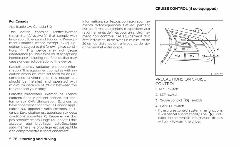
For CanadaApplicable law: Canada 310This device contains licence-exempttransmitter(s)/receiver(s) that comply withInnovation, Science and Economic Develop-ment Canada’s licence-exempt RSS(s). Op-eration is subject to the following two condi-tions: (1) This device may not causeinterference. (2) This device must accept anyinterference, including interference that maycause undesired operation of the device.Radiofrequency radiation exposure infor-mation: This equipment complies with ra-diation exposure limits set forth for an un-controlled environment. This equipmentshould be installed and operated withminimum distance of 20 cm between theradiator and your body.L’émetteur/récepteur exempt de licencecontenu dans le présent appareil est con-forme aux CNR d’Innovation, Sciences etDéveloppement économique Canada appli-cables aux appareils radio exempts de li-cence. L’exploitation est autorisée aux deuxconditions suivantes: (1) L’appareil ne doitpas produire de brouillage. (2) L’appareil doitaccepter tout brouillage radioélectriquesubi, même si le brouillage est susceptibled’en compromettre le fonctionnement.
Informations sur l’exposition aux rayonne-ments radiofréquences: Cet équipementest conforme aux limites d’exposition auxrayonnements définies pour un environne-ment non contrôle. Cet équipement doitêtre installé et utilisé avec un minimum de20 cm de distance entre la source de ray-onnement et votre corps.
PRECAUTIONS ON CRUISECONTROL1. RES+ switch
2. SET– switch
3. Cruise control switch
4. CANCEL switch• If the cruise control system malfunctions,
it will cancel automatically. The indi-cator in the vehicle information displaywill blink to warn the driver.
LSD2929
CRUISE CONTROL (if so equipped)
5-76 Starting and driving
• If the engine coolant temperature be-comes excessively high, the cruise con-trol system will be canceledautomatically.
• If the indicator blinks, turn the Cruisecontrol switch off and have the sys-tem checked. It is recommended thatyou visit an INFINITI retailer for thisservice.
• The indicator may sometimes blinkwhen the Cruise control switch isturned on while pushing the RES+, SET– orCANCEL switch. To properly set the cruisecontrol system, perform the steps below.
WARNING
Do not use the cruise control when driv-ing under the following conditions:• When it is not possible to keep the
vehicle at a set speed• In heavy traffic or in traffic that varies
in speed• On winding or hilly roads• On slippery roads (rain, snow, ice,
etc.)• In very windy areasDoing so could cause a loss of vehiclecontrol and result in an accident.
CRUISE CONTROL OPERATIONSThe cruise control allows driving at a speedbetween 25 - 89 mph (40 - 144 km/h) with-out keeping your foot on the acceleratorpedal.To turn on the cruise control, push theCruise control switch on. Theindicator in the vehicle information displaywill illuminate.To set cruising speed, accelerate the ve-hicle to the desired speed, push the SET–switch and release it. The indicator inthe vehicle information display will illumi-nate. Take your foot off the acceleratorpedal. Your vehicle maintains the setspeed.• To pass another vehicle, depress the ac-
celerator pedal. When you release thepedal, the vehicle returns to the previ-ously set speed.
• The vehicle may not maintain the setspeed when going up or down steep hills.If this happens, drive without the cruisecontrol.
To cancel the preset speed, use one of thefollowing three methods:• Push the CANCEL switch; the indica-
tor in the vehicle information displaygoes out.
• Tap the brake pedal; the indicatorgoes out.
• Push the Cruise control switch off.The indicator in the vehicle informa-tion display go out.
The cruise control is automatically can-celed and the indicator in the vehicleinformation display goes out if:• You depress the brake pedal while push-
ing the RES+ or SET– switch. The presetspeed is deleted from memory.
• The vehicle slows down more than 8 mph(13 km/h) below the set speed.
• You move the shift lever to N (Neutral).To reset at a faster cruising speed, useone of the following three methods:• Depress the accelerator pedal. When the
vehicle attains the desired speed, pushand release the SET– switch.
• Push and hold the RES+ switch. When thevehicle attains the speed you desire, re-lease the switch.
• Push and release the RES+ switch. Eachtime you do this, the set speed increasesby about 1 mph (1.6 km/h).
Starting and driving 5-77
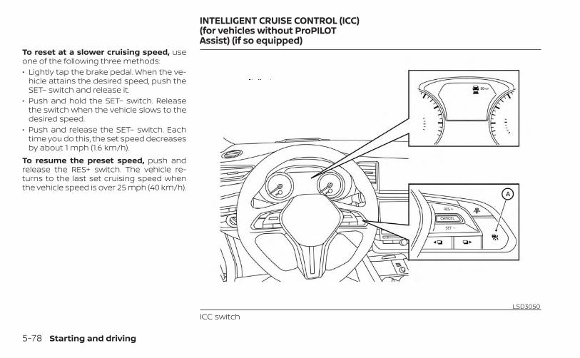
To reset at a slower cruising speed, useone of the following three methods:• Lightly tap the brake pedal. When the ve-
hicle attains the desired speed, push theSET– switch and release it.
• Push and hold the SET– switch. Releasethe switch when the vehicle slows to thedesired speed.
• Push and release the SET– switch. Eachtime you do this, the set speed decreasesby about 1 mph (1.6 km/h).
To resume the preset speed, push andrelease the RES+ switch. The vehicle re-turns to the last set cruising speed whenthe vehicle speed is over 25 mph (40 km/h).
LSD3050ICC switch
INTELLIGENT CRUISE CONTROL (ICC)(for vehicles without ProPILOTAssist) (if so equipped)
5-78 Starting and driving

WARNING
Failure to follow the warnings and in-structions for proper use of the ICC sys-tem could result in serious injury ordeath.• The ICC system is only an aid to assist
the driver and is not a collision warn-ing or avoidance device. It is the driv-er’s responsibility to stay alert, drivesafely, and be in control of the vehicleat all times.
• Always observe posted speed limitsand do not set the speed over them.
• Always drive carefully and atten-tively when using the ICC system.Read and understand the Owner’sManual thoroughly before using theICC system. To avoid serious injury ordeath, do not rely on the system toprevent accidents or to control thevehicle’s speed in emergency situa-tions. Do not use the ICC system ex-cept in appropriate road and trafficconditions.
• In the conventional (fixed speed)cruise control mode, a warningchime will not sound to warn you ifyou are too close to the vehicleahead. Pay special attention to thedistance between your vehicle andthe vehicle ahead of you or a collisioncould occur.
The ICC system maintains a selected dis-tance from the vehicle in front of you withinthe speed range of 0 to 90 mph (0 to 144km/h) up to the set speed. The set speedcan be selected by the driver between 20 to90 mph (30 to 144 km/h).The vehicle travels at a set speed when theroad ahead is clear.The ICC system can be set to one of twocruise control modes:• Vehicle-to-vehicle distance control
mode: For maintaining a selected dis-tance between your vehicle and the ve-hicle in front of you up to the preset speed
• Conventional (fixed speed) cruise con-trol mode: For cruising at a preset speed
Push the ICC switch OA to choose thecruise control mode between the vehicle-to-vehicle distance control mode and theconventional (fixed speed) cruise controlmode.Once a control mode is activated, it cannotbe changed to the other cruise controlmode. To change the mode, push the ICCswitch OA once to turn the system off. Thenpush the ICC switch OA again to turn thesystem back on and select the desiredcruise control mode.Always confirm the setting in the ICC sys-tem display.For the vehicle-to-vehicle distance controlmode, see “Vehicle-to-vehicle distancecontrol mode” (P. 5-80).For the conventional (fixed speed) cruisecontrol mode, see “Conventional (fixedspeed) cruise control mode” (P. 5-97).
Starting and driving 5-79

HOW TO SELECT THE CRUISECONTROL MODESelecting the vehicle-to-vehicle dis-tance control mode: To choose thevehicle-to-vehicle distance control modeO1 , quickly push and release the ICC switchOA .
Selecting the conventional (fixed speed)cruise control mode: To choose the con-ventional (fixed speed) cruise control modeO2 , push and hold the ICC switch OA forlonger than approximately 1.5 seconds. Foradditional information, see “Conventional(fixed speed) cruise control mode” (P. 5-97).
VEHICLE-TO-VEHICLE DISTANCECONTROL MODEIn the vehicle-to-vehicle distance controlmode, the ICC system automatically main-tains a selected distance from the vehicletraveling in front of you according to thatvehicle’s speed (up to the set speed), or atthe set speed when the road ahead is clear.The ICC system is intended to enhance theoperation of the vehicle when following avehicle traveling in the same lane anddirection.
LSD4246 LSD4094
5-80 Starting and driving
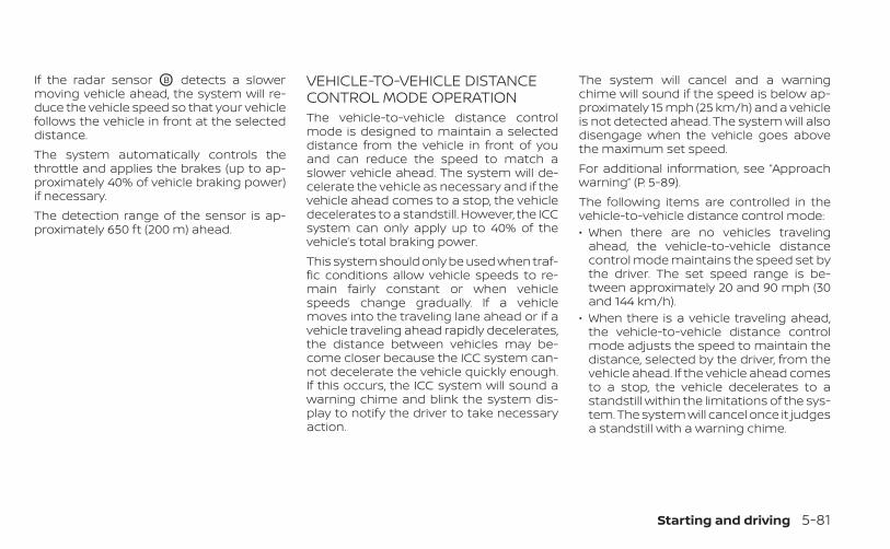
If the radar sensor OB detects a slowermoving vehicle ahead, the system will re-duce the vehicle speed so that your vehiclefollows the vehicle in front at the selecteddistance.The system automatically controls thethrottle and applies the brakes (up to ap-proximately 40% of vehicle braking power)if necessary.The detection range of the sensor is ap-proximately 650 ft (200 m) ahead.
VEHICLE-TO-VEHICLE DISTANCECONTROL MODE OPERATIONThe vehicle-to-vehicle distance controlmode is designed to maintain a selecteddistance from the vehicle in front of youand can reduce the speed to match aslower vehicle ahead. The system will de-celerate the vehicle as necessary and if thevehicle ahead comes to a stop, the vehicledecelerates to a standstill. However, the ICCsystem can only apply up to 40% of thevehicle’s total braking power.This system should only be used when traf-fic conditions allow vehicle speeds to re-main fairly constant or when vehiclespeeds change gradually. If a vehiclemoves into the traveling lane ahead or if avehicle traveling ahead rapidly decelerates,the distance between vehicles may be-come closer because the ICC system can-not decelerate the vehicle quickly enough.If this occurs, the ICC system will sound awarning chime and blink the system dis-play to notify the driver to take necessaryaction.
The system will cancel and a warningchime will sound if the speed is below ap-proximately 15 mph (25 km/h) and a vehicleis not detected ahead. The system will alsodisengage when the vehicle goes abovethe maximum set speed.For additional information, see “Approachwarning” (P. 5-89).The following items are controlled in thevehicle-to-vehicle distance control mode:• When there are no vehicles traveling
ahead, the vehicle-to-vehicle distancecontrol mode maintains the speed set bythe driver. The set speed range is be-tween approximately 20 and 90 mph (30and 144 km/h).
• When there is a vehicle traveling ahead,the vehicle-to-vehicle distance controlmode adjusts the speed to maintain thedistance, selected by the driver, from thevehicle ahead. If the vehicle ahead comesto a stop, the vehicle decelerates to astandstill within the limitations of the sys-tem. The system will cancel once it judgesa standstill with a warning chime.
Starting and driving 5-81
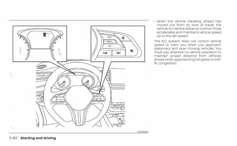
• When the vehicle traveling ahead hasmoved out from its lane of travel, thevehicle-to-vehicle distance control modeaccelerates and maintains vehicle speedup to the set speed.
The ICC system does not control vehiclespeed or warn you when you approachstationary and slow moving vehicles. Youmust pay attention to vehicle operation tomaintain proper distance from vehiclesahead when approaching toll gates or traf-fic congestion.
LSD3052
5-82 Starting and driving

When driving on the freeway at a set speedand approaching a slower traveling vehicleahead, the ICC system will adjust the speedto maintain the distance, selected by thedriver, from the vehicle ahead. If the vehicleahead changes lanes or exits the freeway,the ICC system will accelerate and main-tain the speed up to the set speed. Payattention to the driving operation to main-tain control of the vehicle as it acceleratesto the set speed.The vehicle may not maintain the setspeed on winding or hilly roads. If this oc-curs, you will have to manually control thevehicle speed.
Normally when controlling the distance toa vehicle ahead, this system automaticallyaccelerates or decelerates your vehicle ac-cording to the speed of the vehicle ahead.Depress the accelerator to properly accel-erate your vehicle when acceleration is re-quired for a lane change. Depress the brakepedal when deceleration is required tomaintain a safe distance to the vehicleahead due to its sudden braking or if avehicle cuts in. Always stay alert when us-ing the ICC system.
VEHICLE-TO-VEHICLE DISTANCECONTROL MODE SWITCHESThe system is operated by the ICC switchand four control switches, all mounted onthe steering wheel.1. RES+ switch:
Resumes set speed or increases speedincrementally.
SSD0254 LSD2934
Starting and driving 5-83
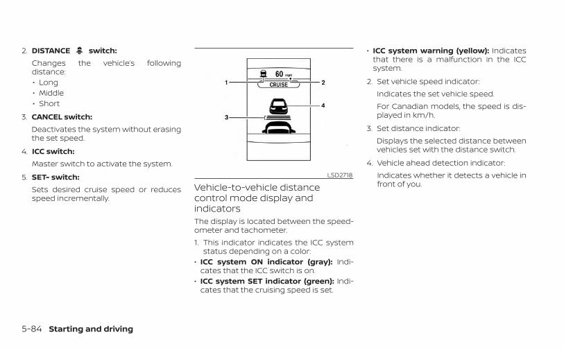
2. DISTANCE switch:Changes the vehicle’s followingdistance:• Long• Middle• Short
3. CANCEL switch:Deactivates the system without erasingthe set speed.
4. ICC switch:Master switch to activate the system.
5. SET- switch:Sets desired cruise speed or reducesspeed incrementally.
Vehicle-to-vehicle distancecontrol mode display andindicatorsThe display is located between the speed-ometer and tachometer.1. This indicator indicates the ICC system
status depending on a color:• ICC system ON indicator (gray): Indi-
cates that the ICC switch is on.• ICC system SET indicator (green): Indi-
cates that the cruising speed is set.
• ICC system warning (yellow): Indicatesthat there is a malfunction in the ICCsystem.
2. Set vehicle speed indicator:Indicates the set vehicle speed.For Canadian models, the speed is dis-played in km/h.
3. Set distance indicator:Displays the selected distance betweenvehicles set with the distance switch.
4. Vehicle ahead detection indicator:Indicates whether it detects a vehicle infront of you.
LSD2718
5-84 Starting and driving
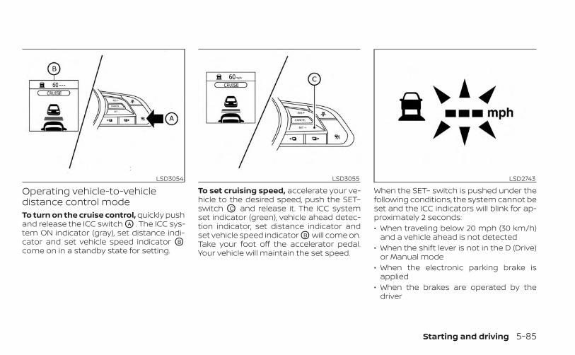
Operating vehicle-to-vehicledistance control modeTo turn on the cruise control, quickly pushand release the ICC switch OA . The ICC sys-tem ON indicator (gray), set distance indi-cator and set vehicle speed indicator OB
come on in a standby state for setting.
To set cruising speed, accelerate your ve-hicle to the desired speed, push the SET–switch OC and release it. The ICC systemset indicator (green), vehicle ahead detec-tion indicator, set distance indicator andset vehicle speed indicator OB will come on.Take your foot off the accelerator pedal.Your vehicle will maintain the set speed.
When the SET– switch is pushed under thefollowing conditions, the system cannot beset and the ICC indicators will blink for ap-proximately 2 seconds:• When traveling below 20 mph (30 km/h)
and a vehicle ahead is not detected• When the shift lever is not in the D (Drive)
or Manual mode• When the electronic parking brake is
applied• When the brakes are operated by the
driver
LSD3054 LSD3055 LSD2743
Starting and driving 5-85
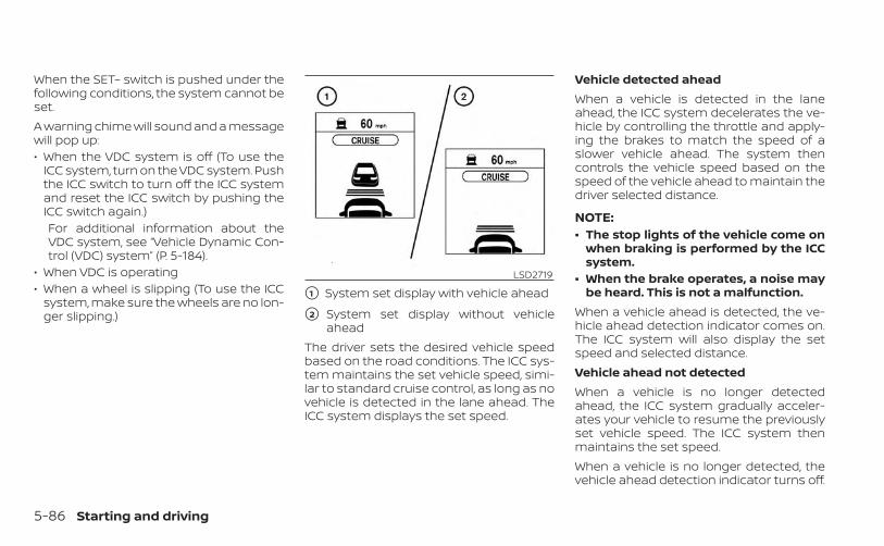
When the SET– switch is pushed under thefollowing conditions, the system cannot beset.A warning chime will sound and a messagewill pop up:• When the VDC system is off (To use the
ICC system, turn on the VDC system. Pushthe ICC switch to turn off the ICC systemand reset the ICC switch by pushing theICC switch again.)For additional information about theVDC system, see “Vehicle Dynamic Con-trol (VDC) system” (P. 5-184).
• When VDC is operating• When a wheel is slipping (To use the ICC
system, make sure the wheels are no lon-ger slipping.)
�1 System set display with vehicle ahead
�2 System set display without vehicleahead
The driver sets the desired vehicle speedbased on the road conditions. The ICC sys-tem maintains the set vehicle speed, simi-lar to standard cruise control, as long as novehicle is detected in the lane ahead. TheICC system displays the set speed.
Vehicle detected aheadWhen a vehicle is detected in the laneahead, the ICC system decelerates the ve-hicle by controlling the throttle and apply-ing the brakes to match the speed of aslower vehicle ahead. The system thencontrols the vehicle speed based on thespeed of the vehicle ahead to maintain thedriver selected distance.
NOTE:• The stop lights of the vehicle come on
when braking is performed by the ICCsystem.
• When the brake operates, a noise maybe heard. This is not a malfunction.
When a vehicle ahead is detected, the ve-hicle ahead detection indicator comes on.The ICC system will also display the setspeed and selected distance.Vehicle ahead not detectedWhen a vehicle is no longer detectedahead, the ICC system gradually acceler-ates your vehicle to resume the previouslyset vehicle speed. The ICC system thenmaintains the set speed.When a vehicle is no longer detected, thevehicle ahead detection indicator turns off.
LSD2719
5-86 Starting and driving
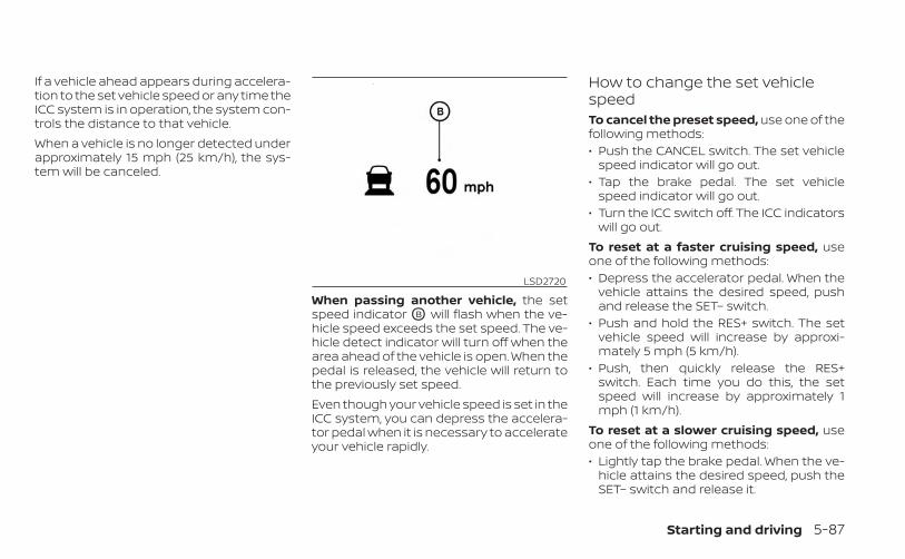
If a vehicle ahead appears during accelera-tion to the set vehicle speed or any time theICC system is in operation, the system con-trols the distance to that vehicle.When a vehicle is no longer detected underapproximately 15 mph (25 km/h), the sys-tem will be canceled.
When passing another vehicle, the setspeed indicator OB will flash when the ve-hicle speed exceeds the set speed. The ve-hicle detect indicator will turn off when thearea ahead of the vehicle is open. When thepedal is released, the vehicle will return tothe previously set speed.Even though your vehicle speed is set in theICC system, you can depress the accelera-tor pedal when it is necessary to accelerateyour vehicle rapidly.
How to change the set vehiclespeedTo cancel the preset speed, use one of thefollowing methods:• Push the CANCEL switch. The set vehicle
speed indicator will go out.• Tap the brake pedal. The set vehicle
speed indicator will go out.• Turn the ICC switch off. The ICC indicators
will go out.To reset at a faster cruising speed, useone of the following methods:• Depress the accelerator pedal. When the
vehicle attains the desired speed, pushand release the SET– switch.
• Push and hold the RES+ switch. The setvehicle speed will increase by approxi-mately 5 mph (5 km/h).
• Push, then quickly release the RES+switch. Each time you do this, the setspeed will increase by approximately 1mph (1 km/h).
To reset at a slower cruising speed, useone of the following methods:• Lightly tap the brake pedal. When the ve-
hicle attains the desired speed, push theSET– switch and release it.
LSD2720
Starting and driving 5-87

• Push and hold the SET– switch. The setvehicle speed will decrease by approxi-mately 5 mph (5 km/h).
• Push, then quickly release the SET–switch. Each time you do this, the setspeed will decrease by approximately 1mph (1 km/h).
To resume the preset speed, push andrelease the RES+ switch. The vehicle willresume the last set cruising speed whenthe vehicle speed is over 20 mph (30 km/h).
How to change the set distanceto the vehicle aheadThe distance to the vehicle ahead can beselected at any time depending on the traf-fic conditions.Each time the distance switch OA ispushed, the set distance will change tolong, middle, short and back to long again,in that sequence.
Distance Approximate distance at60 mph (100 km/h)[ft (m)]
1. Long 200 (60)2. Middle 150 (45)3. Short 90 (30)
• The distance to the vehicle ahead willchange according to the vehicle speed.The higher the vehicle speed, the longerthe distance.
• The distance setting will remain at thecurrent setting even if the engine isrestarted.
LSD3056 LSD2752
5-88 Starting and driving
Approach warningIf your vehicle comes closer to the vehicleahead due to rapid deceleration of that ve-hicle or if another vehicle cuts in, the sys-tem warns the driver with the chime andICC system display. Decelerate by depress-ing the brake pedal to maintain a safe ve-hicle distance if:• The chime sounds.• The vehicle ahead detection indicator
blinks.The warning chime may not sound insome cases when there is a short distancebetween vehicles. Some examples are:• When the vehicles are traveling at the
same speed and the distance betweenvehicles is not changing.
• When the vehicle ahead is traveling fasterand the distance between vehicles isincreasing.
• When a vehicle cuts in near your vehicle.The warning chime will not sound when:• The vehicle approaches other vehicles
that are parked or moving slowly.• The accelerator pedal is depressed, over-
riding the system.
NOTE:
The approach warning chime may soundand the system display may blink whenthe ICC sensor detects objects on theside of the vehicle or on the side of theroad. This may cause the ICC system todecelerate or accelerate the vehicle. TheICC sensor may detect these objectswhen the vehicle is driven on windingroads, narrow roads, hilly roads, or whenentering or exiting a curve. In thesecases you will have to manually controlthe proper distance ahead of yourvehicle.Also, the sensor sensitivity can be af-fected by vehicle operation (steeringmaneuver or driving position in the lane)or traffic or vehicle condition (for ex-ample, if a vehicle is being driven withsome damage).
Acceleration when passingWhen the ICC system is engaged above 44mph and following a slower vehicle (belowICC set speed), and the turn signal is acti-vated to the left, the ICC system will auto-matically start to accelerate the vehicle tohelp initiate passing on the left and willbegin to reduce the distance to vehicle di-rectly ahead. Only the left side turn signal
operates this feature. As the driver steersthe vehicle and moves into the passinglane, if no vehicle is detected ahead the ICCsystem will continue to accelerate to theICC system set speed. If another vehicle isdetected ahead, then the vehicle will accel-erate up to the following speed of that ve-hicle. If the vehicle is not steered into theleft lane to pass, the acceleration will stopafter a short time and regain the set follow-ing distance. Acceleration can be stoppedat any point by depressing the brake pedalor the CANCEL switch on the steeringwheel.
WARNING
In order to reduce the risk of a collisionthat may result in serious injury ordeath, please be aware of the following:• This function is only activated with
the left turn signal and will briefly ac-celerate the vehicle even if a lanechange is not initiated. This can in-clude non-passing situations such asleft side exits.
Starting and driving 5-89
• Ensure that when passing anothervehicle, the adjacent lane is clear be-fore initiating the pass. Suddenchanges in traffic may occur whilepassing- always manually steer orbrake as needed- never solely rely onthe system.
Automatic cancellationA chime sounds under the following condi-tions and the control is automatically can-celed:• When the vehicle ahead is not detected
and your vehicle is traveling below thespeed of 15 mph (25 km/h)
• When the system judges the vehicle is ata standstill
• When the shift lever is not in the D (Drive)position or Manual mode
• When the electronic parking brake sys-tem is applied
• When the VDC system is turned off• When VDC operates• When distance measurement becomes
impaired due to adhesion of dirt or ob-struction to the sensor
• When a wheel slips• When the radar signal is temporarily
interrupted
VEHICLE-TO-VEHICLE DISTANCECONTROL MODE LIMITATIONS
WARNING
Listed below are the system limitationsfor the ICC system. Failure to operatethe vehicle in accordance with thesesystem limitations could result in seri-ous injury or death.• The ICC system is primarily intended
for use on straight, dry, open roadswith light traffic. It is not advisable touse the ICC system in city traffic orcongested areas.
• The ICC system will not adapt auto-matically to road conditions. Thissystem should be used in evenlyflowing traffic. Do not use the systemon roads with sharp curves, or on icyroads, in heavy rain or in fog.
• As there is a performance limit to thedistance control function, never relysolely on the ICC system. This systemdoes not correct careless, inattentiveor absentminded driving, or over-come poor visibility in rain, fog, orother bad weather. Decelerate thevehicle speed by depressing thebrake pedal, depending on the dis-tance to the vehicle ahead and thesurrounding circumstances in orderto maintain a safe distance betweenvehicles.
• If the vehicle ahead comes to a stop,the vehicle decelerates to a standstillwithin the limitations of the system.The system will cancel once it judgesthat the vehicle has come to a stand-still and sound a warning chime. Toprevent the vehicle from moving, thedriver must depress the brake pedal.
• Always pay attention to the opera-tion of the vehicle and be ready tomanually control the proper follow-ing distance. The ICC system may notbe able to maintain the selected dis-tance between vehicles (followingdistance) or selected vehicle speedunder some circumstances.
5-90 Starting and driving
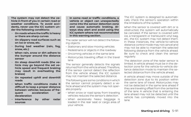
• The system may not detect the ve-hicle in front of you in certain road orweather conditions. To avoid acci-dents, never use the ICC system un-der the following conditions:– On roads where the traffic is heavy
or there are sharp curves– On slippery road surfaces such as
on ice or snow, etc.– During bad weather (rain, fog,
snow, etc.)– When rain, snow or dirt adhere to
the bumper around the distancesensor
– On steep downhill roads (the ve-hicle may go beyond the set ve-hicle speed and frequent brakingmay result in overheating thebrakes)
– On repeated uphill and downhillroads
– When traffic conditions make itdifficult to keep a proper distancebetween vehicles because of fre-quent acceleration ordeceleration
– Interference by other radarsources
• In some road or traffic conditions, avehicle or object can unexpectedlycome into the sensor detection zoneand cause automatic braking. Al-ways stay alert and avoid using theICC system where not recommendedin this warning section.
The radar sensor will not detect the follow-ing objects:• Stationary and slow moving vehicles• Pedestrians or objects in the roadway• Oncoming vehicles in the same lane• Motorcycles traveling offset in the travel
laneThe sensor generally detects the signalsreturned from the vehicle ahead. Therefore,if the sensor cannot detect the reflectionfrom the vehicle ahead, the ICC systemmay not maintain the selected distance.The following are some conditions in whichthe sensor cannot properly detect a ve-hicle ahead and the system may not oper-ate properly:• When snow or road spray from traveling
vehicles reduces the sensor’s detection.• When excessively heavy baggage is
loaded in the rear seat or cargo area ofyour vehicle.
The ICC system is designed to automati-cally check the sensor’s operation withinthe limitations of the system.When the sensor is covered with dirt or isobstructed, the system will automaticallybe canceled. If the sensor is covered withice, a transparent or translucent vinyl bag,etc., the ICC system may not detect them.In these instances, the vehicle-to-vehicledistance control mode may not cancel andmay not be able to maintain the selectedfollowing distance from the vehicle ahead.Be sure to check and clean the sensorregularly.The detection zone of the radar sensor islimited. A vehicle ahead must be in the de-tection zone for the vehicle-to-vehicle dis-tance detection mode to maintain the se-lected distance from the vehicle ahead.A vehicle ahead may move outside of thedetection zone due to its position withinthe same lane of travel. Motorcycles maynot be detected in the same lane ahead ifthey are traveling offset from the centerlineof the lane. A vehicle that is entering thelane ahead may not be detected until thevehicle has completely moved into thelane.
Starting and driving 5-91
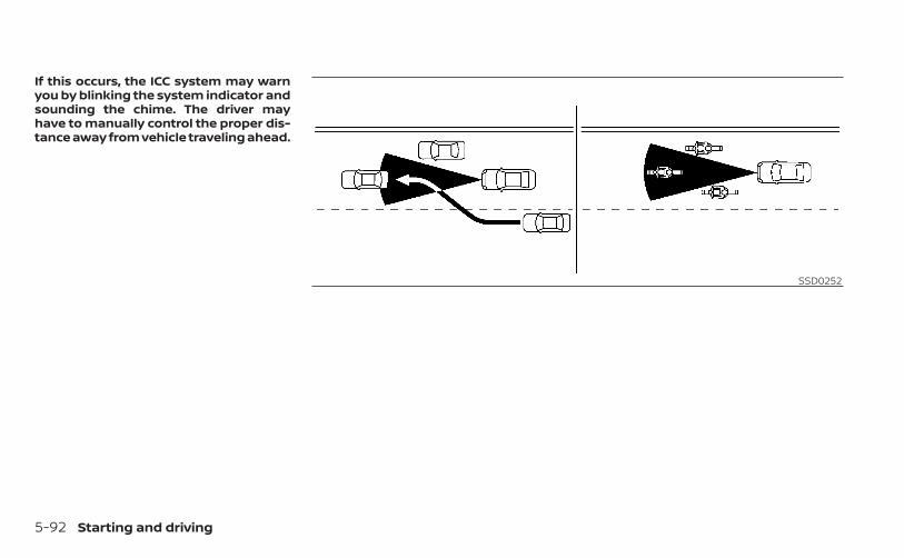
If this occurs, the ICC system may warnyou by blinking the system indicator andsounding the chime. The driver mayhave to manually control the proper dis-tance away from vehicle traveling ahead.
SSD0252
5-92 Starting and driving
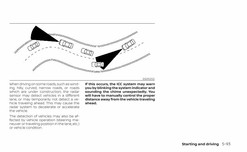
When driving on some roads, such as wind-ing, hilly, curved, narrow roads, or roadswhich are under construction, the radarsensor may detect vehicles in a differentlane, or may temporarily not detect a ve-hicle traveling ahead. This may cause theradar system to decelerate or acceleratethe vehicle.The detection of vehicles may also be af-fected by vehicle operation (steering ma-neuver or traveling position in the lane, etc.)or vehicle condition.
If this occurs, the ICC system may warnyou by blinking the system indicator andsounding the chime unexpectedly. Youwill have to manually control the properdistance away from the vehicle travelingahead.
SSD0253
Starting and driving 5-93

SYSTEM TEMPORARILYUNAVAILABLEThe following are conditions in which theICC system may be temporarily unavail-able. In these instances, the ICC systemmay not cancel and may not be able tomaintain the selected following distancefrom the vehicle ahead.Condition AUnder the following conditions, the ICC sys-tem is automatically canceled. A chime willsound and the system will not be able to beset:• When the VDC system is turned off• When the VDC operates• When a vehicle ahead is not detected and
your vehicle is traveling below the speedof 15 mph (25 km/h)
• When the system judges the vehicle is ata standstill
• When the shift lever is not in the D (Drive),Manual mode or L (Low) range.
• When the electronic parking brake isapplied
• When a wheel slips• When the radar signal is temporarily
interruptedLSD2938
5-94 Starting and driving

Action to takeWhen the conditions listed above are nolonger present, turn the system off usingthe ICC switch. Turn the ICC system back onto use the system.Condition BWhen there is inclement weather (rain, fog,snow, etc.) blocking the front radar sensor,the ICC system will automatically be can-celed, the chime will sound and the “NotAvailable: Front Radar Blocked” warningmessage will appear in the vehicle infor-mation display.Action to takeWhen the conditions listed above are nolonger present, the warning message willno longer be available in the vehicle infor-mation display and the system will operatenormally. If the “Not Available: Front RadarBlocked” warning message continues tobe displayed, have the system checked. It isrecommended that you visit an INFINITI re-tailer for this service.
Condition CWhen the radar sensor area of the frontbumper is covered with dirt or is ob-structed, the ICC system will automaticallybe canceled.The chime will sound and the “Not Avail-able: Front Radar Blocked” warning mes-sage will appear in the vehicle informationdisplay.
Action to takeIf the warning message appears, stop thevehicle in a safe place, place the shift leverin the P (Park) position, and turn the engineoff. When the radar signal is temporarilyinterrupted, clean the sensor area of thefront bumper and restart the engine. If the“Not Available: Front Radar Blocked” warn-ing message continues to be displayed,have the system checked. It is recom-mended that you visit an INFINITI retailer forthis service.
LSD4155
Starting and driving 5-95
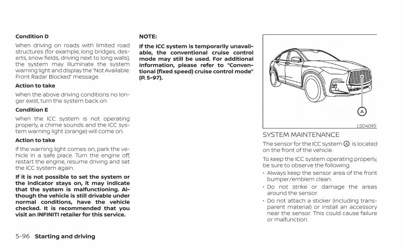
Condition DWhen driving on roads with limited roadstructures (for example, long bridges, des-erts, snow fields, driving next to long walls),the system may illuminate the systemwarning light and display the “Not Available:Front Radar Blocked” message.Action to takeWhen the above driving conditions no lon-ger exist, turn the system back on.Condition EWhen the ICC system is not operatingproperly, a chime sounds and the ICC sys-tem warning light (orange) will come on.Action to takeIf the warning light comes on, park the ve-hicle in a safe place. Turn the engine off,restart the engine, resume driving and setthe ICC system again.If it is not possible to set the system orthe indicator stays on, it may indicatethat the system is malfunctioning. Al-though the vehicle is still drivable undernormal conditions, have the vehiclechecked. It is recommended that youvisit an INFINITI retailer for this service.
NOTE:
If the ICC system is temporarily unavail-able, the conventional cruise controlmode may still be used. For additionalInformation, please refer to “Conven-tional (fixed speed) cruise control mode”(P. 5-97).
SYSTEM MAINTENANCEThe sensor for the ICC system OA is locatedon the front of the vehicle.To keep the ICC system operating properly,be sure to observe the following:• Always keep the sensor area of the front
bumper/emblem clean.• Do not strike or damage the areas
around the sensor.• Do not attach a sticker (including trans-
parent material) or install an accessorynear the sensor. This could cause failureor malfunction.
LSD4095
5-96 Starting and driving
• Do not attach metallic objects near thesensor area (brush guard, etc.) This couldcause failure or malfunction.
• Do not alter, remove, or paint the frontbumper. Before customizing or restoringthe front bumper, it is recommended thatyou visit an INFINITI retailer.
Radio frequency statementFor USA/CanadaModel: ARS4–AIC: 4135A-ARS4AFCC ID: OAYARS4AThis device complies with Part 15 of the FCCRules and with Industry Canada licence-exempt RSS standard(s):Operation is subject to the following twoconditions:1. This device may not cause harmful inter-
ference, and
2. This device must accept any interfer-ence received, including interferencethat may cause undesired operation.
Le présent appareil est conforme aux CNRd'Industrie Canada applicables aux appar-eils radio exempts de licence. L'exploitationest autorisée aux deux conditions suiv-antes:1. L'appareil ne doit pas produire de brouil-
lage, et
2. L'utilisateur de l'appareil doit acceptertout brouillage radioélectrique subi,même si le brouillage est susceptibled'en compromettre le fonctionnement.
Radio Frequency Radiation ExposureInformation:This equipment complies with FCC radia-tion exposure limits set forth for an uncon-trolled environment.This equipment should be installed andoperated with minimum distance of 30 cmbetween the radiator and your body.The transmitter must not be co-located oroperating in conjunction with any other an-tenna or transmitter.
Cet équipement est conforme aux limitesd'exposition aux rayonnements IC établiespour un environnement non contrôlé. Cetéquipement doit être installé et utilisé avecun minimum de 30 cm de distance entre lasource de rayonnement et votre corps.FCC NoticeChanges or modifications not expresslyapproved by the party responsible forcompliance could void the user’s authorityto operate the equipment.
CONVENTIONAL (fixed speed)CRUISE CONTROL MODEThis mode allows driving at a speed be-tween 25 to 90 mph (40 to 144 km/h) with-out keeping your foot on the acceleratorpedal.
Starting and driving 5-97
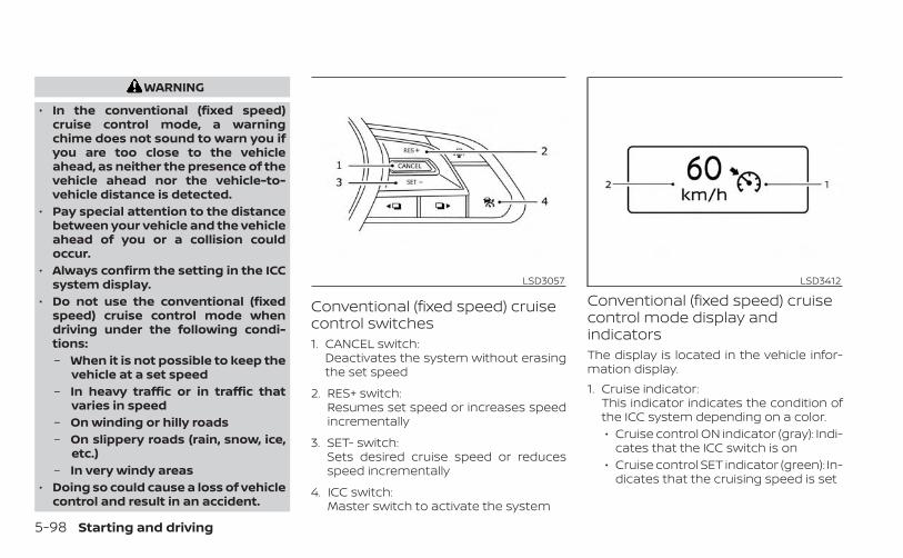
WARNING
• In the conventional (fixed speed)cruise control mode, a warningchime does not sound to warn you ifyou are too close to the vehicleahead, as neither the presence of thevehicle ahead nor the vehicle-to-vehicle distance is detected.
• Pay special attention to the distancebetween your vehicle and the vehicleahead of you or a collision couldoccur.
• Always confirm the setting in the ICCsystem display.
• Do not use the conventional (fixedspeed) cruise control mode whendriving under the following condi-tions:– When it is not possible to keep the
vehicle at a set speed– In heavy traffic or in traffic that
varies in speed– On winding or hilly roads– On slippery roads (rain, snow, ice,
etc.)– In very windy areas
• Doing so could cause a loss of vehiclecontrol and result in an accident.
Conventional (fixed speed) cruisecontrol switches1. CANCEL switch:
Deactivates the system without erasingthe set speed
2. RES+ switch:Resumes set speed or increases speedincrementally
3. SET- switch:Sets desired cruise speed or reducesspeed incrementally
4. ICC switch:Master switch to activate the system
Conventional (fixed speed) cruisecontrol mode display andindicatorsThe display is located in the vehicle infor-mation display.1. Cruise indicator:
This indicator indicates the condition ofthe ICC system depending on a color.• Cruise control ON indicator (gray): Indi-
cates that the ICC switch is on• Cruise control SET indicator (green): In-
dicates that the cruising speed is set
LSD3057 LSD3412
5-98 Starting and driving
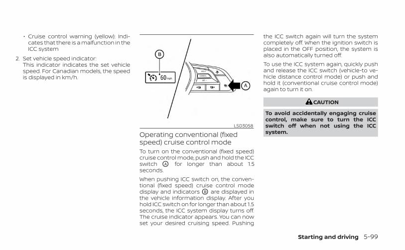
• Cruise control warning (yellow): Indi-cates that there is a malfunction in theICC system
2. Set vehicle speed indicator:This indicator indicates the set vehiclespeed. For Canadian models, the speedis displayed in km/h.
Operating conventional (fixedspeed) cruise control modeTo turn on the conventional (fixed speed)cruise control mode, push and hold the ICCswitch OA for longer than about 1.5seconds.When pushing ICC switch on, the conven-tional (fixed speed) cruise control modedisplay and indicators OB are displayed inthe vehicle information display. After youhold ICC switch on for longer than about 1.5seconds, the ICC system display turns off.The cruise indicator appears. You can nowset your desired cruising speed. Pushing
the ICC switch again will turn the systemcompletely off. When the ignition switch isplaced in the OFF position, the system isalso automatically turned off.To use the ICC system again, quickly pushand release the ICC switch (vehicle-to ve-hicle distance control mode) or push andhold it (conventional cruise control mode)again to turn it on.
CAUTION
To avoid accidentally engaging cruisecontrol, make sure to turn the ICCswitch off when not using the ICCsystem.
LSD3058
Starting and driving 5-99

To set cruising speed, accelerate your ve-hicle to the desired speed, push the SET- OC
switch and release it. (The color of thecruise indicator changes to green and setvehicle speed indicator comes on.) Takeyour foot off the accelerator pedal. Yourvehicle will maintain the set speed.• To pass another vehicle, depress the ac-
celerator pedal. When you release thepedal, the vehicle will return to the previ-ously set speed.
• The vehicle may not maintain the setspeed when going up or down steep hills.If this happens, manually maintain ve-hicle speed.
To cancel the preset speed, use any of thefollowing methods:1. Push the CANCEL switch. The vehicle
speed indicator will turn off.
2. Tap the brake pedal. The vehicle speedindicator will turn off.
3. Turn the ICC switch off. Both the cruiseindicator and vehicle speed indicator willturn off.
To reset at a faster cruising speed, use oneof the following three methods:1. Depress the accelerator pedal. When the
vehicle attains the desired speed, pushand release the SET- switch.
2. Push and hold the RES+ switch. Whenthe vehicle attains the desired speed,release the switch.
3. Push, then quickly release the RES+switch. Each time you do this, the setspeed will increase by about 1 mph (1km/h).
To reset at a slower cruising speed, use oneof the following three methods:1. Lightly tap the brake pedal. When the
vehicle attains the desired speed, pushthe SET- switch and release it.
2. Push and hold the SET- switch. Releasethe switch when the vehicle slows downto the desired speed.
3. Push, then quickly release the SET-switch. Each time you do this, the setspeed will decrease by about 1 mph (1km/h).
To resume the preset speed, push and re-lease the RES+ switch. The vehicle will re-sume the last set cruising speed when thevehicle speed is over 25 mph (40 km/h).
LSD3059
5-100 Starting and driving
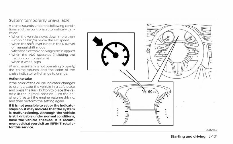
System temporarily unavailableA chime sounds under the following condi-tions and the control is automatically can-celed:• When the vehicle slows down more than
8 mph (13 km/h) below the set speed• When the shift lever is not in the D (Drive)
or manual shift mode• When the electronic parking brake is applied• When the VDC operates (including the
traction control system)• When a wheel slipsWhen the system is not operating properly,the chime sounds and the color of thecruise indicator will change to orange.Action to takeIf the color of the cruise indicator changesto orange, stop the vehicle in a safe placeand press the Park button to place the ve-hicle in the P (Park) position. Turn the en-gine off, restart the engine, resume driving,and then perform the setting again.If it is not possible to set or the indicatorstays on, it may indicate that the systemis malfunctioning. Although the vehicleis still drivable under normal conditions,have the vehicle checked. It is recom-mended that you visit an INFINITI retailerfor this service.
LSD2942
Starting and driving 5-101

WARNING
Failure to follow the warnings and in-structions for proper use of the ProPI-LOT Assist system could result in seri-ous injury or death.• ProPILOT Assist is not a self-driving
system. Within the limits of its capa-bilities, as described in this manual, ithelps the driver with certain drivingactivities.
• The ProPILOT Assist system is not areplacement for proper driving pro-cedures and is not designed to cor-rect careless, inattentive or absent-minded driving. ProPILOT Assist willnot always steer the vehicle to keep itin the lane. The ProPILOT Assist sys-tem is not designed to prevent loss ofcontrol. It is the driver’s responsibilityto stay alert, drive safely, keep thevehicle in the traveling lane, and be incontrol of the vehicle at all times.
• There are limitations to the ProPILOTAssist system capability. The ProPI-LOT Assist system does not functionin all driving, traffic, weather, androad conditions. It is the driver’s re-sponsibility to stay alert, drive safely,keep the vehicle in the traveling lane,and be in control of the vehicle at alltimes.
• The ProPILOT Assist system is only anaid to assist the driver and is not acollision warning or avoidancedevice.
• The ProPILOT Assist system is forhighway use only and is not intendedfor city driving. Failure to apply thebrakes or steer the vehicle when nec-essary may result in a seriousaccident.
• Always observe posted speed limitsand do not set the speed over them.
• Never take your hands off the steer-ing wheel when driving. Always keepyour hands on the steering wheeland drive your vehicle safely.
• Never unfasten your safety beltwhen using ProPILOT Assist. Doing soautomatically cancels the ProPILOTAssist system.
• The ProPILOT Assist system does notreact to stationary and slow movingvehicles.
• Always drive carefully and atten-tively when using the ProPILOT Assistsystem. Read and understand theOwner’s Manual thoroughly beforeusing the ProPILOT Assist system. Toavoid serious injury or death, do notrely on the system to prevent acci-dents or to control the vehicle’sspeed in emergency situations. Donot use the ProPILOT Assist systemexcept in appropriate road and trafficconditions.
PROPILOT ASSIST (if so equipped)
5-102 Starting and driving
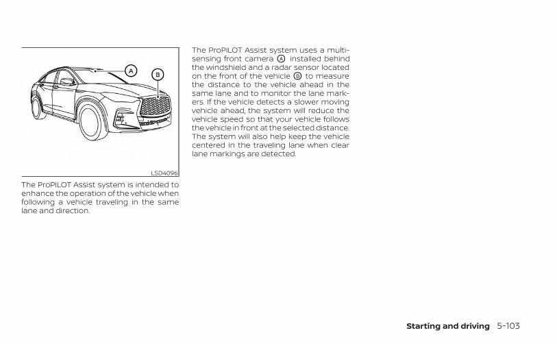
The ProPILOT Assist system is intended toenhance the operation of the vehicle whenfollowing a vehicle traveling in the samelane and direction.
The ProPILOT Assist system uses a multi-sensing front camera OA installed behindthe windshield and a radar sensor locatedon the front of the vehicle OB to measurethe distance to the vehicle ahead in thesame lane and to monitor the lane mark-ers. If the vehicle detects a slower movingvehicle ahead, the system will reduce thevehicle speed so that your vehicle followsthe vehicle in front at the selected distance.The system will also help keep the vehiclecentered in the traveling lane when clearlane markings are detected.
LSD4096
Starting and driving 5-103
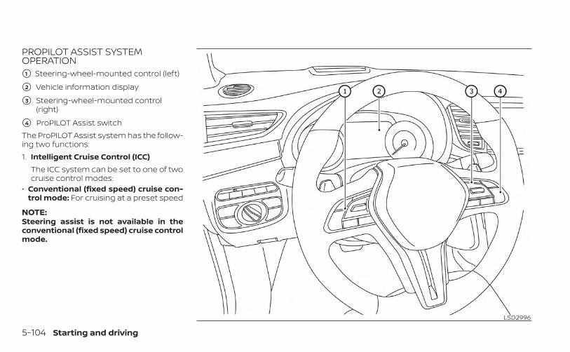
PROPILOT ASSIST SYSTEMOPERATION�1 Steering-wheel-mounted control (left)
�2 Vehicle information display
�3 Steering-wheel-mounted control(right)
�4 ProPILOT Assist switchThe ProPILOT Assist system has the follow-ing two functions:1. Intelligent Cruise Control (ICC)
The ICC system can be set to one of twocruise control modes:
• Conventional (fixed speed) cruise con-trol mode: For cruising at a preset speed
NOTE:Steering assist is not available in theconventional (fixed speed) cruise controlmode.
LSD2996
5-104 Starting and driving
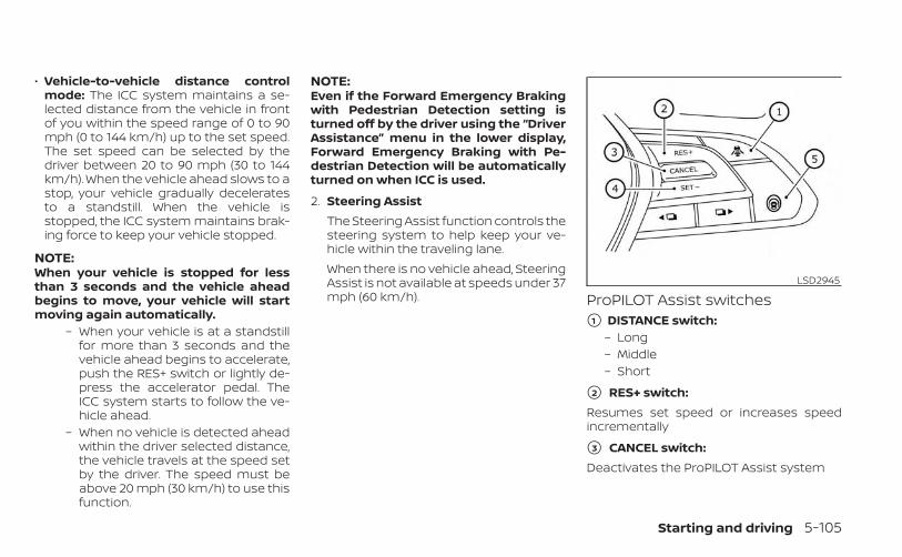
• Vehicle-to-vehicle distance controlmode: The ICC system maintains a se-lected distance from the vehicle in frontof you within the speed range of 0 to 90mph (0 to 144 km/h) up to the set speed.The set speed can be selected by thedriver between 20 to 90 mph (30 to 144km/h). When the vehicle ahead slows to astop, your vehicle gradually deceleratesto a standstill. When the vehicle isstopped, the ICC system maintains brak-ing force to keep your vehicle stopped.
NOTE:When your vehicle is stopped for lessthan 3 seconds and the vehicle aheadbegins to move, your vehicle will startmoving again automatically.
– When your vehicle is at a standstillfor more than 3 seconds and thevehicle ahead begins to accelerate,push the RES+ switch or lightly de-press the accelerator pedal. TheICC system starts to follow the ve-hicle ahead.
– When no vehicle is detected aheadwithin the driver selected distance,the vehicle travels at the speed setby the driver. The speed must beabove 20 mph (30 km/h) to use thisfunction.
NOTE:Even if the Forward Emergency Brakingwith Pedestrian Detection setting isturned off by the driver using the “DriverAssistance” menu in the lower display,Forward Emergency Braking with Pe-destrian Detection will be automaticallyturned on when ICC is used.
2. Steering AssistThe Steering Assist function controls thesteering system to help keep your ve-hicle within the traveling lane.When there is no vehicle ahead, SteeringAssist is not available at speeds under 37mph (60 km/h). ProPILOT Assist switches
�1 DISTANCE switch:– Long– Middle– Short
�2 RES+ switch:Resumes set speed or increases speedincrementally
�3 CANCEL switch:Deactivates the ProPILOT Assist system
LSD2945
Starting and driving 5-105
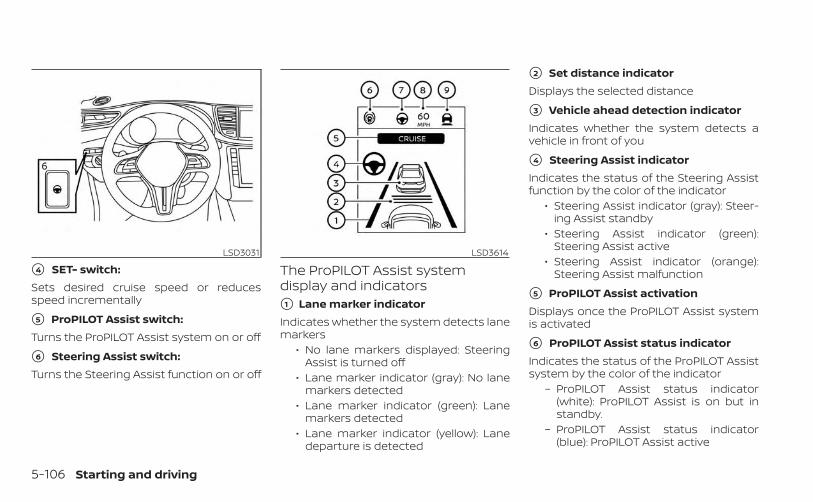
�4 SET- switch:Sets desired cruise speed or reducesspeed incrementally
�5 ProPILOT Assist switch:Turns the ProPILOT Assist system on or off
�6 Steering Assist switch:Turns the Steering Assist function on or off
The ProPILOT Assist systemdisplay and indicators�1 Lane marker indicatorIndicates whether the system detects lanemarkers
• No lane markers displayed: SteeringAssist is turned off
• Lane marker indicator (gray): No lanemarkers detected
• Lane marker indicator (green): Lanemarkers detected
• Lane marker indicator (yellow): Lanedeparture is detected
�2 Set distance indicatorDisplays the selected distance
�3 Vehicle ahead detection indicatorIndicates whether the system detects avehicle in front of you
�4 Steering Assist indicatorIndicates the status of the Steering Assistfunction by the color of the indicator
• Steering Assist indicator (gray): Steer-ing Assist standby
• Steering Assist indicator (green):Steering Assist active
• Steering Assist indicator (orange):Steering Assist malfunction
�5 ProPILOT Assist activationDisplays once the ProPILOT Assist systemis activated
�6 ProPILOT Assist status indicatorIndicates the status of the ProPILOT Assistsystem by the color of the indicator
– ProPILOT Assist status indicator(white): ProPILOT Assist is on but instandby.
– ProPILOT Assist status indicator(blue): ProPILOT Assist active
LSD3031 LSD3614
5-106 Starting and driving

�7 Steering Assist status indicator/warningDisplays the status of the Steering Assist bythe color of the indicator/warning
• No Steering Assist status indicatordisplayed: Steering Assist is turned off
• Steering Assist indicator (gray): Steer-ing Assist standby
• Steering Assist indicator (green):Steering Assist active
• Steering Assist indicator (yellow):Steering Assist malfunction
�8 Set vehicle speed indicatorIndicates the set vehicle speed
�9 Speed control status indicator/warningDisplays the status of speed control by thecolor and shape of the indicator/warning
– Speed control status indicator/warning (gray): ICC standby
– Speed control status indicator/warning (solid green ): ICC (dis-tance control mode) is active (vehicledetected ahead). Your vehiclematches the speed of the vehicleahead.
– Speed control status indicator/warning (green outline ): ICC(maintain speed control mode) is ac-tive (no vehicle detected ahead). Yourvehicle maintains the driver-selectedset speed.
– Speed control status indicator/warning (solid yellow ): ICCmalfunction
TURNING THE CONVENTIONAL(fixed speed) CRUISE CONTROLMODE ONNOTE:
ProPILOT Assist provides no approachwarnings, automatic braking, or steeringassist in the conventional (fixed speed)cruise control mode.To choose the conventional (fixed speed)cruise control mode, push and hold theProPILOT Assist switch for longer than ap-proximately 1.5 seconds. For additional in-formation, see “Conventional (fixed speed)cruise control mode” (P. 5-131).
OPERATING PROPILOT ASSIST1. Push the ProPILOT Assist switch OA . This
turns on the ProPILOT Assist system anddisplays the status of the ProPILOT As-sist system on the vehicle informationdisplay OB .
2. Accelerate or decelerate your vehicle tothe desired speed.
LSD3615
Starting and driving 5-107
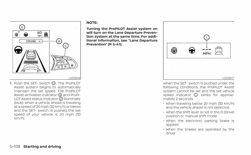
3. Push the SET- switch OC . The ProPILOTAssist system begins to automaticallymaintain the set speed. The ProPILOTAssist activation indicator OD and ProPI-LOT Assist status indicator OE illuminate(blue). When a vehicle ahead is travelingat a speed of 20 mph (30 km/h) or belowand the SET- switch is pushed, the setspeed of your vehicle is 20 mph (30km/h).
NOTE:
Turning the ProPILOT Assist system onwill turn on the Lane Departure Preven-tion system at the same time. For addi-tional information, see “Lane DeparturePrevention” (P. 5-41).
When the SET- switch is pushed under thefollowing conditions, the ProPILOT Assistsystem cannot be set and the set vehiclespeed indicator O1 blinks for approxi-mately 2 seconds:• When traveling below 20 mph (30 km/h)
and the vehicle ahead is not detected• When the shift lever is not in the D (Drive)
position or manual shift mode• When the electronic parking brake is
applied• When the brakes are operated by the
driver
LSD3616 LSD3617
5-108 Starting and driving
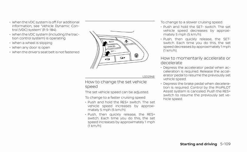
• When the VDC system is off. For additionalinformation, see “Vehicle Dynamic Con-trol (VDC) system” (P. 5-184).
• When the VDC system (including the trac-tion control system) is operating
• When a wheel is slipping• When any door is open• When the driver’s seat belt is not fastened
How to change the set vehiclespeedThe set vehicle speed can be adjusted.To change to a faster cruising speed:• Push and hold the RES+ switch. The set
vehicle speed increases by approxi-mately 5 mph (5 km/h).
• Push, then quickly release, the RES+switch. Each time you do this, the setspeed increases by approximately 1 mph(1 km/h).
To change to a slower cruising speed:• Push and hold the SET- switch. The set
vehicle speed decreases by approxi-mately 5 mph (5 km/h).
• Push, then quickly release, the SET-switch. Each time you do this, the setspeed decreases by approximately 1 mph(1 km/h).
How to momentarily accelerate ordecelerate• Depress the accelerator pedal when ac-
celeration is required. Release the accel-erator pedal to resume the previously setvehicle speed.
• Depress the brake pedal when decelera-tion is required. Control by the ProPILOTAssist system is canceled. Push the RES+switch to resume the previously set ve-hicle speed.
LSD2948
Starting and driving 5-109
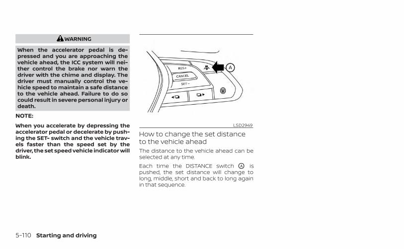
WARNING
When the accelerator pedal is de-pressed and you are approaching thevehicle ahead, the ICC system will nei-ther control the brake nor warn thedriver with the chime and display. Thedriver must manually control the ve-hicle speed to maintain a safe distanceto the vehicle ahead. Failure to do socould result in severe personal injury ordeath.
NOTE:
When you accelerate by depressing theaccelerator pedal or decelerate by push-ing the SET- switch and the vehicle trav-els faster than the speed set by thedriver, the set speed vehicle indicator willblink.
How to change the set distanceto the vehicle aheadThe distance to the vehicle ahead can beselected at any time.Each time the DISTANCE switch OA ispushed, the set distance will change tolong, middle, short and back to long againin that sequence.
LSD2949
5-110 Starting and driving
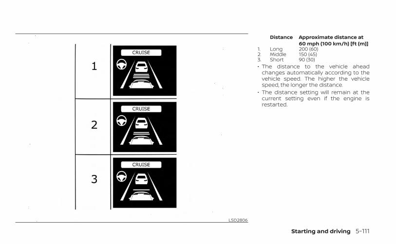
Distance Approximate distance at60 mph (100 km/h) [ft (m)]
1. Long 200 (60)2. Middle 150 (45)3. Short 90 (30)• The distance to the vehicle ahead
changes automatically according to thevehicle speed. The higher the vehiclespeed, the longer the distance.
• The distance setting will remain at thecurrent setting even if the engine isrestarted.
LSD2806
Starting and driving 5-111

HOW TO ENABLE/DISABLE THESTEERING ASSIST�1 Lower display buttons
�2 Lower display
�3 Steering Assist switchUse the following methods to enable ordisable the Steering Assist.Steering Assist switch:To turn the Steering Assist on or off, pushthe Steering Assist switch O3 on the instru-ment panel.
NOTE:• When the Steering Assist switch is
used to turn the system on or off, thesystem remembers the setting even ifthe ignition switch is cycled. The switchmust be pushed again to change thesetting to on or off.
• The Steering Assist switch changes thestatus of the “Steering Assist” selectionmade in the “Settings” screen in thelower display.
LSD3626
5-112 Starting and driving
Setting in the lower display:1. Press the MENU button below the lower
display screen.
2. Select “Driver Assistance.”
3. Select “Lane Centering Assist.”
4. Select “ON” to turn the “Steering Assist”system on or off.
NOTE:• When the Cruise screen is displayed on
the vehicle information display, pressthe OK button on the steering wheel tocall up the “Driving Aids” setting dis-play in the upper display.
• When enabling/disabling the systemthrough the lower display, the systemretains the current settings even if theengine is restarted.
How to cancel the ProPILOT AssistsystemTo cancel the ProPILOT Assist system, useone of the following methods:• Push the CANCEL switch.• Tap the brake pedal (except at a
standstill).• Push the ProPILOT Assist switch to turn
the system off. The ProPILOT Assist statusindicator will go out.
When the ProPILOT Assist system is can-celed while the vehicle is stopped, the elec-tronic parking brake is automaticallyactivated.
WARNING
To prevent the vehicle from moving orrolling unexpectedly, which could re-sult in serious personal injury or prop-erty damage, before exiting the vehiclemake sure to push the ProPILOT Assistswitch to turn the system off, place theshift lever in the P (Park) position, andturn the engine off.
INTELLIGENT CRUISE CONTROL(ICC) (for vehicles with ProPILOTAssist)
WARNING
Failure to follow the warnings and in-structions for proper use of the ICC sys-tem could result in serious injury ordeath.• The ICC system is only an aid to assist
the driver and is not a collision warn-ing or avoidance device. It is recom-mended for highway use only and itis not intended for city driving. It isthe driver’s responsibility to stayalert, drive safely, and be in control ofthe vehicle at all times.
• There are limitations to the ICC sys-tem capability. The ICC system doesnot function in all driving, traffic,weather, and road conditions. It is thedriver’s responsibility to stay alert,drive safely, keep the vehicle in thetraveling lane, and be in control of thevehicle at all times.
• Always observe posted speed limitsand do not set the speed over them.
• The ICC system does not react to sta-tionary and slow moving vehicles.
Starting and driving 5-113
• Always drive carefully and atten-tively when using the ICC system.Read and understand the Owner’sManual thoroughly before using theICC system. To avoid serious injury ordeath, do not rely on the system toprevent accidents or to control thevehicle’s speed in emergency situa-tions. Do not use the ICC system ex-cept in appropriate road and trafficconditions.
ICC system operationThe ICC system is designed to maintain aselected distance from the vehicle in frontof you and can reduce the speed to matcha slower vehicle ahead. The system decel-erates the vehicle as necessary and if thevehicle ahead comes to a stop, the vehicledecelerates to a standstill. However, the ICCsystem can only apply up to 40% of thevehicle’s total braking power. This systemshould only be used when traffic condi-tions allow vehicle speeds to remain fairlyconstant or when vehicle speeds changegradually. If a vehicle moves into the travel-ing lane ahead or if a vehicle travelingahead rapidly decelerates, the distance be-tween vehicles may become closer be-cause the ICC system cannot decelerate
the vehicle quickly enough. If this occurs,the ICC system sounds a warning chimeand blinks the system display to notify thedriver to take necessary action.The ICC system cancels and a warningchime sounds if the speed is below ap-proximately 15 mph (25 km/h) and a vehicleis not detected ahead.The ICC system operates as follows:• When there are no vehicles traveling
ahead, the ICC system maintains thespeed set by the driver. The set speedrange is between approximately 20 and90 mph (30 and 144 km/h).
• When there is a vehicle traveling ahead,the ICC system adjusts the speed tomaintain the distance, selected by thedriver, from the vehicle ahead. If the ve-hicle ahead comes to a stop, the vehicledecelerates to a standstill. Once your ve-hicle stops, the ICC system keeps the ve-hicle stopped.
• When your vehicle is stopped for lessthan 3 seconds and the vehicle aheadbegins to move, your vehicle will startmoving again automatically.
• When your vehicle is at a standstill formore than 3 seconds and the vehicleahead begins to accelerate, push theRES+ switch or lightly depress the accel-erator pedal. The ICC system starts tofollow the vehicle ahead.
• When the vehicle traveling ahead movesto a different traveling lane, the ICC sys-tem accelerates and maintains vehiclespeed up to the set speed.
The ICC system does not control vehiclespeed or warn you when you approachstationary and slow moving vehicles. Youmust pay attention to vehicle operation tomaintain proper distance from vehiclesahead when approaching toll gates or traf-fic congestion.
5-114 Starting and driving
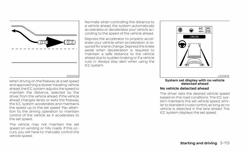
When driving on the freeway at a set speedand approaching a slower traveling vehicleahead, the ICC system adjusts the speed tomaintain the distance, selected by thedriver, from the vehicle ahead. If the vehicleahead changes lanes or exits the freeway,the ICC system accelerates and maintainsthe speed up to the set speed. Pay atten-tion to the driving operation to maintaincontrol of the vehicle as it accelerates tothe set speed.The vehicle may not maintain the setspeed on winding or hilly roads. If this oc-curs, you will have to manually control thevehicle speed.
Normally when controlling the distance toa vehicle ahead, the system automaticallyaccelerates or decelerates your vehicle ac-cording to the speed of the vehicle ahead.Depress the accelerator to properly accel-erate your vehicle when acceleration is re-quired for a lane change. Depress the brakepedal when deceleration is required tomaintain a safe distance to the vehicleahead due to sudden braking or if a vehiclecuts in. Always stay alert when using theICC system.
No vehicle detected aheadThe driver sets the desired vehicle speedbased on the road conditions. The ICC sys-tem maintains the set vehicle speed, simi-lar to standard cruise control, as long as novehicle is detected in the lane ahead. TheICC system displays the set speed.
SSD0254 LSD3618System set display with no vehicle
detected ahead
Starting and driving 5-115
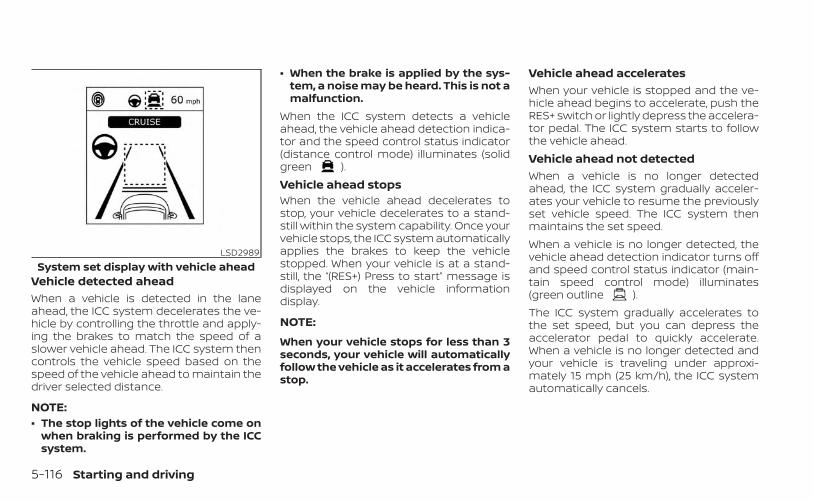
Vehicle detected aheadWhen a vehicle is detected in the laneahead, the ICC system decelerates the ve-hicle by controlling the throttle and apply-ing the brakes to match the speed of aslower vehicle ahead. The ICC system thencontrols the vehicle speed based on thespeed of the vehicle ahead to maintain thedriver selected distance.
NOTE:• The stop lights of the vehicle come on
when braking is performed by the ICCsystem.
• When the brake is applied by the sys-tem, a noise may be heard. This is not amalfunction.
When the ICC system detects a vehicleahead, the vehicle ahead detection indica-tor and the speed control status indicator(distance control mode) illuminates (solidgreen ).Vehicle ahead stopsWhen the vehicle ahead decelerates tostop, your vehicle decelerates to a stand-still within the system capability. Once yourvehicle stops, the ICC system automaticallyapplies the brakes to keep the vehiclestopped. When your vehicle is at a stand-still, the “(RES+) Press to start” message isdisplayed on the vehicle informationdisplay.
NOTE:
When your vehicle stops for less than 3seconds, your vehicle will automaticallyfollow the vehicle as it accelerates from astop.
Vehicle ahead acceleratesWhen your vehicle is stopped and the ve-hicle ahead begins to accelerate, push theRES+ switch or lightly depress the accelera-tor pedal. The ICC system starts to followthe vehicle ahead.Vehicle ahead not detectedWhen a vehicle is no longer detectedahead, the ICC system gradually acceler-ates your vehicle to resume the previouslyset vehicle speed. The ICC system thenmaintains the set speed.When a vehicle is no longer detected, thevehicle ahead detection indicator turns offand speed control status indicator (main-tain speed control mode) illuminates(green outline ).The ICC system gradually accelerates tothe set speed, but you can depress theaccelerator pedal to quickly accelerate.When a vehicle is no longer detected andyour vehicle is traveling under approxi-mately 15 mph (25 km/h), the ICC systemautomatically cancels.
LSD2989System set display with vehicle ahead
5-116 Starting and driving
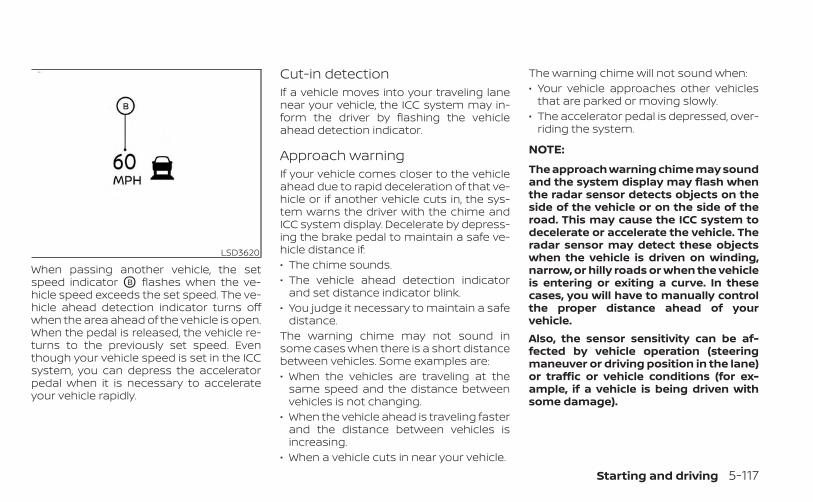
When passing another vehicle, the setspeed indicator OB flashes when the ve-hicle speed exceeds the set speed. The ve-hicle ahead detection indicator turns offwhen the area ahead of the vehicle is open.When the pedal is released, the vehicle re-turns to the previously set speed. Eventhough your vehicle speed is set in the ICCsystem, you can depress the acceleratorpedal when it is necessary to accelerateyour vehicle rapidly.
Cut-in detectionIf a vehicle moves into your traveling lanenear your vehicle, the ICC system may in-form the driver by flashing the vehicleahead detection indicator.
Approach warningIf your vehicle comes closer to the vehicleahead due to rapid deceleration of that ve-hicle or if another vehicle cuts in, the sys-tem warns the driver with the chime andICC system display. Decelerate by depress-ing the brake pedal to maintain a safe ve-hicle distance if:• The chime sounds.• The vehicle ahead detection indicator
and set distance indicator blink.• You judge it necessary to maintain a safe
distance.The warning chime may not sound insome cases when there is a short distancebetween vehicles. Some examples are:• When the vehicles are traveling at the
same speed and the distance betweenvehicles is not changing.
• When the vehicle ahead is traveling fasterand the distance between vehicles isincreasing.
• When a vehicle cuts in near your vehicle.
The warning chime will not sound when:• Your vehicle approaches other vehicles
that are parked or moving slowly.• The accelerator pedal is depressed, over-
riding the system.
NOTE:
The approach warning chime may soundand the system display may flash whenthe radar sensor detects objects on theside of the vehicle or on the side of theroad. This may cause the ICC system todecelerate or accelerate the vehicle. Theradar sensor may detect these objectswhen the vehicle is driven on winding,narrow, or hilly roads or when the vehicleis entering or exiting a curve. In thesecases, you will have to manually controlthe proper distance ahead of yourvehicle.Also, the sensor sensitivity can be af-fected by vehicle operation (steeringmaneuver or driving position in the lane)or traffic or vehicle conditions (for ex-ample, if a vehicle is being driven withsome damage).
LSD3620
Starting and driving 5-117

Acceleration when passingWhen the ICC system is engaged above 44mph and following a slower vehicle (belowICC set speed), and the turn signal is acti-vated to the left, the ICC system will auto-matically start to accelerate the vehicle tohelp initiate passing on the left and willbegin to reduce the distance to vehicle di-rectly ahead. Only the left side turn signaloperates this feature. As the driver steersthe vehicle and moves into the passinglane, if no vehicle is detected ahead the ICCsystem will continue to accelerate to theICC system set speed. If another vehicle isdetected ahead, then the vehicle will accel-erate up to the following speed of that ve-hicle. If the vehicle is not steered into theleft lane to pass, the acceleration will stopafter a short time and regain the set follow-ing distance. Acceleration can be stoppedat any point by depressing the brake pedalor the CANCEL switch on the steeringwheel.
WARNING
In order to reduce the risk of a collisionthat may result in serious injury ordeath, please be aware of the following:• This function is only activated with
the left turn signal and will briefly ac-celerate the vehicle even if a lanechange is not initiated. This can in-clude non-passing situations such asleft side exits.
• Ensure that when passing anothervehicle, the adjacent lane is clear be-fore initiating the pass. Suddenchanges in traffic may occur whilepassing- always manually steer orbrake as needed- never solely rely onthe system.
ICC system limitationsWARNING
Listed below are the system limitationsfor the ICC system. Failure to operatethe vehicle in accordance with thesesystem limitations could result in seri-ous injury or death:• The ICC system is primarily intended
for use on straight, dry, open roadswith light traffic. It is not advisable touse the ICC system in city traffic orcongested areas.
• The ICC system will not adapt auto-matically to road conditions. Thissystem should be used in evenlyflowing traffic. Do not use the systemon roads with sharp curves or on icyroads, in heavy rain or in fog.
5-118 Starting and driving
• As there is a performance limit to thedistance control function, never relysolely on the ICC system. This systemdoes not correct careless, inattentiveor absentminded driving or over-come poor visibility in rain, fog, orother bad weather. Decelerate thevehicle speed by depressing thebrake pedal, depending on the dis-tance to the vehicle ahead and thesurrounding circumstances in orderto maintain a safe distance betweenvehicles.
• When the ICC system automaticallybrings the car to a stop, your vehiclecan automatically accelerate if thevehicle is stopped for less than ap-proximately 3 seconds. Be preparedto stop your vehicle if necessary.
• Always pay attention to the opera-tion of the vehicle and be ready tomanually control the proper follow-ing distance. The ICC system may notbe able to maintain the selected dis-tance between vehicles (followingdistance) or selected vehicle speedunder some circumstances.
• The system may not detect the ve-hicle in front of you in certain road orweather conditions. To avoid acci-dents, never use the ICC system un-der the following conditions:– On roads with heavy, high-speed
traffic or sharp curves– On slippery road surfaces such as
on ice or snow, etc.– During bad weather (rain, fog,
snow, etc.)– When rain, snow or dirt adhere to
the bumper around the distancesensor
– On steep downhill roads (the ve-hicle may go beyond the set ve-hicle speed and frequent brakingmay result in overheating thebrakes)
– On repeated uphill and downhillroads
– When traffic conditions make itdifficult to keep a proper distancebetween vehicles because of fre-quent acceleration ordeceleration
– Interference by other radarsources.
• In some road or traffic conditions, avehicle or object can unexpectedlycome into the sensor detection zoneand cause automatic braking. Al-ways stay alert and avoid using theICC system where not recommendedin this warning section.
The ICC system will not detect the followingobjects:• Stationary or slow moving vehicles• Pedestrians or objects in the roadway• Oncoming vehicles in the same lane• Motorcycles traveling offset in the travel
laneThe following are some conditions in whichthe radar sensor cannot properly detect avehicle ahead and the system may not op-erate properly:• When the sensor detection is reduced
(conditions such as rain, snow, fog, duststorms, sandstorms, and road spray fromother vehicles)
• Driving on a steep downhill slope or roadswith sharp curves
• Driving on a bumpy road surface, such asan uneven dirt road
• If dirt, ice, snow or other material is cover-ing the radar sensor area
Starting and driving 5-119
• A complicated-shaped vehicle such as acar carrier trailer or flatbed truck/trailer isnear the vehicle ahead.
• Interference by other radar sources• When excessively heavy baggage is
loaded in the rear seat or cargo area ofyour vehicle.
The ICC system is designed to automati-cally check the radar sensor’s operationwithin the limitations of the system.The detection zone of the radar sensor islimited. A vehicle ahead must be in the de-tection zone for the ICC system to maintainthe selected distance from the vehicleahead. A vehicle ahead may move outsideof the detection zone due to its positionwithin the same lane of travel. Motorcyclesmay not be detected in the same laneahead if they are traveling offset from thecenter line of the lane. A vehicle that is en-tering the lane ahead may not be detecteduntil the vehicle has completely moved intothe lane.If this occurs, the ICC system may warn youby blinking the system indicator andsounding the chime. The driver may haveto manually control the proper distanceaway from the vehicle traveling ahead.
The ICC system (with ProPILOT Assist) usesa multi-sensing front camera. The follow-ing are some conditions in which the cam-era may not properly detect a vehicle anddetection of a vehicle ahead may be de-layed:• Poor visibility (conditions such as rain,
snow, fog, dust storms, sandstorms, androad spray from other vehicles)
• The camera area of the windshield isfogged up or covered with dirt, waterdrops, ice, snow, etc.
• Strong light (for example, sunlight or highbeams from oncoming vehicles) entersthe front camera
• A sudden change in brightness occurs(for example, when the vehicle enters orexits a tunnel or shaded area or lightningflashes)
5-120 Starting and driving
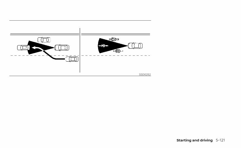
SSD0252
Starting and driving 5-121
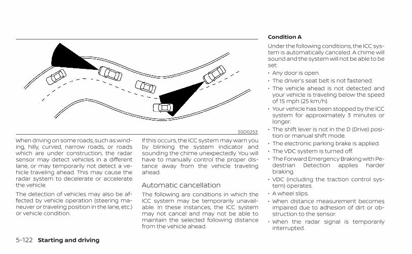
When driving on some roads, such as wind-ing, hilly, curved, narrow roads, or roadswhich are under construction, the radarsensor may detect vehicles in a differentlane, or may temporarily not detect a ve-hicle traveling ahead. This may cause theradar system to decelerate or acceleratethe vehicle.The detection of vehicles may also be af-fected by vehicle operation (steering ma-neuver or traveling position in the lane, etc.)or vehicle condition.
If this occurs, the ICC system may warn youby blinking the system indicator andsounding the chime unexpectedly. You willhave to manually control the proper dis-tance away from the vehicle travelingahead.
Automatic cancellationThe following are conditions in which theICC system may be temporarily unavail-able. In these instances, the ICC systemmay not cancel and may not be able tomaintain the selected following distancefrom the vehicle ahead.
Condition AUnder the following conditions, the ICC sys-tem is automatically canceled. A chime willsound and the system will not be able to beset:• Any door is open.• The driver’s seat belt is not fastened.• The vehicle ahead is not detected and
your vehicle is traveling below the speedof 15 mph (25 km/h).
• Your vehicle has been stopped by the ICCsystem for approximately 3 minutes orlonger.
• The shift lever is not in the D (Drive) posi-tion or manual shift mode.
• The electronic parking brake is applied.• The VDC system is turned off.• The Forward Emergency Braking with Pe-
destrian Detection applies harderbraking.
• VDC (including the traction control sys-tem) operates.
• A wheel slips.• When distance measurement becomes
impaired due to adhesion of dirt or ob-struction to the sensor.
• When the radar signal is temporarilyinterrupted.
SSD0253
5-122 Starting and driving

Action to take:When the conditions listed above are nolonger present, turn the system off usingthe ProPILOT Assist switch. Turn the ProPI-LOT Assist system back on to use thesystem.
NOTE:When the ICC system is canceled un-der the following conditions at astandstill, the electronic parking brakeis automatically activated:• Any door is open.• The driver’s seat belt is not fastened.• Your vehicle has been stopped by the
ICC system for approximately 3 min-utes or longer.
• The shift lever is not in the D (Drive)position or manual shift mode.
• The VDC system is turned off.• When distance measurement be-
comes impaired due to adhesion of dirtor obstruction to the sensor.
• When the radar signal is temporarilyinterrupted.
Condition BWhen the radar sensor of the front bumperis covered with dirt or is obstructed, the ICCsystem will automatically be canceled.The chime will sound and the “Not Avail-able: Front Radar Blocked” warning mes-sage will appear in the vehicle informationdisplay.Action to take:If the warning message appears, stop thevehicle in a safe place, press the Park but-ton to place the vehicle in the P (Park) posi-tion, and turn the engine off. When the ra-dar signal is temporarily interrupted, cleanthe sensor area of the front bumper andrestart the engine. If the “Not Available:Front Radar Blocked” warning messagecontinues to be displayed, have the systemchecked. It is recommended that you visitan INFINITI retailer for this service.Condition CWhen driving on roads with limited roadstructures or buildings (for example, longbridges, deserts, snow fields, driving next tolong walls), the system may illuminate thesystem warning light and display the “NotAvailable: Front Radar Blocked” message.
Action to take:When the above driving conditions no lon-ger exist, turn the system back on.
ICC system malfunctionIf the ICC system malfunctions, it will beturned off automatically, a chime willsound, and the speed control status warn-ing (orange) will illuminate.Action to take:If the warning light comes on, stop the ve-hicle in a safe place. Turn the engine off,restart the engine and set the ICC systemagain. If it is not possible to set the ICCsystem or the indicator stays on, it may bea malfunction. Although the normal drivingcan be continued, the ICC system shouldbe inspected. It is recommended that youvisit an INFINITI retailer for this service.
ICC sensor maintenanceThe radar sensor is located on the front ofthe vehicle.To keep the ICC system operating properly,be sure to observe the following:• Always keep the sensor area clean.• Do not strike or damage the areas
around the sensor.
Starting and driving 5-123
• Do not attach a sticker (including trans-parent material) or install an accessorynear the sensor. This could cause failureor malfunction.
• Do not attach metallic objects near thesensor area (brush guard, etc.). This couldcause failure or malfunction.
• Do not alter, remove, or paint the frontbumper.
Before customizing or restoring the frontbumper, it is recommended that you visitan INFINITI retailer.The camera sensor is located above theinside mirror.To keep the proper operation of the sys-tems and prevent a system malfunction,be sure to observe the following:• Always keep the windshield clean.• Do not attach a sticker (including trans-
parent material) or install an accessorynear the camera unit.
• Do not place reflective materials, such aswhite paper or a mirror, on the instru-ment panel. The reflection of sunlightmay adversely affect the camera unit’scapability of detecting the lane markers.
• Do not strike or damage the areasaround the camera unit. Do not touch thecamera lens or remove the screw locatedon the camera unit.
If the camera unit is damaged due to anaccident, it is recommended that you visitan INFINITI retailer.
STEERING ASSIST
WARNING
Failure to follow the warnings and in-structions for proper use of the Steer-ing Assist could result in serious injuryor death.• The Steering Assist is not a replace-
ment for proper driving proceduresand is not designed to correct care-less, inattentive or absent-mindeddriving. The Steering Assist will notalways steer the vehicle to keep it inthe lane. It is not designed to preventloss of control. It is the driver’s re-sponsibility to stay alert, drive safely,keep the vehicle in the traveling lane,and be in control of the vehicle at alltimes.
• As there is a performance limit to theSteering Assist’s capability, neverrely solely on the system. The Steer-ing Assist does not function in alldriving, traffic, weather, and roadconditions. Always drive safely, payattention to the operation of the ve-hicle, and manually control your ve-hicle appropriately.
• The Steering Assist is intended foruse on well-developed freeways orhighways with gentle (moderate)curves. To avoid risk of an accident,do not use this system on local ornon-highway roads.
• The Steering Assist only steers thevehicle to maintain its position in thecenter of a lane. The vehicle will notsteer to avoid objects in the road infront of the vehicle or to avoid a ve-hicle moving into your lane.
• It is the driver’s responsibility to stayalert, drive safely, keep the vehicle inthe traveling lane, and be in control ofthe vehicle at all times. Never takeyour hands off the steering wheelwhen driving. Always keep yourhands on the steering wheel anddrive your vehicle safely.
5-124 Starting and driving
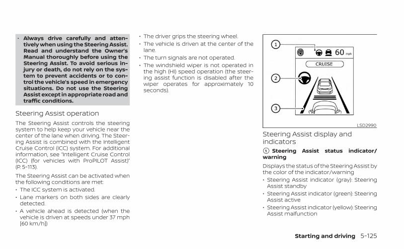
• Always drive carefully and atten-tively when using the Steering Assist.Read and understand the Owner’sManual thoroughly before using theSteering Assist. To avoid serious in-jury or death, do not rely on the sys-tem to prevent accidents or to con-trol the vehicle’s speed in emergencysituations. Do not use the SteeringAssist except in appropriate road andtraffic conditions.
Steering Assist operationThe Steering Assist controls the steeringsystem to help keep your vehicle near thecenter of the lane when driving. The Steer-ing Assist is combined with the IntelligentCruise Control (ICC) system. For additionalinformation, see “Intelligent Cruise Control(ICC) (for vehicles with ProPILOT Assist)”(P. 5-113).The Steering Assist can be activated whenthe following conditions are met:• The ICC system is activated.• Lane markers on both sides are clearly
detected.• A vehicle ahead is detected (when the
vehicle is driven at speeds under 37 mph[60 km/h])
• The driver grips the steering wheel.• The vehicle is driven at the center of the
lane.• The turn signals are not operated.• The windshield wiper is not operated in
the high (HI) speed operation (the steer-ing assist function is disabled after thewiper operates for approximately 10seconds).
Steering Assist display andindicators�1 Steering Assist status indicator/warningDisplays the status of the Steering Assist bythe color of the indicator/warning• Steering Assist indicator (gray): Steering
Assist standby• Steering Assist indicator (green): Steering
Assist active• Steering Assist indicator (yellow): Steering
Assist malfunction
LSD2990
Starting and driving 5-125

�2 Steering Assist indicatorIndicates the status of the Steering Assistby the color of the indicator• Steering Assist indicator (gray): Steering
Assist standby• Steering Assist indicator (green): Steering
Assist active
�3 Lane marker indicatorIndicates whether the system detects thelane marker• Lane marker indicator (gray): Lane mark-
ers not detected• Lane marker indicator (green): Lane
markers detected• Lane marker indicator (yellow): Lane de-
parture is detectedWhen the Steering Assist is in operation,the Steering Assist status indicator O1 , theSteering Assist indicator O2 , and the lanemarker indicator O3 on the vehicle infor-mation display turn green. A chime soundswhen the Steering Assist initially activates.When the Steering Assist deactivates, theSteering Assist status indicator O1 , theSteering Assist indicator O2 , and the lanemarker indicator O3 on the vehicle infor-mation display turn gray and a chimesounds twice.
Lane Departure Prevention (LDP)When a curve or strong cross wind exceedsthe capabilities of the Steering Assist andyour vehicle approaches either the left orthe right side of the traveling lane, a warn-ing chime sounds and the LDP indicatorlight (orange) on the instrument panelflashes to alert the driver. Then, the LDPsystem automatically applies the brakesfor a short period of time to help assist thedriver to return the vehicle to the center ofthe traveling lane. This action is in additionto any Steering Assist actions.
5-126 Starting and driving
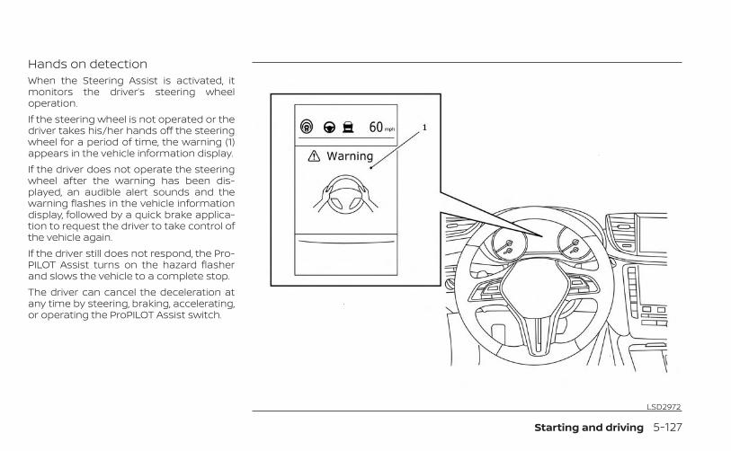
Hands on detectionWhen the Steering Assist is activated, itmonitors the driver’s steering wheeloperation.If the steering wheel is not operated or thedriver takes his/her hands off the steeringwheel for a period of time, the warning (1)appears in the vehicle information display.If the driver does not operate the steeringwheel after the warning has been dis-played, an audible alert sounds and thewarning flashes in the vehicle informationdisplay, followed by a quick brake applica-tion to request the driver to take control ofthe vehicle again.If the driver still does not respond, the Pro-PILOT Assist turns on the hazard flasherand slows the vehicle to a complete stop.The driver can cancel the deceleration atany time by steering, braking, accelerating,or operating the ProPILOT Assist switch.
LSD2972
Starting and driving 5-127
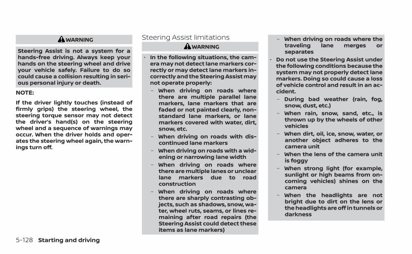
WARNING
Steering Assist is not a system for ahands-free driving. Always keep yourhands on the steering wheel and driveyour vehicle safely. Failure to do socould cause a collision resulting in seri-ous personal injury or death.
NOTE:
If the driver lightly touches (instead offirmly grips) the steering wheel, thesteering torque sensor may not detectthe driver’s hand(s) on the steeringwheel and a sequence of warnings mayoccur. When the driver holds and oper-ates the steering wheel again, the warn-ings turn off.
Steering Assist limitationsWARNING
• In the following situations, the cam-era may not detect lane markers cor-rectly or may detect lane markers in-correctly and the Steering Assist maynot operate properly:– When driving on roads where
there are multiple parallel lanemarkers, lane markers that arefaded or not painted clearly, non-standard lane markers, or lanemarkers covered with water, dirt,snow, etc.
– When driving on roads with dis-continued lane markers
– When driving on roads with a wid-ening or narrowing lane width
– When driving on roads wherethere are multiple lanes or unclearlane markers due to roadconstruction
– When driving on roads wherethere are sharply contrasting ob-jects, such as shadows, snow, wa-ter, wheel ruts, seams, or lines re-maining after road repairs (theSteering Assist could detect theseitems as lane markers)
– When driving on roads where thetraveling lane merges orseparates
• Do not use the Steering Assist underthe following conditions because thesystem may not properly detect lanemarkers. Doing so could cause a lossof vehicle control and result in an ac-cident.– During bad weather (rain, fog,
snow, dust, etc.)– When rain, snow, sand, etc., is
thrown up by the wheels of othervehicles
– When dirt, oil, ice, snow, water, oranother object adheres to thecamera unit
– When the lens of the camera unitis foggy
– When strong light (for example,sunlight or high beams from on-coming vehicles) shines on thecamera
– When the headlights are notbright due to dirt on the lens orthe headlights are off in tunnels ordarkness
5-128 Starting and driving
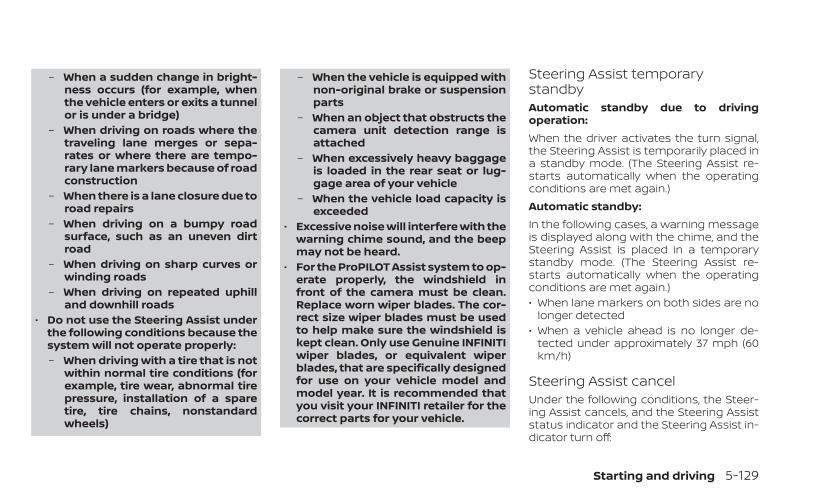
– When a sudden change in bright-ness occurs (for example, whenthe vehicle enters or exits a tunnelor is under a bridge)
– When driving on roads where thetraveling lane merges or sepa-rates or where there are tempo-rary lane markers because of roadconstruction
– When there is a lane closure due toroad repairs
– When driving on a bumpy roadsurface, such as an uneven dirtroad
– When driving on sharp curves orwinding roads
– When driving on repeated uphilland downhill roads
• Do not use the Steering Assist underthe following conditions because thesystem will not operate properly:– When driving with a tire that is not
within normal tire conditions (forexample, tire wear, abnormal tirepressure, installation of a sparetire, tire chains, nonstandardwheels)
– When the vehicle is equipped withnon-original brake or suspensionparts
– When an object that obstructs thecamera unit detection range isattached
– When excessively heavy baggageis loaded in the rear seat or lug-gage area of your vehicle
– When the vehicle load capacity isexceeded
• Excessive noise will interfere with thewarning chime sound, and the beepmay not be heard.
• For the ProPILOT Assist system to op-erate properly, the windshield infront of the camera must be clean.Replace worn wiper blades. The cor-rect size wiper blades must be usedto help make sure the windshield iskept clean. Only use Genuine INFINITIwiper blades, or equivalent wiperblades, that are specifically designedfor use on your vehicle model andmodel year. It is recommended thatyou visit your INFINITI retailer for thecorrect parts for your vehicle.
Steering Assist temporarystandbyAutomatic standby due to drivingoperation:When the driver activates the turn signal,the Steering Assist is temporarily placed ina standby mode. (The Steering Assist re-starts automatically when the operatingconditions are met again.)Automatic standby:In the following cases, a warning messageis displayed along with the chime, and theSteering Assist is placed in a temporarystandby mode. (The Steering Assist re-starts automatically when the operatingconditions are met again.)• When lane markers on both sides are no
longer detected• When a vehicle ahead is no longer de-
tected under approximately 37 mph (60km/h)
Steering Assist cancelUnder the following conditions, the Steer-ing Assist cancels, and the Steering Assiststatus indicator and the Steering Assist in-dicator turn off:
Starting and driving 5-129
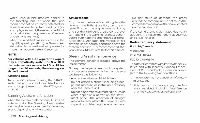
• When unusual lane markers appear inthe traveling lane or when the lanemarker cannot be correctly detected forsome time due to certain conditions (forexample, a snow rut, the reflection of lighton a rainy day, the presence of severalunclear lane markers)
• When the windshield wiper operates in thehigh (HI) speed operation (the Steering As-sist is disabled when the wiper operates formore than approximately 10 seconds)
NOTE:For vehicles with auto wipers, the wipersmay automatically switch to LO or HI. Ifthe auto wipers remain in LO or HI forlonger than 10 seconds, the steering as-sist will cancel.Action to take:Turn the ICC system off using the CANCELswitch. When the conditions listed aboveare no longer present, turn the ICC systemon again.
Steering Assist malfunctionWhen the system malfunctions, it turns offautomatically. The Steering Assist statuswarning illuminates (orange). A chime maysound depending on the situation.
Action to take:Stop the vehicle in a safe location, place thevehicle in the P (Park) position, turn the en-gine off, restart the engine, resume driving,and set the Intelligent Cruise Control sys-tem again. If the warning (orange) contin-ues to illuminate, the Steering Assist is mal-functioning. Although the vehicle is stilldrivable under normal conditions, have thesystem checked. It is recommended thatyou visit an INFINITI retailer for this service.
Steering Assist maintenanceThe camera sensor is located above theinside mirror.To keep the proper operation of the systemand prevent a system malfunction, be sureto observe the following:• Always keep the windshield clean.• Do not attach a sticker (including trans-
parent material) or install an accessorynear the camera unit.
• Do not place reflective materials, such aswhite paper or a mirror, on the instru-ment panel. The reflection of sunlightmay adversely affect the camera unit’scapability of detecting the lane markers.
• Do not strike or damage the areasaround the camera unit. Do not touch thecamera lens or remove the screw locatedon the camera unit.
If the camera unit is damaged due to anaccident, it is recommended that you visitan INFINITI retailer.Radio frequency statementFor USA/CanadaModel: ARS4–AIC: 4135A-ARS4AFCC ID: OAYARS4AThis device complies with Part 15 of the FCCRules and with Industry Canada licence-exempt RSS standard(s). Operation is sub-ject to the following two conditions:1. This device may not cause harmful inter-
ference, and
2. This device must accept any interfer-ence received, including interferencethat may cause undesired operation.
5-130 Starting and driving

Le present appareil est conforme aux CNRd’Industrie Canada applicables aux appar-eils radio exempts de licence. L’exploitationest autorisee aux deux conditions suiv-antes:1. L’appareil ne doit pas produire de brouil-
lage, et
2. L’utilisateur de l’appareil doit acceptertout brouillage radioelectrique subi,meme si le brouillage est susceptibled’en compromettre le fonctionnement.
Radio Frequency Radiation ExposureInformation:This equipment complies with FCC radia-tion exposure limits set forth for an uncon-trolled environment.This equipment should be installed andoperated with minimum distance of 30 cmbetween the radiator and your body.The transmitter must not be co-located oroperating in conjunction with any other an-tenna or transmitter.Cet equipement est conforme aux limitesd’exposition aux rayonnements IC etabliespour un environnement non controle. Cetequipement doit etre installe et utilise avec
un minimum de 30 cm de distance entre lasource de rayonnement et votre corps.FCC NoticeChanges or modifications not expresslyapproved by the party responsible forcompliance could void the user’s authorityto operate the equipment.
CONVENTIONAL (fixed speed)CRUISE CONTROL MODENOTE:
ProPILOT Assist provides no approachwarnings, automatic braking, or steeringassist in the conventional (fixed speed)cruise control mode.This mode allows driving at a speed be-tween 25 to 90 mph (40 to 144 km/h) with-out keeping your foot on the acceleratorpedal.
WARNING
• In the conventional (fixed speed)cruise control mode, a warningchime does not sound to warn you ifyou are too close to the vehicleahead, as neither the presence of thevehicle ahead nor the vehicle-to-vehicle distance is detected.
• Pay special attention to the distancebetween your vehicle and the vehicleahead of you or a collision couldoccur.
• Always confirm the setting in the ICCsystem display.
• Do not use the conventional (fixedspeed) cruise control mode whendriving under the following condi-tions:– When it is not possible to keep the
vehicle at a set speed– In heavy traffic or in traffic that
varies in speed– On winding or hilly roads– On slippery roads (rain, snow, ice,
etc.)– In very windy areas
• Doing so could cause a loss of vehiclecontrol and result in an accident.
Starting and driving 5-131
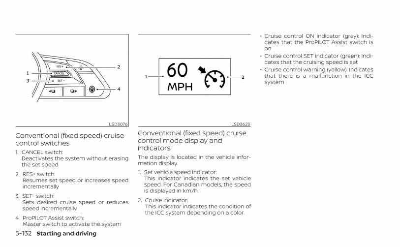
Conventional (fixed speed) cruisecontrol switches1. CANCEL switch:
Deactivates the system without erasingthe set speed
2. RES+ switch:Resumes set speed or increases speedincrementally
3. SET- switch:Sets desired cruise speed or reducesspeed incrementally
4. ProPILOT Assist switch:Master switch to activate the system
Conventional (fixed speed) cruisecontrol mode display andindicatorsThe display is located in the vehicle infor-mation display.1. Set vehicle speed indicator:
This indicator indicates the set vehiclespeed. For Canadian models, the speedis displayed in km/h.
2. Cruise indicator:This indicator indicates the condition ofthe ICC system depending on a color.
• Cruise control ON indicator (gray): Indi-cates that the ProPILOT Assist switch ison
• Cruise control SET indicator (green): Indi-cates that the cruising speed is set
• Cruise control warning (yellow): Indicatesthat there is a malfunction in the ICCsystem
LSD3076 LSD3623
5-132 Starting and driving
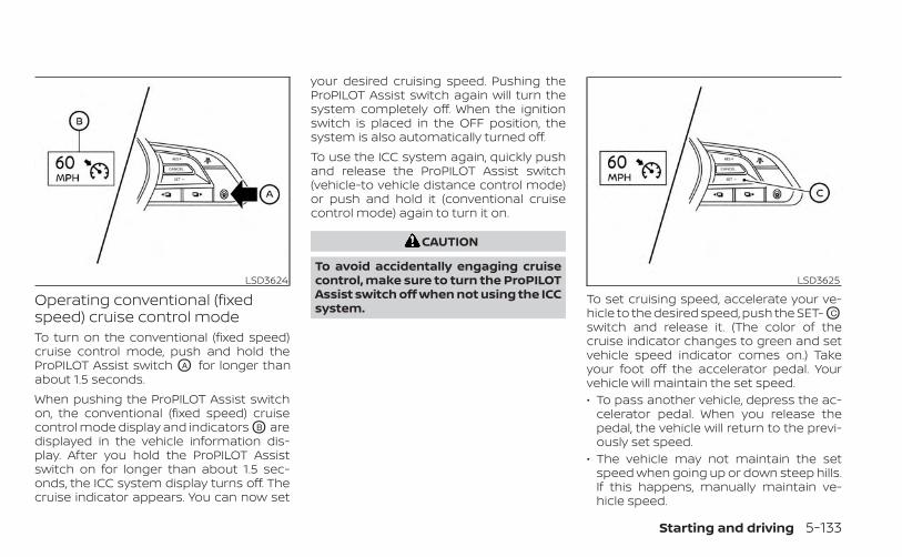
Operating conventional (fixedspeed) cruise control modeTo turn on the conventional (fixed speed)cruise control mode, push and hold theProPILOT Assist switch OA for longer thanabout 1.5 seconds.When pushing the ProPILOT Assist switchon, the conventional (fixed speed) cruisecontrol mode display and indicators OB aredisplayed in the vehicle information dis-play. After you hold the ProPILOT Assistswitch on for longer than about 1.5 sec-onds, the ICC system display turns off. Thecruise indicator appears. You can now set
your desired cruising speed. Pushing theProPILOT Assist switch again will turn thesystem completely off. When the ignitionswitch is placed in the OFF position, thesystem is also automatically turned off.To use the ICC system again, quickly pushand release the ProPILOT Assist switch(vehicle-to vehicle distance control mode)or push and hold it (conventional cruisecontrol mode) again to turn it on.
CAUTION
To avoid accidentally engaging cruisecontrol, make sure to turn the ProPILOTAssist switch off when not using the ICCsystem.
To set cruising speed, accelerate your ve-hicle to the desired speed, push the SET- OC
switch and release it. (The color of thecruise indicator changes to green and setvehicle speed indicator comes on.) Takeyour foot off the accelerator pedal. Yourvehicle will maintain the set speed.• To pass another vehicle, depress the ac-
celerator pedal. When you release thepedal, the vehicle will return to the previ-ously set speed.
• The vehicle may not maintain the setspeed when going up or down steep hills.If this happens, manually maintain ve-hicle speed.
LSD3624 LSD3625
Starting and driving 5-133
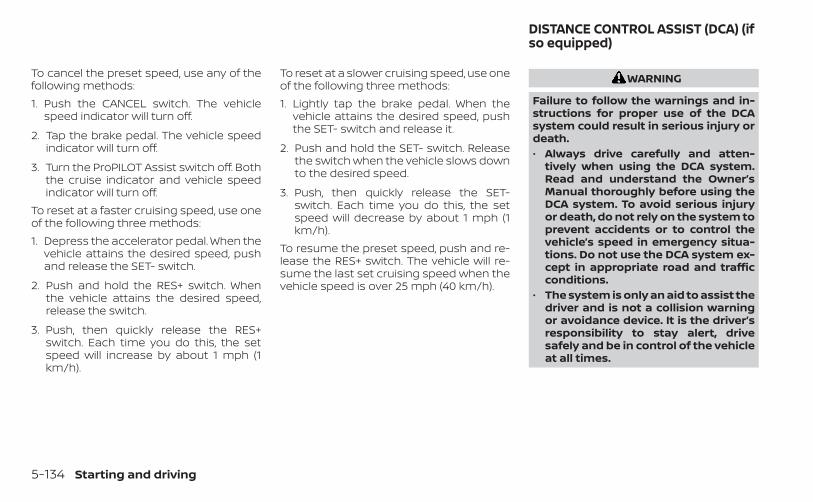
To cancel the preset speed, use any of thefollowing methods:1. Push the CANCEL switch. The vehicle
speed indicator will turn off.
2. Tap the brake pedal. The vehicle speedindicator will turn off.
3. Turn the ProPILOT Assist switch off. Boththe cruise indicator and vehicle speedindicator will turn off.
To reset at a faster cruising speed, use oneof the following three methods:1. Depress the accelerator pedal. When the
vehicle attains the desired speed, pushand release the SET- switch.
2. Push and hold the RES+ switch. Whenthe vehicle attains the desired speed,release the switch.
3. Push, then quickly release the RES+switch. Each time you do this, the setspeed will increase by about 1 mph (1km/h).
To reset at a slower cruising speed, use oneof the following three methods:1. Lightly tap the brake pedal. When the
vehicle attains the desired speed, pushthe SET- switch and release it.
2. Push and hold the SET- switch. Releasethe switch when the vehicle slows downto the desired speed.
3. Push, then quickly release the SET-switch. Each time you do this, the setspeed will decrease by about 1 mph (1km/h).
To resume the preset speed, push and re-lease the RES+ switch. The vehicle will re-sume the last set cruising speed when thevehicle speed is over 25 mph (40 km/h).
WARNING
Failure to follow the warnings and in-structions for proper use of the DCAsystem could result in serious injury ordeath.• Always drive carefully and atten-
tively when using the DCA system.Read and understand the Owner’sManual thoroughly before using theDCA system. To avoid serious injuryor death, do not rely on the system toprevent accidents or to control thevehicle’s speed in emergency situa-tions. Do not use the DCA system ex-cept in appropriate road and trafficconditions.
• The system is only an aid to assist thedriver and is not a collision warningor avoidance device. It is the driver’sresponsibility to stay alert, drivesafely and be in control of the vehicleat all times.
DISTANCE CONTROL ASSIST (DCA) (ifso equipped)
5-134 Starting and driving
• As there is a performance limit to thedistance control function, never relysolely on the DCA system. This sys-tem does not correct careless, inat-tentive or absent-minded driving, orovercome poor visibility in rain, fog,or other bad weather. Decelerate thevehicle speed by depressing thebrake pedal, depending on the dis-tance to the vehicle ahead and thesurrounding circumstances in orderto maintain a safe distance betweenvehicles.
• Always pay attention to the opera-tion of the vehicle and be ready tomanually decelerate to maintain theproper following distance. The DCAsystem may not be able to deceleratethe vehicle under somecircumstances.
• This system only brakes and movesthe accelerator pedal upward to helpassist the driver to maintain a follow-ing distance from the vehicle ahead.Acceleration should be operated bythe driver.
• The DCA system does not control thevehicle speed or warn you when youapproach stationary and slow mov-ing vehicles. You must pay attentionto vehicle operation to maintainproper distance from vehicles ahead.
• The DCA system automatically decel-erates your vehicle to help assist thedriver to maintain a following dis-tance from the vehicle ahead. Manu-ally brake when deceleration is re-quired to maintain a safe distanceupon sudden braking by the vehicleahead or when a vehicle suddenlyappears in front of you. Always stayalert when using the DCA system.
• If the vehicle ahead comes to a stop,the vehicle decelerates to a standstillwithin the limitations of the system.The system will cancel with a warn-ing chime once it judges that the ve-hicle has come to a standstill. To pre-vent the vehicle from moving, thedriver must depress the brake pedal.
The DCA system is intended to assist thedriver in keeping a following distance fromthe vehicle ahead traveling in the samelane and direction.If the radar sensor detects a slower movingvehicle ahead, the system will reduce thevehicle speed to help assist the driver tomaintain a following distance.The system automatically controls thethrottle and applies the brakes (up to ap-proximately 40% of vehicle braking power)if necessary.The detection range of the sensor is ap-proximately 650 ft (200m) ahead.
Starting and driving 5-135

DCA SYSTEM OPERATION1. Vehicle information display
2. Lower display buttons
3. ProPILOT Assist switch (for vehicles withProPILOT Assist)
4. Dynamic driver assistance switch (forvehicles without ProPILOT Assist)
5. DCA ON indicator
WARNING
Failure to follow the warnings and in-structions for proper use of the DCAsystem could result in serious personalinjury or death.• When the vehicle ahead detection in-
dicator light is not illuminated, thesystem will not control the vehicle orwarn the driver.
• Never place your foot under thebrake pedal. Your foot may be caughtwhen the system controls the brake.
• Depending on the position of the ac-celerator pedal, the system may notbe able to assist the driver to releasethe accelerator pedal appropriately.
LSD3562
5-136 Starting and driving

The DCA system brakes and moves theaccelerator pedal upward according to thedistance from and the relative speed of thevehicle ahead to help assist the driver inmaintaining a following distance. The sys-tem will decelerate as necessary and if thevehicle ahead comes to a stop, the vehicledecelerates to a standstill. However, theDCA system can only apply up to approxi-mately 40% of the vehicle’s total brakingpower. If a vehicle moves into the travelinglane ahead or if a vehicle traveling aheadrapidly decelerates, the distance betweenvehicles may become closer because theDCA system cannot decelerate the vehiclequickly enough. If this occurs, the DCA sys-tem will sound a warning chime and blinkthe system display to notify the driver totake necessary action. For additional infor-mation, see “Approach warning” (P. 5-138).
The DCA system helps assist the driver tokeep a following distance to the vehicleahead by braking and moving the accel-erator pedal upward in the normal drivingcondition.When a vehicle is detected ahead:The vehicle ahead detection indicatorcomes on.
When vehicle approaches a vehicleahead:• If the driver’s foot is not on the accelerator
pedal, the system activates the brakes todecelerate smoothly as necessary. If thevehicle ahead comes to a stop, the ve-hicle decelerates to a standstill within thelimitations of the system.
• If the driver’s foot is on the acceleratorpedal, the system moves the acceleratorpedal upward to assist the driver to re-lease the accelerator pedal.
When brake operation by driver isrequired:The system alerts the driver by a warningchime and blinking the vehicle ahead de-tection indicator. If the driver’s foot is on theaccelerator pedal after the warning, thesystem moves the accelerator pedal up-ward to assist the driver to switch to thebrake pedal.
NOTE:• The stop lights of the vehicle come on
when braking is performed by the DCAsystem.
• When the brake operates, a noise maybe heard. This is not a malfunction.
LSD2991
Starting and driving 5-137

Overriding the system:The following driver’s operations overridethe system operation:• When the driver depresses the accelera-
tor pedal even further while the system ismoving the accelerator pedal upward,the DCA system control of the accelera-tor pedal is canceled.
• When the driver’s foot is on the accelera-tor pedal, the brake control by the systemis not operated.
• When the driver’s foot is on the brakepedal, neither the brake control nor thealert by the system operates.
• When the ICC system is set, the DCA sys-tem will be canceled.
Approach warningIf your vehicle comes closer to the vehicleahead due to rapid deceleration of that ve-hicle or if another vehicle cuts in, the sys-tem warns the driver with the chime andDCA system display. Decelerate by de-pressing the brake pedal to maintain a safevehicle distance if:• The chime sounds.• The vehicle ahead detection indicator
blinks.
The warning chime may not sound insome cases when there is a short distancebetween vehicles. Some examples are:• When the vehicles are traveling at the
same speed and the distance betweenvehicles is not changing
• When the vehicle ahead is traveling fasterand the distance between vehicles isincreasing
• When a vehicle cuts in near your vehicleThe warning chime will not sound whenyour vehicle approaches vehicles that areparked or moving slowly.
NOTE:
The approach warning chime may soundand the system display may blink whenthe radar sensor detects objects on theside of the road. This may cause the DCAsystem to decelerate or accelerate thevehicle. The radar sensor may detectthese objects when the vehicle is drivenon winding roads, narrow roads, hillyroads or when entering or exiting acurve. In these cases you will have tomanually control the proper distanceahead of your vehicle.
Also, the sensor sensitivity can be affectedby vehicle operation (steering maneuver ordriving position in the lane) or traffic or ve-hicle condition (for example, if a vehicle isbeing driven with some damage).
5-138 Starting and driving

HOW TO ENABLE/DISABLE THEDCA SYSTEMTo turn on the DCA system, push the dy-namic driver assistance switch (for modelswithout ProPILOT Assist) or the ProPILOTAssist switch (for models with ProPILOT As-sist) on the steering wheel after startingthe engine. The DCA system switch indica-tor light in the vehicle information displaywill illuminate. Push the dynamic driver as-sistance switch (for models without ProPI-LOT Assist) or the ProPILOT Assist switch(for models with ProPILOT Assist) on thesteering wheel again to turn off the DCAsystem. The DCA system switch indicatorlight will turn off.The system will start to operate after thevehicle speed becomes above approxi-mately 3 mph (5 km/h).
LSD3144
Starting and driving 5-139
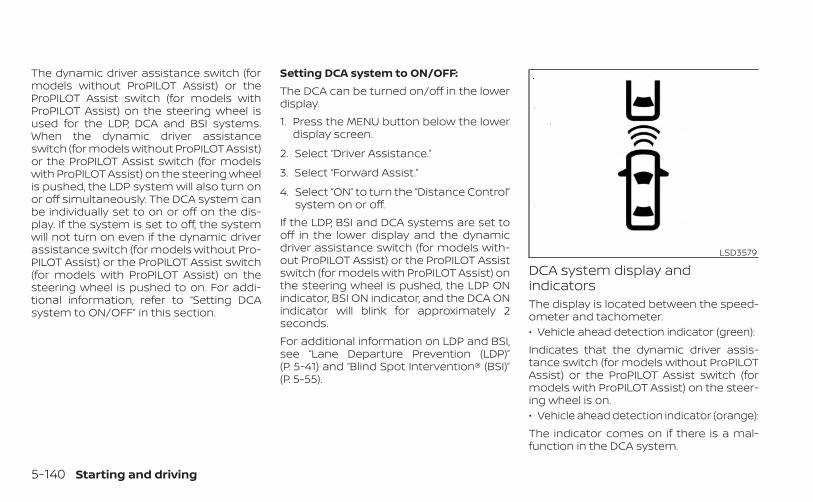
The dynamic driver assistance switch (formodels without ProPILOT Assist) or theProPILOT Assist switch (for models withProPILOT Assist) on the steering wheel isused for the LDP, DCA and BSI systems.When the dynamic driver assistanceswitch (for models without ProPILOT Assist)or the ProPILOT Assist switch (for modelswith ProPILOT Assist) on the steering wheelis pushed, the LDP system will also turn onor off simultaneously. The DCA system canbe individually set to on or off on the dis-play. If the system is set to off, the systemwill not turn on even if the dynamic driverassistance switch (for models without Pro-PILOT Assist) or the ProPILOT Assist switch(for models with ProPILOT Assist) on thesteering wheel is pushed to on. For addi-tional information, refer to “Setting DCAsystem to ON/OFF” in this section.
Setting DCA system to ON/OFF:The DCA can be turned on/off in the lowerdisplay.1. Press the MENU button below the lower
display screen.
2. Select “Driver Assistance.”
3. Select “Forward Assist.”
4. Select “ON” to turn the “Distance Control”system on or off.
If the LDP, BSI and DCA systems are set tooff in the lower display and the dynamicdriver assistance switch (for models with-out ProPILOT Assist) or the ProPILOT Assistswitch (for models with ProPILOT Assist) onthe steering wheel is pushed, the LDP ONindicator, BSI ON indicator, and the DCA ONindicator will blink for approximately 2seconds.For additional information on LDP and BSI,see “Lane Departure Prevention (LDP)”(P. 5-41) and “Blind Spot Intervention® (BSI)”(P. 5-55).
DCA system display andindicatorsThe display is located between the speed-ometer and tachometer.• Vehicle ahead detection indicator (green):Indicates that the dynamic driver assis-tance switch (for models without ProPILOTAssist) or the ProPILOT Assist switch (formodels with ProPILOT Assist) on the steer-ing wheel is on.• Vehicle ahead detection indicator (orange):The indicator comes on if there is a mal-function in the DCA system.
LSD3579
5-140 Starting and driving
DCA SYSTEM LIMITATIONSWARNING
Listed below are the system limitationsof the DCA system. Failure to operatethe vehicle in accordance with thesesystem limitations could result in seri-ous injury or death.• This system will not adapt automati-
cally to road conditions. Do not usethe system on roads with sharpcurves, or on icy roads, in heavy rainor in fog.
• The DCA system will not apply brakecontrol while the driver’s foot is onthe accelerator pedal.
• As there is a performance limit to thedistance control function, never relysolely on the DCA system. This sys-tem does not correct careless, inat-tentive or absent-minded driving, orovercome poor visibility in rain, fog,or other bad weather. Decelerate thevehicle speed by depressing thebrake pedal, depending on the dis-tance to the vehicle ahead and thesurrounding circumstances in orderto maintain a safe distance betweenvehicles.
• The system may not detect the ve-hicle in front of you in certain road orweather conditions. To avoid acci-dents, never use the DCA system un-der the following conditions:– On roads where the traffic is heavy
or there are sharp curves– On slippery road surfaces such as
on ice or snow, etc.– On off-road surfaces such as on
sand or rock, etc.– During bad weather (rain, fog,
snow, etc.)– When rain, snow or dirt adhere to
the sensor area of the frontbumper
– On steep downhill roads (frequentbraking may result in overheatingthe brakes)
– On repeated uphill and downhillroads
– When traffic conditions make itdifficult to keep a proper distancebetween vehicles because of fre-quent acceleration ordeceleration
– Interference by other radarsources
• In some road or traffic conditions, avehicle or object can unexpectedlycome into the sensor detection zoneand cause automatic braking. Youmay need to control the distancefrom other vehicles using the accel-erator pedal. Always stay alert andavoid using the DCA system when it isnot recommended in this section.
The radar sensor will not detect the follow-ing objects:• Stationary and slow moving vehicles• Pedestrians or objects in the roadway• Oncoming vehicles in the same lane• Motorcycles traveling offset in the travel
laneThe following are some conditions in whichthe sensor cannot detect the signals:• When the snow or road spray from trav-
eling vehicles reduces the sensor’svisibility
• When excessively heavy baggage isloaded in the rear seat or the luggageroom of your vehicle
Starting and driving 5-141
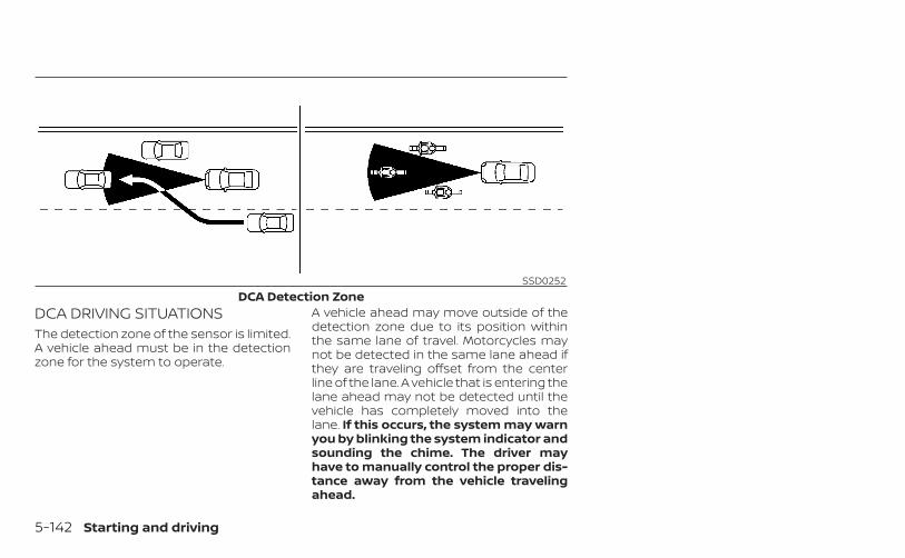
DCA DRIVING SITUATIONSThe detection zone of the sensor is limited.A vehicle ahead must be in the detectionzone for the system to operate.
A vehicle ahead may move outside of thedetection zone due to its position withinthe same lane of travel. Motorcycles maynot be detected in the same lane ahead ifthey are traveling offset from the centerline of the lane. A vehicle that is entering thelane ahead may not be detected until thevehicle has completely moved into thelane. If this occurs, the system may warnyou by blinking the system indicator andsounding the chime. The driver mayhave to manually control the proper dis-tance away from the vehicle travelingahead.
SSD0252DCA Detection Zone
5-142 Starting and driving

When driving on some roads, such as wind-ing, hilly, curved, narrow roads, or roadswhich are under construction, the sensormay detect vehicles in a different lane, ormay temporarily not detect a vehicle trav-eling ahead. This may cause the system towork inappropriately.
The detection of vehicles may also be af-fected by vehicle operation (steering ma-neuver or traveling position in the lane, etc.)or vehicle condition. If this occurs, the sys-tem may warn you by blinking the sys-tem indicator and sounding the chimeunexpectedly. You will have to manuallycontrol the proper distance away fromthe vehicle traveling ahead.
SYSTEM TEMPORARILYUNAVAILABLECondition A:Under the following conditions, the DCAsystem is automatically canceled. Thechime will sound and the DCA systemswitch indicator will blink. The system willnot be able to be set.
SSD0253DCA Detection Zones On Winding Roads
LSD3203
Starting and driving 5-143
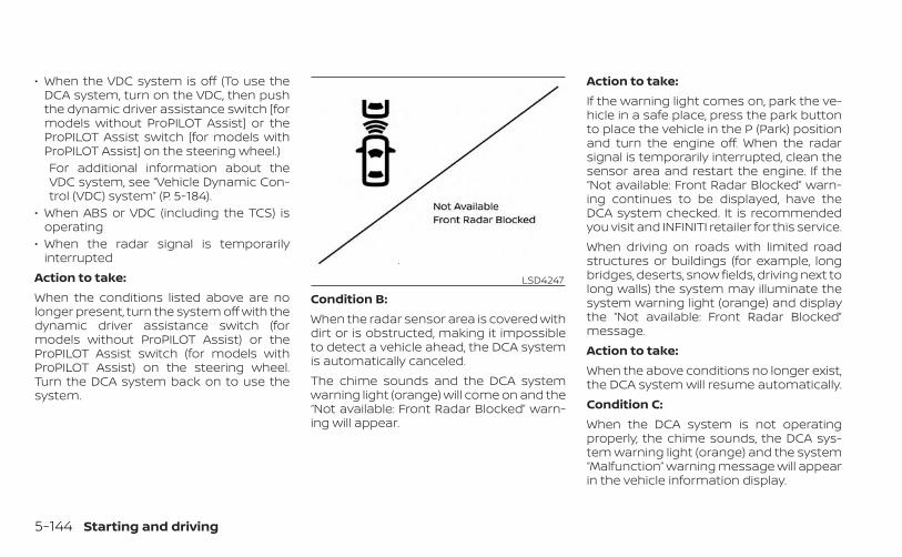
• When the VDC system is off (To use theDCA system, turn on the VDC, then pushthe dynamic driver assistance switch [formodels without ProPILOT Assist] or theProPILOT Assist switch [for models withProPILOT Assist] on the steering wheel.)For additional information about theVDC system, see “Vehicle Dynamic Con-trol (VDC) system” (P. 5-184).
• When ABS or VDC (including the TCS) isoperating
• When the radar signal is temporarilyinterrupted
Action to take:When the conditions listed above are nolonger present, turn the system off with thedynamic driver assistance switch (formodels without ProPILOT Assist) or theProPILOT Assist switch (for models withProPILOT Assist) on the steering wheel.Turn the DCA system back on to use thesystem.
Condition B:When the radar sensor area is covered withdirt or is obstructed, making it impossibleto detect a vehicle ahead, the DCA systemis automatically canceled.The chime sounds and the DCA systemwarning light (orange) will come on and the“Not available: Front Radar Blocked” warn-ing will appear.
Action to take:If the warning light comes on, park the ve-hicle in a safe place, press the park buttonto place the vehicle in the P (Park) positionand turn the engine off. When the radarsignal is temporarily interrupted, clean thesensor area and restart the engine. If the“Not available: Front Radar Blocked” warn-ing continues to be displayed, have theDCA system checked. It is recommendedyou visit and INFINITI retailer for this service.When driving on roads with limited roadstructures or buildings (for example, longbridges, deserts, snow fields, driving next tolong walls) the system may illuminate thesystem warning light (orange) and displaythe “Not available: Front Radar Blocked”message.Action to take:When the above conditions no longer exist,the DCA system will resume automatically.Condition C:When the DCA system is not operatingproperly, the chime sounds, the DCA sys-tem warning light (orange) and the system“Malfunction” warning message will appearin the vehicle information display.
LSD4247
5-144 Starting and driving
Action to take:If the DCA system warning light (orange)and the warning message appear, stop thevehicle in a safe place and place the vehiclein the P (Park) position. Turn the engine off,restart the engine, and turn on the DCAsystem again.If it is not possible to set the system or theindicator stays on, it may indicate that thesystem is malfunctioning. Although the ve-hicle is still drivable under normal condi-tions, have the vehicle checked. It is recom-mended that you visit an INFINITI retailer forthis service
SYSTEM MAINTENANCEThe sensor for the DCA system is commonwith ICC and is located behind the frontbumper.For additional information, see “IntelligentCruise Control (ICC) (for vehicles with ProPI-LOT Assist)” (P. 5-113).For USA/CanadaModel: ARS4–AIC: 4135A-ARS4AFCC ID: OAYARS4A
This device complies with Part 15 of the FCCRules and with Industry Canada licence-exempt RSS standard(s). Operation is sub-ject to the following two conditions: (1) Thisdevice may not cause interference, and (2)this device must accept any interference,including interference that may cause un-desired operation of the device.Le présent appareil est conforme aux CNRd'Industrie Canada applicables aux appar-eils radio exempts de licence. L'exploitationest autorisée aux deux conditions suiv-antes: (1) L'appareil ne doit pas produire debrouillage, et (2) l'utilisateur de l'appareildoit accepter tout brouillage radioélec-trique subi, même si le brouillage est sus-ceptible d'en compromettre lefonctionnement.Radio Frequency Radiation ExposureInformation:This equipment complies with FCC and ICradiation exposure limits set forth for anuncontrolled environment.This equipment should be installed andoperated with minimum distance of 30 cmbetween the radiator and your body.This transmitter must not be co-located oroperating in conjunction with any other an-tenna or transmitter.
Cet équipment est conforme aux limitesd’exposition aux rayonnements IC établiespour un environnement non contrôlé. Cetéquipment doit étre installé et utilisé avecun minimum de 30 cm de distance entre lasource de rayonnement et votre corps.FCC NoticeChanges or modifications not expresslyapproved by the party responsible forcompliance could void the user’s authorityto operate the equipment.
Starting and driving 5-145

WARNING
Failure to follow the warnings and in-structions for proper use of the RABsystem could result in serious injury ordeath.• The RAB system is a supplemental
aid to the driver. It is not a replace-ment for proper driving procedures.Always use the side and rear mirrorsand turn and look in the direction youwill move before and while backingup. Never rely solely on the RAB sys-tem. It is the driver’s responsibility tostay alert, drive safely, and be in con-trol of the vehicle at all times.
• There is a limitation to the RAB sys-tem capability. The RAB system is noteffective in all situations.
• Inclement weather or ultrasonicsources such as an automatic carwash, a truck’s compressed-airbrakes or a pneumatic drill may af-fect the function of the system; thismay include reduced performance ora false activation.
The RAB system can assist the driver whenthe vehicle is backing up and approachingobjects directly behind the vehicle.
The RAB system detects obstacles behindthe vehicle using the parking sensors O1
located on the rear bumper.
NOTE:
You can temporarily cancel the sonarfunction in the vehicle, but the RAB sys-tem will continue to operate. For addi-tional information, see “Front and rearsonar system” (P. 5-190).
LSD4097
REAR AUTOMATIC BRAKING (RAB)
5-146 Starting and driving
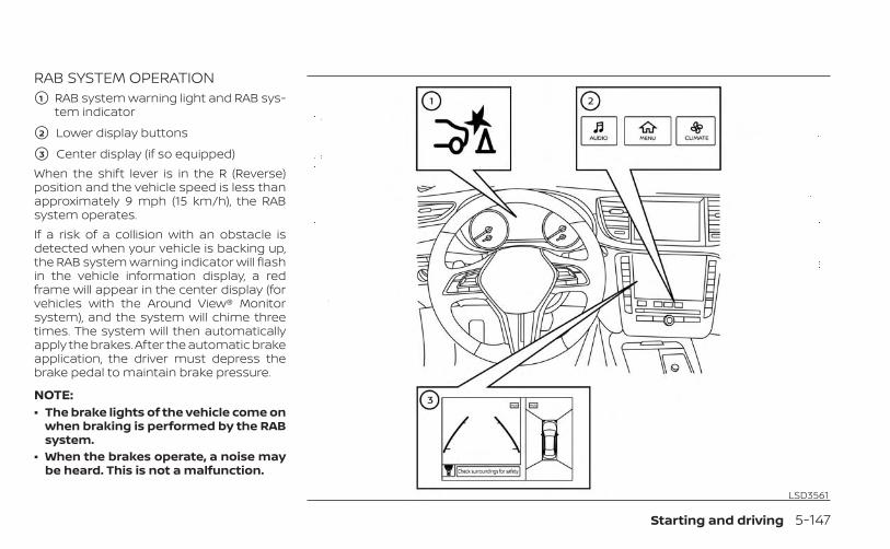
RAB SYSTEM OPERATION�1 RAB system warning light and RAB sys-
tem indicator
�2 Lower display buttons
�3 Center display (if so equipped)When the shift lever is in the R (Reverse)position and the vehicle speed is less thanapproximately 9 mph (15 km/h), the RABsystem operates.If a risk of a collision with an obstacle isdetected when your vehicle is backing up,the RAB system warning indicator will flashin the vehicle information display, a redframe will appear in the center display (forvehicles with the Around View® Monitorsystem), and the system will chime threetimes. The system will then automaticallyapply the brakes. After the automatic brakeapplication, the driver must depress thebrake pedal to maintain brake pressure.
NOTE:• The brake lights of the vehicle come on
when braking is performed by the RABsystem.
• When the brakes operate, a noise maybe heard. This is not a malfunction.
LSD3561
Starting and driving 5-147

TURNING THE RAB SYSTEMON/OFFPerform the following steps to turn the RABsystem ON or OFF.1. Press the MENU button below the lower
display screen.
2. Select “Driver Assistance.”
3. Select “Emergency Assist.”
4. Select “ON” to turn the “Backward” sys-tem on or off.
When the RAB system is turned off, the RABsystem warning light illuminates.
NOTE:
The RAB system will be automaticallyturned on when the engine is restarted.
LSD3610
5-148 Starting and driving
RAB SYSTEM LIMITATIONSWARNING
Listed below are the system limitationsfor the RAB system. Failure to follow thewarnings and instructions for properuse of the RAB system could result inserious injury or death.• When the vehicle approaches an ob-
stacle while the accelerator or brakepedal is depressed, the function maynot operate or the start of operationmay be delayed. The RAB systemmay not operate or may not performsufficiently due to vehicle conditions,driving conditions, the traffic envi-ronment, the weather, road surfaceconditions, etc. Do not wait for thesystem to operate. Operate the brakepedal by yourself as soon asnecessary.
• If it is necessary to override RAB op-eration, strongly press the accelera-tor pedal.
• Always check your surroundings andturn to check what is behind you be-fore and while backing up. The RABsystem detects stationary objectsbehind the vehicle. The RAB systemdoes not detect the following ob-jects:– Moving objects– Low objects– Narrow objects– Wedge-shaped objects– Objects close to the bumper (less
than approximately 1 ft [30 cm])– Objects that suddenly appear– Thin objects such as rope, wire,
chain, etc.• The RAB system may not operate for
the following obstacles:– Obstacles located high off the
ground– Obstacles in a position offset from
your vehicle– Obstacles, such as spongy materi-
als or snow, that have soft outersurfaces and can easily absorb asound wave
• The RAB system may not operate inthe following conditions:– There is rain, snow, ice, dirt, etc.,
attached to the sonar sensors.– A loud sound is heard in the area
around the vehicle.– The surface of the obstacle is di-
agonal to the rear of the vehicle.• The RAB system may unintentionally
operate in the following conditions:– There is overgrown grass in the
area around the vehicle.– There is a structure (e.g., a wall, toll
gate equipment, a narrow tunnel,a parking lot gate) near the side ofthe vehicle.
– There are bumps, protrusions, ormanhole covers on the roadsurface.
– The vehicle drives through adraped flag or a curtain.
– There is an accumulation of snowor ice behind the vehicle.
– An ultrasonic wave source, such asanother vehicle’s sonar, is nearthe vehicle.
Starting and driving 5-149
• Once the automatic brake controloperates, it does not operate again ifthe vehicle approaches the sameobstacle.
• The automatic brake control can onlyoperate for a short period of time.Therefore, the driver must depressthe brake pedal.
• In the following situations, the RABsystem may not operate properly ormay not function sufficiently:– The vehicle is driven in bad
weather (rain, fog, snow, etc.).– The vehicle is driven on a steep
hill.– The vehicle’s posture is changed
(e.g., when driving over a bump).– The vehicle is driven on a slippery
road.– The vehicle is turned sharply by
turning the steering wheel fully.– Snow chains are used.– Wheels or tires other than INFINITI
recommended are used.– The brakes are cold at low ambi-
ent temperatures or immediatelyafter driving has started.
– The braking force becomes poordue to wet brakes after drivingthrough a puddle or washing thevehicle.
• Turn the RAB system off in the follow-ing conditions to prevent the occur-rence of an unexpected accident re-sulting from sudden systemoperation:– The vehicle is towed.– The vehicle is carried on a flatbed
truck.– The vehicle is on the chassis
dynamometer.– The vehicle drives on an uneven
road surface.– Suspension parts other than
those designated as GenuineINFINITI parts are used. (If the ve-hicle height or the vehicle body in-clination is changed, the systemmay not detect an obstaclecorrectly.)
– If the vehicle is using an accessorylike a bike rack, or cargo carrierthat blocks the sensors.
• Excessive noise (e.g., audio systemvolume, an open vehicle window) willinterfere with the chime sound, and itmay not be heard.
SYSTEM MALFUNCTIONIf the RAB system malfunctions, it will beturned off automatically, the RAB systemwarning light will illuminate, and the “Sys-tem fault See Owner’s Manual” warningmessage will appear in the vehicle infor-mation display.Action to takeIf the warning light illuminates, park the ve-hicle in a safe location, turn the engine off,and restart the engine. If the warning lightcontinues to illuminate, have the RAB sys-tem checked. It is recommended that youvisit an INFINITI retailer for this service.
NOTE:
If the RAB system cannot be operatedtemporarily, the RAB system warninglight blinks.
5-150 Starting and driving

SYSTEM MAINTENANCEObserve the following items to ensureproper operation of the system:• Always keep the parking sensors O1
clean.• If the parking sensors are dirty, wipe them
off with a soft cloth while being careful tonot damage them.
• Do not subject the area around the park-ing sensors O1 to strong impact. Also, donot remove or disassemble the parkingsensors. If the parking sensors and pe-ripheral areas are deformed in an acci-dent, etc., have the sensors checked. It isrecommended that you visit an INFINITIretailer for this service.
• Do not install any stickers (includingtransparent stickers) or accessories onthe parking sensors O1 and their sur-rounding areas. This may cause a mal-function or improper operation.
WARNING
Failure to follow the warnings and in-structions for proper use of the FEBwith Pedestrian Detection systemcould result in serious injury or death.• The FEB with Pedestrian Detection
system is a supplemental aid to thedriver. It is not a replacement for thedriver’s attention to traffic condi-tions or responsibility to drive safely.It cannot prevent accidents due tocarelessness or dangerous drivingtechniques.
• The FEB with Pedestrian Detectionsystem does not function in all driv-ing, traffic, weather and roadconditions.
The FEB with Pedestrian Detection systemcan assist the driver when there is a risk ofa forward collision with the vehicle ahead inthe traveling lane or with a pedestrianahead in the traveling lane.
LSD4097
FORWARD EMERGENCY BRAKING(FEB) WITH PEDESTRIAN DETECTIONSYSTEM
Starting and driving 5-151
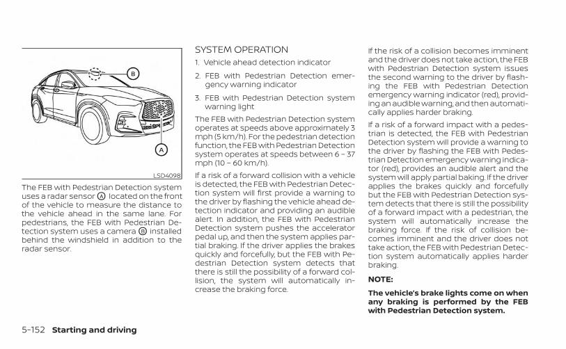
The FEB with Pedestrian Detection systemuses a radar sensor OA located on the frontof the vehicle to measure the distance tothe vehicle ahead in the same lane. Forpedestrians, the FEB with Pedestrian De-tection system uses a camera OB installedbehind the windshield in addition to theradar sensor.
SYSTEM OPERATION1. Vehicle ahead detection indicator
2. FEB with Pedestrian Detection emer-gency warning indicator
3. FEB with Pedestrian Detection systemwarning light
The FEB with Pedestrian Detection systemoperates at speeds above approximately 3mph (5 km/h). For the pedestrian detectionfunction, the FEB with Pedestrian Detectionsystem operates at speeds between 6 – 37mph (10 – 60 km/h).If a risk of a forward collision with a vehicleis detected, the FEB with Pedestrian Detec-tion system will first provide a warning tothe driver by flashing the vehicle ahead de-tection indicator and providing an audiblealert. In addition, the FEB with PedestrianDetection system pushes the acceleratorpedal up, and then the system applies par-tial braking. If the driver applies the brakesquickly and forcefully, but the FEB with Pe-destrian Detection system detects thatthere is still the possibility of a forward col-lision, the system will automatically in-crease the braking force.
If the risk of a collision becomes imminentand the driver does not take action, the FEBwith Pedestrian Detection system issuesthe second warning to the driver by flash-ing the FEB with Pedestrian Detectionemergency warning indicator (red), provid-ing an audible warning, and then automati-cally applies harder braking.If a risk of a forward impact with a pedes-trian is detected, the FEB with PedestrianDetection system will provide a warning tothe driver by flashing the FEB with Pedes-trian Detection emergency warning indica-tor (red), provides an audible alert and thesystem will apply partial baking. If the driverapplies the brakes quickly and forcefullybut the FEB with Pedestrian Detection sys-tem detects that there is still the possibilityof a forward impact with a pedestrian, thesystem will automatically increase thebraking force. If the risk of collision be-comes imminent and the driver does nottake action, the FEB with Pedestrian Detec-tion system automatically applies harderbraking.
NOTE:
The vehicle’s brake lights come on whenany braking is performed by the FEBwith Pedestrian Detection system.
LSD4098
5-152 Starting and driving
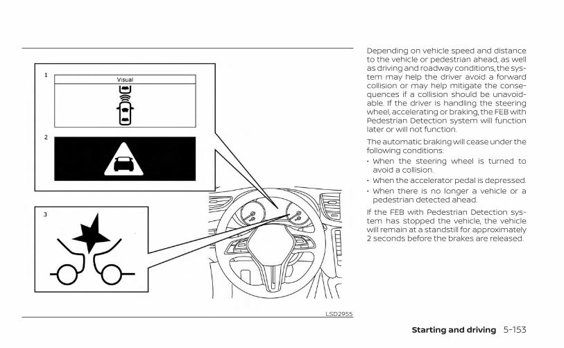
Depending on vehicle speed and distanceto the vehicle or pedestrian ahead, as wellas driving and roadway conditions, the sys-tem may help the driver avoid a forwardcollision or may help mitigate the conse-quences if a collision should be unavoid-able. If the driver is handling the steeringwheel, accelerating or braking, the FEB withPedestrian Detection system will functionlater or will not function.The automatic braking will cease under thefollowing conditions:• When the steering wheel is turned to
avoid a collision.• When the accelerator pedal is depressed.• When there is no longer a vehicle or a
pedestrian detected ahead.If the FEB with Pedestrian Detection sys-tem has stopped the vehicle, the vehiclewill remain at a standstill for approximately2 seconds before the brakes are released.
LSD2955
Starting and driving 5-153

TURNING THE FEB WITHPEDESTRIAN DETECTION SYSTEMON/OFFPerform the following steps to enable ordisable the FEB with Pedestrian Detectionsystem.1. Press the MENU button below the lower
display screen.
2. Select “Driver Assistance.”
3. Select “Emergency Assist.”
4. Select “ON” to turn the “Forward” systemon or off.
When the FEB with Pedestrian Detectionsystem is turned off, the FEB with Pedes-trian Detection system warning lightilluminates.
LSD3610
5-154 Starting and driving
NOTE:• The FEB with Pedestrian Detection
system will be automatically turned onwhen the engine is restarted.
• The Predictive Forward Collision Warn-ing (PFCW) system (if so equipped) isintegrated into the FEB with Pedes-trian Detection system. There is not aseparate selection in the lower displayfor the PFCW system. When the FEBwith Pedestrian Detection is turned off,the PFCW system is also turned off.
FEB WITH PEDESTRIANDETECTION SYSTEM LIMITATIONS
WARNING
Listed below are the system limitationsfor the FEB with Pedestrian Detectionsystem. Failure to operate the vehicle inaccordance with these system limita-tions could result in serious injury ordeath.• The FEB with Pedestrian Detection
system cannot detect all vehicles orpedestrians under all conditions.
• The FEB with Pedestrian Detectionsystem does not detect the follow-ing:
– Pedestrians that are small (for ex-ample, children), in a sitting posi-tion, operating toys/skateboards,on scooters or in wheelchairs, ornot in an upright standing orwalking position.
– Animals of any size.– Obstacles (for examples, cargo or
debris) on the roadway orroadside.
– Oncoming or crossing vehicles.– Vehicles where the tires are diffi-
cult to see or the shape of the rearof the vehicle is unclear orobstructed.
– Parked vehicles.• The FEB with Pedestrian Detection
system has some performance limi-tations.
– If a stationary vehicle is in the ve-hicle’s path, the FEB with Pedes-trian Detection system will notfunction when the vehicle ap-proaches the stationary vehicle atspeeds over approximately 50mph (80 km/h).
– Pedestrian detection will notfunction when the vehicle isdriven at speeds over approxi-mately 37 mph (60 km/h) or belowapproximately 6 mph (10km/h).
• For pedestrians, the FEB with Pedes-trian Detection system will not issuethe first warning.
• The FEB with Pedestrian Detectionsystem may not function properly ordetect a vehicle or pedestrian aheadin the following conditions:
– In poor visibility conditions (suchas rain, snow, fog, dust storms,sand storms, smoke, and roadspray from other vehicles).
– If dirt, ice, snow, fog or other ma-terial is covering the radar sensorarea or camera area ofwindshield.
– If strong light (for example, sun-light or high beams) enters thefront camera or a sudden changein brightness occurs (for example,entering a tunnel or driving inlightning).
– In dark or dimly lit conditions,such as at night or in tunnels, in-cluding cases where your vehi-cle’s headlights are off or dim, orthe tail lights of the vehicle aheadare off.
– When the direction of the camerais misaligned.
Starting and driving 5-155
– When driving on a steep downhillslope, on roads with sharp curves,and/or bumpy or dirt roads.
– If there is interference by other ra-dar sources.
– When your vehicle’s position ormovement is changed quickly orsignificantly (for example, lanechange, turning vehicle, abruptsteering, sudden acceleration ordeceleration).
– When your vehicle or the vehicleor pedestrian ahead movesquickly or significantly such thatthe system cannot detect and re-act in time (for example, pedes-trian moving quickly toward thevehicle at close range, vehicle cut-ting in, changing lanes, making aturn, steering abruptly, suddenacceleration or deceleration).
– When the vehicle or pedestrian isoffset from the vehicle’s forwardpath.
– If the speed difference betweenthe two vehicles is small.
– The pedestrian’s profile is par-tially obscured or unidentifiable;for example, due to transportingluggage, pushing a stroller, wear-ing bulky or very loose-fittingclothing or accessories, or beingin a unique posture (such as rais-ing hands).
– There is poor contrast of a personto the background, such as havingclothing color or pattern which issimilar to the background.
– For approximately 15 seconds af-ter starting the engine.
– If the vehicle ahead has a uniqueor unusual shape, extremely lowor high clearance heights, or un-usual cargo loading or is narrow(for example, a motorcycle).
– When the vehicle or pedestrian islocated near a traffic sign, a reflec-tive area (for example, water onroad), or is in a shadow.
– When multiple pedestrians aregrouped together.
– When the view of the pedestrian isobscured by a vehicle or otherobject.
• The system performance may be de-graded in the following conditions:
– The vehicle is driven on a slipperyroad.
– The vehicle is driven on a slope.– Excessively heavy baggage is
loaded in the rear seat or thecargo area of your vehicle.
• The system is designed to automati-cally check the sensor’s (radar andcamera) functionality, within certainlimitations. The system may not de-tect some forms of obstruction of thesensor area such as ice, snow orstickers, for example. In these cases,the system may not be able to warnthe driver properly. Be sure that youcheck, clean and clear sensor areasregularly.
• In some road and traffic conditions,the FEB with Pedestrian Detectionsystem may unexpectedly apply par-tial braking. When acceleration isnecessary, depress the acceleratorpedal to override the system.
5-156 Starting and driving
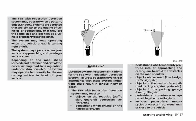
• The FEB with Pedestrian Detectionsystem may operate when a pattern,object, shadow or lights are detectedthat are similar to the outline of ve-hicles or pedestrians, or if they arethe same size and position as a ve-hicle or motorcycle’s tail lights.
• The system may keep operatingwhen the vehicle ahead is turningright or left.
• The system may operate when yourvehicle is approaching and passing avehicle ahead.
• Depending on the road shape(curved road, entrance and exit of thecurve, winding road, lane regulation,under construction, etc.), the systemmay operate temporarily for the on-coming vehicle in front of yourvehicle.
WARNING
Listed below are the system limitationsfor the FEB with Pedestrian Detectionsystem. Failure to operate the vehicle inaccordance with these system limita-tions could result in serious injury ordeath.• The FEB with Pedestrian Detection
system may react to:– objects on the roadside (traffic
sign, guardrail, pedestrian, ve-hicle, etc.)
– pedestrians when driving on thenarrow alleys, etc.
– pedestrians who temporarily pro-trude into or approaching thedriving lane to avoid the obstacleson the road shoulder
– objects above road (low bridge,traffic sign, etc.)
– objects on the road surface (rail-road track, grate, steel plate, etc.)
– objects in the parking garage(beam, pillar, etc.)
– pedestrians or motorcycles ap-proaching the travelling lane
– vehicles, pedestrians, motor-cycles or objects in adjacent lanesor close to the vehicle
LSD4248
Starting and driving 5-157
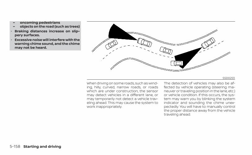
– oncoming pedestrians– objects on the road (such as trees)
• Braking distances increase on slip-pery surfaces.
• Excessive noise will interfere with thewarning chime sound, and the chimemay not be heard.
When driving on some roads, such as wind-ing, hilly, curved, narrow roads, or roadswhich are under construction, the sensormay detect vehicles in a different lane, ormay temporarily not detect a vehicle trav-eling ahead. This may cause the system towork inappropriately.
The detection of vehicles may also be af-fected by vehicle operating (steering ma-neuver or traveling position in the lane, etc.)or vehicle condition. If this occurs, the sys-tem may warn you by blinking the systemindicator and sounding the chime unex-pectedly. You will have to manually controlthe proper distance away from the vehicletraveling ahead.
SSD0253
5-158 Starting and driving
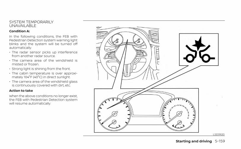
SYSTEM TEMPORARILYUNAVAILABLECondition A:In the following conditions, the FEB withPedestrian Detection system warning lightblinks and the system will be turned offautomatically.• The radar sensor picks up interference
from another radar source.• The camera area of the windshield is
misted or frozen.• Strong light is shining from the front.• The cabin temperature is over approxi-
mately 104°F (40°C) in direct sunlight.• The camera area of the windshield glass
is continuously covered with dirt, etc.Action to takeWhen the above conditions no longer exist,the FEB with Pedestrian Detection systemwill resume automatically.
LSD3920
Starting and driving 5-159

NOTE:
When the inside of the windshield orcamera area is misted or frozen, it willtake a period of time to remove it afterA/C turns ON. If dirt appears on this areahave it checked. It is recommended thatyou visit an INFINITI retailer for thisservice.Condition B:In the following conditions, the FEB withPedestrian Detection system warning lightwill illuminate, the system will be turned offautomatically and the “Not available: FrontRadar Blocked” warning message will ap-pear in the vehicle information display.• The sensor area of the front bumper is
covered with dirt or is obstructed.Action to takeIf the warning light (orange) comes on, stopthe vehicle in a safe place, place the shiftlever in the P (Park) position and turn theengine off. Clean the radar sensor area ofthe front bumper or the camera area of thewindshield with a soft cloth, and restart theengine. If the warning light continues toilluminate, have the FEB with PedestrianDetection system checked. It is recom-mended that you visit an INFINITI retailer forthis service.
When driving on roads with limited roadstructures or buildings (for example, longbridges, deserts, snow fields, driving next tolong walls).Action to takeWhen the above conditions no longer exist,the FEB with pedestrian detection systemwill resume automatically.
NOTE:
If the FEB with Pedestrian Detection sys-tem stops working, the PFCW system (ifso equipped) will also stop working.
SYSTEM MALFUNCTIONIf the FEB with Pedestrian Detection sys-tem malfunctions, it will be turned off auto-matically, a chime will sound, the FEB withPedestrian Detection system warning light(orange) will illuminate and the warningmessage [Malfunction] will appear in thevehicle information display.
Action to takeIf the warning light (orange) comes on, stopthe vehicle in a safe location, turn the en-gine off and restart the engine. If the warn-ing light continues to illuminate, have theFEB with Pedestrian Detection systemchecked. It is recommended that you visitan INFINITI retailer for this service.
NOTE:
If the FEB with Pedestrian Detection sys-tem stops working, the PFCW system (ifso equipped) will also stop working.
5-160 Starting and driving
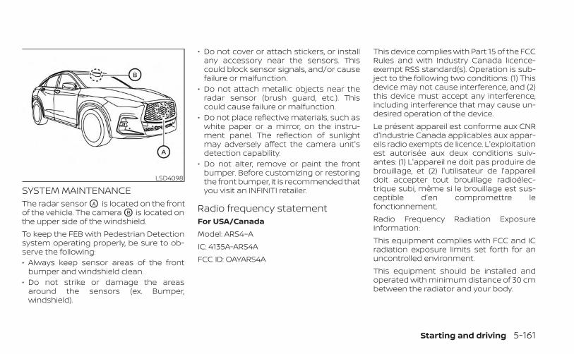
SYSTEM MAINTENANCEThe radar sensor OA is located on the frontof the vehicle. The camera OB is located onthe upper side of the windshield.To keep the FEB with Pedestrian Detectionsystem operating properly, be sure to ob-serve the following:• Always keep sensor areas of the front
bumper and windshield clean.• Do not strike or damage the areas
around the sensors (ex. Bumper,windshield).
• Do not cover or attach stickers, or installany accessory near the sensors. Thiscould block sensor signals, and/or causefailure or malfunction.
• Do not attach metallic objects near theradar sensor (brush guard, etc.). Thiscould cause failure or malfunction.
• Do not place reflective materials, such aswhite paper or a mirror, on the instru-ment panel. The reflection of sunlightmay adversely affect the camera unit'sdetection capability.
• Do not alter, remove or paint the frontbumper. Before customizing or restoringthe front bumper, it is recommended thatyou visit an INFINITI retailer.
Radio frequency statementFor USA/CanadaModel: ARS4–AIC: 4135A-ARS4AFCC ID: OAYARS4A
This device complies with Part 15 of the FCCRules and with Industry Canada licence-exempt RSS standard(s). Operation is sub-ject to the following two conditions: (1) Thisdevice may not cause interference, and (2)this device must accept any interference,including interference that may cause un-desired operation of the device.Le présent appareil est conforme aux CNRd'Industrie Canada applicables aux appar-eils radio exempts de licence. L'exploitationest autorisée aux deux conditions suiv-antes: (1) L'appareil ne doit pas produire debrouillage, et (2) l'utilisateur de l'appareildoit accepter tout brouillage radioélec-trique subi, même si le brouillage est sus-ceptible d'en compromettre lefonctionnement.Radio Frequency Radiation ExposureInformation:This equipment complies with FCC and ICradiation exposure limits set forth for anuncontrolled environment.This equipment should be installed andoperated with minimum distance of 30 cmbetween the radiator and your body.
LSD4098
Starting and driving 5-161

This transmitter must not be co-located oroperating in conjunction with any other an-tenna or transmitter.Cet équipment est conforme aux limitesd’exposition aux rayonnements IC établiespour un environnement non contrôlé. Cetéquipment doit étre installé et utilisé avecun minimum de 30 cm de distance entre lasource de rayonnnement et votre corps.FCC NoticeChanges or modifications not expresslyapproved by the party responsible forcompliance could void the user’s authorityto operate the equipment.
WARNING
Failure to follow the warnings and in-structions for proper use of the PFCWsystem could result in serious injury ordeath.• The PFCW system can help warn the
driver before a collision occurs butwill not avoid a collision. It is the driv-er’s responsibility to stay alert, drivesafely and be in control of the vehicleat all times.
The PFCW system can help alert the driverwhen there is a sudden braking of a secondvehicle traveling in front of the vehicleahead in the same lane. The PFCW system uses a radar sensor OA
located on the front of the vehicle to mea-sure the distance to the vehicle ahead inthe same lane.
LSD4095
PREDICTIVE FORWARD COLLISIONWARNING (PFCW)
5-162 Starting and driving
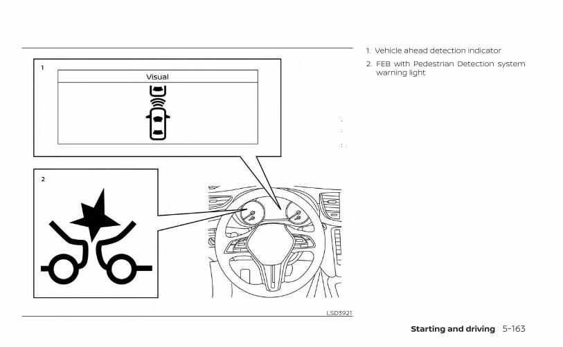
1. Vehicle ahead detection indicator
2. FEB with Pedestrian Detection systemwarning light
LSD3921
Starting and driving 5-163
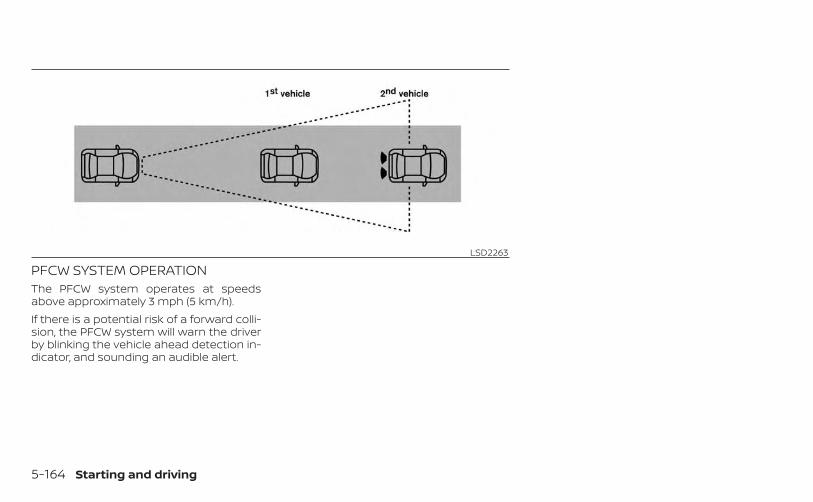
PFCW SYSTEM OPERATIONThe PFCW system operates at speedsabove approximately 3 mph (5 km/h).If there is a potential risk of a forward colli-sion, the PFCW system will warn the driverby blinking the vehicle ahead detection in-dicator, and sounding an audible alert.
LSD2263
5-164 Starting and driving
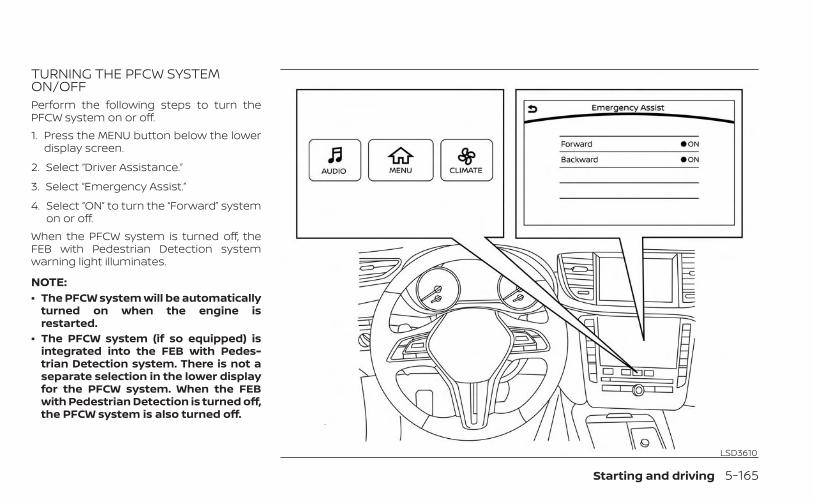
TURNING THE PFCW SYSTEMON/OFFPerform the following steps to turn thePFCW system on or off.1. Press the MENU button below the lower
display screen.
2. Select “Driver Assistance.”
3. Select “Emergency Assist.”
4. Select “ON” to turn the “Forward” systemon or off.
When the PFCW system is turned off, theFEB with Pedestrian Detection systemwarning light illuminates.
NOTE:• The PFCW system will be automatically
turned on when the engine isrestarted.
• The PFCW system (if so equipped) isintegrated into the FEB with Pedes-trian Detection system. There is not aseparate selection in the lower displayfor the PFCW system. When the FEBwith Pedestrian Detection is turned off,the PFCW system is also turned off.
LSD3610
Starting and driving 5-165

PFCW SYSTEM LIMITATIONS
LSD2312Illustration A
5-166 Starting and driving
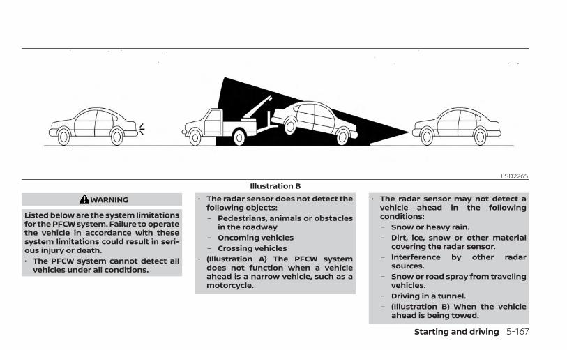
WARNING
Listed below are the system limitationsfor the PFCW system. Failure to operatethe vehicle in accordance with thesesystem limitations could result in seri-ous injury or death.• The PFCW system cannot detect all
vehicles under all conditions.
• The radar sensor does not detect thefollowing objects:– Pedestrians, animals or obstacles
in the roadway– Oncoming vehicles– Crossing vehicles
• (Illustration A) The PFCW systemdoes not function when a vehicleahead is a narrow vehicle, such as amotorcycle.
• The radar sensor may not detect avehicle ahead in the followingconditions:– Snow or heavy rain.– Dirt, ice, snow or other material
covering the radar sensor.– Interference by other radar
sources.– Snow or road spray from traveling
vehicles.– Driving in a tunnel.– (Illustration B) When the vehicle
ahead is being towed.
LSD2265Illustration B
Starting and driving 5-167
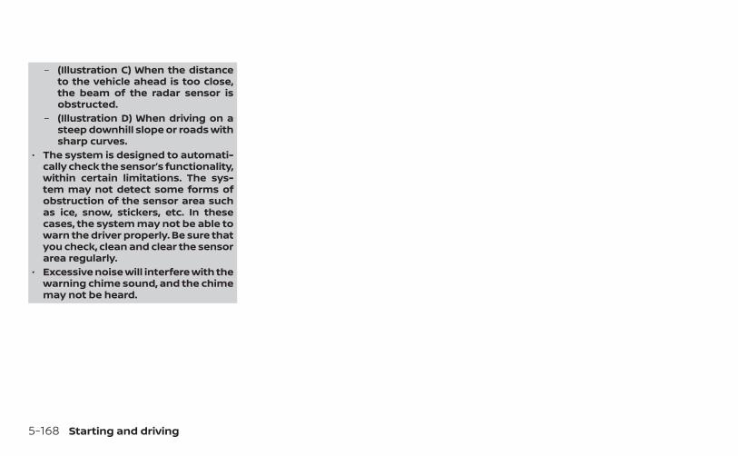
– (Illustration C) When the distanceto the vehicle ahead is too close,the beam of the radar sensor isobstructed.
– (Illustration D) When driving on asteep downhill slope or roads withsharp curves.
• The system is designed to automati-cally check the sensor’s functionality,within certain limitations. The sys-tem may not detect some forms ofobstruction of the sensor area suchas ice, snow, stickers, etc. In thesecases, the system may not be able towarn the driver properly. Be sure thatyou check, clean and clear the sensorarea regularly.
• Excessive noise will interfere with thewarning chime sound, and the chimemay not be heard.
5-168 Starting and driving
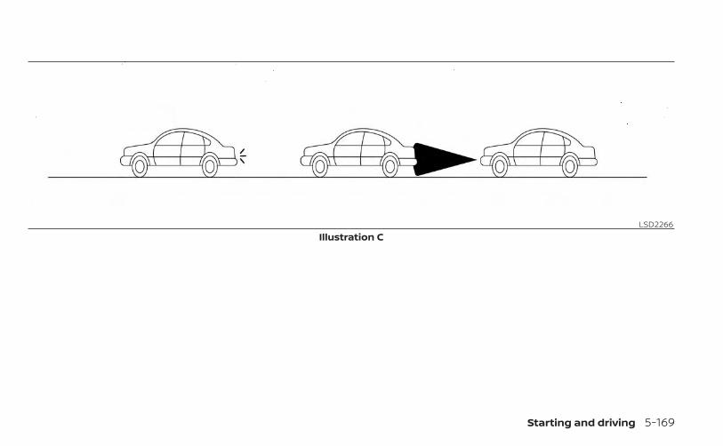
LSD2266Illustration C
Starting and driving 5-169
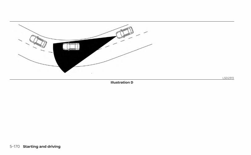
LSD2313Illustration D
5-170 Starting and driving
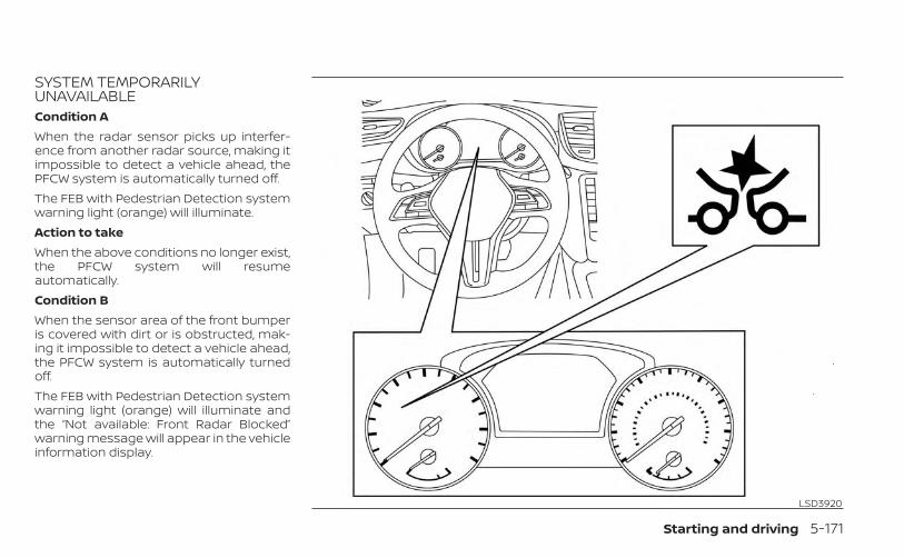
SYSTEM TEMPORARILYUNAVAILABLECondition AWhen the radar sensor picks up interfer-ence from another radar source, making itimpossible to detect a vehicle ahead, thePFCW system is automatically turned off.The FEB with Pedestrian Detection systemwarning light (orange) will illuminate.Action to takeWhen the above conditions no longer exist,the PFCW system will resumeautomatically.Condition BWhen the sensor area of the front bumperis covered with dirt or is obstructed, mak-ing it impossible to detect a vehicle ahead,the PFCW system is automatically turnedoff.The FEB with Pedestrian Detection systemwarning light (orange) will illuminate andthe “Not available: Front Radar Blocked”warning message will appear in the vehicleinformation display.
LSD3920
Starting and driving 5-171
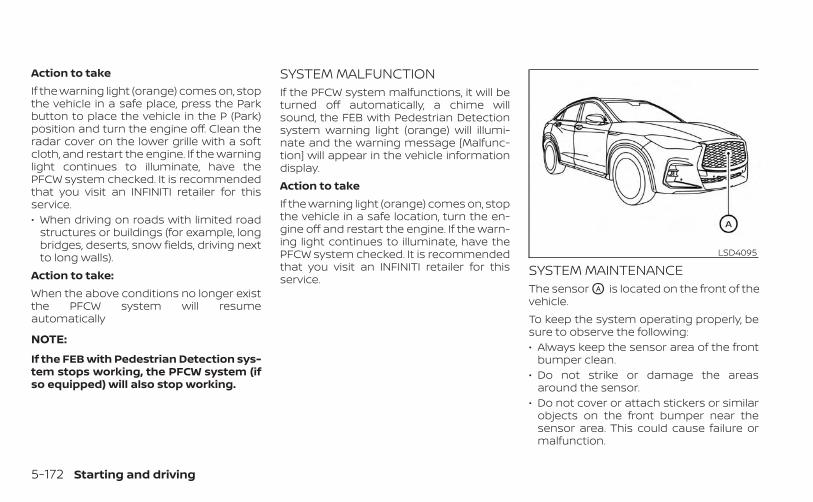
Action to takeIf the warning light (orange) comes on, stopthe vehicle in a safe place, press the Parkbutton to place the vehicle in the P (Park)position and turn the engine off. Clean theradar cover on the lower grille with a softcloth, and restart the engine. If the warninglight continues to illuminate, have thePFCW system checked. It is recommendedthat you visit an INFINITI retailer for thisservice.• When driving on roads with limited road
structures or buildings (for example, longbridges, deserts, snow fields, driving nextto long walls).
Action to take:When the above conditions no longer existthe PFCW system will resumeautomatically
NOTE:
If the FEB with Pedestrian Detection sys-tem stops working, the PFCW system (ifso equipped) will also stop working.
SYSTEM MALFUNCTIONIf the PFCW system malfunctions, it will beturned off automatically, a chime willsound, the FEB with Pedestrian Detectionsystem warning light (orange) will illumi-nate and the warning message [Malfunc-tion] will appear in the vehicle informationdisplay.Action to takeIf the warning light (orange) comes on, stopthe vehicle in a safe location, turn the en-gine off and restart the engine. If the warn-ing light continues to illuminate, have thePFCW system checked. It is recommendedthat you visit an INFINITI retailer for thisservice.
SYSTEM MAINTENANCEThe sensor OA is located on the front of thevehicle.To keep the system operating properly, besure to observe the following:• Always keep the sensor area of the front
bumper clean.• Do not strike or damage the areas
around the sensor.• Do not cover or attach stickers or similar
objects on the front bumper near thesensor area. This could cause failure ormalfunction.
LSD4095
5-172 Starting and driving
• Do not attach metallic objects near thesensor area (brush guard, etc.). This couldcause failure or malfunction.
• Do not alter, remove or paint the frontbumper. Before customizing or restoringthe front bumper, it is recommended thatyou visit an INFINITI retailer.
For USA/CanadaModel: ARS4–AIC: 4135A-ARS4AFCC ID: OAYARS4AThis device complies with Part 15 of the FCCRules and with Industry Canada licence-exempt RSS standard(s). Operation is sub-ject to the following two conditions: (1) Thisdevice may not cause interference, and (2)this device must accept any interference,including interference that may cause un-desired operation of the device.Le présent appareil est conforme aux CNRd'Industrie Canada applicables aux appar-eils radio exempts de licence. L'exploitationest autorisée aux deux conditions suiv-antes: (1) L'appareil ne doit pas produire debrouillage, et (2) l'utilisateur de l'appareildoit accepter tout brouillage radioélec-trique subi, même si le brouillage est sus-ceptible d'en compromettre lefonctionnement.
Radio Frequency Radiation ExposureInformation:This equipment complies with FCC and ICradiation exposure limits set forth for anuncontrolled environment.This equipment should be installed andoperated with minimum distance of 30 cmbetween the radiator and your body.This transmitter must not be co-located oroperating in conjunction with any other an-tenna or transmitter.Cet équipment est conforme aux limitesd’exposition aux rayonnements IC établiespour un environnement non contrôlé. Cetéquipment doit étre installé et utilisé avecun minimum de 30 cm de distance entre lasource de rayonnement et votre corps.FCC NoticeChanges or modifications not expresslyapproved by the party responsible forcompliance could void the user’s authorityto operate the equipment.
CAUTION
During the first 1,200 miles (2,000 km),follow these recommendations to ob-tain maximum engine performanceand ensure the future reliability andeconomy of your new vehicle. Failure tofollow these recommendations mayresult in shortened engine life and re-duced engine performance.
• Avoid driving for long periods at constantspeed, either fast or slow, and do not runthe engine over 4,000 rpm.
• Do not accelerate at full throttle in anygear.
• Avoid quick starts.• Avoid hard braking as much as possible.
BREAK-IN SCHEDULE
Starting and driving 5-173

Follow these easy-to-use Fuel EfficientDriving Tips to help you achieve the mostfuel economy from your vehicle.1. Use Smooth Accelerator and Brake
Pedal Application• Avoid rapid starts and stops.• Use smooth, gentle accelerator and
brake application whenever possible.• Maintain constant speed while com-
muting and coast whenever possible.
2. Maintain Constant Speed• Look ahead to try and anticipate and
minimize stops.• Synchronizing your speed with traffic
lights allows you to reduce your num-ber of stops.
• Maintaining a steady speed can mini-mize red light stops and improve fuelefficiency.
3. Use Air Conditioning (A/C) at HigherVehicle Speeds• Below 40 mph (64 km/h), it is more
efficient to open windows to cool thevehicle due to reduced engine load.
• Above 40 mph (64 km/h), it is moreefficient to use A/C to cool the vehicledue to increased aerodynamic drag.
• Recirculating the cool air in the cabinwhen the A/C is on reduces coolingload.
4. Drive at Economical Speeds andDistances• Observing the speed limit and not ex-
ceeding 60 mph (97 km/h) (where le-gally allowed) can improve fuel effi-ciency due to reduced aerodynamicdrag.
• Maintaining a safe following distancebehind other vehicles reduces unnec-essary braking.
• Safely monitoring traffic to anticipatechanges in speed permits reducedbraking and smooth accelerationchanges.
• Select a gear range suitable to roadconditions.
5. Use Cruise Control• Using cruise control during highway
driving helps maintain a steady speed.• Cruise control is particularly effective
in providing fuel savings when drivingon flat terrains.
6. Plan for the Shortest Route• Utilize a map or navigation system to
determine the best route to save time.
7. Avoid Idling• Shutting off your engine when safe for
stops exceeding 30–60 seconds savesfuel and reduces emissions.
8. Buy an Automated Pass for Toll Roads• Automated passes permit drivers to
use special lanes to maintain cruisingspeed through the toll and avoid stop-ping and starting.
9. Winter Warm Up• Limit idling time to minimize impact to
fuel economy.• Vehicles typically need no more than
30 seconds of idling at start-up to ef-fectively circulate the engine oil beforedriving.
• Your vehicle will reach its ideal operat-ing temperature more quickly whiledriving versus idling.
10. Keeping your Vehicle Cool• Park your vehicle in a covered parking
area or in the shade wheneverpossible.
• When entering a hot vehicle, openingthe windows will help to reduce theinside temperature faster, resulting inreduced demand on your A/C system.
FUEL EFFICIENT DRIVING TIPS
5-174 Starting and driving
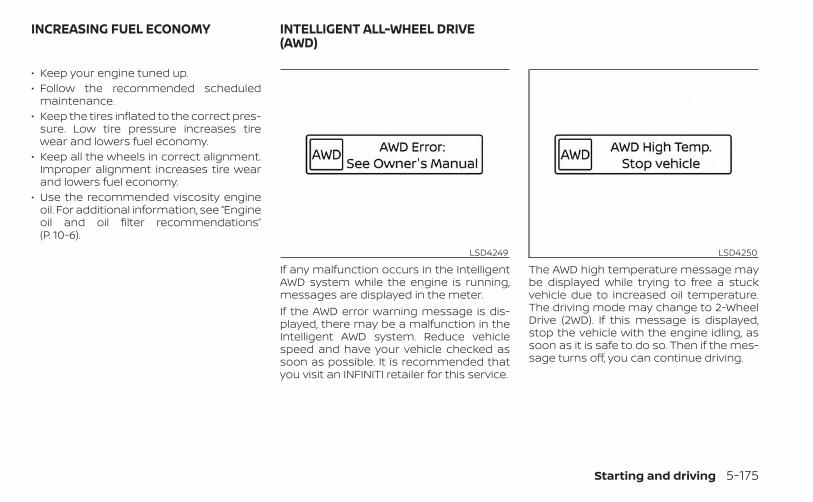
• Keep your engine tuned up.• Follow the recommended scheduled
maintenance.• Keep the tires inflated to the correct pres-
sure. Low tire pressure increases tirewear and lowers fuel economy.
• Keep all the wheels in correct alignment.Improper alignment increases tire wearand lowers fuel economy.
• Use the recommended viscosity engineoil. For additional information, see “Engineoil and oil filter recommendations”(P. 10-6).
If any malfunction occurs in the IntelligentAWD system while the engine is running,messages are displayed in the meter.If the AWD error warning message is dis-played, there may be a malfunction in theIntelligent AWD system. Reduce vehiclespeed and have your vehicle checked assoon as possible. It is recommended thatyou visit an INFINITI retailer for this service.
The AWD high temperature message maybe displayed while trying to free a stuckvehicle due to increased oil temperature.The driving mode may change to 2-WheelDrive (2WD). If this message is displayed,stop the vehicle with the engine idling, assoon as it is safe to do so. Then if the mes-sage turns off, you can continue driving.
LSD4249 LSD4250
INCREASING FUEL ECONOMY INTELLIGENT ALL-WHEEL DRIVE(AWD)
Starting and driving 5-175

The tire size message may be displayed ifthere is a large difference between the di-ameters of front and rear wheels. Pull offthe road in a safe area, with the engineidling. Check that all tire sizes are the same,that the tire pressure is correct and thatthe tires are not excessively worn.If any warning messages continue to bedisplayed, have your vehicle checked assoon as possible. It is recommended thatyou visit an INFINITI retailer for this service.
WARNING
• Do not drive beyond the perfor-mance capability of the tires. Acceler-ating quickly, sharp steering maneu-vers or sudden braking may causeloss of control, even with IntelligentAWD engaged.
• For AWD equipped vehicles, do notattempt to raise two wheels off theground and shift the transmission toany drive or reverse position with theengine running. Doing so may resultin drivetrain damage or unexpectedvehicle movement which could resultin serious personal injury or vehicledamage.
• Do not attempt to test an AWDequipped vehicle on a 2-wheel dyna-mometer (such as the dynamom-eters used by some states for emis-sions testing) or similar equipmenteven if the other two wheels areraised off the ground. Make sure thatyou inform the test facility personnelthat your vehicle is equipped withAWD before it is placed on a dyna-mometer. Using the wrong testequipment may result in drivetraindamage or unexpected vehiclemovement which could result in seri-ous personal injury or vehicledamage.
LSD4251
5-176 Starting and driving
CAUTION
• Do not operate the engine on a freeroller when any of the wheels areraised.
• If you use the free roller, rotate fourwheels with the same speed withoutraising any wheels.
• If an AWD warning message is dis-played while driving there may be amalfunction in the AWD system. Re-duce the vehicle speed immediatelyand have your vehicle checked assoon as possible. It is recommendedthat you visit an INFINITI retailer forthis service.
• The powertrain may be damaged ifyou continue driving when the AWDtemperature or tire size incorrectmessages are displayed.
• If the AWD high temperature mes-sage is displayed while you are driv-ing, pull off the road in a safe area,and idle the engine. The drivingmode will change to 2WD to preventthe AWD system from malfunction-ing. If the warning message turns off,you can drive again.
• If the tire size incorrect message isdisplayed while you are driving, pulloff the road in a safe area with theengine idling. Check that all tire sizesare the same, that the tire pressure iscorrect and that the tires are not ex-cessively worn.
• If a warning message continues to bedisplayed after the above opera-tions, have your vehicle checked assoon as possible. It is recommendedthat you visit an INFINITI retailer forthis service.
Starting and driving 5-177
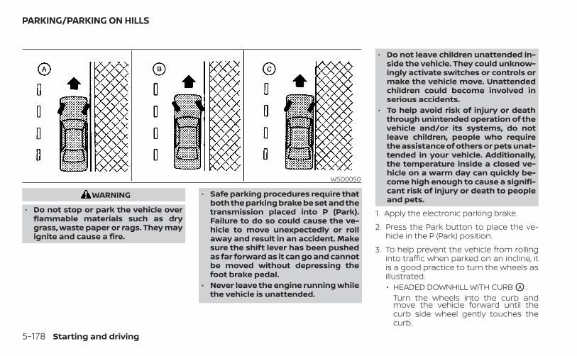
WARNING
• Do not stop or park the vehicle overflammable materials such as drygrass, waste paper or rags. They mayignite and cause a fire.
• Safe parking procedures require thatboth the parking brake be set and thetransmission placed into P (Park).Failure to do so could cause the ve-hicle to move unexpectedly or rollaway and result in an accident. Makesure the shift lever has been pushedas far forward as it can go and cannotbe moved without depressing thefoot brake pedal.
• Never leave the engine running whilethe vehicle is unattended.
• Do not leave children unattended in-side the vehicle. They could unknow-ingly activate switches or controls ormake the vehicle move. Unattendedchildren could become involved inserious accidents.
• To help avoid risk of injury or deaththrough unintended operation of thevehicle and/or its systems, do notleave children, people who requirethe assistance of others or pets unat-tended in your vehicle. Additionally,the temperature inside a closed ve-hicle on a warm day can quickly be-come high enough to cause a signifi-cant risk of injury or death to peopleand pets.
1. Apply the electronic parking brake.
2. Press the Park button to place the ve-hicle in the P (Park) position.
3. To help prevent the vehicle from rollinginto traffic when parked on an incline, itis a good practice to turn the wheels asillustrated.• HEADED DOWNHILL WITH CURB OA :
Turn the wheels into the curb andmove the vehicle forward until thecurb side wheel gently touches thecurb.
WSD0050
PARKING/PARKING ON HILLS
5-178 Starting and driving

• HEADED UPHILL WITH CURB OB :Turn the wheels away from the curband move the vehicle back until thecurb side wheel gently touches thecurb.
• HEADED UPHILL OR DOWNHILL, NOCURB OC :Turn the wheels toward the side of theroad so the vehicle will move awayfrom the center of the road if it moves.
4. Place the ignition switch in the LOCKposition.
ELECTRIC POWER STEERING TYPEWARNING
• If the engine is not running or isturned off while driving, the powerassist for the steering will not work.Steering will be harder to operate.
• When the power steering warninglight illuminates with the engine run-ning, there will be no power assist forthe steering. You will still have controlof the vehicle, but the steering will beharder to operate. Have the powersteering system checked. It is recom-mended that you visit an INFINITI re-tailer for this service.
The power steering system is designed toprovide power assist while driving to oper-ate the steering wheel with light force.When the steering wheel is operated re-peatedly or continuously while parking ordriving at a very low speed, the power as-sist for the steering wheel will be reduced.This is to prevent overheating of the powersteering system and protect it from gettingdamaged. While the power assist is re-duced, steering wheel operation will be-come heavy. When the temperature of thepower steering system goes down, thepower assist level will return to normal.
Avoid repeating such steering wheel op-erations that could cause the power steer-ing system to overheat.You may hear a sound when the steeringwheel is operated quickly. However, this isnot a malfunction.If the power steering warning light illumi-nates while the engine is running, it mayindicate the power steering system is notfunctioning properly and may need servic-ing. Have the power steering systemchecked. It is recommended that you visitan INFINITI retailer for this service.When the power steering warning light illu-minates with the engine running, there willbe no power assist for the steering, but youwill still have control of the vehicle. At thistime, greater steering effort is required tooperate the steering wheel, especially insharp turns and at low speeds.For additional information, see “Powersteering warning light” (P. 2-16).
POWER STEERING
Starting and driving 5-179
DIRECT ADAPTIVE STEERING®TYPE
WARNING
• When the power steering warninglight illuminates with the engine run-ning, the power assist for the steer-ing will cease operation. You will stillhave control of the vehicle, but thesteering will be harder to operate.
• If wheels or tires other than theINFINITI recommended ones areused, Direct Adaptive Steering® maynot operate properly and the powersteering warning light mayilluminate.
• Do not modify the vehicle’s suspen-sion parts such as shock absorbers,struts, springs, stabilizer bars, bush-ings and wheels are not INFINITI rec-ommended for your vehicle or are ex-tremely deteriorated, Direct AdaptiveSteering may not operate properlyand the power steering warning lightmay illuminate.
• Do not modify the vehicle’s steering.If steering parts are not INFINITI rec-ommended for your vehicle or are ex-tremely deteriorated, Direct AdaptiveSteering may not operate properlyand the power steering warning lightmay illuminate.
• If the Vehicle Dynamic Control (VDC)OFF indicator light illuminates, thepower steering warning light mayalso illuminate at the same time.Stop the vehicle in a safe location,turn the engine off and restart theengine. If the power steering warn-ing light continues to illuminate,have the system checked. It is recom-mended that you visit an INFINITI re-tailer for this service. For additionalinformation, see “Vehicle DynamicControl (VDC) system” (P. 5-184).
CAUTION
• Do not place the ignition switch in theON position while the steering wheelor a tire is removed.
• Do not turn the steering wheel asmuch as possible while the ignitionswitch is any position other than theON position.
• Installing an accessory on the steer-ing wheel, or changing the steeringwheel, may reduce the steeringperformance.
Direct Adaptive Steering is designed tocontrol the steering force and steeringangle according to the vehicle speed andamount of turning of the steering wheel.The steering characteristic can be selectedusing the INFINITI Drive Mode Selector. Foradditional information, see “INFINITI DriveMode Selector” (P. 5-29).If the VDC system is turned off, the settingof steering becomes Standard mode.If the power steering warning light illumi-nates while the engine is running, it mayindicate that Direct Adaptive Steering is notfunctioning properly and may need servic-ing. Have the system checked. It is recom-mended that you visit an INFINITI retailer forthis service. For additional information, see“Power steering warning light” (P. 2-16)When the power steering warning light illu-minates with the engine running, the
5-180 Starting and driving
power assist for the steering will cease op-eration. You will still have control of the ve-hicle. However, greater steering effort willbe needed, especially in sharp turns and atlow speeds.If Direct Adaptive Steering is malfunction-ing, the steering wheel may turn slightlyeven when driving on a straight road.Under the following conditions, the steer-ing wheel may turn slightly even when driv-ing on a straight road. This is due to a pro-tection mechanism for Direct AdaptiveSteering. The steering wheel will return tothe normal position after the protectionmechanism is deactivated.Condition A:• When the engine is stalled or likely to be
stalled• When the steering wheel is held in the full
lock position or when the front tiretouches an obstruction
• When the battery is dischargedTo return the steering wheel to the normalposition, stop the vehicle in a safe locationand stop operating the steering wheel.Then drive the vehicle for a short period oftime.
Condition B:• When the steering wheel is operated re-
peatedly or continuously while parking ordriving at a very low speed. In this case,the power assist for the steering wheelwill be reduced.
To return the steering wheel to the normalposition, stop the vehicle in a safe locationand wait for a period of time, without oper-ating the steering wheel, until the tempera-ture of Direct Adaptive Steering coolsdown. Avoid repeated steering wheel op-erations that could cause Direct AdaptiveSteering to overheat.When the vehicle is tested on the 2–wheeldynamometer, the power steering warninglight may illuminate. To turn off the powersteering warning light, stop the vehicle in asafe location, turn the engine off, restart theengine, and then drive the vehicle for a pe-riod of time.The following conditions do not indicate amalfunction of Direct Adaptive Steering:• You may notice wider steering play when
the ignition switch is in the OFF or AUTOACC position compared to when it is inthe ON position.
• After the engine is started, the steeringwheel may turn slightly even when driv-ing a straight road. To return to the nor-mal position, drive the vehicle on astraight road for a period of time.
• After the engine is started, the steeringwheel may move if the steering wheelwas turned to the fully locked positionwhile the ignition switch was in the OFFposition.
• After the vehicle is tested on the 4–wheeldynamometer, the steering wheel mayturn slightly even when driving on astraight road. To return the steeringwheel to the normal position, drive thevehicle on a straight road for a period oftime.
You may hear a noise under the followingconditions. However, this is not a malfunc-tion.• When the engine is started or stopped.• When the steering wheel is turned in the
full lock position.
Starting and driving 5-181

The brake system has two separate hy-draulic circuits. If one circuit malfunctions,you will still have braking at two wheels.
BRAKE PRECAUTIONS
Vacuum assisted brakesThe brake booster aids braking by usingengine vacuum. If the engine stops, youcan stop the vehicle by depressing thebrake pedal. However, greater foot pres-sure on the brake pedal will be required tostop the vehicle and stopping distance willbe longer.
Using the brakesAvoid resting your foot on the brake pedalwhile driving. This will overheat the brakes,wear out the brake pads faster, and reducegas mileage.To help reduce brake wear and to preventthe brakes from overheating, reduce speedand downshift to a lower gear before goingdown a slope or long grade. Overheatedbrakes may reduce braking performanceand could result in loss of vehicle control.
WARNING
• While driving on a slippery surface,be careful when braking, accelerat-ing or downshifting. Abrupt brakingor accelerating could cause thewheels to skid and result in anaccident.
• If the engine is not running or isturned off while driving, the powerassist for the brakes will not work.Braking will be harder.
Wet brakesWhen the vehicle is washed or driventhrough water, the brakes may get wet. Asa result, your braking distance will be lon-ger and the vehicle may pull to one sideduring braking.To dry the brakes, drive the vehicle at a safespeed while lightly pressing the brakepedal to heat up the brakes. Do this untilthe brakes return to normal. Avoid drivingthe vehicle at high speeds until the brakesfunction correctly.
Parking brake break-inBreak in the parking brake shoes wheneverthe stopping effect of the parking brake isweakened or whenever the parking brakeshoes and/or rotors are replaced, in orderto assure the best brake performance.This procedure is described in the INFINITIService Manual. It is recommended thatyou visit an INFINITI retailer for this service.
ANTI-LOCK BRAKING SYSTEM (ABS)
WARNING
• The ABS is a sophisticated device, butit cannot prevent accidents resultingfrom careless or dangerous drivingtechniques. It can help maintain ve-hicle control during braking on slip-pery surfaces. Remember that stop-ping distances on slippery surfaceswill be longer than on normal sur-faces even with ABS. Stopping dis-tances may also be longer on rough,gravel or snow covered roads, or ifyou are using tire chains. Alwaysmaintain a safe distance from the ve-hicle in front of you. Ultimately, thedriver is responsible for safety.
BRAKE SYSTEM
5-182 Starting and driving
• Tire type and condition may also af-fect braking effectiveness.– When replacing tires, install the
specified size of tires on all fourwheels.
– When installing a spare tire, makesure that it is the proper size andtype as specified on the Tire andLoading Information label. For ad-ditional information, see “Tire andLoading Information label”(P. 8-30).
– For additional information, see“Wheels and tires” (P. 8-28).
The ABS controls the brakes so the wheelsdo not lock during hard braking or whenbraking on slippery surfaces. The systemdetects the rotation speed at each wheeland varies the brake fluid pressure to pre-vent each wheel from locking and sliding.By preventing each wheel from locking, thesystem helps the driver maintain steeringcontrol and helps to minimize swervingand spinning on slippery surfaces.
Using the systemDepress the brake pedal and hold it down.Depress the brake pedal with firm steadypressure, but do not pump the brakes. TheAnti-lock Braking System will operate toprevent the wheels from locking up. Steerthe vehicle to avoid obstacles.
WARNING
Do not pump the brake pedal. Doing somay result in increased stoppingdistances.
Self-test featureThe Anti-lock Braking System (ABS) in-cludes electronic sensors, electric pumps,hydraulic solenoids and a computer. Thecomputer has a built-in diagnostic featurethat tests the system each time you startthe engine and move the vehicle at a lowspeed in forward or reverse. When the self-test occurs, you may hear a “clunk” noiseand/or feel a pulsation in the brake pedal.This is normal and does not indicate a mal-function. If the computer senses a mal-function, it switches the ABS off and illumi-nates the ABS warning light on the
instrument panel. The brake system thenoperates normally but without anti-lockassistance.If the ABS warning light illuminates duringthe self-test or while driving, have the ve-hicle checked. It is recommended that youvisit an INFINITI retailer for this service.
Normal operationThe Anti-lock Braking System (ABS) oper-ates at speeds above 3 - 6 mph (5 - 10km/h). The speed varies according to roadconditions.When the ABS senses that one or morewheels are close to locking up, the actuatorrapidly applies and releases hydraulic pres-sure. This action is similar to pumping thebrakes very quickly. You may feel a pulsa-tion in the brake pedal and hear a noisefrom under the hood or feel a vibrationfrom the actuator when it is operating. Thisis normal and indicates that the ABS is op-erating properly. However, the pulsationmay indicate that road conditions are haz-ardous and extra care is required whiledriving.
Starting and driving 5-183
BRAKE ASSISTWhen the force applied to the brake pedalexceeds a certain level, the Brake Assist isactivated generating greater braking forcethan a conventional brake booster evenwith light pedal force.
WARNING
The Brake Assist is only an aid to assistbraking operation and is not a collisionwarning or avoidance device. It is thedriver’s responsibility to stay alert,drive safely and be in control of the ve-hicle at all times.
The VDC system uses various sensors tomonitor driver inputs and vehicle motion.Under certain driving conditions, the VDCsystem helps to perform the followingfunctions:• Controls brake pressure to reduce wheel
slip on one slipping drive wheel so poweris transferred to a non-slipping drivewheel on the same axle.
• Controls brake pressure and engine out-put to reduce drive wheel slip based onvehicle speed (traction control function).
• Controls brake pressure at individualwheels and engine output to help thedriver maintain control of the vehicle inthe following conditions:
Understeer (vehicle tends to not follow thesteered path despite increased steeringinput)Oversteer (vehicle tends to spin due to cer-tain road or driving conditions)The VDC system can help the driver tomaintain control of the vehicle, but it can-not prevent loss of vehicle control in all driv-ing situations.
When the VDC system operates, theindicator light in the instrument panelflashes to note the following:• The road may be slippery or the system
may determine some action is requiredto help keep the vehicle on the steeredpath.
• You may feel a pulsation in the brakepedal and hear a noise or vibration fromunder the hood. This is normal and indi-cates that the VDC system is workingproperly.
• Adjust your speed and driving to the roadconditions.
For additional information, see “Slip indica-tor light” (P. 2-17) and ”Vehicle Dynamic Con-trol (VDC) OFF indicator light” (P. 2-17).If a malfunction occurs in the system, the
and indicator lights come on inthe instrument panel. The VDC system au-tomatically turns off when these indicatorlights are on.
VEHICLE DYNAMIC CONTROL (VDC)SYSTEM
5-184 Starting and driving
The lower display is used to turn off theVDC system. When the VDC system isturned off, the indicator light, the RABsystem warning light, and the FEB with Pe-destrian Detection system warning light il-luminate to indicate the VDC, FEB with Pe-destrian Detection, and RAB systems areoff.When the lower display is used to turn offthe system, the VDC system still operatesto prevent one drive wheel from slipping bytransferring power to a non-slipping drivewheel. The indicator light flashes if thisoccurs. All other VDC functions are off andthe indicator light will not flash.The VDC system is automatically reset toon when the ignition switch is placed in theOFF position then back to the ON position.The computer has a built-in diagnostic fea-ture that tests the system each time youstart the engine and move the vehicle for-ward or in reverse at a slow speed. Whenthe self-test occurs, you may hear a clunknoise and/or feel a pulsation in the brakepedal. This is normal and is not an indica-tion of a malfunction.
WARNING
• The VDC system is designed to helpthe driver maintain controllabilitybut does not prevent accidents dueto abrupt steering operation at highspeeds or by careless or dangerousdriving techniques. Reduce vehiclespeed and be especially careful whendriving and cornering on slipperysurfaces and always drive carefully.
• Do not modify the vehicle's suspen-sion. If suspension parts such asshock absorbers, struts, springs, sta-bilizer bars, bushings and wheels arenot INFINITI recommended for yourvehicle or are extremely deterio-rated, the VDC system may not oper-ate properly. This could adversely af-fect vehicle handling performance,and the indicator light may flashor both the and indicatorlights may illuminate.
• If brake related parts such as brakepads, rotors and calipers are notINFINITI recommended or are ex-tremely deteriorated, the VDC sys-tem may not operate properly andboth the and the indicatorlights may illuminate.
• If engine control related parts are notINFINITI recommended or are ex-tremely deteriorated, both theand indicator lights mayilluminate.
• When driving on extremely inclinedsurfaces such as higher banked cor-ners, the VDC system may not oper-ate properly and the indicatorlight may flash or both the and
indicator lights may illuminate.Do not drive on these types of roads.
• When driving on an unstable surfacesuch as a turntable, ferry, elevator orramp, the indicator light mayflash or both the and indi-cator lights may illuminate. This isnot a malfunction. Restart the engineafter driving onto a stable surface.
• If wheels or tires other than theINFINITI recommended ones areused, the VDC system may not oper-ate properly and the indicatorlight may flash or both the and
indicator lights may illuminate.• The VDC system is not a substitute
for winter tires or tire chains on asnow covered road.
Starting and driving 5-185
BRAKE FORCE DISTRIBUTIONDuring braking while driving through turns,the system optimizes the distribution offorce to each of the four wheels dependingon the radius of the turn.
WARNING
• The VDC system is designed to helpthe driver maintain controllabilitybut does not prevent accidents dueto abrupt steering operation at highspeeds or by careless or dangerousdriving techniques. Reduce vehiclespeed and be especially careful whendriving and cornering on slipperysurfaces and always drive carefully.
• Do not modify the vehicle’s suspen-sion. If suspension parts such asshock absorbers, struts, springs, sta-bilizer bars, bushings and wheels arenot INFINITI recommended for yourvehicle or are extremely deterio-rated, the VDC system may not oper-ate properly. This could adversely af-fect vehicle handling performance,and the indicator light may flashor both the and indicatorlights may illuminate.
• If brake related parts such as brakepads, rotors and calipers are notINFINITI recommended or are ex-tremely deteriorated, the VDC sys-tem may not operate properly andboth the and the indicatorlights may illuminate.
• If engine control related parts are notINFINITI recommended or are ex-tremely deteriorated, both theand indicator lights mayilluminate.
• When driving on extremely inclinedsurfaces such as higher banked cor-ners, the VDC system may not oper-ate properly and the indicatorlight may flash or both the and
indicator lights may illuminate.Do not drive on these types of roads.
• When driving on an unstable surfacesuch as a turntable, ferry, elevator orramp, the indicator light mayflash or both the and indi-cator lights may illuminate. This isnot a malfunction. Restart the engineafter driving onto a stable surface.
• If wheels or tires other than theINFINITI recommended ones areused, the VDC system may not oper-ate properly and the indicatorlight may flash or both the and
indicator lights may illuminate.• The VDC system is not a substitute
for winter tires or tire chains on asnow covered road.
5-186 Starting and driving

The chassis control is an electric controlmodule that includes the followingfunctions:• Active Trace Control• Active Engine Brake• Active Ride Control
ACTIVE TRACE CONTROLThis system senses driving based on thedriver’s steering and acceleration/brakingpatterns, and controls brake pressure atindividual wheels to help smooth vehicleresponse.When the lower display is used to turn offthe Vehicle Dynamic Control system, theActive Trace Control system is also turnedoff.The Active Trace Control can be set to on(enabled) or off (disabled) through thelower display “Infiniti Drive Mode Selector”menu option.
When the Active Trace Control is operatedand the “Chassis Control” mode is selectedin the vehicle information display, the Ac-tive Trace Control graphics are shown inthe vehicle information display.If the chassis control warning message ap-pears in the vehicle information display, itmay indicate that the Active Trace Controlis not functioning properly. Have the sys-tem checked as soon as possible by anINFINITI dealer.
WARNING
The Active Trace Control may not be ef-fective depending on the driving condi-tion. Always drive carefully andattentively.
When the Active Trace Control is operating,you may feel a pulsation in the brake pedaland hear a noise. This is normal and indi-cates that the Active Trace Control is oper-ating properly.You may also feel deceleration when theActive Trace Control is operating. However,this is not a malfunction.
LSD2185
CHASSIS CONTROL
Starting and driving 5-187

Even if the Active Trace Control is set to OFF,some functions will remain on to assist thedriver (for example: avoidance scenes).
ACTIVE ENGINE BRAKEThe Active Engine Brake function addssubtle deceleration by controlling Continu-ously Variable Transmission (CVT) gear ra-tio, depending on the cornering conditioncalculated from the driver's steering inputand plural sensors. This benefit is for easiertraceability and less workload of adjustingspeed with braking at corners.The Active Engine Brake also enhancesbraking feel by adding subtle decelerationwith CVT gear ratio control according tothe driver's brake pedal operationThe Active Engine Brake can be set to on(enabled) or off (disabled) through thelower display “Infiniti Drive Mode Selector”menu option.
When the Active Engine Brake is operatedat corners and the “Chassis Control” modeis selected in the vehicle information dis-play, the Active Engine Brake graphics areshown in the vehicle information display.If the chassis control warning message ap-pears in the vehicle information display, itmay indicate that the Active Engine Brakeis not functioning properly. Have the sys-tem checked as soon as possible. It is rec-ommended that you visit an INFINITI re-tailer for this service.
WARNING
The Active Engine Brake may not be ef-fective depending on the driving condi-tion. Always drive carefully andattentively.
When the Active Engine Brake is operating,the needle of the tachometer will rise upand you may hear an engine noise. This isnormal and indicates that the Active En-gine Brake is operating properly.You may also feel deceleration when theActive Engine Brake is operating. However,this is not a malfunction.
LSD2185
5-188 Starting and driving

ACTIVE RIDE CONTROLThis system senses upper body motion(based on wheel speed information) andcontrols four wheel brake pressure. This willenhance ride comfort in an effort to re-strain uncomfortable upper body move-ment when passing over undulated roadsurfaces.When the lower display is used to turn offthe VDC system, the Active Ride Control isalso turned off.When the Active Ride Control is operatedand the “Chassis Control” mode is selectedin the vehicle information display, the Ac-tive Ride Control graphics are shown in thevehicle information display.
If the chassis control system error warningmessage appears in the vehicle informa-tion display, it may indicate that the ActiveRide Control is not functioning properly.Have the system checked as soon as pos-sible. It is recommended that you visit anINFINITI retailer for this service.When the Active Ride Control is operating,you may hear noise and sense slight decel-eration. This is normal and indicates thatthe Active Ride Control is operatingproperly.
WARNING
• Never rely solely on the hill start as-sist system to prevent the vehiclefrom moving backward on a hill. Al-ways drive carefully and attentively.Depress the brake pedal when thevehicle is stopped on a steep hill. Beespecially careful when stopped on ahill on frozen or muddy roads. Failureto prevent the vehicle from rollingbackwards may result in a loss ofcontrol of the vehicle and possibleserious injury or death.
• The hill start assist system is not de-signed to hold the vehicle at a stand-still on a hill. Depress the brake pedalwhen the vehicle is stopped on asteep hill. Failure to do so may causethe vehicle to roll backwards andmay result in a collision or seriouspersonal injury.
• The hill start assist system may notprevent the vehicle from rollingbackwards on a hill under all load orroad conditions. Always be preparedto depress the brake pedal to preventthe vehicle from rolling backwards.Failure to do so may result in a colli-sion or serious personal injury.
LSD3922
HILL START ASSIST SYSTEM
Starting and driving 5-189
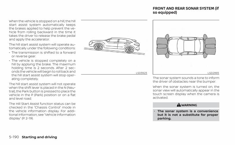
When the vehicle is stopped on a hill, the hillstart assist system automatically keepsthe brakes applied to help prevent the ve-hicle from rolling backward in the time ittakes the driver to release the brake pedaland apply the accelerator.The hill start assist system will operate au-tomatically under the following conditions:• The transmission is shifted to a forward
or reverse gear.• The vehicle is stopped completely on a
hill by applying the brake. The maximumholding time is 2 seconds. After 2 sec-onds the vehicle will begin to roll back andthe hill start assist system will stop oper-ating completely.
The hill start assist system will not operatewhen the shift lever is placed in the N (Neu-tral), the Park button is pressed to place thevehicle in the P (Park) position or on a flatand level road.The Hill Start Assist function status can bechecked in the “Chassis Control” mode inthe vehicle information display. For addi-tional information, see “Vehicle informationdisplay” (P. 2-19).
The sonar system sounds a tone to informthe driver of obstacles near the bumper.When the sonar system is turned on, thesonar view will automatically appear in thetouch screen display when the camera isactivated.
WARNING
• The sonar system is a conveniencebut it is not a substitute for properparking.
LSD3923 LSD2993
FRONT AND REAR SONAR SYSTEM (ifso equipped)
5-190 Starting and driving

• The driver is always responsible forsafety during parking and other ma-neuvers. Always look around andcheck that it is safe to do so beforeparking.
• Read and understand the limitationsof the sonar system as contained inthis section. The colors of the sonarindicator indicates different dis-tances to the object.
• Inclement weather or ultrasonicsources such as an automatic carwash, a truck’s compressed-airbrakes or a pneumatic drill may af-fect the function of the system; thismay include reduced performance ora false activation.
• The sonar system is designed as anaid to the driver in detecting largestationary objects to help avoiddamaging the vehicle.
• The sonar system is not designed toprevent contact with small or movingobject. Always move slowly. The sys-tem will not detect small objects be-low the bumper, and may not detectobjects close to the bumper or on theground.
• The sonar system may not detect thefollowing objects: fluffy objects suchas snow, cloth, cotton, glass-wool,etc.; thin objects such as rope, wireand chain, etc.; or wedge-shapedobjects.
CAUTION
• Excessive noise (such as audio sys-tem volume or an open vehicle win-dow) will interfere with the tone andit may not be heard.
• The front and rear sonar detect thedistance between the vehicle and theobstacle by detecting the soundwave reflected from the surface of anobstacle. When there is a sound suchas horn, or an ultrasonic source (suchas sonar of other vehicles) aroundthe vehicle, the sonar may not detectobjects properly.
• Keep the sonar sensors (located onthe bumper fascia) free from snow,ice and large accumulations of dirt.Do not clean the sonar with sharp ob-jects. If the sensors are covered, theaccuracy of the sonar function will bediminished.
SYSTEM OPERATIONThe system informs with a visual and au-dible signal of front obstacles when theshift lever is in the D (Drive) position andboth front and rear obstacles when theshift lever is in the R (Reverse) position.
Sonar Operation Table
FR Sensor RR SensorRange Sound Display Sound Dis-
playP x † x †R o o o oN x † x †D o o x †
o – Display/Beep when detect† – Display on camera viewx – No Display and Beep
The system is deactivated at speeds above6 mph (10 km/h). It is reactivated at lowerspeeds.The intermittent tone will stop after 3 sec-onds when an obstacle is detected by onlythe corner sensor and the distance doesnot change. The tone will stop when theobstacle get away from the vehicle.
Starting and driving 5-191
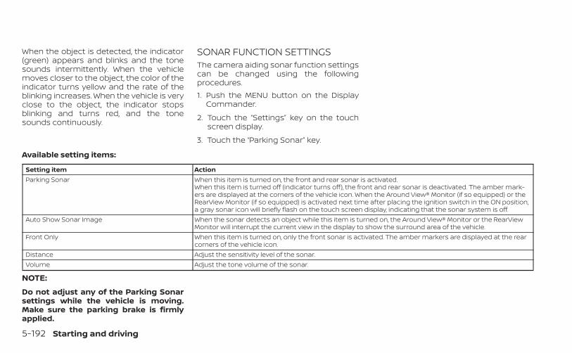
When the object is detected, the indicator(green) appears and blinks and the tonesounds intermittently. When the vehiclemoves closer to the object, the color of theindicator turns yellow and the rate of theblinking increases. When the vehicle is veryclose to the object, the indicator stopsblinking and turns red, and the tonesounds continuously.
SONAR FUNCTION SETTINGSThe camera aiding sonar function settingscan be changed using the followingprocedures.1. Push the MENU button on the Display
Commander.
2. Touch the “Settings” key on the touchscreen display.
3. Touch the “Parking Sonar” key.
Available setting items:
Setting item ActionParking Sonar When this item is turned on, the front and rear sonar is activated.
When this item is turned off (indicator turns off), the front and rear sonar is deactivated. The amber mark-ers are displayed at the corners of the vehicle icon. When the Around View® Monitor (if so equipped) or theRearView Monitor (if so equipped) is activated next time after placing the ignition switch in the ON position,a gray sonar icon will briefly flash on the touch screen display, indicating that the sonar system is off.
Auto Show Sonar Image When the sonar detects an object while this item is turned on, the Around View® Monitor or the RearViewMonitor will interrupt the current view in the display to show the surround area of the vehicle.
Front Only When this item is turned on, only the front sonar is activated. The amber markers are displayed at the rearcorners of the vehicle icon.
Distance Adjust the sensitivity level of the sonar.Volume Adjust the tone volume of the sonar.
NOTE:
Do not adjust any of the Parking Sonarsettings while the vehicle is moving.Make sure the parking brake is firmlyapplied.
5-192 Starting and driving
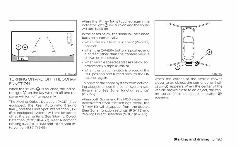
TURNING ON AND OFF THE SONARFUNCTIONWhen the “P” key OA is touched, the indica-tor light OB on the key will turn off and thesonar will turn off temporarily.The Moving Object Detection (MOD) (if soequipped), the Rear Automatic Braking(RAB), and the Blind Spot Intervention (BSI)(if so equipped) systems will also be turnedoff at the same time. See “Moving ObjectDetection (MOD)” (P. 4-27), “Rear AutomaticBraking (RAB)” (P. 5-146) and “Blind Spot In-tervention (BSI)” (P. 5-55).
When the “P” key OA is touched again, theindicator light OB will turn on and the sonarwill turn back on.In the cases below, the sonar will be turnedback on automatically:• When the shift lever is in the R (Reverse)
position.• When the CAMERA button is pushed and
a screen other than the camera view isshown on the display.
• When vehicle speed decreases below ap-proximately 5 mph (8 km/h).
• When the ignition switch is placed in theOFF position and turned back to the ONposition again.
To prevent the sonar system from activat-ing altogether, use the sonar system set-tings menu. See “Sonar function settings”(P. 5-192).When both Sonar and the MOD system aredeactivated from the settings menu, the"P" key OA will disappear from the display.(See “Sonar function settings” (P. 5-192) and“Moving Object Detection (MOD)” (P. 4-27).)
When the corner of the vehicle movescloser to an object, the corner sonar indi-cator OA appears. When the center of thevehicle moves close to an object, the cen-ter sonar (if so equipped) indicator OB
appears.
LSD4241 LSD2136
Starting and driving 5-193

The system indicators OA will appear whenthe vehicle moves closer to an object.
SONAR LIMITATIONS
WARNING
Listed below are the system limitationsfor the sonar system. Failure to operatethe vehicle in accordance with thesesystem limitations could result in seri-ous injury or death.
• Read and understand the limitationsof the sonar system as contained inthis section. Inclement weather mayaffect the function of the sonar sys-tem; this may include reduced per-formance or a false activation.
• The sonar system is deactivated atspeeds above 6 mph (10 km/h). It isreactivated at lower speeds.
• Inclement weather or ultrasonicsources such as an automatic carwash, a truck’s compressed-airbrakes or a pneumatic drill may af-fect the function of the sonar sys-tem; this may include reduced per-formance or a false activation.
• The sonar system is not designed toprevent contact with small or movingobjects. Always move slowly. Thesystem will not detect small objectsbelow the bumper or on the ground.
• The sonar system may not detect thefollowing objects: fluffy objects suchas snow, cloth, cotton, glass-wool,etc.; thin objects such as rope, wireand chain, etc.; or wedge-shaped ob-jects; complex-shaped objects ormultiple objects in close.
• The sonar system may not detect ob-jects at speeds above 3 mph (5 km/h)and may not detect certain angularor moving objects.
• The sonar system may not operate inthe following conditions:
– When rain, snow, ice, dirt, etc. ad-heres to the sonar.
– When a loud sound is heard in thearea around the vehicle.
– When the surface of the obstacleis diagonal to the front or rear ofthe vehicle.
– When a sonar or the area aroundthe sensor is extremely hot orcold.
• The sonar system may unintention-ally operate in the following condi-tions:
– When there is overgrown grass inthe area around the vehicle.
– When there are bumps, protru-sions or manhole covers on theroad surface.
– When the vehicle drives through adraped flag or a curtain.
– When there is an accumulation ofsnow or ice behind the vehicle.
– When driving on a steep hill.
LSD4242
5-194 Starting and driving
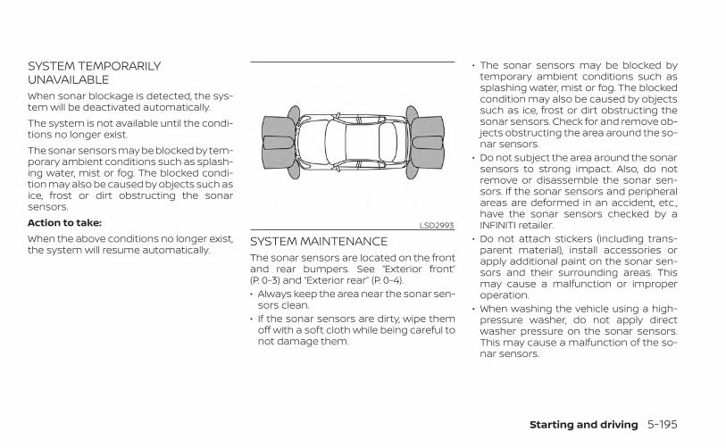
SYSTEM TEMPORARILYUNAVAILABLEWhen sonar blockage is detected, the sys-tem will be deactivated automatically.The system is not available until the condi-tions no longer exist.The sonar sensors may be blocked by tem-porary ambient conditions such as splash-ing water, mist or fog. The blocked condi-tion may also be caused by objects such asice, frost or dirt obstructing the sonarsensors.Action to take:When the above conditions no longer exist,the system will resume automatically.
SYSTEM MAINTENANCEThe sonar sensors are located on the frontand rear bumpers. See “Exterior front”(P. 0-3) and “Exterior rear” (P. 0-4).• Always keep the area near the sonar sen-
sors clean.• If the sonar sensors are dirty, wipe them
off with a soft cloth while being careful tonot damage them.
• The sonar sensors may be blocked bytemporary ambient conditions such assplashing water, mist or fog. The blockedcondition may also be caused by objectssuch as ice, frost or dirt obstructing thesonar sensors. Check for and remove ob-jects obstructing the area around the so-nar sensors.
• Do not subject the area around the sonarsensors to strong impact. Also, do notremove or disassemble the sonar sen-sors. If the sonar sensors and peripheralareas are deformed in an accident, etc.,have the sonar sensors checked by aINFINITI retailer.
• Do not attach stickers (including trans-parent material), install accessories orapply additional paint on the sonar sen-sors and their surrounding areas. Thismay cause a malfunction or improperoperation.
• When washing the vehicle using a high-pressure washer, do not apply directwasher pressure on the sonar sensors.This may cause a malfunction of the so-nar sensors.
LSD2993
Starting and driving 5-195
FREEING A FROZEN DOOR LOCKTo prevent a door lock from freezing, applyde-icer through the key hole. If the lockbecomes frozen, heat the key before in-serting it into the key hole, or use theINFINITI Intelligent Key.
ANTIFREEZEIn the winter when it is anticipated that thetemperature will drop below 32°F (0°C),check the antifreeze to assure proper win-ter protection. For additional information,see “Engine cooling system” (P. 8-5).
BATTERYIf the battery is not fully charged duringextremely cold weather conditions, thebattery fluid may freeze and damage thebattery. To maintain maximum efficiency,the battery should be checked regularly.For additional information, see “Battery”(P. 8-13).
DRAINING OF COOLANT WATERIf the vehicle is to be left outside withoutantifreeze, drain the cooling system, includ-ing the engine block. Refill before operatingthe vehicle. For additional information, see“Changing engine coolant” (P. 8-6).
TIRE EQUIPMENT1. SUMMER tires have a tread designed to
provide superior performance on drypavement. However, the performance ofthese tires will be substantially reducedin snowy and icy conditions. If you oper-ate your vehicle on snowy or icy roads,INFINITI recommends the use of MUD &SNOW or ALL SEASON TIRES on all fourwheels. It is recommended that you visitan INFINITI retailer for the tire type, size,speed rating and availability information.
2. For additional traction on icy roads,studded tires may be used. However,some U.S. states and Canadian prov-inces prohibit their use. Check local,state and provincial laws before install-ing studded tires.
Skid and traction capabilities of studdedsnow tires on wet or dry surfaces may bepoorer than that of non-studded snowtires.3. Tire chains may be used. For additional
information, see “Tire chains”(P. 8-38).
SPECIAL WINTER EQUIPMENTIt is recommended that the following itemsbe carried in the vehicle during winter:• A scraper and stiff-bristled brush to re-
move ice and snow from the windowsand wiper blades.
• A sturdy, flat board to be placed under thejack to give it firm support.
• A shovel to dig the vehicle out ofsnowdrifts.
• Extra washer fluid to refill the windshield-washer fluid reservoir.
DRIVING ON SNOW OR ICE
WARNING
• Wet ice (32°F, 0°C and freezing rain),very cold snow or ice can be slick andvery hard to drive on. The vehicle willhave much less traction or “grip” un-der these conditions. Try to avoiddriving on wet ice until the road issalted or sanded.
• Whatever the condition, drive withcaution. Accelerate and slow downwith care. If accelerating or down-shifting too fast, the drive wheels willlose even more traction.
COLD WEATHER DRIVING
5-196 Starting and driving
• Allow more stopping distance underthese conditions. Braking should bestarted sooner than on drypavement.
• Allow greater following distances onslippery roads.
• Watch for slippery spots (glare ice).These may appear on an otherwiseclear road in shaded areas. If a patchof ice is seen ahead, brake beforereaching it. Try not to brake while onthe ice, and avoid any sudden steer-ing maneuvers.
• Do not use the cruise control on slip-pery roads.
• Snow can trap dangerous exhaustgases under your vehicle. Keep snowclear of the exhaust pipe and fromaround your vehicle.
ENGINE BLOCK HEATER (if soequipped)Engine block heaters are used to assistwith cold temperature starting.The engine block heater should be usedwhen the outside temperature is 20°F (-7°C)or lower.
WARNING
• Do not use your engine block heaterwith an ungrounded electrical sys-tem or a 2-pronged adapter. You canbe seriously injured by an electricalshock if you use an ungroundedconnection.
• Disconnect and properly store theengine block heater cord beforestarting the engine. Damage to thecord could result in an electricalshock and can cause serious injury.
• Use a heavy-duty 3-wire, 3-prongedextension cord rated for at least 10 A.Plug the extension cord into aGround Fault Interrupt (GFI) pro-tected, grounded 110-VAC outlet.Failure to use the proper extensioncord or a grounded outlet can resultin a fire or electrical shock and causeserious personal injury.
To use the engine block heater:1. Turn the engine off.
2. Open the hood and unwrap the engineblock heater cord.
3. Plug the engine block heater cord into agrounded 3-wire, 3-pronged extensioncord.
4. Plug the extension cord into a GroundFault Interrupt (GFI) protected, grounded110-volt AC (VAC) outlet.
5. The engine block heater must beplugged in for at least 2 - 4 hours, de-pending on outside temperatures, toproperly warm the engine coolant. Usean appropriate timer to turn the engineblock heater on.
6. Before starting the engine, unplug andproperly store the cord to keep it awayfrom moving parts.
Starting and driving 5-197
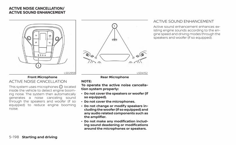
ACTIVE NOISE CANCELLATIONThis system uses microphones O1 locatedinside the vehicle to detect engine boom-ing noise. The system then automaticallygenerates a noise canceling soundthrough the speakers and woofer (if soequipped) to reduce engine boomingnoise.
NOTE:To operate the active noise cancella-tion system properly:• Do not cover the speakers or woofer (if
so equipped).• Do not cover the microphones.• Do not change or modify speakers in-
cluding the woofer (if so equipped) andany audio related components such asthe amplifier.
• Do not make any modification includ-ing sound deadening or modificationsaround the microphones or speakers.
ACTIVE SOUND ENHANCEMENTActive sound enhancement enhances ex-isting engine sounds according to the en-gine speed and driving modes through thespeakers and woofer (if so equipped).
LSD2959Front Microphone
LSD4152Rear Microphone
ACTIVE NOISE CANCELLATION/ACTIVE SOUND ENHANCEMENT
5-198 Starting and driving

6 In case of emergency
Hazard warning flasher switch . . . . . . . . . . . . . . . . . . 6-2Roadside assistance program . . . . . . . . . . . . . . . . . . . 6-2Emergency engine shut off . . . . . . . . . . . . . . . . . . . . . . 6-3Flat tire . . . . . . . . . . . . . . . . . . . . . . . . . . . . . . . . . . . . . . . . . . 6-3
Tire Pressure Monitoring System(TPMS) . . . . . . . . . . . . . . . . . . . . . . . . . . . . . . . . . . . . . . . 6-3Run-flat tires . . . . . . . . . . . . . . . . . . . . . . . . . . . . . . . . . 6-4
Jump starting . . . . . . . . . . . . . . . . . . . . . . . . . . . . . . . . . . . 6-5Push starting . . . . . . . . . . . . . . . . . . . . . . . . . . . . . . . . . . . . 6-7If your vehicle overheats . . . . . . . . . . . . . . . . . . . . . . . . . 6-7Towing your vehicle . . . . . . . . . . . . . . . . . . . . . . . . . . . . . 6-8
Towing recommended by INFINITI . . . . . . . . . . . . 6-8Vehicle recovery (freeing a stuckvehicle) . . . . . . . . . . . . . . . . . . . . . . . . . . . . . . . . . . . . . . . 6-9
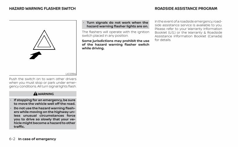
Push the switch on to warn other driverswhen you must stop or park under emer-gency conditions. All turn signal lights flash.
WARNING
• If stopping for an emergency, be sureto move the vehicle well off the road.
• Do not use the hazard warning flash-ers while moving on the highway un-less unusual circumstances forceyou to drive so slowly that your ve-hicle might become a hazard to othertraffic.
• Turn signals do not work when thehazard warning flasher lights are on.
The flashers will operate with the ignitionswitch placed in any position.Some jurisdictions may prohibit the useof the hazard warning flasher switchwhile driving.
In the event of a roadside emergency, road-side assistance service is available to you.Please refer to your Warranty InformationBooklet (U.S.) or the Warranty & RoadsideAssistance Information Booklet (Canada)for details.
LIC0394
HAZARD WARNING FLASHER SWITCH ROADSIDE ASSISTANCE PROGRAM
6-2 In case of emergency
To shut off the engine in an emergencysituation while driving, perform the follow-ing procedure:– Rapidly push the push-button ignition
switch three consecutive times in lessthan 1.5 seconds, or
– Push and hold the push-button ignitionswitch for more than 2 seconds.
TIRE PRESSURE MONITORINGSYSTEM (TPMS)This vehicle is equipped with Tire PressureMonitoring System (TPMS). It monitors tirepressure of all tires. When the low tire pres-sure warning light is lit, and the “Tire Pres-sure Low - Add Air” warning appears in thevehicle information display, one or more ofyour tires is significantly under-inflated. Thesystem also displays pressure of all tires(except the spare tire) on the vehicle infor-mation display screen by sending a signalfrom a sensor that is installed in eachwheel. If the vehicle is being driven with lowtire pressure, the TPMS will activate andwarn you of it by the low tire pressure warn-ing light. This system will activate onlywhen the vehicle is driven at speeds above16 mph (25 km/h). For additional informa-tion, see “Warning lights, indicator lightsand audible reminders” (P. 2-9) and “TirePressure Monitoring System (TPMS)”(P. 8-28).
WARNING
• Radio waves could adversely affectelectric medical equipment. Thosewho use a pacemaker should contactthe electric medical equipmentmanufacturer for the possible influ-ences before use.
EMERGENCY ENGINE SHUT OFF FLAT TIRE
In case of emergency 6-3

• If the low tire pressure warning lightilluminates while driving, avoid sud-den steering maneuvers or abruptbraking, reduce vehicle speed, pulloff the road to a safe location andstop the vehicle as soon as possible.Driving with under-inflated tires maypermanently damage the tires andincrease the likelihood of tire failure.Serious vehicle damage could occurand may lead to an accident andcould result in serious personal in-jury. Check the tire pressure for allfour tires. Adjust the tire pressure tothe recommended COLD tire pres-sure shown on the Tire and LoadingInformation label to turn the low tirepressure warning light OFF. If thelight still illuminates while driving af-ter adjusting the tire pressure, a tiremay be flat or the TPMS may be mal-functioning. If you have a flat tire, re-place it with a replacement tire assoon as possible. If no tires are flatand all tires are properly inflated,have the vehicle checked. It is recom-mended that you visit an INFINITI re-tailer for this service.
• When using a wheel without TPMSsuch as the spare tire, the TPMS willnot function and the low tire pres-sure warning light will flash for ap-proximately 1 minute. The light willremain on after 1 minute. Have yourtires replaced and/or TPMS systemreset as soon as possible. It is recom-mended that you visit an INFINITI re-tailer for these services.
• Replacing tires with those not origi-nally specified by INFINITI could af-fect the proper operation of theTPMS.
• Do not inject any tire liquid or aerosoltire sealant into the tires, as this maycause a malfunction of the tire pres-sure sensors.
RUN-FLAT TIRESThis vehicle is equipped with run-flat tires.Run-flat tires can be used temporarily ifthey are punctured. When the “Flat Tire —Visit dealer” warning appears in the vehicleinformation display, one or more of yourtires is punctured. For additional informa-tion, see “Run-flat tires” (P. 8-36).For additional information, refer to the tiresafety information in the Warranty Infor-mation Booklet.
WARNING
• Although you can continue drivingwith a punctured run-flat tire, re-member that vehicle handling stabil-ity is reduced, which could lead to anaccident and personal injury. Also,driving a long distance at highspeeds may damage the tires.
• Do not drive at speeds above 50 mph(80 km/h) and do not drive more thanapproximately 93 miles (150 km) witha punctured run-flat tire. The actualdistance the vehicle can be driven ona flat tire depends on outside tem-perature, vehicle load, road condi-tions and other factors.
• Drive safely at reduced speeds. Avoidhard cornering or braking, whichmay cause you to lose control of thevehicle.
• If you detect any unusual sounds orvibrations while driving with a punc-tured run-flat tire, pull off the road toa safe location and stop the vehicleas soon as possible. The tire may beseriously damaged and need to bereplaced.
6-4 In case of emergency
CAUTION
• Never install tire chains on a punc-tured run-flat tire, as this could dam-age your vehicle.
• Avoid diving over any projection orpothole, as the clearance betweenthe vehicle and the ground is smallerthan normal.
• Do not enter an automated car washwith a punctured run-flat tire.
• Have the punctured tire inspected byan INFINITI retailer or other autho-rized repair shop. Replace the tire assoon as possible if the tire is seriouslydamaged.
To start your engine with a booster battery,the instructions and precautions belowmust be followed.
WARNING
• If done incorrectly, jump starting canlead to a battery explosion, resultingin severe injury or death. It could alsodamage your vehicle.
• Explosive hydrogen gas is alwayspresent in the vicinity of the battery.Keep all sparks and flames awayfrom the battery.
• Do not allow battery fluid to comeinto contact with eyes, skin, clothingor painted surfaces. Battery fluid is acorrosive sulfuric acid solution whichcan cause severe burns. If the fluidshould come into contact with any-thing, immediately flush the con-tacted area with water.
• Keep battery out of the reach ofchildren.
• The booster battery must be rated at12 volts. Use of an improperly ratedbattery can damage your vehicle.
• Whenever working on or near a bat-tery, always wear suitable eye pro-tectors (for example, goggles or in-dustrial safety spectacles) andremove rings, metal bands, or anyother jewelry. Do not lean over thebattery when jump starting.
• Do not attempt to jump start a frozenbattery. It could explode and causeserious injury.
• Your vehicle has an automatic enginecooling fan. It could come on at anytime. Keep hands and other objectsaway from it.
JUMP STARTING
In case of emergency 6-5
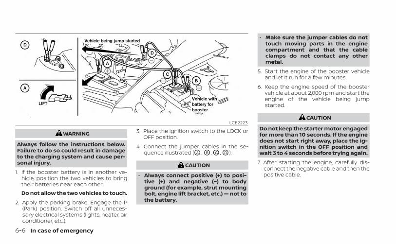
WARNING
Always follow the instructions below.Failure to do so could result in damageto the charging system and cause per-sonal injury.
1. If the booster battery is in another ve-hicle, position the two vehicles to bringtheir batteries near each other.Do not allow the two vehicles to touch.
2. Apply the parking brake. Engage the P(Park) position. Switch off all unneces-sary electrical systems (lights, heater, airconditioner, etc.).
3. Place the ignition switch to the LOCK orOFF position.
4. Connect the jumper cables in the se-quence illustrated (OA , OB , OC , OD ).
CAUTION
• Always connect positive (+) to posi-tive (+) and negative (−) to bodyground (for example, strut mountingbolt, engine lift bracket, etc.) — not tothe battery.
• Make sure the jumper cables do nottouch moving parts in the enginecompartment and that the cableclamps do not contact any othermetal.
5. Start the engine of the booster vehicleand let it run for a few minutes.
6. Keep the engine speed of the boostervehicle at about 2,000 rpm and start theengine of the vehicle being jumpstarted.
CAUTION
Do not keep the starter motor engagedfor more than 10 seconds. If the enginedoes not start right away, place the ig-nition switch in the OFF position andwait 3 to 4 seconds before trying again.
7. After starting the engine, carefully dis-connect the negative cable and then thepositive cable.
LCE2223
6-6 In case of emergency
CAUTION
• Continuously Variable Transmission(CVT) models cannot be push-started or tow-started. Attemptingto do so may cause transmissiondamage.
• Do not push start this vehicle. Thethree-way catalyst may bedamaged.
WARNING
• Do not continue to drive if your ve-hicle overheats. Doing so could causeengine damage or a vehicle fire.
• To avoid the danger of being scalded,never remove the coolant reservoircap while the engine is still hot. Whenthe coolant reservoir cap is removed,pressurized hot water will spurt out,possibly causing serious injury.
• Do not open the hood if steam iscoming out.
If your vehicle is overheating (indicated byan extremely high temperature gaugereading), or if you feel a lack of enginepower, detect abnormal noise, etc. take thefollowing steps.1. Move the vehicle safely off the road, ap-
ply the parking brake and engage the P(Park) position.Do not stop the engine.
2. Turn off the air conditioner. Open all thewindows, move the heater or air condi-tioner temperature control to maximumhot and fan control to high speed.
3. Get out of the vehicle. Look and listen forsteam or coolant escaping from the ra-diator before opening the hood. (Ifsteam or coolant is escaping, turn offthe engine.) Do not open the hood fur-ther until no steam or coolant can beseen.
4. Open the engine hood.
WARNING
If steam or water is coming from theengine, stand clear to prevent gettingburned.
5. Visually check drive belts for damage orlooseness. Also check if the cooling fanis running. The radiator hoses and radia-tor should not leak water. If coolant isleaking, the water pump belt is missingor loose, or the cooling fan does not run,stop the engine.
WARNING
Be careful not to allow your hands, hair,jewelry or clothing to come into con-tact with, or get caught in, engine beltsor the engine cooling fan. The enginecooling fan can start at any time.
PUSH STARTING IF YOUR VEHICLE OVERHEATS
In case of emergency 6-7
6. After the engine cools down, check thecoolant level in the engine coolant res-ervoir tank with the engine running. Addcoolant to the engine coolant reservoirtank if necessary. Have your vehicle re-paired. It is recommended that you visitan INFINITI retailer for this service.
When towing your vehicle, all jurisdictionsand local regulations for towing must befollowed. Incorrect towing equipmentcould damage your vehicle. Towing in-structions are available from an INFINITI re-tailer. Local service operators are generallyfamiliar with the applicable laws and pro-cedures for towing. To assure proper tow-ing and to prevent accidental damage toyour vehicle, INFINITI recommends havinga service operator tow your vehicle. It isadvisable to have the service operatorcarefully read the following precautions:
WARNING
• Never ride in a vehicle that is beingtowed.
• Never get under your vehicle after ithas been lifted by a tow truck.
CAUTION
• When towing, make sure that thetransmission, axles, steering systemand powertrain are in working condi-tion. Use dollies or flatbed if any ofthe listed systems are not working.
• Always attach safety chains beforetowing.
For additional information about towingyour vehicle behind a Recreational Vehicle(RV), see “Flat towing for all–wheel drive ve-hicle” (P. 10-21).
TOWING RECOMMENDED BYINFINITIINFINITI recommends towing your vehiclebased upon the type of drivetrain. For addi-tional information, refer to the diagrams inthis section to ensure that your vehicle isproperly towed.
TOWING YOUR VEHICLE
6-8 In case of emergency

All-Wheel Drive (AWD) models withContinuously VariableTransmission (CVT)INFINITI recommends that towing dolliesbe used when towing your vehicle or placethe vehicle on a flatbed truck as illustrated.
CAUTION
Never tow AWD models equipped witha Continuously Variable Transmission(CVT) with any of the wheels on theground as this may cause serious andexpensive damage to the transfer caseand transmission.
NOTE:
If the battery is completely drained thetransmission will not manually shift toother positions.
VEHICLE RECOVERY (freeing astuck vehicle)
WARNING
To avoid vehicle damage, serious per-sonal injury or death when recovering astuck vehicle:• Contact a professional towing ser-
vice to recover the vehicle if you haveany questions regarding the recov-ery procedure.
• Tow chains or cables must be at-tached only to main structural mem-bers of the vehicle.
• Do not use the vehicle tie-downs totow or free a stuck vehicle.
• Only use devices specifically de-signed for vehicle recovery and fol-low the manufacturer's instructions.
• Always pull the recovery devicestraight out from the front of the ve-hicle. Never pull at an angle.
• Route recovery devices so they donot touch any part of the vehicle ex-cept the attachment point.
LCE2468
In case of emergency 6-9
If your vehicle is stuck in sand, snow, mud,etc., use a tow strap or other device de-signed specifically for vehicle recovery. Al-ways follow the manufacturer's instruc-tions for the recovery device.
Rocking a stuck vehicle
WARNING
• Stand clear of a stuck vehicle.• Do not spin your tires at high speed.
This could cause them to explodeand result in serious injury. Parts ofyour vehicle could also overheat andbe damaged.
If your vehicle is stuck in sand, snow, mud,etc., use the following procedure:1. Turn off the Vehicle Dynamic Control
(VDC) system.
2. Make sure the area in front and behindthe vehicle is clear of obstructions.
3. Turn the steering wheel right and left toclear an area around the front tires.
4. Slowly rock the vehicle forward andbackward.• Shift back and forth between R (Re-
verse) and D (Drive).• Apply the accelerator as little as pos-
sible to maintain the rocking motion.• Release the accelerator pedal before
shifting between R (Reverse) and D(Drive).
• Do not spin the tires above 35 mph (55km/h).
5. If the vehicle cannot be freed after a fewtries, contact a professional towing ser-vice to remove the vehicle.
6-10 In case of emergency
7 Appearance and care
Cleaning exterior . . . . . . . . . . . . . . . . . . . . . . . . . . . . . . . . 7-2Washing . . . . . . . . . . . . . . . . . . . . . . . . . . . . . . . . . . . . . 7-2Waxing . . . . . . . . . . . . . . . . . . . . . . . . . . . . . . . . . . . . . . . 7-3Removing spots . . . . . . . . . . . . . . . . . . . . . . . . . . . . . . 7-3Underbody . . . . . . . . . . . . . . . . . . . . . . . . . . . . . . . . . . . 7-3Glass . . . . . . . . . . . . . . . . . . . . . . . . . . . . . . . . . . . . . . . . . 7-3Aluminum alloy wheels . . . . . . . . . . . . . . . . . . . . . . . 7-3Chrome parts . . . . . . . . . . . . . . . . . . . . . . . . . . . . . . . . 7-3Tire dressings . . . . . . . . . . . . . . . . . . . . . . . . . . . . . . . . 7-4
Cleaning interior . . . . . . . . . . . . . . . . . . . . . . . . . . . . . . . . 7-4Air fresheners . . . . . . . . . . . . . . . . . . . . . . . . . . . . . . . . 7-5
Power moonroof . . . . . . . . . . . . . . . . . . . . . . . . . . . . . 7-5Floor mats (if so equipped) . . . . . . . . . . . . . . . . . . . 7-5Seat belts . . . . . . . . . . . . . . . . . . . . . . . . . . . . . . . . . . . . 7-6Cleaning the seat tracks . . . . . . . . . . . . . . . . . . . . . 7-7
Corrosion protection . . . . . . . . . . . . . . . . . . . . . . . . . . . . 7-7Most common factors contributing tovehicle corrosion . . . . . . . . . . . . . . . . . . . . . . . . . . . . . 7-7Environmental factors influence therate of corrosion . . . . . . . . . . . . . . . . . . . . . . . . . . . . . 7-7Protect your vehicle from corrosion . . . . . . . . . . 7-8
In order to maintain the appearance ofyour vehicle, it is important to take propercare of it.To protect the paint surfaces, wash yourvehicle as soon as you can:• After a rainfall to prevent possible dam-
age from acid rain.• After driving on coastal roads.• When contaminants such as soot, bird
droppings, tree sap, metal particles orbugs get on the paint surface.
• When dust or mud builds up on thesurface.
Whenever possible, store or park your ve-hicle inside a garage or in a covered area.When it is necessary to park outside, park ina shady area or protect the vehicle with abody cover.Be careful not to scratch the paint sur-face when putting on or removing thebody cover.
WASHINGWash dirt off with a wet sponge and plentyof water. Clean the vehicle thoroughly us-ing a mild soap, a special vehicle soap orgeneral purpose dishwashing liquid mixedwith clean, lukewarm (never hot) water.
CAUTION
• Do not concentrate water spray di-rectly on the sonar sensors (if soequipped) on the bumper as this willresult in damage to the sensors. Donot use pressure washers capable ofspraying water over 1,200 psi (8,274kPa) to wash your vehicle. Use ofhigh-pressure washers over 1,200 psi(8,274 kPa) can result in damage to orremoval of paint or graphics. Avoidusing a high-pressure washer closerthan 12 inches (30 cm) to the vehicle.Always use a wide-angle nozzle only,keep the nozzle moving and do notconcentrate the water spray on anyone area.
• Do not use car washes that use acidin the detergent. Some car washes,especially brushless ones, use someacid for cleaning. The acid may reactwith some plastic vehicle compo-nents, causing them to crack. Thiscould affect their appearance, andalso could cause them not to func-tion properly. Always check with yourcar wash to confirm that acid is notused.
• Do not wash the vehicle with stronghousehold soap, strong chemical de-tergents, gasoline or solvents.
• Do not wash the vehicle in direct sun-light or while the vehicle body is hot,as the surface may becomewater-spotted.
• Avoid using tight-napped or roughcloths, such as washing mitts. Caremust be taken when removingcaked-on dirt or other foreign sub-stances so the paint surface is notscratched or damaged.
Rinse the vehicle thoroughly with plenty ofclean water.Inside edges, seams and folds on thedoors, hatches and hood are particularlyvulnerable to the effects of road salt. There-fore, these areas must be cleaned regularly.Take care that the drain holes in the loweredge of the door are open. Spray waterunder the body and in the wheel wells toloosen the dirt and wash away road salt.A damp chamois can be used to dry thevehicle to avoid water spots.
CLEANING EXTERIOR
7-2 Appearance and care

WAXINGRegular waxing protects the paint surfaceand helps retain new vehicle appearance.Polishing is recommended to removebuilt-up wax residue and to avoid a weath-ered appearance before re-applying wax.An INFINITI retailer can assist you in choos-ing the proper product.• Wax your vehicle only after a thorough
washing. Follow the instructions suppliedwith the wax.
• Do not use a wax containing any abra-sives, cutting compounds or cleanersthat may damage the vehicle finish.
Machine compounding or aggressive pol-ishing on a base coat/clear coat paint fin-ish may dull the finish or leave swirl marks.
REMOVING SPOTSRemove tar and oil spots, industrial dust,insects, and tree sap as quickly as possiblefrom the surface of the paint to avoid last-ing damage or staining. Special cleaningproducts are available at an INFINITI retaileror any automotive accessory store. It isrecommended that you visit an INFINITI re-tailer for these products.
UNDERBODYIn areas where road salt is used in winter, itis necessary to clean the underbody regu-larly in order to prevent dirt and salt frombuilding up and causing the acceleration ofcorrosion on the underbody and suspen-sion. Before the winter period and again inthe spring, the underseal must be checkedand, if necessary, re-treated.
GLASSUse glass cleaner to remove smoke anddust film from the glass surfaces. It is nor-mal for glass to become coated with a filmafter the vehicle is parked in the hot sun.Glass cleaner and a soft cloth will easilyremove this film.
CAUTION
When cleaning the inside of the win-dows, do not use sharp-edged tools,abrasive cleaners or chlorine-baseddisinfectant cleaners. They could dam-age the electrical conductors, radio an-tenna elements or rear window de-froster elements.
ALUMINUM ALLOY WHEELSWash the wheels regularly with a spongedampened in a mild soap solution, espe-cially during winter months in areas whereroad salt is used. If not removed, road saltcan discolor the wheels.
CAUTION
Follow the directions below to avoidstaining or discoloring the wheels:• Do not use a cleaner that uses strong
acid or alkali contents to clean thewheels.
• Do not apply wheel cleaners to thewheels when they are hot. The wheeltemperature should be the same asambient temperature.
• Rinse the wheel to completely re-move the cleaner within 15 minutesafter the cleaner is applied.
CHROME PARTSClean all chrome parts regularly with anon-abrasive chrome polish to maintainthe finish.
Appearance and care 7-3

TIRE DRESSINGSINFINITI does not recommend the use oftire dressings. Tire manufacturers apply acoating to the tires to help reduce discolor-ation of the rubber. If a tire dressing is ap-plied to the tires, it may react with the coat-ing and form a compound. This compoundmay come off the tire while driving andstain the vehicle paint.If you choose to use a tire dressing, take thefollowing precautions:• Use a water-based tire dressing. The
coating on the tire dissolves more easilythan with an oil-based tire dressing.
• Apply a light coat of tire dressing to helpprevent it from entering the tire tread/grooves (where it would be difficult toremove).
• Wipe off excess tire dressing using a drytowel. Make sure the tire dressing is com-pletely removed from the tiretread/grooves.
• Allow the tire dressing to dry as recom-mended by tire dressing manufacturer.
This vehicle has new and unique surfaceson the center console and door pull finish-ers. If cleaning is required use mild soapand water. However if mild soap and waterwon’t clean the center console and doorpull finishers, use Genuine INFINITI Vinyl andLeather Cleaner (or equivalent).Occasionally remove loose dust from theinterior trim, plastic parts and seats using avacuum cleaner or soft bristled brush. Wipethe vinyl and leather surfaces with a clean,soft cloth dampened in mild soap solution,then wipe clean with a dry, soft cloth.Regular care and cleaning is required inorder to maintain the appearance of theleather.Before using any fabric protector, read themanufacturer's recommendations. Somefabric protectors contain chemicals thatmay stain or bleach the seat material.Use a cloth dampened only with water toclean the meter and gauge lens.Use a slightly moist (with water) microfibercloth to clean the wood trim. If necessary,use water with natural soap or wood dedi-cated cleaning products, such as furniturepolish.
WARNING
Do not use water or acidic cleaners (hotsteam cleaners) on the seat. This candamage the seat or occupant classifi-cation sensor. This can also affect theoperation of the air bag system and re-sult in serious personal injury.
CAUTION
• Never use benzine, thinner, or anysimilar material on the interior sur-faces or surface damage may occur.Such damage is not covered underthe INFINITI warranty.
• Small dirt particles can be abrasiveand damaging to leather surfacesand should be removed promptly. Donot use saddle soap, car waxes, pol-ishes, oils, cleaning fluids, solvents,detergents or ammonia-basedcleaners as they may damage theleather's natural finish.
• Never use fabric protectors unlessrecommended by the manufacturer.
• Do not use glass or plastic cleaner onmeter or gauge lens covers. It maydamage the lens cover.
CLEANING INTERIOR
7-4 Appearance and care

• Never use chloride solutions forcleaning aluminum decoratives (if soequipped), damage may occur.
AIR FRESHENERSMost air fresheners use a solvent thatcould affect the vehicle interior. If you usean air freshener, take the followingprecautions:• Hanging-type air fresheners can cause
permanent discoloration when they con-tact vehicle interior surfaces. Place the airfreshener in a location that allows it tohang free and not contact an interiorsurface.
• Liquid-type air fresheners typically clip onthe vents. These products can cause im-mediate damage and discolorationwhen spilled on interior surfaces.
Carefully read and follow the manufactur-er's instructions before using the airfresheners.
POWER MOONROOFThe sunshade is made from a tricotmaterial.
CAUTION
To help prevent damaging the moon-roof while cleaning:• Do not rub the material with a cloth.
Doing so can damage the surface ofthe material or cause a stain tospread.
• Never use benzine, thinner or anysimilar chemical to clean the sun-shade. This may discolor the moon-roof and damage the surface.
• Clean water based stains by pattingthe surface with a clean soft clothdampened in warm water. Press aclean dry cloth onto the surface toremove as much dampness as pos-sible and then let air dry.
• Clean oil based stains by patting thesurface with a clean soft cloth damp-ened in warm water. Press a clean drycloth onto the surface to remove asmuch dampness as possible andthen let air dry.
FLOOR MATS (if so equipped)WARNING
To avoid potential pedal interferencethat may result in a collision, injury ordeath:• NEVER place a floor mat on top of
another floor mat in the driver frontposition or install them upside downor backwards.
• Use only Genuine INFINITI floor matsor equivalent floor mats, specificallydesigned for use in your vehiclemodel and model year.
LAI2094
Appearance and care 7-5
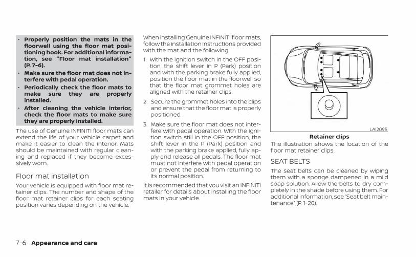
• Properly position the mats in thefloorwell using the floor mat posi-tioning hook. For additional informa-tion, see "Floor mat installation"(P. 7-6).
• Make sure the floor mat does not in-terfere with pedal operation.
• Periodically check the floor mats tomake sure they are properlyinstalled.
• After cleaning the vehicle interior,check the floor mats to make surethey are properly installed.
The use of Genuine INFINITI floor mats canextend the life of your vehicle carpet andmake it easier to clean the interior. Matsshould be maintained with regular clean-ing and replaced if they become exces-sively worn.
Floor mat installationYour vehicle is equipped with floor mat re-tainer clips. The number and shape of thefloor mat retainer clips for each seatingposition varies depending on the vehicle.
When installing Genuine INFINITI floor mats,follow the installation instructions providedwith the mat and the following:1. With the ignition switch in the OFF posi-
tion, the shift lever in P (Park) positionand with the parking brake fully applied,position the floor mat in the floorwell sothat the floor mat grommet holes arealigned with the retainer clips.
2. Secure the grommet holes into the clipsand ensure that the floor mat is properlypositioned.
3. Make sure the floor mat does not inter-fere with pedal operation. With the igni-tion switch still in the OFF position, theshift lever in the P (Park) position andwith the parking brake applied, fully ap-ply and release all pedals. The floor matmust not interfere with pedal operationor prevent the pedal from returning toits normal position.
It is recommended that you visit an INFINITIretailer for details about installing the floormats in your vehicle.
The illustration shows the location of thefloor mat retainer clips.
SEAT BELTSThe seat belts can be cleaned by wipingthem with a sponge dampened in a mildsoap solution. Allow the belts to dry com-pletely in the shade before using them. Foradditional information, see “Seat belt main-tenance” (P. 1-20).
LAI2095Retainer clips
7-6 Appearance and care
WARNING
Do not allow wet seat belts to roll up inthe retractor. NEVER use bleach, dye orchemical solvents to clean the seatbelts, since these materials may se-verely weaken the seat belt webbing.
CLEANING THE SEAT TRACKS
CAUTION
Periodically clean the seat tracks toprevent reduction of ability to move theseats.
Clean periodically with a high-poweredvacuum cleaner. Dirt and debris may re-duce the ability to adjust the seat. A wetcleansing agent may be used if necessary.
MOST COMMON FACTORSCONTRIBUTING TO VEHICLECORROSIONMost vehicle corrosion is caused by:• The accumulation of moisture-retaining
dirt and debris in body panel sections,cavities, and other areas.
• Damage to paint and other protectivecoatings caused by gravel and stonechips or minor traffic collisions.
• The use of chloride detergents.
ENVIRONMENTAL FACTORSINFLUENCE THE RATE OFCORROSION
MoistureAccumulation of sand, dirt and water onthe vehicle body underside can acceleratecorrosion. Wet floor coverings will not drycompletely inside the vehicle and shouldbe removed for drying to avoid floor panelcorrosion.
Relative humidityCorrosion will be accelerated in areas ofhigh relative humidity, especially those ar-eas where the temperatures stay abovefreezing and where atmospheric pollutionexists and road salt is used.
TemperatureHigh temperatures accelerate the rate ofcorrosion to those parts which are not wellventilated.
Air pollutionIndustrial pollution, the presence of salt inthe air in coastal areas, or heavy road saltuse accelerates the corrosion process.Road salt also accelerates the disintegra-tion of paint surfaces.
CORROSION PROTECTION
Appearance and care 7-7
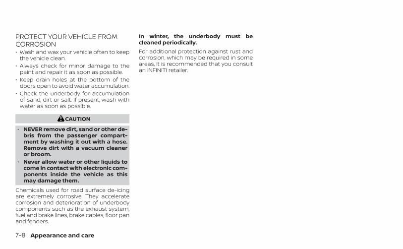
PROTECT YOUR VEHICLE FROMCORROSION• Wash and wax your vehicle often to keep
the vehicle clean.• Always check for minor damage to the
paint and repair it as soon as possible.• Keep drain holes at the bottom of the
doors open to avoid water accumulation.• Check the underbody for accumulation
of sand, dirt or salt. If present, wash withwater as soon as possible.
CAUTION
• NEVER remove dirt, sand or other de-bris from the passenger compart-ment by washing it out with a hose.Remove dirt with a vacuum cleaneror broom.
• Never allow water or other liquids tocome in contact with electronic com-ponents inside the vehicle as thismay damage them.
Chemicals used for road surface de-icingare extremely corrosive. They acceleratecorrosion and deterioration of underbodycomponents such as the exhaust system,fuel and brake lines, brake cables, floor panand fenders.
In winter, the underbody must becleaned periodically.For additional protection against rust andcorrosion, which may be required in someareas, it is recommended that you consultan INFINITI retailer.
7-8 Appearance and care
8 Do-it-yourself
Maintenance precautions . . . . . . . . . . . . . . . . . . . . . . . 8-2Engine compartment check locations . . . . . . . . . . . 8-4Engine cooling system . . . . . . . . . . . . . . . . . . . . . . . . . . 8-5
Checking engine coolant level . . . . . . . . . . . . . . . . 8-6Changing engine coolant . . . . . . . . . . . . . . . . . . . . 8-6
Engine oil . . . . . . . . . . . . . . . . . . . . . . . . . . . . . . . . . . . . . . . 8-7Checking engine oil level . . . . . . . . . . . . . . . . . . . . . 8-7Changing engine oil and oil filter . . . . . . . . . . . . . . 8-7
Continuously Variable Transmission (CVT)fluid . . . . . . . . . . . . . . . . . . . . . . . . . . . . . . . . . . . . . . . . . . . . .8-11Brake fluid . . . . . . . . . . . . . . . . . . . . . . . . . . . . . . . . . . . . . . .8-11Windshield-washer fluid . . . . . . . . . . . . . . . . . . . . . . . . 8-12
Windshield-washer fluid reservoir . . . . . . . . . . . 8-12Battery . . . . . . . . . . . . . . . . . . . . . . . . . . . . . . . . . . . . . . . . . 8-13
Jump starting . . . . . . . . . . . . . . . . . . . . . . . . . . . . . . . 8-15Variable voltage control system . . . . . . . . . . . . . . . . 8-15Drive belt . . . . . . . . . . . . . . . . . . . . . . . . . . . . . . . . . . . . . . . 8-16Spark plugs . . . . . . . . . . . . . . . . . . . . . . . . . . . . . . . . . . . . 8-16
Replacing spark plugs . . . . . . . . . . . . . . . . . . . . . . . 8-16Air cleaner . . . . . . . . . . . . . . . . . . . . . . . . . . . . . . . . . . . . . 8-17
In-cabin microfilter . . . . . . . . . . . . . . . . . . . . . . . . . . 8-18Windshield wiper blades . . . . . . . . . . . . . . . . . . . . . . . . 8-18
Cleaning . . . . . . . . . . . . . . . . . . . . . . . . . . . . . . . . . . . . 8-18Replacing . . . . . . . . . . . . . . . . . . . . . . . . . . . . . . . . . . . 8-18
Brakes . . . . . . . . . . . . . . . . . . . . . . . . . . . . . . . . . . . . . . . . .8-20Fuses . . . . . . . . . . . . . . . . . . . . . . . . . . . . . . . . . . . . . . . . . . 8-21
Engine compartment . . . . . . . . . . . . . . . . . . . . . . . 8-21Passenger compartment . . . . . . . . . . . . . . . . . . . 8-23
Battery replacement . . . . . . . . . . . . . . . . . . . . . . . . . . . 8-24INFINITI Intelligent Key . . . . . . . . . . . . . . . . . . . . . . . 8-24
Lights . . . . . . . . . . . . . . . . . . . . . . . . . . . . . . . . . . . . . . . . . .8-26Headlights . . . . . . . . . . . . . . . . . . . . . . . . . . . . . . . . . .8-26Fog lights . . . . . . . . . . . . . . . . . . . . . . . . . . . . . . . . . . . 8-26Exterior and interior lights . . . . . . . . . . . . . . . . . . .8-26
Wheels and tires . . . . . . . . . . . . . . . . . . . . . . . . . . . . . . .8-28Tire pressure . . . . . . . . . . . . . . . . . . . . . . . . . . . . . . . .8-28Tire labeling . . . . . . . . . . . . . . . . . . . . . . . . . . . . . . . . . 8-32Types of tires . . . . . . . . . . . . . . . . . . . . . . . . . . . . . . . . 8-35Tire chains . . . . . . . . . . . . . . . . . . . . . . . . . . . . . . . . . .8-38Changing wheels and tires . . . . . . . . . . . . . . . . . .8-38
When performing any inspection or main-tenance work on your vehicle, always takecare to prevent serious accidental injury toyourself or damage to the vehicle. The fol-lowing are general precautions whichshould be closely observed.
WARNING
• Park the vehicle on a level surface,apply the parking brake securely andblock the wheels to prevent the ve-hicle from moving. Move the shift le-ver to P (Park).
• Be sure the ignition switch is in theOFF or LOCK position when perform-ing any parts replacement or repairs.
• If you must work with the engine run-ning, keep your hands, clothing, hairand tools away from moving fans,belts and any other moving parts.
• It is advisable to secure or removeany loose clothing and remove anyjewelry, such as rings, watches, etc.before working on your vehicle.
• Always wear eye protection when-ever you work on your vehicle.
• Your vehicle is equipped with an au-tomatic engine cooling fan. It maycome on at any time without warn-ing, even if the ignition switch is inthe OFF position and the engine isnot running. To avoid injury, alwaysdisconnect the negative batterycable before working near the fan.
• If you must run the engine in an en-closed space such as a garage, besure there is proper ventilation forexhaust gases to escape.
• Never get under the vehicle while it issupported only by a jack. If it is nec-essary to work under the vehicle,support it with safety stands.
• Keep smoking materials, flame andsparks away from the fuel tank andbattery.
• Because the fuel lines on gasolineengine models are under high pres-sure even when the engine is off, it isrecommended that you visit anINFINITI retailer for service of the fuelfilter or fuel lines.
CAUTION
• Do not work under the hood whilethe engine is hot. Turn the engine offand wait until it cools down.
• Avoid contact with used engine oiland coolant. Improperly disposedengine oil, engine coolant and/orother vehicle fluids can damage theenvironment. Always conform to lo-cal regulations for disposal of vehiclefluid.
• Never leave the engine or Continu-ously Variable Transmission (CVT) re-lated component harnesses discon-nected while the ignition switch is inthe ON position.
• Never connect or disconnect the bat-tery or any transistorized compo-nent while the ignition switch is inthe ON position.
NOTE:
If the battery is completely drained thetransmission will not manually shift toother positions.This “Do-it-yourself ” section gives instruc-tions regarding only those items which arerelatively easy for an owner to perform.
MAINTENANCE PRECAUTIONS
8-2 Do-it-yourself
A Genuine INFINITI service manual is alsoavailable. For additional information, see“Owner’s Manual/Service Manual order in-formation” (P. 10-26).You should be aware that incomplete orimproper servicing may result in operatingdifficulties or excessive emissions, andcould affect warranty coverage. If in doubtabout any servicing, it is recommendedthat you have it done by an INFINITIretailer.
Do-it-yourself 8-3
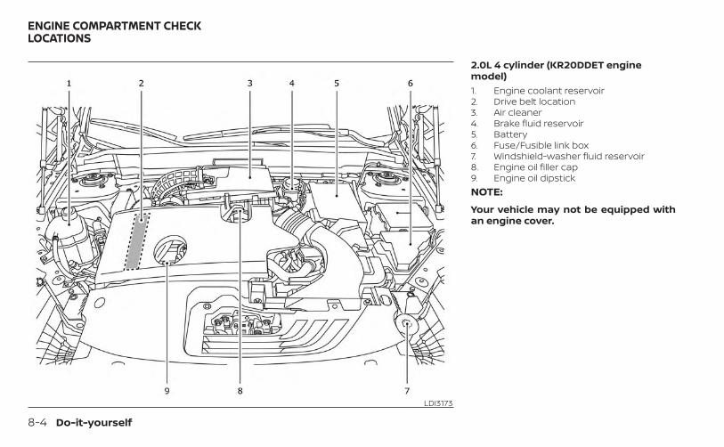
2.0L 4 cylinder (KR20DDET enginemodel)1. Engine coolant reservoir2. Drive belt location3. Air cleaner4. Brake fluid reservoir5. Battery6. Fuse/Fusible link box7. Windshield-washer fluid reservoir8. Engine oil filler cap9. Engine oil dipstickNOTE:
Your vehicle may not be equipped withan engine cover.
LDI3173
ENGINE COMPARTMENT CHECKLOCATIONS
8-4 Do-it-yourself
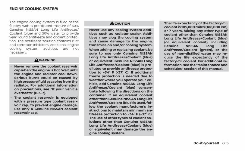
The engine cooling system is filled at thefactory with a pre-diluted mixture of 50%Genuine NISSAN Long Life Antifreeze/Coolant (blue) and 50% water to provideyear-round antifreeze and coolant protec-tion. The antifreeze solution contains rustand corrosion inhibitors. Additional enginecooling system additives are notnecessary.
WARNING
• Never remove the coolant reservoircap when the engine is hot. Wait untilthe engine and radiator cool down.Serious burns could be caused byhigh pressure fluid escaping from theradiator. For additional informationon precautions, see “If your vehicleoverheats” (P. 6-7).
• The coolant reservoir is equippedwith a pressure type coolant reser-voir cap. To prevent engine damage,use only a Genuine NISSAN coolantreservoir cap.
CAUTION
• Never use any cooling system addi-tives such as radiator sealer. Addi-tives may clog the cooling systemand cause damage to the engine,transmission and/or cooling system.
• When adding or replacing coolant, besure to use only Genuine NISSANLong Life Antifreeze/Coolant (blue)or equivalent. Genuine NISSAN LongLife Antifreeze/Coolant (blue) is pre-diluted to provide antifreeze protec-tion to -34° F (-37° C). If additionalfreeze protection is needed due toweather where you operate your ve-hicle, add Genuine NISSAN Long LifeAntifreeze/Coolant (blue) concen-trate following the directions on thecontainer. If an equivalent coolantother than Genuine NISSAN Long LifeAntifreeze/Coolant (blue) is used, fol-low the coolant manufacturer’s in-structions to maintain minimum an-tifreeze protection to -34° F (-37° C).The use of other types of coolant so-lutions other than Genuine NISSANLong Life Antifreeze/Coolant (blue)or equivalent may damage the en-gine cooling system.
• The life expectancy of the factory-fillcoolant is 105,000 miles (168,000 km)or 7 years. Mixing any other type ofcoolant other than Genuine NISSANLong Life Antifreeze/Coolant (blue)(or equivalent coolant), includingGenuine NISSAN Long LifeAntifreeze/Coolant (green), or theuse of non-distilled water may re-duce the life expectancy of thefactory-fill coolant. For additional in-formation, see the “Maintenance andschedules” section of this manual.
ENGINE COOLING SYSTEM
Do-it-yourself 8-5
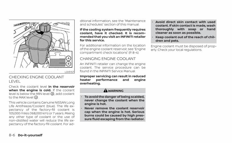
CHECKING ENGINE COOLANTLEVELCheck the coolant level in the reservoirwhen the engine is cold. If the coolantlevel is below the MIN level OB , add coolantto the MAX level OA .This vehicle contains Genuine NISSAN LongLife Antifreeze/Coolant (blue). The life ex-pectancy of the factory-fill coolant is105,000 miles (168,000 km) or 7 years. Mixingany other type of coolant or the use ofnon-distilled water will reduce the life ex-pectancy of the factory-fill coolant. For ad-
ditional information, see the “Maintenanceand schedules” section of this manual.If the cooling system frequently requirescoolant, have it checked. It is recom-mended that you visit an INFINITI retailerfor this service.For additional information on the locationof the engine coolant reservoir, see “Enginecompartment check locations” (P. 8-4).
CHANGING ENGINE COOLANTAn INFINITI retailer can change the enginecoolant. The service procedure can befound in the INFINITI Service Manual.Improper servicing can result in reducedheater performance and engineoverheating.
WARNING
• To avoid the danger of being scalded,never change the coolant when theengine is hot.
• Never remove the coolant reservoircap when the engine is hot. Seriousburns could be caused by high pres-sure fluid escaping from the radiator.
• Avoid direct skin contact with usedcoolant. If skin contact is made, washthoroughly with soap or handcleaner as soon as possible.
• Keep coolant out of the reach of chil-dren and pets.
Engine coolant must be disposed of prop-erly. Check your local regulations.
LDI3157
8-6 Do-it-yourself
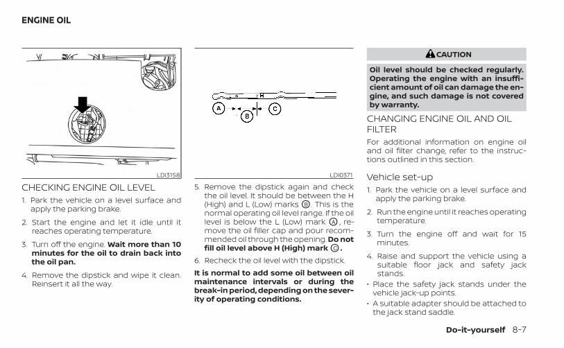
CHECKING ENGINE OIL LEVEL1. Park the vehicle on a level surface and
apply the parking brake.
2. Start the engine and let it idle until itreaches operating temperature.
3. Turn off the engine. Wait more than 10minutes for the oil to drain back intothe oil pan.
4. Remove the dipstick and wipe it clean.Reinsert it all the way.
5. Remove the dipstick again and checkthe oil level. It should be between the H(High) and L (Low) marks OB . This is thenormal operating oil level range. If the oillevel is below the L (Low) mark OA , re-move the oil filler cap and pour recom-mended oil through the opening. Do notfill oil level above H (High) mark OC .
6. Recheck the oil level with the dipstick.It is normal to add some oil between oilmaintenance intervals or during thebreak-in period, depending on the sever-ity of operating conditions.
CAUTION
Oil level should be checked regularly.Operating the engine with an insuffi-cient amount of oil can damage the en-gine, and such damage is not coveredby warranty.
CHANGING ENGINE OIL AND OILFILTERFor additional information on engine oiland oil filter change, refer to the instruc-tions outlined in this section.
Vehicle set-up1. Park the vehicle on a level surface and
apply the parking brake.
2. Run the engine until it reaches operatingtemperature.
3. Turn the engine off and wait for 15minutes.
4. Raise and support the vehicle using asuitable floor jack and safety jackstands.
• Place the safety jack stands under thevehicle jack-up points.
• A suitable adapter should be attached tothe jack stand saddle.
LDI3158 LDI0371
ENGINE OIL
Do-it-yourself 8-7
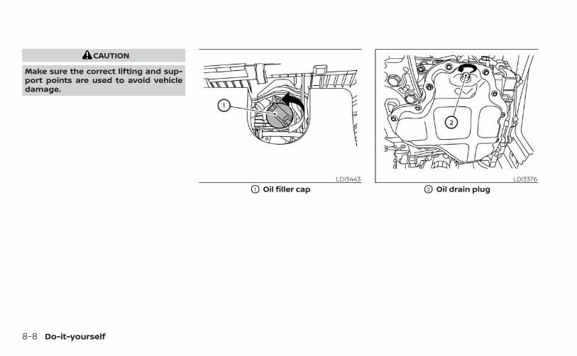
CAUTION
Make sure the correct lifting and sup-port points are used to avoid vehicledamage.
LDI3443
O1 Oil filler capLDI3376
O2 Oil drain plug
8-8 Do-it-yourself
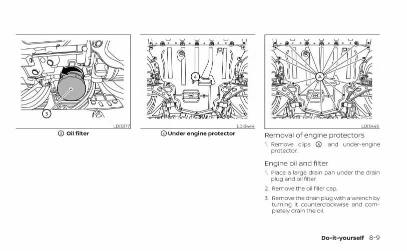
Removal of engine protectors1. Remove clips OA and under-engine
protector.
Engine oil and filter1. Place a large drain pan under the drain
plug and oil filter.
2. Remove the oil filler cap.
3. Remove the drain plug with a wrench byturning it counterclockwise and com-pletely drain the oil.
LDI3377
O3 Oil filterLDI3444
O4 Under engine protectorLDI3445
Do-it-yourself 8-9
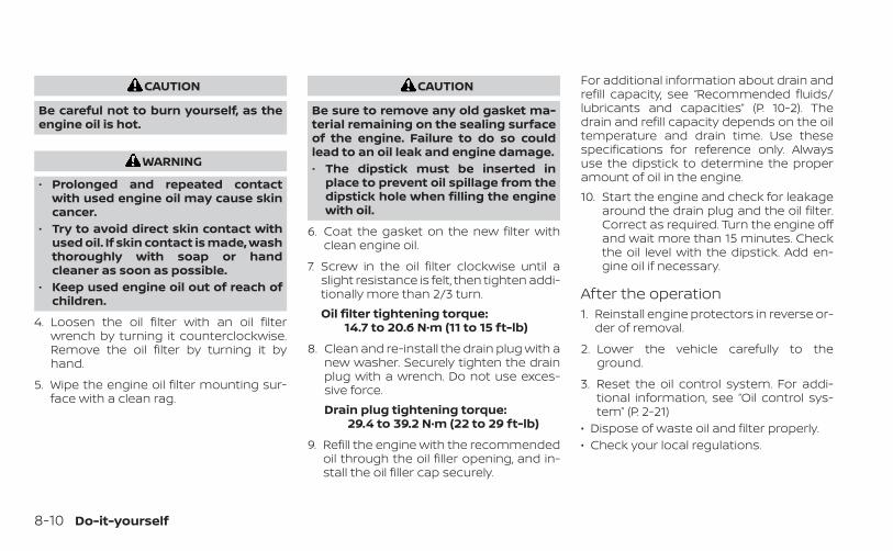
CAUTION
Be careful not to burn yourself, as theengine oil is hot.
WARNING
• Prolonged and repeated contactwith used engine oil may cause skincancer.
• Try to avoid direct skin contact withused oil. If skin contact is made, washthoroughly with soap or handcleaner as soon as possible.
• Keep used engine oil out of reach ofchildren.
4. Loosen the oil filter with an oil filterwrench by turning it counterclockwise.Remove the oil filter by turning it byhand.
5. Wipe the engine oil filter mounting sur-face with a clean rag.
CAUTION
Be sure to remove any old gasket ma-terial remaining on the sealing surfaceof the engine. Failure to do so couldlead to an oil leak and engine damage.• The dipstick must be inserted in
place to prevent oil spillage from thedipstick hole when filling the enginewith oil.
6. Coat the gasket on the new filter withclean engine oil.
7. Screw in the oil filter clockwise until aslight resistance is felt, then tighten addi-tionally more than 2/3 turn.Oil filter tightening torque:
14.7 to 20.6 N·m (11 to 15 ft-lb)
8. Clean and re-install the drain plug with anew washer. Securely tighten the drainplug with a wrench. Do not use exces-sive force.Drain plug tightening torque:
29.4 to 39.2 N·m (22 to 29 ft-lb)
9. Refill the engine with the recommendedoil through the oil filler opening, and in-stall the oil filler cap securely.
For additional information about drain andrefill capacity, see “Recommended fluids/lubricants and capacities” (P. 10-2). Thedrain and refill capacity depends on the oiltemperature and drain time. Use thesespecifications for reference only. Alwaysuse the dipstick to determine the properamount of oil in the engine.10. Start the engine and check for leakage
around the drain plug and the oil filter.Correct as required. Turn the engine offand wait more than 15 minutes. Checkthe oil level with the dipstick. Add en-gine oil if necessary.
After the operation1. Reinstall engine protectors in reverse or-
der of removal.
2. Lower the vehicle carefully to theground.
3. Reset the oil control system. For addi-tional information, see “Oil control sys-tem” (P. 2-21)
• Dispose of waste oil and filter properly.• Check your local regulations.
8-10 Do-it-yourself
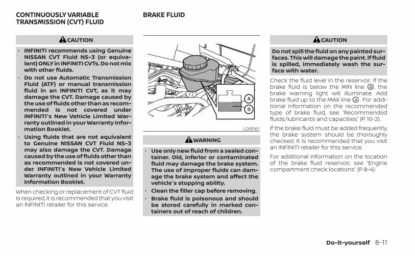
CAUTION
• INFINITI recommends using GenuineNISSAN CVT Fluid NS-3 (or equiva-lent) ONLY in INFINITI CVTs. Do not mixwith other fluids.
• Do not use Automatic TransmissionFluid (ATF) or manual transmissionfluid in an INFINITI CVT, as it maydamage the CVT. Damage caused bythe use of fluids other than as recom-mended is not covered underINFINITI's New Vehicle Limited War-ranty outlined in your Warranty Infor-mation Booklet.
• Using fluids that are not equivalentto Genuine NISSAN CVT Fluid NS-3may also damage the CVT. Damagecaused by the use of fluids other thanas recommended is not covered un-der INFINITI's New Vehicle LimitedWarranty outlined in your WarrantyInformation Booklet.
When checking or replacement of CVT fluidis required, it is recommended that you visitan INFINITI retailer for this service.
WARNING
• Use only new fluid from a sealed con-tainer. Old, inferior or contaminatedfluid may damage the brake system.The use of improper fluids can dam-age the brake system and affect thevehicle's stopping ability.
• Clean the filler cap before removing.• Brake fluid is poisonous and should
be stored carefully in marked con-tainers out of reach of children.
CAUTION
Do not spill the fluid on any painted sur-faces. This will damage the paint. If fluidis spilled, immediately wash the sur-face with water.
Check the fluid level in the reservoir. If thebrake fluid is below the MIN line OB , thebrake warning light will illuminate. Addbrake fluid up to the MAX line OA . For addi-tional information on the recommendedtype of brake fluid, see “Recommendedfluids/lubricants and capacities” (P. 10-2).If the brake fluid must be added frequently,the brake system should be thoroughlychecked. It is recommended that you visitan INFINITI retailer for this service.For additional information on the locationof the brake fluid reservoir, see “Enginecompartment check locations” (P. 8-4).
LDI3161
CONTINUOUSLY VARIABLETRANSMISSION (CVT) FLUID
BRAKE FLUID
Do-it-yourself 8-11
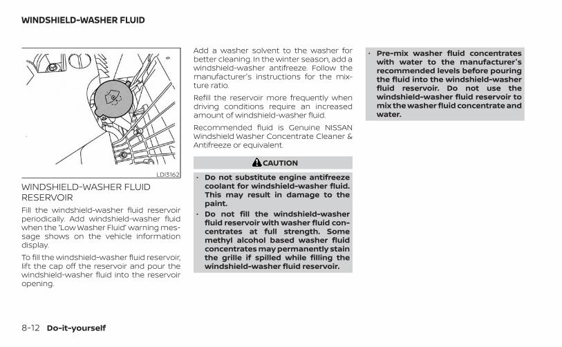
WINDSHIELD-WASHER FLUIDRESERVOIRFill the windshield-washer fluid reservoirperiodically. Add windshield-washer fluidwhen the “Low Washer Fluid” warning mes-sage shows on the vehicle informationdisplay.To fill the windshield-washer fluid reservoir,lift the cap off the reservoir and pour thewindshield-washer fluid into the reservoiropening.
Add a washer solvent to the washer forbetter cleaning. In the winter season, add awindshield-washer antifreeze. Follow themanufacturer's instructions for the mix-ture ratio.Refill the reservoir more frequently whendriving conditions require an increasedamount of windshield-washer fluid.Recommended fluid is Genuine NISSANWindshield Washer Concentrate Cleaner &Antifreeze or equivalent.
CAUTION
• Do not substitute engine antifreezecoolant for windshield-washer fluid.This may result in damage to thepaint.
• Do not fill the windshield-washerfluid reservoir with washer fluid con-centrates at full strength. Somemethyl alcohol based washer fluidconcentrates may permanently stainthe grille if spilled while filling thewindshield-washer fluid reservoir.
• Pre-mix washer fluid concentrateswith water to the manufacturer'srecommended levels before pouringthe fluid into the windshield-washerfluid reservoir. Do not use thewindshield-washer fluid reservoir tomix the washer fluid concentrate andwater.
LDI3162
WINDSHIELD-WASHER FLUID
8-12 Do-it-yourself

Caution symbols for battery WARNING
O1No smoking, No exposed flames, No
SparksDo not expose the battery to flames or electrical sparks. Hydrogen gas generated by the battery is
explosive. Explosive gases can cause blindness or injury.
O2 Shield eyes Handle the battery cautiously. Always wear eye protection glasses to protect against explosion orbattery acid.
O3 Keep away from children Never allow children to handle the battery. Keep the battery out of the reach of children.
O4 Battery acid
Do not allow battery fluid to contact your skin, eyes, fabrics, or painted surfaces. After touching abattery or battery cap, immediately wash your hands thoroughly. If the battery fluid gets into youreyes, or onto your skin or clothing, flush with water immediately for at least 15 minutes and seekmedical attention. Battery fluid is acid. If the battery fluid gets into your eyes or onto your skin, it
could cause loss of your eyesight or burns.
O5 Note operating instructions Before handling the battery, read this instruction carefully to ensure correct and safe handling.
O6 Explosive gas Hydrogen gas generated by battery fluid is explosive. Explosive gases can cause blindness orinjury.
BATTERY
Do-it-yourself 8-13

• If the battery is labeled "do not open" it ismaintenance free and battery fluidshould not be checked. It is recom-mended that you visit an INFINITI retaileror a qualified specialist workshop to con-firm the battery's performance.
• Keep the battery surface clean and dry.Clean the battery with a solution of bak-ing soda and water.
• Make certain the terminal connectionsare clean and securely tightened.
• If the vehicle is not to be used for 30 daysor longer, disconnect the negative (-) bat-tery terminal cable to prevent discharge.
NOTE:Care should be taken to avoid situa-tions that can lead to potential batterydischarge and potential no-start con-ditions such as:1. Installation or extended use of elec-
tronic accessories that consume bat-tery power when the engine is notrunning (Phone chargers, GPS, DVDplayers, etc.)
2. Vehicle is not driven regularly and/oronly driven short distances.
In these cases, the battery may need tobe charged to maintain battery health.
WARNING
• Do not expose the battery to flames,an electrical spark or a cigarette. Hy-drogen gas generated by the batteryis explosive. Explosive gases cancause blindness or injury. Do not al-low battery fluid to contact your skin,eyes, fabrics or painted surfaces. Sul-furic acid can cause blindness or in-jury. After touching a battery or bat-tery cap, do not touch or rub youreyes. Thoroughly wash your hands. Ifthe acid contacts your eyes, skin orclothing, immediately flush with wa-ter for at least 15 minutes and seekmedical attention.
• When working on or near a battery,always wear suitable eye protectionand remove all jewelry.
• Battery posts, terminals and relatedaccessories contain lead and leadcompounds. Wash hands afterhandling.
• Keep battery out of the reach ofchildren.
• Do not tip the battery.
NOTE:
Do not try to open the top of the battery.This battery is not equipped with remov-able vent caps.Vehicles operated in high temperatures orunder severe conditions might presentbattery liquid loss. It is recommended thatyou visit an INFINITI retailer for a properbattery diagnosis and service in case ofrequired.
LDI3595
8-14 Do-it-yourself
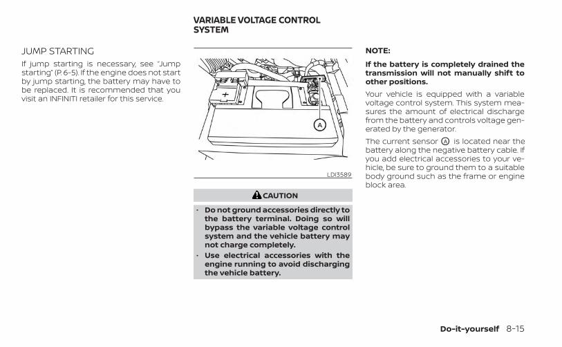
JUMP STARTINGIf jump starting is necessary, see “Jumpstarting” (P. 6-5). If the engine does not startby jump starting, the battery may have tobe replaced. It is recommended that youvisit an INFINITI retailer for this service.
CAUTION
• Do not ground accessories directly tothe battery terminal. Doing so willbypass the variable voltage controlsystem and the vehicle battery maynot charge completely.
• Use electrical accessories with theengine running to avoid dischargingthe vehicle battery.
NOTE:
If the battery is completely drained thetransmission will not manually shift toother positions.Your vehicle is equipped with a variablevoltage control system. This system mea-sures the amount of electrical dischargefrom the battery and controls voltage gen-erated by the generator.The current sensor OA is located near thebattery along the negative battery cable. Ifyou add electrical accessories to your ve-hicle, be sure to ground them to a suitablebody ground such as the frame or engineblock area.
LDI3589
VARIABLE VOLTAGE CONTROLSYSTEM
Do-it-yourself 8-15
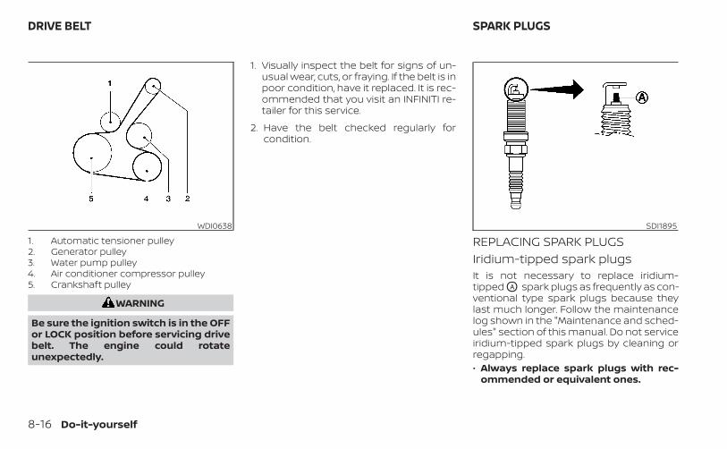
1. Automatic tensioner pulley2. Generator pulley3. Water pump pulley4. Air conditioner compressor pulley5. Crankshaft pulley
WARNING
Be sure the ignition switch is in the OFFor LOCK position before servicing drivebelt. The engine could rotateunexpectedly.
1. Visually inspect the belt for signs of un-usual wear, cuts, or fraying. If the belt is inpoor condition, have it replaced. It is rec-ommended that you visit an INFINITI re-tailer for this service.
2. Have the belt checked regularly forcondition.
REPLACING SPARK PLUGSIridium-tipped spark plugsIt is not necessary to replace iridium-tipped OA spark plugs as frequently as con-ventional type spark plugs because theylast much longer. Follow the maintenancelog shown in the "Maintenance and sched-ules" section of this manual. Do not serviceiridium-tipped spark plugs by cleaning orregapping.• Always replace spark plugs with rec-
ommended or equivalent ones.
WDI0638 SDI1895
DRIVE BELT SPARK PLUGS
8-16 Do-it-yourself
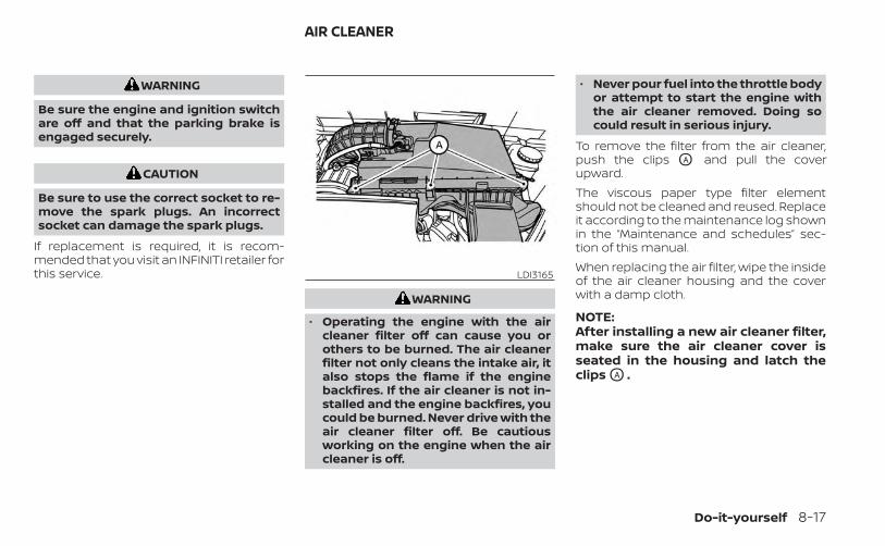
WARNING
Be sure the engine and ignition switchare off and that the parking brake isengaged securely.
CAUTION
Be sure to use the correct socket to re-move the spark plugs. An incorrectsocket can damage the spark plugs.
If replacement is required, it is recom-mended that you visit an INFINITI retailer forthis service.
WARNING
• Operating the engine with the aircleaner filter off can cause you orothers to be burned. The air cleanerfilter not only cleans the intake air, italso stops the flame if the enginebackfires. If the air cleaner is not in-stalled and the engine backfires, youcould be burned. Never drive with theair cleaner filter off. Be cautiousworking on the engine when the aircleaner is off.
• Never pour fuel into the throttle bodyor attempt to start the engine withthe air cleaner removed. Doing socould result in serious injury.
To remove the filter from the air cleaner,push the clips OA and pull the coverupward.The viscous paper type filter elementshould not be cleaned and reused. Replaceit according to the maintenance log shownin the “Maintenance and schedules” sec-tion of this manual.When replacing the air filter, wipe the insideof the air cleaner housing and the coverwith a damp cloth.
NOTE:After installing a new air cleaner filter,make sure the air cleaner cover isseated in the housing and latch theclips OA .
LDI3165
AIR CLEANER
Do-it-yourself 8-17

IN-CABIN MICROFILTERThe in-cabin microfilter restricts the entryof airborne dust and pollen particles andreduces some objectionable outsideodors. The filter is located behind the glovebox. For additional information on changeintervals, see the "Maintenance and sched-ules" section of this manual.If replacement is required, it is recom-mended that you visit an INFINITI retailer forthis service.
CLEANINGIf your windshield is not clear after usingthe windshield-washer or if a wiper bladechatters when running, wax or other mate-rial may be on the blade or windshield.Clean the outside of the windshield with awasher solution or a mild detergent. Yourwindshield is clean if beads do not formwhen rinsing with clear water.Clean each blade by wiping it with a clothsoaked in a washer solution or a mild de-tergent. Then rinse the blades with clearwater. If your windshield is still not clearafter cleaning the blades and using thewiper, replace the blades.
CAUTION
Worn windshield wiper blades candamage the windshield and impairdriver vision.
REPLACINGReplace the wiper blades if they are worn.To replace the windshield wiper blades, fol-low the procedure below:1. When the ignition switch is ON or within
60 seconds after placing the ignitionswitch from the ON to OFF position,place the windshield wiper and washerlever into the OFF position.
2. Rapidly lift the windshield wiper andwasher lever OA upwards twice within0.5 seconds. This action will cause thewipers to automatically take the serviceposition.
LDI3250
WINDSHIELD WIPER BLADES
8-18 Do-it-yourself

3. Once the wipers are in the service posi-tion, push the release tab OC .
4. Move the wiper blade down OB andremove.
5. Insert the new wiper blade onto thewiper arm until it clicks into place.
6. Rotate the wiper blade so the dimple isin the groove.
7. Finally, lift the windshield wiper andwasher lever to the mist position OD
once and release. This action will causethe wipers to resume the set position.
CAUTION
• After wiper blade replacement, re-turn the wiper arm to its original po-sition; otherwise it may be damagedwhen the hood is opened.
• Make sure the wiper blades contactthe glass; otherwise the arms may bedamaged from wind pressure.
LDI2785 LDI3251
Do-it-yourself 8-19
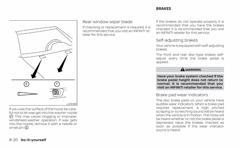
If you wax the surface of the hood, be care-ful not to let wax get into the washer nozzleOF . This may cause clogging or improperwindshield-washer operation. If wax getsinto the nozzle, remove it with a needle orsmall pin OE .
Rear window wiper bladeIf checking or replacement is required, it isrecommended that you visit an INFINITI re-tailer for this service.
If the brakes do not operate properly, it isrecommended that you have the brakeschecked. It is recommended that you visitan INFINITI retailer for this service.
Self-adjusting brakesYour vehicle is equipped with self-adjustingbrakes.The front and rear disc-type brakes self-adjust every time the brake pedal isapplied.
WARNING
Have your brake system checked if thebrake pedal height does not return tonormal. It is recommended that youvisit an INFINITI retailer for this service.
Brake pad wear indicatorsThe disc brake pads on your vehicle haveaudible wear indicators. When a brake padrequires replacement, a high pitchedscraping or screeching sound will be heardwhen the vehicle is in motion. The noise willbe heard whether or not the brake pedal isdepressed. Have the brakes checked assoon as possible if the wear indicatorsound is heard.
LDI3189
BRAKES
8-20 Do-it-yourself
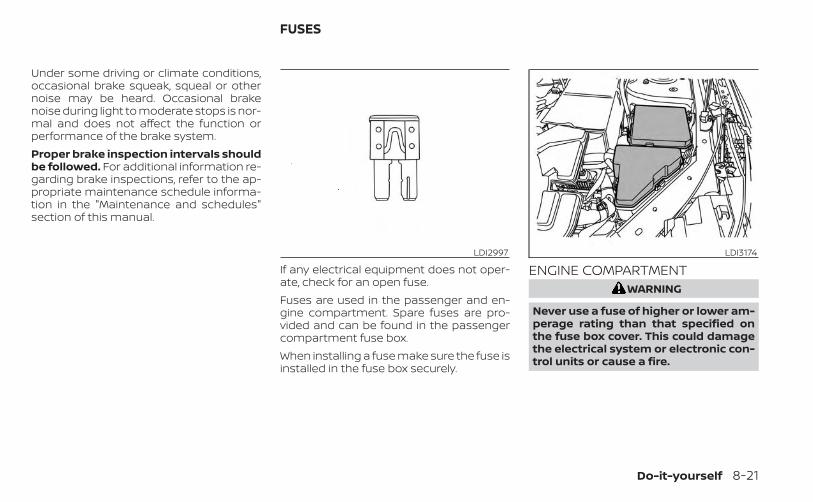
Under some driving or climate conditions,occasional brake squeak, squeal or othernoise may be heard. Occasional brakenoise during light to moderate stops is nor-mal and does not affect the function orperformance of the brake system.Proper brake inspection intervals shouldbe followed. For additional information re-garding brake inspections, refer to the ap-propriate maintenance schedule informa-tion in the "Maintenance and schedules"section of this manual.
If any electrical equipment does not oper-ate, check for an open fuse.Fuses are used in the passenger and en-gine compartment. Spare fuses are pro-vided and can be found in the passengercompartment fuse box.When installing a fuse make sure the fuse isinstalled in the fuse box securely.
ENGINE COMPARTMENTWARNING
Never use a fuse of higher or lower am-perage rating than that specified onthe fuse box cover. This could damagethe electrical system or electronic con-trol units or cause a fire.
LDI2997 LDI3174
FUSES
Do-it-yourself 8-21
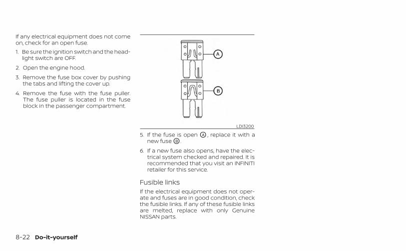
If any electrical equipment does not comeon, check for an open fuse.1. Be sure the ignition switch and the head-
light switch are OFF.
2. Open the engine hood.
3. Remove the fuse box cover by pushingthe tabs and lifting the cover up.
4. Remove the fuse with the fuse puller.The fuse puller is located in the fuseblock in the passenger compartment.
5. If the fuse is open OA , replace it with anew fuse OB .
6. If a new fuse also opens, have the elec-trical system checked and repaired. It isrecommended that you visit an INFINITIretailer for this service.
Fusible linksIf the electrical equipment does not oper-ate and fuses are in good condition, checkthe fusible links. If any of these fusible linksare melted, replace with only GenuineNISSAN parts.
LDI3200
8-22 Do-it-yourself
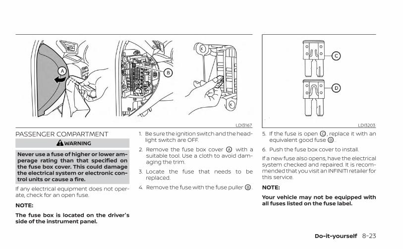
PASSENGER COMPARTMENTWARNING
Never use a fuse of higher or lower am-perage rating than that specified onthe fuse box cover. This could damagethe electrical system or electronic con-trol units or cause a fire.
If any electrical equipment does not oper-ate, check for an open fuse.
NOTE:
The fuse box is located on the driver'sside of the instrument panel.
1. Be sure the ignition switch and the head-light switch are OFF.
2. Remove the fuse box cover OA with asuitable tool. Use a cloth to avoid dam-aging the trim.
3. Locate the fuse that needs to bereplaced.
4. Remove the fuse with the fuse puller OB .
5. If the fuse is open OC , replace it with anequivalent good fuse OD .
6. Push the fuse box cover to install.If a new fuse also opens, have the electricalsystem checked and repaired. It is recom-mended that you visit an INFINITI retailer forthis service.
NOTE:
Your vehicle may not be equipped withall fuses listed on the fuse label.
LDI3167 LDI3203
Do-it-yourself 8-23
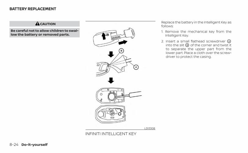
CAUTION
Be careful not to allow children to swal-low the battery or removed parts.
INFINITI INTELLIGENT KEY
Replace the battery in the Intelligent Key asfollows:1. Remove the mechanical key from the
Intelligent Key.
2. Insert a small flathead screwdriver OA
into the slit OB of the corner and twist itto separate the upper part from thelower part. Place a cloth over the screw-driver to protect the casing.
LDI3308
BATTERY REPLACEMENT
8-24 Do-it-yourself
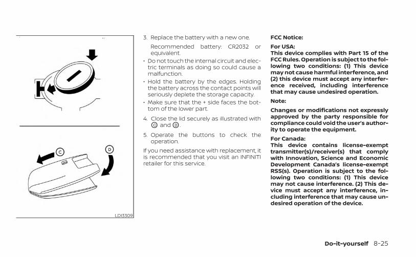
3. Replace the battery with a new one.Recommended battery: CR2032 orequivalent.
• Do not touch the internal circuit and elec-tric terminals as doing so could cause amalfunction.
• Hold the battery by the edges. Holdingthe battery across the contact points willseriously deplete the storage capacity.
• Make sure that the + side faces the bot-tom of the lower part.
4. Close the lid securely as illustrated withOC and OD .
5. Operate the buttons to check theoperation.
If you need assistance with replacement, itis recommended that you visit an INFINITIretailer for this service.
FCC Notice:For USA:This device complies with Part 15 of theFCC Rules. Operation is subject to the fol-lowing two conditions: (1) This devicemay not cause harmful interference, and(2) this device must accept any interfer-ence received, including interferencethat may cause undesired operation.Note:Changes or modifications not expresslyapproved by the party responsible forcompliance could void the user’s author-ity to operate the equipment.For Canada:This device contains license-exempttransmitter(s)/receiver(s) that complywith Innovation, Science and EconomicDevelopment Canada’s license-exemptRSS(s). Operation is subject to the fol-lowing two conditions: (1) This devicemay not cause interference. (2) This de-vice must accept any interference, in-cluding interference that may cause un-desired operation of the device.
LDI3309
Do-it-yourself 8-25
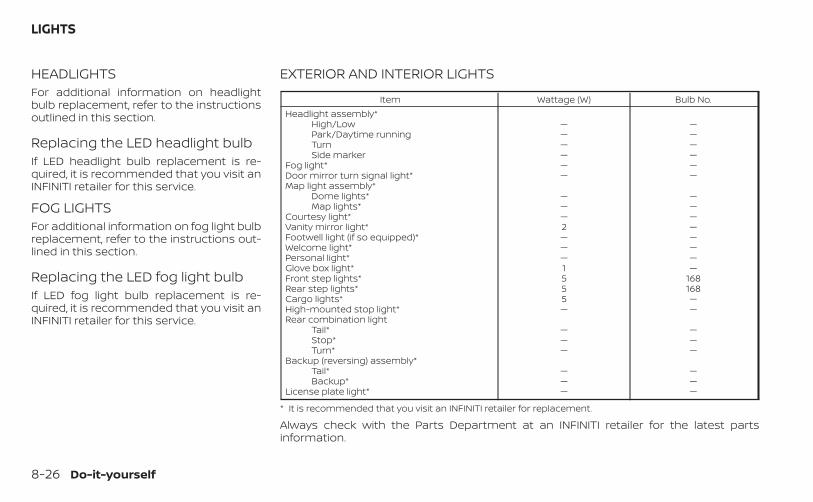
HEADLIGHTSFor additional information on headlightbulb replacement, refer to the instructionsoutlined in this section.
Replacing the LED headlight bulbIf LED headlight bulb replacement is re-quired, it is recommended that you visit anINFINITI retailer for this service.
FOG LIGHTSFor additional information on fog light bulbreplacement, refer to the instructions out-lined in this section.
Replacing the LED fog light bulbIf LED fog light bulb replacement is re-quired, it is recommended that you visit anINFINITI retailer for this service.
EXTERIOR AND INTERIOR LIGHTS
Item Wattage (W) Bulb No.Headlight assembly*
High/Low — —Park/Daytime running — —Turn — —Side marker — —
Fog light* — —Door mirror turn signal light* — —Map light assembly*
Dome lights* — —Map lights* — —
Courtesy light* — —Vanity mirror light* 2 —Footwell light (if so equipped)* — —Welcome light* — —Personal light* — —Glove box light* 1 —Front step lights* 5 168Rear step lights* 5 168Cargo lights* 5 —High-mounted stop light* — —Rear combination light
Tail* — —Stop* — —Turn* — —
Backup (reversing) assembly*Tail* — —Backup* — —
License plate light* — —
* It is recommended that you visit an INFINITI retailer for replacement.
Always check with the Parts Department at an INFINITI retailer for the latest partsinformation.
LIGHTS
8-26 Do-it-yourself
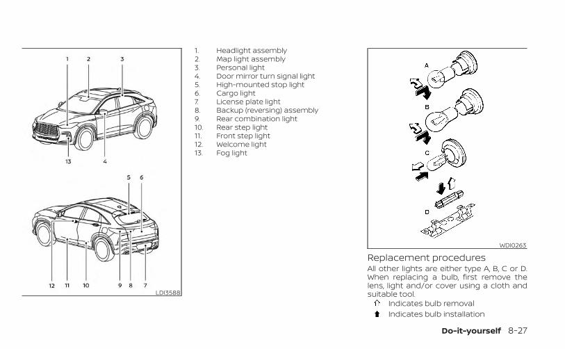
1. Headlight assembly2. Map light assembly3. Personal light4. Door mirror turn signal light5. High-mounted stop light6. Cargo light7. License plate light8. Backup (reversing) assembly9. Rear combination light10. Rear step light11. Front step light12. Welcome light13. Fog light
Replacement proceduresAll other lights are either type A, B, C or D.When replacing a bulb, first remove thelens, light and/or cover using a cloth andsuitable tool.
Indicates bulb removalIndicates bulb installation
LDI3588
WDI0263
Do-it-yourself 8-27
If you have a flat tire, see “Flat tire”(P. 6-3).
TIRE PRESSURE
Tire Pressure Monitoring System(TPMS)
WARNING
Radio waves could adversely af-fect electric medical equipment.Those who use a pacemakershould contact the electric medi-cal equipment manufacturer forthe possible influences beforeuse.
This vehicle is equipped with the TirePressure Monitoring System (TPMS).It monitors tire pressure of all tiresexcept the spare. When the low tirepressure warning light is lit and the“Tire Pressure Low – Add Air” warningappears in the vehicle informationdisplay, one or more of your tires issignificantly under-inflated. If
equipped, the system also displayspressure of all tires (except the sparetire) on the display screen by send-ing a signal from a sensor that isinstalled in each wheel.The TPMS will activate only when thevehicle is driven at speeds above 16mph (25 km/h). Also, this systemmay not detect a sudden drop in tirepressure (for example a flat tire whiledriving).For additional information, see “Lowtire pressure warning light” (P. 2-14),“Tire Pressure Monitoring System(TPMS)” (P. 5-5) and “Flat tire” (P. 6-3).
Tire inflation pressureCheck the tire pressures (includingthe spare) often and always prior tolong distance trips. The recom-mended tire pressure specificationsare shown on the F.M.V.S.S./C.M.V.S.S.certification label or the Tire andLoading Information label under the
“Cold Tire Pressure” heading. The Tireand Loading Information label is af-fixed to the driver side center pillar.Tire pressures should be checkedregularly because:• Most tires naturally lose air over
time.• Tires can lose air suddenly when
driven over potholes or other ob-jects or if the vehicle strikes a curbwhile parking.
The tire pressures should bechecked when the tires are cold. Thetires are considered COLD after thevehicle has been parked for 3 ormore hours, or driven less than 1 mile(1.6 km) at moderate speeds.TPMS with Tire Inflation Indicatorprovides visual and audible signalsoutside the vehicle for inflating thetires to the recommended COLD tirepressure. For additional information,see “TPMS with tire inflation indica-tor” (P. 5-8).
WHEELS AND TIRES
8-28 Do-it-yourself

Incorrect tire pressure, includingunder inflation, may adversely af-fect tire life and vehicle handling.
WARNING
• Improperly inflated tires canfail suddenly and cause anaccident.
• The Gross Vehicle Weight Rat-ing (GVWR) is located on theF.M.V.S.S./C.M.V.S.S. certifica-tion label. The vehicle weightcapacity is indicated on the Tireand Loading Information label.Do not load your vehicle be-yond this capacity. Overload-ing your vehicle may result inreduced tire life, unsafe operat-ing conditions due to prema-ture tire failure, or unfavorablehandling characteristics andcould also lead to a serious ac-cident. Loading beyond thespecified capacity may also re-sult in failure of other vehiclecomponents.
• Before taking a long trip, orwhenever you heavily loadyour vehicle, use a tire pressuregauge to ensure that the tirepressures are at the specifiedlevel.
• For additional information re-garding tires, refer to “Impor-tant Tire Safety Information”(US) or “Tire Safety Informa-tion” (Canada) in the WarrantyInformation Booklet.
Do-it-yourself 8-29
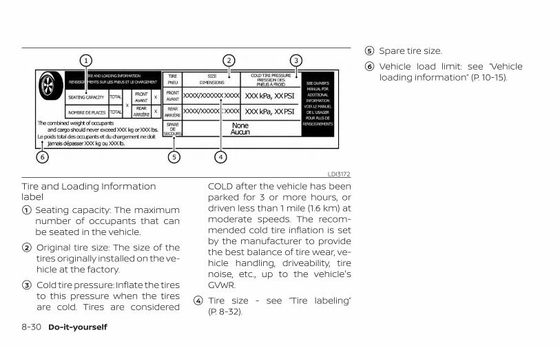
Tire and Loading Informationlabel�1 Seating capacity: The maximum
number of occupants that canbe seated in the vehicle.
�2 Original tire size: The size of thetires originally installed on the ve-hicle at the factory.
�3 Cold tire pressure: Inflate the tiresto this pressure when the tiresare cold. Tires are considered
COLD after the vehicle has beenparked for 3 or more hours, ordriven less than 1 mile (1.6 km) atmoderate speeds. The recom-mended cold tire inflation is setby the manufacturer to providethe best balance of tire wear, ve-hicle handling, driveability, tirenoise, etc., up to the vehicle'sGVWR.
�4 Tire size - see “Tire labeling”(P. 8-32).
�5 Spare tire size.
�6 Vehicle load limit: see “Vehicleloading information” (P. 10-15).
LDI3172
8-30 Do-it-yourself

Checking tire pressureWARNING
• Driving at high speeds, 100mph (160 km/h) or higher sus-tained where it is legal to do so,can cause tires to have exces-sive heat build up, which mayresult in a tire failure causingloss of control, crash, injuries oreven death.
• Some high-speed rated tiresrequire inflation pressure ad-justment for high-speed op-eration. When speed limits androad conditions allow vehicledriving at high speeds, makesure tires are rated to supporthigh speed operation, tires arein optimal conditions and pres-sure is adjusted to correct coldinflation pressure for highspeed operation.
• If your vehicle is equipped withP235/55RF19 or P255/45RF20tire sizes, tires require adjust-ment to the inflation pressurewhen driving the vehicle atspeeds of 100 mph (160 km/h)or higher where it is legal to doso. Set the cold inflation pres-sure to 36 psi (250 kPa).
• After vehicle high speed opera-tion has ended, readjust thetire pressure to the recom-mended cold inflation pres-sure. For additional informa-tion, see "Checking tirepressure" (P. 8-31).
1. Remove the valve stem cap fromthe tire.
2. Press the pressure gaugesquarely onto the valve stem. Donot press too hard or force thevalve stem sideways, or air will es-cape. If the hissing sound of airescaping from the tire is heardwhile checking the pressure, re-position the gauge to eliminatethis leakage.
3. Remove the gauge.
4. Read the tire pressure on thegauge stem and compare to thespecification shown on the Tireand Loading Information label.
LDI0393
Do-it-yourself 8-31
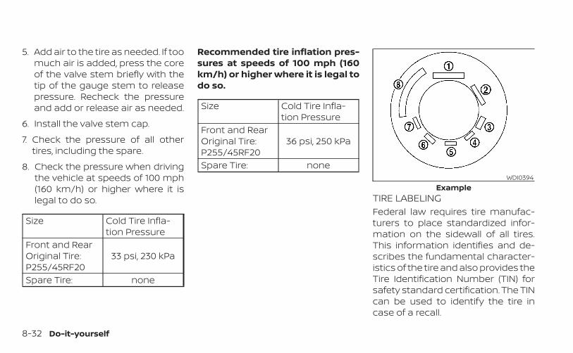
5. Add air to the tire as needed. If toomuch air is added, press the coreof the valve stem briefly with thetip of the gauge stem to releasepressure. Recheck the pressureand add or release air as needed.
6. Install the valve stem cap.
7. Check the pressure of all othertires, including the spare.
8. Check the pressure when drivingthe vehicle at speeds of 100 mph(160 km/h) or higher where it islegal to do so.
Size Cold Tire Infla-tion Pressure
Front and RearOriginal Tire:P255/45RF20
33 psi, 230 kPa
Spare Tire: none
Recommended tire inflation pres-sures at speeds of 100 mph (160km/h) or higher where it is legal todo so.
Size Cold Tire Infla-tion Pressure
Front and RearOriginal Tire:P255/45RF20
36 psi, 250 kPa
Spare Tire: none
TIRE LABELINGFederal law requires tire manufac-turers to place standardized infor-mation on the sidewall of all tires.This information identifies and de-scribes the fundamental character-istics of the tire and also provides theTire Identification Number (TIN) forsafety standard certification. The TINcan be used to identify the tire incase of a recall.
WDI0394Example
8-32 Do-it-yourself
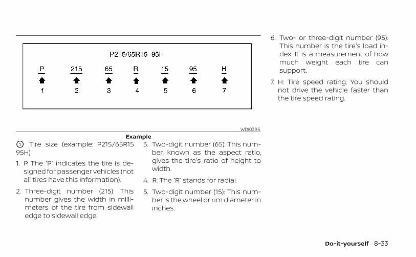
O1 Tire size (example: P215/65R1595H)1. P: The “P” indicates the tire is de-
signed for passenger vehicles (notall tires have this information).
2. Three-digit number (215): Thisnumber gives the width in milli-meters of the tire from sidewalledge to sidewall edge.
3. Two-digit number (65): This num-ber, known as the aspect ratio,gives the tire's ratio of height towidth.
4. R: The “R” stands for radial.
5. Two-digit number (15): This num-ber is the wheel or rim diameter ininches.
6. Two- or three-digit number (95):This number is the tire's load in-dex. It is a measurement of howmuch weight each tire cansupport.
7. H: Tire speed rating. You shouldnot drive the vehicle faster thanthe tire speed rating.
WDI0395Example
Do-it-yourself 8-33
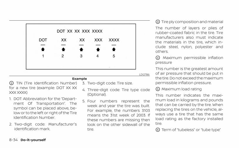
O2 TIN (Tire Identification Number)for a new tire (example: DOT XX XXXXX XXXX)1. DOT: Abbreviation for the “Depart-
ment Of Transportation”. Thesymbol can be placed above, be-low or to the left or right of the TireIdentification Number.
2. Two-digit code: Manufacturer'sidentification mark.
3. Two-digit code: Tire size.
4. Three-digit code: Tire type code(Optional).
5. Four numbers represent theweek and year the tire was built.For example, the numbers 3103means the 31st week of 2003. Ifthese numbers are missing thenlook on the other sidewall of thetire.
O3 Tire ply composition and materialThe number of layers or plies ofrubber-coated fabric in the tire. Tiremanufacturers also must indicatethe materials in the tire, which in-clude steel, nylon, polyester andothers.
O4 Maximum permissible inflationpressureThis number is the greatest amountof air pressure that should be put inthe tire. Do not exceed the maximumpermissible inflation pressure.
O5 Maximum load ratingThis number indicates the maxi-mum load in kilograms and poundsthat can be carried by the tire. Whenreplacing the tires on the vehicle, al-ways use a tire that has the sameload rating as the factory installedtire.
O6 Term of “tubeless” or “tube type”
LDI2786Example
8-34 Do-it-yourself
Indicates whether the tire requiresan inner tube (“tube type”) or not(“tubeless”).
O7 The word “radial”The word “radial” is shown if the tirehas radial structure.
O8 Manufacturer or brand nameManufacturer or brand name isshown.
Other Tire-related TerminologyIn addition to the many terms thatare defined throughout this section,Intended Outboard Sidewall is (1) thesidewall that contains a whitewall,bears white lettering or bearsmanufacturer, brand, and/or modelname molding that is higher ordeeper than the same molding onthe other sidewall of the tire, or (2)the outward facing sidewall of anasymmetrical tire that has a particu-
lar side that must always face out-ward when mounted on a vehicle.
TYPES OF TIRES
WARNING
• When changing or replacing tires, besure all four tires are of the same type(i.e., Summer, All Season or Snow)and construction. An INFINITI retailermay be able to help you with infor-mation about tire type, size, speedrating and availability.
• Replacement tires may have a lowerspeed rating than the factoryequipped tires, and may not matchthe potential maximum vehiclespeed. Never exceed the maximumspeed rating of the tire.
• Replacing tires with those not origi-nally specified by INFINITI could af-fect the proper operation of the lowtire pressure warning system.
• Always use tires of the same type,size, brand, construction and treadpattern on all four wheels. Failure todo so may result in a circumferencedifference between tires on the frontand rear axles which can cause theVehicle Dynamic Control (VDC) sys-tem to malfunction resulting in per-sonal injury or death, excessive tirewear and may damage the transmis-sion, transfer case and differentialgears.
• For additional information regardingtires, refer to “Important Tire SafetyInformation” (US) or “Tire Safety In-formation” (Canada) in the WarrantyInformation Booklet.
All-Wheel Drive (AWD) models
CAUTION
• ONLY use spare tires specified for theAWD model.
Do-it-yourself 8-35

If excessive tire wear is found, it is recom-mended that all four tires be replaced withtires of the same size, brand, constructionand tread pattern. The tire pressure andwheel alignment should also be checkedand corrected as necessary. It is recom-mended that you visit an INFINITI retailer forthis service.
All season tiresINFINITI specifies All Season tires on somemodels to provide good performance allyear, including snowy and icy road condi-tions. All Season tires are identified by ALLSEASON and/or M&S on the tire sidewall.Snow tires have better snow traction thanAll Season tires and may be more appropri-ate in some areas.
Summer tiresINFINITI specifies summer tires on somemodels to provide superior performanceon dry roads. Summer tire performance issubstantially reduced in snow and ice.Summer tires do not have the tire tractionrating “M&S” on the tire sidewall.If you plan to operate your vehicle in snowyor icy conditions, INFINITI recommends theuse of SNOW tires or ALL SEASON tires on allfour wheels.
Snow tiresIf snow tires are needed, it is necessary toselect tires equivalent in size and load rat-ing to the original equipment tires. If you donot, it can adversely affect the safety andhandling of your vehicle.Generally, snow tires have lower speed rat-ings than factory equipped tires and maynot match the potential maximum vehiclespeed. Never exceed the maximum speedrating of the tire.If you install snow tires, they must be thesame size, brand, construction and treadpattern on all four wheels.For additional traction on icy roads, stud-ded tires may be used. However, some U.S.states and Canadian provinces prohibittheir use. Check local, state and provinciallaws before installing studded tires. Skidand traction capabilities of studded snowtires on wet or dry surfaces may be poorerthan that of non-studded snow tires.
Run–flat tiresYour vehicle is equipped with run-flat tiresand is not equipped with a spare tire, or ajack and tool kit. The jack and tool kit maybe purchased at the dealer. Please consultan INFINITI retailer for additional informa-
tion. You can continue driving to a safe lo-cation even if the run-flat tires are punc-tured. Always use run-flat tires of thespecified size on all four wheels. Mixing tiresizes or construction may reduce vehiclehandling stability. If necessary, it is recom-mended that you visit an INFINITI retailer forthis service.Frequently check the tire pressure and ad-just pressure of each tire properly. The tirepressure can be also checked in the vehicleinformation display.It can be difficult to tell if a run-flat tire isunder-inflated or flat. Check the tire pres-sures as described in this section. If the tirebecomes under-inflated while driving, thelow tire pressure warning light will illumi-nate and the “Tire Pressure Low – Add Air”warning appears in the vehicle informationdisplay. If the tire becomes flat while driving,the low tire pressure warning light and the“Flat Tire – Visit dealer" warning will appear.Low tire pressure:If the vehicle is being driven with low tirepressure, the low tire pressure warninglight will illuminate and the “Tire PressureLow – Add Air” warning appears in the ve-hicle information display.
8-36 Do-it-yourself
Flat tire:If the vehicle is being driven with one ormore flat tires, the low tire pressure warn-ing light will illuminate continuously and achime will sound for 10 seconds. A “Flat-Tire– Visit dealer" warning also appears in thevehicle information display.The chime will only sound at the first indi-cation of a flat tire and the warning light willilluminate continuously. When the flat tirewarning is activated, have the system resetand the tire checked and replaced if neces-sary. It is recommended that you visit anINFINITI retailer for this service. Even if thetire is inflated to the specified COLD tirepressure, the warning light will continue toilluminate until the system is reset. It is rec-ommended that you visit an INFINITI re-tailer for this service.If the low tire pressure warning light illumi-nates continuously and the “Flat Tire – Visitdealer" warning appears in the vehicle in-formation display:• Do not exceed 50 mph (80 km/h).• Increase your following distance to allow
for increased stopping distances.• Avoid sudden maneuvers, hard cornering
and hard braking.
WARNING
• Although you can continue drivingwith a punctured run-flat tire, re-member that vehicle handling stabil-ity is reduced, which could lead to anaccident and personal injury. Also,driving a long distance at highspeeds may damage the tire.
• Do not drive at speeds above 50 mph(80 km/h) and do not drive more thanapproximately 93 miles (150 km) witha punctured run-flat tire. The actualdistance the vehicle can be driven ona flat tire depends on outside tem-perature, vehicle load, read condi-tions and other factors.
• Drive safely at reduced speeds. Avoidhard cornering or braking, whichmay cause you to lose control of thevehicle.
• If you detect any unusual sounds orvibrations while driving with a punc-tured run-flat tire, pull off the road toa safe location and stop the vehicleas soon as possible. The tire may beseriously damaged and need to bereplaced.
CAUTION
• Never install tire chains on a punc-tured run-flat tire, as this could dam-age your vehicle.
• Avoid driving over any projection orpothole, as the clearance betweenthe vehicle and the ground is smallerthan normal.
• Do not enter an automated car washwith a punctured run-flat tire.
• Have the punctured tire inspected byan INFINITI retailer or other autho-rized repair shop. Replace the tire assoon as possible if the tire is seriouslydamaged.
• Always use tires of the same type,size, brand, construction (bias, bias-belted or radial), and tread pattern onall four wheels. Failure to do so mayresult in a circumference differencebetween tires on the front and rearaxles which will cause excessive tirewear and may damage the transmis-sion, transfer case and differentialgears (AWD models).
• ONLY use spare tires specified for theAWD model.
Do-it-yourself 8-37
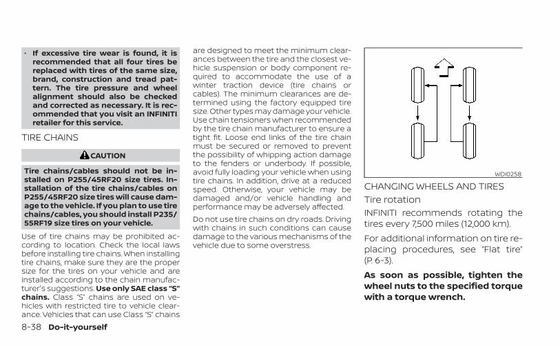
• If excessive tire wear is found, it isrecommended that all four tires bereplaced with tires of the same size,brand, construction and tread pat-tern. The tire pressure and wheelalignment should also be checkedand corrected as necessary. It is rec-ommended that you visit an INFINITIretailer for this service.
TIRE CHAINS
CAUTION
Tire chains/cables should not be in-stalled on P255/45RF20 size tires. In-stallation of the tire chains/cables onP255/45RF20 size tires will cause dam-age to the vehicle. If you plan to use tirechains/cables, you should install P235/55RF19 size tires on your vehicle.
Use of tire chains may be prohibited ac-cording to location. Check the local lawsbefore installing tire chains. When installingtire chains, make sure they are the propersize for the tires on your vehicle and areinstalled according to the chain manufac-turer's suggestions. Use only SAE class “S”chains. Class “S” chains are used on ve-hicles with restricted tire to vehicle clear-ance. Vehicles that can use Class “S” chains
are designed to meet the minimum clear-ances between the tire and the closest ve-hicle suspension or body component re-quired to accommodate the use of awinter traction device (tire chains orcables). The minimum clearances are de-termined using the factory equipped tiresize. Other types may damage your vehicle.Use chain tensioners when recommendedby the tire chain manufacturer to ensure atight fit. Loose end links of the tire chainmust be secured or removed to preventthe possibility of whipping action damageto the fenders or underbody. If possible,avoid fully loading your vehicle when usingtire chains. In addition, drive at a reducedspeed. Otherwise, your vehicle may bedamaged and/or vehicle handling andperformance may be adversely affected.Do not use tire chains on dry roads. Drivingwith chains in such conditions can causedamage to the various mechanisms of thevehicle due to some overstress.
CHANGING WHEELS AND TIRESTire rotationINFINITI recommends rotating thetires every 7,500 miles (12,000 km).For additional information on tire re-placing procedures, see “Flat tire”(P. 6-3).As soon as possible, tighten thewheel nuts to the specified torquewith a torque wrench.
WDI0258
8-38 Do-it-yourself
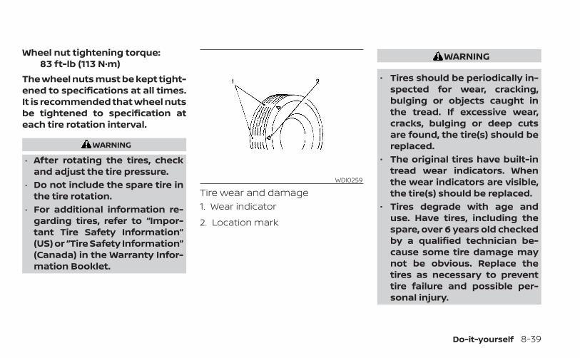
Wheel nut tightening torque:83 ft-lb (113 N·m)
The wheel nuts must be kept tight-ened to specifications at all times.It is recommended that wheel nutsbe tightened to specification ateach tire rotation interval.
WARNING
• After rotating the tires, checkand adjust the tire pressure.
• Do not include the spare tire inthe tire rotation.
• For additional information re-garding tires, refer to “Impor-tant Tire Safety Information”(US) or “Tire Safety Information”(Canada) in the Warranty Infor-mation Booklet.
Tire wear and damage1. Wear indicator
2. Location mark
WARNING
• Tires should be periodically in-spected for wear, cracking,bulging or objects caught inthe tread. If excessive wear,cracks, bulging or deep cutsare found, the tire(s) should bereplaced.
• The original tires have built-intread wear indicators. Whenthe wear indicators are visible,the tire(s) should be replaced.
• Tires degrade with age anduse. Have tires, including thespare, over 6 years old checkedby a qualified technician be-cause some tire damage maynot be obvious. Replace thetires as necessary to preventtire failure and possible per-sonal injury.
WDI0259
Do-it-yourself 8-39

• Improper service of the sparetire may result in serious per-sonal injury. If it is necessary torepair the spare tire, it is rec-ommended that you visit anINFINITI retailer for this service.
• For additional information re-garding tires, refer to “Impor-tant Tire Safety Information”(US) or “Tire Safety Informa-tion” (Canada) in the WarrantyInformation Booklet.
Replacing wheels and tiresWhen replacing a tire, use the same size,tread design, speed rating and load carry-ing capacity as originally equipped. For ad-ditional information, see “Wheels and tires”(P. 10-9).
WARNING
• The use of tires other than those rec-ommended or the mixed use of tiresof different brands, construction(bias, bias-belted or radial), or treadpatterns can adversely affect theride, braking, handling, VDC system,ground clearance, body-to-tire clear-ance, tire chain clearance, speedom-eter calibration, headlight aim andbumper height. Some of these ef-fects may lead to accidents andcould result in serious personalinjury.
• For 2WD models, if your vehicle wasoriginally equipped with four tiresthat were the same size and you areonly replacing two of the four tires,install the new tires on the rear axle.Placing new tires on the front axlemay cause loss of vehicle control insome driving conditions and causean accident and personal injury.
• If the wheels are changed for anyreason, always replace with wheelswhich have the same off-set dimen-sion. Wheels of a different off-setcould cause premature tire wear, de-grade vehicle handling characteris-tics, affect the VDC system and/or in-terference with the brake discs. Suchinterference can lead to decreasedbraking efficiency and/or early brakepad wear. For additional informationon wheel off-set dimensions, see“Wheels and tires” (P. 10-9).
• When using a wheel without theTPMS, such as the spare tire, theTPMS will not function and the lowtire pressure warning light will flashfor approximately 1 minute. The lightwill remain on after 1 minute. Haveyour tires replaced and/or TPMS sys-tem reset as soon as possible. It isrecommended that you visit anINFINITI retailer for this service.
• Replacing tires with those not origi-nally specified by INFINITI could af-fect the proper operation of theTPMS.
• The TPMS sensor may be damaged ifit is not handled correctly. Be carefulwhen handling the TPMS sensor.
8-40 Do-it-yourself

• When replacing the TPMS sensor, theID registration may be required. It isrecommended that you visit anINFINITI retailer for ID registration.
• Do not use a valve stem cap that isnot specified by INFINITI. The valvestem cap may become stuck.
• Be sure that the valve stem caps arecorrectly fitted. Otherwise the valvemay be clogged up with dirt andcause a malfunction or loss ofpressure.
• Do not install a damaged or de-formed wheel or tire even if it hasbeen repaired. Such wheels or tirescould have structural damage andcould fail without warning.
• The use of retread tires is notrecommended.
• For additional information regardingtires, refer to “Important Tire SafetyInformation” (US) or “Tire Safety In-formation” (Canada) in the WarrantyInformation Booklet.
Wheel balanceUnbalanced wheels may affect vehiclehandling and tire life. Even with regular use,wheels can get out of balance. Therefore,they should be balanced as required.Wheel balance service should be per-formed with the wheels off the vehicle.Spin balancing the wheels on the vehiclecould lead to mechanical damage.• For additional information regarding
tires, refer to “Important Tire Safety In-formation” (US) or “Tire Safety Informa-tion” (Canada) in the Warranty Informa-tion Booklet.
Care of wheels• Wash the wheels when washing the ve-
hicle to maintain their appearance.• Clean the inner side of the wheels when
the wheel is changed or the underside ofthe vehicle is washed.
• Do not use abrasive cleaners whenwashing the wheels.
• Inspect wheel rims regularly for dents orcorrosion. Such damage may cause lossof pressure or poor seal at the tire bead.
• INFINITI recommends waxing the roadwheels to protect against road salt in ar-eas where it is used during winter.
Do-it-yourself 8-41

MEMO
8-42 Do-it-yourself

9 Maintenance and schedules
Maintenance requirements . . . . . . . . . . . . . . . . . . . . . 9-2General maintenance . . . . . . . . . . . . . . . . . . . . . . . . 9-2Scheduled maintenance . . . . . . . . . . . . . . . . . . . . . 9-2Where to go for service . . . . . . . . . . . . . . . . . . . . . . . 9-2
General maintenance . . . . . . . . . . . . . . . . . . . . . . . . . . . 9-2Explanation of general maintenanceitems . . . . . . . . . . . . . . . . . . . . . . . . . . . . . . . . . . . . . . . . 9-2
Explanation of scheduled maintenance items . . . 9-5
Emission control system maintenance: . . . . . . 9-6Chassis and body maintenance: . . . . . . . . . . . . . 9-6
Maintenance schedules . . . . . . . . . . . . . . . . . . . . . . . . . 9-7Additional Maintenance Items forsevere operating conditions . . . . . . . . . . . . . . . . . . 9-7Oil control system . . . . . . . . . . . . . . . . . . . . . . . . . . . . 9-82.0L 4 cylinder(KR20DDET engine model) . . . . . . . . . . . . . . . . . . . . 9-8
Some day-to-day and regular mainte-nance is essential to maintain your vehiclegood mechanical condition, as well as itsemissions and engine performance.It is the owner's responsibility to make surethat the scheduled maintenance, as well asgeneral maintenance, is performed.As the vehicle owner, you are the only onewho can ensure that your vehicle receivesproper maintenance. You are a vital link inthe maintenance chain.
GENERAL MAINTENANCEGeneral maintenance includes those itemswhich should be checked during normalday-to-day operation. They are essentialfor proper vehicle operation. It is your re-sponsibility to perform these proceduresregularly as prescribed.Performing general maintenance checksrequires minimal mechanical skill and onlya few general automotive tools.These checks or inspections can be doneby yourself, a qualified technician or, if youprefer, an INFINITI retailer.
SCHEDULED MAINTENANCEThe maintenance items listed in this sec-tion are required to be serviced at regularintervals. However under severe drivingconditions, additional or more frequentmaintenance will be required.
WHERE TO GO FOR SERVICEIf maintenance service is required or yourvehicle appears to malfunction, have thesystems checked and serviced. It is recom-mended that you visit an INFINITI retailer forthis service.INFINITI technicians are well-trained spe-cialists and are kept up-to-date with thelatest service information through techni-cal bulletins, service tips and training pro-grams. They are fully qualified to work onINFINITI vehicles before work begins.If your vehicle is involved in a collision, it isrecommended that you ask your INFINITIretailer where the nearest INFINITI CertifiedCollision Center is located, or go tohttp://collision.infinitiusa.com.You can be confident that an INFINITI retail-er’s service department can perform theservice needed to meet the maintenancerequirements on your vehicle.
During the normal day-to-day operation ofthe vehicle, general maintenance shouldbe performed regularly as prescribed inthis section. If you detect any unusualsounds, vibrations or smells, be sure tocheck for the cause or have it checkedpromptly. In addition, it is recommendedthat you visit an INFINITI retailer if you thinkthat repairs are required.When performing any checks or mainte-nance work, closely observe the “Mainte-nance precautions” in the “Do-it-yourself ”section of this manual.
EXPLANATION OF GENERALMAINTENANCE ITEMS
WARNING
Failure to follow the procedures listedwithin this section may result in per-sonal injury.
Additional information on the followingitems with “ * ” is found in the “Do-it-yourself” section of this manual.
MAINTENANCE REQUIREMENTS GENERAL MAINTENANCE
9-2 Maintenance and schedules

Outside the vehicleThe maintenance items listed here shouldbe performed from time to time, unlessotherwise specified.Doors and engine hood: Check that thedoors and engine hood operate properly.Also ensure that all latches lock securely.Lubricate hinges, latches, latch pins, rollersand links if necessary. Make sure that thesecondary latch keeps the hood fromopening when the primary latch isreleased.When driving in areas using road salt orother corrosive materials, check lubrica-tion frequently.Check that the gas stays or struts properlyand securely hold the hood, trunk, or rearhatch fully open. If the hood, trunk, or rearhatch is not held open, have the gas staysor struts replaced.Lights*: Clean the headlights on a regularbasis. Make sure that the headlights, stoplights, tail lights, turn signal lights, and otherlights are all operating properly and in-stalled securely. Also check headlight aim.Road wheel nuts (lug nuts)*: When check-ing the tires, make sure no wheel nuts are
missing, and check for any loose wheelnuts. Tighten if necessary.Tire rotation*: Rotate tires at the specifiedinterval shown in the maintenanceschedule.Tires*: Check the pressure with a gaugeoften and always prior to long distancetrips. If necessary, adjust the pressure in alltires, including the spare, to the pressurespecified. Check carefully for damage, cutsor excessive wear.Tire Pressure Monitoring System (TPMS)tire pressure sensor: It is recommendedthat you replace the tire pressure sensorassembly when the tires are replaced dueto wear or age.Wheel alignment and balance: If the ve-hicle should pull to either side while drivingon a straight and level road, or if you detectuneven or abnormal tire wear, there maybe a need for wheel alignment.If the steering wheel or seat vibrates atnormal highway speeds, wheel balancingmay be needed.For additional information regarding tires,refer to “Important Tire Safety Information”(US) or “Tire Safety Information” (Canada) inthe INFINITI Warranty Information Booklet.
Windshield: Clean the windshield on aregular basis. Check the windshield at leastevery six months for cracks or other dam-age. Have a damaged windshield repairedby a qualified repair facility. It is recom-mended that you have a damaged wind-shield repaired by an INFINITI retailer, or anINFINITI Certified Collision Center. To locatea collision center in your area, refer tohttp://collision.infinitiusa.com.
Inside the vehicleThe maintenance items listed here shouldbe checked on a regular basis, such aswhen performing scheduled maintenance,cleaning the vehicle, etc.Accelerator pedal: Check the pedal forsmooth operation and make sure thepedal does not catch or require uneveneffort. Keep the floor mat away from thepedal.Brake pedal: Check the pedal for smoothoperation. If the brake pedal suddenly goesdown further than normal, the pedal feelsspongy or the vehicle seems to take longerto stop, have your vehicle checked imme-diately. It is recommended that you visit anINFINITI retailer for this service. Keep thefloor mat away from the pedal.
Maintenance and schedules 9-3
Brakes: Check that the brakes do not pullthe vehicle to one side when applied.Continuously Variable Transmission(CVT) P (Park) position mechanism: On afairly steep hill check that the vehicle is heldsecurely with the shift lever in the P (Park)position without applying any brakes.Parking brake: Check the parking brakeoperation regularly. The vehicle should besecurely held on a fairly steep hill with onlythe parking brake applied. If the parkingbrake does not securely hold the vehicle, itis recommended that you visit an INFINITIretailer for service.Seat belts: Check that all parts of the seatbelt system (for example, buckles, anchors,adjusters and retractors) operate properlyand smoothly, and are installed securely.Check the belt webbing for cuts, fraying,wear or damage.Seats: Check seat position controls suchas seat adjusters, seatback recliner, etc., toensure they operate smoothly and alllatches lock securely in every position.Check that the head restraints/headrestsmove up and down smoothly and the locks(if so equipped) hold securely in all latchedpositions.
Steering wheel: Check for changes in thesteering system, such as excessive freeplay, hard steering or strange noises.Warning lights and chimes: Make sure allwarning lights and chimes are operatingproperly.Windshield defroster: Check that the aircomes out of the defroster outlets properlyand in sufficient quantity when operatingthe heater or air conditioner.Windshield wiper and washer*: Checkthat the wipers and washer operate prop-erly and that the wipers do not streak.
Under the hood and vehicleThe maintenance items listed here shouldbe checked periodically (for example, eachtime you check the engine oil or refuel).Battery (for maintenance free batter-ies)*: This vehicle is equipped with a sealedmaintenance free battery. It is recom-mended that you visit an INFINITI retailer forthis service.
NOTE:
Care should be taken to avoid situationsthat can lead to potential battery dis-charge and potential no-start conditionssuch as:1. Installation or extended use of elec-
tronic accessories that consume bat-tery power when the engine is notrunning (Phone chargers, GPS, DVDplayers, etc.).
2. Vehicle is not driven regularly and/oronly driven short distances.
In these cases, the battery may need tobe charged to maintain battery health.Brake fluid level*: Make sure that the brakefluid level is between the MAX and MIN lineson the reservoir.Engine coolant level*: Check the coolantlevel when the engine is cold.Engine drive belt*: Make sure the drive beltis not frayed, worn, cracked or oily.Engine oil level*: Check the level afterparking the vehicle on a level spot andturning off the engine. Wait more than 15minutes for the oil to drain back into the oilpan.
9-4 Maintenance and schedules
Exhaust system: Make sure there are noloose supports, cracks or holes. If thesound of the exhaust seems unusual orthere is a smell of exhaust fumes, immedi-ately have the exhaust system inspected. Itis recommended that you visit an INFINITIretailer for this service. For additional infor-mation, see “Exhaust gas (carbon monox-ide)” (P. 5-4).Fluid leaks: Check under the vehicle forfuel, oil, water or other fluid leaks after thevehicle has been parked for a while. Waterdripping from the air conditioner after useis normal. If you should notice any leaks or iffuel fumes are evident, check for the causeand have it corrected immediately.Radiator and hoses: Check the front of theradiator and clean off any dirt, insects,leaves, etc., that may have accumulated.Make sure the hoses have no cracks, defor-mation, rot or loose connections.
Underbody: The underbody is frequentlyexposed to corrosive substances such asthose used on icy roads or to control dust. Itis very important to remove these sub-stances, otherwise rust may form on thefloor pan, frame, fuel lines and around theexhaust system. At the end of winter, theunderbody should be thoroughly flushedwith plain water, being careful to cleanthose areas where mud and dirt may accu-mulate. For additional information, see“Cleaning exterior” (P. 7-2).Windshield-washer fluid*: Check thatthere is adequate fluid in the reservoir.
The following descriptions are provided togive you a better understanding of thescheduled maintenance items that shouldbe regularly checked or replaced. Themaintenance schedule indicates at whichmileage/time intervals each item requiresservice.In addition to scheduled maintenance,your vehicle requires that some items bechecked during normal day-to-day opera-tion. For additional information, see “Gen-eral maintenance” (P. 9-2).Items marked with “*” are recommendedby INFINITI for reliable vehicle operation.You are not required to perform mainte-nance on these items in order to maintainthe warranties which come with yourINFINITI. Other maintenance items and in-tervals are required.When applicable, additional informationcan be found in the “Do-it-yourself ” sectionof this manual.
EXPLANATION OF SCHEDULEDMAINTENANCE ITEMS
Maintenance and schedules 9-5
NOTE:
INFINITI does not advocate the use ofnon-OEM approved aftermarket flush-ing systems and strongly advisesagainst performing these services on anINFINITI product. Many of the aftermar-ket flushing systems use non-OEM ap-proved chemicals or solvents, the use ofwhich has not been validated by INFINITI.For recommended fuel, lubricants, fluids,grease, and refrigerant, see “Recom-mended fluids/lubricants and capaci-ties” (P. 10-2).
EMISSION CONTROL SYSTEMMAINTENANCE:Drive belt*: Check engine drive belt forwear, fraying or cracking and for propertension. Replace any damaged drive belt.Engine air filter: Replace at specified inter-vals. When driving for prolonged periods industy conditions, check/replace the filtermore frequently.Engine coolant*: First replacement inter-val is 105,000 miles (168,000 km). After firstreplacement, replace every 75,000 miles(120,000 km) or 60 months. When adding orreplacing coolant, be sure to use onlyGenuine NISSAN Long Life Antifreeze/
Coolant (blue) or equivalent with the propermixture. For additional information on theproper mixture for your area, see “Enginecooling system” (P. 8-5).NOTE: Mixing any other type of coolantor the use of non-distilled water may re-duce the recommended service intervalof the coolant.Engine oil and oil filter: Replace engine oiland oil filter at the specified intervals. Forrecommended oil grade and viscosity, see“Recommended fluids/lubricants and ca-pacities” (P. 10-2).Engine valve clearance*: Inspect only ifvalve noise increases. Adjust valve clear-ance if necessary.Evaporative emissions control vaporlines*: Check vapor lines for leaks or loose-ness. Tighten connections or replace partsas necessary.Fuel filter: Periodic maintenance is not re-quired. (in-tank type filter)Fuel lines*: Check the fuel hoses, pipingand connections for leaks, looseness, ordeterioration. Tighten connections or re-place parts as necessary.
Spark plugs: Replace every 105,000 miles(168,000 km). Replace the spark plug whenthe plug gap exceeds 0.045 in (1.25 mm)even if within specified replacement mile-age. Install new plugs of the same type asoriginally equipped.
CHASSIS AND BODYMAINTENANCE:Brake lines and cables: Visually inspect forproper installation. Check for chafing,cracks, deterioration, and signs of leaking.Replace any deteriorated or damagedparts immediately.Brake pads and rotors: Check for wear,deterioration and fluid leaks. Replace anydeteriorated or damaged partsimmediately.Exhaust system: Visually inspect the ex-haust pipes, muffler and hangers for leaks,cracks, deterioration, and damage. Tightenconnections or replace parts as necessary.In-cabin microfilter: Replace at specifiedintervals. When driving for prolonged peri-ods in dusty conditions, replace the filtermore frequently.Propeller shaft(s): Check for damage,looseness, and grease leakage. (AWD)
9-6 Maintenance and schedules
Steering gear and linkage, axle and sus-pension parts, drive shaft boots: Checkfor damage, looseness, and leakage of oilor grease. Under severe driving conditions,inspect more frequently.Tire rotation: Rotate tires at the specifiedinterval shown in the maintenance sched-ule. When rotating tires, check for damageand uneven wear. Replace if necessary.Transmission fluid/oil, differential oiland transfer case oil: Visually inspect forsigns of leakage at specified intervals.Replace at specified intervals.
To help ensure smooth, safe and economi-cal driving, INFINITI provides two mainte-nance schedules that may be used, de-pending upon the conditions in which youusually drive. These schedules containboth distance and time intervals, up to90,000 miles (144,000 km)/144 months. Formost people, the odometer reading will in-dicate when service is needed. However, ifyou drive very little, your vehicle should beserviced at the regular time intervalsshown in the schedule.After 90,000 miles (144,000 km)/144months, continue maintenance at thesame mileage/time intervals.
ADDITIONAL MAINTENANCE ITEMSFOR SEVERE OPERATINGCONDITIONSAdditional maintenance items for severeoperating conditions should be per-formed on vehicles that are driven underespecially demanding conditions. Addi-tional maintenance items should be per-formed if you primarily operate your vehicleunder the following conditions:• Repeated short trips of less than 5 miles
(8 km).
• Repeated short trips of less than 10 miles(16 km) with outside temperatures re-maining below freezing.
• Operating in hot weather in stop-and-go“rush hour” traffic.
• Extensive idling and/or low speed drivingfor long distances, such as police, taxi ordoor-to-door delivery use.
• Driving in dusty conditions.• Driving on rough, muddy or salt spread
roads.• Using a car-top carrier.If your vehicle is mostly operated under thesevere conditions, follow the severe usemaintenance intervals shown in the main-tenance schedule.
MAINTENANCE SCHEDULES
Maintenance and schedules 9-7
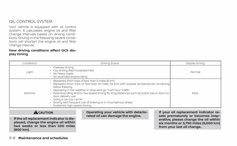
OIL CONTROL SYSTEMYour vehicle is equipped with oil controlsystem. It calculates engine oil and filterchange intervals based on driving condi-tions. Driving in the following severe condi-tions will shorten the engine oil and filterchange interval.How driving conditions affect OCS dis-play timing
Conditions Driving Scene Display timing
Light
• Freeway driving• City driving (flat/moderate hills)• No heavy loads• No extended engine idling
Normal
Extreme
• Repeated short trips of less than 5 miles (8 km).• Repeated short trips of less than 10 miles (16 km) with outside temperatures remaining
below freezing.• Operating in hot weather in stop-and-go “rush hour” traffic.• Extensive idling and/or low speed driving for long distances, such as police, taxi or door-to-
door delivery use.• Using a car-top carrier.• Driving with frequent use of braking or in mountainous areas.• Sustained high speed driving.
Early
CAUTION
• If the oil replacement indicator is dis-played, change the engine oil withintwo weeks or less than 500 miles(800 km).
• Operating your vehicle with deterio-rated oil can damage the engine.
• If your oil replacement indicator re-sets prematurely or becomes inop-erative, please change the oil withinsix months or 3,750 miles (6,000 km)from your last oil change.
9-8 Maintenance and schedules

2.0L 4 CYLINDER (KR20DDETengine model)The following shows the maintenanceschedule.Choose the maintenance scheduleneeded based on your vehicle drivingconditions.After 90,000 miles (144,000 km)/144months, continue maintenance at thesame mileage/time interval.
NOTE:
For information regarding coolant orspark plug replacement, see “Additionalinformation” (P. 9-27).
3,750 miles/(6,000 km)/6 monthsPerform at number of miles, kilometers ormonths, whichever comes first.
Standard maintenance:• Not applicable. Proceed to next interval.
Severe use maintenance:Inspections:• Brake pads & rotors• Exhaust system• Propeller shaft (AWD models)• Drive shaft boots• Steering gear and linkage• Axle & suspension parts• Horn, lights, signals, wipers, rear hatch/
hood lift supports• All fluids inspected (engine, wiper, brake,
power steering, coolant)• Engine drive belts• Hose inspections• Engine air filter• Suspension components (shocks, sub-
frame, tie rods)• Battery terminals and cables, battery test• Tire pressure, treadwear and depth• Differential oil (AWD models)
7,500 miles/(12,000 km)/12 monthsPerform at number of miles, kilometers ormonths, whichever comes first.
Standard maintenance:Inspections:• Brake lines & cables• Brake pads & rotors• CVT fluid• Propeller shaft (AWD models)• Drive shaft boots• Transfer case oil (AWD models)• Differential oil (AWD models)• Horn, lights, signals, wipers, rear hatch/
hood lift supports• All fluids inspected (engine, wiper, brake,
power steering, coolant)• Engine drive belts• Hose inspections• Engine air filter• Suspension components (shocks, sub-
frame, tie rods)• Battery terminals and cables, battery test• Tire pressure, treadwear and depthEssentials:• Replace engine oil & filter (1)• Tire rotation
Maintenance and schedules 9-9

Severe use maintenance:Inspections:• Brake pads & rotors• Exhaust system• Propeller shaft (AWD models)• Drive shaft boots• Steering gear and linkage• Axle & suspension partsEssentials:• Replace brake fluid(1) If the oil replacement indicator is dis-played, change the engine oil and filterwithin two weeks or less than 500 miles(800 km).
11,250 miles/(18,000 km)/18 monthsPerform at number of miles, kilometers ormonths, whichever comes first.
Standard maintenance:Inspections:• Intelligent key battery• Horn, lights, signals, wipers, rear hatch/
hood lift supports• All fluids inspected (engine, wiper, brake,
power steering, coolant)• Engine drive belts• Hose inspections• Engine air filter• Suspension components (shocks, sub-
frame, tie rods)• Battery terminals and cables, battery test• Tire pressure, treadwear and depth• Differential oil (AWD models)Essentials:• Replace in-cabin microfilter
Severe use maintenance:Inspections:• Brake pads & rotors• Exhaust system• Propeller shaft (AWD models)• Drive shaft boots• Steering gear and linkage• Axle & suspension parts
9-10 Maintenance and schedules

15,000 miles/(24,000 km)/24 monthsPerform at number of miles, kilometers ormonths, whichever comes first.
Standard maintenance:Inspections:• Brake lines & cables• Brake pads & rotors• CVT fluid• Fuel tank vapor vent system*• Fuel lines/connections*• Exhaust system• Steering gear and linkage• Axle & suspension parts• Propeller shaft (AWD models)• Drive shaft boots• Transfer case oil (AWD models) (2)• Differential oil (AWD models) (2)• Horn, lights, signals, wipers, rear hatch/
hood lift supports• All fluids inspected (engine, wiper, brake,
power steering, coolant)• Engine drive belts• Hose inspections• Engine air filter
• Suspension components (shocks, sub-frame, tie rods)
• Battery terminals and cables, battery test• Tire pressure, treadwear and depthEssentials:• Replace engine oil & filter (1)• Tire rotation• Replace brake fluid
Severe use maintenance:Inspections:• Brake pads & rotors• Exhaust system• Propeller shaft (AWD models)• Drive shaft boots• Steering gear and linkage• Axle & suspension partsEssentials:• Replace brake fluid(1) If the oil replacement indicator is dis-played, change the engine oil and filterwithin two weeks or less than 500 miles(800 km).(2) If using a car-top carrier, or driving onrough or muddy roads, change (not justinspect) oil every 20,000 miles (32,000 km)or 24 months.
* Maintenance items and intervals with “ * ”are recommended by INFINITI for reliablevehicle operation. The owner need not per-form such maintenance in order to main-tain the emission warranty or manufac-turer recall liability. Other maintenanceitems and intervals are required.
Maintenance and schedules 9-11
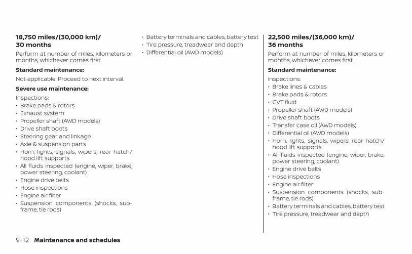
18,750 miles/(30,000 km)/30 monthsPerform at number of miles, kilometers ormonths, whichever comes first.
Standard maintenance:Not applicable. Proceed to next interval.
Severe use maintenance:Inspections:• Brake pads & rotors• Exhaust system• Propeller shaft (AWD models)• Drive shaft boots• Steering gear and linkage• Axle & suspension parts• Horn, lights, signals, wipers, rear hatch/
hood lift supports• All fluids inspected (engine, wiper, brake,
power steering, coolant)• Engine drive belts• Hose inspections• Engine air filter• Suspension components (shocks, sub-
frame, tie rods)
• Battery terminals and cables, battery test• Tire pressure, treadwear and depth• Differential oil (AWD models)
22,500 miles/(36,000 km)/36 monthsPerform at number of miles, kilometers ormonths, whichever comes first.
Standard maintenance:Inspections:• Brake lines & cables• Brake pads & rotors• CVT fluid• Propeller shaft (AWD models)• Drive shaft boots• Transfer case oil (AWD models)• Differential oil (AWD models)• Horn, lights, signals, wipers, rear hatch/
hood lift supports• All fluids inspected (engine, wiper, brake,
power steering, coolant)• Engine drive belts• Hose inspections• Engine air filter• Suspension components (shocks, sub-
frame, tie rods)• Battery terminals and cables, battery test• Tire pressure, treadwear and depth
9-12 Maintenance and schedules
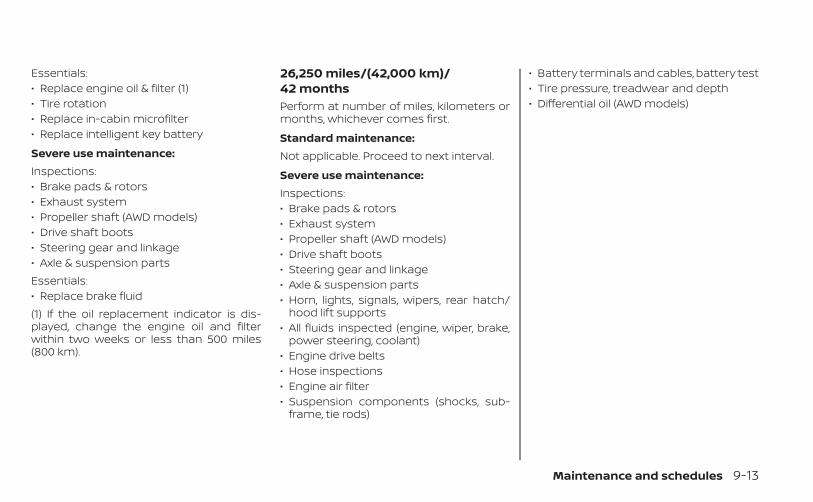
Essentials:• Replace engine oil & filter (1)• Tire rotation• Replace in-cabin microfilter• Replace intelligent key battery
Severe use maintenance:Inspections:• Brake pads & rotors• Exhaust system• Propeller shaft (AWD models)• Drive shaft boots• Steering gear and linkage• Axle & suspension partsEssentials:• Replace brake fluid(1) If the oil replacement indicator is dis-played, change the engine oil and filterwithin two weeks or less than 500 miles(800 km).
26,250 miles/(42,000 km)/42 monthsPerform at number of miles, kilometers ormonths, whichever comes first.
Standard maintenance:Not applicable. Proceed to next interval.
Severe use maintenance:Inspections:• Brake pads & rotors• Exhaust system• Propeller shaft (AWD models)• Drive shaft boots• Steering gear and linkage• Axle & suspension parts• Horn, lights, signals, wipers, rear hatch/
hood lift supports• All fluids inspected (engine, wiper, brake,
power steering, coolant)• Engine drive belts• Hose inspections• Engine air filter• Suspension components (shocks, sub-
frame, tie rods)
• Battery terminals and cables, battery test• Tire pressure, treadwear and depth• Differential oil (AWD models)
Maintenance and schedules 9-13

30,000 miles/(48,000 km)/48 monthsPerform at number of miles, kilometers ormonths, whichever comes first.
Standard maintenance:Inspections:• Brake lines & cables• Brake pads & rotors• CVT fluid• Engine drive belts*• Fuel tank vapor vent system*• Fuel lines/connections*• Exhaust system• Steering gear and linkage• Axle & suspension parts• Propeller shaft (AWD models)• Drive shaft boots• Transfer case oil (AWD models) (3)• Differential oil (AWD models) (3)• Horn, lights, signals, wipers, rear hatch/
hood lift supports• All fluids inspected (engine, wiper, brake,
power steering, coolant)• Hose inspections• Suspension components (shocks, sub-
frame, tie rods)
• Battery terminals and cables, battery test• Tire pressure, treadwear and depthEssentials:• Replace engine oil & filter (1)• Replace engine air filter (2)• Replace brake fluid• Tire rotation
Severe use maintenance:Inspections:• Brake pads & rotors• Exhaust system• Propeller shaft (AWD models)• Drive shaft boots• Steering gear and linkage• Axle & suspension partsEssentials:• Replace brake fluid(1) If the oil replacement indicator is dis-played, change the engine oil and filterwithin two weeks or less than 500 miles(800 km).(2) If operating mainly in dusty conditions,more frequent maintenance may berequired.
(3) If using a car-top carrier, or driving onrough or muddy roads, change (not justinspect) oil every 20,000 miles (32,000 km)or 24 months.* Maintenance items and intervals with “ * ”are recommended by INFINITI for reliablevehicle operation. The owner need not per-form such maintenance in order to main-tain the emission warranty or manufac-turer recall liability. Other maintenanceitems and intervals are required.
9-14 Maintenance and schedules
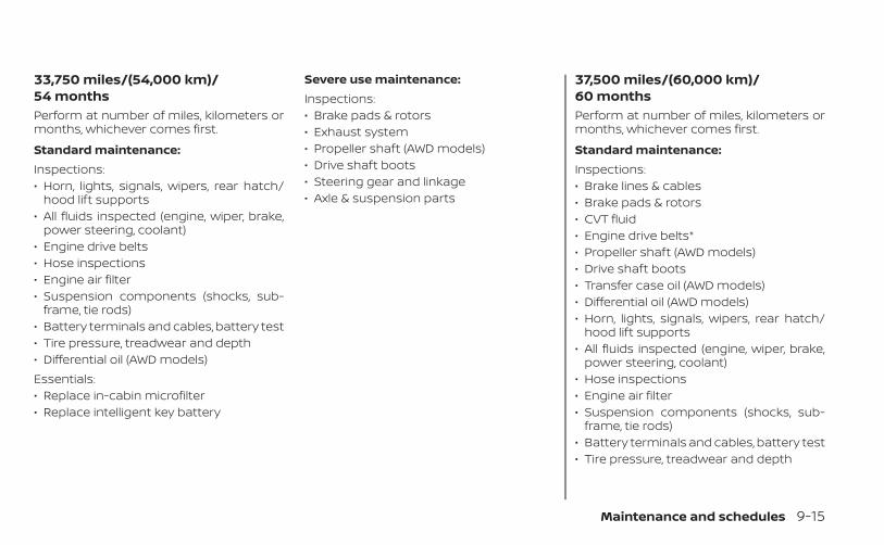
33,750 miles/(54,000 km)/54 monthsPerform at number of miles, kilometers ormonths, whichever comes first.
Standard maintenance:Inspections:• Horn, lights, signals, wipers, rear hatch/
hood lift supports• All fluids inspected (engine, wiper, brake,
power steering, coolant)• Engine drive belts• Hose inspections• Engine air filter• Suspension components (shocks, sub-
frame, tie rods)• Battery terminals and cables, battery test• Tire pressure, treadwear and depth• Differential oil (AWD models)Essentials:• Replace in-cabin microfilter• Replace intelligent key battery
Severe use maintenance:Inspections:• Brake pads & rotors• Exhaust system• Propeller shaft (AWD models)• Drive shaft boots• Steering gear and linkage• Axle & suspension parts
37,500 miles/(60,000 km)/60 monthsPerform at number of miles, kilometers ormonths, whichever comes first.
Standard maintenance:Inspections:• Brake lines & cables• Brake pads & rotors• CVT fluid• Engine drive belts*• Propeller shaft (AWD models)• Drive shaft boots• Transfer case oil (AWD models)• Differential oil (AWD models)• Horn, lights, signals, wipers, rear hatch/
hood lift supports• All fluids inspected (engine, wiper, brake,
power steering, coolant)• Hose inspections• Engine air filter• Suspension components (shocks, sub-
frame, tie rods)• Battery terminals and cables, battery test• Tire pressure, treadwear and depth
Maintenance and schedules 9-15
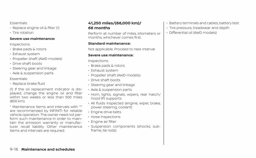
Essentials:• Replace engine oil & filter (1)• Tire rotation
Severe use maintenance:Inspections:• Brake pads & rotors• Exhaust system• Propeller shaft (AWD models)• Drive shaft boots• Steering gear and linkage• Axle & suspension partsEssentials:• Replace brake fluid(1) If the oil replacement indicator is dis-played, change the engine oil and filterwithin two weeks or less than 500 miles(800 km).* Maintenance items and intervals with “*”are recommended by INFINITI for reliablevehicle operation. The owner need not per-form such maintenance in order to main-tain the emission warranty or manufac-turer recall liability. Other maintenanceitems and intervals are required.
41,250 miles/(66,000 km)/66 monthsPerform at number of miles, kilometers ormonths, whichever comes first.
Standard maintenance:Not applicable. Proceed to next interval.
Severe use maintenance:Inspections:• Brake pads & rotors• Exhaust system• Propeller shaft (AWD models)• Drive shaft boots• Steering gear and linkage• Axle & suspension parts• Horn, lights, signals, wipers, rear hatch/
hood lift supports• All fluids inspected (engine, wiper, brake,
power steering, coolant)• Engine drive belts• Hose inspections• Engine air filter• Suspension components (shocks, sub-
frame, tie rods)
• Battery terminals and cables, battery test• Tire pressure, treadwear and depth• Differential oil (AWD models)
9-16 Maintenance and schedules

45,000 miles/(72,000 km)/72 monthsPerform at number of miles, kilometers ormonths, whichever comes first.
Standard maintenance:Inspections:• Brake lines & cables• Brake pads & rotors• CVT fluid• Engine drive belts*• Fuel tank vapor vent system*• Fuel lines/connections*• Exhaust system• Steering gear and linkage• Axle & suspension parts• Propeller shaft (AWD models)• Drive shaft boots• Transfer case oil (AWD models) (2)• Differential oil (AWD models) (2)• Horn, lights, signals, wipers, rear hatch/
hood lift supports• All fluids inspected (engine, wiper, brake,
power steering, coolant)• Hose inspections• Suspension components (shocks, sub-
frame, tie rods)
• Battery terminals and cables, battery test• Tire pressure, treadwear and depthEssentials:• Replace engine oil & filter (1)• Tire rotation• Replace in-cabin microfilter• Replace brake fluid• Replace intelligent key battery
Severe use maintenance:Inspections:• Brake pads & rotors• Exhaust system• Propeller shaft (AWD models)• Drive shaft boots• Steering gear and linkage• Axle & suspension partsEssentials:• Replace brake fluid(1) If the oil replacement indicator is dis-played, change the engine oil and filterwithin two weeks or less than 500 miles(800 km).(2) If using a car-top carrier, or driving onrough or muddy roads, change (not justinspect) oil every 20,000 miles (32,000 km)or 24 months.
* Maintenance items and intervals with “ * ”are recommended by INFINITI for reliablevehicle operation. The owner need not per-form such maintenance in order to main-tain the emission warranty or manufac-turer recall liability. Other maintenanceitems and intervals are required.
Maintenance and schedules 9-17

48,750 miles/(78,000 km)/78 monthsPerform at number of miles, kilometers ormonths, whichever comes first.
Standard maintenance:Not applicable. Proceed to next interval.
Severe use maintenance:Inspections:• Brake pads & rotors• Exhaust system• Propeller shaft (AWD models)• Drive shaft boots• Steering gear and linkage• Axle & suspension parts• Horn, lights, signals, wipers, rear hatch/
hood lift supports• All fluids inspected (engine, wiper, brake,
power steering, coolant)• Engine drive belts• Hose inspections• Engine air filter• Suspension components (shocks, sub-
frame, tie rods)
• Battery terminals and cables, battery test• Tire pressure, treadwear and depth• Differential oil (AWD models)
52,500 miles/(84,000 km)/84 monthsPerform at number of miles, kilometers ormonths, whichever comes first.
Standard maintenance:Inspections:• Brake lines & cables• Brake pads & rotors• CVT fluid• Engine drive belts*• Propeller shaft (AWD models)• Drive shaft boots• Transfer case oil (AWD models)• Differential oil (AWD models)• Horn, lights, signals, wipers, rear hatch/
hood lift supports• All fluids inspected (engine, wiper, brake,
power steering, coolant)• Hose inspections• Engine air filter• Suspension components (shocks, sub-
frame, tie rods)• Battery terminals and cables, battery test• Tire pressure, treadwear and depth
9-18 Maintenance and schedules

Essentials:• Replace engine oil & filter (1)• Tire rotation
Severe use maintenance:Inspections:• Brake pads & rotors• Exhaust system• Propeller shaft (AWD models)• Drive shaft boots• Steering gear and linkage• Axle & suspension partsEssentials:• Replace brake fluid(1) If the oil replacement indicator is dis-played, change the engine oil and filterwithin two weeks or less than 500 miles(800 km).* Maintenance items and intervals with “ * ”are recommended by INFINITI for reliablevehicle operation. The owner need not per-form such maintenance in order to main-tain the emission warranty or manufac-turer recall liability. Other maintenanceitems and intervals are required.
56,250 miles/(90,000 km)/90 monthsPerform at number of miles, kilometers ormonths, whichever comes first.
Standard maintenance:Inspections:• Horn, lights, signals, wipers, rear hatch/
hood lift supports• All fluids inspected (engine, wiper, brake,
power steering, coolant)• Engine drive belts• Hose inspections• Engine air filter• Suspension components (shocks, sub-
frame, tie rods)• Battery terminals and cables, battery test• Tire pressure, treadwear and depth• Differential oil (AWD models)Essentials:• Replace in-cabin microfilter• Replace intelligent key battery
Severe use maintenance:Inspections:• Brake pads & rotors• Exhaust system• Propeller shaft (AWD models)• Drive shaft boots• Steering gear and linkage• Axle & suspension parts
Maintenance and schedules 9-19
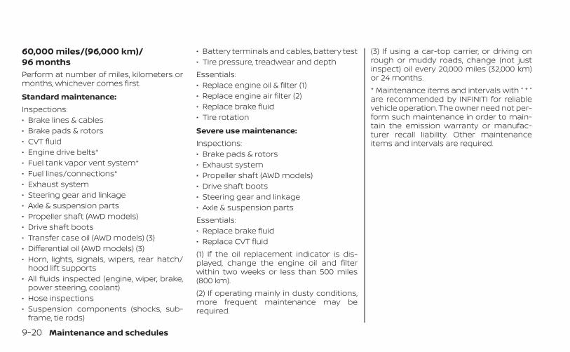
60,000 miles/(96,000 km)/96 monthsPerform at number of miles, kilometers ormonths, whichever comes first.
Standard maintenance:Inspections:• Brake lines & cables• Brake pads & rotors• CVT fluid• Engine drive belts*• Fuel tank vapor vent system*• Fuel lines/connections*• Exhaust system• Steering gear and linkage• Axle & suspension parts• Propeller shaft (AWD models)• Drive shaft boots• Transfer case oil (AWD models) (3)• Differential oil (AWD models) (3)• Horn, lights, signals, wipers, rear hatch/
hood lift supports• All fluids inspected (engine, wiper, brake,
power steering, coolant)• Hose inspections• Suspension components (shocks, sub-
frame, tie rods)
• Battery terminals and cables, battery test• Tire pressure, treadwear and depthEssentials:• Replace engine oil & filter (1)• Replace engine air filter (2)• Replace brake fluid• Tire rotation
Severe use maintenance:Inspections:• Brake pads & rotors• Exhaust system• Propeller shaft (AWD models)• Drive shaft boots• Steering gear and linkage• Axle & suspension partsEssentials:• Replace brake fluid• Replace CVT fluid(1) If the oil replacement indicator is dis-played, change the engine oil and filterwithin two weeks or less than 500 miles(800 km).(2) If operating mainly in dusty conditions,more frequent maintenance may berequired.
(3) If using a car-top carrier, or driving onrough or muddy roads, change (not justinspect) oil every 20,000 miles (32,000 km)or 24 months.* Maintenance items and intervals with “ * ”are recommended by INFINITI for reliablevehicle operation. The owner need not per-form such maintenance in order to main-tain the emission warranty or manufac-turer recall liability. Other maintenanceitems and intervals are required.
9-20 Maintenance and schedules

63,750 miles/(102,000 km)/102 monthsPerform at number of miles, kilometers ormonths, whichever comes first.
Standard maintenance:Not applicable. Proceed to next interval.
Severe use maintenance:Inspections:• Brake pads & rotors• Exhaust system• Propeller shaft (AWD models)• Drive shaft boots• Steering gear and linkage• Axle & suspension parts• Horn, lights, signals, wipers, rear hatch/
hood lift supports• All fluids inspected (engine, wiper, brake,
power steering, coolant)• Engine drive belts• Hose inspections• Engine air filter• Suspension components (shocks, sub-
frame, tie rods)
• Battery terminals and cables, battery test• Tire pressure, treadwear and depth• Differential oil (AWD models)
67,500 miles/(108,000 km)/108 monthsPerform at number of miles, kilometers ormonths, whichever comes first.
Standard maintenance:Inspections:• Brake lines & cables• Brake pads & rotors• CVT fluid• Engine drive belts*• Propeller shaft (AWD models)• Drive shaft boots• Transfer case oil (AWD models)• Differential oil (AWD models)• Horn, lights, signals, wipers, rear hatch/
hood lift supports• All fluids inspected (engine, wiper, brake,
power steering, coolant)• Hose inspections• Engine air filter• Suspension components (shocks, sub-
frame, tie rods)• Battery terminals and cables, battery test• Tire pressure, treadwear and depth
Maintenance and schedules 9-21
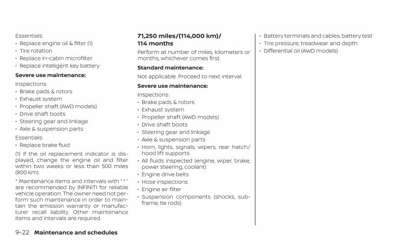
Essentials:• Replace engine oil & filter (1)• Tire rotation• Replace in-cabin microfilter• Replace intelligent key battery
Severe use maintenance:Inspections:• Brake pads & rotors• Exhaust system• Propeller shaft (AWD models)• Drive shaft boots• Steering gear and linkage• Axle & suspension partsEssentials:• Replace brake fluid(1) If the oil replacement indicator is dis-played, change the engine oil and filterwithin two weeks or less than 500 miles(800 km).* Maintenance items and intervals with “ * ”are recommended by INFINITI for reliablevehicle operation. The owner need not per-form such maintenance in order to main-tain the emission warranty or manufac-turer recall liability. Other maintenanceitems and intervals are required.
71,250 miles/(114,000 km)/114 monthsPerform at number of miles, kilometers ormonths, whichever comes first.
Standard maintenance:Not applicable. Proceed to next interval.
Severe use maintenance:Inspections:• Brake pads & rotors• Exhaust system• Propeller shaft (AWD models)• Drive shaft boots• Steering gear and linkage• Axle & suspension parts• Horn, lights, signals, wipers, rear hatch/
hood lift supports• All fluids inspected (engine, wiper, brake,
power steering, coolant)• Engine drive belts• Hose inspections• Engine air filter• Suspension components (shocks, sub-
frame, tie rods)
• Battery terminals and cables, battery test• Tire pressure, treadwear and depth• Differential oil (AWD models)
9-22 Maintenance and schedules
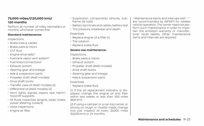
75,000 miles/(120,000 km)/120 monthsPerform at number of miles, kilometers ormonths, whichever comes first.
Standard maintenance:Inspections:• Brake lines & cables• Brake pads & rotors• CVT fluid• Engine drive belts*• Fuel tank vapor vent system*• Fuel lines/connections*• Exhaust system• Steering gear and linkage• Axle & suspension parts• Propeller shaft (AWD models)• Drive shaft boots• Transfer case oil (AWD models) (2)• Differential oil (AWD models) (2)• Horn, lights, signals, wipers, rear hatch/
hood lift supports• All fluids inspected (engine, wiper, brake,
power steering, coolant)• Hose inspections• Engine air filter
• Suspension components (shocks, sub-frame, tie rods)
• Battery terminals and cables, battery test• Tire pressure, treadwear and depthEssentials:• Replace engine oil & filter (1)• Tire rotation• Replace brake fluid
Severe use maintenance:Inspections:• Brake pads & rotors• Exhaust system• Propeller shaft (AWD models)• Drive shaft boots• Steering gear and linkage• Axle & suspension partsEssentials:• Replace brake fluid(1) If the oil replacement indicator is dis-played, change the engine oil and filterwithin two weeks or less than 500 miles(800 km).(2) If using a camper or a car-top carrier, ordriving on rough or muddy roads, change(not just inspect) oil every 20,000 miles(32,000 km) or 24 months.
* Maintenance items and intervals with “ * ”are recommended by INFINITI for reliablevehicle operation. The owner need not per-form such maintenance in order to main-tain the emission warranty or manufac-turer recall liability. Other maintenanceitems and intervals are required.
Maintenance and schedules 9-23
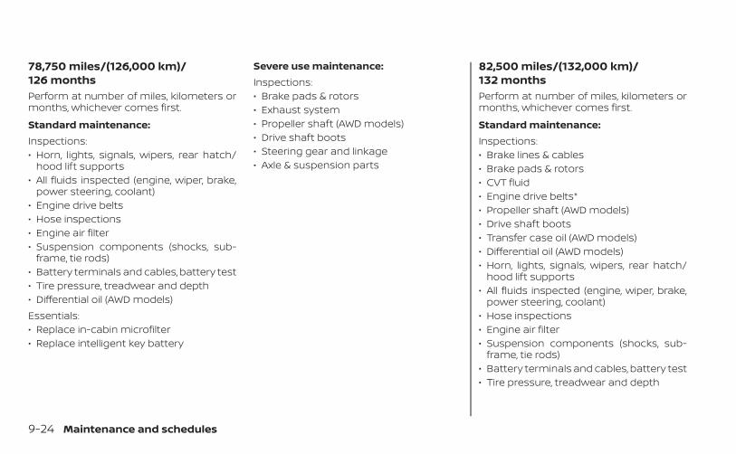
78,750 miles/(126,000 km)/126 monthsPerform at number of miles, kilometers ormonths, whichever comes first.
Standard maintenance:Inspections:• Horn, lights, signals, wipers, rear hatch/
hood lift supports• All fluids inspected (engine, wiper, brake,
power steering, coolant)• Engine drive belts• Hose inspections• Engine air filter• Suspension components (shocks, sub-
frame, tie rods)• Battery terminals and cables, battery test• Tire pressure, treadwear and depth• Differential oil (AWD models)Essentials:• Replace in-cabin microfilter• Replace intelligent key battery
Severe use maintenance:Inspections:• Brake pads & rotors• Exhaust system• Propeller shaft (AWD models)• Drive shaft boots• Steering gear and linkage• Axle & suspension parts
82,500 miles/(132,000 km)/132 monthsPerform at number of miles, kilometers ormonths, whichever comes first.
Standard maintenance:Inspections:• Brake lines & cables• Brake pads & rotors• CVT fluid• Engine drive belts*• Propeller shaft (AWD models)• Drive shaft boots• Transfer case oil (AWD models)• Differential oil (AWD models)• Horn, lights, signals, wipers, rear hatch/
hood lift supports• All fluids inspected (engine, wiper, brake,
power steering, coolant)• Hose inspections• Engine air filter• Suspension components (shocks, sub-
frame, tie rods)• Battery terminals and cables, battery test• Tire pressure, treadwear and depth
9-24 Maintenance and schedules
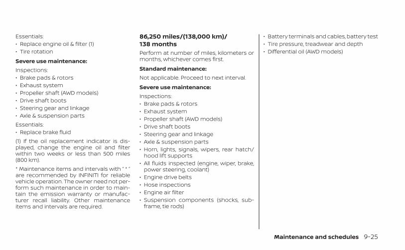
Essentials:• Replace engine oil & filter (1)• Tire rotation
Severe use maintenance:Inspections:• Brake pads & rotors• Exhaust system• Propeller shaft (AWD models)• Drive shaft boots• Steering gear and linkage• Axle & suspension partsEssentials:• Replace brake fluid(1) If the oil replacement indicator is dis-played, change the engine oil and filterwithin two weeks or less than 500 miles(800 km).* Maintenance items and intervals with “ * ”are recommended by INFINITI for reliablevehicle operation. The owner need not per-form such maintenance in order to main-tain the emission warranty or manufac-turer recall liability. Other maintenanceitems and intervals are required.
86,250 miles/(138,000 km)/138 monthsPerform at number of miles, kilometers ormonths, whichever comes first.
Standard maintenance:Not applicable. Proceed to next interval.
Severe use maintenance:Inspections:• Brake pads & rotors• Exhaust system• Propeller shaft (AWD models)• Drive shaft boots• Steering gear and linkage• Axle & suspension parts• Horn, lights, signals, wipers, rear hatch/
hood lift supports• All fluids inspected (engine, wiper, brake,
power steering, coolant)• Engine drive belts• Hose inspections• Engine air filter• Suspension components (shocks, sub-
frame, tie rods)
• Battery terminals and cables, battery test• Tire pressure, treadwear and depth• Differential oil (AWD models)
Maintenance and schedules 9-25
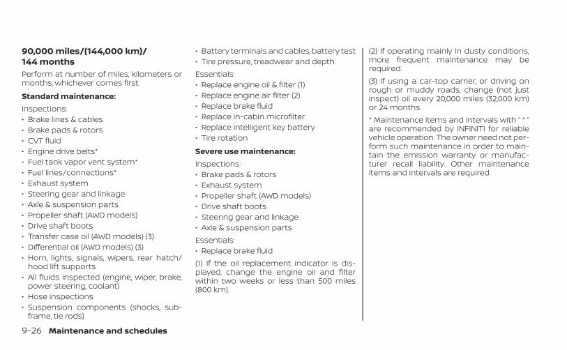
90,000 miles/(144,000 km)/144 monthsPerform at number of miles, kilometers ormonths, whichever comes first.
Standard maintenance:Inspections:• Brake lines & cables• Brake pads & rotors• CVT fluid• Engine drive belts*• Fuel tank vapor vent system*• Fuel lines/connections*• Exhaust system• Steering gear and linkage• Axle & suspension parts• Propeller shaft (AWD models)• Drive shaft boots• Transfer case oil (AWD models) (3)• Differential oil (AWD models) (3)• Horn, lights, signals, wipers, rear hatch/
hood lift supports• All fluids inspected (engine, wiper, brake,
power steering, coolant)• Hose inspections• Suspension components (shocks, sub-
frame, tie rods)
• Battery terminals and cables, battery test• Tire pressure, treadwear and depthEssentials:• Replace engine oil & filter (1)• Replace engine air filter (2)• Replace brake fluid• Replace in-cabin microfilter• Replace intelligent key battery• Tire rotation
Severe use maintenance:Inspections:• Brake pads & rotors• Exhaust system• Propeller shaft (AWD models)• Drive shaft boots• Steering gear and linkage• Axle & suspension partsEssentials:• Replace brake fluid(1) If the oil replacement indicator is dis-played, change the engine oil and filterwithin two weeks or less than 500 miles(800 km).
(2) If operating mainly in dusty conditions,more frequent maintenance may berequired.(3) If using a car-top carrier, or driving onrough or muddy roads, change (not justinspect) oil every 20,000 miles (32,000 km)or 24 months.* Maintenance items and intervals with “ * ”are recommended by INFINITI for reliablevehicle operation. The owner need not per-form such maintenance in order to main-tain the emission warranty or manufac-turer recall liability. Other maintenanceitems and intervals are required.
9-26 Maintenance and schedules
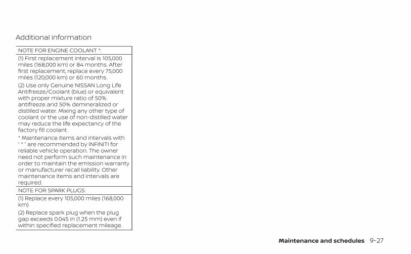
Additional information
NOTE FOR ENGINE COOLANT *:(1) First replacement interval is 105,000miles (168,000 km) or 84 months. Afterfirst replacement, replace every 75,000miles (120,000 km) or 60 months.(2) Use only Genuine NISSAN Long LifeAntifreeze/Coolant (blue) or equivalentwith proper mixture ratio of 50%antifreeze and 50% demineralized ordistilled water. Mixing any other type ofcoolant or the use of non-distilled watermay reduce the life expectancy of thefactory fill coolant.* Maintenance items and intervals with“ * ” are recommended by INFINITI forreliable vehicle operation. The ownerneed not perform such maintenance inorder to maintain the emission warrantyor manufacturer recall liability. Othermaintenance items and intervals arerequired.NOTE FOR SPARK PLUGS:(1) Replace every 105,000 miles (168,000km)(2) Replace spark plug when the pluggap exceeds 0.045 in (1.25 mm) even ifwithin specified replacement mileage.
Maintenance and schedules 9-27

MEMO
9-28 Maintenance and schedules
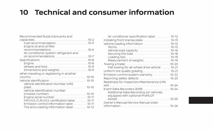
10 Technical and consumer information
Recommended fluids/lubricants andcapacities . . . . . . . . . . . . . . . . . . . . . . . . . . . . . . . . . . . . . . 10-2
Fuel recommendation . . . . . . . . . . . . . . . . . . . . . . 10-3Engine oil and oil filterrecommendations . . . . . . . . . . . . . . . . . . . . . . . . . . 10-6Air conditioner system refrigerant andoil recommendations . . . . . . . . . . . . . . . . . . . . . . . 10-7
Specifications . . . . . . . . . . . . . . . . . . . . . . . . . . . . . . . . . . 10-8Engine . . . . . . . . . . . . . . . . . . . . . . . . . . . . . . . . . . . . . . 10-8Wheels and tires . . . . . . . . . . . . . . . . . . . . . . . . . . . . 10-9Dimensions and weights . . . . . . . . . . . . . . . . . . . . 10-9
When traveling or registering in anothercountry . . . . . . . . . . . . . . . . . . . . . . . . . . . . . . . . . . . . . . . 10-10Vehicle identification . . . . . . . . . . . . . . . . . . . . . . . . . . 10-10
Vehicle Identification Number (VIN)plate . . . . . . . . . . . . . . . . . . . . . . . . . . . . . . . . . . . . . . . 10-10Vehicle identification number(chassis number) . . . . . . . . . . . . . . . . . . . . . . . . . . . 10-10Engine serial number . . . . . . . . . . . . . . . . . . . . . . . 10-11F.M.V.S.S./C.M.V.S.S. certification label . . . . . . . . . 10-11Emission control information label . . . . . . . . . . 10-11Tire and Loading Information label . . . . . . . . . 10-12
Air conditioner specification label . . . . . . . . . . 10-12Installing front license plate . . . . . . . . . . . . . . . . . . . 10-13Vehicle loading information . . . . . . . . . . . . . . . . . . . 10-15
Terms . . . . . . . . . . . . . . . . . . . . . . . . . . . . . . . . . . . . . . 10-15Vehicle load capacity . . . . . . . . . . . . . . . . . . . . . . . 10-16Securing the load . . . . . . . . . . . . . . . . . . . . . . . . . . 10-18Loading tips . . . . . . . . . . . . . . . . . . . . . . . . . . . . . . . . 10-19Measurement of weights . . . . . . . . . . . . . . . . . . . 10-19
Towing a trailer . . . . . . . . . . . . . . . . . . . . . . . . . . . . . . . . 10-20Flat towing for all–wheel drive vehicle . . . . . . 10-21
Uniform tire quality grading . . . . . . . . . . . . . . . . . . . 10-21Emission control system warranty . . . . . . . . . . . . 10-22Reporting safety defects . . . . . . . . . . . . . . . . . . . . . . 10-23Readiness for Inspection/Maintenance (I/M)test . . . . . . . . . . . . . . . . . . . . . . . . . . . . . . . . . . . . . . . . . . . 10-24Event Data Recorders (EDR) . . . . . . . . . . . . . . . . . . . 10-24
Additional Data Recording (on vehiclesequipped with optional ProPILOTAssist) . . . . . . . . . . . . . . . . . . . . . . . . . . . . . . . . . . . . . . 10-25
Owner's Manual/Service Manual orderinformation . . . . . . . . . . . . . . . . . . . . . . . . . . . . . . . . . . . 10-26

The following are approximate capacities. The actual refill capacities may be slightly different. When refilling, follow the proceduredescribed in the “Do-it-yourself” section to determine the proper refill capacity.
Fluid typeCapacity (approximate)
Recommended Fluids/LubricantsMetricMeasure
USMeasure
ImperialMeasure
Fuel 60 L 15-7/8 gal 13-1/4 gal • For additional information, see “Fuel recommendation” (P. 10-3).
Engine oil*1Drain and refill*1 For additional information,see “Engine oil” (P. 8-7).
With oil filterchange 4.7 L 5 qt 4-1/8 qt
• Genuine “NISSAN Motor Oil Ester 5W-30 SN” (or equivalent) is rec-ommended.• If the above motor oil (or engine oil) is not available, a synthetic SAE5W-30 GF-5 SN motor oil (or engine oil) may be used. Damagecaused by the use of motor oil (or engine oil) other than as recom-mended is not covered under INFINITI’s New Vehicle Limited War-ranty. For additional information, see “Engine oil and oil filter recom-mendations” (P. 10-6).
Without oil filterchange 4.6 L 4-7/8 qt 4 qt
Engine coolant(with reservoir) 7.7 L 2 gal 1-3/4 gal • Pre-diluted Genuine NISSAN Long Life Antifreeze/Coolant (blue) or
equivalent
Continuously Variable Transmission (CVT) fluid — — —
• Genuine NISSAN CVT Fluid NS-3• INFINITI recommends using Genuine NISSAN CVT Fluid NS-3 (orequivalent) ONLY in INFINITI CVTs. Do not mix with other fluids. Usingfluids that are not equivalent to Genuine NISSAN CVT Fluid NS-3 maydamage the CVT. Damage caused by the use of fluids other than asrecommended is not covered under INFINITI’s New Vehicle LimitedWarranty outlined in your Warranty Information Booklet.
Differential gear oil — — — • Genuine NISSAN HYPOID FLUID•S1 GL-5 75W-80 or equivalent
Transfer oil — — — • Genuine NISSAN Differential Oil Hypoid Super GL-5 80W-90 orequivalent conventional (non-synthetic) oil
Brake fluid — — —• Genuine NISSAN Super Heavy Duty Brake Fluid*2 or equivalentDOT 3.*2: Available in mainland U.S.A. through an INFINITI retailer
Multi-purpose grease — — — • NLGI No. 2 (Lithium Soap base)
RECOMMENDED FLUIDS/LUBRICANTS AND CAPACITIES
10-2 Technical and consumer information
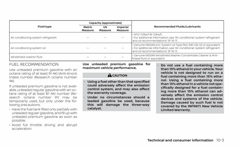
Fluid typeCapacity (approximate)
Recommended Fluids/LubricantsMetricMeasure
USMeasure
ImperialMeasure
Air conditioning system refrigerant — — —• HFO-1234yf (R-1234yf)• For additional information, see “Air conditioner system refrigerantand oil recommendations” (P. 10-7).
Air conditioning system oil — — —• Genuine NISSAN A/C System oil Type PAG (ND-OIL12) or equivalent• For additional information, see “Air conditioner system refrigerantand oil recommendations” (P. 10-7).
Windshield-washer fluid — — — • Genuine NISSAN Windshield Washer Concentrate Cleaner & Anti-freeze fluid or equivalent
FUEL RECOMMENDATIONUse unleaded premium gasoline with anoctane rating of at least 91 AKI (Anti-KnockIndex) number (Research octane number96).If unleaded premium gasoline is not avail-able, unleaded regular gasoline with an oc-tane rating of at least 87 AKI number (Re-search octane number 91) may betemporarily used, but only under the fol-lowing precautions:• Have the fuel tank filled only partially with
unleaded regular gasoline, and fill up withunleaded premium gasoline as soon aspossible.
• Avoid full throttle driving and abruptacceleration.
Use unleaded premium gasoline formaximum vehicle performance.
CAUTION
• Using a fuel other than that specifiedcould adversely affect the emissioncontrol system, and may also affectthe warranty coverage.
• Under no circumstances should aleaded gasoline be used, becausethis will damage the three-waycatalyst.
• Do not use a fuel containing morethan 15% ethanol in your vehicle. Yourvehicle is not designed to run on afuel containing more than 15% etha-nol. Using a fuel containing morethan 15% ethanol in a vehicle not spe-cifically designed for a fuel contain-ing more than 15% ethanol can ad-versely affect the emission controldevices and systems of the vehicle.Damage caused by such fuel is notcovered by the INFINITI New VehicleLimited Warranty.
Technical and consumer information 10-3
• Do not use fuel that contains the oc-tane booster methylcyclopentadi-enyl manganese tricarbonyl (MMT).Using fuel containing MMT may ad-versely affect vehicle performanceand vehicle emissions. Not all fueldispensers are labeled to indicateMMT content, so you may have toconsult your gasoline retailer formore details. Note that Federal andCalifornia laws prohibit the use ofMMT in reformulated gasoline.
• U.S. government regulations requireethanol dispensing pumps to beidentified by a small, square, orangeand black label with the common ab-breviation or the appropriate per-centage for that region.
Gasoline specificationsINFINITI recommends using gasoline thatmeets the World-Wide Fuel Charter (WWFC)specifications where it is available. Many ofthe automobile manufacturers developedthis specification to improve emission con-trol system and vehicle performance. Askyour service station manager if the gaso-line meets the WWFC specifications.
Reformulated gasolineSome fuel suppliers are now producing re-formulated gasolines. These gasolines arespecially designed to reduce vehicle emis-sions. INFINITI supports efforts towardscleaner air and suggests that you use re-formulated gasoline when available.
Gasoline containing oxygenatesSome fuel suppliers sell gasoline contain-ing oxygenates such as ethanol, MTBE andmethanol with or without advertising theirpresence. INFINITI does not recommendthe use of fuels of which the oxygenatecontent and the fuel compatibility for yourINFINITI cannot be readily determined. If indoubt, ask your service station manager.If you use oxygenate-blend gasoline,please take the following precautions asthe usage of such fuels may cause vehicleperformance problems and/or fuel systemdamage.• The fuel should be unleaded and have
an octane rating no lower than thatrecommended for unleaded gasoline.
• If an oxygenate-blend other thanmethanol blend is used, it should con-tain no more than 15% oxygenate.
• If a methanol blend is used, it shouldcontain no more than 5% methanol(methyl alcohol, wood alcohol). Itshould also contain a suitable amountof appropriate cosolvents and corro-sion inhibitors. If not properly formu-lated with appropriate cosolvents andcorrosion inhibitors, such methanolblends may cause fuel system damageand/or vehicle performance problems.At this time, sufficient data is not avail-able to ensure that all methanol blendsare suitable for use in INFINITI vehicles.
If any driveability problems such as enginestalling and difficult hot-starting are expe-rienced after using oxygenate-blend fuels,immediately change to a non-oxygenatefuel or a fuel with a low blend of MTBE.Take care not to spill gasoline during re-fueling. Gasoline containing oxygenatescan cause paint damage.
10-4 Technical and consumer information
E–15 fuelE-15 fuel is a mixture of approximately 15%fuel ethanol and 85% unleaded gasoline.E-15 can only be used in vehicles designedto run on E-15 fuel. U.S. government regula-tions require fuel ethanol dispensingpumps to be identified with small, square,orange and black label with the commonabbreviation or the appropriate percent-age for that region.
E–85 fuelE-85 fuel is a mixture of approximately 85%fuel ethanol and 15% unleaded gasoline.E-85 can only be used in a Flexible FuelVehicle (FFV). Do not use E-85 in your ve-hicle. U.S. government regulations requirefuel ethanol dispensing pumps to be iden-tified by a small, square, orange and blacklabel with the common abbreviation or theappropriate percentage for that region.
Fuel containing MMTMMT, or methylcyclopentadienyl manga-nese tricarbonyl, is an octane boosting ad-ditive. INFINITI does not recommend theuse of fuel containing MMT. Such fuel mayadversely affect vehicle performance, in-cluding the emissions control system. Notethat while some fuel pumps label MMT
content, not all do, so you may have toconsult your gasoline retailer for moredetails.
Aftermarket fuel additivesINFINITI does not recommend the use ofany aftermarket fuel additives (for ex-ample, fuel injector cleaner, octanebooster, intake valve deposit removers,etc.) which are sold commercially. Many ofthese additives intended for gum, varnishor deposit removal may contain active sol-vents or similar ingredients that can beharmful to the fuel system and engine.
Octane rating tipsUsing unleaded gasoline with an octanerating lower than recommended cancause persistent, heavy “spark knock.”(“Spark knock” is a metallic rappingnoise.) If severe, this can lead to enginedamage. If you detect a persistent heavyspark knock even when using gasolineof the stated octane rating, or if you hearsteady spark knock while holding asteady speed on level roads, it is recom-mended that you have an INFINITI re-tailer correct the condition. Failure to
correct the condition is misuse of the ve-hicle, for which INFINITI is notresponsible.Incorrect ignition timing may result inspark knock, after-run and/or overheating,which may cause excessive fuel consump-tion or engine damage. If any of the abovesymptoms are encountered, have your ve-hicle checked. It is recommended that youvisit an INFINITI retailer.However, now and then you may noticelight spark knock for a short time whileaccelerating or driving up hills. This is nota cause for concern, because you get thegreatest fuel benefit when there is lightspark knock for a short time under heavyengine load.
Technical and consumer information 10-5
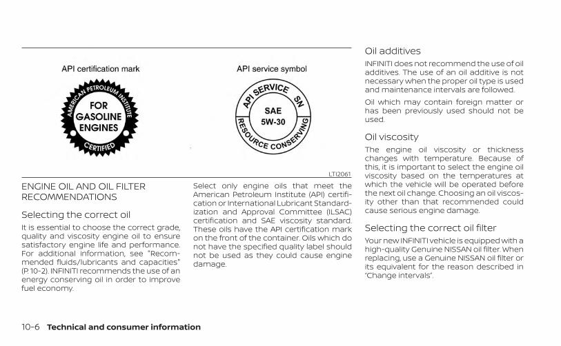
ENGINE OIL AND OIL FILTERRECOMMENDATIONS
Selecting the correct oilIt is essential to choose the correct grade,quality and viscosity engine oil to ensuresatisfactory engine life and performance.For additional information, see "Recom-mended fluids/lubricants and capacities"(P. 10-2). INFINITI recommends the use of anenergy conserving oil in order to improvefuel economy.
Select only engine oils that meet theAmerican Petroleum Institute (API) certifi-cation or International Lubricant Standard-ization and Approval Committee (ILSAC)certification and SAE viscosity standard.These oils have the API certification markon the front of the container. Oils which donot have the specified quality label shouldnot be used as they could cause enginedamage.
Oil additivesINFINITI does not recommend the use of oiladditives. The use of an oil additive is notnecessary when the proper oil type is usedand maintenance intervals are followed.Oil which may contain foreign matter orhas been previously used should not beused.
Oil viscosityThe engine oil viscosity or thicknesschanges with temperature. Because ofthis, it is important to select the engine oilviscosity based on the temperatures atwhich the vehicle will be operated beforethe next oil change. Choosing an oil viscos-ity other than that recommended couldcause serious engine damage.
Selecting the correct oil filterYour new INFINITI vehicle is equipped with ahigh-quality Genuine NISSAN oil filter. Whenreplacing, use a Genuine NISSAN oil filter orits equivalent for the reason described in“Change intervals”.
LTI2061
10-6 Technical and consumer information

Change intervalsThe oil and oil filter change intervals for yourengine are based on the use of the specifiedquality oils and filters. Using engine oil andfilters that are not of the specified quality, orexceeding recommended oil and filterchange intervals could reduce engine life.
CAUTION
Damage to engine caused by impropermaintenance or use of incorrect oil andfilter quality and/or viscosity is not cov-ered by the INFINITI New Vehicle Lim-ited Warranty.
Your engine was filled with a high-qualityengine oil when it was built. You do not haveto change the oil before the first recom-mended change interval. Oil and filterchange intervals depend upon how youuse your vehicle.Operation under the following conditionsmay require more frequent oil and filterchanges:• repeated short distance driving at cold
outside temperatures• driving in dusty conditions• extensive idling• stop and go commuting
For additional information on mainte-nance schedules, refer to the “Maintenanceand schedules” section of this manual.
AIR CONDITIONER SYSTEMREFRIGERANT AND OILRECOMMENDATIONSThe air conditioner system in yourINFINITI vehicle must be charged withthe refrigerant HFO-1234yf (R-1234yf)and the oil, Genuine NISSAN A/C SystemOil Type PAG (ND-OIL12) or the exactequivalents.
CAUTION
The use of any other refrigerant or oilwill cause severe damage to the airconditioning system and will requirethe replacement of all air conditionersystem components.
The refrigerant HFO-1234yf (R-1234yf) inyour INFINITI vehicle does not harm theearth's ozone layer. Although this refriger-ant does not affect the earth's atmo-sphere, certain government regulations re-quire the recovery and recycling of anyrefrigerant during automotive air condi-tioner system service. Air conditioner sys-tem should only be serviced by trained andcertified technicians to ensure proper andsafe operation (SAE J2845). An INFINITI re-tailer has the trained technicians andequipment needed to recover and recycleyour air conditioner system refrigerant.Only new and SAEJ2842 certified evapora-tor(s) shall be used as replacement parts.A damaged or leaking air conditioningevaporator shall never be repaired or re-placed with one removed from a used orsalvaged vehicle. To replace a damaged orleaking evaporator, use only new and SAEJ2842 certified evaporator(s). It is recom-mended that you visit an INFINITI retailerwhen servicing your air conditionersystem.
Technical and consumer information 10-7
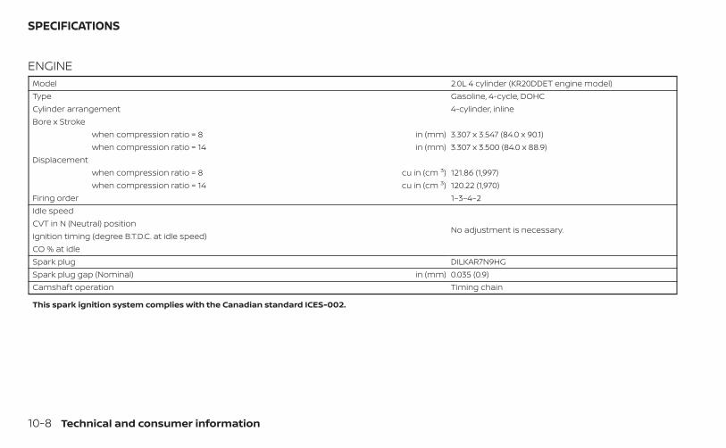
ENGINEModel 2.0L 4 cylinder (KR20DDET engine model)Type Gasoline, 4-cycle, DOHCCylinder arrangement 4-cylinder, inlineBore x Stroke
when compression ratio = 8 in (mm) 3.307 x 3.547 (84.0 x 90.1)when compression ratio = 14 in (mm) 3.307 x 3.500 (84.0 x 88.9)
Displacementwhen compression ratio = 8 cu in (cm 3) 121.86 (1,997)when compression ratio = 14 cu in (cm 3) 120.22 (1,970)
Firing order 1–3–4–2Idle speed
No adjustment is necessary.CVT in N (Neutral) positionIgnition timing (degree B.T.D.C. at idle speed)CO % at idleSpark plug DILKAR7N9HGSpark plug gap (Nominal) in (mm) 0.035 (0.9)Camshaft operation Timing chain
This spark ignition system complies with the Canadian standard ICES-002.
SPECIFICATIONS
10-8 Technical and consumer information

WHEELS AND TIRES
Wheel type Offset in (mm) SizeAluminum 1.73 (44) 20 x 8.5JTire size P255/45RF20Spare tire Not equipped
DIMENSIONS AND WEIGHTS
Units: in (mm)Overall length
with license plate bracket 186.3 (4,732)Overall width
without mirrors 74.9 (1,903)with mirrors 85.1 (2,161)
Overall heightto SAT antenna top 63.7 (1,619)
Front track 64.0 (1,625)Rear track 63.8 (1,620)Wheelbase 110.2 (2,800)Gross vehicle weight rating lbs. (kg) Refer to the
“F.M.V.S.S./C.M.V.S.S.certification label”on the center pillarbetween the driv-er's side front andrear doors.
Gross axle weight rating
Front lbs. (kg)
Rear lbs. (kg)
Technical and consumer information 10-9
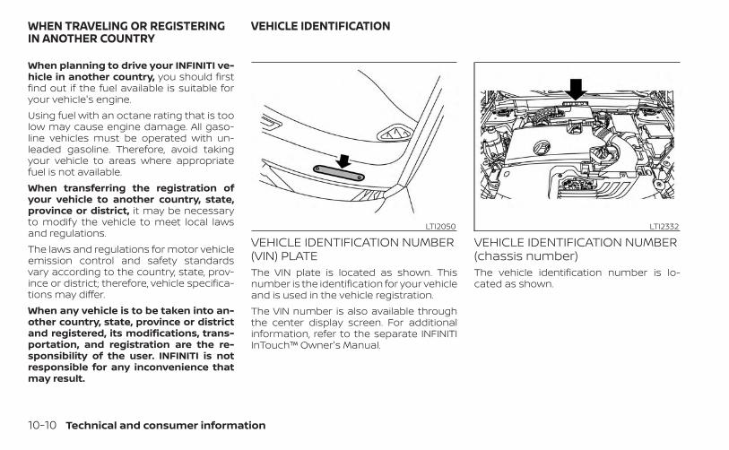
When planning to drive your INFINITI ve-hicle in another country, you should firstfind out if the fuel available is suitable foryour vehicle's engine.Using fuel with an octane rating that is toolow may cause engine damage. All gaso-line vehicles must be operated with un-leaded gasoline. Therefore, avoid takingyour vehicle to areas where appropriatefuel is not available.When transferring the registration ofyour vehicle to another country, state,province or district, it may be necessaryto modify the vehicle to meet local lawsand regulations.The laws and regulations for motor vehicleemission control and safety standardsvary according to the country, state, prov-ince or district; therefore, vehicle specifica-tions may differ.When any vehicle is to be taken into an-other country, state, province or districtand registered, its modifications, trans-portation, and registration are the re-sponsibility of the user. INFINITI is notresponsible for any inconvenience thatmay result.
VEHICLE IDENTIFICATION NUMBER(VIN) PLATEThe VIN plate is located as shown. Thisnumber is the identification for your vehicleand is used in the vehicle registration.The VIN number is also available throughthe center display screen. For additionalinformation, refer to the separate INFINITIInTouch™ Owner's Manual.
VEHICLE IDENTIFICATION NUMBER(chassis number)The vehicle identification number is lo-cated as shown.
LTI2050 LTI2332
WHEN TRAVELING OR REGISTERINGIN ANOTHER COUNTRY
VEHICLE IDENTIFICATION
10-10 Technical and consumer information
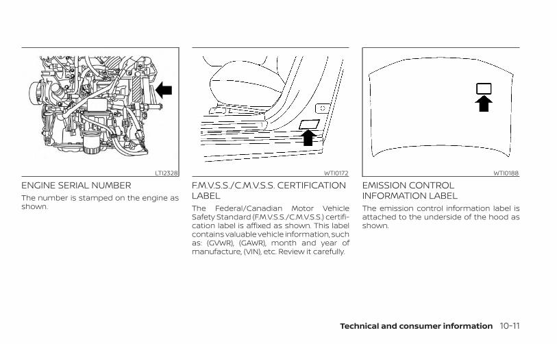
ENGINE SERIAL NUMBERThe number is stamped on the engine asshown.
F.M.V.S.S./C.M.V.S.S. CERTIFICATIONLABELThe Federal/Canadian Motor VehicleSafety Standard (F.M.V.S.S./C.M.V.S.S.) certifi-cation label is affixed as shown. This labelcontains valuable vehicle information, suchas: (GVWR), (GAWR), month and year ofmanufacture, (VIN), etc. Review it carefully.
EMISSION CONTROLINFORMATION LABELThe emission control information label isattached to the underside of the hood asshown.
LTI2328 WTI0172 WTI0188
Technical and consumer information 10-11
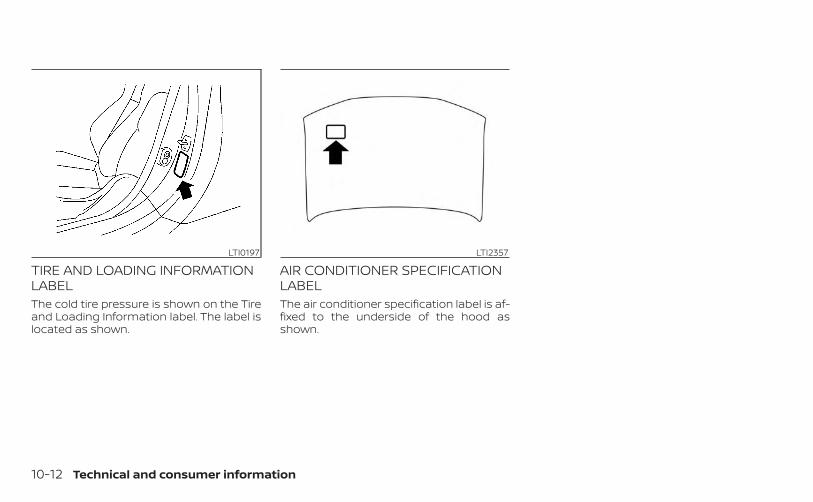
TIRE AND LOADING INFORMATIONLABELThe cold tire pressure is shown on the Tireand Loading Information label. The label islocated as shown.
AIR CONDITIONER SPECIFICATIONLABELThe air conditioner specification label is af-fixed to the underside of the hood asshown.
LTI0197 LTI2357
10-12 Technical and consumer information

Symbol Name Reference Graphic
Caution ISO 7000 0434
Air Conditioning System(MAC) ISO 2575 D01
MAC System Lubricant Type(PAG–POE)
Requires Registered Technician toService MAC System
Flammable Refrigerant
Air Conditioner Specification Label Symbols
1. Find the centerline of the vehicle andmeasure down 1.06 in (27 mm). Mark thelocation on the fascia.
2. Drill a 0.47 in (12 mm) hole OA in thefascia.
LTI2237
INSTALLING FRONT LICENSE PLATE
Technical and consumer information 10-13
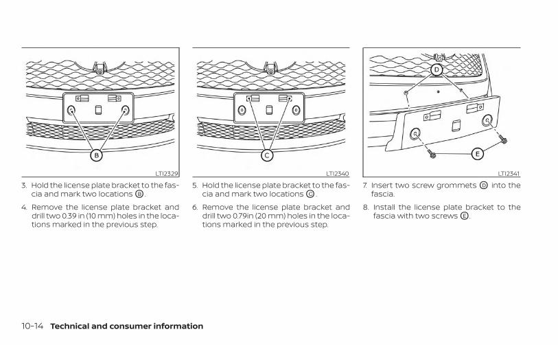
3. Hold the license plate bracket to the fas-cia and mark two locations OB .
4. Remove the license plate bracket anddrill two 0.39 in (10 mm) holes in the loca-tions marked in the previous step.
5. Hold the license plate bracket to the fas-cia and mark two locations OC .
6. Remove the license plate bracket anddrill two 0.79in (20 mm) holes in the loca-tions marked in the previous step.
7. Insert two screw grommets OD into thefascia.
8. Install the license plate bracket to thefascia with two screws OE .
LTI2329 LTI2340 LTI2341
10-14 Technical and consumer information
WARNING
• It is extremely dangerous toride in a cargo area inside a ve-hicle. In a collision, people rid-ing in these areas are morelikely to be seriously injured orkilled.
• Do not allow people to ride inany area of your vehicle that isnot equipped with seats andseat belts.
• Be sure everyone in your ve-hicle is in a seat and using aseat belt properly.
TERMSIt is important to familiarize yourselfwith the following terms beforeloading your vehicle:
• Curb Weight (actual weight of yourvehicle) - vehicle weight including:standard and optional equipment,fluids, emergency tools, and sparetire assembly. This weight doesnot include passengers and cargo.
• GVW (Gross Vehicle Weight) - curbweight plus the combined weightof passengers and cargo.
• GVWR (Gross Vehicle Weight Rat-ing) - maximum total combinedweight of the unloaded vehicle,passengers, cargo, hitch, trailertongue load and any other op-tional equipment. This informationis located on the F.M.V.S.S./C.M.V.S.S. certification label.
• GAWR (Gross Axle Weight Rating) -maximum weight (load) limitspecified for the front or rear axle.This information is located on theF.M.V.S.S./C.M.V.S.S. certificationlabel.
• GCWR (Gross Combined WeightRating) - The maximum totalweight rating of the vehicle, pas-sengers, cargo, and trailer.
• Vehicle Capacity Weight, Load limit,Total load capacity - maximum to-tal weight limit specified of the load(passengers and cargo) for the ve-hicle. This is the maximum com-bined weight of occupants andcargo that can be loaded into thevehicle. If the vehicle is used to towa trailer, the trailer tongue weightmust be included as part of thecargo load. This information is lo-cated on the Tire and Loading In-formation label.
• Cargo capacity - permissibleweight of cargo, the subtractedweight of occupants from the loadlimit.
VEHICLE LOADING INFORMATION
Technical and consumer information 10-15

VEHICLE LOAD CAPACITYBefore driving a loaded vehicle, con-firm that you do not exceed theGross Vehicle Weight Rating (GVWR)or the Gross Axle Weight Rating(GAWR) for your vehicle. Both theGVWR and GAWR are located on theF.M.V.S.S./C.M.V.S.S. certification label.For additional information, see “Mea-surement of weights” (P. 10-19).Do not exceed the load limit of yourvehicle shown as “The combinedweight of occupants and cargo” onthe Tire and Loading Information la-bel. Do not exceed the number ofoccupants shown as “Seating Ca-pacity” on the Tire and Loading Infor-mation label.To get “the combined weight of oc-cupants and cargo”, add the weightof all occupants, then add the totalcargo weight. Examples are shownin the following illustration.
10-16 Technical and consumer information
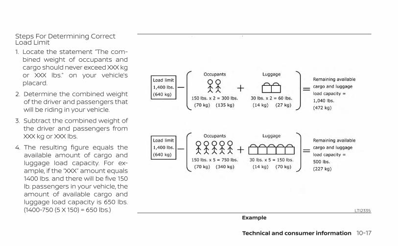
Steps For Determining CorrectLoad Limit1. Locate the statement “The com-
bined weight of occupants andcargo should never exceed XXX kgor XXX lbs.” on your vehicle’splacard.
2. Determine the combined weightof the driver and passengers thatwill be riding in your vehicle.
3. Subtract the combined weight ofthe driver and passengers fromXXX kg or XXX lbs.
4. The resulting figure equals theavailable amount of cargo andluggage load capacity. For ex-ample, if the “XXX” amount equals1400 lbs. and there will be five 150lb. passengers in your vehicle, theamount of available cargo andluggage load capacity is 650 lbs.(1400-750 (5 X 150) = 650 lbs.) LTI2335
Example
Technical and consumer information 10-17
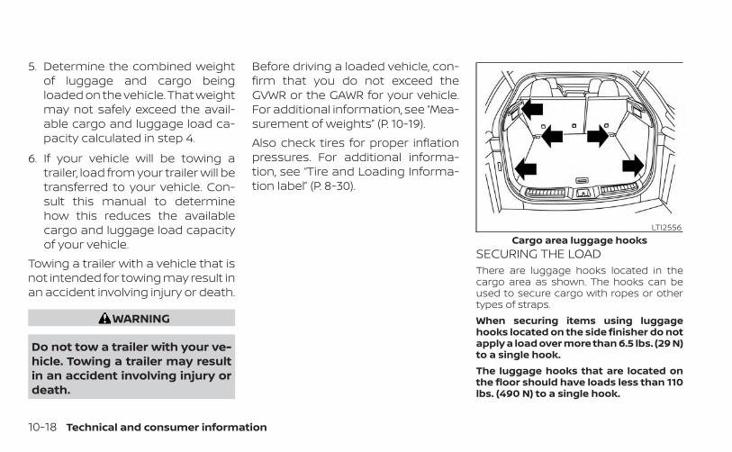
5. Determine the combined weightof luggage and cargo beingloaded on the vehicle. That weightmay not safely exceed the avail-able cargo and luggage load ca-pacity calculated in step 4.
6. If your vehicle will be towing atrailer, load from your trailer will betransferred to your vehicle. Con-sult this manual to determinehow this reduces the availablecargo and luggage load capacityof your vehicle.
Towing a trailer with a vehicle that isnot intended for towing may result inan accident involving injury or death.
WARNING
Do not tow a trailer with your ve-hicle. Towing a trailer may resultin an accident involving injury ordeath.
Before driving a loaded vehicle, con-firm that you do not exceed theGVWR or the GAWR for your vehicle.For additional information, see “Mea-surement of weights” (P. 10-19).Also check tires for proper inflationpressures. For additional informa-tion, see “Tire and Loading Informa-tion label” (P. 8-30).
SECURING THE LOADThere are luggage hooks located in thecargo area as shown. The hooks can beused to secure cargo with ropes or othertypes of straps.When securing items using luggagehooks located on the side finisher do notapply a load over more than 6.5 lbs. (29 N)to a single hook.The luggage hooks that are located onthe floor should have loads less than 110lbs. (490 N) to a single hook.
LTI2556Cargo area luggage hooks
10-18 Technical and consumer information
WARNING
• Properly secure all cargo with ropesor straps to help prevent it from slid-ing or shifting. Do not place cargohigher than the seatbacks. In a sud-den stop or collision, unsecuredcargo could cause personal injury.
• The child restraint top tether strapmay be damaged by contact withitems in the cargo area. Secure anyitems in the cargo area. Your childcould be seriously injured or killed ina collision if the top tether strap isdamaged.
• Do not load your vehicle any heavierthan the GVWR or the maximum frontand rear GAWRs. If you do, parts ofyour vehicle can break, tire damagecould occur, or it can change the wayyour vehicle handles. This could re-sult in loss of control and cause per-sonal injury.
LOADING TIPS• The GVW must not exceed GVWR or
GAWR as specified on the F.M.V.S.S./C.M.V.S.S. certification label.
• Do not load the front and rear axleto the GAWR. Doing so will exceedthe GVWR.
WARNING
• Properly secure all cargo withropes or straps to help preventit from sliding or shifting. Donot place cargo higher than theseatbacks. In a sudden stop orcollision, unsecured cargocould cause personal injury.
• Do not load your vehicle anyheavier than the GVWR or themaximum front and rearGAWRs. If you do, parts of yourvehicle can break, tire damagecould occur, or it can changethe way your vehicle handles.This could result in loss of con-trol and cause personal injury.
• Overloading not only canshorten the life of your vehicleand the tire, but can also causeunsafe vehicle handling andlonger braking distances. Thismay cause a premature tirefailure which could result in aserious accident and personalinjury. Failures caused by over-loading are not covered by thevehicle’s warranty.
MEASUREMENT OF WEIGHTSSecure loose items to preventweight shifts that could affect thebalance of your vehicle. When the ve-hicle is loaded, drive to a scale andweigh the front and the rear wheelsseparately to determine axle loads.Individual axle loads should not ex-ceed either of the Gross Axle WeightRatings (GAWR). The total of the axleloads should not exceed the GrossVehicle Weight Rating (GVWR). These
Technical and consumer information 10-19

ratings are given on the vehicle cer-tification label. If weight ratings areexceeded, move or remove items tobring all weights below the ratings.
Do not tow a trailer with your vehicle.
Lifestyle Receiver (if so equipped)
WARNING
The Lifestyle Receiver cannot be usedfor towing a trailer. Only use the Life-style Receiver for receiver mounted ac-cessories that meet the belowrequirements.• The maximum allowable load is 300
lbs. (136 kg) including the weight ofthe installed accessory carrier.
• Do not exceed allowable cargoweight capacity of your vehicle.
LTI2338
TOWING A TRAILER
10-20 Technical and consumer information
Failure to use the Lifestyle Receiver asintended can result in serious injury ordeath.
CAUTION
If your vehicle is equipped with the Life-style Receiver to avoid damage to yourvehicle do not tow a trailer with yourvehicle.
Do not tow a trailer with your vehicle withthe Lifestyle Receiver (if so equipped). TheLifestyle Receiver should be used forreceiver-mounted accessories only. TheLifestyle Receiver is designed for carryingbikes, snow boards/skis, camping gearand various other bulky items.
FLAT TOWING FOR ALL–WHEELDRIVE VEHICLETowing your vehicle with all four wheels onthe ground is sometimes called flat towing.This method is sometimes used whentowing a vehicle behind a recreational ve-hicle, such as a motor home.
CAUTION
• Failure to follow these guidelines canresult in severe transmissiondamage.
• Never flat tow your All-wheel drive(AWD) vehicle.
• DO NOT tow your All-wheel drive(AWD) vehicle with any wheels on theground. Doing so may cause seriousand expensive damage to thepowertrain.
• For emergency towing proceduressee “Towing recommended byINFINITI” (P. 6-8).
Continuously VariableTransmissionTo tow a vehicle equipped with a continu-ously variable transmission, an appropriatevehicle dolly MUST be placed under thetowed vehicle's drive wheels. Always followthe dolly manufacturer's recommenda-tions when using their product.
NOTE:
It the battery is completely drained thetransmission will not manually shift toother positions.
DOT (Department of Transportation) Qual-ity Grades: All passenger car tires mustconform to federal safety requirements inaddition to these grades.Quality grades can be found where appli-cable on the tire sidewall between treadshoulder and maximum section width. Forexample:Treadwear 200 Traction AA TemperatureATreadwearThe treadwear grade is a comparative rat-ing based on the wear rate of the tire whentested under controlled conditions on aspecified government test course. For ex-ample, a tire graded 150 would wear oneand one-half (1 1/2) times as well on thegovernment course as a tire graded 100.The relative performance of tires dependsupon the actual conditions of their use,however, and may depart significantly fromthe norm due to variations in driving habits,service practices and differences in roadcharacteristics and climate.
UNIFORM TIRE QUALITY GRADING
Technical and consumer information 10-21
Traction AA, A, B and CThe traction grades, from highest to low-est, are AA, A, B, and C. Those grades repre-sent the tire's ability to stop on wet pave-ment as measured under controlledconditions on specified government testsurfaces of asphalt and concrete. A tiremarked C may have poor tractionperformance.
WARNING
The traction grade assigned to this tireis based on straight-ahead brakingtraction tests, and does not include ac-celeration, cornering, hydroplaning, orpeak traction characteristics.
Temperature A, B and CThe temperature grades are A (the high-est), B, and C, representing the tire’s resis-tance to the generation of heat, and itsability to dissipate heat when tested undercontrolled conditions on a specified indoorlaboratory test wheel. Sustained high tem-perature can cause the material of the tireto degenerate and reduce tire life, and ex-cessive temperature can lead to suddentire failure. The grade C corresponds to alevel of performance which all passengercar tires must meet under the Federal Mo-
tor Safety Standard No. 109. Grades B and Arepresent higher levels of performance onthe laboratory test wheel than the mini-mum required by law.
WARNING
The temperature grade for this tire isestablished for a tire that is properlyinflated and not overloaded. Excessivespeed, under-inflation, or excessiveloading, either separately or in combi-nation, can cause heat build-up andpossible tire failure.
Your INFINITI is covered by the followingemission warranties:For USA1. Emission Defects Warranty
2. Emissions Performance WarrantyDetails of these warranties may be foundwith other vehicle warranties in your War-ranty Information Booklet which comes withyour INFINITI. If you did not receive a WarrantyInformation Booklet, or it is lost, you mayobtain a replacement by writing to:
• INFINITI DivisionNissan North America, Inc.Consumer Affairs DepartmentP.O. Box 685003Franklin, TN 37068-5003
For CanadaEmission Control System WarrantyDetails of these warranties may be foundwith other vehicle warranties in your War-ranty Information Booklet which comes withyour INFINITI. If you did not receive a WarrantyInformation Booklet, or it is lost, you mayobtain a replacement by writing to:
• Nissan Canada Inc.5290 Orbitor DriveMississauga, Ontario, L4W 4Z5
EMISSION CONTROL SYSTEMWARRANTY
10-22 Technical and consumer information

For USAIf you believe that your vehicle has adefect which could cause a crash orcould cause injury or death, youshould immediately inform the Na-tional Highway Traffic Safety Admin-istration (NHTSA) in addition to noti-fying INFINITI.If NHTSA receives similar complaints,it may open an investigation, and if itfinds that a safety defect exists in agroup of vehicles, it may order a re-call and remedy campaign. However,NHTSA cannot become involved inindividual problems between you,your retailer, or INFINITI.To contact NHTSA, you may call theVehicle Safety Hotline toll-free at1-888-327-4236 (TTY: 1-800-424-9153);go to http://www.safercar.gov; orwrite to: Administrator, NHTSA, 400Seventh Street, SW., Washington, D.C.20590. You can also obtain other in-
formation about motor vehicle safetyfrom http://www.safercar.gov.You may notify INFINITI by contact-ing our Consumer Affairs Depart-ment, toll-free, at 1-800-662-6200.For CanadaIf you believe that your vehicle has adefect which could cause a crash orcould cause injury or death, youshould immediately inform Trans-port Canada in addition to notifyingINFINITI.If Transport Canada receives com-plaints, it may open an investigation,and if it finds that a safety defectexists in a group of vehicles, it mayrequest that INFINITI conduct a recallcampaign. However, TransportCanada cannot become involved inindividual problems between you,your retailer, or INFINITI.You may contact Transport Canada'sDefect Investigations and Recalls Divi-
sion toll free at 1-800-333-0510. Youmay also report safety defects onlineat: http://www.tc.gc.ca/eng/motorvehiclesafety/menu.htm (Eng-lish speakers) or http://www.tc.gc.ca/fra/securiteautomobile/menu.htm(French speakers)Or contact Transport Canada bymail at:Transport Canada Motor VehicleSafety Investigations Laboratory80 Noel Street Gatineau, QC J8Z0A1Additional information concerningmotor vehicle safety may be obtainedfrom Transport Canada's Road SafetyInformation Centre at 1-800-333-0371or online at www.tc.gc.ca/roadsafety(English speakers) or www.tc.gc.ca/securiteroutiere (French speakers).To notify INFINITI of any safety con-cerns please contact our ConsumerInformation Centre toll free at1-800-361-4792.
REPORTING SAFETY DEFECTS
Technical and consumer information 10-23
WARNING
A vehicle equipped with All-Wheel Drive(AWD) should never be tested using atwo wheel dynamometer (such as thedynamometers used by some statesfor emissions testing), or similar equip-ment. Make sure you inform the testfacility personnel that your vehicle isequipped with AWD before it is placedon a dynamometer. Using the wrongtest equipment may result in transmis-sion damage or unexpected vehiclemovement which could result in seri-ous vehicle damage or personal injury.
Due to legal requirements in some statesand Canadian Provinces, your vehicle maybe required to be in what is called the“ready condition” for an Inspection/Maintenance (I/M) test of the emissioncontrol system.The vehicle is set to the “ready condition”when it is driven through certain drivingpatterns. Usually, the ready condition canbe obtained by ordinary usage of thevehicle.
If a powertrain system component is re-paired or the battery is disconnected, thevehicle may be reset to a “not ready” condi-tion. Before taking the I/M test, check thevehicle's inspection/maintenance testreadiness condition. Place the ignitionswitch in the ON position without startingthe engine. If the Malfunction IndicatorLight (MIL) comes on steady for 20 secondsand then blinks for 10 seconds , the I/M testcondition is “not ready”. If the MIL does notblink after 20 seconds, the I/M test condi-tion is “ready”. It is recommended that youvisit an INFINITI retailer to set the “readycondition” or to prepare the vehicle fortesting.
This vehicle is equipped with an Event DataRecorder (EDR). The main purpose of anEDR is to record, in certain crash or nearcrash-like situations, such as an air bagdeployment or hitting a road obstacle, datathat will assist in understanding how a ve-hicle's systems performed. The EDR is de-signed to record data related to vehicle dy-namics and safety systems for a shortperiod of time, typically 30 seconds or less.The EDR in this vehicle is designed to re-cord such data as:• How various systems in your vehicle were
operating;• Whether or not the driver and passenger
safety belts were buckled/fastened;• How far (if at all) the driver was depress-
ing the accelerator and/or brake pedal;and,
• How fast the vehicle was traveling.• Sounds are not recorded.These data can help provide a better un-derstanding of the circumstances in whichcrashes and injuries occur. NOTE: EDR dataare recorded by your vehicle only if a non-trivial crash situation occurs; no data arerecorded by the EDR under normal drivingconditions and no personal data (e.g.,name, gender, age, and crash location) arerecorded. However, other parties, such as
READINESS FOR INSPECTION/MAINTENANCE (I/M) TEST
EVENT DATA RECORDERS (EDR)
10-24 Technical and consumer information
law enforcement, could combine the EDRdata with the type of personally identifyingdata routinely acquired during a crashinvestigation.To read data recorded by an EDR, specialequipment is required, and access to thevehicle or the EDR is needed. In addition tothe vehicle manufacturer and INFINITI re-tailer, other parties, such as law enforce-ment, that have the special equipment, canread the information if they have access tothe vehicle or the EDR.EDR data will only be accessed with theconsent of the vehicle owner or lessee oras otherwise required or permitted by law.
ADDITIONAL DATA RECORDING (onvehicles equipped with optionalProPILOT Assist)If your vehicle is equipped with the optionalProPILOT Assist, it will also be equippedwith a supplemental vehicle data record-ing function.The data recording function is designed torecord such data as:• Driver operational status of accelerator,
brakes, steering, etc.• Detection status of a vehicle ahead and
lane markers
• Vehicle information including distance tovehicle ahead and lateral position
• Information on the operation of the Pro-PILOT Assist and other crash avoidancefeatures
• ProPILOT Assist malfunction diagnosisinformation
• External images from multi-sensing frontcamera (Available only when SRS air bagor FEB with Pedestrian Detection systemis activated)
ProPILOT Assist does not record conversa-tions, sounds or images of the inside of thevehicle.To read this vehicle data, special equip-ment is required and access to the vehicleor the recording unit is needed. This vehicledata will only be accessed with the consentof the vehicle owner or lessee or as other-wise required or permitted by law.If downloaded, NISSAN may use the datarecorded for the purpose of improvingNISSAN's vehicle safety performance.NISSAN will not disclose/provide the re-corded data to a third party except:• With the consent of the vehicle owner or
with the consent of the lessee
• In response to an official request from lawenforcement, a court order, governmen-tal agency, or other legally enforceablerequests
• For use as part of NISSAN's defense oflitigation
• For research purposes after the data ismodified such that it is no longer tied to aspecific vehicle or vehicle owner
If you have any questions regarding thedata NISSAN may collect about you, pleasevisit our Privacy Policy:https://www.infinitiusa.com.
Technical and consumer information 10-25

Genuine INFINITI Service Manuals for thismodel year and prior can be purchased. AGenuine INFINITI Service Manual is the bestsource of service and repair information foryour vehicle. This manual is the same oneused by the factory-trained techniciansworking at INFINITI retailers. GenuineINFINITI Owner’s Manuals can also bepurchased.For USAFor current pricing and availability of Genu-ine INFINITI Service Manuals, contact:www.infiniti-techinfo.comFor current pricing and availability of Genu-ine INFINITI Owner's Manuals, contact:1-800-247-5321For CanadaTo purchase a copy of a Genuine INFINITIService Manual or Owner’s Manual, for thismodel year and prior, please contact yournearest INFINITI retailer. For the phonenumber and location of an INFINITI retailerin your area call the INFINITI SatisfactionCenter at 1-800-361-4792 and a bilingualINFINITI representative will assist you.
OWNER'S MANUAL/SERVICEMANUAL ORDER INFORMATION
10-26 Technical and consumer information
11 IndexA
Active Engine Brake . . . . . . . . . . . .5-188Active noise cancellation
Active sound enhancement . . . . .5-198Active Ride Control . . . . . . . . . . . . .5-189Active Trace Control . . . . . . . . . . . .5-187Aiming control, headlights . . . . . . . . .2-42Air bag (See supplemental restraintsystem) . . . . . . . . . . . . . . . . . . . . .1-43Air bag system
Front (See supplemental front impact airbag system) . . . . . . . . . . . . . . . .1-50
Air bag warning labels. . . . . . . . . . . .1-63Air bag warning light . . . . . . . . .1-63, 2-12Air bag warning light,supplemental. . . . . . . . . . . . . .1-63, 2-12Air cleaner . . . . . . . . . . . . . . . . . . .8-17Air cleaner housing filter . . . . . . . . . .8-17Air conditioner
Air conditioner operation . . . . . . . .4-34Air conditioner specification label . .10-12Air conditioner system refrigerant and oilrecommendations . . . . . . . . . . . .10-7Heater and air conditioner (automatic)(if so equipped) . . . . . . . . . . . . . .4-33Heater and air conditioner controls . .4-34Servicing air conditioner. . . . . . . . .4-41
Alarm system (See vehicle securitysystem) . . . . . . . . . . . . . . . . . . . .2-30Anchor point locations . . . . . . . . . . .1-28
Antenna . . . . . . . . . . . . . . . . . . . .4-41Anti-lock brake warning light . . . .2-10, 2-13Anti-lock Braking System (ABS) . . . . .5-182Antifreeze. . . . . . . . . . . . . . . . . . .5-196Armrests . . . . . . . . . . . . . . . . . . . . .1-5Around View® Monitor . . . . . . . . . . . .4-11Autolight switch . . . . . . . . . . . . . . .2-38Automatic
Automatic power window switch . . .2-65Automatic anti-glare inside mirror . . . .3-36Automatic brake hold . . . . . . . . . . . .5-26Automatic door locks. . . . . . . . . . . . .3-6
B
Battery . . . . . . . . . . . . . . . . .5-196, 8-13Charge warning light . . . . . . . . . . .2-11
Battery replacement . . . . . . . . . . . .8-24INFINITI Intelligent Key . . . . . . . . . .8-24Key fob . . . . . . . . . . . . . . . . . . .8-24
Before starting the engine . . . . . . . . .5-16Belt (See drive belt). . . . . . . . . . . . . .8-16Blind Spot Intervention® (BSI) . . . . . . .5-55Blind Spot Warning (BSW). . . . . . . . . .5-47Booster seats . . . . . . . . . . . . . . . . .1-39Brake
Anti-lock Braking System (ABS). . . .5-182Brake fluid . . . . . . . . . . . . . . . . . .8-11Brake light (See stop light) . . . . . . .8-26Brake system. . . . . . . . . . . . . . .5-182
Brake warning light . . . . . . . . . . . .2-10Brake wear indicators. . . . . . .2-19, 8-20Self-adjusting brakes . . . . . . . . . .8-20
Brake Assist . . . . . . . . . . . . . . . . .5-184Brake fluid . . . . . . . . . . . . . . . . . . .8-11Brake system . . . . . . . . . . . . . . . .5-182Brakes . . . . . . . . . . . . . . . . . . . . .8-20Break-in schedule. . . . . . . . . . . . . .5-173Brightness control
Instrument panel . . . . . . . . . . . . .2-43Bulb check/instrument panel . . . . . . .2-10Bulb replacement . . . . . . . . . . . . . .8-26
C
C.M.V.S.S. certification label. . . . . . . . .10-11Camera Aiding Sonar (parking sensor) . .4-24Capacities and recommendedfuel/lubricants . . . . . . . . . . . . . . . .10-2Car phone or CB radio . . . . . . . . . . .4-42Cargo (See vehicle loadinginformation) . . . . . . . . . . . . . . . . .10-15Cargo area storage bin . . . . . . . . . . .2-59Cargo cover . . . . . . . . . . . . . . . . . .2-62Chassis control . . . . . . . . . . . . . . .5-187Check tire pressure . . . . . . . . . . . . .2-25Child restraint with top tether strap . . .1-27Child restraints . . . . . . .1-20, 1-21, 1-23, 1-25
LATCH (Lower Anchors and Tethers forCHildren) System . . . . . . . . . . . . .1-25

Precautions on childrestraints . . . . . . . . .1-23, 1-30, 1-35, 1-40Top tether strap anchor pointlocations . . . . . . . . . . . . . . . . . . .1-28
Child safety rear door lock . . . . . . . . . .3-6Cleaning exterior and interior . . . . . .7-2, 7-4Climate control seat switch. . . . . . . . .2-45Cold weather driving . . . . . . . . . . . .5-196Console box . . . . . . . . . . . . . . . . . .2-57Continuously Variable Transmission(CVT) . . . . . . . . . . . . . . . . . . . . . . .5-18
Continuously Variable Transmission (CVT)fluid . . . . . . . . . . . . . . . . . . . . . .8-11Driving with Continuously VariableTransmission (CVT) . . . . . . . . . . . .5-18
ControlsHeater and air conditioner controls . .4-34
CoolantCapacities and recommendedfuel/lubricants . . . . . . . . . . . . . . .10-2Changing engine coolant . . . . . . . . .8-6Checking engine coolant level . . . . . .8-6Engine coolant temperature gauge. . .2-6
Corrosion protection . . . . . . . . . . . . . .7-7Cruise control . . . . . . . . . . . . . .5-76, 5-77Cup holders . . . . . . . . . . . . . . . . . .2-58
D
Dimensions and weights . . . . . . . . . .10-9Dimmer switch for instrument panel . . .2-43Distance Control Assist (DCA) system . .5-134Door locks . . . . . . . . . . . . . . . . . . . .3-4
Drive belt . . . . . . . . . . . . . . . . . . . .8-16Driving
Cold weather driving. . . . . . . . . . .5-196Driving with Continuously VariableTransmission (CVT) . . . . . . . . . . . .5-18Precautions when starting anddriving. . . . . . . . . . . . . . . . . .5-4, 5-10
Driving the vehicle. . . . . . . . . . . . . . .5-18Dynamic driver assistance switch(for vehicles without ProPILOT Assist) . . .2-47
E
Economy - fuel . . . . . . . . . . . . . . . .5-175Electronic parking brake. . . . . . . . . . .5-24Emergency call (SOS) button . . . . . . . .2-51Emergency engine shutoff. . . . . . .5-15, 6-3Emission control information label . . . .10-11Emission control system warranty . . . .10-22Engine
Before starting the engine . . . . . . . .5-16Capacities and recommendedfuel/lubricants . . . . . . . . . . . . . . .10-2Changing engine coolant . . . . . . . . .8-6Changing engine oil. . . . . . . . . . . . .8-7Changing engine oil filter . . . . . . . . .8-7Checking engine coolant level . . . . . .8-6Checking engine oil level . . . . . . . . . .8-7Engine compartment check locations . .8-4Engine coolant temperature gauge. . .2-6Engine cooling system. . . . . . . . . . .8-5Engine oil . . . . . . . . . . . . . . . . . . .8-7
Engine oil and oil filterrecommendation . . . . . . . . . . . . .10-6Engine oil pressure warning light . . . .2-11Engine oil viscosity . . . . . . . . . . . . .10-6Engine serial number . . . . . . . . . . .10-11Engine specifications . . . . . . . . . . .10-8Starting the engine . . . . . . . . . . . .5-17
Engine Block Heater . . . . . . . . . . . . .5-197Engine coolant temperature gauge . . . .2-6Event Data recorders . . . . . . . .10-24, 10-25Exhaust gas (Carbon monoxide) . . . . . .5-4Explanation of maintenance items . . . . .9-2Explanation of scheduled maintenanceitems . . . . . . . . . . . . . . . . . . . . . . .9-5Extended storage switch . . . . . . . . . .2-53
F
F.M.V.S.S. certification label . . . . . . . . .10-11Flashers (See hazard warning flasherswitch) . . . . . . . . . . . . . . . . . . . . . .6-2Flat tire . . . . . . . . . . . . . . . . . . . . . .6-3Floor mat positioning aid . . . . . . . . . . .7-6Fluid
Brake fluid . . . . . . . . . . . . . . . . . .8-11Capacities and recommendedfuel/lubricants . . . . . . . . . . . . . . .10-2Continuously Variable Transmission (CVT)fluid . . . . . . . . . . . . . . . . . . . . . .8-11Engine coolant. . . . . . . . . . . . . . . .8-5Engine oil . . . . . . . . . . . . . . . . . . .8-7Windshield-washer fluid . . . . . . . . .8-12
Fog light switch . . . . . . . . . . . . . . . .2-44
11-2
Forward Emergency Braking (FEB) withPedestrian Detection system . . . .2-13, 5-151Front air bag system (See supplementalrestraint system) . . . . . . . . . . . . . . .1-50Front and rear sonar system . . . . . . .5-190Front and rear sonar system switch . . .2-48Front power seat adjustment . . . . . . . .1-3Front seats . . . . . . . . . . . . . . . . . . . .1-2Front-door pocket . . . . . . . . . . . . . .2-54Fuel
Capacities and recommendedfuel/lubricants . . . . . . . . . . . . . . .10-2Fuel economy . . . . . . . . . . . . . . .5-175Fuel gauge . . . . . . . . . . . . . . . . . .2-7Fuel octane rating . . . . . . . . . . . . .10-5Fuel recommendation . . . . . . . . . .10-3Fuel-filler door and cap . . . . . . . . . .3-31Loose fuel cap warning . . . . . . . . . .2-23
Fuel efficient driving tips . . . . . . . . . .5-174Fuel gauge . . . . . . . . . . . . . . . . . . . .2-7Fuel-filler door . . . . . . . . . . . . . . . . .3-31Fuses. . . . . . . . . . . . . . . . . . . . . . .8-21Fusible links . . . . . . . . . . . . . . . . . .8-22
G
Garage door opener, HomeLink® UniversalTransceiver . . . . . . . . .2-69, 2-71, 2-72, 2-73Gas cap . . . . . . . . . . . . . . . . . . . . .3-31Gauge
Engine coolant temperature gauge. . .2-6Fuel gauge . . . . . . . . . . . . . . . . . .2-7Odometer. . . . . . . . . . . . . . . . . . .2-5
Speedometer. . . . . . . . . . . . . .2-4, 2-5Tachometer . . . . . . . . . . . . . . . . .2-6Trip odometer . . . . . . . . . . . . . . . .2-5
General maintenance . . . . . . . . . . . . .9-2Glove box . . . . . . . . . . . . . . . . . . . .2-56Glove box lock . . . . . . . . . . . . . . . . .2-56Grocery hooks . . . . . . . . . . . . . . . . .2-60
H
Hazard warning flasher switch. . . . . . . .6-2Head restraints . . . . . . . . . . . . . . . . .1-7Head Up Display (HUD) . . . . . . . . . . . .2-49Headlight aiming control . . . . . . . . . .2-42Headlight and turn signal switch. . . . . .2-37Headlight switch. . . . . . . . . . . . . . . .2-37Headlights . . . . . . . . . . . . . . . . . . .8-26Headlights, aiming control . . . . . . . . .2-42Heated seats. . . . . . . . . . . . . . . . . .2-46Heater
Heater and air conditioner (automatic)(if so equipped) . . . . . . . . . . . . . . .4-33Heater and air conditioner controls . .4-34Heater operation . . . . . . . . . . . . .4-35
Heater and air conditioner (automatic). .4-33Heater and air conditioner settings. . . .4-40Hill start assist system . . . . . . . . . . .5-189HomeLink® UniversalTransceiver . . . . . . . . .2-69, 2-71, 2-72, 2-73Hood . . . . . . . . . . . . . . . . . . . . . . .3-23Hook
Luggage hook . . . . . . . . . . . . . . .2-60Horn . . . . . . . . . . . . . . . . . . . . . . .2-45
I
Ignition switchPush-button ignition switch . . . . . . .5-13
Immobilizer system. . . . . . . . . . . . . .5-16Important vehicle information label . . .10-11In-cabin microfilter . . . . . . . . . . . . . .8-18Increasing fuel economy . . . . . . . . . .5-175Indicator lights and audible reminders(See warning/indicator lights and audiblereminders). . . . . . . . . . . . . . . . .2-9, 2-10INFINITI Drive Mode Selector . . . . . . . .5-29INFINITI Intelligent Key System . . . . .3-2, 3-6INFINITI Vehicle ImmobilizerSystem . . . . . . . . . . . . . . .2-31, 3-4, 5-16Inside automatic anti-glare mirror . . . .3-36Instrument brightness control . . . . . . .2-43Instrument panel . . . . . . . . . . . . .0-6, 2-2Instrument panel dimmer switch . . . . .2-43Intelligent All-Wheel Drive (AWD). . . . . .5-175Intelligent Cruise Control (ICC)(for vehicles with ProPILOT Assist). . . . .5-113Intelligent Cruise Control (ICC)(for vehicles without ProPILOT Assist) . . .5-78Intelligent Key system
Key operating range . . . . . . . . . . . .3-8Key operation . . . . . . . . . . . . . . . .3-10Mechanical key. . . . . . . . . . . . . . . .3-3Remote keyless entry operation . . . .3-14Troubleshooting guide . . . . . . . . . .3-18Warning signals. . . . . . . . . . . . . . .3-18
Interior light . . . . . . . . . . . . . . . . . .2-67ISOFIX child restraints. . . . . . . . . . . . .1-25
11-3
J
Jump starting. . . . . . . . . . . . . . .6-5, 8-15
K
Key . . . . . . . . . . . . . . . . . . . . . . . . .3-2Key fob battery replacement . . . . . . . .8-24Keyless entry
With Intelligent Key system(See Intelligent Key system) . . . . . . .3-14
L
LabelTire and Loading Information label . .10-12
LabelsAir conditioner specification label . . .10-12C.M.V.S.S. certification label . . . . . . .10-11Emission control information label . .10-11Engine serial number . . . . . . . . . . .10-11F.M.V.S.S. certification label . . . . . . . .10-11Tire and Loading Information label . .10-12Vehicle identification number (VIN) . .10-10Vehicle identification number (VIN)plate . . . . . . . . . . . . . . . . . . . . .10-10Warning labels (for SRS) . . . . . . . . . .1-63
Lane Departure Prevention (LDP) . . . . .5-41Lane Departure Warning (LDW). . . . . . .5-36LATCH (Lower Anchors and Tethers forCHildren) System . . . . . . . . . . . . . . .1-25
LED Daytime Running Lights (DRL)system . . . . . . . . . . . . . . . . . . . . .2-42License plate
Installing the license plate. . . . . . . .10-13Liftgate . . . . . . . . . . . . . . . . . . . . .3-24Liftgate release . . . . . . . . . . . . . . . .3-29Light
Air bag warning light . . . . . . . .1-63, 2-12Brake light (See stop light) . . . . . . . .8-26Bulb check/instrument panel . . . . . .2-10Bulb replacement . . . . . . . . . . . . .8-26Charge warning light. . . . . . . . . . . .2-11Exterior and Interior lights . . . . . . . .8-26Fog light switch . . . . . . . . . . . . . .2-44Fog lights . . . . . . . . . . . . . . . . . .8-26Headlight and turn signal switch . . . .2-37Headlights. . . . . . . . . . . . . . . . . .8-26Interior light . . . . . . . . . . . . . . . . .2-67Light bulbs . . . . . . . . . . . . . . . . .8-26Low tire pressure warning light . . . . .2-14Low windshield-washer fluid warninglight . . . . . . . . . . . . . . . . . . . . . .2-23Personal lights . . . . . . . . . . . . . . .2-68Security indicator light . . . . . . . . . .2-12Trunk light . . . . . . . . . . . . . . . . . .2-68Warning/indicator lights and audiblereminders . . . . . . . . . . . . . . .2-9, 2-10
Lights . . . . . . . . . . . . . . . . . . . . . .8-26Map lights . . . . . . . . . . . . . . . . . .2-68
LockChild safety rear door lock. . . . . . . . .3-6Door locks . . . . . . . . . . . . . . . . . .3-4Glove box lock . . . . . . . . . . . . . . .2-56Liftgate release. . . . . . . . . . . . . . .3-29
Power door locks . . . . . . . . . . . . . .3-5Loose fuel cap warning . . . . . . . . . . .2-23Low fuel warning light. . . . . .2-12, 2-16, 2-23Low tire pressure warning light. . . . . . .2-14Low windshield-washer fluid warninglight . . . . . . . . . . . . . . . . . . . . . . .2-23Luggage (See vehicle loadinginformation) . . . . . . . . . . . . . . . . . .10-15Luggage hook . . . . . . . . . . . . . . . . .2-60Luggage rack (see roof rack). . . . .2-61, 2-62
M
MaintenanceGeneral maintenance . . . . . . . . . . .9-2Inside the vehicle . . . . . . . . . . . . . .9-3Maintenance precautions . . . . . . . . .8-2Outside the vehicle . . . . . . . . . . . . .9-3Seat belt maintenance . . . . . . . . . .1-20Under the hood and vehicle . . . . . . .9-4
Maintenance requirements. . . . . . . . . .9-2Maintenance schedules . . . . . . . . .9-7, 9-8Malfunction indicator light . . . . . . . . . .2-15Map lights . . . . . . . . . . . . . . . . . . .2-68Memory seat . . . . . . . . . . . . . .3-38, 3-40Meters and gauges . . . . . . . . . . . . . .2-4
Instrument brightness control . . . . .2-43Mirror
Automatic anti-glare inside mirror . . .3-36Outside mirrors. . . . . . . . . . . . . . .3-37Vanity mirror . . . . . . . . . . . . . . . .3-35
Mirrors . . . . . . . . . . . . . . . . . . . . . .3-36Moonroof . . . . . . . . . . . . . . . . .2-65, 7-5Moving Object Detection (MOD) . . . . . .4-27
11-4
N
NissanConnect® Owner's Manual . . . . . .4-2
O
Octane rating (See fuel octane rating) . .10-5Odometer . . . . . . . . . . . . . . . . . . . .2-5Oil
Capacities and recommendedfuel/lubricants . . . . . . . . . . . . . . .10-2Changing engine oil. . . . . . . . . . . . .8-7Changing engine oil filter . . . . . . . . .8-7Checking engine oil level . . . . . . . . . .8-7Engine oil . . . . . . . . . . . . . . . . . . .8-7Engine oil and oil filterrecommendation . . . . . . . . . . . . .10-6Engine oil viscosity . . . . . . . . . . . . .10-6
Outside mirrors . . . . . . . . . . . . . . . .3-37Overhead sunglasses holder . . . . . . . .2-57Overheat
If your vehicle overheats . . . . . . . . . .6-7Owner's manual order form . . . . . . . .10-26Owner's manual/service manual orderinformation . . . . . . . . . . . . . . . . . .10-26
P
ParkingParking/parking on hills . . . . . . . . .5-178
Parking brake . . . . . . . . . . .2-11, 2-13, 2-18Personal lights. . . . . . . . . . . . . . . . .2-68
PowerPower door locks . . . . . . . . . . . . . .3-5Power outlet . . . . . . . . . . . . . . . .2-52Power rear windows . . . . . . . . . . .2-64Power steering system . . . . .5-179, 5-180Power windows . . . . . . . . . . . . . .2-63Rear power windows . . . . . . . . . . .2-64
Power outlet . . . . . . . . . . . . . . . . . .2-52Power steering . . . . . . . . . . . .5-179, 5-180Precautions
Maintenance precautions . . . . . . . . .8-2On-pavement and off-road drivingprecautions . . . . . . . . . . . . . . . . .5-8Precautions on boosterseats . . . . . . . . . . .1-23, 1-30, 1-35, 1-40Precautions on childrestraints . . . . . . . . .1-23, 1-30, 1-35, 1-40Precautions on seat belt usage . . . . .1-11Precautions on supplemental restraintsystem . . . . . . . . . . . . . . . . . . . .1-43Precautions when starting anddriving. . . . . . . . . . . . . . . . . .5-4, 5-10
Predictive Forward Collision Warning(PFCW) . . . . . . . . . . . . . . . . . . . . .5-162ProPILOT Assist . . . . . . . . . . . . . . . .5-102Push starting . . . . . . . . . . . . . . . . . .6-7
R
RadioCar phone or CB radio . . . . . . . . . .4-42
Rain sensor. . . . . . . . . . . . . . . . . . .2-34Readiness for inspection maintenance (I/M)test . . . . . . . . . . . . . . . . . . . . . . .10-24
Rear Automatic Braking (RAB) . . .2-17, 5-146Rear bench seat adjustment . . . . . . . . .1-5Rear Cross Traffic Alert (RCTA) . . . . . . .5-68Rear power windows. . . . . . . . . . . . .2-64Rear window defroster, outside mirrordefroster, and wiper deicer switch. . . . .2-36Rear window wiper and washerswitches . . . . . . . . . . . . . . . . . . . .2-35RearView Monitor . . . . . . . . . . . . . . . .4-3Recommended Fluids . . . . . . . . . . . .10-2Recorders
Event Data . . . . . . . . . . . . .10-24, 10-25Refrigerant recommendation . . . . . . . .10-7Registering a vehicle in anothercountry . . . . . . . . . . . . . . . . . . . . .10-10Remote Engine Start . . . . . . . . .3-20, 5-18Reporting safety defects (US only) . . . .10-23Roadside assistance program . . . . . . . .6-2Roof rack . . . . . . . . . . . . . . . . .2-61, 2-62
S
SafetyChild safety rear door lock. . . . . . . . .3-6Child seat belts . . . . .1-23, 1-30, 1-35, 1-40Reporting safety defects (US only) . .10-23
SeatMemory seat . . . . . . . . . . . .3-38, 3-40
Seat adjustmentFront power seat adjustment . . . . . . .1-3Rear bench seats . . . . . . . . . . . . . .1-5
Seat beltChild safety . . . . . . . . . . . . . . . . .1-20
11-5
Infants and small children . . . . . . . .1-21Injured person. . . . . . . . . . . . . . . .1-14Larger children . . . . . . . . . . . . . . .1-21Precautions on seat belt usage . . . . .1-11Pregnant women . . . . . . . . . . . . . .1-15Seat belt extenders . . . . . . . . . . . .1-19Seat belt maintenance . . . . . . . . . .1-20Seat belts . . . . . . . . . . . . . . . .1-11, 7-6Three-point type with retractor . . . . .1-15
Seat belt extenders . . . . . . . . . . . . . .1-19Seat belt warning light . . . . . . . . .1-14, 2-12Seatback pockets. . . . . . . . . . . . . . .2-55Seats
Adjustment . . . . . . . . . . . . . . . . . .1-2Armrests. . . . . . . . . . . . . . . . . . . .1-5Front seats . . . . . . . . . . . . . . . . . .1-2Heated seats . . . . . . . . . . . . . . . .2-46Rear bench seat . . . . . . . . . . . . . . .1-5
Seats/floor mats . . . . . . . . . . . . . . . .7-5Security indicator light . . . . . . . . . . . .2-12Security system
(INFINITI vehicle immobilizer system),engine start . . . . . . . . . . .2-31, 3-4, 5-16
Security systemsVehicle security system . . . . . . . . .2-30
Self-adjusting brakes. . . . . . . . . . . . .8-20Service manual order form . . . . . . . .10-26Servicing air conditioner . . . . . . . . . . .4-41Spark plug replacement . . . . . . . . . . .8-16Spark plugs . . . . . . . . . . . . . . . . . . .8-16Specifications . . . . . . . . . . . . . . . . .10-8Speedometer . . . . . . . . . . . . . . .2-4, 2-5SRS warning label . . . . . . . . . . . . . . .1-63Stability control. . . . . . . . . . . . . . . .5-184
Standard maintenance . . . . . . . . . . . .9-9Starting
Before starting the engine . . . . . . . .5-16Jump starting . . . . . . . . . . . . .6-5, 8-15Precautions when starting anddriving. . . . . . . . . . . . . . . . . .5-4, 5-10Push starting . . . . . . . . . . . . . . . . .6-7Starting the engine . . . . . . . . . . . .5-17
Starting the engine . . . . . . . . . . . . . .5-17Steering
Power steering system . . . . .5-179, 5-180Steering Assist switch (for vehicles withProPILOT Assist) . . . . . . . . . . . . . . . .2-48Steering wheel . . . . . . . . . . . . . . . . .3-33Stop light . . . . . . . . . . . . . . . . . . . .8-26Storage . . . . . . . . . . . . . . . . . . . . .2-54Storage tray . . . . . . . . . . . . . . .2-55, 2-56Sun visors. . . . . . . . . . . . . . . . . . . .3-35Sunglasses case . . . . . . . . . . . . . . .2-57Sunglasses holder . . . . . . . . . . . . . .2-57Sunroof . . . . . . . . . . . . . . . . . .2-65, 7-5Supplemental air bag warning labels . . .1-63Supplemental air bag warninglight . . . . . . . . . . . . . . . . . . . .1-63, 2-12Supplemental front impact air bagsystem. . . . . . . . . . . . . . . . . . . . . .1-50Supplemental restraint system
Information and warning labels. . . . .1-63Precautions on supplemental restraintsystem . . . . . . . . . . . . . . . . . . . .1-43
Supplemental restraint system(Supplemental air bag system) . . . . . . .1-43Switch
Autolight switch . . . . . . . . . . . . . .2-38
Automatic power window switch . . .2-65Fog light switch . . . . . . . . . . . . . .2-44Hazard warning flasher switch . . . . . .6-2Headlight aiming control. . . . . . . . .2-42Headlight and turn signal switch . . . .2-37Instrument brightness control . . . . .2-43Power door lock switch . . . . . . . . . .3-5Rear window wiper and washerswitches . . . . . . . . . . . . . . . . . . .2-35Turn signal switch . . . . . . . . . . . . .2-43
T
Tachometer . . . . . . . . . . . . . . . . . . .2-6Temperature gauge
Engine coolant temperature gauge. . .2-6Theft
(INFINITI vehicle immobilizer system),engine start . . . . . . . . . . .2-31, 3-4, 5-16
Three-way catalyst . . . . . . . . . . . . . . .5-4Tire
Flat tire . . . . . . . . . . . . . . . . . . . .6-3Tire and Loading Information label . .10-12Tire chains . . . . . . . . . . . . . . . . .8-38Tire pressure . . . . . . . . . . . . . . . .8-28Tire rotation. . . . . . . . . . . . . . . . .8-38Types of tires . . . . . . . . . . . . . . . .8-35Uniform tire quality grading. . . . . . .10-21Wheel/tire size . . . . . . . . . . . . . . .10-9Wheels and tires . . . . . . . . . . . . . .8-28
Tire pressureLow tire pressure warning light . . . . .2-14
Tire Pressure Monitoring System (TPMS) . .5-5
11-6
Top tether strap child restraint . . . . . . .1-27Towing
All-wheel drive models . . . . . . . . . . .6-9Flat towing . . . . . . . . . . . . . . . . .10-21Tow truck towing . . . . . . . . . . . . . .6-8Trailer towing . . . . . . . . . . . . . . .10-20
Towing a trailer . . . . . . . . . . . . . . . .10-20Traffic Sign Recognition (TSR) . . . . . . . .5-33Transceiver
HomeLink® UniversalTransceiver . . . . . . .2-69, 2-71, 2-72, 2-73
TransmissionContinuously Variable Transmission (CVT)fluid . . . . . . . . . . . . . . . . . . . . . .8-11Driving with Continuously VariableTransmission (CVT) . . . . . . . . . . . .5-18
Travel (See registering a vehicle in anothercountry) . . . . . . . . . . . . . . . . . . . .10-10Trip odometer . . . . . . . . . . . . . . . . . .2-5Trunk light . . . . . . . . . . . . . . . . . . .2-68Turn signal switch. . . . . . . . . . . . . . .2-43
U
Uniform tire quality grading . . . . . . . .10-21USB/iPod® Charging Ports. . . . . . . . . .2-51
V
Vanity mirror . . . . . . . . . . . . . . . . . .3-35Variable voltage control system . . . . . .8-15Vehicle dimensions and weights. . . . . .10-9Vehicle Dynamic Control (VDC) system . .5-184
Vehicle identification . . . . . . . . . . . .10-10Vehicle identification number (VIN) . . . .10-10Vehicle identification number (VIN)(Chassis number) . . . . . . . . . . . . . .10-10Vehicle identification number (VIN)plate . . . . . . . . . . . . . . . . . . . . . .10-10Vehicle immobilizer system . . . . . . . . .5-16Vehicle information display . . . . . . . . .2-19Vehicle loading information . . . . . . . .10-15Vehicle recovery . . . . . . . . . . . . .6-9, 6-10Vehicle security system . . . . . . . . . . .2-30
(INFINITI vehicle immobilizer system),engine start . . . . . . . . . . .2-31, 3-4, 5-16
Vents . . . . . . . . . . . . . . . . . . . . . .4-32Visors . . . . . . . . . . . . . . . . . . . . . .3-35
W
WarningAir bag warning light . . . . . . . .1-63, 2-12Anti-lock brake warning light . . .2-10, 2-13Battery charge warning light . . . . . . .2-11Brake warning light . . . . . . . . . . . .2-10Distance Control Assist (DCA) . . . . .5-134Engine oil pressure warning light . . . .2-11Hazard warning flasher switch . . . . . .6-2Loose fuel cap warning . . . . . . . . . .2-23Low fuel warning light . . . .2-12, 2-16, 2-23Low tire pressure warning light . . . . .2-14Low windshield-washer fluid warninglight . . . . . . . . . . . . . . . . . . . . . .2-23Seat belt warning light . . . . . . .1-14, 2-12Supplemental air bag warninglight . . . . . . . . . . . . . . . . . . .1-63, 2-12
Vehicle security system . . . . . . . . .2-30Warning labels (for SRS) . . . . . . . . . .1-63Warning/indicator lights and audiblereminders . . . . . . . . . . . . . . .2-9, 2-10
Warning lights . . . . . . . . . . . . . .2-9, 2-10Warning lights, indicator lights and audiblereminders . . . . . . . . . . . . . . . . . . . .2-9Warning systems switch . . . . . . .2-47, 2-48Warning/indicator lights and audiblereminders . . . . . . . . . . . . . . . . .2-9, 2-10
Audible reminders . . . . . . . . . .2-9, 2-10Indicator lights . . . . . . . . . . . .2-9, 2-10Warning lights . . . . . . . . . . . . .2-9, 2-10
Washer switchRear window wiper and washerswitches . . . . . . . . . . . . . . . . . . .2-35
Weights (See dimensions and weights). .10-9Wheel/tire size . . . . . . . . . . . . . . . . .10-9Wheels and tires. . . . . . . . . . . . . . . .8-28When traveling or registering in anothercountry . . . . . . . . . . . . . . . . . . . . .10-10Windows . . . . . . . . . . . . . . . . . . . .2-63
Locking passengers' windows . . . . .2-64Power rear windows . . . . . . . . . . .2-64Power windows . . . . . . . . . . . . . .2-63Rear power windows . . . . . . . . . . .2-64
Windshield wiper blades . . . . . . . . . . .8-18Windshield-washer fluid . . . . . . . . . . .8-12Wiper
Rear window wiper and washerswitches . . . . . . . . . . . . . . . . . . .2-35Wiper blades . . . . . . . . . . . . . . . .8-18
Wiper and washer switch . . . . . . . . . .2-33
11-7
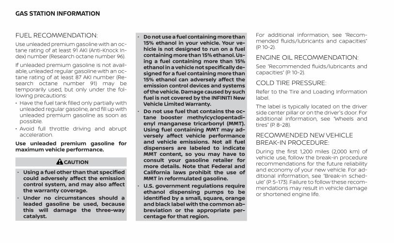
FUEL RECOMMENDATION:Use unleaded premium gasoline with an oc-tane rating of at least 91 AKI (Anti-Knock In-dex) number (Research octane number 96).If unleaded premium gasoline is not avail-able, unleaded regular gasoline with an oc-tane rating of at least 87 AKI number (Re-search octane number 91) may betemporarily used, but only under the fol-lowing precautions:• Have the fuel tank filled only partially with
unleaded regular gasoline, and fill up withunleaded premium gasoline as soon aspossible.
• Avoid full throttle driving and abruptacceleration.
Use unleaded premium gasoline formaximum vehicle performance.
CAUTION
• Using a fuel other than that specifiedcould adversely affect the emissioncontrol system, and may also affectthe warranty coverage.
• Under no circumstances should aleaded gasoline be used, becausethis will damage the three-waycatalyst.
• Do not use a fuel containing more than15% ethanol in your vehicle. Your ve-hicle is not designed to run on a fuelcontaining more than 15% ethanol. Us-ing a fuel containing more than 15%ethanol in a vehicle not specifically de-signed for a fuel containing more than15% ethanol can adversely affect theemission control devices and systemsof the vehicle. Damage caused by suchfuel is not covered by the INFINITI NewVehicle Limited Warranty.
• Do not use fuel that contains the oc-tane booster methylcyclopentadi-enyl manganese tricarbonyl (MMT).Using fuel containing MMT may ad-versely affect vehicle performanceand vehicle emissions. Not all fueldispensers are labeled to indicateMMT content, so you may have toconsult your gasoline retailer formore details. Note that Federal andCalifornia laws prohibit the use ofMMT in reformulated gasoline.
• U.S. government regulations requireethanol dispensing pumps to beidentified by a small, square, orangeand black label with the common ab-breviation or the appropriate per-centage for that region.
For additional information, see “Recom-mended fluids/lubricants and capacities”(P. 10-2).
ENGINE OIL RECOMMENDATION:See “Recommended fluids/lubricants andcapacities” (P. 10-2).
COLD TIRE PRESSURE:Refer to the Tire and Loading Informationlabel.The label is typically located on the driverside center pillar or on the driver's door. Foradditional information, see “Wheels andtires” (P. 8-28).
RECOMMENDED NEW VEHICLEBREAK-IN PROCEDURE:During the first 1,200 miles (2,000 km) ofvehicle use, follow the break-in procedurerecommendations for the future reliabilityand economy of your new vehicle. For ad-ditional information, see “Break-in sched-ule” (P. 5-173). Failure to follow these recom-mendations may result in vehicle damageor shortened engine life.
GAS STATION INFORMATION

Printing : October 2021Publication No.:
Printed in the U.S.A.OM22E0 J55XU2
J55X-D
To view the digital Infiniti InTouch manual, go towww.infinitiquickguide.com/qx55/2022/browse
or snap this QR code with an appropriate QR code reader.
Related Documents