For your safety, read carefully and keep in this vehicle. 2021 ALTIMA SEDAN OWNER’S MANUAL and MAINTENANCE INFORMATION

Welcome message from author
This document is posted to help you gain knowledge. Please leave a comment to let me know what you think about it! Share it to your friends and learn new things together.
Transcript
For your safety, read carefully and keep in this vehicle.
2021 ALTIMA SEDANOWNER’S MANUAL
and MAINTENANCE INFORMATION
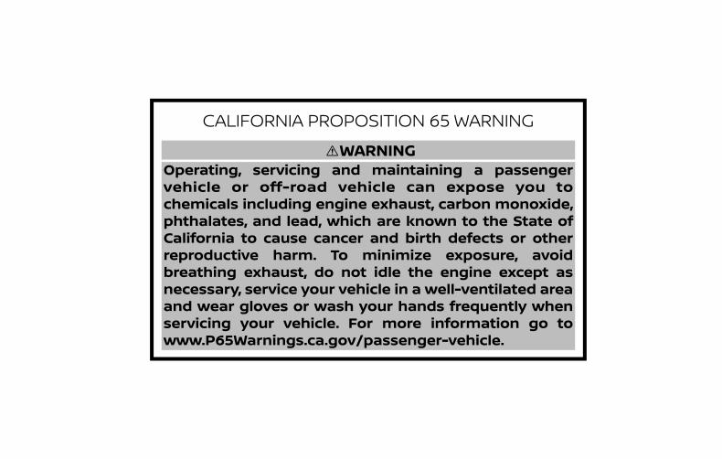
CALIFORNIA PROPOSITION 65 WARNING
Operating, servicing and maintaining a passenger vehicle or off-road vehicle can expose you to chemicals including engine exhaust, carbon monoxide, phthalates, and lead, which are known to the State of California to cause cancer and birth defects or otherreproductive harm. To minimize exposure, avoidbreathing exhaust, do not idle the engine except as necessary, service your vehicle in a well-ventilated areaand wear gloves or wash your hands frequently whenservicing your vehicle. For more information go to www.P65Warnings.ca.gov/passenger-vehicle.
WARNING
This manual was prepared to help you un-derstand the operation and maintenanceof your vehicle so that you may enjoy manymiles (kilometers) of driving pleasure.Please read through this manual beforeoperating your vehicle.A separate Warranty Information Book-let explains details about the warrantiescovering your vehicle. The “Maintenanceand schedules” section of this manualexplains details about maintaining andservicing your vehicle. Additionally, aseparate Customer Care/Lemon LawBooklet (U.S. only) will explain how to re-solve any concerns you may have withyour vehicle, and clarify your rights un-der your state's lemon law.When you require any service or have anyquestions, a NISSAN dealer will be glad toassist you with the extensive resourcesavailable to them.In addition to factory-installed options,your vehicle may also be equipped withadditional accessories installed prior to de-livery. It is recommended that you visit aNISSAN dealer for details concerning theparticular accessories with which your ve-hicle is equipped. It is important that youfamiliarize yourself with all disclosures,warnings, cautions and instructions con-
cerning proper use of such accessoriesprior to operating the vehicle and/or ac-cessory. It is recommended that you visit aNISSAN dealer for details concerning theparticular accessories with which your ve-hicle is equipped.
Before driving your vehicle, please read thisOwner's Manual carefully. This will ensurefamiliarity with controls and maintenancerequirements assisting you in the safe op-eration of your vehicle.
WARNING
IMPORTANT SAFETY INFORMATION RE-MINDERS!Follow these important driving rules tohelp ensure a safe and comfortable tripfor you and your passengers!• NEVER drive under the influence of
alcohol or drugs.• ALWAYS observe posted speed limits
and never drive too fast for conditions.• ALWAYS give your full attention to
driving and avoid using vehicle fea-tures or taking other actions thatcould distract you.
• ALWAYS use your seat belts and ap-propriate child restraint systems.Preteen children should be seated inthe rear seat.
• ALWAYS provide information aboutthe proper use of vehicle safety fea-tures to all occupants of the vehicle.
• ALWAYS review this Owner’s Manualfor important safety information.
FOREWORD READ FIRST—THEN DRIVE SAFELY
MODIFICATION OF YOUR VEHICLEThis vehicle should not be modified.Modification could affect its perfor-mance, safety, emissions or durabilityand may even violate governmentalregulations. In addition, damage or per-formance problems resulting frommodifications may not be covered un-der NISSAN warranties.
WARNING
Installing an aftermarket On-Board Di-agnostic (OBD) plug-in device that usesthe port during normal driving, for ex-ample remote insurance companymonitoring, remote vehicle diagnos-tics, telematics or engine reprogram-ming, may cause interference or dam-age to vehicle systems. We do notrecommend or endorse the use of anyaftermarket OBD plug-in devices, un-less specifically approved by NISSAN.The vehicle warranty may not coverdamage caused by any aftermarketplug-in device.
This manual includes information for allfeatures and equipment available on thismodel. Features and equipment in your ve-hicle may vary depending on model, trimlevel, options selected, order, date of pro-duction, region or availability. Therefore,you may find information about features orequipment that are not included or in-stalled on your vehicle.All information, specifications and illustra-tions in this manual are those in effect atthe time of printing. NISSAN reserves theright to change specifications, perfor-mance, design or component supplierswithout notice and without obligation.From time to time, NISSAN may update orrevise this manual to provide Owners withthe most accurate information currentlyavailable. Please carefully read and retainwith this manual all revision updates sentto you by NISSAN to ensure you have ac-cess to accurate and up-to-date informa-tion regarding your vehicle. Current ver-sions of vehicle Owner's Manuals and anyupdates can also be found in the Ownersection of the NISSAN website at https://owners.nissanusa.com/nowners/navigation/manualsGuide. If you havequestions concerning any information inyour Owner's Manual, contact NISSAN Con-sumer Affairs. For contact information, re-
fer to the NISSAN CUSTOMER CARE PRO-GRAM page in this Owner’s Manual.
IMPORTANT INFORMATION ABOUTTHIS MANUALYou will see various symbols in this manual.They are used in the following ways:
WARNING
This is used to indicate the presence ofa hazard that could cause death or se-rious personal injury. To avoid or re-duce the risk, the procedures must befollowed precisely.
CAUTION
This is used to indicate the presence ofa hazard that could cause minor ormoderate personal injury or damage toyour vehicle. To avoid or reduce the risk,the procedures must be followedcarefully.
WHEN READING THE MANUAL
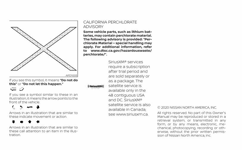
If you see this symbol, it means “Do not dothis” or “Do not let this happen.”
If you see a symbol similar to these in anillustration, it means the arrow points to thefront of the vehicle.
Arrows in an illustration that are similar tothese indicate movement or action.
Arrows in an illustration that are similar tothese call attention to an item in the illus-tration.
CALIFORNIA PERCHLORATEADVISORYSome vehicle parts, such as lithium bat-teries, may contain perchlorate material.The following advisory is provided: “Per-chlorate Material – special handling mayapply. For additional information, referto www.dtsc.ca.gov/hazardouswaste/perchlorate/”.
SiriusXM® servicesrequire a subscriptionafter trial period andare sold separately oras a package. Thesatellite service isavailable only in the48 contiguous USAand DC. SiriusXM®satellite service is alsoavailable in Canada;see www.siriusxm.ca.
© 2020 NISSAN NORTH AMERICA, INC.All rights reserved. No part of this Owner'sManual may be reproduced or stored in aretrieval system, or transmitted in anyform, or by any means, electronic, me-chanical, photocopying, recording or oth-erwise, without the prior written permis-sion of Nissan North America, Inc.
APD1005

NISSAN CARES . . .Both NISSAN and your NISSAN dealer are dedicated to serving all your automotive needs. Your satisfaction with your vehicle and yourNISSAN dealer are our primary concerns. Your NISSAN dealer is always available to assist you with all your automobile sales and serviceneeds.However, if there is something that yourNISSAN dealer cannot assist you with oryou would like to provide NISSAN directlywith comments or questions, please con-tact the NISSAN Consumer Affairs Depart-ment using our toll-free number:For U.S. customers
1-800-NISSAN-1(1-800-647-7261)
For Canadian customers1-800-387-0122
The Consumer Affairs Department will askfor the following information:– Your name, address, and telephone
number– Vehicle identification number (attached
to the top of the instrument panel on thedriver's side)
– Date of purchase– Current odometer reading– Your NISSAN dealer's name– Your comments or questionsOR
You can write to NISSAN with the informa-tion at:For U.S. customers
Nissan North America, Inc.Consumer Affairs DepartmentP.O. Box 685003Franklin, TN 37068-5003or via e-mail at:[email protected]
For Canadian customersNissan Canada Inc.5290 Orbitor DriveMississauga, Ontario L4W 4Z5or via e-mail at:[email protected]
If you prefer, visit us at:www.nissanusa.com (for U.S. customers)orwww.nissan.ca (for Canadian customers)
We appreciate your interest in NISSAN and thank you for buying a quality NISSAN vehicle.
NISSAN CUSTOMER CARE PROGRAM
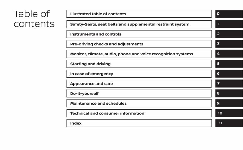
Table ofcontents
Illustrated table of contents
Safety-Seats, seat belts and supplemental restraint system
Instruments and controls
Pre-driving checks and adjustments
Monitor, climate, audio, phone and voice recognition systems
Starting and driving
In case of emergency
Appearance and care
Do-it-yourself
Maintenance and schedules
Technical and consumer information
Index
0
1
2
3
4
5
6
7
8
9
10
11

0 Illustrated table of contents
Air bags, seat belts and child restraints . . . . . . . . . . 0-2Exterior front . . . . . . . . . . . . . . . . . . . . . . . . . . . . . . . . . . . . 0-3Exterior rear . . . . . . . . . . . . . . . . . . . . . . . . . . . . . . . . . . . . . 0-4Passenger compartment . . . . . . . . . . . . . . . . . . . . . . . 0-5
Instrument panel . . . . . . . . . . . . . . . . . . . . . . . . . . . . . . . . 0-6Engine compartment check locations . . . . . . . . . . . 0-8Warning/Indicator lights . . . . . . . . . . . . . . . . . . . . . . . . 0-10
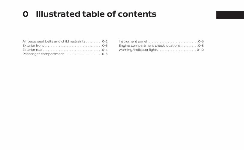
1. Top tether strap anchor (P. 1-23)2. Rear seat belts with pretensioner(s) for
outboard seating (P. 1-12)
3. Roof-mounted curtain side-impact androllover supplemental air bag (P. 1-46)
4. Front seat-mounted side-impactsupplemental air bag (P. 1-46)
5. Head restraints/headrests (P. 1-7)6. Front seat belt with pretensioner(s) and
shoulder height adjuster (P. 1-12, 1-46)7. Side-impact pressure sensor (driver's
side shown; passenger's side similar)(P. 1-46)
8. Supplemental air bags (P. 1-46)9. Front seats (P. 1-2)10. Occupant classification sensor (weight
sensor) (P. 1-46)11. Rear seats (P. 1-2)12. LATCH (Lower Anchors and Tethers for
CHildren) system (P. 1-23)13. Rear outboard seat-mounted side
impact supplemental air bag (P. 1-46)Refer to the page number indicated inparentheses for operating details.
LII2583
AIR BAGS, SEAT BELTS AND CHILDRESTRAINTS
0-2 Illustrated table of contents
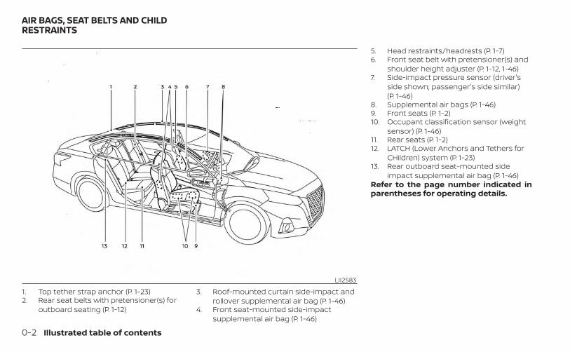
1. Power windows (P. 2-71)2. Windshield (P. 8-19)3. Wiper and washer switch (P. 2-54)4. Engine hood (P. 3-22)
5. Front view camera (if so equipped)(P. 4-16)
6. Fog light switch (if so equipped) (P. 2-55)Turn signal switch (P. 2-55)
7. Headlight switch (P. 2-55)LED Daytime Running Lights (DRL)system (if so equipped) (P. 2-55)Replacing bulbs (P. 8-25)
8. Tire pressure (P. 8-29)Flat tire (P. 6-3)Tire chains (P. 8-29)
9. Mirrors (P. 3-29)Side view camera (if so equipped)(P. 4-16)
10. Door locks (P. 3-4)NISSAN Intelligent Key® (P. 3-7)Keys (P. 3-2)
Refer to the page number indicated inparentheses for operating details.
LII2559
EXTERIOR FRONT
Illustrated table of contents 0-3
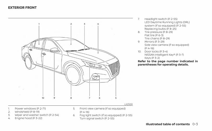
1. Rear window and outside mirror (if soequipped) defroster switch (P. 2-55)
2. Trunk lid (P. 3-22)
3. Sonar sensors (P. 5-151)4. Rearview camera (P. 4-8)5. Replacing bulbs (P. 8-25)
6. Fuel-filler cap (P. 3-25)Fuel recommendation (P. 10-2)Fuel-filler door (P. 3-25)
7. Child safety rear door lock (P. 3-4)Refer to the page number indicated inparentheses for operating details.
LIC4027
EXTERIOR REAR
0-4 Illustrated table of contents
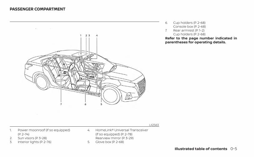
1. Power moonroof (if so equipped)(P. 2-74)
2. Sun visors (P. 3-28)3. Interior lights (P. 2-76)
4. HomeLink® Universal Transceiver(if so equipped) (P. 2-78)Rearview mirror (P. 3-29)
5. Glove box (P. 2-68)
6. Cup holders (P. 2-68)Console box (P. 2-68)
7. Rear armrest (P. 1-2)Cup holders (P. 2-68)
Refer to the page number indicated inparentheses for operating details.
LII2563
PASSENGER COMPARTMENT
Illustrated table of contents 0-5
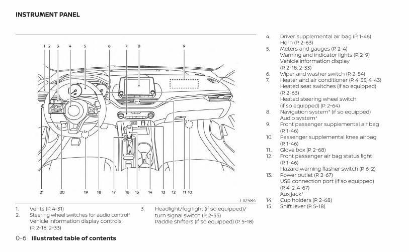
1. Vents (P. 4-31)2. Steering wheel switches for audio control*
Vehicle information display controls(P. 2-18, 2-33)
3. Headlight/fog light (if so equipped)/turn signal switch (P. 2-55)Paddle shifters (if so equipped) (P. 5-18)
4. Driver supplemental air bag (P. 1-46)Horn (P. 2-63)
5. Meters and gauges (P. 2-4)Warning and indicator lights (P. 2-9)Vehicle information display(P. 2-18, 2-33)
6. Wiper and washer switch (P. 2-54)7. Heater and air conditioner (P. 4-33, 4-43)
Heated seat switches (if so equipped)(P. 2-63)Heated steering wheel switch(if so equipped) (P. 2-64)
8. Navigation system* (if so equipped)Audio system*
9. Front passenger supplemental air bag(P. 1-46)
10. Passenger supplemental knee airbag(P. 1-46)
11.. Glove box (P. 2-68)12. Front passenger air bag status light
(P. 1-46)Hazard warning flasher switch (P. 6-2)
13. Power outlet (P. 2-67)USB connection port (if so equipped)(P. 4-2, 4-67)Aux jack*
14. Cup holders (P. 2-68)15 Shift lever (P. 5-18)
LII2584
INSTRUMENT PANEL
0-6 Illustrated table of contents
16. Electronic parking brake switch(if so equipped) (P. 5-24)Automatic brake hold switch(if so equipped) (P. 5-24)
17. Push-button ignition switch (P. 5-13)18. Cruise control switches (if so equipped)
(P. 5-68)Bluetooth® Hands-free Phone System*ProPILOT Assist Switch (if so equipped)(P. 2-65)
19. Driver supplemental knee airbag(P. 1-46)
20. Hood release (P. 3-22)Fuel-filler door release (P. 3-25)Tilt/telescopic steering wheel controls(P. 3-27)
21. Trip computer reset switch (P. 2-4)Instrument brightness control (P. 2-55)Steering assist switch (for vehicles withProPILOT Assist) (if so equipped)(P. 2-65)Trunk opener (P. 3-22)
*: For additional information, refer to theseparate NissanConnect® Owner's Manual.Refer to the page number indicated inparentheses for operating details.
Illustrated table of contents 0-7
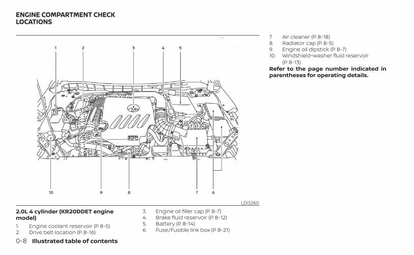
2.0L 4 cylinder (KR20DDET enginemodel)1. Engine coolant reservoir (P. 8-5)2. Drive belt location (P. 8-16)
3. Engine oil filler cap (P. 8-7)4. Brake fluid reservoir (P. 8-12)5. Battery (P. 8-14)6. Fuse/Fusible link box (P. 8-21)
7. Air cleaner (P. 8-18)8. Radiator cap (P. 8-5)9. Engine oil dipstick (P. 8-7)10. Windshield-washer fluid reservoir
(P. 8-13)Refer to the page number indicated inparentheses for operating details.
LDI3260
ENGINE COMPARTMENT CHECKLOCATIONS
0-8 Illustrated table of contents
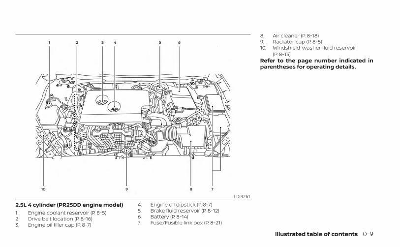
2.5L 4 cylinder (PR25DD engine model)1. Engine coolant reservoir (P. 8-5)2. Drive belt location (P. 8-16)3. Engine oil filler cap (P. 8-7)
4. Engine oil dipstick (P. 8-7)5. Brake fluid reservoir (P. 8-12)6. Battery (P. 8-14)7. Fuse/Fusible link box (P. 8-21)
8. Air cleaner (P. 8-18)9. Radiator cap (P. 8-5)10. Windshield-washer fluid reservoir
(P. 8-13)Refer to the page number indicated inparentheses for operating details.
LDI3261
Illustrated table of contents 0-9
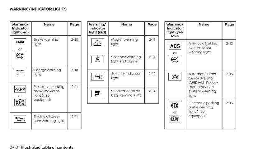
Warning/Indicatorlight (red)
Name Page
or
Brake warninglight
2-10
Charge warninglight
2-10
or
Electronic parkingbrake indicatorlight (if soequipped)
2-11
Engine oil pres-sure warning light
2-11
Warning/Indicatorlight (red)
Name Page
Master warninglight
2-11
Seat belt warninglight and chime
2-12
Security indicatorlight
2-12
Supplemental airbag warning light
2-12
Warning/Indicatorlight (yel-
low)
Name Page
or
Anti-lock BrakingSystem (ABS)warning light
2-12
Automatic Emer-gency Braking(AEB) with Pedes-trian Detectionsystem warninglight
2-13
or
Electronic parkingbrake warninglight (if soequipped)
2-13
WARNING/INDICATOR LIGHTS
0-10 Illustrated table of contents
Warning/Indicatorlight (yel-
low)
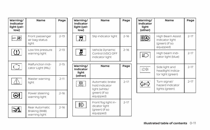
Name Page
Front passengerair bag statuslight
2-13
Low tire pressurewarning light
2-13
Malfunction Indi-cator Light (MIL)
2-15
Master warninglight
2-11
Power steeringwarning light
2-16
Rear AutomaticBraking (RAB)warning light
2-16
Warning/Indicatorlight (yel-
low)
Name Page
Slip indicator light 2-16
Vehicle DynamicControl (VDC) OFFindicator light
2-16
Warning/Indicator
light(other)
Name Page
Automatic brakehold indicatorlight (white/green) (if soequipped)
2-17
Front fog light in-dicator light(green) (if soequipped)
2-17
Warning/Indicator
light(other)
Name Page
High Beam Assistindicator light(green) (if soequipped)
2-17
High beam indi-cator light (blue)
2-17
Side light andheadlight indica-tor light (green)
2-17
Turn signal/hazard indicatorlights (green)
2-17
Illustrated table of contents 0-11

MEMO
0-12 Illustrated table of contents
1 Safety-Seats, seat belts andsupplemental restraint system
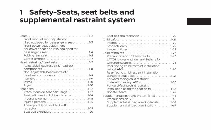
Seats . . . . . . . . . . . . . . . . . . . . . . . . . . . . . . . . . . . . . . . . . . . . 1-2Front manual seat adjustment(if so equipped for passenger’s seat) . . . . . . . . . .1-3Front power seat adjustment(for driver’s seat and if so equipped forpassenger’s seat) . . . . . . . . . . . . . . . . . . . . . . . . . . . . 1-4Folding rear seat . . . . . . . . . . . . . . . . . . . . . . . . . . . . . 1-5Center armrest . . . . . . . . . . . . . . . . . . . . . . . . . . . . . . . .1-7
Head restraints/headrests . . . . . . . . . . . . . . . . . . . . . . .1-7Adjustable head restraint/headrestcomponents . . . . . . . . . . . . . . . . . . . . . . . . . . . . . . . . . 1-8Non-adjustable head restraint/headrest components . . . . . . . . . . . . . . . . . . . . . . . 1-9Remove . . . . . . . . . . . . . . . . . . . . . . . . . . . . . . . . . . . . . . 1-9Install . . . . . . . . . . . . . . . . . . . . . . . . . . . . . . . . . . . . . . . .1-10Adjust . . . . . . . . . . . . . . . . . . . . . . . . . . . . . . . . . . . . . . . .1-10
Seat belts . . . . . . . . . . . . . . . . . . . . . . . . . . . . . . . . . . . . . . .1-12Precautions on seat belt usage. . . . . . . . . . . . . . .1-12Seat belt warning light and chime . . . . . . . . . . . .1-14Pregnant women . . . . . . . . . . . . . . . . . . . . . . . . . . . .1-15Injured persons . . . . . . . . . . . . . . . . . . . . . . . . . . . . . .1-15Three-point type seat belt withretractor . . . . . . . . . . . . . . . . . . . . . . . . . . . . . . . . . . . . .1-15Seat belt extenders . . . . . . . . . . . . . . . . . . . . . . . . . 1-20
Seat belt maintenance . . . . . . . . . . . . . . . . . . . . . . 1-20Child safety . . . . . . . . . . . . . . . . . . . . . . . . . . . . . . . . . . . . .1-21
Infants . . . . . . . . . . . . . . . . . . . . . . . . . . . . . . . . . . . . . . 1-22Small children . . . . . . . . . . . . . . . . . . . . . . . . . . . . . . . 1-22Larger children . . . . . . . . . . . . . . . . . . . . . . . . . . . . . . 1-22
Child restraints . . . . . . . . . . . . . . . . . . . . . . . . . . . . . . . . . 1-23Precautions on child restraints . . . . . . . . . . . . . . 1-23LATCH (Lower Anchors and Tethers forCHildren) system . . . . . . . . . . . . . . . . . . . . . . . . . . . . 1-25Rear-facing child restraint installationusing LATCH . . . . . . . . . . . . . . . . . . . . . . . . . . . . . . . . 1-28Rear-facing child restraint installationusing the seat belts . . . . . . . . . . . . . . . . . . . . . . . . . .1-31Forward-facing child restraintinstallation using LATCH . . . . . . . . . . . . . . . . . . . . . 1-33Forward-facing child restraintinstallation using the seat belts . . . . . . . . . . . . . 1-37Booster seats . . . . . . . . . . . . . . . . . . . . . . . . . . . . . . . 1-42
Supplemental Restraint System (SRS) . . . . . . . . . . 1-46Precautions on SRS . . . . . . . . . . . . . . . . . . . . . . . . . 1-46Supplemental air bag warning labels . . . . . . . . 1-67Supplemental air bag warning light . . . . . . . . . 1-67
WARNING
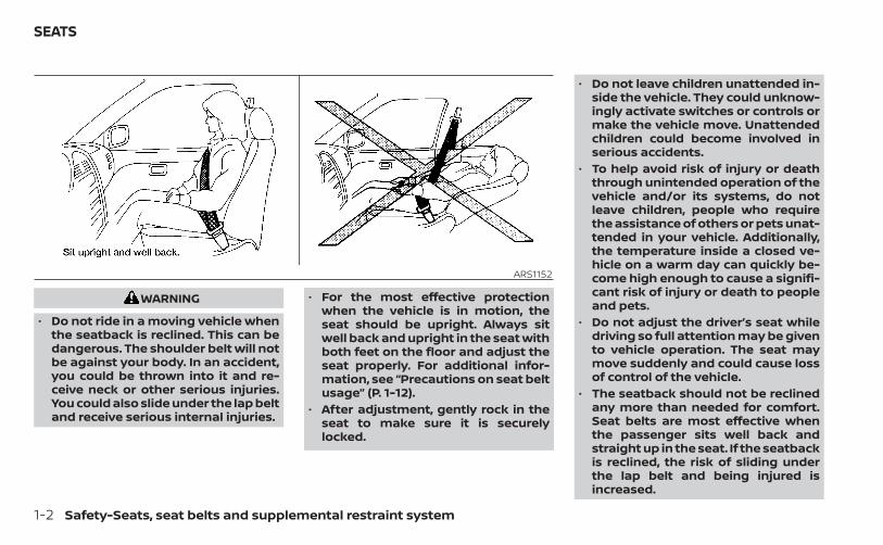
• Do not ride in a moving vehicle whenthe seatback is reclined. This can bedangerous. The shoulder belt will notbe against your body. In an accident,you could be thrown into it and re-ceive neck or other serious injuries.You could also slide under the lap beltand receive serious internal injuries.
• For the most effective protectionwhen the vehicle is in motion, theseat should be upright. Always sitwell back and upright in the seat withboth feet on the floor and adjust theseat properly. For additional infor-mation, see “Precautions on seat beltusage” (P. 1-12).
• After adjustment, gently rock in theseat to make sure it is securelylocked.
• Do not leave children unattended in-side the vehicle. They could unknow-ingly activate switches or controls ormake the vehicle move. Unattendedchildren could become involved inserious accidents.
• To help avoid risk of injury or deaththrough unintended operation of thevehicle and/or its systems, do notleave children, people who requirethe assistance of others or pets unat-tended in your vehicle. Additionally,the temperature inside a closed ve-hicle on a warm day can quickly be-come high enough to cause a signifi-cant risk of injury or death to peopleand pets.
• Do not adjust the driver’s seat whiledriving so full attention may be givento vehicle operation. The seat maymove suddenly and could cause lossof control of the vehicle.
• The seatback should not be reclinedany more than needed for comfort.Seat belts are most effective whenthe passenger sits well back andstraight up in the seat. If the seatbackis reclined, the risk of sliding underthe lap belt and being injured isincreased.
ARS1152
SEATS
1-2 Safety-Seats, seat belts and supplemental restraint system
CAUTION
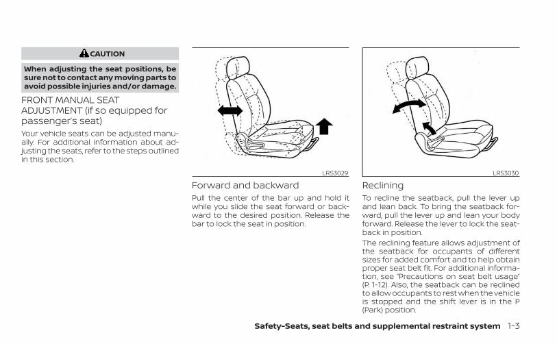
When adjusting the seat positions, besure not to contact any moving parts toavoid possible injuries and/or damage.
FRONT MANUAL SEATADJUSTMENT (if so equipped forpassenger’s seat)Your vehicle seats can be adjusted manu-ally. For additional information about ad-justing the seats, refer to the steps outlinedin this section.
Forward and backwardPull the center of the bar up and hold itwhile you slide the seat forward or back-ward to the desired position. Release thebar to lock the seat in position.
RecliningTo recline the seatback, pull the lever upand lean back. To bring the seatback for-ward, pull the lever up and lean your bodyforward. Release the lever to lock the seat-back in position.The reclining feature allows adjustment ofthe seatback for occupants of differentsizes for added comfort and to help obtainproper seat belt fit. For additional informa-tion, see “Precautions on seat belt usage”(P. 1-12). Also, the seatback can be reclinedto allow occupants to rest when the vehicleis stopped and the shift lever is in the P(Park) position.
LRS3029 LRS3030
Safety-Seats, seat belts and supplemental restraint system 1-3
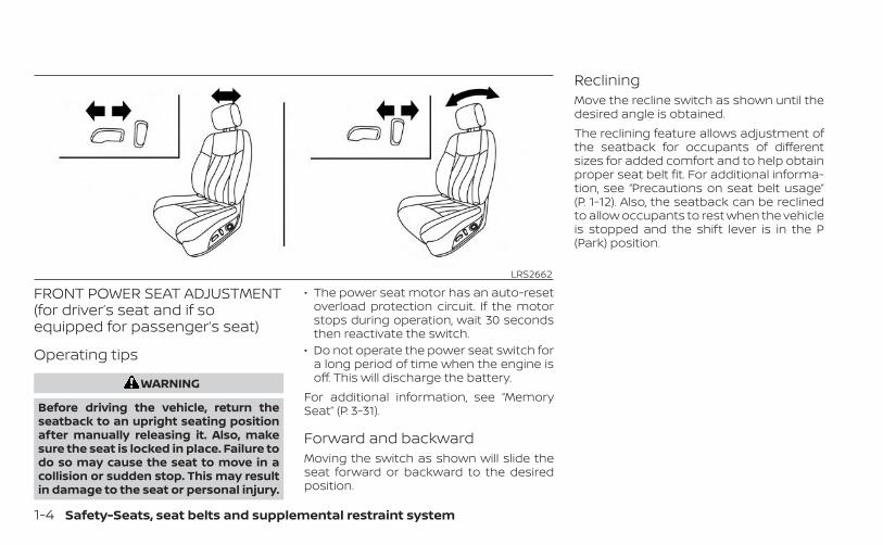
FRONT POWER SEAT ADJUSTMENT(for driver’s seat and if soequipped for passenger’s seat)
Operating tips
WARNING
Before driving the vehicle, return theseatback to an upright seating positionafter manually releasing it. Also, makesure the seat is locked in place. Failure todo so may cause the seat to move in acollision or sudden stop. This may resultin damage to the seat or personal injury.
• The power seat motor has an auto-resetoverload protection circuit. If the motorstops during operation, wait 30 secondsthen reactivate the switch.
• Do not operate the power seat switch fora long period of time when the engine isoff. This will discharge the battery.
For additional information, see “MemorySeat” (P. 3-31).
Forward and backwardMoving the switch as shown will slide theseat forward or backward to the desiredposition.
RecliningMove the recline switch as shown until thedesired angle is obtained.The reclining feature allows adjustment ofthe seatback for occupants of differentsizes for added comfort and to help obtainproper seat belt fit. For additional informa-tion, see “Precautions on seat belt usage”(P. 1-12). Also, the seatback can be reclinedto allow occupants to rest when the vehicleis stopped and the shift lever is in the P(Park) position.
LRS2662
1-4 Safety-Seats, seat belts and supplemental restraint system
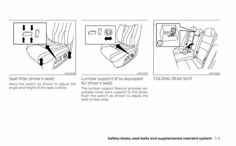
Seat lifter (driver’s seat)Move the switch as shown to adjust theangle and height of the seat cushion.
Lumbar support (if so equippedfor driver's seat)The lumbar support feature provides ad-justable lower back support to the driver.Push the switch as shown to adjust theseat lumbar area.
FOLDING REAR SEATLRS2636 LRS2270 LRS3286
\
Safety-Seats, seat belts and supplemental restraint system 1-5
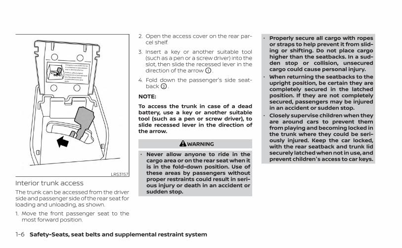
Interior trunk accessThe trunk can be accessed from the driverside and passenger side of the rear seat forloading and unloading, as shown.1. Move the front passenger seat to the
most forward position.
2. Open the access cover on the rear par-cel shelf.
3. Insert a key or another suitable tool(such as a pen or a screw driver) into theslot, then slide the recessed lever in thedirection of the arrow O1 .
4. Fold down the passenger's side seat-back O2 .
NOTE:
To access the trunk in case of a deadbattery, use a key or another suitabletool (such as a pen or screw driver), toslide recessed lever in the direction ofthe arrow.
WARNING
• Never allow anyone to ride in thecargo area or on the rear seat when itis in the fold-down position. Use ofthese areas by passengers withoutproper restraints could result in seri-ous injury or death in an accident orsudden stop.
• Properly secure all cargo with ropesor straps to help prevent it from slid-ing or shifting. Do not place cargohigher than the seatbacks. In a sud-den stop or collision, unsecuredcargo could cause personal injury.
• When returning the seatbacks to theupright position, be certain they arecompletely secured in the latchedposition. If they are not completelysecured, passengers may be injuredin an accident or sudden stop.
• Closely supervise children when theyare around cars to prevent themfrom playing and becoming locked inthe trunk where they could be seri-ously injured. Keep the car locked,with the rear seatback and trunk lidsecurely latched when not in use, andprevent children's access to car keys.
LRS3157
1-6 Safety-Seats, seat belts and supplemental restraint system
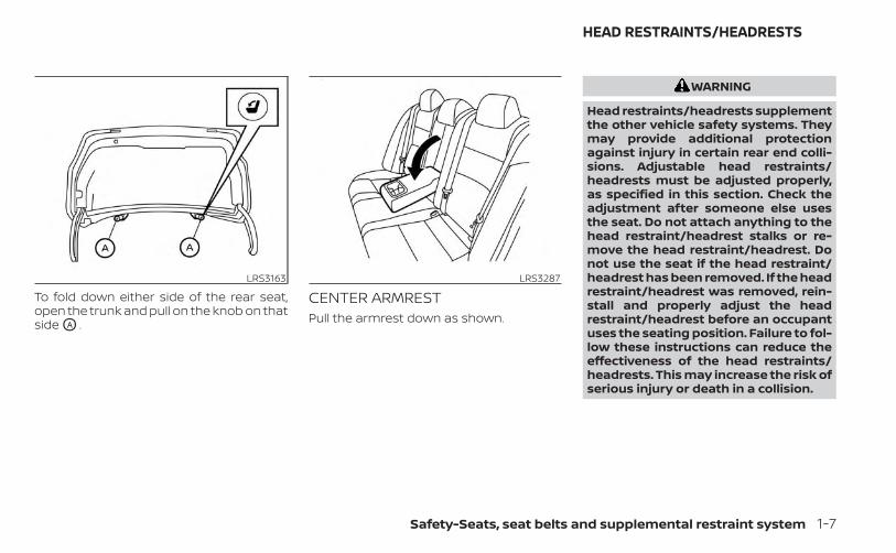
To fold down either side of the rear seat,open the trunk and pull on the knob on thatside OA .
CENTER ARMRESTPull the armrest down as shown.
WARNING
Head restraints/headrests supplementthe other vehicle safety systems. Theymay provide additional protectionagainst injury in certain rear end colli-sions. Adjustable head restraints/headrests must be adjusted properly,as specified in this section. Check theadjustment after someone else usesthe seat. Do not attach anything to thehead restraint/headrest stalks or re-move the head restraint/headrest. Donot use the seat if the head restraint/headrest has been removed. If the headrestraint/headrest was removed, rein-stall and properly adjust the headrestraint/headrest before an occupantuses the seating position. Failure to fol-low these instructions can reduce theeffectiveness of the head restraints/headrests. This may increase the risk ofserious injury or death in a collision.
LRS3163 LRS3287
HEAD RESTRAINTS/HEADRESTS
Safety-Seats, seat belts and supplemental restraint system 1-7
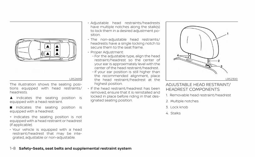
The illustration shows the seating posi-tions equipped with head restraints/headrests.� Indicates the seating position isequipped with a head restraint.� Indicates the seating position isequipped with a headrest.+ Indicates the seating position is notequipped with a head restraint or headrest(if applicable).• Your vehicle is equipped with a head
restraint/headrest that may be inte-grated, adjustable or non-adjustable.
• Adjustable head restraints/headrestshave multiple notches along the stalk(s)to lock them in a desired adjustment po-sition.
• The non-adjustable head restraints/headrests have a single locking notch tosecure them to the seat frame.
• Proper Adjustment:– For the adjustable type, align the head
restraint/headrest so the center ofyour ear is approximately level with thecenter of the head restraint/headrest.
– If your ear position is still higher thanthe recommended alignment, placethe head restraint/headrest at thehighest position.
• If the head restraint/headrest has beenremoved, ensure that it is reinstalled andlocked in place before riding in that des-ignated seating position.
ADJUSTABLE HEAD RESTRAINT/HEADREST COMPONENTS1. Removable head restraint/headrest
2. Multiple notches
3. Lock knob
4. Stalks
LRS2695 LRS2300
1-8 Safety-Seats, seat belts and supplemental restraint system
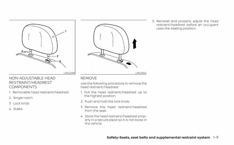
NON-ADJUSTABLE HEADRESTRAINT/HEADRESTCOMPONENTS1. Removable head restraint/headrest
2. Single notch
3. Lock knob
4. Stalks
REMOVEUse the following procedure to remove thehead restraint/headrest:1. Pull the head restraint/headrest up to
the highest position.
2. Push and hold the lock knob.
3. Remove the head restraint/headrestfrom the seat.
4. Store the head restraint/headrest prop-erly in a secure place so it is not loose inthe vehicle.
5. Reinstall and properly adjust the headrestraint/headrest before an occupantuses the seating position.
LRS2299 LRS2302
Safety-Seats, seat belts and supplemental restraint system 1-9
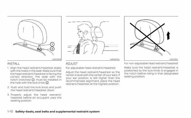
INSTALL1. Align the head restraint/headrest stalks
with the holes in the seat. Make sure thatthe head restraint/headrest is facing thecorrect direction. The stalk with thenotch (notches) O1 must be installed inthe hole with the lock knob O2 .
2. Push and hold the lock knob and pushthe head restraint/headrest down.
3. Properly adjust the head restraint/headrest before an occupant uses theseating position.
ADJUSTFor adjustable head restraint/headrestAdjust the head restraint/headrest so thecenter is level with the center of your ears. Ifyour ear position is still higher than therecommended alignment, place the headrestraint/headrest at the highest position.
For non-adjustable head restraint/headrestMake sure the head restraint/headrest ispositioned so the lock knob is engaged inthe notch before riding in that designatedseating position.
LRS2303 WRS0134 LRS2351
1-10 Safety-Seats, seat belts and supplemental restraint system
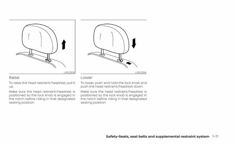
RaiseTo raise the head restraint/headrest, pull itup.Make sure the head restraint/headrest ispositioned so the lock knob is engaged inthe notch before riding in that designatedseating position.
LowerTo lower, push and hold the lock knob andpush the head restraint/headrest down.Make sure the head restraint/headrest ispositioned so the lock knob is engaged inthe notch before riding in that designatedseating position.
LRS2305 LRS2306
Safety-Seats, seat belts and supplemental restraint system 1-11
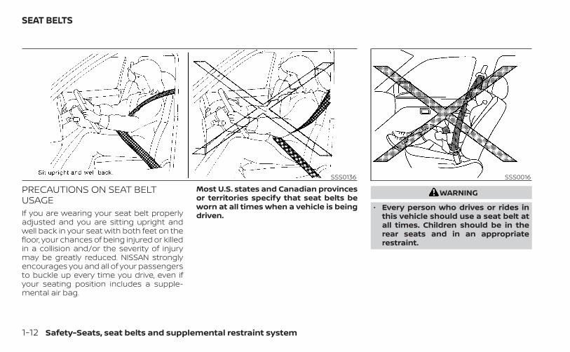
PRECAUTIONS ON SEAT BELTUSAGEIf you are wearing your seat belt properlyadjusted and you are sitting upright andwell back in your seat with both feet on thefloor, your chances of being injured or killedin a collision and/or the severity of injurymay be greatly reduced. NISSAN stronglyencourages you and all of your passengersto buckle up every time you drive, even ifyour seating position includes a supple-mental air bag.
Most U.S. states and Canadian provincesor territories specify that seat belts beworn at all times when a vehicle is beingdriven.
WARNING
• Every person who drives or rides inthis vehicle should use a seat belt atall times. Children should be in therear seats and in an appropriaterestraint.
SSS0136 SSS0016
SEAT BELTS
1-12 Safety-Seats, seat belts and supplemental restraint system
WARNING
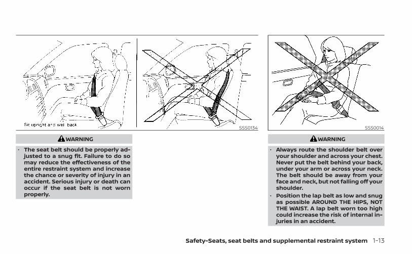
• The seat belt should be properly ad-justed to a snug fit. Failure to do somay reduce the effectiveness of theentire restraint system and increasethe chance or severity of injury in anaccident. Serious injury or death canoccur if the seat belt is not wornproperly.
WARNING
• Always route the shoulder belt overyour shoulder and across your chest.Never put the belt behind your back,under your arm or across your neck.The belt should be away from yourface and neck, but not falling off yourshoulder.
• Position the lap belt as low and snugas possible AROUND THE HIPS, NOTTHE WAIST. A lap belt worn too highcould increase the risk of internal in-juries in an accident.
SSS0134 SSS0014
Safety-Seats, seat belts and supplemental restraint system 1-13
• Be sure the seat belt tongue is se-curely fastened to the proper buckle.
• Do not wear the seat belt inside outor twisted. Doing so may reduce itseffectiveness.
• Do not allow more than one personto use the same seat belt.
• Never carry more people in the ve-hicle than there are seat belts.
• If the seat belt warning light glowscontinuously while the ignition isturned ON with all doors closed andall seat belts fastened, it may indi-cate a malfunction in the system.Have the system checked. It is rec-ommended that you visit a NISSANdealer for this service.
• No changes should be made to theseat belt system. For example, do notmodify the seat belt, add material, orinstall devices that may change theseat belt routing or tension. Doing somay affect the operation of the seatbelt system. Modifying or tamperingwith the seat belt system may resultin serious personal injury.
• Once seat belt pretensioner(s) haveactivated, they cannot be reused andmust be replaced together with theretractor. It is recommended that youvisit a NISSAN dealer for this service.
• All seat belt assemblies, including re-tractors and attaching hardware,should be inspected after any colli-sion. It is recommended that you visita NISSAN dealer for this service.NISSAN recommends that all seatbelt assemblies in use during a colli-sion be replaced unless the collisionwas minor and the belts show nodamage and continue to operateproperly. Seat belt assemblies not inuse during a collision should also beinspected and replaced if eitherdamage or improper operation isnoted.
• All child restraints and attaching hard-ware should be inspected after anycollision. Always follow the restraintmanufacturer's inspection instruc-tions and replacement recommenda-tions. The child restraints should be re-placed if they are damaged.
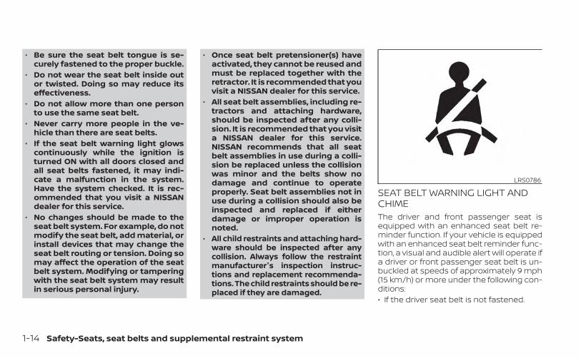
SEAT BELT WARNING LIGHT ANDCHIMEThe driver and front passenger seat isequipped with an enhanced seat belt re-minder function. If your vehicle is equippedwith an enhanced seat belt reminder func-tion, a visual and audible alert will operate ifa driver or front passenger seat belt is un-buckled at speeds of approximately 9 mph(15 km/h) or more under the following con-ditions:• If the driver seat belt is not fastened.
LRS0786
1-14 Safety-Seats, seat belts and supplemental restraint system
• The front passenger’s seat belt is not fas-tened and the seat is occupied by a pas-senger for 7 seconds after the ignitionswitch is placed in the ON position.
• The front passenger’s seat belt is not fas-tened and objects or external force onthe passenger seat change the seat beltreminder classification to Occupied.
The seat belt warning light will flash underthe conditions shown above until the nec-essary seat belt is securely fastened.A warning chime will sound for approxi-mately 90 seconds or until one of the fol-lowing conditions is met:• The unbuckled front occupant’s seat belt
is securely fastened.• The seat belt reminder function in the
front passenger seat no longer detectsthat the front passenger seat is occupied.
• The ignition is turned off or the vehicle isplaced in P (Park).
The below situations could result in theseat belt reminder light being illuminatedand the chime sounding, even with no oc-cupant present in the passenger seat:• Heavy objects placed on the seat.• Someone pushing or pulling on the front
passenger seat.
• An object placed under the front passen-ger seat.
• An object placed between the seat cush-ion and center console or between theseat cushion and the door.
• An object hanging on the seat or placedin the seatback pocket.
• A child restraint or other object pressingagainst the rear of the seatback.
PREGNANT WOMENNISSAN recommends that pregnantwomen use seat belts. The seat belt shouldbe worn snug and always position the lapbelt as low as possible around the hips, notthe waist. Place the shoulder belt over yourshoulder and across your chest. Never runthe lap/shoulder belt over your abdominalarea. Contact your doctor for specific rec-ommendations.
INJURED PERSONSNISSAN recommends that injured personsuse seat belts. Check with your doctor forspecific recommendations.
THREE-POINT TYPE SEAT BELTWITH RETRACTOR
WARNING
• Every person who drives or rides inthis vehicle should use a seat belt atall times. Children should be in therear seats and in an appropriaterestraint.
• Do not ride in a moving vehicle whenthe seatback is reclined. This can bedangerous. The shoulder belt will notbe against your body. In an accident,you could be thrown into it and re-ceive neck or other serious injuries.You could also slide under the lap beltand receive serious internal injuries.
• For the most effective protectionwhen the vehicle is in motion, theseat should be upright. Always sitwell back and upright in the seat withboth feet on the floor and adjust theseat belt properly.
Safety-Seats, seat belts and supplemental restraint system 1-15
• Do not allow children to play with theseat belts. Most seating positions areequipped with Automatic LockingRetractor (ALR) mode seat belts. Ifthe seat belt becomes wrappedaround a child’s neck with the ALRmode activated, the child can be se-riously injured or killed if the seat beltretracts and becomes tight. This canoccur even if the vehicle is parked.Unbuckle the seat belt to release thechild. If the seat belt cannot be un-buckled or is already unbuckled, re-lease the child by cutting the seatbelt with a suitable tool (such as aknife or scissors) to release the seatbelt.
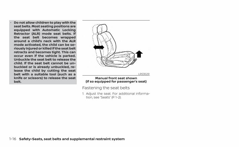
Fastening the seat belts1. Adjust the seat. For additional informa-
tion, see “Seats” (P. 1-2).
LRS3029Manual front seat shown
(if so equipped for passenger’s seat)
1-16 Safety-Seats, seat belts and supplemental restraint system
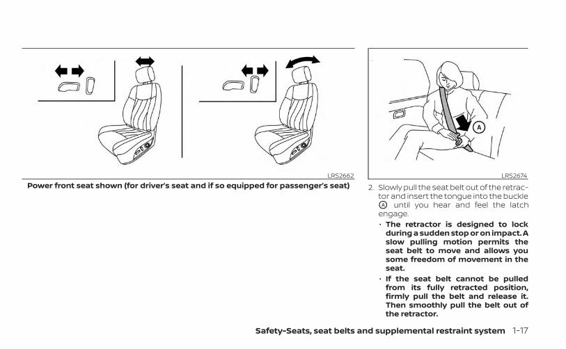
2. Slowly pull the seat belt out of the retrac-tor and insert the tongue into the buckleOA until you hear and feel the latchengage.• The retractor is designed to lock
during a sudden stop or on impact. Aslow pulling motion permits theseat belt to move and allows yousome freedom of movement in theseat.
• If the seat belt cannot be pulledfrom its fully retracted position,firmly pull the belt and release it.Then smoothly pull the belt out ofthe retractor.
LRS2662Power front seat shown (for driver’s seat and if so equipped for passenger’s seat)
LRS2674
Safety-Seats, seat belts and supplemental restraint system 1-17
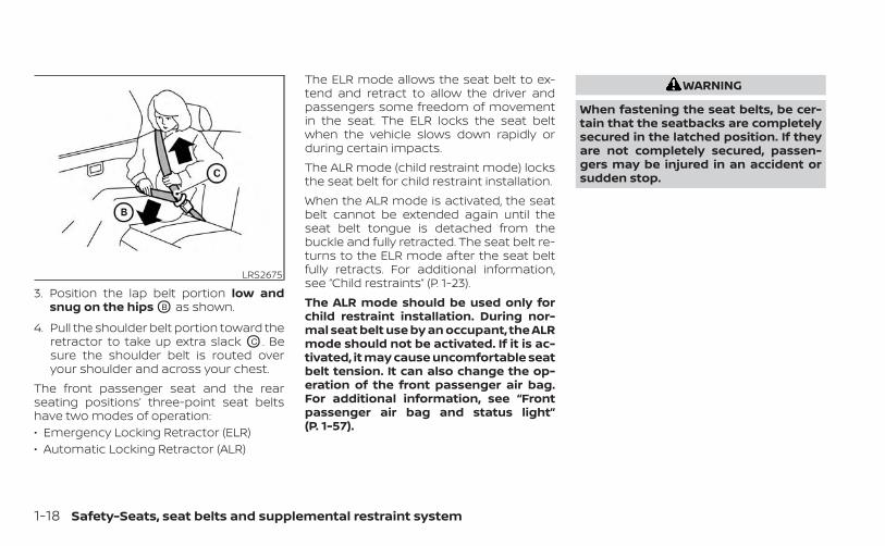
3. Position the lap belt portion low andsnug on the hips OB as shown.
4. Pull the shoulder belt portion toward theretractor to take up extra slack OC . Besure the shoulder belt is routed overyour shoulder and across your chest.
The front passenger seat and the rearseating positions’ three-point seat beltshave two modes of operation:• Emergency Locking Retractor (ELR)• Automatic Locking Retractor (ALR)
The ELR mode allows the seat belt to ex-tend and retract to allow the driver andpassengers some freedom of movementin the seat. The ELR locks the seat beltwhen the vehicle slows down rapidly orduring certain impacts.The ALR mode (child restraint mode) locksthe seat belt for child restraint installation.When the ALR mode is activated, the seatbelt cannot be extended again until theseat belt tongue is detached from thebuckle and fully retracted. The seat belt re-turns to the ELR mode after the seat beltfully retracts. For additional information,see “Child restraints” (P. 1-23).The ALR mode should be used only forchild restraint installation. During nor-mal seat belt use by an occupant, the ALRmode should not be activated. If it is ac-tivated, it may cause uncomfortable seatbelt tension. It can also change the op-eration of the front passenger air bag.For additional information, see “Frontpassenger air bag and status light”(P. 1-57).
WARNING
When fastening the seat belts, be cer-tain that the seatbacks are completelysecured in the latched position. If theyare not completely secured, passen-gers may be injured in an accident orsudden stop.
LRS2675
1-18 Safety-Seats, seat belts and supplemental restraint system
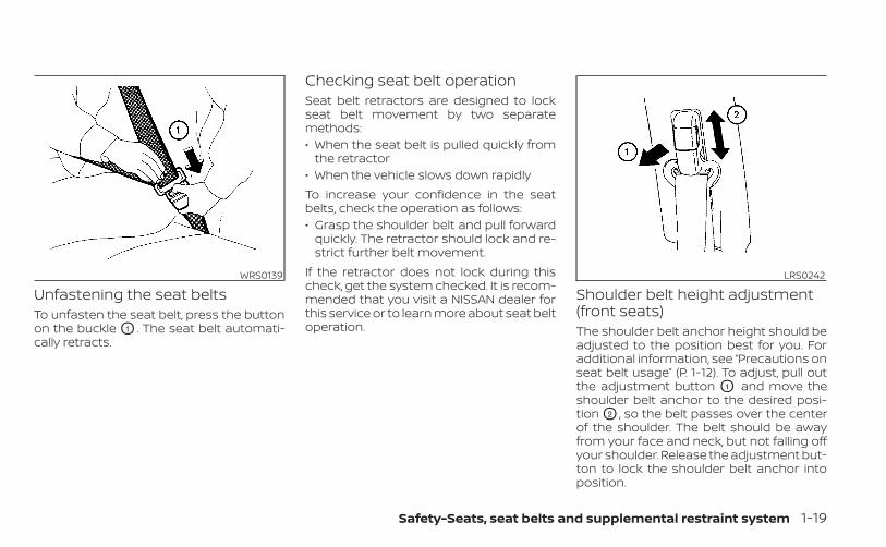
Unfastening the seat beltsTo unfasten the seat belt, press the buttonon the buckle O1 . The seat belt automati-cally retracts.
Checking seat belt operationSeat belt retractors are designed to lockseat belt movement by two separatemethods:• When the seat belt is pulled quickly from
the retractor• When the vehicle slows down rapidlyTo increase your confidence in the seatbelts, check the operation as follows:• Grasp the shoulder belt and pull forward
quickly. The retractor should lock and re-strict further belt movement.
If the retractor does not lock during thischeck, get the system checked. It is recom-mended that you visit a NISSAN dealer forthis service or to learn more about seat beltoperation.
Shoulder belt height adjustment(front seats)The shoulder belt anchor height should beadjusted to the position best for you. Foradditional information, see “Precautions onseat belt usage” (P. 1-12). To adjust, pull outthe adjustment button O1 and move theshoulder belt anchor to the desired posi-tion O2 , so the belt passes over the centerof the shoulder. The belt should be awayfrom your face and neck, but not falling offyour shoulder. Release the adjustment but-ton to lock the shoulder belt anchor intoposition.
WRS0139 LRS0242
Safety-Seats, seat belts and supplemental restraint system 1-19
WARNING
• After adjustment, release the adjust-ment button and try to move theshoulder belt anchor up and down tomake sure it is securely fixed inposition.
• The shoulder belt anchor heightshould be adjusted to the positionbest for you. Failure to do so may re-duce the effectiveness of the entirerestraint system and increase thechance or severity of injury in anaccident.
SEAT BELT EXTENDERSIf, because of body size or driving position, itis not possible to properly fit the lap/shoulder belt and fasten it, an extenderthat is compatible with the installed seatbelts is available for purchase. The ex-tender adds approximately 8 in (200 mm)of length and may be used for either thedriver or front passenger seating position.It is recommended that you visit a NISSANdealer for assistance with purchasing anextender if an extender is required.
WARNING
• Only NISSAN seat belt extenders,made by the same company whichmade the original equipment seatbelts, should be used with NISSANseat belts.
• Adults and children who can use thestandard seat belt should not use anextender. Such unnecessary usecould result in serious personal injuryin the event of an accident.
• Never use seat belt extenders to in-stall child restraints. If the child re-straint is not secured properly, thechild could be seriously injured orkilled in a collision or a sudden stop.
SEAT BELT MAINTENANCE• To clean the seat belt webbing, apply a
mild soap solution or any solution rec-ommended for cleaning upholstery orcarpet. Then wipe with a cloth and allowthe seat belts to dry in the shade. Do notallow the seat belts to retract until theyare completely dry.
• If dirt builds up in the shoulder beltguide of the seat belt anchors, the seatbelts may retract slowly. Wipe the shoul-der belt guide with a clean, dry cloth.
• Periodically check to see that the seatbelt and the metal components, suchas buckles, tongues, retractors, flexiblewires and anchors, work properly. If looseparts, deterioration, cuts or other dam-age on the webbing is found, the entireseat belt assembly should be replaced.
1-20 Safety-Seats, seat belts and supplemental restraint system
WARNING
Do not allow children to play with theseat belts. Most seating positions areequipped with Automatic Locking Re-tractor (ALR) mode seat belts. If the seatbelt becomes wrapped around a child’sneck with the ALR mode activated, thechild can be seriously injured or killed ifthe seat belt retracts and becomestight. This can occur even if the vehicleis parked. Unbuckle the seat belt to re-lease the child. If the seat belt cannotbe unbuckled or is already unbuckled,release the child by cutting the seatbelt with a suitable tool (such as a knifeor scissors) to release the seat belt.
Children need adults to help protectthem. They need to be properly re-strained.In addition to the general information inthis manual, child safety information isavailable from many other sources, includ-ing doctors, teachers, government trafficsafety offices, and community organiza-tions. Every child is different, so be sure tolearn the best way to transport your child.
There are three basic types of child re-straint systems:• Rear-facing child restraints• Forward-facing child restraints• Booster seatsThe proper restraint depends on the child'ssize. Generally, infants up to about 1 yearand less than 20 lbs. (9 kg) should be placedin rear-facing child restraints. Forward-facing child restraints are available for chil-dren who outgrow rear-facing child re-straints and are at least 1 year old. Boosterseats are used to help position a vehiclelap/shoulder belt on a child who can nolonger use a forward-facing child restraint.
WARNING
Infants and children need special pro-tection. The vehicle's seat belts maynot fit them properly. The shoulder beltmay come too close to the face or neck.The lap belt may not fit over their smallhip bones. In an accident, an improp-erly fitting seat belt could cause seriousor fatal injury. Always use appropriatechild restraints.
All U.S. states and Canadian provinces orterritories require the use of approved childrestraints for infants and small children.For additional information, see “Child re-straints” (P. 1-23).A child restraint may be secured in the ve-hicle by using either the LATCH (Lower An-chors and Tethers for CHildren) system orwith the vehicle seat belt. For additionalinformation, see “Child restraints” (P. 1-23).NISSAN recommends that all pre-teensand children be restrained in the rearseat. Studies show that children aresafer when properly restrained in therear seat than in the front seat.This is especially important becauseyour vehicle has a supplemental re-straint system (air bag system) for thefront passenger. For additional informa-tion, see “Supplemental Restraint Sys-tem (SRS)” (P. 1-46).
CHILD SAFETY
Safety-Seats, seat belts and supplemental restraint system 1-21
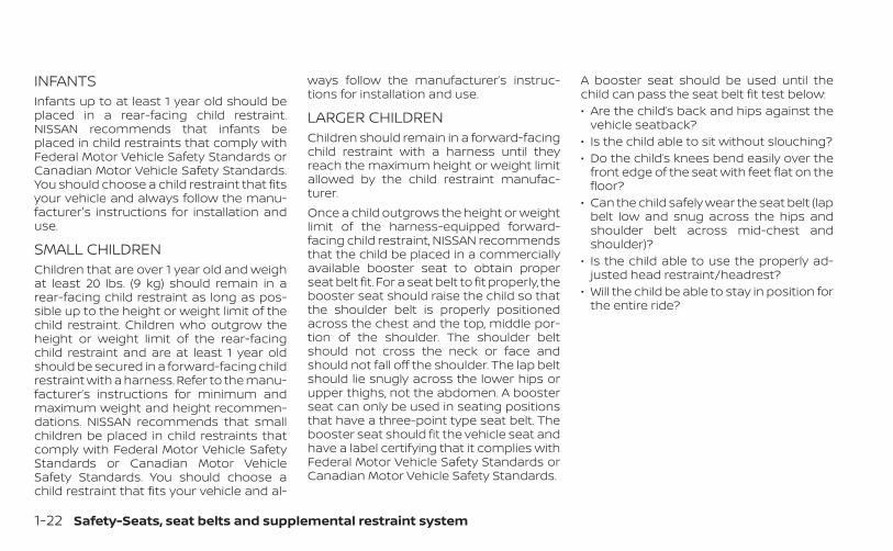
INFANTSInfants up to at least 1 year old should beplaced in a rear-facing child restraint.NISSAN recommends that infants beplaced in child restraints that comply withFederal Motor Vehicle Safety Standards orCanadian Motor Vehicle Safety Standards.You should choose a child restraint that fitsyour vehicle and always follow the manu-facturer's instructions for installation anduse.
SMALL CHILDRENChildren that are over 1 year old and weighat least 20 lbs. (9 kg) should remain in arear-facing child restraint as long as pos-sible up to the height or weight limit of thechild restraint. Children who outgrow theheight or weight limit of the rear-facingchild restraint and are at least 1 year oldshould be secured in a forward-facing childrestraint with a harness. Refer to the manu-facturer’s instructions for minimum andmaximum weight and height recommen-dations. NISSAN recommends that smallchildren be placed in child restraints thatcomply with Federal Motor Vehicle SafetyStandards or Canadian Motor VehicleSafety Standards. You should choose achild restraint that fits your vehicle and al-
ways follow the manufacturer’s instruc-tions for installation and use.
LARGER CHILDRENChildren should remain in a forward-facingchild restraint with a harness until theyreach the maximum height or weight limitallowed by the child restraint manufac-turer.Once a child outgrows the height or weightlimit of the harness-equipped forward-facing child restraint, NISSAN recommendsthat the child be placed in a commerciallyavailable booster seat to obtain properseat belt fit. For a seat belt to fit properly, thebooster seat should raise the child so thatthe shoulder belt is properly positionedacross the chest and the top, middle por-tion of the shoulder. The shoulder beltshould not cross the neck or face andshould not fall off the shoulder. The lap beltshould lie snugly across the lower hips orupper thighs, not the abdomen. A boosterseat can only be used in seating positionsthat have a three-point type seat belt. Thebooster seat should fit the vehicle seat andhave a label certifying that it complies withFederal Motor Vehicle Safety Standards orCanadian Motor Vehicle Safety Standards.
A booster seat should be used until thechild can pass the seat belt fit test below:• Are the child’s back and hips against the
vehicle seatback?• Is the child able to sit without slouching?• Do the child’s knees bend easily over the
front edge of the seat with feet flat on thefloor?
• Can the child safely wear the seat belt (lapbelt low and snug across the hips andshoulder belt across mid-chest andshoulder)?
• Is the child able to use the properly ad-justed head restraint/headrest?
• Will the child be able to stay in position forthe entire ride?
1-22 Safety-Seats, seat belts and supplemental restraint system
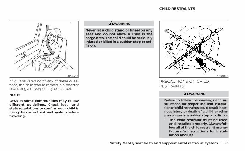
If you answered no to any of these ques-tions, the child should remain in a boosterseat using a three-point type seat belt.
NOTE:
Laws in some communities may followdifferent guidelines. Check local andstate regulations to confirm your child isusing the correct restraint system beforetraveling.
WARNING
Never let a child stand or kneel on anyseat and do not allow a child in thecargo area. The child could be seriouslyinjured or killed in a sudden stop or col-lision.
PRECAUTIONS ON CHILDRESTRAINTS
WARNING
• Failure to follow the warnings and in-structions for proper use and installa-tion of child restraints could result in se-rious injury or death of a child or otherpassengers in a sudden stop or collision:– The child restraint must be used
and installed properly. Always fol-low all of the child restraint manu-facturer's instructions for instal-lation and use.
LRS2690 ARS1098
CHILD RESTRAINTS
Safety-Seats, seat belts and supplemental restraint system 1-23
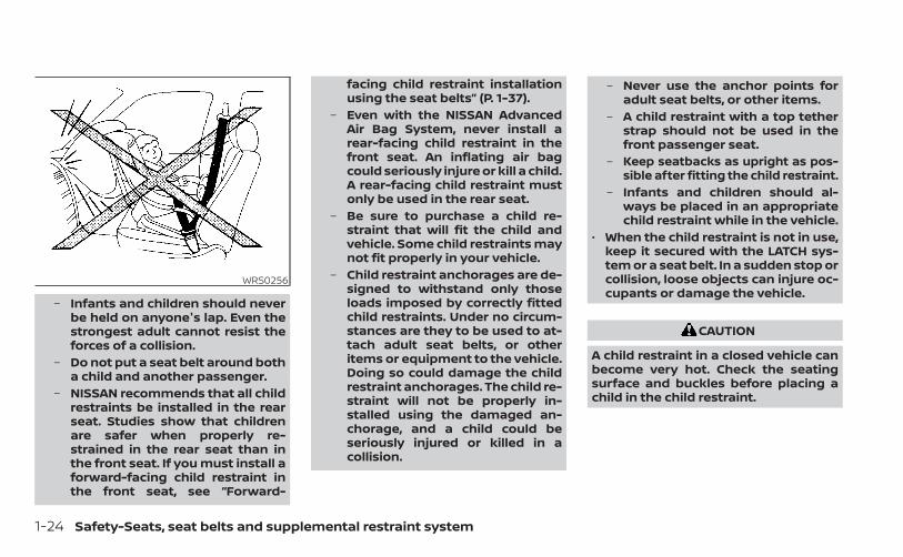
– Infants and children should neverbe held on anyone's lap. Even thestrongest adult cannot resist theforces of a collision.
– Do not put a seat belt around botha child and another passenger.
– NISSAN recommends that all childrestraints be installed in the rearseat. Studies show that childrenare safer when properly re-strained in the rear seat than inthe front seat. If you must install aforward-facing child restraint inthe front seat, see “Forward-
facing child restraint installationusing the seat belts” (P. 1-37).
– Even with the NISSAN AdvancedAir Bag System, never install arear-facing child restraint in thefront seat. An inflating air bagcould seriously injure or kill a child.A rear-facing child restraint mustonly be used in the rear seat.
– Be sure to purchase a child re-straint that will fit the child andvehicle. Some child restraints maynot fit properly in your vehicle.
– Child restraint anchorages are de-signed to withstand only thoseloads imposed by correctly fittedchild restraints. Under no circum-stances are they to be used to at-tach adult seat belts, or otheritems or equipment to the vehicle.Doing so could damage the childrestraint anchorages. The child re-straint will not be properly in-stalled using the damaged an-chorage, and a child could beseriously injured or killed in acollision.
– Never use the anchor points foradult seat belts, or other items.
– A child restraint with a top tetherstrap should not be used in thefront passenger seat.
– Keep seatbacks as upright as pos-sible after fitting the child restraint.
– Infants and children should al-ways be placed in an appropriatechild restraint while in the vehicle.
• When the child restraint is not in use,keep it secured with the LATCH sys-tem or a seat belt. In a sudden stop orcollision, loose objects can injure oc-cupants or damage the vehicle.
CAUTION
A child restraint in a closed vehicle canbecome very hot. Check the seatingsurface and buckles before placing achild in the child restraint.
WRS0256
1-24 Safety-Seats, seat belts and supplemental restraint system
This vehicle is equipped with a universalchild restraint anchor system, referred toas the LATCH (Lower Anchors and Tethersfor CHildren) system. Some child restraintsinclude rigid or webbing-mounted attach-ments that can be connected to these an-chors. For additional information, see“LATCH (Lower Anchors and Tethers forCHildren) system” (P. 1-25).If you do not have a LATCH compatiblechild restraint, the vehicle seat belts can beused.Several manufacturers offer child re-straints for infants and children of varioussizes. When selecting any child restraint,keep the following points in mind:• Choose only a restraint with a label certi-
fying that it complies with Federal MotorVehicle Safety Standard 213 or CanadianMotor Vehicle Safety Standard 213.
• Check the child restraint in your vehicle tobe sure it is compatible with the vehicle'sseat and seat belt system.
• If the child restraint is compatible withyour vehicle, place your child in the childrestraint and check the various adjust-ments to be sure the child restraint iscompatible with your child. Choose achild restraint that is designed for yourchild's height and weight. Always followall recommended procedures.
• If the combined weight of the child andchild restraint is less than 65 lbs. (29.5 kg),you may use either the LATCH anchors orthe seat belt to install the child restraint(not both at the same time).
• If the combined weight of the child andchild restraint is greater than 65 lbs. (29.5kg), use the vehicle’s seat belt (not thelower anchors) to install the child re-straint.
• Be sure to follow the child restraintmanufacturer’s instructions for installa-tion.
All U.S. states and Canadian provinces orterritories require that infants and smallchildren be restrained in an approvedchild restraint at all times while the ve-hicle is being operated. Canadian law re-quires the top tether strap on forward-facing child restraints be secured to thedesignated anchor point on the vehicle.
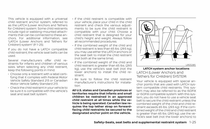
LATCH (Lower Anchors andTethers for CHildren) SYSTEMYour vehicle is equipped with special an-chor points that are used with LATCH sys-tem compatible child restraints. This sys-tem may also be referred to as the ISOFIXor ISOFIX compatible system. With this sys-tem, you do not have to use a vehicle seatbelt to secure the child restraint unless thecombined weight of the child and child re-straint exceeds 65 lbs. (29.5 kg). If the com-bined weight of the child and child restraintis greater than 65 lbs. (29.5 kg), use the ve-hicle’s seat belt (not the lower anchors) to
LRS3285LATCH system anchor locations
Safety-Seats, seat belts and supplemental restraint system 1-25
install the child restraint. Be sure to followthe child restraint manufacturer’s instruc-tions for installation.The LATCH anchor points are provided toinstall child restraints in the rear outboardseating positions only. Do not attempt toinstall a child restraint in the center positionusing the LATCH anchors.
LATCH lower anchor
WARNING
Failure to follow the warnings and in-structions for proper use and installa-tion of child restraints could result inserious injury or death of a child orother passengers in a sudden stop orcollision:– Attach LATCH system compatible
child restraints only at the locationsshown in the illustration.
– Do not secure a child restraint in thecenter rear seating position usingthe LATCH lower anchors. The childrestraint will not be securedproperly.
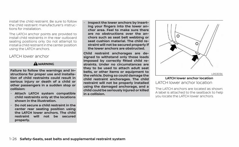
– Inspect the lower anchors by insert-ing your fingers into the lower an-chor area. Feel to make sure thereare no obstructions over the an-chors such as seat belt webbing orseat cushion material. The child re-straint will not be secured properly ifthe lower anchors are obstructed.
Child restraint anchorages are de-signed to withstand only those loadsimposed by correctly fitted child re-straints. Under no circumstances arethey to be used to attach adult seatbelts, or other items or equipment tothe vehicle. Doing so could damage thechild restraint anchorages. The childrestraint will not be properly installedusing the damaged anchorage, and achild could be seriously injured or killedin a collision.
LATCH lower anchor locationThe LATCH anchors are located as shown.A label is attached to the seatback to helpyou locate the LATCH lower anchors.
LRS3036LATCH lower anchor location
1-26 Safety-Seats, seat belts and supplemental restraint system
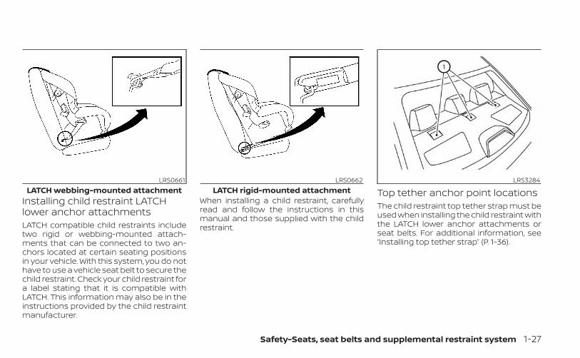
Installing child restraint LATCHlower anchor attachmentsLATCH compatible child restraints includetwo rigid or webbing-mounted attach-ments that can be connected to two an-chors located at certain seating positionsin your vehicle. With this system, you do nothave to use a vehicle seat belt to secure thechild restraint. Check your child restraint fora label stating that it is compatible withLATCH. This information may also be in theinstructions provided by the child restraintmanufacturer.
When installing a child restraint, carefullyread and follow the instructions in thismanual and those supplied with the childrestraint.
Top tether anchor point locationsThe child restraint top tether strap must beused when installing the child restraint withthe LATCH lower anchor attachments orseat belts. For additional information, see“Installing top tether strap” (P. 1-36).
LRS0661LATCH webbing-mounted attachment
LRS0662LATCH rigid-mounted attachment
LRS3284
Safety-Seats, seat belts and supplemental restraint system 1-27
WARNING
Child restraint anchorages are de-signed to withstand only those loadsimposed by correctly fitted child re-straints. Under no circumstances arethey to be used to attach adult seatbelts, or other items or equipment tothe vehicle. Doing so could damage thechild restraint anchorages. The childrestraint will not be properly installedusing the damaged anchorage, and achild could be seriously injured or killedin a collision.
If you have any questions when install-ing a top tether strap, it is recommendedthat you visit a NISSAN dealer for thisservice.Anchor points O1 are located on the rearparcel shelf.
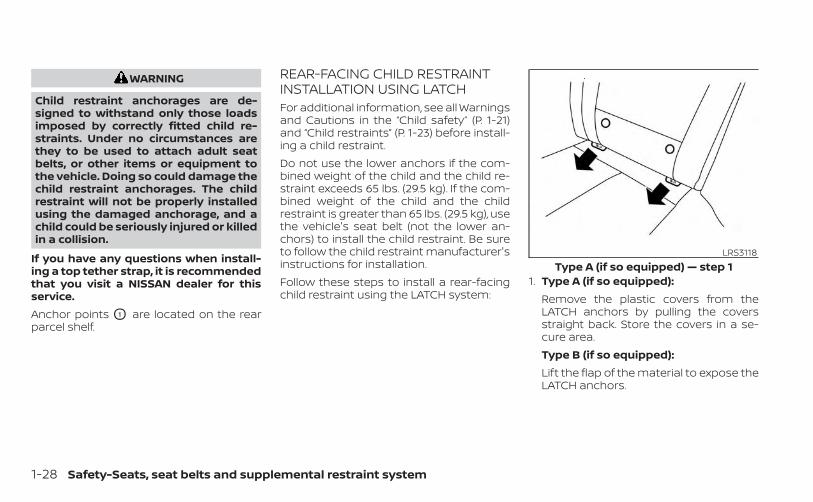
REAR-FACING CHILD RESTRAINTINSTALLATION USING LATCHFor additional information, see all Warningsand Cautions in the “Child safety” (P. 1-21)and “Child restraints” (P. 1-23) before install-ing a child restraint.Do not use the lower anchors if the com-bined weight of the child and the child re-straint exceeds 65 lbs. (29.5 kg). If the com-bined weight of the child and the childrestraint is greater than 65 lbs. (29.5 kg), usethe vehicle's seat belt (not the lower an-chors) to install the child restraint. Be sureto follow the child restraint manufacturer'sinstructions for installation.Follow these steps to install a rear-facingchild restraint using the LATCH system:
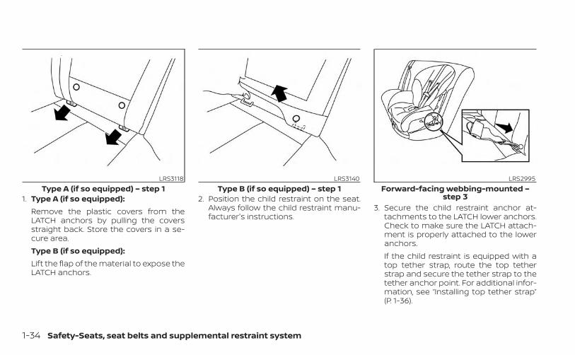
1. Type A (if so equipped):Remove the plastic covers from theLATCH anchors by pulling the coversstraight back. Store the covers in a se-cure area.Type B (if so equipped):Lift the flap of the material to expose theLATCH anchors.
LRS3118Type A (if so equipped) — step 1
1-28 Safety-Seats, seat belts and supplemental restraint system
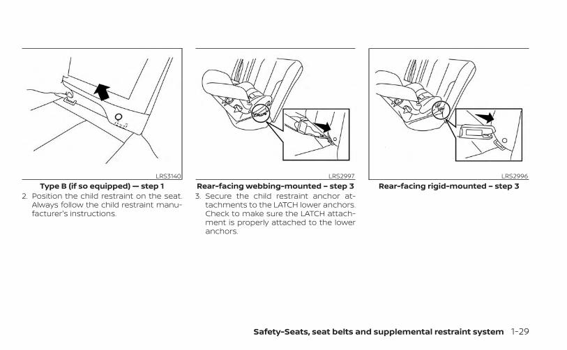
2. Position the child restraint on the seat.Always follow the child restraint manu-facturer's instructions.
3. Secure the child restraint anchor at-tachments to the LATCH lower anchors.Check to make sure the LATCH attach-ment is properly attached to the loweranchors.
LRS3140Type B (if so equipped) — step 1
LRS2997Rear-facing webbing-mounted – step 3
LRS2996Rear-facing rigid-mounted – step 3
Safety-Seats, seat belts and supplemental restraint system 1-29
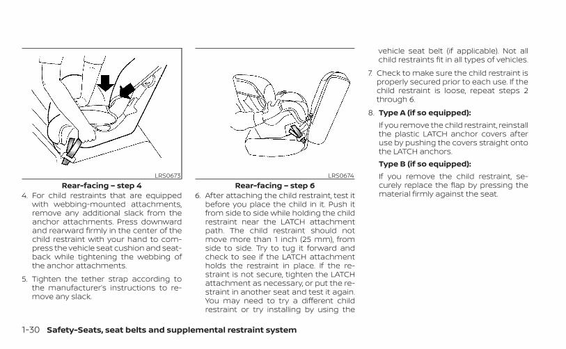
4. For child restraints that are equippedwith webbing-mounted attachments,remove any additional slack from theanchor attachments. Press downwardand rearward firmly in the center of thechild restraint with your hand to com-press the vehicle seat cushion and seat-back while tightening the webbing ofthe anchor attachments.
5. Tighten the tether strap according tothe manufacturer’s instructions to re-move any slack.
6. After attaching the child restraint, test itbefore you place the child in it. Push itfrom side to side while holding the childrestraint near the LATCH attachmentpath. The child restraint should notmove more than 1 inch (25 mm), fromside to side. Try to tug it forward andcheck to see if the LATCH attachmentholds the restraint in place. If the re-straint is not secure, tighten the LATCHattachment as necessary, or put the re-straint in another seat and test it again.You may need to try a different childrestraint or try installing by using the
vehicle seat belt (if applicable). Not allchild restraints fit in all types of vehicles.
7. Check to make sure the child restraint isproperly secured prior to each use. If thechild restraint is loose, repeat steps 2through 6.
8. Type A (if so equipped):If you remove the child restraint, reinstallthe plastic LATCH anchor covers afteruse by pushing the covers straight ontothe LATCH anchors.Type B (if so equipped):If you remove the child restraint, se-curely replace the flap by pressing thematerial firmly against the seat.
LRS0673Rear-facing – step 4
LRS0674Rear-facing – step 6
1-30 Safety-Seats, seat belts and supplemental restraint system
REAR-FACING CHILD RESTRAINTINSTALLATION USING THE SEATBELTS
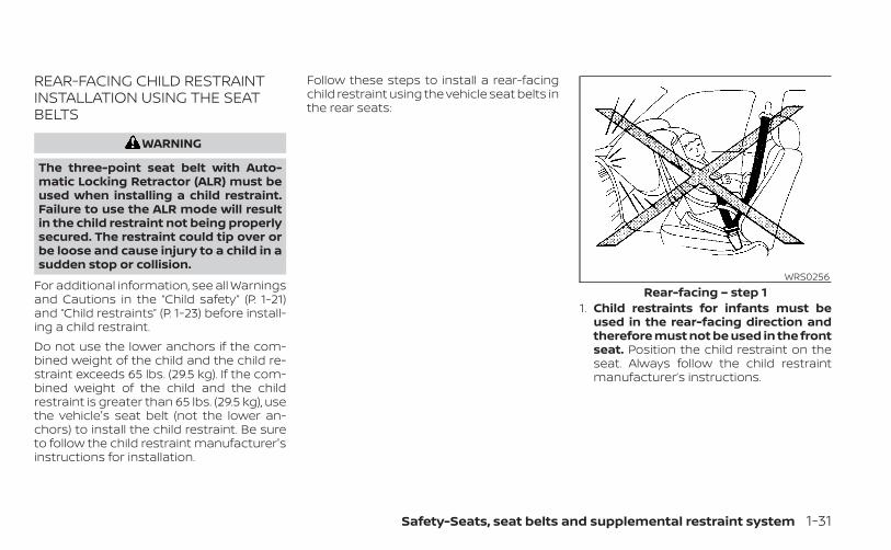
WARNING
The three-point seat belt with Auto-matic Locking Retractor (ALR) must beused when installing a child restraint.Failure to use the ALR mode will resultin the child restraint not being properlysecured. The restraint could tip over orbe loose and cause injury to a child in asudden stop or collision.
For additional information, see all Warningsand Cautions in the “Child safety” (P. 1-21)and “Child restraints” (P. 1-23) before install-ing a child restraint.Do not use the lower anchors if the com-bined weight of the child and the child re-straint exceeds 65 lbs. (29.5 kg). If the com-bined weight of the child and the childrestraint is greater than 65 lbs. (29.5 kg), usethe vehicle's seat belt (not the lower an-chors) to install the child restraint. Be sureto follow the child restraint manufacturer'sinstructions for installation.
Follow these steps to install a rear-facingchild restraint using the vehicle seat belts inthe rear seats:
1. Child restraints for infants must beused in the rear-facing direction andtherefore must not be used in the frontseat. Position the child restraint on theseat. Always follow the child restraintmanufacturer’s instructions.
WRS0256Rear-facing – step 1
Safety-Seats, seat belts and supplemental restraint system 1-31
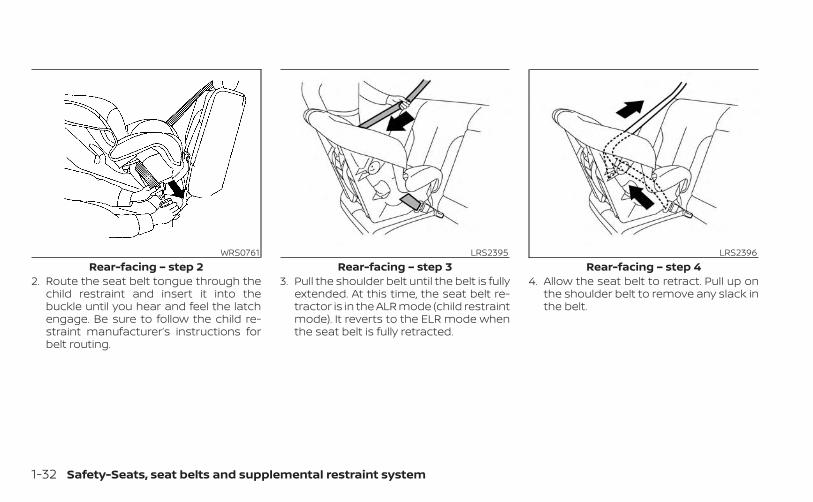
2. Route the seat belt tongue through thechild restraint and insert it into thebuckle until you hear and feel the latchengage. Be sure to follow the child re-straint manufacturer’s instructions forbelt routing.
3. Pull the shoulder belt until the belt is fullyextended. At this time, the seat belt re-tractor is in the ALR mode (child restraintmode). It reverts to the ELR mode whenthe seat belt is fully retracted.
4. Allow the seat belt to retract. Pull up onthe shoulder belt to remove any slack inthe belt.
WRS0761Rear-facing – step 2
LRS2395Rear-facing – step 3
LRS2396Rear-facing – step 4
1-32 Safety-Seats, seat belts and supplemental restraint system
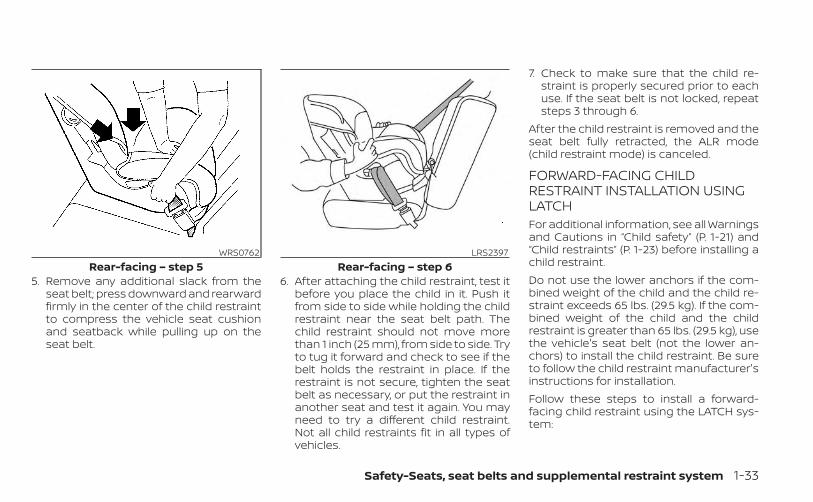
5. Remove any additional slack from theseat belt; press downward and rearwardfirmly in the center of the child restraintto compress the vehicle seat cushionand seatback while pulling up on theseat belt.
6. After attaching the child restraint, test itbefore you place the child in it. Push itfrom side to side while holding the childrestraint near the seat belt path. Thechild restraint should not move morethan 1 inch (25 mm), from side to side. Tryto tug it forward and check to see if thebelt holds the restraint in place. If therestraint is not secure, tighten the seatbelt as necessary, or put the restraint inanother seat and test it again. You mayneed to try a different child restraint.Not all child restraints fit in all types ofvehicles.
7. Check to make sure that the child re-straint is properly secured prior to eachuse. If the seat belt is not locked, repeatsteps 3 through 6.
After the child restraint is removed and theseat belt fully retracted, the ALR mode(child restraint mode) is canceled.
FORWARD-FACING CHILDRESTRAINT INSTALLATION USINGLATCHFor additional information, see all Warningsand Cautions in “Child safety” (P. 1-21) and“Child restraints” (P. 1-23) before installing achild restraint.Do not use the lower anchors if the com-bined weight of the child and the child re-straint exceeds 65 lbs. (29.5 kg). If the com-bined weight of the child and the childrestraint is greater than 65 lbs. (29.5 kg), usethe vehicle's seat belt (not the lower an-chors) to install the child restraint. Be sureto follow the child restraint manufacturer'sinstructions for installation.Follow these steps to install a forward-facing child restraint using the LATCH sys-tem:
WRS0762Rear-facing – step 5
LRS2397Rear-facing – step 6
Safety-Seats, seat belts and supplemental restraint system 1-33
1. Type A (if so equipped):Remove the plastic covers from theLATCH anchors by pulling the coversstraight back. Store the covers in a se-cure area.Type B (if so equipped):Lift the flap of the material to expose theLATCH anchors.
2. Position the child restraint on the seat.Always follow the child restraint manu-facturer's instructions.
3. Secure the child restraint anchor at-tachments to the LATCH lower anchors.Check to make sure the LATCH attach-ment is properly attached to the loweranchors.If the child restraint is equipped with atop tether strap, route the top tetherstrap and secure the tether strap to thetether anchor point. For additional infor-mation, see “Installing top tether strap”(P. 1-36).
LRS3118Type A (if so equipped) – step 1
LRS3140Type B (if so equipped) – step 1
LRS2995Forward-facing webbing-mounted –
step 3
1-34 Safety-Seats, seat belts and supplemental restraint system
Do not install child restraints that requirethe use of a top tether strap in seatingpositions that do not have a top tetheranchor.
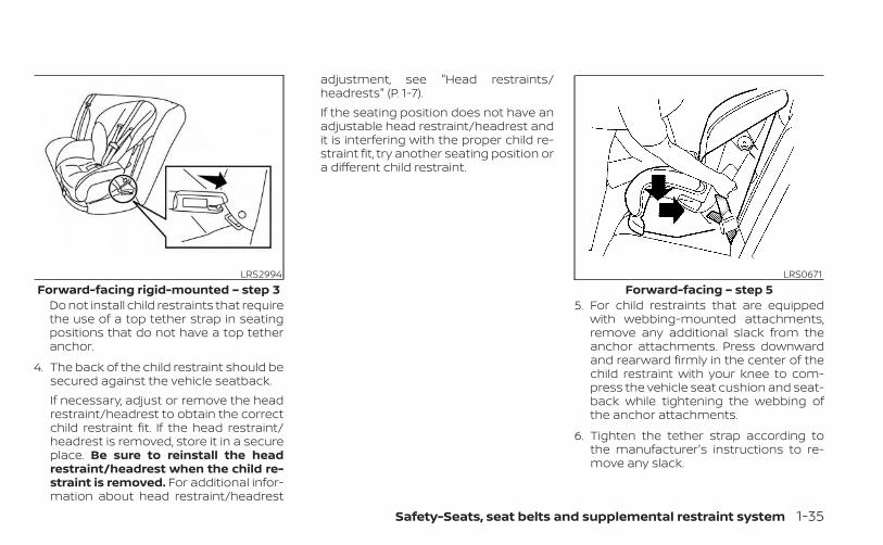
4. The back of the child restraint should besecured against the vehicle seatback.If necessary, adjust or remove the headrestraint/headrest to obtain the correctchild restraint fit. If the head restraint/headrest is removed, store it in a secureplace. Be sure to reinstall the headrestraint/headrest when the child re-straint is removed. For additional infor-mation about head restraint/headrest
adjustment, see "Head restraints/headrests" (P. 1-7).If the seating position does not have anadjustable head restraint/headrest andit is interfering with the proper child re-straint fit, try another seating position ora different child restraint.
5. For child restraints that are equippedwith webbing-mounted attachments,remove any additional slack from theanchor attachments. Press downwardand rearward firmly in the center of thechild restraint with your knee to com-press the vehicle seat cushion and seat-back while tightening the webbing ofthe anchor attachments.
6. Tighten the tether strap according tothe manufacturer's instructions to re-move any slack.
LRS2994Forward-facing rigid-mounted – step 3
LRS0671Forward-facing – step 5
Safety-Seats, seat belts and supplemental restraint system 1-35
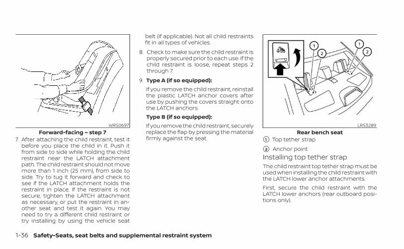
7. After attaching the child restraint, test itbefore you place the child in it. Push itfrom side to side while holding the childrestraint near the LATCH attachmentpath. The child restraint should not movemore than 1 inch (25 mm), from side toside. Try to tug it forward and check tosee if the LATCH attachment holds therestraint in place. If the restraint is notsecure, tighten the LATCH attachmentas necessary, or put the restraint in an-other seat and test it again. You mayneed to try a different child restraint ortry installing by using the vehicle seat
belt (if applicable). Not all child restraintsfit in all types of vehicles.
8. Check to make sure the child restraint isproperly secured prior to each use. If thechild restraint is loose, repeat steps 2through 7.
9. Type A (if so equipped):If you remove the child restraint, reinstallthe plastic LATCH anchor covers afteruse by pushing the covers straight ontothe LATCH anchors.Type B (if so equipped):If you remove the child restraint, securelyreplace the flap by pressing the materialfirmly against the seat.
Installing top tether strapThe child restraint top tether strap must beused when installing the child restraint withthe LATCH lower anchor attachments.First, secure the child restraint with theLATCH lower anchors (rear outboard posi-tions only).
WRS0697Forward-facing – step 7
LRS3289Rear bench seat
�1 Top tether strap
�2 Anchor point
1-36 Safety-Seats, seat belts and supplemental restraint system
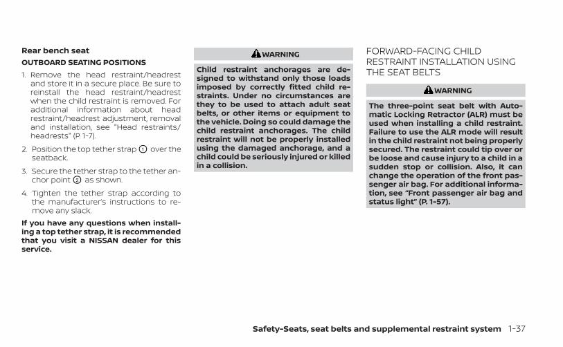
Rear bench seatOUTBOARD SEATING POSITIONS1. Remove the head restraint/headrest
and store it in a secure place. Be sure toreinstall the head restraint/headrestwhen the child restraint is removed. Foradditional information about headrestraint/headrest adjustment, removaland installation, see "Head restraints/headrests" (P. 1-7).
2. Position the top tether strap O1 over theseatback.
3. Secure the tether strap to the tether an-chor point O2 as shown.
4. Tighten the tether strap according tothe manufacturer’s instructions to re-move any slack.
If you have any questions when install-ing a top tether strap, it is recommendedthat you visit a NISSAN dealer for thisservice.
WARNING
Child restraint anchorages are de-signed to withstand only those loadsimposed by correctly fitted child re-straints. Under no circumstances arethey to be used to attach adult seatbelts, or other items or equipment tothe vehicle. Doing so could damage thechild restraint anchorages. The childrestraint will not be properly installedusing the damaged anchorage, and achild could be seriously injured or killedin a collision.
FORWARD-FACING CHILDRESTRAINT INSTALLATION USINGTHE SEAT BELTS
WARNING
The three-point seat belt with Auto-matic Locking Retractor (ALR) must beused when installing a child restraint.Failure to use the ALR mode will resultin the child restraint not being properlysecured. The restraint could tip over orbe loose and cause injury to a child in asudden stop or collision. Also, it canchange the operation of the front pas-senger air bag. For additional informa-tion, see “Front passenger air bag andstatus light” (P. 1-57).
Safety-Seats, seat belts and supplemental restraint system 1-37
For additional information, see all Warningsand Cautions in the “Child safety” (P. 1-21)and “Child restraints” (P. 1-23) before install-ing a child restraint.Do not use the lower anchors if the com-bined weight of the child and the child re-straint exceeds 65 lbs. (29.5 kg). If the com-bined weight of the child and the childrestraint is greater than 65 lbs. (29.5 kg), usethe vehicle's seat belt (not the lower an-chors) to install the child restraint. Be sureto follow the child restraint manufacturer'sinstructions for installation.
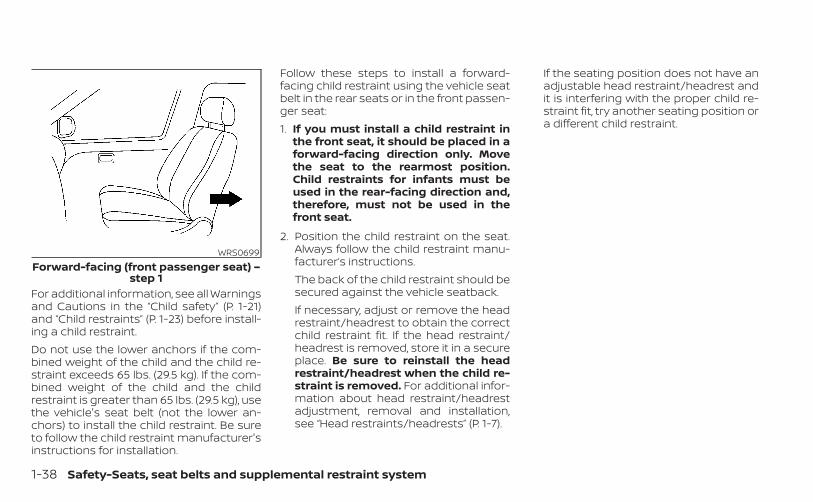
Follow these steps to install a forward-facing child restraint using the vehicle seatbelt in the rear seats or in the front passen-ger seat:1. If you must install a child restraint in
the front seat, it should be placed in aforward-facing direction only. Movethe seat to the rearmost position.Child restraints for infants must beused in the rear-facing direction and,therefore, must not be used in thefront seat.
2. Position the child restraint on the seat.Always follow the child restraint manu-facturer’s instructions.The back of the child restraint should besecured against the vehicle seatback.If necessary, adjust or remove the headrestraint/headrest to obtain the correctchild restraint fit. If the head restraint/headrest is removed, store it in a secureplace. Be sure to reinstall the headrestraint/headrest when the child re-straint is removed. For additional infor-mation about head restraint/headrestadjustment, removal and installation,see “Head restraints/headrests” (P. 1-7).
If the seating position does not have anadjustable head restraint/headrest andit is interfering with the proper child re-straint fit, try another seating position ora different child restraint.
WRS0699Forward-facing (front passenger seat) –
step 1
1-38 Safety-Seats, seat belts and supplemental restraint system
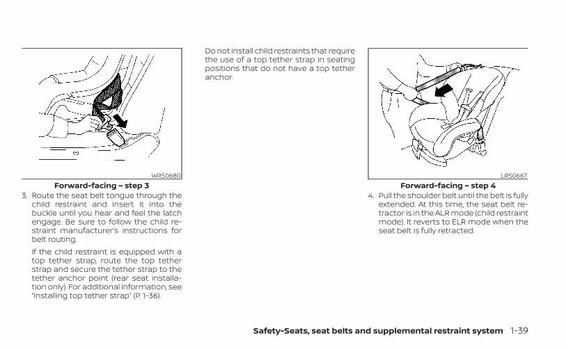
3. Route the seat belt tongue through thechild restraint and insert it into thebuckle until you hear and feel the latchengage. Be sure to follow the child re-straint manufacturer’s instructions forbelt routing.If the child restraint is equipped with atop tether strap, route the top tetherstrap and secure the tether strap to thetether anchor point (rear seat installa-tion only). For additional information, see“Installing top tether strap” (P. 1-36).
Do not install child restraints that requirethe use of a top tether strap in seatingpositions that do not have a top tetheranchor.
4. Pull the shoulder belt until the belt is fullyextended. At this time, the seat belt re-tractor is in the ALR mode (child restraintmode). It reverts to ELR mode when theseat belt is fully retracted.
WRS0680Forward-facing – step 3
LRS0667Forward-facing – step 4
Safety-Seats, seat belts and supplemental restraint system 1-39
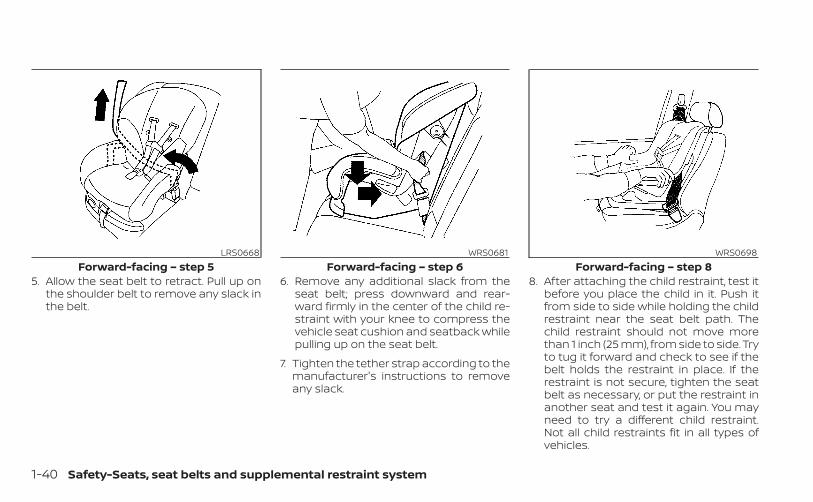
5. Allow the seat belt to retract. Pull up onthe shoulder belt to remove any slack inthe belt.
6. Remove any additional slack from theseat belt; press downward and rear-ward firmly in the center of the child re-straint with your knee to compress thevehicle seat cushion and seatback whilepulling up on the seat belt.
7. Tighten the tether strap according to themanufacturer's instructions to removeany slack.
8. After attaching the child restraint, test itbefore you place the child in it. Push itfrom side to side while holding the childrestraint near the seat belt path. Thechild restraint should not move morethan 1 inch (25 mm), from side to side. Tryto tug it forward and check to see if thebelt holds the restraint in place. If therestraint is not secure, tighten the seatbelt as necessary, or put the restraint inanother seat and test it again. You mayneed to try a different child restraint.Not all child restraints fit in all types ofvehicles.
LRS0668Forward-facing – step 5
WRS0681Forward-facing – step 6
WRS0698Forward-facing – step 8
1-40 Safety-Seats, seat belts and supplemental restraint system
9. Check to make sure the child restraint isproperly secured prior to each use. If theseat belt is not locked, repeat steps 4through 8.
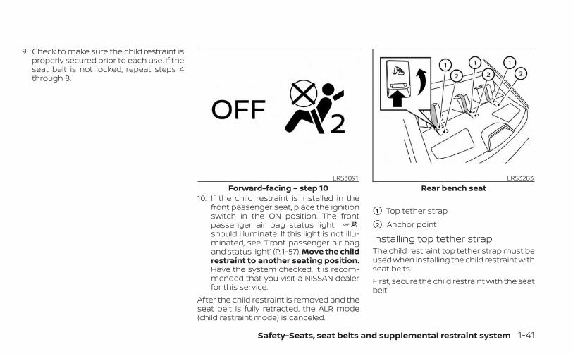
10. If the child restraint is installed in thefront passenger seat, place the ignitionswitch in the ON position. The frontpassenger air bag status lightshould illuminate. If this light is not illu-minated, see “Front passenger air bagand status light” (P. 1-57). Move the childrestraint to another seating position.Have the system checked. It is recom-mended that you visit a NISSAN dealerfor this service.
After the child restraint is removed and theseat belt is fully retracted, the ALR mode(child restraint mode) is canceled.
Installing top tether strapThe child restraint top tether strap must beused when installing the child restraint withseat belts.First, secure the child restraint with the seatbelt.
LRS3091Forward-facing – step 10
LRS3283Rear bench seat
�1 Top tether strap
�2 Anchor point
Safety-Seats, seat belts and supplemental restraint system 1-41
Rear bench seat1. Remove the head restraint/headrest
and store it in a secure place. Be sure toreinstall the head restraint/headrestwhen the child restraint is removed. Foradditional information about headrestraint/headrest adjustment, removaland installation, see "Head restraints/headrests" (P. 1-7).
2. Position the top tether strap O1 over theseatback.
3. Secure the tether strap to the tether an-chor point O2 as shown.
4. Tighten the tether strap according tothe manufacturer’s instructions to re-move any slack.
If you have any questions when install-ing a top tether strap, it is recommendedthat you visit a NISSAN dealer for thisservice.
WARNING
Child restraint anchorages are de-signed to withstand only those loadsimposed by correctly fitted child re-straints. Under no circumstances arethey to be used to attach adult seatbelts, or other items or equipment to
the vehicle. Doing so could damage thechild restraint anchorages. The childrestraint will not be properly installedusing the damaged anchorage, and achild could be seriously injured or killedin a collision.
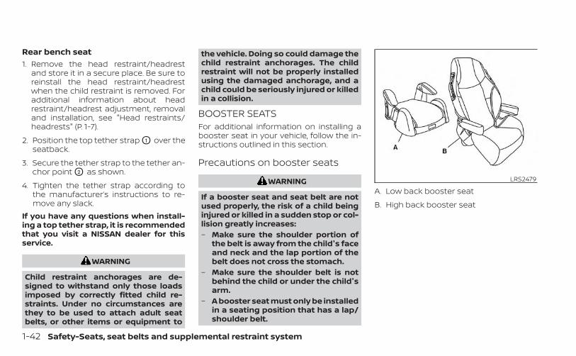
BOOSTER SEATSFor additional information on installing abooster seat in your vehicle, follow the in-structions outlined in this section.
Precautions on booster seats
WARNING
If a booster seat and seat belt are notused properly, the risk of a child beinginjured or killed in a sudden stop or col-lision greatly increases:– Make sure the shoulder portion of
the belt is away from the child's faceand neck and the lap portion of thebelt does not cross the stomach.
– Make sure the shoulder belt is notbehind the child or under the child'sarm.
– A booster seat must only be installedin a seating position that has a lap/shoulder belt.
LRS2479
A. Low back booster seat
B. High back booster seat
1-42 Safety-Seats, seat belts and supplemental restraint system
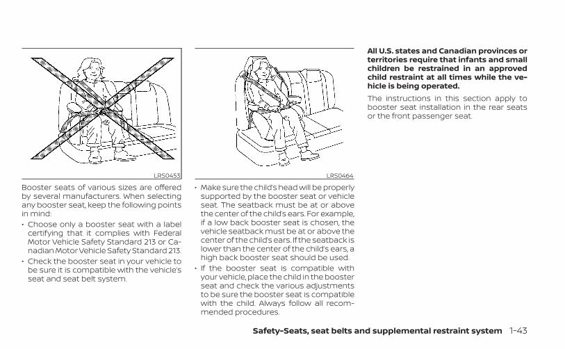
Booster seats of various sizes are offeredby several manufacturers. When selectingany booster seat, keep the following pointsin mind:• Choose only a booster seat with a label
certifying that it complies with FederalMotor Vehicle Safety Standard 213 or Ca-nadian Motor Vehicle Safety Standard 213.
• Check the booster seat in your vehicle tobe sure it is compatible with the vehicle’sseat and seat belt system.
• Make sure the child’s head will be properlysupported by the booster seat or vehicleseat. The seatback must be at or abovethe center of the child’s ears. For example,if a low back booster seat is chosen, thevehicle seatback must be at or above thecenter of the child’s ears. If the seatback islower than the center of the child’s ears, ahigh back booster seat should be used.
• If the booster seat is compatible withyour vehicle, place the child in the boosterseat and check the various adjustmentsto be sure the booster seat is compatiblewith the child. Always follow all recom-mended procedures.
All U.S. states and Canadian provinces orterritories require that infants and smallchildren be restrained in an approvedchild restraint at all times while the ve-hicle is being operated.The instructions in this section apply tobooster seat installation in the rear seatsor the front passenger seat.
LRS0453 LRS0464
Safety-Seats, seat belts and supplemental restraint system 1-43
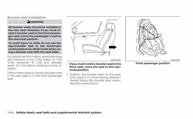
Booster seat installationWARNING
All booster seats should be installed inthe rear seat. However, if you must in-stall a booster seat in the front passen-ger seat, move the passenger's seat tothe rearmost position.To avoid injury to child, do not use thelap/shoulder belt in the AutomaticLocking Retractor (ALR) mode when us-ing a booster seat with the seat belts.
For additional information, see all Warningsand Cautions in the “Child safety” (P. 1-21),“Child restraints” (P. 1-23) and “Boosterseats” (P. 1-42) before installing a child re-straint.Follow these steps to install a booster seatin the rear seat or in the front passengerseat:
1. If you must install a booster seat in thefront seat, move the seat to the rear-most position.
2. Position the booster seat on the seat.Only place it in a front-facing direction.Always follow the booster seat manu-facturer’s instructions.
WRS0699 LRS0454Front passenger position
1-44 Safety-Seats, seat belts and supplemental restraint system
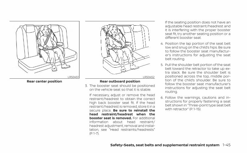
3. The booster seat should be positionedon the vehicle seat so that it is stable.If necessary, adjust or remove the headrestraint/headrest to obtain the correcthigh back booster seat fit. If the headrestraint/headrest is removed, store it in asecure place. Be sure to reinstall thehead restraint/headrest when thebooster seat is removed. For additionalinformation about head restraint/headrest adjustment, removal and instal-lation, see "Head restraints/headrests"(P. 1-7).
If the seating position does not have anadjustable head restraint/headrest andit is interfering with the proper boosterseat fit, try another seating position or adifferent booster seat.
4. Position the lap portion of the seat beltlow and snug on the child’s hips. Be sureto follow the booster seat manufactur-er’s instructions for adjusting the seatbelt routing.
5. Pull the shoulder belt portion of the seatbelt toward the retractor to take up ex-tra slack. Be sure the shoulder belt ispositioned across the top, middle por-tion of the child’s shoulder. Be sure tofollow the booster seat manufacturer’sinstructions for adjusting the seat beltrouting.
6. Follow the warnings, cautions and in-structions for properly fastening a seatbelt shown in “Three-point type seat beltwith retractor” (P. 1-15).
LRS0451Rear center position
LRS0452Rear outboard position
Safety-Seats, seat belts and supplemental restraint system 1-45
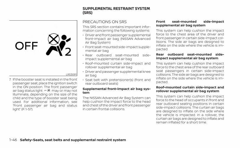
7. If the booster seat is installed in the frontpassenger seat, place the ignition switchin the ON position. The front passengerair bag status light may or may notilluminate, depending on the size of thechild and the type of booster seat beingused. For additional information, see“Front passenger air bag and statuslight” (P. 1-57).
PRECAUTIONS ON SRSThis SRS section contains important infor-mation concerning the following systems:• Driver and front passenger supplemental
front-impact air bag (NISSAN AdvancedAir Bag System)
• Front seat-mounted side-impact supple-mental air bag
• Rear outboard seat-mounted side-impact supplemental air bag
• Roof-mounted curtain side-impact androllover supplemental air bag
• Driver and passenger supplemental kneeair bag
• Seat belt with pretensioner(s) (front andrear outboard seats)
Supplemental front-impact air bag sys-temThe NISSAN Advanced Air Bag System canhelp cushion the impact force to the headand chest of the driver and front passengerin certain frontal collisions.
Front seat-mounted side-impactsupplemental air bag systemThis system can help cushion the impactforce to the chest area of the driver andfront passenger in certain side-impact col-lisions. The side air bags are designed toinflate on the side where the vehicle is im-pacted.Rear outboard seat-mounted side-impact supplemental air bag systemThis system can help cushion the impactforce to the chest area of the rear outboardseat passengers in certain side-impactcollisions. The side air bags are designed toinflate on the side where the vehicle is im-pacted.Roof-mounted curtain side-impact androllover supplemental air bag systemThis system can help cushion the impactforce to the head of occupants in front andrear outboard seating positions in certainside-impact collisions. The curtain air bagsare designed to inflate on the side wherethe vehicle is impacted. In a rollover, thecurtain air bags are designed to inflate andremain inflated for a short time.
LRS3091
SUPPLEMENTAL RESTRAINT SYSTEM(SRS)
1-46 Safety-Seats, seat belts and supplemental restraint system
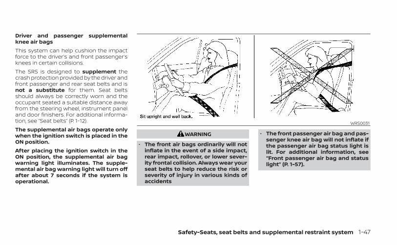
Driver and passenger supplementalknee air bagsThis system can help cushion the impactforce to the driver’s and front passenger’sknees in certain collisions.The SRS is designed to supplement thecrash protection provided by the driver andfront passenger and rear seat belts and isnot a substitute for them. Seat beltsshould always be correctly worn and theoccupant seated a suitable distance awayfrom the steering wheel, instrument paneland door finishers. For additional informa-tion, see “Seat belts” (P. 1-12).The supplemental air bags operate onlywhen the ignition switch is placed in theON position.After placing the ignition switch in theON position, the supplemental air bagwarning light illuminates. The supple-mental air bag warning light will turn offafter about 7 seconds if the system isoperational.
WARNING
• The front air bags ordinarily will notinflate in the event of a side impact,rear impact, rollover, or lower sever-ity frontal collision. Always wear yourseat belts to help reduce the risk orseverity of injury in various kinds ofaccidents
• The front passenger air bag and pas-senger knee air bag will not inflate ifthe passenger air bag status light islit. For additional information, see“Front passenger air bag and statuslight” (P. 1-57).
WRS0031
Safety-Seats, seat belts and supplemental restraint system 1-47
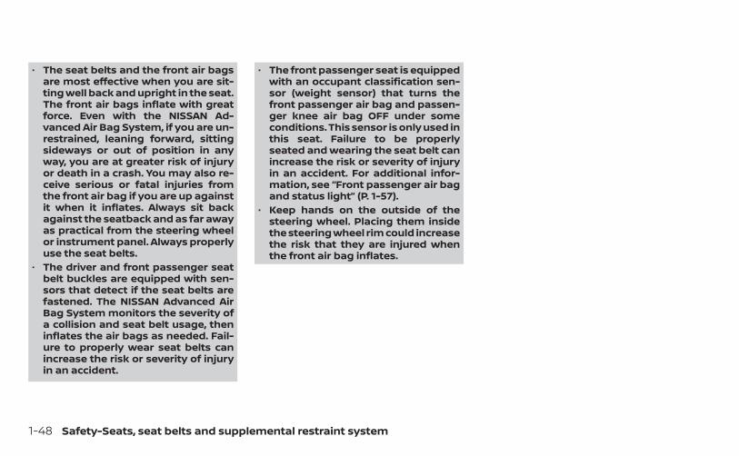
• The seat belts and the front air bagsare most effective when you are sit-ting well back and upright in the seat.The front air bags inflate with greatforce. Even with the NISSAN Ad-vanced Air Bag System, if you are un-restrained, leaning forward, sittingsideways or out of position in anyway, you are at greater risk of injuryor death in a crash. You may also re-ceive serious or fatal injuries fromthe front air bag if you are up againstit when it inflates. Always sit backagainst the seatback and as far awayas practical from the steering wheelor instrument panel. Always properlyuse the seat belts.
• The driver and front passenger seatbelt buckles are equipped with sen-sors that detect if the seat belts arefastened. The NISSAN Advanced AirBag System monitors the severity ofa collision and seat belt usage, theninflates the air bags as needed. Fail-ure to properly wear seat belts canincrease the risk or severity of injuryin an accident.
• The front passenger seat is equippedwith an occupant classification sen-sor (weight sensor) that turns thefront passenger air bag and passen-ger knee air bag OFF under someconditions. This sensor is only used inthis seat. Failure to be properlyseated and wearing the seat belt canincrease the risk or severity of injuryin an accident. For additional infor-mation, see “Front passenger air bagand status light” (P. 1-57).
• Keep hands on the outside of thesteering wheel. Placing them insidethe steering wheel rim could increasethe risk that they are injured whenthe front air bag inflates.
1-48 Safety-Seats, seat belts and supplemental restraint system
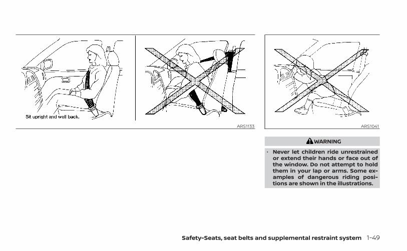
WARNING
• Never let children ride unrestrainedor extend their hands or face out ofthe window. Do not attempt to holdthem in your lap or arms. Some ex-amples of dangerous riding posi-tions are shown in the illustrations.
ARS1133 ARS1041
Safety-Seats, seat belts and supplemental restraint system 1-49
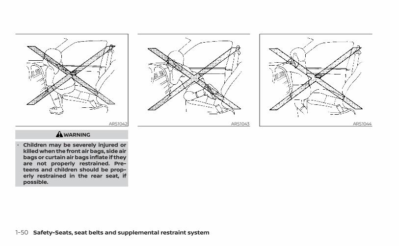
WARNING
• Children may be severely injured orkilled when the front air bags, side airbags or curtain air bags inflate if theyare not properly restrained. Pre-teens and children should be prop-erly restrained in the rear seat, ifpossible.
ARS1042 ARS1043 ARS1044
1-50 Safety-Seats, seat belts and supplemental restraint system
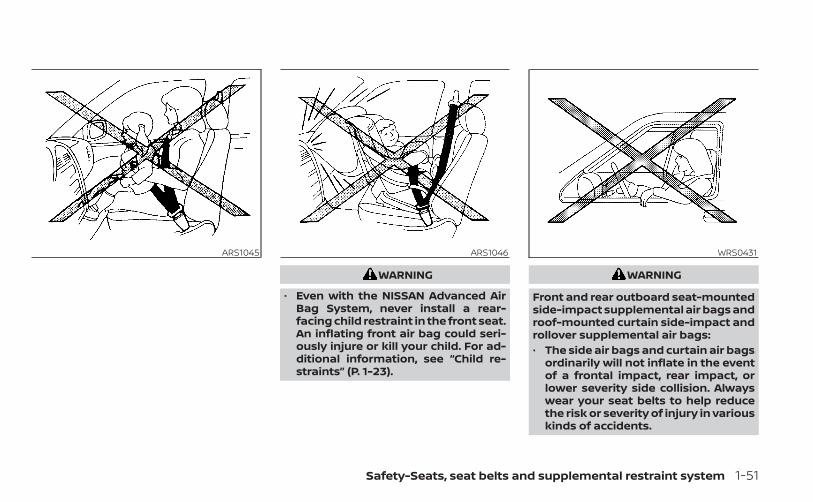
WARNING
• Even with the NISSAN Advanced AirBag System, never install a rear-facing child restraint in the front seat.An inflating front air bag could seri-ously injure or kill your child. For ad-ditional information, see “Child re-straints” (P. 1-23).
WARNING
Front and rear outboard seat-mountedside-impact supplemental air bags androof-mounted curtain side-impact androllover supplemental air bags:• The side air bags and curtain air bags
ordinarily will not inflate in the eventof a frontal impact, rear impact, orlower severity side collision. Alwayswear your seat belts to help reducethe risk or severity of injury in variouskinds of accidents.
ARS1045 ARS1046 WRS0431
Safety-Seats, seat belts and supplemental restraint system 1-51
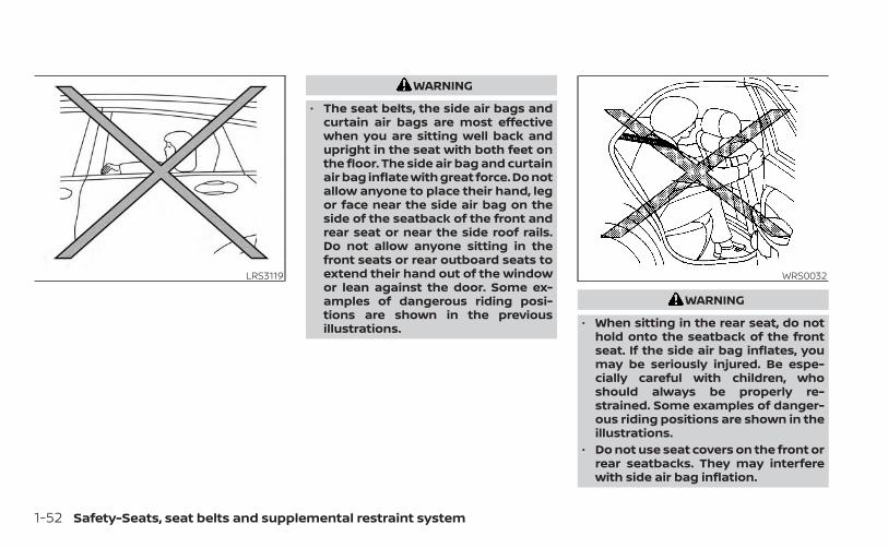
WARNING
• The seat belts, the side air bags andcurtain air bags are most effectivewhen you are sitting well back andupright in the seat with both feet onthe floor. The side air bag and curtainair bag inflate with great force. Do notallow anyone to place their hand, legor face near the side air bag on theside of the seatback of the front andrear seat or near the side roof rails.Do not allow anyone sitting in thefront seats or rear outboard seats toextend their hand out of the windowor lean against the door. Some ex-amples of dangerous riding posi-tions are shown in the previousillustrations.
WARNING
• When sitting in the rear seat, do nothold onto the seatback of the frontseat. If the side air bag inflates, youmay be seriously injured. Be espe-cially careful with children, whoshould always be properly re-strained. Some examples of danger-ous riding positions are shown in theillustrations.
• Do not use seat covers on the front orrear seatbacks. They may interferewith side air bag inflation.
LRS3119 WRS0032
1-52 Safety-Seats, seat belts and supplemental restraint system
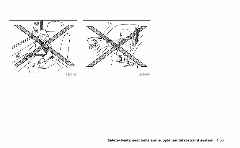
SSS0162 SSS0159
Safety-Seats, seat belts and supplemental restraint system 1-53
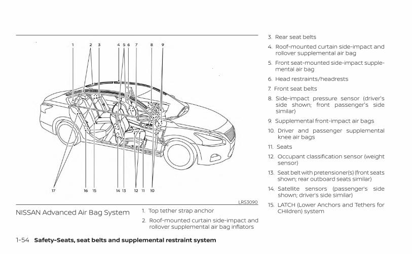
NISSAN Advanced Air Bag System 1. Top tether strap anchor
2. Roof-mounted curtain side-impact androllover supplemental air bag inflators
3. Rear seat belts
4. Roof-mounted curtain side-impact androllover supplemental air bag
5. Front seat-mounted side-impact supple-mental air bag
6. Head restraints/headrests
7. Front seat belts
8. Side-impact pressure sensor (driver'sside shown; front passenger's sidesimilar)
9. Supplemental front-impact air bags
10. Driver and passenger supplementalknee air bags
11. Seats
12. Occupant classification sensor (weightsensor)
13. Seat belt with pretensioner(s) (front seatsshown; rear outboard seats similar)
14. Satellite sensors (passenger’s sideshown; driver’s side similar)
15. LATCH (Lower Anchors and Tethers forCHildren) system
LRS3090
1-54 Safety-Seats, seat belts and supplemental restraint system
16. Satellite sensors (passenger’s sideshown; driver’s side similar)
17. Rear outboard seat-mounted side-impact supplemental air bags
WARNING
To ensure proper operation of the pas-senger’s NISSAN Advanced Air Bag Sys-tem, please observe the followingitems.• Do not allow a passenger in the rear
seat to push or pull on the seatbackpocket.
• Do not place heavy loads heavierthan 9.1 lbs. (4 kg) on the seatback,head restraint/headrest or in theseatback pocket.
• Make sure that there is nothingpressing against the rear of the seat-back, such as a child restraint in-stalled in the rear seat or an objectstored on the floor.
• Make sure that there is no objectplaced under the front passengerseat.
• Make sure that there is no objectplaced between the seat cushion andcenter console or between the seatcushion and the door.
• If a forward facing child restraint isinstalled in the front passenger seat,do not position the front passengerseat so the child restraint contactsthe instrument panel. If the child re-straint does contact the instrumentpanel, the system may determine theseat is occupied and the passengerair bag and passenger knee air bagmay deploy in a collision. Also thefront passenger air bag status lightmay not illuminate. For additional in-formation about installing and usingchild restraints, see "Child restraints"(P. 1-23).
• Confirm the operating condition withthe front passenger air bag statuslight.
• If you notice that the front passengerair bag status light is not operatingas described in this section, get theoccupant classification systemchecked. It is recommended that youvisit a NISSAN dealer for this service.
• Until you have confirmed with adealer that your passenger seat oc-cupant classification system is work-ing properly, position the occupantsin the rear seating positions.
• Do not position the front passengerseat so it contacts the rear seat. If thefront seat does contact the rear seat,the air bag system may determine asensor malfunction has occurredand the front passenger air bag sta-tus light may illuminate and thesupplemental air bag warning lightmay flash.
This vehicle is equipped with the NISSANAdvanced Air Bag System for the driver andfront passenger seats. This system is de-signed to meet certification requirementsunder U.S. regulations. It is also permitted inCanada. However, all of the information,cautions and warnings in this manualstill apply and must be followed.The driver supplemental front-impact airbag is located in the center of the steeringwheel. The front passenger supplementalfront-impact air bag is mounted in the dash-board above the glove box. The front air bagsare designed to inflate in higher severityfrontal collisions, although they may inflate ifthe forces in another type of collision aresimilar to those of a higher severity frontalimpact. They may not inflate in certain fron-tal collisions. Vehicle damage (or lack of it) isnot always an indication of proper front airbag system operation.
Safety-Seats, seat belts and supplemental restraint system 1-55
The NISSAN Advanced Air Bag Systemmonitors information from the crash zonesensor, the Air bag Control Unit (ACU), seatbelt buckle sensors and occupant classifi-cation sensor (weight sensor). Inflator op-eration is based on the severity of a colli-sion and seat belt usage for the driver. Forthe front passenger, the occupant classifi-cation sensor is also monitored. Based oninformation from the sensor, only one frontair bag may inflate in a crash, depending onthe crash severity and whether the frontoccupants are belted or unbelted. Addi-tionally, the front passenger air bag andpassenger knee air bag may be automati-cally turned off under some conditions, de-pending on the weight detected on thefront passenger seat and how the seat beltis used. If the front passenger air bag andpassenger knee air bag are OFF, the frontpassenger air bag status light will be illumi-nated. For additional information, see“Front passenger air bag and status light”(P. 1-57). One front air bag inflating does notindicate improper performance of the sys-tem.If you have any questions about your airbag system, it is recommended that youvisit a NISSAN dealer to obtain informationabout the system. If you are consideringmodification of your vehicle due to a dis-
ability, you may also contact NISSAN. Con-tact information is contained in the front ofthis Owner's Manual.When a front air bag inflates, a fairly loudnoise may be heard, followed by the re-lease of smoke. This smoke is not harmfuland does not indicate a fire. Care should betaken to not inhale it, as it may cause irrita-tion and choking. Those with a history of abreathing condition should get fresh airpromptly.Front air bags, along with the use of seatbelts, help to cushion the impact force onthe face and chest of the front occupants.They can help save lives and reduce seri-ous injuries. However, an inflating front airbag may cause facial abrasions or otherinjuries. Front air bags do not provide re-straint to the lower body.Even with NISSAN Advanced Air Bags, seatbelts should be correctly worn and thedriver and front passenger seated uprightas far as practical away from the steeringwheel or instrument panel. The front airbags inflate quickly in order to help protectthe front occupants. Because of this, theforce of the front air bag inflating can in-crease the risk of injury if the occupant istoo close to, or is against, the front air bagmodule during inflation.
The front air bags deflate quickly after acollision.The front air bags operate only when theignition switch is placed in the ON posi-tion.After placing the ignition switch in theON position, the supplemental air bagwarning light illuminates. The supple-mental air bag warning light will turn offafter about 7 seconds if the system isoperational.
1-56 Safety-Seats, seat belts and supplemental restraint system
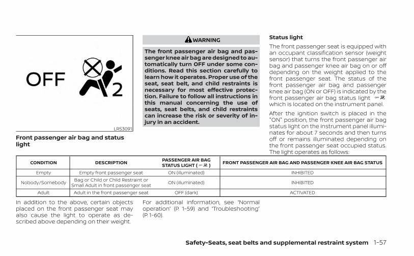
Front passenger air bag and statuslight
WARNING
The front passenger air bag and pas-senger knee air bag are designed to au-tomatically turn OFF under some con-ditions. Read this section carefully tolearn how it operates. Proper use of theseat, seat belt, and child restraints isnecessary for most effective protec-tion. Failure to follow all instructions inthis manual concerning the use ofseats, seat belts, and child restraintscan increase the risk or severity of in-jury in an accident.
Status lightThe front passenger seat is equipped withan occupant classification sensor (weightsensor) that turns the front passenger airbag and passenger knee air bag on or offdepending on the weight applied to thefront passenger seat. The status of thefront passenger air bag and passengerknee air bag (ON or OFF) is indicated by thefront passenger air bag status lightwhich is located on the instrument panel.After the ignition switch is placed in the"ON" position, the front passenger air bagstatus light on the instrument panel illumi-nates for about 7 seconds and then turnsoff or remains illuminated depending onthe front passenger seat occupied status.The light operates as follows:
CONDITION DESCRIPTION PASSENGER AIR BAGSTATUS LIGHT ( ) FRONT PASSENGER AIR BAG AND PASSENGER KNEE AIR BAG STATUS
Empty Empty front passenger seat ON (illuminated) INHIBITED
Nobody/Somebody Bag or Child or Child Restraint orSmall Adult in front passenger seat ON (illuminated) INHIBITED
Adult Adult in the front passenger seat OFF (dark) ACTIVATED
In addition to the above, certain objectsplaced on the front passenger seat mayalso cause the light to operate as de-scribed above depending on their weight.
For additional information, see “Normaloperation” (P. 1-59) and “Troubleshooting”(P. 1-60).
LRS3091
Safety-Seats, seat belts and supplemental restraint system 1-57
Front passenger air bagThe front passenger air bag and passen-ger knee air bag is designed to automati-cally turn OFF when the vehicle is operatedunder some conditions as described be-low in accordance with U.S. regulations. Ifthe front passenger air bag and passengerknee air bag is OFF, it will not inflate in acrash. The driver air bag and other air bagsin your vehicle are not part of this system.The purpose of the regulation is to helpreduce the risk of injury or death from aninflating air bag to certain front passengerseat occupants, such as children, by requir-ing the air bags to be automatically turnedOFF. Certain sensors are used to meet therequirements.The occupant classification sensor in thisvehicle is a weight sensor. It is designed todetect an occupant and objects on theseat by weight. For example, if a child is inthe front passenger seat, the NISSAN Ad-vanced Air Bag System is designed to turnthe front passenger air bag and passengerknee air bag OFF in accordance with theregulations. Also, if a child restraint of thetype specified in the regulations is on theseat, its weight and the child’s weight canbe detected and cause the air bag to turnOFF.
Front passenger seat adult occupants whoare properly seated and using the seat beltas outlined in this manual should notcause the front passenger air bag and pas-senger knee air bag to be automaticallyturned OFF. For small adults it may beturned OFF, however if the occupant takeshis/her weight off the seat cushion (for ex-ample, by not sitting upright, by sitting onan edge of the seat, or by otherwise beingout of position), this could cause the sensorto turn the air bags OFF. Always be sure tobe seated and wearing the seat belt prop-erly for the most effective protection by theseat belt and supplemental air bag.NISSAN recommends that pre-teens andchildren be properly restrained in a rearseat. NISSAN also recommends that ap-propriate child restraints and boosterseats be properly installed in a rear seat. Ifthis is not possible, the occupant classifica-tion sensor is designed to operate as de-scribed above to turn the front passengerair bag and passenger knee air bag OFF forspecified child restraints as required by theregulations. Failing to properly secure childrestraints and to use the ALR mode mayallow the restraint to tip or move in a colli-sion or sudden stop. This can also result inthe passenger air bag and passenger kneeair bag inflating in a crash instead of being
OFF. For additional information aboutproper use and installation, see “Child re-straints” (P. 1-23).If the front passenger seat is not occupied,the front passenger air bag and passengerknee air bag are designed not to inflate in acrash. However, heavy objects placed onthe seat could result in air bag inflation,because of the object’s weight detected bythe occupant classification sensor. Otherconditions could also result in air bag infla-tion, such as if a child is standing on theseat, or if two children are on the seat, con-trary to the instructions in this manual. Al-ways be sure that you and all vehicle occu-pants are seated and restrained properly.Using the front passenger air bag statuslight, you can monitor when the front pas-senger air bag and passenger knee air bagare automatically turned OFF.If an adult occupant is in the seat but thefront passenger air bag status light is illu-minated (indicating that the front passen-ger air bag and passenger knee air bag areOFF), it could be that the person is a smalladult, or is not sitting on the seat properlyor not using the seat belt properly.If a child restraint must be used in the frontseat, the front passenger air bag status
1-58 Safety-Seats, seat belts and supplemental restraint system
light may or may not be illuminated, de-pending on the size of the child and thetype of child restraint being used. If the airbag status light is not illuminated (indicat-ing that the air bag might inflate in a crash),it could be that the child restraint or seatbelt is not being used properly. Make surethat the child restraint is installed properly,the seat belt is used properly and the occu-pant is positioned properly. If the air bagstatus light is still not illuminated, reposi-tion the occupant or child restraint in a rearseat.If the front passenger air bag status lightwill not illuminate even though you believethat the child restraint, the seat belts andthe occupant are properly positioned, it isrecommended that you take your vehicleto a NISSAN dealer. A NISSAN dealer cancheck system status by using a specialtool. However, until you have confirmedwith a dealer that your air bag is workingproperly, reposition the occupant or childrestraint in a rear seat.The NISSAN Advanced Air Bag System andfront passenger air bag status light willtake a few seconds to register a change inthe front passenger seat status. This is nor-mal system operation and does not indi-cate a malfunction.
If a malfunction occurs in the front passen-ger air bag system, the supplemental airbag warning light , located in the me-ter and gauges area of the instrumentpanel, will be illuminated (blinking orsteadily lit). Have the system checked. It isrecommended that you visit a NISSANdealer for this service.Normal operationIn order for the occupant classificationsensor system to classify the front passen-ger based on weight, please follow the pre-cautions and steps outlined below:Precautions• Make sure that there are no objects
weighing over 9.1 lbs. (4 kg) hanging onthe seat or placed in the seatback pocket.
• Make sure that a child restraint or otherobject is not pressing against the rear ofthe seatback.
• Make sure that a rear passenger is notpushing or pulling on the back of the frontpassenger seat.
• Make sure that the front passenger seator seatback is not forced back against anobject on the seat or floor behind it.
• Make sure that there is no object placedunder the front passenger seat.
Steps1. Adjust the seat as outlined in the “Seats”
(P. 1-2) section of this manual. Sit upright,leaning against the seatback, and cen-tered on the seat cushion with your feetcomfortably extended to the floor.
2. Make sure there are no objects on yourlap.
3. Fasten the seat belt as outlined in the“Seat belts” (P. 1-12) section of thismanual. Front passenger seat beltbuckle status is monitored by the occu-pant classification system, and is usedas an input to determine occupancystatus. So, it is highly recommended thatthe front passenger fasten their seatbelt.
4. Remain in this position for 30 secondsallowing the system to classify the frontpassenger before the vehicle is put intomotion.
5. Ensure proper classification by checkingthe front passenger air bag status light.
Safety-Seats, seat belts and supplemental restraint system 1-59
NOTE:
This vehicle’s occupant classificationsensor system generally keeps the clas-sification locked during driving, so it isimportant that you confirm that thefront passenger is properly classifiedprior to driving. However, the occupantclassification sensor may recalculate theweight of the occupant under some con-ditions (both while driving and whenstopped), so front passenger seat occu-pants should continue to remain seatedas outlined above.TroubleshootingIf you think the front passenger air bagstatus light is incorrect:1. If the light is ON with an adult occupying
the front passenger seat:• Occupant is a small adult — the air bag
light is functioning as intended. The frontpassenger air bag and passenger kneeair bag are suppressed.
However, if the occupant is not a smalladult, then this may be due to the followingconditions that may be interfering with theweight sensors:• Occupant is not sitting upright, leaning
against the seatback, and centered onthe seat cushion with his/her feet com-fortably extended to the floor.
• A child restraint or other object pressingagainst the rear of the seatback.
• A rear passenger pushing or pulling onthe back of the front passenger seat.
• Forcing the front seat or seatback againstan object on the seat or floor behind it.
• An object placed under the front passen-ger seat.
• An object placed between the seat cush-ion and center console or between theseat cushion and the door.
If the vehicle is moving, please come to astop when it is safe to do so. Check andcorrect any of the above conditions. Re-start the vehicle and wait 1 minute.
NOTE:
A system check will be performed duringwhich the front passenger air bag statuslight will remain lit for about 7 secondsinitially.
If the light is still ON after this, the personshould be advised not to ride in the frontpassenger seat and the vehicle should bechecked as soon as possible. It is recom-mended that you visit a NISSAN dealer forthis service.2. If the light is OFF with a small adult, child
or child restraint occupying the frontpassenger seat.This may be due to the following condi-tions that may be interfering with theweight sensors:
• Small adult or child is not sitting upright,leaning against the seatback, and cen-tered on the seat cushion with his/herfeet comfortably extended to the floor.
• The child restraint is not properly in-stalled, as outlined in the “Child restraints”section of this manual.
• An object weighing over 9.1 lbs. (4 kg)hanging on the seat or placed in the seat-back pocket.
• A child restraint or other object pressingagainst the rear of the seatback.
• A rear passenger pushing or pulling onthe back of the front passenger seat.
• Forcing the front seat or seatbackagainst an object on the seat or floor be-hind it.
1-60 Safety-Seats, seat belts and supplemental restraint system
• An object placed under the front passen-ger seat.
• An object placed between the seat cush-ion and center console.
If the vehicle is moving, please come to astop when it is safe to do so. Check andcorrect any of the above conditions. Re-start the vehicle and wait 1 minute.
NOTE:
A system check will be performed duringwhich the front passenger air bag statuslight will remain lit for about 7 secondsinitially.If the light is still OFF after this, the smalladult, child or child restraint should be re-positioned in the rear seat and the vehicleshould be checked as soon as possible. It isrecommended that you visit a NISSANdealer for this service.3. If the light is OFF with no front passenger
and no objects on the front passengerseat, the vehicle should be checked. It isrecommended that you visit a NISSANdealer as soon as possible.
Other supplemental front-impact airbag precautions
WARNING
• Do not place any objects on thesteering wheel pad or on the instru-ment panel. Also, do not place anyobjects between any occupant andthe steering wheel or instrumentpanel. Such objects may becomedangerous projectiles and cause in-jury if the front air bags inflate.
• Immediately after inflation, severalfront air bag system components willbe hot. Do not touch them; you mayseverely burn yourself.
• No unauthorized changes should bemade to any components or wiringof the supplemental air bag system.This is to prevent accidental inflationof the supplemental air bag or dam-age to the supplemental air bagsystem.
• Do not make unauthorized changesto your vehicle's electrical system,suspension system or front endstructure. This could affect properoperation of the front air bag system.
• Tampering with the front air bag sys-tem may result in serious personalinjury. Tampering includes changesto the steering wheel and the instru-ment panel assembly by placing ma-terial over the steering wheel padand above the instrument panel orby installing additional trim materialaround the air bag system.
• Removing or modifying the frontpassenger seat may affect the func-tion of the air bag system and resultin serious personal injury.
• Modifying or tampering with thefront passenger seat may result inserious personal injury. For example,do not change the front seats byplacing material on the seat cushionor by installing additional trim mate-rial, such as seat covers, on the seatthat are not specifically designed toassure proper air bag operation. Ad-ditionally, do not stow any objectsunder the front passenger seat or theseat cushion and seatback. Such ob-jects may interfere with the properoperation of the occupant classifica-tion sensor (weight sensor).
Safety-Seats, seat belts and supplemental restraint system 1-61
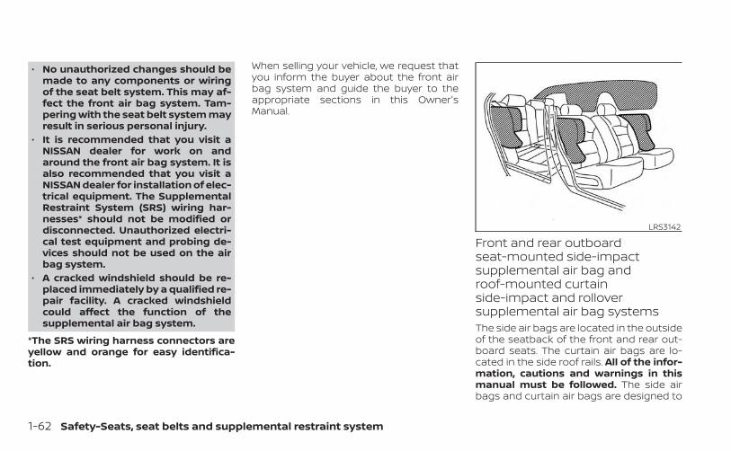
• No unauthorized changes should bemade to any components or wiringof the seat belt system. This may af-fect the front air bag system. Tam-pering with the seat belt system mayresult in serious personal injury.
• It is recommended that you visit aNISSAN dealer for work on andaround the front air bag system. It isalso recommended that you visit aNISSAN dealer for installation of elec-trical equipment. The SupplementalRestraint System (SRS) wiring har-nesses* should not be modified ordisconnected. Unauthorized electri-cal test equipment and probing de-vices should not be used on the airbag system.
• A cracked windshield should be re-placed immediately by a qualified re-pair facility. A cracked windshieldcould affect the function of thesupplemental air bag system.
*The SRS wiring harness connectors areyellow and orange for easy identifica-tion.
When selling your vehicle, we request thatyou inform the buyer about the front airbag system and guide the buyer to theappropriate sections in this Owner'sManual.
Front and rear outboardseat-mounted side-impactsupplemental air bag androof-mounted curtainside-impact and rolloversupplemental air bag systemsThe side air bags are located in the outsideof the seatback of the front and rear out-board seats. The curtain air bags are lo-cated in the side roof rails. All of the infor-mation, cautions and warnings in thismanual must be followed. The side airbags and curtain air bags are designed to
LRS3142
1-62 Safety-Seats, seat belts and supplemental restraint system
inflate in higher severity side collisions, al-though they may inflate if the forces in an-other type of collision are similar to those ofa higher severity impact. They are de-signed to inflate on the side where the ve-hicle is impacted. They may not inflate incertain side collisions.Curtain air bags are also designed to inflatein certain types of rollover collisions or nearrollovers. As a result, certain vehicle move-ments (for example, during severe off-roading) may cause the curtain air bags toinflate.Vehicle damage (or lack of it) is not alwaysan indication of proper side air bag andcurtain air bag operation.When the side air bags and curtain air bagsinflate, a fairly loud noise may be heard,followed by the release of smoke. Thissmoke is not harmful and does not indi-cate a fire. Care should be taken not toinhale it, as it may cause irritation andchoking. Those with a history of a breath-ing condition should get fresh air promptly.Side air bags, along with the use of seatbelts, help to cushion the impact force onthe chest and pelvic area of the front andrear outboard occupants. Curtain air bagshelp to cushion the impact force to the
head of occupants in the front and rearoutboard seating positions. They can helpsave lives and reduce serious injuries. How-ever, an inflating side air bag and curtain airbag may cause abrasions or other injuries.Side air bags and curtain air bags do notprovide restraint to the lower body.The seat belts should be correctly wornand the driver, front passenger and rearoutboard occupants seated upright as faras practical away from the side air bag.Rear seat passengers should be seated asfar away as practical from the door finish-ers and side roof rails. The side air bags andcurtain air bags inflate quickly in order tohelp protect the occupants. Because ofthis, the force of the side air bag and curtainair bag inflating can increase the risk ofinjury if the occupant is too close to, or isagainst, these air bag modules during in-flation. The side air bag will deflate quicklyafter the collision is over.The curtain air bag will remain inflated for ashort time.The side air bags and curtain air bagsoperate only when the ignition switch isplaced in the ON position.After placing the ignition switch in theON position, the supplemental air bag
warning light illuminates. The supple-mental air bag warning light will turn offafter about 7 seconds if the system isoperational.
WARNING
• Do not place any objects near theseatback of the front and rear seats.Also, do not place any objects (anumbrella, bag, etc.) between the frontand rear door finisher and the frontand rear seat. Such objects may be-come dangerous projectiles andcause injury if a side air bag inflate.
• Right after inflation, several side airbag and curtain air bag system com-ponents will be hot. Do not touchthem; you may severely burn yourself.
• No unauthorized changes should bemade to any components or wiringof the side air bag and curtain air bagsystems. This is to prevent damageto or accidental inflation of the sideair bag and curtain air bag or dam-age to the side air bag and curtain airbag systems.
Safety-Seats, seat belts and supplemental restraint system 1-63
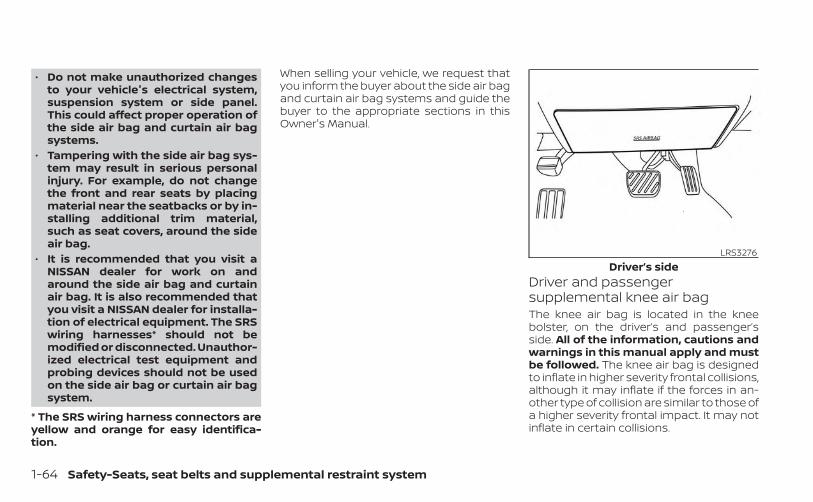
• Do not make unauthorized changesto your vehicle's electrical system,suspension system or side panel.This could affect proper operation ofthe side air bag and curtain air bagsystems.
• Tampering with the side air bag sys-tem may result in serious personalinjury. For example, do not changethe front and rear seats by placingmaterial near the seatbacks or by in-stalling additional trim material,such as seat covers, around the sideair bag.
• It is recommended that you visit aNISSAN dealer for work on andaround the side air bag and curtainair bag. It is also recommended thatyou visit a NISSAN dealer for installa-tion of electrical equipment. The SRSwiring harnesses* should not bemodified or disconnected. Unauthor-ized electrical test equipment andprobing devices should not be usedon the side air bag or curtain air bagsystem.
* The SRS wiring harness connectors areyellow and orange for easy identifica-tion.
When selling your vehicle, we request thatyou inform the buyer about the side air bagand curtain air bag systems and guide thebuyer to the appropriate sections in thisOwner's Manual.
Driver and passengersupplemental knee air bagThe knee air bag is located in the kneebolster, on the driver’s and passenger’sside. All of the information, cautions andwarnings in this manual apply and mustbe followed. The knee air bag is designedto inflate in higher severity frontal collisions,although it may inflate if the forces in an-other type of collision are similar to those ofa higher severity frontal impact. It may notinflate in certain collisions.
LRS3276Driver’s side
1-64 Safety-Seats, seat belts and supplemental restraint system
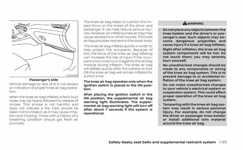
Vehicle damage (or lack of it) is not alwaysan indication of proper knee air bag opera-tion.When the knee air bag inflates, a fairly loudnoise may be heard, followed by release ofsmoke. This smoke is not harmful anddoes not indicate a fire. Care should betaken not to inhale it, as it may cause irrita-tion and choking. Those with a history of abreathing condition should get fresh airpromptly.
The knee air bag helps to cushion the im-pact force on the knees of the driver andpassenger. It can help reduce serious inju-ries. However, an inflating knee air bag maycause abrasions or other injuries. The kneeair bag provides restraint to the lower body.The knee air bag inflates quickly in order tohelp protect the occupants. Because ofthis, the force of the knee air bag inflatingcan increase the risk of injury if the occu-pant is too close to, or is against, this air bagmodule during inflation. The knee air bagwill deflate quickly after the collision is overOR the knee air bag will remain inflated fora short time.The knee air bag operates only when theignition switch is placed in the ON posi-tion.After placing the ignition switch in theON position, the supplemental air bagwarning light illuminates. The supple-mental air bag warning light will turn offafter about 7 seconds if the system isoperational.
WARNING
• Do not place any objects between theknee bolster and the driver’s or pas-senger’s seat. Such objects may be-come dangerous projectiles andcause injury if a knee air bag inflates.
• Right after inflation, the knee air bagsystem components will be hot. Donot touch them; you may severelyburn yourself.
• No unauthorized changes should bemade to any components or wiringof the knee air bag system. This is toprevent damage to or accidental in-flation of the knee air bag system.
• Do not make unauthorized changesto your vehicle's electrical system orsuspension system. This could affectproper operation of the knee air bagsystem.
• Tampering with the knee air bag sys-tem may result in serious personalinjury. For example, do not changethe driver or passenger knee bolsteror install additional trim materialaround the knee air bag.
LRS3290Passenger’s side
Safety-Seats, seat belts and supplemental restraint system 1-65
• It is recommended that you visit aNISSAN dealer for work on andaround the knee air bag. It is also rec-ommended that you visit a NISSANdealer for installation of electricalequipment. The SRS wiring har-nesses* should not be modified ordisconnected. Unauthorized electri-cal test equipment and probing de-vices should not be used on the kneeair bag system.
*The SRS wiring harness or connectorsare yellow or orange for easy identifica-tion.When selling your vehicle, we request thatyou inform the buyer about the knee airbag system and guide the buyer to theappropriate sections in this manual.
Seat belt with pretensioner(s)(front and rear outboard seats)
WARNING
• The pretensioner(s) cannot be re-used after activation. They must bereplaced together with the retractorand buckle as a unit.
• If the vehicle becomes involved in acollision but pretensioner(s) are notactivated, be sure to have the preten-sioner system checked and, if neces-sary, replaced. It is recommendedthat you visit a NISSAN dealer for thisservice.
• No unauthorized changes should bemade to any components or wiringof the pretensioner system. This is toprevent damage to or accidental ac-tivation of the pretensioner(s). Tam-pering with the pretensioner systemmay result in serious personal injury.
• It is recommended that you visit aNISSAN dealer for work on andaround the pretensioner system. It isalso recommended that you visit aNISSAN dealer for installation of elec-trical equipment. Unauthorized elec-trical test equipment and probingdevices should not be used on thepretensioner system.
• If you need to dispose of the preten-sioner(s) or scrap the vehicle, it is rec-ommended that you visit a NISSANdealer for this service. Incorrect dis-posal procedures could cause per-sonal injury.
The pretensioner system may activatewith the supplemental air bag system incertain types of collisions. Working with theseat belt retractor, the pretensioner(s) helptighten the seat belt when the vehicle be-comes involved in certain types of colli-sions, helping to restrain front and rear out-board seat occupants.The pretensioner(s) are encased within theseat belt retractor and to the seat belt an-chor affixed to the floor of the vehicle.These seat belts are used the same way asconventional seat belts.When pretensioner(s) activate, smoke is re-leased and a loud noise may be heard. Thissmoke is not harmful and does not indi-cate a fire. Care should be taken not toinhale it, as it may cause irritation andchoking. Those with a history of a breath-ing condition should get fresh air promptly.After the pretensioner(s’) activation, loadlimiters allow the seat belt to release web-bing (if necessary) to reduce forces againstthe chest.The supplemental air bag warning light
is used to indicate malfunctions in thepretensioner system. For additional infor-mation, see "Supplemental air bag warning
1-66 Safety-Seats, seat belts and supplemental restraint system
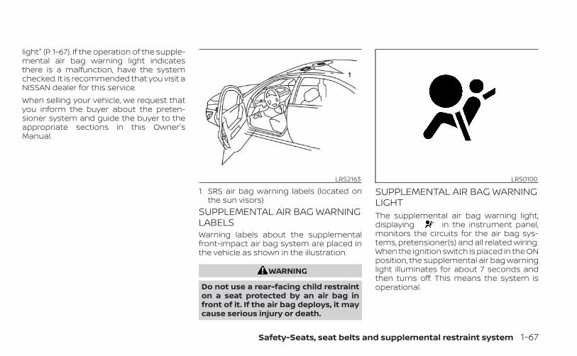
light" (P. 1-67). If the operation of the supple-mental air bag warning light indicatesthere is a malfunction, have the systemchecked. It is recommended that you visit aNISSAN dealer for this service.When selling your vehicle, we request thatyou inform the buyer about the preten-sioner system and guide the buyer to theappropriate sections in this Owner'sManual.
SUPPLEMENTAL AIR BAG WARNINGLABELSWarning labels about the supplementalfront-impact air bag system are placed inthe vehicle as shown in the illustration.
WARNING
Do not use a rear-facing child restrainton a seat protected by an air bag infront of it. If the air bag deploys, it maycause serious injury or death.
SUPPLEMENTAL AIR BAG WARNINGLIGHTThe supplemental air bag warning light,displaying in the instrument panel,monitors the circuits for the air bag sys-tems, pretensioner(s) and all related wiring.When the ignition switch is placed in the ONposition, the supplemental air bag warninglight illuminates for about 7 seconds andthen turns off. This means the system isoperational.
LRS2163
1. SRS air bag warning labels (located onthe sun visors)
LRS0100
Safety-Seats, seat belts and supplemental restraint system 1-67
If any of the following conditions occur, thefront air bag, side air bag, curtain air bag,knee air bag and pretensioner systemsneed servicing:• The supplemental air bag warning light
remains on after approximately 7 sec-onds.
• The supplemental air bag warning lightflashes intermittently.
• The supplemental air bag warning lightdoes not come on at all.
Under these conditions, the front air bag,side air bag, curtain air bag, knee air bag orpretensioner systems may not operateproperly. They must be checked and re-paired. It is recommended that you visit aNISSAN dealer for this service.
WARNING
If the supplemental air bag warninglight is on, it could mean that the frontair bag, side air bag, curtain air bag,knee air bag and/or pretensioner sys-tems will not operate in an accident. Tohelp avoid injury to yourself or others,have your vehicle checked as soon aspossible. It is recommended that youvisit a NISSAN dealer for this service.
Repair and replacementprocedureThe front air bags, side air bags, curtain airbags, knee air bags and pretensioner(s) aredesigned to inflate on a one-time-only ba-sis. As a reminder, unless it is damaged, thesupplemental air bag warning light re-mains illuminated after inflation has oc-curred. These systems should be repairedand/or replaced as soon as possible. It isrecommended that you visit a NISSANdealer for this service.When maintenance work is required on thevehicle, the front air bags, side air bags,curtain air bags, knee air bags, pretension-er(s) and related parts should be pointedout to the person performing the mainte-nance. The ignition switch should alwaysbe placed in the LOCK position when work-ing under the hood or inside the vehicle.
WARNING
• Once a front air bag, side air bag, cur-tain air bag or knee air bag has in-flated, the air bag module will notfunction again and must be replaced.Additionally, the activated preten-sioner(s) must also be replaced. Theair bag module and pretensioner(s)should be replaced. It is recom-mended that you visit a NISSANdealer for this service. However, theair bag module and pretensioner(s)cannot be repaired.
• The front air bag, side air bag, curtainair bag, knee air bag systems and thepretensioner system should be in-spected if there is any damage to thefront end or side portion of the ve-hicle. It is recommended that youvisit a NISSAN dealer for this service.
• If you need to dispose of the supple-mental air bag or pretensioner sys-tems or scrap the vehicle, it is recom-mended that you contact a NISSANdealer for this service. Incorrect dis-posal procedures could cause per-sonal injury.
1-68 Safety-Seats, seat belts and supplemental restraint system
• If there is an impact to your vehiclefrom any direction, your OccupantClassification Sensor (OCS) should bechecked to verify it is still functioningcorrectly. It is recommended that youvisit a NISSAN dealer for this service.The OCS should be checked even if noair bags deploy as a result of the im-pact. Failure to verify proper OCSfunction may result in an improperair bag deployment resulting in in-jury or death.
Safety-Seats, seat belts and supplemental restraint system 1-69
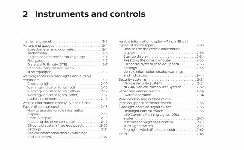
2 Instruments and controls
Instrument panel . . . . . . . . . . . . . . . . . . . . . . . . . . . . . . . . 2-2Meters and gauges . . . . . . . . . . . . . . . . . . . . . . . . . . . . . 2-4
Speedometer and odometer . . . . . . . . . . . . . . . . . 2-4Tachometer . . . . . . . . . . . . . . . . . . . . . . . . . . . . . . . . . . 2-6Engine coolant temperature gauge . . . . . . . . . . 2-6Fuel gauge . . . . . . . . . . . . . . . . . . . . . . . . . . . . . . . . . . . 2-7Distance To Empty (DTE) . . . . . . . . . . . . . . . . . . . . . 2-7Variable Compression Turbo(if so equipped) . . . . . . . . . . . . . . . . . . . . . . . . . . . . . . . 2-8
Warning lights, indicator lights and audiblereminders . . . . . . . . . . . . . . . . . . . . . . . . . . . . . . . . . . . . . . . 2-9
Checking lights . . . . . . . . . . . . . . . . . . . . . . . . . . . . . . 2-10Warning/Indicator lights (red) . . . . . . . . . . . . . . . 2-10Warning/Indicator lights (yellow) . . . . . . . . . . . . 2-12Warning/Indicator lights (other) . . . . . . . . . . . . . 2-17Audible reminders . . . . . . . . . . . . . . . . . . . . . . . . . . . 2-18
Vehicle information display- 5 inch (13 cm)Type A (if so equipped) . . . . . . . . . . . . . . . . . . . . . . . . . 2-18
How to use the vehicle informationdisplay . . . . . . . . . . . . . . . . . . . . . . . . . . . . . . . . . . . . . . 2-19Startup display . . . . . . . . . . . . . . . . . . . . . . . . . . . . . . 2-19Resetting the drive computer . . . . . . . . . . . . . . . 2-19Oil control system (if so equipped) . . . . . . . . . . . 2-20Settings . . . . . . . . . . . . . . . . . . . . . . . . . . . . . . . . . . . . . 2-21Vehicle information display warningsand indicators . . . . . . . . . . . . . . . . . . . . . . . . . . . . . . . 2-27
Vehicle information display —7 inch (18 cm)Type B (if so equipped) . . . . . . . . . . . . . . . . . . . . . . . . . 2-33
How to use the vehicle informationdisplay . . . . . . . . . . . . . . . . . . . . . . . . . . . . . . . . . . . . . . 2-34Startup display . . . . . . . . . . . . . . . . . . . . . . . . . . . . . . 2-34Resetting the drive computer . . . . . . . . . . . . . . . 2-35Oil control system (if so equipped) . . . . . . . . . . . 2-35Settings . . . . . . . . . . . . . . . . . . . . . . . . . . . . . . . . . . . . . 2-36Vehicle information display warningsand indicators . . . . . . . . . . . . . . . . . . . . . . . . . . . . . . . 2-44
Security systems . . . . . . . . . . . . . . . . . . . . . . . . . . . . . . . 2-51Vehicle security system . . . . . . . . . . . . . . . . . . . . . 2-51NISSAN Vehicle Immobilizer System . . . . . . . . . 2-52
Wiper and washer switch . . . . . . . . . . . . . . . . . . . . . . . 2-54Switch operation . . . . . . . . . . . . . . . . . . . . . . . . . . . . 2-54
Rear window and outside mirror(if so equipped) defroster switch . . . . . . . . . . . . . . . 2-55Headlight and turn signal switch . . . . . . . . . . . . . . . 2-55
Headlight control switch . . . . . . . . . . . . . . . . . . . . 2-55LED Daytime Running Lights (DRL)system . . . . . . . . . . . . . . . . . . . . . . . . . . . . . . . . . . . . . . 2-61Instrument brightness control . . . . . . . . . . . . . . 2-61Turn signal switch . . . . . . . . . . . . . . . . . . . . . . . . . . . 2-61Fog light switch (if so equipped) . . . . . . . . . . . . . 2-62
Horn . . . . . . . . . . . . . . . . . . . . . . . . . . . . . . . . . . . . . . . . . . . 2-63
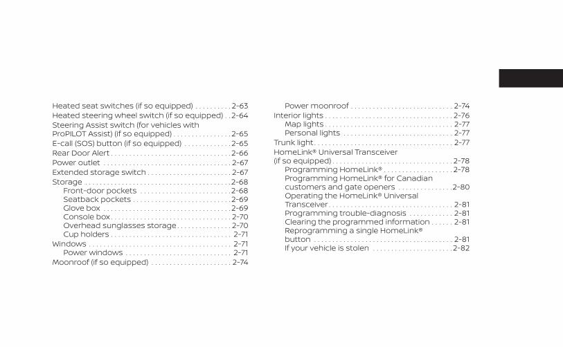
Heated seat switches (if so equipped) . . . . . . . . . . 2-63Heated steering wheel switch (if so equipped) . . 2-64Steering Assist switch (for vehicles withProPILOT Assist) (if so equipped) . . . . . . . . . . . . . . . . 2-65E-call (SOS) button (if so equipped) . . . . . . . . . . . . . 2-65Rear Door Alert . . . . . . . . . . . . . . . . . . . . . . . . . . . . . . . . . 2-66Power outlet . . . . . . . . . . . . . . . . . . . . . . . . . . . . . . . . . . . 2-67Extended storage switch . . . . . . . . . . . . . . . . . . . . . . . 2-67Storage . . . . . . . . . . . . . . . . . . . . . . . . . . . . . . . . . . . . . . . . 2-68
Front-door pockets . . . . . . . . . . . . . . . . . . . . . . . . .2-68Seatback pockets . . . . . . . . . . . . . . . . . . . . . . . . . . . 2-69Glove box . . . . . . . . . . . . . . . . . . . . . . . . . . . . . . . . . . . 2-69Console box . . . . . . . . . . . . . . . . . . . . . . . . . . . . . . . . . 2-70Overhead sunglasses storage . . . . . . . . . . . . . . . 2-70Cup holders . . . . . . . . . . . . . . . . . . . . . . . . . . . . . . . . . 2-71
Windows . . . . . . . . . . . . . . . . . . . . . . . . . . . . . . . . . . . . . . . 2-71Power windows . . . . . . . . . . . . . . . . . . . . . . . . . . . . . 2-71
Moonroof (if so equipped) . . . . . . . . . . . . . . . . . . . . . . 2-74
Power moonroof . . . . . . . . . . . . . . . . . . . . . . . . . . . . 2-74Interior lights . . . . . . . . . . . . . . . . . . . . . . . . . . . . . . . . . . . 2-76
Map lights . . . . . . . . . . . . . . . . . . . . . . . . . . . . . . . . . . . 2-77Personal lights . . . . . . . . . . . . . . . . . . . . . . . . . . . . . . 2-77
Trunk light . . . . . . . . . . . . . . . . . . . . . . . . . . . . . . . . . . . . . . 2-77HomeLink® Universal Transceiver(if so equipped) . . . . . . . . . . . . . . . . . . . . . . . . . . . . . . . . . 2-78
Programming HomeLink® . . . . . . . . . . . . . . . . . . . 2-78Programming HomeLink® for Canadiancustomers and gate openers . . . . . . . . . . . . . . .2-80Operating the HomeLink® UniversalTransceiver . . . . . . . . . . . . . . . . . . . . . . . . . . . . . . . . . . 2-81Programming trouble-diagnosis . . . . . . . . . . . . 2-81Clearing the programmed information . . . . . . 2-81Reprogramming a single HomeLink®button . . . . . . . . . . . . . . . . . . . . . . . . . . . . . . . . . . . . . . 2-81If your vehicle is stolen . . . . . . . . . . . . . . . . . . . . . . 2-82
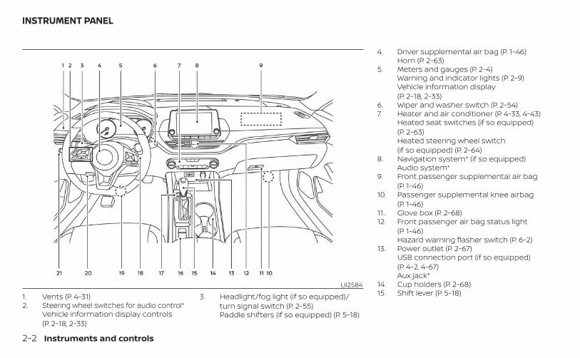
1. Vents (P. 4-31)2. Steering wheel switches for audio control*
Vehicle information display controls(P. 2-18, 2-33)
3. Headlight/fog light (if so equipped)/turn signal switch (P. 2-55)Paddle shifters (if so equipped) (P. 5-18)
4. Driver supplemental air bag (P. 1-46)Horn (P. 2-63)
5. Meters and gauges (P. 2-4)Warning and indicator lights (P. 2-9)Vehicle information display(P. 2-18, 2-33)
6. Wiper and washer switch (P. 2-54)7. Heater and air conditioner (P. 4-33, 4-43)
Heated seat switches (if so equipped)(P. 2-63)Heated steering wheel switch(if so equipped) (P. 2-64)
8. Navigation system* (if so equipped)Audio system*
9. Front passenger supplemental air bag(P. 1-46)
10. Passenger supplemental knee airbag(P. 1-46)
11.. Glove box (P. 2-68)12. Front passenger air bag status light
(P. 1-46)Hazard warning flasher switch (P. 6-2)
13. Power outlet (P. 2-67)USB connection port (if so equipped)(P. 4-2, 4-67)Aux jack*
14. Cup holders (P. 2-68)15 Shift lever (P. 5-18)
LII2584
INSTRUMENT PANEL
2-2 Instruments and controls
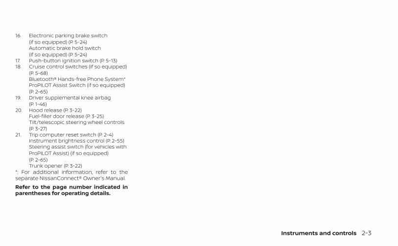
16. Electronic parking brake switch(if so equipped) (P. 5-24)Automatic brake hold switch(if so equipped) (P. 5-24)
17. Push-button ignition switch (P. 5-13)18. Cruise control switches (if so equipped)
(P. 5-68)Bluetooth® Hands-free Phone System*ProPILOT Assist Switch (if so equipped)(P. 2-65)
19. Driver supplemental knee airbag(P. 1-46)
20. Hood release (P. 3-22)Fuel-filler door release (P. 3-25)Tilt/telescopic steering wheel controls(P. 3-27)
21. Trip computer reset switch (P. 2-4)Instrument brightness control (P. 2-55)Steering assist switch (for vehicles withProPILOT Assist) (if so equipped)(P. 2-65)Trunk opener (P. 3-22)
*: For additional information, refer to theseparate NissanConnect® Owner's Manual.Refer to the page number indicated inparentheses for operating details.
Instruments and controls 2-3
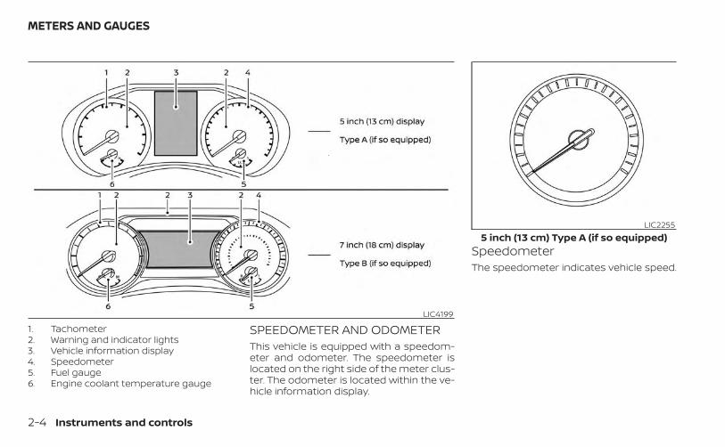
1. Tachometer2. Warning and indicator lights3. Vehicle information display4. Speedometer5. Fuel gauge6. Engine coolant temperature gauge
SPEEDOMETER AND ODOMETERThis vehicle is equipped with a speedom-eter and odometer. The speedometer islocated on the right side of the meter clus-ter. The odometer is located within the ve-hicle information display.
SpeedometerThe speedometer indicates vehicle speed.
LIC4199
LIC22555 inch (13 cm) Type A (if so equipped)
METERS AND GAUGES
2-4 Instruments and controls
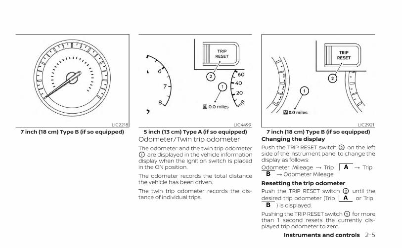
Odometer/Twin trip odometerThe odometer and the twin trip odometerO1 are displayed in the vehicle informationdisplay when the ignition switch is placedin the ON position.The odometer records the total distancethe vehicle has been driven.The twin trip odometer records the dis-tance of individual trips.
Changing the displayPush the TRIP RESET switch O2 on the leftside of the instrument panel to change thedisplay as follows:Odometer Mileage → Trip → Trip
→ Odometer MileageResetting the trip odometerPush the TRIP RESET switch O2 until thedesired trip odometer (Trip or Trip
) is displayed.Pushing the TRIP RESET switch O2 for morethan 1 second resets the currently dis-played trip odometer to zero.
LIC22187 inch (18 cm) Type B (if so equipped)
LIC44995 inch (13 cm) Type A (if so equipped)
LIC29217 inch (18 cm) Type B (if so equipped)
Instruments and controls 2-5
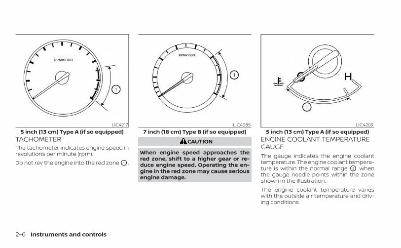
TACHOMETERThe tachometer indicates engine speed inrevolutions per minute (rpm).Do not rev the engine into the red zone O1 .
CAUTION
When engine speed approaches thered zone, shift to a higher gear or re-duce engine speed. Operating the en-gine in the red zone may cause seriousengine damage.
ENGINE COOLANT TEMPERATUREGAUGEThe gauge indicates the engine coolanttemperature. The engine coolant tempera-ture is within the normal range O1 whenthe gauge needle points within the zoneshown in the illustration.The engine coolant temperature varieswith the outside air temperature and driv-ing conditions.
LIC42175 inch (13 cm) Type A (if so equipped)
LIC40857 inch (18 cm) Type B (if so equipped)
LIC42095 inch (13 cm) Type A (if so equipped)
2-6 Instruments and controls
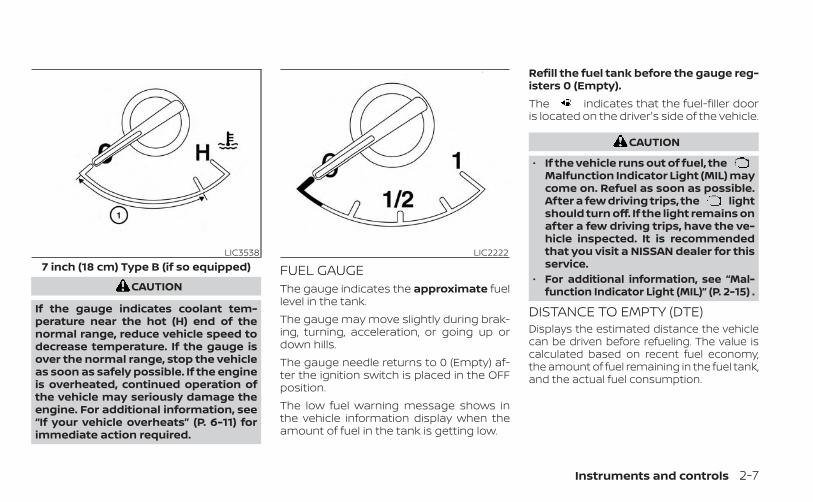
CAUTION
If the gauge indicates coolant tem-perature near the hot (H) end of thenormal range, reduce vehicle speed todecrease temperature. If the gauge isover the normal range, stop the vehicleas soon as safely possible. If the engineis overheated, continued operation ofthe vehicle may seriously damage theengine. For additional information, see“If your vehicle overheats” (P. 6-11) forimmediate action required.
FUEL GAUGEThe gauge indicates the approximate fuellevel in the tank.The gauge may move slightly during brak-ing, turning, acceleration, or going up ordown hills.The gauge needle returns to 0 (Empty) af-ter the ignition switch is placed in the OFFposition.The low fuel warning message shows inthe vehicle information display when theamount of fuel in the tank is getting low.
Refill the fuel tank before the gauge reg-isters 0 (Empty).The indicates that the fuel-filler dooris located on the driver's side of the vehicle.
CAUTION
• If the vehicle runs out of fuel, theMalfunction Indicator Light (MIL) maycome on. Refuel as soon as possible.After a few driving trips, the lightshould turn off. If the light remains onafter a few driving trips, have the ve-hicle inspected. It is recommendedthat you visit a NISSAN dealer for thisservice.
• For additional information, see “Mal-function Indicator Light (MIL)” (P. 2-15) .
DISTANCE TO EMPTY (DTE)Displays the estimated distance the vehiclecan be driven before refueling. The value iscalculated based on recent fuel economy,the amount of fuel remaining in the fuel tank,and the actual fuel consumption.
LIC35387 inch (18 cm) Type B (if so equipped)
LIC2222
Instruments and controls 2-7
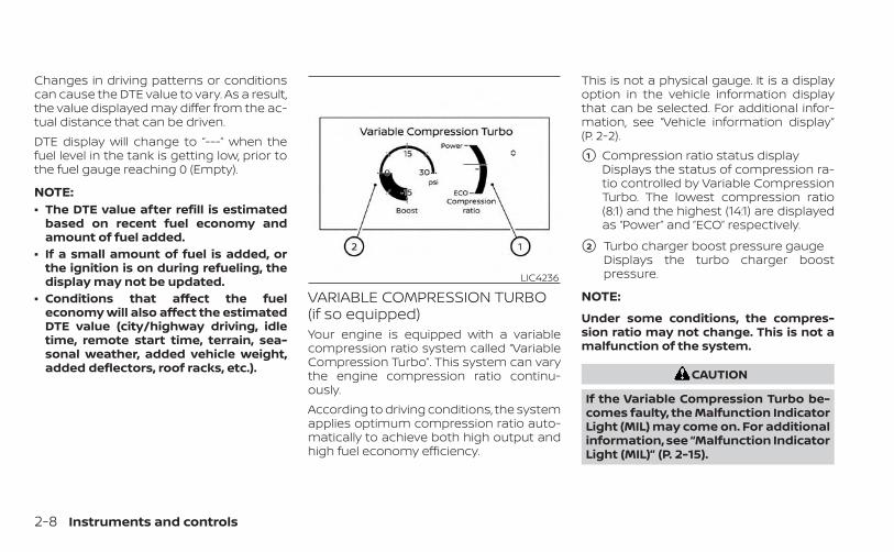
Changes in driving patterns or conditionscan cause the DTE value to vary. As a result,the value displayed may differ from the ac-tual distance that can be driven.DTE display will change to “---” when thefuel level in the tank is getting low, prior tothe fuel gauge reaching 0 (Empty).
NOTE:• The DTE value after refill is estimated
based on recent fuel economy andamount of fuel added.
• If a small amount of fuel is added, orthe ignition is on during refueling, thedisplay may not be updated.
• Conditions that affect the fueleconomy will also affect the estimatedDTE value (city/highway driving, idletime, remote start time, terrain, sea-sonal weather, added vehicle weight,added deflectors, roof racks, etc.).
VARIABLE COMPRESSION TURBO(if so equipped)Your engine is equipped with a variablecompression ratio system called “VariableCompression Turbo”. This system can varythe engine compression ratio continu-ously.According to driving conditions, the systemapplies optimum compression ratio auto-matically to achieve both high output andhigh fuel economy efficiency.
This is not a physical gauge. It is a displayoption in the vehicle information displaythat can be selected. For additional infor-mation, see “Vehicle information display”(P. 2-2).
�1 Compression ratio status displayDisplays the status of compression ra-tio controlled by Variable CompressionTurbo. The lowest compression ratio(8:1) and the highest (14:1) are displayedas “Power” and ”ECO” respectively.
�2 Turbo charger boost pressure gaugeDisplays the turbo charger boostpressure.
NOTE:
Under some conditions, the compres-sion ratio may not change. This is not amalfunction of the system.
CAUTION
If the Variable Compression Turbo be-comes faulty, the Malfunction IndicatorLight (MIL) may come on. For additionalinformation, see “Malfunction IndicatorLight (MIL)” (P. 2-15).
LIC4236
2-8 Instruments and controls
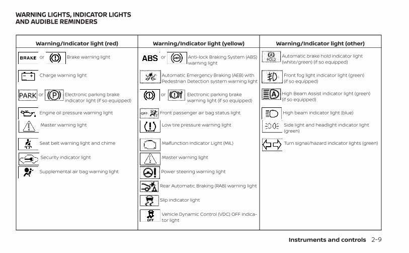
Warning/Indicator light (red) Warning/Indicator light (yellow) Warning/Indicator light (other)
or Brake warning light or Anti-lock Braking System (ABS)warning light
Automatic brake hold indicator light(white/green) (if so equipped)
Charge warning light Automatic Emergency Braking (AEB) withPedestrian Detection system warning light
Front fog light indicator light (green)(if so equipped)
or Electronic parking brakeindicator light (if so equipped)
or Electronic parking brakewarning light (if so equipped)
High Beam Assist indicator light (green)(if so equipped)
Engine oil pressure warning light Front passenger air bag status light High beam indicator light (blue)
Master warning light Low tire pressure warning light Side light and headlight indicator light(green)
Seat belt warning light and chime Malfunction Indicator Light (MIL) Turn signal/hazard indicator lights (green)
Security indicator light Master warning light
Supplemental air bag warning light Power steering warning light
Rear Automatic Braking (RAB) warning light
Slip indicator light
Vehicle Dynamic Control (VDC) OFF indica-tor light
WARNING LIGHTS, INDICATOR LIGHTSAND AUDIBLE REMINDERS
Instruments and controls 2-9
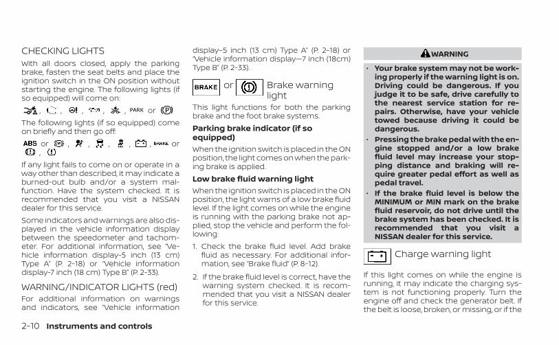
CHECKING LIGHTSWith all doors closed, apply the parkingbrake, fasten the seat belts and place theignition switch in the ON position withoutstarting the engine. The following lights (ifso equipped) will come on:
, , , , , orThe following lights (if so equipped) comeon briefly and then go off:
or , , , , , or,
If any light fails to come on or operate in away other than described, it may indicate aburned-out bulb and/or a system mal-function. Have the system checked. It isrecommended that you visit a NISSANdealer for this service.Some indicators and warnings are also dis-played in the vehicle information displaybetween the speedometer and tachom-eter. For additional information, see “Ve-hicle information display-5 inch (13 cm)Type A” (P. 2-18) or “Vehicle informationdisplay-7 inch (18 cm) Type B” (P. 2-33).
WARNING/INDICATOR LIGHTS (red)For additional information on warningsand indicators, see “Vehicle information
display–5 inch (13 cm) Type A” (P. 2-18) or“Vehicle information display—7 inch (18cm)Type B” (P. 2-33).
or Brake warninglight
This light functions for both the parkingbrake and the foot brake systems.Parking brake indicator (if soequipped)When the ignition switch is placed in the ONposition, the light comes on when the park-ing brake is applied.Low brake fluid warning lightWhen the ignition switch is placed in the ONposition, the light warns of a low brake fluidlevel. If the light comes on while the engineis running with the parking brake not ap-plied, stop the vehicle and perform the fol-lowing:1. Check the brake fluid level. Add brake
fluid as necessary. For additional infor-mation, see “Brake fluid” (P. 8-12).
2. If the brake fluid level is correct, have thewarning system checked. It is recom-mended that you visit a NISSAN dealerfor this service.
WARNING
• Your brake system may not be work-ing properly if the warning light is on.Driving could be dangerous. If youjudge it to be safe, drive carefully tothe nearest service station for re-pairs. Otherwise, have your vehicletowed because driving it could bedangerous.
• Pressing the brake pedal with the en-gine stopped and/or a low brakefluid level may increase your stop-ping distance and braking will re-quire greater pedal effort as well aspedal travel.
• If the brake fluid level is below theMINIMUM or MIN mark on the brakefluid reservoir, do not drive until thebrake system has been checked. It isrecommended that you visit aNISSAN dealer for this service.
Charge warning light
If this light comes on while the engine isrunning, it may indicate the charging sys-tem is not functioning properly. Turn theengine off and check the generator belt. Ifthe belt is loose, broken, or missing, or if the
2-10 Instruments and controls
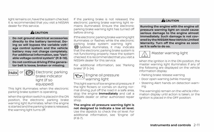
light remains on, have the system checked.It is recommended that you visit a NISSANdealer for this service.
CAUTION
• Do not ground electrical accessoriesdirectly to the battery terminal. Do-ing so will bypass the variable volt-age control system and the vehiclebattery may not charge completely.For additional information, see “Vari-able voltage control system” (P. 8-16).
• Do not continue driving if the genera-tor belt is loose, broken or missing.
or Electronic parkingbrake indicatorlight (if soequipped)
This light illuminates when the electronicparking brake system is operating.When the ignition switch is placed in the ONposition, the electronic parking brakewarning light illuminates. When the engineis started and the parking brake is released,the warning light turns off.
If the parking brake is not released, theelectronic parking brake warning light re-mains illuminated. Ensure the electronicparking brake warning light has turned offbefore driving.If the electronic parking brake warning lightilluminates or flashes while the electronicparking brake system warning light
(yellow) illuminates, it may indicatethat the electronic parking brake system isnot functioning properly. Have the systemchecked. It is recommended that you visit aNISSAN dealer for this service.For additional information, see “Parkingbrake” (P. 5-24).
Engine oil pressurewarning light
This light warns of low engine oil pressure. Ifthe light flickers or comes on during nor-mal driving, pull off the road in a safe area,stop the engine immediately and call aNISSAN dealer or other authorized repairshop.The engine oil pressure warning light isnot designed to indicate a low oil level.Use the dipstick to check the oil level. Foradditional information, see “Engine oil”(P. 8-7).
CAUTION
Running the engine with the engine oilpressure warning light on could causeserious damage to the engine almostimmediately. Such damage is not cov-ered by the NISSAN New Vehicle LimitedWarranty. Turn off the engine as soonas it is safe to do so.
Master warning light
When the ignition is in the ON position, themaster warning light illuminates if any ofthe following are displayed on the vehicleinformation display.• Parking brake release warning• Door open warning (while moving)• Steering Alert hands on detection warn-
ingThe warning(s) remain on the vehicle infor-mation display until action is taken, or theignition is placed in the OFF position.
Instruments and controls 2-11
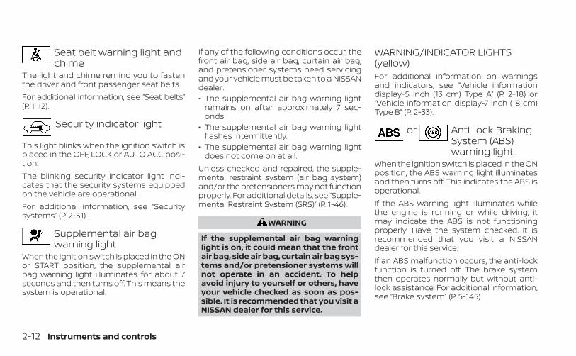
Seat belt warning light andchime
The light and chime remind you to fastenthe driver and front passenger seat belts.For additional information, see “Seat belts”(P. 1-12).
Security indicator light
This light blinks when the ignition switch isplaced in the OFF, LOCK or AUTO ACC posi-tion.The blinking security indicator light indi-cates that the security systems equippedon the vehicle are operational.For additional information, see “Securitysystems” (P. 2-51).
Supplemental air bagwarning light
When the ignition switch is placed in the ONor START position, the supplemental airbag warning light illuminates for about 7seconds and then turns off. This means thesystem is operational.
If any of the following conditions occur, thefront air bag, side air bag, curtain air bag,and pretensioner systems need servicingand your vehicle must be taken to a NISSANdealer:• The supplemental air bag warning light
remains on after approximately 7 sec-onds.
• The supplemental air bag warning lightflashes intermittently.
• The supplemental air bag warning lightdoes not come on at all.
Unless checked and repaired, the supple-mental restraint system (air bag system)and/or the pretensioners may not functionproperly. For additional details, see “Supple-mental Restraint System (SRS)” (P. 1-46).
WARNING
If the supplemental air bag warninglight is on, it could mean that the frontair bag, side air bag, curtain air bag sys-tems and/or pretensioner systems willnot operate in an accident. To helpavoid injury to yourself or others, haveyour vehicle checked as soon as pos-sible. It is recommended that you visit aNISSAN dealer for this service.
WARNING/INDICATOR LIGHTS(yellow)For additional information on warningsand indicators, see “Vehicle informationdisplay-5 inch (13 cm) Type A” (P. 2-18) or“Vehicle information display-7 inch (18 cm)Type B” (P. 2-33).
or Anti-lock BrakingSystem (ABS)warning light
When the ignition switch is placed in the ONposition, the ABS warning light illuminatesand then turns off. This indicates the ABS isoperational.If the ABS warning light illuminates whilethe engine is running or while driving, itmay indicate the ABS is not functioningproperly. Have the system checked. It isrecommended that you visit a NISSANdealer for this service.If an ABS malfunction occurs, the anti-lockfunction is turned off. The brake systemthen operates normally but without anti-lock assistance. For additional information,see “Brake system” (P. 5-145).
2-12 Instruments and controls
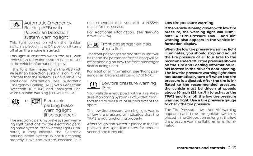
Automatic EmergencyBraking (AEB) withPedestrian Detectionsystem warning light
This light comes on when the ignitionswitch is placed in the ON position. It turnsoff after the engine is started.This light illuminates when the AEB withPedestrian Detection system is set to OFFin the vehicle information display.If the light illuminates when the AEB withPedestrian Detection system is on, it mayindicate that the system is unavailable. Foradditional information, see “AutomaticEmergency Braking (AEB) with PedestrianDetection” (P. 5-108) and “Intelligent For-ward Collision Warning (I-FCW)” (P. 5-120).
or Electronicparking brakewarning light(if so equipped)
The electronic parking brake system warn-ing light functions for the electronic park-ing brake system. If the warning light illumi-nates, it may indicate the electronicparking brake system is not functioningproperly. Have the system checked. It is
recommended that you visit a NISSANdealer for this service.For additional information, see “Parkingbrake” (P. 5-24).
Front passenger air bagstatus light
The front passenger air bag status light willbe lit and the passenger front air bag will beoff depending on how the front passengerseat is being used.For additional information, see “Front pas-senger air bag and status light” (P. 1-57).
Low tire pressure warninglight
Your vehicle is equipped with a Tire Pres-sure Monitoring System (TPMS) that moni-tors the tire pressure of all tires except thespare.The low tire pressure warning light warnsof low tire pressure or indicates that theTPMS is not functioning properly.After the ignition switch is placed in the ONposition, this light illuminates for about 1second and turns off.
Low tire pressure warningIf the vehicle is being driven with low tirepressure, the warning light will illumi-nate. A “Tire Pressure Low - Add Air”warning also appears in the vehicle in-formation display.When the low tire pressure warning lightilluminates, you should stop and adjustthe tire pressure of all four tires to therecommended COLD tire pressure shownon the Tire and Loading Information la-bel located in the driver's door opening.The low tire pressure warning light doesnot automatically turn off when the tirepressure is adjusted. After the tire is in-flated to the recommended pressure,the vehicle must be driven at speedsabove 16 mph (25 km/h) to activate theTPMS and turn off the low tire pressurewarning light. Use a tire pressure gaugeto check the tire pressure.The “Tire Pressure Low - Add Air” warningappears each time the ignition switch isplaced in the ON position as long as the lowtire pressure warning light remains illumi-nated.
Instruments and controls 2-13
For additional information, see “Vehicle in-formation display” (P. 2-33), and “Tire Pres-sure Monitoring System (TPMS)” (P. 5-5) and(P. 6-3).TPMS malfunctionIf the TPMS is not functioning properly, thelow tire pressure warning light will flash forapproximately 1 minute when the ignitionswitch is placed in the ON position. Thelight will remain on after 1 minute. Have thesystem checked. It is recommended thatyou visit a NISSAN dealer for this service.The "Tire Pressure Low — Add Air" warningdoes not appear if the low tire pressurewarning light illuminates to indicate aTPMS malfunction.For additional information, see “Tire Pres-sure Monitoring System (TPMS)” (P. 5-5) and“Tire pressure” (P. 6-3).
WARNING
• Radio waves could adversely affectelectric medical equipment. Thosewho use a pacemaker should contactthe electric medical equipmentmanufacturer for the possible influ-ences before use.
• If the light does not illuminate withthe ignition switch placed in the ONposition, have the vehicle checked assoon as possible. It is recommendedthat you visit a NISSAN dealer for thisservice.
• If the light illuminates while driving,avoid sudden steering maneuversor abrupt braking, reduce vehiclespeed, pull off the road to a safe loca-tion and stop the vehicle as soon aspossible. Driving with under-inflatedtires may permanently damage thetires and increase the likelihood oftire failure. Serious vehicle damagecould occur and may lead to an acci-dent and could result in serious per-sonal injury or death. Check the tirepressure for all four tires. Adjust thetire pressure to the recommendedCOLD tire pressure show on the Tireand Loading Information label lo-cated in the driver’s door opening toturn the low tire pressure warninglight off. If the light still illuminateswhile driving after adjusting the tirepressure, a tire may be flat or theTPMS may be malfunctioning. If youhave a flat tire, replace it with a sparetire as soon as possible. If no tire is
flat and all tires are properly inflated,have the vehicle checked. It is recom-mended that you visit a NISSANdealer for this service.
• When replacing a wheel without theTPMS such as the spare tire, the TPMSwill not function and the low tirepressure warning light will flash forapproximately 1 minute. The light willremain on after 1 minute. Have yourtires replaced and/or TPMS systemreset as soon as possible. It is recom-mended that you visit a NISSANdealer for these services.
• Replacing tires with those not origi-nally specified by NISSAN could af-fect the proper operation of theTPMS.
CAUTION
• The TPMS is not a substitute for theregular tire pressure check. Be sureto check the tire pressure regularly.
• If the vehicle is being driven atspeeds of less than 16 mph (25 km/h),the TPMS may not operate correctly.
• Be sure to install the specified size oftires to the four wheels correctly.
2-14 Instruments and controls
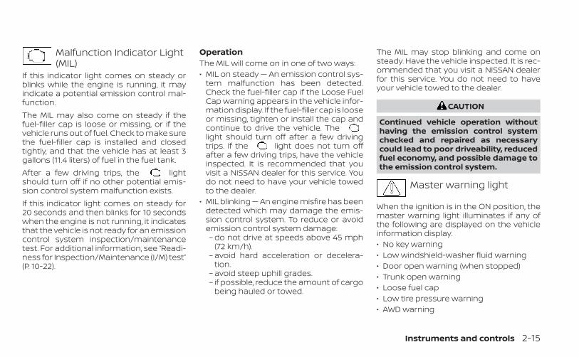
Malfunction Indicator Light(MIL)
If this indicator light comes on steady orblinks while the engine is running, it mayindicate a potential emission control mal-function.The MIL may also come on steady if thefuel-filler cap is loose or missing, or if thevehicle runs out of fuel. Check to make surethe fuel-filler cap is installed and closedtightly, and that the vehicle has at least 3gallons (11.4 liters) of fuel in the fuel tank.After a few driving trips, the lightshould turn off if no other potential emis-sion control system malfunction exists.If this indicator light comes on steady for20 seconds and then blinks for 10 secondswhen the engine is not running, it indicatesthat the vehicle is not ready for an emissioncontrol system inspection/maintenancetest. For additional information, see “Readi-ness for Inspection/Maintenance (I/M) test”(P. 10-22).
OperationThe MIL will come on in one of two ways:• MIL on steady — An emission control sys-
tem malfunction has been detected.Check the fuel-filler cap if the Loose FuelCap warning appears in the vehicle infor-mation display. If the fuel-filler cap is looseor missing, tighten or install the cap andcontinue to drive the vehicle. Thelight should turn off after a few drivingtrips. If the light does not turn offafter a few driving trips, have the vehicleinspected. It is recommended that youvisit a NISSAN dealer for this service. Youdo not need to have your vehicle towedto the dealer.
• MIL blinking — An engine misfire has beendetected which may damage the emis-sion control system. To reduce or avoidemission control system damage:– do not drive at speeds above 45 mph
(72 km/h).– avoid hard acceleration or decelera-
tion.– avoid steep uphill grades.– if possible, reduce the amount of cargo
being hauled or towed.
The MIL may stop blinking and come onsteady. Have the vehicle inspected. It is rec-ommended that you visit a NISSAN dealerfor this service. You do not need to haveyour vehicle towed to the dealer.
CAUTION
Continued vehicle operation withouthaving the emission control systemchecked and repaired as necessarycould lead to poor driveability, reducedfuel economy, and possible damage tothe emission control system.
Master warning light
When the ignition is in the ON position, themaster warning light illuminates if any ofthe following are displayed on the vehicleinformation display.• No key warning• Low windshield-washer fluid warning• Door open warning (when stopped)• Trunk open warning• Loose fuel cap• Low tire pressure warning• AWD warning
Instruments and controls 2-15
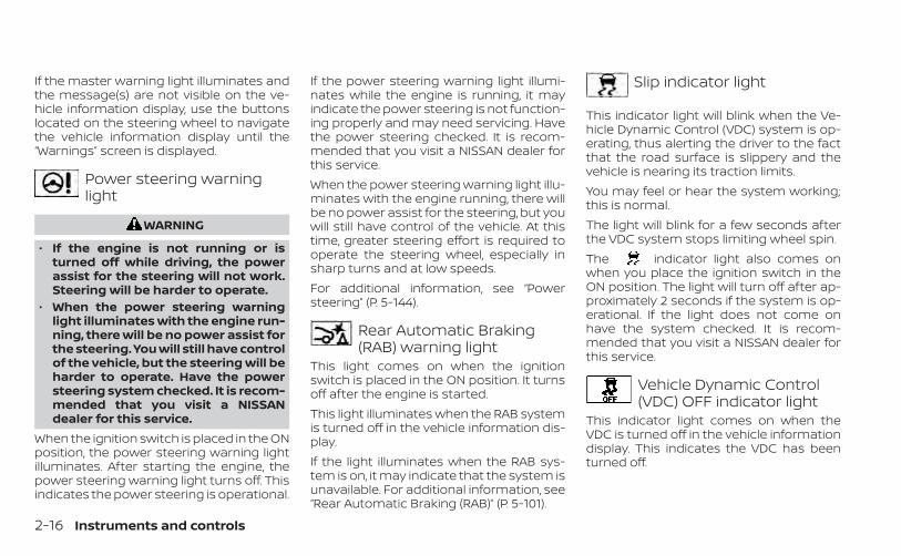
If the master warning light illuminates andthe message(s) are not visible on the ve-hicle information display, use the buttonslocated on the steering wheel to navigatethe vehicle information display until the“Warnings” screen is displayed.
Power steering warninglight
WARNING
• If the engine is not running or isturned off while driving, the powerassist for the steering will not work.Steering will be harder to operate.
• When the power steering warninglight illuminates with the engine run-ning, there will be no power assist forthe steering. You will still have controlof the vehicle, but the steering will beharder to operate. Have the powersteering system checked. It is recom-mended that you visit a NISSANdealer for this service.
When the ignition switch is placed in the ONposition, the power steering warning lightilluminates. After starting the engine, thepower steering warning light turns off. Thisindicates the power steering is operational.
If the power steering warning light illumi-nates while the engine is running, it mayindicate the power steering is not function-ing properly and may need servicing. Havethe power steering checked. It is recom-mended that you visit a NISSAN dealer forthis service.When the power steering warning light illu-minates with the engine running, there willbe no power assist for the steering, but youwill still have control of the vehicle. At thistime, greater steering effort is required tooperate the steering wheel, especially insharp turns and at low speeds.For additional information, see “Powersteering” (P. 5-144).
Rear Automatic Braking(RAB) warning light
This light comes on when the ignitionswitch is placed in the ON position. It turnsoff after the engine is started.This light illuminates when the RAB systemis turned off in the vehicle information dis-play.If the light illuminates when the RAB sys-tem is on, it may indicate that the system isunavailable. For additional information, see“Rear Automatic Braking (RAB)” (P. 5-101).
Slip indicator light
This indicator light will blink when the Ve-hicle Dynamic Control (VDC) system is op-erating, thus alerting the driver to the factthat the road surface is slippery and thevehicle is nearing its traction limits.You may feel or hear the system working;this is normal.The light will blink for a few seconds afterthe VDC system stops limiting wheel spin.The indicator light also comes onwhen you place the ignition switch in theON position. The light will turn off after ap-proximately 2 seconds if the system is op-erational. If the light does not come onhave the system checked. It is recom-mended that you visit a NISSAN dealer forthis service.
Vehicle Dynamic Control(VDC) OFF indicator light
This indicator light comes on when theVDC is turned off in the vehicle informationdisplay. This indicates the VDC has beenturned off.
2-16 Instruments and controls
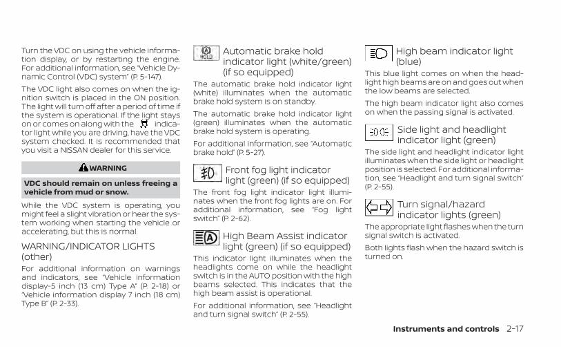
Turn the VDC on using the vehicle informa-tion display, or by restarting the engine.For additional information, see “Vehicle Dy-namic Control (VDC) system” (P. 5-147).The VDC light also comes on when the ig-nition switch is placed in the ON position.The light will turn off after a period of time ifthe system is operational. If the light stayson or comes on along with the indica-tor light while you are driving, have the VDCsystem checked. It is recommended thatyou visit a NISSAN dealer for this service.
WARNING
VDC should remain on unless freeing avehicle from mud or snow.
While the VDC system is operating, youmight feel a slight vibration or hear the sys-tem working when starting the vehicle oraccelerating, but this is normal.
WARNING/INDICATOR LIGHTS(other)For additional information on warningsand indicators, see “Vehicle informationdisplay-5 inch (13 cm) Type A” (P. 2-18) or“Vehicle information display 7 inch (18 cm)Type B” (P. 2-33).
Automatic brake holdindicator light (white/green)(if so equipped)
The automatic brake hold indicator light(white) illuminates when the automaticbrake hold system is on standby.The automatic brake hold indicator light(green) illuminates when the automaticbrake hold system is operating.For additional information, see “Automaticbrake hold” (P. 5-27).
Front fog light indicatorlight (green) (if so equipped)
The front fog light indicator light illumi-nates when the front fog lights are on. Foradditional information, see “Fog lightswitch” (P. 2-62).
High Beam Assist indicatorlight (green) (if so equipped)
This indicator light illuminates when theheadlights come on while the headlightswitch is in the AUTO position with the highbeams selected. This indicates that thehigh beam assist is operational.For additional information, see “Headlightand turn signal switch” (P. 2-55).
High beam indicator light(blue)
This blue light comes on when the head-light high beams are on and goes out whenthe low beams are selected.The high beam indicator light also comeson when the passing signal is activated.
Side light and headlightindicator light (green)
The side light and headlight indicator lightilluminates when the side light or headlightposition is selected. For additional informa-tion, see “Headlight and turn signal switch”(P. 2-55).
Turn signal/hazardindicator lights (green)
The appropriate light flashes when the turnsignal switch is activated.Both lights flash when the hazard switch isturned on.
Instruments and controls 2-17
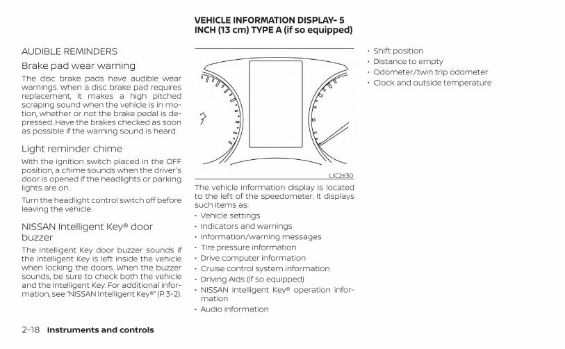
AUDIBLE REMINDERSBrake pad wear warningThe disc brake pads have audible wearwarnings. When a disc brake pad requiresreplacement, it makes a high pitchedscraping sound when the vehicle is in mo-tion, whether or not the brake pedal is de-pressed. Have the brakes checked as soonas possible if the warning sound is heard.
Light reminder chimeWith the ignition switch placed in the OFFposition, a chime sounds when the driver'sdoor is opened if the headlights or parkinglights are on.Turn the headlight control switch off beforeleaving the vehicle.
NISSAN Intelligent Key® doorbuzzerThe Intelligent Key door buzzer sounds ifthe Intelligent Key is left inside the vehiclewhen locking the doors. When the buzzersounds, be sure to check both the vehicleand the Intelligent Key. For additional infor-mation, see “NISSAN Intelligent Key®” (P. 3-2).
The vehicle information display is locatedto the left of the speedometer. It displayssuch items as:• Vehicle settings• Indicators and warnings• Information/warning messages• Tire pressure information• Drive computer information• Cruise control system information• Driving Aids (if so equipped)• NISSAN Intelligent Key® operation infor-
mation• Audio information
• Shift position• Distance to empty• Odometer/twin trip odometer• Clock and outside temperature
LIC2630
VEHICLE INFORMATION DISPLAY- 5INCH (13 cm) TYPE A (if so equipped)
2-18 Instruments and controls
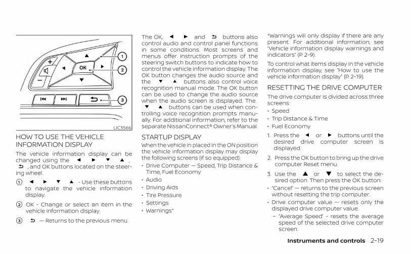
HOW TO USE THE VEHICLEINFORMATION DISPLAYThe vehicle information display can bechanged using the ,
, and OK buttons located on the steer-ing wheel.
�1 - Use these buttonsto navigate the vehicle informationdisplay.
�2 OK - Change or select an item in thevehicle information display.
�3 — Returns to the previous menu.
The OK, and buttons alsocontrol audio and control panel functionsin some conditions. Most screens andmenus offer instruction prompts of thesteering switch buttons to indicate how tocontrol the vehicle information display. TheOK button changes the audio source andthe buttons also control voicerecognition manual mode. The OK buttoncan be used to change the audio sourcewhen the audio screen is displayed. The
buttons can be used when con-trolling voice recognition prompts manu-ally. For additional information, refer to theseparate NissanConnect® Owner’s Manual.
STARTUP DISPLAYWhen the vehicle in placed in the ON positionthe vehicle information display may displaythe following screens (if so equipped):• Drive Computer — Speed, Trip Distance &
Time, Fuel Economy• Audio• Driving Aids• Tire Pressure• Settings• Warnings*
*Warnings will only display if there are anypresent. For additional information, see“Vehicle information display warnings andindicators” (P. 2-9).To control what items display in the vehicleinformation display, see “How to use thevehicle information display” (P. 2-19).
RESETTING THE DRIVE COMPUTERThe drive computer is divided across threescreens:• Speed• Trip Distance & Time• Fuel Economy1. Press the or buttons until the
desired drive computer screen isdisplayed.
2. Press the OK button to bring up the drivecomputer Reset menu.
3. Use the or to select the de-sired option. Then press the OK button:
• “Cancel” — returns to the previous screenwithout resetting the trip computer.
• Drive computer value — resets only thedisplayed drive computer value.– “Average Speed” - resets the average
speed of the selected drive computerscreen.
LIC3566
Instruments and controls 2-19
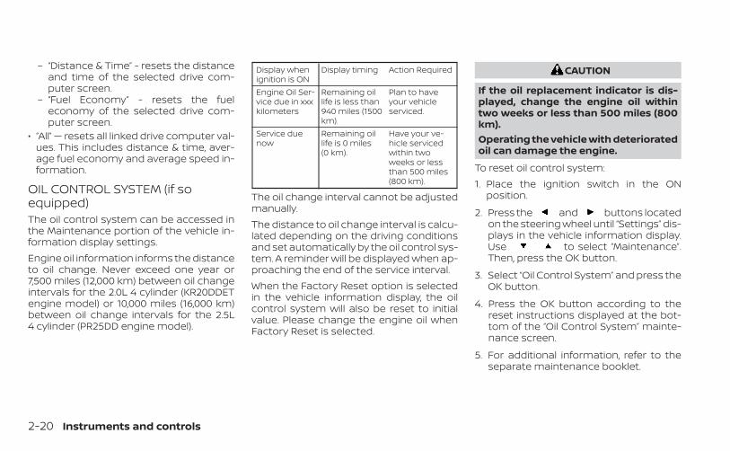
– “Distance & Time” - resets the distanceand time of the selected drive com-puter screen.
– “Fuel Economy” - resets the fueleconomy of the selected drive com-puter screen.
• “All” — resets all linked drive computer val-ues. This includes distance & time, aver-age fuel economy and average speed in-formation.
OIL CONTROL SYSTEM (if soequipped)The oil control system can be accessed inthe Maintenance portion of the vehicle in-formation display settings.Engine oil information informs the distanceto oil change. Never exceed one year or7,500 miles (12,000 km) between oil changeintervals for the 2.0L 4 cylinder (KR20DDETengine model) or 10,000 miles (16,000 km)between oil change intervals for the 2.5L4 cylinder (PR25DD engine model).
Display whenignition is ON
Display timing Action Required
Engine Oil Ser-vice due in xxxkilometers
Remaining oillife is less than940 miles (1500km).
Plan to haveyour vehicleserviced.
Service duenow
Remaining oillife is 0 miles(0 km).
Have your ve-hicle servicedwithin twoweeks or lessthan 500 miles(800 km).
The oil change interval cannot be adjustedmanually.The distance to oil change interval is calcu-lated depending on the driving conditionsand set automatically by the oil control sys-tem. A reminder will be displayed when ap-proaching the end of the service interval.When the Factory Reset option is selectedin the vehicle information display, the oilcontrol system will also be reset to initialvalue. Please change the engine oil whenFactory Reset is selected.
CAUTION
If the oil replacement indicator is dis-played, change the engine oil withintwo weeks or less than 500 miles (800km).Operating the vehicle with deterioratedoil can damage the engine.
To reset oil control system:1. Place the ignition switch in the ON
position.
2. Press the and buttons locatedon the steering wheel until “Settings” dis-plays in the vehicle information display.Use to select “Maintenance”.Then, press the OK button.
3. Select “Oil Control System” and press theOK button.
4. Press the OK button according to thereset instructions displayed at the bot-tom of the “Oil Control System” mainte-nance screen.
5. For additional information, refer to theseparate maintenance booklet.
2-20 Instruments and controls
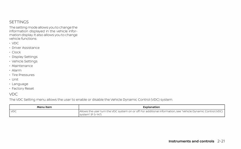
SETTINGSThe setting mode allows you to change theinformation displayed in the vehicle infor-mation display. It also allows you to changevehicle functions:• VDC• Driver Assistance• Clock• Display Settings• Vehicle Settings• Maintenance• Alarm• Tire Pressures• Unit• Language• Factory Reset
VDCThe VDC Setting menu allows the user to enable or disable the Vehicle Dynamic Control (VDC) system.
Menu item ExplanationVDC Allows the user turn the VDC system on or off. For additional information, see “Vehicle Dynamic Control (VDC)
system” (P. 5-147).
Instruments and controls 2-21
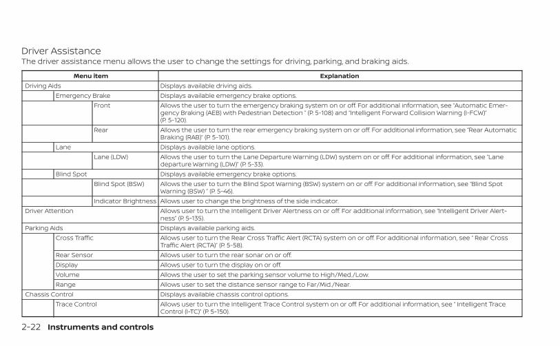
Driver AssistanceThe driver assistance menu allows the user to change the settings for driving, parking, and braking aids.
Menu item ExplanationDriving Aids Displays available driving aids.
Emergency Brake Displays available emergency brake options.Front Allows the user to turn the emergency braking system on or off. For additional information, see “Automatic Emer-
gency Braking (AEB) with Pedestrian Detection ” (P. 5-108) and “Intelligent Forward Collision Warning (I-FCW)”(P. 5-120).
Rear Allows the user to turn the rear emergency braking system on or off. For additional information, see “Rear AutomaticBraking (RAB)” (P. 5-101).
Lane Displays available lane options.Lane (LDW) Allows the user to turn the Lane Departure Warning (LDW) system on or off. For additional information, see “Lane
departure Warning (LDW)” (P. 5-33).Blind Spot Displays available emergency brake options.
Blind Spot (BSW) Allows the user to turn the Blind Spot Warning (BSW) system on or off. For additional information, see “Blind SpotWarning (BSW) ” (P. 5-46).
Indicator Brightness Allows user to change the brightness of the side indicator.Driver Attention Allows user to turn the Intelligent Driver Alertness on or off. For additional information, see “Intelligent Driver Alert-
ness” (P. 5-135).Parking Aids Displays available parking aids.
Cross Traffic Allows user to turn the Rear Cross Traffic Alert (RCTA) system on or off. For additional information, see “ Rear CrossTraffic Alert (RCTA)” (P. 5-58).
Rear Sensor Allows user to turn the rear sonar on or off.Display Allows user to turn the display on or off.Volume Allows the user to set the parking sensor volume to High/Med./Low.Range Allows user to set the distance sensor range to Far/Mid./Near.
Chassis Control Displays available chassis control options.Trace Control Allows user to turn the Intelligent Trace Control system on or off. For additional information, see “ Intelligent Trace
Control (I-TC)” (P. 5-150).
2-22 Instruments and controls
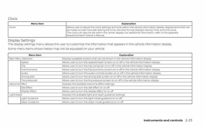
ClockMenu item Explanation
Clock Allows user to adjust the clock settings and time within the vehicle information display. Adjustments that canbe made include manually setting the time, 12H/24H format, Daylight Saving Time, and time zone.The clock can also be set within the center display. For additional information, refer to the separateNissanConnect® Owner’s Manual.
Display SettingsThe display settings menu allows the user to customize the information that appears in the vehicle information display.Some menu items shown below may not be equipped on your vehicle.
Menu item ExplanationMain Menu Selection Displays available screens that can be shown in the vehicle information display.
Speed Allows user to turn the speedometer screen on or off in the vehicle information display.Trip Allows user to turn the trip computer on or off in the vehicle information display.Fuel Economy Allows user to turn the fuel economy screen on or off in the vehicle information display.Audio Allows user to turn the audio controls screen on or off in the vehicle information display.Driving Aids Allows user to turn the driving aids screen on or off in the vehicle information display.Tire pressures Allows user to turn the tire pressure screen on or off in the vehicle information display.
Welcome Effect Displays the available welcome effect settings.Dial Effect Allows user to turn the dial effect on or off.Display Effect Allows user to turn the display effect on or off.
Light/Wiper Displays the available light and wiper guidance settings.Light Guidance Allows user to turn the light mode guidance on or off.Wiper Guidance Allows user to turn the wiper mode guidance on or off.
Instruments and controls 2-23
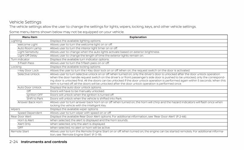
Vehicle SettingsThe vehicle settings allow the user to change the settings for lights, wipers, locking, keys, and other vehicle settings.Some menu items shown below may not be equipped on your vehicle.
Menu item ExplanationLighting Displays the available lighting options.
Welcome Light Allows user to turn the welcome light on or off.Auto Room Lamp Allows user to turn the interior light timer on or off.Light Sensitivity Allows user to change when the auto lights activate based on exterior brightness.Light Off Delay Allows user to change the length of time the exterior lights remain on.
Turn indicator Displays the available turn indicator options.3 Flash Pass Allows user to turn the 3 flash pass on or off.
Locking Displays the available locking options.I-Key Door Lock Allows the user to turn the I-Key door lock on or off. When on, the request switch on the door is activated.Selective Unlock Allows user to turn selective unlock on or off. When turned on, only the driver’s door is unlocked after the door unlock operation.
When the door handle request switch on the driver’s or front passenger’s side door is pushed to be unlocked, only the correspond-ing door is unlocked first. All the doors can be unlocked if the door unlock operation is performed again within 5 seconds. When thisitem is turned off, all the doors will be unlocked after the door unlock operation is performed once.
Auto Door Unlock Displays the auto door unlock options.Off Doors will have to be manually unlocked.Ignition OFF Doors will unlock when the ignition is turned off.Shift to Park Doors will unlock when the vehicle is shifted into Park.
Answer Back Horn Allows user to turn answer back horn on or off. When turned on, the horn will chirp and the hazard indicators will flash once whenlocking the vehicle with the Intelligent Key.
Wipers Displays the available wiper options.Speed Dependent Allows user to turn wiper with speed on or off.
Rear Door Alert Displays the available Rear Door Alert options. For additional information, see “Rear Door Alert” (P. 2-66).Horn & Alert When selected, the alert is displayed and the horn sounds.Alert Only When selected, only the alert is displayed.OFF When selected, no alert or horn will be active.
Remote Start Allows user to turn the Remote Engine Start on or off. When turned on, the engine can be started remotely. For additional informa-tion, see “Remote Engine Start” (P. 3-19).
2-24 Instruments and controls
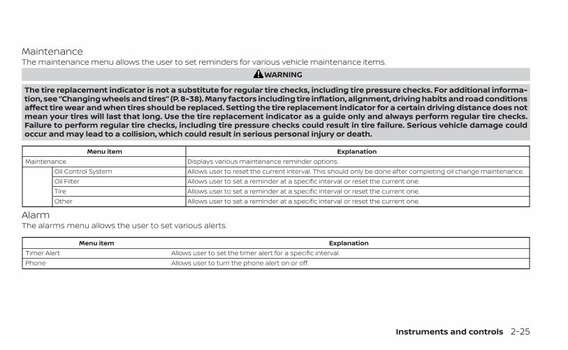
MaintenanceThe maintenance menu allows the user to set reminders for various vehicle maintenance items.
WARNING
The tire replacement indicator is not a substitute for regular tire checks, including tire pressure checks. For additional informa-tion, see “Changing wheels and tires” (P. 8-38). Many factors including tire inflation, alignment, driving habits and road conditionsaffect tire wear and when tires should be replaced. Setting the tire replacement indicator for a certain driving distance does notmean your tires will last that long. Use the tire replacement indicator as a guide only and always perform regular tire checks.Failure to perform regular tire checks, including tire pressure checks could result in tire failure. Serious vehicle damage couldoccur and may lead to a collision, which could result in serious personal injury or death.
Menu item ExplanationMaintenance Displays various maintenance reminder options.
Oil Control System Allows user to reset the current interval. This should only be done after completing oil change maintenance.Oil Filter Allows user to set a reminder at a specific interval or reset the current one.Tire Allows user to set a reminder at a specific interval or reset the current one.Other Allows user to set a reminder at a specific interval or reset the current one.
AlarmThe alarms menu allows the user to set various alerts.
Menu item ExplanationTimer Alert Allows user to set the timer alert for a specific interval.Phone Allows user to turn the phone alert on or off.
Instruments and controls 2-25
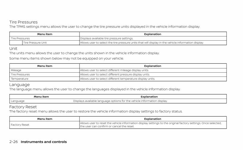
Tire PressuresThe TPMS settings menu allows the user to change the tire pressure units displayed in the vehicle information display.
Menu item ExplanationTire Pressures Displays available tire pressure settings.
Tire Pressure Unit Allows user to select the tire pressure units that will display in the vehicle information display.
UnitThe units menu allows the user to change the units shown in the vehicle information display.Some menu items shown below may not be equipped on your vehicle.
Menu item ExplanationMileage Allows user to select different mileage display units.Tire Pressures Allows user to select different pressure display units.Temperature Allows user to select different temperature display units.
LanguageThe language menu allows the user to change the languages displayed in the vehicle information display.
Menu item ExplanationLanguage Displays available language options for the vehicle information display.
Factory ResetThe factory reset menu allows the user to restore the vehicle information display settings to factory status.
Menu item Explanation
Factory Reset Allows user to reset the vehicle information display settings to the original factory settings. Once selected,the user can confirm or cancel the reset.
2-26 Instruments and controls
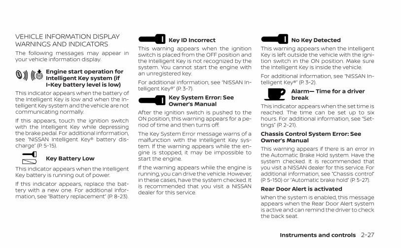
VEHICLE INFORMATION DISPLAYWARNINGS AND INDICATORSThe following messages may appear inyour vehicle information display.
Engine start operation forIntelligent Key system (ifI-Key battery level is low)
This indicator appears when the battery ofthe Intelligent Key is low and when the In-telligent Key system and the vehicle are notcommunicating normally.If this appears, touch the ignition switchwith the Intelligent Key while depressingthe brake pedal. For additional information,see “NISSAN Intelligent Key® battery dis-charge” (P. 5-15).
Key Battery Low
This indicator appears when the IntelligentKey battery is running out of power.If this indicator appears, replace the bat-tery with a new one. For additional infor-mation, see “Battery replacement” (P. 8-23).
Key ID IncorrectThis warning appears when the ignitionswitch is placed from the OFF position andthe Intelligent Key is not recognized by thesystem. You cannot start the engine withan unregistered key.For additional information, see “NISSAN In-telligent Key®” (P. 3-7).
Key System Error: SeeOwner’s Manual
After the ignition switch is pushed to theON position, this warning appears for a pe-riod of time and then turns off.The Key System Error message warns of amalfunction with the Intelligent Key sys-tem. If the warning appears while the en-gine is stopped, it may be impossible tostart the engine.If the warning appears while the engine isrunning, you can drive the vehicle. However,in these cases, have the system checked. Itis recommended that you visit a NISSANdealer for this service.
No Key DetectedThis warning appears when the IntelligentKey is left outside the vehicle with the igni-tion switch in the ON position. Make surethe Intelligent Key is inside the vehicle.For additional information, see “NISSAN In-telligent Key®” (P. 3-2).
Alarm— Time for a driverbreak
This indicator appears when the set time isreached. The time can be set up to sixhours. For additional information, see “Set-tings” (P. 2-21).Chassis Control System Error: SeeOwner’s ManualThis warning appears if there is an error inthe Automatic Brake Hold system. Have thesystem checked. It is recommended thatyou visit a NISSAN dealer for this service. Foradditional information, see “Chassis control”(P. 5-150) or “Automatic brake hold” (P. 5-27).Rear Door Alert is activatedWhen the system is enabled, this messageappears when the Rear Door Alert systemis active and can remind the driver to checkthe back seat.
Instruments and controls 2-27
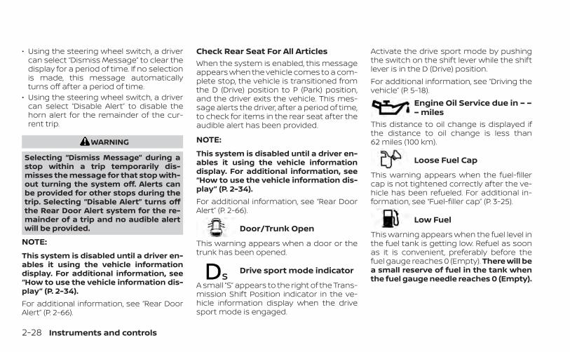
• Using the steering wheel switch, a drivercan select “Dismiss Message” to clear thedisplay for a period of time. If no selectionis made, this message automaticallyturns off after a period of time.
• Using the steering wheel switch, a drivercan select “Disable Alert” to disable thehorn alert for the remainder of the cur-rent trip.
WARNING
Selecting “Dismiss Message” during astop within a trip temporarily dis-misses the message for that stop with-out turning the system off. Alerts canbe provided for other stops during thetrip. Selecting “Disable Alert” turns offthe Rear Door Alert system for the re-mainder of a trip and no audible alertwill be provided.
NOTE:
This system is disabled until a driver en-ables it using the vehicle informationdisplay. For additional information, see“How to use the vehicle information dis-play” (P. 2-34).For additional information, see “Rear DoorAlert” (P. 2-66).
Check Rear Seat For All ArticlesWhen the system is enabled, this messageappears when the vehicle comes to a com-plete stop, the vehicle is transitioned fromthe D (Drive) position to P (Park) position,and the driver exits the vehicle. This mes-sage alerts the driver, after a period of time,to check for items in the rear seat after theaudible alert has been provided.
NOTE:
This system is disabled until a driver en-ables it using the vehicle informationdisplay. For additional information, see“How to use the vehicle information dis-play” (P. 2-34).For additional information, see “Rear DoorAlert” (P. 2-66).
Door/Trunk Open
This warning appears when a door or thetrunk has been opened.
Drive sport mode indicator
A small “S” appears to the right of the Trans-mission Shift Position indicator in the ve-hicle information display when the drivesport mode is engaged.
Activate the drive sport mode by pushingthe switch on the shift lever while the shiftlever is in the D (Drive) position.For additional information, see “Driving thevehicle” (P. 5-18).
Engine Oil Service due in – –– miles
This distance to oil change is displayed ifthe distance to oil change is less than62 miles (100 km).
Loose Fuel Cap
This warning appears when the fuel-fillercap is not tightened correctly after the ve-hicle has been refueled. For additional in-formation, see “Fuel-filler cap” (P. 3-25).
Low Fuel
This warning appears when the fuel level inthe fuel tank is getting low. Refuel as soonas it is convenient, preferably before thefuel gauge reaches 0 (Empty). There will bea small reserve of fuel in the tank whenthe fuel gauge needle reaches 0 (Empty).
2-28 Instruments and controls
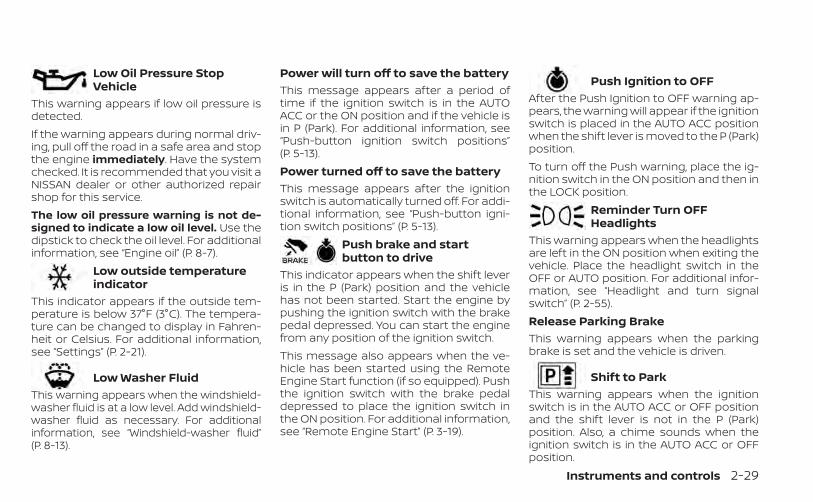
Low Oil Pressure StopVehicle
This warning appears if low oil pressure isdetected.If the warning appears during normal driv-ing, pull off the road in a safe area and stopthe engine immediately. Have the systemchecked. It is recommended that you visit aNISSAN dealer or other authorized repairshop for this service.The low oil pressure warning is not de-signed to indicate a low oil level. Use thedipstick to check the oil level. For additionalinformation, see “Engine oil” (P. 8-7).
Low outside temperatureindicator
This indicator appears if the outside tem-perature is below 37°F (3°C). The tempera-ture can be changed to display in Fahren-heit or Celsius. For additional information,see “Settings” (P. 2-21).
Low Washer FluidThis warning appears when the windshield-washer fluid is at a low level. Add windshield-washer fluid as necessary. For additionalinformation, see “Windshield-washer fluid”(P. 8-13).
Power will turn off to save the batteryThis message appears after a period oftime if the ignition switch is in the AUTOACC or the ON position and if the vehicle isin P (Park). For additional information, see“Push-button ignition switch positions”(P. 5-13).Power turned off to save the batteryThis message appears after the ignitionswitch is automatically turned off. For addi-tional information, see “Push-button igni-tion switch positions” (P. 5-13).
Push brake and startbutton to drive
This indicator appears when the shift leveris in the P (Park) position and the vehiclehas not been started. Start the engine bypushing the ignition switch with the brakepedal depressed. You can start the enginefrom any position of the ignition switch.This message also appears when the ve-hicle has been started using the RemoteEngine Start function (if so equipped). Pushthe ignition switch with the brake pedaldepressed to place the ignition switch inthe ON position. For additional information,see “Remote Engine Start” (P. 3-19).
Push Ignition to OFFAfter the Push Ignition to OFF warning ap-pears, the warning will appear if the ignitionswitch is placed in the AUTO ACC positionwhen the shift lever is moved to the P (Park)position.To turn off the Push warning, place the ig-nition switch in the ON position and then inthe LOCK position.
Reminder Turn OFFHeadlights
This warning appears when the headlightsare left in the ON position when exiting thevehicle. Place the headlight switch in theOFF or AUTO position. For additional infor-mation, see “Headlight and turn signalswitch” (P. 2-55).Release Parking BrakeThis warning appears when the parkingbrake is set and the vehicle is driven.
Shift to ParkThis warning appears when the ignitionswitch is in the AUTO ACC or OFF positionand the shift lever is not in the P (Park)position. Also, a chime sounds when theignition switch is in the AUTO ACC or OFFposition.
Instruments and controls 2-29
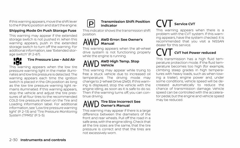
If this warning appears, move the shift leverto the P (Park) position and start the engine.Shipping Mode On Push Storage FuseThis warning may appear if the extendedstorage switch is not pushed in. When thiswarning appears, push in the extendedstorage switch to turn off the warning. Foradditional information, see “Extended stor-age switch” (P. 2-67).
Tire Pressure Low - Add Air
This warning appears when the low tirepressure warning light in the meter illumi-nates and low tire pressure is detected. Thewarning appears each time the ignitionswitch is placed in the ON position as longas the low tire pressure warning light re-mains illuminated. If this warning appears,stop the vehicle and adjust the tire pres-sures of all four tires to the recommendedCOLD tire pressure shown on the Tire andLoading Information label. For additionalinformation, see “Low tire pressure warninglight” (P. 2-13) and “Tire Pressure MonitoringSystem (TPMS)” (P. 5-5).
Transmission Shift Positionindicator
This indicator shows the transmission shiftposition.
AWD Error: See Owner’sManual
This warning appears when the all-wheeldrive system is not functioning properlywhile the engine is running.
AWD High Temp. StopVehicle
This warning may appear while trying tofree a stuck vehicle due to increased oiltemperature. The driving mode maychange to 2-Wheel Drive (2WD). If this warn-ing is displayed, stop the vehicle with theengine idling, as soon as it is safe to do so.Then if the warning turns off, you can con-tinue driving.
Tire Size Incorrect SeeOwner’s Manual
This warning may appear if there is a largedifference between the diameters of thefront and rear wheels. Pull off the road in asafe area, with the engine idling. Check thatall the tire sizes are the same, that the tirepressure is correct and that the tires arenot excessively worn.
Service CVT
This warning appears when there is aproblem with the CVT system. If this warn-ing appears, have the system checked. It isrecommended that you visit a NISSANdealer for this service.
CVT hot Power reduced
This transmission has a high fluid tem-perature protection mode. If the fluid tem-perature becomes too high (for example,climbing steep grades in high tempera-tures with heavy loads, such as when tow-ing a trailer), engine power and, undersome conditions, vehicle speed will be de-creased automatically to reduce thechance of transmission damage. Vehiclespeed can be controlled with the accelera-tor pedal, but the engine and vehicle speedmay be reduced.
2-30 Instruments and controls

WARNING
When the high fluid temperature pro-tection mode operation occurs, vehiclespeed may be gradually reduced. Thereduced speed may be lower thanother traffic, which could increase thechance of a collision. Be especiallycareful when driving. If necessary, pullto the side of the road at a safe placeand allow the transmission to return tonormal operation; or have it repaired ifnecessary.
Engine Stalled: Stop safelyThis message appears 30 seconds beforethe vehicle is shut down due to an abovenormal operating exhaust temperature.The Malfunction Indicator Light (MIL) andmalfunction warning (red) will illuminate.Have the system checked. It is recom-mended that you visit a NISSAN dealer im-mediately for this service.
Engine Malfunction Power reducedService nowThis warning appears when the engine isnot operating under normal conditions. Ifthis warning appears, have the systemchecked. It is recommended that you visit aNISSAN dealer for this service.Engine Malfunction Service nowThis warning appears when there is aproblem with the engine. If this warningappears, have the system checked. It is rec-ommended that you visit a NISSAN dealerfor this service.Engine hot Power reducedThis engine has a high fluid temperatureprotection mode. If the fluid temperaturebecomes too high (for example, climbingsteep grades in high temperatures withheavy loads, such as when towing a trailer),engine power and, under some conditions,vehicle speed will be decreased automati-cally to reduce the chance of engine dam-age. Vehicle speed can be controlled withthe accelerator pedal, but the engine andvehicle speed may be reduced.
WARNING
When the high fluid temperature pro-tection mode operation occurs, vehiclespeed may be gradually reduced. Thereduced speed may be lower thanother traffic, which could increase thechance of a collision. Be especiallycareful when driving. If necessary, pullto the side of the road at a safe placeand allow the engine to return to nor-mal operation; or have it repaired ifnecessary.
Automatic EmergencyBraking (AEB) withPedestrian Detectionemergency warningindicator
This indicator appears along, with an au-dible warning, when the system detectsthe possibility of a forward collision.For additional information, see “AutomaticEmergency Braking (AEB) with PedestrianDetection” (P. 5-108).
Instruments and controls 2-31
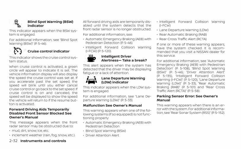
Blind Spot Warning (BSW)indicator
This indicator appears when the BSW sys-tem is engaged.For additional information, see “Blind SpotWarning (BSW)” (P. 5-46).
Cruise control indicator
This indicator shows the cruise control sys-tem status.When cruise control is activated, a greencircle will appear to indicate it is set. Thevehicle information display will also displaythe speed the cruise control was set at. Ifyou accelerate past the set speed, thespeed will blink until you either cancelcruise control or go back to the set speed. Ifcruise control is on and canceled, thespeed will be displayed to show the speedthe vehicle will return to if the resume but-ton is activated.Forward Driving Aids TemporarilyDisabled Front Sensor Blocked SeeOwner’s ManualThis message appears when the frontradar sensor may be obstructed due to:• mud, dirt, snow, ice, etc.• inclement weather (rain, fog, snow, etc.).
All forward driving aids are temporarily dis-abled until the system detects that thefront radar sensor is no longer obstructed.For additional information, see:• Automatic Emergency Braking (AEB) with
Pedestrian Detection (P. 5-46).• Intelligent Forward Collision Warning
(I-FCW) (P. 5-120).Intelligent DriverAlertness— Take a break?
This alert appears when the system hasdetected that the driver may be displayingfatigue or a lack of attention.
Lane Departure Warning(LDW) indicator
This indicator appears when the LDW sys-tem is engaged.For additional information, see “Lane De-parture Warning (LDW)” (P. 5-33).Malfunction See Owner’s ManualThis warning appears when one of the fol-lowing systems (if so equipped) is not func-tioning properly:• Automatic Emergency Braking (AEB) with
Pedestrian Detection• Blind Spot Warning (BSW)• Driver Attention Alert
• Intelligent Forward Collision Warning(I-FCW)
• Lane Departure Warning (LDW)• Rear Automatic Braking (RAB)• Rear Cross Traffic Alert (RCTA)If one or more of these warning appears,have the system checked. It is recom-mended that you visit a NISSAN dealer forthis service.For additional information, see “AutomaticEmergency Braking (AEB) with PedestrianDetection” (P. 5-108), “Blind Spot Warning(BSW)” (P. 5-46), “Driver Attention Alert”(P. 5-135), “Intelligent Forward CollisionWarning (I-FCW)” (P. 5-120), “Lane DepartureWarning (LDW)” (P. 5-33), “Rear AutomaticBraking (RAB)” (P. 5-101) and “Rear CrossTraffic Alert (RCTA)” (P. 5-58).Parking Sensor Error: See Owner’sManualThis warning appears when there is an er-ror with the system. For additional informa-tion, see “Rear Sonar System (RSS)” (P. 5-152).
2-32 Instruments and controls
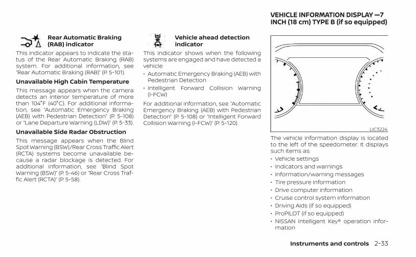
Rear Automatic Braking(RAB) indicator
This indicator appears to indicate the sta-tus of the Rear Automatic Braking (RAB)system. For additional information, see“Rear Automatic Braking (RAB)” (P. 5-101).Unavailable High Cabin TemperatureThis message appears when the cameradetects an interior temperature of morethan 104°F (40°C). For additional informa-tion, see “Automatic Emergency Braking(AEB) with Pedestrian Detection” (P. 5-108)or “Lane Departure Warning (LDW)” (P. 5-33).Unavailable Side Radar ObstructionThis message appears when the BlindSpot Warning (BSW)/Rear Cross Traffic Alert(RCTA) systems become unavailable be-cause a radar blockage is detected. Foradditional information, see “Blind SpotWarning (BSW)” (P. 5-46) or “Rear Cross Traf-fic Alert (RCTA)” (P. 5-58).
Vehicle ahead detectionindicator
This indicator shows when the followingsystems are engaged and have detected avehicle:• Automatic Emergency Braking (AEB) with
Pedestrian Detection• Intelligent Forward Collision Warning
(I-FCW)For additional information, see “AutomaticEmergency Braking (AEB) with PedestrianDetection” (P. 5-108) or “Intelligent ForwardCollision Warning (I-FCW)” (P. 5-120).
The vehicle information display is locatedto the left of the speedometer. It displayssuch items as:• Vehicle settings• Indicators and warnings• Information/warning messages• Tire pressure information• Drive computer information• Cruise control system information• Driving Aids (if so equipped)• ProPILOT (if so equipped)• NISSAN Intelligent Key® operation infor-
mation
LIC3224
VEHICLE INFORMATION DISPLAY —7INCH (18 cm) TYPE B (if so equipped)
Instruments and controls 2-33
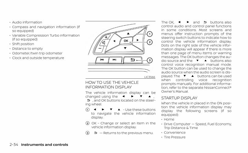
• Audio information• Compass and navigation information (if
so equipped)• Variable Compression Turbo information
(if so equipped)• Shift position• Distance to empty• Odometer/twin trip odometer• Clock and outside temperature
HOW TO USE THE VEHICLEINFORMATION DISPLAYThe vehicle information display can bechanged using the ,
, and OK buttons located on the steer-ing wheel.
�1 - Use these buttonsto navigate the vehicle informationdisplay.
�2 OK - Change or select an item in thevehicle information display.
�3 — Returns to the previous menu.
The OK, and buttons alsocontrol audio and control panel functionsin some conditions. Most screens andmenus offer instruction prompts of thesteering switch buttons to indicate how tocontrol the vehicle information display.Dots on the right side of the vehicle infor-mation display will appear if there is morethan one page of menu items or warningmessages. The OK button changes the au-dio source and the buttons alsocontrol voice recognition manual mode.The OK button can be used to change theaudio source when the audio screen is dis-played. The buttons can be usedwhen controlling voice recognitionprompts manually. For additional informa-tion, refer to the separate NissanConnect®Owner’s Manual.
STARTUP DISPLAYWhen the vehicle in placed in the ON posi-tion the vehicle information display maydisplay the following screens (if soequipped):• Home• Drive Computer — Speed, Fuel Economy,
Trip Distance & Time• Convenience• Tire Pressure
LIC3566
2-34 Instruments and controls
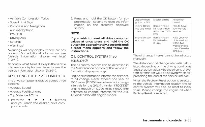
• Variable Compression Turbo• Speed Limit Sign• Compass and Navigation• Audio/telephone• ProPILOT• Driving Aids• Settings• Warnings**Warnings will only display if there are anypresent. For additional information, see“Vehicle information display warnings”(P. 2-44).To control what items display in the vehicleinformation display, see “How to use thevehicle information display” (P. 2-34).
RESETTING THE DRIVE COMPUTERThe drive computer is divided across threescreens:• Average Speed• Average Fuel Economy• Trip Distance & Time1. Press the buttons
until you reach the desired drive com-puter mode.
2. Press and hold the OK button for ap-proximately 1 second to reset the infor-mation on the currently displayedscreen.
NOTE:
If you wish to reset all drive computervalues at once, press and hold the OKbutton for approximately 3 seconds untila reset menu appears; and follow theinstructions.
OIL CONTROL SYSTEM (if soequipped)The oil control system can be accessed inthe Maintenance portion of the vehicle in-formation display settings.Engine oil information informs the distanceto oil change. Never exceed one year or7,500 miles (12000 km) between oil changeintervals for the 2.0L 4 cylinder (KR20DDETengine model) or 10,000 miles (16,000 km)between oil change intervals for the 2.5L4 cylinder (PR25DD engine model).
Display whenignition is ON
Display timing Action Re-quired
Engine Oil Ser-vice due in xxxmiles
Remaining oillife is less than940 miles (1500km).
Plan to haveyour vehicleserviced.
Engine Oil Ser-vice due
Remaining oillife is 0 miles(0 km).
Have your ve-hicle servicedwithin twoweeks or lessthan 500 miles(800 km).
The oil change interval cannot be adjustedmanually.The distance to oil change interval is calcu-lated depending on the driving conditionsand set automatically by the oil control sys-tem. A reminder will be displayed when ap-proaching the end of the service interval.When the Factory Reset option is selectedin the vehicle information display, the oilcontrol system will also be reset to initialvalue. Please change the engine oil whenFactory Reset is selected.
Instruments and controls 2-35
CAUTION
If the oil replacement indicator is dis-played, change the engine oil withintwo weeks or less than 500 miles (800km).Operating the vehicle with deterioratedoil can damage the engine.
To reset oil control system:1. Push ignition button to “ON” position.
2. Push the and buttons locatedon the steering wheel until “Settings” dis-plays in the vehicle information display.Use the buttons to select“Maintenance”. Then, press the OKbutton.
3. Select the “Oil Control System” and pressthe OK button.
4. Press the OK button according to thereset instructions displayed at the bot-tom of the “Oil Control System” mainte-nance screen.
For additional information, see “Oil controlsystem” (P. 9-7).
SETTINGSThe setting mode allows you to change theinformation displayed in the vehicle infor-mation display. It also allows you to changevehicle functions:• VDC Setting• Driver Assistance• TPMS Setting• Clock• Vehicle Settings• Maintenance• Customize Display• Unit/Language• Key-Linked Settings (if so equipped)• Factory Reset
VDC SettingThe VDC Setting menu allows the user to enable or disable the Vehicle Dynamic Control (VDC) system.
Menu item ExplanationSystem Allows the user to turn the VDC system on or off. For additional information, see “Vehicle Dynamic Control
(VDC) system” (P. 5-147).
2-36 Instruments and controls
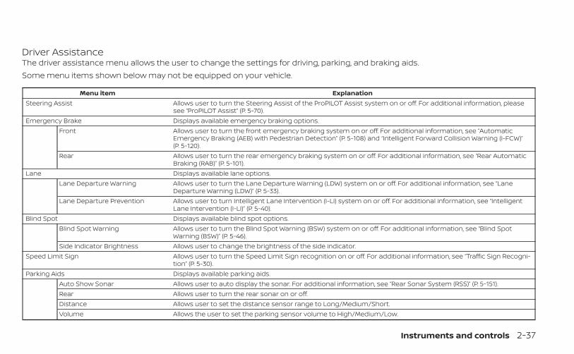
Driver AssistanceThe driver assistance menu allows the user to change the settings for driving, parking, and braking aids.Some menu items shown below may not be equipped on your vehicle.
Menu item ExplanationSteering Assist Allows user to turn the Steering Assist of the ProPILOT Assist system on or off. For additional information, please
see “ProPILOT Assist” (P. 5-70).Emergency Brake Displays available emergency braking options.
Front Allows user to turn the front emergency braking system on or off. For additional information, see “AutomaticEmergency Braking (AEB) with Pedestrian Detection” (P. 5-108) and “Intelligent Forward Collision Warning (I-FCW)”(P. 5-120).
Rear Allows user to turn the rear emergency braking system on or off. For additional information, see “Rear AutomaticBraking (RAB)” (P. 5-101).
Lane Displays available lane options.Lane Departure Warning Allows user to turn the Lane Departure Warning (LDW) system on or off. For additional information, see “Lane
Departure Warning (LDW)” (P. 5-33).Lane Departure Prevention Allows user to turn Intelligent Lane Intervention (I-LI) system on or off. For additional information, see “Intelligent
Lane Intervention (I-LI)” (P. 5-40).Blind Spot Displays available blind spot options.
Blind Spot Warning Allows user to turn the Blind Spot Warning (BSW) system on or off. For additional information, see “Blind SpotWarning (BSW)” (P. 5-46).
Side Indicator Brightness Allows user to change the brightness of the side indicator.Speed Limit Sign Allows user to turn the Speed Limit Sign recognition on or off. For additional information, see “Traffic Sign Recogni-
tion” (P. 5-30).Parking Aids Displays available parking aids.
Auto Show Sonar Allows user to auto display the sonar. For additional information, see “Rear Sonar System (RSS)” (P. 5-151).Rear Allows user to turn the rear sonar on or off.Distance Allows user to set the distance sensor range to Long/Medium/Short.Volume Allows the user to set the parking sensor volume to High/Medium/Low.
Instruments and controls 2-37
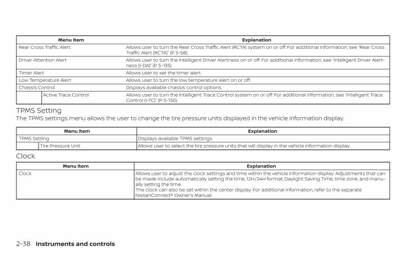
Menu item ExplanationRear Cross Traffic Alert Allows user to turn the Rear Cross Traffic Alert (RCTA) system on or off. For additional information, see “Rear Cross
Traffic Alert (RCTA)” (P. 5-58).Driver Attention Alert Allows user to turn the Intelligent Driver Alertness on or off. For additional information, see “Intelligent Driver Alert-
ness (I-DA)” (P. 5-135).Timer Alert Allows user to set the timer alert.Low Temperature Alert Allows user to turn the low temperature alert on or off.Chassis Control Displays available chassis control options.
Active Trace Control Allows user to turn the Intelligent Trace Control system on or off. For additional information, see “Intelligent TraceControl (I-TC)” (P. 5-150).
TPMS SettingThe TPMS settings menu allows the user to change the tire pressure units displayed in the vehicle information display.
Menu item ExplanationTPMS Setting Displays available TPMS settings.
Tire Pressure Unit Allows user to select the tire pressure units that will display in the vehicle information display.
ClockMenu item Explanation
Clock Allows user to adjust the clock settings and time within the vehicle information display. Adjustments that canbe made include automatically setting the time, 12H/24H format, Daylight Saving Time, time zone, and manu-ally setting the time.The clock can also be set within the center display. For additional information, refer to the separateNissanConnect® Owner’s Manual.
2-38 Instruments and controls
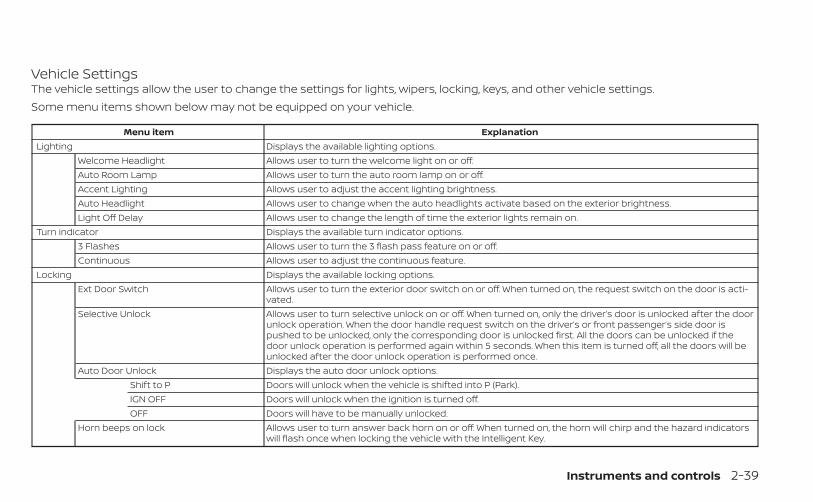
Vehicle SettingsThe vehicle settings allow the user to change the settings for lights, wipers, locking, keys, and other vehicle settings.Some menu items shown below may not be equipped on your vehicle.
Menu item ExplanationLighting Displays the available lighting options.
Welcome Headlight Allows user to turn the welcome light on or off.Auto Room Lamp Allows user to turn the auto room lamp on or off.Accent Lighting Allows user to adjust the accent lighting brightness.Auto Headlight Allows user to change when the auto headlights activate based on the exterior brightness.Light Off Delay Allows user to change the length of time the exterior lights remain on.
Turn indicator Displays the available turn indicator options.3 Flashes Allows user to turn the 3 flash pass feature on or off.Continuous Allows user to adjust the continuous feature.
Locking Displays the available locking options.Ext Door Switch Allows user to turn the exterior door switch on or off. When turned on, the request switch on the door is acti-
vated.Selective Unlock Allows user to turn selective unlock on or off. When turned on, only the driver’s door is unlocked after the door
unlock operation. When the door handle request switch on the driver’s or front passenger’s side door ispushed to be unlocked, only the corresponding door is unlocked first. All the doors can be unlocked if thedoor unlock operation is performed again within 5 seconds. When this item is turned off, all the doors will beunlocked after the door unlock operation is performed once.
Auto Door Unlock Displays the auto door unlock options.Shift to P Doors will unlock when the vehicle is shifted into P (Park).IGN OFF Doors will unlock when the ignition is turned off.OFF Doors will have to be manually unlocked.
Horn beeps on lock Allows user to turn answer back horn on or off. When turned on, the horn will chirp and the hazard indicatorswill flash once when locking the vehicle with the Intelligent Key.
Instruments and controls 2-39
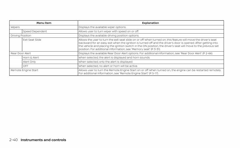
Menu item ExplanationWipers Displays the available wiper options.
Speed Dependent Allows user to turn wiper with speed on or off.Driving Position Displays the available driving position options.
Exit Seat Slide Allows the user to turn the exit seat slide on or off. When turned on, this feature will move the driver’s seatbackward for an easy exit when the ignition is turned off and the driver’s door is opened. After getting intothe vehicle and placing the ignition switch in the ON position, the driver’s seat will move to the previous setposition. For additional information, see “Memory seat” (P. 3-31).
Rear Door Alert Displays the available Rear Door Alert options. For additional information, see “Rear Door Alert” (P. 2-66).Horn & Alert When selected, the alert is displayed and horn sounds.Alert Only When selected, only the alert is displayed.OFF When selected, no alert or horn will be active.
Remote Engine Start Allows user to turn the Remote Engine Start on or off. When turned on, the engine can be restarted remotely.For additional information, see “Remote Engine Start” (P. 5-17).
2-40 Instruments and controls
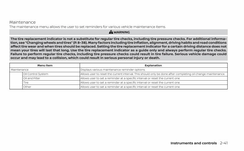
MaintenanceThe maintenance menu allows the user to set reminders for various vehicle maintenance items.
WARNING
The tire replacement indicator is not a substitute for regular tire checks, including tire pressure checks. For additional informa-tion, see “Changing wheels and tires” (P. 8-38). Many factors including tire inflation, alignment, driving habits and road conditionsaffect tire wear and when tires should be replaced. Setting the tire replacement indicator for a certain driving distance does notmean your tires will last that long. Use the tire replacement indicator as a guide only and always perform regular tire checks.Failure to perform regular tire checks, including tire pressure checks could result in tire failure. Serious vehicle damage couldoccur and may lead to a collision, which could result in serious personal injury or death.
Menu item ExplanationMaintenance Displays various maintenance reminder options.
Oil Control System Allows user to reset the current interval. This should only be done after completing oil change maintenance.Oil and Filter Allows user to set a reminder at a specific interval or reset the current one.Tire Allows user to set a reminder at a specific interval or reset the current one.Other Allows user to set a reminder at a specific interval or reset the current one.
Instruments and controls 2-41
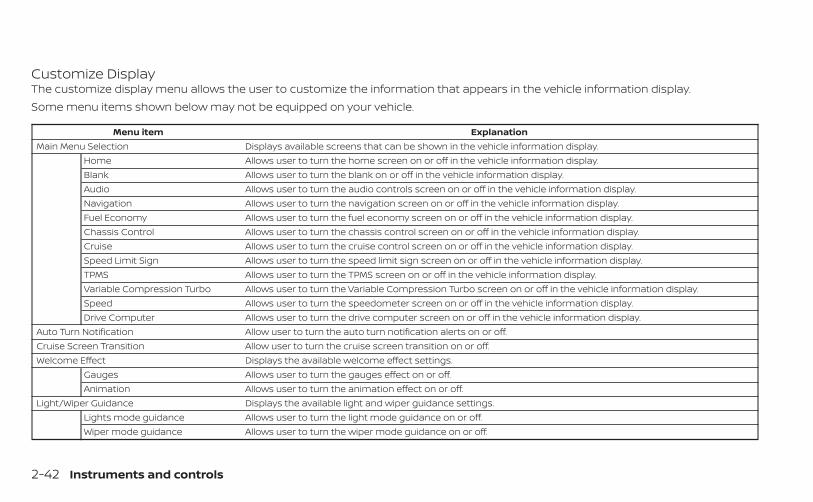
Customize DisplayThe customize display menu allows the user to customize the information that appears in the vehicle information display.Some menu items shown below may not be equipped on your vehicle.
Menu item ExplanationMain Menu Selection Displays available screens that can be shown in the vehicle information display.
Home Allows user to turn the home screen on or off in the vehicle information display.Blank Allows user to turn the blank on or off in the vehicle information display.Audio Allows user to turn the audio controls screen on or off in the vehicle information display.Navigation Allows user to turn the navigation screen on or off in the vehicle information display.Fuel Economy Allows user to turn the fuel economy screen on or off in the vehicle information display.Chassis Control Allows user to turn the chassis control screen on or off in the vehicle information display.Cruise Allows user to turn the cruise control screen on or off in the vehicle information display.Speed Limit Sign Allows user to turn the speed limit sign screen on or off in the vehicle information display.TPMS Allows user to turn the TPMS screen on or off in the vehicle information display.Variable Compression Turbo Allows user to turn the Variable Compression Turbo screen on or off in the vehicle information display.Speed Allows user to turn the speedometer screen on or off in the vehicle information display.Drive Computer Allows user to turn the drive computer screen on or off in the vehicle information display.
Auto Turn Notification Allow user to turn the auto turn notification alerts on or off.Cruise Screen Transition Allow user to turn the cruise screen transition on or off.Welcome Effect Displays the available welcome effect settings.
Gauges Allows user to turn the gauges effect on or off.Animation Allows user to turn the animation effect on or off.
Light/Wiper Guidance Displays the available light and wiper guidance settings.Lights mode guidance Allows user to turn the light mode guidance on or off.Wiper mode guidance Allows user to turn the wiper mode guidance on or off.
2-42 Instruments and controls
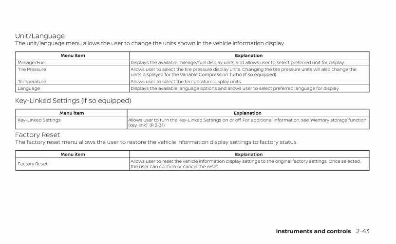
Unit/LanguageThe unit/language menu allows the user to change the units shown in the vehicle information display.
Menu item ExplanationMileage/Fuel Displays the available mileage/fuel display units and allows user to select preferred unit for display.Tire Pressure Allows user to select the tire pressure display units. Changing the tire pressure units will also change the
units displayed for the Variable Compression Turbo (if so equipped).Temperature Allows user to select the temperature display units.Language Displays the available language options and allows user to select preferred language for display.
Key-Linked Settings (if so equipped)
Menu item ExplanationKey-Linked Settings Allows user to turn the Key-Linked Settings on or off. For additional information, see “Memory storage function
(key-link)” (P. 3-31).
Factory ResetThe factory reset menu allows the user to restore the vehicle information display settings to factory status.
Menu item Explanation
Factory Reset Allows user to reset the vehicle information display settings to the original factory settings. Once selected,the user can confirm or cancel the reset.
Instruments and controls 2-43
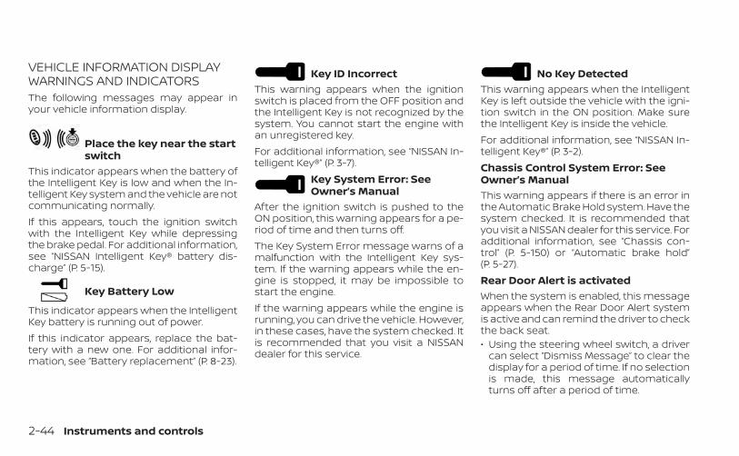
VEHICLE INFORMATION DISPLAYWARNINGS AND INDICATORSThe following messages may appear inyour vehicle information display.
Place the key near the startswitch
This indicator appears when the battery ofthe Intelligent Key is low and when the In-telligent Key system and the vehicle are notcommunicating normally.If this appears, touch the ignition switchwith the Intelligent Key while depressingthe brake pedal. For additional information,see “NISSAN Intelligent Key® battery dis-charge” (P. 5-15).
Key Battery Low
This indicator appears when the IntelligentKey battery is running out of power.If this indicator appears, replace the bat-tery with a new one. For additional infor-mation, see “Battery replacement” (P. 8-23).
Key ID IncorrectThis warning appears when the ignitionswitch is placed from the OFF position andthe Intelligent Key is not recognized by thesystem. You cannot start the engine withan unregistered key.For additional information, see “NISSAN In-telligent Key®” (P. 3-7).
Key System Error: SeeOwner’s Manual
After the ignition switch is pushed to theON position, this warning appears for a pe-riod of time and then turns off.The Key System Error message warns of amalfunction with the Intelligent Key sys-tem. If the warning appears while the en-gine is stopped, it may be impossible tostart the engine.If the warning appears while the engine isrunning, you can drive the vehicle. However,in these cases, have the system checked. Itis recommended that you visit a NISSANdealer for this service.
No Key DetectedThis warning appears when the IntelligentKey is left outside the vehicle with the igni-tion switch in the ON position. Make surethe Intelligent Key is inside the vehicle.For additional information, see “NISSAN In-telligent Key®” (P. 3-2).Chassis Control System Error: SeeOwner’s ManualThis warning appears if there is an error inthe Automatic Brake Hold system. Have thesystem checked. It is recommended thatyou visit a NISSAN dealer for this service. Foradditional information, see “Chassis con-trol” (P. 5-150) or “Automatic brake hold”(P. 5-27).Rear Door Alert is activatedWhen the system is enabled, this messageappears when the Rear Door Alert systemis active and can remind the driver to checkthe back seat.• Using the steering wheel switch, a driver
can select “Dismiss Message” to clear thedisplay for a period of time. If no selectionis made, this message automaticallyturns off after a period of time.
2-44 Instruments and controls
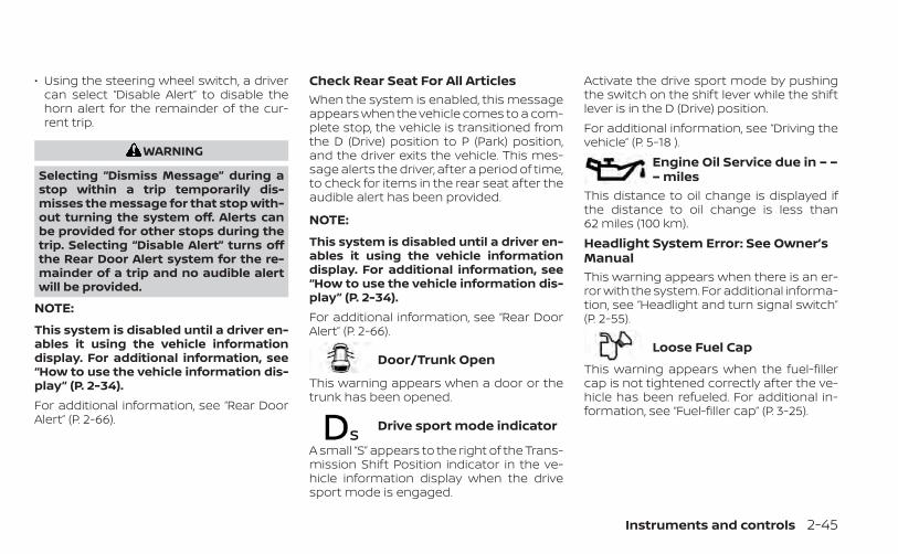
• Using the steering wheel switch, a drivercan select “Disable Alert” to disable thehorn alert for the remainder of the cur-rent trip.
WARNING
Selecting “Dismiss Message” during astop within a trip temporarily dis-misses the message for that stop with-out turning the system off. Alerts canbe provided for other stops during thetrip. Selecting “Disable Alert” turns offthe Rear Door Alert system for the re-mainder of a trip and no audible alertwill be provided.
NOTE:
This system is disabled until a driver en-ables it using the vehicle informationdisplay. For additional information, see“How to use the vehicle information dis-play” (P. 2-34).For additional information, see “Rear DoorAlert” (P. 2-66).
Check Rear Seat For All ArticlesWhen the system is enabled, this messageappears when the vehicle comes to a com-plete stop, the vehicle is transitioned fromthe D (Drive) position to P (Park) position,and the driver exits the vehicle. This mes-sage alerts the driver, after a period of time,to check for items in the rear seat after theaudible alert has been provided.
NOTE:
This system is disabled until a driver en-ables it using the vehicle informationdisplay. For additional information, see“How to use the vehicle information dis-play” (P. 2-34).For additional information, see “Rear DoorAlert” (P. 2-66).
Door/Trunk Open
This warning appears when a door or thetrunk has been opened.
Drive sport mode indicator
A small “S” appears to the right of the Trans-mission Shift Position indicator in the ve-hicle information display when the drivesport mode is engaged.
Activate the drive sport mode by pushingthe switch on the shift lever while the shiftlever is in the D (Drive) position.For additional information, see “Driving thevehicle” (P. 5-18 ).
Engine Oil Service due in – –– miles
This distance to oil change is displayed ifthe distance to oil change is less than62 miles (100 km).Headlight System Error: See Owner’sManualThis warning appears when there is an er-ror with the system. For additional informa-tion, see “Headlight and turn signal switch”(P. 2-55).
Loose Fuel Cap
This warning appears when the fuel-fillercap is not tightened correctly after the ve-hicle has been refueled. For additional in-formation, see “Fuel-filler cap” (P. 3-25).
Instruments and controls 2-45
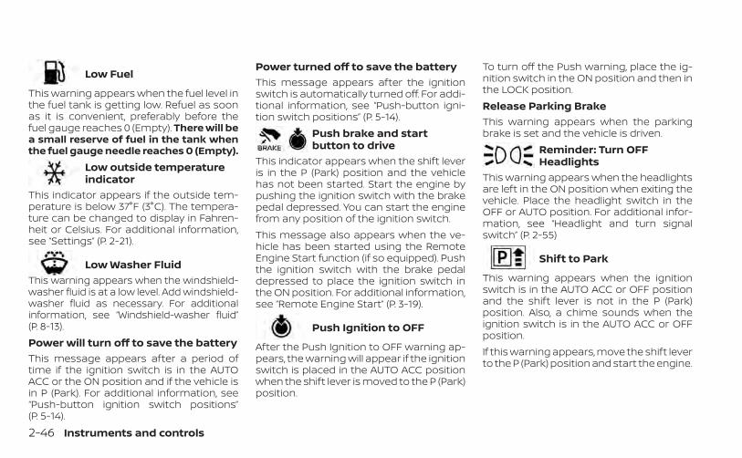
Low Fuel
This warning appears when the fuel level inthe fuel tank is getting low. Refuel as soonas it is convenient, preferably before thefuel gauge reaches 0 (Empty). There will bea small reserve of fuel in the tank whenthe fuel gauge needle reaches 0 (Empty).
Low outside temperatureindicator
This indicator appears if the outside tem-perature is below 37°F (3°C). The tempera-ture can be changed to display in Fahren-heit or Celsius. For additional information,see “Settings” (P. 2-21).
Low Washer FluidThis warning appears when the windshield-washer fluid is at a low level. Add windshield-washer fluid as necessary. For additionalinformation, see “Windshield-washer fluid”(P. 8-13).Power will turn off to save the batteryThis message appears after a period oftime if the ignition switch is in the AUTOACC or the ON position and if the vehicle isin P (Park). For additional information, see“Push-button ignition switch positions”(P. 5-14).
Power turned off to save the batteryThis message appears after the ignitionswitch is automatically turned off. For addi-tional information, see “Push-button igni-tion switch positions” (P. 5-14).
Push brake and startbutton to drive
This indicator appears when the shift leveris in the P (Park) position and the vehiclehas not been started. Start the engine bypushing the ignition switch with the brakepedal depressed. You can start the enginefrom any position of the ignition switch.This message also appears when the ve-hicle has been started using the RemoteEngine Start function (if so equipped). Pushthe ignition switch with the brake pedaldepressed to place the ignition switch inthe ON position. For additional information,see “Remote Engine Start” (P. 3-19).
Push Ignition to OFF
After the Push Ignition to OFF warning ap-pears, the warning will appear if the ignitionswitch is placed in the AUTO ACC positionwhen the shift lever is moved to the P (Park)position.
To turn off the Push warning, place the ig-nition switch in the ON position and then inthe LOCK position.Release Parking BrakeThis warning appears when the parkingbrake is set and the vehicle is driven.
Reminder: Turn OFFHeadlights
This warning appears when the headlightsare left in the ON position when exiting thevehicle. Place the headlight switch in theOFF or AUTO position. For additional infor-mation, see “Headlight and turn signalswitch” (P. 2-55)
Shift to Park
This warning appears when the ignitionswitch is in the AUTO ACC or OFF positionand the shift lever is not in the P (Park)position. Also, a chime sounds when theignition switch is in the AUTO ACC or OFFposition.If this warning appears, move the shift leverto the P (Park) position and start the engine.
2-46 Instruments and controls
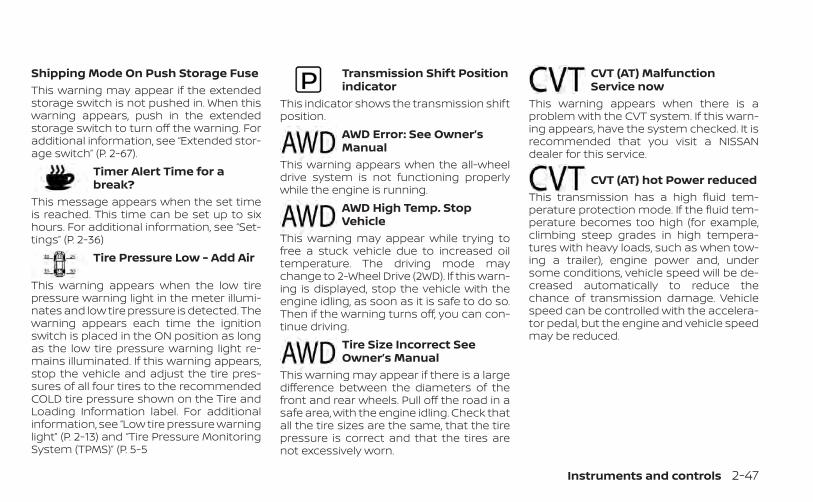
Shipping Mode On Push Storage FuseThis warning may appear if the extendedstorage switch is not pushed in. When thiswarning appears, push in the extendedstorage switch to turn off the warning. Foradditional information, see “Extended stor-age switch” (P. 2-67).
Timer Alert Time for abreak?
This message appears when the set timeis reached. This time can be set up to sixhours. For additional information, see “Set-tings” (P. 2-36)
Tire Pressure Low - Add Air
This warning appears when the low tirepressure warning light in the meter illumi-nates and low tire pressure is detected. Thewarning appears each time the ignitionswitch is placed in the ON position as longas the low tire pressure warning light re-mains illuminated. If this warning appears,stop the vehicle and adjust the tire pres-sures of all four tires to the recommendedCOLD tire pressure shown on the Tire andLoading Information label. For additionalinformation, see “Low tire pressure warninglight” (P. 2-13) and “Tire Pressure MonitoringSystem (TPMS)” (P. 5-5
Transmission Shift Positionindicator
This indicator shows the transmission shiftposition.
AWD Error: See Owner’sManual
This warning appears when the all-wheeldrive system is not functioning properlywhile the engine is running.
AWD High Temp. StopVehicle
This warning may appear while trying tofree a stuck vehicle due to increased oiltemperature. The driving mode maychange to 2-Wheel Drive (2WD). If this warn-ing is displayed, stop the vehicle with theengine idling, as soon as it is safe to do so.Then if the warning turns off, you can con-tinue driving.
Tire Size Incorrect SeeOwner’s Manual
This warning may appear if there is a largedifference between the diameters of thefront and rear wheels. Pull off the road in asafe area, with the engine idling. Check thatall the tire sizes are the same, that the tirepressure is correct and that the tires arenot excessively worn.
CVT (AT) MalfunctionService now
This warning appears when there is aproblem with the CVT system. If this warn-ing appears, have the system checked. It isrecommended that you visit a NISSANdealer for this service.
CVT (AT) hot Power reducedThis transmission has a high fluid tem-perature protection mode. If the fluid tem-perature becomes too high (for example,climbing steep grades in high tempera-tures with heavy loads, such as when tow-ing a trailer), engine power and, undersome conditions, vehicle speed will be de-creased automatically to reduce thechance of transmission damage. Vehiclespeed can be controlled with the accelera-tor pedal, but the engine and vehicle speedmay be reduced.
Instruments and controls 2-47
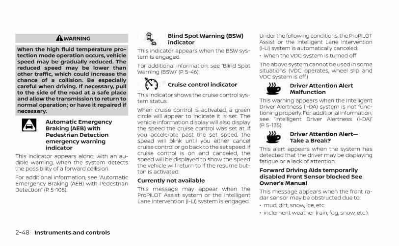
WARNING
When the high fluid temperature pro-tection mode operation occurs, vehiclespeed may be gradually reduced. Thereduced speed may be lower thanother traffic, which could increase thechance of a collision. Be especiallycareful when driving. If necessary, pullto the side of the road at a safe placeand allow the transmission to return tonormal operation; or have it repaired ifnecessary.
Automatic EmergencyBraking (AEB) withPedestrian Detectionemergency warningindicator
This indicator appears along, with an au-dible warning, when the system detectsthe possibility of a forward collision.For additional information, see “AutomaticEmergency Braking (AEB) with PedestrianDetection” (P. 5-108).
Blind Spot Warning (BSW)indicator
This indicator appears when the BSW sys-tem is engaged.For additional information, see “Blind SpotWarning (BSW)” (P. 5-46).
Cruise control indicator
This indicator shows the cruise control sys-tem status.When cruise control is activated, a greencircle will appear to indicate it is set. Thevehicle information display will also displaythe speed the cruise control was set at. Ifyou accelerate past the set speed, thespeed will blink until you either cancelcruise control or go back to the set speed. Ifcruise control is on and canceled, thespeed will be displayed to show the speedthe vehicle will return to if the resume but-ton is activated.Currently not availableThis message may appear when theProPILOT Assist system or the IntelligentLane Intervention (I-LI) system is engaged.
Under the following conditions, the ProPILOTAssist or the Intelligent Lane Intervention(I-LI) system is automatically canceled:• When the VDC system is turned offThe above system cannot be used in somesituations (VDC operates, wheel slip andVDC system is off.)
Driver Attention AlertMalfunction
This warning appears when the IntelligentDriver Alertness (I-DA) system is not func-tioning properly. For additional information,see “Intelligent Driver Alertness (I-DA)”(P. 5-135).
Driver Attention Alert—Take a Break?
This alert appears when the system hasdetected that the driver may be displayingfatigue or a lack of attention.Forward Driving Aids temporarilydisabled Front Sensor blocked SeeOwner’s ManualThis message appears when the front ra-dar sensor may be obstructed due to:• mud, dirt, snow, ice, etc.• inclement weather (rain, fog, snow, etc.).
2-48 Instruments and controls
All forward driving aids are temporarily dis-abled until the system detects that thefront radar sensor is no longer obstructed.For additional information, see:• Automatic Emergency Braking (AEB) with
Pedestrian Detection (P. 5-108)• ProPILOT Assist (P. 5-81)• Intelligent Forward Collision Warning
(I-FCW) (P. 5-120)Intelligent LaneIntervention (I-LI) indicator
This indicator shows when the I-LI systemis engaged.For additional information, see “IntelligentLane Intervention (I-LI)” (P. 5-40).
Lane Departure Warning(LDW) indicator
This indicator shows when the LDW systemis engaged.For additional information, see “Lane De-parture Warning (LDW)” (P. 5-33) and “Intelli-gent Lane Intervention (I-LI)” (P. 5-40).
MalfunctionThis warning appears when one or more ofthe following systems (if so equipped) isnot functioning properly:• Automatic Emergency Braking (AEB) with
Pedestrian Detection• Intelligent Forward Collision Warning
(I-FCW)If one or more of these warning appears,have the system checked. It is recom-mended that you visit a NISSAN dealer forthis service.For additional information, see “AutomaticEmergency Braking (AEB) with PedestrianDetection” (P. 5-108) or “Intelligent ForwardCollision Warning (I-FCW) (P. 5-120).Malfunction: See Owner’s ManualThis warning appears when one or more ofthe following systems (if so equipped) isnot functioning properly:• Traffic Sign Recognition (TSR)• Rear Automatic Braking (RAB)If one or more of these warning appears,have the system checked. It is recom-mended that you visit a NISSAN dealer forthis service.
Not Available Parking Brake OnThis message may appear when theProPILOT Assist system is engaged.Under the following condition, the ProPILOTAssist system is automatically canceled:• The electronic parking brake is applied.The above system cannot be used whenthe electronic parking is activated.For additional information, see "ProPILOTAssist (P. 5-81) and “Parking brake” (P. 5-24).Not Available Poor Road ConditionsThis message may appear when theProPILOT Assist system or the IntelligentLane Intervention (I-LI) system is engaged.Under the following conditions, the ProPILOTAssist system or the Intelligent Lane Inter-vention (I-LI) system is automatically can-celed:• When the VDC system is turned offThe above system cannot be used in somesituations (VDC operates, wheel slip andVDC system is off.)
Instruments and controls 2-49
Not Available Seat Belt Not FastenedThis message may appear when theProPILOT Assist system is engaged.Under the following condition, the ProPILOTAssist system is automatically canceled:• When the driver’s seat belt is not fastenedThe above system cannot be used whenthe driver’s seat belt is not fastened.Not Available System MalfunctionThis warning appears when one or more ofthe following systems (if so equipped) isnot functioning properly.• ProPILOT• Blind Spot Warning (BSW)• Lane Departure Warning (LDW)• Intelligent Lane Intervention (I-LI)If one or more of these warnings appear,have the system checked. It is recom-mended that you visit a NISSAN dealer forthis service.For additional information, see ProPILOTAssist” (P. 5-70), “Blind Spot Warning (BSW)”(P. 5-46), “Lane Departure Warning (LDW)”(P. 5-33) or “Intelligent Lane Intervention(I-LI)” (P. 5-40).
Parking Sensor Error: See Owner’sManualThis warning appears when there is an er-ror with the system. For additional informa-tion, see “Rear Sonar System (RSS)” (P. 5-152).
ProPILOT Assist indicators
These indicators show the ProPILOT Assistsystem status. The status is shown bycolor. For additional information, see “Pro-PILOT Assist” (P. 5-81).
Rear Automatic Braking(RAB) indicator
This indicator appears to indicate the sta-tus of the Rear Automatic Braking (RAB)system. For additional information, see“Rear Automatic Braking (RAB)” (P. 5-101).
Speed Limit Sign indicator
This message may appear when the TrafficSign Recognition system is engaged.For additional information, see “Traffic SignRecognition (TSR)” (P. 5-30).
Steering Assist AlertThis message may appear when the Steer-ing Assist system is engaged.It will be displayed under the following con-dition:• When not holding the steering wheel or
when there is no steering wheel operationPlease hold on the steering wheel immedi-ately. When the steering operation is de-tected, the warning turns off and the steer-ing assist function is automatically restored.
Steering Assist indicator
This indicator appears when the SteeringAssist system is engaged.For additional information, see “ProPILOTAssist” (P. 5-70).Unavailable: High Cabin TemperatureThis message appears when the cameradetects an interior temperature of morethan 104°F (40°C). For additional informa-tion, see “Automatic Emergency Braking(AEB) with Pedestrian Detection” (P. 5-108),“ProPILOT Assist” (P. 5-70), “Intelligent LaneIntervention (I-LI)” (P. 5-93), “Lane DepartureWarning (LDW)” (P. 5-33) or “Traffic Sign Rec-ognition (TSR) . (P. 5-30).
2-50 Instruments and controls
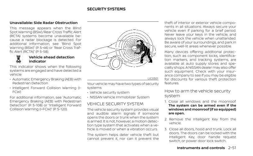
Unavailable: Side Radar ObstructionThis message appears when the BlindSpot Warning (BSW)/Rear Cross Traffic Alert(RCTA) systems become unavailable be-cause a radar blockage is detected. Foradditional information, see “Blind SpotWarning (BSW)” (P. 5-46) or “Rear Cross Traf-fic Alert (RCTA)” (P. 5-58).
Vehicle ahead detectionindicator
This indicator shows when the followingsystems are engaged and have detected avehicle:• Automatic Emergency Braking (AEB) with
Pedestrian Detection• Intelligent Forward Collision Warning (I-
FCW)For additional information, see “AutomaticEmergency Braking (AEB) with PedestrianDetection” (P. 5-108) or “Intelligent ForwardCollision Warning (I-FCW)” (P. 5-120).
Your vehicle may have two types of securitysystems:• Vehicle security system• NISSAN Vehicle Immobilizer System
VEHICLE SECURITY SYSTEMThe vehicle security system provides visualand audible alarm signals if someoneopens the doors or trunk when the systemis armed. It is not, however, a motion detec-tion type system that activates when a ve-hicle is moved or when a vibration occurs.The system helps deter vehicle theft butcannot prevent it, nor can it prevent the
theft of interior or exterior vehicle compo-nents in all situations. Always secure yourvehicle even if parking for a brief period.Never leave your keys in the vehicle, andalways lock the vehicle when unattended.Be aware of your surroundings, and park insecure, well-lit areas whenever possible.Many devices offering additional protec-tion, such as component locks, identifica-tion markers, and tracking systems, areavailable at auto supply stores and spe-cialty shops. A NISSAN dealer may also offersuch equipment. Check with your insur-ance company to see if you may be eligiblefor discounts for various theft protectionfeatures.
How to arm the vehicle securitysystem1. Close all windows and the moonroof.
The system can be armed even if thewindows and moonroof (if so equipped)are open.
2. Remove the Intelligent Key from thevehicle.
3. Close all doors, hood and trunk. Lock alldoors. The doors can be locked with theIntelligent Key, door handle requestswitch, or power door lock switch..
LIC0301
SECURITY SYSTEMS
Instruments and controls 2-51
4. Confirm that the indicator lightcomes on. The indicator staysilluminated for a period of time indicat-ing that the system is in the pre-armedphase.The indicator light will blink every3 seconds once the security system isarmed.If during the pre-armed phase one ofthe following occurs, the system will notarm:
• Any door is unlocked with the IntelligentKey or door request switch.
• The ignition switch is placed in the AUTOACC or ON position.
• Even when the driver and/or passen-gers are in the vehicle, the system willactivate when all the doors, hood andtrunk are locked with the ignitionswitch placed in the LOCK position.When placing the ignition switch in theAUTO ACC or ON position, the systemwill be released.
Vehicle security system activationThe vehicle security system will give thefollowing alarm:• The headlights blink and the horn sounds
intermittently.• The alarm automatically turns off after a
period of time. However, the alarm reacti-vates if the vehicle is tampered withagain. The alarm can be shut off by press-ing the button on the Intelligent Key.
The alarm is activated by:• opening the door or trunk without using
Intelligent Key (even if the door is un-locked by releasing the door inside lockknob switch).
How to stop an activated alarmThe alarm stops only by unlocking a doorby pressing the button on the Intelli-gent Key or pushing the request switch onthe driver's or passenger's door with theIntelligent Key in range of the door handle.
NISSAN VEHICLE IMMOBILIZERSYSTEMThe NISSAN Vehicle Immobilizer Systemwill not allow the engine to start withoutthe use of a registered key.If the engine fails to start using a registeredkey (for example, when interference iscaused by another registered key, an auto-mated toll road device or automatic pay-ment device on the key ring), restart theengine using the following procedures:1. Leave the ignition switch placed in the ON
position for approximately 5 seconds.
2. Place the ignition switch in the OFF orLOCK position, and wait approximately10 seconds.
3. Repeat steps 1 and 2.
4. Restart the engine while holding the de-vice (which may have caused the inter-ference) separate from the registeredkey.
If the no start condition re-occurs, NISSANrecommends placing the registered key ona separate key ring to avoid interferencefrom other devices.
2-52 Instruments and controls
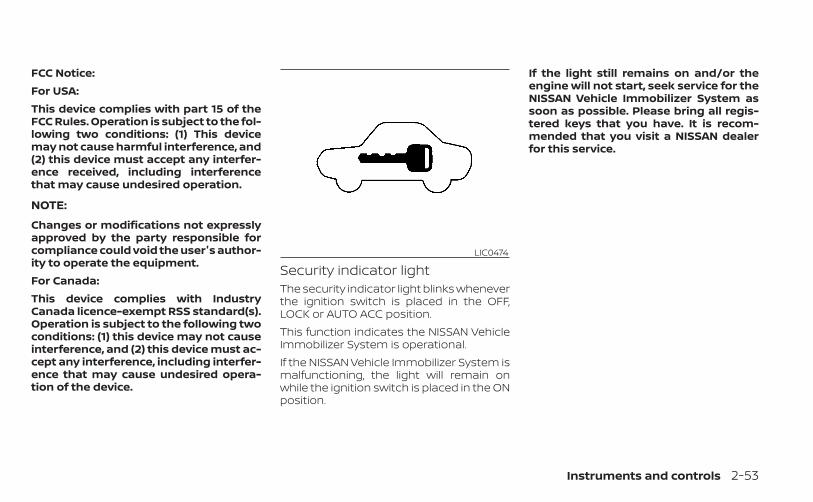
FCC Notice:For USA:This device complies with part 15 of theFCC Rules. Operation is subject to the fol-lowing two conditions: (1) This devicemay not cause harmful interference, and(2) this device must accept any interfer-ence received, including interferencethat may cause undesired operation.
NOTE:
Changes or modifications not expresslyapproved by the party responsible forcompliance could void the user's author-ity to operate the equipment.For Canada:This device complies with IndustryCanada licence-exempt RSS standard(s).Operation is subject to the following twoconditions: (1) this device may not causeinterference, and (2) this device must ac-cept any interference, including interfer-ence that may cause undesired opera-tion of the device.
Security indicator lightThe security indicator light blinks wheneverthe ignition switch is placed in the OFF,LOCK or AUTO ACC position.This function indicates the NISSAN VehicleImmobilizer System is operational.If the NISSAN Vehicle Immobilizer System ismalfunctioning, the light will remain onwhile the ignition switch is placed in the ONposition.
If the light still remains on and/or theengine will not start, seek service for theNISSAN Vehicle Immobilizer System assoon as possible. Please bring all regis-tered keys that you have. It is recom-mended that you visit a NISSAN dealerfor this service.
LIC0474
Instruments and controls 2-53
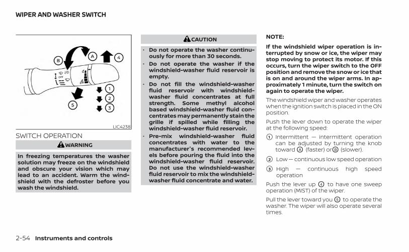
SWITCH OPERATIONWARNING
In freezing temperatures the washersolution may freeze on the windshieldand obscure your vision which maylead to an accident. Warm the wind-shield with the defroster before youwash the windshield.
CAUTION
• Do not operate the washer continu-ously for more than 30 seconds.
• Do not operate the washer if thewindshield-washer fluid reservoir isempty.
• Do not fill the windshield-washerfluid reservoir with windshield-washer fluid concentrates at fullstrength. Some methyl alcoholbased windshield-washer fluid con-centrates may permanently stain thegrille if spilled while filling thewindshield-washer fluid reservoir.
• Pre-mix windshield-washer fluidconcentrates with water to themanufacturer's recommended lev-els before pouring the fluid into thewindshield-washer fluid reservoir.Do not use the windshield-washerfluid reservoir to mix the windshield-washer fluid concentrate and water.
NOTE:
If the windshield wiper operation is in-terrupted by snow or ice, the wiper maystop moving to protect its motor. If thisoccurs, turn the wiper switch to the OFFposition and remove the snow or ice thatis on and around the wiper arms. In ap-proximately 1 minute, turn the switch onagain to operate the wiper.The windshield wiper and washer operateswhen the ignition switch is placed in the ONposition.Push the lever down to operate the wiperat the following speed:
�1 Intermittent — intermittent operationcan be adjusted by turning the knobtoward OA (faster) orOB (slower).
�2 Low — continuous low speed operation
�3 High — continuous high speedoperation
Push the lever up O4 to have one sweepoperation (MIST) of the wiper.Pull the lever toward you O5 to operate thewasher. The wiper will also operate severaltimes.
LIC4238
WIPER AND WASHER SWITCH
2-54 Instruments and controls
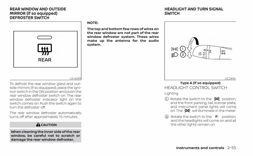
To defrost the rear window glass and out-side mirrors (if so equipped), place the igni-tion switch in the ON position and push therear window defroster switch on. The rearwindow defroster indicator light on theswitch comes on. Push the switch again toturn the defroster off.The rear window defroster automaticallyturns off after approximately 15 minutes.
CAUTION
When cleaning the inner side of the rearwindow, be careful not to scratch ordamage the rear window defroster.
NOTE:
The top and bottom few rows of wires onthe rear window are not part of the rearwindow defroster system. These wiresmake up the antenna for the audiosystem.
HEADLIGHT CONTROL SWITCHLighting
�1 Rotate the switch to the position,and the front parking, tail, license plate,and instrument panel lights will comeon. The will illuminate in the meter.
�2 Rotate the switch to the position,and the headlights will come on and allthe other lights remain on.
LIC4039 LIC2634Type A (if so equipped)
REAR WINDOW AND OUTSIDEMIRROR (if so equipped)DEFROSTER SWITCH
HEADLIGHT AND TURN SIGNALSWITCH
Instruments and controls 2-55
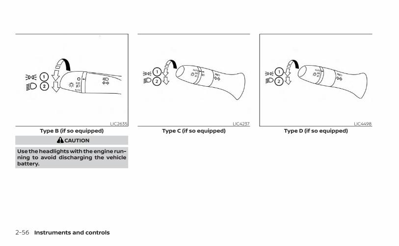
CAUTION
Use the headlights with the engine run-ning to avoid discharging the vehiclebattery.
LIC2635Type B (if so equipped)
LIC4237Type C (if so equipped)
LIC4498Type D (if so equipped)
2-56 Instruments and controls
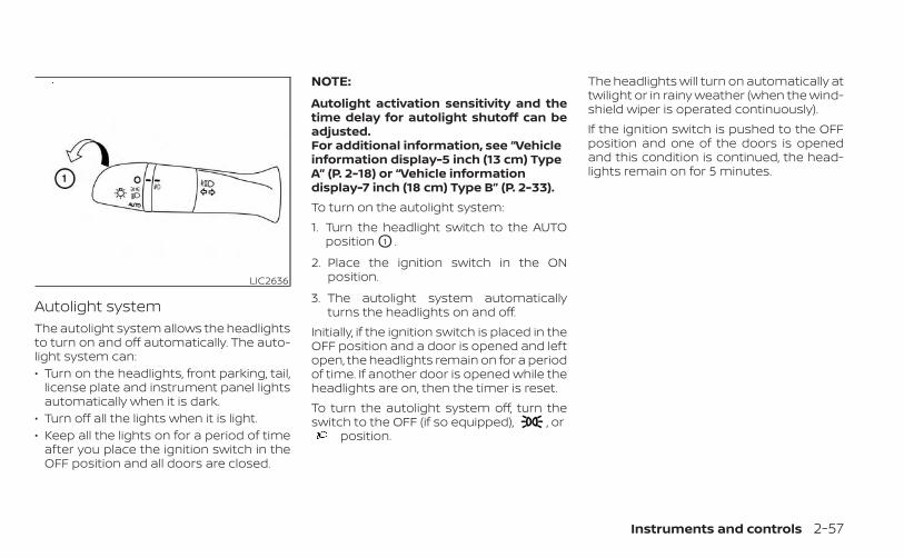
Autolight systemThe autolight system allows the headlightsto turn on and off automatically. The auto-light system can:• Turn on the headlights, front parking, tail,
license plate and instrument panel lightsautomatically when it is dark.
• Turn off all the lights when it is light.• Keep all the lights on for a period of time
after you place the ignition switch in theOFF position and all doors are closed.
NOTE:
Autolight activation sensitivity and thetime delay for autolight shutoff can beadjusted.For additional information, see “Vehicleinformation display-5 inch (13 cm) TypeA” (P. 2-18) or “Vehicle informationdisplay-7 inch (18 cm) Type B” (P. 2-33).To turn on the autolight system:1. Turn the headlight switch to the AUTO
position O1 .
2. Place the ignition switch in the ONposition.
3. The autolight system automaticallyturns the headlights on and off.
Initially, if the ignition switch is placed in theOFF position and a door is opened and leftopen, the headlights remain on for a periodof time. If another door is opened while theheadlights are on, then the timer is reset.To turn the autolight system off, turn theswitch to the OFF (if so equipped), , or
position.
The headlights will turn on automatically attwilight or in rainy weather (when the wind-shield wiper is operated continuously).If the ignition switch is pushed to the OFFposition and one of the doors is openedand this condition is continued, the head-lights remain on for 5 minutes.
LIC2636
Instruments and controls 2-57
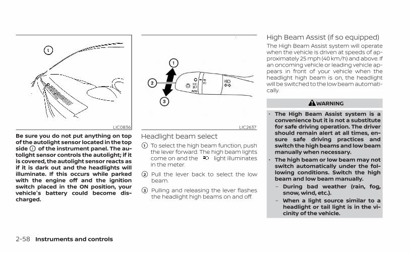
Be sure you do not put anything on topof the autolight sensor located in the topside O1 of the instrument panel. The au-tolight sensor controls the autolight; if itis covered, the autolight sensor reacts asif it is dark out and the headlights willilluminate. If this occurs while parkedwith the engine off and the ignitionswitch placed in the ON position, yourvehicle's battery could become dis-charged.
Headlight beam select�1 To select the high beam function, push
the lever forward. The high beam lightscome on and the light illuminatesin the meter.
�2 Pull the lever back to select the lowbeam.
�3 Pulling and releasing the lever flashesthe headlight high beams on and off.
High Beam Assist (if so equipped)The High Beam Assist system will operatewhen the vehicle is driven at speeds of ap-proximately 25 mph (40 km/h) and above. Ifan oncoming vehicle or leading vehicle ap-pears in front of your vehicle when theheadlight high beam is on, the headlightwill be switched to the low beam automati-cally.
WARNING
• The High Beam Assist system is aconvenience but it is not a substitutefor safe driving operation. The drivershould remain alert at all times, en-sure safe driving practices andswitch the high beams and low beammanually when necessary.
• The high beam or low beam may notswitch automatically under the fol-lowing conditions. Switch the highbeam and low beam manually.– During bad weather (rain, fog,
snow, wind, etc.).– When a light source similar to a
headlight or tail light is in the vi-cinity of the vehicle.
LIC0836 LIC2637
2-58 Instruments and controls
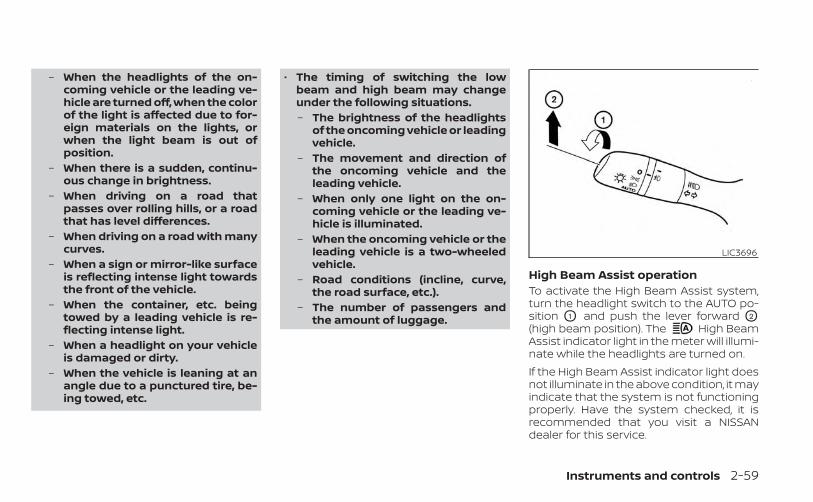
– When the headlights of the on-coming vehicle or the leading ve-hicle are turned off, when the colorof the light is affected due to for-eign materials on the lights, orwhen the light beam is out ofposition.
– When there is a sudden, continu-ous change in brightness.
– When driving on a road thatpasses over rolling hills, or a roadthat has level differences.
– When driving on a road with manycurves.
– When a sign or mirror-like surfaceis reflecting intense light towardsthe front of the vehicle.
– When the container, etc. beingtowed by a leading vehicle is re-flecting intense light.
– When a headlight on your vehicleis damaged or dirty.
– When the vehicle is leaning at anangle due to a punctured tire, be-ing towed, etc.
• The timing of switching the lowbeam and high beam may changeunder the following situations.– The brightness of the headlights
of the oncoming vehicle or leadingvehicle.
– The movement and direction ofthe oncoming vehicle and theleading vehicle.
– When only one light on the on-coming vehicle or the leading ve-hicle is illuminated.
– When the oncoming vehicle or theleading vehicle is a two-wheeledvehicle.
– Road conditions (incline, curve,the road surface, etc.).
– The number of passengers andthe amount of luggage.
High Beam Assist operationTo activate the High Beam Assist system,turn the headlight switch to the AUTO po-sition O1 and push the lever forward O2
(high beam position). The High BeamAssist indicator light in the meter will illumi-nate while the headlights are turned on.If the High Beam Assist indicator light doesnot illuminate in the above condition, it mayindicate that the system is not functioningproperly. Have the system checked, it isrecommended that you visit a NISSANdealer for this service.
LIC3696
Instruments and controls 2-59
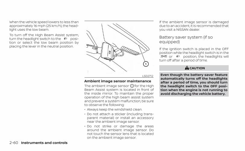
When the vehicle speed lowers to less thanapproximately 16 mph (25 km/h), the head-light uses the low beam.To turn off the High Beam Assist system,turn the headlight switch to the posi-tion or select the low beam position byplacing the lever in the neutral position.
Ambient image sensor maintenanceThe ambient image sensor O1 for the HighBeam Assist system is located in front ofthe inside mirror. To maintain the properoperation of the high beam assist systemand prevent a system malfunction, be sureto observe the following:• Always keep the windshield clean.• Do not attach a sticker (including trans-
parent material) or install an accessorynear the ambient image sensor.
• Do not strike or damage the areasaround the ambient image sensor. Donot touch the sensor lens that is locatedon the ambient image sensor.
If the ambient image sensor is damageddue to an accident, it is recommended thatyou visit a NISSAN dealer.
Battery saver system (if soequipped)
If the ignition switch is placed in the OFFposition while the headlight switch is in the
or position, the headlights willturn off after a period of time.
CAUTION
Even though the battery saver featureautomatically turns off the headlightsafter a period of time, you should turnthe headlight switch to the OFF posi-tion when the engine is not running toavoid discharging the vehicle battery.
LSD2712
2-60 Instruments and controls
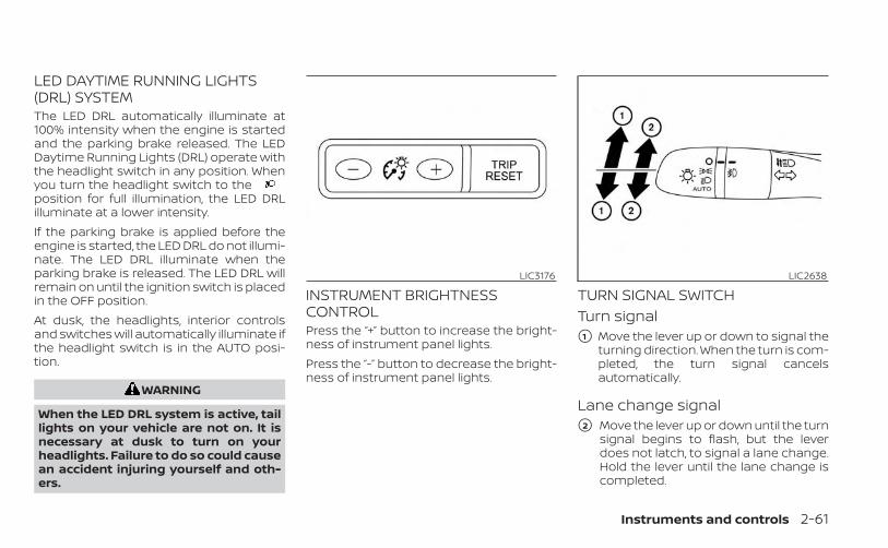
LED DAYTIME RUNNING LIGHTS(DRL) SYSTEMThe LED DRL automatically illuminate at100% intensity when the engine is startedand the parking brake released. The LEDDaytime Running Lights (DRL) operate withthe headlight switch in any position. Whenyou turn the headlight switch to theposition for full illumination, the LED DRLilluminate at a lower intensity.If the parking brake is applied before theengine is started, the LED DRL do not illumi-nate. The LED DRL illuminate when theparking brake is released. The LED DRL willremain on until the ignition switch is placedin the OFF position.At dusk, the headlights, interior controlsand switches will automatically illuminate ifthe headlight switch is in the AUTO posi-tion.
WARNING
When the LED DRL system is active, taillights on your vehicle are not on. It isnecessary at dusk to turn on yourheadlights. Failure to do so could causean accident injuring yourself and oth-ers.
INSTRUMENT BRIGHTNESSCONTROLPress the “+” button to increase the bright-ness of instrument panel lights.Press the “-” button to decrease the bright-ness of instrument panel lights.
TURN SIGNAL SWITCHTurn signal�1 Move the lever up or down to signal the
turning direction. When the turn is com-pleted, the turn signal cancelsautomatically.
Lane change signal�2 Move the lever up or down until the turn
signal begins to flash, but the leverdoes not latch, to signal a lane change.Hold the lever until the lane change iscompleted.
LIC3176 LIC2638
Instruments and controls 2-61
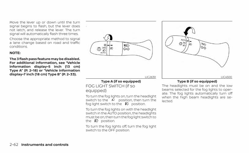
Move the lever up or down until the turnsignal begins to flash, but the lever doesnot latch, and release the lever. The turnsignal will automatically flash three times.Choose the appropriate method to signala lane change based on road and trafficconditions.
NOTE:
The 3 flash pass feature may be disabled.For additional information, see “Vehicleinformation display-5 inch (13 cm)Type A” (P. 2-18) or “Vehicle informationdisplay-7 inch (18 cm) Type B” (P. 2-33).
FOG LIGHT SWITCH (if soequipped)To turn the fog lights on, turn the headlightswitch to the position, then turn thefog light switch to the position.To turn the fog lights on with the headlightswitch in the AUTO position, the headlightsmust be on, then turn the fog light switch tothe position.To turn the fog lights off, turn the fog lightswitch to the OFF position.
The headlights must be on and the lowbeams selected for the fog lights to oper-ate. The fog lights automatically turn offwhen the high beam headlights are se-lected.
LIC2639Type A (if so equipped)
LIC4500Type B (if so equipped)
2-62 Instruments and controls
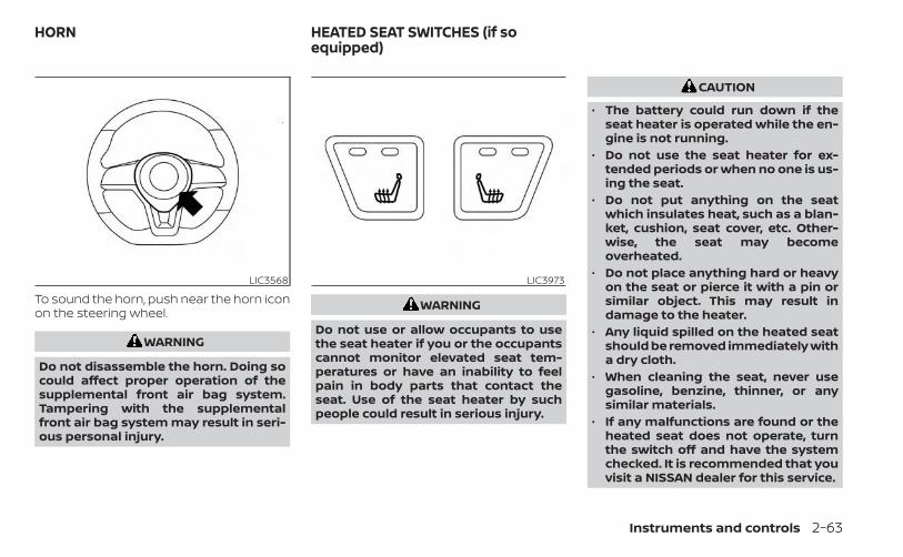
To sound the horn, push near the horn iconon the steering wheel.
WARNING
Do not disassemble the horn. Doing socould affect proper operation of thesupplemental front air bag system.Tampering with the supplementalfront air bag system may result in seri-ous personal injury.
WARNING
Do not use or allow occupants to usethe seat heater if you or the occupantscannot monitor elevated seat tem-peratures or have an inability to feelpain in body parts that contact theseat. Use of the seat heater by suchpeople could result in serious injury.
CAUTION
• The battery could run down if theseat heater is operated while the en-gine is not running.
• Do not use the seat heater for ex-tended periods or when no one is us-ing the seat.
• Do not put anything on the seatwhich insulates heat, such as a blan-ket, cushion, seat cover, etc. Other-wise, the seat may becomeoverheated.
• Do not place anything hard or heavyon the seat or pierce it with a pin orsimilar object. This may result indamage to the heater.
• Any liquid spilled on the heated seatshould be removed immediately witha dry cloth.
• When cleaning the seat, never usegasoline, benzine, thinner, or anysimilar materials.
• If any malfunctions are found or theheated seat does not operate, turnthe switch off and have the systemchecked. It is recommended that youvisit a NISSAN dealer for this service.
LIC3568 LIC3973
HORN HEATED SEAT SWITCHES (if soequipped)
Instruments and controls 2-63
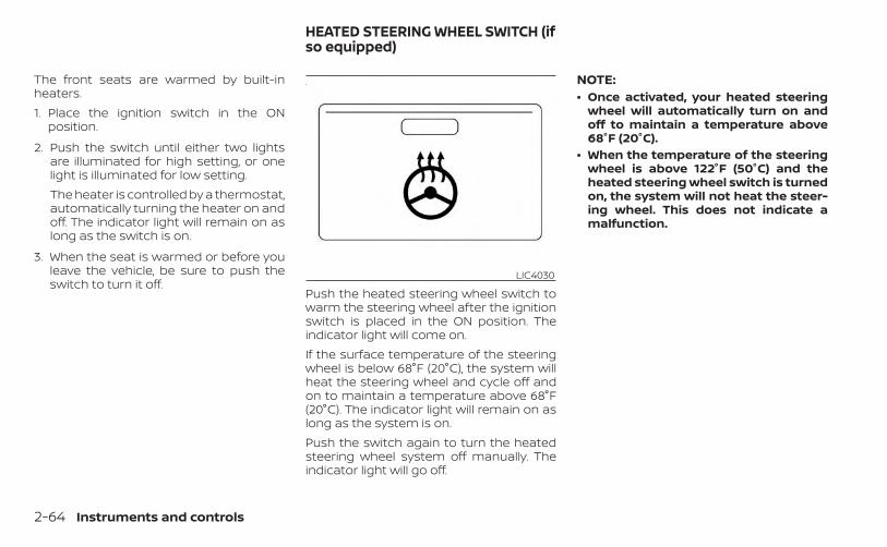
The front seats are warmed by built-inheaters.1. Place the ignition switch in the ON
position.
2. Push the switch until either two lightsare illuminated for high setting, or onelight is illuminated for low setting.The heater is controlled by a thermostat,automatically turning the heater on andoff. The indicator light will remain on aslong as the switch is on.
3. When the seat is warmed or before youleave the vehicle, be sure to push theswitch to turn it off.
Push the heated steering wheel switch towarm the steering wheel after the ignitionswitch is placed in the ON position. Theindicator light will come on.If the surface temperature of the steeringwheel is below 68°F (20°C), the system willheat the steering wheel and cycle off andon to maintain a temperature above 68°F(20°C). The indicator light will remain on aslong as the system is on.Push the switch again to turn the heatedsteering wheel system off manually. Theindicator light will go off.
NOTE:• Once activated, your heated steering
wheel will automatically turn on andoff to maintain a temperature above68°F (20°C).
• When the temperature of the steeringwheel is above 122°F (50°C) and theheated steering wheel switch is turnedon, the system will not heat the steer-ing wheel. This does not indicate amalfunction.
LIC4030
HEATED STEERING WHEEL SWITCH (ifso equipped)
2-64 Instruments and controls
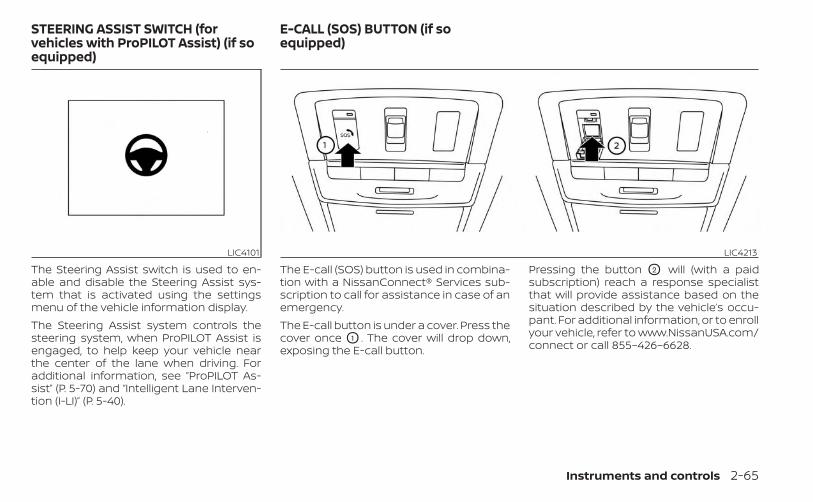
The Steering Assist switch is used to en-able and disable the Steering Assist sys-tem that is activated using the settingsmenu of the vehicle information display.The Steering Assist system controls thesteering system, when ProPILOT Assist isengaged, to help keep your vehicle nearthe center of the lane when driving. Foradditional information, see ”ProPILOT As-sist” (P. 5-70) and “Intelligent Lane Interven-tion (I-LI)” (P. 5-40).
The E-call (SOS) button is used in combina-tion with a NissanConnect® Services sub-scription to call for assistance in case of anemergency.The E-call button is under a cover. Press thecover once O1 . The cover will drop down,exposing the E-call button.
Pressing the button O2 will (with a paidsubscription) reach a response specialistthat will provide assistance based on thesituation described by the vehicle’s occu-pant. For additional information, or to enrollyour vehicle, refer to www.NissanUSA.com/connect or call 855–426–6628.
LIC4101 LIC4213
STEERING ASSIST SWITCH (forvehicles with ProPILOT Assist) (if soequipped)
E-CALL (SOS) BUTTON (if soequipped)
Instruments and controls 2-65
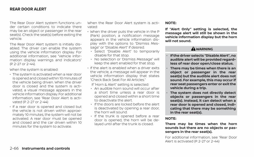
The Rear Door Alert system functions un-der certain conditions to indicate theremay be an object or passenger in the rearseat(s). Check the seat(s) before exiting thevehicle.The Rear Door Alert system is initially dis-abled. The driver can enable the systemusing the vehicle information display. Foradditional information, see “Vehicle infor-mation display warnings and indicators”(P. 2-27 or 2-44).When the system is enabled:• The system is activated when a rear door
is opened and closed within 10 minutes ofthe vehicle being driven. When the driverdoor is closed and the system is acti-vated, a visual message appears in thevehicle information display. For additionalinformation, see “Rear Door Alert is acti-vated (P. 2-27 or 2-44)
• If a rear door is opened and closed butthe vehicle is not driven within approxi-mately 10 minutes, the system will not beactivated. A rear door must be openedand closed and the car driven within 10minutes for the system to activate.
When the Rear Door Alert system is acti-vated:• When the driver puts the vehicle in the P
(Park) position, a notification messageappears in the vehicle information dis-play with the options to “Dismiss Mes-sage” or “Disable Alert” if desired.• Select “Disable Alert” to temporarily
disable for that stop.• No selection or ‘Dismiss Message” will
keep the alert enabled for that stop.• If the alert is enabled when a driver exits
the vehicle, a message will appear in thevehicle information display that states“Check Back Seat For All Articles.”If “Horn & Alert” setting is selected:• An audible horn sound will occur after
a short time unless a rear door isopened and closed within a short timeto deactivate the alert.
• If the doors are locked before the alertis deactivated by opening a rear door,the horn will sound.
• If the trunk is opened before a reardoor is opened, the horn will be de-layed until after the trunk is closed.
NOTE:
If “Alert Only” setting is selected, themessage alert will still be shown in thevehicle information display but the hornwill not sound.
WARNING
• If the driver selects “Disable Alert”, noaudible alert will be provided regard-less of rear door open/close status.
• There may be times when there is anobject or passenger in the rearseat(s) but the audible alert does notsound. For example, this may occur ifrear seat passengers enter or exit thevehicle during a trip.
• The system does not directly detectobjects or passengers in the rearseat(s). Instead, it can detect when arear door is opened and closed, indi-cating that there may be somethingin the rear seat(s).
NOTE:There may be times when the hornsounds but there are no objects or pas-sengers in the rear seat(s).For additional information, see “Rear DoorAlert is activated (P. 2-27 or 2-44)
REAR DOOR ALERT
2-66 Instruments and controls
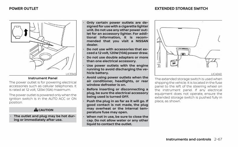
The power outlet is for powering electricalaccessories such as cellular telephones. Itis rated at 12 volt, 120W (10A) maximum.The power outlet is powered only when theignition switch is in the AUTO ACC or ONposition.
CAUTION
• The outlet and plug may be hot dur-ing or immediately after use.
• Only certain power outlets are de-signed for use with a cigarette lighterunit. Do not use any other power out-let for an accessory lighter. For addi-tional information, it is recom-mended that you visit a NISSANdealer.
• Do not use with accessories that ex-ceed a 12 volt, 120W (10A) power draw.
• Do not use double adapters or morethan one electrical accessory.
• Use power outlets with the enginerunning to avoid discharging the ve-hicle battery.
• Avoid using power outlets when theair conditioner, headlights, or rearwindow defroster is on.
• Before inserting or disconnecting aplug, be sure the electrical accessorybeing used is turned OFF.
• Push the plug in as far as it will go. Ifgood contact is not made, the plugmay overheat or the internal tem-perature fuse may open.
• When not in use, be sure to close thecap. Do not allow water or any otherliquid to contact the outlet.
The extended storage switch is used whenshipping the vehicle. It is located in the fusepanel to the left of the steering wheel onthe instrument panel. If any electricalequipment does not operate, ensure theextended storage switch is pushed fully inplace, as shown.
LIC3345Instrument Panel
LIC4040
POWER OUTLET EXTENDED STORAGE SWITCH
Instruments and controls 2-67
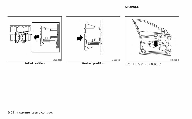
FRONT-DOOR POCKETSLIC3266
Pulled positionLIC3268
Pushed positionLIC4088
STORAGE
2-68 Instruments and controls
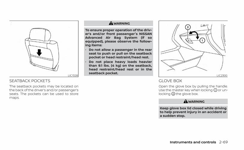
SEATBACK POCKETSThe seatback pockets may be located onthe back of the driver’s and/or passenger’sseats. The pockets can be used to storemaps.
WARNING
To ensure proper operation of the driv-er’s and/or front passenger's NISSANAdvanced Air Bag System (if soequipped), please observe the follow-ing items:• Do not allow a passenger in the rear
seat to push or pull on the seatbackpocket or head restraint/head rest.
• Do not place heavy loads heavierthan 9.1 lbs. (4 kg) on the seatback,head restraint/head rest or in theseatback pocket.
GLOVE BOXOpen the glove box by pulling the handle.Use the master key when locking O1 or un-locking O2 the glove box.
WARNING
Keep glove box lid closed while drivingto help prevent injury in an accident ora sudden stop.
LIC1328 LIC2300
Instruments and controls 2-69
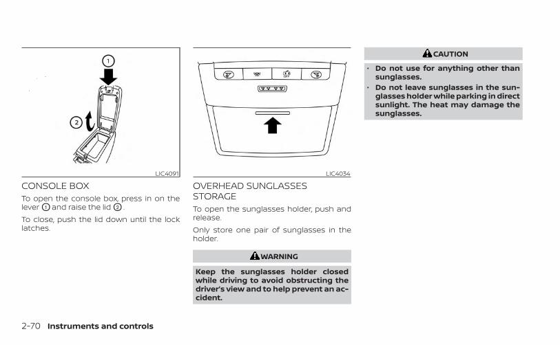
CONSOLE BOXTo open the console box, press in on thelever O1 and raise the lid O2 .To close, push the lid down until the locklatches.
OVERHEAD SUNGLASSESSTORAGETo open the sunglasses holder, push andrelease.Only store one pair of sunglasses in theholder.
WARNING
Keep the sunglasses holder closedwhile driving to avoid obstructing thedriver’s view and to help prevent an ac-cident.
CAUTION
• Do not use for anything other thansunglasses.
• Do not leave sunglasses in the sun-glasses holder while parking in directsunlight. The heat may damage thesunglasses.
LIC4091 LIC4034
2-70 Instruments and controls
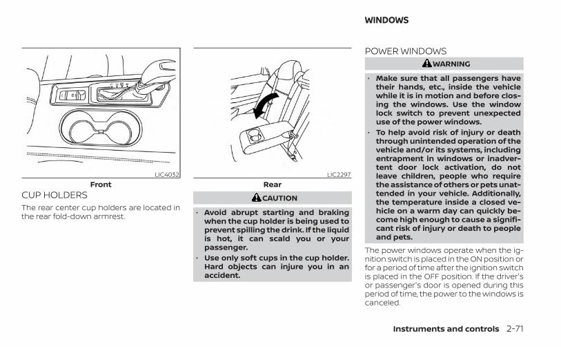
CUP HOLDERSThe rear center cup holders are located inthe rear fold-down armrest.
CAUTION
• Avoid abrupt starting and brakingwhen the cup holder is being used toprevent spilling the drink. If the liquidis hot, it can scald you or yourpassenger.
• Use only soft cups in the cup holder.Hard objects can injure you in anaccident.
POWER WINDOWSWARNING
• Make sure that all passengers havetheir hands, etc., inside the vehiclewhile it is in motion and before clos-ing the windows. Use the windowlock switch to prevent unexpecteduse of the power windows.
• To help avoid risk of injury or deaththrough unintended operation of thevehicle and/or its systems, includingentrapment in windows or inadver-tent door lock activation, do notleave children, people who requirethe assistance of others or pets unat-tended in your vehicle. Additionally,the temperature inside a closed ve-hicle on a warm day can quickly be-come high enough to cause a signifi-cant risk of injury or death to peopleand pets.
The power windows operate when the ig-nition switch is placed in the ON position orfor a period of time after the ignition switchis placed in the OFF position. If the driver'sor passenger's door is opened during thisperiod of time, the power to the windows iscanceled.
LIC4032Front
LIC2297Rear
WINDOWS
Instruments and controls 2-71
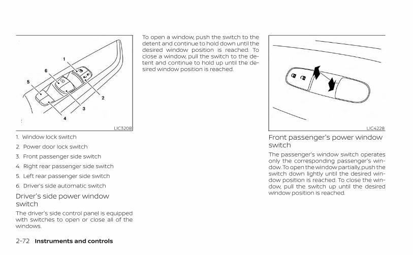
Driver's side power windowswitchThe driver's side control panel is equippedwith switches to open or close all of thewindows.
To open a window, push the switch to thedetent and continue to hold down until thedesired window position is reached. Toclose a window, pull the switch to the de-tent and continue to hold up until the de-sired window position is reached.
Front passenger's power windowswitchThe passenger's window switch operatesonly the corresponding passenger's win-dow. To open the window partially, push theswitch down lightly until the desired win-dow position is reached. To close the win-dow, pull the switch up until the desiredwindow position is reached.
LIC3208
1. Window lock switch
2. Power door lock switch
3. Front passenger side switch
4. Right rear passenger side switch
5. Left rear passenger side switch
6. Driver’s side automatic switch
LIC4228
2-72 Instruments and controls
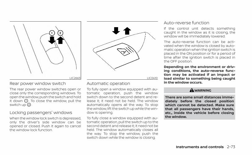
Rear power window switchThe rear power window switches open orclose only the corresponding windows. Toopen the window, push the switch and holdit down O1 . To close the window, pull theswitch up O2 .
Locking passengers' windowsWhen the window lock switch is depressed,only the driver's side window can beopened or closed. Push it again to cancelthe window lock function.
Automatic operationTo fully open a window equipped with au-tomatic operation, push the windowswitch down to the second detent and re-lease it; it need not be held. The windowautomatically opens all the way. To stopthe window, lift the switch up while the win-dow is opening.To fully close a window equipped with au-tomatic operation, pull the switch up to thesecond detent and release it; it need not beheld. The window automatically closes allthe way. To stop the window, push theswitch down while the window is closing.
Auto-reverse functionIf the control unit detects somethingcaught in the window as it is closing, thewindow will be immediately lowered.The auto-reverse function can be acti-vated when the window is closed by auto-matic operation when the ignition switch isplaced in the ON position or for a period oftime after the ignition switch is placed inthe OFF position.Depending on the environment or driv-ing conditions, the auto-reverse func-tion may be activated if an impact orload similar to something being caughtin the window occurs.
WARNING
There are some small distances imme-diately before the closed positionwhich cannot be detected. Make surethat all passengers have their hands,etc., inside the vehicle before closingthe window.
LIC2663 LIC0410
Instruments and controls 2-73
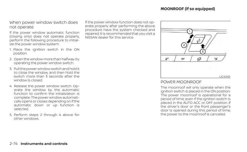
When power window switch doesnot operateIf the power window automatic function(closing only) does not operate properly,perform the following procedure to initial-ize the power window system:1. Place the ignition switch in the ON
position.
2. Open the window more than halfway byoperating the power window switch.
3. Pull the power window switch and hold itto close the window, and then hold theswitch more than 3 seconds after thewindow is closed.
4. Release the power window switch. Op-erate the window by the automaticfunction to confirm the initialization iscomplete. The power window automati-cally opens or closes depending on if theautomatic down or up function isselected.
5. Perform steps 2 through 4 above forother windows.
If the power window function does not op-erate properly after performing the aboveprocedure have the system checked andrepaired. It is recommended that you visit aNISSAN dealer for this service.
POWER MOONROOFThe moonroof will only operate when theignition switch is placed in the ON position.The power moonroof is operational for aperiod of time, even if the ignition switch isplaced in the AUTO ACC or OFF position. Ifthe driver's door or the front passenger'sdoor is opened during this period of time,the power to the moonroof is canceled.
LIC4249
MOONROOF (if so equipped)
2-74 Instruments and controls
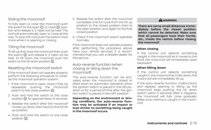
Sliding the moonroofTo fully open or close the moonroof, pushthe switch to the open O1 or close O2 posi-tion and release it; it need not be held. Theroof will automatically open or close all theway. To stop the roof, push the switch oncemore while it is opening or closing.
Tilting the moonroofTo tilt up, first close the moonroof, then pushthe switch O3 and release it; it need not beheld. To tilt down the moonroof, push theswitch to the tilt down position O2 .
Resetting the moonroof switchIf the moonroof does not operate properly,perform the following procedure to initial-ize the moonroof operation system.1. If the moonroof is open, close it fully by
repeatedly pushing the moonroofswitch to the close position O2 .
2. Push and hold the switch to the closeposition O2 for approximately 15 seconds.
3. Release the switch after the moonroofmoves up, down, then back to the full tiltup position.
4. Push and hold the switch to the closeposition O2 .
5. Release the switch after the moonroofcompletes one full cycle from the tilt upposition to the closed position, then tothe open position, and again to the fullyclosed position.
6. Check if the moonroof switch operatesnormally.
If the moonroof does not operate properlyafter performing the procedure above,have your vehicle serviced. It is recom-mended that you visit a NISSAN dealer forthis service.
Auto-reverse function (whenclosing or tilting down themoonroof)The auto-reverse function can be acti-vated when the moonroof is closed ortilted down by automatic operation whenthe ignition switch is placed in the ON po-sition or for a period of time after the igni-tion switch is placed in the OFF position.Depending on the environment or driv-ing conditions, the auto-reverse func-tion may be activated if an impact orload similar to something being caughtin the moonroof occurs.
WARNING
There are some small distances imme-diately before the closed positionwhich cannot be detected. Make surethat all passengers have their hands,etc., inside the vehicle before closingthe moonroof.
When closingIf the control unit detects somethingcaught in the moonroof as it moves to thefront, the moonroof will immediately openbackward.When tilting downIf the control unit detects somethingcaught in the moonroof as it tilts down, themoonroof will immediately tilt up.If the auto-reverse function malfunctionsand repeats opening or tilting up themoonroof, keep pushing the tilt downswitch within 5 seconds after it happens;the moonroof will fully close gradually.Make sure nothing is caught in the moon-roof.
Instruments and controls 2-75
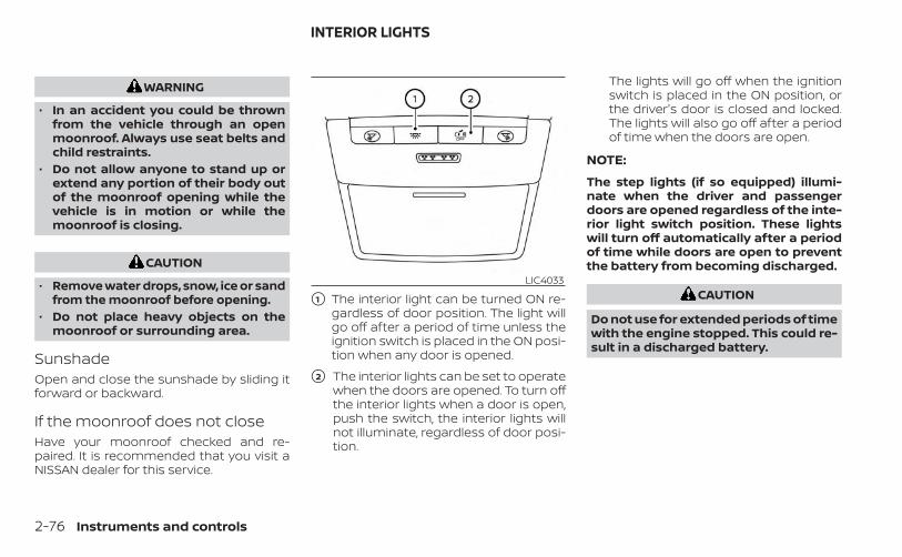
WARNING
• In an accident you could be thrownfrom the vehicle through an openmoonroof. Always use seat belts andchild restraints.
• Do not allow anyone to stand up orextend any portion of their body outof the moonroof opening while thevehicle is in motion or while themoonroof is closing.
CAUTION
• Remove water drops, snow, ice or sandfrom the moonroof before opening.
• Do not place heavy objects on themoonroof or surrounding area.
SunshadeOpen and close the sunshade by sliding itforward or backward.
If the moonroof does not closeHave your moonroof checked and re-paired. It is recommended that you visit aNISSAN dealer for this service.
�1 The interior light can be turned ON re-gardless of door position. The light willgo off after a period of time unless theignition switch is placed in the ON posi-tion when any door is opened.
�2 The interior lights can be set to operatewhen the doors are opened. To turn offthe interior lights when a door is open,push the switch, the interior lights willnot illuminate, regardless of door posi-tion.
The lights will go off when the ignitionswitch is placed in the ON position, orthe driver's door is closed and locked.The lights will also go off after a periodof time when the doors are open.
NOTE:
The step lights (if so equipped) illumi-nate when the driver and passengerdoors are opened regardless of the inte-rior light switch position. These lightswill turn off automatically after a periodof time while doors are open to preventthe battery from becoming discharged.
CAUTION
Do not use for extended periods of timewith the engine stopped. This could re-sult in a discharged battery.
LIC4033
INTERIOR LIGHTS
2-76 Instruments and controls
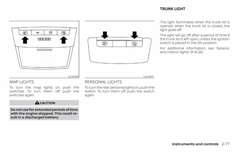
MAP LIGHTSTo turn the map lights on, push theswitches. To turn them off, push theswitches again.
CAUTION
Do not use for extended periods of timewith the engine stopped. This could re-sult in a discharged battery.
PERSONAL LIGHTSTo turn the rear personal lights on, push theswitch. To turn them off, push the switchagain.
The light illuminates when the trunk lid isopened. When the trunk lid is closed, thelight goes off.The light will go off after a period of time ifthe trunk lid is left open, unless the ignitionswitch is placed in the ON position.For additional information, see “Exteriorand interior lights” (P. 8-26).
LIC4035 LIC4041
TRUNK LIGHT
Instruments and controls 2-77
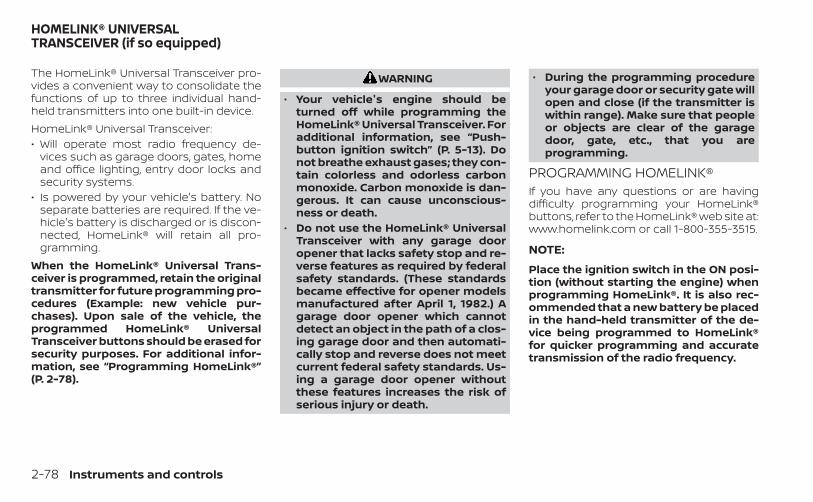
The HomeLink® Universal Transceiver pro-vides a convenient way to consolidate thefunctions of up to three individual hand-held transmitters into one built-in device.HomeLink® Universal Transceiver:• Will operate most radio frequency de-
vices such as garage doors, gates, homeand office lighting, entry door locks andsecurity systems.
• Is powered by your vehicle's battery. Noseparate batteries are required. If the ve-hicle's battery is discharged or is discon-nected, HomeLink® will retain all pro-gramming.
When the HomeLink® Universal Trans-ceiver is programmed, retain the originaltransmitter for future programming pro-cedures (Example: new vehicle pur-chases). Upon sale of the vehicle, theprogrammed HomeLink® UniversalTransceiver buttons should be erased forsecurity purposes. For additional infor-mation, see “Programming HomeLink®”(P. 2-78).
WARNING
• Your vehicle's engine should beturned off while programming theHomeLink® Universal Transceiver. Foradditional information, see “Push-button ignition switch” (P. 5-13). Donot breathe exhaust gases; they con-tain colorless and odorless carbonmonoxide. Carbon monoxide is dan-gerous. It can cause unconscious-ness or death.
• Do not use the HomeLink® UniversalTransceiver with any garage dooropener that lacks safety stop and re-verse features as required by federalsafety standards. (These standardsbecame effective for opener modelsmanufactured after April 1, 1982.) Agarage door opener which cannotdetect an object in the path of a clos-ing garage door and then automati-cally stop and reverse does not meetcurrent federal safety standards. Us-ing a garage door opener withoutthese features increases the risk ofserious injury or death.
• During the programming procedureyour garage door or security gate willopen and close (if the transmitter iswithin range). Make sure that peopleor objects are clear of the garagedoor, gate, etc., that you areprogramming.
PROGRAMMING HOMELINK®If you have any questions or are havingdifficulty programming your HomeLink®buttons, refer to the HomeLink® web site at:www.homelink.com or call 1-800-355-3515.
NOTE:
Place the ignition switch in the ON posi-tion (without starting the engine) whenprogramming HomeLink®. It is also rec-ommended that a new battery be placedin the hand-held transmitter of the de-vice being programmed to HomeLink®for quicker programming and accuratetransmission of the radio frequency.
HOMELINK® UNIVERSALTRANSCEIVER (if so equipped)
2-78 Instruments and controls
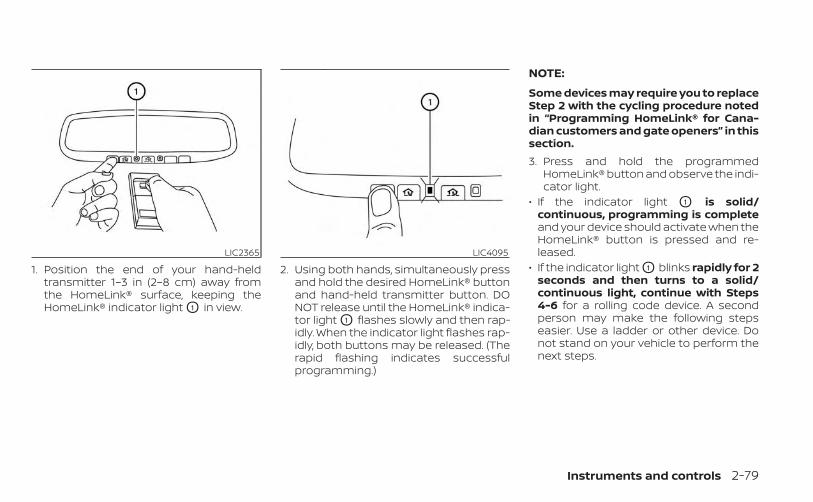
1. Position the end of your hand-heldtransmitter 1–3 in (2–8 cm) away fromthe HomeLink® surface, keeping theHomeLink® indicator light O1 in view.
2. Using both hands, simultaneously pressand hold the desired HomeLink® buttonand hand-held transmitter button. DONOT release until the HomeLink® indica-tor light O1 flashes slowly and then rap-idly. When the indicator light flashes rap-idly, both buttons may be released. (Therapid flashing indicates successfulprogramming.)
NOTE:
Some devices may require you to replaceStep 2 with the cycling procedure notedin “Programming HomeLink® for Cana-dian customers and gate openers” in thissection.3. Press and hold the programmed
HomeLink® button and observe the indi-cator light.
• If the indicator light O1 is solid/continuous, programming is completeand your device should activate when theHomeLink® button is pressed and re-leased.
• If the indicator light O1 blinks rapidly for 2seconds and then turns to a solid/continuous light, continue with Steps4-6 for a rolling code device. A secondperson may make the following stepseasier. Use a ladder or other device. Donot stand on your vehicle to perform thenext steps.
LIC2365 LIC4095
Instruments and controls 2-79

4. At the receiver located on the garagedoor opener motor in the garage, locatethe “learn” or “smart” button (the nameand color of the button may vary bymanufacturer but it is usually locatednear where the hanging antenna wire isattached to the unit). If there is difficultylocating the button, reference the ga-rage door opener’s manual.
5. Press and release the “learn” or “smart”button.
NOTE:Once the button is pressed, you have ap-proximately 30 seconds to initiate thenext step.
6. Return to the vehicle and firmly pressand hold the trained HomeLink® buttonfor 2 seconds and release. Repeat the“press/hold/release” sequence up tothree times to complete the trainingprocess. HomeLink® should now acti-vate your rolling code equipped device.
7. If you have any questions or are havingdifficulty programming your HomeLink®buttons, refer to the HomeLink® website at: www.homelink.com or call1-800-355-3515.
PROGRAMMING HOMELINK® FORCANADIAN CUSTOMERS AND GATEOPENERSCanadian radio-frequency laws requiretransmitter signals to “time-out” (or quit)after several seconds of transmission –which may not be long enough forHomeLink® to pick up the signal duringtraining. Similar to this Canadian law, someU.S. gate operators are designed to “tim-eout” in the same manner.If you live in Canada or you are having diffi-culties training a gate operator or garagedoor opener by using the “Training” proce-dures, replace “Programming HomeLink®”step 2 with the following:
NOTE:
When programming a garage dooropener, etc., unplug the device duringthe “cycling” process to prevent possibledamage to the garage door openercomponents.1. For additional information, see “Pro-
gramming HomeLink®” step 1 (P. 2-78).
2. Using both hands, simultaneously pressand hold the desired HomeLink® buttonand the hand-held transmitter button.During training, your hand-held trans-mitter may automatically stop transmit-ting. Continue to press and hold the de-sired HomeLink® button while you pressand re-press (“cycle”) your hand-heldtransmitter every 2 seconds until thefrequency signal has been learned. TheHomeLink® indicator light will flashslowly and then rapidly after severalseconds upon successful training. DONOT release until the HomeLink® indica-tor light flashes slowly and then rapidly.When the indicator light flashes rapidly,both buttons may be released. The rapidflashing indicates successful training.Proceed with “Programming HomeLink®”step 3 to complete.If the device was unplugged during theprogramming procedure, remember toplug it back in when programming iscompleted.
2-80 Instruments and controls
OPERATING THE HOMELINK®UNIVERSAL TRANSCEIVERThe HomeLink® Universal Transceiver, afterit is programmed, can be used to activatethe programmed device. To operate, sim-ply press and release the appropriate pro-grammed HomeLink® Universal Trans-ceiver button. The amber indicator light willilluminate while the signal is being trans-mitted.For convenience, the hand-held transmit-ter of the device may also be used at anytime.
PROGRAMMING TROUBLE-DIAGNOSISIf the HomeLink® does not quickly learn thehand-held transmitter information:• Replace the hand-held transmitter bat-
teries with new batteries.• Position the hand-held transmitter with
its battery area facing away from theHomeLink® surface.
• Press and hold both the HomeLink® andhand-held transmitter buttons withoutinterruption.
• Position the hand-held transmitter 1 - 3inches (26 - 76 mm) away from theHomeLink® surface. Hold the transmitterin that position for up to 15 seconds. IfHomeLink® is not programmed withinthat time, try holding the transmitter inanother position – keeping the indicatorlight in view at all times.
If you have any questions or are havingdifficulty programming your HomeLink®buttons, refer to the HomeLink® web site at:www.homelink.com or call 1-800-355-3515.
CLEARING THE PROGRAMMEDINFORMATIONThe following procedure clears the pro-grammed information from both buttons.Individual buttons cannot be cleared. How-ever, individual buttons can be repro-grammed. For additional information, see“Reprogramming a single HomeLink® but-ton” (P. 2-81).To clear all programming:1. Press and hold the two outer HomeLink®
buttons until the indicator light begins toflash in approximately 10 seconds. Donot hold for longer than 20 seconds.
2. Release both buttons.
HomeLink® is now in the programmingmode and can be programmed at anytime beginning with “ProgrammingHomeLink®” - step 1.
REPROGRAMMING A SINGLEHOMELINK® BUTTONTo reprogram a HomeLink® UniversalTransceiver button, complete the following:1. Press and hold the desired HomeLink®
button. DO NOT release the button.
2. The indicator light will begin to flash af-ter 20 seconds. Without releasing theHomeLink® button, proceed with “Pro-gramming HomeLink®” - step 1 (P. 2-78).
For questions or comments, contactHomeLink® at: www.homelink.com or1–800–355–3515 (except Mexico).The HomeLink® Universal Transceiver but-ton has now been reprogrammed. The newdevice can be activated by pressing theHomeLink® button that was just pro-grammed. This procedure will not affect anyother programmed HomeLink® buttons.
Instruments and controls 2-81
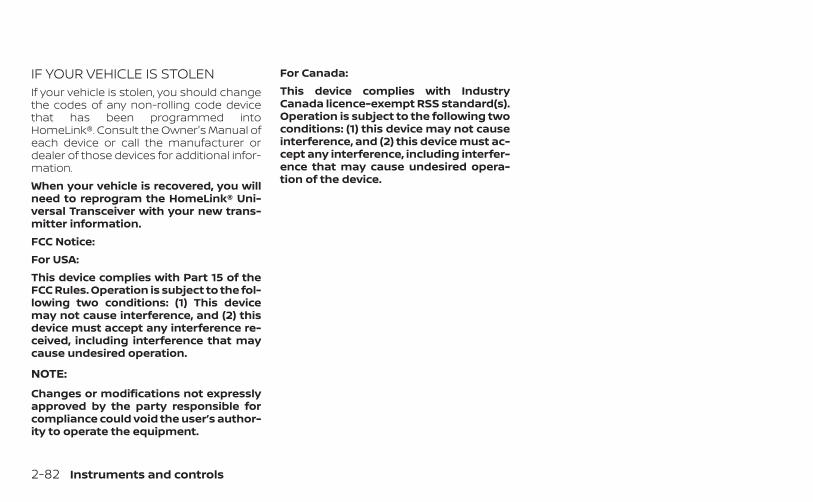
IF YOUR VEHICLE IS STOLENIf your vehicle is stolen, you should changethe codes of any non-rolling code devicethat has been programmed intoHomeLink®. Consult the Owner's Manual ofeach device or call the manufacturer ordealer of those devices for additional infor-mation.When your vehicle is recovered, you willneed to reprogram the HomeLink® Uni-versal Transceiver with your new trans-mitter information.FCC Notice:For USA:This device complies with Part 15 of theFCC Rules. Operation is subject to the fol-lowing two conditions: (1) This devicemay not cause interference, and (2) thisdevice must accept any interference re-ceived, including interference that maycause undesired operation.
NOTE:
Changes or modifications not expresslyapproved by the party responsible forcompliance could void the user’s author-ity to operate the equipment.
For Canada:This device complies with IndustryCanada licence-exempt RSS standard(s).Operation is subject to the following twoconditions: (1) this device may not causeinterference, and (2) this device must ac-cept any interference, including interfer-ence that may cause undesired opera-tion of the device.
2-82 Instruments and controls
3 Pre-driving checks and adjustments
Keys . . . . . . . . . . . . . . . . . . . . . . . . . . . . . . . . . . . . . . . . . . . . . 3-2NISSAN Intelligent Key® . . . . . . . . . . . . . . . . . . . . . . . 3-2NISSAN Vehicle Immobilizer Systemkeys . . . . . . . . . . . . . . . . . . . . . . . . . . . . . . . . . . . . . . . . . . 3-4
Doors . . . . . . . . . . . . . . . . . . . . . . . . . . . . . . . . . . . . . . . . . . . 3-4Locking with key . . . . . . . . . . . . . . . . . . . . . . . . . . . . . 3-5Locking with inside lock knob . . . . . . . . . . . . . . . . 3-5Locking with power door lock switch . . . . . . . . . 3-6Automatic door locks . . . . . . . . . . . . . . . . . . . . . . . . 3-6Child safety rear door lock . . . . . . . . . . . . . . . . . . . . 3-6
NISSAN Intelligent Key® . . . . . . . . . . . . . . . . . . . . . . . . . . 3-7Operating range . . . . . . . . . . . . . . . . . . . . . . . . . . . . . 3-8Door locks/unlocks precaution . . . . . . . . . . . . . . . 3-9NISSAN Intelligent Key® operation . . . . . . . . . . . 3-10How to use the remote keyless entryfunction . . . . . . . . . . . . . . . . . . . . . . . . . . . . . . . . . . . . . 3-13Warning signals . . . . . . . . . . . . . . . . . . . . . . . . . . . . . 3-16Troubleshooting guide . . . . . . . . . . . . . . . . . . . . . . 3-16
Remote Engine Start . . . . . . . . . . . . . . . . . . . . . . . . . . . 3-19Remote Engine Start operating range . . . . . . . 3-19Remote starting the vehicle . . . . . . . . . . . . . . . . . 3-19Extending engine run time . . . . . . . . . . . . . . . . . . 3-20Canceling a Remote Engine Start . . . . . . . . . . . 3-20Conditions the Remote Engine Start willnot work . . . . . . . . . . . . . . . . . . . . . . . . . . . . . . . . . . . . 3-20
Hood . . . . . . . . . . . . . . . . . . . . . . . . . . . . . . . . . . . . . . . . . . . 3-22Trunk lid . . . . . . . . . . . . . . . . . . . . . . . . . . . . . . . . . . . . . . . . 3-22
Opener operation . . . . . . . . . . . . . . . . . . . . . . . . . . . 3-22Interior trunk lid release . . . . . . . . . . . . . . . . . . . . . 3-24Interior trunk access . . . . . . . . . . . . . . . . . . . . . . . . 3-24
Fuel-filler door . . . . . . . . . . . . . . . . . . . . . . . . . . . . . . . . . . 3-25Opener operation . . . . . . . . . . . . . . . . . . . . . . . . . . . 3-25Fuel-filler cap . . . . . . . . . . . . . . . . . . . . . . . . . . . . . . . . 3-25
Steering wheel . . . . . . . . . . . . . . . . . . . . . . . . . . . . . . . . . 3-27Tilt operation . . . . . . . . . . . . . . . . . . . . . . . . . . . . . . . . 3-27Telescopic operation . . . . . . . . . . . . . . . . . . . . . . . . 3-27
Sun visors . . . . . . . . . . . . . . . . . . . . . . . . . . . . . . . . . . . . . . 3-28Vanity mirrors . . . . . . . . . . . . . . . . . . . . . . . . . . . . . . . 3-29
Mirrors . . . . . . . . . . . . . . . . . . . . . . . . . . . . . . . . . . . . . . . . . 3-29Manual anti-glare rearview mirror(if so equipped) . . . . . . . . . . . . . . . . . . . . . . . . . . . . . . 3-29Automatic anti-glare rearview mirror(if so equipped) . . . . . . . . . . . . . . . . . . . . . . . . . . . . . . 3-29Outside mirrors . . . . . . . . . . . . . . . . . . . . . . . . . . . . . 3-30
Memory seat (if so equipped) . . . . . . . . . . . . . . . . . . . 3-31Memory storage function . . . . . . . . . . . . . . . . . . . 3-31Memory storage function (switch) . . . . . . . . . . . 3-32Entry/exit function . . . . . . . . . . . . . . . . . . . . . . . . . . 3-33System operation . . . . . . . . . . . . . . . . . . . . . . . . . . . 3-33
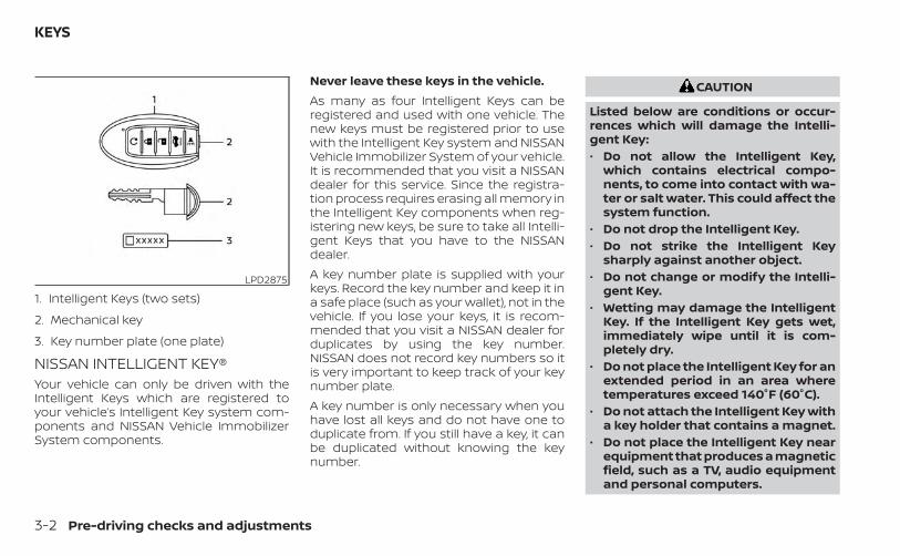
NISSAN INTELLIGENT KEY®Your vehicle can only be driven with theIntelligent Keys which are registered toyour vehicle’s Intelligent Key system com-ponents and NISSAN Vehicle ImmobilizerSystem components.
Never leave these keys in the vehicle.As many as four Intelligent Keys can beregistered and used with one vehicle. Thenew keys must be registered prior to usewith the Intelligent Key system and NISSANVehicle Immobilizer System of your vehicle.It is recommended that you visit a NISSANdealer for this service. Since the registra-tion process requires erasing all memory inthe Intelligent Key components when reg-istering new keys, be sure to take all Intelli-gent Keys that you have to the NISSANdealer.A key number plate is supplied with yourkeys. Record the key number and keep it ina safe place (such as your wallet), not in thevehicle. If you lose your keys, it is recom-mended that you visit a NISSAN dealer forduplicates by using the key number.NISSAN does not record key numbers so itis very important to keep track of your keynumber plate.A key number is only necessary when youhave lost all keys and do not have one toduplicate from. If you still have a key, it canbe duplicated without knowing the keynumber.
CAUTION
Listed below are conditions or occur-rences which will damage the Intelli-gent Key:• Do not allow the Intelligent Key,
which contains electrical compo-nents, to come into contact with wa-ter or salt water. This could affect thesystem function.
• Do not drop the Intelligent Key.• Do not strike the Intelligent Key
sharply against another object.• Do not change or modify the Intelli-
gent Key.• Wetting may damage the Intelligent
Key. If the Intelligent Key gets wet,immediately wipe until it is com-pletely dry.
• Do not place the Intelligent Key for anextended period in an area wheretemperatures exceed 140°F (60°C).
• Do not attach the Intelligent Key witha key holder that contains a magnet.
• Do not place the Intelligent Key nearequipment that produces a magneticfield, such as a TV, audio equipmentand personal computers.
LPD2875
1. Intelligent Keys (two sets)
2. Mechanical key
3. Key number plate (one plate)
KEYS
3-2 Pre-driving checks and adjustments
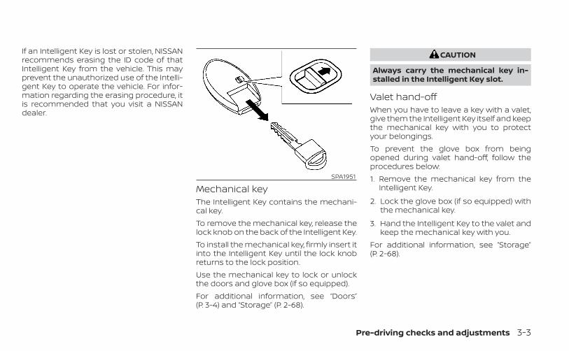
If an Intelligent Key is lost or stolen, NISSANrecommends erasing the ID code of thatIntelligent Key from the vehicle. This mayprevent the unauthorized use of the Intelli-gent Key to operate the vehicle. For infor-mation regarding the erasing procedure, itis recommended that you visit a NISSANdealer.
Mechanical keyThe Intelligent Key contains the mechani-cal key.To remove the mechanical key, release thelock knob on the back of the Intelligent Key.To install the mechanical key, firmly insert itinto the Intelligent Key until the lock knobreturns to the lock position.Use the mechanical key to lock or unlockthe doors and glove box (if so equipped).For additional information, see “Doors”(P. 3-4) and “Storage” (P. 2-68).
CAUTION
Always carry the mechanical key in-stalled in the Intelligent Key slot.
Valet hand-offWhen you have to leave a key with a valet,give them the Intelligent Key itself and keepthe mechanical key with you to protectyour belongings.To prevent the glove box from beingopened during valet hand-off, follow theprocedures below:1. Remove the mechanical key from the
Intelligent Key.
2. Lock the glove box (if so equipped) withthe mechanical key.
3. Hand the Intelligent Key to the valet andkeep the mechanical key with you.
For additional information, see “Storage”(P. 2-68).
SPA1951
Pre-driving checks and adjustments 3-3
NISSAN VEHICLE IMMOBILIZERSYSTEM KEYSAdditional or replacement keys:If you still have a key, the key number is notnecessary when you need extra NISSANVehicle Immobilizer System keys. Your ex-isting key can be duplicated without know-ing the key number. As many as fourNISSAN Vehicle Immobilizer System keyscan be used with one vehicle. You shouldbring all NISSAN Vehicle Immobilizer Sys-tem keys that you have to the NISSANdealer for registration. This is because theregistration process will erase the memoryof all key codes previously registered intothe NISSAN Vehicle Immobilizer System. Af-ter the registration process, these compo-nents will only recognize keys coded intothe NISSAN Vehicle Immobilizer Systemduring registration. Any key that is notgiven to the dealer at the time of registra-tion will no longer be able to start yourvehicle.
CAUTION
Do not allow the immobilizer systemkey, which contains an electrical tran-sponder, to come into contact with wa-ter or salt water. This could affect sys-tem function.
When the doors are locked using one of thefollowing methods, the doors cannot beopened using the inside or outside doorhandles. The doors must be unlocked toopen the doors.
WARNING
• Always have the doors locked whiledriving. Along with the use of seatbelts, this provides greater safety inthe event of an accident by helping toprevent persons from being thrownfrom the vehicle. This also helps keepchildren and others from uninten-tionally opening the doors, and willhelp keep out intruders.
• Before opening any door, always lookfor and avoid oncoming traffic.
• To help avoid risk of injury or deaththrough unintended operation of thevehicle and/or its systems, includingentrapment in windows and/or inad-vertent door lock activation, do notleave children, people who requirethe assistance of others and/or petsunattended in your vehicle. Addition-ally, the temperature inside a closedvehicle on a warm day can quicklybecome high enough to cause a sig-nificant risk of injury or death topeople and pets.
DOORS
3-4 Pre-driving checks and adjustments
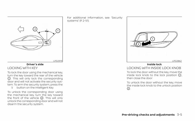
LOCKING WITH KEYTo lock the door using the mechanical key,turn the key toward the rear of the vehicleO1 . This will only lock the correspondingdoor and will not activate the security sys-tem. To arm the security system, press the
button on the Intelligent Key.To unlock the corresponding door usingthe mechanical key, turn the key towardthe front of the vehicle O2 . This will onlyunlock the corresponding door and will notdisarm the security system.
For additional information, see “Securitysystems” (P. 2-51).
LOCKING WITH INSIDE LOCK KNOBTo lock the door without the key, move theinside lock knob to the lock position O1 ,then close the door.To unlock the door without the key, movethe inside lock knob to the unlock positionO2 .
LPD2919Driver's side
LPD2862Inside lock
Pre-driving checks and adjustments 3-5
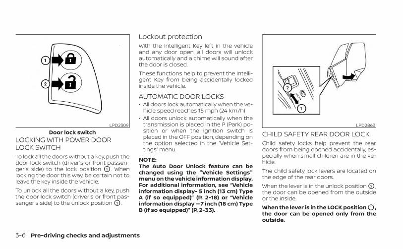
LOCKING WITH POWER DOORLOCK SWITCHTo lock all the doors without a key, push thedoor lock switch (driver's or front passen-ger's side) to the lock position O1 . Whenlocking the door this way, be certain not toleave the key inside the vehicle.To unlock all the doors without a key, pushthe door lock switch (driver's or front pas-senger's side) to the unlock position O2 .
Lockout protectionWith the Intelligent Key left in the vehicleand any door open, all doors will unlockautomatically and a chime will sound afterthe door is closed.These functions help to prevent the Intelli-gent Key from being accidentally lockedinside the vehicle.
AUTOMATIC DOOR LOCKS• All doors lock automatically when the ve-
hicle speed reaches 15 mph (24 km/h)• All doors unlock automatically when the
transmission is placed in the P (Park) po-sition or when the ignition switch isplaced in the OFF position, depending onthe option selected in the “Vehicle Set-tings” menu.
NOTE:The Auto Door Unlock feature can bechanged using the "Vehicle Settings"menu on the vehicle information display.For additional information, see “Vehicleinformation display- 5 inch (13 cm) TypeA (if so equipped)” (P. 2-18) or “Vehicleinformation display —7 inch (18 cm) TypeB (if so equipped)” (P. 2-33).
CHILD SAFETY REAR DOOR LOCKChild safety locks help prevent the reardoors from being opened accidentally, es-pecially when small children are in the ve-hicle.The child safety lock levers are located onthe edge of the rear doors.When the lever is in the unlock position O2 ,the door can be opened from the outsideor the inside.When the lever is in the LOCK position O1 ,the door can be opened only from theoutside.
LPD2309Door lock switch
LPD2863
3-6 Pre-driving checks and adjustments
WARNING
• Radio waves could adversely affectelectric medical equipment. Thosewho use a pacemaker should contactthe electric medical equipmentmanufacturer for the possible influ-ences before use.
• The Intelligent Key transmits radiowaves when the buttons are pressed.The FAA advises the radio waves mayaffect aircraft navigation and com-munication systems. Do not operatethe Intelligent Key while on an air-plane. Make sure the buttons are notoperated unintentionally when theunit is stored for a flight.
The Intelligent Key can operate all the doorlocks using the remote control function orpushing the request switch on the vehiclewithout taking the key out from a pocket orpurse. The operating environment and/orconditions may affect the Intelligent Keyoperation.Be sure to read the following before usingthe Intelligent Key.
CAUTION
• Be sure to carry the Intelligent Keywith you when operating the vehicle.
• Never leave the Intelligent Key in thevehicle when you leave the vehicle.
The Intelligent Key is always communicat-ing with the vehicle as it receives radiowaves. The Intelligent Key transmits weakradio waves. Environmental conditionsmay interfere with the operation of the In-telligent Key under the following operatingconditions:• When operating near a location where
strong radio waves are transmitted, suchas a TV tower, power station and broad-casting station.
• When in possession of wireless equip-ment, such as a cellular telephone, trans-ceiver or a CB radio.
• When the Intelligent Key is in contact withor covered by metallic materials.
• When any type of radio wave remote con-trol is used nearby.
• When the Intelligent Key is placed near anelectric appliance such as a personalcomputer.
• When the vehicle is parked near a parkingmeter.
In such cases, correct the operating condi-tions before using the Intelligent Key func-tion or use the mechanical key.Although the life of the battery varies de-pending on the operating conditions, thebattery’s life is approximately two years. Ifthe battery is discharged, replace it with anew one.When the Intelligent Key battery is low, anindicator illuminates in the vehicle informa-tion display. For additional information, see“Vehicle information display - 5 inch (13 cm)Type A (if so equipped)” (P. 2-18) or “Vehicleinformation display - 7 inch (18 cm) Type B (ifso equipped)” (P. 2-33).Since the Intelligent Key is continuously re-ceiving radio waves, if the key is left nearequipment which transmits strong radiowaves, such as signals from a TV and per-sonal computer, the battery life may be-come shorter.For additional information, see “Battery re-placement” (P. 8-23).As many as four Intelligent Keys can beregistered and used with one vehicle. Forinformation about the purchase and use ofadditional Intelligent Keys, it is recom-mended that you visit a NISSAN dealer.
NISSAN INTELLIGENT KEY®
Pre-driving checks and adjustments 3-7
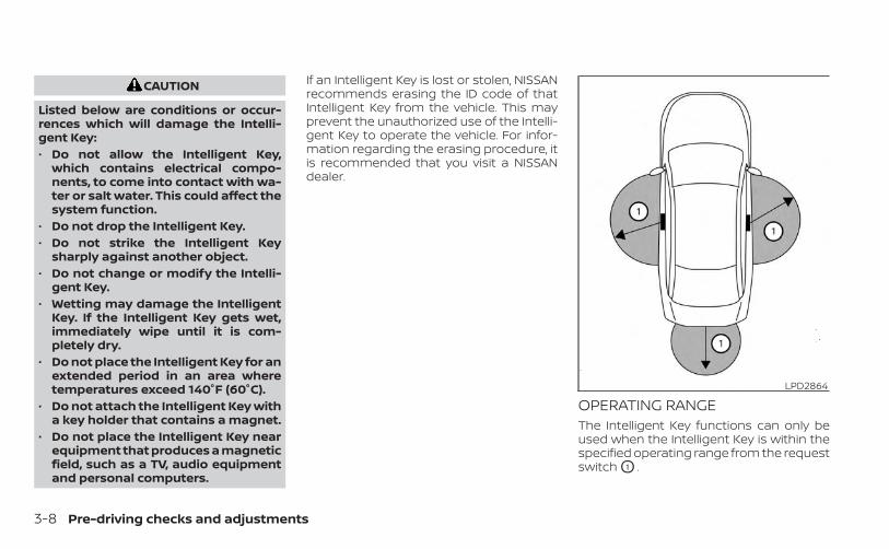
CAUTION
Listed below are conditions or occur-rences which will damage the Intelli-gent Key:• Do not allow the Intelligent Key,
which contains electrical compo-nents, to come into contact with wa-ter or salt water. This could affect thesystem function.
• Do not drop the Intelligent Key.• Do not strike the Intelligent Key
sharply against another object.• Do not change or modify the Intelli-
gent Key.• Wetting may damage the Intelligent
Key. If the Intelligent Key gets wet,immediately wipe until it is com-pletely dry.
• Do not place the Intelligent Key for anextended period in an area wheretemperatures exceed 140°F (60°C).
• Do not attach the Intelligent Key witha key holder that contains a magnet.
• Do not place the Intelligent Key nearequipment that produces a magneticfield, such as a TV, audio equipmentand personal computers.
If an Intelligent Key is lost or stolen, NISSANrecommends erasing the ID code of thatIntelligent Key from the vehicle. This mayprevent the unauthorized use of the Intelli-gent Key to operate the vehicle. For infor-mation regarding the erasing procedure, itis recommended that you visit a NISSANdealer.
OPERATING RANGEThe Intelligent Key functions can only beused when the Intelligent Key is within thespecified operating range from the requestswitch O1 .
LPD2864
3-8 Pre-driving checks and adjustments
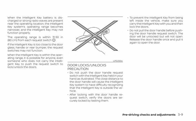
When the Intelligent Key battery is dis-charged or strong radio waves are presentnear the operating location, the IntelligentKey system’s operating range becomesnarrower, and the Intelligent Key may notfunction properly.The operating range is within 31.50 in(80 cm) from each request switch O1 .If the Intelligent Key is too close to the doorglass, handle or rear bumper, the requestswitches may not function.When the Intelligent Key is within the oper-ating range, it is possible for anyone, evensomeone who does not carry the Intelli-gent Key, to push the request switch tolock/unlock the doors. DOOR LOCKS/UNLOCKS
PRECAUTION• Do not push the door handle request
switch with the Intelligent Key held in yourhand as illustrated. The close distance tothe door handle will cause the IntelligentKey system to have difficulty recognizingthat the Intelligent Key is outside the ve-hicle.
• After locking with the door handle re-quest switch, verify the doors are se-curely locked by testing them.
• To prevent the Intelligent Key from beingleft inside the vehicle, make sure youcarry the Intelligent Key with you and thenlock the doors.
• Do not pull the door handle before push-ing the door handle request switch. Thedoor will be unlocked but will not open.Release the door handle once and pull itagain to open the door.
LPD2554
Pre-driving checks and adjustments 3-9
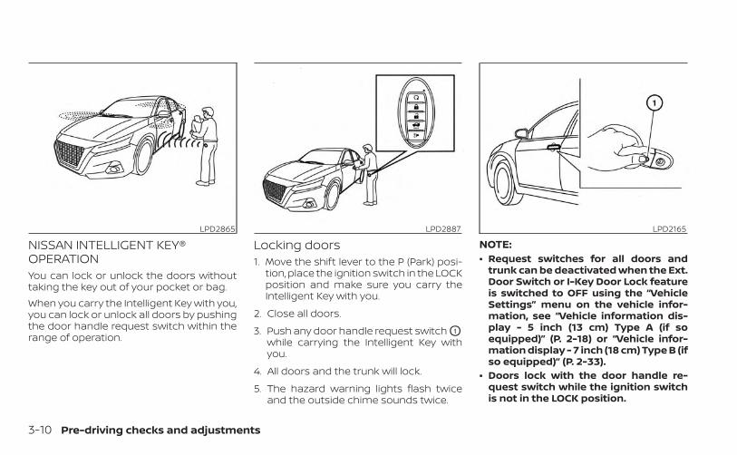
NISSAN INTELLIGENT KEY®OPERATIONYou can lock or unlock the doors withouttaking the key out of your pocket or bag.When you carry the Intelligent Key with you,you can lock or unlock all doors by pushingthe door handle request switch within therange of operation.
Locking doors1. Move the shift lever to the P (Park) posi-
tion, place the ignition switch in the LOCKposition and make sure you carry theIntelligent Key with you.
2. Close all doors.
3. Push any door handle request switch O1
while carrying the Intelligent Key withyou.
4. All doors and the trunk will lock.
5. The hazard warning lights flash twiceand the outside chime sounds twice.
NOTE:• Request switches for all doors and
trunk can be deactivated when the Ext.Door Switch or I-Key Door Lock featureis switched to OFF using the “VehicleSettings” menu on the vehicle infor-mation, see “Vehicle information dis-play - 5 inch (13 cm) Type A (if soequipped)” (P. 2-18) or “Vehicle infor-mation display - 7 inch (18 cm) Type B (ifso equipped)” (P. 2-33).
• Doors lock with the door handle re-quest switch while the ignition switchis not in the LOCK position.
LPD2865 LPD2887 LPD2165
3-10 Pre-driving checks and adjustments
• Doors lock by pushing the driver’s sidedoor handle request switch while anydoor is open. However, the correspond-ing door locks with the mechanical keyeven if any door is open.
• Doors do not lock with the door handlerequest switch with the Intelligent Keyinside the vehicle and a beep sounds towarn you. However, when an IntelligentKey is inside the vehicle, doors can belocked with another Intelligent Key.
WARNING
After locking the doors using the re-quest switch, make sure that the doorshave been securely locked by operat-ing the door handles. Failure to followthese instructions may result in inad-vertently unlocking the doors, whichmay decrease the safety and securityof your vehicle.
CAUTION
• When locking the doors using the re-quest switch, make sure to have theIntelligent Key in your possessionbefore operating the request switchto prevent the Intelligent Key frombeing left in the vehicle.
• The request switch is operationalonly when the Intelligent Key hasbeen detected by the Intelligent Keysystem.
Lockout protectionTo prevent the Intelligent Key from beingaccidentally locked in the vehicle, lockoutprotection is equipped with the IntelligentKey.When the driver’s side door is open, thedoors are locked and then the IntelligentKey is put inside the vehicle and all thedoors are closed; the lock will automati-cally unlock and the door chime sounds.
NOTE:
The doors may not lock when the Intelli-gent Key is in the same hand that is op-erating the request switch to lock thedoor. Put the Intelligent Key in a purse,pocket or your other hand.
CAUTION
The lockout protection may not func-tion under the following conditions:• When the Intelligent Key is placed on
top of the instrument panel.• When the Intelligent Key is placed on
top of the rear parcel shelf.• When the Intelligent Key is placed in-
side the glove box or a storage bin.• When the Intelligent Key is placed in-
side the door pockets.• When the Intelligent Key is placed on
or under the spare tire area.• When the Intelligent Key is placed in-
side or near metallic materials.
Pre-driving checks and adjustments 3-11
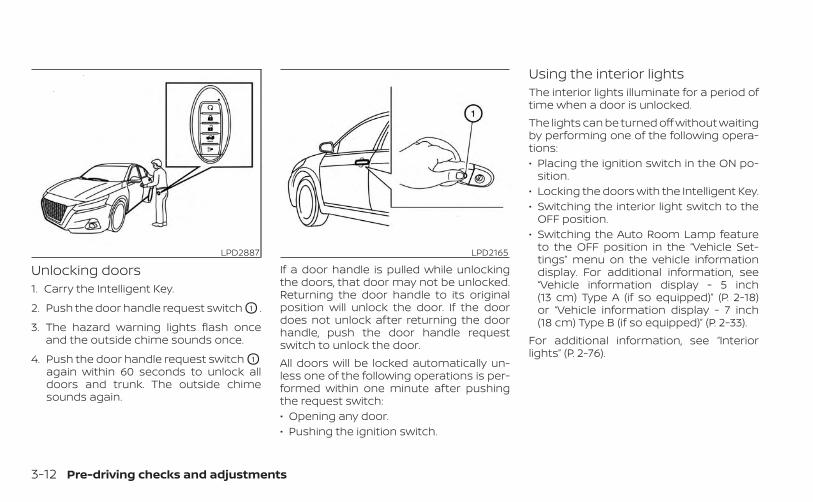
Unlocking doors1. Carry the Intelligent Key.
2. Push the door handle request switch O1 .
3. The hazard warning lights flash onceand the outside chime sounds once.
4. Push the door handle request switch O1
again within 60 seconds to unlock alldoors and trunk. The outside chimesounds again.
If a door handle is pulled while unlockingthe doors, that door may not be unlocked.Returning the door handle to its originalposition will unlock the door. If the doordoes not unlock after returning the doorhandle, push the door handle requestswitch to unlock the door.All doors will be locked automatically un-less one of the following operations is per-formed within one minute after pushingthe request switch:• Opening any door.• Pushing the ignition switch.
Using the interior lightsThe interior lights illuminate for a period oftime when a door is unlocked.The lights can be turned off without waitingby performing one of the following opera-tions:• Placing the ignition switch in the ON po-
sition.• Locking the doors with the Intelligent Key.• Switching the interior light switch to the
OFF position.• Switching the Auto Room Lamp feature
to the OFF position in the “Vehicle Set-tings” menu on the vehicle informationdisplay. For additional information, see“Vehicle information display - 5 inch(13 cm) Type A (if so equipped)” (P. 2-18)or “Vehicle information display - 7 inch(18 cm) Type B (if so equipped)” (P. 2-33).
For additional information, see “Interiorlights” (P. 2-76).
LPD2887 LPD2165
3-12 Pre-driving checks and adjustments
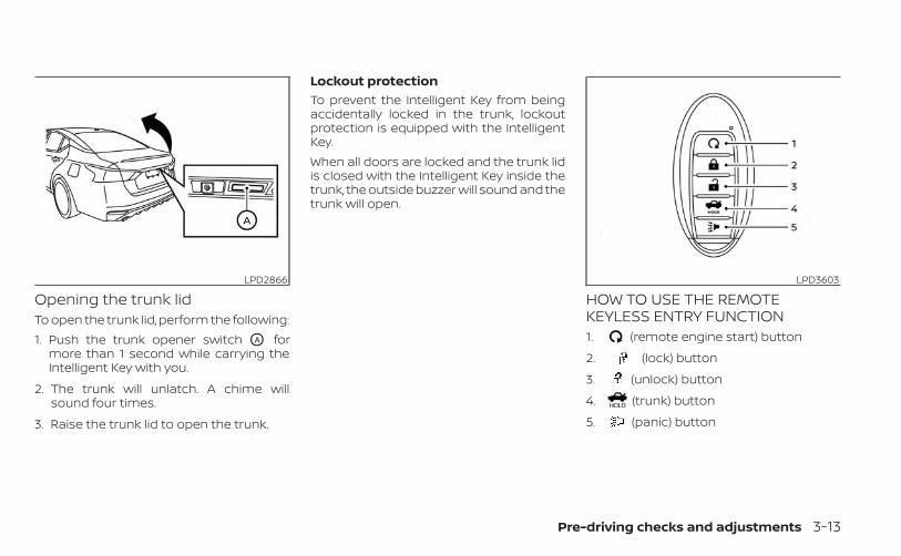
Opening the trunk lidTo open the trunk lid, perform the following:1. Push the trunk opener switch OA for
more than 1 second while carrying theIntelligent Key with you.
2. The trunk will unlatch. A chime willsound four times.
3. Raise the trunk lid to open the trunk.
Lockout protectionTo prevent the Intelligent Key from beingaccidentally locked in the trunk, lockoutprotection is equipped with the IntelligentKey.When all doors are locked and the trunk lidis closed with the Intelligent Key inside thetrunk, the outside buzzer will sound and thetrunk will open.
HOW TO USE THE REMOTEKEYLESS ENTRY FUNCTION1. (remote engine start) button
2. (lock) button
3. (unlock) button
4. (trunk) button
5. (panic) button
LPD2866 LPD3603
Pre-driving checks and adjustments 3-13
The remote keyless entry function can op-erate all door locks using the remote key-less function of the Intelligent Key. The re-mote keyless function can operate at adistance of 33 ft (10 m) away from the ve-hicle. The operating distance dependsupon the conditions around the vehicle.The remote keyless entry function will notfunction under the following conditions:• When the Intelligent Key is not within the
operational range.• When the doors or the trunk are open or
not closed securely.• When the Intelligent Key battery is dis-
charged.
CAUTION
When locking the doors using the Intel-ligent Key, be sure not to leave the keyin the vehicle.
Locking doors1. Place the ignition switch in the LOCK
position.
2. Close all doors.
3. Press the button on the IntelligentKey.
4. The hazard indicator lights flash twiceand the horn beeps once.
5. All doors will be locked.
WARNING
After locking the doors using the Intel-ligent Key, be sure that the doors havebeen securely locked by operating thedoor handles. Failure to follow these in-structions may result in inadvertentlyunlocking the doors, which may de-crease the safety and security of yourvehicle.
Unlocking doors1. Press the button on the Intelligent
Key.
2. The hazard indicator lights flash onceand the driver’s door will unlock.
3. Press the button again within 1 min-ute to unlock all doors and trunk.
NOTE:
The Selective Unlock feature can bechanged using the “Vehicle Settings”menu on the vehicle information display.For additional information, see “Vehicleinformation display - 5 inch (13 cm) TypeA (if so equipped)” (P. 2-18) or “Vehicleinformation display - 7 inch (18 cm) TypeB (if so equipped)” (P. 2-33).All doors will be locked automatically un-less one of the following operations is per-formed within 1 minute after pressing the
button:• Opening any doors.• Pushing the ignition switch.
Using the interior lightsThe interior lights illuminate for a period oftime when a door is unlocked.The lights can be turned off without waitingby performing one of the following opera-tions:• Placing the ignition switch in the ON po-
sition.• Locking the doors with the Intelligent Key.• Switching the interior light switch to the
OFF position.
3-14 Pre-driving checks and adjustments
• Switching the Auto Room Lamp featureto the OFF position in the “Vehicle Set-tings” menu on the vehicle informationdisplay. For additional information, see“Vehicle information display - 5 inch(13 cm) Type A (if so equipped)” (P. 2-18)or “Vehicle information display - 7 inch(18 cm) Type B (if so equipped)” (P. 2-33).
For additional information, see “Interiorlights” (P. 2-76).
Opening windowsThe Intelligent Key allows you to simultane-ously open windows equipped with auto-matic operation.To open the windows, press the but-ton on the Intelligent Key longer than 3seconds after all doors are unlocked.The door windows cannot be closed byusing the Intelligent Key.
Releasing the trunk lidPress the button for longer than 0.5seconds to open the trunk lid. The trunkrelease button will not operate when theignition switch is placed in the ON position.
Using the panic alarmIf you are near your vehicle and feel threat-ened, you may activate the panic alarm tocall attention by pressing and holding the
button on the Intelligent Key for lon-ger than 0.5 seconds.The panic alarm and headlights will stay onfor a period of time.The panic alarm stops when:• It has run for a period of time, or• Any button is pressed on the Intelligent
Key.• The request switch on the driver or pas-
senger door is pushed and the IntelligentKey is in range of the door handle.
Answer back horn featureIf desired, the answer back horn featurecan be deactivated using the IntelligentKey. When it is deactivated and thebutton is pressed, the hazard indicatorlights flash twice. When the button ispressed, neither the hazard indicator lightsnor the horn operates.
NOTE:
If you can change the Answer Back Hornfeature with the Intelligent Key, the ve-hicle information display screen willshow the current mode after the ignitionswitch has been cycled from the OFF tothe ON position. The vehicle informationdisplay screen can also be used tochange the answer back horn mode.For additional information, see “Vehicleinformation display - 5 inch (13 cm) TypeA (if so equipped)” (P. 2-18 or “Vehicle in-formation display - 7 inch (18 cm) Type B(if so equipped)” (P. 2-33).To deactivate:Press and hold the and but-tons for at least 2 seconds. The hazardindicator lights will flash three times to con-firm that the answer back horn feature hasbeen deactivated.To activate:Press and hold the and but-tons for at least 2 seconds once more.The hazard indicator lights will flash onceand the horn will sound once to confirmthat the horn beep feature has been reac-tivated.
Pre-driving checks and adjustments 3-15
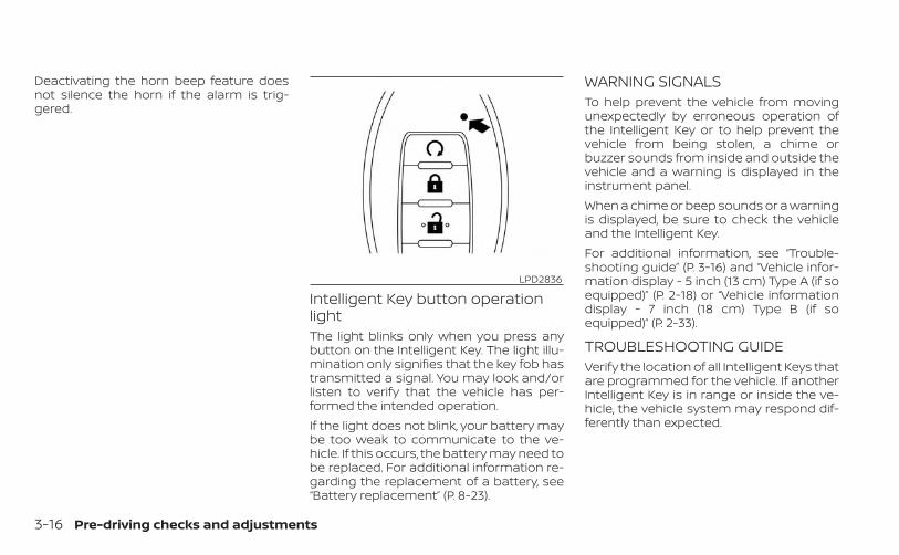
Deactivating the horn beep feature doesnot silence the horn if the alarm is trig-gered.
Intelligent Key button operationlightThe light blinks only when you press anybutton on the Intelligent Key. The light illu-mination only signifies that the key fob hastransmitted a signal. You may look and/orlisten to verify that the vehicle has per-formed the intended operation.If the light does not blink, your battery maybe too weak to communicate to the ve-hicle. If this occurs, the battery may need tobe replaced. For additional information re-garding the replacement of a battery, see“Battery replacement” (P. 8-23).
WARNING SIGNALSTo help prevent the vehicle from movingunexpectedly by erroneous operation ofthe Intelligent Key or to help prevent thevehicle from being stolen, a chime orbuzzer sounds from inside and outside thevehicle and a warning is displayed in theinstrument panel.When a chime or beep sounds or a warningis displayed, be sure to check the vehicleand the Intelligent Key.For additional information, see “Trouble-shooting guide” (P. 3-16) and “Vehicle infor-mation display - 5 inch (13 cm) Type A (if soequipped)” (P. 2-18) or “Vehicle informationdisplay - 7 inch (18 cm) Type B (if soequipped)” (P. 2-33).
TROUBLESHOOTING GUIDEVerify the location of all Intelligent Keys thatare programmed for the vehicle. If anotherIntelligent Key is in range or inside the ve-hicle, the vehicle system may respond dif-ferently than expected.
LPD2836
3-16 Pre-driving checks and adjustments
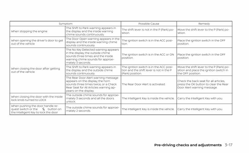
Symptom Possible Cause Remedy
When stopping the engineThe Shift to Park warning appears inthe display and the inside warningchime sounds continuously.
The shift lever is not in the P (Park) po-sition.
Move the shift lever to the P (Park) po-sition.
When opening the driver's door to getout of the vehicle
The Door Open warning appears in thedisplay and the inside warning chimesounds continuously.
The ignition switch is in the ACC posi-tion.
Place the ignition switch in the OFFposition.
When closing the door after gettingout of the vehicle
The No Key Detected warning appearsin the display, the outside chimesounds three times and the insidewarning chime sounds for approxi-mately 3 seconds.
The ignition switch is in the ACC or ONposition.
Place the ignition switch in the OFFposition.
The Shift to Park warning appears inthe display and the outside chimesounds continuously.
The ignition switch is in the ACC posi-tion and the shift lever is not in the P(Park) position.
Move the shift lever to the P (Park) po-sition and place the ignition switch inthe OFF position.
The Rear Door Alert warning messageappears on the display, the hornsounds three times twice, or a CheckRear Seat for All Articles warning ap-pears on the display.
The Rear Door Alert is activated.Check the back seat for all articles,press the OK button to clear the RearDoor Alert warning message.
When closing the door with the insidelock knob turned to LOCK
The outside chime sounds for approxi-mately 3 seconds and all the doorsunlock.
The Intelligent Key is inside the vehicle. Carry the Intelligent Key with you.
When pushing the door handle re-quest switch or the button onthe Intelligent Key to lock the door
The outside chime sounds for approxi-mately 2 seconds. The Intelligent Key is inside the vehicle. Carry the Intelligent Key with you.
Pre-driving checks and adjustments 3-17
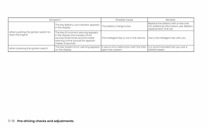
Symptom Possible Cause Remedy
When pushing the ignition switch tostart the engine
The Key Battery Low indicator appearsin the display. The battery charge is low.
Replace the battery with a new one.For additional information, see “Batteryreplacement” (P. 8-23).
The Key ID Incorrect warning appearsin the display, the outside chimesounds three times and the insidewarning chime sounds for approxi-mately 3 seconds.
The Intelligent Key is not in the vehicle. Carry the Intelligent Key with you.
When pressing the ignition switch The Key System Error warning appearson the display.
It warns of a malfunction with the Intel-ligent Key system.
It is recommended that you visit aNISSAN dealer.
3-18 Pre-driving checks and adjustments
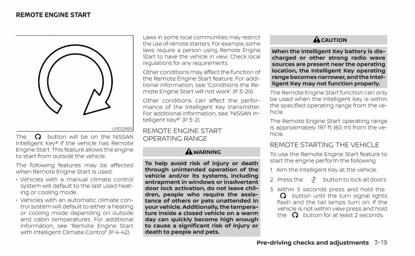
The button will be on the NISSANIntelligent Key® if the vehicle has RemoteEngine Start. This feature allows the engineto start from outside the vehicle.The following features may be affectedwhen Remote Engine Start is used:• Vehicles with a manual climate control
system will default to the last used heat-ing or cooling mode.
• Vehicles with an automatic climate con-trol system will default to either a heatingor cooling mode depending on outsideand cabin temperatures. For additionalinformation, see “Remote Engine Startwith Intelligent Climate Control” (P. 4-42).
Laws in some local communities may restrictthe use of remote starters. For example, somelaws require a person using Remote EngineStart to have the vehicle in view. Check localregulations for any requirements.Other conditions may affect the function ofthe Remote Engine Start feature. For addi-tional information, see “Conditions the Re-mote Engine Start will not work” (P. 3-20).Other conditions can affect the perfor-mance of the Intelligent Key transmitter.For additional information, see “NISSAN In-telligent Key®” (P. 3-2).
REMOTE ENGINE STARTOPERATING RANGE
WARNING
To help avoid risk of injury or deaththrough unintended operation of thevehicle and/or its systems, includingentrapment in windows or inadvertentdoor lock activation, do not leave chil-dren, people who require the assis-tance of others or pets unattended inyour vehicle. Additionally, the tempera-ture inside a closed vehicle on a warmday can quickly become high enoughto cause a significant risk of injury ordeath to people and pets.
CAUTION
When the Intelligent Key battery is dis-charged or other strong radio wavesources are present near the operatinglocation, the Intelligent Key operatingrange becomes narrower, and the Intel-ligent Key may not function properly.
The Remote Engine Start function can onlybe used when the Intelligent Key is withinthe specified operating range from the ve-hicle.The Remote Engine Start operating rangeis approximately 197 ft (60 m) from the ve-hicle.
REMOTE STARTING THE VEHICLETo use the Remote Engine Start feature tostart the engine perform the following:1. Aim the Intelligent Key at the vehicle.
2. Press the button to lock all doors.
3. Within 5 seconds press and hold thebutton until the turn signal lights
flash and the tail lamps turn on. If thevehicle is not within view press and holdthe button for at least 2 seconds.
LPD2995
REMOTE ENGINE START
Pre-driving checks and adjustments 3-19
The following events will occur when theengine starts:• The parking lights will turn on and remain
on as long as the engine is running.• The doors will be locked and the climate
control system may come on.• The engine will continue to run for 10 min-
utes. Repeat the steps to extend the timefor an additional 10 minutes. For addi-tional information, see “Extending enginerun time” (P. 3-20).
Depress and hold the brake then push thepush-button ignition switch to the ON po-sition before driving. For additional infor-mation, see “Driving the vehicle” (P. 5-18).
EXTENDING ENGINE RUN TIMEThe Remote Engine Start feature can beextended one time by performing thesteps listed in “Remote starting the vehicle”in this section. Run time will be calculatedas follows:• The first 10 minute run time will start
when the Remote Engine Start function isperformed.
• The second 10 minutes will start immedi-ately when the Remote Engine Startfunction is performed again. For example,if the engine has been running for 5 min-utes, and 10 minutes are added, the en-gine will run for a total of 15 minutes.
• Extending engine run time will count to-wards the two Remote Engine Start limit.
A maximum of two Remote Engine Starts,or a single Remote Engine Start with anextension, are allowed between ignitioncycles. The ignition switch must be cycledto the ON position and then back to theOFF position before the Remote EngineStart procedure can be used again.
CANCELING A REMOTE ENGINESTARTTo cancel a Remote Engine Start, performone of the following:• Aim the Intelligent Key at the vehicle and
press until the parking lights turn off.• Turn on the hazard warning flashers.• Cycle the ignition switch ON and then
OFF.• The extended engine run time has ex-
pired.
• The first 10 minute timer has expired.• The engine hood has been opened.• The shift lever is moved out of park.• The alarm sounds due to illegal entry into
the vehicle.• The ignition switch is pushed without an
Intelligent Key in the vehicle.• The ignition switch is pushed with an In-
telligent Key in the vehicle but the brakepedal is not depressed.
CONDITIONS THE REMOTE ENGINESTART WILL NOT WORKThe Remote Engine Start will not operate ifany of the following conditions are present:• The ignition switch is placed in the ON
position.• The hood is not securely closed.• The hazard indicator lights are on.• The engine is still running. The engine
must be completely stopped. Wait atleast 6 seconds if the engine goes fromrunning to off. This is not applicable whenextending engine run time.
• The button is not pressed and heldfor at least 2 seconds.
3-20 Pre-driving checks and adjustments
• The button is not pressed and heldwithin 5 seconds of pressing the lock but-ton.
• The brake is pressed.• The doors are not closed and locked.• The trunk is open.• The Key System Error remains solid in the
vehicle information display.• The alarm sounds due to illegal entry into
the vehicle.• Two Remote Engine Starts, or a single
Remote Engine Start with an extension,have already been used.
• The vehicle is not in P (Park).• There is a detected registered key already
inside of the vehicle.• The Remote Engine Start feature has
been switched to the OFF using the “Ve-hicle Settings” menu on the vehicle infor-mation display. For additional informa-tion, see “Vehicle information display - 5inch (13 cm) Type A (if so equipped)”(P. 2-18) or “Vehicle information display - 7inch (18 cm) Type B (if so equipped)”(P. 2-33).
The Remote Engine Start may display awarning or indicator in the vehicle informa-tion display. For additional information, see“Vehicle information display - 5 inch (13 cm)Type A (if so equipped)” (P. 2-18) or “Vehicleinformation display - 7 inch (18 cm) Type B (ifso equipped)” (P. 2-33).
Pre-driving checks and adjustments 3-21
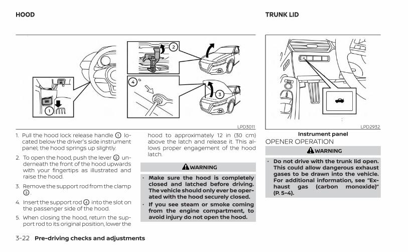
1. Pull the hood lock release handle O1 lo-cated below the driver's side instrumentpanel; the hood springs up slightly.
2. To open the hood, push the lever O2 un-derneath the front of the hood upwardswith your fingertips as illustrated andraise the hood.
3. Remove the support rod from the clampO3 .
4. Insert the support rod O4 into the slot onthe passenger side of the hood.
5. When closing the hood, return the sup-port rod to its original position, lower the
hood to approximately 12 in (30 cm)above the latch and release it. This al-lows proper engagement of the hoodlatch.
WARNING
• Make sure the hood is completelyclosed and latched before driving.The vehicle should only ever be oper-ated with the hood securely closed.
• If you see steam or smoke comingfrom the engine compartment, toavoid injury do not open the hood.
OPENER OPERATIONWARNING
• Do not drive with the trunk lid open.This could allow dangerous exhaustgases to be drawn into the vehicle.For additional information, see “Ex-haust gas (carbon monoxide)”(P. 5-4).
LPD3011 LPD2932Instrument panel
HOOD TRUNK LID
3-22 Pre-driving checks and adjustments
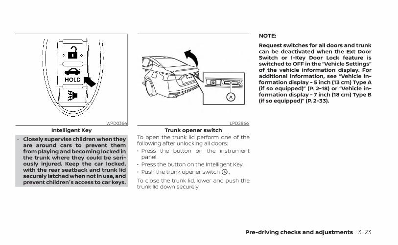
• Closely supervise children when theyare around cars to prevent themfrom playing and becoming locked inthe trunk where they could be seri-ously injured. Keep the car locked,with the rear seatback and trunk lidsecurely latched when not in use, andprevent children's access to car keys.
To open the trunk lid perform one of thefollowing after unlocking all doors:• Press the button on the instrument
panel.• Press the button on the Intelligent Key.• Push the trunk opener switch OA .To close the trunk lid, lower and push thetrunk lid down securely.
NOTE:
Request switches for all doors and trunkcan be deactivated when the Ext DoorSwitch or I-Key Door Lock feature isswitched to OFF in the “Vehicle Settings”of the vehicle information display. Foradditional information, see “Vehicle in-formation display - 5 inch (13 cm) Type A(if so equipped)” (P. 2-18) or “Vehicle in-formation display - 7 inch (18 cm) Type B(if so equipped)” (P. 2-33).
WPD0364Intelligent Key
LPD2866Trunk opener switch
Pre-driving checks and adjustments 3-23
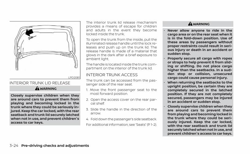
INTERIOR TRUNK LID RELEASEWARNING
Closely supervise children when theyare around cars to prevent them fromplaying and becoming locked in thetrunk where they could be seriously in-jured. Keep the car locked, with the rearseatback and trunk lid securely latchedwhen not in use, and prevent children'saccess to car keys.
The interior trunk lid release mechanismprovides a means of escape for childrenand adults in the event they becomelocked inside the trunk.To open the trunk from the inside, pull theilluminated release handle until the lock re-leases and push up on the trunk lid. Therelease handle is made of a material thatglows in the dark after a brief exposure toambient light.The handle is located inside the trunk com-partment on the interior of the trunk lid.
INTERIOR TRUNK ACCESSThe trunk can be accessed from the pas-senger side of the rear seat.1. Move the front passenger seat to the
most forward position.
2. Open the access cover on the rear par-cel shelf.
3. Slide the handle in the direction of thearrow.
4. Fold down the passenger’s side seatback.For additional information, see “Seats” (P. 1-2).
WARNING
• Never allow anyone to ride in thecargo area or on the rear seat when itis in the fold-down position. Use ofthese areas by passengers withoutproper restraints could result in seri-ous injury or death in an accident orsudden stop.
• Properly secure all cargo with ropesor straps to help prevent it from slid-ing or shifting. Do not place cargohigher than the seatbacks. In a sud-den stop or collision, unsecuredcargo could cause personal injury.
• When returning the seatbacks to theupright position, be certain they arecompletely secured in the latchedposition. If they are not completelysecured, passengers may be injuredin an accident or sudden stop.
• Closely supervise children when theyare around cars to prevent themfrom playing and becoming locked inthe trunk where they could be seri-ously injured. Keep the car locked,with the rear seatback and trunk lidsecurely latched when not in use, andprevent children's access to car keys.
LPD2081
3-24 Pre-driving checks and adjustments
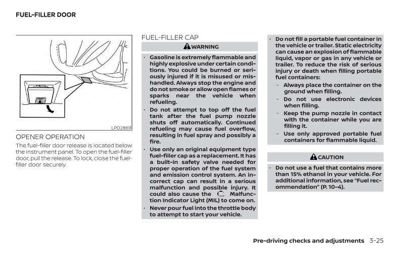
OPENER OPERATIONThe fuel-filler door release is located belowthe instrument panel. To open the fuel-fillerdoor, pull the release. To lock, close the fuel-filler door securely.
FUEL-FILLER CAPWARNING
• Gasoline is extremely flammable andhighly explosive under certain condi-tions. You could be burned or seri-ously injured if it is misused or mis-handled. Always stop the engine anddo not smoke or allow open flames orsparks near the vehicle whenrefueling.
• Do not attempt to top off the fueltank after the fuel pump nozzleshuts off automatically. Continuedrefueling may cause fuel overflow,resulting in fuel spray and possibly afire.
• Use only an original equipment typefuel-filler cap as a replacement. It hasa built-in safety valve needed forproper operation of the fuel systemand emission control system. An in-correct cap can result in a seriousmalfunction and possible injury. Itcould also cause the Malfunc-tion Indicator Light (MIL) to come on.
• Never pour fuel into the throttle bodyto attempt to start your vehicle.
• Do not fill a portable fuel container inthe vehicle or trailer. Static electricitycan cause an explosion of flammableliquid, vapor or gas in any vehicle ortrailer. To reduce the risk of seriousinjury or death when filling portablefuel containers:– Always place the container on the
ground when filling.– Do not use electronic devices
when filling.– Keep the pump nozzle in contact
with the container while you arefilling it.
– Use only approved portable fuelcontainers for flammable liquid.
CAUTION
• Do not use a fuel that contains morethan 15% ethanol in your vehicle. Foradditional information, see “Fuel rec-ommendation” (P. 10-4).
LPD2869
FUEL-FILLER DOOR
Pre-driving checks and adjustments 3-25
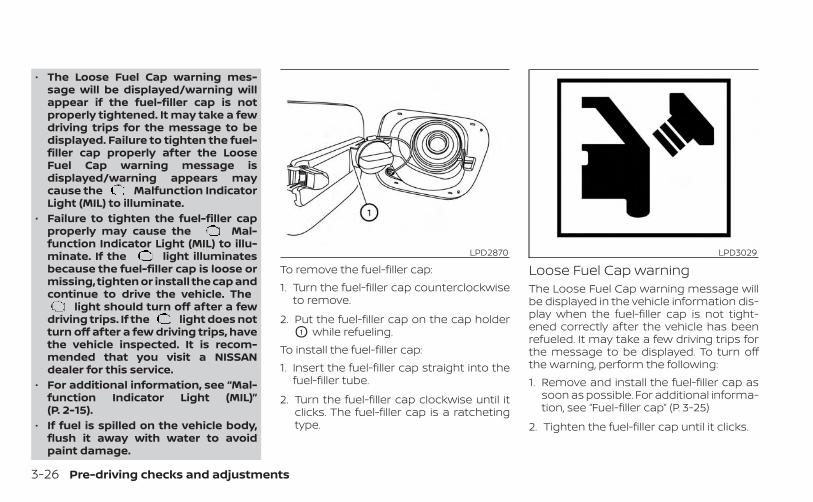
• The Loose Fuel Cap warning mes-sage will be displayed/warning willappear if the fuel-filler cap is notproperly tightened. It may take a fewdriving trips for the message to bedisplayed. Failure to tighten the fuel-filler cap properly after the LooseFuel Cap warning message isdisplayed/warning appears maycause the Malfunction IndicatorLight (MIL) to illuminate.
• Failure to tighten the fuel-filler capproperly may cause the Mal-function Indicator Light (MIL) to illu-minate. If the light illuminatesbecause the fuel-filler cap is loose ormissing, tighten or install the cap andcontinue to drive the vehicle. The
light should turn off after a fewdriving trips. If the light does notturn off after a few driving trips, havethe vehicle inspected. It is recom-mended that you visit a NISSANdealer for this service.
• For additional information, see “Mal-function Indicator Light (MIL)”(P. 2-15).
• If fuel is spilled on the vehicle body,flush it away with water to avoidpaint damage.
To remove the fuel-filler cap:1. Turn the fuel-filler cap counterclockwise
to remove.
2. Put the fuel-filler cap on the cap holderO1 while refueling.
To install the fuel-filler cap:1. Insert the fuel-filler cap straight into the
fuel-filler tube.
2. Turn the fuel-filler cap clockwise until itclicks. The fuel-filler cap is a ratchetingtype.
Loose Fuel Cap warningThe Loose Fuel Cap warning message willbe displayed in the vehicle information dis-play when the fuel-filler cap is not tight-ened correctly after the vehicle has beenrefueled. It may take a few driving trips forthe message to be displayed. To turn offthe warning, perform the following:1. Remove and install the fuel-filler cap as
soon as possible. For additional informa-tion, see “Fuel-filler cap” (P. 3-25)
2. Tighten the fuel-filler cap until it clicks.
LPD2870 LPD3029
3-26 Pre-driving checks and adjustments
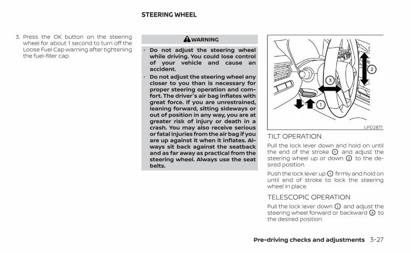
3. Press the OK button on the steeringwheel for about 1 second to turn off theLoose Fuel Cap warning after tighteningthe fuel-filler cap.
WARNING
• Do not adjust the steering wheelwhile driving. You could lose controlof your vehicle and cause anaccident.
• Do not adjust the steering wheel anycloser to you than is necessary forproper steering operation and com-fort. The driver's air bag inflates withgreat force. If you are unrestrained,leaning forward, sitting sideways orout of position in any way, you are atgreater risk of injury or death in acrash. You may also receive seriousor fatal injuries from the air bag if youare up against it when it inflates. Al-ways sit back against the seatbackand as far away as practical from thesteering wheel. Always use the seatbelts.
TILT OPERATIONPull the lock lever down and hold on untilthe end of the stroke O1 and adjust thesteering wheel up or down O2 to the de-sired position.Push the lock lever up O1 firmly and hold onuntil end of stroke to lock the steeringwheel in place.
TELESCOPIC OPERATIONPull the lock lever down O1 and adjust thesteering wheel forward or backward O3 tothe desired position.
LPD2871
STEERING WHEEL
Pre-driving checks and adjustments 3-27
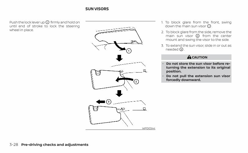
Push the lock lever up O1 firmly and hold onuntil end of stroke to lock the steeringwheel in place.
1. To block glare from the front, swingdown the main sun visor O1 .
2. To block glare from the side, remove themain sun visor O2 from the centermount and swing the visor to the side.
3. To extend the sun visor, slide in or out asneeded O3 .
CAUTION
• Do not store the sun visor before re-turning the extension to its originalposition.
• Do not pull the extension sun visorforcedly downward.
WPD0344
SUN VISORS
3-28 Pre-driving checks and adjustments
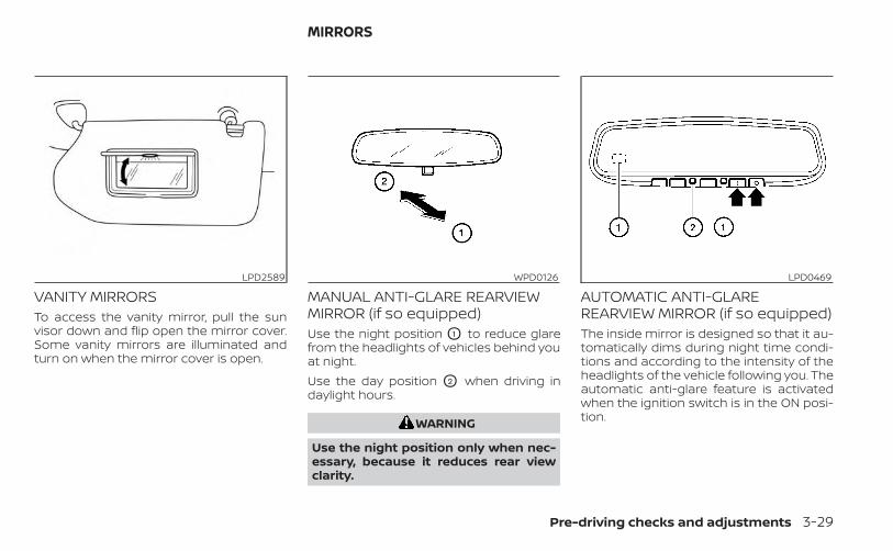
VANITY MIRRORSTo access the vanity mirror, pull the sunvisor down and flip open the mirror cover.Some vanity mirrors are illuminated andturn on when the mirror cover is open.
MANUAL ANTI-GLARE REARVIEWMIRROR (if so equipped)Use the night position O1 to reduce glarefrom the headlights of vehicles behind youat night.Use the day position O2 when driving indaylight hours.
WARNING
Use the night position only when nec-essary, because it reduces rear viewclarity.
AUTOMATIC ANTI-GLAREREARVIEW MIRROR (if so equipped)The inside mirror is designed so that it au-tomatically dims during night time condi-tions and according to the intensity of theheadlights of the vehicle following you. Theautomatic anti-glare feature is activatedwhen the ignition switch is in the ON posi-tion.
LPD2589 WPD0126 LPD0469
MIRRORS
Pre-driving checks and adjustments 3-29
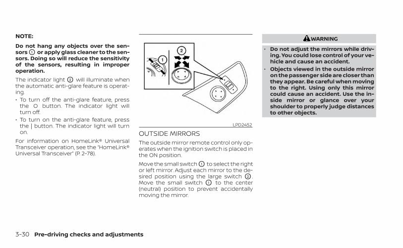
NOTE:
Do not hang any objects over the sen-sors O1 or apply glass cleaner to the sen-sors. Doing so will reduce the sensitivityof the sensors, resulting in improperoperation.The indicator light O2 will illuminate whenthe automatic anti-glare feature is operat-ing.• To turn off the anti-glare feature, press
the O button. The indicator light willturn off.
• To turn on the anti-glare feature, pressthe | button. The indicator light will turnon.
For information on HomeLink® UniversalTransceiver operation, see the “HomeLink®Universal Transceiver” (P. 2-78).
OUTSIDE MIRRORSThe outside mirror remote control only op-erates when the ignition switch is placed inthe ON position.Move the small switch O1 to select the rightor left mirror. Adjust each mirror to the de-sired position using the large switch O2 .Move the small switch O1 to the center(neutral) position to prevent accidentallymoving the mirror.
WARNING
• Do not adjust the mirrors while driv-ing. You could lose control of your ve-hicle and cause an accident.
• Objects viewed in the outside mirroron the passenger side are closer thanthey appear. Be careful when movingto the right. Using only this mirrorcould cause an accident. Use the in-side mirror or glance over yourshoulder to properly judge distancesto other objects.
LPD2452
3-30 Pre-driving checks and adjustments
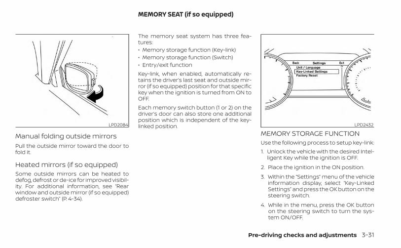
Manual folding outside mirrorsPull the outside mirror toward the door tofold it.
Heated mirrors (if so equipped)Some outside mirrors can be heated todefog, defrost or de-ice for improved visibil-ity. For additional information, see “Rearwindow and outside mirror (if so equipped)defroster switch” (P. 4-34).
The memory seat system has three fea-tures:• Memory storage function (Key-link)• Memory storage function (Switch)• Entry/exit functionKey-link, when enabled, automatically re-tains the driver’s last seat and outside mir-ror (if so equipped) position for that specifickey when the ignition is turned from ON toOFF.Each memory switch button (1 or 2) on thedriver’s door can also store one additionalposition which is independent of the key-linked position.
MEMORY STORAGE FUNCTIONUse the following process to setup key-link:1. Unlock the vehicle with the desired Intel-
ligent Key while the ignition is OFF.
2. Place the ignition in the ON position.
3. Within the “Settings” menu of the vehicleinformation display, select “Key-LinkedSettings” and press the OK button on thesteering switch.
4. While in the menu, press the OK buttonon the steering switch to turn the sys-tem ON/OFF.
LPD2084 LPD2432
MEMORY SEAT (if so equipped)
Pre-driving checks and adjustments 3-31
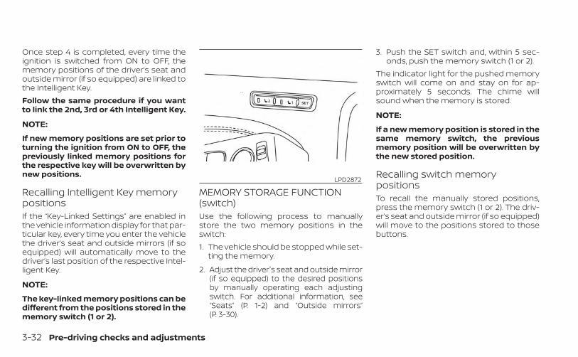
Once step 4 is completed, every time theignition is switched from ON to OFF, thememory positions of the driver’s seat andoutside mirror (if so equipped) are linked tothe Intelligent Key.Follow the same procedure if you wantto link the 2nd, 3rd or 4th Intelligent Key.
NOTE:
If new memory positions are set prior toturning the ignition from ON to OFF, thepreviously linked memory positions forthe respective key will be overwritten bynew positions.
Recalling Intelligent Key memorypositionsIf the “Key-Linked Settings” are enabled inthe vehicle information display for that par-ticular key, every time you enter the vehiclethe driver’s seat and outside mirrors (if soequipped) will automatically move to thedriver’s last position of the respective Intel-ligent Key.
NOTE:
The key-linked memory positions can bedifferent from the positions stored in thememory switch (1 or 2).
MEMORY STORAGE FUNCTION(switch)Use the following process to manuallystore the two memory positions in theswitch:1. The vehicle should be stopped while set-
ting the memory.
2. Adjust the driver's seat and outside mirror(if so equipped) to the desired positionsby manually operating each adjustingswitch. For additional information, see“Seats” (P. 1-2) and “Outside mirrors”(P. 3-30).
3. Push the SET switch and, within 5 sec-onds, push the memory switch (1 or 2).
The indicator light for the pushed memoryswitch will come on and stay on for ap-proximately 5 seconds. The chime willsound when the memory is stored.
NOTE:
If a new memory position is stored in thesame memory switch, the previousmemory position will be overwritten bythe new stored position.
Recalling switch memorypositionsTo recall the manually stored positions,press the memory switch (1 or 2). The driv-er’s seat and outside mirror (if so equipped)will move to the positions stored to thosebuttons.
LPD2872
3-32 Pre-driving checks and adjustments
ENTRY/EXIT FUNCTIONThis system is designed so that the driver'sseat will automatically move when the shiftlever is in the P (Park) position. This allowsthe driver to easily get in and out of thedriver’s seat.The driver’s seat will slide backward:• When the driver's door is opened and the
ignition switch is in the OFF position.• When the ignition switch is turned from
ACC to OFF with the driver’s door open.The driver’s seat will return to the previousposition:• When the ignition switch is turned to ACC
or ON while the shift lever is in the P (Park)position.
The entry/exit function can be adjusted orcanceled through the “Vehicle Settings” inthe vehicle information display by perform-ing the following:• Switch the Exit Seat Slide from ON to OFF.
SYSTEM OPERATIONThe memory seat system will not work orwill stop operating under the followingconditions:• When the vehicle speed is above 4 mph
(7 km/h).• When any of the memory switches are
pushed while the memory seat is operat-ing.
• When the switch for the driver’s seat andsteering column is pushed while thememory seat is operating.
• When the seat has already been movedto the memorized position.
• When no seat position is stored in thememory switch.
• When the shift lever is moved from P(Park) to any other position.
The memory seat system can be adjustedand canceled. It is recommended you visita NISSAN dealer for this service.
Pre-driving checks and adjustments 3-33
4 Monitor, climate, audio, phone andvoice recognition systems
NissanConnect® Owner’s Manual . . . . . . . . . . . . . . . 4-2Control panel buttons . . . . . . . . . . . . . . . . . . . . . . . . . . . 4-3
How to use the touch-screen . . . . . . . . . . . . . . . . 4-3How to use the MENU button . . . . . . . . . . . 4-5
(brightness control) button . . . . . . . . . . . . . 4-7How to use the VOL (volume) knob /PUSH (power) button . . . . . . . . . . . . . . . . . . . . 4-7Selecting menu from launch bar . . . . . . . . . . . . . 4-7
RearView Monitor (if so equipped) . . . . . . . . . . . . . . . 4-8RearView Monitor system operation . . . . . . . . . . 4-9How to read the displayed lines . . . . . . . . . . . . . . 4-9Difference between predicted andactual distances . . . . . . . . . . . . . . . . . . . . . . . . . . . . 4-10How to park with predicted courselines . . . . . . . . . . . . . . . . . . . . . . . . . . . . . . . . . . . . . . . . . 4-12Adjusting the screen . . . . . . . . . . . . . . . . . . . . . . . . 4-13How to turn on and off predictedcourse lines . . . . . . . . . . . . . . . . . . . . . . . . . . . . . . . . . 4-13RearView Monitor system limitations . . . . . . . . 4-14System maintenance . . . . . . . . . . . . . . . . . . . . . . . 4-15
Intelligent Around View Monitor(if so equipped) . . . . . . . . . . . . . . . . . . . . . . . . . . . . . . . . . 4-16
Intelligent Around View Monitor systemoperation . . . . . . . . . . . . . . . . . . . . . . . . . . . . . . . . . . . 4-17Difference between predicted andactual distances . . . . . . . . . . . . . . . . . . . . . . . . . . . . 4-20
How to park with predicted courselines . . . . . . . . . . . . . . . . . . . . . . . . . . . . . . . . . . . . . . . . . 4-22How to switch the display . . . . . . . . . . . . . . . . . . . 4-23Adjusting the screen . . . . . . . . . . . . . . . . . . . . . . . . 4-24Intelligent Around View Monitor systemlimitations . . . . . . . . . . . . . . . . . . . . . . . . . . . . . . . . . . 4-24System maintenance . . . . . . . . . . . . . . . . . . . . . . . 4-26
Moving Object Detection (MOD)(if so equipped) . . . . . . . . . . . . . . . . . . . . . . . . . . . . . . . . . 4-27
MOD system operation . . . . . . . . . . . . . . . . . . . . . . 4-28Turning MOD on and off (if so equipped) . . . . . 4-29MOD system limitations . . . . . . . . . . . . . . . . . . . . . 4-30System maintenance . . . . . . . . . . . . . . . . . . . . . . . 4-31
Vents . . . . . . . . . . . . . . . . . . . . . . . . . . . . . . . . . . . . . . . . . . 4-31Heater and air conditioner (manual)(if so equipped) . . . . . . . . . . . . . . . . . . . . . . . . . . . . . . . . . 4-33
Controls . . . . . . . . . . . . . . . . . . . . . . . . . . . . . . . . . . . . . 4-34Heater operation . . . . . . . . . . . . . . . . . . . . . . . . . . . . 4-34Air conditioner operation . . . . . . . . . . . . . . . . . . . . 4-35Air flow charts . . . . . . . . . . . . . . . . . . . . . . . . . . . . . . . 4-36
Heater and air conditioner (automatic)(if so equipped) . . . . . . . . . . . . . . . . . . . . . . . . . . . . . . . . .4-40
Automatic operation . . . . . . . . . . . . . . . . . . . . . . . . 4-41Manual operation . . . . . . . . . . . . . . . . . . . . . . . . . . . 4-42Operating tips . . . . . . . . . . . . . . . . . . . . . . . . . . . . . . . 4-43
Servicing air conditioner . . . . . . . . . . . . . . . . . . . . . . . .4-44Audio system . . . . . . . . . . . . . . . . . . . . . . . . . . . . . . . . . . 4-45
Radio . . . . . . . . . . . . . . . . . . . . . . . . . . . . . . . . . . . . . . . 4-45FM radio reception . . . . . . . . . . . . . . . . . . . . . . . . . . 4-45AM radio reception . . . . . . . . . . . . . . . . . . . . . . . . . . 4-45Audio operation precautions . . . . . . . . . . . . . . . .4-46FM/AM radio . . . . . . . . . . . . . . . . . . . . . . . . . . . . . . . .4-49USB (Universal Serial Bus) ConnectionPort . . . . . . . . . . . . . . . . . . . . . . . . . . . . . . . . . . . . . . . . . 4-54iPod®* player operation . . . . . . . . . . . . . . . . . . . . . 4-57Bluetooth® streaming audio . . . . . . . . . . . . . . . . .4-60Steering wheel switch for audio control . . . . . 4-63
USB/iPod® charging port (if so equipped) . . . . . . .4-64Antenna. . . . . . . . . . . . . . . . . . . . . . . . . . . . . . . . . . . . . . . .4-64Siri® Eyes Free (if so equipped) . . . . . . . . . . . . . . . . . .4-64
Requirements . . . . . . . . . . . . . . . . . . . . . . . . . . . . . . . 4-65Operating Siri® Eyes Free . . . . . . . . . . . . . . . . . . . . 4-65Troubleshooting guide . . . . . . . . . . . . . . . . . . . . . .4-66
Car phone or CB radio . . . . . . . . . . . . . . . . . . . . . . . . . . 4-67Bluetooth® Hands-Free Phone System . . . . . . . . . 4-67
Regulatory information . . . . . . . . . . . . . . . . . . . . . .4-69Using the system . . . . . . . . . . . . . . . . . . . . . . . . . . .4-69Indicators . . . . . . . . . . . . . . . . . . . . . . . . . . . . . . . . . . . 4-71Control buttons . . . . . . . . . . . . . . . . . . . . . . . . . . . . . 4-71Connecting procedure . . . . . . . . . . . . . . . . . . . . . . 4-72Voice commands . . . . . . . . . . . . . . . . . . . . . . . . . . . 4-73Phone display screen . . . . . . . . . . . . . . . . . . . . . . . 4-75Making a call . . . . . . . . . . . . . . . . . . . . . . . . . . . . . . . . 4-76Receiving a call . . . . . . . . . . . . . . . . . . . . . . . . . . . . . . 4-76During a call . . . . . . . . . . . . . . . . . . . . . . . . . . . . . . . . . 4-76Ending a call . . . . . . . . . . . . . . . . . . . . . . . . . . . . . . . . 4-77Text messaging (if so equipped) . . . . . . . . . . . . . 4-77Bluetooth® connections screen . . . . . . . . . . . . .4-80Phone and text message settings . . . . . . . . . . . 4-81Volume & beeps . . . . . . . . . . . . . . . . . . . . . . . . . . . . . 4-83
iPod®/iPhone® . . . . . . . . . . . . . . . . . . . . . . . . . . . . . . . . . 4-83
Refer to the NissanConnect® Owner’sManual that includes the following infor-mation.• NissanConnect® Services (if so equipped)• Navigation system (if so equipped)• Audio system• Apple CarPlay® (if so equipped)• Android AutoTM (if so equipped)• Bluetooth® Hands-Free Phone system• Viewing information• Other settings• Voice recognition• General system information
NISSANCONNECT® OWNER’SMANUAL
4-2 Monitor, climate, audio, phone and voice recognition systems
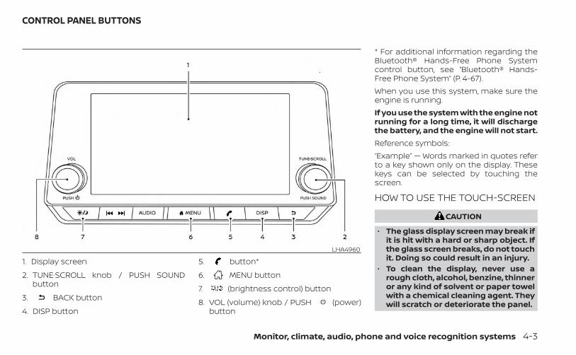
1. Display screen
2. TUNE·SCROLL knob / PUSH SOUNDbutton
3. BACK button
4. DISP button
5. button*
6. MENU button
7. (brightness control) button
8. VOL (volume) knob / PUSH (power)button
* For additional information regarding theBluetooth® Hands-Free Phone Systemcontrol button, see “Bluetooth® Hands-Free Phone System” (P. 4-67).When you use this system, make sure theengine is running.If you use the system with the engine notrunning for a long time, it will dischargethe battery, and the engine will not start.Reference symbols:“Example” — Words marked in quotes referto a key shown only on the display. Thesekeys can be selected by touching thescreen.
HOW TO USE THE TOUCH-SCREEN
CAUTION
• The glass display screen may break ifit is hit with a hard or sharp object. Ifthe glass screen breaks, do not touchit. Doing so could result in an injury.
• To clean the display, never use arough cloth, alcohol, benzine, thinneror any kind of solvent or paper towelwith a chemical cleaning agent. Theywill scratch or deteriorate the panel.
LHA4960
CONTROL PANEL BUTTONS
Monitor, climate, audio, phone and voice recognition systems 4-3
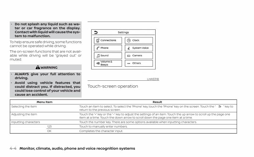
• Do not splash any liquid such as wa-ter or car fragrance on the display.Contact with liquid will cause the sys-tem to malfunction.
To help ensure safe driving, some functionscannot be operated while driving.The on-screen functions that are not avail-able while driving will be “grayed out” ormuted.
WARNING
• ALWAYS give your full attention todriving.
• Avoid using vehicle features thatcould distract you. If distracted, youcould lose control of your vehicle andcause an accident.
Touch-screen operation
Menu Item ResultSelecting the item Touch an item to select. To select the “Phone” key, touch the “Phone” key on the screen. Touch the “ ” key to
return to the previous screen.Adjusting the item Touch the “+” key or the “−” key to adjust the settings of an item. Touch the up arrow to scroll up the page one
item at a time. Touch the down arrow to scroll down the page one item at a time.Inputting characters Touch the number key. There are some options available when inputting characters.
123 Touch to manually enter numbers.OK Completes the character input.
LHA5318
4-4 Monitor, climate, audio, phone and voice recognition systems
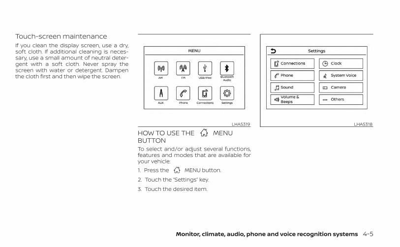
Touch-screen maintenanceIf you clean the display screen, use a dry,soft cloth. If additional cleaning is neces-sary, use a small amount of neutral deter-gent with a soft cloth. Never spray thescreen with water or detergent. Dampenthe cloth first and then wipe the screen.
HOW TO USE THE MENUBUTTONTo select and/or adjust several functions,features and modes that are available foryour vehicle:1. Press the MENU button.
2. Touch the “Settings” key.
3. Touch the desired item.
LHA5319 LHA5318
Monitor, climate, audio, phone and voice recognition systems 4-5
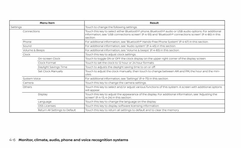
Menu item ResultSettings Touch to change the following settings.
Connections Touch this key to select either Bluetooth® phone, Bluetooth® audio or USB audio options. For additionalinformation, see “USB connections screen” (P. 4-55) and “Bluetooth® connections screen” (P. 4-80) in thissection.
Phone For additional information, see “Bluetooth® Hands-Free Phone System” (P. 4-67) in this section.Sound For additional information, see “Audio system” (P. 4-45) in this section.Volume & Beeps For additional information, see “Volume & beeps” (P. 4-83) in this section.Clock Touch this key to adjust clock settings.
On-screen Clock Touch to toggle ON or OFF the clock display on the upper right corner of the display screen.Clock Format Touch to set the clock to 12 hour or 24 hour formats.Daylight Savings Time Touch to adjusts the daylight saving time to on or off.Set Clock Manually Touch to adjust the clock manually; then touch to change between AM and PM, the hour and the min-
utes.System Voice For additional information, see “Settings” (P. 4-75) in this section.Camera Touch this key to change the camera settings.Others Touch this key to select and/or adjust various functions of this system. A screen with additional options
will appear.Display Touch this key to adjust the appearance of the display. For additional information, see “Adjusting the
screen” (P. 4-13, 4-24) in this section.Language Touch this key to change the language on the display.OSS Licenses Touch this key to display software licensing information.Return All Settings to Default Touch this key to return all settings to default and to clear the memory.
4-6 Monitor, climate, audio, phone and voice recognition systems
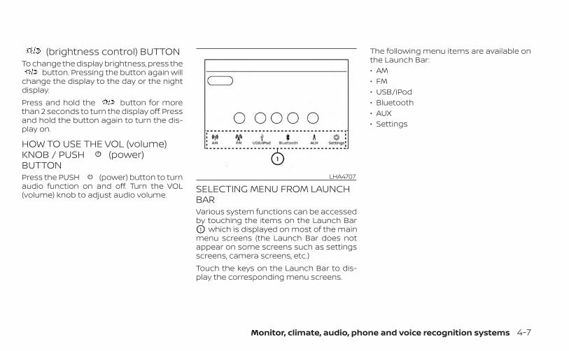
(brightness control) BUTTONTo change the display brightness, press the
button. Pressing the button again willchange the display to the day or the nightdisplay.Press and hold the button for morethan 2 seconds to turn the display off. Pressand hold the button again to turn the dis-play on.
HOW TO USE THE VOL (volume)KNOB / PUSH (power)BUTTONPress the PUSH (power) button to turnaudio function on and off. Turn the VOL(volume) knob to adjust audio volume.
SELECTING MENU FROM LAUNCHBARVarious system functions can be accessedby touching the items on the Launch BarO1 which is displayed on most of the mainmenu screens (the Launch Bar does notappear on some screens such as settingsscreens, camera screens, etc.)Touch the keys on the Launch Bar to dis-play the corresponding menu screens.
The following menu items are available onthe Launch Bar:• AM• FM• USB/iPod• Bluetooth• AUX• Settings
LHA4707
Monitor, climate, audio, phone and voice recognition systems 4-7
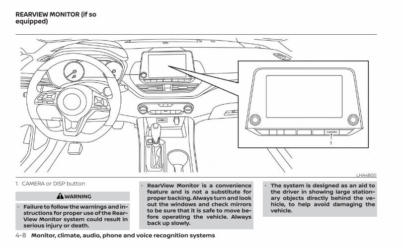
1. CAMERA or DISP button
WARNING
• Failure to follow the warnings and in-structions for proper use of the Rear-View Monitor system could result inserious injury or death.
• RearView Monitor is a conveniencefeature and is not a substitute forproper backing. Always turn and lookout the windows and check mirrorsto be sure that it is safe to move be-fore operating the vehicle. Alwaysback up slowly.
• The system is designed as an aid tothe driver in showing large station-ary objects directly behind the ve-hicle, to help avoid damaging thevehicle.
LHA4800
REARVIEW MONITOR (if soequipped)
4-8 Monitor, climate, audio, phone and voice recognition systems
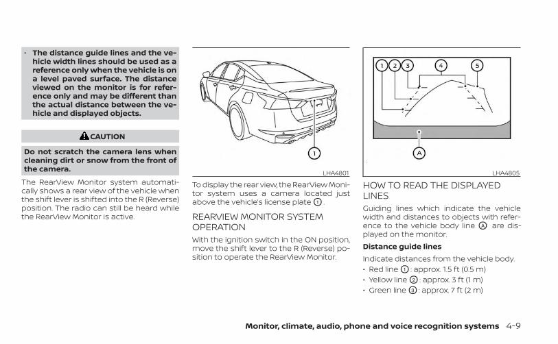
• The distance guide lines and the ve-hicle width lines should be used as areference only when the vehicle is ona level paved surface. The distanceviewed on the monitor is for refer-ence only and may be different thanthe actual distance between the ve-hicle and displayed objects.
CAUTION
Do not scratch the camera lens whencleaning dirt or snow from the front ofthe camera.
The RearView Monitor system automati-cally shows a rear view of the vehicle whenthe shift lever is shifted into the R (Reverse)position. The radio can still be heard whilethe RearView Monitor is active.
To display the rear view, the RearView Moni-tor system uses a camera located justabove the vehicle’s license plate O1 .
REARVIEW MONITOR SYSTEMOPERATIONWith the ignition switch in the ON position,move the shift lever to the R (Reverse) po-sition to operate the RearView Monitor.
HOW TO READ THE DISPLAYEDLINESGuiding lines which indicate the vehiclewidth and distances to objects with refer-ence to the vehicle body line OA are dis-played on the monitor.Distance guide linesIndicate distances from the vehicle body.• Red line O1 : approx. 1.5 ft (0.5 m)• Yellow line O2 : approx. 3 ft (1 m)• Green line O3 : approx. 7 ft (2 m)
LHA4801 LHA4805
Monitor, climate, audio, phone and voice recognition systems 4-9
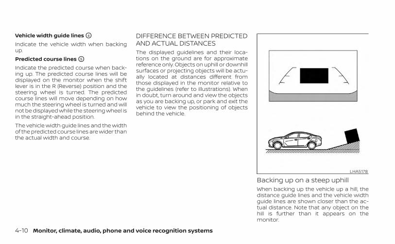
Vehicle width guide lines O4
Indicate the vehicle width when backingup.Predicted course lines O5
Indicate the predicted course when back-ing up. The predicted course lines will bedisplayed on the monitor when the shiftlever is in the R (Reverse) position and thesteering wheel is turned. The predictedcourse lines will move depending on howmuch the steering wheel is turned and willnot be displayed while the steering wheel isin the straight-ahead position.The vehicle width guide lines and the widthof the predicted course lines are wider thanthe actual width and course.
DIFFERENCE BETWEEN PREDICTEDAND ACTUAL DISTANCESThe displayed guidelines and their loca-tions on the ground are for approximatereference only. Objects on uphill or downhillsurfaces or projecting objects will be actu-ally located at distances different fromthose displayed in the monitor relative tothe guidelines (refer to illustrations). Whenin doubt, turn around and view the objectsas you are backing up, or park and exit thevehicle to view the positioning of objectsbehind the vehicle.
Backing up on a steep uphillWhen backing up the vehicle up a hill, thedistance guide lines and the vehicle widthguide lines are shown closer than the ac-tual distance. Note that any object on thehill is further than it appears on themonitor.
LHA5178
4-10 Monitor, climate, audio, phone and voice recognition systems
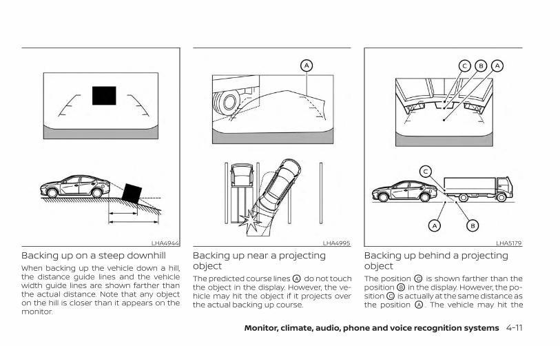
Backing up on a steep downhillWhen backing up the vehicle down a hill,the distance guide lines and the vehiclewidth guide lines are shown farther thanthe actual distance. Note that any objecton the hill is closer than it appears on themonitor.
Backing up near a projectingobjectThe predicted course lines OA do not touchthe object in the display. However, the ve-hicle may hit the object if it projects overthe actual backing up course.
Backing up behind a projectingobjectThe position OC is shown farther than theposition OB in the display. However, the po-sition OC is actually at the same distance asthe position OA . The vehicle may hit the
LHA4944 LHA4995 LHA5179
Monitor, climate, audio, phone and voice recognition systems 4-11
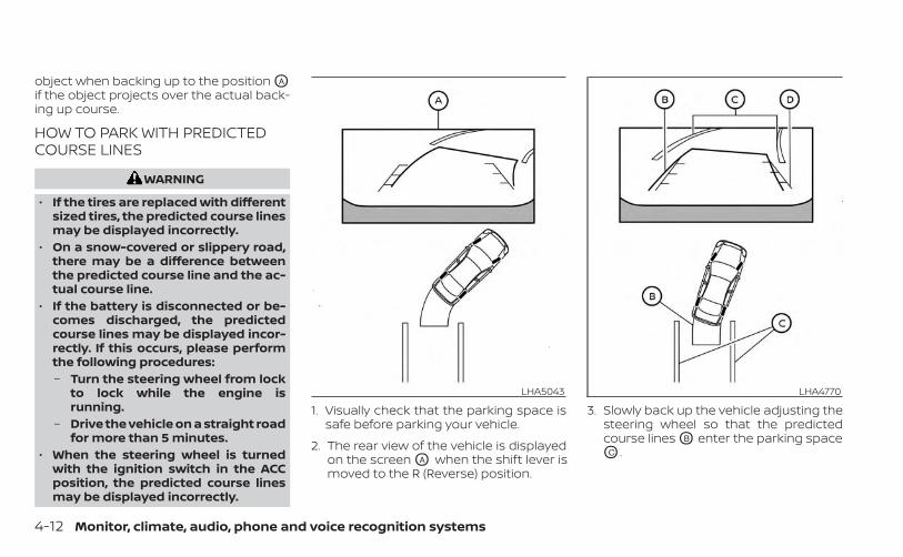
object when backing up to the position OA
if the object projects over the actual back-ing up course.
HOW TO PARK WITH PREDICTEDCOURSE LINES
WARNING
• If the tires are replaced with differentsized tires, the predicted course linesmay be displayed incorrectly.
• On a snow-covered or slippery road,there may be a difference betweenthe predicted course line and the ac-tual course line.
• If the battery is disconnected or be-comes discharged, the predictedcourse lines may be displayed incor-rectly. If this occurs, please performthe following procedures:– Turn the steering wheel from lock
to lock while the engine isrunning.
– Drive the vehicle on a straight roadfor more than 5 minutes.
• When the steering wheel is turnedwith the ignition switch in the ACCposition, the predicted course linesmay be displayed incorrectly.
1. Visually check that the parking space issafe before parking your vehicle.
2. The rear view of the vehicle is displayedon the screen OA when the shift lever ismoved to the R (Reverse) position.
3. Slowly back up the vehicle adjusting thesteering wheel so that the predictedcourse lines OB enter the parking spaceOC .
LHA5043 LHA4770
4-12 Monitor, climate, audio, phone and voice recognition systems
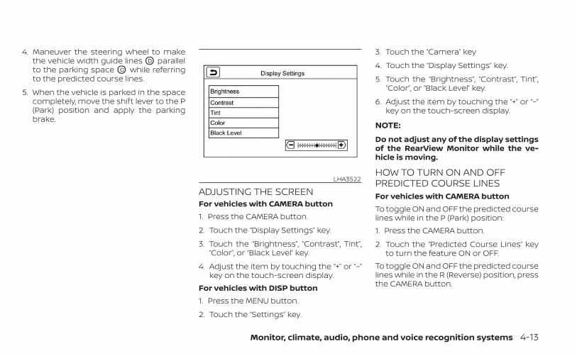
4. Maneuver the steering wheel to makethe vehicle width guide lines OD parallelto the parking space OC while referringto the predicted course lines.
5. When the vehicle is parked in the spacecompletely, move the shift lever to the P(Park) position and apply the parkingbrake.
ADJUSTING THE SCREENFor vehicles with CAMERA button1. Press the CAMERA button.
2. Touch the “Display Settings” key.
3. Touch the “Brightness”, “Contrast”, Tint”,“Color”, or “Black Level” key.
4. Adjust the item by touching the “+” or “–”key on the touch-screen display.
For vehicles with DISP button1. Press the MENU button.
2. Touch the “Settings” key.
3. Touch the “Camera” key
4. Touch the “Display Settings” key.
5. Touch the “Brightness”, “Contrast”, Tint”,“Color”, or “Black Level” key.
6. Adjust the item by touching the “+” or “–”key on the touch-screen display.
NOTE:
Do not adjust any of the display settingsof the RearView Monitor while the ve-hicle is moving.
HOW TO TURN ON AND OFFPREDICTED COURSE LINESFor vehicles with CAMERA buttonTo toggle ON and OFF the predicted courselines while in the P (Park) position:1. Press the CAMERA button.
2. Touch the “Predicted Course Lines” keyto turn the feature ON or OFF.
To toggle ON and OFF the predicted courselines while in the R (Reverse) position, pressthe CAMERA button.
LHA3522
Monitor, climate, audio, phone and voice recognition systems 4-13
For vehicles with DISP buttonTo toggle ON and OFF the predicted courselines while in the P (Park) position:1. Touch the “Settings” key.
2. Touch the “Camera” key.
3. Touch the “Predicted Course Lines” keyto turn the feature ON or OFF.
REARVIEW MONITOR SYSTEMLIMITATIONS
WARNING
Listed below are the system limitationsfor RearView Monitor. Failure to oper-ate the vehicle in accordance withthese system limitations could result inserious injury or death.• The system cannot completely elimi-
nate blind spots and may not showevery object.
• Underneath the bumper and the cor-ner areas of the bumper cannot beviewed on the RearView Monitor be-cause of its monitoring range limita-tion. The system will not show smallobjects below the bumper, and maynot show objects close to the bum-per or on the ground.
• Objects viewed in the RearViewMonitor differ from actual distancebecause a wide-angle lens is used.
• Objects in the RearView Monitor willappear visually opposite comparedto when viewed in the rearview andoutside mirrors.
• Use the displayed lines as a refer-ence. The lines are highly affected bythe number of occupants, fuel level,vehicle position, road conditions androad grade.
• Make sure that the trunk is securelyclosed when backing up.
• Do not put anything on the rearviewcamera. The rearview camera is in-stalled above the license plate.
• When washing the vehicle with highpressure water, be sure not to spray itaround the camera. Otherwise, watermay enter the camera unit causingwater condensation on the lens, amalfunction, fire or an electric shock.
• Do not strike the camera. It is a preci-sion instrument. Otherwise, it maymalfunction or cause damage result-ing in a fire or an electric shock.
The following are operating limitations anddo not represent a system malfunction:• When the temperature is extremely high
or low, the screen may not clearly displayobjects.
• When strong light directly shines on thecamera, objects may not be displayedclearly.
• Vertical lines may be seen in objects onthe screen. This is due to strong reflectedlight from the bumper.
• The screen may flicker under fluorescentlight.
• The colors of objects on the RearViewMonitor may differ somewhat from theactual color of objects.
• Objects on the monitor may not be clearin a dark environment.
• There may be a delay when switchingbetween views.
• If dirt, rain or snow accumulate on thecamera, the RearView Monitor may notdisplay objects clearly. Clean the camera.
• Do not use wax on the camera lens. Wipeoff any wax with a clean cloth dampenedwith a diluted mild cleaning agent, thenwipe with a dry cloth.
4-14 Monitor, climate, audio, phone and voice recognition systems
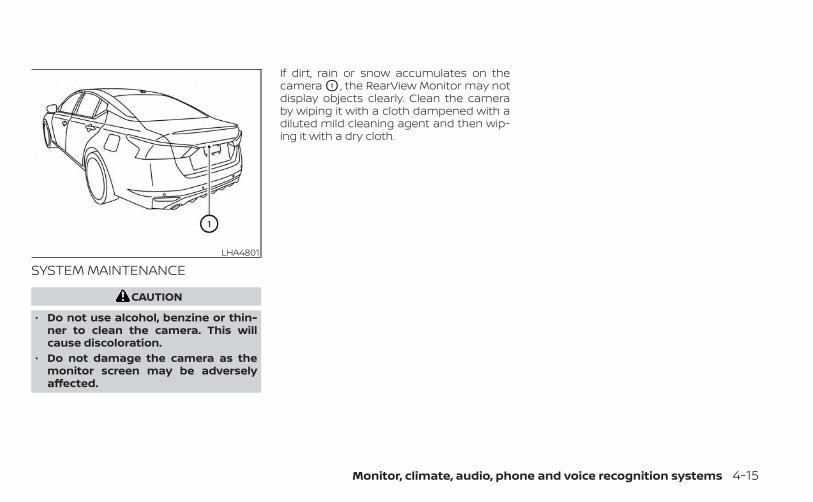
SYSTEM MAINTENANCE
CAUTION
• Do not use alcohol, benzine or thin-ner to clean the camera. This willcause discoloration.
• Do not damage the camera as themonitor screen may be adverselyaffected.
If dirt, rain or snow accumulates on thecamera O1 , the RearView Monitor may notdisplay objects clearly. Clean the cameraby wiping it with a cloth dampened with adiluted mild cleaning agent and then wip-ing it with a dry cloth.
LHA4801
Monitor, climate, audio, phone and voice recognition systems 4-15
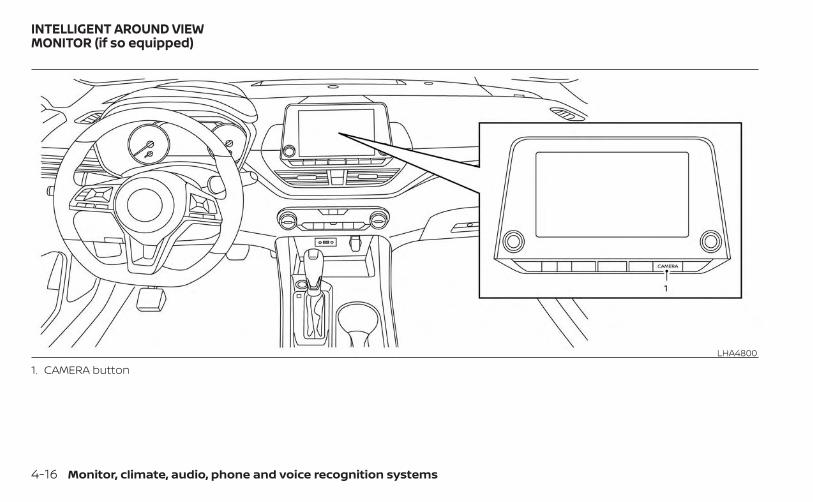
1. CAMERA buttonLHA4800
INTELLIGENT AROUND VIEWMONITOR (if so equipped)
4-16 Monitor, climate, audio, phone and voice recognition systems
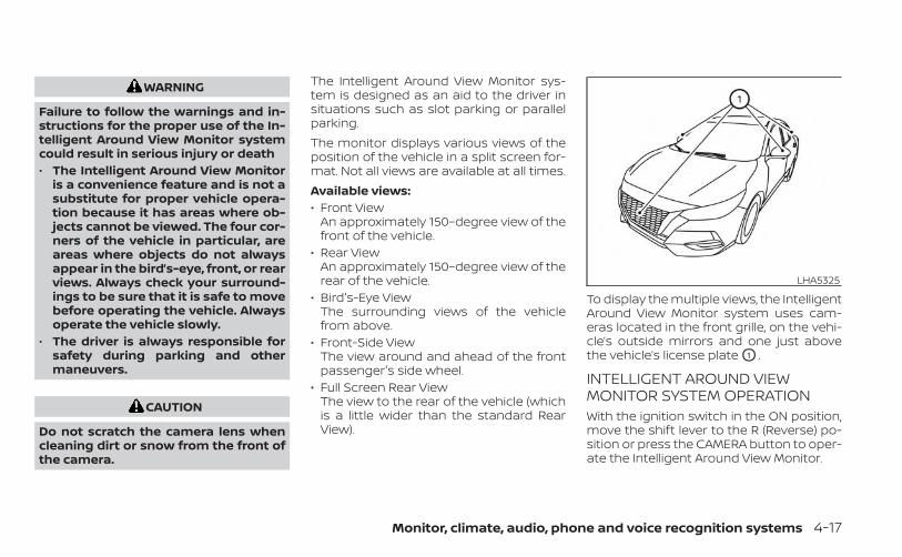
WARNING
Failure to follow the warnings and in-structions for the proper use of the In-telligent Around View Monitor systemcould result in serious injury or death• The Intelligent Around View Monitor
is a convenience feature and is not asubstitute for proper vehicle opera-tion because it has areas where ob-jects cannot be viewed. The four cor-ners of the vehicle in particular, areareas where objects do not alwaysappear in the bird’s-eye, front, or rearviews. Always check your surround-ings to be sure that it is safe to movebefore operating the vehicle. Alwaysoperate the vehicle slowly.
• The driver is always responsible forsafety during parking and othermaneuvers.
CAUTION
Do not scratch the camera lens whencleaning dirt or snow from the front ofthe camera.
The Intelligent Around View Monitor sys-tem is designed as an aid to the driver insituations such as slot parking or parallelparking.The monitor displays various views of theposition of the vehicle in a split screen for-mat. Not all views are available at all times.Available views:• Front View
An approximately 150–degree view of thefront of the vehicle.
• Rear ViewAn approximately 150–degree view of therear of the vehicle.
• Bird's-Eye ViewThe surrounding views of the vehiclefrom above.
• Front-Side ViewThe view around and ahead of the frontpassenger's side wheel.
• Full Screen Rear ViewThe view to the rear of the vehicle (whichis a little wider than the standard RearView).
To display the multiple views, the IntelligentAround View Monitor system uses cam-eras located in the front grille, on the vehi-cle’s outside mirrors and one just abovethe vehicle’s license plate O1 .
INTELLIGENT AROUND VIEWMONITOR SYSTEM OPERATIONWith the ignition switch in the ON position,move the shift lever to the R (Reverse) po-sition or press the CAMERA button to oper-ate the Intelligent Around View Monitor.
LHA5325
Monitor, climate, audio, phone and voice recognition systems 4-17
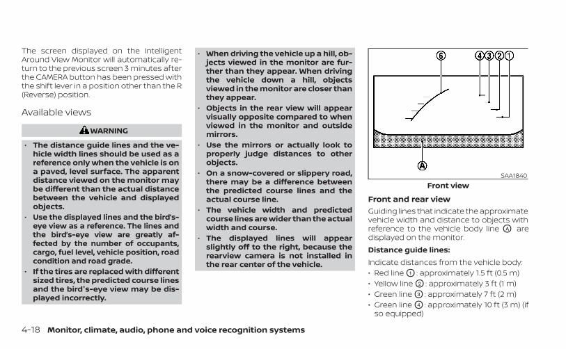
The screen displayed on the IntelligentAround View Monitor will automatically re-turn to the previous screen 3 minutes afterthe CAMERA button has been pressed withthe shift lever in a position other than the R(Reverse) position.
Available views
WARNING
• The distance guide lines and the ve-hicle width lines should be used as areference only when the vehicle is ona paved, level surface. The apparentdistance viewed on the monitor maybe different than the actual distancebetween the vehicle and displayedobjects.
• Use the displayed lines and the bird’s-eye view as a reference. The lines andthe bird’s-eye view are greatly af-fected by the number of occupants,cargo, fuel level, vehicle position, roadcondition and road grade.
• If the tires are replaced with differentsized tires, the predicted course linesand the bird's-eye view may be dis-played incorrectly.
• When driving the vehicle up a hill, ob-jects viewed in the monitor are fur-ther than they appear. When drivingthe vehicle down a hill, objectsviewed in the monitor are closer thanthey appear.
• Objects in the rear view will appearvisually opposite compared to whenviewed in the monitor and outsidemirrors.
• Use the mirrors or actually look toproperly judge distances to otherobjects.
• On a snow-covered or slippery road,there may be a difference betweenthe predicted course lines and theactual course line.
• The vehicle width and predictedcourse lines are wider than the actualwidth and course.
• The displayed lines will appearslightly off to the right, because therearview camera is not installed inthe rear center of the vehicle.
Front and rear viewGuiding lines that indicate the approximatevehicle width and distance to objects withreference to the vehicle body line OA aredisplayed on the monitor.Distance guide lines:Indicate distances from the vehicle body:• Red line O1 : approximately 1.5 ft (0.5 m)• Yellow line O2 : approximately 3 ft (1 m)• Green line O3 : approximately 7 ft (2 m)• Green line O4 : approximately 10 ft (3 m) (if
so equipped)
SAA1840Front view
4-18 Monitor, climate, audio, phone and voice recognition systems
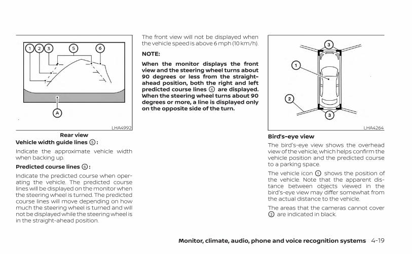
Vehicle width guide lines O5 :Indicate the approximate vehicle widthwhen backing up.Predicted course lines O6 :Indicate the predicted course when oper-ating the vehicle. The predicted courselines will be displayed on the monitor whenthe steering wheel is turned. The predictedcourse lines will move depending on howmuch the steering wheel is turned and willnot be displayed while the steering wheel isin the straight-ahead position.
The front view will not be displayed whenthe vehicle speed is above 6 mph (10 km/h).
NOTE:
When the monitor displays the frontview and the steering wheel turns about90 degrees or less from the straight-ahead position, both the right and leftpredicted course lines O6 are displayed.When the steering wheel turns about 90degrees or more, a line is displayed onlyon the opposite side of the turn.
Bird’s-eye viewThe bird's-eye view shows the overheadview of the vehicle, which helps confirm thevehicle position and the predicted courseto a parking space.The vehicle icon O1 shows the position ofthe vehicle. Note that the apparent dis-tance between objects viewed in thebird's-eye view may differ somewhat fromthe actual distance to the vehicle.The areas that the cameras cannot coverO2 are indicated in black.
LHA4992Rear view
LHA4264
Monitor, climate, audio, phone and voice recognition systems 4-19
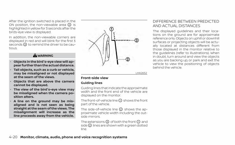
After the ignition switched is placed in theON position, the non-viewable area O2 ishighlighted in yellow for 3 seconds after thebirds-eye view is displayed.In addition, the non-viewable corners aredisplayed in red and will blink for the first 3seconds O3 to remind the driver to be cau-tious.
WARNING
• Objects in the bird's-eye view will ap-pear further than the actual distance.
• Tall objects, such as a curb or vehicle,may be misaligned or not displayedat the seam of the views.
• Objects that are above the cameracannot be displayed.
• The view of the bird's-eye view maybe misaligned when the camera po-sition alters.
• A line on the ground may be mis-aligned and is not seen as beingstraight at the seam of the views. Themisalignment will increase as theline proceeds away from the vehicle.
Front-side viewGuiding linesGuiding lines that indicate the approximatewidth and the front end of the vehicle aredisplayed on the monitor.The front-of-vehicle line O1 shows the frontpart of the vehicle.The side-of-vehicle line O2 shows the ap-proximate vehicle width including the out-side mirrors.The extensions O3 of both the front O1 andside O2 lines are shown with a green dottedline.
DIFFERENCE BETWEEN PREDICTEDAND ACTUAL DISTANCESThe displayed guidelines and their loca-tions on the ground are for approximatereference only. Objects on uphill or downhillsurfaces or projecting objects will be actu-ally located at distances different fromthose displayed in the monitor relative tothe guidelines (refer to illustrations). Whenin doubt, turn around and view the objectsas you are backing up, or park and exit thevehicle to view the positioning of objectsbehind the vehicle.
LHA2652
4-20 Monitor, climate, audio, phone and voice recognition systems
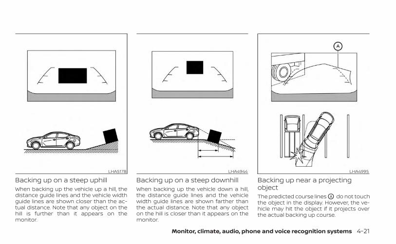
Backing up on a steep uphillWhen backing up the vehicle up a hill, thedistance guide lines and the vehicle widthguide lines are shown closer than the ac-tual distance. Note that any object on thehill is further than it appears on themonitor.
Backing up on a steep downhillWhen backing up the vehicle down a hill,the distance guide lines and the vehiclewidth guide lines are shown farther thanthe actual distance. Note that any objecton the hill is closer than it appears on themonitor.
Backing up near a projectingobjectThe predicted course lines OA do not touchthe object in the display. However, the ve-hicle may hit the object if it projects overthe actual backing up course.
LHA5178 LHA4944 LHA4995
Monitor, climate, audio, phone and voice recognition systems 4-21
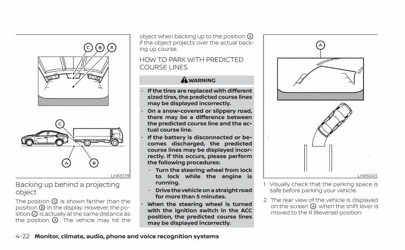
Backing up behind a projectingobjectThe position OC is shown farther than theposition OB in the display. However, the po-sition OC is actually at the same distance asthe position OA . The vehicle may hit the
object when backing up to the position OA
if the object projects over the actual back-ing up course.
HOW TO PARK WITH PREDICTEDCOURSE LINES
WARNING
• If the tires are replaced with differentsized tires, the predicted course linesmay be displayed incorrectly.
• On a snow-covered or slippery road,there may be a difference betweenthe predicted course line and the ac-tual course line.
• If the battery is disconnected or be-comes discharged, the predictedcourse lines may be displayed incor-rectly. If this occurs, please performthe following procedures:– Turn the steering wheel from lock
to lock while the engine isrunning.
– Drive the vehicle on a straight roadfor more than 5 minutes.
• When the steering wheel is turnedwith the ignition switch in the ACCposition, the predicted course linesmay be displayed incorrectly.
1. Visually check that the parking space issafe before parking your vehicle.
2. The rear view of the vehicle is displayedon the screen OA when the shift lever ismoved to the R (Reverse) position.
LHA5179 LHA5043
4-22 Monitor, climate, audio, phone and voice recognition systems
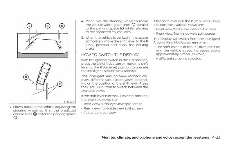
3. Slowly back up the vehicle adjusting thesteering wheel so that the predictedcourse lines OB enter the parking spaceOC .
4. Maneuver the steering wheel to makethe vehicle width guide lines OD parallelto the parking space OC while referringto the predicted course lines.
5. When the vehicle is parked in the spacecompletely, move the shift lever to the P(Park) position and apply the parkingbrake.
HOW TO SWITCH THE DISPLAYWith the ignition switch in the ON position,press the CAMERA button or move the shiftlever to the R (Reverse) position to operatethe Intelligent Around View Monitor.The Intelligent Around View Monitor dis-plays different split screen views depend-ing on the position of the shift lever. Pressthe CAMERA button to switch between theavailable views.If the shift lever is in the R (Reverse) position,the available views are:• Rear view/bird’s-eye view split screen• Rear view/front-side view split screen• Full screen rear view
If the shift lever is in the P (Park) or D (Drive)position, the available views are:• Front view/bird’s-eye view split screen• Front view/front-side view split screenThe display will switch from the IntelligentAround View Monitor screen when:• The shift lever is in the D (Drive) position
and the vehicle speed increases aboveapproximately 6 mph (10 km/h)
• A different screen is selected.
LHA4770
Monitor, climate, audio, phone and voice recognition systems 4-23
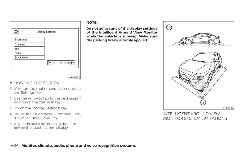
ADJUSTING THE SCREEN1. While on the main menu screen, touch
the “Settings” key.
2. Use the arrow to tab to the next screenand touch the “Camera” key.
3. Touch the “Display Settings” key.
4. Touch the “Brightness”, “Contrast”, Tint”,“Color”, or “Black Level” key.
5. Adjust the item by touching the “+” or “–”key on the touch-screen display.
NOTE:
Do not adjust any of the display settingsof the Intelligent Around View Monitorwhile the vehicle is moving. Make surethe parking brake is firmly applied.
INTELLIGENT AROUND VIEWMONITOR SYSTEM LIMITATIONS
LHA3522
LHA5326
4-24 Monitor, climate, audio, phone and voice recognition systems
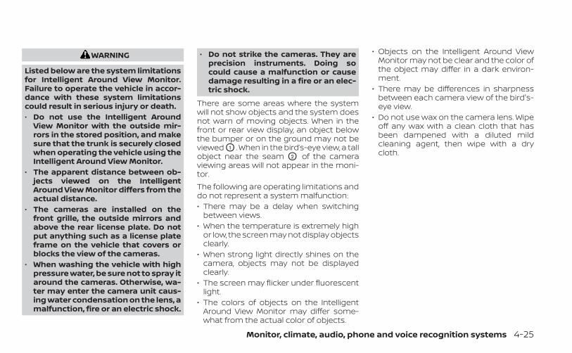
WARNING
Listed below are the system limitationsfor Intelligent Around View Monitor.Failure to operate the vehicle in accor-dance with these system limitationscould result in serious injury or death.• Do not use the Intelligent Around
View Monitor with the outside mir-rors in the stored position, and makesure that the trunk is securely closedwhen operating the vehicle using theIntelligent Around View Monitor.
• The apparent distance between ob-jects viewed on the IntelligentAround View Monitor differs from theactual distance.
• The cameras are installed on thefront grille, the outside mirrors andabove the rear license plate. Do notput anything such as a license plateframe on the vehicle that covers orblocks the view of the cameras.
• When washing the vehicle with highpressure water, be sure not to spray itaround the cameras. Otherwise, wa-ter may enter the camera unit caus-ing water condensation on the lens, amalfunction, fire or an electric shock.
• Do not strike the cameras. They areprecision instruments. Doing socould cause a malfunction or causedamage resulting in a fire or an elec-tric shock.
There are some areas where the systemwill not show objects and the system doesnot warn of moving objects. When in thefront or rear view display, an object belowthe bumper or on the ground may not beviewed O1 . When in the bird’s-eye view, a tallobject near the seam O2 of the cameraviewing areas will not appear in the moni-tor.The following are operating limitations anddo not represent a system malfunction:• There may be a delay when switching
between views.• When the temperature is extremely high
or low, the screen may not display objectsclearly.
• When strong light directly shines on thecamera, objects may not be displayedclearly.
• The screen may flicker under fluorescentlight.
• The colors of objects on the IntelligentAround View Monitor may differ some-what from the actual color of objects.
• Objects on the Intelligent Around ViewMonitor may not be clear and the color ofthe object may differ in a dark environ-ment.
• There may be differences in sharpnessbetween each camera view of the bird's-eye view.
• Do not use wax on the camera lens. Wipeoff any wax with a clean cloth that hasbeen dampened with a diluted mildcleaning agent, then wipe with a drycloth.
Monitor, climate, audio, phone and voice recognition systems 4-25
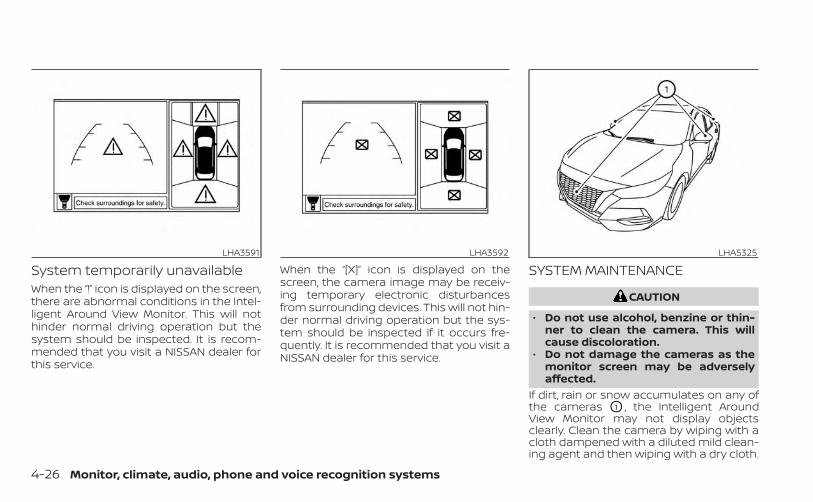
System temporarily unavailableWhen the “!” icon is displayed on the screen,there are abnormal conditions in the Intel-ligent Around View Monitor. This will nothinder normal driving operation but thesystem should be inspected. It is recom-mended that you visit a NISSAN dealer forthis service.
When the “[X]” icon is displayed on thescreen, the camera image may be receiv-ing temporary electronic disturbancesfrom surrounding devices. This will not hin-der normal driving operation but the sys-tem should be inspected if it occurs fre-quently. It is recommended that you visit aNISSAN dealer for this service.
SYSTEM MAINTENANCE
CAUTION
• Do not use alcohol, benzine or thin-ner to clean the camera. This willcause discoloration.
• Do not damage the cameras as themonitor screen may be adverselyaffected.
If dirt, rain or snow accumulates on any ofthe cameras O1 , the Intelligent AroundView Monitor may not display objectsclearly. Clean the camera by wiping with acloth dampened with a diluted mild clean-ing agent and then wiping with a dry cloth.
LHA3591 LHA3592 LHA5325
4-26 Monitor, climate, audio, phone and voice recognition systems
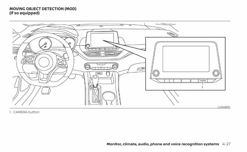
1. CAMERA buttonLHA4800
MOVING OBJECT DETECTION (MOD)(if so equipped)
Monitor, climate, audio, phone and voice recognition systems 4-27
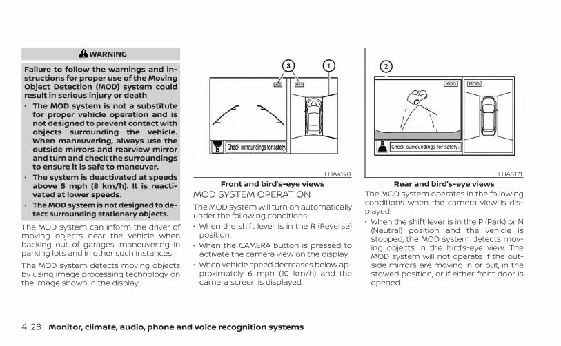
WARNING
Failure to follow the warnings and in-structions for proper use of the MovingObject Detection (MOD) system couldresult in serious injury or death• The MOD system is not a substitute
for proper vehicle operation and isnot designed to prevent contact withobjects surrounding the vehicle.When maneuvering, always use theoutside mirrors and rearview mirrorand turn and check the surroundingsto ensure it is safe to maneuver.
• The system is deactivated at speedsabove 5 mph (8 km/h). It is reacti-vated at lower speeds.
• The MOD system is not designed to de-tect surrounding stationary objects.
The MOD system can inform the driver ofmoving objects near the vehicle whenbacking out of garages, maneuvering inparking lots and in other such instances.The MOD system detects moving objectsby using image processing technology onthe image shown in the display.
MOD SYSTEM OPERATIONThe MOD system will turn on automaticallyunder the following conditions:• When the shift lever is in the R (Reverse)
position.• When the CAMERA button is pressed to
activate the camera view on the display.• When vehicle speed decreases below ap-
proximately 6 mph (10 km/h) and thecamera screen is displayed.
The MOD system operates in the followingconditions when the camera view is dis-played:• When the shift lever is in the P (Park) or N
(Neutral) position and the vehicle isstopped, the MOD system detects mov-ing objects in the bird’s-eye view. TheMOD system will not operate if the out-side mirrors are moving in or out, in thestowed position, or if either front door isopened.
LHA4190Front and bird’s-eye views
LHA5171Rear and bird’s-eye views
4-28 Monitor, climate, audio, phone and voice recognition systems
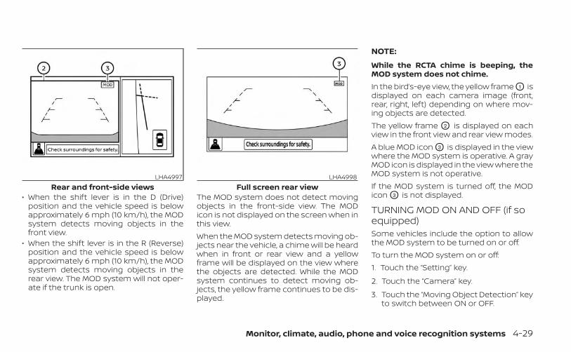
• When the shift lever is in the D (Drive)position and the vehicle speed is belowapproximately 6 mph (10 km/h), the MODsystem detects moving objects in thefront view.
• When the shift lever is in the R (Reverse)position and the vehicle speed is belowapproximately 6 mph (10 km/h), the MODsystem detects moving objects in therear view. The MOD system will not oper-ate if the trunk is open.
The MOD system does not detect movingobjects in the front-side view. The MODicon is not displayed on the screen when inthis view.When the MOD system detects moving ob-jects near the vehicle, a chime will be heardwhen in front or rear view and a yellowframe will be displayed on the view wherethe objects are detected. While the MODsystem continues to detect moving ob-jects, the yellow frame continues to be dis-played.
NOTE:
While the RCTA chime is beeping, theMOD system does not chime.In the bird’s-eye view, the yellow frame O1 isdisplayed on each camera image (front,rear, right, left) depending on where mov-ing objects are detected.The yellow frame O2 is displayed on eachview in the front view and rear view modes.A blue MOD icon O3 is displayed in the viewwhere the MOD system is operative. A grayMOD icon is displayed in the view where theMOD system is not operative.If the MOD system is turned off, the MODicon O3 is not displayed.
TURNING MOD ON AND OFF (if soequipped)Some vehicles include the option to allowthe MOD system to be turned on or off.To turn the MOD system on or off:1. Touch the “Setting” key.
2. Touch the “Camera” key.
3. Touch the “Moving Object Detection” keyto switch between ON or OFF.
LHA4997Rear and front-side views
LHA4998Full screen rear view
Monitor, climate, audio, phone and voice recognition systems 4-29
MOD SYSTEM LIMITATIONSWARNING
Listed below are the system limitationsfor MOD. Failure to operate the vehiclein accordance with these system limi-tations could result in serious injury ordeath.• Do not use the MOD system when
towing a trailer. The system may notfunction properly.
• Excessive noise (for example, audiosystem volume or open vehicle win-dow) will interfere with the chimesound, and it may not be heard.
• The MOD system performance will belimited according to environmentalconditions and surrounding objectssuch as:– When there is low contrast be-
tween background and the mov-ing objects.
– When there is a blinking source oflight.
– When strong light such as anothervehicle’s headlight or sunlight ispresent.
– When camera orientation is not inits usual position, such as when amirror is folded.
– When there is dirt, water drops orsnow on the camera lens.
– When the position of the movingobjects in the display is notchanged.
• The MOD system might detect flow-ing water droplets on the cameralens, white smoke from the muffler,moving shadows, etc.
• The MOD system may not functionproperly depending on the speed, di-rection, distance or shape of themoving objects.
• If your vehicle sustains damage tothe parts where the camera is in-stalled, leaving it misaligned or bent,the sensing zone may be altered andthe MOD system may not detect ob-jects properly.
• When the temperature is extremelyhigh or low, the screen may not dis-play objects clearly. This is not amalfunction.
NOTE:
The blue MOD icon will change to orangeif one of the following has occurred:• When the system is malfunctioning.• When the component temperature
reaches a high level (icon will blink).• When the RearView camera has detected
a blockage (icon will blink).If the icon light continues to illuminateorange, have the MOD system checked. Itis recommended that you visit a NISSANdealer for this service.
4-30 Monitor, climate, audio, phone and voice recognition systems
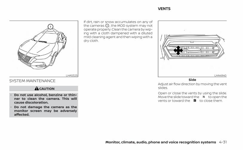
SYSTEM MAINTENANCE
CAUTION
• Do not use alcohol, benzine or thin-ner to clean the camera. This willcause discoloration.
• Do not damage the camera as themonitor screen may be adverselyaffected.
If dirt, rain or snow accumulates on any ofthe cameras O1 , the MOD system may notoperate properly. Clean the camera by wip-ing with a cloth dampened with a dilutedmild cleaning agent and then wiping with adry cloth.
Adjust air flow direction by moving the ventslides.Open or close the vents by using the slide.Move the slide toward the to open thevents or toward the to close them.
LHA5325 LHA4940Side
VENTS
Monitor, climate, audio, phone and voice recognition systems 4-31
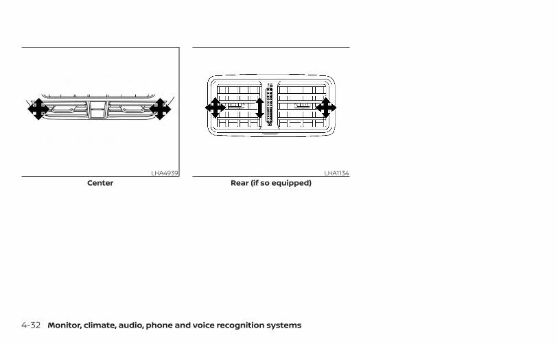
LHA4939Center
LHA1134Rear (if so equipped)
4-32 Monitor, climate, audio, phone and voice recognition systems
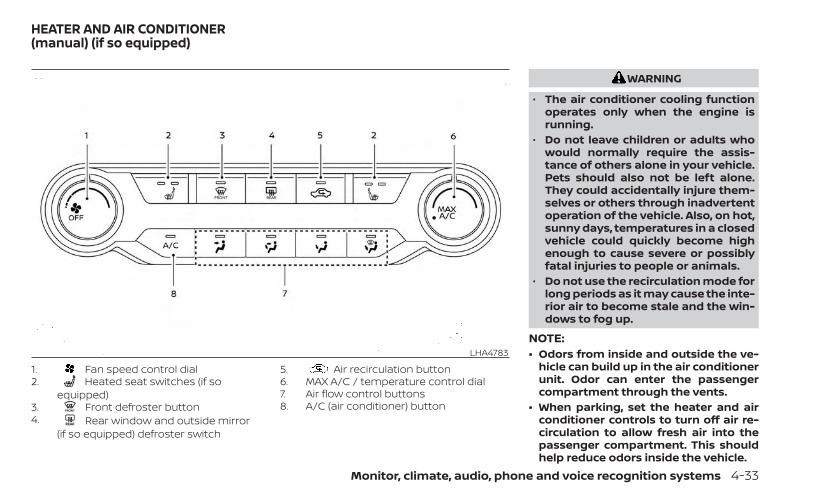
1. Fan speed control dial2. Heated seat switches (if so
equipped)3. Front defroster button4. Rear window and outside mirror
(if so equipped) defroster switch
5. Air recirculation button6. MAX A/C / temperature control dial7. Air flow control buttons8. A/C (air conditioner) button
WARNING
• The air conditioner cooling functionoperates only when the engine isrunning.
• Do not leave children or adults whowould normally require the assis-tance of others alone in your vehicle.Pets should also not be left alone.They could accidentally injure them-selves or others through inadvertentoperation of the vehicle. Also, on hot,sunny days, temperatures in a closedvehicle could quickly become highenough to cause severe or possiblyfatal injuries to people or animals.
• Do not use the recirculation mode forlong periods as it may cause the inte-rior air to become stale and the win-dows to fog up.
NOTE:• Odors from inside and outside the ve-
hicle can build up in the air conditionerunit. Odor can enter the passengercompartment through the vents.
• When parking, set the heater and airconditioner controls to turn off air re-circulation to allow fresh air into thepassenger compartment. This shouldhelp reduce odors inside the vehicle.
LHA4783
HEATER AND AIR CONDITIONER(manual) (if so equipped)
Monitor, climate, audio, phone and voice recognition systems 4-33
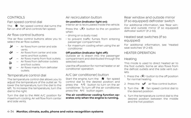
CONTROLSFan speed control dialThe fan speed control dial turns thefan on and off and controls fan speed.
Air flow control buttonsThe air flow control buttons allow you toselect the air flow outlets.
— Air flows from center and sidevents.
— Air flows from center and sidevents and foot outlets.
— Air flows mainly from foot outlets.— Air flows from defroster outlets
and foot outlets.— Air flows mainly from defroster
outlets.
Temperature control dialThe temperature control dial allows you toadjust the temperature of the outlet air. Tolower the temperature, turn the dial to theleft. To increase the temperature, turn thedial to the right.Turn the dial to the MAX A/C position formaximum cooling. Air will flow from centerand side vents.
Air recirculation buttonOn position (Indicator light on):Interior air is recirculated inside the vehicle.Press the button to the on positionwhen:• driving on a dusty road.• to prevent traffic fumes from entering
passenger compartment.• for maximum cooling when using the air
conditioner.Off position (Indicator light off):Outside air is drawn into the passengercompartment and distributed through theselected outlet.Use the off position for normal heater or airconditioner operation.
A/C (air conditioner) buttonStart the engine, turn the fan speedcontrol dial to the desired position andpress the button to turn on the airconditioner. To turn off the air conditioner,press the button again.The air conditioner cooling function op-erates only when the engine is running.
Rear window and outside mirror(if so equipped) defroster switchFor additional information, see “Rear win-dow and outside mirror (if so equipped)defroster switch” (P. 2-55).
Heated seat switches (if soequipped)For additional information, see “Heatedseat switches” (P. 2-63).
HEATER OPERATION
HeatingThis mode is used to direct heated air tothe foot outlets. Some air also flows fromthe defrost outlets and the side vent out-lets.1. Press the button to the off position
for normal heating.
2. Press the air flow control button.
3. Turn the fan speed control dial tothe desired position.
4. Turn the temperature control dial to thedesired position between the middleand the hot position.
4-34 Monitor, climate, audio, phone and voice recognition systems
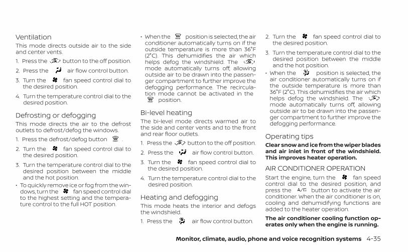
VentilationThis mode directs outside air to the sideand center vents.1. Press the button to the off position.
2. Press the air flow control button.
3. Turn the fan speed control dial tothe desired position.
4. Turn the temperature control dial to thedesired position.
Defrosting or defoggingThis mode directs the air to the defrostoutlets to defrost/defog the windows.1. Press the defrost/defog button .
2. Turn the fan speed control dial tothe desired position.
3. Turn the temperature control dial to thedesired position between the middleand the hot position.
• To quickly remove ice or fog from the win-dows, turn the fan speed control dialto the highest setting and the tempera-ture control to the full HOT position.
• When the position is selected, the airconditioner automatically turns on if theoutside temperature is more than 36°F(2°C). This dehumidifies the air whichhelps defog the windshield. Themode automatically turns off, allowingoutside air to be drawn into the passen-ger compartment to further improve thedefogging performance. The recircula-tion mode cannot be activated in the
position.
Bi-level heatingThe bi-level mode directs warmed air tothe side and center vents and to the frontand rear floor outlets.1. Press the button to the off position.
2. Press the air flow control button.
3. Turn the fan speed control dial tothe desired position.
4. Turn the temperature control dial to thedesired position.
Heating and defoggingThis mode heats the interior and defogsthe windshield.1. Press the air flow control button.
2. Turn the fan speed control dial tothe desired position.
3. Turn the temperature control dial to thedesired position between the middleand the hot position.
• When the position is selected, theair conditioner automatically turns on ifthe outside temperature is more than36°F (2°C). This dehumidifies the air whichhelps defog the windshield. Themode automatically turns off, allowingoutside air to be drawn into the passen-ger compartment to further improve thedefogging performance.
Operating tipsClear snow and ice from the wiper bladesand air inlet in front of the windshield.This improves heater operation.
AIR CONDITIONER OPERATIONStart the engine, turn the fan speedcontrol dial to the desired position, andpress the button to activate the airconditioner. When the air conditioner is on,cooling and dehumidifying functions areadded to the heater operation.The air conditioner cooling function op-erates only when the engine is running.
Monitor, climate, audio, phone and voice recognition systems 4-35
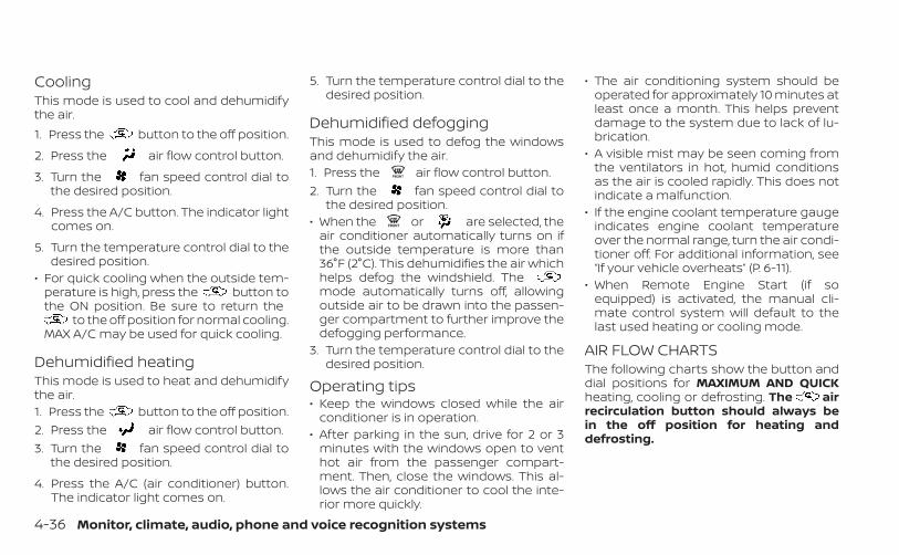
CoolingThis mode is used to cool and dehumidifythe air.1. Press the button to the off position.
2. Press the air flow control button.
3. Turn the fan speed control dial tothe desired position.
4. Press the A/C button. The indicator lightcomes on.
5. Turn the temperature control dial to thedesired position.
• For quick cooling when the outside tem-perature is high, press the button tothe ON position. Be sure to return the
to the off position for normal cooling.MAX A/C may be used for quick cooling.
Dehumidified heatingThis mode is used to heat and dehumidifythe air.1. Press the button to the off position.2. Press the air flow control button.3. Turn the fan speed control dial to
the desired position.
4. Press the A/C (air conditioner) button.The indicator light comes on.
5. Turn the temperature control dial to thedesired position.
Dehumidified defoggingThis mode is used to defog the windowsand dehumidify the air.1. Press the air flow control button.2. Turn the fan speed control dial to
the desired position.• When the or are selected, the
air conditioner automatically turns on ifthe outside temperature is more than36°F (2°C). This dehumidifies the air whichhelps defog the windshield. Themode automatically turns off, allowingoutside air to be drawn into the passen-ger compartment to further improve thedefogging performance.
3. Turn the temperature control dial to thedesired position.
Operating tips• Keep the windows closed while the air
conditioner is in operation.• After parking in the sun, drive for 2 or 3
minutes with the windows open to venthot air from the passenger compart-ment. Then, close the windows. This al-lows the air conditioner to cool the inte-rior more quickly.
• The air conditioning system should beoperated for approximately 10 minutes atleast once a month. This helps preventdamage to the system due to lack of lu-brication.
• A visible mist may be seen coming fromthe ventilators in hot, humid conditionsas the air is cooled rapidly. This does notindicate a malfunction.
• If the engine coolant temperature gaugeindicates engine coolant temperatureover the normal range, turn the air condi-tioner off. For additional information, see“If your vehicle overheats” (P. 6-11).
• When Remote Engine Start (if soequipped) is activated, the manual cli-mate control system will default to thelast used heating or cooling mode.
AIR FLOW CHARTSThe following charts show the button anddial positions for MAXIMUM AND QUICKheating, cooling or defrosting. The airrecirculation button should always bein the off position for heating anddefrosting.
4-36 Monitor, climate, audio, phone and voice recognition systems
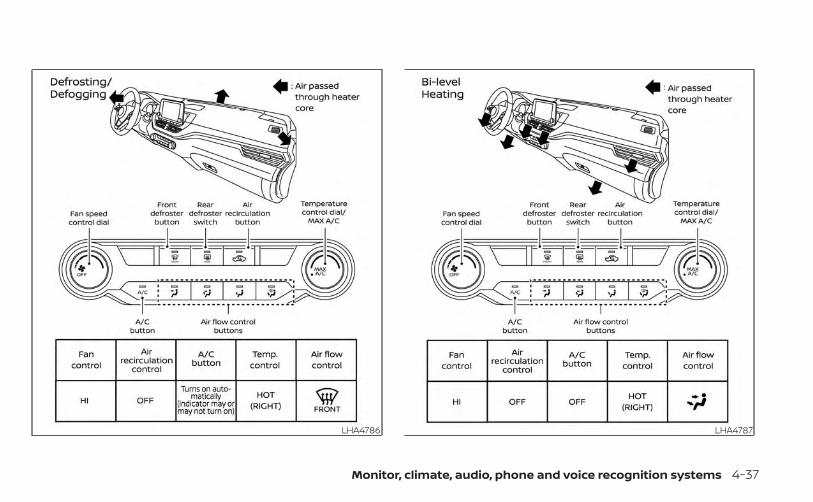
LHA4786 LHA4787
Monitor, climate, audio, phone and voice recognition systems 4-37
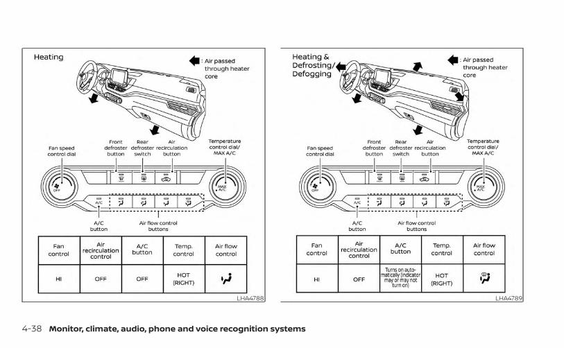
LHA4788 LHA4789
4-38 Monitor, climate, audio, phone and voice recognition systems
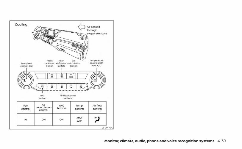
LHA4790
Monitor, climate, audio, phone and voice recognition systems 4-39
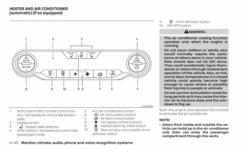
1. AUTO (automatic) climate control but-ton / temperature control dial (driversside)
2. Display screen3. Heated seat switches4. SYNC button / temperature control dial
(passenger’s side)
5. A/C (air conditioner) button6. Air recirculation button7. Air flow control button8. Fan speed control buttons9. Heated steering wheel switch10. Rear window and outside mirror
defroster switch
11. Front defroster button12. ON-OFF button
WARNING
• The air conditioner cooling functionoperates only when the engine isrunning.
• Do not leave children or adults whowould normally require the assis-tance of others alone in your vehicle.Pets should also not be left alone.They could accidentally injure them-selves or others through inadvertentoperation of the vehicle. Also, on hot,sunny days, temperatures in a closedvehicle could quickly become highenough to cause severe or possiblyfatal injuries to people or animals.
• Do not use the recirculation mode forlong periods as it may cause the inte-rior air to become stale and the win-dows to fog up.
Start the engine and operate the controlsto activate the air conditioner.
NOTE:• Odors from inside and outside the ve-
hicle can build up in the air conditionerunit. Odor can enter the passengercompartment through the vents.
LHA4784
HEATER AND AIR CONDITIONER(automatic) (if so equipped)
4-40 Monitor, climate, audio, phone and voice recognition systems
• When parking, set the heater and airconditioner controls to turn off air re-circulation to allow fresh air into thepassenger compartment. This shouldhelp reduce odors inside the vehicle.
AUTOMATIC OPERATION
Cooling and/or dehumidifiedheating (AUTO)This mode may be used all year round asthe system automatically works to keep aconstant temperature. Air flow distribution,air intake control, and fan speed are alsocontrolled automatically.1. Press the AUTO button on.
2. Turn the temperature control dial to theleft or right to set the desiredtemperature.
• Adjust the temperature display to about75°F (24°C) for normal operation.
• The temperature of the passenger com-partment will be maintained automati-cally. Air flow distribution, air intake con-trol and fan speed are also controlledautomatically.
• A visible mist may be seen coming fromthe vents in hot, humid conditions as theair is cooled rapidly. This does not indicatea malfunction.
3. You can individually set driver's and frontpassenger's side temperature usingeach temperature control dial. To syn-chronize the driver’s and front passen-ger’s temperature settings, press theSYNC button.
Heating (A/C OFF)The air conditioner does not activate. Whenyou need to heat only, use this mode.1. Press the AUTO button.
2. Turn the temperature control dial to setthe desired temperature.
• The temperature of the passenger com-partment will be maintained automati-cally. Air flow distribution and fan speedare also controlled automatically.
• Do not set the temperature lower thanthe outside air temperature. Otherwise,the system may not work properly.
• Not recommended if windows fog up.
Dehumidified defrosting ordefogging1. Press the front defroster button on.
2. Turn the temperature control dial to setthe desired temperature.
• To quickly remove ice from the outside ofthe windows, use the fan speed con-trol buttons to set the fan speed to maxi-mum.
• As soon as possible after the windshieldis clean, press the AUTO button to returnto the automatic mode.
• When the front defroster button ispressed, the air conditioner will automati-cally be turned on at outside tempera-tures above 36°F (2°C). The air recirculatemode automatically turns off, allowingoutside air to be drawn into the passen-ger compartment to further improve thedefogging performance.
Monitor, climate, audio, phone and voice recognition systems 4-41
Remote Engine Start withIntelligent Climate Control (if soequipped)Vehicles equipped with automatic climatecontrols and Remote Engine Start functionmay go into automatic heating or coolingmode when Remote Engine Start is acti-vated depending on outside and cabintemperatures. During this period, the cli-mate control display and buttons will beinoperable until the ignition switch isturned on. In Remote Engine Start defrost-ing mode, the rear window defroster andheated steering wheel (if so equipped) maybe activated automatically.
MANUAL OPERATION
Fan speed control buttonsPress the fan speed control buttonsto manually control the fan speed.Press the AUTO button to return to auto-matic control of the fan speed.
Temperature control dialThe temperature control dial allows you toadjust the temperature of the outlet air. Tolower the temperature, turn the dial to theleft. To increase the temperature, turn the
dial to the right. Temperature can be ad-justed on the driver’s and passenger’s side.
Air recirculationPress the air recirculation button torecirculate interior air inside the vehicle.The indicator light on the button willcome on.The air recirculation cannot be activatedwhen the air conditioner is in the frontdefrosting mode.When the outside temperature exceeds70°F (21°C), the air conditioning system maydefault to air recirculation mode automati-cally to reduce overall power consumption.To exit air recirculation mode, deselect theair recirculation button (indicator light willturn off) to enter fresh air mode.
Automatic intake air controlIn the AUTO mode, the intake air will becontrolled automatically. To manually con-trol the intake air, press the air recir-culation button. To return to the automaticcontrol mode, press and hold the airrecirculation button for about 2 seconds.The indicator light will flash twice, and thenthe intake air will be controlled automati-cally.
A/C (air conditioner) buttonStart the engine, press the fan speedcontrol buttons to the desired position andpress the button to turn on the airconditioner. To turn off the air conditioner,press the button again.The air conditioner cooling function op-erates only when the engine is running.
Air flow controlPressing the button manually con-trols air flow and selects the air outlet:
— Air flows from center and sidevents.
— Air flows from center and sidevents and foot outlets.
— Air flows mainly from foot outlets.— Air flows from defroster and foot
outlets.
Synchronize climate settingsPress the SYNC button to synchronize cli-mate settings. The sync indicator will turnon.Pressing SYNC will synchronize driver's andfront passenger's climate settings.
4-42 Monitor, climate, audio, phone and voice recognition systems
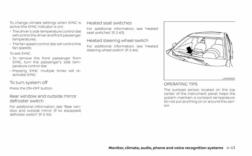
To change climate settings when SYNC isactive (the SYNC indicator is on):• The driver's side temperature control dial
will control the driver and front passengertemperatures.
• The fan speed control dial will control thefan speeds.
To exit SYNC:• To remove the front passenger from
SYNC, turn the passenger's side tem-perature control dial.
• Pressing SYNC multiple times will re-activate SYNC.
To turn system offPress the ON-OFF button.
Rear window and outside mirrordefroster switchFor additional information, see “Rear win-dow and outside mirror (if so equipped)defroster switch” (P. 2-55).
Heated seat switchesFor additional information, see “Heatedseat switches” (P. 2-63).
Heated steering wheel switchFor additional information, see “Heatedsteering wheel switch” (P. 2-64).
OPERATING TIPSThe sunload sensor, located on the topcenter of the instrument panel, helps thesystem maintain a constant temperature.Do not put anything on or around this sen-sor.
LHA4943
Monitor, climate, audio, phone and voice recognition systems 4-43
• When the climate system is in automaticoperation and the engine coolant tem-perature and outside air temperatureare low, the air flow outlet may default todefroster mode for a maximum of 2 min-utes 30 seconds. This is not a malfunc-tion. After the engine coolant tempera-ture warms up, the air flow outlet willreturn to foot mode and operation willcontinue normally.
• When the outside and interior cabin tem-peratures are moderate to high, the in-take setting may default to turn off airrecirculation to allow fresh air into thepassenger compartment. You may no-tice air flow from the foot mode, bi-levelmode, or side demist vent outlets for amaximum of 15 seconds. This may occurwhen the previous climate setting wasturned off. This is not a malfunction. Afterthe initial warm air is expelled, the intakewill return to automatic control, the airflow outlet will return to previous settings,and operation will continue normally. Toexit, press any climate control button.
• Keep the moonroof (if so equipped)closed while the air conditioner is in op-eration.
• If you feel that the air flow mode you haveselected and the outlets the air is comingout do not match, select the mode.
• When you change the air flow mode, youmay feel air flow from the foot outlets forjust a moment. This is not a malfunction.
The air conditioner system in your NISSANvehicle is charged with a refrigerant de-signed with the environment in mind.This refrigerant does not harm theearth's ozone layer.Special charging equipment and lubricant isrequired when servicing your NISSAN airconditioner. Using improper refrigerants orlubricants will cause severe damage to yourair conditioner system. For additional infor-mation, see “Air conditioner system refriger-ant and oil recommendations” (P. 10-8).It is recommended that you visit a NISSANdealer to service your “environmentallyfriendly” air conditioner system.
WARNING
The air conditioner system contains re-frigerant under high pressure. To avoidpersonal injury, any air conditioner ser-vice should be done only by an experi-enced technician with proper equip-ment.
SERVICING AIR CONDITIONER
4-44 Monitor, climate, audio, phone and voice recognition systems
RADIOPlace the ignition switch in the ACC or ONposition and press the PUSH buttonto turn the radio on. If you listen to the radiowith the engine not running, the ignitionswitch should be placed in the ACC posi-tion.Radio reception is affected by station sig-nal strength, distance from radio transmit-ter, buildings, bridges, mountains and otherexternal influences. Intermittent changesin reception quality normally are caused bythese external influences.Using a cellular phone in or near the ve-hicle may influence radio reception qual-ity.
Radio receptionYour NISSAN radio system is equipped withstate-of-the-art electronic circuits to en-hance radio reception. These circuits aredesigned to extend reception range, and toenhance the quality of that reception.However, there are some general charac-teristics of both FM and AM radio signalsthat can affect radio reception quality in amoving vehicle, even when the finestequipment is used. These characteristicsare completely normal in a given reception
area and do not indicate any malfunctionin your NISSAN radio system.Reception conditions will constantlychange because of vehicle movement.Buildings, terrain, signal distance and inter-ference from other vehicles can workagainst ideal reception. Described beloware some of the factors that can affect yourradio reception.Some cellular phones or other devices maycause interference or a buzzing noise tocome from the audio system speakers.Storing the device in a different locationmay reduce or eliminate the noise.
FM RADIO RECEPTIONRange: FM range is normally limited to 25 –30 mi (40 – 48 km), with monaural (singlechannel) FM having slightly more rangethan stereo FM. External influences maysometimes interfere with FM station re-ception even if the FM station is within 25mi (40 km). The strength of the FM signal isdirectly related to the distance betweenthe transmitter and receiver. FM signals fol-low a line-of-sight path, exhibiting many ofthe same characteristics as light. For ex-ample, they will reflect off objects.
Fade and drift: As your vehicle moves awayfrom a station transmitter, the signals willtend to fade and/or drift.Static and flutter: During signal interfer-ence from buildings, large hills or due toantenna position (usually in conjunctionwith increased distance from the stationtransmitter), static or flutter can be heard.This can be reduced by adjusting the treblecontrol to reduce treble response.Multipath reception: Because of the reflec-tive characteristics of FM signals, direct andreflected signals reach the receiver at thesame time. The signals may cancel eachother, resulting in momentary flutter or lossof sound.
AM RADIO RECEPTIONAM signals, because of their low frequency,can bend around objects and skip alongthe ground. In addition, the signals can bebounced off the ionosphere and bent backto earth. Because of these characteristics,AM signals are also subject to interferenceas they travel from transmitter to receiver.
AUDIO SYSTEM
Monitor, climate, audio, phone and voice recognition systems 4-45
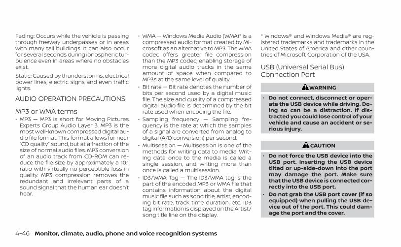
Fading: Occurs while the vehicle is passingthrough freeway underpasses or in areaswith many tall buildings. It can also occurfor several seconds during ionospheric tur-bulence even in areas where no obstaclesexist.Static: Caused by thunderstorms, electricalpower lines, electric signs and even trafficlights.
AUDIO OPERATION PRECAUTIONS
MP3 or WMA terms• MP3 — MP3 is short for Moving Pictures
Experts Group Audio Layer 3. MP3 is themost well-known compressed digital au-dio file format. This format allows for near“CD quality” sound, but at a fraction of thesize of normal audio files. MP3 conversionof an audio track from CD-ROM can re-duce the file size by approximately a 10:1ratio with virtually no perceptible loss inquality. MP3 compression removes theredundant and irrelevant parts of asound signal that the human ear doesn’thear.
• WMA — Windows Media Audio (WMA)* is acompressed audio format created by Mi-crosoft as an alternative to MP3. The WMAcodec offers greater file compressionthan the MP3 codec, enabling storage ofmore digital audio tracks in the sameamount of space when compared toMP3s at the same level of quality.
• Bit rate — Bit rate denotes the number ofbits per second used by a digital musicfile. The size and quality of a compresseddigital audio file is determined by the bitrate used when encoding the file.
• Sampling frequency — Sampling fre-quency is the rate at which the samplesof a signal are converted from analog todigital (A/D conversion) per second.
• Multisession — Multisession is one of themethods for writing data to media. Writ-ing data once to the media is called asingle session, and writing more thanonce is called a multisession.
• ID3/WMA Tag — The ID3/WMA tag is thepart of the encoded MP3 or WMA file thatcontains information about the digitalmusic file such as song title, artist, encod-ing bit rate, track time duration, etc. ID3tag information is displayed on the Artist/song title line on the display.
* Windows® and Windows Media® are reg-istered trademarks and trademarks in theUnited States of America and other coun-tries of Microsoft Corporation of the USA.
USB (Universal Serial Bus)Connection Port
WARNING
• Do not connect, disconnect or oper-ate the USB device while driving. Do-ing so can be a distraction. If dis-tracted you could lose control of yourvehicle and cause an accident or se-rious injury.
CAUTION
• Do not force the USB device into theUSB port. Inserting the USB devicetilted or up-side-down into the portmay damage the port. Make surethat the USB device is connected cor-rectly into the USB port.
• Do not grab the USB port cover (if soequipped) when pulling the USB de-vice out of the port. This could dam-age the port and the cover.
4-46 Monitor, climate, audio, phone and voice recognition systems
• Do not leave the USB cable in a placewhere it can be pulled unintention-ally. Pulling the cable may damagethe port.
The vehicle is not equipped with a USB de-vice. USB devices should be purchasedseparately as necessary.This system cannot be used to format USBdevices. To format a USB device, use a per-sonal computer.In some jurisdictions, the USB device for thefront seats plays only sound without im-ages for regulatory reasons, even when thevehicle is parked.This system supports various USBmemory devices, USB hard drives andiPod® players. Some USB devices may notbe supported by this system.• Partitioned USB devices may not play
correctly.• Some characters used in other lan-
guages (Chinese, Japanese, etc.) may notappear properly in the display. Using Eng-lish language characters with a USB de-vice is recommended.
General notes for USB use:• For additional information, refer to your
device manufacturer’s owner informa-tion regarding the proper use and care ofthe device.
Notes for iPod® use:iPod® is a trademark of Apple Inc., regis-tered in the U.S. and other countries.• Improperly plugging in the iPod® may
cause a checkmark to be displayed onand off (flickering). Always make sure thatthe iPod® is connected properly.
• An iPod® nano (1st Generation) may remainin fast forward or rewind mode if it is con-nected during a seek operation. In thiscase, please manually reset the iPod®.
• An iPod® nano (2nd Generation) will con-tinue to fast-forward or rewind if it is dis-connected during a seek operation.
• An incorrect song title may appear whenthe Play Mode is changed while using aniPod® nano (2nd Generation).
• Audiobooks may not play in the sameorder as they appear on an iPod®.
• Large video files cause slow responses inan iPod®. The vehicle center display maymomentarily black out, but will soon re-cover.
• If an iPod® automatically selects largevideo files while in the shuffle mode, thevehicle center display may momentarilyblack out, but will soon recover.
iPod®* player• Some characters used in other lan-
guages (Chinese, Japanese, etc.) are notdisplayed properly on the vehicle centerscreen. We recommend using English orSpanish language characters with aniPod®.
• Large video podcast files cause slow re-sponses in the iPod®. The vehicle centerdisplay may momentarily black out, but itwill soon recover.
• If the iPod® automatically selects largevideo podcast files while in the shufflemode, the vehicle center display maymomentarily black out, but it will soonrecover.
• Improperly plugging in the iPod® maycause a checkmark to be displayed onand off (flickering). Always make sure thatthe iPod® is connected properly.
• The iPod® nano (2nd Generation) will con-tinue to fast forward or rewind if it is dis-connected during a seek operation.
Monitor, climate, audio, phone and voice recognition systems 4-47
• An incorrect song title may appear whenthe Play Mode is changed while using theiPod® nano (2nd Generation).
• Audiobooks may not play in the sameorder as they appear on the iPod®.
• The iPod® nano (1st Generation) may re-main in fast forward or rewind mode if it isconnected during a seek operation. Inthis case, please manually reset theiPod®.
• If you are using an iPod® (3rd Generationwith Dock connector), do not use verylong names for the song title, albumname or artist name to prevent the iPod®from resetting itself.
• Be careful not to do the following, or thecable could be damaged and a loss offunction may occur:– Bend the cable excessively (1.6 in (40 mm)
radius maximum).– Twist the cable excessively (more than
180 degrees).– Pull or drop the cable.– Do not force the iPod® cable connector
into the device port.– Close the center console lid on the
cable or connectors.– Store objects with sharp edges in the
storage where the cable is stored.
– Spill liquids on the cable and connec-tors.
• Do not connect the cable to the iPod® ifthe cable and/or connectors are wet. Itmay damage the iPod®.
• If the cable and connectors are exposedto water, allow the cable and/or connec-tors to dry completely before connectingthe cable to the iPod® (wait 24 hours for itto dry).
• If the connector is exposed to fluids otherthan water, evaporative residue maycause a short between the connectorpins. In this case, replace the cable, other-wise damage to the iPod® and a loss offunction may occur.
• If the cable is damaged (insulation cut,connectors cracked, contamination suchas liquids, dust, dirt, etc. in the connec-tors), do not use the cable. It is recom-mended that you visit a NISSAN dealer toreplace the cable with a new one.
• When not in use for extended periods oftime, store the cable in a clean, dust freeenvironment at room temperature andwithout direct sun exposure.
• Do not use the cable for any other pur-poses other than its intended use in thevehicle.
*iPod® is a trademark of Apple Inc., regis-tered in the U.S. and other countries.
Bluetooth® streaming audio
• Some Bluetooth® audio devices may notbe recognized by the in-vehicle audiosystem.
• It is necessary to set up the wireless con-nection between a compatibleBluetooth® audio device and the in-vehicle Bluetooth® module before usingthe Bluetooth® audio.
• Operating procedure of the Bluetooth®audio will vary depending on the devices.Make sure how to operate your audio de-vice before using it with this system.
• The Bluetooth® audio may be stoppedunder the following conditions:– Receiving a call on the Bluetooth®
Hands-Free Phone System.– Checking the connection to the
hands-free phone.• Do not place the Bluetooth® audio device
in an area surrounded by metal or faraway from the in-vehicle Bluetooth®module to prevent tone quality degrada-tion and wireless connection disruption.
4-48 Monitor, climate, audio, phone and voice recognition systems
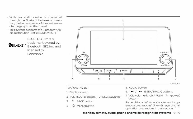
• While an audio device is connectedthrough the Bluetooth® wireless connec-tion, the battery power of the device maydischarge quicker than usual.
• This system supports the Bluetooth® Au-dio Distribution Profile (A2DP, AVRCP).
BLUETOOTH® is atrademark owned byBluetooth SIG, Inc. andlicensed toPanasonic.
FM/AM RADIO1. Display screen
2. PUSH SOUND button / TUNE·SCROLL knob
3. BACK button
4. MENU button
5. AUDIO button6. / (SEEK/TRACK) buttons7. VOL (volume) knob / PUSH (power)
buttonFor additional information, see “Audio op-eration precautions” (P. 4-46) regarding alloperation precautions in this section.
LHA4963
Monitor, climate, audio, phone and voice recognition systems 4-49
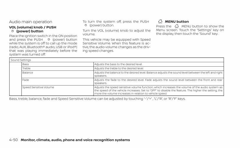
Audio main operationVOL (volume) knob / PUSH
(power) buttonPlace the ignition switch in the ON positionand press the PUSH (power) buttonwhile the system is off to call up the mode(radio, AUX, Bluetooth® audio, USB or iPod®)that was playing immediately before thesystem was turned off.
To turn the system off, press the PUSH(power) button.
Turn the VOL (volume) knob to adjust thevolume.This vehicle may be equipped with SpeedSensitive Volume. When this feature is ac-tive, the audio volume changes as the driv-ing speed changes.
MENU buttonPress the MENU button to show theMenu screen. Touch the “Settings” key onthe display, then touch the “Sound” key.
Sound SettingsBass Adjusts the bass to the desired level.Treble Adjusts the treble to the desired level.Balance Adjusts the balance to the desired level. Balance adjusts the sound level between the left and right
speakers.Fade Adjusts the fade to the desired level. Fade adjusts the sound level between the front and rear
speakers.Speed Sensitive Volume Adjusts the speed sensitive volume function, which increases the volume of the audio system as
the speed of the vehicle increases. Set to “OFF” to disable the feature. The higher the setting, themore the volume increases in relation to vehicle speed.
Bass, treble, balance, fade and Speed Sensitive Volume can be adjusted by touching “-”/“+” , “L”/”R”, or “R”/”F” keys.
4-50 Monitor, climate, audio, phone and voice recognition systems
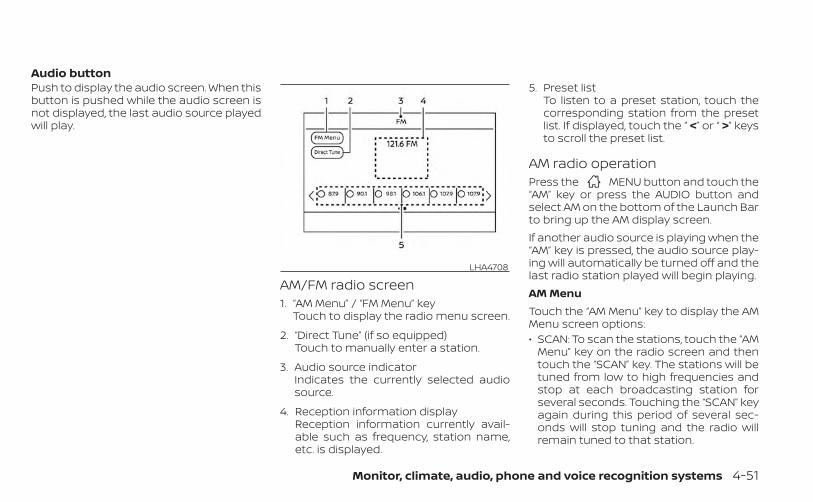
Audio buttonPush to display the audio screen. When thisbutton is pushed while the audio screen isnot displayed, the last audio source playedwill play.
AM/FM radio screen1. “AM Menu” / “FM Menu” key
Touch to display the radio menu screen.
2. “Direct Tune” (if so equipped)Touch to manually enter a station.
3. Audio source indicatorIndicates the currently selected audiosource.
4. Reception information displayReception information currently avail-able such as frequency, station name,etc. is displayed.
5. Preset listTo listen to a preset station, touch thecorresponding station from the presetlist. If displayed, touch the “ <” or “ >” keysto scroll the preset list.
AM radio operationPress the MENU button and touch the“AM” key or press the AUDIO button andselect AM on the bottom of the Launch Barto bring up the AM display screen.If another audio source is playing when the“AM” key is pressed, the audio source play-ing will automatically be turned off and thelast radio station played will begin playing.AM MenuTouch the “AM Menu” key to display the AMMenu screen options:• SCAN: To scan the stations, touch the “AM
Menu” key on the radio screen and thentouch the “SCAN” key. The stations will betuned from low to high frequencies andstop at each broadcasting station forseveral seconds. Touching the “SCAN” keyagain during this period of several sec-onds will stop tuning and the radio willremain tuned to that station.
LHA4708
Monitor, climate, audio, phone and voice recognition systems 4-51
• Refresh: Touch the “Refresh” key to scanand update the station list displayed onthe right side of the AM Menu screen.
(SEEK/TRACK) buttonsPress the or buttons to tunefrom low to high or high to low frequenciesand to stop at the next broadcasting sta-tion.1 to 6 Station memory operationsUp to six stations can be registered in thepreset list.1. Select the AM radio band.
2. Tune to the station you wish to store.
3. Touch and hold one of the preset num-bers in the preset list.
The information such as frequency will bedisplayed on the preset list.To select and listen to the preset stations,push on the steering wheel briefly ortouch a preferred station on the preset liston the radio screen.
FM radio operationPress the MENU button and touch the“FM Menu” key or press the AUDIO buttonand select FM on the bottom of the LaunchBar to bring up the FM display screen.
If another audio source is playing when the“FM” key is pressed, the audio source play-ing will automatically be turned off and thelast radio station played will begin playing.The FM stereo indicator (STEREO) is shownon the screen during FM stereo reception.When the stereo broadcast signal is weak,the radio automatically changes from ste-reo to monaural reception.FM MenuTouch the “FM” Menu key to display the FMMenu screen options:• SCAN: To scan tune the stations, touch
the “FM Menu” key on the radio screenand then touch the “SCAN” key. The sta-tions will be tuned from low to high fre-quencies and stop at each broadcastingstations for several seconds. Touchingthe “SCAN” key again during this period ofseveral seconds will stop tuning and theradio will remain tuned to that station.
• Refresh: Touch the “Refresh” key to up-date the station list displayed on the rightside of the FM Menu screen.
• RDS Info: Radio station and song informa-tion can be displayed on the FM displayscreen.
(SEEK/TRACK) buttonsPress the or buttons to tunefrom low to high or high to low frequenciesand to stop at the next broadcasting sta-tion.1 to 12 Station memory operationsUp to 12 stations can be registered in thepreset list.1. Select the FM radio band.
2. Tune to the station you wish to store.
3. Touch and hold one of the preset num-bers in the preset list.
The information such as frequency will bedisplayed on the preset list.To select and listen to the preset stations,push on the steering wheel briefly ortouch a preferred station on the preset liston the radio screen.
4-52 Monitor, climate, audio, phone and voice recognition systems
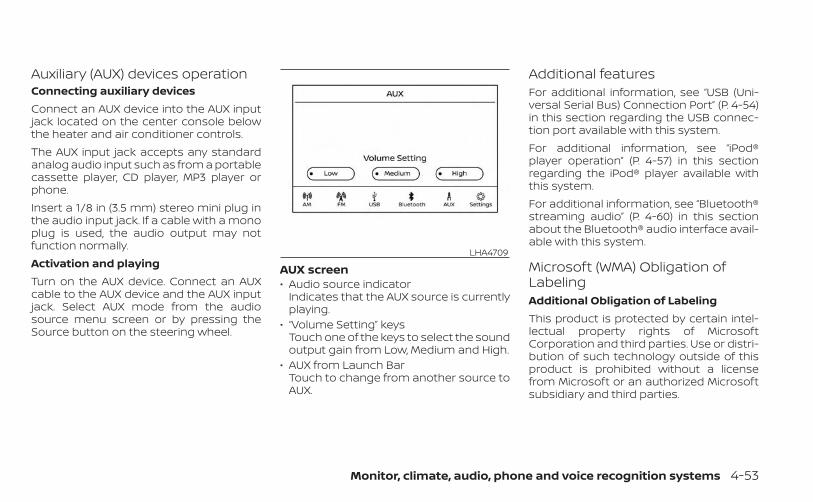
Auxiliary (AUX) devices operationConnecting auxiliary devicesConnect an AUX device into the AUX inputjack located on the center console belowthe heater and air conditioner controls.The AUX input jack accepts any standardanalog audio input such as from a portablecassette player, CD player, MP3 player orphone.Insert a 1/8 in (3.5 mm) stereo mini plug inthe audio input jack. If a cable with a monoplug is used, the audio output may notfunction normally.Activation and playingTurn on the AUX device. Connect an AUXcable to the AUX device and the AUX inputjack. Select AUX mode from the audiosource menu screen or by pressing theSource button on the steering wheel.
AUX screen• Audio source indicator
Indicates that the AUX source is currentlyplaying.
• “Volume Setting” keysTouch one of the keys to select the soundoutput gain from Low, Medium and High.
• AUX from Launch BarTouch to change from another source toAUX.
Additional featuresFor additional information, see “USB (Uni-versal Serial Bus) Connection Port” (P. 4-54)in this section regarding the USB connec-tion port available with this system.For additional information, see “iPod®player operation” (P. 4-57) in this sectionregarding the iPod® player available withthis system.For additional information, see “Bluetooth®streaming audio” (P. 4-60) in this sectionabout the Bluetooth® audio interface avail-able with this system.
Microsoft (WMA) Obligation ofLabelingAdditional Obligation of LabelingThis product is protected by certain intel-lectual property rights of MicrosoftCorporation and third parties. Use or distri-bution of such technology outside of thisproduct is prohibited without a licensefrom Microsoft or an authorized Microsoftsubsidiary and third parties.
LHA4709
Monitor, climate, audio, phone and voice recognition systems 4-53
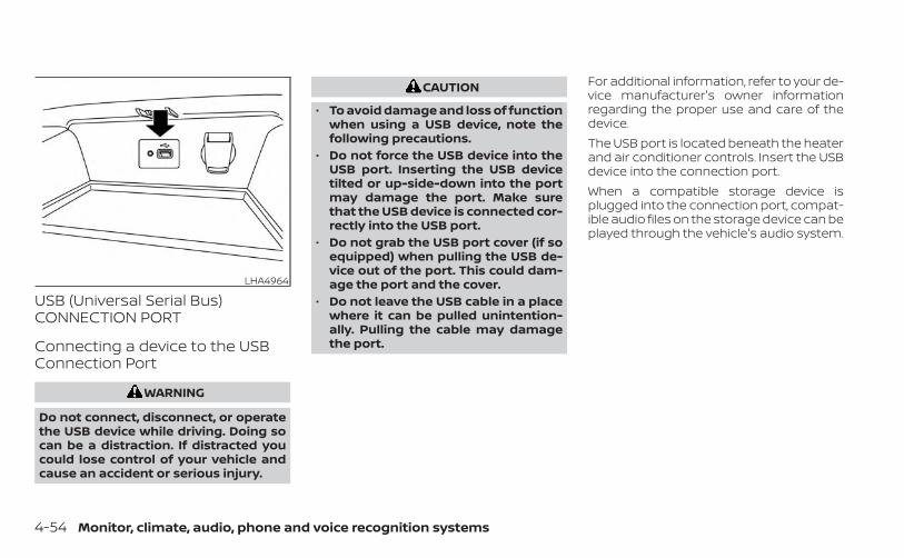
USB (Universal Serial Bus)CONNECTION PORT
Connecting a device to the USBConnection Port
WARNING
Do not connect, disconnect, or operatethe USB device while driving. Doing socan be a distraction. If distracted youcould lose control of your vehicle andcause an accident or serious injury.
CAUTION
• To avoid damage and loss of functionwhen using a USB device, note thefollowing precautions.
• Do not force the USB device into theUSB port. Inserting the USB devicetilted or up-side-down into the portmay damage the port. Make surethat the USB device is connected cor-rectly into the USB port.
• Do not grab the USB port cover (if soequipped) when pulling the USB de-vice out of the port. This could dam-age the port and the cover.
• Do not leave the USB cable in a placewhere it can be pulled unintention-ally. Pulling the cable may damagethe port.
For additional information, refer to your de-vice manufacturer's owner informationregarding the proper use and care of thedevice.The USB port is located beneath the heaterand air conditioner controls. Insert the USBdevice into the connection port.When a compatible storage device isplugged into the connection port, compat-ible audio files on the storage device can beplayed through the vehicle's audio system.
LHA4964
4-54 Monitor, climate, audio, phone and voice recognition systems
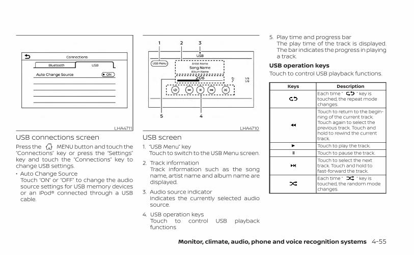
USB connections screenPress the MENU button and touch the“Connections” key or press the “Settings”key and touch the “Connections” key tochange USB settings.• Auto Change Source
Touch “ON” or “OFF” to change the audiosource settings for USB memory devicesor an iPod® connected through a USBcable.
USB screen1. “USB Menu” key
Touch to switch to the USB Menu screen.
2. Track informationTrack information such as the songname, artist name and album name aredisplayed.
3. Audio source indicatorIndicates the currently selected audiosource.
4. USB operation keysTouch to control USB playbackfunctions
5. Play time and progress barThe play time of the track is displayed.The bar indicates the progress in playinga track.
USB operation keysTouch to control USB playback functions.
Keys DescriptionEach time “ ” key istouched, the repeat modechanges.Touch to return to the begin-ning of the current track.Touch again to select theprevious track. Touch andhold to rewind the currenttrack.Touch to play the track.Touch to pause the track.Touch to select the nexttrack. Touch and hold tofast-forward the track.Each time “ ” key istouched, the random modechanges.
LHA4711 LHA4710
Monitor, climate, audio, phone and voice recognition systems 4-55
USB memory device playeroperationActivation and playingConnecting the USB memory device intothe port will start playing the USB memory.USB memory device can also be played bytouching the “USB” key on the Menu screenor by touching USB on the Launch Bar.To pause playing the USB memory devicetouch the “ ” key. To resume playing,touch the “ ” key.Skipping tracksTo skip the tracks, push the orbuttons on the control panel or touch the“ ” or “ ” keys on the screen repeat-edly until the preferred track is selected.
NOTE:
Depending on the condition, skipping tothe previous track may require pushingthe button or touching the key twice.Pushing the button or touching the keyonce may only restart the current trackfrom the beginning.
Fast-forwarding/rewindingTo rewind or fast-forward the track, pushand hold the or buttons on thecontrol panel or touch and hold the “ ”or “ ” keys on the screen.Changing play modeRepeat modeTouch the “ ” key on the USB screen tochange the repeat mode.The following modes are available:All: Repeat all1 Folder: Repeat folder/sub-folder1 Track: Repeat trackRandom modeTouch the “ ” key on the screen tochange the random mode as follows:No text displayed: Random offAll: Repeat all1 Folder: Repeat folder/sub-folder
USB menuTouch the “USB Menu” key on the USBscreen to display the USB Menu screen.
“Now Playing” key Touch to display the USBscreen.
“Folder List” key Touch to display the folder list.Touch an item on the list toselect the folder. The sub-folder or track list will be dis-played. Select a sub-folder ortrack from the list.
“Album Artwork” Touch to run on/off the albumartwork display on the USBscreen.
4-56 Monitor, climate, audio, phone and voice recognition systems
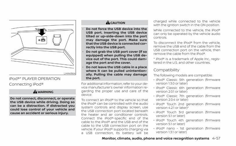
iPod®* PLAYER OPERATIONConnecting iPod®
WARNING
Do not connect, disconnect, or operatethe USB device while driving. Doing socan be a distraction. If distracted youcould lose control of your vehicle andcause an accident or serious injury.
CAUTION
• Do not force the USB device into theUSB port. Inserting the USB devicetilted or up-side-down into the portmay damage the port. Make surethat the USB device is connected cor-rectly into the USB port.
• Do not grab the USB port cover (if soequipped) when pulling the USB de-vice out of the port. This could dam-age the port and the cover.
• Do not leave the USB cable in a placewhere it can be pulled unintention-ally. Pulling the cable may damagethe port.
For additional information, refer to your de-vice manufacturer’s owner information re-garding the proper use and care of thedevice.To connect an iPod® to the vehicle so thatthe iPod® can be controlled with the audiosystem controls and display screen, usethe USB connection port located beneaththe heater and air conditioner controls.Connect the iPod®-specific end of thecable to the iPod® and the USB end of thecable to the USB connection port on thevehicle. If your iPod® supports charging viaa USB connection, its battery will be
charged while connected to the vehiclewith the ignition switch in the ON position.While connected to the vehicle, the iPod®can only be operated by the vehicle audiocontrols.To disconnect the iPod® from the vehicle,remove the USB end of the cable from theUSB connection port on the vehicle, thenremove the cable from the iPod®.* iPod® is a trademark of Apple Inc., regis-tered in the U.S. and other countries.
CompatibilityThe following models are compatible:• iPod® Classic 5th generation (firmware
version 1.3.0 or later)• iPod® Classic 6th generation (firmware
version 2.0.1 or later)• iPod® Classic 7th generation (firmware
version 2.0.4 or later)• iPod® Touch 2nd generation (firmware
version 4.2.1 or later)*• iPod® Touch 3rd generation (firmware
version 5.1 or later)• iPod® Touch 4th generation (firmware
version 5.1 or later)• iPod® nano - 1st generation (firmware
version 1.3.1 or later)
LHA4964
Monitor, climate, audio, phone and voice recognition systems 4-57
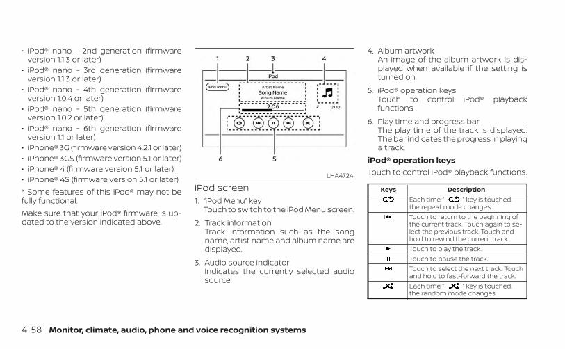
• iPod® nano - 2nd generation (firmwareversion 1.1.3 or later)
• iPod® nano - 3rd generation (firmwareversion 1.1.3 or later)
• iPod® nano - 4th generation (firmwareversion 1.0.4 or later)
• iPod® nano - 5th generation (firmwareversion 1.0.2 or later)
• iPod® nano - 6th generation (firmwareversion 1.1 or later)
• iPhone® 3G (firmware version 4.2.1 or later)• iPhone® 3GS (firmware version 5.1 or later)• iPhone® 4 (firmware version 5.1 or later)• iPhone® 4S (firmware version 5.1 or later)* Some features of this iPod® may not befully functional.Make sure that your iPod® firmware is up-dated to the version indicated above.
iPod screen1. “iPod Menu” key
Touch to switch to the iPod Menu screen.
2. Track informationTrack information such as the songname, artist name and album name aredisplayed.
3. Audio source indicatorIndicates the currently selected audiosource.
4. Album artworkAn image of the album artwork is dis-played when available if the setting isturned on.
5. iPod® operation keysTouch to control iPod® playbackfunctions
6. Play time and progress barThe play time of the track is displayed.The bar indicates the progress in playinga track.
iPod® operation keysTouch to control iPod® playback functions.
Keys DescriptionEach time “ ” key is touched,the repeat mode changes.Touch to return to the beginning ofthe current track. Touch again to se-lect the previous track. Touch andhold to rewind the current track.Touch to play the track.Touch to pause the track.Touch to select the next track. Touchand hold to fast-forward the track.Each time “ ” key is touched,the random mode changes.
LHA4724
4-58 Monitor, climate, audio, phone and voice recognition systems
iPod® memory device playeroperationActivation and playingConnecting the iPod® to the vehicle via USBcable will activate the iPod® mode.The iPod® can also be played by touchingthe “iPod” key on the Menu screen or bytouching iPod on the Launch Bar.Skipping tracksTo skip the tracks, push the orbuttons on the control panel or touch the“ ” or “ ” keys on the screen repeat-edly until the preferred track is selected.
NOTE:
Depending on the condition, skipping tothe previous track may require pushingthe button or touching the key twice.Pushing the button or touching the keyonce may only restart the current trackfrom the beginning.
Fast-forwarding/rewindingTo rewind or fast-forward the track, pushand hold the or buttons on thecontrol panel or touch and hold the “ ”or “ ” keys on the screen,Changing play modeRepeat modeTouch the “ ” key on the iPod® screento change the repeat mode. The followingmodes are available.No text displayed: Repeat offAll: Repeat allOne: Repeat trackRandom modeTouch the “ ” key on the screen tochange the random mode as follows.“ ” is not highlighted: Random off“ ” highlighted: Random on
iPod® MenuTouch the “iPod Menu” key on the iPod®screen to display the iPod® Menu screen.
“Now Playing” key Touch to display the USBscreen.
“Folder List” key(if so equipped)
Touch to display the folder list.Touch an item on the list toselect the folder. The sub-folder or track list will be dis-played. Select a sub-folder ortrack from the list.
“Album Artwork”key
Touch to run on/off the albumartwork display on the USBscreen.
“Playlists” key Touch to display the list ac-cording to the selected item.“Artists” key
“Albums” key“Songs” key“Podcasts” key“Genres” key“Composers” key“Audiobooks” key“iTunes Radio”key
Monitor, climate, audio, phone and voice recognition systems 4-59
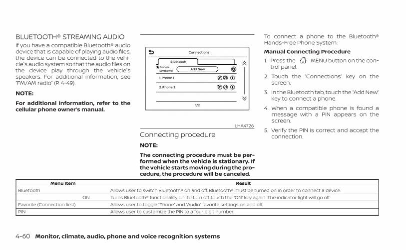
BLUETOOTH® STREAMING AUDIOIf you have a compatible Bluetooth® audiodevice that is capable of playing audio files,the device can be connected to the vehi-cle's audio system so that the audio files onthe device play through the vehicle'sspeakers. For additional information, see“FM/AM radio” (P. 4-49).
NOTE:
For additional information, refer to thecellular phone owner’s manual.
Connecting procedureNOTE:
The connecting procedure must be per-formed when the vehicle is stationary. Ifthe vehicle starts moving during the pro-cedure, the procedure will be canceled.
To connect a phone to the Bluetooth®Hands-Free Phone System:Manual Connecting Procedure1. Press the MENU button on the con-
trol panel.
2. Touch the “Connections” key on thescreen.
3. In the Bluetooth tab, touch the “Add New”key to connect a phone.
4. When a compatible phone is found amessage with a PIN appears on thescreen.
5. Verify the PIN is correct and accept theconnection.
Menu Item ResultBluetooth Allows user to switch Bluetooth® on and off. Bluetooth® must be turned on in order to connect a device.
ON Turns Bluetooth® functionality on. To turn off, touch the “ON” key again. The indicator light will go off.Favorite (Connection first) Allows user to toggle “Phone” and “Audio” favorite settings on and off.PIN Allows user to customize the PIN to a four digit number.
LHA4726
4-60 Monitor, climate, audio, phone and voice recognition systems
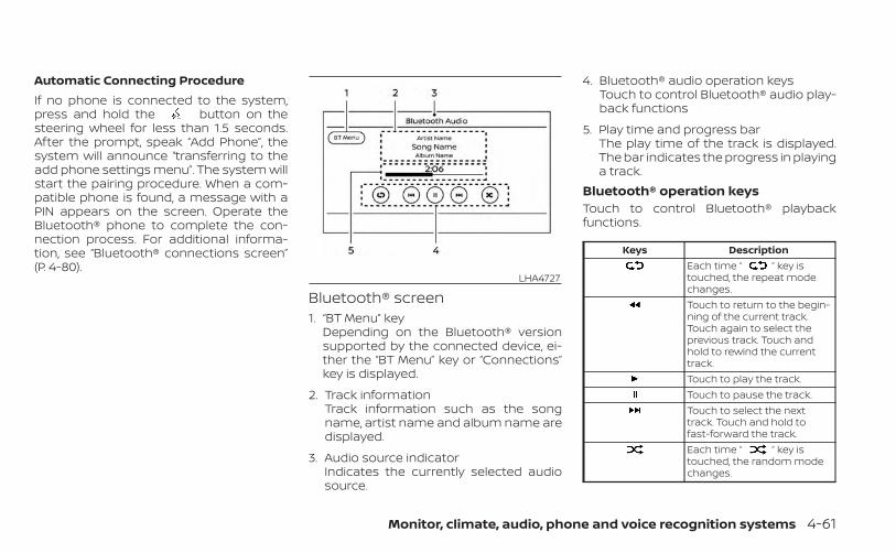
Automatic Connecting ProcedureIf no phone is connected to the system,press and hold the button on thesteering wheel for less than 1.5 seconds.After the prompt, speak “Add Phone”, thesystem will announce “transferring to theadd phone settings menu”. The system willstart the pairing procedure. When a com-patible phone is found, a message with aPIN appears on the screen. Operate theBluetooth® phone to complete the con-nection process. For additional informa-tion, see “Bluetooth® connections screen”(P. 4-80).
Bluetooth® screen1. “BT Menu” key
Depending on the Bluetooth® versionsupported by the connected device, ei-ther the “BT Menu” key or “Connections”key is displayed.
2. Track informationTrack information such as the songname, artist name and album name aredisplayed.
3. Audio source indicatorIndicates the currently selected audiosource.
4. Bluetooth® audio operation keysTouch to control Bluetooth® audio play-back functions
5. Play time and progress barThe play time of the track is displayed.The bar indicates the progress in playinga track.
Bluetooth® operation keysTouch to control Bluetooth® playbackfunctions.
Keys DescriptionEach time “ ” key istouched, the repeat modechanges.Touch to return to the begin-ning of the current track.Touch again to select theprevious track. Touch andhold to rewind the currenttrack.Touch to play the track.Touch to pause the track.Touch to select the nexttrack. Touch and hold tofast-forward the track.Each time “ ” key istouched, the random modechanges.
LHA4727
Monitor, climate, audio, phone and voice recognition systems 4-61
Bluetooth® audio operationThe ability to pause, change tracks, fastforward, rewind, randomize and repeatmusic may be different between devices.Some or all of these functions may not besupported on each device.
NOTE:
Depending on the Bluetooth® audio de-vice that is connected, it may not be pos-sible to perform audio operations or adelay may occur before music is playedback.Activation and playingA Bluetooth® audio device can be played bytouching the “Bluetooth” key on the Menuscreen or by touching Bluetooth on theLaunch Bar.To pause playing the Bluetooth® audio,touch the “ ” key. Touch the “ ” keyto resume playing.Changing foldersTo change folders, touch the “BT Menu” key.
Fast-forwarding/rewindingTo fast-forward or rewind the track, pushand hold the or buttons on thecontrol panel or touch the “ ” or “ ”keys on the screen.Changing play modeRepeat modeTouch the “ ” key on the screen tochange the repeat mode.Random modeTouch the “ ” key on the screen tochange the random mode.
NOTE:
Available repeat/random modes changedepending on the connected device.
BT MenuTouch the “BT Menu” key on the Bluetooth®audio screen to display the Bluetooth® au-dio menu screen.The following items are available.
“Now Playing” key Touch to display theBluetooth® audio screen.
“Current List” key (if soequipped)*
A list of track in the cur-rently selected folder isdisplayed.
“Connections” key Touch to display theconnections screen.
“Folder List” key* Touch to display thefolder list. Touch an itemon the list to select thefolder.
*: displayed only when available.
NOTE:
Depending on the connected device, the“BT Menu” key may not be displayed.
4-62 Monitor, climate, audio, phone and voice recognition systems
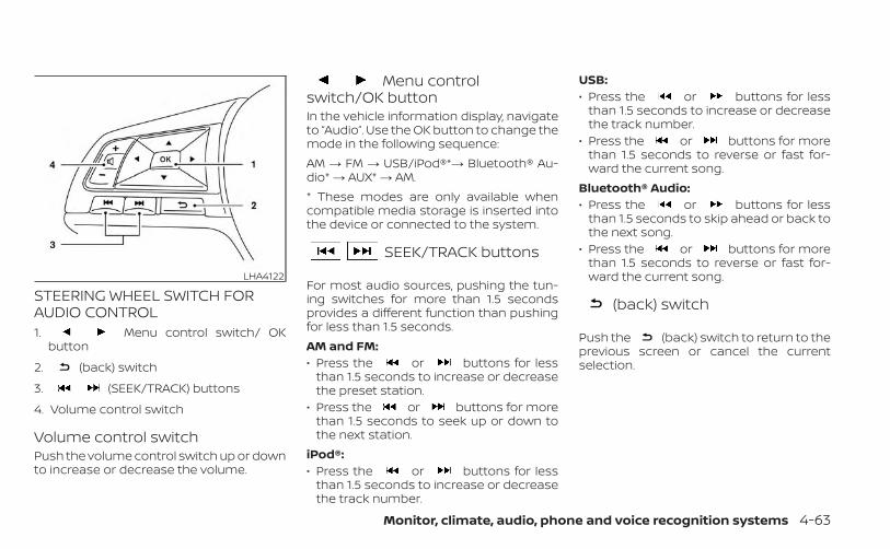
STEERING WHEEL SWITCH FORAUDIO CONTROL1. Menu control switch/ OK
button
2. (back) switch
3. (SEEK/TRACK) buttons
4. Volume control switch
Volume control switchPush the volume control switch up or downto increase or decrease the volume.
Menu controlswitch/OK buttonIn the vehicle information display, navigateto “Audio”. Use the OK button to change themode in the following sequence:AM → FM → USB/iPod®*→ Bluetooth® Au-dio* → AUX* → AM.* These modes are only available whencompatible media storage is inserted intothe device or connected to the system.
SEEK/TRACK buttons
For most audio sources, pushing the tun-ing switches for more than 1.5 secondsprovides a different function than pushingfor less than 1.5 seconds.AM and FM:• Press the or buttons for less
than 1.5 seconds to increase or decreasethe preset station.
• Press the or buttons for morethan 1.5 seconds to seek up or down tothe next station.
iPod®:• Press the or buttons for less
than 1.5 seconds to increase or decreasethe track number.
USB:• Press the or buttons for less
than 1.5 seconds to increase or decreasethe track number.
• Press the or buttons for morethan 1.5 seconds to reverse or fast for-ward the current song.
Bluetooth® Audio:• Press the or buttons for less
than 1.5 seconds to skip ahead or back tothe next song.
• Press the or buttons for morethan 1.5 seconds to reverse or fast for-ward the current song.
(back) switch
Push the (back) switch to return to theprevious screen or cancel the currentselection.
LHA4122
Monitor, climate, audio, phone and voice recognition systems 4-63
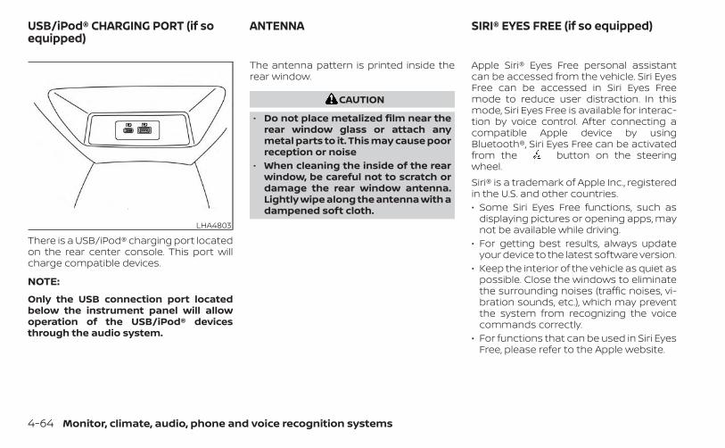
There is a USB/iPod® charging port locatedon the rear center console. This port willcharge compatible devices.
NOTE:
Only the USB connection port locatedbelow the instrument panel will allowoperation of the USB/iPod® devicesthrough the audio system.
The antenna pattern is printed inside therear window.
CAUTION
• Do not place metalized film near therear window glass or attach anymetal parts to it. This may cause poorreception or noise
• When cleaning the inside of the rearwindow, be careful not to scratch ordamage the rear window antenna.Lightly wipe along the antenna with adampened soft cloth.
Apple Siri® Eyes Free personal assistantcan be accessed from the vehicle. Siri EyesFree can be accessed in Siri Eyes Freemode to reduce user distraction. In thismode, Siri Eyes Free is available for interac-tion by voice control. After connecting acompatible Apple device by usingBluetooth®, Siri Eyes Free can be activatedfrom the button on the steeringwheel.Siri® is a trademark of Apple Inc., registeredin the U.S. and other countries.• Some Siri Eyes Free functions, such as
displaying pictures or opening apps, maynot be available while driving.
• For getting best results, always updateyour device to the latest software version.
• Keep the interior of the vehicle as quiet aspossible. Close the windows to eliminatethe surrounding noises (traffic noises, vi-bration sounds, etc.), which may preventthe system from recognizing the voicecommands correctly.
• For functions that can be used in Siri EyesFree, please refer to the Apple website.
LHA4803
USB/iPod® CHARGING PORT (if soequipped)
ANTENNA SIRI® EYES FREE (if so equipped)
4-64 Monitor, climate, audio, phone and voice recognition systems
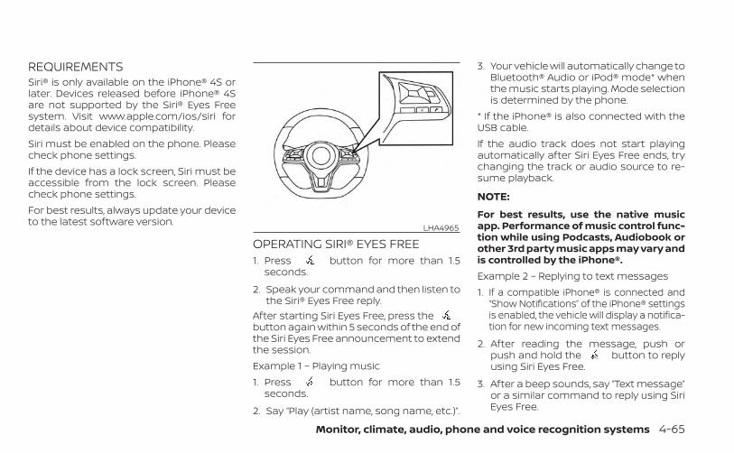
REQUIREMENTSSiri® is only available on the iPhone® 4S orlater. Devices released before iPhone® 4Sare not supported by the Siri® Eyes Freesystem. Visit www.apple.com/ios/siri fordetails about device compatibility.Siri must be enabled on the phone. Pleasecheck phone settings.If the device has a lock screen, Siri must beaccessible from the lock screen. Pleasecheck phone settings.For best results, always update your deviceto the latest software version.
OPERATING SIRI® EYES FREE1. Press button for more than 1.5
seconds.
2. Speak your command and then listen tothe Siri® Eyes Free reply.
After starting Siri Eyes Free, press thebutton again within 5 seconds of the end ofthe Siri Eyes Free announcement to extendthe session.Example 1 – Playing music1. Press button for more than 1.5
seconds.
2. Say “Play (artist name, song name, etc.)”.
3. Your vehicle will automatically change toBluetooth® Audio or iPod® mode* whenthe music starts playing. Mode selectionis determined by the phone.
* If the iPhone® is also connected with theUSB cable.If the audio track does not start playingautomatically after Siri Eyes Free ends, trychanging the track or audio source to re-sume playback.
NOTE:
For best results, use the native musicapp. Performance of music control func-tion while using Podcasts, Audiobook orother 3rd party music apps may vary andis controlled by the iPhone®.Example 2 – Replying to text messages1. If a compatible iPhone® is connected and
“Show Notifications” of the iPhone® settingsis enabled, the vehicle will display a notifica-tion for new incoming text messages.
2. After reading the message, push orpush and hold the button to replyusing Siri Eyes Free.
3. After a beep sounds, say “Text message”or a similar command to reply using SiriEyes Free.
LHA4965
Monitor, climate, audio, phone and voice recognition systems 4-65
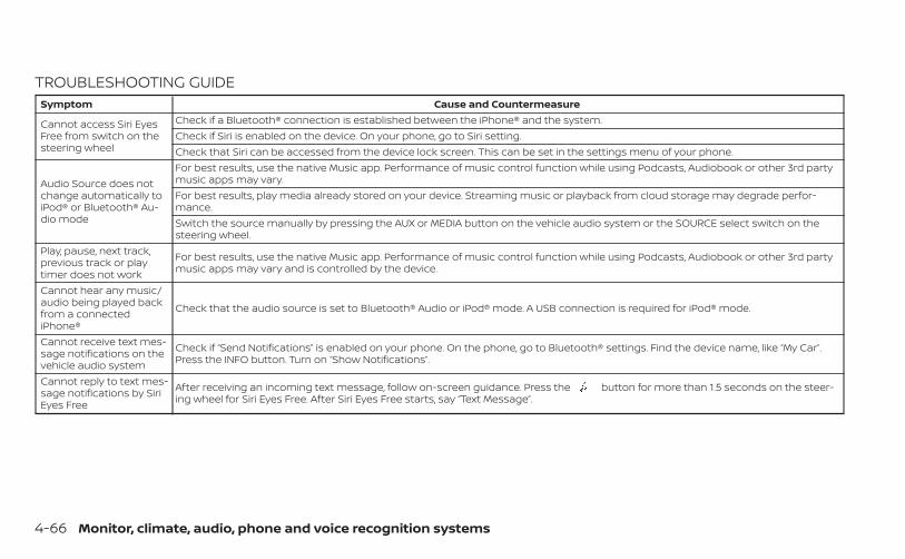
TROUBLESHOOTING GUIDESymptom Cause and Countermeasure
Cannot access Siri EyesFree from switch on thesteering wheel
Check if a Bluetooth® connection is established between the iPhone® and the system.Check if Siri is enabled on the device. On your phone, go to Siri setting.Check that Siri can be accessed from the device lock screen. This can be set in the settings menu of your phone.
Audio Source does notchange automatically toiPod® or Bluetooth® Au-dio mode
For best results, use the native Music app. Performance of music control function while using Podcasts, Audiobook or other 3rd partymusic apps may vary.For best results, play media already stored on your device. Streaming music or playback from cloud storage may degrade perfor-mance.Switch the source manually by pressing the AUX or MEDIA button on the vehicle audio system or the SOURCE select switch on thesteering wheel.
Play, pause, next track,previous track or playtimer does not work
For best results, use the native Music app. Performance of music control function while using Podcasts, Audiobook or other 3rd partymusic apps may vary and is controlled by the device.
Cannot hear any music/audio being played backfrom a connectediPhone®
Check that the audio source is set to Bluetooth® Audio or iPod® mode. A USB connection is required for iPod® mode.
Cannot receive text mes-sage notifications on thevehicle audio system
Check if “Send Notifications” is enabled on your phone. On the phone, go to Bluetooth® settings. Find the device name, like “My Car”.Press the INFO button. Turn on “Show Notifications”.
Cannot reply to text mes-sage notifications by SiriEyes Free
After receiving an incoming text message, follow on-screen guidance. Press the button for more than 1.5 seconds on the steer-ing wheel for Siri Eyes Free. After Siri Eyes Free starts, say “Text Message”.
4-66 Monitor, climate, audio, phone and voice recognition systems
When installing a CB, ham radio or carphone in your vehicle, be sure to observethe following precautions; otherwise, thenew equipment may adversely affect theengine control system and other electronicparts.
WARNING
• A cellular phone should not be usedfor any purpose while driving so fullattention may be given to vehicle op-eration. Some jurisdictions prohibitthe use of cellular phones whiledriving.
• If you must make a call while yourvehicle is in motion, the hands freecellular phone operational mode ishighly recommended. Exercise ex-treme caution at all times so full at-tention may be given to vehicleoperation.
• If you are unable to devote full atten-tion to vehicle operation while talk-ing on the phone, pull off the road toa safe location and stop your vehicle.
CAUTION
• Keep the antenna as far away as pos-sible from the electronic controlmodules.
• Keep the antenna wire more than 8 in(20 cm) away from the electroniccontrol system harnesses. Do notroute the antenna wire next to anyharness.
• Adjust the antenna standing-waveratio as recommended by themanufacturer.
• Connect the ground wire from the CBradio chassis to the body.
• For additional information, it is rec-ommended that you visit a NISSANdealer for servicing.
WARNING
• Use a phone after stopping your ve-hicle in a safe location. If you have touse a phone while driving, exerciseextreme caution at all times so fullattention may be given to vehicleoperation.
• If you are unable to devote full atten-tion to vehicle operation while talk-ing on the phone, pull off the road toa safe location and stop your vehicle.
CAUTION
To avoid discharging the vehicle bat-tery, use a phone after starting theengine.
CAR PHONE OR CB RADIO BLUETOOTH® HANDS-FREE PHONESYSTEM
Monitor, climate, audio, phone and voice recognition systems 4-67
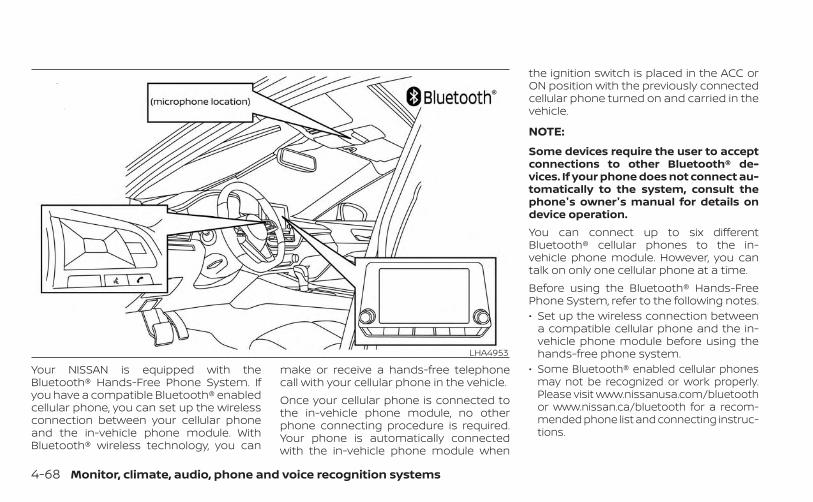
Your NISSAN is equipped with theBluetooth® Hands-Free Phone System. Ifyou have a compatible Bluetooth® enabledcellular phone, you can set up the wirelessconnection between your cellular phoneand the in-vehicle phone module. WithBluetooth® wireless technology, you can
make or receive a hands-free telephonecall with your cellular phone in the vehicle.Once your cellular phone is connected tothe in-vehicle phone module, no otherphone connecting procedure is required.Your phone is automatically connectedwith the in-vehicle phone module when
the ignition switch is placed in the ACC orON position with the previously connectedcellular phone turned on and carried in thevehicle.
NOTE:
Some devices require the user to acceptconnections to other Bluetooth® de-vices. If your phone does not connect au-tomatically to the system, consult thephone's owner's manual for details ondevice operation.You can connect up to six differentBluetooth® cellular phones to the in-vehicle phone module. However, you cantalk on only one cellular phone at a time.Before using the Bluetooth® Hands-FreePhone System, refer to the following notes.• Set up the wireless connection between
a compatible cellular phone and the in-vehicle phone module before using thehands-free phone system.
• Some Bluetooth® enabled cellular phonesmay not be recognized or work properly.Please visit www.nissanusa.com/bluetoothor www.nissan.ca/bluetooth for a recom-mended phone list and connecting instruc-tions.
LHA4953
4-68 Monitor, climate, audio, phone and voice recognition systems
• You will not be able to use a hands-freephone under the following conditions:– Your vehicle is outside of the cellular
service area.– Your vehicle is in an area where it is
difficult to receive a cellular signal; suchas in a tunnel, in an underground park-ing garage, near a tall building or in amountainous area.
– Your cellular phone is locked to preventit from being dialed.
• When the radio wave condition is notideal or ambient sound is too loud, it maybe difficult to hear the other person'svoice during a call.
• Do not place the cellular phone in an areasurrounded by metal or far away fromthe in-vehicle phone module to preventtone quality degradation and wirelessconnection disruption.
• While a cellular phone is connectedthrough the Bluetooth® wireless connec-tion, the battery power of the cellularphone may discharge quicker than usual.The Bluetooth® Hands-Free Phone Sys-tem cannot charge cellular phones.
• Some cellular phones or other devicesmay cause interference or a buzzingnoise to come from the audio systemspeakers. Storing the device in a differentlocation may reduce or eliminate thenoise.
• For additional information, refer to thecellular phone owner's manual regardingthe telephone charges, cellular phoneantenna and body, etc.
REGULATORY INFORMATIONFCC Regulatory information– CAUTION: To maintain compliance with
FCC’s RF exposure guidelines, use onlythe supplied antenna. Unauthorized an-tenna, modification, or attachmentscould damage the transmitter and mayviolate FCC regulations.
– Operation is subject to the following twoconditions:1.1) This device may not cause interfer-
ence and2.2) this device must accept any interfer-
ence, including interference that maycause undesired operation of thedevice.
IC Regulatory information– Operation is subject to the following two
conditions: (1) this device may not causeinterference, and (2) this device must ac-cept any interference, including interfer-ence that may cause undesired opera-tion of the device.
– This Class B digital apparatus meets all re-quirements of the Canadian Interference-Causing Equipment Regulations.
BLUETOOTH® is atrademark owned byBluetooth SIG, Inc.and licensed toPanasonic.
USING THE SYSTEMThe system allows hands-free operation ofthe Bluetooth® Hands-Free Phone System.If the vehicle is in motion, some commandsmay not be available so full attention maybe given to vehicle operation.
Monitor, climate, audio, phone and voice recognition systems 4-69
InitializationWhen the ignition switch is placed in the ONposition, NISSAN Voice Recognition is initial-ized, which takes a few seconds. If thebutton is pressed before the initializationcompletes, the system will announce“There is no phone connected” and will notreact to voice commands.
Operating tipsTo get the best performance out of theNISSAN Voice Recognition System, observethe following:• Keep the interior of the vehicle as quiet as
possible. Keep all vents pointed awayfrom the microphone and close the win-dows to eliminate surrounding noises(traffic noises, vibration sounds, etc.),which may prevent the system from rec-ognizing voice commands correctly.
• Wait until the tone sounds before speak-ing a command. Otherwise, the com-mand will not be received properly.
• Start speaking a command within 5 sec-onds after the tone sounds.
• Speak in a natural voice without pausingbetween words.
• For calling contacts by name, please sayboth the first and last name of the con-tact for better recognition.
Giving voice commands
To operate NISSAN Voice Recognition,press the button located on the steer-ing wheel for less than 1.5 seconds. Afterthe tone sounds, speak a command.The command given is picked up by themicrophone, and voice feedback is givenwhen the command is accepted.• If a command is not recognized, the sys-
tem announces, “Please say or select acommand from the displayed list.” Makesure the command is said exactly asprompted by the system and repeat thecommand in a clear voice.
• If you want to go back to the previouscommand, you can say “Go back” or “Cor-rection” any time the system is waiting fora response.
• You can cancel a command when thesystem is waiting for a response by say-ing, “Cancel” or “Quit.” The system an-nounces “Exit” and ends the Voice Recog-nition session. You can also press andhold the button on the steeringwheel for 1.5 seconds at any time to endthe Voice Recognition session. Wheneverthe Voice Recognition session is can-celed, a double beep is played to indicateyou have exited the system.
• If you want to adjust the volume of thevoice feedback, push the (+ or -) volumecontrol switches on the steering wheelwhile being provided with feedback. Youcan also use the radio volume controlknob.
Voice Prompt InterruptIn most cases you can interrupt the voicefeedback to speak the next command bypressing the button on the steeringwheel. After interrupting the system, waitfor a beep before speaking your command.
4-70 Monitor, climate, audio, phone and voice recognition systems
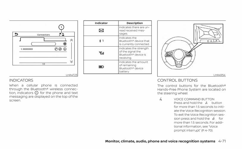
INDICATORSWhen a cellular phone is connectedthrough the Bluetooth® wireless connec-tion, indicators O1 for the phone and textmessaging are displayed on the top of thescreen.
Indicator DescriptionIndicates there are un-read received mes-sages.Indicates theBluetooth® device thatis currently connected.Indicates the strengthof the signal theBluetooth® device isreceiving.Indicates the amountof remainingBluetooth® devicebattery.
CONTROL BUTTONSThe control buttons for the Bluetooth®Hands-Free Phone System are located onthe steering wheel.
VOICE COMMAND BUTTONPress and hold the buttonfor more than 1.5 seconds to initi-ate the Voice Recognition session.To exit the Voice Recognition ses-sion press and hold the formore than 1.5 seconds. For addi-tional information, see “Voiceprompt interrupt” (P. 4-70).
LHA4723 LHA4954
Monitor, climate, audio, phone and voice recognition systems 4-71
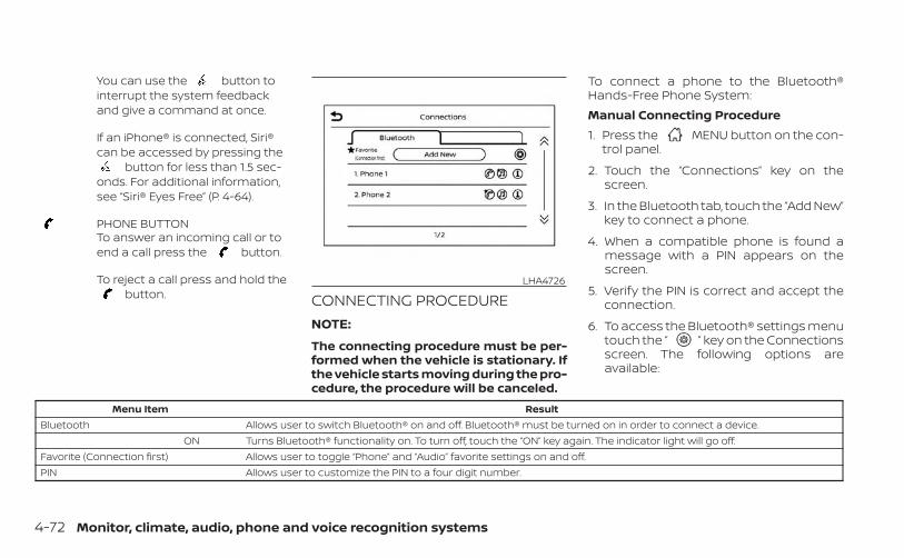
You can use the button tointerrupt the system feedbackand give a command at once.
If an iPhone® is connected, Siri®can be accessed by pressing the
button for less than 1.5 sec-onds. For additional information,see “Siri® Eyes Free” (P. 4-64).
PHONE BUTTONTo answer an incoming call or toend a call press the button.
To reject a call press and hold thebutton. CONNECTING PROCEDURE
NOTE:
The connecting procedure must be per-formed when the vehicle is stationary. Ifthe vehicle starts moving during the pro-cedure, the procedure will be canceled.
To connect a phone to the Bluetooth®Hands-Free Phone System:Manual Connecting Procedure1. Press the MENU button on the con-
trol panel.
2. Touch the “Connections” key on thescreen.
3. In the Bluetooth tab, touch the “Add New”key to connect a phone.
4. When a compatible phone is found amessage with a PIN appears on thescreen.
5. Verify the PIN is correct and accept theconnection.
6. To access the Bluetooth® settings menutouch the “ ” key on the Connectionsscreen. The following options areavailable:
Menu Item ResultBluetooth Allows user to switch Bluetooth® on and off. Bluetooth® must be turned on in order to connect a device.
ON Turns Bluetooth® functionality on. To turn off, touch the “ON” key again. The indicator light will go off.Favorite (Connection first) Allows user to toggle “Phone” and “Audio” favorite settings on and off.PIN Allows user to customize the PIN to a four digit number.
LHA4726
4-72 Monitor, climate, audio, phone and voice recognition systems
NOTE:
Some cellular phones may require you toaccept certain permissions in order toenable features on your Bluetooth® sys-tem. During the Bluetooth® pairing pro-cess, please check your cellular phone’sdisplay for a pop-up with the request togrant phonebook access.Granting phonebook access permissionwill allow your contacts to be down-loaded to the vehicle’s Bluetooth® sys-tem. A pop-up may display on your cellu-lar phone stating that the Bluetooth®system would like to access your con-tacts and call history. Please select “Al-low” or Yes” to grant this permission.Automatic Connecting ProcedureIf no phone is connected to the system,press and hold the button on thesteering wheel for less than 1.5 seconds.After the prompt, speak “Add Phone”, thesystem will announce “transferring to theadd phone settings menu”. The system willstart the pairing procedure. When a com-patible phone is found, a message with aPIN appears on the screen. Operate theBluetooth® phone to complete the con-nection process. For additional informa-tion, see “Bluetooth® connections screen”(P. 4-80).
VOICE COMMANDSVoice commands can be used to operatethe Bluetooth® Hands-Free Phone System.Press and hold the button for lessthan 1.5 seconds to bring up the phonecommand menu. The commands avail-able are:• Call <name>• Dial <number>• Recent Calls• Read/Send Text (if so equipped)• Siri® (if so equipped)• Voice Assistant (if so equipped)• Phonebook• Quick Dial• Redial• Select Phone• Add Phone• Call <name> Mobile• Call <name> Home• Call <name> Office• Call <name> Main• Call <name> Other• Settings
“Call <name>”Speak this command to make a call to acontact that is stored in the phonebook.Say “Call” followed by a phonebook name toinitiate a call. If the system does not recog-nize the name it will display a list of similarnames. After the prompt, speak or touchan item number from the displayed list toplace the call.
“Dial <number>”Speak this command to make a call with aspoken phone number. After the prompt,say “Dial” followed by a 7 to 10 digit phonenumber. The system will repeat the num-ber back. Say “Dial” to initiate the call or“Correction” to re-enter the phone number.
“Recent Calls”The following commands are available un-der “Recent Calls”:
Monitor, climate, audio, phone and voice recognition systems 4-73
• Incoming CallsSpeak this command to list the last 20incoming calls to the vehicle. If the call isfrom an entry in the phonebook, thename will be displayed. Otherwise, thephone number of the incoming call willbe displayed.When prompted, speak or touch the itemnumber on the screen to place the call.Touch the “Next” key to move through thelist of incoming calls.
• Outgoing CallsSpeak this command to list the last 20outgoing calls from the vehicle. If the callwas to an entry in the phonebook, thename will be displayed. Otherwise, thephone number of the outgoing call will bedisplayed.When prompted, speak or touch the itemnumber on the screen to place the call.Touch the “Next” key to move through thelist of outgoing calls.
• Missed CallsSpeak this command to list the last 20missed calls to the vehicle. If the call isfrom an entry in the phonebook, thename will be displayed. Otherwise, thephone number of the missed call will bedisplayed.When prompted, speak or touch the itemnumber on the screen to place the call.Touch the “Next” key to move through thelist of missed calls.
“Read Text/Send Text” (if soequipped)Speak this command to access text mes-saging functions. For additional informa-tion, see “Text messaging” (P. 4-77).
“Phonebook through voicecommand”Speak “Phonebook” to view a list of quicksteps to access entries stored in thephonebook. Commands are organized bythe phone number type selected in the cel-lular device. For additional information, re-fer to the cellular phone’s owner’s manual.
The following commands are available:• <Say a Contact Name>• <Say a Contact Name> Main• <Say a Contact Name> Home• <Say a Contact Name> Mobile• <Say a Contact Name> Office• <Say a Contact Name> OtherFor additional information on manually se-lecting phonebook entries, see “Making acall” (P. 4-76).
“Quick dial”Speak this command to access the Quickdial menu. After the prompt, speak or se-lect an item number on the displayed list toplace the call. For additional information,see “Making a call” (P. 4-76).
“Redial”Speak this command to call the last num-ber dialed. After the prompt, say “Redial” todial the number of the last outgoing call.The system will display “Redialing <name/number>”. The name of the phonebook en-try will be displayed if it is available, other-wise the number being redialed will bedisplayed.
4-74 Monitor, climate, audio, phone and voice recognition systems
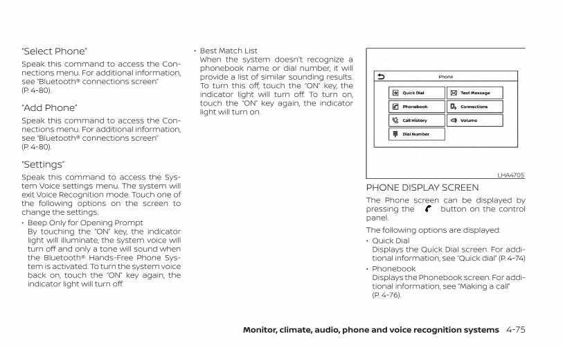
“Select Phone”Speak this command to access the Con-nections menu. For additional information,see “Bluetooth® connections screen”(P. 4-80).
“Add Phone”Speak this command to access the Con-nections menu. For additional information,see “Bluetooth® connections screen”(P. 4-80).
“Settings”Speak this command to access the Sys-tem Voice settings menu. The system willexit Voice Recognition mode. Touch one ofthe following options on the screen tochange the settings.• Beep Only for Opening Prompt
By touching the “ON” key, the indicatorlight will illuminate, the system voice willturn off and only a tone will sound whenthe Bluetooth® Hands-Free Phone Sys-tem is activated. To turn the system voiceback on, touch the “ON” key again, theindicator light will turn off.
• Best Match ListWhen the system doesn't recognize aphonebook name or dial number, it willprovide a list of similar sounding results.To turn this off, touch the “ON” key, theindicator light will turn off. To turn on,touch the “ON” key again, the indicatorlight will turn on.
PHONE DISPLAY SCREENThe Phone screen can be displayed bypressing the button on the controlpanel.The following options are displayed:• Quick Dial
Displays the Quick Dial screen. For addi-tional information, see “Quick dial” (P. 4-74)
• PhonebookDisplays the Phonebook screen. For addi-tional information, see “Making a call”(P. 4-76).
LHA4705
Monitor, climate, audio, phone and voice recognition systems 4-75
• Call HistoryDisplays the Call History screen. For addi-tional information, see “Making a call”(P. 4-76).
• Dial NumberDisplays the Dial Number screen. For ad-ditional information, see “Making a call”(P. 4-76).
• Text MessageDisplays the received message screen.For additional information, see “Text mes-saging” (P. 4-77).
• ConnectionsDisplays the Connections screen. For ad-ditional information, see “Bluetooth® con-nections screen” (P. 4-80).
• VolumeDisplays the volume adjustment screen.For additional information, see “Volume &beeps” (P. 4-83).
MAKING A CALLTo make a call press the button on thecontrol panel. Touch an option from menuscreen:
• PhonebookSelect a person and the phone numberyou wish to call from the phonebook.Depending on the device, the phonebookwill be downloaded from the cellularphone automatically when it is con-nected. If the automatic download doesnot take place, the phone number mustbe transferred to the hands-free phonesystem from the cellular phone prior tousing this method. For additional infor-mation, see “Phone and text messagesettings” (P. 4-81).
• Call HistorySelect a phonebook name or phonenumber from the recent incoming, out-going or missed calls tabs. Touch aphonebook name or phone numberlisted to initiate the call.
• Dial NumberEnter the phone number manually usingthe keypad displayed on the screen.Touch the “OK” key on the screen to initi-ate the call.
For additional options to make a call, see“Voice commands” (P. 4-73).
RECEIVING A CALLWhen a call is received by the phone con-nected to the vehicle’s Bluetooth® Hands-Free Phone System, the call information isdisplayed on the control panel display.Press the button on the steeringwheel or touch the “ Answer” key onthe screen to accept the call. To reject thecall touch the “ Decline” key on thescreen.If the user is not able to answer the callright away, touch the “Hold Call” key dis-played on the screen. A message will beplayed for the caller: “I’m not able to take acall right now.” The user may then acceptthe call when available or reject the call.To reject a call, press and hold thebutton on the steering wheel.
DURING A CALLWhile a call is active the following optionswill appear on the control panel display:• Mute
Touch this key to mute or unmute thesystem.
• Dial NumberTouch this key to dial digits during thephone call.
4-76 Monitor, climate, audio, phone and voice recognition systems
• Use HandsetTouch this key to transfer the call to thehandset. To transfer the call back fromthe handset to the Bluetooth® Hands-Free Phone System, press the but-ton on the control panel then select the“Transfer Hands-free” key on the screen.
• Switch CallThis option will only be available when asecond call is active.
If supported by the phone, theBluetooth® Hands-Free Phone Systemallows for call waiting functionality. If acall is received while another call is al-ready active, a message will be displayedon the screen. Press the button onthe steering wheel or touch the “Answer” key on screen to accept the in-coming call. Touch the “ Decline” keyon the screen to reject the second call.
While a call is active, press the buttonon the steering wheel to access additionaloptions. Speak one of the following com-mands:• “Send Digits”
Speak this command followed by the dig-its to enter digits during the phone call.
• “Switch call”Speak this command to hold the secondcall and switch back to the original call.
ENDING A CALLTo end an active call, press the buttonon the steering wheel or touch the “Hang up” key on the screen.
TEXT MESSAGING (if so equipped)
WARNING
• Laws in some jurisdictions may re-strict the use of “Text-to-Speech”.Check local regulations before usingthis feature.
• Laws in some jurisdictions may re-strict the use of some of the applica-tions and features, such as socialnetworking and texting. Check localregulations for any requirements.
• Use the text messaging feature afterstopping your vehicle in a safe loca-tion. If you have to use the featurewhile driving, exercise extreme cau-tion at all times so full attention maybe given to vehicle operation.
• If you are unable to devote full atten-tion to vehicle operation while usingthe text messaging feature, pull offthe road to a safe location and stopyour vehicle.
NOTE:
This feature is automatically disabled ifthe connected device does not supportthe Message Access Profile (MAP). Foradditional information, refer to thephone’s owner’s manual for details andinstructions.
NOTE:
Many phones may require special per-mission to enable text messaging. Checkthe phone’s screen during Bluetooth®pairing. For some phones, you may needto enable ‘Notifications’ in the phone’sBluetooth® menu for text messages toappear on the headunit. For additionalinformation, refer to your phone’s own-er’s manual. Text message integrationrequires that the phone support MAP(Message Access Profile) for both receiv-ing and sending text messages. Somephones may not support all text mes-saging features. Please refer towww.nissanusa.com/bluetooth orwww.nissan.ca/bluetooth for compat-ibility information, as well as your de-vice’s owner’s manual.The system allows for the sending and re-ceiving of text messages through the ve-hicle interface.
Monitor, climate, audio, phone and voice recognition systems 4-77
The availability of the text message func-tion may vary depending on the cellularphone.When the cellular phone connected to thevehicle receives a text message, a notifica-tion will appear on the control panel dis-play. To check the message, touch the“Read” key. Touch the “Ignore” key to savethe message to be checked later.Access text messaging through the ve-hicles Bluetooth® Hands-Free Phone orthrough the vehicles control panel.
Text messaging using Bluetooth®Hands-Free Phone System (if soequipped)Sending a text message (if so equipped)1. Press and hold the button on the
steering wheel for less than 1.5 seconds.
2. Say “Send Text” after the tone.
3. The system will provide a list of availablecommands in order to determine therecipient of the text message. Choosefrom the following:
• Phonebook• Quick Dial• Incoming Calls
• Outgoing Calls• Missed Calls• Dial
4. Once a recipient is chosen, the systemprompts for which message to send.Nine predefined messages are avail-able. To choose one of the predefinedmessages, speak one of the followingafter the tone:
• “Driving, can't text”• “Call me”• “On my way”• “Running late”• “Okay”• “Yes”• “No”• “Where are you?”• “When?”Reading a received text message1. Press and hold the button on the
steering wheel for less than 1.5 seconds.
2. Say “Read Text” after the tone.The display will show a list of 20 messageswith the sender and delivery time. Touchthe “Next” key on the screen to view all mes-sages. To view a text message press the
button on the steering wheel andspeak the number item list on the screen.The following options will be available:• Play
Speak this command to have the systemsay the message.
• ReplySpeak this command to send a text mes-sage response to the sender of the textmessage.
• CallSpeak this command to call the sender.
• PreviousSpeak this command to move to the pre-vious text message (if available).
• NextSpeak this command to move to the nexttext message (if available).
Siri® Eyes Free (if so equipped)If a connected phone is equipped with Siri®,it can also be used to create custom mes-sages that are sent through the phone. Foradditional information, see “Siri® Eyes Free”(P. 4-64).
NOTE:
Text messages are only displayed if thevehicle speed is less than 5 mph (8 km/h).
4-78 Monitor, climate, audio, phone and voice recognition systems
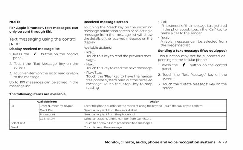
NOTE:
For Apple iPhones®, text messages canonly be sent through Siri.
Text messaging using the controlpanelDisplay received message list1. Press the button on the control
panel.
2. Touch the “Text Message” key on thescreen
3. Touch an item on the list to read or replyto the message.
Up to 100 messages can be stored in themessage list.
Received message screenTouching the “Read” key on the incomingmessage notification screen or selecting amessage from the message list will showthe details of the received message on thedisplay.Available actions:• Prev.
Touch this key to read the previous mes-sage.
• NextTouch this key to read the next message.
• Play/StopTouch the “Play” key to have the hands-free phone system read out the receivedmessage. Touch the “Stop” key to stopreading.
• CallIf the sender of the message is registeredin the phonebook, touch the “Call” key tomake a call to the sender.
• ReplyA reply message can be selected fromthe predefined list.
Sending a text message (if so equipped)This function may not be supported de-pending on the cellular phone.1. Press the button on the control
panel.
2. Touch the “Text Message” key on thescreen.
3. Touch the “Create Message” key on thescreen.
The following items are available:
Available item ActionTo Enter Number by Keypad Enter the phone number of the recipient using the keypad. Touch the “OK” key to confirm.
Quick Dial Select a recipient from the quick dial list.Phonebook Select a recipient from the phonebook.Call History Select a recipient/phone number from call history.
Select Text Touch to display a list of predefined text messages.Send Touch to send the message.
Monitor, climate, audio, phone and voice recognition systems 4-79
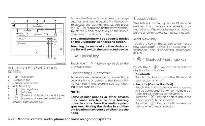
BLUETOOTH® CONNECTIONSSCREEN1. “ ” (back) key2. Bluetooth tab3. Connections screen4. “Add New” key5. “ ” (settings) key6. “ ” (info) key7. “ ” (Bluetooth® Audio connection) key8. “ ” (Bluetooth® Hands-Free Phone
System connection) key
Access the Connections screen to changesettings and view Bluetooth® information.To access the Connections screen pressthe MENU button on the control panel.Touch the “Connections” key on the screenthen select the Bluetooth tab.The paired phone will be added to the liston the Bluetooth® connections screen.Touching the name of another device onthe list will switch the connected device.
“ ” (back) key
Touch the “ ” key to go back to theprevious screen.
Connecting Bluetooth®For additional information on connecting acellular phone or device to the Bluetooth®Hands-Free Phone System, see “Connect-ing procedure” (P. 4-72).
NOTE:
Some cellular phones or other devicesmay cause interference or a buzzingnoise to come from the audio systemspeakers. Storing the device in a differ-ent location may reduce or eliminate thenoise.
Bluetooth tabThis tab will display up to six Bluetooth®devices. If six devices are already con-nected, one of the devices must be deletedbefore another device can be connected.
“Add New” keyTouch the key on the screen to connect anew Bluetooth® device. For additional in-formation, see “Connecting procedure”(P. 4-72).
“ ” (Bluetooth® settings) key
Touch the “ ” key on the screen todisplay a list of options.• Bluetooth
Touch this key to turn the Bluetooth®connection on or off
• Favorite (Connection first)Touch this key to change which devicewill be connected first when multiple de-vices are connected to the vehicle.Turn the “ ” key on or off to make thedevice a favorite connection.Turn the “ ” key on or off to make thedevice a favorite connection.
LHA4716
4-80 Monitor, climate, audio, phone and voice recognition systems
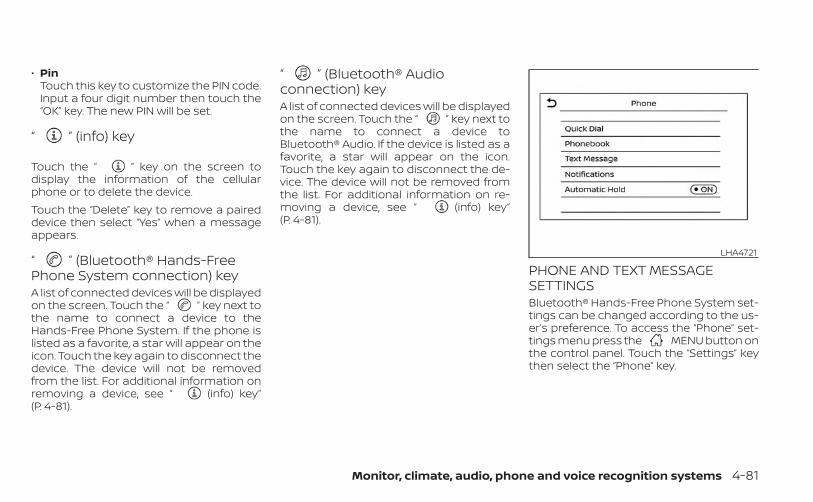
• PinTouch this key to customize the PIN code.Input a four digit number then touch the“OK” key. The new PIN will be set.
“ ” (info) key
Touch the “ ” key on the screen todisplay the information of the cellularphone or to delete the device.Touch the “Delete” key to remove a paireddevice then select “Yes” when a messageappears.
“ ” (Bluetooth® Hands-FreePhone System connection) keyA list of connected devices will be displayedon the screen. Touch the “ ” key next tothe name to connect a device to theHands-Free Phone System. If the phone islisted as a favorite, a star will appear on theicon. Touch the key again to disconnect thedevice. The device will not be removedfrom the list. For additional information onremoving a device, see “ (info) key”(P. 4-81).
“ ” (Bluetooth® Audioconnection) keyA list of connected devices will be displayedon the screen. Touch the “ ” key next tothe name to connect a device toBluetooth® Audio. If the device is listed as afavorite, a star will appear on the icon.Touch the key again to disconnect the de-vice. The device will not be removed fromthe list. For additional information on re-moving a device, see “ (info) key”(P. 4-81).
PHONE AND TEXT MESSAGESETTINGSBluetooth® Hands-Free Phone System set-tings can be changed according to the us-er’s preference. To access the “Phone” set-tings menu press the MENU button onthe control panel. Touch the “Settings” keythen select the “Phone” key.
LHA4721
Monitor, climate, audio, phone and voice recognition systems 4-81
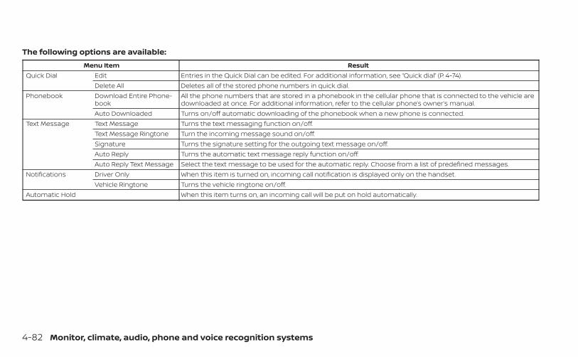
The following options are available:Menu Item Result
Quick Dial Edit Entries in the Quick Dial can be edited. For additional information, see “Quick dial” (P. 4-74).Delete All Deletes all of the stored phone numbers in quick dial.
Phonebook Download Entire Phone-book
All the phone numbers that are stored in a phonebook in the cellular phone that is connected to the vehicle aredownloaded at once. For additional information, refer to the cellular phone’s owner’s manual.
Auto Downloaded Turns on/off automatic downloading of the phonebook when a new phone is connected.Text Message Text Message Turns the text messaging function on/off.
Text Message Ringtone Turn the incoming message sound on/off.Signature Turns the signature setting for the outgoing text message on/off.Auto Reply Turns the automatic text message reply function on/off.Auto Reply Text Message Select the text message to be used for the automatic reply. Choose from a list of predefined messages.
Notifications Driver Only When this item is turned on, incoming call notification is displayed only on the handset.Vehicle Ringtone Turns the vehicle ringtone on/off.
Automatic Hold When this item turns on, an incoming call will be put on hold automatically.
4-82 Monitor, climate, audio, phone and voice recognition systems
VOLUME & BEEPSThere are several methods to customizethe volume settings.Volume & BeepsThe Volume & Beeps screen can be foundby pressing the MENU button on thecontrol panel, touching the “Settings” keyon the screen and selecting “Volume &Beeps”. To adjust the volume of the follow-ing options, touch the “–” and “+” keys on thescreen.The available settings are:• Ringtone
Adjust the volume level of the ringtone ofincoming calls.
• Outgoing CallAdjust the volume level of the outgoingcalls.
• Voice Prompt Vol.Adjust the volume level of the systemvoice.
• Text-to-speech Vol.Adjust the volume of the replay voice fortext messaging.
• Button BeepsTurns on/off the button beep sounds andalarm for prohibited operations.
Volume SettingsThe Volume settings screen can be foundby pressing the button on the controlpanel then touching the “Volume” key onthe screen. To adjust the volume of thefollowing options, touch the “–” and “+” keyson the screen.The available settings are:• Ringtone
Adjust the volume level of the ringtone ofincoming calls.
• Outgoing CallAdjust the volume level of the outgoingcalls.
“Made for iPod”, “Made for iPhone” and“Made for iPad” mean that an electronicaccessory has been designed to connectspecifically to iPod, iPhone or iPad, respec-tively, and has been certified by the devel-oper to meet Apple performance stan-dards. Apple is not responsible for theoperation of this device or its compliancewith safety and regulatory standards.Please note that the use of this accessorywith iPod, iPhone or iPad may affect wire-less performance.iPad, iPhone, iPod classic, iPod nano, iPodshuffle and iPod touch are trademarks ofApple Inc., registered in the U.S. and othercountries. Lightning is a trademark ofApple Inc.
iPod®/IPHONE®
Monitor, climate, audio, phone and voice recognition systems 4-83

MEMO
4-84 Monitor, climate, audio, phone and voice recognition systems
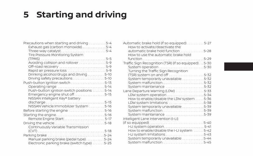
5 Starting and driving
Precautions when starting and driving . . . . . . . . . . 5-4Exhaust gas (carbon monoxide) . . . . . . . . . . . . . . 5-4Three-way catalyst . . . . . . . . . . . . . . . . . . . . . . . . . . . 5-4Tire Pressure Monitoring System(TPMS) . . . . . . . . . . . . . . . . . . . . . . . . . . . . . . . . . . . . . . . 5-5Avoiding collision and rollover . . . . . . . . . . . . . . . . 5-9Off-road recovery . . . . . . . . . . . . . . . . . . . . . . . . . . . . 5-9Rapid air pressure loss . . . . . . . . . . . . . . . . . . . . . . . 5-9Drinking alcohol/drugs and driving . . . . . . . . . . 5-10Driving safety precautions . . . . . . . . . . . . . . . . . . . 5-10
Push-button ignition switch . . . . . . . . . . . . . . . . . . . . 5-13Operating range . . . . . . . . . . . . . . . . . . . . . . . . . . . . 5-14Push-button ignition switch positions . . . . . . . 5-14Emergency engine shut off . . . . . . . . . . . . . . . . . . 5-15NISSAN Intelligent Key® batterydischarge . . . . . . . . . . . . . . . . . . . . . . . . . . . . . . . . . . . 5-15NISSAN Vehicle Immobilizer System . . . . . . . . . 5-16
Before starting the engine . . . . . . . . . . . . . . . . . . . . . 5-16Starting the engine . . . . . . . . . . . . . . . . . . . . . . . . . . . . . 5-16
Remote Engine Start . . . . . . . . . . . . . . . . . . . . . . . . 5-17Driving the vehicle . . . . . . . . . . . . . . . . . . . . . . . . . . . . . . 5-18
Continuously Variable Transmission(CVT) . . . . . . . . . . . . . . . . . . . . . . . . . . . . . . . . . . . . . . . . 5-18
Parking brake . . . . . . . . . . . . . . . . . . . . . . . . . . . . . . . . . . 5-24Manual parking brake (pedal type) . . . . . . . . . . . 5-24Electronic parking brake (switch type) . . . . . . . 5-25
Automatic brake hold (if so equipped) . . . . . . . . . . 5-27How to activate/deactivate theautomatic brake hold function . . . . . . . . . . . . . . 5-28How to use the automatic brake holdfunction . . . . . . . . . . . . . . . . . . . . . . . . . . . . . . . . . . . . . 5-29
Traffic Sign Recognition (TSR) (if so equipped) . . . 5-30System operation . . . . . . . . . . . . . . . . . . . . . . . . . . . 5-30Turning the Traffic Sign Recognition(TSR) system on and off . . . . . . . . . . . . . . . . . . . . . 5-32System temporarily unavailable . . . . . . . . . . . . . 5-32System malfunction . . . . . . . . . . . . . . . . . . . . . . . . . 5-32System maintenance . . . . . . . . . . . . . . . . . . . . . . . 5-32
Lane Departure Warning (LDW) . . . . . . . . . . . . . . . . . 5-33LDW system operation . . . . . . . . . . . . . . . . . . . . . . 5-34How to enable/disable the LDW system . . . . . 5-36LDW system limitations . . . . . . . . . . . . . . . . . . . . . 5-38System temporarily unavailable . . . . . . . . . . . . . 5-39System malfunction . . . . . . . . . . . . . . . . . . . . . . . . . 5-39System maintenance . . . . . . . . . . . . . . . . . . . . . . . 5-39
Intelligent Lane Intervention (I-LI)(if so equipped) . . . . . . . . . . . . . . . . . . . . . . . . . . . . . . . . . 5-40
I-LI system operation . . . . . . . . . . . . . . . . . . . . . . . . 5-41How to enable/disable the I-LI system . . . . . . 5-42I-LI system limitations . . . . . . . . . . . . . . . . . . . . . . . 5-43System temporarily unavailable . . . . . . . . . . . . . 5-44System malfunction . . . . . . . . . . . . . . . . . . . . . . . . . 5-45
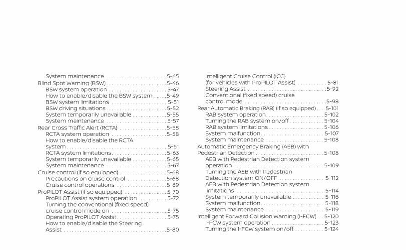
System maintenance . . . . . . . . . . . . . . . . . . . . . . . 5-45Blind Spot Warning (BSW) . . . . . . . . . . . . . . . . . . . . . . . 5-46
BSW system operation . . . . . . . . . . . . . . . . . . . . . . 5-47How to enable/disable the BSW system . . . . . 5-49BSW system limitations . . . . . . . . . . . . . . . . . . . . . 5-51BSW driving situations . . . . . . . . . . . . . . . . . . . . . . . 5-52System temporarily unavailable . . . . . . . . . . . . . 5-55System maintenance . . . . . . . . . . . . . . . . . . . . . . . 5-57
Rear Cross Traffic Alert (RCTA) . . . . . . . . . . . . . . . . . . 5-58RCTA system operation . . . . . . . . . . . . . . . . . . . . .5-58How to enable/disable the RCTAsystem . . . . . . . . . . . . . . . . . . . . . . . . . . . . . . . . . . . . . . 5-61RCTA system limitations . . . . . . . . . . . . . . . . . . . . . 5-63System temporarily unavailable . . . . . . . . . . . . . 5-65System maintenance . . . . . . . . . . . . . . . . . . . . . . . 5-67
Cruise control (if so equipped) . . . . . . . . . . . . . . . . . .5-68Precautions on cruise control . . . . . . . . . . . . . . .5-68Cruise control operations . . . . . . . . . . . . . . . . . . . 5-69
ProPILOT Assist (if so equipped) . . . . . . . . . . . . . . . . 5-70ProPILOT Assist system operation . . . . . . . . . . . 5-72Turning the conventional (fixed speed)cruise control mode on . . . . . . . . . . . . . . . . . . . . . 5-75Operating ProPILOT Assist . . . . . . . . . . . . . . . . . . . 5-75How to enable/disable the SteeringAssist . . . . . . . . . . . . . . . . . . . . . . . . . . . . . . . . . . . . . . .5-80
Intelligent Cruise Control (ICC)(for vehicles with ProPILOT Assist) . . . . . . . . . . . 5-81Steering Assist . . . . . . . . . . . . . . . . . . . . . . . . . . . . . . 5-92Conventional (fixed speed) cruisecontrol mode . . . . . . . . . . . . . . . . . . . . . . . . . . . . . . .5-98
Rear Automatic Braking (RAB) (if so equipped) . . . 5-101RAB system operation . . . . . . . . . . . . . . . . . . . . . . 5-102Turning the RAB system on/off . . . . . . . . . . . . . 5-104RAB system limitations . . . . . . . . . . . . . . . . . . . . . 5-106System malfunction . . . . . . . . . . . . . . . . . . . . . . . . 5-107System maintenance . . . . . . . . . . . . . . . . . . . . . . 5-108
Automatic Emergency Braking (AEB) withPedestrian Detection . . . . . . . . . . . . . . . . . . . . . . . . . . 5-108
AEB with Pedestrian Detection systemoperation . . . . . . . . . . . . . . . . . . . . . . . . . . . . . . . . . . 5-109Turning the AEB with PedestrianDetection system ON/OFF . . . . . . . . . . . . . . . . . 5-112AEB with Pedestrian Detection systemlimitations . . . . . . . . . . . . . . . . . . . . . . . . . . . . . . . . . 5-114System temporarily unavailable . . . . . . . . . . . . 5-116System malfunction . . . . . . . . . . . . . . . . . . . . . . . . 5-118System maintenance . . . . . . . . . . . . . . . . . . . . . . 5-119
Intelligent Forward Collision Warning (I-FCW) . . 5-120I-FCW system operation . . . . . . . . . . . . . . . . . . . . 5-123Turning the I-FCW system on/off . . . . . . . . . . . 5-124
I-FCW system limitations . . . . . . . . . . . . . . . . . . . 5-126System temporarily unavailable . . . . . . . . . . . . 5-131System malfunction . . . . . . . . . . . . . . . . . . . . . . . . 5-133System maintenance . . . . . . . . . . . . . . . . . . . . . . 5-134
Intelligent Driver Alertness (I-DA) . . . . . . . . . . . . . . . 5-135Intelligent Driver Alertness systemoperation . . . . . . . . . . . . . . . . . . . . . . . . . . . . . . . . . . 5-135How to enable/disable the IntelligentDriver Alertness (I-DA) system . . . . . . . . . . . . . . 5-136Intelligent Driver Alertness (I-DA)system limitations . . . . . . . . . . . . . . . . . . . . . . . . . 5-137
Break-in schedule . . . . . . . . . . . . . . . . . . . . . . . . . . . . . 5-139Fuel efficient driving tips . . . . . . . . . . . . . . . . . . . . . . . 5-139Increasing fuel economy . . . . . . . . . . . . . . . . . . . . . . 5-140All-Wheel Drive (AWD) (if so equipped) . . . . . . . . . . 5-140Parking/parking on hills . . . . . . . . . . . . . . . . . . . . . . . 5-143Power steering . . . . . . . . . . . . . . . . . . . . . . . . . . . . . . . . 5-144Brake system . . . . . . . . . . . . . . . . . . . . . . . . . . . . . . . . . 5-145
Brake precautions . . . . . . . . . . . . . . . . . . . . . . . . . . 5-145Anti-lock Braking System (ABS) . . . . . . . . . . . . . 5-145Brake Assist . . . . . . . . . . . . . . . . . . . . . . . . . . . . . . . . 5-147
Vehicle Dynamic Control (VDC) system . . . . . . . . 5-147Brake force distribution . . . . . . . . . . . . . . . . . . . . 5-149
Chassis Control (if so equipped) . . . . . . . . . . . . . . . 5-150
Intelligent Trace Control (I-TC) . . . . . . . . . . . . . . 5-150Active Ride Control (ARC) . . . . . . . . . . . . . . . . . . . 5-150
Hill start assist system . . . . . . . . . . . . . . . . . . . . . . . . 5-150Rear Sonar System (RSS) (if so equipped) . . . . . . 5-151
System operation . . . . . . . . . . . . . . . . . . . . . . . . . . 5-152How to enable/disable the sonarsystem . . . . . . . . . . . . . . . . . . . . . . . . . . . . . . . . . . . . . 5-154Sonar limitations . . . . . . . . . . . . . . . . . . . . . . . . . . . 5-156System temporarily unavailable . . . . . . . . . . . . 5-156System maintenance . . . . . . . . . . . . . . . . . . . . . . 5-156
Cold weather driving . . . . . . . . . . . . . . . . . . . . . . . . . . 5-157Freeing a frozen door lock . . . . . . . . . . . . . . . . . . 5-157Antifreeze . . . . . . . . . . . . . . . . . . . . . . . . . . . . . . . . . . 5-157Battery . . . . . . . . . . . . . . . . . . . . . . . . . . . . . . . . . . . . . 5-157Draining of coolant water . . . . . . . . . . . . . . . . . . 5-157Tire equipment . . . . . . . . . . . . . . . . . . . . . . . . . . . . . 5-157Special winter equipment . . . . . . . . . . . . . . . . . . 5-158Driving on snow or ice . . . . . . . . . . . . . . . . . . . . . . 5-158Engine block heater (if so equipped) . . . . . . . . 5-158
Active noise cancellation/Active soundenhancement (if so equipped) . . . . . . . . . . . . . . . . . 5-159
Active noise cancellation . . . . . . . . . . . . . . . . . . . 5-159Active sound enhancement . . . . . . . . . . . . . . . . 5-159
WARNING
• Do not leave children or adults whowould normally require the assis-tance of others alone in your vehicle.Pets should also not be left alone.They could accidentally injure them-selves or others through inadvertentoperation of the vehicle. Also, on hot,sunny days, temperatures in a closedvehicle could quickly become highenough to cause severe or possiblyfatal injuries to people or animals.
• Closely supervise children when theyare around cars to prevent themfrom playing and becoming locked inthe trunk where they could be seri-ously injured. Keep the car locked,with the rear seatback and trunk lidsecurely latched when not in use, andprevent children's access to car keys.
EXHAUST GAS (carbon monoxide)
WARNING
• Do not breathe exhaust gases; theycontain colorless and odorless car-bon monoxide. Carbon monoxide isdangerous. It can cause uncon-sciousness or death.
• If you suspect that exhaust fumesare entering the vehicle, drive with allwindows fully open, and have the ve-hicle inspected immediately.
• Do not run the engine in closedspaces such as a garage.
• Do not park the vehicle with the en-gine running for any extended lengthof time.
• Keep the rear vent windows, lift-gates, doors and trunk lids (if soequipped) closed while driving, oth-erwise exhaust gases could bedrawn into the passenger compart-ment. If you must drive with one ofthese open, follow these precau-tions:1. Open all the windows.2. Set the air recirculation but-
ton to off and the fan control dialto high to circulate the air.
• If electrical wiring or other cable con-nections must pass to a trailerthrough the seal on the trunk lid orthe body, follow the manufacturer'srecommendation to prevent carbonmonoxide entry into the vehicle.
• The exhaust system and body shouldbe inspected by a qualified mechanicwhenever:a. The vehicle is raised for service.b. You suspect that exhaust fumes
are entering into the passengercompartment.
c. You notice a change in the soundof the exhaust system.
d. You have had an accident involv-ing damage to the exhaust sys-tem, underbody, or rear of thevehicle.
THREE-WAY CATALYSTThe three-way catalyst is an emission con-trol device installed in the exhaust system.Exhaust gases in the three-way catalystare burned at high temperatures to helpreduce pollutants.
WARNING
• The exhaust gas and the exhaustsystem are very hot. Keep people,animals or flammable materialsaway from the exhaust systemcomponents.
PRECAUTIONS WHEN STARTING ANDDRIVING
5-4 Starting and driving
• Do not stop or park the vehicle overflammable materials such as drygrass, waste paper or rags. They mayignite and cause a fire.
CAUTION
• Do not use leaded gasoline. Depositsfrom leaded gasoline will seriouslyreduce the three-way catalyst's abil-ity to help reduce exhaust pollutants.
• Keep your engine tuned up. Malfunc-tions in the ignition, fuel injection, orelectrical systems can cause overrichfuel flow into the three-way catalyst,causing it to overheat. Do not keepdriving if the engine misfires, or if no-ticeable loss of performance or otherunusual operating conditions are de-tected. Have the vehicle inspectedpromptly. It is recommended thatyou visit a NISSAN dealer for thisservice.
• Avoid driving with an extremely lowfuel level. Running out of fuel couldcause the engine to misfire, damag-ing the three-way catalyst.
• Do not race the engine while warm-ing it up.
• Do not push or tow your vehicle tostart the engine.
TIRE PRESSURE MONITORINGSYSTEM (TPMS)Each tire, including the spare (if provided),should be checked monthly when cold andinflated to the inflation pressure recom-mended by the vehicle manufacturer onthe vehicle placard or tire inflation pressurelabel. (If your vehicle has tires of a differentsize than the size indicated on the vehicleplacard or tire inflation pressure label, youshould determine the proper tire inflationpressure for those tires.)As an added safety feature, your vehiclehas been equipped with a Tire PressureMonitoring System (TPMS) that illuminatesa low tire pressure telltale when one ormore of your tires is significantly under-inflated. Accordingly, when the low tirepressure telltale illuminates, you shouldstop and check your tires as soon as pos-sible, and inflate them to the proper pres-sure. Driving on a significantly under-inflated tire causes the tire to overheat andcan lead to tire failure. Under-inflation alsoreduces fuel efficiency and tire tread life,and may affect the vehicle’s handling andstopping ability.
Please note that the TPMS is not a substi-tute for proper tire maintenance, and it isthe driver’s responsibility to maintain cor-rect tire pressure, even if under-inflationhas not reached the level to trigger illumi-nation of the TPMS low tire pressure telltale.Your vehicle has also been equipped with aTPMS malfunction indicator to indicatewhen the system is not operating properly.The TPMS malfunction indicator is com-bined with the low tire pressure telltale.When the system detects a malfunction,the telltale will flash for approximately oneminute and then remain continuously illu-minated. This sequence will continue uponsubsequent vehicle start-ups as long asthe malfunction exists. When the malfunc-tion indicator is illuminated, the systemmay not be able to detect or signal low tirepressure as intended. TPMS malfunctionsmay occur for a variety of reasons, includ-ing the installation of replacement or alter-nate tires or wheels on the vehicle thatprevent the TPMS from functioning prop-erly. Always check the TPMS malfunctiontelltale after replacing one or more tires orwheels on your vehicle to ensure that thereplacement or alternate tires and wheelsallow the TPMS to continue to functionproperly.
Starting and driving 5-5
Additional information:• When replacing a wheel without the
TPMS such as the spare tire, the TPMSdoes not monitor the tire pressure of thespare tire.
• The TPMS will activate only when the ve-hicle is driven at speeds above 16 mph(25 km/h). Also, this system may not de-tect a sudden drop in tire pressure (forexample, a flat tire while driving).
• The low tire pressure warning light does notautomatically turn off when the tire pressureis adjusted on all four tires. After all four tiresare inflated to the recommended pressure,the vehicle must be driven at speeds above 16mph (25 km/h) to activate the TPMS and turnoff the low tire pressure warning light. Use atire pressure gauge to check the tire pressure.
• The “Tire Pressure Low - Add Air” warningappears in the vehicle information dis-play when the low tire pressure warninglight is illuminated and low tire pressure isdetected. The “Tire Pressure Low - AddAir” warning turns off when the low tirepressure warning light turns off.
• The “Tire Pressure Low - Add Air” warningappears each time the ignition switch isplaced in the ON position as long as thelow tire pressure warning light remainsilluminated.
• The “Tire Pressure Low - Add Air” warningdoes not appear if the low tire pressurewarning light illuminates to indicate aTPMS malfunction.
• Tire pressure rises and falls depending onthe heat caused by the vehicle’s opera-tion and the outside temperature. Do notreduce the tire pressure after driving be-cause the tire pressure rises after driving.Low outside temperature can lower thetemperature of the air inside the tirewhich can cause a lower tire inflationpressure. This may cause the low tirepressure warning light to illuminate. If thewarning light illuminates, check the tirepressure for all four tires.
• The Tire and Loading Information label islocated in the driver's door opening.
• You can also check the tire pressure of alltires (except the spare) on the vehicle in-formation display screen. The order ofthe tire pressure figures displayed on thescreen corresponds with the actual orderof the tire position.
For additional information, see “Low tirepressure warning light” (P. 2-13), “Tire Pres-sure Monitoring System (TPMS)” (P. 6-3) and“Tire pressure” (P. 8-29).
WARNING
• Radio waves could adversely affectelectric medical equipment. Thosewho use a pacemaker should contactthe electric medical equipmentmanufacturer for the possible influ-ences before use.
• If the low tire pressure warning lightilluminates while driving, avoid sud-den steering maneuvers or abruptbraking, reduce vehicle speed, pulloff the road to a safe location andstop the vehicle as soon as possible.Driving with underinflated tires maypermanently damage the tires andincrease the likelihood of tire failure.Serious vehicle damage could occurand may lead to an accident andcould result in serious personal in-jury. Check the tire pressure for allfour tires. Adjust the tire pressure tothe recommended COLD tire pres-sure shown on the Tire and LoadingInformation label to turn the low tirepressure warning light off. If you havea flat tire, replace it with a spare tireas soon as possible. (For additionalinformation, see “Flat tire” (P. 6-3) forchanging a flat tire.)
5-6 Starting and driving
• When replacing a wheel without theTPMS such as the spare tire, when aspare tire is mounted or a wheel isreplaced, tire pressure will not be in-dicated, the TPMS will not functionand the low tire pressure warninglight will flash for approximately1 minute. The light will remain on af-ter 1 minute. It is recommended thatyou visit a NISSAN dealer for tire re-placement and/or system resetting.
• Replacing tires with those not origi-nally specified by NISSAN could af-fect the proper operation of theTPMS.
• Do not inject any tire liquid or aerosoltire sealant into the tires, as this maycause a malfunction of the tire pres-sure sensors.
CAUTION
Do not place metalized film or anymetal parts (antenna, etc.) on the win-dows. This may cause poor reception ofthe signals from the tire pressure sen-sors, and the TPMS will not functionproperly.
Some devices and transmitters may tem-porarily interfere with the operation of theTPMS and cause the low tire pressurewarning light to illuminate.Some examples are:• Facilities or electric devices using similar
radio frequencies are near the vehicle.• If a transmitter set to similar frequencies
is being used in or near the vehicle.• If a computer (or similar equipment) or a
DC/AC converter is being used in or nearthe vehicle.
The low tire pressure warning light mayilluminate in the following cases:• If the vehicle is equipped with a wheel and
tire without TPMS.• If the TPMS has been replaced and the ID
has not been registered.• If the wheel is not originally specified by
NISSAN.
FCC Notice:For USA:This device complies with Part 15 of theFCC Rules. Operation is subject to the fol-lowing two conditions: (1) This devicemay not cause harmful interference, and(2) this device must accept any interfer-ence received, including interferencethat may cause undesired operation.
NOTE:Changes or modifications not ex-pressly approved by the party re-sponsible for compliance could voidthe user's authority to operate theequipment.For Canada:This device complies with IndustryCanada licence-exempt RSS standard(s).Operation is subject to the following twoconditions: (1) this device may not causeinterference, and (2) this device must ac-cept any interference, including interfer-ence that may cause undesired opera-tion of the device.
Starting and driving 5-7
TPMS with Easy-Fill Tire AlertWhen adding air to an under-inflated tire,the TPMS with Easy-Fill Tire Alert providesvisual and audible signals outside the ve-hicle to help you inflate the tires to the rec-ommended COLD tire pressure.Vehicle set-up1. Park the vehicle in a safe and level place.
2. Apply the parking brake and place theshift lever in the P (Park) position.
3. Place the ignition switch in the ON posi-tion. Do not start the engine.
Operation1. Add air to the tire.
2. After a few seconds, the hazard indica-tors will start flashing.
3. When the designated pressure isreached, the horn beeps once and thehazard indicators stop flashing.
4. Perform the above steps for each tire.• If the tire is over-inflated more than
approximately 4 psi (30 kPa), the hornbeeps and the hazard indicators flashthree times. To correct the pressure,push the core of the valve stem on thetire briefly to release pressure. Whenthe pressure reaches the designatedpressure, the horn beeps once.
• If the hazard indicator does not flashwithin approximately 15 seconds afterstarting to inflate the tire, it indicatesthat the Easy-Fill Tire Alert is not oper-ating.
• The TPMS will not activate the Easy-FillTire Alert under the following condi-tions:– If there is interference from an exter-
nal device or transmitter.– The air pressure from the inflation
device is not sufficient to inflate thetire.
– There is a malfunction in the TPMS.– There is a malfunction in the horn or
hazard indicators.– The identification code of the tire
pressure sensor is not registered tothe system.
– The battery of the tire pressure sen-sor is low.
• If the Easy-Fill Tire Alert does not oper-ate due to TPMS interference, movethe vehicle about 3 ft (1 m) backwardor forward and try again.
If the Easy-Fill Tire Alert is not working, use atire pressure gauge.
5-8 Starting and driving
AVOIDING COLLISION ANDROLLOVER
WARNING
Failure to operate this vehicle in a safeand prudent manner may result in lossof control or an accident.
Be alert and drive defensively at all times.Obey all traffic regulations. Avoid excessivespeed, high speed cornering, or suddensteering maneuvers, because these drivingpractices could cause you to lose control ofyour vehicle.As with any vehicle, loss of control couldresult in a collision with other vehicles orobjects or cause the vehicle to roll over,particularly if the loss of control causesthe vehicle to slide sideways.Be attentive at all times, and avoid drivingwhen tired. Never drive when under the in-fluence of alcohol or drugs (including pre-scription or over-the-counter drugs whichmay cause drowsiness). Always wear yourseat belt as outlined in the “Safety – Seats,seat belts and supplemental restraint sys-tem” section of this manual, and also in-struct your passengers to do so.
Seat belts help reduce the risk of injury incollisions and rollovers. In a rollover crash,an unbelted person is significantly morelikely to die than a person wearing a seatbelt.
OFF-ROAD RECOVERYWhile driving, the right side or left sidewheels may unintentionally leave the roadsurface. If this occurs, maintain control ofthe vehicle by following the procedure be-low. Please note that this procedure is onlya general guide. The vehicle must be drivenas appropriate based on the conditions ofthe vehicle, road and traffic.1. Remain calm and do not overreact.
2. Do not apply the brakes.
3. Maintain a firm grip on the steeringwheel with both hands and try to hold astraight course.
4. When appropriate, slowly release the ac-celerator pedal to gradually slow thevehicle.
5. If there is nothing in the way, steer thevehicle to follow the road while vehiclespeed is reduced. Do not attempt todrive the vehicle back onto the road sur-face until vehicle speed is reduced.
6. When it is safe to do so, gradually turnthe steering wheel until both tires returnto the road surface. When all tires are onthe road surface, steer the vehicle tostay in the appropriate driving lane.• If you decide that it is not safe to return
the vehicle to the road surface basedon vehicle, road or traffic conditions,gradually slow the vehicle to a stop ina safe place off the road.
RAPID AIR PRESSURE LOSSRapid air pressure loss or a “blow-out” canoccur if the tire is punctured or is damageddue to hitting a curb or pothole. Rapid airpressure loss can also be caused by drivingon under-inflated tires.Rapid air pressure loss can affect the han-dling and stability of the vehicle, especiallyat highway speeds.Help prevent rapid air pressure loss bymaintaining the correct air pressure andvisually inspecting the tires for wear anddamage. For additional information, see“Wheels and tires” (P. 8-29). If a tire rapidlyloses air pressure or “blows-out” while driv-ing, maintain control of the vehicle by fol-lowing the procedure below. Please notethat this procedure is only a general guide.
Starting and driving 5-9
The vehicle must be driven as appropriatebased on the conditions of the vehicle, roadand traffic.
WARNING
The following actions can increase thechance of losing control of the vehicle ifthere is a sudden loss of tire air pres-sure. Losing control of the vehicle maycause a collision and result in personalinjury.• The vehicle generally moves or pulls
in the direction of the flat tire.• Do not rapidly apply the brakes.• Do not rapidly release the accelerator
pedal.• Do not rapidly turn the steering
wheel.
1. Remain calm and do not overreact.
2. Maintain a firm grip on the steeringwheel with both hands and try to hold astraight course.
3. When appropriate, slowly release the ac-celerator pedal to gradually slow thevehicle.
4. Gradually steer the vehicle to a safe lo-cation off the road and away from trafficif possible.
5. Lightly apply the brake pedal to gradu-ally stop the vehicle.
6. Turn on the hazard warning flashers andcontact a roadside emergency serviceto change the tire. For additional infor-mation, see “Changing a flat tire” (P. 6-4).
DRINKING ALCOHOL/DRUGS ANDDRIVING
WARNING
Never drive under the influence of alco-hol or drugs. Alcohol in the blood-stream reduces coordination, delaysreaction time and impairs judgement.Driving after drinking alcohol increasesthe likelihood of being involved in anaccident injuring yourself and others.Additionally, if you are injured in an ac-cident, alcohol can increase the sever-ity of the injury.
NISSAN is committed to safe driving. How-ever, you must choose not to drive underthe influence of alcohol. Every year thou-sands of people are injured or killed inalcohol-related collisions. Although the lo-cal laws vary on what is considered to belegally intoxicated, the fact is that alcoholaffects all people differently and mostpeople underestimate the effects of alco-hol.Remember, drinking and driving don't mix!That is true for drugs (over-the-counter,prescription) and illegal drugs, too. Don'tdrive if your ability to operate your vehicle isimpaired by alcohol, drugs, or some otherphysical condition.
DRIVING SAFETY PRECAUTIONSYour NISSAN is designed for both normaland off-road use. However, avoid driving indeep water or mud as your NISSAN ismainly designed for leisure use, unlike aconventional off-road vehicle.Remember that 2-Wheel Drive (2WD) mod-els are less capable than All-Wheel Drive(AWD) models for rough road driving andextrication when stuck in deep snow ormud, or the like.
5-10 Starting and driving
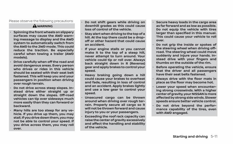
Please observe the following precautions:WARNING
• Spinning the front wheels on slipperysurfaces may cause the AWD warn-ing message to display and the AWDsystem to automatically switch fromthe AWD to the 2WD mode. This couldreduce the traction. Be especiallycareful when towing a trailer (AWDmodels).
• Drive carefully when off the road andavoid dangerous areas. Every personwho drives or rides in this vehicleshould be seated with their seat beltfastened. This will keep you and yourpassengers in position when drivingover rough terrain.
• Do not drive across steep slopes. In-stead drive either straight up orstraight down the slopes. Off-roadvehicles can tip over sideways muchmore easily than they can forward orbackward.
• Many hills are too steep for any ve-hicle. If you drive up them, you maystall. If you drive down them, you maynot be able to control your speed. Ifyou drive across them, you may rollover.
• Do not shift gears while driving ondownhill grades as this could causeloss of control of the vehicle.
• Stay alert when driving to the top of ahill. At the top there could be a drop-off or other hazard that could causean accident.
• If your engine stalls or you cannotmake it to the top of a steep hill,never attempt to turn around. Yourvehicle could tip or roll over. Alwaysback straight down in R (Reverse)gear and apply brakes to control yourspeed.
• Heavy braking going down a hillcould cause your brakes to overheatand fade, resulting in loss of controland an accident. Apply brakes lightlyand use a low gear to control yourspeed.
• Unsecured cargo can be thrownaround when driving over rough ter-rain. Properly secure all cargo so itwill not be thrown forward and causeinjury to you or your passengers.
• Exceeding the roof rack capacity canraise the center of gravity excessivelyand affect the handling and stabilityof the vehicle.
• Secure heavy loads in the cargo areaas far forward and as low as possible.Do not equip the vehicle with tireslarger than specified in this manual.This could cause your vehicle to rollover.
• Do not grip the inside or spokes ofthe steering wheel when driving off-road. The steering wheel could movesuddenly and injure your hands. In-stead drive with your fingers andthumbs on the outside of the rim.
• Before operating the vehicle, ensurethat the driver and all passengershave their seat belts fastened.
• Always drive with the floor mats inplace as the floor may become hot.
• Lower your speed when encounter-ing strong crosswinds. With a highercenter of gravity, your NISSAN is moreaffected by strong side winds. Slowerspeeds ensure better vehicle control.
• Do not drive beyond the perfor-mance capability of the tires, evenwith AWD engaged.
Starting and driving 5-11
• For AWD equipped vehicles, do notattempt to raise two wheels off theground and shift the transmission toany drive or reverse position with theengine running. Doing so may resultin drivetrain damage or unexpectedvehicle movement which could resultin serious vehicle damage or per-sonal injury.
• Do not attempt to test an AWDequipped vehicle on a 2-wheel dyna-mometer (such as the dynamom-eters used by some states for emis-sions testing) or similar equipmenteven if the other two wheels areraised off the ground. Make sure youinform test facility personnel thatyour vehicle is equipped with AWDbefore it is placed on a dynamom-eter. Using the wrong test equipmentmay result in drivetrain damage orunexpected vehicle movementwhich could result in serious vehicledamage or personal injury.
• When a wheel is off the ground due toan unlevel surface, do not spin thewheel excessively.
• Accelerating quickly, sharp steeringmaneuvers or sudden braking maycause loss of control.
• If at all possible, avoid sharp turningmaneuvers, particularly at highspeeds. Your NISSAN vehicle has ahigher center of gravity than a pas-senger car. The vehicle is not de-signed for cornering at the samespeeds as passenger cars.
• Failure to operate this vehicle cor-rectly could result in loss of controland/or a rollover accident.
• Always use tires of the same type,size, brand, construction (bias, bias-belted, or radial), and tread patternon all four wheels. Install tire chainson the front wheels when driving onslippery roads and drive carefully.
• Be sure to check the brakes immedi-ately after driving in mud or water.For additional information, see“Brake precautions” (P. 5-145).
• Avoid parking your vehicle on steephills. If you get out of the vehicle andit rolls forward, backward or side-ways, you could be injured.
• Whenever you drive off-road throughsand, mud or water as deep as thewheel hub, more frequent mainte-nance may be required. For addi-tional information, see “Maintenanceunder severe operating conditions”(P. 9-7).
5-12 Starting and driving
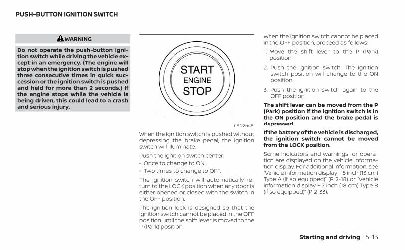
WARNING
Do not operate the push-button igni-tion switch while driving the vehicle ex-cept in an emergency. (The engine willstop when the ignition switch is pushedthree consecutive times in quick suc-cession or the ignition switch is pushedand held for more than 2 seconds.) Ifthe engine stops while the vehicle isbeing driven, this could lead to a crashand serious injury.
When the ignition switch is pushed withoutdepressing the brake pedal, the ignitionswitch will illuminate.Push the ignition switch center:• Once to change to ON.• Two times to change to OFF.The ignition switch will automatically re-turn to the LOCK position when any door iseither opened or closed with the switch inthe OFF position.The ignition lock is designed so that theignition switch cannot be placed in the OFFposition until the shift lever is moved to theP (Park) position.
When the ignition switch cannot be placedin the OFF position, proceed as follows:1. Move the shift lever to the P (Park)
position.
2. Push the ignition switch. The ignitionswitch position will change to the ONposition.
3. Push the ignition switch again to theOFF position.
The shift lever can be moved from the P(Park) position if the ignition switch is inthe ON position and the brake pedal isdepressed.If the battery of the vehicle is discharged,the ignition switch cannot be movedfrom the LOCK position.Some indicators and warnings for opera-tion are displayed on the vehicle informa-tion display. For additional information, see“Vehicle information display – 5 inch (13 cm)Type A (if so equipped)” (P. 2-18) or “Vehicleinformation display – 7 inch (18 cm) Type B(if so equipped)” (P. 2-33).
LSD2645
PUSH-BUTTON IGNITION SWITCH
Starting and driving 5-13
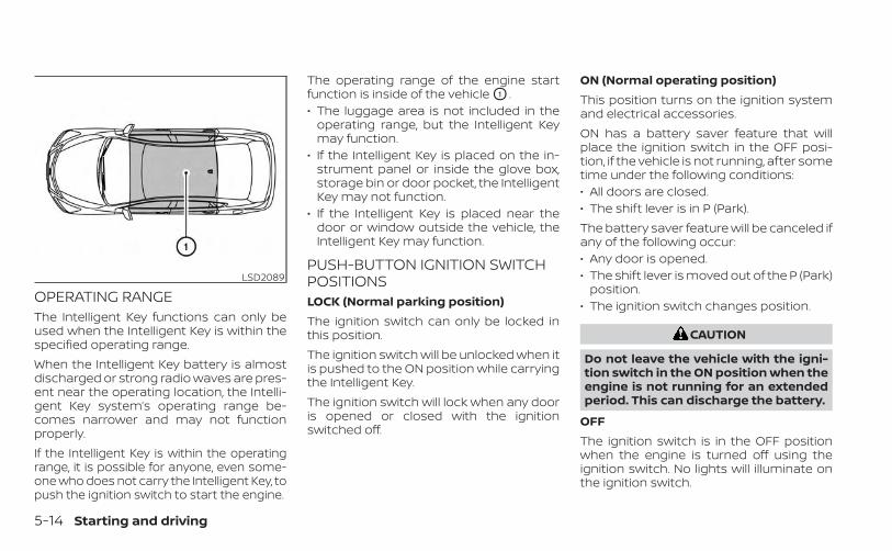
OPERATING RANGEThe Intelligent Key functions can only beused when the Intelligent Key is within thespecified operating range.When the Intelligent Key battery is almostdischarged or strong radio waves are pres-ent near the operating location, the Intelli-gent Key system’s operating range be-comes narrower and may not functionproperly.If the Intelligent Key is within the operatingrange, it is possible for anyone, even some-one who does not carry the Intelligent Key, topush the ignition switch to start the engine.
The operating range of the engine startfunction is inside of the vehicle O1 .• The luggage area is not included in the
operating range, but the Intelligent Keymay function.
• If the Intelligent Key is placed on the in-strument panel or inside the glove box,storage bin or door pocket, the IntelligentKey may not function.
• If the Intelligent Key is placed near thedoor or window outside the vehicle, theIntelligent Key may function.
PUSH-BUTTON IGNITION SWITCHPOSITIONSLOCK (Normal parking position)The ignition switch can only be locked inthis position.The ignition switch will be unlocked when itis pushed to the ON position while carryingthe Intelligent Key.The ignition switch will lock when any dooris opened or closed with the ignitionswitched off.
ON (Normal operating position)This position turns on the ignition systemand electrical accessories.ON has a battery saver feature that willplace the ignition switch in the OFF posi-tion, if the vehicle is not running, after sometime under the following conditions:• All doors are closed.• The shift lever is in P (Park).The battery saver feature will be canceled ifany of the following occur:• Any door is opened.• The shift lever is moved out of the P (Park)
position.• The ignition switch changes position.
CAUTION
Do not leave the vehicle with the igni-tion switch in the ON position when theengine is not running for an extendedperiod. This can discharge the battery.
OFFThe ignition switch is in the OFF positionwhen the engine is turned off using theignition switch. No lights will illuminate onthe ignition switch.
LSD2089
5-14 Starting and driving
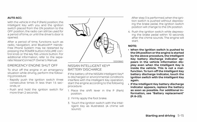
AUTO ACC:With the vehicle in the P (Park) position, theIntelligent Key with you and the ignitionswitch placed from the ON position to theOFF position, the radio can still be used fora period of time, or until the driver’s door isopened.After a period of time, functions such asradio, navigation, and Bluetooth® Hands-Free Phone System may be restarted bypressing the POWER button/VOLUME con-trol knob or the key fob unlock button. Foradditional information, refer to the sepa-rate NissanConnect® Owner’s Manual.
EMERGENCY ENGINE SHUT OFFTo shut off the engine in an emergencysituation while driving, perform the follow-ing procedure:• Rapidly push the ignition switch three
consecutive times in less than 1.5 sec-onds, or
• Push and hold the ignition switch formore than 2 seconds.
NISSAN INTELLIGENT KEY®BATTERY DISCHARGEIf the battery of the NISSAN Intelligent Key®is discharged or environmental conditionsinterfere with the Intelligent Key operation,start the engine according to the followingprocedure:1. Place the shift lever in the P (Park)
position.
2. Firmly apply the foot brake.
3. Touch the ignition switch with the Intel-ligent Key as illustrated. (A chime willsound.)
After step 3 is performed, when the igni-tion switch is pushed without depress-ing the brake pedal, the ignition switchposition will change to the ON position.
4. Push the ignition switch while depress-ing the brake pedal within 10 secondsafter the chime sounds. The engine willstart.
NOTE:• When the ignition switch is pushed to
the ON position or the engine is startedby the above procedure, the IntelligentKey battery discharge indicator ap-pears in the vehicle information dis-play even when the Intelligent Key isinside the vehicle. This is not a mal-function. To turn off the Intelligent Keybattery discharge indicator, touch theignition switch with the Intelligent Keyagain.
• If the Intelligent Key battery dischargeindicator appears, replace the batteryas soon as possible. For additional in-formation, see “Battery replacement”(P. 8-23).
SSD0860
Starting and driving 5-15
NISSAN VEHICLE IMMOBILIZERSYSTEMThe NISSAN Vehicle Immobilizer Systemwill not allow the engine to start withoutthe use of the registered key.If the engine fails to start using a registeredkey (for example, when interference iscaused by another registered key, an auto-mated toll road device or automatic pay-ment device on the key ring), restart theengine using the following procedure:1. Leave the ignition switch in the ON posi-
tion for approximately 5 seconds.
2. Place the ignition switch in the OFF orLOCK position, and wait approximately10 seconds.
3. Repeat steps 1 and 2.
4. Restart the engine while holding the de-vice (which may have caused the inter-ference) separate from the registeredkey.
If the no start condition re-occurs, NISSANrecommends placing the registered key ona separate key ring to avoid interferencefrom other devices.
• Make sure the area around the vehicle isclear.
• Check fluid levels such as engine oil, cool-ant, brake fluid, and windshield-washerfluid as frequently as possible, or at leastwhenever you refuel.
• Check that all windows and lights areclean.
• Visually inspect tires for their appearanceand condition. Also check tires for properinflation.
• Lock all doors.• Position seat and adjust headrests/head
restraints.• Adjust inside and outside mirrors.• Fasten seat belts and ask all passengers
to do likewise.• Check the operation of warning lights
when the ignition switch is pushed to theON position. For additional information,see “Warning lights, indicator lights andaudible reminders” (P. 2-9).
1. Apply the parking brake.
2. Move the shift lever to P (Park) or N (Neu-tral). P (Park) is recommended.The starter is designed not to operateif the shift lever is in any of the drivingpositions.
3. Push the ignition switch to the ON posi-tion. Depress the brake pedal and pushthe ignition switch to start the engine.To start the engine immediately, pushand release the ignition switch while de-pressing the brake pedal with the igni-tion switch in any position.• If the engine is very hard to start in
extremely cold weather or when re-starting, depress the acceleratorpedal a little (approximately 1/3 to thefloor) and while holding, crank the en-gine. Release the accelerator pedalwhen the engine starts.
• If the engine is very hard to start be-cause it is flooded, depress the accel-erator pedal all the way to the floorand hold it. Push the ignition switch tothe ON position to start cranking theengine. After 5 or 6 seconds, stopcranking by pushing the ignitionswitch to the LOCK position. After
BEFORE STARTING THE ENGINE STARTING THE ENGINE
5-16 Starting and driving
cranking the engine, release the accel-erator pedal. Crank the engine withyour foot off the accelerator pedal bydepressing the brake pedal and push-ing the ignition switch to start the en-gine. If the engine starts, but fails torun, repeat the above procedure.
CAUTION
Do not operate the starter for morethan 15 seconds at a time. If the enginedoes not start, push the ignition switchto the OFF position and wait 10 secondsbefore cranking again, otherwise thestarter could be damaged.
4. Warm-up:Allow the engine to idle for at least 30seconds after starting. Do not race theengine while warming it up. Drive at amoderate speed for a short distancefirst, especially in cold weather. In coldweather, keep the engine running for aminimum of 2 to 3 minutes before shut-ting it off. Starting and stopping the en-gine over a short period of time maymake the vehicle more difficult to start.
5. To stop the engine, move the shift leverto the P (Park) position and push theignition switch to the OFF position.
NOTE:Care should be taken to avoid situa-tions that can lead to potential bat-tery discharge and potential no-startconditions such as:1. Installation or extended use of elec-
tronic accessories that consume bat-tery power when the engine is notrunning (phone chargers, GPS, DVDplayers, etc.).
2. The vehicle is not driven regularlyand/or only driven short distances.
In these cases, the battery may need tobe charged to maintain battery health.
REMOTE ENGINE STARTVehicles started with the Remote EngineStart require the ignition switch to beplaced in the ON position before the shiftlever can be moved from the P (Park) posi-tion. To place the ignition switch in the ONposition, follow these steps:1. Make sure that the Intelligent Key is on
you.
2. Apply the brake.
3. Push the ignition switch once to the ONposition.
For additional information, see “NISSAN In-telligent Key®” (P. 3-7).
Starting and driving 5-17
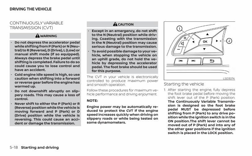
CONTINUOUSLY VARIABLETRANSMISSION (CVT)
WARNING
• Do not depress the accelerator pedalwhile shifting from P (Park) or N (Neu-tral) to R (Reverse), D (Drive), L (Low) ormanual shift mode (if so equipped).Always depress the brake pedal untilshifting is completed. Failure to do socould cause you to lose control andhave an accident.
• Cold engine idle speed is high, so usecaution when shifting into a forwardor reverse gear before the engine haswarmed up.
• Do not downshift abruptly on slip-pery roads. This may cause a loss ofcontrol.
• Never shift to either the P (Park) or R(Reverse) position while the vehicle ismoving forward and P (Park) or D(Drive) position while the vehicle isreversing. This could cause an acci-dent or damage the transmission.
CAUTION
• Except in an emergency, do not shiftto the N (Neutral) position while driv-ing. Coasting with the transmissionin the N (Neutral) position may causeserious damage to the transmission.
• To avoid possible damage to your ve-hicle, when stopping the vehicle onan uphill grade, do not hold the ve-hicle by depressing the acceleratorpedal. The foot brake should be usedfor this purpose.
The CVT in your vehicle is electronicallycontrolled to produce maximum powerand smooth operation.Follow these procedures for maximum ve-hicle performance and driving enjoyment.
NOTE:
Engine power may be automatically re-duced to protect the CVT if the enginespeed increases quickly when driving onslippery roads or while being tested onsome dynamometers.
Starting the vehicle1. After starting the engine, fully depress
the foot brake pedal before moving theshift lever out of the P (Park) position.The Continuously Variable Transmis-sion is designed so the foot brakepedal MUST be depressed beforeshifting from P (Park) to any drive po-sition while the ignition switch is in theON position.The shift lever cannot bemoved out of P (Park) and into any ofthe other gear positions if the ignitionswitch is placed in the LOCK position.
LSD3074
DRIVING THE VEHICLE
5-18 Starting and driving
2. A screen is displayed for a period of timethat indicates the status of the drivingaid functions (if so equipped).– AEB with Pedestrian Detection, LDW,
and BSW are enabled when the speci-fied driving aid is shaded.
– I-LI is enabled when the driving aid issolid.
– Use the O1 or O2 button tonavigate the settings screen. For ad-ditional information, see “How to usethe vehicle information display”(P. 2-19) or (P. 2-34)
3. Keep the foot brake pedal depressedand move the shift lever to a drivingposition.
4. Release the foot brake, then graduallystart the vehicle in motion.
5. Stop the vehicle completely before mov-ing the shift lever to the P (Park) position.
WARNING
• Do not depress the accelerator pedalwhile shifting from P (Park) or N (Neu-tral) to R (Reverse), D (Drive), L (Low) ormanual shift mode (if so equipped).Always depress the brake pedal untilshifting is completed. Failure to do socould cause you to lose control andhave an accident.
• Cold engine idle speed is high, so usecaution when shifting into a forwardor reverse gear before the engine haswarmed up.
• Do not downshift abruptly on slip-pery roads. This may cause a loss ofcontrol.
• Never shift to either the P (Park) or R(Reverse) position while the vehicle ismoving forward and P (Park) or D(Drive) position while the vehicle isreversing. This could cause an acci-dent or damage the transmission.
CAUTION
• Except in an emergency, do not shiftto the N (Neutral) position while driv-ing. Coasting with the transmissionin the N (Neutral) position may causeserious damage to the transmission.
• To avoid possible damage to your ve-hicle, when stopping the vehicle onan uphill grade, do not hold the ve-hicle by depressing the acceleratorpedal. The foot brake should be usedfor this purpose.
Starting and driving 5-19
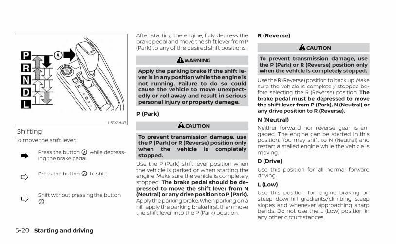
ShiftingTo move the shift lever:
Press the button OA while depress-ing the brake pedal
Press the button OA to shift
Shift without pressing the buttonOA
After starting the engine, fully depress thebrake pedal and move the shift lever from P(Park) to any of the desired shift positions.
WARNING
Apply the parking brake if the shift le-ver is in any position while the engine isnot running. Failure to do so couldcause the vehicle to move unexpect-edly or roll away and result in seriouspersonal injury or property damage.
P (Park)
CAUTION
To prevent transmission damage, usethe P (Park) or R (Reverse) position onlywhen the vehicle is completelystopped.
Use the P (Park) shift lever position whenthe vehicle is parked or when starting theengine. Make sure the vehicle is completelystopped. The brake pedal should be de-pressed to move the shift lever from N(Neutral) or any drive position to P (Park).Apply the parking brake. When parking on ahill, apply the parking brake first, then movethe shift lever into the P (Park) position.
R (Reverse)
CAUTION
To prevent transmission damage, usethe P (Park) or R (Reverse) position onlywhen the vehicle is completely stopped.
Use the R (Reverse) position to back up. Makesure the vehicle is completely stopped be-fore selecting the R (Reverse) position. Thebrake pedal must be depressed to movethe shift lever from P (Park), N (Neutral) orany drive position to R (Reverse).N (Neutral)Neither forward nor reverse gear is en-gaged. The engine can be started in thisposition. You may shift to N (Neutral) andrestart a stalled engine while the vehicle ismoving.D (Drive)Use this position for all normal forwarddriving.L (Low)Use this position for engine braking onsteep downhill gradients/climbing steepslopes and whenever approaching sharpbends. Do not use the L (Low) position inany other circumstances.
LSD2643
5-20 Starting and driving
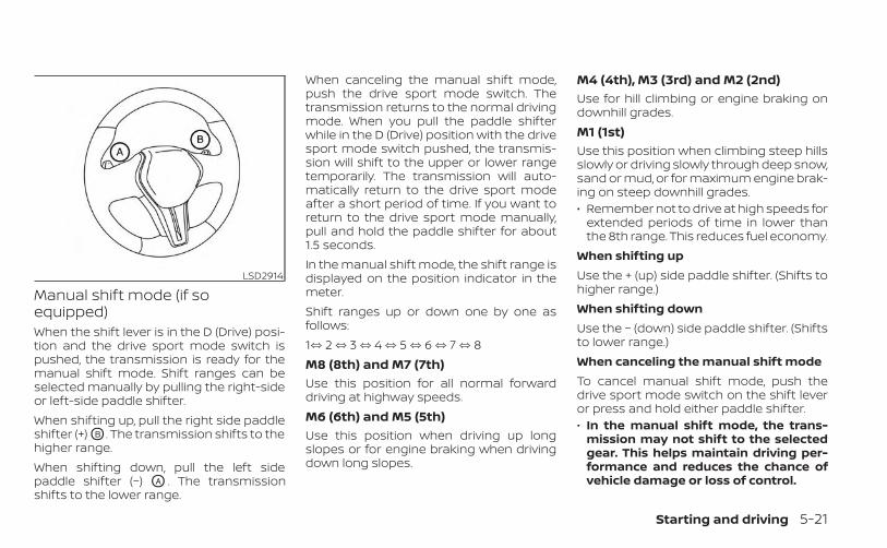
Manual shift mode (if soequipped)When the shift lever is in the D (Drive) posi-tion and the drive sport mode switch ispushed, the transmission is ready for themanual shift mode. Shift ranges can beselected manually by pulling the right-sideor left-side paddle shifter.When shifting up, pull the right side paddleshifter (+) OB . The transmission shifts to thehigher range.When shifting down, pull the left sidepaddle shifter (−) OA . The transmissionshifts to the lower range.
When canceling the manual shift mode,push the drive sport mode switch. Thetransmission returns to the normal drivingmode. When you pull the paddle shifterwhile in the D (Drive) position with the drivesport mode switch pushed, the transmis-sion will shift to the upper or lower rangetemporarily. The transmission will auto-matically return to the drive sport modeafter a short period of time. If you want toreturn to the drive sport mode manually,pull and hold the paddle shifter for about1.5 seconds.In the manual shift mode, the shift range isdisplayed on the position indicator in themeter.Shift ranges up or down one by one asfollows:1⇔ 2 ⇔ 3 ⇔ 4 ⇔ 5 ⇔ 6 ⇔ 7 ⇔ 8M8 (8th) and M7 (7th)Use this position for all normal forwarddriving at highway speeds.M6 (6th) and M5 (5th)Use this position when driving up longslopes or for engine braking when drivingdown long slopes.
M4 (4th), M3 (3rd) and M2 (2nd)Use for hill climbing or engine braking ondownhill grades.M1 (1st)Use this position when climbing steep hillsslowly or driving slowly through deep snow,sand or mud, or for maximum engine brak-ing on steep downhill grades.• Remember not to drive at high speeds for
extended periods of time in lower thanthe 8th range. This reduces fuel economy.
When shifting upUse the + (up) side paddle shifter. (Shifts tohigher range.)When shifting downUse the − (down) side paddle shifter. (Shiftsto lower range.)When canceling the manual shift modeTo cancel manual shift mode, push thedrive sport mode switch on the shift leveror press and hold either paddle shifter.• In the manual shift mode, the trans-
mission may not shift to the selectedgear. This helps maintain driving per-formance and reduces the chance ofvehicle damage or loss of control.
LSD2914
Starting and driving 5-21
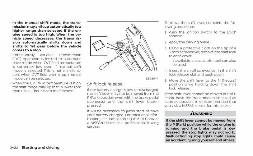
• In the manual shift mode, the trans-mission may shift up automatically to ahigher range than selected if the en-gine speed is too high. When the ve-hicle speed decreases, the transmis-sion automatically shifts down andshifts to 1st gear before the vehiclecomes to a stop.
• Continuously Variable Transmission(CVT) operation is limited to automaticdrive mode when CVT fluid temperatureis extremely low even if manual shiftmode is selected. This is not a malfunc-tion. When CVT fluid warms up, manualmode can be selected.
• When the CVT fluid temperature is high,the shift range may upshift in lower rpmthan usual. This is not a malfunction.
Shift lock releaseIf the battery charge is low or discharged,the shift lever may not be moved from theP (Park) position even with the brake pedaldepressed and the shift lever buttonpressed.It will be necessary to jump start or haveyour battery charged. For additional infor-mation, see “Jump starting” (P. 6-9). Contacta NISSAN dealer or a professional towingservice.
To move the shift lever, complete the fol-lowing procedure:1. Push the ignition switch to the LOCK
position.
2. Apply the parking brake.
3. Using a protective cloth on the tip of a3 mm screwdriver, remove the shift lockrelease cover.• If available, a plastic trim tool can also
be used.
4. Insert the small screwdriver in the shiftlock release slot and push down.
5. Move the shift lever to the N (Neutral)position while holding down the shiftlock release.
If the shift lever cannot be moved out of P(Park), have the transmission checked assoon as possible. It is recommended thatyou visit a NISSAN dealer for this service.
WARNING
If the shift lever cannot be moved fromthe P (Park) position while the engine isrunning and the brake pedal is de-pressed, the stop lights may not work.Malfunctioning stop lights could causean accident injuring yourself and others.
LSD2644
5-22 Starting and driving
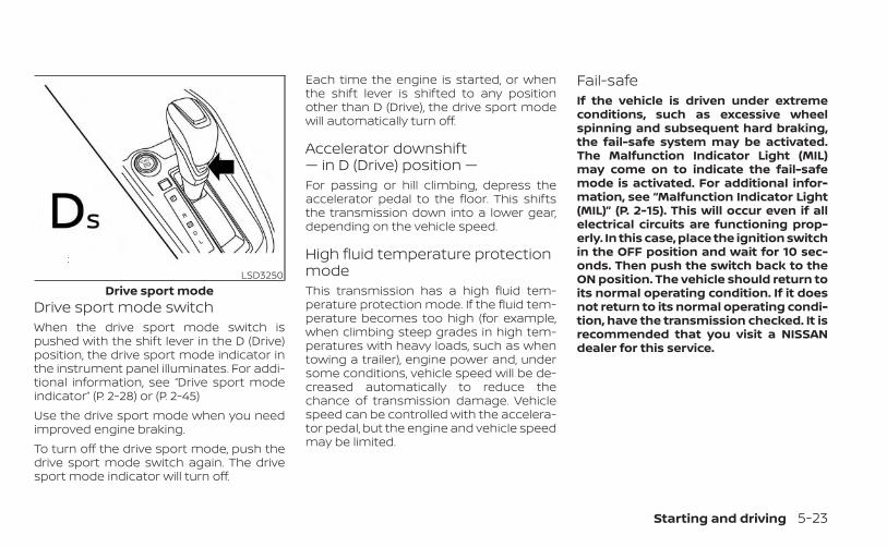
Drive sport mode switchWhen the drive sport mode switch ispushed with the shift lever in the D (Drive)position, the drive sport mode indicator inthe instrument panel illuminates. For addi-tional information, see “Drive sport modeindicator” (P. 2-28) or (P. 2-45)Use the drive sport mode when you needimproved engine braking.To turn off the drive sport mode, push thedrive sport mode switch again. The drivesport mode indicator will turn off.
Each time the engine is started, or whenthe shift lever is shifted to any positionother than D (Drive), the drive sport modewill automatically turn off.
Accelerator downshift— in D (Drive) position —For passing or hill climbing, depress theaccelerator pedal to the floor. This shiftsthe transmission down into a lower gear,depending on the vehicle speed.
High fluid temperature protectionmodeThis transmission has a high fluid tem-perature protection mode. If the fluid tem-perature becomes too high (for example,when climbing steep grades in high tem-peratures with heavy loads, such as whentowing a trailer), engine power and, undersome conditions, vehicle speed will be de-creased automatically to reduce thechance of transmission damage. Vehiclespeed can be controlled with the accelera-tor pedal, but the engine and vehicle speedmay be limited.
Fail-safeIf the vehicle is driven under extremeconditions, such as excessive wheelspinning and subsequent hard braking,the fail-safe system may be activated.The Malfunction Indicator Light (MIL)may come on to indicate the fail-safemode is activated. For additional infor-mation, see “Malfunction Indicator Light(MIL)” (P. 2-15). This will occur even if allelectrical circuits are functioning prop-erly. In this case, place the ignition switchin the OFF position and wait for 10 sec-onds. Then push the switch back to theON position. The vehicle should return toits normal operating condition. If it doesnot return to its normal operating condi-tion, have the transmission checked. It isrecommended that you visit a NISSANdealer for this service.
LSD3250Drive sport mode
Starting and driving 5-23
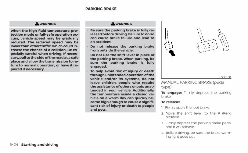
WARNING
When the high fluid temperature pro-tection mode or fail-safe operation oc-curs, vehicle speed may be graduallyreduced. The reduced speed may belower than other traffic, which could in-crease the chance of a collision. Be es-pecially careful when driving. If neces-sary, pull to the side of the road at a safeplace and allow the transmission to re-turn to normal operation, or have it re-paired if necessary.
WARNING
• Be sure the parking brake is fully re-leased before driving. Failure to do socan cause brake failure and lead toan accident.
• Do not release the parking brakefrom outside the vehicle.
• Do not use the shift lever in place ofthe parking brake. When parking, besure the parking brake is fullyengaged.
• To help avoid risk of injury or deaththrough unintended operation of thevehicle and/or its systems, do notleave children, people who requirethe assistance of others or pets unat-tended in your vehicle. Additionally,the temperature inside a closed ve-hicle on a warm day can quickly be-come high enough to cause a signifi-cant risk of injury or death to peopleand pets.
MANUAL PARKING BRAKE (pedaltype)To engage: Firmly depress the parkingbrake.To release:1. Firmly apply the foot brake.
2. Move the shift lever to the P (Park)position.
3. Firmly depress the parking brake pedaland it will release.
4. Before driving, be sure the brake warn-ing light goes out.
LSD0158
PARKING BRAKE
5-24 Starting and driving
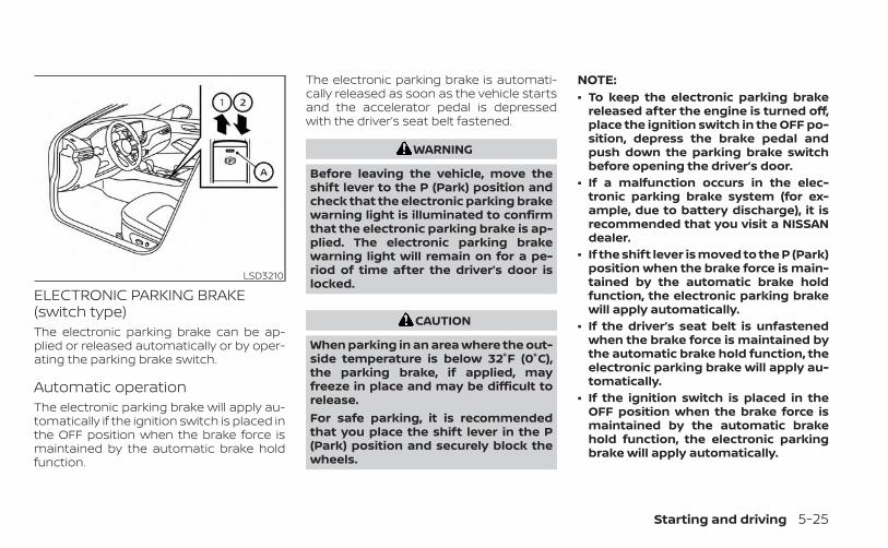
ELECTRONIC PARKING BRAKE(switch type)The electronic parking brake can be ap-plied or released automatically or by oper-ating the parking brake switch.
Automatic operationThe electronic parking brake will apply au-tomatically if the ignition switch is placed inthe OFF position when the brake force ismaintained by the automatic brake holdfunction.
The electronic parking brake is automati-cally released as soon as the vehicle startsand the accelerator pedal is depressedwith the driver’s seat belt fastened.
WARNING
Before leaving the vehicle, move theshift lever to the P (Park) position andcheck that the electronic parking brakewarning light is illuminated to confirmthat the electronic parking brake is ap-plied. The electronic parking brakewarning light will remain on for a pe-riod of time after the driver’s door islocked.
CAUTION
When parking in an area where the out-side temperature is below 32°F (0°C),the parking brake, if applied, mayfreeze in place and may be difficult torelease.For safe parking, it is recommendedthat you place the shift lever in the P(Park) position and securely block thewheels.
NOTE:• To keep the electronic parking brake
released after the engine is turned off,place the ignition switch in the OFF po-sition, depress the brake pedal andpush down the parking brake switchbefore opening the driver’s door.
• If a malfunction occurs in the elec-tronic parking brake system (for ex-ample, due to battery discharge), it isrecommended that you visit a NISSANdealer.
• If the shift lever is moved to the P (Park)position when the brake force is main-tained by the automatic brake holdfunction, the electronic parking brakewill apply automatically.
• If the driver’s seat belt is unfastenedwhen the brake force is maintained bythe automatic brake hold function, theelectronic parking brake will apply au-tomatically.
• If the ignition switch is placed in theOFF position when the brake force ismaintained by the automatic brakehold function, the electronic parkingbrake will apply automatically.
LSD3210
Starting and driving 5-25
Manual operationThe electronic parking brake will not be au-tomatically applied if the engine is stoppedwithout using the ignition switch (for ex-ample, by engine stalling). In such a case,you have to apply the parking brake manu-ally.To apply: Pull the switch up O1 . The indica-tor light OA will illuminate.To release: With the ignition switch in theON position, depress the brake pedal andpush the switch down O2 . The indicatorlight OA will turn off.Before driving, check that the electronicparking brake indicator light ( or PARK)goes out. For additional information, see“Warning lights, indicator lights and audiblereminders” (P. 2-9).
NOTE:• A buzzer will sound if the vehicle is
driven without releasing the parkingbrake. For additional information, see“Warning lights, indicator lights andaudible reminders” (P. 2-9).
• While the electronic parking brake isapplied or released, an operatingsound is heard from the lower side ofthe rear seat. This is normal and doesnot indicate a malfunction.
• When the electronic parking brake isfrequently applied and released in ashort period of time, the parking brakemay not operate in order to prevent theparking brake system from overheat-ing. If this occurs, operate the elec-tronic parking brake switch again afterwaiting approximately 1 minute.
• If the electronic parking brake must beapplied while driving in an emergency,pull up and hold the parking brakeswitch. When you release the parkingbrake switch, the parking brake will bereleased.
• While pulling up the electronic parkingbrake switch during driving, the park-ing brake is applied and a chimesounds. The electronic parking brakeindicator light in the meter and in theparking brake switch illuminates. Thisdoes not indicate a malfunction. Theelectronic parking brake indicator lightin the meter and in the parking brakeswitch turns off when the parkingbrake is released.
• When pulling the electronic parkingbrake switch up with the ignitionswitch in the OFF or AUTO ACC position,the parking brake switch indicatorlight will continue to illuminate for ashort period of time.
5-26 Starting and driving
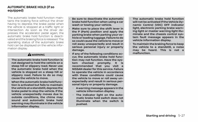
The automatic brake hold function main-tains the braking force without the driverhaving to depress the brake pedal whenthe vehicle is stopped at a traffic light orintersection. As soon as the driver de-presses the accelerator pedal again, theautomatic brake hold function is deacti-vated and the braking force is released. Theoperating status of the automatic brakehold can be displayed on the vehicle infor-mation display.
WARNING
• The automatic brake hold function isnot designed to hold the vehicle on asteep hill or slippery road. Never usethe automatic brake hold when thevehicle is stopped on a steep hill orslippery road. Failure to do so maycause the vehicle to move.
• When the automatic brake hold func-tion is activated but fails to maintainthe vehicle at a standstill, depress thebrake pedal to stop the vehicle. If thevehicle unexpectedly moves due tooutside conditions, the chime maysound and automatic brake holdwarning may illuminate in the vehicleinformation display.
• Be sure to deactivate the automaticbrake hold function when using a carwash or towing your vehicle.
• Make sure to place the shift lever inthe P (Park) position and apply theparking brake when parking your ve-hicle or loading luggage. Failure to doso could cause the vehicle to move orroll away unexpectedly and result inserious personal injury or propertydamage.
• If any of the following conditions oc-cur, the automatic brake hold func-tion may not function. Have the sys-tem checked promptly. It isrecommended that you visit aNISSAN dealer for this service. Failureto operate the vehicle in accordancewith these conditions could causethe vehicle to move or roll away un-expectedly and result in serious per-sonal injury or property damage.– A warning message appears in the
vehicle information display.– The indicator light on the auto-
matic brake hold switch does notilluminate when the switch ispushed.
• The automatic brake hold functionwill not be activated if the Vehicle Dy-namic Control (VDC) OFF indicatorlight, electronic parking brake warn-ing light or master warning light illu-minate and the chassis control sys-tem fault message appears in thevehicle information display.
• To maintain the braking force to keepthe vehicle to a standstill, a noisemay be heard. This is not amalfunction.
AUTOMATIC BRAKE HOLD (if soequipped)
Starting and driving 5-27
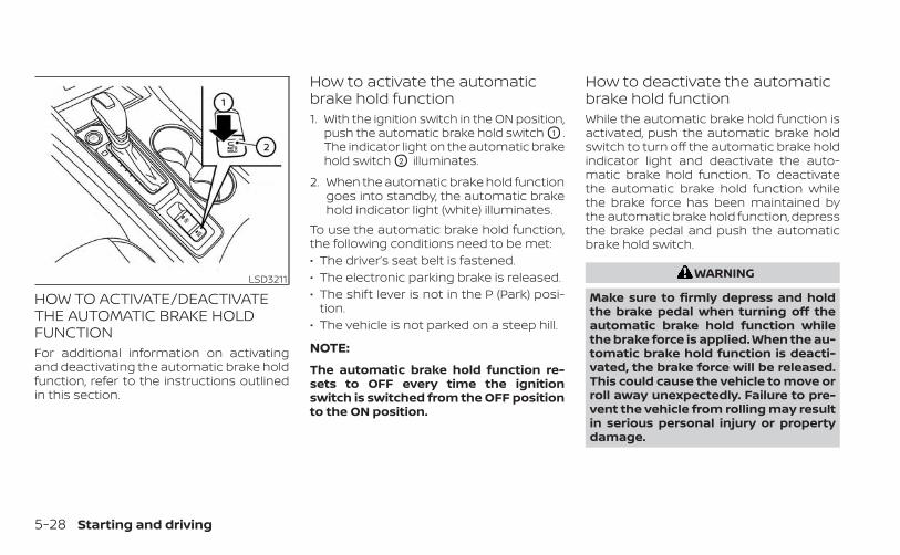
HOW TO ACTIVATE/DEACTIVATETHE AUTOMATIC BRAKE HOLDFUNCTIONFor additional information on activatingand deactivating the automatic brake holdfunction, refer to the instructions outlinedin this section.
How to activate the automaticbrake hold function1. With the ignition switch in the ON position,
push the automatic brake hold switch O1 .The indicator light on the automatic brakehold switch O2 illuminates.
2. When the automatic brake hold functiongoes into standby, the automatic brakehold indicator light (white) illuminates.
To use the automatic brake hold function,the following conditions need to be met:• The driver’s seat belt is fastened.• The electronic parking brake is released.• The shift lever is not in the P (Park) posi-
tion.• The vehicle is not parked on a steep hill.
NOTE:
The automatic brake hold function re-sets to OFF every time the ignitionswitch is switched from the OFF positionto the ON position.
How to deactivate the automaticbrake hold functionWhile the automatic brake hold function isactivated, push the automatic brake holdswitch to turn off the automatic brake holdindicator light and deactivate the auto-matic brake hold function. To deactivatethe automatic brake hold function whilethe brake force has been maintained bythe automatic brake hold function, depressthe brake pedal and push the automaticbrake hold switch.
WARNING
Make sure to firmly depress and holdthe brake pedal when turning off theautomatic brake hold function whilethe brake force is applied. When the au-tomatic brake hold function is deacti-vated, the brake force will be released.This could cause the vehicle to move orroll away unexpectedly. Failure to pre-vent the vehicle from rolling may resultin serious personal injury or propertydamage.
LSD3211
5-28 Starting and driving
HOW TO USE THE AUTOMATICBRAKE HOLD FUNCTIONFor additional information on using the au-tomatic brake hold function, refer to theinstructions outlined in this section.
To maintain braking forceautomaticallyWith the automatic brake hold function ac-tivated and the automatic brake hold indi-cator light (white) illuminated on the meter,depress the braking pedal to stop the ve-hicle. The brake force is automaticallymaintained without your foot depressedon the brake pedal. While the brake hold ismaintained, the automatic brake hold indi-cator light (green) illuminates on the meter.
To start the vehicle from astandstillWith the shift lever not in the P (Park) or N(Neutral) position, depress the acceleratorpedal while the brake force is maintained.The brake force will automatically be re-leased to restart the vehicle.The automatic brake hold indicator light(white) on the meter illuminates and theautomatic brake hold returns to standby.
ParkingWhen the shift lever is in the P (Park) posi-tion with the brake force maintained by theautomatic brake hold function, the parkingbrake will automatically be applied and thebrake force of the automatic brake hold willbe released. The automatic brake hold in-dicator light turns off. When the parkingbrake is applied with the brake force main-tained by the automatic brake hold func-tion, the brake force of the automatic brakehold will be released. The automatic brakehold indicator light turns off.
NOTE:• Under the following conditions, the
parking brake will automatically be ap-plied and the brake force of the auto-matic brake hold will be released:– The braking force is applied by the
automatic brake hold function for 3minutes or longer.
– The driver's seat belt is unfastened.– The ignition switch is placed in the
OFF position.– If a malfunction occurs in the auto-
matic brake hold function.
• When the vehicle stops, but the brakeforce is not automatically applied, de-press the brake pedal firmly until theautomatic brake hold indicator light(green) illuminates.
Starting and driving 5-29
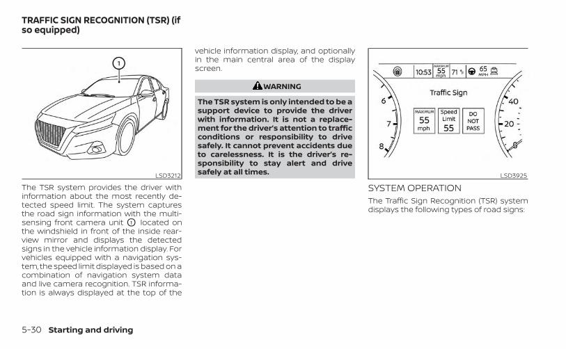
The TSR system provides the driver withinformation about the most recently de-tected speed limit. The system capturesthe road sign information with the multi-sensing front camera unit O1 located onthe windshield in front of the inside rear-view mirror and displays the detectedsigns in the vehicle information display. Forvehicles equipped with a navigation sys-tem, the speed limit displayed is based on acombination of navigation system dataand live camera recognition. TSR informa-tion is always displayed at the top of the
vehicle information display, and optionallyin the main central area of the displayscreen.
WARNING
The TSR system is only intended to be asupport device to provide the driverwith information. It is not a replace-ment for the driver’s attention to trafficconditions or responsibility to drivesafely. It cannot prevent accidents dueto carelessness. It is the driver’s re-sponsibility to stay alert and drivesafely at all times.
SYSTEM OPERATIONThe Traffic Sign Recognition (TSR) systemdisplays the following types of road signs:
LSD3212 LSD3925
TRAFFIC SIGN RECOGNITION (TSR) (ifso equipped)
5-30 Starting and driving
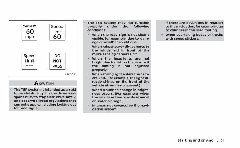
CAUTION
• The TSR system is intended as an aidto careful driving. It is the driver’s re-sponsibility to stay alert, drive safely,and observe all road regulations thatcurrently apply, including looking outfor road signs.
• The TSR system may not functionproperly under the followingconditions:– When the road sign is not clearly
visible, for example, due to dam-age or weather conditions.
– When rain, snow or dirt adheres tothe windshield in front of themulti-sensing camera unit.
– When the headlights are notbright due to dirt on the lens or ifthe aiming is not adjustedproperly.
– When strong light enters the cam-era unit. (For example, the light di-rectly shines on the front of thevehicle at sunrise or sunset.)
– When a sudden change in bright-ness occurs. (For example, whenthe vehicle enters or exits a tunnelor under a bridge.)
– In areas not covered by the navi-gation system.
– If there are deviations in relationto the navigation, for example dueto changes in the road routing.
– When overtaking buses or truckswith speed stickers.
LSD3940
Starting and driving 5-31
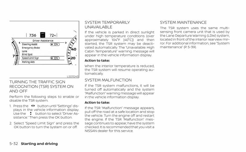
TURNING THE TRAFFIC SIGNRECOGNITION (TSR) SYSTEM ONAND OFFPerform the following steps to enable ordisable the TSR system.1. Press the button until “Settings” dis-
plays in the vehicle information display.Use the button to select “Driver As-sistance.” Then press the OK button.
2. Select “Speed Limit Sign” and press theOK button to turn the system on or off.
SYSTEM TEMPORARILYUNAVAILABLEIf the vehicle is parked in direct sunlightunder high temperature conditions (overapproximately 104°F [40°C]) and thenstarted, the TSR system may be deacti-vated automatically. The “Unavailable: HighCabin Temperature” warning message willappear in the vehicle information display.Action to take:When the interior temperature is reduced,the TSR system will resume operating au-tomatically.
SYSTEM MALFUNCTIONIf the TSR system malfunctions, it will beturned off automatically and the system“Malfunction” warning message will appearin the vehicle information display.Action to take:If the TSR “Malfunction” message appears,pull off the road at a safe location and stopthe vehicle. Turn the engine off and restartthe engine. If the TSR “Malfunction” mes-sage continues to appear, have the systemchecked. It is recommended that you visit aNISSAN dealer for this service.
SYSTEM MAINTENANCEThe TSR system uses the same multi-sensing front camera unit that is used bythe Lane Departure Warning (LDW) system,located in front of the interior rearview mir-ror. For additional information, see ”Systemmaintenance” (P. 5-39).
LSD3243
5-32 Starting and driving
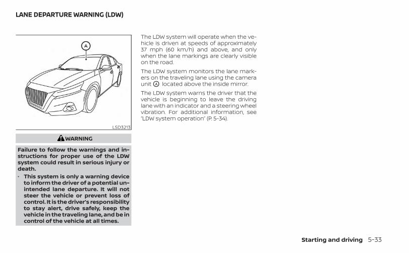
WARNING
Failure to follow the warnings and in-structions for proper use of the LDWsystem could result in serious injury ordeath.• This system is only a warning device
to inform the driver of a potential un-intended lane departure. It will notsteer the vehicle or prevent loss ofcontrol. It is the driver’s responsibilityto stay alert, drive safely, keep thevehicle in the traveling lane, and be incontrol of the vehicle at all times.
The LDW system will operate when the ve-hicle is driven at speeds of approximately37 mph (60 km/h) and above, and onlywhen the lane markings are clearly visibleon the road.The LDW system monitors the lane mark-ers on the traveling lane using the cameraunit OA located above the inside mirror.The LDW system warns the driver that thevehicle is beginning to leave the drivinglane with an indicator and a steering wheelvibration. For additional information, see“LDW system operation” (P. 5-34).
LSD3213
LANE DEPARTURE WARNING (LDW)
Starting and driving 5-33
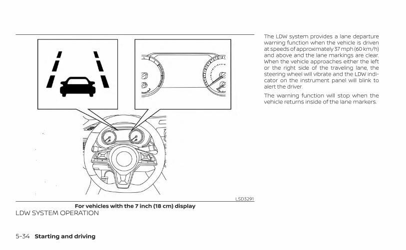
LDW SYSTEM OPERATION
The LDW system provides a lane departurewarning function when the vehicle is drivenat speeds of approximately 37 mph (60 km/h)and above and the lane markings are clear.When the vehicle approaches either the leftor the right side of the traveling lane, thesteering wheel will vibrate and the LDW indi-cator on the instrument panel will blink toalert the driver.The warning function will stop when thevehicle returns inside of the lane markers.
LSD3291For vehicles with the 7 inch (18 cm) display
5-34 Starting and driving
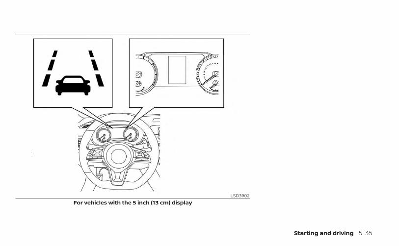
LSD3902For vehicles with the 5 inch (13 cm) display
Starting and driving 5-35
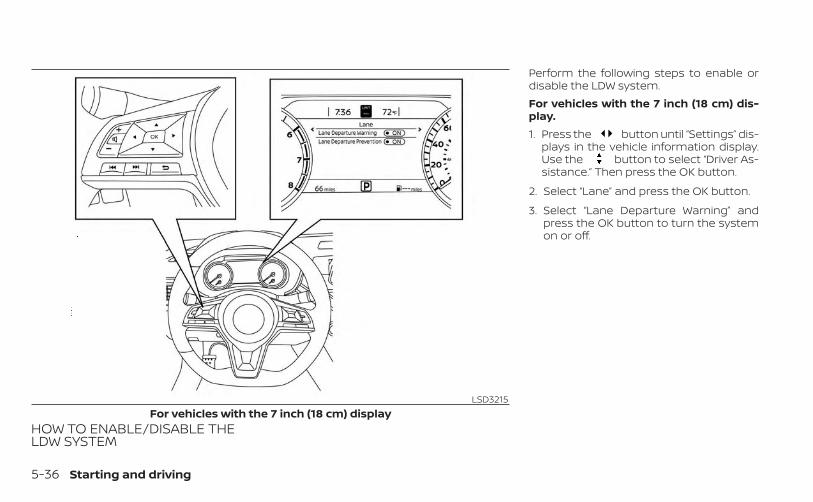
HOW TO ENABLE/DISABLE THELDW SYSTEM
Perform the following steps to enable ordisable the LDW system.For vehicles with the 7 inch (18 cm) dis-play.1. Press the button until “Settings” dis-
plays in the vehicle information display.Use the button to select “Driver As-sistance.” Then press the OK button.
2. Select “Lane” and press the OK button.
3. Select “Lane Departure Warning” andpress the OK button to turn the systemon or off.
LSD3215For vehicles with the 7 inch (18 cm) display
5-36 Starting and driving
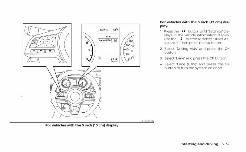
For vehicles with the 5 inch (13 cm) dis-play.1. Press the button until “Settings” dis-
plays in the vehicle information display.Use the button to select “Driver As-sistance.” Then press the OK button.
2. Select “Driving Aids” and press the OKbutton.
3. Select “Lane” and press the OK button.
4. Select “Lane (LDW)” and press the OKbutton to turn the system on or off.
LSD3926For vehicles with the 5 inch (13 cm) display
Starting and driving 5-37
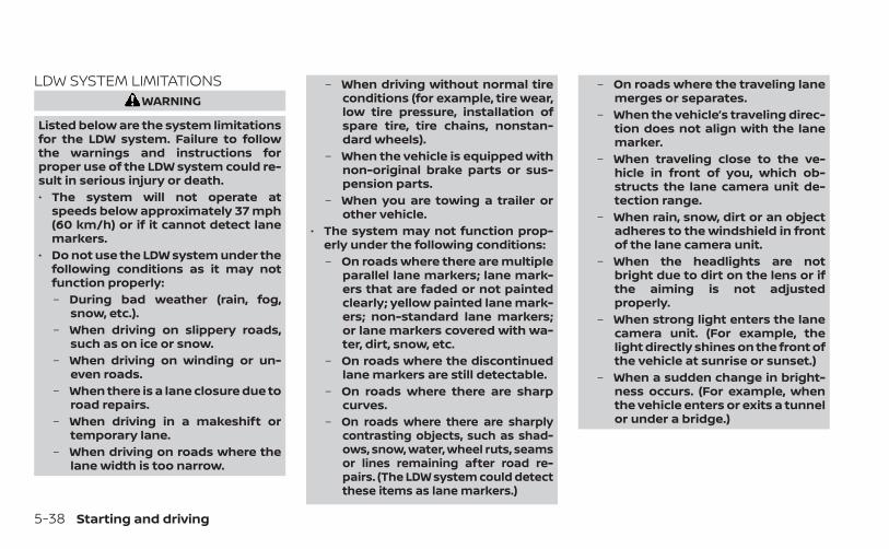
LDW SYSTEM LIMITATIONSWARNING
Listed below are the system limitationsfor the LDW system. Failure to followthe warnings and instructions forproper use of the LDW system could re-sult in serious injury or death.• The system will not operate at
speeds below approximately 37 mph(60 km/h) or if it cannot detect lanemarkers.
• Do not use the LDW system under thefollowing conditions as it may notfunction properly:– During bad weather (rain, fog,
snow, etc.).– When driving on slippery roads,
such as on ice or snow.– When driving on winding or un-
even roads.– When there is a lane closure due to
road repairs.– When driving in a makeshift or
temporary lane.– When driving on roads where the
lane width is too narrow.
– When driving without normal tireconditions (for example, tire wear,low tire pressure, installation ofspare tire, tire chains, nonstan-dard wheels).
– When the vehicle is equipped withnon-original brake parts or sus-pension parts.
– When you are towing a trailer orother vehicle.
• The system may not function prop-erly under the following conditions:– On roads where there are multiple
parallel lane markers; lane mark-ers that are faded or not paintedclearly; yellow painted lane mark-ers; non-standard lane markers;or lane markers covered with wa-ter, dirt, snow, etc.
– On roads where the discontinuedlane markers are still detectable.
– On roads where there are sharpcurves.
– On roads where there are sharplycontrasting objects, such as shad-ows, snow, water, wheel ruts, seamsor lines remaining after road re-pairs. (The LDW system could detectthese items as lane markers.)
– On roads where the traveling lanemerges or separates.
– When the vehicle’s traveling direc-tion does not align with the lanemarker.
– When traveling close to the ve-hicle in front of you, which ob-structs the lane camera unit de-tection range.
– When rain, snow, dirt or an objectadheres to the windshield in frontof the lane camera unit.
– When the headlights are notbright due to dirt on the lens or ifthe aiming is not adjustedproperly.
– When strong light enters the lanecamera unit. (For example, thelight directly shines on the front ofthe vehicle at sunrise or sunset.)
– When a sudden change in bright-ness occurs. (For example, whenthe vehicle enters or exits a tunnelor under a bridge.)
5-38 Starting and driving
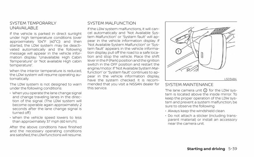
SYSTEM TEMPORARILYUNAVAILABLEIf the vehicle is parked in direct sunlightunder high temperature conditions (overapproximately 104°F [40°C]) and thenstarted, the LDW system may be deacti-vated automatically and the followingmessage will appear in the vehicle infor-mation display: “Unavailable: High CabinTemperature” or “Not available High cabintemperature”.When the interior temperature is reduced,the LDW system will resume operating au-tomatically.The LDW system is not designed to warnunder the following conditions:• When you operate the lane change signal
and change traveling lanes in the direc-tion of the signal. (The LDW system willbecome operable again approximately 2seconds after the lane change signal isturned off.)
• When the vehicle speed lowers to lessthan approximately 37 mph (60 km/h).
After the above conditions have finishedand the necessary operating conditionsare satisfied, the LDW functions will resume.
SYSTEM MALFUNCTIONIf the LDW system malfunctions, it will can-cel automatically and “Not Available Sys-tem Malfunction” or “System fault” will ap-pear in the vehicle information display. If“Not Available System Malfunction” or “Sys-tem fault” appears in the vehicle informa-tion display, pull off the road to a safe loca-tion and stop the vehicle. Place the shiftlever in the P (Park) position and the ignitionswitch in the OFF position and restart theengine/motor. If “Not Available System Mal-function” or “System fault” continues to ap-pear in the vehicle information display,have the system checked. It is recom-mended that you visit a NISSAN dealer forthis service.
SYSTEM MAINTENANCEThe lane camera unit O1 for the LDW sys-tem is located above the inside mirror. Tokeep the proper operation of the LDW sys-tem and prevent a system malfunction, besure to observe the following:• Always keep the windshield clean.• Do not attach a sticker (including trans-
parent material) or install an accessorynear the camera unit.
LSD3484
Starting and driving 5-39
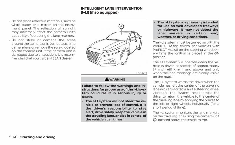
• Do not place reflective materials, such aswhite paper or a mirror, on the instru-ment panel. The reflection of sunlightmay adversely affect the camera unit’scapability of detecting the lane markers.
• Do not strike or damage the areasaround the camera unit. Do not touch thecamera lens or remove the screw locatedon the camera unit. If the camera unit isdamaged due to an accident, it is recom-mended that you visit a NISSAN dealer.
WARNING
Failure to follow the warnings and in-structions for proper use of the I-LI sys-tem could result in serious injury ordeath.• The I-LI system will not steer the ve-
hicle or prevent loss of control. It isthe driver’s responsibility to stayalert, drive safely, keep the vehicle inthe traveling lane, and be in control ofthe vehicle at all times.
• The I-LI system is primarily intendedfor use on well-developed freewaysor highways. It may not detect thelane markers in certain road,weather, or driving conditions.
The I-LI system must be turned on with theProPILOT Assist switch (for vehicles withProPILOT Assist) on the steering wheel, ev-ery time the ignition is placed in the ONposition.The I-LI system will operate when the ve-hicle is driven at speeds of approximately37 mph (60 km/h) and above, and onlywhen the lane markings are clearly visibleon the road.The I-LI system warns the driver when thevehicle has left the center of the travelinglane with an indicator and a steering wheelvibration. The system helps assist thedriver to return the vehicle to the center ofthe traveling lane by applying the brakes tothe left or right wheels individually (for ashort period of time).The I-LI system monitors the lane markerson the traveling lane using the camera unitOA located above the inside mirror.
LSD3213
INTELLIGENT LANE INTERVENTION(I-LI) (if so equipped)
5-40 Starting and driving
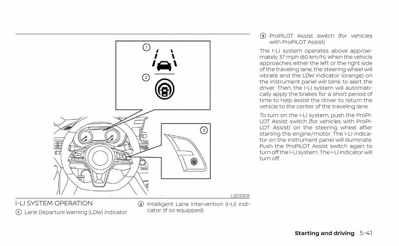
I-LI SYSTEM OPERATION�1 Lane Departure Warning (LDW) indicator
�2 Intelligent Lane Intervention (I-LI) indi-cator (if so equipped)
�3 ProPILOT Assist switch (for vehicleswith ProPILOT Assist)
The I-LI system operates above approxi-mately 37 mph (60 km/h). When the vehicleapproaches either the left or the right sideof the traveling lane, the steering wheel willvibrate and the LDW indicator (orange) onthe instrument panel will blink to alert thedriver. Then, the I-LI system will automati-cally apply the brakes for a short period oftime to help assist the driver to return thevehicle to the center of the traveling lane.To turn on the I-LI system, push the ProPI-LOT Assist switch (for vehicles with ProPI-LOT Assist) on the steering wheel afterstarting the engine/motor. The I-LI indica-tor on the instrument panel will illuminate.Push the ProPILOT Assist switch again toturn off the I-LI system. The I-LI indicator willturn off.
LSD3309
Starting and driving 5-41
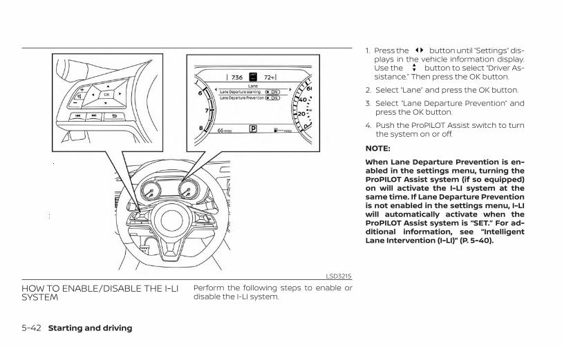
HOW TO ENABLE/DISABLE THE I-LISYSTEM
Perform the following steps to enable ordisable the I-LI system.
1. Press the button until “Settings” dis-plays in the vehicle information display.Use the button to select “Driver As-sistance.” Then press the OK button.
2. Select “Lane” and press the OK button.
3. Select “Lane Departure Prevention” andpress the OK button.
4. Push the ProPILOT Assist switch to turnthe system on or off.
NOTE:
When Lane Departure Prevention is en-abled in the settings menu, turning theProPILOT Assist system (if so equipped)on will activate the I-LI system at thesame time. If Lane Departure Preventionis not enabled in the settings menu, I-LIwill automatically activate when theProPILOT Assist system is “SET.” For ad-ditional information, see “IntelligentLane Intervention (I-LI)” (P. 5-40).
LSD3215
5-42 Starting and driving
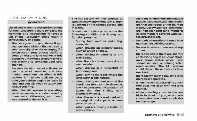
I-LI SYSTEM LIMITATIONSWARNING
Listed below are the system limitationsfor the I-LI system. Failure to follow thewarnings and instructions for properuse of the I-LI system could result inserious injury or death.• The I-LI system may activate if you
change lanes without first activatingyour turn signal or, for example, if aconstruction zone directs traffic tocross an existing lane marker. If thisoccurs you may need to apply correc-tive steering to complete your lanechange.
• Because the I-LI may not activate un-der the road, weather, and lanemarker conditions described in thissection, it may not activate everytime your vehicle begins to leave itslane and you will need to apply cor-rective steering.
• When the I-LI system is operating,avoid excessive or sudden steeringmaneuvers. Otherwise, you couldlose control of the vehicle.
• The I-LI system will not operate atspeeds below approximately 37 mph(60 km/h) or if it cannot detect lanemarkers.
• Do not use the I-LI system under thefollowing conditions as it may notfunction properly:– During bad weather (rain, fog,
snow, etc.).– When driving on slippery roads,
such as on ice or snow.– When driving on winding or un-
even roads.– When there is a lane closure due to
road repairs.– When driving in a makeshift or
temporary lane.– When driving on roads where the
lane width is too narrow.– When driving without normal tire
conditions (for example, tire wear,low tire pressure, installation ofspare tire, tire chains, non-standard wheels).
– When the vehicle is equipped withnonoriginal brake parts or sus-pension parts.
– When you are towing a trailer orother vehicle.
– On roads where there are multipleparallel lane markers; lane mark-ers that are faded or not paintedclearly; yellow painted lane mark-ers; non-standard lane markers;or lane markers covered with wa-ter, dirt, snow, etc.
– On roads where discontinued lanemarkers are still detectable.
– On roads where there are sharpcurves.
– On roads where there are sharplycontrasting objects, such as shad-ows, snow, water, wheel ruts,seams or lines remaining afterroad repairs. (The I-LI systemcould detect these items as lanemarkers.)
– On roads where the traveling lanemerges or separates.
– When the vehicle’s traveling direc-tion does not align with the lanemarker.
– When traveling close to the ve-hicle in front of you, which ob-structs the lane camera unit de-tection range.
Starting and driving 5-43
– When rain, snow or dirt adheres tothe windshield in front of the lanecamera unit.
– When the headlights are notbright due to dirt on the lens or ifthe aiming is not adjustedproperly.
– When strong light enters the lanecamera unit. (For example, thelight directly shines on the front ofthe vehicle at sunrise or sunset.)
– When a sudden change in bright-ness occurs. (For example, whenthe vehicle enters or exits a tunnelor under a bridge.)
While the I-LI system is operating, you mayhear a sound of brake operation. This isnormal and indicates that the I-LI system isoperating properly.
SYSTEM TEMPORARILYUNAVAILABLECondition A:The warning and assist functions of the I-LIsystem are not designed to work under thefollowing conditions:• When you operate the lane change signal
and change the traveling lanes in the di-rection of the signal. (The I-LI system willbe deactivated for approximately 2 sec-onds after the lane change signal isturned off.)
• When the vehicle speed lowers to lessthan approximately 37 mph (60 km/h).
After the above conditions have finishedand the necessary operating conditionsare satisfied, the warning and assist func-tions will resume.Condition B:The assist function of the I-LI system is notdesigned to work under the following con-ditions (warning is still functional):• When the brake pedal is depressed.• When the steering wheel is turned as far
as necessary for the vehicle to changelanes.
• When the vehicle is accelerated duringI-LI system operation.
• When the Intelligent Cruise Control (ICC)approach warning occurs.
• When the hazard warning flashers areoperated.
• When driving on a curve at high speed.After the above conditions have finishedand the necessary operating conditionsare satisfied, the I-LI system application ofthe brakes will resume.Condition C:If the following messages appear in thevehicle information display, the I-LI systemwill be turned off automatically.• “Not Available Poor Road Conditions”:
When the VDC system (except TractionControl System [TCS] function) or ABS op-erates.
• “Currently not available”:When the VDC system is turned off.
Action to take:When the above conditions no longer exist,turn off the I-LI system. Push the ProPILOTAssist switch (for vehicles with ProPILOTAssist) on the steering wheel again to turnthe I-LI system back on.
5-44 Starting and driving
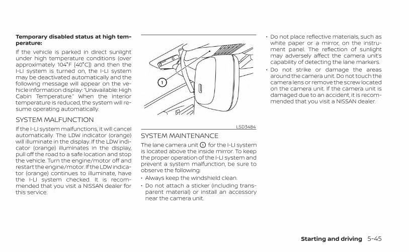
Temporary disabled status at high tem-perature:If the vehicle is parked in direct sunlightunder high temperature conditions (overapproximately 104°F [40°C]) and then theI-LI system is turned on, the I-LI systemmay be deactivated automatically and thefollowing message will appear on the ve-hicle information display: “Unavailable: HighCabin Temperature.” When the interiortemperature is reduced, the system will re-sume operating automatically.
SYSTEM MALFUNCTIONIf the I-LI system malfunctions, it will cancelautomatically. The LDW indicator (orange)will illuminate in the display. If the LDW indi-cator (orange) illuminates in the display,pull off the road to a safe location and stopthe vehicle. Turn the engine/motor off andrestart the engine/motor. If the LDW indica-tor (orange) continues to illuminate, havethe I-LI system checked. It is recom-mended that you visit a NISSAN dealer forthis service.
SYSTEM MAINTENANCEThe lane camera unit O1 for the I-LI systemis located above the inside mirror. To keepthe proper operation of the I-LI system andprevent a system malfunction, be sure toobserve the following:• Always keep the windshield clean.• Do not attach a sticker (including trans-
parent material) or install an accessorynear the camera unit.
• Do not place reflective materials, such aswhite paper or a mirror, on the instru-ment panel. The reflection of sunlightmay adversely affect the camera unit’scapability of detecting the lane markers.
• Do not strike or damage the areasaround the camera unit. Do not touch thecamera lens or remove the screw locatedon the camera unit. If the camera unit isdamaged due to an accident, it is recom-mended that you visit a NISSAN dealer.
LSD3484
Starting and driving 5-45
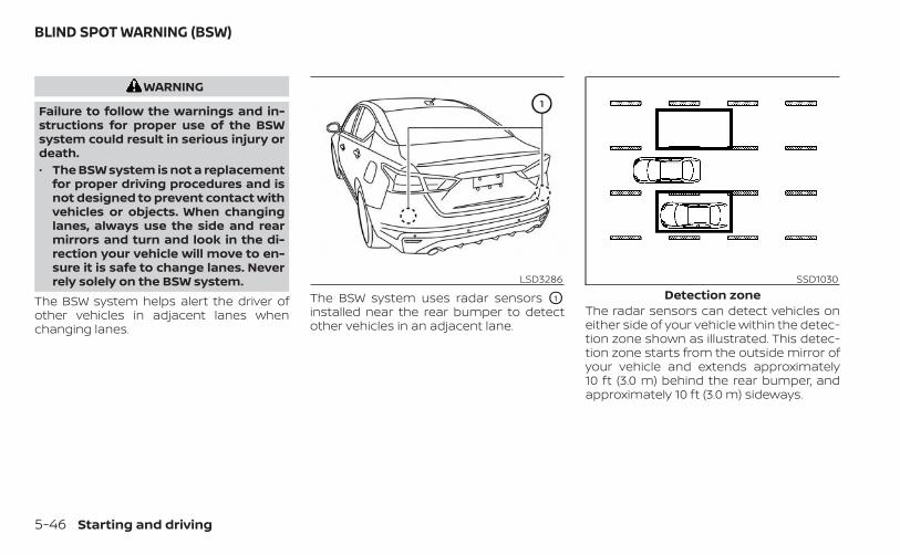
WARNING
Failure to follow the warnings and in-structions for proper use of the BSWsystem could result in serious injury ordeath.• The BSW system is not a replacement
for proper driving procedures and isnot designed to prevent contact withvehicles or objects. When changinglanes, always use the side and rearmirrors and turn and look in the di-rection your vehicle will move to en-sure it is safe to change lanes. Neverrely solely on the BSW system.
The BSW system helps alert the driver ofother vehicles in adjacent lanes whenchanging lanes.
The BSW system uses radar sensors O1
installed near the rear bumper to detectother vehicles in an adjacent lane.
The radar sensors can detect vehicles oneither side of your vehicle within the detec-tion zone shown as illustrated. This detec-tion zone starts from the outside mirror ofyour vehicle and extends approximately10 ft (3.0 m) behind the rear bumper, andapproximately 10 ft (3.0 m) sideways.
LSD3286 SSD1030Detection zone
BLIND SPOT WARNING (BSW)
5-46 Starting and driving
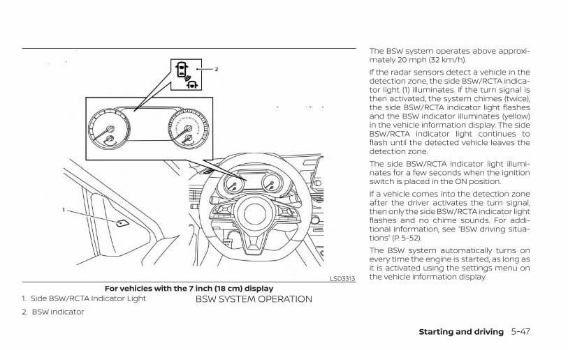
1. Side BSW/RCTA Indicator Light
2. BSW indicatorBSW SYSTEM OPERATION
The BSW system operates above approxi-mately 20 mph (32 km/h).If the radar sensors detect a vehicle in thedetection zone, the side BSW/RCTA indica-tor light (1) illuminates. If the turn signal isthen activated, the system chimes (twice),the side BSW/RCTA indicator light flashesand the BSW indicator illuminates (yellow)in the vehicle information display. The sideBSW/RCTA indicator light continues toflash until the detected vehicle leaves thedetection zone.The side BSW/RCTA indicator light illumi-nates for a few seconds when the ignitionswitch is placed in the ON position.If a vehicle comes into the detection zoneafter the driver activates the turn signal,then only the side BSW/RCTA indicator lightflashes and no chime sounds. For addi-tional information, see “BSW driving situa-tions” (P. 5-52).The BSW system automatically turns onevery time the engine is started, as long asit is activated using the settings menu onthe vehicle information display.LSD3313
For vehicles with the 7 inch (18 cm) display
Starting and driving 5-47
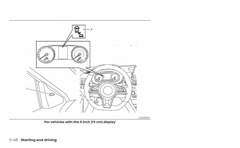
LSD3904For vehicles with the 5 inch (13 cm) display
5-48 Starting and driving
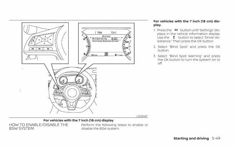
HOW TO ENABLE/DISABLE THEBSW SYSTEM
Perform the following steps to enable ordisable the BSW system.
For vehicles with the 7 inch (18 cm) dis-play.1. Press the button until “Settings” dis-
plays in the vehicle information display.Use the button to select “Driver As-sistance.” Then press the OK button.
2. Select “Blind Spot” and press the OKbutton.
3. Select “Blind Spot Warning” and pressthe OK button to turn the system on oroff.
LSD3487For vehicles with the 7 inch (18 cm) display
Starting and driving 5-49
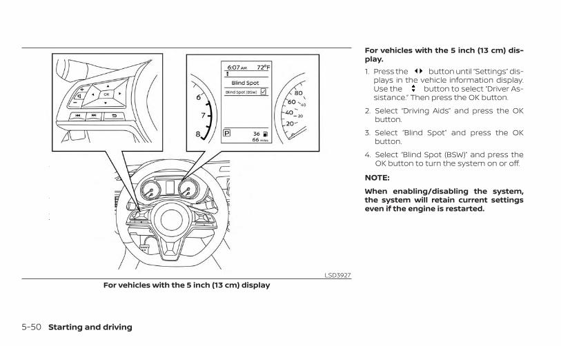
For vehicles with the 5 inch (13 cm) dis-play.1. Press the button until “Settings” dis-
plays in the vehicle information display.Use the button to select “Driver As-sistance.” Then press the OK button.
2. Select “Driving Aids” and press the OKbutton.
3. Select “Blind Spot” and press the OKbutton.
4. Select “Blind Spot (BSW)” and press theOK button to turn the system on or off.
NOTE:
When enabling/disabling the system,the system will retain current settingseven if the engine is restarted.
LSD3927For vehicles with the 5 inch (13 cm) display
5-50 Starting and driving
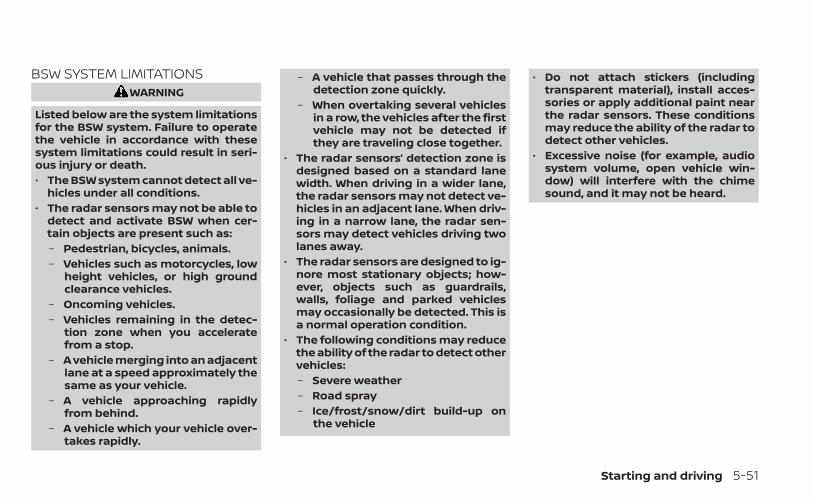
BSW SYSTEM LIMITATIONSWARNING
Listed below are the system limitationsfor the BSW system. Failure to operatethe vehicle in accordance with thesesystem limitations could result in seri-ous injury or death.• The BSW system cannot detect all ve-
hicles under all conditions.• The radar sensors may not be able to
detect and activate BSW when cer-tain objects are present such as:– Pedestrian, bicycles, animals.– Vehicles such as motorcycles, low
height vehicles, or high groundclearance vehicles.
– Oncoming vehicles.– Vehicles remaining in the detec-
tion zone when you acceleratefrom a stop.
– A vehicle merging into an adjacentlane at a speed approximately thesame as your vehicle.
– A vehicle approaching rapidlyfrom behind.
– A vehicle which your vehicle over-takes rapidly.
– A vehicle that passes through thedetection zone quickly.
– When overtaking several vehiclesin a row, the vehicles after the firstvehicle may not be detected ifthey are traveling close together.
• The radar sensors’ detection zone isdesigned based on a standard lanewidth. When driving in a wider lane,the radar sensors may not detect ve-hicles in an adjacent lane. When driv-ing in a narrow lane, the radar sen-sors may detect vehicles driving twolanes away.
• The radar sensors are designed to ig-nore most stationary objects; how-ever, objects such as guardrails,walls, foliage and parked vehiclesmay occasionally be detected. This isa normal operation condition.
• The following conditions may reducethe ability of the radar to detect othervehicles:– Severe weather– Road spray– Ice/frost/snow/dirt build-up on
the vehicle
• Do not attach stickers (includingtransparent material), install acces-sories or apply additional paint nearthe radar sensors. These conditionsmay reduce the ability of the radar todetect other vehicles.
• Excessive noise (for example, audiosystem volume, open vehicle win-dow) will interfere with the chimesound, and it may not be heard.
Starting and driving 5-51
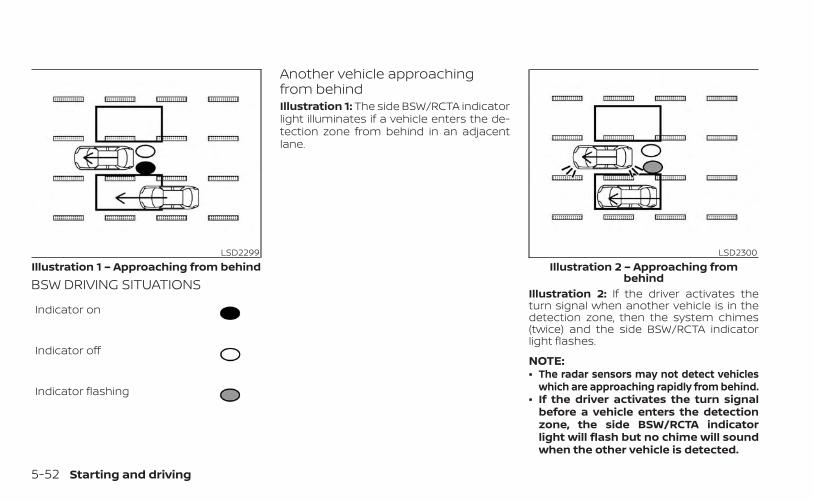
BSW DRIVING SITUATIONS
Indicator on
Indicator off
Indicator flashing
Another vehicle approachingfrom behindIllustration 1: The side BSW/RCTA indicatorlight illuminates if a vehicle enters the de-tection zone from behind in an adjacentlane.
Illustration 2: If the driver activates theturn signal when another vehicle is in thedetection zone, then the system chimes(twice) and the side BSW/RCTA indicatorlight flashes.
NOTE:• The radar sensors may not detect vehicles
which are approaching rapidly from behind.• If the driver activates the turn signal
before a vehicle enters the detectionzone, the side BSW/RCTA indicatorlight will flash but no chime will soundwhen the other vehicle is detected.
LSD2299Illustration 1 – Approaching from behind
LSD2300Illustration 2 – Approaching from
behind
5-52 Starting and driving
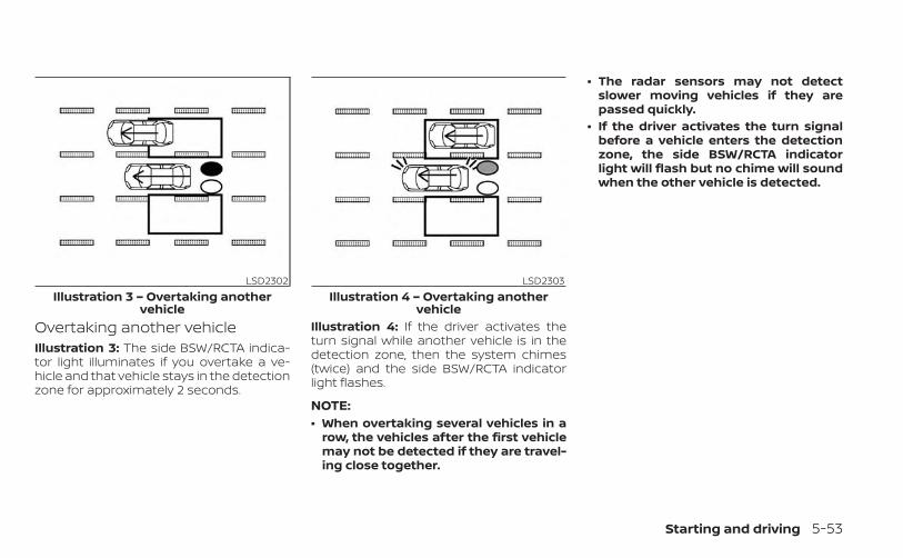
Overtaking another vehicleIllustration 3: The side BSW/RCTA indica-tor light illuminates if you overtake a ve-hicle and that vehicle stays in the detectionzone for approximately 2 seconds.
Illustration 4: If the driver activates theturn signal while another vehicle is in thedetection zone, then the system chimes(twice) and the side BSW/RCTA indicatorlight flashes.
NOTE:• When overtaking several vehicles in a
row, the vehicles after the first vehiclemay not be detected if they are travel-ing close together.
• The radar sensors may not detectslower moving vehicles if they arepassed quickly.
• If the driver activates the turn signalbefore a vehicle enters the detectionzone, the side BSW/RCTA indicatorlight will flash but no chime will soundwhen the other vehicle is detected.
LSD2302Illustration 3 – Overtaking another
vehicle
LSD2303Illustration 4 – Overtaking another
vehicle
Starting and driving 5-53
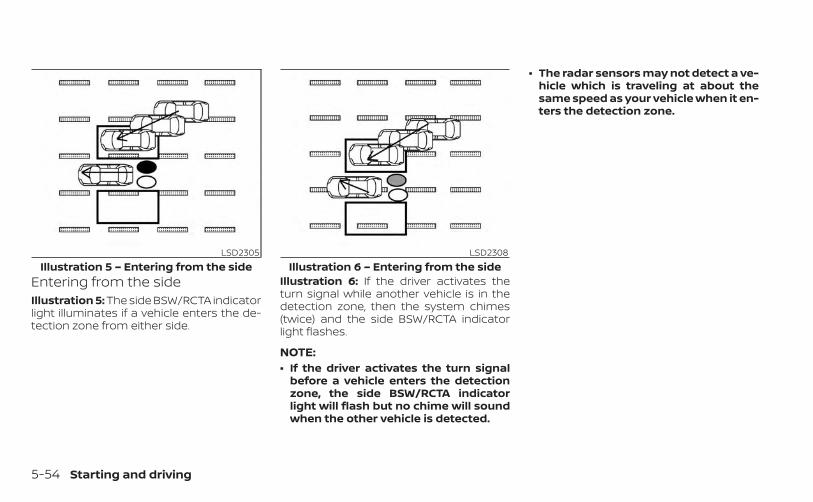
Entering from the sideIllustration 5: The side BSW/RCTA indicatorlight illuminates if a vehicle enters the de-tection zone from either side.
Illustration 6: If the driver activates theturn signal while another vehicle is in thedetection zone, then the system chimes(twice) and the side BSW/RCTA indicatorlight flashes.
NOTE:• If the driver activates the turn signal
before a vehicle enters the detectionzone, the side BSW/RCTA indicatorlight will flash but no chime will soundwhen the other vehicle is detected.
• The radar sensors may not detect a ve-hicle which is traveling at about thesame speed as your vehicle when it en-ters the detection zone.
LSD2305Illustration 5 – Entering from the side
LSD2308Illustration 6 – Entering from the side
5-54 Starting and driving
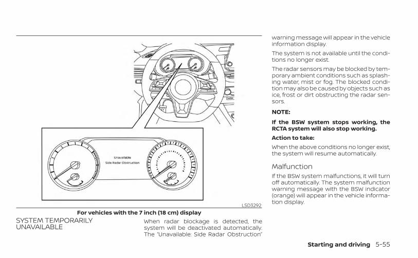
SYSTEM TEMPORARILYUNAVAILABLE
When radar blockage is detected, thesystem will be deactivated automatically.The “Unavailable: Side Radar Obstruction”
warning message will appear in the vehicleinformation display.The system is not available until the condi-tions no longer exist.The radar sensors may be blocked by tem-porary ambient conditions such as splash-ing water, mist or fog. The blocked condi-tion may also be caused by objects such asice, frost or dirt obstructing the radar sen-sors.
NOTE:
If the BSW system stops working, theRCTA system will also stop working.Action to take:When the above conditions no longer exist,the system will resume automatically.
MalfunctionIf the BSW system malfunctions, it will turnoff automatically. The system malfunctionwarning message with the BSW indicator(orange) will appear in the vehicle informa-tion display.LSD3292
For vehicles with the 7 inch (18 cm) display
Starting and driving 5-55
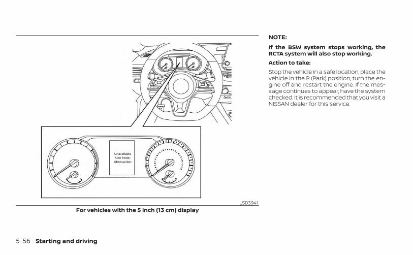
NOTE:
If the BSW system stops working, theRCTA system will also stop working.Action to take:Stop the vehicle in a safe location, place thevehicle in the P (Park) position, turn the en-gine off and restart the engine. If the mes-sage continues to appear, have the systemchecked. It is recommended that you visit aNISSAN dealer for this service.
LSD3941For vehicles with the 5 inch (13 cm) display
5-56 Starting and driving
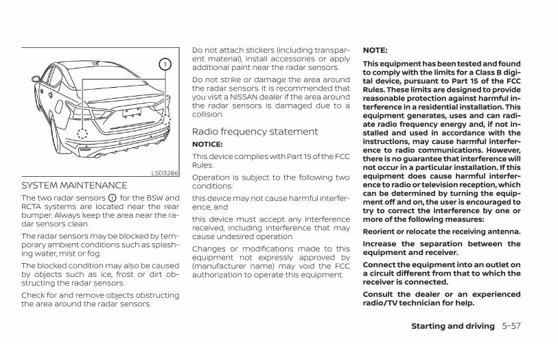
SYSTEM MAINTENANCEThe two radar sensors O1 for the BSW andRCTA systems are located near the rearbumper. Always keep the area near the ra-dar sensors clean.The radar sensors may be blocked by tem-porary ambient conditions such as splash-ing water, mist or fog.The blocked condition may also be causedby objects such as ice, frost or dirt ob-structing the radar sensors.Check for and remove objects obstructingthe area around the radar sensors.
Do not attach stickers (including transpar-ent material), install accessories or applyadditional paint near the radar sensors.Do not strike or damage the area aroundthe radar sensors. It is recommended thatyou visit a NISSAN dealer if the area aroundthe radar sensors is damaged due to acollision.
Radio frequency statementNOTICE:This device complies with Part 15 of the FCCRules.Operation is subject to the following twoconditions:this device may not cause harmful interfer-ence, andthis device must accept any interferencereceived, including interference that maycause undesired operation.Changes or modifications made to thisequipment not expressly approved by(manufacturer name) may void the FCCauthorization to operate this equipment.
NOTE:
This equipment has been tested and foundto comply with the limits for a Class B digi-tal device, pursuant to Part 15 of the FCCRules. These limits are designed to providereasonable protection against harmful in-terference in a residential installation. Thisequipment generates, uses and can radi-ate radio frequency energy and, if not in-stalled and used in accordance with theinstructions, may cause harmful interfer-ence to radio communications. However,there is no guarantee that interference willnot occur in a particular installation. If thisequipment does cause harmful interfer-ence to radio or television reception, whichcan be determined by turning the equip-ment off and on, the user is encouraged totry to correct the interference by one ormore of the following measures:Reorient or relocate the receiving antenna.Increase the separation between theequipment and receiver.Connect the equipment into an outlet ona circuit different from that to which thereceiver is connected.Consult the dealer or an experiencedradio/TV technician for help.
LSD3286
Starting and driving 5-57
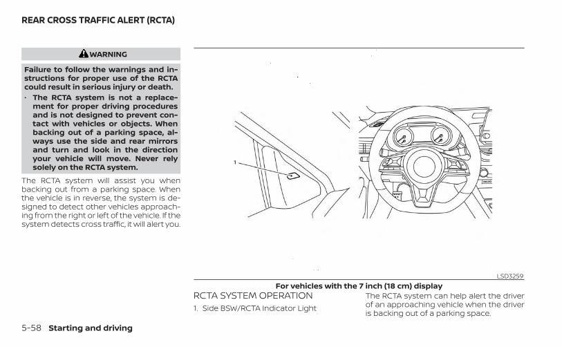
WARNING
Failure to follow the warnings and in-structions for proper use of the RCTAcould result in serious injury or death.• The RCTA system is not a replace-
ment for proper driving proceduresand is not designed to prevent con-tact with vehicles or objects. Whenbacking out of a parking space, al-ways use the side and rear mirrorsand turn and look in the directionyour vehicle will move. Never relysolely on the RCTA system.
The RCTA system will assist you whenbacking out from a parking space. Whenthe vehicle is in reverse, the system is de-signed to detect other vehicles approach-ing from the right or left of the vehicle. If thesystem detects cross traffic, it will alert you.
RCTA SYSTEM OPERATION1. Side BSW/RCTA Indicator Light
The RCTA system can help alert the driverof an approaching vehicle when the driveris backing out of a parking space.
LSD3259For vehicles with the 7 inch (18 cm) display
REAR CROSS TRAFFIC ALERT (RCTA)
5-58 Starting and driving
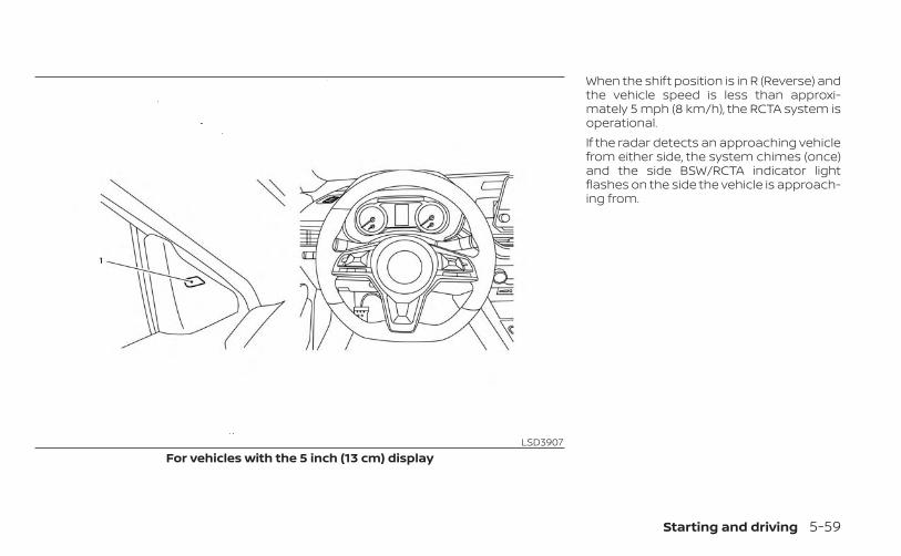
When the shift position is in R (Reverse) andthe vehicle speed is less than approxi-mately 5 mph (8 km/h), the RCTA system isoperational.If the radar detects an approaching vehiclefrom either side, the system chimes (once)and the side BSW/RCTA indicator lightflashes on the side the vehicle is approach-ing from.
LSD3907For vehicles with the 5 inch (13 cm) display
Starting and driving 5-59
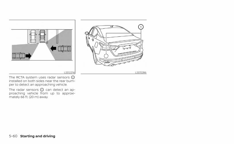
The RCTA system uses radar sensors O1
installed on both sides near the rear bum-per to detect an approaching vehicle.The radar sensors O1 can detect an ap-proaching vehicle from up to approxi-mately 66 ft. (20 m) away.
LSD2216 LSD3286
5-60 Starting and driving
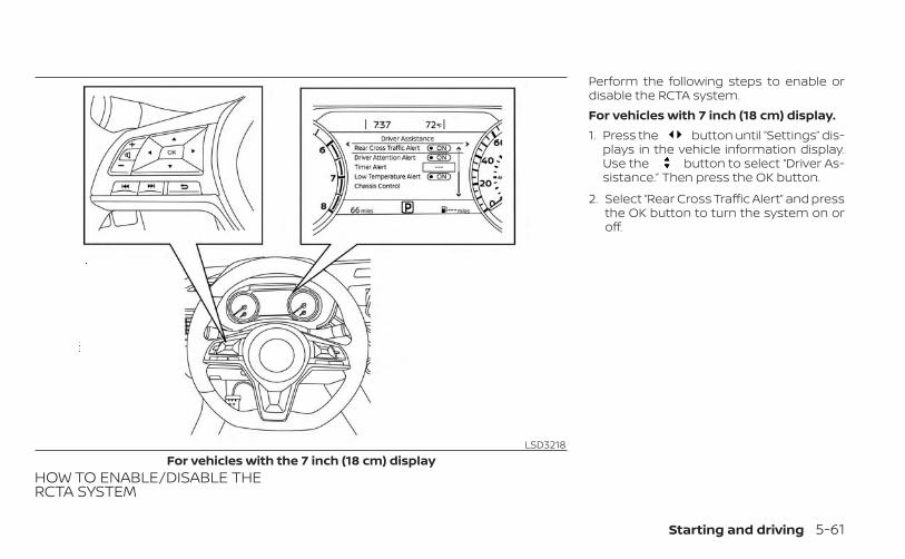
HOW TO ENABLE/DISABLE THERCTA SYSTEM
Perform the following steps to enable ordisable the RCTA system.For vehicles with 7 inch (18 cm) display.1. Press the button until “Settings” dis-
plays in the vehicle information display.Use the button to select “Driver As-sistance.” Then press the OK button.
2. Select “Rear Cross Traffic Alert” and pressthe OK button to turn the system on oroff.
LSD3218For vehicles with the 7 inch (18 cm) display
Starting and driving 5-61
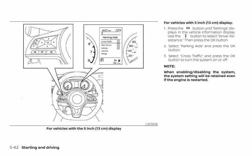
For vehicles with 5 inch (13 cm) display.1. Press the button until “Settings” dis-
plays in the vehicle information display.Use the button to select “Driver As-sistance.” Then press the OK button.
2. Select “Parking Aids” and press the OKbutton.
3. Select “Cross Traffic” and press the OKbutton to turn the system on or off.
NOTE:When enabling/disabling the system,the system setting will be retained evenif the engine is restarted.
LSD3928For vehicles with the 5 inch (13 cm) display
5-62 Starting and driving
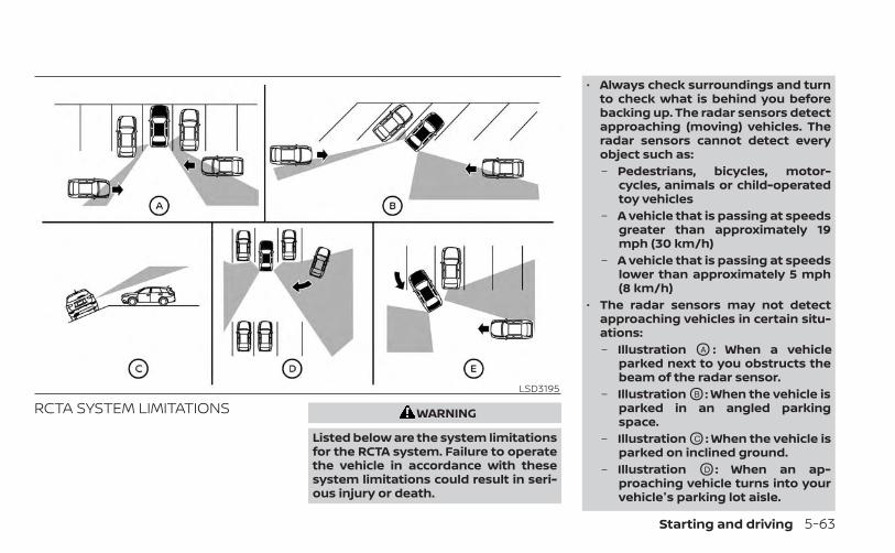
RCTA SYSTEM LIMITATIONS WARNING
Listed below are the system limitationsfor the RCTA system. Failure to operatethe vehicle in accordance with thesesystem limitations could result in seri-ous injury or death.
• Always check surroundings and turnto check what is behind you beforebacking up. The radar sensors detectapproaching (moving) vehicles. Theradar sensors cannot detect everyobject such as:– Pedestrians, bicycles, motor-
cycles, animals or child-operatedtoy vehicles
– A vehicle that is passing at speedsgreater than approximately 19mph (30 km/h)
– A vehicle that is passing at speedslower than approximately 5 mph(8 km/h)
• The radar sensors may not detectapproaching vehicles in certain situ-ations:– Illustration OA : When a vehicle
parked next to you obstructs thebeam of the radar sensor.
– Illustration OB : When the vehicle isparked in an angled parkingspace.
– Illustration OC : When the vehicle isparked on inclined ground.
– Illustration OD : When an ap-proaching vehicle turns into yourvehicle's parking lot aisle.
LSD3195
Starting and driving 5-63
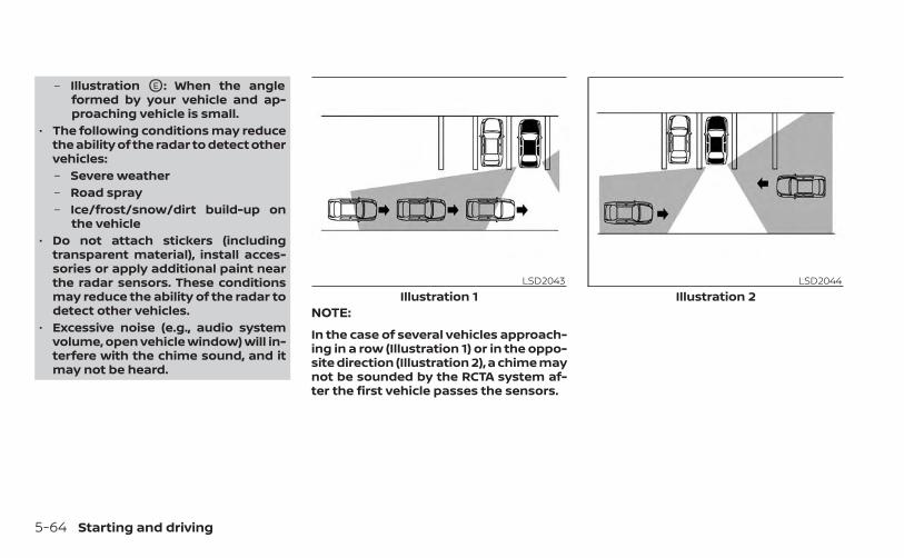
– Illustration OE : When the angleformed by your vehicle and ap-proaching vehicle is small.
• The following conditions may reducethe ability of the radar to detect othervehicles:– Severe weather– Road spray– Ice/frost/snow/dirt build-up on
the vehicle• Do not attach stickers (including
transparent material), install acces-sories or apply additional paint nearthe radar sensors. These conditionsmay reduce the ability of the radar todetect other vehicles.
• Excessive noise (e.g., audio systemvolume, open vehicle window) will in-terfere with the chime sound, and itmay not be heard.
NOTE:
In the case of several vehicles approach-ing in a row (Illustration 1) or in the oppo-site direction (Illustration 2), a chime maynot be sounded by the RCTA system af-ter the first vehicle passes the sensors.
LSD2043Illustration 1
LSD2044Illustration 2
5-64 Starting and driving
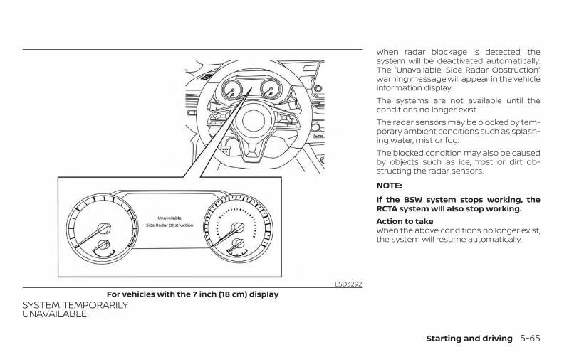
SYSTEM TEMPORARILYUNAVAILABLE
When radar blockage is detected, thesystem will be deactivated automatically.The “Unavailable: Side Radar Obstruction”warning message will appear in the vehicleinformation display.The systems are not available until theconditions no longer exist.The radar sensors may be blocked by tem-porary ambient conditions such as splash-ing water, mist or fog.The blocked condition may also be causedby objects such as ice, frost or dirt ob-structing the radar sensors.
NOTE:
If the BSW system stops working, theRCTA system will also stop working.Action to takeWhen the above conditions no longer exist,the system will resume automatically.
LSD3292For vehicles with the 7 inch (18 cm) display
Starting and driving 5-65
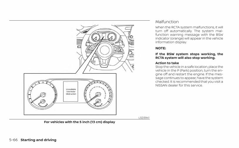
MalfunctionWhen the RCTA system malfunctions, it willturn off automatically. The system mal-function warning message with the BSWindicator (orange) will appear in the vehicleinformation display.
NOTE:
If the BSW system stops working, theRCTA system will also stop working.Action to takeStop the vehicle in a safe location, place thevehicle in the P (Park) position, turn the en-gine off and restart the engine. If the mes-sage continues to appear, have the systemchecked. It is recommended that you visit aNISSAN dealer for this service.
LSD3941For vehicles with the 5 inch (13 cm) display
5-66 Starting and driving
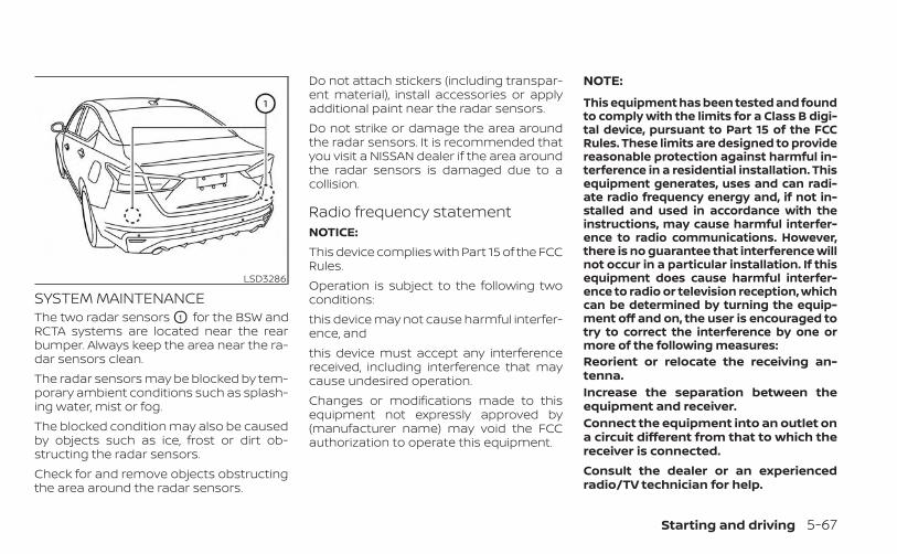
SYSTEM MAINTENANCEThe two radar sensors O1 for the BSW andRCTA systems are located near the rearbumper. Always keep the area near the ra-dar sensors clean.The radar sensors may be blocked by tem-porary ambient conditions such as splash-ing water, mist or fog.The blocked condition may also be causedby objects such as ice, frost or dirt ob-structing the radar sensors.Check for and remove objects obstructingthe area around the radar sensors.
Do not attach stickers (including transpar-ent material), install accessories or applyadditional paint near the radar sensors.Do not strike or damage the area aroundthe radar sensors. It is recommended thatyou visit a NISSAN dealer if the area aroundthe radar sensors is damaged due to acollision.
Radio frequency statementNOTICE:This device complies with Part 15 of the FCCRules.Operation is subject to the following twoconditions:this device may not cause harmful interfer-ence, andthis device must accept any interferencereceived, including interference that maycause undesired operation.Changes or modifications made to thisequipment not expressly approved by(manufacturer name) may void the FCCauthorization to operate this equipment.
NOTE:
This equipment has been tested and foundto comply with the limits for a Class B digi-tal device, pursuant to Part 15 of the FCCRules. These limits are designed to providereasonable protection against harmful in-terference in a residential installation. Thisequipment generates, uses and can radi-ate radio frequency energy and, if not in-stalled and used in accordance with theinstructions, may cause harmful interfer-ence to radio communications. However,there is no guarantee that interference willnot occur in a particular installation. If thisequipment does cause harmful interfer-ence to radio or television reception, whichcan be determined by turning the equip-ment off and on, the user is encouraged totry to correct the interference by one ormore of the following measures:Reorient or relocate the receiving an-tenna.Increase the separation between theequipment and receiver.Connect the equipment into an outlet ona circuit different from that to which thereceiver is connected.Consult the dealer or an experiencedradio/TV technician for help.
LSD3286
Starting and driving 5-67
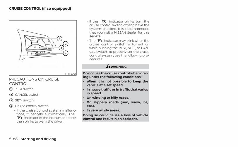
PRECAUTIONS ON CRUISECONTROL�1 RES+ switch
�2 CANCEL switch
�3 SET– switch
�4 Cruise control switch• If the cruise control system malfunc-
tions, it cancels automatically. Theindicator in the instrument panel
then blinks to warn the driver.
• If the indicator blinks, turn thecruise control switch off and have thesystem checked. It is recommendedthat you visit a NISSAN dealer for thisservice.
• The indicator may blink when thecruise control switch is turned onwhile pushing the RES+, SET–, or CAN-CEL switch. To properly set the cruisecontrol system, use the following pro-cedures.
WARNING
Do not use the cruise control when driv-ing under the following conditions:• When it is not possible to keep the
vehicle at a set speed.• In heavy traffic or in traffic that varies
in speed.• On winding or hilly roads.• On slippery roads (rain, snow, ice,
etc.).• In very windy areas.Doing so could cause a loss of vehiclecontrol and result in an accident.
LSD3251
CRUISE CONTROL (if so equipped)
5-68 Starting and driving
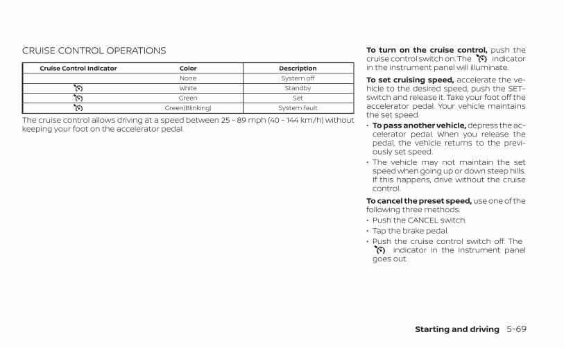
CRUISE CONTROL OPERATIONS
Cruise Control Indicator Color DescriptionNone System offWhite StandbyGreen Set
Green(Blinking) System fault
The cruise control allows driving at a speed between 25 - 89 mph (40 - 144 km/h) withoutkeeping your foot on the accelerator pedal.
To turn on the cruise control, push thecruise control switch on. The indicatorin the instrument panel will illuminate.To set cruising speed, accelerate the ve-hicle to the desired speed, push the SET–switch and release it. Take your foot off theaccelerator pedal. Your vehicle maintainsthe set speed.• To pass another vehicle, depress the ac-
celerator pedal. When you release thepedal, the vehicle returns to the previ-ously set speed.
• The vehicle may not maintain the setspeed when going up or down steep hills.If this happens, drive without the cruisecontrol.
To cancel the preset speed, use one of thefollowing three methods:• Push the CANCEL switch.• Tap the brake pedal.• Push the cruise control switch off. The
indicator in the instrument panelgoes out.
Starting and driving 5-69
The cruise control is automatically can-celed if:• You depress the brake pedal while push-
ing the RES+ or SET– switch. The presetspeed is deleted from memory.
• The vehicle slows down more than 8 mph(13 km/h) below the set speed.
• You move the shift lever to N (Neutral).To reset at a faster cruising speed, useone of the following three methods:• Depress the accelerator pedal. When the
vehicle attains the desired speed, pushand release the SET– switch.
• Push and hold the RES+ switch. When thevehicle attains the speed you desire, re-lease the switch.
• Push and release the RES+ switch. Eachtime you do this, the set speed increasesby about 1 mph (1.6 km/h).
To reset at a slower cruising speed, useone of the following three methods:• Lightly tap the brake pedal. When the ve-
hicle attains the desired speed, push theSET– switch and release it.
• Push and hold the SET– switch. Releasethe switch when the vehicle slows to thedesired speed.
• Push and release the SET– switch. Eachtime you do this, the set speed decreasesby about 1 mph (1.6 km/h).
To resume the preset speed, push andrelease the RES+ switch. The vehicle re-turns to the last set cruising speed whenthe vehicle speed is over 25 mph (40 km/h).To turn off the cruise control, use one ofthe following three methods:• Push the CANCEL switch.• Tap the brake pedal.• Push the cruise control switch off. The
indicator in the instrument panelgoes out.
WARNING
Failure to follow the warnings and in-structions for proper use of the ProPI-LOT Assist system could result in seri-ous injury or death.• ProPILOT Assist is not a self-driving
system. Within the limits of its capa-bilities, as described in this manual, ithelps the driver with certain drivingactivities.
• The ProPILOT Assist system is not areplacement for proper driving pro-cedures and is not designed to cor-rect careless, inattentive or absent-minded driving. ProPILOT Assist willnot always steer the vehicle to keep itin the lane. The ProPILOT Assist sys-tem is not designed to prevent loss ofcontrol. It is the driver’s responsibilityto stay alert, drive safely, keep thevehicle in the traveling lane, and be incontrol of the vehicle at all times.
PROPILOT ASSIST (if so equipped)
5-70 Starting and driving
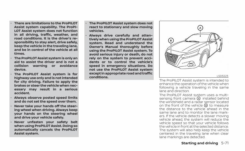
• There are limitations to the ProPILOTAssist system capability. The ProPI-LOT Assist system does not functionin all driving, traffic, weather, androad conditions. It is the driver’s re-sponsibility to stay alert, drive safely,keep the vehicle in the traveling lane,and be in control of the vehicle at alltimes.
• The ProPILOT Assist system is only anaid to assist the driver and is not acollision warning or avoidancedevice.
• The ProPILOT Assist system is forhighway use only and is not intendedfor city driving. Failure to apply thebrakes or steer the vehicle when nec-essary may result in a seriousaccident.
• Always observe posted speed limitsand do not set the speed over them.
• Never take your hands off the steer-ing wheel when driving. Always keepyour hands on the steering wheeland drive your vehicle safely.
• Never unfasten your safety beltwhen using ProPILOT Assist. Doing soautomatically cancels the ProPILOTAssist system.
• The ProPILOT Assist system does notreact to stationary and slow movingvehicles.
• Always drive carefully and atten-tively when using the ProPILOT Assistsystem. Read and understand theOwner’s Manual thoroughly beforeusing the ProPILOT Assist system. Toavoid serious injury or death, do notrely on the system to prevent acci-dents or to control the vehicle’sspeed in emergency situations. Donot use the ProPILOT Assist systemexcept in appropriate road and trafficconditions.
The ProPILOT Assist system is intended toenhance the operation of the vehicle whenfollowing a vehicle traveling in the samelane and direction.The ProPILOT Assist system uses a multi-sensing front camera OA installed behindthe windshield and a radar sensor locatedon the front of the vehicle OB to measurethe distance to the vehicle ahead in thesame lane and to monitor the lane mark-ers. If the vehicle detects a slower movingvehicle ahead, the system will reduce thevehicle speed so that your vehicle followsthe vehicle in front at the selected distance.The system will also help keep the vehiclecentered in the traveling lane when clearlane markings are detected.
LSD3223
Starting and driving 5-71
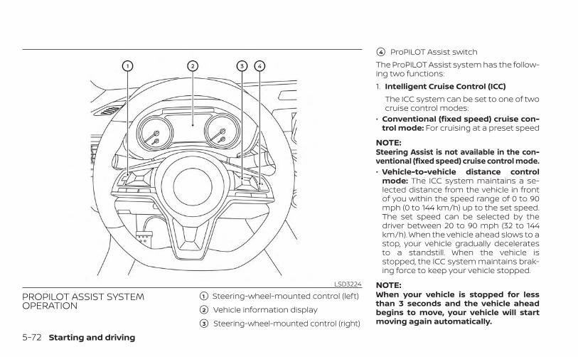
PROPILOT ASSIST SYSTEMOPERATION
�1 Steering-wheel-mounted control (left)
�2 Vehicle information display
�3 Steering-wheel-mounted control (right)
�4 ProPILOT Assist switchThe ProPILOT Assist system has the follow-ing two functions:1. Intelligent Cruise Control (ICC)
The ICC system can be set to one of twocruise control modes:
• Conventional (fixed speed) cruise con-trol mode: For cruising at a preset speed
NOTE:Steering Assist is not available in the con-ventional (fixed speed) cruise control mode.• Vehicle-to-vehicle distance control
mode: The ICC system maintains a se-lected distance from the vehicle in frontof you within the speed range of 0 to 90mph (0 to 144 km/h) up to the set speed.The set speed can be selected by thedriver between 20 to 90 mph (32 to 144km/h). When the vehicle ahead slows to astop, your vehicle gradually deceleratesto a standstill. When the vehicle isstopped, the ICC system maintains brak-ing force to keep your vehicle stopped.
NOTE:When your vehicle is stopped for lessthan 3 seconds and the vehicle aheadbegins to move, your vehicle will startmoving again automatically.
LSD3224
5-72 Starting and driving
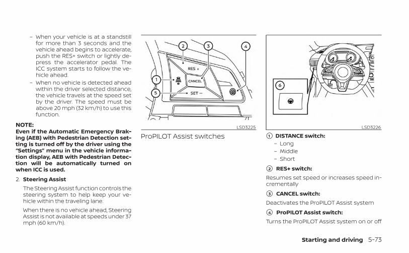
– When your vehicle is at a standstillfor more than 3 seconds and thevehicle ahead begins to accelerate,push the RES+ switch or lightly de-press the accelerator pedal. TheICC system starts to follow the ve-hicle ahead.
– When no vehicle is detected aheadwithin the driver selected distance,the vehicle travels at the speed setby the driver. The speed must beabove 20 mph (32 km/h) to use thisfunction.
NOTE:Even if the Automatic Emergency Brak-ing (AEB) with Pedestrian Detection set-ting is turned off by the driver using the“Settings” menu in the vehicle informa-tion display, AEB with Pedestrian Detec-tion will be automatically turned onwhen ICC is used.
2. Steering AssistThe Steering Assist function controls thesteering system to help keep your ve-hicle within the traveling lane.When there is no vehicle ahead, SteeringAssist is not available at speeds under 37mph (60 km/h).
ProPILOT Assist switches �1 DISTANCE switch:– Long– Middle– Short
�2 RES+ switch:Resumes set speed or increases speed in-crementally
�3 CANCEL switch:Deactivates the ProPILOT Assist system
�4 ProPILOT Assist switch:Turns the ProPILOT Assist system on or off
LSD3225 LSD3226
Starting and driving 5-73
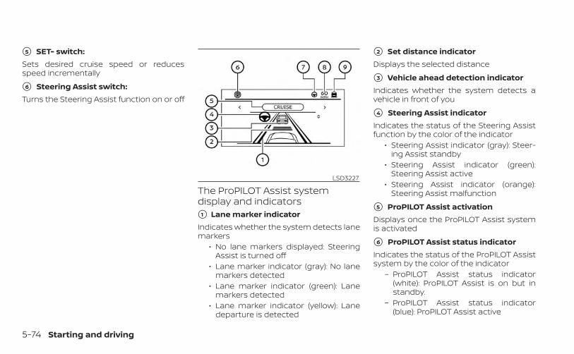
�5 SET- switch:Sets desired cruise speed or reducesspeed incrementally
�6 Steering Assist switch:Turns the Steering Assist function on or off
The ProPILOT Assist systemdisplay and indicators�1 Lane marker indicatorIndicates whether the system detects lanemarkers
• No lane markers displayed: SteeringAssist is turned off
• Lane marker indicator (gray): No lanemarkers detected
• Lane marker indicator (green): Lanemarkers detected
• Lane marker indicator (yellow): Lanedeparture is detected
�2 Set distance indicatorDisplays the selected distance
�3 Vehicle ahead detection indicatorIndicates whether the system detects avehicle in front of you
�4 Steering Assist indicatorIndicates the status of the Steering Assistfunction by the color of the indicator
• Steering Assist indicator (gray): Steer-ing Assist standby
• Steering Assist indicator (green):Steering Assist active
• Steering Assist indicator (orange):Steering Assist malfunction
�5 ProPILOT Assist activationDisplays once the ProPILOT Assist systemis activated
�6 ProPILOT Assist status indicatorIndicates the status of the ProPILOT Assistsystem by the color of the indicator
– ProPILOT Assist status indicator(white): ProPILOT Assist is on but instandby.
– ProPILOT Assist status indicator(blue): ProPILOT Assist active
LSD3227
5-74 Starting and driving
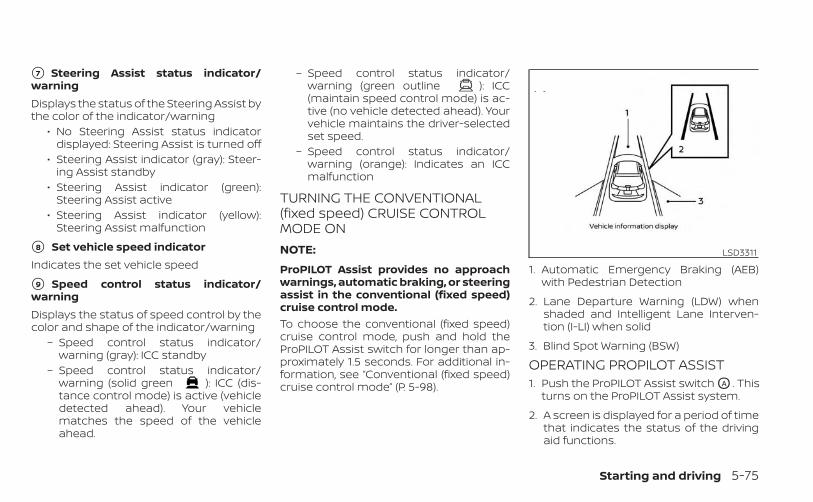
�7 Steering Assist status indicator/warningDisplays the status of the Steering Assist bythe color of the indicator/warning
• No Steering Assist status indicatordisplayed: Steering Assist is turned off
• Steering Assist indicator (gray): Steer-ing Assist standby
• Steering Assist indicator (green):Steering Assist active
• Steering Assist indicator (yellow):Steering Assist malfunction
�8 Set vehicle speed indicatorIndicates the set vehicle speed
�9 Speed control status indicator/warningDisplays the status of speed control by thecolor and shape of the indicator/warning
– Speed control status indicator/warning (gray): ICC standby
– Speed control status indicator/warning (solid green ): ICC (dis-tance control mode) is active (vehicledetected ahead). Your vehiclematches the speed of the vehicleahead.
– Speed control status indicator/warning (green outline ): ICC(maintain speed control mode) is ac-tive (no vehicle detected ahead). Yourvehicle maintains the driver-selectedset speed.
– Speed control status indicator/warning (orange): Indicates an ICCmalfunction
TURNING THE CONVENTIONAL(fixed speed) CRUISE CONTROLMODE ONNOTE:
ProPILOT Assist provides no approachwarnings, automatic braking, or steeringassist in the conventional (fixed speed)cruise control mode.To choose the conventional (fixed speed)cruise control mode, push and hold theProPILOT Assist switch for longer than ap-proximately 1.5 seconds. For additional in-formation, see “Conventional (fixed speed)cruise control mode” (P. 5-98).
OPERATING PROPILOT ASSIST1. Push the ProPILOT Assist switch OA . This
turns on the ProPILOT Assist system.
2. A screen is displayed for a period of timethat indicates the status of the drivingaid functions.
LSD3311
1. Automatic Emergency Braking (AEB)with Pedestrian Detection
2. Lane Departure Warning (LDW) whenshaded and Intelligent Lane Interven-tion (I-LI) when solid
3. Blind Spot Warning (BSW)
Starting and driving 5-75
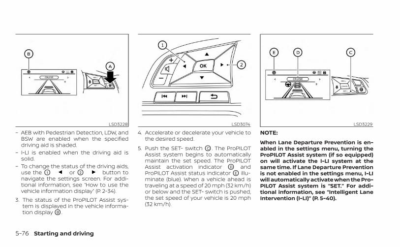
– AEB with Pedestrian Detection, LDW, andBSW are enabled when the specifieddriving aid is shaded.
– I-LI is enabled when the driving aid issolid.
– To change the status of the driving aids,use the O1 or O2 button tonavigate the settings screen. For addi-tional information, see “How to use thevehicle information display” (P. 2-34).
3. The status of the ProPILOT Assist sys-tem is displayed in the vehicle informa-tion display OB .
4. Accelerate or decelerate your vehicle tothe desired speed.
5. Push the SET- switch OC . The ProPILOTAssist system begins to automaticallymaintain the set speed. The ProPILOTAssist activation indicator OD andProPILOT Assist status indicator OE illu-minate (blue). When a vehicle ahead istraveling at a speed of 20 mph (32 km/h)or below and the SET- switch is pushed,the set speed of your vehicle is 20 mph(32 km/h).
NOTE:
When Lane Departure Prevention is en-abled in the settings menu, turning theProPILOT Assist system (if so equipped)on will activate the I-LI system at thesame time. If Lane Departure Preventionis not enabled in the settings menu, I-LIwill automatically activate when the Pro-PILOT Assist system is “SET.” For addi-tional information, see “Intelligent LaneIntervention (I-LI)” (P. 5-40).
LSD3228 LSD3074 LSD3229
5-76 Starting and driving
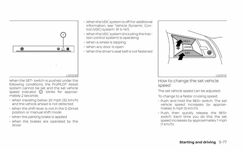
When the SET- switch is pushed under thefollowing conditions, the ProPILOT Assistsystem cannot be set and the set vehiclespeed indicator O1 blinks for approxi-mately 2 seconds:• When traveling below 20 mph (32 km/h)
and the vehicle ahead is not detected• When the shift lever is not in the D (Drive)
position or manual shift mode• When the parking brake is applied• When the brakes are operated by the
driver
• When the VDC system is off. For additionalinformation, see “Vehicle Dynamic Con-trol (VDC) system” (P. 5-147).
• When the VDC system (including the trac-tion control system) is operating
• When a wheel is slipping• When any door is open• When the driver’s seat belt is not fastened
How to change the set vehiclespeedThe set vehicle speed can be adjusted.To change to a faster cruising speed:• Push and hold the RES+ switch. The set
vehicle speed increases by approxi-mately 5 mph (5 km/h).
• Push, then quickly release, the RES+switch. Each time you do this, the setspeed increases by approximately 1 mph(1 km/h).
LSD3230 LSD3113
Starting and driving 5-77
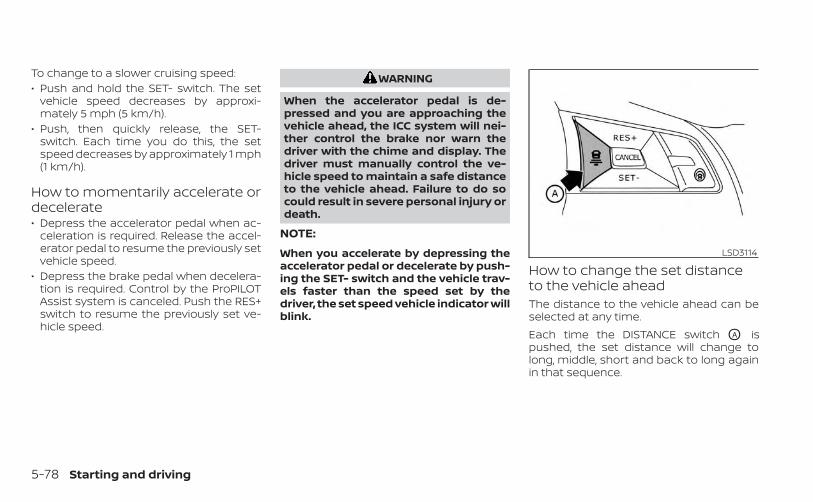
To change to a slower cruising speed:• Push and hold the SET- switch. The set
vehicle speed decreases by approxi-mately 5 mph (5 km/h).
• Push, then quickly release, the SET-switch. Each time you do this, the setspeed decreases by approximately 1 mph(1 km/h).
How to momentarily accelerate ordecelerate• Depress the accelerator pedal when ac-
celeration is required. Release the accel-erator pedal to resume the previously setvehicle speed.
• Depress the brake pedal when decelera-tion is required. Control by the ProPILOTAssist system is canceled. Push the RES+switch to resume the previously set ve-hicle speed.
WARNING
When the accelerator pedal is de-pressed and you are approaching thevehicle ahead, the ICC system will nei-ther control the brake nor warn thedriver with the chime and display. Thedriver must manually control the ve-hicle speed to maintain a safe distanceto the vehicle ahead. Failure to do socould result in severe personal injury ordeath.
NOTE:
When you accelerate by depressing theaccelerator pedal or decelerate by push-ing the SET- switch and the vehicle trav-els faster than the speed set by thedriver, the set speed vehicle indicator willblink.
How to change the set distanceto the vehicle aheadThe distance to the vehicle ahead can beselected at any time.Each time the DISTANCE switch OA ispushed, the set distance will change tolong, middle, short and back to long againin that sequence.
LSD3114
5-78 Starting and driving
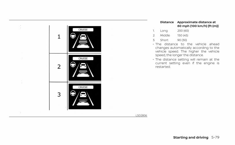
Distance Approximate distance at60 mph (100 km/h) [ft (m)]
1. Long 200 (60)2. Middle 150 (45)3. Short 90 (30)• The distance to the vehicle ahead
changes automatically according to thevehicle speed. The higher the vehiclespeed, the longer the distance.
• The distance setting will remain at thecurrent setting even if the engine isrestarted.
LSD2806
Starting and driving 5-79
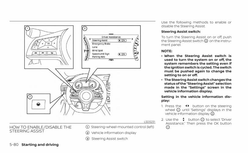
HOW TO ENABLE/DISABLE THESTEERING ASSIST
�1 Steering-wheel-mounted control (left)
�2 Vehicle information display
�3 Steering Assist switch
Use the following methods to enable ordisable the Steering Assist.Steering Assist switch:To turn the Steering Assist on or off, pushthe Steering Assist switch O3 on the instru-ment panel.
NOTE:• When the Steering Assist switch is
used to turn the system on or off, thesystem remembers the setting even ifthe ignition switch is cycled. The switchmust be pushed again to change thesetting to on or off.
• The Steering Assist switch changes thestatus of the “Steering Assist” selectionmade in the “Settings” screen in thevehicle information display.
Setting in the vehicle information dis-play:1. Press the button on the steering
wheel O1 until “Settings” displays in thevehicle information display O2 .
2. Use the button O1 to select “DriverAssistance.” Then press the OK buttonO1 .
LSD3231
5-80 Starting and driving
3. Use the button O1 to select “Steer-ing Assist” and then press the OK buttonO1 to turn the system on or off.
NOTE:• When the Cruise screen is displayed on
the vehicle information display, pressthe OK button on the steering wheel tocall up the “Driving Aids” setting dis-play.
• When enabling/disabling the systemthrough the vehicle information dis-play or when pushing the Steering As-sist switch, the system retains the cur-rent settings even if the engine isrestarted.
How to cancel the ProPILOT AssistsystemTo cancel the ProPILOT Assist system, useone of the following methods:• Push the CANCEL switch.• Tap the brake pedal (except at a stand-
still).• Push the ProPILOT Assist switch to turn
the system off. The ProPILOT Assist statusindicator will go out.
When the ProPILOT Assist system is can-celed while the vehicle is stopped, the elec-tronic parking brake is automatically acti-vated.
WARNING
To prevent the vehicle from moving orrolling unexpectedly, which could re-sult in serious personal injury or prop-erty damage, before exiting the vehiclemake sure to push the ProPILOT Assistswitch to turn the system off, place theshift lever in the P (Park) position, andturn the engine off.
INTELLIGENT CRUISE CONTROL(ICC) (for vehicles with ProPILOTAssist)
WARNING
Failure to follow the warnings and in-structions for proper use of the ICC sys-tem could result in serious injury ordeath.
• The ICC system is only an aid to assistthe driver and is not a collision warn-ing or avoidance device. It is recom-mended for highway use only and itis not intended for city driving. It isthe driver’s responsibility to stayalert, drive safely, and be in control ofthe vehicle at all times.
• There are limitations to the ICC sys-tem capability. The ICC system doesnot function in all driving, traffic,weather, and road conditions. It is thedriver’s responsibility to stay alert,drive safely, keep the vehicle in thetraveling lane, and be in control of thevehicle at all times.
• Always observe posted speed limitsand do not set the speed over them.
• The ICC system does not react to sta-tionary and slow moving vehicles.
Starting and driving 5-81
• Always drive carefully and atten-tively when using the ICC system.Read and understand the Owner’sManual thoroughly before using theICC system. To avoid serious injury ordeath, do not rely on the system toprevent accidents or to control thevehicle’s speed in emergency situa-tions. Do not use the ICC system ex-cept in appropriate road and trafficconditions.
ICC system operationThe ICC system is designed to maintain aselected distance from the vehicle in frontof you and can reduce the speed to matcha slower vehicle ahead. The system decel-erates the vehicle as necessary and if thevehicle ahead comes to a stop, the vehicledecelerates to a standstill. However, the ICCsystem can only apply up to 40% of thevehicle’s total braking power. This systemshould only be used when traffic condi-tions allow vehicle speeds to remain fairlyconstant or when vehicle speeds changegradually. If a vehicle moves into the travel-ing lane ahead or if a vehicle travelingahead rapidly decelerates, the distance be-tween vehicles may become closer be-cause the ICC system cannot decelerate
the vehicle quickly enough. If this occurs,the ICC system sounds a warning chimeand blinks the system display to notify thedriver to take necessary action.The ICC system cancels and a warningchime sounds if the speed is below ap-proximately 15 mph (24 km/h) and a vehicleis not detected ahead.The ICC system operates as follows:• When there are no vehicles traveling
ahead, the ICC system maintains thespeed set by the driver. The set speedrange is between approximately 20 and90 mph (32 and 144 km/h).
• When there is a vehicle traveling ahead,the ICC system adjusts the speed tomaintain the distance, selected by thedriver, from the vehicle ahead. If the ve-hicle ahead comes to a stop, the vehicledecelerates to a standstill. Once your ve-hicle stops, the ICC system keeps the ve-hicle stopped.
• When your vehicle is stopped for lessthan 3 seconds and the vehicle aheadbegins to move, your vehicle will startmoving again automatically.
• When your vehicle is at a standstill formore than 3 seconds and the vehicleahead begins to accelerate, push theRES+ switch or lightly depress the accel-erator pedal. The ICC system starts tofollow the vehicle ahead.
• When the vehicle traveling ahead movesto a different traveling lane, the ICC sys-tem accelerates and maintains vehiclespeed up to the set speed.
The ICC system does not control vehiclespeed or warn you when you approachstationary and slow moving vehicles. Youmust pay attention to vehicle operation tomaintain proper distance from vehiclesahead when approaching toll gates or traf-fic congestion.
5-82 Starting and driving
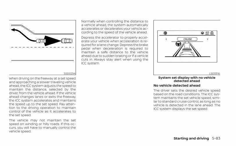
When driving on the freeway at a set speedand approaching a slower traveling vehicleahead, the ICC system adjusts the speed tomaintain the distance, selected by thedriver, from the vehicle ahead. If the vehicleahead changes lanes or exits the freeway,the ICC system accelerates and maintainsthe speed up to the set speed. Pay atten-tion to the driving operation to maintaincontrol of the vehicle as it accelerates tothe set speed.The vehicle may not maintain the setspeed on winding or hilly roads. If this oc-curs, you will have to manually control thevehicle speed.
Normally when controlling the distance toa vehicle ahead, the system automaticallyaccelerates or decelerates your vehicle ac-cording to the speed of the vehicle ahead.Depress the accelerator to properly accel-erate your vehicle when acceleration is re-quired for a lane change. Depress the brakepedal when deceleration is required tomaintain a safe distance to the vehicleahead due to sudden braking or if a vehiclecuts in. Always stay alert when using theICC system.
No vehicle detected aheadThe driver sets the desired vehicle speedbased on the road conditions. The ICC sys-tem maintains the set vehicle speed, simi-lar to standard cruise control, as long as novehicle is detected in the lane ahead. TheICC system displays the set speed.
SSD0254 LSD3316System set display with no vehicle
detected ahead
Starting and driving 5-83
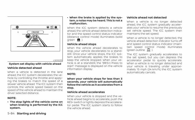
Vehicle detected aheadWhen a vehicle is detected in the laneahead, the ICC system decelerates the ve-hicle by controlling the throttle and apply-ing the brakes to match the speed of aslower vehicle ahead. The ICC system thencontrols the vehicle speed based on thespeed of the vehicle ahead to maintain thedriver selected distance.
NOTE:• The stop lights of the vehicle come on
when braking is performed by the ICCsystem.
• When the brake is applied by the sys-tem, a noise may be heard. This is not amalfunction.
When the ICC system detects a vehicleahead, the vehicle ahead detection indica-tor and the speed control status indicator(distance control mode) illuminates (solidgreen ).Vehicle ahead stopsWhen the vehicle ahead decelerates tostop, your vehicle decelerates to a stand-still. Once your vehicle stops, the ICC sys-tem automatically applies the brakes tokeep the vehicle stopped. When your ve-hicle is at a standstill, the “(RES+) Press tostart” message is displayed on the vehicleinformation display.
NOTE:
When your vehicle stops for less than 3seconds, your vehicle will automaticallyfollow the vehicle as it accelerates from astop.Vehicle ahead acceleratesWhen your vehicle is stopped and the ve-hicle ahead begins to accelerate, push theRES+ switch or lightly depress the accelera-tor pedal. The ICC system starts to followthe vehicle ahead.
Vehicle ahead not detectedWhen a vehicle is no longer detectedahead, the ICC system gradually acceler-ates your vehicle to resume the previouslyset vehicle speed. The ICC system thenmaintains the set speed.When a vehicle is no longer detected, thevehicle ahead detection indicator turns offand speed control status indicator (main-tain speed control mode) illuminates(green outline ).The ICC system gradually accelerates tothe set speed, but you can depress theaccelerator pedal to quickly accelerate.When a vehicle is no longer detected andyour vehicle is traveling under approxi-mately 15 mph (24 km/h), the ICC systemautomatically cancels.
LSD3233System set display with vehicle ahead
5-84 Starting and driving
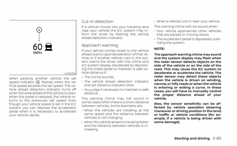
When passing another vehicle, the setspeed indicator OA flashes when the ve-hicle speed exceeds the set speed. The ve-hicle ahead detection indicator turns offwhen the area ahead of the vehicle is open.When the pedal is released, the vehicle re-turns to the previously set speed. Eventhough your vehicle speed is set in the ICCsystem, you can depress the acceleratorpedal when it is necessary to accelerateyour vehicle rapidly.
Cut-in detectionIf a vehicle moves into your traveling lanenear your vehicle, the ICC system may in-form the driver by flashing the vehicleahead detection indicator.
Approach warningIf your vehicle comes closer to the vehicleahead due to rapid deceleration of that ve-hicle or if another vehicle cuts in, the sys-tem warns the driver with the chime andICC system display. Decelerate by depress-ing the brake pedal to maintain a safe ve-hicle distance if:• The chime sounds.• The vehicle ahead detection indicator
and set distance indicator blink.• You judge it necessary to maintain a safe
distance.The warning chime may not sound insome cases when there is a short distancebetween vehicles. Some examples are:• When the vehicles are traveling at the
same speed and the distance betweenvehicles is not changing.
• When the vehicle ahead is traveling fasterand the distance between vehicles is in-creasing.
• When a vehicle cuts in near your vehicle.The warning chime will not sound when:• Your vehicle approaches other vehicles
that are parked or moving slowly.• The accelerator pedal is depressed, over-
riding the system.
NOTE:
The approach warning chime may soundand the system display may flash whenthe radar sensor detects objects on theside of the vehicle or on the side of theroad. This may cause the ICC system todecelerate or accelerate the vehicle. Theradar sensor may detect these objectswhen the vehicle is driven on winding,narrow, or hilly roads or when the vehicleis entering or exiting a curve. In thesecases, you will have to manually controlthe proper distance ahead of yourvehicle.Also, the sensor sensitivity can be af-fected by vehicle operation (steeringmaneuver or driving position in the lane)or traffic or vehicle conditions (for ex-ample, if a vehicle is being driven withsome damage).
LSD3234
Starting and driving 5-85
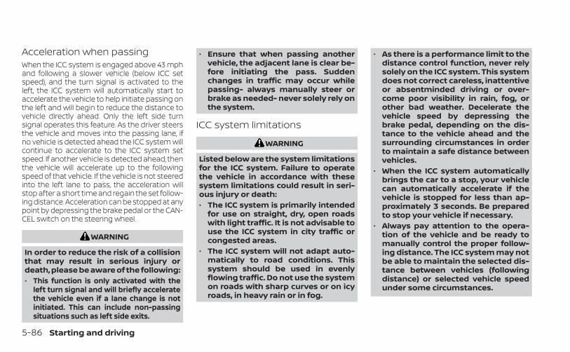
Acceleration when passingWhen the ICC system is engaged above 43 mphand following a slower vehicle (below ICC setspeed), and the turn signal is activated to theleft, the ICC system will automatically start toaccelerate the vehicle to help initiate passing onthe left and will begin to reduce the distance tovehicle directly ahead. Only the left side turnsignal operates this feature. As the driver steersthe vehicle and moves into the passing lane, ifno vehicle is detected ahead the ICC system willcontinue to accelerate to the ICC system setspeed. If another vehicle is detected ahead, thenthe vehicle will accelerate up to the followingspeed of that vehicle. If the vehicle is not steeredinto the left lane to pass, the acceleration willstop after a short time and regain the set follow-ing distance. Acceleration can be stopped at anypoint by depressing the brake pedal or the CAN-CEL switch on the steering wheel.
WARNING
In order to reduce the risk of a collisionthat may result in serious injury ordeath, please be aware of the following:• This function is only activated with the
left turn signal and will briefly acceleratethe vehicle even if a lane change is notinitiated. This can include non-passingsituations such as left side exits.
• Ensure that when passing anothervehicle, the adjacent lane is clear be-fore initiating the pass. Suddenchanges in traffic may occur whilepassing- always manually steer orbrake as needed- never solely rely onthe system.
ICC system limitations
WARNING
Listed below are the system limitationsfor the ICC system. Failure to operatethe vehicle in accordance with thesesystem limitations could result in seri-ous injury or death:• The ICC system is primarily intended
for use on straight, dry, open roadswith light traffic. It is not advisable touse the ICC system in city traffic orcongested areas.
• The ICC system will not adapt auto-matically to road conditions. Thissystem should be used in evenlyflowing traffic. Do not use the systemon roads with sharp curves or on icyroads, in heavy rain or in fog.
• As there is a performance limit to thedistance control function, never relysolely on the ICC system. This systemdoes not correct careless, inattentiveor absentminded driving or over-come poor visibility in rain, fog, orother bad weather. Decelerate thevehicle speed by depressing thebrake pedal, depending on the dis-tance to the vehicle ahead and thesurrounding circumstances in orderto maintain a safe distance betweenvehicles.
• When the ICC system automaticallybrings the car to a stop, your vehiclecan automatically accelerate if thevehicle is stopped for less than ap-proximately 3 seconds. Be preparedto stop your vehicle if necessary.
• Always pay attention to the opera-tion of the vehicle and be ready tomanually control the proper follow-ing distance. The ICC system may notbe able to maintain the selected dis-tance between vehicles (followingdistance) or selected vehicle speedunder some circumstances.
5-86 Starting and driving

• The system may not detect the ve-hicle in front of you in certain road orweather conditions. To avoid acci-dents, never use the ICC system un-der the following conditions:– On roads with heavy, high-speed
traffic or sharp curves– On slippery road surfaces such as
on ice or snow, etc.– During bad weather (rain, fog,
snow, etc.)– When rain, snow or dirt adhere to
the bumper around the distancesensor
– On steep downhill roads (the ve-hicle may go beyond the set ve-hicle speed and frequent brakingmay result in overheating thebrakes)
– On repeated uphill and downhillroads
– When traffic conditions make itdifficult to keep a proper distancebetween vehicles because of fre-quent acceleration ordeceleration
– Interference by other radarsources.
• Do not use the ICC system if you aretowing a trailer. The system may notdetect a vehicle ahead.
• In some road or traffic conditions, avehicle or object can unexpectedlycome into the sensor detection zoneand cause automatic braking. Al-ways stay alert and avoid using theICC system where not recommendedin this warning section.
The ICC system will not detect the followingobjects:• Stationary or slow moving vehicles• Pedestrians or objects in the roadway• Oncoming vehicles in the same lane• Motorcycles traveling offset in the travel
laneThe following are some conditions in whichthe radar sensor cannot properly detect avehicle ahead and the system may not op-erate properly:• When the sensor detection is reduced
(conditions such as rain, snow, fog, duststorms, sandstorms, and road spray fromother vehicles)
• Driving on a steep downhill slope or roadswith sharp curves
• Driving on a bumpy road surface, such asan uneven dirt road
• If dirt, ice, snow or other material is cover-ing the radar sensor area
• A complicated-shaped vehicle such as acar carrier trailer or flatbed truck/trailer isnear the vehicle ahead.
• Interference by other radar sources• When your vehicle is towing a trailer, etc.• When excessively heavy baggage is
loaded in the rear seat or cargo area ofyour vehicle.
The ICC system is designed to automati-cally check the radar sensor’s operationwithin the limitations of the system.The detection zone of the radar sensor islimited. A vehicle ahead must be in the de-tection zone for the ICC system to maintainthe selected distance from the vehicleahead. A vehicle ahead may move outsideof the detection zone due to its positionwithin the same lane of travel. Motorcyclesmay not be detected in the same laneahead if they are traveling offset from thecenter line of the lane. A vehicle that is en-tering the lane ahead may not be detecteduntil the vehicle has completely moved intothe lane.
Starting and driving 5-87
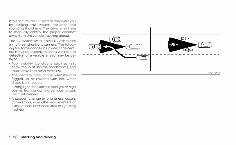
If this occurs, the ICC system may warn youby blinking the system indicator andsounding the chime. The driver may haveto manually control the proper distanceaway from the vehicle traveling ahead.The ICC system (with ProPILOT Assist) usesa multi-sensing front camera. The follow-ing are some conditions in which the cam-era may not properly detect a vehicle anddetection of a vehicle ahead may be de-layed:• Poor visibility (conditions such as rain,
snow, fog, dust storms, sandstorms, androad spray from other vehicles)
• The camera area of the windshield isfogged up or covered with dirt, waterdrops, ice, snow, etc.
• Strong light (for example, sunlight or highbeams from oncoming vehicles) entersthe front camera
• A sudden change in brightness occurs(for example, when the vehicle enters orexits a tunnel or shaded area or lightningflashes)
SSD0252
5-88 Starting and driving
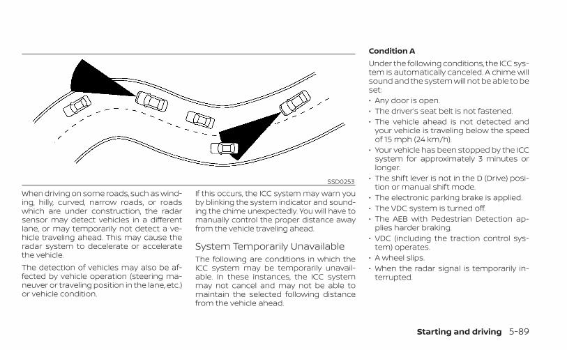
When driving on some roads, such as wind-ing, hilly, curved, narrow roads, or roadswhich are under construction, the radarsensor may detect vehicles in a differentlane, or may temporarily not detect a ve-hicle traveling ahead. This may cause theradar system to decelerate or acceleratethe vehicle.The detection of vehicles may also be af-fected by vehicle operation (steering ma-neuver or traveling position in the lane, etc.)or vehicle condition.
If this occurs, the ICC system may warn youby blinking the system indicator and sound-ing the chime unexpectedly. You will have tomanually control the proper distance awayfrom the vehicle traveling ahead.
System Temporarily UnavailableThe following are conditions in which theICC system may be temporarily unavail-able. In these instances, the ICC systemmay not cancel and may not be able tomaintain the selected following distancefrom the vehicle ahead.
Condition AUnder the following conditions, the ICC sys-tem is automatically canceled. A chime willsound and the system will not be able to beset:• Any door is open.• The driver’s seat belt is not fastened.• The vehicle ahead is not detected and
your vehicle is traveling below the speedof 15 mph (24 km/h).
• Your vehicle has been stopped by the ICCsystem for approximately 3 minutes orlonger.
• The shift lever is not in the D (Drive) posi-tion or manual shift mode.
• The electronic parking brake is applied.• The VDC system is turned off.• The AEB with Pedestrian Detection ap-
plies harder braking.• VDC (including the traction control sys-
tem) operates.• A wheel slips.• When the radar signal is temporarily in-
terrupted.
SSD0253
Starting and driving 5-89
Action to take:When the conditions listed above are nolonger present, turn the system off usingthe ProPILOT Assist switch. Turn the ProPI-LOT Assist system back on to use the sys-tem.
NOTE:When the ICC system is canceled un-der the following conditions at astandstill, the electronic parkingbrake is automatically activated:• Any door is open.• The driver’s seat belt is not fastened.• Your vehicle has been stopped by the
ICC system for approximately 3 min-utes or longer.
• The shift lever is not in the D (Drive)position or manual shift mode.
• The VDC system is turned off.• When distance measurement be-
comes impaired due to adhesion of dirtor obstruction to the sensor.
• When the radar signal is temporarilyinterrupted.
Condition BWhen there is inclement weather (rain, fog,snow, etc.) blocking the front radar sensor,the ICC system will automatically be can-celed, the chime will sound and the “For-ward Driving Aids Temporarily DisabledFront Sensor Blocked See Owner’s Manual”warning message will appear in the vehicleinformation display.Action to take:When the conditions listed above are nolonger present, the warning message willno longer be available in the vehicle infor-mation display and the system will operatenormally. If the “Forward Driving Aids Tem-porarily Disabled Front Sensor Blocked SeeOwner’s Manual” warning message contin-ues to be displayed, have the systemchecked. It is recommended that you visit aNISSAN dealer for this service.Condition CWhen the radar sensor of the front bumperis covered with dirt or is obstructed, the ICCsystem will automatically be canceled.The chime will sound and the “ForwardDriving Aids Temporarily Disabled FrontSensor Blocked See Owner’s Manual”
warning message will appear in the vehicleinformation display.Action to take:If the warning message appears, stop thevehicle in a safe place, place the shift leverin the P (Park) position, and turn the engineoff. When the radar signal is temporarilyinterrupted, clean the sensor area of thefront bumper and restart the engine. If the“Forward Driving Aids Temporarily DisabledFront Sensor Blocked See Owner’s Manual”warning message continues to be dis-played, have the system checked. It is rec-ommended that you visit a NISSAN dealerfor this service.Condition DWhen driving on roads with limited roadstructures or buildings (for example, longbridges, deserts, snow fields, driving next tolong walls), the system may illuminate thesystem warning light and display the “For-ward Driving Aids Temporarily DisabledFront Sensor Blocked See Owner’s Manual”warning message.Action to take:When the above driving conditions no lon-ger exist, turn the system back on.
5-90 Starting and driving
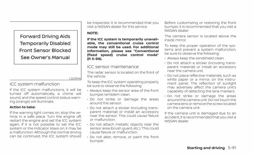
ICC system malfunctionIf the ICC system malfunctions, it will beturned off automatically, a chime willsound, and the speed control status warn-ing (orange) will illuminate.Action to take:If the warning light comes on, stop the ve-hicle in a safe place. Turn the engine off,restart the engine and set the ICC systemagain. If it is not possible to set the ICCsystem or the indicator stays on, it may bea malfunction. Although the normal drivingcan be continued, the ICC system should
be inspected. It is recommended that youvisit a NISSAN dealer for this service.
NOTE:
If the ICC system is temporarily unavail-able, the conventional cruise controlmode may still be used. For additionalinformation, please see “Conventional(fixed speed) cruise control mode”(P. 5-98).
ICC sensor maintenanceThe radar sensor is located on the front ofthe vehicle.To keep the ICC system operating properly,be sure to observe the following:• Always keep the sensor area of the front
bumper/emblem clean.• Do not strike or damage the areas
around the sensor.• Do not attach a sticker (including trans-
parent material) or install an accessorynear the sensor. This could cause failureor malfunction.
• Do not attach metallic objects near thesensor area (brush guard, etc.). This couldcause failure or malfunction.
• Do not alter, remove, or paint the frontbumper.
Before customizing or restoring the frontbumper, it is recommended that you visit aNISSAN dealer.The camera sensor is located above theinside mirror.To keep the proper operation of the sys-tems and prevent a system malfunction,be sure to observe the following:• Always keep the windshield clean.• Do not attach a sticker (including trans-
parent material) or install an accessorynear the camera unit.
• Do not place reflective materials, such aswhite paper or a mirror, on the instru-ment panel. The reflection of sunlightmay adversely affect the camera unit’scapability of detecting the lane markers.
• Do not strike or damage the areasaround the camera unit. Do not touch thecamera lens or remove the screw locatedon the camera unit.
If the camera unit is damaged due to anaccident, it is recommended that you visit aNISSAN dealer.
LSD3916
Starting and driving 5-91
STEERING ASSISTWARNING
Failure to follow the warnings and in-structions for proper use of the Steer-ing Assist could result in serious injuryor death.• The Steering Assist is not a replace-
ment for proper driving proceduresand is not designed to correct care-less, inattentive or absent-mindeddriving. The Steering Assist will notalways steer the vehicle to keep it inthe lane. It is not designed to preventloss of control. It is the driver’s re-sponsibility to stay alert, drive safely,keep the vehicle in the traveling lane,and be in control of the vehicle at alltimes.
• As there is a performance limit to theSteering Assist’s capability, neverrely solely on the system. The Steer-ing Assist does not function in alldriving, traffic, weather, and roadconditions. Always drive safely, payattention to the operation of the ve-hicle, and manually control your ve-hicle appropriately.
• The Steering Assist is intended foruse on well-developed freeways orhighways with gentle (moderate)curves. To avoid risk of an accident,do not use this system on local ornon-highway roads.
• The Steering Assist only steers thevehicle to maintain its position in thecenter of a lane. The vehicle will notsteer to avoid objects in the road infront of the vehicle or to avoid a ve-hicle moving into your lane.
• It is the driver’s responsibility to stayalert, drive safely, keep the vehicle inthe traveling lane, and be in control ofthe vehicle at all times. Never takeyour hands off the steering wheelwhen driving. Always keep yourhands on the steering wheel anddrive your vehicle safely.
• Always drive carefully and attentivelywhen using the Steering Assist. Readand understand the Owner’s Manualthoroughly before using the SteeringAssist. To avoid serious injury or death,do not rely on the system to preventaccidents or to control the vehicle’sspeed in emergency situations. Do notuse the Steering Assist except in ap-propriate road and traffic conditions.
Steering Assist operationThe Steering Assist controls the steeringsystem to help keep your vehicle near thecenter of the lane when driving. The Steer-ing Assist is combined with the IntelligentCruise Control (ICC) system. For additionalinformation, see “Intelligent Cruise Control(ICC) (for vehicles with ProPILOT Assist)”(P. 5-81).The Steering Assist can be activated whenthe following conditions are met:• The ICC system is activated.• Lane markers on both sides are clearly
detected.• A vehicle ahead is detected (when the
vehicle is driven at speeds under 37 mph[60 km/h]).
• The driver grips the steering wheel.• The vehicle is driven at the center of the
lane.• The turn signals are not operated.• The windshield wiper is not operated in
the high (HI) speed operation (the Steer-ing Assist function is disabled after thewiper operates for approximately 10 sec-onds).
5-92 Starting and driving
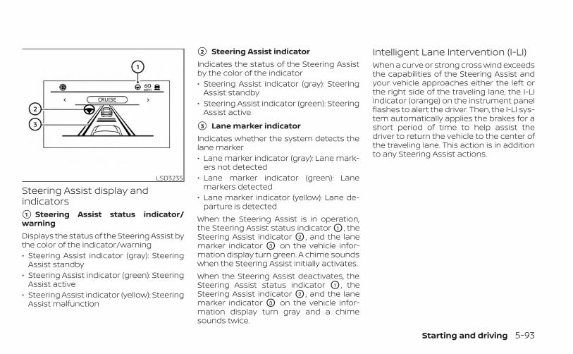
Steering Assist display andindicators�1 Steering Assist status indicator/warningDisplays the status of the Steering Assist bythe color of the indicator/warning• Steering Assist indicator (gray): Steering
Assist standby• Steering Assist indicator (green): Steering
Assist active• Steering Assist indicator (yellow): Steering
Assist malfunction
�2 Steering Assist indicatorIndicates the status of the Steering Assistby the color of the indicator• Steering Assist indicator (gray): Steering
Assist standby• Steering Assist indicator (green): Steering
Assist active
�3 Lane marker indicatorIndicates whether the system detects thelane marker• Lane marker indicator (gray): Lane mark-
ers not detected• Lane marker indicator (green): Lane
markers detected• Lane marker indicator (yellow): Lane de-
parture is detectedWhen the Steering Assist is in operation,the Steering Assist status indicator O1 , theSteering Assist indicator O2 , and the lanemarker indicator O3 on the vehicle infor-mation display turn green. A chime soundswhen the Steering Assist initially activates.When the Steering Assist deactivates, theSteering Assist status indicator O1 , theSteering Assist indicator O2 , and the lanemarker indicator O3 on the vehicle infor-mation display turn gray and a chimesounds twice.
Intelligent Lane Intervention (I-LI)When a curve or strong cross wind exceedsthe capabilities of the Steering Assist andyour vehicle approaches either the left orthe right side of the traveling lane, the I-LIindicator (orange) on the instrument panelflashes to alert the driver. Then, the I-LI sys-tem automatically applies the brakes for ashort period of time to help assist thedriver to return the vehicle to the center ofthe traveling lane. This action is in additionto any Steering Assist actions.
LSD3235
Starting and driving 5-93
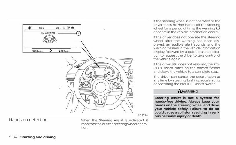
Hands on detection When the Steering Assist is activated, itmonitors the driver’s steering wheel opera-tion.
If the steering wheel is not operated or thedriver takes his/her hands off the steeringwheel for a period of time, the warning O1
appears in the vehicle information display.If the driver does not operate the steeringwheel after the warning has been dis-played, an audible alert sounds and thewarning flashes in the vehicle informationdisplay, followed by a quick brake applica-tion to request the driver to take control ofthe vehicle again.If the driver still does not respond, the Pro-PILOT Assist turns on the hazard flasherand slows the vehicle to a complete stop.The driver can cancel the deceleration atany time by steering, braking, accelerating,or operating the ProPILOT Assist switch.
WARNING
Steering Assist is not a system forhands-free driving. Always keep yourhands on the steering wheel and driveyour vehicle safely. Failure to do socould cause a collision resulting in seri-ous personal injury or death.LSD3236
5-94 Starting and driving
NOTE:
If the driver lightly touches (instead offirmly grips) the steering wheel, thesteering torque sensor may not detectthe driver’s hand(s) on the wheel and asequence of warnings may occur. Whenthe driver holds and operates the steer-ing wheel again, the warnings turn off.
Steering Assist limitations
WARNING
• In the following situations, the cam-era may not detect lane markers cor-rectly or may detect lane markers in-correctly and the Steering Assist maynot operate properly:– When driving on roads where
there are multiple parallel lanemarkers, lane markers that arefaded or not painted clearly, non-standard lane markers, or lanemarkers covered with water, dirt,snow, etc.
– When driving on roads with dis-continued lane markers
– When driving on roads with a wid-ening or narrowing lane width
– When driving on roads wherethere are multiple lanes or unclearlane markers due to roadconstruction
– When driving on roads wherethere are sharply contrasting ob-jects, such as shadows, snow, wa-ter, wheel ruts, seams, or lines re-maining after road repairs (theSteering Assist could detect theseitems as lane markers)
– When driving on roads where thetraveling lane merges orseparates
• Do not use the Steering Assist underthe following conditions because thesystem may not properly detect lanemarkers. Doing so could cause a lossof vehicle control and result in an ac-cident.– During bad weather (rain, fog,
snow, dust, etc.)– When rain, snow, sand, etc., is
thrown up by the wheels of othervehicles
– When dirt, oil, ice, snow, water, oranother object adheres to thecamera unit
– When the lens of the camera unitis foggy
– When strong light (for example,sunlight or high beams from on-coming vehicles) shines on thecamera
– When the headlights are notbright due to dirt on the lens orthe headlights are off in tunnels ordarkness
– When a sudden change in bright-ness occurs (for example, whenthe vehicle enters or exits a tunnelor is under a bridge)
– When driving on roads where thetraveling lane merges or sepa-rates or where there are tempo-rary lane markers because of roadconstruction
– When there is a lane closure due toroad repairs
– When driving on a bumpy roadsurface, such as an uneven dirtroad
– When driving on sharp curves orwinding roads
– When driving on repeated uphilland downhill roads
Starting and driving 5-95
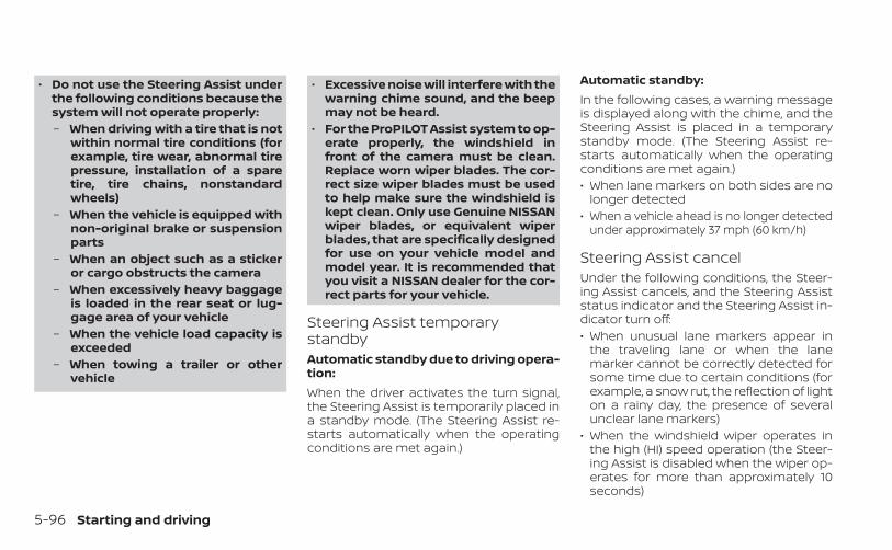
• Do not use the Steering Assist underthe following conditions because thesystem will not operate properly:– When driving with a tire that is not
within normal tire conditions (forexample, tire wear, abnormal tirepressure, installation of a sparetire, tire chains, nonstandardwheels)
– When the vehicle is equipped withnon-original brake or suspensionparts
– When an object such as a stickeror cargo obstructs the camera
– When excessively heavy baggageis loaded in the rear seat or lug-gage area of your vehicle
– When the vehicle load capacity isexceeded
– When towing a trailer or othervehicle
• Excessive noise will interfere with thewarning chime sound, and the beepmay not be heard.
• For the ProPILOT Assist system to op-erate properly, the windshield infront of the camera must be clean.Replace worn wiper blades. The cor-rect size wiper blades must be usedto help make sure the windshield iskept clean. Only use Genuine NISSANwiper blades, or equivalent wiperblades, that are specifically designedfor use on your vehicle model andmodel year. It is recommended thatyou visit a NISSAN dealer for the cor-rect parts for your vehicle.
Steering Assist temporarystandbyAutomatic standby due to driving opera-tion:When the driver activates the turn signal,the Steering Assist is temporarily placed ina standby mode. (The Steering Assist re-starts automatically when the operatingconditions are met again.)
Automatic standby:In the following cases, a warning messageis displayed along with the chime, and theSteering Assist is placed in a temporarystandby mode. (The Steering Assist re-starts automatically when the operatingconditions are met again.)• When lane markers on both sides are no
longer detected• When a vehicle ahead is no longer detected
under approximately 37 mph (60 km/h)
Steering Assist cancelUnder the following conditions, the Steer-ing Assist cancels, and the Steering Assiststatus indicator and the Steering Assist in-dicator turn off:• When unusual lane markers appear in
the traveling lane or when the lanemarker cannot be correctly detected forsome time due to certain conditions (forexample, a snow rut, the reflection of lighton a rainy day, the presence of severalunclear lane markers)
• When the windshield wiper operates inthe high (HI) speed operation (the Steer-ing Assist is disabled when the wiper op-erates for more than approximately 10seconds)
5-96 Starting and driving
Action to take:Turn the ICC system off using the CANCELswitch. When the conditions listed aboveare no longer present, turn the ICC systemon again.
Steering Assist malfunctionWhen the system malfunctions, it turns offautomatically. The Steering Assist statuswarning illuminates (orange). A chime maysound depending on the situation.Action to take:Stop the vehicle in a safe location, place thevehicle in the P (Park) position, turn the en-gine off, restart the engine, resume driving,and set the Intelligent Cruise Control sys-tem again. If the warning (orange) contin-ues to illuminate, the Steering Assist is mal-functioning. Although the vehicle is stilldrivable under normal conditions, have thesystem checked. It is recommended thatyou visit a NISSAN dealer for this service.
Steering Assist maintenanceThe camera sensor is located above theinside mirror.
To keep the proper operation of the systemand prevent a system malfunction, be sureto observe the following:• Always keep the windshield clean.• Do not attach a sticker (including trans-
parent material) or install an accessorynear the camera unit.
• Do not place reflective materials, such aswhite paper or a mirror, on the instru-ment panel. The reflection of sunlightmay adversely affect the camera unit’scapability of detecting the lane markers.
• Do not strike or damage the areasaround the camera unit. Do not touch thecamera lens or remove the screw locatedon the camera unit.
If the camera unit is damaged due to anaccident, it is recommended that you visit aNISSAN dealer.Radio frequency statementFor USAFCC ID OAYARS4BThis device complies with Part 15 of the FCCRules. Operation is subject to the followingtwo conditions:1. This device may not cause harmful inter-
ference, and
2. This device must accept any interfer-ence received, including interferencethat may cause undesired operation.
FCC WarningChanges or modifications not expresslyapproved by the party responsible forcompliance could void the user’s authorityto operate the equipment.For CanadaModel: ARS4–BIC: 4135A-ARS4BFCC ID: OAYARS4BThis device complies with Part 15 of the FCCRules and with Industry Canada licence-exempt RSS standard(s). Operation is sub-ject to the following two conditions:1. This device may not cause interference,
and
2. This device must accept any interfer-ence received, including interferencethat may cause undesired operation ofthe device.
Starting and driving 5-97
Le présent appareil est conforme aux CNRd'Industrie Canada applicables aux appar-eils radio exempts de licence. L'exploitationest autorisée aux deux conditions suiv-antes:1. L'appareil ne doit pas produire de brouil-
lage, et
2. L'utilisateur de l'appareil doit acceptertout brouillage radioélectrique subi,même si le brouillage est susceptibled'en compromettre le fonctionnement.
Radio frequency radiation exposure infor-mation:This equipment complies with FCC and ICradiation exposure limits set forth for anuncontrolled environment.This equipment should be installed andoperated with minimum distance of 30 cmbetween the radiator and your body.This transmitter must not be co-located oroperating in conjunction with any other an-tenna or transmitter.Cet équipement est conforme aux limitesd'exposition aux rayonnements IC établiespour un environnement non contrôlé.
Cet équipement doit être installé et utiliséavec un minimum de 30 cm de distanceentre la source de rayonnement et votrecorps.FCC NoticeChanges or modifications not expresslyapproved by the party responsible forcompliance could void the user’s authorityto operate the equipment.
CONVENTIONAL (fixed speed)CRUISE CONTROL MODENOTE:
ProPILOT Assist provides no approachwarnings, automatic braking, or steeringassist in the conventional (fixed speed)cruise control mode.This mode allows driving at a speed be-tween 25 to 90 mph (40 to 144 km/h) with-out keeping your foot on the acceleratorpedal.
WARNING
• In the conventional (fixed speed)cruise control mode, a warningchime does not sound to warn you ifyou are too close to the vehicleahead, as neither the presence of thevehicle ahead nor the vehicle-to-vehicle distance is detected.
• Pay special attention to the distancebetween your vehicle and the vehicleahead of you or a collision couldoccur.
• Always confirm the setting in the ICCsystem display.
• Do not use the conventional (fixedspeed) cruise control mode whendriving under the following condi-tions:– When it is not possible to keep the
vehicle at a set speed– In heavy traffic or in traffic that
varies in speed– On winding or hilly roads– On slippery roads (rain, snow, ice,
etc.)– In very windy areas
• Doing so could cause a loss of vehiclecontrol and result in an accident.
5-98 Starting and driving
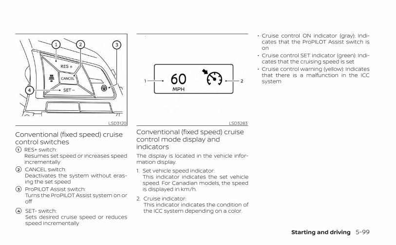
Conventional (fixed speed) cruisecontrol switches�1 RES+ switch:
Resumes set speed or increases speedincrementally
�2 CANCEL switch:Deactivates the system without eras-ing the set speed
�3 ProPILOT Assist switch:Turns the ProPILOT Assist system on oroff
�4 SET- switch:Sets desired cruise speed or reducesspeed incrementally
Conventional (fixed speed) cruisecontrol mode display andindicatorsThe display is located in the vehicle infor-mation display.1. Set vehicle speed indicator:
This indicator indicates the set vehiclespeed. For Canadian models, the speedis displayed in km/h.
2. Cruise indicator:This indicator indicates the condition ofthe ICC system depending on a color.
• Cruise control ON indicator (gray): Indi-cates that the ProPILOT Assist switch ison
• Cruise control SET indicator (green): Indi-cates that the cruising speed is set
• Cruise control warning (yellow): Indicatesthat there is a malfunction in the ICCsystem
LSD3120 LSD3283
Starting and driving 5-99
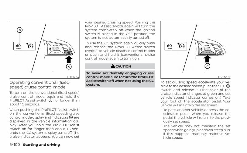
Operating conventional (fixedspeed) cruise control modeTo turn on the conventional (fixed speed)cruise control mode, push and hold theProPILOT Assist switch OA for longer thanabout 1.5 seconds.When pushing the ProPILOT Assist switchon, the conventional (fixed speed) cruisecontrol mode display and indicators OB aredisplayed in the vehicle information dis-play. After you hold the ProPILOT Assistswitch on for longer than about 1.5 sec-onds, the ICC system display turns off. Thecruise indicator appears. You can now set
your desired cruising speed. Pushing theProPILOT Assist switch again will turn thesystem completely off. When the ignitionswitch is placed in the OFF position, thesystem is also automatically turned off.To use the ICC system again, quickly pushand release the ProPILOT Assist switch(vehicle-to vehicle distance control mode)or push and hold it (conventional cruisecontrol mode) again to turn it on.
CAUTION
To avoid accidentally engaging cruisecontrol, make sure to turn the ProPILOTAssist switch off when not using the ICCsystem.
To set cruising speed, accelerate your ve-hicle to the desired speed, push the SET- OC
switch and release it. (The color of thecruise indicator changes to green and setvehicle speed indicator comes on.) Takeyour foot off the accelerator pedal. Yourvehicle will maintain the set speed.• To pass another vehicle, depress the ac-
celerator pedal. When you release thepedal, the vehicle will return to the previ-ously set speed.
• The vehicle may not maintain the setspeed when going up or down steep hills.If this happens, manually maintain ve-hicle speed.
LSD3284 LSD3285
5-100 Starting and driving
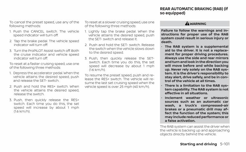
To cancel the preset speed, use any of thefollowing methods:1. Push the CANCEL switch. The vehicle
speed indicator will turn off.
2. Tap the brake pedal. The vehicle speedindicator will turn off.
3. Turn the ProPILOT Assist switch off. Boththe cruise indicator and vehicle speedindicator will turn off.
To reset at a faster cruising speed, use oneof the following three methods:1. Depress the accelerator pedal. When the
vehicle attains the desired speed, pushand release the SET- switch.
2. Push and hold the RES+ switch. Whenthe vehicle attains the desired speed,release the switch.
3. Push, then quickly release the RES+switch. Each time you do this, the setspeed will increase by about 1 mph(1.6 km/h).
To reset at a slower cruising speed, use oneof the following three methods:1. Lightly tap the brake pedal. When the
vehicle attains the desired speed, pushthe SET- switch and release it.
2. Push and hold the SET- switch. Releasethe switch when the vehicle slows downto the desired speed.
3. Push, then quickly release the SET-switch. Each time you do this, the setspeed will decrease by about 1 mph(1.6 km/h).
To resume the preset speed, push and re-lease the RES+ switch. The vehicle will re-sume the last set cruising speed when thevehicle speed is over 25 mph (40 km/h).
WARNING
Failure to follow the warnings and in-structions for proper use of the RABsystem could result in serious injury ordeath.• The RAB system is a supplemental
aid to the driver. It is not a replace-ment for proper driving procedures.Always use the side and rear mirrorsand turn and look in the direction youwill move before and while backingup. Never rely solely on the RAB sys-tem. It is the driver’s responsibility tostay alert, drive safely, and be in con-trol of the vehicle at all times.
• There is a limitation to the RAB sys-tem capability. The RAB system is noteffective in all situations.
• Inclement weather or ultrasonicsources such as an automatic carwash, a truck’s compressed-airbrakes or a pneumatic drill may af-fect the function of the system; thismay include reduced performance ora false activation.
The RAB system can assist the driver whenthe vehicle is backing up and approachingobjects directly behind the vehicle.
REAR AUTOMATIC BRAKING (RAB) (ifso equipped)
Starting and driving 5-101
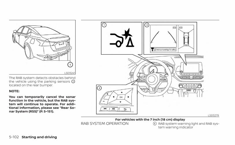
The RAB system detects obstacles behindthe vehicle using the parking sensors O1
located on the rear bumper.
NOTE:
You can temporarily cancel the sonarfunction in the vehicle, but the RAB sys-tem will continue to operate. For addi-tional information, please see “Rear So-nar System (RSS)” (P. 5-151).
RAB SYSTEM OPERATION �1 RAB system warning light and RAB sys-tem warning indicator
LSD3241
LSD3279For vehicles with the 7 inch (18 cm) display
5-102 Starting and driving
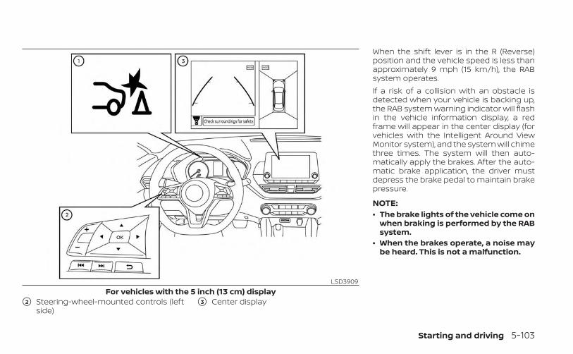
�2 Steering-wheel-mounted controls (leftside)
�3 Center display
When the shift lever is in the R (Reverse)position and the vehicle speed is less thanapproximately 9 mph (15 km/h), the RABsystem operates.If a risk of a collision with an obstacle isdetected when your vehicle is backing up,the RAB system warning indicator will flashin the vehicle information display, a redframe will appear in the center display (forvehicles with the Intelligent Around ViewMonitor system), and the system will chimethree times. The system will then auto-matically apply the brakes. After the auto-matic brake application, the driver mustdepress the brake pedal to maintain brakepressure.
NOTE:• The brake lights of the vehicle come on
when braking is performed by the RABsystem.
• When the brakes operate, a noise maybe heard. This is not a malfunction.
LSD3909For vehicles with the 5 inch (13 cm) display
Starting and driving 5-103

TURNING THE RAB SYSTEMON/OFF
Perform the following steps to turn the RABsystem ON or OFF.
For vehicles with the 7 inch (18 cm) dis-play.1. Press the button until “Settings” dis-
plays in the vehicle information display.Use the button to select “Driver As-sistance.” Then press the OK button.
2. Select “Emergency Brake” and press theOK button.
3. To set the RAB system to on or off, usethe OK button to check the box for “Rear.”
LSD3237For vehicles with the 7 inch (18 cm) display
5-104 Starting and driving
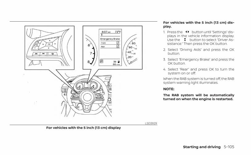
For vehicles with the 5 inch (13 cm) dis-play.1. Press the button until “Settings” dis-
plays in the vehicle information display.Use the button to select “Driver As-sistance.” Then press the OK button.
2. Select “Driving Aids” and press the OKbutton.
3. Select “Emergency Brake” and press theOK button.
4. Select “Rear” and press OK to turn thesystem on or off.
When the RAB system is turned off, the RABsystem warning light illuminates.
NOTE:
The RAB system will be automaticallyturned on when the engine is restarted.
LSD3929For vehicles with the 5 inch (13 cm) display
Starting and driving 5-105
RAB SYSTEM LIMITATIONSWARNING
Listed below are the system limitationsfor the RAB system. Failure to follow thewarnings and instructions for properuse of the RAB system could result inserious injury or death.• When the vehicle approaches an ob-
stacle while the accelerator or brakepedal is depressed, the function maynot operate or the start of operationmay be delayed. The RAB systemmay not operate or may not performsufficiently due to vehicle conditions,driving conditions, the traffic envi-ronment, the weather, road surfaceconditions, etc. Do not wait for thesystem to operate. Operate the brakepedal by yourself as soon asnecessary.
• If it is necessary to override RAB op-eration, strongly press the accelera-tor pedal.
• Always check your surroundings andturn to check what is behind you be-fore and while backing up. The RABsystem detects stationary objectsbehind the vehicle. The RAB systemdoes not detect the following ob-jects:– Moving objects– Low objects– Narrow objects– Wedge-shaped objects– Objects close to the bumper (less
than approximately 1 ft [30 cm])– Objects that suddenly appear– Thin objects such as rope, wire,
chain, etc.• The RAB system may not operate for
the following obstacles:– Obstacles located high off the
ground– Obstacles in a position offset from
your vehicle– Obstacles, such as spongy materi-
als or snow, that have soft outersurfaces and can easily absorb asound wave
• The RAB system may not operate inthe following conditions:– There is rain, snow, ice, dirt, etc.,
attached to the sonar sensors.– A loud sound is heard in the area
around the vehicle.– The surface of the obstacle is di-
agonal to the rear of the vehicle.• The RAB system may unintentionally
operate in the following conditions:– There is overgrown grass in the
area around the vehicle.– There is a structure (e.g., a wall, toll
gate equipment, a narrow tunnel,a parking lot gate) near the side ofthe vehicle.
– There are bumps, protrusions, ormanhole covers on the roadsurface.
– The vehicle drives through adraped flag or a curtain.
– There is an accumulation of snowor ice behind the vehicle.
– An ultrasonic wave source, such asanother vehicle’s sonar, is nearthe vehicle.
5-106 Starting and driving
• Once the automatic brake controloperates, it does not operate again ifthe vehicle approaches the sameobstacle.
• The automatic brake control can onlyoperate for a short period of time.Therefore, the driver must depressthe brake pedal.
• In the following situations, the RABsystem may not operate properly ormay not function sufficiently:– The vehicle is driven in bad
weather (rain, fog, snow, etc.).– The vehicle is driven on a steep
hill.– The vehicle’s posture is changed
(e.g., when driving over a bump).– The vehicle is driven on a slippery
road.– The vehicle is turned sharply by
turning the steering wheel fully.– Snow chains are used.– Wheels or tires other than NISSAN
recommended are used.– The brakes are cold at low ambi-
ent temperatures or immediatelyafter driving has started.
– The braking force becomes poordue to wet brakes after drivingthrough a puddle or washing thevehicle.
• Turn the RAB system off in the follow-ing conditions to prevent the occur-rence of an unexpected accident re-sulting from sudden systemoperation:– The vehicle is towed.– The vehicle is carried on a flatbed
truck.– The vehicle is on the chassis
dynamometer.– The vehicle drives on an uneven
road surface.– The vehicle is towing an object (if
so equipped).– Suspension parts other than
those designated as GenuineNISSAN parts are used. (If the ve-hicle height or the vehicle body in-clination is changed, the systemmay not detect an obstaclecorrectly.)
• Excessive noise (e.g., audio systemvolume, an open vehicle window) willinterfere with the chime sound, and itmay not be heard.
SYSTEM MALFUNCTIONIf the RAB system malfunctions, it will beturned off automatically, the RAB systemwarning light will illuminate, and the “Mal-function” warning message will appear inthe vehicle information display.Action to takeIf the warning light illuminates, park the ve-hicle in a safe location, turn the engine off,and restart the engine. If the warning lightcontinues to illuminate, have the RAB sys-tem checked. It is recommended that youvisit a NISSAN dealer for this service.
NOTE:
If the RAB system cannot be operatedtemporarily, the RAB system warninglight blinks.
Starting and driving 5-107
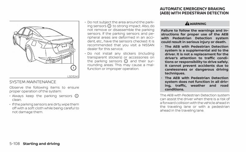
SYSTEM MAINTENANCEObserve the following items to ensureproper operation of the system:• Always keep the parking sensors O1
clean.• If the parking sensors are dirty, wipe them
off with a soft cloth while being careful tonot damage them.
• Do not subject the area around the park-ing sensors O1 to strong impact. Also, donot remove or disassemble the parkingsensors. If the parking sensors and pe-ripheral areas are deformed in an acci-dent, etc., have the sensors checked. It isrecommended that you visit a NISSANdealer for this service.
• Do not install any stickers (includingtransparent stickers) or accessories onthe parking sensors O1 and their sur-rounding areas. This may cause a mal-function or improper operation.
WARNING
Failure to follow the warnings and in-structions for proper use of the AEBwith Pedestrian Detection systemcould result in serious injury or death.• The AEB with Pedestrian Detection
system is a supplemental aid to thedriver. It is not a replacement for thedriver’s attention to traffic condi-tions or responsibility to drive safely.It cannot prevent accidents due tocarelessness or dangerous drivingtechniques.
• The AEB with Pedestrian Detectionsystem does not function in all driv-ing, traffic, weather and roadconditions.
The AEB with Pedestrian Detection systemcan assist the driver when there is a risk ofa forward collision with the vehicle ahead inthe traveling lane or with a pedestrianahead in the traveling lane.
LSD3241
AUTOMATIC EMERGENCY BRAKING(AEB) WITH PEDESTRIAN DETECTION
5-108 Starting and driving
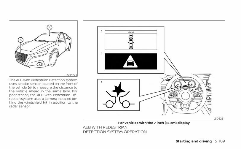
The AEB with Pedestrian Detection systemuses a radar sensor located on the front ofthe vehicle OB to measure the distance tothe vehicle ahead in the same lane. Forpedestrians, the AEB with Pedestrian De-tection system uses a camera installed be-hind the windshield OA in addition to theradar sensor.
AEB WITH PEDESTRIANDETECTION SYSTEM OPERATION
LSD3223
LSD3281For vehicles with the 7 inch (18 cm) display
Starting and driving 5-109
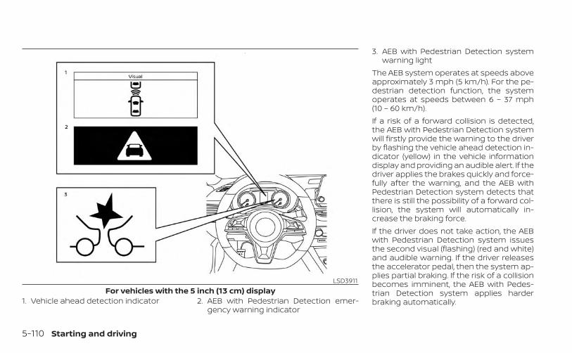
1. Vehicle ahead detection indicator 2. AEB with Pedestrian Detection emer-gency warning indicator
3. AEB with Pedestrian Detection systemwarning light
The AEB system operates at speeds aboveapproximately 3 mph (5 km/h). For the pe-destrian detection function, the systemoperates at speeds between 6 – 37 mph(10 – 60 km/h).If a risk of a forward collision is detected,the AEB with Pedestrian Detection systemwill firstly provide the warning to the driverby flashing the vehicle ahead detection in-dicator (yellow) in the vehicle informationdisplay and providing an audible alert. If thedriver applies the brakes quickly and force-fully after the warning, and the AEB withPedestrian Detection system detects thatthere is still the possibility of a forward col-lision, the system will automatically in-crease the braking force.If the driver does not take action, the AEBwith Pedestrian Detection system issuesthe second visual (flashing) (red and white)and audible warning. If the driver releasesthe accelerator pedal, then the system ap-plies partial braking. If the risk of a collisionbecomes imminent, the AEB with Pedes-trian Detection system applies harderbraking automatically.
LSD3911For vehicles with the 5 inch (13 cm) display
5-110 Starting and driving
While the AEB with Pedestrian Detectionsystem is operating, you may hear thesound of brake operation. This is normaland indicates that the AEB with PedestrianDetection system is operating properly.
NOTE:
The vehicle’s brake lights come on whenany braking is performed by the AEBwith Pedestrian Detection system.Depending on vehicle speed and distanceto the vehicle or pedestrian ahead, as wellas driving and roadway conditions, the sys-tem may help the driver avoid a forwardcollision or may help mitigate the conse-quences if a collision should be unavoid-able. If the driver is handling the steeringwheel, accelerating or braking, the AEB withPedestrian Detection system will functionlater or will not function.
The automatic braking will cease under thefollowing conditions:• When the steering wheel is turned to
avoid a collision.• When the accelerator pedal is depressed.• When there is no longer a vehicle or a
pedestrian detected ahead.If the AEB with Pedestrian Detection sys-tem has stopped the vehicle, the vehiclewill remain at a standstill for approximately2 seconds before the brakes are released.
Starting and driving 5-111
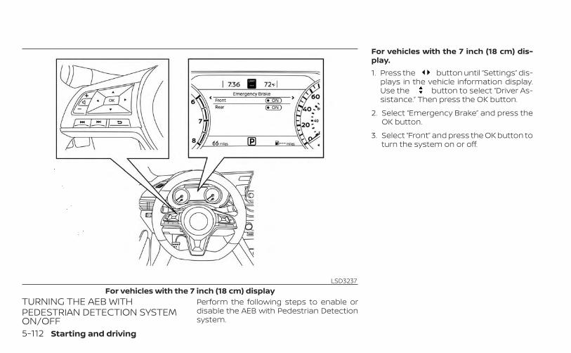
TURNING THE AEB WITHPEDESTRIAN DETECTION SYSTEMON/OFF
Perform the following steps to enable ordisable the AEB with Pedestrian Detectionsystem.
For vehicles with the 7 inch (18 cm) dis-play.1. Press the button until “Settings” dis-
plays in the vehicle information display.Use the button to select “Driver As-sistance.” Then press the OK button.
2. Select “Emergency Brake” and press theOK button.
3. Select “Front” and press the OK button toturn the system on or off.
LSD3237For vehicles with the 7 inch (18 cm) display
5-112 Starting and driving
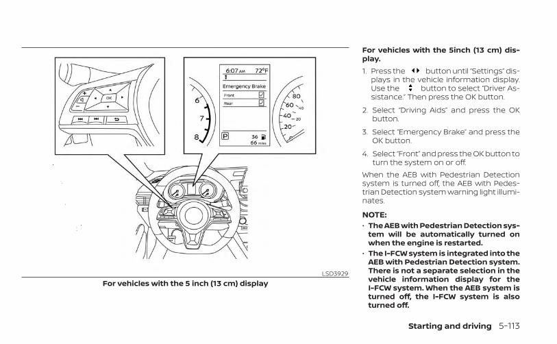
For vehicles with the 5inch (13 cm) dis-play.1. Press the button until “Settings” dis-
plays in the vehicle information display.Use the button to select “Driver As-sistance.” Then press the OK button.
2. Select “Driving Aids” and press the OKbutton.
3. Select “Emergency Brake” and press theOK button.
4. Select “Front” and press the OK button toturn the system on or off.
When the AEB with Pedestrian Detectionsystem is turned off, the AEB with Pedes-trian Detection system warning light illumi-nates.
NOTE:• The AEB with Pedestrian Detection sys-
tem will be automatically turned onwhen the engine is restarted.
• The I-FCW system is integrated into theAEB with Pedestrian Detection system.There is not a separate selection in thevehicle information display for theI-FCW system. When the AEB system isturned off, the I-FCW system is alsoturned off.
LSD3929For vehicles with the 5 inch (13 cm) display
Starting and driving 5-113
AEB WITH PEDESTRIANDETECTION SYSTEM LIMITATIONS
WARNING
Listed below are the system limitationsfor the AEB with Pedestrian Detectionsystem. Failure to operate the vehicle inaccordance with these system limita-tions could result in serious injury ordeath.• The AEB with Pedestrian Detection
system cannot detect all vehicles orpedestrians under all conditions.
• The AEB with Pedestrian Detectionsystem does not detect the followingobjects:– Small pedestrians (including
small children), animals andcyclists.
– Pedestrians in wheelchairs or us-ing mobile transport such asscooters, child-operated toys, orskateboards.
– Pedestrians who are seated orotherwise not in a full uprightstanding or walking position.
– Oncoming vehicles– Crossing vehicles– Obstacles on the roadside
• The AEB with Pedestrian Detectionsystem has some performancelimitations.– If a stationary vehicle is in the ve-
hicle’s path, the AEB with Pedes-trian Detection system will notfunction when the vehicle isdriven at speeds over approxi-mately 50 mph (80 km/h).
– For pedestrian detection, the AEBwith Pedestrian Detection systemwill not function when the vehicleis driven at speeds over approxi-mately 37 mph (60 km/h) or belowapproximately 6 mph (10 km/h).
• The AEB with Pedestrian Detectionsystem will not function for pedestri-ans in darkness or in tunnels, even ifthere is street lighting in the area.
• The AEB with Pedestrian Detectionsystem may not function if the ve-hicle ahead is narrow (for example, amotorcycle).
• The AEB with Pedestrian Detectionsystem may not function if the speeddifference between the two vehiclesis too small.
• The radar sensor AEB with Pedes-trian Detection system may notfunction properly or detect a vehicleahead in the following conditions:– Poor visibility (conditions such as
rain, snow, fog, dust storms, sand-storms, and road spray from othervehicles)
– Driving on a steep downhill slopeor roads with sharp curves.
– Driving on a bumpy road surface,such as an uneven dirt road.
– If dirt, ice, snow or other materialis covering the radar sensor area.
– Interference by other radarsources.
– The camera area of the windshieldis fogged up, or covered with dirt,water drops, ice, snow, etc.
5-114 Starting and driving
– Strong light (for example, sunlightor high beams from oncoming ve-hicles) enters the front camera.Strong light causes the areaaround the pedestrian to be castin a shadow, making it difficult tosee.
– A sudden change in brightnessoccurs. (For example, when thevehicle enters or exits a tunnel or ashaded area or lightning flashes.)
– The poor contrast of a person tothe background, such as havingclothing color or pattern which issimilar to the background.
– The pedestrian’s profile is partiallyobscured or unidentifiable due tothe pedestrian transporting lug-gage, wearing bulky or very loose-fitting clothing or accessories.
• The system performance may de-grade in the following conditions:– The vehicle is driven on a slippery
road.– The vehicle is driven on a slope.– Excessively heavy baggage is
loaded in the rear seat or the trunkroom of your vehicle.
• The system is designed to automati-cally check the sensor’s (radar andcamera) functionality, within certainlimitations. The system may not de-tect blockage of sensor areas cov-ered by ice, snow or stickers, for ex-ample. In these cases, the systemmay not be able to warn the driverproperly. Be sure that you check,clean and clear sensor areasregularly.
• In some road and traffic conditions,the AEB with Pedestrian Detectionsystem may unexpectedly apply par-tial braking. When acceleration isnecessary, depress the acceleratorpedal to override the system.
• Excessive noise will interfere with thewarning chime sound, and the chimemay not be heard.
Starting and driving 5-115
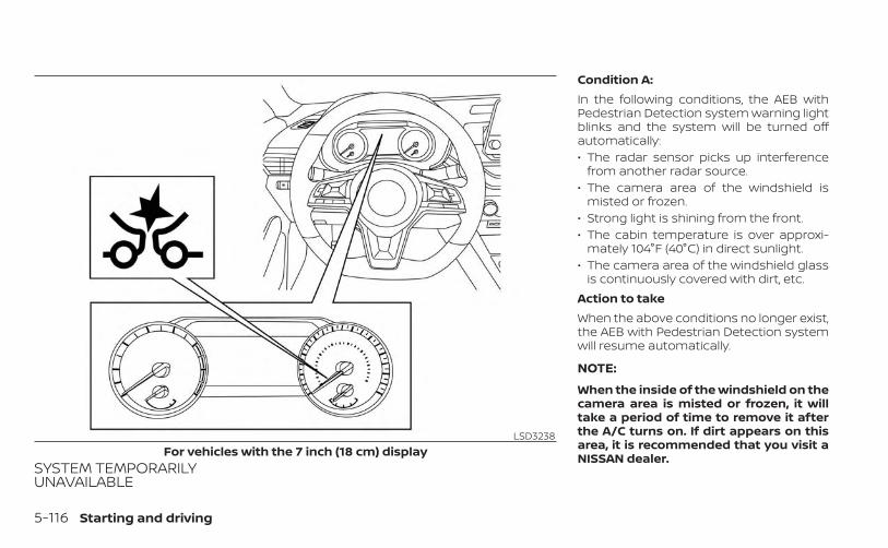
SYSTEM TEMPORARILYUNAVAILABLE
Condition A:In the following conditions, the AEB withPedestrian Detection system warning lightblinks and the system will be turned offautomatically:• The radar sensor picks up interference
from another radar source.• The camera area of the windshield is
misted or frozen.• Strong light is shining from the front.• The cabin temperature is over approxi-
mately 104°F (40°C) in direct sunlight.• The camera area of the windshield glass
is continuously covered with dirt, etc.Action to takeWhen the above conditions no longer exist,the AEB with Pedestrian Detection systemwill resume automatically.
NOTE:
When the inside of the windshield on thecamera area is misted or frozen, it willtake a period of time to remove it afterthe A/C turns on. If dirt appears on thisarea, it is recommended that you visit aNISSAN dealer.
LSD3238For vehicles with the 7 inch (18 cm) display
5-116 Starting and driving
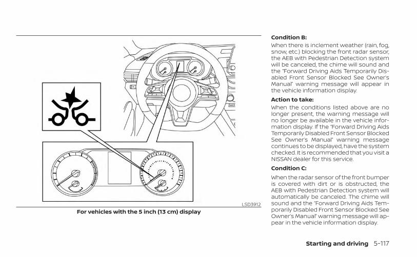
Condition B:When there is inclement weather (rain, fog,snow, etc.) blocking the front radar sensor,the AEB with Pedestrian Detection systemwill be canceled, the chime will sound andthe “Forward Driving Aids Temporarily Dis-abled Front Sensor Blocked See Owner’sManual” warning message will appear inthe vehicle information display.Action to take:When the conditions listed above are nolonger present, the warning message willno longer be available in the vehicle infor-mation display. If the “Forward Driving AidsTemporarily Disabled Front Sensor BlockedSee Owner’s Manual” warning messagecontinues to be displayed, have the systemchecked. It is recommended that you visit aNISSAN dealer for this service.Condition C:When the radar sensor of the front bumperis covered with dirt or is obstructed, theAEB with Pedestrian Detection system willautomatically be canceled. The chime willsound and the “Forward Driving Aids Tem-porarily Disabled Front Sensor Blocked SeeOwner’s Manual” warning message will ap-pear in the vehicle information display.
LSD3912For vehicles with the 5 inch (13 cm) display
Starting and driving 5-117
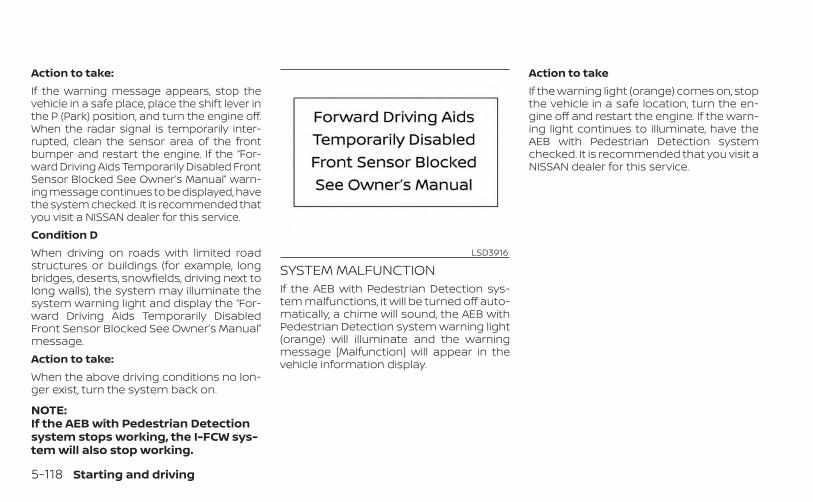
Action to take:If the warning message appears, stop thevehicle in a safe place, place the shift lever inthe P (Park) position, and turn the engine off.When the radar signal is temporarily inter-rupted, clean the sensor area of the frontbumper and restart the engine. If the “For-ward Driving Aids Temporarily Disabled FrontSensor Blocked See Owner’s Manual” warn-ing message continues to be displayed, havethe system checked. It is recommended thatyou visit a NISSAN dealer for this service.Condition DWhen driving on roads with limited roadstructures or buildings (for example, longbridges, deserts, snowfields, driving next tolong walls), the system may illuminate thesystem warning light and display the “For-ward Driving Aids Temporarily DisabledFront Sensor Blocked See Owner’s Manual”message.Action to take:When the above driving conditions no lon-ger exist, turn the system back on.
NOTE:If the AEB with Pedestrian Detectionsystem stops working, the I-FCW sys-tem will also stop working.
SYSTEM MALFUNCTIONIf the AEB with Pedestrian Detection sys-tem malfunctions, it will be turned off auto-matically, a chime will sound, the AEB withPedestrian Detection system warning light(orange) will illuminate and the warningmessage [Malfunction] will appear in thevehicle information display.
Action to takeIf the warning light (orange) comes on, stopthe vehicle in a safe location, turn the en-gine off and restart the engine. If the warn-ing light continues to illuminate, have theAEB with Pedestrian Detection systemchecked. It is recommended that you visit aNISSAN dealer for this service.
LSD3916
5-118 Starting and driving
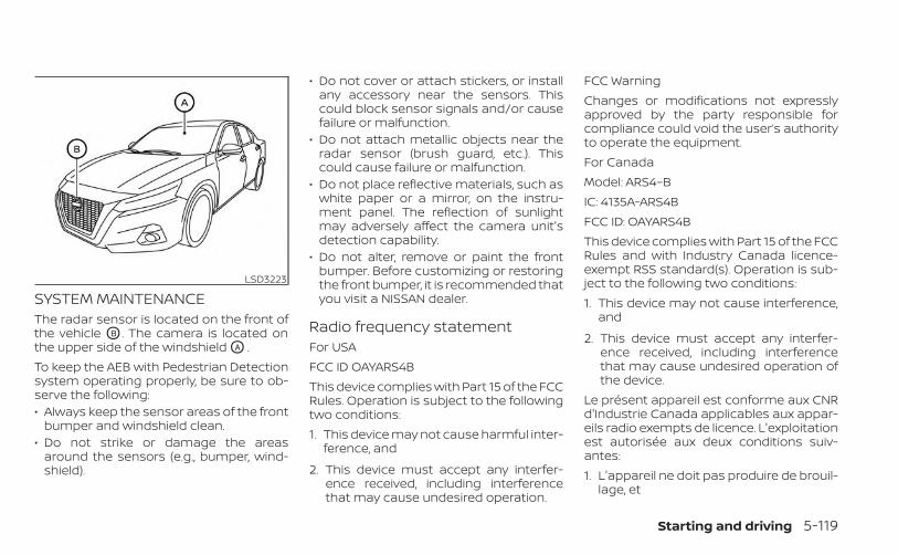
SYSTEM MAINTENANCEThe radar sensor is located on the front ofthe vehicle OB . The camera is located onthe upper side of the windshield OA .To keep the AEB with Pedestrian Detectionsystem operating properly, be sure to ob-serve the following:• Always keep the sensor areas of the front
bumper and windshield clean.• Do not strike or damage the areas
around the sensors (e.g., bumper, wind-shield).
• Do not cover or attach stickers, or installany accessory near the sensors. Thiscould block sensor signals and/or causefailure or malfunction.
• Do not attach metallic objects near theradar sensor (brush guard, etc.). Thiscould cause failure or malfunction.
• Do not place reflective materials, such aswhite paper or a mirror, on the instru-ment panel. The reflection of sunlightmay adversely affect the camera unit'sdetection capability.
• Do not alter, remove or paint the frontbumper. Before customizing or restoringthe front bumper, it is recommended thatyou visit a NISSAN dealer.
Radio frequency statementFor USAFCC ID OAYARS4BThis device complies with Part 15 of the FCCRules. Operation is subject to the followingtwo conditions:1. This device may not cause harmful inter-
ference, and
2. This device must accept any interfer-ence received, including interferencethat may cause undesired operation.
FCC WarningChanges or modifications not expresslyapproved by the party responsible forcompliance could void the user’s authorityto operate the equipment.For CanadaModel: ARS4–BIC: 4135A-ARS4BFCC ID: OAYARS4BThis device complies with Part 15 of the FCCRules and with Industry Canada licence-exempt RSS standard(s). Operation is sub-ject to the following two conditions:1. This device may not cause interference,
and
2. This device must accept any interfer-ence received, including interferencethat may cause undesired operation ofthe device.
Le présent appareil est conforme aux CNRd'Industrie Canada applicables aux appar-eils radio exempts de licence. L'exploitationest autorisée aux deux conditions suiv-antes:1. L'appareil ne doit pas produire de brouil-
lage, et
LSD3223
Starting and driving 5-119
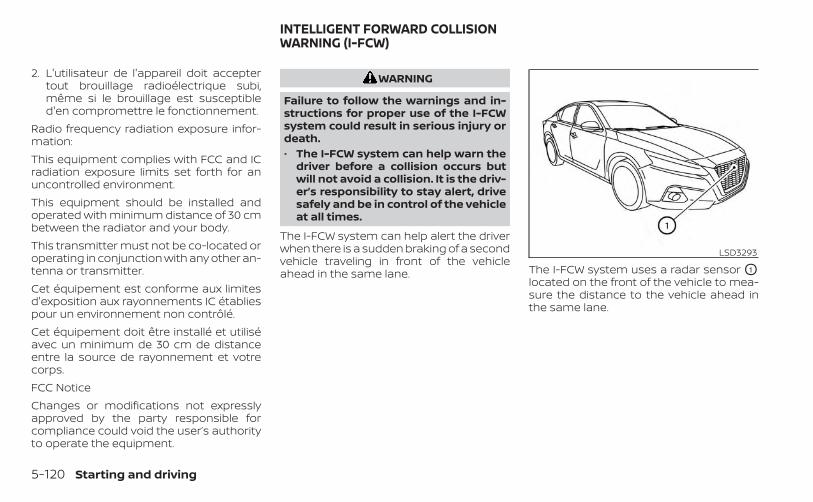
2. L'utilisateur de l'appareil doit acceptertout brouillage radioélectrique subi,même si le brouillage est susceptibled'en compromettre le fonctionnement.
Radio frequency radiation exposure infor-mation:This equipment complies with FCC and ICradiation exposure limits set forth for anuncontrolled environment.This equipment should be installed andoperated with minimum distance of 30 cmbetween the radiator and your body.This transmitter must not be co-located oroperating in conjunction with any other an-tenna or transmitter.Cet équipement est conforme aux limitesd'exposition aux rayonnements IC établiespour un environnement non contrôlé.Cet équipement doit être installé et utiliséavec un minimum de 30 cm de distanceentre la source de rayonnement et votrecorps.FCC NoticeChanges or modifications not expresslyapproved by the party responsible forcompliance could void the user’s authorityto operate the equipment.
WARNING
Failure to follow the warnings and in-structions for proper use of the I-FCWsystem could result in serious injury ordeath.• The I-FCW system can help warn the
driver before a collision occurs butwill not avoid a collision. It is the driv-er’s responsibility to stay alert, drivesafely and be in control of the vehicleat all times.
The I-FCW system can help alert the driverwhen there is a sudden braking of a secondvehicle traveling in front of the vehicleahead in the same lane. The I-FCW system uses a radar sensor O1
located on the front of the vehicle to mea-sure the distance to the vehicle ahead inthe same lane.
LSD3293
INTELLIGENT FORWARD COLLISIONWARNING (I-FCW)
5-120 Starting and driving
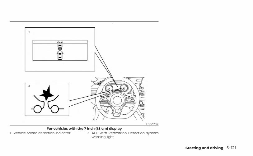
1. Vehicle ahead detection indicator 2. AEB with Pedestrian Detection systemwarning light
LSD3282For vehicles with the 7 inch (18 cm) display
Starting and driving 5-121
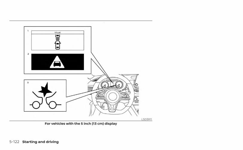
LSD3911For vehicles with the 5 inch (13 cm) display
5-122 Starting and driving
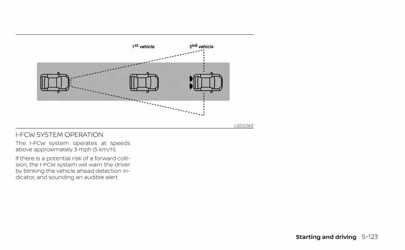
I-FCW SYSTEM OPERATIONThe I-FCW system operates at speedsabove approximately 3 mph (5 km/h).If there is a potential risk of a forward colli-sion, the I-FCW system will warn the driverby blinking the vehicle ahead detection in-dicator, and sounding an audible alert.
LSD2263
Starting and driving 5-123
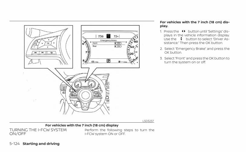
TURNING THE I-FCW SYSTEMON/OFF
Perform the following steps to turn theI-FCW system ON or OFF.
For vehicles with the 7 inch (18 cm) dis-play.1. Press the button until “Settings” dis-
plays in the vehicle information display.Use the button to select “Driver As-sistance.” Then press the OK button.
2. Select “Emergency Brake” and press theOK button.
3. Select “Front” and press the OK button toturn the system on or off.
LSD3237For vehicles with the 7 inch (18 cm) display
5-124 Starting and driving
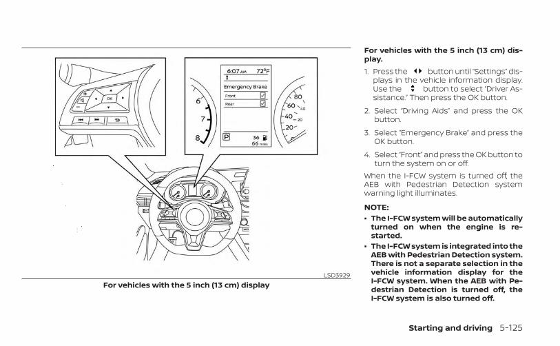
For vehicles with the 5 inch (13 cm) dis-play.1. Press the button until “Settings” dis-
plays in the vehicle information display.Use the button to select “Driver As-sistance.” Then press the OK button.
2. Select “Driving Aids” and press the OKbutton.
3. Select “Emergency Brake” and press theOK button.
4. Select “Front” and press the OK button toturn the system on or off.
When the I-FCW system is turned off, theAEB with Pedestrian Detection systemwarning light illuminates.
NOTE:• The I-FCW system will be automatically
turned on when the engine is re-started.
• The I-FCW system is integrated into theAEB with Pedestrian Detection system.There is not a separate selection in thevehicle information display for theI-FCW system. When the AEB with Pe-destrian Detection is turned off, theI-FCW system is also turned off.
LSD3929For vehicles with the 5 inch (13 cm) display
Starting and driving 5-125
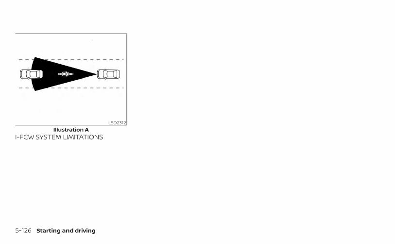
I-FCW SYSTEM LIMITATIONS
LSD2312Illustration A
5-126 Starting and driving
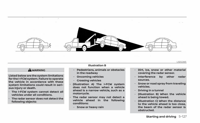
WARNING
Listed below are the system limitationsfor the I-FCW system. Failure to operatethe vehicle in accordance with thesesystem limitations could result in seri-ous injury or death.• The I-FCW system cannot detect all
vehicles under all conditions.• The radar sensor does not detect the
following objects:
– Pedestrians, animals or obstaclesin the roadway
– Oncoming vehicles– Crossing vehicles
• (Illustration A) The I-FCW systemdoes not function when a vehicleahead is a narrow vehicle, such as amotorcycle.
• The radar sensor may not detect avehicle ahead in the followingconditions:– Snow or heavy rain
– Dirt, ice, snow or other materialcovering the radar sensor.
– Interference by other radarsources.
– Snow or road spray from travelingvehicles.
– Driving in a tunnel– (Illustration B) When the vehicle
ahead is being towed.– (Illustration C) When the distance
to the vehicle ahead is too close,the beam of the radar sensor isobstructed.
LSD2265Illustration B
Starting and driving 5-127

– (Illustration D) When driving on asteep downhill slope or roads withsharp curves.
• The system is designed to automati-cally check the sensor’s functionality,within certain limitations. The sys-tem may not detect some forms ofobstruction of the sensor area suchas ice, snow, stickers, etc. In thesecases, the system may not be able towarn the driver properly. Be sure thatyou check, clean and clear the sensorarea regularly.
• Excessive noise will interfere with thewarning chime sound, and the chimemay not be heard.
5-128 Starting and driving
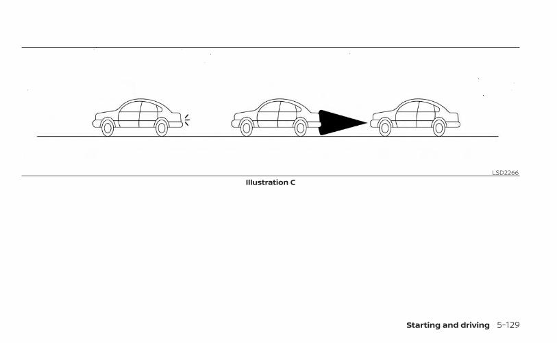
LSD2266Illustration C
Starting and driving 5-129
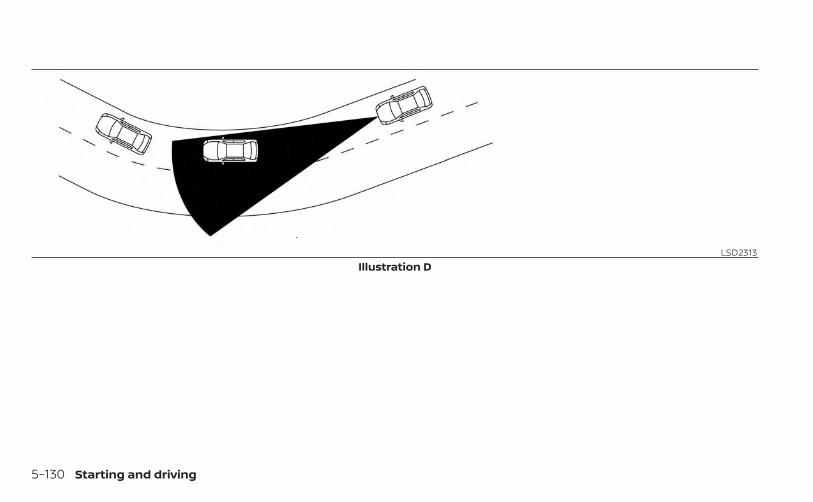
LSD2313Illustration D
5-130 Starting and driving
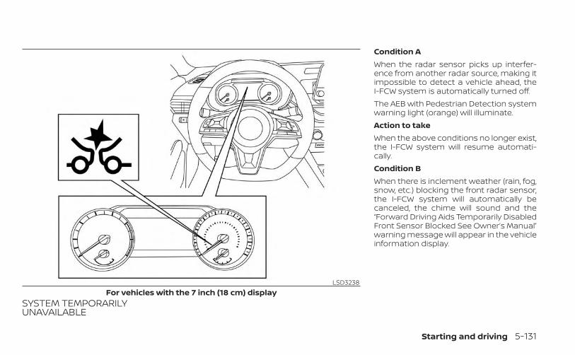
SYSTEM TEMPORARILYUNAVAILABLE
Condition AWhen the radar sensor picks up interfer-ence from another radar source, making itimpossible to detect a vehicle ahead, theI-FCW system is automatically turned off.The AEB with Pedestrian Detection systemwarning light (orange) will illuminate.Action to takeWhen the above conditions no longer exist,the I-FCW system will resume automati-cally.Condition BWhen there is inclement weather (rain, fog,snow, etc.) blocking the front radar sensor,the I-FCW system will automatically becanceled, the chime will sound and the“Forward Driving Aids Temporarily DisabledFront Sensor Blocked See Owner’s Manual”warning message will appear in the vehicleinformation display.
LSD3238For vehicles with the 7 inch (18 cm) display
Starting and driving 5-131
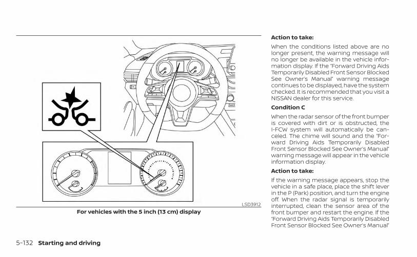
Action to take:When the conditions listed above are nolonger present, the warning message willno longer be available in the vehicle infor-mation display. If the “Forward Driving AidsTemporarily Disabled Front Sensor BlockedSee Owner’s Manual” warning messagecontinues to be displayed, have the systemchecked. It is recommended that you visit aNISSAN dealer for this service.Condition CWhen the radar sensor of the front bumperis covered with dirt or is obstructed, theI-FCW system will automatically be can-celed. The chime will sound and the “For-ward Driving Aids Temporarily DisabledFront Sensor Blocked See Owner’s Manual”warning message will appear in the vehicleinformation display.Action to take:If the warning message appears, stop thevehicle in a safe place, place the shift leverin the P (Park) position, and turn the engineoff. When the radar signal is temporarilyinterrupted, clean the sensor area of thefront bumper and restart the engine. If the“Forward Driving Aids Temporarily DisabledFront Sensor Blocked See Owner’s Manual”
LSD3912For vehicles with the 5 inch (13 cm) display
5-132 Starting and driving
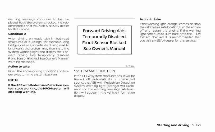
warning message continues to be dis-played, have the system checked. It is rec-ommended that you visit a NISSAN dealerfor this service.Condition DWhen driving on roads with limited roadstructures or buildings (for example, longbridges, deserts, snowfields, driving next tolong walls), the system may illuminate thesystem warning light and display the “For-ward Driving Aids Temporarily DisabledFront Sensor Blocked See Owner’s Manual”warning message.Action to take:When the above driving conditions no lon-ger exist, turn the system back on.
NOTE:
If the AEB with Pedestrian Detection sys-tem stops working, the I-FCW system willalso stop working.
SYSTEM MALFUNCTIONIf the I-FCW system malfunctions, it will beturned off automatically, a chime willsound, the AEB with Pedestrian Detectionsystem warning light (orange) will illumi-nate and the warning message [Malfunc-tion] will appear in the vehicle informationdisplay.
Action to takeIf the warning light (orange) comes on, stopthe vehicle in a safe location, turn the engineoff and restart the engine. If the warninglight continues to illuminate, have the I-FCWsystem checked. It is recommended thatyou visit a NISSAN dealer for this service.
LSD3916
Starting and driving 5-133
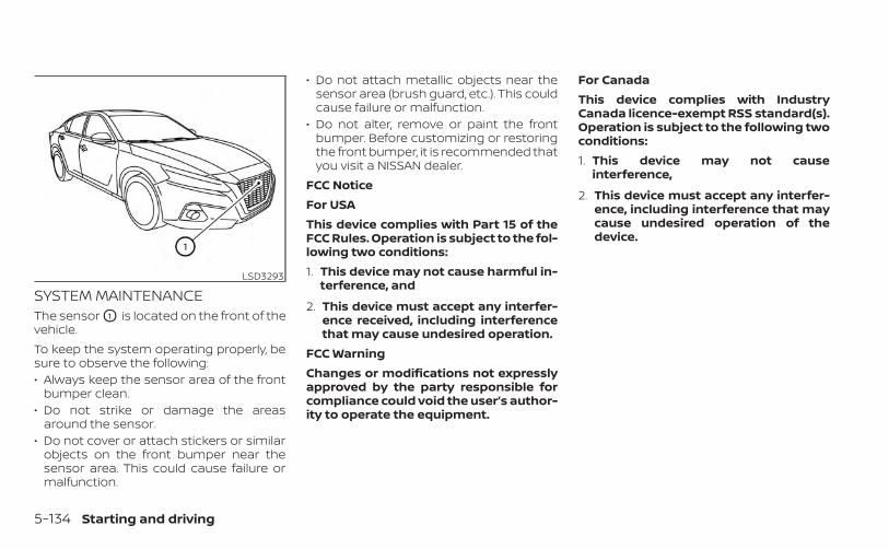
SYSTEM MAINTENANCEThe sensor O1 is located on the front of thevehicle.To keep the system operating properly, besure to observe the following:• Always keep the sensor area of the front
bumper clean.• Do not strike or damage the areas
around the sensor.• Do not cover or attach stickers or similar
objects on the front bumper near thesensor area. This could cause failure ormalfunction.
• Do not attach metallic objects near thesensor area (brush guard, etc.). This couldcause failure or malfunction.
• Do not alter, remove or paint the frontbumper. Before customizing or restoringthe front bumper, it is recommended thatyou visit a NISSAN dealer.
FCC NoticeFor USAThis device complies with Part 15 of theFCC Rules. Operation is subject to the fol-lowing two conditions:1. This device may not cause harmful in-
terference, and
2. This device must accept any interfer-ence received, including interferencethat may cause undesired operation.
FCC WarningChanges or modifications not expresslyapproved by the party responsible forcompliance could void the user’s author-ity to operate the equipment.
For CanadaThis device complies with IndustryCanada licence-exempt RSS standard(s).Operation is subject to the following twoconditions:1. This device may not cause
interference,
2. This device must accept any interfer-ence, including interference that maycause undesired operation of thedevice.
LSD3293
5-134 Starting and driving
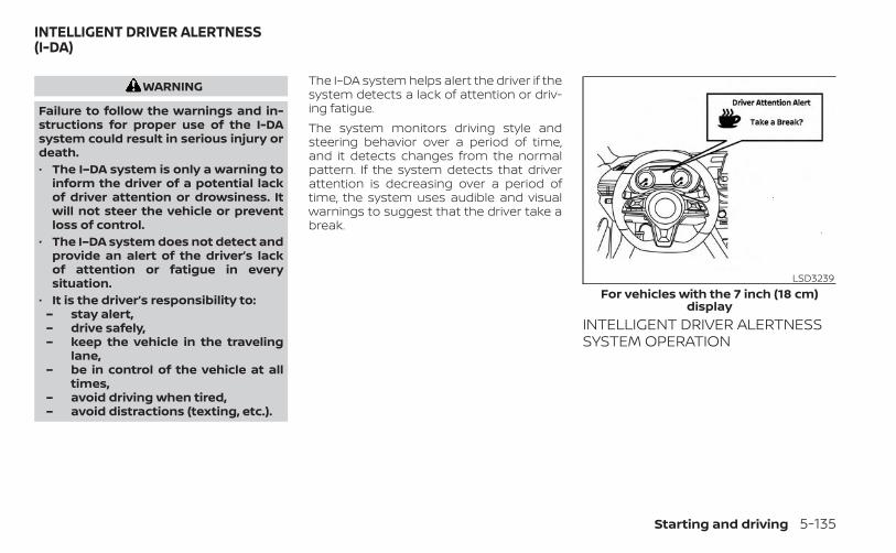
WARNING
Failure to follow the warnings and in-structions for proper use of the I-DAsystem could result in serious injury ordeath.• The I–DA system is only a warning to
inform the driver of a potential lackof driver attention or drowsiness. Itwill not steer the vehicle or preventloss of control.
• The I–DA system does not detect andprovide an alert of the driver’s lackof attention or fatigue in everysituation.
• It is the driver’s responsibility to:– stay alert,– drive safely,– keep the vehicle in the traveling
lane,– be in control of the vehicle at all
times,– avoid driving when tired,– avoid distractions (texting, etc.).
The I–DA system helps alert the driver if thesystem detects a lack of attention or driv-ing fatigue.The system monitors driving style andsteering behavior over a period of time,and it detects changes from the normalpattern. If the system detects that driverattention is decreasing over a period oftime, the system uses audible and visualwarnings to suggest that the driver take abreak.
INTELLIGENT DRIVER ALERTNESSSYSTEM OPERATION
LSD3239For vehicles with the 7 inch (18 cm)
display
INTELLIGENT DRIVER ALERTNESS(I-DA)
Starting and driving 5-135
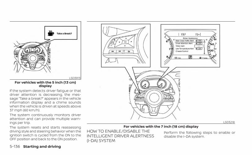
If the system detects driver fatigue or thatdriver attention is decreasing, the mes-sage “Take a break?” appears in the vehicleinformation display and a chime soundswhen the vehicle is driven at speeds above37 mph (60 km/h).The system continuously monitors driverattention and can provide multiple warn-ings per trip.The system resets and starts reassessingdriving style and steering behavior when theignition switch is cycled from the ON to theOFF position and back to the ON position.
HOW TO ENABLE/DISABLE THEINTELLIGENT DRIVER ALERTNESS(I-DA) SYSTEM
Perform the following steps to enable ordisable the I–DA system.
LSD3913For vehicles with the 5 inch (13 cm)
display
LSD3218For vehicles with the 7 inch (18 cm) display
5-136 Starting and driving
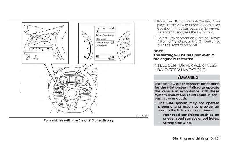
1. Press the button until “Settings” dis-plays in the vehicle information display.Use the button to select “Driver As-sistance.” Then press the OK button.
2. Select “Driver Attention Alert” or “ DriverAttention” and press the OK button toturn the system on or off.
NOTE:The setting will be retained even ifthe engine is restarted.
INTELLIGENT DRIVER ALERTNESS(I-DA) SYSTEM LIMITATIONS
WARNING
Listed below are the system limitationsfor the I–DA system. Failure to operatethe vehicle in accordance with thesesystem limitations could result in seri-ous injury or death.• The I-DA system may not operate
properly and may not provide analert in the following conditions:– Poor road conditions such as an
uneven road surface or pot holes.– Strong side wind.
LSD3930For vehicles with the 5 inch (13 cm) display
Starting and driving 5-137
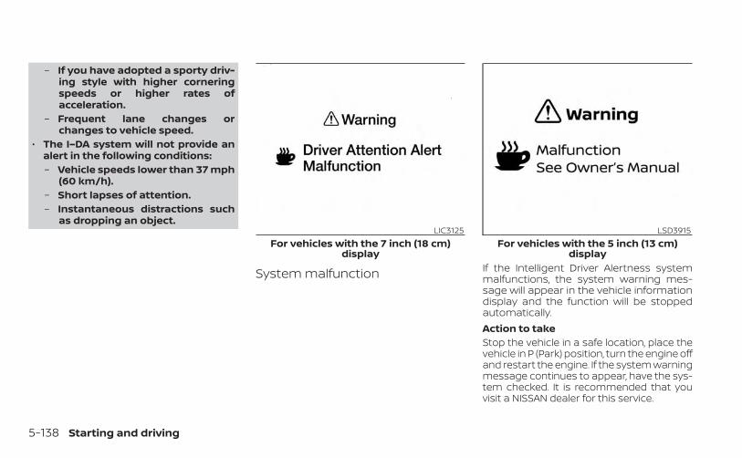
– If you have adopted a sporty driv-ing style with higher corneringspeeds or higher rates ofacceleration.
– Frequent lane changes orchanges to vehicle speed.
• The I–DA system will not provide analert in the following conditions:– Vehicle speeds lower than 37 mph
(60 km/h).– Short lapses of attention.– Instantaneous distractions such
as dropping an object.
System malfunction If the Intelligent Driver Alertness systemmalfunctions, the system warning mes-sage will appear in the vehicle informationdisplay and the function will be stoppedautomatically.Action to takeStop the vehicle in a safe location, place thevehicle in P (Park) position, turn the engine offand restart the engine. If the system warningmessage continues to appear, have the sys-tem checked. It is recommended that youvisit a NISSAN dealer for this service.
LIC3125For vehicles with the 7 inch (18 cm)
display
LSD3915For vehicles with the 5 inch (13 cm)
display
5-138 Starting and driving
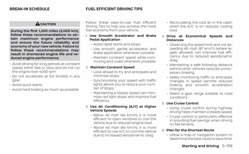
CAUTION
During the first 1,200 miles (2,000 km),follow these recommendations to ob-tain maximum engine performanceand ensure the future reliability andeconomy of your new vehicle. Failure tofollow these recommendations mayresult in shortened engine life and re-duced engine performance.
• Avoid driving for long periods at constantspeed, either fast or slow, and do not runthe engine over 4,000 rpm.
• Do not accelerate at full throttle in anygear.
• Avoid quick starts.• Avoid hard braking as much as possible.
Follow these easy-to-use Fuel EfficientDriving Tips to help you achieve the mostfuel economy from your vehicle.1. Use Smooth Accelerator and Brake
Pedal Application• Avoid rapid starts and stops.• Use smooth, gentle accelerator and
brake application whenever possible.• Maintain constant speed while com-
muting and coast whenever possible.
2. Maintain Constant Speed• Look ahead to try and anticipate and
minimize stops.• Synchronizing your speed with traffic
lights allows you to reduce your num-ber of stops.
• Maintaining a steady speed can mini-mize red light stops and improve fuelefficiency.
3. Use Air Conditioning (A/C) at HigherVehicle Speeds• Below 40 mph (64 km/h), it is more
efficient to open windows to cool thevehicle due to reduced engine load.
• Above 40 mph (64 km/h), it is moreefficient to use A/C to cool the vehicledue to increased aerodynamic drag.
• Recirculating the cool air in the cabinwhen the A/C is on reduces coolingload.
4. Drive at Economical Speeds andDistances• Observing the speed limit and not ex-
ceeding 60 mph (97 km/h) (where le-gally allowed) can improve fuel effi-ciency due to reduced aerodynamicdrag.
• Maintaining a safe following distancebehind other vehicles reduces unnec-essary braking.
• Safely monitoring traffic to anticipatechanges in speed permits reducedbraking and smooth accelerationchanges.
• Select a gear range suitable to roadconditions.
5. Use Cruise Control• Using cruise control during highway
driving helps maintain a steady speed.• Cruise control is particularly effective
in providing fuel savings when drivingon flat terrains.
6. Plan for the Shortest Route• Utilize a map or navigation system to
determine the best route to save time.
BREAK-IN SCHEDULE FUEL EFFICIENT DRIVING TIPS
Starting and driving 5-139
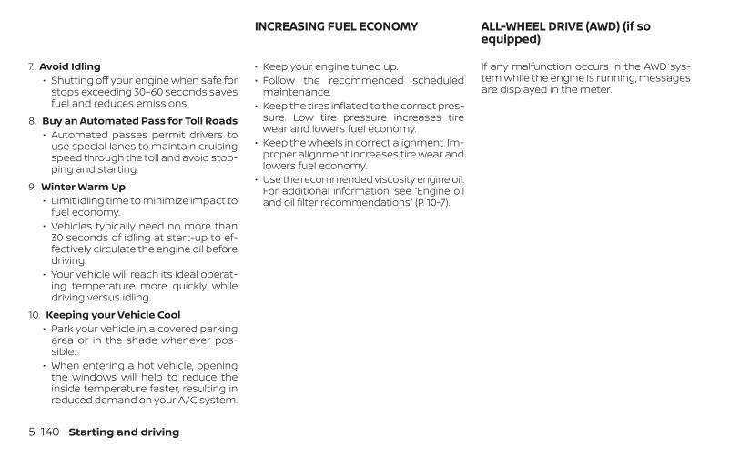
7. Avoid Idling• Shutting off your engine when safe for
stops exceeding 30–60 seconds savesfuel and reduces emissions.
8. Buy an Automated Pass for Toll Roads• Automated passes permit drivers to
use special lanes to maintain cruisingspeed through the toll and avoid stop-ping and starting.
9. Winter Warm Up• Limit idling time to minimize impact to
fuel economy.• Vehicles typically need no more than
30 seconds of idling at start-up to ef-fectively circulate the engine oil beforedriving.
• Your vehicle will reach its ideal operat-ing temperature more quickly whiledriving versus idling.
10. Keeping your Vehicle Cool• Park your vehicle in a covered parking
area or in the shade whenever pos-sible.
• When entering a hot vehicle, openingthe windows will help to reduce theinside temperature faster, resulting inreduced demand on your A/C system.
• Keep your engine tuned up.• Follow the recommended scheduled
maintenance.• Keep the tires inflated to the correct pres-
sure. Low tire pressure increases tirewear and lowers fuel economy.
• Keep the wheels in correct alignment. Im-proper alignment increases tire wear andlowers fuel economy.
• Use the recommended viscosity engine oil.For additional information, see “Engine oiland oil filter recommendations” (P. 10-7).
If any malfunction occurs in the AWD sys-tem while the engine is running, messagesare displayed in the meter.
INCREASING FUEL ECONOMY ALL-WHEEL DRIVE (AWD) (if soequipped)
5-140 Starting and driving
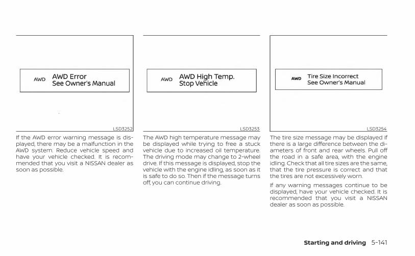
If the AWD error warning message is dis-played, there may be a malfunction in theAWD system. Reduce vehicle speed andhave your vehicle checked. It is recom-mended that you visit a NISSAN dealer assoon as possible.
The AWD high temperature message maybe displayed while trying to free a stuckvehicle due to increased oil temperature.The driving mode may change to 2-wheeldrive. If this message is displayed, stop thevehicle with the engine idling, as soon as itis safe to do so. Then if the message turnsoff, you can continue driving.
The tire size message may be displayed ifthere is a large difference between the di-ameters of front and rear wheels. Pull offthe road in a safe area, with the engineidling. Check that all tire sizes are the same,that the tire pressure is correct and thatthe tires are not excessively worn.If any warning messages continue to bedisplayed, have your vehicle checked. It isrecommended that you visit a NISSANdealer as soon as possible.
LSD3252 LSD3253 LSD3254
Starting and driving 5-141
WARNING
• Do not drive beyond the performancecapability of the tires. Acceleratingquickly, sharp steering maneuvers orsudden braking may cause loss of con-trol, even with AWD engaged.
• For AWD equipped vehicles, do not at-tempt to raise two wheels off theground and shift the transmission toany drive or reverse position with theengine running. Doing so may result indrivetrain damage or unexpected ve-hicle movement which could result inserious personal injury or vehicledamage.
• Do not attempt to test an AWDequipped vehicle on a 2-wheel dyna-mometer (such as the dynamometersused by some states for emissions test-ing) or similar equipment even if theother two wheels are raised off theground. Make sure that you inform thetest facility personnel that your vehicleis equipped with AWD before it is placedon a dynamometer. Using the wrongtest equipment may result in drivetraindamage or unexpected vehicle move-ment which could result in serious per-sonal injury or vehicle damage.
CAUTION
• Do not operate the engine on a freeroller when any of the wheels areraised.
• If you use the free roller, rotate fourwheels with the same speed withoutraising any wheels.
• If an AWD warning message is dis-played while driving there may be amalfunction in the AWD system. Re-duce the vehicle speed immediatelyand have your vehicle checked. It isrecommended that you visit aNISSAN dealer as soon as possible.
• The powertrain may be damaged ifyou continue driving when the AWDtemperature or tire size incorrectmessages are displayed
• If the AWD high temperature mes-sage is displayed while you are driv-ing, pull off the road in a safe area,and idle the engine. The drivingmode will change to 2WD to preventthe AWD system from malfunction-ing. If the warning message turns off,you can drive again.
• If the tire size incorrect message isdisplayed while you are driving, pulloff the road in a safe area with theengine idling. Check that all tire sizesare the same, that the tire pressure iscorrect and that the tires are not ex-cessively worn.
• If a warning message continues to bedisplayed after the above opera-tions, have your vehicle checked assoon as possible. It is recommendedthat you visit a NISSAN dealer for thisservice.
5-142 Starting and driving
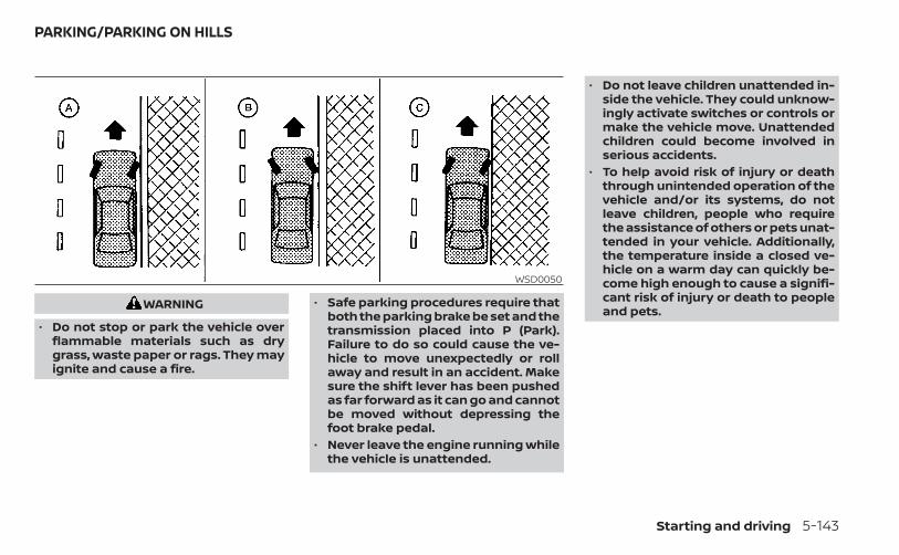
WARNING
• Do not stop or park the vehicle overflammable materials such as drygrass, waste paper or rags. They mayignite and cause a fire.
• Safe parking procedures require thatboth the parking brake be set and thetransmission placed into P (Park).Failure to do so could cause the ve-hicle to move unexpectedly or rollaway and result in an accident. Makesure the shift lever has been pushedas far forward as it can go and cannotbe moved without depressing thefoot brake pedal.
• Never leave the engine running whilethe vehicle is unattended.
• Do not leave children unattended in-side the vehicle. They could unknow-ingly activate switches or controls ormake the vehicle move. Unattendedchildren could become involved inserious accidents.
• To help avoid risk of injury or deaththrough unintended operation of thevehicle and/or its systems, do notleave children, people who requirethe assistance of others or pets unat-tended in your vehicle. Additionally,the temperature inside a closed ve-hicle on a warm day can quickly be-come high enough to cause a signifi-cant risk of injury or death to peopleand pets.
WSD0050
PARKING/PARKING ON HILLS
Starting and driving 5-143
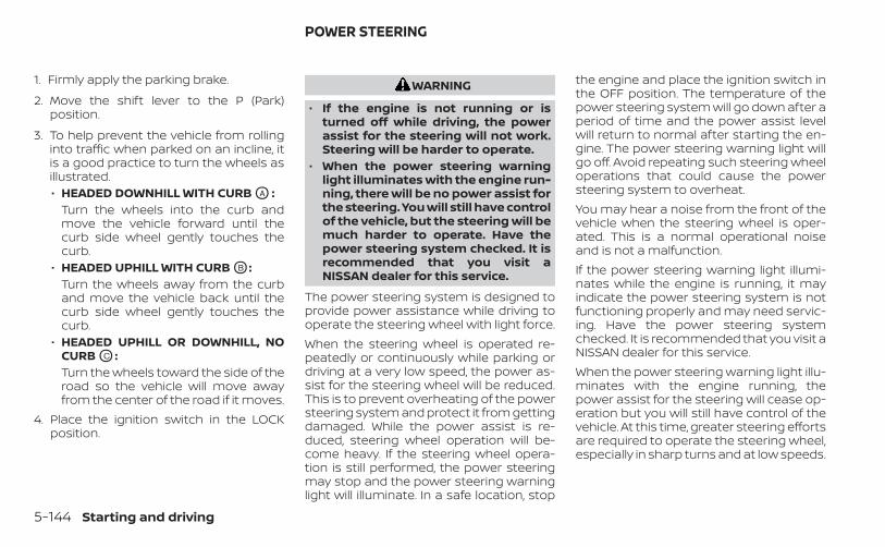
1. Firmly apply the parking brake.
2. Move the shift lever to the P (Park)position.
3. To help prevent the vehicle from rollinginto traffic when parked on an incline, itis a good practice to turn the wheels asillustrated.• HEADED DOWNHILL WITH CURB OA :
Turn the wheels into the curb andmove the vehicle forward until thecurb side wheel gently touches thecurb.
• HEADED UPHILL WITH CURB OB :Turn the wheels away from the curband move the vehicle back until thecurb side wheel gently touches thecurb.
• HEADED UPHILL OR DOWNHILL, NOCURB OC :Turn the wheels toward the side of theroad so the vehicle will move awayfrom the center of the road if it moves.
4. Place the ignition switch in the LOCKposition.
WARNING
• If the engine is not running or isturned off while driving, the powerassist for the steering will not work.Steering will be harder to operate.
• When the power steering warninglight illuminates with the engine run-ning, there will be no power assist forthe steering. You will still have controlof the vehicle, but the steering will bemuch harder to operate. Have thepower steering system checked. It isrecommended that you visit aNISSAN dealer for this service.
The power steering system is designed toprovide power assistance while driving tooperate the steering wheel with light force.When the steering wheel is operated re-peatedly or continuously while parking ordriving at a very low speed, the power as-sist for the steering wheel will be reduced.This is to prevent overheating of the powersteering system and protect it from gettingdamaged. While the power assist is re-duced, steering wheel operation will be-come heavy. If the steering wheel opera-tion is still performed, the power steeringmay stop and the power steering warninglight will illuminate. In a safe location, stop
the engine and place the ignition switch inthe OFF position. The temperature of thepower steering system will go down after aperiod of time and the power assist levelwill return to normal after starting the en-gine. The power steering warning light willgo off. Avoid repeating such steering wheeloperations that could cause the powersteering system to overheat.You may hear a noise from the front of thevehicle when the steering wheel is oper-ated. This is a normal operational noiseand is not a malfunction.If the power steering warning light illumi-nates while the engine is running, it mayindicate the power steering system is notfunctioning properly and may need servic-ing. Have the power steering systemchecked. It is recommended that you visit aNISSAN dealer for this service.When the power steering warning light illu-minates with the engine running, thepower assist for the steering will cease op-eration but you will still have control of thevehicle. At this time, greater steering effortsare required to operate the steering wheel,especially in sharp turns and at low speeds.
POWER STEERING
5-144 Starting and driving
The brake system has two separate hy-draulic circuits. If one circuit malfunctions,you will still have braking at two wheels.
BRAKE PRECAUTIONS
Vacuum assisted brakesThe brake booster aids braking by usingengine vacuum. If the engine stops, youcan stop the vehicle by depressing thebrake pedal. However, greater foot pres-sure on the brake pedal will be required tostop the vehicle and stopping distance willbe longer.
Using the brakesAvoid resting your foot on the brake pedalwhile driving. This will overheat the brakes,wear out the brake pads faster, and reducegas mileage.To help reduce brake wear and to preventthe brakes from overheating, reduce speedand downshift to a lower gear before goingdown a slope or long grade. Overheatedbrakes may reduce braking performanceand could result in loss of vehicle control.
WARNING
• While driving on a slippery surface,be careful when braking, accelerat-ing or downshifting. Abrupt brakingor accelerating could cause thewheels to skid and result in anaccident.
• If the engine is not running or isturned off while driving, the powerassist for the brakes will not work.Braking will be harder.
Wet brakesWhen the vehicle is washed or driventhrough water, the brakes may get wet. Asa result, your braking distance will be lon-ger and the vehicle may pull to one sideduring braking.To dry the brakes, drive the vehicle at a safespeed while lightly pressing the brakepedal to heat up the brakes. Do this untilthe brakes return to normal. Avoid drivingthe vehicle at high speeds until the brakesfunction correctly.
Parking brake break-inBreak in the parking brake shoes wheneverthe stopping effect of the parking brake isweakened or whenever the parking brakeshoes and/or drums/rotors are replaced,in order to assure the best braking perfor-mance.This procedure is described in the vehicleservice manual. It is recommended thatyou visit a NISSAN dealer for this service.
ANTI-LOCK BRAKING SYSTEM (ABS)
WARNING
• The ABS is a sophisticated device, butit cannot prevent accidents resultingfrom careless or dangerous drivingtechniques. It can help maintain ve-hicle control during braking on slip-pery surfaces. Remember that stop-ping distances on slippery surfaceswill be longer than on normal sur-faces even with ABS. Stopping dis-tances may also be longer on rough,gravel or snow covered roads, or ifyou are using tire chains. Alwaysmaintain a safe distance from the ve-hicle in front of you. Ultimately, thedriver is responsible for safety.
BRAKE SYSTEM
Starting and driving 5-145
• Tire type and condition may also af-fect braking effectiveness.– When replacing tires, install the
specified size of tires on all fourwheels.
– When installing a spare tire, makesure that it is the proper size andtype as specified on the Tire andLoading Information label. For ad-ditional information, see “Tire andLoading Information label”(P. 10-14).
– For additional information, see“Wheels and tires” (P. 8-29).
The ABS controls the brakes so the wheelsdo not lock during hard braking or whenbraking on slippery surfaces. The systemdetects the rotation speed at each wheeland varies the brake fluid pressure to pre-vent each wheel from locking and sliding.By preventing each wheel from locking, thesystem helps the driver maintain steeringcontrol and helps to minimize swervingand spinning on slippery surfaces.
Using the systemDepress the brake pedal and hold it down.Depress the brake pedal with firm steadypressure, but do not pump the brakes. TheAnti-lock Braking System will operate toprevent the wheels from locking up. Steerthe vehicle to avoid obstacles.
WARNING
Do not pump the brake pedal. Doing somay result in increased stopping dis-tances.
Self-test featureThe Anti-lock Braking System (ABS) in-cludes electronic sensors, electric pumps,hydraulic solenoids and a computer. Thecomputer has a built-in diagnostic featurethat tests the system each time you startthe engine and move the vehicle at a lowspeed in forward or reverse. When the self-test occurs, you may hear a “clunk” noiseand/or feel a pulsation in the brake pedal.This is normal and does not indicate amalfunction. If the computer senses a mal-function, it switches the ABS off and illumi-nates the ABS warning light on the instru-
ment panel. The brake system thenoperates normally but without anti-lockassistance.If the ABS warning light illuminates duringthe self-test or while driving, have the ve-hicle checked. It is recommended that youvisit a NISSAN dealer for this service.
Normal operationThe Anti-lock Braking System (ABS) operatesat speeds above 3 - 6 mph (5 - 10 km/h). Thespeed varies according to road conditions.When the ABS senses that one or morewheels are close to locking up, the actuatorrapidly applies and releases hydraulic pres-sure. This action is similar to pumping thebrakes very quickly. You may feel a pulsa-tion in the brake pedal and hear a noisefrom under the hood or feel a vibrationfrom the actuator when it is operating. Thisis normal and indicates that the ABS is op-erating properly. However, the pulsationmay indicate that road conditions are haz-ardous and extra care is required whiledriving.
5-146 Starting and driving
BRAKE ASSISTWhen the force applied to the brake pedalexceeds a certain level, the Brake Assist isactivated generating greater braking forcethan a conventional brake booster evenwith light pedal force.
WARNING
The Brake Assist is only an aid to assistbraking operation and is not a collisionwarning or avoidance device. It is thedriver’s responsibility to stay alert,drive safely and be in control of the ve-hicle at all times.
The VDC system uses various sensors tomonitor driver inputs and vehicle motion.Under certain driving conditions, the VDCsystem helps to perform the followingfunctions:• Controls brake pressure to reduce wheel
slip on one slipping drive wheel so poweris transferred to a non-slipping drivewheel on the same axle.
• Controls brake pressure and engine out-put to reduce drive wheel slip based onvehicle speed (traction control function).
• Controls brake pressure at individualwheels and engine output to help thedriver maintain control of the vehicle inthe following conditions:– Understeer (vehicle tends to not follow
the steered path despite increasedsteering input)
– Oversteer (vehicle tends to spin due tocertain road or driving conditions)
The VDC system can help the driver tomaintain control of the vehicle, but it can-not prevent loss of vehicle control in all driv-ing situations.
When the VDC system operates, theindicator light in the instrument panelflashes to note the following:• The road may be slippery or the system
may determine some action is requiredto help keep the vehicle on the steeredpath.
• You may feel a pulsation in the brakepedal and hear a noise or vibration fromunder the hood. This is normal and indi-cates that the VDC system is workingproperly.
• Adjust your speed and driving to the roadconditions.
For additional information, see “Slip indica-tor light” (P. 2-16) and “Vehicle Dynamic Con-trol (VDC) OFF indicator light” (P. 2-16).If a malfunction occurs in the system, the
indicator light comes on in the instru-ment panel. The VDC system automaticallyturns off when the indicator light is on.
VEHICLE DYNAMIC CONTROL (VDC)SYSTEM
Starting and driving 5-147
The vehicle information display is used toturn off the VDC system. When the VDCsystem is turned off, the indicator lightand if so equipped, the RAB system warn-ing light, AEB system warning light and AEBwith Pedestrian Detection system warninglight illuminate to indicate the VDC, AEB,AEB with Pedestrian Detection, and RABsystems are off.When the VDC system is turned off in thevehicle information display, the VDC sys-tem still operates to prevent one drivewheel from slipping by transferring powerto a non-slipping drive wheel. Theindicator light flashes if this occurs. Allother VDC functions are off and theindicator light will not flash.The VDC system is automatically reset toON when the ignition switch is placed in theOFF position then back to the ON position.The computer has a built-in diagnostic fea-ture that tests the system each time youstart the engine and move the vehicle for-ward or in reverse at a slow speed. Whenthe self-test occurs, you may hear a clunknoise and/or feel a pulsation in the brakepedal. This is normal and is not an indica-tion of a malfunction.
WARNING
• The VDC system is designed to helpthe driver maintain stability but doesnot prevent accidents due to abruptsteering operation at high speeds orby careless or dangerous drivingtechniques. Reduce vehicle speedand be especially careful when driv-ing and cornering on slippery sur-faces and always drive carefully.
• Do not modify the vehicle's suspen-sion. If suspension parts such asshock absorbers, struts, springs, sta-bilizer bars, bushings and wheels arenot NISSAN recommended for yourvehicle or are extremely deterio-rated, the VDC system may not oper-ate properly. This could adversely af-fect vehicle handling performance,and the indicator light may flashor the indicator light mayilluminate.
• If brake related parts such as brakepads, rotors and calipers are notNISSAN recommended or are ex-tremely deteriorated, the VDC sys-tem may not operate properly andboth the and indicatorlights may illuminate.
• If engine control related parts are notNISSAN recommended or are ex-tremely deteriorated, both theand the indicator lights mayilluminate.
• When driving on extremely inclinedsurfaces such as higher banked cor-ners, the VDC system may not oper-ate properly and the indicatorlight may flash or the indicatorlight may illuminate. Do not drive onthese types of roads.
• When driving on an unstable surfacesuch as a turntable, ferry, elevator orramp, the indicator light mayflash or the indicator light mayilluminate. This is not a malfunction.Restart the engine after driving ontoa stable surface.
• If wheels or tires other than theNISSAN recommended ones areused, the VDC system may not oper-ate properly and the indicatorlight may flash or the indicatorlight may illuminate.
• The VDC system is not a substitutefor winter tires or tire chains on asnow covered road.
5-148 Starting and driving
BRAKE FORCE DISTRIBUTIONDuring braking while driving through turns,the system optimizes the distribution offorce to each of the front and rear wheelsdepending on the radius of the turn.
WARNING
• The VDC system is designed to helpthe driver maintain stability but doesnot prevent accidents due to abruptsteering operation at high speeds orby careless or dangerous drivingtechniques. Reduce vehicle speedand be especially careful when driv-ing and cornering on slippery sur-faces and always drive carefully.
• Do not modify the vehicle's suspen-sion. If suspension parts such asshock absorbers, struts, springs, sta-bilizer bars, bushings and wheels arenot NISSAN recommended for yourvehicle or are extremely deterio-rated, the VDC system may not oper-ate properly. This could adversely af-fect vehicle handling performance,and the indicator light may flashor the indicator light mayilluminate.
• If brake related parts such as brakepads, rotors and calipers are notNISSAN recommended or are ex-tremely deteriorated, the VDC sys-tem may not operate properly andboth the and indicator lightmay illuminate.
• If engine control related parts are notNISSAN recommended or are ex-tremely deteriorated, both theand the indicator light mayilluminate.
• When driving on extremely inclinedsurfaces such as higher banked cor-ners, the VDC system may not oper-ate properly and the indicatorlight may flash or the indicatorlight may illuminate. Do not drive onthese types of roads.
• When driving on an unstable surfacesuch as a turntable, ferry, elevator orramp, the indicator light mayflash or the indicator light mayilluminate. This is not a malfunction.Restart the engine after driving ontoa stable surface.
• If wheels or tires other than theNISSAN recommended ones areused, the VDC system may not oper-ate properly and the indicatorlight may flash or the indicatorlight may illuminate.
• The VDC system is not a substitutefor winter tires or tire chains on asnow covered road.
Starting and driving 5-149
The chassis control is an electric controlmodule that includes the following func-tions:• Intelligent Trace Control• Active Ride Control
INTELLIGENT TRACE CONTROL(I-TC)This system senses driving based on thedriver’s steering and acceleration/brakingpatterns, and controls brake pressure atindividual wheels to aid tracing at cornersand help smooth vehicle response.The I-TC can be set to on (enabled) or off(disabled) through the vehicle informationdisplay “Settings” page. For additional infor-mation, see “Vehicle information display —5 inch (13 cm) Type A (if so equipped)”(P. 2-18) or “Vehicle information display — 7inch (18 cm) Type B (if so equipped)” (P. 2-33).When the VDC system is turned off, the I-TCis also turned off.
WARNING
The I-TC may not be effective depend-ing on the driving condition. Alwaysdrive carefully and attentively.
When the I-TC is operating, you may feel apulsation in the brake pedal and hear anoise. This is normal and indicates that theI-TC is operating properly.Even if the I-TC is turned off, some functionswill remain on to assist the driver (for ex-ample, avoidance scenes).
ACTIVE RIDE CONTROL (ARC)This system senses upper body motion(based on wheel speed information) andcontrols engine torque and four wheelbrake pressure. This will enhance ride com-fort in effort to restrain uncomfortable up-per body movement when passing overundulated road surfaces. This systemcomes into effect above 25 mph (40 km/h).When the VDC system is turned off, the ARCis also turned off.When the ARC is operating, you may hearnoise and sense slight deceleration. This isnormal and indicates that the ARC is oper-ating properly.
WARNING
• Never rely solely on the hill start as-sist system to prevent the vehiclefrom moving backward on a hill. Al-ways drive carefully and attentively.Depress the brake pedal when thevehicle is stopped on a steep hill. Beespecially careful when stopped on ahill on frozen or muddy roads. Failureto prevent the vehicle from rollingbackwards may result in a loss ofcontrol of the vehicle and possibleserious injury or death.
• The hill start assist system is not de-signed to hold the vehicle at a stand-still on a hill. Depress the brake pedalwhen the vehicle is stopped on asteep hill. Failure to do so may causethe vehicle to roll backwards andmay result in a collision or seriouspersonal injury.
• The hill start assist system may notprevent the vehicle from rollingbackwards on a hill under all load orroad conditions. Always be preparedto depress the brake pedal to preventthe vehicle from rolling backwards.Failure to do so may result in a colli-sion or serious personal injury.
CHASSIS CONTROL (if so equipped) HILL START ASSIST SYSTEM
5-150 Starting and driving
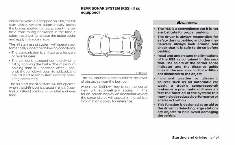
When the vehicle is stopped on a hill, the hillstart assist system automatically keepsthe brakes applied to help prevent the ve-hicle from rolling backward in the time ittakes the driver to release the brake pedaland apply the accelerator.The hill start assist system will operate au-tomatically under the following conditions:• The transmission is shifted to a forward
or reverse gear.• The vehicle is stopped completely on a
hill by applying the brake. The maximumholding time is 2 seconds. After 2 sec-onds the vehicle will begin to roll back andthe hill start assist system will stop oper-ating completely.
The hill start assist system will not operatewhen the shift lever is placed in the N (Neu-tral) or P (Park) position or on a flat and levelroad.
The RSS sounds a tone to inform the driverof obstacles near the bumper.When the “DISPLAY” key is on, the sonarview will automatically appear in thetouch-screen display. An additional view ofthe sonar status will appear in the vehicleinformation display for reference.
WARNING
• The RSS is a convenience but it is nota substitute for proper parking.
• The driver is always responsible forsafety during parking and other ma-neuvers. Always look around andcheck that it is safe to do so beforeparking.
• Read and understand the limitationsof the RSS as contained in this sec-tion. The colors of the corner sonarindicator and the distance guidelines in the rear view indicate differ-ent distances to the object.
• Inclement weather or ultrasonicsources such as an automatic carwash, a truck's compressed-airbrakes or a pneumatic drill may af-fect the function of the system; thismay include reduced performance ora false activation.
• This function is designed as an aid tothe driver in detecting large station-ary objects to help avoid damagingthe vehicle.
LSD3247
REAR SONAR SYSTEM (RSS) (if soequipped)
Starting and driving 5-151
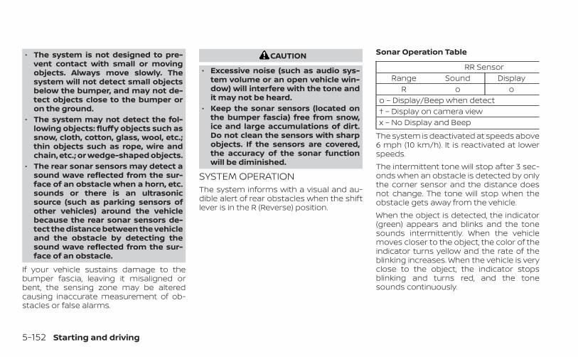
• The system is not designed to pre-vent contact with small or movingobjects. Always move slowly. Thesystem will not detect small objectsbelow the bumper, and may not de-tect objects close to the bumper oron the ground.
• The system may not detect the fol-lowing objects: fluffy objects such assnow, cloth, cotton, glass, wool, etc.;thin objects such as rope, wire andchain, etc.; or wedge-shaped objects.
• The rear sonar sensors may detect asound wave reflected from the sur-face of an obstacle when a horn, etc.sounds or there is an ultrasonicsource (such as parking sensors ofother vehicles) around the vehiclebecause the rear sonar sensors de-tect the distance between the vehicleand the obstacle by detecting thesound wave reflected from the sur-face of an obstacle.
If your vehicle sustains damage to thebumper fascia, leaving it misaligned orbent, the sensing zone may be alteredcausing inaccurate measurement of ob-stacles or false alarms.
CAUTION
• Excessive noise (such as audio sys-tem volume or an open vehicle win-dow) will interfere with the tone andit may not be heard.
• Keep the sonar sensors (located onthe bumper fascia) free from snow,ice and large accumulations of dirt.Do not clean the sensors with sharpobjects. If the sensors are covered,the accuracy of the sonar functionwill be diminished.
SYSTEM OPERATIONThe system informs with a visual and au-dible alert of rear obstacles when the shiftlever is in the R (Reverse) position.
Sonar Operation Table
RR SensorRange Sound Display
R o oo – Display/Beep when detect† – Display on camera viewx – No Display and Beep
The system is deactivated at speeds above6 mph (10 km/h). It is reactivated at lowerspeeds.The intermittent tone will stop after 3 sec-onds when an obstacle is detected by onlythe corner sensor and the distance doesnot change. The tone will stop when theobstacle gets away from the vehicle.When the object is detected, the indicator(green) appears and blinks and the tonesounds intermittently. When the vehiclemoves closer to the object, the color of theindicator turns yellow and the rate of theblinking increases. When the vehicle is veryclose to the object, the indicator stopsblinking and turns red, and the tonesounds continuously.
5-152 Starting and driving
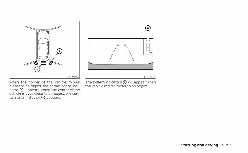
When the corner of the vehicle movescloser to an object, the corner sonar indi-cator OA appears. When the center of thevehicle moves close to an object, the cen-ter sonar indicator OB appears.
The system indicators OA will appear whenthe vehicle moves closer to an object.
LSD3246 LSD2137
Starting and driving 5-153
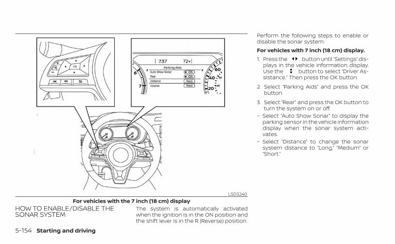
HOW TO ENABLE/DISABLE THESONAR SYSTEM
The system is automatically activatedwhen the ignition is in the ON position andthe shift lever is in the R (Reverse) position.
Perform the following steps to enable ordisable the sonar system:For vehicles with 7 inch (18 cm) display.1. Press the button until “Settings” dis-
plays in the vehicle information display.Use the button to select “Driver As-sistance.” Then press the OK button.
2. Select “Parking Aids” and press the OKbutton.
3. Select “Rear” and press the OK button toturn the system on or off.
– Select “Auto Show Sonar” to display theparking sensor in the vehicle informationdisplay when the sonar system acti-vates.
– Select “Distance” to change the sonarsystem distance to “Long,” “Medium” or“Short.”
LSD3240For vehicles with the 7 inch (18 cm) display
5-154 Starting and driving
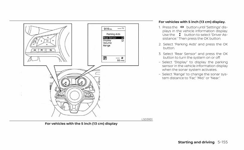
For vehicles with 5 inch (13 cm) display.1. Press the button until “Settings” dis-
plays in the vehicle information display.Use the button to select “Driver As-sistance.” Then press the OK button.
2. Select “Parking Aids” and press the OKbutton.
3. Select “Rear Sensor” and press the OKbutton to turn the system on or off.
– Select “Display” to display the parkingsensor in the vehicle information displaywhen the sonar system activates.
– Select “Range” to change the sonar sys-tem distance to “Far,” “Mid.” or “Near.”
LSD3931For vehicles with the 5 inch (13 cm) display
Starting and driving 5-155
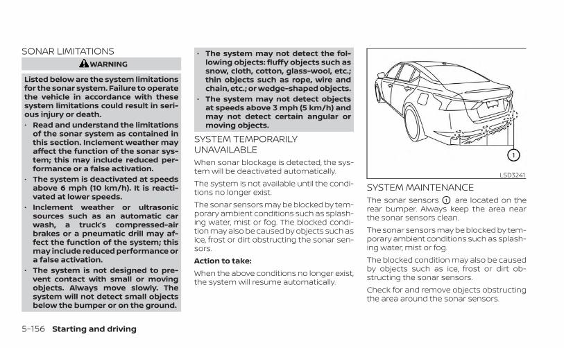
SONAR LIMITATIONSWARNING
Listed below are the system limitationsfor the sonar system. Failure to operatethe vehicle in accordance with thesesystem limitations could result in seri-ous injury or death.• Read and understand the limitations
of the sonar system as contained inthis section. Inclement weather mayaffect the function of the sonar sys-tem; this may include reduced per-formance or a false activation.
• The system is deactivated at speedsabove 6 mph (10 km/h). It is reacti-vated at lower speeds.
• Inclement weather or ultrasonicsources such as an automatic carwash, a truck’s compressed-airbrakes or a pneumatic drill may af-fect the function of the system; thismay include reduced performance ora false activation.
• The system is not designed to pre-vent contact with small or movingobjects. Always move slowly. Thesystem will not detect small objectsbelow the bumper or on the ground.
• The system may not detect the fol-lowing objects: fluffy objects such assnow, cloth, cotton, glass-wool, etc.;thin objects such as rope, wire andchain, etc.; or wedge-shaped objects.
• The system may not detect objectsat speeds above 3 mph (5 km/h) andmay not detect certain angular ormoving objects.
SYSTEM TEMPORARILYUNAVAILABLEWhen sonar blockage is detected, the sys-tem will be deactivated automatically.The system is not available until the condi-tions no longer exist.The sonar sensors may be blocked by tem-porary ambient conditions such as splash-ing water, mist or fog. The blocked condi-tion may also be caused by objects such asice, frost or dirt obstructing the sonar sen-sors.Action to take:When the above conditions no longer exist,the system will resume automatically.
SYSTEM MAINTENANCEThe sonar sensors O1 are located on therear bumper. Always keep the area nearthe sonar sensors clean.The sonar sensors may be blocked by tem-porary ambient conditions such as splash-ing water, mist or fog.The blocked condition may also be causedby objects such as ice, frost or dirt ob-structing the sonar sensors.Check for and remove objects obstructingthe area around the sonar sensors.
LSD3241
5-156 Starting and driving
Do not attach stickers (including transpar-ent material), install accessories or applyadditional paint near the sonar sensors.Do not strike or damage the area aroundthe sonar sensors. It is recommended thatyou visit a NISSAN dealer if the area aroundthe sonar sensors is damaged due to acollision.
FREEING A FROZEN DOOR LOCKTo prevent a door lock from freezing, applyde-icer through the key hole. If the lockbecomes frozen, heat the key before in-serting it into the key hole or use the re-mote keyless entry function on the Intelli-gent Key.
ANTIFREEZEIn the winter when it is anticipated that thetemperature will drop below 32°F (0°C),check the antifreeze to assure proper win-ter protection. For additional information,see “Engine cooling system” (P. 8-5).
BATTERYIf the battery is not fully charged duringextremely cold weather conditions, thebattery fluid may freeze and damage thebattery. To maintain maximum efficiency,the battery should be checked regularly.For additional information, see “Battery”(P. 8-14).
DRAINING OF COOLANT WATERIf the vehicle is to be left outside withoutantifreeze, drain the cooling system, includ-ing the engine block. Refill before operatingthe vehicle. For additional information, see“Changing engine coolant” (P. 8-6).
TIRE EQUIPMENT1. SUMMER tires have a tread designed to
provide superior performance on drypavement. However, the performance ofthese tires will be substantially reducedin snowy and icy conditions. If you oper-ate your vehicle on snowy or icy roads,NISSAN recommends the use of MUD &SNOW or ALL SEASON TIRES on all fourwheels. It is recommended that you visita NISSAN dealer for the tire type, size,speed rating and availability information.
2. For additional traction on icy roads,studded tires may be used. However,some U.S. states and Canadian prov-inces prohibit their use. Check local,state and provincial laws before install-ing studded tires.
Skid and traction capabilities of studdedsnow tires on wet or dry surfaces may bepoorer than that of non-studded snowtires.3. Tire chains may be used. For additional
information, see “Tire chains” (P. 8-36).
COLD WEATHER DRIVING
Starting and driving 5-157
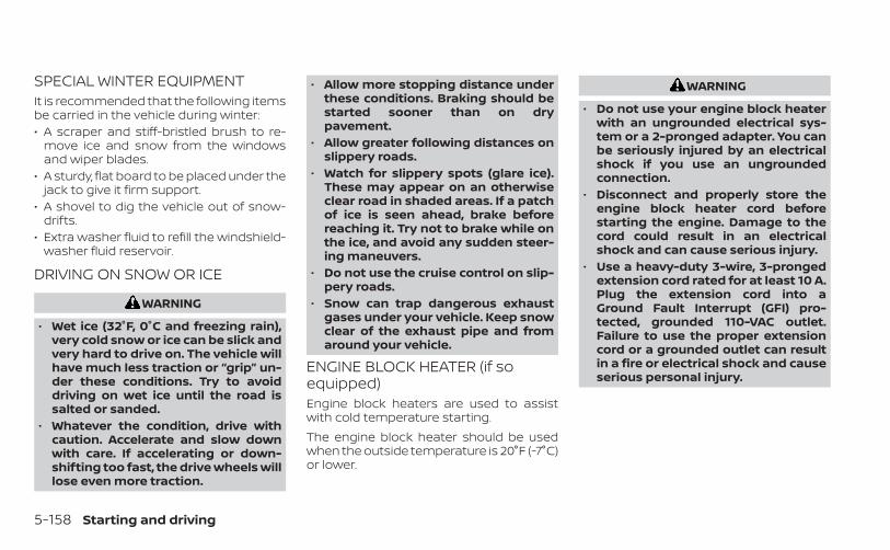
SPECIAL WINTER EQUIPMENTIt is recommended that the following itemsbe carried in the vehicle during winter:• A scraper and stiff-bristled brush to re-
move ice and snow from the windowsand wiper blades.
• A sturdy, flat board to be placed under thejack to give it firm support.
• A shovel to dig the vehicle out of snow-drifts.
• Extra washer fluid to refill the windshield-washer fluid reservoir.
DRIVING ON SNOW OR ICE
WARNING
• Wet ice (32°F, 0°C and freezing rain),very cold snow or ice can be slick andvery hard to drive on. The vehicle willhave much less traction or “grip” un-der these conditions. Try to avoiddriving on wet ice until the road issalted or sanded.
• Whatever the condition, drive withcaution. Accelerate and slow downwith care. If accelerating or down-shifting too fast, the drive wheels willlose even more traction.
• Allow more stopping distance underthese conditions. Braking should bestarted sooner than on drypavement.
• Allow greater following distances onslippery roads.
• Watch for slippery spots (glare ice).These may appear on an otherwiseclear road in shaded areas. If a patchof ice is seen ahead, brake beforereaching it. Try not to brake while onthe ice, and avoid any sudden steer-ing maneuvers.
• Do not use the cruise control on slip-pery roads.
• Snow can trap dangerous exhaustgases under your vehicle. Keep snowclear of the exhaust pipe and fromaround your vehicle.
ENGINE BLOCK HEATER (if soequipped)Engine block heaters are used to assistwith cold temperature starting.The engine block heater should be usedwhen the outside temperature is 20°F (-7°C)or lower.
WARNING
• Do not use your engine block heaterwith an ungrounded electrical sys-tem or a 2-pronged adapter. You canbe seriously injured by an electricalshock if you use an ungroundedconnection.
• Disconnect and properly store theengine block heater cord beforestarting the engine. Damage to thecord could result in an electricalshock and can cause serious injury.
• Use a heavy-duty 3-wire, 3-prongedextension cord rated for at least 10 A.Plug the extension cord into aGround Fault Interrupt (GFI) pro-tected, grounded 110-VAC outlet.Failure to use the proper extensioncord or a grounded outlet can resultin a fire or electrical shock and causeserious personal injury.
5-158 Starting and driving
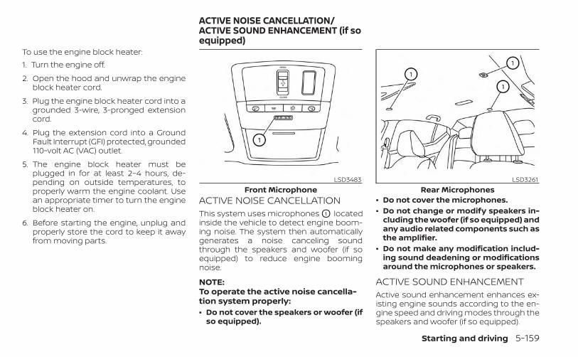
To use the engine block heater:1. Turn the engine off.
2. Open the hood and unwrap the engineblock heater cord.
3. Plug the engine block heater cord into agrounded 3-wire, 3-pronged extensioncord.
4. Plug the extension cord into a GroundFault Interrupt (GFI) protected, grounded110-volt AC (VAC) outlet.
5. The engine block heater must beplugged in for at least 2–4 hours, de-pending on outside temperatures, toproperly warm the engine coolant. Usean appropriate timer to turn the engineblock heater on.
6. Before starting the engine, unplug andproperly store the cord to keep it awayfrom moving parts.
ACTIVE NOISE CANCELLATIONThis system uses microphones O1 locatedinside the vehicle to detect engine boom-ing noise. The system then automaticallygenerates a noise canceling soundthrough the speakers and woofer (if soequipped) to reduce engine boomingnoise.
NOTE:To operate the active noise cancella-tion system properly:• Do not cover the speakers or woofer (if
so equipped).
• Do not cover the microphones.• Do not change or modify speakers in-
cluding the woofer (if so equipped) andany audio related components such asthe amplifier.
• Do not make any modification includ-ing sound deadening or modificationsaround the microphones or speakers.
ACTIVE SOUND ENHANCEMENTActive sound enhancement enhances ex-isting engine sounds according to the en-gine speed and driving modes through thespeakers and woofer (if so equipped).
LSD3483Front Microphone
LSD3261Rear Microphones
ACTIVE NOISE CANCELLATION/ACTIVE SOUND ENHANCEMENT (if soequipped)
Starting and driving 5-159

MEMO
5-160 Starting and driving
6 In case of emergency
Hazard warning flasher switch . . . . . . . . . . . . . . . . . . 6-2Emergency engine shut off . . . . . . . . . . . . . . . . . . . . . . 6-2Flat tire . . . . . . . . . . . . . . . . . . . . . . . . . . . . . . . . . . . . . . . . . . 6-3
Tire Pressure Monitoring System(TPMS) . . . . . . . . . . . . . . . . . . . . . . . . . . . . . . . . . . . . . . . 6-3Changing a flat tire . . . . . . . . . . . . . . . . . . . . . . . . . . . 6-4
Jump starting . . . . . . . . . . . . . . . . . . . . . . . . . . . . . . . . . . . 6-9
Push starting . . . . . . . . . . . . . . . . . . . . . . . . . . . . . . . . . . . .6-11If your vehicle overheats . . . . . . . . . . . . . . . . . . . . . . . . .6-11Towing your vehicle . . . . . . . . . . . . . . . . . . . . . . . . . . . . 6-12
Towing recommended by NISSAN . . . . . . . . . . . 6-12Vehicle recovery(freeing a stuck vehicle) . . . . . . . . . . . . . . . . . . . . . 6-15
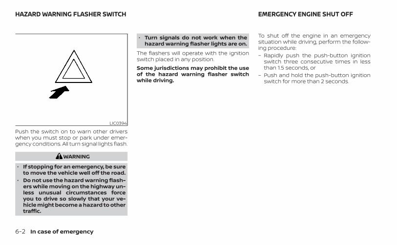
Push the switch on to warn other driverswhen you must stop or park under emer-gency conditions. All turn signal lights flash.
WARNING
• If stopping for an emergency, be sureto move the vehicle well off the road.
• Do not use the hazard warning flash-ers while moving on the highway un-less unusual circumstances forceyou to drive so slowly that your ve-hicle might become a hazard to othertraffic.
• Turn signals do not work when thehazard warning flasher lights are on.
The flashers will operate with the ignitionswitch placed in any position.Some jurisdictions may prohibit the useof the hazard warning flasher switchwhile driving.
To shut off the engine in an emergencysituation while driving, perform the follow-ing procedure:– Rapidly push the push-button ignition
switch three consecutive times in lessthan 1.5 seconds, or
– Push and hold the push-button ignitionswitch for more than 2 seconds.
LIC0394
HAZARD WARNING FLASHER SWITCH EMERGENCY ENGINE SHUT OFF
6-2 In case of emergency
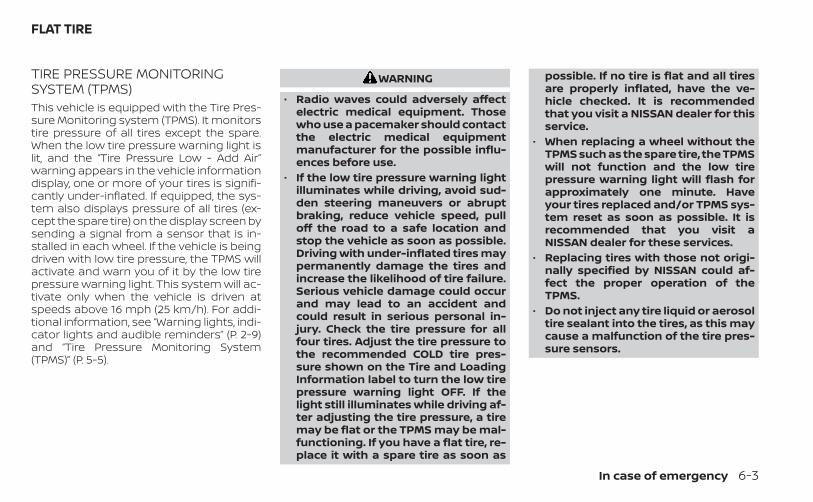
TIRE PRESSURE MONITORINGSYSTEM (TPMS)This vehicle is equipped with the Tire Pres-sure Monitoring system (TPMS). It monitorstire pressure of all tires except the spare.When the low tire pressure warning light islit, and the “Tire Pressure Low - Add Air”warning appears in the vehicle informationdisplay, one or more of your tires is signifi-cantly under-inflated. If equipped, the sys-tem also displays pressure of all tires (ex-cept the spare tire) on the display screen bysending a signal from a sensor that is in-stalled in each wheel. If the vehicle is beingdriven with low tire pressure, the TPMS willactivate and warn you of it by the low tirepressure warning light. This system will ac-tivate only when the vehicle is driven atspeeds above 16 mph (25 km/h). For addi-tional information, see “Warning lights, indi-cator lights and audible reminders” (P. 2-9)and “Tire Pressure Monitoring System(TPMS)” (P. 5-5).
WARNING
• Radio waves could adversely affectelectric medical equipment. Thosewho use a pacemaker should contactthe electric medical equipmentmanufacturer for the possible influ-ences before use.
• If the low tire pressure warning lightilluminates while driving, avoid sud-den steering maneuvers or abruptbraking, reduce vehicle speed, pulloff the road to a safe location andstop the vehicle as soon as possible.Driving with under-inflated tires maypermanently damage the tires andincrease the likelihood of tire failure.Serious vehicle damage could occurand may lead to an accident andcould result in serious personal in-jury. Check the tire pressure for allfour tires. Adjust the tire pressure tothe recommended COLD tire pres-sure shown on the Tire and LoadingInformation label to turn the low tirepressure warning light OFF. If thelight still illuminates while driving af-ter adjusting the tire pressure, a tiremay be flat or the TPMS may be mal-functioning. If you have a flat tire, re-place it with a spare tire as soon as
possible. If no tire is flat and all tiresare properly inflated, have the ve-hicle checked. It is recommendedthat you visit a NISSAN dealer for thisservice.
• When replacing a wheel without theTPMS such as the spare tire, the TPMSwill not function and the low tirepressure warning light will flash forapproximately one minute. Haveyour tires replaced and/or TPMS sys-tem reset as soon as possible. It isrecommended that you visit aNISSAN dealer for these services.
• Replacing tires with those not origi-nally specified by NISSAN could af-fect the proper operation of theTPMS.
• Do not inject any tire liquid or aerosoltire sealant into the tires, as this maycause a malfunction of the tire pres-sure sensors.
FLAT TIRE
In case of emergency 6-3
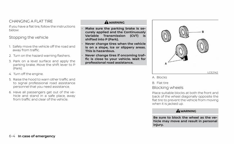
CHANGING A FLAT TIREIf you have a flat tire, follow the instructionsbelow:
Stopping the vehicle
1. Safely move the vehicle off the road andaway from traffic.
2. Turn on the hazard warning flashers.
3. Park on a level surface and apply theparking brake. Move the shift lever to P(Park).
4. Turn off the engine.
5. Raise the hood to warn other traffic andto signal professional road assistancepersonnel that you need assistance.
6. Have all passengers get out of the ve-hicle and stand in a safe place, awayfrom traffic and clear of the vehicle.
WARNING
• Make sure the parking brake is se-curely applied and the ContinuouslyVariable Transmission (CVT) isshifted into P (Park).
• Never change tires when the vehicleis on a slope, ice or slippery areas.This is hazardous.
• Never change tires if oncoming traf-fic is close to your vehicle. Wait forprofessional road assistance.
Blocking wheelsPlace suitable blocks at both the front andback of the wheel diagonally opposite theflat tire to prevent the vehicle from movingwhen it is jacked up.
WARNING
Be sure to block the wheel as the ve-hicle may move and result in personalinjury.
LCE2142
A. Blocks
B. Flat tire
6-4 In case of emergency
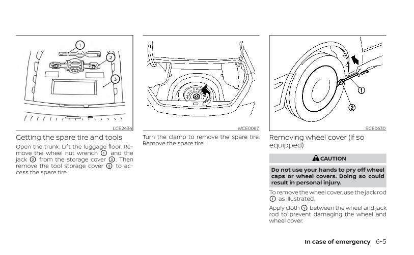
Getting the spare tire and toolsOpen the trunk. Lift the luggage floor. Re-move the wheel nut wrench O1 and thejack O2 from the storage cover O3 . Thenremove the tool storage cover O3 to ac-cess the spare tire.
Turn the clamp to remove the spare tire.Remove the spare tire.
Removing wheel cover (if soequipped)
CAUTION
Do not use your hands to pry off wheelcaps or wheel covers. Doing so couldresult in personal injury.
To remove the wheel cover, use the jack rodO1 as illustrated.Apply cloth O2 between the wheel and jackrod to prevent damaging the wheel andwheel cover.
LCE2434 WCE0067 SCE0630
In case of emergency 6-5
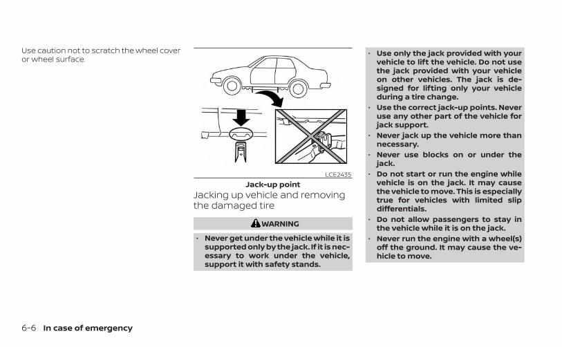
Use caution not to scratch the wheel coveror wheel surface.
Jacking up vehicle and removingthe damaged tire
WARNING
• Never get under the vehicle while it issupported only by the jack. If it is nec-essary to work under the vehicle,support it with safety stands.
• Use only the jack provided with yourvehicle to lift the vehicle. Do not usethe jack provided with your vehicleon other vehicles. The jack is de-signed for lifting only your vehicleduring a tire change.
• Use the correct jack-up points. Neveruse any other part of the vehicle forjack support.
• Never jack up the vehicle more thannecessary.
• Never use blocks on or under thejack.
• Do not start or run the engine whilevehicle is on the jack. It may causethe vehicle to move. This is especiallytrue for vehicles with limited slipdifferentials.
• Do not allow passengers to stay inthe vehicle while it is on the jack.
• Never run the engine with a wheel(s)off the ground. It may cause the ve-hicle to move.
LCE2435Jack-up point
6-6 In case of emergency
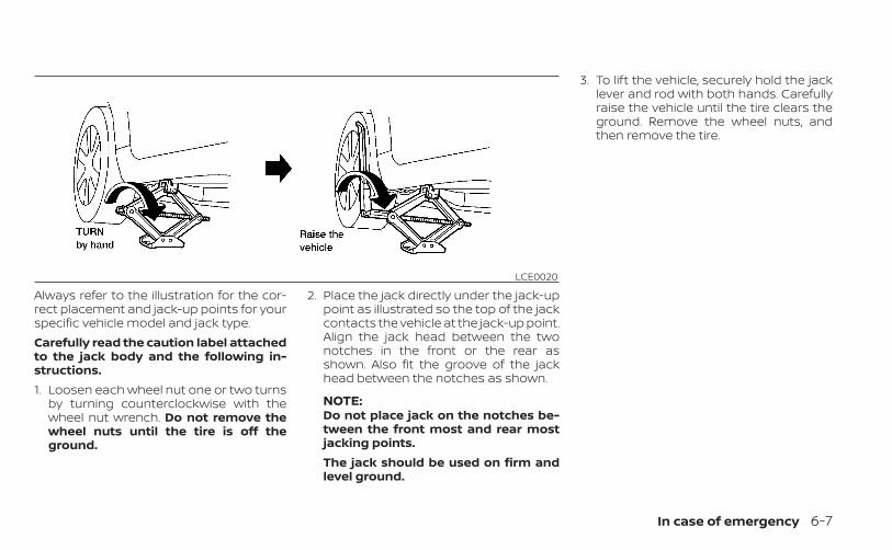
Always refer to the illustration for the cor-rect placement and jack-up points for yourspecific vehicle model and jack type.Carefully read the caution label attachedto the jack body and the following in-structions.1. Loosen each wheel nut one or two turns
by turning counterclockwise with thewheel nut wrench. Do not remove thewheel nuts until the tire is off theground.
2. Place the jack directly under the jack-uppoint as illustrated so the top of the jackcontacts the vehicle at the jack-up point.Align the jack head between the twonotches in the front or the rear asshown. Also fit the groove of the jackhead between the notches as shown.
NOTE:Do not place jack on the notches be-tween the front most and rear mostjacking points.The jack should be used on firm andlevel ground.
3. To lift the vehicle, securely hold the jacklever and rod with both hands. Carefullyraise the vehicle until the tire clears theground. Remove the wheel nuts, andthen remove the tire.
LCE0020
In case of emergency 6-7
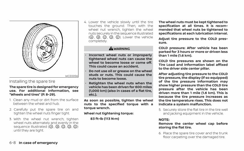
Installing the spare tireThe spare tire is designed for emergencyuse. For additional information, see“Wheels and tires” (P. 8-29).1. Clean any mud or dirt from the surface
between the wheel and hub.
2. Carefully put the spare tire on andtighten the wheel nuts finger tight.
3. With the wheel nut wrench, tightenwheel nuts alternately and evenly in thesequence illustrated (OA , OB , OC , OD , OE )until they are tight.
4. Lower the vehicle slowly until the tiretouches the ground. Then, with thewheel nut wrench, tighten the wheelnuts securely in the sequence illustrated(OA , OB , OC , OD , OE ). Lower the vehiclecompletely.
WARNING
• Incorrect wheel nuts or improperlytightened wheel nuts can cause thewheel to become loose or come off.This could cause an accident.
• Do not use oil or grease on the wheelstuds or nuts. This could cause thenuts to become loose.
• Retighten the wheel nuts when thevehicle has been driven for 600 miles(1,000 km) (also in cases of a flat tire,etc.).
As soon as possible, tighten the wheelnuts to the specified torque with atorque wrench.Wheel nut tightening torque:
83 ft-lb (113 N·m)
The wheel nuts must be kept tightened tospecification at all times. It is recom-mended that wheel nuts be tightened tospecifications at each lubrication interval.Adjust tire pressure to the COLD pres-sure.COLD pressure: After vehicle has beenparked for 3 hours or more or driven lessthan 1 mile (1.6 km).COLD tire pressures are shown on theTire Load and Information label affixedto the driver side center pillar.After adjusting tire pressure to the COLDtire pressure, the display (if so equipped)of the tire pressure information mayshow higher pressure than the COLD tirepressure after the vehicle has beendriven more than 1 mile (1.6 km). This isbecause the tire pressure increases asthe tire temperature rises. This does notindicate a system malfunction.5. Securely store the flat tire in the tire well
and jacking equipment in the vehicle.
NOTE:Remove the center wheel cap beforestoring the flat tire.
6. Place the spare tire cover and the trunkfloor carpeting over the damaged tire.
WCE0056
6-8 In case of emergency
7. Close the trunk.WARNING
• Always make sure that the spare tireand jacking equipment are properlysecured after use. Such items can be-come dangerous projectiles in an ac-cident or sudden stop.
• The spare tire is designed for emer-gency use. For additional informa-tion, see “Wheels and tires” (P. 8-29).
To start your engine with a booster battery,the instructions and precautions belowmust be followed.
WARNING
• If done incorrectly, jump starting canlead to a battery explosion, resultingin severe injury or death. It could alsodamage your vehicle.
• Explosive hydrogen gas is alwayspresent in the vicinity of the battery.Keep all sparks and flames awayfrom the battery.
• Do not allow battery fluid to comeinto contact with eyes, skin, clothingor painted surfaces. Battery fluid is acorrosive sulfuric acid solution whichcan cause severe burns. If the fluidshould come into contact with any-thing, immediately flush the con-tacted area with water.
• Keep battery out of the reach ofchildren.
• The booster battery must be rated at12 volts. Use of an improperly ratedbattery can damage your vehicle.
• Whenever working on or near a bat-tery, always wear suitable eye pro-tectors (for example, goggles or in-dustrial safety spectacles) andremove rings, metal bands, or anyother jewelry. Do not lean over thebattery when jump starting.
• Do not attempt to jump start a frozenbattery. It could explode and causeserious injury.
• Your vehicle has an automatic enginecooling fan. It could come on at anytime. Keep hands and other objectsaway from it.
JUMP STARTING
In case of emergency 6-9
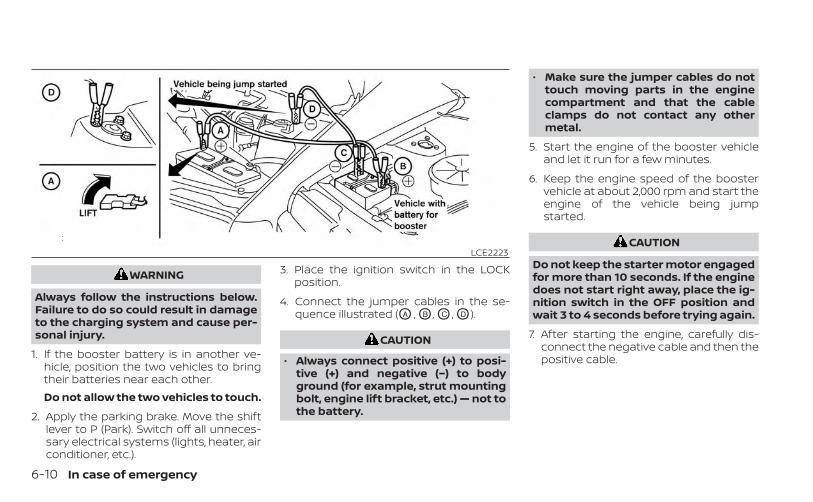
WARNING
Always follow the instructions below.Failure to do so could result in damageto the charging system and cause per-sonal injury.
1. If the booster battery is in another ve-hicle, position the two vehicles to bringtheir batteries near each other.Do not allow the two vehicles to touch.
2. Apply the parking brake. Move the shiftlever to P (Park). Switch off all unneces-sary electrical systems (lights, heater, airconditioner, etc.).
3. Place the ignition switch in the LOCKposition.
4. Connect the jumper cables in the se-quence illustrated (OA , OB , OC , OD ).
CAUTION
• Always connect positive (+) to posi-tive (+) and negative (−) to bodyground (for example, strut mountingbolt, engine lift bracket, etc.) — not tothe battery.
• Make sure the jumper cables do nottouch moving parts in the enginecompartment and that the cableclamps do not contact any othermetal.
5. Start the engine of the booster vehicleand let it run for a few minutes.
6. Keep the engine speed of the boostervehicle at about 2,000 rpm and start theengine of the vehicle being jumpstarted.
CAUTION
Do not keep the starter motor engagedfor more than 10 seconds. If the enginedoes not start right away, place the ig-nition switch in the OFF position andwait 3 to 4 seconds before trying again.
7. After starting the engine, carefully dis-connect the negative cable and then thepositive cable.
LCE2223
6-10 In case of emergency
CAUTION
• Do not push start this vehicle. Thethree-way catalyst may be damaged.
• Continuously Variable Transmission(CVT) models cannot be push-started or tow-started. Attemptingto do so may cause transmissiondamage.
If your vehicle is overheating (indicated byan extremely high temperature gaugereading), or if you feel a lack of enginepower, detect abnormal noise, etc. take thefollowing steps.
WARNING
• Do not continue to drive if your ve-hicle overheats. Doing so could causeengine damage or a vehicle fire.
• To avoid the danger of being scalded,never remove the radiator or coolantreservoir cap while the engine is stillhot. When the radiator or coolant res-ervoir cap is removed, pressurizedhot water will spurt out, possiblycausing serious injury.
• Do not open the hood if steam iscoming out.
1. Move the vehicle safely off the road, ap-ply the parking brake and move the shiftlever to P (Park).Do not stop the engine.
2. Turn off the air conditioner. Open all thewindows, move the heater or air condi-tioner temperature control to maximumhot and fan control to high speed.
3. Get out of the vehicle. Look and listen forsteam or coolant escaping from the ra-diator before opening the hood. (Ifsteam or coolant is escaping, turn offthe engine.) Do not open the hood fur-ther until no steam or coolant can beseen.
4. Open the engine hood.
WARNING
If steam or water is coming from theengine, stand clear to prevent gettingburned.
5. Visually check drive belts for damage orlooseness. Also check if the cooling fanis running. The radiator hoses and radia-tor should not leak water. If coolant isleaking, the water pump belt is missingor loose, or the cooling fan does not run,stop the engine.
WARNING
Be careful not to allow your hands, hair,jewelry or clothing to come into con-tact with, or get caught in, engine beltsor the engine cooling fan. The enginecooling fan can start at any time.
PUSH STARTING IF YOUR VEHICLE OVERHEATS
In case of emergency 6-11
6. After the engine cools down, check thecoolant level in the engine coolant res-ervoir tank with the engine running. Addcoolant to the engine coolant reservoirtank if necessary. It is recommendedthat you visit a NISSAN dealer for thisservice.
When towing your vehicle, all State (Provin-cial in Canada) and local regulations fortowing must be followed. Incorrect towingequipment could damage your vehicle.Towing instructions are available from aNISSAN dealer. Local service operators aregenerally familiar with the applicable lawsand procedures for towing. To assureproper towing and to prevent accidentaldamage to your vehicle, NISSAN recom-mends having a service operator tow yourvehicle. It is advisable to have the serviceoperator carefully read the following pre-cautions:
WARNING
• Never ride in a vehicle that is beingtowed.
• Never get under your vehicle after ithas been lifted by a tow truck.
CAUTION
• When towing, make sure that thetransmission, axles, steering systemand powertrain are in working condi-tion. If any of these conditions apply,dollies or a flatbed tow truck must beused.
• Always attach safety chains beforetowing.
For additional information about towingyour vehicle behind a Recreational Vehicle(RV), see “Flat towing” (P. 10-19).
TOWING RECOMMENDED BYNISSANNISSAN recommends towing your vehiclebased upon the type of drivetrain. For addi-tional information, refer to the diagrams inthis section to ensure that your vehicle isproperly towed.
TOWING YOUR VEHICLE
6-12 In case of emergency
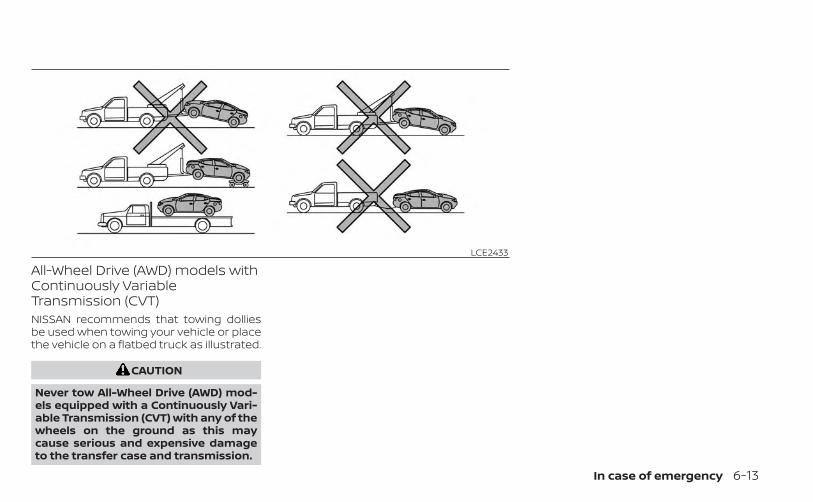
All-Wheel Drive (AWD) models withContinuously VariableTransmission (CVT)NISSAN recommends that towing dolliesbe used when towing your vehicle or placethe vehicle on a flatbed truck as illustrated.
CAUTION
Never tow All-Wheel Drive (AWD) mod-els equipped with a Continuously Vari-able Transmission (CVT) with any of thewheels on the ground as this maycause serious and expensive damageto the transfer case and transmission.
LCE2433
In case of emergency 6-13
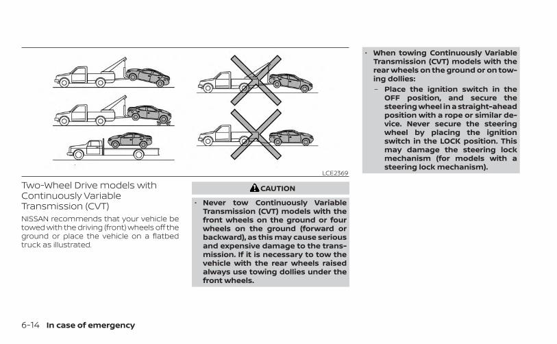
Two-Wheel Drive models withContinuously VariableTransmission (CVT)NISSAN recommends that your vehicle betowed with the driving (front) wheels off theground or place the vehicle on a flatbedtruck as illustrated.
CAUTION
• Never tow Continuously VariableTransmission (CVT) models with thefront wheels on the ground or fourwheels on the ground (forward orbackward), as this may cause seriousand expensive damage to the trans-mission. If it is necessary to tow thevehicle with the rear wheels raisedalways use towing dollies under thefront wheels.
• When towing Continuously VariableTransmission (CVT) models with therear wheels on the ground or on tow-ing dollies:– Place the ignition switch in the
OFF position, and secure thesteering wheel in a straight-aheadposition with a rope or similar de-vice. Never secure the steeringwheel by placing the ignitionswitch in the LOCK position. Thismay damage the steering lockmechanism (for models with asteering lock mechanism).
LCE2369
6-14 In case of emergency
VEHICLE RECOVERY (freeing astuck vehicle)
WARNING
To avoid vehicle damage, serious per-sonal injury or death when recovering astuck vehicle:• Contact a professional towing ser-
vice to recover the vehicle if you haveany questions regarding the recov-ery procedure.
• Tow chains or cables must be at-tached only to main structural mem-bers of the vehicle.
• Do not use the vehicle tie-downs totow or free a stuck vehicle.
• Only use devices specifically de-signed for vehicle recovery and fol-low the manufacturer's instructions.
• Always pull the recovery devicestraight out from the front of the ve-hicle. Never pull at an angle.
• Route recovery devices so they donot touch any part of the vehicle ex-cept the attachment point.
If your vehicle is stuck in sand, snow, mud,etc., use a tow strap or other device de-signed specifically for vehicle recovery. Al-ways follow the manufacturer's instruc-tions for the recovery device.
Rocking a stuck vehicle
WARNING
• Stand clear of a stuck vehicle.• Do not spin your tires at high speed.
This could cause them to explodeand result in serious injury. Parts ofyour vehicle could also overheat andbe damaged.
If your vehicle is stuck in sand, snow, mud,etc., use the following procedure:1. Turn off the Vehicle Dynamic Control
(VDC) system.
2. Make sure the area in front and behindthe vehicle is clear of obstructions.
3. Turn the steering wheel right and left toclear an area around the front tires.
4. Slowly rock the vehicle forward andbackward.• Shift back and forth between R (Re-
verse) and D (Drive).• Apply the accelerator as little as pos-
sible to maintain the rocking motion.• Release the accelerator pedal before
shifting between R (Reverse) and D(Drive).
• Do not spin the tires above 35 mph (55km/h).
5. If the vehicle cannot be freed after a fewtries, contact a professional towing ser-vice to remove the vehicle.
In case of emergency 6-15

MEMO
6-16 In case of emergency
7 Appearance and care
Cleaning exterior . . . . . . . . . . . . . . . . . . . . . . . . . . . . . . . . 7-2Washing . . . . . . . . . . . . . . . . . . . . . . . . . . . . . . . . . . . . . 7-2Waxing . . . . . . . . . . . . . . . . . . . . . . . . . . . . . . . . . . . . . . . 7-3Removing spots . . . . . . . . . . . . . . . . . . . . . . . . . . . . . . 7-3Underbody . . . . . . . . . . . . . . . . . . . . . . . . . . . . . . . . . . . 7-3Glass . . . . . . . . . . . . . . . . . . . . . . . . . . . . . . . . . . . . . . . . . 7-3Aluminum alloy wheels (if so equipped) . . . . . . . 7-4Chrome parts . . . . . . . . . . . . . . . . . . . . . . . . . . . . . . . . 7-4Tire dressings . . . . . . . . . . . . . . . . . . . . . . . . . . . . . . . . 7-4
Cleaning interior . . . . . . . . . . . . . . . . . . . . . . . . . . . . . . . . 7-5
Air fresheners . . . . . . . . . . . . . . . . . . . . . . . . . . . . . . . . 7-5Power moonroof (if so equipped) . . . . . . . . . . . . . 7-5Floor mats (if so equipped) . . . . . . . . . . . . . . . . . . . 7-6Seat belts . . . . . . . . . . . . . . . . . . . . . . . . . . . . . . . . . . . . 7-7
Corrosion protection . . . . . . . . . . . . . . . . . . . . . . . . . . . . 7-8Most common factors contributing tovehicle corrosion . . . . . . . . . . . . . . . . . . . . . . . . . . . . . 7-8Environmental factors influence therate of corrosion . . . . . . . . . . . . . . . . . . . . . . . . . . . . . 7-8Protect your vehicle from corrosion . . . . . . . . . . 7-8
In order to maintain the appearance ofyour vehicle, it is important to take propercare of it.To protect the paint surfaces, wash yourvehicle as soon as you can:• After a rainfall to prevent possible dam-
age from acid rain.• After driving on coastal roads.• When contaminants such as soot, bird
droppings, tree sap, metal particles orbugs get on the paint surface.
• When dust or mud builds up on the sur-face.
Whenever possible, store or park your ve-hicle inside a garage or in a covered area.When it is necessary to park outside, park ina shady area or protect the vehicle with abody cover.Be careful not to scratch the paint sur-face when putting on or removing thebody cover.
WASHINGWash dirt off with a wet sponge and plentyof water. Clean the vehicle thoroughly us-ing a mild soap, a special vehicle soap orgeneral purpose dishwashing liquid mixedwith clean, lukewarm (never hot) water.
CAUTION
• Do not concentrate water spray di-rectly on the sonar sensors (if soequipped) on the bumper as this willresult in damage to the sensors. Donot use pressure washers capable ofspraying water over 1,200 psi (8,274kPa) to wash your vehicle. Use ofhigh-pressure washers over 1,200 psi(8,274 kPa) can result in damage to orremoval of paint or graphics. Avoidusing a high-pressure washer closerthan 12 inches (30 cm) to the vehicle.Always use a wide-angle nozzle only,keep the nozzle moving and do notconcentrate the water spray on anyone area.
• Do not use car washes that use acidin the detergent. Some car washes,especially brushless ones, use someacid for cleaning. The acid may reactwith some plastic vehicle compo-nents, causing them to crack. Thiscould affect their appearance, andalso could cause them not to func-tion properly. Always check with yourcar wash to confirm that acid is notused.
• Do not wash the vehicle with stronghousehold soap, strong chemical de-tergents, gasoline or solvents.
• Do not wash the vehicle in direct sun-light or while the vehicle body is hot,as the surface may becomewater-spotted.
• Avoid using tight-napped or roughcloths, such as washing mitts. Caremust be taken when removingcaked-on dirt or other foreign sub-stances so the paint surface is notscratched or damaged.
Rinse the vehicle thoroughly with plenty ofclean water.Inside edges, seams and folds on thedoors, hatches and hood are particularlyvulnerable to the effects of road salt. There-fore, these areas must be cleaned regularly.Take care that the drain holes in the loweredge of the door are open. Spray waterunder the body and in the wheel wells toloosen the dirt and wash away road salt.A damp chamois can be used to dry thevehicle to avoid water spots.
CLEANING EXTERIOR
7-2 Appearance and care
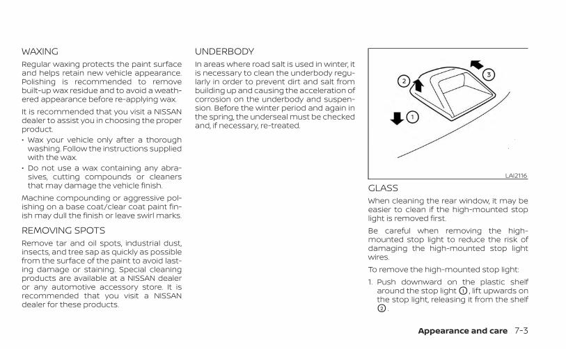
WAXINGRegular waxing protects the paint surfaceand helps retain new vehicle appearance.Polishing is recommended to removebuilt-up wax residue and to avoid a weath-ered appearance before re-applying wax.It is recommended that you visit a NISSANdealer to assist you in choosing the properproduct.• Wax your vehicle only after a thorough
washing. Follow the instructions suppliedwith the wax.
• Do not use a wax containing any abra-sives, cutting compounds or cleanersthat may damage the vehicle finish.
Machine compounding or aggressive pol-ishing on a base coat/clear coat paint fin-ish may dull the finish or leave swirl marks.
REMOVING SPOTSRemove tar and oil spots, industrial dust,insects, and tree sap as quickly as possiblefrom the surface of the paint to avoid last-ing damage or staining. Special cleaningproducts are available at a NISSAN dealeror any automotive accessory store. It isrecommended that you visit a NISSANdealer for these products.
UNDERBODYIn areas where road salt is used in winter, itis necessary to clean the underbody regu-larly in order to prevent dirt and salt frombuilding up and causing the acceleration ofcorrosion on the underbody and suspen-sion. Before the winter period and again inthe spring, the underseal must be checkedand, if necessary, re-treated.
GLASSWhen cleaning the rear window, it may beeasier to clean if the high-mounted stoplight is removed first.Be careful when removing the high-mounted stop light to reduce the risk ofdamaging the high-mounted stop lightwires.To remove the high-mounted stop light:1. Push downward on the plastic shelf
around the stop light O1 , lift upwards onthe stop light, releasing it from the shelfO2 .
LAI2116
Appearance and care 7-3
2. Once it is released from the shelf, gentlypull the stop light towards the rear seat-back O3 .
The high-mounted stop light must beproperly reinstalled before driving your ve-hicle.Use glass cleaner to remove smoke anddust film from the glass surfaces. It is nor-mal for glass to become coated with a filmafter the vehicle is parked in the hot sun.Glass cleaner and a soft cloth will easilyremove this film.To reinstall the high-mounted stop light,reverse steps O3 , then O2 .
CAUTION
When cleaning the inside of the win-dows, do not use sharp-edged tools,abrasive cleaners or chlorine-baseddisinfectant cleaners. They could dam-age the electrical conductors, radio an-tenna elements or rear window defog-ger elements.
ALUMINUM ALLOY WHEELS (if soequipped)Wash the wheels regularly with a spongedampened in a mild soap solution, espe-cially during winter months in areas whereroad salt is used. If not removed, road saltcan discolor the wheels.
CAUTION
Follow the directions below to avoidstaining or discoloring the wheels:• Do not use a cleaner that uses strong
acid or alkali contents to clean thewheels.
• Do not apply wheel cleaners to thewheels when they are hot. The wheeltemperature should be the same asambient temperature.
• Rinse the wheel to completely re-move the cleaner within 15 minutesafter the cleaner is applied.
CHROME PARTSClean all chrome parts regularly with anon-abrasive chrome polish to maintainthe finish.
TIRE DRESSINGSNISSAN does not recommend the use oftire dressings. Tire manufacturers apply acoating to the tires to help reduce discolor-ation of the rubber. If a tire dressing is ap-plied to the tires, it may react with the coat-ing and form a compound. This compoundmay come off the tire while driving andstain the vehicle paint.If you choose to use a tire dressing, take thefollowing precautions:• Use a water-based tire dressing. The
coating on the tire dissolves more easilythan with an oil-based tire dressing.
• Apply a light coat of tire dressing to helpprevent it from entering the tire tread/grooves (where it would be difficult to re-move).
• Wipe off excess tire dressing using a drytowel. Make sure the tire dressing is com-pletely removed from the tire tread/grooves.
• Allow the tire dressing to dry as recom-mended by the tire dressing manufac-turer.
7-4 Appearance and care
Occasionally remove loose dust from theinterior trim, plastic parts and seats using avacuum cleaner or soft bristled brush. Wipethe vinyl and leather (if so equipped) sur-faces with a clean, soft cloth dampened inmild soap solution, then wipe clean with adry, soft cloth.Regular care and cleaning is required inorder to maintain the appearance of theleather (if so equipped).Before using any fabric protector, read themanufacturer's recommendations. Somefabric protectors contain chemicals thatmay stain or bleach the seat material.Use a cloth dampened only with water toclean the meter and gauge lens.
WARNING
Do not use water or acidic cleaners (hotsteam cleaners) on the seat. This candamage the seat or occupant classifi-cation sensor. This can also affect theoperation of the air bag system and re-sult in serious personal injury.
CAUTION
• Never use benzine, thinner or anysimilar material.
• Small dirt particles can be abrasiveand damaging to leather surfacesand should be removed promptly. Donot use saddle soap, car waxes, pol-ishes, oils, cleaning fluids, solvents,detergents or ammonia-basedcleaners as they may damage theleather's natural finish.
• Never use fabric protectors unlessrecommended by the manufacturer.
• Do not use glass or plastic cleaner onmeter or gauge lens covers. It maydamage the lens cover.
AIR FRESHENERSMost air fresheners use a solvent thatcould affect the vehicle interior. If you usean air freshener, take the following precau-tions:• Hanging-type air fresheners can cause
permanent discoloration when they con-tact vehicle interior surfaces. Place the airfreshener in a location that allows it tohang free and not contact an interior sur-face.
• Liquid-type air fresheners typically clip onthe vents. These products can cause im-mediate damage and discolorationwhen spilled on interior surfaces.
Carefully read and follow the manufactur-er's instructions before using the air fresh-eners.
POWER MOONROOF (if soequipped)The sunshade is made from a tricot mate-rial.
CAUTION
To help prevent damaging the moon-roof while cleaning:• Do not rub the material with a cloth.
Doing so can damage the surface ofthe material or cause a stain tospread.
• Never use benzine, thinner or anysimilar chemical to clean the sun-shade. This may discolor the moon-roof and damage the surface.
• Clean water based stains by pattingthe surface with a clean soft clothdampened in warm water. Press aclean dry cloth onto the surface toremove as much dampness as pos-sible and then let air dry.
CLEANING INTERIOR
Appearance and care 7-5
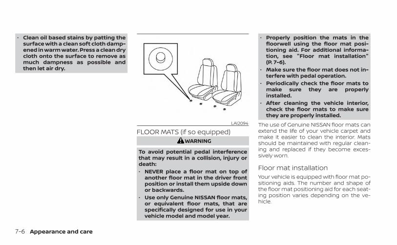
• Clean oil based stains by patting thesurface with a clean soft cloth damp-ened in warm water. Press a clean drycloth onto the surface to remove asmuch dampness as possible andthen let air dry.
FLOOR MATS (if so equipped)WARNING
To avoid potential pedal interferencethat may result in a collision, injury ordeath:• NEVER place a floor mat on top of
another floor mat in the driver frontposition or install them upside downor backwards.
• Use only Genuine NISSAN floor mats,or equivalent floor mats, that arespecifically designed for use in yourvehicle model and model year.
• Properly position the mats in thefloorwell using the floor mat posi-tioning aid. For additional informa-tion, see "Floor mat installation"(P. 7-6).
• Make sure the floor mat does not in-terfere with pedal operation.
• Periodically check the floor mats tomake sure they are properlyinstalled.
• After cleaning the vehicle interior,check the floor mats to make surethey are properly installed.
The use of Genuine NISSAN floor mats canextend the life of your vehicle carpet andmake it easier to clean the interior. Matsshould be maintained with regular clean-ing and replaced if they become exces-sively worn.
Floor mat installationYour vehicle is equipped with floor mat po-sitioning aids. The number and shape ofthe floor mat positioning aid for each seat-ing position varies depending on the ve-hicle.
LAI2094
7-6 Appearance and care
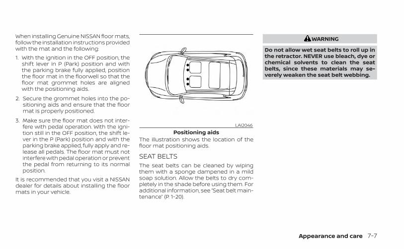
When installing Genuine NISSAN floor mats,follow the installation instructions providedwith the mat and the following:1. With the ignition in the OFF position, the
shift lever in P (Park) position and withthe parking brake fully applied, positionthe floor mat in the floorwell so that thefloor mat grommet holes are alignedwith the positioning aids.
2. Secure the grommet holes into the po-sitioning aids and ensure that the floormat is properly positioned.
3. Make sure the floor mat does not inter-fere with pedal operation. With the igni-tion still in the OFF position, the shift le-ver in the P (Park) position and with theparking brake applied, fully apply and re-lease all pedals. The floor mat must notinterfere with pedal operation or preventthe pedal from returning to its normalposition.
It is recommended that you visit a NISSANdealer for details about installing the floormats in your vehicle.
The illustration shows the location of thefloor mat positioning aids.
SEAT BELTSThe seat belts can be cleaned by wipingthem with a sponge dampened in a mildsoap solution. Allow the belts to dry com-pletely in the shade before using them. Foradditional information, see “Seat belt main-tenance” (P. 1-20).
WARNING
Do not allow wet seat belts to roll up inthe retractor. NEVER use bleach, dye orchemical solvents to clean the seatbelts, since these materials may se-verely weaken the seat belt webbing.
LAI2046Positioning aids
Appearance and care 7-7
MOST COMMON FACTORSCONTRIBUTING TO VEHICLECORROSIONMost vehicle corrosion is caused by:• The accumulation of moisture-retaining
dirt and debris in body panel sections,cavities, and other areas.
• Damage to paint and other protectivecoatings caused by gravel and stonechips or minor traffic collisions.
ENVIRONMENTAL FACTORSINFLUENCE THE RATE OFCORROSIONMoistureAccumulation of sand, dirt and water onthe vehicle body underside can acceleratecorrosion. Wet floor coverings will not drycompletely inside the vehicle and shouldbe removed for drying to avoid floor panelcorrosion.
Relative humidityCorrosion will be accelerated in areas ofhigh relative humidity, especially those ar-eas where the temperatures stay abovefreezing and where atmospheric pollutionexists and road salt is used.
TemperatureHigh temperatures accelerate the rate ofcorrosion to those parts which are not wellventilated.
Air pollutionIndustrial pollution, the presence of salt inthe air in coastal areas, or heavy road saltuse accelerates the corrosion process.Road salt also accelerates the disintegra-tion of paint surfaces.
PROTECT YOUR VEHICLE FROMCORROSION• Wash and wax your vehicle often to keep
the vehicle clean.• Always check for minor damage to the
paint and repair it as soon as possible.• Keep drain holes at the bottom of the
doors open to avoid water accumulation.• Check the underbody for accumulation
of sand, dirt or salt. If present, wash withwater as soon as possible.
CAUTION
• NEVER remove dirt, sand or other de-bris from the passenger compart-ment by washing it out with a hose.Remove dirt with a vacuum cleaneror broom.
• Never allow water or other liquids tocome in contact with electronic com-ponents inside the vehicle as thismay damage them.
Chemicals used for road surface de-icingare extremely corrosive. They acceleratecorrosion and deterioration of underbodycomponents such as the exhaust system,fuel and brake lines, brake cables, floor panand fenders.In winter, the underbody must becleaned periodically.For additional protection against rust andcorrosion, which may be required in someareas, it is recommended that you visit aNISSAN dealer.
CORROSION PROTECTION
7-8 Appearance and care
8 Do-it-yourself
Maintenance precautions . . . . . . . . . . . . . . . . . . . . . . . 8-2Engine compartment check locations . . . . . . . . . . . 8-3Engine cooling system . . . . . . . . . . . . . . . . . . . . . . . . . . 8-5
Checking engine coolant level . . . . . . . . . . . . . . . . 8-6Changing engine coolant . . . . . . . . . . . . . . . . . . . . 8-6
Engine oil . . . . . . . . . . . . . . . . . . . . . . . . . . . . . . . . . . . . . . . 8-7Checking engine oil level . . . . . . . . . . . . . . . . . . . . . 8-7Changing engine oil and oil filter . . . . . . . . . . . . . . 8-8
Continuously Variable Transmission (CVT)fluid . . . . . . . . . . . . . . . . . . . . . . . . . . . . . . . . . . . . . . . . . . . . 8-12Brake fluid . . . . . . . . . . . . . . . . . . . . . . . . . . . . . . . . . . . . . . 8-12Windshield-washer fluid . . . . . . . . . . . . . . . . . . . . . . . . 8-13
Windshield-washer fluid reservoir . . . . . . . . . . . 8-13Battery . . . . . . . . . . . . . . . . . . . . . . . . . . . . . . . . . . . . . . . . . 8-14
Jump starting . . . . . . . . . . . . . . . . . . . . . . . . . . . . . . . 8-15Variable voltage control system . . . . . . . . . . . . . . . . 8-16Drive belt . . . . . . . . . . . . . . . . . . . . . . . . . . . . . . . . . . . . . . . 8-16Spark plugs . . . . . . . . . . . . . . . . . . . . . . . . . . . . . . . . . . . . 8-17
Replacing spark plugs . . . . . . . . . . . . . . . . . . . . . . . 8-17Air cleaner . . . . . . . . . . . . . . . . . . . . . . . . . . . . . . . . . . . . . 8-18
In-cabin microfilter . . . . . . . . . . . . . . . . . . . . . . . . . . 8-18
Windshield wiper blades . . . . . . . . . . . . . . . . . . . . . . . . 8-19Cleaning . . . . . . . . . . . . . . . . . . . . . . . . . . . . . . . . . . . . 8-19Replacing . . . . . . . . . . . . . . . . . . . . . . . . . . . . . . . . . . . 8-19
Brakes . . . . . . . . . . . . . . . . . . . . . . . . . . . . . . . . . . . . . . . . .8-20Fuses . . . . . . . . . . . . . . . . . . . . . . . . . . . . . . . . . . . . . . . . . . 8-21
Engine compartment . . . . . . . . . . . . . . . . . . . . . . . 8-21Passenger compartment . . . . . . . . . . . . . . . . . . . 8-22
Battery replacement . . . . . . . . . . . . . . . . . . . . . . . . . . . 8-23NISSAN Intelligent Key® . . . . . . . . . . . . . . . . . . . . . . 8-24
Lights . . . . . . . . . . . . . . . . . . . . . . . . . . . . . . . . . . . . . . . . . . 8-25Headlights . . . . . . . . . . . . . . . . . . . . . . . . . . . . . . . . . . 8-25Fog lights (if so equipped) . . . . . . . . . . . . . . . . . . .8-26Exterior and interior lights . . . . . . . . . . . . . . . . . . .8-26
Wheels and tires . . . . . . . . . . . . . . . . . . . . . . . . . . . . . . . 8-29Tire pressure . . . . . . . . . . . . . . . . . . . . . . . . . . . . . . . . 8-29Tire labeling . . . . . . . . . . . . . . . . . . . . . . . . . . . . . . . . . 8-33Types of tires . . . . . . . . . . . . . . . . . . . . . . . . . . . . . . . . 8-35Tire chains . . . . . . . . . . . . . . . . . . . . . . . . . . . . . . . . . . 8-36Changing wheels and tires . . . . . . . . . . . . . . . . . .8-38
When performing any inspection or main-tenance work on your vehicle, always takecare to prevent serious accidental injury toyourself or damage to the vehicle. The fol-lowing are general precautions whichshould be closely observed.
WARNING
• Park the vehicle on a level surface,apply the parking brake securely andblock the wheels to prevent the ve-hicle from moving. Move the shift le-ver to P (Park).
• Be sure the ignition switch is in theOFF or LOCK position when perform-ing any parts replacement or repairs.
• If you must work with the engine run-ning, keep your hands, clothing, hairand tools away from moving fans,belts and any other moving parts.
• It is advisable to secure or removeany loose clothing and remove anyjewelry, such as rings, watches, etc.before working on your vehicle.
• Always wear eye protection when-ever you work on your vehicle.
• Your vehicle is equipped with an au-tomatic engine cooling fan. It maycome on at any time without warn-ing, even if the ignition switch is inthe OFF position and the engine isnot running. To avoid injury, alwaysdisconnect the negative batterycable before working near the fan.
• If you must run the engine in an en-closed space such as a garage, besure there is proper ventilation forexhaust gases to escape.
• Never get under the vehicle while it issupported only by a jack. If it is nec-essary to work under the vehicle,support it with safety stands.
• Keep smoking materials, flame andsparks away from the fuel tank andbattery.
• On gasoline engine models, the fuelfilter or fuel lines should be serviced.It is recommended that you visit aNISSAN dealer for this service be-cause the fuel lines are under highpressure even when the engine is off.
CAUTION
• Do not work under the hood whilethe engine is hot. Turn the engine offand wait until it cools down.
• Avoid contact with used engine oiland coolant. Improperly disposedengine oil, engine coolant and/orother vehicle fluids can damage theenvironment. Always conform to lo-cal regulations for disposal of vehiclefluid.
• Never leave the engine or the trans-mission related component harnessconnector disconnected while the ig-nition switch is in the ON position.
• Never connect or disconnect the bat-tery or any transistorized compo-nent while the ignition switch is inthe ON position.
This “Do-it-yourself ” section gives instruc-tions regarding only those items which arerelatively easy for an owner to perform.A Genuine NISSAN service manual is alsoavailable. For additional information, see“Owner's Manual/Service Manual order in-formation” (P. 10-24).You should be aware that incomplete orimproper servicing may result in operatingdifficulties or excessive emissions, andcould affect warranty coverage. If in doubtabout any servicing, it is recommendedthat you have it done by a NISSAN dealer.
MAINTENANCE PRECAUTIONS
8-2 Do-it-yourself
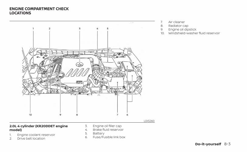
2.0L 4 cylinder (KR20DDET enginemodel)1. Engine coolant reservoir2. Drive belt location
3. Engine oil filler cap4. Brake fluid reservoir5. Battery6. Fuse/Fusible link box
7. Air cleaner8. Radiator cap9. Engine oil dipstick10. Windshield-washer fluid reservoir
LDI3260
ENGINE COMPARTMENT CHECKLOCATIONS
Do-it-yourself 8-3
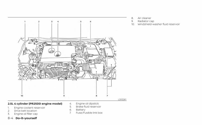
2.5L 4 cylinder (PR25DD engine model)1. Engine coolant reservoir2. Drive belt location3. Engine oil filler cap
4. Engine oil dipstick5. Brake fluid reservoir6. Battery7. Fuse/Fusible link box
8. Air cleaner9. Radiator cap10. Windshield-washer fluid reservoir
LDI3261
8-4 Do-it-yourself
The engine cooling system is filled at thefactory with a pre-diluted mixture of 50%Genuine NISSAN Long Life Antifreeze/Coolant (blue) and 50% water to provideyear-round antifreeze and coolant protec-tion. The antifreeze solution contains rustand corrosion inhibitors. Additional enginecooling system additives are not neces-sary.
WARNING
• Never remove the radiator or coolantreservoir cap when the engine is hot.Wait until the engine and radiatorcool down. Serious burns could becaused by high pressure fluid escap-ing from the radiator. For additionalinformation on precautions, see “Ifyour vehicle overheats” (P. 6-11).
• The radiator is equipped with a pres-sure type radiator cap. To prevent en-gine damage, use only a GenuineNISSAN radiator cap.
CAUTION
• Never use any cooling system addi-tives such as radiator sealer. Addi-tives may clog the cooling systemand cause damage to the engine,transmission and/or cooling system.
• When adding or replacing coolant, besure to use only Genuine NISSANLong Life Antifreeze/Coolant (blue)or equivalent. Genuine NISSAN LongLife Antifreeze/Coolant (blue) is pre-diluted to provide antifreeze protec-tion to -34° F (-37° C). If additionalfreeze protection is needed due toweather where you operate your ve-hicle, add Genuine NISSAN Long LifeAntifreeze/Coolant (blue) concen-trate following the directions on thecontainer. If an equivalent coolantother than Genuine NISSAN Long LifeAntifreeze/Coolant (blue) is used, fol-low the coolant manufacturer’s in-structions to maintain minimum an-tifreeze protection to -34° F (-37° C).The use of other types of coolant so-lutions other than Genuine NISSANLong Life Antifreeze/Coolant (blue)or equivalent may damage the en-gine cooling system.
• The life expectancy of the factory-fillcoolant is 105,000 miles (168,000 km)or 7 years. Mixing any other type ofcoolant other than Genuine NISSANLong Life Antifreeze/Coolant (blue)(or equivalent coolant), includingGenuine NISSAN Long LifeAntifreeze/Coolant (green), or theuse of non-distilled water may re-duce the life expectancy of thefactory-fill coolant. For additional in-formation, see "Maintenance andschedules" (P. 9-2).
ENGINE COOLING SYSTEM
Do-it-yourself 8-5
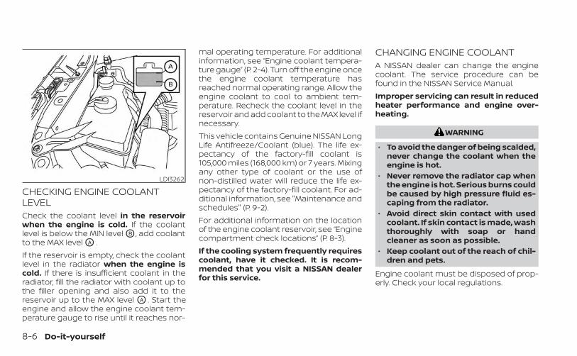
CHECKING ENGINE COOLANTLEVELCheck the coolant level in the reservoirwhen the engine is cold. If the coolantlevel is below the MIN level OB , add coolantto the MAX level OA .If the reservoir is empty, check the coolantlevel in the radiator when the engine iscold. If there is insufficient coolant in theradiator, fill the radiator with coolant up tothe filler opening and also add it to thereservoir up to the MAX level OA . Start theengine and allow the engine coolant tem-perature gauge to rise until it reaches nor-
mal operating temperature. For additionalinformation, see “Engine coolant tempera-ture gauge” (P. 2-4). Turn off the engine oncethe engine coolant temperature hasreached normal operating range. Allow theengine coolant to cool to ambient tem-perature. Recheck the coolant level in thereservoir and add coolant to the MAX level ifnecessary.This vehicle contains Genuine NISSAN LongLife Antifreeze/Coolant (blue). The life ex-pectancy of the factory-fill coolant is105,000 miles (168,000 km) or 7 years. Mixingany other type of coolant or the use ofnon-distilled water will reduce the life ex-pectancy of the factory-fill coolant. For ad-ditional information, see "Maintenance andschedules" (P. 9-2).For additional information on the locationof the engine coolant reservoir, see “Enginecompartment check locations” (P. 8-3).If the cooling system frequently requirescoolant, have it checked. It is recom-mended that you visit a NISSAN dealerfor this service.
CHANGING ENGINE COOLANTA NISSAN dealer can change the enginecoolant. The service procedure can befound in the NISSAN Service Manual.Improper servicing can result in reducedheater performance and engine over-heating.
WARNING
• To avoid the danger of being scalded,never change the coolant when theengine is hot.
• Never remove the radiator cap whenthe engine is hot. Serious burns couldbe caused by high pressure fluid es-caping from the radiator.
• Avoid direct skin contact with usedcoolant. If skin contact is made, washthoroughly with soap or handcleaner as soon as possible.
• Keep coolant out of the reach of chil-dren and pets.
Engine coolant must be disposed of prop-erly. Check your local regulations.
LDI3262
8-6 Do-it-yourself
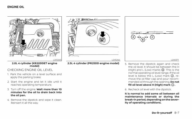
CHECKING ENGINE OIL LEVEL1. Park the vehicle on a level surface and
apply the parking brake.
2. Start the engine and let it idle until itreaches operating temperature.
3. Turn off the engine. Wait more than 10minutes for the oil to drain back intothe oil pan.
4. Remove the dipstick and wipe it clean.Reinsert it all the way.
5. Remove the dipstick again and checkthe oil level. It should be between the H(High) and L (Low) marks OB . This is thenormal operating oil level range. If the oillevel is below the L (Low) mark OA , re-move the oil filler cap and pour recom-mended oil through the opening. Do notfill oil level above H (High) mark OC .
6. Recheck oil level with the dipstick.It is normal to add some oil between oilmaintenance intervals or during thebreak-in period, depending on the sever-ity of operating conditions.
LDI32632.0L 4 cylinder (KR20DDET engine
model)
LDI32642.5L 4 cylinder (PR25DD engine model)
LDI0371
ENGINE OIL
Do-it-yourself 8-7
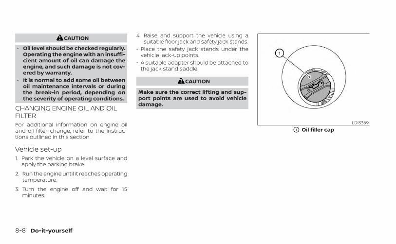
CAUTION
• Oil level should be checked regularly.Operating the engine with an insuffi-cient amount of oil can damage theengine, and such damage is not cov-ered by warranty.
• It is normal to add some oil betweenoil maintenance intervals or duringthe break-in period, depending onthe severity of operating conditions.
CHANGING ENGINE OIL AND OILFILTERFor additional information on engine oiland oil filter change, refer to the instruc-tions outlined in this section.
Vehicle set-up1. Park the vehicle on a level surface and
apply the parking brake.
2. Run the engine until it reaches operatingtemperature.
3. Turn the engine off and wait for 15minutes.
4. Raise and support the vehicle using asuitable floor jack and safety jack stands.
• Place the safety jack stands under thevehicle jack-up points.
• A suitable adapter should be attached tothe jack stand saddle.
CAUTION
Make sure the correct lifting and sup-port points are used to avoid vehicledamage.
LDI3369
O1 Oil filler cap
8-8 Do-it-yourself
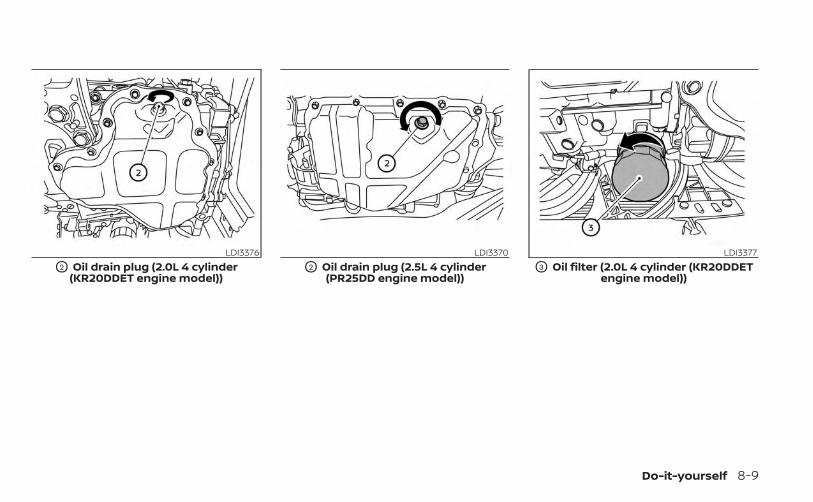
LDI3376
O2 Oil drain plug (2.0L 4 cylinder(KR20DDET engine model))
LDI3370
O2 Oil drain plug (2.5L 4 cylinder(PR25DD engine model))
LDI3377
O3 Oil filter (2.0L 4 cylinder (KR20DDETengine model))
Do-it-yourself 8-9
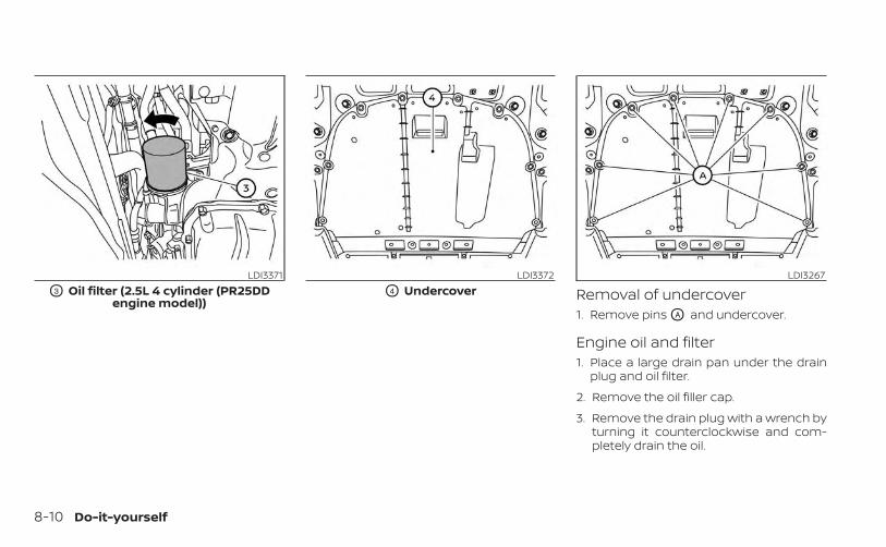
Removal of undercover1. Remove pins OA and undercover.
Engine oil and filter1. Place a large drain pan under the drain
plug and oil filter.
2. Remove the oil filler cap.
3. Remove the drain plug with a wrench byturning it counterclockwise and com-pletely drain the oil.
LDI3371
O3 Oil filter (2.5L 4 cylinder (PR25DDengine model))
LDI3372
O4 UndercoverLDI3267
8-10 Do-it-yourself
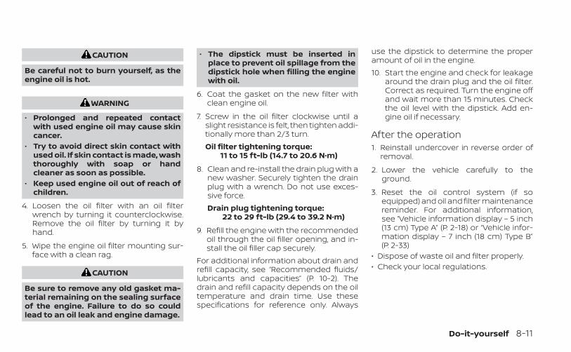
CAUTION
Be careful not to burn yourself, as theengine oil is hot.
WARNING
• Prolonged and repeated contactwith used engine oil may cause skincancer.
• Try to avoid direct skin contact withused oil. If skin contact is made, washthoroughly with soap or handcleaner as soon as possible.
• Keep used engine oil out of reach ofchildren.
4. Loosen the oil filter with an oil filterwrench by turning it counterclockwise.Remove the oil filter by turning it byhand.
5. Wipe the engine oil filter mounting sur-face with a clean rag.
CAUTION
Be sure to remove any old gasket ma-terial remaining on the sealing surfaceof the engine. Failure to do so couldlead to an oil leak and engine damage.
• The dipstick must be inserted inplace to prevent oil spillage from thedipstick hole when filling the enginewith oil.
6. Coat the gasket on the new filter withclean engine oil.
7. Screw in the oil filter clockwise until aslight resistance is felt, then tighten addi-tionally more than 2/3 turn.Oil filter tightening torque:
11 to 15 ft-lb (14.7 to 20.6 N·m)
8. Clean and re-install the drain plug with anew washer. Securely tighten the drainplug with a wrench. Do not use exces-sive force.Drain plug tightening torque:
22 to 29 ft-lb (29.4 to 39.2 N·m)
9. Refill the engine with the recommendedoil through the oil filler opening, and in-stall the oil filler cap securely.
For additional information about drain andrefill capacity, see “Recommended fluids/lubricants and capacities” (P. 10-2). Thedrain and refill capacity depends on the oiltemperature and drain time. Use thesespecifications for reference only. Always
use the dipstick to determine the properamount of oil in the engine.10. Start the engine and check for leakage
around the drain plug and the oil filter.Correct as required. Turn the engine offand wait more than 15 minutes. Checkthe oil level with the dipstick. Add en-gine oil if necessary.
After the operation1. Reinstall undercover in reverse order of
removal.
2. Lower the vehicle carefully to theground.
3. Reset the oil control system (if soequipped) and oil and filter maintenancereminder. For additional information,see “Vehicle information display – 5 inch(13 cm) Type A” (P. 2-18) or “Vehicle infor-mation display – 7 inch (18 cm) Type B”(P. 2-33)
• Dispose of waste oil and filter properly.• Check your local regulations.
Do-it-yourself 8-11
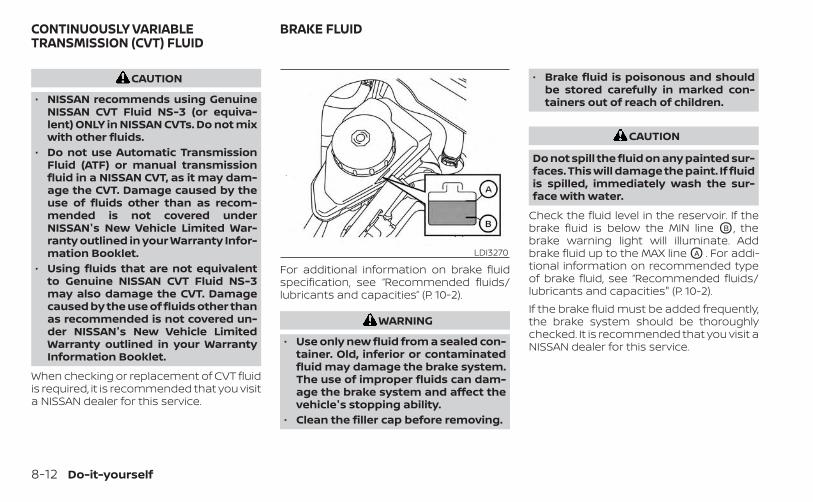
CAUTION
• NISSAN recommends using GenuineNISSAN CVT Fluid NS-3 (or equiva-lent) ONLY in NISSAN CVTs. Do not mixwith other fluids.
• Do not use Automatic TransmissionFluid (ATF) or manual transmissionfluid in a NISSAN CVT, as it may dam-age the CVT. Damage caused by theuse of fluids other than as recom-mended is not covered underNISSAN's New Vehicle Limited War-ranty outlined in your Warranty Infor-mation Booklet.
• Using fluids that are not equivalentto Genuine NISSAN CVT Fluid NS-3may also damage the CVT. Damagecaused by the use of fluids other thanas recommended is not covered un-der NISSAN's New Vehicle LimitedWarranty outlined in your WarrantyInformation Booklet.
When checking or replacement of CVT fluidis required, it is recommended that you visita NISSAN dealer for this service.
For additional information on brake fluidspecification, see “Recommended fluids/lubricants and capacities” (P. 10-2).
WARNING
• Use only new fluid from a sealed con-tainer. Old, inferior or contaminatedfluid may damage the brake system.The use of improper fluids can dam-age the brake system and affect thevehicle's stopping ability.
• Clean the filler cap before removing.
• Brake fluid is poisonous and shouldbe stored carefully in marked con-tainers out of reach of children.
CAUTION
Do not spill the fluid on any painted sur-faces. This will damage the paint. If fluidis spilled, immediately wash the sur-face with water.
Check the fluid level in the reservoir. If thebrake fluid is below the MIN line OB , thebrake warning light will illuminate. Addbrake fluid up to the MAX line OA . For addi-tional information on recommended typeof brake fluid, see “Recommended fluids/lubricants and capacities" (P. 10-2).If the brake fluid must be added frequently,the brake system should be thoroughlychecked. It is recommended that you visit aNISSAN dealer for this service.
LDI3270
CONTINUOUSLY VARIABLETRANSMISSION (CVT) FLUID
BRAKE FLUID
8-12 Do-it-yourself

WINDSHIELD-WASHER FLUIDRESERVOIRFill the windshield-washer fluid reservoirperiodically. Add windshield-washer fluidwhen the “Low Washer Fluid” warning ap-pears in the vehicle information display.To check the fluid level with the dip tube,use your finger to plug the center hole OA ofthe cap/tube assembly, then remove itfrom the reservoir. If there is no fluid in thedip tube, add fluid.
To fill the windshield-washer fluid reservoir,lift the cap off the reservoir and pour thewindshield-washer fluid into the reservoiropening.Add a washer solvent to the washer forbetter cleaning. In the winter season, add awindshield washer antifreeze. Follow themanufacturer's instructions for the mix-ture ratio.Refill the reservoir more frequently whendriving conditions require an increasedamount of windshield-washer fluid.Recommended fluid is Genuine NISSANWindshield Washer Concentrate Cleaner &Antifreeze or equivalent.
WARNING
Antifreeze is poisonous and should bestored carefully in marked containersout of the reach of children.
CAUTION
• Do not substitute engine antifreezecoolant for windshield-washer fluid.This may result in damage to thepaint.
• Do not fill the windshield-washerfluid reservoir with washer fluid con-centrates at full strength. Somemethyl alcohol based washer fluidconcentrates may permanently stainthe grille if spilled while filling thewindshield-washer fluid reservoir.
• Pre-mix washer fluid concentrateswith water to the manufacturer'srecommended levels before pouringthe fluid into the windshield-washerfluid reservoir. Do not use thewindshield-washer fluid reservoir tomix the washer fluid concentrate andwater.
LDI3271
WINDSHIELD-WASHER FLUID
Do-it-yourself 8-13
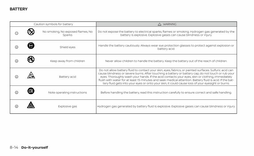
Caution symbols for battery WARNING
O1No smoking, No exposed flames, No
SparksDo not expose the battery to electrical sparks, flames or smoking. Hydrogen gas generated by the
battery is explosive. Explosive gases can cause blindness or injury.
O2 Shield eyes Handle the battery cautiously. Always wear eye protection glasses to protect against explosion orbattery acid.
O3 Keep away from children Never allow children to handle the battery. Keep the battery out of the reach of children.
O4 Battery acid
Do not allow battery fluid to contact your skin, eyes, fabrics, or painted surfaces. Sulfuric acid cancause blindness or severe burns. After touching a battery or battery cap, do not touch or rub your
eyes. Thoroughly wash your hands. If the acid contacts your eyes, skin or clothing, immediatelyflush with water for at least 15 minutes and seek medical attention. Battery fluid is acid. If the bat-
tery fluid gets into your eyes or onto your skin, it could cause loss of your eyesight or burns.
O5 Note operating instructions Before handling the battery, read this instruction carefully to ensure correct and safe handling.
O6 Explosive gas Hydrogen gas generated by battery fluid is explosive. Explosive gases can cause blindness or injury.
BATTERY
8-14 Do-it-yourself
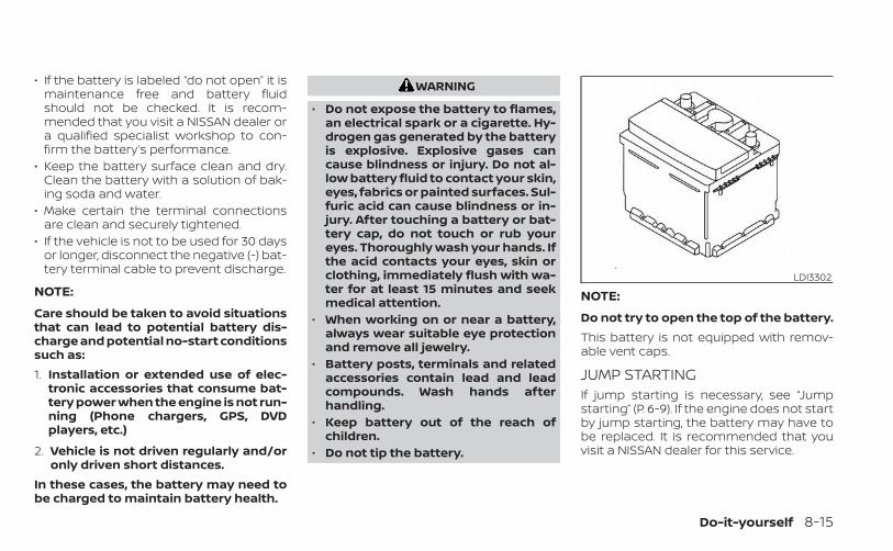
• If the battery is labeled “do not open” it ismaintenance free and battery fluidshould not be checked. It is recom-mended that you visit a NISSAN dealer ora qualified specialist workshop to con-firm the battery’s performance.
• Keep the battery surface clean and dry.Clean the battery with a solution of bak-ing soda and water.
• Make certain the terminal connectionsare clean and securely tightened.
• If the vehicle is not to be used for 30 daysor longer, disconnect the negative (-) bat-tery terminal cable to prevent discharge.
NOTE:
Care should be taken to avoid situationsthat can lead to potential battery dis-charge and potential no-start conditionssuch as:1. Installation or extended use of elec-
tronic accessories that consume bat-tery power when the engine is not run-ning (Phone chargers, GPS, DVDplayers, etc.)
2. Vehicle is not driven regularly and/oronly driven short distances.
In these cases, the battery may need tobe charged to maintain battery health.
WARNING
• Do not expose the battery to flames,an electrical spark or a cigarette. Hy-drogen gas generated by the batteryis explosive. Explosive gases cancause blindness or injury. Do not al-low battery fluid to contact your skin,eyes, fabrics or painted surfaces. Sul-furic acid can cause blindness or in-jury. After touching a battery or bat-tery cap, do not touch or rub youreyes. Thoroughly wash your hands. Ifthe acid contacts your eyes, skin orclothing, immediately flush with wa-ter for at least 15 minutes and seekmedical attention.
• When working on or near a battery,always wear suitable eye protectionand remove all jewelry.
• Battery posts, terminals and relatedaccessories contain lead and leadcompounds. Wash hands afterhandling.
• Keep battery out of the reach ofchildren.
• Do not tip the battery.
NOTE:
Do not try to open the top of the battery.This battery is not equipped with remov-able vent caps.
JUMP STARTINGIf jump starting is necessary, see “Jumpstarting” (P. 6-9). If the engine does not startby jump starting, the battery may have tobe replaced. It is recommended that youvisit a NISSAN dealer for this service.
LDI3302
Do-it-yourself 8-15
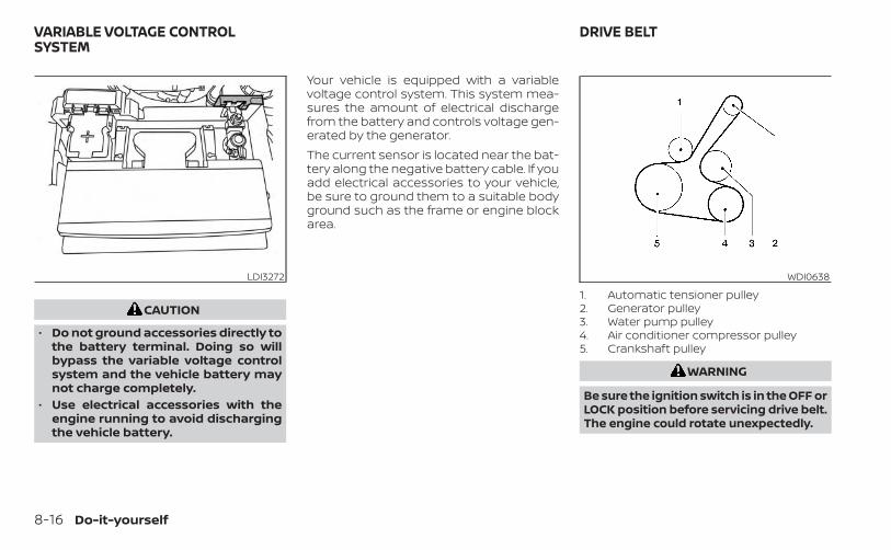
CAUTION
• Do not ground accessories directly tothe battery terminal. Doing so willbypass the variable voltage controlsystem and the vehicle battery maynot charge completely.
• Use electrical accessories with theengine running to avoid dischargingthe vehicle battery.
Your vehicle is equipped with a variablevoltage control system. This system mea-sures the amount of electrical dischargefrom the battery and controls voltage gen-erated by the generator.The current sensor is located near the bat-tery along the negative battery cable. If youadd electrical accessories to your vehicle,be sure to ground them to a suitable bodyground such as the frame or engine blockarea.
1. Automatic tensioner pulley2. Generator pulley3. Water pump pulley4. Air conditioner compressor pulley5. Crankshaft pulley
WARNING
Be sure the ignition switch is in the OFF orLOCK position before servicing drive belt.The engine could rotate unexpectedly.
LDI3272 WDI0638
VARIABLE VOLTAGE CONTROLSYSTEM
DRIVE BELT
8-16 Do-it-yourself
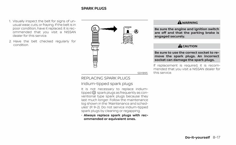
1. Visually inspect the belt for signs of un-usual wear, cuts, or fraying. If the belt is inpoor condition, have it replaced. It is rec-ommended that you visit a NISSANdealer for this service.
2. Have the belt checked regularly forcondition.
REPLACING SPARK PLUGSIridium-tipped spark plugsIt is not necessary to replace iridium-tipped OA spark plugs as frequently as con-ventional type spark plugs because theylast much longer. Follow the maintenancelog shown in the “Maintenance and sched-ules” (P. 9-2). Do not service iridium-tippedspark plugs by cleaning or regapping.• Always replace spark plugs with rec-
ommended or equivalent ones.
WARNING
Be sure the engine and ignition switchare off and that the parking brake isengaged securely.
CAUTION
Be sure to use the correct socket to re-move the spark plugs. An incorrectsocket can damage the spark plugs.
If replacement is required, it is recom-mended that you visit a NISSAN dealer forthis service.SDI1895
SPARK PLUGS
Do-it-yourself 8-17
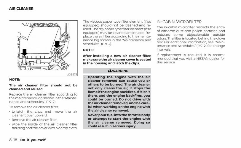
NOTE:
The air cleaner filter should not becleaned and reused.Replace the air cleaner filter according tothe maintenance log shown in the ”Mainte-nance and schedules” (P. 9-2).To remove the air cleaner filter:• Unlatch the clips and move the air
cleaner cover upward.• Remove the air cleaner filter.• Wipe the inside of the air cleaner filter
housing and the cover with a damp cloth.
The viscous paper type filter element (if soequipped) should not be cleaned and re-used. The dry paper type filter element (if soequipped) may be cleaned and reused. Re-place the air filter according to the mainte-nance log shown in the “Maintenance andschedules” (P. 9-2).
NOTE:
After installing a new air cleaner filter,make sure the air cleaner cover is seatedin the housing and latch the clips.
WARNING
• Operating the engine with the aircleaner removed can cause you orothers to be burned. The air cleanernot only cleans the air, it stops theflame if the engine backfires. If it isn'tthere, and the engine backfires, youcould be burned. Do not drive withthe air cleaner removed, and be care-ful when working on the engine withthe air cleaner removed.
• Never pour fuel into the throttle bodyor attempt to start the engine withthe air cleaner removed. Doing socould result in serious injury.
IN-CABIN MICROFILTERThe in-cabin microfilter restricts the entryof airborne dust and pollen particles andreduces some objectionable outsideodors. The filter is located behind the glovebox. For additional information, see "Main-tenance and schedules" (P. 9-2) for changeintervals.If replacement is required, it is recom-mended that you visit a NISSAN dealer forthis service.
LDI3273
AIR CLEANER
8-18 Do-it-yourself
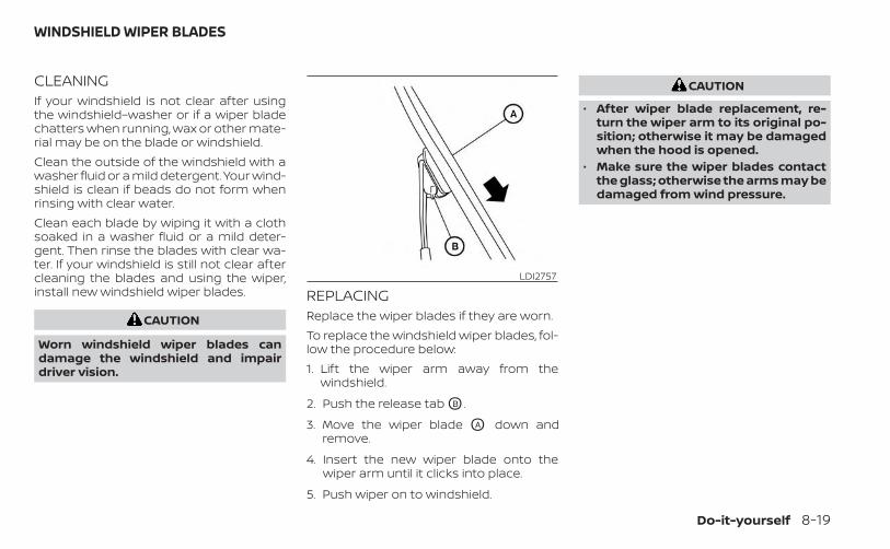
CLEANINGIf your windshield is not clear after usingthe windshield–washer or if a wiper bladechatters when running, wax or other mate-rial may be on the blade or windshield.Clean the outside of the windshield with awasher fluid or a mild detergent. Your wind-shield is clean if beads do not form whenrinsing with clear water.Clean each blade by wiping it with a clothsoaked in a washer fluid or a mild deter-gent. Then rinse the blades with clear wa-ter. If your windshield is still not clear aftercleaning the blades and using the wiper,install new windshield wiper blades.
CAUTION
Worn windshield wiper blades candamage the windshield and impairdriver vision.
REPLACINGReplace the wiper blades if they are worn.To replace the windshield wiper blades, fol-low the procedure below:1. Lift the wiper arm away from the
windshield.
2. Push the release tab OB .
3. Move the wiper blade OA down andremove.
4. Insert the new wiper blade onto thewiper arm until it clicks into place.
5. Push wiper on to windshield.
CAUTION
• After wiper blade replacement, re-turn the wiper arm to its original po-sition; otherwise it may be damagedwhen the hood is opened.
• Make sure the wiper blades contactthe glass; otherwise the arms may bedamaged from wind pressure.
LDI2757
WINDSHIELD WIPER BLADES
Do-it-yourself 8-19
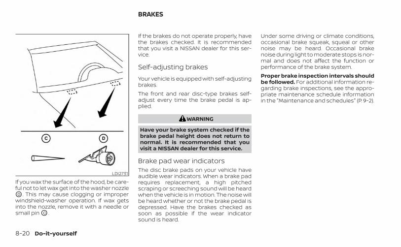
If you wax the surface of the hood, be care-ful not to let wax get into the washer nozzleOD . This may cause clogging or improperwindshield-washer operation. If wax getsinto the nozzle, remove it with a needle orsmall pin OC .
If the brakes do not operate properly, havethe brakes checked. It is recommendedthat you visit a NISSAN dealer for this ser-vice.
Self-adjusting brakes
Your vehicle is equipped with self-adjustingbrakes.The front and rear disc-type brakes self-adjust every time the brake pedal is ap-plied.
WARNING
Have your brake system checked if thebrake pedal height does not return tonormal. It is recommended that youvisit a NISSAN dealer for this service.
Brake pad wear indicatorsThe disc brake pads on your vehicle haveaudible wear indicators. When a brake padrequires replacement, a high pitchedscraping or screeching sound will be heardwhen the vehicle is in motion. The noise willbe heard whether or not the brake pedal isdepressed. Have the brakes checked assoon as possible if the wear indicatorsound is heard.
Under some driving or climate conditions,occasional brake squeak, squeal or othernoise may be heard. Occasional brakenoise during light to moderate stops is nor-mal and does not affect the function orperformance of the brake system.Proper brake inspection intervals shouldbe followed. For additional information re-garding brake inspections, see the appro-priate maintenance schedule informationin the "Maintenance and schedules" (P. 9-2).
LDI2731
BRAKES
8-20 Do-it-yourself
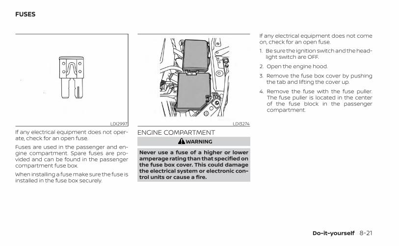
If any electrical equipment does not oper-ate, check for an open fuse.Fuses are used in the passenger and en-gine compartment. Spare fuses are pro-vided and can be found in the passengercompartment fuse box.When installing a fuse make sure the fuse isinstalled in the fuse box securely.
ENGINE COMPARTMENTWARNING
Never use a fuse of a higher or loweramperage rating than that specified onthe fuse box cover. This could damagethe electrical system or electronic con-trol units or cause a fire.
If any electrical equipment does not comeon, check for an open fuse.1. Be sure the ignition switch and the head-
light switch are OFF.
2. Open the engine hood.
3. Remove the fuse box cover by pushingthe tab and lifting the cover up.
4. Remove the fuse with the fuse puller.The fuse puller is located in the centerof the fuse block in the passengercompartment.
LDI2997 LDI3274
FUSES
Do-it-yourself 8-21
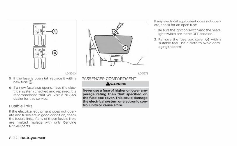
5. If the fuse is open OA , replace it with anew fuse OB .
6. If a new fuse also opens, have the elec-trical system checked and repaired. It isrecommended that you visit a NISSANdealer for this service.
Fusible linksIf the electrical equipment does not oper-ate and fuses are in good condition, checkthe fusible links. If any of these fusible linksare melted, replace with only GenuineNISSAN parts.
PASSENGER COMPARTMENTWARNING
Never use a fuse of higher or lower am-perage rating than that specified onthe fuse box cover. This could damagethe electrical system or electronic con-trol units or cause a fire.
If any electrical equipment does not oper-ate, check for an open fuse.1. Be sure the ignition switch and the head-
light switch are in the OFF position.
2. Remove the fuse box cover OA with asuitable tool. Use a cloth to avoid dam-aging the trim.
LDI3200 LDI3275
8-22 Do-it-yourself
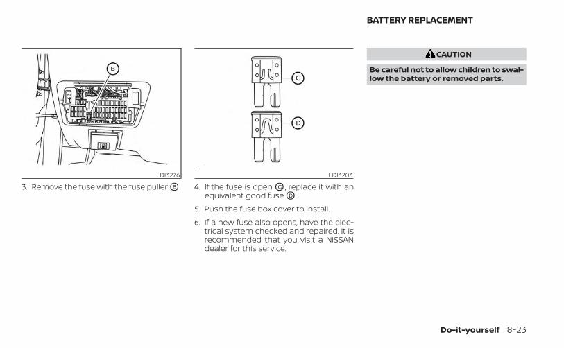
3. Remove the fuse with the fuse puller OB . 4. If the fuse is open OC , replace it with anequivalent good fuse OD .
5. Push the fuse box cover to install.
6. If a new fuse also opens, have the elec-trical system checked and repaired. It isrecommended that you visit a NISSANdealer for this service.
CAUTION
Be careful not to allow children to swal-low the battery or removed parts.
LDI3276 LDI3203
BATTERY REPLACEMENT
Do-it-yourself 8-23
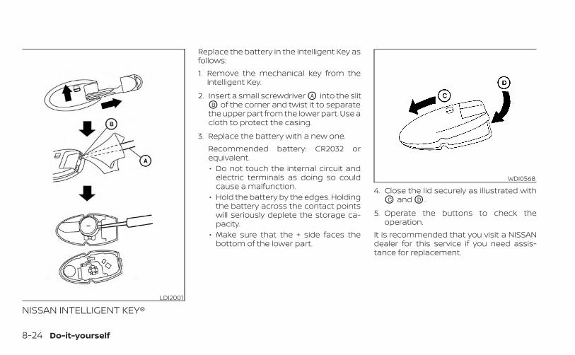
NISSAN INTELLIGENT KEY®
Replace the battery in the Intelligent Key asfollows:1. Remove the mechanical key from the
Intelligent Key.
2. Insert a small screwdriver OA into the slitOB of the corner and twist it to separatethe upper part from the lower part. Use acloth to protect the casing.
3. Replace the battery with a new one.Recommended battery: CR2032 orequivalent.• Do not touch the internal circuit and
electric terminals as doing so couldcause a malfunction.
• Hold the battery by the edges. Holdingthe battery across the contact pointswill seriously deplete the storage ca-pacity.
• Make sure that the + side faces thebottom of the lower part.
4. Close the lid securely as illustrated withOC and OD .
5. Operate the buttons to check theoperation.
It is recommended that you visit a NISSANdealer for this service if you need assis-tance for replacement.
LDI2001
WDI0568
8-24 Do-it-yourself
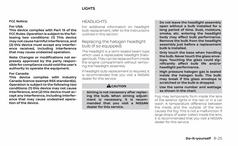
FCC Notice:For USA:This device complies with Part 15 of theFCC Rules. Operation is subject to the fol-lowing two conditions: (1) This devicemay not cause harmful interference, and(2) this device must accept any interfer-ence received, including interferencethat may cause undesired operation.Note: Changes or modifications not ex-pressly approved by the party respon-sible for compliance could void the user’sauthority to operate the equipment.For Canada:This device complies with IndustryCanada licence-exempt RSS standard(s).Operation is subject to the following twoconditions: (1) this device may not causeinterference, and (2) this device must ac-cept any interference, including interfer-ence that may cause undesired opera-tion of the device.
HEADLIGHTSFor additional information on headlightbulb replacement, refer to the instructionsoutlined in this section.
Replacing the halogen headlightbulb (if so equipped)The headlight is a semi-sealed beam typewhich uses a replaceable headlight (halo-gen) bulb. They can be replaced from insidethe engine compartment without remov-ing the headlight assembly.If headlight bulb replacement is required, itis recommended that you visit a NISSANdealer for this service.
CAUTION
• Aiming is not necessary after replac-ing the bulb. When aiming adjust-ment is necessary, it is recom-mended that you visit a NISSANdealer for this service.
• Do not leave the headlight assemblyopen without a bulb installed for along period of time. Dust, moisture,smoke, etc. entering the headlightbody may affect bulb performance.Remove the bulb from the headlightassembly just before a replacementbulb is installed.
• Only touch the base when handlingthe bulb. Never touch the glass enve-lope. Touching the glass could sig-nificantly affect bulb life and/orheadlight performance.
• High pressure halogen gas is sealedinside the halogen bulb. The bulbmay break if the glass envelope isscratched or the bulb is dropped.
• Use the same number and wattageas shown in the chart.
Fog may temporarily form inside the lensof the exterior lights in the rain or in a carwash. A temperature difference betweenthe inside and the outside of the lenscauses the fog. This is not a malfunction. Iflarge drops of water collect inside the lens,it is recommended that you visit a NISSANdealer for this service.
LIGHTS
Do-it-yourself 8-25
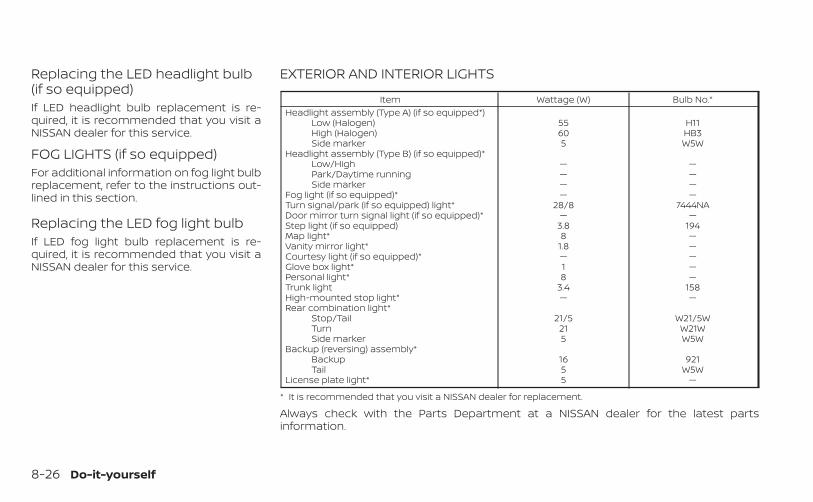
Replacing the LED headlight bulb(if so equipped)If LED headlight bulb replacement is re-quired, it is recommended that you visit aNISSAN dealer for this service.
FOG LIGHTS (if so equipped)For additional information on fog light bulbreplacement, refer to the instructions out-lined in this section.
Replacing the LED fog light bulbIf LED fog light bulb replacement is re-quired, it is recommended that you visit aNISSAN dealer for this service.
EXTERIOR AND INTERIOR LIGHTS
Item Wattage (W) Bulb No.*Headlight assembly (Type A) (if so equipped*)
Low (Halogen) 55 H11High (Halogen) 60 HB3Side marker 5 W5W
Headlight assembly (Type B) (if so equipped)*Low/High — —Park/Daytime running — —Side marker — —
Fog light (if so equipped)* — —Turn signal/park (if so equipped) light* 28/8 7444NADoor mirror turn signal light (if so equipped)* — —Step light (if so equipped) 3.8 194Map light* 8 —Vanity mirror light* 1.8 —Courtesy light (if so equipped)* — —Glove box light* 1 —Personal light* 8 —Trunk light 3.4 158High-mounted stop light* — —Rear combination light*
Stop/Tail 21/5 W21/5WTurn 21 W21WSide marker 5 W5W
Backup (reversing) assembly*Backup 16 921Tail 5 W5W
License plate light* 5 —
* It is recommended that you visit a NISSAN dealer for replacement.
Always check with the Parts Department at a NISSAN dealer for the latest partsinformation.
8-26 Do-it-yourself
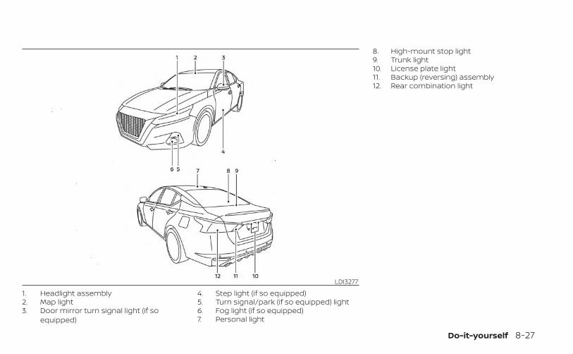
1. Headlight assembly2. Map light3. Door mirror turn signal light (if so
equipped)
4. Step light (if so equipped)5. Turn signal/park (if so equipped) light6. Fog light (if so equipped)7. Personal light
8. High-mount stop light9. Trunk light10. License plate light11. Backup (reversing) assembly12. Rear combination light
LDI3277
Do-it-yourself 8-27
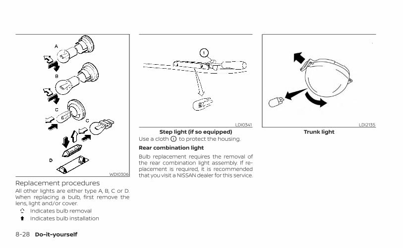
Replacement proceduresAll other lights are either type A, B, C or D.When replacing a bulb, first remove thelens, light and/or cover.
Indicates bulb removalIndicates bulb installation
Use a cloth O1 to protect the housing.Rear combination lightBulb replacement requires the removal ofthe rear combination light assembly. If re-placement is required, it is recommendedthat you visit a NISSAN dealer for this service.WDI0306
LDI0341Step light (if so equipped)
LDI2135Trunk light
8-28 Do-it-yourself
If you have a flat tire, see “Flat tire”(P. 6-3).
TIRE PRESSURE
Tire Pressure Monitoring System(TPMS)
WARNING
Radio waves could adversely af-fect electric medical equipment.Those who use a pacemakershould contact the electric medi-cal equipment manufacturer forthe possible influences beforeuse.
This vehicle is equipped with the TirePressure Monitoring System (TPMS).It monitors tire pressure of all tiresexcept the spare. When the low tirepressure warning light is lit and the“Tire Pressure Low - Add Air” warningappears in the vehicle informationdisplay, one or more of your tires issignificantly under-inflated.
The TPMS will activate only when thevehicle is driven at speeds above 16mph (25 km/h). Also, this systemmay not detect a sudden drop in tirepressure (for example a flat tire whiledriving).For additional information, see “Lowtire pressure warning light” (P. 2-47),“Tire Pressure Monitoring System(TPMS)” (P. 5-5), and “Flat tire” (P. 6-3).
Tire inflation pressureCheck the tire pressures (includingthe spare) often and always prior tolong distance trips. The recom-mended tire pressure specificationsare shown on the F.M.V.S.S./C.M.V.S.S.certification label or the Tire andLoading Information label under the"Cold Tire Pressure" heading. TheTire and Loading Information label isaffixed to the driver side center pillar.Tire pressures should be checkedregularly because:
• Most tires naturally lose air overtime.
• Tires can lose air suddenly whendriven over potholes or other ob-jects or if the vehicle strikes a curbwhile parking.
The tire pressures should bechecked when the tires are cold. Thetires are considered COLD after thevehicle has been parked for 3 ormore hours, or driven less than 1 mile(1.6 km) at moderate speeds.The TPMS with Easy-Fill Tire Alertprovides visual and audible signalsoutside the vehicle for inflating thetires to the recommended COLD tirepressure. For additional information,see “TPMS with Easy-Fill Tire Alert”(P. 5-8).
WHEELS AND TIRES
Do-it-yourself 8-29
If the tires are used at speeds above100 mph (162 km/h) where it is legalto do so (on a race track for ex-ample), the cold tire inflation pres-sure must be increased. For addi-tional information, see “Checking tirepressure” (P. 8-32).Set the tire pressure to the normalcold tire inflation pressure when thevehicle speed or load is reduced.Incorrect tire pressure, includingunder inflation, may adversely af-fect tire life and vehicle handling.
WARNING
• Improperly inflated tires canfail suddenly and cause anaccident.
• The Gross Vehicle Weight Rat-ing (GVWR) is located on theF.M.V.S.S./C.M.V.S.S. certifica-tion label. The vehicle weightcapacity is indicated on the Tireand Loading Information label.Do not load your vehicle be-yond this capacity. Overload-ing your vehicle may result inreduced tire life, unsafe operat-ing conditions due to prema-ture tire failure, or unfavorablehandling characteristics andcould also lead to a serious ac-cident. Loading beyond thespecified capacity may also re-sult in failure of other vehiclecomponents.
• Before taking a long trip, orwhenever you heavily loadyour vehicle, use a tire pressuregauge to ensure that the tirepressures are at the specifiedlevel.
• Increase the cold tire inflationpressure as indicated in"Checking tire pressure"(P. 8-32) when using the tiresspecified by NISSAN above 100mph (162 km/h) where it is le-gal to do so (on a race track forexample). Failure to increasethe cold tire inflation pressuremay result in tire failure, loss ofcontrol and possible injury. Af-ter such use, readjust tirepressure.
• For additional information re-garding tires, refer to “Impor-tant Tire Safety Information”(US) or “Tire Safety Informa-tion” (Canada) in the WarrantyInformation Booklet.
8-30 Do-it-yourself
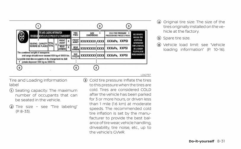
Tire and Loading Informationlabel�1 Seating capacity: The maximum
number of occupants that canbe seated in the vehicle.
�2 Tire size – see “Tire labeling”(P. 8-33).
�3 Cold tire pressure: Inflate the tiresto this pressure when the tires arecold. Tires are considered COLDafter the vehicle has been parkedfor 3 or more hours, or driven lessthan 1 mile (1.6 km) at moderatespeeds. The recommended coldtire inflation is set by the manu-facturer to provide the best bal-ance of tire wear, vehicle handling,driveability, tire noise, etc., up tothe vehicle's GVWR.
�4 Original tire size: The size of thetires originally installed on the ve-hicle at the factory.
�5 Spare tire size.
�6 Vehicle load limit: see “Vehicleloading information” (P. 10-16).
LDI2737
Do-it-yourself 8-31
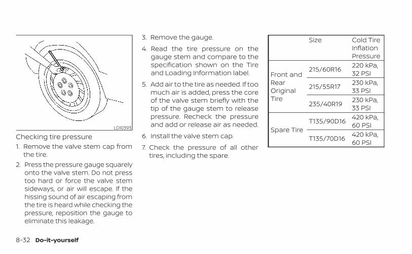
Checking tire pressure1. Remove the valve stem cap from
the tire.2. Press the pressure gauge squarely
onto the valve stem. Do not presstoo hard or force the valve stemsideways, or air will escape. If thehissing sound of air escaping fromthe tire is heard while checking thepressure, reposition the gauge toeliminate this leakage.
3. Remove the gauge.
4. Read the tire pressure on thegauge stem and compare to thespecification shown on the Tireand Loading Information label.
5. Add air to the tire as needed. If toomuch air is added, press the coreof the valve stem briefly with thetip of the gauge stem to releasepressure. Recheck the pressureand add or release air as needed.
6. Install the valve stem cap.
7. Check the pressure of all othertires, including the spare.
Size Cold TireInflationPressure
Front andRearOriginalTire
215/60R16 220 kPa,32 PSI
215/55R17 230 kPa,33 PSI
235/40R19 230 kPa,33 PSI
Spare TireT135/90D16 420 kPa,
60 PSI
T135/70D16 420 kPa,60 PSI
LDI0393
8-32 Do-it-yourself
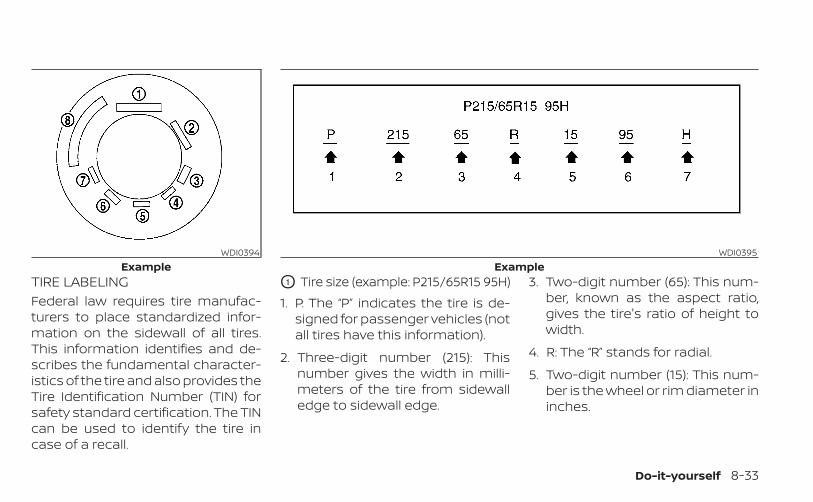
TIRE LABELINGFederal law requires tire manufac-turers to place standardized infor-mation on the sidewall of all tires.This information identifies and de-scribes the fundamental character-istics of the tire and also provides theTire Identification Number (TIN) forsafety standard certification. The TINcan be used to identify the tire incase of a recall.
O1 Tire size (example: P215/65R15 95H)1. P: The “P” indicates the tire is de-
signed for passenger vehicles (notall tires have this information).
2. Three-digit number (215): Thisnumber gives the width in milli-meters of the tire from sidewalledge to sidewall edge.
3. Two-digit number (65): This num-ber, known as the aspect ratio,gives the tire's ratio of height towidth.
4. R: The “R” stands for radial.
5. Two-digit number (15): This num-ber is the wheel or rim diameter ininches.
WDI0394Example
WDI0395Example
Do-it-yourself 8-33
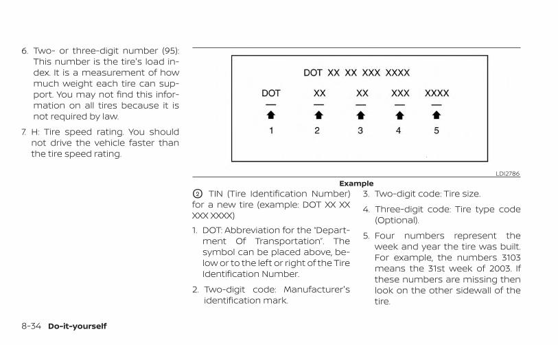
6. Two- or three-digit number (95):This number is the tire's load in-dex. It is a measurement of howmuch weight each tire can sup-port. You may not find this infor-mation on all tires because it isnot required by law.
7. H: Tire speed rating. You shouldnot drive the vehicle faster thanthe tire speed rating.
O2 TIN (Tire Identification Number)for a new tire (example: DOT XX XXXXX XXXX)1. DOT: Abbreviation for the “Depart-
ment Of Transportation”. Thesymbol can be placed above, be-low or to the left or right of the TireIdentification Number.
2. Two-digit code: Manufacturer'sidentification mark.
3. Two-digit code: Tire size.
4. Three-digit code: Tire type code(Optional).
5. Four numbers represent theweek and year the tire was built.For example, the numbers 3103means the 31st week of 2003. Ifthese numbers are missing thenlook on the other sidewall of thetire.
LDI2786Example
8-34 Do-it-yourself
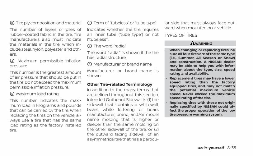
O3 Tire ply composition and materialThe number of layers or plies ofrubber-coated fabric in the tire. Tiremanufacturers also must indicatethe materials in the tire, which in-clude steel, nylon, polyester and oth-ers.
O4 Maximum permissible inflationpressureThis number is the greatest amountof air pressure that should be put inthe tire. Do not exceed the maximumpermissible inflation pressure.
O5 Maximum load ratingThis number indicates the maxi-mum load in kilograms and poundsthat can be carried by the tire. Whenreplacing the tires on the vehicle, al-ways use a tire that has the sameload rating as the factory installedtire.
O6 Term of “tubeless” or “tube type”Indicates whether the tire requiresan inner tube (“tube type”) or not(“tubeless”).
O7 The word “radial”The word “radial” is shown if the tirehas radial structure.
O8 Manufacturer or brand nameManufacturer or brand name isshown.
Other Tire-related TerminologyIn addition to the many terms thatare defined throughout this section,Intended Outboard Sidewall is (1) thesidewall that contains a whitewall,bears white lettering or bearsmanufacturer, brand, and/or modelname molding that is higher ordeeper than the same molding onthe other sidewall of the tire, or (2)the outward facing sidewall of anasymmetrical tire that has a particu-
lar side that must always face out-ward when mounted on a vehicle.
TYPES OF TIRES
WARNING
• When changing or replacing tires, besure all four tires are of the same type(i.e., Summer, All Season or Snow)and construction. A NISSAN dealermay be able to help you with infor-mation about tire type, size, speedrating and availability.
• Replacement tires may have a lowerspeed rating than the factoryequipped tires, and may not matchthe potential maximum vehiclespeed. Never exceed the maximumspeed rating of the tire.
• Replacing tires with those not origi-nally specified by NISSAN could af-fect the proper operation of the lowtire pressure warning system.
Do-it-yourself 8-35
• Always use tires of the same type,size, brand, construction and treadpattern on all four wheels. Failure todo so may result in a circumferencedifference between tires on the frontand rear axles which can cause theVehicle Dynamic Control (VDC) sys-tem to malfunction resulting in per-sonal injury or death, excessive tirewear and may damage the transmis-sion and differential gears.
• For additional information regardingtires, refer to “Important Tire SafetyInformation” (US) or “Tire Safety In-formation” (Canada) in the WarrantyInformation Booklet.
All-Wheel Drive (AWD) models
CAUTION
• ONLY use spare tires specified for theAWD model.
If excessive tire wear is found, it is recom-mended that all four tires be replaced withtires of the same size, brand, constructionand tread pattern. The tire pressure andwheel alignment should also be checkedand corrected as necessary. It is recom-mended that you visit a NISSAN dealer forthis service.
All season tiresNISSAN specifies All Season tires on somemodels to provide good performance allyear, including snowy and icy road condi-tions. All Season tires are identified by ALLSEASON and/or M&S on the tire sidewall.Snow tires have better snow traction thanAll Season tires and may be more appropri-ate in some areas.
Summer tiresNISSAN specifies summer tires on somemodels to provide superior performanceon dry roads. Summer tire performance issubstantially reduced in snow and ice.Summer tires do not have the tire tractionrating “M&S” on the tire sidewall.If you plan to operate your vehicle in snowyor icy conditions, NISSAN recommends theuse of SNOW tires or ALL SEASON tires on allfour wheels.
Snow tiresIf snow tires are needed, it is necessary toselect tires equivalent in size and load rat-ing to the original equipment tires. If you donot, it can adversely affect the safety andhandling of your vehicle.
Generally, snow tires have lower speed rat-ings than factory equipped tires and maynot match the potential maximum vehiclespeed. Never exceed the maximum speedrating of the tire.If you install snow tires, they must be thesame size, brand, construction and treadpattern on all four wheels.For additional traction on icy roads, stud-ded tires may be used. However, some U.S.states and Canadian provinces prohibittheir use. Check local, state and provinciallaws before installing studded tires. Skidand traction capabilities of studded snowtires on wet or dry surfaces may be poorerthan that of non-studded snow tires.
TIRE CHAINS
CAUTION
Only certain SAE class “S” tire chainscan be used on this vehicle. Using thewrong Class “S” chains on this vehiclewill cause damage to the vehicle. If youplan to use tire chains/cables, youshould use a tire chain that meets theminimum clearances for your vehicle.
8-36 Do-it-yourself
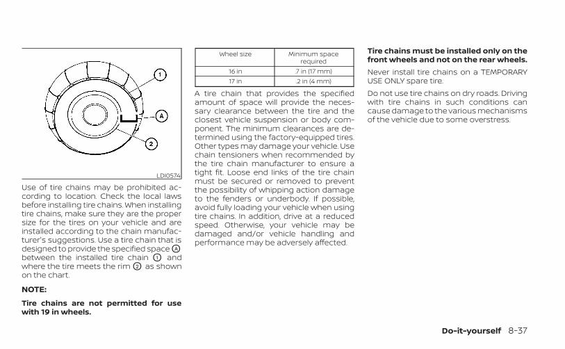
Use of tire chains may be prohibited ac-cording to location. Check the local lawsbefore installing tire chains. When installingtire chains, make sure they are the propersize for the tires on your vehicle and areinstalled according to the chain manufac-turer's suggestions. Use a tire chain that isdesigned to provide the specified space OA
between the installed tire chain O1 andwhere the tire meets the rim O2 as shownon the chart.
NOTE:
Tire chains are not permitted for usewith 19 in wheels.
Wheel size Minimum spacerequired
16 in .7 in (17 mm)17 in .2 in (4 mm)
A tire chain that provides the specifiedamount of space will provide the neces-sary clearance between the tire and theclosest vehicle suspension or body com-ponent. The minimum clearances are de-termined using the factory-equipped tires.Other types may damage your vehicle. Usechain tensioners when recommended bythe tire chain manufacturer to ensure atight fit. Loose end links of the tire chainmust be secured or removed to preventthe possibility of whipping action damageto the fenders or underbody. If possible,avoid fully loading your vehicle when usingtire chains. In addition, drive at a reducedspeed. Otherwise, your vehicle may bedamaged and/or vehicle handling andperformance may be adversely affected.
Tire chains must be installed only on thefront wheels and not on the rear wheels.Never install tire chains on a TEMPORARYUSE ONLY spare tire.Do not use tire chains on dry roads. Drivingwith tire chains in such conditions cancause damage to the various mechanismsof the vehicle due to some overstress.
LDI0574
Do-it-yourself 8-37
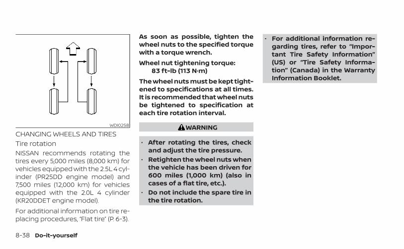
CHANGING WHEELS AND TIRESTire rotationNISSAN recommends rotating thetires every 5,000 miles (8,000 km) forvehicles equipped with the 2.5L 4 cyl-inder (PR25DD engine model) and7,500 miles (12,000 km) for vehiclesequipped with the 2.0L 4 cylinder(KR20DDET engine model).For additional information on tire re-placing procedures, “Flat tire” (P. 6-3).
As soon as possible, tighten thewheel nuts to the specified torquewith a torque wrench.Wheel nut tightening torque:
83 ft-lb (113 N·m)The wheel nuts must be kept tight-ened to specifications at all times.It is recommended that wheel nutsbe tightened to specification ateach tire rotation interval.
WARNING
• After rotating the tires, checkand adjust the tire pressure.
• Retighten the wheel nuts whenthe vehicle has been driven for600 miles (1,000 km) (also incases of a flat tire, etc.).
• Do not include the spare tire inthe tire rotation.
• For additional information re-garding tires, refer to “Impor-tant Tire Safety Information”(US) or “Tire Safety Informa-tion” (Canada) in the WarrantyInformation Booklet.
WDI0258
8-38 Do-it-yourself
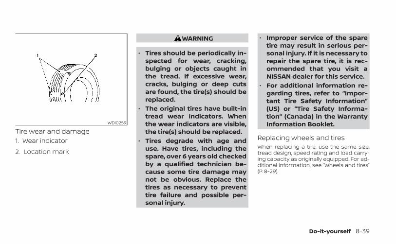
Tire wear and damage1. Wear indicator
2. Location mark
WARNING
• Tires should be periodically in-spected for wear, cracking,bulging or objects caught inthe tread. If excessive wear,cracks, bulging or deep cutsare found, the tire(s) should bereplaced.
• The original tires have built-intread wear indicators. Whenthe wear indicators are visible,the tire(s) should be replaced.
• Tires degrade with age anduse. Have tires, including thespare, over 6 years old checkedby a qualified technician be-cause some tire damage maynot be obvious. Replace thetires as necessary to preventtire failure and possible per-sonal injury.
• Improper service of the sparetire may result in serious per-sonal injury. If it is necessary torepair the spare tire, it is rec-ommended that you visit aNISSAN dealer for this service.
• For additional information re-garding tires, refer to “Impor-tant Tire Safety Information”(US) or “Tire Safety Informa-tion” (Canada) in the WarrantyInformation Booklet.
Replacing wheels and tiresWhen replacing a tire, use the same size,tread design, speed rating and load carry-ing capacity as originally equipped. For ad-ditional information, see “Wheels and tires”(P. 8-29).
WDI0259
Do-it-yourself 8-39
WARNING
• The use of tires other than those rec-ommended or the mixed use of tiresof different brands, construction(bias, bias-belted or radial), or treadpatterns can adversely affect theride, braking, handling, Vehicle Dy-namic Control (VDC) system, groundclearance, body-to-tire clearance,tire chain clearance, speedometercalibration, headlight aim and bum-per height. Some of these effectsmay lead to accidents and could re-sult in serious personal injury.
• If your vehicle was originallyequipped with four tires that werethe same size and you are only re-placing two of the four tires, installthe new tires on the rear axle. Placingnew tires on the front axle may causeloss of vehicle control in some drivingconditions and cause an accidentand personal injury.
• If the wheels are changed for anyreason, always replace with wheelswhich have the same off-set dimen-sion. Wheels of a different off-setcould cause premature tire wear, de-grade vehicle handling characteris-tics, affect the VDC system and/or in-terference with the brake discs. Suchinterference can lead to decreasedbraking efficiency and/or early brakepad wear. For additional informationon wheel off-set dimensions, see“Wheels and tires” (P. 8-29).
• When replacing a wheel without theTPMS, such as the spare tire, theTPMS will not function and the lowtire pressure warning light will flashfor approximately 1 minute. The lightwill remain on after 1 minute. Haveyour tires replaced and/or TPMS sys-tem reset as soon as possible. It isrecommended that you visit aNISSAN dealer for this service.
• Replacing tires with those not origi-nally specified by NISSAN could af-fect the proper operation of theTPMS.
• The TPMS sensor may be damaged ifit is not handled correctly. Be carefulwhen handling the TPMS sensor.
• When replacing the TPMS sensor, theID registration may be required. It isrecommended that you visit aNISSAN dealer for ID registration.
• Do not use a valve stem cap that isnot specified by NISSAN. The valvestem cap may become stuck.
• Be sure that the valve stem caps arecorrectly fitted. Otherwise the valvemay be clogged up with dirt andcause a malfunction or loss ofpressure.
• Do not install a damaged or de-formed wheel or tire even if it hasbeen repaired. Such wheels or tirescould have structural damage andcould fail without warning.
• The use of retread tires is notrecommended.
• For additional information regardingtires, refer to “Important Tire SafetyInformation” (US) or “Tire Safety In-formation” (Canada) in the WarrantyInformation Booklet.
8-40 Do-it-yourself
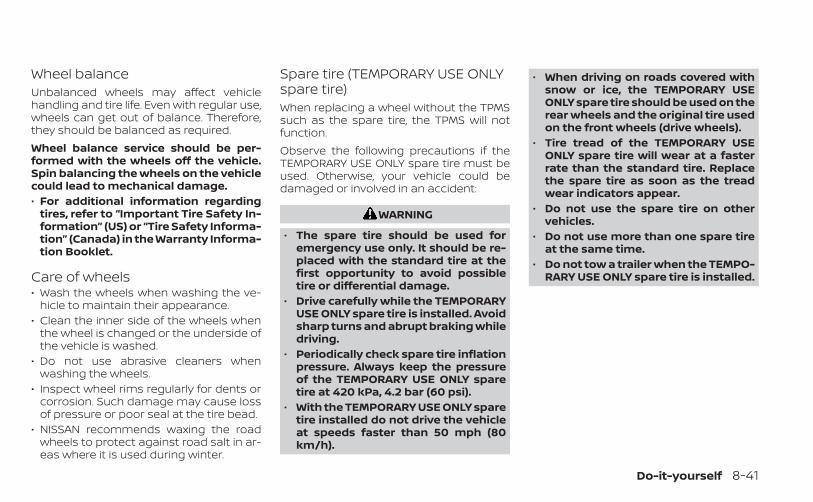
Wheel balanceUnbalanced wheels may affect vehiclehandling and tire life. Even with regular use,wheels can get out of balance. Therefore,they should be balanced as required.Wheel balance service should be per-formed with the wheels off the vehicle.Spin balancing the wheels on the vehiclecould lead to mechanical damage.• For additional information regarding
tires, refer to “Important Tire Safety In-formation” (US) or “Tire Safety Informa-tion” (Canada) in the Warranty Informa-tion Booklet.
Care of wheels• Wash the wheels when washing the ve-
hicle to maintain their appearance.• Clean the inner side of the wheels when
the wheel is changed or the underside ofthe vehicle is washed.
• Do not use abrasive cleaners whenwashing the wheels.
• Inspect wheel rims regularly for dents orcorrosion. Such damage may cause lossof pressure or poor seal at the tire bead.
• NISSAN recommends waxing the roadwheels to protect against road salt in ar-eas where it is used during winter.
Spare tire (TEMPORARY USE ONLYspare tire)When replacing a wheel without the TPMSsuch as the spare tire, the TPMS will notfunction.Observe the following precautions if theTEMPORARY USE ONLY spare tire must beused. Otherwise, your vehicle could bedamaged or involved in an accident:
WARNING
• The spare tire should be used foremergency use only. It should be re-placed with the standard tire at thefirst opportunity to avoid possibletire or differential damage.
• Drive carefully while the TEMPORARYUSE ONLY spare tire is installed. Avoidsharp turns and abrupt braking whiledriving.
• Periodically check spare tire inflationpressure. Always keep the pressureof the TEMPORARY USE ONLY sparetire at 420 kPa, 4.2 bar (60 psi).
• With the TEMPORARY USE ONLY sparetire installed do not drive the vehicleat speeds faster than 50 mph (80km/h).
• When driving on roads covered withsnow or ice, the TEMPORARY USEONLY spare tire should be used on therear wheels and the original tire usedon the front wheels (drive wheels).
• Tire tread of the TEMPORARY USEONLY spare tire will wear at a fasterrate than the standard tire. Replacethe spare tire as soon as the treadwear indicators appear.
• Do not use the spare tire on othervehicles.
• Do not use more than one spare tireat the same time.
• Do not tow a trailer when the TEMPO-RARY USE ONLY spare tire is installed.
Do-it-yourself 8-41
CAUTION
• Do not use tire chains on a TEMPO-RARY USE ONLY spare tire. Tire chainswill not fit properly and may causedamage to the vehicle.
• Because the TEMPORARY USE ONLYspare tire is smaller than the originaltire, ground clearance is reduced. Toavoid damage to the vehicle, do notdrive over obstacles. Also, do notdrive the vehicle through an auto-matic car wash since it may getcaught.
8-42 Do-it-yourself
9 Maintenance and schedules
Maintenance requirements . . . . . . . . . . . . . . . . . . . . . 9-2General maintenance . . . . . . . . . . . . . . . . . . . . . . . . 9-2Scheduled maintenance . . . . . . . . . . . . . . . . . . . . . 9-2Where to go for service . . . . . . . . . . . . . . . . . . . . . . . 9-2
General maintenance . . . . . . . . . . . . . . . . . . . . . . . . . . . 9-2Explanation of general maintenanceitems . . . . . . . . . . . . . . . . . . . . . . . . . . . . . . . . . . . . . . . . 9-2
Explanation of scheduled maintenance items . . . 9-5Emission control system maintenance: . . . . . . 9-6
Chassis and body maintenance: . . . . . . . . . . . . . 9-6Maintenance schedules . . . . . . . . . . . . . . . . . . . . . . . . . 9-7
Additional maintenance items forsevere operating conditions . . . . . . . . . . . . . . . . . . 9-7Oil control system (if so equipped) . . . . . . . . . . . . 9-72.5L 4 cylinder (PR25DD engine model) . . . . . . . . 9-92.0L 4 cylinder (KR20DDET enginemodel) . . . . . . . . . . . . . . . . . . . . . . . . . . . . . . . . . . . . . . 9-28
Some day-to-day and regular mainte-nance is essential to maintain your vehiclegood mechanical condition, as well as itsemissions and engine performance.It is the owner's responsibility to make surethat the scheduled maintenance, as well asgeneral maintenance, is performed.As the vehicle owner, you are the only onewho can ensure that your vehicle receivesproper maintenance. You are a vital link inthe maintenance chain.
GENERAL MAINTENANCEGeneral maintenance includes those itemswhich should be checked during normalday-to-day operation. They are essentialfor proper vehicle operation. It is your re-sponsibility to perform these proceduresregularly as prescribed.Performing general maintenance checksrequires minimal mechanical skill and onlya few general automotive tools.These checks or inspections can be doneby yourself, a qualified technician or, if youprefer, a NISSAN dealer.
SCHEDULED MAINTENANCEThe maintenance items listed in this sec-tion are required to be serviced at regularintervals. However under severe drivingconditions, additional or more frequentmaintenance will be required.
WHERE TO GO FOR SERVICEIf maintenance service is required or yourvehicle appears to malfunction, have thesystems checked and serviced. It is recom-mended that you visit a NISSAN dealer forthis service.NISSAN technicians are well-trained spe-cialists and are kept up-to-date with thelatest service information through techni-cal bulletins, service tips and training pro-grams. They are fully qualified to work onNISSAN vehicles before work begins.If your vehicle is involved in a collision, it isrecommended that you ask your NISSANdealer where the nearest NISSAN CertifiedCollision Center is located, or go to http://collision.nissanusa.com.You can be confident that a NISSAN deal-er's service department can perform theservice needed to meet the maintenancerequirements on your vehicle.
During the normal day-to-day operation ofthe vehicle, general maintenance shouldbe performed regularly as prescribed inthis section. If you detect any unusualsounds, vibrations or smells, be sure tocheck for the cause or have it checkedpromptly. In addition, it is recommendedthat you visit a NISSAN dealer if you thinkthat repairs are required.When performing any checks or mainte-nance work, closely observe the “Mainte-nance precautions” in the “Do-it-yourself ”section of this manual.
EXPLANATION OF GENERALMAINTENANCE ITEMS
WARNING
Failure to follow the procedures listedwithin this section may result in per-sonal injury.
Additional information on the followingitems with “ * ” is found in the “Do-it-yourself” section of this manual.
MAINTENANCE REQUIREMENTS GENERAL MAINTENANCE
9-2 Maintenance and schedules
Outside the vehicleThe maintenance items listed here shouldbe performed from time to time, unlessotherwise specified.Doors and engine hood: Check that thedoors and engine hood operate properly.Also ensure that all latches lock securely.Lubricate hinges, latches, latch pins, rollersand links if necessary. Make sure that thesecondary latch keeps the hood fromopening when the primary latch is re-leased.When driving in areas using road salt orother corrosive materials, check lubrica-tion frequently.Check that the gas strays or struts properlyand securely hold the hood, trunk, or rearhatch in the fully open position. If the hood,trunk, or rear hatch is not held open, havethe gas stays or struts replaced.Lights*: Clean the headlights on a regularbasis. Make sure that the headlights, stoplights, tail lights, turn signal lights, and otherlights are all operating properly and in-stalled securely. Also check headlight aim.Road wheel nuts (lug nuts)*: When check-ing the tires, make sure no wheel nuts are
missing, and check for any loose wheelnuts. Tighten if necessary.Tire rotation*: Rotate tires at the specifiedinterval shown in the maintenance sched-ule.Tires*: Check the pressure with a gaugeoften and always prior to long distancetrips. If necessary, adjust the pressure in alltires, including the spare, to the pressurespecified. Check carefully for damage, cutsor excessive wear.Tire Pressure Monitoring System (TPMS)transmitter components: Replace theTPMS transmitter grommet seal, valve coreand cap when the tires are replaced due towear or age.Wheel alignment and balance: If the ve-hicle should pull to either side while drivingon a straight and level road, or if you detectuneven or abnormal tire wear, there maybe a need for wheel alignment. If the steer-ing wheel or seat vibrates at normal high-way speeds, wheel balancing may beneeded.For additional information regarding tires,refer to “Important Tire Safety Information”(US) or “Tire Safety Information” (Canada) inthe Warranty Information Booklet.
Windshield: Clean the windshield on aregular basis. Check the windshield at leastevery six months for cracks or other dam-age. Have a damaged windshield repairedby a qualified repair facility. It is recom-mended that you have a damaged wind-shield repaired by a NISSAN dealer, or aNISSAN Certified Collision Center. To locatea collision center in your area, refer tohttp://collision.nissanusa.com.Windshield wiper blades*: Check forcracks or wear if they do not wipe properly.
Inside the vehicleThe maintenance items listed here shouldbe checked on a regular basis, such aswhen performing scheduled maintenance,cleaning the vehicle, etc.Accelerator pedal: Check the pedal forsmooth operation and make sure the pedaldoes not catch or require uneven effort.Keep the floor mat away from the pedal.Brake pedal: Check the pedal for smoothoperation. If the brake pedal suddenly goesdown further than normal, the pedal feelsspongy or the vehicle seems to take longerto stop, have your vehicle checked imme-diately. It is recommended that you visit aNISSAN dealer for this service. Keep thefloor mat away from the pedal.
Maintenance and schedules 9-3
Brakes: Check that the brakes do not pullthe vehicle to one side when applied.Continuously Variable Transmission(CVT) P (Park) position mechanism: On afairly steep hill check that the vehicle is heldsecurely with the shift lever in the P (Park)position without applying any brakes.Parking brake: Check the parking brakeoperation regularly. The vehicle should besecurely held on a fairly steep hill with onlythe parking brake applied. If the parkingbrake needs adjustment, it is recom-mended that you visit a NISSAN dealer forthis service.Seats: Check seat position controls suchas seat adjusters, seatback recliner, etc., toensure they operate smoothly and alllatches lock securely in every position.Check that the head restraints/headrestsmove up and down smoothly and the locks(if so equipped) hold securely in all latchedpositions.Seat belts: Check that all parts of the seatbelt system (for example, buckles, anchors,adjusters and retractors) operate properlyand smoothly, and are installed securely.Check the belt webbing for cuts, fraying,wear or damage.
Steering wheel: Check for changes in thesteering system, such as excessive freeplay, hard steering or strange noises.Warning lights and chimes: Make sure allwarning lights and chimes are operatingproperly.Windshield defroster: Check that the aircomes out of the defroster outlets properlyand in sufficient quantity when operatingthe heater or air conditioner.Windshield wiper and washer*: Checkthat the wipers and washer operate prop-erly and that the wipers do not streak.
Under the hood and vehicleThe maintenance items listed here shouldbe checked periodically (for example, eachtime you check the engine oil or refuel).Battery*: This vehicle is equipped with asealed maintenance free battery. It is rec-ommended that you visit a NISSAN dealerfor service.
NOTE:
Care should be taken to avoid situationsthat can lead to potential battery dis-charge and potential no-start conditionssuch as:1. Installation or extended use of elec-
tronic accessories that consume bat-tery power when the engine is not run-ning (Phone chargers, GPS, DVDplayers, etc.).
2. Vehicle is not driven regularly and/oronly driven short distances.
In these cases, the battery may need tobe charged to maintain battery health.Brake fluid level*: Make sure that the brakefluid level is between the MAX and MIN lineson the reservoir.Engine coolant level*: Check the coolantlevel when the engine is cold.Engine drive belts*: Make sure the drivebelts are not frayed, worn, cracked or oily.Engine oil level*: Check the level afterparking the vehicle on a level spot andturning off the engine. Wait more than 15minutes for the oil to drain back into the oilpan.
9-4 Maintenance and schedules
Exhaust system: Make sure there are noloose supports, cracks or holes. If thesound of the exhaust seems unusual orthere is a smell of exhaust fumes, immedi-ately have the exhaust system inspected. Itis recommended that you visit a NISSANdealer for this service. For additional infor-mation, see “Exhaust gas (carbon monox-ide)” (P. 5-4).Fluid leaks: Check under the vehicle forfuel, oil, water or other fluid leaks after thevehicle has been parked for a while. Waterdripping from the air conditioner after useis normal. If you should notice any leaks or iffuel fumes are evident, check for the causeand have it corrected immediately.Radiator and hoses: Check the front of theradiator and clean off any dirt, insects,leaves, etc., that may have accumulated.Make sure the hoses have no cracks, defor-mation, rot or loose connections.Underbody: The underbody is frequentlyexposed to corrosive substances such asthose used on icy roads or to control dust. Itis very important to remove these sub-stances, otherwise rust may form on thefloor pan, frame, fuel lines and around theexhaust system. At the end of winter, theunderbody should be thoroughly flushedwith plain water, being careful to clean
those areas where mud and dirt may accu-mulate. For additional information, see the“Cleaning exterior” (P. 7-2).Windshield-washer fluid*: Check thatthere is adequate fluid in the reservoir.
The following descriptions are provided togive you a better understanding of thescheduled maintenance items that shouldbe regularly checked or replaced. Themaintenance schedule indicates at whichmileage/time intervals each item requiresservice.In addition to scheduled maintenance,your vehicle requires that some items bechecked during normal day-to-day opera-tion. For additional information, see “Gen-eral maintenance” (P. 9-2).Items marked with “*” are recommendedby NISSAN for reliable vehicle operation.You are not required to perform mainte-nance on these items in order to maintainthe warranties which come with yourNISSAN. Other maintenance items and in-tervals are required.When applicable, additional informationcan be found in the “Do-it-yourself ” sectionof this manual.
EXPLANATION OF SCHEDULEDMAINTENANCE ITEMS
Maintenance and schedules 9-5
NOTE:
NISSAN does not advocate the use ofnon-OEM approved aftermarket flush-ing systems and strongly advisesagainst performing these services on aNISSAN product. Many of the aftermar-ket flushing systems use non-OEM ap-proved chemicals or solvents, the use ofwhich has not been validated by NISSAN.For recommended fuel, lubricants, fluids,grease, and refrigerant, see “Recom-mended fluids/lubricants and capaci-ties” (P. 10-2).
EMISSION CONTROL SYSTEMMAINTENANCE:Drive belts*: Check engine drive belts forwear, fraying or cracking and for propertension. Replace any damaged drive belts.Engine air filter: Replace at specified inter-vals. When driving for prolonged periods industy conditions, check/replace the filtermore frequently.Engine coolant*: Replace coolant at thespecified interval. When adding or replac-ing coolant, be sure to use only GenuineNISSAN Long Life Antifreeze/Coolant (blue)or equivalent with the proper mixture. (For
additional information on the proper mix-ture for your area, see “Engine cooling sys-tem” (P. 8-5).NOTE: Mixing any other type of coolantor the use of non-distilled water may re-duce the recommended service intervalof the coolant.Engine oil and oil filter: Replace engine oiland oil filter at the specified intervals. Forrecommended oil grade and viscosity see“Recommended fluids/lubricants and ca-pacities” (P. 10-2).Engine valve clearance*: Inspect only ifvalve noise increases. Adjust valve clear-ance if necessary.Evaporative emissions control vaporlines*: Check vapor lines for leaks or loose-ness. Tighten connections or replace partsas necessary.Fuel filter: Periodic maintenance is not re-quired. (in-tank type filter)Fuel lines*: Check the fuel hoses, pipingand connections for leaks, looseness, ordeterioration. Tighten connections or re-place parts as necessary.Spark plugs: Replace at specified intervals.Install new plugs of the type as originallyequipped.
CHASSIS AND BODYMAINTENANCE:Brake lines and cables: Visually inspect forproper installation. Check for chafing,cracks, deterioration, and signs of leaking.Replace any deteriorated or damagedparts immediately.Brake pads and rotors: Check for wear,deterioration and fluid leaks. Replace anydeteriorated or damaged parts immedi-ately.Exhaust system: Visually inspect the ex-haust pipes, muffler and hangers for leaks,cracks, deterioration, and damage. Tightenconnections or replace parts as necessary.Propeller shaft(s): Check for damage,looseness, and grease leakage. (AWD)In-cabin microfilter: Replace at specifiedintervals. When driving for prolonged peri-ods in dusty conditions, replace the filtermore frequently.Steering gear and linkage, axle and sus-pension parts, drive shaft boots: Checkfor damage, looseness, and leakage of oilor grease. Under severe driving conditions,inspect more frequently.
9-6 Maintenance and schedules
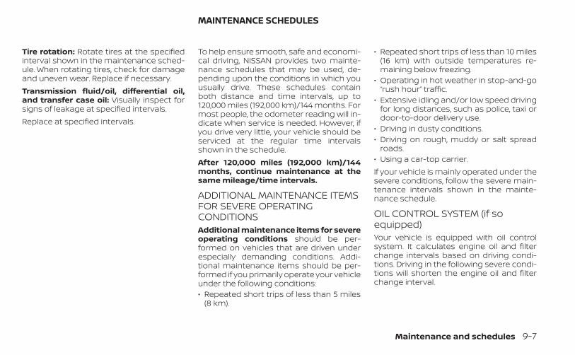
Tire rotation: Rotate tires at the specifiedinterval shown in the maintenance sched-ule. When rotating tires, check for damageand uneven wear. Replace if necessary.Transmission fluid/oil, differential oil,and transfer case oil: Visually inspect forsigns of leakage at specified intervals.Replace at specified intervals.
To help ensure smooth, safe and economi-cal driving, NISSAN provides two mainte-nance schedules that may be used, de-pending upon the conditions in which youusually drive. These schedules containboth distance and time intervals, up to120,000 miles (192,000 km)/144 months. Formost people, the odometer reading will in-dicate when service is needed. However, ifyou drive very little, your vehicle should beserviced at the regular time intervalsshown in the schedule.After 120,000 miles (192,000 km)/144months, continue maintenance at thesame mileage/time intervals.
ADDITIONAL MAINTENANCE ITEMSFOR SEVERE OPERATINGCONDITIONSAdditional maintenance items for severeoperating conditions should be per-formed on vehicles that are driven underespecially demanding conditions. Addi-tional maintenance items should be per-formed if you primarily operate your vehicleunder the following conditions:• Repeated short trips of less than 5 miles
(8 km).
• Repeated short trips of less than 10 miles(16 km) with outside temperatures re-maining below freezing.
• Operating in hot weather in stop-and-go“rush hour” traffic.
• Extensive idling and/or low speed drivingfor long distances, such as police, taxi ordoor-to-door delivery use.
• Driving in dusty conditions.• Driving on rough, muddy or salt spread
roads.• Using a car-top carrier.If your vehicle is mainly operated under thesevere conditions, follow the severe main-tenance intervals shown in the mainte-nance schedule.
OIL CONTROL SYSTEM (if soequipped)Your vehicle is equipped with oil controlsystem. It calculates engine oil and filterchange intervals based on driving condi-tions. Driving in the following severe condi-tions will shorten the engine oil and filterchange interval.
MAINTENANCE SCHEDULES
Maintenance and schedules 9-7
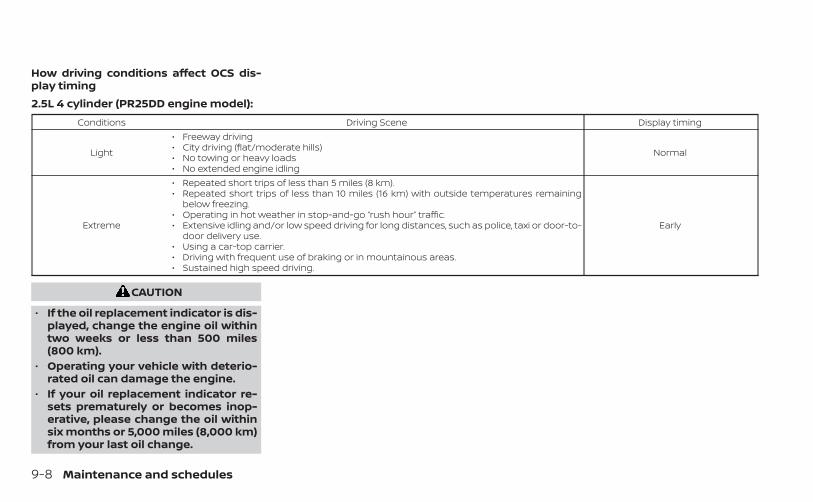
How driving conditions affect OCS dis-play timing2.5L 4 cylinder (PR25DD engine model):
Conditions Driving Scene Display timing
Light
• Freeway driving• City driving (flat/moderate hills)• No towing or heavy loads• No extended engine idling
Normal
Extreme
• Repeated short trips of less than 5 miles (8 km).• Repeated short trips of less than 10 miles (16 km) with outside temperatures remaining
below freezing.• Operating in hot weather in stop-and-go “rush hour” traffic.• Extensive idling and/or low speed driving for long distances, such as police, taxi or door-to-
door delivery use.• Using a car-top carrier.• Driving with frequent use of braking or in mountainous areas.• Sustained high speed driving.
Early
CAUTION
• If the oil replacement indicator is dis-played, change the engine oil withintwo weeks or less than 500 miles(800 km).
• Operating your vehicle with deterio-rated oil can damage the engine.
• If your oil replacement indicator re-sets prematurely or becomes inop-erative, please change the oil withinsix months or 5,000 miles (8,000 km)from your last oil change.
9-8 Maintenance and schedules
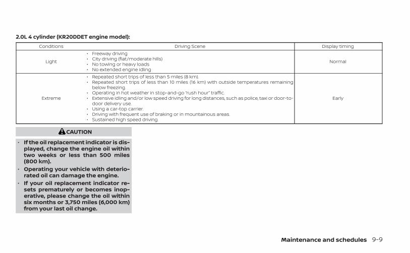
2.0L 4 cylinder (KR20DDET engine model):Conditions Driving Scene Display timing
Light
• Freeway driving• City driving (flat/moderate hills)• No towing or heavy loads• No extended engine idling
Normal
Extreme
• Repeated short trips of less than 5 miles (8 km).• Repeated short trips of less than 10 miles (16 km) with outside temperatures remaining
below freezing.• Operating in hot weather in stop-and-go “rush hour” traffic.• Extensive idling and/or low speed driving for long distances, such as police, taxi or door-to-
door delivery use.• Using a car-top carrier.• Driving with frequent use of braking or in mountainous areas.• Sustained high speed driving.
Early
CAUTION
• If the oil replacement indicator is dis-played, change the engine oil withintwo weeks or less than 500 miles(800 km).
• Operating your vehicle with deterio-rated oil can damage the engine.
• If your oil replacement indicator re-sets prematurely or becomes inop-erative, please change the oil withinsix months or 3,750 miles (6,000 km)from your last oil change.
Maintenance and schedules 9-9
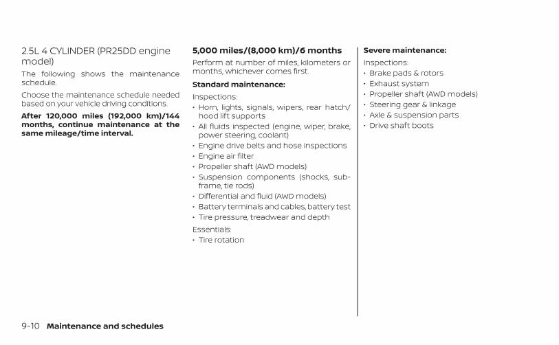
2.5L 4 CYLINDER (PR25DD enginemodel)The following shows the maintenanceschedule.Choose the maintenance schedule neededbased on your vehicle driving conditions.After 120,000 miles (192,000 km)/144months, continue maintenance at thesame mileage/time interval.
5,000 miles/(8,000 km)/6 monthsPerform at number of miles, kilometers ormonths, whichever comes first.
Standard maintenance:Inspections:• Horn, lights, signals, wipers, rear hatch/
hood lift supports• All fluids inspected (engine, wiper, brake,
power steering, coolant)• Engine drive belts and hose inspections• Engine air filter• Propeller shaft (AWD models)• Suspension components (shocks, sub-
frame, tie rods)• Differential and fluid (AWD models)• Battery terminals and cables, battery test• Tire pressure, treadwear and depthEssentials:• Tire rotation
Severe maintenance:Inspections:• Brake pads & rotors• Exhaust system• Propeller shaft (AWD models)• Steering gear & linkage• Axle & suspension parts• Drive shaft boots
9-10 Maintenance and schedules
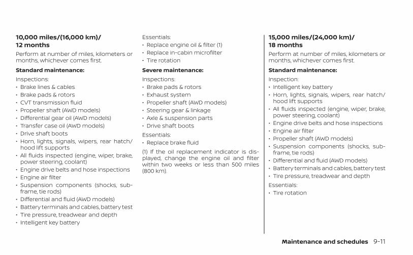
10,000 miles/(16,000 km)/12 monthsPerform at number of miles, kilometers ormonths, whichever comes first.
Standard maintenance:Inspections:• Brake lines & cables• Brake pads & rotors• CVT transmission fluid• Propeller shaft (AWD models)• Differential gear oil (AWD models)• Transfer case oil (AWD models)• Drive shaft boots• Horn, lights, signals, wipers, rear hatch/
hood lift supports• All fluids inspected (engine, wiper, brake,
power steering, coolant)• Engine drive belts and hose inspections• Engine air filter• Suspension components (shocks, sub-
frame, tie rods)• Differential and fluid (AWD models)• Battery terminals and cables, battery test• Tire pressure, treadwear and depth• Intelligent key battery
Essentials:• Replace engine oil & filter (1)• Replace in-cabin microfilter• Tire rotation
Severe maintenance:Inspections:• Brake pads & rotors• Exhaust system• Propeller shaft (AWD models)• Steering gear & linkage• Axle & suspension parts• Drive shaft bootsEssentials:• Replace brake fluid(1) If the oil replacement indicator is dis-played, change the engine oil and filterwithin two weeks or less than 500 miles(800 km).
15,000 miles/(24,000 km)/18 monthsPerform at number of miles, kilometers ormonths, whichever comes first.
Standard maintenance:Inspection:• Intelligent key battery• Horn, lights, signals, wipers, rear hatch/
hood lift supports• All fluids inspected (engine, wiper, brake,
power steering, coolant)• Engine drive belts and hose inspections• Engine air filter• Propeller shaft (AWD models)• Suspension components (shocks, sub-
frame, tie rods)• Differential and fluid (AWD models)• Battery terminals and cables, battery test• Tire pressure, treadwear and depthEssentials:• Tire rotation
Maintenance and schedules 9-11
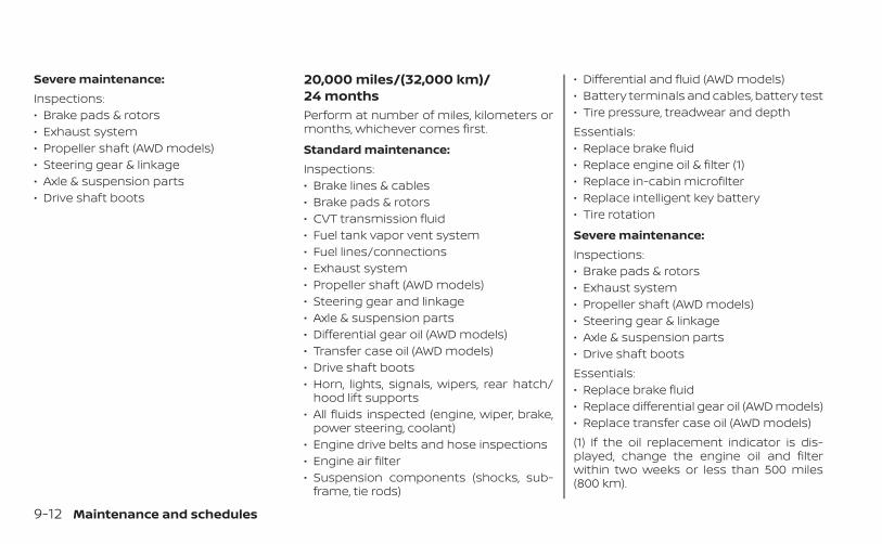
Severe maintenance:Inspections:• Brake pads & rotors• Exhaust system• Propeller shaft (AWD models)• Steering gear & linkage• Axle & suspension parts• Drive shaft boots
20,000 miles/(32,000 km)/24 monthsPerform at number of miles, kilometers ormonths, whichever comes first.
Standard maintenance:Inspections:• Brake lines & cables• Brake pads & rotors• CVT transmission fluid• Fuel tank vapor vent system• Fuel lines/connections• Exhaust system• Propeller shaft (AWD models)• Steering gear and linkage• Axle & suspension parts• Differential gear oil (AWD models)• Transfer case oil (AWD models)• Drive shaft boots• Horn, lights, signals, wipers, rear hatch/
hood lift supports• All fluids inspected (engine, wiper, brake,
power steering, coolant)• Engine drive belts and hose inspections• Engine air filter• Suspension components (shocks, sub-
frame, tie rods)
• Differential and fluid (AWD models)• Battery terminals and cables, battery test• Tire pressure, treadwear and depthEssentials:• Replace brake fluid• Replace engine oil & filter (1)• Replace in-cabin microfilter• Replace intelligent key battery• Tire rotation
Severe maintenance:Inspections:• Brake pads & rotors• Exhaust system• Propeller shaft (AWD models)• Steering gear & linkage• Axle & suspension parts• Drive shaft bootsEssentials:• Replace brake fluid• Replace differential gear oil (AWD models)• Replace transfer case oil (AWD models)(1) If the oil replacement indicator is dis-played, change the engine oil and filterwithin two weeks or less than 500 miles(800 km).
9-12 Maintenance and schedules
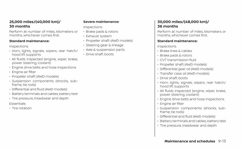
25,000 miles/(40,000 km)/30 monthsPerform at number of miles, kilometers ormonths, whichever comes first.
Standard maintenance:Inspections:• Horn, lights, signals, wipers, rear hatch/
hood lift supports• All fluids inspected (engine, wiper, brake,
power steering, coolant)• Engine drive belts and hose inspections• Engine air filter• Propeller shaft (AWD models)• Suspension components (shocks, sub-
frame, tie rods)• Differential and fluid (AWD models)• Battery terminals and cables, battery test• Tire pressure, treadwear and depthEssentials:• Tire rotation
Severe maintenance:Inspections:• Brake pads & rotors• Exhaust system• Propeller shaft (AWD models)• Steering gear & linkage• Axle & suspension parts• Drive shaft boots
30,000 miles/(48,000 km)/36 monthsPerform at number of miles, kilometers ormonths, whichever comes first.
Standard maintenance:Inspections:• Brake lines & cables• Brake pads & rotors• CVT transmission fluid• Propeller shaft (AWD models)• Differential gear oil (AWD models)• Transfer case oil (AWD models)• Drive shaft boots• Horn, lights, signals, wipers, rear hatch/
hood lift supports• All fluids inspected (engine, wiper, brake,
power steering, coolant)• Engine drive belts and hose inspections• Engine air filter• Suspension components (shocks, sub-
frame, tie rods)• Differential and fluid (AWD models)• Battery terminals and cables, battery test• Tire pressure, treadwear and depth
Maintenance and schedules 9-13
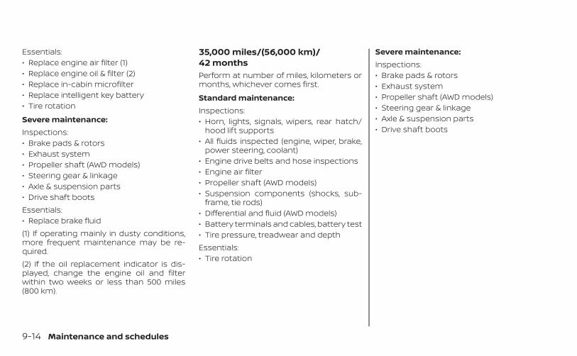
Essentials:• Replace engine air filter (1)• Replace engine oil & filter (2)• Replace in-cabin microfilter• Replace intelligent key battery• Tire rotation
Severe maintenance:Inspections:• Brake pads & rotors• Exhaust system• Propeller shaft (AWD models)• Steering gear & linkage• Axle & suspension parts• Drive shaft bootsEssentials:• Replace brake fluid(1) If operating mainly in dusty conditions,more frequent maintenance may be re-quired.(2) If the oil replacement indicator is dis-played, change the engine oil and filterwithin two weeks or less than 500 miles(800 km).
35,000 miles/(56,000 km)/42 monthsPerform at number of miles, kilometers ormonths, whichever comes first.
Standard maintenance:Inspections:• Horn, lights, signals, wipers, rear hatch/
hood lift supports• All fluids inspected (engine, wiper, brake,
power steering, coolant)• Engine drive belts and hose inspections• Engine air filter• Propeller shaft (AWD models)• Suspension components (shocks, sub-
frame, tie rods)• Differential and fluid (AWD models)• Battery terminals and cables, battery test• Tire pressure, treadwear and depthEssentials:• Tire rotation
Severe maintenance:Inspections:• Brake pads & rotors• Exhaust system• Propeller shaft (AWD models)• Steering gear & linkage• Axle & suspension parts• Drive shaft boots
9-14 Maintenance and schedules
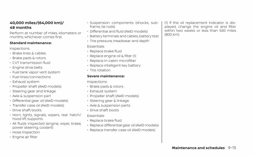
40,000 miles/(64,000 km)/48 monthsPerform at number of miles, kilometers ormonths, whichever comes first.
Standard maintenance:Inspections:• Brake lines & cables• Brake pads & rotors• CVT transmission fluid• Engine drive belts• Fuel tank vapor vent system• Fuel lines/connections• Exhaust system• Propeller shaft (AWD models)• Steering gear and linkage• Axle & suspension part• Differential gear oil (AWD models)• Transfer case oil (AWD models)• Drive shaft boots• Horn, lights, signals, wipers, rear hatch/
hood lift supports• All fluids inspected (engine, wiper, brake,
power steering, coolant)• Hose Inspection• Engine air filter
• Suspension components (shocks, sub-frame, tie rods)
• Differential and fluid (AWD models)• Battery terminals and cables, battery test• Tire pressure, treadwear and depthEssentials:• Replace brake fluid• Replace engine oil & filter (1)• Replace in-cabin microfilter• Replace intelligent key battery• Tire rotation
Severe maintenance:Inspections:• Brake pads & rotors• Exhaust system• Propeller shaft (AWD models)• Steering gear & linkage• Axle & suspension parts• Drive shaft bootsEssentials:• Replace brake fluid• Replace differential gear oil (AWD models)• Replace transfer case oil (AWD models)
(1) If the oil replacement indicator is dis-played, change the engine oil and filterwithin two weeks or less than 500 miles(800 km).
Maintenance and schedules 9-15
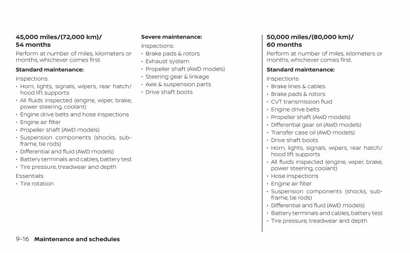
45,000 miles/(72,000 km)/54 monthsPerform at number of miles, kilometers ormonths, whichever comes first.
Standard maintenance:Inspections:• Horn, lights, signals, wipers, rear hatch/
hood lift supports• All fluids inspected (engine, wiper, brake,
power steering, coolant)• Engine drive belts and hose inspections• Engine air filter• Propeller shaft (AWD models)• Suspension components (shocks, sub-
frame, tie rods)• Differential and fluid (AWD models)• Battery terminals and cables, battery test• Tire pressure, treadwear and depthEssentials:• Tire rotation
Severe maintenance:Inspections:• Brake pads & rotors• Exhaust system• Propeller shaft (AWD models)• Steering gear & linkage• Axle & suspension parts• Drive shaft boots
50,000 miles/(80,000 km)/60 monthsPerform at number of miles, kilometers ormonths, whichever comes first.
Standard maintenance:Inspections:• Brake lines & cables• Brake pads & rotors• CVT transmission fluid• Engine drive belts• Propeller shaft (AWD models)• Differential gear oil (AWD models)• Transfer case oil (AWD models)• Drive shaft boots• Horn, lights, signals, wipers, rear hatch/
hood lift supports• All fluids inspected (engine, wiper, brake,
power steering, coolant)• Hose inspections• Engine air filter• Suspension components (shocks, sub-
frame, tie rods)• Differential and fluid (AWD models)• Battery terminals and cables, battery test• Tire pressure, treadwear and depth
9-16 Maintenance and schedules
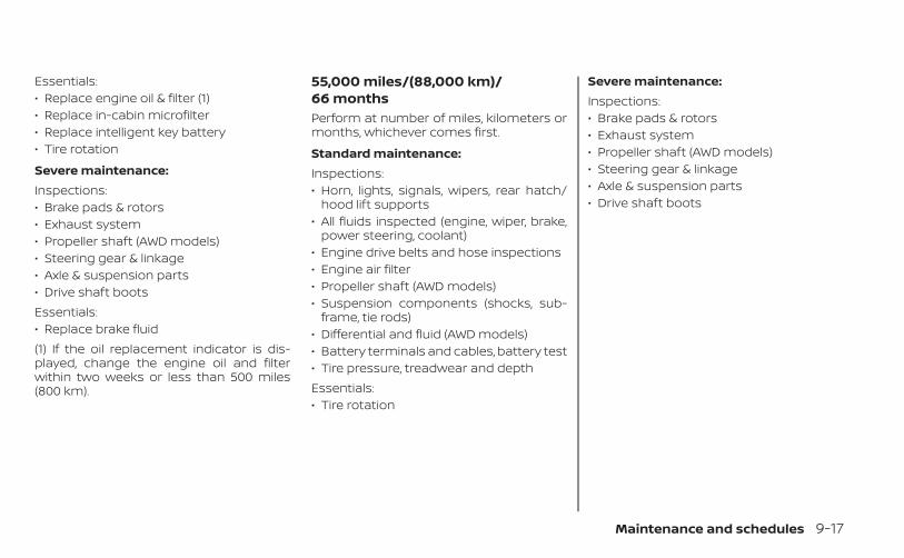
Essentials:• Replace engine oil & filter (1)• Replace in-cabin microfilter• Replace intelligent key battery• Tire rotation
Severe maintenance:Inspections:• Brake pads & rotors• Exhaust system• Propeller shaft (AWD models)• Steering gear & linkage• Axle & suspension parts• Drive shaft bootsEssentials:• Replace brake fluid(1) If the oil replacement indicator is dis-played, change the engine oil and filterwithin two weeks or less than 500 miles(800 km).
55,000 miles/(88,000 km)/66 monthsPerform at number of miles, kilometers ormonths, whichever comes first.
Standard maintenance:Inspections:• Horn, lights, signals, wipers, rear hatch/
hood lift supports• All fluids inspected (engine, wiper, brake,
power steering, coolant)• Engine drive belts and hose inspections• Engine air filter• Propeller shaft (AWD models)• Suspension components (shocks, sub-
frame, tie rods)• Differential and fluid (AWD models)• Battery terminals and cables, battery test• Tire pressure, treadwear and depthEssentials:• Tire rotation
Severe maintenance:Inspections:• Brake pads & rotors• Exhaust system• Propeller shaft (AWD models)• Steering gear & linkage• Axle & suspension parts• Drive shaft boots
Maintenance and schedules 9-17
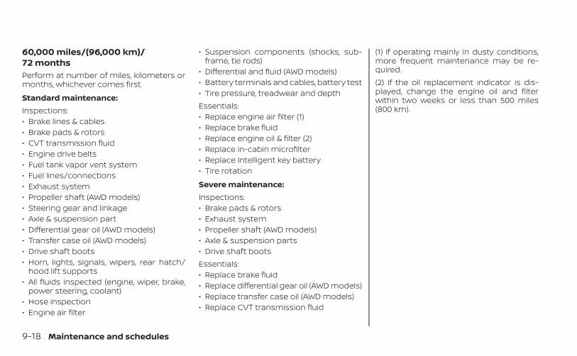
60,000 miles/(96,000 km)/72 monthsPerform at number of miles, kilometers ormonths, whichever comes first.
Standard maintenance:Inspections:• Brake lines & cables• Brake pads & rotors• CVT transmission fluid• Engine drive belts• Fuel tank vapor vent system• Fuel lines/connections• Exhaust system• Propeller shaft (AWD models)• Steering gear and linkage• Axle & suspension part• Differential gear oil (AWD models)• Transfer case oil (AWD models)• Drive shaft boots• Horn, lights, signals, wipers, rear hatch/
hood lift supports• All fluids inspected (engine, wiper, brake,
power steering, coolant)• Hose inspection• Engine air filter
• Suspension components (shocks, sub-frame, tie rods)
• Differential and fluid (AWD models)• Battery terminals and cables, battery test• Tire pressure, treadwear and depthEssentials:• Replace engine air filter (1)• Replace brake fluid• Replace engine oil & filter (2)• Replace in-cabin microfilter• Replace Intelligent key battery• Tire rotation
Severe maintenance:Inspections:• Brake pads & rotors• Exhaust system• Propeller shaft (AWD models)• Axle & suspension parts• Drive shaft bootsEssentials:• Replace brake fluid• Replace differential gear oil (AWD models)• Replace transfer case oil (AWD models)• Replace CVT transmission fluid
(1) If operating mainly in dusty conditions,more frequent maintenance may be re-quired.(2) If the oil replacement indicator is dis-played, change the engine oil and filterwithin two weeks or less than 500 miles(800 km).
9-18 Maintenance and schedules
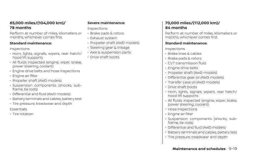
65,000 miles/(104,000 km)/78 monthsPerform at number of miles, kilometers ormonths, whichever comes first.
Standard maintenance:Inspections:• Horn, lights, signals, wipers, rear hatch/
hood lift supports• All fluids inspected (engine, wiper, brake,
power steering, coolant)• Engine drive belts and hose inspections• Engine air filter• Propeller shaft (AWD models)• Suspension components (shocks, sub-
frame, tie rods)• Differential and fluid (AWD models)• Battery terminals and cables, battery test• Tire pressure, treadwear and depthEssentials:• Tire rotation
Severe maintenance:Inspections:• Brake pads & rotors• Exhaust system• Propeller shaft (AWD models)• Steering gear & linkage• Axle & suspension parts• Drive shaft boots
70,000 miles/(112,000 km)/84 monthsPerform at number of miles, kilometers ormonths, whichever comes first.
Standard maintenance:Inspections:• Brake lines & cables• Brake pads & rotors• CVT transmission fluid• Engine drive belts• Propeller shaft (AWD models)• Differential gear oil (AWD models)• Transfer case oil (AWD models)• Drive shaft boots• Horn, lights, signals, wipers, rear hatch/
hood lift supports• All fluids inspected (engine, wiper, brake,
power steering, coolant)• Hose inspections• Engine air filter• Suspension components (shocks, sub-
frame, tie rods)• Differential and fluid (AWD models)• Battery terminals and cables, battery test• Tire pressure, treadwear and depth
Maintenance and schedules 9-19

Essentials:• Replace engine oil & filter (1)• Replace in-cabin microfilter• Replace intelligent key battery• Tire rotation
Severe maintenance:Inspections:• Brake pads & rotors• Exhaust system• Propeller shaft (AWD models)• Steering gear & linkage• Axle & suspension parts• Drive shaft bootsEssentials:• Replace brake fluid(1) If the oil replacement indicator is dis-played, change the engine oil and filterwithin two weeks or less than 500 miles(800 km).
75,000 miles/(120,000 km)/90 monthsPerform at number of miles, kilometers ormonths, whichever comes first.
Standard maintenance:Inspections:• Horn, lights, signals, wipers, rear hatch/
hood lift supports• All fluids inspected (engine, wiper, brake,
power steering, coolant)• Engine drive belts and hose inspections• Engine air filter• Propeller shaft (AWD models)• Suspension components (shocks, sub-
frame, tie rods)• Differential and fluid (AWD models)• Battery terminals and cables, battery test• Tire pressure, treadwear and depthEssentials:• Tire rotation
Severe maintenance:Inspections:• Brake pads & rotors• Exhaust system• Propeller shaft (AWD models)• Steering gear & linkage• Axle & suspension parts• Drive shaft boots
9-20 Maintenance and schedules
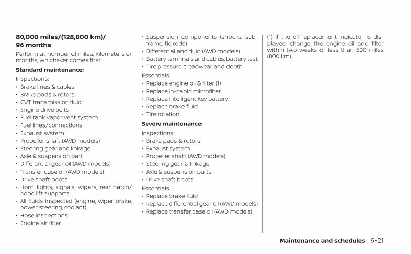
80,000 miles/(128,000 km)/96 monthsPerform at number of miles, kilometers ormonths, whichever comes first.
Standard maintenance:Inspections:• Brake lines & cables• Brake pads & rotors• CVT transmission fluid• Engine drive belts• Fuel tank vapor vent system• Fuel lines/connections• Exhaust system• Propeller shaft (AWD models)• Steering gear and linkage• Axle & suspension part• Differential gear oil (AWD models)• Transfer case oil (AWD models)• Drive shaft boots• Horn, lights, signals, wipers, rear hatch/
hood lift supports• All fluids inspected (engine, wiper, brake,
power steering, coolant)• Hose inspections• Engine air filter
• Suspension components (shocks, sub-frame, tie rods)
• Differential and fluid (AWD models)• Battery terminals and cables, battery test• Tire pressure, treadwear and depthEssentials:• Replace engine oil & filter (1)• Replace in-cabin microfilter• Replace intelligent key battery• Replace brake fluid• Tire rotation
Severe maintenance:Inspections:• Brake pads & rotors• Exhaust system• Propeller shaft (AWD models)• Steering gear & linkage• Axle & suspension parts• Drive shaft bootsEssentials:• Replace brake fluid• Replace differential gear oil (AWD models)• Replace transfer case oil (AWD models)
(1) If the oil replacement indicator is dis-played, change the engine oil and filterwithin two weeks or less than 500 miles(800 km).
Maintenance and schedules 9-21
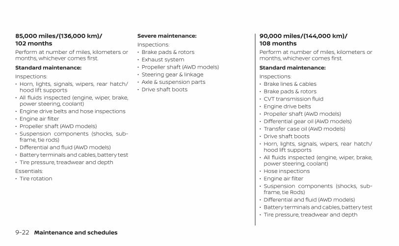
85,000 miles/(136,000 km)/102 monthsPerform at number of miles, kilometers ormonths, whichever comes first.
Standard maintenance:Inspections:• Horn, lights, signals, wipers, rear hatch/
hood lift supports• All fluids inspected (engine, wiper, brake,
power steering, coolant)• Engine drive belts and hose inspections• Engine air filter• Propeller shaft (AWD models)• Suspension components (shocks, sub-
frame, tie rods)• Differential and fluid (AWD models)• Battery terminals and cables, battery test• Tire pressure, treadwear and depthEssentials:• Tire rotation
Severe maintenance:Inspections:• Brake pads & rotors• Exhaust system• Propeller shaft (AWD models)• Steering gear & linkage• Axle & suspension parts• Drive shaft boots
90,000 miles/(144,000 km)/108 monthsPerform at number of miles, kilometers ormonths, whichever comes first.
Standard maintenance:Inspections:• Brake lines & cables• Brake pads & rotors• CVT transmission fluid• Engine drive belts• Propeller shaft (AWD models)• Differential gear oil (AWD models)• Transfer case oil (AWD models)• Drive shaft boots• Horn, lights, signals, wipers, rear hatch/
hood lift supports• All fluids inspected (engine, wiper, brake,
power steering, coolant)• Hose inspections• Engine air filter• Suspension components (shocks, sub-
frame, tie Rods)• Differential and fluid (AWD models)• Battery terminals and cables, battery test• Tire pressure, treadwear and depth
9-22 Maintenance and schedules
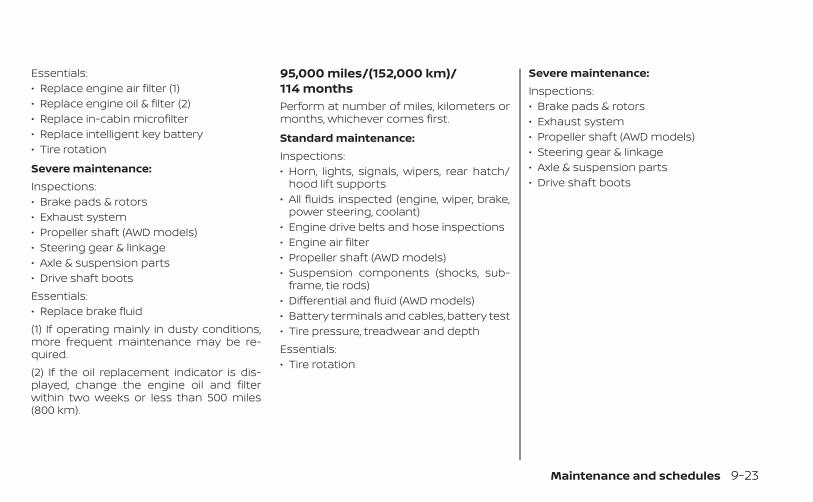
Essentials:• Replace engine air filter (1)• Replace engine oil & filter (2)• Replace in-cabin microfilter• Replace intelligent key battery• Tire rotation
Severe maintenance:Inspections:• Brake pads & rotors• Exhaust system• Propeller shaft (AWD models)• Steering gear & linkage• Axle & suspension parts• Drive shaft bootsEssentials:• Replace brake fluid(1) If operating mainly in dusty conditions,more frequent maintenance may be re-quired.(2) If the oil replacement indicator is dis-played, change the engine oil and filterwithin two weeks or less than 500 miles(800 km).
95,000 miles/(152,000 km)/114 monthsPerform at number of miles, kilometers ormonths, whichever comes first.
Standard maintenance:Inspections:• Horn, lights, signals, wipers, rear hatch/
hood lift supports• All fluids inspected (engine, wiper, brake,
power steering, coolant)• Engine drive belts and hose inspections• Engine air filter• Propeller shaft (AWD models)• Suspension components (shocks, sub-
frame, tie rods)• Differential and fluid (AWD models)• Battery terminals and cables, battery test• Tire pressure, treadwear and depthEssentials:• Tire rotation
Severe maintenance:Inspections:• Brake pads & rotors• Exhaust system• Propeller shaft (AWD models)• Steering gear & linkage• Axle & suspension parts• Drive shaft boots
Maintenance and schedules 9-23
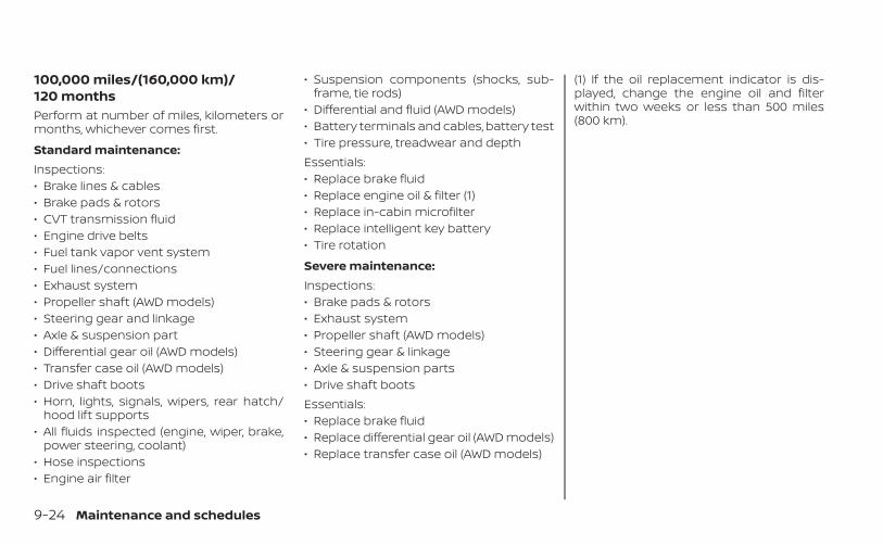
100,000 miles/(160,000 km)/120 monthsPerform at number of miles, kilometers ormonths, whichever comes first.
Standard maintenance:Inspections:• Brake lines & cables• Brake pads & rotors• CVT transmission fluid• Engine drive belts• Fuel tank vapor vent system• Fuel lines/connections• Exhaust system• Propeller shaft (AWD models)• Steering gear and linkage• Axle & suspension part• Differential gear oil (AWD models)• Transfer case oil (AWD models)• Drive shaft boots• Horn, lights, signals, wipers, rear hatch/
hood lift supports• All fluids inspected (engine, wiper, brake,
power steering, coolant)• Hose inspections• Engine air filter
• Suspension components (shocks, sub-frame, tie rods)
• Differential and fluid (AWD models)• Battery terminals and cables, battery test• Tire pressure, treadwear and depthEssentials:• Replace brake fluid• Replace engine oil & filter (1)• Replace in-cabin microfilter• Replace intelligent key battery• Tire rotation
Severe maintenance:Inspections:• Brake pads & rotors• Exhaust system• Propeller shaft (AWD models)• Steering gear & linkage• Axle & suspension parts• Drive shaft bootsEssentials:• Replace brake fluid• Replace differential gear oil (AWD models)• Replace transfer case oil (AWD models)
(1) If the oil replacement indicator is dis-played, change the engine oil and filterwithin two weeks or less than 500 miles(800 km).
9-24 Maintenance and schedules
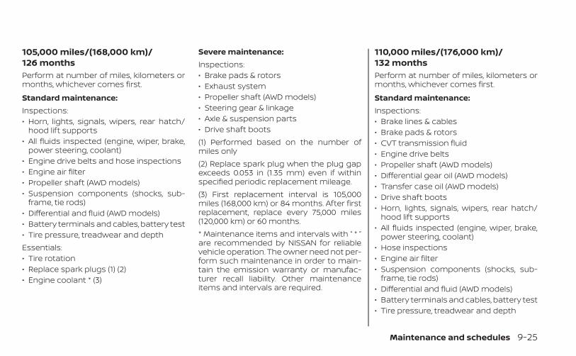
105,000 miles/(168,000 km)/126 monthsPerform at number of miles, kilometers ormonths, whichever comes first.
Standard maintenance:Inspections:• Horn, lights, signals, wipers, rear hatch/
hood lift supports• All fluids inspected (engine, wiper, brake,
power steering, coolant)• Engine drive belts and hose inspections• Engine air filter• Propeller shaft (AWD models)• Suspension components (shocks, sub-
frame, tie rods)• Differential and fluid (AWD models)• Battery terminals and cables, battery test• Tire pressure, treadwear and depthEssentials:• Tire rotation• Replace spark plugs (1) (2)• Engine coolant * (3)
Severe maintenance:Inspections:• Brake pads & rotors• Exhaust system• Propeller shaft (AWD models)• Steering gear & linkage• Axle & suspension parts• Drive shaft boots(1) Performed based on the number ofmiles only(2) Replace spark plug when the plug gapexceeds 0.053 in (1.35 mm) even if withinspecified periodic replacement mileage.(3) First replacement interval is 105,000miles (168,000 km) or 84 months. After firstreplacement, replace every 75,000 miles(120,000 km) or 60 months.* Maintenance items and intervals with “ * ”are recommended by NISSAN for reliablevehicle operation. The owner need not per-form such maintenance in order to main-tain the emission warranty or manufac-turer recall liability. Other maintenanceitems and intervals are required.
110,000 miles/(176,000 km)/132 monthsPerform at number of miles, kilometers ormonths, whichever comes first.
Standard maintenance:Inspections:• Brake lines & cables• Brake pads & rotors• CVT transmission fluid• Engine drive belts• Propeller shaft (AWD models)• Differential gear oil (AWD models)• Transfer case oil (AWD models)• Drive shaft boots• Horn, lights, signals, wipers, rear hatch/
hood lift supports• All fluids inspected (engine, wiper, brake,
power steering, coolant)• Hose inspections• Engine air filter• Suspension components (shocks, sub-
frame, tie rods)• Differential and fluid (AWD models)• Battery terminals and cables, battery test• Tire pressure, treadwear and depth
Maintenance and schedules 9-25
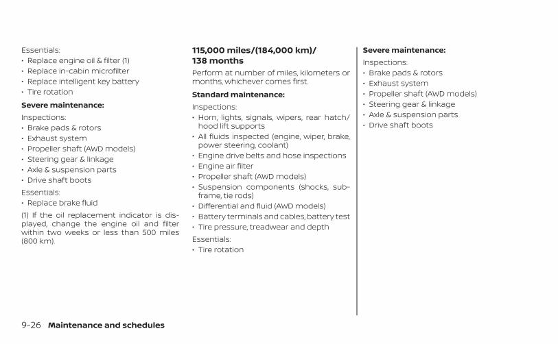
Essentials:• Replace engine oil & filter (1)• Replace in-cabin microfilter• Replace intelligent key battery• Tire rotation
Severe maintenance:Inspections:• Brake pads & rotors• Exhaust system• Propeller shaft (AWD models)• Steering gear & linkage• Axle & suspension parts• Drive shaft bootsEssentials:• Replace brake fluid(1) If the oil replacement indicator is dis-played, change the engine oil and filterwithin two weeks or less than 500 miles(800 km).
115,000 miles/(184,000 km)/138 monthsPerform at number of miles, kilometers ormonths, whichever comes first.
Standard maintenance:Inspections:• Horn, lights, signals, wipers, rear hatch/
hood lift supports• All fluids inspected (engine, wiper, brake,
power steering, coolant)• Engine drive belts and hose inspections• Engine air filter• Propeller shaft (AWD models)• Suspension components (shocks, sub-
frame, tie rods)• Differential and fluid (AWD models)• Battery terminals and cables, battery test• Tire pressure, treadwear and depthEssentials:• Tire rotation
Severe maintenance:Inspections:• Brake pads & rotors• Exhaust system• Propeller shaft (AWD models)• Steering gear & linkage• Axle & suspension parts• Drive shaft boots
9-26 Maintenance and schedules
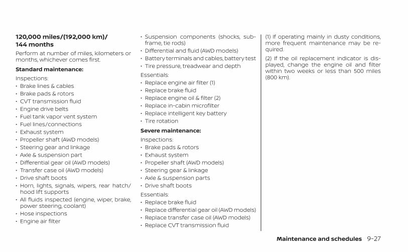
120,000 miles/(192,000 km)/144 monthsPerform at number of miles, kilometers ormonths, whichever comes first.
Standard maintenance:Inspections:• Brake lines & cables• Brake pads & rotors• CVT transmission fluid• Engine drive belts• Fuel tank vapor vent system• Fuel lines/connections• Exhaust system• Propeller shaft (AWD models)• Steering gear and linkage• Axle & suspension part• Differential gear oil (AWD models)• Transfer case oil (AWD models)• Drive shaft boots• Horn, lights, signals, wipers, rear hatch/
hood lift supports• All fluids inspected (engine, wiper, brake,
power steering, coolant)• Hose inspections• Engine air filter
• Suspension components (shocks, sub-frame, tie rods)
• Differential and fluid (AWD models)• Battery terminals and cables, battery test• Tire pressure, treadwear and depthEssentials:• Replace engine air filter (1)• Replace brake fluid• Replace engine oil & filter (2)• Replace in-cabin microfilter• Replace intelligent key battery• Tire rotation
Severe maintenance:Inspections:• Brake pads & rotors• Exhaust system• Propeller shaft (AWD models)• Steering gear & linkage• Axle & suspension parts• Drive shaft bootsEssentials:• Replace brake fluid• Replace differential gear oil (AWD models)• Replace transfer case oil (AWD models)• Replace CVT transmission fluid
(1) If operating mainly in dusty conditions,more frequent maintenance may be re-quired.(2) If the oil replacement indicator is dis-played, change the engine oil and filterwithin two weeks or less than 500 miles(800 km).
Maintenance and schedules 9-27
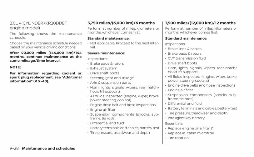
2.0L 4 CYLINDER (KR20DDETengine model)The following shows the maintenanceschedule.Choose the maintenance schedule neededbased on your vehicle driving conditions.After 90,000 miles (144,000 km)/144months, continue maintenance at thesame mileage/time interval.
NOTE:
For information regarding coolant orspark plug replacement, see “Additionalinformation” (P. 9-40).
3,750 miles/(6,000 km)/6 monthsPerform at number of miles, kilometers ormonths, whichever comes first.
Standard maintenance:• Not applicable. Proceed to the next inter-
val.
Severe maintenance:Inspections:• Brake pads & rotors• Exhaust system• Drive shaft boots• Steering gear and linkage• Axle & suspension parts• Horn, lights, signals, wipers, rear hatch/
hood lift supports• All fluids inspected (engine, wiper, brake,
power steering, coolant)• Engine drive belt and hose inspections• Engine air filter• Suspension components (shocks, sub-
frame, tie rods)• Differential and fluid• Battery terminals and cables, battery test• Tire pressure, treadwear and depth
7,500 miles/(12,000 km)/12 monthsPerform at number of miles, kilometers ormonths, whichever comes first.
Standard maintenance:Inspections:• Brake lines & cables• Brake pads & rotors• CVT transmission fluid• Drive shaft boots• Horn, lights, signals, wipers, rear hatch/
hood lift supports• All fluids inspected (engine, wiper, brake,
power steering, coolant)• Engine drive belts and hose inspections• Engine air filter• Suspension components (shocks, sub-
frame, tie rods)• Differential and fluid• Battery terminals and cables, battery test• Tire pressure, treadwear and depth• Intelligent key batteryEssentials:• Replace engine oil & filter (1)• Replace in-cabin microfilter• Tire rotation
9-28 Maintenance and schedules
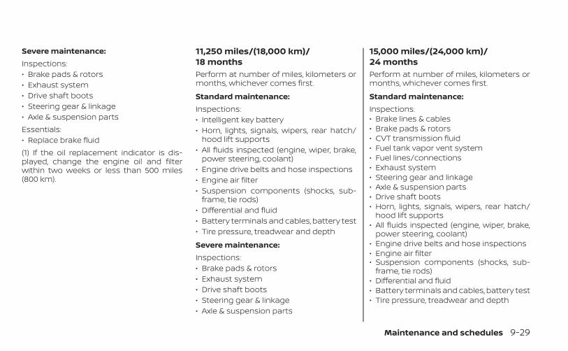
Severe maintenance:Inspections:• Brake pads & rotors• Exhaust system• Drive shaft boots• Steering gear & linkage• Axle & suspension partsEssentials:• Replace brake fluid(1) If the oil replacement indicator is dis-played, change the engine oil and filterwithin two weeks or less than 500 miles(800 km).
11,250 miles/(18,000 km)/18 monthsPerform at number of miles, kilometers ormonths, whichever comes first.
Standard maintenance:Inspections:• Intelligent key battery• Horn, lights, signals, wipers, rear hatch/
hood lift supports• All fluids inspected (engine, wiper, brake,
power steering, coolant)• Engine drive belts and hose inspections• Engine air filter• Suspension components (shocks, sub-
frame, tie rods)• Differential and fluid• Battery terminals and cables, battery test• Tire pressure, treadwear and depth
Severe maintenance:Inspections:• Brake pads & rotors• Exhaust system• Drive shaft boots• Steering gear & linkage• Axle & suspension parts
15,000 miles/(24,000 km)/24 monthsPerform at number of miles, kilometers ormonths, whichever comes first.
Standard maintenance:Inspections:• Brake lines & cables• Brake pads & rotors• CVT transmission fluid• Fuel tank vapor vent system• Fuel lines/connections• Exhaust system• Steering gear and linkage• Axle & suspension parts• Drive shaft boots• Horn, lights, signals, wipers, rear hatch/
hood lift supports• All fluids inspected (engine, wiper, brake,
power steering, coolant)• Engine drive belts and hose inspections• Engine air filter• Suspension components (shocks, sub-
frame, tie rods)• Differential and fluid• Battery terminals and cables, battery test• Tire pressure, treadwear and depth
Maintenance and schedules 9-29
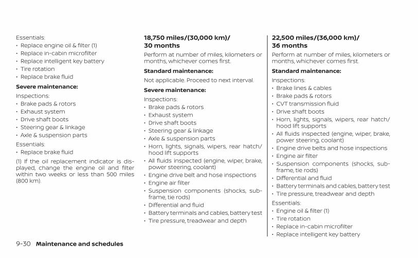
Essentials:• Replace engine oil & filter (1)• Replace in-cabin microfilter• Replace intelligent key battery• Tire rotation• Replace brake fluid
Severe maintenance:Inspections:• Brake pads & rotors• Exhaust system• Drive shaft boots• Steering gear & linkage• Axle & suspension partsEssentials:• Replace brake fluid(1) If the oil replacement indicator is dis-played, change the engine oil and filterwithin two weeks or less than 500 miles(800 km).
18,750 miles/(30,000 km)/30 monthsPerform at number of miles, kilometers ormonths, whichever comes first.
Standard maintenance:Not applicable. Proceed to next interval.
Severe maintenance:Inspections:• Brake pads & rotors• Exhaust system• Drive shaft boots• Steering gear & linkage• Axle & suspension parts• Horn, lights, signals, wipers, rear hatch/
hood lift supports• All fluids inspected (engine, wiper, brake,
power steering, coolant)• Engine drive belt and hose inspections• Engine air filter• Suspension components (shocks, sub-
frame, tie rods)• Differential and fluid• Battery terminals and cables, battery test• Tire pressure, treadwear and depth
22,500 miles/(36,000 km)/36 monthsPerform at number of miles, kilometers ormonths, whichever comes first.
Standard maintenance:Inspections:• Brake lines & cables• Brake pads & rotors• CVT transmission fluid• Drive shaft boots• Horn, lights, signals, wipers, rear hatch/
hood lift supports• All fluids inspected (engine, wiper, brake,
power steering, coolant)• Engine drive belts and hose inspections• Engine air filter• Suspension components (shocks, sub-
frame, tie rods)• Differential and fluid• Battery terminals and cables, battery test• Tire pressure, treadwear and depthEssentials:• Engine oil & filter (1)• Tire rotation• Replace in-cabin microfilter• Replace intelligent key battery
9-30 Maintenance and schedules
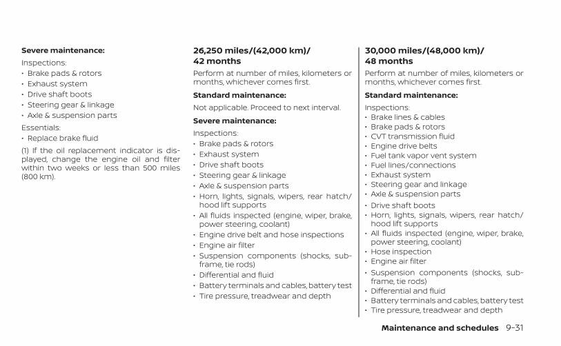
Severe maintenance:Inspections:• Brake pads & rotors• Exhaust system• Drive shaft boots• Steering gear & linkage• Axle & suspension partsEssentials:• Replace brake fluid(1) If the oil replacement indicator is dis-played, change the engine oil and filterwithin two weeks or less than 500 miles(800 km).
26,250 miles/(42,000 km)/42 monthsPerform at number of miles, kilometers ormonths, whichever comes first.
Standard maintenance:Not applicable. Proceed to next interval.
Severe maintenance:Inspections:• Brake pads & rotors• Exhaust system• Drive shaft boots• Steering gear & linkage• Axle & suspension parts• Horn, lights, signals, wipers, rear hatch/
hood lift supports• All fluids inspected (engine, wiper, brake,
power steering, coolant)• Engine drive belt and hose inspections• Engine air filter• Suspension components (shocks, sub-
frame, tie rods)• Differential and fluid• Battery terminals and cables, battery test• Tire pressure, treadwear and depth
30,000 miles/(48,000 km)/48 monthsPerform at number of miles, kilometers ormonths, whichever comes first.
Standard maintenance:Inspections:• Brake lines & cables• Brake pads & rotors• CVT transmission fluid• Engine drive belts• Fuel tank vapor vent system• Fuel lines/connections• Exhaust system• Steering gear and linkage• Axle & suspension parts• Drive shaft boots• Horn, lights, signals, wipers, rear hatch/
hood lift supports• All fluids inspected (engine, wiper, brake,
power steering, coolant)• Hose inspection• Engine air filter• Suspension components (shocks, sub-
frame, tie rods)• Differential and fluid• Battery terminals and cables, battery test• Tire pressure, treadwear and depth
Maintenance and schedules 9-31
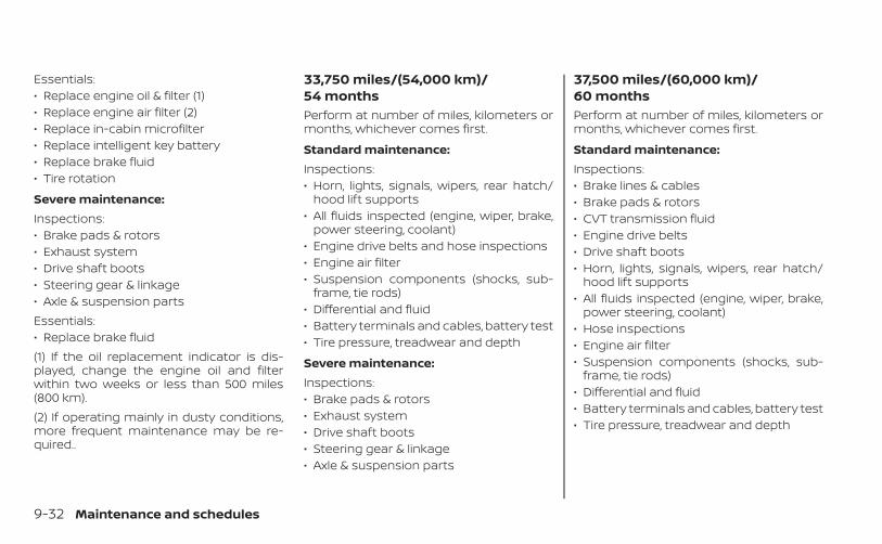
Essentials:• Replace engine oil & filter (1)• Replace engine air filter (2)• Replace in-cabin microfilter• Replace intelligent key battery• Replace brake fluid• Tire rotation
Severe maintenance:Inspections:• Brake pads & rotors• Exhaust system• Drive shaft boots• Steering gear & linkage• Axle & suspension partsEssentials:• Replace brake fluid(1) If the oil replacement indicator is dis-played, change the engine oil and filterwithin two weeks or less than 500 miles(800 km).(2) If operating mainly in dusty conditions,more frequent maintenance may be re-quired..
33,750 miles/(54,000 km)/54 monthsPerform at number of miles, kilometers ormonths, whichever comes first.
Standard maintenance:Inspections:• Horn, lights, signals, wipers, rear hatch/
hood lift supports• All fluids inspected (engine, wiper, brake,
power steering, coolant)• Engine drive belts and hose inspections• Engine air filter• Suspension components (shocks, sub-
frame, tie rods)• Differential and fluid• Battery terminals and cables, battery test• Tire pressure, treadwear and depth
Severe maintenance:Inspections:• Brake pads & rotors• Exhaust system• Drive shaft boots• Steering gear & linkage• Axle & suspension parts
37,500 miles/(60,000 km)/60 monthsPerform at number of miles, kilometers ormonths, whichever comes first.
Standard maintenance:Inspections:• Brake lines & cables• Brake pads & rotors• CVT transmission fluid• Engine drive belts• Drive shaft boots• Horn, lights, signals, wipers, rear hatch/
hood lift supports• All fluids inspected (engine, wiper, brake,
power steering, coolant)• Hose inspections• Engine air filter• Suspension components (shocks, sub-
frame, tie rods)• Differential and fluid• Battery terminals and cables, battery test• Tire pressure, treadwear and depth
9-32 Maintenance and schedules

Essentials:• Replace engine oil & filter (1)• Replace in-cabin microfilter• Replace intelligent key battery• Tire rotation
Severe maintenance:Inspections:• Brake pads & rotors• Exhaust system• Drive shaft boots• Steering gear & linkage• Axle & suspension partsEssentials:• Replace brake fluid(1) If the oil replacement indicator is dis-played, change the engine oil and filterwithin two weeks or less than 500 miles(800 km).
41,250 miles/(66,000 km)/66 monthsPerform at number of miles, kilometers ormonths, whichever comes first.
Standard maintenance:Not applicable. Proceed to next interval.
Severe maintenance:Inspections:• Brake pads & rotors• Exhaust system• Drive shaft boots• Steering gear & linkage• Axle & suspension parts• Horn, lights, signals, wipers, rear hatch/
hood lift supports• All fluids inspected (engine, wiper, brake,
power steering, coolant)• Engine drive belt and hose inspections• Engine air filter• Suspension components (shocks, sub-
frame, tie rods)• Differential and fluid• Battery terminals and cables, battery test• Tire pressure, treadwear and depth
45,000 miles/(72,000 km)/72 monthsPerform at number of miles, kilometers ormonths, whichever comes first.
Standard maintenance:Inspections:• Brake lines & cables• Brake pads & rotors• CVT transmission fluid• Engine drive belts• Fuel tank vapor vent system• Fuel lines/connections• Exhaust system• Steering gear and linkage• Axle & suspension parts• Drive shaft boots• Horn, lights, signals, wipers, rear hatch/
hood lift supports• All fluids inspected (engine, wiper, brake,
power steering, coolant)• Hose inspections• Engine air filter• Suspension components (shocks, sub-
frame, tie rods)• Differential and fluid• Battery terminals and cables, battery test• Tire pressure, treadwear and depth
Maintenance and schedules 9-33
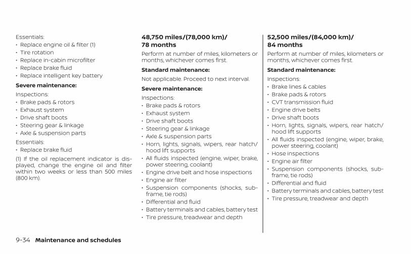
Essentials:• Replace engine oil & filter (1)• Tire rotation• Replace in-cabin microfilter• Replace brake fluid• Replace intelligent key battery
Severe maintenance:Inspections:• Brake pads & rotors• Exhaust system• Drive shaft boots• Steering gear & linkage• Axle & suspension partsEssentials:• Replace brake fluid(1) If the oil replacement indicator is dis-played, change the engine oil and filterwithin two weeks or less than 500 miles(800 km).
48,750 miles/(78,000 km)/78 monthsPerform at number of miles, kilometers ormonths, whichever comes first.
Standard maintenance:Not applicable. Proceed to next interval.
Severe maintenance:Inspections:• Brake pads & rotors• Exhaust system• Drive shaft boots• Steering gear & linkage• Axle & suspension parts• Horn, lights, signals, wipers, rear hatch/
hood lift supports• All fluids inspected (engine, wiper, brake,
power steering, coolant)• Engine drive belt and hose inspections• Engine air filter• Suspension components (shocks, sub-
frame, tie rods)• Differential and fluid• Battery terminals and cables, battery test• Tire pressure, treadwear and depth
52,500 miles/(84,000 km)/84 monthsPerform at number of miles, kilometers ormonths, whichever comes first.
Standard maintenance:Inspections:• Brake lines & cables• Brake pads & rotors• CVT transmission fluid• Engine drive belts• Drive shaft boots• Horn, lights, signals, wipers, rear hatch/
hood lift supports• All fluids inspected (engine, wiper, brake,
power steering, coolant)• Hose inspections• Engine air filter• Suspension components (shocks, sub-
frame, tie rods)• Differential and fluid• Battery terminals and cables, battery test• Tire pressure, treadwear and depth
9-34 Maintenance and schedules
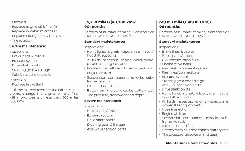
Essentials:• Replace engine oil & filter (1)• Replace in-cabin microfilter• Replace intelligent key battery• Tire rotation
Severe maintenance:Inspections:• Brake pads & rotors• Exhaust system• Drive shaft boots• Steering gear & linkage• Axle & suspension partsEssentials:• Replace brake fluid(1) If the oil replacement indicator is dis-played, change the engine oil and filterwithin two weeks or less than 500 miles(800 km).
56,250 miles/(90,000 km)/90 monthsPerform at number of miles, kilometers ormonths, whichever comes first.
Standard maintenance:Inspections:• Horn, lights, signals, wipers, rear hatch/
hood lift supports• All fluids inspected (engine, wiper, brake,
power steering, coolant)• Engine drive belts and hose inspections• Engine air filter• Suspension components (shocks, sub-
frame, tie rods)• Differential and fluid• Battery terminals and cables, battery test• Tire pressure, treadwear and depth
Severe maintenance:Inspections:• Brake pads & rotors• Exhaust system• Drive shaft boots• Steering gear & linkage• Axle & suspension parts
60,000 miles/(96,000 km)/96 monthsPerform at number of miles, kilometers ormonths, whichever comes first.
Standard maintenance:Inspections:• Brake lines & cables• Brake pads & rotors• CVT transmission fluid• Engine drive belts• Fuel tank vapor vent system• Fuel lines/connections• Exhaust system• Steering gear and linkage• Axle & suspension parts• Drive shaft boots• Horn, lights, signals, wipers, rear hatch/
hood lift supports• All fluids inspected (engine, wiper, brake,
power steering, coolant)• Hose inspection• Engine air filter• Suspension components (shocks, sub-
frame, tie rods)• Differential and fluid• Battery terminals and cables, battery test• Tire pressure, treadwear and depth
Maintenance and schedules 9-35
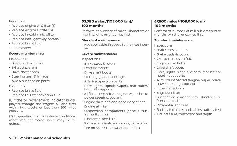
Essentials:• Replace engine oil & filter (1)• Replace engine air filter (2)• Replace in-cabin microfilter• Replace intelligent key battery• Replace brake fluid• Tire rotation
Severe maintenance:Inspections:• Brake pads & rotors• Exhaust system• Drive shaft boots• Steering gear & linkage• Axle & suspension partsEssentials:• Replace brake fluid• Replace CVT transmission fluid(1) If the oil replacement indicator is dis-played, change the engine oil and filterwithin two weeks or less than 500 miles(800 km).(2) If operating mainly in dusty conditions,more frequent maintenance may be re-quired..
63,750 miles/(102,000 km)/102 monthsPerform at number of miles, kilometers ormonths, whichever comes first.
Standard maintenance:• Not applicable. Proceed to the next inter-
val.
Severe maintenance:Inspections:• Brake pads & rotors• Exhaust system• Drive shaft boots• Steering gear and linkage• Axle & suspension parts• Horn, lights, signals, wipers, rear hatch/
hood lift supports• All fluids inspected (engine, wiper, brake,
power steering, coolant)• Engine drive belt and hose inspections• Engine air filter• Suspension components (shocks, sub-
frame, tie rods)• Differential and fluid• Battery terminals and cables, battery test• Tire pressure, treadwear and depth
67,500 miles/(108,000 km)/108 monthsPerform at number of miles, kilometers ormonths, whichever comes first.
Standard maintenance:Inspections:• Brake lines & cables• Brake pads & rotors• CVT transmission fluid• Engine drive belts• Drive shaft boots• Horn, lights, signals, wipers, rear hatch/
hood lift supports• All fluids inspected (engine, wiper, brake,
power steering, coolant)• Hose inspections• Engine air filter• Suspension components (shocks, sub-
frame, tie rods)• Differential and fluid• Battery terminals and cables, battery test• Tire pressure, treadwear and depth
9-36 Maintenance and schedules
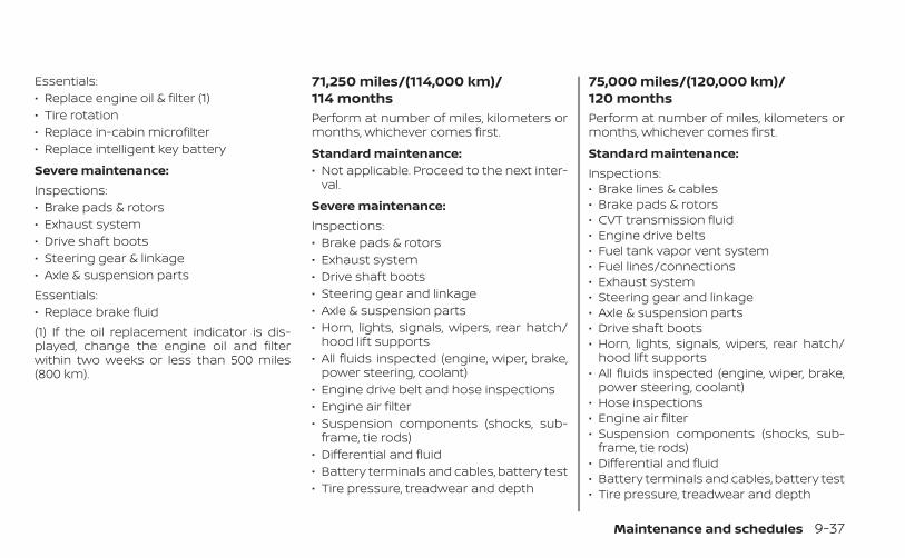
Essentials:• Replace engine oil & filter (1)• Tire rotation• Replace in-cabin microfilter• Replace intelligent key battery
Severe maintenance:Inspections:• Brake pads & rotors• Exhaust system• Drive shaft boots• Steering gear & linkage• Axle & suspension partsEssentials:• Replace brake fluid(1) If the oil replacement indicator is dis-played, change the engine oil and filterwithin two weeks or less than 500 miles(800 km).
71,250 miles/(114,000 km)/114 monthsPerform at number of miles, kilometers ormonths, whichever comes first.
Standard maintenance:• Not applicable. Proceed to the next inter-
val.
Severe maintenance:Inspections:• Brake pads & rotors• Exhaust system• Drive shaft boots• Steering gear and linkage• Axle & suspension parts• Horn, lights, signals, wipers, rear hatch/
hood lift supports• All fluids inspected (engine, wiper, brake,
power steering, coolant)• Engine drive belt and hose inspections• Engine air filter• Suspension components (shocks, sub-
frame, tie rods)• Differential and fluid• Battery terminals and cables, battery test• Tire pressure, treadwear and depth
75,000 miles/(120,000 km)/120 monthsPerform at number of miles, kilometers ormonths, whichever comes first.
Standard maintenance:Inspections:• Brake lines & cables• Brake pads & rotors• CVT transmission fluid• Engine drive belts• Fuel tank vapor vent system• Fuel lines/connections• Exhaust system• Steering gear and linkage• Axle & suspension parts• Drive shaft boots• Horn, lights, signals, wipers, rear hatch/
hood lift supports• All fluids inspected (engine, wiper, brake,
power steering, coolant)• Hose inspections• Engine air filter• Suspension components (shocks, sub-
frame, tie rods)• Differential and fluid• Battery terminals and cables, battery test• Tire pressure, treadwear and depth
Maintenance and schedules 9-37
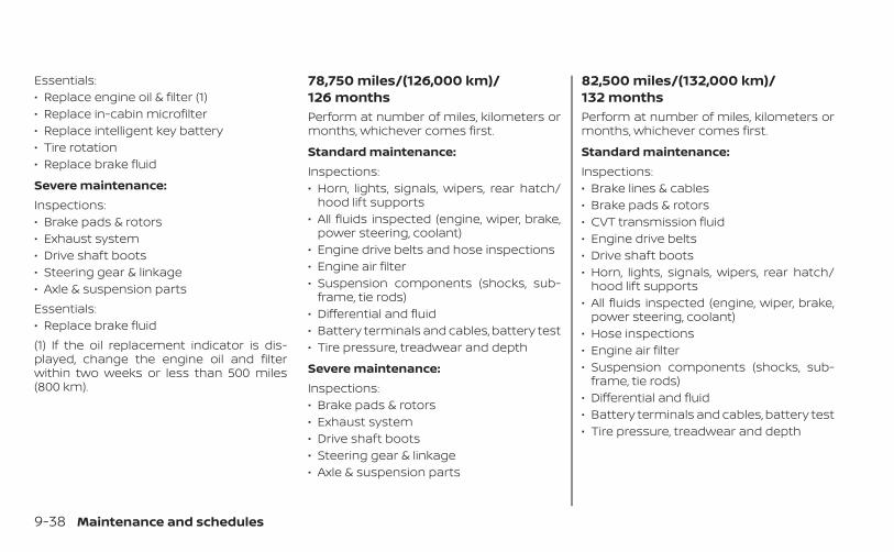
Essentials:• Replace engine oil & filter (1)• Replace in-cabin microfilter• Replace intelligent key battery• Tire rotation• Replace brake fluid
Severe maintenance:Inspections:• Brake pads & rotors• Exhaust system• Drive shaft boots• Steering gear & linkage• Axle & suspension partsEssentials:• Replace brake fluid(1) If the oil replacement indicator is dis-played, change the engine oil and filterwithin two weeks or less than 500 miles(800 km).
78,750 miles/(126,000 km)/126 monthsPerform at number of miles, kilometers ormonths, whichever comes first.
Standard maintenance:Inspections:• Horn, lights, signals, wipers, rear hatch/
hood lift supports• All fluids inspected (engine, wiper, brake,
power steering, coolant)• Engine drive belts and hose inspections• Engine air filter• Suspension components (shocks, sub-
frame, tie rods)• Differential and fluid• Battery terminals and cables, battery test• Tire pressure, treadwear and depth
Severe maintenance:Inspections:• Brake pads & rotors• Exhaust system• Drive shaft boots• Steering gear & linkage• Axle & suspension parts
82,500 miles/(132,000 km)/132 monthsPerform at number of miles, kilometers ormonths, whichever comes first.
Standard maintenance:Inspections:• Brake lines & cables• Brake pads & rotors• CVT transmission fluid• Engine drive belts• Drive shaft boots• Horn, lights, signals, wipers, rear hatch/
hood lift supports• All fluids inspected (engine, wiper, brake,
power steering, coolant)• Hose inspections• Engine air filter• Suspension components (shocks, sub-
frame, tie rods)• Differential and fluid• Battery terminals and cables, battery test• Tire pressure, treadwear and depth
9-38 Maintenance and schedules
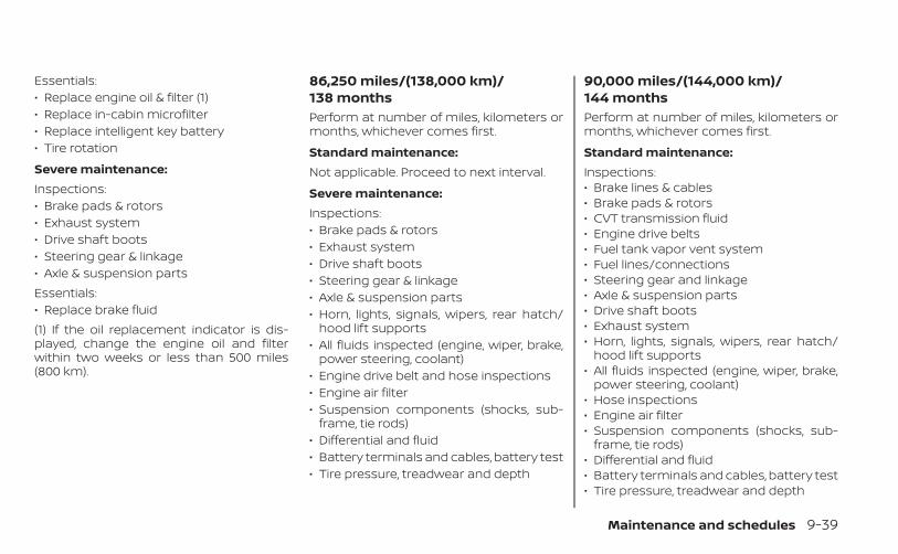
Essentials:• Replace engine oil & filter (1)• Replace in-cabin microfilter• Replace intelligent key battery• Tire rotation
Severe maintenance:Inspections:• Brake pads & rotors• Exhaust system• Drive shaft boots• Steering gear & linkage• Axle & suspension partsEssentials:• Replace brake fluid(1) If the oil replacement indicator is dis-played, change the engine oil and filterwithin two weeks or less than 500 miles(800 km).
86,250 miles/(138,000 km)/138 monthsPerform at number of miles, kilometers ormonths, whichever comes first.
Standard maintenance:Not applicable. Proceed to next interval.
Severe maintenance:Inspections:• Brake pads & rotors• Exhaust system• Drive shaft boots• Steering gear & linkage• Axle & suspension parts• Horn, lights, signals, wipers, rear hatch/
hood lift supports• All fluids inspected (engine, wiper, brake,
power steering, coolant)• Engine drive belt and hose inspections• Engine air filter• Suspension components (shocks, sub-
frame, tie rods)• Differential and fluid• Battery terminals and cables, battery test• Tire pressure, treadwear and depth
90,000 miles/(144,000 km)/144 monthsPerform at number of miles, kilometers ormonths, whichever comes first.
Standard maintenance:Inspections:• Brake lines & cables• Brake pads & rotors• CVT transmission fluid• Engine drive belts• Fuel tank vapor vent system• Fuel lines/connections• Steering gear and linkage• Axle & suspension parts• Drive shaft boots• Exhaust system• Horn, lights, signals, wipers, rear hatch/
hood lift supports• All fluids inspected (engine, wiper, brake,
power steering, coolant)• Hose inspections• Engine air filter• Suspension components (shocks, sub-
frame, tie rods)• Differential and fluid• Battery terminals and cables, battery test• Tire pressure, treadwear and depth
Maintenance and schedules 9-39
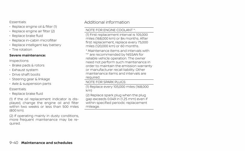
Essentials:• Replace engine oil & filter (1)• Replace engine air filter (2)• Replace brake fluid• Replace in-cabin microfilter• Replace intelligent key battery• Tire rotation
Severe maintenance:Inspections:• Brake pads & rotors• Exhaust system• Drive shaft boots• Steering gear & linkage• Axle & suspension partsEssentials:• Replace brake fluid(1) If the oil replacement indicator is dis-played, change the engine oil and filterwithin two weeks or less than 500 miles(800 km).(2) If operating mainly in dusty conditions,more frequent maintenance may be re-quired.
Additional information
NOTE FOR ENGINE COOLANT *:(1) First replacement interval is 105,000miles (168,000 km) or 84 months. Afterfirst replacement, replace every 75,000miles (120,000 km) or 60 months.* Maintenance items and intervals with“*” are recommended by NISSAN forreliable vehicle operation. The ownerneed not perform such maintenance inorder to maintain the emission warrantyor manufacturer recall liability. Othermaintenance items and intervals arerequired.NOTE FOR SPARK PLUGS:(1) Replace every 105,000 miles (168,000km)(2) Replace spark plug when the pluggap exceeds 0.049 in (1.25 mm) even ifwithin specified periodic replacementmileage.
9-40 Maintenance and schedules
10 Technical and consumer information
Recommended fluids/lubricants andcapacities . . . . . . . . . . . . . . . . . . . . . . . . . . . . . . . . . . . . . . 10-2
Fuel recommendation . . . . . . . . . . . . . . . . . . . . . . 10-4Engine oil and oil filterrecommendations . . . . . . . . . . . . . . . . . . . . . . . . . . 10-7Air conditioner system refrigerant andoil recommendations . . . . . . . . . . . . . . . . . . . . . . . 10-8
Specifications . . . . . . . . . . . . . . . . . . . . . . . . . . . . . . . . . . 10-9Engine . . . . . . . . . . . . . . . . . . . . . . . . . . . . . . . . . . . . . . 10-9Wheels and tires . . . . . . . . . . . . . . . . . . . . . . . . . . . 10-10Dimensions and weights . . . . . . . . . . . . . . . . . . . 10-10
When traveling or registering in anothercountry . . . . . . . . . . . . . . . . . . . . . . . . . . . . . . . . . . . . . . . 10-12Vehicle identification . . . . . . . . . . . . . . . . . . . . . . . . . . 10-12
Vehicle Identification Number (VIN)plate . . . . . . . . . . . . . . . . . . . . . . . . . . . . . . . . . . . . . . . 10-12Vehicle identification number(chassis number) . . . . . . . . . . . . . . . . . . . . . . . . . . . 10-12Engine serial number . . . . . . . . . . . . . . . . . . . . . . 10-13F.M.V.S.S./C.M.V.S.S. certification label . . . . . . . . 10-13Emission control information label . . . . . . . . . 10-14Tire and Loading Information label . . . . . . . . . 10-14
Air conditioner specification label . . . . . . . . . . 10-14Installing front license plate . . . . . . . . . . . . . . . . . . . 10-15Vehicle loading information . . . . . . . . . . . . . . . . . . . 10-16
Terms . . . . . . . . . . . . . . . . . . . . . . . . . . . . . . . . . . . . . . 10-16Vehicle load capacity . . . . . . . . . . . . . . . . . . . . . . . 10-17Loading tips . . . . . . . . . . . . . . . . . . . . . . . . . . . . . . . . 10-18Measurement of weights . . . . . . . . . . . . . . . . . . . 10-19
Towing a trailer . . . . . . . . . . . . . . . . . . . . . . . . . . . . . . . . 10-19Flat towing . . . . . . . . . . . . . . . . . . . . . . . . . . . . . . . . . 10-19
Uniform tire quality grading . . . . . . . . . . . . . . . . . . . 10-20Emission control system warranty . . . . . . . . . . . . 10-21Reporting safety defects . . . . . . . . . . . . . . . . . . . . . . 10-21Readiness for Inspection/Maintenance (I/M)test . . . . . . . . . . . . . . . . . . . . . . . . . . . . . . . . . . . . . . . . . . . 10-22Event Data Recorders (EDR) . . . . . . . . . . . . . . . . . . . 10-23
Additional Data Recording (on vehiclesequipped with optional ProPILOTAssist) . . . . . . . . . . . . . . . . . . . . . . . . . . . . . . . . . . . . . . 10-23
Owner's Manual/Service Manual orderinformation . . . . . . . . . . . . . . . . . . . . . . . . . . . . . . . . . . . 10-24
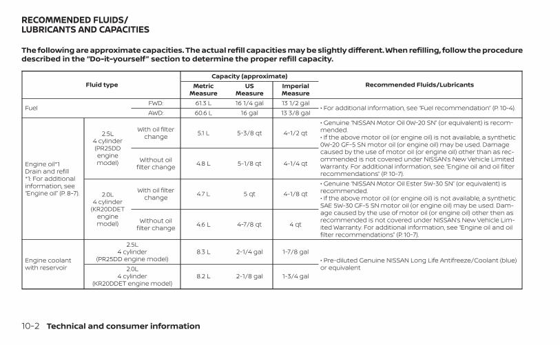
The following are approximate capacities. The actual refill capacities may be slightly different. When refilling, follow the proceduredescribed in the “Do-it-yourself” section to determine the proper refill capacity.
Fluid typeCapacity (approximate)
Recommended Fluids/LubricantsMetricMeasure
USMeasure
ImperialMeasure
FuelFWD: 61.3 L 16 1/4 gal 13 1/2 gal
• For additional information, see “Fuel recommendation” (P. 10-4).AWD: 60.6 L 16 gal 13 3/8 gal
Engine oil*1Drain and refill*1: For additionalinformation, see“Engine oil” (P. 8-7).
2.5L4 cylinder(PR25DDenginemodel)
With oil filterchange 5.1 L 5-3/8 qt 4-1/2 qt
• Genuine “NISSAN Motor Oil 0W-20 SN” (or equivalent) is recom-mended.• If the above motor oil (or engine oil) is not available, a synthetic0W-20 GF-5 SN motor oil (or engine oil) may be used. Damagecaused by the use of motor oil (or engine oil) other than as rec-ommended is not covered under NISSAN’s New Vehicle LimitedWarranty. For additional information, see “Engine oil and oil filterrecommendations” (P. 10-7).
Without oilfilter change 4.8 L 5-1/8 qt 4-1/4 qt
2.0L4 cylinder
(KR20DDETenginemodel)
With oil filterchange 4.7 L 5 qt 4-1/8 qt
• Genuine “NISSAN Motor Oil Ester 5W-30 SN” (or equivalent) isrecommended.• If the above motor oil (or engine oil) is not available, a syntheticSAE 5W-30 GF-5 SN motor oil (or engine oil) may be used. Dam-age caused by the use of motor oil (or engine oil) other then asrecommended is not covered under NISSAN’s New Vehicle Lim-ited Warranty. For additional information, see “Engine oil and oilfilter recommendations” (P. 10-7).
Without oilfilter change 4.6 L 4-7/8 qt 4 qt
Engine coolantwith reservoir
2.5L4 cylinder
(PR25DD engine model)8.3 L 2-1/4 gal 1-7/8 gal
• Pre-diluted Genuine NISSAN Long Life Antifreeze/Coolant (blue)or equivalent2.0L
4 cylinder(KR20DDET engine model)
8.2 L 2-1/8 gal 1-3/4 gal
RECOMMENDED FLUIDS/LUBRICANTS AND CAPACITIES
10-2 Technical and consumer information
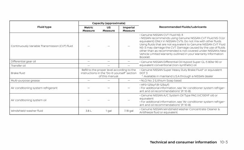
Fluid typeCapacity (approximate)
Recommended Fluids/LubricantsMetricMeasure
USMeasure
ImperialMeasure
Continuously Variable Transmission (CVT) fluid — — —
• Genuine NISSAN CVT Fluid NS-3• NISSAN recommends using Genuine NISSAN CVT Fluid NS-3 (orequivalent) ONLY in NISSAN CVTs. Do not mix with other fluids.Using fluids that are not equivalent to Genuine NISSAN CVT FluidNS-3 may damage the CVT. Damage caused by the use of fluidsother than as recommended is not covered under NISSAN’s NewVehicle Limited Warranty outlined in your Warranty InformationBooklet.
Differential gear oil — — — • Genuine NISSAN Differential Oil Hypoid Super GL-5 80W-90 orequivalent conventional (non-synthetic) oil.Transfer oil — — —
Brake fluidRefill to the proper level according to the
instructions in the “Do-it-yourself ” sectionof this manual.
• Genuine NISSAN Super Heavy Duty Brake Fluid* or equivalentDOT 3
*: Available in mainland U.S.A through a NISSAN dealerMulti-purpose grease — — — • NLGI No. 2 (Lithium Soap base)
Air conditioning system refrigerant — — —• HF0-1234yf (R-1234yf)• For additional information, see “Air conditioner system refriger-ant and oil recommendations” (P. 10-8).
Air conditioning system oil — — —
• Genuine NISSAN A/C System Oil Type PAG (VC100YF oil) orequivalent• For additional information, see “Air conditioner system refriger-ant and oil recommendations” (P. 10-8).
Windshield-washer fluid 3.8 L 1 gal 7/8 gal • Genuine NISSAN Windshield Washer Concentrate Cleaner &Antifreeze fluid or equivalent.
Technical and consumer information 10-3
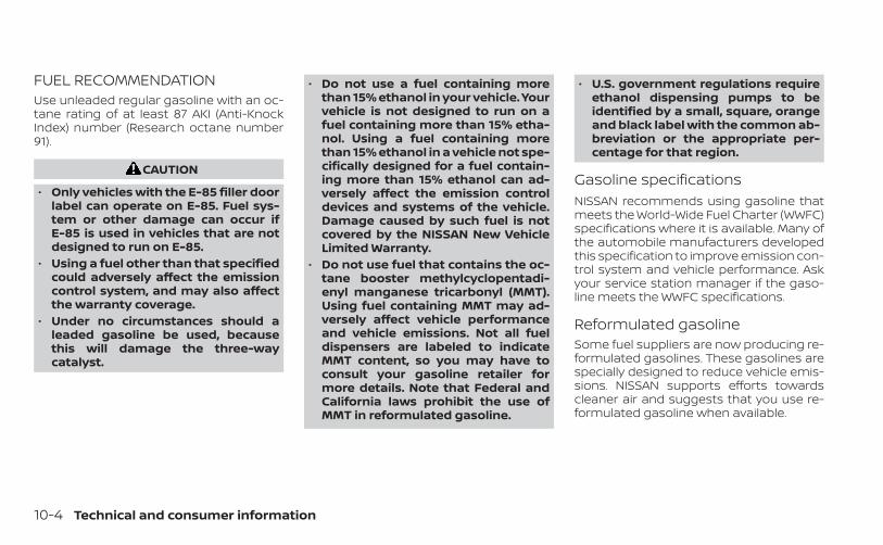
FUEL RECOMMENDATIONUse unleaded regular gasoline with an oc-tane rating of at least 87 AKI (Anti-KnockIndex) number (Research octane number91).
CAUTION
• Only vehicles with the E-85 filler doorlabel can operate on E-85. Fuel sys-tem or other damage can occur ifE-85 is used in vehicles that are notdesigned to run on E-85.
• Using a fuel other than that specifiedcould adversely affect the emissioncontrol system, and may also affectthe warranty coverage.
• Under no circumstances should aleaded gasoline be used, becausethis will damage the three-waycatalyst.
• Do not use a fuel containing morethan 15% ethanol in your vehicle. Yourvehicle is not designed to run on afuel containing more than 15% etha-nol. Using a fuel containing morethan 15% ethanol in a vehicle not spe-cifically designed for a fuel contain-ing more than 15% ethanol can ad-versely affect the emission controldevices and systems of the vehicle.Damage caused by such fuel is notcovered by the NISSAN New VehicleLimited Warranty.
• Do not use fuel that contains the oc-tane booster methylcyclopentadi-enyl manganese tricarbonyl (MMT).Using fuel containing MMT may ad-versely affect vehicle performanceand vehicle emissions. Not all fueldispensers are labeled to indicateMMT content, so you may have toconsult your gasoline retailer formore details. Note that Federal andCalifornia laws prohibit the use ofMMT in reformulated gasoline.
• U.S. government regulations requireethanol dispensing pumps to beidentified by a small, square, orangeand black label with the common ab-breviation or the appropriate per-centage for that region.
Gasoline specificationsNISSAN recommends using gasoline thatmeets the World-Wide Fuel Charter (WWFC)specifications where it is available. Many ofthe automobile manufacturers developedthis specification to improve emission con-trol system and vehicle performance. Askyour service station manager if the gaso-line meets the WWFC specifications.
Reformulated gasolineSome fuel suppliers are now producing re-formulated gasolines. These gasolines arespecially designed to reduce vehicle emis-sions. NISSAN supports efforts towardscleaner air and suggests that you use re-formulated gasoline when available.
10-4 Technical and consumer information
Gasoline containing oxygenatesSome fuel suppliers sell gasoline contain-ing oxygenates such as ethanol, MethylTert-butyl Ether (MTBE) and methanol withor without advertising their presence.NISSAN does not recommend the use offuels of which the oxygenate content andthe fuel compatibility for your NISSAN can-not be readily determined. If in doubt, askyour service station manager.If you use oxygenate-blend gasoline,please take the following precautions asthe usage of such fuels may cause vehicleperformance problems and/or fuel systemdamage.• The fuel should be unleaded and have
an octane rating no lower than thatrecommended for unleaded gasoline.
• If an oxygenate-blend other thanmethanol blend is used, it should con-tain no more than 15% oxygenate.
• If a methanol blend is used, it shouldcontain no more than 5% methanol(methyl alcohol, wood alcohol). Itshould also contain a suitable amountof appropriate cosolvents and corro-sion inhibitors. If not properly formu-lated with appropriate cosolvents andcorrosion inhibitors, such methanolblends may cause fuel system damageand/or vehicle performance problems.At this time, sufficient data is not avail-able to ensure that all methanol blendsare suitable for use in NISSAN vehicles.
If any driveability problems such as enginestalling and difficult hot-starting are expe-rienced after using oxygenate-blend fuels,immediately change to a non-oxygenatefuel or a fuel with a low blend of MTBE.Take care not to spill gasoline during re-fueling. Gasoline containing oxygenatescan cause paint damage.
E–15 fuelE-15 fuel is a mixture of approximately 15%fuel ethanol and 85% unleaded gasoline.E-15 can only be used in vehicles designedto run on E-15 fuel. U.S. government regula-tions require fuel ethanol dispensingpumps to be identified with small, square,orange and black label with the common
abbreviation or the appropriate percent-age for that region.
E–85 fuelE-85 fuel is a mixture of approximately 85%fuel ethanol and 15% unleaded gasoline.E-85 can only be used in a Flexible FuelVehicle (FFV). Do not use E-85 in your ve-hicle. U.S. government regulations requirefuel ethanol dispensing pumps to be iden-tified by a small, square, orange and blacklabel with the common abbreviation or theappropriate percentage for that region.
Fuel containing MMTMMT, or methylcyclopentadienyl manga-nese tricarbonyl, is an octane boosting addi-tive. NISSAN does not recommend the use offuel containing MMT. Such fuel may ad-versely affect vehicle performance, includingthe emissions control system. Note thatwhile some fuel pumps label MMT content,not all do, so you may have to consult yourgasoline retailer for more details.
Technical and consumer information 10-5
Aftermarket fuel additivesNISSAN does not recommend the use ofany aftermarket fuel additives (for ex-ample, fuel injector cleaner, octanebooster, intake valve deposit removers,etc.) which are sold commercially. Many ofthese additives intended for gum, varnishor deposit removal may contain active sol-vents or similar ingredients that can beharmful to the fuel system and engine.
Octane rating tipsUsing unleaded gasoline with an octanerating lower than recommended cancause persistent, heavy “spark knock.”(“Spark knock” is a metallic rappingnoise.) If severe, this can lead to enginedamage. If you detect a persistent heavyspark knock even when using gasolineof the stated octane rating, or if you hearsteady spark knock while holding asteady speed on level roads, it is recom-mended that you have a NISSAN dealercorrect the condition. Failure to correctthe condition is misuse of the vehicle, forwhich NISSAN is not responsible.
Incorrect ignition timing may result inspark knock, after-run and/or overheating,which may cause excessive fuel consump-tion or engine damage. If any of the abovesymptoms are encountered, have your ve-hicle checked. It is recommended that youvisit a NISSAN dealer for servicing.However, now and then you may noticelight spark knock for a short time whileaccelerating or driving up hills. This is nota cause for concern, because you get thegreatest fuel benefit when there is lightspark knock for a short time under heavyengine load.
10-6 Technical and consumer information
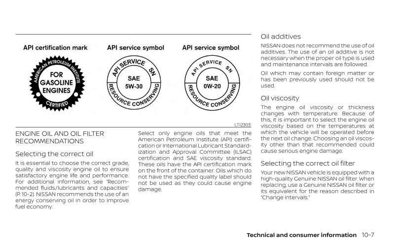
ENGINE OIL AND OIL FILTERRECOMMENDATIONS
Selecting the correct oilIt is essential to choose the correct grade,quality and viscosity engine oil to ensuresatisfactory engine life and performance.For additional information, see “Recom-mended fluids/lubricants and capacities”(P. 10-2). NISSAN recommends the use of anenergy conserving oil in order to improvefuel economy.
Select only engine oils that meet theAmerican Petroleum Institute (API) certifi-cation or International Lubricant Standard-ization and Approval Committee (ILSAC)certification and SAE viscosity standard.These oils have the API certification markon the front of the container. Oils which donot have the specified quality label shouldnot be used as they could cause enginedamage.
Oil additivesNISSAN does not recommend the use of oiladditives. The use of an oil additive is notnecessary when the proper oil type is usedand maintenance intervals are followed.Oil which may contain foreign matter orhas been previously used should not beused.
Oil viscosityThe engine oil viscosity or thicknesschanges with temperature. Because ofthis, it is important to select the engine oilviscosity based on the temperatures atwhich the vehicle will be operated beforethe next oil change. Choosing an oil viscos-ity other than that recommended couldcause serious engine damage.
Selecting the correct oil filterYour new NISSAN vehicle is equipped with ahigh-quality Genuine NISSAN oil filter. Whenreplacing, use a Genuine NISSAN oil filter orits equivalent for the reason described in“Change intervals.”
LTI2303
Technical and consumer information 10-7
Change intervalsThe oil and oil filter change intervals foryour engine are based on the use of thespecified quality oils and filters. Using en-gine oil and filters that are not of the speci-fied quality, or exceeding recommended oiland filter change intervals could reduceengine life. Damage to the engine causedby improper maintenance or use of incor-rect oil and filter quality and/or viscosity isnot covered by the NISSAN New VehicleLimited Warranty.Your engine was filled with a high-qualityengine oil when it was built. You do not haveto change the oil before the first recom-mended change interval. Oil and filterchange intervals depend upon how youuse your vehicle.Operation under the following conditionsmay require more frequent oil and filterchanges:• repeated short distance driving at cold
outside temperatures• driving in dusty conditions• extensive idling• stop and go commutingFor additional information, see the “Mainte-nance and schedules” (P. 9-2).
AIR CONDITIONER SYSTEMREFRIGERANT AND OILRECOMMENDATIONSThe air conditioner system in yourNISSAN vehicle must be charged with therefrigerant HFO-1234yf (R-1234yf) andNISSAN A/C system oil Type PAG(VC100YF oil) or the exact equivalents.
CAUTION
The use of any other refrigerant or oilwill cause severe damage to the airconditioning system and will requirethe replacement of all air conditionersystem components.
The refrigerant HFO-1234yf (R-1234yf) inyour NISSAN vehicle does not harm theearth's ozone layer. Although this refriger-ant does not affect the earth's atmo-sphere, certain government regulations re-quire the recovery and recycling of anyrefrigerant during automotive air condi-tioner system service. Air conditioner sys-tem should only be serviced by trained andcertified technicians to ensure proper andsafe operation (SAE J2845). A NISSAN dealerhas the trained technicians and equip-ment needed to recover and recycle yourair conditioner system refrigerant. Only
new and SAEJ2842 certified evaporator(s)shall be used as replacement parts.A damaged or leaking air conditioningevaporator shall never be repaired or re-placed with one removed from a used orsalvaged vehicle. To replace a damaged orleaking evaporator, use only new and SAEJ2842 certified evaporator(s). It is recom-mended that you visit a NISSAN dealerwhen servicing your air conditioner sys-tem.
10-8 Technical and consumer information
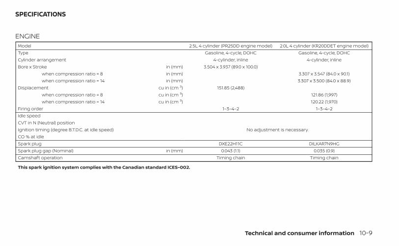
ENGINEModel 2.5L 4 cylinder (PR25DD engine model) 2.0L 4 cylinder (KR20DDET engine model)Type Gasoline, 4-cycle, DOHC Gasoline, 4-cycle, DOHCCylinder arrangement 4-cylinder, inline 4-cylinder, inlineBore x Stroke in (mm) 3.504 x 3.937 (89.0 x 100.0)
when compression ratio = 8 in (mm) 3.307 x 3.547 (84.0 x 90.1)when compression ratio = 14 in (mm) 3.307 x 3.500 (84.0 x 88.9)
Displacement cu in (cm 3) 151.85 (2,488)when compression ratio = 8 cu in (cm 3) 121.86 (1,997)when compression ratio = 14 cu in (cm 3) 120.22 (1,970)
Firing order 1–3–4–2 1–3–4–2Idle speedCVT in N (Neutral) position
No adjustment is necessary.Ignition timing (degree B.T.D.C. at idle speed)CO % at idleSpark plug DXE22H11C DILKAR7N9HGSpark plug gap (Nominal) in (mm) 0.043 (1.1) 0.035 (0.9)Camshaft operation Timing chain Timing chain
This spark ignition system complies with the Canadian standard ICES-002.
SPECIFICATIONS
Technical and consumer information 10-9
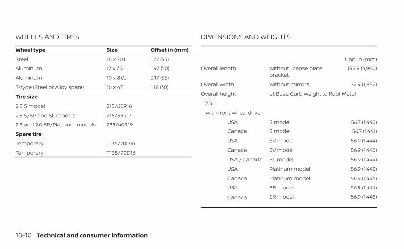
WHEELS AND TIRES
Wheel type Size Offset in (mm)
Steel 16 x 7.0J 1.77 (45)
Aluminum 17 x 7.5J 1.97 (50)
Aluminum 19 x 8.0J 2.17 (55)
T-type (Steel or Alloy spare) 16 x 4T 1.18 (30)
Tire size
2.5 S model 215/60R16
2.5 S/SV and SL models 215/55R17
2.5 and 2.0 SR/Platinum models 235/40R19
Spare tire
Temporary T135/70D16
Temporary T135/90D16
DIMENSIONS AND WEIGHTS
Unit: in (mm)
Overall length without license platebracket
192.9 (4,900)
Overall width without mirrors 72.9 (1,852)
Overall height at Base Curb Weight to Roof Metal
2.5 L
with front wheel drive
USA S model 56.7 (1,440)
Canada S model 56.7 (1,441)
USA SV model 56.9 (1,444)
Canada SV model 56.9 (1,445)
USA / Canada SL model 56.9 (1,444)
USA Platinum model 56.9 (1,445)
Canada Platinum model 56.9 (1,446)
USA SR model 56.9 (1,444)
Canada SR model 56.9 (1,445)
10-10 Technical and consumer information
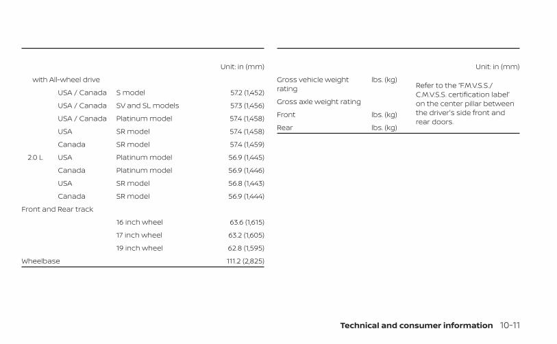
Unit: in (mm)
with All-wheel drive
USA / Canada S model 57.2 (1,452)
USA / Canada SV and SL models 57.3 (1,456)
USA / Canada Platinum model 57.4 (1,458)
USA SR model 57.4 (1,458)
Canada SR model 57.4 (1,459)
2.0 L USA Platinum model 56.9 (1,445)
Canada Platinum model 56.9 (1,446)
USA SR model 56.8 (1,443)
Canada SR model 56.9 (1,444)
Front and Rear track
16 inch wheel 63.6 (1,615)
17 inch wheel 63.2 (1,605)
19 inch wheel 62.8 (1,595)
Wheelbase 111.2 (2,825)
Unit: in (mm)
Gross vehicle weightrating
lbs. (kg)Refer to the “F.M.V.S.S./C.M.V.S.S. certification label”on the center pillar betweenthe driver's side front andrear doors.
Gross axle weight rating
Front lbs. (kg)
Rear lbs. (kg)
Technical and consumer information 10-11
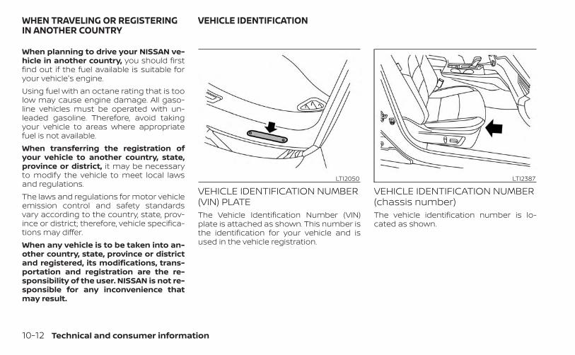
When planning to drive your NISSAN ve-hicle in another country, you should firstfind out if the fuel available is suitable foryour vehicle's engine.Using fuel with an octane rating that is toolow may cause engine damage. All gaso-line vehicles must be operated with un-leaded gasoline. Therefore, avoid takingyour vehicle to areas where appropriatefuel is not available.When transferring the registration ofyour vehicle to another country, state,province or district, it may be necessaryto modify the vehicle to meet local lawsand regulations.The laws and regulations for motor vehicleemission control and safety standardsvary according to the country, state, prov-ince or district; therefore, vehicle specifica-tions may differ.When any vehicle is to be taken into an-other country, state, province or districtand registered, its modifications, trans-portation and registration are the re-sponsibility of the user. NISSAN is not re-sponsible for any inconvenience thatmay result.
VEHICLE IDENTIFICATION NUMBER(VIN) PLATEThe Vehicle Identification Number (VIN)plate is attached as shown. This number isthe identification for your vehicle and isused in the vehicle registration.
VEHICLE IDENTIFICATION NUMBER(chassis number)The vehicle identification number is lo-cated as shown.
LTI2050 LTI2387
WHEN TRAVELING OR REGISTERINGIN ANOTHER COUNTRY
VEHICLE IDENTIFICATION
10-12 Technical and consumer information
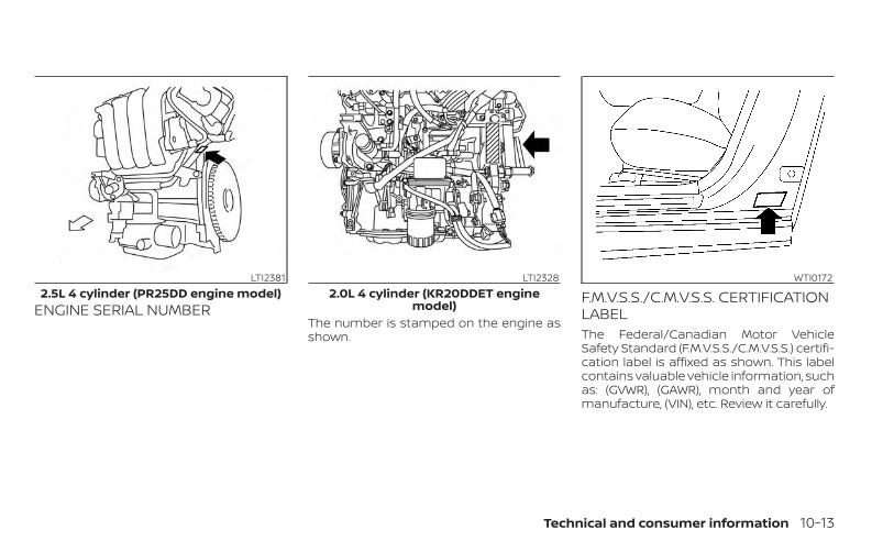
ENGINE SERIAL NUMBERThe number is stamped on the engine asshown.
F.M.V.S.S./C.M.V.S.S. CERTIFICATIONLABELThe Federal/Canadian Motor VehicleSafety Standard (F.M.V.S.S./C.M.V.S.S.) certifi-cation label is affixed as shown. This labelcontains valuable vehicle information, suchas: (GVWR), (GAWR), month and year ofmanufacture, (VIN), etc. Review it carefully.
LTI23812.5L 4 cylinder (PR25DD engine model)
LTI23282.0L 4 cylinder (KR20DDET engine
model)
WTI0172
Technical and consumer information 10-13
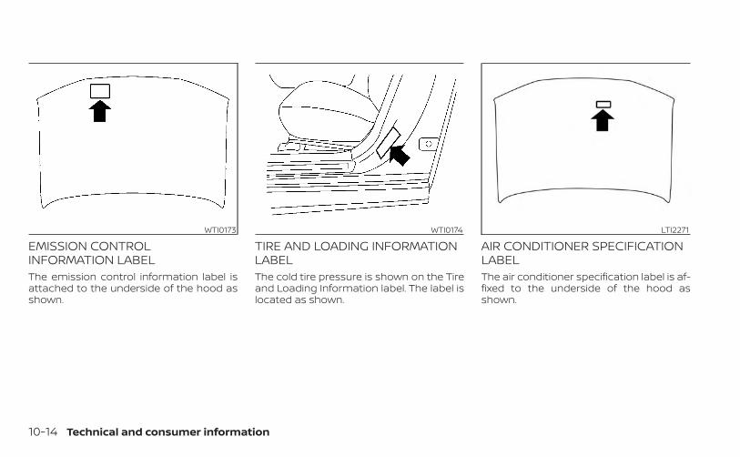
EMISSION CONTROLINFORMATION LABELThe emission control information label isattached to the underside of the hood asshown.
TIRE AND LOADING INFORMATIONLABELThe cold tire pressure is shown on the Tireand Loading Information label. The label islocated as shown.
AIR CONDITIONER SPECIFICATIONLABELThe air conditioner specification label is af-fixed to the underside of the hood asshown.
WTI0173 WTI0174 LTI2271
10-14 Technical and consumer information
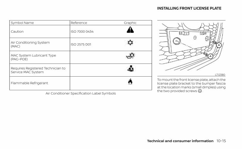
Symbol Name Reference Graphic
Caution ISO 7000 0434
Air Conditioning System(MAC) ISO 2575 D01
MAC System Lubricant Type(PAG–POE)
Requires Registered Technician toService MAC System
Flammable Refrigerant
Air Conditioner Specification Label Symbols
To mount the front license plate, attach thelicense plate bracket to the bumper fasciaat the location marks (small dimples) usingthe two provided screws OA .
LTI2380
INSTALLING FRONT LICENSE PLATE
Technical and consumer information 10-15
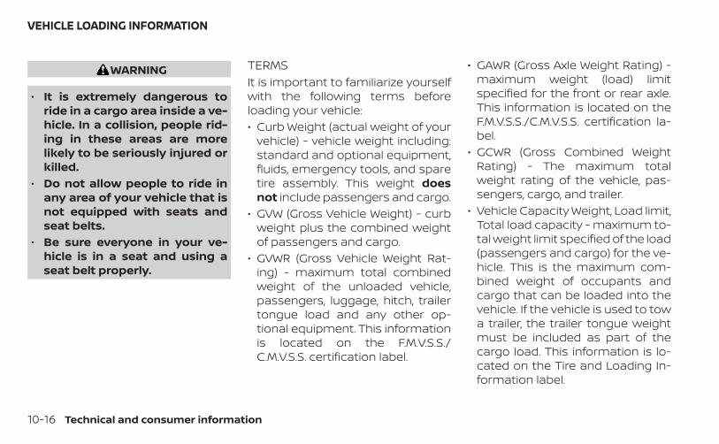
WARNING
• It is extremely dangerous toride in a cargo area inside a ve-hicle. In a collision, people rid-ing in these areas are morelikely to be seriously injured orkilled.
• Do not allow people to ride inany area of your vehicle that isnot equipped with seats andseat belts.
• Be sure everyone in your ve-hicle is in a seat and using aseat belt properly.
TERMSIt is important to familiarize yourselfwith the following terms beforeloading your vehicle:• Curb Weight (actual weight of your
vehicle) - vehicle weight including:standard and optional equipment,fluids, emergency tools, and sparetire assembly. This weight doesnot include passengers and cargo.
• GVW (Gross Vehicle Weight) - curbweight plus the combined weightof passengers and cargo.
• GVWR (Gross Vehicle Weight Rat-ing) - maximum total combinedweight of the unloaded vehicle,passengers, luggage, hitch, trailertongue load and any other op-tional equipment. This informationis located on the F.M.V.S.S./C.M.V.S.S. certification label.
• GAWR (Gross Axle Weight Rating) -maximum weight (load) limitspecified for the front or rear axle.This information is located on theF.M.V.S.S./C.M.V.S.S. certification la-bel.
• GCWR (Gross Combined WeightRating) - The maximum totalweight rating of the vehicle, pas-sengers, cargo, and trailer.
• Vehicle Capacity Weight, Load limit,Total load capacity - maximum to-tal weight limit specified of the load(passengers and cargo) for the ve-hicle. This is the maximum com-bined weight of occupants andcargo that can be loaded into thevehicle. If the vehicle is used to towa trailer, the trailer tongue weightmust be included as part of thecargo load. This information is lo-cated on the Tire and Loading In-formation label.
VEHICLE LOADING INFORMATION
10-16 Technical and consumer information
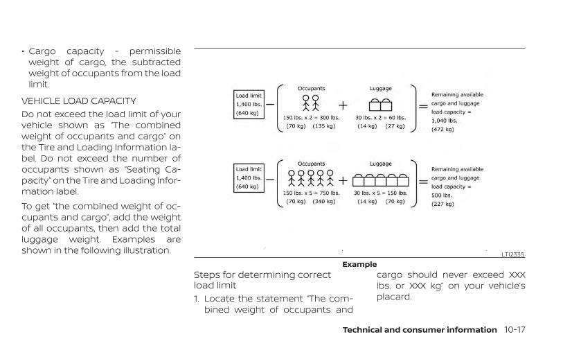
• Cargo capacity - permissibleweight of cargo, the subtractedweight of occupants from the loadlimit.
VEHICLE LOAD CAPACITYDo not exceed the load limit of yourvehicle shown as “The combinedweight of occupants and cargo” onthe Tire and Loading Information la-bel. Do not exceed the number ofoccupants shown as “Seating Ca-pacity” on the Tire and Loading Infor-mation label.To get “the combined weight of oc-cupants and cargo”, add the weightof all occupants, then add the totalluggage weight. Examples areshown in the following illustration.
Steps for determining correctload limit1. Locate the statement “The com-
bined weight of occupants and
cargo should never exceed XXXlbs. or XXX kg” on your vehicle’splacard.
LTI2335Example
Technical and consumer information 10-17
2. Determine the combined weightof the driver and passengers thatwill be riding in your vehicle.
3. Subtract the combined weight ofthe driver and passengers fromXXX lbs. or XXX kg.
4. The resulting figure equals theavailable amount of cargo andluggage load capacity. For ex-ample, if the XXX amount equals1,400 lbs. and there will be five 150lbs. passengers in your vehicle,the amount of available cargoand luggage load capacity is 650lbs. (1,400-750 (5 X 150) = 650 lbs.) or(640-340 (5 X 70) = 300 kg.)
5. Determine the combined weightof luggage and cargo beingloaded on the vehicle. That weightmay not safely exceed the avail-able cargo and luggage load ca-pacity calculated in step 4.
Before driving a loaded vehicle, con-firm that you do not exceed theGross Vehicle Weight Rating (GVWR)or the Gross Axle Weight Rating(GAWR) for your vehicle. For addi-tional information, see “Measure-ment of weights” (P. 10-19).Also check tires for proper inflationpressures. For additional informa-tion, see “Tire and Loading Informa-tion label” (P. 8-31).
LOADING TIPS• The GVW must not exceed GVWR or
GAWR as specified on the F.M.V.S.S./C.M.V.S.S. certification label.
• Do not load the front and rear axleto the GAWR. Doing so will exceedthe GVWR.
WARNING
• Properly secure all cargo withropes or straps to help preventit from sliding or shifting. Donot place cargo higher than theseatbacks. In a sudden stop orcollision, unsecured cargocould cause personal injury.
• Do not load your vehicle anyheavier than the GVWR or themaximum front and rearGAWRs. If you do, parts of yourvehicle can break, tire damagecould occur, or it can changethe way your vehicle handles.This could result in loss of con-trol and cause personal injury.
• Overloading not only canshorten the life of your vehicleand the tire, but can also causeunsafe vehicle handling andlonger braking distances. Thismay cause a premature tire
10-18 Technical and consumer information
failure which could result in aserious accident and personalinjury. Failures caused by over-loading are not covered by thevehicle’s warranty.
MEASUREMENT OF WEIGHTSSecure loose items to preventweight shifts that could affect thebalance of your vehicle. When the ve-hicle is loaded, drive to a scale andweigh the front and the rear wheelsseparately to determine axle loads.Individual axle loads should not ex-ceed either of the gross axle weightratings (GAWR). The total of the axleloads should not exceed the grossvehicle weight rating (GVWR). Theseratings are given on the vehicle cer-tification label. If weight ratings areexceeded, move or remove items tobring all weights below the ratings.
Do not tow a trailer with your vehicle.
FLAT TOWINGTowing your vehicle with all four wheels onthe ground is sometimes called flat towing.This method is sometimes used whentowing a vehicle behind a recreational ve-hicle, such as a motor home.
CAUTION
• Failure to follow these guidelines canresult in severe transmissiondamage.
• Whenever flat towing your vehicle,always tow forward, never backward.
• Never tow your front wheel drive ve-hicle with the front tires on theground. Doing so may cause seriousand expensive damage to thepowertrain.
• DO NOT tow any continuously vari-able transmission vehicle with allfour wheels on the ground (flat tow-ing). Doing so WILL DAMAGE internaltransmission parts due to lack oftransmission lubrication.
• For emergency towing proceduressee “Towing recommended byNISSAN” (P. 6-12).
Continuously VariableTransmission (CVT)To tow a vehicle equipped with a CVT, anappropriate vehicle dolly MUST be placedunder the towed vehicle's drive wheels. Al-ways follow the dolly manufacturer's rec-ommendations when using their product.
TOWING A TRAILER
Technical and consumer information 10-19
DOT (Department of Transportation) Qual-ity Grades: All passenger car tires mustconform to federal safety requirements inaddition to these grades.Quality grades can be found where appli-cable on the tire sidewall between treadshoulder and maximum section width. Forexample:Treadwear 200 Traction AA Temperature ATreadwearThe treadwear grade is a comparative rat-ing based on the wear rate of the tire whentested under controlled conditions on aspecified government test course. For ex-ample, a tire graded 150 would wear oneand one-half (1 1/2) times as well on thegovernment course as a tire graded 100.The relative performance of tires dependsupon the actual conditions of their use,however, and may depart significantly fromthe norm due to variations in driving habits,service practices and differences in roadcharacteristics and climate.Traction AA, A, B and CThe traction grades, from highest to low-est, are AA, A, B, and C. Those grades repre-sent the tire's ability to stop on wet pave-ment as measured under controlled
conditions on specified government testsurfaces of asphalt and concrete. A tiremarked C may have poor traction perfor-mance.
WARNING
The traction grade assigned to this tireis based on straight-ahead brakingtraction tests, and does not include ac-celeration, cornering, hydroplaning, orpeak traction characteristics.
Temperature A, B and CThe temperature grades are A (the high-est), B, and C, representing the tire’s resis-tance to the generation of heat, and itsability to dissipate heat when tested undercontrolled conditions on a specified indoorlaboratory test wheel. Sustained high tem-perature can cause the material of the tireto degenerate and reduce tire life, and ex-cessive temperature can lead to suddentire failure. The grade C corresponds to alevel of performance which all passengercar tires must meet under the Federal Mo-tor Vehicle Safety Standard No. 109. GradesB and A represent higher levels of perfor-mance on the laboratory test wheel thanthe minimum required by law.
WARNING
The temperature grade for this tire isestablished for a tire that is properlyinflated and not overloaded. Excessivespeed, under-inflation, or excessiveloading, either separately or in combi-nation, can cause heat build-up andpossible tire failure.
UNIFORM TIRE QUALITY GRADING
10-20 Technical and consumer information
Your NISSAN vehicle is covered by the fol-lowing emission warranties:For USA1. Emission Defects Warranty
2. Emissions Performance WarrantyDetails of this warranty may be found withother vehicle warranties in your WarrantyInformation Booklet which comes withyour NISSAN vehicle. If you did not receive aWarranty Information Booklet, or it is lost,you may obtain a replacement by writingto:• Nissan North America, Inc.
Consumer Affairs DepartmentP.O. Box 685003Franklin, TN 37068-5003
For CanadaEmission Control System WarrantyDetails of this warranty may be found withother vehicle warranties in your WarrantyInformation Booklet which comes withyour NISSAN vehicle. If you did not receive aWarranty Information Booklet, or it is lost,you may obtain a replacement by writingto:• Nissan Canada Inc.
5290 Orbitor DriveMississauga, Ontario, L4W 4Z5
For USAIf you believe that your vehicle has adefect which could cause a crash orcould cause injury or death, youshould immediately inform the Na-tional Highway Traffic Safety Admin-istration (NHTSA) in addition to noti-fying NISSAN.If NHTSA receives similar complaints,it may open an investigation, and if itfinds that a safety defect exists in agroup of vehicles, it may order a re-call and remedy campaign. However,NHTSA cannot become involved inindividual problems between you,your dealer, or NISSAN.To contact NHTSA, you may call theVehicle Safety Hotline toll-free at1-888-327-4236 (TTY: 1-800-424-9153);go to http://www.safercar.gov; orwrite to: Administrator, NHTSA, 400Seventh Street, SW., Washington, D.C.20590. You can also obtain other in-
formation about motor vehicle safetyfrom http://www.safercar.gov.You may notify NISSAN by contact-ing our Consumer Affairs Depart-ment, toll-free, at 1-800-NISSAN-1.For CanadaIf you believe that your vehicle has adefect which could cause a crash orcould cause injury or death, youshould immediately inform Trans-port Canada in addition to notifyingNISSAN.If Transport Canada receives com-plaints, it may open an investigation,and if it finds that a safety defectexists in a group of vehicles, it mayrequest that NISSAN conduct a re-call campaign. However, TransportCanada cannot become involved inindividual problems between you,your dealer, or NISSAN.
EMISSION CONTROL SYSTEMWARRANTY
REPORTING SAFETY DEFECTS
Technical and consumer information 10-21
You may contact Transport Canada'sDefect Investigations and RecallsDivision toll free at 1-800-333-0510.You may also report safety defectsonline at: https://wwwapps.tc.gc.ca/Saf-Sec-Sur/7/PCDB-BDPP/fc-cp.aspx?lang=eng (English speakers)or https://wwwapps.tc.gc.ca/Saf-Sec-Sur/7/PCDB-BDPP/fc-cp.aspx?lang=fra (French speakers)Additional information concerningmotor vehicle safety may be obtainedfrom Transport Canada's Road SafetyInformation Centre at 1-800-333-0371or online at www.tc.gc.ca/roadsafety(English speakers) or www.tc.gc.ca/securiteroutiere (French speakers).To notify NISSAN of any safety con-cerns please contact our ConsumerInformation Centre toll free at 1-800-387-0122.
WARNING
A vehicle equipped with All -WheelDrive (AWD) should never be tested us-ing a two wheel dynamometer (such asthe dynamometers used by somestates for emissions testing), or similarequipment. Make sure you inform thetest facility personnel that your vehicleis equipped with AWD before it is placedon a dynamometer. Using the wrongtest equipment may result in drivetraindamage or unexpected vehicle move-ment which could result in serious ve-hicle damage or personal injury.
Due to legal requirements in some statesand Canadian Provinces, your vehicle maybe required to be in what is called the“ready condition” for an Inspection/Maintenance (I/M) test of the emissioncontrol system.The vehicle is set to the “ready condition”when it is driven through certain driving pat-terns. Usually, the ready condition can be ob-tained by ordinary usage of the vehicle.
If a powertrain system component is re-paired or the battery is disconnected, thevehicle may be reset to a “not ready” condi-tion. Before taking the I/M test, check thevehicle's inspection/maintenance testreadiness condition. Place the ignitionswitch in the ON position without startingthe engine. If the Malfunction IndicatorLight (MIL) comes on steady for 20 secondsand then blinks for 10 seconds , the I/M testcondition is “not ready”. If the MIL does notblink after 20 seconds, the I/M test condi-tion is “ready”. It is recommended that youvisit a NISSAN dealer to set the “ready con-dition” or to prepare the vehicle for testing.
READINESS FOR INSPECTION/MAINTENANCE (I/M) TEST
10-22 Technical and consumer information
This vehicle is equipped with an Event DataRecorder (EDR). The main purpose of anEDR is to record, in certain collision or nearcollision-like situations, such as an air bagdeployment or hitting a road obstacle, datathat will assist in understanding how a ve-hicle's systems performed. The EDR is de-signed to record data related to vehicle dy-namics and safety systems for a shortperiod of time, typically 30 seconds or less.The EDR in this vehicle is designed to re-cord such data as:• How various systems in your vehicle were
operating;• Whether or not the driver and passenger
safety belts were buckled/fastened;• How far (if at all) the driver was depress-
ing the accelerator and/or brake pedal;and,
• How fast the vehicle was traveling.• Sounds are not recorded.These data can help provide a better un-derstanding of the circumstances in whichcollisions and injuries occur. NOTE: EDRdata are recorded by your vehicle only if anontrivial collision situation occurs; no dataare recorded by the EDR under normal driv-ing conditions and no personal data (e.g.,name, gender, age, and crash location) arerecorded. However, other parties, such as
law enforcement, could combine the EDRdata with the type of personally identifyingdata routinely acquired during a crash in-vestigation.To read data recorded by an EDR, specialequipment is required, and access to thevehicle or the EDR is needed. In addition tothe vehicle manufacturer and NISSANdealer, other parties, such as law enforce-ment, that have the special equipment, canread the information if they have access tothe vehicle or the EDR. EDR data will only beaccessed with the consent of the vehicleowner or lessee or as otherwise required orpermitted by law.
ADDITIONAL DATA RECORDING(on vehicles equipped withoptional ProPILOT Assist)If your vehicle is equipped with the optionalProPILOT Assist, it will also be equippedwith supplemental data recording functionintended to assist in understanding howProPILOT Assist performs in certain non-trivial crash or near-crash scenarios. Spe-cifically, supplemental recording is de-signed to capture the following:• Driver operational status of the accelera-
tor, brakes, steering, etc.
• Detection status of a vehicle ahead andlane markers
• Vehicle information including distance tovehicle ahead and lateral position
• Information on the operation of the Pro-PILOT Assist and other crash avoidancefeatures
• ProPILOT Assist malfunction diagnosisinformation
• External images from the multi-sensingfront camera (Available only when theSRS air bag or IEB system is activated)
The ProPILOT Assist does not record con-versations, sounds or images of the insideof the vehicle.To read this supplemental data, specialequipment is required and access to thevehicle or the recording unit is needed. Thissupplemental data will only be accessedwith the consent of the vehicle owner orlessee or as otherwise required or permit-ted by law. If downloaded, NISSAN and thirdparties entrusted by NISSAN may use thedata recorded for the purpose of improv-ing NISSAN’s vehicle safety performance.
EVENT DATA RECORDERS (EDR)
Technical and consumer information 10-23
NISSAN and third parties entrusted byNISSAN will not disclose/provide the re-corded data to a third party except:- With the consent of the vehicle owner orwith the consent of the lessee- In response to an official request from lawenforcement, court order, governmentalagency, or other legally enforceable re-quest- For research purposes after the data ismodified such that it is no longer tied to aspecific vehicle or vehicle owner (anony-mized)
Genuine NISSAN Service Manuals for thismodel year and prior can be purchased. AGenuine NISSAN Service Manual is the bestsource of service and repair information foryour vehicle. This manual is the same oneused by the factory-trained techniciansworking at NISSAN dealerships. GenuineNISSAN Owner’s Manuals can also be pur-chased.For USAFor current pricing and availability of Genu-ine NISSAN Service Manuals, contact:www.nissan-techinfo.comFor current pricing and availability of Genu-ine NISSAN Owner's Manuals, contact:1-800-247-5321For CanadaTo purchase a copy of a Genuine NISSANService Manual or Owner’s Manual, for thismodel year and prior, please contact yournearest NISSAN dealer. For the phone num-ber and location of a NISSAN dealer in yourarea, call the NISSAN Information Center at1-800-387-0122 and a bilingual NISSAN rep-resentative will assist you.
OWNER'S MANUAL/SERVICEMANUAL ORDER INFORMATION
10-24 Technical and consumer information

11 IndexA
Active noise cancellationActive sound enhancement. . . . . .5-159
Active Ride Control (ARC) . . . . . . . . .5-150Air bag (See supplemental restraintsystem) . . . . . . . . . . . . . . . . . . . . .1-46Air bag system
Front (See supplemental front impact airbag system) . . . . . . . . . . . . . . . .1-54
Air bag warning light . . . . . . . . .1-67, 2-12Air bag warning light,supplemental . . . . . . . . . . . . . .1-67, 2-12Air cleaner housing filter . . . . . . . . . .8-18Air conditioner
Air conditioner operation. . . . .4-35, 4-41Air conditioner specification label . .10-14Air conditioner system refrigerantrecommendations . . . . . . . . . . . .10-8Air conditioner system refrigerant and oilrecommendations . . . . . . . . . . . .10-8Heater and air conditionercontrols . . . . . . . . . . . . . . .4-33, 4-41Servicing air conditioner . . . . . . . .4-44
Air flow charts . . . . . . . . . . . . . . . .4-36Alarm system (See vehicle securitysystem) . . . . . . . . . . . . . . . . . . . . .2-51All-Wheel Drive . . . . . . . . . . . .5-140, 6-13Anchor point locations . . . . . . . . . . .1-27Antenna . . . . . . . . . . . . . . . . . . . .4-64Anti-lock Braking System (ABS) . . . . .5-145
Antifreeze . . . . . . . . . . . . . . . . . . .5-157Armrests . . . . . . . . . . . . . . . . . . . . .1-7Audio system . . . . . . . . . . . . . . . . .4-45
AM radio operation . . . . . . . . . . . .4-51AM radio reception . . . . . . . . . . . .4-45AM/FM radio . . . . . . . . . . . .4-49, 4-51Auxiliary (AUX) devices operation . . .4-53Bluetooth® audio . . . . . . . . . . . . .4-60FM radio operation . . . . . . . . . . . .4-52FM radio reception . . . . . . . . . . . .4-45iPod® Player . . . . . . . . . . . . . . . .4-57iPod® player operation. . . . . . . . . .4-57Radio . . . . . . . . . . . . . . . . . . . .4-45USB (Universal Serial Bus) ConnectionPort . . . . . . . . . . . . . . . . . . . . .4-54USB Connections . . . . . . . . . . . . .4-55USB interface . . . . . . . . . . . . . . .4-54
Autolight switch . . . . . . . . . . . . . . .2-57Automatic
Automatic power window switch . . .2-73Automatic anti-glare inside mirror . . . .3-29Automatic brake hold . . . . . . . . . . . .5-27Automatic door locks. . . . . . . . . . . . .3-6Automatic Emergency Braking(AEB) . . . . . . . . . . . . . . . . . . .2-13, 2-16Automatic Emergency Braking (AEB) withPedestrian Detection . . . . . . . . . . .5-108AWD . . . . . . . . . . . . . . . . . . .5-140, 6-13
B
Battery . . . . . . . . . . . . . . . . .5-157, 8-14Charge warning light . . . . . . . . . . .2-10
Battery replacement . . . . . . . . . . . .8-23Key fob . . . . . . . . . . . . . . . . . . .8-23NISSAN Intelligent Key® . . . . . . . . .8-24
Before starting the engine . . . . . . . . .5-16Belt (See drive belt). . . . . . . . . . . . . .8-16Blind Spot Warning (BSW) . . . . . . . . .5-46Bluetooth® audio . . . . . . . . . . . . . .4-60Bluetooth® hands-free phone system. .4-67
Bluetooth® connections . . . . . . . .4-80Connecting procedure. . . . . . . . . .4-72Phone indicators . . . . . . . . . . . . .4-71Text messaging . . . . . . . . . . . . . .4-77Voice commands . . . . . . . . . . . . .4-73
Booster seats . . . . . . . . . . . . . . . . .1-42Brake
Anti-lock Braking System (ABS). . . .5-145Brake fluid . . . . . . . . . . . . . . . . .8-12Brake light (See stop light) . . . . . . .8-26Brake system. . . . . . . . . . . . . . .5-145Brake warning light . . . . . . . . . . . .2-10Brake wear indicators. . . . . . .2-18, 8-20Self-adjusting brakes . . . . . . . . . .8-20
Brake Assist . . . . . . . . . . . . . . . . .5-147Brake fluid . . . . . . . . . . . . . . . . . . .8-12Brake system . . . . . . . . . . . . . . . .5-145Brakes . . . . . . . . . . . . . . . . . . . . .8-20Break-in schedule . . . . . . . . . . . . .5-139
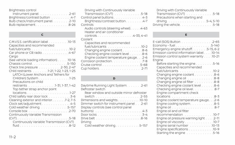
Brightness controlInstrument panel. . . . . . . . . . . . . .2-61
Brightness/contrast button . . . . . . . . .4-7Bulb check/instrument panel. . . . . . . .2-10Bulb replacement . . . . . . . . . . . . . . .8-26
C
C.M.V.S.S. certification label . . . . . . . . .10-13Capacities and recommendedfuel/lubricants . . . . . . . . . . . . . . . . .10-2Car phone or CB radio . . . . . . . . . . . .4-67Cargo(See vehicle loading information) . . . . .10-16Chassis control . . . . . . . . . . . . . . . .5-150Check tire pressure . . . . . . . . . .2-30, 2-47Child restraints . . . . . . .1-21, 1-22, 1-23, 1-25
LATCH (Lower Anchors and Tethers forCHildren) System . . . . . . . . . . . . . .1-25Precautions on childrestraints . . . . . . . . . . . .1-31, 1-37, 1-42Top tether strap anchor pointlocations . . . . . . . . . . . . . . . . . . .1-27
Child safety rear door lock . . . . . . . . . .3-6Cleaning exterior and interior . . . . . .7-2, 7-5Clock set/adjustment . . . . . . . . . . . . .4-5Cold weather driving . . . . . . . . . . . .5-157Console box . . . . . . . . . . . . . . . . . .2-70Continuously Variable Transmission(CVT) . . . . . . . . . . . . . . . . . . . . . . .5-18
Continuously Variable Transmission (CVT)fluid . . . . . . . . . . . . . . . . . . . . . .8-12
Driving with Continuously VariableTransmission (CVT) . . . . . . . . . . . .5-18
Control panel buttons . . . . . . . . . . . . .4-3Brightness/contrast button . . . . . . . .4-7
ControlsAudio controls (steering wheel) . . . . .4-63Heater and air conditionercontrols . . . . . . . . . . . . . . . .4-33, 4-41
CoolantCapacities and recommendedfuel/lubricants . . . . . . . . . . . . . . .10-2Changing engine coolant . . . . . . . . .8-6Checking engine coolant level . . . . . .8-6Engine coolant temperature gauge. . .2-6
Corrosion protection. . . . . . . . . . . . . .7-8Cruise control . . . . . . . . . . . . . . . . .5-68Cup holders . . . . . . . . . . . . . . . . . . .2-71
D
Daytime Running Light System. . . . . . .2-61Defroster switch
Rear window and outside mirror defrosterswitch . . . . . . . . . . . . . . . . . . . .2-55
Dimensions and weights . . . . . . . . . .10-10Dimmer switch for instrument panel . . .2-61Display controls (see control panelbuttons) . . . . . . . . . . . . . . . . . . . . .4-3Door locks . . . . . . . . . . . . . . . . . . . .3-4Drive belt . . . . . . . . . . . . . . . . . . . .8-16Driving
Cold weather driving . . . . . . . . . . .5-157
Driving with Continuously VariableTransmission (CVT) . . . . . . . . . . . .5-18Precautions when starting anddriving. . . . . . . . . . . . . . . . . .5-4, 5-10
Driving the vehicle. . . . . . . . . . . . . . .5-18
E
E-call (SOS) Button . . . . . . . . . . . . . .2-65Economy - fuel . . . . . . . . . . . . . . . .5-140Emergency engine shutoff . . . . . . .5-15, 6-2Emission control information label . . . .10-14Emission control system warranty . . . .10-21Engine
Before starting the engine . . . . . . . .5-16Capacities and recommendedfuel/lubricants . . . . . . . . . . . . . . .10-2Changing engine coolant . . . . . . . . .8-6Changing engine oil . . . . . . . . . . . .8-8Changing engine oil filter . . . . . . . . .8-8Checking engine coolant level . . . . . .8-6Checking engine oil level . . . . . . . . . .8-7Engine compartment checklocations . . . . . . . . . . . . . . . . . . .8-3Engine coolant temperature gauge. . .2-6Engine cooling system. . . . . . . . . . .8-5Engine oil . . . . . . . . . . . . . . . . . . .8-7Engine oil and oil filterrecommendation . . . . . . . . . . . . .10-7Engine oil pressure warning light . . . .2-11Engine oil viscosity . . . . . . . . . . . . .10-7Engine serial number . . . . . . . . . .10-13Engine specifications . . . . . . . . . . .10-9Starting the engine . . . . . . . . . . . .5-16
11-2
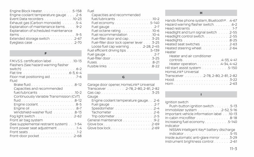
Engine Block Heater. . . . . . . . . . . . .5-158Engine coolant temperature gauge . . . .2-6Event Data recorders . . . . . . . . . . . .10-23Exhaust gas (Carbon monoxide) . . . . . .5-4Explanation of maintenance items . . . . .9-2Explanation of scheduled maintenanceitems . . . . . . . . . . . . . . . . . . . . . . .9-5Extended storage switch . . . . . . . . . .2-67Eyeglass case . . . . . . . . . . . . . . . . .2-70
F
F.M.V.S.S. certification label . . . . . . . . .10-13Flashers (See hazard warning flasherswitch) . . . . . . . . . . . . . . . . . . . . . .6-2Flat tire . . . . . . . . . . . . . . . . . . .6-3, 6-4Floor mat positioning aid . . . . . . . . . . .7-6Fluid
Brake fluid . . . . . . . . . . . . . . . . . .8-12Capacities and recommendedfuel/lubricants . . . . . . . . . . . . . . .10-2Continuously Variable Transmission (CVT)fluid . . . . . . . . . . . . . . . . . . . . . .8-12Engine coolant. . . . . . . . . . . . . . . .8-5Engine oil . . . . . . . . . . . . . . . . . . .8-7Windshield-washer fluid . . . . . . . . .8-13
Fog light switch . . . . . . . . . . . . . . . .2-62Front air bag system(See supplemental restraint system) . . .1-54Front power seat adjustment . . . . . . . .1-4Front seats . . . . . . . . . . . . . . . . . . . .1-2Front-door pocket . . . . . . . . . . . . . .2-68
FuelCapacities and recommendedfuel/lubricants . . . . . . . . . . . . . . .10-2Fuel economy . . . . . . . . . . . . . . .5-140Fuel gauge . . . . . . . . . . . . . . . . . .2-7Fuel octane rating . . . . . . . . . . . . .10-6Fuel recommendation . . . . . . . . . .10-4Fuel-filler door and cap . . . . . . . . . .3-25Fuel-filler door lock opener lever . . . .3-25Loose fuel cap warning . . . . . .2-28, 2-45
Fuel efficient driving tips . . . . . . . . . .5-139Fuel gauge . . . . . . . . . . . . . . . . . . . .2-7Fuel-filler door . . . . . . . . . . . . . . . . .3-25Fuses. . . . . . . . . . . . . . . . . . . . . . .8-21Fusible links . . . . . . . . . . . . . . . . . .8-22
G
Garage door opener, HomeLink® UniversalTransceiver . . . . . . . .2-78, 2-80, 2-81, 2-82Gas cap . . . . . . . . . . . . . . . . . . . . .3-25Gauge
Engine coolant temperature gauge. . .2-6Fuel gauge . . . . . . . . . . . . . . . . . .2-7Speedometer . . . . . . . . . . . . . . . .2-4Tachometer . . . . . . . . . . . . . . . . .2-6Trip odometer . . . . . . . . . . . . . . . .2-5
General maintenance . . . . . . . . . . . . .9-2Glove box . . . . . . . . . . . . . . . . . . . .2-69Glove box lock . . . . . . . . . . . . . . . . .2-69
H
Hands-free phone system, Bluetooth® . .4-67Hazard warning flasher switch. . . . . . . .6-2Head restraints . . . . . . . . . . . . . . . . .1-7Headlight and turn signal switch . . . . .2-55Headlight control switch. . . . . . . . . . .2-55Headlights . . . . . . . . . . . . . . . . . . .8-25Heated seat switches . . . . . . . . . . . .2-63Heated steering wheel. . . . . . . . . . . .2-64Heater
Heater and air conditionercontrols . . . . . . . . . . . . . . . .4-33, 4-41Heater operation . . . . . . . . . .4-34, 4-42
Hill start assist system . . . . . . . . . . .5-150HomeLink® UniversalTransceiver . . . . . . . .2-78, 2-80, 2-81, 2-82Hood . . . . . . . . . . . . . . . . . . . . . . .3-22Horn . . . . . . . . . . . . . . . . . . . . . . .2-63
I
Ignition switchPush-button ignition switch . . . . . . .5-13
Immobilizer system . . . . . . . . . .2-52, 5-16Important vehicle information label . . .10-13In-cabin microfilter . . . . . . . . . . . . . .8-18Increasing fuel economy . . . . . . . . . .5-140Indicator
NISSAN Intelligent Key® battery dischargeindicator . . . . . . . . . . . . . . . . . . .5-15
Inside automatic anti-glare mirror . . . .3-29Instrument brightness control . . . . . . .2-61
11-3
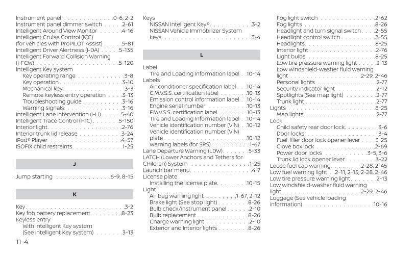
Instrument panel . . . . . . . . . . . . .0-6, 2-2Instrument panel dimmer switch . . . . .2-61Intelligent Around View Monitor . . . . . .4-16Intelligent Cruise Control (ICC)(for vehicles with ProPILOT Assist) . . . . .5-81Intelligent Driver Alertness (I-DA) . . . . .5-135Intelligent Forward Collision Warning(I-FCW) . . . . . . . . . . . . . . . . . . . . .5-120Intelligent Key system
Key operating range . . . . . . . . . . . .3-8Key operation . . . . . . . . . . . . . . . .3-10Mechanical key. . . . . . . . . . . . . . . .3-3Remote keyless entry operation . . . .3-13Troubleshooting guide . . . . . . . . . .3-16Warning signals. . . . . . . . . . . . . . .3-16
Intelligent Lane Intervention (I-LI) . . . . .5-40Intelligent Trace Control (I-TC) . . . . . . .5-150Interior light. . . . . . . . . . . . . . . . . . .2-76Interior trunk lid release . . . . . . . . . . .3-24iPod® Player . . . . . . . . . . . . . . . . . .4-57ISOFIX child restraints. . . . . . . . . . . . .1-25
J
Jump starting . . . . . . . . . . . . . .6-9, 8-15
K
Key . . . . . . . . . . . . . . . . . . . . . . . . .3-2Key fob battery replacement . . . . . . . .8-23Keyless entry
With Intelligent Key system(See Intelligent Key system) . . . . . . .3-13
KeysNISSAN Intelligent Key® . . . . . . . . . . .3-2NISSAN Vehicle Immobilizer Systemkeys . . . . . . . . . . . . . . . . . . . . . .3-4
L
LabelTire and Loading Information label . .10-14
LabelsAir conditioner specification label . . .10-14C.M.V.S.S. certification label . . . . . . .10-13Emission control information label . .10-14Engine serial number . . . . . . . . . .10-13F.M.V.S.S. certification label. . . . . . . .10-13Tire and Loading Information label . .10-14Vehicle identification number (VIN) . .10-12Vehicle identification number (VIN)plate . . . . . . . . . . . . . . . . . . . . .10-12Warning labels (for SRS) . . . . . . . . . .1-67
Lane Departure Warning (LDW). . . . . . .5-33LATCH (Lower Anchors and Tethers forCHildren) System . . . . . . . . . . . . . . .1-25Launch bar menu. . . . . . . . . . . . . . . .4-7License plate
Installing the license plate. . . . . . . .10-15Light
Air bag warning light . . . . . . . .1-67, 2-12Brake light (See stop light) . . . . . . . .8-26Bulb check/instrument panel . . . . . .2-10Bulb replacement . . . . . . . . . . . . .8-26Charge warning light . . . . . . . . . . .2-10Exterior and Interior lights . . . . . . . .8-26
Fog light switch . . . . . . . . . . . . . .2-62Fog lights . . . . . . . . . . . . . . . . . .8-26Headlight and turn signal switch . . . .2-55Headlight control switch . . . . . . . . .2-55Headlights. . . . . . . . . . . . . . . . . .8-25Interior light . . . . . . . . . . . . . . . . .2-76Light bulbs . . . . . . . . . . . . . . . . .8-25Low tire pressure warning light . . . . .2-13Low windshield-washer fluid warninglight . . . . . . . . . . . . . . . . . .2-29, 2-46Personal lights . . . . . . . . . . . . . . .2-77Security indicator light . . . . . . . . . .2-12Spotlights (See map light) . . . . . . . .2-77Trunk light . . . . . . . . . . . . . . . . . .2-77
Lights . . . . . . . . . . . . . . . . . . . . . .8-25Map lights . . . . . . . . . . . . . . . . . .2-77
LockChild safety rear door lock. . . . . . . . .3-6Door locks . . . . . . . . . . . . . . . . . .3-4Fuel-filler door lock opener lever . . . .3-25Glove box lock . . . . . . . . . . . . . . .2-69Power door locks . . . . . . . . . . .3-5, 3-6Trunk lid lock opener lever . . . . . . . .3-22
Loose fuel cap warning . . . . . . . .2-28, 2-45Low fuel warning light . .2-11, 2-15, 2-28, 2-46Low tire pressure warning light . . . . . . .2-13Low windshield-washer fluid warninglight . . . . . . . . . . . . . . . . . . . .2-29, 2-46Luggage (See vehicle loadinginformation) . . . . . . . . . . . . . . . . . .10-16
11-4
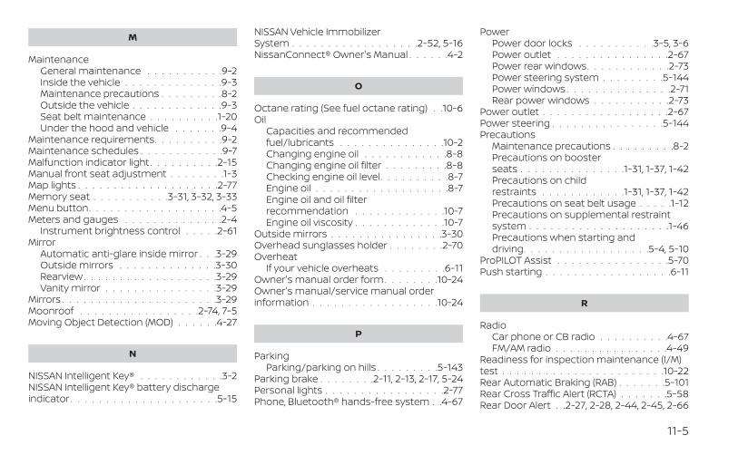
M
MaintenanceGeneral maintenance . . . . . . . . . . .9-2Inside the vehicle . . . . . . . . . . . . . .9-3Maintenance precautions . . . . . . . . .8-2Outside the vehicle . . . . . . . . . . . . .9-3Seat belt maintenance . . . . . . . . . .1-20Under the hood and vehicle . . . . . . .9-4
Maintenance requirements. . . . . . . . . .9-2Maintenance schedules . . . . . . . . . . . .9-7Malfunction indicator light . . . . . . . . . .2-15Manual front seat adjustment . . . . . . . .1-3Map lights . . . . . . . . . . . . . . . . . . . .2-77Memory seat . . . . . . . . . . .3-31, 3-32, 3-33Menu button. . . . . . . . . . . . . . . . . . .4-5Meters and gauges . . . . . . . . . . . . . .2-4
Instrument brightness control . . . . .2-61Mirror
Automatic anti-glare inside mirror . . .3-29Outside mirrors . . . . . . . . . . . . . .3-30Rearview . . . . . . . . . . . . . . . . . . .3-29Vanity mirror . . . . . . . . . . . . . . . .3-29
Mirrors . . . . . . . . . . . . . . . . . . . . . .3-29Moonroof . . . . . . . . . . . . . . . . .2-74, 7-5Moving Object Detection (MOD) . . . . . .4-27
N
NISSAN Intelligent Key® . . . . . . . . . . . .3-2NISSAN Intelligent Key® battery dischargeindicator . . . . . . . . . . . . . . . . . . . . .5-15
NISSAN Vehicle ImmobilizerSystem . . . . . . . . . . . . . . . . . .2-52, 5-16NissanConnect® Owner's Manual . . . . . .4-2
O
Octane rating (See fuel octane rating) . .10-6Oil
Capacities and recommendedfuel/lubricants . . . . . . . . . . . . . . .10-2Changing engine oil . . . . . . . . . . . .8-8Changing engine oil filter . . . . . . . . .8-8Checking engine oil level . . . . . . . . . .8-7Engine oil . . . . . . . . . . . . . . . . . . .8-7Engine oil and oil filterrecommendation . . . . . . . . . . . . .10-7Engine oil viscosity . . . . . . . . . . . . .10-7
Outside mirrors . . . . . . . . . . . . . . . .3-30Overhead sunglasses holder . . . . . . . .2-70Overheat
If your vehicle overheats . . . . . . . . .6-11Owner's manual order form . . . . . . . .10-24Owner's manual/service manual orderinformation . . . . . . . . . . . . . . . . . .10-24
P
ParkingParking/parking on hills . . . . . . . . .5-143
Parking brake . . . . . . . .2-11, 2-13, 2-17, 5-24Personal lights . . . . . . . . . . . . . . . . .2-77Phone, Bluetooth® hands-free system . .4-67
PowerPower door locks . . . . . . . . . . .3-5, 3-6Power outlet . . . . . . . . . . . . . . . .2-67Power rear windows. . . . . . . . . . . .2-73Power steering system . . . . . . . . .5-144Power windows . . . . . . . . . . . . . . .2-71Rear power windows . . . . . . . . . . .2-73
Power outlet . . . . . . . . . . . . . . . . . .2-67Power steering . . . . . . . . . . . . . . . .5-144Precautions
Maintenance precautions . . . . . . . . .8-2Precautions on boosterseats . . . . . . . . . . . . . . .1-31, 1-37, 1-42Precautions on childrestraints . . . . . . . . . . . .1-31, 1-37, 1-42Precautions on seat belt usage . . . . .1-12Precautions on supplemental restraintsystem . . . . . . . . . . . . . . . . . . . .1-46Precautions when starting anddriving. . . . . . . . . . . . . . . . . .5-4, 5-10
ProPILOT Assist . . . . . . . . . . . . . . . .5-70Push starting . . . . . . . . . . . . . . . . . .6-11
R
RadioCar phone or CB radio . . . . . . . . . .4-67FM/AM radio . . . . . . . . . . . . . . . .4-49
Readiness for inspection maintenance (I/M)test . . . . . . . . . . . . . . . . . . . . . . .10-22Rear Automatic Braking (RAB) . . . . . . .5-101Rear Cross Traffic Alert (RCTA) . . . . . . .5-58Rear Door Alert . .2-27, 2-28, 2-44, 2-45, 2-66
11-5
Rear power windows . . . . . . . . . . . . .2-73Rear seat . . . . . . . . . . . . . . . . . . . . .1-5Rear Sonar System (RSS) . . . . . . . . . .5-151Rear window and outside mirror defrosterswitch . . . . . . . . . . . . . . . . . . . . . .2-55Rearview mirror . . . . . . . . . . . . . . . .3-29RearView Monitor. . . . . . . . . . . . . . . .4-8Recommended Fluids . . . . . . . . . . . .10-2Recorders
Event Data . . . . . . . . . . . . . . . . .10-23Refrigerant recommendation . . . . . . .10-8Registering a vehicle in anothercountry . . . . . . . . . . . . . . . . . . . . .10-12Remote Engine Start . . . . . . . . . .3-19, 5-17Reporting safety defects (US only) . . . .10-21
S
SafetyChild safety rear door lock. . . . . . . . .3-6Child seat belts . . . . .1-23, 1-31, 1-37, 1-42Reporting safety defects (US only) . . .10-21
SeatMemory seat . . . . . . . . .3-31, 3-32, 3-33
Seat adjustmentFront manual seat adjustment . . . . . .1-3Front power seat adjustment . . . . . . .1-4Rear seat adjustment. . . . . . . . . . . .1-5
Seat beltChild safety. . . . . . . . . . . . . . . . . .1-21Infants and small children . . . . . . . .1-22Injured person. . . . . . . . . . . . . . . .1-15Larger children . . . . . . . . . . . . . . .1-22
Precautions on seat belt usage . . . . .1-12Pregnant women . . . . . . . . . . . . . .1-15Seat belt extenders . . . . . . . . . . . .1-20Seat belt maintenance . . . . . . . . . .1-20Seat belts . . . . . . . . . . . . . . . .1-12, 7-7Shoulder belt height adjustment . . . .1-19Three-point type with retractor . . . . .1-15
Seat belt extenders . . . . . . . . . . . . . .1-20Seat belt warning light . . . . . . . . .1-14, 2-12Seatback pockets. . . . . . . . . . . . . . .2-69Seats
Adjustment . . . . . . . . . . . . . . . . . .1-2Armrests . . . . . . . . . . . . . . . . . . . .1-7Front seats . . . . . . . . . . . . . . . . . .1-2Manual front seat adjustment . . . . . .1-3Rear seat . . . . . . . . . . . . . . . . . . .1-5
Security indicator light . . . . . . . . . . . .2-12Security system (NISSAN Vehicle ImmobilizerSystem), engine start . . . . . . . . .2-52, 5-16Security systems
Vehicle security system. . . . . . . . . .2-51Self-adjusting brakes. . . . . . . . . . . . .8-20Service manual order form . . . . . . . .10-24Servicing air conditioner. . . . . . . . . . .4-44Shift lever lock release . . . . . . . . . . . .5-22Shifting
Continuously Variable Transmission(CVT) . . . . . . . . . . . . . . . . . . . . .5-20
Shoulder belt height adjustment . . . . . .1-19Siri® Eyes-Free . . . . . . . . . . . . . . . . .4-64Sonar
Rear system . . . . . . . . . . . . . . . .5-151Spark plug replacement . . . . . . . . . . .8-17Spark plugs . . . . . . . . . . . . . . . . . . .8-17
Specifications . . . . . . . . . . . . . . . . .10-9Speedometer . . . . . . . . . . . . . . . . . .2-4Speedometer and odometer . . . . . . . .2-4Spotlights (See map light) . . . . . . . . . .2-77SRS warning label . . . . . . . . . . . . . . .1-67Stability control . . . . . . . . . . . . . . . .5-147Standard maintenance . . . . . . . .9-10, 9-28Starting
Before starting the engine . . . . . . . .5-16Jump starting . . . . . . . . . . . . .6-9, 8-15Precautions when starting anddriving. . . . . . . . . . . . . . . . . .5-4, 5-10Push starting . . . . . . . . . . . . . . . .6-11Starting the engine . . . . . . . . . . . .5-16
Starting the engine . . . . . . . . . . . . . .5-16Steering
Heated steering wheel . . . . . . . . . .2-64Power steering system . . . . . . . . .5-144
Steering Assist switch(for vehicles with ProPILOT Assist) . . . . .2-65Steering wheel . . . . . . . . . . . . . . . . .3-27Stop light . . . . . . . . . . . . . . . . . . . .8-26Storage . . . . . . . . . . . . . . . . . . . . .2-68Sun visors. . . . . . . . . . . . . . . . . . . .3-28Sunglasses case. . . . . . . . . . . . . . . .2-70Sunglasses holder . . . . . . . . . . . . . .2-70Sunroof. . . . . . . . . . . . . . . . . . .2-74, 7-5Supplemental air bag warninglight . . . . . . . . . . . . . . . . . . . .1-67, 2-12Supplemental front impact air bagsystem. . . . . . . . . . . . . . . . . . . . . .1-54Supplemental restraint system
Information and warning labels . . . . .1-67
11-6
Precautions on supplemental restraintsystem . . . . . . . . . . . . . . . . . . . .1-46
Supplemental restraint system(Supplemental air bag system) . . . . . . .1-46Switch
Autolight switch . . . . . . . . . . . . . .2-57Automatic power window switch. . . .2-73Fog light switch . . . . . . . . . . . . . .2-62Hazard warning flasher switch . . . . . .6-2Headlight and turn signal switch . . . .2-55Headlight control switch . . . . . . . . .2-55Instrument brightness control . . . . .2-61Power door lock switch. . . . . . . .3-5, 3-6Rear window and outside mirror defrosterswitch . . . . . . . . . . . . . . . . . . . .2-55Turn signal switch . . . . . . . . . . . . .2-61
T
Tachometer . . . . . . . . . . . . . . . . . . .2-6Temperature gauge
Engine coolant temperature gauge. . .2-6Theft (NISSAN Vehicle Immobilizer System),engine start . . . . . . . . . . . . . . .2-52, 5-16Three-way catalyst . . . . . . . . . . . . . . .5-4Tilt
Telescopic steering . . . . . . . . . . . .3-27Tire
Flat tire . . . . . . . . . . . . . . . . . .6-3, 6-4Spare tire . . . . . . . . . . . . . . . .6-5, 8-41Tire and Loading Information label . .10-14Tire chains . . . . . . . . . . . . . . . . .8-36Tire pressure . . . . . . . . . . . . . . . .8-29
Tire rotation. . . . . . . . . . . . . . . . .8-38Types of tires . . . . . . . . . . . . . . . .8-35Uniform tire quality grading . . . . . .10-20Wheel/tire size . . . . . . . . . . . . . . .10-10Wheels and tires . . . . . . . . . . . . . .8-29
Tire pressureLow tire pressure warning light . . . . .2-13
Tire Pressure Monitoring System(TPMS) . . . . . . . . . . . . . . . . . . . .5-5, 6-3Towing
4-wheel drive models . . . . . . . . . . .6-14Flat towing . . . . . . . . . . . . . . . . .10-19Trailer towing . . . . . . . . . . . . . . .10-19
Towing a trailer . . . . . . . . . . . . . . . .10-19Towing your vehicle . . . . . . . . . . . . . .6-12Traffic Sign Recognition (TSR). . . . . . . .5-30Transceiver
HomeLink® UniversalTransceiver. . . . . . .2-78, 2-80, 2-81, 2-82
TransmissionContinuously Variable Transmission (CVT)fluid . . . . . . . . . . . . . . . . . . . . . .8-12Driving with Continuously VariableTransmission (CVT) . . . . . . . . . . . .5-18
Transmission shift lever lock release . . .5-22Travel (See registering a vehicle in anothercountry) . . . . . . . . . . . . . . . . . . . .10-12Trip odometer . . . . . . . . . . . . . . . . . .2-5Trunk access through the rearseat . . . . . . . . . . . . . . . . . . . . .1-6, 3-24Trunk lid . . . . . . . . . . . . . . . . . . . . .3-22Trunk lid lock opener lever. . . . . . . . . .3-22Trunk light . . . . . . . . . . . . . . . . . . . .2-77Turn signal switch . . . . . . . . . . . . . . .2-61
U
Uniform tire quality grading . . . . . . . .10-20USB interface . . . . . . . . . . . . . . . . .4-54USB/iPod® Charging Ports . . . . . . . . .4-64
V
Vanity mirror . . . . . . . . . . . . . . . . . .3-29Variable voltage control system . . . . . .8-16Vehicle dimensions and weights . . . . .10-10Vehicle Dynamic Control (VDC)system . . . . . . . . . . . . . . . . . . . . .5-147Vehicle identification. . . . . . . . . . . . .10-12Vehicle identification number (VIN) . . . .10-12Vehicle identification number (VIN)(Chassis number). . . . . . . . . . . . . . .10-12Vehicle identification number (VIN)plate. . . . . . . . . . . . . . . . . . . . . . .10-12Vehicle immobilizer system . . . . .2-52, 5-16Vehicle information display. . . . . .2-18, 2-33Vehicle loading information . . . . . . . .10-16Vehicle recovery . . . . . . . . . . . . . . . .6-15Vehicle security system . . . . . . . . . . .2-51Vehicle security system(NISSAN Vehicle Immobilizer System),engine start . . . . . . . . . . . . . . .2-52, 5-16Ventilators . . . . . . . . . . . . . . . . . . .4-31Visors . . . . . . . . . . . . . . . . . . . . . .3-28Voice Prompt Interrupt. . . . . . . . . . . .4-70
11-7
W
WarningAir bag warning light . . . . . . . .1-67, 2-12Battery charge warning light . . . . . .2-10Brake warning light . . . . . . . . . . . .2-10Engine oil pressure warning light . . . .2-11Hazard warning flasher switch . . . . . .6-2Loose fuel cap warning . . . . . .2-28, 2-45Low fuel warninglight . . . . . . . . . . . .2-11, 2-15, 2-28, 2-46Low tire pressure warning light . . . . .2-13Low windshield-washer fluid warninglight . . . . . . . . . . . . . . . . . .2-29, 2-46Seat belt warning light . . . . . . .1-14, 2-12Supplemental air bag warninglight . . . . . . . . . . . . . . . . . . .1-67, 2-12TPMS . . . . . . . . . . . . . . . . . . . . . .2-4Vehicle security system. . . . . . . . . .2-51Warning labels (for SRS) . . . . . . . . . .1-67
Warning lights, indicator lights and audiblereminders . . . . . . . . . . . . . . . . . . . .2-9Weights(See dimensions and weights) . . . . . .10-10Wheel/tire size . . . . . . . . . . . . . . . .10-10Wheels and tires. . . . . . . . . . . . . . . .8-29When traveling or registering in anothercountry . . . . . . . . . . . . . . . . . . . . .10-12Windows . . . . . . . . . . . . . . . . . . . . .2-71
Locking passengers' windows . . . . .2-73Power rear windows. . . . . . . . . . . .2-73Power windows . . . . . . . . . . . . . . .2-71Rear power windows . . . . . . . . . . .2-73
Windshield wiper blades . . . . . . . . . . .8-19
Windshield-washer fluid . . . . . . . . . . .8-13Wiper
Wiper blades . . . . . . . . . . . . . . . .8-19Wiper and washer switch . . . . . . . . . .2-54
11-8

MEMO

MEMO

MEMO

MEMO

MEMO
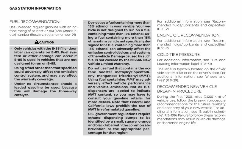
FUEL RECOMMENDATION:Use unleaded regular gasoline with an oc-tane rating of at least 87 AKI (Anti-Knock In-dex) number (Research octane number 91).
CAUTION
• Only vehicles with the E-85 filler doorlabel can operate on E-85. Fuel sys-tem or other damage can occur ifE-85 is used in vehicles that are notdesigned to run on E-85.
• Using a fuel other than that specifiedcould adversely affect the emissioncontrol system, and may also affectthe warranty coverage.
• Under no circumstances should aleaded gasoline be used, becausethis will damage the three-waycatalyst.
• Do not use a fuel containing more than15% ethanol in your vehicle. Your ve-hicle is not designed to run on a fuelcontaining more than 15% ethanol. Us-ing a fuel containing more than 15%ethanol in a vehicle not specifically de-signed for a fuel containing more than15% ethanol can adversely affect theemission control devices and systemsof the vehicle. Damage caused by suchfuel is not covered by the NISSAN NewVehicle Limited Warranty.
• Do not use fuel that contains the oc-tane booster methylcyclopentadi-enyl manganese tricarbonyl (MMT).Using fuel containing MMT may ad-versely affect vehicle performanceand vehicle emissions. Not all fueldispensers are labeled to indicateMMT content, so you may have toconsult your gasoline retailer formore details. Note that Federal andCalifornia laws prohibit the use ofMMT in reformulated gasoline.
• U.S. government regulations requireethanol dispensing pumps to beidentified by a small, square, orangeand black label with the common ab-breviation or the appropriate per-centage for that region.
For additional information, see “Recom-mended fluids/lubricants and capacities”(P. 10-2).
ENGINE OIL RECOMMENDATION:For additional information, see “Recom-mended fluids/lubricants and capacities”(P. 10-2).
COLD TIRE PRESSURE:For additional information, see “Tire andLoading Information label” (P. 8-31).The label is typically located on the driverside center pillar or on the driver's door. Foradditional information, see “Wheels andtires” (P. 8-29).
RECOMMENDED NEW VEHICLEBREAK-IN PROCEDURE:During the first 1,200 miles (2,000 km) ofvehicle use, follow the break-in procedurerecommendations for the future reliabilityand economy of your new vehicle. For ad-ditional information, see “Break-in sched-ule” (P. 5-139). Failure to follow these recom-mendations may result in vehicle damageor shortened engine life.
GAS STATION INFORMATION

L34-D
Printing : May 2020Publication No.:
Printed in the U.S.A.OM21EA 0L34U0
Related Documents