Owners Manual V40 WEB EDITION

Welcome message from author
This document is posted to help you gain knowledge. Please leave a comment to let me know what you think about it! Share it to your friends and learn new things together.
Transcript
Owners ManualV40
WEB EDITION

DEAR VOLVO OWNERTHANK YOU FOR CHOOSING VOLVO
We hope you will enjoy many years of drivingpleasure in your Volvo. The car has beendesigned for the safety and comfort of you andyour passengers. Volvo is one of the safest cars inthe world. Your Volvo has also been designed tosatisfy all current safety and environmentalrequirements.
In order to increase your enjoyment of the car, werecommend that you familiarise yourself with theequipment, instructions and maintenance infor-mation contained in this owner's manual.
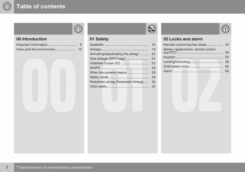
Table of contents
2 * Option/accessory, for more information, see Introduction.
0000 IntroductionImportant information................................. 6Volvo and the environment....................... 10
0101 SafetySeatbelts .................................................. 16Airbags...................................................... 19Activating/deactivating the airbag*........... 22Side airbags (SIPS bags) ......................... 24Inflatable Curtain (IC) ............................... 25WHIPS ...................................................... 26When the systems deploy ........................ 28Safety mode.............................................. 29Pedestrian airbag (Pedestrian Airbag)...... 30Child safety............................................... 32 02
02 Locks and alarmRemote control key/key blade.................. 44Battery replacement, remote controlkey/PCC*................................................... 50Keyless*.................................................... 52Locking/unlocking..................................... 56Child safety locks...................................... 62Alarm*....................................................... 63
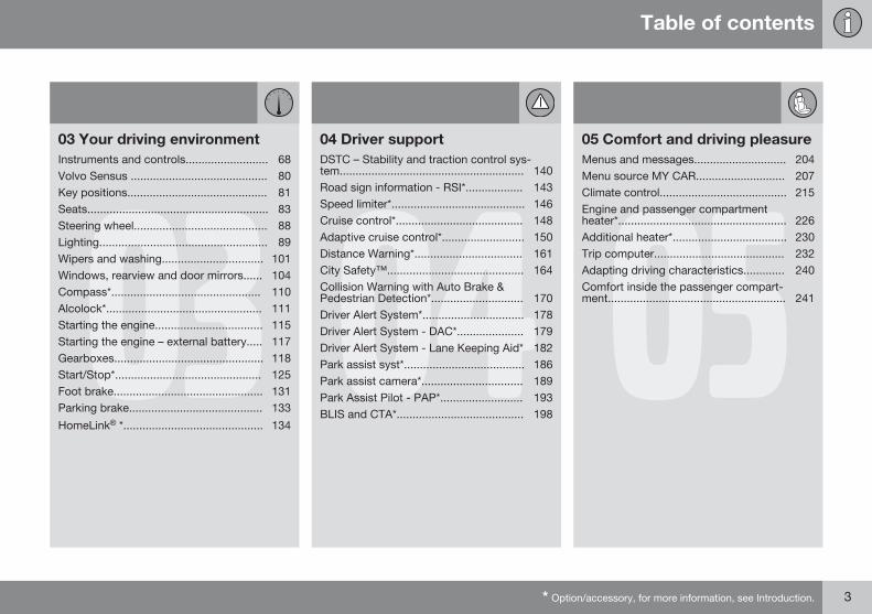
Table of contents
* Option/accessory, for more information, see Introduction. 3
0303 Your driving environmentInstruments and controls.......................... 68Volvo Sensus ........................................... 80Key positions............................................ 81Seats......................................................... 83Steering wheel.......................................... 88Lighting..................................................... 89Wipers and washing................................ 101Windows, rearview and door mirrors...... 104Compass*............................................... 110Alcolock*................................................. 111Starting the engine.................................. 115Starting the engine – external battery..... 117Gearboxes............................................... 118Start/Stop*.............................................. 125Foot brake............................................... 131Parking brake.......................................... 133
HomeLink® *............................................ 134
0404 Driver supportDSTC – Stability and traction control sys-tem.......................................................... 140Road sign information - RSI*.................. 143Speed limiter*.......................................... 146Cruise control*........................................ 148Adaptive cruise control*.......................... 150Distance Warning*.................................. 161City Safety™........................................... 164Collision Warning with Auto Brake &Pedestrian Detection*............................. 170Driver Alert System*................................ 178Driver Alert System - DAC*..................... 179Driver Alert System - Lane Keeping Aid* 182Park assist syst*...................................... 186Park assist camera*................................ 189Park Assist Pilot - PAP*.......................... 193BLIS and CTA*........................................ 198
0505 Comfort and driving pleasureMenus and messages............................. 204Menu source MY CAR............................ 207Climate control........................................ 215Engine and passenger compartmentheater*..................................................... 226Additional heater*.................................... 230Trip computer......................................... 232Adapting driving characteristics............. 240Comfort inside the passenger compart-ment........................................................ 241
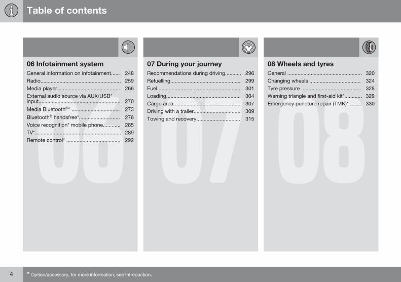
Table of contents
4 * Option/accessory, for more information, see Introduction.
0606 Infotainment systemGeneral information on infotainment...... 248Radio....................................................... 259Media player........................................... 266External audio source via AUX/USB*input........................................................ 270
Media Bluetooth®* ................................. 273
Bluetooth® handsfree*............................ 276Voice recognition* mobile phone............ 285TV*........................................................... 289Remote control* ..................................... 292 07
07 During your journeyRecommendations during driving........... 296Refuelling................................................ 299Fuel......................................................... 301Loading................................................... 304Cargo area.............................................. 307Driving with a trailer................................ 309Towing and recovery.............................. 315
0808 Wheels and tyresGeneral ................................................... 320Changing wheels ................................... 324Tyre pressure ......................................... 328Warning triangle and first-aid kit*............ 329Emergency puncture repair (TMK)* ........ 330
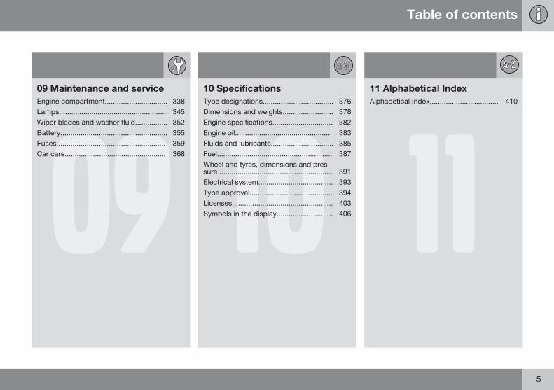
Table of contents
5
0909 Maintenance and serviceEngine compartment............................... 338Lamps..................................................... 345Wiper blades and washer fluid................ 352Battery..................................................... 355Fuses...................................................... 359Car care.................................................. 368
1010 SpecificationsType designations................................... 376Dimensions and weights......................... 378Engine specifications.............................. 382Engine oil................................................ 383Fluids and lubricants............................... 385Fuel......................................................... 387Wheel and tyres, dimensions and pres-sure ........................................................ 391Electrical system..................................... 393Type approval......................................... 394Licenses.................................................. 403Symbols in the display............................ 406 11
11 Alphabetical IndexAlphabetical Index.................................. 410
Introduction
Important information
6 * Option/accessory, for more information, see Introduction.
Reading the Owner's Manual
IntroductionA good way of getting to know your new caris to read the owner's manual, ideally beforeyour first journey. This will give you theopportunity to familiarise yourself with newfunctions, to see how best to handle the carin different situations, and to make the bestuse of all the car's features. Please pay atten-tion to the safety instructions contained in themanual.
The specifications, design features and illus-trations in this owner's manual are not bind-ing. We reserve the right to make modifica-tions without prior notice.© Volvo Car Corporation
OptionAll types of option/accessory are marked withan asterisk*.
In addition to standard equipment, this man-ual also describes options (factory fittedequipment) and certain accessories (retrofit-ted extra equipment).
The equipment described in the owner'smanual is not available in all cars - they havedifferent equipment depending on adapta-tions for the needs of different markets andnational or local laws and regulations.
In the event of uncertainty over what is stand-ard or an option/accessory, contact a Volvodealer.
Special texts
WARNING
Warning texts appear if there is a risk ofinjury.
IMPORTANT
"Important" texts appear if there is a risk ofdamage.
NOTE
NOTE texts give advice or tips that facili-tate the use of features and functions forexample.
FootnoteThere is footnote information in the owner'smanual that is located at the bottom of thepage. This information is an addition to thetext that it refers to via a number. If the foot-note refers to text in a table then letters areused instead of numbers for referral.
Message textsText messages can be shown in the com-bined instrument panel and in the screen.
These text messages are highlighted in theowner's manual by means of the text beingslightly larger and printed in grey. Examplesof this are in menu texts and message texts inthe screen (e.g. Audio settings).
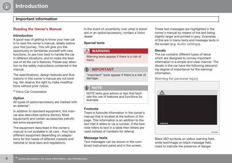
DecalsThe car contains different types of decalwhich are designed to convey importantinformation in a simple and clear manner. Thedecals in the car have the following descend-ing degree of importance for the warning/information.
Warning for personal injury
G031590
Black ISO symbols on yellow warning field,white text/image on black message field.Used to indicate the presence of danger
Introduction
Important information
7
which, if the warning is ignored, may result inserious personal injury or fatality.
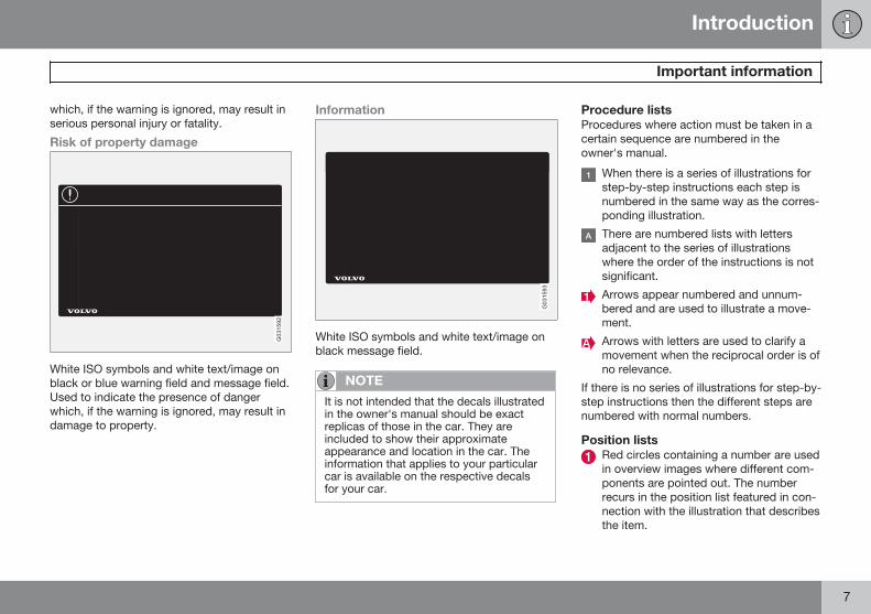
Risk of property damage
G031592
White ISO symbols and white text/image onblack or blue warning field and message field.Used to indicate the presence of dangerwhich, if the warning is ignored, may result indamage to property.
Information
G031593
White ISO symbols and white text/image onblack message field.
NOTE
It is not intended that the decals illustratedin the owner's manual should be exactreplicas of those in the car. They areincluded to show their approximateappearance and location in the car. Theinformation that applies to your particularcar is available on the respective decalsfor your car.
Procedure listsProcedures where action must be taken in acertain sequence are numbered in theowner's manual.
When there is a series of illustrations forstep-by-step instructions each step isnumbered in the same way as the corres-ponding illustration.
There are numbered lists with lettersadjacent to the series of illustrationswhere the order of the instructions is notsignificant.
Arrows appear numbered and unnum-bered and are used to illustrate a move-ment.
Arrows with letters are used to clarify amovement when the reciprocal order is ofno relevance.
If there is no series of illustrations for step-by-step instructions then the different steps arenumbered with normal numbers.
Position listsRed circles containing a number are usedin overview images where different com-ponents are pointed out. The numberrecurs in the position list featured in con-nection with the illustration that describesthe item.
Introduction
Important information
8
Bulleted listsA bulleted list is used when there is a list ofpoints in the owner's manual.
Example:
• Coolant
• Engine oil
ImagesThe manual's images are sometimes sche-matic and may deviate from the car's appear-ance depending on equipment level and mar-ket.
To be continued}} This symbol is located furthest down tothe right when a section continues on the fol-lowing page.
Recording dataYour vehicle contains a number of computerswhose function is to continuously check andmonitor the vehicle's operation and function-ality. Some of the computers can recordinformation during normal driving if theydetect an error. In addition, information isrecorded in the event of a collision or inci-dent. Parts of the recorded information arerequired so that technicians can diagnoseand rectify faults in the vehicle during servic-ing and maintenance and so that Volvo can
fulfil legal requirements and other regulations.In addition to this, the information is used forresearch purposes by Volvo in order to con-tinually develop quality and safety, as theinformation can contribute to a better under-standing of the factors that cause accidentsand injuries. The information includes detailsof the status and functionality of various sys-tems and modules in the vehicle with regardto engine, throttle, steering and brake sys-tems, amongst other things. This informationmay include details regarding the way thedriver drives the vehicle, such as vehiclespeed, brake and accelerator pedal use,steering wheel movement and whether or notthe driver and passengers have used theirseatbelts. For the reasons given this informa-tion may be stored in the vehicle's computersfor a certain length of time, but also as aresult of a collision or incident. This informa-tion may be stored by Volvo as long as it canhelp to further develop and further enhancesafety and quality and as long as there arelegal requirements and other regulations thatVolvo needs to consider.
Volvo will not contribute to the above-descri-bed information being disclosed to third par-ties without the vehicle owner's consent.However, due to national legislation and reg-ulations Volvo may be required to disclosesuch information to authorities such as police
authorities, or others who may assert a legalright to have access to it.
To be able to read and interpret the informa-tion recorded by the computers in the vehiclerequires special technical equipment thatVolvo, and workshops that have entered intoagreements with Volvo, have access to. Volvois responsible that the information, which istransferred to Volvo during servicing andmaintenance, is stored and handled in asecure manner and that the handling com-plies with applicable legal requirements. Forfurther information - contact a Volvo dealer.
Accessories and extra equipmentThe incorrect connection and installation ofaccessories can negatively affect the car'selectrical system. Certain accessories onlyfunction when their associated software isinstalled in the car's computer system. Volvotherefore recommends that you always con-tact an authorised Volvo workshop beforeinstalling accessories which are connected toor affect the electrical system.
Introduction
Important information
* Option/accessory, for more information, see Introduction. 9
Change of ownership for cars withVolvo On Call*Volvo On Call is a supplemental service thatconsists of safety, security and comfort serv-ices. If the car has Volvo On Call and there isa change of owner, it is very important thatthese services are discontinued so that theformer owner cannot access the services inthe car. Contact an authorised Volvo dealer inthe event of a change of ownership.
Information on the InternetAt www.volvocars.com there is further infor-mation concerning your car.
A QR code reader is required to read the QRcode, which is available as a supplementalprogram for several mobile phones. The QRcode reader can be downloaded from AppStore or Google Play.
QR code
Introduction
Volvo and the environment
10
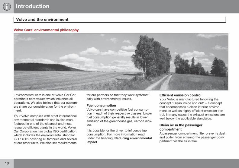
Volvo Cars' environmental philosophy
G000000
Environmental care is one of Volvo Car Cor-poration's core values which influence alloperations. We also believe that our custom-ers share our consideration for the environ-ment.
Your Volvo complies with strict internationalenvironmental standards and is also manu-factured in one of the cleanest and mostresource-efficient plants in the world. VolvoCar Corporation has global ISO certification,which includes the environmental standardISO 14001 covering all factories and severalof our other units. We also set requirements
for our partners so that they work systemati-cally with environmental issues.
Fuel consumptionVolvo cars have competitive fuel consump-tion in each of their respective classes. Lowerfuel consumption generally results in loweremission of the greenhouse gas, carbon diox-ide.
It is possible for the driver to influence fuelconsumption. For more information readunder the heading, Reducing environmentalimpact.
Efficient emission controlYour Volvo is manufactured following theconcept "Clean inside and out" – a conceptthat encompasses a clean interior environ-ment as well as highly efficient emission con-trol. In many cases the exhaust emissions arewell below the applicable standards.
Clean air in the passengercompartmentA passenger compartment filter prevents dustand pollen from entering the passenger com-partment via the air intake.
Introduction
Volvo and the environment
* Option/accessory, for more information, see Introduction. 11
A sophisticated air quality system, IAQS*(Interior Air Quality System) ensures that theincoming air is cleaner than the air in the traf-fic outside.
The system consists of an electronic sensorand a carbon filter. The incoming air is moni-tored continuously and if there is an increasein the level of certain unhealthy gases such ascarbon monoxide then the air intake isclosed. Such a situation may arise in heavytraffic, queues and tunnels for example.
The entry of nitrous oxides, ground-levelozone and hydrocarbons is prevented by thecarbon filter.
InteriorThe interior of a Volvo is designed to be plea-sant and comfortable, even for people withcontact allergies and for asthma sufferers.Extreme attention has been given to choosingenvironmentally-compatible materials.
Volvo workshops and the environmentRegular maintenance creates the conditionsfor a long service life and low fuel consump-tion for your car. In this way you contribute toa cleaner environment. When Volvo's work-shops are entrusted with the service andmaintenance of your car it becomes part ofour system. Volvo makes clear demandsregarding the way in which our workshopsare designed in order to prevent spills and
discharges into the environment. Our work-shop staff have the knowledge and the toolsrequired to guarantee good environmentalcare.
Reducing environmental impactYou can easily help reduce environmentalimpact - here are a few tips:
• Avoid letting the engine idle - switch offthe engine when stationary for longerperiods. Pay attention to local regula-tions.
• Drive economically - think ahead.
• Perform service and maintenance inaccordance with the owner's manual'sinstructions - follow the Service and War-ranty Booklet's recommended intervals.
• If the car is equipped with an engineblock heater*, use it before starting fromcold - it improves starting capacity andreduces wear in cold weather and theengine reaches normal operating tem-perature more quickly, which lowers con-sumption and reduces emissions.
• High speed increases consumption con-siderably due to increased wind resis-tance - a doubling of speed increaseswind resistance 4 times.
• Always dispose of environmentally hazar-dous waste, such as batteries and oils, inan environmentally safe manner. Consult
a workshop in the event of uncertaintyabout how this type of waste should bediscarded - an authorised Volvo work-shop is recommended.
Following this advice can save money, theplanet's resources are saved, and the car'sdurability is extended. For more informationand further advice, see the pages 296 and387.
RecyclingAs a part of Volvo's environmental work, it isimportant that the car is recycled in an envi-ronmentally sound manner. Almost all of thecar can be recycled. The last owner of the caris therefore requested to contact a dealer forreferral to a certified/approved recyclingfacility.
The owner's manual and theenvironmentThe Forest Stewardship Council® symbolshows that the paper pulp in this publicationcomes from FSC® certified forests or othercontrolled sources.
Introduction
Volvo and the environment
12
Introduction
13
14 * Option/accessory, for more information, see Introduction.
Seatbelts ................................................................................................ 16Airbags.................................................................................................... 19Activating/deactivating the airbag*......................................................... 22Side airbags (SIPS bags) ....................................................................... 24Inflatable Curtain (IC) ............................................................................. 25WHIPS .................................................................................................... 26When the systems deploy ...................................................................... 28Safety mode............................................................................................ 29Pedestrian airbag (Pedestrian Airbag).................................................... 30Child safety............................................................................................. 32
SAFETY
01 Safety
Seatbelts 01
16
General information
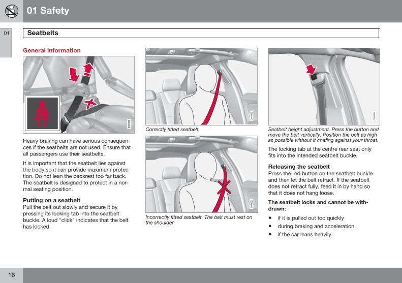
Heavy braking can have serious consequen-ces if the seatbelts are not used. Ensure thatall passengers use their seatbelts.
It is important that the seatbelt lies againstthe body so it can provide maximum protec-tion. Do not lean the backrest too far back.The seatbelt is designed to protect in a nor-mal seating position.
Putting on a seatbeltPull the belt out slowly and secure it bypressing its locking tab into the seatbeltbuckle. A loud "click" indicates that the belthas locked.
Correctly fitted seatbelt.
Incorrectly fitted seatbelt. The belt must rest onthe shoulder.
Seatbelt height adjustment. Press the button andmove the belt vertically. Position the belt as highas possible without it chafing against your throat.
The locking tab at the centre rear seat onlyfits into the intended seatbelt buckle.
Releasing the seatbeltPress the red button on the seatbelt buckleand then let the belt retract. If the seatbeltdoes not retract fully, feed it in by hand sothat it does not hang loose.
The seatbelt locks and cannot be with-drawn:
• if it is pulled out too quickly
• during braking and acceleration
• if the car leans heavily.
01 Safety
Seatbelts 01
17
Make sure that you:• do not use clips or anything else that can
prevent the seatbelt from fitting properly
• ensure that the seatbelt is not twisted orcaught on anything
• the hip strap must be positioned lowdown (not over the abdomen)
• tension the hip strap over the lap by pull-ing the diagonal shoulder belt up towardsthe shoulder.
WARNING
The seatbelts and airbags interact. If aseatbelt is not used or is used incorrectly,this may diminish the protection providedby the airbag in the event of a collision.
WARNING
Each seatbelt is designed for only one per-son.
WARNING
Never modify or repair the seatbelts your-self. Volvo recommends that you contactan authorised Volvo workshop.
If the seatbelt has been subjected to amajor load, such as in conjunction with acollision, the entire seatbelt must bereplaced. Some of the seatbelt's protectiveproperties may have been lost even if theseatbelt does not appear damaged. Theseatbelt must also be replaced if it showssigns of wear or damage. The new seatbeltmust be type-approved and designed forinstallation at the same location as thereplaced seatbelt.
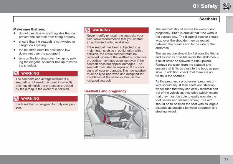
Seatbelts and pregnancy
G020998
The seatbelt should always be worn duringpregnancy. But it is crucial that it be worn inthe correct way. The diagonal section shouldwrap over the shoulder then be routedbetween the breasts and to the side of theabdomen.
The lap section should lay flat over the thighsand as low as possible under the abdomen. –It must never be allowed to ride upward.Remove the slack from the seatbelt andensure that it fits as close to the body as pos-sible. In addition, check that there are notwists in the seatbelt.
As the pregnancy progresses, pregnant dri-vers should adjust their seats and steeringwheel such that they can easily maintain con-trol of the vehicle as they drive (which meansthat they must be able to easily operate thefoot pedals and steering wheel). The aimshould be to position the seat with as large adistance as possible between abdomen andsteering wheel.
01 Safety
Seatbelts 01
18
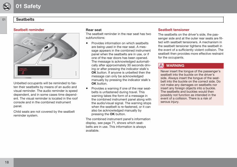
Seatbelt reminder
Unbelted occupants will be reminded to fas-ten their seatbelts by means of an audio andvisual reminder. The audio reminder is speeddependent, and in some cases time depend-ent. The visual reminder is located in the roofconsole and in the combined instrumentpanel.
Child seats are not covered by the seatbeltreminder system.
Rear seatThe seatbelt reminder in the rear seat has twosubfunctions:
• Provides information on which seatbeltsare being used in the rear seat. A mes-sage appears in the combined instrumentpanel when the seatbelts are in use, or ifone of the rear doors has been opened.The message is acknowledged automati-cally after approximately 30 seconds driv-ing or after pressing the indicator stalk'sOK button. If anyone is unbelted then themessage can only be acknowledgedmanually by pressing the indicator stalk'sOK button.
• Provides a warning if one of the rear seat-belts is unfastened during travel. Thiswarning takes the form of a message inthe combined instrument panel along withthe audio/visual signal. The warning stopswhen the seatbelt is re-fastened, or it canalso be acknowledged manually bypressing the OK button.
The combined instrument panel's informationdisplay, see page 71, shows which seat-belts are in use. This information is alwaysavailable.
Seatbelt tensionerThe seatbelts on the driver’s side, the pas-senger side and at the outer rear seats are fit-ted with seatbelt tensioners. A mechanism inthe seatbelt tensioner tightens the seatbelt inthe event of a sufficiently violent collision. Theseatbelt then provides more effective restraintfor the occupants.
WARNING
Never insert the tongue of the passenger'sseatbelt into the buckle on the driver'sside. Always insert the tongue of the seat-belt into the buckle on the correct side. Donot make any damages on seatbelts norinsert any foreign objects into a buckle.The seatbelts and buckles would thenpossibly not function as intended in theevent of a collision. There is a risk ofserous injury.
01 Safety
Airbags 01
19
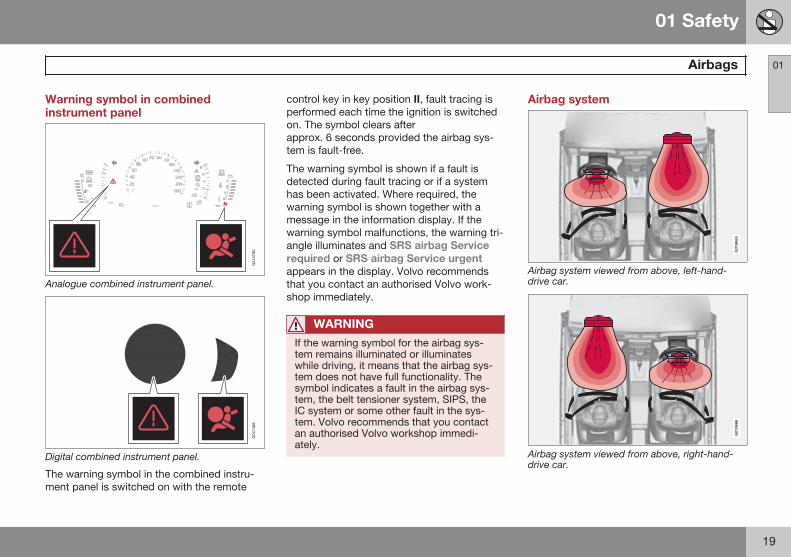
Warning symbol in combinedinstrument panel
Analogue combined instrument panel.
Digital combined instrument panel.
The warning symbol in the combined instru-ment panel is switched on with the remote
control key in key position II, fault tracing isperformed each time the ignition is switchedon. The symbol clears afterapprox. 6 seconds provided the airbag sys-tem is fault-free.
The warning symbol is shown if a fault isdetected during fault tracing or if a systemhas been activated. Where required, thewarning symbol is shown together with amessage in the information display. If thewarning symbol malfunctions, the warning tri-angle illuminates and SRS airbag Servicerequired or SRS airbag Service urgentappears in the display. Volvo recommendsthat you contact an authorised Volvo work-shop immediately.
WARNING
If the warning symbol for the airbag sys-tem remains illuminated or illuminateswhile driving, it means that the airbag sys-tem does not have full functionality. Thesymbol indicates a fault in the airbag sys-tem, the belt tensioner system, SIPS, theIC system or some other fault in the sys-tem. Volvo recommends that you contactan authorised Volvo workshop immedi-ately.
Airbag system
G018665
Airbag system viewed from above, left-hand-drive car.
G018666
Airbag system viewed from above, right-hand-drive car.
01 Safety
Airbags 01
20
The system consists of airbags and sensors.A sufficiently violent collision trips the sensorsand the airbag(s) are inflated and becomehot. The airbag cushions the initial collisionimpact for the occupant. The airbag deflateswhen compressed by the collision. When thisoccurs, smoke escapes into the car. This iscompletely normal. The entire process,including inflation and deflation of the airbag,occurs within tenths of a second.
WARNING
Volvo recommends that you contact anauthorised Volvo workshop for repair.Defective work in the airbag system couldcause malfunction and result in seriouspersonal injury.
NOTE
The detectors react differently dependingon the nature of the collision and whetheror not the seatbelts are fastened. Appliesto all seatbelt positions apart from centreseat rear.
It is therefore possible that only one (ornone) of the airbags may inflate in a colli-sion. The detectors sense the force of thecollision on the vehicle and the action isadapted accordingly so that one or moreairbags are deployed.
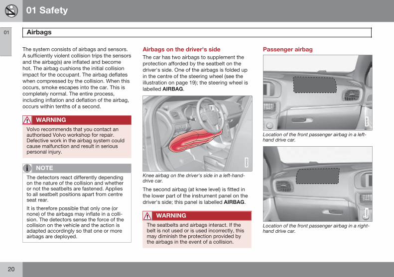
Airbags on the driver's sideThe car has two airbags to supplement theprotection afforded by the seatbelt on thedriver's side. One of the airbags is folded upin the centre of the steering wheel (see theillustration on page 19); the steering wheel islabelled AIRBAG.
Knee airbag on the driver's side in a left-hand-drive car.
The second airbag (at knee level) is fitted inthe lower part of the instrument panel on thedriver's side; this panel is labelled AIRBAG.
WARNING
The seatbelts and airbags interact. If thebelt is not used or is used incorrectly, thismay diminish the protection provided bythe airbags in the event of a collision.
Passenger airbag
Location of the front passenger airbag in a left-hand drive car.
Location of the front passenger airbag in a right-hand drive car.
01 Safety
Airbags 01
21
The car has an airbag to supplement the pro-tection afforded by the seatbelt on the pas-senger side. It is folded up into a compart-ment above the glovebox. Its cover panel ismarked AIRBAG.
WARNING
The seatbelts and airbags interact. If thebelt is not used or is used incorrectly, thismay diminish the protection provided bythe airbag in the event of a collision.
To minimise the risk of injury if the airbagdeploys, passengers must sit as upright aspossible with their feet on the floor andbacks against the backrest. Seatbeltsmust be secured.
WARNING
Do not put objects in front of or above thedashboard where the passenger airbag islocated.
WARNING
Never place a child in a child seat or on abooster cushion in the front seat if the air-bag is activated.
Never allow anybody to stand or sit in frontof the front passenger seat.
No one shorter than 140 cm should eversit in the front passenger seat if the airbagis activated.
Failure to follow the advice given abovecan endanger life.
01 Safety
Activating/deactivating the airbag* 01
22 * Option/accessory, for more information, see Introduction.
Key switch off - PACOS*
General informationThe airbag for the front passenger seat canbe deactivated if the car is equipped with aswitch, PACOS (Passenger Airbag Cut OffSwitch). For information on how to activate/deactivate, see under the heading Activating/deactivating.
Key switch off/switchThe switch for the passenger airbag (PACOS)is located on the passenger end of the instru-ment panel and is accessible when the pas-senger door is open (see under the headingbelow, Activating/deactivating).
Check that the switch is in the required posi-tion. The remote control key's key bladeshould be used to change position.
For information on the key blade, seepage 48.
WARNING
Failure to follow the advice given abovecan endanger the lives of passengers inthe car.
WARNING
If the car is equipped with a front passen-ger airbag, but does not have a PACOSswitch (Passenger Airbag Cut Off Switch),then the airbag will always be activated.
WARNING
Never place a child in a child seat or on abooster cushion in the front seat if the air-bag is activated and the symbol inthe roof console is illuminated. Failure tofollow this advice could endanger the lifeof the child.
WARNING
Do not allow anyone to sit in the front pas-senger seat if the message in the roof con-sole (see page 23) indicates that the air-bag is deactivated, at the same time as thewarning symbol for the airbag system isshown in the combined instrument panel.This indicates that there has been a severemalfunction. Visit a workshop as soon aspossible. Volvo recommends that you con-tact an authorised Volvo workshop.
Activating/deactivating
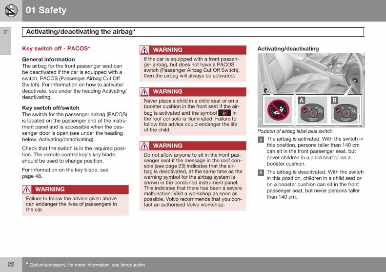
Position of airbag label plus switch.
The airbag is activated. With the switch inthis position, persons taller than 140 cmcan sit in the front passenger seat, butnever children in a child seat or on abooster cushion.
The airbag is deactivated. With the switchin this position, children in a child seat oron a booster cushion can sit in the frontpassenger seat, but never persons tallerthan 140 cm.
01 Safety
Activating/deactivating the airbag* 01
* Option/accessory, for more information, see Introduction. 23
WARNING
Activated airbag (passenger seat):
Never place a child in a child seat or on abooster cushion on the front passengerseat when the airbag is activated. Thisapplies to everyone shorter than 140 cm.
Deactivated airbag (passenger seat):
No one taller than 140 cm should ever sitin the front passenger seat when the air-bag is deactivated.
Failure to follow the advice given abovecan endanger life.
NOTE
When the remote control key is in keyposition II the warning symbol for the air-bag is shown in the combined instrumentpanel for approx. 6 seconds (see page 19).
Following which, the indicator in the roofconsole is illuminated showing the correctstatus for the front passenger seat airbag.For more information about the differentkey positions for the remote control key,see page 81.
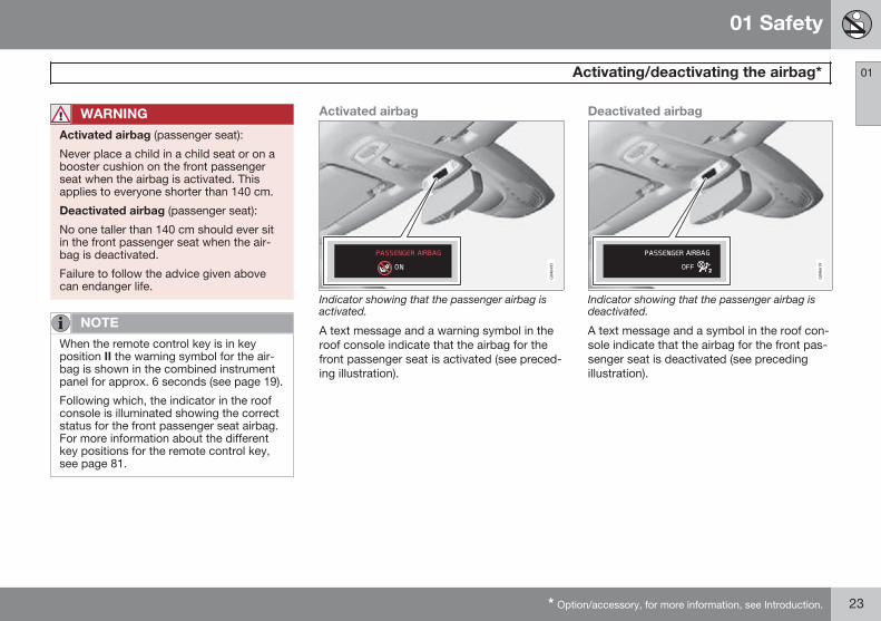
Activated airbag
Indicator showing that the passenger airbag isactivated.
A text message and a warning symbol in theroof console indicate that the airbag for thefront passenger seat is activated (see preced-ing illustration).
Deactivated airbag
Indicator showing that the passenger airbag isdeactivated.
A text message and a symbol in the roof con-sole indicate that the airbag for the front pas-senger seat is deactivated (see precedingillustration).
01 Safety
Side airbags (SIPS bags) 01
24
Side airbag
In a side impact collision a large proportion ofthe collision force is transferred by the SIPS(Side Impact Protection System) to beams,pillars, the floor, the roof and other structuralparts of the body. The side airbags at thedriver's and front passenger seats protect thechest area and the hip and are an importantpart of the SIPS.
The SIPS bag system consists of two maincomponents, side airbag and sensors. Theside airbags are located in the front seatbackrests.
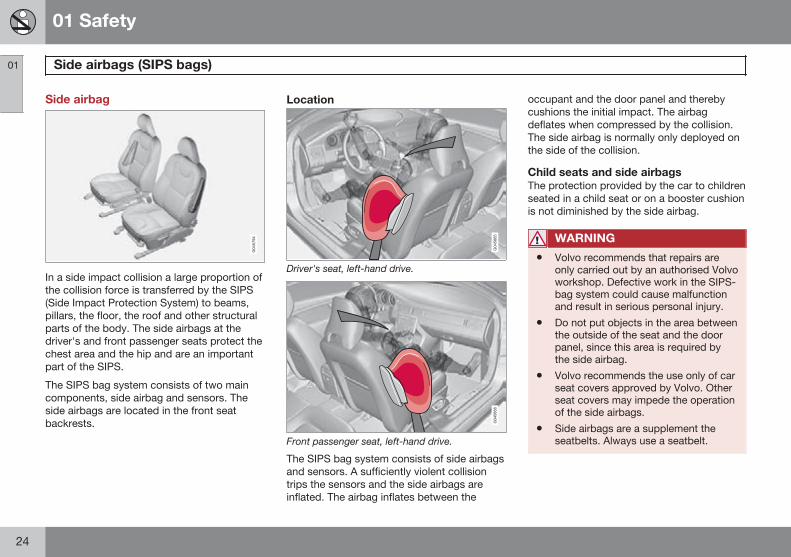
Location
Driver's seat, left-hand drive.
Front passenger seat, left-hand drive.
The SIPS bag system consists of side airbagsand sensors. A sufficiently violent collisiontrips the sensors and the side airbags areinflated. The airbag inflates between the
occupant and the door panel and therebycushions the initial impact. The airbagdeflates when compressed by the collision.The side airbag is normally only deployed onthe side of the collision.
Child seats and side airbagsThe protection provided by the car to childrenseated in a child seat or on a booster cushionis not diminished by the side airbag.
WARNING
• Volvo recommends that repairs areonly carried out by an authorised Volvoworkshop. Defective work in the SIPS-bag system could cause malfunctionand result in serious personal injury.
• Do not put objects in the area betweenthe outside of the seat and the doorpanel, since this area is required bythe side airbag.
• Volvo recommends the use only of carseat covers approved by Volvo. Otherseat covers may impede the operationof the side airbags.
• Side airbags are a supplement theseatbelts. Always use a seatbelt.
01 Safety
Inflatable Curtain (IC) 01
25
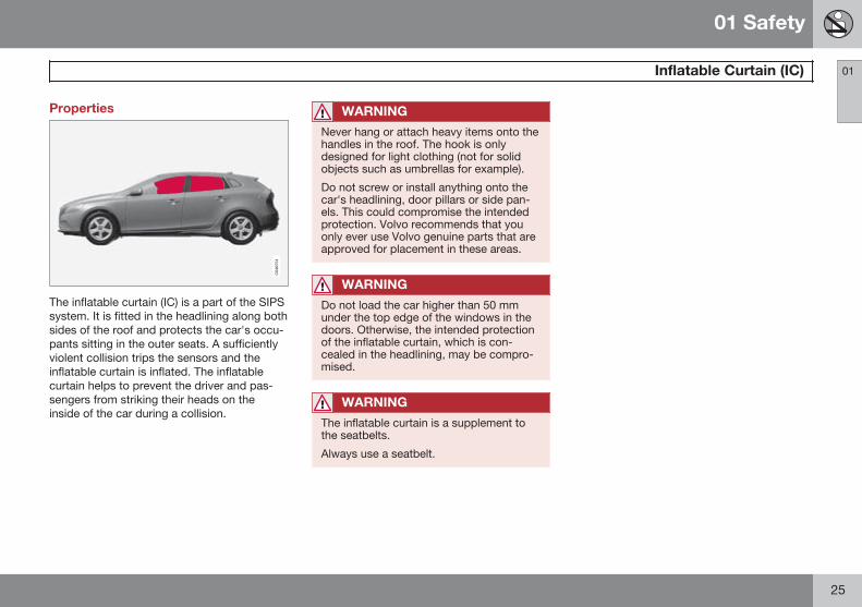
Properties
The inflatable curtain (IC) is a part of the SIPSsystem. It is fitted in the headlining along bothsides of the roof and protects the car's occu-pants sitting in the outer seats. A sufficientlyviolent collision trips the sensors and theinflatable curtain is inflated. The inflatablecurtain helps to prevent the driver and pas-sengers from striking their heads on theinside of the car during a collision.
WARNING
Never hang or attach heavy items onto thehandles in the roof. The hook is onlydesigned for light clothing (not for solidobjects such as umbrellas for example).
Do not screw or install anything onto thecar's headlining, door pillars or side pan-els. This could compromise the intendedprotection. Volvo recommends that youonly ever use Volvo genuine parts that areapproved for placement in these areas.
WARNING
Do not load the car higher than 50 mmunder the top edge of the windows in thedoors. Otherwise, the intended protectionof the inflatable curtain, which is con-cealed in the headlining, may be compro-mised.
WARNING
The inflatable curtain is a supplement tothe seatbelts.
Always use a seatbelt.
01 Safety
WHIPS 01
26
Protection against whiplash injury –WHIPS
The whiplash protection system (WHIPS) con-sists of energy absorbing backrests and spe-cially designed head restraints in the frontseats. The system is actuated by a rear-endcollision, where the angle and speed of thecollision, and the nature of the colliding vehi-cle all have an influence.
WARNING
The WHIPS system is a supplement to theseatbelts. Always use a seatbelt.
Properties of the seatWhen the WHIPS system is deployed, thefront seat backrests are lowered backward toalter the seating position of the driver andfront seat passenger. This reduces the risk ofwhiplash injury.
WARNING
Never modify or repair the seat or WHIPSsystem yourself. Volvo recommends thatyou contact an authorised Volvo work-shop.
WHIPS system and child seats/boostercushionsThe protection provided by the car to childrenseated in a child seat or on a booster cushionis not diminished by the WHIPS system.
Correct seating positionFor the best possible protection, the driverand front seat passenger should sit in thecentre of the seat with as little space as pos-sible between the head and the headrestraint.
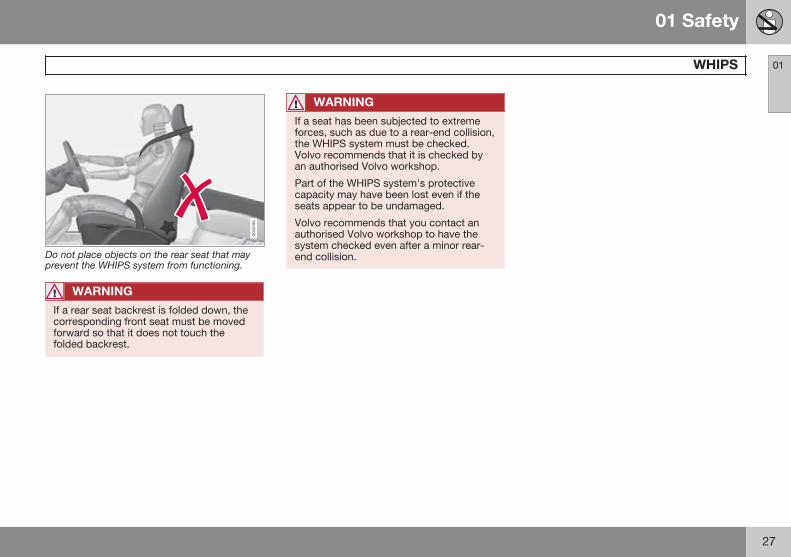
Do not obstruct the WHIPS system
Do not leave any objects on the floor behind thedriver's seat/passenger seat that may prevent theWHIPS system from functioning.
WARNING
Do not squeeze rigid objects between therear seat cushion and the front seat back-rest. Make sure you do not to obstruct thefunction of the WHIPS system.
01 Safety
WHIPS 01
27
Do not place objects on the rear seat that mayprevent the WHIPS system from functioning.
WARNING
If a rear seat backrest is folded down, thecorresponding front seat must be movedforward so that it does not touch thefolded backrest.
WARNING
If a seat has been subjected to extremeforces, such as due to a rear-end collision,the WHIPS system must be checked.Volvo recommends that it is checked byan authorised Volvo workshop.
Part of the WHIPS system's protectivecapacity may have been lost even if theseats appear to be undamaged.
Volvo recommends that you contact anauthorised Volvo workshop to have thesystem checked even after a minor rear-end collision.
01 Safety
When the systems deploy 01
28
When the systems deploy
System Triggered
Seatbelt ten-sioner, front seat
In the event of a frontalcollision, and/or side-impact collision, and/orrear-end collisionand/or overturning
Seatbelt ten-sioner, rearseatA
In a frontal collisionand/or side-impactaccident and/or over-turning
Airbags
(Steering wheelairbag, knee air-bag, passengerairbag)
In a frontal collisionB
Side airbags(SIPS)
In a side-impact acci-dentB
System Triggered
Inflatable Cur-tain IC
In the event of a sideimpact and/or over-turning and/or somefrontal collisionsB
Whiplash pro-tection WHIPS
In a rear-end collision
A There is no seatbelt tensioner at the centre rear seat.B The bodywork of the car could be greatly deformed in a
collision without airbag deployment. A number of factorssuch as the rigidity and weight of the object hit, the speedof the car, the angle of the collision etc. affects how thedifferent safety systems of the car are activated.
If the airbags have deployed, the following isrecommended:
• Recovering the car. Volvo recommendsthat you have it conveyed to an author-ised Volvo workshop. Do not drive withdeployed airbags.
• Volvo recommends that you engage anauthorised Volvo workshop to handle thereplacement of components in the car'ssafety systems.
• Always contact a doctor.
NOTE
The airbags and belt tensioner system aredeployed only once during a collision.
WARNING
The airbag system's control module islocated in the centre console. If the centreconsole is drenched with water or otherliquid, disconnect the battery cables. Donot attempt to start the car since the air-bags may deploy. Recovering the car.Volvo recommends that you have it con-veyed to an authorised Volvo workshop.
WARNING
Never drive with deployed airbags. Theycan make steering difficult. Other safetysystems may also be damaged. Thesmoke and dust created when the airbagsare deployed can cause skin and eye irrita-tion/injury after intensive exposure. In caseof irritation, wash with cold water. Therapid deployment sequence and airbagfabric may cause friction and skin burns.
01 Safety
Safety mode 01
29
Driving after a collision
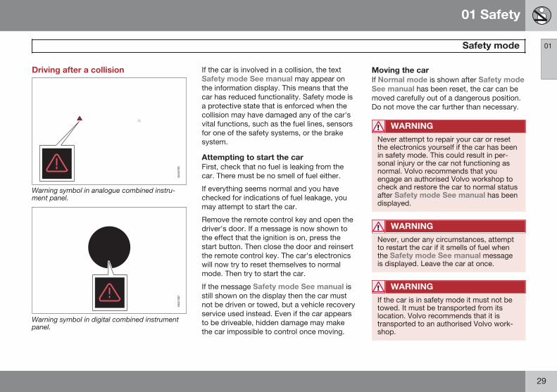
Warning symbol in analogue combined instru-ment panel.
Warning symbol in digital combined instrumentpanel.
If the car is involved in a collision, the textSafety mode See manual may appear onthe information display. This means that thecar has reduced functionality. Safety mode isa protective state that is enforced when thecollision may have damaged any of the car'svital functions, such as the fuel lines, sensorsfor one of the safety systems, or the brakesystem.
Attempting to start the carFirst, check that no fuel is leaking from thecar. There must be no smell of fuel either.
If everything seems normal and you havechecked for indications of fuel leakage, youmay attempt to start the car.
Remove the remote control key and open thedriver's door. If a message is now shown tothe effect that the ignition is on, press thestart button. Then close the door and reinsertthe remote control key. The car's electronicswill now try to reset themselves to normalmode. Then try to start the car.
If the message Safety mode See manual isstill shown on the display then the car mustnot be driven or towed, but a vehicle recoveryservice used instead. Even if the car appearsto be driveable, hidden damage may makethe car impossible to control once moving.
Moving the carIf Normal mode is shown after Safety modeSee manual has been reset, the car can bemoved carefully out of a dangerous position.Do not move the car further than necessary.
WARNING
Never attempt to repair your car or resetthe electronics yourself if the car has beenin safety mode. This could result in per-sonal injury or the car not functioning asnormal. Volvo recommends that youengage an authorised Volvo workshop tocheck and restore the car to normal statusafter Safety mode See manual has beendisplayed.
WARNING
Never, under any circumstances, attemptto restart the car if it smells of fuel whenthe Safety mode See manual messageis displayed. Leave the car at once.
WARNING
If the car is in safety mode it must not betowed. It must be transported from itslocation. Volvo recommends that it istransported to an authorised Volvo work-shop.
01 Safety
Pedestrian airbag (Pedestrian Airbag) 01
30
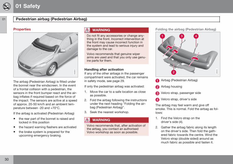
Properties
The airbag (Pedestrian Airbag) is fitted underthe bonnet near the windscreen. In the eventof a frontal collision with a pedestrian, thesensors in the front bumper react and the air-bag inflates if required based on the force ofthe impact. The sensors are active at a speedof approx. 20-50 km/h and an ambient tem-perature between -20 and +70°C.
If the airbag is activated (Pedestrian Airbag)
• the rear part of the bonnet is raised andlocked in this position
• the hazard warning flashers are activated
• the brake system is prepared for theupcoming emergency braking.
WARNING
Do not fit any accessories or change any-thing in the front. Incorrect intervention atthe front may cause incorrect function inthe system and lead to serious injury anddamage to the car.
Volvo recommends that genuine wiperarms are used and that you only use genu-ine parts for them.
Handling after activationIf any of the other airbags in the passengercompartment were activated, the car remainsin safety mode, see page 29.
If only the pedestrian airbag was activated:
1. Move the car to a safe location as closeas possible.
2. Fold the airbag following the instructionsunder the next heading "Folding the air-bag (Pedestrian Airbag)".
3. Seek the nearest workshop.
WARNING
Volvo recommends that, after activation ofthe airbag, you contact an authorisedVolvo workshop as soon as possible.
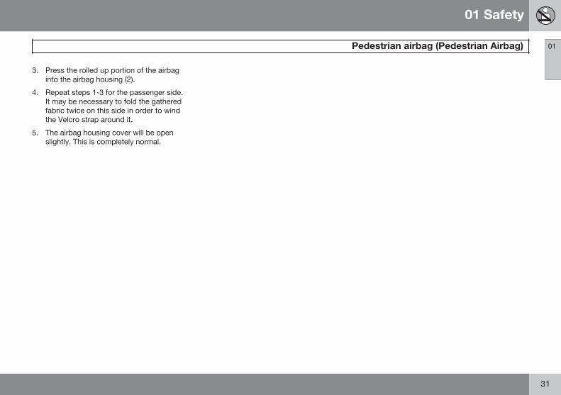
Folding the airbag (Pedestrian Airbag)
Airbag (Pedestrian Airbag)
Airbag housing
Velcro strap, passenger side
Velcro strap, driver's side
The airbag may feel warm and give offsmoke. This is normal. Fold the airbag as fol-lows:
1. Find the Velcro strap on thedriver's side (4).
2. Gather the airbag fabric along its lengthon the driver's side. Then fold the gath-ered fabric towards the centre. Wind theVelcro strap (double sided) around asmuch fabric as possible and fasten it.
01 Safety
Pedestrian airbag (Pedestrian Airbag) 01
31
3. Press the rolled up portion of the airbaginto the airbag housing (2).
4. Repeat steps 1-3 for the passenger side.It may be necessary to fold the gatheredfabric twice on this side in order to windthe Velcro strap around it.
5. The airbag housing cover will be openslightly. This is completely normal.
01 Safety
Child safety 01
32
Children should sit comfortably andsafelyVolvo recommends that children travel inrear-facing child seats until as late an age aspossible, at least until 3-4 years of age, andthen front-facing booster cushions/child seatsuntil up to 10 years of age.
The position of a child in the car and thechoice of equipment are dictated by thechild's weight and size, for more information,see page 34.
NOTE
Regulations regarding the placement ofchildren in cars vary from country to coun-try. Check what does apply.
Children of all ages and sizes must always sitcorrectly secured in the car. Never allow achild to sit on the knee of a passenger.
Volvo has child safety equipment (child seats,booster cushions & attachment devices)which is designed for your particular car.Using Volvo's child safety equipment pro-vides you with optimum conditions for yourchild to travel safely in the car. Furthermore,the child safety equipment fits and is easy touse.
NOTE
In the event of questions when fitting childsafety products, contact the manufacturerfor clearer instructions.
Child seats
G020739
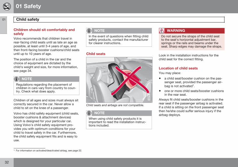
Child seats and airbags are not compatible.
NOTE
When using child safety products it isimportant to read the installation instruc-tions included.
WARNING
Do not secure the straps of the child seatto the seat's horizontal adjustment bar,springs or the rails and beams under theseat. Sharp edges may damage the straps.
Look in the installation instructions for thechild seat for the correct fitting.
Location of child seatsYou may place:
• a child seat/booster cushion on the pas-senger seat, provided the passenger air-bag is not activated1.
• one or more child seats/booster cushionsin the rear seat.
Always fit child seats/booster cushions in therear seat if the passenger airbag is activated.If a child is sitting on the front passenger seatthen he/she could suffer serious injury if theairbag deploys.
1 For information on activated/deactivated airbag, see page 22.
01 Safety
Child safety 01
33
WARNING
Never place a child in a child seat or on abooster cushion in the front seat if the air-bag (SRS) is activated.
No one shorter than 140 cm should eversit in the front passenger seat if the airbag(SRS) is activated.
Failure to follow the advice given abovecan endanger life.
WARNING
Booster cushions/child seats with steelbraces or some other design that couldrest on the seatbelt buckle's opening but-ton must not be used, as they could causethe seatbelt buckle to open accidentally.
Do not allow the upper section of the childseat to rest against the windscreen.
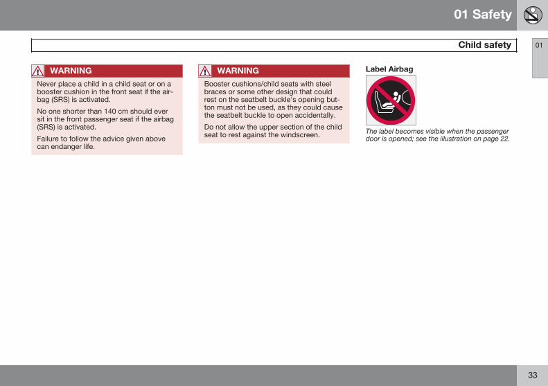
Label Airbag
The label becomes visible when the passengerdoor is opened; see the illustration on page 22.
01 Safety
Child safety 01
34
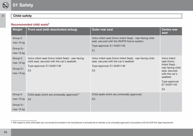
Recommended child seats2
Weight Front seat (with deactivated airbag) Outer rear seat Centre rearseat
Group 0
max 10 kg
Group 0+
max 13 kg
Volvo infant seat (Volvo Infant Seat) - rear-facing childseat, secured with the ISOFIX fixture system.
Type approval: E1 04301146
(L)
Group 0
max 10 kg
Group 0+
max 13 kg
Volvo infant seat (Volvo Infant Seat) - rear-facingchild seat, secured with the car's seatbelt.
Type approval: E1 04301146
(U)
Volvo infant seat (Volvo Infant Seat) - rear-facing childseat, secured with the car's seatbelt.
Type approval: E1 04301146
(U)
Volvo infantseat (VolvoInfant Seat) -rear-facing childseat, securedwith the car'sseatbelt.
Type approval:E1 04301146
(U)
Group 0
max 10 kg
Group 0+
max 13 kg
Child seats which are universally approved.A
(U)
Child seats which are universally approved.
(U)
2 With regard to other child seats your car should be included in the manufacturer's enclosed list of vehicles or be universally approved in accordance with the ECE R44 legal requirement.
01 Safety
Child safety 01
}}35
Weight Front seat (with deactivated airbag) Outer rear seat Centre rearseat
Group 1
9-18 kg
Volvo rear-facing/turnable child seat (VolvoConvertible Child Seat) - rear-facing child seat,secured with the car's seatbelt and straps.
Type approval: E5 04192
(L)
Volvo rear-facing/turnable child seat (Volvo ConvertibleChild Seat) - rear-facing child seat, secured with the car'sseatbelt and straps.
Type approval: E5 04192
(L)
Group 1
9-18 kg
Child seats which are universally approved.A
(U)
Child seats which are universally approved.
(U)
Group 2
15-25 kg
Volvo rear-facing/turnable child seat (VolvoConvertible Child Seat) - rear-facing child seat,secured with the car's seatbelt and straps.
Type approval: E5 04192
(L)
Volvo rear-facing/turnable child seat (Volvo ConvertibleChild Seat) - rear-facing child seat, secured with the car'sseatbelt and straps.
Type approval: E5 04192
(L)
Group 2
15-25 kg
Volvo rear-facing/turnable child seat (VolvoConvertible Child Seat) - front-facing child seat,secured with the car's seatbelt.
Type approval: E5 04191
(U)
Volvo rear-facing/turnable child seat (Volvo ConvertibleChild Seat) - front-facing child seat, secured with thecar's seatbelt.
Type approval: E5 04191
(U)
Group 2/3
15-36 kg
Volvo booster seat with backrest (Volvo BoosterSeat with backrest).
Type approval: E1 04301169
(UF)
Volvo booster seat with backrest (Volvo Booster Seatwith backrest).
Type approval: E1 04301169
(UF)
01 Safety
Child safety 01
36
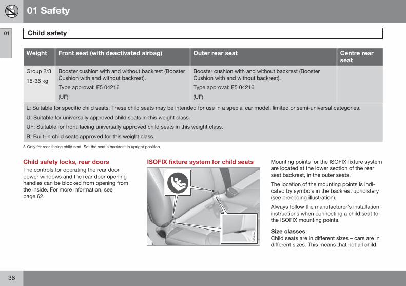
Weight Front seat (with deactivated airbag) Outer rear seat Centre rearseat
Group 2/3
15-36 kg
Booster cushion with and without backrest (BoosterCushion with and without backrest).
Type approval: E5 04216
(UF)
Booster cushion with and without backrest (BoosterCushion with and without backrest).
Type approval: E5 04216
(UF)
L: Suitable for specific child seats. These child seats may be intended for use in a special car model, limited or semi-universal categories.
U: Suitable for universally approved child seats in this weight class.
UF: Suitable for front-facing universally approved child seats in this weight class.
B: Built-in child seats approved for this weight class.
A Only for rear-facing child seat. Set the seat's backrest in upright position.
Child safety locks, rear doorsThe controls for operating the rear doorpower windows and the rear door openinghandles can be blocked from opening fromthe inside. For more information, seepage 62.
ISOFIX fixture system for child seats Mounting points for the ISOFIX fixture systemare located at the lower section of the rearseat backrest, in the outer seats.
The location of the mounting points is indi-cated by symbols in the backrest upholstery(see preceding illustration).
Always follow the manufacturer's installationinstructions when connecting a child seat tothe ISOFIX mounting points.
Size classesChild seats are in different sizes – cars are indifferent sizes. This means that not all child
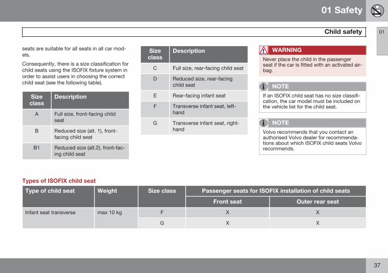
01 Safety
Child safety 01
37
seats are suitable for all seats in all car mod-els.
Consequently, there is a size classification forchild seats using the ISOFIX fixture system inorder to assist users in choosing the correctchild seat (see the following table).
Sizeclass
Description
A Full size, front-facing childseat
B Reduced size (alt. 1), front-facing child seat
B1 Reduced size (alt.2), front-fac-ing child seat
Sizeclass
Description
C Full size, rear-facing child seat
D Reduced size, rear-facingchild seat
E Rear-facing infant seat
F Transverse infant seat, left-hand
G Transverse infant seat, right-hand
WARNING
Never place the child in the passengerseat if the car is fitted with an activated air-bag.
NOTE
If an ISOFIX child seat has no size classifi-cation, the car model must be included onthe vehicle list for the child seat.
NOTE
Volvo recommends that you contact anauthorised Volvo dealer for recommenda-tions about which ISOFIX child seats Volvorecommends.
Types of ISOFIX child seat
Type of child seat Weight Size class Passenger seats for ISOFIX installation of child seats
Front seat Outer rear seat
Infant seat transverse max 10 kg F X X
G X X
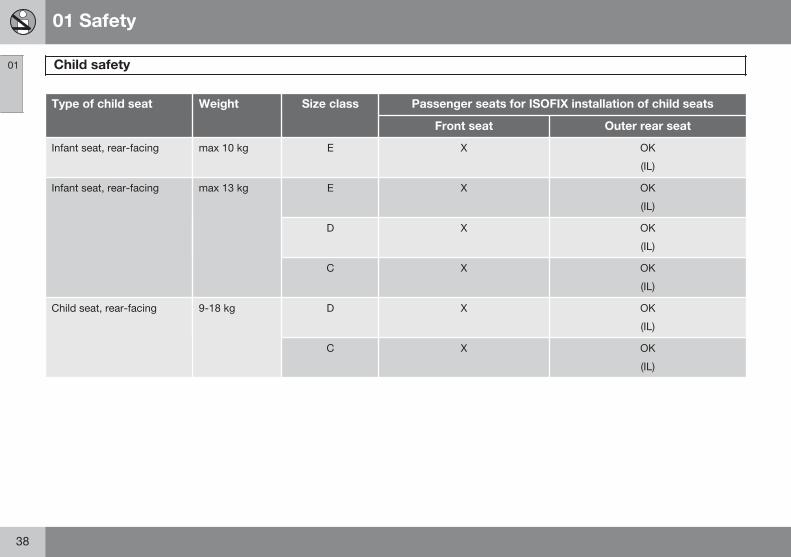
01 Safety
Child safety 01
38
Type of child seat Weight Size class Passenger seats for ISOFIX installation of child seats
Front seat Outer rear seat
Infant seat, rear-facing max 10 kg E X OK
(IL)
Infant seat, rear-facing max 13 kg E X OK
(IL)
D X OK
(IL)
C X OK
(IL)
Child seat, rear-facing 9-18 kg D X OK
(IL)
C X OK
(IL)
01 Safety
Child safety 01
}}39
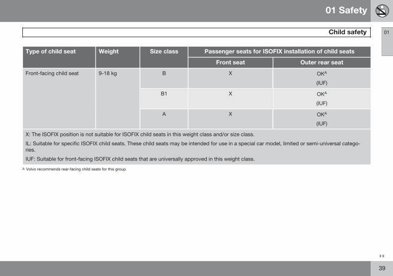
Type of child seat Weight Size class Passenger seats for ISOFIX installation of child seats
Front seat Outer rear seat
Front-facing child seat 9-18 kg B X OKA
(IUF)
B1 X OKA
(IUF)
A X OKA
(IUF)
X: The ISOFIX position is not suitable for ISOFIX child seats in this weight class and/or size class.
IL: Suitable for specific ISOFIX child seats. These child seats may be intended for use in a special car model, limited or semi-universal catego-ries.
IUF: Suitable for front-facing ISOFIX child seats that are universally approved in this weight class.
A Volvo recommends rear-facing child seats for this group.

01 Safety
Child safety 01
40
Upper mounting points for child seats
The car is equipped with upper mountingpoints for certain front-facing child seats.These mounting points are located on therear of the seat.
The upper mounting points are primarilyintended for use with front-facing child seats.Volvo recommends that small children shouldsit in rear-facing child seats to as late an ageas possible.
NOTE
Fold the head restraints in order to facili-tate fitting this type of child seat in carswith folding head restraints on the outerseats.
NOTE
In cars with a cargo cover over the lug-gage compartment, this must be removedbefore child seats can be attached to thesecuring points.
For detailed information on how the child seatshould be tensioned in the upper mountingpoints, see the seat manufacturer's instruc-tions.
WARNING
The child seat's straps must always bedrawn through the hole in the headrestraint leg before they are tensioned atthe attachment point.
01 Safety
01
41
42 * Option/accessory, for more information, see Introduction.
Remote control key/key blade................................................................ 44Battery replacement, remote control key/PCC*...................................... 50Keyless*.................................................................................................. 52Locking/unlocking................................................................................... 56Child safety locks.................................................................................... 62Alarm*...................................................................................................... 63
LOCKS AND ALARM
02 Locks and alarm
Remote control key/key blade
02
44
GeneralThe car is supplied with two remote controlkeys - standard or with keyless function. Theyare used to start/switch off the car and forlocking/unlocking.
The remote control key contains a removablekey blade made of metal. The visible sectionis available in two versions so that it is possi-ble to distinguish between the remote controlkeys.
Additional remote control keys can beordered - up to six can be programmed andused for the same car.
There are four remote control key variants:
• Remote control key, standard1
• Remote control key with Keyless start1
• Remote control key with Keyless drive1
• PCC with Keyless drive 2
For information on remote control key func-tion buttons see page 46.
PCC plus remote control key with keylessfunction has extended functionality comparedwith standard remote control key. The rest of
this chapter describes functions available inall variants.
WARNING
If there are children in the car:
Remember to switch off the supply to thepower windows by removing the remotecontrol key if the driver leaves the car.
Loss of a remote control keyIf you lose a remote control key then a newone can be ordered at a workshop - anauthorised Volvo workshop is recommended.The remaining remote control keys must thenbe taken to the workshop. The code of themissing remote control key must be erasedfrom the system as a theft prevention meas-ure.
The current number of keys registered to thecar can be checked in the menu system MYCAR under Information Number of keys.For a description of the menu system, seepage 207.
Key memory3 - door mirrors, driver’sseat and steering forceThe settings are automatically connected toeach respective remote control key, seepages 84, 106 and 240. When locking withthe remote control key the setting of the com-bined instrument panel's theme is saved inthe key, see pages 72 and 209.
The function can be activated/deactivated inthe menu system MY CAR under SettingsCar settings Car key memory.
For a description of the menu system, seepage 207.
For remote control keys with keyless function,see page 52.
Indicator for locking/unlockingWhen the car is locked or unlocked using theremote control key, the direction indicatorsconfirm that locking/unlocking was correctlyperformed.
• Locking - one flash and the door mirrorsare folded4 in.
• Unlocking - two flashes and the door mir-rors are folded4 out.
1 5-button key2 6-button key3 Only in combination with power driver's seat and power mirrors.4 Only for cars with retractable power door mirrors.
02 Locks and alarm
Remote control key/key blade
02
45
NOTE
Be aware of the risk of locking the remotecontrol key in the car.
When locking, indication is given only if alllocks have been locked and all doors areclosed. Indication is given when the last doorhas been closed.
Selecting the functionDifferent options for indicating locking/unlocking with light can be set in the car'smenu system, see page 207.
Search in the menu system MY CAR forSettings Car settings Light settingsand select Door lock confirmation lightand/or Unlock confirmation light.
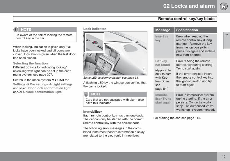
Lock indicator
Same LED as alarm indicator, see page 63.
A flashing LED by the windscreen verifies thatthe car is locked.
NOTE
Cars that are not equipped with alarm alsohave this indicator.
ImmobiliserEach remote control key has a unique code.The car can only be started with the correctremote control key with the correct code.
The following error messages in the com-bined instrument panel's information displayare related to the electronic immobiliser:
Message Specification
Insert carkey
Error when reading theremote control key duringstarting - Remove the keyfrom the ignition switch,press it in again and make anew start attempt.
Car keynot found
(Applicableonly to carswith Key-less Drive,seepage 54.)
Error reading the remotecontrol key during starting -Try to start again.
If the error persists: Insertthe remote control key intothe ignition switch and tryto start again.
Immobi-liser Try tostart again
Error in immobiliser systemduring starting. If the errorpersists: Contact a work-shop - an authorised Volvoworkshop is recommended.
For starting the car, see page 115.
02 Locks and alarm
Remote control key/key blade
02
46 * Option/accessory, for more information, see Introduction.
Functions
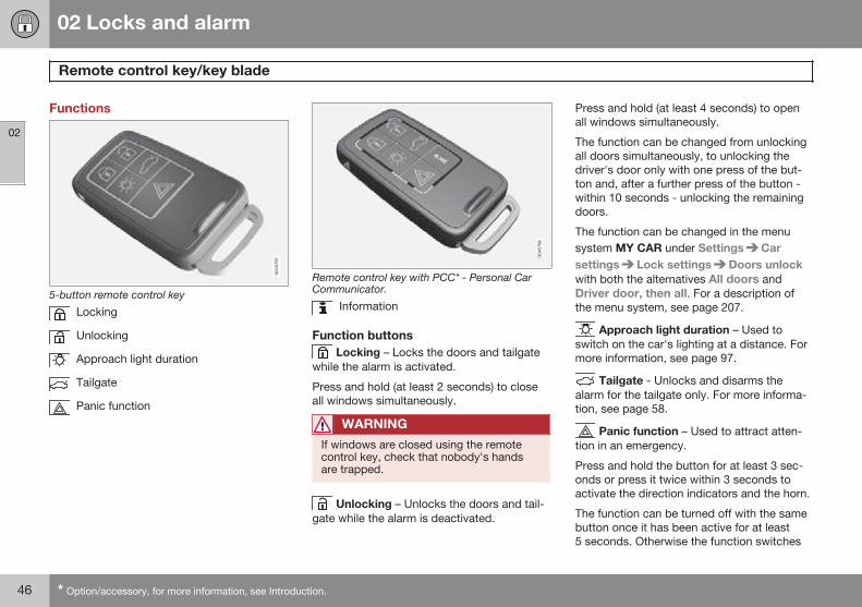
5-button remote control key
Locking
Unlocking
Approach light duration
Tailgate
Panic function
Remote control key with PCC* - Personal CarCommunicator.
Information
Function buttons Locking – Locks the doors and tailgate
while the alarm is activated.
Press and hold (at least 2 seconds) to closeall windows simultaneously.
WARNING
If windows are closed using the remotecontrol key, check that nobody's handsare trapped.
Unlocking – Unlocks the doors and tail-gate while the alarm is deactivated.
Press and hold (at least 4 seconds) to openall windows simultaneously.
The function can be changed from unlockingall doors simultaneously, to unlocking thedriver's door only with one press of the but-ton and, after a further press of the button -within 10 seconds - unlocking the remainingdoors.
The function can be changed in the menusystem MY CAR under Settings Carsettings Lock settings Doors unlockwith both the alternatives All doors andDriver door, then all. For a description ofthe menu system, see page 207.
Approach light duration – Used toswitch on the car's lighting at a distance. Formore information, see page 97.
Tailgate - Unlocks and disarms thealarm for the tailgate only. For more informa-tion, see page 58.
Panic function – Used to attract atten-tion in an emergency.
Press and hold the button for at least 3 sec-onds or press it twice within 3 seconds toactivate the direction indicators and the horn.
The function can be turned off with the samebutton once it has been active for at least5 seconds. Otherwise the function switches
02 Locks and alarm
Remote control key/key blade
02
* Option/accessory, for more information, see Introduction. 47
off automatically after 2 minutes and 45 sec-onds.
RangeThe remote control key's functions have arange of about 20 m from the car.
If the car does not verify a button beingpressed - move closer and try again.
NOTE
The remote control key functions may bedisrupted by surrounding radio waves,buildings, topographical conditions, etc.The car can always be locked/unlockedwith the key blade, see page 49.
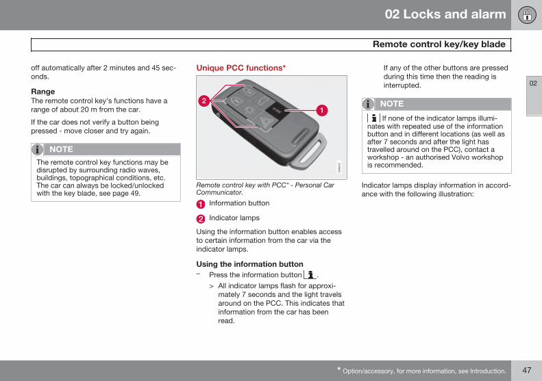
Unique PCC functions*
Remote control key with PCC* - Personal CarCommunicator.
Information button
Indicator lamps
Using the information button enables accessto certain information from the car via theindicator lamps.
Using the information button– Press the information button .
> All indicator lamps flash for approxi-mately 7 seconds and the light travelsaround on the PCC. This indicates thatinformation from the car has beenread.
If any of the other buttons are pressedduring this time then the reading isinterrupted.
NOTE
If none of the indicator lamps illumi-nates with repeated use of the informationbutton and in different locations (as well asafter 7 seconds and after the light hastravelled around on the PCC), contact aworkshop - an authorised Volvo workshopis recommended.
Indicator lamps display information in accord-ance with the following illustration:
02 Locks and alarm
Remote control key/key blade
02
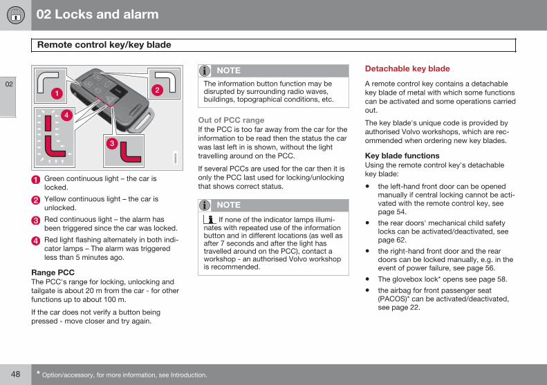
48 * Option/accessory, for more information, see Introduction.
Green continuous light – the car islocked.
Yellow continuous light – the car isunlocked.
Red continuous light – the alarm hasbeen triggered since the car was locked.
Red light flashing alternately in both indi-cator lamps – The alarm was triggeredless than 5 minutes ago.
Range PCCThe PCC's range for locking, unlocking andtailgate is about 20 m from the car - for otherfunctions up to about 100 m.
If the car does not verify a button beingpressed - move closer and try again.
NOTE
The information button function may bedisrupted by surrounding radio waves,buildings, topographical conditions, etc.
Out of PCC rangeIf the PCC is too far away from the car for theinformation to be read then the status the carwas last left in is shown, without the lighttravelling around on the PCC.
If several PCCs are used for the car then it isonly the PCC last used for locking/unlockingthat shows correct status.
NOTE
If none of the indicator lamps illumi-nates with repeated use of the informationbutton and in different locations (as well asafter 7 seconds and after the light hastravelled around on the PCC), contact aworkshop - an authorised Volvo workshopis recommended.
Detachable key blade
A remote control key contains a detachablekey blade of metal with which some functionscan be activated and some operations carriedout.
The key blade's unique code is provided byauthorised Volvo workshops, which are rec-ommended when ordering new key blades.
Key blade functionsUsing the remote control key's detachablekey blade:
• the left-hand front door can be openedmanually if central locking cannot be acti-vated with the remote control key, seepage 54.
• the rear doors' mechanical child safetylocks can be activated/deactivated, seepage 62.
• the right-hand front door and the reardoors can be locked manually, e.g. in theevent of power failure, see page 56.
• The glovebox lock* opens see page 58.
• the airbag for front passenger seat(PACOS)* can be activated/deactivated,see page 22.
02 Locks and alarm
Remote control key/key blade
02
49
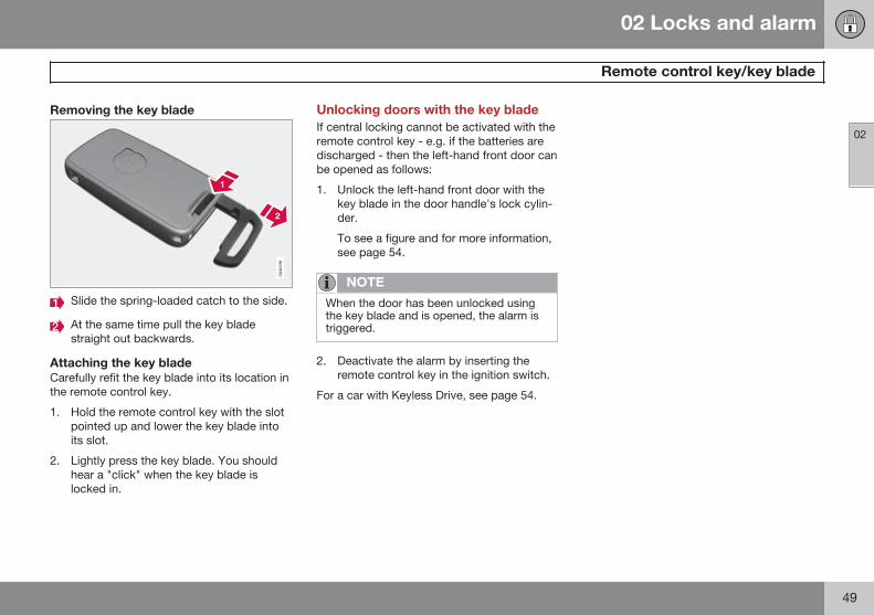
Removing the key blade
Slide the spring-loaded catch to the side.
At the same time pull the key bladestraight out backwards.
Attaching the key bladeCarefully refit the key blade into its location inthe remote control key.
1. Hold the remote control key with the slotpointed up and lower the key blade intoits slot.
2. Lightly press the key blade. You shouldhear a "click" when the key blade islocked in.
Unlocking doors with the key bladeIf central locking cannot be activated with theremote control key - e.g. if the batteries aredischarged - then the left-hand front door canbe opened as follows:
1. Unlock the left-hand front door with thekey blade in the door handle's lock cylin-der.
To see a figure and for more information,see page 54.
NOTE
When the door has been unlocked usingthe key blade and is opened, the alarm istriggered.
2. Deactivate the alarm by inserting theremote control key in the ignition switch.
For a car with Keyless Drive, see page 54.
02 Locks and alarm
Battery replacement, remote control key/PCC*
02
50 * Option/accessory, for more information, see Introduction.
Replacing the batteryThe batteries should be replaced if:
• the information symbol illuminates in thecombined instrument panel and its infor-mation display shows Low battery inremote control. Please changebatteries.
and/or
• the locks repeatedly do not react to sig-nals from the remote control key within20 metres from the car.
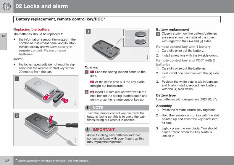
Opening Slide the spring-loaded catch to the
side.
At the same time pull the key bladestraight out backwards.
Insert a 3 mm slot screwdriver in thehole behind the spring-loaded catch andgently prize the remote control key up.
NOTE
Turn the remote control key over with thebuttons facing up, this is to avoid the bat-teries falling out when it is opened.
IMPORTANT
Avoid touching new batteries and theircontact surfaces with your fingers as thismay impair their function.
Battery replacementClosely study how the battery/batteriesare secured on the inside of the cover,with regard to their (+) and (–) sides.
Remote control key with 1 battery1. Carefully prize out the battery.2. Install a new one with the (+) side down.
Remote control key and PCC* with 2batteries1. Carefully prize out the batteries.2. First install one new one with the (+) side
up.3. Position the white plastic tab in between
and finally install a second new batterywith the (+) side down.
Battery typeUse batteries with designation CR2430, 3 V.
Assembly1. Press the remote control key together.
2. Hold the remote control key with the slotpointed up and lower the key blade intoits slot.
3. Lightly press the key blade. You shouldhear a "click" when the key blade islocked in.

02 Locks and alarm
Battery replacement, remote control key/PCC*
02
* Option/accessory, for more information, see Introduction. 51
IMPORTANT
Make sure that exhausted batteries aredisposed of in a manner which is kind tothe environment.
02 Locks and alarm
Keyless*
02
52 * Option/accessory, for more information, see Introduction.
Keyless lock and ignition system*
General
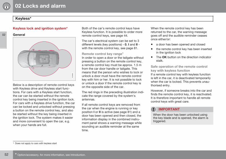
Below is a description of remote control keyswith Keyless drive and Keyless start func-tions. For cars with a Keyless start function,the car can be started without the remotecontrol key being inserted in the ignition lock.For cars with a Keyless drive function, the carcan be locked and unlocked without pressinga button on the remote control key, and alsobe started without the key being inserted inthe ignition lock. The system makes it easierand more convenient to open the car, e.g.when your hands are full.
Both of the car's remote control keys haveKeyless function. It is possible to order moreremote control keys, see page 44.
The car's electrical system can be set to 3different levels (key positions) - 0, I and II -with the remote control key, see page 81.
Remote control key range1
In order to open a door or the tailgate withoutpressing a button on the remote control key,a remote control key must be approx. 1.5 mfrom the car door handle or tailgate. Thismeans that the person who wishes to lock orunlock a door must have the remote controlkey with him or her. It is not possible to lockor unlock a door if the remote control key ison the opposite side of the car.
The red rings in the preceding illustration indi-cate the range covered by the system'santennas.
If all remote control keys are removed fromthe car when the engine is running or keyposition I or II is active (see page 81) and adoor has been opened and then closed, theinformation display in the combined instru-ment panel shows a warning message whilesounding an audible reminder at the sametime.
When the remote control key has beenreturned to the car, the warning messagegoes off and the audible reminder ceasesonce either/or:
• a door has been opened and closed
• the remote control key has been insertedin the ignition lock
• The OK button on the direction indicatorstalk.
Safe operation of the remote controlkey with keyless functionIf a remote control key with keyless functionis left in the car, it is deactivated temporarilywhen the car is locked. This prevents unau-thorised entry.
However, if someone breaks into the car andfinds the remote control key, it is reactivated.It is therefore important to handle all remotecontrol keys with great care.
IMPORTANT
When the door has been unlocked usingthe key blade and is opened, the alarm istriggered.
1 Does not apply to cars with keyless start
02 Locks and alarm
Keyless*
02
* Option/accessory, for more information, see Introduction. 53
Interference to remote control keyfunctionElectromagnetic fields and screening caninterfere with the Keyless function.
NOTE
Do not place/store the remote control keywith keyless function near a mobile phoneor metal object - no closer than 10-15 cm.
If interference is experienced nonetheless,use the remote control key and the key bladelike a traditional remote control key, seepage 46.
Locking2
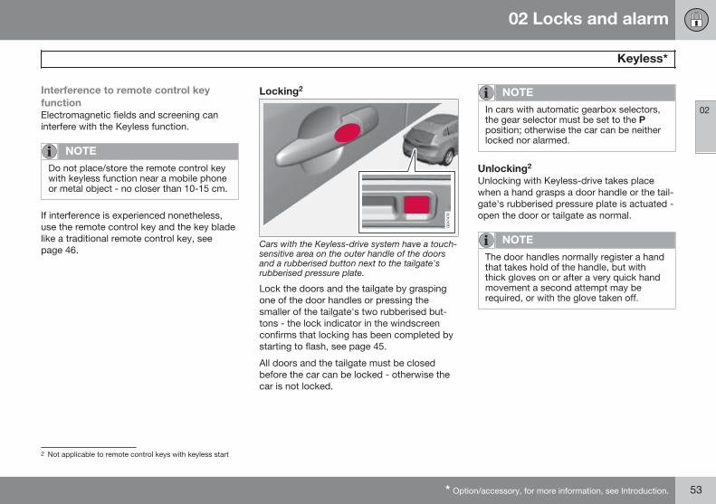
Cars with the Keyless-drive system have a touch-sensitive area on the outer handle of the doorsand a rubberised button next to the tailgate'srubberised pressure plate.
Lock the doors and the tailgate by graspingone of the door handles or pressing thesmaller of the tailgate's two rubberised but-tons - the lock indicator in the windscreenconfirms that locking has been completed bystarting to flash, see page 45.
All doors and the tailgate must be closedbefore the car can be locked - otherwise thecar is not locked.
NOTE
In cars with automatic gearbox selectors,the gear selector must be set to the Pposition; otherwise the car can be neitherlocked nor alarmed.
Unlocking2
Unlocking with Keyless-drive takes placewhen a hand grasps a door handle or the tail-gate's rubberised pressure plate is actuated -open the door or tailgate as normal.
NOTE
The door handles normally register a handthat takes hold of the handle, but withthick gloves on or after a very quick handmovement a second attempt may berequired, or with the glove taken off.
2 Not applicable to remote control keys with keyless start
02 Locks and alarm
Keyless*
02
54 * Option/accessory, for more information, see Introduction.
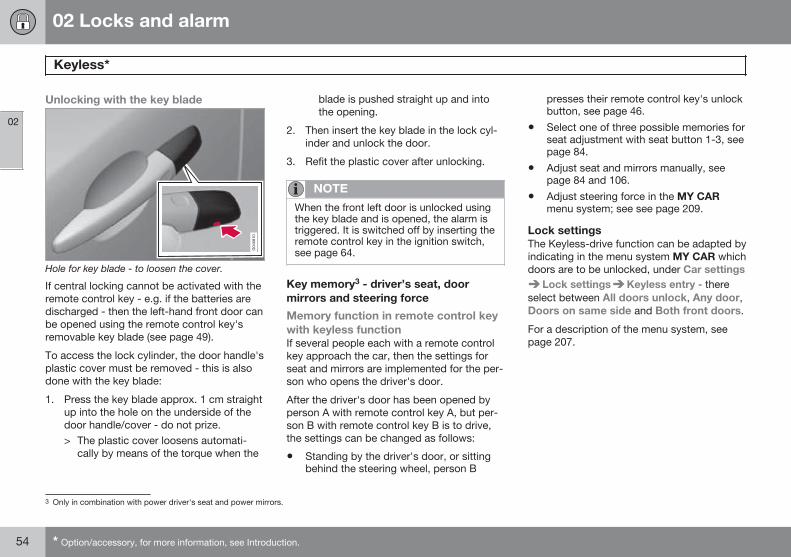
Unlocking with the key blade
Hole for key blade - to loosen the cover.
If central locking cannot be activated with theremote control key - e.g. if the batteries aredischarged - then the left-hand front door canbe opened using the remote control key'sremovable key blade (see page 49).
To access the lock cylinder, the door handle'splastic cover must be removed - this is alsodone with the key blade:
1. Press the key blade approx. 1 cm straightup into the hole on the underside of thedoor handle/cover - do not prize.> The plastic cover loosens automati-
cally by means of the torque when the
blade is pushed straight up and intothe opening.
2. Then insert the key blade in the lock cyl-inder and unlock the door.
3. Refit the plastic cover after unlocking.
NOTE
When the front left door is unlocked usingthe key blade and is opened, the alarm istriggered. It is switched off by inserting theremote control key in the ignition switch,see page 64.
Key memory3 - driver’s seat, doormirrors and steering force
Memory function in remote control keywith keyless functionIf several people each with a remote controlkey approach the car, then the settings forseat and mirrors are implemented for the per-son who opens the driver's door.
After the driver's door has been opened byperson A with remote control key A, but per-son B with remote control key B is to drive,the settings can be changed as follows:
• Standing by the driver's door, or sittingbehind the steering wheel, person B
presses their remote control key's unlockbutton, see page 46.
• Select one of three possible memories forseat adjustment with seat button 1-3, seepage 84.
• Adjust seat and mirrors manually, seepage 84 and 106.
• Adjust steering force in the MY CARmenu system; see see page 209.
Lock settingsThe Keyless-drive function can be adapted byindicating in the menu system MY CAR whichdoors are to be unlocked, under Car settings
Lock settings Keyless entry - thereselect between All doors unlock, Any door,Doors on same side and Both front doors.
For a description of the menu system, seepage 207.
3 Only in combination with power driver's seat and power mirrors.
02 Locks and alarm
Keyless*
02
* Option/accessory, for more information, see Introduction. 55
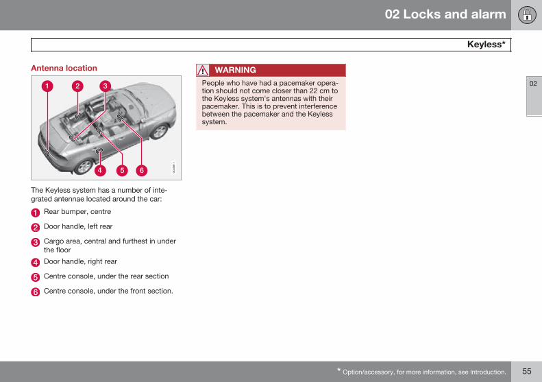
Antenna location
The Keyless system has a number of inte-grated antennae located around the car:
Rear bumper, centre
Door handle, left rear
Cargo area, central and furthest in underthe floor
Door handle, right rear
Centre console, under the rear section
Centre console, under the front section.
WARNING
People who have had a pacemaker opera-tion should not come closer than 22 cm tothe Keyless system's antennas with theirpacemaker. This is to prevent interferencebetween the pacemaker and the Keylesssystem.
02 Locks and alarm
Locking/unlocking
02
56 * Option/accessory, for more information, see Introduction.
From the outsideThe remote control key can lock/unlock alldoors, the tailgate and the fuel filler flap. Dif-ferent sequences for unlocking can beselected, see "Unlocking with the remotecontrol key" page 46.
In order that the lock sequence can be acti-vated, the driver's door must be closed - ifany of the other doors or the tailgate is open,then it/they is/are locked and the alarm isactivated only when it/they are closed. Withthe Keyless* system all the doors and tailgatemust be closed.
NOTE
Be aware of the risk of locking the remotecontrol key in the car.
If it is not possible to lock/unlock with theremote control key, the battery may be dis-charged - lock or unlock the left-hand frontdoor with the detachable key blade, seepage 49.
NOTE
Remember that the alarm is triggeredwhen the door is opened after beingunlocked with the key blade - the alarm isswitched off when the remote control keyis inserted into the ignition switch.
WARNING
Be aware of the risk of being locked in thecar when it is locked from the outsideusing the remote control key - it is then notpossible to open any of the doors from theinside with the door controls. For moreinformation, see page 60, Deadlocks.
Automatic relockingIf none of the doors or the tailgate is openedwithin 2 minutes of unlocking, all are lockedagain automatically. This function reduces therisk that the car is left unlocked unintention-ally. (For cars with alarm, see page 63.)
Manual lockingIn certain situations the car must be lockablemanually, e.g. in the event of power failure.
The left-hand front door can be locked withits lock cylinder and the remote control key'sdetachable key blade, see page 54.
Other doors have no lock cylinders andinstead have a lock switch on the end of each
door which must be depressed using the keyblade - they are then mechanically locked/blocked to prevent them being opened fromoutside. The doors can still be opened fromthe inside.
Manual locking of the door. Not to be mixed upwith child safety locks, see page 62.
– Remove the removable key blade fromthe remote control key, see page 49.Insert the key blade into the hole for thelock switch and press in the key until itreaches the bottom, approx. 12 mm.
The door can be opened from both theoutside and the inside.
The door is blocked against opening fromthe outside. To return to position A, theinner door handle must be opened.
02 Locks and alarm
Locking/unlocking
02
* Option/accessory, for more information, see Introduction. 57
The doors can also be unlocked with theunlock button on the remote control key orwith the central locking button on the driver'sdoor.
NOTE
• A door's lock reset only locks that par-ticular door - not all doors simultane-ously.
• A manually locked rear door with anactivated manual child safety lock can-not be opened from either the outsideor the inside, see page 62. A reardoor that is locked in this way can onlybe unlocked with the remote controlkey or central locking button.
From the inside
Central locking
Central locking.
All of the doors and the tailgate can be lockedor unlocked simultaneously using the centrallocking button on the driver's door.
• Press one side of the button to lock -the other side to unlock.
Lamp in lock buttonWhen the lamp in the central locking buttonfor the driver's door is illuminated it meansthat all doors are locked.
UnlockingA door can be unlocked from the inside intwo different ways:
• Press the central locking button .
Press and hold (at least 4 seconds) to alsoopen all the side windows* simultaneously.
• Pull the door handle and open the door -the door is unlocked and opened in oneoperation.
Locking• Both front doors must be closed for the
central locking to be activated. Press thecentral locking button - all doors arelocked. If any of the rear doors is open, itwill lock when it is closed.
Press and hold (at least 2 seconds) to alsoclose all the side windows simultaneously.
Global openingPress and hold the central locking button (at least 4 seconds) to also open all the win-dows simultaneously - for example, to quicklyventilate the passenger compartment duringhot weather.
Automatic lockingThe doors and tailgate are locked automati-cally when the car starts to move.
The function can be activated/deactivated inthe menu system MY CAR under SettingsCar settings Lock settings Automaticdoor locking. For a description of the menusystem, see page 207.
02 Locks and alarm
Locking/unlocking
02
58 * Option/accessory, for more information, see Introduction.
Lock cylinder, glovebox*
The glovebox can only be locked/unlockedusing the remote control key's detachablekey blade. For information on the key blade,see page 49.
Locking the glovebox:
Insert the key blade in the glovebox lockcylinder.
Turn the key blade 90 degrees clockwise.The keyhole is horizontal in the lockedposition.
Pull out the key blade.
• Unlock by carrying this out in reverseorder.
Tailgate
Manual opening
Rubber plate with electrical contact.
The tailgate is held closed by an electricallock. To open:
1. Push down gently on the wider of the tworubberised pressure plates under theouter handle - the lock is released.
2. Lift the outside handle in order to fullyopen the tailgate.
IMPORTANT
• Minimal force is required to release therear hatch lock - just gently press therubberised panel.
• Do not place the lift force on the rub-ber panel when opening the rear hatch- lift the handle. Using too much forcemay damage the electrical contacts onthe rubber panel.
Unlocking with the remote control key
The alarm for the tailgate can be disarmed*and the tailgate unlocked on its own by usingthe remote control key's button.
The lock indicator on the instrument panelstops flashing in order to show that not all ofthe car is locked and the alarm's* level and
02 Locks and alarm
Locking/unlocking
02
* Option/accessory, for more information, see Introduction. 59
movement sensors and the sensors for open-ing the tailgate are disconnected.
The doors remain locked and armed.
The tailgate can be opened in two differentways using the remote control key:
One press - The boot lid is unlocked, butremains closed - press lightly on the rubber-ised pressure plate under the outer handleand lift the boot lid. If the tailgate is notopened within 2 minutes then it is relockedand the alarm is re-armed.
Two presses - The boot lid is unlocked andthe lock is disengaged at which the boot lidopens about a centimetre - lift the outer han-dle to open. Rain, cold, frost or snow couldhowever prevent the tailgate from disengag-ing from the lock.
NOTE
• When the boot lid/tailgate is unlockedwith 2 presses or from the car interior,automatic relocking does not takeplace because the boot lid/tailgate isopen - it must be closed manually.
• After the boot lid/tailgate has beenclosed it is unlocked and the alarm isnot armed - relock it and re-arm thealarm with the remote control key'slock button .
Opening the car from inside
To open the tailgate:
– Press the lighting panel button.
> The lock releases and the tailgateopens by a few centimetres.
Locking with the remote control key– Press the remote control key's button for
locking, , see page 46.> The lock indicator on the instrument
panel starts flashing, which means thatthe car is locked and the alarm* hasbeen activated.
Fuel filler flapThe fuel filler flap is unlocked using theremote control key button. The fuel fillerflap remains unlocked until the car is lockedwith the remote control key button. If thecar is locked during travel or with the interiorbuttons, the fuel filler flap will remainunlocked.
The fuel filler flap locking logic also followsthe locking or unlocking of the keyless-driveand the central locking system. Fuel filler flaplocking always occurs after a 10-minutedelay.
02 Locks and alarm
Locking/unlocking
02
60 * Option/accessory, for more information, see Introduction.
Deadlocks*1
Deadlocks means that all door handles aremechanically disengaged, which preventsdoors being opened from the inside.
The deadlocks are activated with the remotecontrol key and are set after an approximately10 second delay after the doors have beenlocked.
NOTE
If a door is opened within the delay timethen the sequence is interrupted and thealarm is deactivated.
The car can only be unlocked from a dead-lock state with the remote control key. Thefront left door can also be unlocked with thedetachable key blade.
WARNING
Do not allow anyone to remain in the carwithout first deactivating the deadlocks inorder to avoid the risk of anyone beinglocked in.
Temporary deactivation
Active menu options are indicated with a cross.
MY CAR
OK MENU
TUNE knob control
EXIT
If someone is going to stay in the car but thedoors must be locked from the outside, thenthe deadlocks function can be temporarilyswitched off. This is carried out as follows:
1. Access the menu system MY CAR underSettings Car settings ReducedGuard (for a detailed description of themenu system, see page 207).
2. Select Activate once.> The combined instrument panel shows
the message Locks and alarmReduced guard and the deadlocksfunction is switched off when the car islocked.
or
– Select Ask when exiting.> Each time the engine is switched off
the centre console's screen shows themessage Activate Reduced Guarduntil engine has started again? fol-lowed by the alternatives Confirmwith OK and Cancel with EXIT.
If the deadlocks function shall be switchedoff
– Press OK/MENU and lock the car. (Notethat the alarm's movement and tilt detec-tors* are switched off at the same time,see page 64.)> The next time the engine is started, the
system is reset to zero and the com-bined instrument panel shows themessage Locks and alarm Fullguard at which the deadlocks functionand the alarm's movement and tiltdetectors are re-engaged.
1 Only in combination with alarm.

02 Locks and alarm
Locking/unlocking
02
61
If the locking system shall not be changed
– Press EXIT and lock the car.
NOTE
• Remember that the alarm is activatedwhen the car is locked.
• If any of the doors are opened fromthe inside then the alarm is triggered.
02 Locks and alarm
Child safety locks
02
62 * Option/accessory, for more information, see Introduction.
Manual blocking of the rear doorsThe child safety locks prevent children fromopening a rear door from the inside.
With child safety locks. Not to be mixed up withmanual door locks, see page 56.
The child safety locks are located on the trail-ing edge of the rear doors and are onlyaccessible when the doors are open.
To activate/deactivate the child safety locks:
– Use the remote control key's detachablekey blade to turn the knob - see page 49.
The door is blocked against opening fromthe inside.
The door can be opened from both theoutside and the inside.
NOTE
• A door's knob control only blocks thatparticular door - not both rear doorssimultaneously.
• Cars with an electric child safety lockdo not have a manual child lock.
Electrical locking of the rear doors*and power windows
Control panel driver's door.
The child safety locks can be activated/deac-tivated in all key positions higher than 0 - seepage 81. Activation/deactivation can beperformed up to 2 minutes after switching offthe engine, provided that no door is opened.
To activate the child safety locks:
1. Start the engine or choose a key positionhigher than 0.
2. Press the button in the driver's door con-trol panel.> The information display shows the
message Rear child lock activatedand the button's lamp illuminates - thelocks are active.
When the electric child safety lock is activethen the rear:
• windows can only be opened with thedriver's door control panel
• doors cannot be opened from inside.
The current setting is stored when the engineis switched off - if the child safety locks areactivated at engine shutdown, the functionwill remain activated the next time the engineis started.
02 Locks and alarm
Alarm*
02
* Option/accessory, for more information, see Introduction. 63
GeneralActivated alarm is triggered if:
• a door, the bonnet or the tailgate isopened
• a movement is detected in the passengercompartment (if fitted with a movementdetector*)
• the car is raised or towed away (if fittedwith a tilt detector*)
• the battery's cable is disconnected
• the siren is disconnected.
If there is a fault in the alarm system then theinformation display in the combined instru-ment panel shows a message. In which case,contact a workshop - an authorised Volvoworkshop is recommended.
NOTE
The movement sensors trigger an alarm inthe event of movement in the passengercompartment - air currents are also regis-tered. For this reason the alarm is trig-gered if the car is left with a window openor if the passenger compartment heater isused.
To avoid this: Close the window whenleaving the car. If the car's integrated pas-senger compartment heater (or a portableelectric heater) shall be used - direct theairflow from the air vents so that they arenot pointing upwards in the passengercompartment. Alternatively, reduced alarmlevel can be used, see page 64.
NOTE
Do not attempt to repair or alter compo-nents in the alarm system yourself. Anysuch attempts may affect the terms of theinsurance.
Alarm indicator
Same LED as lock indicator, see page 45.
A red LED on the instrument panel indicatesthe alarm system's status:
• LED not lit – Alarm not armed
• The LED flashes once every other second– Alarm is armed
• The LED flashes rapidly after disarmingthe alarm (and until the remote controlkey is inserted in the ignition switch andkey position I is selected) – Alarm hasbeen triggered.
Arming the alarm– Press the remote control key lock button.
Deactivate the alarm– Press the remote control key unlock but-
ton.
02 Locks and alarm
Alarm*
02
64 * Option/accessory, for more information, see Introduction.
Deactivating a triggered alarm– Press the remote control key unlock but-
ton or insert the remote control key in theignition switch.
Other alarm functions
Automatic re-arming of the alarmThis function prevents the car being left withthe alarm disarmed unintentionally.
If the car is unlocked with the remote controlkey (and the alarm is disarmed) but none ofthe doors or the tailgate is opened within 2minutes, then the alarm is automatically re-armed. The car is relocked at the same time.
Automatic alarm activationIn certain countries, the alarm is activatedafter a certain delay if the driver's door wasopened and closed but the car was not re-locked.
Remote control key not workingIf the alarm cannot be deactivated with theremote control key, e.g. if the key's battery isdischarged - the car can be unlocked, dis-armed and the engine started as follows:
1. Open the left-hand front door with thedetachable key blade - see page 54.> The alarm is triggered, the direction
indicators flash and the siren sounds.
2. Insert the remote control key in the igni-tion switch.> The alarm is deactivated.
Alarm signalsWhen the alarm is triggered, the followinghappens:
• A siren sounds for 30 seconds or until thealarm is switched off. The siren has itsown battery and works independently ofthe car battery.
• The direction indicators flash for 5minutes or until the alarm is switched off.
Reduced alarm levelTo avoid accidental triggering of the alarm -e.g. if a dog is left in a locked car or duringtransport on a car train or car ferry - tempo-rarily deactivate the movement and tilt detec-tors.
The procedure is the same as with the tem-porary disengaging of deadlocks, seepage 60.

02 Locks and alarm
02
65
66 * Option/accessory, for more information, see Introduction.
Instruments and controls........................................................................ 68Volvo Sensus ......................................................................................... 80Key positions.......................................................................................... 81Seats....................................................................................................... 83Steering wheel........................................................................................ 88Lighting................................................................................................... 89Wipers and washing.............................................................................. 101Windows, rearview and door mirrors.................................................... 104Compass*.............................................................................................. 110Alcolock*............................................................................................... 111Starting the engine................................................................................ 115Starting the engine – external battery................................................... 117Gearboxes............................................................................................. 118Start/Stop*............................................................................................ 125Foot brake............................................................................................. 131Parking brake........................................................................................ 133
HomeLink® *.......................................................................................... 134
YOUR DRIVING ENVIRONMENT
03 Your driving environment
Instruments and controls
03
68
Instrument overview
Left-hand drive.
03 Your driving environment
Instruments and controls
03
}}* Option/accessory, for more information, see Introduction. 69
Function Page
Menus and messages,direction indicators,main/dipped beam, tripcomputer
204, 95,91, 232
Cruise control* 148,150
Horn, airbags 88,20
Combined instrumentpanel
71
Menu navigation, audiocontrol, phone control*
207, 249,251, 276
START/STOP ENGINEbutton
115
Ignition switch 81
Screen for infotainmentand display of menus
248, 249,207
Door handle –
Control panel 57, 62,104, 106
Hazard warning flash-ers
94
Function Page
Control panel for info-tainment system andmenu navigation
249, 251,207
Control panel for cli-mate control
218
Gear selector 118
Parking brake 133
Wipers and washing 101,102
Steering wheel adjust-ment
88
Bonnet opener 338
Light switch, opener fortailgate
89,58
Seat adjustment* 84
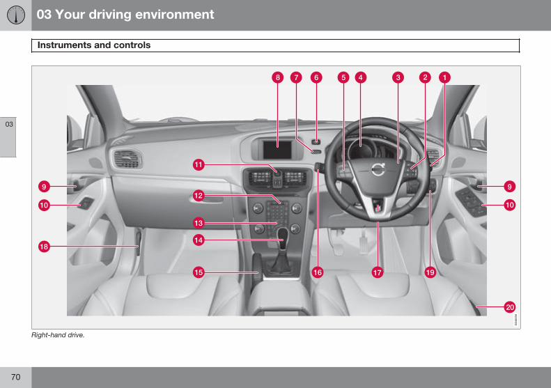
03 Your driving environment
Instruments and controls
03
70
Right-hand drive.
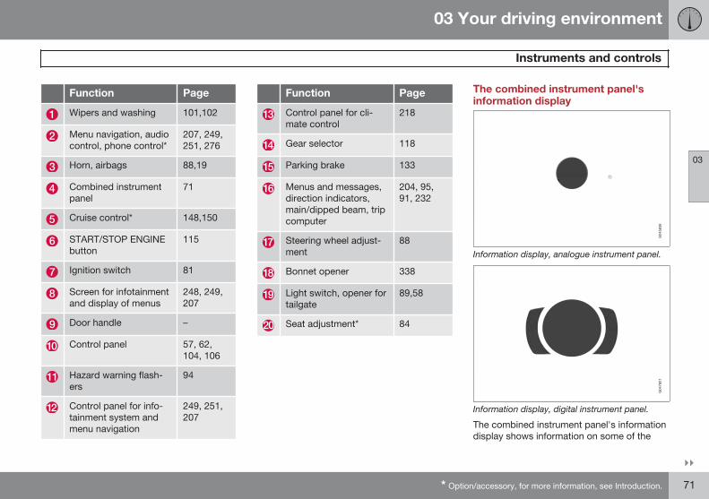
03 Your driving environment
Instruments and controls
03
}}* Option/accessory, for more information, see Introduction. 71
Function Page
Wipers and washing 101,102
Menu navigation, audiocontrol, phone control*
207, 249,251, 276
Horn, airbags 88,19
Combined instrumentpanel
71
Cruise control* 148,150
START/STOP ENGINEbutton
115
Ignition switch 81
Screen for infotainmentand display of menus
248, 249,207
Door handle –
Control panel 57, 62,104, 106
Hazard warning flash-ers
94
Control panel for info-tainment system andmenu navigation
249, 251,207
Function Page
Control panel for cli-mate control
218
Gear selector 118
Parking brake 133
Menus and messages,direction indicators,main/dipped beam, tripcomputer
204, 95,91, 232
Steering wheel adjust-ment
88
Bonnet opener 338
Light switch, opener fortailgate
89,58
Seat adjustment* 84
The combined instrument panel'sinformation display
Information display, analogue instrument panel.
Information display, digital instrument panel.
The combined instrument panel's informationdisplay shows information on some of the
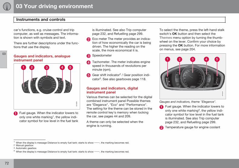
03 Your driving environment
Instruments and controls
03
72
car's functions, e.g. cruise control and tripcomputer, as well as messages. The informa-tion is shown with symbols and text.
There are further descriptions under the func-tions that use the display.
Gauges and indicators, analogueinstrument panel
Fuel gauge. When the indicator lowers toonly one white marking1, the yellow indi-cator symbol for low level in the fuel tank
is illuminated. See also Trip computer page 232, and Refuelling page 299.
Eco meter The meter provides an indica-tion of how economically the car is beingdriven. The higher the reading on thescale, the more economical it is.
Speedometer
Tachometer. The meter indicates enginespeed in thousands of revolutions perminute (rpm).
Gear shift indicator2 / Gear position indi-cator3. See also gearboxes page 118.
Gauges and indicators, digitalinstrument panelVarious themes can be selected for the digitalcombined instrument panel Possible themesare "Elegance", "Eco" and "Performance".The setting for the theme can be stored in theremote control key's memory when lockingthe car, see pages 44 and 209.
A theme can only be selected when theengine is running.
To select the theme, press the left-hand stalkswitch's OK button and then select theThemes menu option by turning the thumb-wheel on the lever. Confirm your choice bypressing the OK button. For more informationon menus, see page 204.
Gauges and indicators, theme "Elegance".
Fuel gauge. When the indicator lowers toonly one white marking4, the yellow indi-cator symbol for low level in the fuel tankis illuminated. See also Trip computerpage 232, and Refuelling page 299.
Temperature gauge for engine coolant
1 When the display's message Distance to empty fuel tank: starts to show ----, the marking becomes red.2 Manual gearbox3 Automatic gearbox4 When the display's message Distance to empty fuel tank: starts to show ----, the marking becomes red.
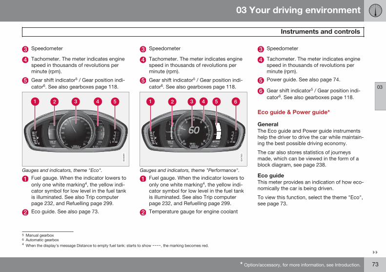
03 Your driving environment
Instruments and controls
03
}}* Option/accessory, for more information, see Introduction. 73
Speedometer
Tachometer. The meter indicates enginespeed in thousands of revolutions perminute (rpm).
Gear shift indicator5 / Gear position indi-cator6. See also gearboxes page 118.
Gauges and indicators, theme "Eco".
Fuel gauge. When the indicator lowers toonly one white marking4, the yellow indi-cator symbol for low level in the fuel tankis illuminated. See also Trip computerpage 232, and Refuelling page 299.
Eco guide. See also page 73.
Speedometer
Tachometer. The meter indicates enginespeed in thousands of revolutions perminute (rpm).
Gear shift indicator5 / Gear position indi-cator6. See also gearboxes page 118.
Gauges and indicators, theme "Performance".
Fuel gauge. When the indicator lowers toonly one white marking4, the yellow indi-cator symbol for low level in the fuel tankis illuminated. See also Trip computerpage 232, and Refuelling page 299.
Temperature gauge for engine coolant
Speedometer
Tachometer. The meter indicates enginespeed in thousands of revolutions perminute (rpm).
Power guide. See also page 74.
Gear shift indicator5 / Gear position indi-cator6. See also gearboxes page 118.
Eco guide & Power guide*
GeneralThe Eco guide and Power guide instrumentshelp the driver to drive the car while maintain-ing the best possible driving economy.
The car also stores statistics of journeysmade, which can be viewed in the form of ablock diagram, see page 238.
Eco guideThis meter provides an indication of how eco-nomically the car is being driven.
To view this function, select the theme "Eco",see page 73.
5 Manual gearbox6 Automatic gearbox4 When the display's message Distance to empty fuel tank: starts to show ----, the marking becomes red.
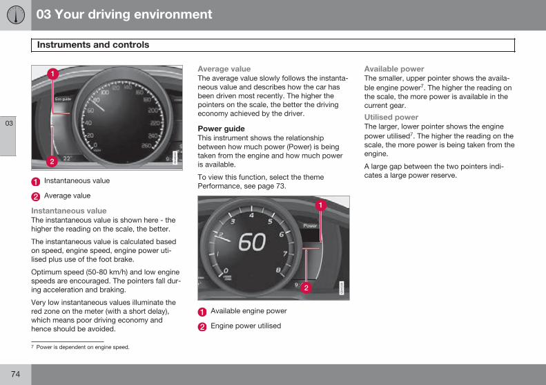
03 Your driving environment
Instruments and controls
03
74
Instantaneous value
Average value
Instantaneous valueThe instantaneous value is shown here - thehigher the reading on the scale, the better.
The instantaneous value is calculated basedon speed, engine speed, engine power uti-lised plus use of the foot brake.
Optimum speed (50-80 km/h) and low enginespeeds are encouraged. The pointers fall dur-ing acceleration and braking.
Very low instantaneous values illuminate thered zone on the meter (with a short delay),which means poor driving economy andhence should be avoided.
Average valueThe average value slowly follows the instanta-neous value and describes how the car hasbeen driven most recently. The higher thepointers on the scale, the better the drivingeconomy achieved by the driver.
Power guideThis instrument shows the relationshipbetween how much power (Power) is beingtaken from the engine and how much poweris available.
To view this function, select the themePerformance, see page 73.
Available engine power
Engine power utilised
Available powerThe smaller, upper pointer shows the availa-ble engine power7. The higher the reading onthe scale, the more power is available in thecurrent gear.
Utilised powerThe larger, lower pointer shows the enginepower utilised7. The higher the reading on thescale, the more power is being taken from theengine.
A large gap between the two pointers indi-cates a large power reserve.
7 Power is dependent on engine speed.
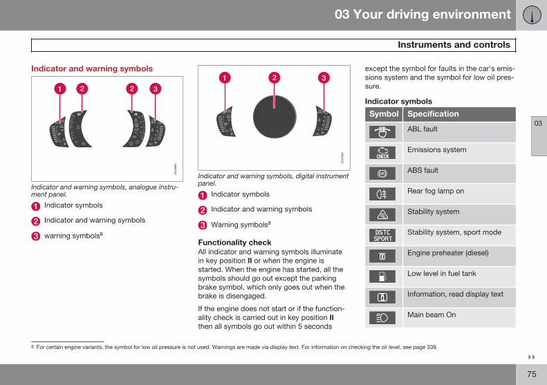
03 Your driving environment
Instruments and controls
03
}}75
Indicator and warning symbols
Indicator and warning symbols, analogue instru-ment panel.
Indicator symbols
Indicator and warning symbols
warning symbols8
Indicator and warning symbols, digital instrumentpanel.
Indicator symbols
Indicator and warning symbols
Warning symbols8
Functionality checkAll indicator and warning symbols illuminatein key position II or when the engine isstarted. When the engine has started, all thesymbols should go out except the parkingbrake symbol, which only goes out when thebrake is disengaged.
If the engine does not start or if the function-ality check is carried out in key position IIthen all symbols go out within 5 seconds
except the symbol for faults in the car's emis-sions system and the symbol for low oil pres-sure.
Indicator symbols
Symbol Specification
ABL fault
Emissions system
ABS fault
Rear fog lamp on
Stability system
Stability system, sport mode
Engine preheater (diesel)
Low level in fuel tank
Information, read display text
Main beam On
8 For certain engine variants, the symbol for low oil pressure is not used. Warnings are made via display text. For information on checking the oil level, see page 339.
03 Your driving environment
Instruments and controls
03
76
Symbol Specification
Left-hand direction indicator
Right-hand direction indicator
Start/Stop, the engine auto-stopped, see page 125
ABL faultThe symbol illuminates if a fault has arisen inthe ABL function (Active Bending Lights).
Emissions systemIf the symbol illuminates then it may be due toa fault in the car's emissions system. Drive toa workshop for checking. Volvo recommendsthat you seek assistance from an authorisedVolvo workshop.
ABS faultIf this symbol illuminates then the system isnot working. The car's regular brake systemcontinues to work, but without the ABS func-tion.
1. Stop the car in a safe place and turn offthe engine.
2. Restart the engine.
3. If the symbol remains illuminated, drive toa workshop to have the ABS systemchecked. Volvo recommends that you
seek assistance from an authorised Volvoworkshop.
Rear fog lamp onThis symbol illuminates when the rear foglamp is switched on.
Stability systemA flashing symbol indicates that the stabilitysystem is operating. If the symbol illuminateswith constant glow then there is a fault in thesystem.
Stability system, sport modeSport mode allows for a more active drivingexperience. The system then detects whetherthe accelerator pedal, steering wheel move-ments and cornering are more active than innormal driving and then allows controlledskidding of the rear section up to a certainlevel before it intervenes and stabilises thecar.
Engine preheater (diesel)This symbol illuminates during engine pre-heating. Preheating mostly takes place due tolow temperature.
Low level in fuel tankWhen the symbol illuminates the level in thefuel tank is low, refuel as soon as possible.
Information, read display textWhen one of the car's systems does notbehave as intended, this information symbol
illuminates and a text appears on the informa-tion display. The message text is cleared withthe OK button, see page 204, or it disap-pears automatically after a time (timedepending on which function is indicated).The information symbol can also illuminate inconjunction with other symbols.
NOTE
When a service message is shown, thesymbol and message are cleared using theOK button, or disappear automaticallyafter a time.
Main beam OnThe symbol illuminates when main beam is onand with main beam flash.
Left/right-hand direction indicatorsBoth direction indicator symbols flash whenthe hazard warning flashers are used.
Start/StopThe symbol shines when the engine is auto-stopped.
03 Your driving environment
Instruments and controls
03
77
Warning symbols
Symbol Specification
Low oil pressureA
Parking brake applied
Parking brake applied, alterna-tive symbol
Airbags – SRS
Seatbelt reminder
Alternator not charging
Fault in brake system
Warning
A For certain engine variants, the symbol for low oil pressureis not used. Warnings are made via display text, see pages339 and 341.
Low oil pressureIf this symbol illuminates during driving thenthe engine's oil pressure is too low. Stop theengine immediately and check the engine oillevel, top up if necessary. If the symbol illumi-nates and the oil level is normal, contact aworkshop. Volvo recommends that you seek
assistance from an authorised Volvo work-shop.
Parking brake appliedThis symbol illuminates with a constant glowwhen the parking brake is applied. The sym-bol is illuminated during application. For moreinformation, see page 133.
Airbags – SRSIf this symbol remains illuminated or illumi-nates while driving, it means a fault has beendetected in the seatbelt buckle, SRS, SIPS, orIC systems. Drive immediately to a workshopto have the system checked. Volvo recom-mends that you seek assistance from anauthorised Volvo workshop.
Seatbelt reminderThis symbol flashes if someone in a front seathas not put on their seatbelt or if someone ina rear seat has taken off their seatbelt.
Alternator not chargingThis symbol illuminates during driving if afault has occurred in the electrical system.Visit a workshop. Volvo recommends that youseek assistance from an authorised Volvoworkshop.
Fault in brake systemIf this symbol illuminates, the brake fluid levelmay be too low. Stop the car in a safe placeand check the level in the brake fluid reser-voir, see page 343.
If the brake and ABS symbols illuminate atthe same time, there may be a fault in thebrake force distribution system.
1. Stop the car in a safe place and turn offthe engine.
2. Restart the engine.
• If both symbols extinguish, continuedriving.
• If the symbols remain illuminated,check the level in the brake fluid reser-voir, see page 343. If the brake fluidlevel is normal but the symbols are stillilluminated, the car can be driven, withgreat care, to a workshop to have thebrake system checked. Volvo recom-mends that you seek assistance froman authorised Volvo workshop.
WARNING
If the brake fluid is below the MIN level inthe brake fluid reservoir, do not drive fur-ther before topping up the brake fluid.
The loss of brake fluid must be investiga-ted by a workshop. Volvo recommendsthat you contact an authorised Volvoworkshop.
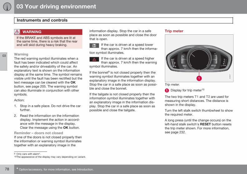
03 Your driving environment
Instruments and controls
03
78 * Option/accessory, for more information, see Introduction.
WARNING
If the BRAKE and ABS symbols are lit atthe same time, there is a risk that the rearend will skid during heavy braking.
WarningThe red warning symbol illuminates when afault has been indicated which could affectthe safety and/or driveability of the car. Anexplanatory text is shown on the informationdisplay at the same time. The symbol remainsvisible until the fault has been rectified but thetext message can be cleared with the OKbutton, see page 205. The warning symbolcan also illuminate in conjunction with othersymbols.
Action:
1. Stop in a safe place. Do not drive the carfurther.
2. Read the information on the informationdisplay. Implement the action in accord-ance with the message in the display.Clear the message using the OK button.
Reminder – doors not closedIf one of the doors is not closed properly thenthe information or warning symbol illuminatestogether with an explanatory image in the
information display. Stop the car in a safeplace as soon as possible and close the doorthat is open.
If the car is driven at a speed lowerthan approx. 7 km/h then the informa-
tion symbol illuminates.
If the car is driven at a speed higherthan approx. 7 km/h then the warning
symbol illuminates.
If the bonnet9 is not closed properly then thewarning symbol illuminates together with anexplanatory image in the information display.Stop the car in a safe place as soon as possi-ble and close the bonnet.
If the tailgate is not closed properly then theinformation symbol illuminates together withan explanatory image in the information dis-play. Stop the car in a safe place as soon aspossible and close the tailgate.
Trip meter
Trip meter.
Display for trip meter10
The two trip meters T1 and T2 are used formeasuring short distances. The distance isshown in the display.
Turn the left stalk switch thumbwheel to showthe required meter.
A long press (until the change occurs) on theleft-hand stalk switch's RESET button resetsthe trip meter shown. For more information,see page 232.
9 Only cars with alarm*.10The appearance of the display may vary depending on variant.
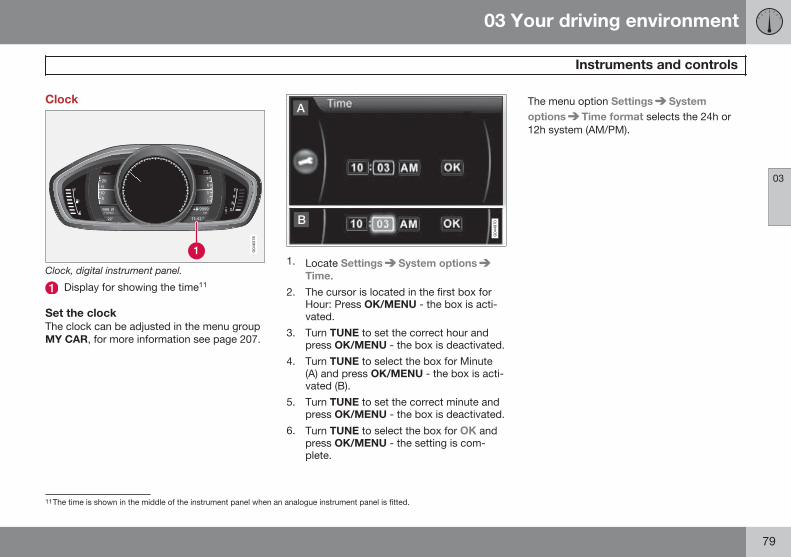
03 Your driving environment
Instruments and controls
03
79
Clock
Clock, digital instrument panel.
Display for showing the time11
Set the clockThe clock can be adjusted in the menu groupMY CAR, for more information see page 207.
1. Locate Settings System optionsTime.
2. The cursor is located in the first box forHour: Press OK/MENU - the box is acti-vated.
3. Turn TUNE to set the correct hour andpress OK/MENU - the box is deactivated.
4. Turn TUNE to select the box for Minute(A) and press OK/MENU - the box is acti-vated (B).
5. Turn TUNE to set the correct minute andpress OK/MENU - the box is deactivated.
6. Turn TUNE to select the box for OK andpress OK/MENU - the setting is com-plete.
The menu option Settings Systemoptions Time format selects the 24h or12h system (AM/PM).
11The time is shown in the middle of the instrument panel when an analogue instrument panel is fitted.
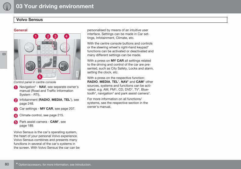
03 Your driving environment
Volvo Sensus
03
80 * Option/accessory, for more information, see Introduction.
General
Control panel in centre console
Navigation* - NAV, see separate owner'smanual (Road and Traffic InformationSystem - RTI).
Infotainment (RADIO, MEDIA, TEL*), seepage 248.
Car settings - MY CAR, see page 207.
Climate control, see page 215.
Park assist camera - CAM*, seepage 189.
Volvo Sensus is the car's operating system,the heart of your personal Volvo experience.Volvo Sensus combines and presents manyfunctions in several of the car's systems inthe screen. With Volvo Sensus the car can be
personalised by means of an intuitive userinterface. Settings can be made in Car set-tings, Infotainment, Climate, etc.
With the centre console buttons and controlsor the steering wheel's right-hand keypad*functions can be activated or deactivated andmany different settings can be made.
With a press on MY CAR all settings relatedto the driving and control of the car are pre-sented, such as City Safety, Locks and alarm,setting the clock, etc.
With a press on the respective function:RADIO, MEDIA, TEL*, NAV* and CAM* othersources, systems and functions can be acti-vated, e.g. AM, FM1, CD, DVD*, TV*, Blue-tooth*, navigation* and park assist camera*.
For more information on all functions/systems, see the respective section in theowner's manual.
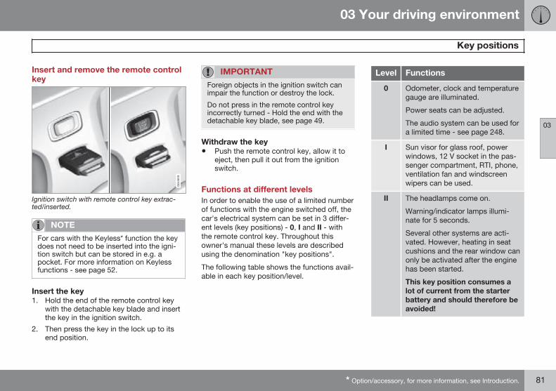
03 Your driving environment
Key positions
03
* Option/accessory, for more information, see Introduction. 81
Insert and remove the remote controlkey
Ignition switch with remote control key extrac-ted/inserted.
NOTE
For cars with the Keyless* function the keydoes not need to be inserted into the igni-tion switch but can be stored in e.g. apocket. For more information on Keylessfunctions - see page 52.
Insert the key1. Hold the end of the remote control key
with the detachable key blade and insertthe key in the ignition switch.
2. Then press the key in the lock up to itsend position.
IMPORTANT
Foreign objects in the ignition switch canimpair the function or destroy the lock.
Do not press in the remote control keyincorrectly turned - Hold the end with thedetachable key blade, see page 49.
Withdraw the key• Push the remote control key, allow it to
eject, then pull it out from the ignitionswitch.
Functions at different levelsIn order to enable the use of a limited numberof functions with the engine switched off, thecar's electrical system can be set in 3 differ-ent levels (key positions) - 0, I and II - withthe remote control key. Throughout thisowner's manual these levels are describedusing the denomination "key positions".
The following table shows the functions avail-able in each key position/level.
Level Functions
0 Odometer, clock and temperaturegauge are illuminated.
Power seats can be adjusted.
The audio system can be used fora limited time - see page 248.
I Sun visor for glass roof, powerwindows, 12 V socket in the pas-senger compartment, RTI, phone,ventilation fan and windscreenwipers can be used.
II The headlamps come on.
Warning/indicator lamps illumi-nate for 5 seconds.
Several other systems are acti-vated. However, heating in seatcushions and the rear window canonly be activated after the enginehas been started.
This key position consumes alot of current from the starterbattery and should therefore beavoided!
03 Your driving environment
Key positions
03
82 * Option/accessory, for more information, see Introduction.
Choosing key position/level
Key position 0• Unlock the car - this means that the car's
electrical system is at level 0.
Key position I• With the remote control key fully inserted
into the ignition switch1 - Briefly pressSTART/STOP ENGINE.
NOTE
To reach level I or II without starting theengine - do not depress the brake/clutchpedal when these key positions are due tobe selected.
Key position II• With the remote control key fully inserted
into the ignition switch1 - Give a long2
press on START/STOP ENGINE.
Back to key position 0• To return to key position 0 from position II
and I - Briefly press on START/STOPENGINE.
Audio systemFor information on the audio system's func-tions with remote control key removed - seepage 248.
Starting and stopping the engineFor information about starting/switching offthe engine - see page 115.
TowingFor important information about the remotecontrol key during towing - see page 315.
1 Not necessary for cars with the Keyless* function.2 Approx. 2 seconds.
03 Your driving environment
Seats
03
* Option/accessory, for more information, see Introduction. 83
Front seats
To adjust lumbar support*, turn thewheel1.
Forward/backward: lift the handle toadjust the distance to the steering wheeland pedals. Check that the seat is lockedafter changing position.
To raise/lower the front edge of seatcushion*, pump up/down.
Adjust backrest rake, turn the wheel.
Raise/lower the seat*, pump up/down.
Control panel for power seat*.
WARNING
Adjust the position of the driver's seatbefore setting off, never while driving.Make sure that the seat is in locked posi-tion in order to avoid personal injury in theevent of sudden braking or an accident.
Adjusting front seat head restraints
The height of the front seat head restraints canbe adjusted.
Adjust the head restraint based on the per-son's height so that the whole of the back ofthe head is covered if possible.
To adjust the height, the button (see illustra-tion) must be pressed while the restraint ismoved up or down.
The head restraint can be adjusted in threedifferent positions.
Lowering the front seat backrest*
The passenger seat backrest can be foldedforward to make room for long loads.
Move the seat as far back/down as possi-ble.
Adjust the backrest to an upright position.
Lift the catches on the rear of the back-rest and fold it forward.
4. Push the seat forward so that the headrestraint "locks" in under the glovebox.
Raising takes place in reverse order.
1 Also applies to power seat.
03 Your driving environment
Seats
03
84 * Option/accessory, for more information, see Introduction.
WARNING
Do not use the space behind the frontseat, or the rear seat's centre seat, whenthe front seat backrest is lowered.
WARNING
Grasp the backrest and make sure that itis properly locked after being folded up inorder to avoid personal injury in the eventof sudden braking or an accident.
Power seat*
Front edge of seat cushion up/down
Seat forward/backward and up/down
Backrest rake
The power front seats have overload protec-tion which is tripped if a seat is blocked by anobject. If this happens, go to key position I or0 and wait a short time before adjusting theseat again.
Only one movement (forward/back/up/down)can be made at a time.
PreparationsThe seats can be adjusted for a certain timeafter unlocking the door with the remote con-trol key without the key in the ignition switch.
Seat adjustment is normally made in keyposition I and can always be made when theengine is running.
Seat with memory function*
Store settingMemory button
Memory button
Memory button
Button for storing settings
1. Adjust the seat and the door mirrors.
2. Hold the button depressed to store set-tings while depressing one of the memorybuttons.
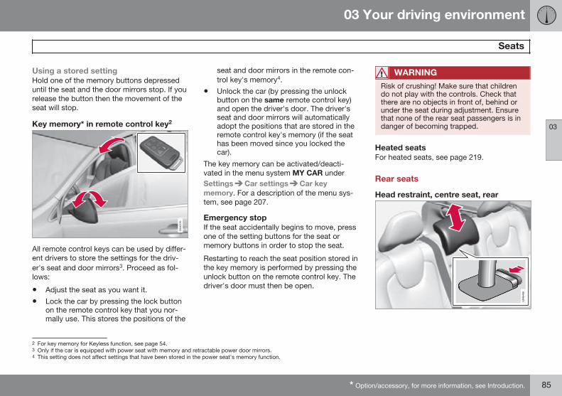
03 Your driving environment
Seats
03
* Option/accessory, for more information, see Introduction. 85
Using a stored settingHold one of the memory buttons depresseduntil the seat and the door mirrors stop. If yourelease the button then the movement of theseat will stop.
Key memory* in remote control key2
All remote control keys can be used by differ-ent drivers to store the settings for the driv-er's seat and door mirrors3. Proceed as fol-lows:
• Adjust the seat as you want it.
• Lock the car by pressing the lock buttonon the remote control key that you nor-mally use. This stores the positions of the
seat and door mirrors in the remote con-trol key's memory4.
• Unlock the car (by pressing the unlockbutton on the same remote control key)and open the driver's door. The driver'sseat and door mirrors will automaticallyadopt the positions that are stored in theremote control key's memory (if the seathas been moved since you locked thecar).
The key memory can be activated/deacti-vated in the menu system MY CAR underSettings Car settings Car keymemory. For a description of the menu sys-tem, see page 207.
Emergency stopIf the seat accidentally begins to move, pressone of the setting buttons for the seat ormemory buttons in order to stop the seat.
Restarting to reach the seat position stored inthe key memory is performed by pressing theunlock button on the remote control key. Thedriver's door must then be open.
WARNING
Risk of crushing! Make sure that childrendo not play with the controls. Check thatthere are no objects in front of, behind orunder the seat during adjustment. Ensurethat none of the rear seat passengers is indanger of becoming trapped.
Heated seatsFor heated seats, see page 219.
Rear seats
Head restraint, centre seat, rear
2 For key memory for Keyless function, see page 54.3 Only if the car is equipped with power seat with memory and retractable power door mirrors.4 This setting does not affect settings that have been stored in the power seat's memory function.
03 Your driving environment
Seats
03
86
Adjust the head restraint according to pas-senger height so that the whole of the back ofthe head is covered if possible. Slide it up asrequired.
To lower the head restraint again, the button(see illustration) must be pressed while therestraint is carefully moved down.
The head restraint can be adjusted in five dif-ferent positions.
NOTE
Do not sit in the centre seat with the headrestraint in fully lowered position.
Manual lowering of the outer headrestraints, rear seat
Pull the locking handle closest to the headrestraint to fold the head restraint forward.
The head restraint is moved back manually.
WARNING
The head restraint must be in locked posi-tion after being folded up.
Lowering the rear seat backrest
IMPORTANT
When the backrest is to be folded, the rearseat cup holder must not be open andthere must be no objects in the rear seat.Nor may the seat belts be connected. Oth-erwise there is a risk of damage to the rearseat upholstery.
The two-section backrest can be folded indifferent ways.
NOTE
The front seats may need to be pushedforwards, and/or the backrests adjustedupwards, in order that the rear backrestscan be folded forward fully.
• Both sections can be folded separately.
• If the entire backrest is to be folded thenthe different sections should be foldedseparately.
If the right-hand section is being lowered- release and adjust the centre seat headrestraint downwards, see page 85.
The outer head restraints are loweredautomatically when the backrests arelowered. Pull up the backrest's locking
03 Your driving environment
Seats
03
87
handle while folding the backrest for-ward at the same time. A red indicator onthe lock catch shows that the back-rest is no longer locked in place.
NOTE
When the backrests have been loweredthe head restraints must be moved for-ward slightly so as not to make contactwith the seat cushion.
Raising takes place in reverse order.
NOTE
When the backrest has been raised, thered indicator should no longer be showing.If it is still showing then the backrest is notlocked in place.
WARNING
Check that the backrests and headrestraints in the rear seat are locked prop-erly after being folded up.
03 Your driving environment
Steering wheel
03
88 * Option/accessory, for more information, see Introduction.
Adjusting
Adjusting the steering wheel.
Lever - releasing the steering wheel
Possible steering wheel positions
The steering wheel can be adjusted for bothheight and depth:
1. Push the lever forwards to release thesteering wheel.
2. Adjust the steering wheel to the positionthat suits you.
3. Pull the lever back to fix the steeringwheel in place. If the lever is stiff, pressthe steering wheel lightly at the same timeas you push the lever back.
WARNING
Adjust the steering wheel and fix it beforedriving away.
With speed related power steering* the levelof steering force can be adjusted, seepage 240.
Keypads*
Keypads in the steering wheel.
Cruise control, see page 148
Adaptive cruise control, see page 150
Audio and phone control, see page 249.
Horn
Horn.
Press the centre of the steering wheel to sig-nal.
03 Your driving environment
Lighting
03
}}* Option/accessory, for more information, see Introduction. 89
Light switches
Overview, light switches.
Thumbwheel for adjusting display andinstrument lighting and ambient lighting*
Button for rear fog lamp
Knob for daytime running lights and park-ing lamps
Thumbwheel1 for headlamp levelling
Knob positions
Posi-tion
Specification
Daytime running lightsA whenthe car's electrical system is inkey position II or the engine isrunning.
Main beam flash can be used.
Daytime running lights andposition/parking lamps/sidemarker lamps when the car'selectrical system is in key posi-tion II or the engine is running.
Automatic switching to posi-tion/parking lamps/side markerlamps when the car is parked.
Main beam flash can be used.
Posi-tion
Specification
Daytime running lights andposition/parking lamps/sidemarker lamps during the daywhen the car's electrical sys-tem is in key position II or theengine is running.
Automatic switching to dippedbeam and position/parkinglamps/side marker lamps inpoor light conditions or whenthe windscreen wipers or rearfog lamps are activated.
The "Tunnel detection*" func-tion is activated, see page 91.
The "Active high beam*" func-tion can be used, seepage 92.
Main beam can be activatedwhen dipped beam is switchedon.
Main beam flash can be used.
1 Not available for cars equipped with active Xenon headlamps*.
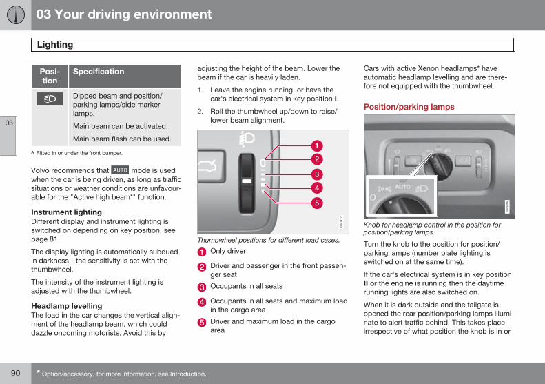
03 Your driving environment
Lighting
03
90 * Option/accessory, for more information, see Introduction.
Posi-tion
Specification
Dipped beam and position/parking lamps/side markerlamps.
Main beam can be activated.
Main beam flash can be used.
A Fitted in or under the front bumper.
Volvo recommends that mode is usedwhen the car is being driven, as long as trafficsituations or weather conditions are unfavour-able for the "Active high beam*" function.
Instrument lightingDifferent display and instrument lighting isswitched on depending on key position, seepage 81.
The display lighting is automatically subduedin darkness - the sensitivity is set with thethumbwheel.
The intensity of the instrument lighting isadjusted with the thumbwheel.
Headlamp levellingThe load in the car changes the vertical align-ment of the headlamp beam, which coulddazzle oncoming motorists. Avoid this by
adjusting the height of the beam. Lower thebeam if the car is heavily laden.
1. Leave the engine running, or have thecar's electrical system in key position I.
2. Roll the thumbwheel up/down to raise/lower beam alignment.
Thumbwheel positions for different load cases.
Only driver
Driver and passenger in the front passen-ger seat
Occupants in all seats
Occupants in all seats and maximum loadin the cargo area
Driver and maximum load in the cargoarea
Cars with active Xenon headlamps* haveautomatic headlamp levelling and are there-fore not equipped with the thumbwheel.
Position/parking lamps
Knob for headlamp control in the position forposition/parking lamps.
Turn the knob to the position for position/parking lamps (number plate lighting isswitched on at the same time).
If the car's electrical system is in key positionII or the engine is running then the daytimerunning lights are also switched on.
When it is dark outside and the tailgate isopened the rear position/parking lamps illumi-nate to alert traffic behind. This takes placeirrespective of what position the knob is in or
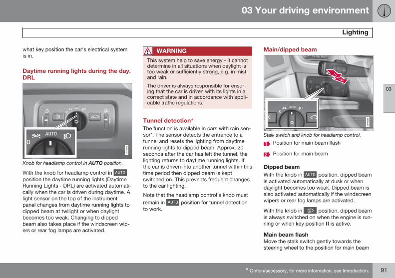
03 Your driving environment
Lighting
03
* Option/accessory, for more information, see Introduction. 91
what key position the car's electrical systemis in.
Daytime running lights during the day.DRL
Knob for headlamp control in AUTO position.
With the knob for headlamp control in position the daytime running lights (DaytimeRunning Lights - DRL) are activated automati-cally when the car is driven during daytime. Alight sensor on the top of the instrumentpanel changes from daytime running lights todipped beam at twilight or when daylightbecomes too weak. Changing to dippedbeam also takes place if the windscreen wip-ers or rear fog lamps are activated.
WARNING
This system help to save energy - it cannotdetermine in all situations when daylight istoo weak or sufficiently strong, e.g. in mistand rain.
The driver is always responsible for ensur-ing that the car is driven with its lights in acorrect state and in accordance with appli-cable traffic regulations.
Tunnel detection*The function is available in cars with rain sen-sor*. The sensor detects the entrance to atunnel and resets the lighting from daytimerunning lights to dipped beam. Approx. 20seconds after the car has left the tunnel, thelighting returns to daytime running lights. Ifthe car is driven into another tunnel within thistime period then dipped beam is keptswitched on. This prevents frequent changesto the car lighting.
Note that the headlamp control's knob mustremain in position for tunnel detectionto work.
Main/dipped beam
Stalk switch and knob for headlamp control.
Position for main beam flash
Position for main beam
Dipped beamWith the knob in position, dipped beamis activated automatically at dusk or whendaylight becomes too weak. Dipped beam isalso activated automatically if the windscreenwipers or rear fog lamps are activated.
With the knob in position, dipped beamis always switched on when the engine is run-ning or when key position II is active.
Main beam flashMove the stalk switch gently towards thesteering wheel to the position for main beam
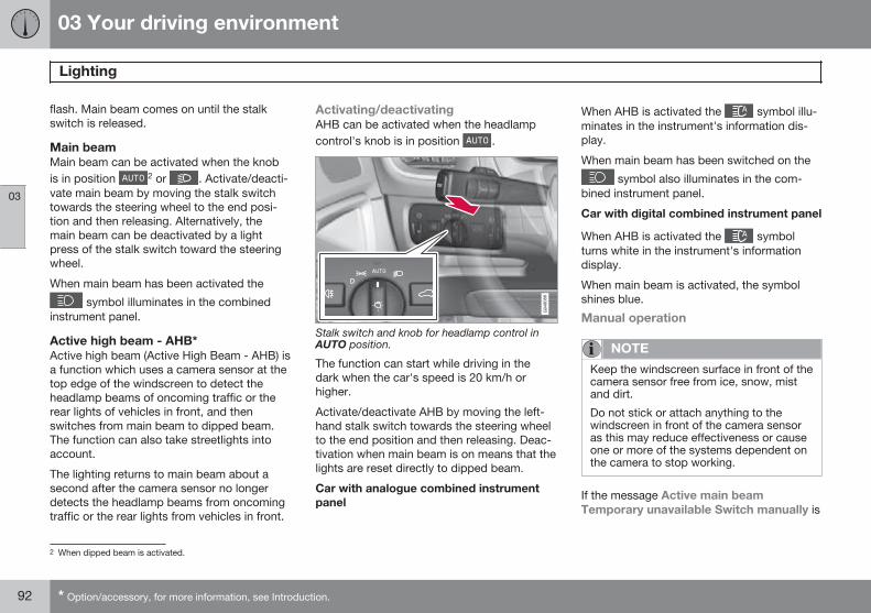
03 Your driving environment
Lighting
03
92 * Option/accessory, for more information, see Introduction.
flash. Main beam comes on until the stalkswitch is released.
Main beamMain beam can be activated when the knobis in position 2 or . Activate/deacti-vate main beam by moving the stalk switchtowards the steering wheel to the end posi-tion and then releasing. Alternatively, themain beam can be deactivated by a lightpress of the stalk switch toward the steeringwheel.
When main beam has been activated the
symbol illuminates in the combinedinstrument panel.
Active high beam - AHB*Active high beam (Active High Beam - AHB) isa function which uses a camera sensor at thetop edge of the windscreen to detect theheadlamp beams of oncoming traffic or therear lights of vehicles in front, and thenswitches from main beam to dipped beam.The function can also take streetlights intoaccount.
The lighting returns to main beam about asecond after the camera sensor no longerdetects the headlamp beams from oncomingtraffic or the rear lights from vehicles in front.
Activating/deactivatingAHB can be activated when the headlampcontrol's knob is in position .
Stalk switch and knob for headlamp control inAUTO position.
The function can start while driving in thedark when the car's speed is 20 km/h orhigher.
Activate/deactivate AHB by moving the left-hand stalk switch towards the steering wheelto the end position and then releasing. Deac-tivation when main beam is on means that thelights are reset directly to dipped beam.
Car with analogue combined instrumentpanel
When AHB is activated the symbol illu-minates in the instrument's information dis-play.
When main beam has been switched on the
symbol also illuminates in the com-bined instrument panel.
Car with digital combined instrument panel
When AHB is activated the symbolturns white in the instrument's informationdisplay.
When main beam is activated, the symbolshines blue.
Manual operation
NOTE
Keep the windscreen surface in front of thecamera sensor free from ice, snow, mistand dirt.
Do not stick or attach anything to thewindscreen in front of the camera sensoras this may reduce effectiveness or causeone or more of the systems dependent onthe camera to stop working.
If the message Active main beamTemporary unavailable Switch manually is
2 When dipped beam is activated.
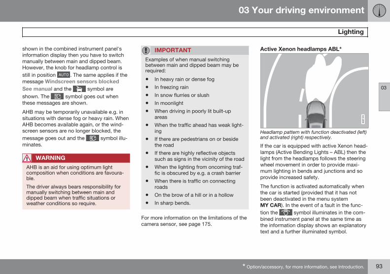
03 Your driving environment
Lighting
03
* Option/accessory, for more information, see Introduction. 93
shown in the combined instrument panel'sinformation display then you have to switchmanually between main and dipped beam.However, the knob for headlamp control isstill in position . The same applies if themessage Windscreen sensors blockedSee manual and the symbol areshown. The symbol goes out whenthese messages are shown.
AHB may be temporarily unavailable e.g. insituations with dense fog or heavy rain. WhenAHB becomes available again, or the wind-screen sensors are no longer blocked, themessage goes out and the symbol illu-minates.
WARNING
AHB is an aid for using optimum lightcomposition when conditions are favoura-ble.
The driver always bears responsibility formanually switching between main anddipped beam when traffic situations orweather conditions so require.
IMPORTANT
Examples of when manual switchingbetween main and dipped beam may berequired:
• In heavy rain or dense fog
• In freezing rain
• In snow flurries or slush
• In moonlight
• When driving in poorly lit built-upareas
• When the traffic ahead has weak light-ing
• If there are pedestrians on or besidethe road
• If there are highly reflective objectssuch as signs in the vicinity of the road
• When the lighting from oncoming traf-fic is obscured by e.g. a crash barrier
• When there is traffic on connectingroads
• On the brow of a hill or in a hollow
• In sharp bends.
For more information on the limitations of thecamera sensor, see page 175.
Active Xenon headlamps ABL*
Headlamp pattern with function deactivated (left)and activated (right) respectively.
If the car is equipped with active Xenon head-lamps (Active Bending Lights – ABL) then thelight from the headlamps follows the steeringwheel movement in order to provide maxi-mum lighting in bends and junctions and soprovide increased safety.
The function is activated automatically whenthe car is started (provided that it has notbeen deactivated in the menu systemMY CAR). In the event of a fault in the func-tion the symbol illuminates in the com-bined instrument panel at the same time asthe information display shows an explanatorytext and a further illuminated symbol.
03 Your driving environment
Lighting
03
94
Symbol Display Specification
Headlampsystemmalfunc-tion Serv-icerequired
The system isdisengaged. Visita workshop ifthe messageremains. Volvorecommendsthat you contactan authorisedVolvo workshop.
The function is only active in twilight or dark-ness and only when the car is moving.
The function3 can be deactivated/ activated inthe menu system MY CAR under SettingsCar settings Light settings ActiveBending Lights. For a description of themenu system, see page 208.
Rear fog lamp
Button for rear fog lamp.
The rear fog lamp can only be switched onwhen key position II is active or the engine isrunning and the headlamp control's knob is inposition or .
Press the button for On/Off. The rear foglamp indicator symbol in the combinedinstrument panel and the lamp in the buttonilluminate when the rear fog lamp is switchedon.
The rear fog lamp is switched off automati-cally when the engine is switched off or whenthe headlamp control's knob is turned toposition or .
NOTE
Regulations on the use of rear fog lampsvary from country to country.
Brake lightsThe brake light automatically comes on dur-ing braking. For information on the emer-gency brake lights and automatic hazardwarning flashers, see page 131.
Hazard warning flashers
Button for hazard warning flashers.
Press the button to activate the hazard warn-ing flashers. Both direction indicator symbols
3 Activated on delivery from the factory.
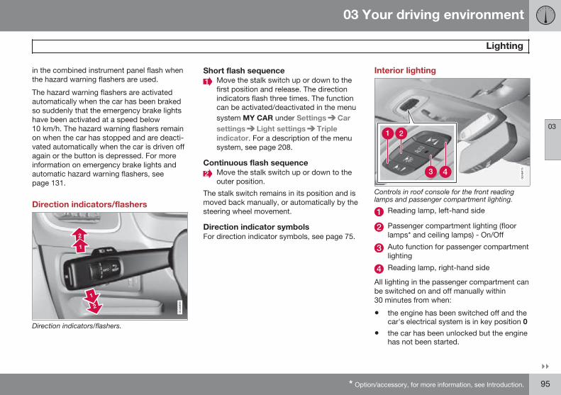
03 Your driving environment
Lighting
03
}}* Option/accessory, for more information, see Introduction. 95
in the combined instrument panel flash whenthe hazard warning flashers are used.
The hazard warning flashers are activatedautomatically when the car has been brakedso suddenly that the emergency brake lightshave been activated at a speed below10 km/h. The hazard warning flashers remainon when the car has stopped and are deacti-vated automatically when the car is driven offagain or the button is depressed. For moreinformation on emergency brake lights andautomatic hazard warning flashers, seepage 131.
Direction indicators/flashers
Direction indicators/flashers.
Short flash sequenceMove the stalk switch up or down to thefirst position and release. The directionindicators flash three times. The functioncan be activated/deactivated in the menusystem MY CAR under Settings Carsettings Light settings Tripleindicator. For a description of the menusystem, see page 208.
Continuous flash sequenceMove the stalk switch up or down to theouter position.
The stalk switch remains in its position and ismoved back manually, or automatically by thesteering wheel movement.
Direction indicator symbolsFor direction indicator symbols, see page 75.
Interior lighting
Controls in roof console for the front readinglamps and passenger compartment lighting.
Reading lamp, left-hand side
Passenger compartment lighting (floorlamps* and ceiling lamps) - On/Off
Auto function for passenger compartmentlighting
Reading lamp, right-hand side
All lighting in the passenger compartment canbe switched on and off manually within30 minutes from when:
• the engine has been switched off and thecar's electrical system is in key position 0
• the car has been unlocked but the enginehas not been started.
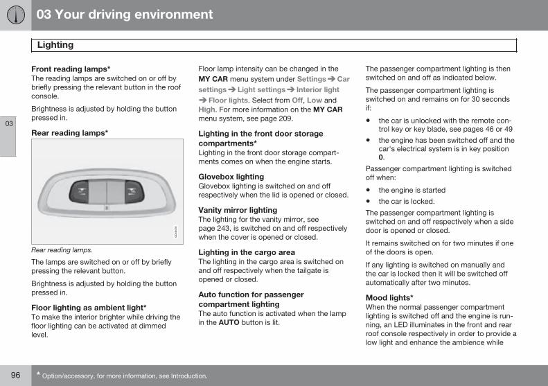
03 Your driving environment
Lighting
03
96 * Option/accessory, for more information, see Introduction.
Front reading lamps*The reading lamps are switched on or off bybriefly pressing the relevant button in the roofconsole.
Brightness is adjusted by holding the buttonpressed in.
Rear reading lamps*
Rear reading lamps.
The lamps are switched on or off by brieflypressing the relevant button.
Brightness is adjusted by holding the buttonpressed in.
Floor lighting as ambient light*To make the interior brighter while driving thefloor lighting can be activated at dimmedlevel.
Floor lamp intensity can be changed in theMY CAR menu system under Settings Carsettings Light settings Interior light
Floor lights. Select from Off, Low andHigh. For more information on the MY CARmenu system, see page 209.
Lighting in the front door storagecompartments*Lighting in the front door storage compart-ments comes on when the engine starts.
Glovebox lightingGlovebox lighting is switched on and offrespectively when the lid is opened or closed.
Vanity mirror lightingThe lighting for the vanity mirror, seepage 243, is switched on and off respectivelywhen the cover is opened or closed.
Lighting in the cargo areaThe lighting in the cargo area is switched onand off respectively when the tailgate isopened or closed.
Auto function for passengercompartment lightingThe auto function is activated when the lampin the AUTO button is lit.
The passenger compartment lighting is thenswitched on and off as indicated below.
The passenger compartment lighting isswitched on and remains on for 30 secondsif:
• the car is unlocked with the remote con-trol key or key blade, see pages 46 or 49
• the engine has been switched off and thecar's electrical system is in key position0.
Passenger compartment lighting is switchedoff when:
• the engine is started
• the car is locked.
The passenger compartment lighting isswitched on and off respectively when a sidedoor is opened or closed.
It remains switched on for two minutes if oneof the doors is open.
If any lighting is switched on manually andthe car is locked then it will be switched offautomatically after two minutes.
Mood lights*When the normal passenger compartmentlighting is switched off and the engine is run-ning, an LED illuminates in the front and rearroof console respectively in order to provide alow light and enhance the ambience while
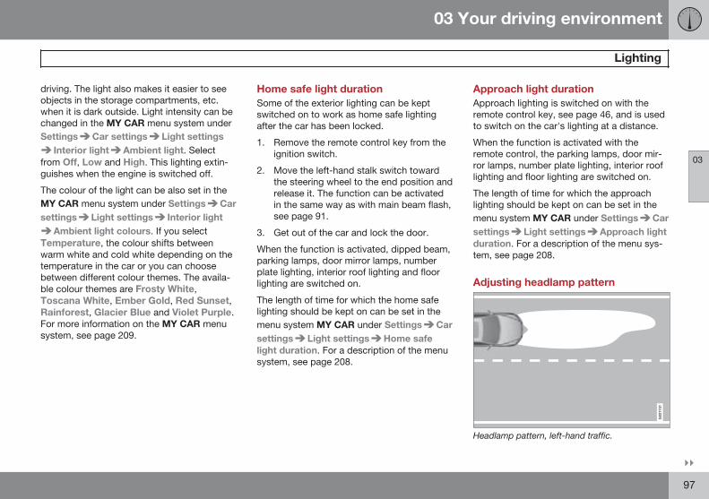
03 Your driving environment
Lighting
03
}}97
driving. The light also makes it easier to seeobjects in the storage compartments, etc.when it is dark outside. Light intensity can bechanged in the MY CAR menu system underSettings Car settings Light settings
Interior light Ambient light. Selectfrom Off, Low and High. This lighting extin-guishes when the engine is switched off.
The colour of the light can be also set in theMY CAR menu system under Settings Carsettings Light settings Interior light
Ambient light colours. If you selectTemperature, the colour shifts betweenwarm white and cold white depending on thetemperature in the car or you can choosebetween different colour themes. The availa-ble colour themes are Frosty White,Toscana White, Ember Gold, Red Sunset,Rainforest, Glacier Blue and Violet Purple.For more information on the MY CAR menusystem, see page 209.
Home safe light durationSome of the exterior lighting can be keptswitched on to work as home safe lightingafter the car has been locked.
1. Remove the remote control key from theignition switch.
2. Move the left-hand stalk switch towardthe steering wheel to the end position andrelease it. The function can be activatedin the same way as with main beam flash,see page 91.
3. Get out of the car and lock the door.
When the function is activated, dipped beam,parking lamps, door mirror lamps, numberplate lighting, interior roof lighting and floorlighting are switched on.
The length of time for which the home safelighting should be kept on can be set in themenu system MY CAR under Settings Carsettings Light settings Home safelight duration. For a description of the menusystem, see page 208.
Approach light durationApproach lighting is switched on with theremote control key, see page 46, and is usedto switch on the car's lighting at a distance.
When the function is activated with theremote control, the parking lamps, door mir-ror lamps, number plate lighting, interior rooflighting and floor lighting are switched on.
The length of time for which the approachlighting should be kept on can be set in themenu system MY CAR under Settings Carsettings Light settings Approach lightduration. For a description of the menu sys-tem, see page 208.
Adjusting headlamp pattern
G021151
Headlamp pattern, left-hand traffic.
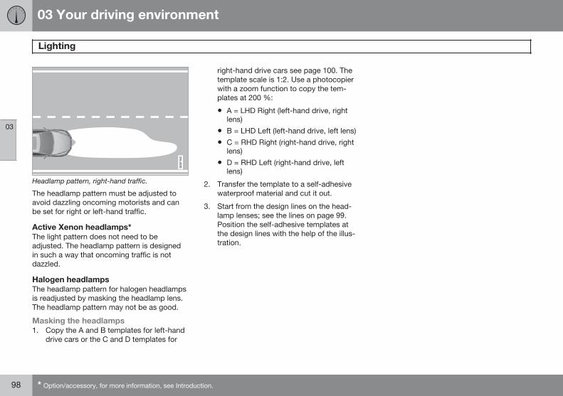
03 Your driving environment
Lighting
03
98 * Option/accessory, for more information, see Introduction.
G021152
Headlamp pattern, right-hand traffic.
The headlamp pattern must be adjusted toavoid dazzling oncoming motorists and canbe set for right or left-hand traffic.
Active Xenon headlamps*The light pattern does not need to beadjusted. The headlamp pattern is designedin such a way that oncoming traffic is notdazzled.
Halogen headlampsThe headlamp pattern for halogen headlampsis readjusted by masking the headlamp lens.The headlamp pattern may not be as good.
Masking the headlamps1. Copy the A and B templates for left-hand
drive cars or the C and D templates for
right-hand drive cars see page 100. Thetemplate scale is 1:2. Use a photocopierwith a zoom function to copy the tem-plates at 200 %:
• A = LHD Right (left-hand drive, rightlens)
• B = LHD Left (left-hand drive, left lens)
• C = RHD Right (right-hand drive, rightlens)
• D = RHD Left (right-hand drive, leftlens)
2. Transfer the template to a self-adhesivewaterproof material and cut it out.
3. Start from the design lines on the head-lamp lenses; see the lines on page 99.Position the self-adhesive templates atthe design lines with the help of the illus-tration.
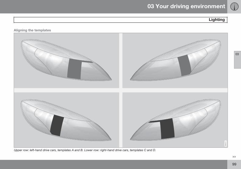
03 Your driving environment
Lighting
03
}}99
Aligning the templates
Upper row: left-hand drive cars, templates A and B. Lower row: right-hand drive cars, templates C and D.
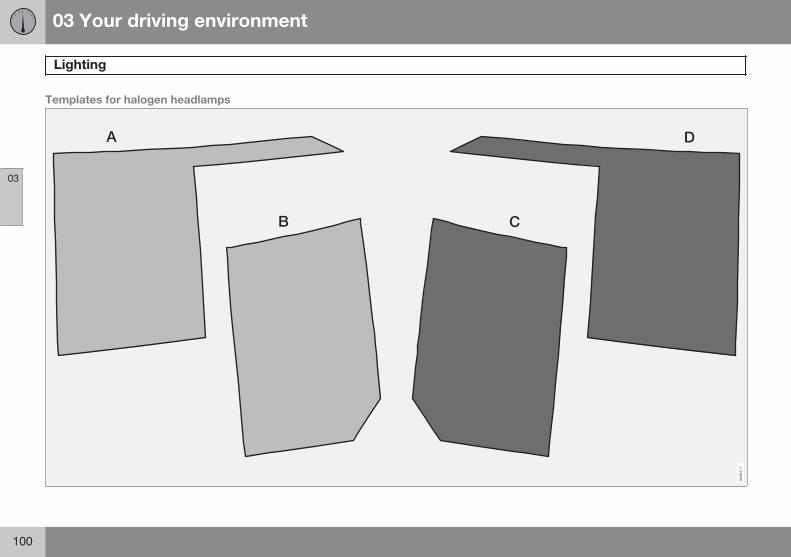
03 Your driving environment
Lighting
03
100
Templates for halogen headlamps
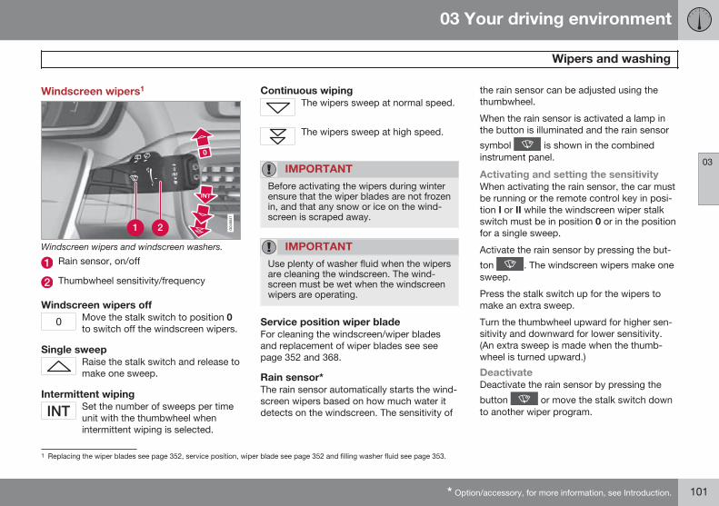
03 Your driving environment
Wipers and washing
03
* Option/accessory, for more information, see Introduction. 101
Windscreen wipers1
Windscreen wipers and windscreen washers.
Rain sensor, on/off
Thumbwheel sensitivity/frequency
Windscreen wipers offMove the stalk switch to position 0to switch off the windscreen wipers.
Single sweepRaise the stalk switch and release tomake one sweep.
Intermittent wipingSet the number of sweeps per timeunit with the thumbwheel whenintermittent wiping is selected.
Continuous wipingThe wipers sweep at normal speed.
The wipers sweep at high speed.
IMPORTANT
Before activating the wipers during winterensure that the wiper blades are not frozenin, and that any snow or ice on the wind-screen is scraped away.
IMPORTANT
Use plenty of washer fluid when the wipersare cleaning the windscreen. The wind-screen must be wet when the windscreenwipers are operating.
Service position wiper bladeFor cleaning the windscreen/wiper bladesand replacement of wiper blades see seepage 352 and 368.
Rain sensor*The rain sensor automatically starts the wind-screen wipers based on how much water itdetects on the windscreen. The sensitivity of
the rain sensor can be adjusted using thethumbwheel.
When the rain sensor is activated a lamp inthe button is illuminated and the rain sensor
symbol is shown in the combinedinstrument panel.
Activating and setting the sensitivityWhen activating the rain sensor, the car mustbe running or the remote control key in posi-tion I or II while the windscreen wiper stalkswitch must be in position 0 or in the positionfor a single sweep.
Activate the rain sensor by pressing the but-
ton . The windscreen wipers make onesweep.
Press the stalk switch up for the wipers tomake an extra sweep.
Turn the thumbwheel upward for higher sen-sitivity and downward for lower sensitivity.(An extra sweep is made when the thumb-wheel is turned upward.)
DeactivateDeactivate the rain sensor by pressing the
button or move the stalk switch downto another wiper program.
1 Replacing the wiper blades see page 352, service position, wiper blade see page 352 and filling washer fluid see page 353.
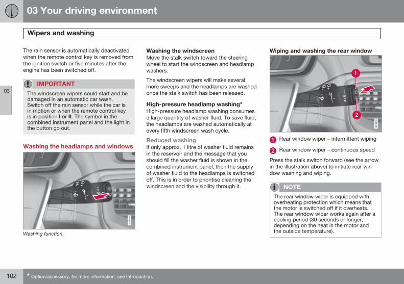
03 Your driving environment
Wipers and washing
03
102 * Option/accessory, for more information, see Introduction.
The rain sensor is automatically deactivatedwhen the remote control key is removed fromthe ignition switch or five minutes after theengine has been switched off.
IMPORTANT
The windscreen wipers could start and bedamaged in an automatic car wash.Switch off the rain sensor while the car isin motion or when the remote control keyis in position I or II. The symbol in thecombined instrument panel and the light inthe button go out.
Washing the headlamps and windows
Washing function.
Washing the windscreenMove the stalk switch toward the steeringwheel to start the windscreen and headlampwashers.
The windscreen wipers will make severalmore sweeps and the headlamps are washedonce the stalk switch has been released.
High-pressure headlamp washing*High-pressure headlamp washing consumesa large quantity of washer fluid. To save fluid,the headlamps are washed automatically atevery fifth windscreen wash cycle.
Reduced washingIf only approx. 1 litre of washer fluid remainsin the reservoir and the message that youshould fill the washer fluid is shown in thecombined instrument panel, then the supplyof washer fluid to the headlamps is switchedoff. This is in order to prioritise cleaning thewindscreen and the visibility through it.
Wiping and washing the rear window
Rear window wiper – intermittent wiping
Rear window wiper – continuous speed
Press the stalk switch forward (see the arrowin the illustration above) to initiate rear win-dow washing and wiping.
NOTE
The rear window wiper is equipped withoverheating protection which means thatthe motor is switched off if it overheats.The rear window wiper works again after acooling period (30 seconds or longer,depending on the heat in the motor andthe outside temperature).
03 Your driving environment
Wipers and washing
03
103
Wiper – reversingEngaging reverse gear while the windscreenwipers are on initiates intermittent rear win-dow wiping2. The function stops whenreverse gear is disengaged.
If the rear window wiper is already on at con-tinuous speed, no change is made.
NOTE
On cars with rain sensors, the rear wiper isactivated during reversing if the sensor isactivated and it is raining.
2 This function (intermittent wiping when reversing) can be deactivated. Visit a workshop. Volvo recommends that you contact an authorised Volvo workshop.
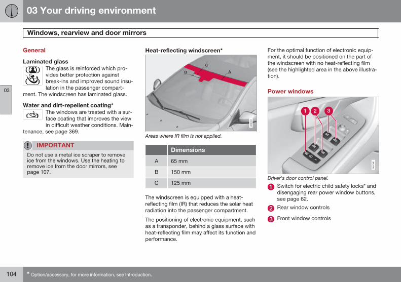
03 Your driving environment
Windows, rearview and door mirrors
03
104 * Option/accessory, for more information, see Introduction.
General
Laminated glassThe glass is reinforced which pro-vides better protection againstbreak-ins and improved sound insu-lation in the passenger compart-
ment. The windscreen has laminated glass.
Water and dirt-repellent coating*The windows are treated with a sur-face coating that improves the viewin difficult weather conditions. Main-
tenance, see page 369.
IMPORTANT
Do not use a metal ice scraper to removeice from the windows. Use the heating toremove ice from the door mirrors, seepage 107.
Heat-reflecting windscreen*
Areas where IR film is not applied.
Dimensions
A 65 mm
B 150 mm
C 125 mm
The windscreen is equipped with a heat-reflecting film (IR) that reduces the solar heatradiation into the passenger compartment.
The positioning of electronic equipment, suchas a transponder, behind a glass surface withheat-reflecting film may affect its function andperformance.
For the optimal function of electronic equip-ment, it should be positioned on the part ofthe windscreen with no heat-reflecting film(see the highlighted area in the above illustra-tion).
Power windows
Driver's door control panel.
Switch for electric child safety locks* anddisengaging rear power window buttons,see page 62.
Rear window controls
Front window controls
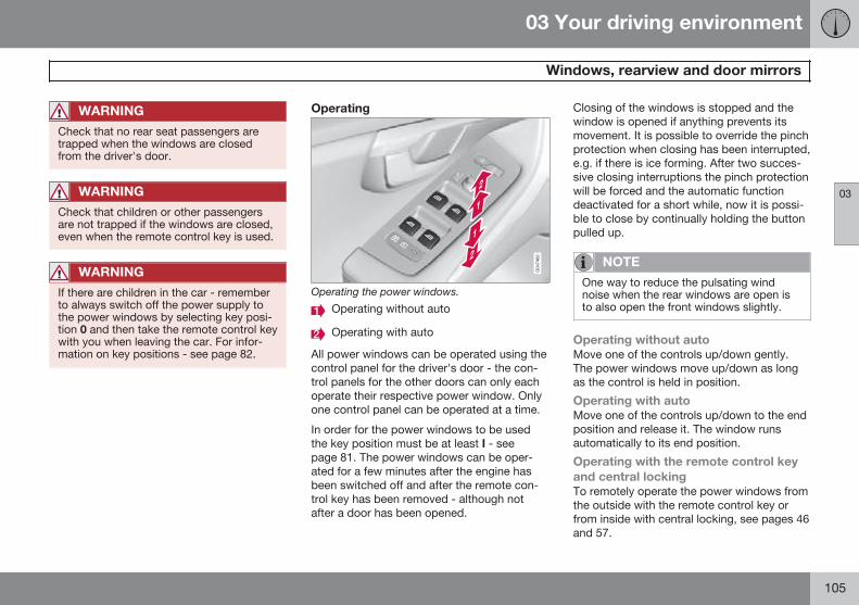
03 Your driving environment
Windows, rearview and door mirrors
03
105
WARNING
Check that no rear seat passengers aretrapped when the windows are closedfrom the driver's door.
WARNING
Check that children or other passengersare not trapped if the windows are closed,even when the remote control key is used.
WARNING
If there are children in the car - rememberto always switch off the power supply tothe power windows by selecting key posi-tion 0 and then take the remote control keywith you when leaving the car. For infor-mation on key positions - see page 82.
Operating
Operating the power windows.
Operating without auto
Operating with auto
All power windows can be operated using thecontrol panel for the driver's door - the con-trol panels for the other doors can only eachoperate their respective power window. Onlyone control panel can be operated at a time.
In order for the power windows to be usedthe key position must be at least I - seepage 81. The power windows can be oper-ated for a few minutes after the engine hasbeen switched off and after the remote con-trol key has been removed - although notafter a door has been opened.
Closing of the windows is stopped and thewindow is opened if anything prevents itsmovement. It is possible to override the pinchprotection when closing has been interrupted,e.g. if there is ice forming. After two succes-sive closing interruptions the pinch protectionwill be forced and the automatic functiondeactivated for a short while, now it is possi-ble to close by continually holding the buttonpulled up.
NOTE
One way to reduce the pulsating windnoise when the rear windows are open isto also open the front windows slightly.
Operating without autoMove one of the controls up/down gently.The power windows move up/down as longas the control is held in position.
Operating with autoMove one of the controls up/down to the endposition and release it. The window runsautomatically to its end position.
Operating with the remote control keyand central lockingTo remotely operate the power windows fromthe outside with the remote control key orfrom inside with central locking, see pages 46and 57.
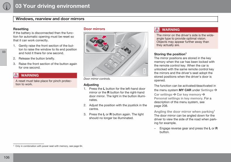
03 Your driving environment
Windows, rearview and door mirrors
03
106
ResettingIf the battery is disconnected then the func-tion for automatic opening must be reset sothat it can work correctly.
1. Gently raise the front section of the but-ton to raise the window to its end positionand hold it there for one second.
2. Release the button briefly.
3. Raise the front section of the button againfor one second.
WARNING
A reset must take place for pinch protec-tion to work.
Door mirrors
Door mirror controls.
Adjusting1. Press the L button for the left-hand door
mirror or the R button for the right-handdoor mirror. The light in the button illumi-nates.
2. Adjust the position with the joystick in thecentre.
3. Press the L or R button again. The lightshould no longer be illuminated.
WARNING
The mirror on the driver's side is the wide-angle type to provide optimal vision.Objects may appear further away thanthey actually are.
Storing the position1
The mirror positions are stored in the keymemory when the car has been locked withthe remote control key. When the car isunlocked with the same remote control keythe mirrors and the driver's seat adopt thestored positions when the driver's door isopened.
The function can be activated/deactivated inthe menu system MY CAR under SettingsCar settings Car key memoryPersonal settings in key memory. For adescription of the menu system, seepage 208.
Angling the door mirror when parking1
The door mirror can be angled down for thedriver to view the side of the road when park-ing for example.
– Engage reverse gear and press the L or Rbutton.
1 Only in combination with power seat with memory, see page 84.
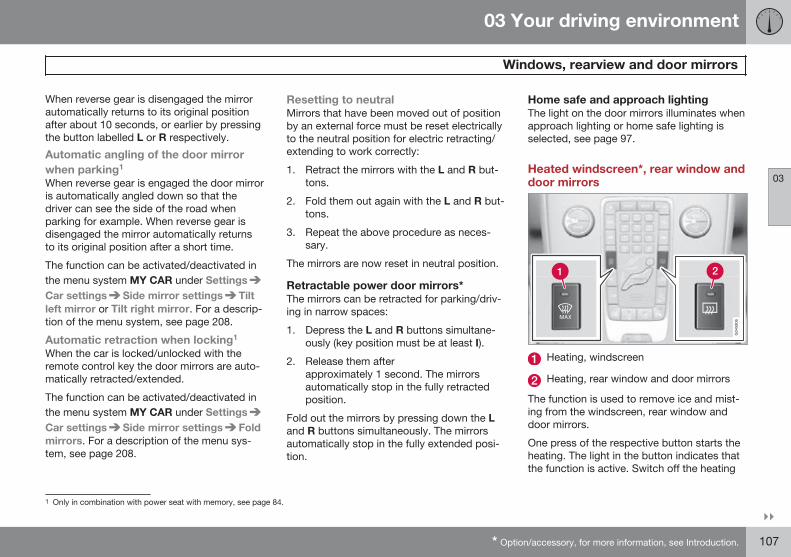
03 Your driving environment
Windows, rearview and door mirrors
03
}}* Option/accessory, for more information, see Introduction. 107
When reverse gear is disengaged the mirrorautomatically returns to its original positionafter about 10 seconds, or earlier by pressingthe button labelled L or R respectively.
Automatic angling of the door mirrorwhen parking1
When reverse gear is engaged the door mirroris automatically angled down so that thedriver can see the side of the road whenparking for example. When reverse gear isdisengaged the mirror automatically returnsto its original position after a short time.
The function can be activated/deactivated inthe menu system MY CAR under SettingsCar settings Side mirror settings Tiltleft mirror or Tilt right mirror. For a descrip-tion of the menu system, see page 208.
Automatic retraction when locking1
When the car is locked/unlocked with theremote control key the door mirrors are auto-matically retracted/extended.
The function can be activated/deactivated inthe menu system MY CAR under SettingsCar settings Side mirror settings Foldmirrors. For a description of the menu sys-tem, see page 208.
Resetting to neutralMirrors that have been moved out of positionby an external force must be reset electricallyto the neutral position for electric retracting/extending to work correctly:
1. Retract the mirrors with the L and R but-tons.
2. Fold them out again with the L and R but-tons.
3. Repeat the above procedure as neces-sary.
The mirrors are now reset in neutral position.
Retractable power door mirrors*The mirrors can be retracted for parking/driv-ing in narrow spaces:
1. Depress the L and R buttons simultane-ously (key position must be at least I).
2. Release them afterapproximately 1 second. The mirrorsautomatically stop in the fully retractedposition.
Fold out the mirrors by pressing down the Land R buttons simultaneously. The mirrorsautomatically stop in the fully extended posi-tion.
Home safe and approach lightingThe light on the door mirrors illuminates whenapproach lighting or home safe lighting isselected, see page 97.
Heated windscreen*, rear window anddoor mirrors
Heating, windscreen
Heating, rear window and door mirrors
The function is used to remove ice and mist-ing from the windscreen, rear window anddoor mirrors.
One press of the respective button starts theheating. The light in the button indicates thatthe function is active. Switch off the heating
1 Only in combination with power seat with memory, see page 84.
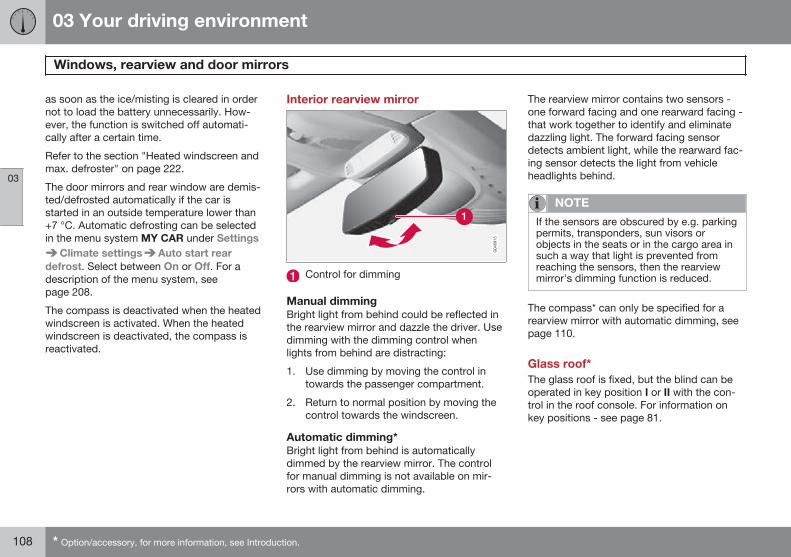
03 Your driving environment
Windows, rearview and door mirrors
03
108 * Option/accessory, for more information, see Introduction.
as soon as the ice/misting is cleared in ordernot to load the battery unnecessarily. How-ever, the function is switched off automati-cally after a certain time.
Refer to the section "Heated windscreen andmax. defroster" on page 222.
The door mirrors and rear window are demis-ted/defrosted automatically if the car isstarted in an outside temperature lower than+7 °C. Automatic defrosting can be selectedin the menu system MY CAR under Settings
Climate settings Auto start reardefrost. Select between On or Off. For adescription of the menu system, seepage 208.
The compass is deactivated when the heatedwindscreen is activated. When the heatedwindscreen is deactivated, the compass isreactivated.
Interior rearview mirror
Control for dimming
Manual dimmingBright light from behind could be reflected inthe rearview mirror and dazzle the driver. Usedimming with the dimming control whenlights from behind are distracting:
1. Use dimming by moving the control intowards the passenger compartment.
2. Return to normal position by moving thecontrol towards the windscreen.
Automatic dimming*Bright light from behind is automaticallydimmed by the rearview mirror. The controlfor manual dimming is not available on mir-rors with automatic dimming.
The rearview mirror contains two sensors -one forward facing and one rearward facing -that work together to identify and eliminatedazzling light. The forward facing sensordetects ambient light, while the rearward fac-ing sensor detects the light from vehicleheadlights behind.
NOTE
If the sensors are obscured by e.g. parkingpermits, transponders, sun visors orobjects in the seats or in the cargo area insuch a way that light is prevented fromreaching the sensors, then the rearviewmirror's dimming function is reduced.
The compass* can only be specified for arearview mirror with automatic dimming, seepage 110.
Glass roof*The glass roof is fixed, but the blind can beoperated in key position I or II with the con-trol in the roof console. For information onkey positions - see page 81.
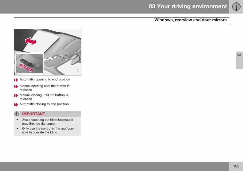
03 Your driving environment
Windows, rearview and door mirrors
03
109
Automatic opening to end position
Manual opening until the button isreleased
Manual closing until the button isreleased
Automatic closing to end position
IMPORTANT
• Avoid touching the blind because itmay then be damaged.
• Only use the control in the roof con-sole to operate the blind.
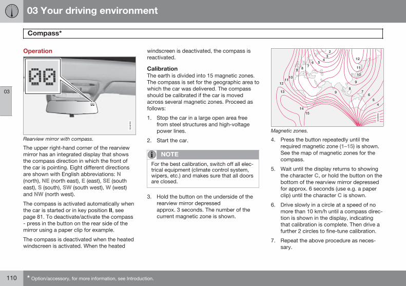
03 Your driving environment
Compass*
03
110 * Option/accessory, for more information, see Introduction.
Operation
Rearview mirror with compass.
The upper right-hand corner of the rearviewmirror has an integrated display that showsthe compass direction in which the front ofthe car is pointing. Eight different directionsare shown with English abbreviations: N(north), NE (north east), E (east), SE (southeast), S (south), SW (south west), W (west)and NW (north west).
The compass is activated automatically whenthe car is started or in key position II, seepage 81. To deactivate/activate the compass- press in the button on the rear side of themirror using a paper clip for example.
The compass is deactivated when the heatedwindscreen is activated. When the heated
windscreen is deactivated, the compass isreactivated.
CalibrationThe earth is divided into 15 magnetic zones.The compass is set for the geographic area towhich the car was delivered. The compassshould be calibrated if the car is movedacross several magnetic zones. Proceed asfollows:
1. Stop the car in a large open area freefrom steel structures and high-voltagepower lines.
2. Start the car.
NOTE
For the best calibration, switch off all elec-trical equipment (climate control system,wipers, etc.) and makes sure that all doorsare closed.
3. Hold the button on the underside of therearview mirror depressedapprox. 3 seconds. The number of thecurrent magnetic zone is shown.
G030295
Magnetic zones.
4. Press the button repeatedly until therequired magnetic zone (1–15) is shown.See the map of magnetic zones for thecompass.
5. Wait until the display returns to showingthe character C, or hold the button on thebottom of the rearview mirror depressedfor approx. 6 seconds (use e.g. a paperclip) until the character C is shown.
6. Drive slowly in a circle at a speed of nomore than 10 km/h until a compass direc-tion is shown in the display, indicatingthat calibration is complete. Then drive afurther 2 circles to fine-tune calibration.
7. Repeat the above procedure as neces-sary.
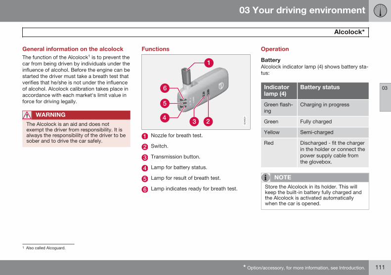
03 Your driving environment
Alcolock*
03
* Option/accessory, for more information, see Introduction. 111
General information on the alcolockThe function of the Alcolock1 is to prevent thecar from being driven by individuals under theinfluence of alcohol. Before the engine can bestarted the driver must take a breath test thatverifies that he/she is not under the influenceof alcohol. Alcolock calibration takes place inaccordance with each market's limit value inforce for driving legally.
WARNING
The Alcolock is an aid and does notexempt the driver from responsibility. It isalways the responsibility of the driver to besober and to drive the car safely.
Functions
Nozzle for breath test.
Switch.
Transmission button.
Lamp for battery status.
Lamp for result of breath test.
Lamp indicates ready for breath test.
Operation
BatteryAlcolock indicator lamp (4) shows battery sta-tus:
Indicatorlamp (4)
Battery status
Green flash-ing
Charging in progress
Green Fully charged
Yellow Semi-charged
Red Discharged - fit the chargerin the holder or connect thepower supply cable fromthe glovebox.
NOTE
Store the Alcolock in its holder. This willkeep the built-in battery fully charged andthe Alcolock is activated automaticallywhen the car is opened.
1 Also called Alcoguard.
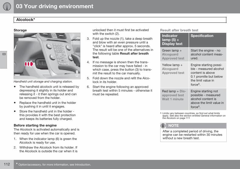
03 Your driving environment
Alcolock*
03
112 * Option/accessory, for more information, see Introduction.
Storage
Handheld unit storage and charging station.
• The handheld alcolock unit is released bydepressing it slightly in its holder andreleasing it - it then springs out and canbe removed from the holder.
• Replace the handheld unit in the holderby pushing it in until it engages.
• Store the handheld unit in the holder -this provides it with the best protectionand keeps its batteries fully charged.
Before starting the engineThe Alcolock is activated automatically and isthen ready for use when the car is opened.
1. When the indicator lamp (6) is green theAlcolock is ready for use.
2. Withdraw the Alcolock from its holder. Ifthe Alcolock is outside the car when it is
unlocked then it must first be activatedwith the switch (2).
3. Fold up the nozzle (1), take a deep breathand blow with an even pressure until a"click" is heard after approx. 5 seconds.The result will be one of the alternatives inthe following table Result after breathtest.
4. If no message is shown then the trans-mission to the car may have failed - inwhich case, press the button (3) to trans-mit the result to the car manually.
5. Fold down the nozzle and refit the Alco-lock in its holder.
6. Start the engine following an approvedbreath test within 5 minutes - otherwise itmust be repeated.
Result after breath test
Indicatorlamp (5) +Display text
Specification
Green lamp +AlcoguardApproved test
Start the engine - noalcohol content meas-ured.
Yellow lamp +AlcoguardApproved test
Engine starting possi-ble - measured alcoholcontent is above0.1 promille but belowthe limit value inforceA.
Red lamp + Dis-approved testWait 1 minute
Engine starting notpossible - measuredalcohol content isabove the limit value inforceA.
A Limits vary between countries, so find out what limitsapply. See also the section entitled General information onthe Alcolock on page 111
NOTE
After a completed period of driving, theengine can be restarted within 30 minuteswithout a new breath test.
03 Your driving environment
Alcolock*
03
* Option/accessory, for more information, see Introduction. 113
To bear in mind
Before the breath testIn order to obtain correct function and asaccurate a measurement result as possible:
• Avoid eating or drinkingapprox. 5 minutes before the breath test.
• Avoid excess windscreen washing - thealcohol in the washer fluid may result inan incorrect measurement result.
Change of driverIn order to ensure that a new breath test iscarried out in the event of a change of driver -depress the switch (2) and the send button (3)simultaneously for approx. 3 seconds. Atwhich point the car returns to start inhibitionmode and a new approved breath test isrequired before starting the engine.
Calibration and serviceThe Alcolock must be checked and calibratedat a workshop2 every 12 months.
30 days before recalibration is necessary thecombined instrument panel shows the mes-sage Alcoguard Calibr. required. If calibra-tion is not carried out within these 30 daysthen normal engine starting will be blocked -only starting with the Bypass function will
then be possible, see page 113 sectionEmergency situation.
The message can be cleared by pressing thesend button (3) once. Otherwise it goes outon its own after approx. 2 minutes but thenreappears each time the engine is started -only recalibration at a workshop2 can clearthe message permanently.
Cold or hot weatherThe colder the weather the longer it takesbefore the Alcolock is ready for use:
Temperature (ºC) Maximum heat-ing time (sec-
onds)
+10 to +85 10
-5 to +10 60
-40 to -5 180
At temperatures below -20 ºC or above+60 ºC the Alcolock requires additional powersupply. The combined instrument panelshows Alcoguard insert power cable. Inwhich case, connect the power supply cablefrom the glovebox and wait until indicatorlamp (6) is green.
In extremely cold weather the heating timecan be reduced by taking the Alcolockindoors.
Emergency situationIn the event of an emergency situation or theAlcolock is out of order, it is possible tobypass the Alcolock in order to drive the car.
NOTE
All Bypass activation is logged and savedin memory, see page 8 in the section,Recording data.
After the bypass function has been activatedthe combined instrument panel showsAlcoguard Bypass enabled the whole timewhile driving and can only be reset by a work-shop2.
The Bypass function can be tested withoutthe error message being logged - in whichcase, carry out all the steps without startingthe car. The error message is cleared whenthe car is locked.
When the Alcolock is installed, either theBypass or Emergency function is selected asthe bypassing option. This setting can bechanged afterwards at a workshop2.
2 An authorised Volvo workshop is recommended.
03 Your driving environment
Alcolock*
03
114 * Option/accessory, for more information, see Introduction.
Activating the Bypass function• Depress and hold the left-hand stalk
switch OK button and the button for haz-ard warning flashers simultaneously forapprox. 5 seconds - the combined instru-ment panel first shows Bypass activatedWait 1 minute and then AlcoguardBypass enabled - after which the enginecan be started.
This function can be activated several times.The error message shown during driving canonly be cleared at a workshop2.
Activating the Emergency function• Depress and hold the left-hand stalk
switch OK button and the button for haz-ard warning flashers simultaneously forapprox. 5 seconds - the combined instru-ment panel shows Alcoguard Bypassenabled and the engine can be started.
This function can be used once, after which areset must be made at a workshop2.
Symbols and text messagesIn addition to the messages already descri-bed, the following may also be shown:
Display text Meaning/Action
AlcoguardRestart possi-ble
The engine has beenswitched off for less than30 minutes - engine star-ting possible withoutnew test.
AlcoguardServicerequired
Contact a workshop2.
Alcoguard Nosignal
Transmission failed -send manually with but-ton (3) or take a newbreath test.
AlcoguardInvalid test
Test failed - take a newbreath test.
AlcoguardBlow longer
Blowing too short - blowfor longer.
AlcoguardBlow softer
Blowing too hard - blowmore gently.
Display text Meaning/Action
AlcoguardBlow harder
Blowing too weak - blowharder.
Alcoguardwait Preheat-ing
Heating not finished -wait for text AlcoguardBlow 5 seconds.
2 An authorised Volvo workshop is recommended.
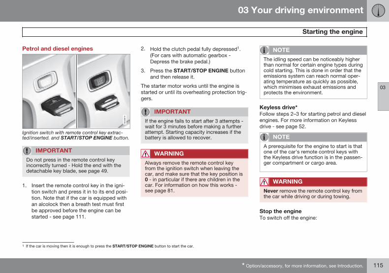
03 Your driving environment
Starting the engine
03
* Option/accessory, for more information, see Introduction. 115
Petrol and diesel engines
Ignition switch with remote control key extrac-ted/inserted. and START/STOP ENGINE button.
IMPORTANT
Do not press in the remote control keyincorrectly turned - Hold the end with thedetachable key blade, see page 49.
1. Insert the remote control key in the igni-tion switch and press it in to its end posi-tion. Note that if the car is equipped withan alcolock then a breath test must firstbe approved before the engine can bestarted - see page 111.
2. Hold the clutch pedal fully depressed1.(For cars with automatic gearbox -Depress the brake pedal.)
3. Press the START/STOP ENGINE buttonand then release it.
The starter motor works until the engine isstarted or until its overheating protection trig-gers.
IMPORTANT
If the engine fails to start after 3 attempts -wait for 3 minutes before making a furtherattempt. Starting capacity increases if thebattery is allowed to recover.
WARNING
Always remove the remote control keyfrom the ignition switch when leaving thecar, and make sure that the key position is0 - in particular if there are children in thecar. For information on how this works -see page 81.
NOTE
The idling speed can be noticeably higherthan normal for certain engine types duringcold starting. This is done in order that theemissions system can reach normal oper-ating temperature as quickly as possible,which minimises exhaust emissions andprotects the environment.
Keyless drive*Follow steps 2–3 for starting petrol and dieselengines. For more information on Keylessdrive - see page 52.
NOTE
A prerequisite for the engine to start is thatone of the car's remote control keys withthe Keyless drive function is in the passen-ger compartment or cargo area.
WARNING
Never remove the remote control key fromthe car while driving or during towing.
Stop the engineTo switch off the engine:
1 If the car is moving then it is enough to press the START/STOP ENGINE button to start the car.
03 Your driving environment
Starting the engine
03
116
• Press START/STOP ENGINE - theengine stops.
• If the car has an automatic gearbox andthe gear selector is not in a position P orif the car is moving - Press twice or holdthe START/STOP ENGINE buttondepressed until the engine stops.
Steering lockA mechanical noise can be perceived whenthe steering lock unlocks or locks.
• The steering lock unlocks when theremote control key is in the ignitionswitch2 and the START/STOP ENGINEbutton is depressed.
• The steering lock locks when the driver'sdoor is opened after the engine has beenswitched off.
Key positionsFor information on the remote control key'sdifferent key positions - see page 81
2 Cars with Keyless drive must have a remote control key inside the passenger compartment.
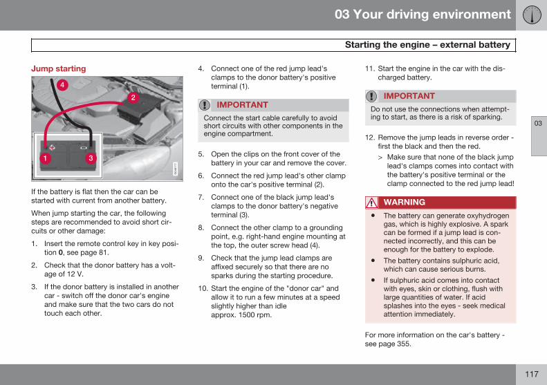
03 Your driving environment
Starting the engine – external battery
03
117
Jump starting
If the battery is flat then the car can bestarted with current from another battery.
When jump starting the car, the followingsteps are recommended to avoid short cir-cuits or other damage:
1. Insert the remote control key in key posi-tion 0, see page 81.
2. Check that the donor battery has a volt-age of 12 V.
3. If the donor battery is installed in anothercar - switch off the donor car's engineand make sure that the two cars do nottouch each other.
4. Connect one of the red jump lead'sclamps to the donor battery's positiveterminal (1).
IMPORTANT
Connect the start cable carefully to avoidshort circuits with other components in theengine compartment.
5. Open the clips on the front cover of thebattery in your car and remove the cover.
6. Connect the red jump lead's other clamponto the car's positive terminal (2).
7. Connect one of the black jump lead'sclamps to the donor battery's negativeterminal (3).
8. Connect the other clamp to a groundingpoint, e.g. right-hand engine mounting atthe top, the outer screw head (4).
9. Check that the jump lead clamps areaffixed securely so that there are nosparks during the starting procedure.
10. Start the engine of the "donor car" andallow it to run a few minutes at a speedslightly higher than idleapprox. 1500 rpm.
11. Start the engine in the car with the dis-charged battery.
IMPORTANT
Do not use the connections when attempt-ing to start, as there is a risk of sparking.
12. Remove the jump leads in reverse order -first the black and then the red.> Make sure that none of the black jump
lead's clamps comes into contact withthe battery's positive terminal or theclamp connected to the red jump lead!
WARNING
• The battery can generate oxyhydrogengas, which is highly explosive. A sparkcan be formed if a jump lead is con-nected incorrectly, and this can beenough for the battery to explode.
• The battery contains sulphuric acid,which can cause serious burns.
• If sulphuric acid comes into contactwith eyes, skin or clothing, flush withlarge quantities of water. If acidsplashes into the eyes - seek medicalattention immediately.
For more information on the car's battery -see page 355.
03 Your driving environment
Gearboxes
03
118 * Option/accessory, for more information, see Introduction.
General
IMPORTANT
To prevent damage to any drive systemcomponents, the working temperature ofthe gearbox is checked. If there is a risk ofoverheating, a warning symbol in the com-bined instrument lights up and a text mes-sage is shown. Follow the recommenda-tion given in the text message.
Start assistance on a hill - HSA*The foot brake can be released before settingoff or reversing uphill - the HSA (Hill StartAssist) function means that the car does notroll backwards.
The function means that the pedal pressure inthe brake system remains for several secondswhile the driver's foot is moved from brakepedal to accelerator pedal.
The temporary braking effect releases afterseveral seconds or when the driver acceler-ates.
Manual gearbox
Gearing pattern.
Look at the actual gearshift pattern imprintedon the gear lever.
• Depress the clutch pedal fully duringeach gear change.
• Take your foot off the clutch pedalbetween gear changes.
WARNING
Always apply the parking brake whenparking on a slope - leaving the car in gearis not sufficient to hold the car in all situa-tions.
Reverse gear inhibitorThe reverse gear inhibitor hinders the possi-bility of mistakenly attempting to engagereverse gear during normal forward travel.
• Follow the gearing pattern printed on thegear lever and start from neutral position,N then depress the gear lever beforemoving it to R position.
• Engage reverse gear only when the car isstationary.
Gear shift indicator*An essential detail in connection with environ-mental driving is to drive in the right gear andto change gear in plenty of time.
An indicator is available as an aid on somevariants - GSI (Gear Shift Indicator) - whichnotifies the driver when it is appropriate toengage the next higher or lower gear in orderto obtain the lowest possible fuel consump-tion. However, taking into consideration cha-racteristics such as performance and vibra-tion-free running, it may be advantageous tochange gear at a higher engine speed. Theframed number indicates the current gear.
03 Your driving environment
Gearboxes
03
* Option/accessory, for more information, see Introduction. 119
Manual gearboxGear shift indicator for man-ual gearbox. Only onemarker is illuminated at atime - it is illuminated in thecentre only during normaldriving.
When gearing up/down as recommended, theupper one is illuminated at +" or the lower at"-", marked red in the illustration.
Automatic gearbox
Combined instrument panel "Digital" with gearshift indicator.
With "Analogue" combinedinstrument panel, the gearpositions and indicatorarrows are displayed in itscentre.
Automatic gearbox Geartronic*
D: Automatic gear positions. +/–: Manual gearpositions. S: Sport mode*.1
The combined instrument panel shows theposition of the gear selector using the follow-ing indications: P, R, N, D, S*, 1, 2, 3 etc.
Gear positionsAutomatic gear positions areindicated on the right of thecombined instrument panel.(Only one marker is illumi-nated at a time - the oneshowing the current gearselector position.)
Symbol "S" for Sport mode is ORANGE whenthe mode is active.
P – Parking positionSelect P when starting the engine or whenthe car is parked.
• In order to be able to move the gearselector from P position, the brake pedalmust first be depressed firmly.
The gearbox is mechanically blocked whenthe P position is engaged. Apply the parkingbrake as well, as a precaution - seepage 133.
NOTE
The gear selector must be in P position toallow the car to be locked and alarmed.
1 The gear lever's gearshift pattern varies depending on engine option.
03 Your driving environment
Gearboxes
03
120
IMPORTANT
The car must be stationary when posi-tion P is selected.
WARNING
Always apply the parking brake whenparking on a slope - the automatic trans-mission in P is not sufficient to hold the carin all situations.
R – ReverseThe car must be stationary when position R isselected.
N – NeutralNo gear is engaged and the engine can bestarted. Apply the parking brake if the car isstationary with the gear selector in position N.
D – DriveD is the normal driving position. Shifting upand down takes place automatically based onthe level of acceleration and speed. The carmust be stationary when the gear selector ismoved to position D from position R.
Geartronic – Manual gear positions (+/-)The driver can also change gear manuallyusing the Geartronic automatic gearbox. Thecar engine-brakes when the accelerator pedalis released.
The manual gear position is reached by mov-ing the lever to the side from position D to theend position at "+/-". The combined instru-ment panel's symbol "+/-" changes colourfrom WHITE to ORANGE and the digits 1, 2, 3etc. are displayed in a box which corre-sponds to the gear that has just beenselected.
• Move the lever forwards towards "+"(plus) to change up a gear and release thelever, which returns to its neutral positionbetween "+" and "–".
or
• Pull the lever back towards "–" (minus) tochange down a gear and release it.
The manual gearshift mode "+/-" can beselected at any time while driving.
Geartronic automatically shifts down if thedriver allows the speed to decrease lowerthan a level suitable for the selected gear, inorder to avoid jerking and stalling.
To return to automatic driving mode:
• Move the lever to the side to the endposition at D.
NOTE
f the gearbox has a Sport programme thenthe gearbox will only become manual afterthe lever has been moved forwards orbackwards in its "+/-" position. The com-bined instrument panel then shifts the indi-cation from S to show which of the gears1, 2, 3 etc. is engaged.
Geartronic - Sport mode (S)The Sport programme providessportier characteristics and allowshigher engine speed for the gears.At the same time it responds more
quickly to acceleration. During active driving,the use of a lower gear is prioritised, leadingto a delayed upshift.
To activate Sport mode:
• Move the gear selector to the side from Dposition to the end position at "+S–" - thecombined instrument panel changes indi-cation from D to S.
Sport mode can be selected at any time whiledriving.
Geartronic - Winter modeIt can be easier to pull away on slippery roadsif 3rd gear is engaged manually.
1. Depress the brake pedal and move thegear selector from D position to the end
03 Your driving environment
Gearboxes
03
}}* Option/accessory, for more information, see Introduction. 121
position at "+/–" - the combined instru-ment panel shifts the indication from D tothe figure 12.
2. Scroll up to gear 3 by pushing the leverforward towards "+" (plus) twice - thecombined instrument panel shifts theindication from 1 to 3.
3. Release the brake and accelerate care-fully.
The gearbox "winter mode" means that thecar moves off with a lower engine speed andreduced engine power on the drive wheels.
Kick-downWhen the accelerator pedal is pressed all theway to the floor (beyond the position normallyregarded as full acceleration) a lower gear isimmediately engaged. This is known as kick-down.
If the accelerator is released from the kick-down position, the gearbox automaticallychanges up.
Kick-down is used when maximum accelera-tion is needed, such as for overtaking.
Safety functionTo prevent overrevving the engine, the gear-box control program has a protective down-
shift inhibitor which prevents the kick-downfunction.
Geartronic does not permit downshifting/kick-down which would result in an enginespeed high enough to damage the engine.Nothing happens if the driver still tries to shiftdown in this way at high engine speed – theoriginal gear remains engaged.
When kick-down is activated the car canchange one or more gears at a time depend-ing on engine speed. The car changes upwhen the engine reaches its maximum speedin order to prevent damage to the engine.
Mechanical gear selector inhibitor
G021351
The gear selector can be moved forward andback freely between N and D. Other positionsare locked with a latch that is released withthe inhibitor button on the gear selector.
With the inhibitor button depressed the levercan be moved forwards or backwardsbetween P, R, N and D.
Automatic gear selector inhibitorThe automatic gearbox has special safetysystems:
Parking position (P)Stationary car with engine running:
• Keep your foot on the brake pedal whenmoving the gear selector to another posi-tion.
Electric gear inhibitor – ShiftlockParking position (P)To be able to move the gear selector from Pto other gear positions, the brake pedal mustbe depressed and the remote control keymust be in position II, see page 81.
Shiftlock – Neutral (N)If the gear selector is in the N position andthe car has been stationary for at least 3 sec-onds (irrespective of whether the engine isrunning) then the gear selector is locked.
2 If the car has Sport mode* then "S" is shown first.
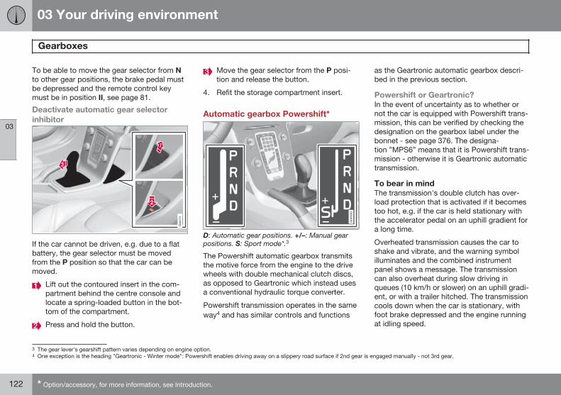
03 Your driving environment
Gearboxes
03
122 * Option/accessory, for more information, see Introduction.
To be able to move the gear selector from Nto other gear positions, the brake pedal mustbe depressed and the remote control keymust be in position II, see page 81.
Deactivate automatic gear selectorinhibitor
If the car cannot be driven, e.g. due to a flatbattery, the gear selector must be movedfrom the P position so that the car can bemoved.
Lift out the contoured insert in the com-partment behind the centre console andlocate a spring-loaded button in the bot-tom of the compartment.
Press and hold the button.
Move the gear selector from the P posi-tion and release the button.
4. Refit the storage compartment insert.
Automatic gearbox Powershift*
D: Automatic gear positions. +/–: Manual gearpositions. S: Sport mode*.3
The Powershift automatic gearbox transmitsthe motive force from the engine to the drivewheels with double mechanical clutch discs,as opposed to Geartronic which instead usesa conventional hydraulic torque converter.
Powershift transmission operates in the sameway4 and has similar controls and functions
as the Geartronic automatic gearbox descri-bed in the previous section.
Powershift or Geartronic?In the event of uncertainty as to whether ornot the car is equipped with Powershift trans-mission, this can be verified by checking thedesignation on the gearbox label under thebonnet - see page 376. The designa-tion ”MPS6” means that it is Powershift trans-mission - otherwise it is Geartronic automatictransmission.
To bear in mindThe transmission's double clutch has over-load protection that is activated if it becomestoo hot, e.g. if the car is held stationary withthe accelerator pedal on an uphill gradient fora long time.
Overheated transmission causes the car toshake and vibrate, and the warning symbolilluminates and the combined instrumentpanel shows a message. The transmissioncan also overheat during slow driving inqueues (10 km/h or slower) on an uphill gradi-ent, or with a trailer hitched. The transmissioncools down when the car is stationary, withfoot brake depressed and the engine runningat idling speed.
3 The gear lever's gearshift pattern varies depending on engine option.4 One exception is the heading "Geartronic - Winter mode": Powershift enables driving away on a slippery road surface if 2nd gear is engaged manually - not 3rd gear.
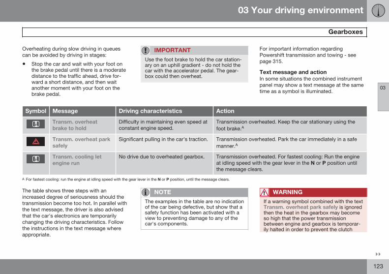
03 Your driving environment
Gearboxes
03
}}123
Overheating during slow driving in queuescan be avoided by driving in stages:
• Stop the car and wait with your foot onthe brake pedal until there is a moderatedistance to the traffic ahead, drive for-ward a short distance, and then waitanother moment with your foot on thebrake pedal.
IMPORTANT
Use the foot brake to hold the car station-ary on an uphill gradient - do not hold thecar with the accelerator pedal. The gear-box could then overheat.
For important information regardingPowershift transmission and towing - seepage 315.
Text message and actionIn some situations the combined instrumentpanel may show a text message at the sametime as a symbol is illuminated.
Symbol Message Driving characteristics Action
Transm. overheatbrake to hold
Difficulty in maintaining even speed atconstant engine speed.
Transmission overheated. Keep the car stationary using thefoot brake.A
Transm. overheat parksafely
Significant pulling in the car's traction. Transmission overheated. Park the car immediately in a safemanner.A
Transm. cooling letengine run
No drive due to overheated gearbox. Transmission overheated. For fastest cooling: Run the engineat idling speed with the gear lever in the N or P position untilthe message clears.
A For fastest cooling: run the engine at idling speed with the gear lever in the N or P position, until the message clears.
The table shows three steps with anincreased degree of seriousness should thetransmission become too hot. In parallel withthe text message, the driver is also advisedthat the car's electronics are temporarilychanging the driving characteristics. Followthe instructions in the text message whereappropriate.
NOTE
The examples in the table are no indicationof the car being defective, but show that asafety function has been activated with aview to preventing damage to any of thecar's components.
WARNING
If a warning symbol combined with the textTransm. overheat park safely is ignoredthen the heat in the gearbox may becomeso high that the power transmissionbetween engine and gearbox is temporar-ily halted in order to prevent the clutch
03 Your driving environment
Gearboxes
03
124
from malfunctioning - the car then losesdrive and is stationary until gearbox tem-perature has cooled to an acceptablelevel.
For more possible text messages with theirrespective proposals for solutions concerningautomatic transmission, see page 205.
A text message extinguishes automaticallyafter the action has been carried out or afterone press on the indicator stalk OK button.
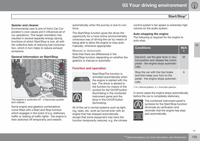
03 Your driving environment
Start/Stop*
03
}}* Option/accessory, for more information, see Introduction. 125
Quieter and cleanerEnvironmental care is one of Volvo Car Cor-poration's core values and it influences all ofour operations. This target orientation hasresulted in several separate energy-savingfunctions of which Start/Stop is one, all withthe collective task of reducing fuel consump-tion, which in turn helps to reduce exhaustemissions.
General information on Start/Stop
The engine is switched off - it becomes quieterand cleaner...
Some engine and gearbox combinationscome fitted with a Start and Stop functionwhich engages in the event of e.g. stationarytraffic or waiting at traffic lights - the engine isthen switched off temporarily and restarts
automatically when the journey is due to con-tinue.
The Start/Stop function gives the driver theopportunity for a more active environmentallyconscious way of driving the car by means ofbeing able to allow the engine to stop auto-matically, whenever appropriate.
Manual or AutomaticNote that there are differences in theStart/Stop function depending on whether thegearbox is manual or automatic.
Function and operation
Start/StopThe function isactivated automatically whenthe engine is started with thekey. The driver is alerted tothe function by means of thesymbol for the On/Off buttonilluminating in the combinedinstrument panel and thelamp in the On/Off buttonilluminating.
All of the car's normal systems such as light-ing, radio, etc. work as normal even with anengine that has stopped automatically,except that some equipment may have thefunction temporarily reduced, e.g. the climate
control system's fan speed or extremely highvolume on the audio system.
Auto-stopping the engineThe following is required for the engine toauto-stop:
Conditions M/AA
Declutch, set the gear lever in neu-tral position and release the clutchpedal - the engine stops automati-cally.
M
Stop the car with the foot brakeand then keep your foot on thepedal - the engine stops automati-cally.
A
A M = Manual gearbox, A = Automatic gearbox.
In some cases the engine stops automaticallybefore the car is completely stationary.
The combined instrument panel'ssymbols for the Start/Stop functionilluminate as verification andreminder that the engine has stop-ped automatically.
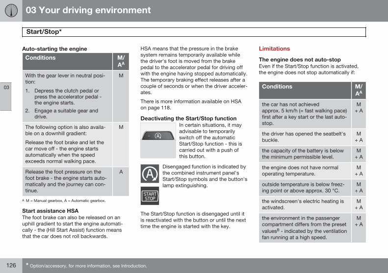
03 Your driving environment
Start/Stop*
03
126 * Option/accessory, for more information, see Introduction.
Auto-starting the engine
Conditions M/AA
With the gear lever in neutral posi-tion:
1. Depress the clutch pedal orpress the accelerator pedal -the engine starts.
2. Engage a suitable gear anddrive.
M
The following option is also availa-ble on a downhill gradient:
Release the foot brake and let thecar move off - the engine startsautomatically when the speedexceeds normal walking pace.
M
Release the foot pressure on thefoot brake - the engine starts auto-matically and the journey can con-tinue.
A
A M = Manual gearbox, A = Automatic gearbox.
Start assistance HSAThe foot brake can also be released on anuphill gradient to start the engine automati-cally - the (Hill Start Assist) function meansthat the car does not roll backwards.
HSA means that the pressure in the brakesystem remains temporarily available whilethe driver's foot is moved from the brakepedal to the accelerator pedal for driving offwith the engine having stopped automatically.The temporary braking effect releases after acouple of seconds or when the driver acceler-ates.
There is more information available on HSAon page 118.
Deactivating the Start/Stop functionIn certain situations, it mayadvisable to temporarilyswitch off the automaticStart/Stop function - this iscarried out with a push ofthis button.
Disengaged function is indicated bythe combined instrument panel'sStart/Stop symbols and the button'slamp extinguishing.
The Start/Stop function is disengaged until itis reactivated with the button or until the nexttime the engine is started with the key.
Limitations
The engine does not auto-stopEven if the Start/Stop function is activated,the engine does not stop automatically if:
Conditions M/AA
the car has not achievedapprox. 5 km/h (= fast walking pace)first after a key start or the last auto-stop.
M+ A
the driver has opened the seatbelt'sbuckle.
M+ A
the capacity of the battery is belowthe minimum permissible level.
M+ A
the engine does not have normaloperating temperature.
M+ A
outside temperature is below freez-ing point or above approx. 30 °C.
M+ A
the windscreen's electric heating isactivated.
M+ A
the environment in the passengercompartment differs from the presetvaluesB - indicated by the ventilationfan running at a high speed.
M+ A
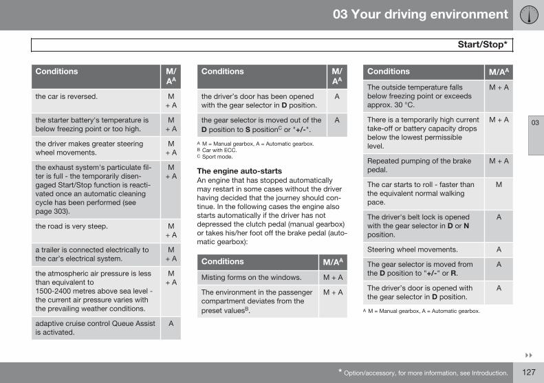
03 Your driving environment
Start/Stop*
03
}}* Option/accessory, for more information, see Introduction. 127
Conditions M/AA
the car is reversed. M+ A
the starter battery's temperature isbelow freezing point or too high.
M+ A
the driver makes greater steeringwheel movements.
M+ A
the exhaust system's particulate fil-ter is full - the temporarily disen-gaged Start/Stop function is reacti-vated once an automatic cleaningcycle has been performed (seepage 303).
M+ A
the road is very steep. M+ A
a trailer is connected electrically tothe car’s electrical system.
M+ A
the atmospheric air pressure is lessthan equivalent to1500-2400 metres above sea level -the current air pressure varies withthe prevailing weather conditions.
M+ A
adaptive cruise control Queue Assistis activated.
A
Conditions M/AA
the driver’s door has been openedwith the gear selector in D position.
A
the gear selector is moved out of theD position to S positionC or "+/-".
A
A M = Manual gearbox, A = Automatic gearbox.B Car with ECC.C Sport mode.
The engine auto-startsAn engine that has stopped automaticallymay restart in some cases without the driverhaving decided that the journey should con-tinue. In the following cases the engine alsostarts automatically if the driver has notdepressed the clutch pedal (manual gearbox)or takes his/her foot off the brake pedal (auto-matic gearbox):
Conditions M/AA
Misting forms on the windows. M + A
The environment in the passengercompartment deviates from thepreset valuesB.
M + A
Conditions M/AA
The outside temperature fallsbelow freezing point or exceedsapprox. 30 °C.
M + A
There is a temporarily high currenttake-off or battery capacity dropsbelow the lowest permissiblelevel.
M + A
Repeated pumping of the brakepedal.
M + A
The car starts to roll - faster thanthe equivalent normal walkingpace.
M
The driver's belt lock is openedwith the gear selector in D or Nposition.
A
Steering wheel movements. A
The gear selector is moved fromthe D position to "+/-" or R.
A
The driver’s door is opened withthe gear selector in D position.
A
A M = Manual gearbox, A = Automatic gearbox.
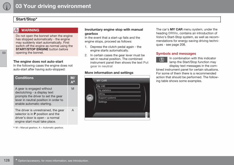
03 Your driving environment
Start/Stop*
03
128 * Option/accessory, for more information, see Introduction.
WARNING
Do not open the bonnet when the enginehas stopped automatically - the enginemay suddenly start automatically. Firstswitch off the engine as normal using theSTART/STOP ENGINE button beforeopening the bonnet.
The engine does not auto-startIn the following cases the engine does notauto-start after having auto-stopped:
Conditions M/AA
A gear is engaged withoutdeclutching - a display textprompts the driver to set the gearlever in neutral position in order toenable automatic starting.
M
The driver is unrestrained, the gearselector is in P position and thedriver’s door is open - a normalengine start must take place.
A
A M = Manual gearbox, A = Automatic gearbox.
Involuntary engine stop with manualgearboxIn the event that a start-up fails and theengine stops, proceed as follows:
1. Depress the clutch pedal again - theengine starts automatically.
2. In certain cases the gear lever must beset in neutral position. The combinedinstrument panel then shows the text Putgear in neutral
More information and settings
The car's MY CAR menu system, under theheading DRIVe, contains an introduction ofVolvo's Start-Stop system, as well as recom-mendations for energy-saving driving techni-ques - see page 208.
Symbols and messagesIn combination with this indicatorlamp the Start/Stop function maydisplay text messages in the com-
bined instrument panel for certain situations.For some of them there is a recommendedaction that should be performed. The follow-ing table shows some examples.
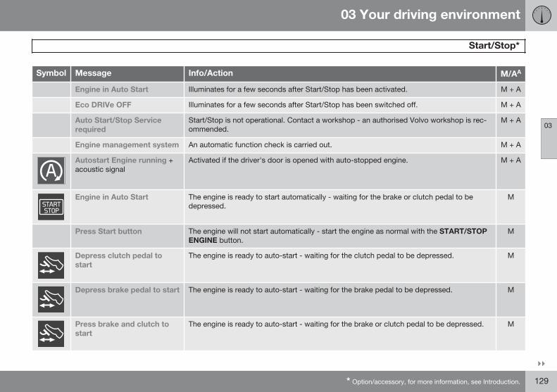
03 Your driving environment
Start/Stop*
03
}}* Option/accessory, for more information, see Introduction. 129
Symbol Message Info/Action M/AA
Engine in Auto Start Illuminates for a few seconds after Start/Stop has been activated. M + A
Eco DRIVe OFF Illuminates for a few seconds after Start/Stop has been switched off. M + A
Auto Start/Stop Servicerequired
Start/Stop is not operational. Contact a workshop - an authorised Volvo workshop is rec-ommended.
M + A
Engine management system An automatic function check is carried out. M + A
Autostart Engine running +acoustic signal
Activated if the driver's door is opened with auto-stopped engine. M + A
Engine in Auto Start The engine is ready to start automatically - waiting for the brake or clutch pedal to bedepressed.
M
Press Start button The engine will not start automatically - start the engine as normal with the START/STOPENGINE button.
M
Depress clutch pedal tostart
The engine is ready to auto-start - waiting for the clutch pedal to be depressed. M
Depress brake pedal to start The engine is ready to auto-start - waiting for the brake pedal to be depressed. M
Press brake and clutch tostart
The engine is ready to auto-start - waiting for the brake or clutch pedal to be depressed. M
03 Your driving environment
Start/Stop*
03
130 * Option/accessory, for more information, see Introduction.
Symbol Message Info/Action M/AA
Put gear in neutral to start Gear is engaged without declutching - disengage and set the gear lever in neutral position. M
Engine in Auto Start The engine is ready to start automatically - waiting for the brake pedal to be released. A
Select P or N to start Start/Stop has been deactivated - move the gear selector to N or P position and start theengine as normal with the START/STOP ENGINE button.
A
Press Start button The engine will not start automatically - start the engine as normal with the START/STOPENGINE button and the gear selector in P or N.
A
A M = Manual gearbox, A = Automatic gearbox.
If a message does not go out following com-pletion of the action then a workshop shouldbe contacted - an authorised Volvo workshopis recommended.
03 Your driving environment
Foot brake
03
131
GeneralThe car is equipped with two brake circuits. Ifone brake circuit is damaged then this willmean that the brakes engage at a deeperlevel and harder pressure on the pedal is nee-ded to produce the normal braking effect.
The driver's brake pedal pressure is assistedby a brake servo.
WARNING
The brake servo only works when theengine is running.
If the brake is used when the engine isswitched off then the pedal will feel stiff andmore force must be used to brake the car.
In very hilly terrain or when driving with aheavy load the brakes can be relieved byusing engine braking. Engine braking is mostefficiently used if the same gear is useddownhill as up.
For more general information on heavy loadson the car, see page 383.
Anti-lock braking systemThe car is equipped with ABS (Anti-lockBraking System) which prevents the wheelsfrom locking during braking. This means theability to steer is maintained and it is easier to
swerve to avoid a hazard for example. Vibra-tion may be felt in the brake pedal when thisis engaged and this is normal.
A short test of the ABS system is made auto-matically after the engine has been startedwhen the driver releases the brake pedal. Afurther automatic test of the ABS system maybe made when the car reaches 10 km/h. Thetest may be experienced as pulses in thebrake pedal.
Emergency brake lights and automatichazard warning flashersEmergency brake lights are activated to alertvehicles behind about sudden braking. Thefunction means that the brake light flashesinstead of - as in normal braking - shiningwith a constant glow.
Emergency brake lights are activated atspeeds above 50 km/h if the ABS system isworking and/or in the event of sudden brak-ing. Once the car's speed has been braked tobelow 10 km/h, the brake light stops flashingand returns to a normal constant glow - haz-ard warning flashers are activated at thesame time, which flash until the driver accel-erates the car to at least 20 km/h or they areswitched off with their button, see page 94.
Cleaning the brake discsCoatings of dirt and water on the brake discsmay result in delayed brake function. Thisdelay is minimised by cleaning the brake lin-ings.
Manual cleaning is advisable with wet roadsurfaces, prior to long-stay parking and afterthe car has been washed. Carry this out bybraking gently during a short period while enroute.
Emergency Brake AssistanceEmergency Brake Assistance EBA(Emergency Brake Assist) helps to increasebrake force and so reduce braking distance.EBA detects the driver's braking style andincreases brake force as necessary. Thebrake force can be reinforced up to the levelwhen the ABS system is engaged. The EBAfunction is interrupted when the pressure onthe brake pedal is reduced.
NOTE
When EBA is activated the brake pedallowers slightly more than usual, depress(hold) the brake pedal as long as neces-sary. If the brake pedal is released then allbraking ceases.
03 Your driving environment
Foot brake
03
132
MaintenanceTo keep the car as safe and reliable as possi-ble, follow the Volvo service intervals asspecified in the Service and Warranty Book-let, see page 338.
IMPORTANT
The wear on the brake system's compo-nents must be checked regularly.
Contact a workshop for information aboutthe procedure or engage a workshop tocarry out the inspection - an authorisedVolvo workshop is recommended.
Symbols in the combined instrumentpanel
Symbol Specification
Constant glow – Check thebrake fluid level. If the level islow, fill with brake fluid andcheck for the cause of thebrake fluid loss.
Constant glow for 2 secondswhen the engine is started -automatic function check.
WARNING
If and illuminate at the sametime, there may be a fault in the brake sys-tem.
If the level in the brake fluid reservoir isnormal at this stage, drive carefully to thenearest workshop and have the brake sys-tem checked - an authorised Volvo work-shop is recommended.
If the brake fluid is below the MIN level inthe brake fluid reservoir, do not drive fur-ther before topping up the brake fluid.
The reason for the loss of brake fluid mustbe investigated.
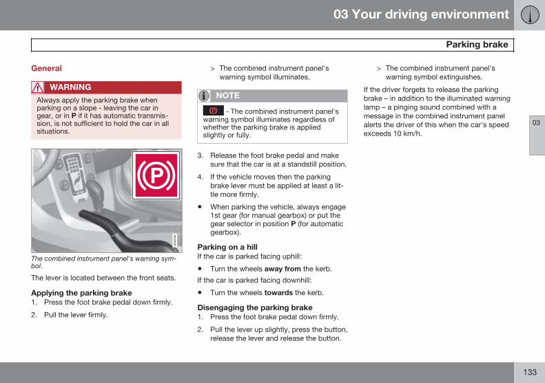
03 Your driving environment
Parking brake
03
133
General
WARNING
Always apply the parking brake whenparking on a slope - leaving the car ingear, or in P if it has automatic transmis-sion, is not sufficient to hold the car in allsituations.
The combined instrument panel's warning sym-bol.
The lever is located between the front seats.
Applying the parking brake1. Press the foot brake pedal down firmly.
2. Pull the lever firmly.
> The combined instrument panel'swarning symbol illuminates.
NOTE
- The combined instrument panel'swarning symbol illuminates regardless ofwhether the parking brake is appliedslightly or fully.
3. Release the foot brake pedal and makesure that the car is at a standstill position.
4. If the vehicle moves then the parkingbrake lever must be applied at least a lit-tle more firmly.
• When parking the vehicle, always engage1st gear (for manual gearbox) or put thegear selector in position P (for automaticgearbox).
Parking on a hillIf the car is parked facing uphill:
• Turn the wheels away from the kerb.
If the car is parked facing downhill:
• Turn the wheels towards the kerb.
Disengaging the parking brake1. Press the foot brake pedal down firmly.
2. Pull the lever up slightly, press the button,release the lever and release the button.
> The combined instrument panel'swarning symbol extinguishes.
If the driver forgets to release the parkingbrake – in addition to the illuminated warninglamp – a pinging sound combined with amessage in the combined instrument panelalerts the driver of this when the car's speedexceeds 10 km/h.
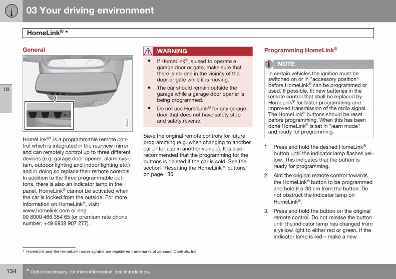
03 Your driving environment
HomeLink® *
03
134 * Option/accessory, for more information, see Introduction.
General
HomeLink®1 is a programmable remote con-trol which is integrated in the rearview mirrorand can remotely control up to three differentdevices (e.g. garage door opener, alarm sys-tem, outdoor lighting and indoor lighting etc.)and in doing so replace their remote controls.In addition to the three programmable but-tons, there is also an indicator lamp in thepanel. HomeLink® cannot be activated whenthe car is locked from the outside. For moreinformation on HomeLink®, visit:www.homelink.com or ring00 8000 466 354 65 (or premium rate phonenumber, +49 6838 907 277).
WARNING
• If HomeLink® is used to operate agarage door or gate, make sure thatthere is no-one in the vicinity of thedoor or gate while it is moving.
• The car should remain outside thegarage while a garage door opener isbeing programmed.
• Do not use HomeLink® for any garagedoor that does not have safety stopand safety reverse.
Save the original remote controls for futureprogramming (e.g. when changing to anothercar or for use in another vehicle). It is alsorecommended that the programming for thebuttons is deleted if the car is sold. See thesection "Resetting the HomeLink® buttons"on page 135.
Programming HomeLink®
NOTE
In certain vehicles the ignition must beswitched on or in "accessory position"before HomeLink® can be programmed orused. If possible, fit new batteries in theremote control that shall be replaced byHomeLink® for faster programming andimproved transmission of the radio signal.The HomeLink® buttons should be resetbefore programming. When this has beendone HomeLink® is set in "learn mode"and ready for programming.
1. Press and hold the desired HomeLink®
button until the indicator lamp flashes yel-low. This indicates that the button isready for programming.
2. Aim the original remote control towardsthe HomeLink® button to be programmedand hold it 5-30 cm from the button. Donot obstruct the indicator lamp onHomeLink®.
3. Press and hold the button on the originalremote control. Do not release the buttonuntil the indicator lamp has changed froma yellow light to either red or green. If theindicator lamp is red – make a new
1 HomeLink and the HomeLink house symbol are registered trademarks of Johnson Controls, Inc.
03 Your driving environment
HomeLink® *
03
* Option/accessory, for more information, see Introduction. 135
attempt to program the remote control,holding the original remote control at adifferent distance from the HomeLink®
button. A green light indicates that pro-gramming was successful.
4. Depress the HomeLink® button beingprogrammed, hold it depressed for5 seconds and then release it. Repeat ifnecessary until the garage door is acti-vated. If the door is not activated, pressthe programmed HomeLink® button andhold it depressed and check the indicatorlamp.> Steady green light: The indicator lamp
illuminates with a constant glow whenthe button is kept depressed, this indi-cates that the programming is com-plete. The garage door, gate or similarshould now be activated when the pro-grammed HomeLink® button isdepressed.
Flashing green light: The indicatorlamp flashes while the button is helddepressed. In which case, continuewith the programming steps 5-7 inorder to complete the programming ofa device with rolling code (usually agarage door opener).
5. Locate the "programming button2" on thereceiver for the garage door for example,normally located close to the antenna'sbracket on the receiver.
6. Depress and release the receiver's "pro-gramming button". The button flashes forapprox. 30 seconds and the next stepmust be carried out within this period.
7. While the receiver's "programming but-ton" is still flashing, press the button onHomeLink® being programmed and holdit depressed for approx. 3 seconds andthen release it. Repeat the press/hold/release sequence up to 3 times to con-clude the programming.
OperationWhen HomeLink® is fully programmed it canbe used in place of the separate originalremote controls.
Press and hold the programmed button3 untilthe garage door, alarm system, etc. is acti-vated (may take several seconds). Naturallythe original remote controls can still be usedin parallel with HomeLink® if required.
NOTE
If the ignition is switched off, HomeLink®will work for 30 minutes after the driver'sdoor has been opened.
If programming problems persist, contactHomeLink® on: www.homelink.com or ring00 8000 466 354 65 (or premium rate phonenumber +49 6838 907 277).
Resetting the HomeLink® buttonsIt is only possible to reset all of theHomeLink® buttons at the same time, noteach button individually. However, individualbuttons can be reprogrammed, see the fol-lowing section "Programming individual but-tons".
1. Press and hold the two outer buttons onHomeLink®. Do not release them until theindicator lamp has changed from a yellowlight to either red or green.
2. Release the buttons.> HomeLink® is now set in so-called
"learn mode" and is ready to bereprogrammed, see section "Program-ming HomeLink®" on page 134.
2 Button designation and colour vary depending on manufacturer.3 The indicator lamp remains lit while the button is held depressed.
03 Your driving environment
HomeLink® *
03
136 * Option/accessory, for more information, see Introduction.
Programming individual buttonsTo reprogram an individual HomeLink® but-ton, proceed as follows:
1. Depress the required button and do notrelease.
2. When the indicator lamp on HomeLink®
starts to flash yellow (after about 10 sec-onds), release the button and start withstep 2 of section "Programming Home-Link®" on page 134.
For more information or to leave commentsabout HomeLink®, visit: www.homelink.comor ring 00 8000 466 354 65 (or premium ratephone number +49 6838 907 277).
03 Your driving environment
03
137
G000000
138 * Option/accessory, for more information, see Introduction.
DSTC – Stability and traction control system....................................... 140Road sign information - RSI*................................................................ 143Speed limiter*........................................................................................ 146Cruise control*...................................................................................... 148Adaptive cruise control*........................................................................ 150Distance Warning*................................................................................. 161City Safety™......................................................................................... 164Collision Warning with Auto Brake & Pedestrian Detection*................ 170Driver Alert System*.............................................................................. 178Driver Alert System - DAC*................................................................... 179Driver Alert System - Lane Keeping Aid*.............................................. 182Park assist syst*.................................................................................... 186Park assist camera*.............................................................................. 189Park Assist Pilot - PAP*........................................................................ 193BLIS and CTA*...................................................................................... 198
DRIVER SUPPORT
04 Driver support
DSTC – Stability and traction control system
04
140 * Option/accessory, for more information, see Introduction.
General information on DSTC
The stability and traction control system,DSTC (Dynamic Stability & Traction Control)helps the driver to avoid skidding andimproves the car's traction.
The activation of the system during brakingmay be noticed as a throbbing sound. Thecar may accelerate slower than expectedwhen the accelerator pedal is depressed.
WARNING
The stability and traction control system isa supplementary function - it cannot han-dle all situations in all road conditions.
The driver always bears responsibility forensuring that the vehicle is driven safelyand that applicable road traffic rules andregulations are followed.
Active Yaw ControlThe function limits the driving and brake forceof the wheels individually in order to stabilisethe car.
Spin ControlThe function reduces engine power if thedrive wheels slip against the underlying sur-face in order to maintain stability and traction.
Traction control systemThe function is active at low speed and trans-fers power from the driving wheel that is spin-ning to the one that is not.
Engine drag control - EDCEDC (Engine Drag Control) prevents involun-tary wheel locking, e.g. after shifting down orengine braking when driving in low gears onslippery road surfaces.
Involuntary wheel locking while driving can,amongst other things, impair the driver's abil-ity to steer the car.
Corner Traction Control – CTCCTC compensates for understeer and allowshigher than normal acceleration in a bendwithout wheelspin on the inner wheel, e.g. onan arcing motorway entrance road to quicklyreach the prevailing traffic speed.
Driver Steering Recommendation – DSRDSR (Driver Steering Recommendation) helpsthe driver steer the car in the right directionwhen there is reduced traction or when theABS system engages.
The primary role of the DSR function is tohelp the driver steer in the right directionwhen the car is skidding.
DSR engages by applying slight torque to thesteering wheel in the direction in which the
car should be steered to maintain/achievemaximum possible traction and stabilise thecar.
Trailer Stability Assist* - TSAThe function serves to stabilise the car andtrailer combination if it begins to snake, seepage 309.
NOTE
The function is deactivated if the driverselects Sport mode.
Operation
Selection of level - Sport modeThe DSTC system is always activated - itcannot be deactivated.
However, the driver can select the Sportmode, which allows for a more active drivingexperience. In Sport mode the systemdetects whether the accelerator pedal, steer-ing wheel movements and cornering are moreactive than in normal driving and then allowscontrolled skidding with the rear section up toa certain level before it intervenes and stabil-ises the car.
If the driver stops a controlled skid by releas-ing the accelerator pedal then the DSTC sys-tem intervenes and stabilises the car.
04 Driver support
DSTC – Stability and traction control system
04
}}141
With Sport mode, maximum traction isobtained if the car has become stuck, orwhen driving on a loose surface - e.g. sand ordeep snow.
Proceed as follows to select Sport mode:
1. Press the centre console button MY CARand search in the screen's menu systemand locate My V40 DSTC. (For infor-mation on the menu system, seepage 207).
2. Uncheck the box and back out of themenu system with EXIT.> The system then allows a more sporty
driving style.
The Sport mode is active until the driverdeselects it or until the engine is switched off- after the engine is started the next time theDSTC system is back in its normal modeagain.
Symbols and text messages
SymbolA Message Specification
DSTC Temporarily OFF DSTC system temporarily reduced due to excessive brake disc temperature. - The function is reacti-vated automatically when the brakes have cooled.
DSTC Service required DSTC system disengaged.
• Stop the car in a safe place, switch off the engine and start it again.
• Visit a workshop if the message remains - an authorised Volvo workshop is recommended.
and
"Message" There is a message in the combined instrument panel - Read it!
Constant glow for2 seconds.
System check when the engine is started.
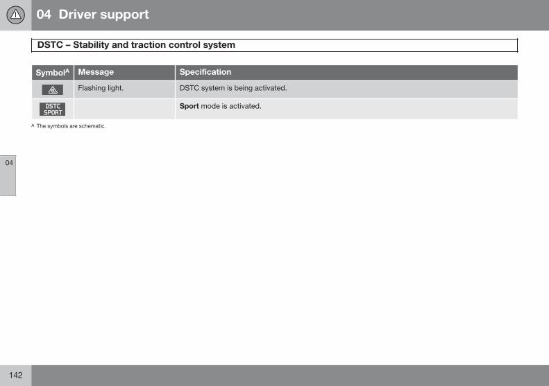
04 Driver support
DSTC – Stability and traction control system
04
142
SymbolA Message Specification
Flashing light. DSTC system is being activated.
Sport mode is activated.
A The symbols are schematic.
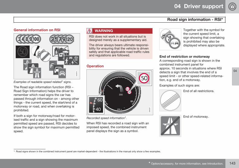
04 Driver support
Road sign information - RSI*
04
* Option/accessory, for more information, see Introduction. 143
General information on RSI
Examples of readable speed related1 signs.
The Road sign information function (RSI –Road Sign Information) helps the driver toremember which road signs the car haspassed through information on - among otherthings - the current speed, the start/end of amotorway or road, and when overtaking isprohibited.
If both a sign for motorway/road for motor-ised traffic and a sign showing the maximumpermitted speed are passed, RSI decides toshow the sign symbol for maximum permittedspeed.
WARNING
RSI does not work in all situations but isdesigned merely as a supplementary aid.
The driver always bears ultimate responsi-bility for ensuring that the vehicle is drivensafely and that applicable road traffic rulesand regulations are followed.
Operation
Recorded speed information1.
When RSI has recorded a road sign with animposed speed, the combined instrumentpanel displays the sign as a symbol.
Together with the symbol forthe current speed limit, asign showing that overtakingis prohibited may also bedisplayed where appropriate.
End of restriction or motorwayA corresponding road sign is shown in thecombined instrument panel forapprox. 10 seconds in situations where RSIdetects a sign that involves the end of aspeed limit - or other speed-related informa-tion, e.g. end of a motorway.
Examples of such signs are:
End of all restrictions.
End of motorway.
1 Road signs shown in the combined instrument panel are market-dependent - the illustrations in the manual only show a few examples.
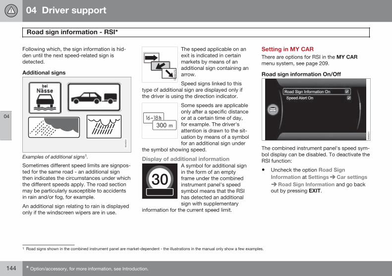
04 Driver support
Road sign information - RSI*
04
144 * Option/accessory, for more information, see Introduction.
Following which, the sign information is hid-den until the next speed-related sign isdetected.
Additional signs
Examples of additional signs1.
Sometimes different speed limits are signpos-ted for the same road - an additional signthen indicates the circumstances under whichthe different speeds apply. The road sectionmay be particularly susceptible to accidentsin rain and/or fog, for example.
An additional sign relating to rain is displayedonly if the windscreen wipers are in use.
The speed applicable on anexit is indicated in certainmarkets by means of anadditional sign containing anarrow.
Speed signs linked to thistype of additional sign are displayed only ifthe driver is using the direction indicator.
Some speeds are applicableonly after a specific distanceor at a certain time of day,for example. The driver'sattention is drawn to the sit-uation by means of a symbolfor an additional sign under
the symbol showing speed.
Display of additional informationA symbol for additional signin the form of an emptyframe under the combinedinstrument panel's speedsymbol means that the RSIhas detected an additionalsign with supplementary
information for the current speed limit.
Setting in MY CARThere are options for RSI in the MY CARmenu system, see page 209.
Road sign information On/Off
The combined instrument panel's speed sym-bol display can be disabled. To deactivate theRSI function:
• Uncheck the option Road SignInformation at Settings Car settings
Road Sign Information and go backout by pressing EXIT.
1 Road signs shown in the combined instrument panel are market-dependent - the illustrations in the manual only show a few examples.
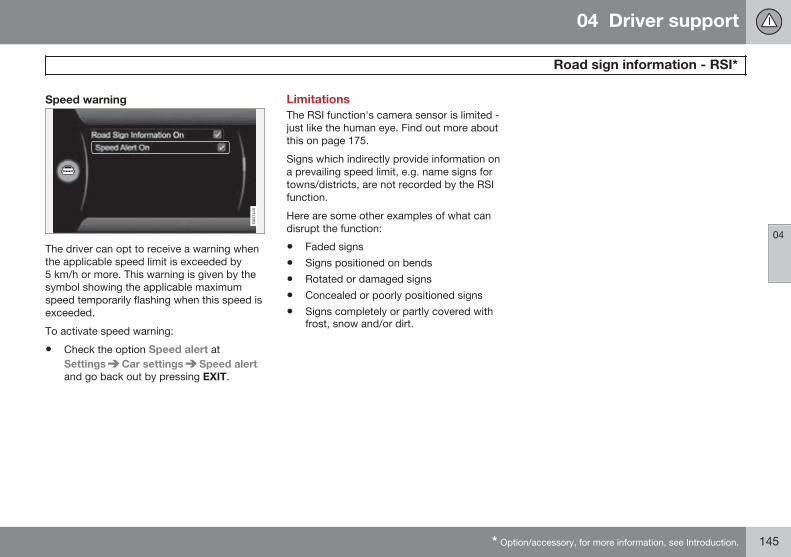
04 Driver support
Road sign information - RSI*
04
* Option/accessory, for more information, see Introduction. 145
Speed warning
The driver can opt to receive a warning whenthe applicable speed limit is exceeded by5 km/h or more. This warning is given by thesymbol showing the applicable maximumspeed temporarily flashing when this speed isexceeded.
To activate speed warning:
• Check the option Speed alert atSettings Car settings Speed alertand go back out by pressing EXIT.
LimitationsThe RSI function's camera sensor is limited -just like the human eye. Find out more aboutthis on page 175.
Signs which indirectly provide information ona prevailing speed limit, e.g. name signs fortowns/districts, are not recorded by the RSIfunction.
Here are some other examples of what candisrupt the function:
• Faded signs
• Signs positioned on bends
• Rotated or damaged signs
• Concealed or poorly positioned signs
• Signs completely or partly covered withfrost, snow and/or dirt.
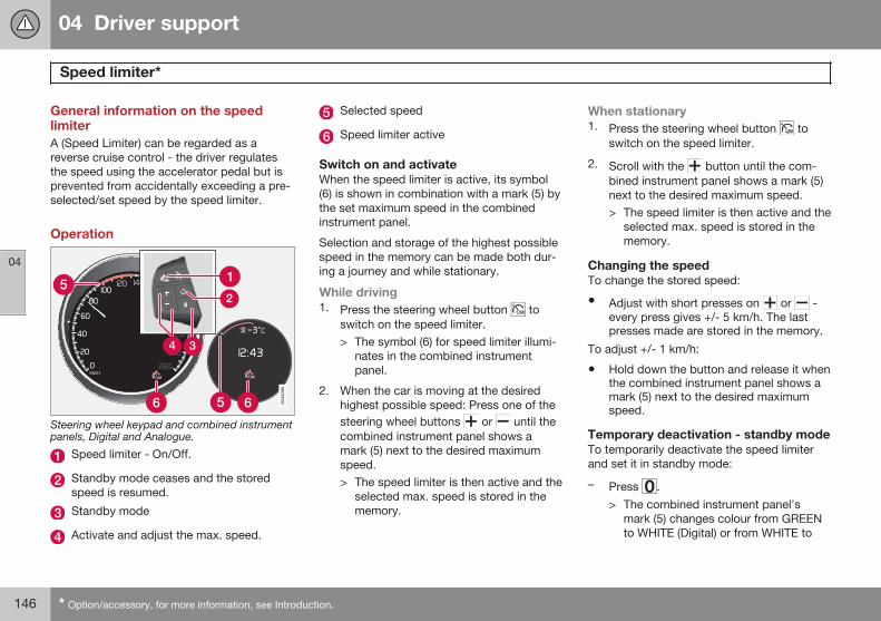
04 Driver support
Speed limiter*
04
146 * Option/accessory, for more information, see Introduction.
General information on the speedlimiterA (Speed Limiter) can be regarded as areverse cruise control - the driver regulatesthe speed using the accelerator pedal but isprevented from accidentally exceeding a pre-selected/set speed by the speed limiter.
Operation
Steering wheel keypad and combined instrumentpanels, Digital and Analogue.
Speed limiter - On/Off.
Standby mode ceases and the storedspeed is resumed.
Standby mode
Activate and adjust the max. speed.
Selected speed
Speed limiter active
Switch on and activateWhen the speed limiter is active, its symbol(6) is shown in combination with a mark (5) bythe set maximum speed in the combinedinstrument panel.
Selection and storage of the highest possiblespeed in the memory can be made both dur-ing a journey and while stationary.
While driving1. Press the steering wheel button to
switch on the speed limiter.> The symbol (6) for speed limiter illumi-
nates in the combined instrumentpanel.
2. When the car is moving at the desiredhighest possible speed: Press one of thesteering wheel buttons or until thecombined instrument panel shows amark (5) next to the desired maximumspeed.> The speed limiter is then active and the
selected max. speed is stored in thememory.
When stationary1. Press the steering wheel button to
switch on the speed limiter.
2. Scroll with the button until the com-bined instrument panel shows a mark (5)next to the desired maximum speed.> The speed limiter is then active and the
selected max. speed is stored in thememory.
Changing the speedTo change the stored speed:
• Adjust with short presses on or -every press gives +/- 5 km/h. The lastpresses made are stored in the memory.
To adjust +/- 1 km/h:
• Hold down the button and release it whenthe combined instrument panel shows amark (5) next to the desired maximumspeed.
Temporary deactivation - standby modeTo temporarily deactivate the speed limiterand set it in standby mode:
– Press .> The combined instrument panel's
mark (5) changes colour from GREENto WHITE (Digital) or from WHITE to
04 Driver support
Speed limiter*
04
* Option/accessory, for more information, see Introduction. 147
GREY (Analogue) and the driver cantemporarily exceed the set maximumspeed.
The speed limiter is reactivated withone press on . The mark (5) thenchanges colour from WHITE to GREEN(Digital) or GREY to WHITE (Analogue)and the car's maximum speed is lim-ited again.
Temporary deactivation with theaccelerator pedalThe speed limiter can also be set in standbymode with the accelerator pedal, e.g. for rap-idly accelerating the car out of a situation:
– Depress the accelerator pedal fully.> The combined instrument panel shows
the stored maximum speed with a col-oured mark (5) and the driver can tem-porarily exceed the set maximumspeed – the mark (5) changes colourfrom GREEN to WHITE (Digital) orWHITE to GREY (Analogue) during thattime.
The speed limiter is automatically reac-tivated after the accelerator pedal isreleased and the car's speed is sloweddown to below the selected/storedmaximum speed - the mark (5)changes colour from WHITE to GREEN(Digital) or GREY to WHITE (Analogue)
and the car's maximum speed is againlimited.
Alarm for speed exceededOn steep roads the engine braking effect maybe inadequate and the selected maximumspeed exceeded. The driver is alerted aboutthis with an acoustic signal.
The signal is active until the driver has slowedto below the selected maximum speed.
NOTE
The alarm is only activated after 5 secondsif the speed has been exceeded by at least3 km/h provided that none of the buttons
or has been depressed during thelast half minute.
DeactivateTo deactivate the speed limiter:
– Press the steering wheel button .> The combined instrument panel's
speed limiter symbol (6) and the setspeed mark (5) are extinguished. Theselected and stored speed are thusdeleted from the memory and cannotbe resumed with the button.
The driver can then use the acceleratorpedal to choose a speed without limi-tation.
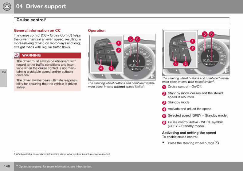
04 Driver support
Cruise control*
04
148 * Option/accessory, for more information, see Introduction.
General information on CCThe cruise control (CC – Cruise Control) helpsthe driver maintain an even speed, resulting inmore relaxing driving on motorways and long,straight roads with regular traffic flows.
WARNING
The driver must always be observant withregard to the traffic conditions and inter-vene when the cruise control is not main-taining a suitable speed and/or suitabledistance.
The driver always bears ultimate responsi-bility for ensuring that the vehicle is drivensafely.
Operation
The steering wheel buttons and combined instru-ment panel in cars without speed limiter1.
The steering wheel buttons and combined instru-ment panel in cars with speed limiter1.
Cruise control - On/Off.
Standby mode ceases and the storedspeed is resumed.
Standby mode
Activate and adjust the speed.
Selected speed (GREY = Standby mode).
Cruise control active - WHITE symbol(GREY = Standby mode).
Activating and setting the speedTo enable cruise control:
• Press the steering wheel button
1 A Volvo dealer has updated information about what applies in each respective market.
04 Driver support
Cruise control*
04
* Option/accessory, for more information, see Introduction. 149
> The cruise control symbol (6) in the com-bined instrument panel changes fromGREY to WHITE and shows that thecruise control is in standby mode.
To activate cruise control:
• At the required speed - press the steeringwheel button or .
> The current speed is stored in the mem-ory and the combined instrument panel'smarking (5) illuminates at the selectedspeed.
NOTE
Cruise Control cannot be enabled atspeeds below 30 km/h.
Changing the speedTo change the stored speed:
• Adjust with short presses on or -every press gives +/- 5 km/h. The lastpresses made are stored in the memory.
To adjust +/- 1 km/h:
• Hold down the button and release it atthe required speed.
A temporary increase in speed with the accel-erator pedal, e.g. during overtaking, does not
affect the cruise control setting - the carreturns to the set speed when the acceleratorpedal is released.
NOTE
If any of the Cruise Control buttons areheld depressed for several minutes then itis blocked and deactivated. To be able toreactivate Cruise Control, the car must bestopped and the engine restarted.
Temporary deactivation - standby modeTo temporarily disengage cruise control andset it in standby mode:
• Press .
> The combined instrument panel's mark-ing (5) and symbol (6) change colour fromWHITE to GREY.
Automatic standby modeCruise control is temporarily disengaged andset in standby mode if:
• wheels lose traction
• the foot brake is used
• speed falls below approx. 30 km/h
• the clutch pedal is depressed for longerthan 1 minute2
• the gear selector/lever is moved to neu-tral position N (automatic gearbox)
• the driver maintains a speed higher thanthe set speed for longer than 1 minute.
The driver must then regulate the speed.
Resume set speedTo reactivate the cruise control from standbymode:
• Press the steering wheel button .
> The combined instrument panel's mark-ing (5) and symbol (6) change colour fromGREY to WHITE and the speed is thenset to the last speed stored.
NOTE
A marked speed increase may occur oncethe speed has been resumed by selecting
.
DeactivateThe cruise control is switched off with thesteering wheel button (1) or by switching offthe engine - the set speed is deleted from thememory and cannot be resumed with the button.
2 Disengaging and selecting a higher or lower gear does not involve standby mode.
04 Driver support
Adaptive cruise control*
04
150 * Option/accessory, for more information, see Introduction.
General information on ACCThe adaptive cruise control (ACC – AdaptiveCruise Control) helps the driver maintain asafe distance from the vehicle ahead. Adap-tive cruise control provides a more relaxingdriving experience on long journeys onmotorways and long straight main roads insmooth traffic flows.
The driver sets the desired speed and timeinterval to the car in front. When the radardetector detects a slower vehicle in front ofthe car, the speed is automatically adapted tothat. When the road is clear again the carreturns to the selected speed.
If the adaptive cruise control is switched offor set to the standby mode and the carcomes too close to a vehicle in front, then thedriver is warned instead by Distance Warning(see page 161) about the short distance.
WARNING
The driver must always be observant withregard to the traffic conditions and inter-vene when the adaptive cruise control isnot maintaining a suitable speed or suita-ble distance.
The adaptive cruise control cannot handleall traffic, weather and road conditions.
Read the whole of this section for informa-tion on the limitations of the adaptivecruise control. The driver must be familiarwith this information before using theadaptive cruise control.
The driver always bears responsibility formaintaining the correct distance andspeed, even when the adaptive cruise con-trol is being used.
IMPORTANT
Maintenance of adaptive cruise controlcomponents must only be performed at aworkshop - an authorised Volvo workshopis recommended.
Automatic gearboxCars with automatic gearbox have enhancedfunctionality with the adaptive cruise control'sQueue Assistant, see page 155.
Function
Function overview1.
Warning lamp - braking by driver required
Steering wheel keypad
Radar sensor
Adaptive cruise control consists of a cruisecontrol system and a coordinated spacingsystem.
1 NOTE: The illustration is schematic - details may differ depending on car model.
04 Driver support
Adaptive cruise control*
04
* Option/accessory, for more information, see Introduction. 151
WARNING
Adaptive cruise control is not a collisionavoidance system. The driver must inter-vene if the system does not detect a vehi-cle in front.
The adaptive cruise control does not brakefor humans or animals, and not for smallvehicles such as bicycles and motorcy-cles. Nor for oncoming, slow or stationaryvehicles and objects.
Do not use the adaptive cruise control, forexample, in city traffic, in dense traffic, atjunctions, on slippery surfaces, with a lotof water or slush on the road, in heavyrain/snow, in poor visibility, on windingroads or on slip roads.
The distance to the vehicle ahead is mainlymeasured by a radar sensor. Cruise controlregulates the speed with acceleration andbraking. It is normal for the brakes to emit alow sound when they are being used by theadaptive cruise control.
WARNING
The brake pedal moves when Cruise Con-trol brakes. Do not rest your foot beneaththe brake pedal as it may become trapped.
The adaptive cruise control aims to follow thevehicle ahead in the same lane at a time inter-val set by the driver. If the radar sensor can-not see any vehicle in front then the car willinstead maintain the cruise control's setspeed. This also happens if the speed of thevehicle in front exceeds the cruise control'sset speed.
The adaptive cruise control aims to controlthe speed in a smooth way. In situations thatdemand sudden braking the driver mustbrake himself/herself. This applies with largedifferences in speed, or if the vehicle in frontbrakes heavily. Due to limitations in the radarsensor, braking may come unexpectedly ornot at all, see page 157.
The adaptive cruise control can be activatedto follow another vehicle at speeds from30 km/h2 up to 200 km/h. If the speed fallsbelow 30 km/h or if the engine speedbecomes too low, the cruise control is set instandby mode at which automatic brakingceases - the driver must then take over him-self/herself to maintain a safe distance to thevehicle ahead.
Warning lamp - braking by driverrequiredAdaptive cruise control has a brakingcapacity that is equivalent to more than 40%of the car's braking capacity.
If the car needs to be braked more heavilythan cruise control capacity and the driverdoes not brake, then the cruise control usesthe collision warning system's warning lampand warning sound (see figure on page 170)to alert the driver that immediate interventionis required.
NOTE
The warning lamp may be difficult to see instrong sunlight or when wearing sun-glasses.
WARNING
Cruise Control warns only of vehicleswhich the radar sensor has detected.Hence the warning may not be given, or itmay be given with a certain delay. Do notwait for a warning without braking when sorequired.
2 Queue Assistant (in cars with automatic gearbox) can operate in the range of 0-200 km/h, see page 155.
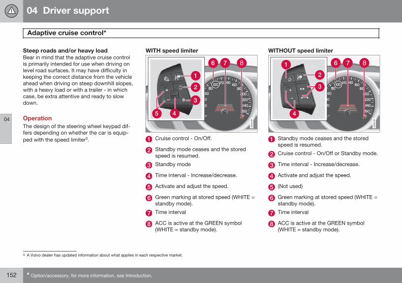
04 Driver support
Adaptive cruise control*
04
152 * Option/accessory, for more information, see Introduction.
Steep roads and/or heavy loadBear in mind that the adaptive cruise controlis primarily intended for use when driving onlevel road surfaces. It may have difficulty inkeeping the correct distance from the vehicleahead when driving on steep downhill slopes,with a heavy load or with a trailer - in whichcase, be extra attentive and ready to slowdown.
OperationThe design of the steering wheel keypad dif-fers depending on whether the car is equip-ped with the speed limiter3.
WITH speed limiter
Cruise control - On/Off.
Standby mode ceases and the storedspeed is resumed.
Standby mode
Time interval - Increase/decrease.
Activate and adjust the speed.
Green marking at stored speed (WHITE =standby mode).
Time interval
ACC is active at the GREEN symbol(WHITE = standby mode).
WITHOUT speed limiter
Standby mode ceases and the storedspeed is resumed.
Cruise control - On/Off or Standby mode.
Time interval - Increase/decrease.
Activate and adjust the speed.
(Not used)
Green marking at stored speed (WHITE =standby mode).
Time interval
ACC is active at the GREEN symbol(WHITE = standby mode).
3 A Volvo dealer has updated information about what applies in each respective market.
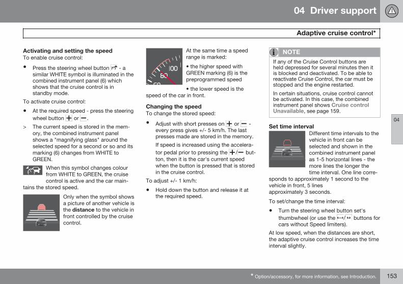
04 Driver support
Adaptive cruise control*
04
* Option/accessory, for more information, see Introduction. 153
Activating and setting the speedTo enable cruise control:
• Press the steering wheel button - asimilar WHITE symbol is illuminated in thecombined instrument panel (6) whichshows that the cruise control is instandby mode.
To activate cruise control:
• At the required speed - press the steeringwheel button or .
> The current speed is stored in the mem-ory, the combined instrument panelshows a "magnifying glass" around theselected speed for a second or so and itsmarking (6) changes from WHITE toGREEN.
When this symbol changes colourfrom WHITE to GREEN, the cruisecontrol is active and the car main-
tains the stored speed.
Only when the symbol showsa picture of another vehicle isthe distance to the vehicle infront controlled by the cruisecontrol.
At the same time a speedrange is marked:
• the higher speed withGREEN marking (6) is thepreprogrammed speed
• the lower speed is thespeed of the car in front.
Changing the speedTo change the stored speed:
• Adjust with short presses on or -every press gives +/- 5 km/h. The lastpresses made are stored in the memory.
If speed is increased using the accelera-tor pedal prior to pressing the / but-ton, then it is the car's current speedwhen the button is pressed that is storedin the cruise control.
To adjust +/- 1 km/h:
• Hold down the button and release it atthe required speed.
NOTE
If any of the Cruise Control buttons areheld depressed for several minutes then itis blocked and deactivated. To be able toreactivate Cruise Control, the car must bestopped and the engine restarted.
In certain situations, cruise control cannotbe activated. In this case, the combinedinstrument panel shows Cruise controlUnavailable, see page 159.
Set time intervalDifferent time intervals to thevehicle in front can beselected and shown in thecombined instrument panelas 1-5 horizontal lines - themore lines the longer thetime interval. One line corre-
sponds to approximately 1 second to thevehicle in front, 5 linesapproximately 3 seconds.
To set/change the time interval:
• Turn the steering wheel button set'sthumbwheel (or use the / buttons forcars without Speed limiters).
At low speed, when the distances are short,the adaptive cruise control increases the timeinterval slightly.
04 Driver support
Adaptive cruise control*
04
154 * Option/accessory, for more information, see Introduction.
The adaptive cruise control allows the timeinterval to vary noticeably in certain situationsin order to allow the car to follow the vehiclein front smoothly and comfortably.
Note that a short time interval only allows thedriver a short time to react and take action ifany unforeseen traffic problem should arise.
The same symbol is also shown when Dis-tance Warning is activated, see page 161.
NOTE
Only use the time intervals permitted bylocal traffic regulations.
If Cruise Control does not appear to reactwhen activated, this may be because thetime distance to the car in front is prevent-ing an increase in speed.
The higher the speed the longer the calcu-lated distance in metres for a given timeinterval.
Temporary deactivation - standby modeTo temporarily disengage adaptive cruisecontrol and set it in standby mode:
• Press the steering wheel button
This symbol and stored speed mark-ing then changes colour fromGREEN to WHITE.
Keypad without Speed limiter*To temporarily disengage cruise control andset it in standby mode:
• Press the steering wheel button .
Standby mode due to driver interventionThe adaptive cruise control is temporarily dis-engaged and set automatically in standbymode if:
• the foot brake is used
• the clutch pedal is depressed for longerthan 1 minute4
• the gear selector/lever is moved to neu-tral position N (automatic gearbox)
• the driver maintains a speed higher thanthe set speed for longer than 1 minute.
The driver must then regulate the speed.
A temporary increase in speed with the accel-erator pedal, e.g. during overtaking, does notaffect the cruise control setting - the carreturns to the last stored speed when theaccelerator pedal is released.
Automatic standby modeThe adaptive cruise control is dependent onother systems, such as DSTC (see page 140).If any of these systems stop working thencruise control is automatically deactivated.
In the event of automatic deactivation a signalwill sound and the message Cruise controlCancelled is shown in the combined instru-ment panel. The driver must then interveneand adapt the speed and distance to thevehicle ahead.
An automatic deactivation can be due to:
• the driver opens the door
• the driver takes off his seatbelt
• engine speed is too low/high
• speed has fallen below 30 km/h5
• wheels lose traction
• brake temperature is high
• the radar sensor is covered e.g. by wetsnow or heavy rain (radar waves blocked).
Resume set speedAdaptive cruise control in standby mode isreactivated with one press on the steeringwheel button - the speed is then set to thelast stored speed.
4 Disengaging and selecting a higher or lower gear does not involve standby mode.5 Does not apply to a car with Queue Assistant - it manages right down to stationary.
04 Driver support
Adaptive cruise control*
04
* Option/accessory, for more information, see Introduction. 155
NOTE
A marked speed increase may occur oncethe speed has been resumed by selecting
.
Overtaking another vehicleWhen the car is following another vehicle andthe driver indicates an impending overtakingmanoeuvre with the direction indicator6, theadaptive cruise control helps to briefly accel-erate the car towards the vehicle in front.
This function is active at speedsabove 70 km/h.
WARNING
Be aware that this function can be acti-vated in more situations other than duringovertaking, e.g. when a direction indicatoris used to indicate a change of lane or exitto another road - the car will then acceler-ate briefly.
Deactivate
Keypad with Speed limiterThe adaptive cruise control is disengagedwith a short press of the steering wheel but-
ton . The set speed is cleared and cannotbe resumed with the button.
Keypad without Speed limiterA short press on the steering wheel button
sets the adaptive cruise control in standbymode. With a further short press the cruisecontrol is deactivated. The set speed iscleared and cannot be resumed with the button.
Switch from ACC to CCA button press can be used to deactivate theadaptive element (spacing system) in theadaptive cruise control, with the car then onlyfollowing the set speed.
• Hold down the steering wheel button - the combined instrument panel's sym-bol changes from to .
> This activates the standard cruise controlCC (Cruise Control), see page 148.
WARNING
The car no longer brakes automaticallyafter switching from ACC to CC - it merelyfollows the set speed.
Switch from CC back to ACCDeactivate CC with 1-2 presses on asdescribed under the heading "Deactivate".ACC will be activated the next time the sys-tem is switched on.
Queue AssistantIn cars with automatic gearbox the adaptivecruise control is supplemented with theQueue Assist function (also referred to as"Queue Assist").
Queue Assistant has the following functions:
• Extended speed range - also below 30km/h and at standstill
• Change of target
• Automatic braking ceases when station-ary
Note that the lowest programmable speed forthe adaptive cruise control is 30 km/h - eventhough the cruise control is capable of follow-ing another vehicle down to a standstill, alower speed cannot be selected.
6 On left flash only in left-hand-drive car, or right flash in right-hand-drive car.
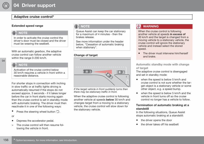
04 Driver support
Adaptive cruise control*
04
156 * Option/accessory, for more information, see Introduction.
Extended speed range
NOTE
In order to activate the cruise control thedriver's door must be closed and the drivermust be wearing the seatbelt.
With an automatic gearbox, the adaptivecruise control can follow another vehiclewithin the range 0-200 km/h.
NOTE
Activation of the cruise control below30 km/h requires a vehicle in front within areasonable distance.
For shorter stops in connection with inchingin slow traffic or at traffic lights driving isautomatically resumed if the stops do notexceed approx. 3 seconds - if it takes longerbefore the car in front starts moving againthen the cruise control is set in standby modewith automatic braking. The driver must thenreactivate it in one of the following ways:
• Press the steering wheel button .
or
• Depress the accelerator pedal.
> The cruise control will then resume fol-lowing the vehicle in front.
NOTE
Queue Assist can keep the car stationaryfor a maximum of 4 minutes - then thebrakes release.
See more information under the headerbelow, "Cessation of automatic brakingwhen stationary".
Change of target
If the target vehicle in front suddenly turns thenthere may be stationary traffic in front.
When the adaptive cruise control is followinganother vehicle at speeds below 30 km/h andchanges target from a moving to a stationaryvehicle, the cruise control will slow down forthe stationary vehicle.
WARNING
When the cruise control is followinganother vehicle at speeds in excess of30 km/h and the target is changed from amoving vehicle to a stationary vehicle, thecruise control will ignore the stationaryvehicle and instead select the storedspeed.
• The driver must intervene him/herselfand brake.
Automatic standby mode with changeof targetThe adaptive cruise control is disengagedand set in standby mode:
• when the speed is below 5 km/h andcruise control is not sure whether the tar-get object is a stationary vehicle or someother object, e.g. a speed bump.
• when the speed is below 5 km/h and thevehicle in front turns off so the cruisecontrol no longer has a vehicle to follow.
Termination of automatic braking at astandstillIn the following situations, Queue Assiststops automatic braking at a standstill:
• the driver opens the door
• the driver takes off his seatbelt
04 Driver support
Adaptive cruise control*
04
* Option/accessory, for more information, see Introduction. 157
This means that the brakes are released andthe car will start to roll - the driver must there-fore intervene and brake the car himself inorder to maintain its position.
IMPORTANT
Queue Assist can keep the car stationaryfor a maximum of 4 minutes - then thebrakes release.
The driver's attention is drawn to this overseveral stages, with increasing intensity:
1. Acoustic alarm (pinging) and text mes-sage.
2. A warning lamp in the windscreen alsostarts to flash.
3. "Stabbing" braking occurs.
Queue Assist releases the foot brake and isset to standby mode in these situations aswell:
• the driver puts his/her foot on the brakepedal
• the gear selector is moved to P, N or Rposition
• the driver sets the cruise control instandby mode
• the parking brake is applied.
The radar sensor and its limitationsThe radar sensor is used - apart from byAdaptive cruise control - by the followingfunctions as well:
• Collision Warning with Auto Brake,seepage 170
• Distance Warning, see page 161.
The function of the radar sensor is to detectcars or larger vehicles in the same direction,in the same lane.
Modification of the radar sensor could resultin it being illegal to use.
IMPORTANT
In the event of visible damage to the car'sgrille, or if you suspect that the radar sen-sor may be damaged:
• Contact a workshop - an authorisedVolvo workshop is recommended.
The function may completely or partiallydisappear - or malfunction - if the grille,the radar sensor or its bracket is damagedor has loosened.
WARNING
The driver must always be observant withregard to the traffic conditions and inter-vene when the adaptive cruise control isnot maintaining a suitable speed or suita-ble distance.
The adaptive cruise control cannot handleall traffic, weather and road conditions.
Read the whole of this section for informa-tion on the limitations of the adaptivecruise control. The driver must be familiarwith this information before using theadaptive cruise control.
The driver always bears responsibility formaintaining the correct distance andspeed, even when the adaptive cruise con-trol is being used.
WARNING
Accessories or other objects such as auxil-iary lamps must not be fitted in front of thegrille.
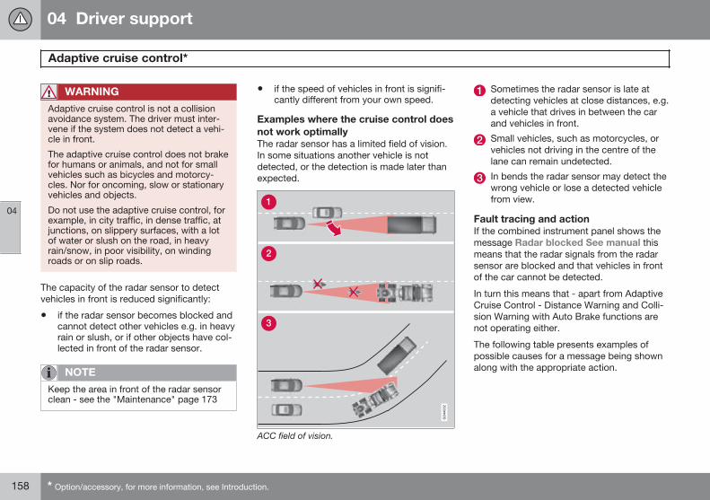
04 Driver support
Adaptive cruise control*
04
158 * Option/accessory, for more information, see Introduction.
WARNING
Adaptive cruise control is not a collisionavoidance system. The driver must inter-vene if the system does not detect a vehi-cle in front.
The adaptive cruise control does not brakefor humans or animals, and not for smallvehicles such as bicycles and motorcy-cles. Nor for oncoming, slow or stationaryvehicles and objects.
Do not use the adaptive cruise control, forexample, in city traffic, in dense traffic, atjunctions, on slippery surfaces, with a lotof water or slush on the road, in heavyrain/snow, in poor visibility, on windingroads or on slip roads.
The capacity of the radar sensor to detectvehicles in front is reduced significantly:
• if the radar sensor becomes blocked andcannot detect other vehicles e.g. in heavyrain or slush, or if other objects have col-lected in front of the radar sensor.
NOTE
Keep the area in front of the radar sensorclean - see the "Maintenance" page 173
• if the speed of vehicles in front is signifi-cantly different from your own speed.
Examples where the cruise control doesnot work optimallyThe radar sensor has a limited field of vision.In some situations another vehicle is notdetected, or the detection is made later thanexpected.
ACC field of vision.
Sometimes the radar sensor is late atdetecting vehicles at close distances, e.g.a vehicle that drives in between the carand vehicles in front.
Small vehicles, such as motorcycles, orvehicles not driving in the centre of thelane can remain undetected.
In bends the radar sensor may detect thewrong vehicle or lose a detected vehiclefrom view.
Fault tracing and actionIf the combined instrument panel shows themessage Radar blocked See manual thismeans that the radar signals from the radarsensor are blocked and that vehicles in frontof the car cannot be detected.
In turn this means that - apart from AdaptiveCruise Control - Distance Warning and Colli-sion Warning with Auto Brake functions arenot operating either.
The following table presents examples ofpossible causes for a message being shownalong with the appropriate action.
04 Driver support
Adaptive cruise control*
04
}}* Option/accessory, for more information, see Introduction. 159
Cause Action
The radar surface in the grille is dirty or covered with ice or snow. Clean the radar surface in the grille from dirt, ice and snow.
Heavy rain or snow blocking the radar signals. No action. Sometimes the radar does not work during heavy rain or snowfall.
Water or snow from the road surface swirls up and blocks theradar signals.
No action. Sometimes the radar does not work on a very wet or snowy roadsurface.
The radar surface has been cleaned but the message remains. Wait. It could take several minutes for the radar to sense that it is no longerblocked.
Symbols and text messages
SymbolA Message Specification
The symbol is WHITE Adaptive cruise control is set to standby mode.
The symbol is GREEN The car maintains the stored speed.
Standard cruise control is selected manually.
DSTC Normal to enableCruise
The adaptive cruise control cannot be activated until DSTC has been set to Normal position - seepage 140.
Cruise control Cancelled The adaptive cruise control has been deactivated - the driver has to regulate the speed himself.
04 Driver support
Adaptive cruise control*
04
160 * Option/accessory, for more information, see Introduction.
SymbolA Message Specification
Cruise control Unavailable The adaptive cruise control cannot be activated.
This could be due to:
• brake temperature is high
• the radar sensor is blocked by e.g. wet snow or rain.
Radar blocked See man-ual
The adaptive cruise control is temporarily disengaged.
• The radar sensor is blocked and cannot detect other vehicles. For example, in the event ofheavy rain or if slush has collected in front of the radar sensor.
The driver can then choose to switch to ordinary Cruise control (CC), see page 155 - a text messageprovides information on appropriate alternatives.
Read about the limitations of the radar sensor, see page 157.
Cruise control Servicerequired
The adaptive cruise control is disengaged.
• Contact a workshop - an authorised Volvo workshop is recommended.
Press Brake To hold +acoustic alarm + warninglight in windscreen + "pull-ing" brakes
(Only with Queue Assistant)
The car is at a standstill and the adaptive cruise control will release the foot brake, which is why thecar may start rolling soon.
• The driver must brake himself/herself. The message remains and the alarm sounds until thedriver depresses the brake pedal or uses the accelerator pedal.
Below 30 km/h Only fol-lowing
(Only with Queue Assistant)
Shown with attempts to activate the adaptive cruise control at speeds below 30 km/h without avehicle in front within the activation distance (approx. 30 metres).
A The symbols are schematic.
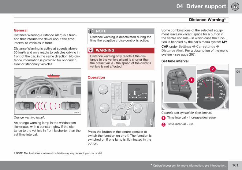
04 Driver support
Distance Warning*
04
* Option/accessory, for more information, see Introduction. 161
GeneralDistance Warning (Distance Alert) is a func-tion that informs the driver about the timeinterval to vehicles in front.
Distance Warning is active at speeds above30 km/h and only reacts to vehicles driving infront of the car, in the same direction. No dis-tance information is provided for oncoming,slow or stationary vehicles.
Orange warning lamp1.
An orange warning lamp in the windscreenilluminates with a constant glow if the dis-tance to the vehicle in front is shorter than theset time interval.
NOTE
Distance warning is deactivated during thetime the adaptive cruise control is active.
WARNING
Distance warning only reacts if the dis-tance to the vehicle ahead is shorter thanthe preset value - the speed of the driver'svehicle is not affected.
Operation
Press the button in the centre console toswitch the function on or off. The function isswitched on if one lamp is illuminated in thebutton.
Some combinations of the selected equip-ment leave no vacant space for a button inthe centre console - in which case the func-tion is handled by the car's menu system MYCAR under Settings Car settingsDistance Alert. For a description of the menusystem - see page 207.
Set time interval
Controls and symbol for time interval.
Time interval - Increase/decrease.
Time interval - On.
1 NOTE: The illustration is schematic - details may vary depending on car model.
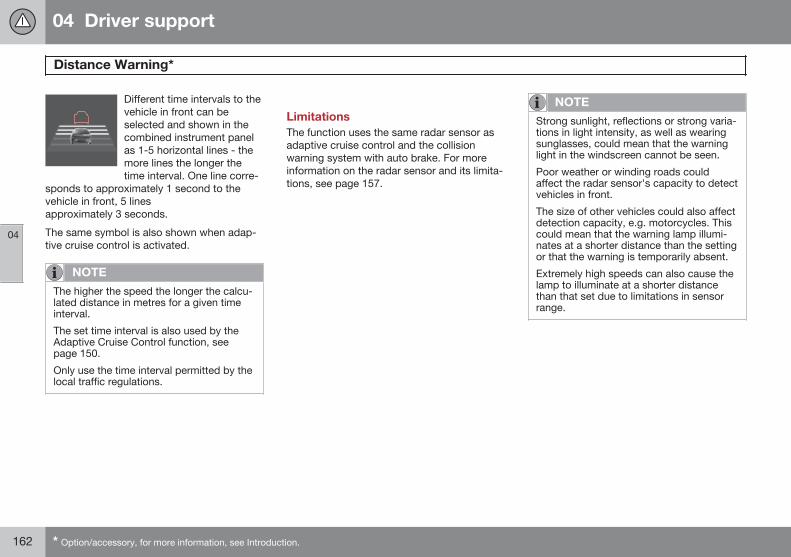
04 Driver support
Distance Warning*
04
162 * Option/accessory, for more information, see Introduction.
Different time intervals to thevehicle in front can beselected and shown in thecombined instrument panelas 1-5 horizontal lines - themore lines the longer thetime interval. One line corre-
sponds to approximately 1 second to thevehicle in front, 5 linesapproximately 3 seconds.
The same symbol is also shown when adap-tive cruise control is activated.
NOTE
The higher the speed the longer the calcu-lated distance in metres for a given timeinterval.
The set time interval is also used by theAdaptive Cruise Control function, seepage 150.
Only use the time interval permitted by thelocal traffic regulations.
LimitationsThe function uses the same radar sensor asadaptive cruise control and the collisionwarning system with auto brake. For moreinformation on the radar sensor and its limita-tions, see page 157.
NOTE
Strong sunlight, reflections or strong varia-tions in light intensity, as well as wearingsunglasses, could mean that the warninglight in the windscreen cannot be seen.
Poor weather or winding roads couldaffect the radar sensor's capacity to detectvehicles in front.
The size of other vehicles could also affectdetection capacity, e.g. motorcycles. Thiscould mean that the warning lamp illumi-nates at a shorter distance than the settingor that the warning is temporarily absent.
Extremely high speeds can also cause thelamp to illuminate at a shorter distancethan that set due to limitations in sensorrange.
04 Driver support
Distance Warning*
04
* Option/accessory, for more information, see Introduction. 163
Symbols and text messages
SymbolA Message Specification
Radar blocked Seemanual
Distance Warning temporarily disengaged.
The radar sensor is blocked and cannot detect other vehicles, e.g. in the event of heavy rain or if slush hascollected in front of the radar sensor.
Read about the limitations of the radar sensor, see page 157.
Collision warn.Service required
Distance Warning and Collision Warning with Auto Brake fully or partially disengaged.
Visit a workshop if the message remains - an authorised Volvo workshop is recommended.
A The symbols are schematic.
04 Driver support
City Safety™
04
164 * Option/accessory, for more information, see Introduction.
GeneralCity Safety™ is a function for helping thedriver to avoid a collision when driving inqueues, amongst other things, when changesin the traffic ahead, combined with a lapse inattention, could lead to an incident.
The function is active at speeds under50 km/h and it helps the driver by automati-cally braking the car in the event of imminentrisk of collision with vehicles in front, shouldthe driver not react in time by braking and/orsteering away.
City Safety™ is activated in situations wherethe driver should have started braking earlier,which is why it cannot help the driver in everysituation.
City Safety™ is designed to be activated aslate as possible in order to avoid unnecessaryintervention.
City Safety™ must not be used as an excusefor the driver to change his/her driving style. Ifthe driver solely relies on City Safety™ to dothe braking, there will be a collision sooner orlater.
The driver or passengers normally only noticeCity Safety™ if a situation arises where thecar is extremely close to being in a collision.
If the car is also equipped with a CollisionWarning function with Auto Brake*, these twosystems complement each other. For moreinformation on Collision Warning function withAuto Brake, see page 170.
IMPORTANT
Maintenance and replacement of CitySafety™ components must only be per-formed by a workshop - an authorisedVolvo workshop is recommended.
WARNING
City Safety™ does not engage in all driv-ing situations or traffic, weather or roadconditions.
City Safety™ does not react to vehiclesdriving in a different direction from the car,to small vehicles and motorcycles or topeople and animals.
City Safety™ can prevent collision at aspeed difference of less than 15 km/h - ata higher speed difference, it is only possi-ble to reduce collision speed. In order toobtain full brake function, the driver mustdepress the brake pedal.
Never wait for City Safety™ to engage.The driver always bears responsibility formaintaining the proper distance andspeed.
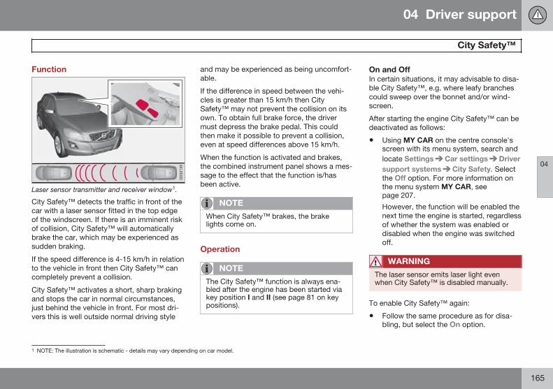
04 Driver support
City Safety™
04
165
Function
Laser sensor transmitter and receiver window1.
City Safety™ detects the traffic in front of thecar with a laser sensor fitted in the top edgeof the windscreen. If there is an imminent riskof collision, City Safety™ will automaticallybrake the car, which may be experienced assudden braking.
If the speed difference is 4-15 km/h in relationto the vehicle in front then City Safety™ cancompletely prevent a collision.
City Safety™ activates a short, sharp brakingand stops the car in normal circumstances,just behind the vehicle in front. For most dri-vers this is well outside normal driving style
and may be experienced as being uncomfort-able.
If the difference in speed between the vehi-cles is greater than 15 km/h then CitySafety™ may not prevent the collision on itsown. To obtain full brake force, the drivermust depress the brake pedal. This couldthen make it possible to prevent a collision,even at speed differences above 15 km/h.
When the function is activated and brakes,the combined instrument panel shows a mes-sage to the effect that the function is/hasbeen active.
NOTE
When City Safety™ brakes, the brakelights come on.
Operation
NOTE
The City Safety™ function is always ena-bled after the engine has been started viakey position I and II (see page 81 on keypositions).
On and OffIn certain situations, it may advisable to disa-ble City Safety™, e.g. where leafy branchescould sweep over the bonnet and/or wind-screen.
After starting the engine City Safety™ can bedeactivated as follows:
• Using MY CAR on the centre console'sscreen with its menu system, search andlocate Settings Car settings Driversupport systems City Safety. Selectthe Off option. For more information onthe menu system MY CAR, seepage 207.
However, the function will be enabled thenext time the engine is started, regardlessof whether the system was enabled ordisabled when the engine was switchedoff.
WARNING
The laser sensor emits laser light evenwhen City Safety™ is disabled manually.
To enable City Safety™ again:
• Follow the same procedure as for disa-bling, but select the On option.
1 NOTE: The illustration is schematic - details may vary depending on car model.
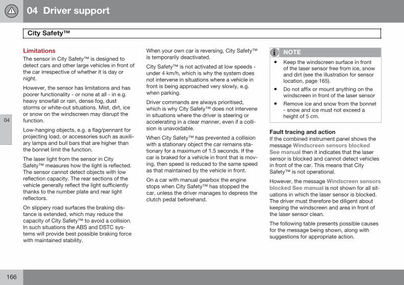
04 Driver support
City Safety™
04
166
LimitationsThe sensor in City Safety™ is designed todetect cars and other large vehicles in front ofthe car irrespective of whether it is day ornight.
However, the sensor has limitations and haspoorer functionality - or none at all - in e.g.heavy snowfall or rain, dense fog, duststorms or white-out situations. Mist, dirt, iceor snow on the windscreen may disrupt thefunction.
Low-hanging objects, e.g. a flag/pennant forprojecting load, or accessories such as auxili-ary lamps and bull bars that are higher thanthe bonnet limit the function.
The laser light from the sensor in CitySafety™ measures how the light is reflected.The sensor cannot detect objects with lowreflection capacity. The rear sections of thevehicle generally reflect the light sufficientlythanks to the number plate and rear lightreflectors.
On slippery road surfaces the braking dis-tance is extended, which may reduce thecapacity of City Safety™ to avoid a collision.In such situations the ABS and DSTC sys-tems will provide best possible braking forcewith maintained stability.
When your own car is reversing, City Safety™is temporarily deactivated.
City Safety™ is not activated at low speeds -under 4 km/h, which is why the system doesnot intervene in situations where a vehicle infront is being approached very slowly, e.g.when parking.
Driver commands are always prioritised,which is why City Safety™ does not intervenein situations where the driver is steering oraccelerating in a clear manner, even if a colli-sion is unavoidable.
When City Safety™ has prevented a collisionwith a stationary object the car remains sta-tionary for a maximum of 1.5 seconds. If thecar is braked for a vehicle in front that is mov-ing, then speed is reduced to the same speedas that maintained by the vehicle in front.
On a car with manual gearbox the enginestops when City Safety™ has stopped thecar, unless the driver manages to depress theclutch pedal beforehand.
NOTE
• Keep the windscreen surface in frontof the laser sensor free from ice, snowand dirt (see the illustration for sensorlocation, page 165).
• Do not affix or mount anything on thewindscreen in front of the laser sensor
• Remove ice and snow from the bonnet- snow and ice must not exceed aheight of 5 cm.
Fault tracing and actionIf the combined instrument panel shows themessage Windscreen sensors blockedSee manual then it indicates that the lasersensor is blocked and cannot detect vehiclesin front of the car. This means that CitySafety™ is not operational.
However, the message Windscreen sensorsblocked See manual is not shown for all sit-uations in which the laser sensor is blocked.The driver must therefore be diligent aboutkeeping the windscreen and area in front ofthe laser sensor clean.
The following table presents possible causesfor the message being shown, along withsuggestions for appropriate action.
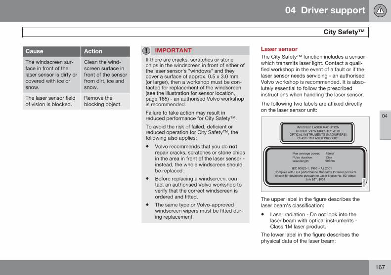
04 Driver support
City Safety™
04
167
Cause Action
The windscreen sur-face in front of thelaser sensor is dirty orcovered with ice orsnow.
Clean the wind-screen surface infront of the sensorfrom dirt, ice andsnow.
The laser sensor fieldof vision is blocked.
Remove theblocking object.
IMPORTANT
If there are cracks, scratches or stonechips in the windscreen in front of either ofthe laser sensor's "windows" and theycover a surface of approx. 0.5 x 3.0 mm(or larger), then a workshop must be con-tacted for replacement of the windscreen(see the illustration for sensor location,page 165) - an authorised Volvo workshopis recommended.
Failure to take action may result inreduced performance for City Safety™.
To avoid the risk of failed, deficient orreduced operation for City Safety™, thefollowing also applies:
• Volvo recommends that you do notrepair cracks, scratches or stone chipsin the area in front of the laser sensor -instead, the whole windscreen shouldbe replaced.
• Before replacing a windscreen, con-tact an authorised Volvo workshop toverify that the correct windscreen isordered and fitted.
• The same type or Volvo-approvedwindscreen wipers must be fitted dur-ing replacement.
Laser sensorThe City Safety™ function includes a sensorwhich transmits laser light. Contact a quali-fied workshop in the event of a fault or if thelaser sensor needs servicing - an authorisedVolvo workshop is recommended. It is abso-lutely essential to follow the prescribedinstructions when handling the laser sensor.
The following two labels are affixed directlyon the laser sensor unit:
The upper label in the figure describes thelaser beam's classification:
• Laser radiation - Do not look into thelaser beam with optical instruments -Class 1M laser product.
The lower label in the figure describes thephysical data of the laser beam:
04 Driver support
City Safety™
04
168
• IEC 60825-1:1993 + A2:2001. Complieswith FDA (U.S. Food Administration)standards for laser product design withthe exception of deviations in accordancewith "Laser Notice No. 50" from26 July 2001.
Radiation data for the laser sensorThe following table specifies the laser sen-sor's physical data.
Maximum pulse energy 2.64 µJ
Maximum average output 45 mW
Pulse duration 33 ns
Divergence (horizontal x verti-cal)
28° × 12°
WARNING
If any of these instructions are not followedthen there is a risk of eye injury!
• Never look into the laser sensor (whichemits spreading invisible laser radia-tion) at a distance of 100 mm or closerwith magnifying optics such as a mag-nifying glass, microscope, lens or simi-lar optical instruments.
• Testing, repair, removal, adjustmentand/or replacement of the laser sen-sor's spare parts must only be carriedout by a qualified workshop - we rec-ommend an authorised Volvo work-shop.
• To avoid exposure to harmful radia-tion, do not carry out any readjust-ments or maintenance other thanthose specified here.
• The repairer must follow speciallydrawn up workshop information for thelaser sensor.
• Do not remove the laser sensor (thisincludes removing the lenses). Aremoved laser sensor does not fulfil
laser class 3B as per standard IEC60825-1. Laser class 3B is not eye-safe and therefore entails a risk ofinjury.
• The laser sensor's connector must beunplugged before removal from thewindscreen.
• The laser sensor must be fitted ontothe windscreen before the sensor'sconnector is plugged in.
• The laser sensor transmits laser lightwhen the remote control key is in posi-tion II and also with the engineswitched off (see page 81 on key posi-tions).
Symbols and text messagesIn conjunction with automatic braking by theCity Safety™ system, one or more symbolsmay illuminate in the combined instrumentpanel and a text message may be shown.
A text message can be acknowledged bybriefly pressing the OK button on the direc-tion indicator stalk.
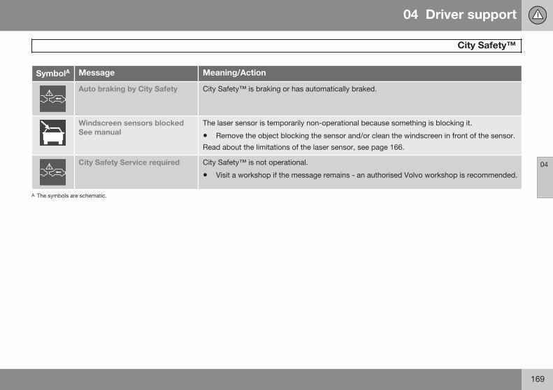
04 Driver support
City Safety™
04
169
SymbolA Message Meaning/Action
Auto braking by City Safety City Safety™ is braking or has automatically braked.
Windscreen sensors blockedSee manual
The laser sensor is temporarily non-operational because something is blocking it.
• Remove the object blocking the sensor and/or clean the windscreen in front of the sensor.
Read about the limitations of the laser sensor, see page 166.
City Safety Service required City Safety™ is not operational.
• Visit a workshop if the message remains - an authorised Volvo workshop is recommended.
A The symbols are schematic.
04 Driver support
Collision Warning with Auto Brake & Pedestrian Detection*
04
170 * Option/accessory, for more information, see Introduction.
General"Collision Warning with Auto Brake & Pedes-trian Detection" is an aid to assist the driverwhen there is a risk of colliding with a pedes-trian or vehicle in front that is stationary ormoving in the same direction.
Collision Warning with Auto Brake & Pedes-trian Detection is activated in situations wherethe driver should have started braking earlier,which is why it cannot help the driver in everysituation.
Collision Warning with Auto Brake & Pedes-trian Detection is designed to be activated aslate as possible in order to avoid unnecessaryintervention.
Collision Warning with Auto Brake & Pedes-trian Detection may prevent a collision orreduce the collision speed.
Collision Warning with Auto Brake & Pedes-trian Detection must not be used as anexcuse for the driver to change his/her drivingstyle. If the driver solely relies on CollisionWarning with Auto Brake to do the braking,there will be a collision sooner or later.
Two system levelsDepending on how the car equipped, the Col-lision Warning with Auto Brake & PedestrianProtection function may appear in two vari-ants: Level 1 and Level 2.
Level 1The driver is merely warned of occurringobstacles by means of visual and acousticsignals - no automatic braking intervenes, thedriver must himself brake.
Level 2The driver is warned of occurring obstaclesby means of visual and acoustic signals - thecar is braked automatically if the driver him-self does not act within a reasonable time.
IMPORTANT
Maintenance of components included inCollision Warning with Auto Brake &Pedestrian Detection must only be carriedout in a workshop - an authorised Volvoworkshop is recommended.
Function
Function overview1.
Audio-visual warning signal in the eventof a collision risk.
Radar sensor2
Camera sensor
Collision Warning with Auto Brake executesthree steps in the following order:
1. Collision warning
2. Brake support2
3. Auto Brake2
1 NOTE: The illustration is schematic - details may vary depending on car model.2 With system Level 2 only.
04 Driver support
Collision Warning with Auto Brake & Pedestrian Detection*
04
* Option/accessory, for more information, see Introduction. 171
The collision warning system and CitySafety™ complement each other. For moreinformation on City Safety™, see page 164.
1 - Collision warningThe driver is first warned of a potentiallyimminent collision.
The collision warning system detects pedes-trians, stationary vehicles as well as vehiclesdriving in the same direction in front of thecar.
If there is a risk of collision with a pedestrianor a vehicle, the driver's attention is attractedwith a flashing red warning signal (no. [1] inthe illustration on page 170) and an acousticsignal
2 - Brake support2
If the risk of collision has increased furtherafter the collision warning then the brake sup-port is activated.
This means that the brake system is preparedfor fast braking by applying the brakes gently,which may be experienced as a slight jerk.
If the brake pedal is depressed sufficientlyquickly then full brake function is imple-mented.
Brake support also reinforces the driver'sbraking if the system considers that the brak-ing is not sufficient to avoid a collision.
3 - Auto Brake2
The automatic brake function is activatedlast.
If in this situation the driver has not yetstarted to take evasive action and the risk ofcollision is imminent then the automatic brak-ing function is deployed - this takes placeirrespective of whether or not the driverbrakes. Braking then takes place with fullbrake force in order to reduce collision speed,or with limited brake force if it is sufficient toavoid a collision.
WARNING
The collision warning system does notengage in all driving situations or traffic,weather or road conditions. The collisionwarning system does not react to vehiclesdriving in another direction to the car or toanimals.
Warning only activated in the event of ahigh risk for collision. This section "Func-tion" and the section "Limitations" informabout limitations that the driver must beaware of before using the Collision Warn-ing system with Auto Brake.
Warnings and brake interventions forpedestrians are switched off at vehiclespeeds exceeding 80 km/h.
Warnings and brake interventions forpedestrians do not work in darkness andtunnels - not even when streetlights are lit.
The auto-brake function can prevent a col-lision or reduce collision speed. To ensurefull brake performance, the driver shouldalways depress the brake pedal - evenwhen the car auto-brakes.
Never wait for a collision warning. Thedriver is always responsible that the cor-rect distance and speed are maintained -even when the collision warning systemwith auto-brake is used.
2 With system Level 2 only.
04 Driver support
Collision Warning with Auto Brake & Pedestrian Detection*
04
172 * Option/accessory, for more information, see Introduction.
Detection of pedestrians
Optimal examples of what the system regards aspedestrians with clear body contours.
Optimal performance of the system requiresthat the system function that detects pedes-trians receives as unambiguous informationas possible about the contours of the body -this implies the opportunity to identify thehead, arms, shoulders, legs, upper and lowerbody combined with a normal human patternof movement.
If large parts of the body are not visible to thecamera then the system cannot detect apedestrian.
• In order for a pedestrian to be detectedhe/she must appear full-length and havea height of at least 80 cm.
• The system cannot detect a pedestriancarrying larger items.
• The camera sensor's ability to see pedes-trians at dusk and dawn is limited - justlike the human eye.
• The camera sensor's capacity to detectpedestrians is deactivated when driving indarkness and tunnels - even when street-lights are lit.
WARNING
Collision Warning with Auto Brake &Pedestrian Detection is an assistance tool.
This function cannot detect all pedestriansin all situations and it cannot see e.g. parti-ally obscured pedestrians, people in cloth-ing that hides the contours of the body orpedestrians shorter than 80 cm.
• The driver is always responsible thatthe vehicle is driven properly and witha safety distance adapted to thespeed.
OperationSettings are made from MY CAR via the cen-tre console's screen and menu system. Forinformation on how the menu system is used,see page 207.
Warning signals On and OffYou can select whether the collision warningsystem's acoustic and visual warning signalsshould be switched on or off.
When starting the engine, the setting that wasselected when the engine was switched off isobtained automatically.
NOTE
The Brake Support and Auto Brake func-tions are always activated - they cannot bedeactivated.
Light and acoustic signalsTo deactivate the light and acoustic signals:
• Locate Settings Car settingsDriver support systems CollisionWarning - there select to uncheck thebox.
The warning lamp (no. [1] in the figure page170) is tested every time the engine is startedby briefly illuminating the warning lamp's sep-arate points of light if the collision warning
04 Driver support
Collision Warning with Auto Brake & Pedestrian Detection*
04
* Option/accessory, for more information, see Introduction. 173
system's light and acoustic warnings are acti-vated.
Acoustic signalThe warning sound can be activated/deacti-vated separately:
• Select On or Off in the menu systemunder Settings Car settings Driversupport systems Collision Warning
Warning sound.
Set warning distanceThe warning distance regulates the distanceat which the visual and acoustic warnings aredeployed.
• Select Long, Normal or Short in themenu system MY CAR under Settings
Car settings Driver supportsystems Collision WarningWarning distance
The warning distance determines the sys-tem's sensitivity. Warning distance Long pro-vides an earlier warning. First test with Longand if this setting produces too many warn-ings, which could be perceived as irritating incertain situations, then change to warningdistance Normal.
Only use warning distance Short in excep-tional cases, e.g. for dynamic driving.
NOTE
When the adaptive cruise control is in usethe warning lamp and warning sound willbe used by the cruise control even if thecollision warning system is switched off.
The collision warning system warns thedriver in the event of a risk of a collision,but the function cannot shorten driverreaction time.
In order for the collision warning system tobe effective, always drive with the Dis-tance Alert set at time interval 4–5, seepage 161.
NOTE
Even if the warning distance has been setto Long warnings could be perceived asbeing late in certain situations, e.g. whenthere are large differences in speed or ifvehicles in front brake heavily.
WARNING
No automatic system can guarantee100 % correct function in all situations.Therefore, never test Collision Warningwith Auto Brake by driving at people orvehicles - this may cause severe damageand injury and risk lives.
Checking settingsThe settings required can be controlled onthe centre console's screen. Search with themenu system MY CAR under Settings Carsettings Driver support systemsCollision Warning, see page 207.
Maintenance
Camera and radar sensor.
For the sensors to work correctly, they mustbe kept clear of dirt, ice and snow, and becleaned regularly with water and car sham-poo.
NOTE
Dirt, ice and snow covering the sensorswill reduce their function and may preventmeasurement.
04 Driver support
Collision Warning with Auto Brake & Pedestrian Detection*
04
174 * Option/accessory, for more information, see Introduction.
LimitationsCollision Warning with Auto Brake andPedestrian Detection is active fromapprox. 4 km/h.
The visual warning signal (no. [1] in the illus-tration on page 170) may be difficult to noticein the event of strong sunlight, reflections,when sunglasses are being worn or if thedriver is not looking straight ahead. The warn-ing sound should therefore always be acti-vated.
On slippery road surfaces the braking dis-tance is extended, which may reduce thecapacity to avoid a collision. In such situa-tions the ABS and DSTC systems will providebest possible braking force with maintainedstability.
NOTE
The visual warning signal can be temporar-ily disengaged in the event of high passen-ger compartment temperature caused bystrong sunlight for example. If this occursthen the warning sound is activated even ifit is deactivated in the menu system.
• Warnings may not appear if the dis-tance to the vehicle in front is small orif steering wheel and pedal move-ments are large, e.g. a very active driv-ing style.
WARNING
Warnings and brake interventions could beimplemented late or not at all if the trafficsituation or external influences mean thatthe radar or camera sensor cannot detecta pedestrian or a vehicle in front correctly.
The sensor system has a limited range forpedestrians and the system therefore pro-vides effective warnings and brake inter-ventions at vehicle speeds up to 50 km/h.For stationary or slow-moving vehicles,warnings and brake interventions areeffective at vehicle speeds up to 70 km/h.
Warnings for stationary or slow-movingvehicles could be disengaged due to dark-ness or poor visibility.
Warnings and brake interventions forpedestrians are switched off at vehiclespeeds exceeding 80 km/h.
The collision warning system uses the sameradar sensors as adaptive cruise control. Formore information on the radar sensor and itslimitations, see page 157.
If warnings are perceived as being too fre-quent or disturbing then the warning distancecan be reduced. This then leads to the sys-tem providing a warning at a later stage,which reduces the total number of warnings;see the section "Set warning distance" onpage 173.
04 Driver support
Collision Warning with Auto Brake & Pedestrian Detection*
04
* Option/accessory, for more information, see Introduction. 175
Collision Warning with Auto Brake is tempo-rarily deactivated with reverse gear engaged.
Collision Warning with Auto Brake is not acti-vated at low speeds - under 4 km/h, which iswhy the system does not intervene in situa-tions where the car is approaching a vehiclein front very slowly, e.g. when parking.
In situations where the driver demonstratesactive, aware driving behaviour, a collisionwarning may be postponed slightly in order tokeep unnecessary warnings to a minimum.
When Auto Brake has prevented a collisionwith a stationary object the car remains sta-tionary for a maximum of 1.5 seconds. If thecar is braked for a vehicle in front that is mov-ing, then speed is reduced to the same speedas that maintained by the vehicle in front.
On a car with manual gearbox the enginestops when Auto Brake has stopped the car,unless the driver manages to depress theclutch pedal beforehand.
Camera sensor limitationsThe car’s camera sensor is also used - aswell as by Collision Warning with Auto Brake- by the functions:
• Automatic main/dipped beam dimming -see page 92
• Road sign information - see page 143.
• Driver Alert Control – see page 179
• Lane keeping assistant - see page 182
NOTE
Keep the windscreen surface in front of thecamera sensor free from ice, snow, mistand dirt.
Do not stick or attach anything to thewindscreen in front of the camera sensoras this may reduce effectiveness or causeone or more of the systems dependent onthe camera to stop working.
The camera sensors have limitations similarto the human eye, i.e. they "see" worse indarkness, heavy snowfall or rain and in thickfog for example. Under such conditions thefunctions of camera-dependent systemscould be significantly reduced or temporarilydisengaged.
Strong oncoming light, reflections in the car-riageway, snow or ice on the road surface,dirty road surfaces or unclear lane markingscould also significantly reduce camera sensorfunction when it is used to scan the carriage-way and detect pedestrians and other vehi-cles.
The field of vision of the camera sensor is lim-ited, which is why pedestrians and vehicles
cannot be detected in some situations, orthey are detected later than anticipated.
During very high temperatures the camera istemporarily switched off for about 15 minutesafter the engine is started in order to protectcamera functionality.
Fault tracing and actionIf the combined instrument panel shows themessage Windscreen Sensors blockedthen this means that the camera sensor isblocked and cannot detect pedestrians, vehi-cles or road markings in front of the car.
At the same time, this means that - besidesCollision Warning with Auto Brake - the Auto-matic main/dipped beam dimming, Road SignInformation, Driver Alert Control and LaneKeeping Aid functions will not have full func-tionality either.
The following table presents possible causesfor a message being shown along with theappropriate action.
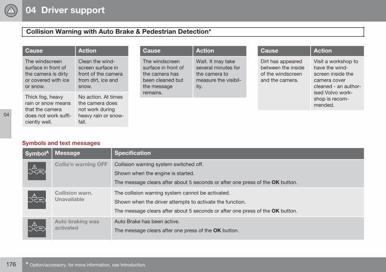
04 Driver support
Collision Warning with Auto Brake & Pedestrian Detection*
04
176 * Option/accessory, for more information, see Introduction.
Cause Action
The windscreensurface in front ofthe camera is dirtyor covered with iceor snow.
Clean the wind-screen surface infront of the camerafrom dirt, ice andsnow.
Thick fog, heavyrain or snow meansthat the cameradoes not work suffi-ciently well.
No action. At timesthe camera doesnot work duringheavy rain or snow-fall.
Cause Action
The windscreensurface in front ofthe camera hasbeen cleaned butthe messageremains.
Wait. It may takeseveral minutes forthe camera tomeasure the visibil-ity.
Cause Action
Dirt has appearedbetween the insideof the windscreenand the camera.
Visit a workshop tohave the wind-screen inside thecamera covercleaned - an author-ised Volvo work-shop is recom-mended.
Symbols and text messages
SymbolA Message Specification
Collis'n warning OFF Collision warning system switched off.
Shown when the engine is started.
The message clears after about 5 seconds or after one press of the OK button.
Collision warn.Unavailable
The collision warning system cannot be activated.
Shown when the driver attempts to activate the function.
The message clears after about 5 seconds or after one press of the OK button.
Auto braking wasactivated
Auto Brake has been active.
The message clears after one press of the OK button.
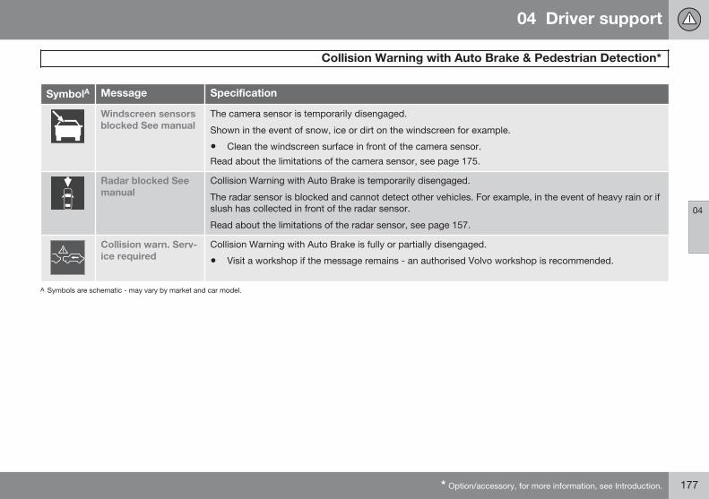
04 Driver support
Collision Warning with Auto Brake & Pedestrian Detection*
04
* Option/accessory, for more information, see Introduction. 177
SymbolA Message Specification
Windscreen sensorsblocked See manual
The camera sensor is temporarily disengaged.
Shown in the event of snow, ice or dirt on the windscreen for example.
• Clean the windscreen surface in front of the camera sensor.
Read about the limitations of the camera sensor, see page 175.
Radar blocked Seemanual
Collision Warning with Auto Brake is temporarily disengaged.
The radar sensor is blocked and cannot detect other vehicles. For example, in the event of heavy rain or ifslush has collected in front of the radar sensor.
Read about the limitations of the radar sensor, see page 157.
Collision warn. Serv-ice required
Collision Warning with Auto Brake is fully or partially disengaged.
• Visit a workshop if the message remains - an authorised Volvo workshop is recommended.
A Symbols are schematic - may vary by market and car model.
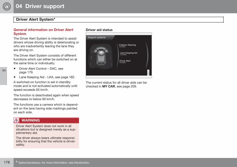
04 Driver support
Driver Alert System*
04
178 * Option/accessory, for more information, see Introduction.
General information on Driver AlertSystemThe Driver Alert System is intended to assistdrivers whose driving ability is deteriorating orwho are inadvertently leaving the lane theyare driving on.
The Driver Alert System consists of differentfunctions which can either be switched on atthe same time or individually:
• Driver Alert Control – DAC, seepage 179.
• Lane Keeping Aid - LKA, see page 182.
A switched-on function is set in standbymode and is not activated automatically untilspeed exceeds 65 km/h.
The function is deactivated again when speeddecreases to below 60 km/h.
The functions use a camera which is depend-ent on the lane having side markings paintedon each side.
WARNING
Driver Alert System does not work in allsituations but is designed merely as a sup-plementary aid.
The driver always bears ultimate responsi-bility for ensuring that the vehicle is drivensafely.
Driver aid status
The current status for all driver aids can bechecked in MY CAR, see page 209.
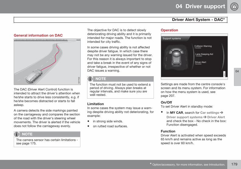
04 Driver support
Driver Alert System - DAC*
04
* Option/accessory, for more information, see Introduction. 179
General information on DAC
The DAC (Driver Alert Control) function isintended to attract the driver's attention whenhe/she starts to drive less consistently, e.g. ifhe/she becomes distracted or starts to fallasleep.
A camera detects the side markings paintedon the carriageway and compares the sectionof the road with the driver's steering wheelmovements. The driver is alerted if the vehicledoes not follow the carriageway evenly.
NOTE
The camera sensor has certain limitations -see page 175.
The objective for DAC is to detect slowlydeteriorating driving ability and it is primarilyintended for major roads. The function is notintended for city traffic.
In some cases driving ability is not affecteddespite driver fatigue. In which case theremay not be any warning issued for the driver.For this reason it is always important to stopand take a break in the event of any signs ofdriver fatigue, irrespective of whether or notDAC issues a warning.
NOTE
The function must not be used to extend aperiod of driving. Always plan breaks atregular intervals, and make sure you arewell rested.
LimitationIn some cases the system may issue a warn-ing despite driving ability not deteriorating, forexample:
• in strong side winds.
• on rutted road surfaces.
Operation
Settings are made from the centre console'sscreen and its menu system. For informationon how the menu system is used, seepage 207.
On/OffTo set Driver Alert in standby mode:
• In MY CAR, search for Car settingsDriver support systems Driver Alertand check the box - No check in the box:Function disengaged.
FunctionDriver Alert is activated when speed exceeds65 km/h and remains active as long as thespeed is over 60 km/h.
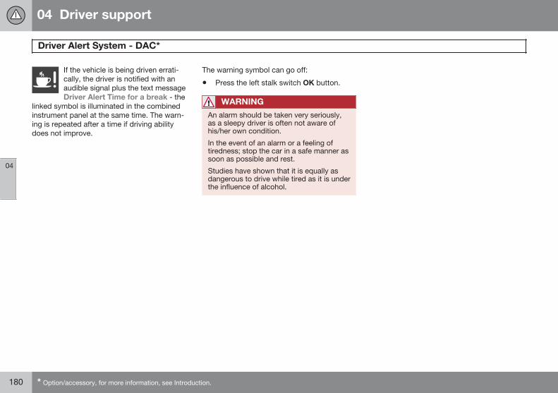
04 Driver support
Driver Alert System - DAC*
04
180 * Option/accessory, for more information, see Introduction.
If the vehicle is being driven errati-cally, the driver is notified with anaudible signal plus the text messageDriver Alert Time for a break - the
linked symbol is illuminated in the combinedinstrument panel at the same time. The warn-ing is repeated after a time if driving abilitydoes not improve.
The warning symbol can go off:
• Press the left stalk switch OK button.
WARNING
An alarm should be taken very seriously,as a sleepy driver is often not aware ofhis/her own condition.
In the event of an alarm or a feeling oftiredness; stop the car in a safe manner assoon as possible and rest.
Studies have shown that it is equally asdangerous to drive while tired as it is underthe influence of alcohol.
04 Driver support
Driver Alert System - DAC*
04
* Option/accessory, for more information, see Introduction. 181
Symbols and messages
Combined instrument panel
SymbolA Message Specification
Driver Alert Time for abreak
The vehicle has been driven inconsistently - the driver is alerted by an acoustic warning signal + text.
Windscreen sensorsblocked See manual
The camera sensor is temporarily disengaged.
Shown in the event of snow, ice or dirt on the windscreen for example.
• Clean the windscreen surface in front of the camera sensor.
Read about the limitations of the camera sensor, see page 175.
Driver Alert system Serv-ice required
The system is disengaged.
• Visit a workshop if the message remains - an authorised Volvo workshop is recommended.
A The symbols are schematic.
Screen
Sym-bol
Message Specification
Driver Alert OFF The function is disengaged.
Driver Alert Available The function is activated.
Driver Alert Standby <65 km/h The function is set in standby mode due to speed being lower than 65 km/h.
Driver Alert Unavailable The carriageway does not have clear side markings or the camera sensor is temporarily disen-gaged. Read about the limitations of the camera sensor, see page 175.
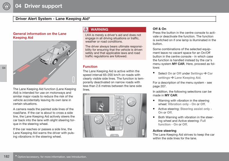
04 Driver support
Driver Alert System - Lane Keeping Aid*
04
182 * Option/accessory, for more information, see Introduction.
General information on the LaneKeeping Aid
The Lane Keeping Aid function (Lane KeepingAid) is intended for use on motorways andsimilar major roads to reduce the risk of thevehicle accidentally leaving its own lane incertain situations.
A camera reads the painted side lines of theroad/lane. If the car is about to cross a sideline, the Lane Keeping Aid actively steers thecar back into the lane with slight steering tor-que in the steering wheel.
If the car reaches or passes a side line, theLane Keeping Aid warns the driver with puls-ing vibrations in the steering wheel.
WARNING
LKA is merely a driver's aid and does notengage in all driving situations or traffic,weather or road conditions.
The driver always bears ultimate responsi-bility for ensuring that the vehicle is drivensafely and that applicable laws and roadtraffic regulations are followed.
FunctionThe Lane Keeping Aid is active within thespeed interval 65-200 km/h on roads withclearly visible side lines. The function is tem-porarily deactivated on narrow roads withless than 2.6 metres between the lane sidelines.
Off & OnPress the button in the centre console to acti-vate or deactivate the function. The functionis switched on if one lamp is illuminated in thebutton.
Some combinations of the selected equip-ment leave no vacant space for an On/Offbutton in the centre console - in which casethe function is handled instead by the car'smenu system MY CAR. Here, proceed as fol-lows:
• Select On or Off under Settings Carsettings Lane Keeping Aid.
For a description of the menu system - seepage 207.
In addition, the following selections can bemade in MY CAR:
• Warning with vibration in the steeringwheel: Vibration only - On or Off.
• Active steering: Steering assist only -On or Off.
• Both Warning with vibration in the steer-ing wheel and Active steering: Fullfunction - On or Off.
Active steeringThe Lane Keeping Aid strives to keep the carwithin the side lines for the lane.
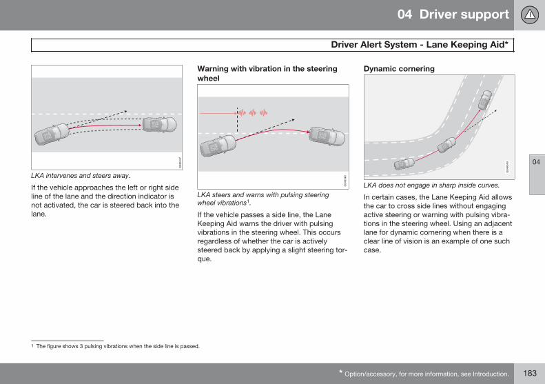
04 Driver support
Driver Alert System - Lane Keeping Aid*
04
* Option/accessory, for more information, see Introduction. 183
LKA intervenes and steers away.
If the vehicle approaches the left or right sideline of the lane and the direction indicator isnot activated, the car is steered back into thelane.
Warning with vibration in the steeringwheel
LKA steers and warns with pulsing steeringwheel vibrations1.
If the vehicle passes a side line, the LaneKeeping Aid warns the driver with pulsingvibrations in the steering wheel. This occursregardless of whether the car is activelysteered back by applying a slight steering tor-que.
Dynamic cornering
LKA does not engage in sharp inside curves.
In certain cases, the Lane Keeping Aid allowsthe car to cross side lines without engagingactive steering or warning with pulsing vibra-tions in the steering wheel. Using an adjacentlane for dynamic cornering when there is aclear line of vision is an example of one suchcase.
1 The figure shows 3 pulsing vibrations when the side line is passed.
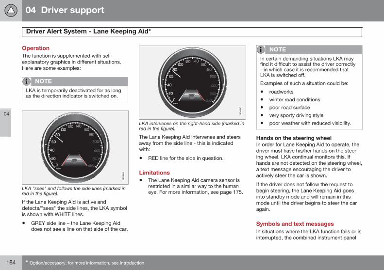
04 Driver support
Driver Alert System - Lane Keeping Aid*
04
184 * Option/accessory, for more information, see Introduction.
OperationThe function is supplemented with self-explanatory graphics in different situations.Here are some examples:
NOTE
LKA is temporarily deactivated for as longas the direction indicator is switched on.
LKA "sees" and follows the side lines (marked inred in the figure).
If the Lane Keeping Aid is active anddetects/"sees" the side lines, the LKA symbolis shown with WHITE lines.
• GREY side line – the Lane Keeping Aiddoes not see a line on that side of the car.
LKA intervenes on the right-hand side (marked inred in the figure).
The Lane Keeping Aid intervenes and steersaway from the side line - this is indicatedwith:
• RED line for the side in question.
Limitations• The Lane Keeping Aid camera sensor is
restricted in a similar way to the humaneye. For more information, see page 175.
NOTE
In certain demanding situations LKA mayfind it difficult to assist the driver correctly- in which case it is recommended thatLKA is switched off.
Examples of such a situation could be:
• roadworks
• winter road conditions
• poor road surface
• very sporty driving style
• poor weather with reduced visibility.
Hands on the steering wheelIn order for Lane Keeping Aid to operate, thedriver must have his/her hands on the steer-ing wheel. LKA continual monitors this. Ifhands are not detected on the steering wheel,a text message encouraging the driver toactively steer the car is shown.
If the driver does not follow the request tobegin steering, the Lane Keeping Aid goesinto standby mode and will remain in thismode until the driver begins to steer the caragain.
Symbols and text messagesIn situations where the LKA function fails or isinterrupted, the combined instrument panel
04 Driver support
Driver Alert System - Lane Keeping Aid*
04
* Option/accessory, for more information, see Introduction. 185
may show a symbol, along with an explana-tory message. If so, follow the recommenda-tion given.
Message examples:
SymbolA Message Specification
Lane Keeping Aid Unavailableat this speed
The Lane Keeping Aid is set to standby mode because the speed is lower than 65 km/h.
Lane Keeping Aid Unavailablefor current markings
The lane does not have clear side lines or the camera sensor is temporarily disengaged. Readabout the limitations of the camera sensor, see page 175.
Lane Keeping Aid Available The function scans the lane's side lines.
Windscreen sensors blockedSee manual
The camera sensor is temporarily disengaged.
Shown in the event of snow, ice or dirt on the windscreen for example.
• Clean the windscreen surface in front of the camera sensor.
Read about the limitations of the camera sensor, see page 175.
Lane Keeping Aid Servicerequired
The system is disengaged.
• Visit a workshop if the message remains - an authorised Volvo workshop is recommended.
Lane Keeping Aid Interrupted LKA has been set to standby mode. The lines of the LKA symbol indicate when the function isactive again.
A The table symbols are schematic. The symbols shown in the combined instrument panel may have a slightly different appearance.
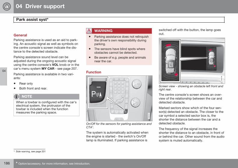
04 Driver support
Park assist syst*
04
186 * Option/accessory, for more information, see Introduction.
GeneralParking assistance is used as an aid to park-ing. An acoustic signal as well as symbols onthe centre console's screen indicate the dis-tance to the detected obstacle.
Parking assistance sound level can beadjusted during the ongoing acoustic signalusing the centre console's VOL knob or in thecar's menu system MY CAR - see page 207.
Parking assistance is available in two vari-ants:
• Rear only
• Both front and rear.
NOTE
When a towbar is configured with the car'selectrical system, the protrusion of thetowbar is included when the functionmeasures the parking space.
WARNING
• Parking assistance does not relinquishthe driver's own responsibility duringparking.
• The sensors have blind spots whereobstacles cannot be detected.
• Be aware of e.g. people and animalsnear the car.
Function
On/Off for the sensors for parking assistance andCTA1.
The system is automatically activated whenthe engine is started - the switch's On/Offlamp is illuminated. If parking assistance is
switched off with the button, the lamp goesout.
Screen view - showing an obstacle left front andright rear.
The centre console's screen shows an over-view of the relationship between the car anddetected obstacle.
Marked sectors show which of the four sen-sor(s) detected an obstacle. The closer to thecar symbol a selected sector box is, theshorter the distance between the car and adetected obstacle.
The frequency of the signal increases theshorter the distance to an obstacle, in front ofor behind the car. Other sound from the audiosystem is muted automatically.
1 Side warning, see page 201
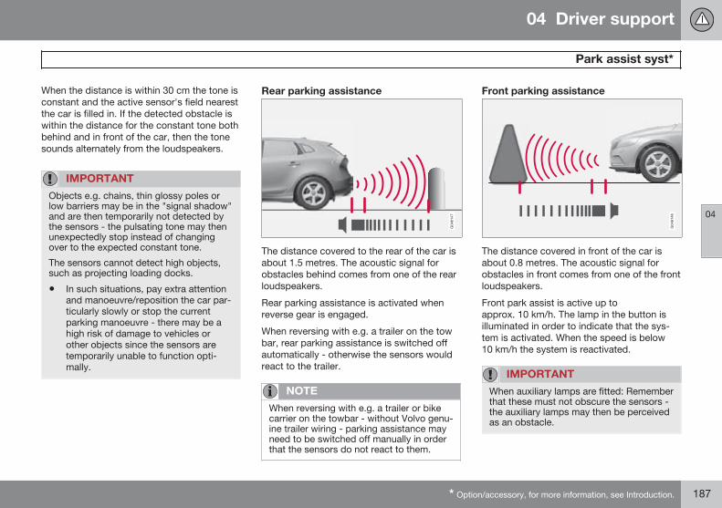
04 Driver support
Park assist syst*
04
* Option/accessory, for more information, see Introduction. 187
When the distance is within 30 cm the tone isconstant and the active sensor's field nearestthe car is filled in. If the detected obstacle iswithin the distance for the constant tone bothbehind and in front of the car, then the tonesounds alternately from the loudspeakers.
IMPORTANT
Objects e.g. chains, thin glossy poles orlow barriers may be in the "signal shadow"and are then temporarily not detected bythe sensors - the pulsating tone may thenunexpectedly stop instead of changingover to the expected constant tone.
The sensors cannot detect high objects,such as projecting loading docks.
• In such situations, pay extra attentionand manoeuvre/reposition the car par-ticularly slowly or stop the currentparking manoeuvre - there may be ahigh risk of damage to vehicles orother objects since the sensors aretemporarily unable to function opti-mally.
Rear parking assistance
The distance covered to the rear of the car isabout 1.5 metres. The acoustic signal forobstacles behind comes from one of the rearloudspeakers.
Rear parking assistance is activated whenreverse gear is engaged.
When reversing with e.g. a trailer on the towbar, rear parking assistance is switched offautomatically - otherwise the sensors wouldreact to the trailer.
NOTE
When reversing with e.g. a trailer or bikecarrier on the towbar - without Volvo genu-ine trailer wiring - parking assistance mayneed to be switched off manually in orderthat the sensors do not react to them.
Front parking assistance
The distance covered in front of the car isabout 0.8 metres. The acoustic signal forobstacles in front comes from one of the frontloudspeakers.
Front park assist is active up toapprox. 10 km/h. The lamp in the button isilluminated in order to indicate that the sys-tem is activated. When the speed is below10 km/h the system is reactivated.
IMPORTANT
When auxiliary lamps are fitted: Rememberthat these must not obscure the sensors -the auxiliary lamps may then be perceivedas an obstacle.
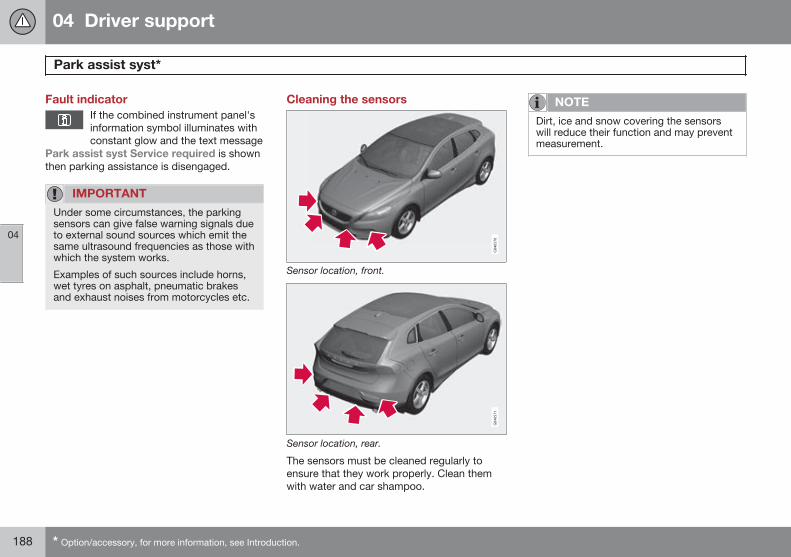
04 Driver support
Park assist syst*
04
188 * Option/accessory, for more information, see Introduction.
Fault indicatorIf the combined instrument panel'sinformation symbol illuminates withconstant glow and the text message
Park assist syst Service required is shownthen parking assistance is disengaged.
IMPORTANT
Under some circumstances, the parkingsensors can give false warning signals dueto external sound sources which emit thesame ultrasound frequencies as those withwhich the system works.
Examples of such sources include horns,wet tyres on asphalt, pneumatic brakesand exhaust noises from motorcycles etc.
Cleaning the sensors
Sensor location, front.
Sensor location, rear.
The sensors must be cleaned regularly toensure that they work properly. Clean themwith water and car shampoo.
NOTE
Dirt, ice and snow covering the sensorswill reduce their function and may preventmeasurement.
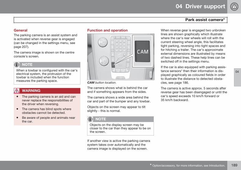
04 Driver support
Park assist camera*
04
* Option/accessory, for more information, see Introduction. 189
GeneralThe parking camera is an assist system andis activated when reverse gear is engaged(can be changed in the settings menu, seepage 207).
The camera image is shown on the centreconsole's screen.
NOTE
When a towbar is configured with the car'selectrical system, the protrusion of thetowbar is included when the functionmeasures the parking space.
WARNING
• The parking camera is an aid and cannever replace the responsibilities ofthe driver when reversing.
• The camera has blind spots whereobstacles cannot be detected.
• Be aware of people and animals nearthe car.
Function and operation
CAM button location.
The camera shows what is behind the carand if something appears from the sides.
The camera shows a wide area behind thecar and part of the bumper and any towbar.
Objects on the screen may appear to tiltslightly - this is normal.
NOTE
Objects on the display screen may becloser to the car than they appear to be onthe screen.
If another view is active the parking camerasystem takes over automatically and thecamera image is displayed on the screen.
When reverse gear is engaged two unbrokenlines are shown graphically which illustratewhere the car's rear wheels will roll with thecurrent steering wheel angle, this facilitatestight parking, reversing into tight spaces andfor hitching a trailer. The car’s approximateexternal dimensions are illustrated by meansof two dashed lines. These help lines can beswitched off in the settings menu.
If the car is also equipped with parking assis-tance sensors* then their information is dis-played graphically as coloured fields in orderto illustrate the distance to detected obsta-cles, see page 186.
The camera is active approx. 5 seconds afterreverse gear has been disengaged or until thecar's speed exceeds 10 km/h forward or35 km/h backward.
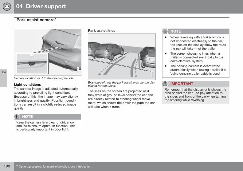
04 Driver support
Park assist camera*
04
190 * Option/accessory, for more information, see Introduction.
Camera location next to the opening handle.
Light conditionsThe camera image is adjusted automaticallyaccording to prevailing light conditions.Because of this, the image may vary slightlyin brightness and quality. Poor light condi-tions can result in a slightly reduced imagequality.
NOTE
Keep the camera lens clear of dirt, snowand ice to ensure optimum function. Thisis particularly important in poor light.
Park assist lines
Examples of how the park assist lines can be dis-played for the driver.
The lines on the screen are projected as ifthey were at ground level behind the car andare directly related to steering wheel move-ment, which shows the driver the path the carwill take when it turns.
NOTE
• When reversing with a trailer which isnot connected electrically to the car,the lines on the display show the routethe car will take - not the trailer.
• The screen shows no lines when atrailer is connected electrically to thecar's electrical system.
• The parking camera is deactivatedautomatically when towing a trailer if aVolvo genuine trailer cable is used.
IMPORTANT
Remember that the display only shows thearea behind the car - so pay attention tothe sides and front of the car when turningthe steering while reversing.
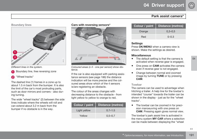
04 Driver support
Park assist camera*
04
}}* Option/accessory, for more information, see Introduction. 191
Boundary lines
Different lines in the system.
Boundary line, free reversing zone
"Wheel tracks"
The dashed line (1) frames in a zone up toabout 1.5 m back from the bumper. It is alsothe limit of the car's most protruding parts,such as door mirrors and corners - also dur-ing turning.
The wide "wheel tracks" (2) between the sidelines indicate where the wheels will roll andcan extend about 3.2 m back from thebumper if no obstacle is in the way.
Cars with reversing sensors*
Coloured areas (x 4 - one per sensor) show dis-tance.
If the car is also equipped with parking assis-tance sensors (see page 186) the distanceindication will be more precise and the col-oured areas show which of the 4 sensorsis/are registering an obstacle.
The colour of the areas changes withdecreasing distance to the obstacle - fromlight yellow to yellow to orange to red.
Colour / paint Distance (metres)
Light yellow 0.7–1.5
Yellow 0,5–0,7
Colour / paint Distance (metres)
Orange 0,3–0,5
Red 0–0.3
SettingsPress OK/MENU when a camera view isshown. Make the settings as desired.
Miscellaneous• The default setting is that the camera is
activated when reverse gear is engaged.
• One press on CAM activates the cameraeven if reverse gear is not engaged.
• Change between normal and zoomedimage by turning TUNE or by pressingCAM.
TowbarThe camera can be used to advantage whenhitching a trailer. A help line for the towbar'sintended "course" towards the trailer can beshown in the display - just as for the "wheeltracks".
• The towbar can be zoomed in for preci-sion manoeuvring with one press onCAM. Pressing again gives normal view.
The towbar's park assist line is activated inthe menu system MY CAR where a selectioncan be made between displaying the "wheel
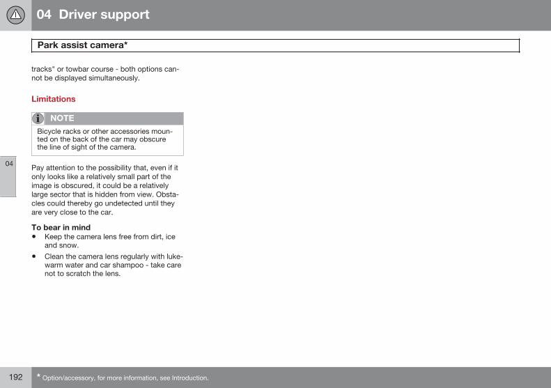
04 Driver support
Park assist camera*
04
192 * Option/accessory, for more information, see Introduction.
tracks" or towbar course - both options can-not be displayed simultaneously.
Limitations
NOTE
Bicycle racks or other accessories moun-ted on the back of the car may obscurethe line of sight of the camera.
Pay attention to the possibility that, even if itonly looks like a relatively small part of theimage is obscured, it could be a relativelylarge sector that is hidden from view. Obsta-cles could thereby go undetected until theyare very close to the car.
To bear in mind• Keep the camera lens free from dirt, ice
and snow.
• Clean the camera lens regularly with luke-warm water and car shampoo - take carenot to scratch the lens.
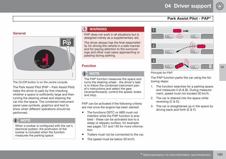
04 Driver support
Park Assist Pilot - PAP*
04
* Option/accessory, for more information, see Introduction. 193
General
The On/Off button is on the centre console.
The Park Assist Pilot (PAP – Park Assist Pilot)helps the driver to park by first checkingwhether a space is sufficiently large and thenturning the steering wheel and steering thecar into the space. The combined instrumentpanel uses symbols, graphics and text toshow when different operations should beperformed.
NOTE
When a towbar is configured with the car'selectrical system, the protrusion of thetowbar is included when the functionmeasures the parking space.
WARNING
PAP does not work in all situations but isdesigned merely as a supplementary aid.
The driver always has the final responsibil-ity for driving the vehicle in a safe mannerand for paying attention to the surround-ings and other road users approaching orpassing during parking.
Function
NOTE
The PAP function measures the space andturns the steering wheel - the driver's taskis to follow the combined instrument pan-el's instructions and select the gear(reverse/forward), control the speed, brakeand stop.
PAP can be activated if the following criteriaare met once the engine has been started:
• The functions DSTC or ABS must notinterfere while the PAP function is ena-bled - these can be activated due to asteep or slippery surface, for example:see pages 131 and 140 for more informa-tion.
• Trailers must not be connected to the car.
• The speed must be below 50 km/h.
Principle for PAP.
The PAP function parks the car using the fol-lowing steps:
1. The function searches for a parking spaceand measures it (A & B). During measure-ment, speed must not exceed 30 km/h.
2. The car is steered into the space whilereversing (C & D).
3. The car is straightened up in the space bydriving back and forth (E & F).
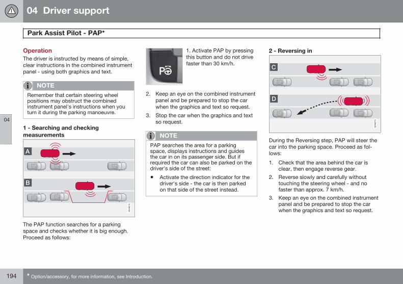
04 Driver support
Park Assist Pilot - PAP*
04
194 * Option/accessory, for more information, see Introduction.
OperationThe driver is instructed by means of simple,clear instructions in the combined instrumentpanel - using both graphics and text.
NOTE
Remember that certain steering wheelpositions may obstruct the combinedinstrument panel's instructions when youturn it during the parking manoeuvre.
1 - Searching and checkingmeasurements
The PAP function searches for a parkingspace and checks whether it is big enough.Proceed as follows:
1. Activate PAP by pressingthis button and do not drivefaster than 30 km/h.
2. Keep an eye on the combined instrumentpanel and be prepared to stop the carwhen the graphics and text so request.
3. Stop the car when the graphics and textso request.
NOTE
PAP searches the area for a parkingspace, displays instructions and guidesthe car in on its passenger side. But ifrequired the car can also be parked on thedriver's side of the street:
• Activate the direction indicator for thedriver's side - the car is then parkedon that side of the street instead.
2 - Reversing in
During the Reversing step, PAP will steer thecar into the parking space. Proceed as fol-lows:
1. Check that the area behind the car isclear, then engage reverse gear.
2. Reverse slowly and carefully withouttouching the steering wheel - and nofaster than approx. 7 km/h.
3. Keep an eye on the combined instrumentpanel and be prepared to stop the carwhen the graphics and text so request.
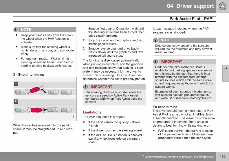
04 Driver support
Park Assist Pilot - PAP*
04
* Option/accessory, for more information, see Introduction. 195
NOTE
• Keep your hands away from the steer-ing wheel when the PAP function isactivated.
• Make sure that the steering wheel isnot hindered in any way and can rotatefreely.
• For optimum results - Wait until thesteering wheel has been turned beforestarting to drive backwards/forwards.
3 - Straightening up
When the car has reversed into the parkingspace, it must be straightened up and stop-ped.
1. Engage first gear or D position, wait untilthe steering wheel has been turned, thendrive slowly forwards.
2. Stop the car when the graphics and textmessage so request.
3. Engage reverse gear and drive back-wards slowly until the graphics and textmessage tell you to stop.
The function is disengaged automaticallywhen parking is complete, and the graphicsand text message show that parking is com-plete. It may be necessary for the driver tocorrect the positioning. Only the driver candetermine whether the car is properly parked.
IMPORTANT
The warning distance is shorter when thesensors are used by Active Park Assistcompared with when Park Assist uses thesensors.
LimitationsThe PAP sequence is stopped:
• if the car is driven too quickly - above7 km/h
• if the driver touches the steering wheel
• if the ABS or DSTC function is enabled -e.g. if a wheel loses grip on a slipperyroad.
A text message indicates where the PAPsequence was stopped.
NOTE
Dirt, ice and snow covering the sensorswill reduce their function and may preventmeasurement.
IMPORTANT
Under certain circumstances, PAP isunable to find parking spaces - one reasonfor this may be the fact that there is inter-ference with the sensors from externalsound sources which emit the same ultra-sound frequencies as those with which thesystem works.
Examples of such sources include horns,wet tyres on asphalt, pneumatic brakesand exhaust noises from motorcycles etc.
To bear in mindThe driver should bear in mind that the ParkAssist Pilot is an aid – not an infallible, fully-automatic function. The driver must thereforebe prepared to intervene. There are alsodetails to bear in mind while parking, e.g.:
• PAP starts out from the current locationof the parked vehicles - if they are inap-propriately parked then the car's tyres
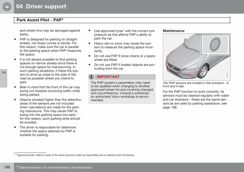
04 Driver support
Park Assist Pilot - PAP*
04
196 * Option/accessory, for more information, see Introduction.
and wheel rims may be damaged againstkerbs.
• PAP is designed for parking on straightstreets, not sharp curves or bends. Forthis reason, make sure the car is parallelto the parking space when PAP measuresthe space.
• It is not always possible to find parkingspaces on narrow streets since there isnot enough space for manoeuvring. Insuch parking situations, it helps the sys-tem to drive as close to the side of theroad as possible where you intend topark.
• Bear in mind that the front of the car mayswing out towards oncoming traffic whilebeing parked.
• Objects situated higher than the detectionareas of the sensors are not includedwhen calculations are made for the park-ing manoeuvre. This may cause PAP toswing into the parking space too early -for this reason, such parking slots shouldbe avoided.
• The driver is responsible for determinewhether the space selected by PAP issuitable for parking.
• Use approved tyres1 with the correct tyrepressure as this affects PAP's ability topark the car.
• Heavy rain or snow may cause the sys-tem to measure the parking space incor-rectly.
• Do not use PAP if snow chains or a sparewheel are fitted.
• Do not use PAP if loaded objects are pro-truding from the car.
IMPORTANT
The PAP system's parameters may needto be updated when changing to anotherapproved wheel rim size involving changedtyre circumference. Consult a workshop -an authorised Volvo workshop is recom-mended.
Maintenance
The PAP sensors are located in the bumpers - 6front and 4 rear.
For the PAP function to work correctly, itssensors must be cleaned regularly with waterand car shampoo - these are the same sen-sors as are used by parking assistance, seepage 188.
1 "Approved tyres" refers to tyres of the same type and make as those fitted new on delivery from the factory.
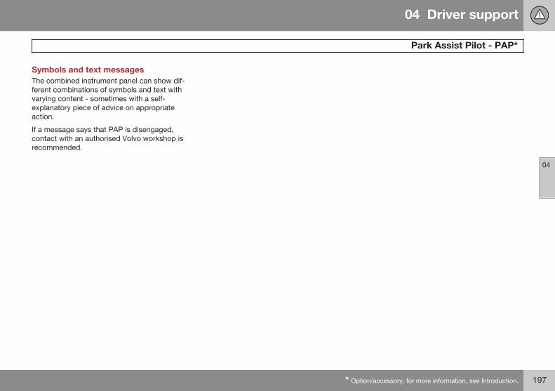
04 Driver support
Park Assist Pilot - PAP*
04
* Option/accessory, for more information, see Introduction. 197
Symbols and text messagesThe combined instrument panel can show dif-ferent combinations of symbols and text withvarying content - sometimes with a self-explanatory piece of advice on appropriateaction.
If a message says that PAP is disengaged,contact with an authorised Volvo workshop isrecommended.
04 Driver support
BLIS and CTA*
04
198 * Option/accessory, for more information, see Introduction.
General information on BLIS and CTAThe BLIS function (Blind Spot InformationSystem) is designed for driving in dense traf-fic on roads with several lanes in the samedirection. BLIS is a driver's aid intended toprovide a warning about:
• vehicles in the car's blind spot
• quickly approaching vehicles in the leftand right lanes closest to the car.
The BLIS function CTA (Cross Traffic Alert) isa driver's aid intended to provide a warningabout:
• crossing traffic when the car is reversed.
WARNING
BLIS and CTA are supplementary aids anddo not work in all situations.
BLIS and CTA are no substitutes for a safedriving style and the use of rearview anddoor mirrors.
BLIS and CTA can never replace the driv-er's responsibility and attention - it isalways the driver's responsibility to reverseand change lanes in a safe manner.
Operation
Position of the BLIS lamp1.
Indicator lamp
BLIS symbol
NOTE
The lamp illuminates on the side of the carwhere the system has detected the vehi-cle. If the car is overtaken on both sides atthe same time then both lamps illuminate.
FunctionBLIS and CTA are activated when the engineis started. This is confirmed by the indicatorlamps in the door panels flashing once.
Activate/deactivate BLIS
Button for activating/deactivating.
The BLIS function can be deactivated/acti-vated by pressing the BLIS button on thecentre console.
Some combinations of the selected equip-ment leave no vacant space for a button inthe centre console - in which case the func-tion is handled by the car's menu system MYCAR2:
1 NOTE: The illustration is schematic - details may vary depending on car model.2 For information on the menu system - see page 207.
04 Driver support
BLIS and CTA*
04
* Option/accessory, for more information, see Introduction. 199
• Select On or Off at Settings Carsettings BLIS.
When BLIS is deactivated/activated the lampin the button goes out/illuminates and thecombined instrument panel confirms thechange with a text message. The door panelindicator lamps flash once upon activation.
To extinguish the message:
• Press the left stalk switch OK button.
or
• Wait approx. 5 seconds – the messageextinguishes.
When BLIS operates
Principle for BLIS: 1. Zone in blind spot. 2. Zonefor quickly approaching vehicle.
The BLIS function is active at speeds aboveapprox. 10 km/h.
The system is designed to react when:
• the vehicle is overtaken by other vehicles
• another vehicle is quickly approachingthe vehicle
When BLIS detects a vehicle in zone 1 or aquickly approaching vehicle in zone 2, thedoor panel BLIS lamp illuminates with a con-stant glow. If the driver activates the directionindicator on the same side as the warning inthis situation then the BLIS lamp will changefrom a constant glow to flashing with a moreintense light.
WARNING
BLIS does not work in sharp bends.
BLIS does not work when the car is beingreversed.
Activate/deactivate CTAIn cars equipped with parking assistance (seepage 186), the CTA function can be deacti-vated/activated with the parking assistanceOn/Off button.
On/Off for parking assistance and CTA sensors.
CTA itself can be deactivated in the MY CAR2
menu system as follows:
• Go to Settings Car settings BLISCross Traffic Alert and deselect. The
CTA function is then deactivated. BLISremains activated.
2 For information on the menu system - see page 207.
04 Driver support
BLIS and CTA*
04
200 * Option/accessory, for more information, see Introduction.
When CTA operates
Principle for CTA.
CTA supplements the BLIS function by beingable to see crossing traffic from the side dur-ing reversing, such as when reversing out of aparking space.
CTA is primarily designed to detect vehicles.In favourable conditions, it may also be ableto detect smaller objects, such as cyclistsand pedestrians.
CTA is only active during reversing and isactivated automatically when reverse isselected at the gearbox.
• If CTA detects something approachingfrom the side, an acoustic warning signalsounds. The signal comes from either theleft or the right speaker depending on
which direction the approaching object iscoming from.
• CTA also warns by illuminating the BLISlamps.
• An additional warning is provided in theform of an illuminated icon in the screen'sPAS graphics, see page 186.
LimitationsCTA does not perform optimally in all situa-tions, but has a certain limitation - for exam-ple, the CTA sensors cannot "see" throughother parked vehicles or obstructing objects.
Here are some examples of when CTA's "fieldof vision" may be limited from the beginningand approaching vehicles cannot therefore bedetected until they are very close:
The car is parked deep inside a parking slot.
Blind CTA sector.
Sector where CTA can detect/"see".
In an angled parking slot CTA can be completely"blind" on one side.
04 Driver support
BLIS and CTA*
04
* Option/accessory, for more information, see Introduction. 201
However, when the driver is slowly reversingthe car, the angle is changed in relation to thevehicle/object that is blocking, at which theblind sector rapidly decreases.
Examples of further limitations:
• Dirt, ice and snow covering sensors canreduce functionality and make it impossi-ble to provide warnings. BLIS and CTAare unable to detect hazards if covered.
• Do not affix any objects, tape or labels inthe area of the sensors.
• BLIS and CTA are deactivated when atrailer is connected to the car’s electricalsystem.
IMPORTANT
Repair of the BLIS and CTA functions'components must only be performed by aworkshop - an authorised Volvo workshopis recommended.
Maintenance
Location of BLIS and CTA sensors.
The BLIS and CTA sensors are located insidethe rear wing/bumper on each side of the car.
• To ensure optimal functionality, the areasin front of the sensors must be keptclean.
MessagesIn situations where the BLIS and CTA func-tions fail or are interrupted, the combinedinstrument panel may show a symbol, sup-plemented by an explanatory message. Fol-low any recommendation given.
Message examples:
Message Specification
CTA OFF CTA has been deactivatedmanually. BLIS is active.
BLIS andCTA OFFTrailerattached
BLIS and CTA are tempo-rarily disabled because atrailer is connected to thecar’s electrical system.
BLIS andCTA Serv-ice required
BLIS and CTA are notworking.
• Visit a workshop if themessage remains - anauthorised Volvo work-shop is recommended.
A text message can be acknowledged bybriefly pressing the OK button on the direc-tion indicator stalk.
202 * Option/accessory, for more information, see Introduction.
Menus and messages........................................................................... 204Menu source MY CAR.......................................................................... 207Climate control...................................................................................... 215Engine and passenger compartment heater*....................................... 226Additional heater*.................................................................................. 230Trip computer........................................................................................ 232Adapting driving characteristics........................................................... 240Comfort inside the passenger compartment........................................ 241
COMFORT AND DRIVING PLEASURE
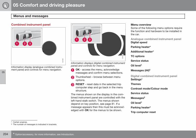
05 Comfort and driving pleasure
Menus and messages
05
204 * Option/accessory, for more information, see Introduction.
Combined instrument panel
Information display (analogue combined instru-ment panel) and controls for menu navigation.
Information displays (digital combined instrumentpanel) and controls for menu navigation.
OK - access the menu, acknowledgemessages and confirm menu selections.
Thumbwheel – browse between menuoptions.
RESET - reset data in the selected tripcomputer step and go back in the menustructure.
The menus shown on the display in the com-bined instrument panel are controlled with theleft-hand stalk switch. The menus showndepend on key position, see page 81. If amessage appears then this must be acknowl-edged with OK for the menus to be shown.
Menu overviewSome of the following menu options requirethe function and hardware to be installed inthe car.
Analogue combined instrument panelDigital speed
Parking heater*
Additional heater*
TC options
Service status
Oil level1
Messages (##)2
Digital combined instrument panelSettings*
Themes
Contrast mode/Colour mode
Service status
Messages2
Oil level1
Parking heater*
Trip computer reset
1 Certain engines.2 The number of messages is indicated in brackets.
05 Comfort and driving pleasure
Menus and messages
05
205
MessageWhen a warning, information or indicatorsymbol illuminates, a corresponding messageappears in the display. An error message isstored in a memory list until the fault hasbeen rectified.
Press OK (see the figure in the section "Com-bined instrument panel" on page 204) in orderto confirm3 a message. Scroll through mes-sages with the thumbwheel.
NOTE
If a warning message appears while youare using the trip computer, the messagemust be read (press OK) before the previ-ous activity can be resumed.
Message Specification
Stop safelyA Stop and switch off theengine. Serious risk ofdamage - consult a work-shopB.
Stop engineA Stop and switch off theengine. Serious risk ofdamage - consult a work-shopB.
Message Specification
ServiceurgentA
Contact a workshopB tocheck the car immedi-ately.
ServicerequiredA
Contact a workshopB tocheck the car as soon aspossible.
See manualA Read the owner's man-ual.
Book timefor mainte-nance
Time to book regularservice - contact a work-shopB.
Time for reg-ular mainte-nance
Time for regular service -contact a workshopB. Thetiming is determined bythe number of kilometresdriven, number of monthssince the last service,engine running time andoil grade.
Maintenanceoverdue
If the service intervals arenot followed then thewarranty does not coverany damaged parts -contact a workshopB.
Message Specification
TransmissionOil changeneeded
Contact a workshopB tocheck the car as soon aspossible.
TransmissionReducedperformance
The gearbox cannot han-dle full capacity. Drivecarefully until the mes-sage clearsC.
If shown repeatedly -contact a workshopB.
Transmissionhot Reducespeed
Drive more smoothly orstop the car in a safemanner. Disengage thegear and run the engineat idling speed until themessage clearsC.
Transmissionhot Stopsafely Waitfor cooling
Critical fault. Stop the carimmediately in a safemanner and contact aworkshopB.
3 A message can also be acknowledged via the thumbwheel or RESET button.
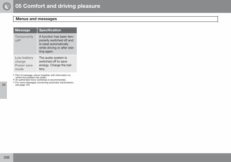
05 Comfort and driving pleasure
Menus and messages
05
206
Message Specification
TemporarilyoffA
A function has been tem-porarily switched off andis reset automaticallywhile driving or after star-ting again.
Low batterychargePower savemode
The audio system isswitched off to saveenergy. Charge the bat-tery.
A Part of message, shown together with information onwhere the problem has arisen.
B An authorised Volvo workshop is recommended.C For more messages concerning automatic transmission,
see page 123.
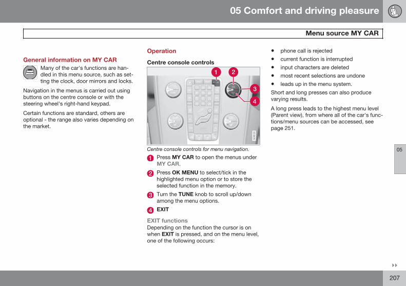
05 Comfort and driving pleasure
Menu source MY CAR
05
}}207
General information on MY CARMany of the car's functions are han-dled in this menu source, such as set-ting the clock, door mirrors and locks.
Navigation in the menus is carried out usingbuttons on the centre console or with thesteering wheel's right-hand keypad.
Certain functions are standard, others areoptional - the range also varies depending onthe market.
Operation
Centre console controls
Centre console controls for menu navigation.
Press MY CAR to open the menus underMY CAR.
Press OK MENU to select/tick in thehighlighted menu option or to store theselected function in the memory.
Turn the TUNE knob to scroll up/downamong the menu options.
EXIT
EXIT functionsDepending on the function the cursor is onwhen EXIT is pressed, and on the menu level,one of the following occurs:
• phone call is rejected
• current function is interrupted
• input characters are deleted
• most recent selections are undone
• leads up in the menu system.
Short and long presses can also producevarying results.
A long press leads to the highest menu level(Parent view), from where all of the car's func-tions/menu sources can be accessed, seepage 251.
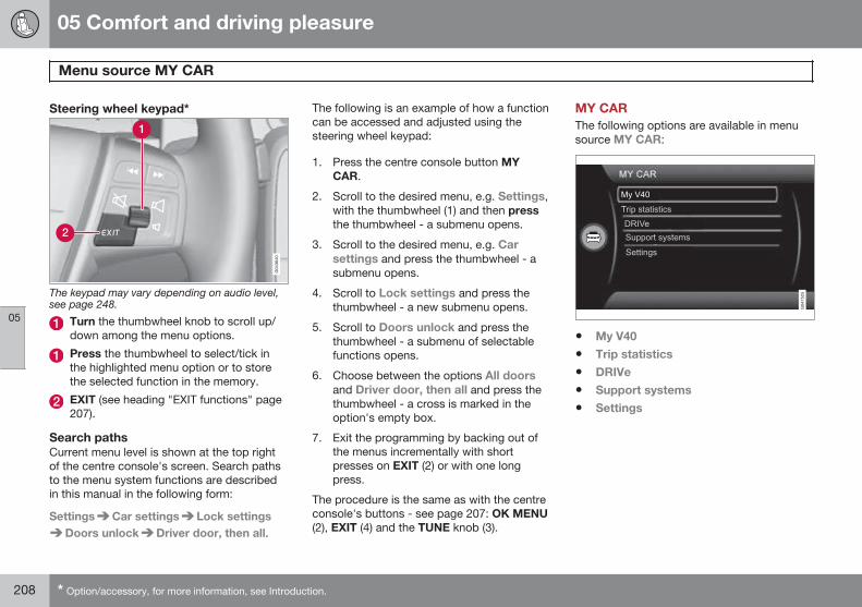
05 Comfort and driving pleasure
Menu source MY CAR
05
208 * Option/accessory, for more information, see Introduction.
Steering wheel keypad*
The keypad may vary depending on audio level,see page 248.
Turn the thumbwheel knob to scroll up/down among the menu options.
Press the thumbwheel to select/tick inthe highlighted menu option or to storethe selected function in the memory.
EXIT (see heading "EXIT functions" page207).
Search pathsCurrent menu level is shown at the top rightof the centre console's screen. Search pathsto the menu system functions are describedin this manual in the following form:
Settings Car settings Lock settingsDoors unlock Driver door, then all.
The following is an example of how a functioncan be accessed and adjusted using thesteering wheel keypad:
1. Press the centre console button MYCAR.
2. Scroll to the desired menu, e.g. Settings,with the thumbwheel (1) and then pressthe thumbwheel - a submenu opens.
3. Scroll to the desired menu, e.g. Carsettings and press the thumbwheel - asubmenu opens.
4. Scroll to Lock settings and press thethumbwheel - a new submenu opens.
5. Scroll to Doors unlock and press thethumbwheel - a submenu of selectablefunctions opens.
6. Choose between the options All doorsand Driver door, then all and press thethumbwheel - a cross is marked in theoption's empty box.
7. Exit the programming by backing out ofthe menus incrementally with shortpresses on EXIT (2) or with one longpress.
The procedure is the same as with the centreconsole's buttons - see page 207: OK MENU(2), EXIT (4) and the TUNE knob (3).
MY CARThe following options are available in menusource MY CAR:
• My V40
• Trip statistics
• DRIVe
• Support systems
• Settings
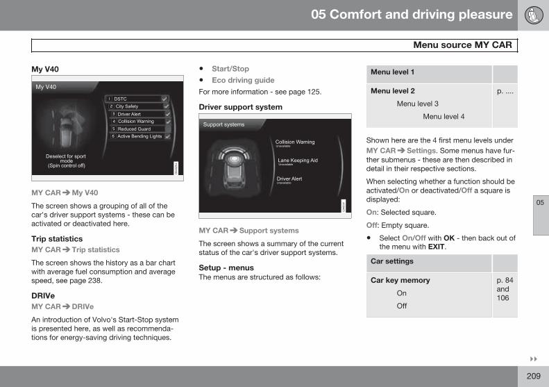
05 Comfort and driving pleasure
Menu source MY CAR
05
}}209
My V40
MY CAR My V40
The screen shows a grouping of all of thecar's driver support systems - these can beactivated or deactivated here.
Trip statisticsMY CAR Trip statistics
The screen shows the history as a bar chartwith average fuel consumption and averagespeed, see page 238.
DRIVeMY CAR DRIVe
An introduction of Volvo's Start-Stop systemis presented here, as well as recommenda-tions for energy-saving driving techniques.
• Start/Stop
• Eco driving guide
For more information - see page 125.
Driver support system
MY CAR Support systems
The screen shows a summary of the currentstatus of the car's driver support systems.
Setup - menusThe menus are structured as follows:
Menu level 1
Menu level 2
Menu level 3
Menu level 4
p. ....
Shown here are the 4 first menu levels underMY CAR Settings. Some menus have fur-ther submenus - these are then described indetail in their respective sections.
When selecting whether a function should beactivated/On or deactivated/Off a square isdisplayed:
On: Selected square.
Off: Empty square.
• Select On/Off with OK - then back out ofthe menu with EXIT.
Car settings
Car key memory
On
Off
p. 84and106
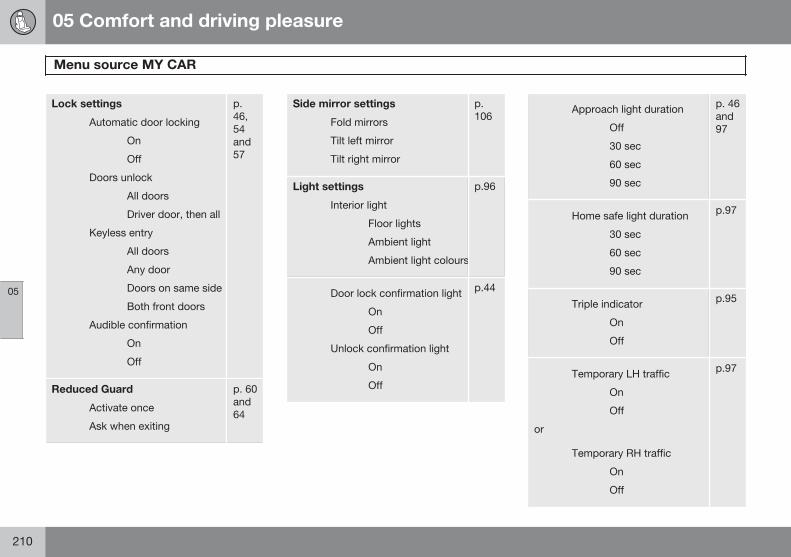
05 Comfort and driving pleasure
Menu source MY CAR
05
210
Lock settings
Automatic door locking
On
Off
Doors unlock
All doors
Driver door, then all
Keyless entry
All doors
Any door
Doors on same side
Both front doors
Audible confirmation
On
Off
p.46,54and57
Reduced Guard
Activate once
Ask when exiting
p. 60and64
Side mirror settings
Fold mirrors
Tilt left mirror
Tilt right mirror
p.106
Light settings
Interior light
Floor lights
Ambient light
Ambient light colours
p.96
Door lock confirmation light
On
Off
Unlock confirmation light
On
Off
p.44
Approach light duration
Off
30 sec
60 sec
90 sec
p. 46and97
Home safe light duration
30 sec
60 sec
90 sec
p.97
Triple indicator
On
Off
p.95
Temporary LH traffic
On
Off
or
Temporary RH traffic
On
Off
p.97
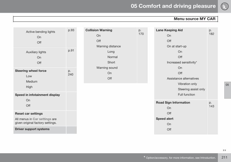
05 Comfort and driving pleasure
Menu source MY CAR
05
}}* Option/accessory, for more information, see Introduction. 211
Active bending lights
On
Off
p.93
Auxiliary lights
On
Off
p.91
Steering wheel force
Low
Medium
High
p.240
Speed in infotainment display
On
Off
Reset car settings
All menus in Car settings aregiven original factory settings.
Driver support systems
Collision Warning
On
Off
Warning distance
Long
Normal
Short
Warning sound
On
Off
p.170
Lane Keeping Aid
On
Off
On at start-up
On
Off
Increased sensitivity*
On
Off
Assistance alternatives
Vibration only
Steering assist only
Full function
p.182
Road Sign Information
On
Off
Speed alert
On
Off
p.143
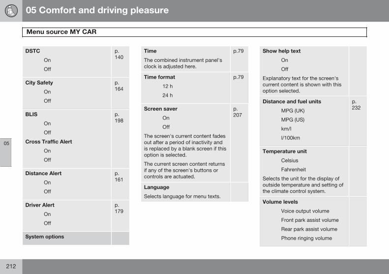
05 Comfort and driving pleasure
Menu source MY CAR
05
212
DSTC
On
Off
p.140
City Safety
On
Off
p.164
BLIS
On
Off
Cross Traffic Alert
On
Off
p.198
Distance Alert
On
Off
p.161
Driver Alert
On
Off
p.179
System options
Time
The combined instrument panel'sclock is adjusted here.
p.79
Time format
12 h
24 h
p.79
Screen saver
On
Off
The screen's current content fadesout after a period of inactivity andis replaced by a blank screen if thisoption is selected.
The current screen content returnsif any of the screen's buttons orcontrols are actuated.
p.207
Language
Selects language for menu texts.
Show help text
On
Off
Explanatory text for the screen'scurrent content is shown with thisoption selected.
Distance and fuel units
MPG (UK)
MPG (US)
km/l
l/100km
p.232
Temperature unit
Celsius
Fahrenheit
Selects the unit for the display ofoutside temperature and setting ofthe climate control system.
Volume levels
Voice output volume
Front park assist volume
Rear park assist volume
Phone ringing volume
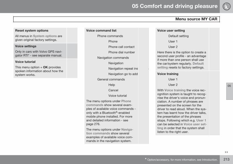
05 Comfort and driving pleasure
Menu source MY CAR
05
}}* Option/accessory, for more information, see Introduction. 213
Reset system options
All menus in System options aregiven original factory settings.
Voice settings
Only in cars with Volvo GPS navi-gator RTI* - see separate manual.
Voice tutorial
This menu option + OK providesspoken information about how thesystem works.
Voice command list
Phone commands
Phone
Phone call contact
Phone dial number
Navigation commands
Navigation
Navigation repeat instruction
Navigation go to address
General commands
Help
Cancel
Voice tutorial
The menu options under Phonecommands show several exam-ples of available voice commands -only with a Bluetooth®-enabledmobile phone installed. For moreand detailed information - seepage 276.
The menu options under Naviga-tion commands show severalexamples of available voice com-mands in the navigation system.
Voice user setting
Default setting
User 1
User 2
Here there is the option to create asecond user profile - an advantageif more than one person shall usethe car/system regularly. Defaultsetting resets to factory settings.
Voice training
User 1
User 2
With Voice training the voice rec-ognition system is taught to recog-nise the driver's voice and pronun-ciation. A number of phrases arepresented on the screen for thedriver to read aloud. When the sys-tem has learnt how the driver talks,the presentation of the phrasesstops. Following which e.g. User 1can be selected in Voice user set-ting in order that the system shalllisten to the right user.
05 Comfort and driving pleasure
Menu source MY CAR
05
214 * Option/accessory, for more information, see Introduction.
Voice output volume
A volume control appears on thescreen - at which point, proceed asfollows:
1. Adjust the volume with thethumbwheel.
2. Test-listen using OK.
3. Use EXIT to store the settingand the menu is switched off.
Voice POI list
Edit list
The number of facilities is exten-sive and varies depending on mar-ket. Maximum 30 favourite facilitiescan be stored in this list.
For more information on Facilitiesand Voice recognition - see theNavigation system's owner's man-ual.
Audio settings p.248
Climate settings
Automatic blower adjustment
Normal
High
Low
Recirculation timer
On
Off
Automatic rear defroster
On
Off
Interior air quality system
On
Off
Reset climate settings
All menus in Climate settings aregiven original factory settings.
p.220
Favourites (FAV) p.252
Volvo On Call
Described in a separate manual.
Information
Number of keys p.44
VIN number p.376
DivX® VOD code p.269
Bluetooth softwareversion in car
p.275
Map and software version*
Only in cars with Volvo GPS navi-gator - see separate manual.
05 Comfort and driving pleasure
Climate control
05
215
General
Climate controlThe car is equipped with electronic climatecontrol. The climate control system cools orheats as well as dehumidifies the air in thepassenger compartment.
NOTE
The air conditioning system (AC) can beswitched off, but to ensure the best possi-ble climate comfort in the passenger com-partment and to prevent the windows frommisting, it should always be on.
Actual temperatureThe temperature you select corresponds tothe physical experience with reference to fac-tors such as air speed, humidity and solarradiation etc. in and around the car.
The system includes a sun sensor whichdetects on which side the sun is shining intothe passenger compartment. This means1
that the temperature can differ between theright and left-hand air vents despite the con-trols being set for the same temperature onboth sides.
Sensor location• The sun sensor is located on the top side
of the dashboard.
• The temperature sensor for the passen-ger compartment is located below the cli-mate control panel.
• The outside temperature sensor islocated in the door mirror.
NOTE
Do not cover or block the sensors withclothing or other objects.
Side windowsTo ensure that the air conditioning worksoptimally, the side windows must be closed.
Misting windowsRemove misting on the insides of the win-dows by primarily using the defroster func-tion.
To reduce the risk of misting, keep the win-dows clean and use window cleaner.
Temporary shut-off of the airconditioningWhen the engine requires full power, e.g. forfull acceleration or driving uphill with a trailer,the air conditioning can be temporarily
switched off. There may then be a temporaryincrease in temperature in the passengercompartment.
CondensationIn warm weather, condensation from the airconditioning may drip under the car. This isnormal.
Ice and snowRemove ice and snow from the climate con-trol system air intake (the grille between thebonnet and the windscreen).
Total airing functionThe function opens/closes all side windowssimultaneously and can be used for exampleto quickly air the car during hot weather, seepage 57.
Passenger compartment filterAll air entering the car's passenger compart-ment is cleaned with a filter. This must bereplaced at regular intervals. Follow the VolvoService Programme for the recommendedreplacement intervals. If the car is used in aseverely contaminated environment, it maybe necessary to replace the filter more often.
1 Only applies to ECC.
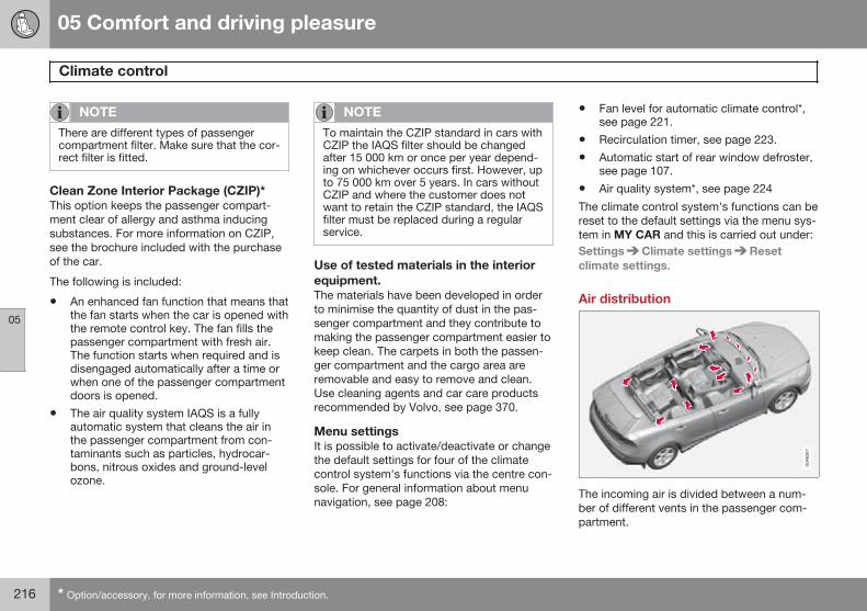
05 Comfort and driving pleasure
Climate control
05
216 * Option/accessory, for more information, see Introduction.
NOTE
There are different types of passengercompartment filter. Make sure that the cor-rect filter is fitted.
Clean Zone Interior Package (CZIP)*This option keeps the passenger compart-ment clear of allergy and asthma inducingsubstances. For more information on CZIP,see the brochure included with the purchaseof the car.
The following is included:
• An enhanced fan function that means thatthe fan starts when the car is opened withthe remote control key. The fan fills thepassenger compartment with fresh air.The function starts when required and isdisengaged automatically after a time orwhen one of the passenger compartmentdoors is opened.
• The air quality system IAQS is a fullyautomatic system that cleans the air inthe passenger compartment from con-taminants such as particles, hydrocar-bons, nitrous oxides and ground-levelozone.
NOTE
To maintain the CZIP standard in cars withCZIP the IAQS filter should be changedafter 15 000 km or once per year depend-ing on whichever occurs first. However, upto 75 000 km over 5 years. In cars withoutCZIP and where the customer does notwant to retain the CZIP standard, the IAQSfilter must be replaced during a regularservice.
Use of tested materials in the interiorequipment.The materials have been developed in orderto minimise the quantity of dust in the pas-senger compartment and they contribute tomaking the passenger compartment easier tokeep clean. The carpets in both the passen-ger compartment and the cargo area areremovable and easy to remove and clean.Use cleaning agents and car care productsrecommended by Volvo, see page 370.
Menu settingsIt is possible to activate/deactivate or changethe default settings for four of the climatecontrol system's functions via the centre con-sole. For general information about menunavigation, see page 208:
• Fan level for automatic climate control*,see page 221.
• Recirculation timer, see page 223.
• Automatic start of rear window defroster,see page 107.
• Air quality system*, see page 224
The climate control system's functions can bereset to the default settings via the menu sys-tem in MY CAR and this is carried out under:Settings Climate settings Resetclimate settings.
Air distribution
The incoming air is divided between a num-ber of different vents in the passenger com-partment.
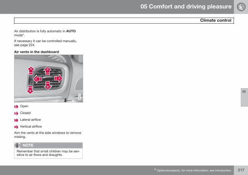
05 Comfort and driving pleasure
Climate control
05
* Option/accessory, for more information, see Introduction. 217
Air distribution is fully automatic in AUTOmode*.
If necessary it can be controlled manually,see page 224.
Air vents in the dashboard
Open
Closed
Lateral airflow
Vertical airflow
Aim the vents at the side windows to removemisting.
NOTE
Remember that small children may be sen-sitive to air flows and draughts.
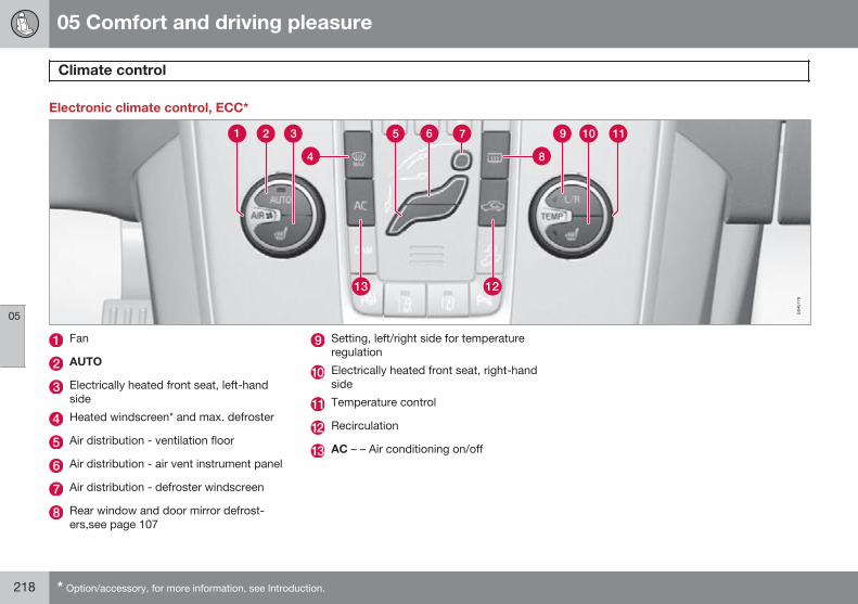
05 Comfort and driving pleasure
Climate control
05
218 * Option/accessory, for more information, see Introduction.
Electronic climate control, ECC*
Fan
AUTO
Electrically heated front seat, left-handside
Heated windscreen* and max. defroster
Air distribution - ventilation floor
Air distribution - air vent instrument panel
Air distribution - defroster windscreen
Rear window and door mirror defrost-ers,see page 107
Setting, left/right side for temperatureregulation
Electrically heated front seat, right-handside
Temperature control
Recirculation
AC – – Air conditioning on/off
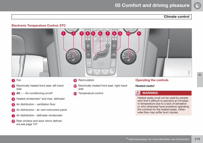
05 Comfort and driving pleasure
Climate control
05
* Option/accessory, for more information, see Introduction. 219
Electronic Temperature Control, ETC
Fan
Electrically heated front seat, left-handside
AC – – Air conditioning on/off
Heated windscreen* and max. defroster
Air distribution - ventilation floor
Air distribution - air vent instrument panel
Air distribution - defroster windscreen
Rear window and door mirror defrost-ers,see page 107
Recirculation
Electrically heated front seat, right-handside
Temperature control
Operating the controls
Heated seats*
WARNING
Heated seats must not be used by peoplewho find it difficult to perceive an increasein temperature due to a lack of sensationor who otherwise have problems operatingthe controls for the heated seats. Other-wise they may suffer burn injuries.
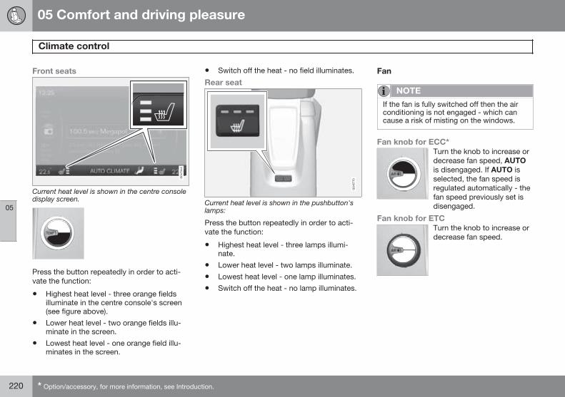
05 Comfort and driving pleasure
Climate control
05
220 * Option/accessory, for more information, see Introduction.
Front seats
Current heat level is shown in the centre consoledisplay screen.
Press the button repeatedly in order to acti-vate the function:
• Highest heat level - three orange fieldsilluminate in the centre console's screen(see figure above).
• Lower heat level - two orange fields illu-minate in the screen.
• Lowest heat level - one orange field illu-minates in the screen.
• Switch off the heat - no field illuminates.
Rear seat
Current heat level is shown in the pushbutton'slamps:
Press the button repeatedly in order to acti-vate the function:
• Highest heat level - three lamps illumi-nate.
• Lower heat level - two lamps illuminate.
• Lowest heat level - one lamp illuminates.
• Switch off the heat - no lamp illuminates.
Fan
NOTE
If the fan is fully switched off then the airconditioning is not engaged - which cancause a risk of misting on the windows.
Fan knob for ECC*Turn the knob to increase ordecrease fan speed, AUTOis disengaged. If AUTO isselected, the fan speed isregulated automatically - thefan speed previously set isdisengaged.
Fan knob for ETCTurn the knob to increase ordecrease fan speed.
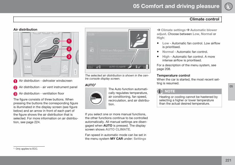
05 Comfort and driving pleasure
Climate control
05
221
Air distribution
Air distribution - defroster windscreen
Air distribution - air vent instrument panel
Air distribution - ventilation floor
The figure consists of three buttons. Whenpressing the buttons the corresponding figureis illuminated in the display screen (see figurebelow) and an arrow in front of each part ofthe figure shows the air distribution that isselected. For more information on air distribu-tion, see page 224.
The selected air distribution is shown in the cen-tre console display screen.
AUTO1
The Auto function automati-cally regulates temperature,air conditioning, fan speed,recirculation, and air distribu-tion.
If you select one or more manual functions,the other functions continue to be controlledautomatically. All manual settings are disen-gaged when AUTO is pressed. The displayscreen shows AUTO CLIMATE.
Fan speed in automatic mode can be set inthe menu system MY CAR under: Settings
Climate settings Automatic bloweradjust. Choose between Low, Normal orHigh:
• Low - Automatic fan control. Low airflowis prioritised.
• Normal - Automatic fan control.
• High - Automatic fan control. A moreintense airflow is prioritised.
For a description of the menu system, seepage 208.
Temperature controlWhen the car is started, the most recent set-ting is resumed.
NOTE
Heating or cooling cannot be hastened byselecting a higher or lower temperaturethan the actual desired temperature.
1 Only applies to ECC.
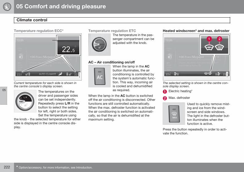
05 Comfort and driving pleasure
Climate control
05
222 * Option/accessory, for more information, see Introduction.
Temperature regulation ECC*
Current temperature for each side is shown inthe centre console's display screen.
The temperatures on thedriver and passenger sidescan be set independently.Repeatedly press L/R in thebutton to select the settingfor left, right or both sides.Set the temperature using
the knob - the selected temperature for eitherside is displayed in the centre console dis-play.
Temperature regulation ETCThe temperature in the pas-senger compartment can beadjusted with the knob.
AC – Air conditioning on/offWhen the lamp in the ACbutton illuminates, the airconditioning is controlled bythe system's automatic func-tion. This way, incoming airis cooled and dehumidifiedas required.
When the lamp in the AC button is switchedoff the air conditioning is disconnected. Otherfunctions are still controlled automatically.When the max. defroster function is activatedthe air conditioning is switched on automati-cally, so that the air is dehumidified at themaximum setting.
Heated windscreen* and max. defroster
The selected setting is shown in the centre con-sole display screen.
Electric heating*
Max. defroster
Used to quickly remove mist-ing and ice from the wind-screen and side windows.The light in the defroster but-ton illuminates when thefunction is active.
Press the button repeatedly in order to acti-vate the function.
05 Comfort and driving pleasure
Climate control
05
223
For cars without heated windscreens:
• Air flows to the windows - symbol (2) illu-minates in the screen.
• Switch off the function - no symbol illumi-nates.
For cars with heated windscreens:
• Start the heating for the windscreen2 -symbol (1) illuminates in the screen.
• Start the heating for the windscreen2 andair flow to the windows - symbols (1) and(2) illuminate in the screen.
• Switch off the function - no symbol illumi-nates.
NOTE
Electrically heated windscreen and IR win-dow, see page 104, can have an impact onthe performance of transponders andother communication equipment.
NOTE
A triangular area at the end of each side ofthe windscreen is not electrically heated,where de-icing may take longer.
NOTE
Electrically heated windscreen is not avail-able when the engine is auto-stopped, seepage 125.
The following also takes place when the func-tion is active in order to provide maximumdehumidification in the passenger compart-ment:
• the air conditioning is automaticallyengaged
• recirculation and the air quality systemare automatically disengaged.
NOTE
The noise level increases as the fan isoperating at max.
When the defroster is switched off the climatecontrol returns to the previous settings.
RecirculationWhen recirculation isengaged the orange lamp inthe button illuminates. Thefunction is selected to shutout bad air, exhaust gasesetc. from the passengercompartment. The air in the
passenger compartment is recirculated, i.e.no outside air is taken into the car when thisfunction is activated.
IMPORTANT
If the air in the car recirculates for too long,there is a risk of misting on the insides ofthe windows.
TimerWith the timer function activated the systemwill exit manually activated recirculation modeaccording to a time that depends on the out-side temperature. This reduces the risk of ice,misting and bad air. Activate/deactivate thefunction in the menu system MY CAR underSettings Climate settingsRecirculation timer. For a description of themenu system, see page 208.
2 The compass goes off when the heated windscreen is active.
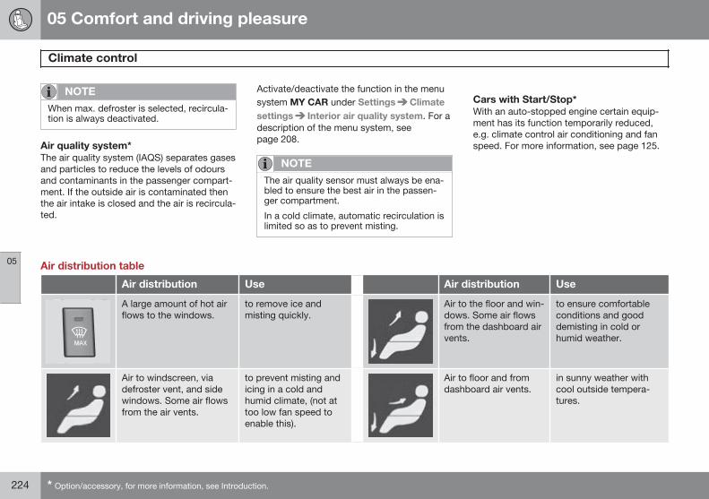
05 Comfort and driving pleasure
Climate control
05
224 * Option/accessory, for more information, see Introduction.
NOTE
When max. defroster is selected, recircula-tion is always deactivated.
Air quality system*The air quality system (IAQS) separates gasesand particles to reduce the levels of odoursand contaminants in the passenger compart-ment. If the outside air is contaminated thenthe air intake is closed and the air is recircula-ted.
Activate/deactivate the function in the menusystem MY CAR under Settings Climatesettings Interior air quality system. For adescription of the menu system, seepage 208.
NOTE
The air quality sensor must always be ena-bled to ensure the best air in the passen-ger compartment.
In a cold climate, automatic recirculation islimited so as to prevent misting.
Cars with Start/Stop*With an auto-stopped engine certain equip-ment has its function temporarily reduced,e.g. climate control air conditioning and fanspeed. For more information, see page 125.
Air distribution table
Air distribution Use Air distribution Use
A large amount of hot airflows to the windows.
to remove ice andmisting quickly.
Air to the floor and win-dows. Some air flowsfrom the dashboard airvents.
to ensure comfortableconditions and gooddemisting in cold orhumid weather.
Air to windscreen, viadefroster vent, and sidewindows. Some air flowsfrom the air vents.
to prevent misting andicing in a cold andhumid climate, (not attoo low fan speed toenable this).
Air to floor and fromdashboard air vents.
in sunny weather withcool outside tempera-tures.
05 Comfort and driving pleasure
Climate control
05
225
Air distribution Use Air distribution Use
Airflow to windows andfrom dashboard air vents.
to ensure good comfortin warm, dry weather.
Air to floor. Some airflows to the dashboardair vents and windows.
to direct heat or cold tothe floor.
Airflow to the head andchest from the dashboardair vents.
to ensure efficient cool-ing in warm weather.
Airflow to windows,from dashboard airvents and to the floor.
to provide cooler airalong the floor or warmerair higher up in coldweather or hot, dryweather.
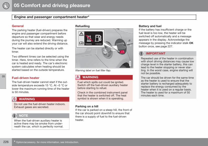
05 Comfort and driving pleasure
Engine and passenger compartment heater*
05
226 * Option/accessory, for more information, see Introduction.
GeneralThe parking heater (fuel-driven) prepares theengine and passenger compartment beforedeparture so that wear and energy needsduring the journey are reduced. Warming upyour car will also extend the driving distance.
The heater can be started directly or withtimer.
Two different times can be selected using thetimer. Here, time refers to the time when thecar is heated and ready. The car's electronicsystem calculates when heating should bestarted based on the outside temperature.
Fuel-driven heaterThe fuel-driven heater cannot start if the out-side temperature exceeds 15 °C. At –5 °C orlower the maximum running time of the heateris 50 minutes.
WARNING
Do not use the fuel-driven heater indoors.Exhaust gases are secreted.
NOTE
When the fuel-driven auxiliary heater isactive there may be smoke from under-neath the car, which is perfectly normal.
Refuelling
Warning label on fuel filler flap.
WARNING
Fuel which spills out could be ignited.Switch off the fuel-driven auxiliary heaterbefore starting to refuel.
Check in the combined instrument panelthat the heater is switched off. The heatsymbol is shown when it is operating.
Parking on a hillIf the car is parked on a steep hill, the front ofthe car should point downhill to ensure thatthere is a supply of fuel to the fuel-drivenheater.
Battery and fuelIf the battery has insufficient charge or thefuel level is too low, the heater will beswitched off automatically and a messageappears in the display. Acknowledge themessage by pressing the indicator stalk OKbutton once, see page 227.
IMPORTANT
Repeated use of the heater in combinationwith short driving distances may cause lowcharge level in the starter battery, this canlead to the heater stopping or never star-ting. In the worst case, engine starting willnot be possible.
The car should be driven for the same timeas the heater is used to ensure that thestarter battery is recharged adequately toreplace the energy consumed by theheater when it is used on a regular basis.The heater is used for a maximum of 50minutes each time.
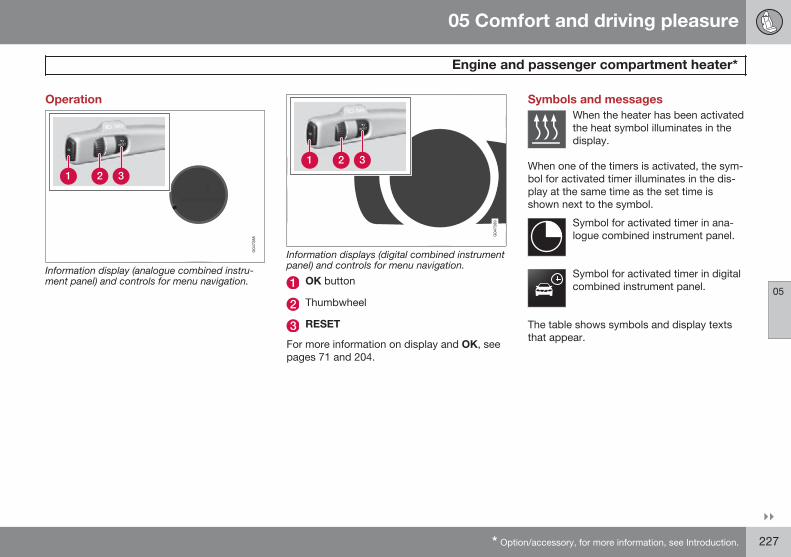
05 Comfort and driving pleasure
Engine and passenger compartment heater*
05
}}* Option/accessory, for more information, see Introduction. 227
Operation
Information display (analogue combined instru-ment panel) and controls for menu navigation.
Information displays (digital combined instrumentpanel) and controls for menu navigation.
OK button
Thumbwheel
RESET
For more information on display and OK, seepages 71 and 204.
Symbols and messagesWhen the heater has been activatedthe heat symbol illuminates in thedisplay.
When one of the timers is activated, the sym-bol for activated timer illuminates in the dis-play at the same time as the set time isshown next to the symbol.
Symbol for activated timer in ana-logue combined instrument panel.
Symbol for activated timer in digitalcombined instrument panel.
The table shows symbols and display textsthat appear.
05 Comfort and driving pleasure
Engine and passenger compartment heater*
05
228 * Option/accessory, for more information, see Introduction.
Symbol Display Specification
The heater is switched on and running.
The heater's timer is activated after the remote control key has been removed from the ignition switchand leaving the car - the engine and passenger compartment are heated at the set time.
Fuel operated heaterstopped Battery savingmode
The heater has been stopped by the car's electronics in order to facilitate starting the engine.
Fuel operated heaterstopped Low fuel level
Setting the heater is not possible due to fuel level being too low - this is in order to facilitate startingthe engine as well as approx. 50 km driving.
Fuel operated heaterService required
Heater not working. Contact a workshop for repair. Volvo recommends that you contact an author-ised Volvo workshop.
A display text clears automatically after a timeor after one press on the indicator stalk OKbutton.
Direct start and immediate stopFollowing the direct start of the heater it willbe activated for 50 minutes.
Heating of the passenger compartment willbegin as soon as the engine coolant hasreached the correct temperature.
NOTE
The car can be started and driven whilethe heater is running.
1. Press OK to access the menu.
2. Scroll with the thumbwheel to Parkingheater and select with OK.
05 Comfort and driving pleasure
Engine and passenger compartment heater*
05
* Option/accessory, for more information, see Introduction. 229
3. Scroll forward in the next menu to Directstart/Stop in order to activate/deactivatethe heater and select with OK.
4. Exit the menu with RESET.
TimerThe time when the car shall be used andheated is specified with the timer.
Setting the timer1. Press OK to access the menu.
2. Scroll with the thumbwheel to Parkingheater and select with OK.
3. Select one of the two timers using thethumbwheel and confirm with OK.
4. Briefly press OK to move to the lit hourssetting.
5. Select the required hour using the thumb-wheel.
6. Briefly press OK to move to the litminutes setting.
7. Select the required minute using thethumbwheel.
8. Press OK1 to confirm the setting.
9. Go back in the menu structure usingRESET.
10. Select the other time (continue from step2) or exit the menu with RESET.
Start the timer1. Press OK to access the menu.
2. Scroll with the thumbwheel to Parkingheater and select with OK.
3. Select one of the two timers using thethumbwheel and activate with OK.
4. Exit the menu with RESET.
Deactivating the timerA timer-started heater can be switched offmanually before the set time has elapsed.Proceed as follows:
1. Press OK to access the menu.
2. Scroll with the thumbwheel to Parkingheater and select with OK.> If a timer is set but not activated, a
clock icon is shown next to the settime.
3. Select one of the two timers using thethumbwheel and confirm with OK.
4. Deactivate the timer as follows:
• long press on OK or
• short press on OK to continue in themenu. Then select to stop the timerand confirm with OK.
5. Exit the menu with RESET.
A timer-started heater can be switched off asdescribed in the instructions in the section"Direct start and immediate stop"; see page228.
Clock/timerThe heater's time is connected to the car'sclock.
NOTE
All timer programming will be cleared if thecar's clock is reset.
1 Press OK again to activate the timer.
05 Comfort and driving pleasure
Additional heater*
05
230 * Option/accessory, for more information, see Introduction.
General information about theadditional heaterFor cars with diesel engines sold in cold cli-mate zones1 an additional heater may berequired to obtain the correct operating tem-perature in the engine and to obtain sufficientheating in the passenger compartment.
In such instances, the car is equipped witheither:
• an additional electric heater or
• a fuel-driven additional heater2.
Electric additional heaterThe heater cannot be controlled manually butis instead activated automatically after theengine has been started in outside tempera-tures below 9 °C and is switched off after theset passenger compartment temperature hasbeen reached.
Fuel-driven additional heaterThe heater starts automatically when extraheat is required when the engine is running.
The heater is switched off automatically whenthe correct temperature is reached or whenthe engine is switched off.
NOTE
When the auxiliary heater is active theremay be smoke from underneath the car,which is perfectly normal.
Auto mode or shutdownThe additional heater's automatic startsequence can be switched off if required.
Information display (analogue combined instru-ment panel) and controls for menu navigation.
1 An authorised Volvo dealer has information regarding the geographical areas concerned.2 For cars fitted with parking heaters, see page 226.
05 Comfort and driving pleasure
Additional heater*
05
* Option/accessory, for more information, see Introduction. 231
Information displays (digital combined instrumentpanel) and controls for menu navigation.
OK button
Thumbwheel
RESET button
1. Before starting the engine: Select keyposition I, see page 82.
2. Press OK to access the menu.
3. Scroll with the thumbwheel to Additionalheater3 or Settings4 and select with OK.
4. Select one of the options ON or OFFusing the thumbwheel and confirm withOK.
5. Exit the menu with RESET.
NOTE
The menu options are only visible in keyposition I - any adjustments must thereforebe made before starting the engine.
3 Analogue combined instrument panel.4 Digital combined instrument panel.
05 Comfort and driving pleasure
Trip computer
05
232
GeneralChecking and settings can be made immedi-ately after the combined instrument panel isautomatically illuminated in connection withunlocking. If none of the trip computer's con-trols are actuated within approx. 30 secondsafter the driver's door has been opened thenthe instrument extinguishes, after whicheither key position II1 or engine starting isrequired in order to operate the trip com-puter.
NOTE
If a warning message appears when thetrip computer is used then the messagemust first be acknowledged before the tripcomputer can be reactivated.
• Acknowledge the message by brieflypressing the indicator stalk OK button.
Group menusThe trip computer has two different groupmenus:
• Functions
• Heading in combined instrument panel
The trip computer's functions or headingsare each listed in an infinite loop.
Combined instrument panel "Analog"
Information display and controls.
OK - Opens the loop with the trip com-puter's functions + Activates the selectedoption.
Thumbwheel - Opens the loop with thetrip computer's headings + Scrollsthrough the options.
RESET - Undoes, zeroes or backs out ofa function after making a selection.
FunctionsProceed as follows to open and check/adjustfunctions:
1. To ensure that no control is in the middleof a sequence - "Reset" them first with2 presses on RESET.
2. Press OK - the loop with all functionsopens.
3. Browse through the functions with thethumbwheel and select/confirm with OK.
4. Finish by pressing RESET twice aftercompleted checking/ adjustment.
The different functions of the trip computerare listed in the following table:
1 For information on key positions - see page 81.
05 Comfort and driving pleasure
Trip computer
05
}}* Option/accessory, for more information, see Introduction. 233
Functions Information
Digital speed
- km/h
- mph
- No display
Shows the car's speed digitally in the centre of the combined instrument panel:
• Open with OK, select with the thumbwheel, confirm with OK and back out with ENTER.
Parking heater*
- Direct start
- Timer 1 - leads to the menu for selecting time.
- Timer 2 - leads to the menu for selecting time.
For a description of programming the timer, see page 226.
Additional heater*
– Auto On
– Off
For more information, see page 230.
TC options
- Distance to empty tank
- Fuel consumption
Average speed
Trip meter T1 and total dist.
Trip meter T2 and total dist.
Here you can select/activate the options that you want to be available as selectable headingsin the trip computer. The symbols for the items already selected are WHITE with a "tick" - oth-ers are GREY and have no "tick":
1. Open the function with OK, scroll through the symbols for the options with the thumb-wheel and select/stop on the desired symbol.
2. Confirm with OK - the symbol changes colour from GREY to WHITE and is marked with a"tick".
3. Continue to select the function symbols with the thumbwheel or finish with RESET.
Service status Shows the number of months and the distance until the next service.
05 Comfort and driving pleasure
Trip computer
05
234
Functions Information
Oil levelA For more information, see page 341.
Messages (##) For more information, see page 205.
A Certain engines.
HeadingsOne of the headings in the following table canbe selected for constant display in the com-bined instrument panel. Proceed as follows todetermine which:
1. To ensure that no control is in the middleof a sequence - "Reset" them first with2 presses on RESET.
2. Turn the thumbwheel - selectable head-ings for the trip computer are shown in aloop.
3. Stop on desired heading.
Trip computer heading in combined instrumentpanel
Information
Trip meter T1 and total dist. • Long press on RESET resets trip meter T1.
Trip meter T2 and total dist. • Long press on RESET resets trip meter T2.
Distance to empty For more information - see page 238, "Distance to empty tank".
Fuel consumption Current consumption.
Average speed • Long press on RESET resets Average speed.
No trip computer information. This option shows a blank display - it also marks the beginning/end of the loop.
The combined instrument panel's trip com-puter can be changed to another option at
any time during the journey. Proceed as fol-lows:
• Turn the thumbwheel - stop on thedesired heading.
05 Comfort and driving pleasure
Trip computer
05
}}235
Combined instrument panel "Digital"
Information displays and controls.
OK - Opens the loop with the trip com-puter's functions + Activates the selectedoption.
Thumbwheel - Opens the loop with thetrip computer's headings + Scrollsthrough the options.
RESET - Undoes, zeroes or backs out ofa function after making a selection.
FunctionsProceed as follows to open and check/adjustfunctions:
1. To ensure that no control is in the middleof a sequence - "Reset" them first with2 presses on RESET.
2. Press OK - loop with all functions opens.
3. Browse through the functions with thethumbwheel and select/confirm with OK.
4. Finish by pressing RESET twice aftercompleted checking/ adjustment.
The different functions of the trip computerare listed in the following table:
05 Comfort and driving pleasure
Trip computer
05
236 * Option/accessory, for more information, see Introduction.
Functions Information
Trip computer reset
Average
Average speed
Note that this function does not reset both trip meters T1 and T2 - see the table in the sec-tion "Headings" page 237 or the heading "Resetting with Digital" page 238 for informationon the process.
Messages For more information, see page 205.
Themes Combined instrument panel appearance is selected here, see page 72.
Settings* Select Auto On or Off.
For more information, see page 230.
Contrast mode/Colour mode Adjusting the combined instrument panel's brightness and colour intensity.
Parking heater*
– Direct start
- Symbol Timer 1 - leads to the menu for selectingtime.
- Symbol Timer 2 - leads to the menu for selectingtime.
For a description of programming the timer, see page 226.
Service status Shows the number of months and the distance until the next service.
Oil levelA For more information, see page 341.
A Certain engines.
05 Comfort and driving pleasure
Trip computer
05
* Option/accessory, for more information, see Introduction. 237
HeadingsThree trip computer headings can be dis-played simultaneously - one in each "win-dow" (see previous figure).
One of the heading combinations in the fol-lowing table can be selected for constant dis-
play in the combined instrument panel. Pro-ceed as follows to determine which:
1. To ensure that no control is in the middleof a sequence - "Reset" them first with2 presses on RESET.
2. Turn the thumbwheel - selectable head-ing combinations are shown in a loop.
3. Stop on desired heading combination.
Heading combinations Information
Average Trip meter T1 + Meter reading Average speed • Long press on RESET resets trip meter T1.
Instantaneous Trip meter T2 + Meter reading Distance to emptytank
• Long press on RESET resets trip meter T2.
Instantaneous Meter reading kmh<>mph kmh<>mph - see "Digital speed display" page 238.
No trip computer information. This option extinguishes all three trip computer displays - it also marksthe beginning/end of the loop.
The combined instrument panel's headingcombination for the trip computer can bechanged to another option at any time duringthe journey. Proceed as follows:
• Turn the thumbwheel - stop on thedesired heading.
Supplementary information
AverageAverage fuel consumption is calculated fromthe last resetting.
NOTE
There may be a slight error in the reading ifa fuel-driven heater* has been used.
Average speedThe average speed is calculated for the driv-ing distance driven since the last reset tozero.
InstantaneousThe information for current fuel consumptionis updated continuously - approximately onceper second. When the car is driven at lowspeed the consumption is shown per timeunit - at a higher speed it is shown related tomileage.
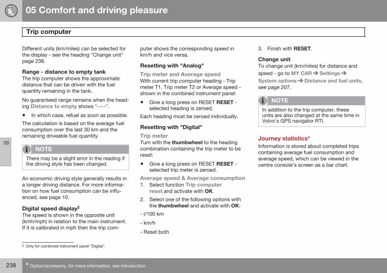
05 Comfort and driving pleasure
Trip computer
05
238 * Option/accessory, for more information, see Introduction.
Different units (km/miles) can be selected forthe display - see the heading "Change unit"page 238.
Range - distance to empty tankThe trip computer shows the approximatedistance that can be driven with the fuelquantity remaining in the tank.
No guaranteed range remains when the head-ing Distance to empty shows "----".
• In which case, refuel as soon as possible.
The calculation is based on the average fuelconsumption over the last 30 km and theremaining driveable fuel quantity.
NOTE
There may be a slight error in the reading ifthe driving style has been changed.
An economic driving style generally results ina longer driving distance. For more informa-tion on how fuel consumption can be influ-enced, see page 10.
Digital speed display2
The speed is shown in the opposite unit(kmh/mph) in relation to the main instrument.If it is calibrated in mph then the trip com-
puter shows the corresponding speed inkm/h and vice versa.
Resetting with "Analog"
Trip meter and Average speedWith current trip computer heading - Tripmeter T1, Trip meter T2 or Average speed -shown in the combined instrument panel:
• Give a long press on RESET RESET -selected heading is zeroed.
Each heading must be zeroed individually.
Resetting with "Digital"
Trip meterTurn with the thumbwheel to the headingcombination containing the trip meter to bereset:
• Give a long press on RESET RESET -selected trip meter is zeroed.
Average speed & Average consumption1. Select function Trip computer
reset and activate with OK.
2. Select one of the following options withthe thumbwheel and activate with OK:
- l/100 km
- km/h
- Reset both
3. Finish with RESET.
Change unitTo change unit (km/miles) for distance andspeed - go to MY CAR SettingsSystem options Distance and fuel units,see page 207.
NOTE
In addition to the trip computer, theseunits are also changed at the same time inVolvo's GPS navigator RTI.
Journey statistics*Information is stored about completed tripscontaining average fuel consumption andaverage speed, which can be viewed in thecentre console's screen as a bar chart.
2 Only for combined instrument panel "Digital".
05 Comfort and driving pleasure
Trip computer
05
239
Function
Trip statistics3.
Each bar symbolises 1 km or 10 km drivendistance, depending on the scale selected -the bar at the far right shows the value for thecurrent kilometre or 10 km.
The TUNE knob can be used to change thescale for each bar between 1 km and 10 km -the cursor at the far right changes positionbetween up and down depending on thescale selected.
OperationA setting can be defined in the MY CARmenu system:
MY CAR My V40 Trip statistics:
• Start new trip - ENTER is used to deleteall previous statistics, back out of themenu by selecting EXIT.
• Reset for every driving cycle - checkthe box by selecting ENTER and backout of the menu by selecting EXIT.
With the "Reset for every driving cycle"option checked, all statistics are deletedautomatically once driving is complete andthe car has been stopped for 4 hours. Thejourney statistics start again from zero thenext time the engine is started.
If a new drive cycle begins before 4 hourshave passed, the current period has to bedeleted manually first using the "Start newtrip" option.
See also information on Eco guide on page73.
3 The figure is schematic - layout may vary depending on updated software and market.
05 Comfort and driving pleasure
Adapting driving characteristics
05
240 * Option/accessory, for more information, see Introduction.
Speed related power steering*Steering force increases with the speed of thecar to give the driver enhanced sensitivity.The steering is firmer and more immediate onmotorways. Steering is light and requires noextra effort when parking and at low speed.
The driver can choose between three differ-ent levels of steering force for road respon-siveness or steering sensitivity. Go to themenu system MY CAR and locate Settings
Car settings Steering wheel force andselect Low, Medium or High.
For a description of the menu system, seepage 207. This menu cannot be accessedwhile the car is in motion.
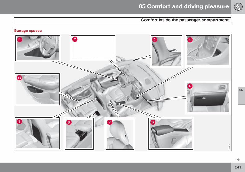
05 Comfort and driving pleasure
Comfort inside the passenger compartment
05
}}241
Storage spaces
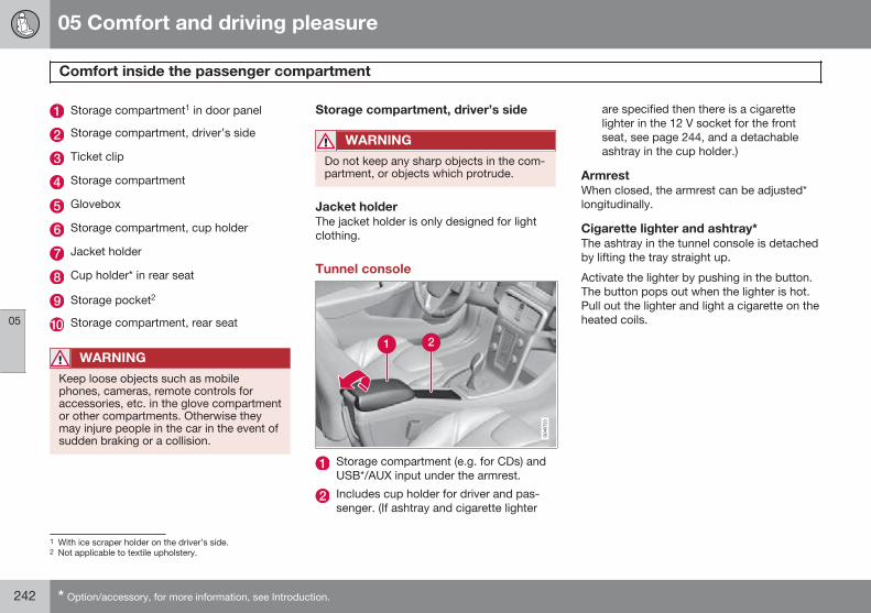
05 Comfort and driving pleasure
Comfort inside the passenger compartment
05
242 * Option/accessory, for more information, see Introduction.
Storage compartment1 in door panel
Storage compartment, driver’s side
Ticket clip
Storage compartment
Glovebox
Storage compartment, cup holder
Jacket holder
Cup holder* in rear seat
Storage pocket2
Storage compartment, rear seat
WARNING
Keep loose objects such as mobilephones, cameras, remote controls foraccessories, etc. in the glove compartmentor other compartments. Otherwise theymay injure people in the car in the event ofsudden braking or a collision.
Storage compartment, driver’s side
WARNING
Do not keep any sharp objects in the com-partment, or objects which protrude.
Jacket holderThe jacket holder is only designed for lightclothing.
Tunnel console
Storage compartment (e.g. for CDs) andUSB*/AUX input under the armrest.
Includes cup holder for driver and pas-senger. (If ashtray and cigarette lighter
are specified then there is a cigarettelighter in the 12 V socket for the frontseat, see page 244, and a detachableashtray in the cup holder.)
ArmrestWhen closed, the armrest can be adjusted*longitudinally.
Cigarette lighter and ashtray*The ashtray in the tunnel console is detachedby lifting the tray straight up.
Activate the lighter by pushing in the button.The button pops out when the lighter is hot.Pull out the lighter and light a cigarette on theheated coils.
1 With ice scraper holder on the driver’s side.2 Not applicable to textile upholstery.
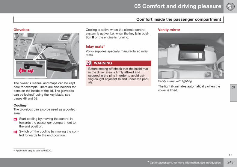
05 Comfort and driving pleasure
Comfort inside the passenger compartment
05
}}* Option/accessory, for more information, see Introduction. 243
Glovebox
The owner's manual and maps can be kepthere for example. There are also holders forpens on the inside of the lid. The gloveboxcan be locked* using the key blade, seepages 48 and 58.
Cooling3
The glovebox can also be used as a cooledarea.
Start cooling by moving the control intowards the passenger compartment tothe end position.
Switch off the cooling by moving the con-trol forwards to the end position.
Cooling is active when the climate controlsystem is active, i.e. when the key is in posi-tion II or the engine is running.
Inlay mats*Volvo supplies specially manufactured inlaymats.
WARNING
Before setting off check that the inlaid matin the driver area is firmly affixed andsecured in the pins in order to avoid get-ting caught adjacent to and under the ped-als.
Vanity mirror
Vanity mirror with lighting.
The light illuminates automatically when thecover is lifted.
3 Applicable only to cars with ECC.
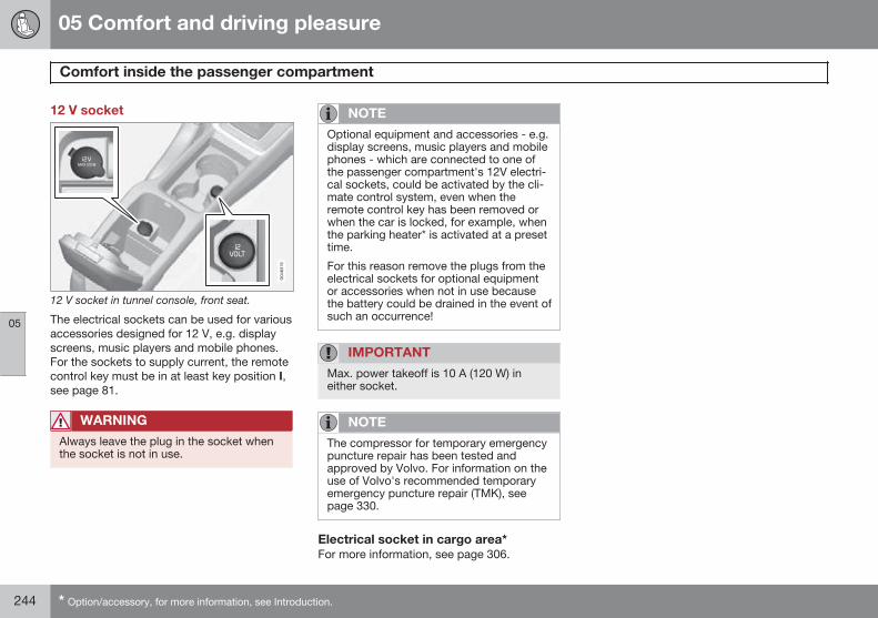
05 Comfort and driving pleasure
Comfort inside the passenger compartment
05
244 * Option/accessory, for more information, see Introduction.
12 V socket
12 V socket in tunnel console, front seat.
The electrical sockets can be used for variousaccessories designed for 12 V, e.g. displayscreens, music players and mobile phones.For the sockets to supply current, the remotecontrol key must be in at least key position I,see page 81.
WARNING
Always leave the plug in the socket whenthe socket is not in use.
NOTE
Optional equipment and accessories - e.g.display screens, music players and mobilephones - which are connected to one ofthe passenger compartment's 12V electri-cal sockets, could be activated by the cli-mate control system, even when theremote control key has been removed orwhen the car is locked, for example, whenthe parking heater* is activated at a presettime.
For this reason remove the plugs from theelectrical sockets for optional equipmentor accessories when not in use becausethe battery could be drained in the event ofsuch an occurrence!
IMPORTANT
Max. power takeoff is 10 A (120 W) ineither socket.
NOTE
The compressor for temporary emergencypuncture repair has been tested andapproved by Volvo. For information on theuse of Volvo's recommended temporaryemergency puncture repair (TMK), seepage 330.
Electrical socket in cargo area*For more information, see page 306.
05 Comfort and driving pleasure
05
245
246 * Option/accessory, for more information, see Introduction.
General information on infotainment..................................................... 248Radio..................................................................................................... 259Media player......................................................................................... 266External audio source via AUX/USB* input........................................... 270
Media Bluetooth®* ................................................................................ 273
Bluetooth® handsfree*.......................................................................... 276Voice recognition* mobile phone.......................................................... 285TV*......................................................................................................... 289Remote control* ................................................................................... 292
INFOTAINMENT SYSTEM
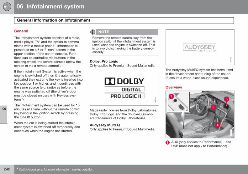
06 Infotainment system
General information on infotainment
06
248 * Option/accessory, for more information, see Introduction.
General
The Infotainment system consists of a radio,media player, TV* and the option to commu-nicate with a mobile phone*. Information ispresented on a 5 or 7-inch* screen in theupper section of the centre console. Func-tions can be controlled via buttons in thesteering wheel, the centre console below thescreen or via a remote control*.
If the Infotainment System is active when theengine is switched off then it is automaticallyactivated the next time the key is inserted intokey position I or higher, and it continues withthe same source (e.g. radio) as before theengine was switched off (the driver's doormust be closed on cars with Keyless sys-tems*).
The infotainment system can be used for 15minutes at a time without the remote controlkey being in the ignition switch by pressingthe On/Off button.
When the car is being started the infotain-ment system is switched off temporarily andcontinues when the engine has started.
NOTE
Remove the remote control key from theignition switch if the infotainment system isused when the engine is switched off. Thisis to avoid discharging the battery unnec-essarily.
Dolby, Pro LogicOnly applies to Premium Sound Multimedia.
Made under license from Dolby Laboratories.Dolby, Pro Logic and the double-D symbolare trademarks of Dolby Laboratories.
Audyssey MultEQOnly applies to Premium Sound Multimedia.
The Audyssey MultEQ system has been usedin the development and tuning of the soundto ensure a world-class sound experience.
Overview
AUX (only applies to Performance) - andUSB (does not apply to Performance) -
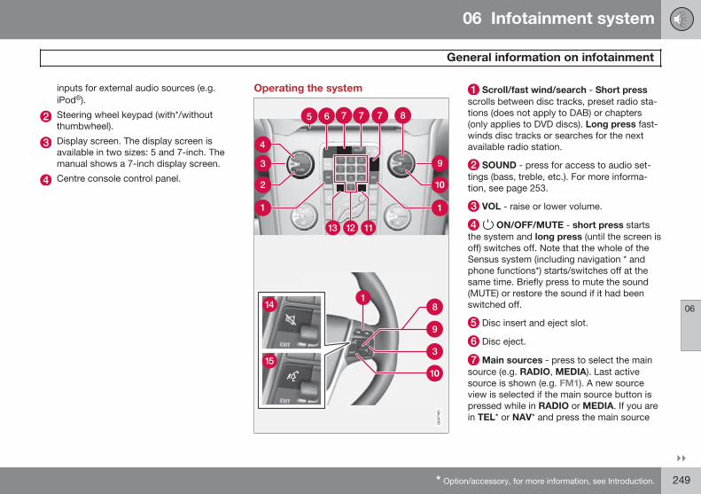
06 Infotainment system
General information on infotainment
06
}}* Option/accessory, for more information, see Introduction. 249
inputs for external audio sources (e.g.iPod®).
Steering wheel keypad (with*/withoutthumbwheel).
Display screen. The display screen isavailable in two sizes: 5 and 7-inch. Themanual shows a 7-inch display screen.
Centre console control panel.
Operating the system Scroll/fast wind/search - Short pressscrolls between disc tracks, preset radio sta-tions (does not apply to DAB) or chapters(only applies to DVD discs). Long press fast-winds disc tracks or searches for the nextavailable radio station.
SOUND - press for access to audio set-tings (bass, treble, etc.). For more informa-tion, see page 253.
VOL - raise or lower volume.
ON/OFF/MUTE - short press startsthe system and long press (until the screen isoff) switches off. Note that the whole of theSensus system (including navigation * andphone functions*) starts/switches off at thesame time. Briefly press to mute the sound(MUTE) or restore the sound if it had beenswitched off.
Disc insert and eject slot.
Disc eject.
Main sources - press to select the mainsource (e.g. RADIO, MEDIA). Last activesource is shown (e.g. FM1). A new sourceview is selected if the main source button ispressed while in RADIO or MEDIA. If you arein TEL* or NAV* and press the main source
06 Infotainment system
General information on infotainment
06
250 * Option/accessory, for more information, see Introduction.
button then a shortcut menu is shown withcommonly used menu options.
OK/MENU - press the thumbwheel in thesteering wheel or the button in the centreconsole to accept a menu selection. If OK/MENU is pressed while in the normal view, amenu for the selected source opens (e.g.RADIO or MEDIA). Arrow to the right of thescreen is shown when there are underlyingmenus.
TUNE - turn the thumbwheel in the steer-ing wheel or the knob in the centre console toscroll among tracks/folders, radio and TV*stations, phone contacts* or to navigateamong choices on the display screen.
EXIT - Short press leads upwards in themenu system, interrupts current function,interrupts/rejects phone calls or erasesentered characters. Long press leads to nor-mal view, or if you are in normal view to thehighest menu level (main source view), fromwhere you can reach the same main sourcebuttons located in the centre console (7).
INFO - If more information than can beshown on the screen is available, press theINFO button to see the remaining informa-tion.
Preset buttons, input of numbers and let-ters.
FAV – shortcut to a favourite setting. Thebutton can be programmed for a commonlyused function in AM, FM, etc. For more infor-mation, see page 252.
MUTE (cars without navigation) - press todeactivate the radio/media audio or restorethe audio if it has been switched off.
Voice recognition (cars with navigation) -press to activate voice recognition (for Blue-tooth®-connected mobile phone and naviga-tion system*).
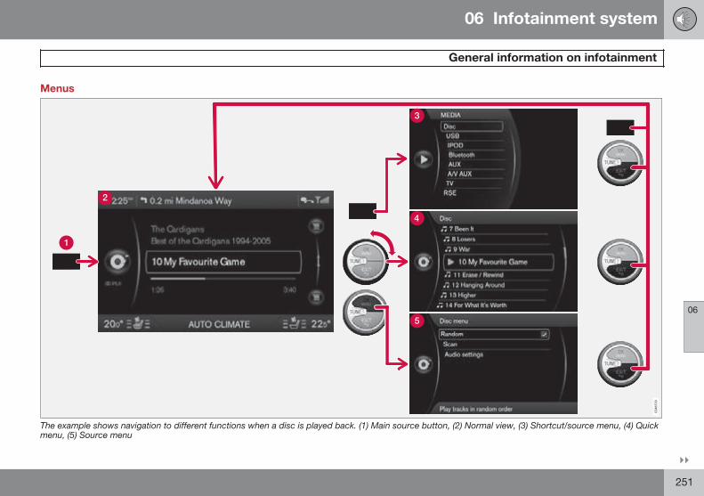
06 Infotainment system
General information on infotainment
06
}}251
Menus
The example shows navigation to different functions when a disc is played back. (1) Main source button, (2) Normal view, (3) Shortcut/source menu, (4) Quickmenu, (5) Source menu
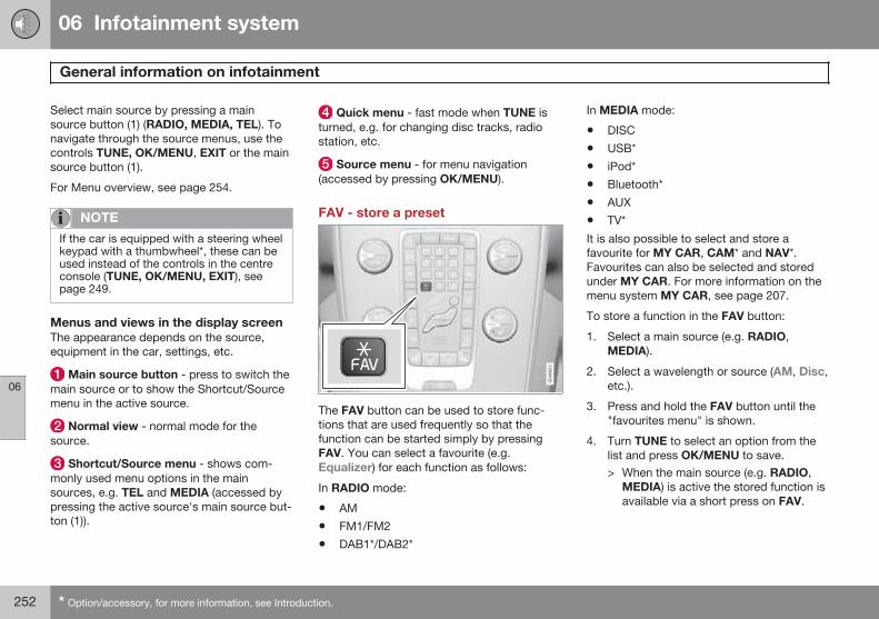
06 Infotainment system
General information on infotainment
06
252 * Option/accessory, for more information, see Introduction.
Select main source by pressing a mainsource button (1) (RADIO, MEDIA, TEL). Tonavigate through the source menus, use thecontrols TUNE, OK/MENU, EXIT or the mainsource button (1).
For Menu overview, see page 254.
NOTE
If the car is equipped with a steering wheelkeypad with a thumbwheel*, these can beused instead of the controls in the centreconsole (TUNE, OK/MENU, EXIT), seepage 249.
Menus and views in the display screenThe appearance depends on the source,equipment in the car, settings, etc.
Main source button - press to switch themain source or to show the Shortcut/Sourcemenu in the active source.
Normal view - normal mode for thesource.
Shortcut/Source menu - shows com-monly used menu options in the mainsources, e.g. TEL and MEDIA (accessed bypressing the active source's main source but-ton (1)).
Quick menu - fast mode when TUNE isturned, e.g. for changing disc tracks, radiostation, etc.
Source menu - for menu navigation(accessed by pressing OK/MENU).
FAV - store a preset
The FAV button can be used to store func-tions that are used frequently so that thefunction can be started simply by pressingFAV. You can select a favourite (e.g.Equalizer) for each function as follows:
In RADIO mode:
• AM
• FM1/FM2
• DAB1*/DAB2*
In MEDIA mode:
• DISC
• USB*
• iPod*
• Bluetooth*
• AUX
• TV*
It is also possible to select and store afavourite for MY CAR, CAM* and NAV*.Favourites can also be selected and storedunder MY CAR. For more information on themenu system MY CAR, see page 207.
To store a function in the FAV button:
1. Select a main source (e.g. RADIO,MEDIA).
2. Select a wavelength or source (AM, Disc,etc.).
3. Press and hold the FAV button until the"favourites menu" is shown.
4. Turn TUNE to select an option from thelist and press OK/MENU to save.> When the main source (e.g. RADIO,
MEDIA) is active the stored function isavailable via a short press on FAV.
06 Infotainment system
General information on infotainment
06
}}* Option/accessory, for more information, see Introduction. 253
General audio settingsPress SOUND to access the audio settingsmenu (Bass, Treble, etc.). Scroll forward withSOUND or OK/MENU to your selection (e.g.Treble).
Adjust the setting by turning TUNE and savethe setting with OK/MENU.
Continue pressing SOUND or OK/MENU toaccess other options:
• Surround1 - Can be set to the On/Offposition. When On is selected, the sys-tem selects the setting for optimal soundreproduction. Normally DPLII and then appear in the display screen. If therecording is made with Dolby Digital tech-nology then playback will take place withthis setting, then appears in thedisplay screen. When Off is selected, 3-channel stereo is available.
• Bass - Bass level.
• Treble - Treble level.
• Fader – Balance between the front andrear speakers.
• Balance – Balance between the left andright-hand speakers.
• Subwoofer*1 - Bass speaker level.
• DPL II centre level3 channel centrelevel1 - Volume for centre speaker.
• DPL II surround level1, 2 – Level for sur-round.
Advanced audio settings
Equalizer3
The volume level can be adjusted separatelyfor different wavelengths.
1. Press OK/MENU to access Audiosettings and select Equalizer.
2. Select wavelength by turning TUNE andconfirm with OK/MENU.
3. Adjust the audio settings by turningTUNE and confirm with OK/MENU. Con-tinue in the same way with other wave-lengths you want to change.
4. When you have finished with audio set-tings, press EXIT to confirm and return tonormal view.
For general information on menu navigation,see page 251 and menu overview, seepage 254.
Sound stage1
The sound experience can be optimised forthe driver's seat, both front seats or the rearseat. If there are passengers in both the frontand rear seats then the option recommendedis; both front seats. The options can beselected under Audio settings Soundstage.
For general information on menu navigation,see page 251 and menu overview, seepage 254.
Audio volume and automatic volumecontrolThe audio system compensates for disruptingnoises in the passenger compartment byincreasing the volume in relation to the speedof the car. The compensation level can be setto low, medium, high or off. Select the levelunder Audio settings Volumecompensation.
For general information on menu navigation,see page 251 and menu overview, seepage 254.
1 Only Premium Sound Multimedia.2 Only when Surround is activated.3 Not Performance.
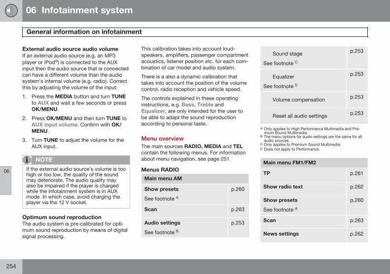
06 Infotainment system
General information on infotainment
06
254
External audio source audio volumeIf an external audio source (e.g. an MP3player or iPod®) is connected to the AUXinput then the audio source that is connectedcan have a different volume than the audiosystem's internal volume (e.g. radio). Correctthis by adjusting the volume of the input:
1. Press the MEDIA button and turn TUNEto AUX and wait a few seconds or pressOK/MENU.
2. Press OK/MENU and then turn TUNE toAUX input volume. Confirm with OK/MENU.
3. Turn TUNE to adjust the volume for theAUX input.
NOTE
If the external audio source's volume is toohigh or too low, the quality of the soundmay deteriorate. The audio quality mayalso be impaired if the player is chargedwhile the infotainment system is in AUXmode. In which case, avoid charging theplayer via the 12 V socket.
Optimum sound reproductionThe audio system is pre-calibrated for opti-mum sound reproduction by means of digitalsignal processing.
This calibration takes into account loud-speakers, amplifiers, passenger compartmentacoustics, listener position etc. for each com-bination of car model and audio system.
There is a also a dynamic calibration thattakes into account the position of the volumecontrol, radio reception and vehicle speed.
The controls explained in these operatinginstructions, e.g. Bass, Treble andEqualizer, are only intended for the user tobe able to adapt the sound reproductionaccording to personal taste.
Menu overviewThe main sources RADIO, MEDIA and TELcontain the following menus. For informationabout menu navigation, see page 251.
Menus RADIO
Main menu AM
Show presets
See footnote Ap.260
Scan p.263
Audio settings
See footnote Bp.253
Sound stage
See footnote C
p.253
Equalizer
See footnote D
p.253
Volume compensation p.253
Reset all audio settings p.253
A Only applies to High Performance Multimedia and Pre-mium Sound Multimedia.
B The menu options for audio settings are the same for allaudio sources.
C Only applies to Premium Sound Multimedia.D Does not apply to Performance.
Main menu FM1/FM2
TP p.261
Show radio text p.262
Show presets
See footnote Ap.260
Scan p.263
News settings p.262
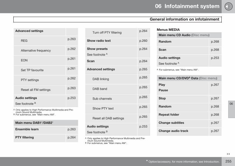
06 Infotainment system
General information on infotainment
06
}}* Option/accessory, for more information, see Introduction. 255
Advanced settings
REG p.263
Alternative frequency p.262
EON p.261
Set TP favourite p.261
PTY settings p.262
Reset all FM settings p.263
Audio settings
See footnote Bp.253
A Only applies to High Performance Multimedia and Pre-mium Sound Multimedia.
B For submenus, see "Main menu AM".
Main menu DAB1*/DAB2*
Ensemble learn p.263
PTY filtering p.264
Turn off PTY filtering p.264
Show radio text p.260
Show presets
See footnote Ap.264
Scan p.264
Advanced settings p.265
DAB linking p.265
DAB band p.265
Sub channels p.265
Show PTY text p.265
Reset all DAB settings p.265
Audio settings
See footnote Bp.253
A Only applies to High Performance Multimedia and Pre-mium Sound Multimedia.
B For submenus, see "Main menu AM".
Menus MEDIA
Main menu CD Audio (Disc menu)
Random p.268
Scan p.268
Audio settings
See footnote Ap.253
A For submenus, see "Main menu AM".
Main menu CD/DVDA Data (Disc menu)
Play
Pause
p.267
Stop p.267
Random p.268
Repeat folder p.268
Change subtitles p.267
Change audio track p.267
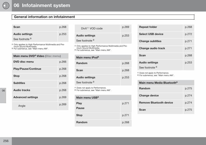
06 Infotainment system
General information on infotainment
06
256
Scan p.268
Audio settings
See footnote Bp.253
A Only applies to High Performance Multimedia and Pre-mium Sound Multimedia.
B For submenus, see "Main menu AM".
Main menu DVDA Video (Disc menu)
DVD disc menu p.266
Play/Pause/Continue p.268
Stop p.268
Subtitles p.268
Audio tracks p.268
Advanced settings p.269
Angle p.269
DivX® VOD code p.269
Audio settings
See footnote Bp.253
A Only applies to High Performance Multimedia and Pre-mium Sound Multimedia.
B For submenus, see "Main menu AM".
Main menu iPodA
Random p.268
Scan p.268
Audio settings
See footnote Bp.253
A Does not apply to Performance.B For submenus, see "Main menu AM".
Main menu USBA
Play
Pause
p.271
Stop p.271
Random p.268
Repeat folder p.268
Select USB device p.272
Change subtitles p.271
Change audio track p.271
Scan p.268
Audio settings
See footnote Bp.253
A Does not apply to Performance.B For submenus, see "Main menu AM".
Main menu Media BluetoothA
Random p.275
Change device p.274
Remove Bluetooth device p.274
Scan p.275
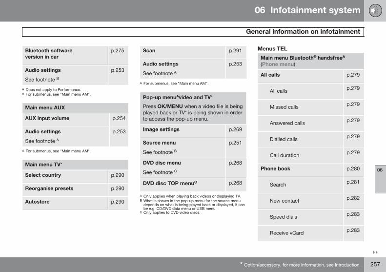
06 Infotainment system
General information on infotainment
06
}}* Option/accessory, for more information, see Introduction. 257
Bluetooth softwareversion in car
p.275
Audio settings
See footnote Bp.253
A Does not apply to Performance.B For submenus, see "Main menu AM".
Main menu AUX
AUX input volume p.254
Audio settings
See footnote Ap.253
A For submenus, see "Main menu AM".
Main menu TV*
Select country p.290
Reorganise presets p.290
Autostore p.290
Scan p.291
Audio settings
See footnote Ap.253
A For submenus, see "Main menu AM".
Pop-up menuAvideo and TV*
Press OK/MENU when a video file is beingplayed back or TV* is being shown in orderto access the pop-up menu.
Image settings p.269
Source menu
See footnote Bp.251
DVD disc menu
See footnote Cp.268
DVD disc TOP menuC p.268
A Only applies when playing back videos or displaying TV.B What is shown in the pop-up menu for the source menu
depends on what is being played back or displayed, it canbe e.g. CD/DVD data menu or USB menu.
C Only applies to DVD video discs.
Menus TEL
Main menu Bluetooth® handsfreeA
(Phone menu)
All calls p.279
All calls p.279
Missed calls p.279
Answered calls p.279
Dialled calls p.279
Call duration p.279
Phone book p.280
Search p.281
New contact p.282
Speed dials p.283
Receive vCard p.283
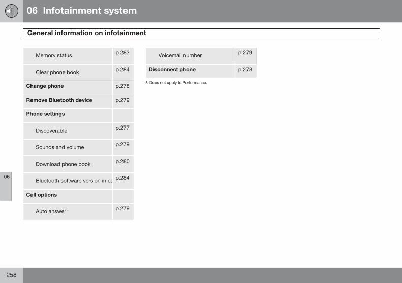
06 Infotainment system
General information on infotainment
06
258
Memory status p.283
Clear phone book p.284
Change phone p.278
Remove Bluetooth device p.279
Phone settings
Discoverable p.277
Sounds and volume p.279
Download phone book p.280
Bluetooth software version in carp.284
Call options
Auto answer p.279
Voicemail number p.279
Disconnect phone p.278
A Does not apply to Performance.
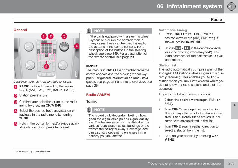
06 Infotainment system
Radio
06
* Option/accessory, for more information, see Introduction. 259
General
Centre console, controls for radio functions.
RADIO button for selecting the wave-length (AM, FM1, FM2, DAB1*, DAB2*).
Station presets (0-9)
Confirm your selection or go to the radiomenu by pressing OK/MENU.
Select the desired frequency/station ornavigate in the radio menu by turningTUNE.
Hold in the button for next/previous avail-able station. Short press for preset.
NOTE
If the car is equipped with a steering wheelkeypad* and/or remote control* then inmany cases these can be used instead ofthe buttons in the centre console. For adescription of the buttons in the steeringwheel, see page 249. For a description ofthe remote control, see page 292.
MenusThe menus inRADIO are controlled from thecentre console and the steering wheel key-pad*. For general information on menu navi-gation, see page 251 and menu overview, seepage 254.
Radio AM/FM
Tuning
NOTE
The reception is dependent both on howgood the signal strength and signal qualityare. The transmission may be disturbed byvarious factors such as tall buildings or thetransmitter being far away. Coverage levelcan also vary depending on where in thecountry you are located.
Automatic tuning1. Press RADIO, turn TUNE until the
desired wavelength (AM, FM1 etc.) isshown, press OK/MENU.
2. Hold in / in the centre console(or in the steering wheel keypad*). Theradio searches for the next/previous avail-able station.
Station list1
The radio automatically compiles a list of thestrongest FM stations whose signals it is cur-rently receiving. This enables you to find astation when you drive into an area where youdo not know the radio stations and their fre-quencies.
To go to the list and select a station:
1. Select the desired wavelength (FM1 orFM2).
2. Turn TUNE one step in either direction.This displays the list of all stations in thearea. The currently tuned station is indi-cated with enlarged text in the list.
3. Turn TUNE again in either direction toselect a station from the list.
4. Confirm your choice by pressing OK/MENU.
1 Does not apply to Performance.
06 Infotainment system
Radio
06
260
NOTE
• The list only shows the frequencies ofstations that are currently beingreceived, not a complete list of allradio frequencies on the selectedwavelength.
• If the signal from the currently receivedstation is weak, this may prevent theradio from updating the station list. Ifthis occurs, press the button(while the station list is shown in thedisplay screen) in order to change tomanual tuning and set a frequency. Ifthe station list is no longer shown, turnTUNE one step in either direction toshow the list again, and press toswitch.
The list disappears from the TV screen after afew seconds.
If the station list is no longer shown, turnTUNE one step in either direction and pressthe button in the centre console tochange to manual tuning (or to return frommanual tuning to the function for "Stationlist").
Manual tuningThe preset from the factory is that the radioshows the station list of the strongest stationsin the area when you turn TUNE (see the sec-tion "Station list", page 259). When the sta-tion list is shown, press the button inthe centre console to change to manual tun-ing. This allows you to select a frequencyfrom the list of all available radio frequenciesin the selected wavelength. In other words, ifturn TUNE one step in a manual search thefrequency is changed from e.g. 93.3 to93.4 MHz, etc.
To manually select a station:
1. Press the RADIO button, turn TUNE untilthe required frequency band (AM, FM1etc.) is displayed, press OK/MENU.
2. Turn TUNE to select a frequency.
NOTE
The preset from the factory is that theradio automatically searches for the sta-tions in the area where you are driving (seeprevious section "Station list" above).
But if you have changed over to manualtuning (by pressing the button in thecentre console when the station list wasshown), then the radio remains set in thefunction for manual tuning the next timeyou switch on the radio. To change backto the function for "Station list", turn TUNEone step (to show the complete list of sta-tions) and press the button .
Note that if you press when the sta-tion list is not shown then INFO is acti-vated. For more information on this func-tion, see page 249.
Preset10 presets can be stored per wavelength(AM, FM1 etc.).
The stored presets are selected using thepreset buttons.
1. Tune into a station (see "Tuning", page259).
2. Hold in one of the preset buttons for afew seconds, the sound disappears dur-
06 Infotainment system
Radio
06
261
ing this time and returns when the stationis stored. The preset button can now beused.
A list of pre-selected channels can be shown2
in the TV screen. The function is activated/deactivated in FM/AM mode under FM menu
Show presets or AM menu Showpresets.
RDS functionsRDS (Radio Data System) links FM transmit-ters into a network. An FM transmitter in sucha network sends information that gives anRDS radio the following functions:
• Automatically switches to a strongertransmitter if reception in the area is poor.
• Searches for programme type, such astraffic information or news.
• Receives text information on current radioprogramme.
NOTE
Some radio stations do not use RDS oronly selected parts of its functionality.
If a required programme type is located theradio can switch stations interrupting the
audio source currently in use. For example, ifthe CD player is in use, it is paused. Theinterrupting transmission is played at a presetvolume, see page 263. The radio returns tothe previous audio source and volume whenthe set programme type is no longer broad-cast.
The programme functions alarm (ALARM!),traffic information (TP), news (NEWS), andprogramme types (PTY) interrupt one anotherin order of priority, where alarm has the high-est priority and programme types has thelowest. For additional settings of program-ming interruptions (EON Distant and EONLocal), see the section "Enhanced Other Net-works – EON" below. Press EXIT to return tothe interrupted audio source, press the OK/MENU to clear the message.
AlarmThis function is used to warn of serious acci-dents and catastrophes. The alarm cannot betemporarily interrupted or deactivated. Themessage ALARM! appears on the TV screenwhen an alarm message is transmitted.
Traffic information – TPThis function allows traffic information sentwithin a set station's RDS network to break
through. The TP symbol indicates that thefunction is activated. If the preset station cansend traffic information then this is shown byTP glowing brightly in the TV screen, other-wise TP will be grey.
– Activate/deactivate in FM mode underFM menu TP.
Enhanced Other Networks – EONThis function is useful in urban areas withmany regional radio stations. It allows the dis-tance between the car and the radio stationtransmitter to determine when programmefunctions should interrupt the current audiosource.
– Activate/deactivate in FM mode byselecting one of the options under FMmenu Advanced settings EON:
• Local – interrupts only if the radio stationtransmitter is close.
• Distant3 – interrupts if the station trans-mitter is far away, even if there is a lot ofstatic.
TP from selected station/all stationsThe radio can only interrupt for traffic infor-mation from the selected station or all sta-tions within the RDS network.
2 Only applies to High Performance Multimedia and Premium Sound Multimedia.3 Factory settings.
06 Infotainment system
Radio
06
262
– Go in FM mode to FM menuAdvanced settings Set TP favouriteto change.
NewsThis function allows news broadcasts sentwithin a set station's RDS network to breakthrough. The NEWS symbol indicates that thefunction is active.
– Activate/deactivate in FM mode underFM menu News settings News.
News from selected station/all stationsThe radio can only interrupt for news from theselected station or all stations in the RDS net-work.
– Go in FM mode to FM menu Newssettings Set news favourite tochange.
Programme types – PTYThe PTY function can be used to select oneor more programme types, such as popmusic and serious classic. The PTY symbolindicates that the function is active. This func-tion allows programme types broadcastwithin a set station's RDS network to breakthrough.
1. Activate in FM mode by first selecting theprogramme types under FM menuAdvanced settings PTY settingsSelect PTY.
2. Then the PTY function must be activatedunder FM menu Advanced settings
PTY settings Receive trafficbulletins from other networks.
An indicator is shown in the TV screen whenPTY is activated.
Deactivation of the PTY function is performedin FM mode under FM menu Advancedsettings PTY settings Receive trafficbulletins from other networks. Selectedprogramme types (PTY) are not reset.
Resetting and removing PTY are performedunder FM menu Advanced settingsPTY settings Select PTY Clear all.
PTY searchThis function searches the entire wavelengthfor the selected programme type.
1. In FM mode select one or more PTYunder FM menu Advanced settings
PTY settings Select PTY.
2. Go to FM menu Advanced settingsPTY settings Seek PTY.
To finish searching, press EXIT.
– To continue searching for another broad-cast of the selected programme types,press on or .
Display of programme typeThe programme type of the current stationcan be shown on the TV screen.
– Activate/deactivate in FM mode underFM menu Advanced settings PTYsettings Show PTY text.
Radio text4
Some RDS stations transmit information onprogramme content, artists, etc. This informa-tion can be shown on the TV screen.
– Activate/deactivate in FM mode underFM menu Show radio text.
Automatic frequency update – AFThe function selects the strongest transmitterfor the set station. In order to find a strongtransmitter the function may, in exceptionalcases, need to search the entire FM wave-length.
4 Only cars with 7-inch screen
06 Infotainment system
Radio
06
* Option/accessory, for more information, see Introduction. 263
– Activate/deactivate in FM mode underFM menu Advanced settingsAlternative frequency.
Regional radio programmes – REGThis function causes the radio to continuewith a regional transmitter even if its signalstrength is low. The symbol REG shows thatthe function is active.
– Activate/deactivate in FM mode underFM menu Advanced settings REG.
Resetting RDS functionsAll radio settings can be reset to the originalfactory settings.
– The reset is carried out in FM mode underFM menu Advanced settingsReset all FM settings.
Volume control, programme typesThe interrupting programme types, e.g.NEWS or TP, are heard at the volumeselected for each respective programmetype. If the volume level is adjusted during theprogramme interruption, the new level issaved until the next programme interruption.
Scan wavelengthThe function automatically searches for avail-able channels and takes into account anyprogramme type filtering. When a station is
found, it is played for approx. 10 secondsbefore scanning is resumed. When a stationis playing back it can be saved as a preset inthe usual way, see the section Preset, page260.
– To start scanning go in FM/AM mode toFM menu Scan or AM menu Scan.
NOTE
Scanning stops if a station is saved.
Radio system - DAB*
GeneralDAB (Digital Audio Broadcasting) is a digitalbroadcasting system for radio. This systemsupports DAB, DAB+ and DMB.
NOTE
Coverage for DAB is not available in alllocations. If there is no coverage then themessage No reception is shown in thedisplay screen.
Service and Ensemble• Service - Channel, radio channel (only
audio services are supported by the sys-tem).
• Ensemble - A collection of radio chan-nels on the same frequency.
Storing channel groups (Ensemblelearn)When the vehicle is moved to a new broad-casting area, programming of existing chan-nel groups in the area may be necessary.
Programming of channel groups creates anupdated list of all available channel groups.The list is not updated automatically.
Programming is carried out in the menu sys-tem in DAB mode under DAB menuEnsemble learn. Programming can also takeplace as follows:
1. Turn TUNE one step in either direction.> Ensemble learn is shown in the list of
available channel groups.
2. Press OK/MENU.> New programming is started.
Programming can be cancelled with EXIT.
06 Infotainment system
Radio
06
264
Navigation in channel group list(Ensemble)To navigate in and access the channel grouplist turn TUNE. The name of the Ensemble isshown in the upper part of the TV screen.When switching to the new Ensemble thename changes to the new one.
• Service - Shows channels irrespective ofthe channel group to which they are allo-cated. The list can also be filtered usingthe selection of programme type (PTYfiltering), see below.
ScanningThe function automatically searches the cur-rent wavelength for strong stations. When astation is found, it is played for approx. 10seconds before scanning is resumed. When astation is playing back it is saved as a presetin the usual way. For more information onpresets, see "Preset" below.
– Go in DAB mode to DAB menu Scanto start scanning.
NOTE
Scanning stops if a station is saved.
Scanning can also be selected in DAB-PTYmode. In which case only channels of thepre-selected programme type are played.
Programme type (PTY)Various types of radio programmes can beselected using the programme type function.There are a number of different programmetypes which also include different programmecategories. After selecting a programme type,navigation only takes place within the chan-nels that are broadcasting that type.
Programme type is selected in DAB modeunder DAB menu PTY filtering. Exit thismode as follows:
– Press EXIT.> An indicator is shown in the TV screen
when PTY is activated.
In certain cases DAB radio will exit PTY modewhen DAB to DAB linking (see below) isimplemented.
Preset10 station presets can be stored per wave-length. DAB has 2 memories for presets:DAB1 and DAB2. Storage of presets is madeby means of a long press on the desired pre-set button, for more information see
page 260. The stored presets are selectedusing the preset buttons.
A preset contains one channel but no sub-channels. If a subchannel is being played anda preset is saved then only the main channelis registered. This is because subchannelsare temporary. At the next attempt to retrievethe preset, the channel which contained thesubchannel will be played. The preset is notdependent on the channel list.
A list of pre-selected channels can be shown5
in the TV screen. The function is activated/deactivated in DAB mode under DAB menu
Show presets.
NOTE
The audio system's DAB system does notsupport all functions in the DAB standard.
Radio textSome radio stations transmit information onprogramme content, artists, etc. This informa-tion is shown on the TV screen.
The function is deactivated/activated in DABmode under DAB menu Show radio text.
5 Only applies to High Performance Multimedia and Premium Sound Multimedia
06 Infotainment system
Radio
06
265
NOTE
Only one of the functions "Show radiotext" and "Show presets" can be acti-vated at a time. If one of them is activatedwhen the other is already activated, thenthe previously activated function is deacti-vated automatically. Both functions can bedeactivated.
Advanced settings
DAB to DAB linkDAB to DAB linking means that the DAB radiocan go from one channel with poor or noreception to the same channel in anotherchannel group with better reception. Theremay be a certain delay when changing chan-nel group. There may be a period of silencebetween the current channel no longer beingavailable to the new channel becoming avail-able.
The function can be activated/deactivated inDAB mode under DAB menu Advancedsettings DAB linking.
WavelengthDAB can be transmitted on two6 wave-lengths:
• Band III - covers most areas.
• LBand - available only in a few areas.
By selecting for example Band III on its own,channel programming takes place morequickly than if both Band III and LBand havebeen selected. It is not certain that all channelgroups will be found. Wavelength selectiondoes not affect the stored memories.
Wavelengths can be deactivated/activated inDAB mode under DAB menu Advancedsettings DAB band.
SubchannelSecondary components are usually namedsubchannels. These are temporary and cancontain e.g. translations of the main pro-gramme into other languages.
If one or more subchannels are broadcastthen the symbol is shown to the left of thechannel name in the TV screen. A subchannelis indicated by the - symbol appearing to theleft of the channel name in the TV screen.
Press to access the subchannels.
Subchannels can only be accessed on theselected main channel and not on any otherchannel without selecting it.
Display of subchannels can be deactivated/activated in DAB mode under DAB menuAdvanced settings Sub channels
Programme type textSome radio stations broadcast informationabout programme type and programme cate-gory, for information on Programme types –PTY, see page 262. This information is shownon the TV screen.
The function is activated/deactivated in DABmode under DAB menu Advancedsettings Show PTY text.
Resetting the DAB settingsAll DAB settings can be reset to the originalfactory settings.
– The reset is carried out in DAB modeunder DAB menu Advanced settings
Reset all DAB settings.
6 Not all areas/countries use both wavelengths.
06 Infotainment system
Media player
06
266 * Option/accessory, for more information, see Introduction.
GeneralThe media player can playback audio andvideo from CD/DVD* discs and externallyconnected audio sources via the AUX/USB*input or wirelessly stream audio files fromexternal devices using Bluetooth®. Certainmedia players can show TV* and have theoption to communicate with a mobile phone(see page 276)* via Bluetooth®.
CD/DVD1 functions
Centre console control panel.
Disc insert and eject slot
Disc eject
MEDIA button, activates last activemedia source. If you are already in amedia source and press the MEDIA but-ton then a shortcut menu is shown forcommonly used menu options.
Input of numbers and letters.
Confirm your selection or go to the menufor the selected media source by pressingOK/MENU.
Select the disc tracks/folders, or navigatethrough menu options by turning TUNE.
Fast forward/reverse and change disctrack or chapter2.
The media player supports and can play thefollowing main types of discs and files:
• Pre-recorded CD discs (CD Audio).
• Burned CD discs with audio and/or videofiles1.
• Pre-recorded DVD video discs1.
• Burned DVD discs1 with audio and/orvideo files.
For more information about the supportedformats, see page 269.
NOTE
If the car is equipped with a steering wheelkeypad* and/or remote control* then inmany cases these can be used instead ofthe buttons in the centre console. For adescription of the buttons in the steeringwheel, see page 249. For a description ofthe remote control, see page 292.
MenusThe menus inMEDIA are controlled from thecentre console and the steering wheel key-pad*. For general information on menu navi-gation, see page 251 and menu overview, seepage 254.
Starting playback of a discPress the MEDIA button, turn TUNE untilDisc is displayed, press OK/MENU. If thereis a disc in the media player then the discstarts playing back automatically, otherwiseInsert disc is shown in the TV screen. Theninsert a disc, with text side up. The disc startsto play back automatically.
If a disc with audio/video files is inserted intothe player then the disc's folder structureneeds to be loaded. Depending on the qualityof the disc and the quantity of information
1 Only applies to High Performance Multimedia and Premium Sound Multimedia.2 Only applies to DVD discs.
06 Infotainment system
Media player
06
* Option/accessory, for more information, see Introduction. 267
there may be a certain delay before playbackstarts.
Disc ejectA disc remains in the ejected position forabout 12 seconds, after which it is insertedback into the player for safety reasons.
PauseWhen the volume is reduced entirely or MUTEis pressed, the media player is paused. Whenthe volume is increased or MUTE is pressedagain, the media player starts. It is also possi-ble to pause via the menu system3, pressOK/MENU, select Play/Pause.
Playback and navigation
CD audio discsTurn TUNE to access the disc's playlist andnavigate in the list. Use OK/MENU to confirmthe selection of the disc track and start play-back. Press EXIT to cancel and exit the play-list. A long press on EXIT leads to the play-list's root level.
Disc tracks can also be changed by pressingon / on the centre console or thesteering wheel keypad*.
Burned discs audio/video files1
Turn TUNE to access the disc's playlist/folderstructure and navigate in the list/structure.Use OK/MENU to confirm either selection ofsubfolder or start of playback of the selectedaudio/video file. Press EXIT to either stop andexit the playlist or go up (back) in the folderstructure. A long press on EXIT leads to theplaylist's root level.
Audio/video files can also be changed bypressing / on the centre console orthe steering wheel keypad*.
Audio files have the symbol , video files1
have the symbol and folders have thesymbol .
When playback of a file is complete the play-back of the other files (of the same type) inthat particular folder continues. Change4 offolder takes place automatically when all thefiles in the current folder have been playedback. The system automatically detects andchanges setting when a disc containing onlyaudio files or only video files is loaded intothe media player and then plays back thesefiles. However, the system does not changesetting if a disc containing a mixture of audio
and video files is loaded into the mediaplayer, but instead the player continues toplay back the previous file type.
NOTE
A video film is only shown when the car isstationary. When the car is moving at aspeed of over about 8 km/h no picture isshown and No visual media availablewhile driving appears on the displayscreen, although the audio is heard duringthis time. The picture is shown again assoon as the car's speed falls below about6 km/h.
NOTE
Some audio files that are copy-protectedby record companies or privately copiedaudio files cannot be loaded by the player.
DVD video discs1
For playback of DVD video discs, seepage 268.
Fast forward/reverseHold in the buttons / to fast forward/rewind. Audio files are fast forwarded/rewound at one speed, while video files are
3 Does not apply to CD Audio1 Only applies to High Performance Multimedia and Premium Sound Multimedia.4 If Repeat folder is activated then this does not take place.
06 Infotainment system
Media player
06
268 * Option/accessory, for more information, see Introduction.
fast forwarded/rewound at several speeds.Repeatedly press the buttons / toincrease the fast forward/rewind speed forvideo files. Release the button to return toviewing at normal speed.
Scan5
This function plays the first ten seconds ofeach disc track/audio file. To scan:
1. Press OK/MENU
2. Turn TUNE to Scan> The first 10 seconds of each disc track
or audio file are played.
3. Cancel the scan with EXIT, the disc trackor audio file being played back will con-tinue playing.
Random5
This function plays the tracks in randomorder. To listen to the tracks in random order:
1. Press OK/MENU
2. Turn TUNE to Random
3. Press OK/MENU to activate/deactivatethe function.
Disc tracks/audio files can be changed bypressing / on the centre console orthe steering wheel keypad*.
Repeat folder6
This function makes it possible to play files ina folder over and over again. When the lastfile has been played out, playback of the firstfile starts again.
1. Press OK/MENU
2. Turn TUNE to Repeat folder
3. Press OK/MENU to activate/deactivatethe function.
Playback of DVD video discs1
PlaybackWhen playing back a DVD video disc a discmenu may appear on the display screen. Thedisc menu gives access to additional func-tions and settings, such as selecting subtitles,language and scene selection.
NOTE
A video film is only shown when the car isstationary. When the car is moving at aspeed of over about 8 km/h no picture isshown and No visual media availablewhile driving appears on the displayscreen, although the audio is heard duringthis time. The picture is shown again assoon as the car's speed falls below about6 km/h.
Navigation in the DVD video disc'smenu
Navigation in the DVD video disc's menu isperformed using the number keys in the cen-tre console as illustrated above.
5 Does not apply to DVD video discs.6 Only applies to audio/video files on burned discs or USB.1 Only applies to High Performance Multimedia and Premium Sound Multimedia.
06 Infotainment system
Media player
06
* Option/accessory, for more information, see Introduction. 269
Changing chapter or titleTurn TUNE to access the list of chapters andnavigate through them (if the film is beingplayed back then it is paused). Press OK/MENU to select the chapter, this also leadsback to the original position (if the film wasbeing played back then it is restarted). PressEXIT to access the title list.
Titles are selected in the title list by turningTUNE and the selection is confirmed withOK/MENU, this also leads back to the chap-ter list. Press OK/MENU to activate theselection and return to the start position. UseEXIT to cancel the selection and this leadsback to the original position (without anyselection being made).
The chapter can also be changed by pressingon / on the centre console or thesteering wheel keypad*.
Advanced settings7
AngleIf the DVD video disc supports it, the functioncan be used to choose from which cameraposition a particular scene should be shown.Go in disc mode to Disc menu Advancedsettings Angle.
DivX® Video On DemandThe media player can be registered in orderto play DivX VOD type files from burned discsor USB. The code for registration can befound in the menu system MY CAR Settings
Information DivX® VOD code. Forgeneral information on menus, see underMY CAR, see page 207.
For more information visit www.divx.com/vod.
Picture settings7
You can adjust the settings (when the car isstationary) for brightness and contrast.
1. Press OK/MENU and select Imagesettings, confirm with OK/MENU.
2. Turn TUNE to the adjustment option andconfirm with OK/MENU.
3. Adjust the setting by turning TUNE andconfirm with OK/MENU.
To return to the settings list, press the OK/MENU or EXIT.
The picture settings can be reset to factorysettings with the Reset option.
Compatible file formatsThe media player can play back a variety offile types and is compatible with the formatsin the following table.
NOTE
Dual format, double-sided discs (DVDPlus, CD-DVD format) are thicker than reg-ular CD discs and therefore playback can-not be guaranteed and malfunction mayarise.
If a CD contains a mixture of MP3 andCDDA tracks, all MP3s will be ignored.
Audio formatA CD audio, mp3, wma
Audio formatB CD audio, mp3, wma, aac,m4a
Video formatC CD video, DVD video,divx, avi, asf
A Applies to Performance.B Does not apply to Performance.C Only applies to High Performance Multimedia and Pre-
mium Sound Multimedia.
7 Applies to High Performance Multimedia and Premium Sound Multimedia.
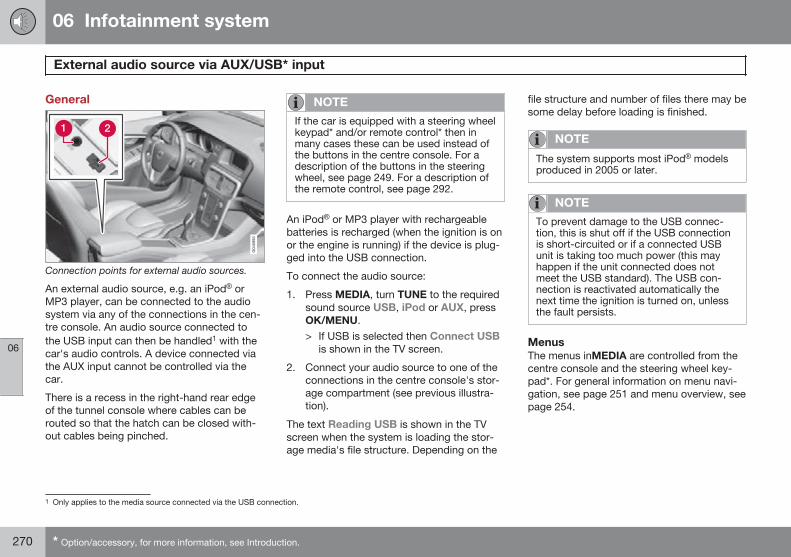
06 Infotainment system
External audio source via AUX/USB* input
06
270 * Option/accessory, for more information, see Introduction.
General
Connection points for external audio sources.
An external audio source, e.g. an iPod® orMP3 player, can be connected to the audiosystem via any of the connections in the cen-tre console. An audio source connected tothe USB input can then be handled1 with thecar's audio controls. A device connected viathe AUX input cannot be controlled via thecar.
There is a recess in the right-hand rear edgeof the tunnel console where cables can berouted so that the hatch can be closed with-out cables being pinched.
NOTE
If the car is equipped with a steering wheelkeypad* and/or remote control* then inmany cases these can be used instead ofthe buttons in the centre console. For adescription of the buttons in the steeringwheel, see page 249. For a description ofthe remote control, see page 292.
An iPod® or MP3 player with rechargeablebatteries is recharged (when the ignition is onor the engine is running) if the device is plug-ged into the USB connection.
To connect the audio source:
1. Press MEDIA, turn TUNE to the requiredsound source USB, iPod or AUX, pressOK/MENU.> If USB is selected then Connect USB
is shown in the TV screen.
2. Connect your audio source to one of theconnections in the centre console's stor-age compartment (see previous illustra-tion).
The text Reading USB is shown in the TVscreen when the system is loading the stor-age media's file structure. Depending on the
file structure and number of files there may besome delay before loading is finished.
NOTE
The system supports most iPod® modelsproduced in 2005 or later.
NOTE
To prevent damage to the USB connec-tion, this is shut off if the USB connectionis short-circuited or if a connected USBunit is taking too much power (this mayhappen if the unit connected does notmeet the USB standard). The USB con-nection is reactivated automatically thenext time the ignition is turned on, unlessthe fault persists.
MenusThe menus inMEDIA are controlled from thecentre console and the steering wheel key-pad*. For general information on menu navi-gation, see page 251 and menu overview, seepage 254.
1 Only applies to the media source connected via the USB connection.
06 Infotainment system
External audio source via AUX/USB* input
06
}}* Option/accessory, for more information, see Introduction. 271
Playback and navigation2
Turn TUNE to access the playlist/folder struc-ture and navigate in the list/structure. UseOK/MENU to either confirm selection of sub-folder or start of playback of the selectedaudio/video file. Press EXIT to either stop andexit the playlist or go up (back) in the folderstructure. A long press on EXIT leads to theplaylist's root level.
Audio/video files can also be changed bypressing / on the centre console orthe steering wheel keypad*.
Audio files have the symbol , video files3
have the symbol and folders have thesymbol .
When playback of a file is complete the play-back of the other files (of the same type) inthat particular folder continues. Change4 offolder takes place automatically when all thefiles in the current folder have been playedback. The system automatically detects andchanges setting when a device containingonly audio files or only video files is con-nected to the USB port and then it plays back
these files. However, the system does notchange setting if a device containing a mix-ture of audio and video files is connected tothe USB port, but instead the player contin-ues to play back the previous file type.
Fast forward/reverse2
See page 267.
Scan2
See page 268.
Random2
See page 268.
Search function2
The keypad on the control panel in the centreconsole can be used to find a filename in thecurrent folder.
The search function is accessed either byturning TUNE (to access the folder structure)or by pressing one of the letter keys. As a let-ter or character in a search string is enteredyou get closer to your search target.
Start playback of a file by pressing OK/MENU.
Repeat folder5
See page 268.
PauseWhen the volume is reduced entirely or MUTEis pressed, the media player is paused. Whenthe volume is increased or MUTE is pressedagain, the media player starts. It is also possi-ble to pause via the menu system6, pressOK/MENU, select Play/Pause.
Audio sources
USB memoryTo facilitate the use of a USB memory stick,only store music files on it. It takes a lotlonger for the system to load storage mediathat contains anything other than compatiblemusic files.
2 Only applies to USB and iPod®.3 Applies to High Performance Multimedia and Premium Sound Multimedia.4 If Repeat folder is activated then this does not take place.5 Only applies to USB.6 Does not apply to iPod®
06 Infotainment system
External audio source via AUX/USB* input
06
272 * Option/accessory, for more information, see Introduction.
NOTE
The system supports mobile media com-pliant with USB 2.0 and the FAT32 file sys-tem and can handle 1000 folders with amaximum of 254 subfolders/files in everyfolder. The top level, which can handle upto 1000 subfolders/files, is an exception tothis.
NOTE
When using a longer model USB memorystick the use of a USB adapter cable isrecommended. This is to avoid mechanicalwear to the USB input and the connectedUSB memory stick.
USB hubIt is possible to connect a USB hub to theUSB connection and thereby connect multi-ple USB devices simultaneously. Selection ofUSB device is made in USB mode underUSB menu Select USB device.
MP3 playerMany MP3 players have their own file sys-tems that are not supported by the audio sys-tem. For use in the system, an MP3 playermust be set in USB Removable device/Mass Storage Device mode.
iPod®
An iPod® is charged and supplied with powerby the USB connection* via the player's con-nection cable.
NOTE
The system only supports the playback ofaudio files from iPod®.
NOTE
When an iPod® is used as audio source,the car's infotainment system has a menustructure that is similar to the iPod® play-er's own menu structure.
Compatible file formats via the USBconnectionAudio and video files in the following table aresupported by the system for playback via theUSB connection.
Audio format mp3, wma, aac, m4a
Video formatA divx, avi, asf
A Only applies to High Performance Multimedia and Pre-mium Sound Multimedia.
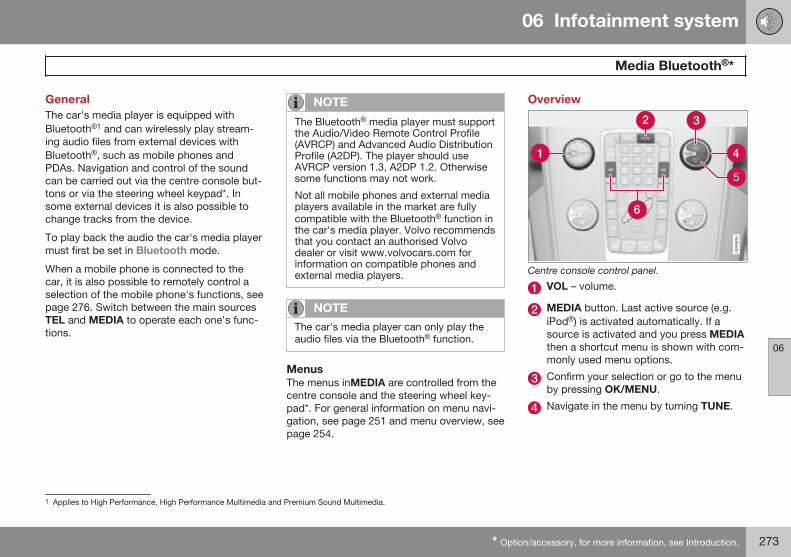
06 Infotainment system
Media Bluetooth®*
06
* Option/accessory, for more information, see Introduction. 273
GeneralThe car's media player is equipped withBluetooth®1 and can wirelessly play stream-ing audio files from external devices withBluetooth®, such as mobile phones andPDAs. Navigation and control of the soundcan be carried out via the centre console but-tons or via the steering wheel keypad*. Insome external devices it is also possible tochange tracks from the device.
To play back the audio the car's media playermust first be set in Bluetooth mode.
When a mobile phone is connected to thecar, it is also possible to remotely control aselection of the mobile phone's functions, seepage 276. Switch between the main sourcesTEL and MEDIA to operate each one's func-tions.
NOTE
The Bluetooth® media player must supportthe Audio/Video Remote Control Profile(AVRCP) and Advanced Audio DistributionProfile (A2DP). The player should useAVRCP version 1.3, A2DP 1.2. Otherwisesome functions may not work.
Not all mobile phones and external mediaplayers available in the market are fullycompatible with the Bluetooth® function inthe car's media player. Volvo recommendsthat you contact an authorised Volvodealer or visit www.volvocars.com forinformation on compatible phones andexternal media players.
NOTE
The car's media player can only play theaudio files via the Bluetooth® function.
MenusThe menus inMEDIA are controlled from thecentre console and the steering wheel key-pad*. For general information on menu navi-gation, see page 251 and menu overview, seepage 254.
Overview
Centre console control panel.
VOL – volume.
MEDIA button. Last active source (e.g.iPod®) is activated automatically. If asource is activated and you press MEDIAthen a shortcut menu is shown with com-monly used menu options.
Confirm your selection or go to the menuby pressing OK/MENU.
Navigate in the menu by turning TUNE.
1 Applies to High Performance, High Performance Multimedia and Premium Sound Multimedia.
06 Infotainment system
Media Bluetooth®*
06
274 * Option/accessory, for more information, see Introduction.
EXIT - leads up in the menu system,stops the function in progress.
Short presses are used to scroll betweenaudio files. Long presses are used tofast forward and rewind audio files.
NOTE
If the car is equipped with a steering wheelkeypad* and/or remote control* then inmany cases these can be used instead ofthe buttons in the centre console. For adescription of the buttons in the steeringwheel, see page 249. For a description ofthe remote control, see page 292.
Getting started
Connect an external Bluetooth® deviceA maximum of ten external devices can beregistered. The connection is made in thesame way as for the phone, see Connect anexternal Bluetooth® device, page 277.
Automatic connectionWhen the Bluetooth® function is active andthe last external device connected is in rangeit is connected automatically. When the info-tainment system searches for the last deviceconnected its name is shown in the TVscreen. To connect to another device, press
EXIT. Connect a new external device, see"Change to another external device" below.
Change to another external deviceIt is possible to change a connected devicewith another device if there are several devi-ces in the car. However, the device must firsthave been paired, see "Connect an externalBluetooth® device" above. To change toanother device:
1. Press MEDIA, turn TUNE until Bluetoothis displayed, press OK/MENU.
2. Check that the external device is search-able/visible via Bluetooth®, see the man-ual for the external device.
3. Press OK/MENU.
4. Turn TUNE to Change device, and con-firm with OK/MENU.> After a while, the external device's
name is shown in the TV screen. If sev-eral external devices have been pairedthen these are also shown.
5. Select the device to be connected byturning TUNE and confirm with OK/MENU.> Connection of the external device
takes place.
Change audio file by pressing / onthe centre console or the steering wheel key-pad*.
Disconnecting the deviceAutomatic disconnection takes place if theexternal device moves out of the infotainmentsystem's range. For more information on con-nection, see page 274.
Remove the connected device1. Press Bluetooth mode on OK/MENU.
2. Turn TUNE to Remove Bluetoothdevice and confirm with OK/MENU.
3. Select the device to be removed by turn-ing TUNE, and confirm with OK/MENU.> A prompt asking whether or not you
want to remove the connection isshown in the TV screen.
4. Press OK/MENU to confirm.
EXIT cancels.
06 Infotainment system
Media Bluetooth®*
06
* Option/accessory, for more information, see Introduction. 275
Random2
This function plays back the audio files on theexternal device in random order. Activate/deactivate the random function in Bluetoothmode under Bluetooth menu Random.
Change audio file by pressing / onthe centre console or the steering wheel key-pad*.
Scanning of audio files in externaldevice2
This function play backs the first ten secondsof each audio file. Activate/deactivate thefunction in Bluetooth mode under Bluetoothmenu Scan.
Cancel scanning with EXIT.
Version information Bluetooth®
The car's current Bluetooth® version can beseen in Bluetooth mode under Bluetoothmenu Bluetooth software version in car.
2 Not supported by all mobile phones.
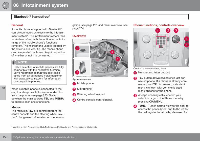
06 Infotainment system
Bluetooth® handsfree*
06
276 * Option/accessory, for more information, see Introduction.
GeneralA mobile phone equipped with Bluetooth®
can be connected wirelessly to the Infotain-ment system1. The infotainment system thenworks handsfree, with the option to control arange of the mobile phone's functionsremotely. The microphone used is located bythe driver's sun visor (2). The mobile phonecan be operated by its own keys irrespectiveof whether or not it is connected.
NOTE
Only a selection of mobile phones are fullycompatible with the handsfree function.Volvo recommends that you seek assis-tance from an authorised Volvo dealer orvisit www.volvocars.com for informationon compatible phones.
When a mobile phone is connected to thecar, it is also possible to stream audio filesfrom the phone, see page 273. Switchbetween the main sources TEL and MEDIAto operate each one's functions.
MenusThe menus in TEL are controlled from thecentre console and the steering wheel key-pad*. For general information on menu navi-
gation, see page 251 and menu overview, seepage 254.
Overview
System overview
Mobile phone.
Microphone.
Steering wheel keypad.
Centre console control panel.
Phone functions, controls overview
Centre console control panel.
Number and letter buttons
TEL button activates/searches last con-nected phone. If a phone is already con-nected, and TEL is pressed, a shortcutmenu is shown with commonly usedmenu options for the phone.
Accept incoming calls, confirm yourselection or go to the Phone menu bypressing OK/MENU.
TUNE - Turn in normal view to the right toaccess the phone book, and to the left forthe call register for all calls; also used for
1 Applies to High Performance, High Performance Multimedia and Premium Sound Multimedia.
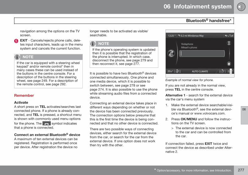
06 Infotainment system
Bluetooth® handsfree*
06
* Option/accessory, for more information, see Introduction. 277
navigation among the options on the TVscreen.
EXIT - Cancels/rejects phone calls, dele-tes input characters, leads up in the menusystem and cancels the current function.
NOTE
If the car is equipped with a steering wheelkeypad* and/or remote control* then inmany cases these can be used instead ofthe buttons in the centre console. For adescription of the buttons in the steeringwheel, see page 249. For a description ofthe remote control, see page 292.
Remember
ActivateA short press on TEL activates/searches lastconnected phone. If a phone is already con-nected, and TEL is pressed, a shortcut menuis shown with commonly used menu optionsfor the phone. The symbol indicatesthat a phone is connected.
Connect an external Bluetooth® deviceA maximum of ten external devices can beregistered. Registration is performed onceper device. After registration the device no
longer needs to be activated as visible/searchable.
NOTE
If the phone's operating system is updatedthen it is possible that the registration ofthe phone is interrupted. In which case,disconnect the phone, see page 279 andthen reconnect it, see page 277.
It is possible to have two Bluetooth® devicesconnected simultaneously. One phone andone media device, which it is possible toswitch between, see page 278 or seepage 274. It is also possible to use the phonewhile streaming audio files from a connecteddevice.
Connecting an external device takes place indifferent ways depending on whether or notthe device has been connected previously.The connection options below presume thatthis is the first time the device is being con-nected and that no other device is connected.
There are two possible ways of connectingdevices, either search for the external devicefrom the car, or search for the car from theexternal device. If one option does not workthen try with the other.
Example of normal view for phone.
If you are not already in the normal view,press TEL in the centre console.
Alternative 1 - search for the external devicevia the car's menu system
1. Make the external device searchable/visi-ble via Bluetooth®, see the external devi-ce's manual or www.volvocars.com.
2. Press OK/MENU and follow the instruc-tions on the TV screen.> The external device is now connected
to the car and can be controlled fromthe car.
If connection failed, press EXIT twice andconnect the device as described under Alter-native 2.
06 Infotainment system
Bluetooth® handsfree*
06
278 * Option/accessory, for more information, see Introduction.
Alternative 2 - Search for the car with theBluetooth® function of the external device.
1. Make the car searchable/visible viaBluetooth®. Turn TUNE to Phonesettings, confirm with OK/MENU, selectDiscoverable and confirm with OK/MENU.
2. Select My Volvo Car on the screen of theexternal device and follow the instruc-tions.
3. Enter a PIN code in the external deviceand then select to connect.
4. Press OK/MENU and enter the same PINcode via the car keypad in the centreconsole.
Once the external device is connected, itsBluetooth® name appears on the car's TVscreen and the unit can be controlled fromthe car.
Automatic connectionWhen the handsfree function is active and thelast mobile phone connected is in range it isconnected automatically. If the last con-nected mobile phone is not available then thesystem will try to connect a mobile phonethat was paired earlier. When the audio sys-
tem searches for the last phone connected itsname is shown in the TV screen.
Manual connectionIf you want to change the connected mobilephone, go in phone mode to Phone menuChange phone.
Change to another external deviceIt is possible to change a connected devicewith another device if there are several devi-ces in the car. However, the device must firsthave been registered to the car, see Connectan external Bluetooth® device. To change toanother device:
1. Check that the external device is search-able/visible via Bluetooth®, see the man-ual for the external device.
2. Press TEL and then select Changephone.> The car searches for previously con-
nected devices. The external devicesdetected are specified with theirrespective Bluetooth® name in the TVscreen.
3. Select the device to be connected byturning TUNE and confirm with OK/MENU.
> Connection of the external devicetakes place.
To call1. Make sure that the symbol appears
at the top of the TV screen and that thehandsfree function is in phone mode.
2. Dial either the desired number or speeddial number, see page 283. Or in normalview turn TUNE to the right to access thephone book, and to the left for the callregister for all calls. For information onthe phone book, see page 280.
3. Press OK/MENU.
The call is interrupted with EXIT.
Disconnecting the mobile phoneAutomatic disconnection takes place if themobile phone moves out of the audio sys-tem's range. The connection to the mobilephone can be manually broken in phonemode under Phone menu Disconnectphone. For more information on connection,see page 277.
The handsfree function is deactivated whenthe engine is switched off and the door isopened2.
2 Only Keyless Drive.
06 Infotainment system
Bluetooth® handsfree*
06
* Option/accessory, for more information, see Introduction. 279
When the mobile phone has been discon-nected an ongoing call can be continued byusing the mobile phone's built-in microphoneand speaker.
NOTE
Even when your mobile phone has beenmanually disconnected, some mobilephones may automatically couple up tothe last handsfree unit connected, e.g.when a new call begins.
Remove the deviceA connected mobile phone can be deregis-tered and removed. This is performed inphone mode under Phone menu RemoveBluetooth device.
Making and receiving calls
Incoming call– Press OK/MENU to answer the call, even
if the audio system is in e.g. RADIO orMEDIA mode.
Refuse or end with EXIT.
Automatic answerThe automatic answer function means thatcalls are accepted automatically.
– Activate/deactivate in phone mode underPhone menu Call options Autoanswer.
In call menuPress OK/MENU during an ongoing call toaccess the following functions:
• Mute - audio system microphone ismuted.
• Mobile phone - the call is transferredfrom handsfree to the mobile phone. Forsome mobile phones the connection isinterrupted. This is normal. The handsfreefunction asks if you want to reconnect.
• Dial number - option to call a third partyusing the number keys (current call set instandby).
Call listsThe call lists are copied to the handsfreefunction at each new connection and are thenupdated during the connection. In normalview, turn to the left with TUNE to see the callregister for All calls .
In phone mode it is possible to see all the calllists under Phone menu All calls:
• All calls
• Missed calls
• Answered calls
• Dialled calls
• Call duration
NOTE
Certain mobile phones show a list of thelast dialled numbers in reverse order.
Voice mailboxIn normal view a speed dial number for thevoice mailbox can be programmed in andthen accessed later via a long press on 1.
Voice mailbox number is changed in phonemode under Phone menu Call optionsVoicemail number Change number. Ifthere is no number stored then this menu canbe reached with one long press on 1.
Audio settings
Phone call volumeThe phone call volume can only be changedduring a call. Use the steering wheel keypad*or turn the VOL control.
Audio system volumeProviding there is no ongoing call takingplace, the audio system volume is controlledas usual by turning VOL.
If an audio source is active during an incom-ing call then it can be muted automatically.
06 Infotainment system
Bluetooth® handsfree*
06
280 * Option/accessory, for more information, see Introduction.
Activate/deactivate in phone mode underPhone menu Phone settings Soundsand volume Mute radio/media.
Ring volumeIn phone mode go to Phone menu Phonesettings Sounds and volume Ringvolume and adjust by turning VOL. PressOK/MENU to hear the audio volume. PressEXIT to save.
Ring signalsThe handsfree function has integrated ringsignals that can be selected in phone modeunder Phone menu Phone settingsSounds and volume Ring signals Ringsignal 1 etc.
NOTE
For some mobile phones, the ringtone onthe phone connected will not be switchedoff when one of the inbuilt signals for thehandsfree system is used.
In order to select the connected phone's ringsignal3, go in phone mode to Phone menu
Phone settings Sounds and volume
Ring signals Mobile phone ringsignal.
Phone bookThere are two phone books. These aremerged into one in the car and are displayedas a single phone book in the car.
• The car downloads the mobile phone'sphone book and only displays this phonebook when the mobile phone from whichthis phone book was downloaded is con-nected.
• The car also has a built-in phone book.This contains all the contacts stored inthe car irrespective of which phone wasconnected when saving them. These con-tacts are visible for all users, regardless ofthe mobile phone that is connected to thecar. If a contact is saved in the car thenthe symbol is shown in front of thecontact in the phone book.
NOTE
Changes made from the car to a record inthe mobile phone's telephone book willresult in a new record in the car's tele-phone book, i.e. changes will not be savedto the phone. From the car, this will nowlook like you have double records, with dif-ferent icons. Note also that when a short-cut number is saved or a change to a con-tact is made, this will result in a newrecord in the car's phone book.
All use of the phone book requires that the symbol appears at the top of the TV
screen and that the handsfree function is inphone mode.
The audio system stores a copy of the phonebook from each paired mobile phone. Thephone book can be copied automatically tothe audio system during each connection.
– Activate/deactivate the function in phonemode under Phone menu Phonesettings Download phone book.
If the phone book contains a ringing caller'scontact information then this is shown in theTV screen.
3 Not supported by all mobile phones.
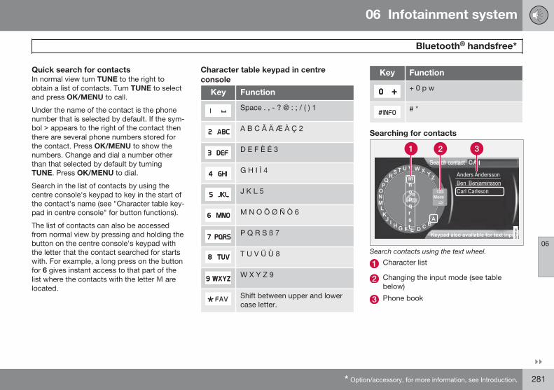
06 Infotainment system
Bluetooth® handsfree*
06
}}* Option/accessory, for more information, see Introduction. 281
Quick search for contactsIn normal view turn TUNE to the right toobtain a list of contacts. Turn TUNE to selectand press OK/MENU to call.
Under the name of the contact is the phonenumber that is selected by default. If the sym-bol > appears to the right of the contact thenthere are several phone numbers stored forthe contact. Press OK/MENU to show thenumbers. Change and dial a number otherthan that selected by default by turningTUNE. Press OK/MENU to dial.
Search in the list of contacts by using thecentre console's keypad to key in the start ofthe contact's name (see "Character table key-pad in centre console" for button functions).
The list of contacts can also be accessedfrom normal view by pressing and holding thebutton on the centre console's keypad withthe letter that the contact searched for startswith. For example, a long press on the buttonfor 6 gives instant access to that part of thelist where the contacts with the letter M arelocated.
Character table keypad in centreconsole
Key Function
Space . , - ? @ : ; / ( ) 1
A B C Å Ä Æ À Ç 2
D E F È Δ 3
G H I Ì 4
J K L 5
M N O Κ Ø Ñ Ò 6
P Q R S Τ 7
T U V Ü Ù 8
W X Y Z 9
Shift between upper and lowercase letter.
Key Function
+ 0 p w
# *
Searching for contacts
Search contacts using the text wheel.
Character list
Changing the input mode (see tablebelow)
Phone book
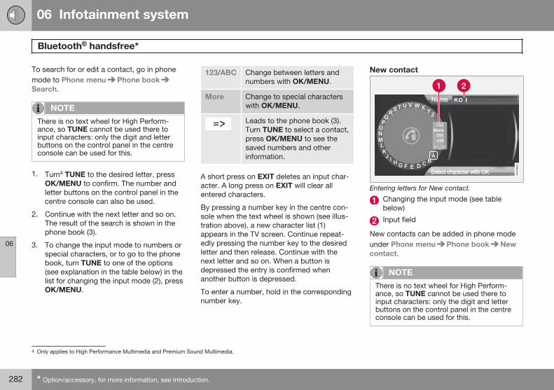
06 Infotainment system
Bluetooth® handsfree*
06
282 * Option/accessory, for more information, see Introduction.
To search for or edit a contact, go in phonemode to Phone menu Phone bookSearch.
NOTE
There is no text wheel for High Perform-ance, so TUNE cannot be used there toinput characters: only the digit and letterbuttons on the control panel in the centreconsole can be used for this.
1. Turn4 TUNE to the desired letter, pressOK/MENU to confirm. The number andletter buttons on the control panel in thecentre console can also be used.
2. Continue with the next letter and so on.The result of the search is shown in thephone book (3).
3. To change the input mode to numbers orspecial characters, or to go to the phonebook, turn TUNE to one of the options(see explanation in the table below) in thelist for changing the input mode (2), pressOK/MENU.
123/ABC Change between letters andnumbers with OK/MENU.
More Change to special characterswith OK/MENU.
Leads to the phone book (3).Turn TUNE to select a contact,press OK/MENU to see thesaved numbers and otherinformation.
A short press on EXIT deletes an input char-acter. A long press on EXIT will clear allentered characters.
By pressing a number key in the centre con-sole when the text wheel is shown (see illus-tration above), a new character list (1)appears in the TV screen. Continue repeat-edly pressing the number key to the desiredletter and then release. Continue with thenext letter and so on. When a button isdepressed the entry is confirmed whenanother button is depressed.
To enter a number, hold in the correspondingnumber key.
New contact
Entering letters for New contact.
Changing the input mode (see tablebelow)
Input field
New contacts can be added in phone modeunder Phone menu Phone book Newcontact.
NOTE
There is no text wheel for High Perform-ance, so TUNE cannot be used there toinput characters: only the digit and letterbuttons on the control panel in the centreconsole can be used for this.
4 Only applies to High Performance Multimedia and Premium Sound Multimedia.
06 Infotainment system
Bluetooth® handsfree*
06
}}* Option/accessory, for more information, see Introduction. 283
1. When the Name row is selected, pressOK/MENU to reach the input mode (illus-tration above).
2. Turn4 TUNE to the desired letter, pressOK/MENU to confirm. The number andletter buttons on the control panel in thecentre console can also be used.
3. Continue with the next letter and so on.The name entered is shown in the inputfield (2) in the TV screen.
4. To change the input mode to numbers,special characters, change betweenuppercase/lowercase letters, etc., turnTUNE to one of the options (see explana-tion in the table below) in the list (1) andthen press OK/MENU.
When the name has been fully entered, selectOK in the list on the TV screen (1) and pressOK/MENU. Now continue with the telephonenumber in the same way as above.
When the telephone number has beenentered, press OK/MENU and select a tele-phone number type (Mobile phone, Home,Work or General). Press OK/MENU to con-firm.
When all details have been filled in, selectSave contact in the menu to save the con-tact.
123/ABC Change between letters andnumbers with OK/MENU.
More Change to special characterswith OK/MENU.
OK Save and go back to Addcontact with OK/MENU.
Change between uppercaseand lowercase letters with OK/MENU.
Press OK/MENU, the cursormoves to the input field (2) atthe top of the TV screen. Thecursor can now be moved,with TUNE, to the appropriateplace to e.g. insert new lettersor delete with EXIT. To be ableto insert new letters first goback to the input mode, bypressing OK/MENU.
Speed dial numbersUse phone mode to add speed dial numbersunder Phone menu Phone bookSpeed dial.
Dialling with speed dial numbers can be per-formed in phone mode using the numberkeys on the keypad in the centre console, bypressing a number key and then pressingOK/MENU. If there is no contact stored onthe speed dial number then an option isshown to save a contact to the selectedspeed dial number.
Receiving a vCardIt is possible to receive a vCard to the car'sphone book from other mobile phones (otherthan the one currently connected to the car).In order to allow this the car is set to visiblemode for Bluetooth®. The function is acti-vated in phone mode under Phone menuPhone book Receive vCard.
Memory statusMemory status of the car's phone book andthe connected mobile phone's phone bookcan be seen in phone mode under Phonemenu Phone book Memory status.
4 Only applies to High Performance Multimedia and Premium Sound Multimedia.
06 Infotainment system
Bluetooth® handsfree*
06
284 * Option/accessory, for more information, see Introduction.
Delete phone bookThe car's phone book can be deleted, this iscarried out in phone mode under Phonemenu Phone book Clear phone book.
NOTE
Deleting the car's telephone book onlydeletes contacts in the car's telephonebook. Contacts in the mobile phone'sphone book are not deleted.
Version information Bluetooth®
The car's current Bluetooth® version can beseen in phone mode under Phone menuPhone settings Bluetooth softwareversion in car.
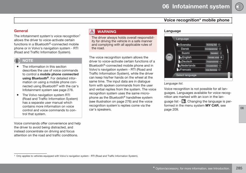
06 Infotainment system
Voice recognition* mobile phone
06
* Option/accessory, for more information, see Introduction. 285
GeneralThe infotainment system's voice recognition1
allows the driver to voice-activate certainfunctions in a Bluetooth®-connected mobilephone or in Volvo's navigation system - RTI(Road and Traffic Information System).
NOTE
• The information in this sectiondescribes the use of voice commandsto control a mobile phone connectedusing Bluetooth®. For detailed infor-mation on using a mobile phone con-nected using Bluetooth® with the car'sInfotainment system see page 276.
• The Volvo navigation system RTI(Road and Traffic Information System)has a separate user manual whichcontains more information on voicecontrol and voice commands to con-trol that system.
Voice commands offer convenience and helpthe driver to avoid being distracted, andinstead concentrate on driving and focusattention on the road and traffic conditions.
WARNING
The driver always holds overall responsibil-ity for driving the vehicle in a safe mannerand complying with all applicable rules ofthe road.
The voice recognition system allows thedriver to voice-activate certain functions of aBluetooth®-connected mobile phone and inVolvo's navigation system - RTI (Road andTraffic Information System), while the drivercan keep his/her hands on the wheel at thesame time. The input data are in dialogueform with spoken commands from the userand verbal replies from the system. The voicerecognition system uses the same micro-phone as the Bluetooth® handsfree system(see illustration on page 276) and the voicerecognition system's replies come via thecar's speakers.
Language
Language list.
Voice recognition is not possible for all lan-guages. Languages available for voice recog-nition are marked with an icon in the lan-guage list - . Changing the language is per-formed in the menu system MY CAR, seepage 209.
1 Only applies to vehicles equipped with Volvo's navigation system - RTI (Road and Traffic Information System).
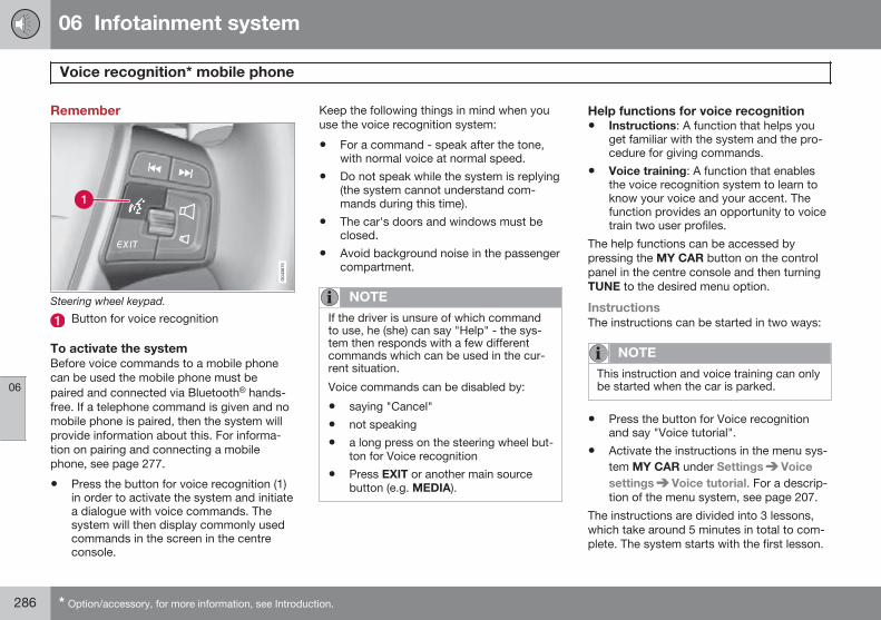
06 Infotainment system
Voice recognition* mobile phone
06
286 * Option/accessory, for more information, see Introduction.
Remember
Steering wheel keypad.
Button for voice recognition
To activate the systemBefore voice commands to a mobile phonecan be used the mobile phone must bepaired and connected via Bluetooth® hands-free. If a telephone command is given and nomobile phone is paired, then the system willprovide information about this. For informa-tion on pairing and connecting a mobilephone, see page 277.
• Press the button for voice recognition (1)in order to activate the system and initiatea dialogue with voice commands. Thesystem will then display commonly usedcommands in the screen in the centreconsole.
Keep the following things in mind when youuse the voice recognition system:
• For a command - speak after the tone,with normal voice at normal speed.
• Do not speak while the system is replying(the system cannot understand com-mands during this time).
• The car's doors and windows must beclosed.
• Avoid background noise in the passengercompartment.
NOTE
If the driver is unsure of which commandto use, he (she) can say "Help" - the sys-tem then responds with a few differentcommands which can be used in the cur-rent situation.
Voice commands can be disabled by:
• saying "Cancel"
• not speaking
• a long press on the steering wheel but-ton for Voice recognition
• Press EXIT or another main sourcebutton (e.g. MEDIA).
Help functions for voice recognition• Instructions: A function that helps you
get familiar with the system and the pro-cedure for giving commands.
• Voice training: A function that enablesthe voice recognition system to learn toknow your voice and your accent. Thefunction provides an opportunity to voicetrain two user profiles.
The help functions can be accessed bypressing the MY CAR button on the controlpanel in the centre console and then turningTUNE to the desired menu option.
InstructionsThe instructions can be started in two ways:
NOTE
This instruction and voice training can onlybe started when the car is parked.
• Press the button for Voice recognitionand say "Voice tutorial".
• Activate the instructions in the menu sys-tem MY CAR under Settings Voicesettings Voice tutorial. For a descrip-tion of the menu system, see page 207.
The instructions are divided into 3 lessons,which take around 5 minutes in total to com-plete. The system starts with the first lesson.
06 Infotainment system
Voice recognition* mobile phone
06
}}* Option/accessory, for more information, see Introduction. 287
To skip a lesson and go to the next one,press the button for voice recognition and say"Next". Go back to the previous lesson bysaying "Previous".
Exit the instructions by means of a long presson the button for voice recognition.
Voice trainingThe system displays up to fifteen phrases foryou to say. Voice training can be started inthe menu system MY CAR under SettingsVoice settings Voice training. Choosebetween User 1 or User 2. For a descriptionof the menu system, see page 207.
After voice training has been completed,remember to set your user profile underVoice user setting.
Additional settings in MY CAR• User setting - Two user profiles can be
set, the function is activated in the menusystem MY CAR under Settings Voicesettings Voice user setting. Choosebetween User 1 or User 2. For a descrip-tion of the menu system, see page 207.
• Voice volume - Can be changed in themenu system MY CAR under Settings
Voice settings Voice outputvolume. For a description of the menusystem, see page 207.
Using voice commandsThe driver initiates a dialogue with the voicecommands by pressing the button for voicerecognition (see illustration on page 286).
Once a dialogue has been started, commonlyused commands will be shown in the screen.Greyed-out text or text within brackets is notincluded in the spoken command.
When the driver becomes accustomed to thesystem, he/she can speed up the commanddialogue and skip the prompts from the sys-tem, by briefly pressing the button for voicerecognition.
Commands can be given in several ways
The command "Phone call contact" can bepronounced as e.g.:
• "Phone > Call contact" - Say "Phone",wait for the system's reply, and then con-tinue by saying "Call contact."
or
• "Phone call contact" - Say the wholecommand in one sequence.
Quick commandsQuick commands for the phone can be foundin the menu system MY CAR under Settings
Voice settings Voice command listPhone commands and General
commands. For a description of the menusystem, see page 207.
Dial a numberThe system understands the numbers 0 (zero)to 9 (nine). These numbers can be pro-nounced individually, in groups of severalnumbers at a time, or the whole number all atonce. Numbers greater than 9 (nine) cannotbe handled by the system, e.g. 10 (ten) or 11(eleven) are not possible.
The following is an example of a dialoguewith voice commands. The system's reply willvary depending on the situation.
The user starts the dialogue by saying:Phone > call number
or
Phone call number
System replyNumber?
User actionStart saying the numbers (as individual units,i.e. six-eight-seven, etc.) in the phone num-ber. If you say several numbers and pause,the system will repeat them, and then say"Continue".
Continue to say the numbers. When finished,finish the command by saying "Call".
06 Infotainment system
Voice recognition* mobile phone
06
288 * Option/accessory, for more information, see Introduction.
• You can also change the number by say-ing the commands "Correct" (which dele-tes the last spoken group of numbers) or"Delete" (which deletes the whole spokenphone number).
Dialling from the call registerThe following dialogue allows you to make aphone call from one of your mobile phone'scall registers.
The user starts the dialogue by saying:Phone > call from the call register
or
Phone call from the call register
Continue by responding to the system'sprompts.
Call a contactThe following dialogue allows you to call yourpre-defined contacts in the mobile phone.
The user starts the dialogue by saying:Phone > call contact
or
Phone call contact
Continue by responding to the system'sprompts.
Consider the following when you call a con-tact:
• If there are several contacts with similarnames, they will be presented in thescreen in the numbered rows and thesystem prompts you to select a row num-ber.
• If there are more rows in the list than canbe displayed simultaneously, saying"Down" allows you to scroll down in thelist (and saying "Up" allows you to scrollup in the list).
Calling voice mailboxThe following dialogue allows you to call yourvoice mailbox to check if you have receivedany messages. The phone number for yourvoice mailbox must be registered in theBluetooth® function, see page 279.
The user starts the dialogue by saying:Phone > call voice mailbox
or
Phone call voice mailbox
Continue by responding to the system'sprompts.
06 Infotainment system
TV*
06
* Option/accessory, for more information, see Introduction. 289
General
NOTE
This system only supports TV broadcastsin the countries that broadcast in MPEG-2format or MPEG-4 format and follow theDVB-T standard. The system does notsupport analogue broadcasts.
NOTE
The TV picture is only shown when the caris stationary. When the car is moving at aspeed over about 6 km/h the picture dis-appears, No visual media availablewhile driving appears on the displayscreen, although the audio is heard duringthis time. The picture reappears when thecar has stopped.
NOTE
The reception is dependent both on howgood the signal strength and signal qualityare. The transmission may be disturbed byvarious factors such as tall buildings or theTV transmitter being far away. Coveragelevel can also vary depending on where inthe country you are located.
IMPORTANT
A TV licence is required for this product insome countries.
MenusThe menus inMEDIA are controlled from thecentre console and the steering wheel key-pad*. For general information on menu navi-gation, see page 251 and menu overview, seepage 254.
Overview
Centre console control panel.
Station presets, numeric input.
MEDIA button. Last active source (e.g.iPod® or TV) is activated. If a source isactivated and you press MEDIA then a
shortcut menu is shown with commonlyused menu options.
Confirm your selection or go to the menuby pressing OK/MENU.
Navigate in channel lists or menus byturning TUNE.
EXIT - leads up in the menu system,stops the function in progress.
The next available channel is shown bypressing / .
NOTE
If the car is equipped with a steering wheelkeypad* and/or remote control* then inmany cases these can be used instead ofthe buttons in the centre console. For adescription of the buttons in the steeringwheel, see page 249. For a description ofthe remote control, see page 292.
Watch TV– Press MEDIA, turn TUNE until TV is
shown in the display, press OK/MENU.> A search starts and after a short while
the most recently used channel isshown.
Changing channelIt is possible to change channel as follows:
06 Infotainment system
TV*
06
290 * Option/accessory, for more information, see Introduction.
• Turn TUNE, a list of all available channelsin the area is shown. If any of these chan-nels is already saved as a preset then itspreset number is shown to the right of thechannel name. Continue turning TUNE toreach the desired channel and press OK/MENU.
• By pressing the preset buttons (0-9).
• Via a short press on the / but-tons the next available channel in the areais shown.
NOTE
If the car has been moved within the coun-try, for example, from one city to another,it is not certain that the presets are availa-ble at the new location as the frequencyrange may have changed. In which case,carry out a new search and save a newpreset list, see the function "Save theavailable TV channels as presets", page290.
NOTE
If no reception is available on the presetbuttons, it may be because the car is at alocation other than where the scan of TVchannels was run, for example, if the carwas driven from Germany to France. Anew selection of country and a new searchmay then need to be carried out.
Searching TV channels/Preset list1. Press TV mode on OK/MENU.
2. Turn TUNE to TV menu and press OK/MENU.
3. Turn TUNE to Select country and pressOK/MENU.> If one or more countries have previ-
ously been selected then they areshown in a list.
4. Turn TUNE to either Other countries orone of the previously selected countries.Press OK/MENU.> A list of all available countries is
shown.
5. Turn TUNE to the desired country (e.g.Sweden) and press OK/MENU.> An automatic scan for available TV
channels starts, this scan takes a littlewhile. During this time the figure foreach channel found and added as apreset is shown. When the scan iscomplete a message is shown and thepicture is shown. A preset list (max. 30presets) has now been created and isavailable. To change channel, seepage 289.
The scan and preset storage can be cancel-led with EXIT.
Channel managementThe preset list can be edited. You can changethe order of the channels that are shown inthe preset list. A TV channel can have morethan one place in the preset list. The TV chan-nel positions can also vary in the preset list.
To change the order in the preset list, go inTV mode to TV menu Reorganisepresets.
1. Turn TUNE to the channel you want tomove in the list and confirm with OK/MENU.> The selected channel is highlighted.
2. Turn TUNE to the new location in the listand confirm with OK/MENU.> The channels change places with each
other.
After the preset channels (max. 30) come allthe other channels available in the area. It ispossible to move a channel up to a place inthe preset list.
Save the available TV channels aspresetsIf the car has been moved within the country,for example, from one city to another, it is notcertain that the presets are available at thenew location as the frequency range may
06 Infotainment system
TV*
06
* Option/accessory, for more information, see Introduction. 291
have changed. In which case, carry outanother scan and save a new preset list.
1. Press TV mode on OK/MENU.
2. Turn TUNE to TV menu and press OK/MENU.
3. Turn TUNE to Autostore and press OK/MENU.> An automatic scan for available TV
channels starts, this scan takes a littlewhile. During this time the figure foreach channel found and added as apreset is shown. When the scan iscomplete a message is shown and thepicture is shown. A preset list (max. 30presets) has now been created and isavailable. To change channel, seepage 289.
Scanning the TV channelsThis function automatically scans through thefrequency range for all channels available inthe area where you are. When a channel isfound, it is shown for approx. 10 secondsbefore scanning is resumed. Scanning isstopped with EXIT, then the channel that youjust watched continues to be shown. Scan-ning does not affect the preset list.
Activate scanning in TV mode under TVmenu Scan.
TeletextIt is possible to read Teletext. Follow thesesteps:
1. Press the button on the remotecontrol.
2. Enter the page number (3 digits) with thenumber keys (0-9) to select page.> The page is shown automatically.
Enter new page number, or press the remotecontrol buttons / to go to the nextpage.
Return to TV screen with EXIT or by pressingthe button on the remote control.
It is also possible to control the teletext withthe coloured buttons on the remote control.
Information about the currentprogrammePress the INFO button in order to display theinformation about the current programme, thenext programme and its start time. If theINFO button is pressed once more then addi-tional information on the current programmecan sometimes be displayed, such as startand end times and a brief description of thecurrent programme. For more information onthe INFO button, see page 249.
To return to the TV picture, wait several sec-onds or press EXIT.
Picture settingsThe settings for brightness and contrast canbe adjusted. For more information, seepage 269.
The reception is lostIf the reception for the TV channel that isbeing shown disappears then the picture willfreeze. Shortly after this a message appearsinforming that the reception has been lost forthe current TV channel, and a new search forthe channel continues. When the receptionreturns the display of the TV channel startsimmediately. It is possible to change channelat any time when the message is shown.
If the message Reception lost, searching isshown then this is because the system hasdetected that there is no reception for all TVchannels. One possible reason may be that aborder has been crossed and that the systemis set to the wrong country. In which case,change to the right country in accordancewith "Searching TV channels/Preset list", seepage 290.
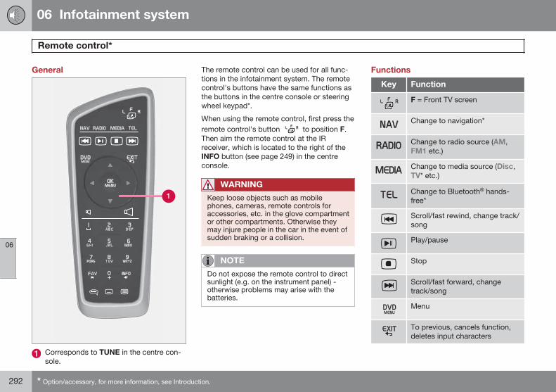
06 Infotainment system
Remote control*
06
292 * Option/accessory, for more information, see Introduction.
General
Corresponds to TUNE in the centre con-sole.
The remote control can be used for all func-tions in the infotainment system. The remotecontrol's buttons have the same functions asthe buttons in the centre console or steeringwheel keypad*.
When using the remote control, first press theremote control's button to position F.Then aim the remote control at the IRreceiver, which is located to the right of theINFO button (see page 249) in the centreconsole.
WARNING
Keep loose objects such as mobilephones, cameras, remote controls foraccessories, etc. in the glove compartmentor other compartments. Otherwise theymay injure people in the car in the event ofsudden braking or a collision.
NOTE
Do not expose the remote control to directsunlight (e.g. on the instrument panel) -otherwise problems may arise with thebatteries.
Functions
Key Function
F = Front TV screen
Change to navigation*
Change to radio source (AM,FM1 etc.)
Change to media source (Disc,TV* etc.)
Change to Bluetooth® hands-free*
Scroll/fast rewind, change track/song
Play/pause
Stop
Scroll/fast forward, changetrack/song
Menu
To previous, cancels function,deletes input characters
06 Infotainment system
Remote control*
06
* Option/accessory, for more information, see Introduction. 293
Key Function
Navigate up/down
Navigate right/left
Confirm selection or go to themenu system for the selectedsource
Volume, decrease
Volume, increase
0-9 Preset channels, number andletter input
Shortcuts for favourite setting
Information about the currentprogramme, song, etc. Alsoused when there is more infor-mation available than can beshown in the TV screen
Selection of language for sound-track
Key Function
Subtitles, selection of languagefor text
Teletext*, On/Off
Replacing the battery in the remotecontrol
NOTE
Battery life is normally 1-4 years anddepends on how much the remote controlis used.
The remote control is powered by four batter-ies of the AA/LR6 type.
Take along extra batteries for a long journey.
1. Push down the catch on the battery coverand slide the battery cover in the direc-tion of the infrared lens.
2. Remove the used batteries, turn the newbatteries in accordance with the symbolsin the battery compartment and fit them.
3. Refit the cover.
NOTE
Be sure to dispose of the exhausted bat-teries in an environmentally safe manner.
294
Recommendations during driving......................................................... 296Refuelling.............................................................................................. 299Fuel....................................................................................................... 301Loading................................................................................................. 304Cargo area............................................................................................ 307Driving with a trailer.............................................................................. 309Towing and recovery............................................................................. 315
DURING YOUR JOURNEY
07 During your journey
Recommendations during driving
07
296
General
Economical drivingDriving economically means driving smoothlywhile thinking ahead and adjusting your driv-ing style and speed to the prevailing condi-tions.
• Drive in the highest gear possible, adap-ted to the current traffic situation androad - lower engine speeds result in lowerfuel consumption.
• Avoid driving with open windows.
• Avoid sudden unnecessary accelerationand heavy braking.
• Remove unnecessary items from the car -the greater the load the higher the fuelconsumption.
• Use engine braking to slow down, when itcan take place without risk to other roadusers.
• A roof load and ski box increase air resis-tance, leading to higher fuel consumption- remove the load carriers when not inuse.
• Do not run the engine to operating tem-perature at idling speed, but rather drivewith a light load as soon as possible - acold engine consumes more fuel than awarm one.
• Cars with manual transmission arestarted in 2nd gear (applies to cars with
up to 18-inch wheels) under normal con-ditions on flat ground.
For more information and further advice, seethe pages 11 and 387.
WARNING
Never switch off the engine while moving,such as downhill, this deactivates impor-tant systems such as the power steeringand brake servo.
Driving in waterThe car can be driven through water at amaximum depth of 25 cm at a maximumspeed of 10 km/h. Extra caution should beexercised when passing through flowingwater.
During driving in water, maintain a low speedand do not stop the car. When the water hasbeen passed, depress the brake pedal lightlyand check that full brake function is achieved.Water and mud for example can make thebrake linings wet resulting in delayed brakefunction.
• Clean the electric contacts of the electricengine block heater and trailer couplingafter driving in water and mud.
• Do not let the car stand with water overthe sills for any long period of time - thiscould cause electrical malfunctions.
IMPORTANT
Engine damage can occur if water entersthe air filter.
In depths greater than 25 cm, water couldenter the transmission. This reduces thelubricating ability of the oils and shortensthe service life of these systems.
In the event of the engine stalling in water,do not try restart - tow the car from thewater to a workshop - an authorised Volvoworkshop is recommended. Risk of enginebreakdown.
Engine, gearbox and cooling systemUnder special conditions, for example harddriving in hilly terrain and hot climate, there isa risk that the engine and drive system mayoverheat - in particular with a heavy load.
For information about overheating when driv-ing with a trailer, see page 310.
• Remove any auxiliary lamps from in frontof the grille when driving in hot climates.
• If the temperature in the engine's coolingsystem is too high then a warning symbolis illuminated and a text message Highengine temp Stop safely is shown in thecombined instrument panel's informationdisplay - stop the car in a safe way andallow the engine to run at idling speed forseveral minutes in order to cool down.
07 During your journey
Recommendations during driving
07
297
• If the text message High engine tempStop engine or Coolant level low, Stopengine is shown then the engine must beswitched off after stopping the car.
• In the event of overheating in the gearboxa built-in protection function is activated,which is indicated by the combinedinstrument panel with a warning symboland the text message Transmission hotReduce speed or Transmission hotStop safely - follow the recommendationgiven and lower the speed and stop thecar in a safe way and allow the engine torun at idling speed for a few minutes inorder to allow the gearbox to cool down.
• If the car overheats, the air conditioningmay be switched off temporarily.
• Do not turn the engine off immediatelyyou stop after a hard drive.
NOTE
It is normal for the engine's cooling fan tooperate for a time after the engine hasbeen switched off.
Open tailgate
WARNING
Do not drive with an open tailgate! Toxicexhaust fumes could be drawn into the carthrough the cargo area.
Do not overload the batteryThe electrical functions in the car load thebattery to varying degrees. Avoid using thekey position II when the engine is switchedoff. Instead use the I mode - which uses lesspower.
Also, be aware of different accessories thatload the electrical system. Do not use func-tions which use a lot of power when theengine is switched off. Examples of suchfunctions are:
• ventilation fan
• headlamps
• windscreen wiper
• audio system (high volume).
If the starter battery's voltage is low then theinformation display in the combined instru-ment panel shows the text Low batteryPower save mode. The energy-saving func-tion then shuts down certain functions orreduces certain functions such as the ventila-tion fan and/or audio system.
– In which case, charge the battery by star-ting the engine and then running it for atleast 15 minutes - battery charging ismore effective during driving than runningthe engine at idling speed while station-ary.
Before a long journey• Check that the engine is working normally
and that fuel consumption is normal.
• Make sure that there are no leaks (fuel, oilor other fluid).
• Check all bulbs and tyre tread depths.
• Carrying a warning triangle is a legalrequirement in certain countries.
Winter drivingCheck the following in particular before thecold season:
• The engine coolant must contain at least50% glycol. This mixture protects theengine against frost erosion down toapproximately –35 °C. To achieve opti-mum antifreeze protection, different typesof glycol must not be mixed.
• The fuel tank must be kept filled to pre-vent condensation.
• Engine oil viscosity is important. Oils withlower viscosity (thinner oils) facilitate star-ting in cold weather and also reduce fuelconsumption while the engine is cold. For
07 During your journey
Recommendations during driving
07
298
more information on suitable oils, seepage 383.
IMPORTANT
Low viscosity oil must not be used for harddriving or in hot weather.
• The condition of the battery and chargelevel must be inspected. Cold weatherplaces great demands on the battery andits capacity is reduced by the cold.
• Use washer fluid to avoid ice forming inthe washer fluid reservoir.
To achieve optimum roadholding Volvo rec-ommends using winter tyres on all wheels ifthere is a risk of snow or ice.
NOTE
The use of winter tyres is a legal require-ment in certain countries. Studded tyresare not permitted in all countries.
Slippery driving conditionsPractise driving on slippery surfaces undercontrolled conditions to learn how the carreacts.
07 During your journey
Refuelling
07
299
Refuelling
Opening/closing the fuel filler flap
Open the fuel filler flap by slightly press-ing in the rear part of the hatch.
Take out the flap.
Close the flap after fuelling.
To lock/unlock the fuel filler flap, see page 59.The fuel filler flap's lock logic also followskeyless-drive and central locking's lockingand unlocking respectively.
Opening the fuel filler flap manually
The fuel filler flap can be opened manuallywhen it cannot be opened from outside.
Open/remove the side hatch in the cargoarea (same side as fuel filler flap).
Carefully pull the line back in a straightline. The flap can now be opened fromoutside.
IMPORTANT
Pull the wire gently - minimal force isrequired to disengage the hatch lock.
Filling up with fuelThe fuel tank is fitted with a coverless fuelfiller system.
• Insert the pump nozzle in the fuel filleropening. Take care to insert the nozzleproperly into the filler pipe. The filler pipeconsists of two opening covers. The noz-zle must be pushed past both coversbefore refuelling is started.
• Do not overfill the tank but fill until thepump nozzle cuts out.
NOTE
Excess fuel in the tank can overflow in hotweather.
NOTE
Avoid spillage by waiting approx.5-8 seconds after refuelling before care-fully removing the nozzle.
07 During your journey
Refuelling
07
300
Filling with a fuel canWhen filling with a fuel can, use the funnellocated under the floor hatch in the cargoarea. Take care to insert the funnel properlyinto the filler pipe. The filler pipe consists oftwo opening covers. The funnel must bepushed past both covers before filling isstarted.
07 During your journey
Fuel
07
301
General information on fuelFuel of a lower quality than that recom-mended by Volvo must not be used as enginepower and fuel consumption is negativelyaffected.
WARNING
Always avoid inhaling fuel vapour and fuelsplashing in the eyes.
In the event of fuel in the eyes, remove anycontact lenses and rinse the eyes in plentyof water for at least 15 minutes and seekmedical attention.
Never swallow fuel. Fuels such as petroland diesel are highly toxic and couldcause permanent injury or be fatal if swal-lowed. Seek medical attention immediatelyif fuel has been swallowed.
WARNING
Fuel which spills onto the ground can beignited.
Switch off the fuel-driven heater beforestarting to refuel.
Never carry an activated mobile phonewhen refuelling. The ring signal couldcause spark build-up and ignite petrolfumes, leading to fire and injury.
IMPORTANT
Mixtures of various fuel types or use offuels which are not recommended willinvalidate Volvo's guarantees and any sup-plementary service agreements; this isapplicable to all engines.
NOTE
Extreme weather conditions, driving with atrailer or driving at high altitudes in combi-nation with fuel grade are factors thatcould affect the car's performance.
Catalytic convertersThe purpose of the catalytic converters is topurify exhaust gases. They are located closeto the engine so that operating temperature isreached quickly.
The catalytic converters consist of a monolith(ceramic or metal) with channels. The channelwalls are lined with a thin layer of platinum/rhodium/palladium. These metals act as cata-lysts, i.e. they participate in and accelerate achemical reaction without being used upthemselves.
Lambda-sondTM oxygen sensorThe Lambda-sond is part of a control systemintended to reduce emissions and improvefuel economy.
An oxygen sensor monitors the oxygen con-tent of the exhaust gases leaving the engine.This value is fed into an electronic systemthat continuously controls the injectors. Theratio of fuel to air directed to the engine iscontinuously adjusted. These adjustmentscreate optimal conditions for efficient com-bustion, and together with the three-way cat-alytic converter reduce harmful emissions(hydrocarbons, carbon monoxide and nitrousoxides).
PetrolPetrol must fulfil the EN 228 standard. Mostengines can be run with octane ratings of 95and 98 RON. Only in exceptional casesshould 91 RON be used.
• 95 RON can be used for normal driving.
• 98 RON is recommended for optimumperformance and minimum fuel consump-tion.
When driving in temperatures above +38 °C,fuel with the highest possible octane rating isrecommended for optimum performance andfuel economy.
07 During your journey
Fuel
07
302
IMPORTANT
• Use only unleaded petrol to avoiddamaging the catalytic converter.
• Do not use any additives which havenot been recommended by Volvo.
DieselOnly use diesel fuel from well-known produc-ers. Never use diesel of dubious quality. Die-sel should fulfil the EN 590 or JIS K2204standards. Diesel engines are sensitive tocontaminants in the fuel, such as excessivelyhigh volumes of sulphur particles for exam-ple.
At low temperatures (-6 °C to -40 °C), a par-affin precipitate may form in the diesel fuel,which may lead to ignition problems. Specialdiesel fuel designed for low temperaturesaround freezing point is available from themajor oil companies. This fuel is less viscousat low temperatures and reduces the risk ofparaffin precipitate.
The risk of condensation in the fuel tank isreduced if the tank is kept well filled. Whenrefuelling, check that the area around the fuelfiller pipe is clean. Avoid spilling fuel onto the
paintwork. Wash off any spillage with deter-gent and water.
IMPORTANT
Only ever use fuel that fulfils the Europeandiesel standard.
The sulphur content must be a maximumof 50 ppm.
IMPORTANT
Diesel type fuels that must not be used:
• Special additives
• Marine diesel fuel
• Heating oil
• FAME1 (Fatty Acid Methyl Ester) andvegetable oil.
These fuels do not fulfil the requirements inaccordance with Volvo recommendationsand generate increased wear and enginedamage that is not covered by the Volvowarranty.
Empty tankThe design of the fuel system in a dieselengine means that if the vehicle runs out offuel, the tank may need to be vented in the
workshop in order to restart the engine afterfuelling.
Once the engine has stopped due to fuelstarvation, the fuel system needs a fewmoments to carry out a check. Do this beforestarting the engine, once the fuel tank hasbeen filled with diesel:
1. Insert the remote control key in the igni-tion switch and push it in to the end posi-tion (see page 81).
2. Press the START button withoutdepressing the brake and/or clutch pedal.
3. Wait approx. 1 minute.4. To start the engine: Depress the brake
and/or clutch pedal and then press theSTART button again.
NOTE
Before filling with fuel in the event of fuelshortage:
• Stop the car on as flat/level ground aspossible - if the car is tilting there is arisk of air pockets in the fuel supply.
1 Diesel fuel may contain a certain amount of FAME, but further amounts must not be added.
07 During your journey
Fuel
07
* Option/accessory, for more information, see Introduction. 303
Draining condensation from the fuelfilterThe fuel filter separates condensation fromthe fuel. Condensation can disrupt engineoperation.
The fuel filter must be drained at the intervalsspecified in the Service and Warranty Bookletor if you suspect that the car has been filledwith contaminated fuel.
IMPORTANT
Certain special additives remove the waterseparation in the fuel filter.
Diesel particle filter (DPF)Diesel cars are equipped with a particle filter,which results in more efficient emission con-trol. The particles in the exhaust gases arecollected in the filter during normal driving.So-called "regeneration" is started in order toburn away the particles and empty the filter.This requires the engine to have reached nor-mal operating temperature.
Filter regeneration takes place automaticallyand normally takes 10-20 minutes. It maytake a little longer at a low average speed.Fuel consumption may increase slightly dur-ing regeneration.
Regeneration in cold weatherIf the car is frequently driven short distancesin cold weather then the engine does notreach normal operating temperature. Thismeans that regeneration of the diesel particlefilter does not take place and the filter is notemptied.
When the filter has become approximately80% full of particles, a yellow warning triangleis shown in the combined instrument panel,and the message Soot filter full See manualis shown in the information display.
Start regeneration of the filter by driving thecar until the engine reaches normal operatingtemperature, preferably on a main road ormotorway. The car should then be driven forapproximately 20 minutes more.
NOTE
The following may arise during regenera-tion:
• a smaller reduction of engine powermay be noticed temporarily
• fuel consumption may increase tem-porarily
• a smell of burning may arise.
When regeneration is complete the warningtext is cleared automatically.
Use the parking heater* in cold weather sothat the engine reaches normal operatingtemperature more quickly.
IMPORTANT
If the filter is completely filled with parti-cles, it may be difficult to start the engineand the filter is non-functional. Then thereis a risk that the filter will need to bereplaced.
Fuel consumption and emissions ofcarbon dioxideFuel consumption figures may change if thecar is equipped with extra equipment thataffects the car's weight. See information onweights page 379 and table page 387.
The manner in which the car is driven, andother non-technical factors can also affectfuel consumption.
Consumption is higher and power outputlower for fuel with an octane rating of91 RON.
NOTE
Extreme weather conditions, driving with atrailer or driving at high altitudes in combi-nation with fuel grade are factors thatcould affect the car's performance.
07 During your journey
Loading
07
304
General information on loadingPayload depends on the car's kerb weight.The total of the weight of the passengers andall accessories reduces the car's payload bya corresponding weight. For more detailedinformation on weights, see page 379.
The tailgate is opened via a buttonon the lighting panel or the remotecontrol key, see page 58.
WARNING
The car’s driving properties changedepending on the weight and positioningof the load.
To bear in mind when loading• Position the load firmly against the rear
seat's backrest.
Note that objects must not prevent the func-tion of the WHIPS system for the front seats ifany of the rear seat's backrests is foldeddown,see page 26.
• Centre the load.
• Heavy objects should be placed as lowas possible. Avoid placing heavy loads onlowered backrests.
• Cover sharp edges with something soft toavoid damaging the upholstery.
• Secure all loads to the load retaining eye-lets with straps or web lashings.
WARNING
A loose object weighing 20 kg can, in afrontal collision at a speed of 50 km/h,carry the impact of an item weighing1000 kg.
WARNING
The protection provided by the inflatablecurtain in the headlining may be compro-mised or eliminated by high loads.
• Never load cargo above the backrest.
WARNING
Always secure the load. Always secure theload. During heavy braking the load mayotherwise shift, causing personal injury tothe car's occupants.
Cover sharp edges and sharp corners withsomething soft.
Switch off the engine and apply the park-ing brake when loading/unloading longitems. Otherwise you may accidentallyknock the gear lever or gear selector withthe load into a drive position - and the carcould then move off.
Front seatThe passenger seat backrest can also befolded for an extra long load, see page 83.
Roof load
Using load carriersTo avoid damaging the car and for maximumpossible safety while driving, the load carriersdesigned by Volvo are recommended.
Carefully follow the installation instructionssupplied with the carriers.
• Check periodically that the load carriersand load are properly secured. Lash theload securely with retaining straps.
• Distribute the load evenly over the loadcarriers. Put the heaviest objects at thebottom.
• The size of the area exposed to the wind,and therefore fuel consumption, increasewith the size of the load.
• Drive gently. Avoid quick acceleration,heavy braking and hard cornering.
WARNING
The car's centre of gravity and driving cha-racteristics are altered by roof loads. Forinformation about the maximum allowableload on the roof, including load carriersand any space box, see page 379.
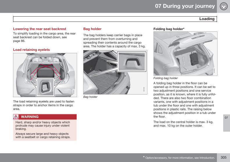
07 During your journey
Loading
07
* Option/accessory, for more information, see Introduction. 305
Lowering the rear seat backrestTo simplify loading in the cargo area, the rearseat backrest can be folded down, seepage 86.
Load retaining eyelets
The load retaining eyelets are used to fastenstraps in order to anchor items in the cargoarea.
WARNING
Hard, sharp and/or heavy objects whichprotrude may cause injury under violentbraking.
Always secure large and heavy objectswith a seatbelt or cargo retaining straps.
Bag holder
The bag holders keep carrier bags in placeand prevent them from overturning andspreading their contents around the cargoarea. The holder has a capacity of max. 3 kg.
Bag holder
Folding bag holder*
Folding bag holder
A folding bag holder in the floor can beopened up in three positions. It can be set totwo adjustment positions and one serviceposition, as it is known, where it is fully unfol-ded. There are also two floor combinationvariants, one with adjustment positions in atub under the floor and one with adjustmentpositions in plastic rails. The raising belowshows the adjustment position in a tub underthe floor.
The load on the central holder is max. 3 kg,and max. 10 kg on the outer holder.
07 During your journey
Loading
07
306 * Option/accessory, for more information, see Introduction.
Lift the handle* on the upper floor andfold up the floor.
Move the floor forwards to an appropriateposition and place it in the adjustmentgroove.
3. In service position, the floor is moved allthe way forwards towards the rear seatback and placed in the plastic support inthe centre.
12 V socket*
Lower the cover to access the electricalsocket.
• The socket also provides voltage whenthe remote control key is not in the igni-tion switch.
IMPORTANT
Max. socket current is 10 A (120 W).
NOTE
Remember that using the electrical socketwith the engine switched off involves therisk of discharging the car's battery.
NOTE
The compressor for temporary emergencypuncture repair has been tested andapproved by Volvo. For information on theuse of Volvo's recommended temporaryemergency puncture repair (TMK), seepage 330.
07 During your journey
Cargo area
07
* Option/accessory, for more information, see Introduction. 307
Cargo net*
The cargo net is fitted into four mounting points.
A cargo net prevents cargo from beingthrown forward in the passenger compart-ment in the event of heavy braking. For safetyreasons, the cargo net must always be cor-rectly fastened and secured. The mesh ismade of a strong nylon fabric and securedbehind the front seat backrests.
WARNING
Loads in the luggage compartment mustbe anchored well, and also have a cor-rectly fitted safety net.
Attaching
NOTE
The easiest way to fit the safety net is viaone of the rear doors.
WARNING
It is necessary to ensure that the uppersecuring points of the safety net are fittedcorrectly and that the puller-straps aresecured properly. Damaged nets must notbe used.
1. Unfold the cargo net and make sure thatthe split upper rod is locked in theextended position.
2. Hook one end of the rod into the roofmounting with the anchoring strap locksturned towards you.
3. Hook the other end of the rod into theroof mounting on the opposite side - thetelescopic spring-loaded retaining hooksfacilitate alignment. Take care to pressforward the rod's retaining hooks for eachrespective roof mounting's front end posi-tion.
4. Hook the cargo net's anchoring strapsinto the eyes on the rear of the seat sliderails - it is easier if the backrests arestraightened and the seats are movedforward slightly.
Pay attention to make sure that you donot press the seat/backrest hard againstthe net when the seat/backrest is movedback again - only adjust until the seat/backrest makes contact with the net.
IMPORTANT
If a seat/backrest is pushed backwardshard into the safety net then the net and/orits roof mounts may be damaged.
5. Tension the cargo net with the anchoringstraps.
07 During your journey
Cargo area
07
308
Removal and storage
The cargo net can be easily removed and foldedup.
Release the tension in the net by pressingin the button on the anchoring strap'slock and feeding out part of the strap.
Press in the catch and detach both of theanchoring strap's hooks.
Unhook the rod from its roof mounting bypulling back on the rod in the roof mount-ings' rear end position. Press the rod inany direction so that the hook engages inthe rod, which at the same time releasesthe hook on the other side.
Finally, remove the remaining roof mount-ing hook from the roof mounting.
4. Break the rod in the centre, fold ittogether and roll up the net.
Insert the net in the storage bag.
The folded cargo net is stored in its bag in thecargo area.
Parcel shelf
The parcel shelf can be removed to provideadditional cargo space.
Parcel shelf removalUndo the parcel shelf lifting eyes on bothsides.
Unhook the front edge of the parcel shelfand remove it.
07 During your journey
Driving with a trailer
07
* Option/accessory, for more information, see Introduction. 309
GeneralPayload depends on the car's kerb weight.The total of the weight of the passengers andall accessories, e.g. towbar, reduces the car'spayload by a corresponding weight. For moredetailed information on weights, seepage 379.
If the towing bracket is mounted by Volvo,then the car is delivered with the necessaryequipment for driving with a trailer.
• The car's towing bracket must be of anapproved type.
• If the towbar is retrofitted, check withyour Volvo dealer that the car is fullyequipped for driving with a trailer.
• Distribute the load on the trailer so thatthe weight on the towing bracket com-plies with the specified maximum towballload.
• Increase the tyre pressure to the recom-mended pressure for a full load. For tyrepressure label location, see page 328.
• The engine is loaded more heavily thanusual when driving with a trailer.
• Do not tow a heavy trailer when the car isbrand new. Wait until it has been drivenat least 1000 km.
• The brakes are loaded much more thanusual on long and steep downhill slopes.
Downshift to a lower gear and adjust yourspeed.
• For safety reasons, the maximum permit-ted speed for the car when coupled witha trailer should not be exceeded. Followthe regulations in force for the permittedspeeds and weights.
• Maintain a low speed when driving with atrailer up long, steep ascents.
• Avoid driving with a trailer on inclines ofmore than 12%.
Trailer cableAn adapter is required if the car's towingbracket has 13 pin electrics and the trailerhas 7 pin electrics. Use an adapter cableapproved by Volvo. Make sure the cable doesnot drag on the ground.
Direction indicators and brake lights onthe trailerIf any of the trailer's lamps for direction indi-cators are broken, then the symbol for direc-tion indicators in the combined instrumentpanel flashes faster than normal and theinformation display shows the text Bulb fail -Ind. signal trailer.
If any of the trailer's lamps for the brake lightare broken then the Bulb fail - Stop lamptrailer text is shown.
Level control*The rear shock absorbers maintain a constantheight irrespective of the car's load (up to themaximum permissible weight). When the caris stationary the rear of the car lowers slightly,which is normal.
Trailer weightsFor information on Volvo's permitted trailerweights, see page 380.
NOTE
The stated maximum permitted trailerweights are those permitted by Volvo. Themaximum permitted speed for a car with atrailer attached is 100 km/h. National vehi-cle regulations may further restrict thetrailer weight and speed. Towbars can becertified for higher towing weights than thecar can actually tow.
WARNING
Follow the stated recommendations fortrailer weights. Otherwise, the car andtrailer may be difficult to control in theevent of sudden movement and braking.
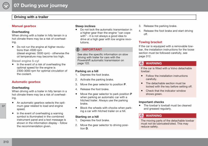
07 During your journey
Driving with a trailer
07
310
Manual gearbox
OverheatingWhen driving with a trailer in hilly terrain in ahot climate there may be a risk of overheat-ing.
• Do not run the engine at higher revolu-tions than 4500 rpm(diesel engines: 3500 rpm) - otherwise theoil temperature may become too high.
Diesel engine 5-cyl• In the event of a risk of overheating the
optimal speed for the engine is2300-3000 rpm for optimal circulation ofthe coolant.
Automatic gearbox
OverheatingWhen driving with a trailer in hilly terrain in ahot climate there may be a risk of overheat-ing.
• An automatic gearbox selects the opti-mum gear related to load and enginespeed.
• In the event of overheating a warningsymbol is illuminated in the combinedinstrument panel and a text message isshown in the information display - followthe recommendation given.
Steep inclines• Do not lock the automatic transmission in
a higher gear than the engine "can copewith" - it is not always a good idea todrive at a high gear with low engine revo-lutions.
IMPORTANT
See also the specific information on slowdriving with trailer for cars with thePowershift automatic transmission onpage 122.
Parking on a hill1. Depress the foot brake.
2. Activate the parking brake.
3. Move the gear selector to position P.
4. Release the foot brake.
• Move the gear selector to park position Pwhen parking an automatic car with ahitched trailer. Always use the parkingbrake.
• Block the wheels with chocks when park-ing a car with hitched trailer on a hill.
Starting on a hill1. Depress the foot brake.
2. Move the gear selector to driving posi-tion D.
3. Release the parking brake.
4. Release the foot brake and start drivingoff.
Towing bracketIf the car is equipped with a removable tow-bar, the installation instructions for the loosesection must be followed carefully, seepage 312.
WARNING
If the car is fitted with a Volvo detachabletowbar:
• Follow the installation instructionscarefully.
• The detachable section must belocked with the key before setting off.
• Check that the indicator windowshows green.
Important checks• The towbar's towball must be cleaned
and greased regularly.
WARNING
The moving parts of the detachable towbarmust not be lubricated/oiled. This mayreduce safety.
07 During your journey
Driving with a trailer
07
311
NOTE
When a hitch with a vibration damper isused, the towball must not be lubricated.
Storing the detachable towbar
The storage location for the removable towbar.
IMPORTANT
Always remove the detachable towbarafter use and store it in the designatedlocation in the car.
Specifications
G021485
Dimensions, mounting points (mm)
A 887
B 79
C 881
D 441
E 109
F 306
G Side member
H Ball centre
07 During your journey
Driving with a trailer
07
312
Fitting of removable towbar
Remove the protective cover by firstpressing in the catch and then pullingthe cover straight back .
G021487
Ensure that the mechanism is in theunlocked position by turning the keyclockwise.
G021488
The indicator window must show red.
G021489
Insert the towball section until you hear aclick.
G021490
The indicator window must show green.
G000000
Turn the key anticlockwise to lockedposition. Remove the key from the lock.
07 During your journey
Driving with a trailer
07
313
G021494
Check that the towball section is secureby pulling it up, down and back.
WARNING
If the towball is not fitted correctly then itmust be detached and reattached inaccordance with the previous instructions.
IMPORTANT
Only grease in the ball for the towballhitch, the remainder of the towbar must beclean and dry.
G021495
Safety cable.
WARNING
Take care to secure the trailer's safetycable in the intended bracket.
Removal of removable towbar
Insert the key and turn it clockwise to theunlocked position.
Push in the locking wheel and turn itanticlockwise until you hear a click.
Turn the locking wheel down fully, until itcomes to a stop. Hold it in this positionwhile pulling the towball rearward andupward.
WARNING
Secure the detachable towbar safely if it isstored in the car, see page 311.
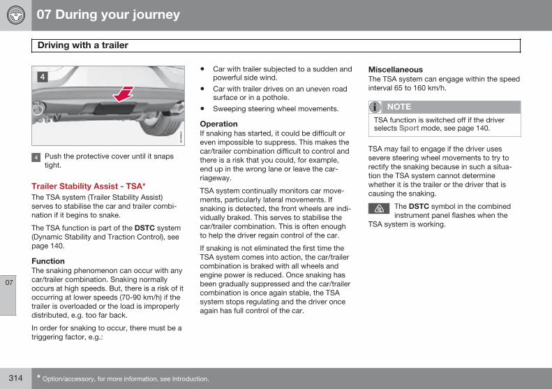
07 During your journey
Driving with a trailer
07
314 * Option/accessory, for more information, see Introduction.
Push the protective cover until it snapstight.
Trailer Stability Assist - TSA*The TSA system (Trailer Stability Assist)serves to stabilise the car and trailer combi-nation if it begins to snake.
The TSA function is part of the DSTC system(Dynamic Stability and Traction Control), seepage 140.
FunctionThe snaking phenomenon can occur with anycar/trailer combination. Snaking normallyoccurs at high speeds. But, there is a risk of itoccurring at lower speeds (70-90 km/h) if thetrailer is overloaded or the load is improperlydistributed, e.g. too far back.
In order for snaking to occur, there must be atriggering factor, e.g.:
• Car with trailer subjected to a sudden andpowerful side wind.
• Car with trailer drives on an uneven roadsurface or in a pothole.
• Sweeping steering wheel movements.
OperationIf snaking has started, it could be difficult oreven impossible to suppress. This makes thecar/trailer combination difficult to control andthere is a risk that you could, for example,end up in the wrong lane or leave the car-riageway.
TSA system continually monitors car move-ments, particularly lateral movements. Ifsnaking is detected, the front wheels are indi-vidually braked. This serves to stabilise thecar/trailer combination. This is often enoughto help the driver regain control of the car.
If snaking is not eliminated the first time theTSA system comes into action, the car/trailercombination is braked with all wheels andengine power is reduced. Once snaking hasbeen gradually suppressed and the car/trailercombination is once again stable, the TSAsystem stops regulating and the driver onceagain has full control of the car.
MiscellaneousThe TSA system can engage within the speedinterval 65 to 160 km/h.
NOTE
TSA function is switched off if the driverselects Sport mode, see page 140.
TSA may fail to engage if the driver usessevere steering wheel movements to try torectify the snaking because in such a situa-tion the TSA system cannot determinewhether it is the trailer or the driver that iscausing the snaking.
The DSTC symbol in the combinedinstrument panel flashes when the
TSA system is working.
07 During your journey
Towing and recovery
07
315
TowingFind out the statutory maximum speed limitfor towing before towing begins.
1. Unlock the steering lock by inserting theremote control key in the ignition switchand giving a long press on the START/STOP ENGINE button - key position II isactivated, see page 81 for more informa-tion on key positions.
2. The remote control key must remain inthe ignition switch while the car is beingtowed.
3. Keep the towline taut when the towingvehicle reduces speed by holding yourfoot gently pressed on the brake pedal -thereby avoiding unnecessary jerking.
4. Be prepared to brake to stop.
WARNING
• Check that the steering lock isunlocked before towing.
• The remote control key must be in keyposition II - in position I all airbags aredeactivated.
• Never remove the remote control keyfrom the ignition switch when the caris being towed.
WARNING
The brake servo and power steering do notwork when the engine is switched off - thebrake pedal needs to be depressedabout 5 times more heavily and the steer-ing is considerably heavier than normal.
Manual gearboxPrior to towing:
– Move gear lever into neutral and releasethe parking brake.
Automatic gearbox Geartronic
IMPORTANT
Note that the car must always be towedwith the wheels rolling forward.
• Do not tow cars with automatic trans-mission at speeds higher than 80 km/hor for distances in excess of 80 km.Follow the speeds that are permittedin accordance with local traffic regula-tions.
Prior to towing:
– Move the gear selector to position N andrelease the parking brake.
Automatic gearbox PowershiftThe model with Powershift transmissionshould not be towed as it is dependent on theengine running in order to receive sufficientlubrication. If towing still has to take place,the route must be as short as possible andthen with very low speed.
In the event of uncertainty as to whether ornot the car is equipped with Powershift trans-mission, this can be verified by checking thedesignation on the transmission's label underthe bonnet - see page 376. The designa-tion ”MPS6” means that it is Powershift –transmission otherwise it is Geartronic auto-matic transmission.
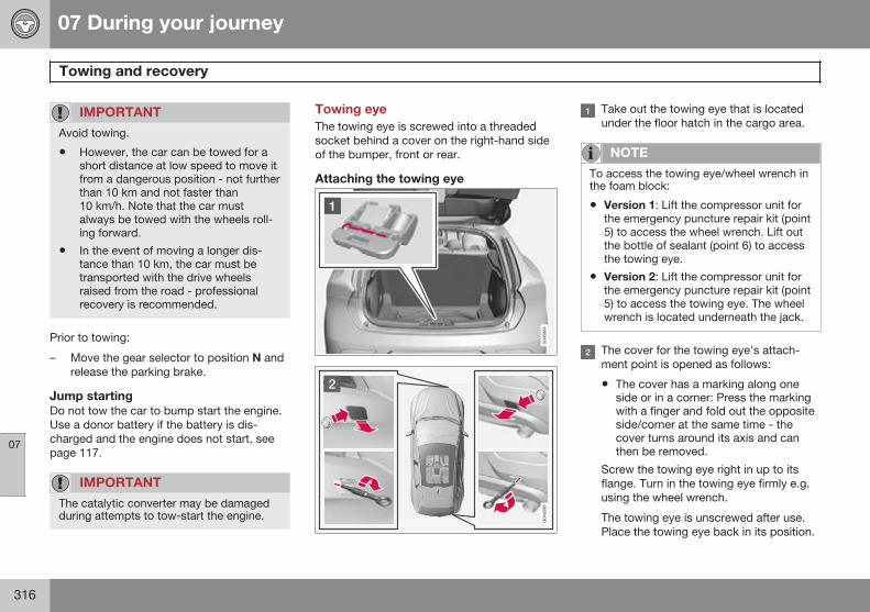
07 During your journey
Towing and recovery
07
316
IMPORTANT
Avoid towing.
• However, the car can be towed for ashort distance at low speed to move itfrom a dangerous position - not furtherthan 10 km and not faster than10 km/h. Note that the car mustalways be towed with the wheels roll-ing forward.
• In the event of moving a longer dis-tance than 10 km, the car must betransported with the drive wheelsraised from the road - professionalrecovery is recommended.
Prior to towing:
– Move the gear selector to position N andrelease the parking brake.
Jump startingDo not tow the car to bump start the engine.Use a donor battery if the battery is dis-charged and the engine does not start, seepage 117.
IMPORTANT
The catalytic converter may be damagedduring attempts to tow-start the engine.
Towing eyeThe towing eye is screwed into a threadedsocket behind a cover on the right-hand sideof the bumper, front or rear.
Attaching the towing eye
Take out the towing eye that is locatedunder the floor hatch in the cargo area.
NOTE
To access the towing eye/wheel wrench inthe foam block:
• Version 1: Lift the compressor unit forthe emergency puncture repair kit (point5) to access the wheel wrench. Lift outthe bottle of sealant (point 6) to accessthe towing eye.
• Version 2: Lift the compressor unit forthe emergency puncture repair kit (point5) to access the towing eye. The wheelwrench is located underneath the jack.
The cover for the towing eye's attach-ment point is opened as follows:
• The cover has a marking along oneside or in a corner: Press the markingwith a finger and fold out the oppositeside/corner at the same time - thecover turns around its axis and canthen be removed.
Screw the towing eye right in up to itsflange. Turn in the towing eye firmly e.g.using the wheel wrench.
The towing eye is unscrewed after use.Place the towing eye back in its position.
07 During your journey
Towing and recovery
07
317
Finish by refitting the cover onto thebumper.
IMPORTANT
The towing eye is only designed for towingon roads - not for pulling the car unstuckor out of a ditch. Call a recovery service forrecovery assistance.
RecoveryCall a recovery service for recovery assis-tance.
IMPORTANT
Note that the car must always be transpor-ted with the wheels rolling forward.
318 * Option/accessory, for more information, see Introduction.
General ................................................................................................. 320Changing wheels .................................................................................. 324Tyre pressure ....................................................................................... 328Warning triangle and first-aid kit*.......................................................... 329Emergency puncture repair (TMK)* ...................................................... 330
WHEELS AND TYRES
08 Wheels and tyres
General
08
320
Driving characteristicsTyres greatly affect the car's driving characte-ristics. The type of tyre, dimensions, tyrepressure and speed rating are important forhow the car performs.
Direction of rotation
G021778
The arrow shows the tyre's direction of rotation.
Tyres with a tread pattern which are designedto only turn in one direction have the directionof rotation marked with an arrow. The tyremust always rotate in the same directionthroughout its lifespan. Tyres should only beswitched between front and rear positions,never between left and right-hand sides, orvice versa. If the tyres are fitted incorrectly,the car's braking characteristics and capacityto force rain and slush out of the way areadversely affected.
Tyres with the greatest tread depth shouldalways be fitted to the rear of the car (todecrease the risk of skidding).
NOTE
Make sure that both pairs of wheels havethe same type and dimension, and also thesame make.
Follow the recommended tyre pressuresspecified in the tyre pressure table, seepage 391.
Tyre care
Tyre ageAll tyres older than 6 years old should bechecked by an expert even if they seemundamaged. Tyres age and decompose, evenif they are hardly ever or never used. Thefunction can therefore be affected. Thisapplies to all tyres that are stored for futureuse. Examples of external signs which indi-cate that the tyre is unsuitable for use arecracks or discoloration.
New tyres
Tyres are perishable. After a few years theybegin to harden at the same time as the fric-tion capacity/characteristics gradually deteri-orate. For this reason, aim to get as freshtyres as possible when you replace them.This is especially important with regard towinter tyres. The last four digits in thesequence mean the week and year of manu-facture. This is the tyre's DOT marking(Department of Transportation), and this isstated with four digits, for example 1510. Thetyre in the illustration was manufactured inweek 15 of 2010.
Summer and winter tyresWhen summer and winter wheels arechanged the wheels should be marked with
08 Wheels and tyres
General
08
321
which side of the car they were mounted on,for example L for left and R for right.
Wear and maintenanceThe correct tyre pressure results in more evenwear, see page 328. Driving style, tyre pres-sure, climate and road condition affect howquickly your tyres age and wear. To avoid dif-ferences in tread depth and to prevent wearpatterns arising, the front and rear wheels canbe switched with each other. A suitable dis-tance for the first change is approx. 5000 kmand then at 10 000 km intervals. Volvo rec-ommends that you contact an authorisedVolvo workshop for checking if you are uncer-tain about tread depth. If significant differen-ces in wear (>1 mm difference in tread depth)between tyres have already occurred, theleast worn tyres must always be placed onthe rear. Understeer is normally easier to cor-rect than oversteer, and leads to the car con-tinuing forwards in a straight line rather thanhaving the rear end skidding to one side,resulting in possible complete loss of controlover the car. This is why it is important for therear wheels never to lose grip before the frontwheels.
Wheels should be stored lying down or hang-ing up - and not standing up.
WARNING
A damaged tyre may lead to loss of controlover the car.
Tyres with tread wear indicators
G021829
Tread wear indicators.
Tread wear indicators are narrow treadlessbands across the width of the tread. On theside of the tyre are the letters TWI (TreadWear Indicator). When the tyre's tread depthis down to 1.6 mm, the tread depth will belevel in height with the tread wear indicators.Change to new tyres as soon as possible.Remember that tyres with little tread depthprovide very poor grip in rain and snow.
Rims and wheel bolts
Low wheel bolt
High wheel bolt
Locking wheel bolts
Tightening torque:
• Type 1 wheel bolt (steel rim): 110 Nm
• Type 2 wheel bolt (aluminium rim): 130Nm
• Type 3 Lockable wheel bolt (steel/aluminium rim): 110 Nm
Only use rims that are tested and approvedby Volvo and which are Volvo genuine acces-sories. Check the torque with a torquewrench.
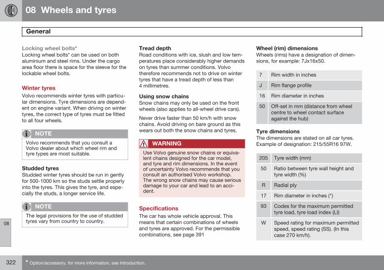
08 Wheels and tyres
General
08
322 * Option/accessory, for more information, see Introduction.
Locking wheel bolts*Locking wheel bolts* can be used on bothaluminium and steel rims. Under the cargoarea floor there is space for the sleeve for thelockable wheel bolts.
Winter tyresVolvo recommends winter tyres with particu-lar dimensions. Tyre dimensions are depend-ent on engine variant. When driving on wintertyres, the correct type of tyres must be fittedto all four wheels.
NOTE
Volvo recommends that you consult aVolvo dealer about which wheel rim andtyre types are most suitable.
Studded tyresStudded winter tyres should be run in gentlyfor 500-1000 km so the studs settle properlyinto the tyres. This gives the tyre, and espe-cially the studs, a longer service life.
NOTE
The legal provisions for the use of studdedtyres vary from country to country.
Tread depthRoad conditions with ice, slush and low tem-peratures place considerably higher demandson tyres than summer conditions. Volvotherefore recommends not to drive on wintertyres that have a tread depth of less than4 millimetres.
Using snow chainsSnow chains may only be used on the frontwheels (also applies to all-wheel drive cars).
Never drive faster than 50 km/h with snowchains. Avoid driving on bare ground as thiswears out both the snow chains and tyres.
WARNING
Use Volvo genuine snow chains or equiva-lent chains designed for the car model,and tyre and rim dimensions. In the eventof uncertainty Volvo recommends that youconsult an authorised Volvo workshop.The wrong snow chains may cause seriousdamage to your car and lead to an acci-dent.
SpecificationsThe car has whole vehicle approval. Thismeans that certain combinations of wheelsand tyres are approved. For the permissiblecombinations, see page 391
Wheel (rim) dimensionsWheels (rims) have a designation of dimen-sions, for example: 7Jx16x50.
7 Rim width in inches
J Rim flange profile
16 Rim diameter in inches
50 Off-set in mm (distance from wheelcentre to wheel contact surfaceagainst the hub)
Tyre dimensionsThe dimensions are stated on all car tyres.Example of designation: 215/55R16 97W.
205 Tyre width (mm)
50 Ratio between tyre wall height andtyre width (%)
R Radial ply
17 Rim diameter in inches (")
93 Codes for the maximum permittedtyre load, tyre load index (LI)
W Speed rating for maximum permittedspeed, speed rating (SS). (In thiscase 270 km/h).
08 Wheels and tyres
General
08
323
Load indexEach tyre has a certain capacity to carry aload, a load index (LI). The car's weight deter-mines the load capacity required of the tyres.Minimum permitted index is specified in thetable, see page 391.
Speed ratingsEach tyre can withstand a certain maximumspeed, a speed rating (Speed Symbol; SS).
Tyre speed class must at least correspondwith the car's top speed. Minimum permittedspeed rating is specified in the table, seepage 391.
The only exception to these conditions is win-ter tyres (both those with metal studs andthose without), where a lower speed ratingmay be used. If such a tyre is chosen, the carmust not be driven faster than the speed rat-ing of the tyre (for example, class Q can bedriven at a maximum of 160 km/h).
Traffic regulations determine how fast a carcan be driven, not the speed rating of thetyres.
NOTE
The maximum permitted speed is speci-fied in the table.
Q 160 km/h (used only on winter tyres)
T 190 km/h
H 210 km/h
V 240 km/h
W 270 km/h
Y 300 km/h
WARNING
The car must be fitted with tyres whichhave the same or a higher load index (LI)and speed rating (SS) than specified. If atyre with too low a load index or speed rat-ing is used, it may overheat.
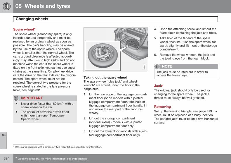
08 Wheels and tyres
Changing wheels
08
324 * Option/accessory, for more information, see Introduction.
Spare wheel*1
The spare wheel (Temporary spare) is onlyintended for use temporarily and must bereplaced by an ordinary wheel as soon aspossible. The car's handling may be alteredby the use of the spare wheel. The sparewheel is smaller than the normal wheel. Thecar's ground clearance is affected accord-ingly. Pay attention to high kerbs and do notmachine wash the car. If the spare wheel isfitted on the front axle, you cannot use snowchains at the same time. On all-wheel drivecars the drive on the rear axle can be discon-nected. The spare wheel must not berepaired. The correct tyre pressure for thespare wheel is stated in the tyre pressuretable, see page 391.
IMPORTANT
• Never drive faster than 80 km/h with aspare wheel on the car.
• The car must never be driven fittedwith more than one "TemporarySpare" wheel.
Taking out the spare wheelThe spare wheel* plus jack* and wheelwrench* are stored under the floor in thecargo area.
1. Lift the rear edge of the luggage compart-ment floor (or on models with a jointedluggage compartment floor, take hold ofthe luggage compartment floor handle, liftand move the rear part of the floor for-wards).
2. Lift out the storage compartment(optional extra) - models with a jointedluggage compartment floor only.
3. Lift out the lower floor (models with a join-ted luggage compartment floor only).
4. Undo the attaching screw and lift out thefoam block containing the jack and tools.
5. Take hold of the far end of the sparewheel, then lift. Push the spare wheel for-wards slightly and lift it out of the storagecompartment.
6. Remove the wheel wrench, the jack andthe towing eye from the foam block.
NOTE
The jack must be lifted out in order toaccess the towing eye.
Jack*The original jack should only be used forchanging to the spare wheel. The jack'sthread must always be well greased.
RemovingSet up the warning triangle, see page 329 if awheel must be replaced at a busy location.The car and jack* must be on a firm horizontalsurface.
1 If the car is equipped with a temporary tyre repair kit, see page 330 for information.
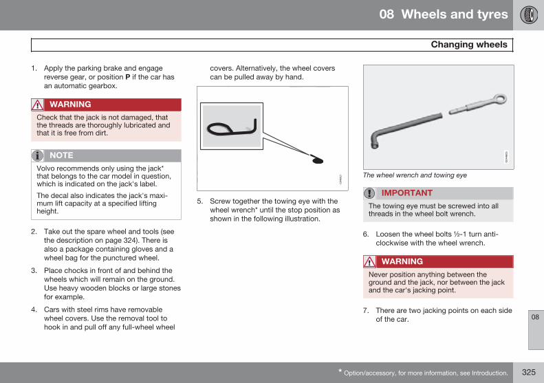
08 Wheels and tyres
Changing wheels
08
* Option/accessory, for more information, see Introduction. 325
1. Apply the parking brake and engagereverse gear, or position P if the car hasan automatic gearbox.
WARNING
Check that the jack is not damaged, thatthe threads are thoroughly lubricated andthat it is free from dirt.
NOTE
Volvo recommends only using the jack*that belongs to the car model in question,which is indicated on the jack's label.
The decal also indicates the jack's maxi-mum lift capacity at a specified liftingheight.
2. Take out the spare wheel and tools (seethe description on page 324). There isalso a package containing gloves and awheel bag for the punctured wheel.
3. Place chocks in front of and behind thewheels which will remain on the ground.Use heavy wooden blocks or large stonesfor example.
4. Cars with steel rims have removablewheel covers. Use the removal tool tohook in and pull off any full-wheel wheel
covers. Alternatively, the wheel coverscan be pulled away by hand.
5. Screw together the towing eye with thewheel wrench* until the stop position asshown in the following illustration.
The wheel wrench and towing eye
IMPORTANT
The towing eye must be screwed into allthreads in the wheel bolt wrench.
6. Loosen the wheel bolts ½-1 turn anti-clockwise with the wheel wrench.
WARNING
Never position anything between theground and the jack, nor between the jackand the car's jacking point.
7. There are two jacking points on each sideof the car.
08 Wheels and tyres
Changing wheels
08
326
IMPORTANT
The ground under the jack must be firm,smooth and level.
8. Wind up the jack so that the flange in thebodywork ends up in the notch in thehead of the jack.
9. Lift the car so that the wheel is free.Remove the wheel bolts and lift off thewheel.
WARNING
Never crawl under the car when it is raisedon the jack.
Passengers must leave the car when it israised on the jack.
Park the car such that passengers havethe car, or ideally a crash barrier, betweenthemselves and the roadway.
NOTE
The car's regular jack is designed only foruse occasionally and for a short time, suchas when changing a wheel with a punc-tured tyre, switching between summertyres and winter tyres, etc. Only the jackbelonging to the specific model is to beused to jack up the car. If the car is to bejacked up more often, or for a longer timethan is required just to change a wheel,use of a garage jack is recommended. Inthis instance, follow the instructions foruse that come with the equipment.
Installation1. Clean the contact surfaces between
wheel and hub.
2. Put on the wheel. Tighten the wheel boltsthoroughly.
3. Lower the car so that the wheels cannotrotate.
4. Tighten the wheel bolts crosswise. It isimportant that the wheel bolts are tight-ened properly (see page 321 for tighten-ing torques). Check the torque with a tor-que wrench.
5.
08 Wheels and tyres
Changing wheels
08
* Option/accessory, for more information, see Introduction. 327
Refit any full wheel covers.
NOTE
The wheel cover outlet for the valve mustbe positioned over the valve on the wheelrim during fitting.
Replacing the spare wheel* and jack* inthe cargo area
The tools and jack* must be returned to theircorrect places in the foam block after use.
1. Unscrew the towing eye from the wheelbolt wrench.
2. Put back any tools that have been used inthe relevant compartments in the foamblock in the following order:
• towing eye/funnel/torx wrench/socketfor locking wheel bolts/tool for wheelcovers
• Jack (must be cranked to the correctheight so that it fits into the foamblock's compartment, the handle
above the foot and down in the groovein the foam block)
• Socket wrench (above the jack)
3. If the spare wheel has been used then thepunctured wheel can be placed in theplastic bag contained in the package withthe gloves. Place the foam block back inthe storage compartment and tighten themounting screw to the floor of the storagecompartment.
If the spare wheel has not been usedthen place the foam block in the sparewheel, and place the spare wheel back inthe storage compartment, and tighten themounting screw to the floor of the storagecompartment.
4. Return the detachable towbar
IMPORTANT
The tools and jack* must be stored in theintended location in the car's cargo areawhen not in use.
08 Wheels and tyres
Tyre pressure
08
328
Tyre pressure
G021830
The tyre pressure decal on the driver's sidedoor pillar (between frame and rear door)shows which pressures the tyres should haveat different loads and speed conditions. Thisis also specified in the tyre pressure table,see page 391.
• Tyre pressure for the car's recommendedtyre dimension
• ECO pressure1
NOTE
Temperature differences change thetyre pressure.
Fuel economy, ECO pressureIn order to obtain optimum fuel economy atspeeds below 160 km/h an ECO pressure isrecommended (applies to both full and lightload - see page 391).
Checking the tyre pressureThe tyre pressures must be checked everymonth.
Check tyre pressures on cold tyres. "Coldtyres" means the tyres are the same tempera-ture as the ambient temperature. After severalfew kilometres of driving, the tyres warm upand the pressure increases.
Inadequate tyre pressure increases fuel con-sumption, shortens tyre lifespan and impairsthe car's roadholding. Driving on tyres withtyre pressure that is too low could result inthe tyres overheating and being damaged.Tyre pressure affects travelling comfort, roadnoise and steering characteristics.
NOTE
Tyre pressure decreases over time, this isa natural phenomenon. Tyre pressure alsovaries depending on ambient temperature.
1 ECO pressure results in improved fuel economy.
08 Wheels and tyres
Warning triangle and first-aid kit*
08
* Option/accessory, for more information, see Introduction. 329
Warning triangle Lift the floor hatch (or push the rear partof the luggage compartment floor for-wards in models with a jointed floor andthen lift the lower floor) and remove thewarning triangle.
Take the warning triangle from the case,fold out and assemble the two loosesides.
Fold out the warning triangle's supportlegs.
Follow the regulations for the use of a warn-ing triangle. Position the warning triangle in asuitable place with regard to traffic.
Ensure the warning triangle and its case areproperly secured in the cargo area after use.
First aid kit*A case containing first aid equipment islocated on the left side of the cargo area.
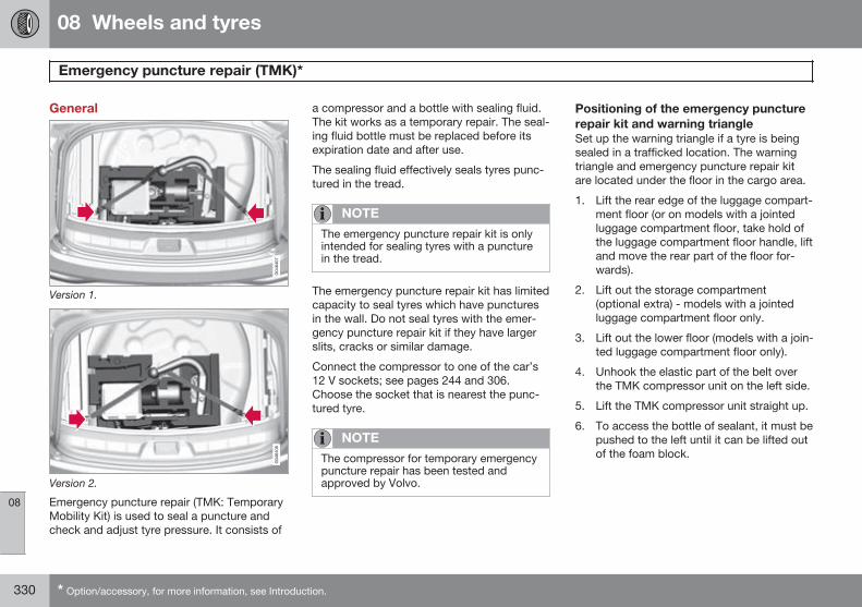
08 Wheels and tyres
Emergency puncture repair (TMK)*
08
330 * Option/accessory, for more information, see Introduction.
General
Version 1.
Version 2.
Emergency puncture repair (TMK: TemporaryMobility Kit) is used to seal a puncture andcheck and adjust tyre pressure. It consists of
a compressor and a bottle with sealing fluid.The kit works as a temporary repair. The seal-ing fluid bottle must be replaced before itsexpiration date and after use.
The sealing fluid effectively seals tyres punc-tured in the tread.
NOTE
The emergency puncture repair kit is onlyintended for sealing tyres with a puncturein the tread.
The emergency puncture repair kit has limitedcapacity to seal tyres which have puncturesin the wall. Do not seal tyres with the emer-gency puncture repair kit if they have largerslits, cracks or similar damage.
Connect the compressor to one of the car’s12 V sockets; see pages 244 and 306.Choose the socket that is nearest the punc-tured tyre.
NOTE
The compressor for temporary emergencypuncture repair has been tested andapproved by Volvo.
Positioning of the emergency puncturerepair kit and warning triangleSet up the warning triangle if a tyre is beingsealed in a trafficked location. The warningtriangle and emergency puncture repair kitare located under the floor in the cargo area.
1. Lift the rear edge of the luggage compart-ment floor (or on models with a jointedluggage compartment floor, take hold ofthe luggage compartment floor handle, liftand move the rear part of the floor for-wards).
2. Lift out the storage compartment(optional extra) - models with a jointedluggage compartment floor only.
3. Lift out the lower floor (models with a join-ted luggage compartment floor only).
4. Unhook the elastic part of the belt overthe TMK compressor unit on the left side.
5. Lift the TMK compressor unit straight up.
6. To access the bottle of sealant, it must bepushed to the left until it can be lifted outof the foam block.
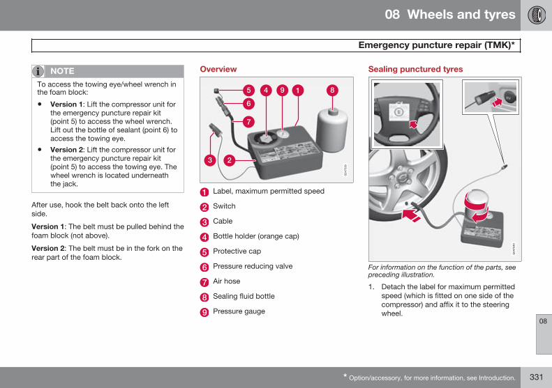
08 Wheels and tyres
Emergency puncture repair (TMK)*
08
* Option/accessory, for more information, see Introduction. 331
NOTE
To access the towing eye/wheel wrench inthe foam block:
• Version 1: Lift the compressor unit forthe emergency puncture repair kit(point 5) to access the wheel wrench.Lift out the bottle of sealant (point 6) toaccess the towing eye.
• Version 2: Lift the compressor unit forthe emergency puncture repair kit(point 5) to access the towing eye. Thewheel wrench is located underneaththe jack.
After use, hook the belt back onto the leftside.
Version 1: The belt must be pulled behind thefoam block (not above).
Version 2: The belt must be in the fork on therear part of the foam block.
Overview
Label, maximum permitted speed
Switch
Cable
Bottle holder (orange cap)
Protective cap
Pressure reducing valve
Air hose
Sealing fluid bottle
Pressure gauge
Sealing punctured tyres
For information on the function of the parts, seepreceding illustration.
1. Detach the label for maximum permittedspeed (which is fitted on one side of thecompressor) and affix it to the steeringwheel.
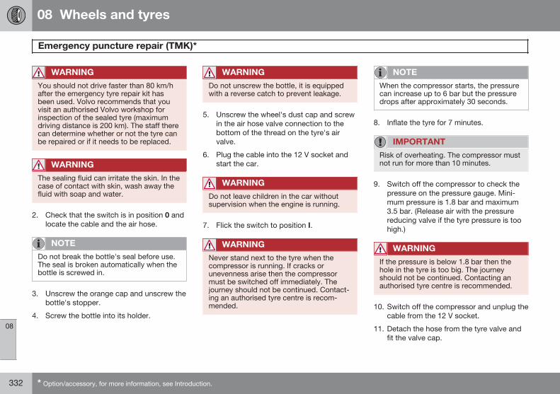
08 Wheels and tyres
Emergency puncture repair (TMK)*
08
332 * Option/accessory, for more information, see Introduction.
WARNING
You should not drive faster than 80 km/hafter the emergency tyre repair kit hasbeen used. Volvo recommends that youvisit an authorised Volvo workshop forinspection of the sealed tyre (maximumdriving distance is 200 km). The staff therecan determine whether or not the tyre canbe repaired or if it needs to be replaced.
WARNING
The sealing fluid can irritate the skin. In thecase of contact with skin, wash away thefluid with soap and water.
2. Check that the switch is in position 0 andlocate the cable and the air hose.
NOTE
Do not break the bottle's seal before use.The seal is broken automatically when thebottle is screwed in.
3. Unscrew the orange cap and unscrew thebottle's stopper.
4. Screw the bottle into its holder.
WARNING
Do not unscrew the bottle, it is equippedwith a reverse catch to prevent leakage.
5. Unscrew the wheel's dust cap and screwin the air hose valve connection to thebottom of the thread on the tyre's airvalve.
6. Plug the cable into the 12 V socket andstart the car.
WARNING
Do not leave children in the car withoutsupervision when the engine is running.
7. Flick the switch to position I.
WARNING
Never stand next to the tyre when thecompressor is running. If cracks orunevenness arise then the compressormust be switched off immediately. Thejourney should not be continued. Contact-ing an authorised tyre centre is recom-mended.
NOTE
When the compressor starts, the pressurecan increase up to 6 bar but the pressuredrops after approximately 30 seconds.
8. Inflate the tyre for 7 minutes.
IMPORTANT
Risk of overheating. The compressor mustnot run for more than 10 minutes.
9. Switch off the compressor to check thepressure on the pressure gauge. Mini-mum pressure is 1.8 bar and maximum3.5 bar. (Release air with the pressurereducing valve if the tyre pressure is toohigh.)
WARNING
If the pressure is below 1.8 bar then thehole in the tyre is too big. The journeyshould not be continued. Contacting anauthorised tyre centre is recommended.
10. Switch off the compressor and unplug thecable from the 12 V socket.
11. Detach the hose from the tyre valve andfit the valve cap.
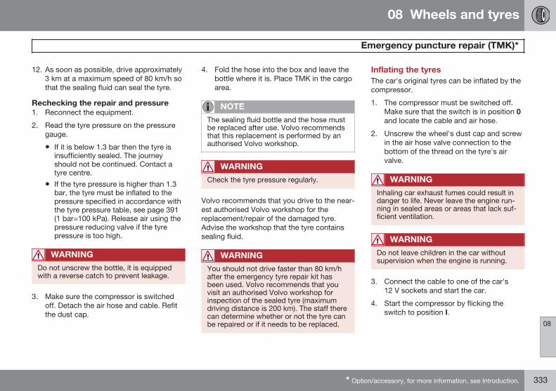
08 Wheels and tyres
Emergency puncture repair (TMK)*
08
* Option/accessory, for more information, see Introduction. 333
12. As soon as possible, drive approximately3 km at a maximum speed of 80 km/h sothat the sealing fluid can seal the tyre.
Rechecking the repair and pressure1. Reconnect the equipment.
2. Read the tyre pressure on the pressuregauge.
• If it is below 1.3 bar then the tyre isinsufficiently sealed. The journeyshould not be continued. Contact atyre centre.
• If the tyre pressure is higher than 1.3bar, the tyre must be inflated to thepressure specified in accordance withthe tyre pressure table, see page 391(1 bar=100 kPa). Release air using thepressure reducing valve if the tyrepressure is too high.
WARNING
Do not unscrew the bottle, it is equippedwith a reverse catch to prevent leakage.
3. Make sure the compressor is switchedoff. Detach the air hose and cable. Refitthe dust cap.
4. Fold the hose into the box and leave thebottle where it is. Place TMK in the cargoarea.
NOTE
The sealing fluid bottle and the hose mustbe replaced after use. Volvo recommendsthat this replacement is performed by anauthorised Volvo workshop.
WARNING
Check the tyre pressure regularly.
Volvo recommends that you drive to the near-est authorised Volvo workshop for thereplacement/repair of the damaged tyre.Advise the workshop that the tyre containssealing fluid.
WARNING
You should not drive faster than 80 km/hafter the emergency tyre repair kit hasbeen used. Volvo recommends that youvisit an authorised Volvo workshop forinspection of the sealed tyre (maximumdriving distance is 200 km). The staff therecan determine whether or not the tyre canbe repaired or if it needs to be replaced.
Inflating the tyresThe car's original tyres can be inflated by thecompressor.
1. The compressor must be switched off.Make sure that the switch is in position 0and locate the cable and air hose.
2. Unscrew the wheel's dust cap and screwin the air hose valve connection to thebottom of the thread on the tyre's airvalve.
WARNING
Inhaling car exhaust fumes could result indanger to life. Never leave the engine run-ning in sealed areas or areas that lack suf-ficient ventilation.
WARNING
Do not leave children in the car withoutsupervision when the engine is running.
3. Connect the cable to one of the car's12 V sockets and start the car.
4. Start the compressor by flicking theswitch to position I.
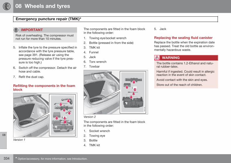
08 Wheels and tyres
Emergency puncture repair (TMK)*
08
334 * Option/accessory, for more information, see Introduction.
IMPORTANT
Risk of overheating. The compressor mustnot run for more than 10 minutes.
5. Inflate the tyre to the pressure specified inaccordance with the tyre pressure table,see page 391. (Release air using thepressure reducing valve if the tyre pres-sure is too high.)
6. Switch off the compressor. Detach the airhose and cable.
7. Refit the dust cap.
Refitting the components in the foamblock
Version 1
The components are fitted in the foam blockin the following order:
1. Towing eye/socket wrench2. Bottle (pressed in from the side)3. TMK kit4. Funnel5. Jack6. Torx wrench7. Towbar
Version 2
The components are fitted in the foam blockin the following order:
1. Socket wrench2. Towing eye3. Bottle4. TMK kit
5. Jack
Replacing the sealing fluid canisterReplace the bottle when the expiration datehas passed. Treat the old bottle as environ-mentally hazardous waste.
WARNING
The bottle contains 1.2-Ethanol and natu-ral rubber-latex.
Harmful if ingested. Could result in allergicreaction in the event of skin contact.
Avoid contact with the skin and eyes.
Store out of the reach of children.
08 Wheels and tyres
08
335
336
Engine compartment............................................................................. 338Lamps................................................................................................... 345Wiper blades and washer fluid.............................................................. 352Battery................................................................................................... 355Fuses..................................................................................................... 359Car care................................................................................................ 368
MAINTENANCE AND SERVICE
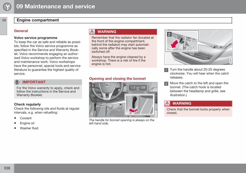
09 Maintenance and service
Engine compartment 09
338
General
Volvo service programmeTo keep the car as safe and reliable as possi-ble, follow the Volvo service programme asspecified in the Service and Warranty Book-let. Volvo recommends engaging an author-ised Volvo workshop to perform the serviceand maintenance work. Volvo workshopshave the personnel, special tools and serviceliterature to guarantee the highest quality ofservice.
IMPORTANT
For the Volvo warranty to apply, check andfollow the instructions in the Service andWarranty Booklet.
Check regularlyCheck the following oils and fluids at regularintervals, e.g. when refuelling:
• Coolant
• Engine oil
• Washer fluid
WARNING
Remember that the radiator fan (located atthe front of the engine compartment,behind the radiator) may start automati-cally some after the engine has beenswitched off.
Always have the engine cleaned by aworkshop. There is a risk of fire if theengine is hot.
Opening and closing the bonnet
The handle for bonnet opening is always on theleft-hand side.
Turn the handle about 20-25 degreesclockwise. You will hear when the catchreleases.
Move the catch to the left and open thebonnet. (The catch hook is locatedbetween the headlamp and grille, seeillustration.)
WARNING
Check that the bonnet locks properly whenclosed.
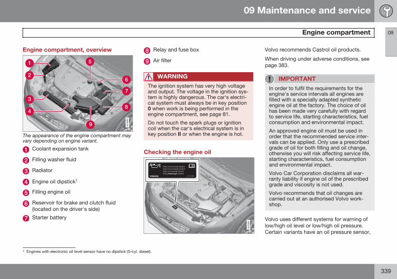
09 Maintenance and service
Engine compartment 09
339
Engine compartment, overview
The appearance of the engine compartment mayvary depending on engine variant.
Coolant expansion tank
Filling washer fluid
Radiator
Engine oil dipstick1
Filling engine oil
Reservoir for brake and clutch fluid(located on the driver's side)
Starter battery
Relay and fuse box
Air filter
WARNING
The ignition system has very high voltageand output. The voltage in the ignition sys-tem is highly dangerous. The car's electri-cal system must always be in key position0 when work is being performed in theengine compartment, see page 81.
Do not touch the spark plugs or ignitioncoil when the car's electrical system is inkey position II or when the engine is hot.
Checking the engine oil
Volvo recommends Castrol oil products.
When driving under adverse conditions, seepage 383.
IMPORTANT
In order to fulfil the requirements for theengine's service intervals all engines arefilled with a specially adapted syntheticengine oil at the factory. The choice of oilhas been made very carefully with regardto service life, starting characteristics, fuelconsumption and environmental impact.
An approved engine oil must be used inorder that the recommended service inter-vals can be applied. Only use a prescribedgrade of oil for both filling and oil change,otherwise you will risk affecting service life,starting characteristics, fuel consumptionand environmental impact.
Volvo Car Corporation disclaims all war-ranty liability if engine oil of the prescribedgrade and viscosity is not used.
Volvo recommends that oil changes arecarried out at an authorised Volvo work-shop.
Volvo uses different systems for warning oflow/high oil level or low/high oil pressure.Certain variants have an oil pressure sensor,
1 Engines with electronic oil level sensor have no dipstick (5-cyl. diesel).
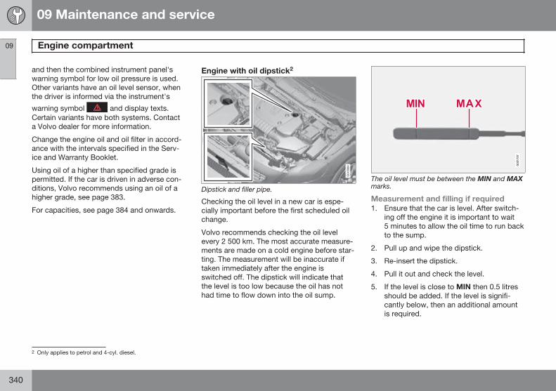
09 Maintenance and service
Engine compartment 09
340
and then the combined instrument panel'swarning symbol for low oil pressure is used.Other variants have an oil level sensor, whenthe driver is informed via the instrument's
warning symbol and display texts.Certain variants have both systems. Contacta Volvo dealer for more information.
Change the engine oil and oil filter in accord-ance with the intervals specified in the Serv-ice and Warranty Booklet.
Using oil of a higher than specified grade ispermitted. If the car is driven in adverse con-ditions, Volvo recommends using an oil of ahigher grade, see page 383.
For capacities, see page 384 and onwards.
Engine with oil dipstick2
Dipstick and filler pipe.
Checking the oil level in a new car is espe-cially important before the first scheduled oilchange.
Volvo recommends checking the oil levelevery 2 500 km. The most accurate measure-ments are made on a cold engine before star-ting. The measurement will be inaccurate iftaken immediately after the engine isswitched off. The dipstick will indicate thatthe level is too low because the oil has nothad time to flow down into the oil sump.
G021737
The oil level must be between the MIN and MAXmarks.
Measurement and filling if required1. Ensure that the car is level. After switch-
ing off the engine it is important to wait5 minutes to allow the oil time to run backto the sump.
2. Pull up and wipe the dipstick.
3. Re-insert the dipstick.
4. Pull it out and check the level.
5. If the level is close to MIN then 0.5 litresshould be added. If the level is signifi-cantly below, then an additional amountis required.
2 Only applies to petrol and 4-cyl. diesel.
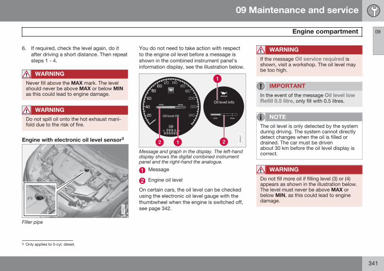
09 Maintenance and service
Engine compartment 09
341
6. If required, check the level again, do itafter driving a short distance. Then repeatsteps 1 - 4.
WARNING
Never fill above the MAX mark. The levelshould never be above MAX or below MINas this could lead to engine damage.
WARNING
Do not spill oil onto the hot exhaust mani-fold due to the risk of fire.
Engine with electronic oil level sensor3
Filler pipe
You do not need to take action with respectto the engine oil level before a message isshown in the combined instrument panel'sinformation display, see the illustration below.
Message and graph in the display. The left-handdisplay shows the digital combined instrumentpanel and the right-hand the analogue.
Message
Engine oil level
On certain cars, the oil level can be checkedusing the electronic oil level gauge with thethumbwheel when the engine is switched off,see page 342.
WARNING
If the message Oil service required isshown, visit a workshop. The oil level maybe too high.
IMPORTANT
In the event of the message Oil level lowRefill 0.5 litre, only fill with 0.5 litres.
NOTE
The oil level is only detected by the systemduring driving. The system cannot directlydetect changes when the oil is filled ordrained. The car must be drivenabout 30 km before the oil level display iscorrect.
WARNING
Do not fill more oil if filling level (3) or (4)appears as shown in the illustration below.The level must never be above MAX orbelow MIN, as this could lead to enginedamage.
3 Only applies to 5-cyl. diesel.
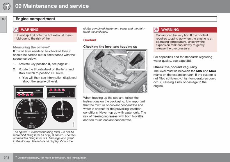
09 Maintenance and service
Engine compartment 09
342 * Option/accessory, for more information, see Introduction.
WARNING
Do not spill oil onto the hot exhaust mani-fold due to the risk of fire.
Measuring the oil level*If the oil level needs to be checked then itshould be carried out in accordance with thesequence below.
1. Activate key position II, see page 81.
2. Rotate the thumbwheel on the left-handstalk switch to position Oil level.> You will then see information displayed
about the engine oil level.
The figures 1-4 represent filling level. Do not fillmore oil if filling level (3) or (4) is shown. The rec-ommended filling level is 4. Message and graphin the display. The left-hand display shows the
digital combined instrument panel and the right-hand the analogue.
Coolant
Checking the level and topping up
When topping up the coolant, follow theinstructions on the packaging. It is importantthat the mixture of coolant concentrate andwater is correct for the prevailing weatherconditions. Never top up with water only. Therisk of freezing increases with both too littleand too much coolant concentrate.
WARNING
Coolant can be very hot. If the coolantrequires topping up when the engine is atoperating temperature, unscrew theexpansion tank cap slowly to gentlyrelease the overpressure.
For capacities and for standards regardingwater quality, see page 385.
Check the coolant regularlyThe level must lie between the MIN and MAXmarks on the expansion tank. If the system isnot filled sufficiently, high temperatures couldoccur, causing a risk of damage to theengine.
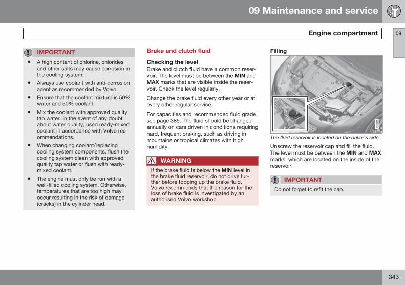
09 Maintenance and service
Engine compartment 09
343
IMPORTANT
• A high content of chlorine, chloridesand other salts may cause corrosion inthe cooling system.
• Always use coolant with anti-corrosionagent as recommended by Volvo.
• Ensure that the coolant mixture is 50%water and 50% coolant.
• Mix the coolant with approved qualitytap water. In the event of any doubtabout water quality, used ready-mixedcoolant in accordance with Volvo rec-ommendations.
• When changing coolant/replacingcooling system components, flush thecooling system clean with approvedquality tap water or flush with ready-mixed coolant.
• The engine must only be run with awell-filled cooling system. Otherwise,temperatures that are too high mayoccur resulting in the risk of damage(cracks) in the cylinder head.
Brake and clutch fluid
Checking the levelBrake and clutch fluid have a common reser-voir. The level must be between the MIN andMAX marks that are visible inside the reser-voir. Check the level regularly.
Change the brake fluid every other year or atevery other regular service.
For capacities and recommended fluid grade,see page 385. The fluid should be changedannually on cars driven in conditions requiringhard, frequent braking, such as driving inmountains or tropical climates with highhumidity.
WARNING
If the brake fluid is below the MIN level inthe brake fluid reservoir, do not drive fur-ther before topping up the brake fluid.Volvo recommends that the reason for theloss of brake fluid is investigated by anauthorised Volvo workshop.
Filling
The fluid reservoir is located on the driver's side.
Unscrew the reservoir cap and fill the fluid.The level must be between the MIN and MAXmarks, which are located on the inside of thereservoir.
IMPORTANT
Do not forget to refit the cap.
09 Maintenance and service
Engine compartment 09
344
Air conditioning system
Troubleshooting and repairThe air conditioning system contains fluores-cent tracing agents. Use ultraviolet light whenlooking for leaks.
Volvo recommends that you contact anauthorised Volvo workshop.
WARNING
The air conditioning system contains pres-surised refrigerant R134a. This systemmust only be serviced and repaired by anauthorised workshop.
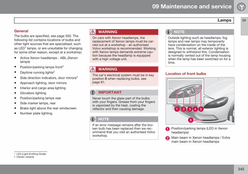
09 Maintenance and service
Lamps 09
345
GeneralThe bulbs are specified, see page 350. Thefollowing list contains locations of bulbs andother light sources that are specialised, suchas LED1 lamps, or are unsuitable for changingfor some other reason, except at a workshop:
• Active Xenon headlamps - ABL (Xenonlamps)
• Position/parking lamps front2
• Daytime running lights2
• Side direction indicators, door mirrors2
• Approach lighting, door mirrors
• Interior and cargo area lighting
• Glovebox lighting
• Position/parking lamps rear
• Side marker lamps, rear
• Brake light above the rear windscreen
• Number plate lighting.
WARNING
On cars with Xenon headlamps, thereplacement of Xenon lamps must be car-ried out at a workshop - an authorisedVolvo workshop is recommended. Workingwith Xenon lamps demands extreme cau-tion because the headlamp is equippedwith a high voltage unit.
WARNING
The car’s electrical system must be in keyposition 0 when replacing bulbs, seepage 81.
IMPORTANT
Never touch the glass part of the bulbswith your fingers. Grease from your fingersis vaporised by the heat, coating thereflector and then causing damage.
NOTE
If an error message remains after the bro-ken bulb has been replaced then we rec-ommend that you visit an authorised Volvoworkshop.
NOTE
Outside lighting such as headlamps, foglamps and rear lamps may temporarilyhave condensation on the inside of thelens. This is normal, all exterior lighting isdesigned to withstand this. Condensationis normally vented out of the lamp housingwhen the lamp has been switched on for atime.
Location of front bulbs
Position/parking lamps (LED in Xenonheadlamps)
Main beam in Xenon headlamps / Extramain beam in Xenon headlamps
1 LED (Light Emitting Diode)2 Certain variants
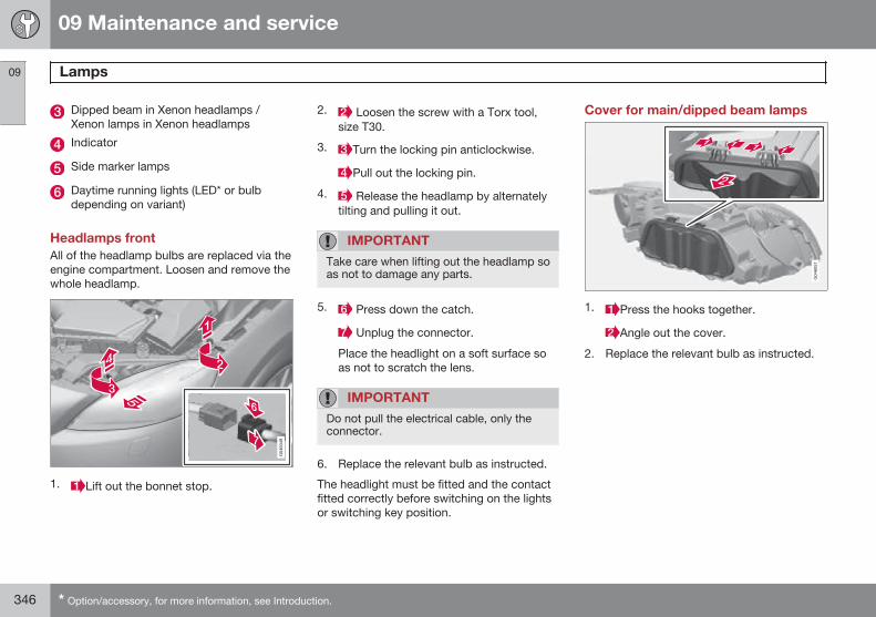
09 Maintenance and service
Lamps 09
346 * Option/accessory, for more information, see Introduction.
Dipped beam in Xenon headlamps /Xenon lamps in Xenon headlamps
Indicator
Side marker lamps
Daytime running lights (LED* or bulbdepending on variant)
Headlamps frontAll of the headlamp bulbs are replaced via theengine compartment. Loosen and remove thewhole headlamp.
1. Lift out the bonnet stop.
2. Loosen the screw with a Torx tool,size T30.
3. Turn the locking pin anticlockwise.
Pull out the locking pin.
4. Release the headlamp by alternatelytilting and pulling it out.
IMPORTANT
Take care when lifting out the headlamp soas not to damage any parts.
5. Press down the catch.
Unplug the connector.
Place the headlight on a soft surface soas not to scratch the lens.
IMPORTANT
Do not pull the electrical cable, only theconnector.
6. Replace the relevant bulb as instructed.
The headlight must be fitted and the contactfitted correctly before switching on the lightsor switching key position.
Cover for main/dipped beam lamps
1. Press the hooks together.
Angle out the cover.
2. Replace the relevant bulb as instructed.
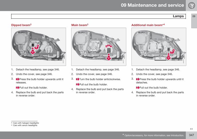
09 Maintenance and service
Lamps 09
}}* Option/accessory, for more information, see Introduction. 347
Dipped beam3
1. Detach the headlamp, see page 346.
2. Undo the cover, see page 346.
3. Press the bulb holder upwards until itreleases.
Pull out the bulb holder.
4. Replace the bulb and put back the partsin reverse order.
Main beam3
1. Detach the headlamp, see page 346.
2. Undo the cover, see page 346.
3. Turn the bulb holder anticlockwise.
Pull out the bulb holder.
4. Replace the bulb and put back the partsin reverse order.
Additional main beam*4
1. Detach the headlamp, see page 346.
2. Undo the cover, see page 346.
3. Press the bulb holder upwards until itdetaches.
Pull out the bulb holder.
4. Replace the bulb and put back the partsin reverse order.
3 Cars with halogen headlights4 Cars with xenon headlights
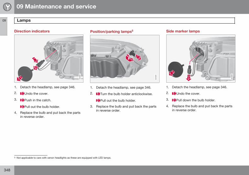
09 Maintenance and service
Lamps 09
348
Direction indicators
1. Detach the headlamp, see page 346.
2. Undo the cover.
3. Push in the catch.
Pull out the bulb holder.
4. Replace the bulb and put back the partsin reverse order.
Position/parking lamps5
1. Detach the headlamp, see page 346.
2. Turn the bulb holder anticlockwise.
Pull out the bulb holder.
3. Replace the bulb and put back the partsin reverse order.
Side marker lamps
1. Detach the headlamp, see page 346.
2. Undo the cover.
3. Pull down the bulb holder.
4. Replace the bulb and put back the partsin reverse order.
5 Not applicable to cars with xenon headlights as these are equipped with LED lamps.
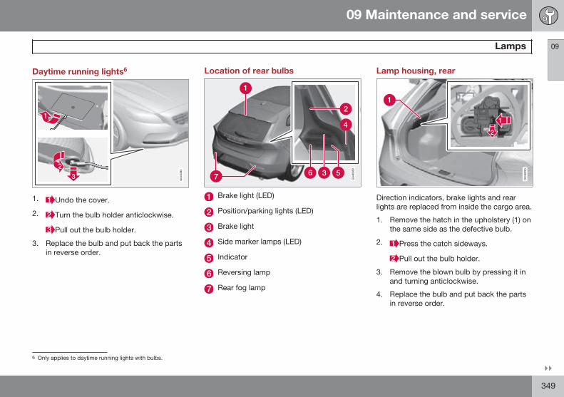
09 Maintenance and service
Lamps 09
}}349
Daytime running lights6
1. Undo the cover.
2. Turn the bulb holder anticlockwise.
Pull out the bulb holder.
3. Replace the bulb and put back the partsin reverse order.
Location of rear bulbs
Brake light (LED)
Position/parking lights (LED)
Brake light
Side marker lamps (LED)
Indicator
Reversing lamp
Rear fog lamp
Lamp housing, rear
Direction indicators, brake lights and rearlights are replaced from inside the cargo area.
1. Remove the hatch in the upholstery (1) onthe same side as the defective bulb.
2. Press the catch sideways.
Pull out the bulb holder.
3. Remove the blown bulb by pressing it inand turning anticlockwise.
4. Replace the bulb and put back the partsin reverse order.
6 Only applies to daytime running lights with bulbs.
09 Maintenance and service
Lamps 09
350
Rear fog lamp
Insert (approx. 20 mm) a blunt, knife-likeobject, e.g. a table knife, at the triangle.
Carefully prise until the lug releases.
IMPORTANT
Take care not to damage any parts.
Turn the bulb holder anticlockwise.
Pull out the bulb holder.
3. Replace the bulb and put back the partsin reverse order.
Vanity mirror lighting
1. Insert a screwdriver under the lamp lensand gently prize up the lug on the edge.
2. Carefully detach and lift aside the lamplens.
3. Using needle-nose pliers, pull the bulbstraight out to the side. Do not squeezetoo hard with the pliers. Otherwise, thebulb glass could break.
4. Replace the bulb and put back the partsin reverse order.
Specifications of bulbs
Lighting [W]A Type
Dipped beamB 55 H7 LL
Main beamB 65 H9
Additional mainbeamC
55 H7 LL
Front directionindicators
21 HY21W
Position/parkinglamps frontB
5 W5W LL
Side marker lampsfront
5 WY5W LL
Daytime runninglightsD
19 PW19W
Side direction indi-cators, door mir-rorsD
5 WY5W LL
Direction indica-tors, rear
21 PY21W LL
Brake light 21 P21W LL
Reversing lamp 21 P21W LL
09 Maintenance and service
Lamps 09
351
Lighting [W]A Type
Rear fog lamp 21 H21W LL
Vanity mirror light-ing
1.2 T5 SocketW2x4.6d
A WattB Cars with halogen headlightsC Cars with xenon headlightsD Certain variants
09 Maintenance and service
Wiper blades and washer fluid 09
352
Wiper blades
Service position
Wiper blades in service position.
In order to change, clean or lift the wiperblades (for scraping off ice from the wind-screen, for example) they must be in serviceposition.
IMPORTANT
Before placing the wiper blades in theservice position, make sure that they arenot frozen down.
1. Place the remote control key in the igni-tion lock1 and briefly press the START/
STOP ENGINE button to set the car’selectrical system to key position I. (Fordetailed information on key positions, seepage 81.)
2. Briefly press the START/STOP ENGINEbutton again to set the car’s electricalsystem in key position 0.
3. Within 3 seconds, move the right stalkswitch up and hold it in position forapprox. 1 second.> The wipers then move to standing
straight up.
The wipers return to their starting positionwhen you briefly press the START/STOPENGINE button to set the car’s electrical sys-tem to key position I (or when the car isstarted).
IMPORTANT
If the wiper arms in the service positionhave been folded up from the windscreen,they must be folded back down onto thewindscreen before the wipers are allowedto return to their starting position. This is toavoid scraping the paint on the bonnet.
Replacing the wiper blades
1 Not necessary in cars with Keyless function.
09 Maintenance and service
Wiper blades and washer fluid 09
353
Fold up the wiper arm when it is in serv-ice position. Press the button located onthe wiper blade mounting and pullstraight out parallel with the wiper arm.
Slide in the new wiper blade until a "click"is heard.
Check that the blade is firmly installed.
4. Fold the wiper arm back towards thewindscreen.
The wipers return from service position totheir starting position when you briefly pressthe START/STOP ENGINE button to set thecar’s electrical system to key position I (orwhen the car is started).
G021763
NOTE
The wiper blades are different lengths. Theblade on the driver's side is longer than onthe passenger side.
WARNING
Since the car is equipped with airbagPedestrian Airbag, Volvo recommends thatgenuine wiper arms are used and that youonly use genuine parts for them.
Replacing the wiper blades, rearwindow
1. Fold out the wiper arm.
2. Grip the inner section of the blade (by thearrow).
3. Turn anticlockwise to use the blade's endposition against the wiper arm as a leverto detach the blade more easily.
4. Press the new wiper blade into position.Check that it is firmly installed.
5. Lower the wiper arm.
CleaningFor cleaning wiper blades and windscreen,see page 368 and onwards.
IMPORTANT
Check the blades regularly. Neglectedmaintenance shortens the service life ofthe wiper blades.
Filling washer fluid
09 Maintenance and service
Wiper blades and washer fluid 09
354
The windscreen and headlamp washers sharea common reservoir.
IMPORTANT
Use washer fluid with antifreeze during thewinter to avoid freezing in the pump, reser-voir and hoses.
For capacities, see page 385.
09 Maintenance and service
Battery 09
355
OperationThe service life and function of the battery isinfluenced by factors such as the number ofstarts, discharging, driving style, driving con-ditions, climatic conditions etc.
• Never disconnect the battery when theengine is running.
• Check that the cables to the battery arecorrectly connected and properly tight-ened.
WARNING
• The battery can generate oxyhydrogengas, which is highly explosive. A sparkcan be formed if a jump lead is con-nected incorrectly, and this can beenough for the battery to explode.
• The battery contains sulphuric acid,which can cause serious burns.
• If sulphuric acid comes into contactwith eyes, skin or clothing, flush withlarge quantities of water. If acidsplashes into the eyes - seek medicalattention immediately.
NOTE
The life of the battery is shortened if itbecomes discharged repeatedly.
The life of the battery is affected by severalfactors, including driving conditions andclimate. Battery starting capacity decrea-ses gradually with time and thereforeneeds to be recharged if the car is notused for a longer time or when it is onlydriven short distances. Extreme cold fur-ther limits starting capacity.
To maintain the battery in good condition,at least 15 minutes of driving/week is rec-ommended or that the battery is con-nected to a battery charger with automatictrickle charging.
A battery that is kept fully charged has amaximum service life.
IMPORTANT
A quick charger must never be used whencharging the battery.
IMPORTANT
If the following instruction is not observedthen the energy saving function for info-tainment may be temporarily disengaged,and/or the message in the combinedinstrument panel's information displayabout the starter battery's state of chargemay be temporarily inapplicable, followingthe connection of an external starter bat-tery or battery charger:
• The negative battery terminal on thecar's starter battery must never beused for connecting an external starterbattery or battery charger - only thecar chassis may be used as thegrounding point.
See the section "Start assistance" - for adescription of how the cable clamps mustbe attached.
09 Maintenance and service
Battery 09
356
Symbols on the battery
Use protective goggles.
Further information in theowner's manual.
Store the battery out ofthe reach of children.
The battery contains cor-rosive acid.
Avoid sparks and nakedflames.
Risk of explosion.
Must be taken for recy-cling.
NOTE
An expended battery must be recycled inan environmentally safe manner as it con-tains lead.
Replacing the main batteryVolvo recommends that you allow an author-ised workshop to replace the batteries - anauthorised Volvo workshop is recommended.For more information on the car's main bat-tery -see page 117
Start/StopCars with the Start/Stop function are equip-ped with two 12 V batteries - one extra pow-erful battery for starting and one support bat-tery that helps during the Start/Stop func-tion's starting sequence.
For more information on Start/Stop - seepage 125.
For more information on the car's main bat-tery - see page 117 and 393.
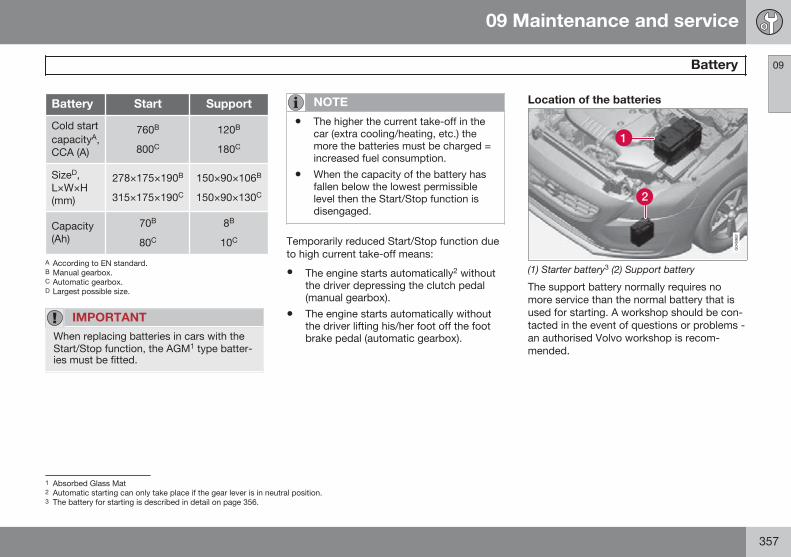
09 Maintenance and service
Battery 09
357
Battery Start Support
Cold startcapacityA,CCA (A)
760B
800C
120B
180C
SizeD,L×W×H(mm)
278×175×190B
315×175×190C
150×90×106B
150×90×130C
Capacity(Ah)
70B
80C
8B
10C
A According to EN standard.B Manual gearbox.C Automatic gearbox.D Largest possible size.
IMPORTANT
When replacing batteries in cars with theStart/Stop function, the AGM1 type batter-ies must be fitted.
NOTE
• The higher the current take-off in thecar (extra cooling/heating, etc.) themore the batteries must be charged =increased fuel consumption.
• When the capacity of the battery hasfallen below the lowest permissiblelevel then the Start/Stop function isdisengaged.
Temporarily reduced Start/Stop function dueto high current take-off means:
• The engine starts automatically2 withoutthe driver depressing the clutch pedal(manual gearbox).
• The engine starts automatically withoutthe driver lifting his/her foot off the footbrake pedal (automatic gearbox).
Location of the batteries
(1) Starter battery3 (2) Support battery
The support battery normally requires nomore service than the normal battery that isused for starting. A workshop should be con-tacted in the event of questions or problems -an authorised Volvo workshop is recom-mended.
1 Absorbed Glass Mat2 Automatic starting can only take place if the gear lever is in neutral position.3 The battery for starting is described in detail on page 356.
09 Maintenance and service
Battery 09
358
IMPORTANT
If the following instruction is not observedthen the Start/Stop function may tempo-rarily cease to work after the connection ofan external battery or battery charger:
• The negative battery terminal on thecar's main battery must never be usedfor connecting an external battery orbattery charger - only the car chassismay be used as the grounding point.
See the section "Start assistance" - for adescription of how the cable clamps mustbe attached.
NOTE
If the battery has become so dischargedthat everything is "black" and in principlethe car does not have all the normal elec-trical functions and the engine is subse-quently started using an external battery orbattery charger, then the Start/Stop func-tion will be activated. It will then be possi-ble for the engine to be auto-stopped butin the event of an auto-stop the Start/Stopfunction may fail to auto-start the enginedue to inadequate capacity in the battery.
The battery must first be charged in orderto ensure a successful auto-start after anauto-stop. At an outside temperature of+15 °C the battery needs to be charged forat least 1 hour. At a lower outside tem-perature a charging time of 3-4 hours isrecommended. The recommendation isthat the battery is charged using an exter-nal battery charger.
If this is not possible then the recommen-dation is to temporarily deactivate theStart/Stop function until the battery hasbeen adequately recharged.
For more information about recharging thebattery, see the section "Battery" in thechapter "Maintenance and service".
09 Maintenance and service
Fuses 09
359
GeneralAll electrical functions and components areprotected by a number of fuses in order toprotect the car's electrical system from dam-age by short circuiting or overloading.
If an electrical component or function doesnot work, it may be because the component'sfuse was temporarily overloaded and failed. Ifthe same fuse fails repeatedly then there is afault in the circuit. Volvo recommends thatyou visit an authorised Volvo workshop forchecking.
Changing1. Look in the fuse diagram to locate the
fuse.
2. Pull out the fuse and check from the sideto see whether the curved wire hasblown.
3. If this is the case, replace it with a newfuse of the same colour and amperage.
WARNING
Never use a foreign object or a fuse withan amperage higher than that specifiedwhen replacing a fuse. This could causesignificant damage to the electrical systemand possibly lead to fire.
Location, fuse boxes
Fuse box locations in a left-hand drive car. Ina right-hand drive car the fuse box under theglovebox changes sides.
Engine compartment
Under the glovebox
Below right front seat
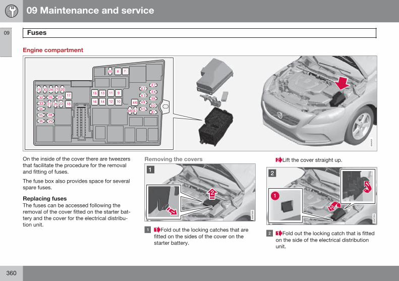
09 Maintenance and service
Fuses 09
360
Engine compartment
On the inside of the cover there are tweezersthat facilitate the procedure for the removaland fitting of fuses.
The fuse box also provides space for severalspare fuses.
Replacing fusesThe fuses can be accessed following theremoval of the cover fitted on the starter bat-tery and the cover for the electrical distribu-tion unit.
Removing the covers
Fold out the locking catches that arefitted on the sides of the cover on thestarter battery.
Lift the cover straight up.
Fold out the locking catch that is fittedon the side of the electrical distributionunit.
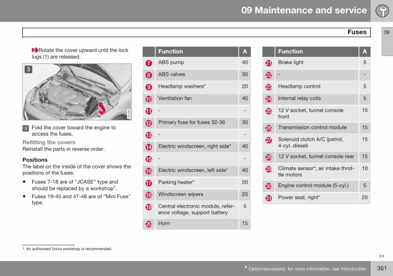
09 Maintenance and service
Fuses 09
}}* Option/accessory, for more information, see Introduction. 361
Rotate the cover upward until the locklugs (1) are released.
Fold the cover toward the engine toaccess the fuses.
Refitting the coversReinstall the parts in reverse order.
PositionsThe label on the inside of the cover shows thepositions of the fuses.
• Fuses 7-18 are of "JCASE" type andshould be replaced by a workshop1.
• Fuses 19-45 and 47-48 are of "Mini Fuse"type.
Function A
ABS pump 40
ABS valves 30
Headlamp washers* 20
Ventilation fan 40
- -
Primary fuse for fuses 32-36 30
- -
Electric windscreen, right side* 40
- -
Electric windscreen, left side* 40
Parking heater* 20
Windscreen wipers 20
Central electronic module, refer-ence voltage, support battery
5
Horn 15
Function A
Brake light 5
- -
Headlamp control 5
Internal relay coils 5
12 V socket, tunnel consolefront
15
Transmission control module 15
Solenoid clutch A/C (petrol,4-cyl. diesel)
15
12 V socket, tunnel console rear 15
Climate sensor*; air intake throt-tle motors
10
Engine control module (5-cyl.) 5
Power seat, right* 20
1 An authorised Volvo workshop is recommended.
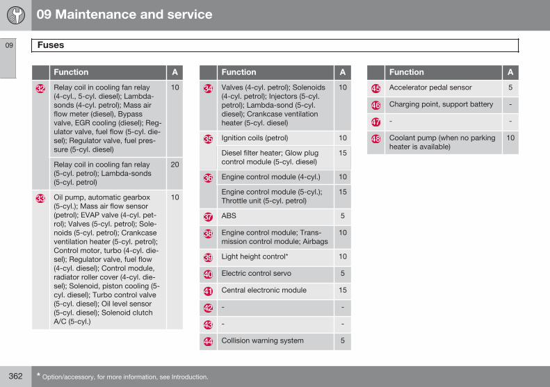
09 Maintenance and service
Fuses 09
362 * Option/accessory, for more information, see Introduction.
Function A
Relay coil in cooling fan relay(4-cyl., 5-cyl. diesel); Lambda-sonds (4-cyl. petrol); Mass airflow meter (diesel), Bypassvalve, EGR cooling (diesel); Reg-ulator valve, fuel flow (5-cyl. die-sel); Regulator valve, fuel pres-sure (5-cyl. diesel)
10
Relay coil in cooling fan relay(5-cyl. petrol); Lambda-sonds(5-cyl. petrol)
20
Oil pump, automatic gearbox(5-cyl.); Mass air flow sensor(petrol); EVAP valve (4-cyl. pet-rol); Valves (5-cyl. petrol); Sole-noids (5-cyl. petrol); Crankcaseventilation heater (5-cyl. petrol);Control motor, turbo (4-cyl. die-sel); Regulator valve, fuel flow(4-cyl. diesel); Control module,radiator roller cover (4-cyl. die-sel); Solenoid, piston cooling (5-cyl. diesel); Turbo control valve(5-cyl. diesel); Oil level sensor(5-cyl. diesel); Solenoid clutchA/C (5-cyl.)
10
Function A
Valves (4-cyl. petrol); Solenoids(4-cyl. petrol); Injectors (5-cyl.petrol); Lambda-sond (5-cyl.diesel); Crankcase ventilationheater (5-cyl. diesel)
10
Ignition coils (petrol) 10
Diesel filter heater; Glow plugcontrol module (5-cyl. diesel)
15
Engine control module (4-cyl.) 10
Engine control module (5-cyl.);Throttle unit (5-cyl. petrol)
15
ABS 5
Engine control module; Trans-mission control module; Airbags
10
Light height control* 10
Electric control servo 5
Central electronic module 15
- -
- -
Collision warning system 5
Function A
Accelerator pedal sensor 5
Charging point, support battery -
- -
Coolant pump (when no parkingheater is available)
10
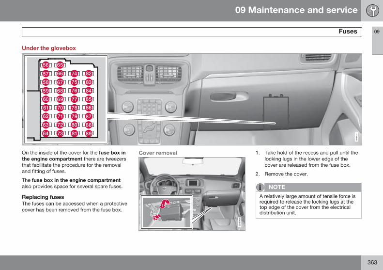
09 Maintenance and service
Fuses 09
363
Under the glovebox
On the inside of the cover for the fuse box inthe engine compartment there are tweezersthat facilitate the procedure for the removaland fitting of fuses.
The fuse box in the engine compartmentalso provides space for several spare fuses.
Replacing fusesThe fuses can be accessed when a protectivecover has been removed from the fuse box.
Cover removal 1. Take hold of the recess and pull until thelocking lugs in the lower edge of thecover are released from the fuse box.
2. Remove the cover.
NOTE
A relatively large amount of tensile force isrequired to release the locking lugs at thetop edge of the cover from the electricaldistribution unit.
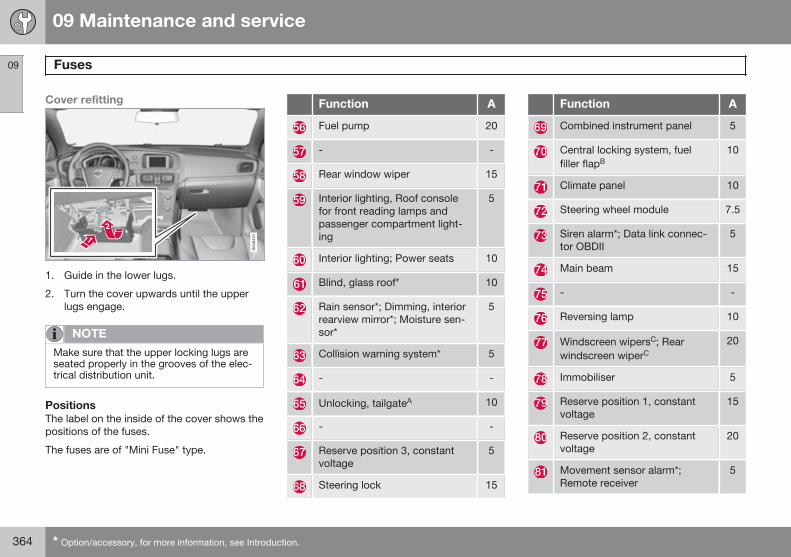
09 Maintenance and service
Fuses 09
364 * Option/accessory, for more information, see Introduction.
Cover refitting
1. Guide in the lower lugs.
2. Turn the cover upwards until the upperlugs engage.
NOTE
Make sure that the upper locking lugs areseated properly in the grooves of the elec-trical distribution unit.
PositionsThe label on the inside of the cover shows thepositions of the fuses.
The fuses are of "Mini Fuse" type.
Function A
Fuel pump 20
- -
Rear window wiper 15
Interior lighting, Roof consolefor front reading lamps andpassenger compartment light-ing
5
Interior lighting; Power seats 10
Blind, glass roof* 10
Rain sensor*; Dimming, interiorrearview mirror*; Moisture sen-sor*
5
Collision warning system* 5
- -
Unlocking, tailgateA 10
- -
Reserve position 3, constantvoltage
5
Steering lock 15
Function A
Combined instrument panel 5
Central locking system, fuelfiller flapB
10
Climate panel 10
Steering wheel module 7.5
Siren alarm*; Data link connec-tor OBDII
5
Main beam 15
- -
Reversing lamp 10
Windscreen wipersC; Rearwindscreen wiperC
20
Immobiliser 5
Reserve position 1, constantvoltage
15
Reserve position 2, constantvoltage
20
Movement sensor alarm*;Remote receiver
5
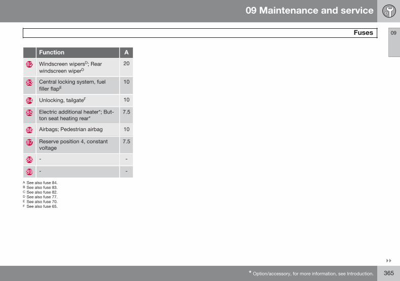
09 Maintenance and service
Fuses 09
}}* Option/accessory, for more information, see Introduction. 365
Function A
Windscreen wipersD; Rearwindscreen wiperD
20
Central locking system, fuelfiller flapE
10
Unlocking, tailgateF 10
Electric additional heater*; But-ton seat heating rear*
7.5
Airbags; Pedestrian airbag 10
Reserve position 4, constantvoltage
7.5
- -
- -
A See also fuse 84.B See also fuse 83.C See also fuse 82.D See also fuse 77.E See also fuse 70.F See also fuse 65.
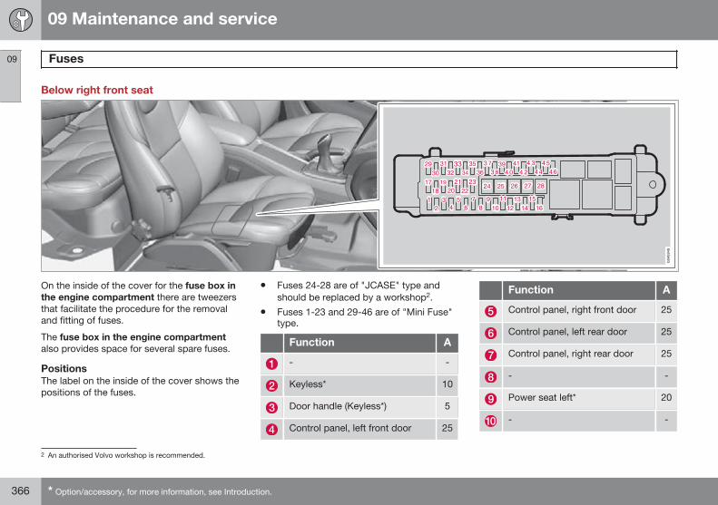
09 Maintenance and service
Fuses 09
366 * Option/accessory, for more information, see Introduction.
Below right front seat
On the inside of the cover for the fuse box inthe engine compartment there are tweezersthat facilitate the procedure for the removaland fitting of fuses.
The fuse box in the engine compartmentalso provides space for several spare fuses.
PositionsThe label on the inside of the cover shows thepositions of the fuses.
• Fuses 24-28 are of "JCASE" type andshould be replaced by a workshop2.
• Fuses 1-23 and 29-46 are of "Mini Fuse"type.
Function A
- -
Keyless* 10
Door handle (Keyless*) 5
Control panel, left front door 25
Function A
Control panel, right front door 25
Control panel, left rear door 25
Control panel, right rear door 25
- -
Power seat left* 20
- -
2 An authorised Volvo workshop is recommended.
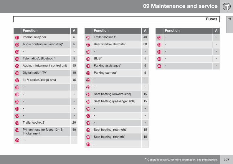
09 Maintenance and service
Fuses 09
* Option/accessory, for more information, see Introduction. 367
Function A
Internal relay coil 5
Audio control unit (amplifier)* 5
- -
Telematics*; Bluetooth* 5
Audio; Infotainment control unit 15
Digital radio*; TV* 10
12 V socket, cargo area 15
- -
- -
- -
- -
- -
Trailer socket 2* 20
Primary fuse for fuses 12-16:Infotainment
40
- -
Function A
Trailer socket 1* 40
Rear window defroster 30
- -
BLIS* 5
Parking assistance* 5
Parking camera* 5
- -
- -
Seat heating (driver's side) 15
Seat heating (passenger side) 15
- -
- -
- -
Seat heating, rear right* 15
Seat heating, rear left* 15
- -
Function A
- -
- -
- -
- -
- -
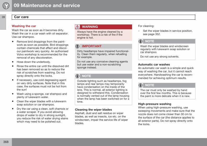
09 Maintenance and service
Car care 09
368
Washing the carWash the car as soon as it becomes dirty.Wash the car in a car wash with oil separator.Use car shampoo.
• Remove bird droppings from the paint-work as soon as possible. Bird droppingscontain chemicals that affect and discol-our paintwork very quickly. An authorisedVolvo workshop is recommended for theremoval of any discoloration.
• Hose down the underbody.
• Rinse the entire car until the dissolved dirthas been removed so as to reduce therisk of scratches from washing. Do notspray directly onto the locks.
• If necessary, use cold degreasing agenton very dirty surfaces. Note that in thiscase, the surfaces must not be hot fromthe sun!
• Wash using a sponge, car shampoo andplenty of lukewarm water.
• Clean the wiper blades with a lukewarmsoap solution or car shampoo.
• Dry the car using a clean, soft chamois ora water scraper. If you avoid allowingdrops of water to dry in strong sunlight,you reduce the risk of water drying stainswhich may need to be polished out.
WARNING
Always have the engine cleaned by aworkshop. There is a risk of fire if theengine is hot.
IMPORTANT
Dirty headlamps have impaired functional-ity. Clean them regularly, when refuellingfor example.
Do not use any corrosive cleaning agentsbut use water and a non-scratchingsponge instead.
NOTE
Outside lighting such as headlamps, foglamps and rear lamps may temporarilyhave condensation on the inside of thelens. This is normal, all exterior lighting isdesigned to withstand this. Condensationis normally vented out of the lamp housingwhen the lamp has been switched on for atime.
Cleaning the wiper bladesAsphalt, dust and salt residue on wiperblades, as well as insects, ice etc. on thewindscreen, impair the service life of wiperblades.
For cleaning:
– Set the wiper blades in service position,see page 352.
NOTE
Wash the wiper blades and windscreenregularly with lukewarm soap solution orcar shampoo.
Do not use any strong solvents.
Automatic car washesAn automatic car wash is a simple and quickway of washing the car, but it cannot reacheverywhere. Handwashing the car is recom-mended for achieving optimum results.
NOTE
The car must only be washed by handover the first few months. This is becausethe paint is more delicate when it is new.
High-pressure washingWhen using high-pressure washing, usesweeping movements and make sure that thenozzle does not come closer than 30 cm tothe surface of the car (the distance applies toall exterior parts). Do not spray directly ontothe locks.
09 Maintenance and service
Car care 09
* Option/accessory, for more information, see Introduction. 369
Testing the brakes
WARNING
Always test the brakes after washing thecar, including the parking brake, to ensurethat moisture and corrosion do not attackthe brake linings and reduce braking per-formance.
Lightly depress the brake pedal now and thenwhen driving long distances in rain or slush.The heat from the friction causes the brakelinings to warm up and dry. Do the samething after starting in very damp or coldweather.
Exterior plastic, rubber and trimcomponentsA special cleaning agent available from Volvodealers is recommended for the cleaning andcare of coloured plastic parts, rubber and trimcomponents, such as glossy trim mouldings.When using such a cleaning agent theinstructions must be followed carefully.
IMPORTANT
Avoid waxing and polishing on plastic andrubber.
When using degreasant on plastic andrubber, only rub with light pressure if it isnecessary. Use a soft washing sponge.
Polishing glossy trim mouldings couldwear away or damage the glossy surfacelayer.
Polishing agent that contains abrasivemust not be used.
RimsOnly use rim cleaning agent recommendedby Volvo.
Strong rim cleaning agents can damage thesurface and cause stains on chrome-platedaluminium rims.
Polishing and waxingPolish and wax the car if the paintwork is dullor to give the paintwork extra protection.
The car does not need to be polished until itis at least one year old. However, the car canbe waxed during this time. Do not polish orwax the car in direct sunlight.
Wash and dry the car thoroughly before youbegin polishing or waxing. Clean off asphalt
and tar stains using tar remover or white spi-rit. More stubborn stains can be removedusing fine rubbing paste designed for carpaintwork.
Polish first with a polish and then wax withliquid or solid wax. Follow the instructions onthe packaging carefully. Many preparationscontain both polish and wax.
IMPORTANT
Only paint treatment recommended byVolvo should be used. Other treatmentsuch as preserving, sealing, protection,lustre sealing or similar could damage thepaintwork. Paintwork damage caused bysuch treatments is not covered by Volvowarranty.
Water-repellent coating*Never use products such as carwax, degreaser or similar on glasssurfaces as this could ruin their
water-repellent properties.
Take care when cleaning so as not to dam-age the glass surface.
To avoid damaging glass surfaces whenremoving ice – only use plastic ice scrapers.
There is natural wear of the water-repellentcoating.
09 Maintenance and service
Car care 09
370
Treatment with a special finishing agent avail-able from Volvo dealers is recommended inorder to maintain the water-repellent proper-ties. This should be used first after threeyears and then each year.
Rustproofing – inspection andmaintenanceThe car received a thorough and completerustproofing at the factory. Parts of the bodyare made of galvanised sheet metal. Theunderbody is protected by a wear-resistantanti-corrosion compound. A thin, penetratingrustproofing fluid was sprayed into theexposed members, cavities, closed sectionsand side doors.
Under normal conditions the rustproofingdoes not require treatment for approximately12 years. After this period, it should be trea-ted at three-year intervals. Volvo recom-mends that you engage an authorised Volvoworkshop for assistance if the car needs fur-ther treatment.
Dirt and road salt can lead to corrosion so itis important to keep the car clean. The car'srustproofing needs to be checked regularlyand touched-up if necessary in order for it tobe maintained.
Cleaning the interiorOnly use cleaning agents and car care prod-ucts recommended by Volvo. Clean regularlyand follow the instructions included with thecar care product.
Vacuuming is important prior to using clean-ing agents.
Carpets and cargo areaRemove inlaid carpets for separate cleaningof the floor carpet and the inlaid carpets. Usea vacuum cleaner to remove dust and dirt.
Each inlay mat is secured with pins.
– Take hold of the inlay mat at each pin andlift the mat straight up.
Fit the inlay mat in place by pressing it in ateach pin.
WARNING
Before setting off check that the inlaid matin the driver area is firmly affixed andsecured in the pins in order to avoid get-ting caught adjacent to and under the ped-als.
A special textile cleaner is recommended forstains on the floor mat after vacuuming. Floormats should be cleaned with agents recom-mended by your Volvo dealer!
Stains on fabric upholstery and roofupholsteryA special fabric cleaning agent, available fromauthorised Volvo dealers, is recommended toavoid impairing the fire retardant qualities ofthe upholstery.
IMPORTANT
Sharp objects and Velcro may damage thefabric upholstery.
Treating stains on leather upholsteryVolvo's leather upholstery is chromium-freeand is treated to preserve its original appear-ance.
Leather upholstery ages and acquires a beau-tiful patina over time. The leather is refinedand processed so that it retains its naturalcharacteristics. It is given a protective coa-ting, but regular cleaning is required in orderto maintain both characteristics and appear-ance. Volvo offers a comprehensive productfor the cleaning and treatment of leatherupholstery which, when used in accordancewith the instructions, preserves the leather'sprotective coating. After a period of use thenatural appearance of the leather will never-theless emerge, depending more or less onthe surface texture of the leather. This is a
09 Maintenance and service
Car care 09
371
natural maturing of the leather and showsthat it is a natural product.
To achieve best results Volvo recommendscleaning and the application of protectivecream once to four times per year (or more ifnecessary). The Volvo Leather Care kit isavailable from your Volvo dealer.
IMPORTANT
• Certain items of coloured clothing (forexample, jeans and suede garments)may stain the upholstery.
• Never use strong solvents. Such prod-ucts may damage fabric, vinyl andleather upholstery.
Washing instructions for leatherupholstery1. Pour the leather cleaner on the damp-
ened sponge and squeeze out a strongfoam.
2. Work the dirt away with gentle circularmovements.
3. Dab accurately with the sponge on thestains. Allow the sponge to absorb thestain. Do not rub.
4. Wipe off with soft paper or a cloth andallow the leather to dry completely.
Protective treatment of leatherupholstery1. Pour a small amount of the protective
cream on the felted cloth and massage ina thin layer of cream with gentle circularmovements on the leather.
2. Allow the leather to dry for 20 minutesbefore use.
The leather has now been given improvedprotection against stains and improved UVprotection.
Washing instructions for the leathersteering wheel• Remove dirt and dust with a soft pre-
moistened sponge and neutral soap.
• Leather needs to breathe. Never coverthe leather steering wheel with protectiveplastic.
• Use natural oils. Volvo's leather careagents are recommended for best results.
If the steering wheel has stains:
Group 1 (ink, wine, coffee, milk, sweat andblood)
– Use a soft cloth or sponge. Mix a 5%ammonia solution. (For blood stains, usea solution of 2 dl water and 25g salt.)
Group 2 (fats, oils, sauces and chocolate)
1. Same procedure as for group 1.
2. Polish with an absorbent paper or cloth.
Group 3 (dry dirt, dust)
1. Use a soft brush to remove the dirt.
2. Same procedure as for group 1.
Treating stains on interior plastic, metaland wood partsA fibrillated fibre or microfibre cloth, lightlymoistened with water, available from Volvodealers, is recommended for cleaning interiorparts and surfaces.
Do not scrape or rub stains. Never use strongstain removers. A special cleaning agentavailable from Volvo dealers can be used formore difficult cleaning.
Cleaning seatbeltsUse water and a synthetic detergent. A spe-cial textile cleaning agent is available fromyour Volvo dealer. Make sure the seatbelt isdry before allowing it to retract.
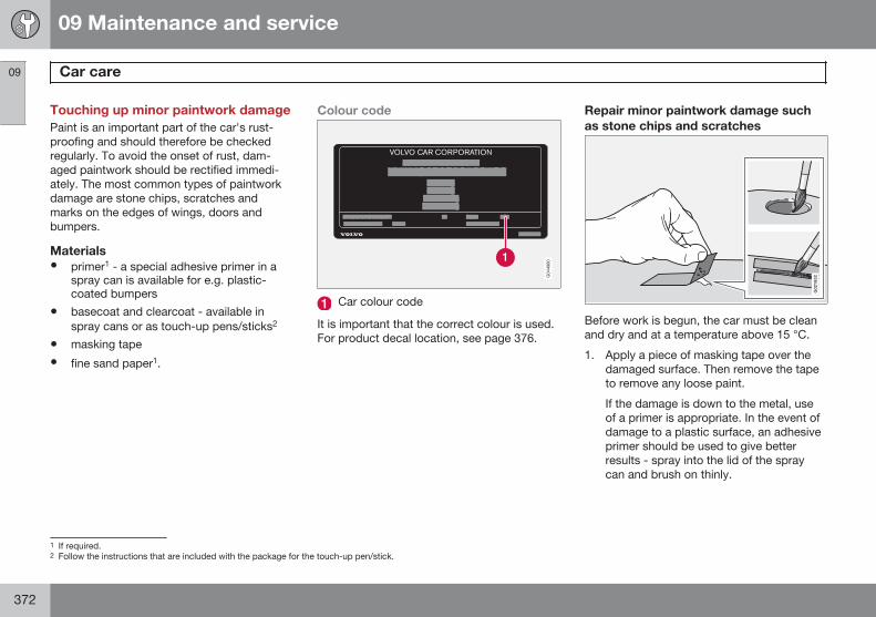
09 Maintenance and service
Car care 09
372
Touching up minor paintwork damagePaint is an important part of the car's rust-proofing and should therefore be checkedregularly. To avoid the onset of rust, dam-aged paintwork should be rectified immedi-ately. The most common types of paintworkdamage are stone chips, scratches andmarks on the edges of wings, doors andbumpers.
Materials• primer1 - a special adhesive primer in a
spray can is available for e.g. plastic-coated bumpers
• basecoat and clearcoat - available inspray cans or as touch-up pens/sticks2
• masking tape
• fine sand paper1.
Colour code
Car colour code
It is important that the correct colour is used.For product decal location, see page 376.
Repair minor paintwork damage suchas stone chips and scratches
G021832
Before work is begun, the car must be cleanand dry and at a temperature above 15 °C.
1. Apply a piece of masking tape over thedamaged surface. Then remove the tapeto remove any loose paint.
If the damage is down to the metal, useof a primer is appropriate. In the event ofdamage to a plastic surface, an adhesiveprimer should be used to give betterresults - spray into the lid of the spraycan and brush on thinly.
1 If required.2 Follow the instructions that are included with the package for the touch-up pen/stick.
09 Maintenance and service
Car care 09
373
2. Before painting, gentle polishing using avery fine polishing agent may be carriedout locally if required (e.g. if there are anyuneven edges). The surface is cleanedthoroughly and left to dry.
3. Stir the primer well and apply using a finebrush, a matchstick or similar. Finish offwith a basecoat and clearcoat once theprimer has dried.
4. For scratches, proceed as above, butmask around the damaged area to pro-tect the undamaged paintwork.
NOTE
If the stone chip has not penetrated downto the meal and an undamaged layer ofpaint remains in place, fill in with basecoatand clearcoat as soon as the surface hasbeen cleaned.
374
Type designations................................................................................. 376Dimensions and weights....................................................................... 378Engine specifications............................................................................ 382Engine oil............................................................................................... 383Fluids and lubricants............................................................................. 385Fuel....................................................................................................... 387Wheel and tyres, dimensions and pressure ......................................... 391Electrical system................................................................................... 393Type approval....................................................................................... 394Licenses................................................................................................ 403Symbols in the display.......................................................................... 406
SPECIF ICATIONS
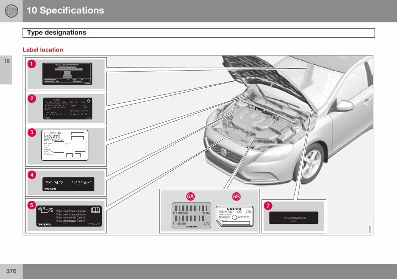
10 Specifications
Type designations
10
376
Label location
10 Specifications
Type designations
10
377
Knowing the car's type designation, vehicleidentification and engine numbers can facili-tate all contact with an authorised Volvodealer regarding the car and when orderingspare parts and accessories.
Type designation, vehicle identificationnumber, maximum permissible weights,codes for colour and upholstery and typeapproval number. The label is visiblewhen the right rear door is opened.
Label for A/C system.
Label for parking heater.
Engine code and engine serial number.
Label for engine oil.
Gearbox type designation and serial num-ber.
Manual gearbox
Automatic gearbox
Car's identification number. (VIN VehicleIdentification Number)
Further information on the car is presented inthe registration document.
NOTE
It is not intended that the decals illustratedin the owner's manual should be exactreplicas of those in the car. They areincluded to show their approximateappearance and location in the car. Theinformation that applies to your particularcar is available on the respective decalsfor your car.
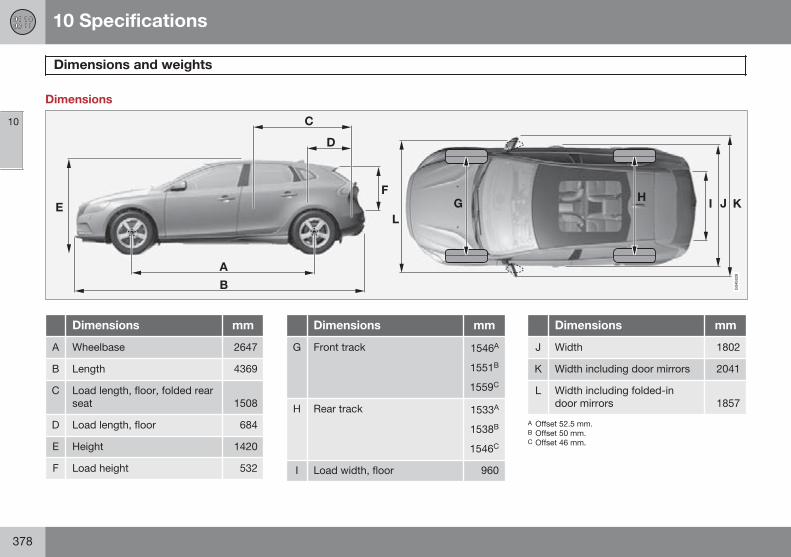
10 Specifications
Dimensions and weights
10
378
Dimensions
Dimensions mm
A Wheelbase 2647
B Length 4369
C Load length, floor, folded rearseat 1508
D Load length, floor 684
E Height 1420
F Load height 532
Dimensions mm
G Front track 1546A
1551B
1559C
H Rear track 1533A
1538B
1546C
I Load width, floor 960
Dimensions mm
J Width 1802
K Width including door mirrors 2041
L Width including folded-indoor mirrors 1857
A Offset 52.5 mm.B Offset 50 mm.C Offset 46 mm.
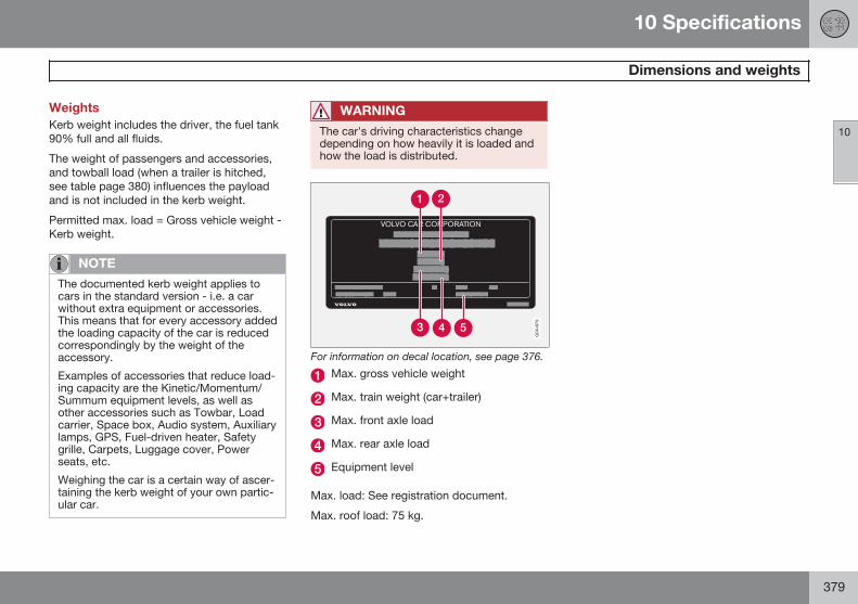
10 Specifications
Dimensions and weights
10
379
WeightsKerb weight includes the driver, the fuel tank90% full and all fluids.
The weight of passengers and accessories,and towball load (when a trailer is hitched,see table page 380) influences the payloadand is not included in the kerb weight.
Permitted max. load = Gross vehicle weight -Kerb weight.
NOTE
The documented kerb weight applies tocars in the standard version - i.e. a carwithout extra equipment or accessories.This means that for every accessory addedthe loading capacity of the car is reducedcorrespondingly by the weight of theaccessory.
Examples of accessories that reduce load-ing capacity are the Kinetic/Momentum/Summum equipment levels, as well asother accessories such as Towbar, Loadcarrier, Space box, Audio system, Auxiliarylamps, GPS, Fuel-driven heater, Safetygrille, Carpets, Luggage cover, Powerseats, etc.
Weighing the car is a certain way of ascer-taining the kerb weight of your own partic-ular car.
WARNING
The car's driving characteristics changedepending on how heavily it is loaded andhow the load is distributed.
For information on decal location, see page 376.
Max. gross vehicle weight
Max. train weight (car+trailer)
Max. front axle load
Max. rear axle load
Equipment level
Max. load: See registration document.
Max. roof load: 75 kg.
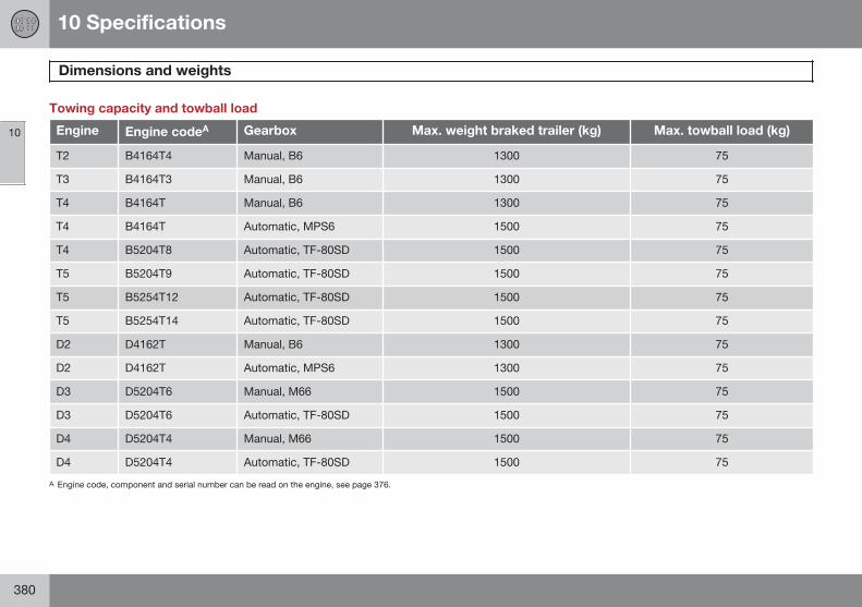
10 Specifications
Dimensions and weights
10
380
Towing capacity and towball load
Engine Engine codeA Gearbox Max. weight braked trailer (kg) Max. towball load (kg)
T2 B4164T4 Manual, B6 1300 75
T3 B4164T3 Manual, B6 1300 75
T4 B4164T Manual, B6 1300 75
T4 B4164T Automatic, MPS6 1500 75
T4 B5204T8 Automatic, TF-80SD 1500 75
T5 B5204T9 Automatic, TF-80SD 1500 75
T5 B5254T12 Automatic, TF-80SD 1500 75
T5 B5254T14 Automatic, TF-80SD 1500 75
D2 D4162T Manual, B6 1300 75
D2 D4162T Automatic, MPS6 1300 75
D3 D5204T6 Manual, M66 1500 75
D3 D5204T6 Automatic, TF-80SD 1500 75
D4 D5204T4 Manual, M66 1500 75
D4 D5204T4 Automatic, TF-80SD 1500 75
A Engine code, component and serial number can be read on the engine, see page 376.
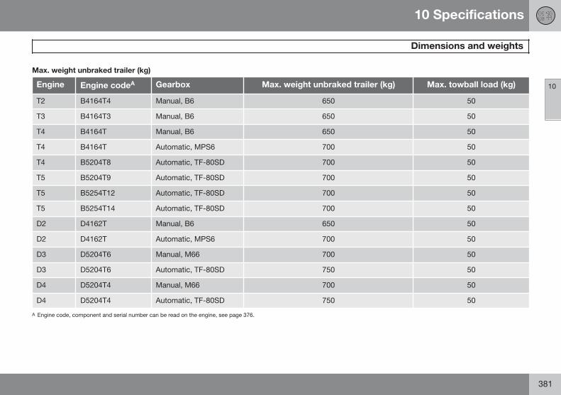
10 Specifications
Dimensions and weights
10
381
Max. weight unbraked trailer (kg)
Engine Engine codeA Gearbox Max. weight unbraked trailer (kg) Max. towball load (kg)
T2 B4164T4 Manual, B6 650 50
T3 B4164T3 Manual, B6 650 50
T4 B4164T Manual, B6 650 50
T4 B4164T Automatic, MPS6 700 50
T4 B5204T8 Automatic, TF-80SD 700 50
T5 B5204T9 Automatic, TF-80SD 700 50
T5 B5254T12 Automatic, TF-80SD 700 50
T5 B5254T14 Automatic, TF-80SD 700 50
D2 D4162T Manual, B6 650 50
D2 D4162T Automatic, MPS6 700 50
D3 D5204T6 Manual, M66 700 50
D3 D5204T6 Automatic, TF-80SD 750 50
D4 D5204T4 Manual, M66 700 50
D4 D5204T4 Automatic, TF-80SD 750 50
A Engine code, component and serial number can be read on the engine, see page 376.
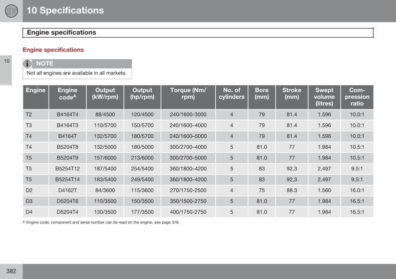
10 Specifications
Engine specifications
10
382
Engine specifications
NOTE
Not all engines are available in all markets.
Engine EnginecodeA
Output(kW/rpm)
Output(hp/rpm)
Torque (Nm/rpm)
No. ofcylinders
Bore(mm)
Stroke(mm)
Sweptvolume(litres)
Com-pression
ratio
T2 B4164T4 88/4500 120/4500 240/1600-3000 4 79 81.4 1.596 10.0:1
T3 B4164T3 110/5700 150/5700 240/1600–4000 4 79 81.4 1.596 10.0:1
T4 B4164T 132/5700 180/5700 240/1600–5000 4 79 81.4 1.596 10.0:1
T4 B5204T8 132/5000 180/5000 300/2700–4000 5 81.0 77 1.984 10.5:1
T5 B5204T9 157/6000 213/6000 300/2700–5000 5 81.0 77 1.984 10.5:1
T5 B5254T12 187/5400 254/5400 360/1800–4200 5 83 92,3 2,497 9.5:1
T5 B5254T14 183/5400 249/5400 360/1800–4200 5 83 92,3 2,497 9.5:1
D2 D4162T 84/3600 115/3600 270/1750-2500 4 75 88.3 1.560 16.0:1
D3 D5204T6 110/3500 150/3500 350/1500-2750 5 81.0 77 1.984 16.5:1
D4 D5204T4 130/3500 177/3500 400/1750-2750 5 81.0 77 1.984 16.5:1
A Engine code, component and serial number can be read on the engine, see page 376.
10 Specifications
Engine oil
10
383
Adverse driving conditionsAdverse driving conditions can lead to abnor-mally high oil temperature or oil consumption.Below are some examples of adverse drivingconditions.
Check the oil level more frequently for longjourneys:
• towing a caravan or trailer
• in mountainous regions
• at high speeds
• in temperatures colder than -30 °C orhotter than +40 °C
The above also apply to shorter driving dis-tances at low temperatures.
Choose a fully synthetic engine oil for adversedriving conditions. It provides extra protectionfor the engine.
Volvo recommends Castrol oil products.
IMPORTANT
In order to fulfil the requirements for theengine's service intervals all engines arefilled with a specially adapted syntheticengine oil at the factory. The choice of oilhas been made very carefully with regardto service life, starting characteristics, fuelconsumption and environmental impact.
An approved engine oil must be used inorder that the recommended service inter-vals can be applied. Only use a prescribedgrade of oil for both filling and oil change,otherwise you will risk affecting service life,starting characteristics, fuel consumptionand environmental impact.
Volvo Car Corporation disclaims all war-ranty liability if engine oil of the prescribedgrade and viscosity is not used.
Volvo recommends that oil changes arecarried out at an authorised Volvo work-shop.
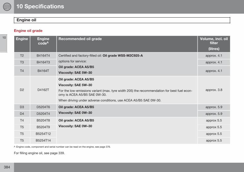
10 Specifications
Engine oil
10
384
Engine oil grade
Engine EnginecodeA
Recommended oil grade Volume, incl. oilfilter
(litres)
T2 B4164T4 Certified and factory-filled oil: Oil grade WSS-M2C925-A
options for service:
Oil grade: ACEA A5/B5
Viscosity: SAE 5W–30
approx. 4.1
T3 B4164T3 approx. 4.1
T4 B4164T approx. 4.1
D2 D4162T
Oil grade: ACEA A5/B5
Viscosity: SAE 5W–30
For the low-emissions variant (max. tyre width 205) the recommendation for best fuel econ-omy is ACEA A5/B5 SAE 0W-30.
When driving under adverse conditions, use ACEA A5/B5 SAE 0W-30.
approx. 3.8
D3 D5204T6 Oil grade: ACEA A5/B5
Viscosity: SAE 0W–30
approx. 5.9
D4 D5204T4 approx. 5.9
T4 B5204T8 Oil grade: ACEA A5/B5
Viscosity: SAE 0W–30
approx 5.5
T5 B5204T9 approx 5.5
T5 B5254T12 approx 5.5
T5 B5254T14 approx 5.5
A Engine code, component and serial number can be read on the engine, see page 376.
For filling engine oil, see page 339.
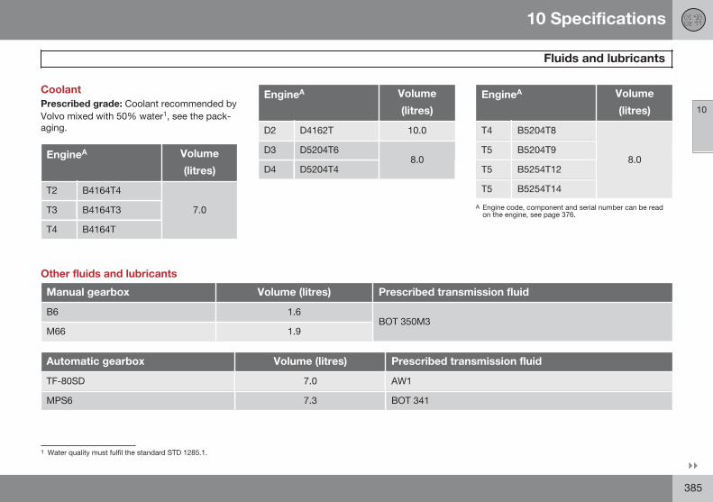
10 Specifications
Fluids and lubricants
10
}}385
CoolantPrescribed grade: Coolant recommended byVolvo mixed with 50% water1, see the pack-aging.
EngineA Volume
(litres)
T2 B4164T4
7.0T3 B4164T3
T4 B4164T
EngineA Volume
(litres)
D2 D4162T 10.0
D3 D5204T68.0
D4 D5204T4
EngineA Volume
(litres)
T4 B5204T8
8.0T5 B5204T9
T5 B5254T12
T5 B5254T14
A Engine code, component and serial number can be readon the engine, see page 376.
Other fluids and lubricants
Manual gearbox Volume (litres) Prescribed transmission fluid
B6 1.6BOT 350M3
M66 1.9
Automatic gearbox Volume (litres) Prescribed transmission fluid
TF-80SD 7.0 AW1
MPS6 7.3 BOT 341
1 Water quality must fulfil the standard STD 1285.1.
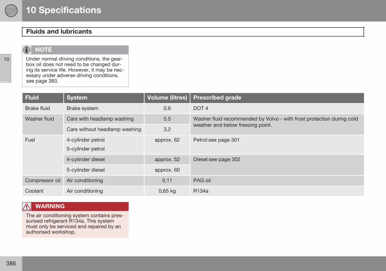
10 Specifications
Fluids and lubricants
10
386
NOTE
Under normal driving conditions, the gear-box oil does not need to be changed dur-ing its service life. However, it may be nec-essary under adverse driving conditions,see page 383.
Fluid System Volume (litres) Prescribed grade
Brake fluid Brake system 0.6 DOT 4
Washer fluid Cars with headlamp washing 5.5 Washer fluid recommended by Volvo - with frost protection during coldweather and below freezing point.
Cars without headlamp washing 3,2
Fuel 4-cylinder petrol
5-cylinder petrol
approx. 62 Petrol:see page 301
4-cylinder diesel approx. 52 Diesel:see page 302
5-cylinder diesel approx. 60
Compressor oil Air conditioning 0,11 PAG oil
Coolant Air conditioning 0,65 kg R134a
WARNING
The air conditioning system contains pres-surised refrigerant R134a. This systemmust only be serviced and repaired by anauthorised workshop.
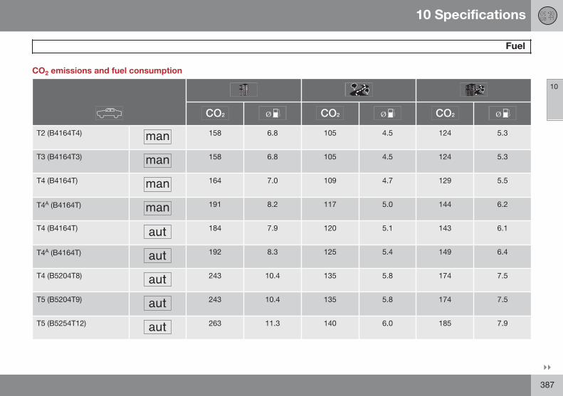
10 Specifications
Fuel
10
}}387
CO2 emissions and fuel consumption
T2 (B4164T4) 158 6.8 105 4.5 124 5.3
T3 (B4164T3) 158 6.8 105 4.5 124 5.3
T4 (B4164T) 164 7.0 109 4.7 129 5.5
T4A (B4164T) 191 8.2 117 5.0 144 6.2
T4 (B4164T) 184 7.9 120 5.1 143 6.1
T4A (B4164T) 192 8.3 125 5.4 149 6.4
T4 (B5204T8) 243 10.4 135 5.8 174 7.5
T5 (B5204T9) 243 10.4 135 5.8 174 7.5
T5 (B5254T12) 263 11.3 140 6.0 185 7.9
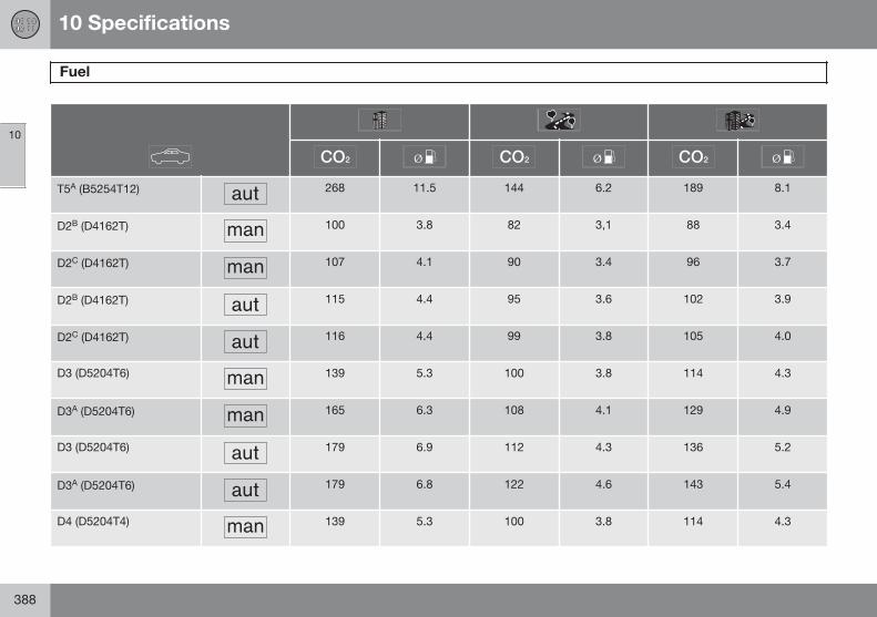
10 Specifications
Fuel
10
388
T5A (B5254T12) 268 11.5 144 6.2 189 8.1
D2B (D4162T) 100 3.8 82 3,1 88 3.4
D2C (D4162T) 107 4.1 90 3.4 96 3.7
D2B (D4162T) 115 4.4 95 3.6 102 3.9
D2C (D4162T) 116 4.4 99 3.8 105 4.0
D3 (D5204T6) 139 5.3 100 3.8 114 4.3
D3A (D5204T6) 165 6.3 108 4.1 129 4.9
D3 (D5204T6) 179 6.9 112 4.3 136 5.2
D3A (D5204T6) 179 6.8 122 4.6 143 5.4
D4 (D5204T4) 139 5.3 100 3.8 114 4.3
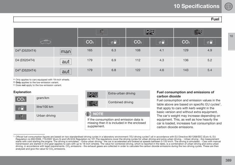
10 Specifications
Fuel
10
389
D4A (D5204T4) 165 6.3 108 4.1 129 4.9
D4 (D5204T4) 179 6.9 112 4.3 136 5.2
D4A (D5204T4) 179 6.8 122 4.6 143 5.4
A Only applies to cars equipped with 19-inch wheels.B Only applies to the low-emission variant.C Does not apply to the low-emission variant.
Explanation
gram/km
litre/100 km
Urban driving
Extra-urban driving
Combined driving
NOTE
If the consumption and emission data ismissing then it is included in the enclosedsupplement.
Fuel consumption and emissions ofcarbon dioxideFuel consumption and emission values in thetable above are based on specific EU cycles1,that apply to cars with kerb weight in thebasic version and without extra equipment.The car's weight may increase depending onequipment. This, as well as how heavily thecar is loaded, increases fuel consumption andcarbon dioxide emissions.
1 Official fuel consumption figures are based on two standardised driving cycles in a laboratory environment ("EU driving cycles") all in accordance with EU Directive 80/1268/EEC (Euro 4), EURegulation no 692/2008, 715/2007 (Euro 5) and UN ECE Regulation no 101.The regulations cover the driving cycles for urban driving and extra-urban driving. - Urban driving - the measurementstarts with cold starting the engine. The driving is simulated. - Extra-urban driving - the car is accelerated and braked at speeds between 0-120 km/h. The driving is simulated. - Cars with manualtransmission are started in 2nd gear (applies to cars with up to 18-inch wheels). The value for combined driving, which is reported in the table, is a combination of urban driving and extra-urbandriving, in accordance with legal requirements. CO2 emissions - the exhaust gases are collected in order to calculate the carbon dioxide emissions during the two driving cycles. These are thenanalysed and give the value for CO2 emissions.
10 Specifications
Fuel
10
390
There are several reasons for increased fuelconsumption compared with the table's val-ues. Examples of this are:
• The driver's driving style.
• If the customer has specified wheelslarger than those fitted as standard on themodel's basic version, then resistanceincreases.
• High speed results in increased windresistance.
• Fuel quality, road and traffic conditions,weather and the condition of the car.
Even a combination of the above-mentionedexamples can result in significantly improvedconsumption. For further information, pleaserefer to the regulations referred to1.
Large deviations in fuel consumption mayarise in a comparison with the EU drivingcycles1 which are used in the certification ofthe car and on which the consumption figuresin the table are based.
To bear in mindTips that the driver can use in order to reduceconsumption:
• Drive gently and avoid unnecessaryacceleration as well as braking too hard.
• Drive with the correct air pressure in thetyres and check this regularly - selectECO tyre pressure for best results, seethe tyre pressure table on page 391.
• Choice of tyres can affect fuel consump-tion - seek advice on suitable tyres from adealer.
See further information and more advice onpages 11 and 296.
See page 301 for general information on fuel.
1 Official fuel consumption figures are based on two standardised driving cycles in a laboratory environment ("EU driving cycles") all in accordance with EU Directive 80/1268/EEC (Euro 4), EURegulation no 692/2008, 715/2007 (Euro 5) and UN ECE Regulation no 101.The regulations cover the driving cycles for urban driving and extra-urban driving. - Urban driving - the measurementstarts with cold starting the engine. The driving is simulated. - Extra-urban driving - the car is accelerated and braked at speeds between 0-120 km/h. The driving is simulated. - Cars with manualtransmission are started in 2nd gear (applies to cars with up to 18-inch wheels). The value for combined driving, which is reported in the table, is a combination of urban driving and extra-urbandriving, in accordance with legal requirements. CO2 emissions - the exhaust gases are collected in order to calculate the carbon dioxide emissions during the two driving cycles. These are thenanalysed and give the value for CO2 emissions.
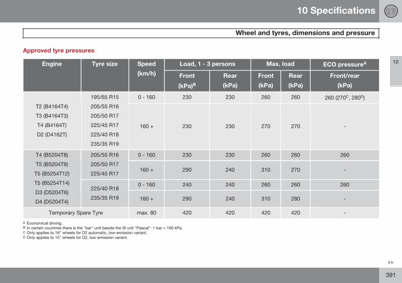
10 Specifications
Wheel and tyres, dimensions and pressure
10
}}391
Approved tyre pressures
Engine Tyre size Speed
(km/h)
Load, 1 - 3 persons Max. load ECO pressureA
Front
(kPa)BRear
(kPa)
Front
(kPa)
Rear
(kPa)
Front/rear
(kPa)
T2 (B4164T4)
T3 (B4164T3)
T4 (B4164T)
D2 (D4162T)
195/65 R15
205/55 R16
205/50 R17
225/45 R17
225/40 R18
235/35 R19
0 - 160 230 230 260 260 260 (270C, 280D)
160 + 230 230 270 270 -
T4 (B5204T8)
T5 (B5204T9)
T5 (B5254T12)
T5 (B5254T14)
D3 (D5204T6)
D4 (D5204T4)
205/55 R16
205/50 R17
225/45 R17
0 - 160 230 230 260 260 260
160 + 290 240 310 270 -
225/40 R18
235/35 R19
0 - 160 240 240 260 260 260
160 + 290 240 310 280 -
Temporary Spare Tyre max. 80 420 420 420 420 -
A Economical driving.B In certain countries there is the "bar" unit beside the SI unit "Pascal": 1 bar = 100 kPa.C Only applies to 16" wheels for D2 automatic, low-emission variant.D Only applies to 15" wheels for D2, low-emission variant.
10 Specifications
Wheel and tyres, dimensions and pressure
10
392
NOTE
All engines, tyres or combinations of theseare not always available in all markets.
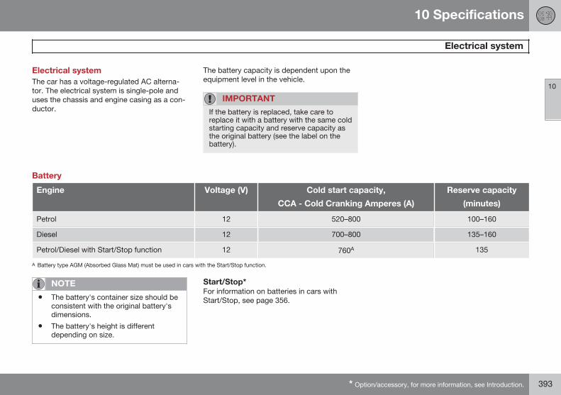
10 Specifications
Electrical system
10
* Option/accessory, for more information, see Introduction. 393
Electrical systemThe car has a voltage-regulated AC alterna-tor. The electrical system is single-pole anduses the chassis and engine casing as a con-ductor.
The battery capacity is dependent upon theequipment level in the vehicle.
IMPORTANT
If the battery is replaced, take care toreplace it with a battery with the same coldstarting capacity and reserve capacity asthe original battery (see the label on thebattery).
Battery
Engine Voltage (V) Cold start capacity,
CCA - Cold Cranking Amperes (A)
Reserve capacity
(minutes)
Petrol 12 520–800 100–160
Diesel 12 700–800 135–160
Petrol/Diesel with Start/Stop function 12 760A 135
A Battery type AGM (Absorbed Glass Mat) must be used in cars with the Start/Stop function.
NOTE
• The battery's container size should beconsistent with the original battery'sdimensions.
• The battery's height is differentdepending on size.
Start/Stop*For information on batteries in cars withStart/Stop, see page 356.
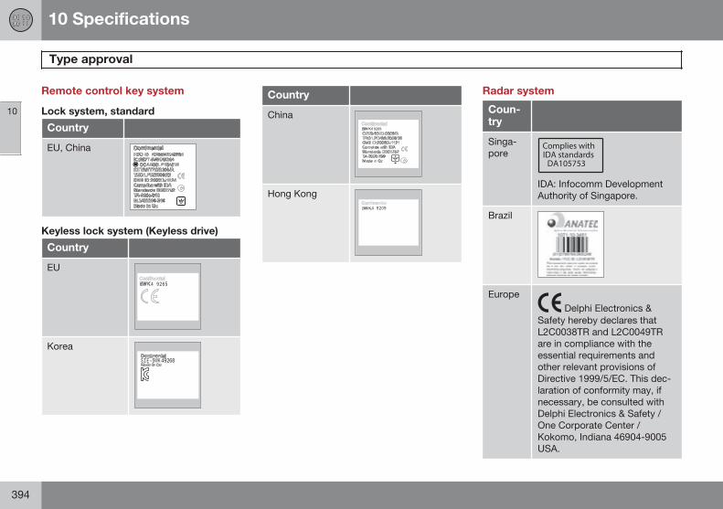
10 Specifications
Type approval
10
394
Remote control key system
Lock system, standard
Country
EU, China
Keyless lock system (Keyless drive)
Country
EU
Korea
Country
China
Hong Kong
Radar system
Coun-try
Singa-pore
IDA: Infocomm DevelopmentAuthority of Singapore.
Brazil
Europe Delphi Electronics &
Safety hereby declares thatL2C0038TR and L2C0049TRare in compliance with theessential requirements andother relevant provisions ofDirective 1999/5/EC. This dec-laration of conformity may, ifnecessary, be consulted withDelphi Electronics & Safety /One Corporate Center /Kokomo, Indiana 46904-9005USA.
10 Specifications
Type approval
10
}}395
Bluetooth®
Declaration of Conformity (Declaration of Conformity)
Country
Countriesin the EU:
Exporting country: Japan
Manufacturer: Alpine Electronics Inc.
Type of equipment: Bluetooth® device
For further information visit http://ec.europa.eu/enterprise/rtte/faq.htm #informing
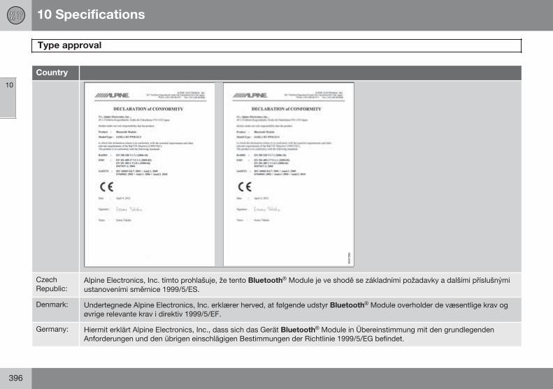
10 Specifications
Type approval
10
396
Country
CzechRepublic:
Alpine Electronics, Inc. tímto prohlašuje, že tento Bluetooth® Module je ve shodě se základními požadavky a dalšími příslušnýmiustanoveními směrnice 1999/5/ES.
Denmark: Undertegnede Alpine Electronics, Inc. erklærer herved, at følgende udstyr Bluetooth® Module overholder de væsentlige krav ogøvrige relevante krav i direktiv 1999/5/EF.
Germany: Hiermit erklärt Alpine Electronics, Inc., dass sich das Gerät Bluetooth® Module in Übereinstimmung mit den grundlegendenAnforderungen und den übrigen einschlägigen Bestimmungen der Richtlinie 1999/5/EG befindet.
10 Specifications
Type approval
10
}}397
Country
Estonia: Käesolevaga kinnitab Alpine Electronics, Inc. seadme Bluetooth® Module vastavust direktiivi 1999/5/EÜ põhinõuetele janimetatud direktiivist tulenevatele teistele asjakohastele sätetele.
UK Hereby, Alpine Electronics, Inc., declares that this Bluetooth® Module is in compliance with the essential requirements and otherrelevant provisions of Directive 1999/5/EC.
Spain: Por medio de la presente Alpine Electronics, Inc. declara que el Bluetooth® Module cumple con los requisitos esenciales ycualesquiera otras disposiciones aplicables o exigibles de la Directiva 1999/5/CE.
Greece: ΜΕ ΗΝ ΠΑΡΟ ΣΑ Alpine Electronics, Inc. ΗΛΩΝΕ Ο Bluetooth® Module Σ ΜΜΟΡΦΩΝΕ Α ΠΡΟΣ Σ Ο Σ Ω Ε ΣΑΠΑ ΗΣΕ Σ Α Σ ΛΟ ΠΕΣ ΣΧΕ ΕΣ Α ΑΞΕ Σ ΗΣ Ο Η ΑΣ 1999/5/Ε .
France: Par la présente Alpine Electronics, Inc. déclare que l'appareil Bluetooth® Module est conforme aux exigences essentielles et auxautres dispositions pertinentes de la directive 1999/5/CE.
Italy: Con la presente Alpine Electronics, Inc. dichiara che questo Bluetooth® Module è conforme ai requisiti essenziali ed alle altredisposizioni pertinenti stabilite dalla direttiva 1999/5/CE.
Latvia: Ar šo Alpine Electronics, Inc. deklarē, ka Bluetooth® Module atbilst Direktīvas 1999/5/EK būtiskajām prasībām un citiem ar tosaistītajiem noteikumiem.
Lithuania: Šiuo Alpine Electronics, Inc. deklaruoja, kad šis Bluetooth® Module atitinka esminius reikalavimus ir kitas 1999/5/EB Direktyvosnuostatas.
Nether-lands:
Hierbij verklaart Alpine Electronics, Inc. dat het toestel Bluetooth® Module in overeenstemming is met de essentiële eisen en deandere relevante bepalingen van richtlijn 1999/5/EG.
Malta: Hawnhekk, Alpine Electronics, Inc., jiddikjara li dan Bluetooth® Module jikkonforma mal-ħtiġijiet essenzjali u ma provvedimentioħrajn relevanti li hemm fid-Dirrettiva 1999/5/EC.
Hungary: Alulírott, Alpine Electronics, Inc. nyilatkozom, hogy a Bluetooth® Module megfelel a vonatkozó alapvetõ követelményeknek és az1999/5/EC irányelv egyéb elõírásainak.
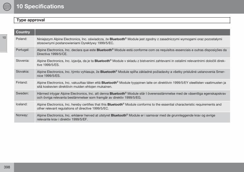
10 Specifications
Type approval
10
398
Country
Poland: Niniejszym Alpine Electronics, Inc. oświadcza, że Bluetooth® Module jest zgodny z zasadniczymi wymogami oraz pozostałymistosownymi postanowieniami Dyrektywy 1999/5/EC.
Portugal: Alpine Electronics, Inc. declara que este Bluetooth® Module está conforme com os requisitos essenciais e outras disposições daDirectiva 1999/5/CE.
Slovenia: Alpine Electronics, Inc. izjavlja, da je ta Bluetooth® Module v skladu z bistvenimi zahtevami in ostalimi relevantnimi določili direk-tive 1999/5/ES.
Slovakia: Alpine Electronics, Inc. týmto vyhlasuje, že Bluetooth® Module spĺňa základné požiadavky a všetky príslušné ustanovenia Smer-nice 1999/5/ES.
Finland: Alpine Electronics, Inc. vakuuttaa täten että Bluetooth® Module tyyppinen laite on direktiivin 1999/5/EY oleellisten vaatimusten jasitä koskevien direktiivin muiden ehtojen mukainen.
Sweden: Härmed intygar Alpine Electronics, Inc. att denna Bluetooth® Module står I överensstämmelse med de väsentliga egenskapskravoch övriga relevanta bestämmelser som framgår av direktiv 1999/5/EG.
Iceland: Alpine Electronics, Inc. hereby certifies that this Bluetooth® Module conforms to the essential characteristic requirements andother relevant regulations of directive 1999/5/EC.
Norway: Alpine Electronics, Inc. erklærer herved at utstyret Bluetooth® Module er i samsvar med de grunnleggende krav og øvrigerelevante krav i direktiv 1999/5/EF.
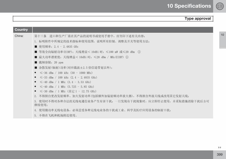
10 Specifications
Type approval
10
}}399
Country
China: 第十三条 进口和生产厂商在其产品的说明书或使用手册中,应刊印下述有关内容
1. 标明附件中所规定的技术指标和使用范围,说明所有控制 调整及开关等使用方法
■ 使用频率 2.4 - 2.4835 GHz
■ 等效全向辐射 率(EIRP) 天线增益 10dBi 时 ≤100 mW 或≤20 dBm ①
■ 最大 率谱密度 天线增益 10dBi 时 ≤20 dBm / MHz(EIRP) ①
■ 载频容限 20 ppm
■ 杂散发射(辐射) 率(对应载波±2.5 倍信道带宽以外)
• ≤-36 dBm / 100 kHz (30 - 1000 MHz)
• ≤-33 dBm / 100 kHz (2.4 - 2.4835 GHz)
• ≤-40 dBm / 1 MHz (3.4 - 3.53 GHz)
• ≤-40 dBm / 1 MHz (5.725 - 5.85 GHz)
• ≤-30 dBm / 1 MHz (其它 1 - 12.75 GHz)
2. 不得擅自更改发射频率 大发射 率(包括额外 装射频 率放大器),不得擅自外接天线或改用其它发射天线
3. 使用时不得对各种合法的无线电通信业 产生有害干扰 一旦发现有干扰现象时,应立即停止使用,并采 措施消除干扰后方可
继续使用
4. 使用微 率无线电设备,必须忍 各种无线电业 的干扰或工业 科学及医疗应用设备的辐射干扰
5. 不得在飞机和机场附近使用
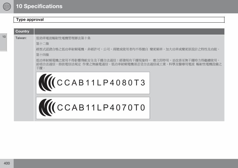
10 Specifications
Type approval
10
400
Country
Taiwan: 低効率電波輻射性電機管理辧法第十条
第十二條
經型式認證合格之低功率射頻電機,非經許可,公司 商號或使用者均不得擅自 變更頻率 加大功率或變更原設計之特性及功能
第十四條
低功率射頻電機之使用不得影響飛航安全及干擾合法通信;經發現有干擾現象時, 應立即停用,並改善至無干擾時方得繼續使用前項合法通信,指依電信法規定 作業之無線電通信 低功率射頻電機須忍受合法通信或工業 科學及醫療用電波 輻射性電機設備之干擾
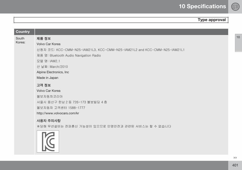
10 Specifications
Type approval
10
}}401
Country
SouthKorea:
제품 정보
Volvo Car Korea
신청자 코드: KCC-CMM-N25-IAM21L3, KCC-CMM-N25-IAM21L2 and KCC-CMM-N25-IAM21L1
제품 명: Bluetooth Audio Navigation Radio
모델 명: IAM2.1
산 날짜: March/2010
Alpine Electronics, Inc
Made in Japan
고객 정보
Volvo Car Korea
볼보자동차코리아
서울시 용산구 한남 2 동 726-173 볼보빌딩 4 층
볼보자동차 고객센터 1588-1777
http://www.volvocars.com/kr
사용자 주의사항
※당해 무선설비는 전파혼신 가능성이 있으므로 인명안전과 관련된 서비스는 할 수 없습니다
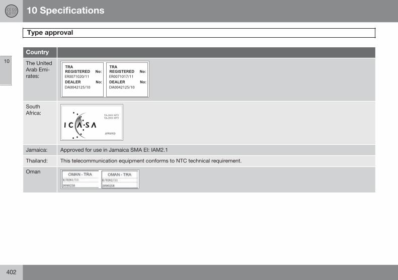
10 Specifications
Type approval
10
402
Country
The UnitedArab Emi-rates:
SouthAfrica:
Jamaica: Approved for use in Jamaica SMA EI: IAM2.1
Thailand: This telecommunication equipment conforms to NTC technical requirement.
Oman
10 Specifications
Licenses
10
}}403
Sensus softwareThis software uses parts of sources fromclib2 and Prex Embedded Real-time OS -Source (Copyright (c) 1982, 1986, 1991,1993, 1994), and Quercus Robusta (Copyright(c) 1990, 1993), The Regents of the Universityof California. All or some portions are derivedfrom material licensed to the University ofCalifornia by American Telephone andTelegraph Co. or Unix System Laboratories,Inc. and are reproduced herein with thepermission of UNIX System Laboratories, Inc.Redistribution and use in source and binaryforms, with or without modification, arepermitted provided that the followingconditions are met: Redistributions of sourcecode must retain the above copyright notice,this list of conditions and the followingdisclaimer. Redistributions in binary formmust reproduce the above copyright notice,this list of conditions and the followingdisclaimer in the documentation and/or othermaterials provided with the distribution.Neither the name of the <ORGANIZATION>nor the names of its contributors may beused to endorse or promote products derivedfrom this software without specific priorwritten permission. THIS SOFTWARE ISPROVIDED BY THE COPYRIGHT HOLDERSAND CONTRIBUTORS "AS IS" AND ANYEXPRESS OR IMPLIED WARRANTIES,
INCLUDING, BUT NOT LIMITED TO, THEIMPLIED WARRANTIES OFMERCHANTABILITY AND FITNESS FOR APARTICULAR PURPOSE ARE DISCLAIMED.IN NO EVENT SHALL THE COPYRIGHTOWNER OR CONTRIBUTORS BE LIABLEFOR ANY DIRECT, INDIRECT, INCIDENTAL,SPECIAL, EXEMPLARY, ORCONSEQUENTIAL DAMAGES (INCLUDING,BUT NOT LIMITED TO, PROCUREMENT OFSUBSTITUTE GOODS OR SERVICES; LOSSOF USE, DATA, OR PROFITS; OR BUSINESSINTERRUPTION) HOWEVER CAUSED ANDON ANY THEORY OF LIABILITY, WHETHERIN CONTRACT, STRICT LIABILITY, OR TORT(INCLUDING NEGLIGENCE OR OTHERWISE)ARISING IN ANY WAY OUT OF THE USE OFTHIS SOFTWARE, EVEN IF ADVISED OF THEPOSSIBILITY OF SUCH DAMAGE.
This software is based in part on the work ofthe Independent JPEG Group.
This software uses parts of sources from"libtess". The Original Code is: OpenGLSample Implementation, Version 1.2.1,released January 26, 2000, developed bySilicon Graphics, Inc. The Original Code isCopyright (c) 1991-2000 Silicon Graphics,Inc. Copyright in any portions created by thirdparties is as indicated elsewhere herein. AllRights Reserved. Copyright (C) [1991-2000]Silicon Graphics, Inc. All Rights Reserved.
Permission is hereby granted, free of charge,to any person obtaining a copy of thissoftware and associated documentation files(the "Software"), to deal in the Softwarewithout restriction, including without limitationthe rights to use, copy, modify, merge,publish, distribute, sublicense, and/or sellcopies of the Software, and to permit personsto whom the Software is furnished to do so,subject to the following conditions: Theabove copyright notice including the dates offirst publication and either this permissionnotice or a reference to http://oss.sgi.com/projects/FreeB/ shall be included in all copiesor substantial portions of the Software. THESOFTWARE IS PROVIDED "AS IS",WITHOUT WARRANTY OF ANY KIND,EXPRESS OR IMPLIED, INCLUDING BUTNOT LIMITED TO THE WARRANTIES OFMERCHANTABILITY, FITNESS FOR APARTICULAR PURPOSE ANDNONINFRINGEMENT. IN NO EVENT SHALLSILICON GRAPHICS, INC. BE LIABLE FORANY CLAIM, DAMAGES OR OTHERLIABILITY, WHETHER IN AN ACTION OFCONTRACT, TORT OR OTHERWISE,ARISING FROM, OUT OF OR INCONNECTION WITH THE SOFTWARE ORTHE USE OR OTHER DEALINGS IN THESOFTWARE. Except as contained in thisnotice, the name of Silicon Graphics, Inc.shall not be used in advertising or otherwise
10 Specifications
Licenses
10
404
to promote the sale, use or other dealings inthis Software without prior writtenauthorization from Silicon Graphics, Inc.
This software is based in parts on the work ofthe FreeType Team.
This software uses parts of SSLeay Library:Copyright (C) 1995-1998 Eric Young([email protected]). All rights reserved
Combined Instrument Panel SoftwareOpen Source Software Notice
This product uses certain free / open sourceand other software originating from thirdparties, that is subject to the GNU GeneralPublic License version 2 and 3 (GPLv2/GPLv3), GNU Lesser General Public Licenseversion 3 (LGPLv3), The FreeType ProjectLicense (“FreeType License”) and otherdifferent and/or additional copyright licenses,disclaimers and notices. The links how toaccess the exact terms of GPLv2, GPLv3,LGPLv3, and the other open source softwarelicenses, disclaimers, acknowledgements andnotices are provided to you below. Pleaserefer to the exact terms of the relevantLicense, regarding your rights under saidlicenses. Volvo Car Corporation (VCC) offersto provide the source code of said free/opensource software to you for a charge coveringthe cost of performing such distribution, such
as the cost of media, shipping and handling,upon written request. Please contact yournearest Volvo Dealer.
This offer is valid for a period of at least three(3) years from the date of the distribution ofthis product by VCC / or for as long as VCCoffers spare parts or customer support.
Portions of this product uses softwarecopyrighted © v2.4.3/2010 TheFreeTypeProject (www.freetype.org). All rightsreserved.
This product includes software underfollowing licenses:
GPL v2 : http://www.gnu.org/licenses/old-licenses/gpl-2.0.html
• Linux kernel (merge between MontaVista2.6.31 kernel and kernel fromL2.6.31_MX51_ER_1007 BSP)
• uBoot (based on v2009.08)
• busybox (based on version 1.13.2.)
GCC runtime library exception: http://www.gnu.org/licenses/gcc-exception.html
• libgcc_s.so.1
LGPL v3: http://www.gnu.org/licenses/lgpl.html
• Libc.so.6, libpthread.so.0, Librt.so.1
The FreeType Project License: http://www.freetype.org/FTL.TXT
• libfreetype.so.6 (version 2.4.3)
DivX®
DivX Certified® to play DivX® video. DivX®,DivX Certified® and associated logos areregistered trademarks of DivX, Inc. and areused under license. ABOUT DIVX VIDEO:DivX® is a digital video format created byDivX, Inc. This is an official DivX Certifieddevice that plays DivX video. Visitwww.divx.com for more information andsoftware tools to convert your files into DivXvideo.
ABOUT DIVX VIDEO-ON-DEMAND: This DivXCertified® device must be registered in orderto play DivX Video-on-Demand (VOD)content. To generate the registration code,locate the DivX VOD section in the device
10 Specifications
Licenses
10
405
setup menu. Go to http://vod.divx.com withthis code to complete the registrationprocess and learn more about DivX VOD.Covered by one or more of the following U.S.Patents: 7,295,673; 7,460,668; 7,515,710;7,519,274.
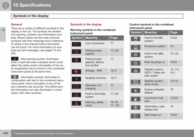
10 Specifications
Symbols in the display
10
406 * Option/accessory, for more information, see Introduction.
GeneralThere are a variety of different symbols in thedisplay in the car. The symbols are dividedinto warning, indicator and information sym-bols. Shown below are the most commonsymbols with their meanings and a referenceto where in the manual further informationcan be found. For more information on sym-bols and text messages, see pages 75 and205.
- Red warning symbol, illuminateswhen a fault has been indicated which couldaffect the safety and/or driveability of the car.An explanatory text is shown in the combinedinstrument panel at the same time.
- Information symbol, illuminates incombination with text in the combined instru-ment panel, when a deviation in any of thecar's systems has occurred. The yellow sym-bol information can also illuminate in combi-nation with other symbols.
Symbols in the display
Warning symbols in the combinedinstrument panel
Symbol Meaning Page
Low oil pressure 77
Parking brakeapplied
77,133
Parking brakeapplied, alterna-tive symbol
77
Airbags - SRS 19,77
Seatbelt reminder 16,77
Alternator notcharging
77
Fault in the brakesystem
77,132
Warning, safetymode
19, 29,77, 123
Control symbols in the combinedinstrument panel
Symbol Meaning Page
Fault in the ABLsystem*
75,93
Emissions system 75
Fault in the ABSsystem
75,132
Rear fog lamp on 75,94
Stability system,DSTC, Trailer sta-bility assist*
75, 141,314
Stability system,sport mode
75,141
Engine preheater(diesel)
75
Low level in fueltank
75,227
Information, readdisplay text
75
Main beam on 75,92
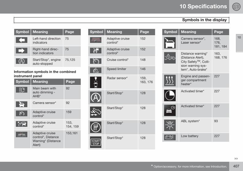
10 Specifications
Symbols in the display
10
}}* Option/accessory, for more information, see Introduction. 407
Symbol Meaning Page
Left-hand directionindicators
75
Right-hand direc-tion indicators
75
Start/Stop*, engineauto-stopped
75,125
Information symbols in the combinedinstrument panel
Symbol Meaning Page
Main beam withauto dimming -AHB*
92
Camera sensor* 92
Adaptive cruisecontrol*
159
Adaptive cruisecontrol*
153,154, 159
Adaptive cruisecontrol*, DistanceWarning* (DistanceAlert)
153,161
Symbol Meaning Page
Adaptive cruisecontrol*
152
Adaptive cruisecontrol*
152
Cruise control* 148
Speed limiter 146
Radar sensor* 159,163, 176
Start/Stop* 128
Start/Stop* 128
Start/Stop* 128
Start/Stop* 128
Symbol Meaning Page
Camera sensor*,Laser sensor*
168,176,181, 184
Distance warning*(Distance Alert),City SafetyTM, Colli-sion warning sys-tem*, Auto-brake*
163,168, 176
Engine and passen-ger compartmentheater*
227
Activated timer* 227
Activated timer* 227
ABL system* 93
Low battery 227
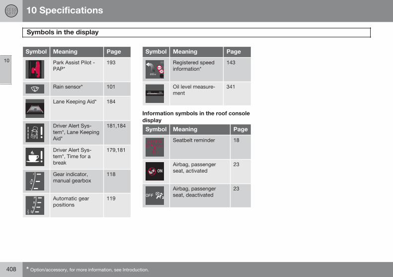
10 Specifications
Symbols in the display
10
408 * Option/accessory, for more information, see Introduction.
Symbol Meaning Page
Park Assist Pilot -PAP*
193
Rain sensor* 101
Lane Keeping Aid* 184
Driver Alert Sys-tem*, Lane KeepingAid*
181,184
Driver Alert Sys-tem*, Time for abreak
179,181
Gear indicator,manual gearbox
118
Automatic gearpositions
119
Symbol Meaning Page
Registered speedinformation*
143
Oil level measure-ment
341
Information symbols in the roof consoledisplay
Symbol Meaning Page
Seatbelt reminder 18
Airbag, passengerseat, activated
23
Airbag, passengerseat, deactivated
23
10 Specifications
10
409
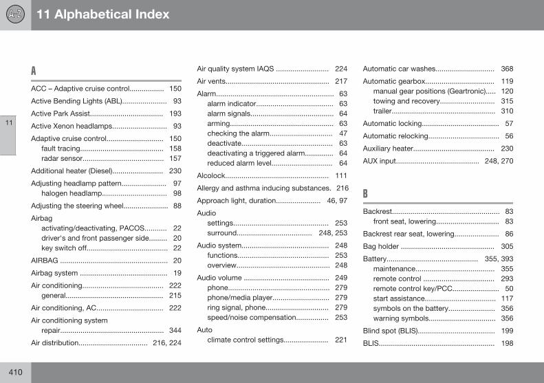
11 Alphabetical Index
11
410
A
ACC – Adaptive cruise control................. 150
Active Bending Lights (ABL)...................... 93
Active Park Assist.................................... 193
Active Xenon headlamps........................... 93
Adaptive cruise control............................ 150fault tracing......................................... 158radar sensor........................................ 157
Additional heater (Diesel)......................... 230
Adjusting headlamp pattern...................... 97halogen headlamp................................ 98
Adjusting the steering wheel...................... 88
Airbagactivating/deactivating, PACOS........... 22driver's and front passenger side......... 20key switch off........................................ 22
AIRBAG ..................................................... 20
Airbag system ........................................... 19
Air conditioning........................................ 222general................................................ 215
Air conditioning, AC................................. 222
Air conditioning systemrepair................................................... 344
Air distribution.................................. 216, 224
Air quality system IAQS .......................... 224
Air vents................................................... 217
Alarm.......................................................... 63alarm indicator...................................... 63alarm signals......................................... 64arming................................................... 63checking the alarm............................... 47deactivate............................................. 63deactivating a triggered alarm.............. 64reduced alarm level.............................. 64
Alcolock................................................... 111
Allergy and asthma inducing substances. 216
Approach light, duration...................... 46, 97
Audiosettings............................................... 253surround..................................... 248, 253
Audio system........................................... 248functions............................................. 253overview.............................................. 248
Audio volume .......................................... 249phone.................................................. 279phone/media player............................ 279ring signal, phone............................... 279speed/noise compensation................ 253
Autoclimate control settings...................... 221
Automatic car washes............................. 368
Automatic gearbox.................................. 119manual gear positions (Geartronic)..... 120towing and recovery........................... 315trailer................................................... 310
Automatic locking...................................... 57
Automatic relocking................................... 56
Auxiliary heater........................................ 230
AUX input......................................... 248, 270
B
Backrest..................................................... 83front seat, lowering............................... 83
Backrest rear seat, lowering...................... 86
Bag holder .............................................. 305
Battery............................................. 355, 393maintenance....................................... 355remote control ................................... 293remote control key/PCC....................... 50start assistance................................... 117symbols on the battery....................... 356warning symbols................................. 356
Blind spot (BLIS)...................................... 199
BLIS......................................................... 198
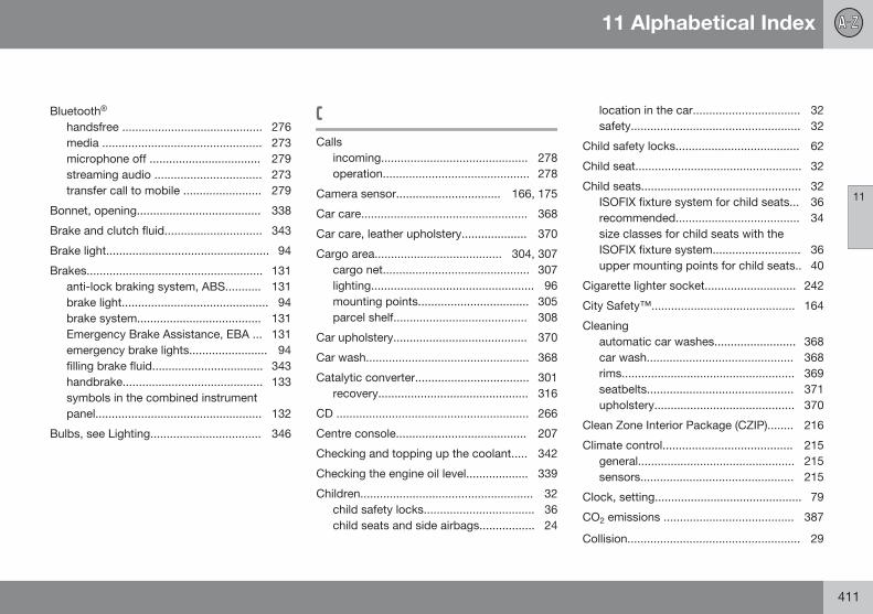
11 Alphabetical Index
11
411
Bluetooth® handsfree ........................................... 276media ................................................. 273microphone off .................................. 279streaming audio ................................. 273transfer call to mobile ........................ 279
Bonnet, opening...................................... 338
Brake and clutch fluid.............................. 343
Brake light.................................................. 94
Brakes...................................................... 131anti-lock braking system, ABS........... 131brake light............................................. 94brake system...................................... 131Emergency Brake Assistance, EBA ... 131emergency brake lights........................ 94filling brake fluid.................................. 343handbrake........................................... 133symbols in the combined instrumentpanel................................................... 132
Bulbs, see Lighting.................................. 346
C
Callsincoming............................................. 278operation............................................. 278
Camera sensor................................ 166, 175
Car care................................................... 368
Car care, leather upholstery.................... 370
Cargo area....................................... 304, 307cargo net............................................. 307lighting.................................................. 96mounting points.................................. 305parcel shelf......................................... 308
Car upholstery......................................... 370
Car wash.................................................. 368
Catalytic converter................................... 301recovery.............................................. 316
CD ........................................................... 266
Centre console........................................ 207
Checking and topping up the coolant..... 342
Checking the engine oil level................... 339
Children..................................................... 32child safety locks.................................. 36child seats and side airbags................. 24
location in the car................................. 32safety.................................................... 32
Child safety locks...................................... 62
Child seat................................................... 32
Child seats................................................. 32ISOFIX fixture system for child seats... 36recommended...................................... 34size classes for child seats with theISOFIX fixture system........................... 36upper mounting points for child seats.. 40
Cigarette lighter socket............................ 242
City Safety™............................................ 164
Cleaningautomatic car washes......................... 368car wash............................................. 368rims..................................................... 369seatbelts............................................. 371upholstery........................................... 370
Clean Zone Interior Package (CZIP)........ 216
Climate control........................................ 215general................................................ 215sensors............................................... 215
Clock, setting............................................. 79
CO2 emissions ........................................ 387
Collision..................................................... 29
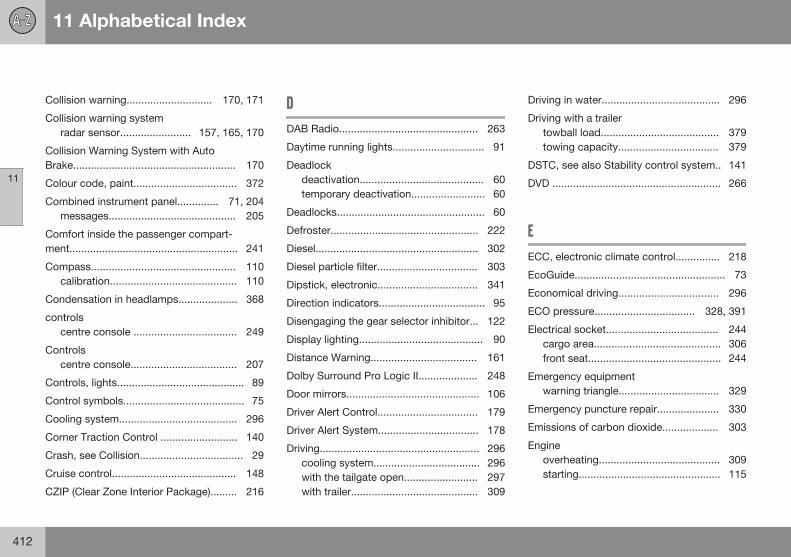
11 Alphabetical Index
11
412
Collision warning............................. 170, 171
Collision warning systemradar sensor........................ 157, 165, 170
Collision Warning System with AutoBrake....................................................... 170
Colour code, paint................................... 372
Combined instrument panel.............. 71, 204messages........................................... 205
Comfort inside the passenger compart-ment......................................................... 241
Compass................................................. 110calibration........................................... 110
Condensation in headlamps.................... 368
controls centre console ................................... 249
Controlscentre console.................................... 207
Controls, lights........................................... 89
Control symbols......................................... 75
Cooling system........................................ 296
Corner Traction Control .......................... 140
Crash, see Collision................................... 29
Cruise control.......................................... 148
CZIP (Clear Zone Interior Package)......... 216
D
DAB Radio............................................... 263
Daytime running lights............................... 91
Deadlockdeactivation.......................................... 60temporary deactivation......................... 60
Deadlocks.................................................. 60
Defroster.................................................. 222
Diesel....................................................... 302
Diesel particle filter.................................. 303
Dipstick, electronic.................................. 341
Direction indicators.................................... 95
Disengaging the gear selector inhibitor... 122
Display lighting.......................................... 90
Distance Warning.................................... 161
Dolby Surround Pro Logic II.................... 248
Door mirrors............................................. 106
Driver Alert Control.................................. 179
Driver Alert System.................................. 178
Driving...................................................... 296cooling system.................................... 296with the tailgate open......................... 297with trailer........................................... 309
Driving in water........................................ 296
Driving with a trailertowball load........................................ 379towing capacity.................................. 379
DSTC, see also Stability control system.. 141
DVD ......................................................... 266
E
ECC, electronic climate control............... 218
EcoGuide................................................... 73
Economical driving.................................. 296
ECO pressure.................................. 328, 391
Electrical socket...................................... 244cargo area........................................... 306front seat............................................. 244
Emergency equipmentwarning triangle.................................. 329
Emergency puncture repair..................... 330
Emissions of carbon dioxide................... 303
Engineoverheating......................................... 309starting................................................ 115
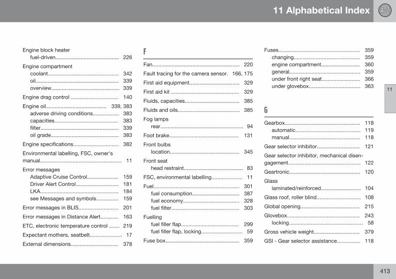
11 Alphabetical Index
11
413
Engine block heaterfuel-driven........................................... 226
Engine compartmentcoolant................................................ 342oil........................................................ 339overview.............................................. 339
Engine drag control ................................ 140
Engine oil......................................... 339, 383adverse driving conditions.................. 383capacities........................................... 383filter..................................................... 339oil grade.............................................. 383
Engine specifications............................... 382
Environmental labelling, FSC, owner'smanual....................................................... 11
Error messagesAdaptive Cruise Control..................... 159Driver Alert Control............................. 181LKA..................................................... 184see Messages and symbols............... 159
Error messages in BLIS........................... 201
Error messages in Distance Alert............ 163
ETC, electronic temperature control ....... 219
Expectant mothers, seatbelt...................... 17
External dimensions................................ 378
F
Fan........................................................... 220
Fault tracing for the camera sensor. 166, 175
First aid equipment.................................. 329
First aid kit .............................................. 329
Fluids, capacities..................................... 385
Fluids and oils.......................................... 385
Fog lampsrear........................................................ 94
Foot brake............................................... 131
Front bulbslocation............................................... 345
Front seathead restraint........................................ 83
FSC, environmental labelling..................... 11
Fuel.......................................................... 301fuel consumption................................ 387fuel economy...................................... 328fuel filter.............................................. 303
Fuellingfuel filler flap....................................... 299fuel filler flap, locking............................ 59
Fuse box.................................................. 359
Fuses....................................................... 359changing............................................. 359engine compartment.......................... 360general................................................ 359under front right seat.......................... 366under glovebox................................... 363
G
Gearbox................................................... 118automatic............................................ 119manual................................................ 118
Gear selector inhibitor............................. 121
Gear selector inhibitor, mechanical disen-gagement................................................. 122
Geartronic................................................ 120
Glasslaminated/reinforced........................... 104
Glass roof, roller blind.............................. 108
Global opening........................................ 215
Glovebox................................................. 243locking.................................................. 58
Gross vehicle weight............................... 379
GSI - Gear selector assistance................ 118
11 Alphabetical Index
11
414
H
Handbrake............................................... 133
Hazard warning flashers............................ 94
Headlamp levelling.................................... 90
Headlamp pattern, adjusting..................... 97
Headlamp pattern adjustment Active Bending Lights .......................... 98
Headlamps............................................... 346
head restraintfront seat............................................... 83
Head restraintcentre seat, rear.................................... 85lowering................................................ 86
Heating.................................................... 221rearview and door mirrors.................. 107rear window........................................ 107seats................................................... 219
Heat-reflecting windscreen...................... 104
High engine temperature......................... 309
High-pressure headlamp washing........... 102
HomeLink® .............................................. 134
Home safe lighting..................................... 97
Hoot........................................................... 88
Horn........................................................... 88
I
IAQS – Interior Air Quality System........... 216
IC – Inflatable Curtain................................ 25
Ignition keys............................................... 81
Immobiliser................................................ 45
Indicator lamps, PCC................................ 47
Inflatable curtain........................................ 25
Information button, PCC............................ 47
Information display.................................... 71
Infotainment system ............................... 248menus ................................................ 251overview ............................................. 248source buttons ................................... 249voice control....................................... 285
Inlaid mats............................................... 243
Instrument lighting, see Lighting................ 90
Instrument overviewleft-hand drive....................................... 68right-hand drive.................................... 70
Instruments and controls........................... 68
Interior lighting, see Lighting..................... 95
Interior rearview mirror............................. 108automatic dimming............................. 108
Intermittent wiping................................... 101
iPod®, connection................................... 270
J
Journey statistics..................................... 238
K
Kerb weight.............................................. 379
Key............................................................. 44
Key blade................................................... 48
Keyless drive...................................... 52, 115
Keyless start (keyless drive)............... 52, 115
Keypad in the steeringwheel................................. 88, 148, 208, 249
Key positions............................................. 81
11 Alphabetical Index
11
415
L
Labels...................................................... 376
Laminated glass....................................... 104
Lamps, see Lighting................................ 345
Lane keeping assistant - LKA.................. 182
Laser sensor............................................ 167
Leather upholstery, washing instructions 370
Lighting.................................................... 345Active Xenon headlamps...................... 93approach light, duration................. 46, 97automatic lighting, passenger com-partment............................................... 96bulbs, specifications........................... 350controls................................................. 95daytime running lights.......................... 91display lighting...................................... 90headlamp levelling................................ 90home safe lighting................................ 97in passenger compartment................... 95instrument lighting................................ 90main/dipped beam............................... 91position/parking lamps......................... 90rear fog lamp........................................ 94tunnel detection.................................... 91
Lighting, bulb replacement...................... 346daytime running lights........................ 349dipped beam (cars with halogen head-lamps)................................................. 347direction indicators, front.................... 348main beam (cars with active xenonheadlamps)......................................... 347main beam (cars with halogen head-lamps)................................................. 347position/parking lamps, front.............. 348rear bulb holder: direction indicators,brake lamps and reversing lamps...... 349rear fog lamps..................................... 350side marker lamps, front..................... 348vanity mirror........................................ 350
Light switches............................................ 89
LKA - Lane keeping assistant.................. 182
Loadingcargo area........................................... 304general................................................ 304mounting points.................................. 305roof load............................................. 304
Lock confirmation ..................................... 44
Locking/unlockinginside.................................................... 56tailgate.................................................. 58
Locksautomatic locking................................. 56locking.................................................. 56unlocking.............................................. 56
Lubricants................................................ 385
Lubricants, capacities.............................. 385
M
Main/dipped beam, see Lightning............. 91
Main beam, automatic activation.............. 92
Maintenancerustproofing........................................ 370
Making calls............................................. 278
Manual gearbox....................................... 118GSI - Gear selector assistance........... 118towing and recovery........................... 315
Manual gear positions (Geartronic).......... 120
Max. roof load ......................................... 379
Media, Bluetooth® ................................... 273
media player ........................................... 266
Memory function in seats.......................... 84
Menu navigation, Infotainment ............... 251
Menus/functions...................................... 209
11 Alphabetical Index
11
416
Menus and messages.............................. 204
Menu system MY CAR............................ 207
Messages and symbolsAdaptive Cruise Control..................... 159Collision Warning with AutoBrake.......................................... 168, 176Distance Alert..................................... 163Driver Alert Control............................. 181LKA..................................................... 184
Messages in BLIS.................................... 201
Messages in the information display....... 141
Metersfuel gauge............................................. 72speedometer......................................... 72tachometer........................................... 72
Microphone.............................................. 276
Misting..................................................... 222attending to the windows................... 215condensation in headlamps............... 368remove with the air vents................... 224timer function...................................... 223
Mobile phoneconnect............................................... 277handsfree............................................ 276register phone..................................... 277voice control....................................... 285
Mood lighting............................................. 96
MY CAR................................................... 207
O
Oil, see also Engine oil............................. 383
Oil level low.............................................. 339
Overheating............................................. 309
Owner's manual, environmental labelling.. 11
P
PACOS....................................................... 22
PACOS, switch.......................................... 22
Paintworkcolour code......................................... 372damage and touch-up........................ 372
Panel lighting............................................. 90
Panic function............................................ 46
PAP - Active Park Assist.......................... 193
Parcel shelf.............................................. 308
Park assist camera.................................. 189
Parking assistance................................... 186parking assistance sensors................ 188
Parking brake........................................... 133
Parking heater.......................................... 226battery and fuel................................... 226parking on a hill.................................. 226time setting......................................... 229
Passenger compartment......................... 241
Passenger compartment filter................. 215
Passenger compartment heaterfuel-driven........................................... 226
Passenger compartment lightingautomatic.............................................. 96
PCC – Personal Car Communicatorfunctions............................................... 46range............................................... 47, 48
Pedestrian protection.............................. 170
Petrol grade............................................. 301
Phoneconnect............................................... 277handsfree............................................ 276incoming calls..................................... 278making calls........................................ 278phone book......................................... 280phone book, shortcut......................... 280receiving a call.................................... 279
11 Alphabetical Index
11
417
register phone..................................... 277voice control....................................... 285
Pocket park assist - PAP......................... 193
Polishing.................................................. 369
Position/parking lamps.............................. 90
Power guide............................................... 73
Power seat................................................. 84
Powershift gearbox.......................... 122, 315
Power windows....................................... 104
Q
Queue Assist............................................ 155
Queue Assistant....................................... 155
R
Radar sensor........................................... 150limitations........................................... 157
Radio ...................................................... 259AM/FM ............................................... 259DAB ................................................... 263
Rain sensor.............................................. 101
Rear bulbslocation............................................... 349
Rearview and door mirrorscompass............................................. 110door.................................................... 106electrically retractable......................... 107heating................................................ 107interior................................................. 108
Rear window, defrosting.......................... 107
Recirculation............................................ 223
Recommendations during driving............ 296
Recommended child seats, table.............. 34
Recovery.................................................. 317
Refrigerant............................................... 344
Refuelling........................................... 59, 299fuel filler flap, manual opening............ 299refuelling............................................. 299
Relay/fuse box, see Fuses....................... 359
Remote control ....................................... 292battery replacement ........................... 293
Remote control, HomeLink® programmable ................................... 134
Remote control key................................... 44battery replacement.............................. 50detachable key blade........................... 48
functions............................................... 46range..................................................... 47
Remote control key system, type appro-val............................................................ 394
Resetting, trip meter................ 234, 237, 238
Resetting the door mirrors....................... 107
Resetting the power windows................. 106
Retractable power door mirrors............... 107
Reverse gear inhibitor.............................. 118
Rimscleaning.............................................. 369
Road sign information............................. 143
Roller blind for glass roof......................... 108
Roof load, max. weight ........................... 379
Rustproofing............................................ 370
S
Safety mode.............................................. 29
Seat, see Seats.......................................... 83
Seatbeltrear seat................................................ 18seatbelt tensioner................................. 18
Seatbelt reminder...................................... 18
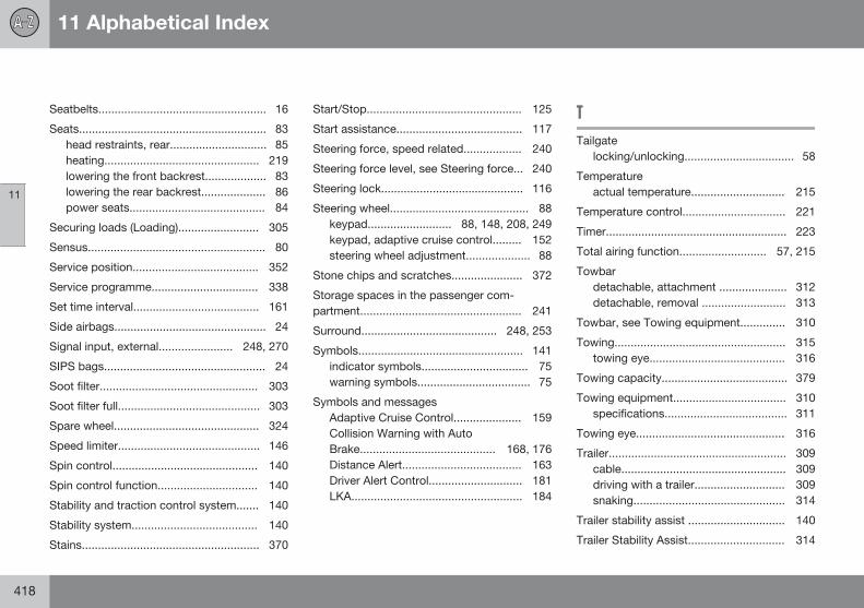
11 Alphabetical Index
11
418
Seatbelts.................................................... 16
Seats.......................................................... 83head restraints, rear.............................. 85heating................................................ 219lowering the front backrest................... 83lowering the rear backrest.................... 86power seats.......................................... 84
Securing loads (Loading)......................... 305
Sensus....................................................... 80
Service position....................................... 352
Service programme................................. 338
Set time interval....................................... 161
Side airbags............................................... 24
Signal input, external....................... 248, 270
SIPS bags.................................................. 24
Soot filter................................................. 303
Soot filter full............................................ 303
Spare wheel............................................. 324
Speed limiter............................................ 146
Spin control............................................. 140
Spin control function............................... 140
Stability and traction control system....... 140
Stability system....................................... 140
Stains....................................................... 370
Start/Stop................................................ 125
Start assistance....................................... 117
Steering force, speed related.................. 240
Steering force level, see Steering force... 240
Steering lock............................................ 116
Steering wheel........................................... 88keypad.......................... 88, 148, 208, 249keypad, adaptive cruise control......... 152steering wheel adjustment.................... 88
Stone chips and scratches...................... 372
Storage spaces in the passenger com-partment.................................................. 241
Surround.......................................... 248, 253
Symbols................................................... 141indicator symbols................................. 75warning symbols................................... 75
Symbols and messagesAdaptive Cruise Control..................... 159Collision Warning with AutoBrake.......................................... 168, 176Distance Alert..................................... 163Driver Alert Control............................. 181LKA..................................................... 184
T
Tailgatelocking/unlocking.................................. 58
Temperatureactual temperature............................. 215
Temperature control................................ 221
Timer........................................................ 223
Total airing function........................... 57, 215
Towbar detachable, attachment ..................... 312detachable, removal .......................... 313
Towbar, see Towing equipment.............. 310
Towing..................................................... 315towing eye.......................................... 316
Towing capacity....................................... 379
Towing equipment................................... 310specifications...................................... 311
Towing eye.............................................. 316
Trailer....................................................... 309cable................................................... 309driving with a trailer............................ 309snaking............................................... 314
Trailer stability assist .............................. 140
Trailer Stability Assist.............................. 314
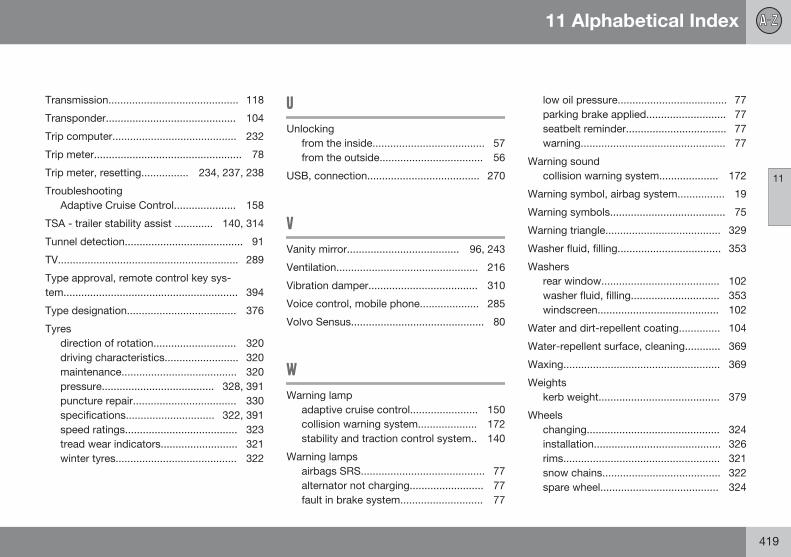
11 Alphabetical Index
11
419
Transmission............................................ 118
Transponder............................................ 104
Trip computer.......................................... 232
Trip meter.................................................. 78
Trip meter, resetting................ 234, 237, 238
TroubleshootingAdaptive Cruise Control..................... 158
TSA - trailer stability assist ............. 140, 314
Tunnel detection........................................ 91
TV............................................................. 289
Type approval, remote control key sys-tem........................................................... 394
Type designation..................................... 376
Tyresdirection of rotation............................ 320driving characteristics......................... 320maintenance....................................... 320pressure...................................... 328, 391puncture repair................................... 330specifications.............................. 322, 391speed ratings...................................... 323tread wear indicators.......................... 321winter tyres......................................... 322
U
Unlockingfrom the inside...................................... 57from the outside................................... 56
USB, connection...................................... 270
V
Vanity mirror...................................... 96, 243
Ventilation................................................ 216
Vibration damper..................................... 310
Voice control, mobile phone.................... 285
Volvo Sensus............................................. 80
W
Warning lampadaptive cruise control....................... 150collision warning system.................... 172stability and traction control system.. 140
Warning lampsairbags SRS.......................................... 77alternator not charging......................... 77fault in brake system............................ 77
low oil pressure..................................... 77parking brake applied........................... 77seatbelt reminder.................................. 77warning................................................. 77
Warning soundcollision warning system.................... 172
Warning symbol, airbag system................ 19
Warning symbols....................................... 75
Warning triangle....................................... 329
Washer fluid, filling................................... 353
Washersrear window........................................ 102washer fluid, filling.............................. 353windscreen......................................... 102
Water and dirt-repellent coating.............. 104
Water-repellent surface, cleaning............ 369
Waxing..................................................... 369
Weightskerb weight......................................... 379
Wheelschanging............................................. 324installation........................................... 326rims..................................................... 321snow chains........................................ 322spare wheel........................................ 324
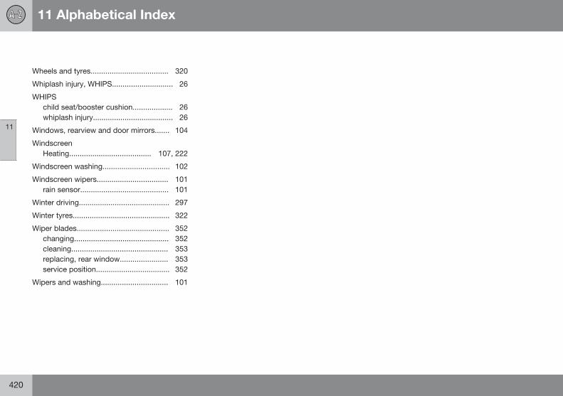
11 Alphabetical Index
11
420
Wheels and tyres..................................... 320
Whiplash injury, WHIPS............................. 26
WHIPSchild seat/booster cushion................... 26whiplash injury...................................... 26
Windows, rearview and door mirrors....... 104
WindscreenHeating....................................... 107, 222
Windscreen washing................................ 102
Windscreen wipers.................................. 101rain sensor.......................................... 101
Winter driving........................................... 297
Winter tyres.............................................. 322
Wiper blades............................................ 352changing............................................. 352cleaning.............................................. 353replacing, rear window....................... 353service position................................... 352
Wipers and washing................................ 101


Volvo Car Corporation TP 16042 (English), AT 1320, Printed in Sweden, Göteborg 2013, Copyright © 2000-2013 Volvo Car Corporation
Related Documents