1 OV/4-6 Overview of the FTU Results B. Angelini, S.V. Annibaldi, M.L. Apicella, G. Apruzzese, E. Barbato, A. Bertocchi, F. Bombarda, C. Bourdelle 3 , A. Bruschi 1 , P. Buratti, G. Calabrò, A. Cardinali, L. Carraro 2 , C. Castaldo, C. Centioli, R. Cesario, S. Cirant 1 , V. Cocilovo, F. Crisanti, R. De Angelis, M. De Benedetti, F. De Marco, B. Esposito, D. Frigione, L. Gabellieri, F. Gandini 1 , L. Garzotti 2 , E. Giovannozzi, C. Gormezano, F. Gravanti, G. Granucci 1 , G.T. Hoang 3 , F. Iannone, H. Kroegler, E. Lazzaro 1 , M. Leigheb, G. Maddaluno, G. Maffia, M. Marinucci, D. Marocco, M. Mattioli 4 , G. Mazzitelli, C. Mazzotta, F. Mirizzi, G. Monari, S. Nowak 1 , F. Orsitto, D. Pacella, L. Panaccione, M. Panella, P. Papitto, V. Pericoli-Ridolfini, L. Pieroni, S. Podda, M. E. Puiatti 2 , G. Ravera, G. Regnoli, G.B. Righetti, F. Romanelli, M. Romanelli, F. Santini, M. Sassi, A. Saviliev 5 , P. Scarin 2 , A. Simonetto 1 , P. Smeulders, E. Sternini, C. Sozzi 1 , N. Tartoni, B. Tilia, A. A. Tuccillo, O. Tudisco, M. Valisa 2 , V. Vershkov 6 , V. Vitale, G. Vlad, F. Zonca. Associazione Euratom-ENEA sulla Fusione C.R. Frascati, 00044, Frascati, Roma, Italy e-mail contact of main author: [email protected] 1 Abstract. An overview of the FTU results during the period 2003-2004 is presented. A prototype ITER-relevant LHCD launcher: the Passive Active Multijunction (PAM) has been successfully tested (f=8GHz). High power handling, good coupling properties and current drive effects comparable to those of a conventional launcher have been achieved. The 140 GHz ECRH system has reached its nominal performances: 1.5MW. Effective electron and ion heating (via collisions) have been observed as well as current drive (25 kA at n e0 =8×10 19 m -3 ). Avoidance and/or suppression of disruptions have been studied with ECRH. IBW studies have shown the importance of recycling in achieving improved confinement plasmas. Results achieved with advanced tokamak (AT) scenarios are presented including repetitive Pellet Enhanced Plasmas (PEP) and electron ITBs. Very peaked density profiles have been achieved with a low speed vertical pellet injector located at about mid-radius on the high field side. Performances are comparable to those achieved with a high-speed horizontal pellet injector. Possible reasons for this behaviour are discussed, among them the presence of an “MHD” drift once particles reach the q=1 surface. Electron ITBs can be produced at high density in FTU with LHCD. Best performances are achieved with the combined use of LHCD and ECRH. Ions are heated by collisions with Δ Ti/Ti up to 40%. A detailed analysis has shown that the ion confinement is comparable to the energy confinement time and that the ITB are not degraded by the electron-ion collisions. A database of the H 97 factor has been established with H 97 up to 1.6 for the e-ITBs. The peaked density profiles achieved with pellet fuelling allows the linear dependence of τ E with n e to be recovered. Particle pinch studies have been made at high densities in full current drive conditions were the Ware pinch plays no role. An anomalous inward pinch exists even at these high densities (n e0 =1.3×10 20 m -3 ). Parametric dependences of the density peaking are given. MHD spectroscopy has revealed high frequency modes (30-80 kHz) in the absence of energetic particles that might have consequences for burning plasmas. 1. Introduction Experiments on the Frascati Tokamak FTU, which is a compact high magnetic field device (R=0.93m, a=0.3m, B t up to 8T, I p up to 1.6 MA) are aimed at developing advanced scenarios at field and densities relevant to ITER operation as well as its supporting physics /1/. The heating and current drive systems, Lower Hybrid Current Drive (LHCD, f=8Ghz), Electron Cyclotron 1 Associazione EURATOM-ENEA-CNR sulla Fusione, Istituto di Fisica del Plasma, Milano, Italy 2 Consozio RFX, Corso Stati uniti 4, I-35100, Padova, Italy 3 Association EURATOM-CEA, Cadarache, F-13108, Saint Paul-lez-Durance, France 4 ENEA guest 5 A.F. Ioffe Physico-Technical Institute RAS, Polytechnichestaya 26, 194021 St. Petersburg, Russian Federation 6 Nuclear Fusion Institute, RRC Kurchatov Institute, 123182 Kurchatov Sq.1, Moskow, Russian Federation

Welcome message from author
This document is posted to help you gain knowledge. Please leave a comment to let me know what you think about it! Share it to your friends and learn new things together.
Transcript

1
OV/4-6
Overview of the FTU Results
B. Angelini, S.V. Annibaldi, M.L. Apicella, G. Apruzzese, E. Barbato, A. Bertocchi, F.Bombarda, C. Bourdelle3, A. Bruschi1, P. Buratti, G. Calabrò, A. Cardinali, L. Carraro2, C.Castaldo, C. Centioli, R. Cesario, S. Cirant1, V. Cocilovo, F. Crisanti, R. De Angelis, M. DeBenedetti, F. De Marco, B. Esposito, D. Frigione, L. Gabellieri, F. Gandini1, L. Garzotti2, E.Giovannozzi, C. Gormezano, F. Gravanti, G. Granucci1, G.T. Hoang3, F. Iannone, H. Kroegler,E. Lazzaro1, M. Leigheb, G. Maddaluno, G. Maffia, M. Marinucci, D. Marocco, M. Mattioli4, G.Mazzitelli, C. Mazzotta, F. Mirizzi, G. Monari, S. Nowak1, F. Orsitto, D. Pacella, L. Panaccione,M. Panella, P. Papitto, V. Pericoli-Ridolfini, L. Pieroni, S. Podda, M. E. Puiatti2, G. Ravera, G.Regnoli, G.B. Righetti, F. Romanelli, M. Romanelli, F. Santini, M. Sassi, A. Saviliev5, P.Scarin2, A. Simonetto1, P. Smeulders, E. Sternini, C. Sozzi1, N. Tartoni, B. Tilia, A. A. Tuccillo,O. Tudisco, M. Valisa2, V. Vershkov6, V. Vitale, G. Vlad, F. Zonca.
Associazione Euratom-ENEA sulla FusioneC.R. Frascati, 00044, Frascati, Roma, Italye-mail contact of main author: [email protected]
Abstract. An overview of the FTU results during the period 2003-2004 is presented. A prototype ITER-relevantLHCD launcher: the Passive Active Multijunction (PAM) has been successfully tested (f=8GHz). High powerhandling, good coupling properties and current drive effects comparable to those of a conventional launcher havebeen achieved. The 140 GHz ECRH system has reached its nominal performances: 1.5MW. Effective electron andion heating (via collisions) have been observed as well as current drive (25 kA at ne0=8×10¹⁹m-3). Avoidance and/orsuppression of disruptions have been studied with ECRH. IBW studies have shown the importance of recycling inachieving improved confinement plasmas. Results achieved with advanced tokamak (AT) scenarios are presentedincluding repetitive Pellet Enhanced Plasmas (PEP) and electron ITBs. Very peaked density profiles have beenachieved with a low speed vertical pellet injector located at about mid-radius on the high field side. Performancesare comparable to those achieved with a high-speed horizontal pellet injector. Possible reasons for this behaviourare discussed, among them the presence of an “MHD” drift once particles reach the q=1 surface. Electron ITBs canbe produced at high density in FTU with LHCD. Best performances are achieved with the combined use of LHCDand ECRH. Ions are heated by collisions with ΔTi/Ti up to 40%. A detailed analysis has shown that the ionconfinement is comparable to the energy confinement time and that the ITB are not degraded by the electron-ioncollisions. A database of the H97 factor has been established with H97 up to 1.6 for the e-ITBs. The peaked densityprofiles achieved with pellet fuelling allows the linear dependence of τE with ne to be recovered. Particle pinchstudies have been made at high densities in full current drive conditions were the Ware pinch plays no role. Ananomalous inward pinch exists even at these high densities (ne0=1.3×10²⁰m-3). Parametric dependences of thedensity peaking are given. MHD spectroscopy has revealed high frequency modes (30-80 kHz) in the absence ofenergetic particles that might have consequences for burning plasmas.
1. Introduction
Experiments on the Frascati Tokamak FTU, which is a compact high magnetic field device(R=0.93m, a=0.3m, Bt up to 8T, Ip up to 1.6 MA) are aimed at developing advanced scenarios atfield and densities relevant to ITER operation as well as its supporting physics /1/. The heatingand current drive systems, Lower Hybrid Current Drive (LHCD, f=8Ghz), Electron Cyclotron 1 Associazione EURATOM-ENEA-CNR sulla Fusione, Istituto di Fisica del Plasma, Milano, Italy2 Consozio RFX, Corso Stati uniti 4, I-35100, Padova, Italy3 Association EURATOM-CEA, Cadarache, F-13108, Saint Paul-lez-Durance, France4ENEA guest5A.F. Ioffe Physico-Technical Institute RAS, Polytechnichestaya 26, 194021 St. Petersburg, Russian Federation6 Nuclear Fusion Institute, RRC Kurchatov Institute, 123182 Kurchatov Sq.1, Moskow, Russian Federation
2
Resonance Frequency (ECRF, f=140 Ghz) and Ion Bernstein Waves (IBW, f=433 MHz), aremainly interacting with electrons. Ion heating is produced by electron-ion collisions as it will bein ITER. The advanced scenarios include peaked electron temperature plasmas (electron InternalTransport Barriers: e-ITBs) or peaked electron density plasmas achieved with pellet injection(Pellet Enhanced Plasmas: PEPs).
The new hardware installed since IAEA 2002 /2/ include: a high field side pellet injector, aprototype LHCD launcher for ITER and the completion of the ECRH system to 4 gyrotrons.New diagnostics include an upgrade of turbulence measurements and the installation of FastElectrons Bremsstrahlung (FEB) cameras and a CO2 multi-channel interferometer. Turbulencemeasurements on FTU are carried out using a two-channel poloidal correlation reflectometer/3//4/ which can work either in O-mode, for low-density plasmas, or in X-mode, for high densityones. This technique is systematically applied to advanced scenarios regimes when plasmaconditions are such that the waves can be reflected in plasma areas of interest. Two FEBcameras (one vertical, one horizontal) detect the hard X-ray emission emitted by the fastelectron tails generated by LH waves in the energy range 20 to 200keV along several chords inthe poloidal cross section. This provides information on the location of these fast electrons,therefore on the localisation of LHCD allowing comparison and benchmarking with LHdeposition codes to be made. The new interferometer is based on an innovative “scanning beam”technique /5/: two CO2 beams are spatially swept at high frequency across the plasma crosssection. In this way, the density is measured along 30 chords separated in time, reconstructingone density profile every ≈50µs.
In this paper, the main new results from the FTU heating and current drive systems will bepresented first. New features of advanced tokamak scenarios including e-ITBs and PEP modeswith the vertical pellet injector will be then discussed. Finally, the issues of ITER supportingphysics (transport studies including particle pinch results and MHD spectroscopy) will besummarised.
2. Heating and Current Drive Systems
2.1 Lower Hybrid Current Drive. The design of the launcher mouth for ITER is verychallenging: namely operation in the full shadow of the vessel port to avoid damage fromescaping particle flow, withstanding of the heating due to escaping particles, radiation andneutron fluxes and achievement of high level of power handling and current drive efficiency. Ithas been proposed to insert one passive waveguide between each active waveguide, the so-called passive active multijunction (PAM) /6/ in order to provide for the cooling of the launchermouth. The passive waveguides have a depth of about a quarter wavelength and reflect the waveso as to construct the required N// spectrum, although with a slightly reduced directivity than aconventional launcher. A clear conceptual advantage is to operate with very low density at thegrill mouth. A prototype PAM unit (see Fig2.1) has been successfully tested in FTU /7/. Anequivalent power density about 1.5 times higher than the value corresponding to the ITERrequest (ITER design value: 33 MW/m2) has been launched for as long as the power can beapplied (0.9s). A very low power reflection coefficient (around 1.5%) has been measured withthe density in front of the launcher close to the cut-off value even with the grill mouth retracted2 mm inside the port shadow /8/.
The fast electron tail behaviour and the overall CD efficiency have been compared with aconventional grill launching quite a similar N|| spectrum. Based on the FEB and loop voltage

3
data, the CD efficiencies appear to be quite similar (Fig2.2) /9/. LHCD simulation codes arecarried out using the FRTC ray tracing LHCD model (1-D (v||) Fokker Planck package)combined with the ASTRA code, that has been already benchmarked on FTU experimental data/10/. In the Fokker Planck model, ad hoc corrections to the collision operator account for 2-Deffects, such as pitch angle scattering, have modelled reasonably well the FTU data. The FEBspectra obtained during a combination of the PAM and of a conventional grill are wellreproduced by the modelling as shown in Fig.2.3. This LHCD modelling code, that has alsobeen benchmarked on JET data, has been used for ITER modelling /11/ both to reassess theLHCD frequency and to predict the LHCD efficiency (Fig2.4) in the frame of an internationaleffort /12/.
0
0.2
0.4
0.6
0.8
1
1.2
0 0.05 0.1 0.15 0.2 0.25 0.3r(m)
a.u.
HXR
JLH
Fig2.3: Comparison of experimental FEBdata for the PAM +CG phase of Fig.2.2(HXR) with prediction from FRTC code
Fig2.1: View of the Passiveactive multijunction (PAM)
Fig.2.2: Current drive performances of the PAM antennacompared with those of a conventional grill (CG) in #24350.
Fig2.4: Predictions of LH current density in ITER(Q=5 steady state scenario, f=5 GHz, PLH=30MW) using the 1-D fast ray tracing code FRTC. Asa comparison, are also plotted simulations fromthe combined ray tracing and 2-D Fokker-Planckmodels CQL3D, which include trapped particleeffects, and DELPHINE/13/.
4
2.2. Electron Cyclotron Resonance Heating
The ECRF system of FTU is progressing to reach its nominal power level of up to 1.6MW, 0.5swith four 140GHz microwave beam each focussed by an independent mirror in a 4 cm spot,with a total maximum power density of 60 MWm-3. In previous experiments /1/, ECRH hasbeen used for a large variety of applications: control of the power deposition profile allowing alarge variety of energy and particle transport experiments to be studied (MHD control, synergywith LHCD fast electrons) in conditions directly relevant to ITER (Bt= 5.3T, ne=1×10²⁰m-3). Ionheating trough collisions from electrons was already observed at a power level of 0.8 MW /14/.In a first demonstrative short pulse (80ms), a dense plasma (<ne>=1.1 1020m-3) has been heatedwith 1.5MW of ECRF power. Te0 increases from 1.3 to 4 keV and Ti0 from 1.1 to 1.32 keV.Consequently the neutron yield was increased by a factor 3. ECCD experiments have beenperformed at a power level of PEC=1.1 MW for 400 ms. In order to have a complete first-passabsorption, plasma parameters were selected to be: 0.5<
€
n e <0.6×10²⁰m-3 and 3<Te< 5 keV. Thepower density of 30-40 MW/m3 leads to 0.09<E///Ecr< 0.25 (Ecr being the electric field abovewhich thermal electrons can runaway/15/) and therefore a linearized theoretical treatment isadequate. A series of experiments with a toroidal injection angle set at ±10°, ±20°, ±30° (offperpendicular) have permitted to have a first assessment of the driven current in discharges withIp=400kA and 2.5 < Zeff < 3. The EC driven current is estimated through plasma resistance:IECCD= Ip - Vloop/Rp - Ibs, with Ibs about 2-3% of Ip. A co-current of 15 to 25 kA has beenestimated to be driven, slightly above the linear theory predictions.
(
2.3. Ion Bernstein Waves. As reported in /1/, 0.4 MW of IBW power was coupled in deuteriumplasma at IP=0.8 MA, ne=0.5x10²⁰ m-3 and BT=7.9 T. Some peaking of the electron pressureprofile (20%) was found accompanied by a decrease of the electron thermal conductivity by40% over the radial region inside the expected IBW deposition layer /17/. Successiveexperiments in 2003 were done in similar conditions. However, a higher impurity content (Mo,
0.1
0.3
0.5
#25913 (no ECRH)#25920 (ECRH)
I p (M
A)
ECRH 0.6 MW
LBO injection
108
109
1010
1011
neut
rons
(s-1
)
0
0.5
1
1.5
0.8 0.82 0.84 0.86 0.88 0.9
Te (
keV
)
time (s)
Fig.2.5: Disruptions produced byinjection of Mo through LBO: effect of theapplication of ECRH on plasma current,neutrons and Te
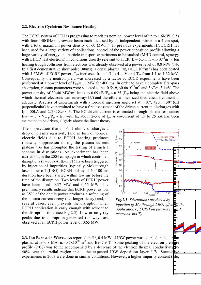
The observation that in FTU ohmic discharges adrop of plasma resistivity (and in turn of toroidalelectric field) due to ECRH heating producesrunaway suppression during the plasma currentplateau /16/ has prompted the testing of a such ascheme in disruptions. An experiment has beencarried out in the 2004 campaign in which controlleddisruptions (Ip=500kA, Bt=5.3T) have been triggeredby injection of impurities (typically Mo) throughlaser blow-off (LBO). ECRH pulses of 20-100 msduration have been started within few ms before thetime of the disruption. Two levels of ECRH powerhave been used: 0.37 MW and 0.65 MW. Thepreliminary results indicate that ECRH power as lowas 35% of the ohmic power produces a softening ofthe plasma current decay (i.e. longer decay) and, inseveral cases, even prevents the disruption whenECRH application is early enough with respect tothe disruption time (see Fig.2.5). Low or no γ-raypeaks due to disruption-generated runaways areobserved at an ECRH power level of 0.65 MW.

5
O) and a higher recycling (Dα being a factor two higher) were observed. As a result, no pressurepeaking with IBW power was observed, possibly due to a spurious absorption of the wave in thescrape-off plasma. Further experiments should be performed in cleaner plasmas with lowerrecycling in order to fully assess the role of the IBW power injection in producing confinementimprovement. However, turbulence measurements were performed showing that some reductionof the turbulence level (about 20%) at the edge occurs during IBW injection /18/. O-modereflectometry measurements on such discharges have shown some interesting behaviour. Twosets of discharges have been compared, with and without IBW, showing that inside theabsorption layer the quasi-coherent (QC) component of the turbulence is reduced while the self-correlation time of the turbulence increases (but not the self correlation length). A reduction ofthe poloidal speed for the quasi-coherent component is also observed but not for the lowfrequency one. Instead, a reduction of the low frequency component is observed at about theabsorption layer. The kθρi of the QC modes is compatible with ITG turbulence. Reflectometrymeasurements have been carried out so far only for a set of discharges in which the improvedconfinement could not be reproduced.
3. Advanced Tokamak Scenarios
3.1 Improved performance plasmas with pellet injection. High-density plasmas with peakeddensity profiles have been achieved in FTU with multiple pellet injection /19/ from a high-speedhorizontal pellet injector (2km/s). Transient improved core confinement plasmas with very lowZeff has lead to record neutron yield value in FTU. Achievement of repetitive PEP modes (up to5 subsequent pellets separated by about 100ms, 5 pellets being the maximum number of pelletsavailable from the launcher, has permitted to maintain an average neutron yield above the ohmicvalues for the full duration of the current plateau (by about a factor of 2-3). A large centraldensity peaking was observed although pellets were fully ablated at about mid-radius. Detailedanalysis of the data /20/ has shown that pellet ablation near the q = 1 surface triggers fast growthof an m =1 magnetic island: as the island reaches a large amplitude, magnetic reconnectionmixes the plasma centre with the q=1 pellet fuelled region, so enhancing the effective pelletdeposition depth. This phenomena was well reproduced by MHD codes /21/ but difficult toassess due to the geometry of the pellet launcher.
A new vertical pellet launcher has been installed to feed a vertical injection line displacedtowards the high toroidal field side at a radius of r/a~0.6. Pellets have been injected along a bentguide system (3m radius) with velocities up to 0.5km/s. As shown in Fig3.1, multiple PEPmodes were achieved with performances similar to the multiple PEP modes achieved with thehorizontal launcher in spite of the large distance between the tangential line and the plasmacenter: reheat of the electrons to the pre-pellet level and comparable increase of neutron yield. Afirst phase, for about 0.3-0.4ms, follows the ablation of the pellet where the ablated particlesreach the q=1 surface. The presence of an electric radial drift due to ∇B/B is not clear and isdiscussed in /22/. In the second phase (from ~0.4 to 8 ms), an island is formed and particles driftrapidly towards the plasma center. The density profile evolve from a hollow profile to a peakedprofile with the central density reaching 7-8×10²⁰m-3. This peaking is slowly increasing for thefull duration of the PEP mode: here ~70 ms, about one τE. The internal mini-collapse of the PEPphase is caused by an MHD event, mainly an m=1 mode.

6
Sometimes, an m=2 mode is triggered after the mini-collapse of the PEP, preventing theformation of a subsequent PEP and sometimes leading to a disruption. It has been shown thatthis is caused by an excessive amount of light impurities (oxygen) leading to a change of thecurrent profile. Clean machine conditions permit to avoid this effect. Such an effect is illustratedin Fig.3.3 where the first pellet produces a PEP mode, followed by an m=2 mode. Theturbulence is analysed by the reflectometer working in X-mode with a cut-off density of about2.5x1020 m-3, so it is assumed that a cut-off layer is present in the plasma for central line averagedensities above 1.2x10²⁰ m-3. The first pellet brings a sharp reduction in the quasi-coherent
Fig3.1Comparison ofmultiple PEPmodes achievedwith the horizontal(#18598) and thevertical (#25255)pellet launchers
Fig.3.3. Turbulence behavior in # 25371.When the 1st pellet is injected a cut-off layeris in the plasma and the turbulence level isvery low. When the 2nd pellet is injected theturbulence remains at a high level.
Fig3.2: Density peaking following vertical pellet injection (from the CO2 multi-channelinterferometer). Times refer to the start of pellet injection. Particle pinch is estimated to takeplace around t=0.4ms. Error bars (about 8%) are larger when the density profile is hollow.
7
component of the fluctuation spectrum. After the second pellet this reduction is not observed.The low level of turbulence corresponds to a much higher particle confinement time /23/.
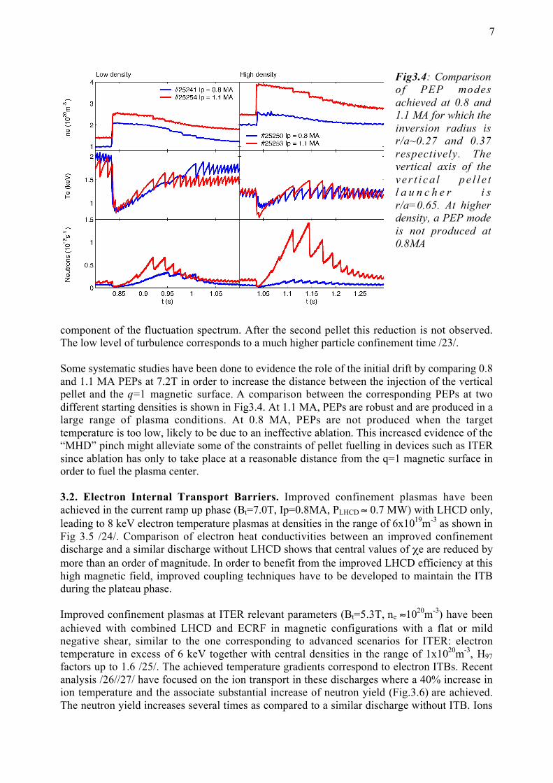
Some systematic studies have been done to evidence the role of the initial drift by comparing 0.8and 1.1 MA PEPs at 7.2T in order to increase the distance between the injection of the verticalpellet and the q=1 magnetic surface. A comparison between the corresponding PEPs at twodifferent starting densities is shown in Fig3.4. At 1.1 MA, PEPs are robust and are produced in alarge range of plasma conditions. At 0.8 MA, PEPs are not produced when the targettemperature is too low, likely to be due to an ineffective ablation. This increased evidence of the“MHD” pinch might alleviate some of the constraints of pellet fuelling in devices such as ITERsince ablation has only to take place at a reasonable distance from the q=1 magnetic surface inorder to fuel the plasma center.
3.2. Electron Internal Transport Barriers. Improved confinement plasmas have beenachieved in the current ramp up phase (Bt=7.0T, Ip=0.8MA, PLHCD ≈ 0.7 MW) with LHCD only,leading to 8 keV electron temperature plasmas at densities in the range of 6x10¹⁹m-3 as shown inFig 3.5 /24/. Comparison of electron heat conductivities between an improved confinementdischarge and a similar discharge without LHCD shows that central values of χe are reduced bymore than an order of magnitude. In order to benefit from the improved LHCD efficiency at thishigh magnetic field, improved coupling techniques have to be developed to maintain the ITBduring the plateau phase.
Improved confinement plasmas at ITER relevant parameters (Bt=5.3T, ne ≈1020m-3) have beenachieved with combined LHCD and ECRF in magnetic configurations with a flat or mildnegative shear, similar to the one corresponding to advanced scenarios for ITER: electrontemperature in excess of 6 keV together with central densities in the range of 1x10²⁰m-3, H97
factors up to 1.6 /25/. The achieved temperature gradients correspond to electron ITBs. Recentanalysis /26//27/ have focused on the ion transport in these discharges where a 40% increase inion temperature and the associate substantial increase of neutron yield (Fig.3.6) are achieved.The neutron yield increases several times as compared to a similar discharge without ITB. Ions
Fig3.4: Comparisonof PEP modesachieved at 0.8 and1.1 MA for which theinversion radius isr/a~0.27 and 0.37respectively. Thevertical axis of thev e r t i c a l p e l l e tl a u n c h e r i sr/a=0.65. At higherdensity, a PEP modeis not produced at0.8MA

8
are heated via collisional power transfer from electrons. However, central ion temperatures Ti0
(1.2<Ti0<1.6 keV and ΔTi0≈ 0.4 keV) are usually smaller than Te0 (3<Te0<10 keV and ΔTe0≈7keV). As compared to a case without ITB, the ion conductivity is reduced all over the plasmavolume down to neoclassical levels (χi ≈ 0.1 m2 s–1). Global ion behaviour is inferred bycomparing the ion thermal energy density and the power transferred to ions by collisions withelectrons in the volume inside the ITB radius. The observed relationship between these twoquantities is linear and is a good indication that ions are efficiently heated from direct collisionalheating. The corresponding incremental ion energy confinement time in the plasma core,τE,iincr≈24.6 ms, is comparable or larger than the global energy confinement time, on average 20ms for the selected set of data /25/. However, the ratio between thermal equipartition time andenergy confinement time remains at about a factor 8. Therefore, although this is a first indicationthat ion-electron collisions do not prevent electron ITBs to be achieved, a clear demonstration ofthis point would require operation at higher density and/or with higher energy confinement.
F i g 3 . 5 : Main signals of an improvedconfinement discharge (#23647 at Bt=7.T,solid line) compared with a similar dischargewithout LHCD (#23640, dotted line).Comparison of the respective χe (at t=0.4s)shows an improved confinement. The LHCDpower was not maintained due to couplingproblems in the transition from ramp-up toplateau phase.
Fig 3.6: Comparison between dischargeswith (#20859) and without (#20772)electron ITBs. The power transferred fromelectrons to ions inside the ITB radius iscalculated from JETTO codes calculations.1.8 MW of LHCD was applied form t=0.2sand 0.6MW of ECRH from t=0.07s to 0.28s.
9
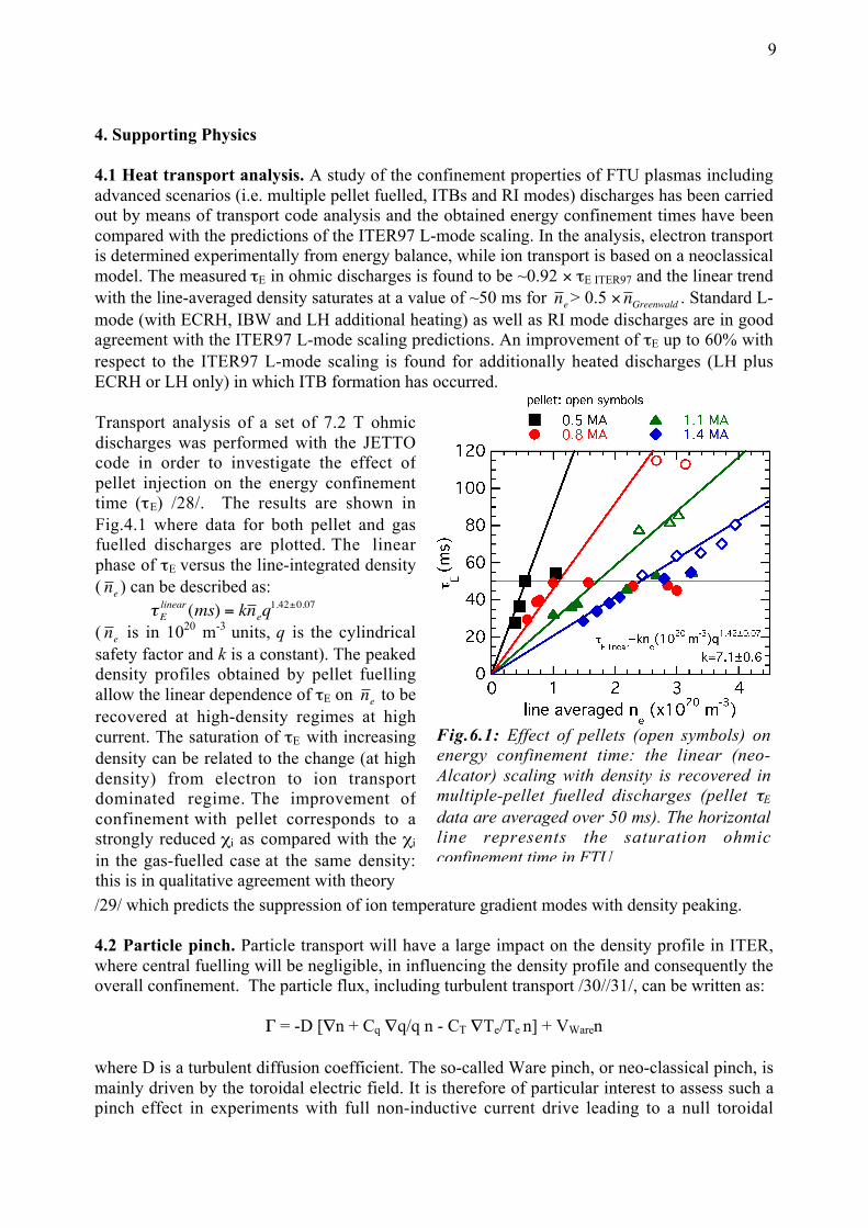
Fig.6.1: Effect of pellets (open symbols) onenergy confinement time: the linear (neo-Alcator) scaling with density is recovered inmultiple-pellet fuelled discharges (pellet τE
data are averaged over 50 ms). The horizontalline represents the saturation ohmicconfinement time in FTU.
Transport analysis of a set of 7.2 T ohmicdischarges was performed with the JETTOcode in order to investigate the effect ofpellet injection on the energy confinementtime (τE) /28/. The results are shown inFig.4.1 where data for both pellet and gasfuelled discharges are plotted. The linearphase of τE versus the line-integrated density(
€
n e ) can be described as:
€
τElinear(ms) = kn eq
1.42±0.07
(
€
n e is in 1020 m-3 units, q is the cylindricalsafety factor and k is a constant). The peakeddensity profiles obtained by pellet fuellingallow the linear dependence of τE on
€
n e to berecovered at high-density regimes at highcurrent. The saturation of τE with increasingdensity can be related to the change (at highdensity) from electron to ion transportdominated regime. The improvement ofconfinement with pellet corresponds to astrongly reduced χi as compared with the χi
in the gas-fuelled case at the same density:this is in qualitative agreement with theory
4. Supporting Physics
4.1 Heat transport analysis. A study of the confinement properties of FTU plasmas includingadvanced scenarios (i.e. multiple pellet fuelled, ITBs and RI modes) discharges has been carriedout by means of transport code analysis and the obtained energy confinement times have beencompared with the predictions of the ITER97 L-mode scaling. In the analysis, electron transportis determined experimentally from energy balance, while ion transport is based on a neoclassicalmodel. The measured τE in ohmic discharges is found to be ~0.92 × τE ITER97 and the linear trendwith the line-averaged density saturates at a value of ~50 ms for
€
n e > 0.5 ×
€
n Greenwald . Standard L-mode (with ECRH, IBW and LH additional heating) as well as RI mode discharges are in goodagreement with the ITER97 L-mode scaling predictions. An improvement of τE up to 60% withrespect to the ITER97 L-mode scaling is found for additionally heated discharges (LH plusECRH or LH only) in which ITB formation has occurred.
/29/ which predicts the suppression of ion temperature gradient modes with density peaking.
4.2 Particle pinch. Particle transport will have a large impact on the density profile in ITER,where central fuelling will be negligible, in influencing the density profile and consequently theoverall confinement. The particle flux, including turbulent transport /30//31/, can be written as:
Γ = -D [∇n + Cq ∇q/q n - CT ∇Te/Te n] + VWaren
where D is a turbulent diffusion coefficient. The so-called Ware pinch, or neo-classical pinch, ismainly driven by the toroidal electric field. It is therefore of particular interest to assess such apinch effect in experiments with full non-inductive current drive leading to a null toroidal

10
electric field with only RF heating and current drive techniques without any internal fuelling.
Data analysis /23/ confirms the results found in Tore Supra at a lower collisionality: the scalingof the density peaking with the temperature gradient depends upon the area of the plasma with atransition phase at about r/a=0.3 (Fig 4.3). Density peaking depends also almost linearly with∇q/q n (Fig 4.4). Attempts to understand these results and to assess their consequence for ITERare underway.
Fig 6.4: Dependence of ∇n/n with ∇q/q(#22424 and #21638)
Fig 6.3: Dependence of grad n/n with ∇T/T(#22424 and #21638)
The existence of an anomalous inward pinch insteady state plasma without electric field wasdemonstrated in Tore Supra /32/. However, sucha demonstration was done at rather low density:ne(0)=2-3.5×10¹⁹m-3 and Te(0)=4.8keV. Asimilar set of experiments has been done in FTUin conditions of higher density and collisionalitymore relevant to ITER. Full current driveconditions were achieved with I.6MW of LHCDfor the following conditions /1/: Bt=7.2T,Ip=0.5MA, ne0=1.3×10²⁰m-3 and Te0=6keV forabout 3τE, followed by almost full current drive(ΔVloop/Vloop=90% with Vloop=0.1V) for a further10τE. The normalised density profile flattenssignificantly during the full current drive phase,as shown in Fig 4.2, but remains peaked. Theprofile remains unchanged during the fullduration of the quasi full current drive phase.
Fig6.2: normalised density profileswithout LHCD(t=1.05s), with full currentdrive (t=0.6s) and with almost fullCD(t=0.9s, ΔV/V=90%)
11
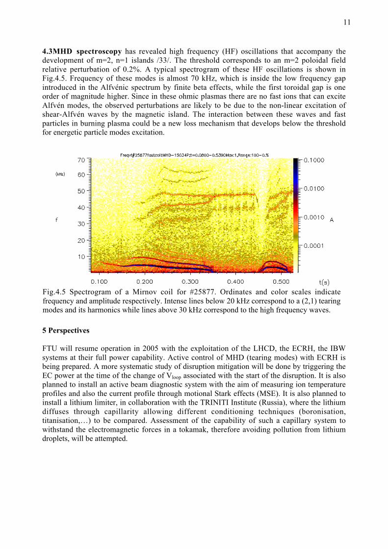
4.3MHD spectroscopy has revealed high frequency (HF) oscillations that accompany thedevelopment of m=2, n=1 islands /33/. The threshold corresponds to an m=2 poloidal fieldrelative perturbation of 0.2%. A typical spectrogram of these HF oscillations is shown inFig.4.5. Frequency of these modes is almost 70 kHz, which is inside the low frequency gapintroduced in the Alfvénic spectrum by finite beta effects, while the first toroidal gap is oneorder of magnitude higher. Since in these ohmic plasmas there are no fast ions that can exciteAlfvén modes, the observed perturbations are likely to be due to the non-linear excitation ofshear-Alfvén waves by the magnetic island. The interaction between these waves and fastparticles in burning plasma could be a new loss mechanism that develops below the thresholdfor energetic particle modes excitation.
5 Perspectives
FTU will resume operation in 2005 with the exploitation of the LHCD, the ECRH, the IBWsystems at their full power capability. Active control of MHD (tearing modes) with ECRH isbeing prepared. A more systematic study of disruption mitigation will be done by triggering theEC power at the time of the change of Vloop associated with the start of the disruption. It is alsoplanned to install an active beam diagnostic system with the aim of measuring ion temperatureprofiles and also the current profile through motional Stark effects (MSE). It is also planned toinstall a lithium limiter, in collaboration with the TRINITI Institute (Russia), where the lithiumdiffuses through capillarity allowing different conditioning techniques (boronisation,titanisation,…) to be compared. Assessment of the capability of such a capillary system towithstand the electromagnetic forces in a tokamak, therefore avoiding pollution from lithiumdroplets, will be attempted.
Fig.4.5 Spectrogram of a Mirnov coil for #25877. Ordinates and color scales indicatefrequency and amplitude respectively. Intense lines below 20 kHz correspond to a (2,1) tearingmodes and its harmonics while lines above 30 kHz correspond to the high frequency waves.
12
References
/1/ Special Issue on FTU in Fusion Science and Technology (Guest editor C.Gormezano) 45(May 2004);/2/ Angelini. B., et al, Nucl. Fusion 43 (2003) 1632-1640;/3/ Vershkov V.A., Dreval V.V., Soldatov S.V., Rev. Sci. Instr., 70 (1999);/4/ Vershkov V.A., et al., 28th EPS Conf. on Plasma Physics, Madeira (2001), P1.011;/5/ Tudisco O., et al, Fusion Science & Tech. 45 (2004) 402;/6/ Bibet Ph., et al, Rep. EUR-CEA-FC-1520, CEN Cadarache, France, Sept. 1994;/7/ Mirizzi F., et al, 20th Symposium on Fusion Engineering (SOFE 2003), Oct.2003, San Diego,USA;/8/ Pericoli Ridolfini V., et al, 31st EPS Conf. on Plasma Physics (London, 28th June-2nd July2004) P2-105;/9/ Pericoli Ridolfini V., et al, this conference, EX/5-5;/10/ Barbato E., et al, Fusion Science & Tech. 45 (2004) 323;/11/ Barbato E., Saviliev A., 31st EPS Conf. on Plasma Physics (London, 28th June-2nd July2004) P2-104;/12/ within the ITPA Topical Group on Steady State Operation: being prepared for theTokamak Physics Basis (to be submitted to Nuclear Fusion);/13/ Bonoli P, et al, in Rado Frequency power in Plasmas, AIP Conf. Proc. 694, Ed. C.B. Forest,(AIP,NY,2003)24;/14/ Granucci G., et al, Fusion Science & Tech. 45 (2004) 387;/15/James R.A., Giruzzi G., et al, Phys. Review A, 45 (1992) 8783;/16/ J.R. Martin-Solis, et al., Nucl. Fusion, 44 (2004) 974;/17/ Castaldo C., et al. Nucl. Fusion 44, (2004) L1-L4;/18/ De Benedetti M., et al., in proc. Conf. on Plasma Physics (London, 28th June-2nd July2004);/19/ Frigione D., et al, Nucl. Fusion 41 (2001) 1613;/20/ Giovannozzi E., et al, Nucl. Fusion 44 (2004) 226;/21/ Annibaldi S.V., et al Nucl. Fusion 44 (2004) 12;/22/ Giovannozzi E., et al, this conference, EX/P4-4;/23/ Romanelli M., et al, this conference, EX/P6-24;/24/ Castaldo C., et al, to be submitted to Nuclear Fusion;/25/ Pericoli Ridolfini V., et al, Nucl. Fusion 43 (2001) 287;/26/ Barbato E., Pericoli Ridolfini V., et al, Fusion Science & Tech. 45 (2004) 387;/27/ Gormezano C., et al, 30th EPS Conf. on Plasma Physics (St Petersburg, 7-11 July 2003) P2-145;/28/ Esposito B., et al, Plasma Phys. Control. Fusion 46 (2004) 1793-1804:/29/ Hassam A.B., et al. Phys. Fluids B2(8) (1990) 1822;/30/ Romanelli F. and Zonca F., Phys. Fluids B6 (11) (1993) 4081;/31/ Garbet X., et al, Phys. Rev. Letters 91(2003) 035001;/32/ Hoang G.T., et al, Phys. Rev. Letters 90 (2003) 155002;/33/ Buratti P., et al, this conference, EX P5-1;
Related Documents

![[IBM] Ibm Banking Overview Final Version for FTU](https://static.cupdf.com/doc/110x72/577d2a5f1a28ab4e1ea90eb8/ibm-ibm-banking-overview-final-version-for-ftu.jpg)