,-7Y _-- O- NASA Technical Memorandum 105318 /-_,/, / J, _j Overview of Rocket Engine Control r,,9 2- i _2_7_ Carl E Lorenzo and Jeffrey L. Musgrave Lewis Research Center Cleveland, Ohio Prepared for the Ninth Symposium on Space Nuclear Power Systems sponsored by the University of New Mexico Albuquerque, New Mexico, January 12-16, 1992 N/ A

Welcome message from author
This document is posted to help you gain knowledge. Please leave a comment to let me know what you think about it! Share it to your friends and learn new things together.
Transcript

,-7Y _-- O-
NASA Technical Memorandum 105318/-_,/, /
J,
_j
Overview of Rocket Engine Control
r,,9 2- i _2_7_
Carl E Lorenzo and Jeffrey L. MusgraveLewis Research Center
Cleveland, Ohio
Prepared for the
Ninth Symposium on Space Nuclear Power Systems
sponsored by the University of New Mexico
Albuquerque, New Mexico, January 12-16, 1992
N/ A

OVERVIEW OF ROCKET ENGINE CONTROL
Cad F. Lorenzo and Jeffrey L. Musgrave
National Aeronautics and Space AdministrationLewis Research Center MS 77-1
Cleveland, OH 44135
Abstract
This paper broadly covets the issues of Chemical Rocket Engine Control. The basic feedback information and
control variables used in expendable and reusable rocket engines, such as the Space Shuttle Main Engine are
discussed. The deficiencies of current approaches are considered and a brief introduction to Intelligent ControlSystems for rocket engines (and vehicles) is presented.
INTRODUCTION
The purpose of this paper is to give a broad overview of Chemical Rocket Engine (CRE) control as background
for Nuclear Thermal Rocket Engine control. The paper will discuss the fundamental (underlying) physical issuesin CRE control. A brief discussion of modem CREs and their control will follow. This will include a discussion
of the Space Shuttle Main Engine (SSME). Recent advanced control approaches for the SSME will be presentedalong with the benefits which ensue. Current research into Intelligent Control Systems for the SSME which allows
high levels of adaptability to engine degradations will be discussed. Finally the connections of current chemical
rocket engine controls research to nuclear rocket controls will be explored.
Wluel I ox
lllmlll
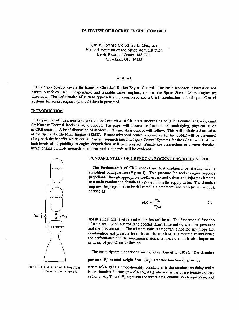
FIGLIItE t. PrassuleFedBi-PropellantRocketEngineSchematic.
FUNDAMENTALS OF CHEMICAL ROCKET ENGINE CONTROL
The fundamentals of CRE control are best explained by starting with a
simplified configuration (Figure I). This pressure fed rocket engine supplies
propellants through appropriate feedlines, control valves and injector elementsto a main combustion chamber by pressurizing the supply tanks. The chamber
requires the propellants to be delivered in a predetermined ratio (mixture ratio),defined as
MR - %`
,%,(I)
and at a flow rate level related to the desired thrust. The fundamental function
of a rocket engine control is to control thrust (inferred by chamber pressure)
and the mixture ratio. The mixture ratio is important since for any propellant
combination and pressure level, it sets the combustion temperature and hence
the performance and the maximum material temperature. It is also importantin terms of propellant utilization.
The basic dynamic equations are found in (Lee et al. 1953). The chamber
pressure (P,) to total weight flow (WT) transfer function is given by
where (c'/Arg) is a proportionality constant, o is the combustion delay and "t
is the chamber fill time (x - c'A_gV./RT=) where c" is the characteristic exhaust
velocity, AT, To, and V. represent the throat area, combustion temperature, and

/
main chamber volume respectively. In linearform the injectors are flow resistors so that
,C,/s)--_,_/s)+w_,fs)=k_(P,,.,fs)-P_(s))+k2fP,.fs)-PJs))
(2)
(3)
where Pt is the injector pressure. The feedline can be represented in lumped parameter form (continuity and
momentum equations) or distributed hyperbolic form (wave equation). In this configuration there are two inputs,
namely the valve areas (positions) which control the individual propellant flows and hence the chamber pressure andmixture ratio.
A classical control for this simplified configuration is
shown in Figure 2. The following observations are made.
Chamber pressure responds to total weight flow. Therefore
the chamber pressure flow loop would usually (but not
necessarily) go with the propellant having the higher flow
rate say Oz in an H2 - O, engine. Also the two loops tendto be interactive and to minimize excursions of the error
signals, one loop is tuned to be the "fast" loop and the
other slower. Experience shows that the mixture ratio
should be the fast loop. 1"his minimizes excursions in MR
away from the set point which in turn keeps the gas and
metal temperatures at the design conditions. The chamber
pressure is the "slower" loop and its bandwidth is set by
thrust response requirements. The type of control shown
here would normally require three measurements
Pc, g,_,,, and *o, with two control inputs (valve areas)
Af,,_ and Ao*. These basic ideas dominate CRE control
design for much more complex cycles.
MODERN CHEMICAL ROCKET ENGINES
Turbine driven pumps supply the propellants in mostmodem rocket vehicles. Numerous cycles a_ proposed,
. "Nox "_ +Mi_
\w_.l/sat
I Rat,oIV'tCootro,I[
wt'_ /
l "Vox tAox
Chamber
Pressure
(Thrust)Control
P _
c set +
FIGURE 2. Classical Control for
Bi-Propellant Rocket Engine.
Pc
Engine
studied, and used in regard to the method that the turbines axe powered. The various engine cycles each have their
benefits and problems and a discussion of these is well beyond the scope of this paper.
Two representative cycles will be considered. The first of these is the Gas Generator Cycle (Figure 3). The
fundamental feature of this cycle is that small amounts of propellant are taken from the main propellant feedlines
to be burned in a small auxiliary combustor (gas generator). The generated gases power the turbopumps, and may
be used to cool the nozzle and are expelled. The most likely mode of control for this cycle would be to regulatechamber pressure by controlling the gas generator pressure. This would control the speed of both turbopumps and
hence the total propellant delivered to the main combustion chamber. Either the oxidizer valve or fuel valve (or both
depending on cycle design) could be used to control mixture ratio as the fast loop. From a high level perspective,
this control philosophy is very much the same as that detailed in the previous section. In the small, the controldesigner must assure that the local mixture ratio of the gas generator is controlled to assure gas generator and turbine
integrity. Also the flow/power balance between the two turbopumps, that is the propellant delivered by each
turbopumps at a given gas generator conditions together with the main chamber cooling requirements will likely
determine which main propellant valve will be used to control main chamber mixture ratio.

The second cycle considered is the Expander Cycle
(Figure 4). Here, one of the propellants (usually fuel)
is circulated as a coolant through the combustion
chamber and nozzle. This heated fuel is used to power
the turbopumps and then returned to the main chamber
where it is injected and burned to create thrust. Note
in this cycle most of the fuel is circulated through the
turbine. From a controls point of view, this cycle is
very similar to the previous cycle. However, overall
propellant delivery is set by pump speed which in turn
is set by the turbine bypass valve. The oxidizer valve
provides control over mixture ratio.
Generally speaking, classical control can be used to
design for adequate P,, and MR control provided loop
speeds (bandwidths) are properly accounted. Sensing
requirements for P, and MR performance are minimal,
usually being chamber pressure and propellant massflows.
This discussion does not include treatment of startup
or shutdown. Startup is usually a scheduled process
based on empirical knowledge of initial ignition,
propellant arrival times, and related parameters.
Shutdown is also a critical part of the process which
must be accurately executed to realize the required
mission delta velocity requirement.
Turbopump
Fuel
Valve
idizer
'_ I Turbopump
Turbine I I
eyp_ II: Valv____...__
Oxidizer _;. [
I .IHhlll:llll:lllll[ _ |
. /
FIGURE 4. Full Expander Cycle
Rocket Engine Schematic.
Hydrogen Oxygen
Fuel
Turbopump
Fuel
Valve
GasGenerator
Valve
Gas IgniterGenerator Oxidizer
Valve
Oxidizer
Turbopump
FIGURE 3. Gas Generator Cycle
Rocket Engine Schematic.
Many variants of these cycles are possible, and the
selection of a cycle for any particular vehicle involves a
broad set of considerations such as mission, reliability,manned or unmanned, and maintenance times. However,
the high level control philosophy is similar in all cases.
SPACE SHUTTLE MAIN ENGINE CONTROL
The SSME is the first large scale reusable rocket engine
developed from a long fine of expendable liquid rocket
propulsion technology. A two stage combustion process
provides the necessary fuel and lox supply pressures to
reach the 20684 kPa (3000 psia) chamber pressure
resulting in 2091 kN (470,000 lbs) of rated (vacuum)
thrust. A propellant flow schematic of the SSME is
shown in Figure 5. Hydrogen used to cool the Main
Combustion Chamber drives the Low Pressure Fuel Pump
(fuel supply) while bleed flow from the High Pressure
Lox Pump drives the Low Pressure Lox Pump (lox
supply). The fuel and lox preburners acting as the first
stage of the combustion process drive the High Pressure
Turbopumps which supply coolant flow and lox for themain combustor respectively. The fuel rich gas from the
prebumers is burned again as primary fuel in the mainchamber.
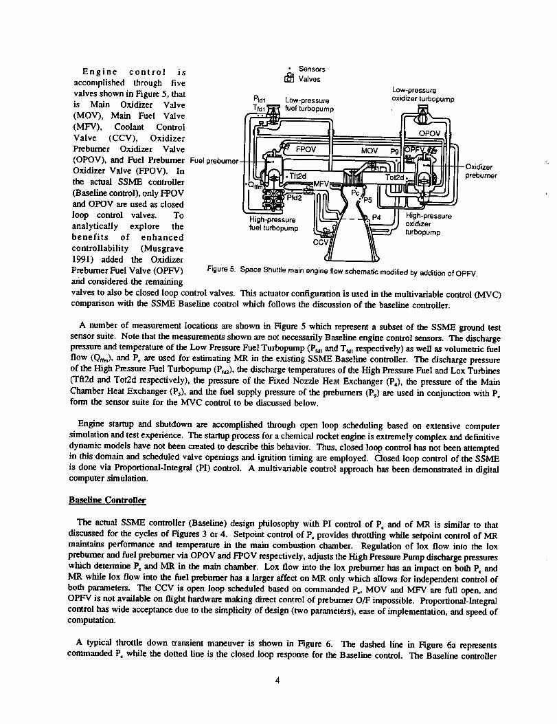
Engine control is
accomplished through fivevalves shown in Figure 5, thatis Main Oxidizer Valve
(MOV), Main Fuel Valve
(MFV), Coolant ConU'ol
Valve (CCV), Oxidizer
Prebumer Oxidizer Valve
(OPOV), and Fuel Prebumer
Oxidizer Valve (FPOV). Inthe actual SSME controller
(Baseline control), only FPOVand OPOV are used as closed
loop control valves. To
analytically explore thebenefits of enhanced
controllability (Musgrave1991) added the Oxidizer
Prebumer Fuel Valve (OPFV)
and considered the remaining
/._ SensorsValves
Low-pressurePfdl Low-pressure oxidizerturbopump
fuel turbopump .
-_hz pressureTue,,umopump I =__r" ,r o,ump
CCV
Figure5. Space Shuttlemainengineflowschematicmodifiedby additionof OPFV.
valves to also he closed loop control valves. This actuator configuration is used in the multivariable control (MVC)comparison with the SSME Baseline control which follows the discussion of the baseline controller.
A number of measurement locations are shown in Figure 5 which represent a subset of the SSME ground test
sensor suite. Note that the measurements shown are not necessarily Baseline engine control sensors. The discharge
pressure and temperature of the Low Pressure Fuel Turbopump (Prdl and Trd1 respectively) as well as volumetric fuel
flow (Qr_,), and P= are used for estimating MR in the existing SSME Baseline controller. The discharge pressureof the High Pressure Fuel Turbopump (Pr_), the discharge temperatures of the High Pressure Fuel and Lox Turbines
(Tfl2d and Tot2d respectively), the pressure of the Fixed Nozzle Heat Exchanger (P4), the pressure of the Main
Chamber Heat Exchanger (Ps), and the fuel supply pressure of the prebumers (Pg) are used in conjunction with P=form the sensor suite for the MVC control to be discussed below.
Engine startup and shutdown are accomplished through open loop scheduling based on extensive computer
simulation and test experience. The startup process for a chemical rocket engine is extremely complex and definitive
dynamic models have not been created to describe this behavior. Thus, closed loop control has not been attempted
in this domain and scheduled valve openings and ignition timing are employed. Closed loop control of the SSME
is done via Proportional-Integral (PI) control. A multlvariable control approach has been demonstrated in digitalcomputer simulation.
Baseline Controller
The actual SSME controller (Baseline) design philosophy with PI control of Pc and of MR is similar to that
discussed for the cycles of Figures 3 or 4. Setpoint control of Po provides throttling while setpoint control of MRmaintains performance and temperature in the main combustion chamber. Regulation of lox flow into the lox
prebumer and fuel prebumer via OPOV and FPOV respectively, adjusts the High Pressure Pump discharge pressures
which determine P= and MR in the main chamber. Lox flow into the lox preburner has an impact on both P= and
MR while lox flow into the fuel prebumer has a larger affect on MR only which allows for independent control ofboth parameters. The CCV is open loop scheduled based on commanded P=, MOV and MFV are full open, and
OPFV is not available on flight hardware making direct control of prebumer O/F impossible. Proportional-lntegral
control has wide acceptance due to the simplicity of design (two parameters), ease of implementation, and speed ofcomputation.
A typical throttle down transient maneuver is shown in Figure 6. The dashed line in Figure 6a representscommanded P= while the dotted line is the closed loop response for the Baseline control. The Baseline controller

r,v
01
et
r-,
6_
"O
7-
32O0
3000
2800
2600
24O0
2200
2000
1800
1700
1650
1600
1550
1500
1450
(a)
o
(c)
-- MVC
'._. ...... Baselin_and
. I . . , J j , , I , , , 1 i i ,
2 4 6 8 10
Time (sec)
-- MVC
........ Baseline
..... Tlt2d Command
2 4 6 8 10
Time (sec)
6.2
6.15
6.1
O'= 6,05
_ 6
x
._ s.gs
5.9
5.85
5.8
1250
1200
1150
E1100
1050"o
_o 10001-
95O
(b)
-- MVC
....... Bnsolino
...",.
(d)
2 4 6 8 10
Time (sec)
900
850
. ..........................-- iVC
........ Baseline _,,.,,
..... Tot2d Command _,-..-,-......,.,.
0 2 4 6 8 10
Time (sec)
Figure 6. (_omparison of Baseline and MVC Responses for the Throttle-Down Transient.
achieves excellent tracking of commanded P° while minimizing MR excursions from the design point (MR = 6.011)
as shown by the dotted line in Figure 6b. The "uncontrolled" turbine discharge temperatures are included in Figures
6c and 6(t for the purpose of comparison with the multivariable control later.
Con_ol of P= and MR only indixectly manage the operation of the four turbopumps which am important life
limiting components in the SSME (Cikanek 1987). That is, prebumer mixture ratios (temperature) are not directly
regulated. This fact may be important relative to the engines not achieving their design life-times. Turbine discharge
temperature redlines are used by the Baseline controller to shutdown the engine. Figure 7 shows the closed loop
engine response resulting from a change in the High Pressure Fuel Turbine efficiency during mainstage operation.
Here, a step decrease of 10% in High Pressure Fuel Turbine efficiency occurs at T = 4 sec while setpoints on P= and
MR are kept constant at design chamber pressure and mixture ratio. The dotted line (Baseline controller) in Figure
7a shows a slight spike in Pc while MR experiences a large increase before returning to setpoint resulting in a
temperature spike in the main combustion chamber which is not shown here. The dotted line in Figure 7c shows
the discharge temperature of the High Pressure Fuel Turbine rapidly approaching the redline cutoff while Figure 7d
shows a rapid drop in High Pressure Oxidizer Turbine discharge temperature. In the next section, the benefits of
multivariable control for rocket engines will be discussed in the context of these two examples.
Multivariable Controller
Multivariable control (MVC) methods generally rely on linear state space models of the process to be controlled.
A perturbation model of a simplified (39 state) nonlinear dynamic engine model at rated power was used for control
design (Musgrave 1991). The linear models of the SSME change very little from the 650 to the 109% power
(thrust) level, therefore gain-scheduling was not required.

q
===
O.
e_
E(=t-
O
Are
10
s-.I--
3200
3000
2800
2600
240O
2200
2000
1800
2000
1950
1900
1850
1800
1750
1700
1650
1600
(a)
(c)
-- MVC
........ Baseline
6.4
6.35
6.3
o 6.25=I_ 6.2
N 6.15
6.1
6.05
• _ " _ 5.952 4 6 8 10
Time (see)
-- MVC...............................................
........ Baseline :...........................
..... Redline Limit "
//
/
Y" • , I , . I , , , I ,
2 4 6
Time (sec)
1800
1700
1600
re
d_ 1500G
_. 1400'o
_o 1300I--
1200
(b)-- MVC
........ Baseline
:\
""'//...,.
i ,%.
"'°"" .......
0 2 4 6 8 10
Time (sec)
(d)
-- MVC
........ Baseline
..... Redline Limit
J
11O0 ""'......,.
, , I , , . 1000 '" + _ + ' ' _' ":'":"-"_"" ....8 10 0 2 4 6 8 10
Time (sec)
FIGURE 7. Comparison of Baseline and MVC Responses for a 10% Drop In Fuel Turbine Efficiency.
MVC allows the integration of multiple objectives of Pc, Mr, Tft2d, and Tot2d command following whiledecoupling each of the loops from the others using all six valves in Figure 5 as control valves. Figure 6 shows amultivariable design running at the same sampling rate as the Baseline control (50 hz). The solid line of Figure 6arepresents the closed loop MVC response of 1)+to reference commands (dashed line). The BaseUne controller (dottedline) achieves slightly fighter 1:'=control than does MVC, however both are satisfactory. Control of MR (solid line)in Figure 6b compares favorably to the Baseline controller with excursions below the setpoint (cool side). The solidlines of Figures 6c and 6<t demonstrate the command following capability of the MVC for Tft2d and Tot2d (solidlines) to reference commands (dashed lines).
The benefit of MVC is demonstrated for 10% decrease in High Pressure Fuel Turbine efficiency. In all cases forthe MVC of Figure 7 as with Baseline, reference commands for P=,MR, TR2d and Tot2d are kept constant at theirrespective 100% power values. In Figure 7a, we see the controller automatically allowing a slight decrease (3%)in delivered chamber pressure while maintaining mixture ratio (solid line in Figure 7b) thereby avoiding temperatureexcursions in the main chamber. The dramatic increase (21.9%) of Tft2d from Baseline in Figure 7c is reduced bythe MVC to only a 6.25% increase in temperature. This action will preserve the turbine blade life and avoid anunnecessary redline shutdown. Finally, Figure 7d shows only a slight change in Tot2d for the MVC (solid fine)
comp,'ued to the dramatic decrease of the Baseline control (dotted lines). Consequently, the MVC is capable ofavoiding a potential redline cutoff which could compromise the mission and/or result in f_rther damage to engine
components.

NEW DIRECTIONS
Rocket Engine Intelligent Control
The SSME (Figure 5) is the first rocket
engine designed with a philosophy of
reusability. The harsh envkonment
encountered in this engine has not allowed
realization of the 55 mission design life.
Numerous durability problems have beendocumented for the SSME (Cikanek 1987).
These facts together with a desire to space-
base some newer rocket engines motivates
a technology thrust (Merrill and Lorenzo
1988, and Lorenzo and Merrill 1990)
toward Reusable Rocket Engine Intelligent
Control. The basic concept of rocket
engine Intelligent Control is that using
advanced sensors (condition monitoring
CONTROL
VEHICLEI _oUE_i [ IN MULTIVARIABLEcoTROLI r,. ",1CONT,O"I---'l ACTUATO,SI
& I It_n /I L, /I IINTERFACEI l i;;i:_oF_" "_ -- I I ..--''1--.-,-.--- J II°_F)FI CONIROL1 l _ / I[ IREOU'REMENTSl."° I ."O0_,SoI IPRIMAR'Y I ._ ]II ICI&RITICAI IT_ I ....... | | CONTROL _ _ II IcR'T'C'_TYIT_ I I I VAR,A"LES_II I"'_, I / ] I SENSORSI I I LEVEL I / I I J
L-----_-.[ SYSTEM [ | | [ 1J I INTELLIGENCE I / / T •
ENGINE I(COORDINATORJ] / __ I SENSOR"/I EN,.,,STATUS , , / - "l ACTUATOR ]--..1 DYN.
II / H"°"/ L___ 1
PROGNOSTIC , CONOITIONEXPERT SYSTEM MONITOR
{'/
_lCS I
OR j
FIGURE 8. REUSEABLE SPACE PROPULSION INTELLIGENT CONTROL SYSIEM FRN_EWORK.
instruments)and on-boarddiagnostic/prognosticand coordinationintelligencean enginewith an IntelligentControl
System (ICS) can detectand accommodate varioussensor,actuatorand engine hardware failures.The key
functionalities of an ICS are: life extending control, adaptive control, real-time engine diagnostics and prognostics,
component condition monitoring, real-time identification, and sensor/actuator fault tolerance. Artificial intelligence
techniques are considered for implementing coordination, diagnostics, prognostics, and control reconfigurationfunctionalities.
A framework for an ICS is shown in Figure 8. The framework provides a rational, top-down basis for the
incorporation of system intelligence through the hierarchical integration of the control functional elements. This
hierarchy integrates functionalities at the execution level such as the high-speed, closed-loop multivariable controller,
engine diagnostics and adaptive reconfiguration with a top level coordination function. The top level coordinationfunction serves to interface the current engine capability with the other engines in the propulsion system, the
vehicle/mission requirements, and the crew. It modifies controller input commands and selects various control
reconfiguration modes to resolve any conflicts between objectives. A practical baseline framework expanding these
ideas for an SSME based Intelligent Control has been proposed (Nemeth 1990). An advanced framework for SSME
Intelligent Control is given (Nemeth et al. 1991). The promise of intelligent control is an engine system with greater
durability and operability in the face of impending or actual component failure.
Life Extending Control
The concept of Life Extending Control (LEC) compliments that of Intelligent Control discussed above. In LEC
the object is to minimize damage accumulation at critical points of the (engine) structure by the way in which the
control moves the system through transients (or by the choice of operating domain). Such a concept must also
maintain required dynamic performance. In contrast to Intelligent Control, LEC represents what can be done to
enhance system durability through the direct control level. LEC is ,an interdisciplinary thrust between controls and
materials/structural science (in particular, fatigue fracture mechanics).
Two broad classes of LEC have been conceptualized by (Lorenzo and Merrill 1991). These are Implicit LEC
which uses current technology cyclic based fracture/fatigue damage laws and the Continuous Life Prediction approach
which assumes development of continuous differential forms of the damage laws. Only the Implicit LEC conceptwill be discussed here in order to expose the basic ideas.
The implicit approach to LEC recognizes that current fracture/fatigue science can not predict the differentialdamage on less than a full cycle of strain. The implicit approach (see Figure 9) selects a sequence of typical
command transients (and disturbances) that are representative of those the system would experience in service. Two

performance measures are defined:
Jp, an objective function thatmaximizes dynamic performance
(possibly by minimizing quadratic
state and control excursions) and
JD, a damage measure which uses
the best (current) fatigue/fracture
theory available to calculate the
damage accumulated over the
sequence of command transients.
An overall performance measure
can be defined as J = Jr + a JDwhere a represents the relative
importance between performance
and life extension. The implicit
approach then selects a "best"
control algorithm which is applied
for the full sequence of command
transients. The dynamic
performance and damage
accumulation over the sequence
are optimized (relative to the
selected measures) against the
TYPICAL
COMMAND _ [
TRANSIENT
SEQUENCE
DAMAGE
RELATED
VARIABLES
CONTROL
t
TYPICAL DISTURBANCE SEQUENCE
°I t*=- PLANT --
PERFORMANCE VARIABLES
[DAMAGE THEORY
BASED OFFUNE
CALC OF J D
_ CALCULATEJ-Jp+ aJ D
I NONLINEAR CALCOF STRESS, STRAIN,
TEMPERATURES, ETCo
OFFLINE CALC
OFJ p
FIGURE 9. Implicit Life Extending Control Approach.
control algorithm parameters. The expectation is to find an algorithm such that the loss in dynamic performance is
small (Jp.,._ -]p.o.,,_,in Figure 10), for a significant reduction in accumulated damage over the sequence of transients
(JD.o_, " ]D.,._,_,is large and life is extended). Here the subscript "o" refers to optimizing for dynamic performanceonly. An actual operating gain set (point q in Figure 10) is then chosen Which satisfies the desired weighting
between performance and damage (J).
The mechanics of the implicit approach are detailed as follows. During the design
variables are considered: (1) the performance variables normally used to manage
Jp
ALGORITHMx
OPTIMIZING J p _"'UI_ILY Y Z
/JP o,rnin
JD OPTIMIZING J ONLYp
x Y
z
qdD .
z,mln
ALGORITHM GAIN SPACE ALGORITHM GAIN SPACE
FIGURE 10. Effect of Various Ufe Extending Control Algorithms
on Performance (J_ and Damage (J_.
process, two types of feedbackdynamic performance and (2)nonlinear functions of the
performance variables
representative of the damagevariables (stresses, strains,
temperature, and variousrates). Various control
algorithms are then examinedwithin this feedback structure.
That is, the sequence of
selected performance anddisturbance transients are
applied to a simulated systemwith a trial control and
performance J (or Jr and JDseparately) is calculated. A
family of algorithms can be
developed which are
parameterized by the relative
tradeoff parameter a. Thefinal control can he selected
from this set of aigorithmswith confidence that an
effective control and a

desirable performance/life tradeoff have been established. It is expected that as LEC technology is developed it will
find broad application in high performance aerospace systems and elsewhere.
EXTENSIONS TO NUCLEAR PROPULSION
While the Nuclear Thermal Rocket engine is conceptually similar to a chemical rocket engine, it is significantly
different in several important ways. One potential Nuclear Rocket Engine cycle is shown in Figure 11. Both
systems create thrust by heating a working fluid and expanding it through a convergent-divergent nozzle to
supersonic velocities. Additionally, turbomachinery provides the necessary supply pressures for the working fluid.The fundamental difference is the heat source in the nuclear rocket results from the reactor core instead of a chemical
combustion process. Specific Impulse (defined as I,p = Thrust ] _T) for a rocket engine can be expressed as I,p
= K'4T. In a chemical rocket the temperature is set by the propellant combination. In a nuclear thermal rocket the
temperature is set by the reactor conditions. Thus I,p is fixed for the chemical rocket but variable for a nuclearthermal rocket limited by core material temperatures.
Bypass
Support Control
System ValveControl
Valve l
PumpDischarge Reactor with
Control Control DrumsValve
Various studies of nuclear rocket control have been performed (Sanders et at.
1962, Arpasi and Hart 1967, and Hart and Arpasi 1967). The basic control
objective of a nuclear rocket is to control thrust level via flow through the
turbine and temperature (I,p) via core reaction rates (control drums).Temperature control is similar to mixture ratio control in chemical rockets.
However, the fundamental dynamics of the heat addition are quite different. An
increase of working fluid (Hydrogen for example) into the reactor core
thermally reduces core temperature through heat transfer while simultaneously
increasing heat generation by increasing the neutron flux (Crouch 1965).
Control of this phenomenon will require anticipatory (lead) action by the reactor
control system for good transient performance. Many other issues such as
startup, shutdown, and idle mode need also be considered.
Many of the technologies being developed and demonstrated for chemical
rocket engine control such as Multivariable Control, Intelligent Control and Life
Extending Control will be applicable to nuclear rocket engines in the
development of durable, reliable and fault tolerant propulsion systems.
FIGURE 11. Nuclear Thermat Rocket
Engine Flow Schematic.
SUMMARY
This paper provided an overview of chemical rocket propulsion control and
new technology developments in this area. It is expected that many of these
new technologies will find application in the Nuclear Rocket Engine.
Acknowledgments
The authors wish to gratefuUy acknowledge the technical input from Carl Aukerman, Dale Arpasi, and AlbertPowers.
9
References
Arpasi, D. J. and C. E. Hart (1967) Controls Analysis of Nuclear Rocket Engine at Power Range OperatingConditions, NASA TN D-3978, LeRC, Cleveland, OH., May 1967.
Cik,-mek, H. A. (1987) "Characteristics of Space Shuttle Main Engine Failu_s," in 23th AIAA/SAE/ASME
Joint Propulsion Conference, Paper No. 87-1939, San Diego, CA., 29 June - 2 July 1987.
Crouch, H. F. (1965) Nuclear Space Propulsion, Astronuclear Press, Granada Hills, CA., pp. 199-233.
Hart, C. E., and D. J. Arpasi (1967) Frequency Response and Transfer Functions of a Nuclear Rocket EngineSystem obtained from Analog Computer Simulation, NASA TN D-3979, LeRC, Cleveland, OH., May 1967.
Lee, Y. C., M. R. Gore and C. C. Ross (1953) "Stability and Control of Liquid Propellant Rocket Systems,"American Rocket Society Journal, March-April 1953, pp. 75-81.
Lorenzo, C. F. and W. C. Merrill (1990) "An Intelligent Conurol System for Rocket Engines: Needs, Vision and
Issues," in Proc. of American Control Conference, San Diego, CA., 23-25 May 1990.
Lorenzo, C. F. and W. C. Merrill (1991) "Life Extending Control: A Concept Paper," in Proc. of American ControlConference, Boston, MA., 26-28 June 1991.
Men'ill, W. C. and C. 1:7.Lorenzo (1988) "A Reusable Rocket Engine Intelligent Control," in 24th AIAA/SAE/ASMEJoint Propulsion Conference, Paper No. 88-3114, Boston, Mass., 11-13 July 1988.
Musgrave, J. L. (1991) "Linear Quadratic Servo Control of a Reusable Rocket Engine," in 27th AIAA/SAE/ASMEJoint Propulsion Conference, Paper No. 91-1999, Sacramento, CA., 24-27 June 1991.
Nemeth, E. (1990) Reusable Rocket Engine Intelligent Control System Framework Design (Phase I), NASA
Contractor Report CR187043 for NASA LeRC by Rocketdyne Div. Rockwell International Corp., Canoga Park,CA., 6 April 1990.
Nemeth, E., R. Anderson, J. Ols, and M. Olasasky (1991) Reusable Rocket Engine Intelligent Control System
Framework Design (Phase II), RI/RD91-158 for NASA LeRC by Rocketdyne Div. Rockwell International Corp.,Canoga Park, CA., 21 June 1991.
Sanders, J. C., H. J. Heppler, and C. E. Hart (1962) Problems in Dynamics and Control of Nuclear Rockets, NASASP 20, LeRC, Cleveland, OH., December 1962.
10

Form ApprovedREPORT DOCUMENTATION PAGE OMBNo.0704-0188
Public reporting burden for this collection o_ information is estimated to average 1 hour per response, including the time for reviewing instructions, searching existing data sources,gathedng snd maintaining the data needed, and completing and reviewing the collection of information. Send comments regarding this burden estimate or any other aspect ot thiscollection of information, including suggestions for reducing this burden, to Washtnglo_ Headquarters Services, Directorate for information Operations and Repods, 1215 JeffersonDavis Highway, Suite 1204, Arlington, VA 22202-4302, and to the Office of Management and Budget, Paperwork Reduction Project (0704-0188), Washington, DC 20503.
1. AGENCY USE ONLY (Leave blank) 2. REPORT DATE
4. TITLE AND SUBTITLE
Overview of Rocket Engine Control
6. AUTHOR(S)
Carl F. Lorenzo and Jeffrey L. Musgrave
7. PERFORMING ORGANIZATION NAME(S) AND ADDRESS(ES)
National Aeronautics and Space Administration
Lewis Research Center
Cleveland, Ohio 44135-3191
9. SPONSORING/MONITORING AGENCY NAMES(S) AND ADDRESS(ES)
National Aeronautics and Space Administration
Washington, D.C. 20546-0001
3. REPORT TYPE AND DATES COVERED
Technical Memorandum
5. FUNDING NUMBERS
WU- 505 - 62 - 50
8. PERFORMING ORGANIZATION
REPORT NUMBER
E-6673
10. SPONSORING/MONITORING
AGENCY REPORT NUMBER
NASA TM-105318
11. SUPPLEMENTARY NOTES
Prepared for the Ninth Symposium on Space Nuclear Power Systems sponsored by the University of New Mexico,
Albuquerque, New Mexico, January 12-16, 1992. Responsible person, Carl F. Lorenzo, (216) 433-3733.
12a. DISTRIBUTION/AVAILABILITY STATEMENT
Unclassified - Unlimited
Subject Category 20
12b. DISTRIBUTION CODE
13. ABSTRACT (Maximum 200 words)
This paper broadly covers the issues of Chemical Rocket Engine Control. The basic feedback information and control
variables used in expendable and reusable rocket engines, such as the Space Shuttle Main Engine are discussed. The
deficiencies of current approaches are considered and a brief introduction to Intelligent Control Systems for rocket
engines (and vehicles) is presented.
14. SUBJECT TERMS
Rocket engine control; Nuclear rocket engines; Nuclear propulsion
17. SECURITY CLASSIFICATION
OF REPORT
Unclassified
18. SECURITY CLASSIFICATION
OF THIS PAGE
Unclassified
NSN 7540-01-280-5500PRECEDING
19, SECURITY CLASSIFICATION
OF ABSTRACT
Unclassified
15. NUMBER OF PAGES
12
16. PRICE CODE
A03
20. LIMITATION OF ABSTRACT
Standard Form 298 (Rev. 2-89)
PAGE BLANK NOT FILMED PrescrlbedbyANSIStd. Z39-18298-102

Related Documents