6/25/01 Alana Whitaker 1 Overview of ISS US Fire Detection and Suppression System 6/25/01 Alana Whitaker 2 Outline Intro to Fire Detection and Suppression (FDS) Description of (FDS) Subsystems Portable Fire Extinguishers (PFE) PFE Testing Smoke Detectors (SD) Ventilation and Air Monitoring/Supply Systems Portable Breathing Apparatus (PBA) FDS System Component Location and Status FDS System Capabilities Overview of ISS U.S. Fire Detection and Suppression System Alana Whitaker ISS ECLS Subsystem Manager Fire Detection and Suppression Systems NASA Johnson Space Center NASA/CP—2003-212103 49 https://ntrs.nasa.gov/search.jsp?R=20030053429 2019-08-21T00:10:37+00:00Z

Welcome message from author
This document is posted to help you gain knowledge. Please leave a comment to let me know what you think about it! Share it to your friends and learn new things together.
Transcript

6/25/01 Alana Whitaker 1
Overview of ISS US Fire Detection and Suppression System
6/25/01 Alana Whitaker 2
Outline
� Intro to Fire Detection and Suppression (FDS)
� Description of (FDS) Subsystems� Portable Fire Extinguishers (PFE)
� PFE Testing
� Smoke Detectors (SD)� Ventilation and Air Monitoring/Supply Systems
� Portable Breathing Apparatus (PBA)
� FDS System Component Location and Status
� FDS System Capabilities
Overview of ISS U.S. Fire Detection and Suppression System
Alana Whitaker
ISS ECLS Subsystem Manager Fire Detection and Suppression Systems
NASA Johnson Space Center
NASA/CP—2003-212103 49
https://ntrs.nasa.gov/search.jsp?R=20030053429 2019-08-21T00:10:37+00:00Z

6/25/01 Alana Whitaker 3
Outline (cont.)
� FDS Automatic and Manual Response
� Post Fire Atmosphere Restoration and Air Quality Assessment
� FDS Research Needs
6/25/01 Alana Whitaker 4
Intro to FDS on ISS
• Fire Detection and Suppression (FDS) includes:– Detection of smoke
– Isolation of fires
– The means to extinguish fires
– The means to recover from fires
NASA/CP—2003-212103 50
6/25/01 Alana Whitaker 5
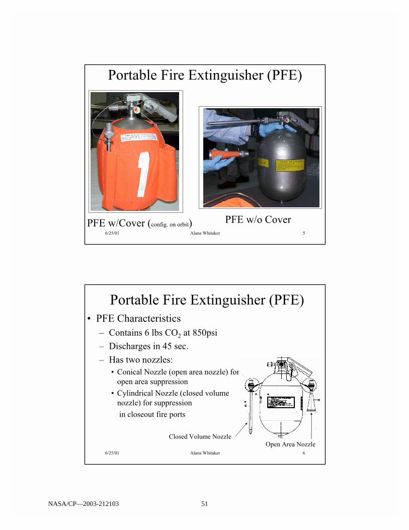
Portable Fire Extinguisher (PFE)
PFE w/Cover (config. on orbit) PFE w/o Cover
6/25/01 Alana Whitaker 6
Portable Fire Extinguisher (PFE)� PFE Characteristics
� Contains 6 lbs CO2 at 850psi
� Discharges in 45 sec.
� Has two nozzles:� Conical Nozzle (open area nozzle) for
open area suppression
� Cylindrical Nozzle (closed volume nozzle) for suppression
in closeout fire ports
Open Area NozzleClosed Volume Nozzle
NASA/CP—2003-212103 51

6/25/01 Alana Whitaker 7
PFE Cover� PFE Cover Characteristics
� Made of Nomex
� Fits snuggly to PFE
� Keeps PFE within allowable touch temp. limits during discharge (w/o Cover, PFE reaches 0 deg. F and nozzle -32
deg. F)
6/25/01 Alana Whitaker 8
Fire Suppression Ports� 1� or 0.5� diameter perforated access
ports in racks and standoffs for the cylindrical nozzle (enclosed area nozzle) to suppress fires
� O2 concentration in a rack is reduced to < 10.5% within 1 min of suppression.
Suppression port nozzle inserted Suppression port nozzle inserted into suppression portinto suppression port
NASA/CP—2003-212103 52
6/25/01 Alana Whitaker 9
Fire Suppression Testing
� Enclosed Volume Tests (cylindrical nozzle)� All CO2 sensors show > 50% concentration for
volumes 60ft3 or less
� Good mix in enclosed volumes
� Open Volume Tests (conical nozzle)� Fire is suppressed by a combination of blowing
the fire out (3 lb mass in first 10 sec) and supplying CO2.
6/25/01 Alana Whitaker 10
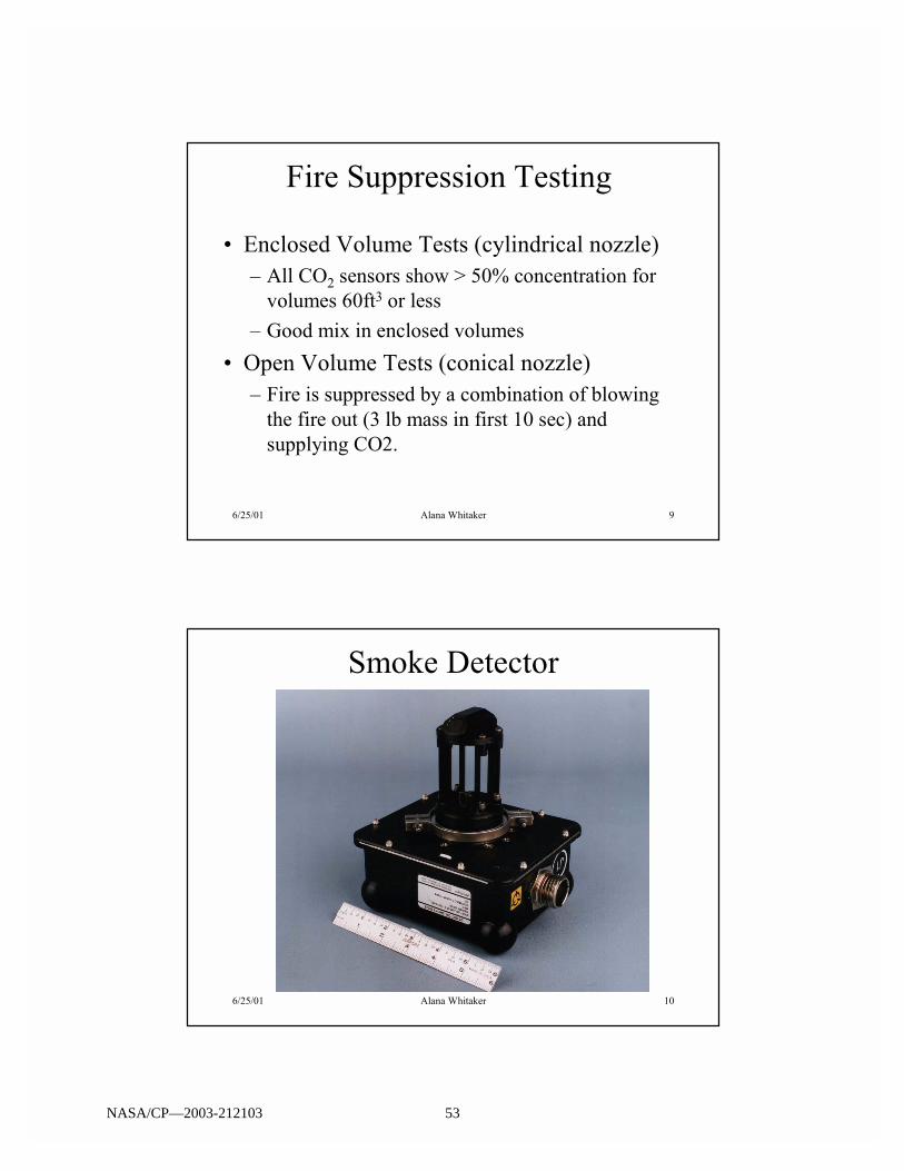
Smoke Detector
NASA/CP—2003-212103 53

6/25/01 Alana Whitaker 11
Smoke Detector
� Photoelectric Smoke Detector� Based on smoke particles scattering a light beam
� Light from a laser source is reflected by mirrors back to a photodiode (obscuration).
� Scattered light is measured by a second photodiode (scattering)
� Alarms are based on the voltage level generated by the scattering photodiode.
6/25/01 Alana Whitaker 12
Smoke Detector Principle
Airflow
El ec tr onics
Photodiodes
Scatter Path
Obscur at i on Path
Laser Diode
NASA/CP—2003-212103 54
6/25/01 Alana Whitaker 13
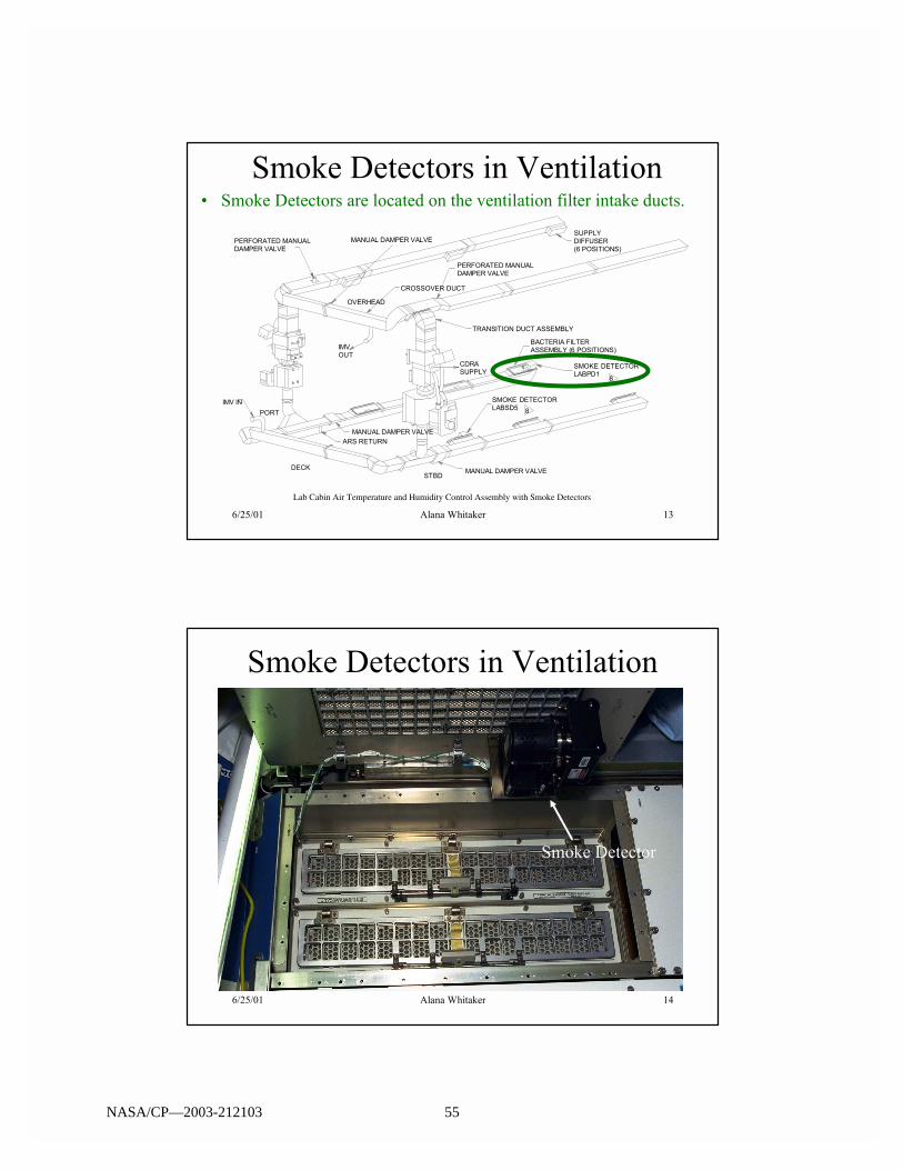
Smoke Detectors in Ventilation� Smoke Detectors are located on the ventilation filter intake ducts.
CROSSOVER DUCT
TRANSITION DUCT ASSEMBLY
PORT
STBD
OVERHEAD
SUPPLYDIFFUSER(6 POSITIONS)
BACTERIA FILTERASSEMBLY (6 POSITIONS)
CDRASUPPLY
IMVOUT
ARS RETURN
IMV IN
PERFORATED MANUALDAMPER VALVE
PERFORATED MANUALDAMPER VALVE
MANUAL DAMPER VALVE
MANUAL DAMPER VALVE
MANUAL DAMPER VALVE
DECK
SMOKE DETECTORLABPD1
SMOKE DETECTORLABSD5 8
8
Lab Cabin Air Temperature and Humidity Control Assembly with Smoke Detectors
6/25/01 Alana Whitaker 14
Smoke Detectors in Ventilation
Smoke Detector
NASA/CP—2003-212103 55

6/25/01 Alana Whitaker 15
Air Monitoring/Supply System� Air components/concentrations are monitored
by the Major Constituent Analyzer (MCA) in the LAB.� Air samples are taken from each module and
routed to the sensor (mass spec.) in the MCA.
� MCA gives percent compositions. (Typical O2
levels on ISS are slightly less than 24%.)
� Metabolic O2 and N2 are supplied from Orbiter, Service Module, and Progress
6/25/01 Alana Whitaker 16
Total and Oxygen Partial Pressure ControlNot In Campout Mode
� Pressure control when Not in Campout Mode (nominal) is done with closed-loop control� Total Pressure
� The PCPs will be taking constant (1 Hz) total pressures
� If the total pressure drops below 14.25 psia the Nitrogen Isolation Valve in the primary PCP will open
� When the total pressure >= 14.3 psia the Nitrogen Isolation Valve in the primary PCP will close
� Oxygen Partial Pressure
� The MCA will be making constant readings of the Station atmosphere
� If the oxygen partial pressure drops below 3.00 psia the Oxygen Isolation Valve in the primary PCP will be opened
� When the oxygen partial pressure >= 3.05 psia the Oxygen Isolation Valve in the primary PCP will close
NASA/CP—2003-212103 56

6/25/01 Alana Whitaker 17
Total and Oxygen Partial Pressure ControlIn Campout Mode
� While in Campout Mode, the ppO2 in the Airlock will be controlled by the following:
� If ppO2 < 2.7 psia in the Airlock, the Airlock PCA will open the PCP OIV for 4 minutes +/- 10 seconds
� If the ppO2 > 2.85 psia in the Airlock, the Airlock PCA will open the PCP NIV for 2 minutes +/- 2 seconds
� If either the PCP NIV or OIV was opened, wait 11 minutes after the valve closes
� Repeat
� Total pressure control is via manual operation of the Depress Pump
� The rest of Station will continue to control total and oxygen partial pressures in the standard method
6/25/01 Alana Whitaker 18
Portable Breathing Apparatus (PBA)
NASA/CP—2003-212103 57

6/25/01 Alana Whitaker 19
Portable Breathing Apparatus (PBA)
� PBA is composed of:� Mask
� 15 minute O2 bottle
� 30� hose
� Provides O2 to crew in emergency situations� Post-fire clean-up
� Environmental contamination
� Depressurization
6/25/01 Alana Whitaker 20
FDS System Component Location
� Node 1 � 2 area Smoke Detectors (SD), 1 (PBA), 1 (PFE)� Currently on orbit
� PFE and PBA are nominal (have not been used)� SD#1 is powered, enabled, and nominal� SD#2 is powered and disabled
� Lab � 2 area SD, 2 system rack SD (AR rack, CHeCS rack), up to 13 experiment rack SD (3 experiment rack SD at 7A), 2 PBA, 2 PFE� Currently on orbit
� PFEs and PBAs are nominal (have not been used)� 4 SDs (2 area and 2 rack) are powered, enabled, and nominal� 1 payload SD is powered, enabled, and nominal� 2 payload SDs operate intermittently based on payload operations
NASA/CP—2003-212103 58

6/25/01 Alana Whitaker 21
FDS System Component Location
� A/L � 1 area SD, 1 duct SD, 2 Pre-breathe Hose Assemblies (PHA), 3 O2 bottles, 1 PHA spares kit, 1 PFE
� MPLM � 1 duct SD, 1 PFE, 1 PBA (PBA & PFE stored in Node1 when MPLM is not attached)
6/25/01 Alana Whitaker 22
FDS System Component Location
Suppression Port
Portable Fire Extinguisher
Smoke Detector
Portable Breathing Apparatus
Visual Indicator (LED)
ISPR FDS equipment required depends onpayload and payload rack integration. Theseschematics show worst case scenario untilpayload rack designs are finalized.
1
1
LAC6DDCUs
LAC5ISPR
LAS6Mod. Temp. TCS /Cabin Air Assembly
LAC4ISPR
LAC3ISPR
LAC2ISPR
LAC1ISPR
1
LAS5MSS / Avionics
LAS4ISPR
LAS3ISPR
LAS2ISPR
1
LAS1ISPR
LAF1Avionics #2
LAF2Avionics #3
LAF3ISPR (Window)
1
LAF4Fuel Cell Water Storage
LAF5Avionics #1 / Cond.
Water Storage
LAF6ARS
(CDRA, MCA, TCCS)
LAP6Low Temp. TCS /Cabin Air Assembly
1
LAP5MSS / Avionics
LAP4ISPR
LAP3FSS / Stowage
LAP2ISPR
1
LAP1ISPR
F Node 2
A
1
Node 1
X4
X1
X2
1
X3
1
1
1 1 1
P Z
N S
A
F
N1ZStowage 1
PMA - 1
N1NStowage 2
N1SStowage 4
N1PStowage 3
Lab
Zenith Truss Cupola
Airlock Node 3
P Node 1
Equipment Lock
Crew Lock
AF1Avionics
AA1Cabin Air Assembly
Airlock
LABNode1
NASA/CP—2003-212103 59

6/25/01 Alana Whitaker 23
FDS System Capabilities
� Node 1, Lab, A/L, & MPLM FDS� Fire emergency alarm received if any single SD
FIRE status flag is set equal to �FIRE� � Scatter must exceed the fire threshold two
consecutive times, the detector then initiates an active Built In Test (BIT), and the scatter must still be exceeding the threshold after the BIT to set the status flag equal to �FIRE.�
� Location may be determined by laptop.
6/25/01 Alana Whitaker 24
FDS Automatic and Manual Response(Overview)
� In case of fire or smoke� The crew can manually push the fire alarm or the
Smoke Detectors can automatically initiate the fire alarm to perform the following functions:
1) Remove power to racks-to isolate ignition sources
2) Isolate module by shutting off ventilation (close IMVvalves, sample delivery systems, cabin fans)-to stop air flow within module and exchange between modules
3) Inhibit introduction of O2 and N2 into module (inhibit pressure control assembly in LAB)
*Crew can use PFE at their discretion*
NASA/CP—2003-212103 60

6/25/01 Alana Whitaker 25
Post Fire Atmosphere Restoration� Gaseous Contaminants removed by the following:
� SM - Micropurification Unit(БМП)� Removes 19 different gaseous contaminants using a catalytic
oxidizer (ambient) and expendable & regenerative charcoal beds.
� FGB - Harmful Impurities Filter (ФВП)� Removes gaseous trace impurities (particles of 0.5 to 300µm
to a level of 0.15 mg/m3).
� Lab - Trace Contaminant Control Subsystem (TCCS)
� Removes gaseous contaminants using a catalytic oxidizer (400ºC) and expendable sorbent and charcoal beds. Sorbent contains LiOH which can remove acid gases.
6/25/01 Alana Whitaker 26
Post Fire Atmosphere Restoration� Carbon Dioxide Removal Assembly (CDRA)
� Removes CO2 from the atmosphere that was discharged from the PFE
� Extra charcoal air filters� Scrub the environment and contain 2% Pt for CO removal.
� CO2 Removal Kit (CRK)� Consists of a portable fan assembly with a LiOH cartridge
adapter.� Can be used with LiOH or ATCO catalyst canister for CO2 or
CO removal
� Venting module to space� Only in worst case scenario
NASA/CP—2003-212103 61

6/25/01 Alana Whitaker 27
Post Fire Air Quality Assessment
� Air quality analysis done with the following equipment:� Compound-Specific Analyzer for Combustion Products
(CSA-CP)
� Carbon Dioxide Monitoring Kit (CDMK)
� Final analysis using Draeger detector tubes
� Atmospheric sampling, using GSC and AK-1 air sampling assemblies, for delivery to ground.
6/25/01 Alana Whitaker 28
FDS Research Needs� Data to support suppressant selection
� Suppressant� Effective
� Not harm ECLSS or other equipment
� No/low toxicity
� Not require extensive clean up
� Microgravity research on suppression of fire� Experiments needed on fabrics and items on orbit likely
to burn
NASA/CP—2003-212103 62

6/25/01 Alana Whitaker 29
??Questions??
Contact Info.
Alana Whitaker - NASA/JSC
ISS ECLS Subsystem Manager
Fire Detection and Suppression Systems
NASA/CP—2003-212103 63

Related Documents