Department of Mechanical Engineering College of Engineering, Pune (COEP) Forerunners in Technical Education Overview of Heat Exchanger Design Methodology Design is an activity aimed at providing complete descriptions of an engineering system, part of a system, or just of a single system component. •An unambiguous specification of the system/component structure, •size, and performance, •as well as other characteristics important for subsequent manufacturing and utilization. a well-defined design methodology must be consistent with the life-cycle design of a system

Overview of Heat Exchanger Design_Rev 1.pptx
Dec 25, 2015
Welcome message from author
This document is posted to help you gain knowledge. Please leave a comment to let me know what you think about it! Share it to your friends and learn new things together.
Transcript

Department of Mechanical Engineering
College of Engineering, Pune (COEP)Forerunners in Technical Education
Overview of Heat Exchanger Design Methodology
Design is an activity aimed at providing complete descriptions of an engineering system, part of a system, or just of a single system component.
• An unambiguous specification of the system/component structure,
• size, and performance, • as well as other characteristics important for subsequent manufacturing and utilization.
a well-defined design methodologymust be consistent with the life-cycle design of a system

Department of Mechanical Engineering
College of Engineering, Pune (COEP)Forerunners in Technical Education
2
Life-cycle design assumes considerations
• Problem formulation (including interaction with a consumer)
• Concept development (selection of workable designs, preliminary design)
• Detailed exchanger design (design calculations and other pertinent considerations)
• Manufacturing• Utilization considerations (operation, phase-out, disposal)
Department of Mechanical Engineering
College of Engineering, Pune (COEP)Forerunners in Technical Education
3
Major design considerations include:
• Process and design specifications• Thermal and hydraulic design• Mechanical design• Manufacturing considerations and cost• Trade-off factors and system-based optimization

Department of Mechanical Engineering
College of Engineering, Pune (COEP)Forerunners in Technical Education
4
Process and Design Specifications
• Problem Specifications• Exchanger Specifications

Department of Mechanical Engineering
College of Engineering, Pune (COEP)Forerunners in Technical Education
5
A. Thermal and Hydraulic Design
1. Enthalpy rate equations
2 1,j..
jjj hqq m
2. Heat transfer rate equation
ms TUAq

Department of Mechanical Engineering
College of Engineering, Pune (COEP)Forerunners in Technical Education
6
a) Heat Exchanger Thermal Design Problems
1. Rating Problem (performance or simulation problem)
Inputs:Heat exchanger construction, flow arrangement and overall dimensions, complete details on the materials and surface geometries on both sides, including their non-dimensional heat transfer and pressure drop characteristics fluid flow rates, inlet temperatures, and fouling factors.To determine:The fluid outlet temperatures, total heat transfer rate, and pressure drops on each side of the exchanger
Department of Mechanical Engineering
College of Engineering, Pune (COEP)Forerunners in Technical Education
7
Heat Exchanger Thermal Design Problems
2. Sizing Problem (Design problem)
Input: Assumption/selection of the exchanger construction type, flow arrangement, and materials etc. To Determine:Determination/selection of an exchanger construction type, flow arrangement, tube/ plate and fin material, and the physical size of an exchanger to meet the specified heat transfer and pressure drops within all specified constraints
Department of Mechanical Engineering
College of Engineering, Pune (COEP)Forerunners in Technical Education
8
b) Basic Thermal and Hydraulic Design Methods
• Formulation of dependent and independent dimensionless groups.
• Determination of relationships between dimensionless groups for different flow arrangements.
• Depending on the choice of dimensionless groups, several design methods such as ε-NTU, P-NTU, MTD correction factor etc are used.
Department of Mechanical Engineering
College of Engineering, Pune (COEP)Forerunners in Technical Education
9
c) Surface Basic Characteristics (f, Nu, Re, p, etc)
d) Surface Geometrical Properties(minimum free-flow area Ao; core frontal area Afr ; heat transfer surface area A)
e) Thermo-physical Properties (dynamic viscosity µ, density ρ, specific heat Cp, and thermal conductivity k )
f) Thermal and Hydraulic Design Problem Solution (This is achieved by employing mathematical optimization techniques after initial sizing to optimize the heat exchanger design objective function within the framework of imposed implicit and explicit constraints)

Department of Mechanical Engineering
College of Engineering, Pune (COEP)Forerunners in Technical Education
10
B. Mechanical Design
• Mechanical design is essential to ensure the mechanical integrity of the exchanger under steady-state, transient, startup, shutdown, upset, and part-load operating conditions during its design life.
• Mechanical/structural design should be performed individually for these exchanger elements.

Department of Mechanical Engineering
College of Engineering, Pune (COEP)Forerunners in Technical Education
11
Information needed• The application of the heat exchanger• The process and design information and specifications• The heat load• Information about environmental and seismic
conditions• Allowable stress limits and fatigue life data• Calculate Empty and static loading• Assess VibrationLoads: Mechanical (pressure and gravity forces), Superimposed (piping connections, support reac-tions)Operating transient and impact loads
Department of Mechanical Engineering
College of Engineering, Pune (COEP)Forerunners in Technical Education
12
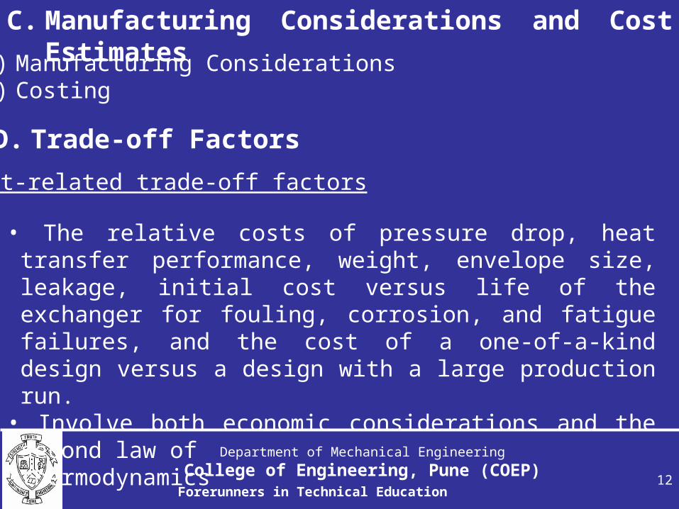
C. Manufacturing Considerations and Cost Estimatesa) Manufacturing Considerations
b) Costing
D. Trade-off Factors
Cost-related trade-off factors
• The relative costs of pressure drop, heat transfer performance, weight, envelope size, leakage, initial cost versus life of the exchanger for fouling, corrosion, and fatigue failures, and the cost of a one-of-a-kind design versus a design with a large production run.
• Involve both economic considerations and the second law of
• thermodynamics

Department of Mechanical Engineering
College of Engineering, Pune (COEP)Forerunners in Technical Education
13
D. Optimum DesignE. Other Considerations

Department of Mechanical Engineering
College of Engineering, Pune (COEP)Forerunners in Technical Education
14
Basic Thermal Design Theory for Recuperators
The determination of the MTD
In a heat exchanger, when hot and cold fluids are maintained at constant temperatures of Th and Tc the driving force for overall heat transfer in the exchanger is mean temperature difference(MTD).
(a) one fluid condensing, the other evaporating; (b) one single-phase fluid cooling, the other fluid evaporating; (c) one fluid condensing, the other single-phase fluid heating
Department of Mechanical Engineering
College of Engineering, Pune (COEP)Forerunners in Technical Education
15
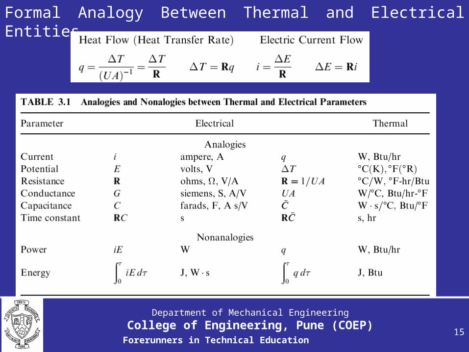
Formal Analogy Between Thermal and Electrical Entities

Department of Mechanical Engineering
College of Engineering, Pune (COEP)Forerunners in Technical Education
16
Assumptions for Heat Transfer Analysis
1. The heat exchanger operates under steady-state conditions.
2. Heat losses to or from the surroundings are negligible.
3. There are no thermal energy sources or sinks in the exchanger walls or fluids, such as electric heating, chemical reaction, or nuclear processes.
4. The temperature of each fluid is uniform over every cross section in counter flow and parallel flow exchangers (i.e., perfect transverse mixing and no temperature gradient normal to the flow direction).
5. Wall thermal resistance is distributed uniformly in the entire exchanger.

Department of Mechanical Engineering
College of Engineering, Pune (COEP)Forerunners in Technical Education
17
Assumptions for Heat Transfer Analysis
6. Either there are no phase changes (condensation or vaporization) in the fluid streams flowing through the exchanger or the phase change occurs at a constant temperature/ pressure.
7. Longitudinal heat conduction in the fluids and in the wall is negligible.
8. The individual and overall heat transfer coefficients are constant(independent of temperature, time, and position) throughout the exchanger, including the case of phase-changing fluids.
9. The specific heat of each fluid is constant throughout the exchanger, so that the heat capacity rate on each side is treated as constant.
Department of Mechanical Engineering
College of Engineering, Pune (COEP)Forerunners in Technical Education
18
Assumptions for Heat Transfer Analysis10.For an extended surface exchanger, the overall
extended surface efficiency ηo is considered uniform and constant.
11.The heat transfer surface area A is distributed uniformly on each fluid side in a single-pass or multi-pass exchanger.
12.For a plate-baffled shell-and-tube exchanger, the temperature rise (or drop) per baffle pass (or compartment) is small compared to the total temperature rise (or drop) of the shell fluid in the exchanger, so that the shell fluid can be treated as mixed at any cross section. This implies that the number of baffles is large in the exchanger.
13.The velocity and temperature at the entrance of the heat exchanger on each fluid side are uniform over the flow cross section. There is no gross flow mal-distribution at the inlet.

Department of Mechanical Engineering
College of Engineering, Pune (COEP)Forerunners in Technical Education
19
Assumptions for Heat Transfer Analysis14.The fluid flow rate is uniformly distributed through
the exchanger on each fluid side in each pass i.e., no passage-to-passage or viscosity-induced mal-distribution occurs in the exchanger core. Also, no flow stratification, flow bypassing, or flow leakages occur in any stream. The flow condition is characterized by the bulk (or mean) velocity at any cross section.

Department of Mechanical Engineering
College of Engineering, Pune (COEP)Forerunners in Technical Education
20
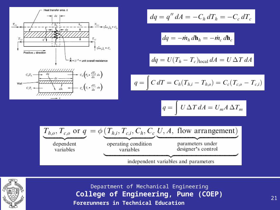
Problem Formulation
Objective:
• to relate the heat transfer rate q, • heat transfer surface area A, • heat capacity rate C of each fluid, • overall heat transfer coefficient U, • and fluid terminal temperatures.
Two basic relationships are used
(1) energy balance based on the first law of thermodynamics, and(2) rate equations for heat transfer,
Department of Mechanical Engineering
College of Engineering, Pune (COEP)Forerunners in Technical Education
21
Department of Mechanical Engineering
College of Engineering, Pune (COEP)Forerunners in Technical Education
22
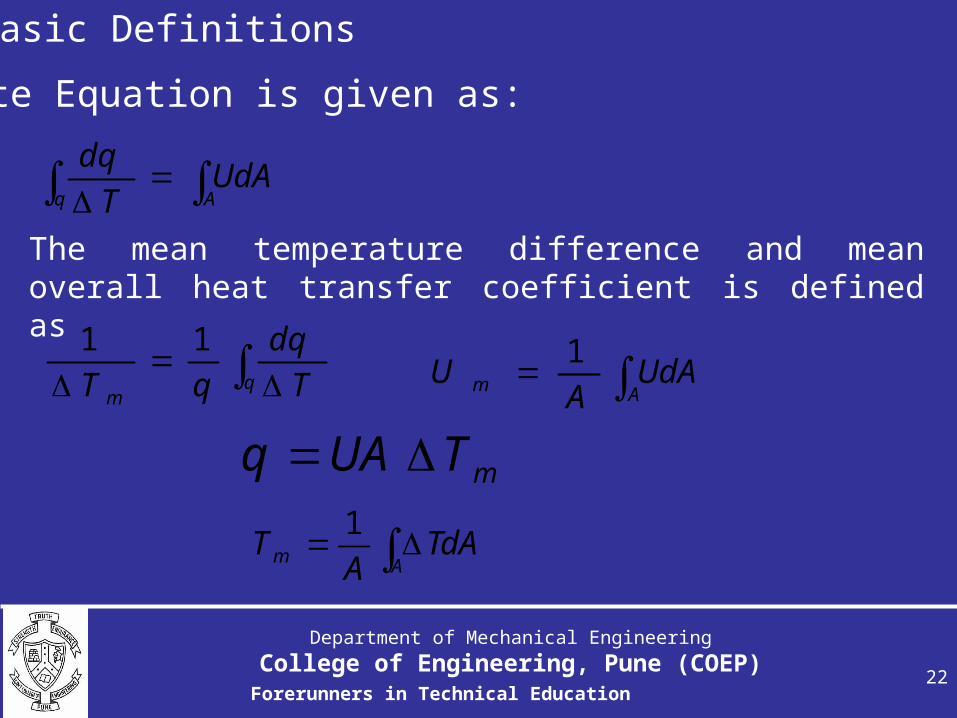
Basic Definitions
Aq
UdAT
dq
Rate Equation is given as:
The mean temperature difference and mean overall heat transfer coefficient is defined as
qm T
dq
qT
11Am UdA
AU
1
mTUAq
Am TdA
AT
1
Department of Mechanical Engineering
College of Engineering, Pune (COEP)Forerunners in Technical Education
23
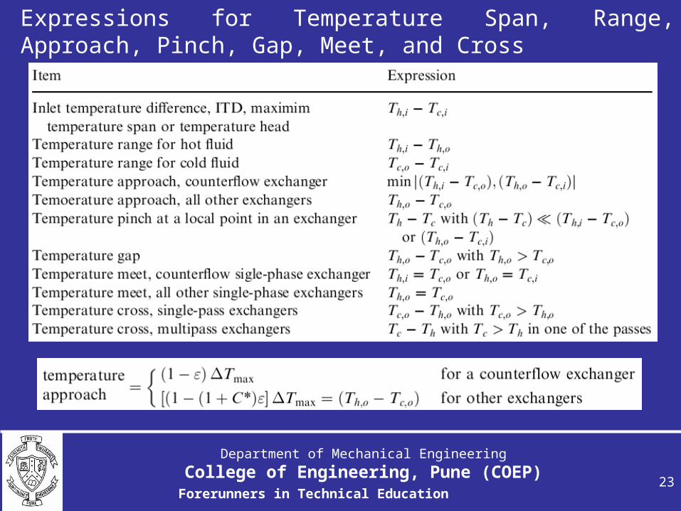
Expressions for Temperature Span, Range, Approach, Pinch, Gap, Meet, and Cross

Department of Mechanical Engineering
College of Engineering, Pune (COEP)Forerunners in Technical Education
24
Thermal Circuit and UAConsider a thermal circuit model with fouling deposit layers

Department of Mechanical Engineering
College of Engineering, Pune (COEP)Forerunners in Technical Education
25
Transfer coefficient dependences
Stanton number
The Stanton number is the ratio of the conductance to the mass velocity of the stream.
m
g.St
.StmCp
h
In practice, Stanton numbers often lie in the range 0.001-0.01. They have the significance of the ratio of the Reynolds flux to the mass flux of the mainstream.

Department of Mechanical Engineering
College of Engineering, Pune (COEP)Forerunners in Technical Education
26
Nusselt and Sherwood numbers
k
hLNuNumberNusselt c
cL
Shnumber Sherwood
Where β is mass transfer coefficient and δ is the diffusion coefficient of the species.
The friction coefficient f
.2f tcoefficien Friction
mvv

Department of Mechanical Engineering
College of Engineering, Pune (COEP)Forerunners in Technical Education
27
The friction factor for fully developed flow in a smooth-walled pipe
For laminar flow
Re
16f
For turbulent flow
2.0Re026.0 f
The famous Reynolds analogy between heat transfer and friction can be expressed by the equality
fSt

Department of Mechanical Engineering
College of Engineering, Pune (COEP)Forerunners in Technical Education
28
Reynolds and Peclet numbers
The Reynolds number measures the relative importance of the inertial stresses to the viscous stresses.
cc VLVL
Re
k
mLCpGLPenumberPeclet
.
Related Documents