1 Overview of ACCC Conductor Training, Installation and Operating Experience Executive Summary: The importance of building an efficient and reliable grid is well understood. Without it, no economy in today’s world can flourish. In order to accomplish this, utilities worldwide continue to leverage advanced, modern and highly proven technologies such as the ACCC ® conductor. Having completed the installation of over 32,000 kilometers of ACCC conductor at over 375 project sites in 35 countries, using more than 40,000 dead-ends and splices, the performance and ease of installation of ACCC conductor is well proven and internationally recognized. Currently well over 150 utilities and their customers are enjoying the commercial and technical benefits offered by the ACCC conductor’s outstanding performance, efficiency and reliability. The purpose of this paper is to share with interested parties how and why the ACCC conductor was developed and tested, how it has gained international market acceptance - in spite of initial challenges - and why it continues to be the conductor of choice for so many major utilities, worldwide. In particular, this paper will explain the ease of ACCC conductor installation given minimal training and accepted work practices. ACCC, in fact, is no more difficult to install than a conventional steel core or homogeneous all-aluminum conductor. The facts show that after initial training and first project completion, many crew workers who were provided with CTC Global training and given suitable (standard) equipment have often commented as to how much easier ACCC is to install compared to other common steel reinforced conductors or optical ground wire (OPGW). While installation incidents have occurred due to improper stringing methods or equipment failures, they will be discussed and described so the reader can recognize how these types of incidents can be easily avoided. Finally, a number of in-service events will also be discussed which will offer additional clarification as to how robust and reliable the ACCC conductor is in-service and during extreme events. Background: Between 2000 and 2002, the Western United States experienced an energy crisis of epic proportion. Wholesale energy prices rose by as much as 800 percent. While market manipulation played a role, congested transmission lines prevented utilities from procuring alternate and less expensive sources of generation. The situation bankrupted Pacific Gas & Electric and almost bankrupted Southern California Edison. Several industrial customers shut down or curtailed their operations and the economic impact in California alone was measured in billions of dollars. 1 The following year, on August 14, 2003, the Northeast United States and Ontario Canada experienced the second most widespread blackout on record at that time (after Brazil in 1999), affecting 55 million people. 2 Six weeks later, on September 28, 2003, a similar outage occurred 1 http://www.ferc.gov/industries/electric/indus-act/wec/chron/chronology.pdf 2 http://www.nerc.com/docs/docs/blackout/NERC_Final_Blackout_Report_07_13_04.pdf

Welcome message from author
This document is posted to help you gain knowledge. Please leave a comment to let me know what you think about it! Share it to your friends and learn new things together.
Transcript
1
Overview of ACCC Conductor
Training, Installation and Operating Experience Executive Summary: The importance of building an efficient and reliable grid is well understood. Without it, no economy in today’s world can flourish. In order to accomplish this, utilities worldwide continue to leverage advanced, modern and highly proven technologies such as the ACCC® conductor. Having completed the installation of over 32,000 kilometers of ACCC conductor at over 375 project sites in 35 countries, using more than 40,000 dead-ends and splices, the performance and ease of installation of ACCC conductor is well proven and internationally recognized. Currently well over 150 utilities and their customers are enjoying the commercial and technical benefits offered by the ACCC conductor’s outstanding performance, efficiency and reliability. The purpose of this paper is to share with interested parties how and why the ACCC conductor was developed and tested, how it has gained international market acceptance - in spite of initial challenges - and why it continues to be the conductor of choice for so many major utilities, worldwide. In particular, this paper will explain the ease of ACCC conductor installation given minimal training and accepted work practices. ACCC, in fact, is no more difficult to install than a conventional steel core or homogeneous all-aluminum conductor. The facts show that after initial training and first project completion, many crew workers who were provided with CTC Global training and given suitable (standard) equipment have often commented as to how much easier ACCC is to install compared to other common steel reinforced conductors or optical ground wire (OPGW). While installation incidents have occurred due to improper stringing methods or equipment failures, they will be discussed and described so the reader can recognize how these types of incidents can be easily avoided. Finally, a number of in-service events will also be discussed which will offer additional clarification as to how robust and reliable the ACCC conductor is in-service and during extreme events. Background: Between 2000 and 2002, the Western United States experienced an energy crisis of epic proportion. Wholesale energy prices rose by as much as 800 percent. While market manipulation played a role, congested transmission lines prevented utilities from procuring alternate and less expensive sources of generation. The situation bankrupted Pacific Gas & Electric and almost bankrupted Southern California Edison. Several industrial customers shut down or curtailed their operations and the economic impact in California alone was measured in billions of dollars.1 The following year, on August 14, 2003, the Northeast United States and Ontario Canada experienced the second most widespread blackout on record at that time (after Brazil in 1999), affecting 55 million people.2 Six weeks later, on September 28, 2003, a similar outage occurred
1 http://www.ferc.gov/industries/electric/indus-act/wec/chron/chronology.pdf 2 http://www.nerc.com/docs/docs/blackout/NERC_Final_Blackout_Report_07_13_04.pdf
2
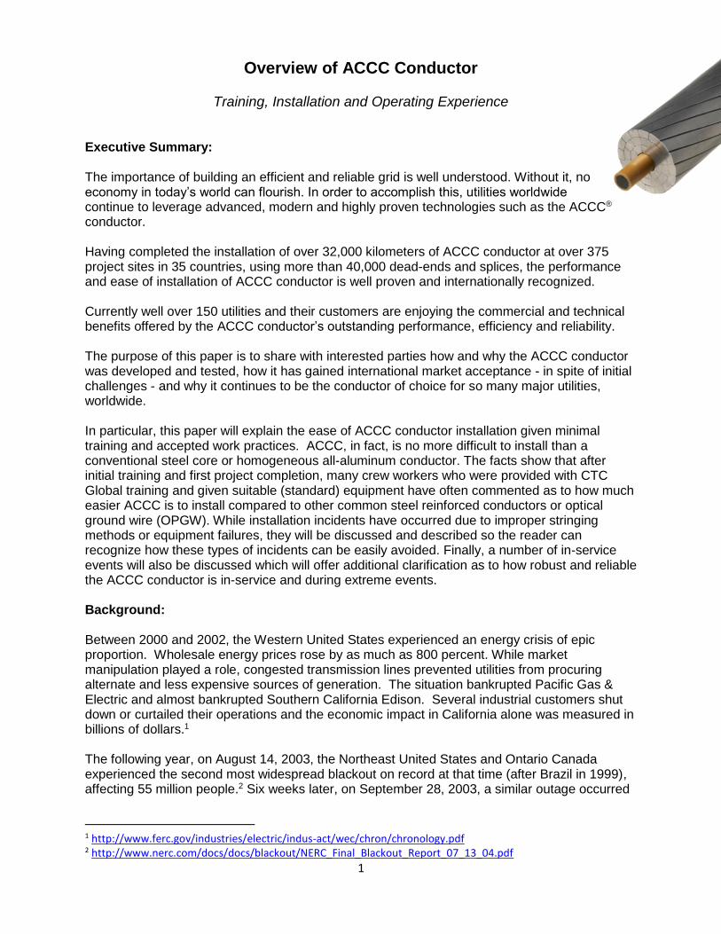
in Europe which affected 56 million people.3 According to the final NERC report, the US/Canada blackout of August 2003 was caused by a number of factors. This included inaccurate telemetry data used to operate the Midwest Independent Transmission System Operator (MISO) “State Estimator” (and a subsequent computer re-boot failure); a “race condition” computer bug in FirstEnergy’s Energy Management System; and three 345 kV transmission line trips (outages) due to excessive conductor sag, which led to a cascading of similar sag-trip outages on their 138 kV system. These events and lack of effective communication between other utilities ultimately shut down 508 generating units at 265 power plants. The economic impact exceeded 10 billion dollars. During this timeframe, CTC Global (formerly Composite Technology Corporation) of Irvine, California, focused their material science expertise on developing a high-capacity, low-sag conductor to help the utilities improve grid capacity and reliability by reducing thermal sag. Essentially, CTC recognized the numerous advantages of hybrid carbon fiber composite materials and developed a product to replace the steel core used in several bare overhead conductor types such as ACSR, ACSS, Invar (a steel/nickel alloy), GAP and others.
Figure 1 – Comparison of several conductor types
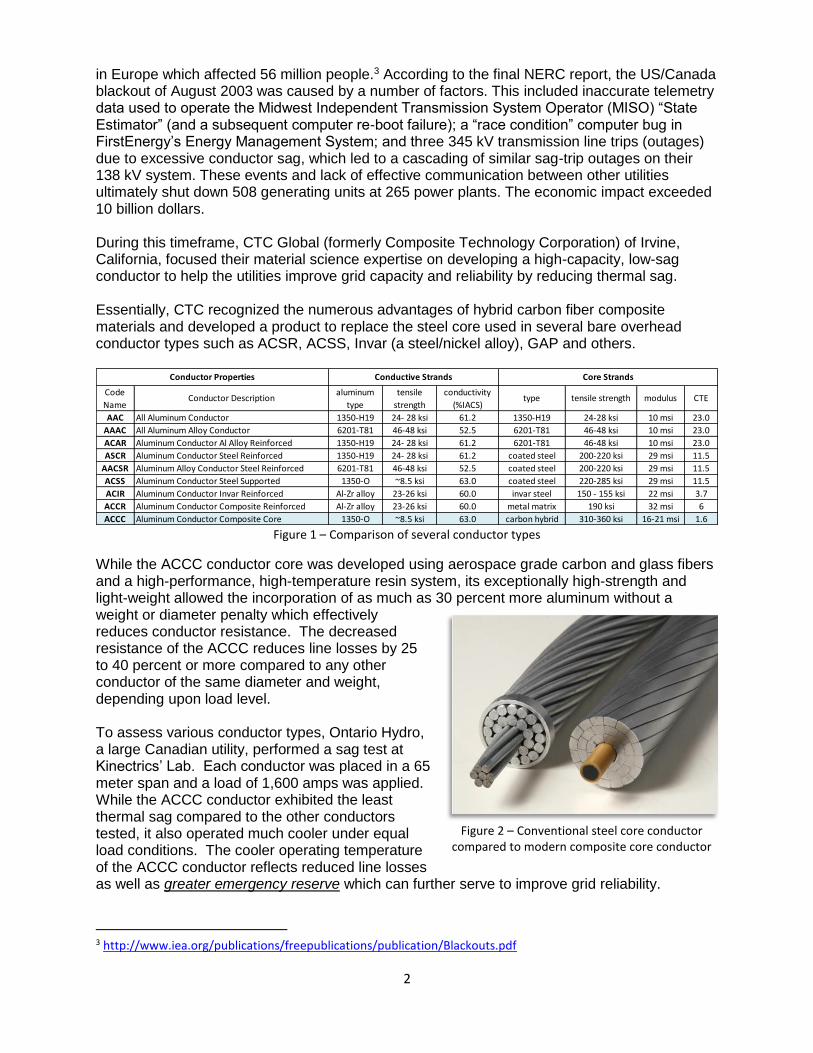
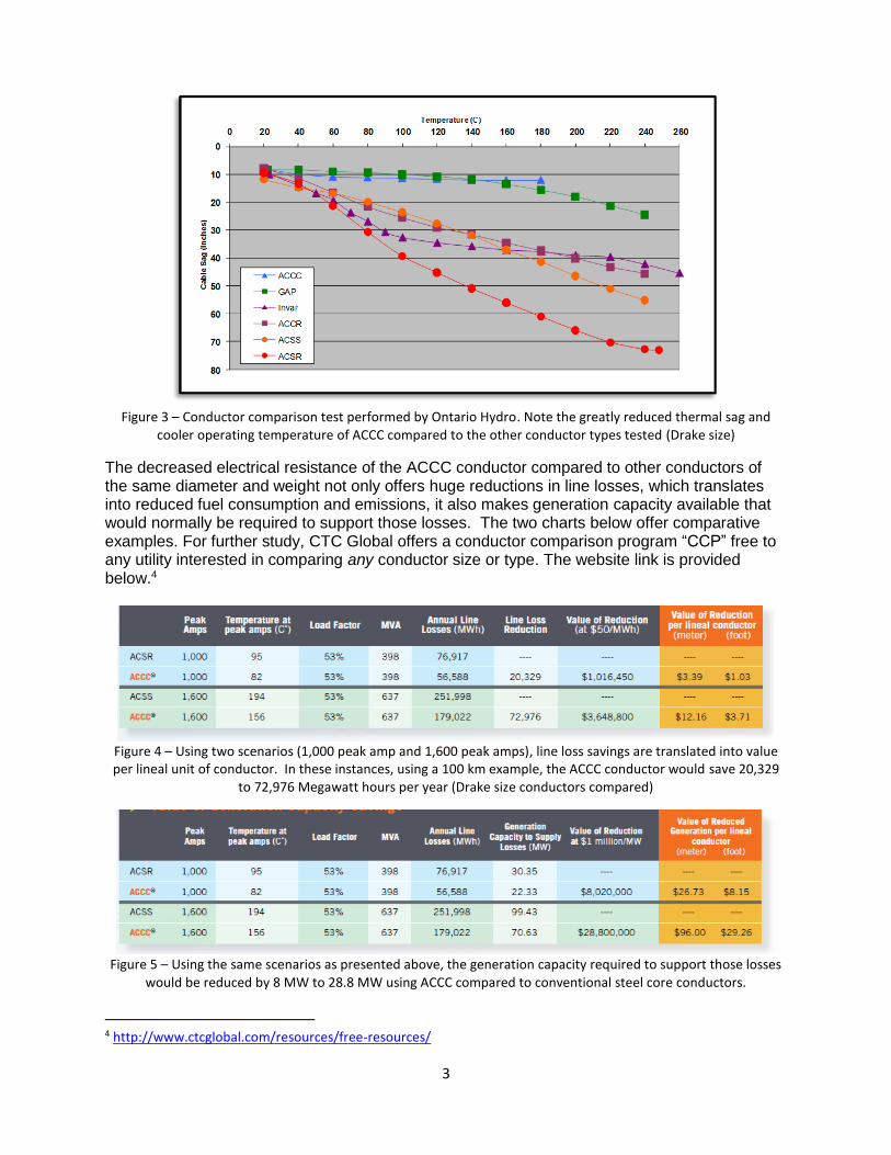
While the ACCC conductor core was developed using aerospace grade carbon and glass fibers and a high-performance, high-temperature resin system, its exceptionally high-strength and light-weight allowed the incorporation of as much as 30 percent more aluminum without a weight or diameter penalty which effectively reduces conductor resistance. The decreased resistance of the ACCC reduces line losses by 25 to 40 percent or more compared to any other conductor of the same diameter and weight, depending upon load level. To assess various conductor types, Ontario Hydro, a large Canadian utility, performed a sag test at Kinectrics’ Lab. Each conductor was placed in a 65 meter span and a load of 1,600 amps was applied. While the ACCC conductor exhibited the least thermal sag compared to the other conductors tested, it also operated much cooler under equal load conditions. The cooler operating temperature of the ACCC conductor reflects reduced line losses as well as greater emergency reserve which can further serve to improve grid reliability.
3 http://www.iea.org/publications/freepublications/publication/Blackouts.pdf
AAC All Aluminum Conductor 1350-H19 24- 28 ksi 61.2 1350-H19 24-28 ksi 10 msi 23.0
AAAC All Aluminum Alloy Conductor 6201-T81 46-48 ksi 52.5 6201-T81 46-48 ksi 10 msi 23.0
ACAR Aluminum Conductor Al Alloy Reinforced 1350-H19 24- 28 ksi 61.2 6201-T81 46-48 ksi 10 msi 23.0
ASCR Aluminum Conductor Steel Reinforced 1350-H19 24- 28 ksi 61.2 coated steel 200-220 ksi 29 msi 11.5
AACSR Aluminum Alloy Conductor Steel Reinforced 6201-T81 46-48 ksi 52.5 coated steel 200-220 ksi 29 msi 11.5
ACSS Aluminum Conductor Steel Supported 1350-O ~8.5 ksi 63.0 coated steel 220-285 ksi 29 msi 11.5
ACIR Aluminum Conductor Invar Reinforced Al-Zr alloy 23-26 ksi 60.0 invar steel 150 - 155 ksi 22 msi 3.7
ACCR Aluminum Conductor Composite Reinforced Al-Zr alloy 23-26 ksi 60.0 metal matrix 190 ksi 32 msi 6
ACCC Aluminum Conductor Composite Core 1350-O ~8.5 ksi 63.0 carbon hybrid 310-360 ksi 16-21 msi 1.6
Conductive StrandsConductor Properties
aluminum
type
tensile
strength
conductivity
(%IACS)
Code
NameConductor Description type tensile strength modulus CTE
Core Strands
Figure 2 – Conventional steel core conductor compared to modern composite core conductor
3
Figure 3 – Conductor comparison test performed by Ontario Hydro. Note the greatly reduced thermal sag and
cooler operating temperature of ACCC compared to the other conductor types tested (Drake size)
The decreased electrical resistance of the ACCC conductor compared to other conductors of the same diameter and weight not only offers huge reductions in line losses, which translates into reduced fuel consumption and emissions, it also makes generation capacity available that would normally be required to support those losses. The two charts below offer comparative examples. For further study, CTC Global offers a conductor comparison program “CCP” free to any utility interested in comparing any conductor size or type. The website link is provided below.4
Figure 4 – Using two scenarios (1,000 peak amp and 1,600 peak amps), line loss savings are translated into value per lineal unit of conductor. In these instances, using a 100 km example, the ACCC conductor would save 20,329
to 72,976 Megawatt hours per year (Drake size conductors compared)
Figure 5 – Using the same scenarios as presented above, the generation capacity required to support those losses
would be reduced by 8 MW to 28.8 MW using ACCC compared to conventional steel core conductors.
4 http://www.ctcglobal.com/resources/free-resources/
4
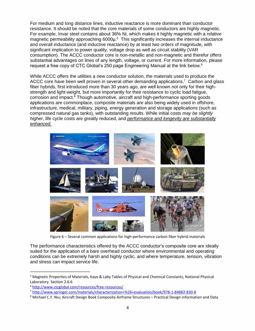
For medium and long distance lines, inductive reactance is more dominant than conductor resistance. It should be noted that the core materials of some conductors are highly magnetic. For example, Invar steel contains about 36% Ni, which makes it highly magnetic with a relative magnetic permeability approaching 6000μ.5 This significantly increases the internal inductance and overall inductance (and inductive reactance) by at least two orders of magnitude, with significant implication to power quality, voltage drop as well as circuit stability (VAR consumption). The ACCC conductor core is non-metallic and non-magnetic and therefor offers substantial advantages on lines of any length, voltage, or current. For more information, please request a free copy of CTC Global’s 250 page Engineering Manual at the link below.6 While ACCC offers the utilities a new conductor solution, the materials used to produce the ACCC core have been well proven in several other demanding applications.7 Carbon and glass fiber hybrids, first introduced more than 30 years ago, are well known not only for their high-strength and light-weight, but more importantly for their resistance to cyclic load fatigue, corrosion and impact.8 Though automotive, aircraft and high-performance sporting goods applications are commonplace, composite materials are also being widely used in offshore, infrastructure, medical, military, piping, energy generation and storage applications (such as compressed natural gas tanks), with outstanding results. While initial costs may be slightly higher, life cycle costs are greatly reduced, and performance and longevity are substantially enhanced.
Figure 6 – Several common applications for high-performance carbon fiber hybrid materials
The performance characteristics offered by the ACCC conductor’s composite core are ideally suited for the application of a bare overhead conductor where environmental and operating conditions can be extremely harsh and highly cyclic, and where temperature, tension, vibration and stress can impact service life.
5 Magnetic Properties of Materials, Kaye & Laby Tables of Physical and Chemical Constants, National Physical Laboratory. Section 2.6.6 6 http://www.ctcglobal.com/resources/free-resources/ 7 http://www.springer.com/materials/characterization+%26+evaluation/book/978-1-84882-830-8 8 Michael C.Y. Niu; Aircraft Design Book Composite Airframe Structures – Practical Design information and Data
5
Product Certification & Testing: The ACCC conductor, developed, internationally patented and commercialized by CTC Global, and produced in association with more than 20 international manufacturing partners, has been extensively tested by several utilities, government agencies and independent labs, globally. The data gathered has not only confirmed the ACCC conductor’s performance attributes, it has also offered a wealth of understanding regarding its toughness and longevity. The list below offers insight into the substantial amount of testing performed. This testing was often repeated on different ACCC conductor and core sizes and repeated at a number of labs in the US, UK, France, Canada, Mexico, China, Brazil, Chile, Belgium, Indonesia, Korea, Germany and other locations.
Core Testing: 2.2.42 Cyclic Thermo-Mechanical Testing
2.1.1 Tensile Testing 2.2.43 Combined Cyclic Load Testing
2.1.2 Flexural, Bending & Shear Tests 2.2.44 Conductor Comparison Testing
2.1.3 Sustained Load Tests
2.1.4 Tg Tests Systems & Hardware Testing:
2.1.5 CTE Measurements 2.4.55 Current Cycle Testing
2.1.6 Shear Testing 2.4.56 Sustained Load Testing
2.1.7 Impact and Crush Testing 2.4.57 Ultimate Assembly Strength Testing
2.1.8 Torsion Testing 2.4.58 Salt Fog Emersion Testing
2.1.9 Notched Degradation Testing 2.4.60 Static Heat Tests
2.1.10 Moisture Resistance Testing 2.4.61 Suspension Clamp Testing
2.1.11 Long Term Thermal Testing 2.4.62 Thermo-Mechanical Testing
2.1.12 Sustained Load Thermal Testing 2.4.63 Cyclic Load Testing
2.1.13 Cyclic Thermal Testing
2.1.14 Specific Heat Capacity Testing Electrical Conductor Testing:
2.1.15 High Temperature Short Duration 2.3.45 Resistivity Testing
2.1.16 High Temperature Core Testing 2.3.46 Power Loss Comparison Testing
2.1.17 Thermal Oxidation Testing 2.3.47 Ampacity
2.1.18 Brittle Fracture Testing 2.3.48 EMF Measurements
2.1.19 UV Testing 2.3.49 Impedance Comparison Testing
2.1.20 Salt Fog Exposure Tests 2.3.50 Corona Testing
2.1.21 Creep Tests 2.3.51 Radio Noise Testing
2.1.22 Stress Strain Testing 2.3.52 Short Circuit Testing
2.1.24 Micrographic Analysis 2.3.53 Lightning Strike Testing
2.1.25 Dye Penetrant Testing 2.3.54 Ultra High Voltage AC & DC Testing
2.1.26 High Temperature Shear Testing
2.1.27 Low Temperature Shear Testing Field Testing:
2.5.64 Ambient Temperature
Mechanical Conductor Testing: 2.5.65 Tension, Sag, and Clearance
2.2.28 Stress Strain Testing 2.5.66 Conductor Temperature
2.2.29 Creep Testing 2.5.67 Electric Current
2.2.30 Aeolian Vibration Testing 2.5.68 Wind Speed and Direction
2.2.31 Galloping Tests 2.5.69 Solar Radiation
2.2.32 Self Damping Tests 2.5.70 Rainfall
2.2.33 Radial Impact and Crush Tests 2.5.71 Ice Buildup
6
2.2.34 Turning Angle Tests 2.5.72 Splice Resistance
2.2.35 Torsion Tests 2.5.73 Infrared Measurements
2.2.36 High Temperature Sag Tests 2.5.74 Corona Observations
2.2.37 High Temperature Sustained Load 2.5.75 Electric and Magnetic Fields
2.2.38 High Temperature Cyclic Load Tests 2.5.76 Wind and Ice Load Measurements
2.2.39 Cyclic Ice Load Tests 2.5.77 Vibration Monitoring
2.2.40 Sheave Wheel Tests 2.5.78 Typhoon Test
2.2.41 Ultimate Strength Tests 2.5.79 Tornado Test
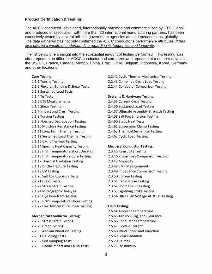
Figure 7 – A few photographs taken during various lab tests
As a function of product development, lab testing began in early 2003. It included core testing, finished conductor testing, hardware and system testing, as well as longevity testing. The testing utilized a number of industry standard protocols as well as several new protocols designed by a number of utilities and labs. CTC offers a complete package of test reports / certification documents and can also provide a summary document that explains the purpose and outcome of these tests. CTC Global, and all of its manufacturing partners, are fully certified and audited to ISO 9001-2000 standards. Details regarding quality assurance procedures and system are available upon request. One example of a unique test protocol developed by a utility to assess longevity was American Electric Power’s (AEP’s) Sequential Mechanical Test. The test was designed to compare a number of conductor types. The conductors were subjected to bending tests to replicate installation stresses, followed by 100 thousand cycles of galloping and 100 million cycles of vibration to replicate stresses anticipated over their service lives.
7
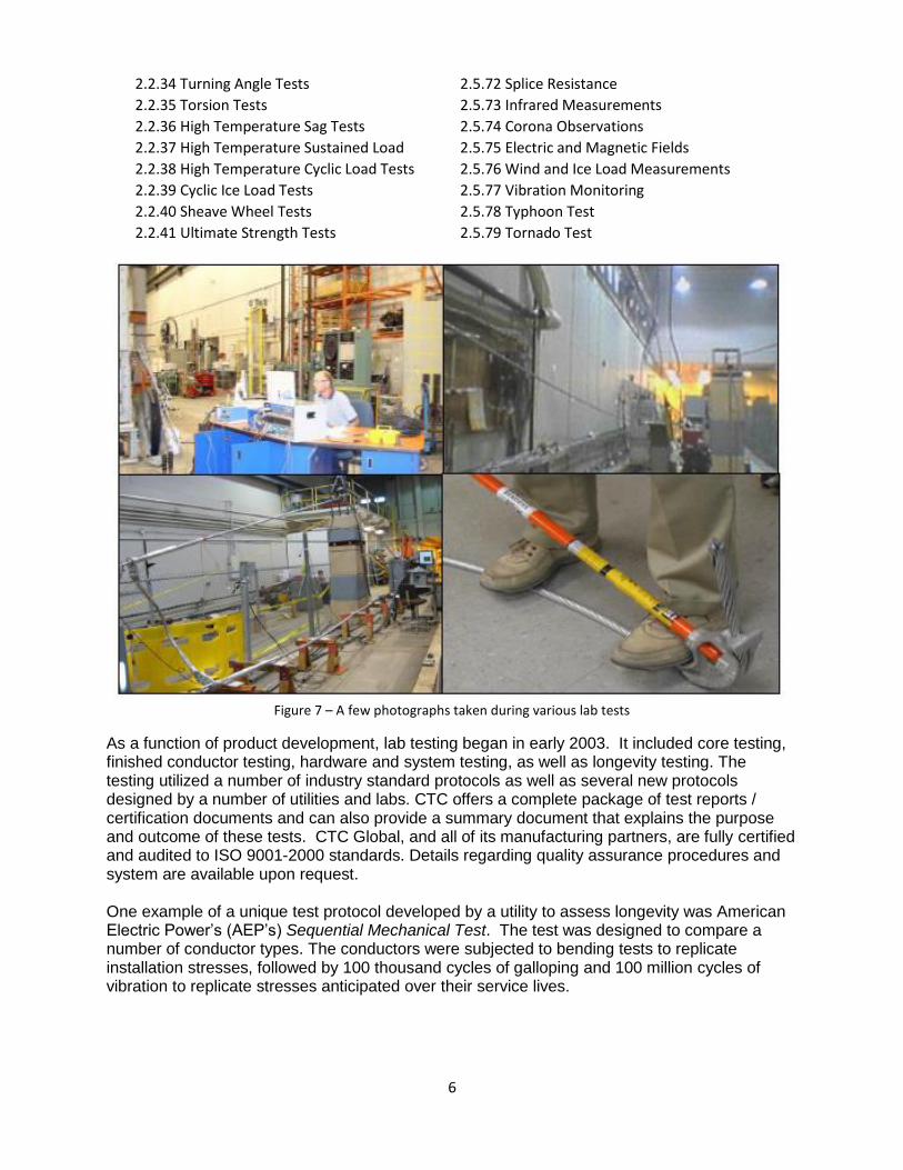
Figure 8 – Fatigue of steel reinforced conductors during AEP’s sequential test. ACCC was not impacted
While the steel core conductors tested showed fatigue failure and broken strands, the ACCC conductor was unscathed. The confidence gained, in spite of some difficulties encountered during AEP’s first installation (discussed below), allowed AEP to not only successfully complete their first installation, it also allowed them to complete seven additional installations without incident. Currently AEP is working on their ninth installation, where they are using ACCC to replacing 386 circuit kilometers (240 miles) of a double-bundled 345 kV line while it remains energized. When complete, the project will utilize over 2,600 kilometers (1,660 miles) of ACCC conductor.9 Training & Field Experience: While lab testing is a critical component of product development, technology advancement, and longevity assessment, training and field experience also play important roles in technology adoption and the development of safe installation procedures. While the ACCC conductor and ancillary components such as dead-ends and splices were developed to be installed using the widely accepted IEEE 524 installation guidelines,10 in some cases, environmental conditions, staff experience, equipment availability / condition and other factors can add unique challenges.
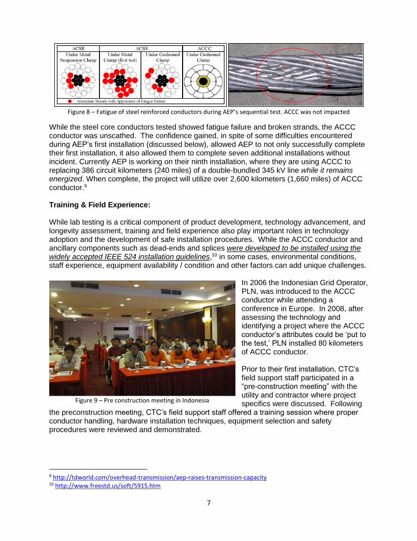
In 2006 the Indonesian Grid Operator, PLN, was introduced to the ACCC conductor while attending a conference in Europe. In 2008, after assessing the technology and identifying a project where the ACCC conductor’s attributes could be ‘put to the test,’ PLN installed 80 kilometers of ACCC conductor. Prior to their first installation, CTC’s field support staff participated in a “pre-construction meeting” with the utility and contractor where project specifics were discussed. Following
the preconstruction meeting, CTC’s field support staff offered a training session where proper conductor handling, hardware installation techniques, equipment selection and safety procedures were reviewed and demonstrated.
9 http://tdworld.com/overhead-transmission/aep-raises-transmission-capacity 10 http://www.freestd.us/soft/5915.htm
Figure 9 – Pre construction meeting in Indonesia
8
Once the crews, equipment and materials arrived at the project site, CTC’s field support staff engaged all crew members with additional training. As the project began, CTC’s staff remained on-site to monitor the project, offer support and help overcome the occasional challenge. After the installation was completed and the line energized, a post construction meeting took place were field experiences were discussed. All participants learned from the experience including CTC’s field support staff who gained knowledge about the environment, working conditions, contractor skill sets, and local practices. In 2009 and 2010, PLN completed three additional projects where previous experience was put to good use and the discussions, training sessions and installation practices all benefited. Following each installation, all members of the crews received certificates of completion from CTC. In 2011, six more projects were successfully completed. In 2012, twelve additional projects were completed. At this point, PLN now has twelve construction companies fully experienced installing ACCC conductor and CTC field support is rarely required. To date, PLN’s contractors have successfully installed over 7,000 km of ACCC conductor at 36 project sites.
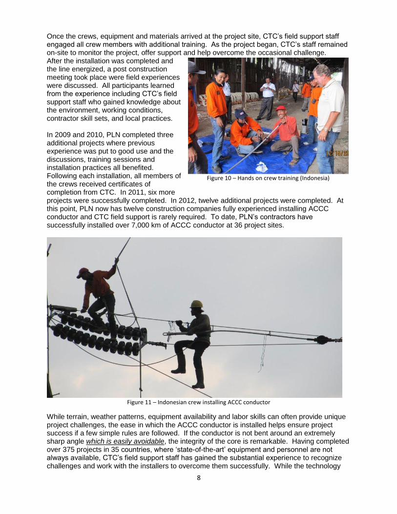
Figure 11 – Indonesian crew installing ACCC conductor
While terrain, weather patterns, equipment availability and labor skills can often provide unique project challenges, the ease in which the ACCC conductor is installed helps ensure project success if a few simple rules are followed. If the conductor is not bent around an extremely sharp angle which is easily avoidable, the integrity of the core is remarkable. Having completed over 375 projects in 35 countries, where ‘state-of-the-art’ equipment and personnel are not always available, CTC’s field support staff has gained the substantial experience to recognize challenges and work with the installers to overcome them successfully. While the technology
Figure 10 – Hands on crew training (Indonesia)
9
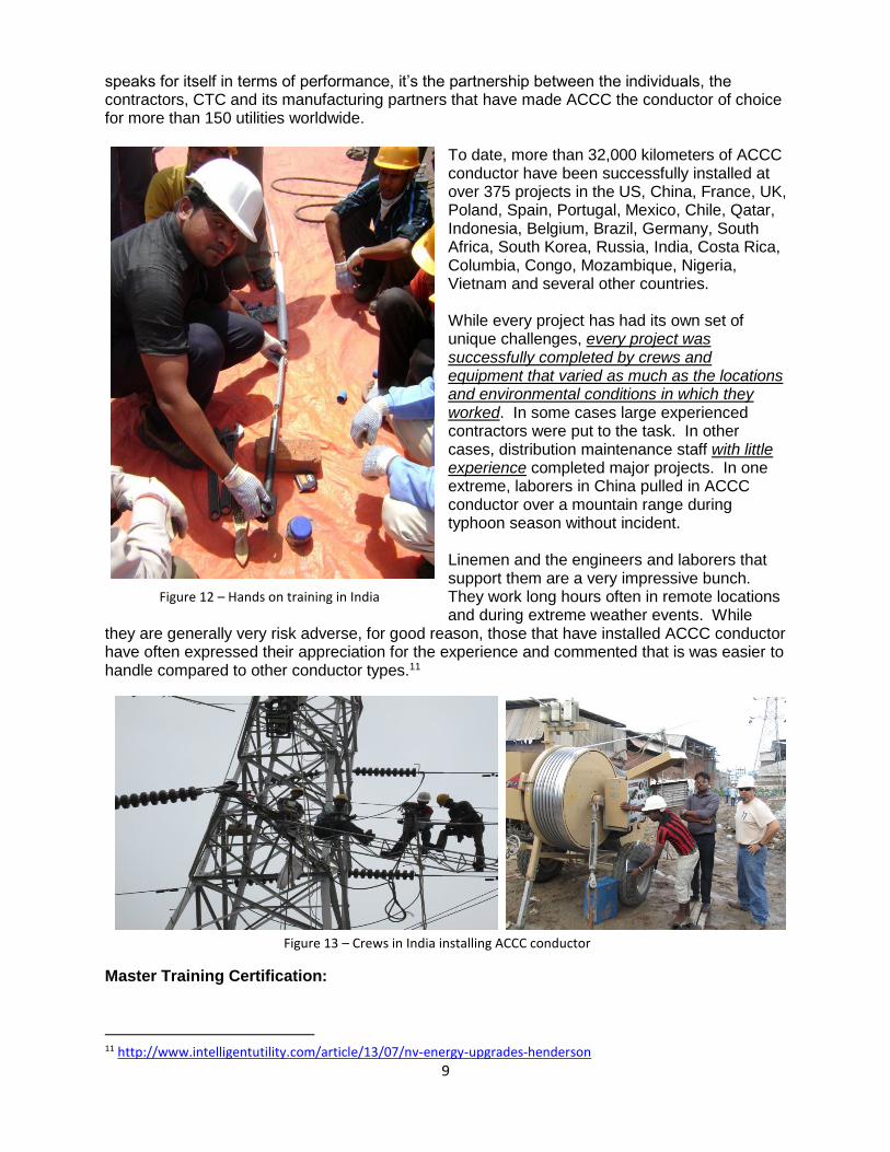
speaks for itself in terms of performance, it’s the partnership between the individuals, the contractors, CTC and its manufacturing partners that have made ACCC the conductor of choice for more than 150 utilities worldwide.
To date, more than 32,000 kilometers of ACCC conductor have been successfully installed at over 375 projects in the US, China, France, UK, Poland, Spain, Portugal, Mexico, Chile, Qatar, Indonesia, Belgium, Brazil, Germany, South Africa, South Korea, Russia, India, Costa Rica, Columbia, Congo, Mozambique, Nigeria, Vietnam and several other countries. While every project has had its own set of unique challenges, every project was successfully completed by crews and equipment that varied as much as the locations and environmental conditions in which they worked. In some cases large experienced contractors were put to the task. In other cases, distribution maintenance staff with little experience completed major projects. In one extreme, laborers in China pulled in ACCC conductor over a mountain range during typhoon season without incident. Linemen and the engineers and laborers that support them are a very impressive bunch. They work long hours often in remote locations and during extreme weather events. While
they are generally very risk adverse, for good reason, those that have installed ACCC conductor have often expressed their appreciation for the experience and commented that is was easier to handle compared to other conductor types.11
Master Training Certification:
11 http://www.intelligentutility.com/article/13/07/nv-energy-upgrades-henderson
Figure 12 – Hands on training in India
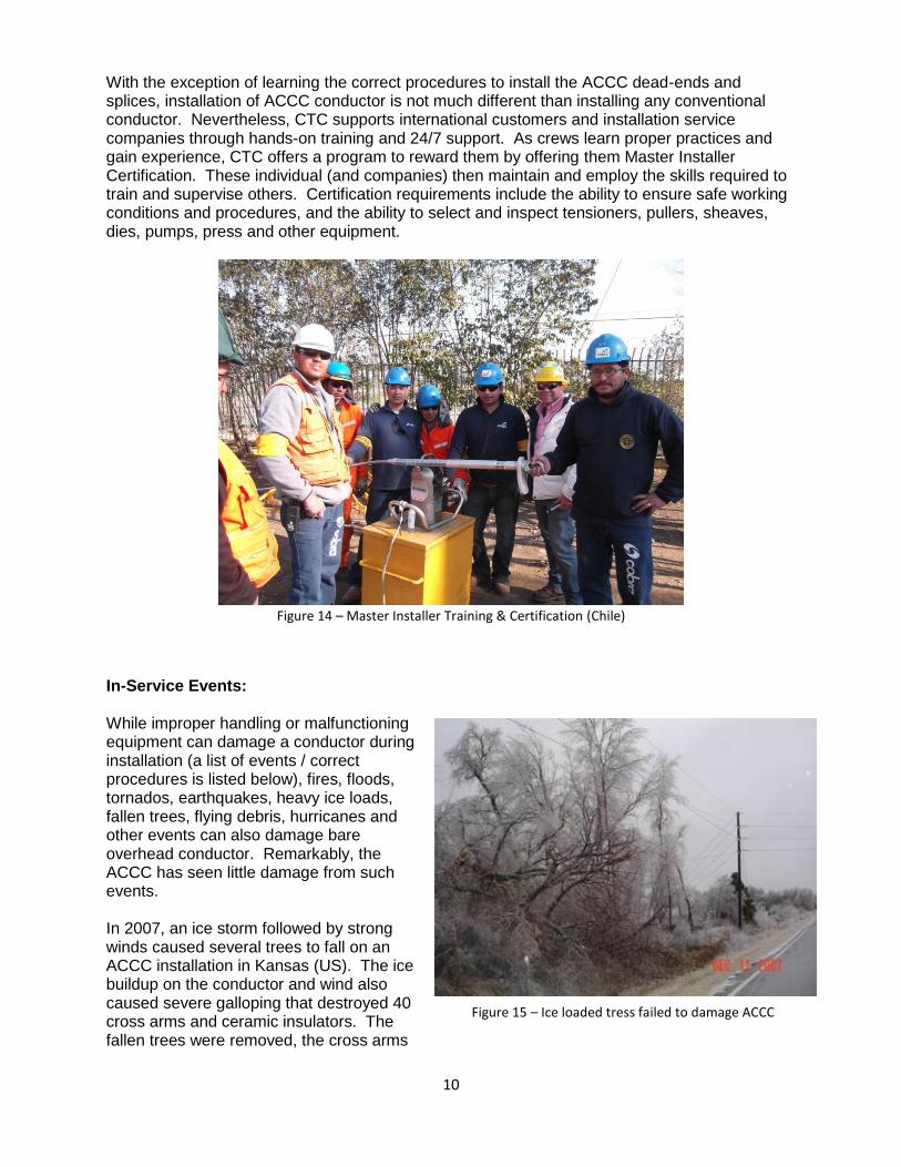
Figure 13 – Crews in India installing ACCC conductor
10
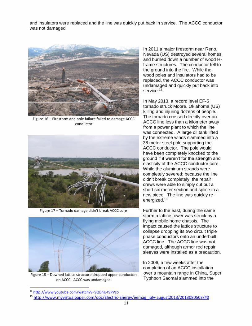
With the exception of learning the correct procedures to install the ACCC dead-ends and splices, installation of ACCC conductor is not much different than installing any conventional conductor. Nevertheless, CTC supports international customers and installation service companies through hands-on training and 24/7 support. As crews learn proper practices and gain experience, CTC offers a program to reward them by offering them Master Installer Certification. These individual (and companies) then maintain and employ the skills required to train and supervise others. Certification requirements include the ability to ensure safe working conditions and procedures, and the ability to select and inspect tensioners, pullers, sheaves, dies, pumps, press and other equipment.
Figure 14 – Master Installer Training & Certification (Chile)
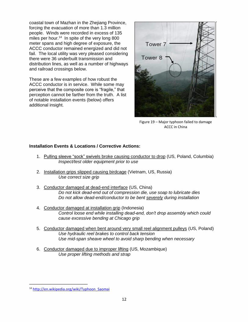
In-Service Events: While improper handling or malfunctioning equipment can damage a conductor during installation (a list of events / correct procedures is listed below), fires, floods, tornados, earthquakes, heavy ice loads, fallen trees, flying debris, hurricanes and other events can also damage bare overhead conductor. Remarkably, the ACCC has seen little damage from such events. In 2007, an ice storm followed by strong winds caused several trees to fall on an ACCC installation in Kansas (US). The ice buildup on the conductor and wind also caused severe galloping that destroyed 40 cross arms and ceramic insulators. The fallen trees were removed, the cross arms
Figure 15 – Ice loaded tress failed to damage ACCC
11
and insulators were replaced and the line was quickly put back in service. The ACCC conductor was not damaged.
In 2011 a major firestorm near Reno, Nevada (US) destroyed several homes and burned down a number of wood H-frame structures. The conductor fell to the ground into the fire. While the wood poles and insulators had to be replaced, the ACCC conductor was undamaged and quickly put back into service.12 In May 2013, a record level EF-5 tornado struck Moore, Oklahoma (US) killing and injuring dozens of people. The tornado crossed directly over an ACCC line less than a kilometer away from a power plant to which the line was connected. A large oil tank lifted by the extreme winds slammed into a 38 meter steel pole supporting the ACCC conductor. The pole would have been completely knocked to the ground if it weren’t for the strength and elasticity of the ACCC conductor core. While the aluminum strands were completely severed; because the line didn’t break completely; the repair crews were able to simply cut out a short six meter section and splice in a new piece. The line was quickly re-energized.13 Further to the east, during the same storm a lattice tower was struck by a flying mobile home chassis. The impact caused the lattice structure to collapse dropping its two circuit triple phase conductors onto an underbuilt ACCC line. The ACCC line was not damaged, although armor rod repair sleeves were installed as a precaution. In 2006, a few weeks after the completion of an ACCC installation over a mountain range in China, Super Typhoon Saomai slammed into the
12 http://www.youtube.com/watch?v=9QBhU49PVzo 13 http://www.myvirtualpaper.com/doc/Electric-Energy/eemag_july-august2013/2013080503/#0
Figure 16 – Firestorm and pole failure failed to damage ACCC conductor
Figure 17 – Tornado damage didn’t break ACCC core
Figure 18 – Downed lattice structure dropped upper conductors on ACCC. ACCC was undamaged.
12
coastal town of Mazhan in the Zhejiang Province, forcing the evacuation of more than 1.3 million people. Winds were recorded in excess of 135 miles per hour.14 In spite of the very long 800 meter spans and high degree of exposure, the ACCC conductor remained energized and did not fail. The local utility was very pleased considering there were 36 underbuilt transmission and distribution lines, as well as a number of highways and railroad crossings below. These are a few examples of how robust the ACCC conductor is in service. While some may perceive that the composite core is “fragile,” that perception cannot be farther from the truth. A list of notable installation events (below) offers additional insight. Installation Events & Locations / Corrective Actions:
1. Pulling sleeve “sock” swivels broke causing conductor to drop (US, Poland, Columbia) Inspect/test older equipment prior to use
2. Installation grips slipped causing birdcage (Vietnam, US, Russia)
Use correct size grip
3. Conductor damaged at dead-end interface (US, China) Do not kick dead-end out of compression die, use soap to lubricate dies Do not allow dead-end/conductor to be bent severely during installation
4. Conductor damaged at installation grip (Indonesia)
Control loose end while installing dead-end, don’t drop assembly which could cause excessive bending at Chicago grip
5. Conductor damaged when bent around very small reel alignment pulleys (US, Poland)
Use hydraulic reel brakes to control back tension Use mid-span sheave wheel to avoid sharp bending when necessary
6. Conductor damaged due to improper lifting (US, Mozambique) Use proper lifting methods and strap
14 http://en.wikipedia.org/wiki/Typhoon_Saomai
Figure 19 – Major typhoon failed to damage ACCC in China
13
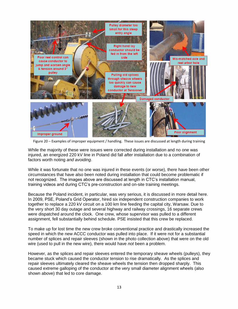
Figure 20 – Examples of improper equipment / handling. These issues are discussed at length during training
While the majority of these were issues were corrected during installation and no one was injured, an energized 220 kV line in Poland did fall after installation due to a combination of factors worth noting and avoiding. While it was fortunate that no one was injured in these events (or worse), there have been other circumstances that have also been noted during installation that could become problematic if not recognized. The images above are discussed at length in CTC’s installation manual, training videos and during CTC’s pre-construction and on-site training meetings. Because the Poland incident, in particular, was very serious, it is discussed in more detail here. In 2009, PSE, Poland’s Grid Operator, hired six independent construction companies to work together to replace a 220 kV circuit on a 100 km line feeding the capital city, Warsaw. Due to the very short 30 day outage and several highway and railway crossings, 16 separate crews were dispatched around the clock. One crew, whose supervisor was pulled to a different assignment, fell substantially behind schedule. PSE insisted that this crew be replaced. To make up for lost time the new crew broke conventional practice and drastically increased the speed in which the new ACCC conductor was pulled into place. If it were not for a substantial number of splices and repair sleeves (shown in the photo collection above) that were on the old wire (used to pull in the new wire), there would have not been a problem. However, as the splices and repair sleeves entered the temporary sheave wheels (pulleys), they became stuck which caused the conductor tension to rise dramatically. As the splices and repair sleeves ultimately cleared the sheave wheels the tension then dropped sharply. This caused extreme galloping of the conductor at the very small diameter alignment wheels (also shown above) that led to core damage.
14
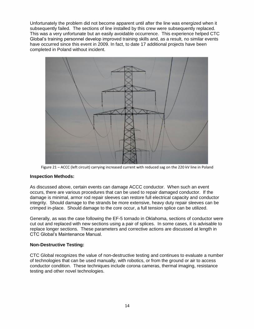
Unfortunately the problem did not become apparent until after the line was energized when it subsequently failed. The sections of line installed by this crew were subsequently replaced. This was a very unfortunate but an easily avoidable occurrence. This experience helped CTC Global’s training personnel develop improved training skills and, as a result, no similar events have occurred since this event in 2009. In fact, to date 17 additional projects have been completed in Poland without incident.
Figure 21 – ACCC (left circuit) carrying increased current with reduced sag on the 220 kV line in Poland
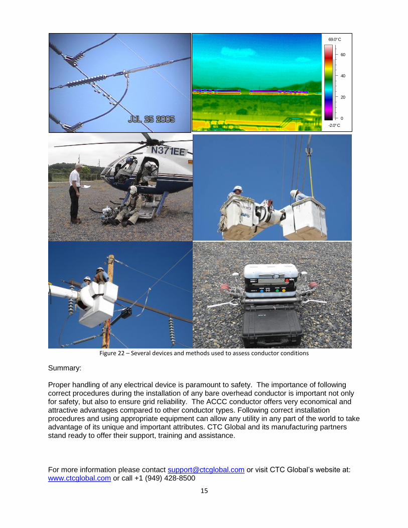
Inspection Methods: As discussed above, certain events can damage ACCC conductor. When such an event occurs, there are various procedures that can be used to repair damaged conductor. If the damage is minimal, armor rod repair sleeves can restore full electrical capacity and conductor integrity. Should damage to the strands be more extensive, heavy duty repair sleeves can be crimped in-place. Should damage to the core occur, a full tension splice can be utilized. Generally, as was the case following the EF-5 tornado in Oklahoma, sections of conductor were cut out and replaced with new sections using a pair of splices. In some cases, it is advisable to replace longer sections. These parameters and corrective actions are discussed at length in CTC Global’s Maintenance Manual. Non-Destructive Testing: CTC Global recognizes the value of non-destructive testing and continues to evaluate a number of technologies that can be used manually, with robotics, or from the ground or air to access conductor condition. These techniques include corona cameras, thermal imaging, resistance testing and other novel technologies.
15
Figure 22 – Several devices and methods used to assess conductor conditions
Summary: Proper handling of any electrical device is paramount to safety. The importance of following correct procedures during the installation of any bare overhead conductor is important not only for safety, but also to ensure grid reliability. The ACCC conductor offers very economical and attractive advantages compared to other conductor types. Following correct installation procedures and using appropriate equipment can allow any utility in any part of the world to take advantage of its unique and important attributes. CTC Global and its manufacturing partners stand ready to offer their support, training and assistance.
For more information please contact [email protected] or visit CTC Global’s website at: www.ctcglobal.com or call +1 (949) 428-8500
-2.0°C
69.0°C
0
20
40
60
Related Documents


