AUTOMATION AND CONTROL www.eaton.com/seasia-electrical 1 Overload relays E Line thermal overload relay xStart series overload relay 1.1 E Line thermal overload relay Thermal overload relays XTOD / XTOG ............................................................................... 2 1.2 xStart series overload relays Bimetal relay ZE, ZB, Z5 .................................................................................................... 9 Overload relay ZW7 ............................................................................................................ 9 Electronic overload relays ZEB ............................................................................................ 11 EMT6 thermistor overload relay for machine protection .................................................... 11 C441 Overload and monitoring relay ................................................................................. 44

Welcome message from author
This document is posted to help you gain knowledge. Please leave a comment to let me know what you think about it! Share it to your friends and learn new things together.
Transcript

AUTOMATION AND CONTROL www.eaton.com/seasia-electrical
1
Overload relays
E Line thermal overload relay
xStart series overload relay
1.1 E Line thermal overload relay
Thermal overload relays XTOD / XTOG ............................................................................... 2
1.2 xStart series overload relays
Bimetal relay ZE, ZB, Z5 .................................................................................................... 9
Overload relay ZW7 ............................................................................................................ 9
Electronic overload relays ZEB ............................................................................................ 11
EMT6 thermistor overload relay for machine protection .................................................... 11
C441 Overload and monitoring relay ................................................................................. 44

1
AUTOMATION AND CONTROL www.eaton.com/seasia-electrical 2
11
1.1
ContentsDescription Page
Thermal overload relays XTOD/XTOGSystem overview . . . . . . . . . . . . . . . . . . . . . . . . . . . . . . . . . . .Product selection . . . . . . . . . . . . . . . . . . . . . . . . . . . .Technical data . . . . . . . . . . . . . . . . . . . . . . . . . . . . . . . . . . . . .Dimensions . . . . . . . . . . . . . . . . . . . . . . . . . . . . . . . . . . . . .
2
3
5
6
Thermal overload relays XTOD/XTOG
Thermal overload relays XTOD/XTOGContents
Thermal overload relays XTOD/XTOGProduct description
• GB 14048• IEC/EN 60947• CCC• CE
Standards and certificationsXTOD/XTOG thermal overload relays offer precision motor protection with phase loss protection and ambient temperature compensation. The seperate mount design allows for flexibility and the units can be mounted on DIN rail or directly on the panel adjacent the motor contactor.
XTOD... is for separate mounting; XTOG is for direct mounting.
Features• Precision motor protection up
to 97A• Integral 1NO/1NC contact for
contactor control and alarm signal
• Phase loss protection• Ambient temperature
compensation• DIN rail or panel mount
options
System overviewThermal overload relays provide protective features for 1 or 3 phase motors. The relay monitors the operating current of the motor and switched the contactor off in the event of an overload situation. It also protects the motor from damage during phase loss.

3 AUTOMATION AND CONTROL www.eaton.com/seasia-electrical
1.1
1
Thermal overload relays XTOD/XTOGProduct selection
Thermal overload relays
Part no.Article no.
Standard package
XTOD..CC1S Seperate mounting 1 N/O 1 N/C 1 piece
Seperate mounting 1 N/O 1 N/C 1 piece
Seperate mounting
Seperate mounting
1 N/O 1 N/C 1 piece
1 N/O 1 N/C 1 piece
Seperate mounting 1 N/O 1 N/C 1 piece
Seperate mounting 1 N/O 1 N/C 1 piece
Seperate mounting 1 N/O 1 N/C 1 piece
Auxiliary contact
N/O =Normally open N/C =Normally closed
Circuit symbol
Setting range of overload releases Ir (A)
Seperate mounting 1 N/O 1 N/C 1 piece
Seperate mounting 1 N/O 1 N/C 1 piece
Seperate mounting 1 N/O 1 N/C 1 piece
Seperate mounting 1 N/O 1 N/C 1 piece
1 N/O 1 N/C 1 piece
Seperate mounting
Seperate mounting
1 N/O 1 N/C 1 piece
Seperate mounting 1 N/O 1 N/C 1 piece
1 piece
1 piece
1 piece
1 piece
1 piece
1 piece
1 piece
1 piece
1 piece
1 piece
1 piece
1 piece
1 piece
0.3~0.45
0.45 ~0.67
0.67~1.0
1.0 ~1.5
1.4 ~2.1
1.8~2.7
2.4~3.6
3.5~5.0
4.0~6.0
5.5~8.5
8.5~12.5
12.5~18
17~24
22~30
XTODP45CC1S
XTODP67CC1S
XTOD001CC1S
XTOD1P5CC1S
XTOD2P2CC1S
XTOD2P7CC1S
XTOD3P6CC1S
XTOD005CC1S
XTOD006CC1S
XTOD8P5CC1S
XTOD013CC1S
XTOD018CC1S
XTOD024CC1S
XTOD030CC1S
167952
167953
167954
167955
167956
167957
167958
167959
167960
167961
167962
167963
167964
167965
For use with
XTCG007XTCG009XTCG012XTCG018XTCG025XTCG032XTCG038
97 95
982 4 6 96
97 95
982 4 6 96
97 95
982 4 6 96
97 95
982 4 6 96
97 95
982 4 6 96
97 95
982 4 6 96
97 95
982 4 6 96
97 95
982 4 6 96
97 95
982 4 6 96
97 95
982 4 6 96
97 95
982 4 6 96
97 95
982 4 6 96
97 95
982 4 6 96
97 95
982 4 6 96
Direct mounting
Direct mounting
Direct mounting
Direct mounting
Direct mounting
Direct mounting
Direct mounting
Direct mounting
Direct mounting
Direct mounting
Direct mounting
Direct mounting
Direct mounting
Direct mounting
1 N/O 1 N/C
1 N/O 1 N/C
1 N/O 1 N/C
1 N/O 1 N/C
1 N/O 1 N/C
1 N/O 1 N/C
1 N/O 1 N/C
1 N/O 1 N/C
1 N/O 1 N/C
1 N/O 1 N/C
1 N/O 1 N/C
1 N/O 1 N/C
1 N/O 1 N/C
0.1~0.16
0.16~0.24
0.24~0.4
0.4~0.6
0.6~1
1~1.6
1.6~2.4
2.4~4
4~6
6~10
9-12
12~16
16~24
24~32
XTOGP16BC1
XTOGP24BC1
XTOGP40BC1
XTOGP60BC1
XTOG001BC1
XTOG1P6BC1
XTOG2P4BC1
XTOG004BC1
XTOG006BC1
XTOG010BC1
XTOG012BC1
XTOG016CC1
XTOG024CC1
XTOG032CC1
173679
173680
173681
173682
173683
173684
173685
173686
173687
173688
173689
173690
173691
173692
XTCG007XTCG009XTCG012XTCG018XTCG025XTCG032XTCG038
97 95
982 4 6 96
97 95
982 4 6 96
97 95
982 4 6 96
97 95
982 4 6 96
97 95
982 4 6 96
97 95
982 4 6 96
97 95
982 4 6 96
97 95
982 4 6 96
97 95
982 4 6 96
97 95
982 4 6 96
97 95
982 4 6 96
97 95
982 4 6 96
97 95
982 4 6 96
1 piece1 N/O 1 N/C97 95
982 4 6 96
XTOG...

AUTOMATION AND CONTROL www.eaton.com/seasia-electrical 4
11
1.1Thermal overload relays XTOD/XTOGProduct selection
Thermal overload relays
Part no.Article no.
Standard package
XTOG...
Auxiliary contact
N/O =Normally open N/C =Normally closed
Circuit symbol
Setting range of overload releases Ir (A)
1 piece
1 piece
1 piece
1 piece
1 piece
1 piece
1 piece
1 piece
1 piece
For use with
Direct mounting 1 N/O 1 N/C
Direct mounting 1 N/O 1 N/C
Direct mounting
Direct mounting
1 N/O 1 N/C
1 N/O 1 N/C
Direct mounting 1 N/O 1 N/C
Direct mounting 1 N/O 1 N/C
Direct mounting 1 N/O 1 N/C
Direct mounting 1 N/O 1 N/C
Direct mounting 1 N/O 1 N/C
17~25
23~32
30~40
37~50
48~65
37~50
48~65
63~80
77~97
XTOG025DC1
XTOG032DC1
XTOG040DC1
XTOG050DC1
XTOG065DC1
XTOG050EC1
XTOG065EC1
XTOG080EC1
XTOG097EC1
173693
173694
173695
173696
173697
173698
173699
173700
173701
XTCG040XTCG050XTCG065XTCG080XTCG095
97 95
982 4 6 96
97 95
982 4 6 96
97 95
982 4 6 96
97 95
982 4 6 96
97 95
982 4 6 96
97 95
982 4 6 96
97 95
982 4 6 96
97 95
982 4 6 96
97 95
982 4 6 96

5 AUTOMATION AND CONTROL www.eaton.com/seasia-electrical
1.1
1
Thermal overload relays XTOD/XTOGTechnical data
Main contacts
Auxiliary and control circuits
Ambient temperature
Temperature compensation
WeightProtection type
Rated impulse withstand voltageOvervoltage category/pollution degree
Rated insulation voltage
Rated operational voltage
Overload release setting range
Terminal capacity
Terminal screwTightening torque
Rated impulse withstand voltageOvervoltage category/pollution degree
Terminal capacity
Terminal screwTightening torqueRated insulation voltageRated operational voltage
Conventional thermal currentRated operational current
AC
General
StandardsClimatic Proofing Damp heat, constant, to IEC60068-2-78
Damp heat, cyclic, to IEC60068-2-30
OpenEnclosed
Solid
Flexible with ferrule
Solid/stranded
Solid
Flexible with ferrule
Solid/stranded
XTOD/XTOG
XTOD/XTOG
XTOD/XTOG
AC-15
DC-13
120V220/240V380V480V500V600V
125V250V
IEC/EN 60947, GB 14048
Uimp
Ui
Ue
Uimp
Ui
Ue
IeIeIeIeIeIe
IeIe
Ith
VAC
VAC
A
AAAAA
A
VAC
VAC
VACA
AA
V
mm2
mm2
Nm
AWG
kg
mm2
mm2
Nm
AWG
°C°C°C
690
690
6
31.91.51.41.2
10
690
6000III/3
6900.1-97
0.550.27
6000III/3
1 x (1-6)2 x (1-6)
1 x (1-6)2 x (1-6)
0.8M3.5
0.15IP20
1 x (1-6)2 x (1-6)
1 x (1-6)2 x (1-6)
1.2M4
-5~40-25~40-25~55

6
11
1.1Thermal overload relays XTOD/XTOGDimensions
AUTOMATION AND CONTROL www.eaton.com/seasia-electrical
Dimensions
Thermal overload relay + mounting adapter
XTOD..CC1S
Thermal overload relays XTOG
17-65A
37-97A

Bimetal relay - overload relay up to 630 A
ZEB electronic overload relay - overload relay up to 1500 A
EMT6 thermistor overload relay for machine protection
Overload relay
Motor protection is a central task of electrical equipment for machinery. From
cost-effective bimetal solutions to demanding full motor protection with cross-linkage -
we offer the right solution for each application.
ATEX Direct mounting on contactor saves mounting time.ATEX approval for the protection of EEx e motors up to 250 A.Comprehensive motor protection through phase failure sensitivity.Integrated test pushbutton facilitates high safety Page 13.
••••
ATEX approval for protection of EEx e motors up to 1500 A.Adjustable tripping classes.Phase failure and unbalance protection.Optional earth fault detection.Additional current setting range (5:1) Page 21.
•••••
Overload protection through direct evaluation of winding temperature.Quick detection of operating state through LED display.Suitable for overload monitoring of motors in EEx e range.Wide range power supply reduces amount of types Page 26.
••••
Overload relays
7 AUTOMATION AND CONTROL www.eaton.com/seasia-electrical
1.2
1

Overload relay
Technical overviewBimetal relay ZE, ZB, Z5 . . . . . . . . . . . . . . . . . . . . . . . . . . . . . Overload relay ZW7 . . . . . . . . . . . . . . . . . . . . . . . . . . . . . . . . Electronic overload relays ZEB . . . . . . . . . . . . . . . . . . . . . . . . EMT6 thermistor overload relay for machine protection . . . .
OrderingBimetal relays for mini-contactor relays . . . . . . . . . . . . . . . . . Bimetal relays up to 150A . . . . . . . . . . . . . . . . . . . . . . . . . . . Bimetal relay greater than 150 A . . . . . . . . . . . . . . . . . . . . . . Overload relays . . . . . . . . . . . . . . . . . . . . . . . . . . . . . . . . . . . Bimetal relay accessories . . . . . . . . . . . . . . . . . . . . . . . . . . . . ZEB Electronic overload relay . . . . . . . . . . . . . . . . . . . . . . . . .
OrderingEMT6 thermistor overload relay for machine protection . . . .
EngineeringEMT6 thermistor overload relay for machine protection . . . . Selection criteria ZE, ZB, Z5, ZW7 . . . . . . . . . . . . . . . . . . . . . Characteristic curve ZB, Z5, ZW7 . . . . . . . . . . . . . . . . . . . . . . UL/CSA short-circuit strength ZE, ZB, Z5 . . . . . . . . . . . . . . . .
Technical dataBimetal relay for mini-contactor relays . . . . . . . . . . . . . . . . . . Bimetal relays up to 150A . . . . . . . . . . . . . . . . . . . . . . . . . . . Overload relays greater than 150 A . . . . . . . . . . . . . . . . . . . . Overload relays . . . . . . . . . . . . . . . . . . . . . . . . . . . . . . . . . . . ZEB electronic overload relay . . . . . . . . . . . . . . . . . . . . . . . . . EMT6 thermistor overload relay for machine protection . . . .
DimensionsBimetal relays for mini-contactor relays . . . . . . . . . . . . . . . . . Bimetal relays up to 150A . . . . . . . . . . . . . . . . . . . . . . . . . . . Bimetal relays greater than 150 A . . . . . . . . . . . . . . . . . . . . . Overload relay . . . . . . . . . . . . . . . . . . . . . . . . . . . . . . . . . . . . ZEB electronic overload relay . . . . . . . . . . . . . . . . . . . . . . . . . EMT6 thermistor overload relay for machine protection . . . .
9
9
11
11
13
15
19
19
28
31
26
27
30
30
31
32
32
33
33
35
36
37
37
39
39
40
42
AUTOMATION AND CONTROL www.eaton.com/seasia-electrical
Overload relaysContents
8
11
1.2
ContentsDescription Page

Overload relaysOverload relays, CT-operated overload relays
Technical overview
Electronic overload relays, thermistor overload relay for machine protection
Setting ranges (A)(note max. current of the contactor)
DILEM DILM7 DILM12 DILM17 DILM32 DILM40 DILM65 DILM80 DILM150DILM9 DILM15 DILM25 DILM38 DILM50 DILM72 DILM95 DILM170
DILM115
Overload relaysZE0.1-12
ZB120.1-16
ZB320.1-38
ZB656-75
ZB15035-175
Z5-.../FF225A70-250
Z5-.../FF25050-300
Current transformer-operated overload relayZW7-...42-630
Overload relays, CT-operated overload relays
9 AUTOMATION AND CONTROL www.eaton.com/seasia-electrical
1.2
1

Overload relaysOverload relays, CT-operated overload relays
DILM185A DILM250 DILM400 DILM580 DILM650DILM225A DILM300 DILM500
AUTOMATION AND CONTROL www.eaton.com/seasia-electrical 10
11
1.2

Overload relaysElectronic overload relays, thermistor overload relay for machine protection
Electronic overload relays, thermistor overload relay for machine protection
Setting ranges (A)(note max. current of the contactor)
DILEM DILM7 DILM12 DILM17 DILM32 DILM40 DILM65 DILM80 DILM150DILM9 DILM15 DILM25 DILM38 DILM50 DILM72 DILM95 DILM170
DILM115
Electronic overload relaysZEB120.33-20
ZEB320.33-45
ZEB659-100
ZEB15020-100
ZEB32-5-(GF)/KK combined withZEB-XCT30060-300
ZEB-XCT600120-600
ZEB-XCT1000200-1000
ZEB-XCT1500300-1500
Thermistor overload relay for machine protection
EMT6((DB)K)
11 AUTOMATION AND CONTROL www.eaton.com/seasia-electrical
1.2
1

Overload relaysElectronic overload relays, thermistor overload relay for machine protection
DILM185A DILM250 DILM400 DILM580 DILM750 DILM820 DILM1000 DILM1600DILM225A DILM300 DILM500 DILM650
AUTOMATION AND CONTROL www.eaton.com/seasia-electrical 12
11
1.2

Overload relaysBimetal relays for mini-contactor relays
Ordering
Setting range of overload releases
Short-circuit protectionFor use withAuxiliary contactCircuit symbol
N/O = normally open contactNC = normally closed contact
Type “1” coordination
Type “2” coordination
Ir gG/gL
A A
gG/gL
A
ZE overload relays for mini contactor relays
• Phase failure sensitivity to IEC/EN 60947, VDE 0660 Part 102• Test/off pushbutton• Reset pushbutton manual/auto• Trip-free release• Direct mounting
DILEM0.1 – 0.16DIULEM/21/MVSDAINLEM
20 0.5
200.16 – 0.24 1
0.24 – 0.4 2
0.4 – 0.6 2
0.6 – 1 4
1 – 1.6 6
1.6 – 2.4 6
2.4 – 4 10
10
10
10
4 – 6
6 – 9
9 – 12
Information relevant for export to North America
2 4 6 98 96
97 95
1 N/O 1 NC
1 N/O 1 NC
201 N/O 1 NC
201 N/O 1 NC
201 N/O 1 NC
201 N/O 1 NC
201 N/O 1 NC
201 N/O 1 NC
201 N/O 1 NC
201 N/O 1 NC
201 N/O 1 NC
UL 508; CSA-C22.2 No.14; IEC/EN 60947-4-1; CE markingE29184NKCR125283211-03UL Listed, CSA certifiedBranch circuits600 V ACIEC: IP20, UL/CSA Type: - Page 31
Product StandardsUL File No.UL CCNCSA File No.CSA Class No.NA CertificationSuitable forMax. Voltage RatingDegree of ProtectionSee also
13 AUTOMATION AND CONTROL www.eaton.com/seasia-electrical
1.2
1

Overload relaysBimetal relays for mini-contactor relays
Part no.Article no.
PriceSee price list
Std. pack Notes
ZE-0.16014263
1 Off Overload release: tripping class 10 AShort-circuit protection: With direct mounting, observe the maximum permissible fuse of the contactor.
Suitable for protection of EEx e motors
II (2) GDPTB 01 ATEX 3331
Observe manual AWB2300-1425D/GB.
With side-by-side mounting, there must be a minimum clearance of 5 mm between overload relays.
1 Contactor Chapter 5Accessories Page 28Manual Page 28
ZE-0.24014285
ZE-0.4014300ZE-0.6014333ZE-1.0014376ZE-1.6014432ZE-2.4014479ZE-4014518
ZE-6014565ZE-9014708ZE-12014752
1
AUTOMATION AND CONTROL www.eaton.com/seasia-electrical 14
11
1.2

Overload relaysOverload relays up to 150A
Information relevant for export to North America
UL 508; CSA-C22.2 No.14; IEC/EN 60947-4-1; CE markingE29184NKCR125283211-03
Product Standards
UL File No.UL CCNCSA File No.CSA Class No.
UL Listed, CSA certifiedBranch circuits600 V ACIEC: IP20, UL/CSA Type: - Page 31
NA CertificationSuitable forMax. Voltage RatingDegree of ProtectionSee also
Setting range of overload releases
Short-circuit protectionFor use withAuxiliary contactCircuit symbol
N/O = normally open contactNC = normally closed contact
Contactors Soft starters Type “1” coordination
Type “2” coordination
Ir gG/gL
A A
gG/gL
A
ZB12 overload relay DILM7, DILM9,0.1 – 0.16DILM12, DILM15,DIULM7, DIULM9, DIULM12,SDAINLM12,SDAINLM16,SDAINLM22
–
–0.16 – 0.24 1
0.24 – 0.4 2
0.4 – 0.6 4
0.6 – 1 4
1 – 1.6 6
1.6 – 2.4 10
2.4 – 4 16DS7-34…SX004…
4 – 6 20DS7-34…SX005…
6 – 10 DS7-34…SX007…DS7-34…SX009…
50
50
50
25
25
25
9 – 12 DS7-34…SX012…
12 – 16 –
ZB32 overload relay DILM17, DILM25,0.1 – 0.16DILM32,DILM38,DILMF8,DILMF11,DILMF14,DILMF17,DILMF25,DILMF32,DIULM17, DIULM25,DIULM32,SDAINLM30,SDAINLM45,SDAINLM55
–
0.16 – 0.24 1
0.24 – 0.4 2
0.4 – 0.6 4
0.6 – 1 4
1 – 1.6 6
1.6 – 2.4 10
2.4 – 4 16
4 – 6 20
6 – 10 50 25
10 – 16 DS7-34...SX016...
16 – 24 DS7-34...SX024...
24 – 32 DS7-34...SX032...
32 – 38 –
63
100
125
125
35
35
63
63
2 4 6 98 96 A2 14/22
97 95
2 4 6 98 96 14/22
97 95
ZB12, ZB32
1 N/O 1 NC
1 N/O 1 NC
–1 N/O 1 NC
–1 N/O 1 NC
–1 N/O 1 NC
–1 N/O 1 NC
–
25 0.5
25
25
25
25
25
25
–
25
25
1 N/O 1 NC
1 N/O 1 NC
1 N/O 1 NC
1 N/O 1 NC
1 N/O 1 NC
1 N/O 1 NC
1 N/O 1 NC
1 N/O 1 NC
–1 N/O 1 NC
–1 N/O 1 NC
–1 N/O 1 NC
–1 N/O 1 NC
–1 N/O 1 NC
–1 N/O 1 NC
–
25 0.5
25
25
25
25
25
25
25
25
–
1 N/O 1 NC
1 N/O 1 NC
1 N/O 1 NC
1 N/O 1 NC
1 N/O 1 NC
1 N/O 1 NC
15 AUTOMATION AND CONTROL www.eaton.com/seasia-electrical
1.2
1

Overload relaysOverload relays up to 150A
Part no.Article no.
PriceSee price list
Std. pack Notes
ZB12-0,16278431
1 Off Overload release: tripping class 10 AShort-circuit protection: With direct mounting, observe the maximum permissible fuse of the contactor.
Suitable for protection of EEx e motors.
II (2) GDPTB 04 ATEX 3022
Observe manual AWB2300-1527D/GB.
• Phase failure sensitivity to IEC/EN 60947, VDE 0660 Part 102
• Test/off pushbutton• Reset pushbutton manual/auto• Trip-free release• Direct mounting
Fitted directly to the contactor
1 Contactor Chapter 5Accessories Page 28Manual Page 28
ZB12-0,24278432ZB12-0,4278433ZB12-0,6278434ZB12-1278435ZB12-1,6278436ZB12-2,4278437ZB12-4278438ZB12-6278439ZB12-10278440ZB12-12278441ZB12-16290168ZB32-0,16278442
1 Off Overload release: tripping class 10 AShort-circuit protection: With direct mounting, observe the maximum permissible fuse of the contactor.
Suitable for protection of EEx e motors.
II (2) GDPTB 04 ATEX 3022
Observe manual AWB2300-1527D/GB.
• Phase failure sensitivity to IEC/EN 60947, VDE 0660 Part 102
• Test/off pushbutton• Reset pushbutton manual/auto• Trip-free release• Direct mounting
ZB32-0,24278443ZB32-0,4278444ZB32-0,6278445ZB32-1278446ZB32-1,6278447ZB32-2,4278448ZB32-4278449ZB32-6278450ZB32-10278451ZB32-16278452ZB32-24278453ZB32-32278454ZB32-38112474
1
Fitted directly to the contactor Separate mounting
1 Contactor Chapter 52 Base Page 28Manual Page 28
1 1
2
AUTOMATION AND CONTROL www.eaton.com/seasia-electrical 16
11
1.2

Overload relaysOverload relays up to 150A
Setting range of overload releases
Circuit symbol Auxiliary contact For use with Short-circuit protection
N/O = normally open contactNC = normally closed contact
Type “1” coordination
Type “2” coordination
Ir gG/gLA A
gG/gLA
ZB65 overload relay• Phase failure sensitivity to IEC/EN 60947, VDE 0660 Part 102• Test/off pushbutton• Reset pushbutton manual/auto• Trip-free release• Direct mounting
DILM40, DILM50,6 – 10DILM65,DILM72,DILMF40,DILMF50,DILMF65,DIULM40, DIULM50,DIULM65,SDAINLM70,SDAINLM90,SDAINLM115
50
10 – 16 63
16 – 24 63
24 – 40 125
40 – 57 160
50 – 65 160
65 – 75 250
ZB150 overload relay• Phase failure sensitivity to IEC/EN 60947, VDE 0660 Part 102• Test/off pushbutton• Reset pushbutton manual/auto• Trip-free release• Direct mounting
DILM80, DILM95,35 – 50DILM115, DILM150,DILM170DILMF80,DILMF95,DILMF115,DILMF150,DIULM80, DIULM95,DIULM115, DIULM150,SDAINLM140,SDAINLM165,SDAINLM200,SDAINLM260
160
50 – 70 250
70 – 100 315
95 – 125 315
120 – 150 315
145 – 175 315
25
35
50
63
80
100
160
125
160
200
250
250
250
ZB150 overload relay• Phase failure sensitivity to IEC/EN 60947, VDE 0660 Part 102• Test/off pushbutton• Reset pushbutton manual/auto• Trip-free release• Separate mounting
DILM80, DILM95,35 – 50DILM115, DILM150,DILM170DILMF80,DILMF95,DILMF115,DILMF150,DIULM80, DIULM95,DIULM115, DIULM150,SDAINLM140,SDAINLM165,SDAINLM200,SDAINLM260
160
50 – 70 250
70 – 100 315
95 – 125 315
120 – 150 315
145 – 175 400
125
160
200
250
250
315
2 4 6 98 96
97 95
2 4 6 98 96
97 95
2 4 6 98 96
97 95
ZB65, ZB150
1 N/O 1 NC
1 N/O 1 NC
1 N/O 1 NC
1 N/O 1 NC
1 N/O 1 NC
1 N/O 1 NC
1 N/O 1 NC
1 N/O 1 NC
1 N/O 1 NC
1 N/O 1 NC
1 N/O 1 NC
1 N/O 1 NC
1 N/O 1 NC
1 N/O 1 NC
1 N/O 1 NC
1 N/O 1 NC
1 N/O 1 NC
1 N/O 1 NC
1 N/O 1 NC
Information relevant for export to North America
UL 508; CSA-C22.2 No.14; IEC/EN 60947-4-1; CE markingE29184NKCR125283211-03UL Listed, CSA certifiedBranch circuits600 V ACIEC: IP00, UL/CSA Type: - Page 31
Product StandardsUL File No.UL CCNCSA File No.CSA Class No.NA CertificationSuitable forMax. Voltage RatingDegree of ProtectionSee also
17 AUTOMATION AND CONTROL www.eaton.com/seasia-electrical
1.2
1

Overload relaysOverload relays up to 150A
Part no.Article no.
PriceSee price list
Std. pack Notes
ZB65-10278455
1 Off Overload release: tripping class 10 AShort-circuit protection: With direct mounting,observe the maximum permissible fuse of the contactor.
Suitable for protection of EExe motors.
II (2) GDPTB 04 ATEX 3022
Observe manual AWB2300-1545D/GB.
ZB65-16278456ZB65-24278457ZB65-40278458ZB65-57278459ZB65-65278460ZB65-75108792ZB150-50278462
1 Off Overload release: tripping class 10 AShort-circuit protection: With direct mounting, observe the maximum permissible fuse of the contactor.
Suitable for protection of EEx e motors.
II (2) GDPTB 04 ATEX 3022
Observe manual AWB2300-1545D/GB.
ZB150-70278463ZB150-100278464ZB150-125278465ZB150-150278466ZB150-175107316
ZB150-50/KK278468
1 Off Overload release: tripping class 10 AShort-circuit protection: With direct mounting, observe the maximum permissible fuse of the contactor.
Suitable for protection of EEx e motors.
II (2) GDPTB 04 ATEX 3022
Observe manual AWB2300-1545D/GB.
ZB150-70/KK278469ZB150-100/KK278470ZB150-125/KK278471ZB150-150/KK278472ZB150-175/KK107317
Fitted directly to the contactor Separate mounting
1 Contactor Chapter 52 Base Page 28Manual Page 28
1
2
1
AUTOMATION AND CONTROL www.eaton.com/seasia-electrical 18
11
1.2

Overload relaysOverload relays greater than 150 A, CT-operated overload relays
Setting range of of overload releases
Circuit symbol Auxiliary contacts
For use with Short-circuit protection
N/O = normally open contactNC = normally closed contact
Type “1” coordinationgG/gL
Type “2” coordinationgG/gL
Ir
A A A
Z5 overload relays greater than 150A• Phase failure sensitivity to IEC/EN 60947, VDE 0660 Part 102 • Test/off pushbutton• Reset pushbutton manual/auto• Trip-free releaseDirect mounting
Z5 overload relays greater than 150A• Phase failure sensitivity to IEC/EN 60947, VDE 0660 Part 102 • Test/off pushbutton• Reset pushbutton manual/auto• Trip-free releaseSeparate mounting
DILM185A50 – 70DILM225A
250250
160160
70 – 100 315315
200200
95 – 125 315315
250250
120 – 160 400400
250250
160 – 220 400500
315400
200 – 250 400500
315400
250DILM25050 – 70250
160160
70 – 100 315315
200200
95 – 125 315315
250250
120 – 160 400400
250250
160 – 220 400500
315400
200 – 250 400500
315400
500DILM300A250 – 300500
400400
ZW7 current transformer-operated overload relays• Test/off button• Reset pushbutton manual/auto• Trip-free release• Protection with heavy starting dutySeparate mounting
–––42 – 63
–––60 – 90
–––85 – 125
–––110 – 160
–––160 – 240
–––190 – 290
–––270 – 400
–––360 – 540
–––420 – 630
1 3 5 97 95
2 4 6 98 96
9698
9597
Z5, ZW7
1 N/O 1 NC
1 N/O 1 NC
1 N/O 1 NC
1 N/O 1 NC
1 N/O 1 NC
1 N/O 1 NC
1 N/O 1 NC
1 N/O 1 NC
1 N/O 1 NC
1 N/O 1 NC
1 N/O 1 NC
1 N/O 1 NC
1 N/O 1 NC
1 N/O 1 NC
1 N/O 1 NC
1 N/O 1 NC
1 N/O 1 NC
1 N/O 1 NC
1 N/O 1 NC
1 N/O 1 NC
1 N/O 1 NC
1 N/O 1 NC
19 AUTOMATION AND CONTROL www.eaton.com/seasia-electrical
1.2
1

Overload relaysOverload relays greater than 150 A, CT-operated overload relays
UL 508; CSA-C22.2 No.14;IEC/EN 60947-4-1; CE markingRequest filed for UL and CSABranch circuits600 V ACIEC: IP00, UL/CSA Type: - Page 31
Product Standards
NA CertificationSuitable forMax. Voltage RatingDegree of ProtectionSee also
UL 508; CSA-C22.2 No.14; IEC/EN 60947-4-1; CE markingE29184NKCR125283211-03UL Listed, CSA certifiedBranch circuits600 V ACIEC: IP00, UL/CSA Type: - Page 31
Product Standards
UL File No.UL CCNCSA File No.CSA Class No.NA CertificationSuitable forMax. Voltage RatingDegree of ProtectionSee also
UL 508; CSA-C22.2 No.14; IEC/EN 60947-4-1; CE markingE29184NKCR125283211-03UL Listed, CSA certifiedBranch circuits600 V ACIEC: IP00, UL/CSA Type: -
Product Standards
UL File No.UL CCNCSA File No.CSA Class No.NA CertificationSuitable forMax. Voltage RatingDegree of Protection
Part no.Article no.
PriceSee price list
Std. pack Information relevant for export to North AmericaNotes
Z5-70/FF225A139572
1 Off Overload release: tripping class 10 AShort-circuit protection: With direct mounting, observe the maximum permissible fuse of the contactor.
Z5-…/FF225A for protecting EEx electric motors in preparation.
Fitted directly to the contactor
1 Contactor Chapter 5Accessories Page 29
UL 508; CSA-C22.2 No.14;IEC/EN 60947-4-1; CE markingRequest filed for UL and CSABranch circuits600 V ACIEC: IP00, UL/CSA Type: -
Product Standards
NA CertificationSuitable forMax. Voltage RatingDegree of Protection
Z5-100/FF225A139573Z5-125/FF225A139574Z5-160/FF225A139575
Z5-220/FF225A139576Z5-250/FF225A139577
Z5-70/FF250210070
Z5-100/FF250210071Z5-125/FF250210072Z5-160/FF250210073
Z5-220/FF250210074
Z5-250/FF250210075Z5-300/FF250139578
ZW7-63000245
1 Off The main current characteristic values are defined by the main current wiring being used.Adjustment for smaller rated motor currents
Page 30ZW7-90002618
ZW7-125004991
ZW7-160007364ZW7-240009737
ZW7-290052448
ZW7-400045329ZW7-540047702
ZW7-630050075
–ffO1
1
AUTOMATION AND CONTROL www.eaton.com/seasia-electrical 20
11
1.2

Electronic overload relays to 1500 ABasic devices
Ground fault detection Setting range of overload releases
Circuit symbol Auxiliary contact For use with
IrA
N/O = normally open contactNC = normally closed contact
ZEB12 electronic overload relay• Phase-failure sensitivity• Test/off pushbutton• Reset button• Manual/Auto reset selectable• Protection with heavy starting duty (Class 10A-30)Direct mounting
DILM70.33 – 1.65WithoutDILM9DILM12DILM15DIULM7DIULM9DIULM12SDAINLM12SDAINLM16SDAINLM22
Without
Without
With
With
With
1 – 5
4 – 20
0.33 – 1.65
1 – 5
4 – 20
ZEB32 electronic overload relay • Phase-failure sensitivity• Test/off pushbutton• Reset button• Manual/Auto reset selectable• Protection with heavy starting duty (Class 10A-30)
ZEB32 electronic overload relay • Phase-failure sensitivity• Test/off pushbutton• Reset button• Manual/Auto reset selectable• Protection with heavy starting duty (Class 10A-30)
Direct mounting
DILM170.33 – 1.65WithoutDILM25DILM32DILM38DIULM17DIULM25DIULM32SDAINLM30SDAINLM45SDAINLM55
Without
Without
Without
With
With
With
With
1 – 5
4 – 20
9 – 45
0.33 – 1.65
1 – 5
4 – 20
9 – 45
Separate mounting
DILM170.33 – 1.65WithoutDILM25DILM32DILM38DIULM17DIULM25DIULM32SDAINLM30SDAINLM45SDAINLM55
Without
Without
Without
With
With
With
With
1 – 5
4 – 20
9 – 45
0.33 – 1.65
1 – 5
4 – 20
9 – 45
2 4 6 98 96
97 95
2 4 6 98 96
97 95
1 3 5 97 95
2 4 6 98 96
ZEB12, ZEB32
1 N/O 1 NC
1 N/O 1 NC
1 N/O 1 NC
1 N/O 1 NC
1 N/O 1 NC
1 N/O 1 NC
1 N/O 1 NC
1 N/O 1 NC
1 N/O 1 NC
1 N/O 1 NC
1 N/O 1 NC
1 N/O 1 NC
1 N/O 1 NC
1 N/O 1 NC
1 N/O 1 NC
1 N/O 1 NC
1 N/O 1 NC
1 N/O 1 NC
1 N/O 1 NC
1 N/O 1 NC
1 N/O 1 NC
1 N/O 1 NC
Information relevant for export to North America
UL 508; CSA-C22.2 No.14; IEC/EN 60947-4-1; CE markingRequest filed for UL and CSABranch circuits600 V ACIEC: IP20, UL/CSA Type: -
Product StandardsNA CertificationSuitable forMax. Voltage RatingDegree of Protection
21 AUTOMATION AND CONTROL www.eaton.com/seasia-electrical
1.2
1

Electronic overload relays to 1500 ABasic devices
Part no.Article no.
PriceSee price list
Std. pack Notes
ZEB12-1,65136480
1 Off Suitable for protection of EEx e motors.
II (2) GDPTB ATEX starting 08/2010
Observe manual AWB2320-1633D/GB.
Switchgear and cable dimensioning according to CLASS
Fitted directly to the contactor
1 Contactor Chapter 5Accessories Page 25
ZEB12-5136481
ZEB12-20136482ZEB12-1,65-GF136483
ZEB12-5-GF136484
ZEB12-20-GF136485
ZEB32-1.65136486
1 Off Suitable for protection of EEx e motors.
II (2) GDPTB ATEX starting 08/2010
Observe manual AWB2320-1633D/GB.
Switchgear and cable dimensioning according to CLASS
Fitted directly to the contactor
1 Contactor Chapter 5Accessories Page 25
ZEB32-5136487
ZEB32-20136488ZEB32-45136489ZEB32-1,65-GF136490
ZEB32-5-GF136491
ZEB32-20-GF136492ZEB32-45-GF136493
ZEB32-1,65/KK136494
1 Off Suitable for protection of EEx e motors.
II (2) GDPTB ATEX starting 08/2010
Observe manual AWB2320-1633D/GB.
Switchgear and cable dimensioning according to CLASS
ZEB32-5/KK136495ZEB32-20/KK136496
ZEB32-45/KK136497
ZEB32-1,65-GF/KK136498ZEB32-5-GF/KK136499ZEB32-20-GF/KK136500
ZEB32-45-GF/KK136501
1
1
Page 25
Page 25
Page 25
AUTOMATION AND CONTROL www.eaton.com/seasia-electrical 22
11
1.2
Electronic overload relays to 1500 ABasic devices
ZEB65 electronic overload relay• Phase-failure sensitivity• Test/off pushbutton• Reset button• Manual/Auto reset selectable• Protection with heavy starting duty (Class 10A-30)Direct mounting
DILM409 – 45WithoutDILM50DILM65DILM72DIULM40DIULM50DIULM65SDAINLM70SDAINLM90SDAINLM115
With
Without
With
9 – 45
20 – 100
20 – 100
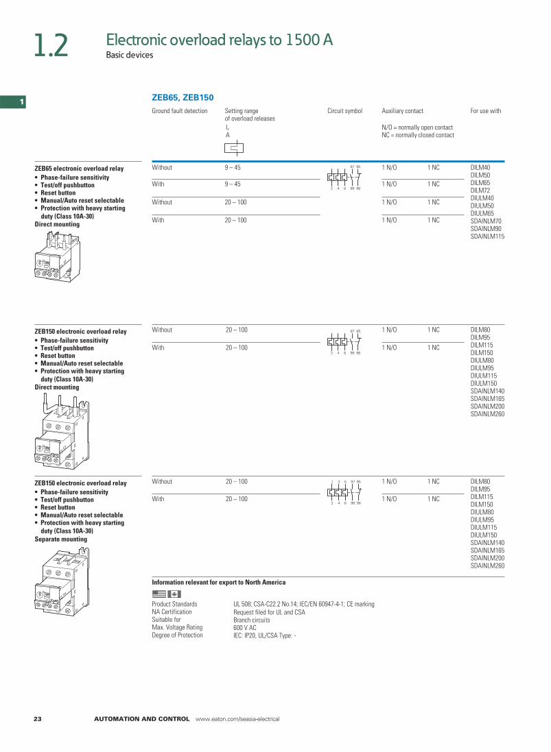
ZEB150 electronic overload relay• Phase-failure sensitivity• Test/off pushbutton• Reset button• Manual/Auto reset selectable• Protection with heavy starting duty (Class 10A-30)Direct mounting
DILM8020 – 100WithoutDILM95DILM115DILM150DIULM80DIULM95DIULM115DIULM150SDAINLM140SDAINLM165SDAINLM200SDAINLM260
20 – 100With
Separate mounting
DILM8020 – 100WithoutDILM95DILM115DILM150DIULM80DIULM95DIULM115DIULM150SDAINLM140SDAINLM165SDAINLM200SDAINLM260
20 – 100With
Ground fault detection Setting range of overload releases
Circuit symbol Auxiliary contact For use with
IrA
N/O = normally open contactNC = normally closed contact
2 4 6 98 96
97 95
2 4 6 98 96
97 95
1 3 5 97 95
2 4 6 98 96
ZEB65, ZEB150
1 N/O 1 NC
1 N/O 1 NC
1 N/O 1 NC
1 N/O 1 NC
1 N/O 1 NC
1 N/O 1 NC
1 N/O 1 NC
1 N/O 1 NC
ZEB150 electronic overload relay• Phase-failure sensitivity• Test/off pushbutton• Reset button• Manual/Auto reset selectable• Protection with heavy starting duty (Class 10A-30)
Information relevant for export to North America
UL 508; CSA-C22.2 No.14; IEC/EN 60947-4-1; CE markingRequest filed for UL and CSABranch circuits600 V ACIEC: IP20, UL/CSA Type: -
Product StandardsNA CertificationSuitable forMax. Voltage RatingDegree of Protection
23 AUTOMATION AND CONTROL www.eaton.com/seasia-electrical
1.2
1

Electronic overload relays to 1500 ABasic devices
ZEB65-45136502
1 Off Suitable for protection of EEx e motors.
II (2) GDPTB ATEX starting 08/2010
Observe manual AWB2320-1633D/GB.
Switchgear and cable dimensioning according to CLASS
Fitted directly to the contactor
1 Contactor Chapter 5Accessories Page 25
ZEB65-45-GF136503
ZEB65-100136504ZEB65-100-GF136505
ZEB150-100136506
1 Off Suitable for protection of EEx e motors.
II (2) GDPTB ATEX starting 08/2010
Observe manual AWB2320-1633D/GB.
Switchgear and cable dimensioning according to CLASS
Fitted directly to the contactor
1 Contactor Chapter 5Accessories Page 25
ZEB150-100-GF136507
ZEB150-100/KK136508
1 Off Suitable for protection of EEx e motors.
II (2) GDPTB ATEX starting 08/2010
Observe manual AWB2320-1633D/GB.
Switchgear and cable dimensioning according to CLASS
ZEB150-100-GF/KK136509
Part no.Article no.
PriceSee price list
Std. pack Notes
1
1
Page 25
Page 25
Page 25
AUTOMATION AND CONTROL www.eaton.com/seasia-electrical 24
11
1.2

Electronic overload relays to 1500 AAccessories
Setting range of overload releases
Language Can be used with Part no.Article no.
PriceSee price list
Std. pack
Ir
A
Current sensors60 – 300
ZEB32-5/KK
ZEB32-5-GF/KKZEB32-5/KK
ZEB32-5-GF/KKZEB32-5/KK
ZEB-XCT3001)
1365111off
1off
1off
1off
120 – 600 ZEB-XCT6001)
136512
200 – 1000 ZEB-XCT10001)
136517
300 – 1500
– ZEB32-5-GF/KK
–
–
– ZEB-XCT15001)
136513
Sealable shroudCover to prevent adjustment of motor current (tamper-proof)
– ZEB-XSC2)
1365141 off
Reset adapterCover to prevent adjustment of motor current (tamper-proof)
–
–
–
–
– ZEB-XRB2)
1365151 off
Documentation
ZEB electronic overload relayOverload monitoring of EEx e motors
– DeutschEnglish
ZEB12ZEB32ZEB65ZEB150
AWB2320-1633DE/EN136516
1 off
1) 2)
Information relevant for export to North AmericaInformation relevant for export to North America
ZEB-XCT…
UL 508; CSA-C22.2 No.14; IEC/EN 60947-4-1; CE markingRequest filed for UL and CSABranch circuits600 V ACIEC: IP00, UL/CSA Type: -
Product Standards
NA CertificationSuitable forMax. Voltage RatingDegree of Protection
UL 508; CSA-C22.2 No.14; IEC/EN 60947-4-1; CE markingRequest filed for UL and CSA600 V ACIEC: IP20, UL/CSA Type: -
Product Standards
NA CertificationMax. Voltage RatingDegree of Protection
Switchgear and cable sizing corresponding to the respective starting inertia (CLASS) for ZEB
Trippling class Class 5 Class 10 Class 15 Class 20 Class 25 Class 30 Class 35 Class 40
Current factor of rated operational current Ie
e
1.00 1.00 1.22 1.41 1.58 1.73 1.89 2.00
Switchgear is designed according to "CLASS 10" requirements for both normal and overload operation conditions. In order for the switchgear (circuit-breaker and contactor) and the cables not to be overloaded with long tripping times, they must be overdimensioned accordingly. The rated operational current, I , for switchgear and cables can be calculated with the following current factor taking the tripping class into account:
25 AUTOMATION AND CONTROL www.eaton.com/seasia-electrical
1.2
1

Overload relays for machine protectionBasic devices, accessories
Ordering
Rated opera-Functiontional current
Conven-tional thermal current
Rated control voltage
Part no.Article no.
PriceSee price list
Std. pack Notes
AC-15240 V
AC-14400 V
Ie Ie Ith Us
A A A V
EMT6 thermistor machine protection overload relays
Without automatic resetMains and fault LED display
3
3
3
3
3
3
3
3
3
3
6 24 - 240 V 50/60 Hz,
6
6
6
6
24 - 240 V DCEMT61) 2)
0661661 off
II (2) G
II (2) GD only for EMT6-K
PTB 02 ATEX 3162
Observe the manual AWB 2327-1446
Page 26Can be snap fitted on a top-hat rail to IEC/EN 60715.Device clearance ≧3 mm.
230 V 50/60 Hz EMT6(230V)1) 2)
066400
Without automatic resetMains and fault LED displayTripped in the event of a short-circuit in the sensor-cable
24 - 240 V 50/60 Hz,24 - 240 V DC
EMT6-K 2)
269470
Selector switch with/without automatic resetFor manual or remote resettingTest buttonMains and fault LED display
24 - 240 V 50/60 Hz,24 - 240 V DC
EMT6-DB1) 2)
066167
230 V 50/60 Hz EMT6-DB(230V)1) 2)
066401
Selector switch with/without automatic resetFor manual or remote resettingTest buttonMains and fault LED displayTrip with short-circuit in the sensor cable
24 - 240 V 50/60 Hz,24 - 240 V DC
EMT6-KDB 2)
269471
All-in-one deviceSelector switch with/without automatic resetTrip with short-circuit in the sensor cableZero-voltage safeFor manual or remote resettingTest buttonShort-circuit detection and retention can be deactivatedMains and fault LED display
24 - 240 V 50/60 Hz,24 - 240 V DC
EMT6-DBK 2)
066168
AccessoriesScrew adapters for screw fixing
CS-TE 3)
09585310 off –
DocumentationEMT6 thermistor overload relayOverload monitoring of machines in the EEx e areaGerman AWB2327-1446D
2648531 off
English AWB2327-1446GB267010
1 off
Notes 1)
EMT6
2) 3)
Information relevant for export to North AmericaInformation relevant for export to North America
UL/CSA certification not requiredUL 508; CSA-C22.2 No.14; IEC/EN 60947-4-1; CE markingE29184NKCR125283211-03UL Listed, CSA certified600 V ACIEC: IP20, UL/CSA Type: -
For EMT6, EMT6(230V), EMT6-DB and EMT6-DB(230V) applies:Provide additional short-circuit protection in the sensor circuitwith a current monitoring relay.
Product Standards
UL File No.UL CCNCSA File No.CSA Class No.NA CertificationMax. Voltage RatingDegree of Protection
AUTOMATION AND CONTROL www.eaton.com/seasia-electrical 26
11
1.2

Overload relays for machine protectionSelection aid
Engineering
Terminal marking according to EN 50005
EMT6(-K), EMT6-(K)DB, EMT6-DBKAuto
EMT6-(K)DB, EMT6-DBKManual
EMT6-DBK
Zero-voltage safe operation
LED display
Supply voltage present
Device has tripped
Device has tripped/short-circuit in the sensor circuit
Sensor circuit
At R K≦ 250 Ω per sensor: 6 sensors, at RK≦ 100 Ω per sensor: 9 sensors in the winding (provided by user), max. cable length to sensor 250 m (not shielded); Total PTC thermistor resistance∑ RK≦ 1500 Ω
Sensor circuit characteristic values at Us and +20 °C
EMT6…RT1-T2 UT1-T2 IT1-T2
V DC max. mA max.
T1, T2 short-circuited - 1.94 kΩ 3 0.8T1-T2 open 5.1 -
Functions that can be disconnected on the EMT6-DBK:
Function Disconnection by link
Short-circuit monitoring Y1 - Y3
Zero-voltage safety Y1 - Y4
L +~
~N
US
A1 21 13
A2 T1 T2 22 14
PTC
Power Tripped
Tripped LED
A1/A2
T1/T2 3.6 K 1.6 K
0
13–14, 21–22
+L ~
~N
US
A1 21
A2 T1 T2 22 14
PTC
13Y2Y1
Power Tripped
Tripped LED
A1/A2
T1/T2 3.6 K 1.6 k
0
13–14, 21–22
Y1/Y2, RESET
L +~
N –~
US
A1 21
A2 T1 222T 14
PTC
13Y2Y1 Y4Y3
Power Tripped
A1/A2
T1/T2 3.6 K 1.6 K
0
13–14, 21–22
Y1/Y2, RESET
Short-circuit
Tripped LED
60
750
1650
4000
12000
[°C]
NATNAT
NAT NAT NAT–20° –5° +5° +15°
3600 Tripping
1600 Reset
Tolerance limitsTemperature
Res
ista
nce
[
]
Resettingrange
IEC-Tripping range
27 AUTOMATION AND CONTROL www.eaton.com/seasia-electrical
1.2
1

Overload relaysAccessories
Ordering
For use with Part no.Article no.
PriceSee price list
Std. pack Information relevant for export toNotesNorth America
DocumentationOverload relaysOverload monitoring of EEx e motors
ZE… AWB2300-1425D258704
1 off German
1 off
1 off
ZB12…ZB32…
AWB2300-1527D/GB284910
German/English
ZB65…ZB150…
AWB2300-1545D/GB102065
German/English
BasesFor separate mounting
ZB32 ZB32-XEZ278473
5 off Can be snap fitted on a top-hat rail to IEC/EN 60715 or can be screw fitted.For ZB32-38, use BK25/3-PKZ0 additionally.
ZB65 ZB65-XEZ278474
2 off
PushbuttonsFor enclosed Overload relayMounting diameter: 22.3 mmExternal reset button, IP65
ZW7...ZEZ5ZB12ZB32ZB65ZB150
M22-DZ-B254833
10 off Button plate, blue
ZW7...ZEZ5ZB12ZB32ZB65ZB150
M22-DZ-B-GB14254834
10 off Button plate, blue RESET
Off button, IP65
ZW7...ZEZ5ZB12ZB32ZB65ZB150
M22-DZ-X254835
10 off Without button plate, add button plate.
Button plates
M22-DZ-X M22-XD-R216423
10 off Button plate, red UL/CSA certification not required
M22-DZ-X M22-XD-R-X0218153
Red button plate with white circle
M22-DZ-X M22-XD-R-GB0218194
Button plate red STOP
ZB, Z5, ZW7
UL 508; CSA-C22.2 No.14; IEC/EN 60947-4-1; CE markingE29184NKCR125283211-03UL Listed, CSA certified600 V ACIEC: IP00, UL/CSA Type: -
Product Standards
UL File No.UL CCNCSA File No.CSA Class No.NA CertificationMax. Voltage RatingDegree of Protection
UL 508; CSA-C22.2 No.14; IEC/EN 60947-4-1; CE markingE29184NKCR125283211-03UL Listed, CSA certified
Product Standards
UL File No.UL CCNCSA File No.CSA Class No.NA Certification
UL 508; CSA-C22.2 No.14; IEC/EN 60947-4-1; CE markingE29184NKCR125283211-03UL Listed, CSA certified
Product Standards
UL File No.UL CCNCSA File No.CSA Class No.NA Certification
PushbuttonsFor enclosed Overload relayMounting diameter: 22.3 mm
PushbuttonsFor enclosed Overload relayMounting diameter: 22.3 mm
AUTOMATION AND CONTROL www.eaton.com/seasia-electrical 28
11
1.2

For use with Part no.Article no.
PriceSee price list
Std. pack Notes
For use with Part no.Article no.
PriceSee price list
Std. pack Notes
Covers Direct mounting Z5-…/FF225 toDILM185ADILM225A
Z5/FF225A-XHB-Z139579
1 off
Z5-…/FF225AZ5-…/FF250
Z5/FF250-XHB215217
1 offthe contactor
Fitted directly to the contactor
Direct mounting Z5-…/FF250 toDILM250DILM300A
Z5/FF250-XHB-Z215218
1 off
Fitted directly to the contactor
Separate mounting Fitted directly to
Fitted directly to the contactor
Box terminals kit
Consisting of 3 individual clamps
For connection of copper flat stripmax. W × Hmm
With protective cover Z5-…/FF250 K-B-DIL6AM064062
1 offprotective covers must be used.
With control circuit terminal and protective cover
Z5-…/FF250
24 × 26
24 × 26 KS-B-DIL6AM064063
1 off
When using box terminals the
When using box terminals the protective covers must be used.
Z5-.../FF225A
DILM400-XHB
Z5/FF225A-XHB-Z
Z5/FF250-XHB
DILM185A/225A
Z5/FF250-XHB
Z5/FF250-XHB
Z5-.../FF250/FF225A
Z5-.../FF250
DILM400-XHB
Z5/FF250-XHB-Z
Z5/FF250-XHB
DILM250/300A
Z5-.../FF225A
DILM400-XHB
Z5/FF225A-XHB-Z
Z5/FF250-XHB
DILM185A/225A
Z5-.../FF250
DILM400-XHB
Z5/FF250-XHB-Z
Z5/FF250-XHB
DILM250/300A
Z5..., K-B..., KS-B...
Covers
Covers
Overload relaysAccessories
29 AUTOMATION AND CONTROL www.eaton.com/seasia-electrical
1.2
1

Engineering
for North America
Protection of single-phase and DC current motors:
1 pole 2 poleMounting position:
ZB12, ZB32, ZB65, ZB150, Z5ZE
Tripping characteristics
These tripping characteristics are mean values of the spread at 20 °C ambient temperature in a cold state. They show the tripping times in relation to the response current. When the devices are at operational temperature the tripping time of the overload relay drops to approx. 25% of the value shown. Specific characteristics for each individual setting range can be found in the manual on Page 28
2h100
60402010
6421
402010
6421
0.6
ZB12, ZB32, ZB65, ZE
1 1.5 2 3 4 6 8 10 15 20x Setting current
2-phaseSeco
nds
Min
utes
3-phase
2h100
60402010
6421
402010
6421
0.6
ZB150
6 8 10 15 20 3 41 1.5 2x Setting current
2-phaseSeco
nds
Min
utes
3-phase
2 h10060402010
6421
402010
6421
1 1.5 2 3 4 6 8 10 15 200.6
ZW7
Min
utes
Seco
nds
x Setting current
Minimum
Maximum
2h100
60402010
6421
402010
6421
0.6
Z5
6 8 10 15 20 3 41 1.5 2x Setting current
2 phaseSeco
nds
Min
utes
3 phase
Adaption of ZW7 to smaller rated motor currents
Number of loops ZW7 -63 -90 -125 -160 -240 -290 -400 -540 -630
Rated motor current IN [A]1 42-63 60-90 85-125 110-160 160-240 190-290 270-400 360-540 420-6302 21-31,5 30-45 42.5-62,5 55-80 80-120 95-145 135-200 180-270 210-3153 14-21 20-30 28.3-41,7 36.7-53,3 53.3-80 63.3-96,7 90-133,3 120-180 140-2104 10.5-15,8 15-22,5 21.3-31,3 27.5-40 40-60 47.5-72,5 67.5-100 90-135 105-157,55 8.4-12,6 12-18 17-25 22-32 32-48 38-58 54-80 72-108 84-126
AUTOMATION AND CONTROL www.eaton.com/seasia-electrical
Overload relaysSelection criteria
30
11
1.2

Overload relaysUL/CSA-short-circuit strength
Overload relay short-circuit strength
UL508, CSA-C22,2 No. 14/SCCR values
Fuse acc. to NEC, CEC CB Fuse acc. to NEC, CEC CBA kA A kA A kA A kA
600V AC 480V AC 600V AC 600 V ACZE-0,16 1 5 15 5 225 5 200 5ZE-0.24 1 5 15 5 250 10 250 10ZE-0.4 1 5 15 5 400 CLASS J 10 400 10ZE-0.6 1 5 15 5 500 CLASS J 10 500 10ZE-1,0 3 5 15 5 600 CLASS J 10 600 10ZE-1.6 6 5 15 5 600 CLASS J 10 600 10ZE-2.4 6 5 15 5 110 CLASS J 100 200 5ZE-4 15 5 15 5 125 CLASS J 100 250 10ZE-6 20 5 15 5 200 CLASS J 100 400 10ZE-9 35 5 15 5 250 CLASS J 100 500 10ZE-12 45 5 - -
ZB150-50ZB150-70ZB150-100ZB150-125ZB150-150ZB150-175ZB150-50(KK)ZB150-70(KK)ZB150-100(KK)ZB150-125(KK)ZB150-150(KK) 300 CLASS J 100 600 10
600V AC ZB150-175(KK) 300 CLASS J 100 600 10ZB12(32)-0,16 1 CLASS J/CC 100 - - 600V AC 600V ACZB12(32)-0,24 1 CLASS J/CC 100 - - 250 10 250 10ZB12(32)-0,4 1 CLASS J/CC 100 - - 400 CLASS J 10 400 10ZB12(32)-0,6 1 CLASS J/CC 100 - - 500 CLASS J 10 500 10ZB-12(32)-1,0 1 CLASS J/CC 100 - - 600 CLASS J 10 600 10ZB-12(32)-1,6 3 CLASS J/CC 100 - - 800 CLASS J 10 800 10ZB-12(32)-2,4 3 CLASS J/CC 100 - - 700 CLASS J 10 600 10ZB-12(32)-4 6 CLASS J/CC 100 - - 125 CLASS J 100 - -ZB-12(32)-6 10 CLASS J/CC 100 - - 200 CLASS J 100 - -ZB-12(32)-10 15 CLASS J/CC 100 - - 250 CLASS J 100 - -ZB12-12 15 CLASS J/CC 100 - -
Z5-70/...Z5-100/...Z5-125/...Z5-160/...Z5-220/...Z5-250/...Z5-70/...Z5-100/...Z5-125/...Z5-160/... 300 CLASS J 100 - -
ZB12-16 30 CLASS J/CC 100 - -ZB32-16 35 CLASS J 100 - -ZB32-24 45 CLASS J 100 - -ZB32-32 60 CLASS J 100 - -
600V AC 600V ACZB65-10 15 CLASS J 100 40 5ZB65-16 35 CLASS J 100 60 5ZB65-24 45 CLASS J 100 90 5ZB65-40 60 CLASS J 100 125 5ZB65-57 110 CLASS J 100 150 10ZB65-65 125 CLASS J 100 150 10ZB65-75 125 CLASS J 100 150 10
ZE, ZB, Z5
For North America
31 AUTOMATION AND CONTROL www.eaton.com/seasia-electrical
1.2
1

Overload relaysOverload relays
Technical data
ZE ZB12, ZB32 ZB65 ZB150(KK)
GeneralStandards IEC/EN 60947, VDE 0660, UL, CSAClimatic proofing Damp heat, constant, to IEC 60068-2-78
Damp heat, cyclic, to IEC 60068-2-30
Ambient temperature
Open1) °C -25…50 -25…55 -25…55 -25…55
Enclosed 1) °C -25…40 -25…40 -25…40 -25…40Temperature compensation Continuous
Mounting position Page 30
kgWeight 0.07 0.15 0.25 1.64Mechanical shock resistance half-sinusoidal shock, 10 ms to IEC 60068-2-27
g 10 10 10 10
Protection type IP20 IP20 IP00 IP00
Protection against direct contact when actuated from front (EN 50274)
Finger- and back-of-hand proof
Main contactsURated impulse withstand voltage imp V AC 6000 6000 6000 8000
Overvoltage category/pollution degree III/3 III/3 III/3 III/3Rated insulation voltage
UAC i V AC 690 690 690 1000
URated operating voltage e V AC 690 690 690 1000Safe isolation according to EN 61140
V ACBetween auxiliary contacts and main contacts 300 440 440 440V ACBetween the main contacts 300 440 440 440
AOverload relay setting range 0.1…12 0.1…38 6…75 25…175
%/KTemperature compensation residual error > 40 ºC ≦ 0.25 ≦ 0.25 ≦ 0.25 ≦ 0.25Short-circuit protection rating maximum fuse Page 13 Page 15 Page 17 Page 17
Current heat loss (3 conductors)
WLower value of setting range 2.5 2.5 3 16WUpper value of setting range 6 6 7.5 18
Terminal capacity
mm²Solid 2 × (0.75 - 2.5) 2 × (1 - 6) 5) 2 × (1 - 16) 4) 2 × (4 - 16)mm²Flexible with ferrule 2 × (0.5 - 1.5) 2 × (1 - 4) 5)
2 × (1 - 6) 3)1 × (1…25)2 × (1…10) 2)
1 × (4 - 70)2 × (4 - 50)
mm²Stranded – – 1 × (16…25) 1 × (16…50)2 × (16…50)
AWGSolid or stranded 18 - 14 14 - 85) 14 - 2 3/0
mmWidthBusbar – – – –
Terminal screw M3.5 M4 M6 M10mNTightening torque 1.2 1.85) 3.5 10
ToolsSizePozidriv screwdriver 2 2 2 –
mmFlat-blade sc rewdriver 0.8 × 5.5 1 × 6 1 × 6 –
mmSWHexagon soc ket – – – 5
Notes 1) Ambient temperature: Operating range to IEC/EN 60947, PTB: -5°C to +55°C2) Use identical cross-section when using two conductors3) 6 mm flexible with ferrules to DIN 462284) With ZB65-XEZ max 1 × (1… 16)5) ZB32-38: solid and flexible with ferrule, 2.5 - 25 mm², 3 Nm tightening torque. AWG10-b, 27 lb-in tightening torque for solid or stranded conductors.
ZE, ZB
AUTOMATION AND CONTROL www.eaton.com/seasia-electrical 32
11
1.2

Overload relaysOverload relays, CT-operated overload relays
Z5-…/FF225A(250) ZW7
GeneralStandards IEC/EN 60947, VDE 0660, UL, CSA IEC/EN 60947, VDE 0660, UL, CSAClimatic proofing Damp heat, constant, to IEC 60068-2-78
Damp heat, cyclic, to IEC 60068-2-30
Ambient temperature
Open1) °C -25…50 -25…50
Enclosed 1) °C -25…40 -25…40Temperature compensation Continuous Continuous
Mounting position Page 30 AnykgWeight 1.55 0.8
Mechanical shock resistance half-sinusoidal shock, 10 ms
to IEC 60068-2-27
g 10 10
Protection type IP00 IP00
Protection against direct contact when actuated from front (EN 50274)
With terminal cover Finger- and back-of-hand proof
Main contacts
URated impulse withstand voltage imp V AC 8000 6000Overvoltage category/pollution degree III/3 III/3
Rated insulation voltage
UAC i V AC 1000 690
URated operating voltage e V AC
V ACV AC
1000 690Safe isolation according to EN 61140
Between auxiliary contacts and main contacts 440 440Between the main contacts 440 440
AOverload relay setting range 50…300 42…630
%/KTemperature compensation residual error > 40 ºC ≦ 0.25 –
Short-circuit protection rating maximum fuse Page 19 With overload relay in conjunction with a transformer as required for the contactor
Current heat loss (3 conductors)
WLower value of setting range 16 3
WUpper value of setting range 28 10
Terminal capacity
mm²Flexible with ferrule 95 –mm²Stranded with ferrule 120 –
AWGSolid or stranded 250 MCM –
Flat conductor. Number of segments × width × thickness mm 6 × 16 × 0.82) –
mmWidthBusbar 20 × 3 –Push-through opening mm – 27
Terminal screw M8 × 25 –NmTightening torque 24 –
Tools
mmSWHexagonal socket 13 –
Notes 1) Ambient temperature: Operating range to IEC/EN 60947, PTB: -5°C to +50°C2) Fixing with box terminals
Z5, ZW7
33 AUTOMATION AND CONTROL www.eaton.com/seasia-electrical
1.2
1

Overload relaysOverload relays, CT-operated overload relays
ZE ZB12, ZB32 ZB65 ZB150(KK) Z5-.../FF225 Z5-.../FF250
ZW7
Auxiliary and control circuitsRated impulse withstand voltage U
U
imp V 6000 6000 6000 6000 6000 6000
Overvoltage category/Pollution degree III/3 III/3 III/3 III/3 III/3 III/3
Terminal capacity
mm²Solid 2 × (0.75 - 2.5) 2 × (0.75 - 4) 2 × (0.75 - 4) 2 × (0.75 - 4) 2 × (0.75 - 4) 2 × (0.75 - 4)
mm²Flexible with ferrule 2 × (0.5 - 1.5) 2 × (0.75 - 2.5) 2 × (0.75 - 2.5) 2 × (0.75 - 2.5) 2 × (0.75 - 2.5) 2 × (0.75 - 2.5)
AWGSolid or stranded 2 × (18 - 12) 2 × (18 - 12) 2 × (18 - 12) 2 × (18 - 12) 2 × (18 - 12) 2 × (18 - 12)Terminal screw M3.5 M3.5 M3.5 M3.5 M3.5 M3.5
NmTightening torque 0.8 - 1.2 0.8 - 1.2 0.8 - 1.2 0.8 - 1.2 0.8 - 1.2 0.8 - 1.2
Tools
SizePozidriv screwdriver 2 2 2 2 2 2
mmFlat-blade screwdriver 0.8 × 5.5 1 × 6 1 × 6 1 × 6 1 × 6 1 × 6Auxiliary circuit rated insulation voltage i V AC 690 500 500 500 500 500
URated operating voltage e V AC 500 500 500 500 500 500
Safe isolation according to EN 61140
V ACBetween the auxiliary contacts 300 240 240 240 240 240
IConventional thermal current th A 6 6 6 6 6 6
Rated operational current
AC-15
N/O
I120 V e A 1.5 1.5 1.5 1.5 1.5 1.5
I240 V e A 1.5 1.5 1.5 1.5 1.5 1.5
I415 V e A 0.5 0.5 0.5 0.5 0.5 0.5
I500 V e A 0.3 0.5 0.5 0.5 0.5 0.5NC
I120 V e A 1.5 1.5 1.5 1.5 1.5 1.5
I240 V e A 1.5 1.5 1.5 1.5 1.5 1.5I415 V e A 0.7 0.9 0.9 0.9 0.9 0.9
I500 V e A 0.5 0.8 0.8 0.8 0.8 0.8DC-13 L/R ≦ 15 ms 1)
I24 V e A 0.9 0.9 0.9 0.9 0.9 0.9
I60 V e A 0.75 0.753) 0.753) 0.753) 0.753) 0.753)
I110 V e A 0.4 0.4 0.4 0.4 0.4 0.4I220 V e A 0.2 0.2 0.2 0.2 0.2 0.2
General Use
VAC operated 240600
– – – – –
AAC operated 1.50.6
– – – – –
VDC operated – – – – – –
ADC operated – – – – – –
Pilot Duty
AC operated D300 B300 4)
B600 5)B300 4)
B600 5)B300 4)
B600 5)B300 4)
B600 5)B300 4)
B600 5)
DC operated R300 R300 R300 R300 R300 R300
Short-circuit rating without welding
Max. fuse 2) A gG/gL 4 6 6 6 6 6
Notes 1) Making and breaking conditions to DC-13, time constant as stated2) See transparent overlay "Fuses" for time/current characteristics (please enquire)3) Rated operational current DC-13, 60 V: N/O auxiliary contact 0.6 A4) With opposite polarity5) With same polarity
ZE, ZB, Z5, ZW7
AUTOMATION AND CONTROL www.eaton.com/seasia-electrical 34
11
1.2

Electronic overload relays to 1500 A
ZEB12, ZEB32 ZEB65-45 ZEB65-100 ZEB150
GeneralStandards IEC/EN 60947, VDE 0660, UL, CSAClimatic proofing Damp heat, constant, to IEC 60068-2-78
Damp heat, cyclic, to IEC 60068-2-30
Ambient temperature°COpen –25…65 –25…65 –25…65 –25…65°CEnclosed –25…65 –25…40 –25…40 –25…40
Temperature compensation Continuous Continuous Continuous ContinuousMounting position Any Any Any Any
Mechanical shock resistance half-sinusoidal shock, 10 ms to IEC 60068-2-27
g 15 15 15 15
Protection type IP20 IP20 IP20 IP20Protection against direct contact when actuated from front (EN 50274)
Finger- and back-of-hand proof
Main contactsURated impulse withstand voltage imp V AC 6000 6000 6000 6000
Overvoltage category/pollution degree III / 3 III / 3 III / 3 III / 3Rated insulation voltage
UCA i V AC 690 690 690 690URated operating voltage e V AC 690 690 690 690
Safe isolation according to EN 61140Between auxiliary contacts and main contacts V AC
V AC600 600 600 600
Between the main contacts 600 600 600 600AOverload relay setting range 0.3…45 9…45 20…100 20…100
Terminal capacitymm²Solid 1 × 2.5 - 16 1 × 2.5 - 16 1 × 6 - 50 1 × 6 - 50AWGSolid or stranded 1 × 14 - 4 1 × 14 - 4 1 × 10 - 1 1 × 10 - 1
Auxiliary and control circuitsURated impulse withstand voltage imp V 6000 6000 6000 6000
Overvoltage category/pollution degree III / 3 III / 3 III / 3 III / 3Terminal capacity
mm²Solid 2 × (0.75 - 4) 2 × (0.75 - 4) 2 × (0.75 - 4) 2 × (0.75 - 4)mm²Flexible with ferrule 2 × (0.75 - 2.5) 2 × (0.75 - 2.5) 2 × (0.75 - 2.5) 2 × (0.75 - 2.5)AWGSolid or stranded 2 × (18 - 12) 2 × (18 - 12) 2 × (18 - 12) 2 × (18 - 12)
Terminal screw M3.5 M3.5 M3.5 M3.5NmTightening torque
Tightening torque
0.8 - 1.2 0.8 - 1.2 0.8 - 1.2 0.8 - 1.2
lb-in 7 - 10.6 7 - 10.6 7 - 10.6 7 - 10.6Tools
SizePozidriv screwdriver 2 2 2 2mmFlat-blade screwdriver 1 × 6 1 × 6 1 × 6 1 x 6
Auxiliary circuit rated insulation voltage U i V AC 500 500 500 500URated operating voltage e V AC 500 500 500 500
Safe isolation according to EN 61140 V ACBetween the auxiliary contacts 240 240 240 240
IConventional thermal current th A 5 5 5 5Rated operational current
AC-15N/O I120 V e A 1.5 1.5 1.5 1.5
I240 V e A 1.5 1.5 1.5 1.5I415 V e A 0.5 0.5 0.5 0.5I500 V e A 0.5 0.5 0.5 0.5
NC I120 V e A 1.5 1.5 1.5 1.5I240 V e A 1.5 1.5 1.5 1.5I415 V e A 0.9 0.9 0.9 0.9I500 V e A 0.8 0.8 0.8 0.8
DC-13 L/R ≦ 15 msI24 V e A 0.9 0.9 0.9 0.9I60 V e A 0.75 0.75 0.75 0.75I110 V e A 0 0.4 0.4 0.4I220 V e A 0.2 0.2 0.2 0.2
Short-circuit rating without weldingA gG/gLMax. fuse 6 6 6 6
ZEB
35 AUTOMATION AND CONTROL www.eaton.com/seasia-electrical
1.2
1

Thermistor machine protection relays
EMT6
GeneralStandards IEC/EN 60947, VDE 0660, EN 55011Climatic proofing Damp heat, constant, to IEC 60068-2-78;
Damp heat, cyclic, to IEC 60068-2-30
Ambient temperature
Open °C -25…60
Enclosed °C -25…45Storage °C -45 - 60
Mounting position AnyWeight kg 0.15
gShock resistance half-sinusoidal shock 10 ms to IEC 60068-2-27 10Protection type IP20
Protection against direct contact when actuated from front (EN 50274) Finger- and back-of-hand proofSafe isolation according to EN 61140
V ACBetween the contacts 250
V ACBetween contacts and supply voltage 250Auxiliary and control circuits
URated impulse withstand voltage imp V AC 6000
Overvoltage category/pollution degree III/3Auxiliary and control circuit terminal capacity
Solid mm² 1 × 2.52 × (0.5 - 1.5)
mm²Flexible with ferrule 1 × 2.52 × (0.5 - 1.5)
AWGSolid or stranded 20 - 14
Terminal screw M3.5NmTightening torque 1.2
ToolsSizePozidriv screwdriver 2
mmFlat-blade screwdriver 1 × 6Auxiliary circuit
URated insulation voltage i V 400Rated operational current
AC-14
N/OI415 V e A 3
NC
I415 V e A 3AC-15
N/OI240 V e A 3
I415 V e A 1NC
I240 V e A 3I415 V e A 1
Max. short-circuit protective deviceAgG/gLFuse 6
Control circuitURated insulation voltage i V 240
URated operational voltage e V 2401)
x UVoltage tolerance e 0.85 - 1.1Power consumption
AC VA 3.5DC W 2
Trip at approx. Ω ≧3600Reset at approx. Ω ≦1600
Notes 1) EMT6(-DB)230V: Ue = 230 V
EMT6
AUTOMATION AND CONTROL www.eaton.com/seasia-electrical 36
11
1.2

Overload relaysOverload relays
DimensionsBaseOverloadrelays
ZB65-XEZZB32-XEZZE-…
ZB12 ZB32
OFF Reset/ON
ZB32-38
OFF Reset/ON
5.5
58
= 5 45
32
49106
>
5
b2
16.5
c2
b
a
c
b1
a1
2 x d
ZB32 ZB65a 45 60b 85 86c 90.5 112c2 3.8 4.7a1 35 50b1 75 75b2 40.5 47d M4 M5
45
27.5
39 88
84
5334
120
45
27.5
39
102
2426 136
45
27.5
39
102
622
25
42
136
120
37 AUTOMATION AND CONTROL www.eaton.com/seasia-electrical
1.2
1

Overload relaysOverload relays
Overload relays
ZB65 OFF Reset/ON
ZB150 OFF Reset/ON
172
40
60
46.5
35 7.5
132
96.5
100
134
44
74
118
95
5
16.5
91
90
150
170
156
160
27
7
70
7
AUTOMATION AND CONTROL www.eaton.com/seasia-electrical 38
11
1.2

Overload relaysOverload relays, CT-operated overload relays
Overload relays
ZB150-50/KK OFF Reset/ON
Z5 overload relays greater than 150A
Z5-.../FF250 OFF Reset/ON
Current transformer-operated overload relays
ZW7-…
12174
7
5
16.5
63
129
134
100
118
99
95
7
121
110
96
128
74 144
169
48
25 5
16.5
144
111
94
7
7
11
200
185
6565
71
27
7.5
26
5521
8571 44 33
8
4.3185
M4
44
26
55
1.5
159172 – 250
90° 90°90° Reset/ON
39 AUTOMATION AND CONTROL www.eaton.com/seasia-electrical
1.2
1

Overload relaysElectronic overload relays
Electronic overload relays
ZEB12 ZEB32
ZEB65-45 ZEB65-100
76
117
34
143
70
103
108
33.2
40.5
45
97.5
139.5
103
108
43
161
79
33.2
40.5
45
132.5
146.1
57.5
184
87
5
103
108
33.2
40.5
45 38.6
46.2
55
128.2
136.3
57.5
213.
6
107
132.5
146.1
AUTOMATION AND CONTROL www.eaton.com/seasia-electrical 40
11
1.2

Overload relaysElectronic overload relays
Electronic overload relays
ZEB150-100
ZEB150-100/KK
132.4
140.5
85
289.
1
145.
4
38.6
63.2
90
111.8 175160
38.6
41
46.1
56
51.7
104.
8
116
132.4
140.5
41 AUTOMATION AND CONTROL www.eaton.com/seasia-electrical
1.2
1

Overload relaysThermistor overload relays for machine protection, electronic overload relays
Thermistor overload relays for machine protection, electronic overload relays
Current sensors
ZEB-XCT300 ZEB-XCT600
ZEB-XCT1000ZEB-XCT1500
EMT6 thermistor overload relays for machine protection External reset button
EMT6… M22-DZ-BM22-DZ-X
190.5
165.110
6.1
127 19
3.5
234.2
206
89.2
205.
4
304.
6
330.
2
317 188.9
10.1
383.5
108108
83.5
ø 73.2
102
78
22.5
3_>
100
19
2 – 5
8
2.5
24.1
22.3
3.2
o 29
.5
AUTOMATION AND CONTROL www.eaton.com/seasia-electrical 42
11
1.2

C441 Overload and monitoring relay ContentsDescription Page
C441 Overload and monitoring relay45
48
49
50
55
67
Features and benefits . . . . . . . . . . . . . . . . . . . . . . . . . . . . . . Catalog number selection . . . . . . . . . . . . . . . . . . . . . . . . . . . Product selection . . . . . . . . . . . . . . . . . . . . . . . . . . . . . . . . . .Accessories . . . . . . . . . . . . . . . . . . . . . . . . . . . . . . . . . . . . . .Technical data and specifications . . . . . . . . . . . . . . . . . . . . . Dimensions . . . . . . . . . . . . . . . . . . . . . . . . . . . . . . . . . . . . . .
C441 Overload and monitoring relayProduct descriptionEaton’s Motor Insight, the first product in the Intelligent Power Control Solutions family, is a highly configurable motor, load and line protection device with power monitoring, diagnostics and flexible communications allowing the customer to save energy, optimize their maintenance schedules and configure greater system protection, thus reducing overall costs and downtime.
Motor Insight is available in either a line-powered or 120 Vac control powered design, capable of monitoring voltages up to 660 Vac. Each of these units is available in a 1–9 amp or a 5–90 amp FLA model. With external CTs, Motor Insight can protect motors up to 540 amps FLA. Available add-on accessories include communication modules for Modbus RTU, DeviceNet, PROFIBUS, Modbus TCP, EtherNet/IP and HTTP web services all with I/O options. For ease-of-use and operator safety, Motor Insight offers a remote display that mounts easily with two 30 mm knockouts.
C441 Overload and monitoring relayProduct description
AUTOMATION AND CONTROL www.eaton.com/seasia-electrical 44
11
1.2

Features and Benefits
Features
Size/RangeBroad FLA range of 1–540ASelectable trip class (5–30)Four operating voltage options
Line-powered from 240 Vac, 480 Vac, 600 VacControl-powered from 120 Vac
Motor ControlTwo output relays
One B300 Form C fault relay and one B300 ground fault shunt relayOther relay configurations are available, including one Form A and one Form B SPST (fault and auxiliary relays) allowing programmable isolated relay behavior and unique voltages
One external remote reset terminalTrip status indicator
Motor ProtectionThermal overload Jam protectionCurrent imbalanceCurrent phase lossGround faultPhase reversal
Load Protection Under currentLow power (kW)High power (kW)
Line ProtectionOver voltageUnder voltageVoltage imbalanceVoltage phase loss
Monitoring Capabilities Current—average and phase rmsVoltage—average and phase rms Power—motor kW Power factorFrequencyThermal capacityRun hoursGround fault currentCurrent imbalance %Voltage imbalance %Motor startsMotor run hours
Options Type 1, 12 remote displayType 3R remote display kitCommunication modules
Modbus Modbus with I/O DeviceNet with I/O PROFIBUS with I/OModbus TCP with I/O EtherNet/IP with I/O
Benefits
Reliability and Improved UptimeAdvanced diagnostics allows for quick and accurate identification of the root source of a motor, pump or power quality fault; reducing trouble-shooting time and the loss of productivity, reducing repeat faults due to misdiagnosis, and increasing process output and profitabilityProvides superior protection of motors and pumps before catastrophic failure occursIncreases profitability with greater process uptime and throughput, reduced costs per repair, reduced energy consumption and extended equipment lifeAdjustments to overload configuration can be made at any time
SafetyIP20 rated terminal blocks Terminal blocks are set back from the display to reduce operator shock hazard Remote display (optional) does not require that the operator open the panel to configure the device
FlexibilityCommunications modules
Offered in a variety of configurationsExternal snap-on modules provide support for multiple communications protocols
Advanced power, voltage and current monitoring capabilitiesCommunications modules and remote display can be used simultaneouslyHighly configurable fault and reset characteristics for numerous applicationsFully programmable isolated fault and auxiliary relays
Ease of UseBright LED display with easy-to-understand setting and referencesPowered from line voltage or 120 Vac control powerRemote display powered from base unitFull word descriptions and units on user interface
Standards and CertificationscULus listed NKCR, NKCR7, 508UL® 1053 applicable sections for ground fault detection
CSA® certified (Class 3211-02)CENEMA®
IEC EN 60947-4-1
CCCRoHS
Features and benefits
C441 Overload and monitoring relay
45 AUTOMATION AND CONTROL www.eaton.com/seasia-electrical
1.2
1

Advanced Overload Education
Description Definition Source ResultMotor InsightProtection
Motor Protection
Thermal overload Overload is a condition in which current draw to a motor exceeds 115% of the full load amperage rating over a period of time for an inductive motor.
An increase in the load or torque that is being driven by the motor.
A low voltage supply to the motor would cause the current to go high to maintain the power needed.
A poor power factor would cause above normal current draw.
Increase in current draw. Current leads to heat and insulation breakdown, which can cause system failure. Additionally, an increase in current can increase power consumption and waste valuable energy.
Thermal trip behavior is defined by UL, CSA and IEC standards.
Trip class is settable from 5–30 by 1
Provides power factor monitoring and low voltage protection features.
Jam Jam is similar to thermal overload in that it is a current draw on the motor above normal operating conditions.
Mechanical stall, interference, jam or seizure of the motor or motor load.
The motor attempts to drive the load, which has more resistive force due to the mechanical interference. In order to drive the load, the motor draws an abnormal amount of current, which can lead to insulation breakdown and system failure.
Provides a configurable Jam setting that is active during “motor run state” to avoid nuisance trips.
Trip Threshold 150–400% of FLA.
Trip Delay 1–20 seconds.
Ground fault A line to ground fault. A current leakage path to ground.
An undetected ground fault can burn through multiple insulation windings, ultimately leading to motor failure.
Motor Insight has ground fault protection capability down to 0.15 amps estimated from the existing three-phase CTs using the residual current method. That is, the three-phase current signals should sum to zero unless a ground fault (GF) condition is present. In the case of a GF, Motor Insight can alarm, trip the starter, or trip an alternative relay that can be used to shunt trip a breaker or light up a warning light. GF current can also be monitored in real-time through the advanced monitoring capabilities.
Note: GF settable thresholds vary with motor FLA. 0.15 amps may not be available in all cases.
Imbalanced phases (voltage and current)
Uneven voltage or currents between phases in a three-phase system.
When a three-phase load is powered with a poor quality line, the voltage per phase may be imbalanced.
Imbalanced voltage causes large imbalanced currents and as a result this can lead to motor stator windings being overloaded, causing excessive heating, reduced motor efficiency and reduced insulation life.
Provides two protection settings that address this problem. The user can choose to set current imbalance thresholds or voltage imbalance thresholds, each of which can trip the starter. Additionally, both of these may be monitored through Motor Insight’s advanced monitoring capabilities, allowing the customer to notice in real-time when and where a condition is present.
Phase loss—current (single-phasing)
One of the three-phase current is not present.
Multiple causes, loose wire, improper wiring, grounded phase, open fuse, and so on.
Single-phasing can lead to unwanted motor vibrations in addition to the results of imbalanced phases as listed above.
Fixed protective setting that takes the starter offline if a phase drops below 60% of the other two phases.
Phase rotation (phase-reversal)
Improper wiring, leading to phases being connected to the motor improperly.
A miswired motor. Inadvertent phase-reversal by the utility.
Phase-reversal can cause unwanted directional rotation of a motor. In the event that the load attached to the motor can only be driven in one direction, the result could be significant mechanical failure and/or injury to an operator.
Configurable phase protection, allowing the user to define the phase sequencing intended for that application. If no phase sequence is required, the user has the ability to disable this feature.
Frequency variance When line frequency is inconsistent.
Malfunctioning alternator speed regulator, or poor line quality caused by an overload of a supply powered by individual sources.
Variations in frequency can cause increases in losses, decreasing the efficiency of the motor. In addition, this can result in interference with synchronous devices.
Advanced monitoring capabilities allow the user to monitor frequency in real-time.
C441 Overload and monitoring relayFeatures and benefits
AUTOMATION AND CONTROL www.eaton.com/seasia-electrical 46
11
1.2

Advanced Overload Education, continued
Description Definition Source ResultMotor InsightProtection
Load Protection
Under current or low power
Average rms current provided to the motor falls below normal operating conditions.
Under current is usually associated with a portion of the user’s load disappearing. Examples of this would be a broken belt, a dry-pump (low suction head) or a dead-headed centrifugal pump.
If under current goes undetected, a mechanical failure can and has occurred. In the case of a pump, running a pump dry or running a pump in a dead-headed condition can cause excessive heating, damaging expensive seals and breaking down desired fluid properties.
Motor Insight has two protection settings to detect this: under current and low power. Low power is a more consistent way of ensuring detection as power is linear with motor load, where as current is not. An unloaded motor may draw 50% of its rated current, but the power draw will be less than 10% of rated power due to a low power factor.
High power The motor load is drawing more power than it should at normal operating conditions.
This is typical of batch processing applications where several ingredients flow into a mixer. When a substance’s consistency changes and viscosity increases from what is expected, the motor may use more power to blend the mixture. Out-of-tolerance conditions can be detected using the High Power and Low Power settings.
If a high-power fault goes undetected, the result may be a batch of material that does not meet specification.
Monitors the three-phase real power. If the real power value is estimated above the set threshold for the set length of time, a fault is detected and the overload will trip the starter. Additionally, power can be monitored in real-time.
Line Protection
Over voltage When the line voltage to the motor exceeds the specified rating.
Poor line quality. An over voltage condition leads to a lower than rated current draw and a poor power factor. A trip limit of 110% of rated voltage is recommended. Over voltage can also lead to exceeding insulation ratings.
Monitors the maximum rms value of the three-phase voltages. If the rms value rises above the set threshold for the set length of time, a fault is detected and the overload can trip the starter or send and display an alarm of the condition. All line-related faults have an “alarm-no-trip” mode.
Under voltage When the line voltage to the motor is below the specified rating.
Poor line quality. An under voltage condition leads to excessive current draw. This increases the heating of the motor windings and can shorten insulation life. A trip limit set to 90% of rated voltage is recommended.
Monitors the minimum rms value of the three-phase voltages. If the rms value drops below the set threshold for the set length of time, a fault is detected and the overload can trip the starter or send and display an alarm of the condition. All line-related faults have an “alarm-no-trip” mode.
Power-up delay Allows for starting motors and loads in a deliberate fashion.
When there is a power failure, or power cycle, multiple loads come online simultaneously.
Multiple loads starting simultaneously can cause sags affecting the operation of devices that may prevent successful startup.
If power is lost to a motor driving a pump, it may be necessary to delay a restart to allow the pump to come to a complete stop to prevent starting a motor during backspin.
Configurable to delay closing the fault relay on power-up. For each Motor Insight controlling a motor, a different setting can be programmed, helping to maintain the integrity of your line power.
Features and benefits
C441 Overload and monitoring relay
47 AUTOMATION AND CONTROL www.eaton.com/seasia-electrical
1.2
1

Catalog Number Selection
Motor Insight Overload Relays
Motor Insight Overload Relays—Communications Modules and Accessory Types
Device TypeC441 = Motor Insight overload relay Overload Relay Current Rating
A = 1–9A (1–540A refer to Page 49 )
B = 5–90A (5–90A refer to Page 49 )
0109 = 120 Vac control power(0–660 Vac, 1–9A)
0590 = 120 Vac control power(0–660 Vac, 5–90A)
Overload RelayPower Source Voltage
B = 240 Vac (170–264 Vac)C = 480 Vac (323–528 Vac)D = 600 Vac (487–660 Vac)Blank = 120 Vac control power
(170–660 Vac)
C441 B A NOUI
Internal User InterfaceBlank = With user interface
(line powered models)NOUI = Without user interface
(120 Vac control models)
Device TypeC441 = Motor Insight overload relay Communication Module
K = DeviceNet module 4IN/2OUT 120 VacL = DeviceNet module 4IN/2OUT 24 VdcM = Modbus RTU moduleN = Modbus RTU module 4IN/2OUT 120 VacP = Modbus RTU module 4IN/2OUT 24 VdcQ = PROFIBUS module 4IN/2OUT 120 VacR = Modbus TCP / EtherNet/IP module
4IN/2OUT 120 VacS = PROFIBUS module 4IN/2OUT 24 VdcT = Modbus TCP / EtherNet/IP module
4IN/2OUT 24 VdcAccessory Type
1 = Type 1 and 12 remote mounted display3 = Type 3R kit for remote displayCMP1 = Conversion plate
C441 K
C441 Overload and monitoring relayCatalog number selection
AUTOMATION AND CONTROL www.eaton.com/seasia-electrical 48
11
1.2

Product Selection
Motor Insight
Motor Insight CT Multiplier and Wire Wrap Schedule
Notes① Underscore indicates Operating Voltage Code required.
Operating Voltage Codes:
② Any manufacturer’s CTs may be used.
Power SourceMonitoringRange
Current Range
Catalog Number
240 Vac (170–264) 170–264 Vac 1–9A C441BA
5–90A C441BB
480 Vac (323–528) 323–528 Vac 1–9A C441CA
5–90A C441CB
600 Vac (489–660) 489–660 Vac 1–9A C441DA
5–90A C441DB
120 Vac (93.5–132) 170–660 Vac 1–9A C4410109NOUI
5–90A C4410590NOUI
Catalog Number ①
Motor FLA
Numberof Loops
Number of Conductors Through CT Primary
CT MultiplierSetting
External CT KitCatalog Number ②
Current Range: 5–90A
C441_B and C4410590NOUI
5–22.5A 3 4 4 —
6.67–30A 2 3 3 —
10–45A 1 2 2 —
20–90A 0 1 1 —
Current Range: 1–9A
C441_A and C4410109NOUI
1–5A 1 2 2 —
2–9A 0 1 1 —
60–135A 0 1 150–(150:5) C441CTKIT150
120–270A 0 1 300–(300:5) C441CTKIT300
240–540A 0 1 600–(600:5) C441CTKIT600
Code Voltage
B 240 Vac
C 480 Vac
D 600 Vac
<empty> 120 Vac Control Power
Motor Insight
Product selection
C441 Overload and monitoring relay
49 AUTOMATION AND CONTROL www.eaton.com/seasia-electrical
1.2
1

Accessories
Modbus Communication ModuleThe Motor Insight Modbus Communication Module is a side-mounted device providing Modbus communication capability to the Motor Insight overload relay.
The Modbus Communication Module with I/O provides communication, monitoring and control for the Motor Insight overload relay.
Features and BenefitsThe Modbus communication module is capable of baud rates up to 115KThe Modbus address and baud rate configuration can be easily changed using the Motor Insight user interface (C441M only)Modbus address and baud rate are set via convenient DIP switches (C441N and C441P); LEDs are provided to display Modbus trafficConfiguration with common Modbus configuration tools
TerminalsUnique locking mechanism provides for easy removal of the terminal block with the field wiring installedEach terminal is marked for ease of wiring and troubleshooting
Selectable I/O assemblies4IN/2OUTSignal types include 24 Vdc I/O and 120 Vac I/O
Each I/O module is optically isolated between the field I/O and the network adapter to protect the I/O and communication circuits from possible damage due to transients and ground loopsInput Module features a user-definable input debounce, which limits the effects of transients and electrical noiseOutput Module supports a user-definable safe state for loss of communication; hold last state, ON or OFF
Modbus Communication Module
Description I/OCatalog Number
Modbus Communication Module None C441M
Modbus Communication Module 4IN/2OUT 120 Vac C441N
Modbus Communication Module 4IN/2OUT 24 Vdc C441P
Modbus Module
Modbus with I/O Module
C441 Overload and monitoring relayAccessories
AUTOMATION AND CONTROL www.eaton.com/seasia-electrical 50
11
1.2

DeviceNet Communication ModulesThe DeviceNet Communication Module provides monitoring and control for the Motor Insight overload relay from a single DeviceNet node. These modules also offer convenient I/O in two voltage options, 24 Vdc and 120 Vac.
Features and BenefitsCommunication to DeviceNet uses only one DeviceNet MAC IDConfiguration
DeviceNet MAC ID and Baud rate are set via convenient DIP switches with an option to set from the networkAdvanced configuration available using common DeviceNet tools
TerminalsUnique locking mechanism provides for easy removal of the terminal block with the field wiring installedEach terminal is marked for ease of wiring and troubleshooting
Selectable I/O assemblies4IN/2OUTSignal types include 24 Vdc I/O and 120 Vac I/OEach I/O module is optically isolated between the field I/O and the network adapter to protect the I/O and communication circuits from possible damage due to transients and ground loops
Input Module features a user-definable input debounce, which limits the effects of transients and electrical noiseOutput Module supports a user-definable safe state for loss of communication; hold last state, ON or OFF
Combined status LED
DeviceNet Modules
Description I/OCatalogNumber
DeviceNet Communication Module 120 Vac C441K
DeviceNet Communication Module 24 Vdc C441L
DeviceNet Module
Accessories
51 AUTOMATION AND CONTROL www.eaton.com/seasia-electrical
1.2
1
C441 Overload and monitoring relay

PROFIBUS Communication ModuleThe Motor Insight PROFIBUS Communication Module is a side-mounted device providing PROFIBUS communication capability to the Motor Insight overload relay.
The PROFIBUS Communication Module with I/O provides communication, monitoring and control for the Motor Insight overload relay.
Features and BenefitsThe PROFIBUS communication module is capable of baud rates up to 12 MbPROFIBUS address is set via convenient DIP switches (C441Q and C441S); LEDs are provided to display PROFIBUS statusIntuitive configuration with common PROFIBUS configuration tools
TerminalsUnique locking mechanism provides for easy removal of the terminal block with the field wiring installedEach terminal is marked for ease of wiring and troubleshooting
Selectable I/O assemblies4IN/2OUTSignal types include 24 Vdc I/O and 120 Vac I/O
Each I/O module is optically isolated between the field I/O and the network adapter to protect the I/O and communication circuits from possible damage due to transients and ground loopsInput Module features a user-definable input debounce, which limits the effects of transients and electrical noiseOutput Module supports a user-definable safe state for loss of communication; hold last state, ON or OFF
PROFIBUS Communication Module
Description I/OCatalog Number
PROFIBUS Communication Module 4IN/2OUT 120 Vac C441S
PROFIBUS Communication Module 4IN/2OUT 24 Vdc C441Q
PROFIBUS with I/O Module
Accessories
AUTOMATION AND CONTROL www.eaton.com/seasia-electrical 52
11
1.2C441 Overload and monitoring relay

Ethernet Communication ModuleThe Motor Insight Ethernet Communication Module is a side-mounted device providing both Modbus TCP and EtherNet/IP communication capabilities with built-in HTTP web services to the Motor Insight overload relay.
The Ethernet Communication Module with I/O provides communication, monitoring and control for the Motor Insight overload relay.
Features and BenefitsSupports Modbus TCP or EtherNet/IP in a single deviceContains internal embedded switch which provides two Ethernet ports allowing linear or ring network configurationsEmbedded web services allow for simple configuration and monitoring through Internet ExplorerIP Address is set via convenient DIP Switches located on the device
TerminalsUnique locking mechanism provides for easy removal of the terminal block with the field wiring installedEach terminal is marked for ease of wiring and troubleshooting
Selectable I/O assemblies4IN/2OUTSignal types include 24 Vdc I/O and 120 Vac I/O
Each I/O module is optically isolated between the field I/O and the network adapter to protect the I/O and communication circuits from possible damage due to transients and ground loopsInput Module features a user-definable input debounce, which limits the effects of transients and electrical noiseOutput Module supports a user-definable safe state for loss of communication; hold last state, ON or OFF
Ethernet Communication Module
Description I/OCatalog Number
Modbus TCP / EtherNet/IP Communication Module 4IN/2OUT 120 Vac C441R
Modbus TCP / EtherNet/IP Communication Module 4IN/2OUT 24 Vdc C441T
Ethernet with I/O Module
Accessories
C441 Overload and monitoring relay
53 AUTOMATION AND CONTROL www.eaton.com/seasia-electrical
1.2
1

Type 3R Kit with Remote Display Mounted InsideMotor Insight offers several accessories for the customer’s ease of useand safety:
Types 1 and 12 remote displayType 3R remote display kit Mounting plate adapter
Features and BenefitsRemote display unit:
Same user interface as the overload relayEnhanced operator safety—operator can configure the overload without opening the enclosure door
Type 3R kit mounts with standard 30 mm holesMounting plate for retrofit in existing installations
Type 3R Kit with Remote Display Mounted Inside
Communication CablesThe Remote Display requires a communication cable to connect to the Motor Insight overload relay:
Communication Cable Lengths
Current Transformer Kits
DescriptionCatalogNumber
Remote display Types 1 and 12 (UL 508) C4411
Type 3R kit for remote display (UL 508) C4413
Conversion plate (not shown) C441CMP1
C4411
C4413
Length in Inches (meters)
CatalogNumber
9.8 (0.25) D77E-QPIP25
39.4 (1.0) D77E-QPIP100
78.7 (2.0) D77E-QPIP200
118.1 (3.0) D77E-QPIP300
DescriptionCatalogNumber
Three 150:5 CTs to be used with Motor Insight C441CTKIT150
Three 300:5 CTs to be used with Motor Insight C441CTKIT300
Three 600:5 CTs to be used with Motor Insight C441CTKIT600
C441 Overload and monitoring relayAccessories
AUTOMATION AND CONTROL www.eaton.com/seasia-electrical 54
11
1.2

Technical Data and Specifications
Motor Insight
Notes① Lower levels are achievable with multiple passes.② Motor fault reset characteristics can be programmed as a group or for motor overloads only. Reference the user manual for more detailed information.
DescriptionSpecificationC441B_ C441C_ C441D_ C441_ _ _ _NOUI
Electrical Ratings
Feature Range
Operating voltage (three-phase) and frequency
170–264 Vac 50/60 Hz 323–528 Vac 50/60 Hz 489–660 Vac 50/60 Hz 170–660 Vac 50/60 Hz
Trip Class
5–30 Selectable Selectable Selectable Selectable
FLA Range
C441_A and C4410109NOUI
sTC lanretxe htiw A045 ot pUA9–1Refer to Page 49 for CT multiplier and wire wrap schedule.
Up to 540A with external CTsRefer to Page 49 for CT multiplier and wire wrap schedule.
Up to 540A with external CTsRefer to Page 49 for CT multiplier and wire wrap schedule.C441_B and
C4410590NOUI5–90A
Monitoring Capabilities
Feature Value
Current Per phase rms (1A, 1B, 1C), 2% accuracy
Average rms, 2% accuracyImbalance percent (0–100%)Ground fault current,
10% accuracy
Per phase rms (1A, 1B, 1C), 2% accuracy
Average rms, 2% accuracyImbalance percent (0–100%)Ground fault current,
10% accuracy
Per phase rms (1A, 1B, 1C), 2% accuracy
Average rms, 2% accuracyImbalance percent (0–100%)Ground fault current,
10% accuracy
Per phase rms (1A, 1B, 1C), 2% accuracy
Average rms, 2% accuracyImbalance percent (0–100%)Ground fault current,
10% accuracy
Voltage Per phase rms (1A, 1B, 1C), 2% accuracy
Average rms, 2% accuracyImbalance percent (0–100%)
Per phase rms (1A, 1B, 1C), 2% accuracy
Average rms, 2% accuracyImbalance percent (0–100%)
Per phase rms (1A, 1B, 1C), 2% accuracy
Average rms, 2% accuracyImbalance percent (0–100%)
Per phase rms (1A, 1B, 1C), 2% accuracy
Average rms, 2% accuracyImbalance percent (0–100%)
Power Motor kW, 5% accuracyMotor power factor,
inductive 0–1.0, 1% accuracy
Motor kW, 5% accuracyMotor power factor,
inductive 0–1.0, 1% accuracy
Motor kW, 5% accuracyMotor power factor,
inductive 0–1.0, 1% accuracy
Motor kW, 5% accuracyMotor power factor,
inductive 0–1.0, 1% accuracy
Thermal capacity 0% cold, 100% trip 0% cold, 100% trip 0% cold, 100% trip 0% cold, 100% trip
Motor run hours 0–65,535 hours 0–65,535 hours 0–65,535 hours 0–65,535 hours
Frequency 47–63 Hz, 1% accuracy 47–63 Hz, 1% accuracy 47–63 Hz, 1% accuracy 47–63 Hz, 1% accuracy
Motor Protection
Thermal overload setting 1.05 x FLA: Does not trip1.15 x FLA: Overload trip
1.05 x FLA: Does not trip1.15 x FLA: Overload trip
1.05 x FLA: Does not trip1.15 x FLA: Overload trip
1.05 x FLA: Does not trip1.15 x FLA: Overload trip
Feature Range Fault Delay Setting
Jam 150–400% of motor FLA, OFF 150–400% of motor FLA, OFF 150–400% of motor FLA, OFF 50–400% of motor FLA, OFF 1–20 seconds
Current imbalance 1–30%, OFF 1–30%, OFF 1–30%, OFF 1–30%, OFF 1–20 seconds
Current phase loss Fixed threshold 60% Fixed threshold 60% Fixed threshold 60% Fixed threshold 60% 1–20 seconds
Ground fault current
C441_A and C4410109NOUI1–9A
0.3–2.0A with one pass through the CTs ①
0.3–2.0A with one pass through the CTs ①
0.3–2.0A with one pass through the CTs ①
0.3–2.0A with one pass through the CTs ①
<150%, 1–60 seconds>150%, 2 seconds>250%, 1 second
C441_B andC4410590NOUI5–90A
3.0–20A with one pass through the CTs ①
3.0–20A with one pass through the CTs ①
3.0–20A with one pass through the CTs ①
3.0–20A with one pass through the CTs ①
<150%, 1–60 seconds>150%, 2 seconds>250%, 1 second
Phase reversal OFF = Ignore, 1 = ACB, 2 = ABC OFF = Ignore, 1 = ACB, 2 = ABC OFF = Ignore, 1 = ACB, 2 = ABC OFF = Ignore, 1 = ACB, 2 = ABC
Fault reset delay 2–500 minutes, auto ② 2–500 minutes, auto ② 2–500 minutes, auto ② 2–500 minutes, auto ②
Fault reset attempts 0–4 restarts allowed or automatic reset ②
0–4 restarts allowed or automatic reset ②
0–4 restarts allowed or automatic reset ②
0–4 restarts allowed or automatic reset ②
Technical data and specifications
C441 Overload and monitoring relay
55 AUTOMATION AND CONTROL www.eaton.com/seasia-electrical
1.2
1

Motor Insight, continued
DescriptionSpecificationC441B_ C441C_ C441D_ C441_ _ _ _NOUI
Load Protection
Feature Range Fault Delay Setting
Under current 50–90% of motor FLA 50–90% of motor FLA 50–90% of motor FLA 50–90% of motor FLA 1–60 seconds
Low power (kW) 20–80% of rated kW 20–80% of rated kW 20–80% of rated kW 20–80% of rated kW 1–60 seconds
High power (kW) 50–110% of rated kW 50–110% of rated kW 50–110% of rated kW 50–110% of rated kW 1–60 seconds
Load reset delay 2–500 minutes, auto 2–500 minutes, auto 2–500 minutes, auto 2–500 minutes, auto
Load reset attempts 0–4, auto 0–4, auto 0–4, auto 0–4, auto
Supply Protection
Feature Range Fault Delay Setting
Over voltage 170–264 Vac 323–528 Vac 489–660 Vac 0–660 Vac 1–20 seconds
Under voltage 170–264 Vac 323–528 Vac 489–660 Vac 0–660 Vac 1–20 seconds
Voltage imbalance 1–20% imbalance 1–20% imbalance 1–20% imbalance 1–20% imbalance 1–20% imbalance
Restart delay setting 1–500 seconds 1–500 seconds 1–500 seconds 1–500 seconds 1–500 seconds
Electrical/EMC
Radiated emissionsIEC 60947-4-1—Table 15, EN 55011 (CISPIR 11) Group 1, Class A
30–1000 mHz 30–1000 mHz 30–1000 mHz 30–1000 mHz 30–1000 mHz
Conducted emissionsIEC 60947-4-1—Table 14, EN 55011 (CISPIR 11) Group 1, Class A
0.15–30 mHz 0.15–30 mHz 0.15–30 mHz 0.15–30 mHz 0.15–30 mHz
ESD immunity IEC 60947-4-1 (Table 13)
±8 kV air, ±4 kV contact ±8 kV air, ±4 kV contact ±8 kV air, ±4 kV contact ±8 kV air, ±4 kV contact ±8 kV air, ±4 kV contact
Radiated immunity IEC 60947-4-1
10 V/m 80–1000 mHz 80% amplitude modulated
1 kHz sine wave
10 V/m 80–1000 mHz 80% amplitude modulated
1 kHz sine wave
10 V/m 80–1000 mHz 80% amplitude modulated
1 kHz sine wave
10 V/m 80–1000 mHz 80% amplitude modulated
1 kHz sine wave
10 V/m 80–1000 mHz 80% amplitude modulated
1 kHz sine wave
Conducted immunityIEC 60947-4-1
140 dBuV (10V rms) 150 kHz–80 mHz
140 dBuV (10V rms) 150 kHz–80 mHz
140 dBuV (10V rms) 150 kHz–80 mHz
140 dBuV (10V rms) 150 kHz–80 mHz
140 dBuV (10V rms) 150 kHz–80 mHz
Fast transient immunityIEC 60947-4-1 (Table 13) IEC 61000-4-4
±2 kV using direct method ±2 kV using direct method ±2 kV using direct method ±2 kV using direct method ±2 kV using direct method
Surge immunityIEC 60947-4-1 (Table 13)IEC 61000-4-4
Three-phase power inputs:±2 kV line-to-line (DM) ±4 kV line-to-ground (CM)
Three-phase power inputs:±2 kV line-to-line (DM) ±4 kV line-to-ground (CM)
Three-phase power inputs:±2 kV line-to-line (DM) ±4 kV line-to-ground (CM)
Three-phase power inputs:±2 kV line-to-line (DM) ±4 kV line-to-ground (CM)
Three-phase power inputs:±2 kV line-to-line (DM) ±4 kV line-to-ground (CM)
IEC 61000-4-5 Class 3 User IOand communication lines:
±1 kV line-to-line (DM) ±2 kV line-to-ground (CM)
IEC 61000-4-5 Class 3 User IOand communication lines:
±1 kV line-to-line (DM) ±2 kV line-to-ground (CM)
IEC 61000-4-5 Class 3 User IOand communication lines:
±1 kV line-to-line (DM) ±2 kV line-to-ground (CM)
IEC 61000-4-5 Class 3 User IOand communication lines:
±1 kV line-to-line (DM) ±2 kV line-to-ground (CM)
IEC 61000-4-5 Class 3 User IOand communication lines:
±1 kV line-to-line (DM) ±2 kV line-to-ground (CM)
Voltage variations immunityIEC 60947-4-1
30% dip, at 100 ms60% dip at 10 ms>95% interrupt at 5 ms
30% dip, at 100 ms60% dip at 10 ms>95% interrupt at 5 ms
30% dip, at 100 ms60% dip at 10 ms>95% interrupt at 5 ms
30% dip, at 100 ms60% dip at 10 ms>95% interrupt at 5 ms
30% dip, at 100 ms60% dip at 10 ms>95% interrupt at 5 ms
Electromagnetic fieldIEC 60947-4-1 (Table 13)IEC 61000-4-3
10 V/m 10 V/m 10 V/m 10 V/m 10 V/m
Ground fault UL 508, UL 1053Sections 21 and 27
UL 508, UL 1053Sections 21 and 27
UL 508, UL 1053Sections 21 and 27
UL 508, UL 1053Sections 21 and 27
UL 508, UL 1053Sections 21 and 27
C441 Overload and monitoring relayTechnical data and specifications
AUTOMATION AND CONTROL www.eaton.com/seasia-electrical 56
11
1.2

Motor Insight, continued
Note① In this model, there are two isolated relays: one Form A and one Form B SPST. One is the fault relay, and one is a programmable auxiliary relay.
DescriptionSpecification
IUON_ _ _ _144C_D144C_C144C_B144C
Environmental Ratings
egnaRerutaeF
Ambient temperature (operating) –4° to 122°F (–20° to 50°C) –4° to 122°F (–20° to 50°C) –4° to 122°F (–20° to 50°C) –4° to 122°F (–20° to 50°C)
Ambient temperature (storage) –40° to 85°C –40° to 85°C –40° to 85°C –40° to 85°C
gnisnednocnon %59 ot %5gnisnednocnon %59 ot %5gnisnednocnon %59 ot %5gnisnednocnon %59 ot %5ytidimuh gnitarepO
m0002m0002m0002m0002)gnitared on( edutitlA
Shock (IEC 60068-2-27) 15G any direction 15G any direction 15G any direction 15G any direction
Vibration (IEC 60068-2-6) 3G any direction 3G any direction 3G any direction 3G any direction
Pollution degree per IEC 60947-1 3333
Ingress protection IP20 IP20 IP20 IP20
Capacity
Input, auxiliary contact and external reset terminals
Terminal capacity 18–12 AWG 18–12 AWG 18–12 AWG 18–12 AWG
Tightening torque 5.3 lb-in (0.6 Nm) 5.3 lb-in (0.6 Nm) 5.3 lb-in (0.6 Nm) 5.3 lb-in (0.6 Nm)
Voltages
Monitoring voltage 170–264 Vac 50/60Hz 323–528 Vac 50/60Hz 489–660 Vac 60Hz 0–660 Vac 50/60Hz
Insulation voltage Ui (three-phase voltage) 600 Vac 600 Vac 600 Vac 600 Vac
Insulation voltage Ui (control) 240 Vac 240 Vac 240 Vac 240 Vac
Impulse withstand Uimp (main/control)
Vk 6Vk 6Vk 6Vk 6
Expected Life
sraey 01sraey 01sraey 01sraey 01lacirtcele/lacinahceM
Output Contact Ratings
Two output relays One Form C SPDT (fault relay) One Form A SPST (ground fault relay)
C441_ _ _ _NOUI models: One Form A SPST One Form B SPST
B300 pilot duty5A thermal continuous current30A make 3.00A break
at 120 Vac and 15A make 1.50A break at 240 Vac
B300 pilot duty5A thermal continuous current30A make 3.00A break
at 120 Vac and 15A make 1.50A break at 240 Vac
B300 pilot duty5A thermal continuous current30A make 3.00A break
at 120 Vac and 15A make 1.50A break at 240 Vac
B300 pilot duty5A thermal continuous current30A make 3.00A break
at 120 Vac and 30A make 1.50A break at 240 Vac ①
External remote reset terminal Isolated 120 Vac digital input IEC 61131-2 Section 5 Type 1
Isolated 120 Vac digital input IEC 61131-2 Section 5 Type 1
Isolated 120 Vac digital input IEC 61131-2 Section 5 Type 1
Isolated 120 Vac digital input IEC 61131-2 Section 5 Type 1
Indications
Trip Fault Fault Fault Fault
Reset Ready Ready Ready Ready
Autoreset Trip faulted/Ready flashing Trip faulted/Ready flashing Trip faulted/Ready flashing Trip faulted/Ready flashing
Power Consumption
Maximu 5m 5W 5W 5W W
Options
Remote display Type 1, 12 and Type 3R kit Type 1, 12 and Type 3R kit Type 1, 12 and Type 3R kit Type 1, 12 and Type 3R kit
Communications modules Modbus, DeviceNet and PROFIBUS with I/O
Modbus, DeviceNet and PROFIBUS with I/O
Modbus, DeviceNet and PROFIBUS with I/O
Modbus, DeviceNet and PROFIBUS with I/O
Technical data and specifications
C441 Overload and monitoring relay
57 AUTOMATION AND CONTROL www.eaton.com/seasia-electrical
1.2
1

Motor Insight Short Circuit Ratings (North America CSA and UL)
OverloadFLA Range
MaximumOperatingVoltage
Standard-Fault Short Circuit DataMaximumWithstand Rating
Maximum Fuse (RK5)
Eaton Thermal-MagneticCircuit Breaker
Catalog Number
WithstandRating
Maximum Fuse (RK5)
Maximum Thermal-Magnetic Circuit Breaker
1–9A 264 Vac 5000A at 240 Vac 35A 35A 100 kA at 240 Vac 35A — C441BA
100 kA at 240 Vac — FDC3035L
1–9A 528 Vac 5000A at 480 Vac 35A 35A 100 kA at 480 Vac 35A — C441CA
100 kA at 480 Vac — FDC3035L
1–9A 660 Vac 5000A at 600 Vac 35A 35A 100 kA at 600 Vac 35A — C441DA
35 kA at 600 Vac — FDC3035L
1–9A 660 Vac 5000A at 600 Vac 35A 35A 100 kA at 240 Vac100 kA at 240 Vac100 kA at 480 Vac100 kA at 480 Vac100 kA at 600 Vac35 kA at 600 Vac
35A—35A—35A—
—FDC3035L—FDC3035L—FDC3035L
C4410109NOUI
5–90A 264 Vac 10,000A at 240 Vac 350A 350A 100 kA at 240 Vac 350A — C441BB
100 kA at 240 Vac — KDC3350
5–90A 528 Vac 10,000A at 480 Vac 350A 350A 100 kA at 480 Vac 350A — C441CB
100 kA at 480 Vac — KDC3350
5–90A 660 Vac 10,000A at 600 Vac 350A 350A 100 kA at 600 Vac 350A — C441DB
65 kA at 600 Vac — KDC3350
5–90A 660 Vac 10,000A at 600 Vac 350A 350A 100 kA at 240 Vac100 kA at 240 Vac100 kA at 480 Vac100 kA at 480 Vac100 kA at 600 Vac35 kA at 600 Vac
350A—350A—350A—
—KDC3350—KDC3350—KDC3350
C4410590NOUI
C441 Overload and monitoring relayTechnical data and specifications
AUTOMATION AND CONTROL www.eaton.com/seasia-electrical 58
11
1.2

Line Powered Models
Terminal Connection Diagram
Terminal Connection Specifications
Control Powered Models
Terminal Connection Diagram
Terminal Connection Specifications
Note① No motor loads, 9A maximum.
noitpircseDtupnInoitangiseDemaN
tupni egatlov enil esahp-eerhTegatlov eniL3L ,2L ,1Legatlov eniLL1, L2, L3 connections must correspond to the respective CT1, CT2, CT3 current leads
69/59yaler tluaF96/97 (common) 97/98
B300 UL 508 Form C contact:95/96 Contact opens when the unit is faulted or unpowered97/98 Contact closes when the unit is faulted or unpowered
51tnuhs FG16
B300 UL 508 Form A contact: Contact closes when a ground fault is active
1 epyT 2-13116 CEI tupni teser tluaFcaV 0212R ,1Rtupni teseR
noitpircseDtupnInoitangiseDemaN
tupni egatlov enil esahp-eerhTegatlov eniL3L ,2L ,1Legatlov eniLL1, L2, L3 connections must correspond to the respective CT1, CT2, CT3 current leads Terminal provided for wiring control power transformer (9A maximum capacity)
caV 021–0112X ,1Xrewop lortnoC50–60Hz (+10/–15%)
Control power option for C441_ _ _ _NOUI
Fault relay For C441_ _ _ _NOUI, the fault relay and auxiliary relay are isolated and do not share a common. By default they will behave like a Form C, but they can be programmed to act independently from one another.
95/9696/97 (isolated) 97/98
B300 UL 508 Form C contact:95/96 Contact opens when the unit is faulted or unpowered97/98 Contact closes when the unit is faulted or unpowered Can be programmed to act independently of the 95/96 only in the C441_ _ _ _NOUI models
GF shunt This relay does not exist on the C441_ _ _ _NOUI models. Instead, this functionality is available in the fully programmable 97/98 auxiliary relay.
97/98 B300 UL 508 Form A contact: Contact closes when a ground fault is activeSeparate GF control can still be achieved by programming auxiliary relay 97/98 to act independently of the 95/96 relay
1 epyT 2-13116 CEI tupni teser tluaFcaV 0212R ,1Rtupni teseR
L1 L2 L3 95 96 97 98 15 16 R1 R2
NC NO GF Shunt Reset
120 Vac
18–12 AWG; Torque 5.3 lb-in/0.6 NmB300 Pilot Duty Only Use 75C CU wire only
For C441BA, BB, CA, CB, DA and DB
L1 L2 L3 95 96 97 98 X1 X2 R1 R2
NC NO Cntrl. Pwr. Reset
120 Vac120 Vac
For C4410109NOUI and C441059NOUI
Technical data and specifications
C441 Overload and monitoring relay
① ①①
59 AUTOMATION AND CONTROL www.eaton.com/seasia-electrical
1.2
1

Modbus Communication Modules
Note① Relates to C441M only.
noitacificepSnoitpircseD
Electrical/EMC
Radiated emissionsIEC 60947-4-1—Table 15, EN 55011 (CISPIR 11) Group 1, Class A
30–1000 mHz
Conducted emissionsIEC 60947-4-1—Table 14, EN 55011 (CISPIR 11) Group 1, Class A
0.15–30 mHz
ESD immunity IEC 60947-4-1 (Table 13) IEC 61000-4-2
±8 kV air, ±4 kV contact
Radiated immunity IEC 60947-4-1
10 V/m 80–1000 mHz 80% amplitude modulated 1 kHz sine wave
Conducted immunity IEC 60947-4-1
140 dBuV (10V rms) 150 kHz–80 mHz
Fast transient immunityIEC 60947-4-1 (Table 13) IEC 61000-4-4
±2 kV using direct method
Surge immunityIEC 60947-4-1 (Table 13)IEC 61000-4-5 Class 3
User IO and communication lines ① :±1 kV line-to-line (DM) ±2 kV line-to-ground (CM)
Electromagnetic field 1IEC 60947-4-1 (Table 13) IEC 61000-4-3
10 V/m
Environmental Ratings
C°05 ot °02–)gnitarepo( erutarepmet tneibmA
C°58 ot °04–)egarots( erutarepmet tneibmA
gnisnednocnon %59 ot 5ytidimuh gnitarepO
m0002)gnitared on( edutitlA
noitcerid yna G51)72-2-86006 CEI( kcohS
noitcerid yna G3)6-2-86006 CEI( noitarbiV
31-74906 CEI rep eerged noitulloP
02PInoitcetorp fo eergeD
III805 LU rep yrogetac egatlov revO
C441P 24 Vdc Input
cdV 42egatlov tupni lanimoN
cdV 03–81egatlov gnitarepO
4stupni fo rebmuN
)ces 56 ot elbammargorp( sm 5yaled langiS
cdV 6<egatlov etats-FFO
cdV 81>egatlov etats-NO
Am 5tnerruc tupni lanimoN
V0051noitalosI
bl-ni 9–7euqrot wercs lanimreT
Am 05tnerruc ecruos cdV 42
Operating Voltage Range—DC Input Modules
etatS NOnoigeR noitisnarTetatS FFO
cdV 03–81cdV 81–6cdV 6–0
C441N 120 Vac Input
caV 021egatlov tupni lanimoN
caV 041–08egatlov gnitarepO
4stupni fo rebmuN
caV 03<egatlov etats-FFO
caV 08>egatlov etats-NO
Am 51tnerruc tupni lanimoN
elcyc 2/1yaled langiS
V0051noitalosI
bl-ni 9–7euqrot wercs lanimreT
C441 Overload and monitoring relayTechnical data and specifications
AUTOMATION AND CONTROL www.eaton.com/seasia-electrical 60
11
1.2

Modbus Communication Modules, continued
DeviceNet Communication Modules
Note① Resistive current at 55°C ambient.
noitacificepSnoitpircseD
Operating Voltage Range—AC Input Modules
etatS NOnoigeR noitisnarTetatS FFO
caV 041–08caV 08–03caV 03–0
Output Modules
caV 021egatlov lanimoN24 Vdc
A mroF ON1)2(stuptuo fo rebmuN1NO/NC Form C
sm 3emit FFO yaleR
sm 7emit NO yaleR
Max. current per point ① 5A (B300 rated)
Electrical life 100,000 cycles
Mechanical life 1,000,000 cycles
Description Specification
Electrical/EMC
Radiated emissionsIEC 60947-4-1—Table 15, EN 55011 (CISPIR 11) Group 1, Class A
30–1000 mHz
Conducted emissionsIEC 60947-4-1—Table 14, EN 55011 (CISPIR 11) Group 1, Class A
0.15–30 mHz
ESD immunity IEC 60947-4-1 (Table 13) IEC 61000-4-2
±8 kV air, ±4 kV contact
Radiated immunity IEC 60947-4-1
10 V/m 80–1000 mHz 80% amplitude modulated 1 kHz sine wave
Conducted immunityIEC 60947-4-1
140 dBuV (10V rms) 150 kHz–80 mHz
Fast transient immunityIEC 60947-4-1 (Table 13) IEC 61000-4-4
±2 kV using direct method
Surge immunityIEC 60947-4-1 (Table 13)IEC 61000-4-5 Class 2
User IO and communication lines:±1 kV line-to-line (DM) ±2 kV line-to-ground (CM)
Electromagnetic fieldIEC 60947-4-1 Table 13, IEC 61000-4-3
10 V/m
Environmental Ratings
Ambient temperature (operating) –20° to 50°C
Ambient temperature (storage) –40° to 85°C
Operating humidity 5–95% noncondensing
Altitude (no derating) 2000m
Shock (IEC 60068-2-27) 15G any direction
Vibration (IEC 60068-2-6) 3G any direction
Pollution degree per IEC 60947-1 3
Degree of protection IP20
DeviceNet
DeviceNet connections Group 2, polling, bit strobe, explicit, no UCMM
DeviceNet baud rate 125K, 250K, 500K
Technical data and specifications
C441 Overload and monitoring relay
61 AUTOMATION AND CONTROL www.eaton.com/seasia-electrical
1.2
1

DeviceNet Communication Modules, continued
Note① Resistive current at 55°C ambient.
noitacificepSnoitpircseD
C441L 24 Vdc Input
cdV 42egatlov tupni lanimoN
cdV 03–81egatlov gnitarepO
4stupni fo rebmuN
)ces 56 ot elbammargorp( sm 5yaled langiS
cdV 6<egatlov etats-FFO
cdV 81>egatlov etats-NO
Am 5tnerruc tupni lanimoN
V052noitalosI
bl-ni 9–7euqrot wercs lanimreT
Am 05tnerruc ecruos V42
Operating Voltage Range—DC Input Modules
etatS NOnoigeR noitisnarTetatS FFO
cdV 03–81cdV 81–6cdV 6–0
C441K 120 Vac Input
caV 021egatlov tupni lanimoN
caV 041–08egatlov gnitarepO
4stupni fo rebmuN
caV 03<egatlov etats-FFO
caV 08>egatlov etats-NO
Am 51tnerruc tupni lanimoN
elcyc 2/1yaled langiS
V052noitalosI
bl-ni 9–7euqrot wercs lanimreT
Operating Voltage Range—AC Input Modules
etatS NOnoigeR noitisnarTetatS FFO
caV 041–08caV 08–03caV 03–0
Output Modules
caV 021egatlov lanimoN24 Vdc
A mroF ON1)2(stuptuo fo rebmuN1NO/NC Form C
sm 3emit FFO yaleR
sm 7emit NO yaleR
Max. current per point ① 5A (B300 rated)
Electrical life 100,000 cycles
Mechanical life 1,000,000 cycles
C441 Overload and monitoring relayTechnical data and specifications
AUTOMATION AND CONTROL www.eaton.com/seasia-electrical 62
11
1.2

PROFIBUS Communication Modules
Description Specification
Electrical/EMC
Radiated emissionsIEC 60947-4-1—Table 15, EN 55011 (CISPIR 11) Group 1, Class A
30–1000 mHz
Conducted emissionsIEC 60947-4-1—Table 14, EN 55011 (CISPIR 11) Group 1, Class A
0.15–30 mHz
ESD immunity IEC 60947-4-1 (Table 13) IEC 61000-4-2
±8 kV air, ±4 kV contact
Radiated immunity IEC 60947-4-1 Table 13, IEC 61000-4-3
10 V/m 80–1000 mHz 80% amplitude modulated 1 kHz sine wave
Conducted immunityIEC 60947-4-1
140 dBuV (10V rms) 150 kHz–80 mHz
Fast transient immunityIEC 60947-4-1 (Table 13) IEC 61000-4-4
±2 kV using direct method
Surge immunityIEC 60947-4-1 (Table 13)IEC 61000-4-5 Class 2
User IO and communication lines:±1 kV line-to-line (DM) ±2 kV line-to-ground (CM)
Environmental Ratings
Ambient temperature (operating) –20° to 50°C
Ambient temperature (storage) –40° to 85°C
Operating humidity 5–95% noncondensing
Altitude (no derating) 2000m
Shock (IEC 60068-2-27) 15G any direction
Vibration (IEC 60068-2-6) 3G any direction
Pollution degree per IEC 60947-1 3
Degree of protection IP20
PROFIBUS
PROFIBUS connections Group 2, polling, bit strobe, explicit, no UCMM
PROFIBUS baud rate 9.6K, 19.2K, 45.45K, 93.75K, 187.5K, 500K, 1.5M, 3M, 6M, 12M
C441Q 24 Vdc Input
Nominal input voltage 24 Vdc
Operating voltage 18–30 Vdc
Number of inputs 4
Signal delay 5 ms (programmable to 65 sec)
OFF-state voltage <6 Vdc
ON-state voltage >10 Vdc
Nominal input current 5 mA
Isolation 1500V
Terminal screw torque 7–9 in-lb
24V source current 50 mA
Technical data and specifications
63 AUTOMATION AND CONTROL www.eaton.com/seasia-electrical
1.2
1
C441 Overload and monitoring relay

PROFIBUS Communication Modules, continued
Note① Resistive current at 55°C ambient.
noitacificepSnoitpircseD
Operating Voltage Range—DC Input Modules
etatS NOnoigeR noitisnarTetatS FFO
cdV 03–81cdV 81–6cdV 6–0
C441S 120 Vac Input
caV 021egatlov tupni lanimoN
caV 041–08egatlov gnitarepO
4stupni fo rebmuN
caV 02<egatlov etats-FFO
caV 07>egatlov etats-NO
Am 51tnerruc tupni lanimoN
elcyc 2/1yaled langiS
V0051noitalosI
bl-ni 9–7euqrot wercs lanimreT
Operating Voltage Range—AC Input Modules
etatS NOnoigeR noitisnarTetatS FFO
caV 041–08caV 08–03caV 03–0
Output Modules
caV 021egatlov lanimoN24 Vdc
Number of outputs (2) 1NO Form A1NO/NC Form C
Relay OFF time 3 ms
Relay ON time 7 ms
Max. current per point ① 5A (B300 rated)
Electrical life 100,000 cycles
Mechanical life 1,000,000 cycles
Technical data and specifications
AUTOMATION AND CONTROL www.eaton.com/seasia-electrical 64
11
1.2C441 Overload and monitoring relay

Ethernet (Modbus TCP / EtherNet/IP) Communication Modules
Description Specification
Electrical/EMC
Radiated emissionsIEC 60947-4-1, Table 15, EN 55011(CISPIR 11) Group 1, Class A
30–1000 mHz
Conducted emissionsIEC 60947-4-1, Table 15, EN 55011(CISPIR 11) Group 1, Class A
0.15–30 mHz
ESD immunityIEC 60947-4-1 (Table 13) IEC 61000-4-2
±8 kV air, ±4 kV contact
Radiated immunityIEC 60947-4-1 (Table 13) IEC 61000-4-3
10 V/m 80–1000 mHz80% amplitude modulated 1 kHz sine wave
Conducted immunityIEC 60947-4-1
140 dBuV (10V rms)150 kHz to 80 mHz
Fast transient immunityIEC 60947-4-1 (Table 13) IEC 61000-4-4
±2 kV using direct method
Surge immunityIEC 60947-4-1 (Table 13)IEC 61000-4-5 Class 2
User IO and communication lines:±1 kV line-to-line (DM)±2 kV line-to-ground (CM)
Environmental Ratings
Ambient temperature (operating) –20° to 50°C
Ambient temperature (storage) –40° to 85°C
Operating humidity 5–95% noncondensing
Altitude (no derating) 2000m
Shock (IEC 60068-2-27) 15G any direction
Vibration (IEC 60068-2-6) 3G any direction
Pollution degree per IEC 60947-1 3
Degree of protection IP20
Ethernet
Ethernet connections Integrated two-port switch with dualRJ45 Ethernet connections
Ethernet type Ethernet 10/100 Mbs, AutoMDX,Auto Negotiation
C441T 24 Vdc Input
Nominal input voltage 24 Vdc
Operating voltage 18–30 Vdc
Number of inputs 4
Signal delay 5 ms (programmable to 65 sec)
OFF-state voltage <6 Vdc
ON-state voltage >18 Vdc
Nominal input current 5 mA
Isolation 1500V
Terminal screw torque 7–9 in-lb
24V source current 50 mA
Technical data and specifications
65 AUTOMATION AND CONTROL www.eaton.com/seasia-electrical
1.2
1
C441 Overload and monitoring relay

Ethernet (Modbus TCP / EtherNet/IP) Communication Modules, continued
Note① Resistive current at 55°C ambient.
noitacificepSnoitpircseD
Operating Voltage Range—DC Input Modules
etatS NOnoigeR noitisnarTetatS FFO
cdV 03–81cdV 81–6cdV 6–0
C441R 120 Vac Input
caV 021egatlov tupni lanimoN
caV 041–08egatlov gnitarepO
4stupni fo rebmuN
caV 03<egatlov etats-FFO
caV 08>egatlov etats-NO
Am 51tnerruc tupni lanimoN
elcyc 2/1yaled langiS
V0051noitalosI
bl-ni 9–7euqrot wercs lanimreT
Operating Voltage Range—AC Input Modules
etatS NOnoigeR noitisnarTetatS FFO
caV 041–08caV 08–03caV 03–0
caV 021egatlov lanimoN24 Vdc
A mroF ON1 )2(stuptuo fo rebmuN1NO/NC Form C
sm 3emit FFO yaleR
sm 7emit NO yaleR
Maximum current per point ① 5A (B300 rated)
Electrical life 100,000 cycles
Mechanical life 1,000,000 cycles
Technical data and specifications
AUTOMATION AND CONTROL www.eaton.com/seasia-electrical 66
11
1.2C441 Overload and monitoring relay

DimensionsApproximate Dimensions in mm
Motor Insight Overload Relay
Motor Insight with Mounted DeviceNet, PROFIBUS or Modbus with I/O Communication Module
100.1
5.14 Places
84.1
88.9
100.1
Mounting Dimension(4) 10-32
Terminal Ref.97.0
100.1
Dia.17.5
3 Places
101.1125.0
100.1
5.184.1
88.9
100.1
Mounting Dimensions(4) 10-32
122.9
125.0101.1
16.0
Dia.17.5
3 Places
Terminal Ref.97.0
100.1
83.1
Dimensions
C441 Overload and monitoring relay
67 AUTOMATION AND CONTROL www.eaton.com/seasia-electrical
1.2
1

Approximate Dimensions in mm
Motor Insight with Mounted Modbus Communication Module
Motor Insight Remote Display
5.14 Places 84.1
88.9
100.1
100.1
Mounting Dimensions(4) 10-32
115.1
125.0Dia.
17.53 Places
101.115.0
Terminal Ref.97.0
48.0
100.1
125.0
68.6
99.112 GA Max.Panel Thickness
2X ø 31.0Hole in Panel
116.8
44.527.9
30.5
25.4
15.2
C441 Overload and monitoring relayDimensions
AUTOMATION AND CONTROL www.eaton.com/seasia-electrical 68
11
1.2

Approximate Dimensions in mm
Motor Insight Cover Assembly
Motor Insight Conversion Plate
106.7
111.8
109.2
35.6
50.8
35.6
25.4
33.044.5
Motor Insight
7.6
83.8
5.1
78.791.4
68.6
10.2
101.6
58.4
5.1
5.1
99.1
Dimensions
C441 Overload and monitoring relay
69 AUTOMATION AND CONTROL www.eaton.com/seasia-electrical
1.2
1
Related Documents