ANDERSON ™ HUBBELL ® POWER SYSTEMS FARGO ® November 2017 DC 1 OVERHEAD PRIMARY TAPS HOT LINE TAP CLAMPS ALUMINUM • For Aluminum and ACSR conductor. • Designed for standard “hot stick” application. Material: Body and Keeper – Aluminum Alloy Eyebolt – Bronze Alloy – Tin Plated Eyestem – Bronze Alloy, Forged or Stainless Steel Spring (on eyestem) – Stainless Steel For Factory greased and bagged clamps, see notes below table. * Replace Prefix “S” with “P” for factory greased and bagged part (i.e. P1534AGP). **Add “XB” Suffix for factory greased and bagged part (i.e. AH7GPXB). #RUS Listed + Aluminum/Copper bimetallic washer in eyebolt. ALUMINUM AH/S1500 CATALOG NUMBER MAIN LINE TAP FIG. NO. PLATING CONDUCTOR RANGE (AWG OR KCMIL) DIMEN- SIONS INCHES (MM) TAP NUT (ACROSS FLATS) AP- PROX. WT. EACH LBS. (KG). MAIN TAP AAC ACSR AAC/CU ACSR L H *S1520AA AL AL 1 None #8 – 2/0 Str. n/a #8 – 1/0 n/a #8 Sol. – 2/0 Str. #8 – 1/0 1.0 (25.4) 5.25 (133) 9/16 (14.3) 0.4 (0.18) *S1520AGP AL AL/CU Tin plated –––0.128 - 0.414––– (3.25 - 10.54) AH4** (#) AL AL 1 None #6 Sol. – 600 #6 Str. – 3/0 Str. #8 – 556.5 (18/1) #6 – 3/0 #6 Sol. – 266.8 #8 – 4/0 1.75 (44) 7.75 (196) 9/16 (14.3) 0.8 (0.36) AH4GP** (#) AL AL/CU Tin plated ––– 0.157 - 0.905 ––– (4.00 - 23.03) ––– 0.157 - 0.593 ––– (4.00 - 15.07) *S1530AA (#) AL AL 2 None #6 Sol – 400 #6 Str. – 2/0 Str. #6 – 397.5 (18/1) #4 – 1/0 #6 Sol. – 4/0 Str. #6 – 3/0 1.75 (44) 7.13 (181) 11/16 (17.5) 0.64 (0.29) *S1530AC (#) AL CU AC Trans+ *S1530AGP AL AL/CU Tin plated ––– 0.162 - 0.745 ––– (4.12 - 18.96) –––0.162 - 0.547––– (4.12 - 13.92) *S1534AGP AL AL/CU Tin plated 3/4 (19) *S1535AA AL AL 3 None #3 Str. – 477 #4 – 3/0 Str. #4 – 397.5 #4 – 2/0 #4 Str. – 477 #8 – 397.5 1.50 (38) 7.75 (196) 3/4 (19) 0.88 (0.40) *S1535AGP AL AL/CU Tin plated ––– 0.250 - 0.806 ––– (6.36 - 20.51) –––0.204 - 0.806––– (5.19 - 20.51) *S1540AC (#) AL CU 2 AC Trans+ 4/0 Str. – 800 #4 Str. – 4/0 3/0 (6/1) – 636 (30/19) #4 – 266.8 #4 Sol. – 350 #6 – 266.8 1.81 (46) 7.31 (186) 3/4 (19) 0.98 (0.45) *S1540AGP AL AL/CU Tin plated ––– 0.502 – 1.031 ––– (12.78 - 26.24) –––0.198 - 0.703––– (5.03 - 17.89) AH7** (#) AL AL 2 None 4/0 Str. – 800 #4 Str.- 4/0 3/0 (6/1) – 636 (30/19) #4 – 266.8 #4 Sol. – 350 #6 – 266.8 1.81 (46) 7.31 (186) 3/4 (19) 0.98 (0.45) AH7GP** (#) AL AL/CU Tin plated ––– 0.502 – 1.031 ––– (12.78 - 26.24) –––0.198 - 0.703––– (5.03 - 17.89) *S1545AA AL AL 2 None 700 Str. – 1500 266.8 – 715.5 556.5 (30/7) – 1510 45/7 266.8 – 556.5 #4 Sol. – 300 #6 – 266.8 2.19 (56) 9.63 (245) 3/4 (19) 1.35 (0.61) *S1545AGP AL AL/CU Tin plated ––– 0.939 – 1.490 ––– (23.90 - 37.92) –––0.198 - 0.703––– (5.03 - 17.89) Product Data & Conductor Size FIGURE 1 S1520 S1535 AH4 FIGURE 2

Welcome message from author
This document is posted to help you gain knowledge. Please leave a comment to let me know what you think about it! Share it to your friends and learn new things together.
Transcript

ANDERSON™ HUBBELL® POWER SYSTEMS FARGO® November 2017
DC1
OVERHEAD PRIMARY TAPSHOT LINE TAP CLAMPS
ALUMINUM
• For Aluminum and ACSR conductor.• Designed for standard “hot stick” application.
Material: Body and Keeper – Aluminum Alloy Eyebolt – Bronze Alloy – Tin Plated Eyestem – Bronze Alloy, Forged or Stainless Steel Spring (on eyestem) – Stainless Steel
For Factory greased and bagged clamps, see notes below table.
* Replace Prefix “S” with “P” for factory greased and bagged part (i.e. P1534AGP).**Add “XB” Suffix for factory greased and bagged part (i.e. AH7GPXB).#RUS Listed+ Aluminum/Copper bimetallic washer in eyebolt.
ALUMINUM
AH/S1500
CATALOG NUMBER
MAINLINE TAP
FIG.NO. PLATING
CONDUCTOR RANGE (AWG OR KCMIL) DIMEN-SIONS
INCHES (MM) TAP NUT
(ACROSSFLATS)
AP-PROX.
WT.EACHLBS.(KG).
MAIN TAP
AAC ACSR AAC/CU ACSR L H
*S1520AA AL AL1
None#8 – 2/0
Str.n/a #8 – 1/0 n/a
#8 Sol. –
2/0 Str.#8 – 1/0
1.0
(25.4)
5.25
(133)
9/16
(14.3)
0.4
(0.18)*S1520AGP AL AL/CU Tin plated
–––0.128 - 0.414–––
(3.25 - 10.54)
AH4** (#) AL AL1
None#6 Sol. –
600
#6 Str. –
3/0 Str.
#8 – 556.5
(18/1)#6 – 3/0
#6 Sol. –
266.8#8 – 4/0
1.75
(44)
7.75
(196)
9/16
(14.3)
0.8
(0.36)AH4GP** (#) AL AL/CU Tin plated
––– 0.157 - 0.905 –––
(4.00 - 23.03)
––– 0.157 - 0.593 –––
(4.00 - 15.07)*S1530AA (#) AL AL
2
None#6 Sol –
400
#6 Str. –
2/0
Str.
#6 – 397.5
(18/1)#4 – 1/0
#6 Sol. –
4/0 Str.#6 – 3/0
1.75
(44)
7.13
(181)
11/16
(17.5) 0.64
(0.29)
*S1530AC (#) AL CU AC Trans+
*S1530AGP AL AL/CU Tin plated––– 0.162 - 0.745 –––
(4.12 - 18.96)
–––0.162 - 0.547–––
(4.12 - 13.92)*S1534AGP AL AL/CU Tin plated3/4
(19)
*S1535AA AL AL3
None#3 Str. –
477
#4 – 3/0
Str.#4 – 397.5 #4 – 2/0
#4 Str. –
477
#8 –
397.5 1.50
(38)
7.75
(196)
3/4
(19)
0.88
(0.40)*S1535AGP AL AL/CU Tin plated
––– 0.250 - 0.806 –––
(6.36 - 20.51)
–––0.204 - 0.806–––
(5.19 - 20.51)
*S1540AC (#) AL CU2
AC Trans+4/0 Str. –
800
#4 Str. –
4/0
3/0 (6/1) –
636 (30/19)
#4 –
266.8
#4 Sol. –
350
#6 –
266.8 1.81
(46)
7.31
(186)
3/4
(19)
0.98
(0.45)*S1540AGP AL AL/CU Tin plated
––– 0.502 – 1.031 –––
(12.78 - 26.24)
–––0.198 - 0.703–––
(5.03 - 17.89)
AH7** (#) AL AL2
None4/0 Str. –
800
#4 Str.-
4/0
3/0 (6/1) –
636 (30/19)
#4 –
266.8
#4 Sol. –
350
#6 –
266.8 1.81
(46)
7.31
(186)
3/4
(19)
0.98
(0.45)AH7GP** (#) AL AL/CU Tin plated
––– 0.502 – 1.031 –––
(12.78 - 26.24)
–––0.198 - 0.703–––
(5.03 - 17.89)
*S1545AA AL AL2
None700 Str. –
1500
266.8 –
715.5
556.5
(30/7)
– 1510 45/7
266.8 –
556.5
#4 Sol. –
300
#6 –
266.8 2.19
(56)
9.63
(245)
3/4
(19)
1.35
(0.61)*S1545AGP AL AL/CU Tin plated
––– 0.939 – 1.490 –––
(23.90 - 37.92)
–––0.198 - 0.703–––
(5.03 - 17.89)
Product Data & Conductor SizeFIGURE 1
S1520 S1535AH4
FIGURE 2

ANDERSON™ HUBBELL® POWER SYSTEMS FARGO® November 2017
DC2
OVERHEAD PRIMARY TAPSHOT LINE CONNECTORS
ALUMINUM
For Aluminum and ACSR conductor.
Designed for standard “hot stick” application.
• May be used for all standard hot line tap connections as well as full duty connections involving major line equipment and apparatus or main to main line joints
• Can be used for bimetal connections (Aluminum run to copper tap) with standard Fargolene inhibitor
Material: Body and Keeper – Aluminum Alloy Spacer – Pure Soft Aluminum Eyestem – Aluminum Alloy, Forged Spring (on eyestem) – Stainless Steel Belleville
ALUMINUM
GA100
CATA-LOG NUM-BER
CONDUCTOR SIZE APPROX. DIMENSIONSINCHES APPROX.
WT.EACHLBS.(KG).
RUN TAP
MAX. MIN. MAX. MIN.
A B C DACSR AL. ACSR AL. ACSRAL. OR
CU. ACSRAL. OR
CU.
GA102L 1/0 2/0 Str. 6 6 Sol. 1/0 2/0 Str. 6 6 Sol. 5 3-7/8 2-1/4 2-1/8 .6 (.27)
GA103L 4/0 4/0 Str. 4 4 Sol. 4/0 4/0 Str. 4 4 Sol. 5-3/4 4-1/2 2-3/4 2-1/2 .88 (.39)
GA104L 4/0 4/0 Str. 4 2 Sol. 2/0 2/0 Str. 6 6 Sol. 5-3/4 4-1/2 2-3/4 2-1/2 .89 (.40)
GA105L 336,400 397,500 3/0 4/0 Str. 336,400 397,500 3/0 4/0 Str. 6 4-5/8 3 2-7/8 .96 (.43)
GA106L 397,500 477,000 3/0 4/0 Str. 4/0 266,800 6 6 Sol. 6 4-5/8 3 2-7/8 .96 (.43)
GA1064L 336,400 397,500 2 1 Str. 2/0 2/0 Str. 4 2 Sol. 6 4-5/8 3 2-7/8 .96 (.43)
GA107L 666,600 800,000 4/0 266,800 4/0 4/0 Str. 2 1 Str. 6-1/2 4-3/4 3-1/2 3-1/4 1.16 (.53)
GA1074L 477,000 636,000 266,800 336,400 336,400 350,000 4 2 Sol. 6-1/2 4-3/4 3-1/2 3-1/4 1.16 (.53)
GA108L 666,600 800,000 4/0 266,800 2/0 2/0 Str. 6 6 Sol. 6-1/2 4-3/4 3-1/2 3-1/4 1.18 (.54)
Two Bolt Hot Line Connector
GA113L 477,000 600,000 4/0 4/0 477,000 600,000 4/0 4/0 6-1/2 5-7/8 3-1/2 4 2.25 (1.02)
GA115L 636,000 800,000 336,400 350,000 636,000 800,000 336,400 350,000 8-1/8 7-3/8 2-1/2 5-1/4 3.8 (1.7)
Product Data & Conductor Size

ANDERSON™ HUBBELL® POWER SYSTEMS FARGO® November 2017
DC3
OVERHEAD PRIMARY TAPSHOT LINE TAP CLAMPS
ALUMINUM
For Aluminum and ACSR conductor.
Designed for standard “hot stick” application.
Material: Body and Keeper – Aluminum Alloy Eyebolt – Bronze – Tin Plated Eyestem – Aluminum, Forged Spring (on eyestem) – Stainless Steel
Note: Add “C” suffix for bi-metal washer to eye bolt, ex. GH102AC Add “L” suffix for factory loaded inhibitor in main
conductor groove, ex. GH102AL Add “LBE” suffix for factory loaded inhibitor in main
conductor and tap eyebolt, ex GH102ALBE
ALUMINUM
GH100A
Note: All above have aluminum body, forged aluminum eye bolt and plated bronze tap bolt, except, GH103A have cast bronze eye stem.
*All “AC” clamps have a bimetal spacer on tap bolt. For use with copper tap conductor.**RUS Listed
CATALOG NUMBER
TYPE CONNECTION RUN CONDUCTOR SIZE TAP CONDUCTOR SIZEAPPROX. DIMENSIONS
INCHES
RUN TAP DIA. IN. MAX. MIN. DIA. IN. MAX. MIN. A B C
GH102A**
*GH102AC**Al.
Al/Cu. 1.075 to
.490
795
Al.
4/0 Str.
Al..610 to .152
250
Al/Cu.
6 Sol.
Al/Cu.7-1/4 4-3/8 2-5/8
Cu.
GH103A
*GH103ACAl.
Al/Cu. 1.795 to
.980
2,000
Al.
666.6
ACSR.610 to .152
250
Al/Cu.
6 Sol.
Al/Cu.9 4-1/2 2-5/8
Cu.
Product Data & Conductor Size

ANDERSON™ HUBBELL® POWER SYSTEMS FARGO® November 2017
DC4
OVERHEAD PRIMARY TAPSHOT LINE TAP CLAMPS
HOT LINE TAPS FOR MOUNTING CURRENT LIMITING FUSES ALUMINUM
BRONZE
CATALOG NUMBER
RANGEAPPROX. DIMENSIONS
INCHESAP-
PROX.WT.
EACHLBS.(KG.)RUN TAP A B C
GH201L** #4 Str. – 2/0 Str. Copper #6 Sol.-2/0 Str. Or C.L. Fuse Spade/Pin Terminal 4-1/4 4-1/8 1-3/4 .82 (.37)
ALUMINUM
GH202AL 795-4/0 AL #8 Sol. – 2/0 Str. Or C.L. Fuse Spade/Pin Terminal 5-1/4 5-1/2 3 .80 (.36)
GH201 Series Hot Line Taps are specifically designed tomount current limiting fuses directly on the line conductor eliminating the need for increased pole height to maintain adequate clearances.
• Fuse replacement can be readily accomplished using standard hot stick techniques
• Accommodates either spade or pin terminals of current limiting fuses as well as conventional solid or stranded tap conductors
• Tap position is located to provide adequate room for installation tools as well as vertical fuse alignment.Permanent contact pressure is maintained by the use of a heavy duty stainless steel Belleville spring. Long “duck-bill” provides a guide for easy initial contact with run conductor
• Forged eyebolts provide consistent strength and uniform expansion under loading conditions
Material: Body and Keeper 201 – Bronze Body and Keeper 201A – Aluminum Alloy Eyebolt – Bronze – Tin Plated Eyestem – Bronze Alloy, Forged Spring (on eyestem) – Stainless Steel Belleville
Note: Add “L” suffix for factory loaded inhibitor in main conductor groove, ex. GH201AL
Add “LBE” suffix for factory loaded inhibitor in main conductor and tap eyebolt, ex GH201ALBE
**RUS Listed
ALUM/BRONZE
GH200A
Product Data & Conductor Size
ANDERSON™ HUBBELL® POWER SYSTEMS FARGO® November 2017
DC5
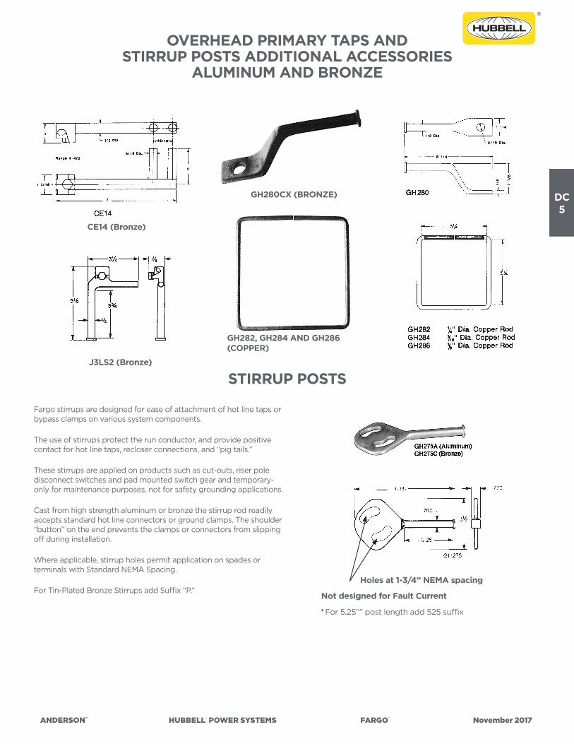
OVERHEAD PRIMARY TAPS ANDSTIRRUP POSTS ADDITIONAL ACCESSORIES
ALUMINUM AND BRONZE
STIRRUP POSTS
Fargo stirrups are designed for ease of attachment of hot line taps or bypass clamps on various system components.
The use of stirrups protect the run conductor, and provide positive contact for hot line taps, recloser connections, and “pig tails.”
These stirrups are applied on products such as cut-outs, riser pole disconnect switches and pad mounted switch gear and temporary-only for maintenance purposes, not for safety grounding applications.
Cast from high strength aluminum or bronze the stirrup rod readily accepts standard hot line connectors or ground clamps. The shoulder “button” on the end prevents the clamps or connectors from slipping off during installation.
Where applicable, stirrup holes permit application on spades or terminals with Standard NEMA Spacing.
For Tin-Plated Bronze Stirrups add Suffix “P.”Not designed for Fault Current
Holes at 1-3/4” NEMA spacing
* For 5.25”” post length add 525 suffix
GH280CX (BRONZE)
CE14 (Bronze)
J3LS2 (Bronze)
GH282, GH284 AND GH286(COPPER)

ANDERSON™ HUBBELL® POWER SYSTEMS FARGO® November 2017
DC6
OVERHEAD PRIMARY TAPSHOT LINE TAP CLAMPS
BRONZEBRONZE
BC/BH
For Copper conductor.
Designed for standard “hot stick” application.
Material: Body and Keeper – BC/BH—Brass Alloy BC/BH—FTP—Brass Alloy
— Tin Plated Eyebolt – Bronze Alloy Eyestem – Bronze Alloy or Stainless Steel Washer – BH—Silicon Bronze BC/BH—FTP—Stainless Steel
1. BC20LD has a longer “DUCKBILL” for easier attachment to a stirrup bail or conductor.
2. For connector with inhibitor in main jaw and plastic bag, add suffix “XB” to catalog number.
*For factory grease, replace “S” prefix with “P”.**RUS Listed
CATALOG NUMBER
MAINLINE TAP
FIG.NO. PLATING
PACKAG-ING
CONDUCTOR RANGE (AWG OR KCMIL)
DIMENSIONS INCHES (MM)
AP-PROX.
WT.EACHLBS.(KG).MAIN TAP D L H
BC20** CU CU
1
None Box
#8 Sol – 2/0 Str.
.128”-.419”
(3.25 - 10.64)
#8 Sol – 2/0 Str.
.128”-.414”
(3.25 - 10.51)
.78
(19.81)
1-1/4
(31.7)
5.0
(127.0)
0.7
(.32)
BC20XB** CU CU None Inhib & Bag
BC20FTP CU CU Tin plated Box
BC20FTPXB CU CU Tin plated Inhib & Bag
1.5
(38.1)
BC20LD CU CU
1A
None Box
BC20LDXB CU CU None Inhib & Bag
BC20LDFTP CU CU Tin Plated Box
BC20LDFTPXB CU CU Tin Plated Inhib & Bag
BH4 CU CU
2
None Box#6 Sol – 400mcm
.162” - .745”
(4.12 - 18.96)
#6 Sol – 4/0 Str.
.162” - .547”
(4.12 - 13.89)
-
1-3/8
(34.92)
6-3/4
(171.45)
1.71
(.78)
BH4XB CU CU None Inhib & Bag
BH4FTP CU CU Tin plated Box
BH4FTPXB CU CU Tin plated Inhib & Bag
*S1530CC CU CU
3
None Box #6 Sol – 400mcm
.162” - .745”
(4.12 - 18.96)
#6 Sol – 4/0 Str.
.162” - .547”
(4.12 - 13.89)
1-3/8
(34.92)
6-3/4
(171.45)
1.59
(.72)*S1530GP CU CU Tin plated Box
*S1540CC CU CU None Box 4/0 Str. - 800mcm
.502” - 1.031”
(12.78 - 26.24)
#4 Sol – 350mcm
.198” - .703”
(5.04 - 17.98)
1-7/8
(48)
8-1/4
(210)
2.03
(.92)*S1540GP CU CU Tin plated Box
Product Data & Conductor Size
FIGURE 1 FIGURE 1A FIGURE 2 FIGURE 3
FIGURE 1 & 1A (BC & BC-LD) FIGURE 2 (BH) FIGURE 3 (S1530CC/S1540CC)

ANDERSON™ HUBBELL® POWER SYSTEMS FARGO® November 2017
DC7
OVERHEAD PRIMARY TAPSLIGHTNING ARRESTER ACCESSORIES
ALUMINUM AND BRONZE ALUM/BRONZE
GH200/GO370
The arrester line connectors allow installation of lightning arrester directly on the line, which conserves pole space and the cost of mounting hardware.
• GH201D (bronze) and GH202AD (aluminum) versions are designed to accommodate the stud of the arrester in the rear extension of the connector.
• GO370 series Bronze Arrester Connectors thread onto the stud of an arrester. Side loading feature provides flexibility in application. Hot stick feature allows for change out of an arrester without interruption of service.
• This connector is intended primarily for bottom termination of lightning arresters to ground. May also be employed on top connections.
• GS580 Wildlife Protector is designed to be mounted on the top of a lightning arrester, and accommodates any of the GO370 series arrester connections. Hinged design allows easy access to connector. Track resistant polypropylene with ultraviolet inhibitors.
Material: Body and Keeper GH201D & GO300 Series – Bronze Body and Keeper 202AD – Aluminum Alloy Eyestem 201D – Bronze Alloy, Forged Eyestem 202AD – Aluminum Alloy, Forged Spring (on eyestem) – Stainless Steel Belleville
Note: Add “P” suffix for tin plating, ex GH201DP Add “L” suffix for factory loaded inhibitor in main
conductor groove, ex. GH201DPL
CATALOG NUMBER
MAINLINE
FIG.NO. PLATING
CONDUCTOR RANGE DIMENSIONS INCHES (MM) APPROX.WT.
EACHLBS.(KG).
PACKAG-ING COPPER ALUMINUM A B C
GH201D CU 1 None Box #8 Sol – 2/0 Str. n/a 4 (102) 1 (25) n/a .74 (.34)
GH202AD AL 2 None Box n/a 4/0 – 795 AAC
.522 – 1.028
6.5 (165) 1.5 (38) n/a .72 (.33)
GH202ADL AL/CU 2 None Box 4/0 Str. - 750 6.5 (165) 1.5 (38) n/a .72 (.33)
GO375 CU 3 None Box #6 – 1/0 Str
.184 - .373
n/a
3.9 (99) 0.9 (23) 1.9 (48) .48 (.22)
GO375P CU 3 Tin plated Box 3.9 (99) 0.9 (23) 1.9 (48) .50 (.23)
GO376 CU 3 None Box 2/0 – 350 Str.
.414 - .710
4.3 (109) 0.9 (23) 2.3 (59) .59 (.27)
GO376P CU 3 Tin plated Box 4.3 (109) 0.9 (23) 2.3 (59) .60 (.27)
GC207LA CU 4 None Box #6 Sol-1/0 Str. 1.25 (32) 0.75 (19) 1.77 (48) .22 (.99)
Product Data & Conductor Size
See also: Page DD-10 GC207LA & LAT
GH202ADGH201D
GO370 SERIES
GC207LAFIGURE 3FIGURE 4
FIGURE 2 FIGURE 1
B
A AOpen
3/8-16UNC 2B
B

ANDERSON™ HUBBELL® POWER SYSTEMS FARGO® November 2017
DC8
OVERHEAD PRIMARY TAPSHOT LINE CONNECTORS TWO HOLE PAD
BRONZE AND ALUMINUM
• Wide body contact area and two hole pad tap provide high current transfer for jumper or hot line clamp application.
• BHF – Bronze protected thread hot line clamp with two hole NEMA pad. Designed for copper main to copper flat pad tap.
• AHF – Aluminum protected thread hot line clamp with two hole NEMA pad. Designed for aluminum main to aluminum flat pad tap.
Material: Casting — BHF/GH1010 – Bronze Alloy BHF—FTP – Bronze Tin Plated AHF – Aluminum Alloy Spring (on eyestem) – Stainless Steel Eyestem – Bronze
BRONZE
BHF/AHF
CATALOG NUMBER FIG. NO.
CONDUCTOR RANGE (KCML) DIMENSIONS INCHES (MM) APPROX.WT. EACH LBS. (KG)MAIN MATERIAL A
MAIN CONTACT WIDTH H
BHF500B2 16 Sol. - 500 Str. CU
.162” - .813”Bronze
1.5
(36.75)
1.375
(35.0)
6.75
(171.4)
1.66
(.75)
GH1010 26 Sol – 400 CU
.160 - .730Bronze –
1.375
(35.0)
5.125
(130.25)
1.52
(.69)
Product Data & Conductor Size
FIGURE 1 FIGURE 2
FIGURE 1

ANDERSON™ HUBBELL® POWER SYSTEMS FARGO® November 2017
DC9
OVERHEAD PRIMARY TAPSSTIRRUP CLAMPS
ALUMINUM
For aluminum or ACSR conductor.
Eyestem is at 30º angle from the stirrup.
Material: Body – Aluminum Alloy Eyestem – Bronze Alloy—Tin Plated or Stainless Steel Stirrup – Copper-un-plated
Notes: Tin plated stirrup available by adding suffix “TB” to catalog number. Examples, AHLS022016ETB, AHLS954022EWBTB
Factory inhibited and bagged, add “XB”
CATALOG NUMBER
FIGURENO.
CONDUCTOR RANGE(AWG OR MCM) COPPER
LOOPSIZE
(INCHES)
BOLTS DIMENSIONS INCHES (MM)APPROX.
WT. EACH LBS. (KG)AAC ACSR NO. SIZE L B H
AHLS022016E 2 & 5 #6 Sol.-2/0 Str. #8-2/0 Str.#4
(.204)1
3/8
(9.52)
1-13/16
(46.04)
2-3/8
(60.32)
4-1/32
(102.39)
.53
(.24)
AHLS022019E 2 & 5#6 Sol.-2/0 Str. #8-2/0 Str.
#1
(.289)1
3/8
(9.52)
1-13/16
(46.04)
2-3/8
(60.32)
4-3/16
(106.36)
.67
(.30)
AHLS022019EWB 4 & 54-1/2
(114.3)
5-1/16
(128.59)
.71
(.32)
AHLS024019E 1 & 5 #2-4/0 Str. #4-4/0 Str.#1
(.289)2
3/8
(9.52)
3-1/2
(88.9)
4
(101.6)
4-1/16
(103.19)
1.19
(.54)
AHLS024021E 1 & 5#2-4/0 Str. #4-4/0 Str.
1/0
(.325)2
3/8
(9.52)
3-1/2
(88.9)
4
(101.6)
4-1/32
(103.19)
1.25
(.57)
AHLS024021EWB 3 & 56
(152.4)
4-29/32
(124.62)
1.29
(.59)
AHLS397021E 1 & 5 1/0-500 MCM 1/0-397.5 MCM1/0
(.325)2
7/16
(11.18)
3-11/16
(93.66)
4
(101.6)
4-3/32
(103.99)
1.56
(.71)
AHLS397022E 1 & 51/0-500 MCM 1/0-397.5 MCM
2/0
(.365)2
7/16
(11.18)
3-11/16
(93.66)
4
(101.6)
4-3/32
(103.99)
1.65
(.75)
AHLS397022EWB 3 & 56
(152.4)
4-31/32
(126.21)
1.91
(.87)
AHLS954022E 1 & 5336.4-1033.5 MCM 336.4-954 MCM
2/0
(.365)2
1/2
(12.7)
4-1/4
(107.95)
4-1/2
(114.3)
4-3/16
(106.36)
2.30
(1.04)
AHLS954022EWB 3 & 56
(152.4)
5-1/16
(128.59
2.41
(1.09)
AHLS954024E 1 & 5 336.4-1033.5 MCM 336.4-954 MCM4/0
(.460)2
1/2
(12.7)
4-1/4
(107.95)
4-1/2
(114.3)
4-3/16
(106.36)
2.49
(1.13)
ALUMINUM
AHLS
Product Data & Conductor Size
FIGURE 5FIGURE 2FIGURE 1 FIGURE 4FIGURE 3

ANDERSON™ HUBBELL® POWER SYSTEMS FARGO® November 2017
DC10
OVERHEAD PRIMARY TAPSSPRING LOADED “LINE SNAPPER”
STIRRUP CLAMPSALUMINUM
ALUMINUM
ESC
CATALOG NUMBER
MAINCONDUCTOR RANGE
STIRRUPNOM. WIRE
SIZE
DIMENSIONS INCHES (MM) APPROX.WT. EACH LBS. (KG)A B C J
ESC202
6 Sol.-2/0 Str.
#6 ACSR-2/0 ACSR
.162”-.447” O.D.
2 Sol.3-3/8
(85.8)
3-1/4
(82.5)
4
(101.6)
3/8
(9.6)140 (63)
ESC50020
2/0 Str.-500 Str.
1/0 ACSR-477(18/1)ACSR
.398”-.814” O.D
2/0 Sol.4
(101.6)
3-1/2
(88.9)
4-1/2
(114.3)
1/2
(12.7)247 (112)
• Two bolt stirrups have clip type springs to apply moderate pressure on the jaws as they are pushed onto the line. This pressure is enough to allow the assembly to support its own weight on the line while one of the eyestems is snugged down.
• Lifting eyes are provided on both jaws and eyestems are standard.• The angular relationship between stirrup and tightening bolts is an
easy approach position for making installation leaving the stirrup hanging straight down.
Material: Castings – Aluminum Alloy Stirrups – Copper Rod—Tin Plated Eyestems – Bronze Alloy Tin Plated or Stainless Steel Spring – Stainless Steel
Note: Factory inhibited and bagged, add “XB”
Product Data & Conductor Size
PEENED THREADS TOPREVENT DISASSEMBLY

ANDERSON™ HUBBELL® POWER SYSTEMS FARGO® November 2017
DC11
OVERHEAD PRIMARY TAPSWIDE JAW STIRRUP CLAMPS
ALUMINUM AND BRONZE ALUM/BRONZE
HLSA/HLSB
• Heavy duty wide range stirrup clamp covers a broad cable range. One eyestem with long contact keeper provides easy installation.
• HLSA aluminum body designed for use on aluminum main.
Material: Castings – Aluminum Alloy Stirrup – Un-plated Copper Eyestem – Bronze Alloy Tin Plated
• HLSB bronze body designed for use on copper main.
Material: Castings – Bronze Alloy Stirrup – Un-plated Copper Eyestem – Bronze Alloy Tin Plated
Note: Factory inhibited and bagged, add “XB”.
CATALOG NUMBER
MAIN LINECONDUCTOR RANGE MATERIAL
STIRRUP NOM. WIRE
SIZE
DIMENSIONS INCHES (MM) APPROX.WT. 100
LBS. (KG)A B C
HLSA4002 6 Sol. - 400 Str.
#6 ACSR - 397.5 (18/1) ACSR
.162” - .743” O.D.
Aluminum2 Sol. (.258)
3-1/8
(79.4)
3-3/8
(85.8)
2-3/4
(69.8)
116 (52)
HLSA40010 1/0 Sol. (.365) 136 (62)
HLSB40026 Sol. - 400 Str. Cu.
.162” - .728” O.D.Bronze 2 Sol. (.258)
3-1/8
(79.4)
3-3/8
(85.8)
2-3/4
(69.8)220 (99.8)
Product Data & Conductor Size
PEENED THREADS TOPREVENT DISASSEMBLY
ANDERSON™ HUBBELL® POWER SYSTEMS FARGO® November 2017
DC12
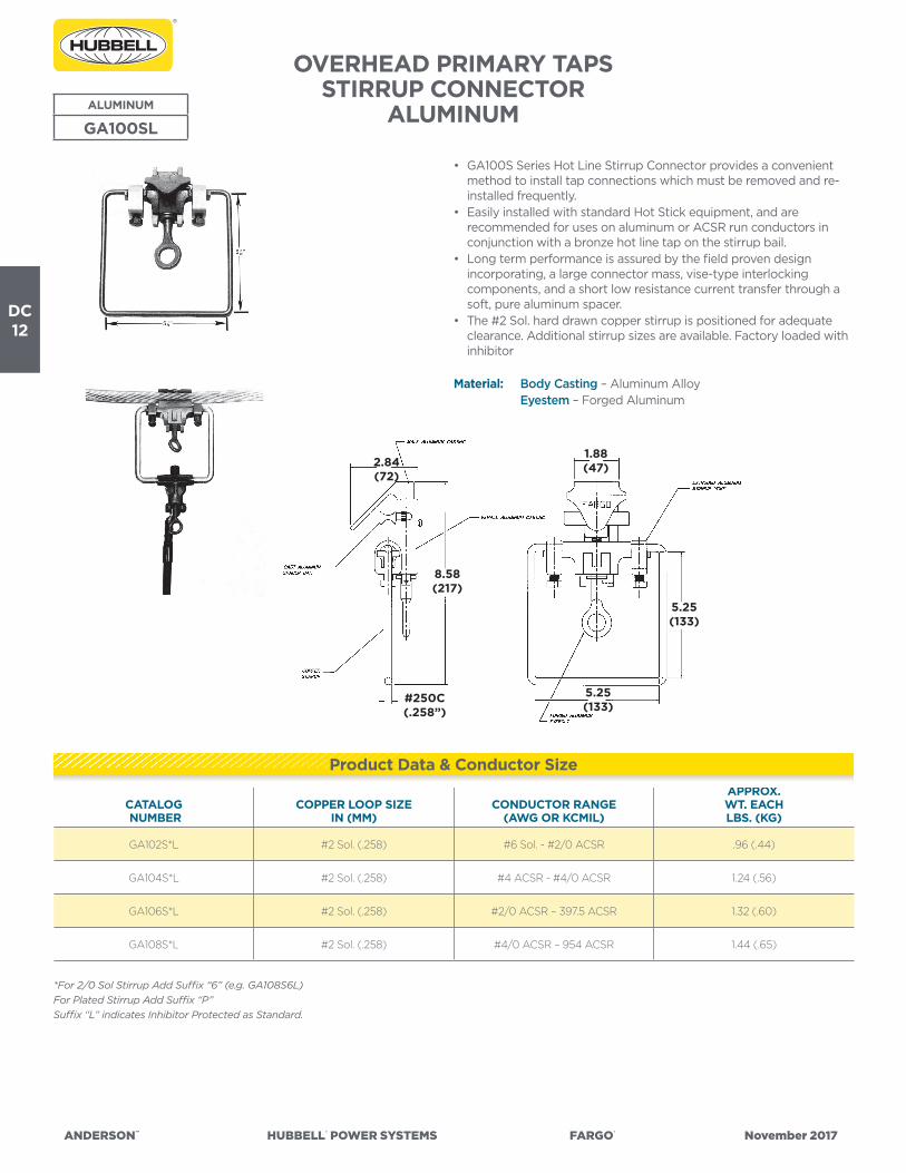
OVERHEAD PRIMARY TAPSSTIRRUP CONNECTOR
ALUMINUMALUMINUM
GA100SL
• GA100S Series Hot Line Stirrup Connector provides a convenient method to install tap connections which must be removed and re-installed frequently.
• Easily installed with standard Hot Stick equipment, and are recommended for uses on aluminum or ACSR run conductors in conjunction with a bronze hot line tap on the stirrup bail.
• Long term performance is assured by the field proven design incorporating, a large connector mass, vise-type interlocking components, and a short low resistance current transfer through a soft, pure aluminum spacer.
• The #2 Sol. hard drawn copper stirrup is positioned for adequate clearance. Additional stirrup sizes are available. Factory loaded with inhibitor
Material: Body Casting – Aluminum Alloy Eyestem – Forged Aluminum
CATALOG NUMBER
COPPER LOOP SIZEIN (MM)
CONDUCTOR RANGE(AWG OR KCMIL)
APPROX.WT. EACH LBS. (KG)
GA102S*L #2 Sol. (.258) #6 Sol. - #2/0 ACSR .96 (.44)
GA104S*L #2 Sol. (.258) #4 ACSR - #4/0 ACSR 1.24 (.56)
GA106S*L #2 Sol. (.258) #2/0 ACSR – 397.5 ACSR 1.32 (.60)
GA108S*L #2 Sol. (.258) #4/0 ACSR – 954 ACSR 1.44 (.65)
*For 2/0 Sol Stirrup Add Suffix “6” (e.g. GA108S6L)For Plated Stirrup Add Suffix “P”Suffix “L” indicates Inhibitor Protected as Standard.
Product Data & Conductor Size
2.84(72)
8.58(217)
#250C(.258”)
5.25(133)
5.25(133)
1.88(47)
ANDERSON™ HUBBELL® POWER SYSTEMS FARGO® November 2017
DC13
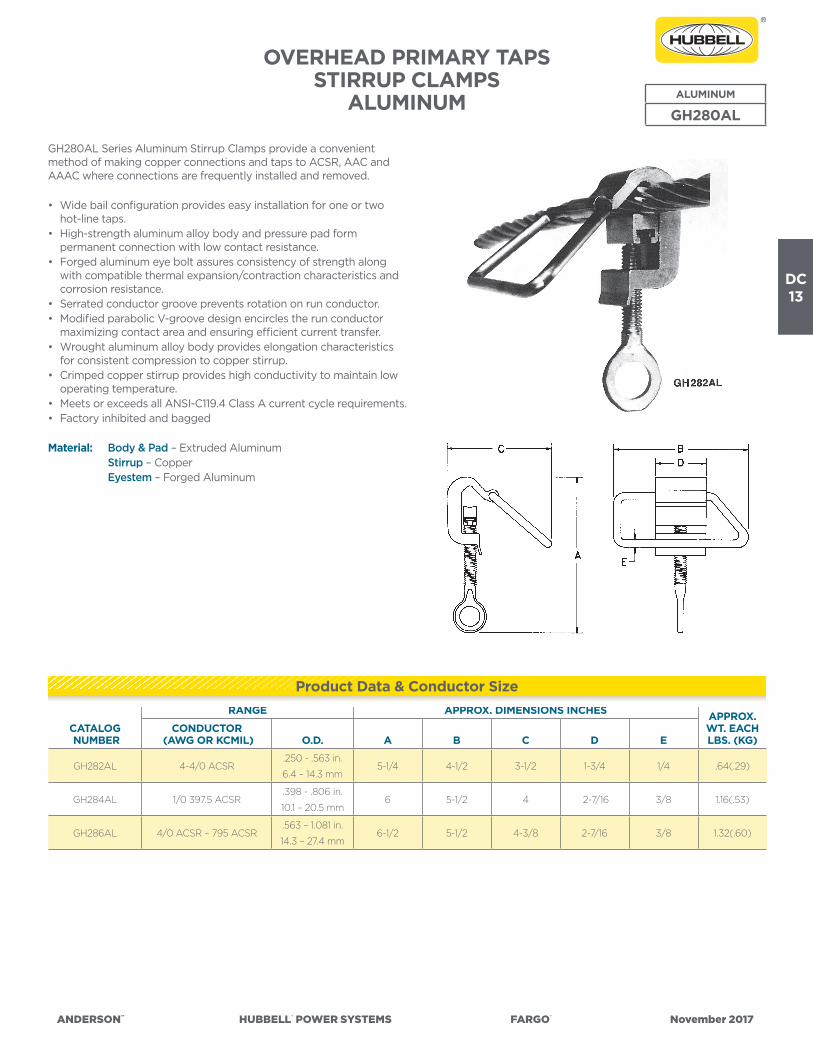
OVERHEAD PRIMARY TAPSSTIRRUP CLAMPS
ALUMINUM ALUMINUM
GH280AL
GH280AL Series Aluminum Stirrup Clamps provide a convenient method of making copper connections and taps to ACSR, AAC and AAAC where connections are frequently installed and removed.
• Wide bail configuration provides easy installation for one or two hot-line taps.
• High-strength aluminum alloy body and pressure pad form permanent connection with low contact resistance.
• Forged aluminum eye bolt assures consistency of strength along with compatible thermal expansion/contraction characteristics and corrosion resistance.
• Serrated conductor groove prevents rotation on run conductor.• Modified parabolic V-groove design encircles the run conductor
maximizing contact area and ensuring efficient current transfer.• Wrought aluminum alloy body provides elongation characteristics
for consistent compression to copper stirrup.• Crimped copper stirrup provides high conductivity to maintain low
operating temperature.• Meets or exceeds all ANSI-C119.4 Class A current cycle requirements.• Factory inhibited and bagged
Material: Body & Pad – Extruded Aluminum Stirrup – Copper Eyestem – Forged Aluminum
CATALOG NUMBER
RANGE APPROX. DIMENSIONS INCHES APPROX.WT. EACH LBS. (KG)
CONDUCTOR (AWG OR KCMIL) O.D. A B C D E
GH282AL 4-4/0 ACSR.250 - .563 in.
6.4 – 14.3 mm5-1/4 4-1/2 3-1/2 1-3/4 1/4 .64(.29)
GH284AL 1/0 397.5 ACSR.398 - .806 in.
10.1 – 20.5 mm6 5-1/2 4 2-7/16 3/8 1.16(.53)
GH286AL 4/0 ACSR – 795 ACSR.563 – 1.081 in.
14.3 – 27.4 mm6-1/2 5-1/2 4-3/8 2-7/16 3/8 1.32(.60)
Product Data & Conductor Size

ANDERSON™ HUBBELL® POWER SYSTEMS FARGO® November 2017
DC14
OVERHEAD PRIMARY TAPSBOLTED STIRRUP CLAMPS
BRONZEBRONZE
BHLS
For copper conductor.
Eyestem is at 30º angle from the stirrup.
Material: Body – Bronze Alloy Stirrup – Copper-un-plated Eyestem – Bronze alloy or Stainless Steel
Note: Tin plated loop available by adding suffix “TB” to catalog number. Example, BHLS025019ETB.
Factory inhibited and bagged, add “XB”
CATALOG NUMBER
FIGURENO.
COPPER CONDUCTOR RANGE
(AWG OR MCM)
COPPERLOOPSIZE
BOLTS DIMENSIONS INCHES (MM) APPROX.WT. 100
LBS. (KG)NO. SIZE L B H
BHLS022016E 2 & 3 #6 Sol.-2/0 Str.#4
(.204)1
3/8
(9.52)
1-13/16
(46.04)
2-3/8
(60.32)
4-3/16
(106.36)
1.06
(.48)
BHLS022019E 2 & 3 #6 Sol.-2/0 Str.#1
(.289)1
3/8
(9.52)
1-13/16
(46.04)
2-3/8
(60.32)
4-3/16
(106.36)
1.06
(.48)
BHLS025019E 1 & 3 #1 Sol.-250 MCM#1
(.289)2
3/8
(9.52)
3-1/2
(88.9)
4
(101.6)
4-1/16
(103.19)
1.71
(.77)
BHLS050022E 1 & 3 4/0-500 MCM2/0
(.365)2
7/16
(11.2)
3-11/16
(93.66)
4
(101.6)
4-3/16
(106.36)
2.70
(1.22)
Product Data & Conductor Size
FIGURE 2FIGURE 1

ANDERSON™ HUBBELL® POWER SYSTEMS FARGO® November 2017
DC15
HEAVY DUTY COMPRESSION STIRRUPTYPE HLS
ALUMINUM
HLS
• For use with Versa-Crimp® or standard compression tools.• Stirrups protect primary lines from arcing damage by allowing hot
line clamp connections to be made without contacting the main line. The HLS design offers convenient installation because it can be lifted and placed on the line using the crimping tool jaws as a holding device.
• Wide stance of crimping segments gives good stability when striking bail with a hot line clamp. All sizes have side opening line slots.
• Stirrups can be used on either aluminum or copper lines. Contact grooves are prefilled with electrical joint compound. Individually packaged in poly bags to prevent contamination.
Material: Castings – Aluminum Alloy Stirrup – Copper Rod—Tin Plated
CATALOG NUMBER
CONDUCTOR RANGE (AL OR CU)
STIRRUPWIRE SIZE
CRIMPDIE
SIZES
HINCHES
(MM)
APPROX.WT. EACH LBS. (KG)AWG & KCMIL ACSR
DIAMETER(INCHES)
HLS42P 6 Sol.-4 Str. 6 .162-.236
2 Sol.
Burndy
Kearney
Etc.
“O” Die
3.25
(82)50 (22.7)HLS22P 2 Sol.-2 Str. 4-2 .250-.325
HLS102P 1/0 Str. 1-1/0 .355-.398
HLS302P 2/0 & 3/0 Str. 2/0-3/0 .414-.517
2 Sol.
EEI-13A
Burndy
316,655 & 705
Kearney
1-1/8
3.25
(82)
60 (27.2)HLS2662P 4/0-266 Str. 4/0-266 18/1 .522-.609
HLS3502P336-350 Str.
266-26/7
336-18/1
336-26/7
.607-.721HLS35020P 2/0 Sol. 81 (36.7)
HLS50010P
397.5-500 Str.
397.5-18/1
397.5-36/1
477-18/1
477-36/1
.720-.814
1/0 Sol.Kearney
1-5/16
3.75
(95)
82 (37.2)
HLS50020P 2/0 Sol. 91 (41.3)
HLS65010P500-650 Str.
477-18/1
556-18/1
636-36/1
.811-.9301/0 Sol.
Kearney
1-1/2
3.75
(95)
95 (43.1)
HLS65020P 2/0 Sol. 105 (47.6)
HLS80010P
700-800 Str.
636-18/1
636-36/1
666.6-36/1
795-36/1
.930-1.040
1/0 Sol.
Kearney
1-1/2
3.75
(95)
92 (41.7)
HLS80020P 2/0 Sol. 102 (46.3)
HLS80040P 4/0 Sol. 122 (55.3)
Product Data & Conductor Size

ANDERSON™ HUBBELL® POWER SYSTEMS FARGO® November 2017
DC16
VERSA-CRIMP® ALUMINUM COMPRESSION STIRRUP TAP TYPE VCLS
• For use with VERSA-CRIMP® Type VC6 (all) tools only.
Material: Body – Aluminum Alloy Stirrup – Un-plated Copper Factory inhibited (See notes below)
CATALOG NUMBER
FIG-URENO.
CONDUCTOR RANGELOOPSIZE
VERSA- CRIMP
TOOL TYPE
DIMENSIONS INCHES (MM) APPROX.WT. EACH LBS. (KG)AAC ACSR COPPER L B H
VCLS3018 1 #6 (7)—#2(19) #6 (6/1)—#2 (7/1) #6 Sol.-#2 (7) #2 Sol.
VC6
(ALL)
8-5/8
(219.1)
4
(101.6)
3-7/16
(87.3)
.44
(.20)
*VCLS5018 1 #6 (7)—2/0 (19) #6 (6/1)—2/0 (6/1) — #2 Sol.7-7/8
(200.0)
4
(101.6)
3-7/16
(87.3)
.48
(.22)
*VCLS6021 1 #4 (7)—266.8 (19) #4 (6/1)—4/0(6/1) — 1/0 Sol.8
(203.2)
4
(101.6)
3-1/2
(88.9)
.65
(.29)
VCLS9022 2 3/0 (7)—556.5 (19)3/0 (6/1)—477
(30/7)—
2/0
Sol.
VC6-3
VC6-FT
9-15/16
(252.41)
4-7/16
(112.7)
5-11/16
(144.5)
.80
(.36)
Note: Tin plated loop available by adding suffix “TB” to catalog number. Example, VCLS3018TB.* For deep throated bail, add suffix “DB” to catalog number. Example, VCLS5018DB.
ALUMINUM
VCLS
Product Data & Conductor Size
FIGURE 1

ANDERSON™ HUBBELL® POWER SYSTEMS FARGO® November 2017
DC17
OVERHEAD PRIMARY TAPSCOMPRESSION VERSA-CRIMP® COPPER COMPRESSION STIRRUP TAP COPPER COPPER
VCLSC
• For use with VERSA-CRIMP® Type VC6 nd VC7 series tools only.• For copper conductor.
Material: Body – Cast Copper Alloy Stirrup – Un-plated Copper
CATALOG NUMBER COPPER CONDUCTOR RANGE
LOOPSIZE
VERSA-CRIMP
TOOL TYPE
DIMENSIONS INCHES (MM) APPROX.WT. EACH LBS. (KG)L B H
VCLSC3018 #6.Sol.–#2/(7)#2 Sol.
Cu.VC7
VC6
(ALL)
5-1/2
(139.7)
5
(127.0)
5-11/32
(17.46)
.80
(.36)
VCLSC5021 #2 Sol.–2/0 (19)1/0 Sol.
Cu.
5-9/16
(141.3)
5
(127.0)
5-15/16
(150.81)
.96
(.44)
VCLSC6022 1/0 (7)–4/0(19)2/0 Sol.
Cu.
5-9/16
(141.3)
5
(127.0)
6-15/16
(176.21)
1.20
(.54)
Product Data & Conductor Size
B
L
H
ANDERSON™ HUBBELL® POWER SYSTEMS FARGO® November 2017
DC18
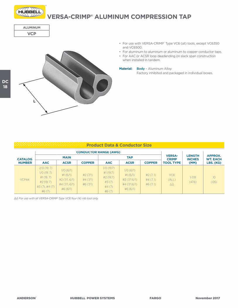
VERSA-CRIMP® ALUMINUM COMPRESSION TAPALUMINUM
VCP
• For use with VERSA-CRIMP® Type VC6 (all) tools, except VC6350 and VC6500.
• For aluminum to aluminum or aluminum to copper conductor taps.• For AAC or ACSR loop deadending on slack span construction
when installed in tandem.
Material: Body – Aluminum Alloy Factory inhibited and packaged in individual boxes.
CATALOG NUMBER
CONDUCTOR RANGE (AWG)VERSA-CRIMP
TOOL TYPE
LENGTHINCHES
(MM)
APPROX.WT. EACH LBS. (KG)
MAIN TAP
AAC ACSR COPPER AAC ACSR COPPER
VCP44
2/0 (19, 7)
1/0 (19, 7)
#1 (19, 7)
#2 (19, 7)
#3 (7), #4 (7)
#6 (7)
1/0 (6/1)
#1 (6/1)
#2 (7/1, 6/1)
#4 (7/1, 6/1)
#6 (6/1)
#2 (7/1)
#4 (7/1)
#6 (7/1)
1/0 (19,7)
#1 (19,7)
#2 (19,7)
#3 (7)
#4 (7)
#6 (7)
1/0 (6/1)
#1 (6/1)
#2 (7/1 6/1)
#4 (7/1,6/1)
#6 (6/1)
#2 (7, 1)
#4 (7, 1)
#6 (7, 1)
VC6
(ALL)
∆∆
1-7/8
(47.6)
.10
(.05)
∆∆ For use with all VERSA-CRIMP Type VC6 four (4) nib tool only.
Product Data & Conductor Size
L
ANDERSON™ HUBBELL® POWER SYSTEMS FARGO® November 2017
DC19
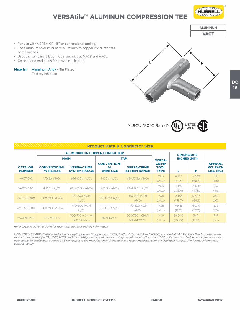
VERSAtile™ ALUMINUM COMPRESSION TEEALUMINUM
VACT
• For use with VERSA-CRIMP® or conventional tooling.• For aluminum to aluminum or aluminum to copper conductor tee
combinations.• Uses the same installation tools and dies as VACS and VACL.• Color coded end plugs for easy die selection.
Material: Aluminum Alloy – Tin Plated Factory inhibited
CATALOG NUMBER
ALUMINUM OR COPPER CONDUCTOR
VERSA-CRIMPTOOLTYPE
DIMENSIONS INCHES (MM)
APPROX.WT. EACH LBS. (KG)
MAIN TAP
CONVENTIONALWIRE SIZE
VERSA-CRIMPSYSTEM RANGE
CONVENTION-AL
WIRE SIZEVERSA-CRIMP
SYSTEM RANGE L H
VACT1010 1/0 Str. Al/Cu #8-1/0 Str. Al/Cu 1/0 Str. Al/Cu #8-1/0 Str. Al/CuVC6
(ALL)
4-1/2
(114.3)
2-5/8
(66.7)
.106
(.05)
VACT4040 4/0 Str. Al/Cu #2-4/0 Str. Al/Cu 4/0 Str. Al/Cu #2-4/0 Str. Al/CuVC6
(ALL)
5-1/4
(133.4)
3-1/16
(77.8)
.237
(.11)
VACT300300 300 MCM Al/Cu1/0-300 MCM
Al/Cu300 MCM Al/Cu
1/0-300 MCM
Al/Cu
VC6
(ALL)
5-1/2
(139.7)
3-5/16
(84.2)
.350
(.16)
VACT500500 500 MCM Al/Cu4/0-500 MCM
Al/Cu500 MCM Al/Cu
4/0-500 MCM
Al-Cu
VC6
(ALL)
7-9/16
(192.1)
4-7/16
(112.7)
.579
(.26)
VACT750750 750 MCM Al500-750 MCM Al
500 MCM Cu750 MCM Al
500-750 MCM Al
500 MCM Cu
VC6
(ALL)
8-13/16
(223.9)
5-1/4
(133.4)
.747
(.34)
Refer to page DC-30 & DC-31 for recommended tool and die information.
HIGH VOLTAGE APPLICATIONS—All Aluminum/Copper and Copper Lugs (VCEL, VACL, VHCL, VHCS and VCELC) are rated at 34.5 KV. The other U.L. listed com-pression connectors (VACS, VACT, VCCT, VHSS and VHS) have a maximum UL voltage requirement of less than 2000 volts, however Anderson recommends these connectors for application through 34.5 KV subject to the manufacturers’ limitations and recommendations for the insulation material. For further information, contact factory.
Product Data & Conductor Size
LISTED261LAL9CU (90°C Rated)
L H

ANDERSON™ HUBBELL® POWER SYSTEMS FARGO® November 2017
DC20
VERSA-CRIMP® ALUMINUM COMPRESSION TAP
ALUMINUM
VCL
• For use with VERSA-CRIMP® Type VC6 (all) tools only.• For aluminum to aluminum or aluminum to copper conductor
connections.• Aluminum alloy conductor recommendations include 5005, 6201
(AAAC) and ACAR which are of the same diameter as a given ACSR conductor shown below.
Material: Aluminum Alloy Factory inhibited
CATALOG NUMBER
CONDUCTOR RANGE VERSA-CRIMPTOOLTYPE
DIMENSIONS INCHES (MM) APPROX.WT. EACH LBS. (KG)MAIN TAP L H
VCL54
#6 (7)—2/0 (19) AAC
#6 (6/1)—2/0 (6/1) ACSR
#6 (7)—#1 (19) Cu
#8 (7)-1/0 (19) AAC
#8 (6/1)—1/0 (6/1) ACSR
#10 Sol.—#2 (7) Cu
VC6
(ALL)
2-11/16
(68.26)
2-1/2
(63.5)
.17
(.08)
VCL64
#4 (7)—4/0 (19) AAC
#4 (6/1)—4/0 (6/1) ACSR
#4 (7)—2/0 (19) Cu
#8 (7)—1/0 (19) AAC
#8 (6/1)— 1/0 (6/1) ACSR
#10 Sol.— #2 (7) Cu
2-23/32
(69.06)
2-33/64
(63.90)
.19
(.09)
VCL66
#4 (7)—4/0 (19) AAC
#4 (6/1)—4/0 (6/1) ACSR
#4 (7)—2/0 (19) Cu
#4 (7)—4/0 (19) AAC
#4 (6/1)—4/0 (6/1) ACSR
#4 Sol.—2/0 (19) Cu
2-31/32
(75.41)
3-19/64
(83.74)
.26
(.12)
VERSA-CRIMP® ALUMINUM COMPRESSION TAPALUMINUM
VC2T
• For use with VERSA-CRIMP® Type VC6 (all) tools only.• For aluminum to aluminum or aluminum to copper conductor
connections.• Aluminum alloy conductor recommendations include 5005, 6201
(AAAC) and ACAR which are of the same diameter as a given ACSR conductor shown below.
Material: Aluminum Alloy Factory inhibited
CATALOG NUMBER
CONDUCTOR RANGE (AWG) VERSA-CRIMPTOOLTYPE
DIMENSIONS INCHES (MM) APPROX.WT. EACH LBS. (KG)MAIN TAP L H
VC2T66
#4 Sol.—4/0 (19) AAC
#4 (6/1)—4/0 (6/1) ACSR
# 4 Sol.—2/0 (19) Cu
#4 Sol.—4/0 (19) AAC
#4 (6/1)— 4/0 (6/1) ACSR
#4 Sol.—2/0 (19) Cu
VC6
(ALL)
3-1/8
(79.4)
5-7/16
(138.1)
.40
(.18)
Product Data & Conductor Size
Product Data & Conductor Size
L
H
L
H

ANDERSON™ HUBBELL® POWER SYSTEMS FARGO® November 2017
DC21
VERSA-CRIMP® ALUMINUM COMPRESSION TEE
ALUMINUM
VCT
• For use with VERSA-CRIMP® Type VC6 (all) tools only.• For aluminum to aluminum or aluminum to copper conductor tee
connections.• Aluminum alloy conductor recommendations include 5005, 6201
(AAAC) and ACAR having the same diameter as a given ACSR conductor shown below.
Material: Aluminum Alloy Factory inhibited
CATALOG NUMBER
FIGURENO.
CONDUCTOR RANGE (AWG OR MCM) VERSA-CRIMP
TOOL TYPE
DIMENSIONS INCHES (MM) APPROX.WT. EACH LBS. (KG)MAIN TAP L H
VCT55 1#6 (7)-2/0 (19) AAC
#6 (6/1)-2/0 (6/1) ACSR
#6 (7)-2/0 (19) AAC
#6 (6/1)-2/0 (6/1) ACSR
#6 Sol.-#1 (19) Cu
VC6
(ALL)
4-1/16
(103.2)
2-7/8
(73.0)
.55
(.25)
VCT95 23/0 (7)-500 (37) AAC
3/0 (6/1)-477 (18/1) ACSR
#6 (7)-2/0 (19) AAC
#6 (6/1)-2/0 (6/1) ACSR
#6 Sol.-1/0 (19) Cu
VC63
VC6FT
5-5/16
(134.9)
4-7/16
(112.7)
.93
(.42)
VCT96 23/0 (7)-500 (37) AAC
3/0 (6/1)-477 (18/1) ACSR
1/0 (7)-4/0 (19) AAC
1/0 (6/1)-4/0 (6/1) ACSR
1/0 (7)-3/0 (19) Cu
VC63
VC6FT
5-5/16
(134.9)
4-7/16
(112.7)
.97
(.44)
VCT99 23/0 (7)-500 (37) AAC
3/0 (6/1)-477 (18/1) ACSR
4/0 (7)-350 (37) AAC
4/0 (6/1)-477 (18/1) ACSR
4/0 (7)-350 (37) Cu
VC63
VC6FT
5-5/16
(134.9)
6-7/16
(163.5)
1.20
(.54)
Product Data & Conductor Size
FIGURE 1
L
H
FIGURE 2

ANDERSON™ HUBBELL® POWER SYSTEMS FARGO® November 2017
DC22
VERSA-CRIMP® ALUMINUM COMPRESSION TAP
ALUMINUM
VCU
• For use with VERSA-CRIMP® Type VC6 (all) tools.• For aluminum to aluminum or aluminum to copper conductors.• Aluminum alloy conductor recommendations include 5005, 6201
(AAAC) and ACAR which are of the same diameter as a given ACSR conductor shown below.
Material: Aluminum Alloy Factory inhibited
CATALOG NUMBER
CONDUCTOR RANGE VERSA-CRIMP
TOOL TYPE
DIMENSIONS INCHES (MM) APPROX.WT. EACHLBS. (KG)MAIN TAP L H
VCU55
#6 (7)-2/0 (19) AAC
#6 (6/1)-2/0 (6/1) ACSR
#8 (7)-#4 (7) Cu
#6 (7)-2/0 (19) AAC
#6 (6/1)-2/0 (6/1) ACSR
#8 (7)-#4 (7) Cu
VC6
(ALL)
3-1/8
(79.38)
3-1/8
(79.38)
.18
(.08)
VCU65
#4 (7)-4/0 (19) AAC
#4 (6/1)-4/0 (6/1) ACSR
#4 (7)-2/0 (19) Cu
#6 (7)-2/0 (19) AAC
#6 (6/1)-2/0 (6/1) ACSR
#8 (7)-#4 (7) Cu
3-3/16
(80.96)
3-1/8
(79.38)
.20
(.09)
VCU66
#4 (7)-4/0 (19) AAC
#4 (6/1)-4/0 (6/1) ACSR
#4 (7)-2/0 (19) Cu
#4 (7)-4/0 (19) AAC
#4 (6/1)-4/0 (6/1) ACSR
#4 (7)-2/0 (19) Cu
3-3/16
(80.96)
3-3/16
(80.96)
.24
(.11)
Product Data & Conductor Size
L
H

ANDERSON™ HUBBELL® POWER SYSTEMS FARGO® November 2017
DC23
Cat
alog
Num
ber
VAC
L (3
)
VAC
S (4
)
VAC
T (4
)
AN
DER
SON
™ V
ERSA
-CR
IMP®
CO
MPR
ESSI
ON
TO
OLS
(Cri
mps
per
Con
nect
ion)
CO
NV
ENTI
ON
AL
CO
MPR
ESSI
ON
DIE
TO
OLI
NG
(Cri
mps
per
Con
nect
ion)
V-C
Too
lsW
ireR
ange
(AW
G o
rM
CM
)
VER
SA-C
RIM
P To
ols
(Num
ber
of C
rim
ps)
Wire
Size
(AW
Gor
MC
M)
Die
Col
orC
ode
(2)
Bur
ndy
(Cri
mps
)B
urnd
y In
dent
or T
ools
(1 C
rim
p)
*VC
650
0V
C6
350
VC
6(1
)
VC
6FT (1
)
VC
8A
LN
IBS
Die
Inde
xN
o.
Tool
Y34
A
Tool
sY
35Y
39To
olY
34B
Tool
Y4
8BTo
olY
486
RB
Tool
MY-
29
Tool
Y34
A(I
nden
-to
r)
Tool
Y34
B(I
nden
-to
r)
Tool
Y4
8B(I
nden
-to
r)
Tool
Y4
86R
B(I
nden
-to
r)D
ieD
ieD
ieD
ieD
ieD
ieN
est
Nes
tN
est
Nes
t
-8#
8 A
L/C
U1
1#
8A
L/C
UB
lue
374
U8C
AB
T(2
)#
8 (1)
-6#
6 A
L/C
U1
1#
6A
L/C
UG
ray
346
A6C
AB
(1)
U6C
AB
T(1
)B
6CD
(1)
#6 (1)
A4
CD
(Y34
PA)
B4
CD
(Y34
PA)
-4#
4 A
L/C
U2
2#
4A
L/C
UG
reen
375
A4
CA
B(1
)U
4C
AB
T*
(1)
B4
CD
(1)
C4
CA
B(1
)#
4 (1)
A1C
D(Y
34PA
)B
1CD
(Y34
PA)
-2#
6-#
2 A
L/C
U2
22
2#
2A
L/C
UP
ink
348
A2C
AB
(1)
U2C
AB
T(1
)B
2CD
(1)
#2
(2)
A26
D(Y
34PA
)B
26D
(Y34
PA)
-1#
8-#
1 AL/
CU
22
22
#1
AL/
CU
Tan
296
A25
AR
(1)
U25
AR
T*
(1)
B1C
D(1
)#
1(2
)A
27D
(Y34
PR
-5)
B27
D(Y
34P
R-5
)
-1/0
#8-
1/0
AL/
CU
22
22
1/0
AL/
CU
Tan
296
A25
AR
(1)
U25
AR
T*
(1)
B25
D(1
)1/
0(2
)A
27D
(Y34
PR
-5)
B27
D(Y
34P
R-5
)
-2/0
#4
-2/0
AL/
CU
22
22
2/0
AL/
CU
Oliv
e29
7A
26A
R(2
)U
26A
RT
(2)
B26
D(1
)2/
0(2
)A
29D
(Y34
PR
-5)
B29
D(Y
34P
R-5
)
-3/0
#4
-3/0
AL/
CU
22
22
3/0
AL/
CU
Rub
y4
67A
27A
R(2
)U
27A
RT
(2)
B27
D(1
)3/
0(2
)A
30D
(Y34
PR
-5)
B30
D(Y
34P
R-5
)
-4/0
#2-
4/0
AL/
CU
33
22
4/0
AL/
CU
Whi
te29
8A
28A
R(2
)U
28A
RT
(2)
B28
D(1
)C
28A
R(1
)F2
8AR
(1)
4/0
(2)
A31
D(Y
34P
R-5
)B
31D
(Y34
PR
-5)
-250
1/0
-250
AL/
CU
33
22
250
AL/
CU
Red
324
A29
AR
(2)
U29
AR
T(2
)B
29D
(1)
C29
AR
(1)
F29A
R(1
)A
32D
(Y34
PR
-5)
B32
D(Y
34P
R-5
)
-30
01/
0-3
00
AL/
CU
33
22
300
AL/
CU
Blu
e47
0A
30A
R(2
)U
30A
RT
(2)
B30
D(2
)C
30A
R(1
)F3
0A
R(1
)A
34D
(Y34
PR
-11)
No
Die
C34
D(Y
48P
R-1
)F3
4D
(Y4
8PR
-1)
-350 (1)
2/0
-350
AL/
CU
43
335
0A
L/C
UB
row
n29
9U
31A
RT
(2)
B31
D(2
)C
31A
R(1
)F3
1AR
(1)
C35
D(Y
48P
R-1
)F3
5D(Y
48P
R-1
)-4
00
(1)
3/0
-40
0 A
L/C
U5
4O
’lap
4O
’lap
40
0A
L/C
UG
reen
472
U32
AR
T(4
)B
32D
(2)
C32
AR
(2)
F32A
R(2
)C
36D
(Y4
8PR
-1)
F36D
(Y4
8PR
-1)
-50
0(1
)4/
0-5
00
AL/
CU
74
O’la
p4
O’la
p50
0A
L/C
UG
reen
472
U32
AR
T(4
)
No
Die
Req
uire
d(2
)
C32
AR
(2)
F32A
R(2
)
-60
035
0 -
60
0 A
L35
0 -
50
0 C
U4
360
0 A
LP
ink
300
U34
AR
T(4
)C
34A
R(2
)F3
4A
R(2
)
-750
500
- 7
50 A
L50
0 C
U4
375
0 A
LP
ink
300
U34
AR
T(4
)C
34A
R(2
)F3
4A
R(2
)
-10
00
750
-10
00
AL
310
00
AL
Bro
wn
302
C4
4A
R(2
)F4
4A
R(2
)C
46D
(Y4
8PR
-1)
F46D
(Y4
8PR
-1)
+ TB
M-8
Too
l ON
LYH
A
nder
son
HC
-12
Die
s, B
urnd
y’s
Y-35
Die
s an
d B
lack
bur
n’s
JB-1
2 D
ies
are
inte
rcha
ngea
ble
.(1
) “V
AC
L” L
ug s
izes
-35
0 t
o -5
00
tak
e 1 l
ess
crim
p (
VC
6 To
ols)
tha
n sh
own.
(2)
Col
or c
ode
is fo
r A
nder
son
and
Bur
ndy
die
s on
ly. U
se t
he r
ecom
men
ded
die
num
ber
(N
OT
die
col
or)
for
Bla
ckb
urn,
Kea
rney
& T
&B
Hyd
. Too
ls/D
ies.
(3)
The
“VA
CL”
lug
s ar
e q
ualifi
ed fo
r U
L “H
V”
app
licat
ions
.(4
) Th
e “V
AC
S” s
leev
es a
nd “
VAC
T” t
ee c
onne
ctor
s ar
e fo
r A
L to
AL
or A
L to
CU
con
nect
ions
ON
LY. (
NO
T fo
r C
U t
o C
U c
onne
ctio
ns).
* N
ot U
L Li
sted
-pen
din
g c
omp
letio
n of
tes
t.
VA
CL/
VA
CS/
VA
CT—
And
erso
n/B
urnd
y

ANDERSON™ HUBBELL® POWER SYSTEMS FARGO® November 2017
DC24
Cat
alog
Num
ber
VAC
L (3
)
VAC
S (4
)
VAC
T (4
)
AN
DER
SON
™ V
ERSA
-CR
IMP®
CO
MPR
ESSI
ON
TO
OLS
(Cri
mps
per
Con
nect
ion)
CO
NV
ENTI
ON
AL
CO
MPR
ESSI
ON
DIE
TO
OLI
NG
(Cri
mps
per
Con
nect
ion)
V-C
Too
lsW
ireR
ange
(AW
G o
rM
CM
)
VER
SA-C
RIM
P To
ols
(Num
ber
of C
rim
ps)
Wire
Size
(AW
Gor
MC
M)
Die
Col
orC
ode
(2)
Bla
ckbu
rn(C
rim
ps)
Kea
rney
(Cri
mps
)Th
omas
& B
etts
(Cri
mps
)
*VC
650
0V
C6
350
VC
6(1
)
VC
6FT (1
)
VC
8A
LN
IBS
Tool
OD
-58
Tool
JB-1
2A
Die
Tool
s(N
o. o
f Cri
mps
)
Tool
sTB
M5
TBM
8
12 T
on
Hyd
. To
ol
15 T
on
Hyd
. To
ol
Die
Die
O-5
2W
H-1
PH-1
WH
-2PH
-2D
ieD
ieD
ie
-8#
8 A
L/C
U1
1#
8
AL/
CU
Blu
eB
Y17
C
(2)
B73
CH
(1)
1/4
(2)
Blu
e
(1)
24 (1)
24 (1)
-6#
6 A
L/C
U1
1#
6
AL/
CU
Gra
yB
Y19
C
(3)
B74
CH
(1)
5/16
(3)
(1)
(1)
Gra
y
(2)
29 (2)
29 (2)
-4#
4 A
L/C
U2
2#
4
AL/
CU
Gre
enB
Y21
C
(3)
U4
CA
BT
* (1
)3/
8(3
)(2
)(2
)G
reen
(2)
37 (2)
37 (2)
-2#
6-#
2 A
L/C
U2
22
2#
2
AL/
CU
Pin
kB
Y23
C
(3)
BO
6CH
(1)
1/2
(3)
(2)
(2)
Pin
k
(2)
45
(2)
45
(2)
-1#
8-#
1 AL/
CU
22
22
#1
AL/
CU
Tan
BY
23C
(4)
U25
AR
T
* (1
)9/
16(4
)(2
)(2
)Ta
n
(2)
50 (2)
50 (2)
-1/0
#8-
1/0
AL/
CU
22
22
1/0
AL/
CU
Tan
BY
25C
(4)
U25
AR
T
* (1
)9/
16(4
)(2
)(2
)Ta
n
(2)
50 (2)
50 (2)
-2/0
#4
-2/0
AL/
CU
22
22
2/0
AL/
CU
Oliv
eB
Y31
C
(4)
B0
9CH
(2)
5/8-
1(4
)(3
)(3
)O
live
(2)
54 (1)
54H
(2)
-3/0
#4
-3/0
AL/
CU
22
22
3/0
AL/
CU
Rub
yB
Y27
C
(5)
B26
CH
(2)
11/16
(5)
(3)
(3)
Rub
y
(2)
62 (1)
62 (1)
-4/0
#2-
4/0
AL/
CU
33
22
4/0
AL/
CU
Whi
teB
Y35
C
(5)
B10
CH
1
(2)
781
(5)
(3)
(3)
+Whi
te
(4)
71H
(3)
71H
(3)
-250
1/0
-250
AL/
CU
33
22
250
AL/
CU
Red
BY
37C
(5)
B11C
H
(2)
840
(5)
(3)
(3)
+Red
(5)
76H
(3)
76 (2)
-30
01/
0-3
00
AL/
CU
33
22
300
AL/
CU
Blu
eB
61E
A
(1)
29/3
2(2
)(2
)+B
lue
(5)
87H
(3)
87H
(3)
-350 (1)
2/0
-350
AL/
CU
43
335
0
AL/
CU
Bro
wn
B12
CH
1
(2)
1-1/
8-1
(2)
(2)
+Bro
wn
(5)
94H
(3)
94H
(3)
-40
0(1
)3/
0-4
00
AL/
CU
54
O’la
p
4
O’la
p
40
0
AL/
CU
Gre
enB
80E
A
(2)
1-1/
8-1
(2)
(2)
99H
(3)
99H
(3)
-50
0(1
)4/
0-5
00
AL/
CU
74
O’la
p
4
O’la
p
500
AL/
CU
Gre
enB
80E
A
(3)
1-1/
8-2
(2)
(2)
96H
(4)
96 (2)
-60
035
0 -
60
0 A
L
350
- 5
00
CU
43
600
AL
Pin
kB
20A
H
(3)
1-5/
16(4
)10
6H (5)
106H (5)
-750
500
- 7
50 A
L
500
CU
43
750
AL
Pin
kB
20A
H
(3)
1-5/
16(4
)10
6H (5)
106H (5)
-10
00
750
-10
00
AL
310
00
AL
Bro
wn
+ TB
M-8
Too
l ON
LYH
A
nder
son
HC
-12
Die
s, B
urnd
y’s
Y-35
Die
s an
d B
lack
bur
n’s
JB-1
2 D
ies
are
inte
rcha
ngea
ble
.(1
) “V
AC
L” L
ug s
izes
-35
0 t
o -5
00
tak
e 1 l
ess
crim
p (
VC
6 To
ols)
tha
n sh
own.
(2)
Col
or c
ode
is fo
r A
nder
son
and
Bur
ndy
die
s on
ly. U
se t
he r
ecom
men
ded
die
num
ber
(N
OT
die
col
or)
for
Bla
ckb
urn,
Kea
rney
& T
&B
Hyd
. Too
ls/D
ies.
(3)
The
“VA
CL”
lug
s ar
e q
ualifi
ed fo
r U
L “H
V”
app
licat
ions
.(4
) Th
e “V
AC
S” s
leev
es a
nd “
VAC
T” t
ee c
onne
ctor
s ar
e fo
r A
L to
AL
or A
L to
CU
con
nect
ions
ON
LY. (
NO
T fo
r C
U t
o C
U c
onne
ctio
ns).
* N
ot U
L Li
sted
-pen
din
g c
omp
letio
n of
tes
t.
VA
CL/
VA
CS/
VA
CT—
And
erso
n/B
urnd
y
Related Documents