Defender Series™ Overfill Prevention Valve Automatic Shutoff for USTs Installation, Operation and Maintenance 708-590 Series Franklin Fueling Systems • 3760 Marsh Rd. • Madison, WI 53718 USA Tel: +1 608 838 8786 • 800 225 9787 • Fax: +1 608 838 6433 • www.franklinfueling.com For use in 4" gravity-fill applications only 25 - 370 Gallons per Minute flow Compatible with all motor fuel blends

Welcome message from author
This document is posted to help you gain knowledge. Please leave a comment to let me know what you think about it! Share it to your friends and learn new things together.
Transcript

Defender Series™Overfill Prevention Valve
Automatic Shutoff for USTs
Installation, Operation and Maintenance708-590 Series
Franklin Fueling Systems • 3760 Marsh Rd. • Madison, WI 53718 USA
Tel: +1 608 838 8786 • 800 225 9787 • Fax: +1 608 838 6433 • www.franklinfueling.com
For use in 4" gravity-fill applications only25 - 370 Gallons per Minute flow
Compatible with all motor fuel blends

2
Important Safety MessagesFranklin Fueling Systems (FFS) equipment is designed to be installed in association with volatile hydrocarbon liquids such as gasoline and diesel fuel. Installing or working on this equipment means working in an environment in which these highly flammable liquids may be present. Working in such a hazardous environment presents a risk of severe injury or death if these instructions and standard industry practices are not followed. Read and follow all instructions thoroughly before installing or working on this, or any other related, equipment.
As you read this guide, please be aware of the following symbols and their meanings.This symbol identifies a warning. A warning sign will appear in the text of this document when a potentially hazardous situation may arise if the instructions that follow are not adhered to closely. A potentially hazardous situation may involve the possibility of severe bodily harm or even death.
This is a caution symbol. A caution sign will appear in the text of this document when a potentially hazardous environmental situation may arise if the instructions that follow are not adhered to closely. A potentially hazardous environmental situation may involve the leakage of fuel from equipment that could severely harm the environment.
Follow all applicable codes governing the installation and servicing of this product and the entire system. Always lock out and tag electrical circuit breakers while installing or servicing this equipment and related equipment. A potentially lethal electrical shock hazard and the possibility of an explosion or fire from a spark can result if the electrical circuit breakers are accidentally turned on during installation or servicing. Please refer to the Installation and Owner’s Manual for this equipment and the appropriate documentation for any other related equipment for complete installation and safety information.
Before entering a containment sump, check for the presence of hydrocarbon vapors. If these vapors are inhaled they could cause dizziness or unconsciousness, and, if ignited, hydrocarbon vapors could explode causing serious injury or death. Electronic and electrical petroleum monitoring equipment is often housed in containment sumps designed to trap hazardous liquid spills and prevent contamination of the environment, and, as a consequence, containment sumps can trap dangerous amounts of hydrocarbon vapors. If these vapor levels reach unsafe amounts, ventilate the sump with fresh air. While working in the sump, periodically check the atmosphere in the sump, if vapors reach unsafe levels, exit the sump and ventilate it before continuing work. Always have a second person standing by for assistance when working in, or around, a containment sump.
Follow all federal, state, and local laws governing the installation of this product and its associated systems. When no other regulations apply, follow NFPA codes 30, 30A, and 70 from the National Fire Protection Association. Failure to follow these codes could result in severe injury, death, serious property damage, and/or environmental contamination.
Always secure the work area from moving vehicles. The equipment in this manual is usually mounted underground, so reduced visibility puts service personnel working on this equipment in danger from moving vehicles entering the work area. To help eliminate these unsafe conditions, secure the area by using a service truck to block access to the work environment, or by using any other reasonable means available to ensure the safety of service personnel.
Use only original FFS parts. Substituting FFS parts may cause failure of the device, which, in turn, may create a hazardous condition and/or damage the environment.
The Overfill Protection Valve uses a strong magnet. Do not allow the Valve near a person with a pacemaker or similar medical aid. The strong magnetic field of the magnet can affect the operation of such medical devices.
Warning
Warning
Warning
Warning
Warning
Caution
Caution
Caution

3
ContentsImportant Safety Messages .................................2
Introduction ........................................................... 3
Determining Drop Tube Length ........................... 4
Marking and Cutting the Tubes ...........................5
Completing the Installation ................................. 7
Maintenance ..........................................................8
Overfill Prevention Valve Inspection ..................8
Inspecting / Verifying ............................................9
Dimension Drawing ............................................10
Specifications .....................................................10
Installation Record Sheet .................................. 11
IntroductionFFS’s model 708-590 Series Overfill Prevention Valve should only be installed in a spill container through a 4" (102 mm) schedule 40 tank riser. The valve is designed with a primary shutoff that will activate between 85 and 92% of tank volume, depending upon tank size. After the primary shut-off is actuated the flow through the valve is limited to less than 8 gpm. A secondary, positive shutoff will occur at 95% tank volume if filling continues. After primary shutoff occurs, the delivery hose may still be drained by using extreme caution, and taking these steps:
• Close the truck bottom loading valve. Wait 5 minutes• Crack open the coupler between the delivery hose
and the bottom loading valve, to allow the hose to drain slowly.
Note: Shutoff points are influenced by the specific gravity of stored liquids. These instructions are based on average performance using all products. This valve was designed to be used as an emergency overfill prevention device only!
Note: Determine if the underground storage tanks is equipped with a ball float vent valve. If the tank is equipped with a ball float vent-valve, the nipple portion must not extend more than 3" (76.2 mm) into the tank for this device to function properly.
To prevent product spillage from an underground storage tank (UST), well-maintained delivery equipment, a proper connection, and a tight fill adaptor are essential. Delivery personnel should inspect delivery elbows and hoses for damage and missing parts.
Caution
Tools Needed for Installation and Assembly Packing List
Tape Measure (1) Valve Assembly Half Round File (1) Installation Manual Permanent Marker (1) Gasket – Upper Drop Tube (4") * FFS Pipe Cutter (1) Hose Clamp* Groove Roller Tool (1) Warning Plate
* Refer to the Product Catalog for ordering information.
4
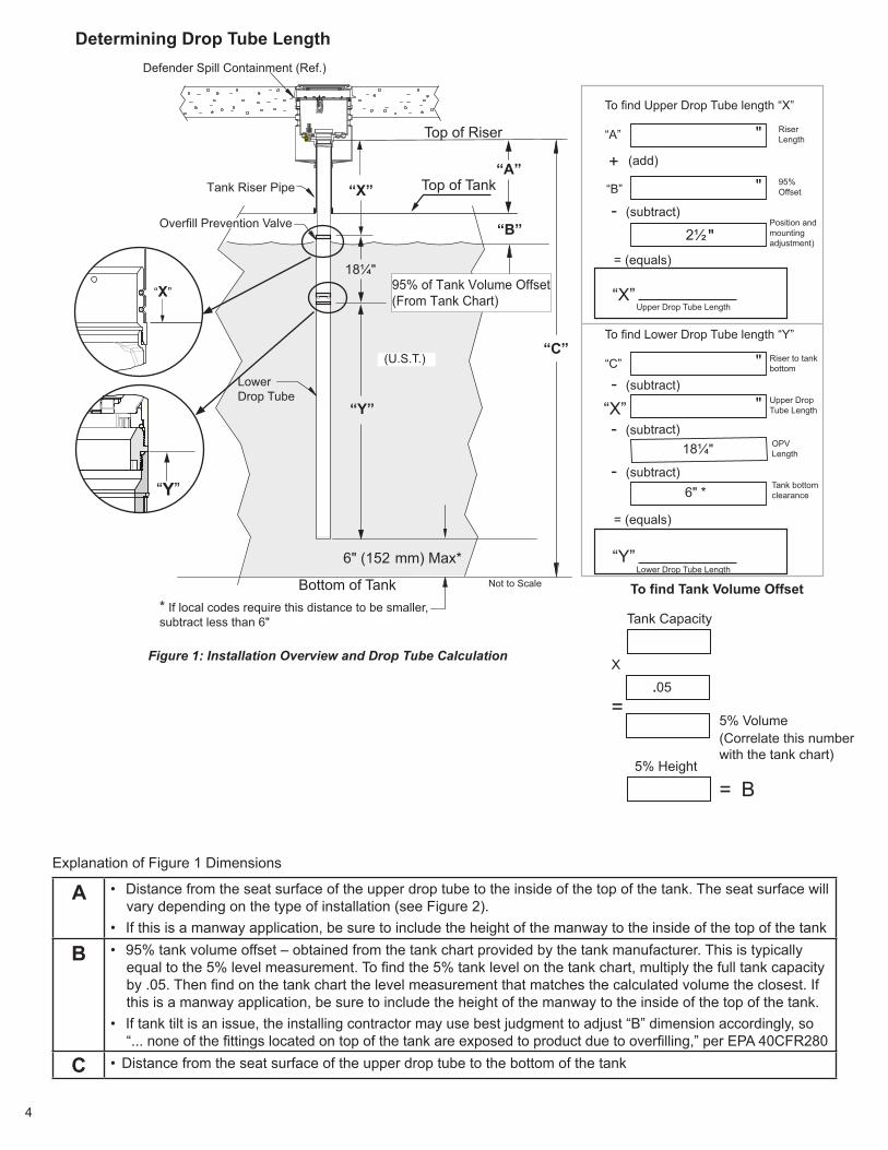
Figure 1: Installation Overview and Drop Tube Calculation
“B”
“A”
“C”
“Y”
“X”
Defender Spill Containment (Ref.)
Tank Riser Pipe
Top of Riser
Top of Tank
Bottom of Tank
6" (152 mm) Max*
Lower Drop Tube
(U.S.T.)
Not to Scale
95% of Tank Volume Offset(From Tank Chart)
Overfill Prevention Valve
To find Upper Drop Tube length “X”
“A”
To find Lower Drop Tube length “Y”
“C”
“B”
+
Position and mounting adjustment)
- (subtract)
- (subtract)
“X”
18¼"
6" *
“X”Upper Drop Tube Length
Riser Length
“Y”Lower Drop Tube Length
18¼"
* If local codes require this distance to be smaller, subtract less than 6"
"
95% Offset
Riser to tank bottom
"
"
"
- (subtract)
= (equals)
= (equals)
- (subtract)
(add)
"2½
Upper Drop Tube Length
OPV Length
Tank bottom clearance
“X”
“Y”
Determining Drop Tube Length
Explanation of Figure 1 Dimensions
A • Distance from the seat surface of the upper drop tube to the inside of the top of the tank. The seat surface will vary depending on the type of installation (see Figure 2).
• If this is a manway application, be sure to include the height of the manway to the inside of the top of the tank
B • 95% tank volume offset – obtained from the tank chart provided by the tank manufacturer. This is typically equal to the 5% level measurement. To find the 5% tank level on the tank chart, multiply the full tank capacity by .05. Then find on the tank chart the level measurement that matches the calculated volume the closest. If this is a manway application, be sure to include the height of the manway to the inside of the top of the tank.
• If tank tilt is an issue, the installing contractor may use best judgment to adjust “B” dimension accordingly, so “... none of the fittings located on top of the tank are exposed to product due to overfilling,” per EPA 40CFR280
C • Distance from the seat surface of the upper drop tube to the bottom of the tank
Tank Capacity
5% Volume
5% Height
X
.05=
=
(Correlate this number with the tank chart)
B
To find Tank Volume Offset

5
Figure 2: Installation Dimensions per Spill ContainerTop of Tank
Underneath Fill Adapter Underneath Bucket Defender Series
MARKING & CUTTING THE TUBES1. Mark the upper drop tube with the length “X”
calculated from Figure 1, measuring per Figure 3:
Upper Drop Tubes
Non-Poppeted Coaxial (EBW)Measure from bottom of lug
X
Dual PointMeasure from flange
X
Poppeted Coaxial (EBW)Measure from retaining ring
X
Figure 3: Dimension X for Upper Drop Tube
2. Mark the lower drop tube with the length “Y” calculated from Figure 1.
Lower Drop Tube
Y
Cut straight
Option: cut approx. 45º
Figure 4: Lower Drop Tube
Tank Diameter Appx. Dim. “B” for 95% Shutoff
4 feet (122 cm) 2½” (64 mm)5 feet (152 cm) 3" (76 mm)6 feet (183 cm) 3½” (89 mm)7 feet (213 cm) 4¼" (108 mm)8 feet (244 cm) 5" (127 mm)9 feet (274 cm) 5 ½” (140 mm)
10 feet (305 cm) 6" (152 mm)12 feet (366 cm) 7¼" (184 mm)
Square Tank
Tank Diameter Appx. Dim. “B” for 95% Shutoff
4 feet (122 cm) 5” (127 mm)5 feet (152 cm) 6¼" (159 mm)6 feet (183 cm) 7½" (191 mm)7 feet (213 cm) 8¾" (222 mm)8 feet (244 cm) 10" (254 mm)9 feet (274 cm) 11¼" (286 mm)
10 feet (305 cm) 12½" (318 mm)12 feet (366 cm) 15¼" (387 mm)
Round Tank with Dome Ends Round Tank with Square Ends
Tank Diameter Appx. Dim. “B” for 95% Shutoff
4 feet (122 cm) 5" (127 mm)5 feet (152 cm) 6" (152 mm)6 feet (183 cm) 7 ½" (191 mm)7 feet (213 cm) 8" (203 mm)8 feet (244 cm) 9 ½" (241 mm)9 feet (274 cm) 10 ½" (267 mm)
10 feet (305 cm) 13" (330 mm)12 feet (366 cm) 14" (356 mm)
If the tank chart is not available, the following tables may be used FOR REFERENCE ONLY. The actual “B” dimension will vary based on the actual tank diameter end type.

6
3. Cut the upper drop tube where marked, using the Franklin Fueling Systems pipe cutter.
a. If using the Franklin Fueling Systems Pipe Cutter, tighten the handle in very small increments (<1/10 turn per every 2 rotations of the tool).
To get the cut started and keep the cutter from “walking”, tighten the blade against the tube just enough to make contact. Then rotate one full turn in one direction.
Next, rotate one full turn in the opposite direction. Tighten the cutter approximately 1/10th of a turn and repeat until a good scribe line is created.
Overtightening the cutter wheel will result in crimping of the aluminum tube, which will cause the end to be too small for the adapter to fit inside.
b. If using a metal cutting saw blade, make sure to cut as squarely as possible. Using the band clamp supplied with the warning tag as a guide will aid in cutting squarely.
4. Using the half-round file, deburr the inside of the tube. Check to see if the upper tube adapter fits inside the upper drop tube – if not, more deburring may be needed.
5. Cut the lower drop tube as marked, using the FFS pipe cutter or a saw with a metal cutting blade.
a. If cutting the lower drop tube at a 45 deg angle, make sure the lowest point of the drop tube does not project within the minimum clearance specified by the tank manufacturer (or per local requirements).
Installing the Upper Tube Adapter1. Replace the cutting wheel on the Franklin Fueling
Systems Pipe Cutter with the Roller Tool (Figure 5)
Roller Tool
Pipe Cutter
Figure 5: Pipe Cutter and Roller Tool2. From the cut end of the upper drop tube, mark the
grooves on the tube (Figure 6)
Mark Location on Drop Tube Figure 6: Mark the Drop Tube
3. Install the drop tube gasket onto the upper drop tube (Dual Point Installation, Figure 7).
Drop Tube Gasket Installed (note orientation)
Figure 7: Drop Tube Gasket Installed4. Check to make sure the O-rings are installed on
the upper tube adapter.5. Insert the upper tube adapter into the cut end of the
upper drop tube.6. Position the Roller Tool over the mark and lightly
tighten.7. To get the cut started and keep the roller from
“walking”, tighten the roller against the tube just enough to make contact. Then rotate one full turn in one direction and then rotate one full turn in the opposite direction. Tighten the roller approximately 1/10th of a turn and repeat until the groove is complete.Cutting Wheel
7
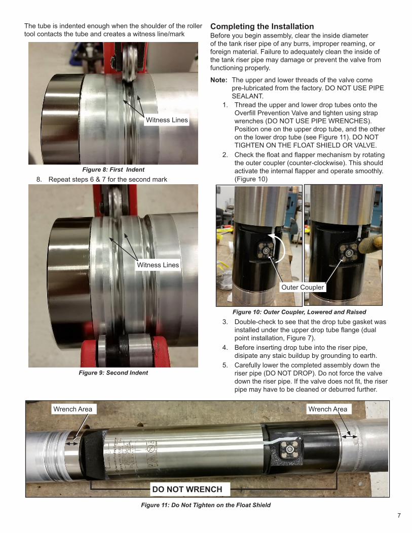
The tube is indented enough when the shoulder of the roller tool contacts the tube and creates a witness line/mark
Figure 8: First Indent8. Repeat steps 6 & 7 for the second mark
Witness Lines
Figure 9: Second Indent
Completing the InstallationBefore you begin assembly, clear the inside diameter of the tank riser pipe of any burrs, improper reaming, or foreign material. Failure to adequately clean the inside of the tank riser pipe may damage or prevent the valve from functioning properly.
Note: The upper and lower threads of the valve come pre-lubricated from the factory. DO NOT USE PIPE SEALANT.
1. Thread the upper and lower drop tubes onto the Overfill Prevention Valve and tighten using strap wrenches (DO NOT USE PIPE WRENCHES). Position one on the upper drop tube, and the other on the lower drop tube (see Figure 11). DO NOT TIGHTEN ON THE FLOAT SHIELD OR VALVE.
2. Check the float and flapper mechanism by rotating the outer coupler (counter-clockwise). This should activate the internal flapper and operate smoothly. (Figure 10)
Outer Coupler
Figure 10: Outer Coupler, Lowered and Raised3. Double-check to see that the drop tube gasket was
installed under the upper drop tube flange (dual point installation, Figure 7).
4. Before inserting drop tube into the riser pipe, disipate any staic buildup by grounding to earth.
5. Carefully lower the completed assembly down the riser pipe (DO NOT DROP). Do not force the valve down the riser pipe. If the valve does not fit, the riser pipe may have to be cleaned or deburred further.
Wrench Area Wrench Area
DO NOT WRENCH
Figure 11: Do Not Tighten on the Float Shield
Witness Lines

8
5. Install the warning plate around the 4" (102 mm) riser pipe below the threaded portion using the stainless steel band clamp (see Figure 12).
Figure 12: Install Warning Plate6. Reinstall the spill bucket components. The valve is
now installed and ready for inspection.
MaintenanceThe 708-590 Series Overfill Prevention Valve is maintenance free. Franklin Fueling Systems recommends, however, that a visual inspection be performed upon installation and annually thereafter.
Overfill Prevention Valve InspectionThe valve can easily be inspected by use of the Franklin Fueling Systems inspection tool.
Figure 13: Inspection Tool
Procedure1. Assemble the remote tool with enough extension
sections to reach the Overfill Protection Valve.2. Insert the remote test tool into the drop tube.
You should feel a “pull” when the magnets are positioned correctly and attract
3. Slowly raise the inspection tool about 1 ½" and you should see the flapper move into the flow path.
Valve Flapper
Inspection Tool
Figure 14: Valve Inspection, Flapper In
Valve Flapper
Inspection Tool
Figure 15: Valve Inspection, Flapper Out4. If the flapper is observed moving back and forth,
the valve is functioning normally.

9
Inspecting / Verifying95% level from grade (without removing from tank)
1. Measure from the top of the drop tube flange to the top edge of the tube adapter (Figure 16).
2. Add 4½" to the measured value.3. This number should match A plus B (from Figure 1).
Measure
Add 4½"
=A+B
Figure 16: Dimension Verification After Installation

10
3.97" (101 mm)
18.40"(467 mm)
17.40"(442 mm)
1.75" (44.5mm)
95% Shutoff Level
Dimension Drawing
Product SpecificationsConstructionValve Body E-Coated Cast AluminumUpper Drop Tube Aluminum or Hard Coat Anodized AluminumLower Drop Tube Aluminum or Hard Coat Anodized AluminumInternal Mechanism Nickel plated Aluminum, Stainless Steel, Acetal

11
Overfill Prevention Valve Installation Record Sheet
Date Installed_______________________________________________________________Site informationSite # / Description _________________________________________________________________________
Site Address _____________________________________________________________________________
Site Contact ______________________________________________________________________________
Installing Contractor
Name ___________________________________________________________________________________
Company ________________________________________________________________________________
Tank InformationProduct Type _____________________________________________________________________________
Underground Tank Manufacturer ______________________________________________________________
Tank Full Volume __________________________________________________________________________
Tank Diameter _____________________________________________________________________________
Tank Chart Available? □ Yes □ No
Tank Type □ Steel □ Fiberglass
□ Square □ Cylinder □ Dome Ends
Tank have compartments? □ Yes □ No
Tank / Drop Tube Measurements Upper Drop Tube Length (X) __________________________________________________________________
Lower Drop Tube Length (Y) __________________________________________________________________
Distance from Lower Drop tube to tank bottom ____________________________________________________
Length A_____________________
B_____________________
C_____________________
Franklin Fueling Systems • 3760 Marsh Rd. • Madison, WI 53718 USA
Tel: +1 608 838 8786 • 800 225 9787 • Fax: +1 608 838 6433 • www.franklinfueling.com

©2014 FFS F-9044 Rev. 2
Related Documents