Overcurrent Protection & Coordination for Overcurrent Protection & Coordination for Industrial Applications Annex (by Dominik Pieniazek, P.E. – VI Engineering, LLC)

Welcome message from author
This document is posted to help you gain knowledge. Please leave a comment to let me know what you think about it! Share it to your friends and learn new things together.
Transcript
Overcurrent Protection & Coordination forOvercurrent Protection & Coordination for Industrial ApplicationsAnnex(by Dominik Pieniazek, P.E. – VI Engineering, LLC)
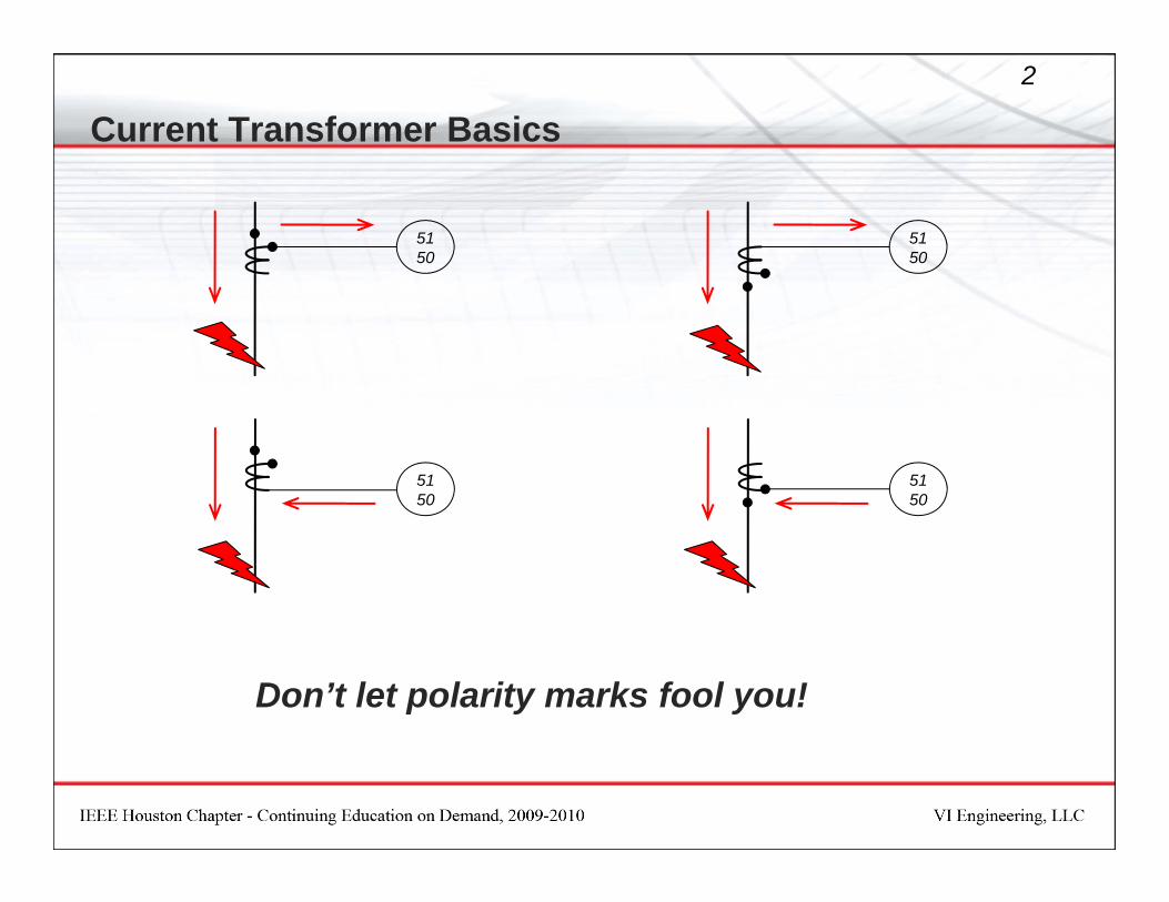
Current Transformer Basics2
5150
5150
5150
5150
Don’t let polarity marks fool you!
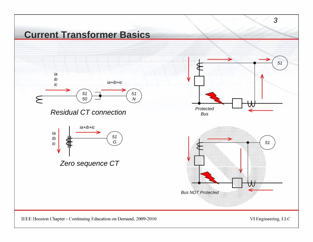
Current Transformer Basics3
ia
51
51N
5150
iaibic ia+ib+ic
51Ia
ia+ib+ic
Residual CT connection Protected Bus
51G
IbIc
Zero sequence CT
51
q
Bus NOT Protected
Current Transformer Basics4
Understand How CTs work!
IEEE Guide for the Application of CurrentTransformers Used for ProtectiveRelaying Purposes - IEEE Std C37.110
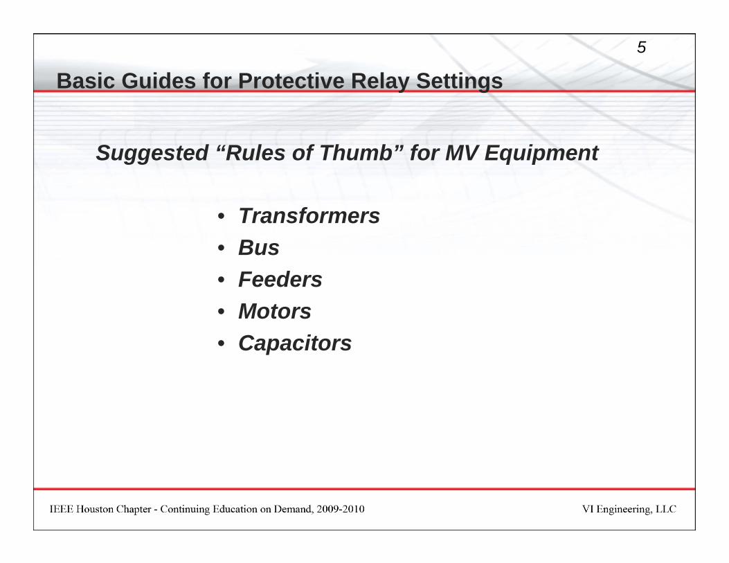
Basic Guides for Protective Relay Settings5
Suggested “Rules of Thumb” for MV Equipment
• Transformers• Bus• Bus• Feeders• MotorsMotors• Capacitors
Basic Guides for Protective Relay Settings6
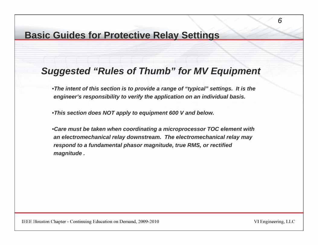
Suggested “Rules of Thumb” for MV Equipment gg•The intent of this section is to provide a range of “typical” settings. It is the engineer’s responsibility to verify the application on an individual basis.
•This section does NOT apply to equipment 600 V and below.
•Care must be taken when coordinating a microprocessor TOC element with an electromechanical relay downstream The electromechanical relay mayan electromechanical relay downstream. The electromechanical relay may respond to a fundamental phasor magnitude, true RMS, or rectified magnitude .

Rules of Thumb…(above 600 V)P T fPower TransformersPhase Relays (delta – wye)
Primary – Phase Settings•CT Ratio: 200% FLA•Set pickup to comply with NEC 450-3, but as a rule of thumb setting should be less than 300% of transformer self cooled rating or 150%should be less than 300% of transformer self cooled rating or 150% of transformer maximum rating.•Try to set the time dial such that pickup time for maximum through fault is in the neighborhood of 1.0 seconds or less. If higher, ensure that ANSI d i t t d ddamage points are not exceeded.•Set instantaneous at between 160% and 200% of maximum through fault (assume infinite bus). Ensure that available system short circuit allows this. •Time Dial set at 1.0 to 1.5 seconds at maximum fault. Do not exceedTime Dial set at 1.0 to 1.5 seconds at maximum fault. Do not exceed 2.0 seconds which is the mechanical damage point.
Rules of Thumb…(above 600 V)P T fPower TransformersPrimary Ground Relay Settings
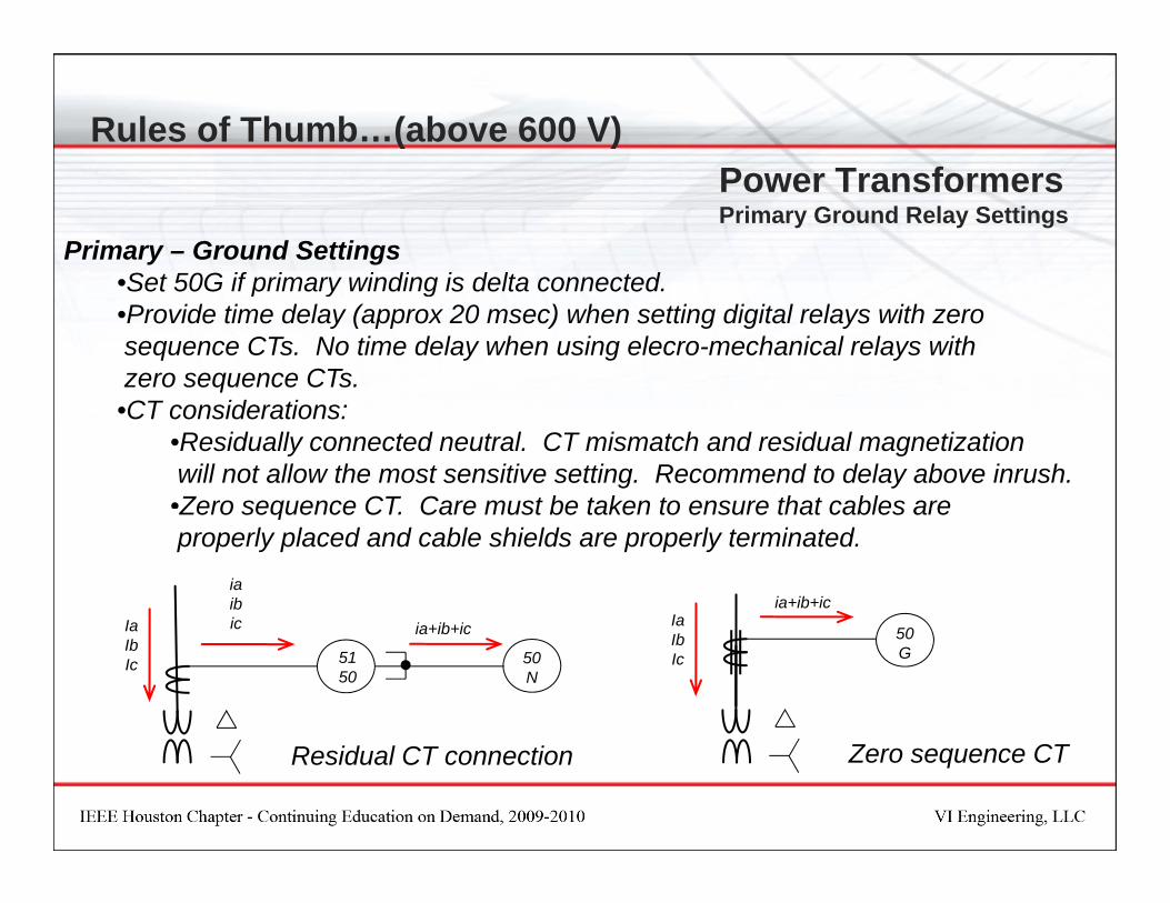
Primary – Ground Settings•Set 50G if primary winding is delta connected•Set 50G if primary winding is delta connected.•Provide time delay (approx 20 msec) when setting digital relays with zero sequence CTs. No time delay when using elecro-mechanical relays with zero sequence CTs.•CT considerations:
•Residually connected neutral. CT mismatch and residual magnetizationwill not allow the most sensitive setting. Recommend to delay above inrush.•Zero sequence CT Care must be taken to ensure that cables areZero sequence CT. Care must be taken to ensure that cables areproperly placed and cable shields are properly terminated.
iaibic i ib i Ia
ia+ib+icIa
50N
5150
ic ia+ib+ic 50G
IaIbIc
IaIbIc
Residual CT connection Zero sequence CT
Rules of Thumb…( above 600 V)
Power TransformersPrimary Fuse Phase Protection
Primary Fuse Rating of power transformer: 135% FLA < Fuse < 250% FLA Try to stay in the range of 150%135% FLA < Fuse < 250% FLA. Try to stay in the range of 150%.
Primary fuse rating of power transformer should be approximately 200% FLA if transformer has a secondary main.
Generally use E-rated fuses. Note that TOC characteristics of fuses are not allthe same.

Rules of Thumb…( above 600 V)
Power TransformersSecondary Resistance Grounded
Secondary Low-Resistance Grounded•Set pickup for 20% to 50% of maximum ground fault. Note that ground resistors typically have a continuous rating of 25-50% of nominal. This valuecan be specified when purchasing the equipmentcan be specified when purchasing the equipment.
Example: 2000 A main breaker (2000:5 CTs), it may make sense to specify an 400 A ground resistor with a continuous rating of 50% (200 A) such that a 2000:5 residually connected CT input can be used with a minimum pickup (0.1 x CT = 0.5 A secondary, 200 A primary).
•Set the time dial such that at the time to trip is 2 0 seconds at maximumSet the time dial such that at the time to trip is 2.0 seconds at maximum ground fault
•Protect resistor using I²t curve Typical resistor is rated for 10 seconds atProtect resistor using I t curve. Typical resistor is rated for 10 seconds at nominal current (to be specified at time of order).

Rules of Thumb…( above 600 V)
Power TransformersSecondary Solidly Grounded
Secondary Solidly Grounded (for balanced three phase industrial loads)•If secondary is solidly grounded and neutral relay is available (using CT on X0 bushing) set pickup at approximately 50% of phase element and ensureX0 bushing), set pickup at approximately 50% of phase element and ensuretransformer 2 second damage point is protected. Coordinate TOC with main breaker (or partial differential) ground relay.
•Decrease the primary phase element by 58% (to account for transformer damage curve shift). This is the equivalent current seen on the primary (delta) for a secondary ground fault (refer to the Symmetrical Components
t ti F b 2 3 2010 b D K t Ed h ff)presentation on Feb 2-3, 2010 by Dr. Kurt Ederhoff).
Rules of Thumb…( above 600 V)
Protection for TransformerSecondary Faults on Solidly Grounded Systems
It is certainly preferable to rely on the50T
87T
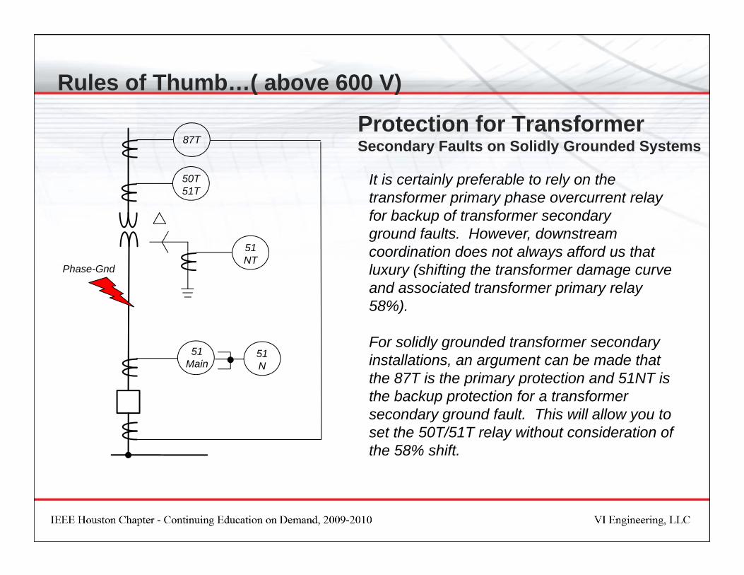
It is certainly preferable to rely on the transformer primary phase overcurrent relayfor backup of transformer secondary ground faults. However, downstream coordination does not always afford us that
50T51T
51 coordination does not always afford us that luxury (shifting the transformer damage curve and associated transformer primary relay 58%).
NTPhase-Gnd
For solidly grounded transformer secondary installations, an argument can be made that the 87T is the primary protection and 51NT is the backup protection for a transformer
51Main
51N
the backup protection for a transformer secondary ground fault. This will allow you to set the 50T/51T relay without consideration of the 58% shift.
Rules of Thumb…( above 600 V)Power TransformersPrimary Neutral (wye – delta)
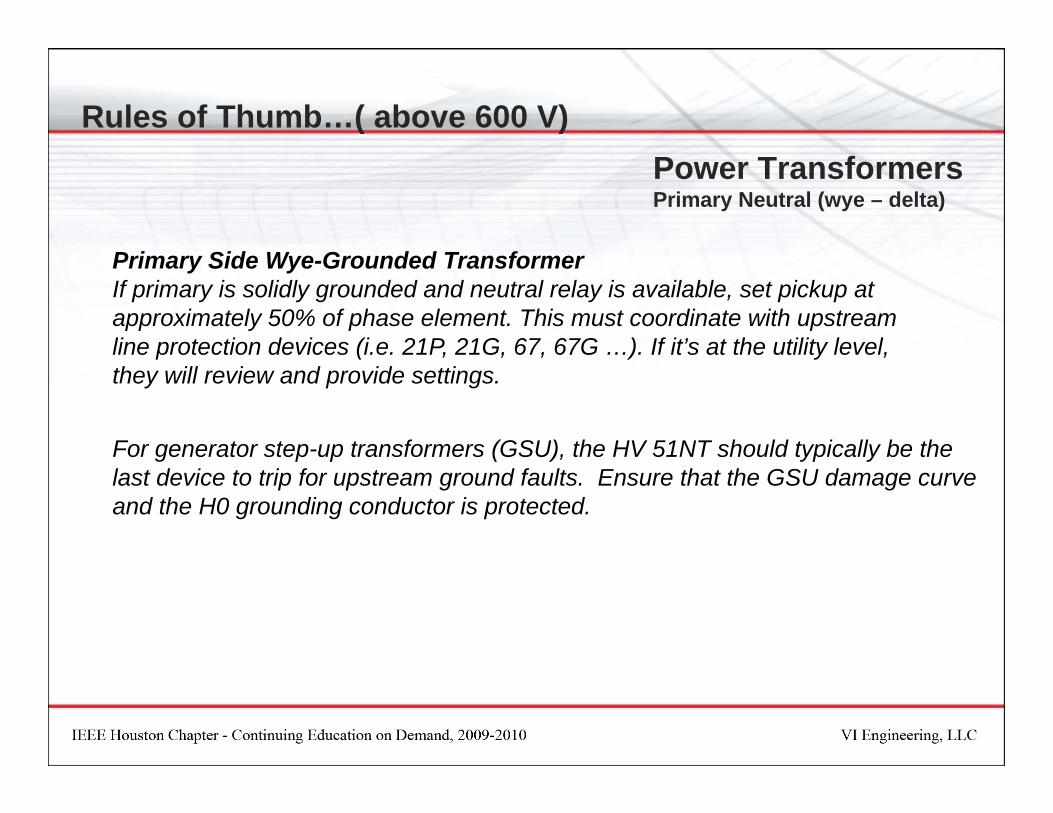
P i Sid W G d d T fPrimary Side Wye-Grounded Transformer If primary is solidly grounded and neutral relay is available, set pickup at approximately 50% of phase element. This must coordinate with upstream line protection devices (i.e. 21P, 21G, 67, 67G …). If it’s at the utility level, p ( , , , ) y ,they will review and provide settings.
For generator step-up transformers (GSU), the HV 51NT should typically be the g p p ( ), yp ylast device to trip for upstream ground faults. Ensure that the GSU damage curveand the H0 grounding conductor is protected.
Rules of Thumb…( above 600 V)O
F f lt b t th
50T51T
50T51T
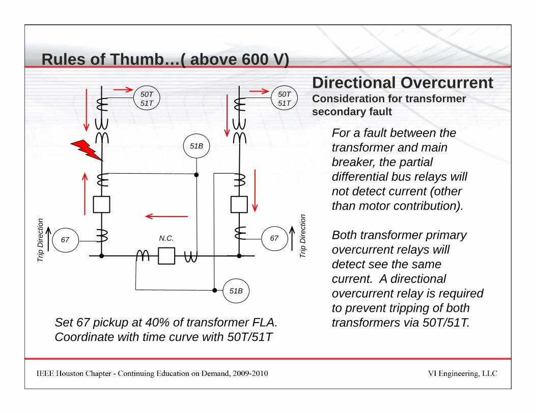
Directional OvercurrentConsideration for transformer secondary fault
For a fault between the transformer and main breaker, the partialdifferential bus relays will
51B
differential bus relays willnot detect current (otherthan motor contribution).
Both transformer primarctio
n
ectio
n
Both transformer primaryovercurrent relays will detect see the same current. A directional
N.C. 6767
Trip
Dire
c
Trip
Dire
overcurrent relay is requiredto prevent tripping of both transformers via 50T/51T.
51B
Set 67 pickup at 40% of transformer FLA.Coordinate with time curve with 50T/51TCoordinate with time curve with 50T/51T

Rules of Thumb…( above 600 V)O
50T51T
50T51T
Directional OvercurrentConsideration for transformer secondary fault
For a fault between the transformer and main breaker, the main and tiebreaker relays will all seebreaker relays will all seethe same current (otherthan motor contribution).
Th ti b k ill t i f ll d
51Tie
51M 51M
n on The tie breaker will trip followed by the respective transformerprimary overcurrent. A directional overcurrent relay is required
N.C. 6767
Trip
Dire
ctio
n
Trip
Dire
ctio
y qto prevent loss of one bus.
Set 67 pickup at 40% of transformer FLA.Coordinate with time curve with 51Tie
Rules of Thumb…( above 600 V)B d F dBus and Feeders
Bus Relays (Main Breaker or Partial Differential):Pickup set between 100% and 125% FLA (150% FLA maximum)p ( )Set to coordinate with transformer primary protective relaying
Do not enable the instantaneous overcurrent element on main breaker relays!
Feeder Relays:Set pickup to comply with NEC 240-100 (limited to 600% of rated ampacity of conductor). Actually, pickup permitted by NEC is slightly higher.Keep it down in the neighborhood of 200%. The intent is NOT to provide overload protection. The intent is to provide short-circuit protection.
Set time dial as required to coordinate with downstream devices while protectingSet time dial as required to coordinate with downstream devices while protecting conductor against damage.
Enable instantaneous element only if the load has a notable impedance (i.e. f ) f ftransformer, motor, capacitor, etc) or if the load is the end of a radial circuit.
Rules of Thumb…( above 600 V)Induction MotorsInduction Motors
Pickup set at 101% - 120% Nameplate Rating depending on Service Factor and normal load.
Motor < 1,500 hp Set at 1.15 x FLAMotor > 1,500 hp Set just above FLA x S.F.
Instantaneous Trip set at 200% LRC. A higher pickup may be used depending on system p g p p y p g yavailable short circuit, however, do not lower below 160% LRC unlessyou know that the relay filters/removes the DC component. Ensure that the instantaneous trip setting will not cause a motor starter to attempt interrupting a fault beyond its rating.p g y g
Ground Overcurrent. For Zero Sequence CT (BYZ) set ground Trip at 10A primary and Alarm at 5A primary. Set for instantaneous if using electromechanical and set at 20 msec delay (minimum) if using digital relays.y ( ) g g yFor solidly grounded systems, ensure that the ground trip setting will not cause a motor starter to attempt interrupting a fault beyond its rating.
Mechanical Jam set 150% FLA at 2 sec, unless application does not allow this (i.e. grinder, pp ( gcrusher, etc).

Rules of Thumb…( above 600 V)Capacitors
Capacitor Bank:For individual protection, the Fuse protecting the capacitor is chosen such that itsFor individual protection, the Fuse protecting the capacitor is chosen such that its continuous current capability is greater than or equal to 135% of rated capacitor current. The feeder cable should be sized as such for continuous operation. This over rating is due to 10% for allowable overvoltage conditions, 15% for
it kVAR ti t l (thi l t t 15% t d i ti fcapacitor kVAR rating tolerance (this correlates to 15% percent deviation from nominal capacitance) and 10% for overcurrent due to harmonics.
For unbalance, set Alarm for loss of one capacitor, set Trip for overvoltage of p p g110% rated (nameplate).
For feeder protection, set Pickup at 135% of FLA, set Time Dial at 1.0, set 50P element above maximum inrush and include a slight time delay toset 50P element above maximum inrush and include a slight time delay to coordinate with individual fuse clear time. Plot TOC to protect the capacitor case rupture curve.
Note: Systems with high harmonic content require special attention.

R d d R fRecommended References
Recommended References
•Applied Protective Relaying – Westinghouse
P t ti R l i Th d A li ti ABB P T&D C Edit d b W lt El•Protective Relaying Theory and Applications – ABB Power T&D Company, Edited by Walter Elmore
•Protective Relaying for Power Systems – IEEE Press, Edited by Stanley H. Horowitz
•Protective Relaying for Power Systems II – IEEE Press, Edited by Stanley H. Horowitzy g y , y y
•Protective Relaying, Principles and Applications – J. Lewis Blackburn
•AC Motor Protection – Stanley E. Zocholl
•Industrial and Commercial Power System Applications Series – ABB Power T&D Company
•Analyzing and Applying Current Transformers - Stanley E. Zocholl
Related Documents