Proceedings of the World Tunnel Congress 2014 – Tunnels for a better Life. Foz do Iguaçu, Brazil. 1 1 Introduction The hydropower project of Cerro del Águila is under construction in the external Andes, 240 km east of Lima, close to the small town of Pampas (Province Tayacaja, Peru, Figure 1). Figure 1. Location map of the Cerro del Águila hydropower project. It exploits the waters of Río Mantaro, shortcutting a 23 km long river loop at roughly 1500 m a.s.l. and passes under the peak of Cerro del Águila, from which the project borrows its name (Figure 2). The hydropower project consists of a 80 m high gravity dam, a 5.7 km long headrace tunnel, a 250 m high vertical pressure shaft, a 40x86x18 m powerhouse, a 1.9 km long tailrace tunnel, and a number of construction and access adits. The system has a waterhead of 267 m, an installed power of 510 MW and a design flow of 211 m 3 /s. Figure 2. Sketch of the hydropower project layout. 2 Tectonic set-up The project is located in the Eastern Cordillera of the Andes, east of the intervening Altiplano. The tectonic set-up is that of a "flat slab" branch of the Nazca-South American subduction zone, where the 30°-inclined subduction proceeds down to about 100 km and then flattens out (Figure 3). The convergence rate is 7 to 9 cm/year. Overcoming the geological and design related challenges of the 510 MW hydropower project of Cerro del Águila (Peru). M. Thüring and S. M. Sayah Lombardi Engineering Ltd., Minusio, Switzerland. C. de Pra and A. Gradizzi Studio di geologia e geomeccanica, Verona, Italy. ABSTRACT: The 510 MW hydropower project Cerro del Águila is currently under construction in the external Peruvian Andes. It includes a 80 m high gravity dam, a 7.6 km long headrace-tailrace tunnel system with a 10.5 m high, simplified horseshoe section, a 250 m high pressure shaft, a 40x86x18 m powerhouse cavern located 350 m underground, and various surge, access and construction tunnels. All underground excavations are carried out by drill and blast. The major geological challenges are possible spalling/rockburst and convergences in the headrace tunnel which reaches more than 1600 m overburden, and the crossing of a major lithological contact. Topography, fracture patterns and up to 150 m thick colluvial/landslide deposits challenge the construction of adits and portals. The powerhouse, located under a strongly inclined slope must be aligned with in- situ stress and joints orientation. The pressure shaft must be checked for water tighting. This paper presents an overview of work in progress.

Welcome message from author
This document is posted to help you gain knowledge. Please leave a comment to let me know what you think about it! Share it to your friends and learn new things together.
Transcript
Proceedings of the World Tunnel Congress 2014 – Tunnels for a better Life. Foz do Iguaçu,
Brazil.
1
1 Introduction
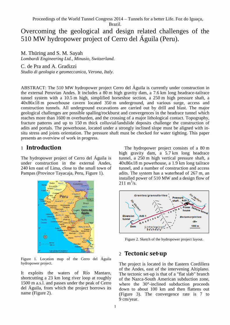
The hydropower project of Cerro del Águila is under construction in the external Andes, 240 km east of Lima, close to the small town of Pampas (Province Tayacaja, Peru, Figure 1).
Figure 1. Location map of the Cerro del Águila hydropower project.
It exploits the waters of Río Mantaro, shortcutting a 23 km long river loop at roughly 1500 m a.s.l. and passes under the peak of Cerro del Águila, from which the project borrows its name (Figure 2).
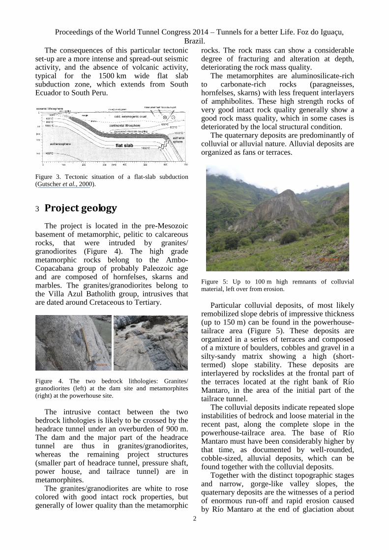
The hydropower project consists of a 80 m high gravity dam, a 5.7 km long headrace tunnel, a 250 m high vertical pressure shaft, a 40x86x18 m powerhouse, a 1.9 km long tailrace tunnel, and a number of construction and access adits. The system has a waterhead of 267 m, an installed power of 510 MW and a design flow of 211 m
3/s.
Figure 2. Sketch of the hydropower project layout.
2 Tectonic set-up
The project is located in the Eastern Cordillera of the Andes, east of the intervening Altiplano. The tectonic set-up is that of a "flat slab" branch of the Nazca-South American subduction zone, where the 30°-inclined subduction proceeds down to about 100 km and then flattens out (Figure 3). The convergence rate is 7 to 9 cm/year.
Overcoming the geological and design related challenges of the 510 MW hydropower project of Cerro del Águila (Peru).
M. Thüring and S. M. Sayah Lombardi Engineering Ltd., Minusio, Switzerland.
C. de Pra and A. Gradizzi Studio di geologia e geomeccanica, Verona, Italy.
ABSTRACT: The 510 MW hydropower project Cerro del Águila is currently under construction in the external Peruvian Andes. It includes a 80 m high gravity dam, a 7.6 km long headrace-tailrace tunnel system with a 10.5 m high, simplified horseshoe section, a 250 m high pressure shaft, a 40x86x18 m powerhouse cavern located 350 m underground, and various surge, access and construction tunnels. All underground excavations are carried out by drill and blast. The major geological challenges are possible spalling/rockburst and convergences in the headrace tunnel which reaches more than 1600 m overburden, and the crossing of a major lithological contact. Topography, fracture patterns and up to 150 m thick colluvial/landslide deposits challenge the construction of adits and portals. The powerhouse, located under a strongly inclined slope must be aligned with in-situ stress and joints orientation. The pressure shaft must be checked for water tighting. This paper presents an overview of work in progress.
Proceedings of the World Tunnel Congress 2014 – Tunnels for a better Life. Foz do Iguaçu,
Brazil.
2
The consequences of this particular tectonic set-up are a more intense and spread-out seismic activity, and the absence of volcanic activity, typical for the 1500 km wide flat slab subduction zone, which extends from South Ecuador to South Peru.
Figure 3. Tectonic situation of a flat-slab subduction (Gutscher et al., 2000).
3 Project geology
The project is located in the pre-Mesozoic basement of metamorphic, pelitic to calcareous rocks, that were intruded by granites/ granodiorites (Figure 4). The high grade metamorphic rocks belong to the Ambo-Copacabana group of probably Paleozoic age and are composed of hornfelses, skarns and marbles. The granites/granodiorites belong to the Villa Azul Batholith group, intrusives that are dated around Cretaceous to Tertiary.
Figure 4. The two bedrock lithologies: Granites/ granodiorites (left) at the dam site and metamorphites (right) at the powerhouse site.
The intrusive contact between the two bedrock lithologies is likely to be crossed by the headrace tunnel under an overburden of 900 m. The dam and the major part of the headrace tunnel are thus in granites/granodiorites, whereas the remaining project structures (smaller part of headrace tunnel, pressure shaft, power house, and tailrace tunnel) are in metamorphites.
The granites/granodiorites are white to rose colored with good intact rock properties, but generally of lower quality than the metamorphic
rocks. The rock mass can show a considerable degree of fracturing and alteration at depth, deteriorating the rock mass quality.
The metamorphites are aluminosilicate-rich to carbonate-rich rocks (paragneisses, hornfelses, skarns) with less frequent interlayers of amphibolites. These high strength rocks of very good intact rock quality generally show a good rock mass quality, which in some cases is deteriorated by the local structural condition.
The quaternary deposits are predominantly of colluvial or alluvial nature. Alluvial deposits are organized as fans or terraces.
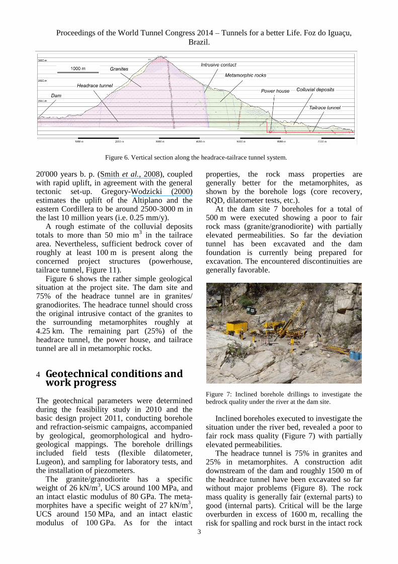
Figure 5: Up to 100 m high remnants of colluvial material, left over from erosion.
Particular colluvial deposits, of most likely remobilized slope debris of impressive thickness (up to 150 m) can be found in the powerhouse-tailrace area (Figure 5). These deposits are organized in a series of terraces and composed of a mixture of boulders, cobbles and gravel in a silty-sandy matrix showing a high (short-termed) slope stability. These deposits are interlayered by rockslides at the frontal part of the terraces located at the right bank of Río Mantaro, in the area of the initial part of the tailrace tunnel.
The colluvial deposits indicate repeated slope instabilities of bedrock and loose material in the recent past, along the complete slope in the powerhouse-tailrace area. The base of Río Mantaro must have been considerably higher by that time, as documented by well-rounded, cobble-sized, alluvial deposits, which can be found together with the colluvial deposits.
Together with the distinct topographic stages and narrow, gorge-like valley slopes, the quaternary deposits are the witnesses of a period of enormous run-off and rapid erosion caused by Río Mantaro at the end of glaciation about
Proceedings of the World Tunnel Congress 2014 – Tunnels for a better Life. Foz do Iguaçu,
Brazil.
3
20'000 years b. p. (Smith et al., 2008), coupled with rapid uplift, in agreement with the general tectonic set-up. Gregory-Wodzicki (2000) estimates the uplift of the Altiplano and the eastern Cordillera to be around 2500-3000 m in the last 10 million years (i.e. 0.25 mm/y).
A rough estimate of the colluvial deposits totals to more than 50 mio m
3 in the tailrace
area. Nevertheless, sufficient bedrock cover of roughly at least 100 m is present along the concerned project structures (powerhouse, tailrace tunnel, Figure 11).
Figure 6 shows the rather simple geological situation at the project site. The dam site and 75% of the headrace tunnel are in granites/ granodiorites. The headrace tunnel should cross the original intrusive contact of the granites to the surrounding metamorphites roughly at 4.25 km. The remaining part (25%) of the headrace tunnel, the power house, and tailrace tunnel are all in metamorphic rocks.
4 Geotechnical conditions and work progress
The geotechnical parameters were determined during the feasibility study in 2010 and the basic design project 2011, conducting borehole and refraction-seismic campaigns, accompanied by geological, geomorphological and hydro-geological mappings. The borehole drillings included field tests (flexible dilatometer, Lugeon), and sampling for laboratory tests, and the installation of piezometers.
The granite/granodiorite has a specific weight of 26 kN/m
3, UCS around 100 MPa, and
an intact elastic modulus of 80 GPa. The meta-morphites have a specific weight of 27 kN/m
3,
UCS around 150 MPa, and an intact elastic modulus of 100 GPa. As for the intact
properties, the rock mass properties are generally better for the metamorphites, as shown by the borehole logs (core recovery, RQD, dilatometer tests, etc.).
At the dam site 7 boreholes for a total of 500 m were executed showing a poor to fair rock mass (granite/granodiorite) with partially elevated permeabilities. So far the deviation tunnel has been excavated and the dam foundation is currently being prepared for excavation. The encountered discontinuities are generally favorable.
Figure 7: Inclined borehole drillings to investigate the bedrock quality under the river at the dam site.
Inclined boreholes executed to investigate the situation under the river bed, revealed a poor to fair rock mass quality (Figure 7) with partially elevated permeabilities.
The headrace tunnel is 75% in granites and 25% in metamorphites. A construction adit downstream of the dam and roughly 1500 m of the headrace tunnel have been excavated so far without major problems (Figure 8). The rock mass quality is generally fair (external parts) to good (internal parts). Critical will be the large overburden in excess of 1600 m, recalling the risk for spalling and rock burst in the intact rock
Figure 6. Vertical section along the headrace-tailrace tunnel system.
Proceedings of the World Tunnel Congress 2014 – Tunnels for a better Life. Foz do Iguaçu,
Brazil.
4
mass sections and convergences in possibly present disturbed sections (see section 4.1).
Due to the excessive overburden, no boreholes were executed in the main part of the headrace tunnel.
All the remaining project structures are in metamorphic rocks (pressure shaft, power house and tailrace tunnel).
Figure 8. Excavation of the headrace tunnel with a 90 m2
section.
The area of the pressure shaft and powerhouse has been investigated with 3 boreholes for a total of 1165 m, revealing a good to very good, low permeability rock mass under a cover of 45 m of strongly disturbed rock mass. The water tightness of the rock mass around the pressure shaft was evaluated by means of hydrojacking tests (see section 4.2). So far only the access tunnels and the construction adits have been excavated.
The tailrace tunnel has been investigated with 4 boreholes for a total of 725 m. The rock mass is generally fair to good with reduced permeabilities. No excavation activities have been conducted so far in this project area.
4.1 Spalling/rock burst risk
A major concern for the excavation of the headrace tunnel is the risk of spalling and rock burst. The tunnel encounters a maximum overburden of more than 1600 m, the rock mass is expected to be good.
The spalling and rock burst risk has been evaluated using the classical approaches, which relate the compressive strength of the intact rock to the overburden stress, accounting for the
excavation geometry and the expected in-situ stress condition (Hoek and Brown, 1980; Diederichs et al., 2004; Hoek, 2010).
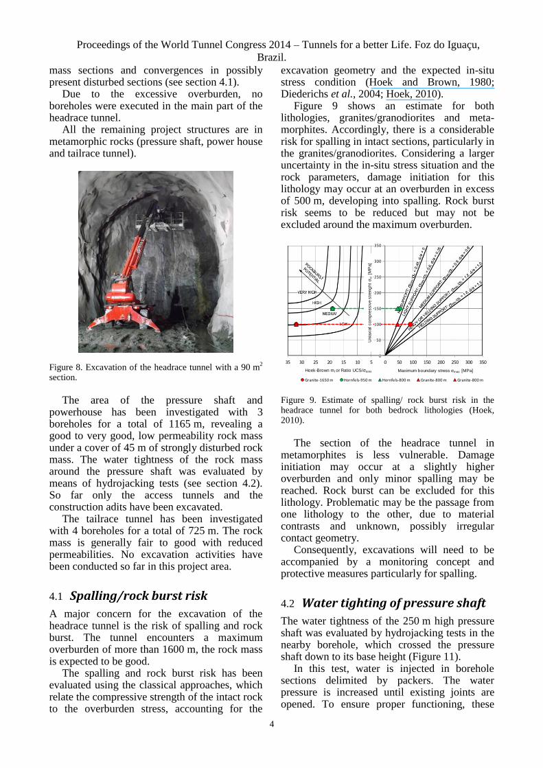
Figure 9 shows an estimate for both lithologies, granites/granodiorites and meta-morphites. Accordingly, there is a considerable risk for spalling in intact sections, particularly in the granites/granodiorites. Considering a larger uncertainty in the in-situ stress situation and the rock parameters, damage initiation for this lithology may occur at an overburden in excess of 500 m, developing into spalling. Rock burst risk seems to be reduced but may not be excluded around the maximum overburden.
35 30 25 20 15 10 5 0 50 100 150 200 250 300 350
0
50
100
150
200
250
300
350
Granite-1650 m Hornfels-950 m Hornfels-800 m Granite-800 m Granite-800 m
Maximum boundary stress σ max [MPa]U
nia
xia
l co
mp
ressiv
e s
treng
ht σ
ci [M
Pa]
Maximum boundary stress σmax [MPa]U
nia
xia
l co
mp
ressiv
e s
treng
ht σ
ci [M
Pa]
Hoek-Brown mi or Ratio UCS/σtens
Figure 9. Estimate of spalling/ rock burst risk in the headrace tunnel for both bedrock lithologies (Hoek, 2010).
The section of the headrace tunnel in metamorphites is less vulnerable. Damage initiation may occur at a slightly higher overburden and only minor spalling may be reached. Rock burst can be excluded for this lithology. Problematic may be the passage from one lithology to the other, due to material contrasts and unknown, possibly irregular contact geometry.
Consequently, excavations will need to be accompanied by a monitoring concept and protective measures particularly for spalling.
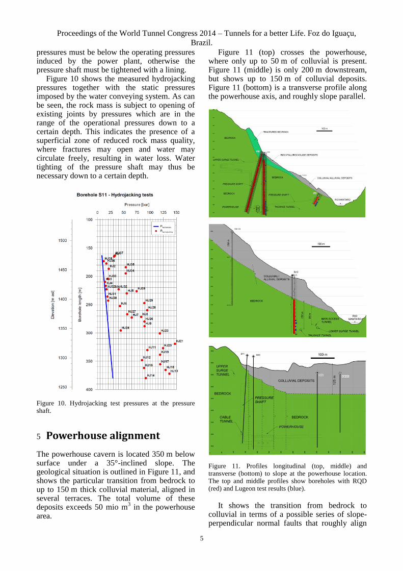
4.2 Water tighting of pressure shaft
The water tightness of the 250 m high pressure shaft was evaluated by hydrojacking tests in the nearby borehole, which crossed the pressure shaft down to its base height (Figure 11).
In this test, water is injected in borehole sections delimited by packers. The water pressure is increased until existing joints are opened. To ensure proper functioning, these
Proceedings of the World Tunnel Congress 2014 – Tunnels for a better Life. Foz do Iguaçu,
Brazil.
5
pressures must be below the operating pressures induced by the power plant, otherwise the pressure shaft must be tightened with a lining.
Figure 10 shows the measured hydrojacking pressures together with the static pressures imposed by the water conveying system. As can be seen, the rock mass is subject to opening of existing joints by pressures which are in the range of the operational pressures down to a certain depth. This indicates the presence of a superficial zone of reduced rock mass quality, where fractures may open and water may circulate freely, resulting in water loss. Water tighting of the pressure shaft may thus be necessary down to a certain depth.
Figure 10. Hydrojacking test pressures at the pressure shaft.
5 Powerhouse alignment
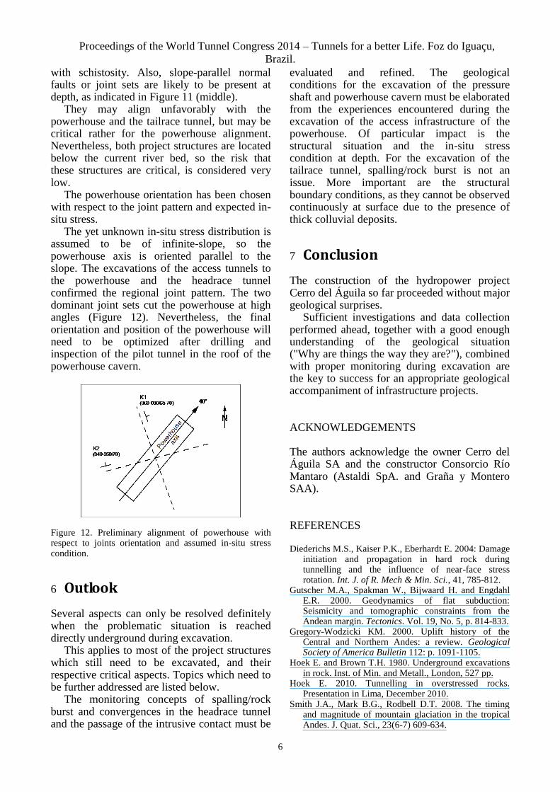
The powerhouse cavern is located 350 m below surface under a 35°-inclined slope. The geological situation is outlined in Figure 11, and shows the particular transition from bedrock to up to 150 m thick colluvial material, aligned in several terraces. The total volume of these deposits exceeds 50 mio m
3 in the powerhouse
area.
Figure 11 (top) crosses the powerhouse, where only up to 50 m of colluvial is present. Figure 11 (middle) is only 200 m downstream, but shows up to 150 m of colluvial deposits. Figure 11 (bottom) is a transverse profile along the powerhouse axis, and roughly slope parallel.
Figure 11. Profiles longitudinal (top, middle) and transverse (bottom) to slope at the powerhouse location. The top and middle profiles show boreholes with RQD (red) and Lugeon test results (blue).
It shows the transition from bedrock to colluvial in terms of a possible series of slope-perpendicular normal faults that roughly align
Proceedings of the World Tunnel Congress 2014 – Tunnels for a better Life. Foz do Iguaçu,
Brazil.
6
with schistosity. Also, slope-parallel normal faults or joint sets are likely to be present at depth, as indicated in Figure 11 (middle).
They may align unfavorably with the powerhouse and the tailrace tunnel, but may be critical rather for the powerhouse alignment. Nevertheless, both project structures are located below the current river bed, so the risk that these structures are critical, is considered very low.
The powerhouse orientation has been chosen with respect to the joint pattern and expected in-situ stress.
The yet unknown in-situ stress distribution is assumed to be of infinite-slope, so the powerhouse axis is oriented parallel to the slope. The excavations of the access tunnels to the powerhouse and the headrace tunnel confirmed the regional joint pattern. The two dominant joint sets cut the powerhouse at high angles (Figure 12). Nevertheless, the final orientation and position of the powerhouse will need to be optimized after drilling and inspection of the pilot tunnel in the roof of the powerhouse cavern.
Figure 12. Preliminary alignment of powerhouse with respect to joints orientation and assumed in-situ stress condition.
6 Outlook
Several aspects can only be resolved definitely when the problematic situation is reached directly underground during excavation.
This applies to most of the project structures which still need to be excavated, and their respective critical aspects. Topics which need to be further addressed are listed below.
The monitoring concepts of spalling/rock burst and convergences in the headrace tunnel and the passage of the intrusive contact must be
evaluated and refined. The geological conditions for the excavation of the pressure shaft and powerhouse cavern must be elaborated from the experiences encountered during the excavation of the access infrastructure of the powerhouse. Of particular impact is the structural situation and the in-situ stress condition at depth. For the excavation of the tailrace tunnel, spalling/rock burst is not an issue. More important are the structural boundary conditions, as they cannot be observed continuously at surface due to the presence of thick colluvial deposits.
7 Conclusion
The construction of the hydropower project Cerro del Águila so far proceeded without major geological surprises.
Sufficient investigations and data collection performed ahead, together with a good enough understanding of the geological situation ("Why are things the way they are?"), combined with proper monitoring during excavation are the key to success for an appropriate geological accompaniment of infrastructure projects.
ACKNOWLEDGEMENTS
The authors acknowledge the owner Cerro del Águila SA and the constructor Consorcio Río Mantaro (Astaldi SpA. and Graña y Montero SAA).
REFERENCES
Diederichs M.S., Kaiser P.K., Eberhardt E. 2004: Damage initiation and propagation in hard rock during tunnelling and the influence of near-face stress rotation. Int. J. of R. Mech & Min. Sci., 41, 785-812.
Gutscher M.A., Spakman W., Bijwaard H. and Engdahl E.R. 2000. Geodynamics of flat subduction: Seismicity and tomographic constraints from the Andean margin. Tectonics. Vol. 19, No. 5, p. 814-833.
Gregory-Wodzicki KM. 2000. Uplift history of the Central and Northern Andes: a review. Geological Society of America Bulletin 112: p. 1091-1105.
Hoek E. and Brown T.H. 1980. Underground excavations in rock. Inst. of Min. and Metall., London, 527 pp.
Hoek E. 2010. Tunnelling in overstressed rocks. Presentation in Lima, December 2010.
Smith J.A., Mark B.G., Rodbell D.T. 2008. The timing and magnitude of mountain glaciation in the tropical Andes. J. Quat. Sci., 23(6-7) 609-634.
Related Documents