Size : ½” ( 015mm) OVAL GEAR I N S T R U C T I O N M A N U A L Medium capacity positive displacement pulse flowmeter

Welcome message from author
This document is posted to help you gain knowledge. Please leave a comment to let me know what you think about it! Share it to your friends and learn new things together.
Transcript

Size : ½” ( 015mm)
OVAL GEAR
I N S T R U C T I O N M A N U A L
Medium capacity positive displacement pulse flowmeter

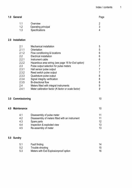
Index / contents 1 1.0 General Page
1.1 Overview 2 1.2 Operating principal 3 1.3 Specifications 4
2.0 Installation
2.1 Mechanical installation 5 2.1.1 Orientation 5 2.1.2 Flow conditioning & locations 6 2.2 Electrical installation 6 2.2.1 Instrument cable 6 2.2.2 Hazardous area wiring (see page 16 for Exd option) 7 2.3 Pulse output selection for pulse meters 7 2.3.1 Hall sensor pulse output 7 2.3.2 Reed switch pulse output 7 2.3.3 Quadrature pulse output 8 2.3.4 Signal integrity verification 8 2.3.5 Bi-directional flow 8 2.4 Meters fitted with integral instruments 9 2.4.1 Meter calibration factor (K-factor or scale factor) 9
3.0 Commissioning 10 4.0 Maintenance 10 4.1 Disassembly of pulse meter 11 4.2 Disassembly of meters fitted with an instrument 11
4.3 Spare parts 12 4.4 Inspection & exploded view 13
4.5 Re-assembly of meter 13 5.0 Sundry 5.1 Fault finding 14 5.2 Trouble shooting 15 5.3 Meters with Exd Explosionproof option 16

2 General 1.1 Overview The Oval Gear meter is a precise positive displacement flowmeter incorporating a pair of oval geared rotors. These meters are capable of measuring the flow of a broad range of clean liquids. Stainless Steel flowmeters are suited to most water based products and chemicals and aluminum meters are suitable for fuels, fuel oils & lubricating liquids. The flowmeter is available as a blind pulse meter with a non-factored pulse output capable of interfacing to most monitoring and control instrumentation or the meter can be fitted with or supplied with instruments such as totalisers, rate totalisers or batch controllers. These instruments also have monitoring and control output options including 4-20mA, scaled pulse, flowrate alarms and batch control logic (preset metering). If your flowmeter is fitted or supplied with an instrument please also refer to the relevant instrument instruction manual. These flowmeters can be installed within hazardous areas by either :
1) Wiring direct to meters with the following optional Exd approvals : Exd IIB T4/T6 general approval (aluminum & stainless meters). Exd I/IIB T4/T6 mines approval (stainless meters only).
2) Wiring reed switch output connection direct to certified Intrinsically Safe Instruments. 3) Wiring to the reed switch output (Simple apparatus) through an approved Intrinsically Safe barrier. Suitable I.S. barriers include MTL Model 5011 or 5012 and P&F Model KHD2-OT1-Ex1.
Manufacturers Declaration This declaration sites Trimec Industries Pty, Ltd as manufacturer of a range of propriety industrial flowmeters most of which incorporate one or more Reed switches qualifying as simple apparatus in accordance with European, USA & Canadian guidelines.
Simple apparatus such as Reed switches, Mechanical contact switches, Thermocouples, Resistive sensors & LED‟s may be employed in a hazardous area without certification provided that the device does not generate or store more than 1.2V, 0.1A, 20µJ and 25mW. This IEC definition is also now used in the USA & Canada.
The surface temperature of simple apparatus under normal or fault conditions must not exceed the ignition temperature of the gas, subject to the following very valuable exception. Because the ability of hot surfaces to cause ignition depends on their size, simple apparatus having a surface area between 20mm² and 100mm² will be classified T4 when the matched output power of the interface device does not exceed 1.3W into 40ºC ambient, 1.2W into 60ºC ambient or 1.0W into 80ºC ambient.
The 1.3W/40ºC element of this European dispensation is now accepted in the USA and Canada. Switches (mechanical & reed switches) and junction boxes dissipate no power and are normally classifies T6 (85ºC).
Reed switch Resistive sensors Thermocouples LED
These simple apparatus can be installed freely in I.S. circuits, no certification is required.

Operating principal 3 1.2 Operating Principle The Oval Gear meters are positive displacement flowmeters where the passage of liquid causes two oval geared rotors to rotate within a precision measuring chamber and with each rotation a fixed volume of liquid is displaced passing through the meter. Magnets embedded within the top of the rotors initiate a high resolution pulse train output. The pulse output can be wired directly to process control and monitoring equipment or can be used as an input to instruments supplied with or fitted directly to the meter. The benefits of this technology allow precise flow measurement and dispensing of most clean liquids irrespective of their conductivity, with other liquid characteristics having nil or minimal effect on meter performance. This metering technology does not require flow profile conditioning as required with alternative flow technologies making the installation relatively compact and low cost.
liquid in transit
flow
OPERATION :
Liquid travels around the crescent shaped chambers created by the
rotational movement of the rotors
liquid entering
measuring chamber liquid exits the
measuring chamber
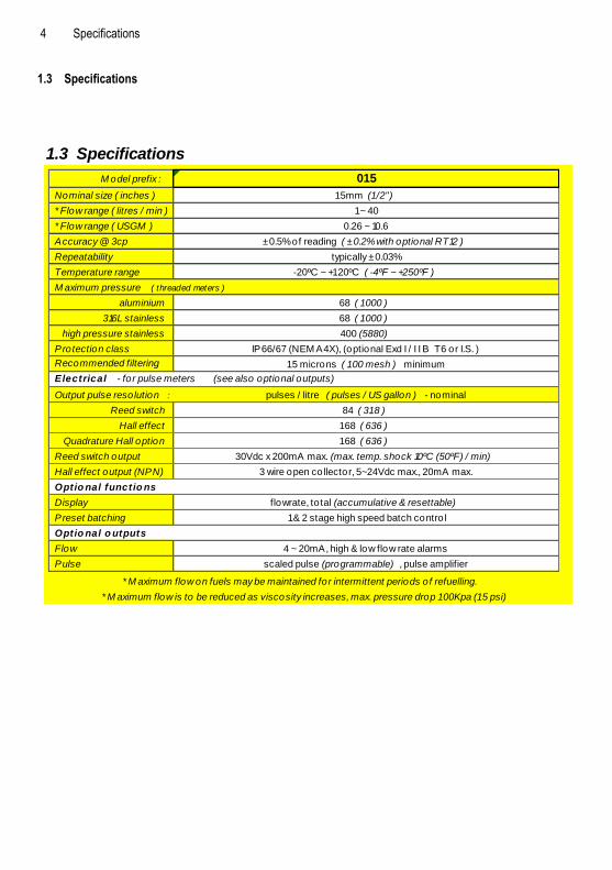
4 Specifications 1.3 Specifications
1.3 Specifications
M odel prefix : 015
Nominal size ( inches ) 1 5mm (1 /2")
* Flow range ( litres / min ) 1 ~ 40
* Flow range ( USGM ) 0.26 ~ 10.6
Accuracy @ 3cp ± 0.5% of reading ( ± 0.2% with optional RT12 )
Repeatability typically ± 0.03%
Temperature range -20ºC ~ +1 20ºC ( -4ºF ~ +250ºF )
M aximum pressure ( threaded meters )
aluminium 68 ( 1 000 )
316L stainless 68 ( 1 000 )
high pressure stainless 400 (5880)
Protection class IP66/67 (NEM A4X), (optional Exd I / I I B T6 or I.S. )
Recommended filtering
(minimum)
1 5 microns ( 1 00 mesh ) minimum
Electrical - for pulse meters (see also optional outputs)
Output pulse resolution : pulses / litre ( pulses / US gallon ) - nominal
Reed switch 84 ( 31 8 )
Hall effect 1 68 ( 636 )
Quadrature Hall option 1 68 ( 636 )
Reed switch output 30Vdc x 200mA max. (max. temp. shock 10ºC (50ºF) / min)
Hall effect output (NPN) 3 wire open collector, 5~24Vdc max., 20mA max.
Optio nal functio ns
Display flowrate, total (accumulative & resettable)
Preset batching 1 & 2 stage high speed batch contro l
Optio nal o utputs
Flow 4 ~ 20mA, high & low flow rate alarms
Pulse scaled pulse (programmable) , pulse amplifier
* M aximum flow is to be reduced as viscosity increases, max. pressure drop 1 00Kpa (1 5 psi)
* M aximum flow on fuels may be maintained for intermittent periods of refuelling.

Installation 5 2.0 Installation 2.1 Mechanical Installation Prior to installing the meter check :
# The fluid is compatible with the meter materials of construction using appropriate information such as fluid compatibility charts and site experience.
# Application and process conditions are compatible with the meter specifications. Minimum and maximum flows are within the meter specified range including any in-situ cleaning processes. When metering viscous liquids the maximum allowable flow may need to be reduced to ensure the pressure drop across the meter does not exceed 100 kPa (1 Barg, 15 PSIG). # Process temperature and pressure does not exceed meter ratings. # The meter is not exposed to process temperatures and pressures that will cause the liquid medium to gasify (flash) within the meter. 2.1.1 Orientation The flowmeter MUST be mounted so that the rotor shafts are in a horizontal plane. This is achieved by mounting the meter so that the terminal cover or integral instrument display, whichever is fitted, is facing in a horizontal direction. Note the terminal cover or instrument display can be rotated in 90 degree increments to provide access to the electrical entry and to allow the display orientation to suit the installation. Liquid can flow into the meter from either a horizontal or vertical direction. For vertical flow installations the most common orientation is for the liquid to rise through the meter (i.e. travel from bottom to top) to assist in air or entrained gas elimination. The meter operation is independent of the liquid flow direction thus there is no markings for inlet or outlet.
C O R R E C T O R I E N T A T I O N S
Note: face conduit entry downwards to avoid conduit moisture migration into
the electronics chamber.
I N C O R R E C T
When installed incorrectly the weight of the rotors will bear down on the base of the measuring chamber.

6 Installation
2.1.2 Flow Conditioning and Locations Strainer : It is recommended to INSTALL a 200mesh (75 micron) strainer immediately upstream of (prior to) the meter. Strainers are available from the factory. Flow conditioning : The flowmeter does not require any flow conditioning, therefore straight pipe runs before or after the meter are not required. If required, the pipe size about the meter can be altered to suit the installation. Locations : The flowmeter is preferred to be fitted upstream of any flow control and/or shut off valve, this prevents free discharge from the meter and minimizes the risk of drainage and air entrapment which can result in erroneous readings or damage the meter on start up. Process or safety critical meters should be installed in a by-pass section of pipe with isolation valves to enable the meter to be isolated and serviced as required. A by-pass installation also allows purging of the system during commissioning (see Commissioning).The meter must be appropriately rated and is typically located downstream (on the discharge side) of the pump. If mounted outdoors ensure a suitable watertight gland or plug is used to seal any open electrical entries. In humid environments take precautions to avoid condensation build up within the electrical and/or instrument enclosure. It is good wiring practice for conduits to be connected from the bottom of an entry port, in this way condensation will gravitate away from any terminal housing. Fluid state : Fluid entering the meter must remain a liquid at all times so protect the meter to avoid solidification or gelling of the metered medium. If meters are to be trace heated or jacketed in any way the maximum temperature rating of the meter must not be exceeded. Size the meter to avoid gasification of volatiles (flashing) within the liquid due to the pressure drop experienced within the system or within the meter. Hydraulic shock : If pressure surges or hydraulic shock of any kind is possible, the system upstream of the meter must be fitted with a surge suppressor or pressure relief valve to protect the meter from damage. High frequency flow pulsations can damage the meter. Such pulsations can be caused by the injection profile in diesel engines. Most pulsations are removed with the installation of a suitable pulsation dampener. 2.2 Electrical Installation 2.2.1 Instrument Cable Twisted pair low capacitance shielded instrument cable 7 x 0.3mm (0.5mm²) should
be used for electrical connection between the flowmeter and remote instrumentation, use Belden® number 9363 or similar. The cable drain or screen should be terminated on a DC COMMON or a specifically assigned shield termination at the readout instrument end only in order to protect the transmitted signal from mutual inductive interference. IMPORTANT, tape off & isolate the shield at the flowmeter end of the cable. The cable should not be run in a common conduit or parallel with power and high inductive load carrying cables as power surges may induce erroneous noise transients onto the transmitted pulse signal or cause damage to the electronics. Run the cable in separate conduit or with other low energy instrument cables. The maximum transmission distance is typically 1000m (3300 Ft).
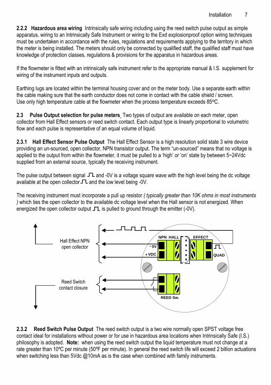
Installation 7 2.2.2 Hazardous area wiring Intrinsically safe wiring including using the reed switch pulse output as simple apparatus, wiring to an Intrinsically Safe Instrument or wiring to the Exd explosionproof option wiring techniques must be undertaken in accordance with the rules, regulations and requirements applying to the territory in which the meter is being installed. The meters should only be connected by qualified staff, the qualified staff must have knowledge of protection classes, regulations & provisions for the apparatus in hazardous areas. If the flowmeter is fitted with an intrinsically safe instrument refer to the appropriate manual & I.S. supplement for wiring of the instrument inputs and outputs. Earthing lugs are located within the terminal housing cover and on the meter body. Use a separate earth within the cable making sure that the earth conductor does not come in contact with the cable shield / screen. Use only high temperature cable at the flowmeter when the process temperature exceeds 85ºC. 2.3 Pulse Output selection for pulse meters Two types of output are available on each meter, open collector from Hall Effect sensors or reed switch contact. Each output type is linearly proportional to volumetric flow and each pulse is representative of an equal volume of liquid. 2.3.1 Hall Effect Sensor Pulse Output The Hall Effect Sensor is a high resolution solid state 3 wire device providing an un-sourced, open collector, NPN transistor output. The term “un-sourced” means that no voltage is applied to the output from within the flowmeter, it must be pulled to a „high‟ or „on‟ state by between 5~24Vdc supplied from an external source, typically the receiving instrument. The pulse output between signal and -0V is a voltage square wave with the high level being the dc voltage available at the open collector and the low level being -0V. The receiving instrument must incorporate a pull up resistor ( typically greater than 10K ohms in most instruments ) which ties the open collector to the available dc voltage level when the Hall sensor is not energized. When energized the open collector output is pulled to ground through the emitter (-0V). 2.3.2 Reed Switch Pulse Output The reed switch output is a two wire normally open SPST voltage free contact ideal for installations without power or for use in hazardous area locations when Intrinsically Safe (I.S.) philosophy is adopted. Note: when using the reed switch output the liquid temperature must not change at a rate greater than 10ºC per minute (50ºF per minute). In general the reed switch life will exceed 2 billion actuations when switching less than 5Vdc @10mA as is the case when combined with family instruments.
VDC +
0V -
QUAD
NPN HALL EFFECT
REED Sw.
Hall Effect NPN open collector
Reed Switch contact closure
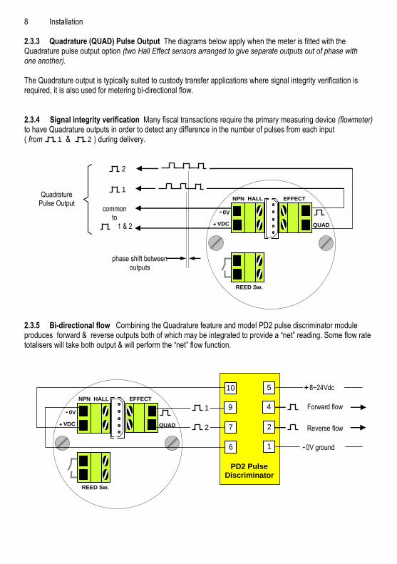
8 Installation 2.3.3 Quadrature (QUAD) Pulse Output The diagrams below apply when the meter is fitted with the Quadrature pulse output option (two Hall Effect sensors arranged to give separate outputs out of phase with one another). The Quadrature output is typically suited to custody transfer applications where signal integrity verification is required, it is also used for metering bi-directional flow. 2.3.4 Signal integrity verification Many fiscal transactions require the primary measuring device (flowmeter) to have Quadrature outputs in order to detect any difference in the number of pulses from each input ( from & ) during delivery. 2.3.5 Bi-directional flow Combining the Quadrature feature and model PD2 pulse discriminator module produces forward & reverse outputs both of which may be integrated to provide a “net” reading. Some flow rate totalisers will take both output & will perform the “net” flow function.
1 2
phase shift between outputs
Quadrature Pulse Output
1
2
common to
1 & 2 VDC +
0V -
QUAD
NPN HALL EFFECT
REED Sw.
VDC +
0V -
QUAD
NPN HALL EFFECT
REED Sw.
PD2 Pulse Discriminator
2
1
10
9
7
6
5
4
2
1
8~24Vdc +
0V ground -
Reverse flow
Forward flow

Installation 9 2.4 Meters fitted with integral Instruments If your flowmeter is fitted with an integral instrument such as a totaliser, rate totaliser or batch controller then the pulse output from the meter has been factory wired to the flow input of the readout instrument. As a default the reed output is pre-wired and DIP switches set for a integral totaliser or rate/totaliser allowing self powered operation of the instrument displays. Also by default the open collector output from the Hall Sensor is pre-wired and DIP switches set for a integral batch controller allowing high speed, solid state operation of the batch controller. These defaults may vary at the customer request or for specific applications such as dual flow input or high or low flow so if unsure remove the instrument bezel to check the wiring. The output(s) and function(s) available from a meter fitted with an integral instrument depends on the model of the instrument fitted and may include meter pulse repeater, prescaled pulse output, 4-20mA flow output, flowrate alarms or single/dual stage batch control logic (preset controller). Refer to the option in the meter model number and relevant instrument manual. Unless programming details were provided at time of order the instrument program will contain factory default parameters. Integral instruments will however be programmed with the relevant calibration factor (K factor or scale factor) for the meter. Factory default settings can be found in the instrument instruction manual and it should be noted all output(s) are turned OFF and if required need to be turned ON then programmed to suit the application requirements. 2.4.1 Meter Calibration Factor (K or scale Factor) Each flowmeter is individually calibrated and supplied with a calibration certificate showing the number of pulses per unit volume (eg pulses per litre or pulses per US gallon). Nominal figures are shown in the specification section of this manual. Meters fitted with Integral Instruments will have the relevant calibration factor entered into the program of the instrument. Please refer to relevant instrument manual for programming details.
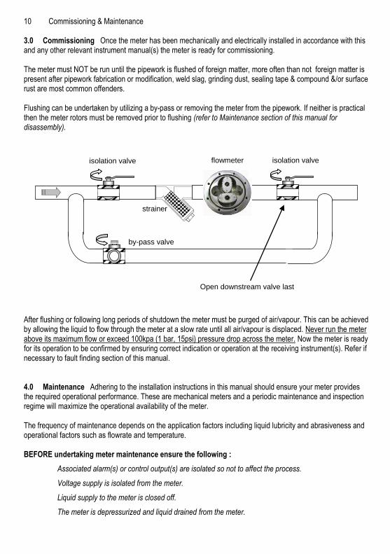
10 Commissioning & Maintenance 3.0 Commissioning Once the meter has been mechanically and electrically installed in accordance with this and any other relevant instrument manual(s) the meter is ready for commissioning. The meter must NOT be run until the pipework is flushed of foreign matter, more often than not foreign matter is present after pipework fabrication or modification, weld slag, grinding dust, sealing tape & compound &/or surface rust are most common offenders. Flushing can be undertaken by utilizing a by-pass or removing the meter from the pipework. If neither is practical then the meter rotors must be removed prior to flushing (refer to Maintenance section of this manual for disassembly). After flushing or following long periods of shutdown the meter must be purged of air/vapour. This can be achieved by allowing the liquid to flow through the meter at a slow rate until all air/vapour is displaced. Never run the meter above its maximum flow or exceed 100kpa (1 bar, 15psi) pressure drop across the meter. Now the meter is ready for its operation to be confirmed by ensuring correct indication or operation at the receiving instrument(s). Refer if necessary to fault finding section of this manual. 4.0 Maintenance Adhering to the installation instructions in this manual should ensure your meter provides the required operational performance. These are mechanical meters and a periodic maintenance and inspection regime will maximize the operational availability of the meter. The frequency of maintenance depends on the application factors including liquid lubricity and abrasiveness and operational factors such as flowrate and temperature. BEFORE undertaking meter maintenance ensure the following :
Associated alarm(s) or control output(s) are isolated so not to affect the process.
Voltage supply is isolated from the meter.
Liquid supply to the meter is closed off.
The meter is depressurized and liquid drained from the meter.
strainer
flowmeter isolation valve isolation valve
by-pass valve
Open downstream valve last

Maintenance 11
4.1 Disassembly of Pulse meter (Refer Exploded View) If required to gain access to the meter terminals and pulse output board, undo the cap screws (10), remove the cover (9) carefully to avoid putting strain on the terminal connections. The pulse output board (6) can now be accessed and removed if necessary (screws 7). If required to gain access to the oval geared rotors undo the body screws (5), carefully pry the meter body apart avoiding misplacing or damaging the O-ring (3) and rotors (2). 4.2 Disassembly of meters fitted with an Instrument If the meter is fitted with an integral instrument the instrument display assembly must be removed if required to gain access to the instrument terminal connections, instrument battery or pulse output board. This is achieved by undoing the bezel screws and separating the display assembly from its base. Do not stress or damage the wires that connect the display assembly to the meter output. Take care not to misplace or damage O-ring(s).The pulse output board can now be accessed. To remove the pulse output board, first undo the screws that fix the instrument base to the flowmeter.
Optional instruments
12 Maintenance
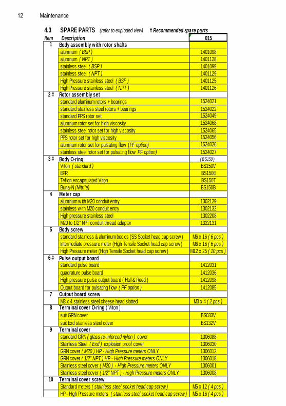
4.3 SPARE PARTS (refer to exploded view) # Recommended spare parts
Item Description 0151 Body assembly w ith rotor shafts
aluminum ( BSP ) 1401098
aluminum ( NPT ) 1401128
stainless steel ( BSP ) 1401099
stainless steel ( NPT ) 1401129
High Pressure stainless steel ( BSP ) 1401125
High Pressure stainless steel ( NPT ) 14011262 # Rotor assembly set
standard aluminum rotors + bearings 1524021
standard stainless steel rotors + bearings 1524022
standard PPS rotor set 1524049
aluminum rotor set for high viscosity 1524068
stainless steel rotor set for high viscosity 1524065
PPS rotor set for high viscosity 1524056
aluminum rotor set for pulsating f low (PF option) 1524026
stainless steel rotor set for pulsating f low PF option) 15240273 # Body O-ring ( BS1 50 )
Viton ( standard ) BS150V
EPR BS150E
Teflon encapsulated Viton BS150T
Buna-N (Nitrile) BS150B4 Meter cap
aluminum w ith M20 conduit entry 1302129
stainless w ith M20 conduit entry 1302132
High pressure stainless steel 1302208
M20 to 1/2" NPT conduit thread adaptor 13221315 Body screw
standard stainless & aluminum bodies (SS Socket head cap screw ) M6 x 16 ( 6 pcs )
Intermediate pressure meter (High Tensile Socket head cap screw ) M6 x 16 ( 6 pcs )
High Pressure meter (High Tensile Socket head cap screw ) M12 x 25 ( 10 pcs )6 # Pulse output board
standard pulse board 1412031
quadrature pulse board 1412036
High pressure pulse output board ( Hall & Reed ) 1412098
Output board for pulsating f low ( PF option ) 14120857 Output board screw
M3 x 4 stainless steel cheese head slotted M3 x 4 ( 2 pcs )8 Terminal cover O-ring ( Viton )
suit GRN cover BS033V
suit Exd stainless steel cover BS132V9 Terminal cover
standard GRN ( glass re-inforced nylon ) cover 1306088
Stainless Steel ( Exd ) explosion proof cover 1306030
GRN cover ( M20 ) HP - High Pressure meters ONLY 1306012
GRN cover ( 1/2" NPT ) HP - High Pressure meters ONLY 1306018
Stainless steel cover ( M20 ) - High Pressure meters ONLY 1306001
Stainless steel cover ( 1/2" NPT ) - High Pressure meters ONLY 130600810 Terminal cover screw
Standard meters ( stainless steel socket head cap screw ) M5 x 12 ( 4 pcs )
HP - High Pressure meters ( stainless steel socket head cap screw ) M5 x 16 ( 4 pcs )
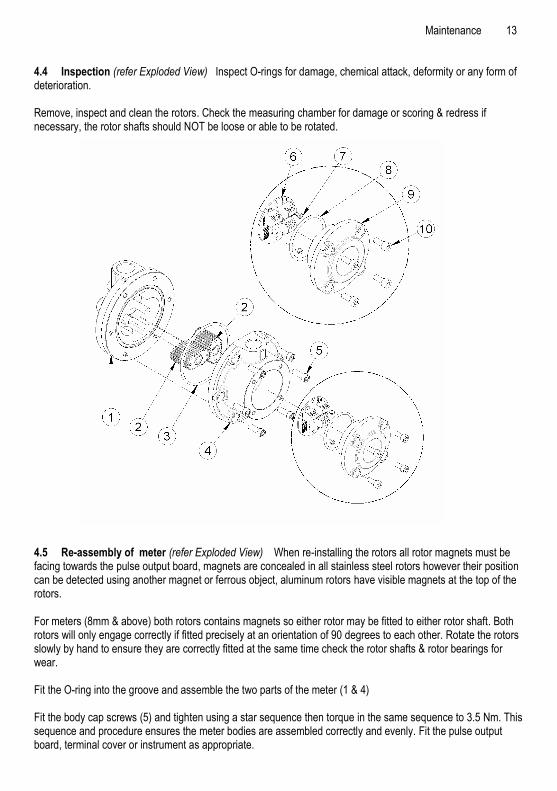
Maintenance 13 4.4 Inspection (refer Exploded View) Inspect O-rings for damage, chemical attack, deformity or any form of deterioration. Remove, inspect and clean the rotors. Check the measuring chamber for damage or scoring & redress if necessary, the rotor shafts should NOT be loose or able to be rotated. 4.5 Re-assembly of meter (refer Exploded View) When re-installing the rotors all rotor magnets must be facing towards the pulse output board, magnets are concealed in all stainless steel rotors however their position can be detected using another magnet or ferrous object, aluminum rotors have visible magnets at the top of the rotors. For meters (8mm & above) both rotors contains magnets so either rotor may be fitted to either rotor shaft. Both rotors will only engage correctly if fitted precisely at an orientation of 90 degrees to each other. Rotate the rotors slowly by hand to ensure they are correctly fitted at the same time check the rotor shafts & rotor bearings for wear. Fit the O-ring into the groove and assemble the two parts of the meter (1 & 4) Fit the body cap screws (5) and tighten using a star sequence then torque in the same sequence to 3.5 Nm. This sequence and procedure ensures the meter bodies are assembled correctly and evenly. Fit the pulse output board, terminal cover or instrument as appropriate.
14 Sundry 5.1 Fault Finding Pulse meters have two distinct sections: the mechanical wetted section housing the rotors and the electrical section housing the pulse output board. Meters fitted with integral instruments have these two sections plus the instrument. The aim of fault finding is to trace the source of the fault to one of these sections. If a fault is traced to an instrument section, refer to the relevant instruction manual. Below are basic fault finding steps. Also refer to Trouble Shooting Guide on following page. Step 1 - Check application, installation and set up. Refer to Mechanical Installation section for installation and application factors that may effect the meter operation including pulsation and air entrainment or incorrect meter selection including incorrect flow rate, temperature and pressure or materials compatibility. Refer to Electrical Installation for correct wiring. Step 2 - Check for blockages. The most common cause of fault/unsatisfactory meter operation, particularly for new or altered installations, is due to blockage within the system or meter caused by foreign particles such as weld slag, sealing tape or compound, rust, etc. Step 3 - Ensure flow is present. No flow or lower than normal minimum flow may be attributed to a blocked strainer, jammed or damaged rotors within the flowmeter, malfunctioning pump, closed valves or low liquid level in feeder tank. Step 4 - Ensure oval gears within meter are rotating. Rotation of the oval gears can be heard by holding a screw driver blade to the meter body and pressing the handle hard against the ear lobe. If necessary test the meter with the flow turned off and turned on to familiarize yourself with the audible rotation signature. Step 5 - Ensure pulses are being generated during flowing conditions. A multimeter is often not fast enough to distinguish the pulse train from the reed switch or Hall Effect sensor. An oscilloscope will allow you to view the output pulse train. When viewing the Hall effect sensor pulse ensure a pull up resistor is installed between the pulse output and the supply voltage (refer electrical installation). Step 6 - Confirm Instrument Operation. If an associated instrument is connected to the flowmeter confirm its operation by simulating a pulse input onto the flow input terminals. In most instances a contact closure on the flow input terminals is an adequate simulation.
Trouble shooting 15
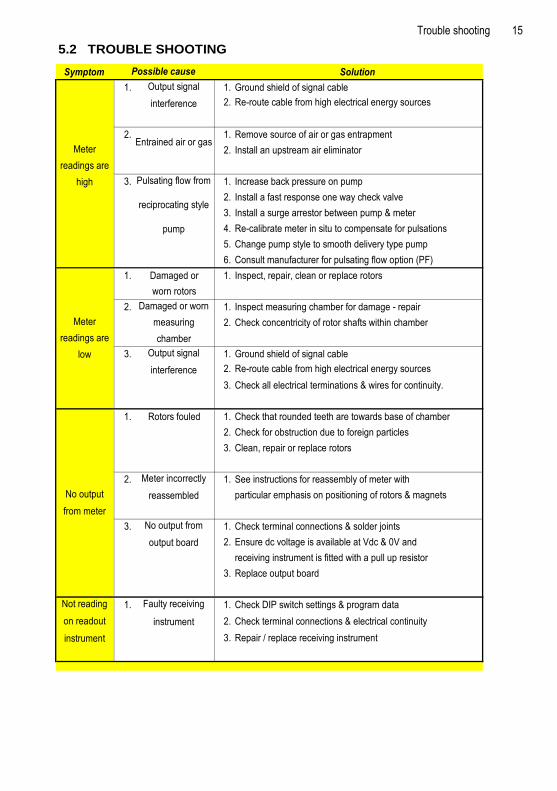
5.2 TROUBLE SHOOTING
Symptom Solution
1. 1. Ground shield of signal cable
2. Re-route cable from high electrical energy sources
2. 1. Remove source of air or gas entrapment
2. Install an upstream air eliminator
3. 1. Increase back pressure on pump
2. Install a fast response one way check valve
3. Install a surge arrestor between pump & meter
4. Re-calibrate meter in situ to compensate for pulsations
5. Change pump style to smooth delivery type pump
6. Consult manufacturer for pulsating flow option (PF)
1. Damaged or 1. Inspect, repair, clean or replace rotors
worn rotors
2. 1. Inspect measuring chamber for damage - repair
2. Check concentricity of rotor shafts within chamber
3. 1. Ground shield of signal cable
2. Re-route cable from high electrical energy sources
3. Check all electrical terminations & wires for continuity.
1. Rotors fouled 1. Check that rounded teeth are towards base of chamber
2. Check for obstruction due to foreign particles
3. Clean, repair or replace rotors
2. 1. See instructions for reassembly of meter with
particular emphasis on positioning of rotors & magnets
3. 1. Check terminal connections & solder joints
2. Ensure dc voltage is available at Vdc & 0V and
receiving instrument is fitted with a pull up resistor
3. Replace output board
1. 1. Check DIP switch settings & program data
2. Check terminal connections & electrical continuity
3. Repair / replace receiving instrument
Meter
readings are
high
Output signal
interference
Meter
readings are
low
Entrained air or gas
Not reading
on readout
instrument
No output
from meter
Possible cause
Output signal
interference
Pulsating flow from
reciprocating style
pump
Damaged or worn
measuring
chamber
No output from
output board
Faulty receiving
instrument
Meter incorrectly
reassembled
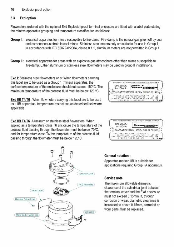
16 Explosionproof option 5.3 Exd option Flowmeters ordered with the optional Exd Explosionproof terminal enclosure are fitted with a label plate stating the relative apparatus grouping and temperature classification as follows: Group I : electrical apparatus for mines susceptible to fire-damp. Fire-damp is the natural gas given off by coal
and carbonaceous strata in coal mines. Stainless steel meters only are suitable for use in Group 1, in accordance with IEC 60079-0:2004, clause 8.1.1, aluminum meters are not permitted in Group 1.
Group II : electrical apparatus for areas with an explosive gas atmosphere other than mines susceptible to fire-damp. Either aluminum or stainless steel flowmeters may be used in group II installations. Exd I: Stainless steel flowmeters only: When flowmeters carrying this label are to be used as a Group 1 (mines) apparatus, the surface temperature of the enclosure should not exceed 150ºC. The maximum temperature of the process fluid must be below 120 ºC. Exd IIB T4/T6 : When flowmeters carrying this label are to be used as a IIB apparatus, temperature restrictions as described below are applicable. Exd IIB T4/T6 Aluminum or stainless steel flowmeters: When applied as a temperature class T6 enclosure the temperature of the process fluid passing through the flowmeter must be below 70ºC, and for temperature class T4 the temperature of the process fluid passing through the flowmeter must be below 120ºC.
General notation :
Apparatus marked IIB is suitable for applications requiring Group IIA apparatus. Service note :
The maximum allowable diametric clearance of the cylindrical joint between the terminal cover and the Exd enclosure must not exceed 0.15mm. If, through corrosion or wear, diametric clearance is increased to above 0.15mm, corroded or
worn parts must be replaced.

Notes:
IMOM015-4912
Each meter has been calibrated on mineral oil and will contain a small amount of oil residue.
The oil used is Castrol Diesel Calibration
Fluid 4113 (product code 055830).
IMPORTANT
© 2017 Great Plains Industries, Inc., All Rights Reserved.Great Plains Industries, Inc. / 888-996-3837 / FLOMEC.net
Related Documents