P.O. ENGINEERING DEPARTMENT EDUCATIONAL PAMPHLET - DRAFT SERIES TELEPHONES 3/1 1 Issue 2.0 3/62 (Crown Copyright Reserved) OUTLINE OF AUTOMATIC STEP BY STEP SYSTEM CONTENTS Page Introduction 1 The Telephone Dial 3 The Selector 4 Switching Arrangements 6 Junction Switching 10 Subscribers' Calling Equipment 11 Typical Numbering Scheme 14 Figures 4, 7, 11 and 16 are appended. INTRODUCTION General The primary object of automatic telephony is to enable subscribers to complete calls without the intervention of an operator. Some of the advantages of an automatic telephone system over a manually- operated system are as follows: (a) Reduction of operating costs, i.e. the overall cost of establishing a call by automatic means is less than by manual handling. (b) Reduction of time taken to set up a call. (c) Reduction in holding time of switching apparatus and junctions due to automatic release at the end of the call. This results in greater circuit efficiency. (d) Privacy. (e) A 24-hour service of uniform standard. In an automatic telephone system the calling subscriber signals his requirements, that is the required number, to the exchange by manipulating a device, the dial, attached to his telephone. At the exchange the signals directly or indirectly cause the operation of electromechanical selecting devices which effect the connexion between the calling and called subscribers. The automatic system adopted by the British Post Office is known as the 'Strowger step by step system' because the selecting devices are operated by ratchet and pawl devices and consequently move with a stepping action.

Welcome message from author
This document is posted to help you gain knowledge. Please leave a comment to let me know what you think about it! Share it to your friends and learn new things together.
Transcript
P.O. ENGINEERING DEPARTMENT EDUCATIONAL PAMPHLET - DRAFT SERIES TELEPHONES 3/1
1 Issue 2.0 3/62
(Crown Copyright Reserved)
OUTLINE OF AUTOMATIC STEP BY STEP SYSTEM
CONTENTS
Page
Introduction 1
The Telephone Dial 3
The Selector 4
Switching Arrangements 6
Junction Switching 10
Subscribers' Calling Equipment 11
Typical Numbering Scheme 14
Figures 4, 7, 11 and 16 are appended.
INTRODUCTION
General
The primary object of automatic telephony is to enable subscribers to complete calls without the intervention of an operator.
Some of the advantages of an automatic telephone system over a manually-operated system are as follows:
(a) Reduction of operating costs, i.e. the overall cost of establishing a call by automatic means is less than by manual handling.
(b) Reduction of time taken to set up a call.
(c) Reduction in holding time of switching apparatus and junctions due to automatic release at the end of the call. This results in greater circuit efficiency.
(d) Privacy.
(e) A 24-hour service of uniform standard.
In an automatic telephone system the calling subscriber signals his requirements, that is the required number, to the exchange by manipulating a device, the dial, attached to his telephone. At the exchange the signals directly or indirectly cause the operation of electromechanical selecting devices which effect the connexion between the calling and called subscribers. The automatic system adopted by the British Post Office is known as the 'Strowger step by step system' because the selecting devices are operated by ratchet and pawl devices and consequently move with a stepping action.

E.P. TELEPHONES 3/1
2.
The selecting devices are arranged in successive stages and, fundamentally, at each stage the calling subscriber by the action of dialling selects one of 10 routes to the next stage. Thus in two stages any one of 100 different routes, and in three stages any one of 1000 different routes can be selected by the dialling of two or three digits respectively. The application of this system of 'decimal selection' to automatic telephone switching systems is dealt with later in this pamphlet.
If the services of an operator are to be completely eliminated the equipment at an automatic telephone exchange must, in addition to selecting the required subscriber's line, provide the following.
(a) A distinctive tone, dial tone, to be connected to a calling subscriber's line when the selecting equipment is ready to receive his signals, i.e. an indication that dialling may commence.
(b) Arrangements whereby the called subscriber's line is tested and, if found free, ringing current applied to the line to ring his bell.
(c) A tone, ring tone, to indicate to the calling subscriber that ringing current is being applied to the called subscriber's line.
(d) Arrangements such that if the called subscriber's line is engaged or out of service, the caller is not extended to the line but is advised by means of tone signals, the busy tone or number unobtainable tone respectively, of the condition of the line.
(e) Arrangements such that when the called subscriber answers, the ringing current and ring tone are disconnected, the circuit completed for conversation and the calling subscriber's call record meter operated.
(f) Arrangements whereby at the conclusion of the call, i.e. when the calling party replaces the telephone handset, all the selecting equipment restores to the normal position thus making it available for use on other calls.
It should be appreciated that during the setting up of a call, the calling subscriber, the equipment employed at each switching stage and finally the called subscriber are marked busy to avoid double connexions. The methods of applying the foregoing tests and tones to the appropriate circuits are beyond the scope of this pamphlet, a brief description of the tones however is included.
Tones
A subscriber is made aware of the progress of a call by means of distinctive tones, with which users of automatic exchanges are required to be familiar. The standard tones and their significance are as follows:
(a) dial tone - a continuous low-frequency or purring tone - signifies that dialling may proceed.
(b) ring tone - a tone of higher frequency, interrupted in the same way as the familiar ringing of the telephone bell - indicating that the final selector has switched to the called subscriber's number and that ringing current is being fed to his line.
(c) busy tone - a tone of the same frequency as ring tone, interrupted at regular intervals - indicates that the required line or switching apparatus is engaged.

E.P. TELEPHONES 3/1
3.
(d) number unobtainable (N.U.) tone - of the same frequency as ring tone but applied continuously - indicates that connexion has been made either to spare equipment or to a line which is spare or out-of-service.
Fig. 1 shows the frequency of the tones, the period of tone 'on' and tone 'off' being indicated in the case of interrupted tones.
Fig. 1
THE TELEPHONE DIAL
When the handset is lifted from the telephone a direct current circuit is completed for the exchange equipment. The primary function of the telephone dial is to interrupt the circuit a number of times corresponding to the figure, or digit, dialled. The dial mechanism is governor controlled so that the interruptions, or pulses, each consist of a 662/3 mS break period and a 331/3 mS make period. Thus it
may be considered to enerate current pulses of 331/3 mS duration at a frequency of 10 pulses per second p.s.). At the exchange the current pulses actuate a relay arrangement which repeats them as 662/3 mS pulses to the selector electromagnets.
The dial mechanism is also arranged so that irrespective of the way it is operated, the circuit is completed for a minimum period of some 220 mS between the dialling of successive digits. The period is known as the 'inter-digit pause', and is needed to give time for certain circuit operations to occur in the exchange equipment before the next train of pulses is received.
Fig. 3

E.P. TELEPHONES 3/1
4.
The dial embodies a finger plate, Fig. 2, having '10 holes, which is rotated by the finger from the selected digit or letter to the finger stop and then allowed to return unimpeded to the normal position. During the return motion a pulse wheel attached to the spindle on which the finger plate is fixed, operates a pulse contact unit to interrupt the associated circuit a number of times corresponding to the selected digit or letter. The pulse wheel and contact unit are shown schematically in Fig. 3. There are ten interruptions when "0" is dialled. The return speed of the finger plate, and consequently the rate at which the pulses occur is controlled by a centrifugal type of governor which is incorporated in the dial mechanism.
SELECTORS
A selector in its simplest form consists of a movable set of contacting arms known as a wiper assembly, associated with a fixed set of contacts known as a contact bank. When the selector is operated the wiper assembly is caused to step one set of contacts at a time over the bank until the desired set is reached. The selectors used by the B.P.O. are of two main types, uniselectors and two-motion selectors.
The Uniselector
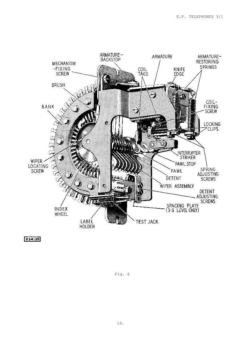
The uniselector is a selector in which the wiper assembly moves in one plane only. The wipers rotate about a central shaft and wipe over series of contacts set radially in a bank which may consist of from 3 to 10 rows of contacts. For the purposes of this pamphlet each row of contacts may be considered to consist of 25 individual contacts equally spaced over the arc. The number of wipers mounted side by side to form the wiper assembly correspond to the number of rows of contacts and when necessary they can be arranged so that effectively one wiper steps over 50 separate contacts in one revolution of the assembly. An illustration, Fig. 4, of a typical uniselector having 8 rows of contacts and arranged to have 25 contacts, or outlets, per revolution of the assembly is appended to this pamphlet. The trunking arrangements of the uniselector are shown in Fig. 5, for simplicity only 10 contacts are shown in the bank; in certain cases, however, all 25 contacts are shown. It should be noted that when the uniselector is normal, the wipers are standing on one of the bank contacts, usually the first.
Fig. 5

E.P. TELEPHONES 3/1
5.
The Two-Motion Selector
The wipers of a two-motion selector can, as the name implies, be moved in two planes. The selector can have more than one contact bank, each of which is composed of 10 horizontal arc-shaped layers, known as levels, with 11 equally
spaced sets of contacts on each level. Only the first 10 contacts on each level
need be considered for the purposes of this pamphlet. The banks are positioned so that the levels are concentric with the shaft which carries the wipers, consequently the sets of wipers can be positioned on to any set of contacts by two movements of the shaft:
(a) a vertical stepping motion by which the shaft is raised until the sets of wipers are standing outside and opposite the required contact level, and
(b) a rotary stepping motion in which the shaft is rotated, so moving the sets of wipers to the required set of contacts.
The arrangement of the wipers with respect to the contacts and the system of numbering the contacts is shown in Fig. 6.
Fig. 6
The contact bank surface, ABCB, may be considered as a portion of the wall of a cylinder and the wiper, XY, free to move up and about the axis of the cylinder. There are two methods of returning the wipers back to the normal position:
(a) from Z to E and from E to G, and
(b) from Z to F, F to C, and C to G
A 2000-type two-motion selector complete with control circuit equipment is shown in Fig. 7 appended. It should be noted that when the selector is normal the wipers are one step outside the left-hand side of the bank and one vertical step below the bottom level, that is level 1.
E.P. TELEPHONES 3/1
6.
SWITCHING ARRANGEMENTS
10 Line Exchange
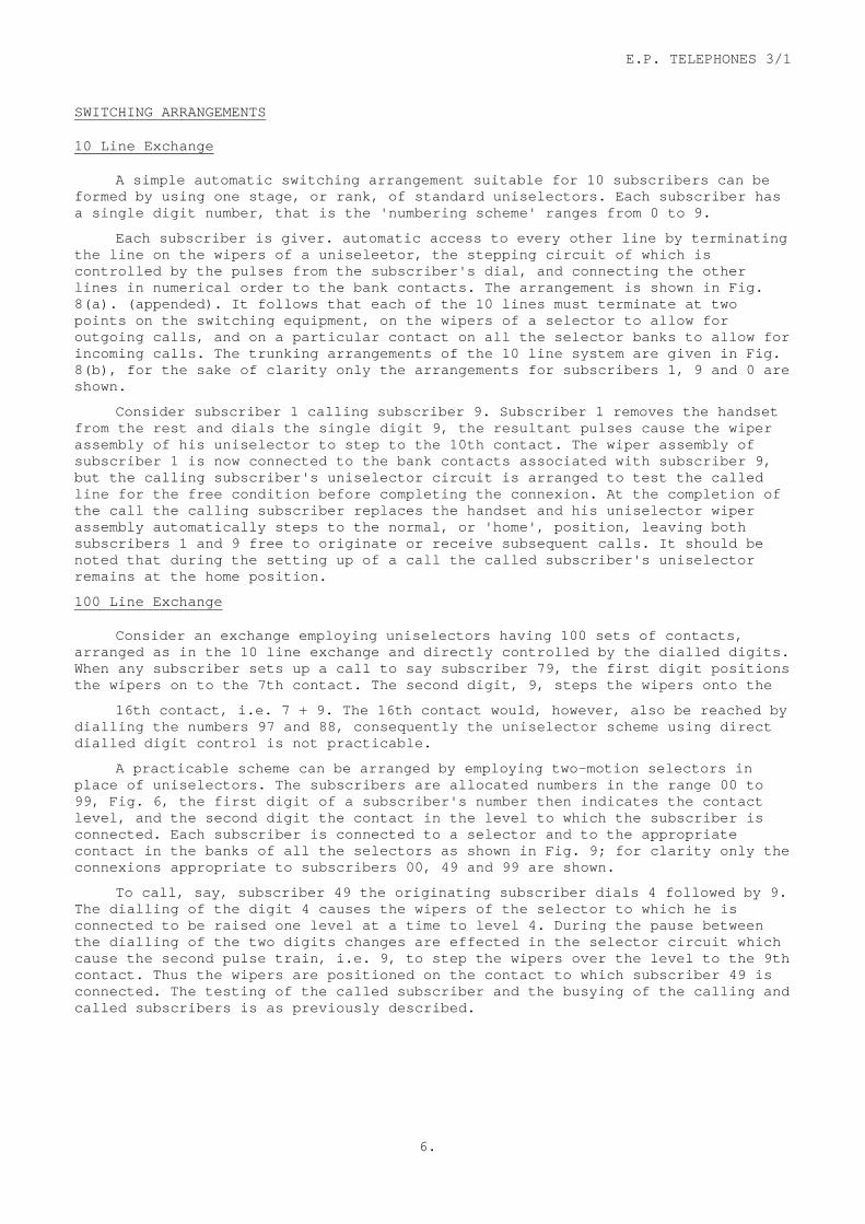
A simple automatic switching arrangement suitable for 10 subscribers can be formed by using one stage, or rank, of standard uniselectors. Each subscriber has a single digit number, that is the 'numbering scheme' ranges from 0 to 9.
Each subscriber is giver. automatic access to every other line by terminating the line on the wipers of a uniseleetor, the stepping circuit of which is controlled by the pulses from the subscriber's dial, and connecting the other lines in numerical order to the bank contacts. The arrangement is shown in Fig. 8(a). (appended). It follows that each of the 10 lines must terminate at two points on the switching equipment, on the wipers of a selector to allow for outgoing calls, and on a particular contact on all the selector banks to allow for incoming calls. The trunking arrangements of the 10 line system are given in Fig. 8(b), for the sake of clarity only the arrangements for subscribers 1, 9 and 0 are shown.
Consider subscriber 1 calling subscriber 9. Subscriber 1 removes the handset from the rest and dials the single digit 9, the resultant pulses cause the wiper assembly of his uniselector to step to the 10th contact. The wiper assembly of subscriber 1 is now connected to the bank contacts associated with subscriber 9, but the calling subscriber's uniselector circuit is arranged to test the called line for the free condition before completing the connexion. At the completion of the call the calling subscriber replaces the handset and his uniselector wiper assembly automatically steps to the normal, or 'home', position, leaving both subscribers 1 and 9 free to originate or receive subsequent calls. It should be noted that during the setting up of a call the called subscriber's uniselector remains at the home position.
100 Line Exchange
Consider an exchange employing uniselectors having 100 sets of contacts, arranged as in the 10 line exchange and directly controlled by the dialled digits. When any subscriber sets up a call to say subscriber 79, the first digit positions the wipers on to the 7th contact. The second digit, 9, steps the wipers onto the
16th contact, i.e. 7 + 9. The 16th contact would, however, also be reached by dialling the numbers 97 and 88, consequently the uniselector scheme using direct dialled digit control is not practicable.
A practicable scheme can be arranged by employing two-motion selectors in place of uniselectors. The subscribers are allocated numbers in the range 00 to 99, Fig. 6, the first digit of a subscriber's number then indicates the contact level, and the second digit the contact in the level to which the subscriber is connected. Each subscriber is connected to a selector and to the appropriate contact in the banks of all the selectors as shown in Fig. 9; for clarity only the connexions appropriate to subscribers 00, 49 and 99 are shown.
To call, say, subscriber 49 the originating subscriber dials 4 followed by 9. The dialling of the digit 4 causes the wipers of the selector to which he is connected to be raised one level at a time to level 4. During the pause between the dialling of the two digits changes are effected in the selector circuit which cause the second pulse train, i.e. 9, to step the wipers over the level to the 9th contact. Thus the wipers are positioned on the contact to which subscriber 49 is connected. The testing of the called subscriber and the busying of the calling and called subscribers is as previously described.

E.P. TELEPHONES 3/1
7.
Fig. 9
100 two-motion selectors are required in the scheme shown in Fig. 9. During the progress of a call the called subscriber's selector is idle, consequently in the extreme case of 50 subscribers connected to the remaining 50 only half the number of selectors in the exchange are in use. In practice it is probable that not more than 12 calls will occur simultaneously, in which case 88 selectors are idle. Inefficient usage of the selectors can be obviated by providing a sufficient number to cope with the highest probable number of simultaneous calls and introducing equipment, known as 'Subscriberst Calling Equipment', whereby every one of the 100 subscribers has access to the selectors. There are two types of subscribers' calling equipment in general use and they are described in outline later in this pamphlet.
1000 Line Exchange
A group of 1000 subscribers can be considered as 10 groups each of 100 subscribers. If the subscribers are each given a 3-digit number in the range 000-999, a suitable switching arrangement can be formed by preceding 10 of the 100 line systems by a switching stage arranged to route the call to the appropriate unit on receipt of the first digit dialled.
The selector in the first switching stage has only to respond to one digit, therefore a uniselector, having each of its first 10 bank contacts connected to a two-motion selector known as a final selector, could be used and arranged as shown in Fig. 10. For the sake of clarity only the final selectors connected to the first and tenth contacts are shown.

E.P. TELEPHONES 3/1
8.
Fig. 10
In the arrangement shown in Fig. 10 each uniselector has ten 2-motion selectors connected to its bank. Under the condition of one half the subscribers connected to the other half, therefore, only half the uniselectors and one twentieth of the 10,000 final selectors will be in use. Such an arrangement is inefficient and not practicable. The number of final selectors required could be reduced by joining together the corresponding bank contacts of, say, twenty uniselectors and then connecting a final selector to each of the 'commoned' contacts. When, however, one of the subscribers is making a call to a subscriber, the remaining nineteen subscribers are unable to call a number in that particular hundreds group. A more efficient method is to utilize two-motion selectors in the first selecting stage as shown in Fig. 11 (appended).
The two-motion selectors used in the first switching stage are known as group selectors and they are arranged to step in the vertical direction under the control of the first digit dialled, and in the rotary direction under the control of the condition on the bank contacts. The bank contacts of the group selectors are multipled and final selectors sufficient to meet the estimated traffic are connected to the contacts of each level. Thus all the final selectors are made available from each group selector.
When a subscriber makes a call, the first digit dialled steps the group selector wipers to the appropriate level, and during the inter-digit pause before the second digit is dialled the wipers automatically step over the contacts of the level until a free final selector is found. If all the selectors are engaged the busy tone is returned to the calling subscriber when the wipers step on to the last contact in the level. The second and third digits dialled position the final selector to complete the call as previously described.
When more than 10 final selectors are necessary to meet the estimated traffic incoming to a particular group of 100 subscribers, it is not possible to make every final selector available from any one group selector. The method, known as grading, which is used to distribute the final selectors over the contacts of the particular level of the group selectors is described best by a simple example.
E.P. TELEPHONES 3/1
9.
Assume 12 final selectors are necessary to meet the estimated traffic. The group selectors are divided into two groups, usually of equal size, thus making
two contact bank multiples. Consider the particular level; the first 2 contacts in each multiple are each connected to final selectors; the remaining 8 contacts in one multiple are each connected to the corresponding contacts in the other multiple
and also to a final selector. Thus the first 2 contacts of the level in each group of selectors each have the exclusive use of a final selector, and the remaining 8 contacts each share a final selector with the corresponding contact in the other group. An explanatory diagram of the arrangement is shown in Fig. 11b. Such a method of connecting contact levels to selectors is designed to give maximum
efficiency of both service to calling subscribers and usage of the selectors. A detailed study of grading is beyond the scope of this pamphlet.
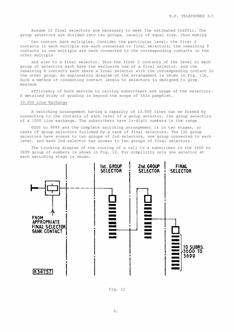
10,000 Line Exchange
A switching arrangement having a capacity of 10,000 lines can be formed by connecting to the contacts of each level of a group selector, the group selectors of a 1000 line exchange. The subscribers have 1+-digit numbers in the range
0000 to 9999 and the complete switching arrangement is in two stages, or ranks of group selectors followed by a rank of final selectors. The 1st group selectors have access to ten groups of 2nd selectors, one group connected to each level, and each 2nd selector has access to ten groups of final selectors.
The trunking diagram of the routing of a call to a subscriber in the 3600 to 3699 group of numbers is shown in Fig. 12. For simplicity only one selector at each switching stage is shown.
Fig. 12
E.P. TELEPHONES 3/1
10.
In modern exchanges having a capacity of 10,000 lines the group selectors, although having only 10 rotary positions, effectively have 20 contacts per level. Such an arrangement allows for larger groups of circuits between a level and the next switching stage, with a consequent increase in the efficiency, i.e. traffic carried per circuit, of the group. When necessary, grading is also employed between the stages or ranks of group selectors.
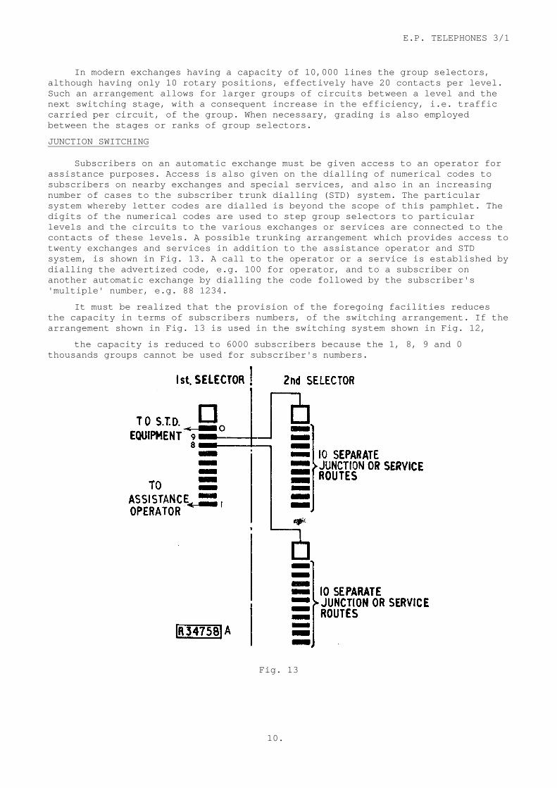
JUNCTION SWITCHING
Subscribers on an automatic exchange must be given access to an operator for assistance purposes. Access is also given on the dialling of numerical codes to subscribers on nearby exchanges and special services, and also in an increasing number of cases to the subscriber trunk dialling (STD) system. The particular system whereby letter codes are dialled is beyond the scope of this pamphlet. The digits of the numerical codes are used to step group selectors to particular levels and the circuits to the various exchanges or services are connected to the contacts of these levels. A possible trunking arrangement which provides access to twenty exchanges and services in addition to the assistance operator and STD system, is shown in Fig. 13. A call to the operator or a service is established by dialling the advertized code, e.g. 100 for operator, and to a subscriber on another automatic exchange by dialling the code followed by the subscriber's 'multiple' number, e.g. 88 1234.
It must be realized that the provision of the foregoing facilities reduces the capacity in terms of subscribers numbers, of the switching arrangement. If the arrangement shown in Fig. 13 is used in the switching system shown in Fig. 12,
the capacity is reduced to 6000 subscribers because the 1, 8, 9 and 0 thousands groups cannot be used for subscriber's numbers.
Fig. 13

E.P. TELEPHONES 3/1
11.
Exchanges composed of ranks of group selectors are in use exclusively as junction switching centres in many parts of the U.K. trunk network. Automatic rotary stepping is employed at all switching stages, thus 2 ranks of selectors with all levels in use provide access to 100 routes and 3 ranks 1000 routes.
SUBSCRIBERS’ CALLING EQUIPMENT
There are two methods whereby subscribers are connected to the 1st selectors, they are the Linefinder system, and the Subscribers' Uniselector system which is the present standard method. Each system is designed such that,
(a) the number of 1st selectors required approximates to the highest estimated number of simultaneous calls that the exchange is likely to carry, and (b) to give each subscriber access to a sufficient number of 1st selectors so that normally one is always available for his use.
Subscribers' Uniselector System
In the existing standard method of connecting calling subscribers to 1st selectors, each subscriber is connected to the wipers of a uniselector and the 1st selectors connected to the multipled bank contacts of the uniselectors as shown in Fig. 14. For the sake of clarity the uniselectors associated with only two subscribers in a 100 line exchange are shown.
When the subscriber removes the handset from the telephone to originate a call, the uniselector wiper assembly is caused to step over the bank contacts until a free selector is found. Dial tone is returned to the caller when connexion is made to the 1st selector, dialling can then commence. At the termination of the
Fig. 14
E.P. TELEPHONES 3/1
12.
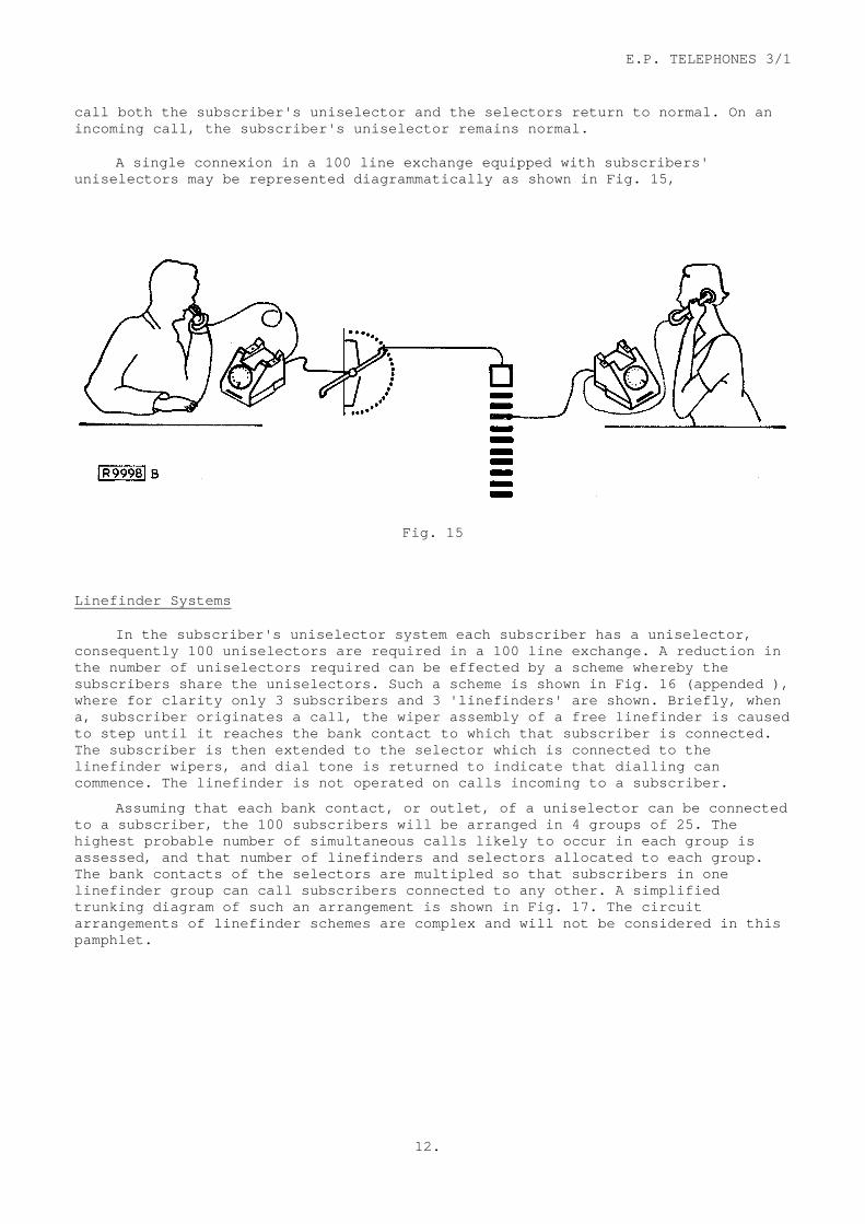
call both the subscriber's uniselector and the selectors return to normal. On an incoming call, the subscriber's uniselector remains normal.
A single connexion in a 100 line exchange equipped with subscribers' uniselectors may be represented diagrammatically as shown in Fig. 15,
Fig. 15
Linefinder Systems
In the subscriber's uniselector system each subscriber has a uniselector, consequently 100 uniselectors are required in a 100 line exchange. A reduction in the number of uniselectors required can be effected by a scheme whereby the subscribers share the uniselectors. Such a scheme is shown in Fig. 16 (appended ), where for clarity only 3 subscribers and 3 'linefinders' are shown. Briefly, when a, subscriber originates a call, the wiper assembly of a free linefinder is caused to step until it reaches the bank contact to which that subscriber is connected. The subscriber is then extended to the selector which is connected to the linefinder wipers, and dial tone is returned to indicate that dialling can commence. The linefinder is not operated on calls incoming to a subscriber.
Assuming that each bank contact, or outlet, of a uniselector can be connected to a subscriber, the 100 subscribers will be arranged in 4 groups of 25. The highest probable number of simultaneous calls likely to occur in each group is assessed, and that number of linefinders and selectors allocated to each group. The bank contacts of the selectors are multipled so that subscribers in one linefinder group can call subscribers connected to any other. A simplified trunking diagram of such an arrangement is shown in Fig. 17. The circuit arrangements of linefinder schemes are complex and will not be considered in this pamphlet.

E.P. TELEPHONES 3/1
13.
Fig. 17
When the subscribers are arranged in small groups as in the previous example the equipment is not used efficiently. The total number of linefinders and two-motion selectors needed for the 100 line exchange can be reduced and the efficiency increased by increasing the number of subscribers in each group.
Fig. 18

E.P. TELEPHONES 3/1
14.
In practice uniselectors arranged to have 50 bank contacts and two-motion selectors having 100 or 200 bank contacts are used as linefinders. A trunking diagram of a linefinder scheme employing two-motion selectors is shown in Fig. 18. The subscribers are connected to the bank contacts of a number of two-motion selectors, the number again being dependent on the highest probable number of simultaneous calls. When a call is originated a free linefinder steps to the level and contact on which the particular subscriber is connected. The calling subscriber is then extended to the two-motion selector associated with the particular linefinder and dialling can commence.
A linefinder or subscribers' uniselector scheme is provided between the selecting equipment and the subscribers' lines in all the types of B.P.O. automatic telephone exchanges.
TYPICAL NUMBERING SCHEME
The capacity of each switching arrangement shown in this pamphlet is the theoretical maximum. In practice the subscribers' must be given access to an assistance operator and in the majority of cases access to other exchanges and services such as '999'. Access to such services is obtained primarily from levels of the 1st selectors, and consequently reduces the subscribers' number range.
The simplified trunking diagram of a switching arrangement having a 4-digit subscribers' numbering scheme and providing access to services and other exchanges is shown in Fig. 19. The diagram also shows the routing of a call from subscriber 6436 to subscriber 2508. Level 0 of the 1st selectors is at present connected to
Fig. 19
the switchboard in order to give subscribers' access to an assistance operator by dialling the single digit 0. When subscriber trunk dialling (S.T.D.) facilities are introduced at an exchange the code for operator is changed to 100; the

E.P. TELEPHONES 3/1
15.
necessary equipment to affect the routing of the call is then connected to level 1 of the 1st selector. The initial digit of a subscriber's national number is 0, consequently level 0 of the 1st selector is required for routing calls to S.T.D.
The provision of access to other exchanges and its restriction on the capacity of the numbering scheme has already been considered. When the estimated number of subscribers some years hence exceeds, say, 6000 then it is standard practice to have a system consisting of 3 ranks of group selectors and one rank of final selectors. The subscribers then have 5-digit numbers and the system has a capacity ten times that of a similar 4-digit arrangement. A description of the larger systems is beyond the scope of this pamphlet.
The circuits, termed junctions, incoming from other exchanges and the assistance operators switchboard are given direct access to the exchange numbering scheme by terminating them directly on to 1st selectors.
The sequence of events likely during the setting up of a local connexion over the system shown in Fig. 19 is as follows. The calling subscriber removes the handset from the telephone and so causes the uniselector to hunt over the bank contacts until a free 1st selector is found. Dial tone is returned from the 1st selector to the caller. On receipt of the first digit dialled the selector steps to the appropriate level and during the pause between the end of the first digit and the receipt of the second, the selector wipers are automatically stepped over the contacts of the level in search of a free 2nd selector. If all the selectors are engaged the wipers step to the 11th rotary position and busy tone is returned to the caller. If the 1st selector level is spare, that is has no circuits to the operator, STD or 2nd selectors connected to its contacts, the number unobtainable tone is returned when the wipers step to the first contact on the level. The second digit dialled steps the 2nd selector to the appropriate level and the wipers step over the contacts in search of a free final selector. Busy tone is returned if all the circuits are busy and number unobtainable tone if the level is spare as for the 1st selector. The third and fourth digits dialled step the final selector vertically and horizontally to the bank contact of the required number. The called circuit can be in a number of conditions,
(a) free to receive calls
(b) busy, therefore not free to receive calls
(c) temporary out of service, and
(d) not allocated to a subscriber.
In (a) the caller will receive ring tone and ringing current will be extended from the final selector to the called line. ,"Then the called subscriber answers both ring tone and ringing current are automatically disconnect, leaving the circuit clear for conversation. In (b) the called circuit is not disturbed and busy tone is returned from the final selector to the caller. In (c) and (d) the number unobtainable tone is returned to the caller.
END
E.P. TELEPHONES 3/1
16.
Fig. 4

E.P. TELEPHONES 3/1
17.
Fig. 7

E.P. TELEPHONES 3/1
18.
Fig. 8

E.P. TELEPHONES 3/1
19.
Fig. 11

E.P. TELEPHONES 3/1
20.
Fig. 16
Related Documents