GPU Architecture Challenges for Throughput Computing Tor M. Aamodt Assistant Professor, UBC March 17, 2011 University of Toronto

Outline GPU Computing GPGPU-Sim / Manycore Accelerators (Micro)Architecture Challenges: –Branch Divergence (DWF, TBC) –On-Chip Interconnect 2.
Dec 16, 2015
Welcome message from author
This document is posted to help you gain knowledge. Please leave a comment to let me know what you think about it! Share it to your friends and learn new things together.
Transcript

GPU Architecture Challenges for Throughput Computing
Tor M. AamodtAssistant Professor, UBC
March 17, 2011University of Toronto
Outline
GPU Computing
GPGPU-Sim / Manycore Accelerators
(Micro)Architecture Challenges:
– Branch Divergence (DWF, TBC)
– On-Chip Interconnect
2
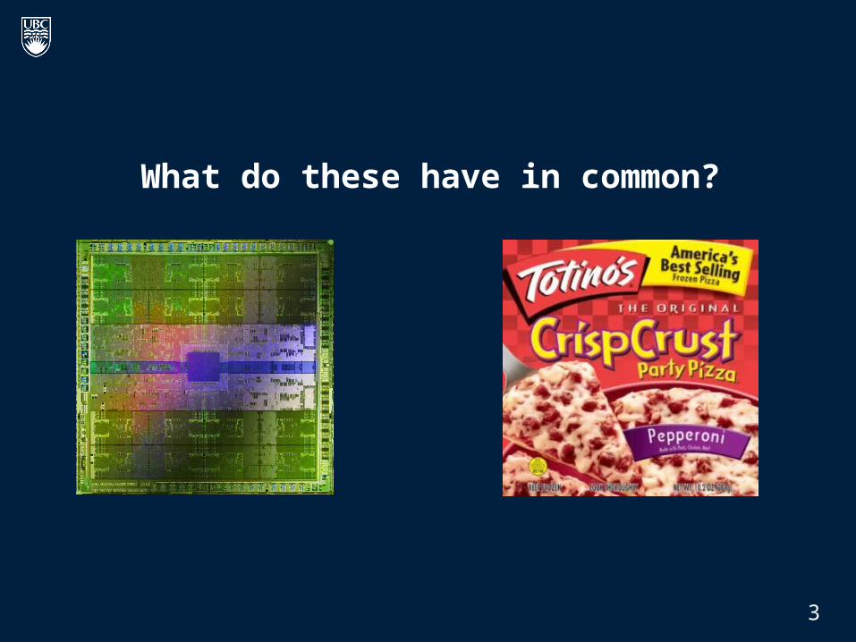
What do these have in common?
3
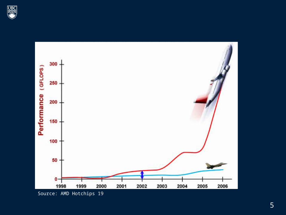
Source: AMD Hotchips 19
5

GPU Computing
Technology trends => want “simpler” cores (less power).
GPUs represent an extreme in terms of computation per unit area.
Current GPUs tend to work well for applications with regular parallelism (e.g., dense matrix multiply).
Research Questions: Can we make GPUs better for a wider class of parallel applications? Can we make them even more efficient?
4
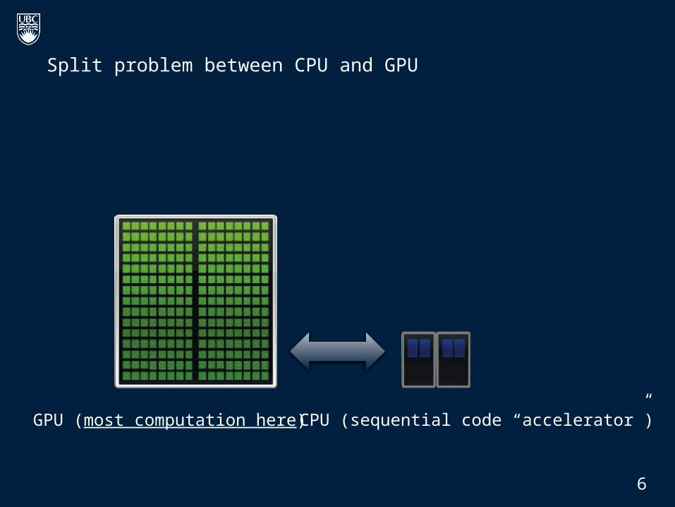
Split problem between CPU and GPU
CPU (sequential code “accelerator”)GPU (most computation here)
6

Heterogeneous Computing
CPU spawn
done
GPU
CPU
Tim
e
CPU spawn
GPU
9
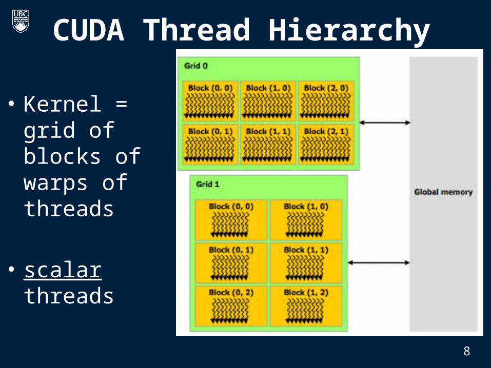
CUDA Thread Hierarchy
• Kernel = grid of blocks of warps of threads
• scalar threads
8

CUDA Example [Luebke]
Standard C Code
void saxpy_serial(int n, float a, float *x, float *y) { for (int i = 0; i < n; ++i)
y[i] = a*x[i] + y[i];}
// Invoke serial SAXPY kernel main() { … saxpy_serial(n, 2.0, x, y); }

CUDA Example [Luebke]CUDA code
__global__ void saxpy_parallel(int n, float a, float *x, float *y) { int i = blockIdx.x*blockDim.x + threadIdx.x; if(i<n) y[i]=a*x[i]+y[i];}
main() { // omitted: allocate and initialize memory // Invoke parallel SAXPY kernel with 256 threads/block int nblocks = (n + 255) / 256; saxpy_parallel<<<nblocks, 256>>>(n, 2.0, x, y); // omitted: transfer results from GPU to CPU}
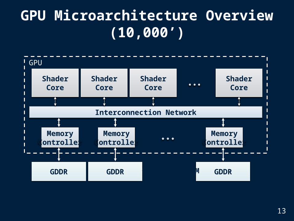
GPU Microarchitecture Overview (10,000’)
Interconnection Network
ShaderCore
ShaderCore
ShaderCore
ShaderCore
MemoryController
GDDR
MemoryController
GDDR
MemoryController
GDDR
GPU
Off-chip DRAM
13

All threads in a kernel grid run same “code”. A given block in kernel grid runs on single “shader core”.
A Warp in a block is a set of threads grouped to execute in SIMD lock step
Using stack hardware and/or predication can support different branch outcomes per thread in warp.
Single Instruction, Multiple Thread (SIMT)
Thread Warp 3Thread Warp 8
Thread Warp 7Thread Warp
ScalarThread
W
ScalarThread
X
ScalarThread
Y
ScalarThread
Z
Common PC
SIMD Pipeline
15

“Shader Core” Microarchitecture
14
Heavily multithreaded: 32 “warps” each representing 32 scalar threads
Designed to tolerate long latency operations rather than avoid them.
“GPGPU-Sim” (ISPASS 2009)
GPGPU simulator developed by my group at UBC
Goal: platform for architecture research on manycore accelerators running massively parallel applications.
Support CUDA’s “virtual instruction set” (PTX).
Provide a timing model with “good enough” accuracy for architecture research.
10
GPGPU-Sim Usage
Input: Unmodified CUDA or OpenCL application
Output: Clock cycles required to execute + statistics that can be used to determine where cycles were lost due to “microarchitecture level” inefficiency.

Accuracy vs. hardware (GPGPU-Sim 2.1.1b)
0 50 100 150 200 2500
50
100
150
200
250HW - GPGPU-Sim Comparison
Quadro FX 5800 IPC
GP
GP
U-S
im I
PC
Correlation~0.90
11
(Architecture simulators give up accuracy to enable flexibility-- can explore more of the design space)
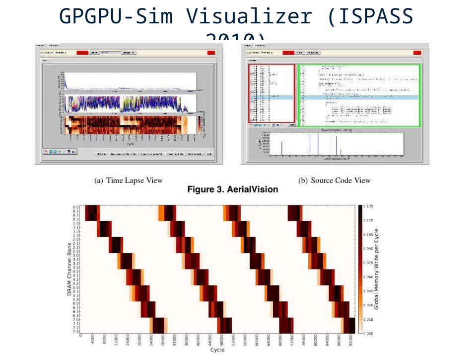
GPGPU-Sim Visualizer (ISPASS 2010)
17
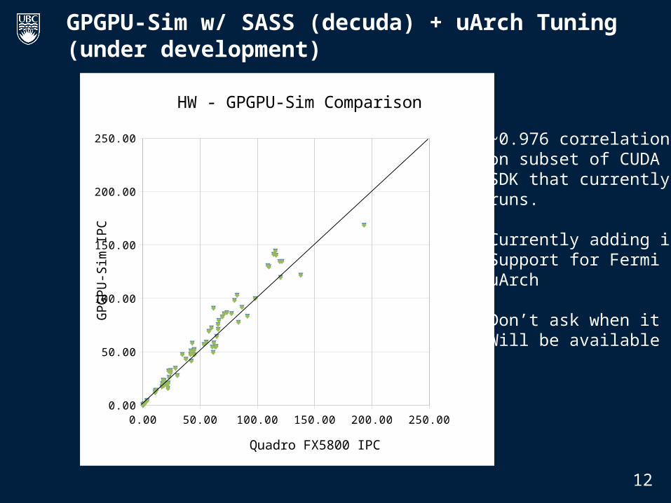
GPGPU-Sim w/ SASS (decuda) + uArch Tuning (under development)
Correlation~0.95
12
0.00 50.00 100.00 150.00 200.00 250.000.00
50.00
100.00
150.00
200.00
250.00
HW - GPGPU-Sim Comparison
Quadro FX5800 IPC
GP
GP
U-S
im IP
C
~0.976 correlation on subset of CUDA SDK that currentlyruns.
Currently adding inSupport for FermiuArch
Don’t ask when itWill be available

Group scalar threads into warps
Branch divergence when threads inside warps want to follow different execution paths.
First Problem: Control flow
Branch
Path A
Path B
Branch
Path A
Path B
16
20
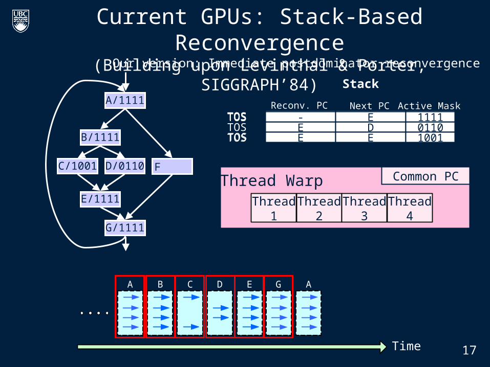
Current GPUs: Stack-Based Reconvergence(Building upon Levinthal & Porter, SIGGRAPH’84)
- G 1111TOS
B
C D
E
F
A
G
Thread Warp Common PC
Thread2
Thread3
Thread4
Thread1
B/1111
C/1001 D/0110
E/1111
A/1111
G/1111
- A 1111TOSE D 0110E C 1001TOS
- E 1111E D 0110TOS- E 1111
A D G A
Time
CB E
- B 1111TOS - E 1111TOSReconv. PC Next PC Active Mask
Stack
E D 0110E E 1001TOS
- E 1111
Our version: Immediate postdominator reconvergence
17
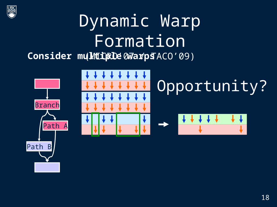
Consider multiple warps
21
Dynamic Warp Formation(MICRO’07 / TACO’09)
Branch
Path A
Path B
Opportunity?Branch
Path A
18

Idea: Form new warp at divergence
Enough threads branching to each path to create full new warps
Dynamic Warp Formation
19

23
Dynamic Warp Formation: Example
A A B B G G A AC C D D E E F F
Time
A A B B G G A AC D E E F
Time
A x/1111y/1111
B x/1110y/0011
C x/1000y/0010 D x/0110
y/0001 F x/0001y/1100
E x/1110y/0011
G x/1111y/1111
A new warp created from scalar threads of both Warp x and y executing at Basic Block D
D
Execution of Warp xat Basic Block A
Execution of Warp yat Basic Block A
LegendAA
Baseline
DynamicWarpFormation

Dynamic Warp Formation: Implementation
21
ModifiedRegister File
New Logic
Thread Block Compaction (HPCA 2011)

26
9 6 3 4D-- 10 -- --D1 2 3 4E5 6 7 8E
9 10 11 12E
DWF Pathologies: Starvation• Majority Scheduling
– Best Performing in Prev. Work – Prioritize largest group of threads with
same PC
• Starvation, Poor Reconvergence – LOWER SIMD Efficiency!
• Key obstacle: Variable Memory Latency
Tim
e
1 2 7 8C 5 -- 11 12C
9 6 3 4D-- 10 -- --D
1 2 7 8E 5 -- 11 12E
9 6 3 4E-- 10 -- --E
B: if (K > 10) C: K = 10; elseD: K = 0;E: B = C[tid.x] + K;
1000s cycles

27
DWF Pathologies: Extra Uncoalesced Accesses• Coalesced Memory Access = Memory SIMD
– 1st Order CUDA Programmer Optimization
• Not preserved by DWF
E: B = C[tid.x] + K;
1 2 3 4E5 6 7 8E
9 10 11 12E
Memory
0x100
0x1400x180
1 2 7 12E9 6 3 8E5 10 11 4E
Memory
0x100
0x1400x180
#Acc = 3
#Acc = 9
No DWF
With DWF
L1 Cache AbsorbsRedundant
Memory Traffic
L1$ Port Conflict
28
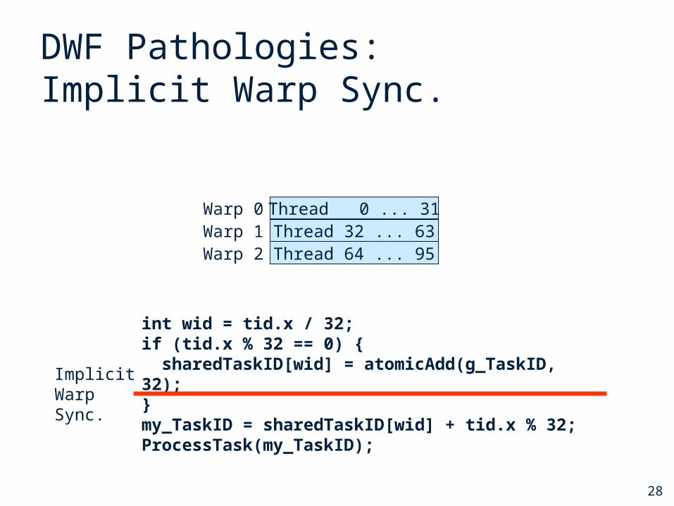
DWF Pathologies:Implicit Warp Sync.
• Some CUDA applications depend on the lockstep execution of “static warps”
– E.g. Task Queue in Ray Tracing
Thread 0 ... 31Thread 32 ... 63Thread 64 ... 95
Warp 0Warp 1Warp 2
int wid = tid.x / 32; if (tid.x % 32 == 0) { sharedTaskID[wid] = atomicAdd(g_TaskID, 32);}my_TaskID = sharedTaskID[wid] + tid.x % 32; ProcessTask(my_TaskID);
ImplicitWarpSync.

29
StaticWarp
DynamicWarp
StaticWarp
Observation
• Compute kernels usually contain divergent and non-divergent (coherent) code segments
• Coalesced memory access usually in coherent code segments– DWF no benefit there
Coherent
Divergent
Coherent
Reset Warps
Divergence
RecvgPt.
Coales. LD/ST
30
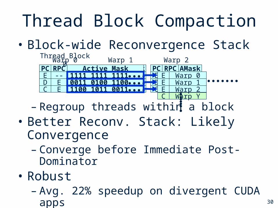
Thread Block Compaction• Block-wide Reconvergence Stack
– Regroup threads within a block• Better Reconv. Stack: Likely Convergence
– Converge before Immediate Post-Dominator• Robust
– Avg. 22% speedup on divergent CUDA apps– No penalty on others
PC RPC AMaskWarp 0
E -- 1111D E 0011C E 1100
PC RPC AMaskWarp 1
E -- 1111D E 0100C E 1011
PC RPC AMaskWarp 2
E -- 1111D E 1100C E 0011
PC RPC Active MaskThread Block 0
E -- 1111 1111 1111D E 0011 0100 1100C E 1100 1011 0011 C Warp X
C Warp Y
D Warp UD Warp T
E Warp 0E Warp 1E Warp 2

31
Thread Block Compaction
• Run a thread block like a warp– Whole block moves between coherent/divergent code– Block-wide stack to track exec. paths reconvg.
• Barrier at branch/reconverge pt.– All avail. threads arrive at branch– Insensitive to warp scheduling
• Warp compaction – Regrouping with all avail. threads– If no divergence, gives static warp arrangement
Starvation
Implicit Warp Sync.
Extra Uncoalesced Memory Access
32
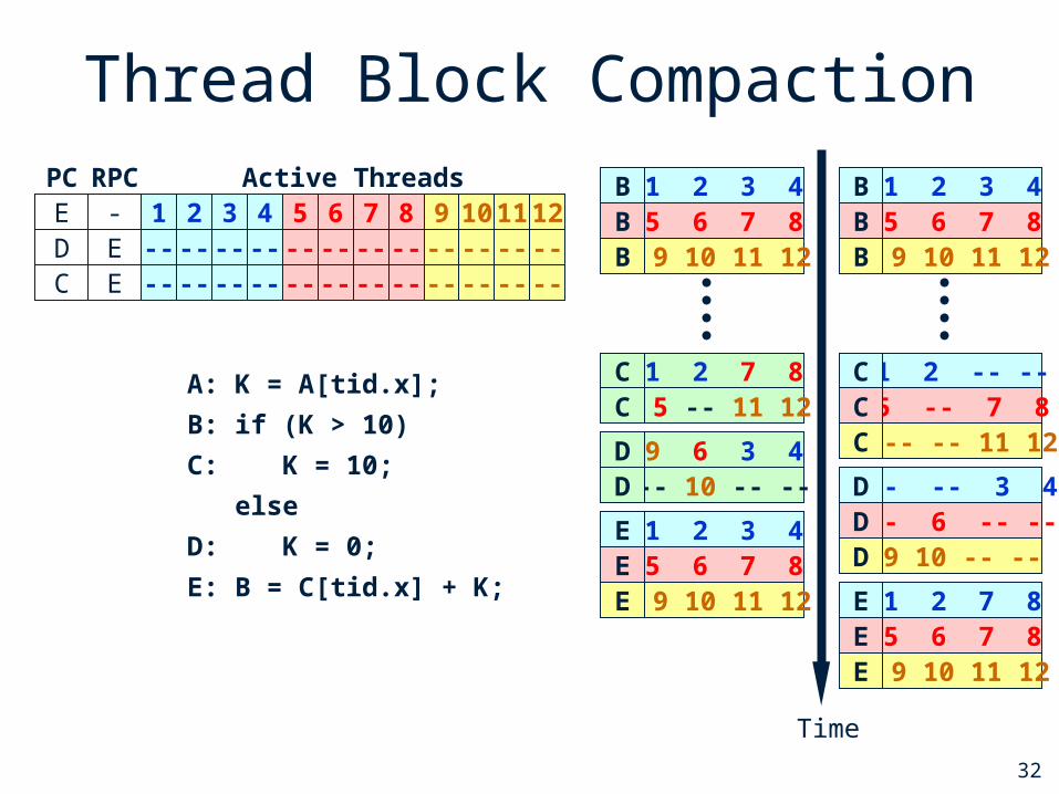
Thread Block CompactionPC RPC Active ThreadsB - 1 2 3 4 5 6 7 8 9 10 11 12D E -- -- 3 4 -- 6 -- -- 9 10 -- --C E 1 2 -- -- 5 -- 7 8 -- -- 11 12
E - 1 2 3 4 5 6 7 8 9 10 11 12
Time
1 2 7 8C 5 -- 11 12C
9 6 3 4D-- 10 -- --D
5 6 7 8B 9 10 11 12B
1 2 3 4B
5 6 7 8E 9 10 11 12E
1 2 3 4E
A: K = A[tid.x];
B: if (K > 10)
C: K = 10;
else
D: K = 0;
E: B = C[tid.x] + K;
5 6 7 8B 9 10 11 12B
1 2 3 4B
5 -- 7 8C -- -- 11 12C
1 2 -- --C
-- 6 -- --D9 10 -- --D
-- -- 3 4D
5 6 7 8E 9 10 11 12E
1 2 7 8E
-- -- -- ---- -- -- --
-- -- -- ---- -- -- --
-- -- -- ---- -- -- --
33
Thread Block Compaction
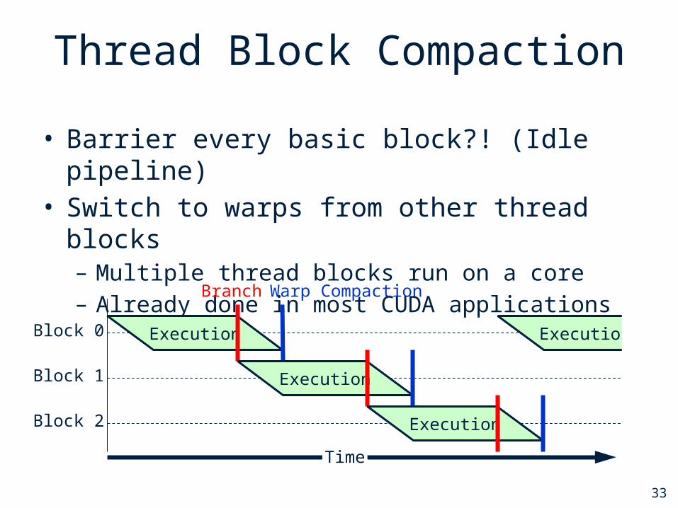
• Barrier every basic block?! (Idle pipeline)• Switch to warps from other thread blocks
– Multiple thread blocks run on a core– Already done in most CUDA applications
Block 0
Block 1
Block 2
Branch Warp Compaction
Execution
Execution
Execution
Execution
Time
34
Microarchitecture Modifications
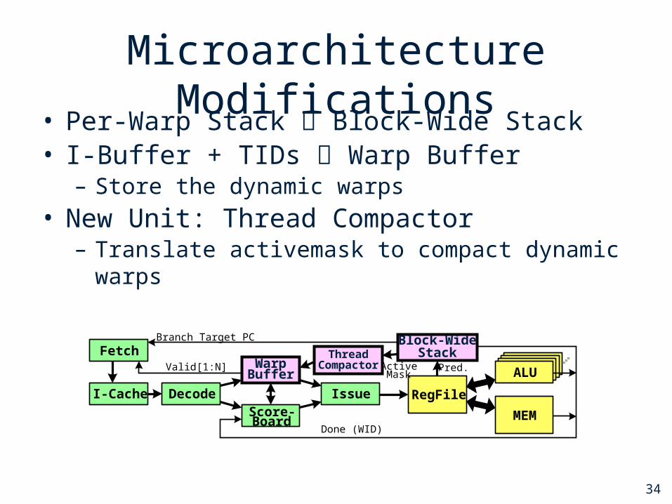
• Per-Warp Stack Block-Wide Stack• I-Buffer + TIDs Warp Buffer
– Store the dynamic warps
• New Unit: Thread Compactor– Translate activemask to compact dynamic warps
ALUALUALU
I-Cache Decode
Warp Buffer
Score-Board
Issue RegFile
MEM
ALU
FetchBlock-Wide
Stack
Done (WID)
Valid[1:N]
Branch Target PC
ActiveMask
Pred.Thread
Compactor

35
RarelyTaken
Likely-Convergence• Immediate Post-Dominator: Conservative
– All paths from divergent branch must merge there• Convergence can happen earlier
– When any two of the paths merge
• Extended Recvg. Stack to exploit this– TBC: 30% speedup for Ray Tracing
while (i < K) { X = data[i];A: if ( X = 0 )B: result[i] = Y;C: else if ( X = 1 )D: break;E: i++; }F: return result[i];
A
B C
DE
FiPDom of A
36
0.6 0.7 0.8 0.9 1 1.1 1.2 1.3
TBC
DWF
IPC Relative to Baseline
COHE
DIVG
Experimental Results
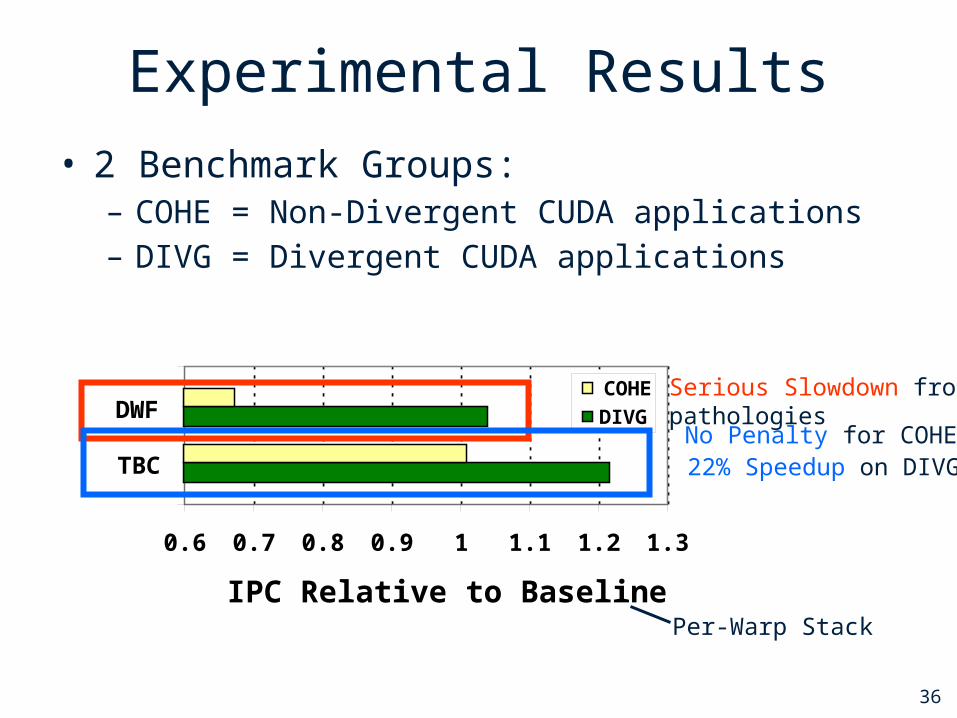
• 2 Benchmark Groups: – COHE = Non-Divergent CUDA applications– DIVG = Divergent CUDA applications
Serious Slowdown from pathologiesNo Penalty for COHE
22% Speedup on DIVG
Per-Warp Stack
Next:
How should on-chip interconnect be designed?(MICRO 2010)
36

Throughput-Effective Design
Two approaches:• Reduce Area• Increase performance
Look at properties of bulk-synchronous parallel (aka “CUDA”) workloads
38
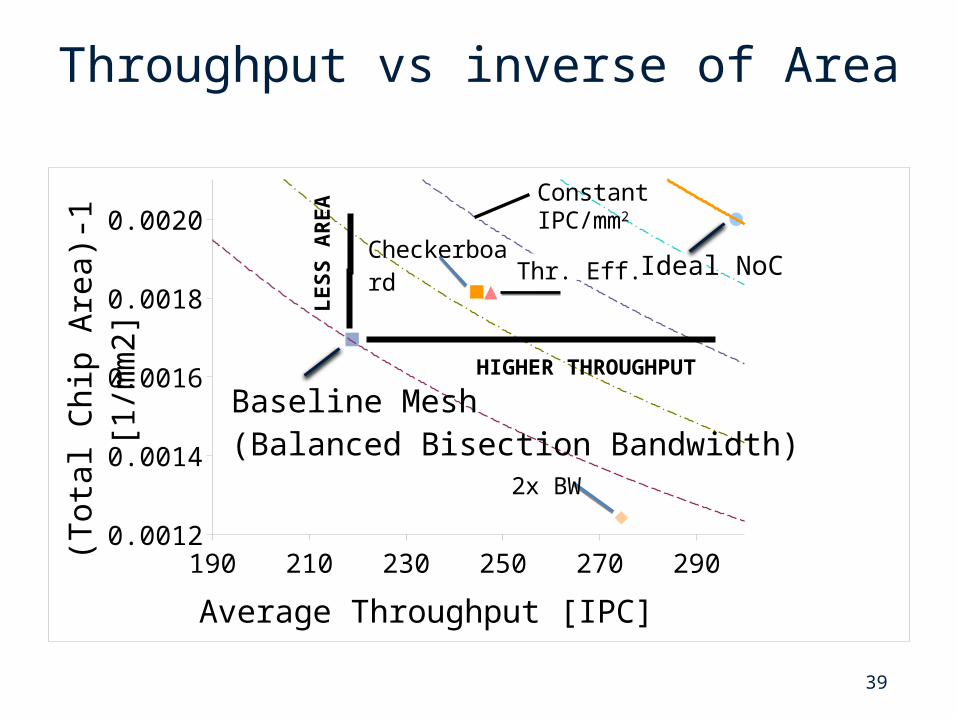
Throughput vs inverse of Area
190 210 230 250 270 2900.00120.00130.00140.00150.00160.00170.00180.00190.00200.0021
Average Throughput [IPC]
(Tot
al C
hip
Area
)-1
[1/m
m2]
Baseline Mesh (Balanced Bisection Bandwidth)
Thr. Eff. Ideal NoC
LE
SS
AR
EA
HIGHER THROUGHPUT
Constant IPC/mm2
2x BW
Checkerboard
39

Many-to-Few-to-Many Traffic Pattern
C0
requ
est
netw
orkC
1
core injectionbandwidth
Cn
C0
C1
Cn
repl
y ne
twor
k
MC0
MC1
MCm
C2
C2
MC inputbandwidth
MC outputbandwidth
40

Exploit Traffic Pattern Somehow?
• Keep bisection bandwidth same, reduce router area…
• Half-Router:– Limited connectivity
• No turns allowed
– Might save ~50% of router crossbar area
Half-Router Connectivity
41
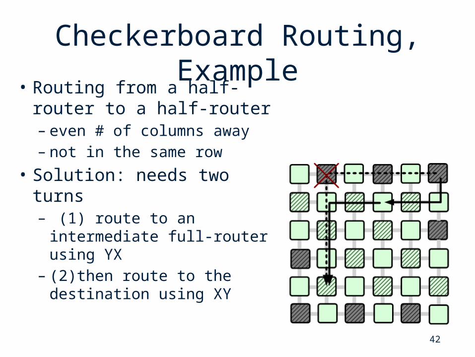
Checkerboard Routing, Example
• Routing from a half-router to a half-router – even # of columns away – not in the same row
• Solution: needs two turns– (1) route to an
intermediate full-router using YX
– (2)then route to the destination using XY
42
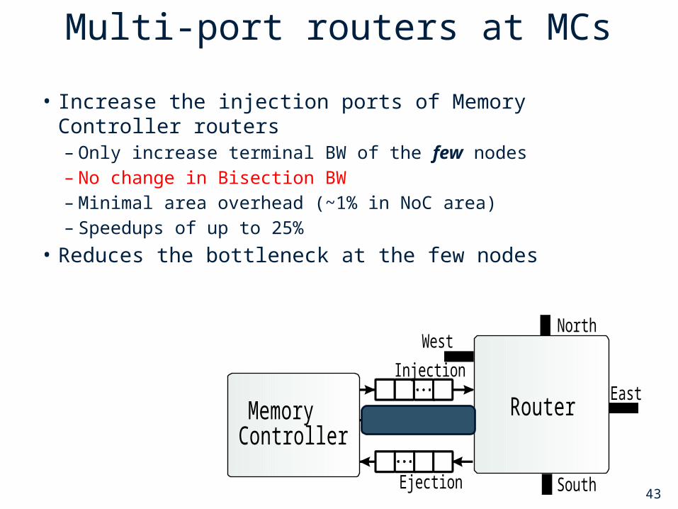
Multi-port routers at MCs
Compute Core Router
Memory Controller Router (a) Staggered Placement (b) Checkerboard Me sh
Half Router
MemoryController
Router
West
East
North
South Ejection
Injection Memory
ControllerRouter
West
East
North
South Ejection
Injection
(a) Connections of a Normal Router (b) Connections of a Router with 2 Injection Ports
• Increase the injection ports of Memory Controller routers– Only increase terminal BW of the few nodes– No change in Bisection BW– Minimal area overhead (~1% in NoC area)– Speedups of up to 25%
• Reduces the bottleneck at the few nodes
43
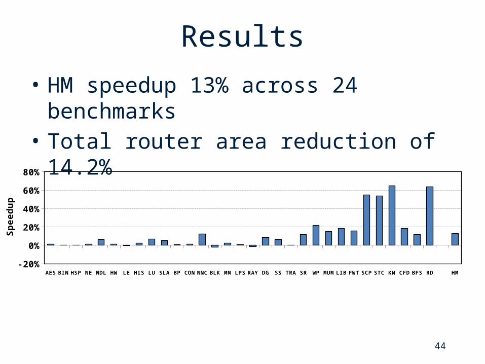
Results
• HM speedup 13% across 24 benchmarks• Total router area reduction of 14.2%
AES BIN HSP NE NDL HW LE HIS LU SLA BP CON
NNC
BLK MM LPS RAY DG SS TRA SR WP MUM
LIB FWT
SCP STC KM CFD BFS RD HM-10%
0%10%20%30%40%50%60%70%
Sp
ee
du
p
44

Next:
GPU Off-chip Memory Bandwidth Problem(MICRO’09)
24

46
Background: DRAM
DRAM
Column Decoder
Memory Array
Ro
w D
eco
derM
emo
ry
Co
ntr
oll
er
Row BufferRow Buffer
Ro
w D
eco
der
Column Decoder
Row Buffer
Column Decoder
Row Buffer
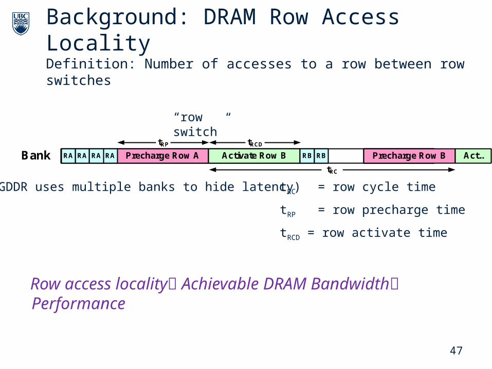
Row Access:
Activate a row of DRAM bank and load into row buffer (slow)
Column Access:
Read and write data in row buffer (fast)
Precharge:
Write row buffer data back into row (slow)
47
tRC = row cycle time
tRP = row precharge time
tRCD = row activate time
Bank Precharge Row A Activate Row B Pre...RB RBRARARARA Precharge Row B Act..
tRP tRCD
tRC
Background: DRAM Row Access LocalityDefinition: Number of accesses to a row between row switches
“row switch”
Row access locality Achievable DRAM Bandwidth Performance
(GDDR uses multiple banks to hide latency)
NW Router ES
48
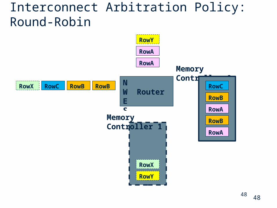
Interconnect Arbitration Policy: Round-Robin
RowA
RowAMemory Controller 0
RowBRowBRowCRowX
RowY
RowA
RowA
RowB
RowB
RowC
RowY
RowX
Memory Controller 1
48

49
The Trend: DRAM Access Locality in Many-Core
Inside the interconnect, interleaving of memory request streams reduces the DRAM access locality seen by the memory controller
8 16 32 64
Before Interconnect After Interconnect
Number of Cores
DR
AM
A
cc
es
s
Lo
ca
lity
Good
Bad
Pre-interconnect access locality
Post-interconnect access locality
49

Opened Row: A
DRAM
50
Today’s Solution: Out-of-Order Scheduling
Row B
Row A
Row A
Request Queue
Row B
Row A
Row A
Youngest
Oldest
Switching RowOpened Row: B
Queue size needs to increase as number of cores increase
Requires fully-associative logic Circuit issues:
o Cycle timeo Areao Power
50

51
Interconnect Arbitration Policy: HG
RowA
RowAMemory Controller 0
RowBRowBRowCRowX
RowY
RowA
RowA
RowB
RowB
RowC
RowY
RowX
Memory Controller 1
NW Router ES
51
52
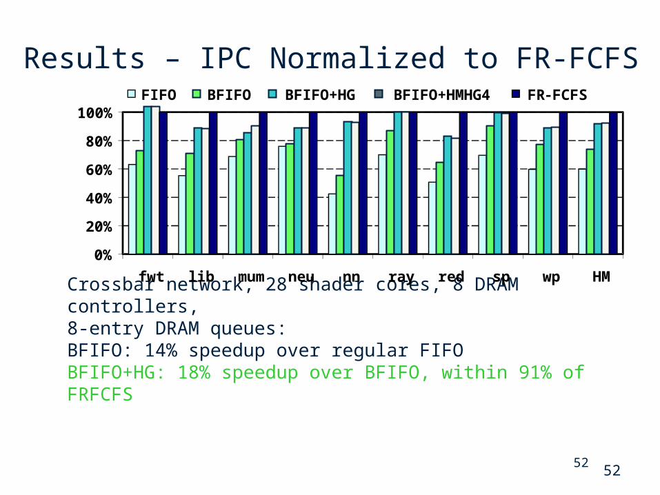
Results – IPC Normalized to FR-FCFS
Crossbar network, 28 shader cores, 8 DRAM controllers, 8-entry DRAM queues:BFIFO: 14% speedup over regular FIFOBFIFO+HG: 18% speedup over BFIFO, within 91% of FRFCFS
0%
20%
40%
60%
80%
100%
fwt lib mum neu nn ray red sp wp HM
FIFO BFIFO BFIFO+HG BFIFO+HMHG4 FR-FCFS
52
Conclusion
Manycore accelerators enable performance scaling with Moore’s Law.
Opportunities to improve performance per unit area (e.g., throughput effective NoC) Small changes to architecture can increase range of applications that can benefit (e.g., DWF).
48

Related Documents


![Dwf 1098[1]](https://static.cupdf.com/doc/110x72/55692d0cd8b42add468b49bf/dwf-10981.jpg)


