Outline • Direct conversion architecture • Time-varying DC offsets • Solutions on offset • Harmonic mixing principle • FLEX pager receiver • Individual receiver blocks • Conclusion

Outline Direct conversion architecture Time-varying DC offsets Solutions on offset Harmonic mixing principle FLEX pager receiver Individual receiver blocks.
Dec 26, 2015
Welcome message from author
This document is posted to help you gain knowledge. Please leave a comment to let me know what you think about it! Share it to your friends and learn new things together.
Transcript
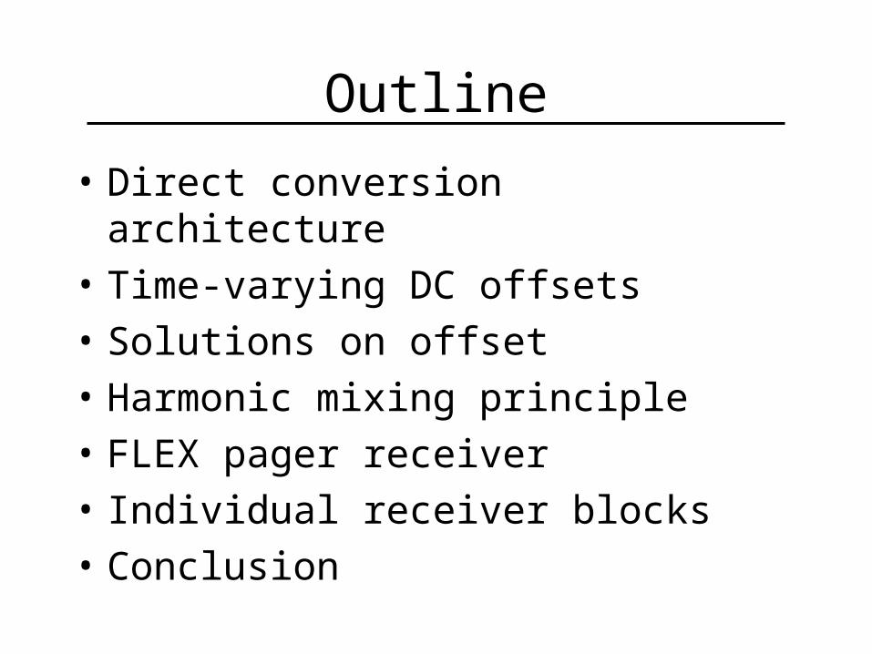
Outline
• Direct conversion architecture• Time-varying DC offsets• Solutions on offset• Harmonic mixing principle• FLEX pager receiver• Individual receiver blocks• Conclusion
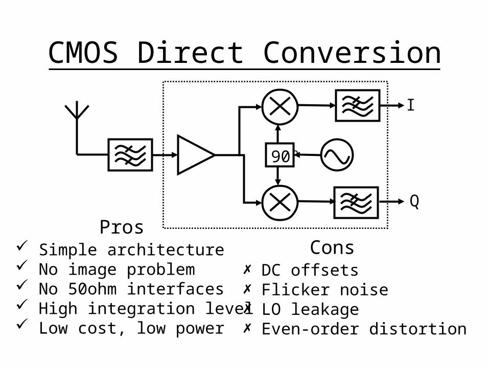
CMOS Direct Conversion
90º
I
Q
Simple architecture No image problem No 50ohm interfaces High integration level Low cost, low power
DC offsets Flicker noise LO leakage Even-order distortion
ProsCons
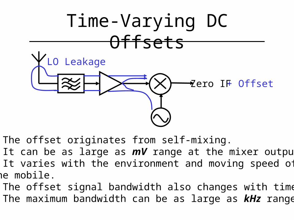
Time-Varying DC Offsets
Zero IF
LO Leakage
+ Offset
• The offset originates from self-mixing.• It can be as large as mV range at the mixer output.• It varies with the environment and moving speed of the mobile.• The offset signal bandwidth also changes with time. • The maximum bandwidth can be as large as kHz range.
Pow
er
Narrow Band Broad Band
Frequency
Pow
er
Frequency
Pow
er
Frequency
Pow
er
Frequency
Signal
DC
Off
sets
Off
set-
Free
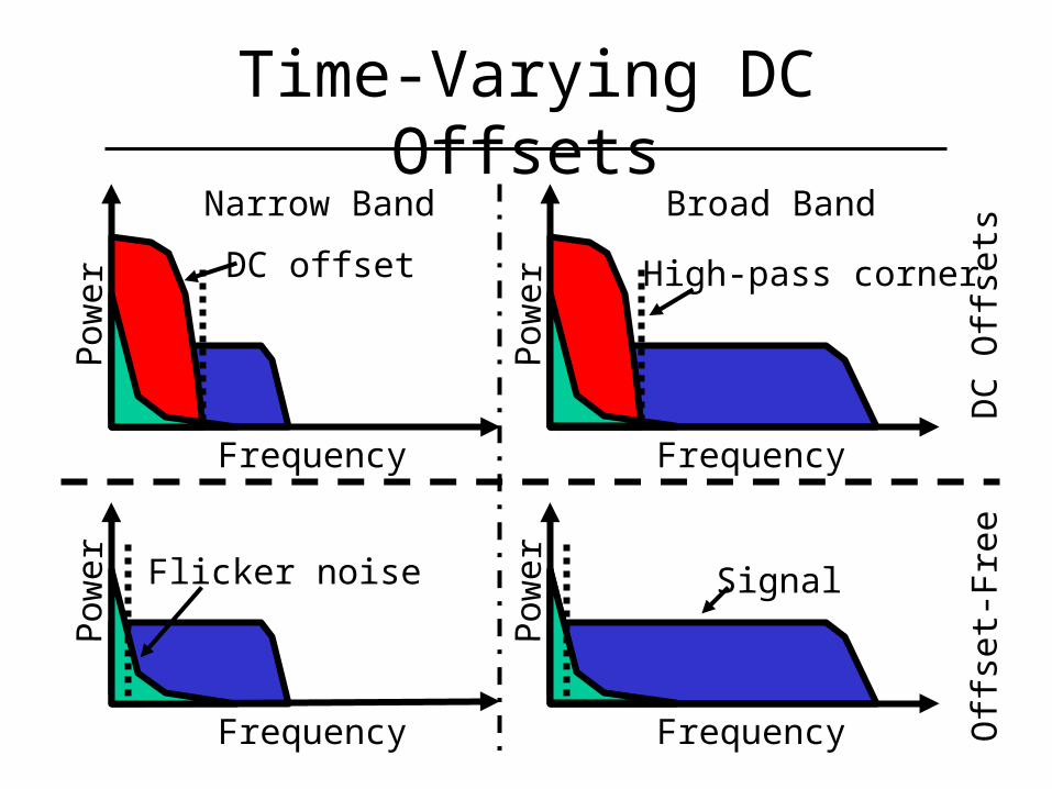
DC offset
Time-Varying DC Offsets
Flicker noise
High-pass corner

Solutions on Offset• Autozeroing or correlated double
sampling• AC coupling or high pass filtering• Digital cancellation• Double LO frequency method [ISSCC99]
• Adaptive dual-loop algorithm combined with the mixer [RAWCON00]
• Pulse-width-modulation based bipolar harmonic mixer [CICC97]
• Square–law based CMOS harmonic mixer [Our work: RAWCON00]
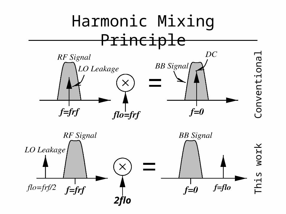
Harmonic Mixing Principle
2flo
Con
ven
tion
al
Th
is w
ork

Square-law Based Mixer
• Ideally self-mixing free.• Traditional voltage controlled switches are replaced by current controlled time-varying transconductances.• Current injection is used to reduce flicker noise.• No noise contribution from LO stage and current source.
M1 M2
M3 M4
LO
2
RF IF
Current
Voltage
Voltage
CouplingNo
DC offset effect
10 -1
10 -2
10 0
BE
R
Eb/N0 (dB)4 8 12 16
A: 0.2 B: 0.4 C: 0.6 D: 0.8 E: 1.0
ED
C
B
A
Offset / Signal
DC
Off
set
Eff
ect
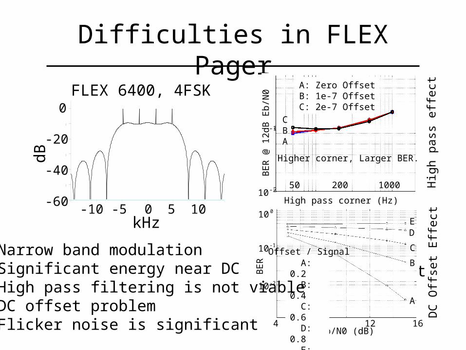
Difficulties in FLEX Pager
-60
-50
-40
-30
-20
-10
0
-15 -10 -5 0 5 10 15
[dB]
FLEX 6400, 4FSK0
-20
-40
-60
dB
1050-5-10kHz
• Narrow band modulation• Significant energy near DC• High pass filtering is not viable• DC offset problem• Flicker noise is significant
Hig
h p
ass
eff
ect
A: Zero OffsetB: 1e-7 OffsetC: 2e-7 Offset
CBA
BE
R @
12
dB E
b/N
0
High pass corner (Hz)
100020050-2
-1
10
Higher corner, Larger BER.
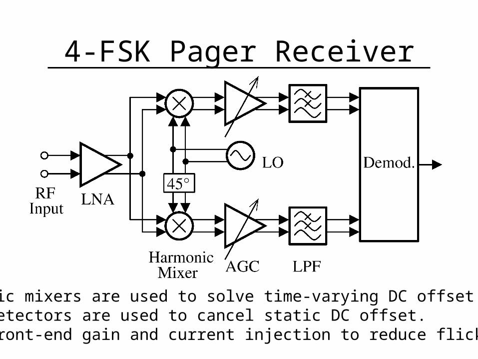
4-FSK Pager Receiver
• Harmonic mixers are used to solve time-varying DC offset.• Peak detectors are used to cancel static DC offset.• High front-end gain and current injection to reduce flicker noise.
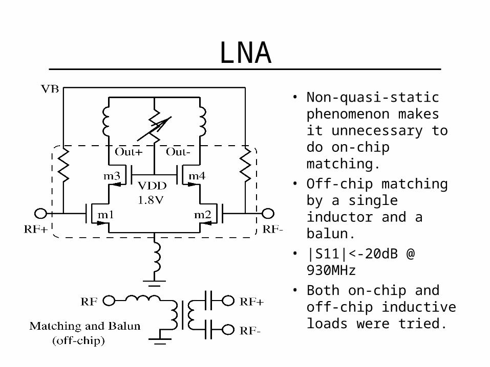
LNA• Non-quasi-static
phenomenon makes it unnecessary to do on-chip matching.
• Off-chip matching by a single inductor and a balun.
• |S11|<-20dB @ 930MHz
• Both on-chip and off-chip inductive loads were tried.
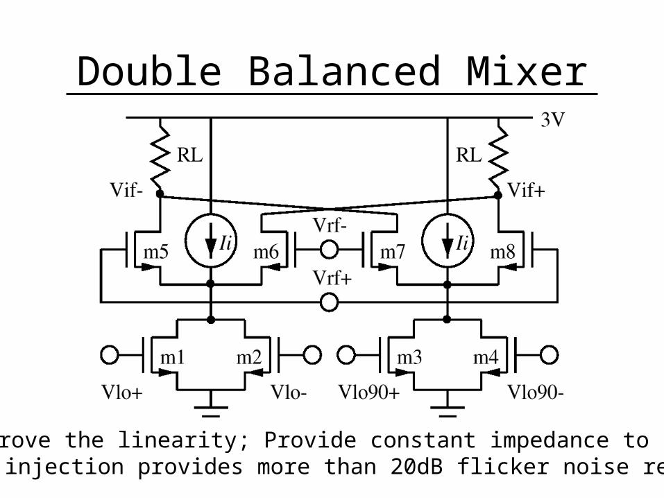
Double Balanced Mixer
Improve the linearity; Provide constant impedance to LNA;Current injection provides more than 20dB flicker noise reduction.
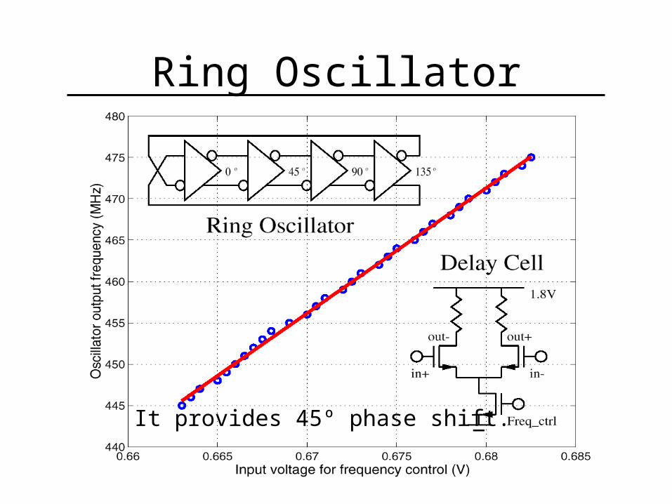
Ring Oscillator
It provides 45º phase shift.
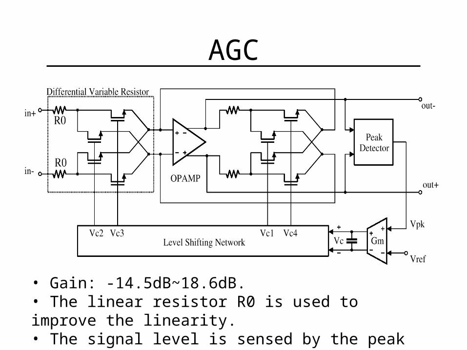
AGC
• Gain: -14.5dB~18.6dB. • The linear resistor R0 is used to improve the linearity.• The signal level is sensed by the peak detector.
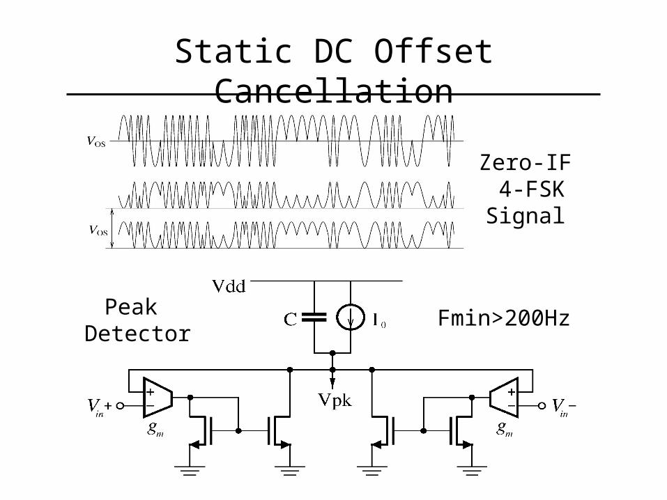
Static DC Offset Cancellation
Peak Detector
Fmin>200Hz
Zero-IF 4-FSKSignal
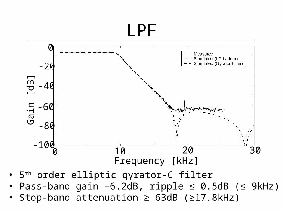
LPF
• 5th order elliptic gyrator-C filter• Pass-band gain –6.2dB, ripple ≤ 0.5dB (≤ 9kHz)• Stop-band attenuation ≥ 63dB (≥17.8kHz)
Gai
n [d
B]
0 10 20 30Frequency [kHz]
0
-20
-80
-60
-40
-100
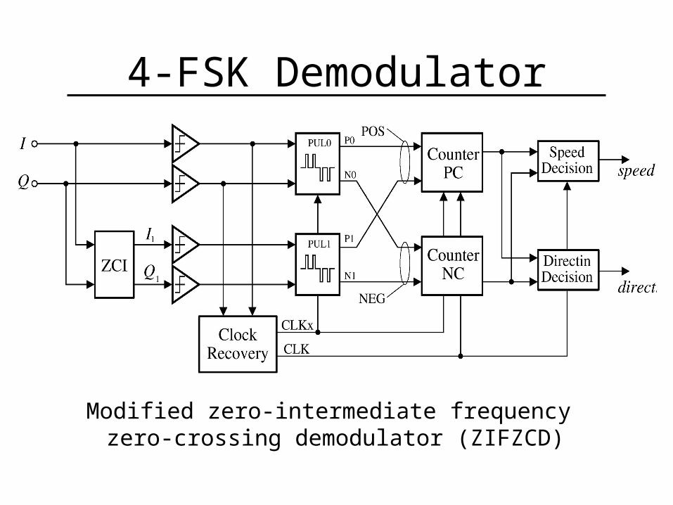
4-FSK Demodulator
Modified zero-intermediate frequency zero-crossing demodulator (ZIFZCD)
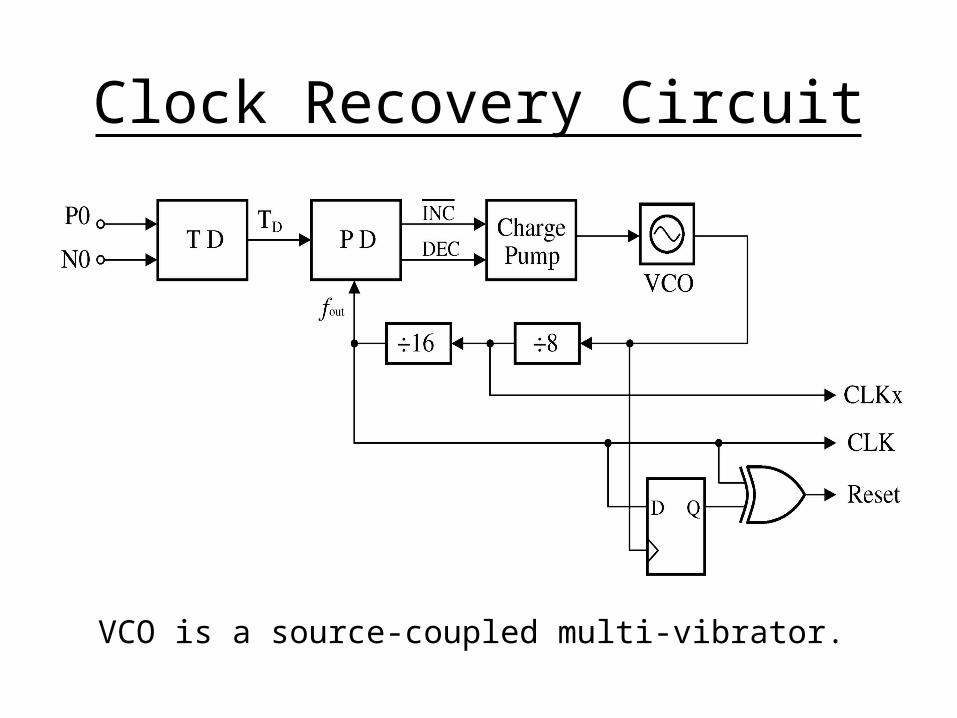
Clock Recovery Circuit
VCO is a source-coupled multi-vibrator.
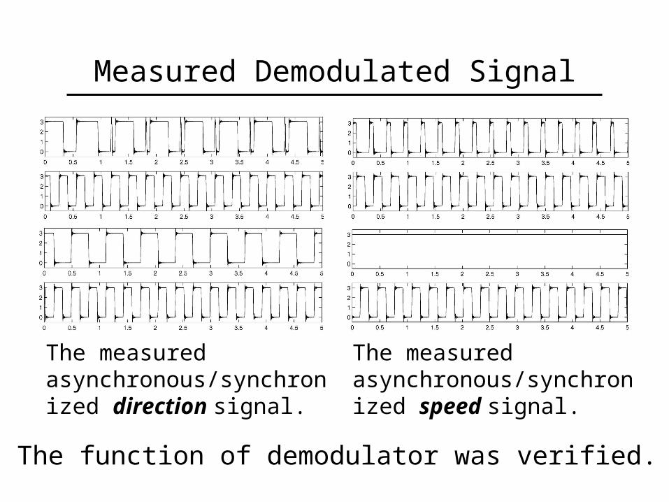
Measured Demodulated Signal
The measured asynchronous/synchronized speed signal.
The measured asynchronous/synchronized direction signal.
The function of demodulator was verified.
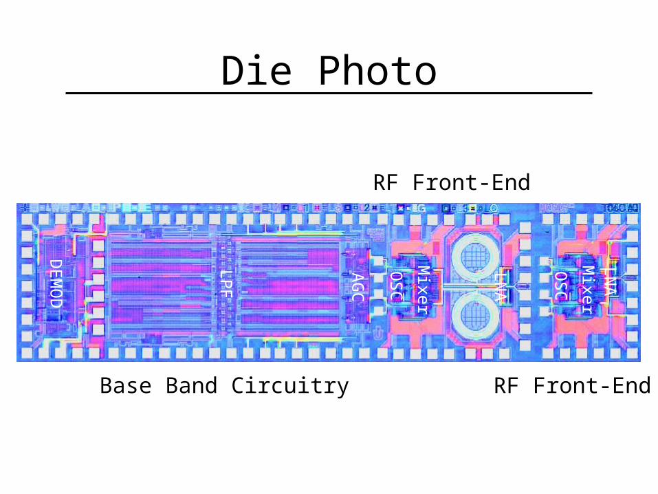
Die Photo
DE
MO
D
LP
F
AG
C
Mixer
OS
C
LN
A
LN
A
OS
C
Mixer
Base Band Circuitry
RF Front-End
RF Front-End
Conclusion• Feasibility of direct conversion has been
demonstrated. • Proposed harmonic mixing technique
solves self-mixing induced DC offset problem successfully.
• With the help of static DC offset cancellation, the total DC offset is less than 1mV at the receiver output.
• The modified ZIFZCD 4-FSK demodulator functions correctly.
• A 4-FSK FLEX pager receiver in a single chip has been implemented.
Related Documents