GAS EJECTOR MODELING FOR DESIGN AND ANALYSIS A Dissertation by CHAQING LIAO Submitted to the Office of Graduate Studies of Texas A&M University in partial fulfillment of the requirements for the degree of DOCTOR OF PHILOSOPHY December 2008 Major Subject: Nuclear Engineering PREVIEW

Welcome message from author
This document is posted to help you gain knowledge. Please leave a comment to let me know what you think about it! Share it to your friends and learn new things together.
Transcript
GAS EJECTOR MODELING FOR DESIGN AND ANALYSIS
A Dissertation
by
CHAQING LIAO
Submitted to the Office of Graduate Studies of Texas A&M University
in partial fulfillment of the requirements for the degree of
DOCTOR OF PHILOSOPHY
December 2008
Major Subject: Nuclear Engineering
PREVIEW

UMI Number: 3347963
INFORMATION TO USERS
The quality of this reproduction is dependent upon the quality of the copy
submitted. Broken or indistinct print, colored or poor quality illustrations and
photographs, print bleed-through, substandard margins, and improper
alignment can adversely affect reproduction.
In the unlikely event that the author did not send a complete manuscript
and there are missing pages, these will be noted. Also, if unauthorized
copyright material had to be removed, a note will indicate the deletion.
______________________________________________________________
UMI Microform 3347963Copyright 2009 by ProQuest LLC
All rights reserved. This microform edition is protected against unauthorized copying under Title 17, United States Code.
_______________________________________________________________
ProQuest LLC 789 East Eisenhower Parkway
P.O. Box 1346 Ann Arbor, MI 48106-1346
PREVIEW

GAS EJECTOR MODELING FOR DESIGN AND ANALYSIS
A Dissertation
by
CHAQING LIAO
Submitted to the Office of Graduate Studies of Texas A&M University
in partial fulfillment of the requirements for the degree of
DOCTOR OF PHILOSOPHY
Approved by:
Chair of Committee, Frederick R. Best Committee Members, Yassin A. Hassan Pavel V. Tsvetkov Debjyoti Banerjee Head of Department, Raymond Juzaitis
December 2008
Major Subject: Nuclear Engineering
PREVIEW

iii
ABSTRACT
Gas Ejector Modeling for Design and Analysis.
(December 2008)
Chaqing Liao, B.S., Zhejiang University;
M.E., Texas A&M University
Chair of Advisory Committee: Dr. Frederick R. Best
A generalized ejector model was successfully developed for gas ejector design and
performance analysis. Previous 1-D analytical models can be derived from this new
comprehensive model as particular cases. For the first time, this model shows the
relationship between the cosntant-pressure and constant-area 1-D ejector models. The
new model extends existing models and provides a high level of confidence in the
understanding of ejector mechanics. “Off-design” operating conditions, such as the
shock occurring in the primary stream, are included in the generalized ejector model.
Additionally, this model has been applied to two-phase systems including the gas-liquid
ejector designed for a Proton Exchange Membrane (PEM) fuel cell system.
The equations of the constant-pressure and constant-area models were verified. A
parametric study was performed on these widely adopted 1-D analytical ejector models.
FLUENT, commercially available Computational Fluid Dynamics (CFD) software, was
used to model gas ejectors. To validate the CFD simulation, the numerical predictions
PREVIEW

iv
were compared to test data and good agreement was found between them. Based on this
benchmark, FLUENT was applied to design ejectors with optimal geometry
configurations.
PREVIEW

v
DEDICATION
To my mother
PREVIEW

vi
ACKNOWLEDGEMENTS
I would like to express my appreciation to a number of individuals who helped produce
this work. My appreciation is extended to Dr. Frederick Best who has spent significant
time guiding me towards completion of this work. Sincere gratitude is extended to Dr.
Yassin A. Hassan, Dr. Pavel V. Tsvetkov and Dr. Debjyoti Banerjee for their
recommendations while reviewing this manuscript. I would also like to extend my
appreciation to Dr. Ryoji Oinuma and Cable R. Kurwitz who provided me with
significant inspiration during our numerous discussions on the analytical models. This
work would not have been completed without the extensive time spent by the above
mentioned and their help has been deeply appreciated.
PREVIEW

vii
NOMENCLATURE
A Area
CFD Computational fluid dynamics
CR Compression ratio
c Sound speed
pc Specific heat capacity at constant pressure
vc Specific heat capacity at constant volume
D A temporary parameter defined by equation (5.19)
D Diameter
E A temporary parameter defined by equation (5.23)
ER Entrainment ratio
nη Primary nozzle efficiency coefficient
dη Diffuser efficiency coefficient
γ Specific heat ratio
h Enthalpy
κ Area ratio, 2m tA Aκ =
L Length
M Mach number
m Mass flow rate
µ Pressure ratio, 1 0sP Pµ =
PREVIEW

viii
ω Entrainment ratio
P Pressure
PEM Proton exchange membrane
R Gas constant
R Universal gas constant
ρ Density
s∆ Entropy change
ψ A temporary parameter defined by equation (3.59)
T Temperature
τ Pressure ratio, 0 2s mP Pτ =
θ Area ratio, 1 2mA Pθ =
W Molecular weight
V Velocity
v Specific volume
x Liquid quality
ξ A temporary parameter defined by equation (3.58)
Subscripts
0 Stagnation condition
1 Ejector section 1
2 Ejector section 2
PREVIEW

ix
3 Ejector section 3
4 Ejector section 4
* Critical flow
a Flow station a
b Flow station b
e Exit
g Gas phase
i Isentropic
l Liquid phase
m Ejector mixed flow
p Ejector primary stream
s Ejector secondary stream
t Nozzle throat
tp Gas-liquid two-phase mixture
x Shock wave
PREVIEW

x
TABLE OF CONTENTS
Page
ABSTRACT .............................................................................................................. iii
DEDICATION .......................................................................................................... v
ACKNOWLEDGEMENTS ...................................................................................... vi
NOMENCLATURE.................................................................................................. vii
TABLE OF CONTENTS .......................................................................................... x
LIST OF FIGURES................................................................................................... xiii
LIST OF TABLES .................................................................................................... xix
CHAPTER
I INTRODUCTION AND LITERATURE REVIEW............................ 1
Introduction .................................................................................... 1 Gas Ejectors Literature Review...................................................... 5 Dissertation Organization............................................................... 10
II THEORETICAL BACKGROUND AND NOZZLES......................... 12
Introduction .................................................................................... 12 Theoretical Background ................................................................. 13 Primary Nozzle of Ejector.............................................................. 23 Summary ........................................................................................ 25
III GAS EJECTOR 1-D ANALYTICAL MODELS ................................ 26
Introduction .................................................................................... 26 Supersonic Primary Nozzle............................................................ 27 Constant-Area Mixing Model ........................................................ 30 Constant-Pressure Mixing Model................................................... 41 Subsonic Diffuser ........................................................................... 48 Parametric Analysis........................................................................ 48 Ejector Design Using 1-D Models ................................................. 70
PREVIEW

xi
CHAPTER Page
Summary and Discussion .............................................................. 74
IV SINGLE PHASE GAS EJECTOR CFD SIMULATIONS .................. 77
Introduction .................................................................................... 77 FLUENT and Simulation Aspects.................................................. 78 Benchmark ..................................................................................... 80 Ejector Optimization ...................................................................... 85 Flow Field Details of Gas Ejector .................................................. 92 Ejector Design for Scalable PEM Fuel System.............................. 98 Conclusions .................................................................................... 104
V A NOVEL GENERALIZED EJECTOR MODEL .............................. 106
Introduction .................................................................................... 106 Generalized Ejector Model............................................................. 107 General Features of Generalized Ejector Model ............................ 128 Optimal Ejector Performance......................................................... 134 Links among Various Ejector Models............................................ 138 Limitations on Ejector Design and Operation................................ 143 Conclusions .................................................................................... 153
VI EJECTOR WORKING WITH TWO-PHASE FLOW......................... 155
Introduction .................................................................................... 155 Gas-Liquid Mixture Model ............................................................ 156 Parametric Analysis of Mixture Properties .................................... 159 Ejector Working with Two-Phase Mixture .................................... 161 Conclusions .................................................................................... 173
VII SUMMARY AND CONCLUSIONS................................................... 174
Summary ........................................................................................ 174 Conclusions .................................................................................... 176 Recommendations .......................................................................... 179
REFERENCES.......................................................................................................... 181
APPENDIX A ........................................................................................................... 185
APPENDIX B ........................................................................................................... 195
PREVIEW

xii
Page
APPENDIX C ........................................................................................................... 212
APPENDIX D ........................................................................................................... 236
VITA ......................................................................................................................... 250
PREVIEW
xiii
LIST OF FIGURES
Page
Fig. 1.1 Cross sectional view of a typical liquid jet pump ............................. 2 Fig. 1.2 Cross sectional view of a typical gas ejector..................................... 2 Fig. 1.3 Schematic of the PEM fuel cell system test bed ............................... 4 Fig. 1.4 Three-dimensional ejector solution surface, Addy & Dutton et al. .. 8 Fig. 2.1 Control volume for 1-D flow ............................................................ 13
Fig. 2.2 Pressure profile for isentropic flow in a converging-diverging nozzle............................................................. 17
Fig. 2.3 Maximum mass flow rate vs. stagnation pressure for various throat diameters, with air at 0 300T K= .......................... 20
Fig. 2.4 Nozzle and diffuser shapes for subsonic flow and supersonic flow........................................................................... 22 Fig. 2.5 Property ratios at the nozzle exit for given Mach numbers............... 24 Fig. 3.1 Supersonic primary nozzle ................................................................ 28 Fig. 3.2 Schematic of constant-area ejector model......................................... 31 Fig. 3.3 Control volume for derivation of constant-area mixing model......... 32 Fig. 3.4 Control volume for analysis of initial interaction region .................. 38 Fig. 3.5 Constant-pressure ejector flow model............................................... 41 Fig. 3.6 Control volume of constant-pressure mixing chamber ..................... 43 Fig. 3.7 Area ratio of nozzle exit to its throat vs. 1pM for various nη .......... 50 Fig. 3.8 Pressure ratio of nozzle exit to its throat vs. 1pM for various nη ...................................................................... 51
PREVIEW

xiv
Page
Fig. 3.9 1pM calculated by using least square data fit ................................... 53 Fig. 3.10 Constant-area ejector ER vs. area ratio for various primary nozzles............................................................... 55 Fig. 3.11 Constant-area ejector ER vs. diameter ratio for various primary nozzles............................................................... 56 Fig. 3.12 Constant-area ejector ER curve for various 1P values ...................... 57 Fig. 3.13 Constant-area ejector ER vs. AR for various 0 0s pT T ...................... 58 Fig. 3.14 Constant-area ejector ER vs. DR for various 0 0s pT T ...................... 59 Fig. 3.15 Impact of specific heat ratio on the constant-area ejector performance........................................................................... 60 Fig. 3.16 Relationship of 1 1s pA A with constant-area ejector ER..................... 61 Fig. 3.17 Relationship of mixed flow Mach number with constant-area ejector ER.................................................................... 62 Fig. 3.18 Plot of CR vs. ER in semi-log scale for constant-area ejector .......... 63 Fig. 3.19 Plot of CR vs. ER in higher ER region for constant-area ejector...... 64 Fig. 3.20 Relationship of ER with AR for constant-pressure ejector with various 1P ...................................................................... 66 Fig. 3.21 ER curves for constant-area ejector and constant-pressure ejector ................................................................... 67 Fig. 3.22 Plot of 2mM against 2m tA A for constant-pressure ejector............... 68 Fig. 3.23 Relationship between CR and ER for constant-pressure ejector....... 69 Fig. 3.24 Plot of CR against 2mM for constant-pressure ejector ...................... 70 Fig. 3.25 Typical ejector configuration used by ESDUpac A9242 .................. 72
PREVIEW

xv
Page
Fig. 3.26 Ejector design procedure for using ESDUpac A9242....................... 73 Fig. 4.1 2-D axis-symmetric ejector design.................................................... 79 Fig. 4.2 Schematic of ejector performance test system .................................. 80 Fig. 4.3 ITP ejector structure .......................................................................... 81 Fig. 4.4 ITP ejector performance curve .......................................................... 82 Fig. 4.5 Ejector geometry configuration simulated by FLUENT................... 83 Fig. 4.6 Primary flow rate vs. gas supply pressure......................................... 83 Fig. 4.7 ER vs. driving pressure ..................................................................... 85 Fig. 4.8 Ejector geometry used for optimization ............................................ 86 Fig. 4.9 Ejector performance against sL ........................................................ 88
Fig. 4.10 Influence of diameter ratio m tD D on ejector performance ............ 89
Fig. 4.11 Influence of mixing tube length on ejector performance.................. 90 Fig. 4.12 Influence of diffuser expansion angle on ejector performance ......... 91 Fig. 4.13 Contours of static pressure in gas ejector.......................................... 94 Fig. 4.14 Contours of axial velocity in gas ejector ........................................... 94 Fig. 4.15 Contours of static temperature in gas ejector .................................... 95 Fig. 4.16 Plot of gas density along the centerline of gas ejector ...................... 96 Fig. 4.17 Plot of Mach number along the centerline of gas ejector.................. 97 Fig. 4.18 Plot of static temperature along the centerline of gas ejector............ 97 Fig. 4.19 Schematic of PEM fuel system ......................................................... 98 Fig. 4.20 ER sensitivity .................................................................................... 99
PREVIEW

xvi
Page
Fig. 4.21 Primary flow rate vs. gas supply pressure......................................... 100 Fig. 4.22 Interpolation of ejector performance curve ....................................... 101 Fig. 4.23 Geometry details of designed gas ejector.......................................... 102 Fig. 4.24 Performance curve of designed gas ejector....................................... 103 Fig. 5.1 Schematic of generalized ejector model............................................ 108 Fig. 5.2 Control volume of mixing chamber for
generalized ejector model.................................................................. 114 Fig. 5.3 Plot of total entropy change with respect to µ ................................. 124 Fig. 5.4 Plots of the total entropy change and its two components ................ 130 Fig. 5.5 Plot of entrainment ratio against variable µ .................................... 132 Fig. 5.6 Plot of the mixing chamber exit Mach number against µ ................ 133 Fig. 5.7 Plot of τ against µ .......................................................................... 133
Fig. 5.8 Plots of 1pM , 1sM and normalized ER ............................................. 136 Fig. 5.9 Plots of optimal ER against κ for various θ ................................... 137 Fig. 5.10 Plots of optimal CR against κ for various θ ................................... 138 Fig. 5.11 Plots of τ against µ for various θ .................................................. 140 Fig. 5.12 Plots of τ against µ for various κ .................................................. 141 Fig. 5.13 Plots of ER against µ for various θ ................................................ 142 Fig. 5.14 Upper limits of ER for ejectors ......................................................... 145 Fig. 5.15 s∆ surface for ejectors working at the optimal point ....................... 146 Fig. 5.16 Top-downward view of s∆ surface
PREVIEW

xvii
Page
intercepted by 0s∆ = plane .............................................................. 147 Fig. 5.17 s∆ surface for constant-area mixing ejector..................................... 149 Fig. 5.18 s∆ surface of ejectors with various θ .............................................. 150 Fig. 5.19 s∆ surface of ejectors with various θ ,
intercepted by 0s∆ = plane .............................................................. 150 Fig. 5.20 Performance surface plotted against
ejector boundary pressures ................................................................ 152 Fig. 5.21 Operable range of pressure ratio
of outlet flow to secondary supply .................................................... 153 Fig. 6.1 Plot of mixture gas constant against the liquid quality x ................. 160 Fig. 6.2 Plot of mixture specific heat ratio against the liquid quality x ........ 161 Fig. 6.3 3-D plot of operational 0b sP P against 0 0p sP P and x ,
two-phase mixture supplied as the primary stream........................... 163 Fig. 6.4 2-D plot of operational 0b sP P against 0 0p sP P for various x ,
two-phase mixture supplied as the primary stream........................... 165 Fig. 6.5 Optimal ER surface against κ and x ,
two-phase mixture supplied as the primary stream........................... 166 Fig. 6.6 Optimal ER surface against θ and x ,
two-phase mixture supplied as the primary stream........................... 166 Fig. 6.7 3-D plot of 0b sP P vs. 0 0p sP P and x ,
mixture supplied at suction port ........................................................ 168 Fig. 6.8 2-D plot of 0b sP P vs. 0 0p sP P for various x ,
mixture supplied at suction port ........................................................ 168 Fig. 6.9 Optimal ER surface vs. κ and x ,
mixture supplied at suction port ........................................................ 169
PREVIEW
xviii
Page
Fig. 6.10 Optimal ER surface vs. θ and x , mixture supplied at suction port ........................................................ 169
Fig. 6.11 Top-down view of s∆ surface intercepted by 0s∆ = plane,
mixture supplied as primary stream, 1θ = ........................................ 171 Fig. 6.12 Top-down view of s∆ surface intercepted by 0s∆ = plane,
mixture supplied as primary stream, 100κ = ................................... 172 Fig. 6.13 Top-down view of s∆ surface intercepted by 0s∆ = plane,
mixture supplied at suction port, 1θ = ............................................. 172 Fig. 6.14 Top-down view of s∆ surface intercepted by 0s∆ = plane,
mixture supplied at suction port, 100κ = ......................................... 173
PREVIEW

xix
LIST OF TABLES
Page
Table 4.1 Geometry parameters of gas ejector with Dt=0.005” ........................ 102
Table 4.2 PEM fuel system operating parameters............................................. 104
Table 5.1 Geometry and operating parameters used for the new model investigation.............................................................. 128
PREVIEW
1
CHAPTER I
INTRODUCTION AND LITERATURE REVIEW
INTRODUCTION
Ejectors are devices used to induce a secondary fluid by momentum and energy transfer
from a high velocity primary jet. Ejectors can be operated with incompressible fluids
(liquids), and in this application are normally referred to as jet pumps or eductors. On the
other hand when ejectors are operated with compressible fluids (gases and vapors) the
terms ejector and injector are generally employed. A major difference between the two,
besides the working fluid states, is the supersonic, choked flow nozzle of the gas ejector
system. The supersonic approach allows a greater conversion of primary fluid energy to
secondary fluid pressure head increase. However, this occurs with the penalty of
considerable thermodynamic complexity in the mixing and diffusion sections. Fig. 1.1
and Fig. 1.2 are typical cross sectional views of liquid jet pumps and gas ejectors.
The working process in a liquid jet pump or in a gas ejector is the same. A high-pressure
fluid with very low velocity at the primary inlet is accelerated to high velocity jet
through a converging nozzle for the liquid jet pump or a converging-diverging
supersonic nozzle for the gas ejector. The supply pressure at the inlet is partly converted
______ This dissertation follows the style of Journal of Fluids Engineering.
PREVIEW

2
to be the jet momentum at the nozzle exit according to the Bernoulli equation. The high
velocity, low static pressure primary jet induces a secondary flow from the suction port
and accelerates it in the direction of the driving jet. The two streams then combine in the
mixing section, and ideally the process is complete by the end of this section. A diffuser
is usually installed at mixing chamber exit to lift the static pressure of mixed flow.
Fig. 1.1 Cross sectional view of a typical liquid jet pump
Fig. 1.2 Cross sectional view of a typical gas ejector
PREVIEW
3
Ejectors have simple geometry and no moving parts. Their operation does not require
electrical or mechanical shaft energy input. This greatly reduces equipment mass and
increases reliability. Ejectors have found wide use in power plant, aerospace, propulsion
and refrigeration application because of the above mentioned features. Liquid Jet pumps
have very good resistance to cavitation compared to other types of pumps. Thus, jet
pumping may be an attractive method for waste heat transport in new generations of
spacecraft. The Inter-phase Transport Phenomenon (ITP) Laboratory of Texas A&M
University [1] proposed a Rankine Cycle System, in which a liquid jet pump is used to
increase pressure recovery for power generation systems of future spacecraft. However,
the research and development of jet pump technology for incompressible fluids (liquid)
is more mature than that for ejectors used for compressible fluids (gases). This
dissertation focuses on gas ejector and discussion on liquid jet pump is limited.
Gas ejectors are also found in high-altitude aircraft, thrust augmentation of aircraft and
hydrogen fuel cells, etc. Lee et al. [2] studied the ejector systems used for a hydrogen
fuel cell. The Center of Space Power (CSP) at Texas A&M University is designing a
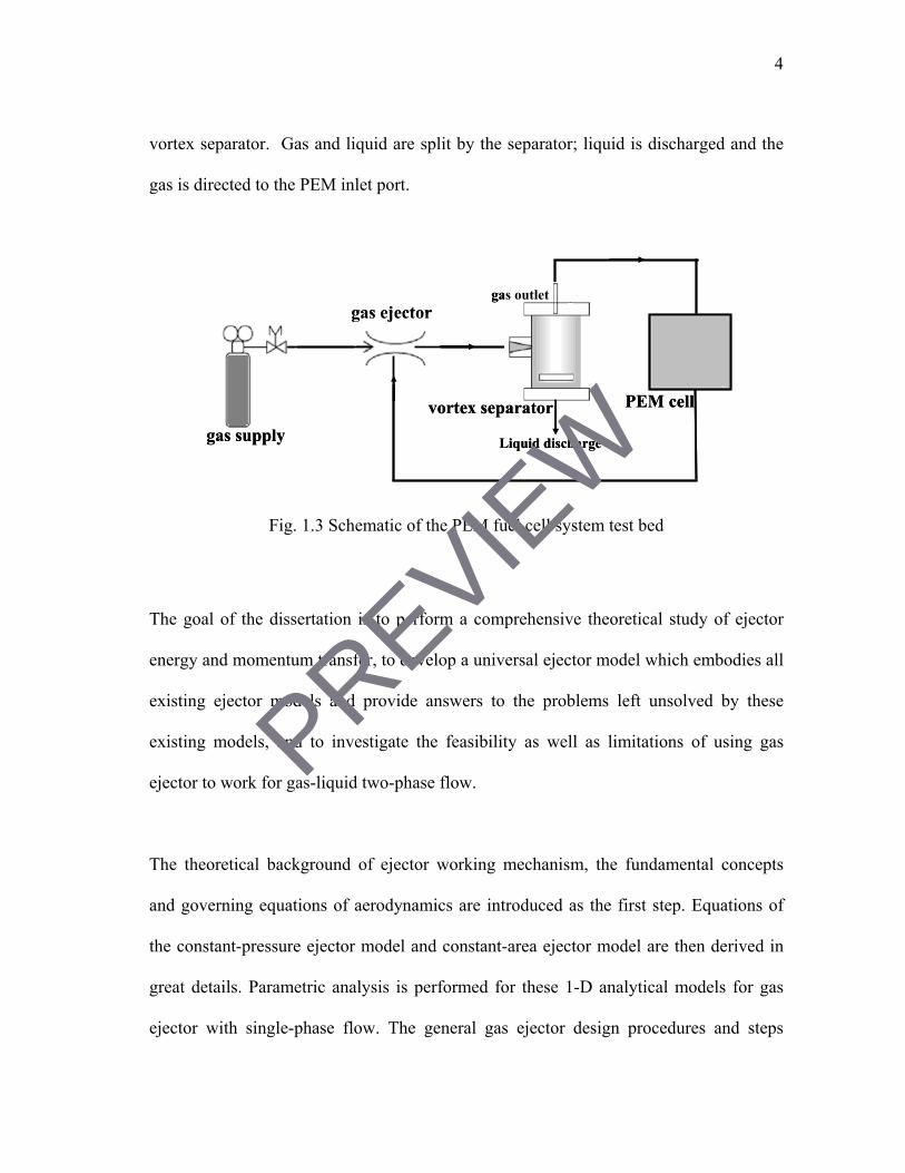
gas-liquid separation system for a Proton Exchange Membrane (PEM) fuel cell. In order
to pump the exhaust from a PEM fuel cell, a two-phase gas ejector is integrated into the
system. Fig. 1.3 is the schematic of PEM fuel cell system test bed. A gas tank supplies
high pressure gas to the ejector primary nozzle inlet and the PEM fuel cell exhaust line is
connected to the ejector secondary inlet (suction) port. PEM cell exhaust is sucked into
the ejector and mixed with the motive stream; the mixed flow then is directed into the
PREVIEW
4
vortex separator. Gas and liquid are split by the separator; liquid is discharged and the
gas is directed to the PEM inlet port.
gas supply
PEM cell
gas ejector
Liquid discharge
vortex separator
gas outlet
gas supply
PEM cell
gas ejector
Liquid discharge
vortex separator
gas outlet
Fig. 1.3 Schematic of the PEM fuel cell system test bed
The goal of the dissertation is to perform a comprehensive theoretical study of ejector
energy and momentum transfer, to develop a universal ejector model which embodies all
existing ejector models and provide answers to the problems left unsolved by these
existing models, and to investigate the feasibility as well as limitations of using gas
ejector to work for gas-liquid two-phase flow.
The theoretical background of ejector working mechanism, the fundamental concepts
and governing equations of aerodynamics are introduced as the first step. Equations of
the constant-pressure ejector model and constant-area ejector model are then derived in
great details. Parametric analysis is performed for these 1-D analytical models for gas
ejector with single-phase flow. The general gas ejector design procedures and steps
PREVIEW
Related Documents