Out-of-Plane Stability of Buckling-Restrained Braces Placed in Chevron Arrangement Tsuyoshi Hikino 1 ; Taichiro Okazaki, M.ASCE 2 ; Koichi Kajiwara 3 ; and Masayoshi Nakashima, M.ASCE 4 Abstract: Large-scale shake table tests were performed at E-Defense to examine the out-of-plane stability of buckling-restrained braces (BRBs). Two specimens were subjected repeatedly to a near-fault ground motion with increasing amplification. The test specimens comprised a single-bay, single-story steel frame and a pair of BRBs placed in a chevron arrangement. The specimens were not braced at the brace-to-beam intersection in order to produce a condition where the BRBs were susceptible to out-of-plane instability. Standard BRBs were used in the first specimen, while BRBs with a flexible segment at each end of the steel core were used in the second specimen. A simple stability model predicted the BRBs in the second specimen to fail because of out-of-plane buckling. The first specimen exhibited excellent ductility during the shake table tests, while the second specimen developed severe out-of-plane deformation that compromised the ductility of the BRBs. Based on the exper- imental observations and the stability model, a methodology is proposed to evaluate bracing requirements at the brace-to-beam intersection. DOI: 10.1061/(ASCE)ST.1943-541X.0000767. © 2013 American Society of Civil Engineers. CE Database subject headings: Shake table tests; Steel frames; Seismic design; Bracing; Lateral stability; Buckling. Author keywords: Shake table tests; Steel frames; Seismic design; Bracing; Lateral stability. Introduction Buckling-restrained braces (BRBs) refer to a class of axially loaded members that achieve stable inelastic behavior under both tension and compression (AISC 2005a; Uang and Nakashima 2004). A BRB comprises a steel core and a buckling-restraining system that con- trols flexural and local buckling of the steel core. The design in- tention is to allow axial forces to be carried solely by the ductile steel core. In many commercial products, buckling restraint is achieved by casing the steel core inside a mortar-filled steel tube, and by limiting shear transfer between the steel core and mortar with adequate clearance and unbonding material. The U.S. practice has incor- porated BRBs into a new category of concentrically braced frames (CBFs), named buckling-restrained braced frames (BRBFs), that exhibit superior ductility over conventional CBFs (AISC 2005a). The stable and predictable cyclic behavior of BRBs has been demonstrated by numerous tests (e.g., Saeki et al. 1995; Black et al. 2004). In the United States, the AISC Seismic Provisions (AISC 2005a) assure reliable performance of BRBs by a qualifying test requirement. On the other hand, recent BRBF system tests indicate that the performance of BRBs can be affected significantly by interaction with the surrounding framing elements and detailing of the bracing connection. For example, tests by Mahin et al. (2004) and Roeder et al. (2006) suggest that local buckling and distortion of framing elements associated with large drifts can cause severe out- of-plane rotation of the gusset plates. Tests by Chou and Chen (2009) suggest that the stable inelastic behavior of BRBs can be com- promised by out-of-plane buckling of gusset plates. Fahnestock et al. (2007) proposed a framing connection detail that shields the BRB bracing connection from moment frame action, and, thereby, pre- cludes out-of-plane distortion of the system. Meanwhile, researchers in Japan noted the need to address out- of-plane stability of BRBs as a limit state independent of frame de- formation or gusset plate buckling. Tembata et al. (2004), Kinoshita et al. (2007), and Takeuchi et al. (2009) derived a comprehensive set of analytical solutions to the out-of-plane stability problem of BRBs, and validated the solutions with static, cyclic loading tests. Takeuchi et al. (2004, 2009) and Kinoshita et al. (2008) investigated the rotational stiffness of BRBs and their bracing connections, respectively, acknowledging these stiffness values to be key factors that control the out-of-plane stability of BRBs. Koetaka and Kinoshita (2009) conducted a review of the Japanese literature and proposed general design criteria to control out-of-plane buckling of BRBs placed in a chevron or single-diagonal arrangement. BRBs placed in a chevron arrangement (also referred to as inverted-V arrangement), as shown in Fig. 1(a), require special atten- tion for out-of-plane stability. For chevron BRBFs, the AISC Seismic Provisions (2005a) require both flanges of the beam to be braced at the BRB-to-beam intersection unless the beam provides the required brace horizontal strength, P br , and stiffness, b, defined as follows: P br ¼ 0:01P r (1) b ¼ 1 0:75 8P r L b (2) 1 Manager, Nippon Steel and Sumikin Engineering Co. Ltd., Osaki Center Building, 1-5-1 Osaki, Shinagawa, Tokyo 141-8604, Japan; formerly, Re- searcher, National Research Institute for Earth Science and Disaster Prevention, Miki, Hyogo 673-0515, Japan. E-mail: [email protected] 2 Associate Professor, Graduate School of Engineering, Hokkaido Univ., Sapporo, Hokkaido 060-8628, Japan; formerly, Researcher, National Research Institute for Earth Science and Disaster Prevention, Miki, Hyogo 673-0515, Japan (corresponding author). E-mail: [email protected] 3 Director of Hyogo Earthquake Engineering Research Center (E-Defense), National Research Institute for Earth Science and Disaster Prevention, Miki, Hyogo 673-0515, Japan. 4 Professor, Disaster Prevention Research Institute, Kyoto Univ., Gokasho, Uji, Kyoto 611-0011, Japan. Note. This manuscript was submitted on June 13, 2012; approved on October 26, 2012; published online on October 29, 2012. Discussion period open until April 1, 2014; separate discussions must be submitted for individual papers. This paper is part of the Journal of Structural Engi- neering, Vol. 139, No. 11, November 1, 2013. ©ASCE, ISSN 0733-9445/ 2013/11-1812–1822/$25.00. 1812 / JOURNAL OF STRUCTURAL ENGINEERING © ASCE / NOVEMBER 2013 J. Struct. Eng. 2013.139:1812-1822. Downloaded from ascelibrary.org by Hokkaido Daigaku on 10/20/13. Copyright ASCE. For personal use only; all rights reserved.

Welcome message from author
This document is posted to help you gain knowledge. Please leave a comment to let me know what you think about it! Share it to your friends and learn new things together.
Transcript

Out-of-Plane Stability of Buckling-Restrained BracesPlaced in Chevron Arrangement
Tsuyoshi Hikino1; Taichiro Okazaki, M.ASCE2; Koichi Kajiwara3; and Masayoshi Nakashima, M.ASCE4
Abstract: Large-scale shake table tests were performed at E-Defense to examine the out-of-plane stability of buckling-restrained braces(BRBs). Two specimens were subjected repeatedly to a near-fault ground motion with increasing amplification. The test specimens compriseda single-bay, single-story steel frame and a pair of BRBs placed in a chevron arrangement. The specimens were not braced at the brace-to-beamintersection in order to produce a condition where the BRBs were susceptible to out-of-plane instability. Standard BRBs were used in the firstspecimen, while BRBswith a flexible segment at each end of the steel corewere used in the second specimen. A simple stabilitymodel predictedthe BRBs in the second specimen to fail because of out-of-plane buckling. The first specimen exhibited excellent ductility during the shake tabletests, while the second specimen developed severe out-of-plane deformation that compromised the ductility of the BRBs. Based on the exper-imental observations and the stability model, a methodology is proposed to evaluate bracing requirements at the brace-to-beam intersection.DOI: 10.1061/(ASCE)ST.1943-541X.0000767. © 2013 American Society of Civil Engineers.
CE Database subject headings: Shake table tests; Steel frames; Seismic design; Bracing; Lateral stability; Buckling.
Author keywords: Shake table tests; Steel frames; Seismic design; Bracing; Lateral stability.
Introduction
Buckling-restrained braces (BRBs) refer to a class of axially loadedmembers that achieve stable inelastic behavior under both tensionandcompression (AISC 2005a; Uang andNakashima 2004). ABRBcomprises a steel core and a buckling-restraining system that con-trols flexural and local buckling of the steel core. The design in-tention is to allow axial forces to be carried solely by the ductile steelcore. Inmany commercial products, buckling restraint is achieved bycasing the steel core inside a mortar-filled steel tube, and by limitingshear transfer between the steel core and mortar with adequateclearance and unbonding material. The U.S. practice has incor-porated BRBs into a new category of concentrically braced frames(CBFs), named buckling-restrained braced frames (BRBFs), thatexhibit superior ductility over conventional CBFs (AISC 2005a).
The stable and predictable cyclic behavior of BRBs has beendemonstrated by numerous tests (e.g., Saeki et al. 1995; Blacket al. 2004). In the United States, the AISC Seismic Provisions
(AISC 2005a) assure reliable performance of BRBs by a qualifyingtest requirement. On the other hand, recent BRBF system testsindicate that the performance of BRBs can be affected significantlyby interaction with the surrounding framing elements and detailingof the bracing connection. For example, tests by Mahin et al. (2004)and Roeder et al. (2006) suggest that local buckling and distortion offraming elements associated with large drifts can cause severe out-of-plane rotation of the gusset plates. Tests byChou andChen (2009)suggest that the stable inelastic behavior of BRBs can be com-promised by out-of-plane buckling of gusset plates. Fahnestock et al.(2007) proposed a framing connection detail that shields the BRBbracing connection from moment frame action, and, thereby, pre-cludes out-of-plane distortion of the system.
Meanwhile, researchers in Japan noted the need to address out-of-plane stability of BRBs as a limit state independent of frame de-formation or gusset plate buckling. Tembata et al. (2004), Kinoshitaet al. (2007), and Takeuchi et al. (2009) derived a comprehensiveset of analytical solutions to the out-of-plane stability problem ofBRBs, and validated the solutions with static, cyclic loading tests.Takeuchi et al. (2004, 2009) and Kinoshita et al. (2008) investigatedthe rotational stiffness of BRBs and their bracing connections,respectively, acknowledging these stiffness values to be key factorsthat control the out-of-plane stability of BRBs. Koetaka andKinoshita (2009) conducted a review of the Japanese literature andproposed general design criteria to control out-of-plane buckling ofBRBs placed in a chevron or single-diagonal arrangement.
BRBs placed in a chevron arrangement (also referred to asinverted-V arrangement), as shown in Fig. 1(a), require special atten-tion for out-of-plane stability. For chevron BRBFs, the AISC SeismicProvisions (2005a) require both flanges of the beam to be braced atthe BRB-to-beam intersection unless the beam provides the requiredbrace horizontal strength, Pbr, and stiffness, b, defined as follows:
Pbr ¼ 0:01Pr (1)
b ¼ 10:75
�8Pr
Lb
�(2)
1Manager, Nippon Steel and Sumikin Engineering Co. Ltd., Osaki CenterBuilding, 1-5-1 Osaki, Shinagawa, Tokyo 141-8604, Japan; formerly, Re-searcher,NationalResearch Institute forEarthScience andDisasterPrevention,Miki, Hyogo 673-0515, Japan. E-mail: [email protected]
2Associate Professor, Graduate School of Engineering, Hokkaido Univ.,Sapporo,Hokkaido 060-8628, Japan; formerly,Researcher,NationalResearchInstitute for Earth Science and Disaster Prevention, Miki, Hyogo 673-0515,Japan (corresponding author). E-mail: [email protected]
3Director of Hyogo EarthquakeEngineeringResearchCenter (E-Defense),National Research Institute for Earth Science and Disaster Prevention, Miki,Hyogo 673-0515, Japan.
4Professor, Disaster Prevention Research Institute, Kyoto Univ., Gokasho,Uji, Kyoto 611-0011, Japan.
Note. This manuscript was submitted on June 13, 2012; approved onOctober 26, 2012; published online on October 29, 2012. Discussion periodopen until April 1, 2014; separate discussions must be submitted forindividual papers. This paper is part of the Journal of Structural Engi-neering, Vol. 139, No. 11, November 1, 2013. ©ASCE, ISSN 0733-9445/2013/11-1812–1822/$25.00.
1812 / JOURNAL OF STRUCTURAL ENGINEERING © ASCE / NOVEMBER 2013
J. Struct. Eng. 2013.139:1812-1822.
Dow
nloa
ded
from
asc
elib
rary
.org
by
Hok
kaid
o D
aiga
ku o
n 10
/20/
13. C
opyr
ight
ASC
E. F
or p
erso
nal u
se o
nly;
all
righ
ts r
eser
ved.
where Pr 5 compressive strength of the BRB; Lb 5 length of theBRBs; and 0.75 5 resistance factor. Eqs. (1) and (2) express thecolumn nodal bracing requirements (AISC 2005b). It is not clearwhether the out-of-plane stability of BRBs noted by the Japanesestudies may be controlled by these requirements.
A research program was conducted to confirm the Japanese de-sign criteria under a dynamic loading condition, and to examine howBRBs may behave after out-of-plane instability occurs. As a keycomponent of this program, large-scale shake table tests were con-ducted at E-Defense, a three-dimensional, large-scale earthquaketesting facility maintained and operated by the National ResearchInstitute for Earth Science and Disaster Prevention of Japan. Thispaper reviews the stability problem reported in earlier Japanesestudies, and subsequently describes analytical solutions to a stabilitymodel that simplifies the previous models in the Japanese literature.The shake-table test program and its design implications are dis-cussed. Finally, the stability model is extended to include out-of-plane imperfection and drift, and used to describe bracing require-ments for beams in chevron BRBFs.
Stability Model
The following five assumptions are introduced to derive an analyt-ical expression for the out-of-plane buckling strength of BRBsplaced in a chevron arrangement, as shown in Fig. 1(a):1. Out-of-plane stability of BRBs is controlled by the forces and
deformation produced in the plane that includes the BRB andthat is perpendicular to the frame. The stability problem is not
influenced by in-plane framing action or tension in the oppo-site BRB.
2. The steel core of the BRBs includes short, unrestrained seg-ments outside of the yielding segment at the termination ofstiffeners. The unrestrained segments have negligible flexuralout-of-plane stiffness compared with any other segment of theBRB.
3. Yielding occurs only in the yielding segment of the steel corewhile all other components remain elastic. Further, because ofadequate stiffening, distortion of the gusset plates and thebeam section is negligibly small.
4. The BRBs are adequately designed such that flexural bucklingor local buckling of the steel core does not control the BRBstrength.
5. Initial imperfection and out-of-plane drift are neglected.Fig. 1(b) shows a first-order, out-of-plane buckling model of the
BRB based on the five assumptions. The model comprises rigidelements, internal hinges, and elastic end restraints. Internal hingesare placed in the steel core per the second assumption. The top end ofthe buckling model is the point of intersection between the BRB andthe beam. The bottom of the system represents the brace–beam–
column node that is well braced and, hence, modeled as rigid. Thismodel is a simplification of the elastic–perfectly plastic modelproposed byTembata et al. (2004) andKinoshita et al. (2007), shownin Fig. 1(c), which accounts for elastic deformation of the gussetplates. Solutions for this model are described in the Appendix.
Figs. 2(a and b) illustrate common bracing connections employedfor BRBs in Japan, which are believed to satisfy the third assumption.
Fig. 1.Out-of-plane stability model: (a) chevron brace; (b) model for standard connections; (c) model proposed by Kinoshita et al. (2007); (d) modelfor alternative conditions
JOURNAL OF STRUCTURAL ENGINEERING © ASCE / NOVEMBER 2013 / 1813
J. Struct. Eng. 2013.139:1812-1822.
Dow
nloa
ded
from
asc
elib
rary
.org
by
Hok
kaid
o D
aiga
ku o
n 10
/20/
13. C
opyr
ight
ASC
E. F
or p
erso
nal u
se o
nly;
all
righ
ts r
eser
ved.

Both connections provide substantial restraint for out-of-plane ro-tation. Fig. 2(c) shows an alternative detail where the fin plates(stiffener plates oriented perpendicular to the gusset plate) are notwelded directly to the beam flanges and where the gusset plates arenot stiffened along the edges. Such connections are commonly usedin the United States. This relatively flexible bracing connection doesnot satisfy the third assumption;thus, the buckling model shown inFig. 1(d) may be more adequate (Takeuchi et al. 2009). The modelsin Figs. 1(b–d) represent BRBF design that accommodates out-of-plane deformation by controlled rotation of elements. AIJ (2009)suggests two options to permit rotation either in the BRBs or in thebracing connections. This study adopts the former option as ex-pressed in the second assumption.
Themodel in Fig. 1(b) is the focus of this paper. Stability of thismodel is governed by the horizontal and rotational stiffness sup-plied at the top end of the BRB, KH and KR, and two lengthmeasurements, L1 and L2. The spring constants may be evaluatedbased on the flexural and torsional stiffness of the beam and theproperties of lateral braces placed at the BRB-to-beam intersection.As shown in Fig. 3(a), the bucklingmodesmay be described in termsof three displacement parameters u1, u2, and u, of which two areindependent. From the equilibrium condition, the critical load, Pcr,is determined as the smaller solution to the following quadraticequation:
ðP2PHÞðP2PRÞ2P ×�L1L2
PH
�¼ 0 (3)
In Eq. (3)
PH ¼ KH × L2 PR ¼ KR
L1(4)
Figs. 3(b and c) illustrate limit cases. For Case 1, when the rotationalspring is infinitely rigid (u1 5 0, u5 L2 u2), the critical load isP1 5PH . For Case 2, when the translational spring is infinitely rigid(u5 0, u1=u2 5 L2=L1), the critical load,P2, is expressed as follows:
P2 ¼ PRL2
L1 þ L2(5)
TheAppendix explains that Eq. (3) is a special case of the solutionderived by Kinoshita et al. (2007). Fig. 4 plots the combinations ofP1 and P2 that achieves Pcr 5P0, where P0 is the compressivestrength of the steel core. The domain in the P1 2P2 space above thecurve and opposite the origin defines the safe domain where thebuckling strength is greater than P0, and, thus, out-of-plane bucklingof the BRB may be avoided. The curves are plotted for L1=L25 0:25 and 0:5. The case L1=L2 5 0:25 may represent BRBs with
Fig. 2. Bracing connection details: (a) standard 1; (b) standard 2; (c) alternative
Fig. 3. Buckling modes: (a) general mode; (b) limit case 1; (c) limit case 2; (d) modified buckling model
1814 / JOURNAL OF STRUCTURAL ENGINEERING © ASCE / NOVEMBER 2013
J. Struct. Eng. 2013.139:1812-1822.
Dow
nloa
ded
from
asc
elib
rary
.org
by
Hok
kaid
o D
aiga
ku o
n 10
/20/
13. C
opyr
ight
ASC
E. F
or p
erso
nal u
se o
nly;
all
righ
ts r
eser
ved.

compact bracing connections,whileL1=L2 5 0:5may representBRBswith larger bracing connections that use bolted splices, as shown inFig. 2.
The buckling mode is expressed as follows:
u1u2
¼ PH
PR2Pcr þ L1L2
PH
¼ PH 2PcrL1
L2PH
or uL1u1
¼ Pcr
PH 2Pcr
(6)
Eq. (6) indicates that Case 1 controls (i.e., u1 � 0) when P2 is sig-nificantly greater than P1 and, thus, Pcr �P1, while Case 2 controls(i.e., u� 0, u1=u2 �L2=L1) when P1 is significantly greater than P2
and, thus, Pcr �P2.
Test Plan
Two large-scale specimens were subjected to a series of strong earth-quake ground motions to examine whether out-of-plane buckling ofBRBs can be predicted based on the analytical solutions previouslydescribed, and to examine how BRBs may behave after out-of-planeinstability occurs.
Specimens
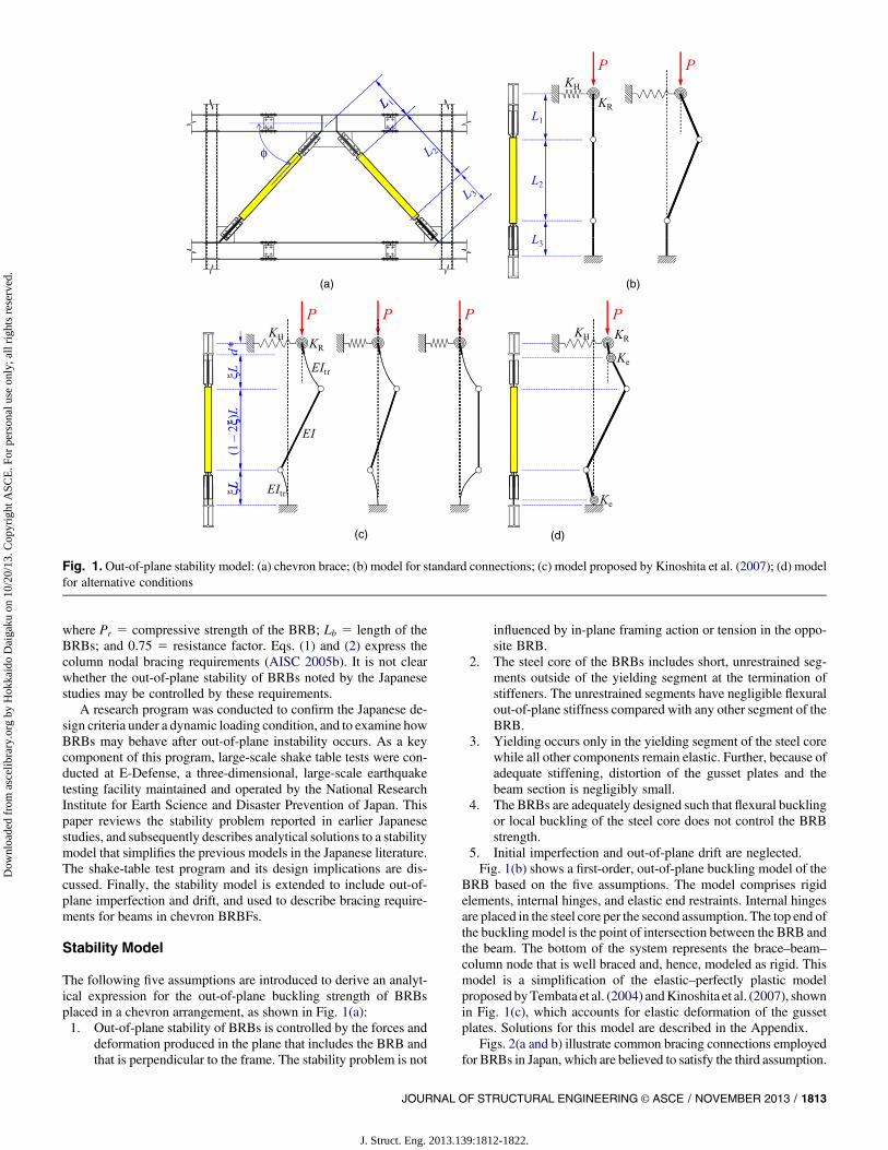
Two braced frame specimens were tested in this program. Fig. 5(a)shows the specimen comprising a built-up, wide-flange beam; two,cold-formed, square hollow structural section (HSS) columns; anda pair of BRBs. The 4.15-m span and 2.10-m height correspond toa 70%-scale building structure. After Specimen 1 was tested, theBRBs were replaced by a new pair of BRBs to prepare Specimen 2.The standard through-diaphragm detail (Nakashima et al. 2000) wasused to achieve rigid beam-to-column connections. The bracingconnections adopted the standarddetail [shown inFig. 2(a)] thatweldsthefinplates directly to the beam.The beam is providedwith stiffenersat the BRB-to-beam intersection to control local beam distortion. Thecolumnswere rigidly connected to the shake table via stiff basebeams.
Table 1 lists the Japanese Industry Standards (JIS) designationand measured mechanical properties for each material used to
fabricate the specimens. The specified minimum yield strength is235, 295, and 325 MPa, respectively, for SN400, BCR295, andSM490 steel. At the top side of the specimens, each end of the beamwas connected to the test-bed system (described in a subsequentsection) through a pin-ended load cell. The specimens were laterallybraced along the columns and beam at discrete locations indicated inFig. 5(a) by cross marks. No bracing was provided at the middlesegment of the beam [between the points designated B and D inFig. 5(a)] to intentionally reduce the torsional and translationalrestraint at the BRB-to-beam intersection.
The two specimens were nominally identical except for theBRBs. As shown in Figs. 5(b and c), the BRBs used a 743 12 mmplate for the steel core and a square-HSS, 1253 1253 2:3 mmcasing filled with mortar for the buckling-restraining system. Thekey difference between the BRBs was the embedment length of thestiffened segment (the transition segment) inside the steel casing. Anexperimental study by Takeuchi et al. (2009) suggest that, if theembedment length exceeds 1.5 to 2 times the width of the yieldingsegment, then no local reduction inflexural stiffness occurs along thelength of the steel core. While Specimen 1 used an embedmentlength exactly at theminimum requirement by Takeuchi et al. (2009)[Fig. 5(b) indicates 110 mm], Specimen 2 used a much shorterembedment length [Fig. 5(c) indicates 30 mm] to represent a leastfavorable BRB design for out-of-plane stability. The BRBs wereoriented with the flat-plate steel core parallel to the plane of theframe. The parallel orientation is more commonly adopted than theorthogonal orientation and represents a less favorable condition forout-of-plane stability. Because rotational stiffness at the end of theyielding segment is developed by bearing between the transitionsegment andmortar, and the yielding segment itself possesses limitedrotational stiffness, the shorter embedment length in Specimen 2 wasexpected to promote out-of-plane instability of the BRBs. In otherwords, the second assumption of the stability model in Fig. 1(b) isvalid for Specimen 2 but not for Specimen 1. Out-of-plane bucklingof BRBs was not likely to occur in Specimen 1.
Assuming that BRB buckling does not occur, a rigid-plasticanalysis using the measured material properties estimated the lat-eral strength of the specimen to be 798 kN, at which stage the BRBsand underlying moment frame provide 58 and 42%, respectively, ofthe lateral strength.
Stability Design Check
The spring constants KH and KR shown in Fig. 1(b) are determinedby the weak-axis bending stiffness and torsional stiffness, re-spectively, of the beam. Elastic analysis assuming the beam to besimply supported at the intermediate bracing points [points desig-nated B and D in Fig. 5(a)] and fixed at the face of the columns[points designated A and E in Fig. 5(a)] for weak-axis bending andtorsion, leads toKH 5 6,070 kN ×m andKR 5 260 kN ×m=rad. UsingL1 5 0:825m and L2 5 1:41m (Fig. 5), Eqs. (3)–(5) give P1
5 8,560 kN, P2 5 199 kN, and Pcr 5 197 kN. While P1 is sub-stantially larger than the yield strength of the steel core based on themeasured yield strength, Py 5 264 kN, P2 and Pcr are smaller thanPy. Therefore, the stabilitymodel suggests the BRBs to buckle out ofplane before developing their yield strength in compression, andsuggests the buckling mode to be dominated by limit case 2.
On theother hand, usingPr 5 1:5Py and Lb 5 3:06m, theminimalbracing requirements defined byEqs. (1) and (2) arePbr 5 4:0 kN andb5 1,380 kN ×m. Because Pbr is very easily exceeded by the weak-axis bending strength of the beam and KH is more than four timeslarger than b, the AISC Seismic Provisions (AISC 2005a) do notrequire lateral bracing at the middle of the beam. In other words,neither specimen violates the AISC Seismic Provisions.
Fig. 4. Condition to achieve Pcr 5P0
JOURNAL OF STRUCTURAL ENGINEERING © ASCE / NOVEMBER 2013 / 1815
J. Struct. Eng. 2013.139:1812-1822.
Dow
nloa
ded
from
asc
elib
rary
.org
by
Hok
kaid
o D
aiga
ku o
n 10
/20/
13. C
opyr
ight
ASC
E. F
or p
erso
nal u
se o
nly;
all
righ
ts r
eser
ved.
Test Bed
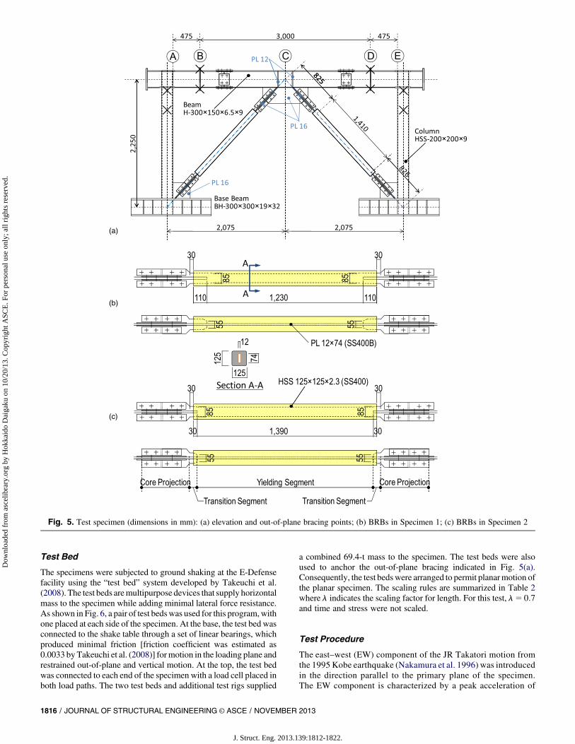
The specimens were subjected to ground shaking at the E-Defensefacility using the “test bed” system developed by Takeuchi et al.(2008). The test beds aremultipurpose devices that supply horizontalmass to the specimen while adding minimal lateral force resistance.As shown in Fig. 6, a pair of test bedswas used for this program,withone placed at each side of the specimen. At the base, the test bed wasconnected to the shake table through a set of linear bearings, whichproduced minimal friction [friction coefficient was estimated as0.0033 by Takeuchi et al. (2008)] formotion in the loading plane andrestrained out-of-plane and vertical motion. At the top, the test bedwas connected to each end of the specimen with a load cell placed inboth load paths. The two test beds and additional test rigs supplied
a combined 69.4-t mass to the specimen. The test beds were alsoused to anchor the out-of-plane bracing indicated in Fig. 5(a).Consequently, the test bedswere arranged to permit planarmotion ofthe planar specimen. The scaling rules are summarized in Table 2where l indicates the scaling factor for length. For this test, l5 0:7and time and stress were not scaled.
Test Procedure
The east–west (EW) component of the JR Takatori motion fromthe 1995 Kobe earthquake (Nakamura et al. 1996) was introducedin the direction parallel to the primary plane of the specimen.The EW component is characterized by a peak acceleration of
(a)
(b)
(c)
Fig. 5. Test specimen (dimensions in mm): (a) elevation and out-of-plane bracing points; (b) BRBs in Specimen 1; (c) BRBs in Specimen 2
1816 / JOURNAL OF STRUCTURAL ENGINEERING © ASCE / NOVEMBER 2013
J. Struct. Eng. 2013.139:1812-1822.
Dow
nloa
ded
from
asc
elib
rary
.org
by
Hok
kaid
o D
aiga
ku o
n 10
/20/
13. C
opyr
ight
ASC
E. F
or p
erso
nal u
se o
nly;
all
righ
ts r
eser
ved.
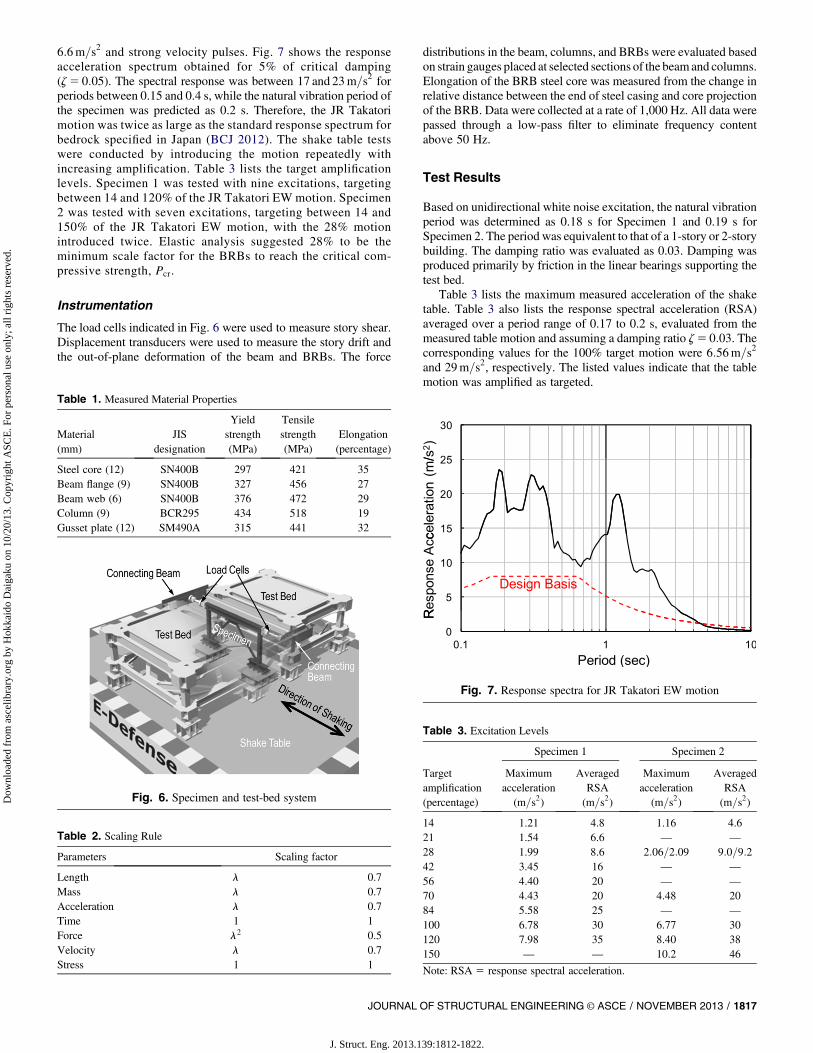
6:6m=s2 and strong velocity pulses. Fig. 7 shows the responseacceleration spectrum obtained for 5% of critical damping(z5 0:05). The spectral response was between 17 and 23m=s2 forperiods between 0.15 and 0.4 s, while the natural vibration period ofthe specimen was predicted as 0.2 s. Therefore, the JR Takatorimotion was twice as large as the standard response spectrum forbedrock specified in Japan (BCJ 2012). The shake table testswere conducted by introducing the motion repeatedly withincreasing amplification. Table 3 lists the target amplificationlevels. Specimen 1 was tested with nine excitations, targetingbetween 14 and 120% of the JR Takatori EW motion. Specimen2 was tested with seven excitations, targeting between 14 and150% of the JR Takatori EW motion, with the 28% motionintroduced twice. Elastic analysis suggested 28% to be theminimum scale factor for the BRBs to reach the critical com-pressive strength, Pcr.
Instrumentation
The load cells indicated in Fig. 6 were used to measure story shear.Displacement transducers were used to measure the story drift andthe out-of-plane deformation of the beam and BRBs. The force
distributions in the beam, columns, and BRBs were evaluated basedon strain gauges placed at selected sections of the beamand columns.Elongation of the BRB steel core was measured from the change inrelative distance between the end of steel casing and core projectionof the BRB. Data were collected at a rate of 1,000 Hz. All data werepassed through a low-pass filter to eliminate frequency contentabove 50 Hz.
Test Results
Based on unidirectional white noise excitation, the natural vibrationperiod was determined as 0.18 s for Specimen 1 and 0.19 s forSpecimen 2. The period was equivalent to that of a 1-story or 2-storybuilding. The damping ratio was evaluated as 0.03. Damping wasproduced primarily by friction in the linear bearings supporting thetest bed.
Table 3 lists the maximum measured acceleration of the shaketable. Table 3 also lists the response spectral acceleration (RSA)averaged over a period range of 0.17 to 0.2 s, evaluated from themeasured table motion and assuming a damping ratio z5 0:03. Thecorresponding values for the 100% target motion were 6:56m=s2
and 29m=s2, respectively. The listed values indicate that the tablemotion was amplified as targeted.
Fig. 6. Specimen and test-bed system
Fig. 7. Response spectra for JR Takatori EW motion
Table 1. Measured Material Properties
Material(mm)
JISdesignation
Yieldstrength(MPa)
Tensilestrength(MPa)
Elongation(percentage)
Steel core (12) SN400B 297 421 35Beam flange (9) SN400B 327 456 27Beam web (6) SN400B 376 472 29Column (9) BCR295 434 518 19Gusset plate (12) SM490A 315 441 32
Table 2. Scaling Rule
Parameters Scaling factor
Length l 0.7Mass l 0.7Acceleration l 0.7Time 1 1Force l2 0.5Velocity l 0.7Stress 1 1
Table 3. Excitation Levels
Targetamplification(percentage)
Specimen 1 Specimen 2
Maximumacceleration
(m=s2)
AveragedRSA(m=s2)
Maximumacceleration
(m=s2)
AveragedRSA(m=s2)
14 1.21 4.8 1.16 4.621 1.54 6.6 — —
28 1.99 8.6 2:06=2:09 9:0=9:242 3.45 16 — —
56 4.40 20 — —
70 4.43 20 4.48 2084 5.58 25 — —
100 6.78 30 6.77 30120 7.98 35 8.40 38150 — — 10.2 46
Note: RSA 5 response spectral acceleration.
JOURNAL OF STRUCTURAL ENGINEERING © ASCE / NOVEMBER 2013 / 1817
J. Struct. Eng. 2013.139:1812-1822.
Dow
nloa
ded
from
asc
elib
rary
.org
by
Hok
kaid
o D
aiga
ku o
n 10
/20/
13. C
opyr
ight
ASC
E. F
or p
erso
nal u
se o
nly;
all
righ
ts r
eser
ved.

Both specimens exhibited very similar response up to the 70%motion. Fig. 8 compares the story shear versus drift ratio responseof the two specimens to the 100 and 120%motions. The drift ratiowas evaluated as the relative displacement measured between thebeam and base beam divided by the story height of 2.1 m.Specimen 1 exhibited very stable and ductile behavior even underthe largest 120% motion, developing a maximum drift of 0.014 radand leaving a residual drift smaller than 0.001 rad. Minimal yieldingwas observed in the framing members after testing of Specimen 1was completed. On the other hand, Specimen 2 experienced sub-stantial degradation in elastic stiffness during motions 100% andlarger, and recorded a maximum drift ratio of 0.016 rad during the100% motion and 0.032 rad during the 120% motion. Fig. 9 showsthe maximum and residual drift ratios measured from each motion;the figure indicates very similar responses of the two specimensunder motions up to 70%. The 100% and larger motions causedminimal damage to Specimen 1 but severe damage to Specimen 2.While the 150% motion produced large drift ratios for Specimen 2,ranging between –0.06 and 0.025 rad, this motion left a fairly smallresidual drift of –0.012 rad.
Fig. 10 shows Specimen 2 between the 120 and 150% motions.Fig. 10(a) views the elevation of the specimen from an angle.Kinking deformation is seen at the top and bottom ends of bothBRBs, between the core projection and steel casing. The kink ro-tation angle was notably larger at the top end of the BRB than at thebottom end, and the direction of kink rotation is opposite between thetop and bottom. Inelastic torsional deformation is seen in the beam.Fig. 10(b) is a close-up view of the middle portion of the beam andthe top ends of the two BRBs. The close-up view indicates that thekinking deformation of the BRBs was accommodated by twisting ofthe beam. The deformation is very similar to the buckling mode forlimit case 2 shown in Fig. 3(c). Although not visible in these pho-tographs, the steel casing bulged outward at the side, which the steelcore bore against.
Fig. 11 further compares the two specimens from the 100%motion by plotting the elongation of the BRB steel core, kink ro-tation at the top and bottom ends of the BRB (u1 1 u2 and u2 inFig. 3), twist angle of the beam at theBRB-to-beam intersection (u1),and lateral translation of the beam at theBRB-to-beam intersection (u),respectively, against the BRB tension. The response is shown for thewest BRB, which was placed on the closer side as in Fig. 10. Thebehavior of the east BRB was symmetric to the west BRB. Positiverotation and twist are taken in the counterclockwise direction, asviewed inFig. 10,while positive beam translation is taken in the left-to-right direction. The broken horizontal lines indicate the yield strengthof the steel core based on the measured yield strength, Py 5 264 kN.The solid horizontal line indicates the critical compressive strength,Pcr 5 197 kN, which applies only to Specimen 2. The maximum ten-sile and compressive forces were 1:24 and 1:19Py, respectively, forSpecimen 1, and 1:22 and 1:17Py, respectively, for Specimen 2.
In Specimen 1, the BRB steadily developed larger forces withlarger elongation, minimal kink rotation, and negligible twist andtranslation of the beam. On the other hand, the BRB in Specimen 2developed severe out-of-plane deformation after exceeding its pre-dicted buckling strength and yield strength. Figs. 11(a–d) indicatefour time instants when out-of-plane deformation in Specimen 2increased rapidly. Fig. 11(a) shows that the compressive strength ofSpecimen 2 reduced after undergoing two substantial compressionexcursions, indicated as Steps 1 and 3. Fig. 11(b) shows the kinkrotation at the top and bottom ends of the BRB, in opposingdirections, with the top end developing twice the rotation as thebottom. Residual kink rotation was present after the 70% motion.The 100%motion caused a very large residual rotation of 0.22 rad atthe top and 0.09 rad at the bottom.
Fig. 8. Frame response at (a) 100% motion; and (b) 120% motion
Fig. 9. Maximum drift and residual drift, recorded at end of eachmotion
1818 / JOURNAL OF STRUCTURAL ENGINEERING © ASCE / NOVEMBER 2013
J. Struct. Eng. 2013.139:1812-1822.
Dow
nloa
ded
from
asc
elib
rary
.org
by
Hok
kaid
o D
aiga
ku o
n 10
/20/
13. C
opyr
ight
ASC
E. F
or p
erso
nal u
se o
nly;
all
righ
ts r
eser
ved.

Fig. 11(c) indicates that the kink rotation of the BRB was ac-companied by very severe twisting of the beam. Interestingly, thebeam twist increased in the same direction when the west BRBdeveloped compression [Steps 1 and 3 in Fig. 11(c)] and when theopposite east BRB developed compression (Steps 2 and 4).Therefore, an important finding from the behavior illustrated inFig. 11(c) is that the opposite BRB provided little rotational restraintat the BRB-to-beam intersection and hence did not restrain thebuckling deformation. Fig. 11(d) indicates that lateral translation ofthe beam remained very small (less than 2 mm over an unbracedlength of 3,000 mm) until buckling deformation of the BRB becamevery evident at Step 2. Figs. 11(c and d) suggest that the out-of-planebucklingmodewas dominated by the limit case 2 shown in Fig. 3(c).
For both Specimens 1 and 2, the predicted critical compressivestrength Pcr was first exceeded during the 28% motion, and in-creasingly larger out-of-plane deformation was observed during the28, 70, and 100% motions. However, no reduction in strength wasobserved until the 100% motion.
Specimen 2 was subjected to two further motions after the 100%motion had caused severe buckling deformation of the BRBs. Asplastic deformation accumulated in the beam and BRBs during the100, 120, and 150%motions, the compressive strength of the BRBsgradually decreased. During the 120 and 150% motions, the BRBs
developed the same tensile strength developed during the 100%motion. The kink rotation of the BRBs exceeded 0.5 rad at the topend and 0.2 rad at the bottom end. The beam twist angle exceeded0.35 rad. It was observed after the 150%motion that the mortar wascrushed and the steel casing was deformed, presumably because ofthe contact with the transition segment. However, no distress wasfound in the bracing connections. No fracture was visible in the steelcore at the location of severe kinking deformation.
Stability of BRBs
Test Observations
The simple buckling model shown in Fig. 1(b) predicted the oc-currence of out-of-plane buckling of BRBs in Specimen 2. Bucklingdeformation was not present until the critical strength, Pcr evaluatedfromEq. (3), and theyield strength,Py, were exceeded. Themaximummeasured BRB compressive force was 1:68Pcr for the east BRBand 1:56Pcr for the west BRB. The buckling deformation in Fig. 10and measured deformation in Fig. 11 agree with the prediction thatlimit case 2, shown in Fig. 3(c), dominates the buckling mode.Consequently, although the prediction was conservative, Eq. (3) maybe used to estimate the buckling strength for BRBs that meet the fiveassumptions that justify the buckling model. The local damage ob-served at the edges of the steel casing indicates that appreciable ro-tational stiffness developed at the ends of the yielding segment as thetransition segment bore against the buckling-restraining system. Therotational stiffness, which is neglected in the simple stability model, isbelieved to be a contributing factor to the increase in buckling strengthover the predicted strength, Pcr.
Fig. 11(a) suggests that the stable inelastic behavior of BRBs islost once out-of-plane buckling occurs. On the other hand, Fig. 8shows that the BRBF maintained appreciable energy dissipationcapacity even after the BRBs had buckled. After the BRBs buckled,a large portion of the input energy was dissipated by the underlyingmoment frame and plastic torsion of the beam, and less substantiallyby the BRBs. The secondary energy dissipation mechanism of theBRBFand the resiliency of theBRBs should be appreciated.However,considering that severe beam torsion causes significant damage tononstructural elements and the concrete slab, and makes replacementof BRBs difficult (a serious drawback when the BRBs are imple-mented as supplemental energy dissipation devices), the out-of-planebuckling deformation ofBRBs demonstrated inSpecimen 2 should beavoided.
Effect of Imperfection
A question remains as to how out-of-plane stability of BRBs isaffected by inherent imperfection and story drifts in the orthogonalloading direction. The question may be addressed by a modifiedbuckling model shown in Fig. 3(d) where the fifth assumption isremoved. In Fig. 3(d), u10, u20, and u0 denote imperfections that arepresent under zero force (P5 0). For the modified model, theequilibrium condition leads to the following relationship betweenthe BRB compression P, deformation u1, and imperfections u10and u0:
ðu1 þ u10ÞP22
�ðu1 þ u10Þ
�1þ L1
L2
�PH þ u1PR
þ PH
L2u0
�Pþ u1 ×PHPR ¼ 0 (7)
Fig. 12 plots the relationship between the BRB compression and(u1 u0), (u1 1 u10), and (u2 1 u20), given the properties of Specimen
Fig. 10. Specimen 2 after 120% motion: (a) side view; (b) close-upview
JOURNAL OF STRUCTURAL ENGINEERING © ASCE / NOVEMBER 2013 / 1819
J. Struct. Eng. 2013.139:1812-1822.
Dow
nloa
ded
from
asc
elib
rary
.org
by
Hok
kaid
o D
aiga
ku o
n 10
/20/
13. C
opyr
ight
ASC
E. F
or p
erso
nal u
se o
nly;
all
righ
ts r
eser
ved.

2, and assuming initial drift ratios (u0 divided by the story height,2.1 m) of 0.002 to 0.02 rad and u1 5 0. Deformation increases as Pasymptotically approaches the critical strength, Pcr 5 197 kN. Al-though the plotted loading paths do not represent response toearthquake ground motions, Fig. 12 demonstrates how the criticalstrength reduces with out-of-plane deformation. An initial drift ratioof 0.002 rad, which is representative of construction tolerance, hasaminor effect on the strength and stability of the BRBs. However, anout-of-plane drift of 0.02 rad, which is the prescribed design drift
limit under seismic loads (ASCE 2005), leads to large out-of-planedeformation at P5 0:75Pcr.
Bracing Requirements at the BRB-to-Beam Intersection
Fig. 12 plots the compression versus deformation relationships forthe case with an initial drift ratio of 0.02 rad and P2 doubled fromwhatwas provided in Specimen 2. Fig. 12 suggests that, even againsta large initial out-of-plane story drift of 0.02 rad, amplification of the
Fig. 11. BRB response at 100% motion: (a) BRB elongation; (b) BRB kink rotation; (c) beam twist angle; (d) beam translation
(a) (b) (c)
Fig. 12. Effect of out-of-plane deformation induced by initial imperfection
1820 / JOURNAL OF STRUCTURAL ENGINEERING © ASCE / NOVEMBER 2013
J. Struct. Eng. 2013.139:1812-1822.
Dow
nloa
ded
from
asc
elib
rary
.org
by
Hok
kaid
o D
aiga
ku o
n 10
/20/
13. C
opyr
ight
ASC
E. F
or p
erso
nal u
se o
nly;
all
righ
ts r
eser
ved.

initial deformation can be contained well by doubling P2. As ob-served by Kinoshita et al. (2007) and Koetaka and Kinoshita (2009),Pcr nearly equals P2 (i.e., Pcr is controlled primarily byKR while KH
plays a minor role) for regularly proportioned chevron BRBFs thatare not laterally braced at the BRB-to-beam intersection. Therefore,out-of-plane stability of the BRBmay be controlled by designing P2
to be at least twice as large as themaximum expected BRB force,P0.In other words the required stiffness of the torsional bracing may beexpressed as follows:
KR $ 2P0L1ðL1 þ L2Þ
L2(8)
If such P2, or equivalently KR, is not supplied by the beam, thenadequate torsional bracing must be provided at the BRB-to-beamintersection.
Conclusions
Large-scale shake table tests were conducted to study the out-of-plane stability of BRBs placed in a chevron arrangement. Twochevron BRBF specimens were repeatedly subjected to a unidirec-tional ground motion with increasing amplification. No lateralbracing was provided at the BRB-to-beam intersection in order topromote out-of-plane instability of the BRBs. The BRBs in Speci-men 2 had an unusually short embedment length of the transitionsegment inside the steel casing. A buckling model, which is a sim-plification of a previously proposed model, was used to predict theout-of-plane buckling strength of BRBs. Key findings from thisstudy are summarized as follows:1. TheBRBs in Specimen 1 had the transition segment embedded
inside the steel casing to 1.5 times the depth of the yieldingsegment, as suggested by Takeuchi et al. (2009). As expected,the BRBs did not buckle and Specimen 1 exhibited excellentseismic behavior. This result validates the suggestion byTakeuchi et al. (2009).
2. The BRBs in Specimen 2 adopted a very short embedmentlength of the steel projection inside the steel casing. Thisspecimen exhibited excellent behavior until the BRBs faileddue to out-of-plane buckling. As predicted by the bucklingmodel, the buckling mode involved kinking deformation atboth ends of the BRBs and twisting of the beam at the BRB-to-beam intersection.
3. The measured BRB compression in Specimen 2 exceeded thepredicted critical strength by 56 to 68% and exceeded the yieldstrength by 17 to 26%. The buckling model provides a con-servative estimate of the critical strength, presumably becausethe model neglects the flexural stiffness of the yielding seg-ment caused by bearing of the transition segment against thesteel casing and mortar.
4. The resiliency of BRBs enabled stable energy dissipation of Spec-imen 2 even as the buckling deformation progressed to an extremeextent. Nonetheless, considering the damage expected to nonstruc-tural elements and theconcrete slabcausedbybeamtwisting,out-of-plane buckling is not a preferred limit state for BRBs.
5. Thebucklingmodel can be extended to incorporate out-of-planeimperfection and story drift. Themodel may be used to estimatethe minimal lateral bracing requirements for chevron BRBFs.
Appendix. Critical Loads Derived fromKinoshita et al. (2007)
Kinoshita et al. (2007) derived the following solutions to the stabilitymodel shown in Fig. 1(c). The original expressions are modified tomatch the expressions adopted in Eq. (3).
�P2PH
��P2PR
�2P ×PX ¼ 0 (9a)
cosðjatrÞ2 2sinðjatrÞ
atr¼ 0 (9b)
cosðjatrÞ ¼ 0 (9c)
Eqs. (9a)–(9c) correspond to the three buckling modes indicated inFig. 1(c). The notations shown in Fig. 1(c) are used,where j5 lengthratio between the stiffened segment (core projection plus transitionsegment) and the entire BRB, and
atr ¼ L
ffiffiffiffiffiffiffiPEItr
r(10)
where EItr 5 elastic flexural rigidity of the stiffened segment[Fig. 1(c)]. Further
PH ¼ KH × LcosðjatrÞ2 2
sinðjatrÞatr
cosðjatrÞ (11a)
PR ¼ KR ×cosðjatrÞ
dp × cosðjatrÞ þ LsinðjatrÞ
atr
(11b)
PX ¼ KH
�dp × cosðjatrÞ þ L
sinðjatrÞatr
�(11c)
BytakingEItr →‘ in the aboveequations,atr → 0, and, thus,PH →PH ,PR →PR, and PX →PHðL1=L2Þ. Therefore, when elastic deformationof the gusset plates is neglected, Eq. (9a) reduces toEq. (3).On the otherhand, Eqs. (9b) and (9c) are buckling loads that are associated withelastic deformation of the gusset plates and cannot be captured by themodel adopted in the current study.Using thedimensionsofSpecimen2and P5 197 kN, atr 5 0:0446, jatr 5 0:0105, and, therefore, Eqs. (3)and (9a) result in the same solution for engineering purposes.
Acknowledgments
The project presented in this paper was funded by the National Re-search Institute for Earth Science andDisaster Prevention (NIED) ofJapan. Naomiki Suzuki and Makoto Ohsaki provided guidance tothe overall project and specimen design. The authors thank ToruTakeuchi and Yuji Koetaka for sharing their views and latest re-search findings. Sachi Furukawa, Ryo Umehara, and Xuchuan Linhelped processing the data. The BRBs were provided by NipponSteel Engineering Co., Ltd.; Maekawa Co., Ltd. managed specimenfabrication and construction of the test setup. Special thanks are ex-tended to the administrative and technical staff of E-Defense, offi-cially named the Hyogo Earthquake Engineering Research Center.The opinions expressed in this paper are those of the authors anddo not necessarily reflect the views of the individuals and organiza-tions mentioned above.
References
American Institute of Steel Construction (AISC). (2005a). “Seismic pro-visions for structural steel buildings.” ANSI/AISC Standard 341-05,Chicago.
JOURNAL OF STRUCTURAL ENGINEERING © ASCE / NOVEMBER 2013 / 1821
J. Struct. Eng. 2013.139:1812-1822.
Dow
nloa
ded
from
asc
elib
rary
.org
by
Hok
kaid
o D
aiga
ku o
n 10
/20/
13. C
opyr
ight
ASC
E. F
or p
erso
nal u
se o
nly;
all
righ
ts r
eser
ved.
American Institute of Steel Construction (AISC). (2005b). “Specification forstructural steel buildings.” ANSI/AISC Standard 360-05, Chicago.
Architectural Institute of Japan (AIJ). (2009). Recommendation for stabilitydesign of steel structures, Maruzen, Tokyo (in Japanese).
ASCE. (2005). “Minimum design loads for buildings and other structures.”ASCE/SEI 7-05, Reston, VA.
Black, C. J., Makris, N., and Aiken, I. D. (2004). “Component testing,seismic evaluation and characterization of buckling-restrained braces.”J. Struct. Eng., 130(6), 880–894.
Building Center of Japan (BCJ). (2012). “Enforcement ordinance of con-struction standard law.”Article 82(5.3),Ministry of Land, Infrastructure,Transport, and Tourism, Tokyo (in Japanese).
Chou, C.-C., and Chen, Pi-J. (2009). “Compressive behavior of centralgusset plate connections for a buckling-restrained braced frame.” J.Constr. Steel Res., 65(5), 1138–1148.
Fahnestock, L. A., Sause, R., and Ricles, J. M. (2007). “Seismic responseand performance of buckling-restrained brace frames.” J. Struct. Eng.,133(9), 1195–1204.
Kinoshita, T., Koetaka, Y., Inoue, K., and Iitani, K. (2007). “Criteria ofbuckling-restrained braces to prevent out-of-plane buckling.” J. Struct.Constr. Eng., 621, 141–148 (in Japanese).
Kinoshita, T., Koetaka, Y., Inoue, K., and Iitani, K. (2008). “Out-of-planestiffness and yield strength of cruciform connection for buckling-restrained brace.” J. Struct. Constr. Eng., 632, 1865–1873 (in Japanese).
Koetaka, Y., and Kinoshita, T. (2009). “Design criteria of buckling-restrained brace to prevent out-of-plane buckling.” J. Struct. Constr.Eng., 641, 1371–1378 (in Japanese).
Mahin, S., Uriz, P., Aiken, I., Field, C., and Ko, E. (2004). “Seismic per-formance of buckling restrained braced frame systems.” 13th WorldConf. on Earthquake Engineering, Paper No. 1681, International Asso-ciation for Earthquake Engineering (IAEE), Tokyo.
Nakamura, Y., Uehan, F., and Inoue, H. (1996). “Waveform and its analysisof the 1995 Hyogo-ken-Nanbu Earthquake II.” JR Earthquake In-formation No. 23d, UrEDAS R&D Promotion Department, RailwayTechnical Research Institute, Tokyo (in Japanese).
Nakashima, M., Roeder, C. W., and Maruoka, Y. (2000). “Steel momentframes for earthquakes inUnited States and Japan.” J. Struct. Eng., 126(8),861–868.
Roeder, C. W., Lehman, D. E., and Christopulos, A. (2006). “Seismicperformance of special concentrically braced frames with buckling re-strained braces.” 8th U.S. National Conf. on Earthquake Engineering,Earthquake Engineering Research Institute (EERI), San Francisco.
Saeki, E., Maeda, Y., Nakamura, H., Midorikawa,M., andWada, A. (1995).“Experimental study on practical-scale unbounded braces.” J. Struct.Constr. Eng., 476, 149–158 (in Japanese).
Takeuchi, T., et al. (2008). “Shaking table test usingE-Defensemultipurposetest bed.” 14th World Conf. on Earthquake Engineering, InternationalAssociation for Earthquake Engineering (IAEE), Tokyo.
Takeuchi, T., Matsui, R., Nishimoto, K., Takahashi, S., and Ohyama, T.(2009). “Effective buckling length for buckling restrained braces con-sidering rotational stiffness at restrainer ends.” J. Struct. Constr. Eng.,639, 925–934 (in Japanese).
Takeuchi, T., Yamada, S., Kitagawa, M., Suzuki, K., and Wada, A. (2004).“Stability of buckling-restrainedbraces affectedby the out-of-plane stiffnessof the joint element.” J. Struct. Constr. Eng., 575, 121–128 (in Japanese).
Tembata, H., Koetaka, Y., and Inoue, K. (2004). “Out-of-plane bucklingload of buckling-restrained braces including brace joints.” J. Struct.Constr. Eng., 581, 127–134 (in Japanese).
Uang, C.-M., and Nakashima, M. (2004). “Steel buckling-restrained bracedframes.” Chapter 16, Earthquake engineering from engineering seis-mology to performance based engineering, Y. Bozorgnia and V. V.Bertero, eds., CRC Press, Boca Raton, FL.
1822 / JOURNAL OF STRUCTURAL ENGINEERING © ASCE / NOVEMBER 2013
J. Struct. Eng. 2013.139:1812-1822.
Dow
nloa
ded
from
asc
elib
rary
.org
by
Hok
kaid
o D
aiga
ku o
n 10
/20/
13. C
opyr
ight
ASC
E. F
or p
erso
nal u
se o
nly;
all
righ
ts r
eser
ved.
Related Documents