Technical Information 2.1.8 Otto Bock Harmony® P3 System 4R147 Fabrication of a TT Fitting

Welcome message from author
This document is posted to help you gain knowledge. Please leave a comment to let me know what you think about it! Share it to your friends and learn new things together.
Transcript

T e c h n i c a l I n f o r m a t i o n 2 . 1 . 8
Otto Bock Harmony® P3 System 4R147
Fabrication of a TT Fitting

Otto Bock Harmony® P3 System 4R147
2 Otto Bock HealthCare GmbH
1 Table of Contents ��������������������������������������������������
1 Table of Contents 2
2 Introduction 3
3 General Information 3
4 Fitting Procedure 4
5 Selection of the Appropriate Liner 55.1 Desription of the Procedure 5
5.1.1 Selection of an Off The Shelf Liner 55.1.2 Ordering of a Custom Made Liner
in advance 55.2 Check Socket based on TT Design Software 5
6 3-Stage Plaster Cast Technique
for Socket 66.1 Preparations 6
6.2 Stage 1 Moulding of the Femur Condyles 7
6.3 Stage 2 Moulding the Tibia 8
6.4 Stage 3 Volume Cast 9
7 Fabricating the Plaster Model 107.1 Preparations 10
7.2 Modifying the Plaster Model 10
8 Fabricating the Check Socket 128.1 Check Socket based on Plaster Model 12
8.1.1 Preparations 128.1.2 Draping of the Check Socket 128.1.3 Finish of the Check Socket 12
9 Volume Check 139.1 Preparations 13
9.2 Volume Check on the Patient 14
9.3 Check of the Trim Line 16
10 Bench Alignment 1710.1 Materials 17
10.2 Attaching the Socket Connector 17
11 Static Alignment 1811.1 Static Alignment with LASAR Posture 18
11.2 Transfer of the Alignment 18
11.3 Adjusting the Harmony® P3 Unit 19
11.4 Change of the Functional Ring 20
12 Dynamic Trial2212.1 Preparations 22
12.2 Trial Fitting 22
12.3 Information for the user during trial fitting 22
13 Fabrication of the Definitive Socket 2313.1 Transfer of the Alignment 23
13.2 Materials 24
13.3 Draping the PETG Socket 24
13.4 Laminating the Socket 25
13.5 Fabricating the sleeve protector 25
13.5.1 Adjusting the Socket Connector 2613.6 Final Adjustment and Summary
of the Results 27
14 Foam 27
15 Information for the End User 2815.1 Donning the System 28
15.2 Caring for the liner 29
15.3 Studies 29
16 Trouble Shooting 3016.1 Harmony® Troubleshooting Table
for the Prosthetist 31
17 appendix 36Pflaster Model Reduction Worksheet 36
Order Form for Custom 4U PUR Liner 37

3
Otto Bock Harmony® P3 System 4R147
Otto Bock HealthCare GmbH
2 Introduction �������������������������������������������������������
The 4R147 Harmony® P3 System is suitable for the prosthetic fitting of lower limb amputees. The Harmony® System provides axial damping and torsional resistance during stance phase. It creates an elevated vacuum between the socket and the liner by removing air from the system during walking with the help of a functional ring. In addition to the Harmony® P3 unit and the socket the Harmony® System consists of a Polyurethane Liner and a gel-coated sleeve. Several studies prove the limitation of volume fluctuations, the extraordinairy suspension and thus propriocep-tion and control of the prosthesis. This Technical Information describes the fabrication of a TT with the Har-mony® P3 system. The other two mechanical units, 4R150 Harmony® HD and 4R146 Harmony DP follow, the same principle while differing in details. For this reason the Instructions for Use of the choosen unit has to be read.
Explanation of Symbols
CAUTION Warnings regarding possible risks of accident or injury.NOTICE Warnings regarding possible technical damage.INFORMATION Additional information on the fitting / use.
3 General Information ������������������������������������������������
CAUTIONHealth risk as a result of bad connection between socket and modular system. The Check Socket may only be used under supervision and responsibility of the orthopedic technician. The orthopedic technician should use his or her professional judgment to determine whether the patient can be sent home with the test prosthesis for an extended trial fitting.
CAUTIONHealth risk as a result of using incorrect prosthetic socket design. The application of incorrect socket techniques can cause health risks for the patient (increased accumulation of fluid in the residual limb, e.g. edemas). Never use a specific weight bearing socket with Harmony®. Doing so would cause skin irritation and/or Liner breakdown. The prosthetic socket has to be fabricated following exclusively the Harmony® socket fabrication technique.
CAUTIONRisk of skin irritation. For fitting patients with Harmony® System always use Otto Bock PUR liners without fabric cover to prevent risk of skin irritation caused by the elevated vacuum!
INFORMATIONIn addition to the below listed Instructions please read the instructions for Use of the chosen products

Otto Bock Harmony® P3 System 4R147
4 Otto Bock HealthCare GmbH
4 Fitting Procedure ��������������������������������������������������
Fabrication of the Definitive Socket
Plaster Modification
Dynamic Trial Fitting
Plaster Cast
Static Alignment
Selection of the Appropriate Liner
Volume Check of the Socket
Vacuum Forming of Check Socket
Preparation of Plaster Model for Vacuum Forming
Final Assembly
Fabrication of Cosmetic Foam Cover

5
Otto Bock Harmony® P3 System 4R147
Otto Bock HealthCare GmbH
5 Selection of the Appropriate Liner �����������������������������������
CAUTIONRisk of skin irritation. For fitting patients with Harmony® System always use Otto Bock PUR liners without fabric cover to prevent risk of skin irritation caused by the elevated vacuum!
For a successful fitting, it is important to choose the appropriate liner. The responsible CP will select a Cus-tom 4U PUR Liner or an Off-the-Shelf PUR Liner. Carefully read the next steps to guarantee correct liner fit. Usually the article number of the liner is found on the inner side distally. With the Simplicity Tapered PUR Lin-er, however, the article number is placed on the outside at the cushion. Custom 4U PUR Liners are identified by the name of the user and a serial number lasered into the inner side distally.
5.1 Desription of the Procedure5.1.1 Selection of an Off The Shelf Liner
The Profile PUR Liner family and the Simplicity PUR Liner family are Off-the-Shelf Liners. The Simplicity PUR liners are not preflexed and work best for users with cylindrical limbs. To choose the right size simply measure the distal circumference of the residual limb and reduce by one size. The Profile PUR liners are preflexed and have an anatomical shape. To select the right size measure the distal circumference of the limb and the length from MPT line to distal end. Take the next size below.
5.1.2 Ordering of a Custom Made Liner in advanceCustom 4U PUR Liner are ordered by measurement form and plaster negative. For detailed article num-bers and features please see the appendix at the end of this technical information. It´s important for the correct fit of the liner to use the 755E20=* Vacu-um Pump set during plaster cast taking. Using a go-niometer guarantees the right knee angle. Mark the MPT line. Follow the instructions on the measure-ment form (see page 37 – 39).
5.2 Check Socket based on TT Design SoftwareFor further information please see Otto Bock catalogue 646K71=*-If you want to continue based on a plaster cast see following pages.
Otto Bock Harmony® P3 System 4R147
6 Otto Bock HealthCare GmbH
6 3-Stage Plaster Cast Technique for Socket ����������������������������
A Harmony fitting requires a Total Surface Weight Bearing Socket. Due to the floating characteristics of the PUR liner and the elevated vacuum, created by the Harmony pump, this kind of plaster cast is of high impor-tance.
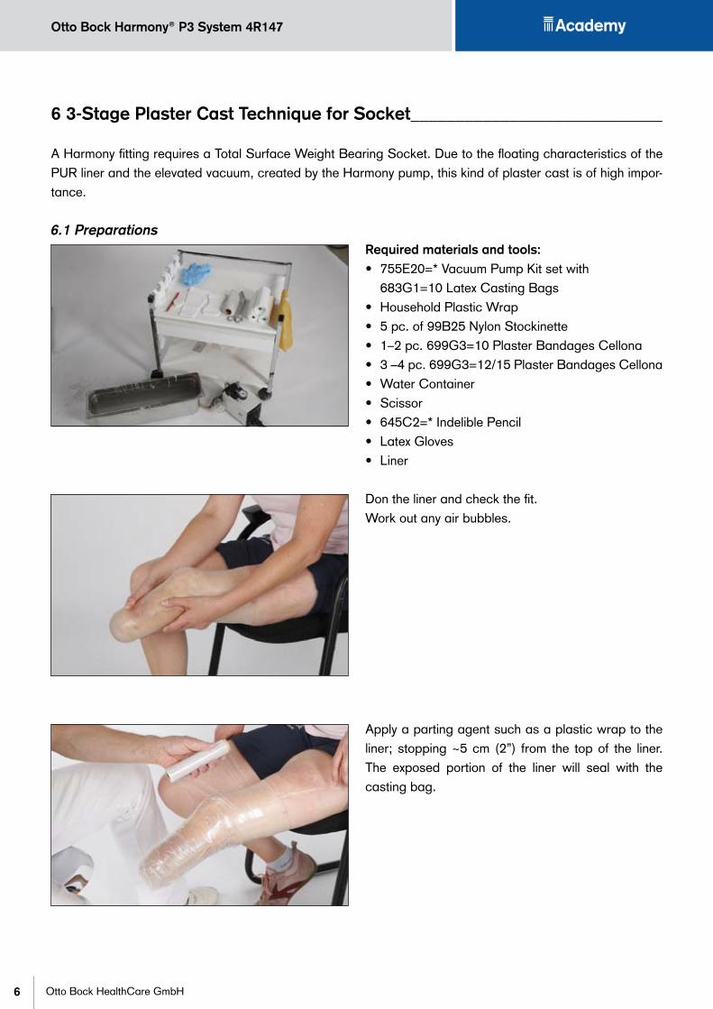
6.1 PreparationsRequired materials and tools:• 755E20=* Vacuum Pump Kit set with
683G1=10 Latex Casting Bags • Household Plastic Wrap• 5 pc. of 99B25 Nylon Stockinette• 1–2 pc. 699G3=10 Plaster Bandages Cellona• 3 –4 pc. 699G3=12/15 Plaster Bandages Cellona• Water Container• Scissor• 645C2=* Indelible Pencil • Latex Gloves• Liner
Don the liner and check the fit. Work out any air bubbles.
Apply a parting agent such as a plastic wrap to the liner; stopping ~5 cm (2”) from the top of the liner. The exposed portion of the liner will seal with the casting bag.
7
Otto Bock Harmony® P3 System 4R147
Otto Bock HealthCare GmbH
Apply a Nylon Stockinette 99B25. Indicate MPT line, patella and prominent spots such as the tibia and fibular head if wanted. Mark the distal end of the Tibia.
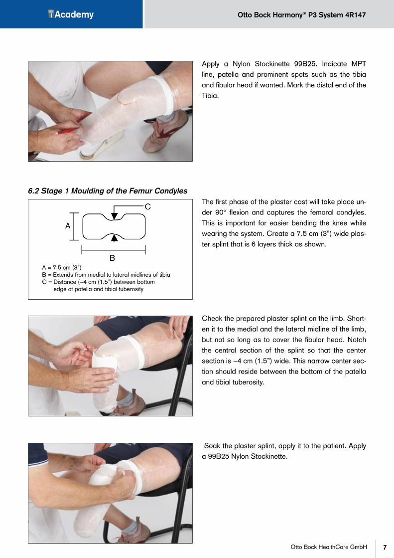
6.2 Stage 1 Moulding of the Femur CondylesThe first phase of the plaster cast will take place un-der 90° flexion and captures the femoral condyles. This is important for easier bending the knee while wearing the system. Create a 7.5 cm (3”) wide plas-ter splint that is 6 layers thick as shown.
Check the prepared plaster splint on the limb. Short-en it to the medial and the lateral midline of the limb, but not so long as to cover the fibular head. Notch the central section of the splint so that the center section is ~4 cm (1.5”) wide. This narrow center sec-tion should reside between the bottom of the patella and tibial tuberosity.
Soak the plaster splint, apply it to the patient. Apply a 99B25 Nylon Stockinette.
A = 7.5 cm (3”)B = Extends from medial to lateral midlines of tibiaC = Distance (~4 cm (1.5”) between bottom
edge of patella and tibial tuberosity

Otto Bock Harmony® P3 System 4R147
8 Otto Bock HealthCare GmbH
Pull on the appropriate Latex Casting Bag, seal it proximally and connect the vacuum line. Make sure that the distal opening of the bag has contact with the Nylon Stockinette. Turn on the casting pump and control the level is at least 15" Mg (500 mbar).Don´t worry about the folds in the bag. They will not affect the quality of the cast.
Very lightly press the splint to define the bottom edge of the patella. This is not a PTB bar. It is strictly a way of making sure the bottom edge of the patella is identifiable in the final cast. Vacuum cast the splint, with the knee in 90° of flexion. Seal the bag with the proximal section of the liner. Once the plaster sets, make sure the splint stays in position as you remove the casting bag and the Stockinette.
6.3 Stage 2 Moulding the TibiaThe second phase is meant to capture the tibial crest and the head of the fibula. Cut a second 4 lay-er splint as shown in the following picture. Its width should extend from the medial to lateral midlines of the limb except in the area of the fibular head; in this area the splint should extend posteriorly to capture the entire head of the fibula. Do not extend the splint into the soft tissues posteriorly. The height of the splint should allow it to extend from the center of the patella down to just proximal to the end of the tibia.
The tibia splint should be terminated about 1 cm proximally from the end of the tibia. This ensures the correct anterior positioning of distal soft tissue while the plaster bandage is wrapped circumferentially. Pull on one Nylon Stockinette.
A = Center of patella down to 3-6 mm (1/8-1/4”) proximal of the end of the tibia
B = from medial to lateral midlines
C = Extension to capture fibu-lar head

9
Otto Bock Harmony® P3 System 4R147
Otto Bock HealthCare GmbH
Pull on the appropriate Latex Casting Bag and con-nect the vacuum line. Draw vacuum and let the splint set while the knee is flexed about at 10°. Remove the casting bag and the Nylon stockinette.Keep the tibia splint in place.
6.4 Stage 3 Volume CastPhase 3 captures the limb volume. With the knee still at 5–10° of flexion, plaster wrap the entire limb with 2–3 Cellona bandages.
Pull on 3 layers of Nylon Stockinette and the Latex Casting Bag. Leave a couple cm of extra Stockinette at distal end to achieve better vacuum. Seal off prox-imally by hand or with Vulkollan® Elastic Band and turn on the vacuum. Allow the plaster to harden.
INFORMATIONAsk the user at the beginning of taking the plas-ter cast to contract his muscles. If the limb chang-es his shape dramatically ask the user to also con-tract and relax alternately during the setting of the plaster.
NOTICE
Important: Make sure that the distal opening of the bag has full contact to the Nylon Stockinette.
After setting remove the cast and fill with plaster.

Otto Bock Harmony® P3 System 4R147
10 Otto Bock HealthCare GmbH
7 Fabricating the Plaster Model ���������������������������������������
In order to follow the principle of the Total Surface Weight Bearing Socket, there will be no specific modifica-tion of the cast model. The model has to be reduced globally.
7.1 PreparationsRequired materials and tools:• 645C2=* Indelible Pencil • Tape Measure• Sheet of Paper• Reduction Chart (see appendix)• 716Y3 Half Round Rasp• 716Y4 Full Round Rasp• 649G22=180 Grit Cloth
7.2 Modifying the Plaster ModelIdentify and mark reference points for the circum-ferencial and length measurements. Take circum-ference and length measurements of the model. Document the measurements in the plaster model re-duction worksheet (see Appendix page 36).
Divide the model into four sections (anterior, posteri-or, medial and lateral). Point out the convex and con-cave shapes by drawing horizontal lines. This is im-portant to keep your concentration on the individual shape of every limb section.

11
Otto Bock Harmony® P3 System 4R147
Otto Bock HealthCare GmbH
Check the circumference measurements on the plas-ter model. Perform a global circumferential reduction of 4–6%. Reduce the length by 5–8 mm No other modifications to the shape of the cast are necessary. Make sure that the reduction is uniform and the re-sidual limb shape remains unchanged.
CAUTIONHealth risk as a result of using incorrect pros-thetic socket design. Never use a specific weight bearing socket with Harmony®. Doing so would cause skin irritation and/or Liner breakdown.
After modifiying and smoothing the model, draw the trim line of the socket. All trim lines are measured from a circumferential reference line drawn at the height of the MPT line. At the anterior it is about 3.5 cm (1.5”) above the reference line, medial and later-al about 6.5 cm (2.5”) above.
For hamstring relief, measure and mark two points 6 mm (¼”) below the reference line, one for each hamstring. In the middle, the trim line is about 6 mm (¼”) above this reference line.

Otto Bock Harmony® P3 System 4R147
12 Otto Bock HealthCare GmbH
8 Fabricating the Check Socket ���������������������������������������
To create a good fit, a transparent check socket is mandatory. It allows you to ‚view‘ the fit by letting you see skin colour and how the liner floats.
8.1 Check Socket based on Plaster Model8.1.1 Preparations
Required materials:• Vacuum Pipe with Disk and Respective Vacuum
Forming Insert• 616T52=* ThermoLyn® Stiff or
616T83=* ThermoLyn® Clear • 641H3 Thermal Gloves• Oscillating Saw• Plaster Model with 99B25 Nylon Stockinette
8.1.2 Draping of the Check SocketDrape the check socket made from Thermolyn stiff or clear as usual. Transfer the drawings of the trim line to the plastic mold. Once the material is cold cut it along the line.
8.1.3 Finish of the Check SocketDrill a hole (Ø 7.5 mm or 0.27”) where the socket connector will be placed later. Remove the socket and grind to desired trim line. Polish the socket brim.
INFORMATIONMake sure to remove any burrs from inside of sock-et after drilling
8.2 Check Socket based on TT Design Software

13
Otto Bock Harmony® P3 System 4R147
Otto Bock HealthCare GmbH
9 Volume Check �����������������������������������������������������
This step describes how to attain the correct socket fit. The floating effect of the liner and the colour of the skin are indicators for correct fit.
9.1 PreparationsRequired materials:• 743A11 Plaster Apparatus• Check Socket• Liner• Permanent Marker• 451F20 FitKit• 453H1=1 Sliding Creme or 453H26 Sensi Care
Lotion
On each side of the liner (the anterior, posterior, me-dial and lateral), make at least 3 dots with the per-manent marker that are in line and distributed at equal distances.
Place the liner in the socket and make circles on the check socket so that they encompass the dots indi-cated on the liner. The distal hole allows air to exit the socket.
Otto Bock Harmony® P3 System 4R147
14 Otto Bock HealthCare GmbH
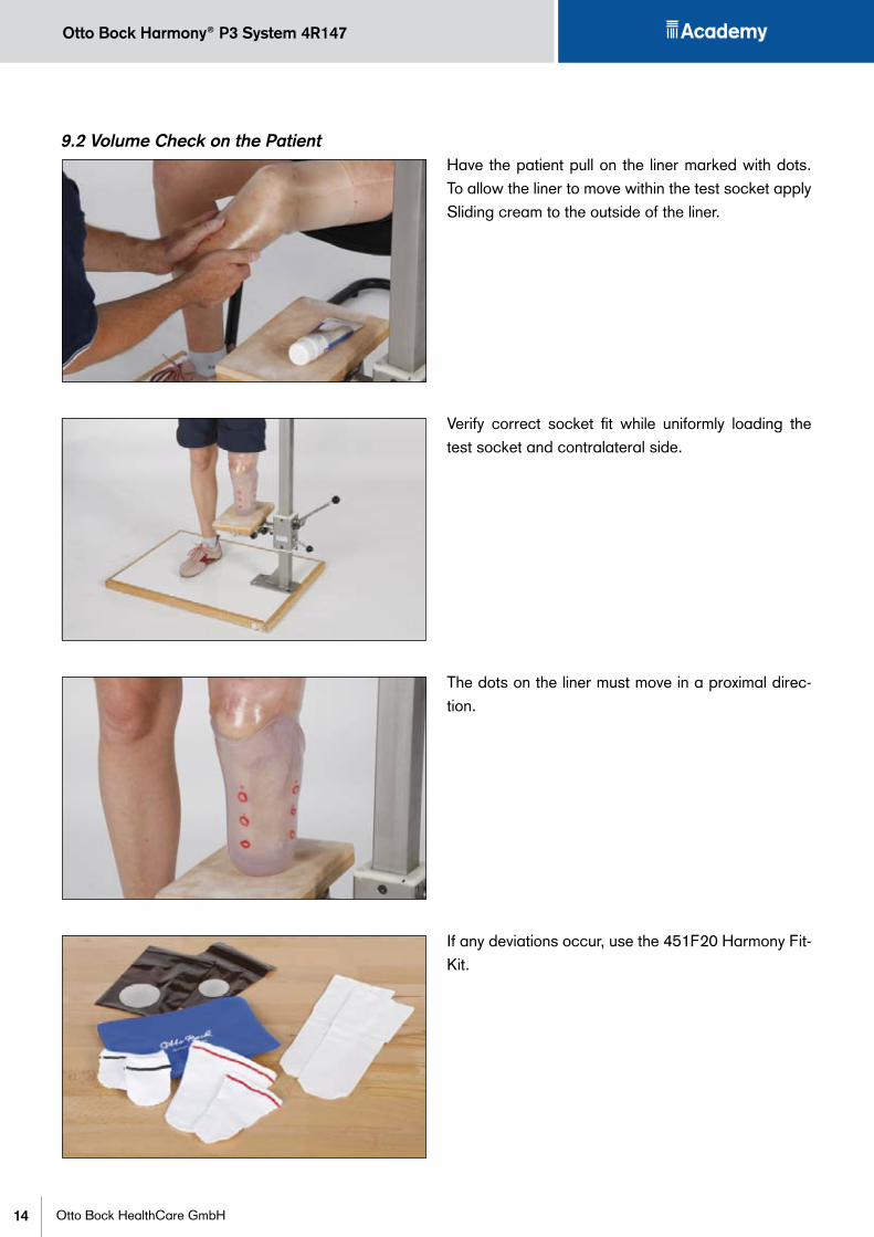
9.2 Volume Check on the PatientHave the patient pull on the liner marked with dots. To allow the liner to move within the test socket apply Sliding cream to the outside of the liner.
Verify correct socket fit while uniformly loading the test socket and contralateral side.
The dots on the liner must move in a proximal direc-tion.
If any deviations occur, use the 451F20 Harmony Fit-Kit.
15
Otto Bock Harmony® P3 System 4R147
Otto Bock HealthCare GmbH
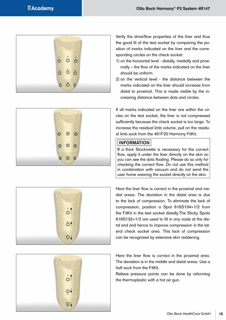
Verify the drive/flow properties of the liner and thus the good fit of the test socket by comparing the po-sition of marks indicated on the liner and the corre-sponding circles on the check socket:1) on the horizontal level - distally, medially and proxi-
mally – the flow of the marks indicated on the liner should be uniform.
2) on the vertical level - the distance between the marks indicated on the liner should increase from distal to proximal. This is made visible by the in-creasing distance between dots and circles.
If all marks indicated on the liner are within the cir-cles on the test socket, the liner is not compressed sufficiently because the check socket is too large. To increase the residual limb volume, pull on the residu-al limb sock from the 451F20 Harmony FitKit.
INFORMATIONIf a thick Stockinette is necessary for the correct flow, apply it under the liner directly on the skin so you can see the dots floating. Please do so only for checking the correct flow. Do not use this method in combination with vacuum and do not send the user home wearing the socket directly on the skin.
Here the liner flow is correct in the proximal and me-dial areas. The deviation in the distal area is due to the lack of compression. To eliminate the lack of compression, position a Spot 616S134=1/2 from the FitKit in the test socket distally.The Sticky Spots 616S132=1/2 are used to fill in any voids at the dis-tal end and hence to improve compression in the lat-eral check socket area. This lack of compression can be recognized by extensive skin reddening.
Here the liner flow is correct in the proximal area. The deviation is in the middle and distal areas. Use a half sock from the FitKit. Relieve pressure points can be done by reforming the thermoplastic with a hot air gun.
Otto Bock Harmony® P3 System 4R147
16 Otto Bock HealthCare GmbH
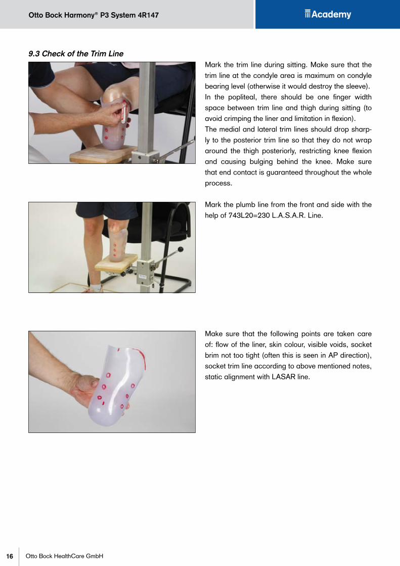
9.3 Check of the Trim LineMark the trim line during sitting. Make sure that the trim line at the condyle area is maximum on condyle bearing level (otherwise it would destroy the sleeve). In the popliteal, there should be one finger width space between trim line and thigh during sitting (to avoid crimping the liner and limitation in flexion).The medial and lateral trim lines should drop sharp-ly to the posterior trim line so that they do not wrap around the thigh posteriorly, restricting knee flexion and causing bulging behind the knee. Make sure that end contact is guaranteed throughout the whole process.
Mark the plumb line from the front and side with the help of 743L20=230 L.A.S.A.R. Line.
Make sure that the following points are taken care of: flow of the liner, skin colour, visible voids, socket brim not too tight (often this is seen in AP direction), socket trim line according to above mentioned notes, static alignment with LASAR line.

17
Otto Bock Harmony® P3 System 4R147
Otto Bock HealthCare GmbH
10 Bench Alignment �������������������������������������������������In this section we‘ll describe how to perform the bench alignment. Align the socket according to known scien-tific studies as well as the instructions for use for the prosthetic foot.
10.1 Materials• Socket• Socket Adapter• 4R1 Sliding Adapter• Tube Adapter• Foot• LASAR Line• Permanent Marker• Rule• Heel Pad• 709S15=4 Allen Screw Driver
Bench alignment of a prothesis based on an example with socket attachment block 5R1=6, sliding adapter 4R1, tube adapter and C-Walk foot 1C40. Using the 4R1 sliding adapter in combination with the 743L100 L.A.S.A.R. Posture is recommenda-tion of Otto Bock. If the alignment is known, the Har-mony® unit can be used instead of the 4R1 sliding adapter. The 6A94=3 TEC plate can also be used instead of the socket attachment block 5R1=6.
10.2 Attaching the Socket ConnectorFix the 2R117=0 socket connector to the socket ac-cording to the IFU.
INFORMATIONIf the mentioned PUR glue is not available, use 2-component-epoxy-glue (5 minutes working time).

Otto Bock Harmony® P3 System 4R147
18 Otto Bock HealthCare GmbH
Checklist:• Socket connector fixed to the socket• Screws torqued correctly and locked • Check the length of the prosthesis
11 Static Alignment ��������������������������������������������������
Before dynamic trial. Once this is completed, change to the Harmony® P3 unit. To avoid changing the align-ment use 743A160 transfer apparatus.
11.1 Static Alignment with LASAR PostureOtto Bock recommends first to adjust the alignment with the LASAR posture and the sliding adapter. During static alignment suction is created with an ex-pulsion valve (4R136)
11.2 Transfer of the AlignmentThe transfer apparatus helps in changing the pros-thetic components from the sliding adapter…

19
Otto Bock Harmony® P3 System 4R147
Otto Bock HealthCare GmbH
…to the Harmony® unit.
11.3 Adjusting the Harmony® P3 UnitUse the following selection table to select the right Functional Ring. The Functional Ring version is marked on the intake valve receiver. Please note that the recommendations do not necessarily repre-sent the optimal selection for the patient. When de-viating from the selection data, the Functional Ring with the highest possible stiffness should be select-ed that nevertheless still creates a sufficient vacuum. Otto Bock recommends that a vacuum of approx. 500 mbar (15 inHg) or more should be reached with-in 50 steps with the prosthesis.
If the patient feels like they are “bottoming out”, a stiffer Functional Ring should be used. If the pump does not reach a sufficient vacuum level, a softer Functional Ring should be used.
Body Weightkg 45-50 50-60 60-73 73-86 86-100lbs 100-110 110-130 130-160 160-190 190-220
Recommended Functional Ring 0 1 2 3 4

Otto Bock Harmony® P3 System 4R147
20 Otto Bock HealthCare GmbH
Preparing the Functional Ring for initial use prior to its first use, Otto Bock recommends that separately ordered Functional Rings should be pre-compressed with the separately available Pre-compression Tool 4X247 to ensure proper function. Without pre-com-pression, new Functional Rings can be overly stiff. If using the pre-installed Functional Ring or an already pre-compressed unit please continue with step 6.a) Open the Pre-compression Tool.b) Place the Functional Ring in the Pre-compression
Tool.c) Completely compress the Functional Ring by tight-
ening the screw completely.d) Compression time: Minimum 3 minutes to a maxi-
mum of 15 minutes.e) Open the Pre-compression Tool remove the Func-
tional Ring and install it in the pump.
11.4 Change of the Functional RingRemove the tube adapter with foot. Loosen the retaining screw on the distal end of the Base and remove it (Step 1).Pull the Base away from the Shaft (Step 2).
2
1

21
Otto Bock Harmony® P3 System 4R147
Otto Bock HealthCare GmbH
Pull off the installed Functional Ring (Step 3).
Slide the pre-compressed functional ring over the shaft, as described on page 20) (step 4). This is only possible in one direction due to the structure of the ring. Reassemble the pump (step 5&6), secure the retaining screw with 636K13 Loctite® 241 and tight-en it clockwise with 7 Nm (60 in-lbs), reassemble prosthesis. For the fine tuning refer to the IFU.
3
4
5
6

Otto Bock Harmony® P3 System 4R147
22 Otto Bock HealthCare GmbH
12 Dynamic Trial
CAUTIONRisk of falling! The Test Prosthesis may only be used under supervision of the orthopedic technician. The orthopedic technician should use his or her professional judgment to determine whether the patient can be sent home with the test prosthesis for an extended trial fitting.
12.1 PreparationsSecure the connection of the socket to the modular system with a Cellacast xtra® rigid Bandage.Check the seal:1) “T” in the vacuum gauge as shown.2) Place a small piece of paper over the expulsion
port inside the socket. Seal the port by placing a piece of pressure sensitive tape over the piece of paper and port. Create vacuum and confirm that vacuum is maintained over 2–3 minutes. If not please see trouble shooting table under Chap. 16.
12.2 Trial FittingHave the patient don the liner and sheath followed by the test prosthesis. Reflect the sheath back over the socket brim. Then pull on the gel-coated Otto Bock knee sleeve.
12.3 Information for the user during trial fittingEducate the user to:• check socket fit every morning• feel the vacuum• use the 451F20 Fitkit• read the user’s broschure (647G416=*)
PUR* Liner Protectsenduser‘slimbSheath Makesiteasytoslideinto
thesocketandcreatesairspaceforthevacuum
Harmony® Socket TheconnectiontotheprosthesisGaiter (optional) Protectsthesleeve
fromsocketedges Sleeve Sealsthevacuumairspace
*Polyurethane
Socket Connector Connectsthepumptothesocket’sairspace
Harmony® P3 Createsanelevatedvacuuminthesockettoimprovesuspensi-onandmanagelimbvolume

23
Otto Bock Harmony® P3 System 4R147
Otto Bock HealthCare GmbH
Checklist:• Check seal between socket adapter and socket.• Check torques settings and Loctite screws.• Check alignment based on LASAR posture.• Make sure user´s training has been adequate.
13 Fabrication of the Definitive Socket ���������������������������������
For fabricating the definitive socket: laminate as usual, maintain the alignment, and seal the inner side of the socket. If desired, a sleeve protector can be laminated.Any FitKit elements used in the Check socket have to be removed before starting fabrication. The plaster model has to be changed according to the spacers used. A thick Stockinette needs 5 mm reduc-tion cirumferentially. A spot requires 2 mm reduction locally. If you’ve used three spacing elements it’s time to make a new check socket!
13.1 Transfer of the AlignmentThe alignment of the trial prosthesis is transferred to the Transfer Apparatus 743A16 for the Harmony® components. Mount the foot adapter into the adapter ring of the Transfer Apparatus. Fix the vacuum tube in the check socket by pouring the plaster. Cut off the test socket and prepare the plaster model for lamination of the lamination socket.
Otto Bock Harmony® P3 System 4R147
24 Otto Bock HealthCare GmbH
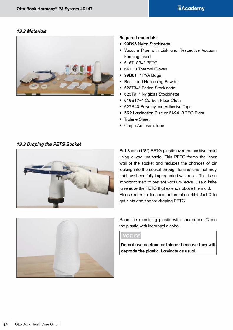
13.2 MaterialsRequired materials: • 99B25 Nylon Stockinette• Vacuum Pipe with disk and Respective Vacuum
Forming Insert• 616T183=* PETG • 641H3 Thermal Gloves• 99B81=* PVA Bags• Resin and Hardening Powder• 623T3=* Perlon Stockinette• 623T9=* Nylglass Stockinette• 616B17=* Carbon Fiber Cloth• 627B40 Polyethylene Adhesive Tape• 5R2 Lamination Disc or 6A94=3 TEC Plate• Trolene Sheet• Crepe Adhesive Tape
13.3 Draping the PETG SocketPull 3 mm (1/8”) PETG plastic over the positive mold using a vacuum table. This PETG forms the inner wall of the socket and reduces the chances of air leaking into the socket through laminations that may not have been fully impregnated with resin. This is an important step to prevent vacuum leaks. Use a knife to remove the PETG that extends above the mold.Please refer to technical information 646T4=1.0 to get hints and tips for draping PETG.
Sand the remaining plastic with sandpaper. Clean the plastic with isopropyl alcohol.
NOTICE
Do not use acetone or thinner because they will degrade the plastic. Laminate as usual.
25
Otto Bock Harmony® P3 System 4R147
Otto Bock HealthCare GmbH
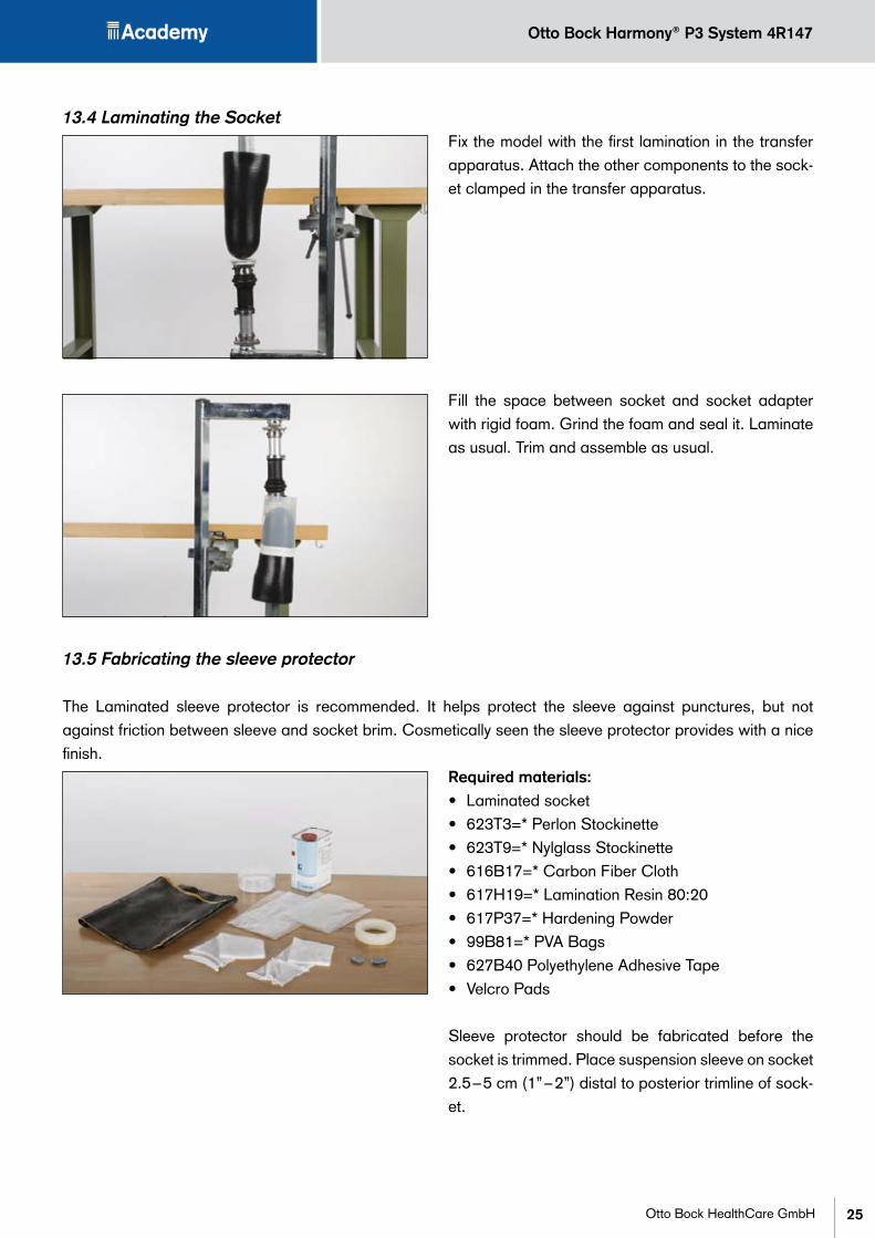
13.4 Laminating the SocketFix the model with the first lamination in the transfer apparatus. Attach the other components to the sock-et clamped in the transfer apparatus.
Fill the space between socket and socket adapter with rigid foam. Grind the foam and seal it. Laminate as usual. Trim and assemble as usual.
13.5 Fabricating the sleeve protector
The Laminated sleeve protector is recommended. It helps protect the sleeve against punctures, but not against friction between sleeve and socket brim. Cosmetically seen the sleeve protector provides with a nice finish.
Required materials:• Laminated socket• 623T3=* Perlon Stockinette• 623T9=* Nylglass Stockinette• 616B17=* Carbon Fiber Cloth• 617H19=* Lamination Resin 80:20• 617P37=* Hardening Powder• 99B81=* PVA Bags• 627B40 Polyethylene Adhesive Tape• Velcro Pads
Sleeve protector should be fabricated before the socket is trimmed. Place suspension sleeve on socket 2.5 – 5 cm (1” – 2”) distal to posterior trimline of sock-et.
Otto Bock Harmony® P3 System 4R147
26 Otto Bock HealthCare GmbH
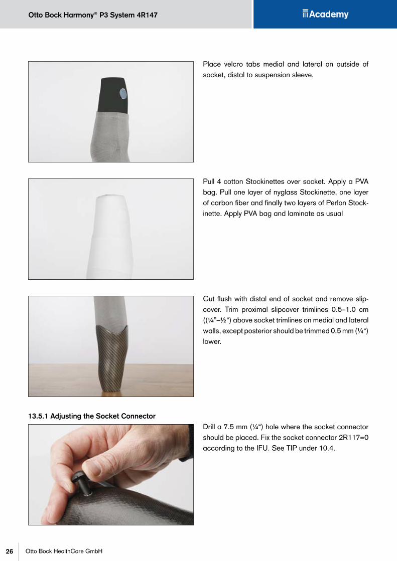
Place velcro tabs medial and lateral on outside of socket, distal to suspension sleeve.
Pull 4 cotton Stockinettes over socket. Apply a PVA bag. Pull one layer of nyglass Stockinette, one layer of carbon fiber and finally two layers of Perlon Stock-inette. Apply PVA bag and laminate as usual
Cut flush with distal end of socket and remove slip-cover. Trim proximal slipcover trimlines 0.5–1.0 cm ((¼”–½“) above socket trimlines on medial and lateral walls, except posterior should be trimmed 0.5 mm (¼“) lower.
13.5.1 Adjusting the Socket ConnectorDrill a 7.5 mm (¼“) hole where the socket connector should be placed. Fix the socket connector 2R117=0 according to the IFU. See TIP under 10.4.
27
Otto Bock Harmony® P3 System 4R147
Otto Bock HealthCare GmbH
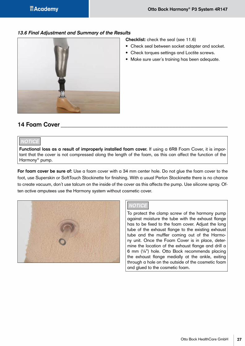
13.6 Final Adjustment and Summary of the Results Checklist: check the seal (see 11.6)• Check seal between socket adapter and socket.• Check torques settings and Loctite screws.• Make sure user´s training has been adequate.
14 Foam Cover ������������������������������������������������������
NOTICE
Functional loss as a result of improperly installed foam cover. If using a 6R8 Foam Cover, it is impor-tant that the cover is not compressed along the length of the foam, as this can affect the function of the Harmony® pump.
For foam cover be sure of: Use a foam cover with a 34 mm center hole. Do not glue the foam cover to the foot, use Superskin or SoftTouch Stockinette for finishing. With a usual Perlon Stockinette there is no chance to create vacuum, don´t use talcum on the inside of the cover as this affects the pump. Use silicone spray. Of-ten active amputees use the Harmony system without cosmetic cover.
NOTICE
To protect the clamp screw of the harmony pump against moisture the tube with the exhaust flange has to be fixed to the foam cover. Adjust the long tube of the exhaust flange to the existing exhaust tube and the muffler coming out of the Harmo-ny unit. Once the Foam Cover is in place, deter-mine the location of the exhaust flange and drill a 6 mm (¼”) hole. Otto Bock recommends placing the exhaust flange medially at the ankle, exiting through a hole on the outside of the cosmetic foam and glued to the cosmetic foam.

Otto Bock Harmony® P3 System 4R147
28 Otto Bock HealthCare GmbH
15 Information for the End User ���������������������������������������
15.1 Donning the SystemApply small amount of sliding cream direct on the skin. Invert liner. Place liner at front of limb. Without tugging on edge of liner, roll up over limb.
Starting from bottom, apply pressure and slide hands up liner, to remove any air bubbles.
Pull sheath up over liner, leaving about 5 cm (2“) of liner exposed.
Your prosthetist will draw a mark on liner. Confirm that socket is lined up to mark.
29
Otto Bock Harmony® P3 System 4R147
Otto Bock HealthCare GmbH
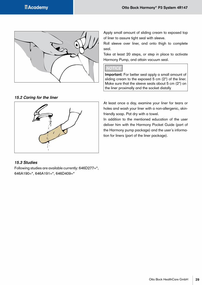
Apply small amount of sliding cream to exposed top of liner to assure tight seal with sleeve.Roll sleeve over liner, and onto thigh to complete seal.Take at least 20 steps, or step in place to activate Harmony Pump, and attain vacuum seal.
NOTICE
Important: For better seal apply a small amount of sliding cream to the exposed 5 cm (2“) of the liner. Make sure that the sleeve seals about 5 cm (2“) on the liner proximally and the socket distally
15.2 Caring for the linerAt least once a day, examine your liner for tears or holes and wash your liner with a non-allergenic, skin-friendly soap. Pat dry with a towel.In addition to the mentioned education of the user deliver him with the Harmony Pocket Guide (part of the Harmony pump package) and the user´s informa-tion for liners (part of the liner package).
15.3 StudiesFollowing studies are available currently: 646D277=*, 646A190=*, 646A191=*, 646D409=*

Otto Bock Harmony® P3 System 4R147
30 Otto Bock HealthCare GmbH
16 Trouble Shooting �������������������������������������������������
Cover the hole on the inside of the socket with a small piece of paper and tape that is not airpermeable (such as PVC tape). Cycle the pump until a vacuum of 508–847mbar (15-25 inHg) is reached. Check if vacuum level is maintained when the pump is not being cycled.
Vacuum maintained: Zone 2 and 3 are OK
Examine Zone 1 (sock-et and sleeve) for any leaks
Vacuum not maintained: Problem exists in Zone 2 or Zone 3
With T-Connector removed, attach the Vacuum Gauge directly to the Intake Valve and cycle the pump until
508–847 mbar (15-25 inHg) is reached. Check if vacuum level is maintained when the pump is not being cycled.
Vacuum maintained: Zone 3 is OK
Problem is in the Socket Connector or in its bonding with the socket. Examine for leaks or damage.
Vacuum not maintained: Problem exists in the Valves or
Functional Ring
Exchange Valves and check again
Vacuum maintained: Replace the Valves
Vacuum not maintained: Prob-lem exists in the Functional Ring
Replace the Functional Ring
1
2
3

31
Otto Bock Harmony® P3 System 4R147
Otto Bock HealthCare GmbH
16.1 Harmony® Troubleshooting Table for the Prosthetist
Problem Reason Solution
Knee
Bulging behind knee Medial and lateral trim lines curve around too far posteriorly. This can squeeze the liner and limb posteriorly.
• Trim them so that they curve around less posteriorly.
Socket is too tight. • Limit how much is removed from the positive mold when blending from the reduced to the unreduced portion of mold.
Posterior trim line is too low. • Keep the top-center and two low points of the posterior “W” trim lines as high as possible without restricting knee flexion to 90°. Your finger should not get pinched at these three points as the knee is flexed and the hamstrings tensed.
Patient is wearing too many full socks. • If the patient has to wear two or more full socks to compensate for volume loss, a new socket should be made.
Difficult to flex knee The posterior trim line is too high. If the trim line is too high it will “dig” into the back of the knee when flexed.
• Keep the top-center and two low points of the posterior “W” trim lines as high as possible without restricting knee flexion to 90°. Your finger should not get pinched at these three points as the knee is flexed and the hamstrings tensed.
Medial and lateral trim lines curve around too far posteriorly.
• Trim them so that they curve around less posteriorly.
Hamstring reliefs are not aligned with the tendons.
• Palpate the tensed hamstring tendons and adjust the shapes of the reliefs so that the tendons align with the bottoms of the “W”.
Patient is wearing too many full socks. • If the patient has to wear two or more full socks to compensate for volume loss, a new socket should be made.
Suspension sleeve is too small. A small, tight sleeve is not recommended since it can impede knee flexion.
• Select a larger size suspension sleeve for the patient. Select a size that will seal with the top of the liner and socket, but no smaller.
2 – stage plaster cast is taken. The condyles don´t have enough space while flexing the knee
• Take a new plaster cast as described in this information.
Anterior trim line is too high. This causes the sleeve to stretch restrict flexion.
• Lower the anterior trim line to 1/3 to 1/2 of the way up from the bottom of the patella.
Limb
Red marks on skin Loss of vacuum. Without vacuum the limb will piston, causing skin irritation.
• Check the patient’s vacuum with a gauge to be sure it is >51 kPa (15” Hg). Restore it if lost.
• Instruct your patients how to determine whether they have vacuum and how to restore it if lost. See “Harmony Pocket Guide” .
Specific weight bearing structures are creating high pressure points.
• NEVER use a specific weight bearing socket with Harmony®. To do so would be negligent prosthetic care. The socket must be a true TSWB socket, without ANY specific weight bearing structures. Do NOT incorporate a PTB bar, or tibial flare or tibial plateau supports.
Limb being pulled into a void. • Do not build a relief into the socket. It must be total surface weight bearing.
• When a patient compensates for limb volume loss, s/he should always first try adding a distal spot and/or half sock. Use of a full sock can cause the limb to hang proximally and create a distal void.
The limb is sliding in the liner. • See the “Sliding in liner” section of this Troubleshooting table.

Otto Bock Harmony® P3 System 4R147
32 Otto Bock HealthCare GmbH
Problem Reason Solution
Limb (continued)
Red welt on thigh at top of the liner
Patient is wearing a cloth covered liner. There is a narrow air space at the top edge of the liner. The cloth cover extends the vacuum up to the thigh, causing a welt to form at the top edge of the liner.
• NEVER have your patient wear a cloth covered liner with Harmony®.
Patient has pulled the sheath up over the top of the liner. This is exactly the same as wearing a cloth covered liner.
• Train your patient to pull the sheath up 2” (5 cm) short of the top of the liner. This will leave the top 2” (5 cm) of the liner exposed to seal with the sleeve and prevent the vacuum from extending up to the thigh.
Blisters Air was not removed from the liner during donning. Air between the liner and limb is usually the cause of blisters.Liner or sleeve is too loose on the thigh. This allows air to leak into the liner.
• Instruct the patient how to properly remove all air from the liner during donning.
• Use a custom urethane liner and properly sized sleeve.• If you use an off-the-shelf urethane liner, make sure that it
fits the entire limb (including the thigh) snugly.White, thickened skin distally
A distal void is creating low pressure on the limb.
• Add a distal spot(s) and/or half sock.• If after several weeks the skin thins and regains its normal
color, a new socket may need to be made.Distal pressure Distal pressure is usually caused by
the limb losing volume distally. This creates a distal void. The vacuum pulls the liner and limb into the void and gives the patient the sensation of pressure. This sensation is often misinterpreted as bottoming out in the socket.
• Check to see if the medial and lateral marks on the liner have fallen below the edge of the socket. If they have, this confirms that the limb has lost volume, causing the liner to recede into the socket.
• If the patient is losing limb volume daily, it is almost certain that s/he does NOT have vacuum. Without vacuum the limb loses volume. Check that the vacuum is >51 kPa (15” Hg) before bothering to compensate for limb volume loss. If vacuum is lost, restore it.
• Once you know the patient has vacuum, add a distal spot and/or a half sock under the sheath. This should relieve the pressure and raise the marks on the liner to the edge of the socket.
• If these distal fillers increased the pressure, the patient has probably lost volume globally and has settled into the bottom of the socket. Remove the distal fillers and see the next row in this table.
Since adding a distal spot and/or half socket made the pressure worse, the limb has probably lost volume globally and settled into the bottom of the socket which is now bearing a large portion of the patient’s weight. Global pressure needs to be restored.
• Check to see if the medial and lateral marks on the liner have fallen below the edge of the socket. If they have, this confirms that the limb has lost volume.
• If the patient is losing limb volume daily, it is almost certain that s/he does NOT have vacuum. Without vacuum the limb loses volume. Check that the vacuum is >51 kPa (15” Hg) before bothering to compensate for limb volume loss. If vacuum is lost, restore it.
• Once you know the patient has vacuum, have the patient wear one full sock under the sheath. If the liner marks become visible and the pressure is relieved, try adding a distal spot and/or half sock in addition to the full sock just in case the full sock caused the limb to hang proximally and create a distal void. If the spot or half sock re-introduces pressure, remove it and just use the full sock.
• If more than 2-3 fillers (spots and/or socks) are needed to create a snug, comfortable fit and make the liner marks visible, it may be time for a new socket.
33
Otto Bock Harmony® P3 System 4R147
Otto Bock HealthCare GmbH
Problem Reason Solution
Limb (continued)
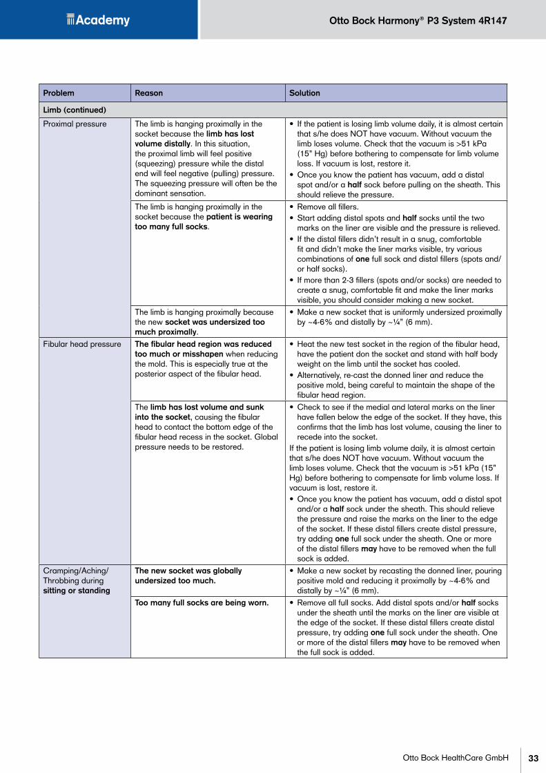
Proximal pressure The limb is hanging proximally in the socket because the limb has lost volume distally. In this situation, the proximal limb will feel positive (squeezing) pressure while the distal end will feel negative (pulling) pressure. The squeezing pressure will often be the dominant sensation.
• If the patient is losing limb volume daily, it is almost certain that s/he does NOT have vacuum. Without vacuum the limb loses volume. Check that the vacuum is >51 kPa (15” Hg) before bothering to compensate for limb volume loss. If vacuum is lost, restore it.
• Once you know the patient has vacuum, add a distal spot and/or a half sock before pulling on the sheath. This should relieve the pressure.
The limb is hanging proximally in the socket because the patient is wearing too many full socks.
• Remove all fillers. • Start adding distal spots and half socks until the two
marks on the liner are visible and the pressure is relieved.• If the distal fillers didn’t result in a snug, comfortable
fit and didn’t make the liner marks visible, try various combinations of one full sock and distal fillers (spots and/or half socks).
• If more than 2-3 fillers (spots and/or socks) are needed to create a snug, comfortable fit and make the liner marks visible, you should consider making a new socket.
The limb is hanging proximally because the new socket was undersized too much proximally.
• Make a new socket that is uniformly undersized proximally by ~4-6% and distally by ~¼” (6 mm).
Fibular head pressure The fibular head region was reduced too much or misshapen when reducing the mold. This is especially true at the posterior aspect of the fibular head.
• Heat the new test socket in the region of the fibular head, have the patient don the socket and stand with half body weight on the limb until the socket has cooled.
• Alternatively, re-cast the donned liner and reduce the positive mold, being careful to maintain the shape of the fibular head region.
The limb has lost volume and sunk into the socket, causing the fibular head to contact the bottom edge of the fibular head recess in the socket. Global pressure needs to be restored.
• Check to see if the medial and lateral marks on the liner have fallen below the edge of the socket. If they have, this confirms that the limb has lost volume, causing the liner to recede into the socket.
If the patient is losing limb volume daily, it is almost certain that s/he does NOT have vacuum. Without vacuum the limb loses volume. Check that the vacuum is >51 kPa (15” Hg) before bothering to compensate for limb volume loss. If vacuum is lost, restore it.• Once you know the patient has vacuum, add a distal spot
and/or a half sock under the sheath. This should relieve the pressure and raise the marks on the liner to the edge of the socket. If these distal fillers create distal pressure, try adding one full sock under the sheath. One or more of the distal fillers may have to be removed when the full sock is added.
Cramping/Aching/Throbbing during sitting or standing
The new socket was globally undersized too much.
• Make a new socket by recasting the donned liner, pouring positive mold and reducing it proximally by ~4-6% and distally by ~¼” (6 mm).
Too many full socks are being worn. • Remove all full socks. Add distal spots and/or half socks under the sheath until the marks on the liner are visible at the edge of the socket. If these distal fillers create distal pressure, try adding one full sock under the sheath. One or more of the distal fillers may have to be removed when the full sock is added.

Otto Bock Harmony® P3 System 4R147
34 Otto Bock HealthCare GmbH
Problem Reason Solution
Limb (continued)
Cramping/Aching/Throbbing during walking
Patient did not tense the calf muscles during stage 3 when casting for the socket.
• Have the patient doff the system. Cup the limb with both hands and have the patient contract the calf muscles. If this noticeably changes the shape of the limb, re-cast the donned liner while the patient keeps the calf muscles tense and make a new socket.
Inadequate blood flow during walking. • Work through the “Proximal pressure” section in this Troubleshooting table to rule out the possibility that the proximal limb is being squeezed heavily.
• Once you are convinced that the limb is experiencing global, uniform pressure and the patient still feels cramping/aching/throbbing while walking, work with the patient’s physician to determine whether the patient is experiencing ischemia.
Liner tears Specific weight bearing structures were put into the socket. Urethane will tear/split when there is a large difference in pressure. This can be caused by having a high pressure point where the liner is pinned against the socket at a specific spot.
• NEVER fabricate specific weight bearing structures in a Harmony® socket.
Reliefs were built into the socket. Urethane will tear/split when there is a large difference in pressure. This can be caused by creating a relief (low pressure) which will invariably create an adjacent high pressure point.
• NEVER build in reliefs, even at the fibular head and distal tibia.
The patient is using the system without vacuum. This causes the limb to lose volume. The limb will piston and can damage the liner.
• Check the patient’s vacuum with a gauge to be sure it is >51 kPa (15” Hg). Restore it if lost.
• Instruct your patients how to determine whether they have vacuum and how to restore it if lost. See “Harmony Pocket Guide” patient brochure.
The patient is not compensating for limb volume loss. This can cause the limb to piston and the liner to be damaged.
• Instruct the patient how to read the two lines on the liner (“gas gauge”) to determine whether the limb has lost volume and how to use the FitKit™ to compensate for volume. See “Maintaining Vacuum and Fit” patient brochure.
Liner Drive
Recommendations • If you have to add half and/or full socks to obtain proper liner drive, have the patient temporarily wear the socks directly on the limb (under the liner). This will keep all dots and circles visible. Spots and a sheath can remain on the outside of the liner where they belong. The socks should be moved back outside the liner (beneath the sheath) after you have finished checking liner drive.
No drive of liner. Socket is too large. As a result, the liner is not being compressed so there is no proximal flow of the liner (dots).
• Add a spot/half sock and full sock. If several fillers are needed to establish a normal, progressive drive of the liner, make a new uniformly undersized socket.
No drive of distal liner, but drive of proximal liner.
Positive mold was not reduced distally. • Temporarily you could add spot(s) and/or half sock(s).• Reduce the distal end of the mold and pull a new test
socket.Positive mold was reduced too much proximally so the limb is “hanging up” proximally.
• Recast and make sure the proximal circumferential reductions are 4-6% or less.
Patient is wearing a full sock(s) so the limb is “hanging up” proximally. This prevents the liner from contacting the bottom of the socket while compressing the liner proximally.
• Remove the full sock(s). If needed, add spots and/or half socks to create a normal, progressive drive of the liner.
• If this doesn’t create a normal, progressive drive of the liner, fabricate a new test socket.
Distal end of limb lost volume. This will almost certainly occur when first switching to Harmony®.
• Add spots and/or half socks to create a normal, progressive drive of the liner.
35
Otto Bock Harmony® P3 System 4R147
Otto Bock HealthCare GmbH
Problem Reason Solution
Noise
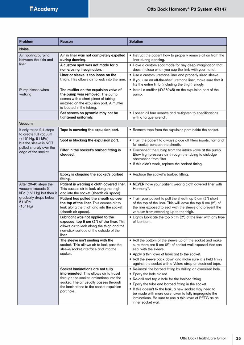
Air rippling/burping between the skin and liner
Air in liner was not completely expelled during donning.
• Instruct the patient how to properly remove all air from the liner during donning.
A custom spot was not made for a non-closing invagination.
• Have a custom spot made for any deep invagination that doesn’t close when you cup the limb with your hand.
Liner or sleeve is too loose on the thigh. This allows air to leak into the liner.
• Use a custom urethane liner and properly sized sleeve.• If you use an off-the-shelf urethane liner, make sure that it
fits the entire limb (including the thigh) snugly.Pump hisses when walking
The muffler on the expulsion valve of the pump was removed. The pump comes with a short piece of tubing installed on the expulsion port. A muffler is located in the tubing.
• Install a muffler (4Y360=5) on the expulsion port of the pump.
Set screws on pyramid may not be tightened uniformly.
• Loosen all four screws and re-tighten to specifications with a torque wrench.
Vacuum
It only takes 2-4 steps to create full vacuum (>15” Hg, 51 kPa) but the sleeve is NOT pulled sharply over the edge of the socket
Tape is covering the expulsion port. • Remove tape from the expulsion port inside the socket.
Spot is blocking the expulsion port. • Train the patient to always place all fillers (spots, half and full socks) beneath the sheath.
Filter in the socket’s barbed fitting is clogged.
• Disconnect the tubing from the intake valve at the pump. Blow high pressure air through the tubing to dislodge obstruction from filter.
• If this didn’t work, replace the barbed fitting.
Epoxy is clogging the socket’s barbed fitting.
• Replace the socket’s barbed fitting.
After 20-40 steps the vacuum exceeds 51 kPa (15” Hg) but then it gradually drops below 51 kPa (15” Hg)
Patient is wearing a cloth covered liner. This causes air to leak along the thigh and into the socket (sheath air space).
• NEVER have your patient wear a cloth covered liner with Harmony®.
Patient has pulled the sheath up over the top of the liner. This causes air to leak along the thigh and into the socket (sheath air space).
• Train your patient to pull the sheath up 5 cm (2") short of the top of the liner. This will leave the top 5 cm (2") of the liner exposed to seal with the sleeve and prevent the vacuum from extending up to the thigh.
Lubricant was not applied to the exposed, top 5 cm (2") of the liner. This allows air to leak along the thigh and the non-stick surface of the outside of the liner.
• Lightly lubricate the top 5 cm (2") of the liner with any type of lubricant.
The sleeve isn’t sealing with the socket. This allows air to leak past the sleeve/socket interface and into the socket.
• Roll the bottom of the sleeve up off the socket and make sure there are 5 cm (2") of socket wall exposed that can seal with the sleeve.
• Apply a thin layer of lubricant to the socket.• Roll the sleeve back down and make sure it is held firmly
against the socket with a Velcro strap or electrical tape.Socket laminations are not fully impregnated. This allows air to travel through the socket laminations into the socket. The air usually passes through the laminations to the socket expulsion port hole.
• Re-install the barbed fitting by drilling an oversized hole.• Epoxy the hole closed.• Re-drill and tap a hole for the barbed fitting.• Epoxy the tube and barbed fitting in the socket.• If this doesn’t fix the leak, a new socket may need to
be made with more care taken to fully impregnate the laminations. Be sure to use a thin layer of PETG as an inner socket wall.

Otto Bock Harmony® P3 System 4R147
36 Otto Bock HealthCare GmbH
17 appendix ��������������������������������������������������������
Plaster Model Reduction Worksheet
Patient Name: �������������������������������������������������������������������������������
Date: ���������������������������������������������������������������������������������������
MarksStarting
Circ (mm)Target Circ
(mm)Starting
Minus TargetRasp
Strokes
A
B
C
D
E
F
G
4% Reduction Chart (mm)Circ 205 210 215 220 225 230 235 240 245 250 255 260 265 270 275 280 285 290 295 300-4% 197 202 206 211 216 221 226 230 235 240 245 250 254 259 264 269 274 278 283 288Circ 305 310 315 320 325 330 335 340 345 350 355 360 365 370 375 380 385 390 395 400-4% 293 298 302 307 312 317 322 326 331 336 341 346 350 355 360 365 370 374 379 384Circ 405 410 415 420 425 430 435 440 445 450 455 460 465 470 475 480 485 490 495 500-4% 389 394 398 403 408 413 418 422 427 432 437 442 446 451 456 461 466 470 475 480
5% Reduction Chart (mm)Circ 205 210 215 220 225 230 235 240 245 250 255 260 265 270 275 280 285 290 295 300-5% 195 200 204 209 214 219 223 228 233 238 242 247 252 257 261 266 271 276 280 285Circ 305 310 315 320 325 330 335 340 345 350 355 360 365 370 375 380 385 390 395 400-5% 290 295 299 304 309 314 318 323 328 333 337 342 347 352 356 361 366 371 375 380Circ 405 410 415 420 425 430 435 440 445 450 455 460 465 470 475 480 485 490 495 500-5% 385 390 394 399 404 409 413 418 423 428 432 437 442 447 451 456 461 466 470 475
6% Reduction Chart (mm)Circ 205 210 215 220 225 230 235 240 245 250 255 260 265 270 275 280 285 290 295 300-6% 193 197 202 207 212 216 221 226 230 235 240 244 249 254 259 263 268 273 277 282Circ 305 310 315 320 325 330 335 340 345 350 355 360 365 370 375 380 385 390 395 400-6% 287 291 296 301 306 310 315 320 324 329 334 338 343 348 353 357 362 367 371 376Circ 405 410 415 420 425 430 435 440 445 450 455 460 465 470 475 480 485 490 495 500-6% 381 385 390 395 400 404 409 414 418 423 428 432 437 442 447 451 456 461 465 470

Billing Address Shipping Address (if different than billing address)
Customer no. Customer no.
Company Company
Address Address
Orthopedic technician Com.
Custom 4U PUR Liner · Syme and transmalleolar amputation
without
with (requires the selection of a fabric coating)
Patient name: _____________________________________
left right
Uniform (6 mm wall thickness with 13 mm distal pad)
Tapered (6 mm wall thickness tapered from MPT to 3 mm thick (± 1 mm) with 13 mm distal pad)
with fabric Color: tan black
without fabric requires a non-stick coating
Comments:
Transtibial measurementsImportant: Lengthen the measurement sections if necessary. Please mark the MPT and all pronounced zones onto the plaster model. Extend the plaster negative 15 cm beyond the knee center!
MPT
Leng
th o
f re
s. li
mb
cm
+ 15 cm
+ 20 cm
+ 25 cm
+ 10 cm
+ 5 cm
+ 10 cm
+ 5 cm
biggest circumference
least circumference
Wall thickness
Distal connection
Outer coating
6Y416 Shape Plus Custom 4U PUR Liner accor- ding to plaster cast and measurement form
Replacement custom liner: Please contact your customer service!
Note: Repeat orders may have tolerances in the wall thickness of ±10%.
Date _____________ Place _____________________________ Signature ___________________________________
Fax to the addresses of our branches throughout the world, which are listed at the end of catalog 646K2=GB.
Otto Bock keeps a record of the plaster cast data for two years following the last order.
Custom Liners are imprinted with your patient’s name.Please clearly write the appropriate name.
Missing information may delay your order!

Billing Address Shipping Address (if different than billing address)
Customer no. Customer no.
Company Company
Address Address
Orthopedic technician Com.
Custom 4U PUR Liner · Transtibial amputations and Shape Plus Liner
Patient name: _____________________________________
left right
Comments:
Missing information may delay your order!
6Y400 Custom 4U PUR Liner based on plaster cast and measurement form
6Y400=M Custom 4U PUR Liner according to measurement form
6Y414 Harmony® Custom 4U PUR Liner based on plaster cast and measurement form
6Y416 Shape Plus Custom 4U PUR Liner based on plaster cast and measurement form
Replacement custom liner: Please contact your customer service!
Note: Repeat orders may have tolerances in the wall thickness of ±10%.
without
with (requires the selection of a fabric coating)
Uniform (6 mm wall thickness with 13 mm distal pad) Tapered (6 mm wall thickness tapered from MPT
to 3 mm thick (± 1 mm) with 13 mm distal pad)
with fabric Color: tan black without fabric requires a non-stick coating
Wall thickness
Distal connection
Outer coating
Otto Bock keeps a record of the plaster cast data for two years following the last order.
+ 5 cm
+ 10 cm
+ 18 cm
MPT
+ 5 cm
+ 2.5 cm
+ 7.5 cm
+ 10 cm
+ 12.5 cm
+ 15 cm
+ 17.5 cmLeng
th o
f res
. lim
b c
m
Date _____________ Place _____________________________ Signature ___________________________________
Fax to the addresses of our branches throughout the world, which are listed at the end of catalog 646K2=GB.
Custom Liners are imprinted with your patient’s name.Please clearly write the appropriate name.
Transtibial measurementsFor limbs > 10 cm in length the cast should be taken in ≤10º flexion and at least 20 cm above MPT. For limbs < 10 cm in length take cast in 20º for best results. 20° flexion requires a 6Y416
Important: Lengthen the measurement sections if required. Please mark the MPT as well as all prominent areas on the plaster model. Extend the plaster negative 23 cm beyond the knee center!

Billing Address Shipping Address (if different than billing address)
Customer no. Customer no.
Company Company
Address Address
Orthopedic technician Com.
Custom 4U PUR Shape plus Knee Disarticulation Liner and Transfemoral amputations
Patient name: _____________________________________
left right
Missing information may delay your order!
with fabric Color: tan black
without fabric requires a non-stick coating
Outer coating
Date _____________ Place _____________________________ Signature ___________________________________
Fax to the addresses of our branches throughout the world, which are listed at the end of catalog 646K2=GB.
Custom Liners are imprinted with your patient’s name.Please clearly write the appropriate name.
6Y416 Shape Plus Custom 4U PUR Liner for Knee Disarticulation, according to plaster cast and measurement form
6Y430 Transfemoral Custom 4U PUR Liner (We recommend making a test socket of the residual limb. This replaces the need of measurements.)
Replacement custom liner: Please contact your customer service!
Note: Repeat orders may have tolerances in the wall thickness of ±10%.
Comments:
Transfemoral measurementsImportant: Lengthen the measurement sections if necessary.
Trochanter
+ 25 cm
+ 20 cm
+ 10 cm
+ 15 cm
+ 5 cm
Leng
th o
f res
. lim
b
cm
without
with (requires the selection of a fabric coating)
Distal connection
Uniform (6 mm wall thickness with 13 mm distal pad)
Tapered (6 mm wall thickness tapered to 3 mm / with 13 mm distal pad)
Harmony Style (6 mm wall thickness tapered to 3 mm / with 7 mm distal pad)
Wall thickness least circumferencecondyles measurement
Otto Bock keeps a record of the plaster cast data for two years following the last order.

Otto Bock HealthCare GmbHMax-Näder-Straße 15 · 37115 Duderstadt · www.ottobock.com
Europe Otto Bock HealthCare Deutschland GmbH Max-Näder-Str. 15 · D–37115 DuderstadtTel. +49 5527 848-3411 · Fax +49 5527 848-1414e-mail: [email protected] · www.ottobock.com
Otto Bock Healthcare Products GmbH Kaiserstraße 39 · A–1070 WienTel. +43 1 5269548 · Fax +43 1 5267985e-mail: [email protected]
Otto Bock Adria Sarajevo D.O.O. Omladinskih radnih brigada 5 · BIH–71000 SarajevoTel. +387 33 766200 · Fax +387 33 [email protected] · www.ottobockadria.com.ba
Otto Bock Suisse AG Pilatusstrasse 2, Postfach 87 · CH–6036 DierikonTel. +41 41 4556171 · Fax +41 41 4556170e-mail: [email protected]
Otto Bock ČR s.r.o. Protetická 460 · CZ–33008 Zruč-SenecTel. +420 37 7825044 · Fax +420 37 7825036e-mail: [email protected] · www.ottobock.cz
Otto Bock Algérie E.U.R.L. 32, rue Ahcène outalab - Coopérative les MimosasMackle-Ben Aknoun - Alger · DZ–AlgérieTel. + 213 21 913863 · Fax + 213 21 913863e-mail: [email protected] · www.ottobock.fr
Otto Bock Iberica S.A. C/Majada, 1 · E–28760 Tres Cantos (Madrid)Tel. +34 91 8063000 · Fax +34 91 8060415e-mail: [email protected] · www.ottobock.es
Otto Bock Egypt S.A.E. 115, El- Alameen St. · Mohandeseen – Giza · ET–EgyptTel. +20 23 302 43 90 · Fax +20 23 302 43 80e-mail: [email protected] · www.ottobock.com.eg
Otto Bock France SNC 4 Rue de la Réunion · B.P. 11F–91941 Les Ulis CedexTél. +33 1 69188830 · Fax +33 1 69071802e-mail: [email protected] · www.ottobock.fr
© DiskArt™ 1988
Otto Bock Healthcare plc 32, Parsonage Road · Englefi eld GreenGB–Egham, Surrey TW20 0LDTel. +44 1784 744900 · Fax +44 1784 744901e-mail: [email protected] · www.ottobock.co.uk
Otto Bock Hungária Kft. Tatai út 74. · H–1135 BudapestTel. +36 1 4 5110 20 · Fax +36 1 4 5110 21e-mail: [email protected] · www.ottobock.hu
Otto Bock Adria D.O.O. Dr. Franje Tuđmana 14 · HR–10431 Sveta NedeljaTel. +385 1 3361544 · Fax +385 1 3365986e-mail: [email protected] · www.ottobock.hr
Otto Bock Italia S.R.L Via Filippo Turati 5/7 · I–40054 Budrio (BO)Tel. +39 051 692-4711 · Fax +39 051 692-4710e-mail: [email protected] · www.ottobock.it
Otto Bock Benelux B.V. Ekkersrijt 1412 · NL–5692 AK-Son en BreugelTel. +31 499 474585 · Fax +31 499 4762 50e-mail: [email protected] · www.ottobock.nl
Industria Ortopédica Otto Bock Unip. Lda. Av. Miguel Bombarda, 21 - 2º Esq.P–1050-161 LisboaTel.: +351 21 3535587 · Fax: +351 21 3535590e-mail: [email protected]
Otto Bock Polska Sp. z o. o. Ulica Koralowa 3 · PL–61-029 PoznańTel. +48 61 6538250 · Fax +48 61 6538031e-mail: [email protected] · www.ottobock.pl
Otto Bock Romania srl Șos de Centura Chitila-Mogoșoia Nr. 3RO–Chitila 077405, Jud. IlfovTel. +40 21 4363110 · Fax +40 21 4363023e-mail: [email protected] · www.ottobock.ro
OOO Otto Bock Service p/o Pultikovo, Business Park „Greenwood“, Building 7, 69 km MKADRUS–143441 Moscow Region/Krasnogorskiy RayonTel. +7 495 564-8360 · Fax +7 495 564-8363e-mail: [email protected] · www.ottobock.ru
Otto Bock Scandinavia AB Koppargatan 3 · Box 623 · S–60114 NorrköpingTel. +46 11 280600 · Fax +46 11 312005e-mail: [email protected] · www.ottobock.se
Otto Bock Slovakia s.r.o. Čajákova 25 · SK–81105 Bratislava 1Slovenská RepublikaTel./Fax. 00421 2 52 44 21 88 e-mail: [email protected] · www.ottobock.sk
Otto Bock Sava d.o.o. Maksima Gorkog bb · 18000 Niš, Republika SrbijaTel./Fax +381 18 539 191e-mail: [email protected] · www.ottobock.rs
Otto Bock Ortopedi ve Rehabilitasyon Tekniği Ltd. Şti. Ali Dursun Bey Caddesi · Lati Lokum SokakMeriç Sitesi B Block No: 6/1TR–34387 Mecidiyeköy-İstanbulTel. + 90 212 3565040· Faks +90 212 3566688e-mail: [email protected] · www.ottobock.com.tr
AmericasOtto Bock Argentina S.A. Piedras, 1314 - Código Postal: RA–1147 Ciudad Autônoma de Buenos AiresTel. + 54 11 4300 [email protected]
Otto Bock do Brasil Ltda. Rua Jovelino Aparecido Miguel, 32 BR–13051-030 Campinas-São PauloTel. +55 19 3729 3500 · Fax +55 19 32 69 [email protected] · www.ottobock.com.br
Otto Bock HealthCare Canada Ltd. 5470 Harvester Rd, Burlington, Ontario L7L 5N5CA–CanadaTel. +1 289 288-4848 · Fax +1 289 288-4837e-mail: [email protected] · www.ottobock.ca
Otto Bock HealthCare Andina Ltda. Clínica Universitária Teletón, Autopista Norte km 21La Caro · Chia, Cundinamarca, Bogotá/ColombiaTel. +57 1 8619988 · Fax +57 1 8619977e-mail: [email protected]
Otto Bock de Mexico S.A. de C.V. Av. Avila Camacho 2246 · Jardines del CountryMEX–Guadalajara, Jal. 44210Tel. +52 33 38246787 · Fax +52 33 38531935e-mail: [email protected]
Otto Bock HealthCare LP Two Carlson Parkway North, Suite 100U.S.A.–Minneapolis, Minnesota 55447Phone +1 800 328 4058 · Fax +1 800 962 2549e-mail: [email protected]
Asia/Pacifi c© DiskArt™ 1988
Otto Bock Australia Pty. Ltd. Suite 1.01, Century Corporate Centre62 Norwest Boulevarde · Norwest Business ParkAUS–Baulkham Hills NSW 2153Tel. +61 2 88182800 · Fax +61 2 88182898e-mail: [email protected]
Beijing Otto Bock Orthopaedic Industries Co. Ltd. HengXiang Tower · No.15 Tuanjiehu South RoadChaoyang District · Beijing 100026 · P.R.ChinaTel. +86 10 85986880 · Fax +86 10 [email protected] · www.ottobock.com.cn
Otto Bock Asia Pacifi c Ltd. Suite 3218, 32/F., Sun Hung Kai Centre30 Harbour Road, Wanchai · Hong KongTel No. +852 2598 9772 · Fax No. +852 2598 7886e-mail: [email protected]
Otto Bock HealthCare India Pvt. Ltd. Behind Fairlawn Housing SocietySion Trombay RoadChembur · IND–Mumbai 400 071Tel. +91 22 2520 1268 · Fax +91 22 2520 1267e-mail: [email protected]
Otto Bock Japan K. K. Yokogawa Building 8F · 4-4-44 Shibaura, Minato-kuJ–Tokyo 108-0023Tel. +81 3 3798-2111 · Fax +81 3 3798-2112e-mail: [email protected]
Otto Bock Korea HealthCare Inc. Beakyoung B/D 2FL · 37-22, Samsung-dongGangnam-gu · ROK–Seoul 135-090Tel. +82 2 577-3831 · Fax +82 2 577-3828e-mail: [email protected]
Otto Bock South East Asia Co. Ltd. 1741 Phaholyothin Road,Kwaeng Chatuchark, Khet Chatuchark,T–Bangkok 10900Tel. +66 2 930 3030 · Fax +66 2 930 3311e-mail: [email protected]
© O
tto B
ock
· 646
T2=1
.8G
B-02
-091
2
Related Documents