[2010] OSPF Security Project Michael Sudkovitch and David I. Roitman Under the guidance of Dr. Gabi Nakibly

Welcome message from author
This document is posted to help you gain knowledge. Please leave a comment to let me know what you think about it! Share it to your friends and learn new things together.
Transcript
[2010]
OSPF Security Project Michael Sudkovitch and David I. Roitman
Under the guidance of Dr. Gabi Nakibly
Contents
1. Project goals ............................................................................................................. 4
1.1 Main goals and assumptions ................................................................................. 4
1.2 Sub goals and milestones ...................................................................................... 4
2. OSPF: A Brief Description of Selected Topics ................................................................. 5
2.1 Introduction ........................................................................................................ 5
2.2 The Link State Database (LSDB) Structure ............................................................... 6
2.3 The Hello Protocol ............................................................................................... 7
2.3.1 The designated router: ................................................................................... 7
2.4 LSA ..................................................................................................................... 8
2.5 The SPF Algorithm ................................................................................................ 9
2.6 OSPF Protection ................................................................................................... 9
3. OSPF Attack methods overview ................................................................................ 10
3.1 Detection: ......................................................................................................... 10
3.2 Protection: ........................................................................................................ 10
3.3 Possible damages attacks can have on the network: .............................................. 11
3.4 Generic Attack Techniques: ................................................................................. 12
3.5 The JiNao team attacks: ...................................................................................... 13
3.6 Other attacks against the OSPF fight back mechanism: ........................................... 14
3.7 Attacks on the OSPF protocol itself: ..................................................................... 15
3.7.1 Attacking the IP Header: ............................................................................... 15
3.7.2 Attacking the OSPF Header: .......................................................................... 15
3.7.3 Attacking the Hello Message: ........................................................................ 16
3.8 Using RIP to falsify OSPF routes: .......................................................................... 17
4. New DR Attack Description: ...................................................................................... 18
4.1 Designated Router (DR) Attack: a brief description ................................................ 18
4.2 Attack 1: The Compromised Router becomes a DR. ................................................ 19
4.2.1 Becoming a DR ............................................................................................ 19
4.2.2 Possible attacks after electing the compromised router as Designated Router: ... 20
4.3 Attack 2: Making an adjacent router a DR ............................................................. 21
4.4 Attack 3: Distant Router Attack ............................................................................ 22
4.5 Implemented Attacks’ Summary .......................................................................... 22
4.5.1 Attack 1: ..................................................................................................... 22
4.5.2 Attack 2: ..................................................................................................... 22
4.5.3 Attack 3: ..................................................................................................... 22
5. Attack measurements and results ............................................................................. 23
5.1 Measurements .................................................................................................. 23
5.2 Results .............................................................................................................. 24
5.2.1 Example...................................................................................................... 24
5.2.2 Attack Effects .............................................................................................. 26
5.3 Conclusions ....................................................................................................... 28
6. Bibliography ........................................................................................................... 29
1. Project goals
1.1 Main goals and assumptions
The main goal of the project is to investigate new means of disrupting traffic in networks
running OSPF. These means can teach us how to design safer networks in the future.
We assume the attacker has control over a one of the routers in the system. This router has
no specific role or position, but it is one of the routers that participate in the OSPF routing
information exchange.
The method we will use includes issuing erroneous LSAs by the compromised router. These
LSAs will contaminate the routing tables of the other routers causing the traffic packets to
flow in routes that are especially long, looped or that do not lead to the correct target
machine. This will cause network degradation due to packet loss, timeouts and network
congestion.
1.2 Sub goals and milestones
The project consists of the following milestones:
1. Detailed study of RFC 2328 (OSPF v2).
2. Research on the known OSPF vulnerabilities and known methods of attacks
on OSPF traffic.
3. Creation of a sample network running OSPF using the FOSS OMNET++ that
will be used for testing the attacks.
4. Finding new means of attacking the protocol.
5. Simulate new attacks on the created sample network and measure their
disruptive efficiency.
6. Derive conclusions from the findings.
2. OSPF: A Brief Description of Selected Topics
2.1 Introduction
OSPF v2 RFC2328 (1) is a widely-used link-state routing protocol, developed for Internet
Protocol (IP) networks by the Interior Gateway Protocol (IGP) working group of the Internet
Engineering Task Force (IETF).
OSPF is based on the relative costs of transferring information between hops (mainly routers
and networks). The protocol is classified as an Interior-Gateway Protocol (IGP), and is
intended to be run internally in an AS. It is distributed amongst the routers in the AS, and
allows them to build the same representation of the AS’s network topology. This is achieved
through publishing Link-State Advertisements (LSAs) by the routers. Each router then
constructs a shortest-path tree to different destinations, with itself as a root. Then, it routes
IP packets through the net, based solely on their IP addresses.
In case of topological changes, the routes will be recalculated, using updated LSAs (or their
absence). Yet, the protocol generates relatively small amounts of traffic used for the
configuration.
OSPF is designed to operate within a hierarchy (2). The largest hierarchy within the
protocol’s scope is the AS, a collection of networks under a common supervision and
administration. Smaller hierarchies are called Areas, which are groups of contiguous
networks and attached hosts. An area’s topology is invisible to entities outside the area.
This partitioning enables information hiding, and significantly reduces the network traffic
needed by the routers to build the database. Also, this isolates areas from “bad influence”
by other, perhaps compromised, networks.
Thus, two types of routing are considered. Intra-area routing occurs when the source and
destination are in the same area. Inter-area routing occurs when they are in different areas.
An OSPF backbone is responsible for distributing routing information between areas. (3)
The protocol also differentiates between point-to-point, broadcast, NBMA or Point-to-
MultiPoint networks.
OSPF supports authentication and error detection (using checksum) used to increase
security and decrease data corruption throughout the LSAs.
2.2 The Link State Database (LSDB) Structure
The AS’s link-state database describes the network as a directed graph, with vertices
that stand for routers or networks, and edges that stand for a physical / virtual
connection between two routers, or a router and a network of computers.
Networks can be classified as either Transit or Stub (there are also several classification
of a Stub network, which will be discussed later). Transit networks may (and are
sometimes supposed to) deliver data which does not originate nor is designated to/for
themselves, through themselves. Stub networks are all the others (mainly meant to send
/ receive data from / to themselves). Each network (stub or transit) in the graph has an
IP address and associated network mask.
Each edge interface is given a cost (for the router that uses it) by a system administrator.
This cost represent the willingness to use this edge when choosing a route for travelling
packets; the lower the cost, the more likely this edge to be used.
When routes between different AS’s are considered, one of two types of metrics can be
chosen. Type 1 metrics is expressed in the same units as regular internal metrics. Type 2
metrics are an order of magnitude larger (i.e. so that internal routes will always be
preferred to external ones).
A router has a separate link state database for every area to which it belongs. All routers
belonging to the same area have identical link state databases for the area.
Due to the different hierarchies used by the protocol, routers are to be classified as well.
We distinguish between four types of routers:
• Internal router: All its directly connected networks are within the same area as the
router itself. It is only concerned with the LSDB for that area.
• Area Border Router (ABR): These routers have interfaces in multiple areas. Hence,
they have to maintain multiple LSDBs, as well as be connected to the backbone. ABR
sends and receives Summary Links Advertisements (see section 2.3 regarding LSA
types) from the backbone area, which describe one network or a range of networks
within the area.
• Backbone Router: These routers have an interface connected to the backbone. They
may or may not be ABR. The backbone itself is an OSPF area, so all backbone routers
use the same procedures and algorithms to maintain routing information within the
backbone that any area router would. The backbone topology is invisible to all intra-
area routers, as are individual area topologies to the backbone.
• AS Boundary Routers (ASBR): This type of router has an interface connected to a
network that is considered to be outside it's AS. The router holds AS’ external
routes, which are advertised throughout the OSPF network (except for stub areas).
Each router within the OSPF network knows the path to each ASBR.
In most modes (other than Point-to-Point and Point-to-Multipoint) a Designated Router
(DR) and a Backup Designated Router (BDR) are chosen, using the Hello Protocol. The DR
originates an LSA for the network. The DR also becomes adjacent to all other routers on
the network. The BDR is used to ensure a smoother transition between DRs, when
electing them. The DR is usually the default address for sending inter-area packets,
especially in stub networks.
2.3 The Hello Protocol
The Hello protocol is used for establishing and maintaining router neighbor relationships.
Hello packets are used for neighbor discovery and recovery. They also indicate that a client is
still operating and network ready through keep-alives.
Every OSPF speaker sends small hello packets out each of its interfaces every ten seconds. It
is through receipt of these packets that OSPF neighbors initially learn of each other's
existence. Hello packets are not forwarded or recorded in the OSPF database, but if none are
received from a particular neighbor for forty seconds, that neighbor is marked down. LSAs
are then generated marking links through a down router as down.
2.3.1 The designated router:
On multiaccess networks, the Hello protocol elects a designated router and a backup
designated router. The job of the designated router is to reduce protocol traffic by acting as
the distributor of topology information.
Each router that may potentially become Designated Router has a list of all other routers
attached to the network. A router, having Designated Router potential, sends Hello Packets
to all other potential Designated Routers when its interface to the NBMA network first
becomes operational. This is an attempt to find the Designated Router for the network. If
the router itself is elected Designated Router, it begins sending Hello Packets to all other
routers attached to the network.
The Designated Router performs two main functions for the routing protocol:
1. It originates a network-LSA on behalf of the network. This LSA lists the set of routers
(including the Designated Router itself) currently attached to the network.
2. It becomes adjacent to all other routers the network.
2.4 LSA
Each router in the Autonomous System originates one or more link state advertisements
(LSAs), which are flooded over the network. Using a set of LSAs, every router can create
an LSDB, and through it, calculate the best paths to every possible destination.
There are seven types of LSAs (3):
• Type 1: Router LSAs are passed within an area by all OSPF routers and describe the
router links to the network.
• Type 2: Network LSAs are flooded within an area by the DR and describes a multi-
access network, i.e. the routers attached to particular networks.
• Type 3: Summary LSAs are passed between areas by ABRs and describe networks
within an area. They are flooded into an area by ABR (including the backbone area),
• Type 4: AS (Autonomous System) Summary LSAs are passed between areas and
describe the path to the AS Boundary Router (ASBR).
• Type 5: AS External LSAs are passed between and flooded into areas by ASBRs and
describe external destinations outside the Autonomous System. Most Stub areas do
not receive type 5 LSAs.
• Type 6: Multicast OSPF routers flood this Group Membership Link Entry.
• Type 7: NSSA AS external routes flooded by the ASBR. The ABR converts these into
Type 5 LSAs before flooding them into the Backbone.
The LSA header contains the LS type, Link State ID and Advertising Router fields. The
combination of these three fields uniquely identifies the LSA.
Into any given OSPF area, a router will originate several LSAs. Each router originates a
router-LSA. If the router is also the Designated Router for any of the area's networks, it will
originate network-LSAs for those networks.
When a router’s interface changes (e.g upon discovery of new connections), or upon startup,
it will send an LSA to its adjacent routers. When receiving updated LSA and confirming its
legality (sequence number, age, authentication, etc.), a router will update its LSDB, and will
usually reconstruct its shortest-path trees from scratch.
LSAs have an aging mechanism that allows keeping the LSDB up-to-date. “Premature Aging”
is used to flush an out-of-date or an invalid LSA out of the routers’ LSDB. Sequence Numbers
are used to distinguish between more and less recent data, and for authentication purposes.
In addition, a checksum mechanism is used.
The Retransmit Interval is the number of seconds between sequential LSAs. The
recommended interval is usually between 5 and 10 seconds, while the required timer
granularity is 1 second. For Hello messages, this interval is between 10 and 30 seconds (3).
2.5 The SPF Algorithm
After a router is assured that its interfaces are functioning, it uses the OSPF Hello protocol to
acquire neighbors. Hello packets also act as keep-alives to let routers know that other
routers are still functional. The Hello protocol also elects a DR and a BDR.
From the topological database generated from LSAs, each router calculates a shortest-path
tree (SPT), with itself as root. The SPT, in turn, yields a routing table.
One path is said to be "shorter" than another if it has a smaller link state cost. The OSPF
Routing Table calculation is done by a two-part algorithm. The first stage is the Dijkstra
algorithm that builds the SPT, while considering other routers or transit networks as
vertices. This is done using the LSDB build from the LSAs (note that aged LSAs do not
participate in the algorithm). The second stage deals with stub networks – those are added
as leaves to the SPT. (4)
2.6 OSPF Protection
The protocol has some build-in protection mechanisms.
First, is the checksum used by LSAs. This checksum is calculated as the 16-bit one's
complement of the one's complement sum of all the 16-bit words in the packet, excepting
the authentication field. It is intended to spot data corruption. If an LSA arrives with an
invalid checksum field, it is dropped.
Second, the OSPF packet header includes an authentication type field and 64-bits of data for
use by one of three authentication schemes:
• Type 0 (the default) scheme is Null Authentication - routing exchanges over the
network/subnet are not authenticated.
• Type 1 is Simple Password Authentication – a plaintext 64-bit password is used. This
password must be known to a router trying to join the network.
• Type 2 is Cryptographic authentication – implementing by having a shared secret
key that is configured on every router. This key is used to create a “message digest”
(MD5-based), that is appended to the end of every LSA packet sent through the net.
In addition, a non-decreasing sequence number is used to prevent replay attacks.
3. OSPF Attack methods overview
In this chapter we will provide an overview of the different known attack methods on
OSPF.
We assume the attacker has root access to one of the OSPF routers. This qualifies
him as an inside attacker since he possesses the secret key for any OSPF
Cryptographic Authentication session that might be implemented in the network.
3.1 Detection:
OSPF uses protocol type 89, therefore the presence of OSPF can be determined
through an nmap protocol scan. Example scan:
root@premis security]# nmap -sO –router.ip.address.252
Interesting protocols on (router.ip.address.252):
Protocol State Name
89 pen ospfigp (5)
3.2 Protection:
OSPF defines three forms of authentication: (6)
• Null Authentication. LSAs are not authenticated and therefore can be easily
spoofed. Only a simple checksum is generated to detect unintentional data
corruption, but this can be easily defeated or spoofed.
• Simple Password. A shared password (8 bytes long) is embedded in the clear
in LSA messages. This method is trivial to defeat by sniffing the network and
intercepting passwords or altering LSAs in transit.
• Cryptographic Authentication. Similar to MD5 authentication in RIP v2, a
shared authentication key is hashed with the LSA message to produce a
cryptographically secure MD5 hash. This hash is then transmitted with the
LSA and validated by all receiving OSPF processes using the same
authentication key. The key itself is never transmitted over the network.
Furthermore, a monotonically increasing sequence number protects against
reply attacks, although there does exist a brief window of opportunity for
replay attacks until the sequence actually increments.
OSPF only provides authentication, not confidentiality. Therefore, hackers can sniff
the network for LSA messages in order to map out the network topology.
3.3 Possible damages attacks can have on the network:
There are different types of damages an attacker can cause to the network. Some of
them are:
1. Starvation:
Data traffic can be rerouted to a part of the network that doesn't include the
target machine.
2. Network congestion:
Large amounts of traffic are rerouted to a specific part of the network that
isn't designed to handle that load.
3. Black hole:
Large amounts of traffic are directed to a specific router that can't handle the
increased level of traffic and drops many packets.
4. Delay:
Data traffic destined for a node is forwarded along a path that is in some way
inferior to the path it would otherwise take.
5. Looping:
Data traffic is forwarded along a path that loops, so that the data is never
delivered.
6. Eavesdropping :
Data traffic is forwarded through some router or network that would
otherwise not see the traffic, affording an opportunity to see the data.
7. Partition:
Some portion of the network believes that it is partitioned from the rest of
the network when it is not.
8. Churn:
The forwarding in the network changes at a rapid pace, resulting in large
variations in the data delivery patterns (and adversely affecting congestion
control techniques).
9. Instability:
OSPF becomes unstable so that convergence on a global forwarding state is
not achieved.
10. Overload:
The OSPF messages themselves become a significant portion of the traffic the
network carries.
11. Resource exhaustion:
The OSPF messages themselves cause exhaustion of critical router resources,
such as table space and queues.
3.4 Generic Attack Techniques:
The OSPF protocol is subject to the following attacks:
1. Eavesdropping:
The routing data carried in OSPF is carried in clear-text, so eavesdropping is a
possible attack against routing data confidentiality.
2. Message Replay:
In general, OSPF with Cryptographic Authentication provides a sufficient
mechanism for replay protection of its messages. Nonetheless, there are still
some scenarios in which an outsider attacker can successfully replay OSPF
messages; these are illustrated over the next sections.
3. Message Insertion:
OSPF with Cryptographic Authentication enabled is not vulnerable to
message insertion from outsiders. In the case of an insider or in the absence
of Cryptographic Authentication, message insertion becomes a trivial
operation even for a remote attacker.
4. Message Deletion:
OSPF provides a certain degree of protection against message deletion. The
receiver itself cannot detect if a message has been deleted or not, but the
sender will detect a deleted Link State Update (LSU) message since it will not
receive any OSPF Link State Acknowledgment message for it. There is no
acknowledging mechanism for Hello messages, but the deletion of some,
generally four or more, consecutive Hello messages belonging to the same
router will cause "adjacency breaking" and thus be easily detected by all the
parties involved.
5. Message Modification:
OSPF with Cryptographic Authentication provides protection against
modification of messages. In the case of an insider or in the absence of
Cryptographic Authentication message modification becomes possible.
6. Man-In-The-Middle:
OSPF with Cryptographic Authentication provides protection against man-in-
the-middle attacks. In the case of an insider or in the absence of
Cryptographic Authentication, the protocol becomes exposed to man-in-the-
middle attacks through the lower network layers - such as ARP spoofing - on
all OSPF peers that are one hop apart; while OSPF peers connected over
virtual links are exposed to Layer 3 man-in-the-middle attacks too.
7. Denial-of-Service:
While bogus routing information data can represent a Denial of Service attack
on the end systems that are trying to transmit data through the network and
on the network infrastructure itself, certain bogus information can represent
a more specific Denial of Service on the OSPF routing protocol itself. For
example, it is possible to reach the limits of the Link State Database of a
victim with External LSAs or with bogus LSA headers during the Link State
Database Exchange phase.
3.5 The JiNao team attacks:
The JiNao team developed and implemented four OSPF attacks. These are basically
DoS attacks but may have other applications if other elements of the packets are
changed.
OSPF has a mechanism for defending itself against spoofed LSAs called “the fight back
mechanism”.
Any router receiving an LSA that lists itself as the advertising router and noticing that
the content of this LSA is not coherent with its status of resources will try to correct
the situation either by flushing or updating the erroneous LSA.
The JiNao attacks leverage the fight-back mechanism.
These attacks are:
1. The Max Age attack:
The maximum age of a LSA is one hour (3600).
The attacker sends LSA packets with maxage set. The original router that sent
this LSA then contests the sudden change in age by generating a refresh
message as part of the fight-back mechanism. Attacker continually interjects
packets with the maxage value for a given routing entity which causes
network confusion and may contribute to a DoS condition.
2. The Sequence++ attack:
The attacker sends an LSA with a larger sequence number, which indicates to
the network that it has a fresher route. The original router contests this in the
fight back process by sending its own LSA with an even newer sequence
number than the attackers sequence number. This creates an unstable
network and could similarly contribute to a DoS condition.
3. Max Sequence attack:
The maximum sequence number 0x7FFFFFFF is injected by an attacker. The
attacker's router then appears to be the freshest route. This in theory should
create the same fight-back condition from the original router. In practice, they
found that in some cases, the MaxSeq LSA is not purged and remains in the
link state database for one hour, giving an attacker control for that time
period.
4. The Bogus LSA attack:
This attack refers to a bug in an implementation of the GateD daemon. This
attack crashed gateD and required that all gateD processes be stopped and
restarted to purge the bad LSA, thereby causing a DoS condition. In a test lab
environment, theses attacks were successfully used to force OSPF to change
routes by changing the link cost, thereby redirecting all network traffic
through a specific host/router of choice.
3.6 Other attacks against the OSPF fight back mechanism:
1. Periodic Injection:
The OSPF routers are configured to never send an LSA faster than once every
MinLSInterval (usually 5 seconds). If an attacker sends his malicious LSAs at a
rate higher than MinLSInterval, it will allow him to make almost permanent
changes in the routing domain.
This is similar to the method used in the JiNao attacks.
The router that's the owner of the LSA may never fight back and it will
collaborate in the flooding of malicious routing information on its behalf. The
flooding happens because the malicious LSA is considered newer than the
copy already present in the legitimate owner's Link State Database - the
malicious LSA will have a higher sequence number and because the legitimate
copy of the LSA that's already present in the Link State Database was not
received via flooding but installed by the router itself.
Only at this stage action is taken to correct it; but since any router must wait
MinLSInterval before updating any of its LSAs, the owner will fight back every
MinLSInterval while the flooding is in progress.
2. Phantom Routers:
All information injected in the routing domain on behalf of non-existing
(phantom) OSPF routers will never trigger a fight back reaction. Thus, this
information will remain in the Link State Databases of the legitimate routers
for MaxAge (1 hour, by default).
3. Attacker Leveraging Fight Back:
An attacker can use the fight back mechanism to it's advantage by causing it
to issue a large amount of correction LSAs. This can cause a DoS due to high
congestion.
In this case, the malicious LSAs should be sent at about the same rate as
MinLSInterval.
4. Abusing external routes:
Routes that are received from external sources, such as a different area or a
different AS, can't be checked for their validity and are assumed to be correct.
Specifically, no fight back will be initiated from them.
This can be used as an attack vector if the attacker manages to subvert an AS
border router, or become one.
Since he is an ASBR, he belongs to the backbone and all the other ASBRs will
accept his routes.
Using this technique an attacker can plant routes that will direct the traffic of
other areas through his, overload other areas and more.
3.7 Attacks on the OSPF protocol itself:
There are five different OSPF message types: Hello, Database Description, Link State
Request, Link State Update and Link State Acknowledgement.
As stated above, OSPF can be configured to use no authentication, text-based
password authentication, or MD5. If an attacker gained the correct level of access,
they could use a tool such as dsniff to monitor OSPF packets and obtain the cleartext
password.
The following attacks attack the protocol itself:
3.7.1 Attacking the IP Header:
Even with Cryptographic Authentication enabled, the fields belonging to the
IP header aren't protected by it's Message Authentication Code (MAC).
This poses a threat to OSPF any time the protocol relies on any IP field. For
example, you can impersonate a neighbor router by sending a Hello message
to it with the source address of the real neighbor.
3.7.2 Attacking the OSPF Header:
When a router reboots, It usually restarts it's Cryptographic Sequence
Number states. This also happens when the peer's Cryptographic Sequence
Number rolls over. At this point, any previously logged packet can be
maliciously replayed and will look legitimate as long as the secret key has not
changed in the mean time. Moreover, if the replayed packet is chosen with a
high enough sequence number, it will block the communication between the
recently rebooted router and its peers for RouterDeadInterval plus the time
needed to establish a new adjacency.
This vulnerability can be used by any attacker that has access to the network
and is able to log OSPF packets on it.
This vulnerability could also be used to break adjacencies between OSPF
peers. This can be achieved by forging a single Hello message, with a high
enough sequence number. Breaking an adjacency will cause an OSPF router to
update its own Router LSA which in turn will force a new SPF calculation. This
may lead to changes in the routing table due to lost peers from the broken
adjacency.
3.7.3 Attacking the Hello Message:
In the case of an insider attack, such as ours, some areas of the Hello message
can be altered. Being an insider is necessary since the secret key is required. If
the secret key is disregarded, the Hello message will be discarded with no
further impact.
Of course, if cryptographic authentication isn't used, then no key is required.
An OSPF hello packet header, sniffed with iptraf, appears as follows:
OSPF hlo (a=3479025376 r=192.168.19.35) (64 bytes) from 192.168.253.67 to
224.0.0.5 on eth0
A border router, 192.168.253.67, has sent a hello packet to multicast
(224.0.0.5) which tells other routers and hosts that it knows how to contact
area a (a= 3479025376) from 192.168.19.35.
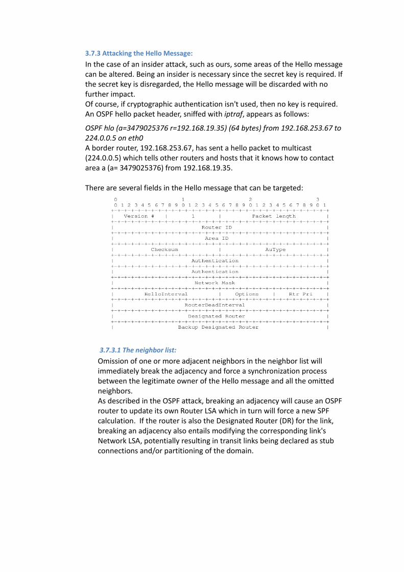
There are several fields in the Hello message that can be targeted:
3.7.3.1 The neighbor list:
Omission of one or more adjacent neighbors in the neighbor list will
immediately break the adjacency and force a synchronization process
between the legitimate owner of the Hello message and all the omitted
neighbors.
As described in the OSPF attack, breaking an adjacency will cause an OSPF
router to update its own Router LSA which in turn will force a new SPF
calculation. If the router is also the Designated Router (DR) for the link,
breaking an adjacency also entails modifying the corresponding link's
Network LSA, potentially resulting in transit links being declared as stub
connections and/or partitioning of the domain.
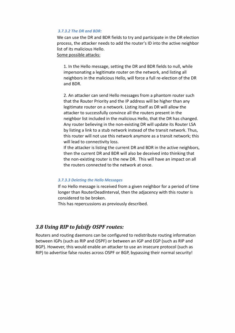
3.7.3.2 The DR and BDR:
We can use the DR and BDR fields to try and participate in the DR election
process, the attacker needs to add the router's ID into the active neighbor
list of its malicious Hello.
Some possible attacks:
1. In the Hello message, setting the DR and BDR fields to null, while
impersonating a legitimate router on the network, and listing all
neighbors in the malicious Hello, will force a full re-election of the DR
and BDR.
2. An attacker can send Hello messages from a phantom router such
that the Router Priority and the IP address will be higher than any
legitimate router on a network. Listing itself as DR will allow the
attacker to successfully convince all the routers present in the
neighbor list included in the malicious Hello, that the DR has changed.
Any router believing in the non-existing DR will update its Router LSA
by listing a link to a stub network instead of the transit network. Thus,
this router will not use this network anymore as a transit network; this
will lead to connectivity loss.
If the attacker is listing the current DR and BDR in the active neighbors,
then the current DR and BDR will also be deceived into thinking that
the non-existing router is the new DR. This will have an impact on all
the routers connected to the network at once.
3.7.3.3 Deleting the Hello Messages
If no Hello message is received from a given neighbor for a period of time
longer than RouterDeadInterval, then the adjacency with this router is
considered to be broken.
This has repercussions as previously described.
3.8 Using RIP to falsify OSPF routes:
Routers and routing daemons can be configured to redistribute routing information
between IGPs (such as RIP and OSPF) or between an IGP and EGP (such as RIP and
BGP). However, this would enable an attacker to use an insecure protocol (such as
RIP) to advertise false routes across OSPF or BGP, bypassing their normal security!
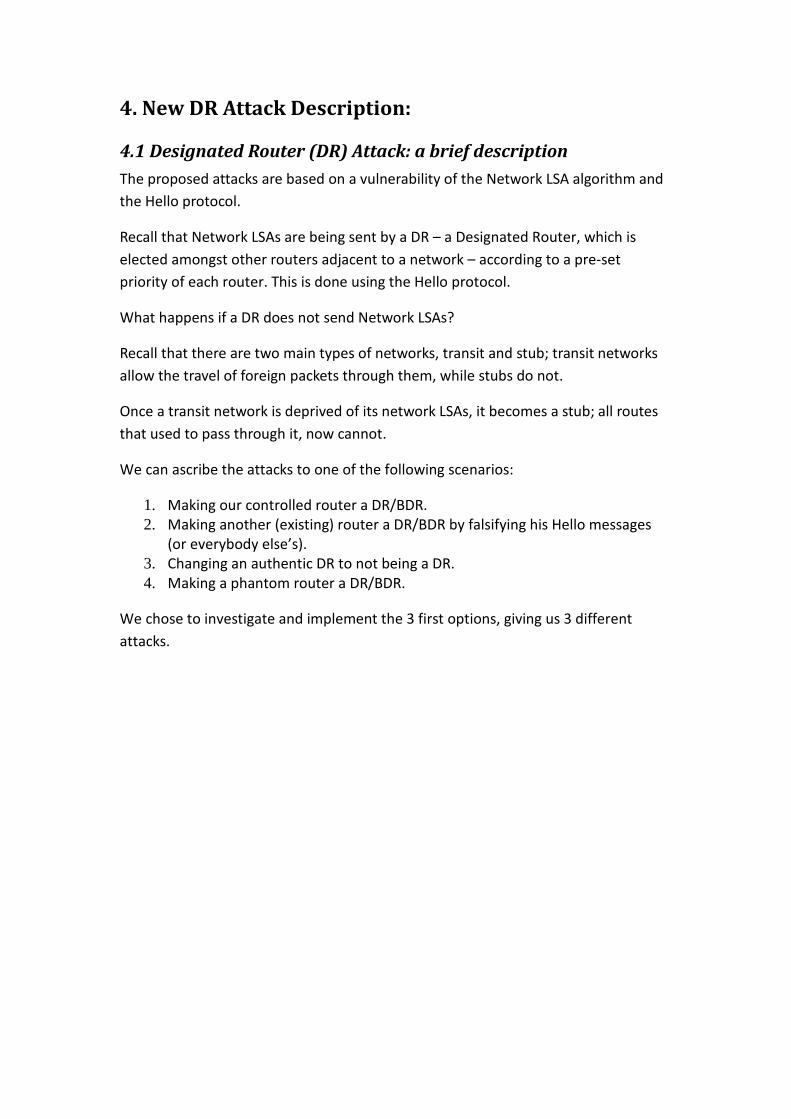
4. New DR Attack Description:
4.1 Designated Router (DR) Attack: a brief description
The proposed attacks are based on a vulnerability of the Network LSA algorithm and
the Hello protocol.
Recall that Network LSAs are being sent by a DR – a Designated Router, which is
elected amongst other routers adjacent to a network – according to a pre-set
priority of each router. This is done using the Hello protocol.
What happens if a DR does not send Network LSAs?
Recall that there are two main types of networks, transit and stub; transit networks
allow the travel of foreign packets through them, while stubs do not.
Once a transit network is deprived of its network LSAs, it becomes a stub; all routes
that used to pass through it, now cannot.
We can ascribe the attacks to one of the following scenarios:
1. Making our controlled router a DR/BDR.
2. Making another (existing) router a DR/BDR by falsifying his Hello messages
(or everybody else’s).
3. Changing an authentic DR to not being a DR.
4. Making a phantom router a DR/BDR.
We chose to investigate and implement the 3 first options, giving us 3 different
attacks.
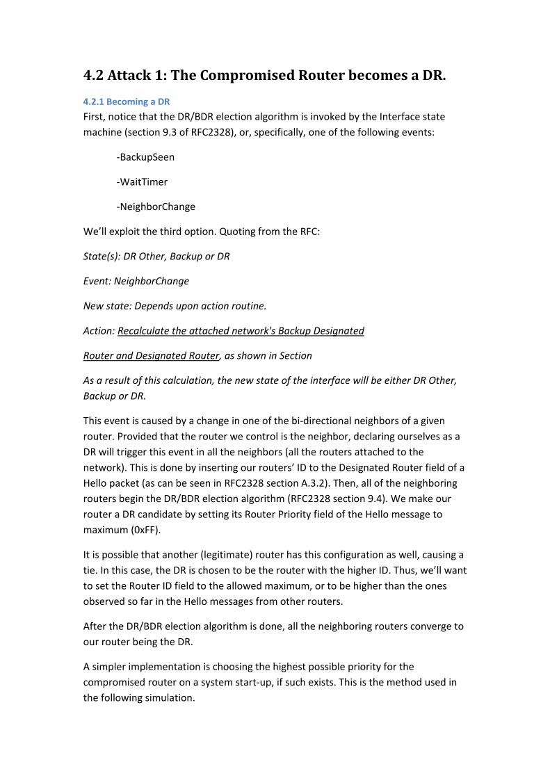
4.2 Attack 1: The Compromised Router becomes a DR.
4.2.1 Becoming a DR
First, notice that the DR/BDR election algorithm is invoked by the Interface state
machine (section 9.3 of RFC2328), or, specifically, one of the following events:
-BackupSeen
-WaitTimer
-NeighborChange
We’ll exploit the third option. Quoting from the RFC:
State(s): DR Other, Backup or DR
Event: NeighborChange
New state: Depends upon action routine.
Action: Recalculate the attached network's Backup Designated
Router and Designated Router, as shown in Section
As a result of this calculation, the new state of the interface will be either DR Other,
Backup or DR.
This event is caused by a change in one of the bi-directional neighbors of a given
router. Provided that the router we control is the neighbor, declaring ourselves as a
DR will trigger this event in all the neighbors (all the routers attached to the
network). This is done by inserting our routers’ ID to the Designated Router field of a
Hello packet (as can be seen in RFC2328 section A.3.2). Then, all of the neighboring
routers begin the DR/BDR election algorithm (RFC2328 section 9.4). We make our
router a DR candidate by setting its Router Priority field of the Hello message to
maximum (0xFF).
It is possible that another (legitimate) router has this configuration as well, causing a
tie. In this case, the DR is chosen to be the router with the higher ID. Thus, we’ll want
to set the Router ID field to the allowed maximum, or to be higher than the ones
observed so far in the Hello messages from other routers.
After the DR/BDR election algorithm is done, all the neighboring routers converge to
our router being the DR.
A simpler implementation is choosing the highest possible priority for the
compromised router on a system start-up, if such exists. This is the method used in
the following simulation.
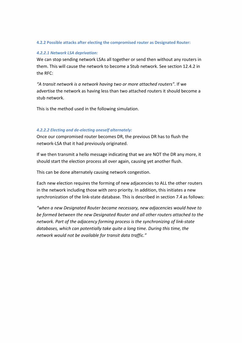
4.2.2 Possible attacks after electing the compromised router as Designated Router:
4.2.2.1 Network LSA deprivation:
We can stop sending network LSAs all together or send then without any routers in
them. This will cause the network to become a Stub network. See section 12.4.2 in
the RFC:
“A transit network is a network having two or more attached routers". If we
advertise the network as having less than two attached routers it should become a
stub network.
This is the method used in the following simulation.
4.2.2.2 Electing and de-electing oneself alternately:
Once our compromised router becomes DR, the previous DR has to flush the
network-LSA that it had previously originated.
If we then transmit a hello message indicating that we are NOT the DR any more, it
should start the election process all over again, causing yet another flush.
This can be done alternately causing network congestion.
Each new election requires the forming of new adjacencies to ALL the other routers
in the network including those with zero priority. In addition, this initiates a new
synchronization of the link-state database. This is described in section 7.4 as follows:
“when a new Designated Router became necessary, new adjacencies would have to
be formed between the new Designated Router and all other routers attached to the
network. Part of the adjacency forming process is the synchronizing of link-state
databases, which can potentially take quite a long time. During this time, the
network would not be available for transit data traffic.”
4.3 Attack 2: Making an adjacent router a DR
This attack achieves a similar effect to the previous attack, but has two main
advantages over it:
a) The attack can target any other adjacent router
b) The attacking (compromised) router itself is not blamed for the attack, since the
direct responsibility lies on the attacked router.
The attack is achieved by the following.
An attacked network is chosen. Recall that for this network, every router attached
has a designated interface for this network. Hence, also an attacked router and an
attacked interface are chosen.
Every time the compromised router sends a valid Hello packet, it also has to send a
“Malicious Hello” packet to every other adjacent router, except the router being
attacked. The “Malicious Hello” is a fake Hello on behalf of the router being
attacked. In this Hello message, the “DR” field is changed to be the attacked router’s
ID; the source ID for the attacked interface is also changed to match it. Thus, the
routers adjacent to the network update their database with a DR as the attacked
router.
From here onward, the routers attached to the attacked network believe that the
attacked router is the DR for the attacked network. The attacked router disagrees
and does not consider himself as a DR. Thus, it does not send Network LSAs, causing
the same effect as in Attack 1.
4.4 Attack 3: Distant Router Attack
This method enables the attacker to target a distant router, connected to a different
network than the attacker’s.
The attack is achieved by the following behavior. Similar to Attack 2, the attacking
router uses additional Hello messages. It sends them, on his behalf, destined to a
distant (attacked) router via unicast. These Hello messages are altered: their DR is
set to the attacker’s ID, their DR priority is set to be the highest possible, and their
content specifies the attacker to be adjacent with the network being attacked.
This causes the attacked router to “believe” that the attacking router is the DR for
the attacked network. It then relinquishes control and stops being a DR, thus stops
sending Network LSA.
The effect is similar – the attacked network stops being transit, and becomes a stub.
The attacker in this attack is easier to trace, since it sends forbidden Hello messages
to the attacked router. These messages are easy to trace to the source. And thus, the
attacked router will most likely be the first to be blamed.
4.5 Implemented Attacks’ Summary
4.5.1 Attack 1:
� Can be launched on the compromised router only.
� The compromised router falsifies its priority to be the highest possible.
� It is then elected to be the DR for its network.
� And then stops sending Network LSA.
4.5.2 Attack 2:
� Can be launched upon routers adjacent to the attacker.
� The compromised router A sends Hello messages, impersonating himself as a
neighboring router B.
� Router A also advertises a false high priority for B.
� Hence, B is elected to become a DR without knowing it.
� B will not send Network LSAs because it is not aware of itself being a DR.
4.5.3 Attack 3:
� The compromised router can target any network in the AS.
� The compromised router sends a malicious hello message with high priority
to the designated router of some network.
� That designated router then thinks that the attacking router will now be the
new DR. Hence, it stops sending network LSAs and relinquishes DR control.
5. Attack measurements and results
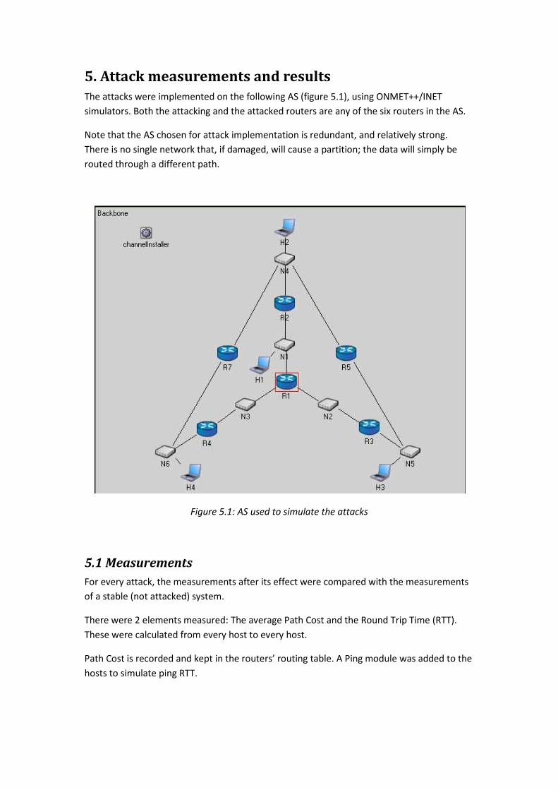
The attacks were implemented on the following AS (figure 5.1), using ONMET++/INET
simulators. Both the attacking and the attacked routers are any of the six routers in the AS.
Note that the AS chosen for attack implementation is redundant, and relatively strong.
There is no single network that, if damaged, will cause a partition; the data will simply be
routed through a different path.
Figure 5.1: AS used to simulate the attacks
5.1 Measurements
For every attack, the measurements after its effect were compared with the measurements
of a stable (not attacked) system.
There were 2 elements measured: The average Path Cost and the Round Trip Time (RTT).
These were calculated from every host to every host.
Path Cost is recorded and kept in the routers’ routing table. A Ping module was added to the
hosts to simulate ping RTT.
5.2 Results
All three attacks brought similar results. As expected, the attacked network became stub,
thus in all cases, all the traffic routes had to change to a different, more expensive ones. In
most cases, this also increased the average RTT; however, in some cases, where the more
expensive channel was actually the shorter one, the RTT was lower than before the attacks.
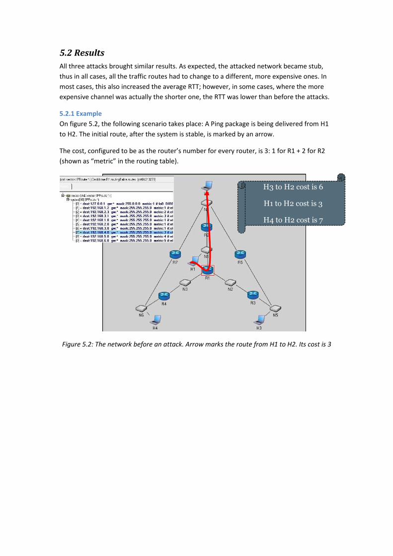
5.2.1 Example
On figure 5.2, the following scenario takes place: A Ping package is being delivered from H1
to H2. The initial route, after the system is stable, is marked by an arrow.
The cost, configured to be as the router’s number for every router, is 3: 1 for R1 + 2 for R2
(shown as “metric” in the routing table).
Figure 5.2: The network before an attack. Arrow marks the route from H1 to H2. Its cost is 3
H3 to H2 cost is 6
H1 to H2 cost is 3
H4 to H2 cost is 7
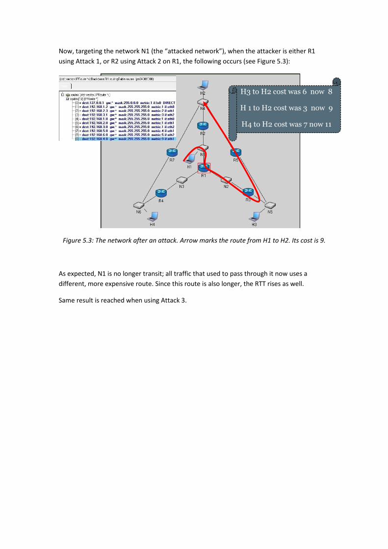
Now, targeting the network N1 (the “attacked network”), when the attacker is either R1
using Attack 1, or R2 using Attack 2 on R1, the following occurs (see Figure 5.3):
Figure 5.3: The network after an attack. Arrow marks the route from H1 to H2. Its cost is 9.
As expected, N1 is no longer transit; all traffic that used to pass through it now uses a
different, more expensive route. Since this route is also longer, the RTT rises as well.
Same result is reached when using Attack 3.
H3 to H2 cost was 6 now 8
H 1 to H2 cost was 3 now 9
H4 to H2 cost was 7 now 11
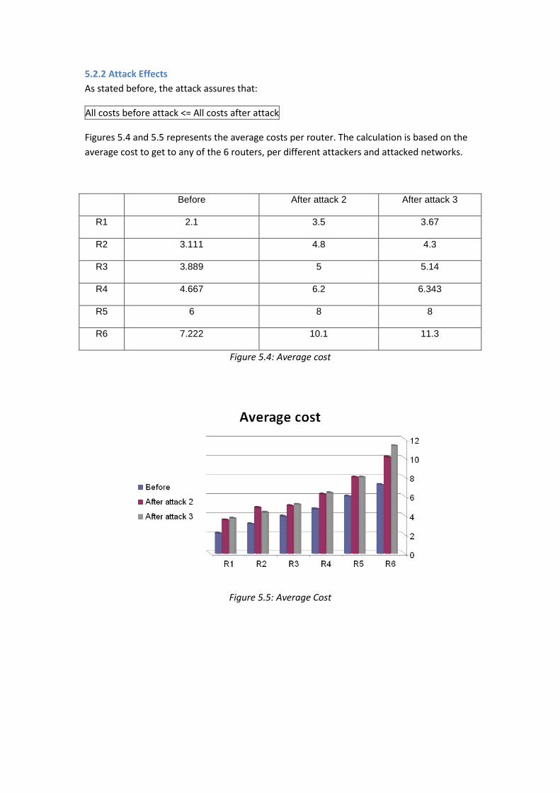
5.2.2 Attack Effects
As stated before, the attack assures that:
All costs before attack <= All costs after attack
Figures 5.4 and 5.5 represents the average costs per router. The calculation is based on the
average cost to get to any of the 6 routers, per different attackers and attacked networks.
Before After attack 2 After attack 3
R1 2.1 3.5 3.67
R2 3.111 4.8 4.3
R3 3.889 5 5.14
R4 4.667 6.2 6.343
R5 6 8 8
R6 7.222 10.1 11.3
Figure 5.4: Average cost
Figure 5.5: Average Cost
The Attacks do not always guarantee the following condition:
RTT before attack <= RTT after attack.
To understand why this isn’t always assured, the following example is given:
Let network 3 (N3) be attacked.
Suppose H4 has a packet to deliver to H2. The regular route will be:
H4->R4->R1->R2->H2 with cost 4+1+2=7.
After an attack on N3, the route will change to:
H4->R4->R7->H2 with cost 4+7=11.
Hence, although as an effect of the attack the cost has risen, the path now is actually
shorter, which means lower RTT, as shown in figures 5.6 and 5.7.
However, in general case in the following AS, the average RTT is indeed higher.
Moreover, if the path cost of every router is left as “1”, then the above condition is
guaranteed.
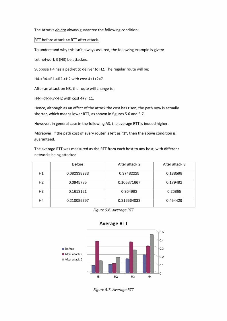
The average RTT was measured as the RTT from each host to any host, with different
networks being attacked.
Before After attack 2 After attack 3
H1 0.082338333 0.37482225 0.138598
H2 0.0945735 0.105871667 0.179492
H3 0.1613121 0.364983 0.26865
H4 0.210085797 0.316564033 0.454429
Figure 5.6: Average RTT
Figure 5.7: Average RTT
5.3 Conclusions
1. The results show that it is possible to cause significant damage to the OSPF protocol.
2. As can be seen from the results, the attack effects vary depending on the chosen network
to attack, and on the attack itself (attacks 1,2 versus attack 3).
3. It was shown that the attacked network becomes a stub. Hence, choosing the most
“bridge-like” network, i.e. a network that will cause a partition if it is turned to a stub, is
preferable for a possible attacker.
4. It is possible to combine between multiple attacks – whether attacks of the same type, or
from different types, and thus achieve full partition, by making the AS’s graph
unconnectable.
5. Attacking central networks, and networks that pass big amounts of data through
themselves, is usually preferable by an attacker.
6. Since Attack 2 allows the attacking router to stay hidden, it is preferable to attack 1.
7. Attack 3, while less discrete than Attack 2, can reach distant networks.
6. Bibliography
1. IETF, John T. Moy -. RFC2328 - OSPF Version 2. faqs.org. [Online] April 1998.
http://www.faqs.org/rfcs/rfc2328.html.
2. Cisco systems Inc. Internetworking Technologies Handbook. Cisco.com. [Online] 2009.
http://www.cisco.com/en/US/docs/internetworking/technology/handbook/OSPF.pdf.
3. OSPF. Data Network Resource. [Online] http://www.rhyshaden.com/ospf.htm.
4. Tanenbaum, Andrew S. Computer Networks, 4/E . Amsterdam, The Netherlands : Prentice
Hall, 2003. ISBN-10: 0130661023 - ISBN-13: 9780130661029.
5. nmap.org. [Online] http://nmap.org/.
6. Russell, Chris. Understanding Dynamic Route Protocol Vulnerabilities. [Online]
http://www.gnorizo.com/node/14.
7. Wilson, Curt. Protecting Network Infrastructure at the Protocol Level. [Online]
http://www.ouah.org/protocol_level.htm.
8. Dror-John Roecher, Patrice <GomoR> Auffret. Routing Protocol Security, Underground,
Prague. gomor.org. [Online] 2007. http://www.gomor.org/bin/view/OspfAsh/ConfItu2007.
9. Balwant Rathore, CISSP. Router and routing protocol attacks. [Online]
http://www.fistconference.org/data/presentaciones/switchandroutersecuritytesting2.pdf.
10. Yasser, Larisa. Overview of security issues related to BGP and OSPF routing protocols.
[Online] http://www.larisaonline.com/school/BGP.doc.
11. E. Jones, O. Le Moigne. Routing Protocol Security Requirements Internet-Draft - OSPF
Security Vulnerabilities Analysis . [Online]
Related Documents


![OSPF Security Project - webcourse.cs.technion.ac.ilwebcourse.cs.technion.ac.il/.../ho/WCFiles/2009-2-ospf-report.pdf · [2010] OSPF Security Project Michael Sudkovitch and David I.](https://static.cupdf.com/doc/110x72/5ae5b1dc7f8b9a6d4f8b9d9a/ospf-security-project-2010-ospf-security-project-michael-sudkovitch-and-david.jpg)