2 OSCILLOGRAPHIC RECORDERS OSCILLOGRAPHIC RECORDERS ORP1200 / ORP1300 & ORM1200 / ORM1300 RECORDERS WAVEFORM MEASURING INSTRUMENTS DIGITAL MEASURING INSTRUMENTS INDEX ORM1200 (7820) 320 × 192 × 435mm 8.8kg (4-ch model) to 9.5kg (8-ch model) (12-5/8 × 7-11/16 × 17-3/16" 19.4 lbs (4ch model) to 20.0 lbs (8-ch model) 7810&7820 Oscillographic Recorders ORP1200 / ORP1300 ORM1200 / ORM1300 Introducing the ORP/ORM Series Oscillographic Re- corders for use in the measurement, recording and analysis of signals from DC to high-speed transient phenomena, with the functions of a pen recorder, electromagnetic oscillo- graph, memory and X-Y recorders all in one instrument. The ORP/ORM Series is truly self-contained, the “all- round recorder with the standards of the future” capable of handling a wide variety of applications, from troubleshoot- ing in the field to product evaluation and analysis in labora- tories. We are confident the ORP/ORM Series will always be the right choice for your varying application needs. The ORP series measures and records multiple events on a max of 32 channels—4, 8, 16 analog-input and 16 logic- input channels—simultaneously. It processes input signals through a high-speed A/D converter with a sampling rate of 100 kS/s, offering guaranteed high accuracy and wideband features. Three amplifier levels are available at the input stage depending on the application: high-voltage, universal, and logic (optional) levels. That is, the ORP series can make high-resolution measurements of a direct input signal from a thermocouple, monitor a transmission line, and handle on/ off signals from a sequencer. The ORM Series is our newest advance in fast universal recorder design. Available with 4, 8 or 16 isolated analog channels plus up to 16 additional logic channels. With indi- vidual 128k sample memory areas for every channel, linkable up to four per channel for 512k sample capacity on selected channels, augmented by standard-equipment IC card slot and 3.5-inch floppy drive. Further enhanced by arithmetic and statistical comput- ing functions, and integral graphic display. More than just recorders, these are multifaceted, all-in-one data acquisition and analysis instruments perfect for testing and analysis, as at home in the field as in the lab. ORM1300 (7820) 320 × 219 × 435mm 12kg (12-5/8 × 8-11/16 × 17-1/8" 25.4 lbs) * Except 7810■1, 7820■1, 7810■2-B, 7820■2-B models * * Model & Suffix code 7810■3, 7820■3 7810■2-D, -F, -R or -G, 7820■2-D, -F, -R or -G 7810■1, 7820■1 7810■2-B, 7820■2-B Safety Standards EN61010-1 CSA1010.1, EN61010-1 CSA1010.1 CSA1010.1 EMI Standard EN55011 Group 1 Class A EN55011 Group 1 Class A – – Immunity Standard EN50082-2: 1995 EN50082-2: 1995 – – ORP1300/ORM1300 ★ Model & Suffix code 7810■3, 7820■3 7810■2-D, -F, -R or -G, 7820■2-D, -F, -R or -G 7810■1, 7820■1 7810■2-B, 7820■2-B Safety Standards EN61010-1 CSA1010.1, EN61010-1 CSA1010.1 CSA1010.1 EMI Standard EN55011 Group 1 Class A EN55011 Group 1 Class A – – Immunity Standard EN50082-2: 1995 EN50082-2: 1995 – – ORP1200/ORM1200 ★

Welcome message from author
This document is posted to help you gain knowledge. Please leave a comment to let me know what you think about it! Share it to your friends and learn new things together.
Transcript
2
OS
CIL
LOG
RA
PH
IC R
EC
OR
DE
RS
OSCILLOGRAPHIC RECORDERSORP1200 / ORP1300 & ORM1200 / ORM1300
RECORDERSWAVEFORMMEASURING
INSTRUMENTS
DIGITAL MEASURING
INSTRUMENTS INDEX
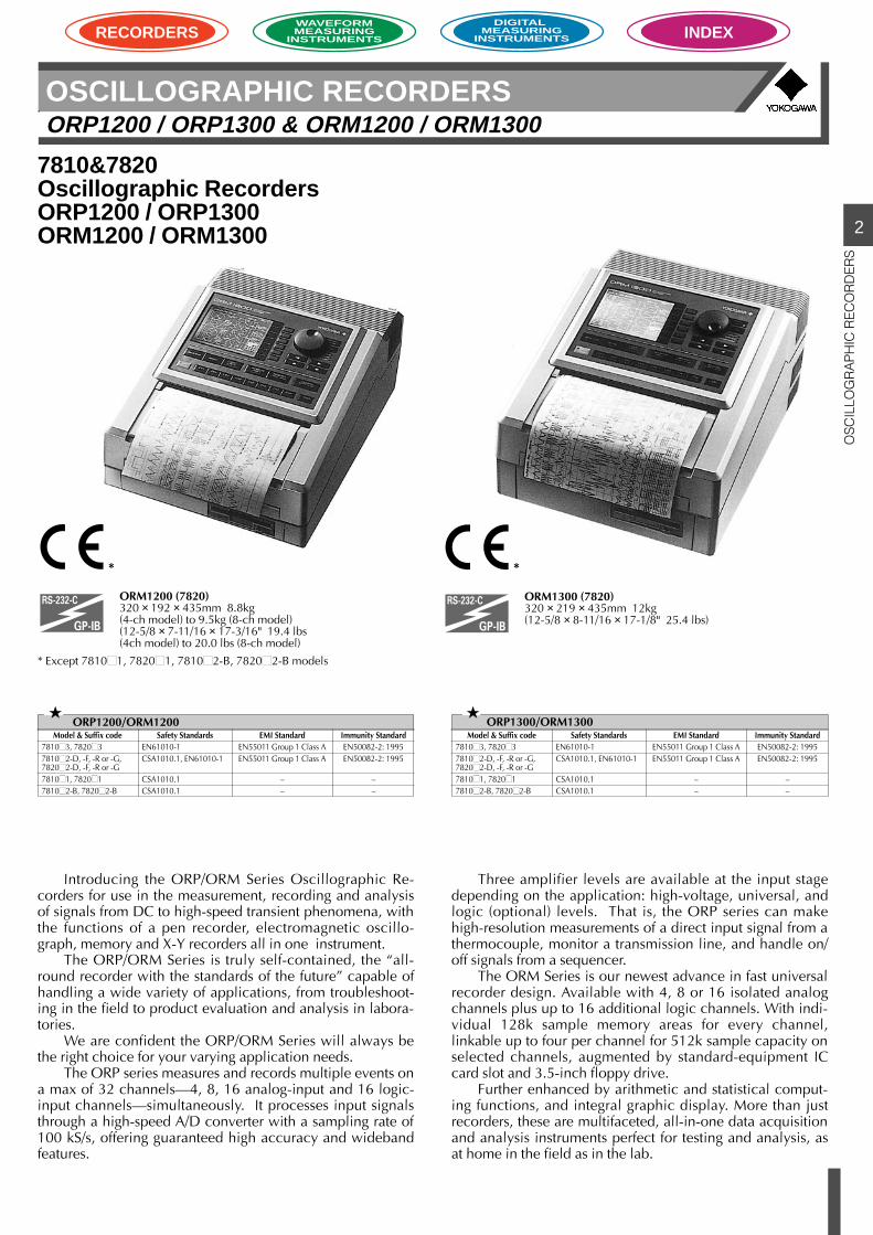
ORM1200 (7820)320 × 192 × 435mm 8.8kg(4-ch model) to 9.5kg (8-ch model)(12-5/8 × 7-11/16 × 17-3/16" 19.4 lbs(4ch model) to 20.0 lbs (8-ch model)
7810&7820Oscillographic RecordersORP1200 / ORP1300ORM1200 / ORM1300
Introducing the ORP/ORM Series Oscillographic Re-corders for use in the measurement, recording and analysisof signals from DC to high-speed transient phenomena, withthe functions of a pen recorder, electromagnetic oscillo-graph, memory and X-Y recorders all in one instrument.
The ORP/ORM Series is truly self-contained, the “all-round recorder with the standards of the future” capable ofhandling a wide variety of applications, from troubleshoot-ing in the field to product evaluation and analysis in labora-tories.
We are confident the ORP/ORM Series will always bethe right choice for your varying application needs.
The ORP series measures and records multiple events ona max of 32 channels—4, 8, 16 analog-input and 16 logic-input channels—simultaneously. It processes input signalsthrough a high-speed A/D converter with a sampling rate of100 kS/s, offering guaranteed high accuracy and widebandfeatures.
Three amplifier levels are available at the input stagedepending on the application: high-voltage, universal, andlogic (optional) levels. That is, the ORP series can makehigh-resolution measurements of a direct input signal from athermocouple, monitor a transmission line, and handle on/off signals from a sequencer.
The ORM Series is our newest advance in fast universalrecorder design. Available with 4, 8 or 16 isolated analogchannels plus up to 16 additional logic channels. With indi-vidual 128k sample memory areas for every channel,linkable up to four per channel for 512k sample capacity onselected channels, augmented by standard-equipment ICcard slot and 3.5-inch floppy drive.
Further enhanced by arithmetic and statistical comput-ing functions, and integral graphic display. More than justrecorders, these are multifaceted, all-in-one data acquisitionand analysis instruments perfect for testing and analysis, asat home in the field as in the lab.
ORM1300 (7820)320 × 219 × 435mm 12kg(12-5/8 × 8-11/16 × 17-1/8" 25.4 lbs)
* Except 78101, 78201, 78102-B, 78202-B models
* *
Model & Suffix code78103, 7820378102-D, -F, -R or -G,78202-D, -F, -R or -G78101, 7820178102-B, 78202-B
Safety StandardsEN61010-1CSA1010.1, EN61010-1
CSA1010.1CSA1010.1
EMI StandardEN55011 Group 1 Class AEN55011 Group 1 Class A
––
Immunity StandardEN50082-2: 1995EN50082-2: 1995
––
ORP1300/ORM1300
Model & Suffix code78103, 7820378102-D, -F, -R or -G,78202-D, -F, -R or -G78101, 7820178102-B, 78202-B
Safety StandardsEN61010-1CSA1010.1, EN61010-1
CSA1010.1CSA1010.1
EMI StandardEN55011 Group 1 Class AEN55011 Group 1 Class A
––
Immunity StandardEN50082-2: 1995EN50082-2: 1995
––
ORP1200/ORM1200
2
OS
CIL
LOG
RA
PH
IC R
EC
OR
DE
RS
OSCILLOGRAPHIC RECORDERSORP1200 / ORP1300 & ORM1200 / ORM1300
RECORDERSWAVEFORMMEASURING
INSTRUMENTS
DIGITAL MEASURING
INSTRUMENTS INDEX
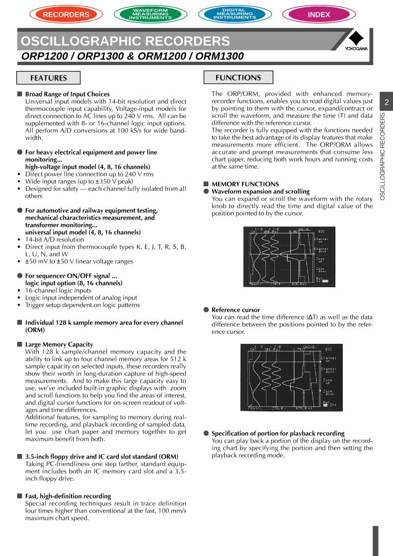
Reference cursorYou can read the time difference (∆T) as well as the datadifference between the positions pointed to by the refer-ence cursor.
Specification of portion for playback recordingYou can play back a portion of the display on the record-ing chart by specifying the portion and then setting theplayback recording mode.
Broad Range of Input ChoicesUniversal input models with 14-bit resolution and directthermocouple input capability, Voltage-input models fordirect connection to AC lines up to 240 V rms. All can besupplemented with 8- or 16-channel logic input options.All perform A/D conversions at 100 kS/s for wide band-width.
For heavy electrical equipment and power linemonitoring...high-voltage input model (4, 8, 16 channels)
• Direct power line connection up to 240 V rms• Wide input ranges (up to ±350 V peak)• Designed for safety — each channel fully isolated from all
others
For automotive and railway equipment testing,mechanical characteristics measurement, andtransformer monitoring...universal input model (4, 8, 16 channels)
• 14-bit A/D resolution• Direct input from thermocouple types K, E, J, T, R, S, B,
L, U, N, and W• ±50 mV to ±50 V linear voltage ranges
For sequencer ON/OFF signal ...logic input option (8, 16 channels)
• 16-channel logic inputs• Logic input independent of analog input• Trigger setup dependent on logic patterns
Individual 128 k sample memory area for every channel(ORM)
Large Memory CapacityWith 128 k sample/channel memory capacity and theability to link up to four channel memory areas for 512 ksample capacity on selected inputs, these recorders reallyshow their worth in long-duration capture of high-speedmeasurements. And to make this large capacity easy touse, we’ve included built-in graphic displays with zoomand scroll functions to help you find the areas of interest,and digital cursor functions for on-screen readout of volt-ages and time differences.Additional features, for sampling to memory during real-time recording, and playback recording of sampled data,let you use chart paper and memory together to getmaximum benefit from both.
3.5-inch floppy drive and IC card slot standard (ORM)Taking PC-friendliness one step farther, standard equip-ment includes both an IC memory card slot and a 3.5-inch floppy drive.
Fast, high-definition recordingSpecial recording techniques result in trace definitionfour times higher than conventional at the fast, 100 mm/smaximum chart speed.
The ORP/ORM, provided with enhanced memory-recorder functions, enables you to read digital values justby pointing to them with the cursor, expand/contract orscroll the waveform, and measure the time (T) and datadifference with the reference cursor.The recorder is fully equipped with the functions neededto take the best advantage of its display features that makemeasurements more efficient. The ORP/ORM allowsaccurate and prompt measurements that consume lesschart paper, reducing both work hours and running costsat the same time.
MEMORY FUNCTIONS Waveform expansion and scrolling
You can expand or scroll the waveform with the rotaryknob to directly read the time and digital value of theposition pointed to by the cursor.
FUNCTIONSFEATURES
2
OS
CIL
LOG
RA
PH
IC R
EC
OR
DE
RS
OSCILLOGRAPHIC RECORDERSORP1200 / ORP1300 & ORM1200 / ORM1300
RECORDERSWAVEFORMMEASURING
INSTRUMENTS
DIGITAL MEASURING
INSTRUMENTS INDEX
You can combine realtime recording with the memory func-tion to run the ORP/ORM.
For example, for normal operation in the unattended con-tinuous monitoring of a power supply, the ORP/ORMrecords only peak values with an envelope at a slow chart-feed rate. It stores the data immediately before and after atrigger only if the trigger is caused by a sudden event such asnoise.
You can utilize the stored data according to your applicationneeds; you can expand the time axis for playback recordingof the stored data or analyze the data on the display afteryou have completed your continuous monitoring.
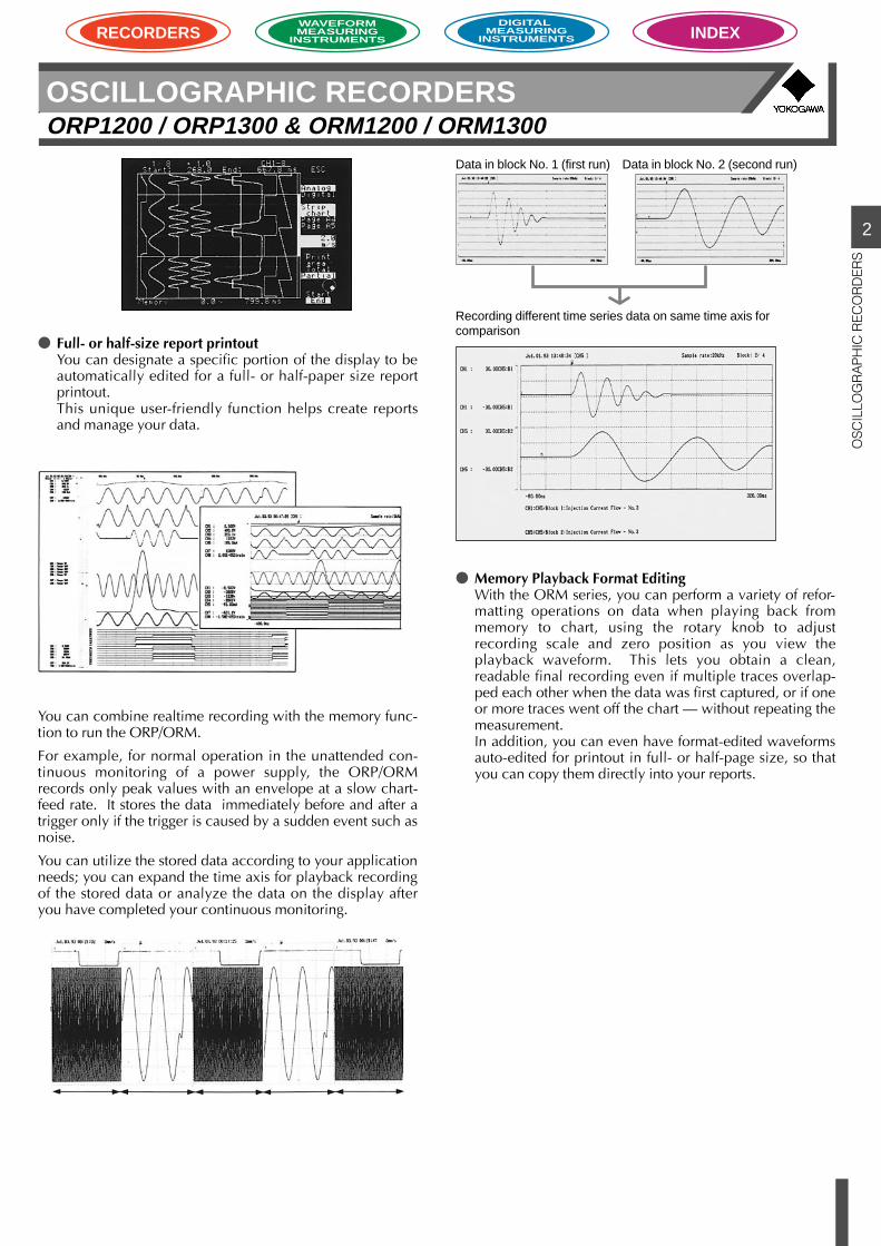
Data in block No. 1 (first run) Data in block No. 2 (second run)
Recording different time series data on same time axis forcomparison
Memory Playback Format EditingWith the ORM series, you can perform a variety of refor-matting operations on data when playing back frommemory to chart, using the rotary knob to adjustrecording scale and zero position as you view theplayback waveform. This lets you obtain a clean,readable final recording even if multiple traces overlap-ped each other when the data was first captured, or if oneor more traces went off the chart — without repeating themeasurement.In addition, you can even have format-edited waveformsauto-edited for printout in full- or half-page size, so thatyou can copy them directly into your reports.
Full- or half-size report printoutYou can designate a specific portion of the display to beautomatically edited for a full- or half-paper size reportprintout.This unique user-friendly function helps create reportsand manage your data.
2
OS
CIL
LOG
RA
PH
IC R
EC
OR
DE
RS
OSCILLOGRAPHIC RECORDERSORP1200 / ORP1300 & ORM1200 / ORM1300
RECORDERSWAVEFORMMEASURING
INSTRUMENTS
DIGITAL MEASURING
INSTRUMENTS INDEX
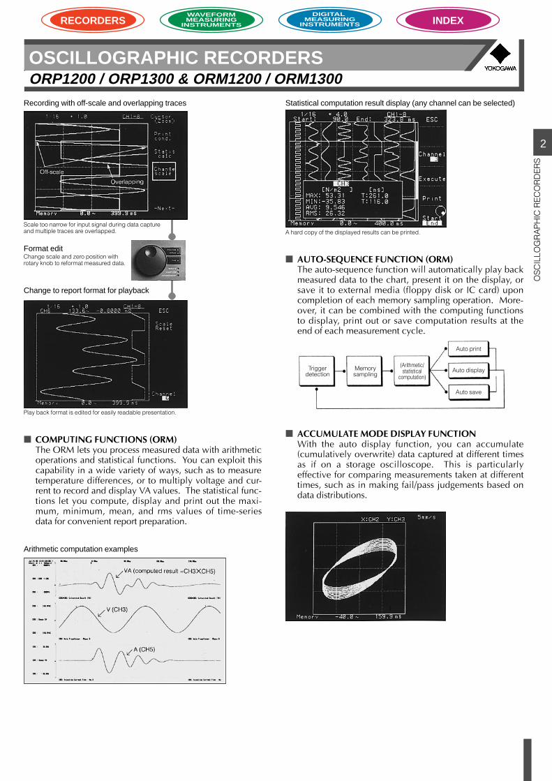
COMPUTING FUNCTIONS (ORM)The ORM lets you process measured data with arithmeticoperations and statistical functions. You can exploit thiscapability in a wide variety of ways, such as to measuretemperature differences, or to multiply voltage and cur-rent to record and display VA values. The statistical func-tions let you compute, display and print out the maxi-mum, minimum, mean, and rms values of time-seriesdata for convenient report preparation.
AUTO-SEQUENCE FUNCTION (ORM)The auto-sequence function will automatically play backmeasured data to the chart, present it on the display, orsave it to external media (floppy disk or IC card) uponcompletion of each memory sampling operation. More-over, it can be combined with the computing functionsto display, print out or save computation results at theend of each measurement cycle.
ACCUMULATE MODE DISPLAY FUNCTIONWith the auto display function, you can accumulate(cumulatively overwrite) data captured at different timesas if on a storage oscilloscope. This is particularlyeffective for comparing measurements taken at differenttimes, such as in making fail/pass judgements based ondata distributions.
Statistical computation result display (any channel can be selected)
A hard copy of the displayed results can be printed.
Recording with off-scale and overlapping traces
Play back format is edited for easily readable presentation.
Scale too narrow for input signal during data captureand multiple traces are overlapped.
Format editChange scale and zero position withrotary knob to reformat measured data.
Change to report format for playback
Arithmetic computation examples
Triggerdetection
Memorysampling
(Arithmetic/statistical
computation)
Auto print
Auto display
Auto save
2
OS
CIL
LOG
RA
PH
IC R
EC
OR
DE
RS
OSCILLOGRAPHIC RECORDERSORP1200 / ORP1300 & ORM1200 / ORM1300
RECORDERSWAVEFORMMEASURING
INSTRUMENTS
DIGITAL MEASURING
INSTRUMENTS INDEX
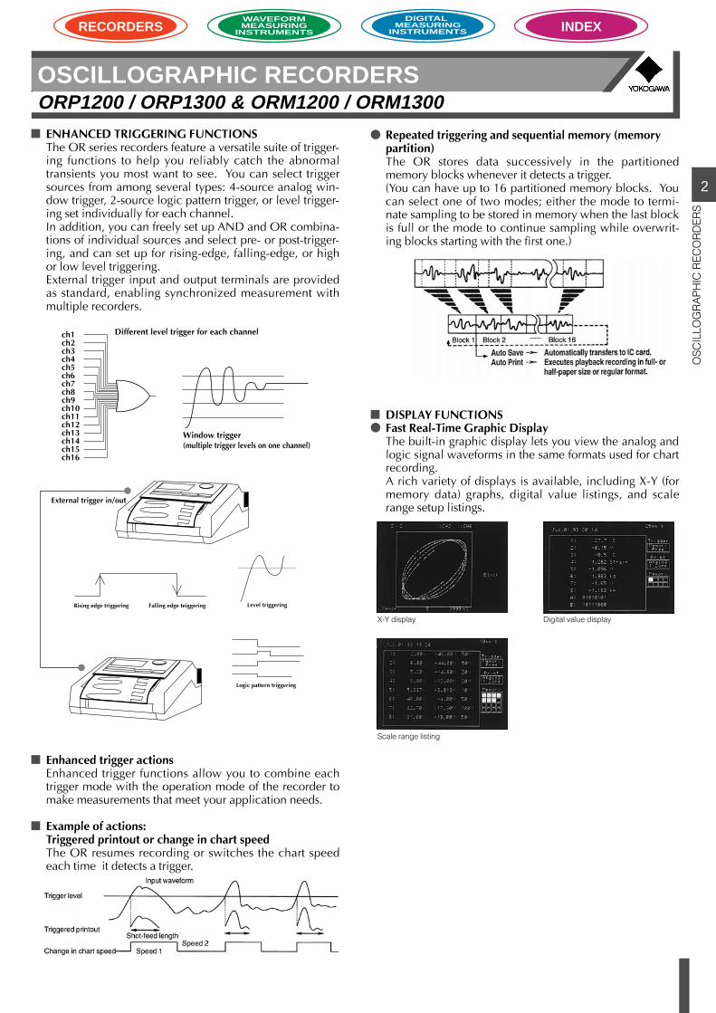
ENHANCED TRIGGERING FUNCTIONSThe OR series recorders feature a versatile suite of trigger-ing functions to help you reliably catch the abnormaltransients you most want to see. You can select triggersources from among several types: 4-source analog win-dow trigger, 2-source logic pattern trigger, or level trigger-ing set individually for each channel.In addition, you can freely set up AND and OR combina-tions of individual sources and select pre- or post-trigger-ing, and can set up for rising-edge, falling-edge, or highor low level triggering.External trigger input and output terminals are providedas standard, enabling synchronized measurement withmultiple recorders.
Enhanced trigger actionsEnhanced trigger functions allow you to combine eachtrigger mode with the operation mode of the recorder tomake measurements that meet your application needs.
Example of actions:Triggered printout or change in chart speedThe OR resumes recording or switches the chart speedeach time it detects a trigger.
Repeated triggering and sequential memory (memorypartition)The OR stores data successively in the partitionedmemory blocks whenever it detects a trigger.(You can have up to 16 partitioned memory blocks. Youcan select one of two modes; either the mode to termi-nate sampling to be stored in memory when the last blockis full or the mode to continue sampling while overwrit-ing blocks starting with the first one.)
DISPLAY FUNCTIONS Fast Real-Time Graphic Display
The built-in graphic display lets you view the analog andlogic signal waveforms in the same formats used for chartrecording.A rich variety of displays is available, including X-Y (formemory data) graphs, digital value listings, and scalerange setup listings.
X-Y display Digital value display
Scale range listing
Level triggering
Window trigger(multiple trigger levels on one channel)
Logic pattern triggering
ch1ch2ch3ch4ch5ch6ch7ch8ch9ch10ch11ch12ch13ch14ch15ch16
Different level trigger for each channel
Rising edge triggering Falling edge teiggering
External trigger in/out

2
OS
CIL
LOG
RA
PH
IC R
EC
OR
DE
RS
OSCILLOGRAPHIC RECORDERSORP1200 / ORP1300 & ORM1200 / ORM1300
RECORDERSWAVEFORMMEASURING
INSTRUMENTS
DIGITAL MEASURING
INSTRUMENTS INDEX
Analog-like Range and Zero AdjustmentInput range and zero setup are done by turning the rotaryknob while viewing the signal on the graphic display, giv-ing the same “feel” as an analog oscillograph. You canalso use the rotary knob for quick readjustment while re-cording is in progress.
RECORDING AND PRINTING FUNCTIONSUsing a dot-overlapping technique, the OR records a to-tal of 12 events with quality: data on both the 16 analogchannels and the 16 logic channels. It demonstrates itsfull capabilities especially in simultaneous measurementor recording of multiple events.You’ll enjoy a variety of recording and printing functions,for example, message printing, scale printing and digitalrecording, as well as continuous analog recording. Thisenables a quicker, easier, and more accurate readout ofdata.
Segregated mode (16 analog + 16 logic channels)
Logic waveform recording zones (8 channels/zone) can beplaced anywhere on chart.
1. Time and date2. Chart speed3. Time/div or Time/cm4. Message5. Channel number
2
OS
CIL
LOG
RA
PH
IC R
EC
OR
DE
RS
OSCILLOGRAPHIC RECORDERSORP1200 / ORP1300 & ORM1200 / ORM1300
RECORDERSWAVEFORMMEASURING
INSTRUMENTS
DIGITAL MEASURING
INSTRUMENTS INDEX
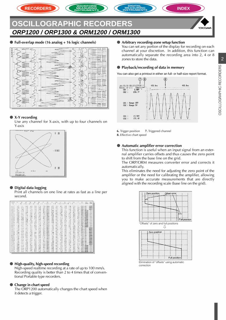
X-Y recordingUse any channel for X-axis, with up to four channels onY-axis
Digital data loggingPrint all channels on one line at rates as fast as a line persecond.
High-quality, high-speed recordingHigh-speed realtime recording at a rate of up to 100 mm/s.Recording quality is better than 2 to 4 times that of conven-tional Portable type recorders.
Change in chart speedThe ORP1200 automatically changes the chart speed whenit detects a trigger.
Automatic amplifier error correctionThis function is useful when an input signal from an exter-nal amplifier carries offsets and thus causes the zero pointto shift from the base line on the grid.The ORP/ORM measures converter error and corrects itautomatically.This eliminates the need for adjusting the zero point of theamplifier or the need for calibrating the amplifier, allowingyou to make accurate measurements that are directlyaligned with the recording scale (base line on the grid).
Full-overlap mode (16 analog + 16 logic channels) Arbitrary recording-zone setup functionYou can set any portion of the display for recording on eachchannel at your discretion. In addition, this function canautomatically separate the recording area into 2, 4 or 8zones to store the data.
Playback/recording of data in memory
You can also get a printout in either an full- or half-size report format.
“Offsets” of zero and full positions
Elimination of “offsets” using automaticcorrection
6. Trigger position 7. Triggered channel8. Effective chart speed
2
OS
CIL
LOG
RA
PH
IC R
EC
OR
DE
RS
OSCILLOGRAPHIC RECORDERSORP1200 / ORP1300 & ORM1200 / ORM1300
RECORDERSWAVEFORMMEASURING
INSTRUMENTS
DIGITAL MEASURING
INSTRUMENTS INDEX
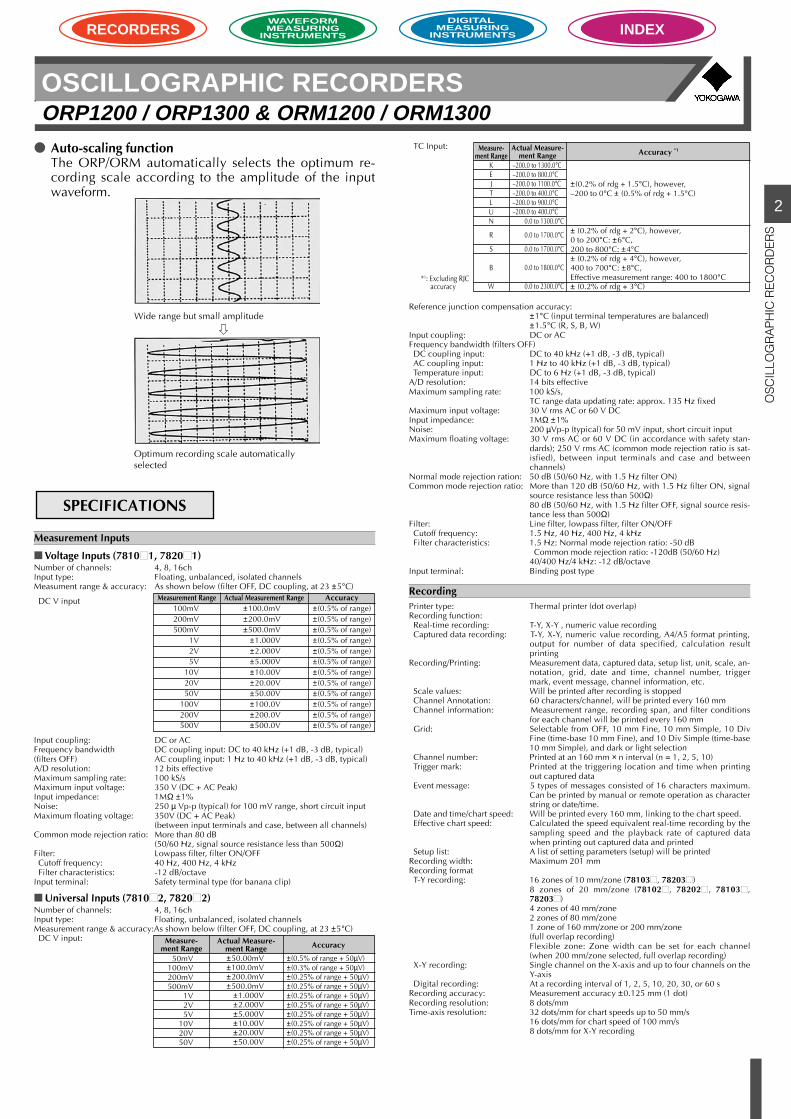
Auto-scaling functionThe ORP/ORM automatically selects the optimum re-cording scale according to the amplitude of the inputwaveform.
Measurement Inputs
Voltage Inputs (78101, 78201)Number of channels: 4, 8, 16chInput type: Floating, unbalanced, isolated channelsMeasument range & accuracy: As shown below (filter OFF, DC coupling, at 23 ±5°C)
DC V input
Input coupling: DC or ACFrequency bandwidth DC coupling input: DC to 40 kHz (+1 dB, -3 dB, typical)(filters OFF) AC coupling input: 1 Hz to 40 kHz (+1 dB, -3 dB, typical)A/D resolution: 12 bits effectiveMaximum sampling rate: 100 kS/sMaximum input voltage: 350 V (DC + AC Peak)Input impedance: 1MΩ ±1%Noise: 250 µ Vp-p (typical) for 100 mV range, short circuit inputMaximum floating voltage: 350V (DC + AC Peak)
(between input terminals and case, between all channels)Common mode rejection ratio: More than 80 dB
(50/60 Hz, signal source resistance less than 500Ω)Filter: Lowpass filter, filter ON/OFF Cutoff frequency: 40 Hz, 400 Hz, 4 kHz Filter characteristics: -12 dB/octaveInput terminal: Safety terminal type (for banana clip)
Universal Inputs (78102, 78202)Number of channels: 4, 8, 16chInput type: Floating, unbalanced, isolated channelsMeasurement range & accuracy:As shown below (filter OFF, DC coupling, at 23 ±5°C) DC V input:
SPECIFICATIONS
Wide range but small amplitude
Optimum recording scale automaticallyselected
Measurement Range100mV200mV500mV
1V2V5V
10V20V50V
100V200V500V
Actual Measurement Range±100.0mV±200.0mV±500.0mV
±1.000V±2.000V±5.000V±10.00V±20.00V±50.00V±100.0V±200.0V±500.0V
Accuracy±(0.5% of range)±(0.5% of range)±(0.5% of range)±(0.5% of range)±(0.5% of range)±(0.5% of range)±(0.5% of range)±(0.5% of range)±(0.5% of range)±(0.5% of range)±(0.5% of range)±(0.5% of range)
Measure-ment Range
50mV100mV200mV500mV
1V2V5V
10V20V50V
Actual Measure-ment Range±50.00mV±100.0mV±200.0mV±500.0mV
±1.000V±2.000V±5.000V±10.00V±20.00V±50.00V
Accuracy
±(0.5% of range + 50µV)±(0.3% of range + 50µV)±(0.25% of range + 50µV)±(0.25% of range + 50µV)±(0.25% of range + 50µV)±(0.25% of range + 50µV)±(0.25% of range + 50µV)±(0.25% of range + 50µV)±(0.25% of range + 50µV)±(0.25% of range + 50µV)
Measure-ment Range
KEJTLUN
R
S
B
W
Actual Measure-ment Range
–200.0 to 1300.0°C–200.0 to 800.0°C–200.0 to 1100.0°C–200.0 to 400.0°C–200.0 to 900.0°C–200.0 to 400.0°C
0.0 to 1300.0°C
0.0 to 1700.0°C
0.0 to 1700.0°C
0.0 to 1800.0°C
0.0 to 2300.0°C*1: Excluding RJC
accuracy
Accuracy *1
±(0.2% of rdg + 1.5°C), however,–200 to 0°C ± (0.5% of rdg + 1.5°C)
± (0.2% of rdg + 2°C), however,0 to 200°C: ±6°C,200 to 800°C: ±4°C± (0.2% of rdg + 4°C), however,400 to 700°C: ±8°C,Effective measurement range: 400 to 1800°C± (0.2% of rdg + 3°C)
TC Input:
Reference junction compensation accuracy:±1°C (input terminal temperatures are balanced)±1.5°C (R, S, B, W)
Input coupling: DC or ACFrequency bandwidth (filters OFF) DC coupling input: DC to 40 kHz (+1 dB, -3 dB, typical) AC coupling input: 1 Hz to 40 kHz (+1 dB, -3 dB, typical) Temperature input: DC to 6 Hz (+1 dB, -3 dB, typical)A/D resolution: 14 bits effectiveMaximum sampling rate: 100 kS/s,
TC range data updating rate: approx. 135 Hz fixedMaximum input voltage: 30 V rms AC or 60 V DCInput impedance: 1MΩ ±1%Noise: 200 µVp-p (typical) for 50 mV input, short circuit inputMaximum floating voltage: 30 V rms AC or 60 V DC (in accordance with safety stan-
dards); 250 V rms AC (common mode rejection ratio is sat-isfied), between input terminals and case and betweenchannels)
Normal mode rejection ration: 50 dB (50/60 Hz, with 1.5 Hz filter ON)Common mode rejection ratio: More than 120 dB (50/60 Hz, with 1.5 Hz filter ON, signal
source resistance less than 500Ω)80 dB (50/60 Hz, with 1.5 Hz filter OFF, signal source resis-tance less than 500Ω)
Filter: Line filter, lowpass filter, filter ON/OFF Cutoff frequency: 1.5 Hz, 40 Hz, 400 Hz, 4 kHz Filter characteristics: 1.5 Hz: Normal mode rejection ratio: -50 dB
Common mode rejection ratio: -120dB (50/60 Hz)40/400 Hz/4 kHz: -12 dB/octave
Input terminal: Binding post type
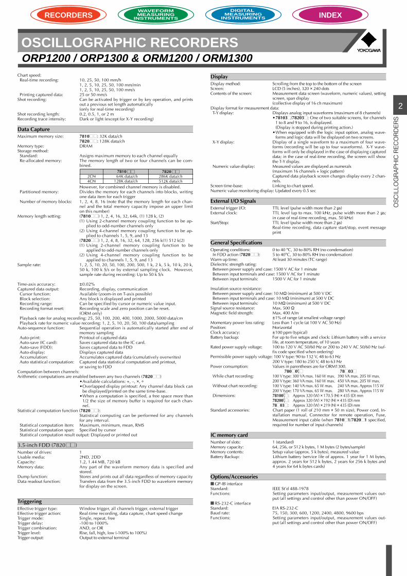
RecordingPrinter type: Thermal printer (dot overlap)Recording function: Real-time recording: T-Y, X-Y , numeric value recording Captured data recording: T-Y, X-Y, numeric value recording, A4/A5 format printing,
output for number of data specified, calculation resultprinting
Recording/Printing: Measurement data, captured data, setup list, unit, scale, an-notation, grid, date and time, channel number, triggermark, event message, channel information, etc.
Scale values: Will be printed after recording is stopped Channel Annotation: 60 characters/channel, will be printed every 160 mm Channel information: Measurement range, recording span, and filter conditions
for each channel will be printed every 160 mm Grid: Selectable from OFF, 10 mm Fine, 10 mm Simple, 10 Div
Fine (time-base 10 mm Fine), and 10 Div Simple (time-base10 mm Simple), and dark or light selection
Channel number: Printed at an 160 mm × n interval (n = 1, 2, 5, 10) Trigger mark: Printed at the triggering location and time when printing
out captured data Event message: 5 types of messages consisted of 16 characters maximum.
Can be printed by manual or remote operation as characterstring or date/time.
Date and time/chart speed: Will be printed every 160 mm, linking to the chart speed. Effective chart speed: Calculated the speed equivalent real-time recording by the
sampling speed and the playback rate of captured datawhen printing out captured data and printed
Setup list: A list of setting parameters (setup) will be printedRecording width: Maximum 201 mmRecording format T-Y recording: 16 zones of 10 mm/zone (78103, 78203)
8 zones of 20 mm/zone (78102 , 78202 , 78103,78203)4 zones of 40 mm/zone2 zones of 80 mm/zone1 zone of 160 mm/zone or 200 mm/zone(full overlap recording)Flexible zone: Zone width can be set for each channel(when 200 mm/zone selected, full overlap recording)
X-Y recording: Single channel on the X-axis and up to four channels on theY-axis
Digital recording: At a recording interval of 1, 2, 5, 10, 20, 30, or 60 sRecording accuracy: Measurement accuracy ±0.125 mm (1 dot)Recording resolution: 8 dots/mmTime-axis resolution: 32 dots/mm for chart speeds up to 50 mm/s
16 dots/mm for chart speed of 100 mm/s8 dots/mm for X-Y recording
2
OS
CIL
LOG
RA
PH
IC R
EC
OR
DE
RS
OSCILLOGRAPHIC RECORDERSORP1200 / ORP1300 & ORM1200 / ORM1300
RECORDERSWAVEFORMMEASURING
INSTRUMENTS
DIGITAL MEASURING
INSTRUMENTS INDEX
Chart speed: Real-time recording: 10, 25, 50, 100 mm/h
1, 2, 5, 10, 25, 50, 100 mm/min1, 2, 5, 10, 25, 50, 100 mm/s
Printing captured data: 25 or 50 mm/sShot recording: Can be activated by trigger or by key operation, and prints
out a previous set length automatically(only for real-time recording)
Shot recording length: 0.2, 0.5, 1, or 2 mRecording trace intensity: Dark or light (except for X-Y recording)
Data CaptureMaximum memory size: 7810 : 32K data/ch
7820 : 128K data/chMemory type: DRAMStorage method: Standard: Assigns maximum memory to each channel equally Re-allocated memory: The memory length of two or four channels can be com-
bined.
However, for combined channel memory is disabled. Partitioned memory: Divides the memory for each channels into blocks, writing
one data item for each trigger Number of memory blocks: 1, 2, 4, 8, 16 (note that the memory length for each chan-
nel and the total memory capacity impose an upper limiton this number)
Memory length setting: (7810 ) 1, 2, 4, 16, 32, 64k, (1) 128 k, (2)(1) Using 2-channel memory coupling function to be ap-
plied to odd-number channels only(2) Using 4-channel memory coupling function to be ap-
plied to channels 1, 5, 9, and 13(7820 ) 1, 2, 4, 8, 16, 32, 64, 128, 256 k(1) 512 k(2)(1) Using 2-channel memory coupling function to be
applied to odd-number channels only(2) Using 4-channel memory coupling function to be
applied to channels 1, 5, 9, and 13Sample rate: 1, 2, 5, 10, 20, 50, 100, 200, 500, 1 k, 2 k, 5 k, 10 k, 20 k,
50 k, 100 k S/s or by external sampling clock. However,sample rate during recording: Up to 50 k S/s
Time-axis accuracy: ±0.02%Captured data output: Recording, display, communication Cursor function: Available (zoom-in on T-axis possible) Block selection: Any block is displayed and printed Recording range: Can be specified by cursor or numeric value input. Recording format reset: Recording scale and zero position can be reset.
(ORM only) Playback rate for analog recording: 25, 50, 100, 200, 400, 1000, 2000, 5000 data/cm Playback rate for numeric value recording: 1, 2, 5, 10, 20, 50, 100 data/samplingAuto-sequence function: Sequential operation is automatically started after end of
memory sampling Auto-print: Printout of captured data Auto-save (IC card): Saves captured data to the IC card. Auto-save (FDD): Saves captured data to FDD Auto-display: Displays captured data Accumulation: Accumulates captured data (cumulatively overwrites) Auto statistical computation: Captured data statistical computation and printout,
or saving to FDDComputation between channels:Arithmetic computations are enabled between any two channels (7820 )
•Available calculations: +, –, ×, ÷•Overlapped display printout: Any channel data block can
be displayed/printed on the same time-base.•When a computation is specified, a free space more than
1/2 the size of memory buffer is required for each chan-nel.
Statistical computation function (7820 ):Statistical computing can be performed for any channelsfor any interval.
Statistical computation item: Maximum, minimum, mean, RMS Statistical computation span: Specified by cursor Statistical computation result output: Displayed or printed out
3.5-inch FDD (7820 )Number of drives: 1Usable media: 2HD, 2DDCapacity: 1.2, 1.44 MB, 720 kBMemory data: Any part of the waveform memory data is specified and
stored.Dump function: Stores and prints out all data regardless of memory capacityData readout function: Transfers data from the 3.5-inch FDD to waveform memory
for display on the screen.
TriggeringEffective trigger type: Window trigger, all channels trigger, external triggerEffective trigger action: Real-time recording, data capture, chart speed changeTrigger mode: Single, repeat, freeTrigger delay: -100 to 1000%Trigger combination: AND, or ORTrigger level: Rise, fall, high, low (-100% to 100%)Trigger output: Output to external terminal
DisplayDisplay method: Scrolling from the top to the bottom of the screenScreen: LCD (5 inches), 320 × 240 dotsContents of the screen: Measurement data screen (waveform, numeric values), setting
screen, span display(collective display of 16 ch maximum)
Display format for measurement data: T-Y display: Displays analog input waveforms (maximum of 8 channels)
•78103/78203: One of two suitable screens, for channels1 to 8 and 9 to 16, is displayed.(Display is stopped during printing action.)
•When equipped with the logic input option, analog wave-forms and logic data will be displayed on two screens.
X-Y display: Display of a single waveform to a maximum of four wave-forms (recording will be up to four waveforms). X-Y wave-forms will only be displayed in the case of displaying captureddata; in the case of real-time recording, the screen will showthe T-Y display.
Numeric value display: Measured values are displayed as numerals(maximum 16 channels + logic pattern)Captured data playback screen changes display every 2 chan-nels.
Screen time-base: Linking to chart speed.Numeric value monitoring display: Updated every 0.5 sec
External I/O SignalsExternal trigger I/O: TTL level (pulse width more than 2 µs)External clock: TTL level (up to max. 100 kHz, pulse width more than 2 µs;
in case of real-time recording, max. 50 kHz)Start/Stop: TTL level (pulse width more than 2 µs)
Real-time recording, data capture start/stop, event messageprint
General SpecificationsOperating conditions: 0 to 40 °C, 30 to 80% RH (no condensation) In FDD action (7820 ): 5 to 40°C, 30 to 80% RH (no condensation)Warm up time: At least 30 minutes (TC range)Dielectric strength rating: Between power supply and case: 1500 V AC for 1 minute Between input terminals and case: 1500 V AC for 1 minute Between input terminals: 1500 V AC for 1 minute
Insulation source resistance: Between power supply and case: 10 MΩ (minimum) at 500 V DC Between input terminals and case: 10 MΩ (minimum) at 500 V DC Between input terminals: 10 MΩ (minimum) at 500 V DCSignal source resistance: Max. 500 ΩMagnetic field strength: Max. 400 A/m
±1% of range (at smallest voltage range)Momentary power loss rating: Less than 1 cycle (at 100 V AC 50 Hz)Position: HorizontalClock accuracy: ±100 ppm (typical)Battery backup: For up to five setups and clock: Lithium battery with a service
life, at room temperature, of 10 yearsRated power supply voltage: 100 to 120 V AC 50/60 Hz or 200 to 240 V AC 50/60 Hz (suf-
fix code specified when ordering)Permissible power supply voltage: 100 V type: 90 to 132 V, 48 to 63 Hz
200 V type: 180 to 250 V, 48 to 63 HzPower consumption: Values in parentheses are for ORM1300.
780021 7803
While chart recording: 100 V type: 300 VA max. 160 W max. 390 VA max. 205 W max.200 V type: 360 VA max. 160 W max. 450 VA max. 205 W max.
Without chart recording: 100 V type: 140 VA max. 65 W max. 240 VA max. Approx 115 W200 V type: 170 VA max. 65 W max. 280 VA max. Approx 115 W
Dimensions: 7810021: Approx 320 (W) × 170.5 (H) × 435 (D) mm
7820021: Approx 320 (W) × 192 (H) × 435 (D) mm
7803: Approx 320 (W) × 219 (H) × 435 (D) mmStandard accessories: Chart paper (1 roll of 210 mm × 50 m size), Power cord, In-
stallation manual, Connector for remote operation, Fuse,Measurement input cable (when 78101/78201 specified,required for number of input channels)
IC memory cardNumber of slots: 1 (standard)Memory capacity: 64, 256, or 512 k bytes, 1 M bytes (2 bytes/sample)Memory contents: Setup value (approx. 5 k bytes), measured valueBattery Backup: Lithium battery (service life of approx. 1 year for 1 M bytes,
approx. 2 years for 512 k bytes, 2 years for 256 k bytes and4 years for 64 k bytes cards)
Options/Accessories GP-IB interfaceStandard: IEEE St’d 488-1978Functions: Setting parameters input/output, measurement values out-
put (all settings and control other than power ON/OFF) RS-232-C interfaceStandard: EIA RS-232-CBaud rate: 75, 150, 300, 600, 1200, 2400, 4800, 9600 bpsFunctions: Setting parameters input/output, measurement values out-
put (all settings and control other than power ON/OFF)
2CH4CH
7820286K data/ch512K data/ch
7810064K data/ch128K data/ch
2
OS
CIL
LOG
RA
PH
IC R
EC
OR
DE
RS
OSCILLOGRAPHIC RECORDERSORP1200 / ORP1300 & ORM1200 / ORM1300
RECORDERSWAVEFORMMEASURING
INSTRUMENTS
DIGITAL MEASURING
INSTRUMENTS INDEX
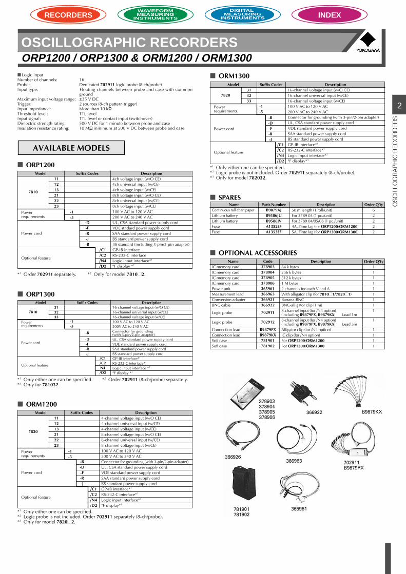
Logic inputNumber of channels: 16Probe: Dedicated 702911 logic probe (8 ch/probe)Input type: Floating channels between probe and case with common
groundMaximum input voltage range: ±35 V DCTrigger: 2 sources (8-ch pattern trigger)Input impedance: More than 10 kΩThreshold level: TTL levelInput signal: TTL level or contact input (switchover)Dielectric strength rating: 500 V DC for 1 minute between probe and caseInsulation resistance rating: 10 MΩ minimum at 500 V DC between probe and case
AVAILABLE MODELS
ORP1200
ORP1300
ORM1200
ORM1300
SPARES
OPTIONAL ACCESSORIES
*1 Order 702911 separately. *2 Only for model 78102.
*1 Only either one can be specified. *2 Order 702911 (8-ch/probe) separately.*3 Only for 781032.
*1 Only either one can be specified.*2 Logic probe is not included. Order 702911 separately (8-ch/probe).*3 Only for model 78202.
*1 Only either one can be specified.*2 Logic probe is not included. Order 702911 separately (8-ch/probe).*3 Only for model 782032.
Description16-channel voltage input (w/O CE)16-channel universal input (w/CE)16-channel voltage input (w/CE)100 V AC to 120 V AC200V AC to 240 V ACConnector for grounding(with 3-pin/2-pin adapter)UL, CSA standard power supply cordVDE standard power supply cordSAA standard power supply cordBS standard power supply cordGP-IB interface*1
RS-232-C interface*1
Logic input interface *2
°F display *3
Suffix CodesModel
/C1/C2N4/D2
7810
Powerrequirements
Power cord
Optional feature
-B
-D-F-R-J
-1-5
313233
Description4-channel voltage input (w/O CE)4-channel universal input (w/CE)4-channel voltage input (w/CE)8-channel voltage input (w/O CE)8-channel universal input (w/CE)8-channel voltage input (w/CE)100 V AC to 120 V AC200 V AC to 240 V ACConnector for grounding (with 3-pin/2-pin adapter)UL, CSA standard power supply cordVDE standard power supply cordSAA standard power supply cordBS standard power supply cordGP-IB interface*1
RS-232-C interface*1
Logic input interface*2
°F display*3
Suffix CodesModel
/C1/C2/N4/D2
-B-D-F-R-J
-1-5
111213212223
7820
Powerrequirements
Power cord
Optional feature
Description4ch voltage input (w/O CE)4ch universal input (w/CE)4ch voltage input (w/CE)8ch voltage input (w/O CE)8ch universal input (w/CE)8ch voltage input (w/CE)100 V AC to 120 V AC200 V AC to 240 V ACUL, CSA standard power supply cordVDE stndard power supply cordSAA standard power supply cordBS standard power supply cordJIS standard (including 3-pin/2-pin adapter)GP-IB interfaceRS-232-C interfaceLogic input interface*1
°F display *2
Suffix CodesModel
/C1/C2/N4/D2
-D-F-R-J-B
-1-5
111213212223
7810
Powerrequirements
Power cord
Optional feature
Description16-channel voltage input (w/O CE)16-channel universal input (w/CE)16-channel voltage input (w/CE)100 V AC to 120 V AC200 V AC to 240 V ACConnector for grounding (with 3-pin/2-pin adapter)UL, CSA standard power supply cordVDE standard power supply cordSAA standard power supply cordBS standard power supply cordGP-IB interface*1
RS-232-C interface*1
Logic input interface*2
°F display*3
Suffix CodesModel
/C1/C2/N4/D2
-B-D-F-R-J
-1-5
313233
7820
Powerrequirements
Power cord
Optional feature
NameContinuous roll chart paperLithium batteryLithium batteryFuseFuse
Parts NumberB9879AJB9586JUB9586JVA1352EFA1353EF
Description50 m length (1 roll/unit)For 3789 03 (1 pc./unit)For 3789 04/05/06 (1 pc./unit)4A, Time lag (for ORP1200/ORM1200)5A, Time lag (for ORP1300/ORM1300)
Order Q’ty62222
NameIC memory cardIC memory cardIC memory cardIC memory cardPower unitMeasurement leadConversion adapterBNC cable
Logic probe
Logic probe
Connection leadConnection leadSoft caseSoft case
Code378903378904378905378906365961366963366921366922
702911
702912
B9879PXB9879KX781901781902
Description64 k bytes256 k bytes512 k bytes1 M bytes2 channels for each V and AWith alligator clip (for 78101/78201)Banana-BNCBNC-alligator clip (1 m)8-channel input (for /N4 option)(including B9879PX, B9879KX) Lead 1m8-channel input (for /N4 option)(including B9879PX, B9879KX) Lead 3mAlligator clip (for /N4 option)IC clip (for /N4 option)For ORP1200/ORM1200For ORP1300/ORM1300
Order Q’ty111111111
1
1111
2
OS
CIL
LOG
RA
PH
IC R
EC
OR
DE
RS
OSCILLOGRAPHIC RECORDERSORP1200 / ORP1300 & ORM1200 / ORM1300
RECORDERSWAVEFORMMEASURING
INSTRUMENTS
DIGITAL MEASURING
INSTRUMENTS INDEX
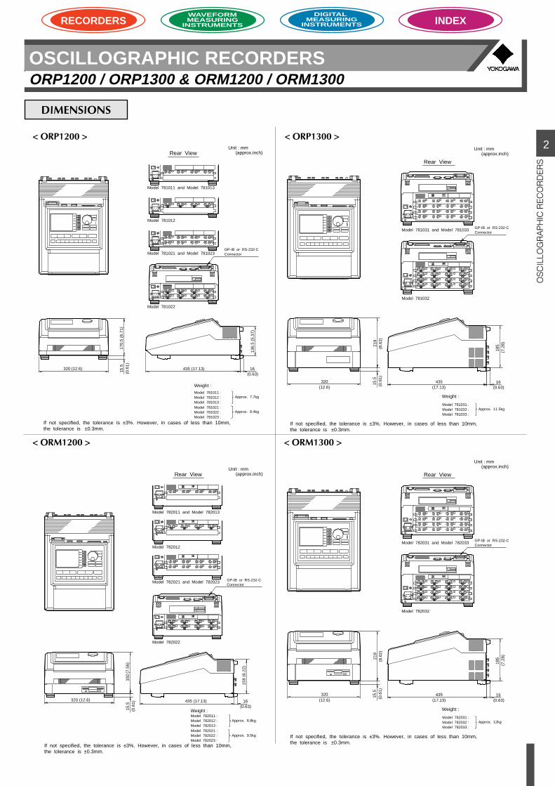
DIMENSIONS
< ORP1200 > < ORP1300 >
< ORM1200 > < ORM1300 >
435
Unit : mm(approx.inch)Rear View
Model 781011 and Model 781013
Model 781012
Model 781021 and Model 781023
Model 781022
GP-IB or RS-232-CConnector
Weight :Model 781011 :Model 781012 :Model 781013 :Model 781021 :Model 781022 :Model 781023 :
Approx. 7.7kg
Approx. 8.4kg
320 (12.6) (17.13)
136.
5 (5
.37)
16(0.63)
170.
5 (6
.71)
15.5
(0.6
1)
If not specified, the tolerance is ±3%. However, in cases of less than 10mm, the tolerance is ±0.3mm.
Unit : mm(approx.inch)
Rear View
Model 781031 and Model 781033
Model 781032
GP-IB or RS-232-CConnector
Weight :
Model 781031 :Model 781032 :Model 781033 :
Approx. 11.5kg
320(12.6)
435(17.13)
185
(7.2
8)
16(0.63)
219
(8.6
2)15
.5(0
.61)
If not specified, the tolerance is ±3%. However, in cases of less than 10mm, the tolerance is ±0.3mm.
Unit : mm(approx.inch)Rear View
Model 782011 and Model 782013
Model 782012
Model 782021 and Model 782023
Model 782022
GP-IB or RS-232-CConnector
Weight :Model 782011 :Model 782012 :Model 782013 :Model 782021 :Model 782022 :Model 782023 :
Approx. 8.8kg
Approx. 9.5kg
320 (12.6) 435 (17.13)
158
(6.2
2)
16(0.63)
192
(7.5
6)15
.5(0
.61)
If not specified, the tolerance is ±3%. However, in cases of less than 10mm, the tolerance is ±0.3mm.
Unit : mm(approx.inch)
Rear View
Model 782031 and Model 782033
Model 782032
GP-IB or RS-232-CConnector
Weight :
Model 782031 :Model 782032 :Model 782033 :
Approx. 12kg
320(12.6)
435(17.13)
185
(7.2
8)
16(0.63)
219
(8.6
2)15
.5(0
.61)
If not specified, the tolerance is ±3%. However, in cases of less than 10mm, the tolerance is ±0.3mm.
Related Documents