1 OSCILLATING/PULSATING HEAT TRANSFER & THERMAL CONTROL DEVICES (IN ACCELERATION ENVIRONMENTS RANGING FROM MICRO- TO SUPERGRAVITY) Ad Delil Delil - AATCS Consultants (Consultants on Advanced Aerospace Thermal Control Systems) [email protected] FORWARD The following lecture gives an overview and discusses operations and applications issues of three other, promising and powerful alternative developments, i.e. concerning: - The oscillating single-phase heat transfer device. - Vapour pressure driven heat transfer devices, like the vapour pressure driven two-phase loop and the T-system. - Other devices carrying several names, like bubble-driven heat transfer device, pulsating or meandering heat pipe, capillary or capillary tunnel heat pipe, flat swinging heat pipe, spirally wound or serpentine-like heat pipe. The simple fact that there are so many names for these devices suggests that there is no clear understanding of the physical phenomena that govern their performance and set their peculiarities. In fact, there is a whole gamma of experts and laymen, which really believe that they precisely know more or less all the relevant issues pertaining to such devices. Therefore this lecture is more or less as a personal attempt to obtain a reserved look (from a distance) at what the quarrelling “specialists” pretend to know of these devices, in order to get some practical feeling of what the possibilities of their use and applications mean. The lecture discusses the different aspects of various heat transfer devices in gravity environments ranging from micro-gravity to super-gravity. It gives an overview of world-wide activities on and the state of the art of pulsating and oscillating heat transfer devices. It attempts to assess their commonality and differences. It reviews research results presented in literature up till say mid 2001, and also a listing of articles published in the last two years. The engineering two-phase heat transport and thermal control developments of classical heat pipes, of capillary pumped loops and loop heat pipes, and of mechanically pumped two-phase loops are discussed in a separate lecture. This lecture gives an overview and discusses operations and applications issues of three other, promising and powerful alternative developments, i.e. concerning: - The oscillating single-phase heat transfer device. - The vapour pressure driven heat transfer devices, like the vapour pressure driven two-phase loop and the T-system. - Devices carrying several names, like bubble-driven heat transfer device, pulsating or meandering heat pipe, capillary heat pipe or capillary tunnel heat pipe, flat swinging heat pipe, or spirally wound or serpentine-like heat pipe. INTRODUCTION & BACKGROUND My publications of the last decade discuss thermal-gravitational modelling & scaling of two-phase heat transport systems for spacecraft applications (Refs. 1 to 14). The initial research focused on mechanically and capillary pumped two-phase loops for use in micro-gravity. The activities dealt with pure geometric, pure fluid to fluid, or hybrid (combined) scaling of a prototype system by a model at the same gravity level, and of a prototype in micro-g by a model on earth. The scaling approach was based on dimension analysis and similarity considerations. The scaling research was later extended to applications for Moon and Mars bases. The research was done: - For a better understanding of the impact of gravitation level on two-phase flow and heat transfer phenomena. - To provide means for comparison and generalisation of data. - To develop tools to design space-oriented two-phase systems and components based on outcomes of tests on earth. - To save money by reducing costs.

Welcome message from author
This document is posted to help you gain knowledge. Please leave a comment to let me know what you think about it! Share it to your friends and learn new things together.
Transcript

1
OSCILLATING/PULSATING HEAT TRANSFER & THERMAL CONTROL DEVICES(IN ACCELERATION ENVIRONMENTS RANGING FROM MICRO- TO SUPERGRAVITY)
Ad DelilDelil - AATCS Consultants
(Consultants on Advanced Aerospace Thermal Control Systems)[email protected]
FORWARD
The following lecture gives an overview and discusses operations and applications issues of three other, promisingand powerful alternative developments, i.e. concerning:- The oscillating single-phase heat transfer device.- Vapour pressure driven heat transfer devices, like the vapour pressure driven two-phase loop and the T-system.- Other devices carrying several names, like bubble-driven heat transfer device, pulsating or meandering heat pipe,capillary or capillary tunnel heat pipe, flat swinging heat pipe, spirally wound or serpentine-like heat pipe.
The simple fact that there are so many names for these devices suggests that there is no clear understanding of thephysical phenomena that govern their performance and set their peculiarities. In fact, there is a whole gamma ofexperts and laymen, which really believe that they precisely know more or less all the relevant issues pertaining tosuch devices. Therefore this lecture is more or less as a personal attempt to obtain a reserved look (from a distance)at what the quarrelling “specialists” pretend to know of these devices, in order to get some practical feeling of whatthe possibilities of their use and applications mean.
The lecture discusses the different aspects of various heat transfer devices in gravity environments ranging frommicro-gravity to super-gravity. It gives an overview of world-wide activities on and the state of the art of pulsatingand oscillating heat transfer devices. It attempts to assess their commonality and differences. It reviews researchresults presented in literature up till say mid 2001, and also a listing of articles published in the last two years.
The engineering two-phase heat transport and thermal control developments of classical heat pipes, of capillarypumped loops and loop heat pipes, and of mechanically pumped two-phase loops are discussed in a separate lecture.
This lecture gives an overview and discusses operations and applications issues of three other, promising andpowerful alternative developments, i.e. concerning:- The oscillating single-phase heat transfer device.- The vapour pressure driven heat transfer devices, like the vapour pressure driven two-phase loop and the T-system.- Devices carrying several names, like bubble-driven heat transfer device, pulsating or meandering heat pipe, capillary
heat pipe or capillary tunnel heat pipe, flat swinging heat pipe, or spirally wound or serpentine-like heat pipe.
INTRODUCTION & BACKGROUND
My publications of the last decade discuss thermal-gravitational modelling & scaling of two-phase heat transportsystems for spacecraft applications (Refs. 1 to 14). The initial research focused on mechanically and capillarypumped two-phase loops for use in micro-gravity. The activities dealt with pure geometric, pure fluid to fluid, orhybrid (combined) scaling of a prototype system by a model at the same gravity level, and of a prototype in micro-gby a model on earth. The scaling approach was based on dimension analysis and similarity considerations. Thescaling research was later extended to applications for Moon and Mars bases. The research was done:- For a better understanding of the impact of gravitation level on two-phase flow and heat transfer phenomena.- To provide means for comparison and generalisation of data.- To develop tools to design space-oriented two-phase systems and components based on outcomes of tests on earth.- To save money by reducing costs.
2
The scaling to super-gravity levels was started a couple of years ago when very promising hyper/super-gravityapplications for two-phase heat transport systems were identified for:- Thermal control systems for hyper-gravity planetary environment.- The cooling of high power electronics in spinning satellites (and in military aircraft, where during manoeuvres the
electronics can be exposed to transient accelerations up to 120 m/s2, 12 g).
Experimental investigation of the high-g performance of two-phase heat transport loops was also started elsewhere(Refs. 17 to 20). The aforementioned overview of my NLR publications includes all relevant issues on the scalingapproach, similarity considerations, useful equations, flow patterns issues, and scaling of “classical” (capillary)pumped two-phase loops between high acceleration levels, earth gravity, reduced gravity and micro-gravity,including against-(super-)gravity mode performances.
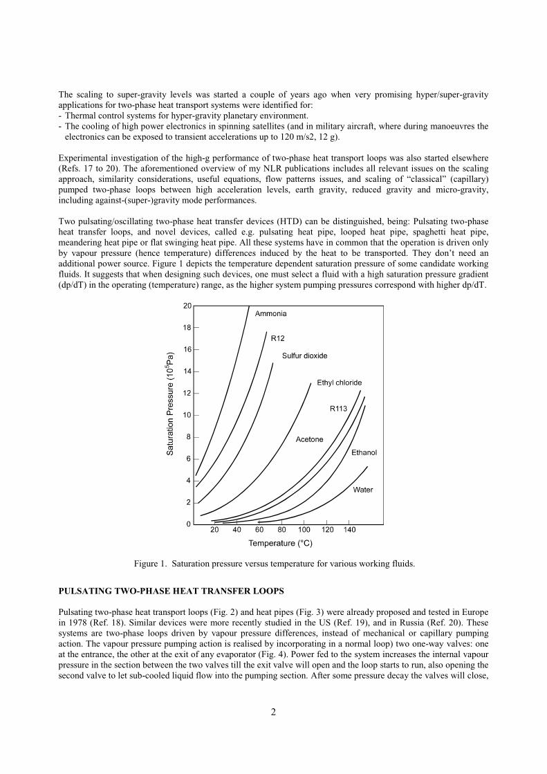
Two pulsating/oscillating two-phase heat transfer devices (HTD) can be distinguished, being: Pulsating two-phaseheat transfer loops, and novel devices, called e.g. pulsating heat pipe, looped heat pipe, spaghetti heat pipe,meandering heat pipe or flat swinging heat pipe. All these systems have in common that the operation is driven onlyby vapour pressure (hence temperature) differences induced by the heat to be transported. They don’t need anadditional power source. Figure 1 depicts the temperature dependent saturation pressure of some candidate workingfluids. It suggests that when designing such devices, one must select a fluid with a high saturation pressure gradient(dp/dT) in the operating (temperature) range, as the higher system pumping pressures correspond with higher dp/dT.
PULSATING TWO-PHASE HEAT TRANSFER LOOPS
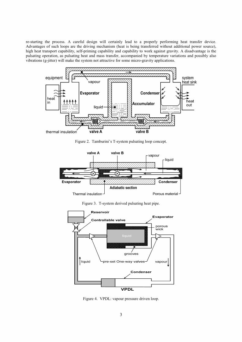
Pulsating two-phase heat transport loops (Fig. 2) and heat pipes (Fig. 3) were already proposed and tested in Europein 1978 (Ref. 18). Similar devices were more recently studied in the US (Ref. 19), and in Russia (Ref. 20). Thesesystems are two-phase loops driven by vapour pressure differences, instead of mechanical or capillary pumpingaction. The vapour pressure pumping action is realised by incorporating in a normal loop) two one-way valves: oneat the entrance, the other at the exit of any evaporator (Fig. 4). Power fed to the system increases the internal vapourpressure in the section between the two valves till the exit valve will open and the loop starts to run, also opening thesecond valve to let sub-cooled liquid flow into the pumping section. After some pressure decay the valves will close,
Figure 1. Saturation pressure versus temperature for various working fluids.
3
re-starting the process. A careful design will certainly lead to a properly performing heat transfer device.Advantages of such loops are the driving mechanism (heat is being transferred without additional power source),high heat transport capability, self-priming capability and capability to work against gravity. A disadvantage is thepulsating operation, as pulsating heat and mass transfer, accompanied by temperature variations and possibly alsovibrations (g-jitter) will make the system not attractive for some micro-gravity applications.
Figure 2. Tamburini’s T-system pulsating loop concept.
Figure 3. T-system derived pulsating heat pipe.
Figure 4. VPDL: vapour pressure driven loop.

2
NOVEL HEAT PULSATING/OSCILLATING HEAT TRANSFER DEVICES
Novel oscillating and pulsating devices have many fancy names, like bubble-driven heat transfer device (Ref.21),oscillation controlled HTD (Ref. 22), pulsating or meandering heat pipe (Refs. 22, 23), looped capillary heat pipe orcapillary tunnel heat pipe (Refs. 24, 25), flat swinging heat pipe (Ref. 26), and spirally wound or serpentine-like heatpipe (Ref. 27). Figure 5 shows a schematic of a section of such a device, called looped (Ref. 28) or closed-loop (Ref.22) if the two legs at each end are not dead ends but interconnected, thus creating a closed loop configuration. If thelatter configuration has a spring-like geometry like the arrangement discussed in the references 28 and 29, theoperation of the device has been frequently observed to stabilise after a certain start-up period, producing a periodicpumping of almost constant frequency into one direction (Ref. 29). Such behaviour is very similar to the behaviourof the pulsating heat transfer loops. This similarity suggests that the function of valves in the pulsating heat transferloops is now delivered by stick-slip conditions of the slug-plug distribution of the working fluid in the closed- loopspring-like meandering structure, whose heating and cooling sections have also a certain periodicity. Anyhow, theslug-plug distribution is essential for these oscillating devices, which can be equipped with or without valves.
Figure 5. Schematics of a meandering heat pipe.
Liquid SectionsTABLE 1.
Relevance of π-numbers for thermal-Gravitational scaling of two-phase loops Adiabatic Heating/Cooling
EvaporatorSwirl &
Capillary
Vapour &2-PhaseSections
Condenser
π1 = D/L = geometry
π2 = Rel = (ρvD/µ)l = inertia/viscous
π3 = Frl = (v2/gD)l = inertia/gravity
π4 = Eul = (∆p/ρv2)l = pressure head/inertia
π5 = cos ν = orientation with respect to g
π6 = S = slip factor = vv/vl
π7 = density ratio = ρv/ρl
π8 = viscosity ratio = µv/µl
π9 = Wel = (ρv2D/σ)l = inertia/surface tension
π10= Prl = (µCp/λ)l
π11= Nul = (hD/λ)l = convection/conduction
π12= λv/λ l = thermal conductivity ratio
π13= Cpv/Cpl = specific heat ratio
π14= ∆H/hlv = Boil =enthalpy nr. = X = quality
π15= Mol = (ρlσ3/µl4 g) = capillarity/buoyancy
π16= Ma = v/(∂p/∂ρ)s1/2
π17= (h/λ l)(µl2g)1/3
π18= L3ρl2 g hlv/λ lµl(T-To)
•••••
•••••
••
•
••••••••••••••••••
••/••/••••/•
•/••
••••••••••••••••••

3
The velocities of bubbles and slugs in a tube are governed by buoyancy, liquid inertia, liquid viscosity and surfacetension forces, in the general case of bubbly or slug-plug flow in a gravity field. This means that properly chosendimensionless groups can be very helpful to discuss the aspects of slug-plug flow in oscillating devices (Ref. 30).The groups can be used together with the groups shown in Table 1 and in the figures 6 and 7, taken from dimension-analytical considerations discussed in the aforementioned overview articles and their references (Refs. 1 to 14, 31).
Figure6. ! l.σ3/µl4 versus temperature for six fluids.
Figure 7. ("�! l )½
= D.g½/(We/Fr)½ versus temperature.
The condition of slug-plug distribution determines the maximum inner capillary tube diameter (Refs. 30, 32, 33) to be
dmax = 1.836 g-1/2 ["��! l – !v)]1/2 ≈ 1.836 g-1/2� � �" ! l)1/2 , (1)
for ! l >> !v. Consequently, the thermal-gravitational scaling of the inner tube diameter can be derived from figure 7.
The slug-plug condition also sets the lower limit of the slug (bubble) size: It shall be at least 0.6 times the tube diameter(Refs. 30, 32, 33). This requirement has impact on the liquid filling ratio (1 − α). If not fulfilled, the bubbles will be toosmall to give slug flow, characterised by high heat transfer density. Bubbly flow means far less efficient heat transfer.
Alternative useful plots of dimensionless numbers (Ref. 30) are shown in the figures 8 and 9. Figure 8 depicts thedimensionless velocity v* as a function of Morton number Mo (see Table 1) and Eötvös Eö or Bond number Bo:
v* = v [g d (1 – !v/! l)] -½ ≈ v / (g d) ½ , (2)
Eö = 4 Bo = We/Fr = g d2 (! l - !v)/ σ ≈. g d2 ! l /σ. (3)
Figure 9 depicts experimental data in the alternative plotting (Ref. 30): v* as a function of the inverse viscosity numberMu, for different values of Archimedes number Ar. The dimensionless numbers Mu and Ar are given by:
Mu = µl [g d3 (! l – !v) ! l] -1/2 ≈ µl (g d3� ! l2) –1/2, (4)
(Ar)2 = Mo = (! l σ3/µl4 g) / (1 – !v /! l] ≅ ! l σ3/µl
4 g . (5)

2
Figure 8. Dimensionless velocity v* as a function ofthe Morton number Mo and the Eötvös number Eö.
Figure 9. Experimental dimensionless velocity v* dataas a function of dimensionless inverse viscosity Mu.
The three asymptotes shown are: v* = 0.345 for Eö > 100 and Mu < 10-3 (the inertia dominant domain), v*. Mu = 10-2
for Eö > 100 and Mu > 0.5 (the viscosity dominant domain), and Mu2. Ar = 0.16 and Eö < 3.37 (the surface tensiondominant domain). The last domain is the most important for the oscillating devices considered here, as Eö < 3.37straightforwardly leads to the maximum tube diameter (eq. 1) and dominating surface tension means that plug-slugsdo not move, if there is no (thermal) power input. In this domain slug flow is guaranteed by surface tension, if slugbubbles have diameters of at least 0.6 times the tube diameter.
Some quantitative considerations on these pulsating two-phase heat transfer devices are presented later on, in order toget a certain feeling for or a better understanding of how to design, scale and test such devices. Geometrical data andsome performance figures of the in the next chapter described single-phase oscillating heat transfer device will be used.
Anticipating later sections it is already remarked that the advantages of a PHP/OHP as compared to normal heat pipesare the starting and restarting without problems, insensitivity for non-condensible gases, and low production costs.Drawbacks are vulnerability to puncture (one puncture destroys the entire system), and lower thermal conductivityand inherent non-isothermal operation. However, these systems are proven to be attractive for applications in high gacceleration environments (Refs. 15, 26). It is stressed that both vapour pressure driven pulsating heat transfer loopsand a novel PHP/OHP require a working fluid with a steep dp/dT. The latent heat of evaporation of the fluid shall belarge in the pulsating heat transfer loops as the heat transfer is mainly by this latent heat. In a PHP/OHP the latentheat shall be small (in order to guarantee very fast growing vapour plugs which drive these systems. The specificheat of the fluid shall be large, as in the latter systems the heat transfer is mainly by caloric heat.
A SINGLE-PHASE HEAT TRANSFER DEVICE AS THE BASELINE TO COMPARE DATA
Single-phase oscillating heat transport devices are discussed here, as not only the modelling of these devices is veryuseful to understand the operation of pulsating and oscillating heat pipes. Such a single-phase oscillating heat transferdevice, depicted in figure 10, can namely be used as a baseline to compare experimental results of pulsating oroscillating heat pipes. Detailed discussions on this synchronised forced oscillatory flow heat transfer device are givenin the publications of the originators (Refs. 34 to 36) and in other publications on this device (Refs. 21, 23, 38, 39),respectively on related phase-shifted forced oscillatory flow heat transfer devices (Refs. 21, 23).
The set-up consists of two reservoirs at different temperatures, connected by a 0.2 m long, 12.7 mm inner diameteracrylic tube, containing 31 glass capillaries with an inner diameter d = 1 mm. The open cross-sectional area of thecapillary structure, including the triangular sections between the capillaries, Al was determined to be 67 mm2, being53% of the total inner cross-sectional area of the tube (A = 127 mm2). The reservoirs are equipped with flexible

7
membranes. A variable frequency shaker is used to oscillate the incompressible working liquid inside the capillarystructure. Frequency f is variable from 2 and 8 Hz. The tidal displacement ∆z is variable between 20 and 125 mm.The operation is. Starting with the capillary structure filled with hot liquid, this liquid is replaced in the first half ofthe oscillation period, by liquid from the cold reservoir, except a thin (Stokes) boundary layer. Heat is nowexchanged very effectively in radial direction between the hot Stokes layer and the cold core. Heat accepted by thecore is removed to the cold reservoir in the second half of the oscillation period. The heat flow, via the liquid,between the reservoirs equals for a temperature difference ∆T between hot and cold reservoir (κeff is the effectivethermal diffusivity , #eff is the effective thermal conductivity):
Q = #eff (Al/L) ∆T = ! l Cpl κeff (Al/L) ∆T. (6)
Figure 11 shows the experimentally determined effective thermal diffusivity as a function of tidal displacement andoscillation frequency, for a device with glass capillaries and water as working fluid. The solid lines are analyticalpredictions from the laminar theory. The figure indicates that the effective thermal conductivity via the liquid is
#eff = B ρl Cpl { (∆z)2 / (d/2)} (2π f µl /ρl)1/2. (7)
The proportionality factor B, the tangent of the straight lines in figure 11, can be written as (Refs. 34, 35):
B = 2-5/2 Prl-1 B’ + B” − B’B” (1 + Prl
1/2) ∗{ Prl-1/2 − 2 (1 + Prl)}) . (8)
B’ = Prl / (Prl − 1) and B” = { (1 − B’) (Prl κl / κwall)1/2 − B’ #l / #wall )}∗{ #l / #wall + (κl / κwall)
1/2} -1. (9)
An important conclusion for future design activities can be drawn by considering equations (6) to (9): The highestvalues of proportionality factor B occur for small Prandtl number fluids and well thermal conductors walls (Ref. 35).
An alternative representation is obtained by defining an enhancement (proportionality) factor E for undevelopedoscillating flow in synchronised systems
(#eff / #l) -1 = (κeff / κl) -1 = (Prl ∆z /2d)2 E. (10)
E depends on the dimensionless Womersley number (analogue to the Schmidt number for axial contaminationpropagation and for pulmonary ventilation)
Wol = (d/2) (2π f ! l / µl )1/2 . (11)
Figure 10. Synchronised forced oscillatory flow HTD. Figure 11. Experimental effective thermal diffusivity.

19
It can be approximated by
E = Wol4 / 24 , for Wol << 1, and E = Wol (Wol − 2-1/2 ) , for Wol << 1 . (12)
Figure 12 shows the enhancement factor E as a function of Womersley number, for three decades of the Prandtlnumber: 0.1, 1 and 10 (Refs. 35, 37).
Figure 12. Enhancement factor E versus Wo and Pr.
Inserting the properties of water at 293 K (20 °C), d = 1 mm, ∆z = 125 mm and f = 8 Hz (hence Prl = 6.9 and Wol =3.55), yields (according to figure 3) for the above synchronised device an enhancement factor 0.14. Thecorresponding #eff (about 1.2 ∗ 104 W/m.K) means a power density slightly above 3 ∗ 106 W/m2. This is confirmed bythe experimental data: 2.9∗ 106 W/m2 for a gradient of 280 K/m (Ref. 34). The total effective thermal conductivity isroughly 5000 W/m.K, if based on the total cross-sectional tube area, including insulating glass walls.
A similar expression has been derived for undeveloped oscillating flow in phase-shifted systems (Ref. 21):
#eff = #l {1 + 0.707 (1 + Prl-1)-1 (1 + Prl
-1/2)-1}∗{ (∆z)2/(d/2)}{ (2π f ! l Cpl/#l)1/2} . (13)
Inserting again the properties of water at 293 K, d = 1 mm, ∆z = 125 mm and f = 8 Hz yields #eff = 2.5∗ 104 W/m.K,being 2.5 times the value of the corresponding synchronised forced oscillatory flow heat transfer device.
Disadvantages of the concepts are poor current state of the art and power consumption of the shaker. The latter, morethan 5 W in the described cases, strongly increases with oscillation frequency and tidal displacement. Disadvantagefor some micro-gravity applications is the noise introduced by the shaker.
The major advantage of the concepts is their variable conductance, which is adjustable via the frequency and tidaldisplacement from almost zero (liquid in rest in a poorly conductance structure) to values comparable to or evenbetter than heat pipes. This makes such devices very useful for instance to drain huge amounts of thermal power froma hot vessel for nuclear reactor cooling, in an emergency case.
Anticipating the section dealing with the definition of the future testing approach, it is remarked that the aboveequations and the corresponding figures straightforwardly can be transformed to other single-phase oscillatingdevices using different working fluids, and having different capillary diameters, cross-sections, lengths and tidaldisplacements, etc. Consequently these transformations can be used to properly interpret the experimental outcomesof the novel oscillating and pulsating two-phase heat transfer devices discussed.

20
REVIEW OF THE MOST RELEVANT PHP & OHP PAPERS PUBLISHED TILL MID 2001
The most relevant publications on the subject up to mid 2001 (Refs. 15, 21, 22, 26, and 41 to 59) contain theinformation summarised in table 2 below.
TABLE 2.Survey
Type Fluid Charge (%) (°)
Channelmm/mm2
Turns(Channels)
ChannelLength
Remarks and Comments
Ref. 41 OHP ethanol 20-80 0 to 90 1.5x1.5 (8) 220 mm Visualisation study
Ref. 42 OHP R142b 20-80 30 to 90 1.5x1.5 (20) 220 mm Many, many useful dataRef. 43 PHP ethanol
R123water
50 -90 to+90
2 mm ID (20) l 10 m intotal
ExperimentalQmax/Q0 =1.8 + 0.06Le
Qmax/Q0 =2.53 + 0.001hlv
Ref. 44 OHP water 30-80 0 to 90 2 mm ID (up to 150) 17.5 /11.155 m in total
ExperimentalR/Rmax = 15.775 N-1.1042
Ref. 45 OHP water 40-80 0 mainly 2 mm ID (8) 120 mm Useful: Experimental & TheoreticalRef. 46 PHP water? 50 0 unknown 3 (4) 300 mm Useful: Theoretical onlyRef. 47 ?? water various various
Possible1.5 mm ID (8) 110 mm Visualisation study on special
structure conceptRef. 48 OHP water
ethanol10-70 0 & 90 2.2x2.0
1.5x1.02 mm ID
12 and 10 104 and145 mm
Useful: Experimental & TheoreticalConclusion: Need for fluid havinghigher dp/dT than water and ethanol
Ref. 21 OHP waterethanolR142bsoapsud
20-98 0 ID 1.8, 5,2.4 mmmainly
4 (4) 396 mm Performance as a function ofILOO � FKDUJH� � 7� DQG� ,'� ZDV$
investigated
Ref.22 OHP water 30-95 90 2.4 mm ID (20) 290 mm Performance versus fill chargeRef.49 OHP water 50 0? 1 mm ID 4 (4) 150 mm Theoretical onlyRef.50 OHP water ..50 0 0.96 ID 8 (8) 430 mm Performance versus resistanceRef.15 PHP acetone 60 -90/0/90 1.1 mm ID 23 (48) 420 mm Performance in –6 to +12 gRef.26 PHP
andOHP
acetone,water,ethanol,FC-87
0-50 -90/0/90
-90
1.2x1.2 and1 mm ID
(48) 100 mm Performance in –8.4 to +8.4 g ofan aluminium PHP.Visualisation study of glassOHP at –90° in 1g
Ref.51 OHP R134a ~50 -90/0/90 2 mm ID (28) 600 mm Check valves impact is positive. Further strange, unusual results
Ref.52 PHP R142b 42 0 2 mm ? (50) 273 mm Visualisation studyRef.53 OHP R142b 50 0 to 90 1 & 2 mm 1 turn D: 200, 300
400 mmChaos theory predictions: InterestingBut strange also
Ref.54 PHP/OHP
R142b 20-90 0 to 90 2 mm ID (16) 400 or 500 mm
Visualisation study: Many, manyuseful data
Ref.55 OHP/PHP
R142b 40-80 60 2 mm ID 3, 4, 5, 6/ 6
? PHP performs between T-shaped OHP afully Looped OHP
Ref.56 ? ? ? Any 2.2 mm ID 1500 250 mm Kenzan, no Heat Lane informationRef.57 PHP pentane ? ? 2 mm ID 2 510 total Visualisation and ModellingRef.58 Open water ? *) 3.34 ID 2 400 total *) Heater above condenser.Ref.59 OHP
PHPwater ? *) 3.34 ID ? 515 total *) Heater above condenser
Theory to be improved
When looking at this table and the contents of the abstracts and corresponding references, it can be concluded that:- The majority of the experiments do not constitute a good basis for a systematic approach. Up to know the overall
picture looks rather random and chaotic (except for the work presented in the references 42 to 45, 48, 21, 15, 54and 55). Co-ordination, being completely absent, is to be realised as soon as possible.
- The results of the most promising theoretical papers (refs. 45, 46) suggest that a critical combination of the twomodels and model equations, some adaptations and additions, will lead to an improved model which properlydescribes OHP/PHP behaviour, thus making the understanding of their operation much clearer.
- Fill charges below 30 % and above 80 % are to be avoided, as they lead to reduced performance or even tofailures.
21
- OHP’s show the far better performance, certainly in the evaporator above the condenser mode.- Only limited evaporator above the condenser mode data is available. For acceleration levels above 1-g (9.8 m/s2)
the extremely scarce data is restricted to the references 15 and 26. This must change because of the differentpromising applications foreseen in hyper-gravity environments.
- As stated already in the introduction ethanol and water are unattractive working fluids, because of low dp/dT.This is confirmed experimentally (Ref.48).
- Incorporation of one-way (check) valve(s) may improve OHP performance (Ref. 51).- A hydraulic channel diameter around 2 mm is favoured by most OHP/PHP researchers. It has sense to define this
as a kind of a “standard” for future terrestrial research, in order to allow comparison with future and alreadyexisting data. For hyper-gravity applications a reduced diameter (around 1 mm) is recommended.
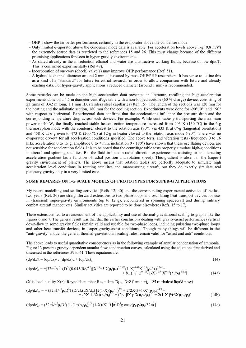
Some remarks can be made on the high acceleration data presented in literature, recalling the high-accelerationexperiments done on a 4.5 m diameter centrifuge table with a non-looped acetone (60 % charge) device, consisting of23 turns of 0.42 m long, 1.1 mm ID, stainless steel capillaries (Ref. 15). The length of the sections was 120 mm forthe heating and the adiabatic section, 180 mm for the cooling section. Experiments were done for -90°, 0°, and +90°with respect to horizontal. Experimental data confirms that the accelerations influence the pressure drop and thecorresponding temperature drop across such devices. For example: While continuously transporting the maximumpower of 40 W, the finally reached stable heater section temperature increased from 403 K (130 °C) in the 6-gthermosyphon mode with the condenser closest to the rotation axis (90º), via 433 K at 0º-g (tangential orientation)and 458 K at 6-g even to 473 K (200 °C) at 12-g in heater closest to the rotation axis mode (-90º). There was noevaporator dry-out for all acceleration conditions specified. The above tests, and vibration tests (frequency 0 to 16kHz, acceleration 0 to 15 g, amplitude 0 to 7 mm, inclination 0 - 180°) have shown that these oscillating devices arenot sensitive for acceleration fields. It is to be noted that the centrifuge table tests properly simulate high-g conditionsin aircraft and spinning satellites. But the fluid in lines in radial direction experiences an assisting or counteractingacceleration gradient (as a function of radial position and rotation speed). This gradient is absent in the (super-)gravity environment of planets. The above means that rotation tables are perfectly adequate to simulate highacceleration level conditions in rotating satellites and manoeuvring aircraft, but they do exactly simulate realplanetary gravity only in a very limited case.
SOME REMARKS ON 1-G SCALE MODELS OF PROTOTYPES FOR SUPER-G APPLICATIONS
My recent modelling and scaling activities (Refs. 12, 40) and the corresponding experimental activities of the lasttwo years (Ref. 26) are straightforward extensions to two-phase loops and oscillating heat transport devices for usein (transient) super-gravity environments (up to 12 g), encountered in spinning spacecraft and during militarycombat aircraft manoeuvres. Similar activities are reported to be done elsewhere (Refs. 15 to 17).
These extensions led to a reassessment of the applicability and use of thermal-gravitational scaling to graphs like thefigures 6 and 7. The general result was that that the earlier conclusions dealing with gravity-assist performance (verticaldown-flow in some gravity field) remain valid and useable for two-phase loops, including pulsating two-phase loopsand other heat transfer devices, in “super-gravity-assist conditions”. Though many things will be different in the“anti-gravity” mode, the general thermal-gravitational scaling rules remain valid for “assist and anti” conditions.
The above leads to useful quantitative consequences as in the following example of annular condensation of ammonia.Figure 13 presents gravity dependent annular flow condensation curves, calculated using the equations first derived anddiscussed in the references 59 to 61. These equations are:
(dp/dz)t = (dp/dz)f + (dp/dz)m + (dp/dz)g (14)
(dp/dz)f = −(32m2/π2!vD5)(0.045/Rev
0.2)[X1.8+5.7(% l/%v)0.0523(1-X)0.47X1.33(!v/! l)
0.261+ + 8.1(% l/%v)
0.105(1-X) 0.94X0.86(!v/! l) 0.52] (14a)
(X is local quality X(z), Reynolds number Rev = 4m./π'%v , & �� �ODPLQDU�� � � � �� � �WXUEXOHQW� OLTXLG� IORZ��
(dp/dz)m = − (32m.2�'2!vD5) (D/2).(dX/dz) [2(1-X)(!v/! l)
2/3 + 2(2X-3+1/X)(!v/! l)4/3 +
� � � � � � � � � � � � � � � � � � � � � � � � � � � � � � � � � � � � � � � � � � � � � � � � � � � �� ��;�� � ;��& !v/! l)1/3 � � � �� � �& & &;� �;��!v/! l)
5/3 � � � ��� �;� � ;��& & !v/! l)] (14b)
(dp/dz)g = (32m.2�'2!vD5){1-[1+(!v/! l)
2/3 (1-X)/X]-1` >'2D5g cosν(! l�!v�!v/32m.2] (14c)
22
(1 - α)/α = S (!v/! l) X /(1- X) (15)
S = (! l/!v)1/3 (16)
m. hlv(dX/dz) = - hπD[T(z)-Ts] (17)
h = 0.018(#l ! l1/2�% l) Prl
0.65 |-(dp/dz)t|1/2 D1/2 + R (4λl/D) ln [1 + (!v/! l)
2/3 (1-X)/X] 0 < R< 1. (18)
∆pt = ∫Lc
0
(dp/dz)t.dz . (19)
F (dX/dz, X) = 0. (20)
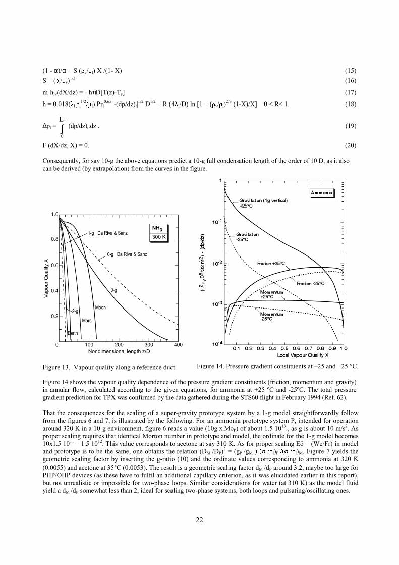
Consequently, for say 10-g the above equations predict a 10-g full condensation length of the order of 10 D, as it alsocan be derived (by extrapolation) from the curves in the figure.
Figure 13. Vapour quality along a reference duct.
Figure 14 shows the vapour quality dependence of the pressure gradient constituents (friction, momentum and gravity)in annular flow, calculated according to the given equations, for ammonia at +25 ºC and -25ºC. The total pressuregradient prediction for TPX was confirmed by the data gathered during the STS60 flight in February 1994 (Ref. 62).
That the consequences for the scaling of a super-gravity prototype system by a 1-g model straightforwardly followfrom the figures 6 and 7, is illustrated by the following. For an ammonia prototype system P, intended for operationaround 320 K in a 10-g environment, figure 6 reads a value (10g x.MoP) of about 1.5 1013., as g is about 10 m/s2. Asproper scaling requires that identical Morton number in prototype and model, the ordinate for the 1-g model becomes10x1.5 1011 = 1.5 1012. This value corresponds to acetone at say 310 K. As for proper scaling Eö = (We/Fr) in modeland prototype is to be the same, one obtains the relation (DM /DP)2 = (gP /gM� � � � � �" ! l)P �� � �" ! l)M. Figure 7 yields thegeometric scaling factor by inserting the g-ratio (10) and the ordinate values corresponding to ammonia at 320 K(0.0055) and acetone at 35°C (0.0053). The result is a geometric scaling factor dM /dP around 3.2, maybe too large forPHP/OHP devices (as these have to fulfil an additional capillary criterion, as it was elucidated earlier in this report),but not unrealistic or impossible for two-phase loops. Similar considerations for water (at 310 K) as the model fluidyield a dM /dP somewhat less than 2, ideal for scaling two-phase systems, both loops and pulsating/oscillating ones.
Figure 14. Pressure gradient constituents at –25 and +25 °C.
23
But as said: many things will be different in “assist and anti” conditions. This is clearly illustrated by figure 14, ifone looks at the fact that at +25 ºC gravity overrules the other pressure constituents, hence is the driving mechanism,for quality values up to approximately 0.7. The curve for 10 g is simply obtained by shifting the gravity curve onedecade upwards, which means that gravity is overwhelming the other constituents up to a quality of say 0.97 (wherethe flow pattern is homogeneous). When the direction of gravity is reversed, the situation is clearly different.Gravity will act against the other constituents, meaning fall back of the liquid, which initially leads to a steepincrease of the saturation temperature to deliver the vapour pressure needed to maintain transport (of course not inthe annular flow pattern anymore, but in the churn or slug/plug flow regime), but soon stopping the flow in theabove mentioned quality ranges.
A complicating factor is the fact that the pressure drops substantially increase, and the equations, derived for nearlyisothermal conditions (hence constant fluid properties), no longer hold and have to be replaced by far morecomplicated ones. The latter is also valid for pulsating/oscillating devices, which essentially need, to operate,relatively large temperature differences between evaporator and condenser.
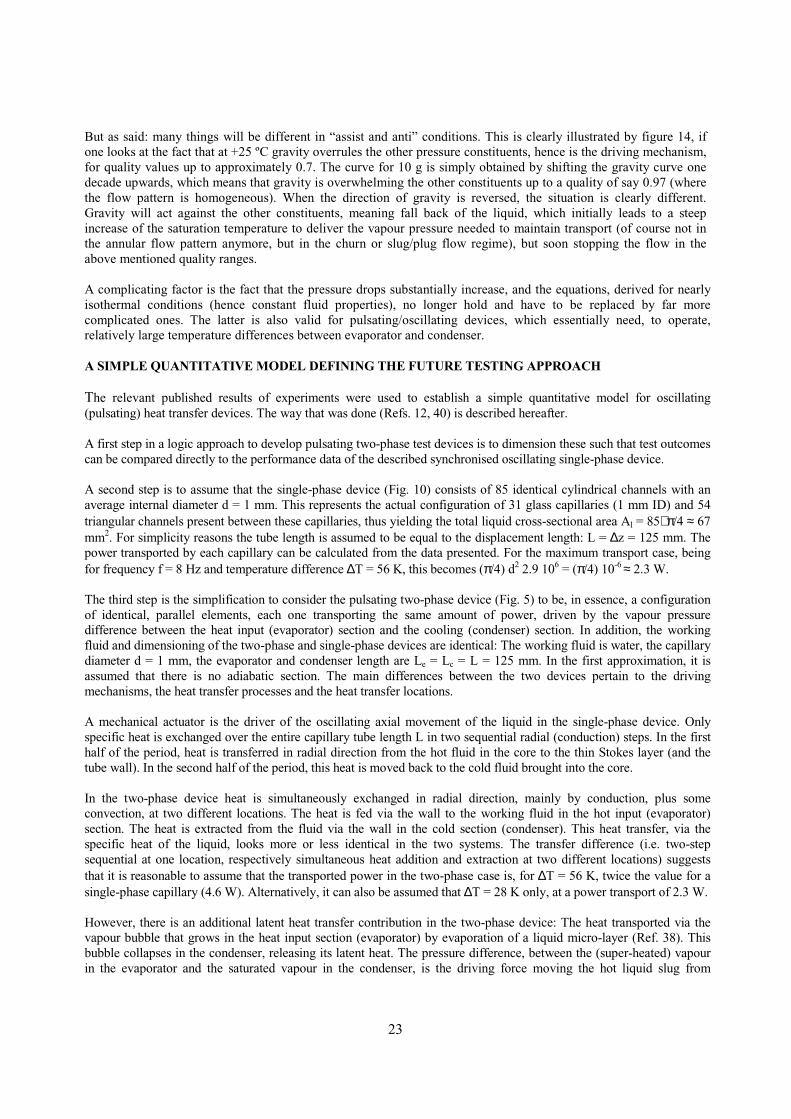
A SIMPLE QUANTITATIVE MODEL DEFINING THE FUTURE TESTING APPROACH
The relevant published results of experiments were used to establish a simple quantitative model for oscillating(pulsating) heat transfer devices. The way that was done (Refs. 12, 40) is described hereafter.
A first step in a logic approach to develop pulsating two-phase test devices is to dimension these such that test outcomescan be compared directly to the performance data of the described synchronised oscillating single-phase device.
A second step is to assume that the single-phase device (Fig. 10) consists of 85 identical cylindrical channels with anaverage internal diameter d = 1 mm. This represents the actual configuration of 31 glass capillaries (1 mm ID) and 54triangular channels present between these capillaries, thus yielding the total liquid cross-sectional area Al = 85∗π/4 ≈ 67mm2. For simplicity reasons the tube length is assumed to be equal to the displacement length: L = ∆z = 125 mm. Thepower transported by each capillary can be calculated from the data presented. For the maximum transport case, beingfor frequency f = 8 Hz and temperature difference ∆T = 56 K, this becomes (π/4) d2 2.9 106 = (π/4) 10-6 ≈ 2.3 W.
The third step is the simplification to consider the pulsating two-phase device (Fig. 5) to be, in essence, a configurationof identical, parallel elements, each one transporting the same amount of power, driven by the vapour pressuredifference between the heat input (evaporator) section and the cooling (condenser) section. In addition, the workingfluid and dimensioning of the two-phase and single-phase devices are identical: The working fluid is water, the capillarydiameter d = 1 mm, the evaporator and condenser length are Le = Lc = L = 125 mm. In the first approximation, it isassumed that there is no adiabatic section. The main differences between the two devices pertain to the drivingmechanisms, the heat transfer processes and the heat transfer locations.
A mechanical actuator is the driver of the oscillating axial movement of the liquid in the single-phase device. Onlyspecific heat is exchanged over the entire capillary tube length L in two sequential radial (conduction) steps. In the firsthalf of the period, heat is transferred in radial direction from the hot fluid in the core to the thin Stokes layer (and thetube wall). In the second half of the period, this heat is moved back to the cold fluid brought into the core.
In the two-phase device heat is simultaneously exchanged in radial direction, mainly by conduction, plus someconvection, at two different locations. The heat is fed via the wall to the working fluid in the hot input (evaporator)section. The heat is extracted from the fluid via the wall in the cold section (condenser). This heat transfer, via thespecific heat of the liquid, looks more or less identical in the two systems. The transfer difference (i.e. two-stepsequential at one location, respectively simultaneous heat addition and extraction at two different locations) suggeststhat it is reasonable to assume that the transported power in the two-phase case is, for ∆T = 56 K, twice the value for asingle-phase capillary (4.6 W). Alternatively, it can also be assumed that ∆T = 28 K only, at a power transport of 2.3 W.
However, there is an additional latent heat transfer contribution in the two-phase device: The heat transported via thevapour bubble that grows in the heat input section (evaporator) by evaporation of a liquid micro-layer (Ref. 38). Thisbubble collapses in the condenser, releasing its latent heat. The pressure difference, between the (super-heated) vapourin the evaporator and the saturated vapour in the condenser, is the driving force moving the hot liquid slug from

24
evaporator to condenser, plus moving at the same moment a similar cold slug from condenser back to the same or aneighbouring evaporator. The power transported by latent heat can be obtained by calculating the energy needed tocreate 8 bubbles, of length L and diameter d, per second. Consequently one obtains 8 (π/4) d2 Lρv hlv = 8 (π/4) 10-6
(0.125) (0.2) (2.25∗ 106 ≈ 0.45 W, which constitutes a minor, but non-negligible contribution.
The pressure head across the capillary single-phase water system can be calculated as follows. The displacement of 125mm at frequency 8 Hz yields a liquid velocity v = 2 m/s. For water around 300 K, the Reynolds number Rel is around2000, which means laminar flow. Consequently, the required pressure drop is 8 kPa, according to the equation
∆p = 4 ∗ (16 / Rel) (L / d) (ρl v2 / 2). (21)
In the corresponding two-phase device the required pressure difference has to be far larger, because of several reasons.In the first place twice the single-phase device mass (a hot and a cold slug) has to be moved. Secondly, this double masshas to be forced through a 180 degrees bend instead a straight channel. Further, the length of the adiabatic section (La) isof course, in reality, never equal to zero. Finally, the process concerns all except fully developed flow, hence there is aliquid acceleration term to be added.
To get a feeling for the magnitude of these pressure enlarging effects, the length La is taken to be also 125 mm (La = L),as an example. This has impact on the contribution of the power transport via the latent heat of evaporation. Thiscontribution will be around 0.9 W, since the length of each of the 8 vapour bubbles, being generated and collapsing inone second, is La + L (hence 2L, instead L). The average liquid velocity becomes v = 4 m/s. For water around 300 K,the Reynolds number Rel now lies around 4000, which means turbulent flow. Consequently the required pressure drophas to be calculated according to
∆p = 4 (0.0791) Re-¼ (L / d) (ρl v2 / 2). (22)
As discussed in textbooks (e.g. Ref. 63), the effect of the two bends can be accounted for by adding an extra length of50 D. The pressure drop can now be calculated, according to equation (22), by inserting the different parameter valuesand by replacing L by 2 (2L + 50 d). The result is 480 kPa. To be complete an inertia term, accounting for theacceleration of the slugs eight times per second, has to be added: 8 (ρl v
2 / 2), hence 16 kPa, yielding about 500 kPa forthe pressure difference required. Hence it can be concluded, from the water curve in figure 1, that the two-phase devicehas to operate at a hot section temperature of at least 350 K, to be able to deliver the pressure drop required. Figure 1makes also clear that more or less comparable power can be transported by ammonia, R12, acetone, etc. Though atcomparable ∆T’s, this will be realised at far lower operating temperatures, as these fluids show a steeper dp/dT-relation.
The results of the above simple approach and of the detailed modelling of the physical processes, including mass-springsimulations, currently is compared and will be compared in the near future to experimental data, resulting from furtherexperimenting at NLR. The experimental activities include many high-acceleration experiments on a rotation table. Theexperiments have been, are, and will be carried out both with all-metal devices, and with all-glass devices (Ref. 26).Additional experiments will be executed with a helical (spring-like) configuration of transparent (PTFE or polyethylene)flexible tubing, equipped with a simple one-way valve to influence direction and frequency of the periodic behaviour ofa closed-loop configuration. Experiments pertain to various working fluids and locations of hot and cold sections, todifferent lengths of adiabatic section, to various orientations, and to different acceleration levels in various directions.
VERSATILE TEST RIG, TEST SET-UP, TEST PROGRAMME AND PROCEDURES
Several references cited in table 2 discuss many excellent, but fully different, test set-ups. As an example I’lldescribe here the versatile rig for experimenting with different pulsating/oscillating HTD’s designed and built atISAS. The rig is shown in the drawing (Fig. 15) and the photograph (Fig. 16). Figure 17 depicts the set-up.
The test section of the rig (left) consists of a steel frame, which can be rotated with respect to the steel support(right) to allow the investigation of tilt on the HTD performance. The inclination can be arbitrarily adjusted withinthe range between the +90 degrees full thermosyphon mode (condenser vertical above evaporator) and the -90degrees full anti-gravity mode (evaporator on top, vertical above condenser). Both the evaporator section and thecondenser section are as good as possible thermally isolated: from the steel frame by spacers of insulating materials,to minimise the thermal leak path through the frame, from the environment by covers of polystyrene.

25
Figure 15. Versatile rig for experimenting with looped oscillating and closed end pulsating HTD’s.
Figure 16. Picture of the versatile test rig.

18
The evaporator section is heated by an electric (Semicon) heater element. Input voltage (V) and current (I) will bePHDVXUHG� � 7KH� FRQGHQVHU� VHFWLRQ� LV � OLTXLG� FRROHG� � 7KH� FRRODQW� IORZ� UDWH � � � � LV � PHDVXUHG� � 7KH� WHPSHUDWXUH � GLIIHUHQFH(EHWZHHQ� FRRODQW� DW� WKH � RXWOHW� DQG� DW� WKH � LQOHW� � 7�� LV � PHDVXUHG� DOVR�$
The basic test item is a closed end HTD, a Pulsating Heat Pipe (PHP), consisting of 180 degrees bent stainless steeltubes (OD 3 mm, ID 2 mm) in the condenser and evaporator sections, connected by flexible transparent PTFE tubing(OD 3 mm, ID 2 mm). The length of the latter (162 mm) tubing can be increased to study the influence of length on thePHP performance. Currently this implies non-straight transparent sections, which is not ideal for flow visualisation.This problem can be solved easily by cutting the frame in two halves, which can be bolted to steel.(connecting)interface parts at both sides. The latter parts are rotatable with respect to the steel support. Each one must have severalholes (or one long elliptic hole) to realise mounting of the frame halves in different ways, in order to meet longer PHPdimensions. In this way it can be guaranteed that the transparent sections are always straight.The rig is equipped with various thermocouples measuring the temperatures at crucial locations and a pressure sensor atthe filling valve to study the history of internal PHP. A second pressure gauge is foreseen at the draining valve.
Parameters, which can be varied, are the already mentioned inclination with respect to gravity, input power, the coolantflow rate (to obtain a balance between LVRWKHUPDOLW\� DQG� D� PHDVXUDEOH � 7�� � SOXV � WKH � ILOOLQJ� UDWLR�$
In order to change from the PHP configuration to the looped Oscillating Heat Pipe (OHP) configuration in a later phaseof the experimental programme, the filling tube and the draining tube are to be connected by a tube. This can be easilyrealised by adding T-pieces at the filling and draining lines. By installing a valve in this line, one can simply changeswitch between the OHP and PHP options. The including of one-way valves, to study their impact on the performance,is even simpler: They can be inserted almost everywhere in the transparent tubing.
I.Rcam era
HighSpeed
cam era
3
7& V
7& V
3 &
' D WD
$ F T X L V L W L R Q
stroboscope
Figure 17. Schematic of the experimental set-up.
18
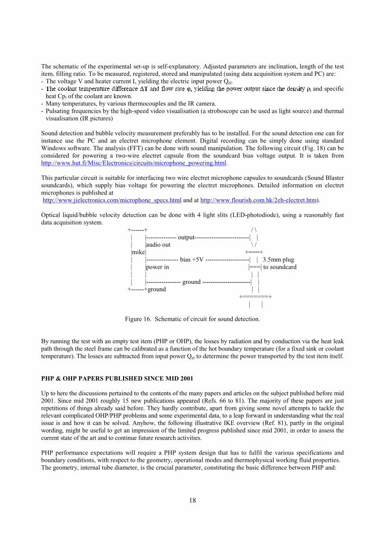
The schematic of the experimental set-up is self-explanatory. Adjusted parameters are inclination, length of the testitem, filling ratio. To be measured, registered, stored and manipulated (using data acquisition system and PC) are:- The voltage V and heater current I, yielding the electric input power Qel.- 7KH � FRRODQW� WHPSHUDWXUH � GLIIHUHQFH � 7 � DQG� IORZ� UDWH �$ ( � � \LHOGLQJ� WKH � SRZHU� RXWSXW� V LQFH � WKH � GHQVLW\� ! l and specific
heat Cpl of the coolant are known.- Many temperatures, by various thermocouples and the IR camera.- Pulsating frequencies by the high-speed video visualisation (a stroboscope can be used as light source) and thermal
visualisation (IR pictures)
Sound detection and bubble velocity measurement preferably has to be installed. For the sound detection one can forinstance use the PC and an electret microphone element. Digital recording can be simply done using standardWindows software. The analysis (FFT) can be done with sound manipulation. The following circuit (Fig. 18) can beconsidered for powering a two-wire electret capsule from the soundcard bias voltage output. It is taken fromhttp://www.hut.fi/Misc/Electronics/circuits/microphone_powering.html.
This particular circuit is suitable for interfacing two wire electret microphone capsules to soundcards (Sound Blastersoundcards), which supply bias voltage for powering the electret microphones. Detailed information on electretmicrophones is published at http://www.jielectronics.com/microphone_specs.html and at http://www.flourish.com.hk/2eh-electret.htm).
Optical liquid/bubble velocity detection can be done with 4 light slits (LED-photodiode), using a reasonably fastdata acquisition system.
+------+ / \ | |-------------- output--------------------------| | | |audio out \ / |mike| +===+ | |--------------- bias +5V ---------------------| | 3.5mm plug | |power in |===| to soundcard | | | | | |---------------- ground -----------------------| | +------+ground | | +=======+ | |
Figure 16. Schematic of circuit for sound detection.
By running the test with an empty test item (PHP or OHP), the losses by radiation and by conduction via the heat leakpath through the steel frame can be calibrated as a function of the hot boundary temperature (for a fixed sink or coolanttemperature). The losses are subtracted from input power Qel to determine the power transported by the test item itself.
PHP & OHP PAPERS PUBLISHED SINCE MID 2001
Up to here the discussions pertained to the contents of the many papers and articles on the subject published before mid2001. Since mid 2001 roughly 15 new publications appeared (Refs. 66 to 81). The majority of these papers are justrepetitions of things already said before. They hardly contribute, apart from giving some novel attempts to tackle therelevant complicated OHP/PHP problems and some experimental data, to a leap forward in understanding what the realissue is and how it can be solved. Anyhow, the following illustrative IKE overview (Ref. 81), partly in the originalwording, might be useful to get an impression of the limited progress published since mid 2001, in order to assess thecurrent state of the art and to continue future research activities.
PHP performance expectations will require a PHP system design that has to fulfil the various specifications andboundary conditions, with respect to the geometry, operational modes and thermophysical working fluid properties.The geometry, internal tube diameter, is the crucial parameter, constituting the basic difference between PHP and:

19
- A conventional heat pipe, where the generated vapour moves from evaporator to condenser by a small saturationtemperature, hence pressure, difference. The liquid phase is sucked back by capillary forces.
- A thermosyphon where the liquid return is by gravitation only.A PHP does not include an external pump, the heat input provides the energy to run the device, constitutes theengine, by creating the pumping action by generating bubbles in the evaporator area and condensing these bubblesin the condenser area. Consequently, a properly designed PHP includes a self-sustained thermally driven bubblepump (working in any orientation of the device), guaranteeing the desired heat transfer.
Before proceeding to discuss actual PHP design criteria, reference 81 starts by considering results from classicalstudies of cylindrical bubbles rising in isothermal static fluids (Fig. 17). A bubble rises through the far denser liquidbecause of buoyancy forces. The steady-state (end) velocity v of a single cylindrical bubble rising through stagnantliquid in a duct is governed by the interaction between buoyancy and the other forces acting on the bubble becauseof its shape and motion. If the viscosity of the vapour in the bubble is neglected, the only forces besides buoyancy,which are important, are those from liquid inertia, liquid viscosity and surface tension.
The balance between buoyancy and these three forces may be expressed in terms of the three non-dimensionalgroups Eö, Fr, and Ps, shown in figure 18. In the above equations, D is typically the characteristic dimension of theduct cross section (for circular tubes it is the internal diameter). In case the viscous forces and surface tension can beneglected, the bubble rise velocity can be correlated only by the earlier defined Froude number, Fr. Similarly, ifviscous forces are predominant, the rise velocity is set by the Poiseuille number, Ps. If the surface tensiondominates, the earlier defined Eötvös number Eö is of interest for the PHP. The above three numbers can becombined to generate new dimensionless quantities for convenience, e.g. the earlier defined Morton number Mo(being called 1/Y in reference 81).
The results of experimental observations for many fluids (Ref. 82) show that a critical value of Eö. Below this valuethe bubble sticks at the wall, meaning that there is no bubble rising. Unfortunately the majority of the fluids used forthese experiments were oils, sucrose solutions, sugar syrops, glyseol, CCl4, glycols, etc. The only usefull datapertained to water and ethanol, being certainly not the preferred PHP working fluids for electronic coolingapplications between room temperature (or lower) and say 70 °C. This data can be summarised by:- )),I� Eö increases beyond a particular value (say 70 for many common fluids as water and ethanol.), the end rising
velocity of bubbles approaches a constant value. The viscous forces and surface tension can be neglected. HenceFr is below 0.6.
- For Eö-values below say say 70, the end rising speed decreases with Eö.- Just below Eö = 4, the bubble sticks to the wall, its velocity is zero. This is the surface tension dominated zone
yielding the critical diameter according to equation (1).
8
4Limiting Case
Bubble sticks
to the wall
Eö ≈
)!!(g
"
2D
vapliq
crit −⋅⋅≈
−⋅
=
∞
)!Dg( !
v!
Buoyancy
ForceInertia
gf
2f
)!!(Dg
u!
FrNumberFroudevapliq
2liq
−
⋅== ∞
−
⋅=
∞
)!g( !D
%
Buoyancy
ForceViscous
gf2
f v
)!!(Dg
D/)%u(PsNumberPoiseuille
vapliq
liq
−
⋅== ∞
2
gf2 Bo
1
Eo
1
)!g( !D
"
Buoyancy
TensionSurface
=
=
−=
)!!(gD
)D/"(
Eö
1
NumberEötvös
1
vapliq−⋅⋅
==
Figure 18. Bubble sticks for line diameter, defined by Eö, and definition of dimensionless numbers Eö, Fr and Ps.
20
The above critical value Eöcrit is certainly not unique and varies somewhat under different experimental conditions,e.g. as the contact angle of the liquid on the tube surface will have an effect on the conditions of zero velocity ifwetting of the surface is incomplete. This factor is not in the dimensionless numbers. Factors like cleanliness or tubesurface roughness certainly will set the experimental determination of the real critical Eö-value.
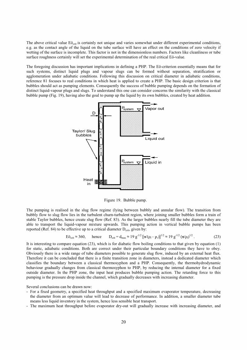
The foregoing discussion has important implications in defining a PHP. The Eö-criterion essentially means that forsuch systems, distinct liquid plugs and vapour slugs can be formed without separation, stratification oragglomeration under adiabatic conditions. Following this discussion on critical diameter in adiabatic conditions,reference 81 focuses to real conditions in which heat is applied to create a PHP. The basic design criterion is thatbubbles should act as pumping elements. Consequently the success of bubble pumping depends on the formation ofdistinct liquid-vapour plugs and slugs. To understand this one can consider concerns the similarity with the classicalbubble pump (Fig. 19), having also the goal to pump up the liquid by its own bubbles, created by heat addition.
The pumping is realised in the slug flow regime (lying between bubbly and annular flow). The transition frombubbly flow to slug flow lies in the turbulent churn-turbulent region, where joining smaller bubbles form a train ofstable Taylor bubbles, hence create slug flow (Ref. 83). As the larger bubbles nearly fill the tube diameter they areable to transport the liquid-vapour mixture upwards. This pumping action in vertical bubble pumps has beenreported (Ref. 84) to be effective up to a critical diameter Dcrit, given by:
Eöcrit ≈ 360, hence Dcrit = dmax ≈ 19 g-1/2 ["��! l – !v)]1/2 ≈ 19 g-1/2� � �" ! l)1/2 . (23)
It is interesting to compare equation (23), which is for diabatic flow boiling conditions to that given by equation (1)for static, adiabatic conditions. Both are correct under their particular boundary conditions they have to obey.Obviously there is a wide range of tube diameters possible to generate slug flow, induced by an external heat flux.Therefore it can be concluded that there is a finite transition zone in diameters, instead a dedicated diameter whichclassifies the boundary between a classical thermosyphon and a PHP. Consequently, the thermohydrodynamicbehaviour gradually changes from classical thermosyphon to PHP, by reducing the internal diameter for a fixedoutside diameter. In the PHP zone, the input heat produces bubble pumping action. The retarding force to thispumping is the pressure drop inside the channel, which gradually decreases with increasing diameter.
Several conclusions can be drawn now:- For a fixed geometry, a specified heat throughput and a specified maximum evaporator temperature, decreasing
the diameter from an optimum value will lead to decrease of performance. In addition, a smaller diameter tubemeans less liquid inventory in the system, hence less sensible heat transport.
- The maximum heat throughput before evaporator dry-out will gradually increase with increasing diameter, and
Figure 19. Bubble pump.

21
leaving the diameter range, the PHP device will loose its fundamental character, starting to behave as aninterconnected array of two-phase thermosyphons, and heat transfer will become mainly governed by pool boilingcharacteristics. If the heat input is able to generate enough wall superheat to create favourable conditions fornucleate pool boiling, the interconnected array of thermosyphons may be the better option (thermally seen), atleast for a range of inclination angles. Of course the above is based on the condition that all other parameters (e.g.filling ratio) are optimal.
- ))$� 3+3� ZLOO � DOZD\V � SHUIRUP� OHVV � WKDQ� DQ� HTXLYDOHQW� KHDW� SLSH � RU� thermosyphon, as the latter two systems are basedon pure latent heat transfer. But PHP performance may be optimised to approach the performance of the classicalheat pipe or thermosyphon. The manufacturing complexities of conventional heat pipes will be avoided.
- )),I� WKH � WKHUPDO� SHUIRUPDQFH � RI� D� 3+3� LV � EHORZ� WKDW� RI� DQ� HTXLYDOHQW� PHWDO � ILQV � DUUD\� V\VWHP� �VD\� RI� FRSSHU�� � WKHUHis only a mass saving advantage.
- ),I� WKH � SHUIRUPDQFH � RI� D� 3+3� LV � ORZHU� WKDQ� WKH � SHUIRUPDQFH � RI� DQ� HTXLYDOHQW� V LQJOH�SKDVH � IRUFHG� FRQYHFWLRQ� OLTXLGcooling system, the only advantage will be the reliability, as of the absence of an external mechanical pump.
The effect of input heat flux on two-phase flow instabilities is well documented. Experimental and analytical studieson density wave oscillations in single-tube two-phase flow proved that these oscillations strongly depend on the heatflux variation, single- and two-phase friction pressure drop, inlet flow rate, level of sub-cooling, system pressure andinlet/exit restrictions (Refs. 85, 86). In such systems, the results may be summarised by: Increasing the inlet heatflux above a certain limit, for a specified (non-zero) level of inlet sub-cooling, causes flow instabilities.
In a PHP with fixed geometry, the input heat flux sets the type of flow pattern in the channel, thus affecting thefundamental relaxation instabilities. Also static Ledinegg-type instabilities are affected by input heat flux in a PHP,as it directly affects the bubble pumping characteristics. Therefore it might be true that the operating heat fluxstraightforwardly affects the perturbation level in a PHP, in this way affecting the thermal performance of thedevice. This is supported by visualisation results obtained during PHP experiments (Ref. 80). The results, showing atypical phenomenological trend for a partially filled device (about 50%-70%), are representative for working fluidslike water, ethanol and R123.
Other visualisation experiments (Refs. 67, 72, 76) confirm the above results, being:- Low input heat fluxes are not able to generate enough perturbations, the resulting bubble pumping action is very
limited. Only high frequency/low amplitude bubble oscillations occur, in combination with rest periods, followedby a small bulk activity phase. All together it yields a poor performance, i.e. high thermal resistance.
- Increasing the heat input yields slug flow oscillations, with amplitudes increasing (even to the length of thedevice) with increasing heat flux. This improves the heat transfer coefficient significantly. When furtherincreasing the heat flux, the oscillating flow starts to take a fixed direction and the thermal resistance reducesfurther. Further increase of the input fluxes lead towards the transition of slug to annular flow at the outlet of theevaporator U-bends. The bulk flow has taken a fixed direction, which does not reverse with time. The alternatingtube sections are then hot and cold, with cold bubbly/slug flow coming down from the condenser to the evaporatorin one tube and annular/semi-annular flow in the adjacent tube being the outlet of the evaporator U-tube (Fig. 20).This implies that the unstable, pulsating slug flow becomes stable after a somewhat higher input heat flux. Is isnoticed that in such a case, the best PHP performance (lowest thermal resistance) is observed. This is as expected,as the evaporator U-sections experience convective boiling through a thin liquid film, rather than nucleate boiling
Figure 20. Pictures taken for increasing heat input (Ref. 81).
22
occurring in the slug flow regime. Thus, strange but true, the best performing closed loop pulsating heat pipe isnot a true ‘pulsating’ device. Further increase in heat flux will lead to evaporator dry-out.
In summary: The heat flux is an important design parameter, as it sets the pulsation degree of the PHP.
The PHP filling ratio (FR) is the ratio of working fluid volume in the device and the total volume of the device.Consequently, a PHP has two FR-extremes: The empty device without working fluid and the fully filled device. It isobvious that the empty PHP tubes are essentially inefficient conduction fins and have a very high thermal resistance.A fully filled PHP operates as a single-phase thermosyphon. There are no bubbles in the tube, hence there is no‘pulsating’ effect. Only some sensible heat transfer can still take place, induced by liquid circulation in the tubes bythermally due to buoyancy. Between these extremes lies the area of interest, where three regions are distinguished:- The nearly 100% fill ratio, where only very few bubbles are present, the rest being liquid. These bubbles are not
capable to generate the required perturbations. The buoyancy induced liquid circulation, present in a 100% filledPHP, gets impaired by the additional flow resistance induced by a few bubbles. This means poor performance anda thermal resistance being much higher than in a fully liquid device.
- The nearly 0% fill ratio, where there is not enough liquid to form slugs and there is a tendency towards evaporatordry-out. The operational characteristics are unstable. The device may, under some operating conditions, work asan array of two-phase thermosyphons.
- The real PHP working range: The PHP operates as a pulsating device between a say 10% to 90% fill charge. Theexact range will differ for different working fluids, operating parameters and construction details. The morebubbles (lower fill charges), the higher is the degree of freedom but simultaneously there is less liquid mass forsensible heat transfer. Less bubbles (higher fill charges) cause less perturbations and the bubble pumping action isreduced, lowering the performance. Consequently there is an optimum fill charge, and it can be concluded that thefilling ratio also is an independent parameter which defines the (closed looped) PHP pipe performance.
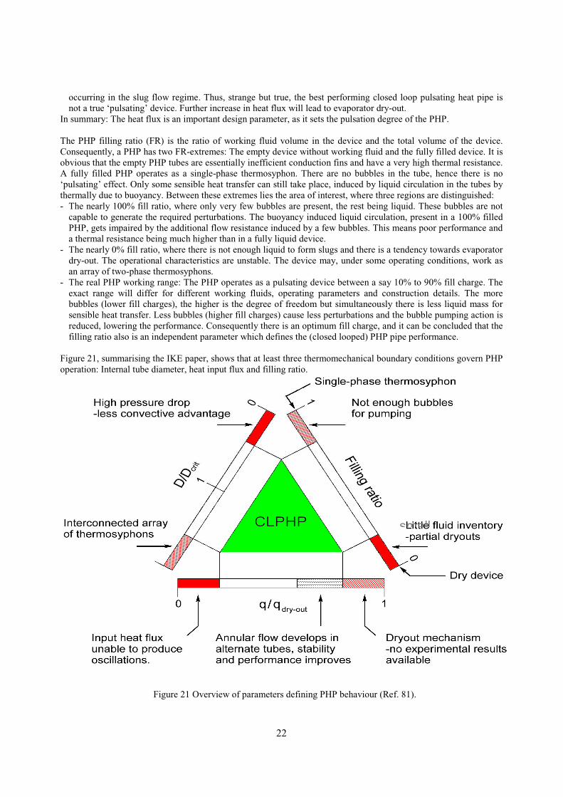
Figure 21, summarising the IKE paper, shows that at least three thermomechanical boundary conditions govern PHPoperation: Internal tube diameter, heat input flux and filling ratio.
small
Figure 21 Overview of parameters defining PHP behaviour (Ref. 81).

23
Most interesting is that the best performing “closed loop” PHP does not behave as a pulsating device: Alternatingtubes have slug and annular flow and the bulk flow takes a fixed direction. This requires further experimental proof.Supporting quantitative data is required, to transform the roughly depicted phenomenological and qualitativedefinition of figure 21 into detailed quantitative definitions. Also, near dry-out behaviour and the mechanism itselfrequires further research.
CONCLUDING REMARKS
In conclusion, it is remarked that a full overview is presented, which includes many papers from the very beginning ofthe oscillating/pulsating heat transfer device research till today.
The presented information summarises the approach for the thermal-gravitational scaling of two-phase systems ingeneral. Results of similarity considerations are given. Modelling results are discussed, including comparison withexperimental data. The discussions include gravity-assist system aspects and issues of operation against gravity orsuper-gravity. They pertain to capillary pumped and mechanically pumped two-phase loops, pulsating two-phase loops,and all other single-phase and two-phase oscillating (pulsating) devices. A simple rationale to get a (quantitative) feelingfor the development of pulsating devices for useful experiments is given.
In addition two very critical issues are to be stressed (again and again), since they are not adequately discussed inliterature (most probably because one did not recognise these). First, planetary super-gravity has a constant magnitudefelt in each part of any (two-phase heat transfer) device. This principally differs from the “super-g” accelerations inspinning satellites, in military combat aircraft and on turntables. In the latter, the g-vectors have gradients across adevice. Those gradients depend on local position and orientation with respect to the rotation axis. Second, in pulsating(pressure driven) two-phase loops heat transfer is by latent heat of evaporation/condensation. This means that theworking fluid selection will be based on high latent heat, in addition to high a dp/dT to deliver a minimum temperaturedrop driving force for the system. The other pulsating two-phase devices also require a fluid with a high dp/dT. But as itwas shown that in the latter devices the majority is by caloric (specific) heat of the liquid, it is clear that a high specificheat, high dp/dT fluid will be preferred. The question is even to be raised whether there exists an ideal high specificheat, high dp/dT fluid, having also a low latent heat. This because low latent heat means that, as the driving bubblegrowth is fast, the pulsation frequency and heat transport efficiency will increase. If such a fluid does not exist, there hascertainly to be looked at a fluid with an optimum combination of the above properties.
It is also remarked that for planetary reduced and super-g conditions there is no information at all on flow patternmaps and the boundaries between the different flow regimes. Therefore, and as it is also expected that the variousitems will substantially differ from the (hardly available) existing 1-g ones, the creation of flow pattern maps forsuper-gravity environment has been started at NLR. Fortunately, investigators in the US recently started to follow theNLR approach in this respect (Ref. 64).
The discussions focus on, in addition to “classical” two-phase loops, also pulsating loops and other novel oscillating/pulsating heat transfer devices. A review of their most relevant recent publications (also on high acceleration issues)is given. The baseline for comparing the experimental data in these and in future publications on these devices, asingle-phase heat transfer device, is elucidated.
A simple quantitative model to define future testing of oscillating/ pulsating heat transfer devices is presented. Basedon this and the literature review, a versatile test rig has been designed and built. The rig and the test set-up aredescribed. A test programme and the filling procedure are given also.
REFERENCES
1. Delil, A.A.M., Two-Phase Heat Transport Systems for Spacecraft – Scaling with Respect to Gravity, NLR-TP-89127, SAE 891467, 19th Int. Conference on Environmental Systems, San Diego, USA, 1989, SAE Trans. J.Aerospace, Vol. 98, 1989, pp. 554-564.
2. Delil, A.A.M., Thermal Gravitational Modelling and Scaling of Two-Phase Heat Transport Systems: SimilarityConsiderations and Useful Equations, Predictions versus Experimental Results, NLR-TP-91477, Proc. 1st
European Symposium Fluids in Space, Ajaccio, France, 1991, ESA SP-353, pp. 579-599.

24
3 Delil, A.A.M., Two-Phase Heat Transport Systems for Space: Thermal Gravitational Modelling and ScalingPredictions Versus Results of Experiments, Proc. ASME-JSME Forum on Microgravity Fluid Flow, Portland,USA, 1991, ASME-FED- 111, pp. 21-27.
4. Delil, A.A.M., Thermal Scaling of Two-Phase Heat Transport Systems for Space: Predictions versus Results ofExperiments, NLR-TP-91477, Proc. 1991 IUTAM Symposium on Microgravity Fluid Mechanics, Bremen,Germany, pp. 469-478.
5. Delil, A.A.M., On Thermal-Gravitational Modelling, Scaling and Flow Pattern Mapping Issues of Two-PhaseHeat Transport Systems, NLR-TP-98268, SAE 981692, 28th International Conference on EnvironmentalSystems, Danvers, USA, 1998, SAE Trans. J. Aerospace, Vol. 107, 1998.
6. Delil, A.A.M., Aerospace Heat and Mass Transfer Research for Spacecraft Thermal Control SystemsDevelopment, NLR-TP-98170, Heat Transfer 1998, Proc. 11th International Heat Transfer Conference,Kyongju, Korea, 1998, 1, Keynotes, pp. 239-260.
7. Delil, A.A.M., Unsolved Aerospace Heat and Mass Transfer Research Issues for the Development of Two-Phase Thermal Control Systems for Space, Proc. International Workshop Non-Compression Refrigeration &Cooling, Odessa, Ukraine, 1999, pp.21-42.
8. Delil, A.A.M., Thermal-Gravitational Modelling, Scaling and Flow Pattern Mapping Issues of Two-Phase HeatTransport Systems, Conference on Applications of Thermophysics in Microgravity and BreakthroughPropulsion Physics, AIP Conf. Proc. 458, Space Technology & Applications International Forum,Albuquerque, NM, USA, 1999, pp. 761-771.
9. Delil, A.A.M., Some Critical Issues in Developing Two-Phase Thermal Control Systems for Space, NLR-TP-99354, Keynote Lecture, Proc. 11th International Heat Pipe Conference, Tokyo, Japan, 1999, pp. 85-102.
10. Delil, A.A.M., Microgravity Two-Phase Flow and Heat Transfer, NLR-TP-99429, Chapter 9 of Fluid Physicsin Microgravity, (Monti, R., Ed.), Overseas Publishing Associates, Reading UK, 2001.
11. Delil, A.A.M., Extension of Thermal-Gravitational Modelling & Scaling of Two-Phase Heat TransportSystems to Super-Gravity Levels and Oscillating Heat Transfer Devices, Keynote Lecture, 6th InternationalHeat Pipe Symposium, Chiang Mai, Thailand, 2000, pp. 492-513, and ESA Proc. Two-Phase 2000 Workshop,Noordwijk, Netherlands, 2000.
12. Delil, A.A.M., Thermal-Gravitational Modelling and Scaling of Heat Transport Systems for Applications inDifferent Gravity Environments: Super-Gravity Levels & Oscillating Heat Transfer Devices”, NLR-TP-2000-213, SAE-2000-01-2377, Proc.30th International Conference on Environmental Systems & 7th EuropeanSymposium on Space Environmental Control Systems, Toulouse, France, SAE Trans. J. Aerospace, 2000.
13. Delil, A.A.M., Fundamentals of Gravity Level Dependent Two-Phase Flow and Heat Transfer – A Tutorial,and Thermal-Gravitational Modelling, AIP Conf. Proc., Space Technology & Applications InternationalForum, Albuquerque, USA, 2001, pp. 209-220.
14. Delil, A.A.M., Scaling of Two-Phase Heat Transport Systems from Micro-Gravity to Super-Gravity Levels,AIP Conf. Proc. 552, Space Technology & Applications International Forum, Albuquerque, USA, 2001, pp.221-229.
15. Kiseev, V.M., Zolkin, K.A., The Influence of Acceleration on the Performance of Oscillating Heat Pipe, Proc.11th Int. Heat Pipe Conference, Tokyo, Japan, 1999, Pre-prints Vol.2, pp. 154-158.
16. Romestant, C., Sophy, T., Alexandre, A., Dynamic of heat pipe behavior under cyclic body forces environment,Proc. 11th International Heat Pipe Conference, Tokyo, Japan, 1999, pp. 435-440.
17. Ku, J., et al., Transient Behaviors of a Miniature LHP Subjected to Periodic Accelerations Parallel to the Axis ofEvaporator and Hydro-accumulator, Proc.30th International Conference on Environmental Systems & 7thEuropean Symposium on Space Environmental Control Systems, Toulouse, France, 2000.
18. Tamburini, P., “T-System”, Proposal of a New Concept Heat Transport System, Proc. 3rd International HeatPipe Conference, Palo Alto, CA, USA, 1978, AIAA CP-784, pp. 346-353.
19. Lund, K.O., Baker, K.W., Weislogel, M.M., The Vapor-Pressure Pumped Loop Concept for Space SystemsHeat Transport, Proc. 1st International. Conference on Aerospace Heat Exchanger Technology 1993, Palo Alto,CA, USA, (Eds. Shah, R.K., Hashemi, A.), Elsevier, Amsterdam 1993, pp. 45-55.
20. Borodkin, A.A., Kotlyarov, E.Yu, Serov, G.P., Evaporation-Condensation Pump for Providing of WorkingFluid Circulation in Two-Phase Heat Transferring System, SAE 951508, 25th International Conference onEnvironmental Systems, San Diego, CA, USA, 1995.
21. Nishio, S., Oscillatory-Flow Heat Transport Device, Proc. 11th International Heat Pipe Conference, Tokyo,Japan, 1999, pp. 39-49.
22. Hosoda, M., Nishio, S., Shirakashi, R., Meandering Closed-Loop Heat-Transport Tube Propagation Phenomenaof Vapor Plug, 5th ASME-JSME Thermal Engineering Conference, San Diego, USA, 1999, pp. 1-8.

25
23. Nishio, S., Shin, H-T, Oh, S-J., Oscillation-Controlled Heat-Transport Tubes (Effect of Transition fromLaminar to Turbulent Flow on Effective Conductivity), Heat Transfer 1998, Proc. 11th International HeatTransfer Conference, Kyongju, Korea, 1998, Vol. 3, pp. 317-322.
24. Wong, T.N., et al., Theoretical Modelling of Pulsating Heat Pipe, Proc. 11th International Heat PipeConference, Tokyo, Japan, 1999, pp. 378-382.
25. Akachi, H., Motoya, S., Maezawa, S., Thermal performance of capillary tunnel type flat heat pipe, Proc. 9thInternational Heat Pipe Conference, Albuquerque, NM, USA, 1995, LA-UR-97-1500, 1997, Vol. 1, pp. 88-96.
26. Es, J. van, Woering, A.A., High-Acceleration Performance of the Flat Swinging Heat Pipe, Proc. 30thInternational Conference on Environmental Systems & 7th European Symposium on Space EnvironmentalControl Systems, Toulouse, France, 2000.
27. Terpstra, M., Veen, J.G. van, Heat Pipes: Construction and Applications, EUR 10925 EN, Elsevier, London,1987.
28. Maezawa, S., et al., Thermal Performance of Capillary Tube Thermosyphon, Proc. 9th International Heat PipeConference, Albuquerque, NM, USA, 1995, LA-UR-97-1500, 1997, Vol. 21, pp. 791-795.
29. Smirnov, H.F., Kuznetsov, I.O., Borisov, V.V., Approximate Pulsating Heat pipe Theory and Experiment,Proc. International Workshop Non-Compression Refrigeration & Cooling, Odessa, Ukraine, 1999, pp.121-125.
30. Wallis, G.B., One-dimensional Two-phase Flow, McGraw-Hill, New York, 1969.31. Murphy, G., Similitude in Engineering, Ronald Press, New York, USA, 1950.32. Bretherton, F.P., The Motion of Long Bubbles in Tubes, J. of Fluid Mechanics, Vol. 10, 1961, pp. 161-188.33. Hattori, S., Rept. Res. Inst. Tokyo Imp. Univ., No. 115, 1935.34. Kurzweg, U.H., Zhao, L., Heat Transfer by High-frequency Oscillations: A New Hydrodynamic Technique for
Achieving Large Effective Conductivities, Physics of Fluids, Vol. 27, 1984, pp. 2624-2627.35. Kurzweg, U.H., Enhanced Heat Conduction in Fluids Subjected to Sinusoidal Oscillations, Trans. ASME, J.
Heat Transfer, Vol. 107, 1985, pp. 459-462.36. Kurzweg, U.H., Lindgren, E.B., Lothrop, B., Onset of Turbulence in Oscillatory Flow at Low Womersley
Number, Physics of Fluids A, Vol. 1(12), 1989, pp. 1972-1975.37. Watson, E.J., Diffusion in Oscillatory Pipe Flow, J. Fluid Mech., Vol. 133, 1983, 233-244.38. Inada, T., Tahara, M., Saitoh, K-I., Longitudinal Heat Transfer in Oscillatory Flows in Pipe Bundles of Various
Cross Sections, JSME International Journal, Series B, Vol. 43, No. 3, 2000, pp. 460-467.39. Inada, T., Kubo, T., Enhanced Heat Transfer through Oscillatory Flow, Heat Transfer – Japanese Research,
Vol. 22, No. 5, 1993, pp. 480-492.40. Delil, A.A.M., Modelling and Scaling of Oscillating or Pulsating Heat Transfer Devices Subjected to Earth
Gravity and to High Acceleration Levels, AIP Conf. Proc., Space Technology & Applications InternationalForum, Albuquerque, USA, 2001, pp. 230-240.
41. Lee W., Jung H., Kim J. and Kim J., Flow Visualization of Oscillating Capillary Tube Heat Pipe, Proc. 11thInternational Heat Pipe Conference, Tokyo, 1999, pp. 355-360.
42. Lee, W.H., et al., Characteristics of Pressure Oscillations in Self-excited Oscillating Heat Pipe Based onExperimental Study, Proc. 6th International Heat Pipe Symposium, Chiang Mai, Thailand, 2000, pp. 394-403.
43. Rittidech, S., et al., Effect of Inclination Angles, Evaporator Section Lengths and Working Fluid Properties onHeat Transfer Characteristics of Closed-End Oscillating Heat Pipe, Proc. 6th International Heat PipeSymposium, Chiang Mai, Thailand, 2000, pp. 413-421.
44. Charoensawan, P., et al., Effect of Inclination Angles, Filling Ratios and Total Section Lengths on HeatTransfer Characteristics of Closed-Loop Oscillating Heat Pipe, Proc. 6th International Heat Pipe Symposium,Chiang Mai, Thailand, 2000, pp. 422-430.
45. Zuo, Z.J., North, M.T., Miniature High Heat Flux Heat Pipes for Cooling of Electronics, SEE 2000, HongKong, China, 2000.
46. Schneider, M, Yoshida, M., Groll, M., Investigation of Interconnected Mini Heat Pipe Arrays for MicroElectronics Cooling, Proc. 11th International Heat Pipe Conference, Tokyo, Japan, 1999, pp. 220-225.
47. Schneider, M, et al., Visualization of Thermofluiddynamic Phenomena in Flat Plate Closed Loop PulsatingHeat Pipes, 6th International Heat Pipe Symposium, Chiang Mai, Thailand, 2000, pp. 235-247.
48. Buz, V.N., The Modeling of Non-Stationary Phenomena in Two-Phase Heat Transferring Devices, Proc.International Workshop Non-Compression Refrigeration & Cooling, Odessa, Ukraine, 1999, pp. 106-111.
49. Smirnov, H.F., Kuznetsov, I.O., Borisov, V.V., The Modeling of Non-Stationary Phenomena in Two-Phase HeatTransferring Devices, Proc. International Workshop Non-Compression Refrigeration & Cooling, Odessa,Ukraine, 1999, pp. 121-125.

26
50. Miyazaki, Y., Polasek, F., Akachi, H., Oscillating Heat Pipe with Check Valves, 6th International Heat PipeSymposium, Chiang Mai, Thailand, 2000, pp. 389-394.
51. Miyazaki Y., Arikawa M., Oscillatory Flow in the Oscillating Heat Pipe, Proc. 11th International Heat PipeConf., Tokyo, 1999, pp. 367-372.
52. Maezawa, S., Sato, F., Gi, K., Chaotic Dynamics of Looped Oscillating Heat Pipes (Theoretical Analysis onSingle Loop), Proc. 6th International Heat Pipe Symposium, Chiang Mai, Thailand, 2000, pp. 404-412.
53. Gi, K., Sato, F., Maezawa, S., Flow Visualization Experiment on Oscillating Heat Pipes, Flow VisualizationExperiment on Oscillating Heat Pipes, 11th International Heat Pipe Conference, Tokyo, Japan, 1999, pp.373-377.
54 Gi, K, Maezawa, S., CPU Cooling of Notebook PC by Oscillating Heat Pipe, 11th International Heat PipeConference, Tokyo, Japan, 1999, pp. 469-472.
55. Rossi, L., Polasek, F., Thermal Control of Electronic Equipment by Heat Pipes and Two-PhaseThermosyphons, Proc. 11th International Heat Pipe Conference, Tokyo, Japan, 1999, pp. 50-74.
56. Swanepoel, G., Taylor, A.B., Dobson, R.T., Theoretical Modeling of Pulsating Heat Pipes, Proc. 6th
International Heat Pipe Symposium, Chiang Mai, Thailand, 2000, pp. 358-365.57. Dobson, R.T., Modeling of an Open Oscillatory Heat Pipe, Proc. 6th International Heat Pipe Symposium,
Chiang Mai, Thailand, 2000, pp. 381-388.58. Dobson, R.T., Harms, T.M., Lumped Parameter Analysis of Closed and Open Oscillatory Heat Pipe, Proc.11th
International Heat Pipe Conference, Tokyo, Japan, 1999, pp. 361-366.59. Soliman, M. & Schuster, J.R., Berenson, P.J., A General Heat Transfer Correlation for Annular Flow
Condensation, Trans. ASME C, J. Heat transfer, 1968, Vol. 90, 267-276.60. Delil, A.A.M., Gravity Dependence of Pressure Drop and Heat Transfer in Straight Two-Phase Heat Transport
System Condenser Ducts, NLR-TP-92167, SAE 921168, 22nd International Conference on EnvironmentalSystems”, Seattle, USA, 1992, SAE Trans., J. of Aerospace, Vol. 101, 1992, pp. 512-522.
61. Delil, A.A.M., Gravity Dependent Condensation Pressure Drop and Heat Transfer in Ammonia Two-PhaseHeat Transport Systems, NLR-TP-92121, AIAA 92-4057, National Heat Transfer Conference, San Diego,USA, 1992.
62. Delil, A.A.M. et al., TPX for In-Orbit Demonstration of Two-Phase Heat Transport Technology - Evaluationof Flight & Post-flight Experiment Results, NLR-TP-95192, SAE 95150, 25th International Conference onEnvironmental Systems, San Diego, USA, 1995.
63. Incroprera, F.P., De Witt, D.P., Fundamentals of Heat and Mass Transfer, John Wiley, New York, 1990.64. Miller-Hurlbert, K., Flow Dynamics for Two-Phase Flow in Partial Gravities, Ph.D. Thesis, University of
Houston, Dec. 2000.65. Delil, A.A.M., Pulsating & oscillating heat transfer devices in acceleration environments from microgravity to
supergravity, NLR-TP-2001-001, SAE-2001-02-2240, Proc. 31st International Conference on SpaceEnvironmental Systems, Orlando, USA, SAE Trans. J. Aerospace, 2000.
66. Shafii, M., Faghri, A., Zhang, Y., Thermal Modeling of Unlooped and Looped Pulsating Heat Pipes,International Journal of Heat Transfer, Vol. 123, Transactions of ASME, 2001, pp. 1159-1172.
67. Tong B., Wong T. and Ooi K., Closed-Loop Pulsating Heat Pipe, Applied Thermal Engineering, ISSN 1359-4311, Vol. 21/18, 2001, pp. 1845-1862.
68. Khandekar, S., et al., M., Thermofluiddynamic Study of Flat Plate Closed Loop Pulsating Heat Pipes,Microscale Thermophysical Engineering, Taylor and Francis, ISSN 1089-3954, Vol. 6/4, 2002, pp. 303-318.
69. Khandekar, S., Schneider, M., Groll, M., Mathematical Modeling of Pulsating Heat Pipes: State of the Art andFuture Challenges, Proc. 5th ASME/ISHMT, Joint International Heat and Mass Transfer Conference, McGrawHill, ISBN-0-07-047443-5, Kolkata, India, 2002, pp. 856-862.
70. Groll, M., Khandekar, S., Pulsating Heat Pipes: A Challenge and Still Unsolved Problem in Heat Pipe Science,Proc. 3rd International Conference on Transport Phenomenon in Multiphase Systems (HEAT 2002), ISBN 83-88906-03-8, pp. 35-43, Baranów Sandomierski, Poland, 2002. Also in Archives of Thermodynamics, BegellHouse, ISSN 1231-0956, Vol. 23/4, 2002, pp. 17-28.
71. Khandekar, S., Cui, X., Groll, M., Thermal Performance Modeling of Pulsating Heat Pipes by Artificial NeuralNetwork, Proc. 12th International Heat Pipe Conf., Moscow, Russia, 2002, pp. 215-219.
72. Khandekar, S., et al., Pulsating Heat Pipes: Thermo-fluidic Characteristics and Comparative Study with SinglePhase Thermosyphon, Proc. 12th International Heat Transfer Conference, ISBN-2-84299-307-1, Vol. 4, pp.459-464, Grenoble, France, 2002.
73. Nishio, S., Nagata, S., Baba S., Shirakashi, R., Thermal Performance of SEMOS Heat Pipes, Proc. 12thInternational Heat Transfer Conference, Vol. 4, pp. 477482, Grenoble, France, 2002.

27
74. Miyazaki Y., Polášek, F., Operating Limit of Oscillating Heat Pipe, Proc. 12th International Heat. TransferConference, Vol. 4, pp. 483-489, Grenoble, France, 2002.
75. Borisov, V., et al., Modeling and Experimentation of Pulsating Heat Pipes, Proc. 12. International Heat PipeConference, pp. 220-225, Moscow, 2002.
76. Qu, W., Ma, T., Experimental Investigation on Flow and Heat Transfer of a Pulsating Heat Pipe, Proc. 12thInternational Heat Pipe Conference, pp. 226-231, Moscow, 2002.
77. Zhang, Y., Faghri, A., Shaffii, M.B., Analysis of Pulsating Liquid-Vapor Flow in a U-Shaped Miniature Tube,International Journal of Heat and Mass Transfer, Vol. 45, No. 12, 2002, pp. 2501-2508.
78. Zhang, Y., Faghri, A.,Heat Transfer in a Pulsating Heat Pipe with Open End, International Journal of Heat andMass Transfer, Vol. 45, No. 4, 2002, pp. 755-764.
79. 79. Zhang, Y., Faghri, A., Oscillary Flow in Pulsating Heat Pipes with Arbitrary Number of Turns, Journal ofThermophysics Vol. 17, No. 3, 2003, pp. 340-347.
80. Khandekar. S., Dollinger, N., Groll, M., Understanding Operational Regimes of Pulsating Heat Pipes: AnExperimental Study, Applied Thermal Engineering, Elsevier Science, ISSN 1359-4311, Vol. 23/6, 2003, pp.707-719.
81. Khandekar, S., Groll M., On the Definition of Pulsating Heat Pipes: An Overview, Proc. 5th InternationalSeminar on Heat Pipes, Heat Pipes, Refrigerators, Minsk, Belarussia, 2003, pp. 117-128 .
82. White E., Beardmore R., The Velocity of Rise of Single Cylindrical Air Bubbles through Liquids Contained inVertical Tubes, Chem. Engng. Science, Vol. 17, pp. 351-361, 1962.
83. Chisholm, D., Two-phase flow in pipelines and heat exchangers, George Goodwin, New York, 1983.84. Delano, A., Design Analysis of the Einstein Refrigeration Cycle, PhD Thesis, Georgia Institute of Technology,
1998.85. Boure, J., Bergles, A., Tong, L., Review of Two-Phase Flow Instability, Nuclear Engineering Design, Vol. 25,
pp. 165-192, 1973.86. Saha, P., Ishii, M., Zuber, N., An Experimental Investigation of the Thermally Induced Flow Oscillations in
Two-Phase Systems, ASME Journal of Heat Transfer, Vol. 98, pp. 616-622, 1976.
NOMENCLATURE
A area (m2)
Ar Archimedes number = Mo½ (-)B proportionality factor (-)Bo Bond number = g D2 ! l /4σ (-)Boil boiling number = ∆H/hlv = Boil (-)C conductance (W/K)Cp specific heat at constant pressure (J/kg.K)D characterisic diameter (m)d diameter of capillary or curvature (m)E enhancement factor (-)Eö Eötvös number = g D2 ! l /σ (-)Eu Euler number = ∆p/ρv2 (-)f frequency (Hz)FR fill ratio (-)Fr Froude number = v2/gD (-)g gravitational acceleration (m/s2)H enthalpy (J/kg)h heat transfer coefficient (W/m2.K)hlv latent heat of vaporisation (J/kg)I current (A)jl superficial liquid velocity = vl (Al
./At) (m/s)
jv superficial vapour velocity = vv (Av.
/At) (m/s)k thermal conductivity (W/m.K)L length (m)
Ma Mach number = v/(∂p/∂ρ)s1/2 (-)
Mo Morton number = ρlσ3/µl4 g (-)
Mu inverse viscosity number ≈ µl /(g D3� ! l2) –1/2 (-)
m.
mass flow rate (kg/s)N number of turns (-)Nu Nusselt number = hD/λ (-)p pressure (Pa = N/m2)Pr Prandtl number = µCp/λ (-)Ps Poisseuille number = vµl / (g D2 ! l)Q power (W)Q, q heat flux (W/m2)Re Reynolds number = ρvD/µ (-)S slip factor, ratio of velocities of the phases (-)T temperature (K = 273 + °C)t time (s)v velocity (m/s)v* dimensionless velocity = v / (g D) ½ (-)v velocity (m/s)V voltage (V)We Weber number = ρv2D/σ (-)Wo Womersley number = (d/2) (2π f ! l / µl )
1/2 (-)X vapour quality = vapour mass fraction (-)Y dimensionless number = 1/Mo (-)z axial or vertical co-ordinate (m)

14
Greekα vapour/void fraction (volumetric) (-)∆ difference, drop (-)δ surface roughness (m)( volume rate (m3/s)κ thermal diffusivity (m2/s)# thermal conductivity (W/m.K)µ viscosity (N.s/m2)ν angle (with respect to gravity) (rad)π dimensionless number (-)ρ density (kg/m3)σ surface tension (N/m)
Subscriptsa acceleration, adiabatic, axialch capillary channelC coldc condensercool coolantcrit criticale evaporatoreff effectiveel electricf frictiong gravitationH, h hot
I innerl liquidm momentummax maximummin minimumM modelo reference, outer, horizontalp poreP prototyper radial, or radius (m)rad radiations entropyt totaltp two-phasev vapourw water
AbbreviationsHP Heat PipeHTD Heat Transfer DevicePHP Pulsating Heat PipeCLPHP Closed Loop PHPOLPHP Open Loop (dead ends) PHPOHP Oscillating Heat PipeVPDL Vapour Pressure Driven Loop
Related Documents