ORTHOPANTOMOGRAM Dr. SHIFAYA NASRIN CRRI(2009-2014)

Welcome message from author
This document is posted to help you gain knowledge. Please leave a comment to let me know what you think about it! Share it to your friends and learn new things together.
Transcript

ORTHOPANTOMOGRAM
Dr. SHIFAYA NASRIN
CRRI(2009-2014)
CONTENTS
Introduction
Principles of panoramic imaging
Image layer
Panoramic machines
Panoramic film
Patient positioning
Interpreting the panoramic imaging
Indication
Advantages
Disadvantages
Conclusion
References
INTRODUCTION
• Panoramic imaging also called pantomography is a technique for producing a single tomographic image of facial structures that includes both the maxillary and mandibular dental arches and their supporting structures .
• This is a curvilinear variant of conventional tomography.

PRINCIPLES OF PANORAMIC IMAGE FORMATION
• Patero and Numata - describe the principles of panoramic
radiography
• based on the principle of reciprocal movement of x-ray
source and an image receptor around a central point or
plane called the image layer, in which the object of image is
located.
• Object in front or behind this image are not clearly captured
because of their movement relative to the centre of rotation
of the receptor and the x-ray source.

The film and x-ray tubehead move around the patient in opposite directions in panoramic radiography
ROTATION CENTER
The pivotal point or axis around which the cassette carrier
and tube head rotate is termed rotation center
Three basic rotation center used in panoramic radiography
Double centre rotation
Triple centre rotation
moving centre rotation
The location and number of rotational centers influence
size and shape of focal trough


IMAGE LAYER
• Also known as focal trough
• It is a three dimensional curved zone where the structures lying
within this layer are reasonably well defined on final panoramic
image.
• The structures seen on a panoramic image are primarily those
located within image layer.
• Objects outside the image layer are blurred magnified are reduced
in size. Even distorted to the extent of not being recognizable.
• This shape of image layer varies with the brand of equipment used.

FOCAL TROUGH

FACTORS AFFECTING SIZE OF IMAGE LAYER:
Arc path
Velocity of receptor and X-ray tube head
Alignment of x-ray beam
Collimator width
The location of image layer change with extensive machine
used so recalibration may be necessary if consistently
suboptimal images are produced.
As a position of object is moved within the image layer size
and shape of image layer change.

PANORAMIC UNIT

A, Orthophos XG Plus extraoral x-ray machine. B,Orthoralix 8500 extraoral x-ray machine. C, Example of
a digital panoramic system
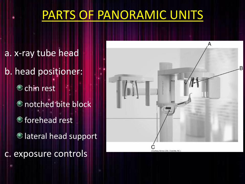
PARTS OF PANORAMIC UNITS
a. x-ray tube head
b. head positioner:
chin rest
notched bite block
forehead rest
lateral head support
c. exposure controls

X-RAY TUBE HEAD:• Similar to intraoral x-ray tube head
• Each has a filament to produce electrons and a target to
produce x-rays
• Collimator is a lead plate with narrow vertical slit
• Narrow x-ray beam emerges from collimator minimize patient
exposure to radiation

• Tube head is fixed in position and rotates
behind the patient head
• Film positioner is used to align the patients
teeth accurately in focal trough

Image receptor

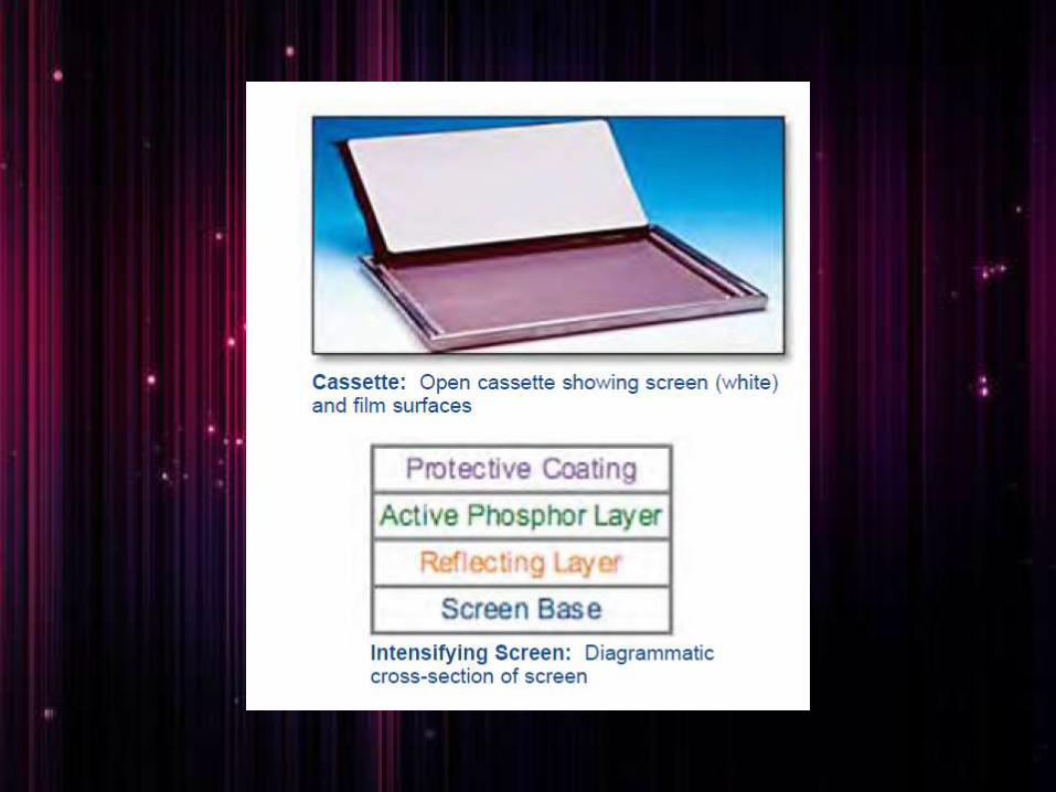
CASSETTE
• It is a device used to hold the extra oral film
and intensifying screens
• Light tight to protect the film from exposure
• Two types
Rigid
Flexible

FILM CASSETTES
A and B, Rigid cassettes.
Intensifying screens are attached to the inside cover and base of a rigid cassette.
When the panoramic film is placed in the cassette, it lies between the screens.
C, FLEXIBLE CASSETTE has an opening at one end, creating a pouch.
The panoramic film is placed between two removable, flexible intensifying screens, which are then slid into the pouch

PANORAMIC FILM
• Screen film used available in two sizes:
5x12 inch
6x12 inch
• Placed between two intensifying screen in a cassette holder
• Sensitive to light emitted from intensifying screens
• When exposed to x-ray, screen convert x-ray energy into
light
INTENSIFYING SCREENS
• Calcium tungstate –emit blue light
• Rare earth –emit green light, less x-ray exposure
• Two types

Other receptor
• PSP - photostimulable phosphor plate
• CCD - charge-coupled device

DIGITAL IMAGING
PATIENT POSITIONING AND HEAD ALIGNMENT
• Dental appliance earrings ,necklace, hairpins, and any other metallic
objects should be removed
• Instruct the patient to stand as tall as possible with back straight
and stand erect .
• Vertical column must be straight
• Instruct the patient to bite on the plastic bite block tooth must be
positioned in edge to edge position in the groove present in the
bite block it is used to align the teeth in the focal trough

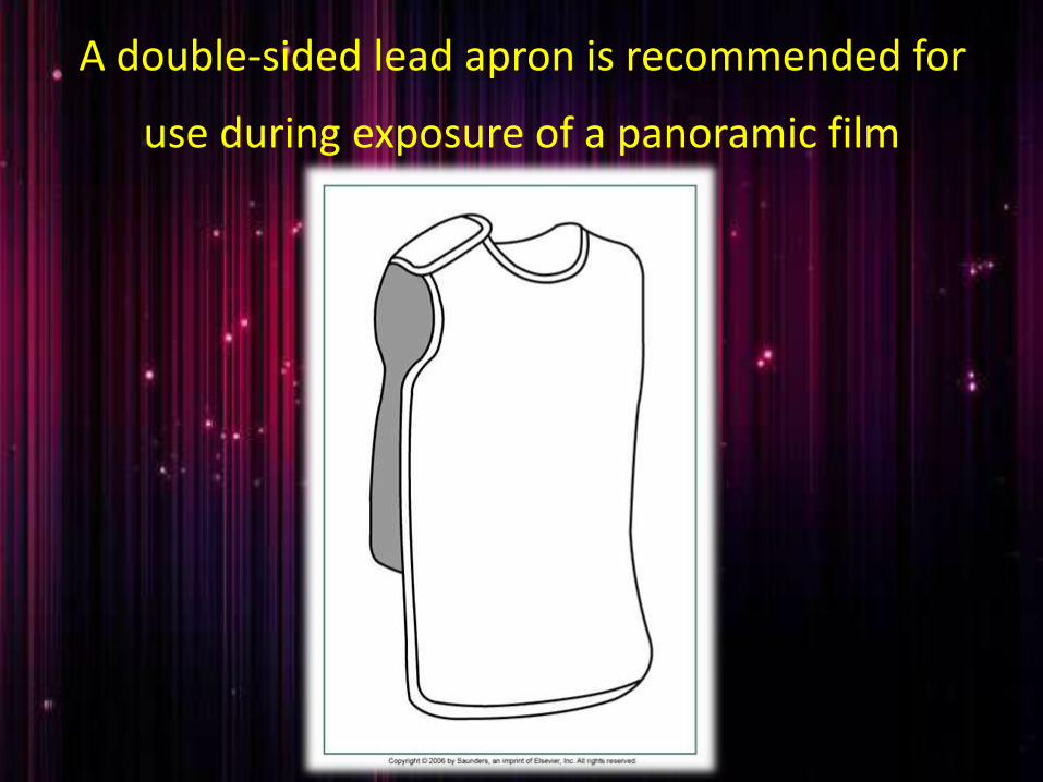
A double-sided lead apron is recommended for
use during exposure of a panoramic film

• Midsagittal plane
perpendicular to floor
• Frankfort horizontal plane
parallel to the floor
• Tongue must be positioned on
the roof of the mouth
• Instruct the patient to remain
still while machine is rotating

INTERPRETING PANORAMIC IMAGE
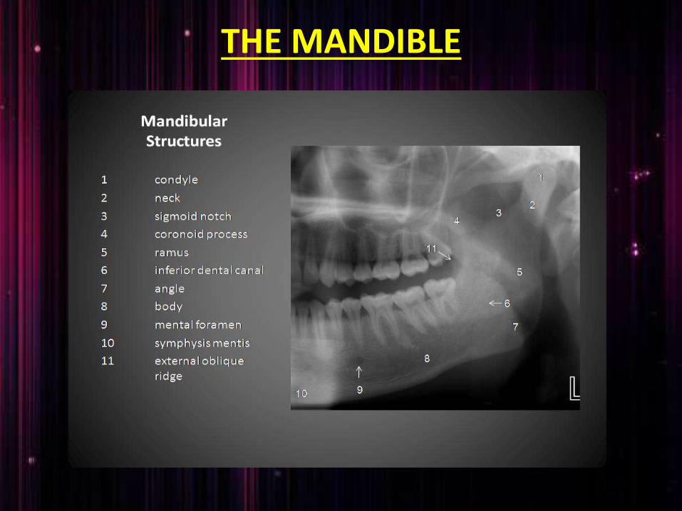
THE MANDIBLE
• Condylar process and TMJ: a bony rounded radioopaque projection extending from ramus of mandible
• Coronoid process: triangular radio opacity posterior to tuberosity region
• Ramus: shadow of other structure may superimposed over the ramus such as
• Pharyngeal airway shadow
• Posterior wall of pharynx
• Cervical vertebra
• Ear lobe
• Nasal cartilage
• Soft palate and uvula
• Dorsum of tongue
• Ghost shadow
• Body and angle : radiopaque bony structure
where the ramus join the body of the
mandible
• mandibular dentition and alveolus

MIDFACIAL REGION
Individual bones:• Temporal• zygoma• mandible• frontal• Maxilla• Sphenoid• Ethmoid• Vomer• Nasal• Palate
• Cortical boundary of maxilla including posterior border and alveolar ridge
• Pterygomaxillary fissure : radiolucent area between the lateral pterygoid plate and maxilla
• Maxillary sinuses: paired radiolucencieslocated above the apices of premolars and molars
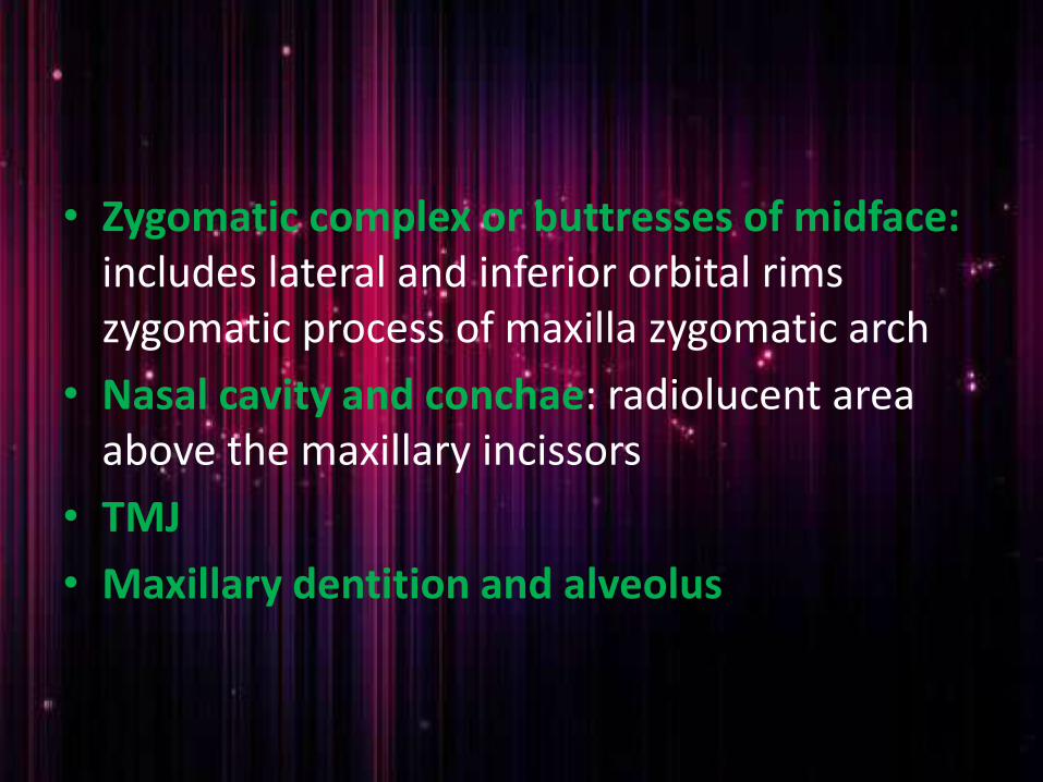
• Zygomatic complex or buttresses of midface: includes lateral and inferior orbital rims zygomatic process of maxilla zygomatic arch
• Nasal cavity and conchae: radiolucent area above the maxillary incissors
• TMJ
• Maxillary dentition and alveolus
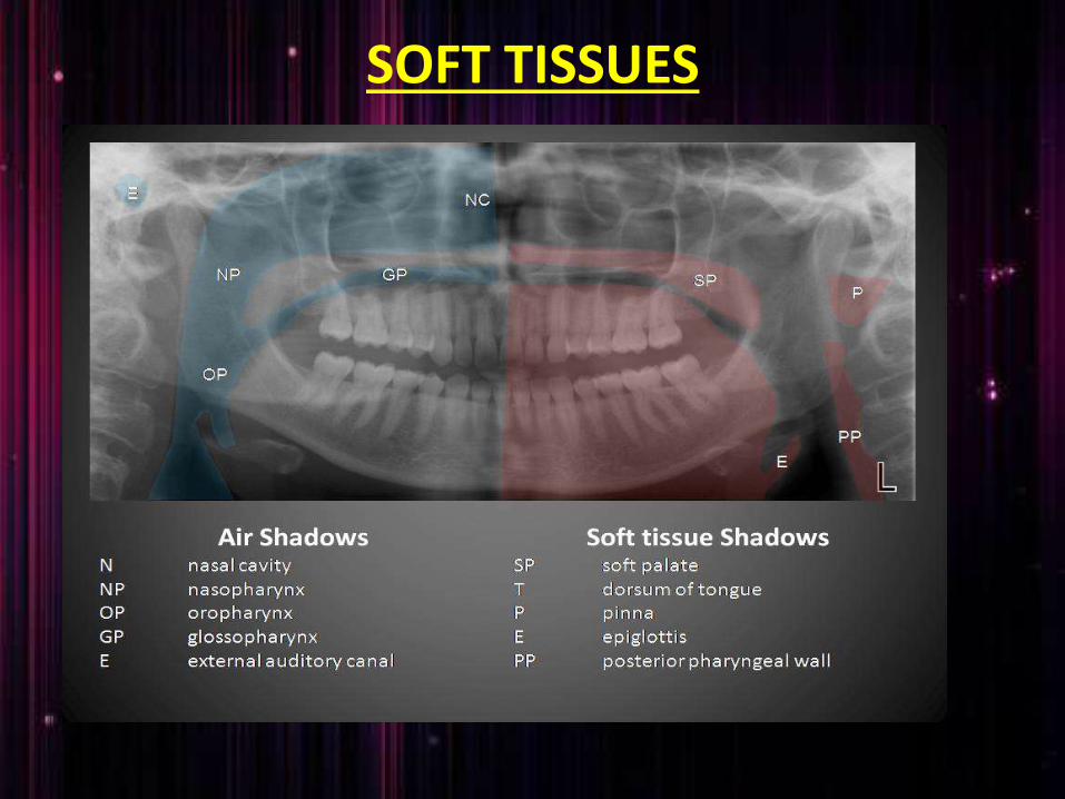
SOFT TISSUES
• Tongue under the hard palate: radiopaque area superimposed over the maxillary posterior teeth
• Lip line: seen in the region of anterior teeth
• Soft palate: extending posteriorly from hard palate
• Posterior wall of pharynx
• Nasal septum
• Ear lobes
• Nose and nasolabial fold

DENTITION
• Teeth and supporting alveolar bone are evaluated
• Teeth examined for
Gross anomalies of number ,position, and anatomy
Impacted third molars
Endodontic obturations, crowns, fixed restoration
INDICATION
• To evaluate impacted teeth
• To evaluate eruption patterns, growth and development
• To detect diseases ,lesions and conditions of the jaw
• To examine extent of large lesions
• To evaluate trauma periodontal bone loss and periapical involvement.
• Finding the source of dental pain• Assessment for the placement of dental implants• Orthodontic assessment. pre and post operative• Caries detection especially in the inter-dental
region.• Diagnosis of developmental anomalies such
as Cherubism, Cleido cranial dysplasia• Carcinoma in relation to the jaws• Tempero mandibular joint dysfunctions
and ankylosis

ADVANTAGES
• Broad coverage of facial bones and teeth
• Low patient radiation dose
• Convenience of the examination of the patient
• Use in patients unable to open their mouth
• Short time required
• In patient education and case presentation
DISADVANTAGE
• Image quality are not sharp
• Focal trough limitations
• Distortion
• Expensive equipment cost

CONCLUSION
• As OPG has several advantages in the field of dentistry and its inevitable role in diagnosis every dentist should know about it.
• Compared with the conventional radiographic technique involving atleast 16 intraoral exposures OPG has several advantage it takes fairly easy; takes one minute and shows entire oral cavity in one minute however resulting image produce less detail than IOPA

REFERENCES
• Freny R.Karjodkar :Text book of Dental and maxillofacial radiology 2nd edition page number :236-255
• Laura Jansen ,Joen M.Ianucci Harring :Dental radiography Principles and techniques of Oral radiology: 3rd edition page number:305-319
• white and pharaoh : Oral radiology principles and interpretation 6th edition; page number: 175-189