OR NL-5176 . . . ’* . . Engineering Tests of the Metal Transfer Process for Extraction of Rare-Earth Fission Products from a Molten-Salt Breeder Reactor Fuel Salt H. C. Savage J. R. Hightower, Jr.

ORNL-5176
Mar 24, 2016
Engineering tests of the metal transfer process for extraction of rare earth fission products from Molten Salt Breeder Reactor fuel salt.
Welcome message from author
This document is posted to help you gain knowledge. Please leave a comment to let me know what you think about it! Share it to your friends and learn new things together.
Transcript
OR NL-5176 .... . . ’* . .
Engineering Tests of the Metal Transfer Process for Extraction of Rare-Earth Fission Products from a Molten-Salt
Breeder Reactor Fuel Salt
H. C. Savage J. R. Hightower, Jr.

Printed in the United States of America. Available from National Technical Information Service
U.S. Department of Commerce 5285 Port Royal Road, Springfield, Virginia 22161
Price: Printed Copy $4,50; Microfiche $3.00 .
This report was prepared as an account of work sponsored by the United States Government. Neither the United States nor the Energy Research and Development AdministratiodUnited States Nuclear Regulatory Commission, nor any of their employees, nor any of their contractors, subcontractors, or their employees, makes any warranty, express or implied, or assumes any legal liability or responsibility for the accuracy, completeness or usefulness of any information, apparatus, product or process disclosed, or represents that its use would not infringe privatelyowned rights.
Y

ORNL-5176 D i s t . C a t e g o r y UC-76
C o n t r a c t N o . W-7405-eng-26
CHEMICAL TECHNOLOGY DIVISION
ENGINEERING TESTS OF THE METAL TRANSFER PROCESS FOR EXTRACTION OF RARE-EARTH F I S S I O N PRODUCTS FROM A MOLTEN-SALT
BREEDER REACTOR FUEL SALT
H . C . Savage J. R. H i g h t o w e r , Jr.
Date Published: February 1977
OAK ZIDGE NATIONAL LABORATORY Oak R i d g e , T e n n e s s e e
operated by UNION CARBIDE CORPORATION
for the ENERGY RESEARCH AND DEVELOPMENT ADMINISTRATION
t/ I
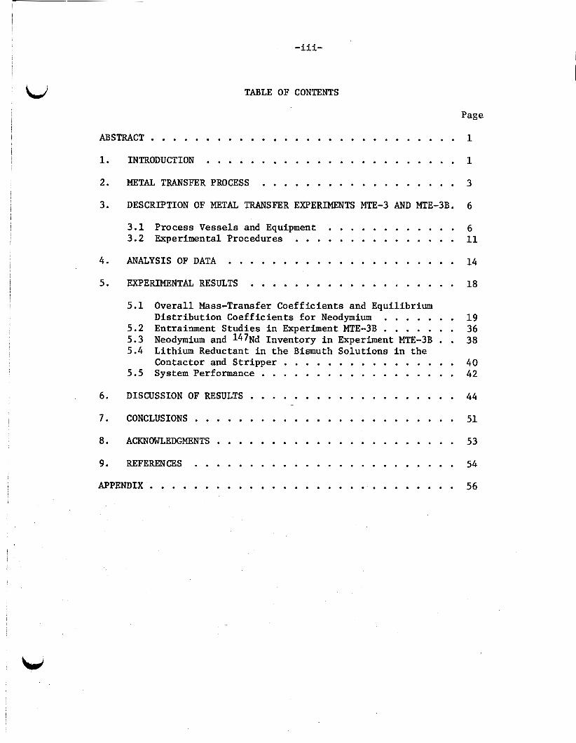
TABLE OF CONTENTS
Page
ABSTRACT . . . . . . . . . . . . . . . . . . . . . . . . . . . . 1
1 . INTRODUCTION . . . . . . . . . . . . . . . . . . . . . . . 1
2 . METAL TRANSFER PROCESS . . . . . . . . . . . . . . . . . . 3
3 . DESCRIPTION OF METAL TRANSFER EXPERIMENTS MTE-3 AND MTE.3B . 6
3.1 Process Vessels and Equipment . . . . . . . . . . . . 6 3.2 Experimental Procedures . . . . . . . . . . . . . . . 11
4 . ANALYSIS OF DATA . . . . . . . . . . . . . . . . . . . . . 14
5 . EXPERIMENTAL RESULTS . . . . . . . . . . . . . . . . . . . 18
5.1 Overall Mass-Transfer Coeff ic ients and Equilibrium Dis t r ibu t ion Coeff ic ients f o r Neodymium . . . . . . . 19
5.2 Entrainment Studies i n Experiment MTE-3B . . . . . . . 36
Contactor and S t r ippe r . . . . . . . . . . . . . . . . 40 5.5 System Performance . . . . . . . . . . . . . . . . . . 42
6 . DISCUSSION OF RESULTS . . . . . . . . . . . . . . . . . . . 44
7 . CONCLUSIONS . . . . . . . . . . . . . . . . . . . . . . . . 51
5.3 Neodymium and 147Nd Inventory i n Experiment MTE-3B . . 38 5.4 Lithium Reductant i n t h e Bismuth Solut ions i n the
..
8 . ACKNOWLEDGMENTS . . . . . . . . . . . . . . . . . . . . . . 53
. . . . . . . . . . . . . . . . . . . . . . . . 9 . REFERENCES 54
APPENDIX . . . . . . . . . . . . . . . . . . . . . . . . . . . . 56

-1-
ENGINEERING TESTS OF THE METAL TRANSFER PROCESS FOR EXTRACTION OF RIIW-EARTH FISSION PRODUCTS FROM A MOLTEN-SALT
BREEDER REACTOR FUEL SALT
H. C. Savage J. R. Hightower, Jr.
ABSTRACT
I n t h e metal t r a n s f e r process f o r removal of rare-ear th f i s s i o n products from t h e f u e l sa l t of a molten-salt breeder r eac to r (MSBR),the rare e a r t h s are ex t rac ted from the molten f u e l sa l t i n t o a molten bismuth so lu t ion containing l i th ium and thorium m e t a l reductants , t ransfer red from the bismuth i n t o molten l i th ium chlor ide and, f i n a l l y , recovered from the l i th ium chlor ide by ex t r ac t ion i n t o molten bismuth containing l i th ium reductant.
Engineering experiments using mechanically ag i t a t ed , non- d ispers ing contactors with sa l t and bismuth flow rates [Q 1% of those required f o r processing t h e f u e l sa l t from a 1000-MW(e) MSBR] have been conducted (1) t o study t h i s process, (2) t o measure the removal rate of a representa t ive rare-ear th f i s s i o n product (neodymium) from MSBR f u e l sa l t , and (3) t o evaluate t h e mechanically ag i t a t ed contactor f o r use i n a p l an t processing f u e l s a l t from a 1000-MW(e) FISBR.
The experimental equipment and procedures are described. Resul ts obtained during f i v e experiments i n which the rare e a r t h neodymium w a s ex t rac ted from MSBR f u e l sa l t are presented. Removal rates and mass-transfer coe f f i c i en t s between the sa l t and bismuth phases were determined f o r neodymium and are discussed i n terms of t h e processing requirements f o r a 1000-MW(e) MSBR.
1. INTRODUCTION
The Oak Ridge National Laboratory has been engaged i n developing 232m-233u a molten-salt breeder r eac to r t h a t would opera te on t h e
f u e l cyc le t o produce low-cost power while producing more f i s s i l e
material than is consumed.
sa l t mixture as t h e f u e l and graphi te as t h e moderator.
t h e r eac to r t o be operated as a breeder, i t would be necessary t o
remove t h e rare-ear th f i s s i o n products on a 25- t o 100-day cyc le and
i s o l a t e 233Pa from the region of high neutron f lux during i ts decay
The r eac to r would use a molten f luo r ide
I n order f o r
"
-2-
t o 233U. Thus an on-si te processing p l an t t h a t contfnuously removes
the protactinium and rare ea r ths is required f o r t h e r eac to r t o
perform as a breeder.
71.6746-12-0.33 mole % LiF-BeF2-ThF4-UF4 and contains 233PaF and
rare-ear th f l u o r i d e f i s s i o n products.
f o r t he processing p lan t , f u e l salt i s removed from the r eac to r a t
a rate of about 0.9 gpm. The sal t is f i r s t fed t o a f luo r ina to r
where-about 99% of the uranium is removed as UF6.
leaving t h e f luo r ina to r is contacted with bismuth that contains
l i th ium and thorium reductants i n order t o e x t r a c t protactinium and
t h e remaining uranium. The sal t stream, e s s e n t i a l l y f r e e of uranium
and protactinium but containing t h e rare-ear th f i s s i o n products, is
then fed t o a rare-ear th removal system where t h e rare-ear th f i s s i o n
products are ext rac ted before re turning the f u e l sa l t t o t h e reac tor .
The equilibrium concentrat ion of t h e rare e a r t h s i n t h e salt from
the reac tor i s .about 100 ppm f o r a 1000-MW(e) MSBR; rare-ear th
removal times range from 25 t o 100 days.
1 The f u e l s a l t f o r a s ingle- f lu id MSBR has t h e composition
4 I n the re ference flowsheet
The sal t stream
~
Engineering experiments t o study a r ecen t ly developed rare-ear th
removal ca l l ed t h e metal t r a n s f e r process , have been
conducted over t h e p a s t s eve ra l years. I n t h i s method, t h e rare e a r t h s
are ex t rac ted from the f u e l salt i n t o bismuth containing l i th ium and
thorium reductants , t ransfer red from the.bismuth i n t o molten l i th ium
chlor ide and, f i n a l l y , recovered from t h e l i th ium chlor ide by
ex t r ac t ion i n t o molten bismuth containing l i th ium reductant . 495 Mechanically ag i t a t ed salt-metal contac tors have been inves t iga ted
f o r use i n t h e MSBR processing systems based on reduct ive ex t rac t ion .
This type of contactor is of p a r t i c u l a r i n t e r e s t f o r t h e metal t r a n s f e r
process since adequate mass-transfer rates may be poss ib le without
d i spe r sa l of the sal t and bismuth phases.
considerably reduces t h e problem of entrainment of bismuth i n t h e
Eliminating phase d i s p e r s a l
processed f u e l carrier sal t and subsequent t r a n s f e r t o t h e r eac to r ,
which is constructed of a nickel-base a l l o y t h a t is subjec t t o damage
by metallic bismuth.
a near-isothermal, i n t e r n a l l y c i r cu la t ed , cap t ive phase t h a t would
minimize the occurrence of mass-transfer corrosion. Also, it is believed
The bismuth i n t h i s type of contactor would be

t h a t a processing system employing t h i s type of contactor can be more
e a s i l y fabr ica ted of graphi te , which is required f o r bismuth containment,
than one using packed columns.
I
Operation and test r e s u l t s of engineering-scale experiments,
u t i l i z i n g t h e metal t r a n s f e r process and mechanically ag i t a t ed contactors ,
are described i n t h i s repor t .
s t e p s i n t h e metal t r a n s f e r process using sal t flow rates t h a t were
about 1% of those requi red f o r processing the f u e l s a l t from a 1000-
MW(e) MSBR. The goa ls of t h e experiments were (1) t o study the var ious
s t eps of the process, (2) t o measure the rate of removal of representa t ive
rare-ear th f i s s i o n products from t h e molten-salt reac tor f u e l , and (3)
t o determine t h e s u i t a b i l i t y of mechanically ag i t a t ed contactors f o r
t h i s process.
t h e s a l t and metal phases i n t h e system w e r e determined using representa t ive
rare-ear th f i s s i o n products.
These experiments incorporated a l l t he
For t h i s evaluat ion, mass-transfer coe f f i c i en t s between
2. METAL TRANSFER PROCESS
I n the metal t r ans fe r process, f l u o r i d e f u e l sa l t t h a t - i s f r e e
of uranium and protactinium is f i r s t contacted with molten bismuth
containing l i th ium and thorium as reductants a t concentrations of
about 0.002 and 0.0025 m.f., respect ively. The rare ea r ths are
ext rac ted i n t o t h e bismuth. The bismuth t h a t contains t h e rare e a r t h s
and thorium is then contacted with molten l i thium chlor ide ; and,
because of highly favorable d i s t r i b u t i o n coe f f i c i en t s , t he rare
e a r t h s d i s t r i b u t e se l ec t ive ly , r e l a t i v e t o thorium, i n t o the LiC1.
The f i n a l s t e p of t he process c o n s i s t s of ex t r ac t ing t h e rare e a r t h s
from t h e L i C l by contac t with molten bismuth containing l i th ium
reductant a t concentrat ions of 5 t o 50 a t . %.
The chemical reac t ions t h a t represent each s t e p of t h e process
are given below, using a t r i v a l e n t rare e a r t h as an example:
Reductive ex t rac t ion : (1) I
Re3+(fuel salt) + 3Li(Bi) Bi--0*2 at ' % Li+ 3Li+(fuel s a l t ) + RE(Bi);
Transfer t o LiC1:
RE(Bi) + 3Li+(LiC1) L i C l
3Li(Bi) + RE3+ (LiC1);
-4-
Str ipping i n t o Bi-Li:
FS3+(LiC1) + 3 L i ( B i ) Bi--5 at' % Li b 3Li+(LiC1) + RE(Bi).
(3)
The e q u i l i b r i a f o r these r eac t ions have been measured and expressed
as d i s t r i b u t i o n c o e f f i c i e n t s f o r t h e rare e a r t h s between the f u e l
carrier salt and bismuth containing l i th ium as a reductant and as
d i s t r i b u t i o n coe f f i c i en t s of thorium and rare e a r t h s between l i thium
chlor ide and bismuth containing l i thium. y 7
coe f f i c i en t is defined as
The d i s t r i b u t i o n
where
DM = d i s t r i b u t i o n c o e f f i c i e n t , 5 = mole f rac t ion .of metal M i n t h e bismuth phase,
hn = mole f r a c t i o n of t h e metal ha l ide i n t h e sa l t phase.
Under condi t ions of interest, t he d i s t r i b u t i o n c o e f f i c i e n t s have
been found t o be dependent on t h e l i th ium concentrat ions as follows: *
log DM = n log si+ log %, (5)
where
n = valence of metal Mn+ i n t h e sal t phase,
si = mole f r a c t i o n of l i th ium i n the bismuth phase,
$ = constant a t a given temperature.
Calculated values of rare earth--thorium separa t ion f a c t o r s 8 between the bismuth and L i C l sa l t range from about lo4 t o 10
d iva len t and t r i v a l e n t rare e a r t h s based on t h e measured d i s t r i b u t i o n
coe f f i c i en t s .
f o r
One vers ion of a flowsheet f o r removing rare e a r t h s from MSBR
f u e l sa l t using the metal t r a n s f e r process is shown i n Fig. 1.
t h i s method, uranium- and protactinium-free f u e l sa l t from t h e
protactinium removal s t e p is fed t o a series of contactor s t ages
thraugh which bismuth containing dissolved reductant is c i r cu la t ed .
The bismuth i n each of these fue l - sa l t contactor s t ages a l s o c i r c u l a t e s
through a corresponding l i th ium chlor ide contactor s t age wi th in a
series of contactors through which a l i th ium ch lo r ide stream flows.
This l i th ium chlor ide stream, i n tu rn , c i r c u l a t e s through a s i n g l e
Using

U, Pa-FREE SALT FROM Pa-REMOVAL STEP
ORNL DWG 76-685
‘I f “YDROFL~8RlNATOR
06 STRIPPER
\ BISMUTH -LITHIUM
STRIPPER SOLUTION
4 / L
/ PROC4ZES;$EfALT . RECIRCULATING RECONSTITUTION
STEP,
i ;SR$JTz
Fig. 1. Metal transfer process using multiple MTE-3--type contactors.

-6-
contac tor , where t h e l i th ium chlor ide i s contacted with a bismuth-
l i th ium s t r i p p e r so lu t ion .
An advantage of t h i s arrangement is t h a t t h e f u e l salt--bismuth
contactors and the l i th ium chloride--bismuth contac tors can be
constructed contiguous t o one another , and the bismuth can be made
t o flow between the two by t h e pumping ac t ion of t he a g i t a t o r s (described
i n experiments MTE-3 and MTE-3B i n Sect. 3) .
need f o r ex terna l bismuth pumps is eliminated. Another advantage is
t h a t t h e bismuth i s t h i s type of contactor would be a near-isothermal,
cap t ive phase t h a t would minimize t h e occurrence of mass-transfer
corrosion.
Thus i n t h i s method, t h e
Although o the r v a r i a t i o n s can be synthesized, t h e removal rates
of neodymium measured i n experiment MTE-3B are discussed i n terms of
processing requirements f o r a 1000-MW(e) MSBR using t h e flowsheet
shown i n Fig. 1.
3. DESCRIPTION OF METAL TRANSFER EXPERIMENTS MTE-3 AND MTE-3B
3.1 Process Vessels and Equipment
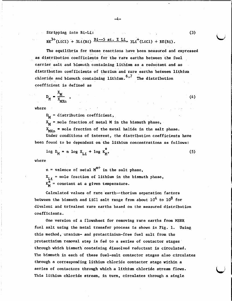
The bas ic equipment used i n t h e experiments (shown diagrammatically
i n Fig. 2) , consis ted of t h ree carbon steel vesse ls : (1) a 14-in.
(0.36-m)-diam f luo r ide sal t r e se rvo i r containing t h e f u e l carrier
sal t (72-16-12 mole % LiF-BeF2-ThF4), a 10-in. (0.25-m)diam salt-
metal contac tor , and a 6-in. (0.15-m)-diam rare-ear th s t r i p p e r . A
photograph of the process equipment is shown i n Fig. 3. The salt-
m e t a l contactor is divided i n t o two equal compartments by a carbon
steel p a r t i t i o n t h a t separa tes t h e f l u o r i d e and L i C l salts. A 1/2-in.
(13-mm)-high s l o t a t the bottom of the p a r t i t i o n in te rconnec ts
t h e capt ive pool of bismuth-lithium-thorium so lu t ion i n t h e contactor .
Mechanical a g i t a t o r s i n both compartments of t he contactor and i n the
s t r i p p e r were used toimprovecontact between the salt and bismuth
phases. Four-bladed turb ines , 2-7/8-in. (73 mm) i n diameter and having
a p i t c h of 45", were located i n each phase.
a g i t a t o r s is shown i n Fig. 4. w e r e such t h a t t he sal t and bismuth flows were d i rec ted toward t h e
in t e r f ace .
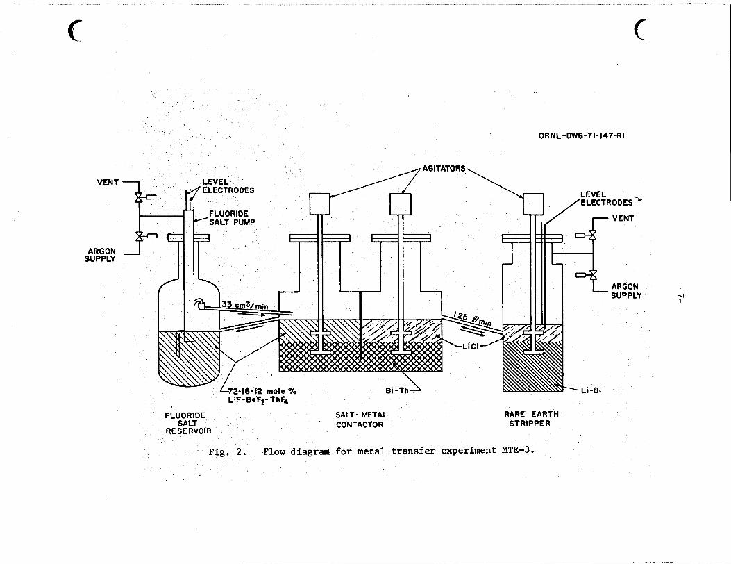
metal t r a n s f e r experiments are l i s t e d i n Table 1.
A photograph of t h e
The blade mounting and s h a f t r o t a t i o n
The engineering drawings used i n t h e construct ion of t h e
ORNL-DWG-71-147-RI
VENT
ARGON SUPPLY
LiF-BeFZ- ThFe
FLUORIDE SALT- METAL RARE EARTH SALT CONTACTOR STRIPPER
RESERVOIR
Flow diagram for metal transfer experiment MTE-3.
I 4 I

-8-
Fig. 3 . Photograph of processing vesse ls for metal transfer experiment MTE-3B with heaters and thermocouples instal led.

Fig. 4. Photograph of agitators used for promoting mass transfer between the s a l t and bismuth solutions i n metal transfer experiments MTE-3 and MTE-3B.
-10-
c.i Table 1. Engineering drawings used i n construct ion of t h e m e t a l t r a n s f e r
experiment
Drawing number Description
F-12172-CD-116E
M-12172-CD-OZD
2 6D
27E
2 9E
30E
31D
3 2E
33D
34D
35E
3 6D
37D
38D
3 9D
4 6D
47D
48E
49c
51D
52E
53c
M-12053-CD-83C
Flowsheet
Fluoride salt tank
Details of pump nozzle, viewing p o r t , sa l t funnel and d ra in
Agitator d e t a i l s of assembly
Contactor vessel assembly
Contactor ves se l plan view
Contactor vessel sec t ions
Contactor vessel d e t a i l shee t 1
Contactor vessel sampler d e t a i l s
Thermowell d e t a i l s
Acceptor vessel assembly
Acceptor vessel sec t ions A-A, B-B, and C-C
Acceptor vessel d e t a i l s
Transfer l i n e i s o l a t i o n f lange assembly and d e t a i l s
D e t a i l s f o r brazing copper sheath t o steel pipe
Heat t r a n s f e r l i n e subassembly
Agitator -blades assembly and d e t a i l s
Vessel s tand and mounting d e t a i l s
Samplers
Details of sa l t t r ans fe r l i n e piping
Fluoride salt pump assembly and d e t a i l s
Sample l a d l e body d e t a i l
S a l t and bismuth f i l t e r
-11-
The outs ide sur faces of the carbon steel vessels were coated with
'L 0.015-in. (0.4-mm)-thick chromium--nickel--6% aluminum oxidation-
r e s i s t a n t material (METCO* No. P443-10) using a plasma spray gun. This
prevented air oxidat ion of the carbon steel vessels a t the operat ing
temperature of 'L 923 K.
Fuel salt w a s c i r cu la t ed between the f luo r ide sal t reservoi r and
one s i d e of t h e contactor by means of a spec ia l ly designed gas-operated
pump u t i l i z i n g molten bismuth check valves.
c i rcu la ted between t h e s t r i p p e r and the o the r s i d e of t he contactor by
a l t e r n a t e l y pressurizing and venting t h e s t r i p p e r vessel. The bismuth
phase i n the contactor w a s c i r cu la t ed between t h e two compartments in
the contactor by the ac t ion of t h e a g i t a t o r s , and no d i r e c t measurement of
t h i s flow rate w a s made during experiments. However, measurements made i n
a mockup using a mercury-water system indicated t h a t t he bismuth flow
rate between t h e two compartments would be high enough t o cause t h e rare-
e a r t h concentrat ions i n t h e compartments t o be e s s e n t i a l l y equal.
The salt flow rates used were about 1% of those required f o r processing the
f u e l sa l t from a 1000-MW(e) MSBR.
Lithium chlor ide w a s
8
Approximate q u a n t i t i e s of sa l t and bismuth used i n t h e experiment
were t h e following: (1) 110 kg of f l u o r i d e sa l t and 64 kg of bismuth-
lithium-thorium (containing about 0.0018 atom f r a c t i o n l i thium and
0.0014 atom f r a c t i o n thorium) i n t h e contactor, and (2) 10 kg of l i th ium
chlor ide and 44 kg of bismuth-lithium (containing 0.05 atom f r a c t i o n
l i thium) i n the s t r i p p e r .
3.2 Experimental Procedures
Procedures f o r t he makeup, p u r i f i c a t i o n , and addi t ion of t he
sal t and bismuth phases t o t h e process ves se l s were designed t o minimize
contamination of these materials with 'oxide ( a i r , water, and any oxides
present i n t h e carbon steel process vessels). P r i o r t o the addi t ion of
t h e salts and bismuth, t h e i n t e r n a l sur faces of a l l vessels were t r e a t e d
with hydrogen a t 923 K t o reduce r e s i d u a l i ron oxides.
oxides had been removed by sandblast ing during fabricat ion.)
t h i s treatment, a pur i f i ed argon atmosphere (Q 0.1 ppm of H20) was maintained i n t h e vessels t o preclude f u r t h e r oxidat ion.
(Most of these
A f t e r
*METCO, Inc., 1101 Prospect Avenue, Westburg, Long Is land , N.Y.
-12-
The sal t and bismuth so lu t ions were made up i n a u x i l i a r y vessels (a l so
t r ea t ed with hydrogen) a t Q 923 K t o remove oxides). The bismuth was hygrogen t r ea t ed a t 'L 923 K, while t he f l u o r i d e sal t and LiCl sa l t were contacted with bismuth containing thorium f o r oxide removal.
makeup and pu r i f i ca t ion , a l l so lu t ions were f i l t e r e d by passing through a s in t e red molybdenum f i l t e r ('L 30-p pore-diameter) during t r ans fe r
from the aux i l i a ry vessels i n t o t h e process vessels.
ves se l s had been charged with t h e sal t and bismuth so lu t ions , t h e e n t i r e
system was maintained a t temperatures above t h e l i qu idus temperature
(1 890 K) of t h e so lu t ions .
After
Af te r t h e process
The experimental procedure w a s e s s e n t i a l l y t h e same f o r each run.
The rare e a r t h f o r which t h e mass t r ans fe r rate and o v e r a l l mass t r a n s f e r
c o e f f i c i e n t s w e r e t o be measured was added t o t h e f l u o r i d e sa l t , t h e
a g i t a t o r s were s t a r t e d and adjusted t o t h e des i red speed, c i r c u l a t i o n of the f l u o r i d e sal t and L i C l w a s started, and t h e sal t and bismuth phases
were pe r iod ica l ly sampled during t h e run period and analyzed f o r rare-
e a r t h content. I n each run, trace q u a n t i t i e s of a rad ioac t ive i so tope
wereincluded i n the rare-ear th addi t ion , and counting of t h e radio-
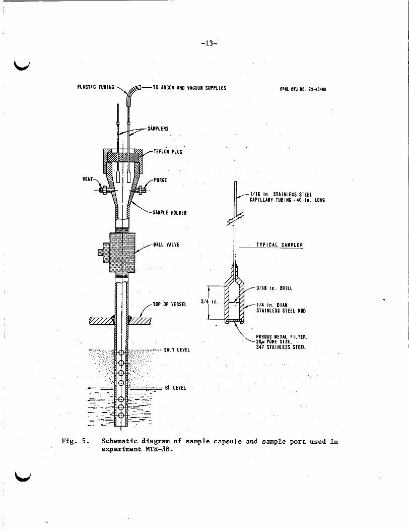
a c t i v i t y of t he samples w a s used t o fol low the t r a n s f e r rate. Samples of t h e sa l t and bismuth phases were taken using a small
3 ('L 0.4-cm ) s t a i n l e s s steel sampling capsule with a s in t e red metal
f i l ter (Q 20-p pore-diameter). A 1/16-in. (0.16-mm)-diam c a p i l l a r y
tube at tached t o the capsule w a s used f o r i n s e r t i n g i t i n t o t h e so lu t ion
t o be sampled (see Fig. 5). During in se r t ion , t h e capsule w a s
continuously purged with pu r i f i ed argon gas u n t i l i t w a s posi t ioned i n
t h e so lu t ion .
taken by applying a vacuum t o t h e capsule.
bismuth so lu t ion reached t h e upper, cool s ec t ion of t h e c a p i l l a r y tube, i t
s o l i d i f i e d .
allowed t o cool under an argon atmosphere before removal.
The flow of purge gas w a s then stopped, and a sample w a s
When t h e molten sa l t o r
The sample w a s then withdrawn i n t o t h e sample p o r t and
A l l runs i n the second experiment, MTE-3B, were made using t h e rare
e a r t h neodymium.
were included i n t h e neodymiqm added t o t h e experiment.
concentrat ion i n each phase was determined by counting t h e 0.53-MeV
gamma emitted by t h e 147Nd i n t h e sample.
neodymium contents of selected samples were determined by a n i so top ic
d i l u t i o n mass spectrometry technique.
I n these runs, trace amounts (50 t o 150 m C i ) of 147Nd
Neodymium
I n addi t ion, t h e t o t a l .
This proved t o be a va luable means
-13-
PLASTIC TUBING -TO ARGON AN0 VACUUM
VENT
SUPPL IES
OF VESSEL
SALT LEVEL
- B 1 LEVEL
ORNL DWC NO. 72-10406
1/16 i n . STAINLESS STEEL CAPILLARY TUBING - 40 i n . LONG
3/16 i n . ORILL
1/4 i n . OlAM STAINLESS STEEL ROO
POROUS METAL FILTER, 20+ PORE S I Z E , 347 STAINLESS STEEL
Fig. 5 . Schematic diagram of sample capsule and sample port used i n experiment MTE-3B.
-14-
of checking on the tracer counting r e s u l t s and w a s e spec ia l ly use fu l
f o r those samples with very low neodymium concentrat ions (< 1 ppm),
where counting techniques were inadequate.
For runs i n t h e i n i t i a l experiment MTE-3, i n which t h e rare e a r t h s
europium, lanthanum, and neodymium were used, counting of t h e 1.28-MeV
gamma emitted from t h e 154Eu tracer w a s used t o follow t h e t r a n s f e r
rate, and t h e lanthanum concentrat ion w a s determined by neutron a c t i v a t i o n
and subsequent counting of t he 14'La produced.
This r epor t pr imari ly descr ibes t h e r e s u l t s obtained using t h e rare
e a r t h neodymium i n the second m e t a l t r a n s f e r experiment, MTE-3B.
f i r s t experiment, MTE-3, was conducted by o t h e r s and reported
previously ;
r e s u l t s .
The
r e s u l t s are summarized f o r comparison with MTE-3B
4. ANALYSIS OF DATA
Experiment MTE-3B involved t h e successive t r a n s f e r of rare earth
from a f l u o r i d e salt t o a bismuth-lithium-thorium pool, t o a l i th ium
chlor ide s a l t , and, u l t imate ly , t o a bismuth-lithium pool. The rate a t
which t h e rare e a r t h w a s t ransfer red through the several contactor s tages
w a s governed by t h e equilibrium d i s t r i b u t i o n c o e f f i c i e n t of t he rare
e a r t h , t h e sa l t and bismuth flow rates, and t h e mass-transfer
coe f f i c i en t s . The determination of these mass-transfer c o e f f i c i e n t s w a s
one of t he major requirements f o r meeting the objec t ives of t h e experiment.
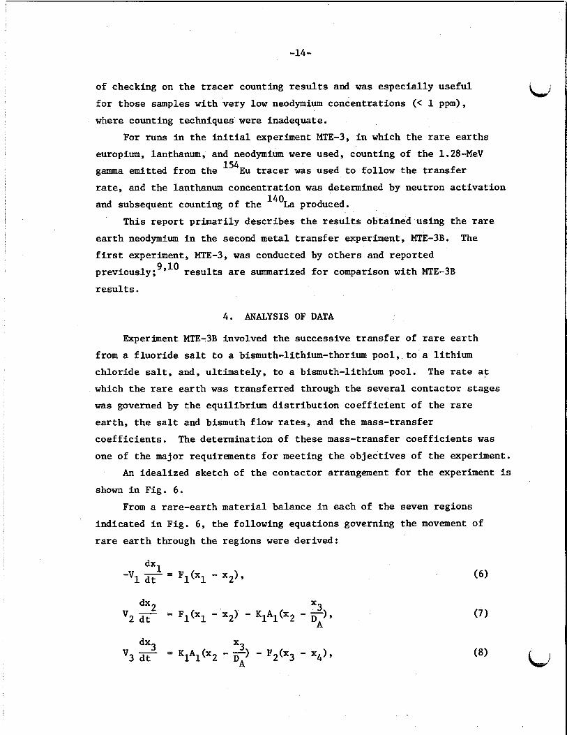
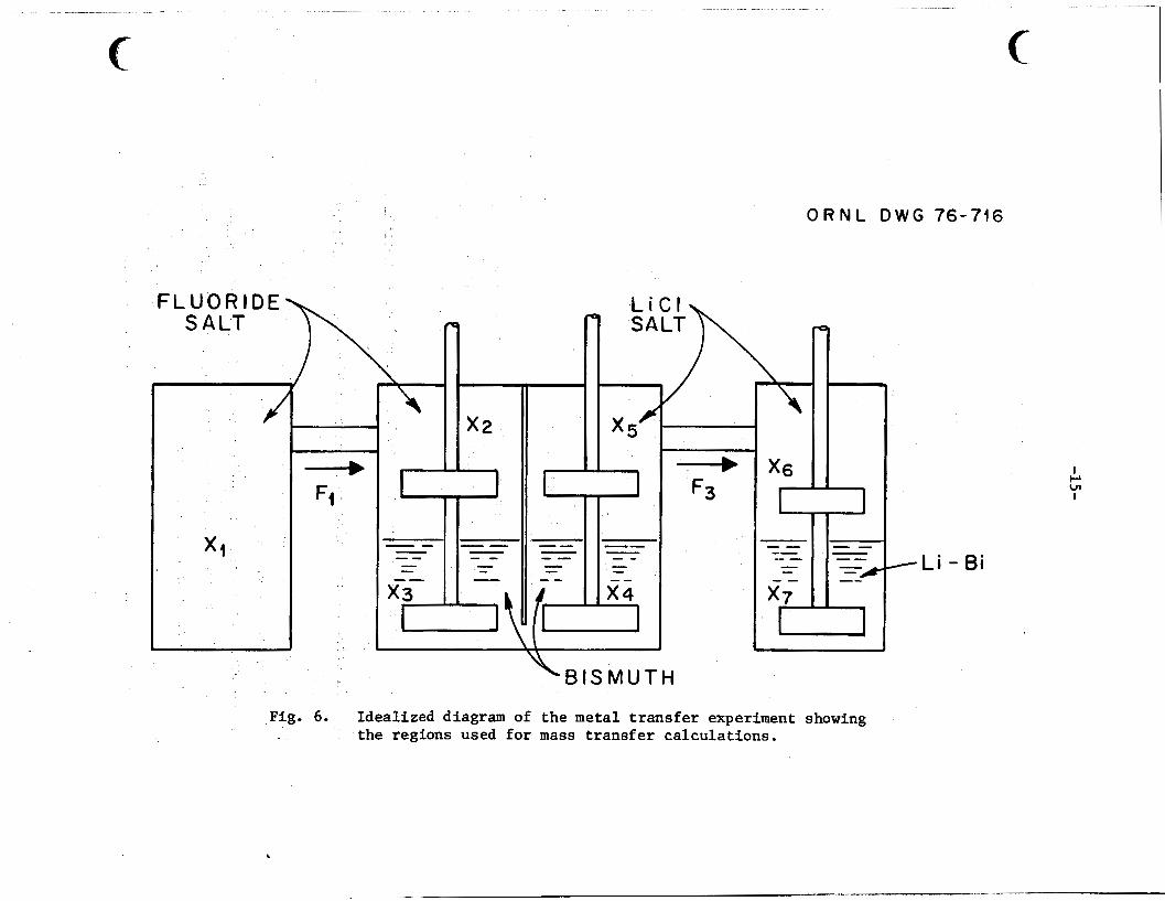
An idea l ized sketch of t he contactor arrangement f o r t h e experiment is
shown i n Fig. 6.
From a rare-ear th material balance i n each of t he seven regions
indicated i n Fig. 6, t h e following equations governing t h e movement of
rare e a r t h through t h e regions were derived:
V3 dt dx3 = K A (X x3 - F 2 ( ~ 3 - ~ 4 1 , 11 2 DA
FLUOR1 SALT
J
O R N L D W G 76-716
Fig.
e Fi F3
x6
6 . Idealized diagram of the metal transfer experiment showing the regions used for mass transfer calculations.
-Li - Bi
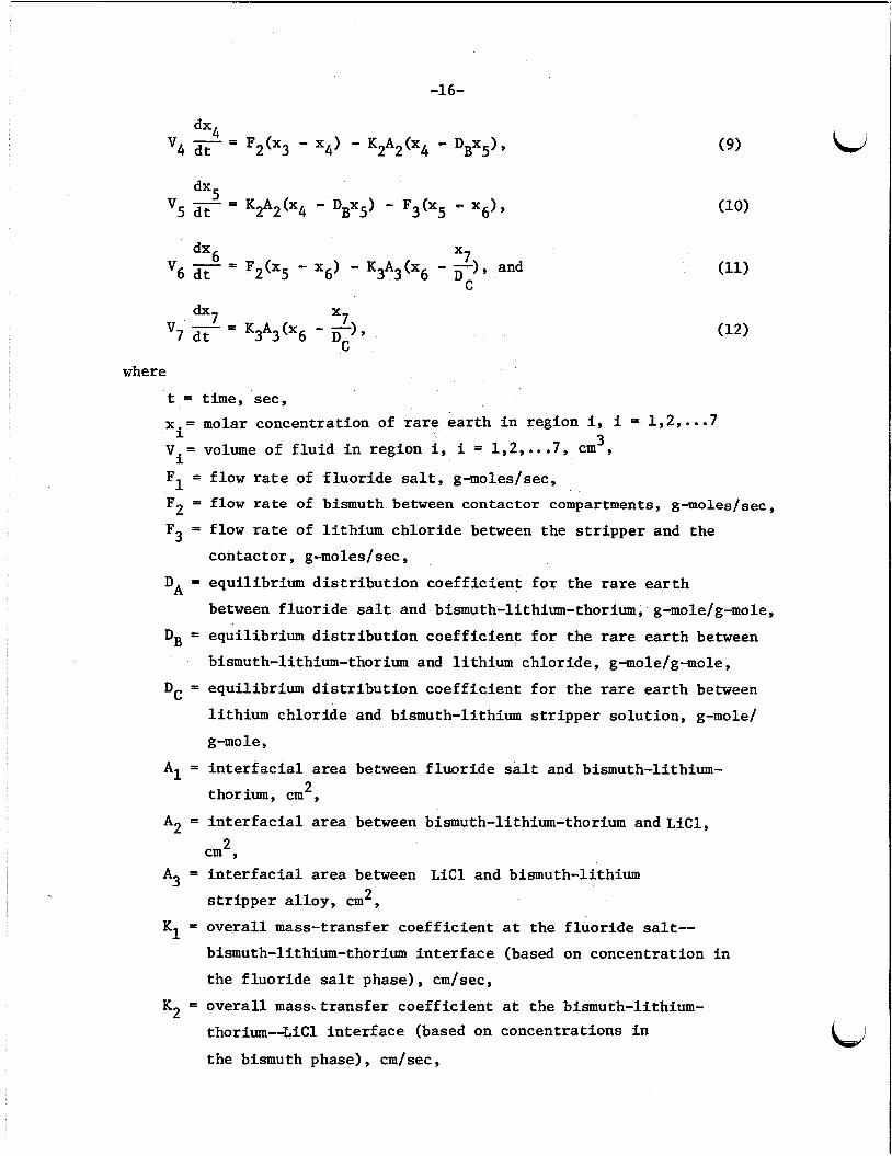
-16-
I I
K3A3(X6 - TI’ v7 dt =
where
t = time, sec, x = molar concentration of rare e a r t h i n region i, i = 1,2,...7
3 Vi= volume of f l u i d i n region i, i = 1,2 ,* . .7 , c m , F1 = flow rate of f luo r ide sal t , g-moles/sec,
F2 = flow rate of bismuth between contactor compartments, g-moles/sec,
F3 = flow rate of l i th ium ch lo r ide between the s t r i p p e r and t h e
i
contactor , g-moles/sec,
DA = equilibrium d i s t r i b u t i o n c o e f f i c i e n t f o r t he rare e a r t h
between f luo r ide sal t and bismuth-lithium-thorium, g-mole/g-mole,
DB = equilibrium d i s t r i b u t i o n c o e f f i c i e n t f o r t he rare e a r t h between
bismuth-lithium-thorium and l i th ium chlor ide , g-mole/g-mole,
DC = equilibrium d i s t r i b u t i o n c o e f f i c i e n t f o r t h e rare e a r t h between
l i th ium chlor ide and bismuth-lithium s t r i p p e r so lu t ion , g-mole/
g-mole,
A1 = i n t e r f a c i a l area between f l u o r i d e salt and bismuth-lithium- 2 thorium, cm ,
A2 = i n t e r f a c i a l area between bismuth-lithium-thorium and L i c l , 2 cm 9
A3 = i n t e r f a c i a l area between L i C l and bismuth-lithium s t r i p p e r a l l o y , c m 2 ,
K1 = overa l l mass-transfer coe f f i c i en t a t t h e f l u o r i d e salt--
bismuth-lithium-thorium i n t e r f a c e (based on concentrat ion i n
t he f l u o r i d e sal t phase), cm/sec,
K2 = overa l l massLtransfer coe f f i c i en t a t the bismuth-lithium- thorium-4iC1 i n t e r f a c e (based on concentrat ions i n
t h e bismuth phase), cm/sec,
-17-
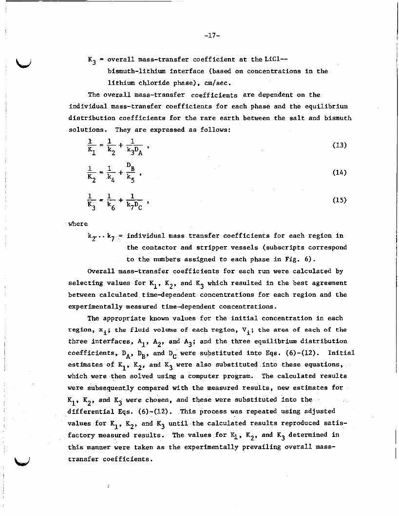
Kg = overa l l mass-transfer coe f f i c i en t a t theLiC1--
bismuth-lithium in t e r f ace (based on concentrations i n t h e
l i th ium chlor ide phase), cm/sec.
a/
The o v e r a l l mass-transfer coe f f i c i en t s are dependent on t h e
ind iv idua l mass-transfer coe f f i c i en t s f o r each phase and the equilibrium
d i s t r i b u t i o n c o e f f i c i e n t s f o r t h e rare e a r t h between the salt and bismuth
so lu t ions . They are expressed as follows:
- = - + + - 1 1 1
1 1 DB
K2 k4 kg
K1 k2 k3DA ’
- = - + - ,
1 +-, 1 1
K3 kg k7DC - = -
where
k2..-k7 = ind iv idua l mass t r a n s f e r coe f f i c i en t s f o r each region i n
the contactor and s t r i p p e r vessels ( subscr ip ts correspond
t o t h e numbers assigned t o each phase i n Fig. 6). Overall mass-transfer coe f f i c i en t s f o r each run were ca lcu la ted by
se l ec t ing values f o r K1, K2, and K3 which r e su l t ed i n the bes t agreement
between calculated time-dependent concentrat ions f o r each region and the
experimentally measured time-dependent concentrations.
The appropriate known values f o r t h e i n i t i a l concentrat ion i n each
region, xi; the f lu id volume of each region, Vi; the area of each of the
t h ree in t e r f aces , AI, A2, and A3; and t h e th ree equilibrium d i s t r i b u t i o n
coe f f i c i en t s , DA, DB, and DC were subs t i t u t ed i n t o Eqs. (6)-(12).
estimates of K1, K2, and K3 were a l s o subs t i tu ted i n t o these equations,
which w e r e then solved using a computer program.
were subsequently compared with the measured r e su l t s , new estimates f o r
K1, K2, and Kg were chosen, and these were subs t i t u t ed i n t o t h e
d i f f e r e n t i a l Eqs. (6)-(12). This process w a s repeated using ad jus ted
values f o r K1, K2, and K3 u n t i l t h e ca lcu la ted r e s u l t s reproduced satis-
f ac to ry measured r e s u l t s .
t h i s manner w e r e taken as t h e experimentally preva i l ing o v e r a l l mass-
t r a n s f e r coe f f i c i en t s .
I n i t i a l
The ca lcu la ted r e s u l t s
The values f o r K l , K2, and K3 determined i n
W
-18 -
5. EXPERIMENTAL RESULTS
Four runs (Nd-1, -2, -3, and -4) using t h e rare e a r t h neodymium as
a representa t ive f i s s i o n product were completed i n metal t r a n s f e r
experiment MTE-3B. Neodymium w a s chosen as the r ep resen ta t ive rare-
e a r t h f i s s i o n product f o r t h e s t u d i e s i n MTE-3B f o r several reasons:
1. Neodymium is one of t h e more important t r i v a l e n t f i s s i o n
products t o be removed from a molten-salt breeder r eac to r
f u e l salt.
2. The use of 147Nd tracer with i t s r e l a t i v e l y sho r t h a l f - l i f e (11
days) would prevent excessive l e v e l s of r ad ioac t iv i ty i n the
experiment (addi t iona l neodymium, containing 147Nd tracer, w a s
added during the s tud ies ) .
Resul ts could be compared wi th those obtained using neodymium
i n the f i r s t experiment, MTE-3.
3.
D a t a f r o m Nd--1, -3, and -4, w e r e analyzed, and o v e r a l l mass-transfer
coe f f i c i en t s a t t h e three salt-metal i n t e r f a c e s were determined. Mass-
t r ans fe r coe f f i c i en t s were not determined i n experiment Nd-2 due t o
unexpected entrainment of f l u o r i d e s a l t i n t o t h e L i C l i n t he contactor .
Entrainment of f l u o r i d e salt i n t o t h e L i C l a f f e c t s t h e equilibrium
d i s t r i b u t i o n c o e f f i c i e n t s of t h e rare e a r t h s and thorium between t h e
L i C l and bismuth phases such t h a t thorium is t r ans fe r r ed i n t o the LiC1.
Entrainment a l s o occurred during run Nd-1; however, t he amount of f l u o r i d e
salt entrained w a s r e l a t i v e l y s m a l l (Q 1.3 wt % F i n t h e L i C l ) , and t h e
d i s t r i b u t i o n c o e f f i c i e n t s measured at t h e end of run Nd-1 were near t he
expected values. During run Nd-2, t h e cumulative amount
of f luo r ide salt entrained (Q 3 wt %) became s i g n i f i c a n t . The
d i s t r i b u t i o n c o e f f i c i e n t s ( p a r t i c u l a r l y f o r thorium a t t h e LiC1-bismuth
i n t e r f a c e i n t h e contactor) were reduced, and a s i g n i f i c a n t quant i ty of
thorium w a s t ransfer red i n t o t h e L i C l and w a s subsequently c i r cu la t ed i n t o
t h e s t r i p p e r , where i t reacted with t h e l i th ium reductant i n t h e Bi-Li
so lu t ion . This r eac t ion continued u n t i l most of t h e l i th ium reductant
was l o s t from the s t r i p p e r and t h e neodymium was no longer ex t rac ted
i n t o t h e Li-Bi i n t h e s t r i p p e r ,
about 50 hr of operat ion of run Nd-2; thus no determination of mass-
t r a n s f e r coe f f i c i en t s could be made.
11
Extract ion of neodymium stopped a f t e r

-19-
Because of t h e entrainment of f luo r ide salt i n t o t h e L i C l during runs
Nd-1 and Nd-2, i t became necessary t o remove both the L i C l from t h e
contactor and s t r i p p e r and t h e bismuth--5 at . % L i from the s t r i p p e r
a f t e r run Nd-2.
t h e system before s t a r t i n g run Nd-3.
Fresh L i C l and bismuth-lithium so lu t ion were charged t o
5.1 Overall Mass-Transfer Coeff ic ien ts and Equilibrium Dis t r ibu t ion Coeff ic ien ts f o r Neodymium
Operating condi t ions and system parameters f o r runs Nd-1 through Nd-4
i n metal t r a n s f e r experiment MTE-3B are shown i n Table 2.
t h e determinations of ove ra l l mass-transfer c o e f f i c i e n t s f o r t h e rare e a r t h
neodymium f o r runs Nd-1, -3, and -4 i n metal t r ans fe r experiment MTE-3B
are given i n Table 3. Values f o r t he equilibrium d i s t r i b u t i o n
Resul ts of
c o e f f i c i e n t s f o r neodymium measured a t t h e completion of each run,
during per iods of no salt c i r cu la t ion , are shown i n Table 4. Previously reported values f o r o v e r a l l mass-transfer c o e f f i c i e n t s f o r
europium, lanthanium, and neodymium obtained i n the experiment, MTE-3,
are shown i n Table 5 f o r reference.
Values f o r o v e r a l l mass-transfer c o e f f i c i e n t s f o r neodymium a t t h e
th ree salt-bismuth i n t e r f a c e s i n metal t r a n s f e r experiment MTE-3B (Table 3)
were obtained by se l ec t ing values f o r t h e mass-transfer coe f f i c i en t s which
r e su l t ed i n a "best f i t " between t h e experimentally obtained concentrat ions
during each run and t h e calculated concentrat ions as discussed i n Sect . 4.
The experimentally measured values f o r t h e equilibrium d i s t r i b u t i o n coe f f i c i en t s
f o r neodymium between t h e sal t and bismuth so lu t ions were used i n ca lcu la t ing
t h e "best f i t " case.
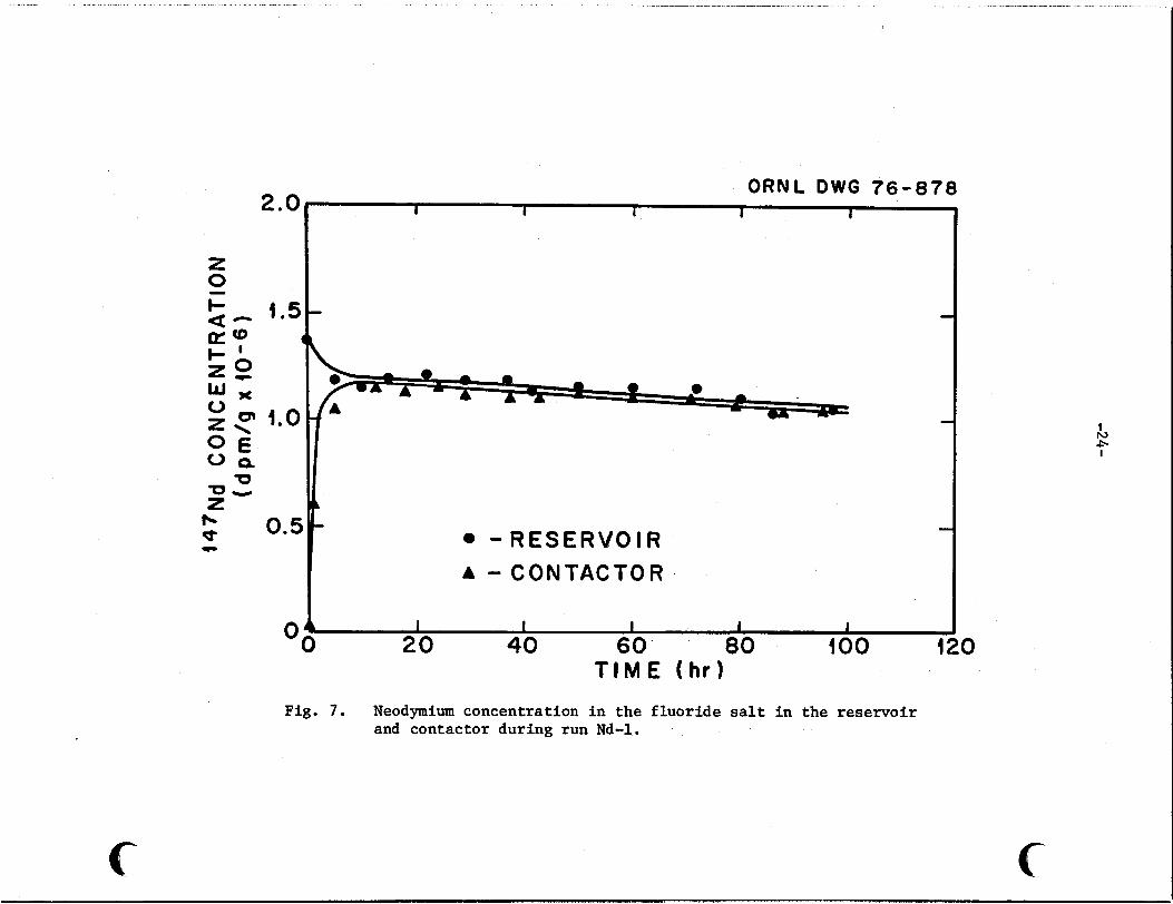
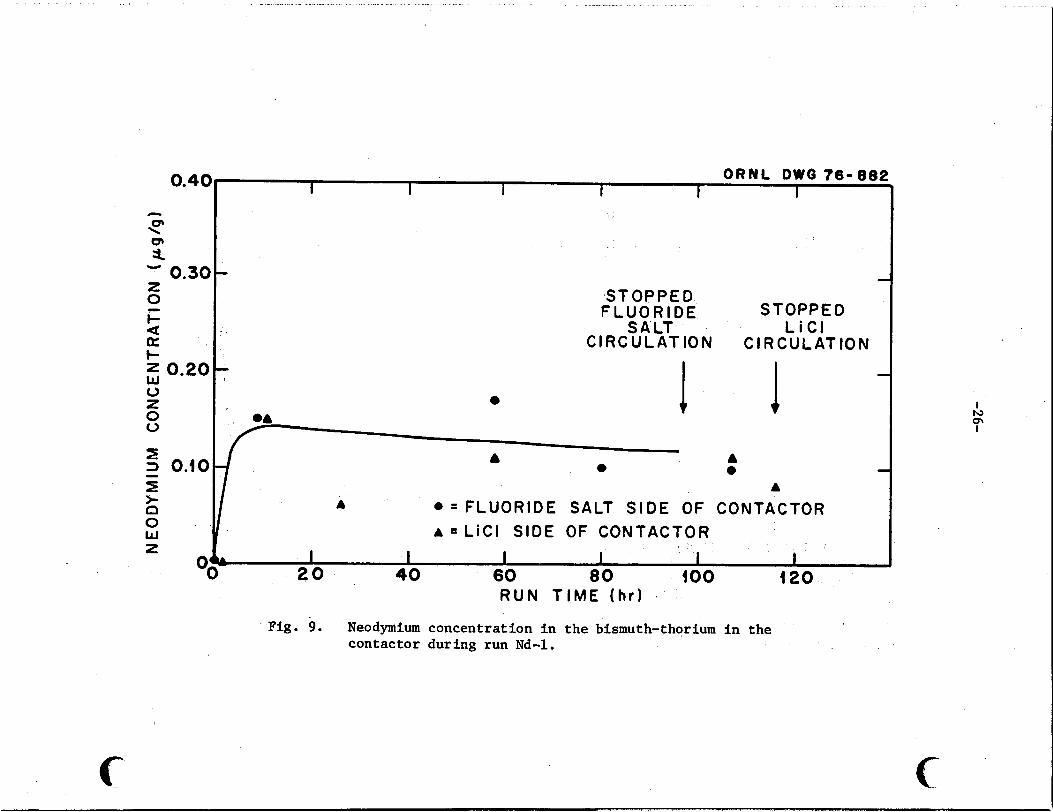
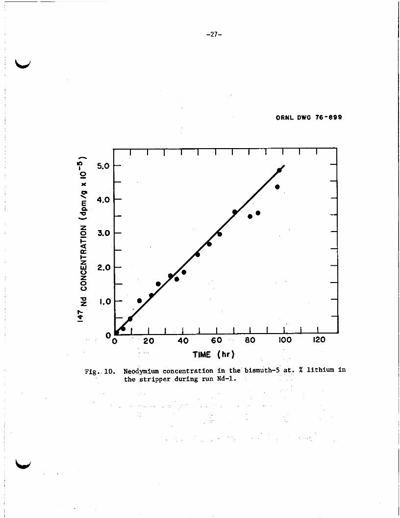
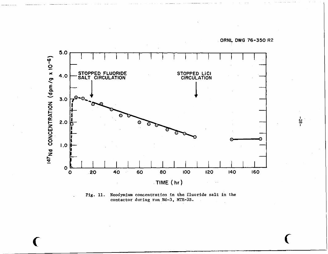
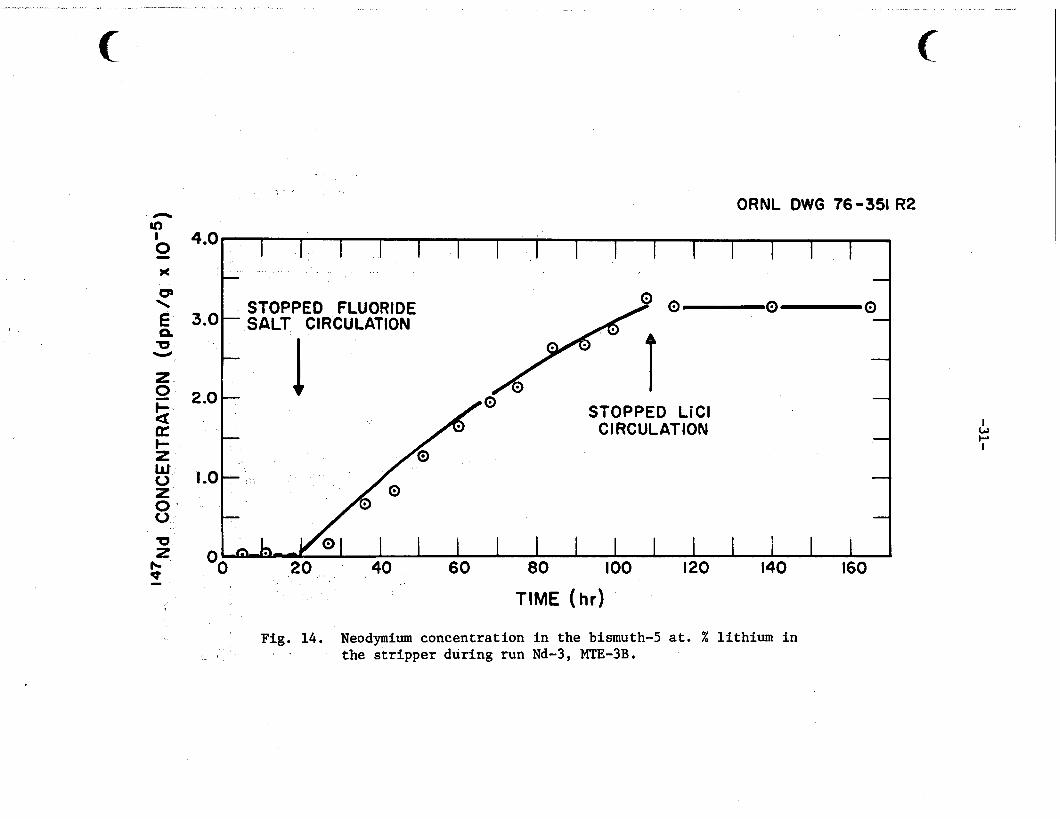
Resul ts are shown i n Figs. 8-18. I n these f igu res , t he experimental
da t a po in t s are indicated f o r each so lu t ion , and the l i n e shown represents
t h e "best f i t " f o r t h e ca lcu la ted concentrat ions during each run.
agreement w a s obtained f o r t h e f l u o r i d e sa l t so lu t ion and the bismuth--5
at . % l i th ium so lu t ion i n t h e s t r i p p e r f o r each run.
t he d a t a obtained by counting t h e 0.53-MeV gamma emitted by t h e 147Nd
tracer (with r e s u l t s expressed i n d i s in t eg ra t ions per minute per gram)
were used.
ana lys i s f o r t o t a l neodymium i n these two phases.
by t o t a l neodymium ana lys i s (&g) are shown f o r t h e bismuth-thorium-
l i thium so lu t ion i n t h e contactor and the L i C l i n t h e contactor and s t r i p p e r .
Excel lent
For these so lu t ions ,
Equally good agreement w a s obtained f o r t h e da t a obtained by
The r e s u l t s obtained

-20-
T a b l e 2. Operating conditions f o r runs Nd-1 through _ _ Nd-4 i n m e t a l t r a n s f e r experiment MTE-3B
Run number 1 2
Run t i m e , h r 140a 138 165. 2a 165a . (l15.7>b (107. 8Ib (109.5Ib
Agitator speed, r p s 5.0 5.0 4.17 1.67
Fluoride sal t c i r cu la t ion 5.8 x 5.8 x 0 0
L i C l c i r cu la t ion rate, 2.0 2.0 2.0 2.0
rate, m3/sec
m3/sec
Average temperature, K 923 923 92 3
Quant i t ies of S a l t and Bismuth (g-moles)
Fluoride f u e l sa l t i n r e se rvo i r
Fluoride f u e l salt i n contactor
Bi-Li-Th i n f luo r ide s a l t compartment of con- t ac to rd
.Bi-Li-Th i n L i C l sa l t compartment of con- t a c t o r
e L i C l i n contactor
L i C l i n s t r i p p e r
Bi--5 at. % Li i n s t r i p p e r f
1535 1535 1535
16 1 161 161
132 132 129
161 161 156
101 101 101
132 132 114
190 190 190
923
1535
16 1
132 ’
156
101
114
190
a
bTime of f luo r ide s a l t and/or L i C l sa l t c i r cu la t ion .
%ole w t = 63.2 g; p = 3.30 g/cm3; 1.1 = 0.0088 P a t 923 K. 13
e 14 Mole w t = 209 g; p = 9.66 g/cm3; 1.1 = 0.016 P a t 923 K.
fMole w t = 199 g; p = 9.28 g/cm ;
Total t i m e of f l uo r ide sal t and/or L i C l sa l t c i r c u l a t i o n p lus equi l ibr ium t i m e with a g i t a t i o n but no sa l t c i r cu la t ion .
%ole w t = 42.4 g; p = 1.48 g/cm3; 1.1 = 0.016 P a t 923 K. 12
3 = 0.0094 P a t 923 K.
-21-
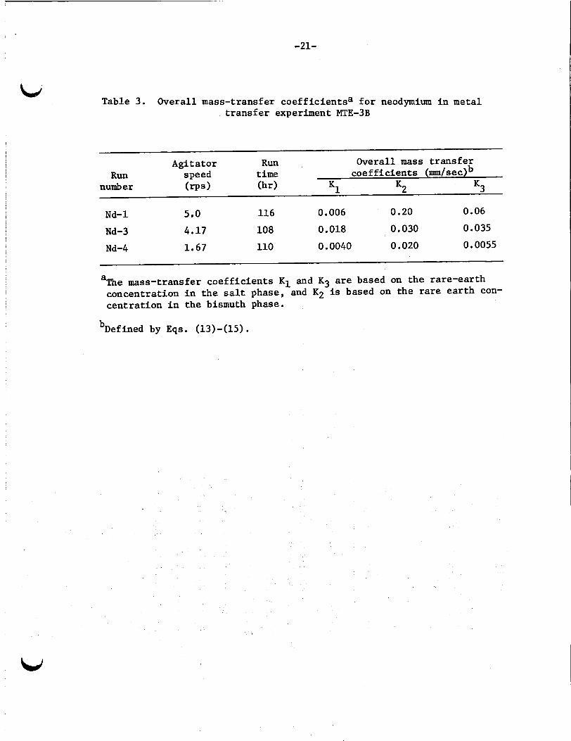
Table 3. Overall mass-transfer coef f ic ien tsa f o r neodymium i n metal t r a n s f e r experiment MTE-3B
Agitator Run Overall mass t r a n s f e r coe f f i c ien t s (ma/ se c)b speed t i m e Run
number ( rps ) (hr) K1 K2 K3
Nd-1 5.0 116 0.006 0.20 0.06
Nd-3 4.17 108 0.018 0.030 0.035
Nd-4 1.67 110 0.0040 0.020 0.0055
a The mass-transfer coe f f i c i en t s K1 and K3 are based on t he rare-ear th concentration i n t h e s a l t phase, and K2 is based on the rare e a r t h con- cent ra t ion i n the bismuth phase.
bDefined by Eqs. (13)-(15).
~.. . .. . . .. - . . . . - . . - ._ . .. . . . . . . . . . .. . . . . .-. . - . . . . . . . .. . . .
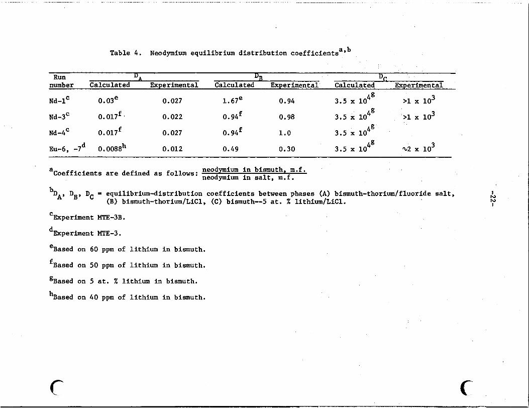
Table 4. Neodymium equilibrium distribution coefficientsayb
Run D* DB D, number Calculated Experimental Calculated Experimental Calculated Experimental
>I lo3
>I lo3
4= Nd-1' 0. 03e 0.027 1.67e 0.94 3.5 x 10 4g Nd-3' 0.017f. 0.022 0. 9qf 0.98 3.5 x 10
Nd-4' 0. 017f 0.027 0. 9qf 1.0
Eu-6, -7d 0.0088h 0.012 0.49 0.30
Coefficients a
b DAY DBY DC =
neodymium in bismuth, m.f. neodymium in salt, m.f. are defined as follows:
equilibrium-distribution coefficients between phases (A) bismuth-thorium/fluoride salt, (B) bismuth-thorium/LiCl , (C) bismuth-5 at. % lithium/LiCl.
Experiment MT.E-3B. C
dExperiment MTE-3.
eBased on
fBased on
gBased on
hBased on
60 ppm of lithium in bismuth.
50 ppm of lithium in bismuth.
5 at. % lithium in bismuth.
40 ppm of lithium in bismuth.
c c
I r e h) I
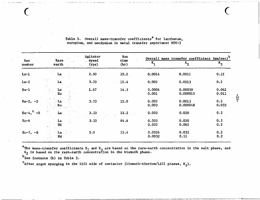
Table 5. Overall mass-transfer coe f f i c i en t sa f o r lanthanum, europium, and neodymium i n metal t r a n s f e r experiment MTE-3
Run number
Agi t a t o r Rare speed
e a r t h (rps)
b Overall mass t r a n s f e r c o e f f i c i e n t (mm/sec)
K1 K2 Kg
La-1
La- 2
Eu-1
Eu-2, -3
C Eu-4, -5
Eu-6
Eu-7, -8
La
La
La Eu
La Eu
La r Nd
La ' Nd
2.50
3.33
1.67
3.33
3.33
3.33
5 .O
15.2
15.4
14.3
15.0
12.2
64.6
15.4
0.0014
0.002
0.0006 0.001
0.002 0.003
0.002
0.002 0.002
0.0026 0.0032
0.0011
0.0013
0.00039 0.000015
0.0013 0.000048
0.020
0.020 0.065
0.032 0.11
0.12
0.2
0.062 0.011 I
0.2 0 033
0.2
0.2 0.2
0.2 0.2
a
bSee footnote (b) i n Table 3.
The mass-transfer c o e f f i c i e n t s K 1 and K K2 i s based on t h e rare-ear th concentra&on i n the bismuth phase.
are based on the rare-ear th concentrat ion i n t h e salt phase, and
After argon sparging i n the L i C l s i d e of contactor (bismuth-thorium/LiCl phases, K2). C
0 0 - 2
2.0
I .5
1.0
0 . 5
0
ORNL D W G 7 6 - 8 7 8 I I I 1 I
t 0 - R E S E R V O I R A - C O N T A C T O R
I I I I I I
1 20 40 60 80 I00 T I M E ( h r )
F i g . 7. Neodymium concentration i n the fluoride s a l t i n the reservoir and contactor during run Nd-1.
0
c

c
ORNL O W 0 76-884
OO
I I I I I I
STOPPED STOPPED
L iC l IN THE CONTACTOR FLUORIDE L i C l IN THE S T R I P P E R 7 7 CIRCULATION CIRCULATION
SALT L iCl
e t 0
A 0 = CONTACTOR A = STRIPPER
20 40 6 0 80 I00 120 RUN T I M E (hr)
F i g . 8. Neodymium concentration i n the L i C l i n the contactor and stripper during run Nd-1.
~. . . . I " " , - . .. ". . . .. . . ... ..
0.4Q
CI
? 4
z 0 t- e p: I-
w 0 z 0 0
Q,
0.30
-
z 0.20
I
E t c3 0 w
- 3 0.10
z O,
ORNL O W 0 76-882 I 1 I I I I
'I
a
S T O P P E D F L U O R I D E
I
1 STOPPED I
1 A a
J I A
A @ = F L U O R I D E SALT S I D E OF CONTACTOR ~ s L i C l SIDE OF CONTACTOR
I I I 1 I I I 2 0 40 60 8 0 I00 120
R U N T I M E ( h t )
Fig. 9. Neodymium concentration i n the bismuth-thorium i n the contactor during run Nd-1.
I h) Q\ I
c
-27-
ORNL O W 0 76-899
5.0
4.0
3.0
2.0
1.0
OO
I I I I I I I I I I I I I 1
TIME (hr)
Fig. 10. Neodymium concentration in the bismuth-5 at. % lithium i n the s t r i p p e r during run Nd-1.
ORNL DWG 76-350 R2
5.0
4.0
3.0
2.0
I ,o
0 0
-
STOPPED FLUORIDE -SALT CIRCULATION
STOPPED Li Cl CIRCULATION
TIME ( hr )
Fig. 11. Neodymium concentration in the fluoride salt in the contactor during run Nd-3, MTE-3B.
1

STOPPED LiCl
CIRCULATION
ORNL DWG ?c)-884 0.5 I 1 I I I I I I
0.2 STObPED l
FL%l!YDE CIRCULATION A
0.1 0
- 0
. * FLUORIDE SALT SIDE or * LiCl SIDE
l
A
I I 20 40
I 60
I I I I I 80 100 120 140 160
RUN TIME (hr)
Fig. 12. Neodymium concentration in the bismuth-thorium solution in the contactor during run Nd-3.

ORNL D W G 76-911 2.5
2.0
.5
.o
0.5
0
STOPPED FLUORIDE S A L T C I R C U L A T I O N
A I
a = C O N T A C T O R A = S T R I P P E R
A
1 /
/ i.
S T O P P E D L i C l
C IRC U L A T IO N I I I I I I I t I A
20 40 60 80 100 120 140 160 180 R U N TIME ( h r )
1 W 0 I
Fig. 13. Neodymium concentration in the LiCl in the contactor and stripper during run Nd-3.
ORNL DWG 76-351 R2
4.07 I I I I I I I I I I I I
3.0 -
. STOPPED FLUORIDE
- SALT CIRCULATION l
1 /
0 0 (
2.0 -
. -
0 f
0 STOPPED LiCl CIRCULATION
I I I I I I I !
I I 60 80 100 120 140 160
TIME (hr)
Fig. 14. Neodymium concentration in the bismuth-5 at. % lithium in the stripper during run Nd-3, MTE-3B.
ORNL DWG 760352Rl
5.0
4.0
3.0
2.0
I .o
I I I I I I I I I I I I I -
STOPPED FLUORIDE STOPPED Li Cl - SALT CIRCULATION CIRCULATION
-
) -
-
I I I I I I I I I I I I I I I I 20 40 60 80 100 120 140 160
TIME (hr)
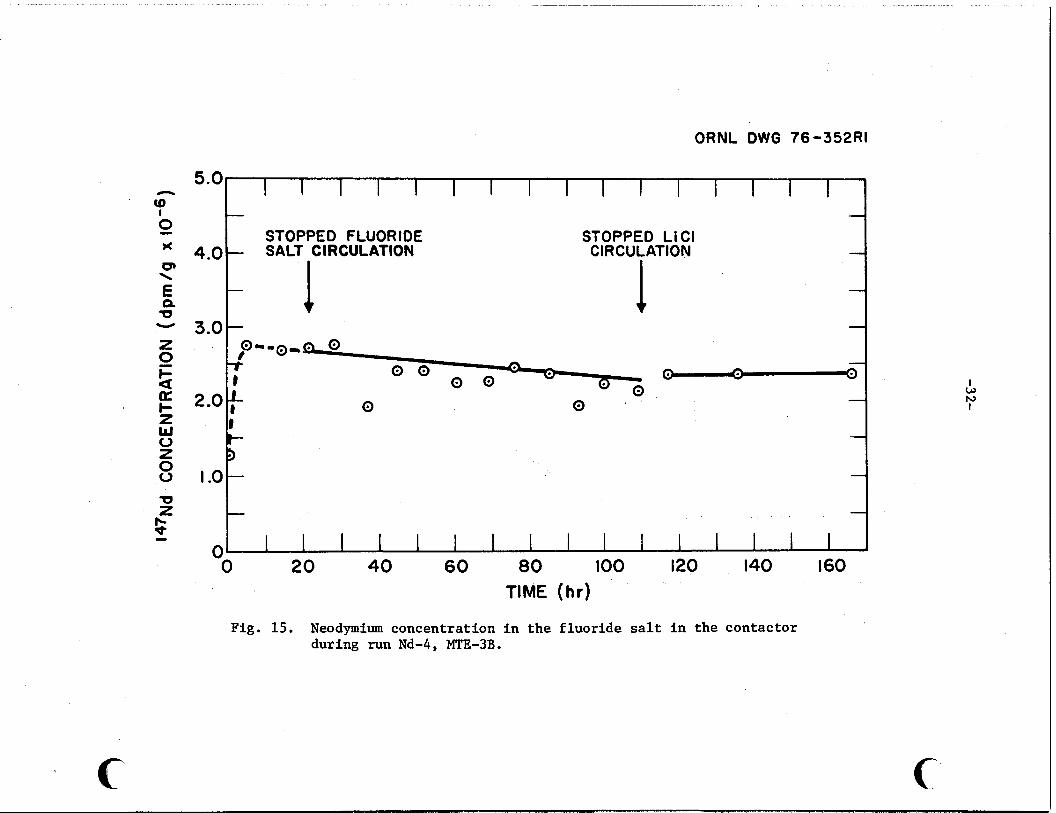
Fig. 15. Neodymium concentration in the fluoride salt in the contactor during run Nd-4, MTE-3B.

0.5 b \ D 1 Y
I I I I I I I I I STOPPED FLUORIDE STOPPED L lC l SAL7 CIRCULATION SALT CIRCULATION
0 FLUORIDE SALT SIDE - A = Ll CI SIDE
0
I -
2 0.4
a
o 0.3
g t- z W
;t 0 0
0.2 3 s 0
z 0. I
0
A A -
0 A 0 ~e
- I
i t
A
0 0
A
0 20 40 60 00 100 120 I40 160 180 RUN TIME ( h r )
I
Fig. 16. Neodymium concentration in the bismuth-thorium in the contactor during run Nd-4.
ORNL O W 0 7 6 - 8 9 6 2.0
1.5 a t- z W 0 2- o m u > 1.0 I * 3- - f 0
W z o 0.5
0
STOPPED FLUORIDE SALT CIRCULATION
= C O N T A C T O R A = S T R I P P E R
STOPPED LiCl C I R C UL AT ION
I I/ / /
STOPPED LiCl C I R C UL AT ION
/ I
/- /
-/ A 0
A 0
A
0
e
e
I I I I I I A I I A
2 0 4 0 60 80 100 120 140 160 1 80 R U N T I M E (hr )
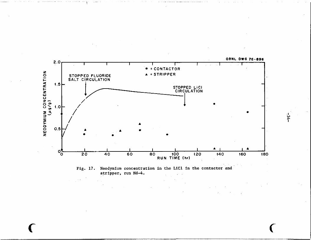
Fig. 1 7 . Neodymium concentration in the L i C l in the contactor and stripper, run Nd-4.
5.0
4.0
3.0
2.0
1.0
ORNL DWG 76-353RI
I I .I I I I I I I I I I I I I -
STOPPED FLUORIDE -SALT CIRCULATION
STOPPED Li Cl CIRCULATION
20 40 60 80 I00 120 140 160
TIME (hr)
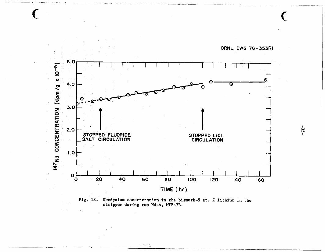
Fig.'18. Neodymium concentration in the bismuth-5 at. % lithium in the stripper during run Nd-4, MTE-3B.
--
, -3 6-
More s c a t t e r and fewer po in t s appear i n these data .
t h a t t he f igu res f o r t he t o t a l neodymium content more near ly represent t h e
t r u e concentrat ion i n these so lu t ions s ince t h e r e s u l t s obtained by the
counting of samples from these so lu t ions were u n r e a l i s t i c a l l y high (by a
f a c t o r of 3) .
a t these very low neodymium concentrat ions (< 1 ppm).
However, i t is f e l t
The d i f f i c u l t y seemed t o be a b i a s i n the counting d a t a
Tabulations of t h e concentrations of 147Nd t r a c e r and t h e t o t a l
neodymium f o r a l l samples removed during runs Nd-1 through Nd-4 are included
i n the Appendix.
5.2 Entrainment Studies i n Experiment MTE-3B
Based on previous s tud ie s i n -a water-mercury system,15 it w a s
concluded t h a t entrainment of f luo r ide sal t i n t o the bismuth and L i C l phases
i n the mechanically ag i t a t ed contactor would occur i f t h e a g i t a t o r s w e r e
operated a t speeds of 5.0 rps o r higher.
t r a n s f e r experiment, MTE-3, entrainment w a s not observed a t 5.0 rps but
w a s seen a t 6.7 rps .
However, i n t h e f i r s t metal
16
Since f l u o r i d e salt entrainment occurred a t a n a g i t a t o r speed of 5.0
rps i n experiment MTE-3B, a series of tests were made t o determine the
maximum allowable a g i t a t o r speed t h a t could be used i n experiment MTE-3B
without entrainment.
i n t h e contactor a t s e v e r a l d i f f e r e n t s p e e d s (3.3, 4.6, and 5.0 r p s ) f o r
time periods ranging from 'L 50 t o 'L 140 hr. During each test a t
constant a g i t a t o r speeds, samples of t h e L i C l salt w e r e removed from t h e
contactor and analyzed f o r f l u o r i d e content.
concentrat ion would ind ica t e entrainment of f l u o r i d e sal t i n t o t h e LiC1.
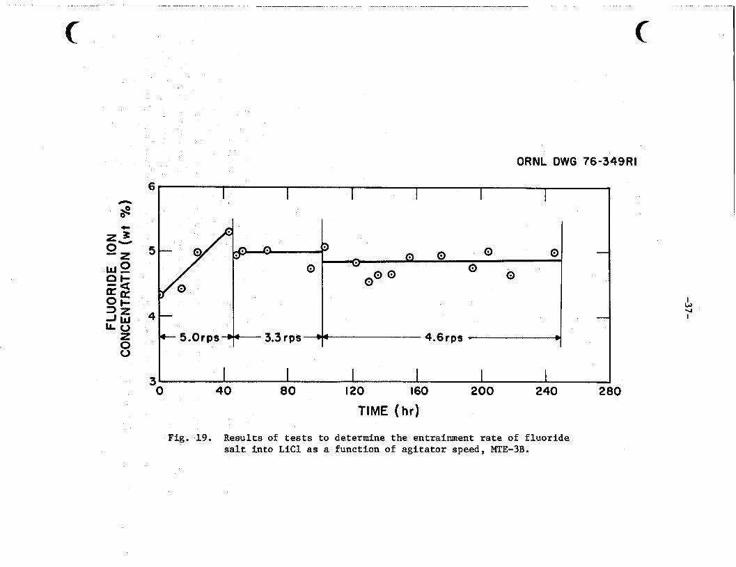
Figure 19 shows t h e f luo r ide ion Concentration i n the L i C l as a funct ion
of time f o r each a g i t a t o r speed. The i n i t i a l concentrat ion of f l u o r i d e
ion of 'L 4 w t % represents t he amount of entrainment t h a t occurred over
a period of 'L 250 h r during runs Nd-1 and Nd-2.
speeds shown i n F ig .19 rep resen t s t he order i n which t h e tests were run.
An increase i n the f l u o r i d e ion concentrat ion is c l e a r l y indicated i n the
'L 50-hr test a t 5.0 rps .
entrainment (within experimental l i m i t s ) appears t o have occurred over t h e
'L 200-hr combined test per iods a t these two speeds.
The tests were conducted by operat ing t h e a g i t a t o r s
An increase i n f l u o r i d e ion
The sequence of a g i t a t o r
A t a g i t a t o r speeds of 3.3 and 4.6 rps , no
5
4
ORNL DWG 76-349Rl
.
+ 5.Orps-rcr - 3.3 rps -+‘p- 4.6rps w I
3 I I I I I I 0 40 80 120 160 200 240 280
TIME (hr)
Fig. .19. Results of tests to determine the entrainment rate of fluoride salt into LiCl as a function of agitator speed, MTE-3B.
-38-
These r e s u l t s indicated t h a t experiments cauld be ca r r i ed ou t a t
a g i t a t o r speeds up t o about 4.5 r p s without entrainment,and experiments
Nd-3 and Nd-4 were conducted using a g i t a t o r speeds of 4.2 and 1.67 rps .
It w a s a l s o concluded t h a t rapid determinations of f l u o r i d e i o n concentrat ion
i n the L i C l duringexperimen:ts were needed t o v e r i f y t h a t no entrainment w a s occurring. For t h i s purpose, an Orion Model 801A pH/mV meter* equipped with
s p e c i f i c ion ( f luor ide) e lec t rodes was obtained f o r rapid analyses of L i C l samples.
record the emf between t h e two bismuth phases i n the contactor and
s t r i p p e r vessels t h a t contained d i f f e r e n t concentrat ions of l i th ium
reductant (0.0015 and 0.050 atom f r a c t i o n l i thium).
The mV meter could a l s o be used t o continuously measure and
A change i n emf would
ind ica t e a change i n t h e l i th ium concentrat ion r a t i o i n these phases
(Sect. 5.3) with a r e s u l t a n t change i n t h e equilibrium d i s t r i b u t i o n
coe f f i c i en t f o r neodymium and thorium between t h e s a l t and bismuth phases.
5.3
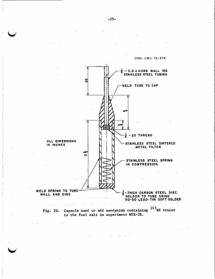
Weighed amounts of neodymium, as NdF3, containing 147Nd tracer w e r e
Neodymium and 147Nd Inventory i n Experiment MTE-3B
added t o t h e f l u o r i d e f u e l sa l t i n the f u e l sa l t r e se rvo i r on th ree
occasions during operat ion of m e t a l t r a n s f e r experiment MTE-3B.
and 147Nd tracer were prepared by t h e Isotopes Divis ion of ORNL.
NdF3 containing t h e tracer w a s placed i n a spec ia l ly designed charging
capsule used t o add the neodymium t o the f u e l sa l t (Fig. 20). The
capsule w a s sealed by a spring-loaded d i s c which w a s soldered t o the
capsule. When inser ted i n t o t h e molten f u e l sa l t (Q923 K ) , t h e so lder
melted and opened t h e capsule, allowing the NdF3 t o d i spe r se i n t o t h e
f u e l salt . Capsules were inspec teda f t e r each addi t ion t o ensure t h a t
a l l of the neodymium had been t r ans fe r r ed i n t o t h e f u e l sa l t .
The NdF3
The
147Nd and t o t a l neodymium inventory during each run i n metal
t r ans fe r experiment MTE-3B was followed by both counting and chemical
analyses of samples of t h e s a l t and bismuth phases.
147Nd w a s determined by counting t h e 0.53-MeV gamma emitted, while t he
concentration of t h e t o t a l neodymium w a s determined by an i so top ic d i l u t i o n
mass-spectrometry technique.
The concentrat ion of
*Orion Research, Inc., Cambridge, Mass.
t
L d
-39-
O R N L D W G 76-874
,
i
- 0. D. x 0.028 WALL 316 STAINLESS STEEL TUBING
WELD TUBE TO CAP
ALL DIMENSIONS IN INCHES STAINLESS STEEL SINTERED
METAL FILTER
STAINLESS STEEL SPRING IN COMPRESSION
'-THICK CARBON STEEL DISC. WELD SPRING TO TUBE
SOLDER TO TUBE USING S O - 5 0 LEAD-TIN SOFT SOLDER
WALL AND DISC 2
Fig. 20. Capsule used to add neodymium containing 147Nd tracer to the fue l s a l t in experiment MTE-3B.

-4 0-
Table 6 compares t h e neodymium and 147Nd inventory i n metal
t r ans fe r experiment MTE-3B based on the amounts added t o t h e system and
those ca lcu la ted from t h e concentrat ions i n a l l phases determined by
sampling.
determined by sampling was'in good agreement with the amounts added,
varying between 84 and 100% f o r each of t he four runs.
As seen i n Table 6, t h e inventory of neodymium and 147Nd tracer
These r e s u l t s i n d i c a t e t h a t (1) t he lo s ses of neodymium were
in s ign i f i can t , (2) t he neodymium remained dispersed i n t h e sal t and bismuth
so lu t ions , and (3) t he sampling procedures provided samples t h a t adequately
represented t h e concentrat ions of neodymium in t h e s a l t and bismuth
so lu t ions .
5.4 Lithium Reductant i n the Bismuth Solut ions i n t h e Contactor and S t r ippe r
The equilibrium d i s t r i b u t i o n c o e f f i c i e n t s f o r neodymium (and o the r
rare ea r ths ) between the salt and bismuth so lu t ions i n t h e m e t a l t r ans fe r
process are dependent on t h e l i th ium reductant concentrat ions i n t h e
bismuth so lu t ions (Sect. 2). Therefore, mass-transfer c o e f f i c i e n t s f o r
t he rare e a r t h s are dependent on these equilibrium d i s t r i b u t i o n
coe f f i c i en t s .
During t h e runs i n experiment MTE-3B, t h e concentrat ions of l i th ium
reductant i n t h e bismuth so lu t ions were known i n i t i a l l y . The relative
concentrat ions of l i thium i n the bismuth i n t h e contactor (Q 0.0015 m.f.)
and i n the s t r i p p e r (Q 0.05 m.f.) were determined during t h e experiments
by measuring the emf between these two bismuth so lu t ions . The contactor
and s t r i p p e r ves se l s are e l e c t r i c a l l y i so l a t ed from each o the r by an
e l e c t r i c a l l y insu la ted " i so l a t ion f lange , I ' and the bismuth so lu t ions
are connected by t h e molten L i C l t h a t circulates between the contactor
and s t r i p p e r . The relative concentrat ions of l i th ium i n the bismuth
so lu t ions can be calculated from t h e emf measurement by the following
equation : 17
emf = -RT/nF I n C1/C2, (16) where
emf = emf developed between t h e two so lu t ions , V,
n = valence,
R = gas constant = 1.987 cal/mole*K,
F = Faraday = 23,050 cal f1 (g-equiv) -1 ,
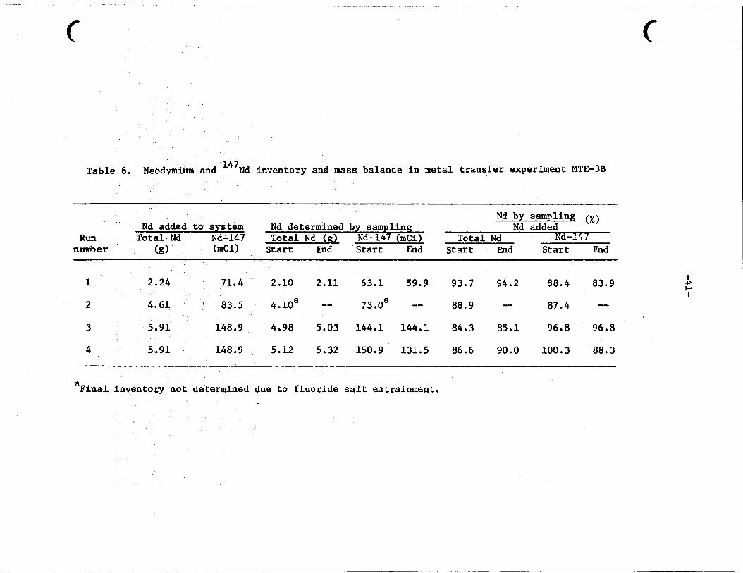
Table 6. Neodymium and 147Nd inventory and mass balance i n metal t r a n s f e r experiment MTE-3B
Nd by sampling ,e",
~~~~~~
Nd added t o system Nd determined by sampling Nd added Nd Nd-147 Tota l Nd (21- Nd-147 (mci) Tota l Nd Nd-14 1
S t a r t End S t a r t m d S t a r t Fnd
1 2.24 71.4 2.10 2.11 63.1 59.9 93.7 94.2 88.4 83.9
2 4.61 83.5 4.10a -- 73.0a -- 88.9 -- 87.4 -- 3 5.91 148.9 4.98 5.03 144.1 144.1 84.3 85.1 96.8 96.8
4 5.91 148.9 5.12 5.32 150.9 131.5 86.6 90.0 100.3 88.3
I
P I
%rial inventory not determined due t o f luo r ide sa l t entrainment.
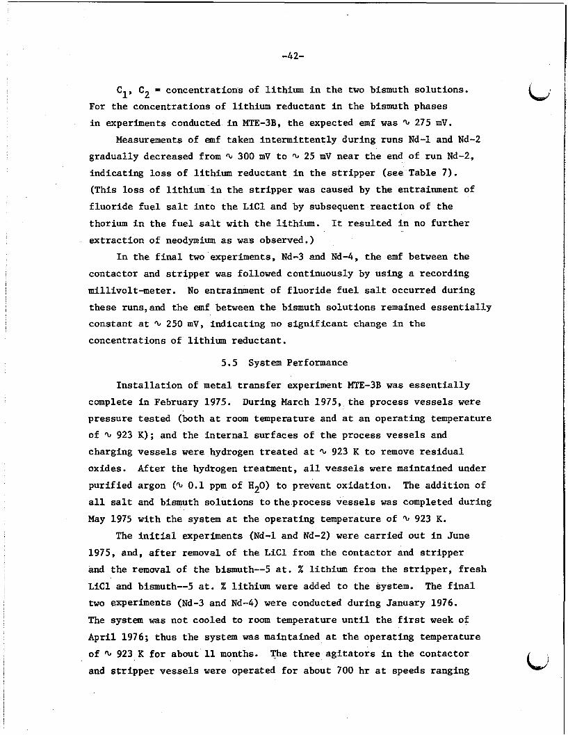
C1, C2 = concentration's of l i th ium i n t h e two bismuth solut ions.
For t h e concentrat ions of l i thium reductant i n the bismuth phases
i n experiments conducted i n MTE-3B, the expected emf w a s 'L 275 mV.
Measurements of emf taken in t e rmi t t en t ly during runs Nd-1 and Nd-2
gradually decreased from 'L 300 mV t o 'L 25 mV near t h e end of run Nd-2,
ind ica t ing l o s s of l i thium reductant i n t h e s t r i p p e r (see Table 7).
(This l o s s of l i th ium i n the s t r i p p e r w a s caused by t h e entrainment of
f luo r ide f u e l sa l t i n t o t h e L i C l and by subsequent r eac t ion of t h e
thorium i n t h e f u e l salt with t h e l i thium. It resu l ted i n no f u r t h e r
ex t r ac t ion of neodymium as w a s observed.)
I n t h e f i n a l two experiments, Nd-3 and Nd-4, t h e emf between the
contactor and s t r i p p e r w a s followed continuously by using a recording
mill ivolt-meter. No entrainment of f l u o r i d e f u e l sa l t occurred during
these runs,and the emf between t h e bismuth so lu t ions remained e s s e n t i a l l y
constant a t 'L 250 mV, ind ica t ing no s i g n i f i c a n t change i n the
concentrat ions of l i th ium reductant .
5.5 System Performance
I n s t a l l a t i o n of metal t r a n s f e r experiment MTE-3B w a s e s s e n t i a l l y
During March 1975, t h e process ves se l s w e r e complete i n February 1975.
pressure t e s t ed (both a t room temperature and a t an operat ing temperature
of 'L 923 K); and the i n t e r n a l sur faces of t h e process vessels and
charging vessels w e r e hydrogen t r e a t e d a t 'L 923 K t o remove r e s i d u a l
oxides. After t h e hydrogen treatment, a l l ves se l s w e r e maintained under
pu r i f i ed argon (Q 0.1 ppm of H20) t o prevent oxidat ion. The addi t ion of
a l l sa l t and bismuth so lu t ions t o t h e p r o c e s s vessels w a s completed during
May 1975 with t h e system a t t h e operat ing temperature of Q 923 K.
The i n i t i a l experiments (Nd-1 and Nd-2) were ca r r i ed ou t i n June
1975, and, a f t e r removal of t h e L i C l from the contactor and s t r i p p e r
and t h e removal of t h e bismuth--5 a t . % l i thium from the s t r i p p e r , f r e s h
L i C l and bismuth--5 at. % l i th ium were added t o the system. The f i n a l
two experiments (Nd-3 and Nd-4) w e r e conducted during January 1976.
The system was not cooled t o room temperature u n t i l t h e f i r s t week of
Apr i l 1976; thus the system w a s maintained a t t h e operat ing temperature
of 'L 923 K f o r about l l m o n t h s . The th ree a g i t a t o r s i n the contactor
and s t r i p p e r ves se l s were operated f o r about 700 h r a t speeds ranging

-43-
Table 7. Measurements of emf between the bismuth so lu t ions i n the contactor and s t r i p p e r ves se l s during runs Nd-1 and Nd-2
i n metal t r ans fe r experiment MTE-3B
Calculated l i th ium concentration Li-Bi i n s t r ippe rb
(atom f r ac t ion )
0 6.8
18 49 71
10 8
0 11.5 30.8 48.1 63.6 78.1 100.1
Run Nd-1
300
200 200 195 195
225
RUG Nd-2
165 165 155 124 100 88 25
0.052 0.020 0.015 0.015 0.014 0.014
0.0095 0.0095 0.0084 0.0057 0.0042 0.0036 0.0016
aRun t i m e = t i m e f r o m start of f luo r ide salt c i r cu la t ion .
bBased on t h e assumption t h a t t h e i n i t i a l concentrat ion of l i th ium (0.0012 at. %) i n t h e bismuth-thorium phase i n the contactor remained constant throughout runs Nd-1 and Nd-2. concentrat ion of l i th ium i n the bismuth-lithium a l l o y i n the s t r i p p e r was Q 0.050 at. X .
The i n i t i a l
-44-
between 100 and 300 rpm (1.67 t o 5.0 rps ) during t h i s period.
f l uo r ide salt pump w a s i n operat ion f o r % 295 hr,and L i C l c i r c u l a t i o n w a s
maintained f o r % 475 hr. With t h e exception of one of t he a g i t a t o r seals
which developed a l eak and allowed inleakage of argon buffer gas i n t o the
system shor t ly a f t e r terminat ionof t h e last run (Nd-4), a l l equipment
functioned without incident throughout t he l i f e of the experiment.
Spec i f ica l ly , no hea ter , thermocouple 3 o r con t ro l system malfunctions
occurred.
observed.
inspected a f t e r shutdown t o determine the e f fec t iveness of t he oxidation-
r e s i s t a n t spray coating (METCO No. P443-10) i n pro tec t ing these sur faces
aga ins t oxidat ion a t t h e operat ing temperature.
were found t o be i n exce l len t condi t ion, with only a small amount of
oxide present.
The
Also, no leakage of sa l t o r bismuth from t h e system was
The outs ide sur faces of the carbon steel process vessels were
The outs ide sur faces
During the four runs conducted i n m e t a l t r a n s f e r experiment MTE-3B,
807 samples of t h e salt and bismuth so lu t ions were taken f o r analyses.
As discussed above, t he sampling procedures adequately obtained
representa t ive samples of the process so lu t ions .
6. DISCUSSION OF RESULTS
The objec t ives of metal t r a n s f e r process experiments MTE-3 and
WE-3B were t o measure t h e rate of removal of representa t ive rare-ear th
f i s s i o n products from a molten-salt breeder r eac to r f u e l sa l t and t o
evaluate t h e s u i t a b i l i t y of mechanically ag i t a t ed contac tors f o r t h e
metal t r a n s f e r process.
mass-transfer c o e f f i c i e n t s f o r rare e a r t h s a t t h e t h r e e salt-bismuth
in t e r f aces i n t h e system and t o study the e f f e c t of a g i t a t i o n on t h e
t r a n s f e r c o e f f i c i e n t s i n s t i r r e d contactors .
Thus it w a s necessary t o determine the o v e r a l l
I n metal t r ans fe r process experiments MTE-3 and MTE-3BY only the
ove ra l l mass-transfer c o e f f i c i e n t s were measured, as discussed i n Sect. 4. Resul ts of ind iv idua l mass-transfer c o e f f i c i e n t s i n s t i r r e d contactors i n
which t h e phases are not dispersed have been reported.
these s tud ie s , mass-transfer c o e f f i c i e n t s i n organic-water, mercury-water,
and LIF-BeF2-ThF4 salt-bismuth systems were determined, and co r re l a t ions
were developed which relate t h e ind iv idua l mass-transfer c o e f f i c i e n t s f o r
5, 18-20 In
b

-45-
L J
b,
each phase t o t h e proper t ies of t h e so lu t ions and system parameters such
as t h e s i z e and speed of t h e stirrer.
mass-transfer coe f f i c i en t on the a g i t a t o r speed var ied widely.
The reported dependence of t h e
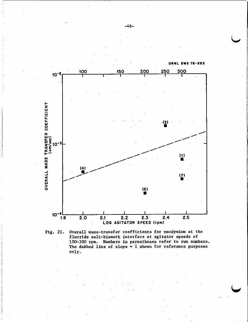
The ove ra l l mass-transfer c o e f f i c i e n t s obtained f o r neodymium
a t the th ree salt-bismuth in t e r f aces i n t h e f i v e runs i n experiments
MTE-3 and MTE-3B a t a g i t a t o r ( s t i r r e r ) speeds ranging from 1.67 r p s t o 5.0 r p s are show inlog-log p l o t s i n Figs. 21-23.
e f f e c t of a g i t a t o r speed on mass-transfer c o e f f i c i e n t s cannot be made
because o ther system parameters - p a r t i c u l a r l y t h e equilibrium
d i s t r i b u t i o n c o e f f i c i e n t s fo r neodymium -were not t he same f o r a l l runs.
Also, s ince the ove ra l l mass-transfer coe f f i c i en t s w e r e determined by
simultaneous so lu t ion of seven d i f f e r e n t i a l equations t o determine mass
balance, p rec i se values f o r t h e th ree c o e f f i c i e n t s calculated f o r each
run are not poss ib le .
Direct co r re l a t ion of the
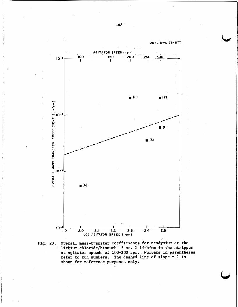
Although the re is a g rea t d e a l of scatter i n the d a t a shown i n Figs.
21-23, t h e o v e r a l l mass-transfer coe f f i c i en t s general ly increase with
increasing a g i t a t o r speed as predicted.
values from those runs i n which only the a g i t a t o r speed w a s changed
(e.g., runs 3 and 4) c l e a r l y shows an increase i n t h e ove ra l lmass -
Direct comparison of selected
t r a n s f e r c o e f f i c i e n t s when t h e a g i t a t o r speed w a s elevated from 1.67 t o
4.17 rps .
previous experiment MTE-3) shows an increase when t h e a g i t a t o r speed w a s
e levated from 3.33 t o 5.0 r p s .
these f igu res f o r re ference purposes only.
i n t he c i t e d references ind ica t e t h a t mass-transfer coe f f i c i en t s ‘are
proport ional t o a g i t a t o r speed r a i sed t o a power between 0.9 and 1.65.
The o v e r a l l mass-transfer c o e f f i c i e n t s f o r rare e a r t h s across t h e
Similar ly , a comparison of runs 6 and 7 (conducted i n a
A dashed l i n e of s lope 1 i s included on
Various co r re l a t ions developed
sal t and bismuth phases determined i n experiments MTE-3 and MTE-3B were
only about 1 t o 50% of those t h a t would be predicted by cu r ren t ly
ava i l ab le co r re l a t ions , with the l a r g e s t discrepancy occurring a t the
l i th ium chloride--bismuth in t e r f aces .
o rder t o ob ta in co r re l a t ions t h a t would r e l i a b l y p red ic t €he o v e r a l l mass-
t r a n s f e r c o e f f i c i e n t s f o r s t i r r e d contac tors i f t h i s type of contactor i s
t o be used i n a fu l l - sca l e processing p l an t t o remove the rare-ear th
f i s s i o n products.
physical p rope r t i e s of the seve ra l so lu t ions ,
t o l a r g e r processing equipment requi res fu r the r inves t iga t ion .
Further s tud ie s are required i n
I n addi t ion t o the inf luence of a g i t a t o r speed and
t h e e f f e c t of scale-up
-46-
4
O R N L D W G 76-883
I I I I I I
J J a a W > 0
100 150 200 250 300 I I I 1 I I
/ 0
/’ I’
I
Fig. 21. overall mass-transfer coefficients for neodymium at the fluoride salt-bismuth interface at agitator speeds of 100-300 rpm. The datrhed line of slope = 1 shown for reference purposes only.
Numbers in parentheses refer to run numbers.
bd
i
a W LL v) z (L I-
a
: IO’? 2 -t J a a W > 0
to-;
-4 7-
ORNL D W G 1 6 - 8 7 9
A G I T A T O R SPEED ( r p m ) 100 150 200 250 300
I I I I I I
( 1 ) E
I
(4) E
(31 E
I I I I I I 2.1 2.2 2.3 2.4 2.5 2 .o
LOG A G I T A T O R SPEED (rPm)
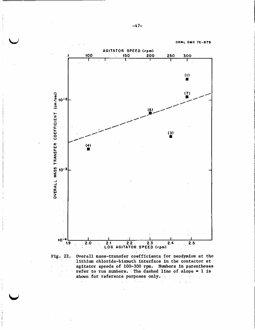
Fig. 22. Overall mass-transfer coeff ic ients for neodymium at the
Numbers i n parentheses lithium chloride-bismuth interface i n the contactor a t agitator speeds of 100-300 rpm. refer to run numbers. The dashed l ine of slope = 1 is shown for reference purposes only. *
-48-
ORNL DWG 76-81?
C\GITATOR SPEED ( rpml .
100 150 200 250 300 I I I I I lo-’
Fig.
- 0 Y n \
u E - 10- I- t W - 0 LL LL w 0 V
U W IL v) 2
+ v) v)
a a
a I
-J
a W > 0
-J lo-, a
/’ I’
I’
I’ /’ (3)
I I I I I I 1.9 2.0 2.1 2.2 2.3 1 2.4 2.5 10-
L O G A G I T A T O R SPEED ( r p m )
23. Overall mass-transfer coef f ic ients for neodymium at the lithium chloride/bismuth--5 a t . % lithium i n the stripper a t agitator speeds of 100-300 rpm. refer to run numbers. shown for reference purposes only.
Numbers i n parentheses The dashed l i n e of slope = 1 is

-4 9-
An important f e a t u r e of the metal t r a n s f e r process is t h e selective separa t ion of thorium from t h e rare e a r t h s a t t h e bismuth--lithium
ch lo r ide in t e r f ace . Rare earth-thorium separat ion f a c t o r s , defined as
’RE-Th DTh’DRE’ (17)
have been determined t o be i n t h e range of lo4 t o lo8 f o r t he t r i v a l e n t and
d iva len t rare earth^.^ Thus neg l ig ib l e l o s s of thorium from the f u e l
b,
salt occurs i n the process. Because of entrainment of t h e f luo r ide sal t
i n t o t h e L I C l i n experiment MTE-3B, i t w a s not poss ib le t o determine t h e
separat ion f a c t o r . However, during s tud ie s i n t h e f i r s t experiment
MTE-3, i n which t h e rare e a r t h s europium, lanthanum, and neodymium were
used, t h e separa t ion f a c t o r s were estimated based on the t o t a l amount of
thorium (< 10 w t ppm) found i n t he bismuth--5 a t . % l i th ium a l l o y i n the
s t r i p p e r a f t e r about 400 hr of operation. Separation f a c t o r s
DTh/DRE f o r these rare ea r ths i n t h e order of 10
Carter21 a t ORNL, have been made t o es t imate the contactor s i z e and
operat ing condi t ions t h a t would be required i n order t o remove the
rare-ear th f i s s i o n products a t t h e design rate22 from the re ference MSBR.
For these ca l cu la t ions , t h e rare e a r t h neodymium w a s chosen as a
representa t ive example,
moles (‘L 174 g) per day f o r a breeding r a t i o of 1.06. (Note: Reducing
the rare-ear th removal rate would not have a p roh ib i t i ve ‘de l e t e r ious e f f e c t
on the breeding r a t i o - a threefold reduction would lower the breeding
r a t i o by about 0.01.)23 I n these ca l cu la t ions , t h e e f f e c t s of severa l
parameters (mass-transfer coe f f i c i en t s , i n t e r f a c i a l area, sal t and
bismuth flow rates, and number of ex t r ac t ion s tages) on t h e removal rate
of neodymium were evaluated, and a combination of parameters t h a t would
be required t o meet t h e design removal rate w a s determined.
Resul ts of t hese ca l cu la t ions are summarized i n Table 8 . The
‘L
4 6 t o 10 w e r e indicated.
Preliminary ca lcu la t ions , using a computer code developed by W. L.
The design removal rate of neodymium i s ‘L 1 .2 g-
cases shown were se lec ted t o ind ica t e the e f f e c t of several v a r i a t i o n s on
neodymium removal rates. The f u e l - s a l t flow rate of 0.9 gpm (5.7 x loh5 m /see) w a s held constant f o r a l l cases s ince it is t h e design fue l - sa l t
flow rate f o r t h e re ference processing p lan t .
were used f o r a l l but one case s ince t h i s seemed t o be a reasonable compromise
based on preliminary ca lcu la t ions .
8 .
3 ’r
Three contactor s t ages
For case 1, t h e values of o v e r a l l m a s s -

-5 0-
i t r ans fe r coe f f i c i en t s a t t h e th ree salt-bismuth i n t e r f a c e s (K1, K2, K3)
are representa t ive of those obtained i n our experimental s tud ies .
area of 1 f t 2 (0.093 m2) per s tage , t h e bismuth flow rate of 3 gpm
(1.9 x lom4 m3/sec), and t h e L i C l flow rate of 30 gpm (1.9 x
m /see) were chosen as a bas i s f o r f u r t h e r extrapolat ion.
Case 1, the neodymium removal rate of 0.003 g-mole/day is about a
f ac to r of 400 below the design value of 1 . 2 g-moles/day.
ove ra l l mass-transfer c o e f f i c i e n t s a t t h e LiC1-bismuth i n t e r f a c e s
i n t h e contactor and s t r i p p e r by a f a c t o r of 5 (case 2) increased t h e
removal rate by about a f ac to r of 4.
i n t e r f a c i a l contact areas t o 1 0 and 20 f t 2 (0.94 and 1.9 m2) is seen i n
cases 3 and 4, and t h e e f f e c t of increasing t h e number of s tages
from 3 t o 6 is seen by comparing 4 and 5.
t h e bismuth and L i C l flow rates t o 6 gpm (3.8 x m3/sec) and
60 gpm (3.8 x m 3 / s e c ) is seen i n cases 7 and 9. In case 8 ,
t he o v e r a l l mass-transfer coe f f i c i en t , K, a t t h e f l u o r i d e salt--bismuth
The
3 As seen i n
Increasing
The e f f e c t of increasing t h e
The r e s u l t s from increasing
i n t e r f a c e is increased by a f a c t o r of 10.
F ina l ly , t h e des i red removal rate is reached by use of t h e parameters
shown i n case 11. For t h e choices made, a neodymium removal rate ‘of 1.37
g-moles/day is indicated f o r t h e following system: 2 sal t and bismuth i n t e r f a c i a l a reas / s tage = 20 f t 2 (1.86 m ),
f luo r ide sal t flow rate = 0.9 gpm (5.7 x bismuth flow rate = 18 gpm (1.1 x L i C l flow rate = 60 gpm (3.8 x
K1 = 0.16 mm/sec, Kg = 1.0 mm/sec, and K3 = 4.0 mm/sec.
m2/sec),
m2/sec),
m2/sec),
The values f o r K1 and K2 a t t h e f l u o r i d e f u e l salt--bismuth and LiC1--
bismuth in t e r f aces i n t h e contactor (case 11) are about a f a c t o r of
10 higher than those observed i n m e t a l t r a n s f e r experiments.
from s tud ie s i n the water-mercury contac tors i nd ica t e t h a t an increase
of about a f a c t o r of 10 i n t h e mass-transfer c o e f f i c i e n t might be
expected with increased a g i t a t o r tu rb ine diameter over those used i n t h e
metal t r ans fe r experiments (1.4 m v s 0.073 m).24 The va lue f o r K3 a t
t h e i n t e r f a c e between t h e LiC1--bismuth and t h e 5 at. % l i t h ium i n t h e
s t r i p p e r (case 11) is about a f a c t o r of 100 higher than t h a t observed i n
metal t r a n s f e r experiments. This l a r g e increase would l i k e l y r equ i r e
Resul t s
b
-51-
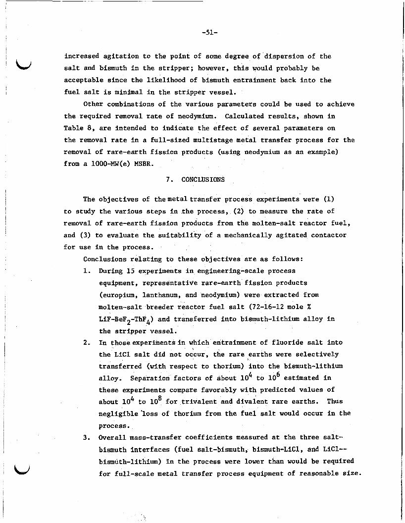
increased a g i t a t i o n t o the poin t of some degree of d i spers ion of t he
sal t and bismuth i n t h e s t r i p p e r ; however, t h i s would probably be
acceptable s ince t h e l ikel ihood of bismuth entrainment back i n t o the
f u e l sa l t is minimal i n t h e s t r i p p e r vessel.
Other combinations of the var ious parameters could be used t o achieve
t h e required removal rate of neodymium. Calculated r e s u l t s , shown i n
Table 8, are intended t o ind ica t e t h e e f f e c t of s eve ra l parameters on
t h e removal rate i n a fu l l - s ized mul t i s tage metal t r ans fe r process f o r t h e
removal of ra re-ear th f i s s i o n products (using neodymium as an example)
from a 1000-MW(e) MSBR.
7. CONCLUSIONS
The objec t ives of themeta l t r a n s f e r process experiments were (1)
t o study t h e var ious s t e p s i n t h e process, (2) t o measure the rate of
removal of ra re-ear th f i s s i o n products from the molten-salt r eac to r f u e l ,
and (3) t o eva lua te t h e s u i t a b i l i t y of a mechanically ag i t a t ed contactor
f o r use i n t h e process.
Conclusions r e l a t i n g t o these objec t ives are as follows:
1. During 15 experiments i n engineering-scale process
equipment, representa t ive rare-ear th f i s s i o n products
(europium, lanthanum, and neodymium) were ex t rac ted from
molten-salt breeder r eac to r f u e l salt (72-16-12 mole X
LiF-BeF2-ThF4) and t ransfer red i n t o bismuth-lithium a l l o y i n
the s t r i p p e r vessel.
2. I n thoseexper iments in which entrainment of f l u o r i d e sal t i n t o
t h e L i C l sa l t did not occur, t he rare e a r t h s w e r e s e l e c t i v e l y
t ransfer red (with respec t t o thorium) i n t o t h e bismuth-lithium
a l loy . Separation f a c t o r s of about 1 0 t o 10 estimated i n
these experiments compare favorably with predicted values of
about 10 t o 10 f o r t r i v a l e n t and d iva len t rare ear ths . Thus
<
4 6
4 8
neg l ig ib l e ' l o s s of thorium from t h e f u e l salt would occur i n the
process.
3. Overall mass-transfer c o e f f i c i e n t s measured a t t h e th ree salt-
bismuth i n t e r f a c e s ( f u e l salt-bismuth, bismuth-LiC1, and LiC1--
bismuth-lithium) i n t h e process were lower than would be required
f o r fu l l - s ca l e metal t r ans fe r process equipment of reasonable s i ze .
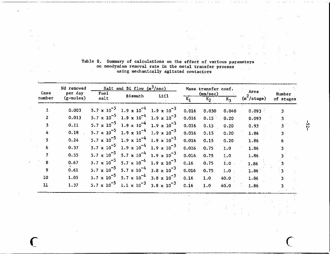
Table 8. Summary of ca lcu la t ions on the e f f e c t of various parameters on neodymium removal rate i n the metal t r a n s f e r process
using mechanically a g i t a t e d contactors
Nd removed S a l t and B i flow (m3/sec) Mass t r a n s f e r coef. Area Number 2 (mm/sec ) (m /s tage) of s tages L i C l
Case per day Fuel number (g-moles) s a l t Bismuth
Y 1 K2 K3
1
2
3
4 5
6
7
8
9
10
11
0.003
0.013
0.11
0.18 ,
0.24
0.37
0.55
0.67
0.61
1.05
1.37
0.016
0.016
0.016
0.016
0.016
0.016
0.016
0.16
0.016
0.16
0.16
0.030 0.040 0.15 ' 0.20
0.15 0.20 0.15 0.20 0.15 0.20
0.75 1.0
0.75 1.0
0.75 1.0
0.75 1.0
1.0 40.0
1.0 40.0
0.093
0.093
0.93
1.86
1.86
1.86
1.86
1.86 1.86
1.86
1.86
3
3
3
3
6
3
3
3
3
3
3
I u h3 I
c c
-53-
I
4. The o v e r a l l mass-transfer c o e f f i c i e n t s increased with
increasing a g i t a t i o n ( ag i t a to r speed) as expected, bu t
meaningful co r re l a t ions w e r e no t poss ib l e with the
l imi t ed d a t a obtained.
5. I n the equipment used i n these experiments, t he degree
of a g i t a t i o n ( ag i t a to r speed) was l imi ted by entrainment
of f luo r ide s a l t i n t o the L i C l i n the contactor. This
would r equ i r e f u r t h e r evaluat ion and c a r e f u l design of
mechanically ag i t a t ed contactors f o r use i n the metal
t r a n s f e r . The e f f e c t of increased equipment size (diameters of t he process
vessels and a g i t a t o r paddles) on the o v e r a l l mass-transfer c o e f f i c i e n t s
and rate of removal f o r t h e rare e a r t h s w a s no t s tud ied and need addi-
t i o n a l inves t iga t ion .
8 . ACKNOWLEDGMENTS
The authors g r a t e f u l l y acknowledge t h e a s s i s t ance of many Oak Ridge
National Laboratory s t a f f members during the course of t he two metal
t r a n s f e r process experiments. The design, i n s t a l l a t i o n , and operat ion of
of t h e f i r s t experiment MTE-3, together with t h e ana lys i s of t he r e s u l t s ,
were done by E. L. Youngblood, L. E. McNeese, W. L. Carter, and W. F.
Schaffer, Jr. The following members a s s i s t e d g r e a t l y with t h e second
experiment MTE-3B: J. Beams, C. H. Brown, Jr., R. M. Counce, R. B.
Lindauer, and R. 0 . Payne, experimental operat ion; W. R. Laing, H. A.
Parker, and R. L, Walker, chemical analyses; and W. L. Carter and E. L.
Youngblood, d a t a ana lys i s and i n t e r p r e t a t i o n . The secretarial a s s i s t a n c e
of Carol Proaps is grea t ly appreciated.
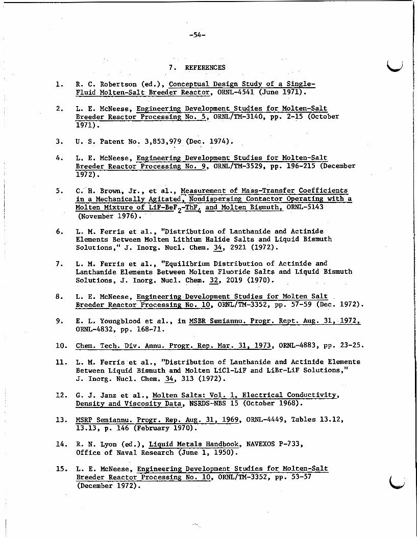
-54-
1.
2.
3.
4.
5.
6.
7.
8.
9.
10.
11.
12.
13.
14.
15.
7. REFERENCES
R. C. Robertson (ed.), Conceptual Design Study of a Single- Fluid Molten-Salt Breeder Reactor, ORNL-4541 (June 1971).
L. E. McNeese, Engineering Development Studies f o r Molten-Salt Breeder Reactor Processing No. 5 , ORNL/TM-3140, pp. 2-15 (October 1971).
U. S. Patent No. 3,853,979 (Dec. 1974).
L. E. McNeese, Engineering Development Studies f o r Molten-Salt Breeder Reactor-Processing No. 9, ORNLITM-3529, pp. 196-215 (December 1972).
C. H. Brown, Jr., et al., Measurement of Mass-Transfer Coeff ic ien ts i n a Mechanically Agitated: Nondispersing Contactor Operating with a Molten Mixture of LiF-BeF2-% and Molten Bismuth, ORNL-5143 (November 1976).
L. M. F e r r i s et al . , "Distr ibut ion of Lanthanide and Actinide Elements Between Molten Lithium Halide S a l t s and Liquid Bismuth Solutions," J. Inorg. Nucl. Chem. - 34, 2921 (1972).
L. M. F e r r i s et al . , "Equilibrium Dis t r ibu t ion of Actinide and Lanthanide Elements Between Molten Fluoride S a l t s and Liquid Bismuth Solut ions, J. Inorg. Nucl. Chem. 32, 2019 (1970).
L. E. McNeese, Engineering Development Studies f o r Molten S a l t Breeder Reactor Processing No. 10, ORNL/TM-3352, pp. 57-59 (Dec. 1972).
E. L. Youngblood e t al., i n MSBR Semiannu. Progr. Rept. Aug. 31, 1972,
c
ORNL-4832, pp. 168-71.
Chem. Tech. Div. Annu. Progr. Rep. Mar. 31, 1973, ORNL-4883, pp. 23-25.
L. M. F e r r i s e t al., "Distr ibut ion of Lanthanide and Act inide Elements Between Liquid Bismuth and Molten LiC1-LiF and LiBr-LiF Solutions," J. Inorg. Nucl. Chem. -9 34 313 (1972).
G. J. Janz et al . , Molten Sa l t s : Vol. 1, Electrical Conductivity, Density and Viscosi ty Data, NSRDS-NBS 15 (October 1968).
MSRP Semiannu. Progr. Rep. Aug. 31, 1969, ORNL-4449, Tables 13.12, 13.13, p. 146 (February 1970).
R. N. Lyon (ed.), Liquid Metals Handbook, NAVEXOS P-733, Off ice of Naval Research (June 1, 1950).
L. E. McNeese, Engineering Development Studies f o r Molten-Salt Breeder Reactor Processing No. 10, ORNL/TM-3352, pp. 53-57 (December 1972).
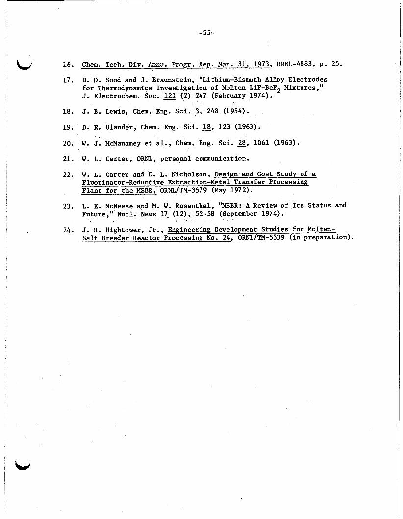
-55-
16. Chern. Tech. Div. Annu. Progr. Rep. Mar. 31, 1973, Om-4883, p. 25.
17. D. D. Sood and J. Braunstein, "Lithium-Bismuth Alloy Electrodes f o r Thermodynamics Inves t iga t ion of Molten LiF-BeF2 Mixtures," J. Electrochem. SOC. 121 (2) 247 (February 1974).
J. B. Lewis, Chem. Eng. Sci. - 3, 248 (1954). 18.
19.
20.
21. W. L. Carter, ORNL, personal communication.
22.
D. R. Olander, Chem. Eng. Sci. - 18, 123 (1963).
W. J. McManamey e t al., Chem. Eng. Sc i . 28, 1061 (1963).
W. L. Carter and E. L. Nicholson, Design and Cost Study of a Fluorinator-Reductive Extraction-Metal Transfer Processing P lan t f o r t h e MSBR, ORNL/TM-3579 (May 1972).
23. L. E. McNeese and M. W. Rosenthal, "MSBR: A R e v i e w of Its S t a t u s and Future," Nucl. News 17 (12), 52-58 (September 1974).
J. R. Hightower, Jr., Engineering Development Studies f o r Molten- S a l t Breeder Reactor Processing No. 24, ORNL/TM-5339 ( i n preparat ion) .
24.
c
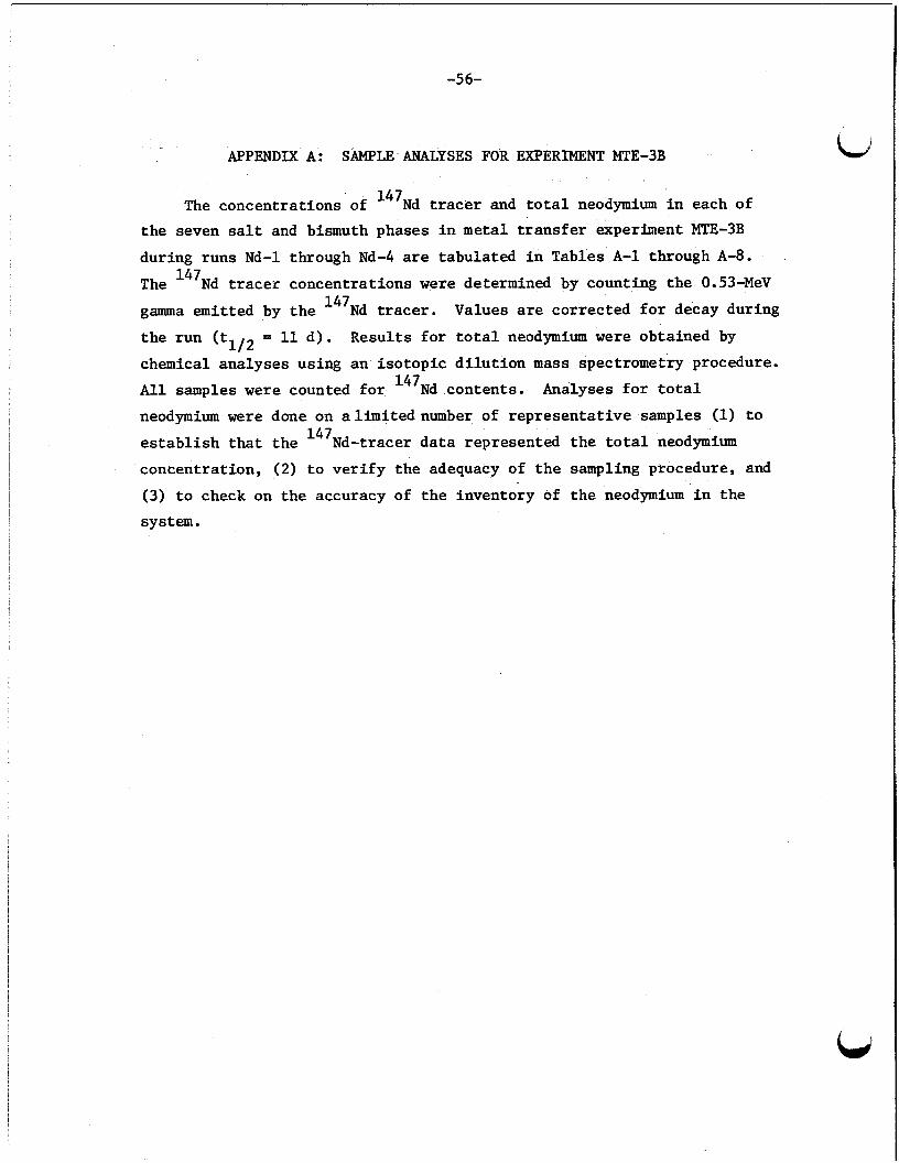
-56-
CJ APPENDIX A: SAMPLE ANALYSES FOR EXPERIMENT MTE-3B
The concentrat ions of 147Nd tracer and t o t a l neodymium i n each of t h e seven salt and bismuth phases i n metal t r a n s f e r experiment MTE-3B
during runs Nd-1 through Nd-4 are tabulated i n Tables A-1 through A-8.
The 147Nd tracer concentrat ions were determined by counting t h e 0.53-MeV
gamma emitted by t h e 147Nd tracer.
t h e run (t = 11 d ) . Resul ts f o r t o t a l neodymium w e r e obtained by
chemical analyses using an i so top ic d i l u t i o n m a s s spectrometry procedure.
A l l samples were counted f o r 147Nd contents .
neodymium were done on alimitednumber of r ep resen ta t ive samples (1) t o
e s t a b l i s h t h a t t h e 147Nd-tracer d a t a represented t h e t o t a l neodymium
concentrat ion, (2) t o v e r i f y t h e adequacy of t h e sampling procedure, and
(3) t o check on the accuracy of t h e inventory of t he neodymium i n t h e system.
Values are corrected f o r decay during
112
Analyses f o r t o t a l
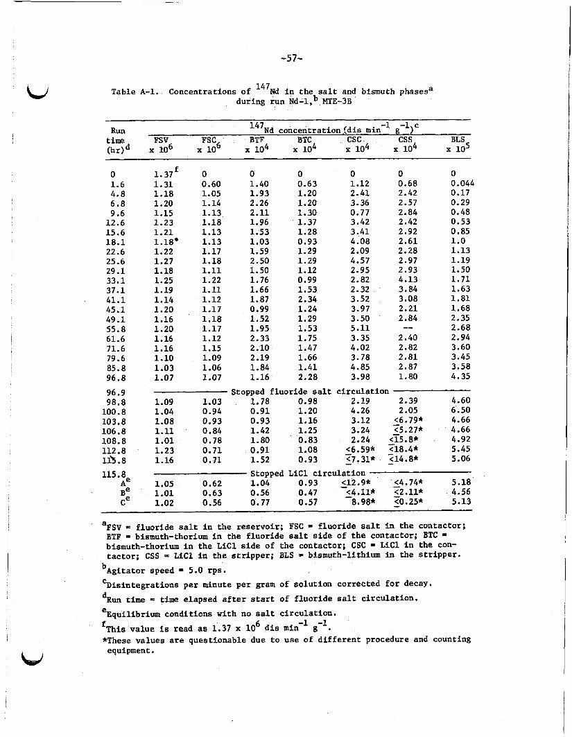
-57-
Table A-1. Concentrat ions of 147Nd i n t h e salt and bismuth phasesa dur ing r u n Nd-l,b WE-3B
- -1 -1)c Run 147Nd c o n c e n t r a t i o n j d i s min g
time FSV FSC6 BTF BTC csc . css BLS (hr)d x IO6 x 1 0 104 104 104 104 105
0 1.6 4.8 6.8 9.6
12.6 15.6 18.1 22.6 25.6 29.1 33.1 37.1 41.1 45.1 49.1 55.8 61.6 71.6 79.6 85.8 96.8
96.9 98.8
100.8 103.8 106.8 108.8 112.8 113.8 115.8
Ae Be Ce
1.37 f O 1.31 0.60 1.18 1.05 1.20 1.14 1.15 1.13 1.23 1.18 1.21 1.13 1.18. 1.13 1.22 1.17 1.27 1.18 1.18 1.11 1.25 1.22 1.19 1.11 1.14 1.12 1.20 I 1.17 1.16 1.18 1.20 1.17 1.16 1.12 1.16 1.15 1.10 1.09 1.03 1.06 1.07 1.07
0 1.40 1.93 2.26 2.11 1.96 1.53 1.03 1.59 2.50 1.50 1.76 1.66 1.87 0.99 1.52 1.95 2.33 2.10 2.19 1.84 1.16
0 0.63 1.20 1.20 1.30 1.37 1.28 0.93 1.29 1.29 1.12 0.99 1.53 2.34 1.24 1.29 1.53 1.75 1.47 1.66 1.41 2.28
0 1.12 2.41 3.36 0.77 3.42 3,41 4.08 2.09 4.57 2.95 2.82 2.32 3.52 3.97 3.50 5.11 3.35 4.02 3.78 4.85 3.98
0 0.68 2.42 2.57 2.84 2.42 2.92 2.61 2.28 2.97 2.93 4.13 3.84 3.08 2.21 2.84
2.40 2.82 2.81
1.80
--
2.87
0 0.044 0.17 0.29 0.48 0.53 0.85 1.0 1.13 1.19 1.50 1.71 1.63 1.81 1.68 2.35 2.68 2.94 3.60 3.45 3.58 4.35
Stopped f l u o r i d e s a l t c i r c u l a t i o n 1.09 1.03 1.78 0.98 2.19 2.39 4.60 1.04 0.94 0.91 1.20 4.26 2.05 6.50 1.08 0.93 0.93 1.16 3.12 <6.79* 4.66 1.11 0.84 1.42 1.25 3.24 <5.27* 4.66 1.01 0.78 1.80 0.83 2.24 _i5.8* 4.92
<7.31* <14.8* 5.06
-
1.23 0.71 0.91 1.08 - <6.59* 518.4* 5.45 1.16 0.71 1.52 0.93 - -
Stopped LiCl c i r c u l a t i o n 1.05 0.62 1.04 0.93 - <12.9* - <4.74* 5.18 1.01 0.63 0.56 0.47 - <4.11* 52.11* 4.56 1.02 0.56 0.77 0.57 8.98* 0 . 2 5 * 5.13
FSV = f l u o r i d e sal t i n t h e r e s e r v o i r ; FSC = f l u o r i d e sa l t i n t h e contac tor ; BTF = bismuth-thorium i n t h e f l u o r i d e sa l t s i d e of t h e contac tor ; BTC = bismuth-thorium i n t h e LiCl s i d e of t h e contac tor ; CSC - LiCl i n t h e con- t a c t o r ; CSS = LiCl i n t h e s t r i p p e r ; BLS - bismuth-li thium i n t h e s t r i p p e r .
a
bAgi ta tor speed = 5.0 r p s . k s i n t e g r a t i o n s p e r minute p e r gram of s o l u t i o n c o r r e c t e d f o r decay.
dRun t i m e = t i m e e lapsed after start of f l u o r i d e sal t c i r c u l a t i o n . e
'This v a l u e is read as 1.37 x lo6 d i s min *These v a l u e s are ques t ionable due t o u s e of d i f f e r e n t procedure and counting
Equi l ibr ium condi t ions w i t h no s a l t c i r c u l a t i o n . -1 -1
g . equipment.
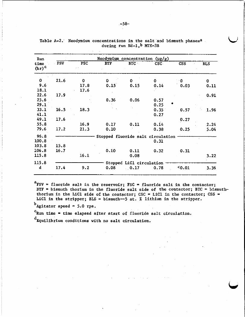
-58-
Table A-2: Neodymium concentrat ions i n the sal t and bismuth phasesa during run Nd-l,b MCE-3B
Run Neodymium concentrat ion ( u g f g ) t i m e FSV FSC BTF BTC csc css BLS
0 9.6
18.1 22.6 25.6 29.1 33.1 41.1 49.1 55.8 79.6
96; 8 100.8 103.8 106.8 115.8
115.8 d
21.6
17.9
16.5
17.6
17.2
0 0 0 0 0 0 17.8 0.15 0.15 0.14 0.03 0.11 17.6
0.91 0.36 0.06 0.57
0.25
0.27 18.3 0.35 0.57 1.96
0.27 16.9 0.17 0.11 0.14 2.24 21.3 0.10 0.38 0.25 5.04
Stopped f luo r ide sal t c i r cu la t ion 0.31
15.8 16.7 0.10 0.11 0.32 0.31
16.1 0.08 3.22
Stopped L i C l c i r c u l a t i o n 17.4 9.2 0.08 0.17 0.78 <o . 01 3.36
-
a FSV = f luo r ide salt. i n the reservoi r ; FSC = f luo r ide sa l t i n the contactor ; BTF = bismuth thorium i n the f luo r ide sal t s i d e of the contactor ; BTC = bismuth- thorium i n t h e L i C l s i d e of t h e contactor ; CSC = L i C l i n t h e contactor ; CSS = L i C l i n t h e s t r i p p e r ; BLS = bismuth--5 a t . % l i th ium i n the s t r ippe r .
bAgitator speed = 5.0 rps .
5 u n time = time elapsed a f t e r start of f luo r ide sal t c i r cu la t ion .
dEquilibrium conditions with no sa l t c i r cu la t ion .
c
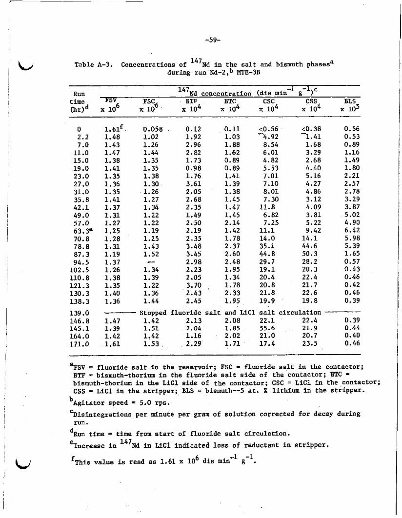
-59-
Table A-3. Concentrations of 147Nd i n t,.e salt and bismuth phasesa during run Nd-2,b MTE-3B
-1 g-l)c Run 147Nd concentrat ion ( d i s min t i m e FSC+ BTP BTC csc css BLS (hr)d x lo6 x 10 104 104 104 104 105
0 2.2 7 .O
11 .o 15.0 19 .o 23.0 27 .O 31 .O 35.8 42.1 49 .O 57.0 63. 3e 70.8 78.8 87.3 94.5
102.5 110.8 121.3 130.3 138.3
139 .O 146.8 145.1 164 .O 171.0
1.61f 1.48 1.43 1.47 1.38 1.41 1.35 1.36 1.35 1.41 1.37 1.31 1.27 1.25 1.28 1.31 1.19 1.37 1.26 1.38 1.35 1.40 1.36
1.47 1.39 1.42 1.61
0.058 1.02 1.26 1.44 1.35 1.35 1.38 1.30 1.26 1.27 1.34 1.22 1.22 1.19 1.25 1.43 1.52
1.34 1.39 1.22 1.36 1.44
Stopped 1.42 1.51 1.42 1.53
--
<0.38 KO. 56 1.41
0.12 0.11 1.92 1.03 4.92 2.96 1.88 8.54 1.68 2.82 1.62 6.01 3.29 1.73 0.89 4.82 2.68 0.98 0.89 5.53 4.40 1.76 1.41 7.01 5.16 3.61 1.39 7.10 4.27 2.05 1.38 8.01 4.86 2.68 1.45 7.30 3.12 2.35 1.47 11.8 4.09 1.49 1.45 6.82 3.81 2.50 2.14 7.25 5.22 2.19 1.42 11.1 9.42 2.35 1.78 14.0 14.1 3.48 2.37 35.1 44.6 3.45 2.60 44.8 50.3 2.98 2.48 29.7 28.2 2.23 1.95 19.1 20.3 2.05 1.34 20.4 22.4 3.70 1.78 20.8 21.7 2.43 2.33 21.8 22.6 2.45 1.95 19.9 19.8
2.13 2.08 22.1 22.4 2.04 1.85 55.6 21.9 1.16 2.02 21.0 20.7 2.29 1.71 17.4 23.5
- .c.
f luo r ide sa l t and LiCl sa l t c i r c u l a t i o n
0.56 0.53 0.89 1.16 1.49 1.80 2.21 2.57 2.78 3.29 3.87 5.02 4.90 6.42 5.98 5.39 1.65 0.57 0.43 0.46 0.42 0.46 0.39
0.39 0.44 0.40 0.46
~
FSV = f l u o r i d e salt i n t h e reservoi r ; FSC = f luo r ide s a l t i n t h e contactor ; BTF = bismuth-thorium i n t h e f luo r ide sa l t s i d e of t h e contactor ; BTC = bismuth-thorium i n t h e LiCl s i d e of the contactor ; CSC = LiCl i n t h e contactor ; CSS = LiCl i n t h e s t r i p p e r ; BLS = bismuth--5 at . % l i t h ium i n t h e s t r i p p e r .
a
bAgitator speed = 5.0 rps .
%is in t eg ra t ions pe r minute per gram of so lu t ion corrected f o r decay during
dRun t i m e 5 t i m e from start of f luo r ide sal t c i r cu la t ion . e
fThis value is read as 1.61 x lo6 d i s min
run.
Increase i n 147Nd i n L i C l ind ica ted loss of reductant i n s t r i p p e r .
-1 -1 g

-60-
Table A-4. Neodymium concentrat ions i n the sal t and bismuth phasesa during run Nd-2,b MTE-3B
RUn t i m e . Neodymium concentration (ug/g) (hr)" FSV FSC BTF BTC csc css BLS
0 2.2 7.0
11.0 15 .O 19 .o 35 .O 42.1 57.0 78. Bd
102.5 130.3 138.3
139 .O 146.8 171.0 182 .O
30.4 9.2 0.08 0.17 0.34 <0.01 3.36 0.55
7.8
33.6 32.9 0.21 0.10 11.9
29.1 0.03 0.06 0.92 0.32 7.6 29.7 26.3 0.06 0.88 0.71 15.1
41.2 33.6 0.45 32.8 36 .O 47.6 0.32 0.03 8.0 0.59
35.4 1.09 5.3 0.83
0.34
1.33 0.42
0.25
0.27
Stopped f luo r ide sal t and L i C l c i r c u l a t i o n 7.6
35.4 0.32 0.07 8.0 1.01 37 .O
%SV = f luo r ide sal t i n the reservoi r ; FSC = f luo r ide sal t i n t h e contactor ; BTF = bismuth-thorium i n the f luo r ide sa l t s i d e o f t h e contac tor ; BTC = bismuth-thorium i n t h e L i C l s i d e of t h e contactor ; CSC = L i C l i n t he contac- t o r ; CSS = L i C l i n t h e s t r i p p e r ; BLS = bismuth--5 at. % l i th ium i n the s t r i p p e r .
bAgitator speed = 5.0 rps .
dIncrease i n the neodymium concentration i n the L i C l i n t he s t r i p p e r and Run time = time elapsed a f t e r start of f luo r ide sal t c i r cu la t ion .
decrease of the neodymium concentration i n the Bi--5 at . X l i th ium i n the s t r i p p e r ind ica ted loss of l i th ium reductant i n t h e s t r i p p e r .
C

-61-
Table A-5. Concentrations of 147Nd i n the sa l t and bismuth phasesa during run Nd-3,b MTE-3B
147Nd concentrat ion ( d i s min -1 g-l)d
Run FSV FSC BTF BTC csc css BLS t i m e C (hr) x 10 x lo6 x 10 lo4 10 x 10 x lo5
0 1.5 4.3
11.5 18.8 19.8 27.0 35.7 43.8 51.0 59.5 68.0 74.8 83.5 92.0 99 .o
107.5 107.8 115.6 139.5 165.2
3.67e 0 0 0 0 0 0 3.05 1.88 3.55 1.94 0.7 0.7 0 3.27 3.07 4.22 3.62 3.63 1.35 0 2.99 3.00 4.85 2.50 3.87 3.33 0
2.88 2.78 4.55 3.21 21.7 9.84 0.052 -- 2.77 4.04 2.56 26.6 40.1 0.16 -- 2.52 4.20 3.01 19.4 19.3 0.66 -- 2.26 2.71 2.49 13.7 22.4 0.80 -- 2.29 3.53 2.03 16.7 24.4 1.23 -- 1.99 3.38 1.96 21.0 23.6 1.62
3.02 1.90 2.39 1.84 12.0 13.5 1.92 -- 1.84 2.62 1.63 22.4 24.1 2.11 -- 1.63 3.73 1.52 12.5 8.3 2.62 -- 1.49 2.53 1.54 9.3 8.7 2.65 -- 1.48 3.00 2.26 11.8 7.1 2.86 -- 1.31 1.46 1.08 7.4 9.8 3.26
-- 2.01 5.33 1.54 16.4 2.1 3.16 1.24 -- 1.24 15.5 co.9 3.13
3.31 1.26 1.36 1.44 12.0 <0.8 3.15
Stopped Fluoride S a l t Circulat ion
Stopped LiCl Ci rcu la t ion
--
FSV = f l u o r i d e f u e l sa l t i n t h e r e se rvo i r ; FSC = f l u o r i d e f u e l sa l t i n t h e contactor ; BTY - bismuth-thorium i n t h e f l u o r i d e salt s i d e of t h e contactor; BTC = bismuth-thorium in the LiCl side of the contactor; CSC = L i C l i n t h e contactor ; CSS = LiCl i n the s t r i p p e r ; BLS = bismuth--5 a t . X l i th ium i n t h e s t r i p p e r .
a
bAgitator speed i n the contactor and s t r i p p e r was 4.17 rps .
'Run time = time elapsed after t h e start of flue-ride salt c i r cu la t ion .
dDis in tegra t ions pe r minute p e r gram of so lu t ion corrected for decay.
ernis va lue is read as 3.67 x 1 0 6 d i s min -1 g -1 .
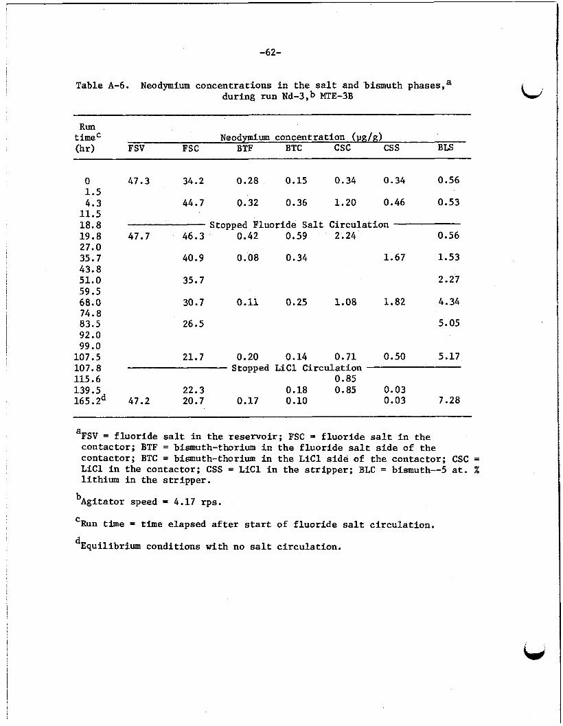
-62-
Table A-6. Neodymium concentrat ions i n t h e s a l t and bismuth phases,a during run Nd-3,b MTE-3B
RUn t i m e C Neodymium concentration (pg/g) (hr) FSV FSC BTF BTC csc cs s BLS
0 47.3 34.2 0.28 0.15 0.34 0.34 0.56 1.5 4.3 44.7 0.32 0.36 1.20 0.46 0.53
11.5 18.8 Stopped Fluoride S a l t Ci rcu la t ion 19.8 27.0 35.7 43.8 51.0 59.5 68.0 74.8 83.5 92.0 99.0
107.5 107.8 115.6 139.5 165. 2d
47.7 46.3 0.42 0.59 2.24 0.56
40.9 0.08 0.34 1.67 1.53
35.7 2.27
30.7 0.11 0.25 1.08 1.82 4.34
26.5 5.05
21.7 0.20 0.14 0.71 0.50 5.17 Stopped L i C l Circulat ion
22.3 0.18 0.85 0.03 47.2 20.7 0.17 0.10 0.03 7.28
0.85
aFSV = f l u o r i d e sal t i n t h e reservoir; FSC = f l u o r i d e sal t i n t h e contactor ; BTF = bismuth-thorium i n t h e f l u o r i d e sal t s i d e of t h e contac tor ; BTC = bismuth-thorium i n t h e L i C l s idd of t h e contactor ; CSC = L i C l i n t h e contactor ; CSS = LiCl i n t h e s t r i p p e r ; BLC = bismuth--5 a t . % l i th ium i n t h e s t r ippe r .
bAgitator speed = 4.17 rps .
‘Run time = time elapsed after start of f l u o r i d e sal t c i r cu la t ion .
dEquilibrium condi t ions w i t h no sal t c i r cu la t ion .
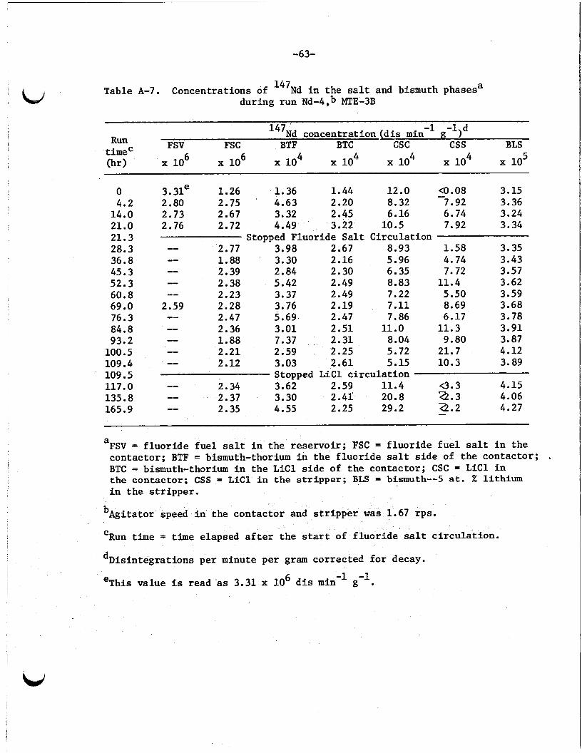
-63-
Table A-7. Concentrations of 147Nd i n the salt and bismuth phasesa during run Nd-4,b MTE-3B
-1 -1)d 147Nd concentration ( d i s min FSV FSC BTF BTC csc css BLS Run
t i m e C (hr) x 10 x 10 x 10 x 10 x 10 x 10 x 10 5
0 4.2
14.0 21.0 21.3 28.3 36.8 45.3 52.3 60.8 69 .O 76.3 84.8 93.2
100.5 109.4 109.5 117.0 135.8 165.9
3. 31e 1.26 1.36 1.44 12.0 <O .08 3.15 2.80 2.75 4.63 2.20 8.32 7.92 3.36 2.73 2.67 3.32 2.45 6.16 6.74 3.24 2.76 2.72 4.49 3.22 10.5 7.92 3.34
Stopped Fluoride S a l t Circulat ion -- 2.77 3.98 2.67 8.93 1.58 3.35 -- 1.88 3.30 2.16 5.96 4.74 3.43 -- 2.39 2.84 2.30 6.35 7.72 3.57 -- 2.38 5.42 2.49 8.83 11.4 3.62 -- 2.23 3.37 2.49 7.22 5.50 3.59
2.59 2.28 3.76 2.19 7.11 8.69 3.68 -- 2.47 5.69 2.47 7.86 6.17 3.78 -- 2.36 3.01 2.51 11.0 11.3 3.91 -- 1.88 7.37 2.31 8.04 9.80 3.87 -- 2.21 2.59 2.25 5.72 21.7 4.12 -- 2.12 3.03 2.61 5.15 10.3 3.89 Stopped L i C l c i r c u l a t i o n -- 2.34 3.62 2.59 11.4 -3.3 4.15
-- 2.37 3.30 2.41' 20.8 22.3 4.06 -- 2.35 4.55 2.25 29.2 42.2 4.27
-
- -
a FSV = f l u o r i d e f u e l s a l t i n the r e se rvo i r ; FSC = f l u o r i d e f u e l s a l t i n t h e contactor ; BTF = bismuth-thorium i n t h e f l u o r i d e s a l t s i d e of t h e contactor ; BTC = bismuth-thorium i n t h e LiCl s i d e of t h e contactor ; CSC = L i C l i n the contac tor ; CSS = L i C l i n the s t r i p p e r ; BLS = bismuth--S at. % lithium i n t h e s t r ipper .
bAgitator speed i n the contac tor and s t r i p p e r was 1.67 rps .
I
Run t i m e = time elapsed a f t e r t h e start of f l u o r i d e salt c i r cu la t ion . C
dDisintegrat ions per minute per gram corrected f o r decay.
eThis value is read 'as 3.31 x 10 d i s min g . 6 -1 -1

-64-
LJ Table A-8. Neodymium concentrat ions i n t h e sal t and bismuth phasesa during run Nd-4,b MTE-3B
Run t i m e C Neodymium concentration (vg/g) (hr) FSV FSC BTF BTC csc css BLS
0 4.2
14.0 21.0 21.3 36.8 45.3 52.3 60.8 69 .O 76.3 84.8 93.2
100.5 109.4
135. 8d 165.9 262. Od
109 .Sd
47.2 20.7 0.17 0.10 0.85 0.03 7.28
43.7 0.36 7.73 0.36 0.48
0.42 0.39 4.27
0.38 0.45 9.13
Stopped Fluoride S a l t Ci rcu la t ion
41.6 0.35
40.2 0.35 47.3 0.46 0.63
0.29 7.46 37.2 37.8 0.34 0.36 6.58
0.25 1.96 6.50 36.1 0.35
34.7 0.29 1.05 0.11 8.54 36.0 0.34 0.85 0.03 8.40 36.1 0.29 0.25 1.34 0.03 9.24
Stopped L i C l Ci rcu la t ion
a FSV = f l u o r i d e sal t i n t h e r e se rvo i r ; FSC = f l u o r i d e sal t i n t h e contactor ; BTF = bismuth-thorium i n t h e f l u o r i d e sa l t s i d e of t h e contac tor ; BTC = bismuth-thorium i n t h e LiCl s i d e of the contac tor ; CSC = L i C l i n t h e contactor ; CSS = LiCl i n t h e s t r i p p e r ; and BLS = bismuth--5 at . X l i th ium i n t h e s t r i p p e r .
bAgitator speed = 1.67 rps .
Run t i m e = t i m e elapsed af ter start of f l u o r i d e s a l t c i r cu la t ion . C
dEquilibrium condi t ions with no sal t c i r cu la t ion .
-65-
OW-517 6 D i s t . Category UC-76
I n t e r n a l Dis t r ibu t ion L i s t
1. 2. 3. 4. 5. 6. 7. 8 . 9. 10. 11. 12. 13. 14. 15. 16.
17-20. 21. 22.
52. 53. 54. 55. 56.
57.
58.
59-60.
61-172.
R. E. Brooksbank 23. W. R. C. H. 3rown, Jr. 24. J. A. W. D. Burch 25. R. E. W. L. Carter 26. R. E. R. M. Counce 27. A. P. F. L. Cul ler 28. C. L. J. M. Dale 29. H. E. F. L. Daley 30-32. L. E.
Laing Lenhard, ERDA-OR0 Leuze MacPherson M a l inauskas Matthews, ERDA-OR0 McCoy McNeese
J. R. R. L. J. R. D. E. L. M. W. R. R. W. R. F. J. R. c. w. A. D.
DiS t e f ano
Engel Ferguson F e r r i s Grimes Glass Hibbs Hightower, Jr . K e e K e l m e r s
Eg l i , ERDA-OR0 33. 34. 35.
36-39. 40. 41. 42. 43. 44.
45-46. 47.
48-50. 51.
E. Newman H. Postma M. W. Rosenthal H. C. Savage C. D. Scot t W. F. Schaffer , Jr. D. B. Trauger R. G. Wymer E. L. Youngblood Central Research Library Document Reference Sect ion Laboratory Records Laboratory Records (LRD-RC)
Consultants and Subcontractors
W. K. Davis E. L. Gaden, Jr. C. H. Ice R. B. Richards D. O'Boyle
External D i s t r ibu t ion
Research and Technical Support Division, Energy Research and Development Administration, Oak Ridge Operations Off ice , P. 0. Box E, Oak Ridge, TN 37830 Director , Reactor Division, Energy Research and Development Administration, Oak Ridge Operations Off ice , P. 0. Box E, Oak Ridge, TN 37830
Director , Division of Nuclear Research and Applications, Energy Research and Development Administration, Washington, D. C. 20545 For d i s t r i b u t i o n as shown i n TID-4500 under UC-76, Molten-Salt Reactor Technology
, ir US GOVERNMENT PRINTING OFFICE: 1977-748-189/166
Related Documents


![The Compact Font Format Specification [TS 5176] (about - CDF](https://static.cupdf.com/doc/110x72/62038664da24ad121e4a6cef/the-compact-font-format-specification-ts-5176-about-cdf.jpg)
