ORIGINAL RESEARCH Open Access Diversity between shell-like and beam-like regions for a cantilever cylindrical shell under follower forces Mohammad Ebrahim Torki 1* , Mohammad Taghi Kazemi 1 and Saied Mahmoudkhani 2 Abstract The effect of length and thickness on dynamic stability analysis of cantilever cylindrical shells under follower forces is addressed. Beck's, Leipholz's, and Hauger's problems were solved for cylindrical shells with different length-to-radius and thicknesses-to-radius ratios using the Galerkin method. First-order shear theory was used, and rotary inertias were considered in deriving the differential equations. Critical circumferential and longitudinal mode numbers and loads were evaluated for each case. Diagrams containing nondimensional load parameters vs. length and thickness parameters were plotted for each problem. For some shells with small length-to-radius ratios, flutter occurred in high longitudinal mode numbers where the first-order shear theory may not suffice to accurately evaluate the deformations. However, for long and moderately thick shells, there are ranges in which the shell can be analyzed using the simplified equivalent beam model. Keywords: Flutter, Follower force, Beck's problem, Leipholz's problem, Hauger's problem, First-order shear theory Introduction A prevailing position of potential instability is when a structure, especially a column, a reservoir, or an aero- space structure such as a projectile, undergoes an axial follower force. The most well-known physical state of fol- lower force is Beck's problem, in which a concentrated follower force is applied at the free end of a cantilever. Practical applications of this problem include the thrust applied at the end of a projectile or missile by a rocket, the thrust applied on the body of aircraft structures by a jet engine or a gas turbine rotor, the gripping force in disk brakes, the eccentric load exerted on a platform by a tip mass, etc. Also, Leipholz's and Hauger's problems can be applied to cantilever reservoirs conveying fluid with constant or linearly varying velocity, respectively Simkins and Anderson (1975); Seyranian and Elishakoff (2002); Simitses and Hodges (2006). Two basic types of instability may exist in the case of a follower force: one characterized with zero frequency, called divergence, and the other with nonzero frequency, known as flutter. However, the prevailing instability type in these struc- tures is flutter, which occurs in high-speed fluid flows Elfesoufi and Azrar (2005). When undergoing follower forces, the only instability type in structures with moder- ate thickness amounts is flutter, which is, for the most part, limited to columns, reservoirs, and aerospace struc- tures, especially projectiles such as missiles Park and Kim (2000). Another boundary condition in structures under fol- lower forces is free-free at the two ends. Free-free beams or shells can also be analyzed with the equivalent canti- lever model, which is rather overestimating Seyranian and Elishakoff (2002). Most of the research on the three above-mentioned problems is concerned with beams and plates. Sugiyama and Kawagoe (1975) studied the dynamic stability of elas- tic columns with different boundary conditions under the simultaneous effect of conservative and nonconservative (follower) axial loads using the finite difference method. Kounadis and Katsikadelis (1976) considered the effects of shear deformation and rotary inertia on the critical Beck's load for columns with open sections and different slender- ness ratios. Sugiyama and Mladenov (1983) studied the dynamic stability of elastic columns under Hauger's * Correspondence: [email protected] 1 Department of Civil Engineering, Sharif University of Technology, Tehran 1136511155, Islamic Republic of Iran Full list of author information is available at the end of the article © 2012 Torki et al.; licensee Springer. This is an Open Access article distributed under the terms of the Creative Commons Attribution License (http://creativecommons.org/licenses/by/2.0), which permits unrestricted use, distribution, and reproduction in any medium, provided the original work is properly cited. Torki et al. International Journal of Advanced Structural Engineering 2012, 4:9 http://www.advancedstructeng.com/content/4/1/9

Welcome message from author
This document is posted to help you gain knowledge. Please leave a comment to let me know what you think about it! Share it to your friends and learn new things together.
Transcript
Torki et al. International Journal of Advanced Structural Engineering 2012, 4:9http://www.advancedstructeng.com/content/4/1/9
ORIGINAL RESEARCH Open Access
Diversity between shell-like and beam-likeregions for a cantilever cylindrical shell underfollower forcesMohammad Ebrahim Torki1*, Mohammad Taghi Kazemi1 and Saied Mahmoudkhani2
Abstract
The effect of length and thickness on dynamic stability analysis of cantilever cylindrical shells under follower forcesis addressed. Beck's, Leipholz's, and Hauger's problems were solved for cylindrical shells with differentlength-to-radius and thicknesses-to-radius ratios using the Galerkin method. First-order shear theory was used, androtary inertias were considered in deriving the differential equations. Critical circumferential and longitudinal modenumbers and loads were evaluated for each case. Diagrams containing nondimensional load parameters vs. lengthand thickness parameters were plotted for each problem. For some shells with small length-to-radius ratios, flutteroccurred in high longitudinal mode numbers where the first-order shear theory may not suffice to accuratelyevaluate the deformations. However, for long and moderately thick shells, there are ranges in which the shell canbe analyzed using the simplified equivalent beam model.
Keywords: Flutter, Follower force, Beck's problem, Leipholz's problem, Hauger's problem, First-order shear theory
IntroductionA prevailing position of potential instability is when astructure, especially a column, a reservoir, or an aero-space structure such as a projectile, undergoes an axialfollower force. The most well-known physical state of fol-lower force is Beck's problem, in which a concentratedfollower force is applied at the free end of a cantilever.Practical applications of this problem include the thrustapplied at the end of a projectile or missile by a rocket,the thrust applied on the body of aircraft structures by ajet engine or a gas turbine rotor, the gripping force indisk brakes, the eccentric load exerted on a platform bya tip mass, etc. Also, Leipholz's and Hauger's problemscan be applied to cantilever reservoirs conveying fluidwith constant or linearly varying velocity, respectivelySimkins and Anderson (1975); Seyranian and Elishakoff(2002); Simitses and Hodges (2006). Two basic types ofinstability may exist in the case of a follower force: onecharacterized with zero frequency, called divergence,and the other with nonzero frequency, known as flutter.
* Correspondence: [email protected] of Civil Engineering, Sharif University of Technology, Tehran1136511155, Islamic Republic of IranFull list of author information is available at the end of the article
© 2012 Torki et al.; licensee Springer. This is anAttribution License (http://creativecommons.orin any medium, provided the original work is p
However, the prevailing instability type in these struc-tures is flutter, which occurs in high-speed fluid flowsElfesoufi and Azrar (2005). When undergoing followerforces, the only instability type in structures with moder-ate thickness amounts is flutter, which is, for the mostpart, limited to columns, reservoirs, and aerospace struc-tures, especially projectiles such as missiles Park andKim (2000).Another boundary condition in structures under fol-
lower forces is free-free at the two ends. Free-free beamsor shells can also be analyzed with the equivalent canti-lever model, which is rather overestimating Seyranianand Elishakoff (2002).Most of the research on the three above-mentioned
problems is concerned with beams and plates. Sugiyamaand Kawagoe (1975) studied the dynamic stability of elas-tic columns with different boundary conditions under thesimultaneous effect of conservative and nonconservative(follower) axial loads using the finite difference method.Kounadis and Katsikadelis (1976) considered the effects ofshear deformation and rotary inertia on the critical Beck'sload for columns with open sections and different slender-ness ratios. Sugiyama and Mladenov (1983) studied thedynamic stability of elastic columns under Hauger's
Open Access article distributed under the terms of the Creative Commonsg/licenses/by/2.0), which permits unrestricted use, distribution, and reproductionroperly cited.
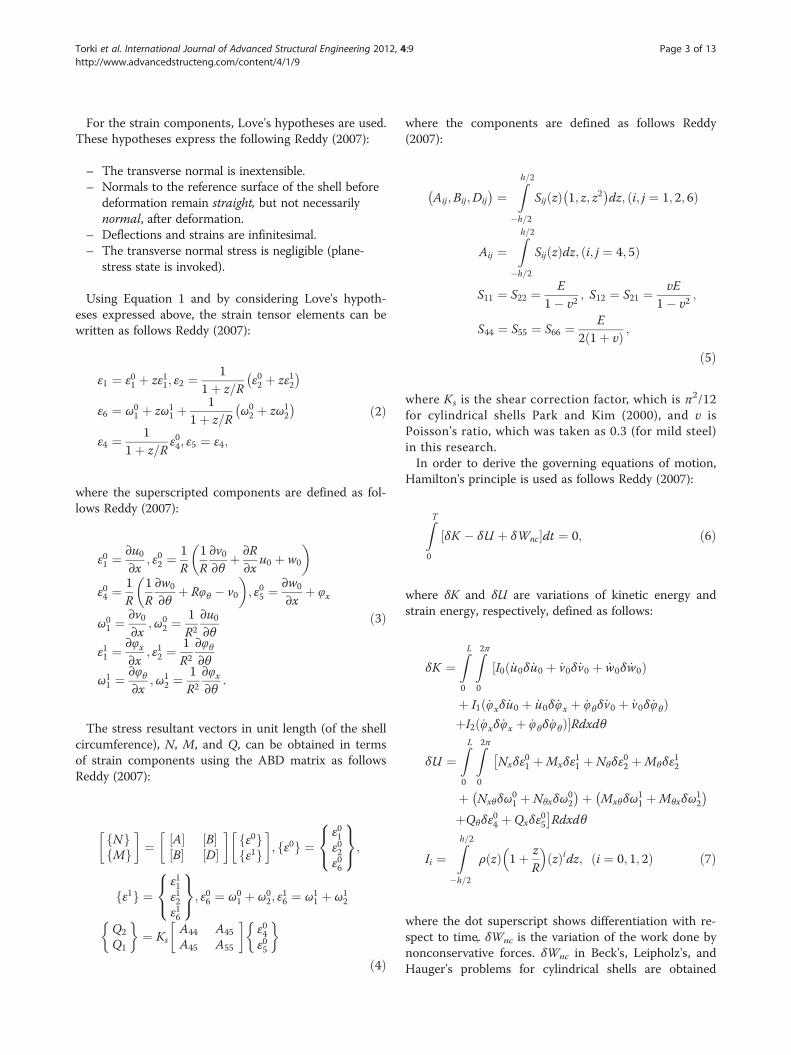
Figure 1 The coordinate system (a) and strain resultants (b)considered for cylindrical shells.
Torki et al. International Journal of Advanced Structural Engineering 2012, 4:9 Page 2 of 13http://www.advancedstructeng.com/content/4/1/9
loading. Ryu and Sugiyama (1994) studied the dynamicstability of cantilever Timoshenko beams under Beck'sloading by modeling the effect of the rocket-throwing en-gine as a follower load and a concentrated mass.Altman and De Oliviera (1988), (1990) studied the
dynamic stability of cantilever cylindrical and conicalpanels with and without slight internal damping. Theyasserted that due to numerical defects, the critical loadcalculated becomes occasionally very small. To over-come this problem, a slight damping matrix propor-tional to the stiffness matrix can be used in thesolution Altman and De Oliviera (1988), (1990). Thedynamic stability of thin cylindrical panels with differ-ent boundary conditions under concentrated and dis-tributed follower forces was first studied by BismarkNasr (1995) using the finite element method with C1
continuity. The dynamic stability of free-free cylin-drical shells under end-follower forces was studied byPark and Kim (2000). They used the finite elementmethod with first-order shear theory (FST) theory.They extracted the critical loads, critical sequentialmodes, and critical circumferential mode numbers fordifferent length-to-radius (L/R) and thickness-to-radius(h/R) ratios. They concluded that FST is valid only forL/R > 20, and for L/R > 40, the cylindrical shell can beanalyzed with the beam theory in certain regions of h/R. The same problem for cylindrical shells was studiedby considering the fluid-shell interaction by Jung et al.(2005). They gathered that, in most cases except thosewith very low filling ratios, the presence of liquid in thecylinder increases the stability. Bochkarev and Mat-veenko (2008) also studied the dynamic stability of cy-lindrical shells conveying fluid for free-free andclamped-free boundary conditions using the perturb-ation of velocity potential method.Although rockets, missiles, and fluid reservoirs are
mostly cylindrical shells rather than beams, to the bestof the authors' knowledge, it seems the dynamic stabil-ity of complete cylindrical shells undergoing followerforces has not been studied to the sufficient extent.Specifically, actual shell-like and beam-like geometricregions in cylindrical shells for all three kinds of fol-lower forces have not been sophisticatedly defined forcantilever structures.In the present research, the dynamic instability of
cantilever cylindrical shells is solved for Beck's, Lei-pholz's, and Hauger's problems to find out the geo-metrical regions in which the structure acts as ageneral shell-like or simplified beam-like model. Flut-ter loads are plotted for different L/R and h/R ratios.Tables containing critical sequential modes and crit-ical circumferential mode numbers are collected fordifferent L/R and h/R ratios. For each L/R, specific h/Rregions could be found in which the structure can be
analyzed simply with an equivalent beam model. Thisregion is found to be almost independent of the load-ing scheme (i.e., almost the same in Beck's, Leipholz's,or Hauger's problems).
MethodsFormulationConsider a cylindrical shell with radius R, thickness h,and length L. In case that the coordinate system is takento be as shown in Figure 1a, then using FST, the deform-ation components of any point can be written as followsReddy (2007):
u x; θ; z; tð Þ ¼ u0 x; θ; tð Þ þ zφx x; θ; tð Þv x; θ; z; tð Þ ¼ v0 x; θ; tð Þ þ zφθ x; θ; tð Þw x; θ; z; tð Þ ¼ w0 x; θ; tð Þ;
ð1Þ
where u0, v0, and w0 are the displacement componentsof the middle surface, and φx and φθ are changes in theslope of the normal to the middle surface around θ andx axes, respectively. The strain resultants per unit lengthfor a cylindrical shell are shown in Figure 1b.
Torki et al. International Journal of Advanced Structural Engineering 2012, 4:9 Page 3 of 13http://www.advancedstructeng.com/content/4/1/9
For the strain components, Love's hypotheses are used.These hypotheses express the following Reddy (2007):
– The transverse normal is inextensible.– Normals to the reference surface of the shell before
deformation remain straight, but not necessarilynormal, after deformation.
– Deflections and strains are infinitesimal.– The transverse normal stress is negligible (plane-
stress state is invoked).
Using Equation 1 and by considering Love's hypoth-eses expressed above, the strain tensor elements can bewritten as follows Reddy (2007):
ε1 ¼ ε01 þ zε11; ε2 ¼1
1þ z=Rε02 þ zε12� �
ε6 ¼ ω01 þ zω1
1 þ1
1þ z=Rω02 þ zω1
2
� �
ε4 ¼ 11þ z=R
ε04; ε5 ¼ ε4;
ð2Þ
where the superscripted components are defined as fol-lows Reddy (2007):
ε01 ¼∂u0∂x
; ε02 ¼1R
1R∂v0∂θ
þ ∂R∂x
u0 þ w0
� �
ε04 ¼1R
1R∂w0
∂θþ Rφθ � v0
� �; ε05 ¼
∂w0
∂xþ φx
ω01 ¼
∂v0∂x
;ω02 ¼
1R2
∂u0∂θ
ε11 ¼∂φx∂x
; ε12 ¼1R2
∂φθ∂θ
ω11 ¼
∂φθ∂x
;ω12 ¼
1R2
∂φx∂θ
:
ð3Þ
The stress resultant vectors in unit length (of the shellcircumference), N, M, and Q, can be obtained in termsof strain components using the ABD matrix as followsReddy (2007):
Nf gMf g
� �¼ A½ �
B½ �B½ �D½ �
� �ε0f gε1f g
� �; ε0f g ¼
ε01ε02ε06
8<:
9=;;
ε1f g ¼ε11ε12ε16
8<:
9=;; ε06 ¼ ω0
1 þ ω02; ε
16 ¼ ω1
1 þ ω12
Q2
Q1
� ¼ Ks
A44
A45
A45
A55
� �ε04ε05
�
ð4Þ
;
where the components are defined as follows Reddy(2007):
Aij;Bij;Dij� � ¼
Zh=2
�h=2
Sij zð Þ 1; z; z2� �
dz; i; j ¼ 1; 2; 6ð Þ
Aij ¼Zh=2
�h=2
Sij zð Þdz; i; j ¼ 4; 5ð Þ
S11 ¼ S22 ¼ E1� υ2
; S12 ¼ S21 ¼ υE1� υ2
;
S44 ¼ S55 ¼ S66 ¼ E2 1þ υð Þ ;
ð5Þ
where Ks is the shear correction factor, which is π2/12for cylindrical shells Park and Kim (2000), and υ isPoisson's ratio, which was taken as 0.3 (for mild steel)in this research.In order to derive the governing equations of motion,
Hamilton's principle is used as follows Reddy (2007):
ZT
0
δK � δU þ δWnc½ �dt ¼ 0; ð6Þ
where δK and δU are variations of kinetic energy andstrain energy, respectively, defined as follows:
δK ¼ZL
0
Z2π
0
I0 _u0δ _u0 þ _v0δ _v0 þ _w0δ _w0ð Þ½
þ I1 _φxδ _u0 þ _u0δ _φx þ _φθδ _v0 þ _v0δ _φθð ÞþI2 _φxδ _φx þ _φθδ _φθð Þ�Rdxdθ
δU ¼ZL
0
Z2π
0
Nxδε01 þMxδε
11 þ Nθδε
02 þMθδε
12
þ Nxθδω01 þ Nθxδω
02
� �þ Mxθδω11 þMθxδω
12
� �þQθδε
04 þ Qxδε
05
�Rdxdθ
Ii ¼Zh=2
�h=2
ρ zð Þ 1þ zR
� zð Þidz; i ¼ 0; 1; 2ð Þ ð7Þ
where the dot superscript shows differentiation with re-spect to time. δWnc is the variation of the work done bynonconservative forces. δWnc in Beck's, Leipholz's, andHauger's problems for cylindrical shells are obtained
Torki et al. International Journal of Advanced Structural Engineering 2012, 4:9 Page 4 of 13http://www.advancedstructeng.com/content/4/1/9
after integration by parts as follows Simitses and Hodges(2006; Altman and De Oliviera (1988); Park and Kim(2000):
δWnc ¼ ��PZL
0
Z2π
0
∂2v∂x2
δvþ ∂2w∂x2
δw
� �Rdxdθ
for Beck’s problem; ð8Þ
δWnc ¼ ��pZL
0
Z2π
0
L� xð Þ ∂2v∂x2
δvþ ∂2w∂x2
δw
� �Rdxdθ
for Leipholz’s problem; ð9Þ
δWnc ¼ � �g2
ZL
0
Z2π
0
L� xð Þ2 ∂2v∂x2
δvþ ∂2w∂x2
δw
� �Rdxdθ
for Hauger’s problem; ð10Þ
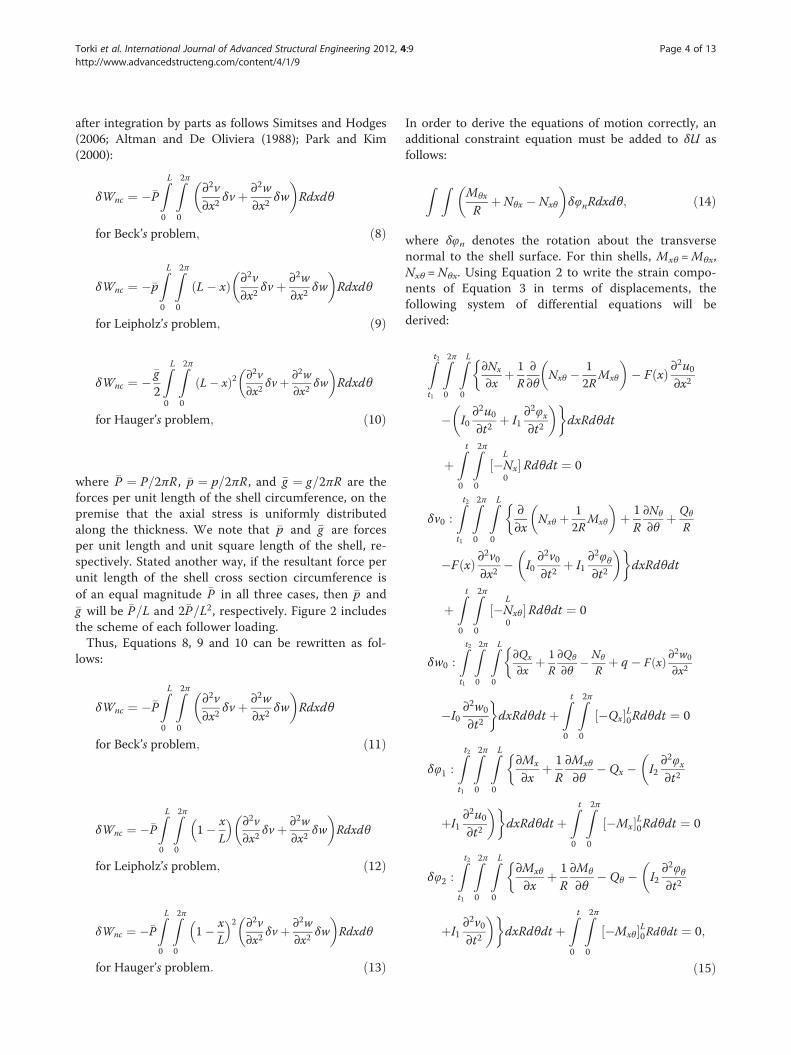
where �P ¼ P=2πR , �p ¼ p=2πR , and �g ¼ g=2πR are theforces per unit length of the shell circumference, on thepremise that the axial stress is uniformly distributedalong the thickness. We note that �p and �g are forcesper unit length and unit square length of the shell, re-spectively. Stated another way, if the resultant force perunit length of the shell cross section circumference isof an equal magnitude �P in all three cases, then �p and�g will be �P=L and 2�P=L2, respectively. Figure 2 includesthe scheme of each follower loading.Thus, Equations 8, 9 and 10 can be rewritten as fol-
lows:
δWnc ¼ ��PZL
0
Z2π
0
∂2v∂x2
δvþ ∂2w∂x2
δw
� �Rdxdθ
for Beck’s problem; ð11Þ
δWnc ¼ ��PZL
0
Z2π
0
1� xL
� ∂2v∂x2
δvþ ∂2w∂x2
δw
� �Rdxdθ
for Leipholz’s problem; ð12Þ
δWnc ¼ ��PZL
0
Z2π
0
1� xL
� 2 ∂2v∂x2
δvþ ∂2w∂x2
δw
� �Rdxdθ
for Hauger’s problem: ð13Þ
In order to derive the equations of motion correctly, anadditional constraint equation must be added to δU asfollows:
Z ZMθx
Rþ Nθx � Nxθ
� �δφnRdxdθ; ð14Þ
where δφn denotes the rotation about the transversenormal to the shell surface. For thin shells, Mxθ =Mθx,Nxθ =Nθx. Using Equation 2 to write the strain compo-nents of Equation 3 in terms of displacements, thefollowing system of differential equations will bederived:
Zt2t1
Z2π
0
ZL
0
∂Nx
∂xþ 1R
∂∂θ
Nxθ � 12R
Mxθ
� �� F xð Þ ∂
2u0∂x2
�
� I0∂2u0∂t2
þ I1∂2φx∂t2
� �dxRdθdt
þZ t
0
Z2π
0
�Nx½ �L
0Rdθdt ¼ 0
δv0 :Zt2t1
Z2π
0
ZL
0
∂∂x
Nxθ þ 12R
Mxθ
� �þ 1R∂Nθ
∂θþ Qθ
R
�
�F xð Þ ∂2v0∂x2
� I0∂2v0∂t2
þ I1∂2φθ∂t2
� �dxRdθdt
þZ t
0
Z2π
0
�Nxθ½ �L
0Rdθdt ¼ 0
δw0 :
Zt2t1
Z2π
0
ZL
0
∂Qx
∂xþ 1
R∂Qθ
∂θ� Nθ
Rþ q � F xð Þ ∂
2w0
∂x2
�
�I0∂2w0
∂t2
dxRdθdt þ
Z t
0
Z2π
0
�Qx½ �L0Rdθdt ¼ 0
δφ1 :Zt2t1
Z2π
0
ZL
0
∂Mx
∂xþ 1R∂Mxθ
∂θ� Qx � I2
∂2φx∂t2
��
þI1∂2u0∂t2
�dxRdθdt þ
Z t
0
Z2π
0
�Mx½ �L0Rdθdt ¼ 0
δφ2 :Zt2t1
Z2π
0
ZL
0
∂Mxθ
∂xþ 1R∂Mθ
∂θ� Qθ � I2
∂2φθ∂t2
��
þI1∂2v0∂t2
�dxRdθdt þ
Z t
0
Z2π
0
�Mxθ½ �L0Rdθdt ¼ 0;
ð15Þ
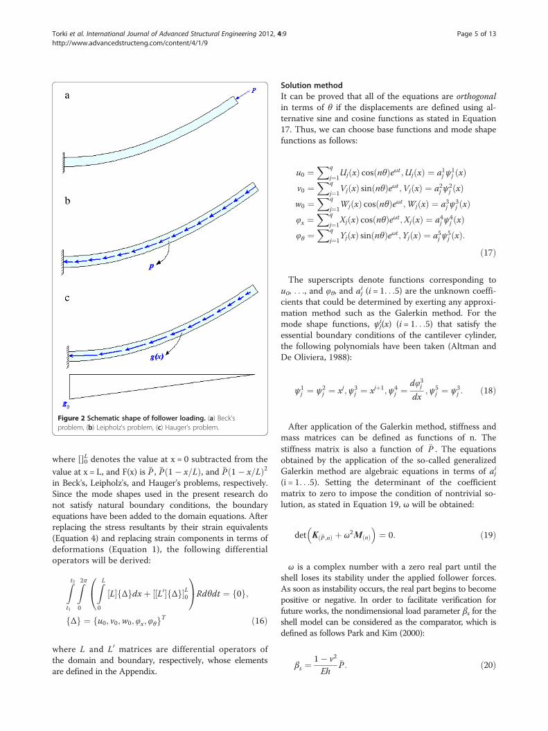
Figure 2 Schematic shape of follower loading. (a) Beck'sproblem, (b) Leipholz's problem, (c) Hauger's problem.
Torki et al. International Journal of Advanced Structural Engineering 2012, 4:9 Page 5 of 13http://www.advancedstructeng.com/content/4/1/9
where []0L denotes the value at x = 0 subtracted from the
value at x = L, and F(x) is �P , �P 1� x=Lð Þ, and �P 1� x=Lð Þ2in Beck's, Leipholz's, and Hauger's problems, respectively.Since the mode shapes used in the present research donot satisfy natural boundary conditions, the boundaryequations have been added to the domain equations. Afterreplacing the stress resultants by their strain equivalents(Equation 4) and replacing strain components in terms ofdeformations (Equation 1), the following differentialoperators will be derived:
Zt2t1
Z2π
0
ZL
0
L½ � Δf gdxþ L0½ � Δf g½ �L0
0@
1ARdθdt ¼ 0f g;
Δf g ¼ u0; v0;w0; φx; φθf gT ð16Þ
where L and L0 matrices are differential operators ofthe domain and boundary, respectively, whose elementsare defined in the Appendix.
Solution methodIt can be proved that all of the equations are orthogonalin terms of θ if the displacements are defined using al-ternative sine and cosine functions as stated in Equation17. Thus, we can choose base functions and mode shapefunctions as follows:
u0 ¼Xq
j¼1Uj xð Þ cos nθð Þeωt ;Uj xð Þ ¼ a1j ψ
1j xð Þ
v0 ¼Xq
j¼1Vj xð Þ sin nθð Þeωt ;Vj xð Þ ¼ a2j ψ
2j xð Þ
w0 ¼Xq
j¼1Wj xð Þ cos nθð Þeωt ;Wj xð Þ ¼ a3j ψ
3j xð Þ
φx ¼Xq
j¼1Xj xð Þ cos nθð Þeωt;Xj xð Þ ¼ a4j ψ
4j xð Þ
φθ ¼Xq
j¼1Yj xð Þ sin nθð Þeωt ;Yj xð Þ ¼ a5j ψ
5j xð Þ:
ð17Þ
The superscripts denote functions corresponding tou0, . . ., and φθ, and aj
i (i = 1. . .5) are the unknown coeffi-cients that could be determined by exerting any approxi-mation method such as the Galerkin method. For themode shape functions, ψj
i(x) (i = 1. . .5) that satisfy theessential boundary conditions of the cantilever cylinder,the following polynomials have been taken (Altman andDe Oliviera, 1988):
ψ1j ¼ ψ2
j ¼ xj;ψ3j ¼ xjþ1;ψ4
j ¼dφ3jdx
;ψ5j ¼ ψ3
j : ð18Þ
After application of the Galerkin method, stiffness andmass matrices can be defined as functions of n. Thestiffness matrix is also a function of �P . The equationsobtained by the application of the so-called generalizedGalerkin method are algebraic equations in terms of aj
i
(i = 1. . .5). Setting the determinant of the coefficientmatrix to zero to impose the condition of nontrivial so-lution, as stated in Equation 19, ω will be obtained:
det K �P ;nð Þ þ ω2M nð Þ�
¼ 0: ð19Þ
ω is a complex number with a zero real part until theshell loses its stability under the applied follower forces.As soon as instability occurs, the real part begins to becomepositive or negative. In order to facilitate verification forfuture works, the nondimensional load parameter βs for theshell model can be considered as the comparator, which isdefined as follows Park and Kim (2000):
βs ¼1� ν2
Eh�P: ð20Þ
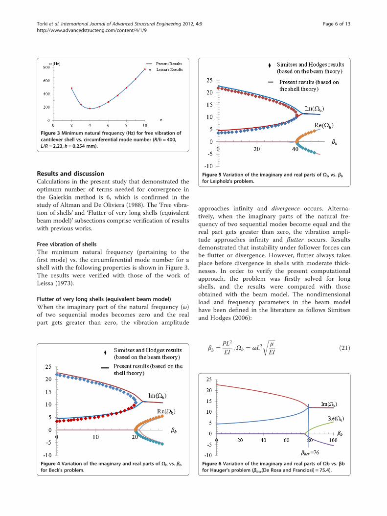
Figure 5 Variation of the imaginary and real parts of Ωb vs. βbfor Leipholz's problem.
Figure 3 Minimum natural frequency (Hz) for free vibration ofcantilever shell vs. circumferential mode number (R/h = 400,L/R = 2.23, h = 0.254 mm).
Torki et al. International Journal of Advanced Structural Engineering 2012, 4:9 Page 6 of 13http://www.advancedstructeng.com/content/4/1/9
Results and discussionCalculations in the present study that demonstrated theoptimum number of terms needed for convergence inthe Galerkin method is 6, which is confirmed in thestudy of Altman and De Oliviera (1988). The ‘Free vibra-tion of shells’ and ‘Flutter of very long shells (equivalentbeam model)’ subsections comprise verification of resultswith previous works.
Free vibration of shellsThe minimum natural frequency (pertaining to thefirst mode) vs. the circumferential mode number for ashell with the following properties is shown in Figure 3.The results were verified with those of the work ofLeissa (1973).
Flutter of very long shells (equivalent beam model)When the imaginary part of the natural frequency (ω)of two sequential modes becomes zero and the realpart gets greater than zero, the vibration amplitude
Figure 4 Variation of the imaginary and real parts of Ωb vs. βbfor Beck's problem.
approaches infinity and divergence occurs. Alterna-tively, when the imaginary parts of the natural fre-quency of two sequential modes become equal and thereal part gets greater than zero, the vibration ampli-tude approaches infinity and flutter occurs. Resultsdemonstrated that instability under follower forces canbe flutter or divergence. However, flutter always takesplace before divergence in shells with moderate thick-nesses. In order to verify the present computationalapproach, the problem was firstly solved for longshells, and the results were compared with thoseobtained with the beam model. The nondimensionalload and frequency parameters in the beam modelhave been defined in the literature as follows Simitsesand Hodges (2006):
βb ¼PL2
EI;Ωb ¼ ωL2
ffiffiffiffiffiμ
EI
rð21Þ
Figure 6 Variation of the imaginary and real parts of Ωb vs. βbfor Hauger's problem (βbcr(De Rosa and Franciosi) = 75.4).
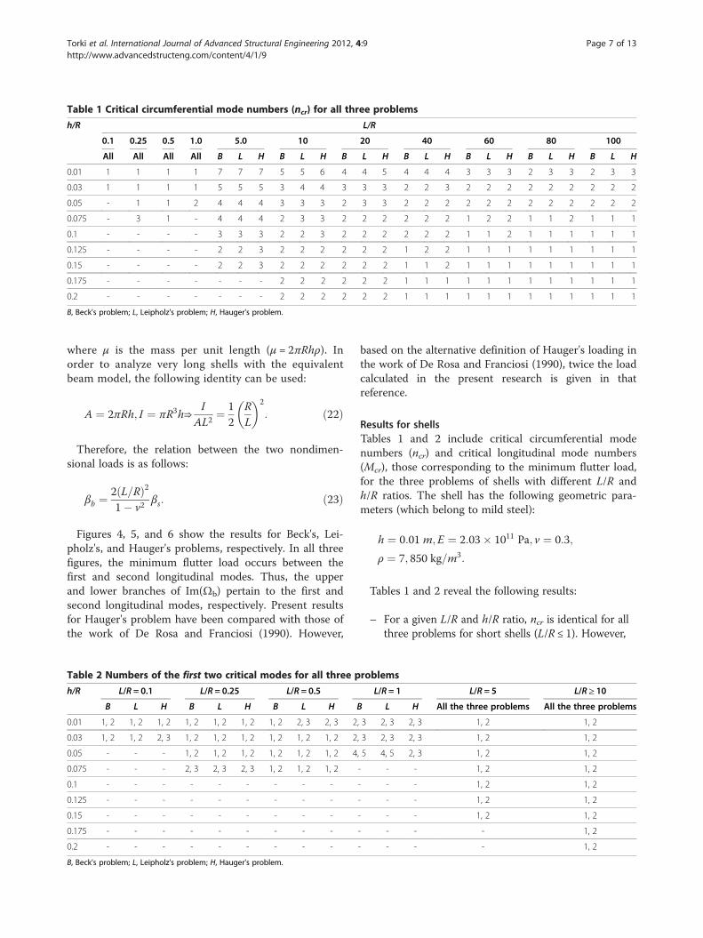
Table 1 Critical circumferential mode numbers (ncr) for all three problems
h/R L/R
0.1 0.25 0.5 1.0 5.0 10 20 40 60 80 100
All All All All B L H B L H B L H B L H B L H B L H B L H
0.01 1 1 1 1 7 7 7 5 5 6 4 4 5 4 4 4 3 3 3 2 3 3 2 3 3
0.03 1 1 1 1 5 5 5 3 4 4 3 3 3 2 2 3 2 2 2 2 2 2 2 2 2
0.05 - 1 1 2 4 4 4 3 3 3 2 3 3 2 2 2 2 2 2 2 2 2 2 2 2
0.075 - 3 1 - 4 4 4 2 3 3 2 2 2 2 2 2 1 2 2 1 1 2 1 1 1
0.1 - - - - 3 3 3 2 2 3 2 2 2 2 2 2 1 1 2 1 1 1 1 1 1
0.125 - - - - 2 2 3 2 2 2 2 2 2 1 2 2 1 1 1 1 1 1 1 1 1
0.15 - - - - 2 2 3 2 2 2 2 2 2 1 1 2 1 1 1 1 1 1 1 1 1
0.175 - - - - - - - 2 2 2 2 2 2 1 1 1 1 1 1 1 1 1 1 1 1
0.2 - - - - - - - 2 2 2 2 2 2 1 1 1 1 1 1 1 1 1 1 1 1
B, Beck's problem; L, Leipholz's problem; H, Hauger's problem.
Torki et al. International Journal of Advanced Structural Engineering 2012, 4:9 Page 7 of 13http://www.advancedstructeng.com/content/4/1/9
where μ is the mass per unit length (μ = 2πRhρ). Inorder to analyze very long shells with the equivalentbeam model, the following identity can be used:
A ¼ 2πRh; I ¼ πR3h⇒I
AL2¼ 1
2RL
� �2
: ð22Þ
Therefore, the relation between the two nondimen-sional loads is as follows:
βb ¼2 L=Rð Þ21� ν2
βs: ð23Þ
Figures 4, 5, and 6 show the results for Beck's, Lei-pholz's, and Hauger's problems, respectively. In all threefigures, the minimum flutter load occurs between thefirst and second longitudinal modes. Thus, the upperand lower branches of Im(Ωb) pertain to the first andsecond longitudinal modes, respectively. Present resultsfor Hauger's problem have been compared with those ofthe work of De Rosa and Franciosi (1990). However,
Table 2 Numbers of the first two critical modes for all three p
h/R L/R = 0.1 L/R = 0.25 L/R = 0.5
B L H B L H B L H B
0.01 1, 2 1, 2 1, 2 1, 2 1, 2 1, 2 1, 2 2, 3 2, 3 2
0.03 1, 2 1, 2 2, 3 1, 2 1, 2 1, 2 1, 2 1, 2 1, 2 2
0.05 - - - 1, 2 1, 2 1, 2 1, 2 1, 2 1, 2 4
0.075 - - - 2, 3 2, 3 2, 3 1, 2 1, 2 1, 2
0.1 - - - - - - - - -
0.125 - - - - - - - - -
0.15 - - - - - - - - -
0.175 - - - - - - - - -
0.2 - - - - - - - - -
B, Beck's problem; L, Leipholz's problem; H, Hauger's problem.
based on the alternative definition of Hauger's loading inthe work of De Rosa and Franciosi (1990), twice the loadcalculated in the present research is given in thatreference.
Results for shellsTables 1 and 2 include critical circumferential modenumbers (ncr) and critical longitudinal mode numbers(Mcr), those corresponding to the minimum flutter load,for the three problems of shells with different L/R andh/R ratios. The shell has the following geometric para-meters (which belong to mild steel):
h ¼ 0:01 m;E ¼ 2:03� 1011 Pa; ν ¼ 0:3;
ρ ¼ 7; 850 kg=m3:
Tables 1 and 2 reveal the following results:
– For a given L/R and h/R ratio, ncr is identical for allthree problems for short shells (L/R ≤ 1). However,
roblems
L/R = 1 L/R = 5 L/R ≥ 10
L H All the three problems All the three problems
, 3 2, 3 2, 3 1, 2 1, 2
, 3 2, 3 2, 3 1, 2 1, 2
, 5 4, 5 2, 3 1, 2 1, 2
- - - 1, 2 1, 2
- - - 1, 2 1, 2
- - - 1, 2 1, 2
- - - 1, 2 1, 2
- - - - 1, 2
- - - - 1, 2
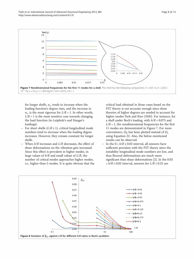
Figure 7 Nondimensional frequencies for the first 11 modes for a shell. The shell has the following components: h = 0.01 m, E = 2.03 ×10¹¹ Pa, ν = 0.3, ρ = 7, 850 kg/m3, h/R = 0.075, L/R = 1.
Torki et al. International Journal of Advanced Structural Engineering 2012, 4:9 Page 8 of 13http://www.advancedstructeng.com/content/4/1/9
for longer shells, ncr tends to increase when theloading function's degree rises, and the increase inncr is the most rigorous for L/R = 1. In other words,L/R = 1 is the most sensitive case towards changingthe load function (to Leipholz's and Hauger'sloadings).
– For short shells (L/R ≤ 1), critical longitudinal modenumbers tend to increase when the loading degreeincreases. However, they remain constant for longershells.
– When h/R increases and L/R decreases, the effect ofshear deformations on the vibration gets increased.Since this effect is prevalent in higher modes, inlarge values of h/R and small values of L/R, thenumber of critical modes approaches higher modes,i.e., higher-than-5 modes. It is quite obvious that the
Figure 8 Variation of βscr against L/R for different h/R ratios in Beck's pr
critical load obtained in those cases based on theFST theory is not accurate enough since sheartheories of higher degrees are needed to account forhigher modes Park and Kim (2000). For instance, fora shell under Beck's loading, with h/R = 0.075 andL/R = 1, the nondimensional frequencies for the first11 modes are demonstrated in Figure 7. For moreconvenience, Ωb has been plotted instead of Ωs
using Equation 22. Also, the below-mentionedresults can be observed.
– In the 0 < h/R ≤ 0.03 interval, all answers havesufficient precision with the FST theory since theinstability longitudinal mode numbers are low, andthus flexural deformations are much moresignificant than shear deformations [2]. In the 0.03< h/R ≤ 0.05 interval, answers for L/R ≥ 0.25 are
oblem.
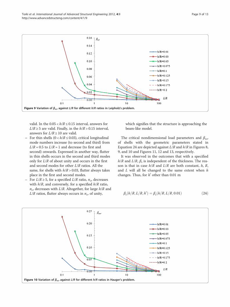
Figure 9 Variation of βscr against L/R for different h/R ratios in Leipholz's problem.
Torki et al. International Journal of Advanced Structural Engineering 2012, 4:9 Page 9 of 13http://www.advancedstructeng.com/content/4/1/9
valid. In the 0.05 < h/R ≤ 0.15 interval, answers forL/R ≥ 5 are valid. Finally, in the h/R > 0.15 interval,answers for L/R ≥ 10 are valid.
– For thin shells (0 < h/R ≤ 0.03), critical longitudinalmode numbers increase (to second and third) fromL/R = 0.5 to L/R = 1 and decrease (to first andsecond) onwards. Expressed in another way, flutterin thin shells occurs in the second and third modesonly for L/R of about unity and occurs in the firstand second modes for other L/R ratios. All thesame, for shells with h/R > 0.03, flutter always takesplace in the first and second modes.
– For L/R ≥ 5, for a specified L/R ratio, ncr decreaseswith h/R, and conversely, for a specified h/R ratio,ncr decreases with L/R. Altogether, for large h/R andL/R ratios, flutter always occurs in ncr of unity,
Figure 10 Variation of βscr against L/R for different h/R ratios in Haug
which signifies that the structure is approaching thebeam-like model.
The critical nondimensional load parameters and βscrof shells with the geometric parameters stated inEquation 24 are depicted against L/R and h/R in Figures 8,9, and 10 and Figures 11, 12 and 13, respectively.It was observed in the outcomes that with a specified
h/R and L/R, βs is independent of the thickness. The rea-son is that in case h/R and L/R are both constant, h, R,and L will all be changed to the same extent when hchanges. Thus, for h0 other than 0.01 m
βs h=R; L=R; h0ð Þ ¼ βs h=R; L=R; 0:01ð Þ ð24Þ
er's problem.
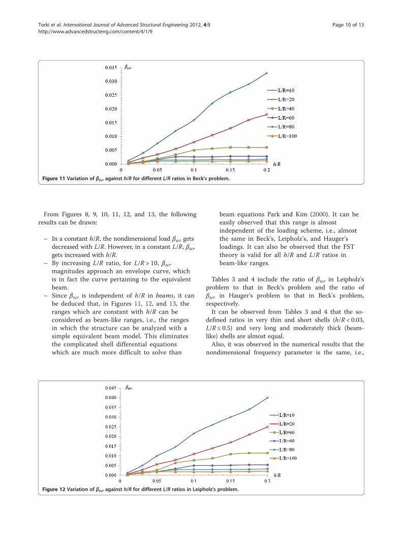
Figure 11 Variation of βscr against h/R for different L/R ratios in Beck's problem.
Torki et al. International Journal of Advanced Structural Engineering 2012, 4:9 Page 10 of 13http://www.advancedstructeng.com/content/4/1/9
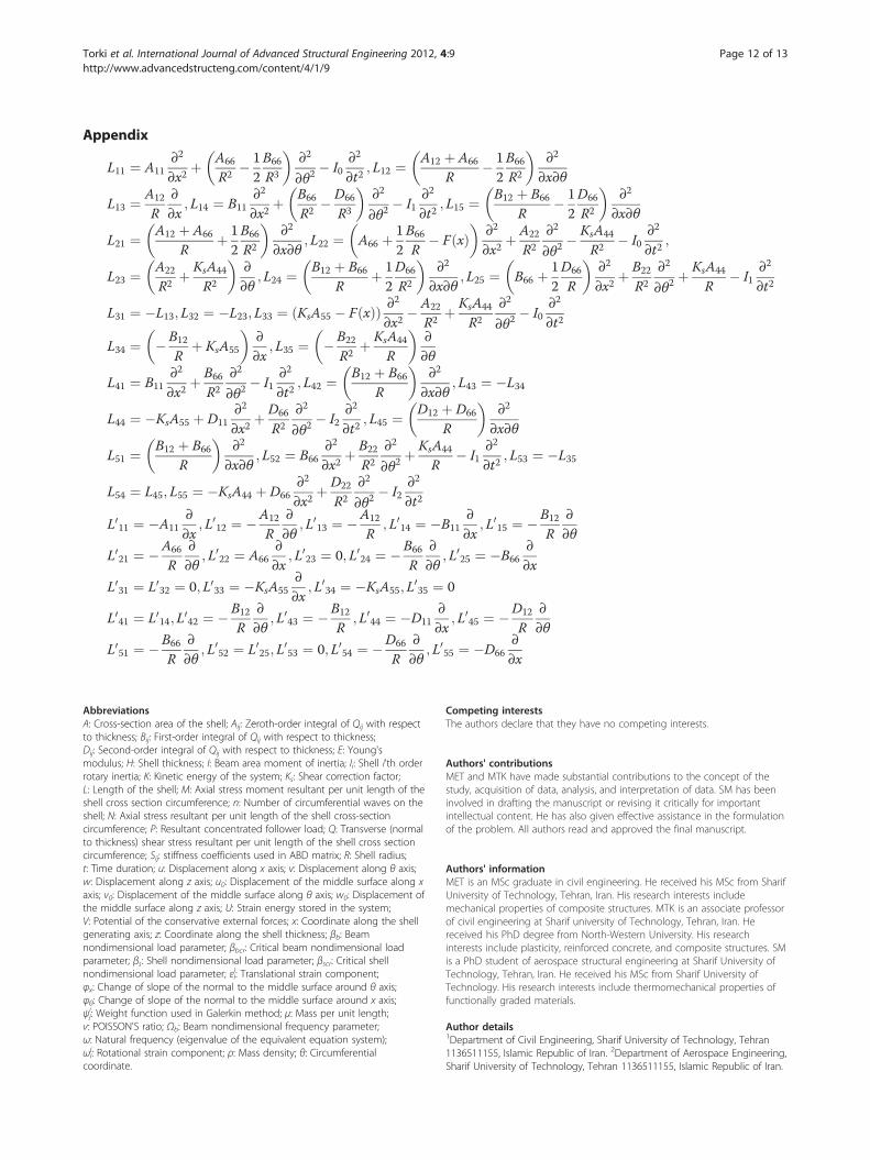
From Figures 8, 9, 10, 11, 12, and 13, the followingresults can be drawn:
– In a constant h/R, the nondimensional load βscr getsdecreased with L/R. However, in a constant L/R, βscrgets increased with h/R.
– By increasing L/R ratio, for L/R > 10, βscrmagnitudes approach an envelope curve, whichis in fact the curve pertaining to the equivalentbeam.
– Since βscr is independent of h/R in beams, it canbe deduced that, in Figures 11, 12, and 13, theranges which are constant with h/R can beconsidered as beam-like ranges, i.e., the rangesin which the structure can be analyzed with asimple equivalent beam model. This eliminatesthe complicated shell differential equationswhich are much more difficult to solve than
Figure 12 Variation of βscr against h/R for different L/R ratios in Leiph
beam equations Park and Kim (2000). It can beeasily observed that this range is almostindependent of the loading scheme, i.e., almostthe same in Beck's, Leipholz's, and Hauger'sloadings. It can also be observed that the FSTtheory is valid for all h/R and L/R ratios inbeam-like ranges.
Tables 3 and 4 include the ratio of βscr in Leipholz'sproblem to that in Beck's problem and the ratio ofβscr in Hauger's problem to that in Beck's problem,respectively.It can be observed from Tables 3 and 4 that the so-
defined ratios in very thin and short shells (h/R < 0.03,L/R ≤ 0.5) and very long and moderately thick (beam-like) shells are almost equal.Also, it was observed in the numerical results that the
nondimensional frequency parameter is the same, i.e.,
olz's problem.
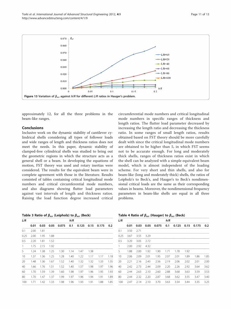
Figure 13 Variation of βscr against h/R for different L/R ratios in Hauger's problem.
Torki et al. International Journal of Advanced Structural Engineering 2012, 4:9 Page 11 of 13http://www.advancedstructeng.com/content/4/1/9
approximately 12, for all the three problems in thebeam-like ranges.
ConclusionsInclusive work on the dynamic stability of cantilever cy-lindrical shells considering all types of follower loadsand wide ranges of length and thickness ratios does notmeet the needs. In this paper, dynamic stability ofclamped-free cylindrical shells was studied to bring outthe geometric regions in which the structure acts as ageneral shell or a beam. In developing the equations ofmotion, FST theory was used and rotary inertias wereconsidered. The results for the equivalent beam were incomplete agreement with those in the literature. Resultsconsisted of tables containing critical longitudinal modenumbers and critical circumferential mode numbers,and also diagrams showing flutter load parametersagainst vast intervals of length and thickness ratios.Raising the load function degree increased critical
Table 3 Ratio of βscr (Leipholz) to βscr (Beck)L/R h/R
0.01 0.03 0.05 0.075 0.1 0.125 0.15 0.175 0.2
0.1 2.00 1.81
0.25 2.00 1.95 1.88
0.5 2.20 1.81 1.52
1 1.75 2.15 1.92
5 1.24 1.38 1.25 1.30 1.14 1.47 1.38
10 1.37 1.36 1.25 1.28 1.40 1.22 1.17 1.17 1.18
20 1.48 1.36 1.67 1.52 1.40 1.32 1.32 1.33 1.35
40 1.66 1.76 1.51 1.52 1.40 1.57 1.98 1.97 1.96
60 1.70 1.59 1.39 1.60 1.98 1.97 1.96 1.95 1.93
80 1.70 1.47 1.37 1.99 1.97 1.96 1.94 1.91 1.89
100 1.71 1.42 1.33 1.98 1.96 1.93 1.91 1.88 1.85
circumferential mode numbers and critical longitudinalmode numbers in specific ranges of thickness andlength ratios. The flutter load parameter decreased byincreasing the length ratio and decreasing the thicknessratio. In some ranges of small length ratios, resultsobtained based on FST theory should be more carefullydealt with since the critical longitudinal mode numbersare obtained to be higher than 5, in which FST seemsnot to be accurate enough. For long and moderatelythick shells, ranges of thickness ratios exist in whichthe shell can be analyzed with a simple equivalent beammodel, which is almost independent of the loadingscheme. For very short and thin shells, and also forbeam-like (long and moderately thick) shells, the ratios ofLeipholz's to Beck's, and Hauger's to Beck's nondimen-sional critical loads are the same as their correspondingvalues in beams. Moreover, the nondimensional frequencyparameters in beam-like shells are equal in all threeproblems.
Table 4 Ratio of βscr (Hauger) to βscr (Beck)L/R h/R
0.01 0.03 0.05 0.075 0.1 0.125 0.15 0.175 0.2
0.1 3.50 2.71
0.25 3.67 3.55 3.29
0.5 3.20 3.05 2.72
1 2.00 2.92 4.32
5 1.88 2.00 1.92 1.90 1.71 1.78 1.92
10 2.06 2.09 2.01 1.95 2.07 2.01 1.89 1.86 1.85
20 2.21 2.16 2.43 2.56 2.19 2.06 2.02 2.01 2.00
40 2.42 2.73 2.44 2.09 2.20 2.26 2.92 3.64 3.62
60 2.44 2.63 2.10 2.60 2.88 3.68 3.63 3.59 3.53
80 2.44 2.32 2.20 2.87 3.68 3.62 3.55 3.47 3.40
100 2.47 2.14 2.10 3.70 3.63 3.54 3.44 3.35 3.25
Torki et al. International Journal of Advanced Structural Engineering 2012, 4:9 Page 12 of 13http://www.advancedstructeng.com/content/4/1/9
Appendix
L11 ¼ A11∂2
∂x2þ A66
R2� 12B66
R3
� �∂2
∂θ2� I0
∂2
∂t2; L12 ¼ A12 þ A66
R� 12B66
R2
� �∂2
∂x∂θ
L13 ¼ A12
R∂∂x
; L14 ¼ B11∂2
∂x2þ B66
R2� D66
R3
� �∂2
∂θ2� I1
∂2
∂t2; L15 ¼ B12 þ B66
R� 12D66
R2
� �∂2
∂x∂θ
L21 ¼ A12 þ A66
Rþ 12B66
R2
� �∂2
∂x∂θ; L22 ¼ A66 þ 1
2B66
R� F xð Þ
� �∂2
∂x2þ A22
R2
∂2
∂θ2� KsA44
R2� I0
∂2
∂t2;
L23 ¼ A22
R2þ KsA44
R2
� �∂∂θ
; L24 ¼ B12 þ B66
Rþ 12D66
R2
� �∂2
∂x∂θ; L25 ¼ B66 þ 1
2D66
R
� �∂2
∂x2þ B22
R2
∂2
∂θ2þ KsA44
R� I1
∂2
∂t2
L31 ¼ �L13; L32 ¼ �L23; L33 ¼ KsA55 � F xð Þð Þ ∂2
∂x2� A22
R2þ KsA44
R2
∂2
∂θ2� I0
∂2
∂t2
L34 ¼ �B12
Rþ KsA55
� �∂∂x
; L35 ¼ �B22
R2þ KsA44
R
� �∂∂θ
L41 ¼ B11∂2
∂x2þ B66
R2
∂2
∂θ2� I1
∂2
∂t2; L42 ¼ B12 þ B66
R
� �∂2
∂x∂θ; L43 ¼ �L34
L44 ¼ �KsA55 þ D11∂2
∂x2þ D66
R2
∂2
∂θ2� I2
∂2
∂t2; L45 ¼ D12 þ D66
R
� �∂2
∂x∂θ
L51 ¼ B12 þ B66
R
� �∂2
∂x∂θ; L52 ¼ B66
∂2
∂x2þ B22
R2
∂2
∂θ2þ KsA44
R� I1
∂2
∂t2; L53 ¼ �L35
L54 ¼ L45; L55 ¼ �KsA44 þ D66∂2
∂x2þ D22
R2
∂2
∂θ2� I2
∂2
∂t2
L011 ¼ �A11∂∂x
; L012 ¼ �A12
R∂∂θ
; L013 ¼ �A12
R; L014 ¼ �B11
∂∂x
; L015 ¼ �B12
R∂∂θ
L021 ¼ �A66
R∂∂θ
; L022 ¼ A66∂∂x
; L023 ¼ 0; L024 ¼ �B66
R∂∂θ
; L025 ¼ �B66∂∂x
L031 ¼ L032 ¼ 0; L033 ¼ �KsA55∂∂x
; L034 ¼ �KsA55; L035 ¼ 0
L041 ¼ L014; L042 ¼ �B12
R∂∂θ
; L043 ¼ �B12
R; L044 ¼ �D11
∂∂x
; L045 ¼ �D12
R∂∂θ
L051 ¼ �B66
R∂∂θ
; L052 ¼ L025; L053 ¼ 0; L054 ¼ �D66
R∂∂θ
; L055 ¼ �D66∂∂x
AbbreviationsA: Cross-section area of the shell; Aij: Zeroth-order integral of Qij with respectto thickness; Bij: First-order integral of Qij with respect to thickness;Dij: Second-order integral of Qij with respect to thickness; E: Young'smodulus; H: Shell thickness; I: Beam area moment of inertia; Ii: Shell i'th orderrotary inertia; K: Kinetic energy of the system; Ks: Shear correction factor;L: Length of the shell; M: Axial stress moment resultant per unit length of theshell cross section circumference; n: Number of circumferential waves on theshell; N: Axial stress resultant per unit length of the shell cross-sectioncircumference; P: Resultant concentrated follower load; Q: Transverse (normalto thickness) shear stress resultant per unit length of the shell cross sectioncircumference; Sij: stiffness coefficients used in ABD matrix; R: Shell radius;t: Time duration; u: Displacement along x axis; v: Displacement along θ axis;w: Displacement along z axis; u0: Displacement of the middle surface along xaxis; v0: Displacement of the middle surface along θ axis; w0: Displacement ofthe middle surface along z axis; U: Strain energy stored in the system;V: Potential of the conservative external forces; x: Coordinate along the shellgenerating axis; z: Coordinate along the shell thickness; βb: Beamnondimensional load parameter; βbcr: Critical beam nondimensional loadparameter; βs: Shell nondimensional load parameter; βscr: Critical shellnondimensional load parameter; εij: Translational strain component;φx: Change of slope of the normal to the middle surface around θ axis;φθ: Change of slope of the normal to the middle surface around x axis;ψji: Weight function used in Galerkin method; μ: Mass per unit length;ν: POISSON'S ratio; Ωb: Beam nondimensional frequency parameter;ω: Natural frequency (eigenvalue of the equivalent equation system);ωij: Rotational strain component; ρ: Mass density; θ: Circumferential
coordinate.
Competing interestsThe authors declare that they have no competing interests.
Authors' contributionsMET and MTK have made substantial contributions to the concept of thestudy, acquisition of data, analysis, and interpretation of data. SM has beeninvolved in drafting the manuscript or revising it critically for importantintellectual content. He has also given effective assistance in the formulationof the problem. All authors read and approved the final manuscript.
Authors' informationMET is an MSc graduate in civil engineering. He received his MSc from SharifUniversity of Technology, Tehran, Iran. His research interests includemechanical properties of composite structures. MTK is an associate professorof civil engineering at Sharif university of Technology, Tehran, Iran. Hereceived his PhD degree from North-Western University. His researchinterests include plasticity, reinforced concrete, and composite structures. SMis a PhD student of aerospace structural engineering at Sharif University ofTechnology, Tehran, Iran. He received his MSc from Sharif University ofTechnology. His research interests include thermomechanical properties offunctionally graded materials.
Author details1Department of Civil Engineering, Sharif University of Technology, Tehran1136511155, Islamic Republic of Iran. 2Department of Aerospace Engineering,Sharif University of Technology, Tehran 1136511155, Islamic Republic of Iran.
Torki et al. International Journal of Advanced Structural Engineering 2012, 4:9 Page 13 of 13http://www.advancedstructeng.com/content/4/1/9
Received: 13 June 2012 Accepted: 5 November 2012Published: 10 December 2012
ReferencesAltman W, De Oliviera MG (1988) Vibration and stability of cantilever cylindrical
shell panels under follower forces. J Sound Vib 122(2):291–298Altman W, De Oliviera MG (1990) Vibration and stability of shell panels with
slight internal damping under follower forces. J Sound Vib 136(l):45–50Bismark Nasr MN (1995) Dynamic stability of shallow shells subjected to follower
forces. AIAA J 33(2):355–360Bochkarev SA, Matveenko VP (2008) Numerical study of the influence of
boundary conditions on the dynamic behavior of a cylindrical shellconveying a fluid. J Mech Solids 43(3):477–486
De Rosa MA, Franciosi C (1990) The influence of an intermediate support on thestability behaviour of cantilever beams subjected to follower forces. J SoundVib 137(l):107–115
Elfesoufi Z, Azrar L (2005) Buckling, flutter and vibration analysis of beams byintegral equation formulations. J Comput Struct 83:2632–2649
Jung SW, Na KS, Kim JH (2005) Dynamic stability of liquid-filled projectiles undera thrust. J Sound Vib 280:611–631
Kounadis A, Katsikadelis JT (1976) Shear and rotatory inertia effect on Beck’scolumn. J Sound Vib 49(2):171–178
Leissa AW (1973) Vibration of shells. Scientific and Technical Information Office.National Aeronautics and Space Administration, Washington, DC
Park SH, Kim JH (2000) Dynamic stability of a completely free circular cylindricalshell subjected to a follower force. J Sound Vib 231(4):989–1005
Reddy JN (2007) Theory and analysis of elastic plates and shells. CRC Press, New YorkRyu BJ, Sugiyama Y (1994) Dynamic stability of cantilever Timoshenko columns
subjected to a rocket thrust. J Comp Struct 51(4):331–335Seyranian AP, Elishakoff I (2002) Modern problems of structural stability.
International Centre for Mechanical Sciences. Springer, New YorkSimitses GJ, Hodges DH (2006) Fundamentals of structural stability. Elsevier,
BurlingtonSimkins TE, Anderson GL (1975) Stability of Beck's column considering support
characteristics. J Sound Vib 39(3):359–369Sugiyama Y, Kawagoe H (1975) Vibration and stability of elastic columns under
the combined action of uniformly distributed vertical and tangential forces.J Sound Vib 38(3):341–355
Sugiyama Y, Mladenov KA (1983) Vibration and stability of elastic columnssubjected to triangularly distributed sub-tangential forces. J Sound Vib88(4):447–457
doi:10.1186/2008-6695-4-9Cite this article as: Torki et al.: Diversity between shell-like and beam-like regions for a cantilever cylindrical shell under follower forces.International Journal of Advanced Structural Engineering 2012 4:9.
Submit your manuscript to a journal and benefi t from:
7 Convenient online submission
7 Rigorous peer review
7 Immediate publication on acceptance
7 Open access: articles freely available online
7 High visibility within the fi eld
7 Retaining the copyright to your article
Submit your next manuscript at 7 springeropen.com
Related Documents
![ORIGINAL RESEARCH Open Access Longitudinal [ F]FDG …](https://static.cupdf.com/doc/110x72/618c23eecc831561f06a46ee/original-research-open-access-longitudinal-ffdg-.jpg)