Original instructions Diesel trucks RX70-40 RX70-45 RX70-50 7331 7332 7333 7334 57348011825 EN - 02/2019 - 12

Welcome message from author
This document is posted to help you gain knowledge. Please leave a comment to let me know what you think about it! Share it to your friends and learn new things together.
Transcript
Original instructions
Diesel trucks
RX70-40RX70-45RX70-50
7331 7332 7333 7334
57348011825 EN - 02/2019 - 12


Prefaceg
Address of manufacturer andcontact detailsSTILL GmbHBerzeliusstraße 1022113 Hamburg, GermanyTel. +49 (0) 40 7339-0Fax: +49 (0) 40 7339-1622Email: [email protected]: http://www.still.de
Rules for the operatingcompany of industrial trucksIn addition to these operating instructions,a code of practice containing additionalinformation for the operating companies ofindustrial trucks is also available.
This guide provides information for handlingindustrial trucks:• Information on how to select suitableindustrial trucks for a particular area ofapplication
• Prerequisites for the safe operation ofindustrial trucks
• Information on the use of industrial trucks• Information on transport, initial commis-sioning and storage of industrial trucks
Internet address and QR codeThe information can be accessed at any timeby pasting the address https://m.still.de/vdmain a web browser or by scanning the QR code.
57348011825 EN - 02/2019 - 12 I

Table of contentsg
1 ForewordList of abbreviations . . . . . . . . . . . . . . . . . . . . . . . . . . . . . . . . . . . . . . . . . . . . . . . . . . . 2
Your truck . . . . . . . . . . . . . . . . . . . . . . . . . . . . . . . . . . . . . . . . . . . . . . . . . . . . . . . . . . 3Description of the truck . . . . . . . . . . . . . . . . . . . . . . . . . . . . . . . . . . . . . . . . . . . . . . . . . 3General . . . . . . . . . . . . . . . . . . . . . . . . . . . . . . . . . . . . . . . . . . . . . . . . . . . . . . . . . . . . 6CE labelling . . . . . . . . . . . . . . . . . . . . . . . . . . . . . . . . . . . . . . . . . . . . . . . . . . . . . . . . . 6EC declaration of conformity in accordance with Machinery Directive . . . . . . . . . . . . . . . 7Accessories overview . . . . . . . . . . . . . . . . . . . . . . . . . . . . . . . . . . . . . . . . . . . . . . . . . 8Labelling points overview . . . . . . . . . . . . . . . . . . . . . . . . . . . . . . . . . . . . . . . . . . . . . . . 9Nameplate . . . . . . . . . . . . . . . . . . . . . . . . . . . . . . . . . . . . . . . . . . . . . . . . . . . . . . . . . 10Production number . . . . . . . . . . . . . . . . . . . . . . . . . . . . . . . . . . . . . . . . . . . . . . . . . . 10StVZO (Road Traffic Licensing Regulations) information . . . . . . . . . . . . . . . . . . . . . . . 11
Using the truck . . . . . . . . . . . . . . . . . . . . . . . . . . . . . . . . . . . . . . . . . . . . . . . . . . . . . . 11Proper usage . . . . . . . . . . . . . . . . . . . . . . . . . . . . . . . . . . . . . . . . . . . . . . . . . . . . . . . 11Proper use during towing . . . . . . . . . . . . . . . . . . . . . . . . . . . . . . . . . . . . . . . . . . . . . . 12Impermissible use . . . . . . . . . . . . . . . . . . . . . . . . . . . . . . . . . . . . . . . . . . . . . . . . . . . 12Place of use . . . . . . . . . . . . . . . . . . . . . . . . . . . . . . . . . . . . . . . . . . . . . . . . . . . . . . . . 12Using working platforms . . . . . . . . . . . . . . . . . . . . . . . . . . . . . . . . . . . . . . . . . . . . . . . 14
Information about the documentation . . . . . . . . . . . . . . . . . . . . . . . . . . . . . . . . . . . . . 15Documentation scope . . . . . . . . . . . . . . . . . . . . . . . . . . . . . . . . . . . . . . . . . . . . . . . . 15Supplementary documentation . . . . . . . . . . . . . . . . . . . . . . . . . . . . . . . . . . . . . . . . . . 16Issue date and topicality of the operating instructions . . . . . . . . . . . . . . . . . . . . . . . . . . 17Copyright and trademark rights . . . . . . . . . . . . . . . . . . . . . . . . . . . . . . . . . . . . . . . . . . 17Explanation of information symbols used . . . . . . . . . . . . . . . . . . . . . . . . . . . . . . . . . . 17List of abbreviations . . . . . . . . . . . . . . . . . . . . . . . . . . . . . . . . . . . . . . . . . . . . . . . . . . 18Definition of directions . . . . . . . . . . . . . . . . . . . . . . . . . . . . . . . . . . . . . . . . . . . . . . . . 20Schematic views . . . . . . . . . . . . . . . . . . . . . . . . . . . . . . . . . . . . . . . . . . . . . . . . . . . . 20
Environmental considerations . . . . . . . . . . . . . . . . . . . . . . . . . . . . . . . . . . . . . . . . . . 22Packaging . . . . . . . . . . . . . . . . . . . . . . . . . . . . . . . . . . . . . . . . . . . . . . . . . . . . . . . . . 22Disposal of components and batteries . . . . . . . . . . . . . . . . . . . . . . . . . . . . . . . . . . . . . 22
2 SafetyDefinition of terms used for responsible persons . . . . . . . . . . . . . . . . . . . . . . . . . . . . . 24Operating company . . . . . . . . . . . . . . . . . . . . . . . . . . . . . . . . . . . . . . . . . . . . . . . . . . 24Specialist . . . . . . . . . . . . . . . . . . . . . . . . . . . . . . . . . . . . . . . . . . . . . . . . . . . . . . . . . . 24Drivers . . . . . . . . . . . . . . . . . . . . . . . . . . . . . . . . . . . . . . . . . . . . . . . . . . . . . . . . . . . 25
Basic principles for safe operation . . . . . . . . . . . . . . . . . . . . . . . . . . . . . . . . . . . . . . . 27Insurance cover on company premises . . . . . . . . . . . . . . . . . . . . . . . . . . . . . . . . . . . . 27Changes and retrofitting . . . . . . . . . . . . . . . . . . . . . . . . . . . . . . . . . . . . . . . . . . . . . . . 27
57348011825 EN - 02/2019 - 12 III
Table of contentsg
Changes to the overhead guard and roof loads . . . . . . . . . . . . . . . . . . . . . . . . . . . . . . 29Warning regarding non-original parts . . . . . . . . . . . . . . . . . . . . . . . . . . . . . . . . . . . . . 29Damage, defects andmisuse of safety systems . . . . . . . . . . . . . . . . . . . . . . . . . . . . . . 30Length of the fork arms . . . . . . . . . . . . . . . . . . . . . . . . . . . . . . . . . . . . . . . . . . . . . . . . 30Tyres . . . . . . . . . . . . . . . . . . . . . . . . . . . . . . . . . . . . . . . . . . . . . . . . . . . . . . . . . . . . . 31Medical equipment . . . . . . . . . . . . . . . . . . . . . . . . . . . . . . . . . . . . . . . . . . . . . . . . . . . 32Exercise caution when handling gas springs and accumulators . . . . . . . . . . . . . . . . . . 33Length of the fork arms . . . . . . . . . . . . . . . . . . . . . . . . . . . . . . . . . . . . . . . . . . . . . . . . 33
Residual risk . . . . . . . . . . . . . . . . . . . . . . . . . . . . . . . . . . . . . . . . . . . . . . . . . . . . . . . 35Residual dangers, residual risks . . . . . . . . . . . . . . . . . . . . . . . . . . . . . . . . . . . . . . . . . 35Special risks associated with using the truck and attachments . . . . . . . . . . . . . . . . . . . 36Overview of hazards and countermeasures . . . . . . . . . . . . . . . . . . . . . . . . . . . . . . . . . 38Danger to employees . . . . . . . . . . . . . . . . . . . . . . . . . . . . . . . . . . . . . . . . . . . . . . . . . 41
Safety tests . . . . . . . . . . . . . . . . . . . . . . . . . . . . . . . . . . . . . . . . . . . . . . . . . . . . . . . . 42Regular safety inspection of the truck . . . . . . . . . . . . . . . . . . . . . . . . . . . . . . . . . . . . . 42Checking the diesel engine emissions . . . . . . . . . . . . . . . . . . . . . . . . . . . . . . . . . . . . . 42Trucks with particle filters . . . . . . . . . . . . . . . . . . . . . . . . . . . . . . . . . . . . . . . . . . . . . . 43Insulation testing . . . . . . . . . . . . . . . . . . . . . . . . . . . . . . . . . . . . . . . . . . . . . . . . . . . . 44
Safety regulations for handling consumables . . . . . . . . . . . . . . . . . . . . . . . . . . . . . . . 45Permissible consumables . . . . . . . . . . . . . . . . . . . . . . . . . . . . . . . . . . . . . . . . . . . . . 45Oils . . . . . . . . . . . . . . . . . . . . . . . . . . . . . . . . . . . . . . . . . . . . . . . . . . . . . . . . . . . . . . 45Hydraulic fluid . . . . . . . . . . . . . . . . . . . . . . . . . . . . . . . . . . . . . . . . . . . . . . . . . . . . . . 46Battery acid . . . . . . . . . . . . . . . . . . . . . . . . . . . . . . . . . . . . . . . . . . . . . . . . . . . . . . . . 47Diesel fuel . . . . . . . . . . . . . . . . . . . . . . . . . . . . . . . . . . . . . . . . . . . . . . . . . . . . . . . . . 48Coolant and cooling fluid . . . . . . . . . . . . . . . . . . . . . . . . . . . . . . . . . . . . . . . . . . . . . . 50Disposal of consumables . . . . . . . . . . . . . . . . . . . . . . . . . . . . . . . . . . . . . . . . . . . . . . 50
Emissions . . . . . . . . . . . . . . . . . . . . . . . . . . . . . . . . . . . . . . . . . . . . . . . . . . . . . . . . . 52
3 OverviewsTruck overview . . . . . . . . . . . . . . . . . . . . . . . . . . . . . . . . . . . . . . . . . . . . . . . . . . . . . 56
Overview of driver's compartment . . . . . . . . . . . . . . . . . . . . . . . . . . . . . . . . . . . . . . . . 57
Operating devices and display elements . . . . . . . . . . . . . . . . . . . . . . . . . . . . . . . . . . . 58Display and operating unit . . . . . . . . . . . . . . . . . . . . . . . . . . . . . . . . . . . . . . . . . . . . . 58Operating devices for hydraulic and driving functions . . . . . . . . . . . . . . . . . . . . . . . . . . 59Double mini-lever . . . . . . . . . . . . . . . . . . . . . . . . . . . . . . . . . . . . . . . . . . . . . . . . . . . . 60Three-way mini-lever . . . . . . . . . . . . . . . . . . . . . . . . . . . . . . . . . . . . . . . . . . . . . . . . . 61Four-way mini-lever . . . . . . . . . . . . . . . . . . . . . . . . . . . . . . . . . . . . . . . . . . . . . . . . . . 62Joystick 4Plus . . . . . . . . . . . . . . . . . . . . . . . . . . . . . . . . . . . . . . . . . . . . . . . . . . . . . . 63Fingertip . . . . . . . . . . . . . . . . . . . . . . . . . . . . . . . . . . . . . . . . . . . . . . . . . . . . . . . . . . 64
IV 57348011825 EN - 02/2019 - 12
Table of contentsg
Mini console . . . . . . . . . . . . . . . . . . . . . . . . . . . . . . . . . . . . . . . . . . . . . . . . . . . . . . . 65
4 OperationChecks and tasks before daily use . . . . . . . . . . . . . . . . . . . . . . . . . . . . . . . . . . . . . . . 68Visual inspections . . . . . . . . . . . . . . . . . . . . . . . . . . . . . . . . . . . . . . . . . . . . . . . . . . . 68Climbing into and out of the truck . . . . . . . . . . . . . . . . . . . . . . . . . . . . . . . . . . . . . . . . 71Climbing into and out of a truck with a raised driver's cab . . . . . . . . . . . . . . . . . . . . . . . 72Checking the side cover is locked . . . . . . . . . . . . . . . . . . . . . . . . . . . . . . . . . . . . . . . . 74Shelves and cup holders . . . . . . . . . . . . . . . . . . . . . . . . . . . . . . . . . . . . . . . . . . . . . . 75Adjusting the MSG 65/MSG 75 driver's seat . . . . . . . . . . . . . . . . . . . . . . . . . . . . . . . . 75Adjusting the armrest . . . . . . . . . . . . . . . . . . . . . . . . . . . . . . . . . . . . . . . . . . . . . . . . . 79Adjusting the steering column . . . . . . . . . . . . . . . . . . . . . . . . . . . . . . . . . . . . . . . . . . . 80Unlocking the emergency off switch . . . . . . . . . . . . . . . . . . . . . . . . . . . . . . . . . . . . . . 81Switching on the key switch . . . . . . . . . . . . . . . . . . . . . . . . . . . . . . . . . . . . . . . . . . . . 81Access authorisation with PIN code (variant) . . . . . . . . . . . . . . . . . . . . . . . . . . . . . . . . 84Operating the signal horn . . . . . . . . . . . . . . . . . . . . . . . . . . . . . . . . . . . . . . . . . . . . . . 93Seat belt . . . . . . . . . . . . . . . . . . . . . . . . . . . . . . . . . . . . . . . . . . . . . . . . . . . . . . . . . . 94Using the driver's cab . . . . . . . . . . . . . . . . . . . . . . . . . . . . . . . . . . . . . . . . . . . . . . . . . 97Starting the engine . . . . . . . . . . . . . . . . . . . . . . . . . . . . . . . . . . . . . . . . . . . . . . . . . . . 98Checking the brake system for correct function . . . . . . . . . . . . . . . . . . . . . . . . . . . . . . 99Checking the steering system for correct function . . . . . . . . . . . . . . . . . . . . . . . . . . . . 101Checking the emergency off function . . . . . . . . . . . . . . . . . . . . . . . . . . . . . . . . . . . . . 102Zero adjustment of the load measurement (variant) . . . . . . . . . . . . . . . . . . . . . . . . . . . 102Checking the vertical lift mast position (variant) for correct function . . . . . . . . . . . . . . . . 104Cleaning the dust valve . . . . . . . . . . . . . . . . . . . . . . . . . . . . . . . . . . . . . . . . . . . . . . . 105
Operating the display-operating unit . . . . . . . . . . . . . . . . . . . . . . . . . . . . . . . . . . . . . . 106Displays . . . . . . . . . . . . . . . . . . . . . . . . . . . . . . . . . . . . . . . . . . . . . . . . . . . . . . . . . . 106Adjusting the displays . . . . . . . . . . . . . . . . . . . . . . . . . . . . . . . . . . . . . . . . . . . . . . . . 107Symbols in the display . . . . . . . . . . . . . . . . . . . . . . . . . . . . . . . . . . . . . . . . . . . . . . . . 108Setting the date or time . . . . . . . . . . . . . . . . . . . . . . . . . . . . . . . . . . . . . . . . . . . . . . . . 113Resetting the daily kilometres and daily operating hours . . . . . . . . . . . . . . . . . . . . . . . 114Setting the language . . . . . . . . . . . . . . . . . . . . . . . . . . . . . . . . . . . . . . . . . . . . . . . . . 114Softkeys for operating various equipment variants . . . . . . . . . . . . . . . . . . . . . . . . . . . . 115Configuring Blue-Q efficiency mode . . . . . . . . . . . . . . . . . . . . . . . . . . . . . . . . . . . . . . 115Shock recognition (variant) . . . . . . . . . . . . . . . . . . . . . . . . . . . . . . . . . . . . . . . . . . . . . 116Additional settings . . . . . . . . . . . . . . . . . . . . . . . . . . . . . . . . . . . . . . . . . . . . . . . . . . . 117
Blue-Q efficiency mode . . . . . . . . . . . . . . . . . . . . . . . . . . . . . . . . . . . . . . . . . . . . . . . 118Functional description . . . . . . . . . . . . . . . . . . . . . . . . . . . . . . . . . . . . . . . . . . . . . . . . 118Switching off additional consumers . . . . . . . . . . . . . . . . . . . . . . . . . . . . . . . . . . . . . . . 119Switching efficiency mode Blue-Q on and off . . . . . . . . . . . . . . . . . . . . . . . . . . . . . . . . 119
57348011825 EN - 02/2019 - 12 V
Table of contentsg
Driving . . . . . . . . . . . . . . . . . . . . . . . . . . . . . . . . . . . . . . . . . . . . . . . . . . . . . . . . . . . . 121Safety regulations when driving . . . . . . . . . . . . . . . . . . . . . . . . . . . . . . . . . . . . . . . . . 121Roadways . . . . . . . . . . . . . . . . . . . . . . . . . . . . . . . . . . . . . . . . . . . . . . . . . . . . . . . . . 123Setting the drive programmes . . . . . . . . . . . . . . . . . . . . . . . . . . . . . . . . . . . . . . . . . . . 125Actuating the vertical rocker switch for the "drive direction", joystick 4Plus version . . . . 126Actuating the drive direction switch, mini-lever version . . . . . . . . . . . . . . . . . . . . . . . . . 126Actuating the drive direction switch, fingertip version . . . . . . . . . . . . . . . . . . . . . . . . . . 127Actuating the drive direction switch, mini-console version . . . . . . . . . . . . . . . . . . . . . . 127Starting to drive . . . . . . . . . . . . . . . . . . . . . . . . . . . . . . . . . . . . . . . . . . . . . . . . . . . . . 127Starting drive mode, dual pedal version (variant) . . . . . . . . . . . . . . . . . . . . . . . . . . . . . 130Operating the service brake . . . . . . . . . . . . . . . . . . . . . . . . . . . . . . . . . . . . . . . . . . . . 132Actuating the mechanical parking brake . . . . . . . . . . . . . . . . . . . . . . . . . . . . . . . . . . . 133Steering . . . . . . . . . . . . . . . . . . . . . . . . . . . . . . . . . . . . . . . . . . . . . . . . . . . . . . . . . . . 135Driving on ascending and descending gradients . . . . . . . . . . . . . . . . . . . . . . . . . . . . . 136Reducing speed with a raised load (variant) . . . . . . . . . . . . . . . . . . . . . . . . . . . . . . . . 137Automatic shut-off of the internal combustion engine (variant) . . . . . . . . . . . . . . . . . . . 137
Parking . . . . . . . . . . . . . . . . . . . . . . . . . . . . . . . . . . . . . . . . . . . . . . . . . . . . . . . . . . . 138Parking the truck securely and switching it off . . . . . . . . . . . . . . . . . . . . . . . . . . . . . . . 138Wheel chock (variant) . . . . . . . . . . . . . . . . . . . . . . . . . . . . . . . . . . . . . . . . . . . . . . . . 139
Lifting . . . . . . . . . . . . . . . . . . . . . . . . . . . . . . . . . . . . . . . . . . . . . . . . . . . . . . . . . . . . 140Lifting system variants . . . . . . . . . . . . . . . . . . . . . . . . . . . . . . . . . . . . . . . . . . . . . . . . 140Automatic lift cut out (variant) . . . . . . . . . . . . . . . . . . . . . . . . . . . . . . . . . . . . . . . . . . . 140Lift mast vertical position (variant) . . . . . . . . . . . . . . . . . . . . . . . . . . . . . . . . . . . . . . . . 141Types of lift mast . . . . . . . . . . . . . . . . . . . . . . . . . . . . . . . . . . . . . . . . . . . . . . . . . . . . 145Malfunctions during lifting mode . . . . . . . . . . . . . . . . . . . . . . . . . . . . . . . . . . . . . . . . . 146Hydraulic blocking function . . . . . . . . . . . . . . . . . . . . . . . . . . . . . . . . . . . . . . . . . . . . . 148Lifting system operating devices . . . . . . . . . . . . . . . . . . . . . . . . . . . . . . . . . . . . . . . . . 148Controlling the lifting system using a double mini-lever . . . . . . . . . . . . . . . . . . . . . . . . . 150Controlling the lifting system using a triple mini-lever . . . . . . . . . . . . . . . . . . . . . . . . . . 151Controlling the lifting system using a quadruple mini-lever . . . . . . . . . . . . . . . . . . . . . . 152Controlling the lifting system using the joystick 4Plus . . . . . . . . . . . . . . . . . . . . . . . . . . 153Controlling the lifting system using the fingertip . . . . . . . . . . . . . . . . . . . . . . . . . . . . . . 155Changing the fork arms . . . . . . . . . . . . . . . . . . . . . . . . . . . . . . . . . . . . . . . . . . . . . . . 156Fork extension (variant) . . . . . . . . . . . . . . . . . . . . . . . . . . . . . . . . . . . . . . . . . . . . . . . 158Operation with reversible fork arms (variant) . . . . . . . . . . . . . . . . . . . . . . . . . . . . . . . . 160
Handling loads . . . . . . . . . . . . . . . . . . . . . . . . . . . . . . . . . . . . . . . . . . . . . . . . . . . . . . 162Safety regulations when handing loads . . . . . . . . . . . . . . . . . . . . . . . . . . . . . . . . . . . . 162Before taking up load . . . . . . . . . . . . . . . . . . . . . . . . . . . . . . . . . . . . . . . . . . . . . . . . . 163Loadmeasurement (variant) . . . . . . . . . . . . . . . . . . . . . . . . . . . . . . . . . . . . . . . . . . . 164Picking up loads . . . . . . . . . . . . . . . . . . . . . . . . . . . . . . . . . . . . . . . . . . . . . . . . . . . . . 167Danger area . . . . . . . . . . . . . . . . . . . . . . . . . . . . . . . . . . . . . . . . . . . . . . . . . . . . . . . 168
VI 57348011825 EN - 02/2019 - 12
Table of contentsg
Transporting pallets . . . . . . . . . . . . . . . . . . . . . . . . . . . . . . . . . . . . . . . . . . . . . . . . . . 169Transporting suspended loads . . . . . . . . . . . . . . . . . . . . . . . . . . . . . . . . . . . . . . . . . . 169Load pick up . . . . . . . . . . . . . . . . . . . . . . . . . . . . . . . . . . . . . . . . . . . . . . . . . . . . . . . 170Transporting loads . . . . . . . . . . . . . . . . . . . . . . . . . . . . . . . . . . . . . . . . . . . . . . . . . . . 174Setting down loads . . . . . . . . . . . . . . . . . . . . . . . . . . . . . . . . . . . . . . . . . . . . . . . . . . . 175Shake function (variant) . . . . . . . . . . . . . . . . . . . . . . . . . . . . . . . . . . . . . . . . . . . . . . . 176Driving on lifts . . . . . . . . . . . . . . . . . . . . . . . . . . . . . . . . . . . . . . . . . . . . . . . . . . . . . . 180Driving on loading bridges . . . . . . . . . . . . . . . . . . . . . . . . . . . . . . . . . . . . . . . . . . . . . 181
Particle filter system . . . . . . . . . . . . . . . . . . . . . . . . . . . . . . . . . . . . . . . . . . . . . . . . . . 182Particle filter - Function . . . . . . . . . . . . . . . . . . . . . . . . . . . . . . . . . . . . . . . . . . . . . . . . 182Particle filter - Performing parked regeneration . . . . . . . . . . . . . . . . . . . . . . . . . . . . . . 184Particle filter - Displays . . . . . . . . . . . . . . . . . . . . . . . . . . . . . . . . . . . . . . . . . . . . . . . . 188
Attachments . . . . . . . . . . . . . . . . . . . . . . . . . . . . . . . . . . . . . . . . . . . . . . . . . . . . . . . 190Fitting attachments . . . . . . . . . . . . . . . . . . . . . . . . . . . . . . . . . . . . . . . . . . . . . . . . . . 190Releasing the pressure from the hydraulic system . . . . . . . . . . . . . . . . . . . . . . . . . . . . 192General instructions for controlling attachments . . . . . . . . . . . . . . . . . . . . . . . . . . . . . 194Controlling attachments using a double mini-lever . . . . . . . . . . . . . . . . . . . . . . . . . . . . 196Controlling attachments using the double mini-lever and the 5th function . . . . . . . . . . . 198Controlling attachments using a triple mini-lever . . . . . . . . . . . . . . . . . . . . . . . . . . . . . 200Controlling attachments using the triple mini-lever and the 5th function . . . . . . . . . . . . . 202Controlling attachments using a quadruple mini-lever . . . . . . . . . . . . . . . . . . . . . . . . . 204Controlling attachments using the quadruple mini-lever and the 5th function . . . . . . . . . 206Controlling attachments via the joystick 4Plus . . . . . . . . . . . . . . . . . . . . . . . . . . . . . . . 208Controlling attachments using the joystick 4Plus and the 5th function . . . . . . . . . . . . . . 209Controlling the attachments with the fingertip . . . . . . . . . . . . . . . . . . . . . . . . . . . . . . . 210Controlling attachments with the fingertip and 5th function . . . . . . . . . . . . . . . . . . . . . . 211Clamp locking mechanism (variant) . . . . . . . . . . . . . . . . . . . . . . . . . . . . . . . . . . . . . . 213Taking up a load using attachments . . . . . . . . . . . . . . . . . . . . . . . . . . . . . . . . . . . . . . 216
Auxiliary equipment . . . . . . . . . . . . . . . . . . . . . . . . . . . . . . . . . . . . . . . . . . . . . . . . . . 217Switching the lighting on and off . . . . . . . . . . . . . . . . . . . . . . . . . . . . . . . . . . . . . . . . . 217Switching the working spotlight for reverse travel on and off . . . . . . . . . . . . . . . . . . . . . 218Switching the rotating beacon on and off . . . . . . . . . . . . . . . . . . . . . . . . . . . . . . . . . . . 219Switching the hazard warning system on and off . . . . . . . . . . . . . . . . . . . . . . . . . . . . . 219Switching the turn indicator on and off . . . . . . . . . . . . . . . . . . . . . . . . . . . . . . . . . . . . . 220Switching the double working spotlights on and off. . . . . . . . . . . . . . . . . . . . . . . . . . . . 223STILL SafetyLight (variant) . . . . . . . . . . . . . . . . . . . . . . . . . . . . . . . . . . . . . . . . . . . . . 225Operating the windscreen wiper/washer . . . . . . . . . . . . . . . . . . . . . . . . . . . . . . . . . . . 226Filling the washer system . . . . . . . . . . . . . . . . . . . . . . . . . . . . . . . . . . . . . . . . . . . . . . 226FleetManager (variant) . . . . . . . . . . . . . . . . . . . . . . . . . . . . . . . . . . . . . . . . . . . . . . . . 227Shock recognition (variant) . . . . . . . . . . . . . . . . . . . . . . . . . . . . . . . . . . . . . . . . . . . . . 227Cruise control (variant) . . . . . . . . . . . . . . . . . . . . . . . . . . . . . . . . . . . . . . . . . . . . . . . . 227
57348011825 EN - 02/2019 - 12 VII
Table of contentsg
Driver restraint systems (variants) . . . . . . . . . . . . . . . . . . . . . . . . . . . . . . . . . . . . . . . 231Ceiling sensor (variant) . . . . . . . . . . . . . . . . . . . . . . . . . . . . . . . . . . . . . . . . . . . . . . . 231
Cab . . . . . . . . . . . . . . . . . . . . . . . . . . . . . . . . . . . . . . . . . . . . . . . . . . . . . . . . . . . . . . 237Opening the cab door . . . . . . . . . . . . . . . . . . . . . . . . . . . . . . . . . . . . . . . . . . . . . . . . . 237Closing the cab door . . . . . . . . . . . . . . . . . . . . . . . . . . . . . . . . . . . . . . . . . . . . . . . . . 238Opening the side windows . . . . . . . . . . . . . . . . . . . . . . . . . . . . . . . . . . . . . . . . . . . . . 238Closing the side windows . . . . . . . . . . . . . . . . . . . . . . . . . . . . . . . . . . . . . . . . . . . . . . 239Operating the interior lighting . . . . . . . . . . . . . . . . . . . . . . . . . . . . . . . . . . . . . . . . . . . 240Operating the rear window heating . . . . . . . . . . . . . . . . . . . . . . . . . . . . . . . . . . . . . . . 241Radio (variant) . . . . . . . . . . . . . . . . . . . . . . . . . . . . . . . . . . . . . . . . . . . . . . . . . . . . . . 241Heating system (variant) . . . . . . . . . . . . . . . . . . . . . . . . . . . . . . . . . . . . . . . . . . . . . . 242Air conditioning (variant) . . . . . . . . . . . . . . . . . . . . . . . . . . . . . . . . . . . . . . . . . . . . . . . 243
Trailer operation . . . . . . . . . . . . . . . . . . . . . . . . . . . . . . . . . . . . . . . . . . . . . . . . . . . . 244Towed load . . . . . . . . . . . . . . . . . . . . . . . . . . . . . . . . . . . . . . . . . . . . . . . . . . . . . . . . 244Coupling pin in the counterweight . . . . . . . . . . . . . . . . . . . . . . . . . . . . . . . . . . . . . . . . 245Automatic tow coupling . . . . . . . . . . . . . . . . . . . . . . . . . . . . . . . . . . . . . . . . . . . . . . . 247Towing trailers . . . . . . . . . . . . . . . . . . . . . . . . . . . . . . . . . . . . . . . . . . . . . . . . . . . . . . 255
Display messages . . . . . . . . . . . . . . . . . . . . . . . . . . . . . . . . . . . . . . . . . . . . . . . . . . . 257Display content . . . . . . . . . . . . . . . . . . . . . . . . . . . . . . . . . . . . . . . . . . . . . . . . . . . . . 257Error code table . . . . . . . . . . . . . . . . . . . . . . . . . . . . . . . . . . . . . . . . . . . . . . . . . . . . . 258General messages . . . . . . . . . . . . . . . . . . . . . . . . . . . . . . . . . . . . . . . . . . . . . . . . . . . 260Drive-specific messages . . . . . . . . . . . . . . . . . . . . . . . . . . . . . . . . . . . . . . . . . . . . . . 269
Refuelling . . . . . . . . . . . . . . . . . . . . . . . . . . . . . . . . . . . . . . . . . . . . . . . . . . . . . . . . . 276Diesel fuel - Specifications . . . . . . . . . . . . . . . . . . . . . . . . . . . . . . . . . . . . . . . . . . . . . 276Filling up with diesel fuel . . . . . . . . . . . . . . . . . . . . . . . . . . . . . . . . . . . . . . . . . . . . . . . 279
Procedure in emergencies . . . . . . . . . . . . . . . . . . . . . . . . . . . . . . . . . . . . . . . . . . . . . 280Emergency shutdown . . . . . . . . . . . . . . . . . . . . . . . . . . . . . . . . . . . . . . . . . . . . . . . . 280Procedure if truck tips over . . . . . . . . . . . . . . . . . . . . . . . . . . . . . . . . . . . . . . . . . . . . . 282Emergency hammer . . . . . . . . . . . . . . . . . . . . . . . . . . . . . . . . . . . . . . . . . . . . . . . . . . 283Emergency lowering . . . . . . . . . . . . . . . . . . . . . . . . . . . . . . . . . . . . . . . . . . . . . . . . . 284Disconnecting the battery . . . . . . . . . . . . . . . . . . . . . . . . . . . . . . . . . . . . . . . . . . . . . . 286Jump-starting . . . . . . . . . . . . . . . . . . . . . . . . . . . . . . . . . . . . . . . . . . . . . . . . . . . . . . 287Towing . . . . . . . . . . . . . . . . . . . . . . . . . . . . . . . . . . . . . . . . . . . . . . . . . . . . . . . . . . . 288
Transporting the truck . . . . . . . . . . . . . . . . . . . . . . . . . . . . . . . . . . . . . . . . . . . . . . . . 290Transport . . . . . . . . . . . . . . . . . . . . . . . . . . . . . . . . . . . . . . . . . . . . . . . . . . . . . . . . . . 290Crane loading . . . . . . . . . . . . . . . . . . . . . . . . . . . . . . . . . . . . . . . . . . . . . . . . . . . . . . 292
Cleaning . . . . . . . . . . . . . . . . . . . . . . . . . . . . . . . . . . . . . . . . . . . . . . . . . . . . . . . . . . 296Cleaning the truck . . . . . . . . . . . . . . . . . . . . . . . . . . . . . . . . . . . . . . . . . . . . . . . . . . . 296Cleaning the electrical system . . . . . . . . . . . . . . . . . . . . . . . . . . . . . . . . . . . . . . . . . . 298Cleaning load chains . . . . . . . . . . . . . . . . . . . . . . . . . . . . . . . . . . . . . . . . . . . . . . . . . 298
VIII 57348011825 EN - 02/2019 - 12
Table of contentsg
Cleaning the windows . . . . . . . . . . . . . . . . . . . . . . . . . . . . . . . . . . . . . . . . . . . . . . . . 299After washing . . . . . . . . . . . . . . . . . . . . . . . . . . . . . . . . . . . . . . . . . . . . . . . . . . . . . . . 299
Decommissioning . . . . . . . . . . . . . . . . . . . . . . . . . . . . . . . . . . . . . . . . . . . . . . . . . . . 300Shutting down and storing the truck . . . . . . . . . . . . . . . . . . . . . . . . . . . . . . . . . . . . . . 300Recommissioning after decommissioning . . . . . . . . . . . . . . . . . . . . . . . . . . . . . . . . . . 301
5 MaintenanceSafety regulations for maintenance . . . . . . . . . . . . . . . . . . . . . . . . . . . . . . . . . . . . . . . 304General information . . . . . . . . . . . . . . . . . . . . . . . . . . . . . . . . . . . . . . . . . . . . . . . . . . 304Working on the hydraulic equipment . . . . . . . . . . . . . . . . . . . . . . . . . . . . . . . . . . . . . . 304Working on the electrical equipment . . . . . . . . . . . . . . . . . . . . . . . . . . . . . . . . . . . . . . 305Working on the ignition system . . . . . . . . . . . . . . . . . . . . . . . . . . . . . . . . . . . . . . . . . . 305Safety devices . . . . . . . . . . . . . . . . . . . . . . . . . . . . . . . . . . . . . . . . . . . . . . . . . . . . . . 306Set values . . . . . . . . . . . . . . . . . . . . . . . . . . . . . . . . . . . . . . . . . . . . . . . . . . . . . . . . . 306Lifting and jacking up . . . . . . . . . . . . . . . . . . . . . . . . . . . . . . . . . . . . . . . . . . . . . . . . . 306Working at the front of the truck . . . . . . . . . . . . . . . . . . . . . . . . . . . . . . . . . . . . . . . . . . 306
General maintenance information . . . . . . . . . . . . . . . . . . . . . . . . . . . . . . . . . . . . . . . . 308Personnel qualifications . . . . . . . . . . . . . . . . . . . . . . . . . . . . . . . . . . . . . . . . . . . . . . . 308Information for carrying out maintenance . . . . . . . . . . . . . . . . . . . . . . . . . . . . . . . . . . 308Maintenance— 1000 hours/annually . . . . . . . . . . . . . . . . . . . . . . . . . . . . . . . . . . . . . 311Maintenance - 3000 hours/every two years . . . . . . . . . . . . . . . . . . . . . . . . . . . . . . . . . 315Ordering spare parts and wearing parts . . . . . . . . . . . . . . . . . . . . . . . . . . . . . . . . . . . . 315Quality and quantity of the required operating materials . . . . . . . . . . . . . . . . . . . . . . . . 316Lubrication plan . . . . . . . . . . . . . . . . . . . . . . . . . . . . . . . . . . . . . . . . . . . . . . . . . . . . . 317Maintenance data table . . . . . . . . . . . . . . . . . . . . . . . . . . . . . . . . . . . . . . . . . . . . . . . 318
Providing access to maintenance points . . . . . . . . . . . . . . . . . . . . . . . . . . . . . . . . . . . 321Opening the side service flap . . . . . . . . . . . . . . . . . . . . . . . . . . . . . . . . . . . . . . . . . . . 321Closing the side service flap . . . . . . . . . . . . . . . . . . . . . . . . . . . . . . . . . . . . . . . . . . . . 322Opening the bonnet . . . . . . . . . . . . . . . . . . . . . . . . . . . . . . . . . . . . . . . . . . . . . . . . . . 322Closing the bonnet . . . . . . . . . . . . . . . . . . . . . . . . . . . . . . . . . . . . . . . . . . . . . . . . . . . 324Installing and removing the bottom plate . . . . . . . . . . . . . . . . . . . . . . . . . . . . . . . . . . . 325
Preserving operational readiness . . . . . . . . . . . . . . . . . . . . . . . . . . . . . . . . . . . . . . . . 327Checking the engine oil level . . . . . . . . . . . . . . . . . . . . . . . . . . . . . . . . . . . . . . . . . . . 327Topping up the coolant and checking the concentration of the coolant additive . . . . . . . 328Cleaning the radiator, checking for leaks . . . . . . . . . . . . . . . . . . . . . . . . . . . . . . . . . . . 331Replacing the air filter cartridges . . . . . . . . . . . . . . . . . . . . . . . . . . . . . . . . . . . . . . . . . 331Draining water from the fuel filter . . . . . . . . . . . . . . . . . . . . . . . . . . . . . . . . . . . . . . . . . 333Lubricating the joints and controls . . . . . . . . . . . . . . . . . . . . . . . . . . . . . . . . . . . . . . . . 334Checking the door latch . . . . . . . . . . . . . . . . . . . . . . . . . . . . . . . . . . . . . . . . . . . . . . . 335Maintaining the seat belt . . . . . . . . . . . . . . . . . . . . . . . . . . . . . . . . . . . . . . . . . . . . . . . 335
57348011825 EN - 02/2019 - 12 IX
Table of contentsg
Checking the driver's seat . . . . . . . . . . . . . . . . . . . . . . . . . . . . . . . . . . . . . . . . . . . . . 337Greasing the automatic tow coupling . . . . . . . . . . . . . . . . . . . . . . . . . . . . . . . . . . . . . . 337Servicing wheels and tyres . . . . . . . . . . . . . . . . . . . . . . . . . . . . . . . . . . . . . . . . . . . . . 340Servicing the battery . . . . . . . . . . . . . . . . . . . . . . . . . . . . . . . . . . . . . . . . . . . . . . . . . 342Replacing fuses . . . . . . . . . . . . . . . . . . . . . . . . . . . . . . . . . . . . . . . . . . . . . . . . . . . . . 345Lubricating the lift mast and roller track . . . . . . . . . . . . . . . . . . . . . . . . . . . . . . . . . . . . 345
1000-hour maintenance/yearly maintenance . . . . . . . . . . . . . . . . . . . . . . . . . . . . . . . 347Other tasks . . . . . . . . . . . . . . . . . . . . . . . . . . . . . . . . . . . . . . . . . . . . . . . . . . . . . . . . 347Checking the hydraulic oil level . . . . . . . . . . . . . . . . . . . . . . . . . . . . . . . . . . . . . . . . . . 347Checking the hydraulic system for leak tightness . . . . . . . . . . . . . . . . . . . . . . . . . . . . . 348Checking the lift cylinders and connections for leaks . . . . . . . . . . . . . . . . . . . . . . . . . . 349Checking the fork arms . . . . . . . . . . . . . . . . . . . . . . . . . . . . . . . . . . . . . . . . . . . . . . . . 350Checking the reversible fork arms . . . . . . . . . . . . . . . . . . . . . . . . . . . . . . . . . . . . . . . . 350
6 Technical dataDimensions . . . . . . . . . . . . . . . . . . . . . . . . . . . . . . . . . . . . . . . . . . . . . . . . . . . . . . . . 352
VDI datasheet . . . . . . . . . . . . . . . . . . . . . . . . . . . . . . . . . . . . . . . . . . . . . . . . . . . . . . 354
Fuse assignment . . . . . . . . . . . . . . . . . . . . . . . . . . . . . . . . . . . . . . . . . . . . . . . . . . . . 357
X 57348011825 EN - 02/2019 - 12

1
Foreword
1 ForewordList of abbreviations
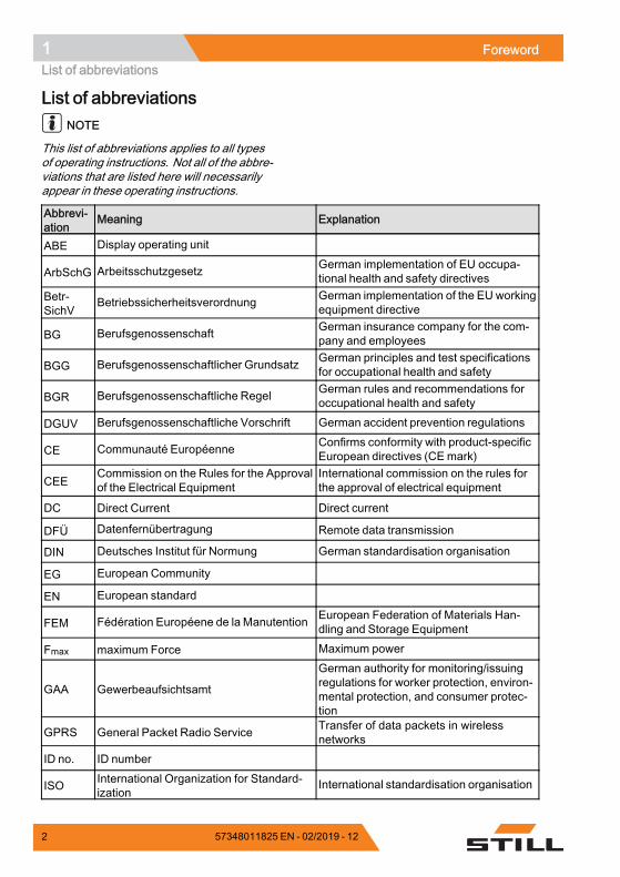
List of abbreviationsNOTE
This list of abbreviations applies to all typesof operating instructions. Not all of the abbre-viations that are listed here will necessarilyappear in these operating instructions.
Abbrevi-ation
Meaning Explanation
ABE Display operating unit
ArbSchG Arbeitsschutzgesetz German implementation of EU occupa-tional health and safety directives
Betr-SichV
Betriebssicherheitsverordnung German implementation of the EU workingequipment directive
BG Berufsgenossenschaft German insurance company for the com-pany and employees
BGG Berufsgenossenschaftlicher Grundsatz German principles and test specificationsfor occupational health and safety
BGR Berufsgenossenschaftliche Regel German rules and recommendations foroccupational health and safety
DGUV Berufsgenossenschaftliche Vorschrift German accident prevention regulations
CE Communauté Européenne Confirms conformity with product-specificEuropean directives (CEmark)
CEECommission on the Rules for the Approvalof the Electrical Equipment
International commission on the rules forthe approval of electrical equipment
DC Direct Current Direct current
DFÜ Datenfernübertragung Remote data transmission
DIN Deutsches Institut für Normung German standardisation organisation
EG European Community
EN European standard
FEM Fédération Européene de la Manutention European Federation of Materials Han-dling and Storage Equipment
Fmax maximum Force Maximum power
GAA Gewerbeaufsichtsamt
German authority for monitoring/issuingregulations for worker protection, environ-mental protection, and consumer protec-tion
GPRS General Packet Radio Service Transfer of data packets in wirelessnetworks
ID no. ID number
ISO International Organization for Standard-ization
International standardisation organisation
2 57348011825 EN - 02/2019 - 12
Foreword 1Your truck
Abbrevi-ation
Meaning Explanation
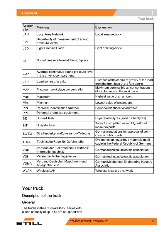
LAN Local Area Network Local area network
KpAUncertainty of measurement of soundpressure levels
LED Light Emitting Diode Light emitting diode
Lp Sound pressure level at the workplace
LpAZAverage continuous sound pressure levelin the driver's compartment
LSP Load centre of gravity Distance of the centre of gravity of the loadfrom the front face of the fork backs
MAK Maximumworkplace concentration Maximum permissible air concentrationsof a substance at the workplace
Max. Maximum Highest value of an amount
Min. Minimum Lowest value of an amount
PIN Personal Identification Number Personal identification numberPPE Personal protective equipment
SE Super-Elastic Superelastic tyres (solid rubber tyres)
SIT Snap-In Tyre Tyres for simplified assembly, withoutloose rim parts
StVZO Straßenverkehrs-Zulassungs-Ordnung German regulations for approval of vehi-cles on public roads
TRGS Technische Regel für Gefahrstoffe Ordinance on hazardous materials appli-cable in the Federal Republic of Germany
VDE Verband der Elektrotechnik ElektronikInformationstechnik German technical/scientific association
VDI Verein Deutscher Ingenieure German technical/scientific association
VDMAVerband Deutscher Maschinen- undAnlagenbau e.V.
GermanMechanical Engineering IndustryAssociation
WLAN Wireless LAN Wireless local area network.
Your truckDescription of the truck
GeneralThe trucks in the RX70-40/45/50 series witha load capacity of up to 5 t are equipped with
57348011825 EN - 02/2019 - 12 3
1 ForewordYour truck
an internal combustion engine/electric drive.This drive combines the advantages of theinternal combustion engine with the precisecontrol of an electric drive. The maximumspeed is 22 km/h (without load).
The drive is suitable for outdoor use and alsofor use in well-ventilated halls in conjunctionwith a particle filter.
The bend-resistant and warp-resistant liftmast enables safe load handling, even withheavy loads. The comfortable driver's com-partment features the most up-to-date er-gonomic design to prevent signs of fatigueand increase safety.
The truck supports all functions of FleetMan-ager 4.0.
Brake system
The brake system of the truck comprises threedifferent brakes:• Service brake• Regenerative brake• Parking brake
The service brake is based on a wear-free,oil-immersed multi-disc brake. This multi-discbrake is used as the service brake for heavybraking or emergency braking with the brakepedal. In the normal working mode, theregenerative brake of the electric tractionmotor takes effect. The regenerative brakeconverts the acceleration energy of the truckinto electrical energy. This causes the truck todecelerate as soon as the accelerator pedalis released. Completely removing your footfrom the accelerator pedal causes the truck tobrake until it comes to a standstill. A parkingbrake ensures that the truck remains securelyin place when parked.
Hydraulic systemThe required oil volume flow is providedvia an adjustable hydraulic pump, which islinked to the internal combustion engine.The proportional valve technology providesparticularly sensitive movements and safehandling of the load. The hydraulic functions
4 57348011825 EN - 02/2019 - 12
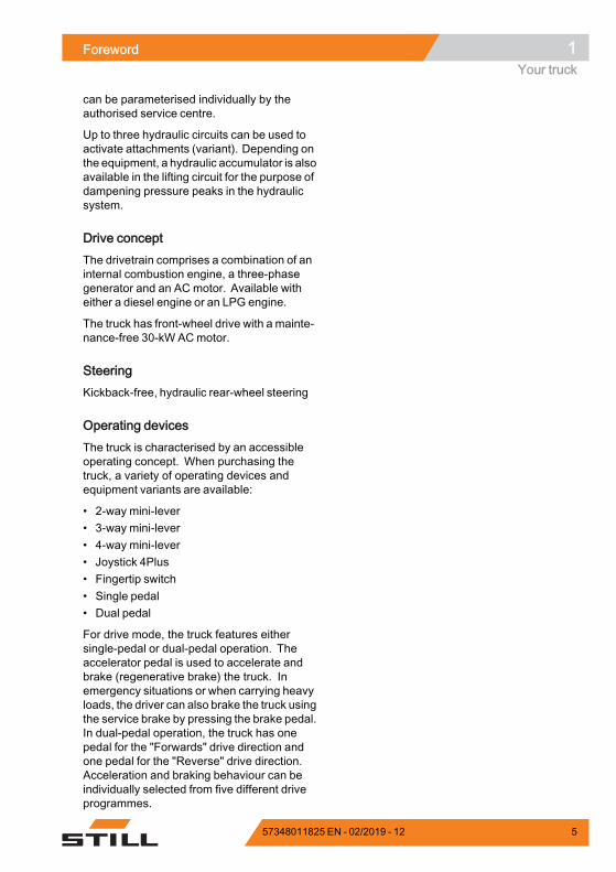
Foreword 1Your truck
can be parameterised individually by theauthorised service centre.
Up to three hydraulic circuits can be used toactivate attachments (variant). Depending onthe equipment, a hydraulic accumulator is alsoavailable in the lifting circuit for the purpose ofdampening pressure peaks in the hydraulicsystem.
Drive conceptThe drivetrain comprises a combination of aninternal combustion engine, a three-phasegenerator and an AC motor. Available witheither a diesel engine or an LPG engine.
The truck has front-wheel drive with a mainte-nance-free 30-kW ACmotor.
SteeringKickback-free, hydraulic rear-wheel steering
Operating devicesThe truck is characterised by an accessibleoperating concept. When purchasing thetruck, a variety of operating devices andequipment variants are available:
• 2-way mini-lever• 3-way mini-lever• 4-way mini-lever• Joystick 4Plus• Fingertip switch• Single pedal• Dual pedal
For drive mode, the truck features eithersingle-pedal or dual-pedal operation. Theaccelerator pedal is used to accelerate andbrake (regenerative brake) the truck. Inemergency situations or when carrying heavyloads, the driver can also brake the truck usingthe service brake by pressing the brake pedal.In dual-pedal operation, the truck has onepedal for the "Forwards" drive direction andone pedal for the "Reverse" drive direction.Acceleration and braking behaviour can beindividually selected from five different driveprogrammes.
57348011825 EN - 02/2019 - 12 5
1 ForewordYour truck
GeneralThe truck described in these operating instruc-tions corresponds to the applicable standardsand safety regulations.
If the truck is to be operated on public roads, itmust conform to the existing national regula-tions for the country in which it is being used.The driving permit must be obtained from theappropriate office.
The truck has been fitted with state-of-the-art technology. Following these operatinginstructions will allow the truck to be handledsafely. By complying with the specifications inthese operating instructions, the functionalityand the approved features of the truck will beretained.
Get to know the technology, understand itand use it safely - these operating instructionsprovide the necessary information and help toavoid accidents and to keep the truck ready foroperation beyond the warranty period.
Therefore:
– Before commissioning the truck, readthe operating instructions and follow theinstructions.
– Always follow all of the safety informationcontained in the operating instructions andon the truck.
CE-Symbol
CE labellingThe manufacturer uses CE labelling to indi-cate that the truck complies with the standardsand regulations valid at the time of marketing.This is confirmed by the issued EC declarationof conformity. The CE labelling is attached tothe nameplate.
An independent structural change or additionto the truck can compromise safety, thusinvalidating the EC declaration of conformity.
The EC declaration of conformity must becarefully stored and made available to theresponsible authorities.
6 57348011825 EN - 02/2019 - 12
Foreword 1Your truck
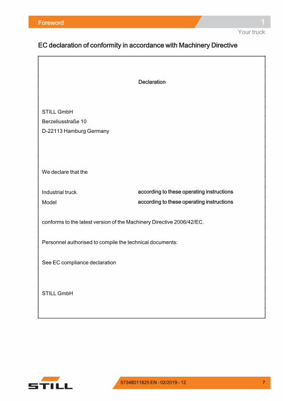
EC declaration of conformity in accordance with Machinery Directive
Declaration
STILL GmbH
Berzeliusstraße 10
D-22113 Hamburg Germany
We declare that the
Industrial truck according to these operating instructions
Model according to these operating instructions
conforms to the latest version of the Machinery Directive 2006/42/EC.
Personnel authorised to compile the technical documents:
See EC compliance declaration
STILL GmbH
.
57348011825 EN - 02/2019 - 12 7

1 ForewordYour truck
Accessories overview• Key for key switch (2 pieces)• Key for cab (variant)• Hexagon socket wrench for emergencylowering
8 57348011825 EN - 02/2019 - 12
Foreword 1Your truck
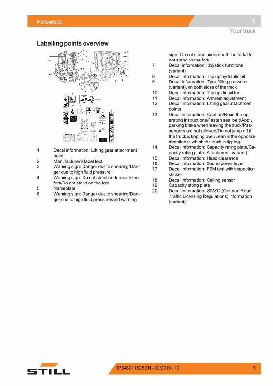
Labelling points overview
1 Decal information: Lifting gear attachmentpoint
2 Manufacturer's label text3 Warning sign: Danger due to shearing/Dan-
ger due to high fluid pressure4 Warning sign: Do not stand underneath the
fork/Do not stand on the fork5 Nameplate6 Warning sign: Danger due to shearing/Dan-
ger due to high fluid pressure/and warning
sign: Do not stand underneath the fork/Donot stand on the fork
7 Decal information: Joystick functions(variant)
8 Decal information: Top up hydraulic oil9 Decal information: Tyre filling pressure
(variant), on both sides of the truck10 Decal information: Top up diesel fuel11 Decal information: Armrest adjustment12 Decal information: Lifting gear attachment
points13 Decal information: Caution/Read the op-
erating instructions/Fasten seat belt/Applyparking brake when leaving the truck/Pas-sengers are not allowed/Do not jump off ifthe truck is tipping over/Lean in the oppositedirection to which the truck is tipping
14 Decal information: Capacity rating plate/Ca-pacity rating plate: Attachment (variant)
15 Decal information: Head clearance16 Decal information: Sound power level17 Decal information: FEM test with inspection
sticker18 Decal information: Ceiling sensor19 Capacity rating plate20 Decal information: StVZO (German Road
Traffic Licensing Regulations) information(variant)
57348011825 EN - 02/2019 - 12 9
1 ForewordYour truck
Type-Modèle-Typ / Serial no.-No. de série-Serien-Nr. / year-année-Baujahr
Rated capacityCapacité nominaleNenn-Tragfähigkeit
Battery voltageTension batterieBatteriespannung
Rated drive powerPuissance motr.nom.Nenn-Antriebsleist.
Unladen massMasse à videLeergewicht
maxmin.*
* see Operating instructions voir Mode d'emploi siehe Betriebsanleitung
kg kg
kgkg
kgkW
V
*
D-22113 HamburgBerzeliusstr. 10
1 2 3
44
56
7
910
111213
6210_921-003_V3
8
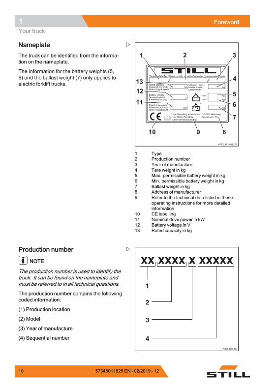
1 Type2 Production number3 Year of manufacture4 Tare weight in kg5 Max. permissible battery weight in kg6 Min. permissible battery weight in kg7 Ballast weight in kg8 Address of manufacturer9 Refer to the technical data listed in these
operating instructions for more detailedinformation
10 CE labelling11 Nominal drive power in kW12 Battery voltage in V13 Rated capacity in kg
NameplateThe truck can be identified from the informa-tion on the nameplate.
The information for the battery weights (5,6) and the ballast weight (7) only applies toelectric forklift trucks.
7090_921-004
xx xxxx x xxxxx
1
2
3
4
Production number
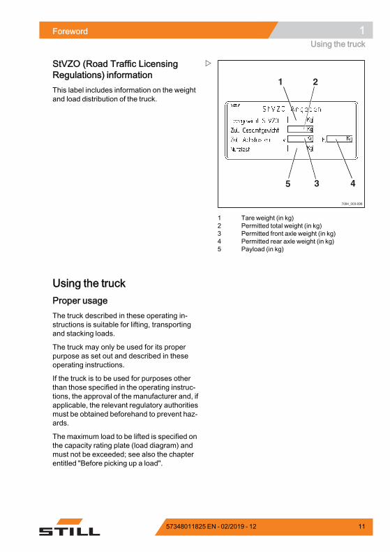
NOTE
The production number is used to identify thetruck. It can be found on the nameplate andmust be referred to in all technical questions.
The production number contains the followingcoded information:
(1) Production location
(2) Model
(3) Year of manufacture
(4) Sequential number
10 57348011825 EN - 02/2019 - 12
Foreword 1Using the truck
7094_003-098
1 2
3 45
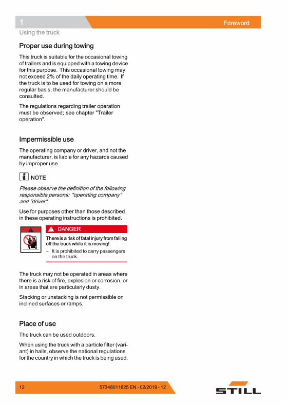
1 Tare weight (in kg)2 Permitted total weight (in kg)3 Permitted front axle weight (in kg)4 Permitted rear axle weight (in kg)5 Payload (in kg)
StVZO (Road Traffic LicensingRegulations) informationThis label includes information on the weightand load distribution of the truck.
Using the truckProper usageThe truck described in these operating in-structions is suitable for lifting, transportingand stacking loads.
The truck may only be used for its properpurpose as set out and described in theseoperating instructions.
If the truck is to be used for purposes otherthan those specified in the operating instruc-tions, the approval of the manufacturer and, ifapplicable, the relevant regulatory authoritiesmust be obtained beforehand to prevent haz-ards.
The maximum load to be lifted is specified onthe capacity rating plate (load diagram) andmust not be exceeded; see also the chapterentitled "Before picking up a load".
57348011825 EN - 02/2019 - 12 11
1 ForewordUsing the truck
Proper use during towingThis truck is suitable for the occasional towingof trailers and is equippedwith a towing devicefor this purpose. This occasional towing maynot exceed 2% of the daily operating time. Ifthe truck is to be used for towing on a moreregular basis, the manufacturer should beconsulted.
The regulations regarding trailer operationmust be observed; see chapter "Traileroperation".
Impermissible useThe operating company or driver, and not themanufacturer, is liable for any hazards causedby improper use.
NOTE
Please observe the definition of the followingresponsible persons: "operating company"and "driver".
Use for purposes other than those describedin these operating instructions is prohibited.
DANGERThere is a risk of fatal injury from fallingoff the truck while it is moving!– It is prohibited to carry passengers
on the truck.
The truck may not be operated in areas wherethere is a risk of fire, explosion or corrosion, orin areas that are particularly dusty.
Stacking or unstacking is not permissible oninclined surfaces or ramps.
Place of useThe truck can be used outdoors.
When using the truck with a particle filter (vari-ant) in halls, observe the national regulationsfor the country in which the truck is being used.
12 57348011825 EN - 02/2019 - 12
Foreword 1Using the truck
Operation on public roads is only permittedwith the "StVZO" (Road Traffic LicensingRegulations) equipment variant.
If the truck is to be operated on public roads, itmust conform to the existing national regula-tions for the country in which it is being used.
The ground must have an adequate loadcapacity (concrete, asphalt) and a roughsurface. Routes, working areas and aislewidths must conform to the specifications inthese operating instructions; see the chapterentitled "Routes".
Driving on upward and downward gradientsis permitted provided the specified data andspecifications are observed; see the chapterentitled "Routes".
The truck is suitable for use in many differentcountries, ranging from those situated in theTropics to those in Nordic regions (tempera-ture range: -20°C to +40°C).
This truck is not designed to be operated incold stores.
The operating company must ensure suitablefire protection for the relevant application inthe truck's surroundings. Depending on theapplication, additional fire protection must beprovided on the truck. If in doubt, contact therelevant authorities.
NOTE
Please observe the definition of the followingresponsible person: "operating company".
57348011825 EN - 02/2019 - 12 13
1 ForewordUsing the truck
DANGERRisk to health from exhaust gases!Exhaust gases from internal combustion enginesare harmful to your health. In particular, the sootparticles contained in the diesel exhaust gas cancause cancer. When the internal combustionengine is left running, there is a risk of poisoningdue to the CO, CH and NOx components containedin the exhaust gas.Modern exhaust gas treatment systems (e.g.catalytic converters, particle filters or comparablesystems) can clean exhaust gases in a way thatreduces the health hazard and risk of poisoningwhen operating the truck.– Observe the national laws and regulations when
using trucks with an internal combustion enginein entirely or partially enclosed working areas.
– Always ensure sufficient ventilation.
Using working platforms
WARNINGThe use of working platforms is regulated by na-tional law. The use of working platforms is onlypermitted by virtue of the jurisdiction in the countryof use.– Observe national legislation.– Before using working platforms, consult the
national regulatory authorities.
14 57348011825 EN - 02/2019 - 12
Foreword 1Information about the documentation
Information about the documentationDocumentation scope• Original operating instructions• Original operating instructions for attach-ments (variant)
• Spare parts list• Depending on the truck equipment, "UPA"operating instructionsmay also be provided
NOTE
Refer to the additional information in thesection entitled "Rules for the operatingcompany of industrial trucks".
These operating instructions describe allmeasures necessary for the safe operationand proper maintenance of the truck in allpossible variants available at the time ofprinting. Special versions to meet customerrequirements (UPA) are documented inseparate operating instructions. If you haveany questions, please contact your authorisedservice centre.
Enter the production number and year ofmanufacture from the nameplate in the spaceprovided:
Production number:
Year of manufacture:
Please quote the production number in alltechnical enquiries.
Each truck comes with a set of operatinginstructions. These instructions must bestored carefully and must be available to thedriver and operating company at all times.The storage location is specified in the chapterentitled "Overviews".
If the operating instructions are lost, the op-erating company must obtain a replacementfrom the manufacturer immediately.
The operating instructions are included in thespare parts list and can be reordered as aspare part.
57348011825 EN - 02/2019 - 12 15
1 ForewordInformation about the documentation
The personnel responsible for operating andmaintaining the equipment must be familiarwith these operating instructions.
The operating company must ensure that allusers have received, read and understoodthese operating instructions.
Safely store the complete documentation andpass on to the subsequent operating companywhen transferring or selling the truck.
NOTE
Please observe the definition of the followingresponsible persons: "operating company"and "driver".
Thank you for reading and complying withthese operating instructions. If you have anyquestions or suggestions for improvements,or if you have found any errors, please contactthe authorised service centre.
Supplementary documentationThis industrial truck can be fitted with un-planned equipment (UPA) that deviates fromthe standard equipment and/or the variants.
The UPAmay be, for example:• Special sensors• Special attachments• Towing devices• Customised attachments
In this case, the industrial truck has additionaldocumentation. This may be in the form of aninsert or separate operating instructions.
The original operating instructions for thisindustrial truck are valid for the operationof standard equipment and variants withoutrestriction. The operational and safety infor-mation in the original operating instructionscontinues to be valid in its entirety unless it iscountermanded in this additional documenta-tion.
The requirements for the qualification ofpersonnel as well as the time for maintenance
16 57348011825 EN - 02/2019 - 12
Foreword 1Information about the documentation
may vary. This is defined in the additionaldocumentation.
– If you have any questions, please contactyour authorised service centre.
Issue date and topicality of theoperating instructionsThe issue date of these operating instructionscan be found on the title page.
STILL is constantly engaged in the furtherdevelopment of trucks. These operatinginstructions are subject to change, and anyclaims based on the information and/orillustrations contained in them cannot beasserted.
Please contact your authorised service centrefor technical support relating to your truck.
Copyright and trademark rightsThese instructions must not be reproduced,translated or made accessible to third par-ties—including as excerpts—except with theexpress written approval of the manufacturer.
Explanation of information symbolsused
DANGERIndicates procedures that must be strictly adheredto in order to prevent the risk of fatalities.
WARNINGIndicates procedures that must be strictly adheredto in order to prevent the risk of injuries.
CAUTIONIndicates procedures that must be strictly adheredto in order to prevent material damage and/ordestruction.
57348011825 EN - 02/2019 - 12 17

1 ForewordInformation about the documentation
NOTE
For technical requirements that requirespecial attention.
ENVIRONMENT NOTE
To prevent environmental damage.
List of abbreviations
NOTE
This list of abbreviations applies to all typesof operating instructions. Not all of the abbre-viations that are listed here will necessarilyappear in these operating instructions.
Abbrevi-ation
Meaning Explanation
ABE Display operating unit
ArbSchG Arbeitsschutzgesetz German implementation of EU occupa-tional health and safety directives
Betr-SichV
Betriebssicherheitsverordnung German implementation of the EU workingequipment directive
BG Berufsgenossenschaft German insurance company for the com-pany and employees
BGG Berufsgenossenschaftlicher Grundsatz German principles and test specificationsfor occupational health and safety
BGR Berufsgenossenschaftliche Regel German rules and recommendations foroccupational health and safety
DGUV Berufsgenossenschaftliche Vorschrift German accident prevention regulations
CE Communauté Européenne Confirms conformity with product-specificEuropean directives (CEmark)
CEECommission on the Rules for the Approvalof the Electrical Equipment
International commission on the rules forthe approval of electrical equipment
DC Direct Current Direct current
DFÜ Datenfernübertragung Remote data transmission
DIN Deutsches Institut für Normung German standardisation organisation
EG European Community
EN European standard
FEM Fédération Européene de la Manutention European Federation of Materials Han-dling and Storage Equipment
Fmax maximum Force Maximum power
18 57348011825 EN - 02/2019 - 12

Foreword 1Information about the documentation
Abbrevi-ation
Meaning Explanation
GAA Gewerbeaufsichtsamt
German authority for monitoring/issuingregulations for worker protection, environ-mental protection, and consumer protec-tion
GPRS General Packet Radio Service Transfer of data packets in wirelessnetworks
ID no. ID number
ISO International Organization for Standard-ization
International standardisation organisation
LAN Local Area Network Local area network
KpAUncertainty of measurement of soundpressure levels
LED Light Emitting Diode Light emitting diode
Lp Sound pressure level at the workplace
LpAZAverage continuous sound pressure levelin the driver's compartment
LSP Load centre of gravity Distance of the centre of gravity of the loadfrom the front face of the fork backs
MAK Maximumworkplace concentration Maximum permissible air concentrationsof a substance at the workplace
Max. Maximum Highest value of an amount
Min. Minimum Lowest value of an amount
PIN Personal Identification Number Personal identification numberPPE Personal protective equipment
SE Super-Elastic Superelastic tyres (solid rubber tyres)
SIT Snap-In Tyre Tyres for simplified assembly, withoutloose rim parts
StVZO Straßenverkehrs-Zulassungs-Ordnung German regulations for approval of vehi-cles on public roads
TRGS Technische Regel für Gefahrstoffe Ordinance on hazardous materials appli-cable in the Federal Republic of Germany
VDE Verband der Elektrotechnik ElektronikInformationstechnik German technical/scientific association
VDI Verein Deutscher Ingenieure German technical/scientific association
VDMAVerband Deutscher Maschinen- undAnlagenbau e.V.
GermanMechanical Engineering IndustryAssociation
WLAN Wireless LAN Wireless local area network.
57348011825 EN - 02/2019 - 12 19
1 ForewordInformation about the documentation
6210_001-031
4 2
3
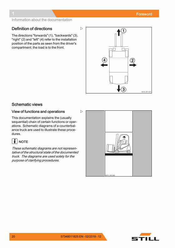
1Definition of directionsThe directions "forwards" (1), "backwards" (3),"right" (2) and "left" (4) refer to the installationposition of the parts as seen from the driver'scompartment; the load is to the front.
Schematic views
6210_003-062
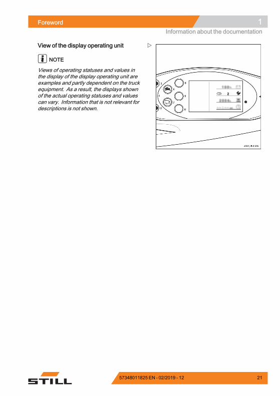
View of functions and operationsThis documentation explains the (usuallysequential) chain of certain functions or oper-ations. Schematic diagrams of a counterbal-ance truck are used to illustrate these proce-dures.
NOTE
These schematic diagrams are not represen-tative of the structural state of the documentedtruck. The diagrams are used solely for thepurpose of clarifying procedures.
20 57348011825 EN - 02/2019 - 12
Foreword 1Information about the documentation
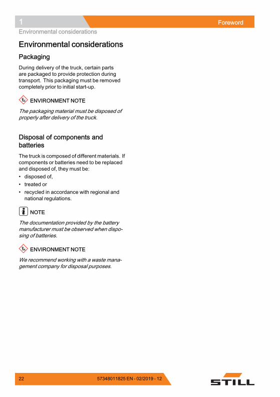
View of the display operating unit
NOTE
Views of operating statuses and values inthe display of the display operating unit areexamples and partly dependent on the truckequipment. As a result, the displays shownof the actual operating statuses and valuescan vary. Information that is not relevant fordescriptions is not shown.
57348011825 EN - 02/2019 - 12 21
1 ForewordEnvironmental considerations
Environmental considerationsPackagingDuring delivery of the truck, certain partsare packaged to provide protection duringtransport. This packaging must be removedcompletely prior to initial start-up.
ENVIRONMENT NOTE
The packaging material must be disposed ofproperly after delivery of the truck.
Disposal of components andbatteriesThe truck is composed of different materials. Ifcomponents or batteries need to be replacedand disposed of, they must be:• disposed of,• treated or• recycled in accordance with regional andnational regulations.
NOTE
The documentation provided by the batterymanufacturer must be observed when dispo-sing of batteries.
ENVIRONMENT NOTE
We recommend working with a waste mana-gement company for disposal purposes.
22 57348011825 EN - 02/2019 - 12

2
Safety
2 SafetyDefinition of terms used for responsible persons
Definition of terms used for responsible personsOperating companyThe operating company is the natural or legalperson or group who operates the truck or onwhose authority the truck is used.
The operating company must ensure that thetruck is only used for its proper purpose and incompliance with the safety regulations set outin these operating instructions.
The operating company must ensure thatall users read and understand the safetyinformation.
The operating company is responsible for thescheduling and correct performance of regularsafety checks.
We recommend that the national performancespecifications are adhered to.
SpecialistA qualified person is defined as a serviceengineer or a person who fulfils the followingrequirements:• A completed vocational qualification thatdemonstrably proves their professionalexpertise. This proof should consist ofa vocational qualification or a similardocument.
• Professional experience indicating thatthe qualified person has gained practicalexperience of industrial trucks over aproven period during their career Duringthis time, this person has become familiarwith a wide range of symptoms that requirechecks to be carried out, such as basedon the results of a hazard assessment or adaily inspection
• Recent professional involvement in thefield of the industrial truck test in questionand an appropriate further qualificationare essential. The qualified person musthave experience of carrying out the testin question or of carrying out similar tests.Moreover, this person must be aware ofthe latest technological developments
24 57348011825 EN - 02/2019 - 12
Safety 2Definition of terms used for responsible persons
regarding the industrial truck to be testedand the risk being assessed
DriversThis truck may only be driven by suitable per-sons who are at least 18 years of age, havebeen trained in driving, have demonstratedtheir skills in driving and handling loads tothe operating company or an authorised rep-resentative, and have been specifically in-structed to drive the truck. Specific knowledgeof the truck to be operated is also required.
The training requirements under §3 of theHealth and Safety at Work Act and §9 of theplant safety regulations are deemed to havebeen satisfied if the driver has been trained inaccordance with BGG (General Employers'Liability Insurance Association Act) 925.Observe the national regulations for yourcountry.
Driver rights, duties and rules of be-haviourThe driver must be trained in his rights andduties.
The drivermust be granted the required rights.
The driver must wear protective equipment(protection suit, safety footwear, safetyhelmet, industrial goggles and gloves) thatis appropriate for the conditions, the job andthe load to be lifted. Solid footwear should beworn to ensure safe driving and braking.
The driver must be familiar with the operatinginstructions and have access to them at alltimes.
The driver must:• have read and understood the operatingmanual
• have familiarised himself with safe opera-tion of the truck
• be physically and mentally able to drive thetruck safely
57348011825 EN - 02/2019 - 12 25
2 SafetyDefinition of terms used for responsible persons
DANGERThe use of drugs, alcohol or medications that affectreactions impair the ability to drive the truck!Individuals under the influence of the aforementio-ned substances are not permitted to perform workof any kind on or with the truck.
Prohibition of use by unauthorisedpersonsThe driver is responsible for the truck duringworking hours. He must not allow unautho-rised persons to operate the truck.
When leaving the truck, the drivermust secureit against unauthorised use, e.g. by pulling outthe key.
26 57348011825 EN - 02/2019 - 12
Safety 2Basic principles for safe operation
Basic principles for safe operationInsurance cover on companypremisesIn many cases, company premises arerestricted public traffic areas.
NOTE
The business liability insurance should bereviewed to ensure that, in the event of anydamage caused in restricted public trafficareas, there is insurance cover for the truck inrespect of third parties.
Changes and retrofittingIf the truck will be used for work that is notlisted in the directives or in these instructions,convert or retrofit the truck for this purposeas required. Any structural modification canimpair the handling and stability of the truck,and can result in accidents.
Any modifications that adversely affect thestability, the load capacity or the circumferen-tial view of the truck require written approvalfrom the manufacturer.
The following components may only bemodified with prior written approval from themanufacturer:• Brakes• Steering• Operating devices• Safety systems• Equipment variants• Attachments
The truck may only be converted with writtenapproval from the manufacturer. If necessary,obtain approval from the relevant authorities.
Only the authorised service centre is permittedto perform welding work on the truck.
We warn against installing and using restraintsystems not approved by the manufacturer.
– Contact the authorised service centrebefore converting or retrofitting the truck.
57348011825 EN - 02/2019 - 12 27
2 SafetyBasic principles for safe operation
DANGERRisk of injury if the truck tips over!Even if an approved restraint systemis in use, there is still a residual riskthat the driver could be injured if thetruck tips over. The risk of injury canbe reduced by using the restraintsystem in conjunction with the seatbelt. In addition, the seat belt protectsagainst the consequences of rear-endcollisions and falling off ramps.– Use the seat belt too.
DANGERRisk of fatal injury from falling load!There is a risk to the driver's life if the truck is notequipped with an overhead guard, as the drivermay be struck by a load falling from a lift height of1800 mm or greater.Operation of the forklift truck without an overheadguard is prohibited with a lift height greater than1800 mm.– At lift heights of 1800 mm and above, only use
the truck in conjunction with an overhead guard.
The operating company is only permitted tomakemodifications to the truck independentlyif the manufacturer goes into liquidation andthe company is not taken over by another legalperson.
The operating company must also fulfil thefollowing prerequisites:• Design documents, test documents andassembly instructions associated with themodification must be permanently archivedand remain accessible at all times.
• The capacity rating plate, the decal informa-tion, the hazard warnings and the operatinginstructions must be checked to ensure thatthey are consistent with the modificationsand must be amended if required.
• Modifications must be designed, checkedand implemented by a design office thatspecialises in industrial trucks. The designoffice must comply with the standards anddirectives valid at the time thatmodificationsare made.
28 57348011825 EN - 02/2019 - 12
Safety 2Basic principles for safe operation
Decal information with the following data mustbe permanently affixed to the truck so that it isclearly visible:• Type of modification• Date of modification• Name and address of the company thatcarried out the modification
Changes to the overhead guard androof loads
DANGERIn the event of the overhead guard failing due toa falling load or the truck tipping over, there arepotentially fatal consequences for the driver. Thereis a risk to life!Welding and drilling on the overhead guard chan-ges the material characteristics and the structuraldesign of the overhead guard. Excessive forcescaused by falling loads or the truck tipping overmayresult in buckling of the modified overhead guardand no protection for the driver.– Do not perform welding on the overhead guard.– Do not perform drilling on the overhead guard.
CAUTIONHeavy roof loads damage the overhead guard!To ensure the stability of the overhead guard atall times, a roof load may only be mounted on theoverhead guard if the structural design has beentested and the manufacturer has given approval.– Seek advice from the authorised service centre
for the mounting of roof loads.
Warning regarding non-original partsOriginal parts, attachments and accessoriesare specially designed for this truck. Wespecifically draw your attention to the fact thatparts, attachments and accessories suppliedby other companies have not been tested andapproved by STILL.
57348011825 EN - 02/2019 - 12 29
2 SafetyBasic principles for safe operation
CAUTIONInstallation and/or use of such products may there-fore have a negative impact on the design featuresof the truck and thus impair active and/or passivedriving safety.We recommend that you obtain approval from themanufacturer and, if necessary, from the relevantregulatory authorities before installing such parts.The manufacturer accepts no liability for any da-mage caused by the use of non-original parts andaccessories without approval.
Damage, defects and misuse ofsafety systemsDamage or other defects on the truck orattachment must be reported to the supervisoror responsible fleet manager immediately sothat they can have the defect rectified.
Trucks and attachments that are not functionalor safe to drivemay not be used until they havebeen properly repaired.
Do not remove or deactivate safety systemsand switches.
Fixed set valuesmay only be changedwith theapproval of the manufacturer.
Work on the electrical system (e.g. connectinga radio, additional headlights etc.) is onlypermitted with the manufacturer's writtenapproval. All electrical system interventionsmust be documented.
Even if they are removable, roof panels maynot be removed, as they are designed toprotect against small falling objects.
Length of the fork arms
DANGERRisk of accident due to the incorrect selection offork arms!– The fork armsmust match the depth of the load.
If the fork arms are too short, the load mayfall off the arms after it has been picked up.In addition, be aware that the load centre of
30 57348011825 EN - 02/2019 - 12
Safety 2Basic principles for safe operation
gravity may shift as a result of dynamic forces,such as braking. A load that is otherwiseresting safely on the fork arms may moveforwards and fall.
If the fork arms are too long, they can catchon loading units behind the load that is to bepicked up. These other loading units then fallover when the load is raised.
– For helpwith selecting the correct fork arms,contact the authorised service centre.
Tyres
DANGERRisk to stability!Failure to observe the following information andinstructions can lead to a loss of stability. The truckmay tip over, risk of accident!
The following factors can lead to a loss ofstability and are therefore prohibited:• Different tyres on the same axle, e.g.pneumatic tyres and superelastic tyres
• Tyres not approved by the manufacturer• Excessive tyre wear• Tyres of inferior quality• Changing rim wheel parts• Combining rim wheel parts from differentmanufacturers
The following rules must be observed toensure stability:• Only use tyres with equal and permittedlevels of wear on the same axle
• Only use wheels and tyres of the same typeon the same axle, e.g. only superelastictyres
• Only use wheels and tyres approved by themanufacturer
• Only use high-quality products
Wheels and tyres approved by the manu-facturer can be found on the spare parts list.If other wheels or tyres are to be used, au-thorisation from the manufacturer must beobtained beforehand.
57348011825 EN - 02/2019 - 12 31
2 SafetyBasic principles for safe operation
– Contact the authorised service centre onthis matter.
When changing wheels or tyres, alwaysensure that this does not cause the truck totilt to one side (e.g. always replace right-hand and left-hand wheels at the sametime). Changes must only be made followingconsultation with the manufacturer.
If the type of tyre used on an axle is changed,for example from superelastic tyres to pneu-matic tyres, the loaddiagrammust be changedaccordingly.
– Contact the authorised service centre onthis matter.
Medical equipment
WARNINGElectromagnetic interferencemayoccur onmedicaldevices!Only use equipment that is sufficiently protectedagainst electromagnetic interference.
Medical equipment, such as pacemakers orhearing aids, may not work properly when thetruck is in operation.
– Ask your doctor or the manufacturer ofthe medical equipment to confirm that themedical equipment is sufficiently protectedagainst electromagnetic interference.
32 57348011825 EN - 02/2019 - 12
Safety 2Basic principles for safe operation
Exercise caution when handling gassprings and accumulators
WARNINGGas springs are under high pressure. Improperremoval results in an elevated risk of injury.For ease of operation, various functions on thetruck can be supported by gas springs. Gas springsare complex components that are subject to highinternal pressures (up to 300 bar). They may underno circumstances be opened unless instructed todo so, and may be installed only when not underpressure. If required, the authorised service centrewill depressurise the gas spring in accordance withthe regulations before removal. Gas springs mustbe depressurised before recycling.– Avoid damage, lateral forces, buckling, tempe-
ratures over 80°C and heavy contamination.– Damaged or defective gas springs must be
changed immediately.– Contact the authorised service centre.
WARNINGAccumulators are under high pressure. Improperinstallation of an accumulator results in an elevatedrisk of injury.Before starting work on the accumulator it must bedepressurised.– Contact the authorised service centre.
Length of the fork arms
DANGERRisk of accident due to the incorrect selection offork arms!– The fork armsmust match the depth of the load.
If the fork arms are too short, the load mayfall off the arms after it has been picked up.In addition, be aware that the load centre ofgravity may shift as a result of dynamic forces,such as braking. A load that is otherwiseresting safely on the fork arms may moveforwards and fall.
If the fork arms are too long, they can catchon loading units behind the load that is to be
57348011825 EN - 02/2019 - 12 33

2 SafetyBasic principles for safe operation
picked up. These other loading units then fallover when the load is raised.
– For helpwith selecting the correct fork arms,contact the authorised service centre.
34 57348011825 EN - 02/2019 - 12
Safety 2Residual risk
Residual riskResidual dangers, residual risksDespite careful working and compliance withstandards and regulations, the occurrenceof other risks when using the truck cannot beentirely excluded.
The truck and all other system componentscomply with current safety requirements.Nevertheless, even when the truck is usedfor its proper purpose and all instructionsare followed, some residual risk cannot beexcluded.
Even beyond the narrow danger areas of thetruck itself, a residual risk cannot be excluded.Persons in this area around the truck mustexercise a heightened degree of awareness,so that they can react immediately in the eventof any malfunction, incident or breakdown etc.
WARNINGAll persons that are in the vicinity of the truckmust be instructed regarding these risks that arisethrough use of the truck.In addition, we draw attention to the safety regulati-ons in these operating instructions.
Risks can include:• Escape of consumables due to leakages,rupture of lines and containers etc.
• Risk of accident when driving over difficultground such as gradients, smooth orirregular surfaces, or with poor visibilityetc.
• Falling, tripping etc. when moving onthe truck, especially in wet weather, withleaking consumables or on icy surfaces
• Fire and explosion risks due to batteries andelectrical voltages
• Human error resulting from failure toobserve the safety regulations,
• Unrepaired damage or defective and worncomponents,
• Insufficient maintenance and testing• Use of incorrect consumables• Exceeding test intervals
57348011825 EN - 02/2019 - 12 35
2 SafetyResidual risk
The manufacturer is not held responsible foraccidents involving the truck caused by thefailure of the operating company to complywith these regulations either intentionally orcarelessly.
StabilityThe stability of the truck has been tested to thelatest technological standards and is guaran-teed provided that the truck is used properlyand according to its intended purpose. Thesestandards only take into account the dynamicand static tipping forces that can arise duringspecified use in accordance with the operat-ing rules and intended purpose. However, thedanger of exceeding the moment of tilt due toimproper use or incorrect operation and losingstability can never be excluded.
The loss of stability can be avoided or min-imised by the following actions:
– Always secure the load against slipping,e.g. by lashing.
– Always transport unstable loads in suitablecontainers.
– Always drive slowly when cornering.
– Drive with the load lowered.
– Even with sideshifts, align the load ascentrally as possible with the truck andtransport in this position.
– Avoid turning and diagonally driving acrossslopes or gradients.
– Never have the load facing downhill whentravelling on slopes or gradients.
– Pick up only loads of the approved width.
– Always take great care when transportingsuspended loads.
– Do not drive over ramp edges or steps.
Special risks associated with usingthe truck and attachmentsApproval from the manufacturer and attach-ment manufacturer must be obtained each
36 57348011825 EN - 02/2019 - 12
Safety 2Residual risk
time the truck is used in a manner that fallsoutside the scope of normal use, and in caseswhere the driver is not certain that he can usethe truck correctly and without the risk of acci-dents.
57348011825 EN - 02/2019 - 12 37
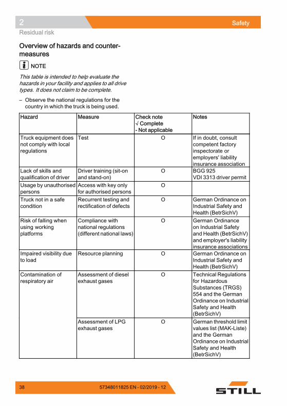
2 SafetyResidual risk
Overview of hazards and counter-measures
NOTE
This table is intended to help evaluate thehazards in your facility and applies to all drivetypes. It does not claim to be complete.
– Observe the national regulations for thecountry in which the truck is being used.
Hazard Measure Check note√ Complete- Not applicable
Notes
Truck equipment doesnot comply with localregulations
Test O If in doubt, consultcompetent factoryinspectorate oremployers' liabilityinsurance association
Lack of skills andqualification of driver
Driver training (sit-onand stand-on)
O BGG 925VDI 3313 driver permit
Usage by unauthorisedpersons
Access with key onlyfor authorised persons
O
Truck not in a safecondition
Recurrent testing andrectification of defects
O German Ordinance onIndustrial Safety andHealth (BetrSichV)
Risk of falling whenusing workingplatforms
Compliance withnational regulations(different national laws)
O German Ordinanceon Industrial Safetyand Health (BetrSichV)and employer's liabilityinsurance associations
Impaired visibility dueto load
Resource planning O German Ordinance onIndustrial Safety andHealth (BetrSichV)
Assessment of dieselexhaust gases
O Technical Regulationsfor HazardousSubstances (TRGS)554 and the GermanOrdinance on IndustrialSafety and Health(BetrSichV)
Contamination ofrespiratory air
Assessment of LPGexhaust gases
O German threshold limitvalues list (MAK-Liste)and the GermanOrdinance on IndustrialSafety and Health(BetrSichV)
38 57348011825 EN - 02/2019 - 12
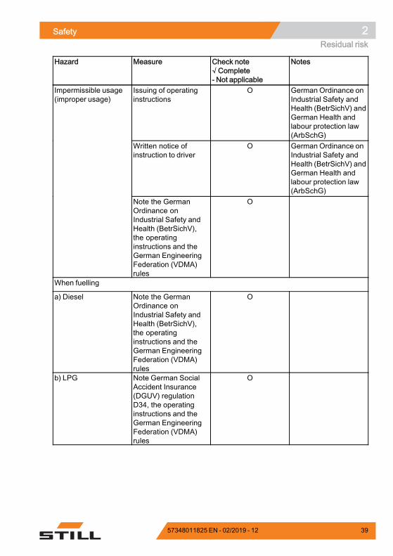
Safety 2Residual risk
Hazard Measure Check note√ Complete- Not applicable
Notes
Issuing of operatinginstructions
O German Ordinance onIndustrial Safety andHealth (BetrSichV) andGerman Health andlabour protection law(ArbSchG)
Written notice ofinstruction to driver
O German Ordinance onIndustrial Safety andHealth (BetrSichV) andGerman Health andlabour protection law(ArbSchG)
Impermissible usage(improper usage)
Note the GermanOrdinance onIndustrial Safety andHealth (BetrSichV),the operatinginstructions and theGerman EngineeringFederation (VDMA)rules
O
When fuelling
a) Diesel Note the GermanOrdinance onIndustrial Safety andHealth (BetrSichV),the operatinginstructions and theGerman EngineeringFederation (VDMA)rules
O
b) LPG Note German SocialAccident Insurance(DGUV) regulationD34, the operatinginstructions and theGerman EngineeringFederation (VDMA)rules
O
57348011825 EN - 02/2019 - 12 39
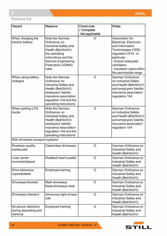
2 SafetyResidual risk
Hazard Measure Check note√ Complete- Not applicable
Notes
When charging thetraction battery
Note the GermanOrdinance onIndustrial Safety andHealth (BetrSichV),the operatinginstructions and theGerman EngineeringFederation (VDMA)rules
O Association forElectrical, Electronicand InformationTechnologies (VDE)regulation 0510: Inparticular- Ensure adequateventilation- Insulation value withinthe permissible range
When using batterychargers
Note the GermanOrdinance onIndustrial Safety andHealth (BetrSichV),employers' liabilityinsurance associationregulation 104 and theoperating instructions
O German Ordinanceon Industrial Safetyand Health (BetrSichV)and employers' liabilityinsurance associationregulation 104
When parking LPGtrucks
Note the GermanOrdinance onIndustrial Safety andHealth (BetrSichV),employers' liabilityinsurance associationregulation 104 and theoperating instructions
O German Ordinanceon Industrial Safetyand Health (BetrSichV)and employers' liabilityinsurance associationregulation 104
With driverless transport systems
Roadway qualityinadequate
Clean/clear driveways O German Ordinance onIndustrial Safety andHealth (BetrSichV)
Load carrierincorrect/slipped
Reattach load to pallet O German Ordinance onIndustrial Safety andHealth (BetrSichV)
Drive behaviourunpredictable
Employee training O German Ordinance onIndustrial Safety andHealth (BetrSichV)
Driveways blocked Mark drivewaysKeep driveways clear
O German Ordinance onIndustrial Safety andHealth (BetrSichV)
Driveways intersect Announce right-of-wayrule
O German Ordinance onIndustrial Safety andHealth (BetrSichV)
No person detectionduring depositing andretrieval
Employee training O German Ordinance onIndustrial Safety andHealth (BetrSichV)
.
40 57348011825 EN - 02/2019 - 12
Safety 2Residual risk
Danger to employeesAccording to the GermanOrdinance on Indus-trial Safety and Health (BetrSichV) and labourprotection law (ArbSchG), the operating com-pany must determine and assess hazardsduring operation, and establish the labourprotection measures required for employ-ees (BetrSichVO). The operating companymust therefore draw up appropriate operatinginstructions (§ 6 ArbSchG) and make themavailable to the driver. A responsible personmust be appointed.
NOTE
Please observe the definition of the followingresponsible persons: "operating company"and "driver".
The construction and equipment of thetruck correspond to the Machinery Directive2006/42/EC and are therefore marked withCE labelling. These elements are thereforenot included in the hazard assessment. At-tachments possess their own CE labelling andlikewise are not included for that reason. Theoperating company must, however, select thetype and equipment of the trucks so as to com-ply with the local provisions for deployment.
The result must be documented (§ 6 Arb-SchG). In the case of truck applications involv-ing similar hazard situations, the results maybe summarised. This overview (see chapter"Overview of hazards and countermeasures")provides help on complying with this regula-tion. The overview specifies the main hazardsthat are the most frequent cause of accidentsin the event of non-compliance. If other majoroperational hazards are involved, they mustalso be taken into consideration.
The conditions of use for trucks are broadlysimilar in many plants, so the hazards canbe summarised in one overview. Observethe information provided by the relevantemployers' liability insurance association onthis subject.
57348011825 EN - 02/2019 - 12 41
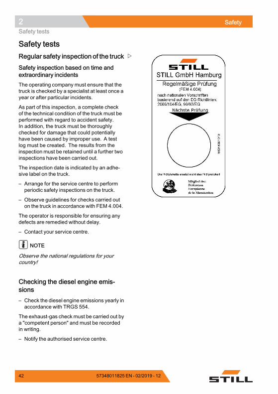
2 SafetySafety tests
Safety testsRegular safety inspection of the truck
Safety inspection based on time andextraordinary incidentsThe operating company must ensure that thetruck is checked by a specialist at least once ayear or after particular incidents.
As part of this inspection, a complete checkof the technical condition of the truck must beperformed with regard to accident safety.In addition, the truck must be thoroughlychecked for damage that could potentiallyhave been caused by improper use. A testlog must be created. The results from theinspection must be retained until a further twoinspections have been carried out.
The inspection date is indicated by an adhe-sive label on the truck.
– Arrange for the service centre to performperiodic safety inspections on the truck.
– Observe guidelines for checks carried outon the truck in accordance with FEM 4.004.
The operator is responsible for ensuring anydefects are remedied without delay.
– Contact your service centre.
NOTE
Observe the national regulations for yourcountry!
Checking the diesel engine emis-sions– Check the diesel engine emissions yearly inaccordance with TRGS 554.
The exhaust-gas checkmust be carried out bya "competent person" and must be recordedin writing.
– Notify the authorised service centre.
42 57348011825 EN - 02/2019 - 12
Safety 2Safety tests
NOTE
Observe the national regulations for thecountry in which the truck is being used.
Trucks with particle filtersTrucks with particle filters (variant) may beoperated in entirely or partially enclosedworking areas.
DANGERRisk to health from exhaust gases! Exhaust gasesfrom internal combustion engines are harmfulto your health. In particular, the soot particlescontained in the diesel exhaust gas can causecancer. When the internal combustion engine is leftrunning, there is a risk of poisoning due to the CO,CH and NOx components present in the exhaustgas.Modern exhaust gas treatment systems (e.g.catalytic converters, particle filters or comparablesystems) can clean exhaust gases in a way thatreduces the health hazard and risk of poisoningwhen operating the truck.– Observe the national laws and regulations when
using trucks fitted with an internal combustionengine in entirely or partially enclosed workingareas.
– Always ensure sufficient ventilation.
NOTE
Observe the national regulations of thecountry in which the truck is being used!
The operating company must ensure thatthe following requirements are met; seechapter entitled "Definition of terms used forresponsible persons":• Usage must be reported to the responsibleoccupational health and safety authorities.
• Operating instructions must be displayed inthe working areas.
• Danger areas should be confined andindicated by appropriate warning and safetysigns.
• Employeesmust bemadeaware of dangersand protective measures.
• The particle filter must be changed every6000 operating hours. The exhaust-gas
57348011825 EN - 02/2019 - 12 43
2 SafetySafety tests
check must be carried out by a specialist(see chapter entitled "Definition of termsused for responsible persons") and must berecorded in writing.
NOTE
Observe the TRGS 554 regulations and thenational regulations of the country in which thetruck is being used.
Insulation testingThe truck insulation must have sufficient insu-lation resistance. For this reason, insulationtesting in accordance with DIN EN 1175 andDIN 43539, VDE 0117 and VDE 0510must beconducted at least once every year.
NOTE
Contact your service centre to arrange for aninsulation test.
Measuring the insulation resistance ofthe electrical system
NOTE
Nominal battery voltage < test voltage < 500V.
– Ensure that all voltage sources have beendisconnected from the circuit to be tested.
– Measure the insulation resistance with asuitable measuring device.
The insulation resistance can be consideredsufficient if it measures at least 1000 Ω/V fornominal battery voltage against ground.
– Contact the authorised service centre.
44 57348011825 EN - 02/2019 - 12
Safety 2Safety regulations for handling consumables
Safety regulations for handling consumablesPermissible consumables
DANGERFailure to observe the safety regulations relating toconsumables may result in a risk of injury, death ordamage to the environment.– Observe the safety regulations when handling
such materials.
Refer to the maintenance data table for thepermissible substances that are necessary foroperation (see ⇒ Chapter "Maintenance datatable", P. 5-318).
Oils
DANGEROils are flammable!– Follow the statutory regulations.– Do not allow oils to come into
contact with hot engine parts.– No smoking, fires or naked flames!
DANGEROils are toxic!– Avoid contact and consumption.– If vapour or fumes are inhaled,
move to fresh air immediately.– In the event of contact with the
eyes, rinse thoroughly (for at least10 minutes) with water and thenconsult an eye specialist.
– If swallowed, do not inducevomiting. Seek immediate medicalattention.
57348011825 EN - 02/2019 - 12 45
2 SafetySafety regulations for handling consumables
WARNINGProlonged intensive contact with theskin can result in dryness and irritatethe skin!– Avoid contact and consumption.– Wear protective gloves.– After any contact, wash the skin
with soap andwater, and thenapplya skin care product.
– Immediately change soakedclothing and shoes.
WARNINGThere is a risk of slipping on spilled oil, particularlywhen combined with water!– Spilt oil should be removed immediately with
oil-binding agents and disposed of according tothe regulations.
ENVIRONMENT NOTE
Oil is a water-polluting substance!• Always store oil in containers that complywith the applicable regulations.
• Avoid spilling oils.• Spilt oil should be removed immediatelywith oil-binding agents and disposed ofaccording to the regulations.
• Dispose of old oils according to the regula-tions.
Hydraulic fluid
WARNINGThese fluids are pressurised duringoperation of the truck and are hazar-dous to your health.– Do not spill the fluids.– Follow the statutory regulations.– Do not allow the fluids to come into
contact with hot engine parts.
46 57348011825 EN - 02/2019 - 12
Safety 2Safety regulations for handling consumables
WARNINGThese fluids are pressurised duringoperation of the truck and are hazar-dous to your health.– Do not allow the fluids to come into
contact with the skin.– Avoid inhaling spray.– Penetration of pressurised fluids
into the skin is particularly danger-ous if these fluids escape at highpressure due to leaks in the hydrau-lic system. In case of such injury,immediate medical assistance isrequired.
– To avoid injury, use appropriatepersonal protective equipment(e.g. protective gloves, industrialgoggles, skin protection and skincare products).
ENVIRONMENT NOTE
Hydraulic fluid is a water-polluting substance.• Always store hydraulic fluid in containersthat comply with regulations
• Avoid spills• Spilt hydraulic fluid should be removedimmediately with oil-binding agents anddisposed of according to the regulations
• Dispose of old hydraulic fluid according tothe regulations
Battery acid
WARNINGBattery acid contains dissolvedsulphuric acid. This is toxic.– Avoid touching or swallowing the
battery acid at all costs.– In case of injury, seek medical
advice immediately.
57348011825 EN - 02/2019 - 12 47
2 SafetySafety regulations for handling consumables
WARNINGBattery acid contains dissolvedsulphuric acid. This is corrosive.– When working with battery acid,
use appropriate PSA (rubbergloves, apron, protection goggles).
– When working with battery acid,never wear a watch or jewellery.
– Do not allow any acid to getonto clothing or skin or into theeyes. If this does happen, rinseimmediately with plenty of cleanwater.
– In case of injury, seek medicaladvice immediately.
– Immediately rinse away spiltbattery acid with plenty of water.
– Follow the statutory regulations.
ENVIRONMENT NOTE
– Dispose of used battery acid in line with theapplicable regulations.
Diesel fuel
WARNINGDiesel fuel is combustible.– Observe statutory regulations.– Do not allow diesel fuel to come
into contact with hot enginecomponents.
Do not smoke!
WARNINGDiesel fuel is toxic!– Avoid contact and swallowing.– If vapour or fumes are inhaled,
administer fresh air immediately.– After contact with the eyes, rinse
thoroughly (for at least 10 minutes)with water and then consult an eyespecialist.
– If swallowed, do not inducevomiting. Seek immediate medicalattention.
48 57348011825 EN - 02/2019 - 12
Safety 2Safety regulations for handling consumables
WARNINGProlonged intensive contact with theskin can result in loss of skin oils andcan irritate the skin!– Avoid contact and swallowing.– Wear protective gloves.– After any contact, wash the skin
with soap andwater, and then applya skin care product.
– Immediately change soakedclothing and shoes.
WARNINGRisk of slipping due to spilled diesel fuel, particularlyin combination with water.– Immediately collect spilled diesel fuel using an
oil-binding agent and dispose of it in accordancewith regulations.
ENVIRONMENT NOTE
Diesel fuel is a water-polluting substance!
– Always store in regulation containers.
– Avoid spilling diesel fuel.
– Immediately collect spilled diesel fuel usingan oil-binding agent and dispose of it inaccordance with regulations.
57348011825 EN - 02/2019 - 12 49
2 SafetySafety regulations for handling consumables
Coolant and cooling fluid
WARNINGCoolant and cooling fluid can behazardous to your health and theenvironment!Coolants are chemical corrosion inhi-bitors and cooling system protectingagents such as Glysantin. The coo-ling fluid is an appropriate mixture ofwater and coolant. Coolant in bothconcentrated and dilute form can behazardous to your health if swallowed,or hazardous to the environment ifspilled.– Store coolant and cooling fluid only
in their original containers and donot spill them.
– Never store coolant or cooling fluidin empty food containers, bottles orother containers.
– Observe the national regulationsfor the country of use.
ENVIRONMENT NOTE
– Soak up any spilt coolant or cooling fluidimmediately using an oil binding agent anddispose of it in accordance with the nationalregulations for the country of use.
– Dispose of old coolant or cooling fluid inaccordance with the national regulations forthe country of use.
Disposal of consumables
ENVIRONMENT NOTE
Materials that accumulate during repair,maintenance and cleaning must be collectedproperly and disposed of in accordance withthe national regulations for the country inwhich the truck is being used. Work mustonly be carried out in areas designated for thepurpose. Care must be taken to minimise anyenvironmental pollution.
– Soak up any spilt fluids such as hydraulicoil, brake fluid or gearbox oil using anoil-binding agent.
50 57348011825 EN - 02/2019 - 12
Safety 2Safety regulations for handling consumables
– Neutralise any spilt battery acid immedi-ately.
– Always observe national regulations con-cerning the disposal of used oil.
57348011825 EN - 02/2019 - 12 51
2 SafetyEmissions
EmissionsThe values specified apply to a standard truck(see technical datasheet). Different tyres,lift masts, additional units etc. may producedifferent values.
Noise emissionsThe values were determined on the basis ofmeasuring procedures from the EN 12053standard (noise measurement for industrialtrucks based on EN 12001 and EN ISO 3744and the requirements of EN ISO 4871).
Continuous sound pressure level in driver'scompartmentLpAZ1 < 75 dB(A)
Uncertainty KpA 4 dB(A)
1: higher continuous sound pressure level withcab/without cab
The values were determined in the test cycleon an identical machine from the weightedvalues for operating statuses and idling.
Time proportions:
• Lifting 18%• Idling 58%• Driving 24%
However, the specifiednoise levels in the truckcannot be used to determine the noise emis-sions in the workplace in accordance with themost recent version of Directive 2003/10/EC(daily personal noise pollution). If necessary,these should be determined directly at theworkplace under the actual conditions there(additional noise sources, special applicationconditions, sound reflections) by the operatingcompany; (see ⇒ Chapter "Definition of termsused for responsible persons", P. 24).
VibrationsThe vibrations of the machine have beendetermined on an identical machine in ac-cordance with the standards DIN EN 13059"Safety of industrial trucks - Test methodsfor measuring vibration" and DIN EN 12096
"Mechanical vibration - Declaration and verifi-cation of vibration emission values".
Weighted effective value ofacceleration to which thebody (feet or seat surface)is subjected
< 0.59 m/s2
Uncertainty K 0.177 m/s2
Tests have indicated that the amplitude of thehand and arm vibrations on the steering wheelor on the controls in the truck is less than 2.5m/s 2. There are therefore no measurementguidelines for these measurements.
The personal vibration load on the driver overa working day shall be determined in accor-dance with the Directive 2002/44/EC by theoperating company (see ⇒Chapter "Definitionof terms used for responsible persons", P. 24)at the actual place of use, in order to considerall additional influences, such as driving route,intensity of use etc.
Exhaust gases
CAUTIONRisk to health from exhaust gases! Exhaust gasesfrom internal combustion engines are harmfulto your health. In particular, the soot particlescontained in the diesel exhaust gas can causecancer. When the internal combustion engine is leftrunning, there is a risk of poisoning due to the CO,CH and NOx components present in the exhaustgas.Modern exhaust gas treatment systems (e.g.catalytic converters, particle filters or comparablesystems) can clean exhaust gases in a way thatreduces the health hazard and risk of poisoningwhen operating the truck.– Observe the national laws and regulations when
using trucks fitted with an internal combustionengine in entirely or partially enclosed workingareas.
– Always ensure sufficient ventilation.
The engine releases exhaust gases into thesurrounding environment during operation.The exhaust gases consist mainly of steam,carbon dioxide (CO2), carbonmonoxide (CO),hydrocarbons (CH), aldehydes, nitrogenoxide
52 57348011825 EN - 02/2019 - 12
Safety 2Emissions
(NOX) and soot. The components CO, CH,NOX and soot are poisonous or are healthhazards, and should not be inhaled at highconcentrations.
Diesel engine emissions
DANGERHealth risk as a result of inhaling exhaust gasesthat have not been filtered!A particle filter (exhaust gas purifier for dieselengines) can be used to clean exhaust gases sothat during truck operation there is no direct healthrisk or risk of poisoning as a result of the exhaustgas.– In working areas that are fully or partially enclo-
sed, only operate the truck with the particle filter.
Diesel engine emissions are harmful toyour health. The particles contained in theexhaust gases in particular are classified ascarcinogenic.
NOTE
Observe the national regulations for yourcountry.
Heat
DANGERRisk of burns caused by hot exhaustgases!Exhaust gases or components thatcarry exhaust gases (e.g. exhaustpipes) can become so hot that directbody contact can cause burns to theskin and materials that are too closecan be burned or singed.– Do not grasp or touch hot exhaust
pipes.– Keep combustible materials away
from the exhaust pipe.– In the event of burns, seek first aid
immediately.– If materials start to burn, take fire
protection measures immediately.
57348011825 EN - 02/2019 - 12 53

2 SafetyEmissions
54 57348011825 EN - 02/2019 - 12

3
Overviews
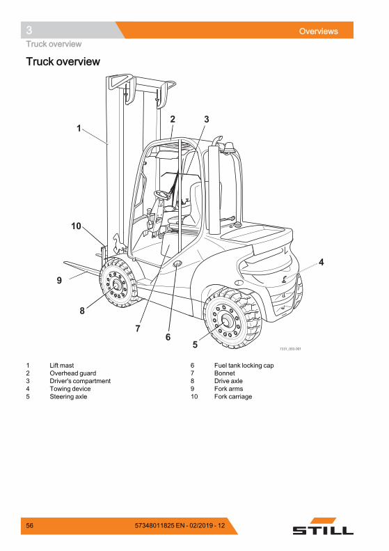
3 OverviewsTruck overview
Truck overview
7331_003-001
1
2
7
4
5
8
9
10
3
6
1 Lift mast2 Overhead guard3 Driver's compartment4 Towing device5 Steering axle
6 Fuel tank locking cap7 Bonnet8 Drive axle9 Fork arms10 Fork carriage
56 57348011825 EN - 02/2019 - 12
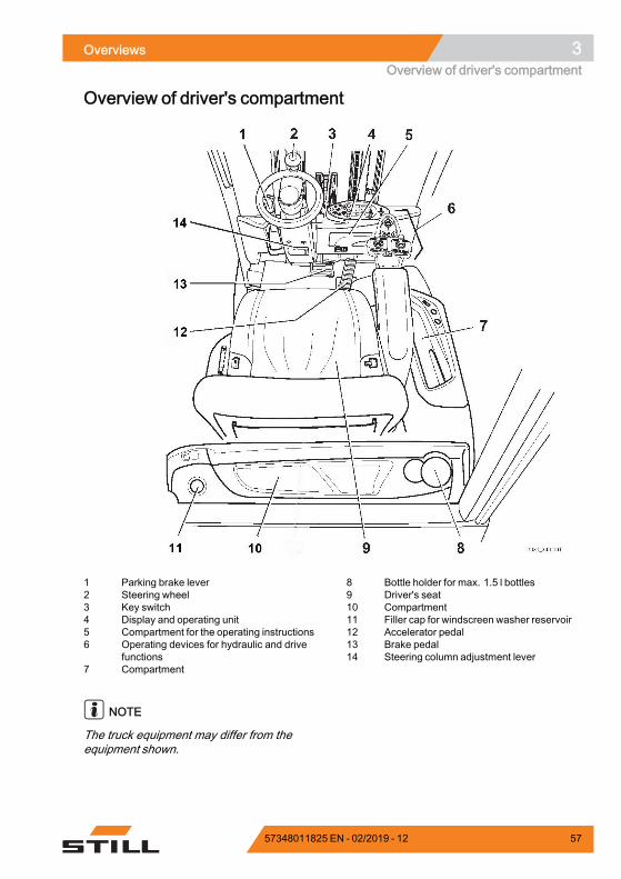
Overviews 3Overview of driver's compartment
Overview of driver's compartment
1 Parking brake lever2 Steering wheel3 Key switch4 Display and operating unit5 Compartment for the operating instructions6 Operating devices for hydraulic and drive
functions7 Compartment
8 Bottle holder for max. 1.5 l bottles9 Driver's seat10 Compartment11 Filler cap for windscreen washer reservoir12 Accelerator pedal13 Brake pedal14 Steering column adjustment lever
NOTE
The truck equipment may differ from theequipment shown.
57348011825 EN - 02/2019 - 12 57
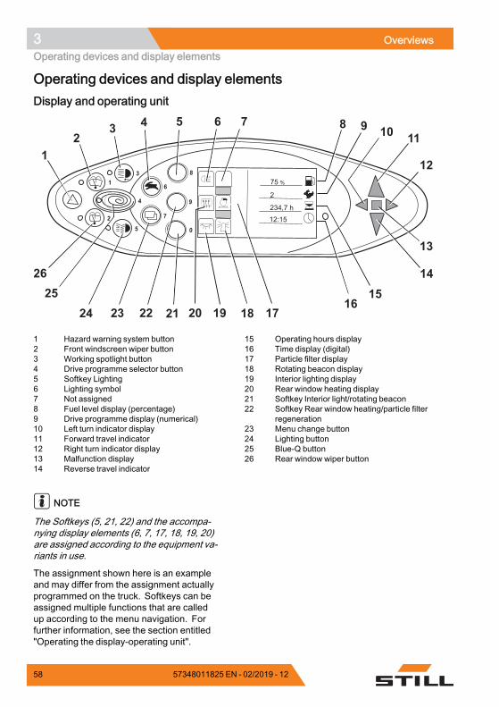
3 OverviewsOperating devices and display elements
Operating devices and display elementsDisplay and operating unit
8
9
6
72
0
13
5
4
%75
2
234,7 h12:15
12
3 4 5 6 7 8 9 10 11
12
13
14
1516
1718192021222324
25
26
1 Hazard warning system button2 Front windscreen wiper button3 Working spotlight button4 Drive programme selector button5 Softkey Lighting6 Lighting symbol7 Not assigned8 Fuel level display (percentage)9 Drive programme display (numerical)10 Left turn indicator display11 Forward travel indicator12 Right turn indicator display13 Malfunction display14 Reverse travel indicator
15 Operating hours display16 Time display (digital)17 Particle filter display18 Rotating beacon display19 Interior lighting display20 Rear window heating display21 Softkey Interior light/rotating beacon22 Softkey Rear window heating/particle filter
regeneration23 Menu change button24 Lighting button25 Blue-Q button26 Rear window wiper button
NOTE
The Softkeys (5, 21, 22) and the accompa-nying display elements (6, 7, 17, 18, 19, 20)are assigned according to the equipment va-riants in use.
The assignment shown here is an exampleand may differ from the assignment actuallyprogrammed on the truck. Softkeys can beassigned multiple functions that are calledup according to the menu navigation. Forfurther information, see the section entitled"Operating the display-operating unit".
58 57348011825 EN - 02/2019 - 12
Overviews 3Operating devices and display elements
– If you have any questions, please contactyour authorised service centre.
Operating devices for hydraulic anddriving functionsDifferent versions of the operating devices areavailable for operating the truck's hydraulicand traction functions.
The truck can be equipped with the followingoperating devices:• Double mini-lever• Triple mini-lever• Quadruple mini-lever• Joystick 4Plus• Fingertip switch• Mini-console
57348011825 EN - 02/2019 - 12 59
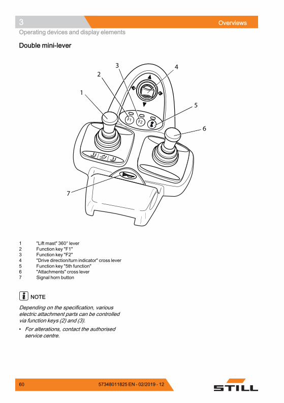
3 OverviewsOperating devices and display elements
Double mini-lever
F1 F2
1
23 4
5
6
7
1 "Lift mast" 360° lever2 Function key "F1"3 Function key "F2"4 "Drive direction/turn indicator" cross lever5 Function key "5th function"6 "Attachments" cross lever7 Signal horn button
NOTE
Depending on the specification, variouselectric attachment parts can be controlledvia function keys (2) and (3).• For alterations, contact the authorisedservice centre.
60 57348011825 EN - 02/2019 - 12
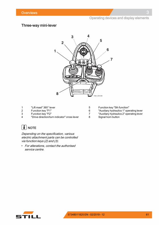
Overviews 3Operating devices and display elements
Three-way mini-lever
1
2
3 45
6
7
87325_003-026
1 "Lift mast" 360° lever2 Function key "F1"3 Function key "F2"4 "Drive direction/turn indicator" cross lever
5 Function key "5th function"6 "Auxiliary hydraulics 1" operating lever7 "Auxiliary hydraulics 2" operating lever8 Signal horn button
NOTE
Depending on the specification, variouselectric attachment parts can be controlledvia function keys (2) and (3).• For alterations, contact the authorisedservice centre.
57348011825 EN - 02/2019 - 12 61
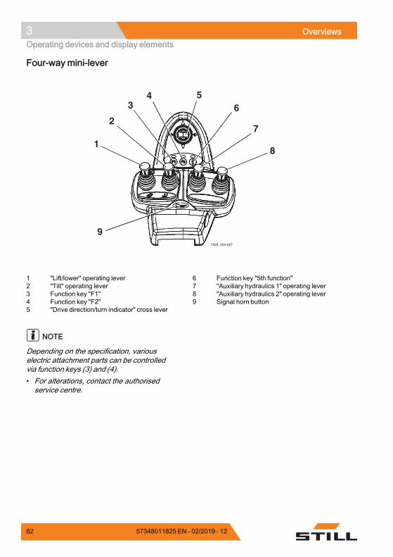
3 OverviewsOperating devices and display elements
Four-way mini-lever
7325_003-027
1
2
34 5
6
7
8
9
1 "Lift/lower" operating lever2 "Tilt" operating lever3 Function key "F1"4 Function key "F2"5 "Drive direction/turn indicator" cross lever
6 Function key "5th function"7 "Auxiliary hydraulics 1" operating lever8 "Auxiliary hydraulics 2" operating lever9 Signal horn button
NOTE
Depending on the specification, variouselectric attachment parts can be controlledvia function keys (3) and (4).• For alterations, contact the authorisedservice centre.
62 57348011825 EN - 02/2019 - 12
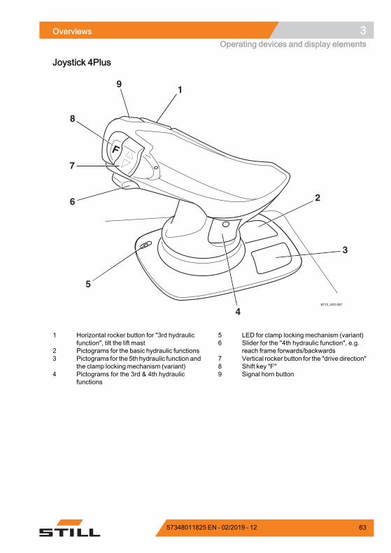
Overviews 3Operating devices and display elements
Joystick 4Plus
1
2
3
4
5
9
8
7
6
6210_003-087
1 Horizontal rocker button for "3rd hydraulicfunction", tilt the lift mast
2 Pictograms for the basic hydraulic functions3 Pictograms for the 5th hydraulic function and
the clamp locking mechanism (variant)4 Pictograms for the 3rd & 4th hydraulic
functions
5 LED for clamp locking mechanism (variant)6 Slider for the "4th hydraulic function", e.g.
reach frame forwards/backwards7 Vertical rocker button for the "drive direction"8 Shift key "F"9 Signal horn button
57348011825 EN - 02/2019 - 12 63
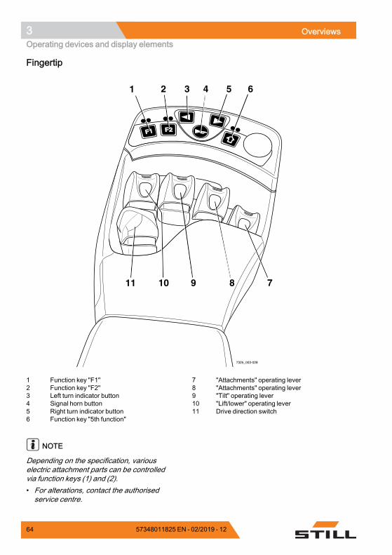
3 OverviewsOperating devices and display elements
Fingertip
F1F1 F2F2
7325_003-028
1 2 3 4 5 6
7891011
1 Function key "F1"2 Function key "F2"3 Left turn indicator button4 Signal horn button5 Right turn indicator button6 Function key "5th function"
7 "Attachments" operating lever8 "Attachments" operating lever9 "Tilt" operating lever10 "Lift/lower" operating lever11 Drive direction switch
NOTE
Depending on the specification, variouselectric attachment parts can be controlledvia function keys (1) and (2).• For alterations, contact the authorisedservice centre.
64 57348011825 EN - 02/2019 - 12
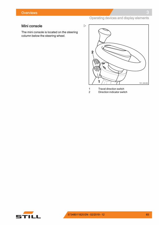
Overviews 3Operating devices and display elements
7311_003-0561
2
1 Travel direction switch2 Direction indicator switch
Mini consoleThe mini console is located on the steeringcolumn below the steering wheel.
57348011825 EN - 02/2019 - 12 65

3 OverviewsOperating devices and display elements
66 57348011825 EN - 02/2019 - 12

4
Operation
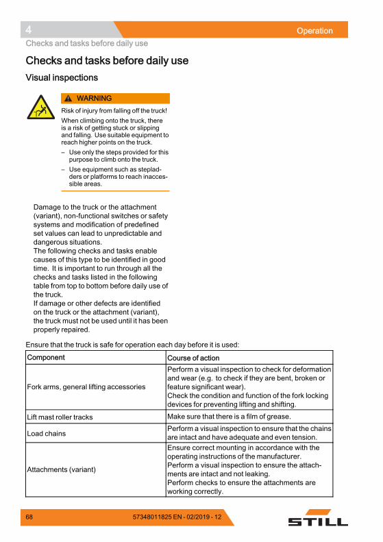
4 OperationChecks and tasks before daily use
Checks and tasks before daily useVisual inspections
WARNINGRisk of injury from falling off the truck!When climbing onto the truck, thereis a risk of getting stuck or slippingand falling. Use suitable equipment toreach higher points on the truck.– Use only the steps provided for this
purpose to climb onto the truck.– Use equipment such as steplad-
ders or platforms to reach inacces-sible areas.
Damage to the truck or the attachment(variant), non-functional switches or safetysystems and modification of predefinedset values can lead to unpredictable anddangerous situations.The following checks and tasks enablecauses of this type to be identified in goodtime. It is important to run through all thechecks and tasks listed in the followingtable from top to bottom before daily use ofthe truck.If damage or other defects are identifiedon the truck or the attachment (variant),the truck must not be used until it has beenproperly repaired.
Ensure that the truck is safe for operation each day before it is used:
Component Course of action
Fork arms, general lifting accessories
Perform a visual inspection to check for deformationand wear (e.g. to check if they are bent, broken orfeature significant wear).Check the condition and function of the fork lockingdevices for preventing lifting and shifting.
Lift mast roller tracks Make sure that there is a film of grease.
Load chainsPerform a visual inspection to ensure that the chainsare intact and have adequate and even tension.
Attachments (variant)
Ensure correct mounting in accordance with theoperating instructions of the manufacturer.Perform a visual inspection to ensure the attach-ments are intact and not leaking.Perform checks to ensure the attachments areworking correctly.
68 57348011825 EN - 02/2019 - 12
Operation 4Checks and tasks before daily use
Component Course of action
Underside Check the area under the forklift truck for leakingconsumables.
Overhead guard, guard grille (variant) Perform a visual inspection for integrity.Check for secure mounting.
Steps Make sure they are clean (free of ice, not slippery).
Panes of glass (variant) Perform a visual inspection for integrity.Make sure they are clean (also free of ice).
Handholds Check for secure mounting.
Maintenance lids Check the close function and close the lids.
Fuel system, fuel tank
Perform a visual inspection for damage and leak-ages.Have damaged components replaced only by theauthorised service centre.
Battery Perform a visual inspection for integrity and defor-mation.
Bonnet and side flap
Perform a visual inspection for integrity and defor-mation.Check that the interlock is in good condition and isworking correctly.Check the close function and close the cover.
Coupling pin, tow coupling (variant)
Perform a visual inspection for deformation andwear (for example, bent, torn, broken).Check the securing bush in the counterweight forintegrity and that it is working correctly.Check that the linchpin is present and workingcorrectly (chain, rope, split pin).
Labelling, adhesive label
Check for presence, integrity and legibility.Replace damaged or missing adhesive labels inaccordance with the section entitled "Labellingpoints".
Driver's seat, seat belt Check the integrity and function.
Lighting, warning units Check the integrity and function.
Antistatic belt
Perform a visual inspection for integrity.Ensure cleanliness.The antistatic belt must be long enough to touch theground adequately.
Lift and tilt cylinders, tank, valve block,hoses, pipes, connections
Perform a visual inspection for damage and leak-ages.Check the area under the truck for leaking consum-ables.Have damaged components replaced only by theauthorised service centre.
57348011825 EN - 02/2019 - 12 69
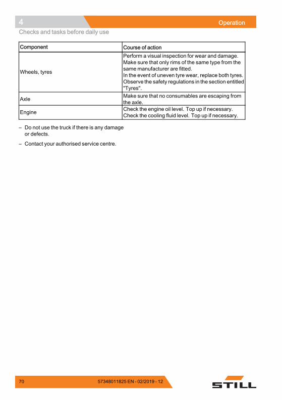
4 OperationChecks and tasks before daily use
Component Course of action
Wheels, tyres
Perform a visual inspection for wear and damage.Make sure that only rims of the same type from thesamemanufacturer are fitted.In the event of uneven tyre wear, replace both tyres.Observe the safety regulations in the section entitled"Tyres".
Axle Make sure that no consumables are escaping fromthe axle.
Engine Check the engine oil level. Top up if necessary.Check the cooling fluid level. Top up if necessary.
– Do not use the truck if there is any damageor defects.
– Contact your authorised service centre.
70 57348011825 EN - 02/2019 - 12
Operation 4Checks and tasks before daily use
Climbing into and out of the truck
WARNINGRisk of injury when climbing into and out of thetruck due to slipping, striking parts of the truck orbecoming stuck!If the footwell cover is very dirty or smeared with oil,there is a risk of slipping. There is a risk of hittingyour head on the overhead guard post or of yourclothes becoming stuck when climbing out of thetruck.– Ensure that the footwell cover is non-slip.– Do not jump into or out of the truck.– Ensure that you have a secure grip on the truck.
WARNINGRisk of injury when jumping out of the truck!If your clothing or jewellery (e.g. watch, ring etc.)becomes stuck on a component while you arejumping out of the truck, this can lead to seriousinjuries (e.g. from falling, loss of fingers etc.). It isforbidden to jump out of the truck.– Do not jump out of the truck.– Do not wear jewellery at work.– Do not wear loose-fitting workwear.
CAUTIONComponents may become damaged throughincorrect use!Truck components, such as the driver's seat,steering wheel, parking brake lever etc., are notdesigned to be used for climbing in and out of thetruck and can be damaged due to misuse.– Only use the fittings specifically designed for the
purpose of climbing into and out of the truck.
57348011825 EN - 02/2019 - 12 71
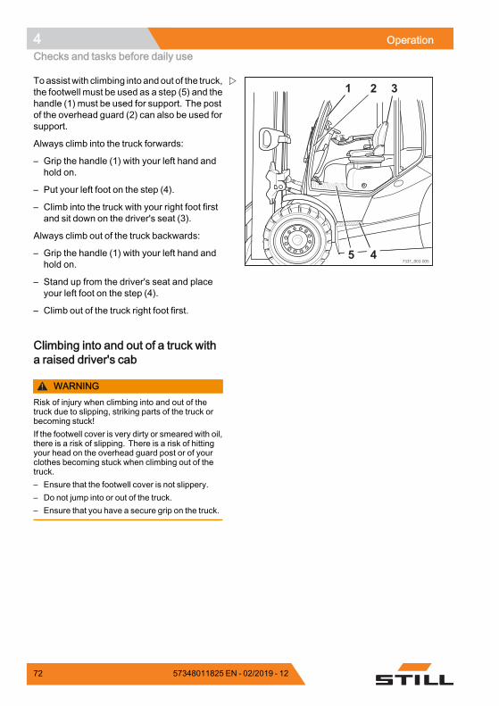
4 OperationChecks and tasks before daily use
7331_003-0055 4
1 2 3Toassistwith climbing into andout of the truck,the footwell must be used as a step (5) and thehandle (1) must be used for support. The postof the overhead guard (2) can also be used forsupport.
Always climb into the truck forwards:
– Grip the handle (1) with your left hand andhold on.
– Put your left foot on the step (4).
– Climb into the truck with your right foot firstand sit down on the driver's seat (3).
Always climb out of the truck backwards:
– Grip the handle (1) with your left hand andhold on.
– Stand up from the driver's seat and placeyour left foot on the step (4).
– Climb out of the truck right foot first.
Climbing into and out of a truck witha raised driver's cab
WARNINGRisk of injury when climbing into and out of thetruck due to slipping, striking parts of the truck orbecoming stuck!If the footwell cover is very dirty or smeared with oil,there is a risk of slipping. There is a risk of hittingyour head on the overhead guard post or of yourclothes becoming stuck when climbing out of thetruck.– Ensure that the footwell cover is not slippery.– Do not jump into or out of the truck.– Ensure that you have a secure grip on the truck.
72 57348011825 EN - 02/2019 - 12
Operation 4Checks and tasks before daily use
WARNINGRisk of injury when jumping out of the truck!If your clothing or jewellery (e.g. watch, ring etc.)becomes stuck on a component while you arejumping out of the truck, this can lead to seriousinjuries (e.g. from falling, loss of fingers etc.). It isforbidden to jump out of the truck.– Do not jump out of the truck.– Do not wear jewellery at work.– Do not wear loose-fitting workwear.
CAUTIONComponents may become damaged throughincorrect use!Truck components, such as the driver's seat,steering wheel, parking brake lever etc., are notdesigned to be used for climbing in and out of thetruck and may be damaged due to misuse.– Only use the fittings specifically designed for the
purpose of climbing into and out of the truck.
If the truck is equipped with a raised driver'scab, the driver's compartment is significantlyhigher than that of a standard truck.
For this reason, particular care must be takenwhen climbing into and out of the truck. Thefollowing section describes the best procedureto adopt.
NOTE
The foot that the driver starts with whenclimbing into and out of the truck is crucialin ensuring this action is carried out safely.This will depend on the number of steps.
To assist when climbing into and out of thetruck, use the handles (2) and (4) for support.The post of the overhead guard (1) can alsobe used for support.
Always climb into the truck facing forwards.
57348011825 EN - 02/2019 - 12 73
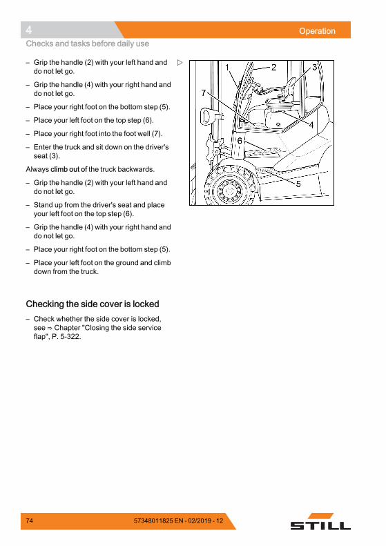
4 OperationChecks and tasks before daily use
– Grip the handle (2) with your left hand anddo not let go.
– Grip the handle (4) with your right hand anddo not let go.
– Place your right foot on the bottom step (5).
– Place your left foot on the top step (6).
– Place your right foot into the foot well (7).
– Enter the truck and sit down on the driver'sseat (3).
Always climb out of the truck backwards.
– Grip the handle (2) with your left hand anddo not let go.
– Stand up from the driver's seat and placeyour left foot on the top step (6).
– Grip the handle (4) with your right hand anddo not let go.
– Place your right foot on the bottom step (5).
– Place your left foot on the ground and climbdown from the truck.
Checking the side cover is locked– Check whether the side cover is locked,see ⇒ Chapter "Closing the side serviceflap", P. 5-322.
74 57348011825 EN - 02/2019 - 12
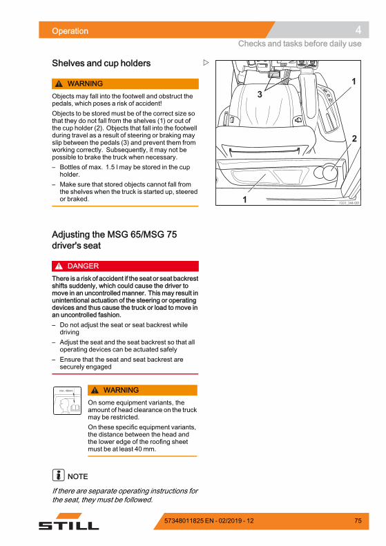
Operation 4Checks and tasks before daily use
7331_344-001
1
2
3
1
Shelves and cup holders
WARNINGObjects may fall into the footwell and obstruct thepedals, which poses a risk of accident!Objects to be stored must be of the correct size sothat they do not fall from the shelves (1) or out ofthe cup holder (2). Objects that fall into the footwellduring travel as a result of steering or braking mayslip between the pedals (3) and prevent them fromworking correctly. Subsequently, it may not bepossible to brake the truck when necessary.– Bottles of max. 1.5 l may be stored in the cup
holder.– Make sure that stored objects cannot fall from
the shelves when the truck is started up, steeredor braked.
Adjusting the MSG 65/MSG 75driver's seat
DANGERThere is a risk of accident if the seat or seat backrestshifts suddenly, which could cause the driver tomove in an uncontrolled manner. This may result inunintentional actuation of the steering or operatingdevices and thus cause the truck or load to move inan uncontrolled fashion.– Do not adjust the seat or seat backrest while
driving– Adjust the seat and the seat backrest so that all
operating devices can be actuated safely– Ensure that the seat and seat backrest are
securely engaged
WARNINGOn some equipment variants, theamount of head clearance on the truckmay be restricted.On these specific equipment variants,the distance between the head andthe lower edge of the roofing sheetmust be at least 40 mm.
NOTE
If there are separate operating instructions forthe seat, they must be followed.
57348011825 EN - 02/2019 - 12 75
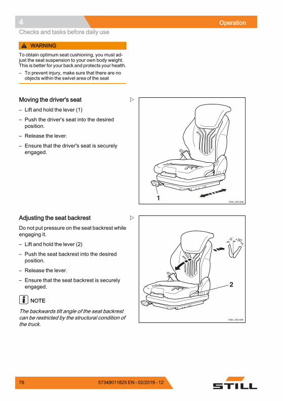
4 OperationChecks and tasks before daily use
WARNINGTo obtain optimum seat cushioning, you must ad-just the seat suspension to your own body weight.This is better for your back and protects your health.– To prevent injury, make sure that there are no
objects within the swivel area of the seat
7094_003-0061
Moving the driver's seat– Lift and hold the lever (1)
– Push the driver's seat into the desiredposition.
– Release the lever.
– Ensure that the driver's seat is securelyengaged.
7094_003-008
2
Adjusting the seat backrestDo not put pressure on the seat backrest whileengaging it.
– Lift and hold the lever (2)
– Push the seat backrest into the desiredposition.
– Release the lever.
– Ensure that the seat backrest is securelyengaged.
NOTE
The backwards tilt angle of the seat backrestcan be restricted by the structural condition ofthe truck.
76 57348011825 EN - 02/2019 - 12
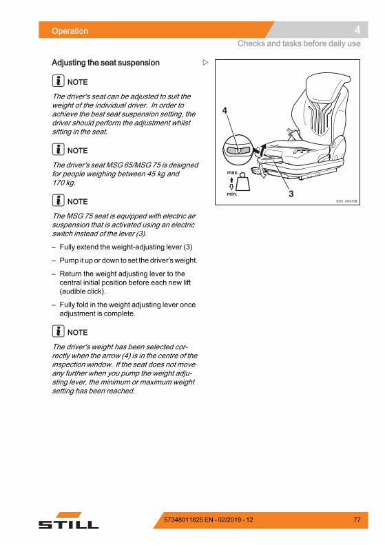
Operation 4Checks and tasks before daily use
6321_003-038
3
4
Adjusting the seat suspension
NOTE
The driver's seat can be adjusted to suit theweight of the individual driver. In order toachieve the best seat suspension setting, thedriver should perform the adjustment whilstsitting in the seat.
NOTE
The driver's seatMSG 65/MSG 75 is designedfor people weighing between 45 kg and170 kg.
NOTE
The MSG 75 seat is equipped with electric airsuspension that is activated using an electricswitch instead of the lever (3).
– Fully extend the weight-adjusting lever (3)
– Pump it up or down to set the driver'sweight.
– Return the weight adjusting lever to thecentral initial position before each new lift(audible click).
– Fully fold in the weight adjusting lever onceadjustment is complete.
NOTE
The driver's weight has been selected cor-rectly when the arrow (4) is in the centre of theinspection window. If the seat does not moveany further when you pump the weight adju-sting lever, the minimum or maximum weightsetting has been reached.
57348011825 EN - 02/2019 - 12 77
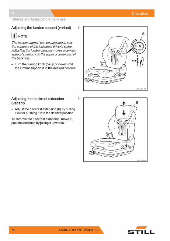
4 OperationChecks and tasks before daily use
6321_003-039
5
Adjusting the lumbar support (variant)
NOTE
The lumbar support can be adjusted to suitthe contours of the individual driver's spine.Adjusting the lumbar support moves a convexsupport cushion into the upper or lower part ofthe backrest.
– Turn the turning knob (5) up or down untilthe lumbar support is in the desired position
6321_003-040
6Adjusting the backrest extension(variant)– Adjust the backrest extension (6) by pullingit out or pushing it into the desired position.
To remove the backrest extension, move itpast the end stop by jolting it upwards.
78 57348011825 EN - 02/2019 - 12
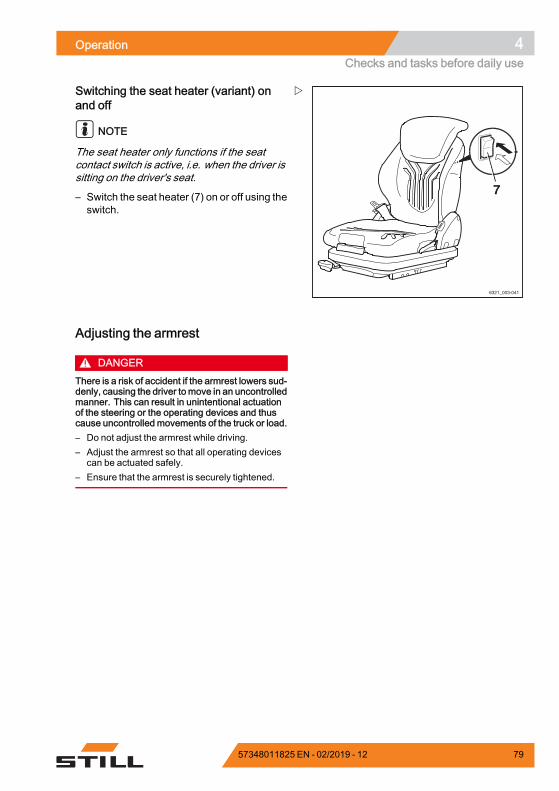
Operation 4Checks and tasks before daily use
6321_003-041
7
Switching the seat heater (variant) onand off
NOTE
The seat heater only functions if the seatcontact switch is active, i.e. when the driver issitting on the driver's seat.
– Switch the seat heater (7) on or off using theswitch.
Adjusting the armrest
DANGERThere is a risk of accident if the armrest lowers sud-denly, causing the driver tomove in an uncontrolledmanner. This can result in unintentional actuationof the steering or the operating devices and thuscause uncontrolled movements of the truck or load.– Do not adjust the armrest while driving.– Adjust the armrest so that all operating devices
can be actuated safely.– Ensure that the armrest is securely tightened.
57348011825 EN - 02/2019 - 12 79
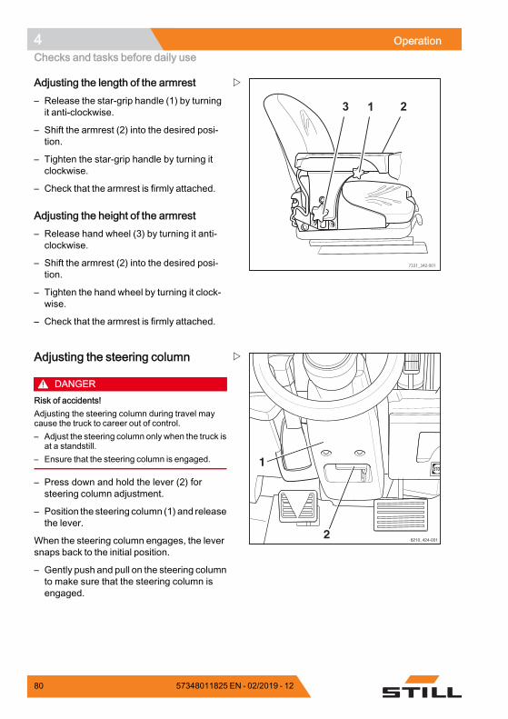
4 OperationChecks and tasks before daily use
7331_342-001
3 1 2
Adjusting the length of the armrest– Release the star-grip handle (1) by turningit anti-clockwise.
– Shift the armrest (2) into the desired posi-tion.
– Tighten the star-grip handle by turning itclockwise.
– Check that the armrest is firmly attached.
Adjusting the height of the armrest– Release hand wheel (3) by turning it anti-clockwise.
– Shift the armrest (2) into the desired posi-tion.
– Tighten the hand wheel by turning it clock-wise.
– Check that the armrest is firmly attached.
6210_424-001
1
2
Adjusting the steering column
DANGERRisk of accidents!Adjusting the steering column during travel maycause the truck to career out of control.– Adjust the steering column only when the truck is
at a standstill.– Ensure that the steering column is engaged.
– Press down and hold the lever (2) forsteering column adjustment.
– Position the steering column (1) and releasethe lever.
When the steering column engages, the leversnaps back to the initial position.
– Gently push and pull on the steering columnto make sure that the steering column isengaged.
80 57348011825 EN - 02/2019 - 12
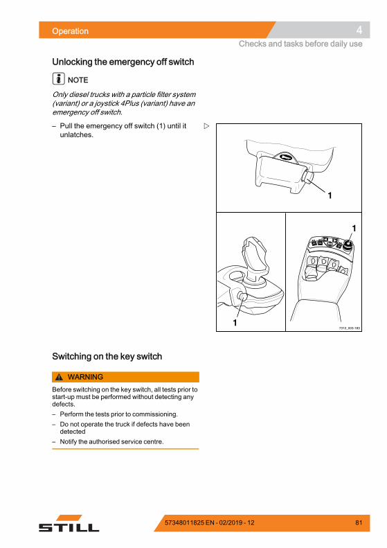
Operation 4Checks and tasks before daily use
Unlocking the emergency off switch
NOTE
Only diesel trucks with a particle filter system(variant) or a joystick 4Plus (variant) have anemergency off switch.
7312_003-183
F1F1 F2F2
1
1
1
– Pull the emergency off switch (1) until itunlatches.
Switching on the key switch
WARNINGBefore switching on the key switch, all tests prior tostart-up must be performed without detecting anydefects.– Perform the tests prior to commissioning.– Do not operate the truck if defects have been
detected– Notify the authorised service centre.
57348011825 EN - 02/2019 - 12 81
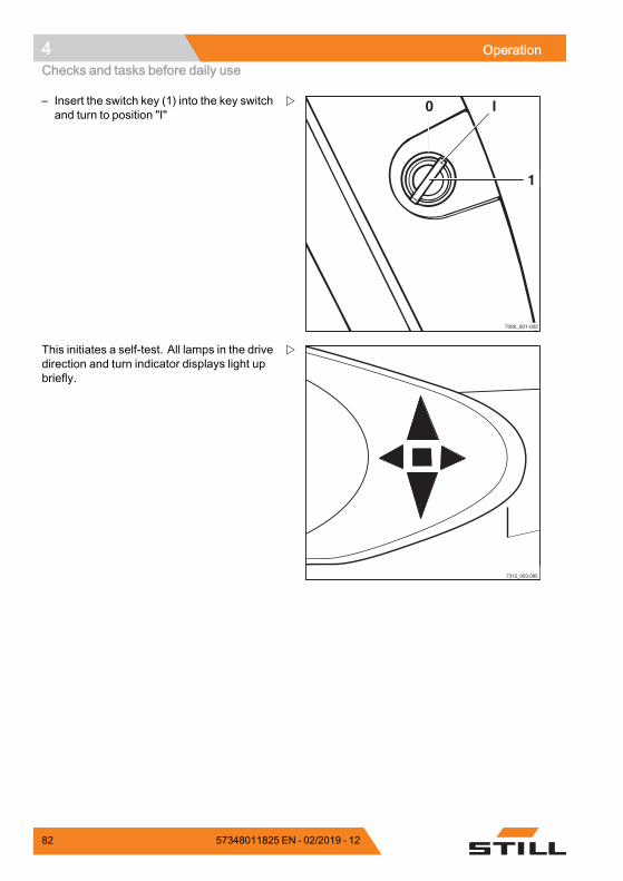
4 OperationChecks and tasks before daily use
7090_001-002
0 I
1
– Insert the switch key (1) into the key switchand turn to position "I"
7312_003-085
This initiates a self-test. All lamps in the drivedirection and turn indicator displays light upbriefly.
82 57348011825 EN - 02/2019 - 12
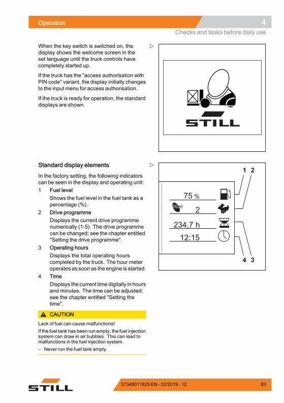
Operation 4Checks and tasks before daily use
When the key switch is switched on, thedisplay shows the welcome screen in theset language until the truck controls havecompletely started up.
If the truck has the "access authorisation withPIN code" variant, the display initially changesto the input menu for access authorisation.
If the truck is ready for operation, the standarddisplays are shown.
%75
2
234,7 h12:15
1 2
34
Standard display elements
In the factory setting, the following indicatorscan be seen in the display and operating unit:1 Fuel level
Shows the fuel level in the fuel tank as apercentage (%).
2 Drive programmeDisplays the current drive programmenumerically (1-5). The drive programmecan be changed; see the chapter entitled"Setting the drive programme".
3 Operating hoursDisplays the total operating hourscompleted by the truck. The hour meteroperates as soon as the engine is started.
4 TimeDisplays the current time digitally in hoursand minutes. The time can be adjusted;see the chapter entitled "Setting thetime".
CAUTIONLack of fuel can cause malfunctions!If the fuel tank has been run empty, the fuel injectionsystem can draw in air bubbles. This can lead tomalfunctions in the fuel injection system.– Never run the fuel tank empty.
57348011825 EN - 02/2019 - 12 83
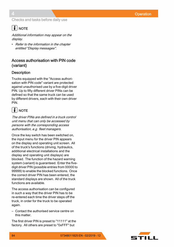
4 OperationChecks and tasks before daily use
NOTE
Additional information may appear on thedisplay.• Refer to the information in the chapterentitled "Display messages".
Access authorisation with PIN code(variant)
DescriptionTrucks equipped with the "Access authori-sation with PIN code" variant are protectedagainst unauthorised use by a five-digit driverPIN. Up to fifty different driver PINs can bedefined so that the same truck can be usedby different drivers, each with their own driverPIN.
NOTE
The driver PINs are defined in a truck controlunit menu that can only be accessed bypersons with the corresponding accessauthorisation, e.g. fleet managers.
Once the key switch has been switched on,the input menu for the driver PIN appearson the display and operating unit screen. Allof the truck's functions (driving, hydraulics,additional electrical installations and thedisplay and operating unit displays) areblocked. The function of the hazard warningsystem (variant) is guaranteed. Enter the five-digit driver PIN (possible entries from 00000 to99999) to enable the blocked functions. Oncethe correct driver PIN has been entered, thestandard displays are shown. All of the truckfunctions are available.
The access authorisation can be configuredin such a way that the driver PIN has to bere-entered each time the driver steps off thetruck, in order for the truck to be operatedagain.
– Contact the authorised service centre onthis matter.
The first driver PIN is preset to "11111" at thefactory. All others are preset to "0xFFF" but
84 57348011825 EN - 02/2019 - 12
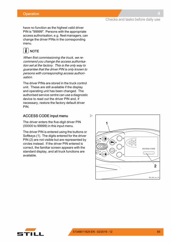
Operation 4Checks and tasks before daily use
have no function as the highest valid driverPIN is "99999". Persons with the appropriateaccessauthorisation, e.g. fleetmanagers, canchange the driver PINs in the correspondingmenu.
NOTE
When first commissioning the truck, we re-commend you change the access authorisa-tion set at the factory. This is the only way toguarantee that the driver PIN is only known topersons with corresponding access authori-sation.
The driver PINs are stored in the truck controlunit. These are still available if the displayand operating unit has been changed. Theauthorised service centre can use a diagnosticdevice to read out the driver PIN and, ifnecessary, restore the factory default driverPIN.
ACCESS CODE input menuThe driver enters the five-digit driver PIN(00000 to 99999) in this input menu.
The driver PIN is entered using the buttons orSoftkeys (1). The digits entered for the driverPIN (2) are not visible but are represented bycircles instead. If the driver PIN entered iscorrect, the familiar screen appears with thestandard display, and all truck functions areavailable.
57348011825 EN - 02/2019 - 12 85
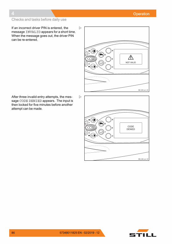
4 OperationChecks and tasks before daily use
8
9
6
7
4
2
0
1
3
5
BQ_023_en_V2
If an incorrect driver PIN is entered, themessage INVALID appears for a short time.When the message goes out, the driver PINcan be re-entered.
8
9
6
7
4
2
0
1
3
5
BQ_024_en_V2
After three invalid entry attempts, the mes-sage CODE DENIED appears. The input isthen locked for five minutes before anotherattempt can be made.
86 57348011825 EN - 02/2019 - 12
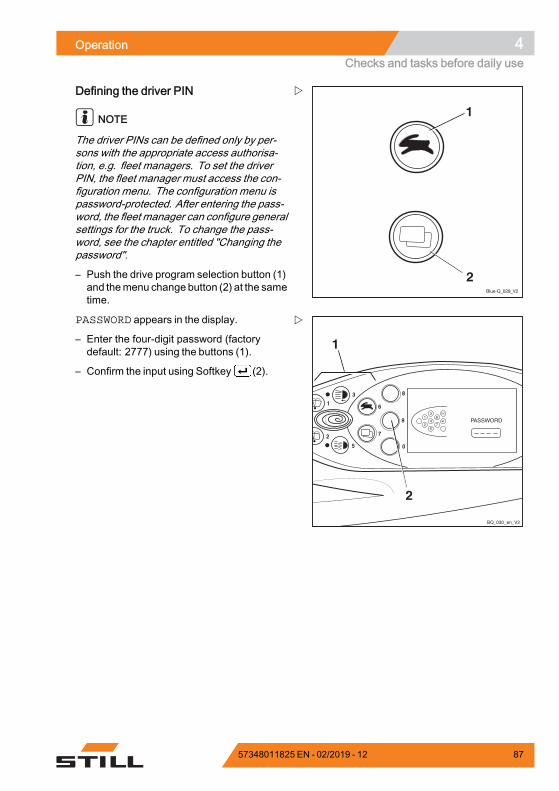
Operation 4Checks and tasks before daily use
Blue-Q_029_V2
1
2
Defining the driver PIN
NOTE
The driver PINs can be defined only by per-sons with the appropriate access authorisa-tion, e.g. fleet managers. To set the driverPIN, the fleet manager must access the con-figuration menu. The configuration menu ispassword-protected. After entering the pass-word, the fleet manager can configure generalsettings for the truck. To change the pass-word, see the chapter entitled "Changing thepassword".
– Push the drive program selection button (1)and themenu change button (2) at the sametime.
8
9
6
7
4
2
0
1
3
5
1
2
BQ_030_en_V2
1
2
6
7
3
4
5
ESC
PASSWORD appears in the display.
– Enter the four-digit password (factorydefault: 2777) using the buttons (1).
– Confirm the input using Softkey (2).
57348011825 EN - 02/2019 - 12 87
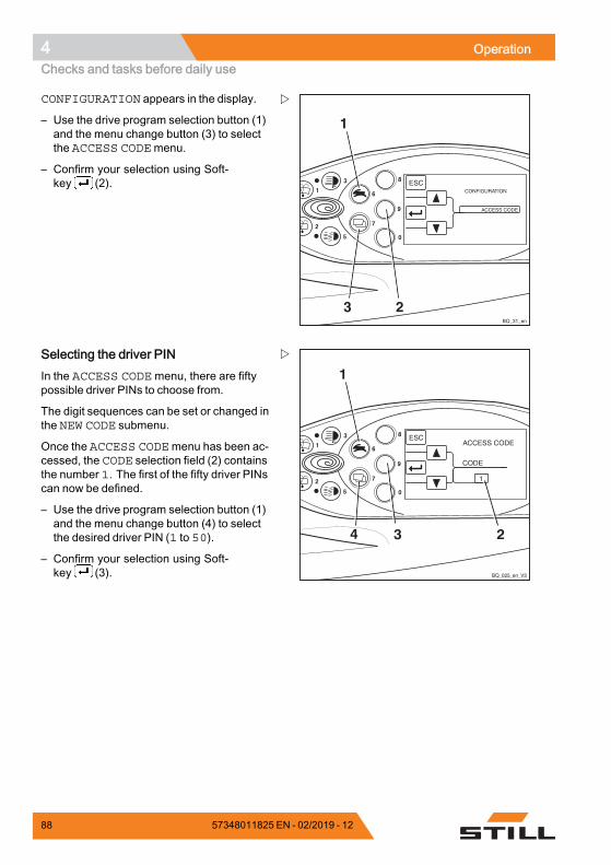
4 OperationChecks and tasks before daily use
8
9
6
7
4
2
0
1
3
5
BQ_31_en
1
3 2
CONFIGURATION appears in the display.
– Use the drive program selection button (1)and the menu change button (3) to selectthe ACCESS CODEmenu.
– Confirm your selection using Soft-key (2).
8
9
6
7
4
2
0
1
3
5
BQ_025_en_V3
1
34 2
Selecting the driver PINIn the ACCESS CODEmenu, there are fiftypossible driver PINs to choose from.
The digit sequences can be set or changed inthe NEW CODE submenu.
Once the ACCESS CODEmenu has been ac-cessed, the CODE selection field (2) containsthe number 1. The first of the fifty driver PINscan now be defined.
– Use the drive program selection button (1)and the menu change button (4) to selectthe desired driver PIN (1 to 50).
– Confirm your selection using Soft-key (3).
88 57348011825 EN - 02/2019 - 12
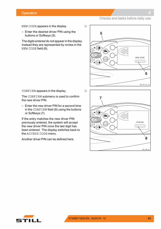
Operation 4Checks and tasks before daily use
NEW CODE appears in the display.
– Enter the desired driver PIN using thebuttons or Softkeys (5).
Thedigits entered do not appear in the display.Instead they are represented by circles in theNEW CODE field (6).
8
9
6
7
4
2
0
1
3
5
7
8
1
2
6
7
3
4
5
8
9
0
BQ_026_en
CONFIRM appears in the display.
The CONFIRM submenu is used to confirmthe new driver PIN.
– Enter the new driver PIN for a second timein the CONFIRM field (8) using the buttonsor Softkeys (7).
If the entry matches the new driver PINpreviously entered, the system will acceptthe new driver PIN once the last digit hasbeen entered. The display switches back tothe ACCESS CODEmenu.
Another driver PIN can be defined here.
57348011825 EN - 02/2019 - 12 89
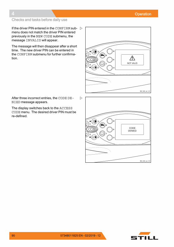
4 OperationChecks and tasks before daily use
8
9
6
7
4
2
0
1
3
5
BQ_023_en_V2
If the driver PIN entered in the CONFIRM sub-menu does not match the driver PIN enteredpreviously in the NEW CODE submenu, themessage INVALIDwill appear.
The message will then disappear after a shorttime. The new driver PIN can be entered inthe CONFIRM submenu for further confirma-tion.
8
9
6
7
4
2
0
1
3
5
BQ_024_en_V2
After three incorrect entries, the CODE DE-NIEDmessage appears.
The display switches back to the ACCESSCODEmenu. The desired driver PIN must bere-defined.
90 57348011825 EN - 02/2019 - 12
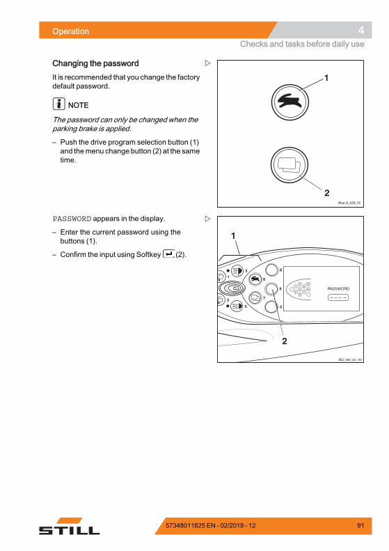
Operation 4Checks and tasks before daily use
Blue-Q_029_V2
1
2
Changing the passwordIt is recommended that you change the factorydefault password.
NOTE
The password can only be changed when theparking brake is applied.
– Push the drive program selection button (1)and themenu change button (2) at the sametime.
8
9
6
7
4
2
0
1
3
5
1
2
BQ_030_en_V2
1
2
6
7
3
4
5
ESC
PASSWORD appears in the display.
– Enter the current password using thebuttons (1).
– Confirm the input using Softkey (2).
57348011825 EN - 02/2019 - 12 91
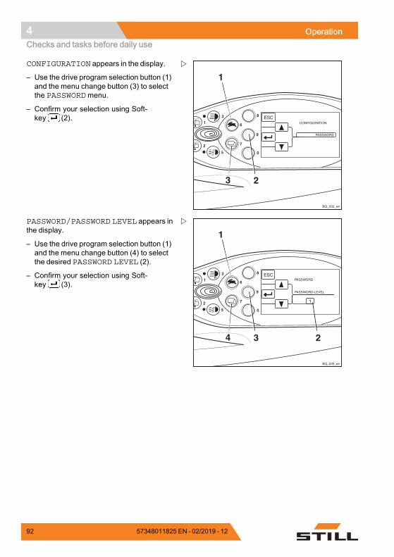
4 OperationChecks and tasks before daily use
8
9
6
7
4
2
0
1
3
5
1
23
BQ_032_en
CONFIGURATION appears in the display.
– Use the drive program selection button (1)and the menu change button (3) to selectthe PASSWORDmenu.
– Confirm your selection using Soft-key (2).
8
9
6
7
4
2
0
1
3
5
1
34
BQ_033_en
2
1
PASSWORD/PASSWORD LEVEL appears inthe display.
– Use the drive program selection button (1)and the menu change button (4) to selectthe desired PASSWORD LEVEL (2).
– Confirm your selection using Soft-key (3).
92 57348011825 EN - 02/2019 - 12
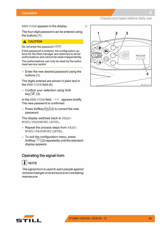
Operation 4Checks and tasks before daily use
8
9
6
7
4
2
0
1
3
5
1
2
6
7
3
4
5
ESC
BQ_034_en_V2
1 2 3
4
NEW CODE appears in the display.
The four-digit password can be entered usingthe buttons (1).
CAUTIONDo not enter the password 1777!If this password is entered, the configuration op-tions for the fleet manager are restricted to driverauthorisations and cannot be reset independently.The authorisations can only be reset by the autho-rised service centre!
– Enter the new desired password using thebuttons (1).
The digits entered are shown in plain text inthe NEW CODE field (4).
– Confirm your selection using Soft-key (3).
In the NEW CODE field, -??- appears briefly.The new password is confirmed.
– Press Softkey (2) to correct the newpassword.
The display switches back to PASS-WORD/PASSWORD LEVEL.
– Repeat the process steps from PASS-WORD/PASSWORD LEVEL.
– To exit the configuration menu, pressSoftkey (2) repeatedly until the standarddisplay appears.
Operating the signal horn
NOTE
The signal horn is used to warn people againstimminent danger or to announceanovertakingmanoeuvre.
57348011825 EN - 02/2019 - 12 93
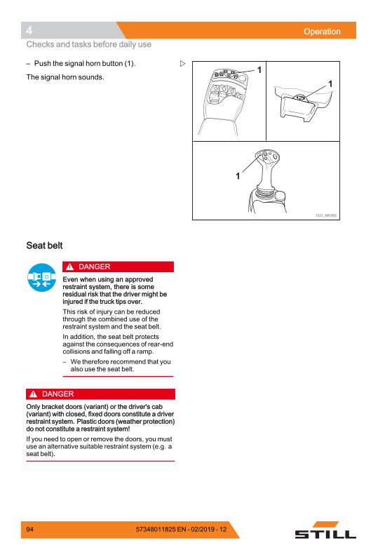
4 OperationChecks and tasks before daily use
F
F1F1F2F2
7331_500-002
1
1
1
– Push the signal horn button (1).
The signal horn sounds.
Seat belt
DANGEREven when using an approvedrestraint system, there is someresidual risk that the driver might beinjured if the truck tips over.This risk of injury can be reducedthrough the combined use of therestraint system and the seat belt.In addition, the seat belt protectsagainst the consequences of rear-endcollisions and falling off a ramp.– We therefore recommend that you
also use the seat belt.
DANGEROnly bracket doors (variant) or the driver's cab(variant) with closed, fixed doors constitute a driverrestraint system. Plastic doors (weather protection)do not constitute a restraint system!If you need to open or remove the doors, you mustuse an alternative suitable restraint system (e.g. aseat belt).
94 57348011825 EN - 02/2019 - 12
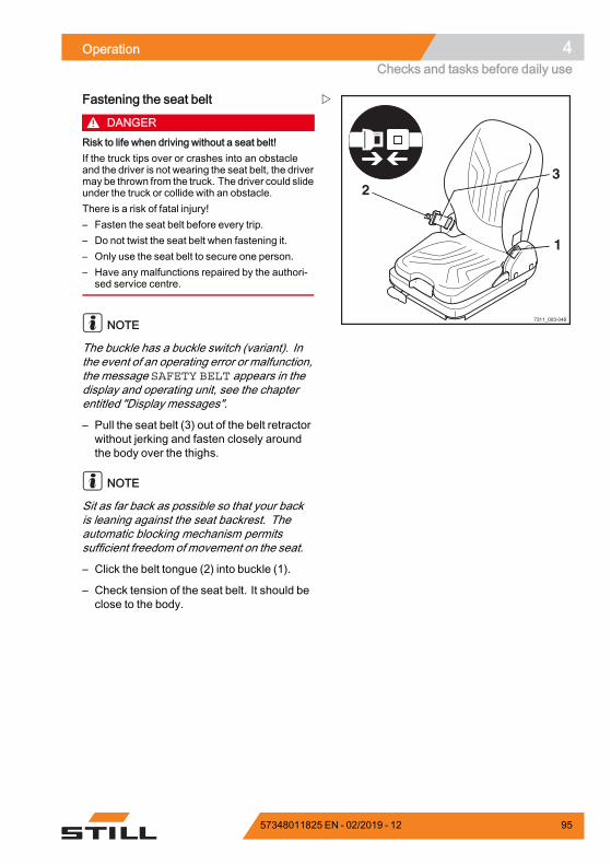
Operation 4Checks and tasks before daily use
7311_003-048
1
23
Fastening the seat belt
DANGERRisk to life when driving without a seat belt!If the truck tips over or crashes into an obstacleand the driver is not wearing the seat belt, the drivermay be thrown from the truck. The driver could slideunder the truck or collide with an obstacle.There is a risk of fatal injury!– Fasten the seat belt before every trip.– Do not twist the seat belt when fastening it.– Only use the seat belt to secure one person.– Have any malfunctions repaired by the authori-
sed service centre.
NOTE
The buckle has a buckle switch (variant). Inthe event of an operating error or malfunction,the message SAFETY BELT appears in thedisplay and operating unit, see the chapterentitled "Display messages".
– Pull the seat belt (3) out of the belt retractorwithout jerking and fasten closely aroundthe body over the thighs.
NOTE
Sit as far back as possible so that your backis leaning against the seat backrest. Theautomatic blocking mechanism permitssufficient freedom of movement on the seat.
– Click the belt tongue (2) into buckle (1).
– Check tension of the seat belt. It should beclose to the body.
57348011825 EN - 02/2019 - 12 95
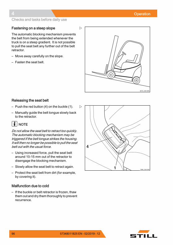
4 OperationChecks and tasks before daily use
6210_342-005
Fastening on a steep slopeThe automatic blocking mechanism preventsthe belt from being extended whenever thetruck is on a steep gradient. It is not possibleto pull the seat belt any further out of the beltretractor.
– Move away carefully on the slope.
– Fasten the seat belt.
Releasing the seat belt
7090_342-0051
4
– Push the red button (4) on the buckle (1).
– Manually guide the belt tongue slowly backto the retractor.
NOTE
Do not allow the seat belt to retract too quickly.The automatic blocking mechanism may betriggered if the belt tongue strikes the housing.It will then no longer be possible to pull the seatbelt out with the usual force.
– Using increased force, pull the seat beltaround 10-15 mm out of the retractor todisengage the blocking mechanism.
– Slowly allow the seat belt to retract again.
– Protect the seat belt from dirt (for example,by covering it).
Malfunction due to cold– If the buckle or belt retractor is frozen, thawthemout anddry them thoroughly to preventrecurrence.
96 57348011825 EN - 02/2019 - 12
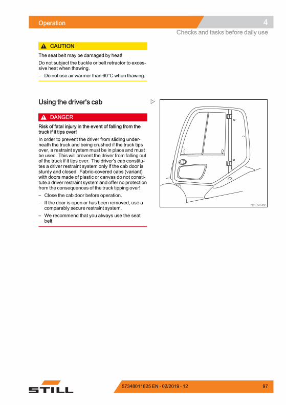
Operation 4Checks and tasks before daily use
CAUTIONThe seat belt may be damaged by heat!Do not subject the buckle or belt retractor to exces-sive heat when thawing.– Do not use air warmer than 60°C when thawing.
7331_341-002
Using the driver's cab
DANGERRisk of fatal injury in the event of falling from thetruck if it tips over!In order to prevent the driver from sliding under-neath the truck and being crushed if the truck tipsover, a restraint systemmust be in place and mustbe used. This will prevent the driver from falling outof the truck if it tips over. The driver's cab constitu-tes a driver restraint system only if the cab door issturdy and closed. Fabric-covered cabs (variant)with doors made of plastic or canvas do not consti-tute a driver restraint system and offer no protectionfrom the consequences of the truck tipping over!– Close the cab door before operation.– If the door is open or has been removed, use a
comparably secure restraint system.– We recommend that you always use the seat
belt.
57348011825 EN - 02/2019 - 12 97
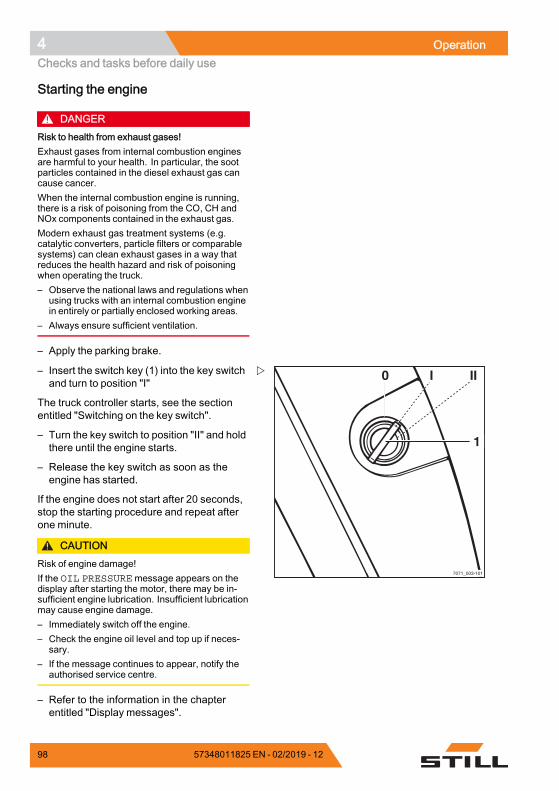
4 OperationChecks and tasks before daily use
Starting the engine
DANGERRisk to health from exhaust gases!Exhaust gases from internal combustion enginesare harmful to your health. In particular, the sootparticles contained in the diesel exhaust gas cancause cancer.When the internal combustion engine is running,there is a risk of poisoning from the CO, CH andNOx components contained in the exhaust gas.Modern exhaust gas treatment systems (e.g.catalytic converters, particle filters or comparablesystems) can clean exhaust gases in a way thatreduces the health hazard and risk of poisoningwhen operating the truck.– Observe the national laws and regulations when
using trucks with an internal combustion enginein entirely or partially enclosed working areas.
– Always ensure sufficient ventilation.
– Apply the parking brake.
7071_003-101
0 I
1
II– Insert the switch key (1) into the key switchand turn to position "I"
The truck controller starts, see the sectionentitled "Switching on the key switch".
– Turn the key switch to position "II" and holdthere until the engine starts.
– Release the key switch as soon as theengine has started.
If the engine does not start after 20 seconds,stop the starting procedure and repeat afterone minute.
CAUTIONRisk of engine damage!If the OIL PRESSUREmessage appears on thedisplay after starting the motor, there may be in-sufficient engine lubrication. Insufficient lubricationmay cause engine damage.– Immediately switch off the engine.– Check the engine oil level and top up if neces-
sary.– If the message continues to appear, notify the
authorised service centre.
– Refer to the information in the chapterentitled "Display messages".
98 57348011825 EN - 02/2019 - 12
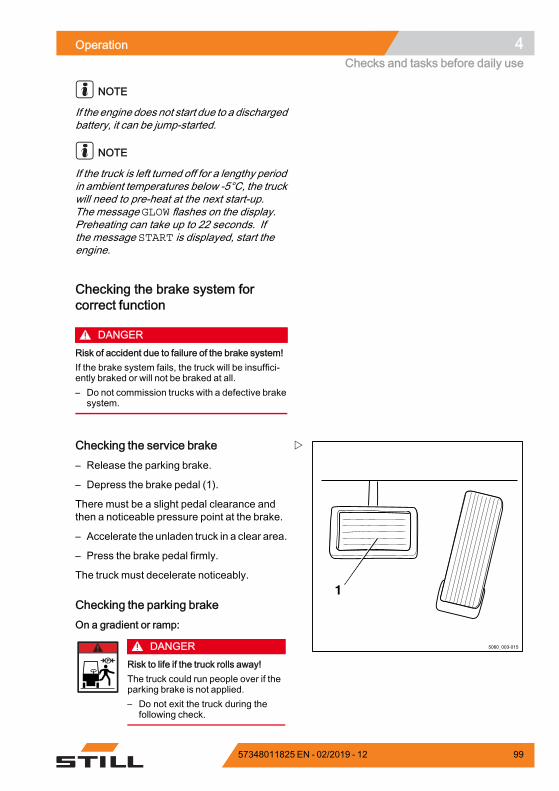
Operation 4Checks and tasks before daily use
NOTE
If the engine does not start due to a dischargedbattery, it can be jump-started.
NOTE
If the truck is left turned off for a lengthy periodin ambient temperatures below -5°C, the truckwill need to pre-heat at the next start-up.The message GLOW flashes on the display.Preheating can take up to 22 seconds. Ifthe message START is displayed, start theengine.
Checking the brake system forcorrect function
DANGERRisk of accident due to failure of the brake system!If the brake system fails, the truck will be insuffici-ently braked or will not be braked at all.– Do not commission trucks with a defective brake
system.
1
5060_003-015
Checking the service brake– Release the parking brake.
– Depress the brake pedal (1).
There must be a slight pedal clearance andthen a noticeable pressure point at the brake.
– Accelerate the unladen truck in a clear area.
– Press the brake pedal firmly.
The truck must decelerate noticeably.
Checking the parking brakeOn a gradient or ramp:
DANGERRisk to life if the truck rolls away!The truck could run people over if theparking brake is not applied.– Do not exit the truck during the
following check.
57348011825 EN - 02/2019 - 12 99
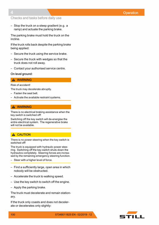
4 OperationChecks and tasks before daily use
– Stop the truck on a steep gradient (e.g. aramp) and actuate the parking brake.
The parking brake must hold the truck on theincline.
If the truck rolls back despite the parking brakebeing applied:
– Secure the truck using the service brake.
– Secure the truck with wedges so that thetruck does not roll away.
– Contact your authorised service centre.
On level ground:
WARNINGRisk of accident!The truck may decelerate abruptly.– Fasten the seat belt.– Activate the available restraint systems.
WARNINGThere is no electrical braking assistance when thekey switch is switched off!Switching off the key switch will de-energise theentire electrical system. The regenerative brakewill not be available.
CAUTIONThere is no power steering when the key switch isswitched off!The truck is equipped with hydraulic power stee-ring. Switching off the key switch shuts down thehydraulics completely. Steering forces are increa-sed by the remaining emergency steering function.– Steer with a higher level of force.
– Find a sufficiently large, open area in whichnobody will be obstructed.
– Accelerate the truck to walking speed.
– Use the key switch to switch off the engine.
– Apply the parking brake.
The truck must decelerate and remain station-ary.
If the truck only coasts and does not deceler-ate or decelerates only slightly:
100 57348011825 EN - 02/2019 - 12
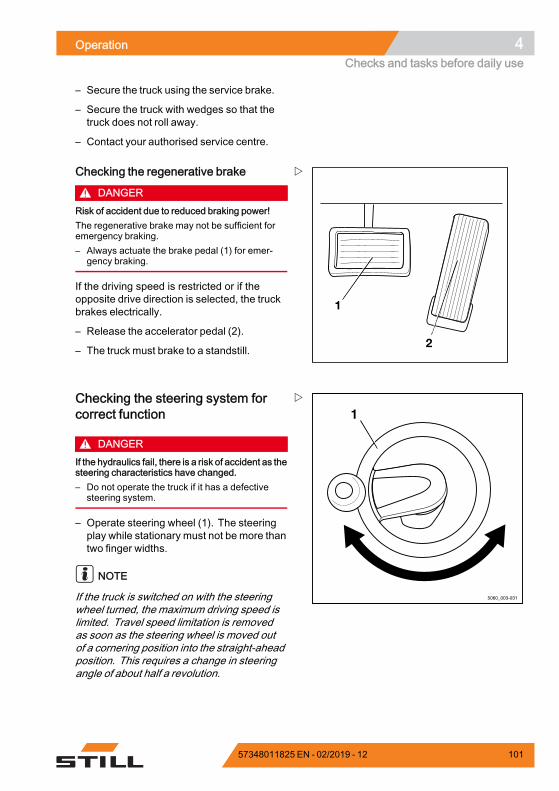
Operation 4Checks and tasks before daily use
– Secure the truck using the service brake.
– Secure the truck with wedges so that thetruck does not roll away.
– Contact your authorised service centre.
1
2
Checking the regenerative brake
DANGERRisk of accident due to reduced braking power!The regenerative brake may not be sufficient foremergency braking.– Always actuate the brake pedal (1) for emer-
gency braking.
If the driving speed is restricted or if theopposite drive direction is selected, the truckbrakes electrically.
– Release the accelerator pedal (2).
– The truck must brake to a standstill.
5060_003-031
1Checking the steering system forcorrect function
DANGERIf the hydraulics fail, there is a risk of accident as thesteering characteristics have changed.– Do not operate the truck if it has a defective
steering system.
– Operate steering wheel (1). The steeringplay while stationary must not be more thantwo finger widths.
NOTE
If the truck is switched on with the steeringwheel turned, the maximum driving speed islimited. Travel speed limitation is removedas soon as the steering wheel is moved outof a cornering position into the straight-aheadposition. This requires a change in steeringangle of about half a revolution.
57348011825 EN - 02/2019 - 12 101
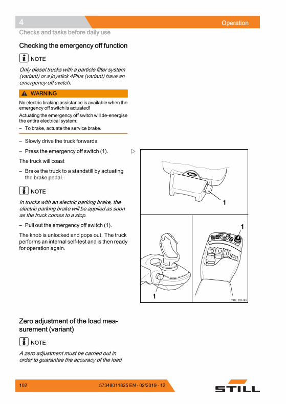
4 OperationChecks and tasks before daily use
Checking the emergency off function
NOTE
Only diesel trucks with a particle filter system(variant) or a joystick 4Plus (variant) have anemergency off switch.
WARNINGNo electric braking assistance is available when theemergency off switch is actuated!Actuating the emergency off switch will de-energisethe entire electrical system.– To brake, actuate the service brake.
– Slowly drive the truck forwards.
7312_003-183
F1F1 F2F2
1
1
1
– Press the emergency off switch (1).
The truck will coast
– Brake the truck to a standstill by actuatingthe brake pedal.
NOTE
In trucks with an electric parking brake, theelectric parking brake will be applied as soonas the truck comes to a stop.
– Pull out the emergency off switch (1).
The knob is unlocked and pops out. The truckperforms an internal self-test and is then readyfor operation again.
Zero adjustment of the load mea-surement (variant)
NOTE
A zero adjustment must be carried out inorder to guarantee the accuracy of the load
102 57348011825 EN - 02/2019 - 12
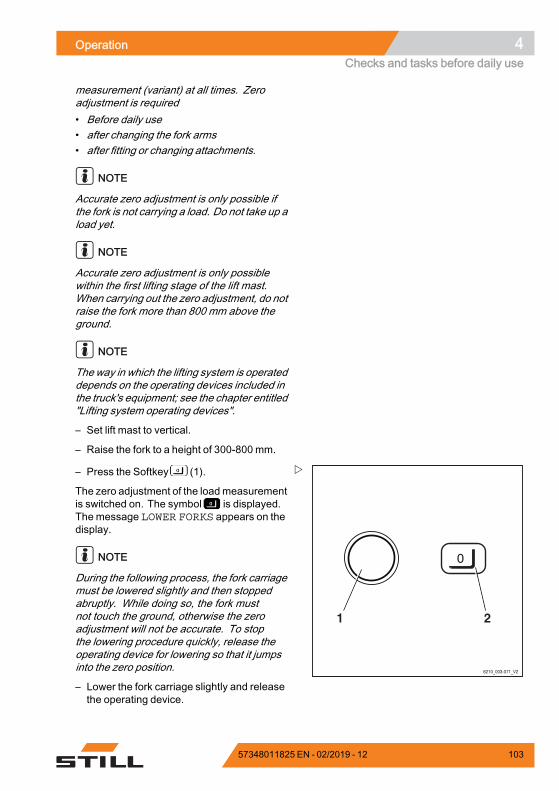
Operation 4Checks and tasks before daily use
measurement (variant) at all times. Zeroadjustment is required• Before daily use• after changing the fork arms• after fitting or changing attachments.
NOTE
Accurate zero adjustment is only possible ifthe fork is not carrying a load. Do not take up aload yet.
NOTE
Accurate zero adjustment is only possiblewithin the first lifting stage of the lift mast.When carrying out the zero adjustment, do notraise the fork more than 800 mm above theground.
NOTE
Theway in which the lifting system is operateddepends on the operating devices included inthe truck's equipment; see the chapter entitled"Lifting system operating devices".
– Set lift mast to vertical.
– Raise the fork to a height of 300-800 mm.
6210_003-071_V2
21
– Press the Softkey (1).
The zero adjustment of the loadmeasurementis switched on. The symbol is displayed.The message LOWER FORKS appears on thedisplay.
NOTE
During the following process, the fork carriagemust be lowered slightly and then stoppedabruptly. While doing so, the fork mustnot touch the ground, otherwise the zeroadjustment will not be accurate. To stopthe lowering procedure quickly, release theoperating device for lowering so that it jumpsinto the zero position.
– Lower the fork carriage slightly and releasethe operating device.
57348011825 EN - 02/2019 - 12 103
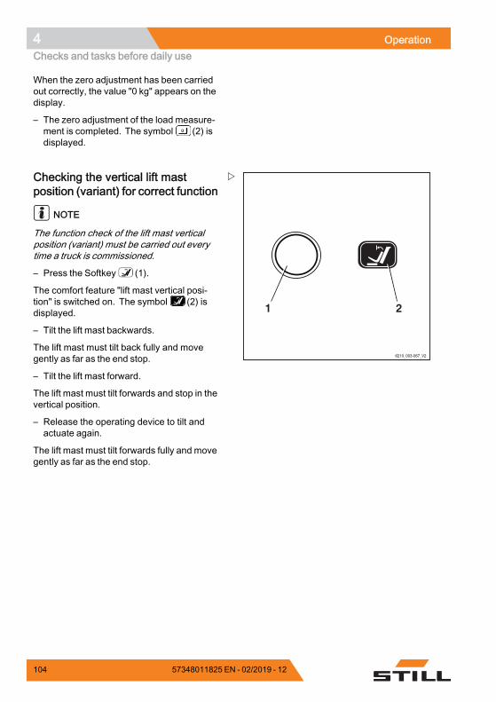
4 OperationChecks and tasks before daily use
When the zero adjustment has been carriedout correctly, the value "0 kg" appears on thedisplay.
– The zero adjustment of the load measure-ment is completed. The symbol (2) isdisplayed.
6210_003-067_V2
21
Checking the vertical lift mastposition (variant) for correct function
NOTE
The function check of the lift mast verticalposition (variant) must be carried out everytime a truck is commissioned.
– Press the Softkey (1).
The comfort feature "lift mast vertical posi-tion" is switched on. The symbol (2) isdisplayed.
– Tilt the lift mast backwards.
The lift mast must tilt back fully and movegently as far as the end stop.
– Tilt the lift mast forward.
The lift mast must tilt forwards and stop in thevertical position.
– Release the operating device to tilt andactuate again.
The lift mast must tilt forwards fully and movegently as far as the end stop.
104 57348011825 EN - 02/2019 - 12
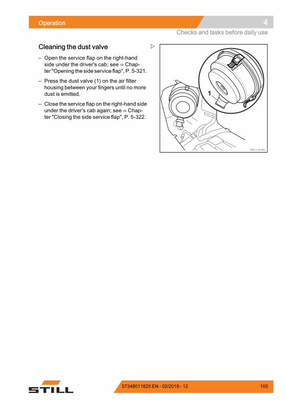
Operation 4Checks and tasks before daily use
1
7331_132-001
Cleaning the dust valve– Open the service flap on the right-handside under the driver's cab; see ⇒ Chap-ter "Opening the side service flap", P. 5-321.
– Press the dust valve (1) on the air filterhousing between your fingers until no moredust is emitted.
– Close the service flap on the right-hand sideunder the driver's cab again; see ⇒ Chap-ter "Closing the side service flap", P. 5-322.
57348011825 EN - 02/2019 - 12 105
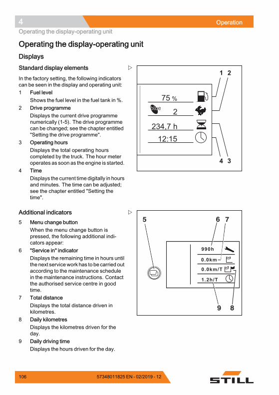
4 OperationOperating the display-operating unit
Operating the display-operating unitDisplays
%75
2
234,7 h12:15
1 2
34
Standard display elements
In the factory setting, the following indicatorscan be seen in the display and operating unit:1 Fuel level
Shows the fuel level in the fuel tank in %.2 Drive programme
Displays the current drive programmenumerically (1-5). The drive programmecan be changed; see the chapter entitled"Setting the drive programme".
3 Operating hoursDisplays the total operating hourscompleted by the truck. The hour meteroperates as soon as the engine is started.
4 TimeDisplays the current time digitally in hoursand minutes. The time can be adjusted;see the chapter entitled "Setting thetime".
990h
0.0km
0.0km/T
1.2h/T
6 75
89
Additional indicators5 Menu change button
When the menu change button ispressed, the following additional indi-cators appear:
6 "Service in" indicatorDisplays the remaining time in hours untilthe next servicework has to be carried outaccording to the maintenance schedulein the maintenance instructions. Contactthe authorised service centre in goodtime.
7 Total distanceDisplays the total distance driven inkilometres.
8 Daily kilometresDisplays the kilometres driven for theday.
9 Daily driving timeDisplays the hours driven for the day.
106 57348011825 EN - 02/2019 - 12
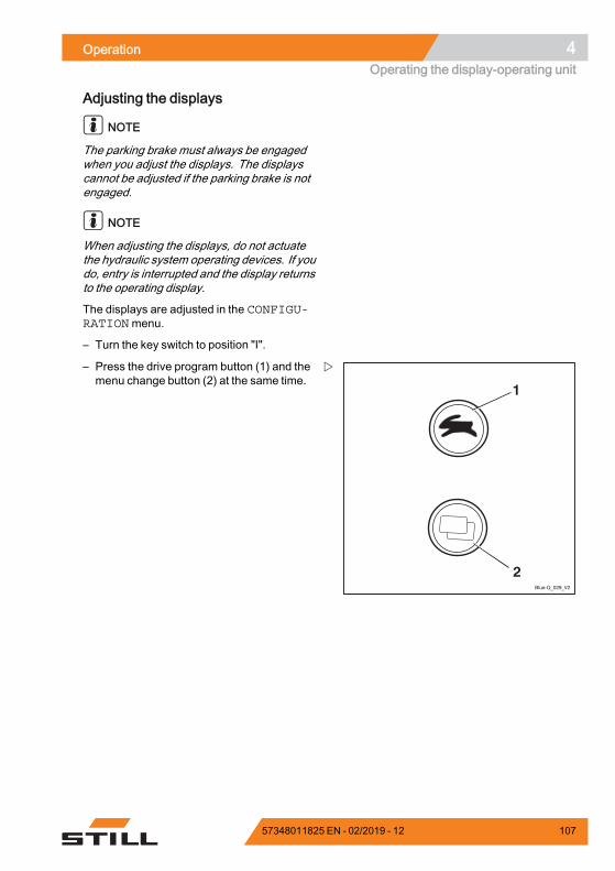
Operation 4Operating the display-operating unit
Adjusting the displays
NOTE
The parking brake must always be engagedwhen you adjust the displays. The displayscannot be adjusted if the parking brake is notengaged.
NOTE
When adjusting the displays, do not actuatethe hydraulic system operating devices. If youdo, entry is interrupted and the display returnsto the operating display.
The displays are adjusted in the CONFIGU-RATIONmenu.
– Turn the key switch to position "I".
Blue-Q_029_V2
1
2
– Press the drive program button (1) and themenu change button (2) at the same time.
57348011825 EN - 02/2019 - 12 107
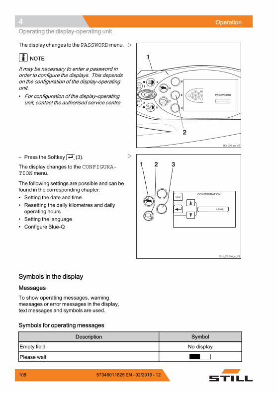
4 OperationOperating the display-operating unit
8
9
6
7
4
2
0
1
3
5
1
2
BQ_030_en_V2
1
2
6
7
3
4
5
ESC
The display changes to thePASSWORDmenu.
NOTE
It may be necessary to enter a password inorder to configure the displays. This dependson the configuration of the display-operatingunit.• For configuration of the display-operatingunit, contact the authorised service centre
7312_003-056_en_V3
ESC
1 2 3– Press the Softkey (3).
The display changes to the CONFIGURA-TIONmenu.
The following settings are possible and can befound in the corresponding chapter:• Setting the date and time• Resetting the daily kilometres and dailyoperating hours
• Setting the language• Configure Blue-Q
Symbols in the display
MessagesTo show operating messages, warningmessages or error messages in the display,text messages and symbols are used.
Symbols for operating messages
Description Symbol
Empty field No display
Please wait
108 57348011825 EN - 02/2019 - 12
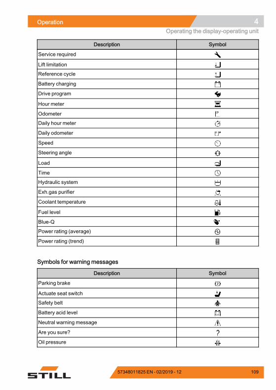
Operation 4Operating the display-operating unit
Description Symbol
Service required
Lift limitation
Reference cycle
Battery charging
Drive program
Hour meter
Odometer
Daily hour meter
Daily odometer
Speed
Steering angle
Load
Time
Hydraulic system
Exh.gas purifier
Coolant temperature
Fuel level
Blue-Q
Power rating (average)
Power rating (trend).
Symbols for warning messages
Description Symbol
Parking brake
Actuate seat switch
Safety belt
Battery acid level
Neutral warning message
Are you sure?
Oil pressure.
57348011825 EN - 02/2019 - 12 109
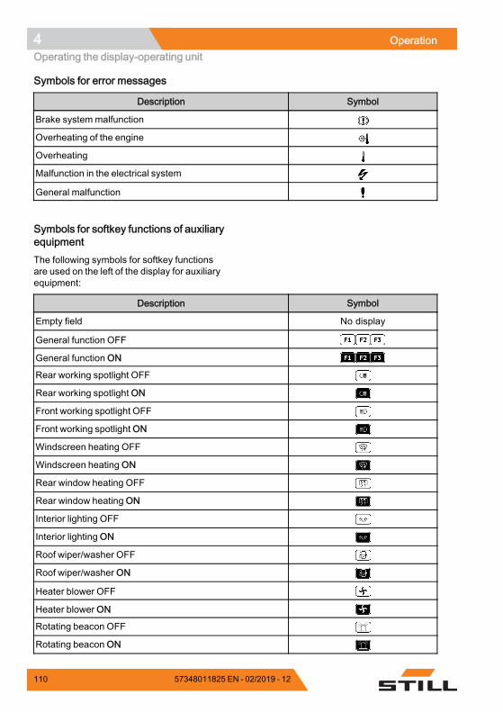
4 OperationOperating the display-operating unit
Symbols for error messages
Description Symbol
Brake systemmalfunction
Overheating of the engine
Overheating
Malfunction in the electrical system
General malfunction.
Symbols for softkey functions of auxiliaryequipmentThe following symbols for softkey functionsare used on the left of the display for auxiliaryequipment:
Description Symbol
Empty field No display
General function OFF
General function ON
Rear working spotlight OFF
Rear working spotlight ON
Front working spotlight OFF
Front working spotlight ON
Windscreen heating OFF
Windscreen heating ON
Rear window heating OFF
Rear window heating ON
Interior lighting OFF
Interior lighting ON
Roof wiper/washer OFF
Roof wiper/washer ON
Heater blower OFF
Heater blower ON
Rotating beacon OFF
Rotating beacon ON
110 57348011825 EN - 02/2019 - 12
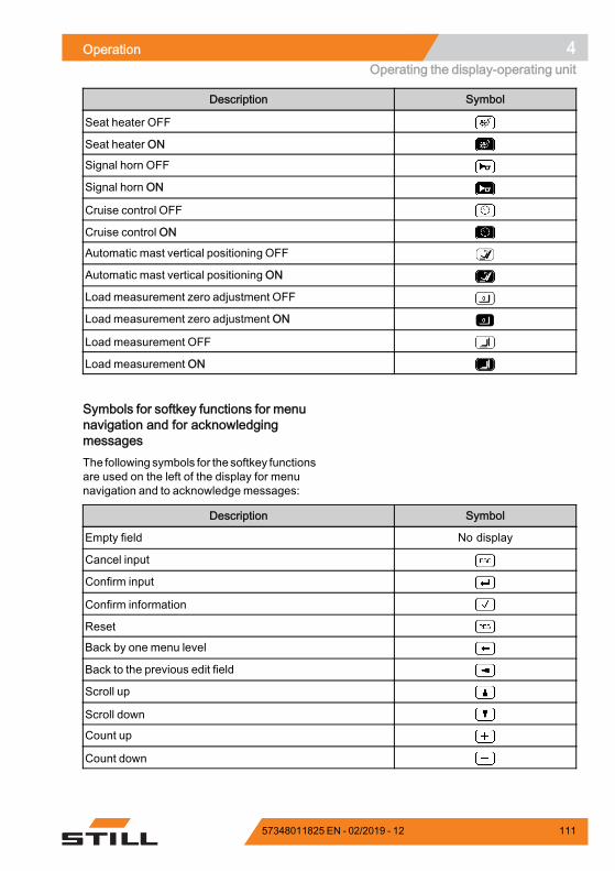
Operation 4Operating the display-operating unit
Description Symbol
Seat heater OFF
Seat heater ON
Signal horn OFF
Signal horn ON
Cruise control OFF
Cruise control ON
Automatic mast vertical positioning OFF
Automatic mast vertical positioning ON
Loadmeasurement zero adjustment OFF
Load measurement zero adjustment ON
Load measurement OFF
Load measurement ON.
Symbols for softkey functions for menunavigation and for acknowledgingmessagesThe following symbols for the softkey functionsare used on the left of the display for menunavigation and to acknowledge messages:
Description Symbol
Empty field No display
Cancel input
Confirm input
Confirm information
Reset
Back by one menu level
Back to the previous edit field
Scroll up
Scroll down
Count up
Count down.
57348011825 EN - 02/2019 - 12 111
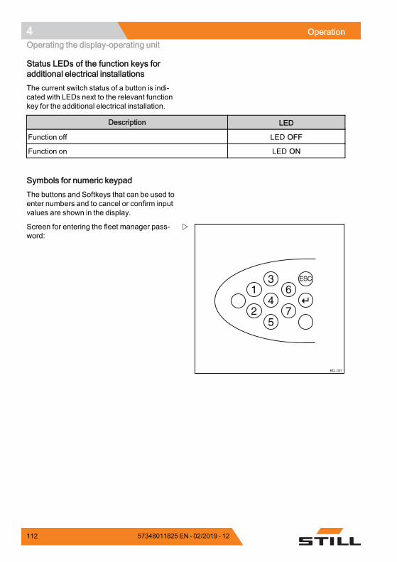
4 OperationOperating the display-operating unit
Status LEDs of the function keys foradditional electrical installationsThe current switch status of a button is indi-cated with LEDs next to the relevant functionkey for the additional electrical installation.
Description LED
Function off LED OFF
Function on LED ON.
Symbols for numeric keypadThe buttons and Softkeys that can be used toenter numbers and to cancel or confirm inputvalues are shown in the display.
BQ_037
1
2
6
7
3
4
5
ESC
Screen for entering the fleet manager pass-word:
112 57348011825 EN - 02/2019 - 12
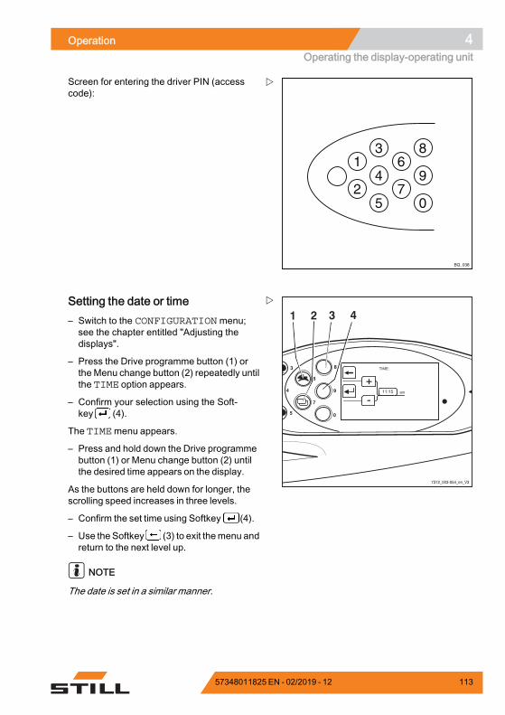
Operation 4Operating the display-operating unit
1
2
6
7
3
4
5
8
9
0
BQ_038
Screen for entering the driver PIN (accesscode):
8
9
0
6
7
4
3
5
7312_003-054_en_V3
1 2 3 4Setting the date or time– Switch to the CONFIGURATIONmenu;see the chapter entitled "Adjusting thedisplays".
– Press the Drive programme button (1) orthe Menu change button (2) repeatedly untilthe TIME option appears.
– Confirm your selection using the Soft-key (4).
The TIMEmenu appears.
– Press and hold down the Drive programmebutton (1) or Menu change button (2) untilthe desired time appears on the display.
As the buttons are held down for longer, thescrolling speed increases in three levels.
– Confirm the set time using Softkey (4).
– Use the Softkey (3) to exit themenu andreturn to the next level up.
NOTE
The date is set in a similar manner.
57348011825 EN - 02/2019 - 12 113
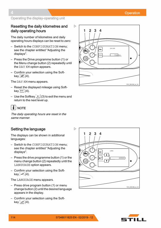
4 OperationOperating the display-operating unit
8
9
0
6
7
4
3
5
7312_003-055_en_V4
1 2 3 4Resetting the daily kilometres anddaily operating hoursThe daily number of kilometres and dailyoperating hours displays can be reset to zero:
– Switch to the CONFIGURATIONmenu;see the chapter entitled "Adjusting thedisplays".
– Press the Drive programme button (1) orthe Menu change button (2) repeatedly untilthe DAY KM option appears.
– Confirm your selection using the Soft-key (4).
The DAY KMmenu appears.
– Reset the displayed mileage using Soft-key (4).
– Use the Softkey (3) to exit themenu andreturn to the next level up.
NOTE
The daily operating hours are reset in thesamemanner.
8
9
0
6
7
4
3
5
7312_003-058_en_V4
1 2 3 4Setting the languageThe displays can be shown in additionallanguages:
– Switch to the CONFIGURATIONmenu;see the chapter entitled "Adjusting thedisplays".
– Press the drive programme button (1) or themenu change button (2) repeatedly until theLANGUAGE option appears.
– Confirm your selection using the Soft-key (4).
The LANGUAGEmenu appears.
– Press drive program button (1) or menuchangebutton (2) until the desired languageappears in the display.
– Confirm your selection using the Soft-key (4).
114 57348011825 EN - 02/2019 - 12
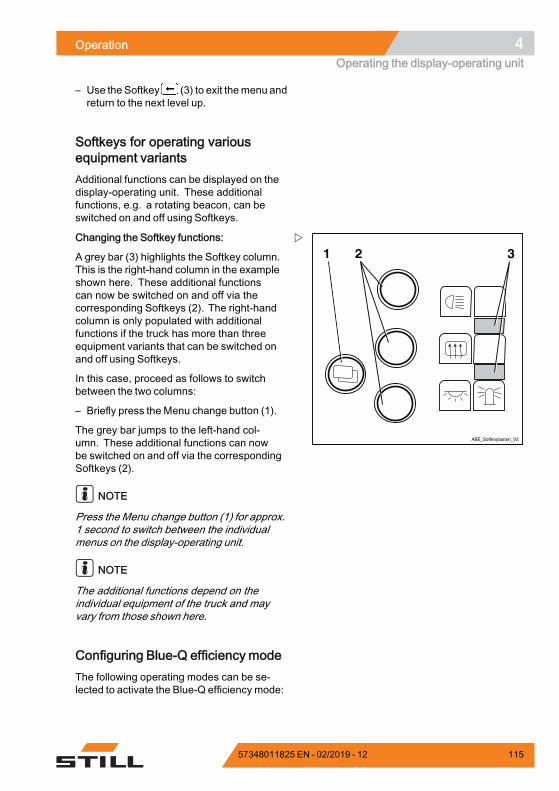
Operation 4Operating the display-operating unit
– Use the Softkey (3) to exit themenu andreturn to the next level up.
Softkeys for operating variousequipment variantsAdditional functions can be displayed on thedisplay-operating unit. These additionalfunctions, e.g. a rotating beacon, can beswitched on and off using Softkeys.
1 2 3
ABE_Softkeytasten_V2
Changing the Softkey functions:
A grey bar (3) highlights the Softkey column.This is the right-hand column in the exampleshown here. These additional functionscan now be switched on and off via thecorresponding Softkeys (2). The right-handcolumn is only populated with additionalfunctions if the truck has more than threeequipment variants that can be switched onand off using Softkeys.
In this case, proceed as follows to switchbetween the two columns:
– Briefly press the Menu change button (1).
The grey bar jumps to the left-hand col-umn. These additional functions can nowbe switched on and off via the correspondingSoftkeys (2).
NOTE
Press the Menu change button (1) for approx.1 second to switch between the individualmenus on the display-operating unit.
NOTE
The additional functions depend on theindividual equipment of the truck and mayvary from those shown here.
Configuring Blue-Q efficiency modeThe following operating modes can be se-lected to activate the Blue-Q efficiency mode:
57348011825 EN - 02/2019 - 12 115
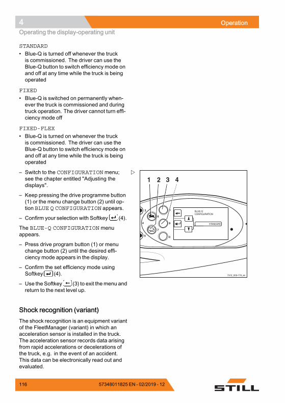
4 OperationOperating the display-operating unit
STANDARD
• Blue-Q is turned off whenever the truckis commissioned. The driver can use theBlue-Q button to switch efficiency mode onand off at any time while the truck is beingoperated
FIXED
• Blue-Q is switched on permanently when-ever the truck is commissioned and duringtruck operation. The driver cannot turn effi-ciency mode off
FIXED-FLEX
• Blue-Q is turned on whenever the truckis commissioned. The driver can use theBlue-Q button to switch efficiency mode onand off at any time while the truck is beingoperated
8
9
0
6
7
4
3
5
7312_003-179_en
1 2 3 4– Switch to the CONFIGURATIONmenu;see the chapter entitled "Adjusting thedisplays".
– Keep pressing the drive programme button(1) or the menu change button (2) until op-tion BLUE Q CONFIGURATION appears.
– Confirm your selection with Softkey (4).
The BLUE-Q CONFIGURATION menuappears.
– Press drive program button (1) or menuchange button (2) until the desired effi-ciency mode appears in the display.
– Confirm the set efficiency mode usingSoftkey (4).
– Use the Softkey (3) to exit themenu andreturn to the next level up.
Shock recognition (variant)The shock recognition is an equipment variantof the FleetManager (variant) in which anacceleration sensor is installed in the truck.The acceleration sensor records data arisingfrom rapid accelerations or decelerations ofthe truck, e.g. in the event of an accident.This data can be electronically read out andevaluated.
116 57348011825 EN - 02/2019 - 12

Operation 4Operating the display-operating unit
– If you have any questions, please contactyour authorised service centre.
Additional settingsBy entering a password, it is possible to setor find other values. The values must only bechanged by your service centre.
57348011825 EN - 02/2019 - 12 117
4 OperationBlue-Q efficiency mode
Blue-Q efficiency modeFunctional descriptionThe Blue-Q efficiency mode affects both thedrive unit and the activation of the additionalconsumers, and reduces the truck's energyconsumption.
If the efficiency mode has been activated, theacceleration behaviour of the truck changes tomake acceleration more moderate.
When travelling at low speeds—normallywhen manoeuvring—no reduction is notice-able despite the activated efficiency mode.For moderate speeds of at least approx.7 km/h, acceleration is gentler. Therefore,on distances of up to approx. 40 m, lowerspeeds are reached than would be the case ifthe efficiency mode was not activated.
Blue-Q has no influence on:• Maximum speed• Climbing capability• Traction• Braking characteristics
NOTE
The Blue-Q efficiency mode can be swit-ched on and off in the STANDARD and FI-XED-FLEX operating modes. If the FIXEDoperating mode is configured in the displayoperating unit, the Blue-Q button has no func-tion and the Blue-Q efficiency mode is swit-ched on permanently; see also chapter "Con-figuring Blue-Q efficiency mode".
118 57348011825 EN - 02/2019 - 12
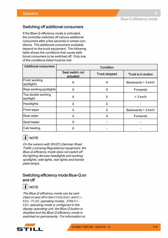
Operation 4Blue-Q efficiency mode
Switching off additional consumersIf the Blue-Q efficiency mode is activated,the controller switches off various additionalconsumers after a few seconds in certain con-ditions. The additional consumers availabledepend on the truck equipment. The followingtable shows the conditions that cause addi-tional consumers to be switched off. Only oneof the conditions listed must be met.
ConditionAdditional consumers
Seat switch notactuated
Truck stopped Truck is in motion
Front workingspotlights X X Backwards > 3 km/h
Rearworking spotlights X X ForwardsTop double workingspotlight X X > 3 km/h
Headlights X X -
Front wiper X X Backwards > 3 km/h
Rear wiper X X Forwards
Seat heater X - -
Cab heating X - -
NOTE
On the version with StVZO (German RoadTraffic Licensing Regulations) equipment, theBlue-Q efficiency mode does not switch offthe lighting devices headlights and workingspotlights, side lights, rear lights and licenseplate lamps.
Switching efficiencymode Blue-Q onand off
NOTE
The Blue-Q efficiency mode can be swit-ched on and off in the STANDARD and FI-XED-FLEX operating modes. If the FI-XED operating mode is configured in thedisplay-operating unit, the Blue-Q button isdisabled and the Blue-Q efficiency mode isswitched on permanently. For information on
57348011825 EN - 02/2019 - 12 119
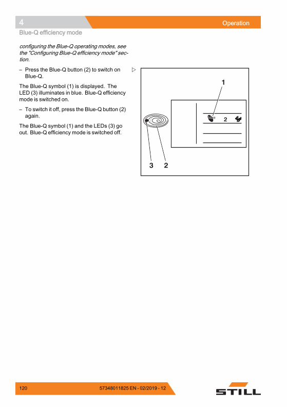
4 OperationBlue-Q efficiency mode
configuring the Blue-Q operating modes, seethe "Configuring Blue-Q efficiency mode" sec-tion.
2
2
1
3
– Press the Blue-Q button (2) to switch onBlue-Q.
The Blue-Q symbol (1) is displayed. TheLED (3) illuminates in blue. Blue-Q efficiencymode is switched on.
– To switch it off, press the Blue-Q button (2)again.
The Blue-Q symbol (1) and the LEDs (3) goout. Blue-Q efficiency mode is switched off.
120 57348011825 EN - 02/2019 - 12
Operation 4Driving
DrivingSafety regulations when driving
Driving conductThe driver must follow the public rules of theroad when driving in company traffic.
The speed must be appropriate to the localconditions.
For example, the driver must drive slowlyaround corners, in tight passageways, whendriving through swing-doors, at blind spots, oron uneven surfaces.
The driver must always maintain a safebraking distance from vehicles and persons infront, and must always have the truck undercontrol. Stopping suddenly, turning quicklyand overtaking at dangerous or blind spotsmust be avoided.
– Initial driving practice must be carried out inan empty space or on a clear roadway.
The following are forbidden during driving:• Allowing arms and legs to hang outside thetruck
• Leaning the body over the outer contour ofthe truck
• Climbing out of the truck• Moving the driver's seat• Adjusting the steering column• Releasing the seat belt• Disabling the restraint system• Raising the load higher than 300 mmabove the ground (with the exceptionof manoeuvring processes during theplacement into stock/removal from stockof loads)
• Using electronic devices, for exampleradios, mobile phones etc.
57348011825 EN - 02/2019 - 12 121
4 OperationDriving
WARNINGThe use of multimedia and communication equip-ment as well as playing these devices at an exces-sive volume during travel or when handling loadscan affect the operator's attention. There is a risk ofaccident!– Do not use devices during travel or when hand-
ling loads.– Set the volume so that warning signals can still
be heard.
WARNINGIn areas where use of mobile phones is prohibited,use of a mobile phone or radio telephone is notpermitted.– Switch off the devices.
Visibility when drivingThe driver must look in the drive direction andhave a sufficient view of the driving lane.
Particularly for reverse travel, the driver mustbe sure that the driving lane is clear.
When transporting goods that impair visibility,the driver must drive the truck in reverse.
If this is not possible, a second person actingas a guide must walk in front of the truck.
In this case the driver must only move atwalking pace and with extra care. The truckmust be stopped immediately if eye contactwith the guide is lost.
Rear-view mirrors are only to be used forobserving the road area behind the truck andnot for reverse travel. If visual aids (mirror,monitor) are necessary to achieve sufficientvisibility, it is necessary to practise using them.For reverse travel using visual aids, extra careshould be taken.
When using attachments, special conditionsapply; see the chapter entitled "Fitting attach-ments".
Any glass (variant, e.g. windscreen) andmirrors must always be clean and free of ice.
122 57348011825 EN - 02/2019 - 12
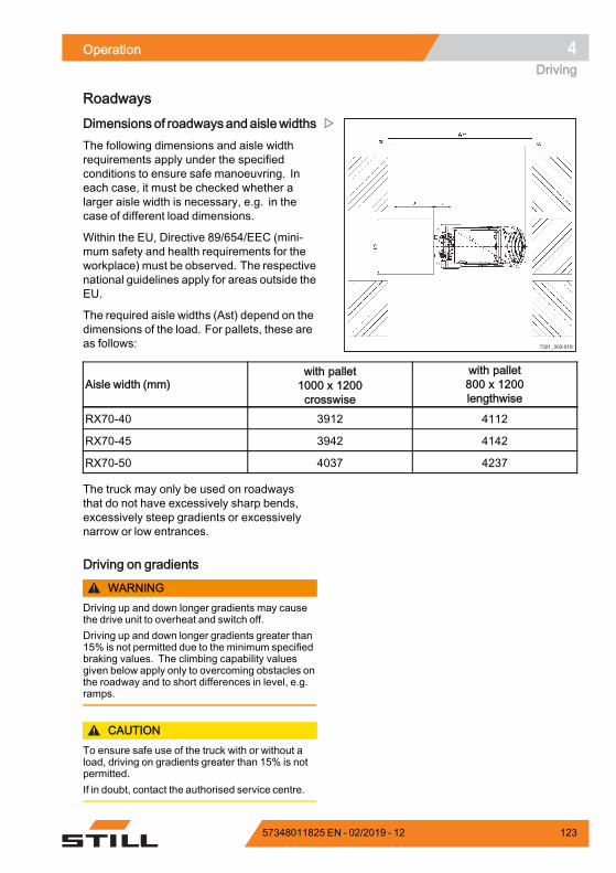
Operation 4Driving
Roadways
7321_003-019
Dimensions of roadwaysandaislewidthsThe following dimensions and aisle widthrequirements apply under the specifiedconditions to ensure safe manoeuvring. Ineach case, it must be checked whether alarger aisle width is necessary, e.g. in thecase of different load dimensions.
Within the EU, Directive 89/654/EEC (mini-mum safety and health requirements for theworkplace) must be observed. The respectivenational guidelines apply for areas outside theEU.
The required aisle widths (Ast) depend on thedimensions of the load. For pallets, these areas follows:
Aisle width (mm)with pallet1000 x 1200crosswise
with pallet800 x 1200lengthwise
RX70-40 3912 4112
RX70-45 3942 4142
RX70-50 4037 4237
The truck may only be used on roadwaysthat do not have excessively sharp bends,excessively steep gradients or excessivelynarrow or low entrances.
Driving on gradients
WARNINGDriving up and down longer gradients may causethe drive unit to overheat and switch off.Driving up and down longer gradients greater than15% is not permitted due to the minimum specifiedbraking values. The climbing capability valuesgiven below apply only to overcoming obstacles onthe roadway and to short differences in level, e.g.ramps.
CAUTIONTo ensure safe use of the truck with or without aload, driving on gradients greater than 15% is notpermitted.If in doubt, contact the authorised service centre.
57348011825 EN - 02/2019 - 12 123
4 OperationDriving
NOTE
The values specified in the following tablemust be used only to compare the perfor-mance of forklift trucks in the same category.The gradient values in no way represent thenormal daily operating conditions.
Max. gradient in % with load without load
RX70-40 29 26
RX70-45 29 26
RX70-50 25 23
The ascending and descending gradientsmust not exceed the gradients listed aboveand must have a rough surface.
Smooth and gradual transitions should beprovided at the top and bottom of the gradientto prevent the load from falling to the ground orthe truck being damaged.
Warning in case components projectbeyond the truck contour
Trucks are often required to drive through verynarrow or very low spaces such as aisles orcontainers. The dimensions of the trucks aredesigned for this purpose. However, movableparts may project beyond the truck contourand be damaged or torn off. Examples ofthese components are:• A folding roof panel in the driver's cab• Cab doors• Folding LPG cylinders
Condition of the roadwaysDriveways must be made sufficiently firm, andbe level and free of dirt and fallen objects.
Drainage channels, level crossings andsimilar obstacles must be evened out so thattrucks can drive over these obstacles with asfew bumps as possible. If necessary, rampsmust be provided for these obstacles.
Ensure that manhole covers, drain covers etc.offer a sufficient load capacity.
124 57348011825 EN - 02/2019 - 12
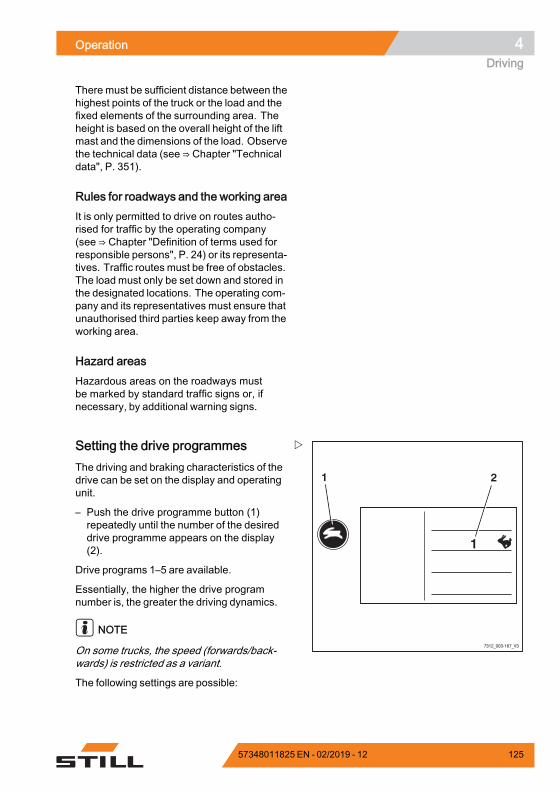
Operation 4Driving
There must be sufficient distance between thehighest points of the truck or the load and thefixed elements of the surrounding area. Theheight is based on the overall height of the liftmast and the dimensions of the load. Observethe technical data (see ⇒ Chapter "Technicaldata", P. 351).
Rules for roadways and the working areaIt is only permitted to drive on routes autho-rised for traffic by the operating company(see ⇒ Chapter "Definition of terms used forresponsible persons", P. 24) or its representa-tives. Traffic routes must be free of obstacles.The load must only be set down and stored inthe designated locations. The operating com-pany and its representatives must ensure thatunauthorised third parties keep away from theworking area.
Hazard areasHazardous areas on the roadways mustbe marked by standard traffic signs or, ifnecessary, by additional warning signs.
7312_003-167_V3
1
1 2
Setting the drive programmesThe driving and braking characteristics of thedrive can be set on the display and operatingunit.
– Push the drive programme button (1)repeatedly until the number of the desireddrive programme appears on the display(2).
Drive programs 1–5 are available.
Essentially, the higher the drive programnumber is, the greater the driving dynamics.
NOTE
On some trucks, the speed (forwards/back-wards) is restricted as a variant.
The following settings are possible:
57348011825 EN - 02/2019 - 12 125
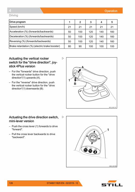
4 OperationDriving
Drive program 1 2 3 4 5
Speed (km/h) 21 21 21 21 21
Acceleration (%) (forwards/backwards) 50 100 120 140 160
Deceleration (%) (forwards/backwards) 50 100 120 140 160
Reversing (%) (forwards/backwards) 50 100 120 140 160
Brake retardation (%) (electric brake booster) 80 90 100 100 100.
1
6210_003-101
A
B
Actuating the vertical rockerswitch for the "drive direction", joy-stick 4Plus version– For the "forwards" drive direction, pushthe vertical rocker button for the "drivedirection"(1) upwards (A).
– For the "reverse" drive direction, pushthe vertical rocker button for the "drivedirection"(1) downwards (B).
5060_003-096
F1 F2
1
Actuating the drive direction switch,mini-lever version– Push the cross lever (1) forwards to drive"forward".
– Pull the cross lever backwards to drive"backward".
126 57348011825 EN - 02/2019 - 12
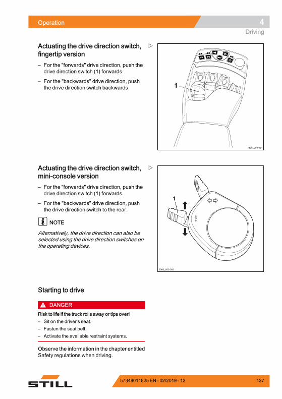
Operation 4Driving
F1F1 F2F2
7325_003-031
1
Actuating the drive direction switch,fingertip version– For the "forwards" drive direction, push thedrive direction switch (1) forwards
– For the "backwards" drive direction, pushthe drive direction switch backwards
5060_003-005
1
Actuating the drive direction switch,mini-console version– For the "forwards" drive direction, push thedrive direction switch (1) forwards.
– For the "backwards" drive direction, pushthe drive direction switch to the rear.
NOTE
Alternatively, the drive direction can also beselected using the drive direction switches onthe operating devices.
Starting to drive
DANGERRisk to life if the truck rolls away or tips over!– Sit on the driver's seat.– Fasten the seat belt.– Activate the available restraint systems.
Observe the information in the chapter entitledSafety regulations when driving.
57348011825 EN - 02/2019 - 12 127
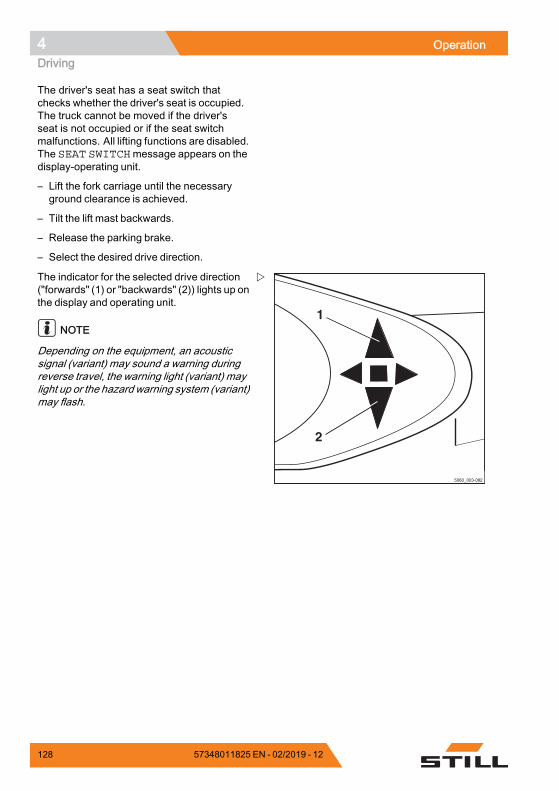
4 OperationDriving
The driver's seat has a seat switch thatchecks whether the driver's seat is occupied.The truck cannot be moved if the driver'sseat is not occupied or if the seat switchmalfunctions. All lifting functions are disabled.The SEAT SWITCHmessage appears on thedisplay-operating unit.
– Lift the fork carriage until the necessaryground clearance is achieved.
– Tilt the lift mast backwards.
– Release the parking brake.
– Select the desired drive direction.
5060_003-082
1
2
The indicator for the selected drive direction("forwards" (1) or "backwards" (2)) lights up onthe display and operating unit.
NOTE
Depending on the equipment, an acousticsignal (variant) may sound a warning duringreverse travel, the warning light (variant) maylight up or the hazard warning system (variant)may flash.
128 57348011825 EN - 02/2019 - 12
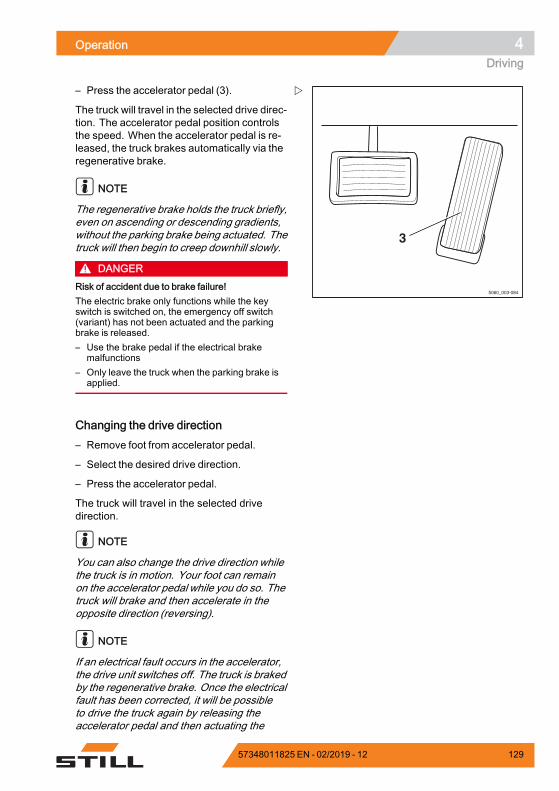
Operation 4Driving
3
5060_003-084
– Press the accelerator pedal (3).
The truck will travel in the selected drive direc-tion. The accelerator pedal position controlsthe speed. When the accelerator pedal is re-leased, the truck brakes automatically via theregenerative brake.
NOTE
The regenerative brake holds the truck briefly,even on ascending or descending gradients,without the parking brake being actuated. Thetruck will then begin to creep downhill slowly.
DANGERRisk of accident due to brake failure!The electric brake only functions while the keyswitch is switched on, the emergency off switch(variant) has not been actuated and the parkingbrake is released.– Use the brake pedal if the electrical brake
malfunctions– Only leave the truck when the parking brake is
applied.
Changing the drive direction– Remove foot from accelerator pedal.
– Select the desired drive direction.
– Press the accelerator pedal.
The truck will travel in the selected drivedirection.
NOTE
You can also change the drive direction whilethe truck is in motion. Your foot can remainon the accelerator pedal while you do so. Thetruck will brake and then accelerate in theopposite direction (reversing).
NOTE
If an electrical fault occurs in the accelerator,the drive unit switches off. The truck is brakedby the regenerative brake. Once the electricalfault has been corrected, it will be possibleto drive the truck again by releasing theaccelerator pedal and then actuating the
57348011825 EN - 02/2019 - 12 129
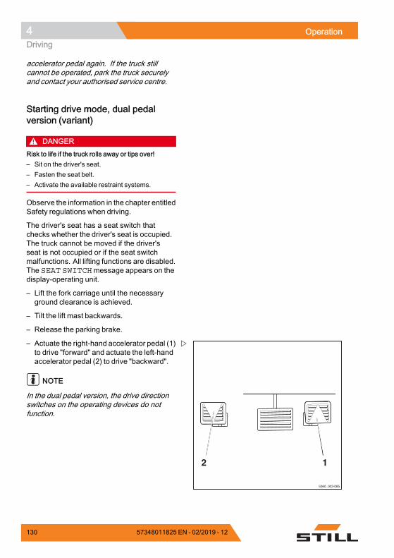
4 OperationDriving
accelerator pedal again. If the truck stillcannot be operated, park the truck securelyand contact your authorised service centre.
Starting drive mode, dual pedalversion (variant)
DANGERRisk to life if the truck rolls away or tips over!– Sit on the driver's seat.– Fasten the seat belt.– Activate the available restraint systems.
Observe the information in the chapter entitledSafety regulations when driving.
The driver's seat has a seat switch thatchecks whether the driver's seat is occupied.The truck cannot be moved if the driver'sseat is not occupied or if the seat switchmalfunctions. All lifting functions are disabled.The SEAT SWITCHmessage appears on thedisplay-operating unit.
– Lift the fork carriage until the necessaryground clearance is achieved.
– Tilt the lift mast backwards.
– Release the parking brake.
5060_003-085
2 1
– Actuate the right-hand accelerator pedal (1)to drive "forward" and actuate the left-handaccelerator pedal (2) to drive "backward".
NOTE
In the dual pedal version, the drive directionswitches on the operating devices do notfunction.
130 57348011825 EN - 02/2019 - 12
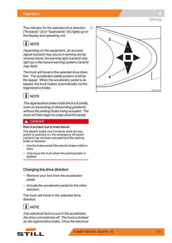
Operation 4Driving
5060_003-083
3
4
The indicator for the selected drive direction("forwards" (3) or "backwards" (4)) lights up onthe display and operating unit.
NOTE
Depending on the equipment, an acousticsignal (variant) may sound a warning duringreverse travel, the warning light (variant) maylight up or the hazard warning system (variant)may flash.
The truck will travel in the selected drive direc-tion. The accelerator pedal position controlsthe speed. When the accelerator pedal is re-leased, the truck brakes automatically via theregenerative brake.
NOTE
The regenerative brake holds the truck briefly,even on ascending or descending gradients,without the parking brake being actuated. Thetruck will then begin to creep downhill slowly.
DANGERRisk of accident due to brake failure!The electric brake only functions while the keyswitch is switched on, the emergency off switch(variant) has not been actuated and the parkingbrake is released.– Use the brake pedal if the electric brakemalfunc-
tions.– Only leave the truck when the parking brake is
applied.
Changing the drive direction– Remove your foot from the acceleratorpedal.
– Actuate the accelerator pedal for the otherdirection.
The truck will travel in the selected drivedirection.
NOTE
If an electrical fault occurs in the accelerator,the drive unit switches off. The truck is brakedby the regenerative brake. Once the electrical
57348011825 EN - 02/2019 - 12 131
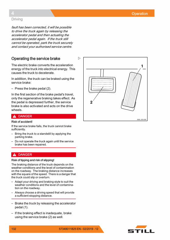
4 OperationDriving
fault has been corrected, it will be possibleto drive the truck again by releasing theaccelerator pedal and then actuating theaccelerator pedal again. If the truck stillcannot be operated, park the truck securelyand contact your authorised service centre.
1
2
5060_003-006
Operating the service brakeThe electric brake converts the accelerationenergy of the truck into electrical energy. Thiscauses the truck to decelerate.
In addition, the truck can be braked using theservice brake:
– Press the brake pedal (2).
In the first section of the brake pedal's travel,only the regenerative braking takes effect. Asthe pedal is depressed further, the servicebrake is also activated and acts on the drivewheels.
DANGERRisk of accident!If the service brake fails, the truck cannot brakesufficiently.– Bring the truck to a standstill by applying the
parking brake.– Do not operate the truck again until the service
brake has been repaired.
DANGERRisk of tipping and risk of slipping!The braking distance of the truck depends on theweather conditions and the level of contaminationon the roadway. The braking distance increaseswith the square of the speed. There is a danger thatthe truck could slip or overturn.– Adapt your driving and braking style to suit the
weather conditions and the level of contamina-tion on the roadway.
– Always choose a driving speed that will providea sufficient stopping distance.
– Brake the truck by releasing the acceleratorpedal (1).
– If the braking effect is inadequate, brakeusing the service brake (2) as well.
132 57348011825 EN - 02/2019 - 12
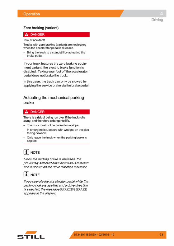
Operation 4Driving
Zero braking (variant)
DANGERRisk of accident!Trucks with zero braking (variant) are not brakedwhen the accelerator pedal is released.– Bring the truck to a standstill by actuating the
brake pedal.
If your truck features the zero braking equip-ment variant, the electric brake function isdisabled. Taking your foot off the acceleratorpedal does not brake the truck.
In this case, the truck can only be slowed byapplying the service brake via the brake pedal.
Actuating the mechanical parkingbrake
DANGERThere is a risk of being run over if the truck rollsaway, and therefore a danger to life.– The truck must not be parked on a slope.– In emergencies, secure with wedges on the side
facing downhill.– Only leave the truck when the parking brake is
applied.
NOTE
Once the parking brake is released, thepreviously selected drive direction is retainedand is shown on the drive direction indicator.
NOTE
If you operate the accelerator pedal while theparking brake is applied and a drive directionis selected, the message PARKING BRAKEappears in the display.
57348011825 EN - 02/2019 - 12 133
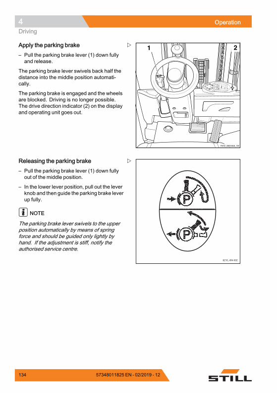
4 OperationDriving
8
9
6
72
0
13
5
%75
h
2
234,712:15
1 2
7312_003-044_V2
Apply the parking brake– Pull the parking brake lever (1) down fullyand release.
The parking brake lever swivels back half thedistance into the middle position automati-cally.
The parking brake is engaged and the wheelsare blocked. Driving is no longer possible.The drive direction indicator (2) on the displayand operating unit goes out.
6210_494-002
Releasing the parking brake– Pull the parking brake lever (1) down fullyout of the middle position.
– In the lower lever position, pull out the leverknob and then guide the parking brake leverup fully.
NOTE
The parking brake lever swivels to the upperposition automatically by means of springforce and should be guided only lightly byhand. If the adjustment is stiff, notify theauthorised service centre.
134 57348011825 EN - 02/2019 - 12
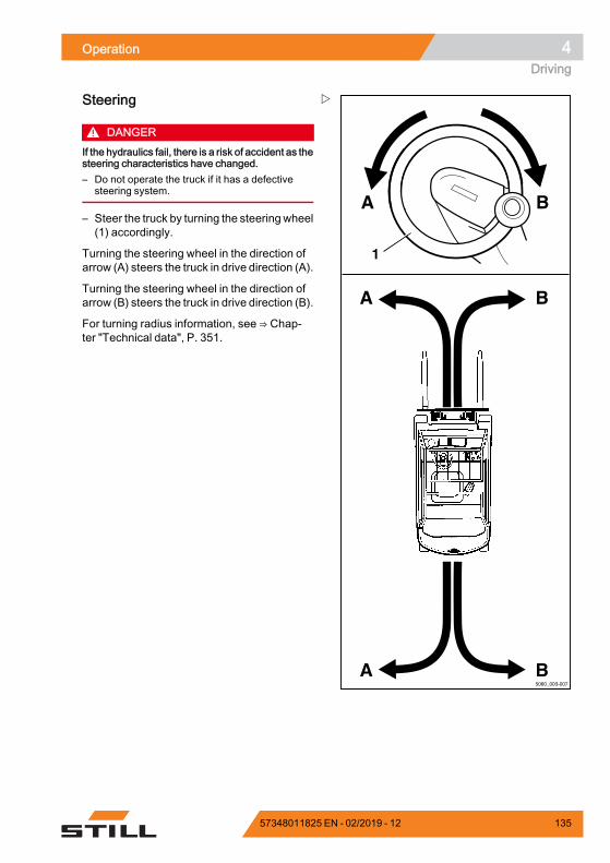
Operation 4Driving
A
A B
A B
B
5060_003-007
1
Steering
DANGERIf the hydraulics fail, there is a risk of accident as thesteering characteristics have changed.– Do not operate the truck if it has a defective
steering system.
– Steer the truck by turning the steeringwheel(1) accordingly.
Turning the steering wheel in the direction ofarrow (A) steers the truck in drive direction (A).
Turning the steering wheel in the direction ofarrow (B) steers the truck in drive direction (B).
For turning radius information, see ⇒ Chap-ter "Technical data", P. 351.
57348011825 EN - 02/2019 - 12 135
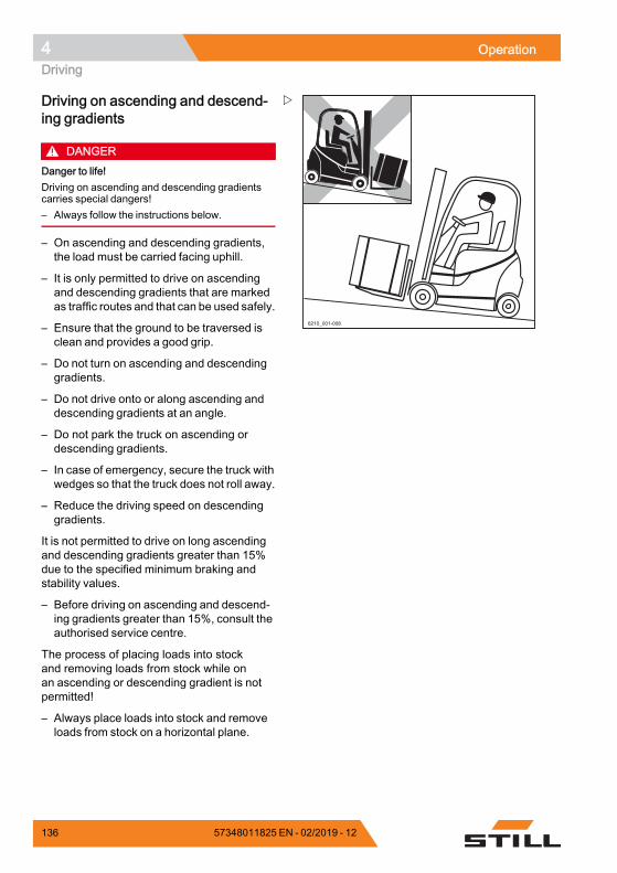
4 OperationDriving
6210_001-008
Driving on ascending and descend-ing gradients
DANGERDanger to life!Driving on ascending and descending gradientscarries special dangers!– Always follow the instructions below.
– On ascending and descending gradients,the load must be carried facing uphill.
– It is only permitted to drive on ascendingand descending gradients that are markedas traffic routes and that can be used safely.
– Ensure that the ground to be traversed isclean and provides a good grip.
– Do not turn on ascending and descendinggradients.
– Do not drive onto or along ascending anddescending gradients at an angle.
– Do not park the truck on ascending ordescending gradients.
– In case of emergency, secure the truck withwedges so that the truck does not roll away.
– Reduce the driving speed on descendinggradients.
It is not permitted to drive on long ascendingand descending gradients greater than 15%due to the specified minimum braking andstability values.
– Before driving on ascending and descend-ing gradients greater than 15%, consult theauthorised service centre.
The process of placing loads into stockand removing loads from stock while onan ascending or descending gradient is notpermitted!
– Always place loads into stock and removeloads from stock on a horizontal plane.
136 57348011825 EN - 02/2019 - 12
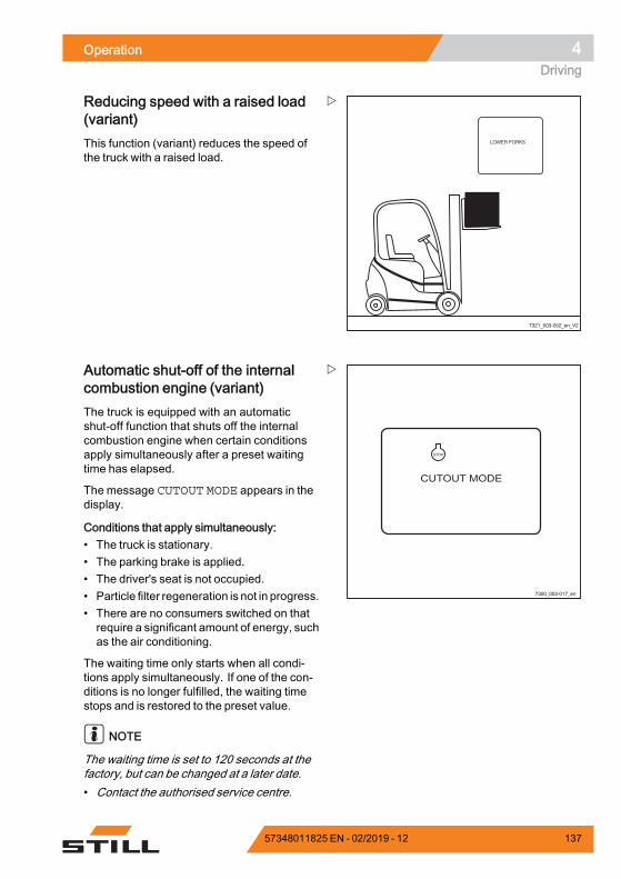
Operation 4Driving
7321_003-052_en_V2
Reducing speed with a raised load(variant)This function (variant) reduces the speed ofthe truck with a raised load.
7300_003-017_en
CUTOUT MODE
STOP
Automatic shut-off of the internalcombustion engine (variant)The truck is equipped with an automaticshut-off function that shuts off the internalcombustion engine when certain conditionsapply simultaneously after a preset waitingtime has elapsed.
The message CUTOUT MODE appears in thedisplay.
Conditions that apply simultaneously:• The truck is stationary.• The parking brake is applied.• The driver's seat is not occupied.• Particle filter regeneration is not in progress.• There are no consumers switched on thatrequire a significant amount of energy, suchas the air conditioning.
The waiting time only starts when all condi-tions apply simultaneously. If one of the con-ditions is no longer fulfilled, the waiting timestops and is restored to the preset value.
NOTE
The waiting time is set to 120 seconds at thefactory, but can be changed at a later date.• Contact the authorised service centre.
57348011825 EN - 02/2019 - 12 137
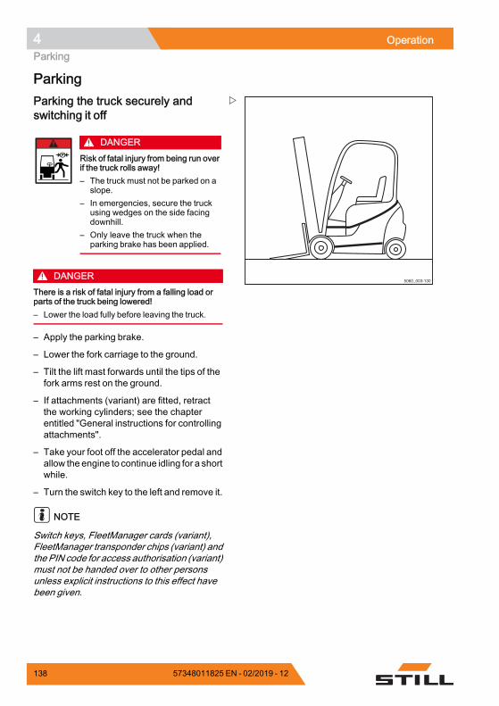
4 OperationParking
Parking
5060_003-130
Parking the truck securely andswitching it off
DANGERRisk of fatal injury from being run overif the truck rolls away!– The truck must not be parked on a
slope.– In emergencies, secure the truck
using wedges on the side facingdownhill.
– Only leave the truck when theparking brake has been applied.
DANGERThere is a risk of fatal injury from a falling load orparts of the truck being lowered!– Lower the load fully before leaving the truck.
– Apply the parking brake.
– Lower the fork carriage to the ground.
– Tilt the lift mast forwards until the tips of thefork arms rest on the ground.
– If attachments (variant) are fitted, retractthe working cylinders; see the chapterentitled "General instructions for controllingattachments".
– Take your foot off the accelerator pedal andallow the engine to continue idling for a shortwhile.
– Turn the switch key to the left and remove it.
NOTE
Switch keys, FleetManager cards (variant),FleetManager transponder chips (variant) andthe PIN code for access authorisation (variant)must not be handed over to other personsunless explicit instructions to this effect havebeen given.
138 57348011825 EN - 02/2019 - 12
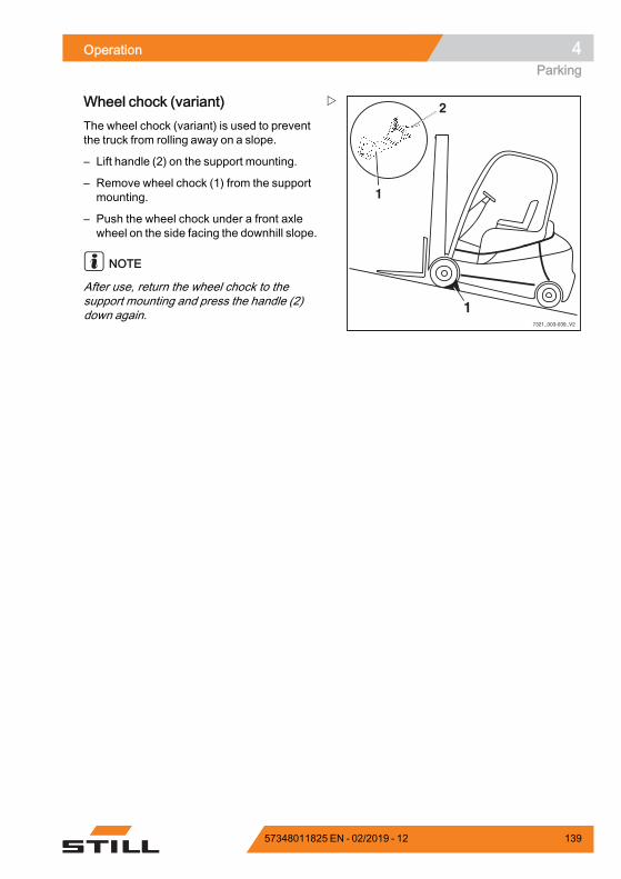
Operation 4Parking
7321_003-039_V2
2
1
1
Wheel chock (variant)The wheel chock (variant) is used to preventthe truck from rolling away on a slope.
– Lift handle (2) on the support mounting.
– Remove wheel chock (1) from the supportmounting.
– Push the wheel chock under a front axlewheel on the side facing the downhill slope.
NOTE
After use, return the wheel chock to thesupport mounting and press the handle (2)down again.
57348011825 EN - 02/2019 - 12 139
4 OperationLifting
LiftingLifting system variantsThe movement of the fork carriage and thelift mast heavily depends on the followingequipment:• The lift mast with which the truck isequipped, see ⇒ Chapter "Types of liftmast", P. 4-145
• The operating device with which thehydraulic functions are controlled, see⇒ Chapter "Lifting system operating de-vices", P. 4-148
Regardless of the equipment variants of thetruck, the basic specifications and proceduresmust be complied with, see ⇒ Chapter "Safetyregulations when handing loads", P. 4-162.
Automatic lift cut out (variant)
Description:The automatic lift cut out (variant) means thatthe load cannot be lifted above a preset height.This function uses a sensor that is welded onat the factory at the required lift mast limitheight. Once attached, the height cannot beeasily changed.
Application:• If the ceiling of the building is lower thanthe maximum lift height of the truck, thisvariant can prevent the lift mast fromaccidentally hitting the ceiling, which canresult in damage.
• If the truck is frequently used at a particularheight, the work is simplified by the auto-matic lift cut out at this height.
NOTE
If a load is lifted very quickly, the fork carriageand load are moved approximately 15 cmabove the position of the sensor due toinertia. This deviation is already taken intoconsideration at the factory when determiningthe position of the sensor.
140 57348011825 EN - 02/2019 - 12
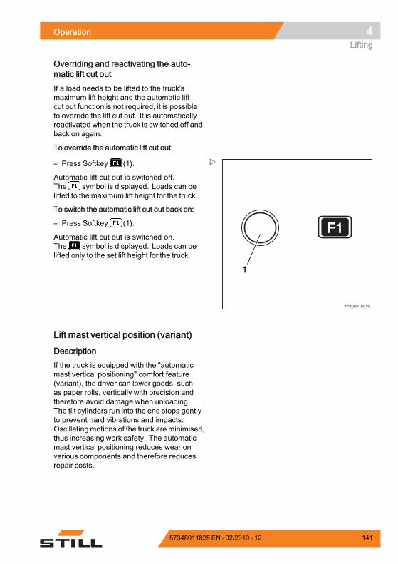
Operation 4Lifting
Overriding and reactivating the auto-matic lift cut outIf a load needs to be lifted to the truck'smaximum lift height and the automatic liftcut out function is not required, it is possibleto override the lift cut out. It is automaticallyreactivated when the truck is switched off andback on again.
To override the automatic lift cut out:
F1
1
7312_003-160_V3
– Press Softkey (1).
Automatic lift cut out is switched off.The symbol is displayed. Loads can belifted to the maximum lift height for the truck.
To switch the automatic lift cut out back on:
– Press Softkey (1).
Automatic lift cut out is switched on.The symbol is displayed. Loads can belifted only to the set lift height for the truck.
Lift mast vertical position (variant)
DescriptionIf the truck is equipped with the "automaticmast vertical positioning" comfort feature(variant), the driver can lower goods, suchas paper rolls, vertically with precision andtherefore avoid damage when unloading.The tilt cylinders run into the end stops gentlyto prevent hard vibrations and impacts.Oscillating motions of the truck are minimised,thus increasing work safety. The automaticmast vertical positioning reduces wear onvarious components and therefore reducesrepair costs.
57348011825 EN - 02/2019 - 12 141
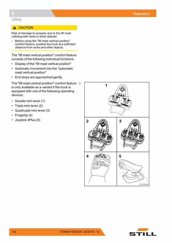
4 OperationLifting
CAUTIONRisk of damage to property due to the lift mastcolliding with racks or other objects!– Before using the "lift mast vertical position"
comfort feature, position the truck at a sufficientdistance from racks and other objects.
The "lift mast vertical position" comfort featureconsists of the following individual functions:• Display of the "lift mast vertical position"• Automatic movement into the "automaticmast vertical position"
• End stops are approached gently
F1F1 F2F2
F1 F2
7314_003-059
2
1
4 5
3
The "lift mast vertical position" comfort featureis only available as a variant if the truck isequipped with one of the following operatingdevices:
• Double mini-lever (1)• Triple mini-lever (2)• Quadruple mini-lever (3)• Fingertip (4)• Joystick 4Plus (5)
142 57348011825 EN - 02/2019 - 12
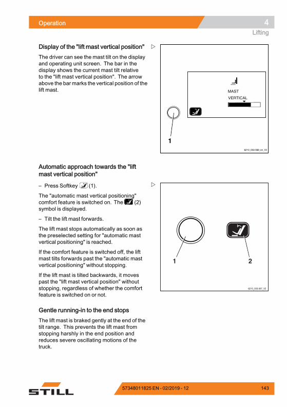
Operation 4Lifting
6210_003-069_en_V2
1
Display of the "lift mast vertical position"The driver can see the mast tilt on the displayand operating unit screen. The bar in thedisplay shows the current mast tilt relativeto the "lift mast vertical position". The arrowabove the barmarks the vertical position of thelift mast.
Automatic approach towards the "liftmast vertical position"
6210_003-067_V2
21
– Press Softkey (1).
The "automatic mast vertical positioning"comfort feature is switched on. The (2)symbol is displayed.
– Tilt the lift mast forwards.
The lift mast stops automatically as soon asthe preselected setting for "automatic mastvertical positioning" is reached.
If the comfort feature is switched off, the liftmast tilts forwards past the "automatic mastvertical positioning" without stopping.
If the lift mast is tilted backwards, it movespast the "lift mast vertical position" withoutstopping, regardless of whether the comfortfeature is switched on or not.
Gentle running-in to the end stopsThe lift mast is braked gently at the end of thetilt range. This prevents the lift mast fromstopping harshly in the end position andreduces severe oscillating motions of thetruck.
57348011825 EN - 02/2019 - 12 143
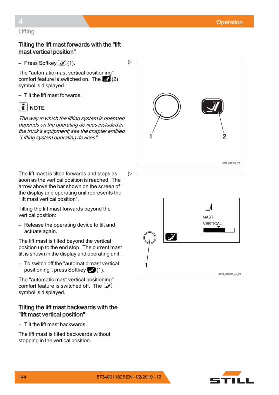
4 OperationLifting
Tilting the lift mast forwards with the "liftmast vertical position"
6210_003-067_V2
21
– Press Softkey (1).
The "automatic mast vertical positioning"comfort feature is switched on. The (2)symbol is displayed.
– Tilt the lift mast forwards.
NOTE
The way in which the lifting system is operateddepends on the operating devices included inthe truck's equipment; see the chapter entitled"Lifting system operating devices".
6210_003-069_en_V2
1
The lift mast is tilted forwards and stops assoon as the vertical position is reached. Thearrow above the bar shown on the screen ofthe display and operating unit represents the"lift mast vertical position".
Tilting the lift mast forwards beyond thevertical position:
– Release the operating device to tilt andactuate again.
The lift mast is tilted beyond the verticalposition up to the end stop. The current masttilt is shown in the display and operating unit.
– To switch off the "automatic mast verticalpositioning", press Softkey (1).
The "automatic mast vertical positioning"comfort feature is switched off. Thesymbol is displayed.
Tilting the lift mast backwards with the"lift mast vertical position"– Tilt the lift mast backwards.
The lift mast is tilted backwards withoutstopping in the vertical position.
144 57348011825 EN - 02/2019 - 12
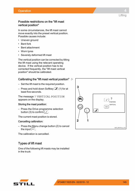
Operation 4Lifting
Possible restrictions on the "lift mastvertical position"
In some circumstances, the lift mast cannotmove exactly into the preset vertical position.Possible causes include:• Uneven ground• Bent fork• Bent attachment• Worn tyres• Severely deformed lift mast
The vertical position can be corrected by tiltingthe lift mast using the relevant operatingdevice. If the vertical position has to becorrected frequently, the "lift mast verticalposition" should be calibrated.
6210_003-070_en_V2
12
3
Calibrating the "lift mast vertical position"– Set the lift mast to the required position.
– Press and hold down Softkey (1) for atleast five seconds.
The message ? VERTICAL POSITIONappears on the display.
Storing the mast position:
– Press the Drive programme selectionbutton (3) to confirm .
The current mast position is stored.
Cancelling calibration:
– Press the Menu change button (2) to cancelthe input .
The calibration is cancelled.
Types of lift mastOne of the following lift masts may be installedin the truck:
57348011825 EN - 02/2019 - 12 145
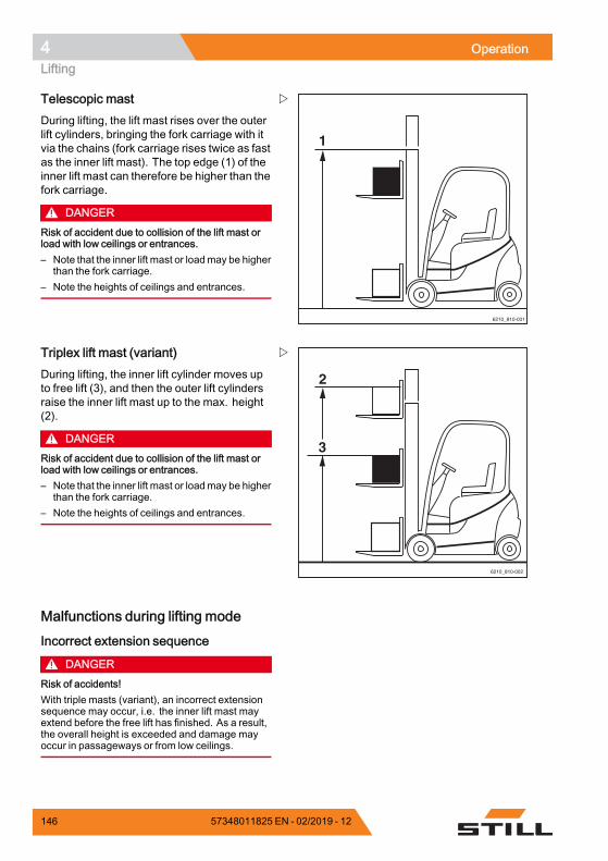
4 OperationLifting
6210_810-001
1
Telescopic mastDuring lifting, the lift mast rises over the outerlift cylinders, bringing the fork carriage with itvia the chains (fork carriage rises twice as fastas the inner lift mast). The top edge (1) of theinner lift mast can therefore be higher than thefork carriage.
DANGERRisk of accident due to collision of the lift mast orload with low ceilings or entrances.– Note that the inner lift mast or loadmay be higher
than the fork carriage.– Note the heights of ceilings and entrances.
6210_810-002
2
3
Triplex lift mast (variant)During lifting, the inner lift cylinder moves upto free lift (3), and then the outer lift cylindersraise the inner lift mast up to the max. height(2).
DANGERRisk of accident due to collision of the lift mast orload with low ceilings or entrances.– Note that the inner lift mast or loadmay be higher
than the fork carriage.– Note the heights of ceilings and entrances.
Malfunctions during lifting mode
Incorrect extension sequence
DANGERRisk of accidents!With triple masts (variant), an incorrect extensionsequence may occur, i.e. the inner lift mast mayextend before the free lift has finished. As a result,the overall height is exceeded and damage mayoccur in passageways or from low ceilings.
146 57348011825 EN - 02/2019 - 12
Operation 4Lifting
An incorrect extension sequence may, forinstance, result from:• The hydraulic oil temperature being too low.• The fork carriage becoming blocked in theinner lift mast.
• Blocking of the free lift cylinder.• The chain roller becoming blocked at thefree lift cylinder.
– If the hydraulic oil temperature is too low,slowly actuate the lift mast functions severaltimes in order to raise the oil temperature.
In the event that the fork carriage is blockedin the inner lift mast, or the free lift cylinderor chain roller are blocked, the cause of theblockage must be eliminated before resumingwork.
– Notify your service centre
Load chains not under tension
DANGERDanger caused by a falling load!– Make sure that the chain(s) does (do) not
become slack when lowering the load.
Slack chains can, for instance, result from:• Resting the fork carriage or the load on theracking.
• Fork carriage rollers becoming blocked inthe lift mast due to contamination.
– If the fork carriage or the load comes to anunexpected stop, lift the fork carriage untilthe chains are under tension again andlower the load at another suitable location.
– If the fork carriage rollers in the lift mastbecome blocked due to contamination, liftthe fork carriage until the chains are undertension again. Remove the contaminationbefore resuming work.
WARNINGRisk of injury!– Observe the safety regulations for working on lift
masts; see⇒Chapter "Working at the front of thetruck", P. 5-306.
57348011825 EN - 02/2019 - 12 147
4 OperationLifting
Hydraulic blocking functionThe hydraulic blocking function ensures thatall hydraulic functions are disabled wheneverthe seat switch in the driver's seat is unloaded.This is when the driver stands up from thedriver's seat or exits the truck. All hydraulicfunctions are disabled in this case:
• Lifting the load• Lowering the load• Tilting the lift mast• Auxiliary hydraulic functions
As soon as the driver sits down again, allhydraulic functions are available again.
Emergency lowering of the load after thehydraulics blocking function has beentriggeredIf the truck's hydraulics are disabled by theexhaust valve of the hydraulic blocking func-tion, either permanently or due to a technicalfault, it is possible to lower a raised load withemergency lowering at the valve block, see⇒ Chapter "Emergency lowering", P. 4-284.
Lifting system operating devicesThe method of operating the lifting systemdepends on the operating devices included inthe truck's equipment.
Possible equipment variants include:• Double mini-lever• Triple mini-lever• Quadruple mini-lever• Joystick 4Plus• Fingertip switch
– The following informationmust be observedregardless of the equipment variant:
148 57348011825 EN - 02/2019 - 12
Operation 4Lifting
DANGERReaching into or climbing between moving partsof the truck (e.g. lift mast, sideshifts, workingequipment, load carrying devices etc.) can lead toserious injury or death and is therefore prohibited.– Observe the safety regulations for handling
loads.– Only operate the lifting system from the driver's
seat.
57348011825 EN - 02/2019 - 12 149
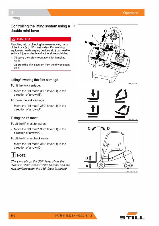
4 OperationLifting
F1 F2
7325_003-035
A
C
D
B
1
7312_003-114
7312_003-022_V2
DC
B
A
Controlling the lifting system using adouble mini-lever
DANGERReaching into or climbing between moving partsof the truck (e.g. lift mast, sideshifts, workingequipment, load carrying devices etc.) can lead toserious injury or death and is therefore prohibited.– Observe the safety regulations for handling
loads.– Operate the lifting system from the driver's seat
only.
Lifting/lowering the fork carriageTo lift the fork carriage:
– Move the "lift mast" 360° lever (1) in thedirection of arrow (B).
To lower the fork carriage:
– Move the "lift mast" 360° lever (1) in thedirection of arrow (A).
Tilting the lift mastTo tilt the lift mast forwards:
– Move the "lift mast" 360° lever (1) in thedirection of arrow (C).
To tilt the lift mast backwards:
– Move the "lift mast" 360° lever (1) in thedirection of arrow (D).
NOTE
The symbols on the 360° lever show thedirection of movement of the lift mast and thefork carriage when the 360° lever is moved.
150 57348011825 EN - 02/2019 - 12
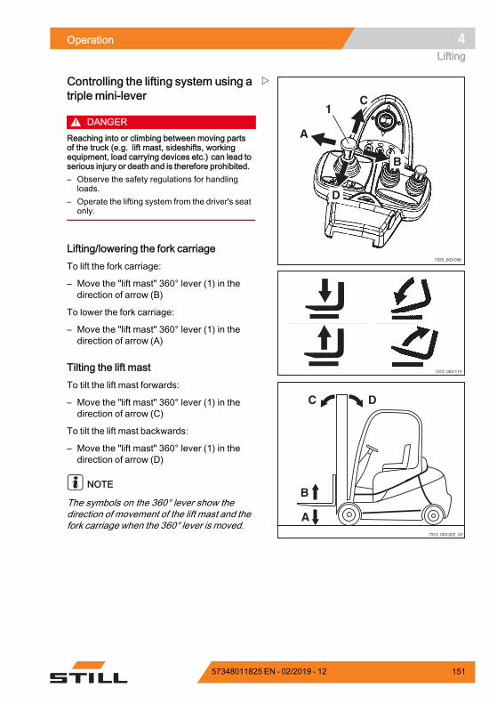
Operation 4Lifting
7325_003-036
A
C
D
B
1
7312_003-114
7312_003-022_V2
DC
B
A
Controlling the lifting system using atriple mini-lever
DANGERReaching into or climbing between moving partsof the truck (e.g. lift mast, sideshifts, workingequipment, load carrying devices etc.) can lead toserious injury or death and is therefore prohibited.– Observe the safety regulations for handling
loads.– Operate the lifting system from the driver's seat
only.
Lifting/lowering the fork carriageTo lift the fork carriage:
– Move the "lift mast" 360° lever (1) in thedirection of arrow (B)
To lower the fork carriage:
– Move the "lift mast" 360° lever (1) in thedirection of arrow (A)
Tilting the lift mastTo tilt the lift mast forwards:
– Move the "lift mast" 360° lever (1) in thedirection of arrow (C)
To tilt the lift mast backwards:
– Move the "lift mast" 360° lever (1) in thedirection of arrow (D)
NOTE
The symbols on the 360° lever show thedirection of movement of the lift mast and thefork carriage when the 360° lever is moved.
57348011825 EN - 02/2019 - 12 151
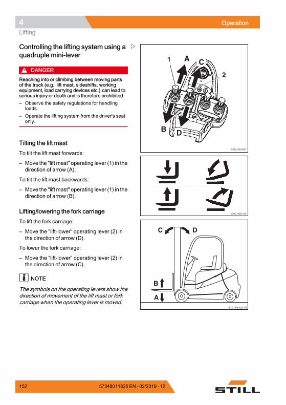
4 OperationLifting
7325_003-037
1 C
D
2
A
B
7312_003-114
7312_003-022_V2
DC
B
A
Controlling the lifting system using aquadruple mini-lever
DANGERReaching into or climbing between moving partsof the truck (e.g. lift mast, sideshifts, workingequipment, load carrying devices etc.) can lead toserious injury or death and is therefore prohibited.– Observe the safety regulations for handling
loads.– Operate the lifting system from the driver's seat
only.
Tilting the lift mastTo tilt the lift mast forwards:
– Move the "lift mast" operating lever (1) in thedirection of arrow (A).
To tilt the lift mast backwards:
– Move the "lift mast" operating lever (1) in thedirection of arrow (B).
Lifting/lowering the fork carriageTo lift the fork carriage:
– Move the "lift-lower" operating lever (2) inthe direction of arrow (D).
To lower the fork carriage:
– Move the "lift-lower" operating lever (2) inthe direction of arrow (C).
NOTE
The symbols on the operating levers show thedirection of movement of the lift mast or forkcarriage when the operating lever is moved.
152 57348011825 EN - 02/2019 - 12
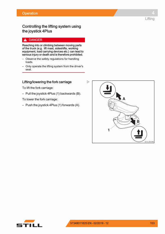
Operation 4Lifting
Controlling the lifting system usingthe joystick 4Plus
DANGERReaching into or climbing between moving partsof the truck (e.g. lift mast, sideshifts, workingequipment, load carrying devices etc.) can lead toserious injury or death and is therefore prohibited.– Observe the safety regulations for handling
loads.– Only operate the lifting system from the driver's
seat.
6210_003-089
1
A
B
Lifting/lowering the fork carriageTo lift the fork carriage:
– Pull the joystick 4Plus (1) backwards (B).
To lower the fork carriage:
– Push the joystick 4Plus (1) forwards (A).
57348011825 EN - 02/2019 - 12 153
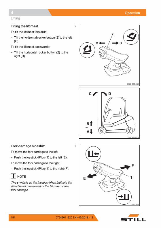
4 OperationLifting
6210_003-090
DC
2
7312_003-022_V2
DC
B
A
Tilting the lift mastTo tilt the lift mast forwards:
– Tilt the horizontal rocker button (2) to the left(C).
To tilt the lift mast backwards:
– Tilt the horizontal rocker button (2) to theright (D).
1
6210_003-091
E
F
Fork-carriage sideshiftTo move the fork carriage to the left.
– Push the joystick 4Plus (1) to the left (E).
To move the fork carriage to the right:
– Push the joystick 4Plus (1) to the right (F).
NOTE
The symbols on the joystick 4Plus indicate thedirection of movement of the lift mast or thefork carriage.
154 57348011825 EN - 02/2019 - 12
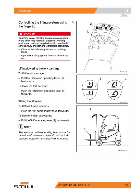
Operation 4Lifting
F1F1 F2F2
7325_003-038
1
2
1 2
6210_003-043
6210_713-002_V2
2
1
Controlling the lifting system usingthe fingertip
DANGERReaching into or climbing between moving partsof the truck (e.g. lift mast, sideshifts, workingequipment, load carrying devices etc.) can lead toserious injury or death and is therefore prohibited.– Observe the safety regulations for handling
loads.– Operate the lifting system from the driver's seat
only.
Lifting/lowering the fork carriageTo lift the fork carriage:
– Pull the "lift/lower" operating lever (1)backwards.
To lower the fork carriage:
– Push the "lift/lower" operating lever (1)forwards.
Tilting the lift mastTo tilt the lift mast forwards:
– Push the "tilt" operating lever (2) forwards.
To tilt the lift mast backwards:
– Pull the "tilt" operating lever (2) backwards.
NOTE
The symbols on the operating levers show thedirection of movement of the lift mast or forkcarriage when the operating lever is moved.
57348011825 EN - 02/2019 - 12 155
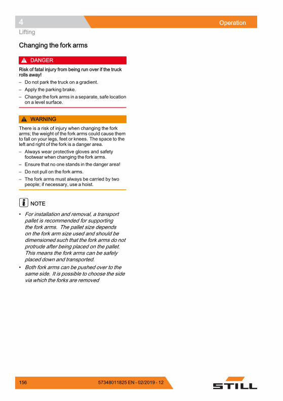
4 OperationLifting
Changing the fork arms
DANGERRisk of fatal injury from being run over if the truckrolls away!– Do not park the truck on a gradient.– Apply the parking brake.– Change the fork arms in a separate, safe location
on a level surface.
WARNINGThere is a risk of injury when changing the forkarms; the weight of the fork arms could cause themto fall on your legs, feet or knees. The space to theleft and right of the fork is a danger area.– Always wear protective gloves and safety
footwear when changing the fork arms.– Ensure that no one stands in the danger area!– Do not pull on the fork arms.– The fork arms must always be carried by two
people; if necessary, use a hoist.
NOTE
• For installation and removal, a transportpallet is recommended for supportingthe fork arms. The pallet size dependson the fork arm size used and should bedimensioned such that the fork arms do notprotrude after being placed on the pallet.This means the fork arms can be safelyplaced down and transported.
• Both fork arms can be pushed over to thesame side. It is possible to choose the sidevia which the forks are removed
156 57348011825 EN - 02/2019 - 12
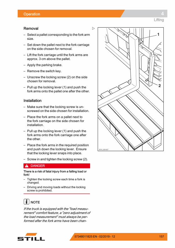
Operation 4Lifting
1
2
6210_003-027
Removal– Select a pallet corresponding to the fork armsize.
– Set down the pallet next to the fork carriageon the side chosen for removal.
– Lift the fork carriage until the fork arms areapprox. 3 cm above the pallet.
– Apply the parking brake.
– Remove the switch key.
– Unscrew the locking screw (2) on the sidechosen for removal.
– Pull up the locking lever (1) and push thefork arms onto the pallet one after the other.
Installation– Make sure that the locking screw is un-screwed on the side chosen for installation.
– Place the fork arms on a pallet next tothe fork carriage on the side chosen forinstallation.
– Pull up the locking lever (1) and push thefork arms onto the fork carriage one afterthe other.
– Place the fork arms in the required positionand push down the locking lever. Ensurethat the locking lever snaps into place.
– Screw in and tighten the locking screw (2).
DANGERThere is a risk of fatal injury from a falling load orfork!– Tighten the locking screw each time a fork is
changed.– Driving and moving loads without the locking
screw is prohibited.
NOTE
If the truck is equipped with the "load measu-rement" comfort feature, a "zero adjustment ofthe load measurement" must always be per-formed after the fork arms have been chan-
57348011825 EN - 02/2019 - 12 157
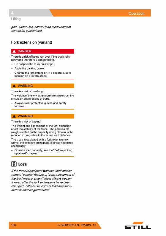
4 OperationLifting
ged. Otherwise, correct load measurementcannot be guaranteed.
Fork extension (variant)
DANGERThere is a risk of being run over if the truck rollsaway and therefore a danger to life.– Do not park the truck on a slope.– Apply the parking brake.– Change the fork extension in a separate, safe
location on a level surface.
WARNINGThere is a risk of crushing!Theweight of the fork extension can cause crushingor cuts on sharp edges or burrs.– Always wear protective gloves and safety
footwear.
WARNINGThere is a risk of tipping!The weight and dimensions of the fork extensionaffect the stability of the truck. The permissibleweights stated on the capacity rating plate must bereduced in proportion to the actual load distance.The truck is equipped with a fork extension exworks, the capacity rating plate is already adjustedaccordingly.– Observe load capacity, see the "Before picking
up a load" chapter.
NOTE
If the truck is equipped with the "load measu-rement" comfort feature, a "zero adjustment ofthe load measurement" must always be per-formed after the fork extensions have beenchanged. Otherwise, correct load measure-ment cannot be guaranteed.
158 57348011825 EN - 02/2019 - 12
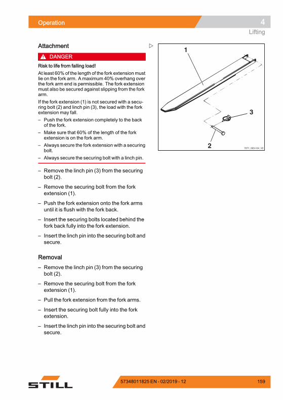
Operation 4Lifting
7071_003-104_V2
1
2
3
Attachment
DANGERRisk to life from falling load!At least 60%of the length of the fork extensionmustlie on the fork arm. Amaximum 40% overhang overthe fork arm end is permissible. The fork extensionmust also be secured against slipping from the forkarm.If the fork extension (1) is not secured with a secu-ring bolt (2) and linch pin (3), the load with the forkextension may fall.– Push the fork extension completely to the back
of the fork.– Make sure that 60% of the length of the fork
extension is on the fork arm.– Always secure the fork extension with a securing
bolt.– Always secure the securing bolt with a linch pin.
– Remove the linch pin (3) from the securingbolt (2).
– Remove the securing bolt from the forkextension (1).
– Push the fork extension onto the fork armsuntil it is flush with the fork back.
– Insert the securing bolts located behind thefork back fully into the fork extension.
– Insert the linch pin into the securing bolt andsecure.
Removal– Remove the linch pin (3) from the securingbolt (2).
– Remove the securing bolt from the forkextension (1).
– Pull the fork extension from the fork arms.
– Insert the securing bolt fully into the forkextension.
– Insert the linch pin into the securing bolt andsecure.
57348011825 EN - 02/2019 - 12 159
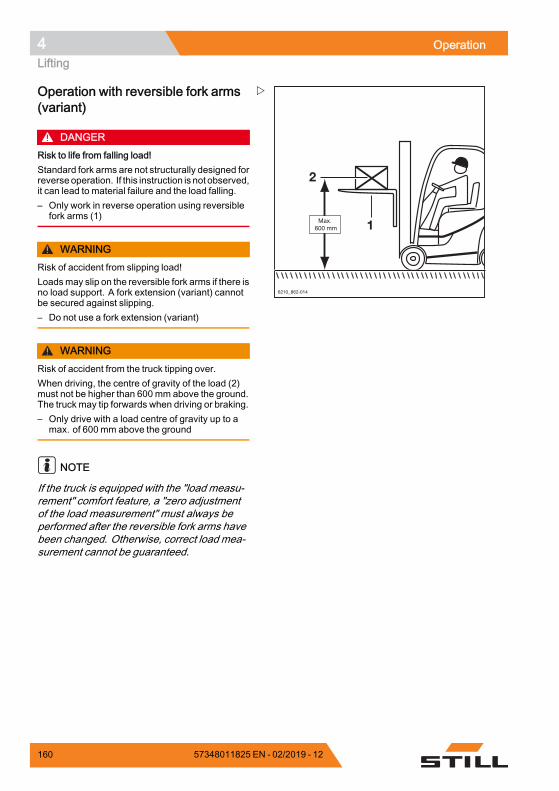
4 OperationLifting
Operation with reversible fork arms(variant)
DANGERRisk to life from falling load!Standard fork arms are not structurally designed forreverseoperation. If this instruction is not observed,it can lead to material failure and the load falling.– Only work in reverse operation using reversible
fork arms (1)
WARNINGRisk of accident from slipping load!Loadsmay slip on the reversible fork arms if there isno load support. A fork extension (variant) cannotbe secured against slipping.– Do not use a fork extension (variant)
WARNINGRisk of accident from the truck tipping over.When driving, the centre of gravity of the load (2)must not be higher than 600 mm above the ground.The truck may tip forwards when driving or braking.– Only drive with a load centre of gravity up to a
max. of 600 mm above the ground
NOTE
If the truck is equipped with the "load measu-rement" comfort feature, a "zero adjustmentof the load measurement" must always beperformed after the reversible fork arms havebeen changed. Otherwise, correct load mea-surement cannot be guaranteed.
160 57348011825 EN - 02/2019 - 12
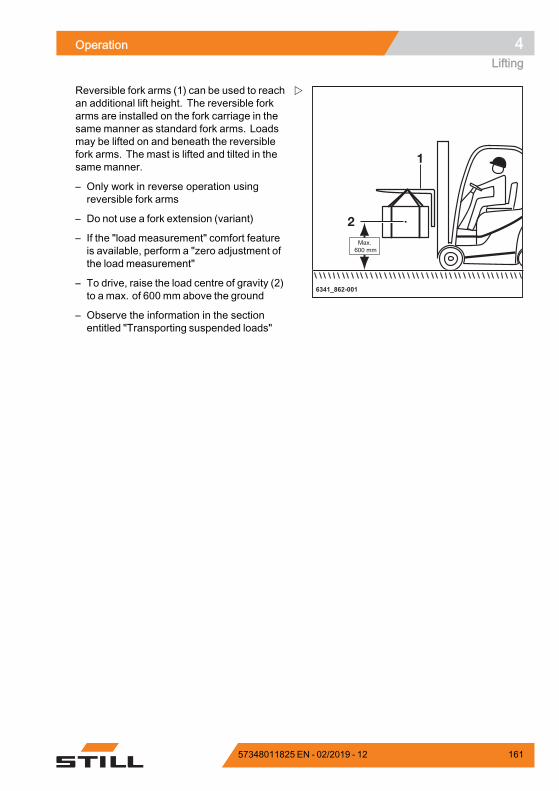
Operation 4Lifting
6341_862-001
Reversible fork arms (1) can be used to reachan additional lift height. The reversible forkarms are installed on the fork carriage in thesame manner as standard fork arms. Loadsmay be lifted on and beneath the reversiblefork arms. The mast is lifted and tilted in thesame manner.
– Only work in reverse operation usingreversible fork arms
– Do not use a fork extension (variant)
– If the "load measurement" comfort featureis available, perform a "zero adjustment ofthe load measurement"
– To drive, raise the load centre of gravity (2)to a max. of 600 mm above the ground
– Observe the information in the sectionentitled "Transporting suspended loads"
57348011825 EN - 02/2019 - 12 161
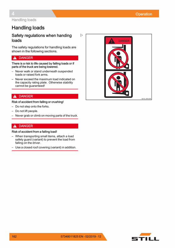
4 OperationHandling loads
Handling loads
6210_003-030
Safety regulations when handingloadsThe safety regulations for handling loads areshown in the following sections.
DANGERThere is a risk to life caused by falling loads or ifparts of the truck are being lowered.– Never walk or stand underneath suspended
loads or raised fork arms.– Never exceed the maximum load indicated on
the capacity rating plate. Otherwise stabilitycannot be guaranteed!
DANGERRisk of accident from falling or crushing!– Do not step onto the forks.– Do not lift people.– Never grab or climb on moving parts of the truck.
DANGERRisk of accident from a falling load!– When transporting small items, attach a load
safety guard (variant) to prevent the load fromfalling on the driver.
– Use a closed roof covering (variant) in addition.
162 57348011825 EN - 02/2019 - 12
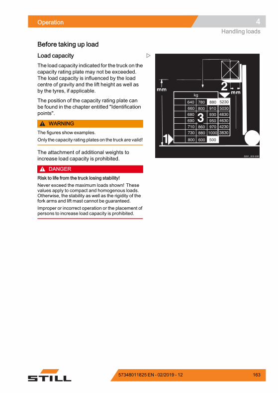
Operation 4Handling loads
Before taking up load
2
1
780
9101310
93012306801500
95012606901500
970860710150010008807301500
600500
6401080
4830
4630
4230
3830
kg
3
5051_003-006
800
800 5030660
5230
500
880
Load capacityThe load capacity indicated for the truck on thecapacity rating plate may not be exceeded.The load capacity is influenced by the loadcentre of gravity and the lift height as well asby the tyres, if applicable.
The position of the capacity rating plate canbe found in the chapter entitled "Identificationpoints".
WARNINGThe figures show examples.Only the capacity rating plateson the truckare valid!
The attachment of additional weights toincrease load capacity is prohibited.
DANGERRisk to life from the truck losing stability!Never exceed the maximum loads shown! Thesevalues apply to compact and homogenous loads.Otherwise, the stability as well as the rigidity of thefork arms and lift mast cannot be guaranteed.Improper or incorrect operation or the placement ofpersons to increase load capacity is prohibited.
57348011825 EN - 02/2019 - 12 163
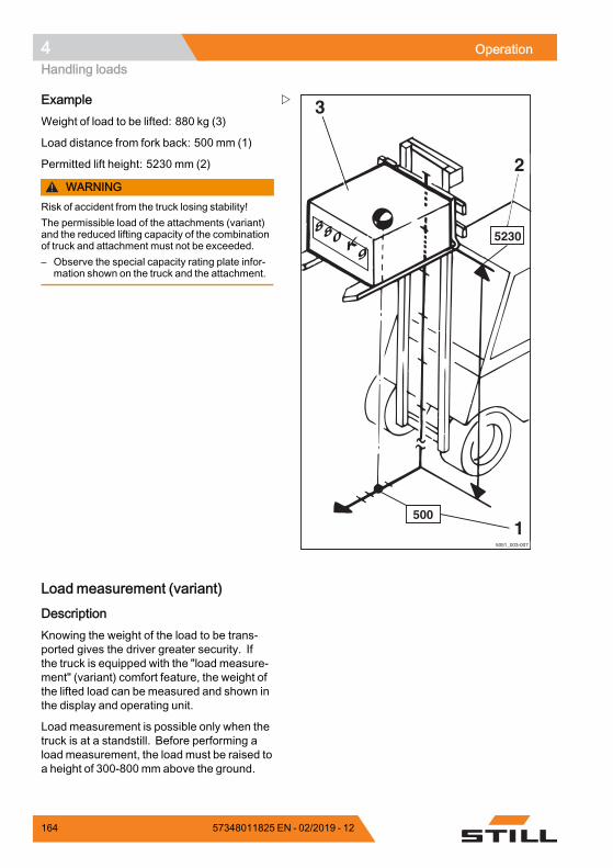
4 OperationHandling loads
5051_003-007
3
5230
500
2
880 Kg
1
ExampleWeight of load to be lifted: 880 kg (3)
Load distance from fork back: 500 mm (1)
Permitted lift height: 5230 mm (2)
WARNINGRisk of accident from the truck losing stability!The permissible load of the attachments (variant)and the reduced lifting capacity of the combinationof truck and attachment must not be exceeded.– Observe the special capacity rating plate infor-
mation shown on the truck and the attachment.
Load measurement (variant)
DescriptionKnowing the weight of the load to be trans-ported gives the driver greater security. Ifthe truck is equipped with the "load measure-ment" (variant) comfort feature, the weight ofthe lifted load can be measured and shown inthe display and operating unit.
Load measurement is possible only when thetruck is at a standstill. Before performing aload measurement, the load must be raised toa height of 300-800 mm above the ground.
164 57348011825 EN - 02/2019 - 12
Operation 4Handling loads
The load measurement has an accuracy of+/-3% of the rated capacity of the truck.
NOTE
In order to ensure accuracy at all times, a zeroadjustment of the load measurement must becarried out. Zero adjustment is required.• as part of daily commissioning• after changing the fork arms• after fitting or changing attachments.
Performing the load measurement
DANGERRisk of accident from a falling load!The loadmay fall if the load centre of gravity has notbeen taken into account or the load has not beenpicked up securely.– Pick up the load securely; see the chapter
entitled "Picking up loads".
CAUTIONIf the weight determined by a load measurementexceeds the permissible residual load capacity ofthe truck, the truck cannot be operated safely.– Set down and reduce load immediately.– If necessary, use another truck with sufficient
load-bearing capacity.
NOTE
Accurate load measurement is only possibleunder the following conditions:• The hydraulic oil is at normal operatingtemperature
• The load is at rest at the beginning of theload measurement
• The load corresponds to at least 10% of thenominal load capacity in trucks with a loadcapacity of up to 2.5 t
• The load corresponds to at least 5% of thenominal load capacity in trucks with a loadcapacity of 3 t and over
• The lift mast is in the vertical position• The fork is not raised to more than 800 mmabove the ground
57348011825 EN - 02/2019 - 12 165
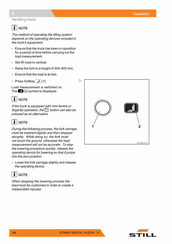
4 OperationHandling loads
NOTE
The method of operating the lifting systemdepends on the operating devices included inthe truck's equipment.
– Ensure that the truck has been in operationfor a period of time before carrying out theload measurement.
– Set lift mast to vertical.
– Raise the fork to a height of 300–800 mm.
– Ensure that the load is at rest.
6210_003-072_V2
21
– Press Softkey (1).
Load measurement is switched on.The (2) symbol is displayed.
NOTE
If the truck is equipped with mini-levers orfingertip operation, the F1 button can also bepressed as an alternative.
NOTE
During the following process, the fork carriagemust be lowered slightly and then stoppedabruptly. While doing so, the fork mustnot touch the ground, otherwise the loadmeasurement will not be accurate. To stopthe lowering procedure quickly, release theoperating device for lowering so that it jumpsinto the zero position.
– Lower the fork carriage slightly and releasethe operating device.
NOTE
When stopping the lowering process theload must be cushioned in order to create ameasurable impulse.
166 57348011825 EN - 02/2019 - 12
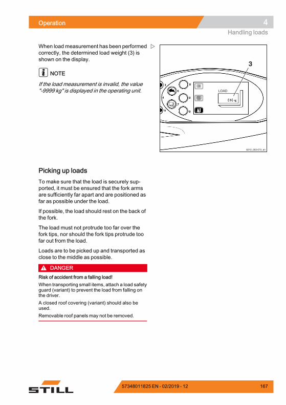
Operation 4Handling loads
6210_003-073_en
3
When loadmeasurement has been performedcorrectly, the determined load weight (3) isshown on the display.
NOTE
If the load measurement is invalid, the value"-9999 kg" is displayed in the operating unit.
Picking up loadsTo make sure that the load is securely sup-ported, it must be ensured that the fork armsare sufficiently far apart and are positioned asfar as possible under the load.
If possible, the load should rest on the back ofthe fork.
The load must not protrude too far over thefork tips, nor should the fork tips protrude toofar out from the load.
Loads are to be picked up and transported asclose to the middle as possible.
DANGERRisk of accident from a falling load!When transporting small items, attach a load safetyguard (variant) to prevent the load from falling onthe driver.A closed roof covering (variant) should also beused.Removable roof panels may not be removed.
57348011825 EN - 02/2019 - 12 167
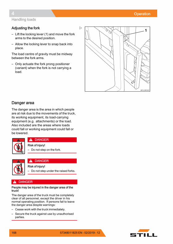
4 OperationHandling loads
1
6210_842-001
Adjusting the fork– Lift the locking lever (1) and move the forkarms to the desired position.
– Allow the locking lever to snap back intoplace.
The load centre of gravity must be midwaybetween the fork arms.
– Only actuate the fork prong positioner(variant) when the fork is not carrying aload.
Danger areaThe danger area is the area in which peopleare at risk due to the movements of the truck,its working equipment, its load-carryingequipment (e.g. attachments) or the load.Also included are the areas where loadscould fall or working equipment could fall orbe lowered.
DANGERRisk of injury!– Do not step on the fork.
DANGERRisk of injury!– Do not step under the raised forks.
DANGERPeople may be injured in the danger area of thetruck!The danger area of the truck must be completelyclear of all personnel, except the driver in hisnormal operating position. If persons fail to leavethe danger area despite warnings:– Cease work with the truck immediately.– Secure the truck against use by unauthorised
parties.
168 57348011825 EN - 02/2019 - 12
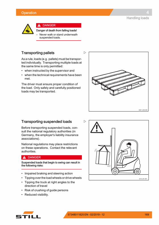
Operation 4Handling loads
DANGERDanger of death from falling loads!– Never walk or stand underneath
suspended loads.
6327_003-009
Transporting palletsAsa rule, loads (e.g. pallets)must be transpor-ted individually. Transporting multiple loads atthe same time is only permitted:• when instructed by the supervisor and• when the technical requirements have beenmet.
The driver must ensure proper condition ofthe load. Only safely and carefully positionedloads may be transported.
6210_001-007
Transporting suspended loadsBefore transporting suspended loads, con-sult the national regulatory authorities (inGermany, the employer's liability insuranceassociations).
National regulations may place restrictionson these operations. Contact the relevantauthorities.
DANGERSuspended loads that begin to swing can result inthe following risks:
• Impaired braking and steering action• Tipping over the loadwheels or drivewheels• Tipping the truck at right angles to thedirection of travel
• Risk of crushing of guide persons• Reduced visibility.
57348011825 EN - 02/2019 - 12 169
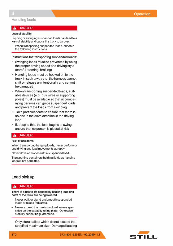
4 OperationHandling loads
DANGERLoss of stability.Slipping or swinging suspended loads can lead to aloss of stability and cause the truck to tip over.– When transporting suspended loads, observe
the following instructions
Instructions for transporting suspended loads:• Swinging loads must be prevented by usingthe proper driving speed and driving style(careful steering, braking)
• Hanging loads must be hooked on to thetruck in such a way that the harness cannotshift or release unintentionally and cannotbe damaged
• When transporting suspended loads, suit-able devices (e.g. guy wires or supportingpoles) must be available so that accompa-nying persons can guide suspended loadsand prevent the loads from swinging
• Take particular care to ensure that there isno one in the drive direction in the drivinglane
• If, despite this, the load begins to swing,ensure that no person is placed at risk
DANGERRisk of accidents!When transporting hanging loads, never perform orend driving and load movements abruptly.Never drive on slopes with a suspended load.Transporting containers holding fluids as hangingloads is not permitted.
Load pick up
DANGERThere is a risk to life caused by a falling load or ifparts of the truck are being lowered.– Never walk or stand underneath suspended
loads or raised fork arms.– Never exceed the maximum load values spe-
cified on the capacity rating plate. Otherwise,stability cannot be guaranteed.
– Only store pallets which do not exceed thespecified maximum size. Damaged loading
170 57348011825 EN - 02/2019 - 12
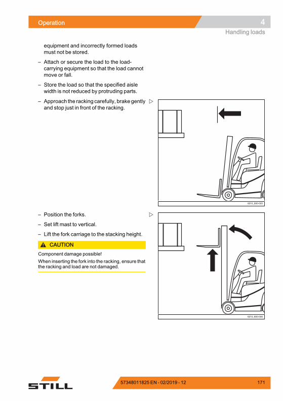
Operation 4Handling loads
equipment and incorrectly formed loadsmust not be stored.
– Attach or secure the load to the load-carrying equipment so that the load cannotmove or fall.
– Store the load so that the specified aislewidth is not reduced by protruding parts.
6210_800-005
– Approach the racking carefully, brake gentlyand stop just in front of the racking.
6210_800-006
– Position the forks.
– Set lift mast to vertical.
– Lift the fork carriage to the stacking height.
CAUTIONComponent damage possible!When inserting the fork into the racking, ensure thatthe racking and load are not damaged.
57348011825 EN - 02/2019 - 12 171
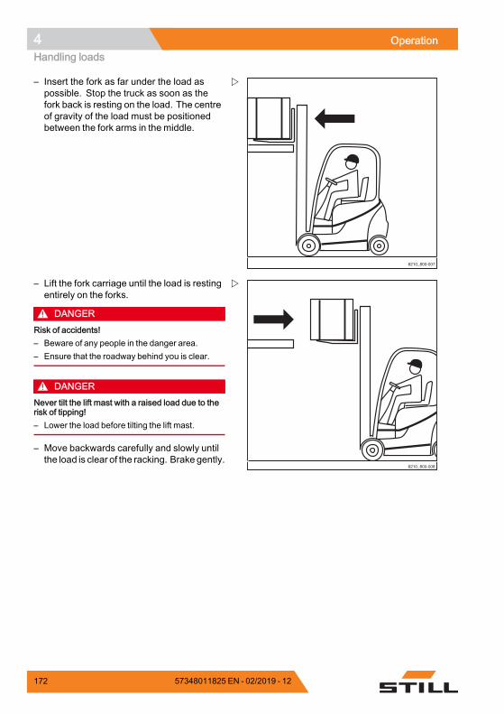
4 OperationHandling loads
6210_800-007
– Insert the fork as far under the load aspossible. Stop the truck as soon as thefork back is resting on the load. The centreof gravity of the load must be positionedbetween the fork arms in the middle.
6210_800-008
– Lift the fork carriage until the load is restingentirely on the forks.
DANGERRisk of accidents!– Beware of any people in the danger area.– Ensure that the roadway behind you is clear.
DANGERNever tilt the lift mast with a raised load due to therisk of tipping!– Lower the load before tilting the lift mast.
– Move backwards carefully and slowly untilthe load is clear of the racking. Brake gently.
172 57348011825 EN - 02/2019 - 12
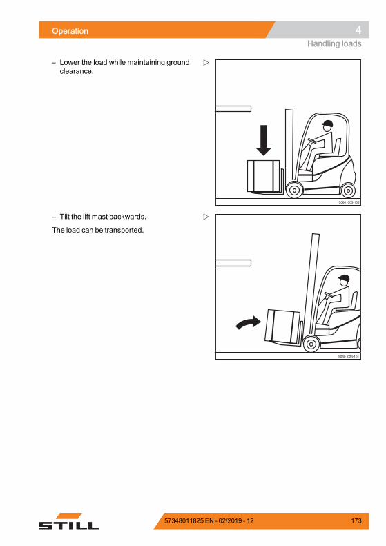
Operation 4Handling loads
5060_003-102
– Lower the load while maintaining groundclearance.
5060_003-101
– Tilt the lift mast backwards.
The load can be transported.
57348011825 EN - 02/2019 - 12 173
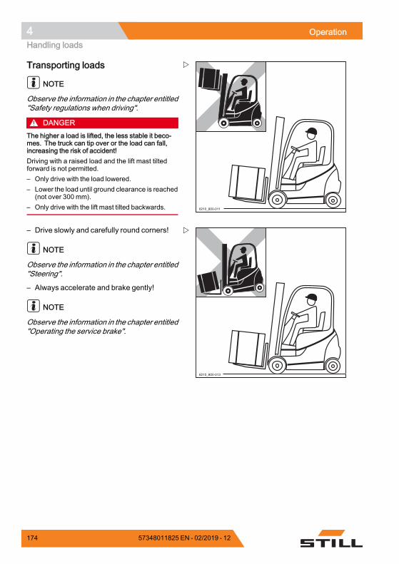
4 OperationHandling loads
6210_800-011
Transporting loads
NOTE
Observe the information in the chapter entitled"Safety regulations when driving".
DANGERThe higher a load is lifted, the less stable it beco-mes. The truck can tip over or the load can fall,increasing the risk of accident!Driving with a raised load and the lift mast tiltedforward is not permitted.– Only drive with the load lowered.– Lower the load until ground clearance is reached
(not over 300 mm).– Only drive with the lift mast tilted backwards.
6210_800-013
– Drive slowly and carefully round corners!
NOTE
Observe the information in the chapter entitled"Steering".
– Always accelerate and brake gently!
NOTE
Observe the information in the chapter entitled"Operating the service brake".
174 57348011825 EN - 02/2019 - 12
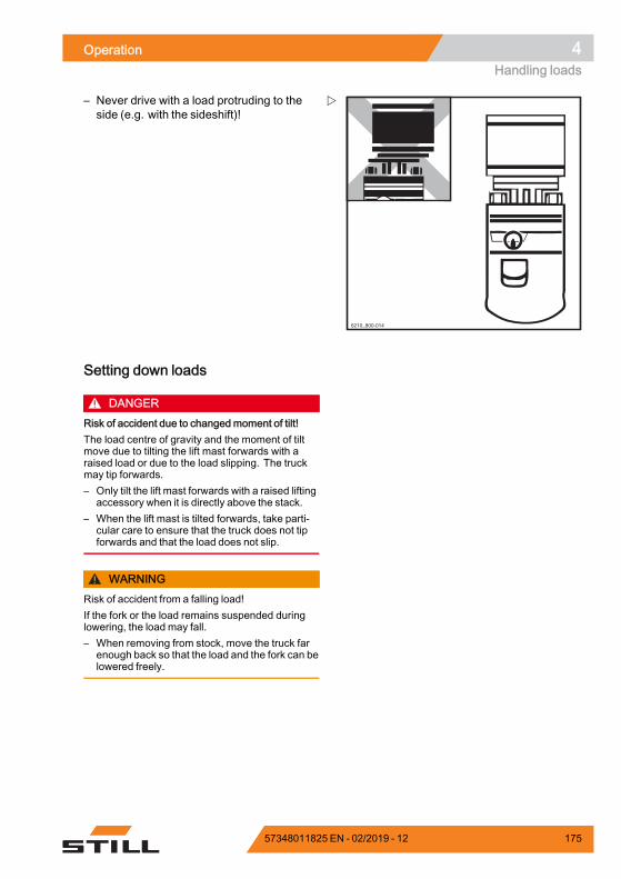
Operation 4Handling loads
6210_800-014
– Never drive with a load protruding to theside (e.g. with the sideshift)!
Setting down loads
DANGERRisk of accident due to changed moment of tilt!The load centre of gravity and the moment of tiltmove due to tilting the lift mast forwards with araised load or due to the load slipping. The truckmay tip forwards.– Only tilt the lift mast forwards with a raised lifting
accessory when it is directly above the stack.– When the lift mast is tilted forwards, take parti-
cular care to ensure that the truck does not tipforwards and that the load does not slip.
WARNINGRisk of accident from a falling load!If the fork or the load remains suspended duringlowering, the load may fall.– When removing from stock, move the truck far
enough back so that the load and the fork can belowered freely.
57348011825 EN - 02/2019 - 12 175
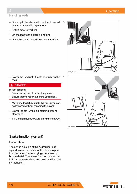
4 OperationHandling loads
6210_800-015
– Drive up to the stack with the load loweredin accordance with regulations.
– Set lift mast to vertical.
– Lift the load to the stacking height.
– Drive the truck towards the rack carefully.
6210_800-016
– Lower the load until it rests securely on therack.
DANGERRisk of accident!– Beware of any people in the danger area.– Ensure that the roadway behind you is clear.
– Move the truck back until the fork arms canbe lowered without touching the stack.
– Lower the fork while maintaining groundclearance.
– Tilt the lift mast backwards and drive away.
Shake function (variant)
DescriptionThe shake function of the hydraulics is de-signed to make it easier for the driver to per-form tasks such as emptying containers ofbulk material. The shake function moves thefork carriage quickly up and down via the "Lift-ing" function.
176 57348011825 EN - 02/2019 - 12
Operation 4Handling loads
NOTE
The shake function is only intended for short-term use as it reduces the service life of theload chains due to increased strain.
OperationTo activate the shake function:
– Move the corresponding operating devicefor the "Lifting" function over the zeroposition four times in quick succession.
The fork carriage moves as normal. Theshake function is active after the fourth timethe operating device is moved.
– Continue tomove the operating device backand forth.
The fork carriage moves up and down morequickly and more jerkily.
The intensity of the shaking is controlled bymeans of the intensitywithwhich the operatingdevice is moved. The more fiercely theoperating device is moved, the more intensethe shaking is.
NOTE
After the function has been activated, thedriver has four seconds to start the shaking.If the four seconds elapse without the shakefunction being used, the shake function isdeactivated again.
WARNINGThe shake function remains active for four secondsfollowing activation.If the driver simply wants to raise or lower theload during this time, it should be noted that thefork carriage may move significantly more jerkilywith the load than in normal operation. If the fourseconds elapse without the shake function beingused, the fork carriage can be moved normallyagain with the load.
The following section shows how the shakefunction is activated via the standard assign-ment for "lifting/lowering" using the differentvariants of the operating devices. If the "Lift-ing/lowering" function is assigned differently
57348011825 EN - 02/2019 - 12 177
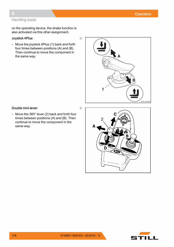
4 OperationHandling loads
on the operating device, the shake function isalso activated via this other assignment.
6210_003-089
1
A
B
Joystick 4Plus:
– Move the joystick 4Plus (1) back and forthfour times between positions (A) and (B).Then continue to move the component inthe same way.
Double mini-lever:
– Move the 360° lever (2) back and forth fourtimes between positions (A) and (B). Thencontinue to move the component in thesame way.
178 57348011825 EN - 02/2019 - 12
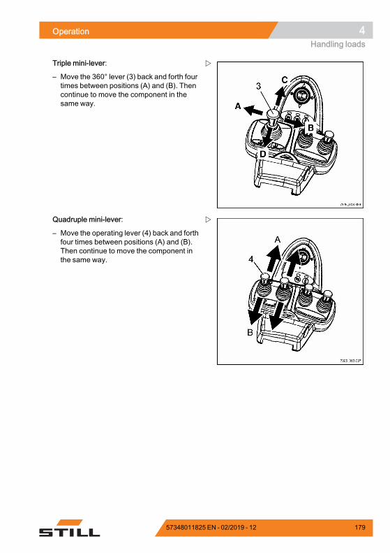
Operation 4Handling loads
Triple mini-lever:
– Move the 360° lever (3) back and forth fourtimes between positions (A) and (B). Thencontinue to move the component in thesame way.
Quadruple mini-lever:
– Move the operating lever (4) back and forthfour times between positions (A) and (B).Then continue to move the component inthe same way.
57348011825 EN - 02/2019 - 12 179
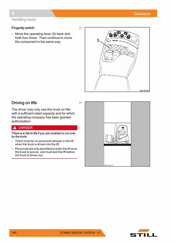
4 OperationHandling loads
Fingertip switch:
– Move the operating lever (5) back andforth four times. Then continue to movethe component in the same way.
5060_003-071
Driving on liftsThe driver may only use this truck on liftswith a sufficient rated capacity and for whichthe operating company has been grantedauthorisation.
DANGERThere is a risk to life if you are crushed or run overby the truck.– There must be no personnel already in the lift
when the truck is driven into the lift.– Personnel are only permitted to enter the lift once
the truck is secure, and must exit the lift beforethe truck is driven out.
180 57348011825 EN - 02/2019 - 12
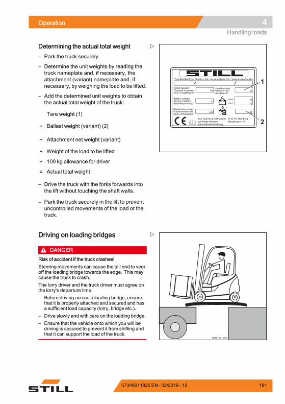
Operation 4Handling loads
Type-Modèle-Typ / Serial no.-No. de série-Serien-Nr. / year-année-Baujahr
Rated capacityCapacité nominaleNenn-Tragfähigkeit
Battery voltageTension batterieBatteriespannung
Rated drive powerPuissance motr.nom.Nenn-Antriebsleist.
Unladen massMasse à videLeergewicht
maxmin.*
* see Operating instructions voir Mode d'emploi siehe Betriebsanleitung
kg kg
kgkg
kgkW
V
*
D-22113 HamburgBerzeliusstr. 10 2
1
Determining the actual total weight– Park the truck securely.
– Determine the unit weights by reading thetruck nameplate and, if necessary, theattachment (variant) nameplate and, ifnecessary, by weighing the load to be lifted.
– Add the determined unit weights to obtainthe actual total weight of the truck:
Tare weight (1)
+ Ballast weight (variant) (2)
+ Attachment net weight (variant)
+ Weight of the load to be lifted
+ 100 kg allowance for driver
= Actual total weight
– Drive the truck with the forks forwards intothe lift without touching the shaft walls.
– Park the truck securely in the lift to preventuncontrolled movements of the load or thetruck.
6210_001-010
Driving on loading bridges
DANGERRisk of accident if the truck crashes!Steering movements can cause the tail end to veeroff the loading bridge towards the edge. This maycause the truck to crash.The lorry driver and the truck driver must agree onthe lorry's departure time.– Before driving across a loading bridge, ensure
that it is properly attached and secured and hasa sufficient load capacity (lorry, bridge etc.).
– Drive slowly and with care on the loading bridge.– Ensure that the vehicle onto which you will be
driving is secured to prevent it from shifting andthat it can support the load of the truck.
57348011825 EN - 02/2019 - 12 181
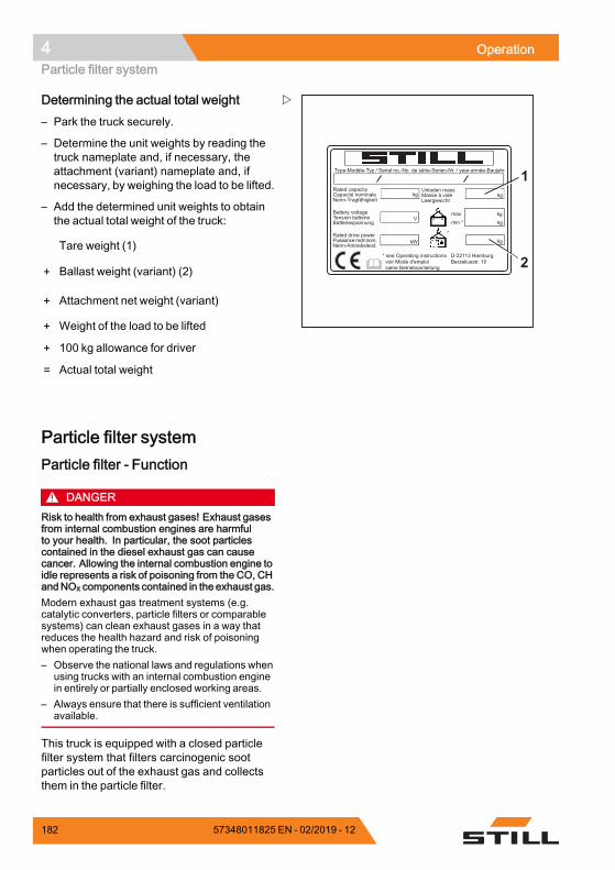
4 OperationParticle filter system
Type-Modèle-Typ / Serial no.-No. de série-Serien-Nr. / year-année-Baujahr
Rated capacityCapacité nominaleNenn-Tragfähigkeit
Battery voltageTension batterieBatteriespannung
Rated drive powerPuissance motr.nom.Nenn-Antriebsleist.
Unladen massMasse à videLeergewicht
maxmin.*
* see Operating instructions voir Mode d'emploi siehe Betriebsanleitung
kg kg
kgkg
kgkW
V
*
D-22113 HamburgBerzeliusstr. 10 2
1
Determining the actual total weight– Park the truck securely.
– Determine the unit weights by reading thetruck nameplate and, if necessary, theattachment (variant) nameplate and, ifnecessary, by weighing the load to be lifted.
– Add the determined unit weights to obtainthe actual total weight of the truck:
Tare weight (1)
+ Ballast weight (variant) (2)
+ Attachment net weight (variant)
+ Weight of the load to be lifted
+ 100 kg allowance for driver
= Actual total weight.
Particle filter systemParticle filter - Function
DANGERRisk to health from exhaust gases! Exhaust gasesfrom internal combustion engines are harmfulto your health. In particular, the soot particlescontained in the diesel exhaust gas can causecancer. Allowing the internal combustion engine toidle represents a risk of poisoning from the CO, CHandNOx components contained in the exhaust gas.Modern exhaust gas treatment systems (e.g.catalytic converters, particle filters or comparablesystems) can clean exhaust gases in a way thatreduces the health hazard and risk of poisoningwhen operating the truck.– Observe the national laws and regulations when
using trucks with an internal combustion enginein entirely or partially enclosed working areas.
– Always ensure that there is sufficient ventilationavailable.
This truck is equipped with a closed particlefilter system that filters carcinogenic sootparticles out of the exhaust gas and collectsthem in the particle filter.
182 57348011825 EN - 02/2019 - 12
Operation 4Particle filter system
The use of a particle filter is recommended forapplications in closed halls with a low degreeof ventilation.
Operating principle during normaloperationThe soot particles that are filtered out ofthe exhaust gas and collected in the filterare removed by means of a continuousregeneration process.
This process requires a sufficiently highexhaust gas temperature, which is alsoreached during normal operation. The truckis then used to such a degree that it burnsoff the soot during operation. The drivermust not interfere with this process. No otherconsumables (e.g. additives) are required.
Operating principle during low-loadoperationIf the truck is used little, a sufficiently highexhaust gas temperaturemay not be reached.In addition, very low ambient temperaturesmay prevent a sufficiently high exhaust gastemperature being reached. This causesthe regeneration process to be disrupted.The soot filtered out of the exhaust gasthen collects in the particle filter, as it is notburned off during the continuous regenerationprocess. In this case, a parked regenerationof the particle filter must be performed. Thisregeneration process, which takes approx. 30minutes, can only beperformedwhen the truckis stationary, meaning the truck cannot beused during this time. The driver is informed ofthe need for a parked regeneration in advanceby means of corresponding messages on thedisplay and operating unit. Details of thesemessages are provided in the chapter entitled"Messages regarding parked regeneration onthe display and operating unit".
Interrupting parked regenerationReleasing the parking brake during parked re-generation interrupts the parked regenerationprocess.
57348011825 EN - 02/2019 - 12 183
4 OperationParticle filter system
In the display and operating unit, the followingmessage appears: PARK. REG. ERROR.
NOTE
If regeneration is interrupted too frequently,additional engine maintenance may berequired from the authorised service centre.
– Apply the parking brake.
– Restart parked regeneration.
The restarted parked regeneration requiresanother 30 minutes to complete, no matterhow complete the interrupted parked regener-ation was.
If the display message PARK. REG. ERRORappears more than twice in successionwithout the parking brake being releasedduring parked regeneration, there may be amalfunction in the internal combustion engine.
– Notify the authorised service centre.
Particle filter - Performing parkedregeneration
CAUTIONRisk of damage to components! If parked regene-ration is not performed when required, the particlefilter may become damaged.A full parked regeneration must be performed inorder to completely empty the particle filter.
CAUTIONDuring the parked regeneration process, very hotcombustion gases escape from the exhaust pipe!The parked regeneration must not be performedin areas containing hazardous materials or highlyflammable materials, or in a hall. In addition, thefollowing instructions must be observed exactly.
During parked regeneration, the surfacetemperature of the exhaust gas system ishigher than the usual operating temperature.This can cause adhering dust and oils to ignite.If the truck is operated with an exhaust gasextraction unit, parked regeneration is notpermitted. The operating company must
184 57348011825 EN - 02/2019 - 12
Operation 4Particle filter system
determine whether parked regeneration ispermitted where the truck is being used orwhether the truckmust bemoved to a separatearea for this purpose.
The parked regeneration must be carriedout while the internal combustion engine isrunning. During the regeneration process,the truck automatically changes the speed ofthe internal combustion engine. The drivercannot influence this change. If the parkedregeneration requested by the truck is notperformed and this remains the case for anextended period of time, the particle filter maybecome damaged. If this happens, it wouldneed to be repaired by your authorised servicecentre.
Before performing parked regeneration, thefollowing points must be observed:• Observe the operating instructions from theoperating company
• Always thoroughly clean dust, oils and othersettling substances from the exhaust gassystem
• Remove any connected exhaust gasextraction units
• Perform parked regeneration in a suitableplace
NOTE
Parked regeneration can only be performedif the parking brake is engaged. If the parkingbrake is not engaged, APPLY HANDBRAKE!appears on the display.
As soon as the message EXH.GAS PURI-FIER appears in the display and operatingunit, parked regeneration can be performed.To do this, proceed as follows:
– Park the truck in a place that is suitable forparked regeneration.
57348011825 EN - 02/2019 - 12 185
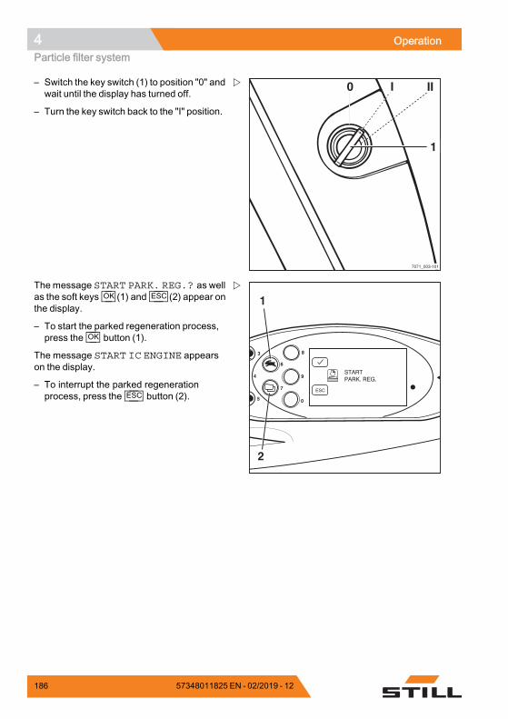
4 OperationParticle filter system
7071_003-101
0 I
1
II– Switch the key switch (1) to position "0" andwait until the display has turned off.
– Turn the key switch back to the "I" position.
8
9
0
6
7
4
3
5
ESC
1
2
Themessage START PARK. REG.? as wellas the soft keys OK (1) and ESC (2) appear onthe display.
– To start the parked regeneration process,press the OK button (1).
The message START IC ENGINE appearson the display.
– To interrupt the parked regenerationprocess, press the ESC button (2).
186 57348011825 EN - 02/2019 - 12
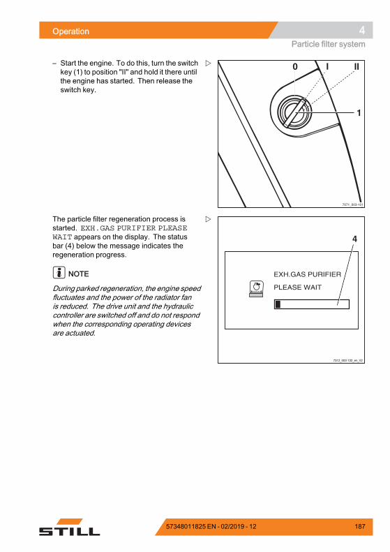
Operation 4Particle filter system
7071_003-101
0 I
1
II– Start the engine. To do this, turn the switchkey (1) to position "II" and hold it there untilthe engine has started. Then release theswitch key.
7312_003-132_en_V2
4
The particle filter regeneration process isstarted. EXH.GAS PURIFIER PLEASEWAIT appears on the display. The statusbar (4) below the message indicates theregeneration progress.
NOTE
During parked regeneration, the engine speedfluctuates and the power of the radiator fanis reduced. The drive unit and the hydrauliccontroller are switched off and do not respondwhen the corresponding operating devicesare actuated.
57348011825 EN - 02/2019 - 12 187
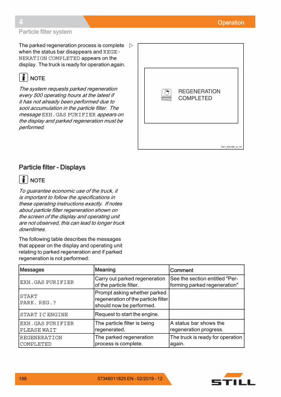
4 OperationParticle filter system
7341_003-039_en_V2
The parked regeneration process is completewhen the status bar disappears and REGE-NERATION COMPLETED appears on thedisplay. The truck is ready for operation again.
NOTE
The system requests parked regenerationevery 500 operating hours at the latest ifit has not already been performed due tosoot accumulation in the particle filter. Themessage EXH.GAS PURIFIER appears onthe display and parked regeneration must beperformed.
Particle filter - Displays
NOTE
To guarantee economic use of the truck, itis important to follow the specifications inthese operating instructions exactly. If notesabout particle filter regeneration shown onthe screen of the display and operating unitare not observed, this can lead to longer truckdowntimes.
The following table describes the messagesthat appear on the display and operating unitrelating to parked regeneration and if parkedregeneration is not performed:
Messages Meaning Comment
EXH.GAS PURIFIERCarry out parked regenerationof the particle filter.
See the section entitled "Per-forming parked regeneration"
STARTPARK. REG.?
Prompt asking whether parkedregeneration of the particle filtershould now be performed.
START IC ENGINE Request to start the engine.
EXH.GAS PURIFIERPLEASE WAIT
The particle filter is beingregenerated.
A status bar shows theregeneration progress.
REGENERATIONCOMPLETED
The parked regenerationprocess is complete.
The truck is ready for operationagain.
188 57348011825 EN - 02/2019 - 12
Operation 4Particle filter system
PARK. REG.URGENT! ! !
Parked regeneration of theparticle filter is urgentlyrequired.
Until parked regeneration hasbeen carried out, the maximumspeed of the truck is reducedto 2 km/h. The lifting speed isrestricted.
PARK. REG.ERROR
Regeneration was interrupteddue to an error.
The parking brake wasreleased during parkedregeneration.Apply the parking brake andrestart regeneration.If the message appears morethan twice in successionwithout the parking brakebeing released during parkedregeneration, there may bea malfunction in the internalcombustion engine. In thiscase, notify your authorisedservice centre.
ASH LOAD
The particle filter has becomeclogged with ash. Repair mustbe performed by the authorisedservice centre.
EXH.GAS PURIFIERSERVICE! ! !
Because regeneration hasnot been performed, theparticle filter system must berepaired by the authorisedservice centre. To avoid furtherdamage, take the truck out ofoperation until the repair hasbeen performed.
Until the particle filter systemhas been repaired, themaximum speed of the truckis reduced to 2 km/h. The liftingspeed is significantly restricted.
.
57348011825 EN - 02/2019 - 12 189
4 OperationAttachments
AttachmentsFitting attachmentsIf the truck is equipped with an integratedattachment (variant) at the factory, the specifi-cations in the STILL operating instructions forintegrated attachments must be observed.
If attachments are fitted at the place of use,the specifications in the operating instructionsof the attachment manufacturer must beobserved.
If an attachment is not delivered togetherwith the forklift truck, the specifications andoperating instructions of the attachmentmanufacturer must be observed.
Before initial commissioning, the functionof the attachment and the visibility from thedriver's position with and without a load mustbe checked by a competent person. If thevisibility is deemed insufficient, visual aidssuch asmirrors, a camera/monitor system etc.must be used.
In addition, it is essential that the warningsbelow are observed.
CAUTIONAttachments must be CE-certified. If the truck isnot fitted with an attachment-specific residual loadcapacity rating plate and the operating devices arenot marked with corresponding pictograms, thetruck must not be used.– Order the residual load capacity rating plate and
pictograms from your authorised service centrein good time.
– The authorised service centre must adapt thehydraulic system to the requirements of theattachment (e.g. by adjusting the pump motorspeed).
190 57348011825 EN - 02/2019 - 12
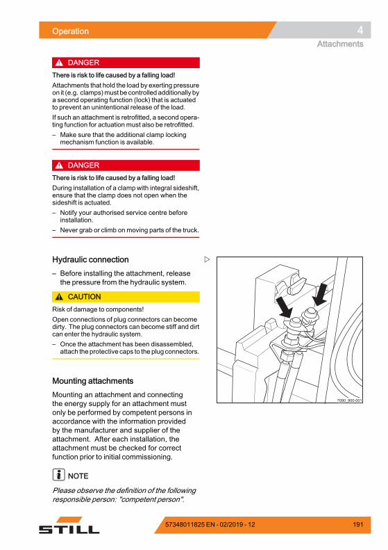
Operation 4Attachments
DANGERThere is risk to life caused by a falling load!Attachments that hold the load by exerting pressureon it (e.g. clamps)must be controlled additionally bya second operating function (lock) that is actuatedto prevent an unintentional release of the load.If such an attachment is retrofitted, a second opera-ting function for actuation must also be retrofitted.– Make sure that the additional clamp locking
mechanism function is available.
DANGERThere is risk to life caused by a falling load!During installation of a clamp with integral sideshift,ensure that the clamp does not open when thesideshift is actuated.– Notify your authorised service centre before
installation.– Never grab or climb on moving parts of the truck.
7090_900-001
Hydraulic connection– Before installing the attachment, releasethe pressure from the hydraulic system.
CAUTIONRisk of damage to components!Open connections of plug connectors can becomedirty. The plug connectors can become stiff and dirtcan enter the hydraulic system.– Once the attachment has been disassembled,
attach theprotective caps to the plug connectors.
Mounting attachmentsMounting an attachment and connectingthe energy supply for an attachment mustonly be performed by competent persons inaccordance with the information providedby the manufacturer and supplier of theattachment. After each installation, theattachment must be checked for correctfunction prior to initial commissioning.
NOTE
Please observe the definition of the followingresponsible person: "competent person".
57348011825 EN - 02/2019 - 12 191
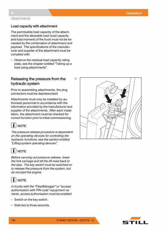
4 OperationAttachments
Load capacity with attachmentThe permissible load capacity of the attach-ment and the allowable load (load capacityand load moment) of the truck must not be ex-ceeded by the combination of attachment andpayload. The specifications of the manufac-turer and supplier of the attachment must becomplied with.
– Observe the residual load capacity ratingplate, see the chapter entitled "Taking up aload using attachments".
7090_900-001
Releasing the pressure from thehydraulic systemPrior to assembling attachments, the plugconnectors must be depressurised.
Attachments must only be installed by au-thorised personnel in accordance with theinformation provided by the manufacturer andsupplier of the attachments. After each instal-lation, the attachment must be checked forcorrect function prior to initial commissioning.
NOTE
The pressure release procedure is dependenton the operating devices for controlling thehydraulic functions; see the section entitled"Lifting system operating devices".
NOTE
Before carrying out pressure release, lowerthe fork carriage and tilt the lift mast back tothe stop. The key switch must be switched onto release the pressure from the system, butdo not start the engine.
NOTE
In trucks with the "FleetManager" or "accessauthorisation with PIN code" equipment va-riants, access authorisation must be enabled.
– Switch on the key switch.
– Wait two to three seconds.
192 57348011825 EN - 02/2019 - 12
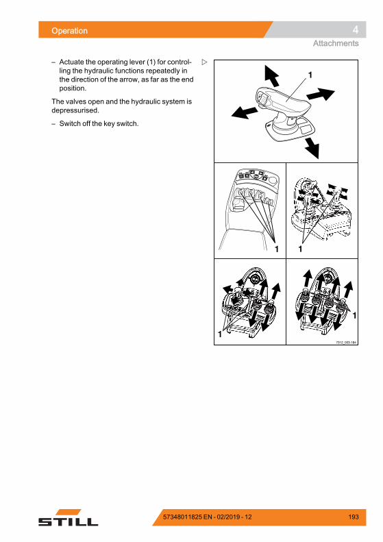
Operation 4Attachments
1
F1F1 F2F2
1
1
1
17312_003-184
– Actuate the operating lever (1) for control-ling the hydraulic functions repeatedly inthe direction of the arrow, as far as the endposition.
The valves open and the hydraulic system isdepressurised.
– Switch off the key switch.
57348011825 EN - 02/2019 - 12 193

4 OperationAttachments
General instructions for controllingattachmentsThe way in which attachments (variant) arecontrolled depends on the operating devicesincluded in the truck's equipment.
Essentially, a distinction is drawn between:• Double mini-lever• Double mini-lever with a 5th function(variant)
• Triple mini-lever• Triplemini-lever with a 5th function (variant)• Quadruple mini-lever• Quadruple mini-lever with a 5th function(variant)
• Joystick 4Plus• Joystick 4Plus with a 5th function (variant)• Fingertip switch• Fingertip with a 5th function (variant)
– For information on controlling attachmentswith the respective operating devices, seethe relevant sections in this chapter.
WARNINGUse of attachments can give rise to additionalhazards such as a change in the centre of gravity,additional danger areas etc.Attachments must only be used for their intendedpurpose as described in the relevant operatinginstructions. Drivers must be taught how to operatethe attachments.Loads may only be picked up and transported withattachments if the loads are securely grasped andattached. Where necessary, loads must also besecured against slipping, rolling away, falling over,swinging or tipping over. Note that any change tothe position of the load centre of gravity will affectthe stability of the truck.– Refer to the capacity rating plate for the attach-
ments being used.
NOTE
Further variants and functions are available inaddition to the functions described below. Thedirections of movement can be seen on thepictograms on the operating devices.
194 57348011825 EN - 02/2019 - 12
Operation 4Attachments
NOTE
All the attachments described fall into thecategory of equipment variants. Pleasesee the respective operating instructionsfor an exact description of the respectivemovements/actions of the attachment fitted.
57348011825 EN - 02/2019 - 12 195
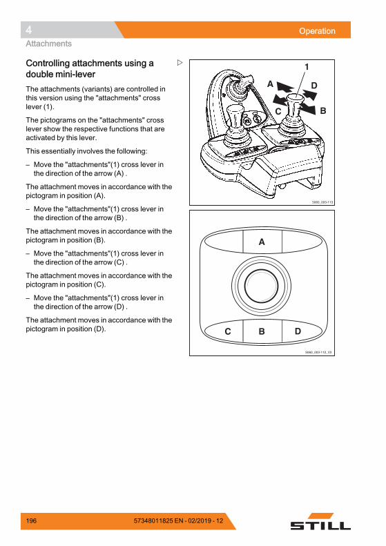
4 OperationAttachments
5060_003-113
A
C B
D
1
5060_003-112_V2
A
C B D
Controlling attachments using adouble mini-leverThe attachments (variants) are controlled inthis version using the "attachments" crosslever (1).
The pictograms on the "attachments" crosslever show the respective functions that areactivated by this lever.
This essentially involves the following:
– Move the "attachments"(1) cross lever inthe direction of the arrow (A) .
The attachment moves in accordance with thepictogram in position (A).
– Move the "attachments"(1) cross lever inthe direction of the arrow (B) .
The attachment moves in accordance with thepictogram in position (B).
– Move the "attachments"(1) cross lever inthe direction of the arrow (C) .
The attachment moves in accordance with thepictogram in position (C).
– Move the "attachments"(1) cross lever inthe direction of the arrow (D) .
The attachment moves in accordance with thepictogram in position (D).
196 57348011825 EN - 02/2019 - 12
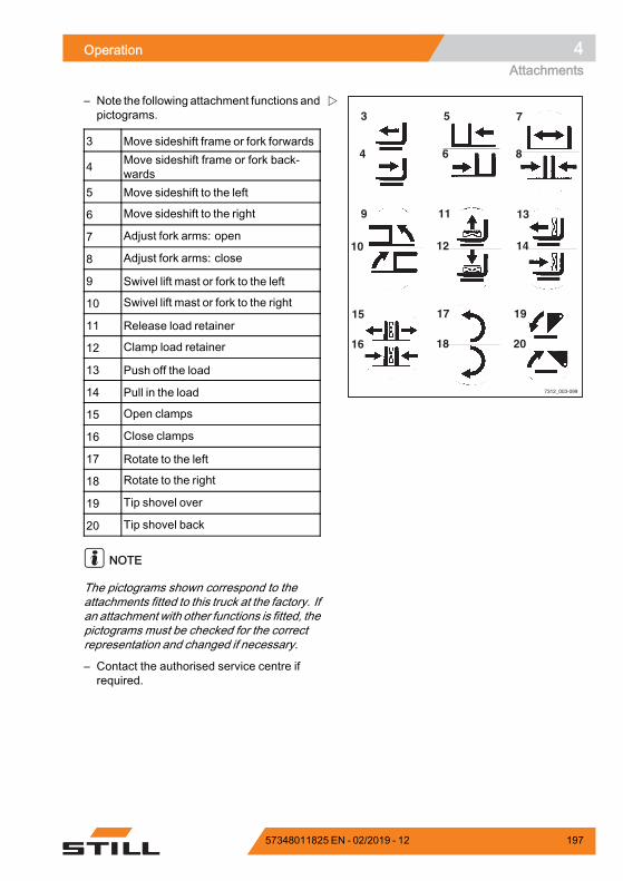
Operation 4Attachments
7312_003-099
3 5
11
7
4 6
13
17 19
9
12 1410
15
18 2016
8
– Note the following attachment functions andpictograms.
3 Move sideshift frame or fork forwards
4 Move sideshift frame or fork back-wards
5 Move sideshift to the left
6 Move sideshift to the right
7 Adjust fork arms: open
8 Adjust fork arms: close
9 Swivel lift mast or fork to the left
10 Swivel lift mast or fork to the right
11 Release load retainer
12 Clamp load retainer
13 Push off the load
14 Pull in the load
15 Open clamps
16 Close clamps
17 Rotate to the left
18 Rotate to the right
19 Tip shovel over
20 Tip shovel back
NOTE
The pictograms shown correspond to theattachments fitted to this truck at the factory. Ifan attachment with other functions is fitted, thepictograms must be checked for the correctrepresentation and changed if necessary.
– Contact the authorised service centre ifrequired.
57348011825 EN - 02/2019 - 12 197
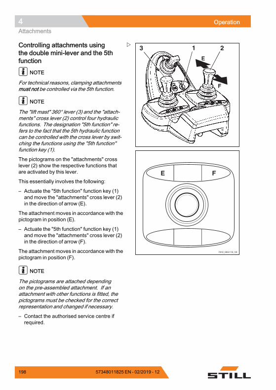
4 OperationAttachments
2
E
F
13
7312_003-113_V2
E F
Controlling attachments usingthe double mini-lever and the 5thfunction
NOTE
For technical reasons, clamping attachmentsmust not be controlled via the 5th function.
NOTE
The "lift mast" 360° lever (3) and the "attach-ments" cross lever (2) control four hydraulicfunctions. The designation "5th function" re-fers to the fact that the 5th hydraulic functioncan be controlled with the cross lever by swit-ching the functions using the "5th function"function key (1).
The pictograms on the "attachments" crosslever (2) show the respective functions thatare activated by this lever.
This essentially involves the following:
– Actuate the "5th function" function key (1)and move the "attachments" cross lever (2)in the direction of arrow (E).
The attachment moves in accordance with thepictogram in position (E).
– Actuate the "5th function" function key (1)and move the "attachments" cross lever (2)in the direction of arrow (F).
The attachment moves in accordance with thepictogram in position (F).
NOTE
The pictograms are attached dependingon the pre-assembled attachment. If anattachment with other functions is fitted, thepictograms must be checked for the correctrepresentation and changed if necessary.
– Contact the authorised service centre ifrequired.
198 57348011825 EN - 02/2019 - 12
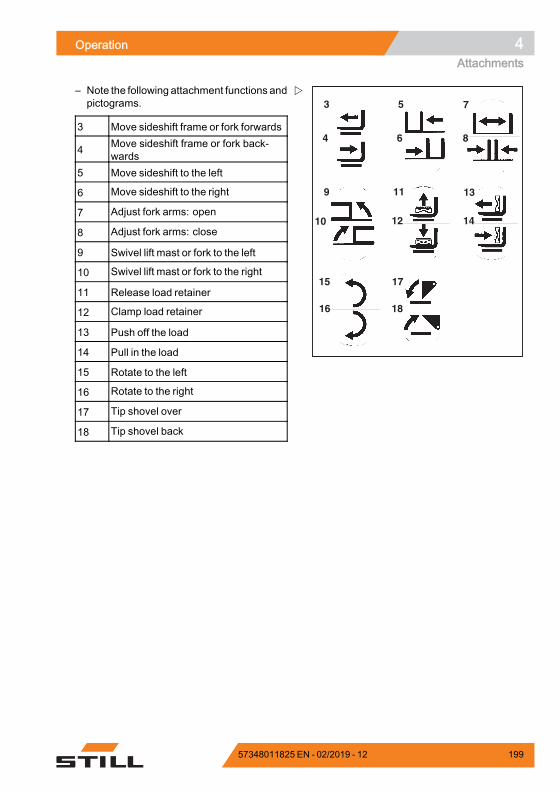
Operation 4Attachments
3 5
11
7
4 6
13
15 17
9
12 1410
16 18
8
– Note the following attachment functions andpictograms.
3 Move sideshift frame or fork forwards
4 Move sideshift frame or fork back-wards
5 Move sideshift to the left
6 Move sideshift to the right
7 Adjust fork arms: open
8 Adjust fork arms: close
9 Swivel lift mast or fork to the left
10 Swivel lift mast or fork to the right
11 Release load retainer
12 Clamp load retainer
13 Push off the load
14 Pull in the load
15 Rotate to the left
16 Rotate to the right
17 Tip shovel over
18 Tip shovel back.
57348011825 EN - 02/2019 - 12 199

4 OperationAttachments
7325_003-039
AC
BD
2
1
5060_003-109_V2
A C
B D
Controlling attachments using atriple mini-leverThe attachments (variant) are controlled inthis version using operating levers (1) and (2).
The pictograms on the operating levers showthe respective functions that are activated bythese levers.
This essentially involves the following:
– Move the operating lever (1) towards (A)
The attachment moves in accordance with thepictogram in position (A).
– Move the operating lever (1) towards (B)
The attachment moves in accordance with thepictogram in position (B).
– Move the operating lever (2) towards (C)
The attachment moves in accordance with thepictogram in position (C).
– Move the operating lever (2) towards (D)
The attachment moves in accordance with thepictogram in position (D).
NOTE
The pictograms are attached dependingon the pre-assembled attachment. If anattachment with other functions is fitted, thepictograms must be checked for the correctrepresentation and changed if necessary.
– Contact the authorised service centre ifrequired.
200 57348011825 EN - 02/2019 - 12
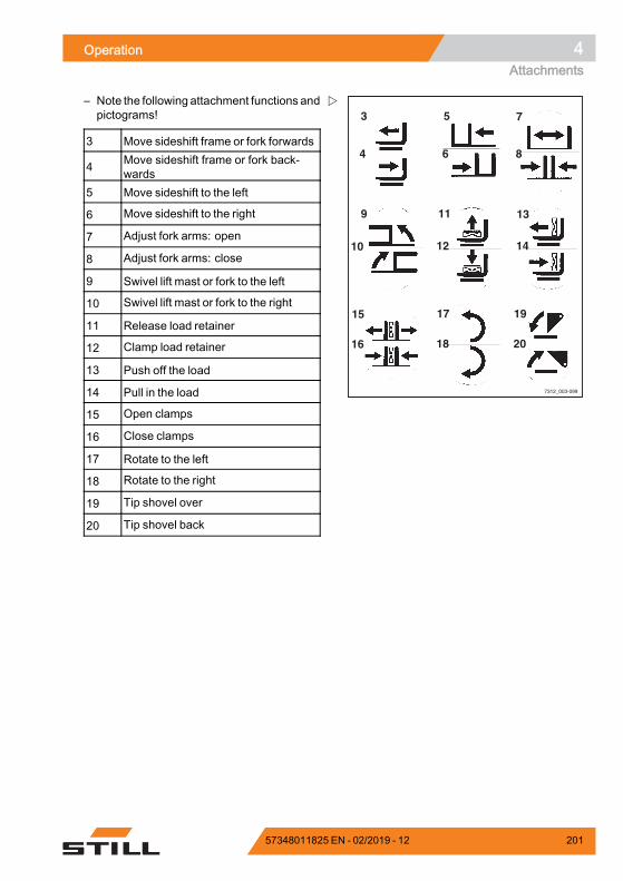
Operation 4Attachments
7312_003-099
3 5
11
7
4 6
13
17 19
9
12 1410
15
18 2016
8
– Note the following attachment functions andpictograms!
3 Move sideshift frame or fork forwards
4 Move sideshift frame or fork back-wards
5 Move sideshift to the left
6 Move sideshift to the right
7 Adjust fork arms: open
8 Adjust fork arms: close
9 Swivel lift mast or fork to the left
10 Swivel lift mast or fork to the right
11 Release load retainer
12 Clamp load retainer
13 Push off the load
14 Pull in the load
15 Open clamps
16 Close clamps
17 Rotate to the left
18 Rotate to the right
19 Tip shovel over
20 Tip shovel back.
57348011825 EN - 02/2019 - 12 201
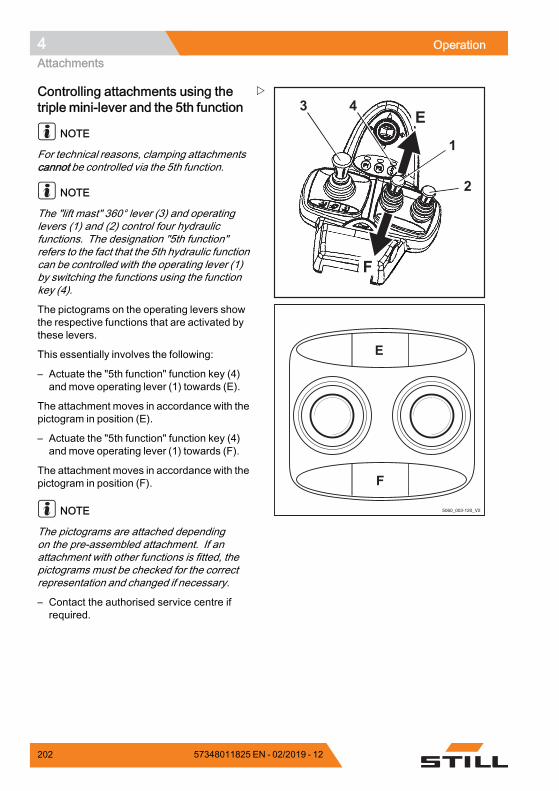
4 OperationAttachments
E
F
2
1
43
5060_003-120_V2
E
F
Controlling attachments using thetriple mini-lever and the 5th function
NOTE
For technical reasons, clamping attachmentscannot be controlled via the 5th function.
NOTE
The "lift mast" 360° lever (3) and operatinglevers (1) and (2) control four hydraulicfunctions. The designation "5th function"refers to the fact that the 5th hydraulic functioncan be controlled with the operating lever (1)by switching the functions using the functionkey (4).
The pictograms on the operating levers showthe respective functions that are activated bythese levers.
This essentially involves the following:
– Actuate the "5th function" function key (4)and move operating lever (1) towards (E).
The attachment moves in accordance with thepictogram in position (E).
– Actuate the "5th function" function key (4)and move operating lever (1) towards (F).
The attachment moves in accordance with thepictogram in position (F).
NOTE
The pictograms are attached dependingon the pre-assembled attachment. If anattachment with other functions is fitted, thepictograms must be checked for the correctrepresentation and changed if necessary.
– Contact the authorised service centre ifrequired.
202 57348011825 EN - 02/2019 - 12
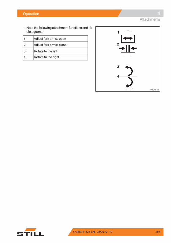
Operation 4Attachments
5060_003-122
3
4
1
2
– Note the following attachment functions andpictograms.
1 Adjust fork arms: open
2 Adjust fork arms: close
3 Rotate to the left
4 Rotate to the right.
57348011825 EN - 02/2019 - 12 203
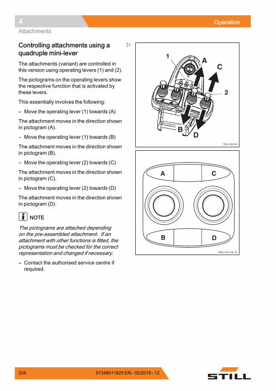
4 OperationAttachments
7325_003-041
1
2
AC
BD
5060_003-109_V2
A C
B D
Controlling attachments using aquadruple mini-leverThe attachments (variant) are controlled inthis version using operating levers (1) and (2).
The pictograms on the operating levers showthe respective function that is activated bythese levers.
This essentially involves the following:
– Move the operating lever (1) towards (A)
The attachment moves in the direction shownin pictogram (A).
– Move the operating lever (1) towards (B)
The attachment moves in the direction shownin pictogram (B).
– Move the operating lever (2) towards (C)
The attachment moves in the direction shownin pictogram (C).
– Move the operating lever (2) towards (D)
The attachment moves in the direction shownin pictogram (D).
NOTE
The pictograms are attached dependingon the pre-assembled attachment. If anattachment with other functions is fitted, thepictograms must be checked for the correctrepresentation and changed if necessary.
– Contact the authorised service centre ifrequired.
204 57348011825 EN - 02/2019 - 12

Operation 4Attachments
7312_003-099
3 5
11
7
4 6
13
17 19
9
12 1410
15
18 2016
8
– Note the following attachment functions andpictograms!
3 Move sideshift frame or fork forwards
4 Move sideshift frame or fork back-wards
5 Move sideshift to the left
6 Move sideshift to the right
7 Adjust fork arms: open
8 Adjust fork arms: close
9 Swivel lift mast or fork to the left
10 Swivel lift mast or fork to the right
11 Release load retainer
12 Clamp load retainer
13 Push off the load
14 Pull in the load
15 Open clamps
16 Close clamps
17 Rotate to the left
18 Rotate to the right
19 Tip shovel over
20 Tip shovel back.
57348011825 EN - 02/2019 - 12 205
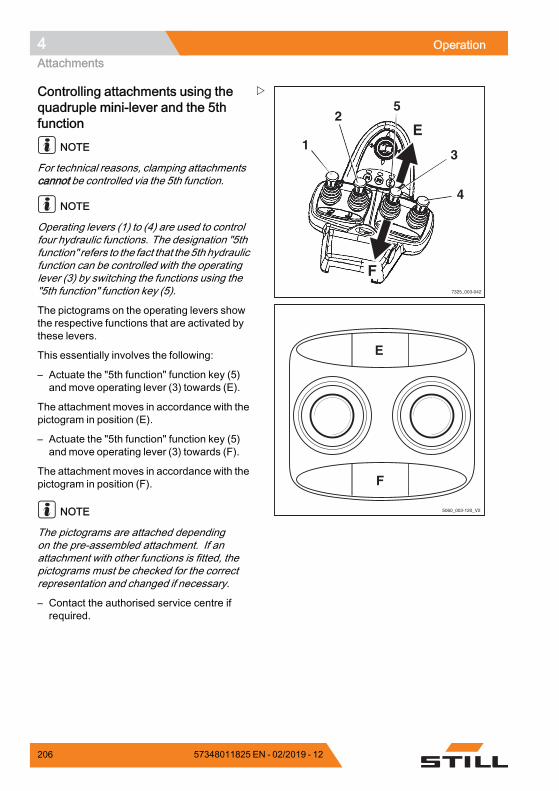
4 OperationAttachments
7325_003-042
4
1
25
3
E
F
5060_003-120_V2
E
F
Controlling attachments using thequadruple mini-lever and the 5thfunction
NOTE
For technical reasons, clamping attachmentscannot be controlled via the 5th function.
NOTE
Operating levers (1) to (4) are used to controlfour hydraulic functions. The designation "5thfunction" refers to the fact that the5th hydraulicfunction can be controlled with the operatinglever (3) by switching the functions using the"5th function" function key (5).
The pictograms on the operating levers showthe respective functions that are activated bythese levers.
This essentially involves the following:
– Actuate the "5th function" function key (5)and move operating lever (3) towards (E).
The attachment moves in accordance with thepictogram in position (E).
– Actuate the "5th function" function key (5)and move operating lever (3) towards (F).
The attachment moves in accordance with thepictogram in position (F).
NOTE
The pictograms are attached dependingon the pre-assembled attachment. If anattachment with other functions is fitted, thepictograms must be checked for the correctrepresentation and changed if necessary.
– Contact the authorised service centre ifrequired.
206 57348011825 EN - 02/2019 - 12

Operation 4Attachments
5060_003-122
3
4
1
2
– Note the following attachment functions andpictograms.
1 Adjust fork arms: open
2 Adjust fork arms: close
3 Rotate to the left
4 Rotate to the right.
57348011825 EN - 02/2019 - 12 207
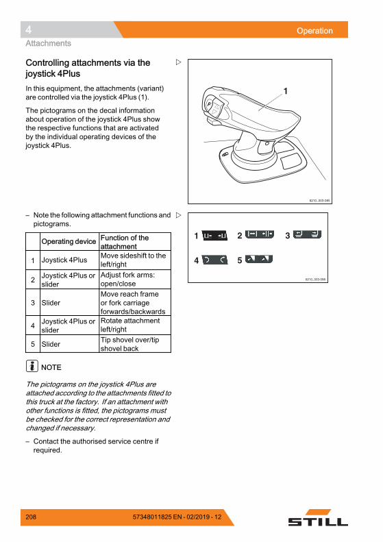
4 OperationAttachments
1
6210_003-085
Controlling attachments via thejoystick 4PlusIn this equipment, the attachments (variant)are controlled via the joystick 4Plus (1).
The pictograms on the decal informationabout operation of the joystick 4Plus showthe respective functions that are activatedby the individual operating devices of thejoystick 4Plus.
6210_003-098
1
4
2
5
3
– Note the following attachment functions andpictograms.
Operating device Function of theattachment
1 Joystick 4Plus Move sideshift to theleft/right
2 Joystick 4Plus orslider
Adjust fork arms:open/close
3 SliderMove reach frameor fork carriageforwards/backwards
4 Joystick 4Plus orslider
Rotate attachmentleft/right
5 Slider Tip shovel over/tipshovel back
NOTE
The pictograms on the joystick 4Plus areattached according to the attachments fitted tothis truck at the factory. If an attachment withother functions is fitted, the pictograms mustbe checked for the correct representation andchanged if necessary.
– Contact the authorised service centre ifrequired.
208 57348011825 EN - 02/2019 - 12
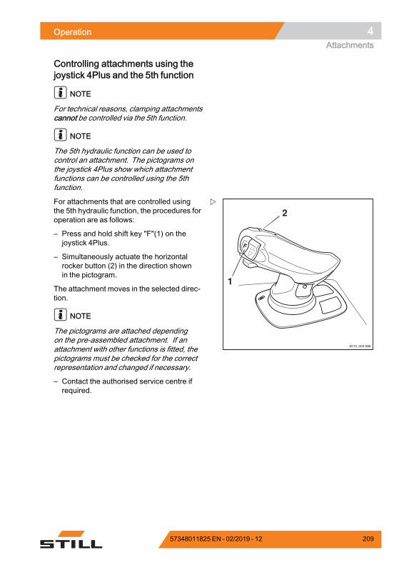
Operation 4Attachments
Controlling attachments using thejoystick 4Plus and the 5th function
NOTE
For technical reasons, clamping attachmentscannot be controlled via the 5th function.
NOTE
The 5th hydraulic function can be used tocontrol an attachment. The pictograms onthe joystick 4Plus show which attachmentfunctions can be controlled using the 5thfunction.
2
1
6210_003-086
For attachments that are controlled usingthe 5th hydraulic function, the procedures foroperation are as follows:
– Press and hold shift key "F"(1) on thejoystick 4Plus.
– Simultaneously actuate the horizontalrocker button (2) in the direction shownin the pictogram.
The attachment moves in the selected direc-tion.
NOTE
The pictograms are attached dependingon the pre-assembled attachment. If anattachment with other functions is fitted, thepictograms must be checked for the correctrepresentation and changed if necessary.
– Contact the authorised service centre ifrequired.
57348011825 EN - 02/2019 - 12 209
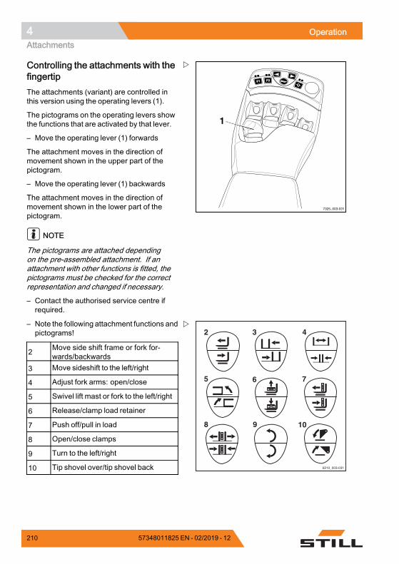
4 OperationAttachments
F1F1 F2F2
7325_003-031
1
Controlling the attachments with thefingertipThe attachments (variant) are controlled inthis version using the operating levers (1).
The pictograms on the operating levers showthe functions that are activated by that lever.
– Move the operating lever (1) forwards
The attachment moves in the direction ofmovement shown in the upper part of thepictogram.
– Move the operating lever (1) backwards
The attachment moves in the direction ofmovement shown in the lower part of thepictogram.
NOTE
The pictograms are attached dependingon the pre-assembled attachment. If anattachment with other functions is fitted, thepictograms must be checked for the correctrepresentation and changed if necessary.
– Contact the authorised service centre ifrequired.
6210_003-031
2 3
6
4
7
9 10
5
8
– Note the following attachment functions andpictograms!
2 Move side shift frame or fork for-wards/backwards
3 Move sideshift to the left/right
4 Adjust fork arms: open/close
5 Swivel lift mast or fork to the left/right
6 Release/clamp load retainer
7 Push off/pull in load
8 Open/close clamps
9 Turn to the left/right
10 Tip shovel over/tip shovel back.
210 57348011825 EN - 02/2019 - 12
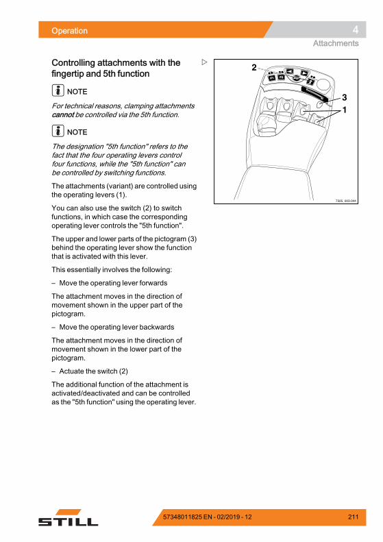
Operation 4Attachments
F1F1 F2F2
7325_003-044
13
2Controlling attachments with thefingertip and 5th function
NOTE
For technical reasons, clamping attachmentscannot be controlled via the 5th function.
NOTE
The designation "5th function" refers to thefact that the four operating levers controlfour functions, while the "5th function" canbe controlled by switching functions.
The attachments (variant) are controlled usingthe operating levers (1).
You can also use the switch (2) to switchfunctions, in which case the correspondingoperating lever controls the "5th function".
The upper and lower parts of the pictogram (3)behind the operating lever show the functionthat is activated with this lever.
This essentially involves the following:
– Move the operating lever forwards
The attachment moves in the direction ofmovement shown in the upper part of thepictogram.
– Move the operating lever backwards
The attachment moves in the direction ofmovement shown in the lower part of thepictogram.
– Actuate the switch (2)
The additional function of the attachment isactivated/deactivated and can be controlledas the "5th function" using the operating lever.
57348011825 EN - 02/2019 - 12 211
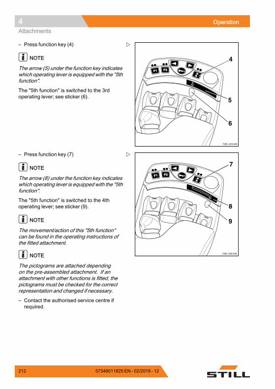
4 OperationAttachments
F1F1 F2F2
7325_003-045
4
5
6
– Press function key (4)
NOTE
The arrow (5) under the function key indicateswhich operating lever is equipped with the "5thfunction".
The "5th function" is switched to the 3rdoperating lever; see sticker (6).
F1F1 F2F2
7325_003-046
7
8
9
– Press function key (7)
NOTE
The arrow (8) under the function key indicateswhich operating lever is equipped with the "5thfunction".
The "5th function" is switched to the 4thoperating lever; see sticker (9).
NOTE
The movement/action of this "5th function"can be found in the operating instructions ofthe fitted attachment.
NOTE
The pictograms are attached dependingon the pre-assembled attachment. If anattachment with other functions is fitted, thepictograms must be checked for the correctrepresentation and changed if necessary.
– Contact the authorised service centre ifrequired.
212 57348011825 EN - 02/2019 - 12
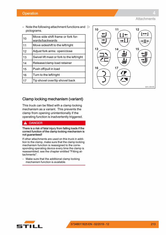
Operation 4Attachments
6210_003-035
10 11
14
12
15
17
13
16
– Note the following attachment functions andpictograms.
10 Move side shift frame or fork for-wards/backwards
11 Move sideshift to the left/right
12 Adjust fork arms: open/close
13 Swivel lift mast or fork to the left/right
14 Release/clamp load retainer
15 Push off/pull in load
16 Turn to the left/right
17 Tip shovel over/tip shovel back.
Clamp locking mechanism (variant)This truck can be fitted with a clamp lockingmechanism as a variant. This prevents theclamp from opening unintentionally if theoperating function is inadvertently triggered.
DANGERThere is a risk of fatal injury from falling loads if thecorrect function of the clamp locking mechanism isnot guaranteed!If other attachments are used on this truck in addi-tion to the clamp, make sure that the clamp lockingmechanism function is reassigned to the corre-sponding operating device every time the clamp isreassembled; see the chapter entitled "Fitting at-tachments".– Make sure that the additional clamp locking
mechanism function is available.
57348011825 EN - 02/2019 - 12 213
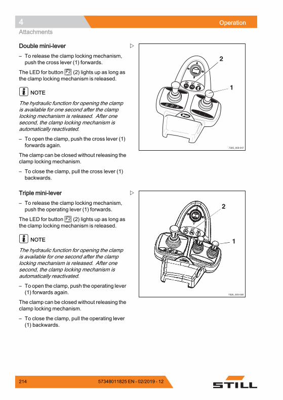
4 OperationAttachments
F1 F2
7325_003-047
1
2
Double mini-lever– To release the clamp locking mechanism,push the cross lever (1) forwards.
The LED for button F2 (2) lights up as long asthe clamp locking mechanism is released.
NOTE
The hydraulic function for opening the clampis available for one second after the clamplocking mechanism is released. After onesecond, the clamp locking mechanism isautomatically reactivated.
– To open the clamp, push the cross lever (1)forwards again.
The clamp can be closed without releasing theclamp locking mechanism.
– To close the clamp, pull the cross lever (1)backwards.
7325_003-048
1
2
Triple mini-lever– To release the clamp locking mechanism,push the operating lever (1) forwards.
The LED for button F2 (2) lights up as long asthe clamp locking mechanism is released.
NOTE
The hydraulic function for opening the clampis available for one second after the clamplocking mechanism is released. After onesecond, the clamp locking mechanism isautomatically reactivated.
– To open the clamp, push the operating lever(1) forwards again.
The clamp can be closed without releasing theclamp locking mechanism.
– To close the clamp, pull the operating lever(1) backwards.
214 57348011825 EN - 02/2019 - 12
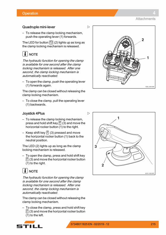
Operation 4Attachments
7325_003-049
1
2
Quadruple mini-lever– To release the clamp locking mechanism,push the operating lever (1) forwards.
The LED for button F2 (2) lights up as long asthe clamp locking mechanism is released.
NOTE
The hydraulic function for opening the clampis available for one second after the clamplocking mechanism is released. After onesecond, the clamp locking mechanism isautomatically reactivated.
– To open the clamp, push the operating lever(1) forwards again.
The clamp can be closed without releasing theclamp locking mechanism.
– To close the clamp, pull the operating lever(1) backwards.
1
3
2
6210_003-097
Joystick 4Plus– To release the clamp locking mechanism,press and hold shift key F (3) andmove thehorizontal rocker button (1) to the right.
– Keep shift key F (3) pressed and movethe horizontal rocker button (1) back to theneutral position.
The LED (2) lights up as long as the clamplocking mechanism is released.
– To open the clamp, press and hold shift keyF (3) andmove the horizontal rocker button(1) to the right.
NOTE
The hydraulic function for opening the clampis available for one second after the clamplocking mechanism is released. After onesecond, the clamp locking mechanism isautomatically reactivated.The clamp can be closed without releasing theclamp locking mechanism.
– To close the clamp, press and hold shift keyF (3) andmove the horizontal rocker button(1) to the left.
57348011825 EN - 02/2019 - 12 215
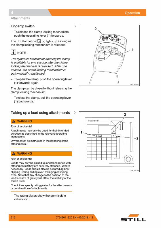
4 OperationAttachments
7325_003-050
F1F1 F2F2
1
2Fingertip switch– To release the clamp locking mechanism,push the operating lever (1) forwards.
The LED for button F2 (2) lights up as long asthe clamp locking mechanism is released.
NOTE
The hydraulic function for opening the clampis available for one second after the clamplocking mechanism is released. After onesecond, the clamp locking mechanism isautomatically reactivated.
– To open the clamp, push the operating lever(1) forwards again.
The clamp can be closed without releasing theclamp locking mechanism.
– To close the clamp, pull the operating lever(1) backwards.
1
2
3
7090_860-002
Taking up a load using attachments
WARNINGRisk of accidents!Attachments may only be used for their intendedpurpose as described in the relevant operatinginstructions.Drivers must be instructed in the handling of theattachments.
WARNINGRisk of accidents!Loads may only be picked up and transported withattachments if they are securely attached. Wherenecessary, loads should also be secured againstslipping, rolling, falling over, swinging or tippingover. Note that any change to the position of theload's centre of gravity will affect the stability of theforklift truck.Check the capacity rating plates for theattachmentsor combination of attachments.
– The rating plates show the permissiblevalues for:
216 57348011825 EN - 02/2019 - 12
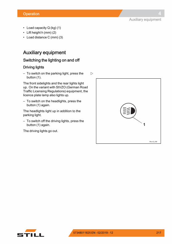
Operation 4Auxiliary equipment
• Load capacity Q (kg) (1)• Lift height h (mm) (2)• Load distance C (mm) (3)
Auxiliary equipmentSwitching the lighting on and off
Driving lights
Blue-Q_039
1
– To switch on the parking light, press thebutton (1).
The front sidelights and the rear lights lightup. On the variant with StVZO (German RoadTraffic Licensing Regulations) equipment, thelicence plate lamp also lights up.
– To switch on the headlights, press thebutton (1) again.
The headlights light up in addition to theparking light.
– To switch off the driving lights, press thebutton (1) again.
The driving lights go out.
57348011825 EN - 02/2019 - 12 217
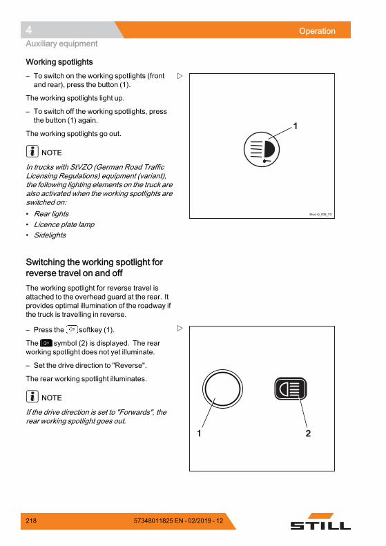
4 OperationAuxiliary equipment
Working spotlights
Blue-Q_008_V3
1
– To switch on the working spotlights (frontand rear), press the button (1).
The working spotlights light up.
– To switch off the working spotlights, pressthe button (1) again.
The working spotlights go out.
NOTE
In trucks with StVZO (German Road TrafficLicensing Regulations) equipment (variant),the following lighting elements on the truck arealso activated when the working spotlights areswitched on:• Rear lights• Licence plate lamp• Sidelights
Switching the working spotlight forreverse travel on and offThe working spotlight for reverse travel isattached to the overhead guard at the rear. Itprovides optimal illumination of the roadway ifthe truck is travelling in reverse.
21
– Press the softkey (1).
The symbol (2) is displayed. The rearworking spotlight does not yet illuminate.
– Set the drive direction to "Reverse".
The rear working spotlight illuminates.
NOTE
If the drive direction is set to "Forwards", therear working spotlight goes out.
218 57348011825 EN - 02/2019 - 12
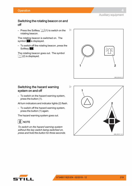
Operation 4Auxiliary equipment
Switching the rotating beacon on andoff
5060_003-045_V2
21
– Press the Softkey (1) to switch on therotating beacon.
The rotating beacon is switched on. Thesymbol is displayed.
– To switch off the rotating beacon, press theSoftkey .
The rotating beacon goes out. The symbol(2) is displayed.
5060_003-011_V2
1
2
Switching the hazard warningsystem on and off– To switch on the hazard warning system,press the button (1).
All turn indicators and indicator lights (2) flash.
– To switch off the hazard warning system,press the button (1) again.
The hazard warning system goes out.
NOTE
To switch on the hazard warning systemwithout the key switch being switched on,press and hold the button for three seconds.
57348011825 EN - 02/2019 - 12 219
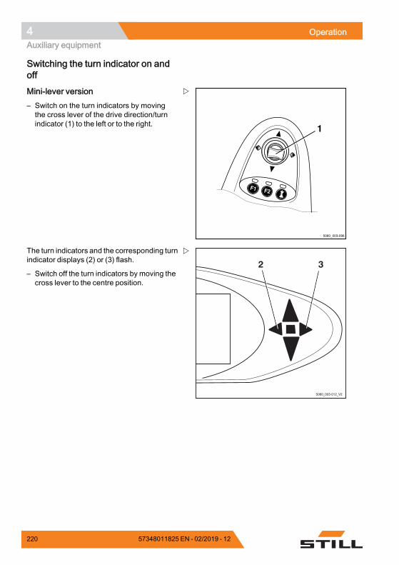
4 OperationAuxiliary equipment
Switching the turn indicator on andoff
5060_003-096
F1 F2
1
Mini-lever version– Switch on the turn indicators by movingthe cross lever of the drive direction/turnindicator (1) to the left or to the right.
2 3
5060_003-012_V2
The turn indicators and the corresponding turnindicator displays (2) or (3) flash.
– Switch off the turn indicators by moving thecross lever to the centre position.
220 57348011825 EN - 02/2019 - 12
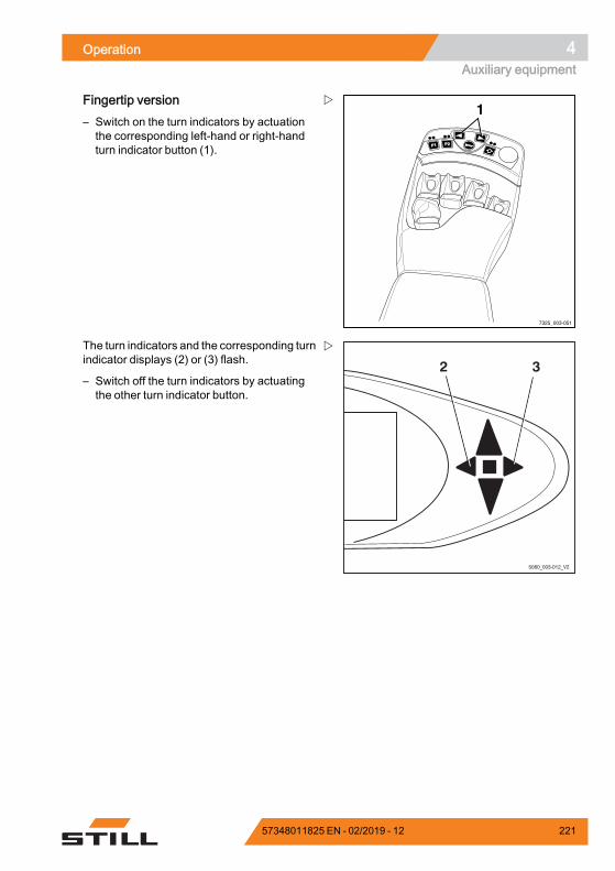
Operation 4Auxiliary equipment
F1F1 F2F2
7325_003-051
1Fingertip version– Switch on the turn indicators by actuationthe corresponding left-hand or right-handturn indicator button (1).
2 3
5060_003-012_V2
The turn indicators and the corresponding turnindicator displays (2) or (3) flash.
– Switch off the turn indicators by actuatingthe other turn indicator button.
57348011825 EN - 02/2019 - 12 221
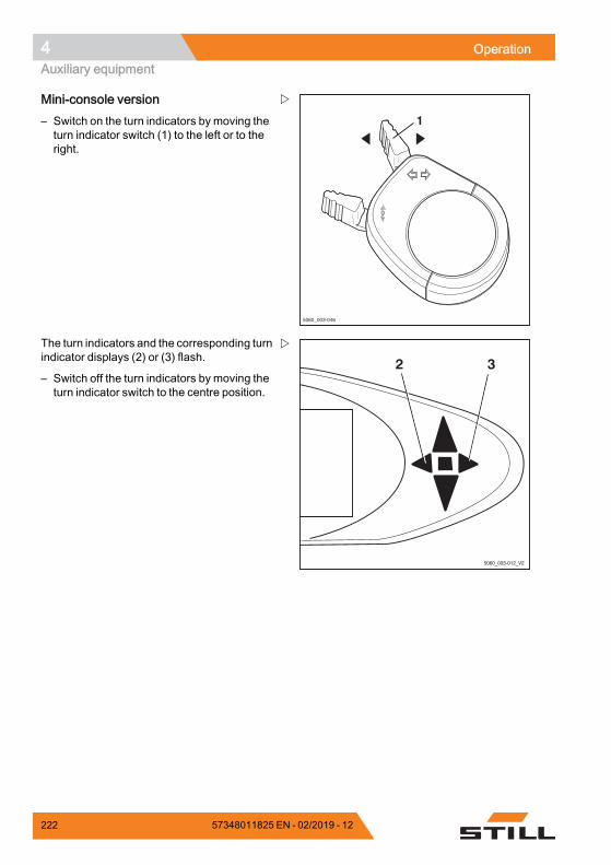
4 OperationAuxiliary equipment
5060_003-046
1
Mini-console version– Switch on the turn indicators by moving theturn indicator switch (1) to the left or to theright.
2 3
5060_003-012_V2
The turn indicators and the corresponding turnindicator displays (2) or (3) flash.
– Switch off the turn indicators by moving theturn indicator switch to the centre position.
222 57348011825 EN - 02/2019 - 12
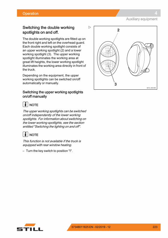
Operation 4Auxiliary equipment
6210_003-060
2
3
Switching the double workingspotlights on and off.The double working spotlights are fitted up onthe front right and left on the overhead guard.Each double working spotlight consists ofan upper working spotlight (2) and a lowerworking spotlight (3). The upper workingspotlight illuminates the working area atgreat lift heights, the lower working spotlightilluminates the working area directly in front ofthe truck.
Depending on the equipment, the upperworking spotlights can be switched on/offautomatically or manually.
Switching the upper working spotlightson/off manually
NOTE
The upper working spotlights can be switchedon/off independently of the lower workingspotlights. For information about switching onthe lower working spotlights, see the sectionentitled "Switching the lighting on and off".
NOTE
This function is not available if the truck isequipped with rear window heating.
– Turn the key switch to position "I".
57348011825 EN - 02/2019 - 12 223
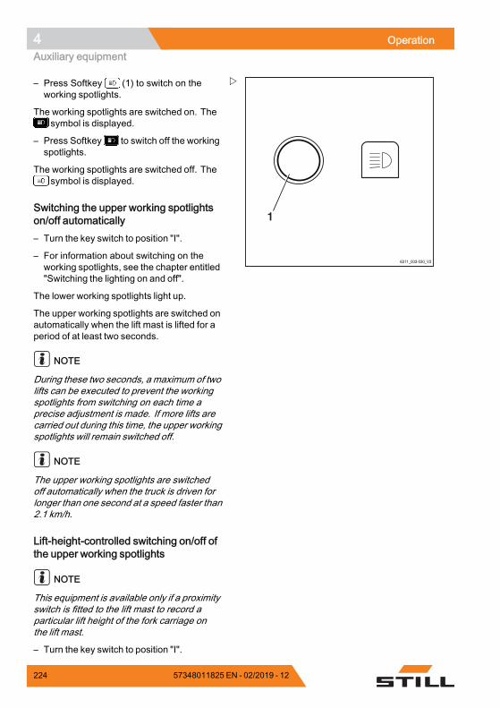
4 OperationAuxiliary equipment
6311_003-030_V3
1
– Press Softkey (1) to switch on theworking spotlights.
The working spotlights are switched on. Thesymbol is displayed.
– Press Softkey to switch off the workingspotlights.
The working spotlights are switched off. Thesymbol is displayed.
Switching the upper working spotlightson/off automatically– Turn the key switch to position "I".
– For information about switching on theworking spotlights, see the chapter entitled"Switching the lighting on and off".
The lower working spotlights light up.
The upper working spotlights are switched onautomatically when the lift mast is lifted for aperiod of at least two seconds.
NOTE
During these two seconds, a maximum of twolifts can be executed to prevent the workingspotlights from switching on each time aprecise adjustment is made. If more lifts arecarried out during this time, the upper workingspotlights will remain switched off.
NOTE
The upper working spotlights are switchedoff automatically when the truck is driven forlonger than one second at a speed faster than2.1 km/h.
Lift-height-controlled switching on/off ofthe upper working spotlights
NOTE
This equipment is available only if a proximityswitch is fitted to the lift mast to record aparticular lift height of the fork carriage onthe lift mast.
– Turn the key switch to position "I".
224 57348011825 EN - 02/2019 - 12
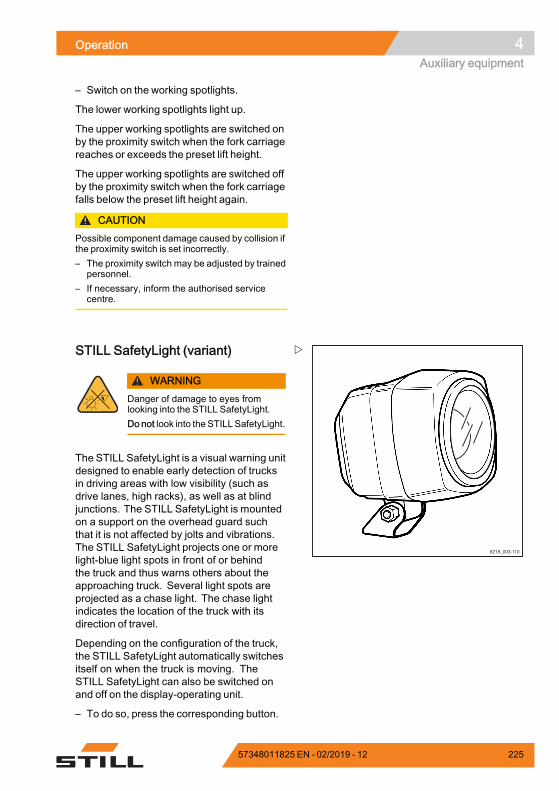
Operation 4Auxiliary equipment
– Switch on the working spotlights.
The lower working spotlights light up.
The upper working spotlights are switched onby the proximity switch when the fork carriagereaches or exceeds the preset lift height.
The upper working spotlights are switched offby the proximity switch when the fork carriagefalls below the preset lift height again.
CAUTIONPossible component damage caused by collision ifthe proximity switch is set incorrectly.– The proximity switch may be adjusted by trained
personnel.– If necessary, inform the authorised service
centre.
STILL SafetyLight (variant)
WARNINGDanger of damage to eyes fromlooking into the STILL SafetyLight.Do not look into theSTILLSafetyLight.
The STILL SafetyLight is a visual warning unitdesigned to enable early detection of trucksin driving areas with low visibility (such asdrive lanes, high racks), as well as at blindjunctions. The STILL SafetyLight is mountedon a support on the overhead guard suchthat it is not affected by jolts and vibrations.The STILL SafetyLight projects one or morelight-blue light spots in front of or behindthe truck and thus warns others about theapproaching truck. Several light spots areprojected as a chase light. The chase lightindicates the location of the truck with itsdirection of travel.
Depending on the configuration of the truck,the STILL SafetyLight automatically switchesitself on when the truck is moving. TheSTILL SafetyLight can also be switched onand off on the display-operating unit.
– To do so, press the corresponding button.
57348011825 EN - 02/2019 - 12 225
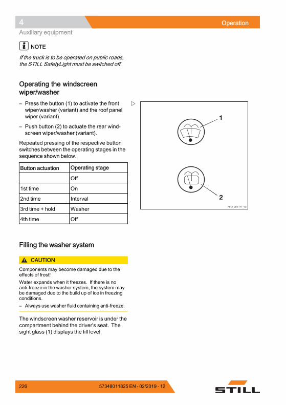
4 OperationAuxiliary equipment
NOTE
If the truck is to be operated on public roads,the STILL SafetyLight must be switched off.
Operating the windscreenwiper/washer
7312_003-171_V3
1
2
– Press the button (1) to activate the frontwiper/washer (variant) and the roof panelwiper (variant).
– Push button (2) to actuate the rear wind-screen wiper/washer (variant).
Repeated pressing of the respective buttonswitches between the operating stages in thesequence shown below.
Button actuation Operating stage
Off
1st time On
2nd time Interval
3rd time + hold Washer
4th time Off.
Filling the washer system
CAUTIONComponents may become damaged due to theeffects of frost!Water expands when it freezes. If there is noanti-freeze in the washer system, the system maybe damaged due to the build up of ice in freezingconditions.– Always use washer fluid containing anti-freeze.
The windscreen washer reservoir is under thecompartment behind the driver's seat. Thesight glass (1) displays the fill level.
226 57348011825 EN - 02/2019 - 12
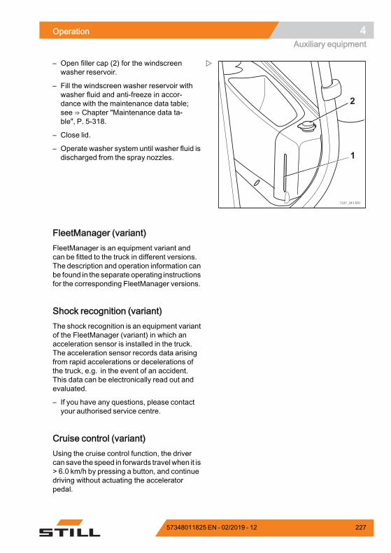
Operation 4Auxiliary equipment
7331_341-001
2
1
– Open filler cap (2) for the windscreenwasher reservoir.
– Fill the windscreen washer reservoir withwasher fluid and anti-freeze in accor-dance with the maintenance data table;see ⇒ Chapter "Maintenance data ta-ble", P. 5-318.
– Close lid.
– Operate washer system until washer fluid isdischarged from the spray nozzles.
FleetManager (variant)FleetManager is an equipment variant andcan be fitted to the truck in different versions.The description and operation information canbe found in the separate operating instructionsfor the corresponding FleetManager versions.
Shock recognition (variant)The shock recognition is an equipment variantof the FleetManager (variant) in which anacceleration sensor is installed in the truck.The acceleration sensor records data arisingfrom rapid accelerations or decelerations ofthe truck, e.g. in the event of an accident.This data can be electronically read out andevaluated.
– If you have any questions, please contactyour authorised service centre.
Cruise control (variant)Using the cruise control function, the drivercan save the speed in forwards travelwhen it is> 6.0 km/h by pressing a button, and continuedriving without actuating the acceleratorpedal.
57348011825 EN - 02/2019 - 12 227
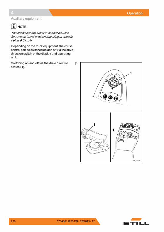
4 OperationAuxiliary equipment
NOTE
The cruise control function cannot be usedfor reverse travel or when travelling at speedsbelow 6.0 km/h.
Depending on the truck equipment, the cruisecontrol can be switched on and off via the drivedirection switch or the display and operatingunit.
7325_003-057
F1F1 F2F2
F1 F2
1
11
Switching on and off via the drive directionswitch (1).
228 57348011825 EN - 02/2019 - 12
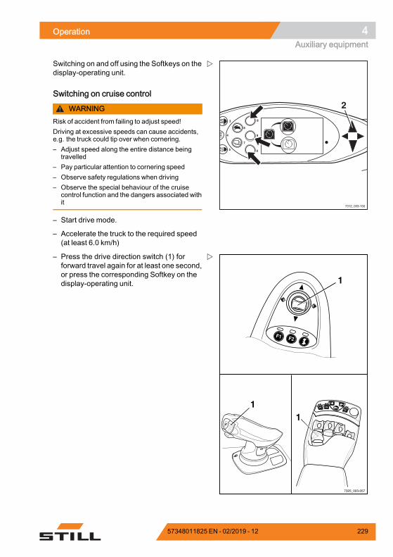
Operation 4Auxiliary equipment
8
9
0
6
7
4
3
5
2
7312_003-150
Switching on and off using the Softkeys on thedisplay-operating unit.
Switching on cruise control
WARNINGRisk of accident from failing to adjust speed!Driving at excessive speeds can cause accidents,e.g. the truck could tip over when cornering.– Adjust speed along the entire distance being
travelled– Pay particular attention to cornering speed– Observe safety regulations when driving– Observe the special behaviour of the cruise
control function and the dangers associated withit
– Start drive mode.
– Accelerate the truck to the required speed(at least 6.0 km/h)
7325_003-057
F1F1 F2F2
F1 F2
1
11
– Press the drive direction switch (1) forforward travel again for at least one second,or press the corresponding Softkey on thedisplay-operating unit.
57348011825 EN - 02/2019 - 12 229
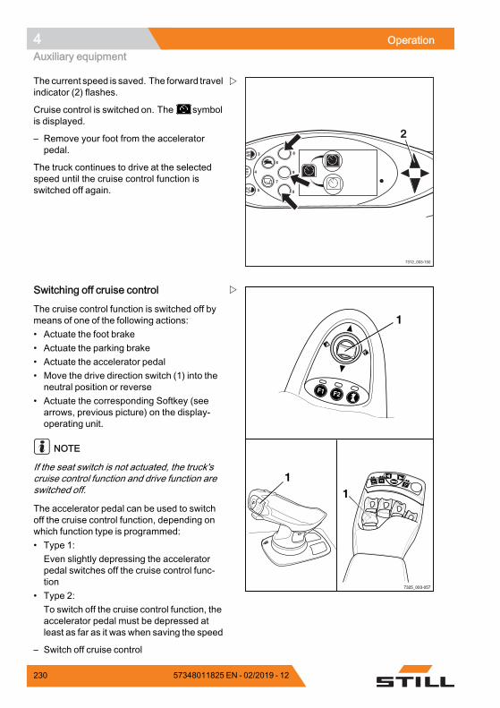
4 OperationAuxiliary equipment
8
9
0
6
7
4
3
5
2
7312_003-150
The current speed is saved. The forward travelindicator (2) flashes.
Cruise control is switched on. The symbolis displayed.
– Remove your foot from the acceleratorpedal.
The truck continues to drive at the selectedspeed until the cruise control function isswitched off again.
7325_003-057
F1F1 F2F2
F1 F2
1
11
Switching off cruise control
The cruise control function is switched off bymeans of one of the following actions:• Actuate the foot brake• Actuate the parking brake• Actuate the accelerator pedal• Move the drive direction switch (1) into theneutral position or reverse
• Actuate the corresponding Softkey (seearrows, previous picture) on the display-operating unit.
NOTE
If the seat switch is not actuated, the truck'scruise control function and drive function areswitched off.
The accelerator pedal can be used to switchoff the cruise control function, depending onwhich function type is programmed:• Type 1:Even slightly depressing the acceleratorpedal switches off the cruise control func-tion
• Type 2:To switch off the cruise control function, theaccelerator pedal must be depressed atleast as far as it was when saving the speed
– Switch off cruise control
230 57348011825 EN - 02/2019 - 12
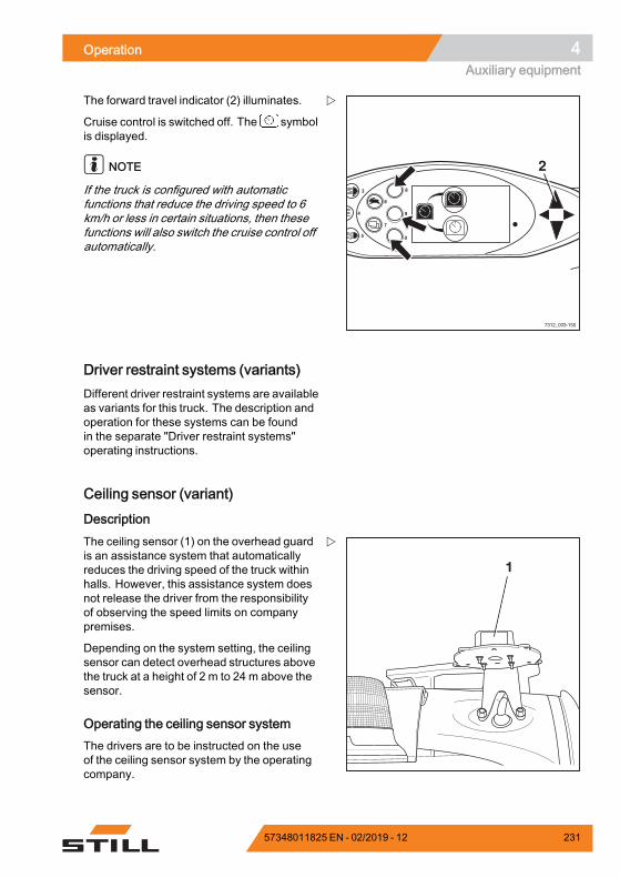
Operation 4Auxiliary equipment
8
9
0
6
7
4
3
5
2
7312_003-150
The forward travel indicator (2) illuminates.
Cruise control is switched off. The symbolis displayed.
NOTE
If the truck is configured with automaticfunctions that reduce the driving speed to 6km/h or less in certain situations, then thesefunctions will also switch the cruise control offautomatically.
Driver restraint systems (variants)Different driver restraint systems are availableas variants for this truck. The description andoperation for these systems can be foundin the separate "Driver restraint systems"operating instructions.
Ceiling sensor (variant)
Description
1
The ceiling sensor (1) on the overhead guardis an assistance system that automaticallyreduces the driving speed of the truck withinhalls. However, this assistance system doesnot release the driver from the responsibilityof observing the speed limits on companypremises.
Depending on the system setting, the ceilingsensor can detect overhead structures abovethe truck at a height of 2 m to 24 m above thesensor.
Operating the ceiling sensor systemThe drivers are to be instructed on the useof the ceiling sensor system by the operatingcompany.
57348011825 EN - 02/2019 - 12 231
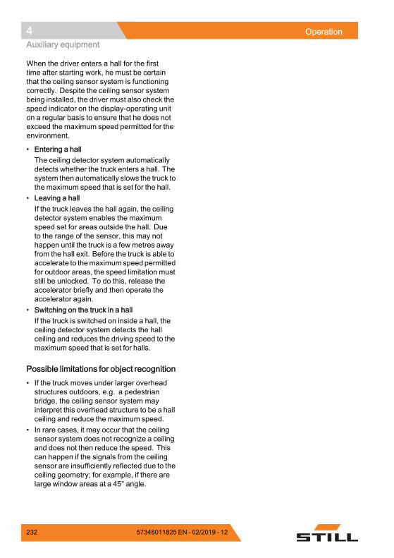
4 OperationAuxiliary equipment
When the driver enters a hall for the firsttime after starting work, he must be certainthat the ceiling sensor system is functioningcorrectly. Despite the ceiling sensor systembeing installed, the driver must also check thespeed indicator on the display-operating uniton a regular basis to ensure that he does notexceed the maximum speed permitted for theenvironment.
• Entering a hallThe ceiling detector system automaticallydetects whether the truck enters a hall. Thesystem then automatically slows the truck tothe maximum speed that is set for the hall.
• Leaving a hallIf the truck leaves the hall again, the ceilingdetector system enables the maximumspeed set for areas outside the hall. Dueto the range of the sensor, this may nothappen until the truck is a few metres awayfrom the hall exit. Before the truck is able toaccelerate to themaximumspeed permittedfor outdoor areas, the speed limitation muststill be unlocked. To do this, release theaccelerator briefly and then operate theaccelerator again.
• Switching on the truck in a hallIf the truck is switched on inside a hall, theceiling detector system detects the hallceiling and reduces the driving speed to themaximum speed that is set for halls.
Possible limitations for object recognition• If the truck moves under larger overheadstructures outdoors, e.g. a pedestrianbridge, the ceiling sensor system mayinterpret this overhead structure to be a hallceiling and reduce the maximum speed.
• In rare cases, it may occur that the ceilingsensor system does not recognize a ceilingand does not then reduce the speed. Thiscan happen if the signals from the ceilingsensor are insufficiently reflected due to theceiling geometry; for example, if there arelarge window areas at a 45° angle.
232 57348011825 EN - 02/2019 - 12
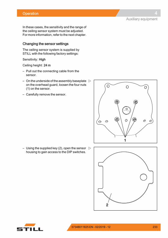
Operation 4Auxiliary equipment
In these cases, the sensitivity and the range ofthe ceiling sensor system must be adjusted.Formore information, refer to the next chapter.
Changing the sensor settingsThe ceiling sensor system is supplied bySTILL with the following factory settings:
Sensitivity: High
Ceiling height: 24 m
– Pull out the connecting cable from thesensor.
1
– On the underside of the assembly baseplateon the overhead guard, loosen the four nuts(1) on the sensor.
– Carefully remove the sensor.
2
– Using the supplied key (2), open the sensorhousing to gain access to the DIP switches.
57348011825 EN - 02/2019 - 12 233
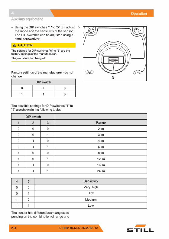
4 OperationAuxiliary equipment
1 2 3 4 5 6 7 8
3
– Using the DIP switches "1" to "5" (3), adjustthe range and the sensitivity of the sensor.The DIP switches can be adjusted using asmall screwdriver.
CAUTIONThe settings for DIP switches "6" to "8" are thefactory settings of the manufacturer.They must not be changed!
Factory settings of the manufacturer - do notchange
DIP switch
6 7 8
1 1 0
The possible settings for DIP switches "1" to"5" are shown in the following tables:
DIP switch
1 2 3 Range
0 0 0 2 m
0 0 1 3 m
0 1 0 4 m
0 1 1 6 m
1 0 0 8 m
1 0 1 12 m
1 1 0 16 m
1 1 1 24 m
4 5 Sensitivity
0 0 Very high
0 1 High
1 0 Medium
1 1 Low
The sensor has different beam angles de-pending on the combination of range and
234 57348011825 EN - 02/2019 - 12
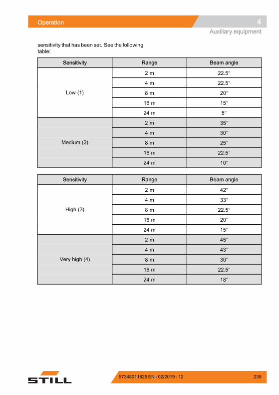
Operation 4Auxiliary equipment
sensitivity that has been set. See the followingtable:
Sensitivity Range Beam angle
2 m 22.5°
4 m 22.5°
8 m 20°
16 m 15°
Low (1)
24 m 5°
2 m 35°
4 m 30°
8 m 25°
16 m 22.5°
Medium (2)
24 m 10°
Sensitivity Range Beam angle
2 m 42°
4 m 33°
8 m 22.5°
16 m 20°
High (3)
24 m 15°
2 m 45°
4 m 43°
8 m 30°
16 m 22.5°
Very high (4)
24 m 18°
57348011825 EN - 02/2019 - 12 235
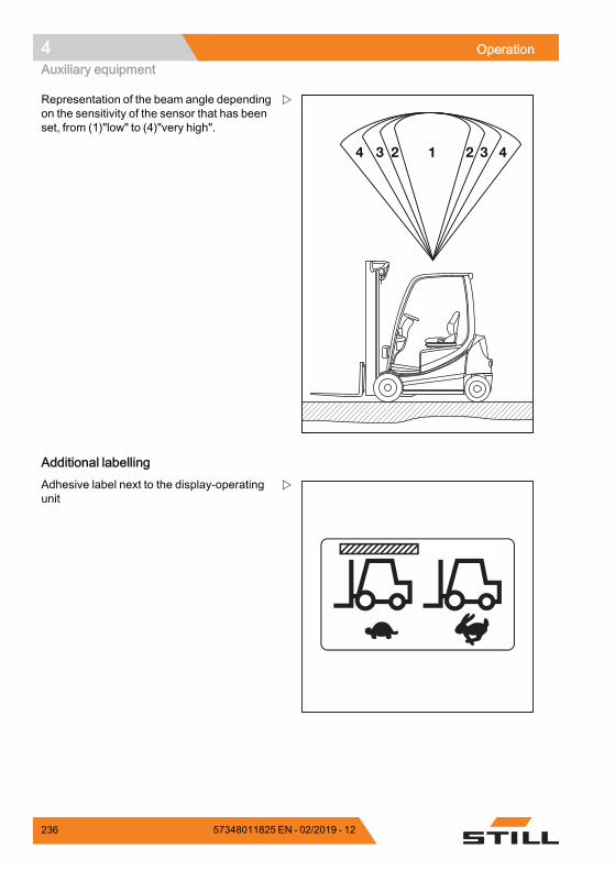
4 OperationAuxiliary equipment
2 3 41234
Representation of the beam angle dependingon the sensitivity of the sensor that has beenset, from (1)"low" to (4)"very high".
Additional labellingAdhesive label next to the display-operatingunit
236 57348011825 EN - 02/2019 - 12
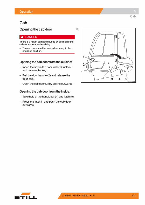
Operation 4Cab
Cab
7331_341-0034 5
2
1
3
Opening the cab door
DANGERThere is a risk of damage caused by collision if thecab door opens while driving.– The cab door must be latched securely in the
engaged position.
Opening the cab door from the outside:– Insert the key in the door lock (1), unlockand remove the key.
– Pull the door handle (2) and release thedoor lock.
– Open the cab door (3) by pulling outwards.
Opening the cab door from the inside:– Take hold of the handlebar (4) and latch (5).
– Press the latch in and push the cab dooroutwards.
57348011825 EN - 02/2019 - 12 237
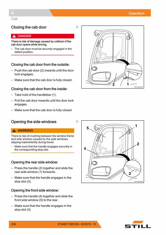
4 OperationCab
7314_003-04112
Closing the cab door
DANGERThere is risk of damage caused by collision if thecab door opens while driving.– The cab door must be securely engaged in the
detent position.
Closing the cab door from the outside:– Push the cab door (2) inwards until the doorlock engages.
– Make sure that the cab door is fully closed.
Closing the cab door from the inside:– Take hold of the handlebar (1).
– Pull the cab door inwards until the door lockengages.
– Make sure that the cab door is fully closed.
7314_003-040
4
5
2
1
3
Opening the side windows
WARNINGThere is risk of crushing between the window frameand side window caused by the side windowsslipping inadvertently during travel.– Make sure that the handle engages securely in
the corresponding stop slot.
Opening the rear side window:– Press the handle (2) together and slide therear side window (1) forwards.
– Make sure that the handle engages in thestop slot (3).
Opening the front side window:– Press the handle (4) together and slide thefront side window (5) to the rear.
– Make sure that the handle engages in thestop slot (3).
238 57348011825 EN - 02/2019 - 12
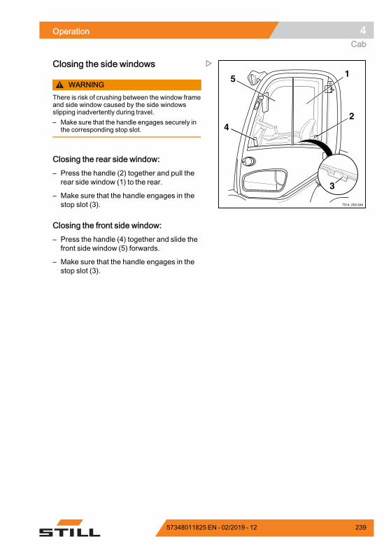
Operation 4Cab
7314_003-040
4
5
2
1
3
Closing the side windows
WARNINGThere is risk of crushing between the window frameand side window caused by the side windowsslipping inadvertently during travel.– Make sure that the handle engages securely in
the corresponding stop slot.
Closing the rear side window:– Press the handle (2) together and pull therear side window (1) to the rear.
– Make sure that the handle engages in thestop slot (3).
Closing the front side window:– Press the handle (4) together and slide thefront side window (5) forwards.
– Make sure that the handle engages in thestop slot (3).
57348011825 EN - 02/2019 - 12 239
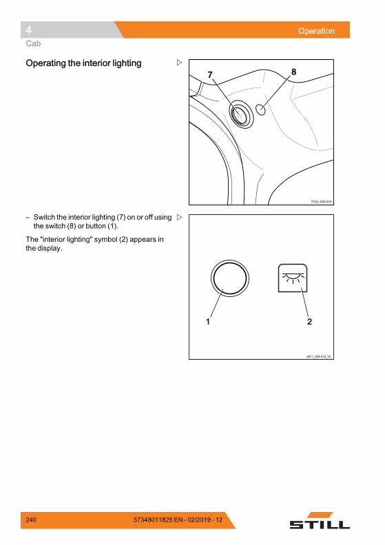
4 OperationCab
7312_003-013
7 8Operating the interior lighting
6311_003-013_V2
21
– Switch the interior lighting (7) on or off usingthe switch (8) or button (1).
The "interior lighting" symbol (2) appears inthe display.
240 57348011825 EN - 02/2019 - 12
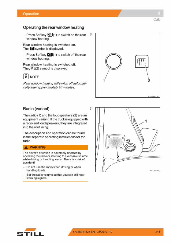
Operation 4Cab
Operating the rear window heating
6311_003-014_V2
21
– Press Softkey (1) to switch on the rearwindow heating.
Rear window heating is switched on.The symbol is displayed.
– Press Softkey (1) to switch off the rearwindow heating.
Rear window heating is switched off.The (2) symbol is displayed.
NOTE
Rear window heating will switch off automati-cally after approximately 10 minutes.
6321_003-015
1
2
Radio (variant)The radio (1) and the loudspeakers (2) are anequipment variant. If the truck is equippedwitha radio and loudspeakers, they are integratedinto the roof lining.
The description and operation can be foundin the separate operating instructions for theradio.
WARNINGThe driver's attention is adversely affected byoperating the radio or listening to excessive volumewhile driving or handling loads. There is a risk ofaccident!– Do not use the radio when driving or when
handling loads.– Set the radio volume so that you can still hear
warning signals.
57348011825 EN - 02/2019 - 12 241
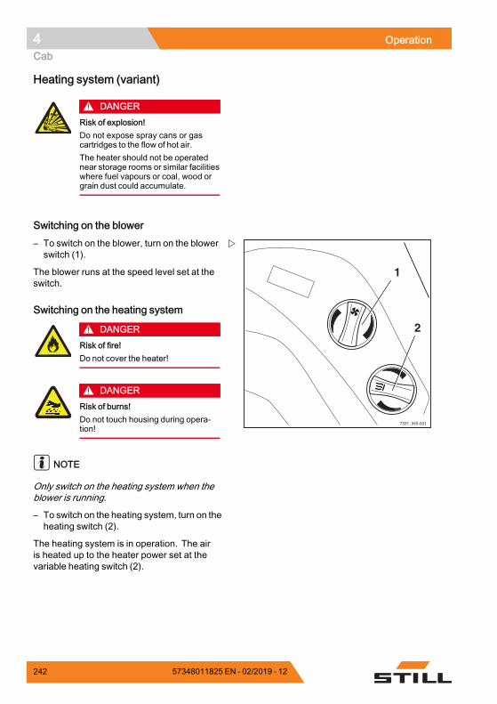
4 OperationCab
Heating system (variant)
DANGERRisk of explosion!Do not expose spray cans or gascartridges to the flow of hot air.The heater should not be operatednear storage rooms or similar facilitieswhere fuel vapours or coal, wood orgrain dust could accumulate.
Switching on the blower
1
2
7331_345-001
– To switch on the blower, turn on the blowerswitch (1).
The blower runs at the speed level set at theswitch.
Switching on the heating system
DANGERRisk of fire!Do not cover the heater!
DANGERRisk of burns!Do not touch housing during opera-tion!
NOTE
Only switch on the heating system when theblower is running.
– To switch on the heating system, turn on theheating switch (2).
The heating system is in operation. The airis heated up to the heater power set at thevariable heating switch (2).
242 57348011825 EN - 02/2019 - 12
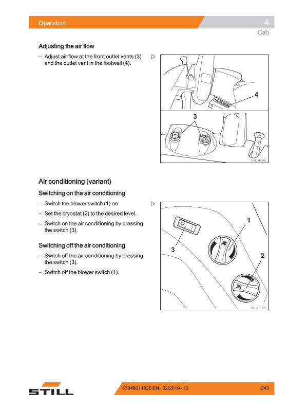
Operation 4Cab
Adjusting the air flow
7331_345-002
4
3
– Adjust air flow at the front outlet vents (3)and the outlet vent in the footwell (4).
Air conditioning (variant)
Switching on the air conditioning
1
2
7331_346-001
3
– Switch the blower switch (1) on.
– Set the cryostat (2) to the desired level.
– Switch on the air conditioning by pressingthe switch (3).
Switching off the air conditioning– Switch off the air conditioning by pressingthe switch (3).
– Switch off the blower switch (1).
57348011825 EN - 02/2019 - 12 243
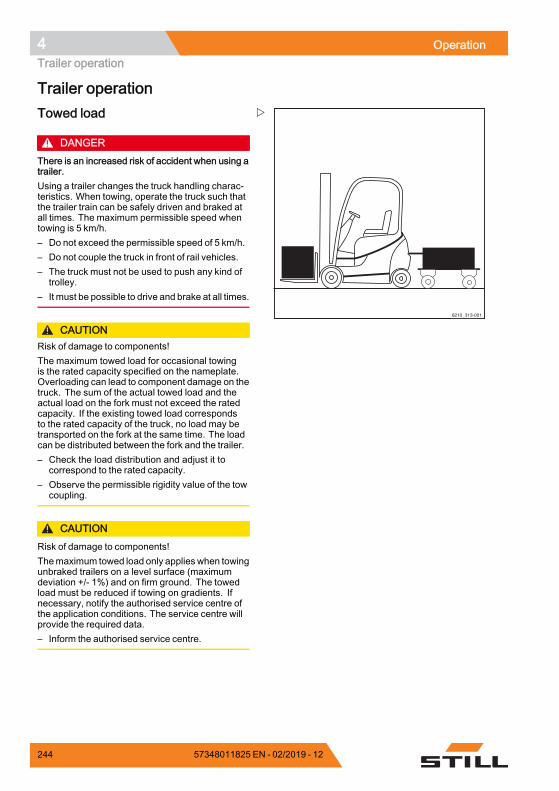
4 OperationTrailer operation
Trailer operation
6210_313-001
Towed load
DANGERThere is an increased risk of accident when using atrailer.Using a trailer changes the truck handling charac-teristics. When towing, operate the truck such thatthe trailer train can be safely driven and braked atall times. The maximum permissible speed whentowing is 5 km/h.– Do not exceed the permissible speed of 5 km/h.– Do not couple the truck in front of rail vehicles.– The truck must not be used to push any kind of
trolley.– It must be possible to drive and brake at all times.
CAUTIONRisk of damage to components!The maximum towed load for occasional towingis the rated capacity specified on the nameplate.Overloading can lead to component damage on thetruck. The sum of the actual towed load and theactual load on the fork must not exceed the ratedcapacity. If the existing towed load correspondsto the rated capacity of the truck, no load may betransported on the fork at the same time. The loadcan be distributed between the fork and the trailer.– Check the load distribution and adjust it to
correspond to the rated capacity.– Observe the permissible rigidity value of the tow
coupling.
CAUTIONRisk of damage to components!Themaximum towed load only applies when towingunbraked trailers on a level surface (maximumdeviation +/- 1%) and on firm ground. The towedload must be reduced if towing on gradients. Ifnecessary, notify the authorised service centre ofthe application conditions. The service centre willprovide the required data.– Inform the authorised service centre.
244 57348011825 EN - 02/2019 - 12
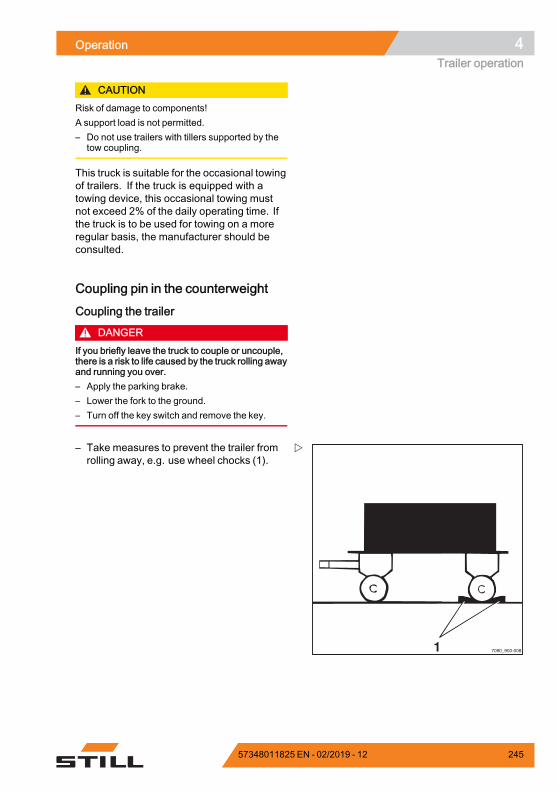
Operation 4Trailer operation
CAUTIONRisk of damage to components!A support load is not permitted.– Do not use trailers with tillers supported by the
tow coupling.
This truck is suitable for the occasional towingof trailers. If the truck is equipped with atowing device, this occasional towing mustnot exceed 2% of the daily operating time. Ifthe truck is to be used for towing on a moreregular basis, the manufacturer should beconsulted.
Coupling pin in the counterweight
Coupling the trailer
DANGERIf you briefly leave the truck to couple or uncouple,there is a risk to life caused by the truck rolling awayand running you over.– Apply the parking brake.– Lower the fork to the ground.– Turn off the key switch and remove the key.
1 7090_900-008
– Take measures to prevent the trailer fromrolling away, e.g. use wheel chocks (1).
57348011825 EN - 02/2019 - 12 245
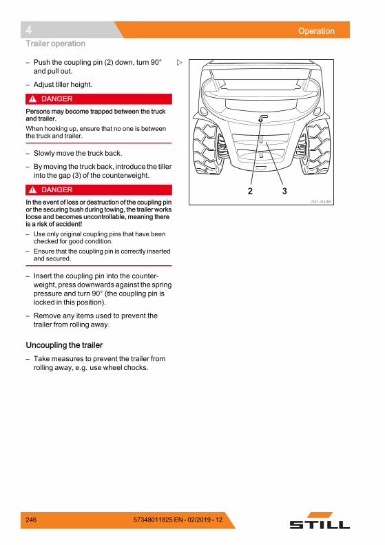
4 OperationTrailer operation
7331_313-001
32
– Push the coupling pin (2) down, turn 90°and pull out.
– Adjust tiller height.
DANGERPersons may become trapped between the truckand trailer.When hooking up, ensure that no one is betweenthe truck and trailer.
– Slowly move the truck back.
– Bymoving the truck back, introduce the tillerinto the gap (3) of the counterweight.
DANGERIn the event of loss or destruction of the coupling pinor the securing bush during towing, the trailer worksloose and becomes uncontrollable, meaning thereis a risk of accident!– Use only original coupling pins that have been
checked for good condition.– Ensure that the coupling pin is correctly inserted
and secured.
– Insert the coupling pin into the counter-weight, press downwards against the springpressure and turn 90° (the coupling pin islocked in this position).
– Remove any items used to prevent thetrailer from rolling away.
Uncoupling the trailer– Take measures to prevent the trailer fromrolling away, e.g. use wheel chocks.
246 57348011825 EN - 02/2019 - 12
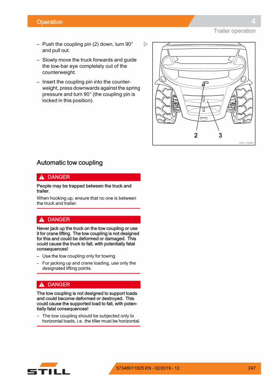
Operation 4Trailer operation
7331_313-001
32
– Push the coupling pin (2) down, turn 90°and pull out.
– Slowly move the truck forwards and guidethe tow-bar eye completely out of thecounterweight.
– Insert the coupling pin into the counter-weight, press downwards against the springpressure and turn 90° (the coupling pin islocked in this position).
Automatic tow coupling
DANGERPeople may be trapped between the truck andtrailer.When hooking up, ensure that no one is betweenthe truck and trailer.
DANGERNever jack up the truck on the tow coupling or useit for crane lifting. The tow coupling is not designedfor this and could be deformed or damaged. Thiscould cause the truck to fall, with potentially fatalconsequences!– Use the tow coupling only for towing.– For jacking up and crane loading, use only the
designated lifting points.
DANGERThe tow coupling is not designed to support loadsand could become deformed or destroyed. Thiscould cause the supported load to fall, with poten-tially fatal consequences!– The tow coupling should be subjected only to
horizontal loads, i.e. the tiller must be horizontal.
57348011825 EN - 02/2019 - 12 247
4 OperationTrailer operation
DANGERIf you briefly leave the truck to couple or uncouplethe trailer, there is a risk to life caused by the truckrolling away and running you over.– Apply the parking brake.– Lower the forks to the ground.– Switch off the key switch and remove the key.
WARNINGNever reach between the coupling pins and thetowing jaws. If the component moves suddenlythere is a risk of injury!– To release the coupling pin, actuate the corre-
sponding lever or use a suitable device (e.g.assembly lever).
– When not in use, close the automatic towcoupling.
WARNINGRisk of damage due to component collision.A truck with tow coupling needs more room formanoeuvring due to its overhang. The tow couplingcan damage the racking or the tow coupling itselfwhen manoeuvring. If there is a collision with thetow coupling, test the tow coupling for damagesuch as cracks. A damaged tow coupling must notbe used again.– Always manoeuvre carefully and with sufficient
room.– In the case of a collision, test the tow coupling for
damage.– Replace tow coupling if damaged, if necessary
contact the authorised service centre.
WARNINGRisk of damage to the tow bar eye or tiller!Due to the truck's rear wheel steering, the sideslewing angle of the tiller may not be adequate. Thecoupling or the tiller may be damaged! The tow bareye of the tiller must fit the tow coupling in terms ofshape and size.– Ensure that the tow bar eye and tiller fit correctly.– Avoid sharp cornering.– Exercise care when travelling and manoeuvring
in reverse.
248 57348011825 EN - 02/2019 - 12
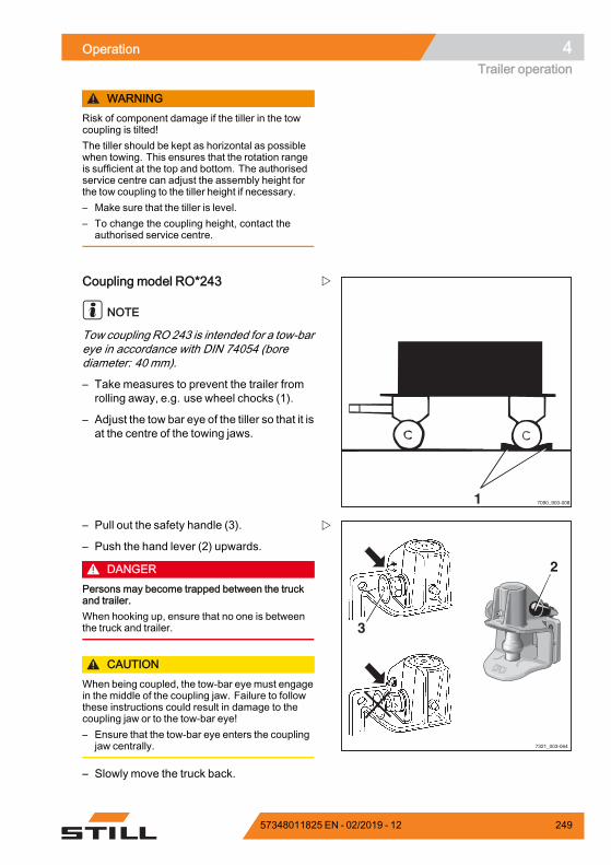
Operation 4Trailer operation
WARNINGRisk of component damage if the tiller in the towcoupling is tilted!The tiller should be kept as horizontal as possiblewhen towing. This ensures that the rotation rangeis sufficient at the top and bottom. The authorisedservice centre can adjust the assembly height forthe tow coupling to the tiller height if necessary.– Make sure that the tiller is level.– To change the coupling height, contact the
authorised service centre.
1 7090_900-008
Coupling model RO*243
NOTE
Tow coupling RO 243 is intended for a tow-bareye in accordance with DIN 74054 (borediameter: 40 mm).
– Take measures to prevent the trailer fromrolling away, e.g. use wheel chocks (1).
– Adjust the tow bar eye of the tiller so that it isat the centre of the towing jaws.
3
7321_003-064
2
– Pull out the safety handle (3).
– Push the hand lever (2) upwards.
DANGERPersons may become trapped between the truckand trailer.When hooking up, ensure that no one is betweenthe truck and trailer.
CAUTIONWhen being coupled, the tow-bar eye must engagein the middle of the coupling jaw. Failure to followthese instructions could result in damage to thecoupling jaw or to the tow-bar eye!– Ensure that the tow-bar eye enters the coupling
jaw centrally.
– Slowly move the truck back.
57348011825 EN - 02/2019 - 12 249
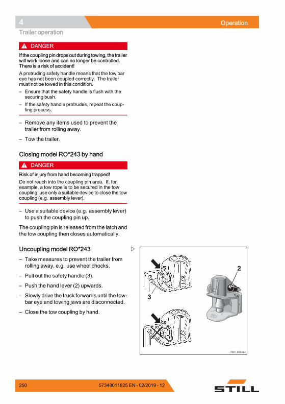
4 OperationTrailer operation
DANGERIf thecoupling pin dropsout during towing, the trailerwill work loose and can no longer be controlled.There is a risk of accident!A protruding safety handle means that the tow bareye has not been coupled correctly. The trailermust not be towed in this condition.– Ensure that the safety handle is flush with the
securing bush.– If the safety handle protrudes, repeat the coup-
ling process.
– Remove any items used to prevent thetrailer from rolling away.
– Tow the trailer.
Closing model RO*243 by hand
DANGERRisk of injury from hand becoming trapped!Do not reach into the coupling pin area. If, forexample, a tow rope is to be secured in the towcoupling, use only a suitable device to close the towcoupling (e.g. assembly lever).
– Use a suitable device (e.g. assembly lever)to push the coupling pin up.
The coupling pin is released from the latch andthe tow coupling then closes automatically.
3
7321_003-064
2
Uncoupling model RO*243– Take measures to prevent the trailer fromrolling away, e.g. use wheel chocks.
– Pull out the safety handle (3).
– Push the hand lever (2) upwards.
– Slowly drive the truck forwards until the tow-bar eye and towing jaws are disconnected.
– Close the tow coupling by hand.
250 57348011825 EN - 02/2019 - 12
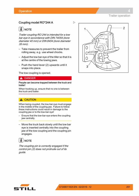
Operation 4Trailer operation
Coupling model RO*244 A
NOTE
Trailer coupling RO 244 is intended for a towbar eye in accordance with DIN 74054 (borediameter 40 mm) or DIN 8454 (bore diameter35 mm).
– Take measures to prevent the trailer fromrolling away, e.g. use wheel chocks.
– Adjust the tow bar eye of the tiller so that it isat the centre of the towing jaws.
– Push the hand lever (2) upwards until itsnaps into place.
The tow coupling is opened.
DANGERPeople can become trapped between the truck andtrailer!When hooking up, ensure that no one is betweenthe truck and trailer.
CAUTIONWhen being coupled, the tow-bar eye must engagein the middle of the coupling jaw. Failure to followthese instructions could result in damage to thecoupling jaw or to the tow-bar eye!– Ensure that the tow-bar eye enters the coupling
jaw centrally.
– Move the truck back slowly until the tow bareye is inserted centrally into the couplingjaw of the tow coupling and the coupling pinengages.
NOTE
The coupling pin is correctly engaged if thecontrol pin (3) does not protrude out of itsguide.
57348011825 EN - 02/2019 - 12 251
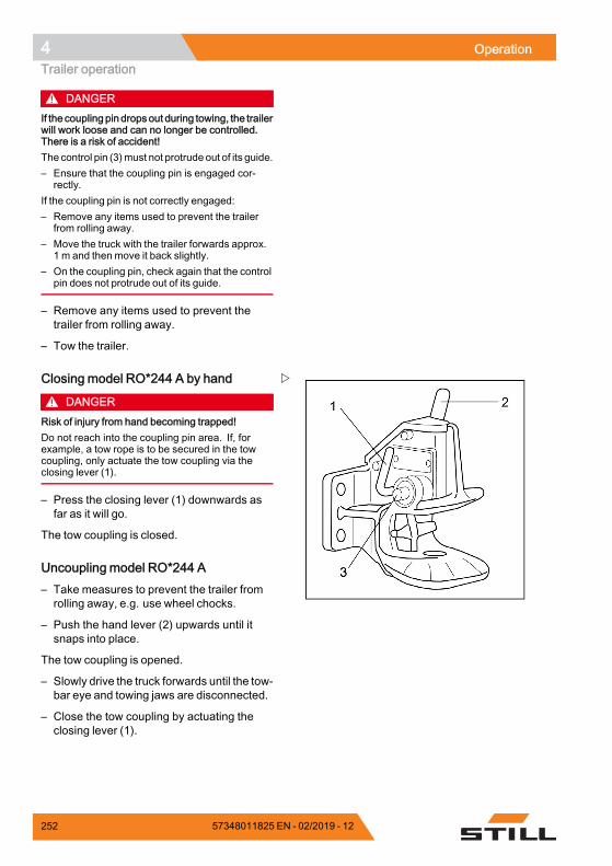
4 OperationTrailer operation
DANGERIf thecoupling pin dropsout during towing, the trailerwill work loose and can no longer be controlled.There is a risk of accident!The control pin (3)must not protrude out of its guide.– Ensure that the coupling pin is engaged cor-
rectly.If the coupling pin is not correctly engaged:– Remove any items used to prevent the trailer
from rolling away.– Move the truck with the trailer forwards approx.
1 m and then move it back slightly.– On the coupling pin, check again that the control
pin does not protrude out of its guide.
– Remove any items used to prevent thetrailer from rolling away.
– Tow the trailer.
Closing model RO*244 A by hand
DANGERRisk of injury from hand becoming trapped!Do not reach into the coupling pin area. If, forexample, a tow rope is to be secured in the towcoupling, only actuate the tow coupling via theclosing lever (1).
– Press the closing lever (1) downwards asfar as it will go.
The tow coupling is closed.
Uncoupling model RO*244 A– Take measures to prevent the trailer fromrolling away, e.g. use wheel chocks.
– Push the hand lever (2) upwards until itsnaps into place.
The tow coupling is opened.
– Slowly drive the truck forwards until the tow-bar eye and towing jaws are disconnected.
– Close the tow coupling by actuating theclosing lever (1).
252 57348011825 EN - 02/2019 - 12
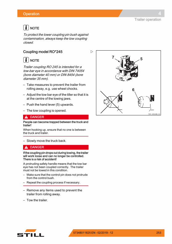
Operation 4Trailer operation
NOTE
To protect the lower coupling pin bush againstcontamination, always keep the tow couplingclosed.
7321_003-066_V2
57
6
Coupling model RO*245
NOTE
Trailer coupling RO 245 is intended for atow-bar eye in accordance with DIN 74054(bore diameter 40 mm) or DIN 8454 (borediameter 35 mm).
– Take measures to prevent the trailer fromrolling away, e.g. use wheel chocks.
– Adjust the tow bar eye of the tiller so that it isat the centre of the towing jaws.
– Push the hand lever (5) upwards.
– The tow coupling is opened.
DANGERPeople can become trapped between the truck andtrailer!When hooking up, ensure that no one is betweenthe truck and trailer.
– Slowly move the truck back.
DANGERIf the coupling pin dropsout during towing, the trailerwill work loose and can no longer be controlled.There is a risk of accident!A protruding safety handle means that the tow bareye has not been coupled correctly. The trailermust not be towed in this condition.– Make sure that the control pin does not protrude
from the control bush.– Repeat the coupling process if necessary.
– Remove any items used to prevent thetrailer from rolling away.
– Tow the trailer.
57348011825 EN - 02/2019 - 12 253
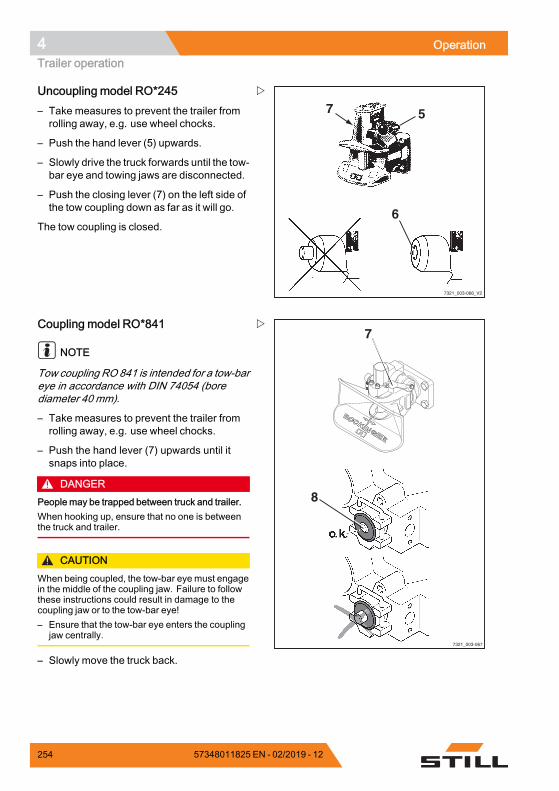
4 OperationTrailer operation
7321_003-066_V2
57
6
Uncoupling model RO*245– Take measures to prevent the trailer fromrolling away, e.g. use wheel chocks.
– Push the hand lever (5) upwards.
– Slowly drive the truck forwards until the tow-bar eye and towing jaws are disconnected.
– Push the closing lever (7) on the left side ofthe tow coupling down as far as it will go.
The tow coupling is closed.
7
8
7321_003-067
Coupling model RO*841
NOTE
Tow coupling RO 841 is intended for a tow-bareye in accordance with DIN 74054 (borediameter 40 mm).
– Take measures to prevent the trailer fromrolling away, e.g. use wheel chocks.
– Push the hand lever (7) upwards until itsnaps into place.
DANGERPeople may be trapped between truck and trailer.When hooking up, ensure that no one is betweenthe truck and trailer.
CAUTIONWhen being coupled, the tow-bar eye must engagein the middle of the coupling jaw. Failure to followthese instructions could result in damage to thecoupling jaw or to the tow-bar eye!– Ensure that the tow-bar eye enters the coupling
jaw centrally.
– Slowly move the truck back.
254 57348011825 EN - 02/2019 - 12
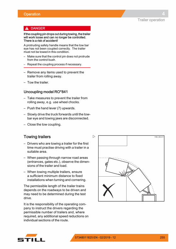
Operation 4Trailer operation
DANGERIf the coupling pin dropsout during towing, the trailerwill work loose and can no longer be controlled.There is a risk of accident!A protruding safety handle means that the tow bareye has not been coupled correctly. The trailermust not be towed in this condition.– Make sure that the control pin does not protrude
from the control bush.– Repeat the coupling process if necessary.
– Remove any items used to prevent thetrailer from rolling away.
– Tow the trailer.
Uncoupling model RO*841– Take measures to prevent the trailer fromrolling away, e.g. use wheel chocks.
– Push the hand lever (7) upwards.
– Slowly drive the truck forwards until the tow-bar eye and towing jaws are disconnected.
– Close the tow coupling.
7090_900-011Towing trailers– Drivers who are towing a trailer for the firsttime must practise driving with a trailer in asuitable area.
– When passing through narrow road areas(entrances, gates etc.), observe the dimen-sions of the trailer and load.
– When towing multiple trailers, ensurea sufficient minimum distance to fixedinstallations when turning and cornering.
The permissible length of the trailer trainsdepends on the roadways to be driven andmay need to be determined during the testdrive.
It is the responsibility of the operating com-pany to instruct the drivers regarding thepermissible number of trailers and, whererequired, any additional speed reductions onindividual sections of the route.
57348011825 EN - 02/2019 - 12 255
4 OperationTrailer operation
NOTE
Please observe the definition of the followingresponsible persons: "operating company"and "driver".
256 57348011825 EN - 02/2019 - 12
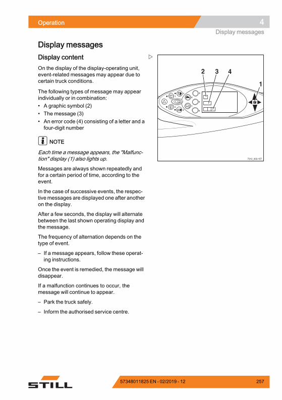
Operation 4Display messages
Display messages
8
9
0
6
7
4
2
1
3
5
7312_003-157
2 3 4
1
Display contentOn the display of the display-operating unit,event-related messages may appear due tocertain truck conditions.
The following types of message may appearindividually or in combination:• A graphic symbol (2)• The message (3)• An error code (4) consisting of a letter and afour-digit number
NOTE
Each time a message appears, the "Malfunc-tion" display (1) also lights up.
Messages are always shown repeatedly andfor a certain period of time, according to theevent.
In the case of successive events, the respec-tivemessages are displayed one after anotheron the display.
After a few seconds, the display will alternatebetween the last shown operating display andthe message.
The frequency of alternation depends on thetype of event.
– If a message appears, follow these operat-ing instructions.
Once the event is remedied, the message willdisappear.
If a malfunction continues to occur, themessage will continue to appear.
– Park the truck safely.
– Inform the authorised service centre.
57348011825 EN - 02/2019 - 12 257
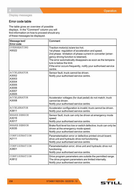
4 OperationDisplay messages
Error code tableThe table gives an overview of possibledisplays. In the "Comment" column you willfind information on how to proceed should anyof these messages be displayed.
Message text/Error code
Comment
OVERHEATINGA5022
Traction motor(s) is/are too hot.1st phase: regulation of acceleration and speed.2nd phase: limitation of phase current in converter (emer-gency driving function is retained).The error automatically disappears as soon as the tempera-ture is below the limit.If the error occurs frequently, notify your authorised servicecentre.
ACCELERATORA3002A3003A3004A3005A3006A3007A3505
Sensor fault, truck cannot be driven.Notify your authorised service centre.
ACCELERATORA3008
Accelerator voltages (for dual pedal) do not match; truckcannot be driven.Notify your authorised service centre.
ACCELERATORA3811
Accelerator configuration is invalid; truck cannot be driven.Notify your authorised service centre.
BRAKE SENSORA3016A3017
Sensor fault; truck can only be driven at emergency modespeed.Notify your authorised service centre.
BRAKE SENSORA3035
Brake fluid level too low or switch defective; truck can only bedriven at the emergency mode speed.Notify your authorised service centre.
CONFIGURATIONA2111
Parameterisation error or defective printed circuit board;drive unit and hydraulic drive not functioning.Notify your authorised service centre.
CONFIGURATIONA3801
Parameterisation error; drive unit and hydraulic drive notfunctioning.Notify your authorised service centre.
CONFIGURATIONA3812
Drive program parameters are outside the permitted range.The drive program parameters are limited internally.Notify your authorised service centre.
258 57348011825 EN - 02/2019 - 12
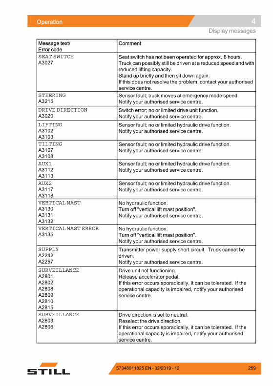
Operation 4Display messages
Message text/Error code
Comment
SEAT SWITCHA3027
Seat switch has not been operated for approx. 8 hours.Truck can possibly still be driven at a reduced speed andwithreduced lifting capacity.Stand up briefly and then sit down again.If this does not resolve the problem, contact your authorisedservice centre.
STEERINGA3215
Sensor fault; truck moves at emergency mode speed.Notify your authorised service centre.
DRIVE DIRECTIONA3020
Switch error; no or limited drive unit function.Notify your authorised service centre.
LIFTINGA3102A3103
Sensor fault; no or limited hydraulic drive function.Notify your authorised service centre.
TILTINGA3107A3108
Sensor fault; no or limited hydraulic drive function.Notify your authorised service centre.
AUX1A3112A3113
Sensor fault; no or limited hydraulic drive function.Notify your authorised service centre.
AUX2A3117A3118
Sensor fault; no or limited hydraulic drive function.Notify your authorised service centre.
VERTICAL MASTA3130A3131A3132
No hydraulic function.Turn off "vertical lift mast position".Notify your authorised service centre.
VERTICAL MAST ERRORA3135
No hydraulic function.Turn off "vertical lift mast position".Notify your authorised service centre.
SUPPLYA2242A2257
Transmitter power supply short circuit. Truck cannot bedriven.Notify your authorised service centre.
SURVEILLANCEA2801A2802A2808A2809A2810A2815
Drive unit not functioning.Release accelerator pedal.If this error occurs sporadically, it can be tolerated. If theoperational capacity is impaired, notify your authorisedservice centre.
SURVEILLANCEA2803A2806
Drive direction is set to neutral.Reselect the drive direction.If this error occurs sporadically, it can be tolerated. If theoperational capacity is impaired, notify your authorisedservice centre.
57348011825 EN - 02/2019 - 12 259

4 OperationDisplay messages
Message text/Error code
Comment
SURVEILLANCEA2817
Truck is not ready for operation.Turn the key switch to the zero position and restart.If this error occurs sporadically, it can be tolerated. If theoperational capacity is impaired, notify your authorisedservice centre.
DRIVEA5041
Temperature sensor faultNotify your authorised service centre.
OIL PRESSUREA5631
Engine faulty (no oil pressure) or sensor faulty. Engine isswitched off for protection.Notify your authorised service centre.
COOLANT LEVELA5611
Fan is not running.Cooling fluid level too low, check the cooling fluid level andtop up the cooling fluid if necessary.If this does not resolve the problem, contact your authorisedservice centre.
AIR FILTERA5651
Depending on the design of the air filter, replace the filterinsert or the filter cartridges.If this does not resolve the problem, contact your authorisedservice centre.
CONTROL UNITA3305
CIO not functioning.Notify your authorised service centre.
EXHAUST GAS PURIFIERA5791
No regeneration and no intermediate glow.Notify your authorised service centre.
EXHAUST GAS PURIFIERA5792A5793A5794A5796
Regeneration cannot be started.Notify your authorised service centre.
EXHAUST GAS PURIFIERA5795A5797A5798
Regeneration has been interrupted.Notify your authorised service centre.
ALTERNATORA5811
Starter battery is not charged.Notify your authorised service centre.
.
General messages
NOTE
Some of the following messages are equip-ment-specific and may not appear on thedisplay and operating unit of every truck. Thefollowing messages are therefore intendedonly as a reference.
260 57348011825 EN - 02/2019 - 12
Operation 4Display messages
SERVICE BRAKEmessageIf the message SERVICE BRAKE appearson the display, notify the authorised servicecentre.
– Park the truck securely for checking by theauthorised service centre.
– If multi-disc brakes in the drive wheel unitsare blocked, tow the truck.
APPLY HANDBRAKEmessage
DANGERRisk of fatal injury from being run over if the truckrolls away!Parking the truck without the parking brake appliedis dangerous and is not permitted.– The truck must not be parked on a slope.– Only leave the truck when the parking brake has
been applied.– In emergencies, secure the truck using wedges
on the side facing downhill.
NOTE
The truck is equipped with a negative spring-operated brake. Switching off the truck willblock the multi-disc brakes in the drive wheelunits after a few minutes. However, the truckcan still roll until the drive wheel units areblocked. For this reason, the parking brakemust always be applied before you leave thetruck!
If you park the truck without applying theparking brake and then vacate the driver'sseat, the APPLY HANDBRAKEmessage willappear in the display (variant). An optionalsignal tone sounds.
– Apply the parking brake.
The APPLY HANDBRAKEmessage disap-pears.
If the truck moves even though the parkingbrake is applied:
– Drive the truck onto level ground and park itsafely. Secure it with wedges if necessary.
– Notify the authorised service centre.
57348011825 EN - 02/2019 - 12 261
4 OperationDisplay messages
BRAKE SENSORmessageIf the BRAKE SENSORmessage appears inthe display, themaximumdriving speedwill bereduced. The brake sensor in the brake pedalmust be checked.
– Notify the authorised service centre.
CODE DENIEDmessageIf the message CODE DENIED appears onthe display, the driver PIN has been enteredincorrectly three times. The input is thenlocked for fiveminutes before another attemptcan be made.
– Enter the driverPIN again after fiveminutes.
ACCELERATORmessageIf the ACCELERATORmessage appears onthe display, the truck will remain stationary.The accelerator must be checked.
– Notify the authorised service centre.
SWITCHOFF TRUCK?messageIf the message SWITCH OFF THE TRUCK?appears on the display, the switching-off of thetruck is verified.
– Press the corresponding softkey on thedisplay and operating unit to switch off thetruck or cancel the operation.
PARKING BRAKE ACTIVEmessageIf the electric parking brake is applied, thePARKING BRAKE ACTIVEmessage ap-pears on the display for 5 seconds.
– Release the parking brake to enable drivingmode.
RELEASE PARKING BRAKEmessageIf the message RELEASE PARKING BRAKEappears on the display, driving mode cannotbe enabled until the parking brake has beenreleased by pressing the button.
262 57348011825 EN - 02/2019 - 12
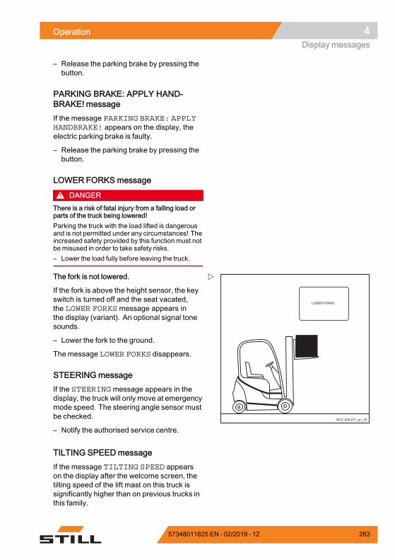
Operation 4Display messages
– Release the parking brake by pressing thebutton.
PARKING BRAKE: APPLY HAND-BRAKE! messageIf the message PARKING BRAKE: APPLYHANDBRAKE! appears on the display, theelectric parking brake is faulty.
– Release the parking brake by pressing thebutton.
LOWER FORKSmessage
DANGERThere is a risk of fatal injury from a falling load orparts of the truck being lowered!Parking the truck with the load lifted is dangerousand is not permitted under any circumstances! Theincreased safety provided by this function must notbe misused in order to take safety risks.– Lower the load fully before leaving the truck.
7312_003-071_en_V2
The fork is not lowered.
If the fork is above the height sensor, the keyswitch is turned off and the seat vacated,the LOWER FORKS message appears inthe display (variant). An optional signal tonesounds.
– Lower the fork to the ground.
The message LOWER FORKS disappears.
STEERINGmessageIf the STEERINGmessage appears in thedisplay, the truck will only move at emergencymode speed. The steering angle sensor mustbe checked.
– Notify the authorised service centre.
TILTING SPEEDmessageIf the message TILTING SPEED appearson the display after the welcome screen, thetilting speed of the lift mast on this truck issignificantly higher than on previous trucks inthis family.
57348011825 EN - 02/2019 - 12 263
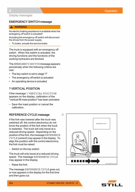
4 OperationDisplay messages
EMERGENCY SWITCHmessage
WARNINGNo electric braking assistance is available when theemergency off switch is actuated!Actuating the emergency off switch will disconnectthe drives from the power supply.– To brake, actuate the service brake.
The truck is equipped with an emergency offswitch. When this switch is actuated, thedriving functions and the functions of theworking hydraulics are blocked.
TheEMERGENCYSWITCHmessageappearsperiodically when the following criteria aremet:• The key switch is set to stage "I"• The emergency off switch is actuated• An operating device is actuated
? VERTICAL POSITIONIf the message ? VERTICAL POSITIONappears on the display, calibration of the"vertical lift mast position" has been activated.
– Save the mast position or cancel thecalibration.
7312_003-072_en_V3
REFERENCE CYCLEmessageIf the fork was lowered after the truck wasswitched off, the control electronics do notknow the position of the fork when the truckis restarted. The truck will only travel at areduced driving speed. Depending on thepositionof the fork, themessageREFERENCECYCLE (variant)may appear in the display. Toalign the position with the control electronics,the fork must be raised.
– Switch on the key switch.
The truck will only travel at a reduced drivingspeed. The message REFERENCE CYCLEmay appear in the display.
– Raise the fork.
The message REFERENCE CYCLE goes out,or now appears in the display for the first timeand then goes out.
264 57348011825 EN - 02/2019 - 12
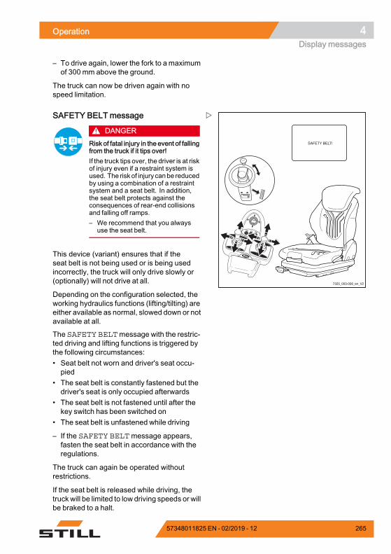
Operation 4Display messages
– To drive again, lower the fork to a maximumof 300 mm above the ground.
The truck can now be driven again with nospeed limitation.
7325_003-056_en_V2
F1 F2
SAFETY BELTmessage
DANGERRisk of fatal injury in the event of fallingfrom the truck if it tips over!If the truck tips over, the driver is at riskof injury even if a restraint system isused. The risk of injury canbe reducedby using a combination of a restraintsystem and a seat belt. In addition,the seat belt protects against theconsequences of rear-end collisionsand falling off ramps.– We recommend that you always
use the seat belt.
This device (variant) ensures that if theseat belt is not being used or is being usedincorrectly, the truck will only drive slowly or(optionally) will not drive at all.
Depending on the configuration selected, theworking hydraulics functions (lifting/tilting) areeither available as normal, slowed down or notavailable at all.
The SAFETY BELTmessage with the restric-ted driving and lifting functions is triggered bythe following circumstances:• Seat belt not worn and driver's seat occu-pied
• The seat belt is constantly fastened but thedriver's seat is only occupied afterwards
• The seat belt is not fastened until after thekey switch has been switched on
• The seat belt is unfastened while driving
– If the SAFETY BELTmessage appears,fasten the seat belt in accordance with theregulations.
The truck can again be operated withoutrestrictions.
If the seat belt is released while driving, thetruck will be limited to low driving speeds or willbe braked to a halt.
57348011825 EN - 02/2019 - 12 265
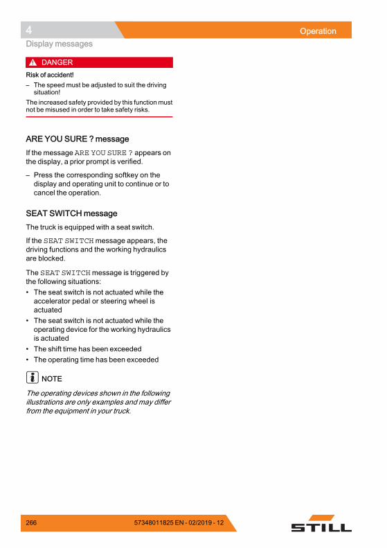
4 OperationDisplay messages
DANGERRisk of accident!– The speed must be adjusted to suit the driving
situation!The increased safety provided by this functionmustnot be misused in order to take safety risks.
ARE YOU SURE ?messageIf the message ARE YOU SURE ? appears onthe display, a prior prompt is verified.
– Press the corresponding softkey on thedisplay and operating unit to continue or tocancel the operation.
SEAT SWITCHmessageThe truck is equipped with a seat switch.
If the SEAT SWITCHmessage appears, thedriving functions and the working hydraulicsare blocked.
The SEAT SWITCHmessage is triggered bythe following situations:• The seat switch is not actuated while theaccelerator pedal or steering wheel isactuated
• The seat switch is not actuated while theoperating device for the working hydraulicsis actuated
• The shift time has been exceeded• The operating time has been exceeded
NOTE
The operating devices shown in the followingillustrations are only examples and may differfrom the equipment in your truck.
266 57348011825 EN - 02/2019 - 12
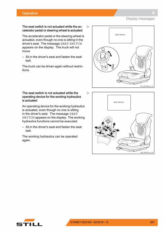
Operation 4Display messages
7312_003-066_en_V2
The seat switch is not actuated while the ac-celerator pedal or steering wheel is actuated
The accelerator pedal or the steering wheel isactuated, even though no one is sitting in thedriver's seat. The message SEAT SWITCHappears on the display. The truck will notmove.
– Sit in the driver's seat and fasten the seatbelt.
The truck can be driven again without restric-tions.
7325_003-054_en_V2
F1 F2
The seat switch is not actuated while theoperating device for the working hydraulicsis actuated
An operating device for the working hydraulicsis actuated, even though no one is sittingin the driver's seat. The message SEATSWITCH appears on the display. The workinghydraulics functions cannot be executed.
– Sit in the driver's seat and fasten the seatbelt.
The working hydraulics can be operatedagain.
57348011825 EN - 02/2019 - 12 267
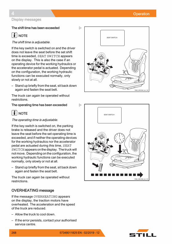
4 OperationDisplay messages
7325_003-054_en_V2
F1 F2
The shift time has been exceeded
NOTE
The shift time is adjustable.
If the key switch is switched on and the driverdoes not leave the seat before the set shifttime is exceeded, SEAT SWITCH appearson the display. This is also the case if anoperating device for the working hydraulics orthe accelerator pedal is actuated. Dependingon the configuration, the working hydraulicfunctions can be executed normally, onlyslowly or not at all.
– Stand up briefly from the seat, sit back downagain and fasten the seat belt.
The truck can again be operated withoutrestrictions.
7325_003-055_en_V3
F1 F2
The operating time has been exceeded
NOTE
The operating time is adjustable.
If the key switch is switched on, the parkingbrake is released and the driver does notleave the seat before the set operating time isexceeded, and if neither the operating devicesfor the working hydraulics nor the acceleratorpedal are actuated during this time, SEATSWITCHappears on the display. The truckwillnotmove. Depending on the configuration, theworking hydraulic functions can be executednormally, only slowly or not at all.
– Stand up briefly from the seat, sit back downagain and fasten the seat belt.
The truck can again be operated withoutrestrictions.
OVERHEATINGmessageIf the message OVERHEATING appearson the display, the traction motors haveoverheated. The acceleration and the speedof the truck are reduced.
– Allow the truck to cool down.
– If the error persists, contact your authorisedservice centre.
268 57348011825 EN - 02/2019 - 12
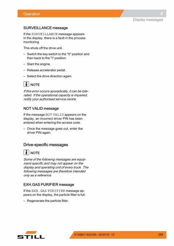
Operation 4Display messages
SURVEILLANCEmessageIf the SURVEILLANCE message appearsin the display, there is a fault in the processmonitoring.
This shuts off the drive unit.
– Switch the key switch to the "0" position andthen back to the "I" position.
– Start the engine.
– Release accelerator pedal.
– Select the drive direction again.
NOTE
If this error occurs sporadically, it can be tole-rated. If the operational capacity is impaired,notify your authorised service centre.
NOT VALID messageIf the message NOT VALID appears on thedisplay, an incorrect driver PIN has beenentered when entering the access code.
– Once the message goes out, enter thedriver PIN again.
Drive-specific messages
NOTE
Some of the following messages are equip-ment-specific and may not appear on thedisplay and operating unit of every truck. Thefollowing messages are therefore intendedonly as a reference.
EXH.GAS PURIFIERmessageIf the EXH.GAS PURIFIERmessage ap-pears on the display, the particle filter is full.
– Regenerate the particle filter.
57348011825 EN - 02/2019 - 12 269
4 OperationDisplay messages
NOTE
If the EXH.GAS PURIFIERmessage ap-pears during regeneration, a fault has occur-red.• Notify the authorised service centre
EXH.GAS PURIFIER PLEASE WAITmessageIf the EXH.GAS PURIFIER PLEASE WAITmessage appears on the display, the particlefilter is being regenerated.
– Wait for particle filter regeneration.
EXH.GAS PURIFIER SERVICE! ! !messageIf the message EXH.GAS PURIFIER SER-VICE! ! ! appears on the display, the par-ticle filter was not regenerated on time. Theparticle filter system must be repaired by theauthorised service centre.
– To avoid damage, take the truck out ofoperation until it is repaired.
– Notify the authorised service centre.
CUTOUTMODEmessageWhen automatic shut-off is activated, themessage CUTOUT MODE appears on thedisplay; see the section entitled "Automaticshut-off of the internal combustion engine(variant)".
– Sit on the driver's seat.
The message goes out and the truck is readyfor operation again.
ADBLUE URGENT! messageIf the AdBlue® filling level drops below 2 litres,the driving speed is limited to 2 km/h.
– Maintain the quality of the AdBlue®; see thesection entitled "Maintenance data table".
– Top up the AdBlue®.
270 57348011825 EN - 02/2019 - 12
Operation 4Display messages
ADBLUE FILLING LEVELmessageIf the filling level of the AdBlue® tank has fallensignificantly, the ADBLUE FILLING LEVELmessage appears on the display-operatingunit.
If an AdBlue® filling level of 2 litres is reached,the driving speed is limited to 5 km/h.
– Maintain the quality of the AdBlue®; see thesection entitled "Maintenance data table".
– Top up the AdBlue®.
ADBLUE REFILL 5l messageIf the message ADBLUE REFILL 5l ap-pears, a maximum of 5 litres of AdBlue® mustbe added.
– Maintain the quality of the AdBlue®; see thesection entitled "Maintenance data table".
– Top up the AdBlue®.
ADBLUEQUALITYmessageThis truck is equipped with a sensor thatmeasures the quality of the exhaust gascleaned using AdBlue®.
If the quality of the exhaust gas deteriorates,the ADBLUE QUALITYmessage appears onthe display and operating unit.
If the exhaust gas quality deteriorates further,the driving speed is limited to 5 km/h.
– Maintain the quality of the AdBlue®; see thesection entitled "Maintenance data table".
– Top up the AdBlue®.
ADBLUEQUALITY URGENT! messageIf the quality sensor detects a deterioration inthe quality of the exhaust gas cleaned usingAdBlue®, the message ADBLUE QUALITYURGENT! appears on the display-operatingunit.
The driving speed is limited to 2 km/h.
– Maintain the quality of the AdBlue®; see thesection entitled "Maintenance data table".
57348011825 EN - 02/2019 - 12 271
4 OperationDisplay messages
– Top up the AdBlue®.
ASH LOADmessageIf the message ASH LOAD appears on thedisplay, the particle filter has become cloggedwith ash. Repair must be performed by theauthorised service centre.
– Notify the authorised service centre.
GLOWmessageIf the GLOWmessage appears in the display,the engine is being preheated.
Preheating can take up to 22 seconds. If theengine is already at operating temperature,preheating is not performed.
– Once the message goes out, start theengine.
HYBRID SYSTEMmessageIf the message HYBRID SYSTEM is shownon the display, the energy storage system hasbeen deactivated because of an error.
The truck remains operational. However, thefuel consumption increases marginally.
– Contact the authorised service centre inorder to rectify the error.
HYDRAULIC PUMPmessageIf the HYDRAULIC PUMPmessage appearson the display, there was an error in thehydraulic-pump volume control.
The engine can be overloaded and stall asa result of the overload. This causes theassisted steering and regenerative brakingto malfunction. Further operation of the truckis therefore not permissible. Thedriving speedis limited to 5 km/h.
– Contact the authorised service centre inorder to rectify the error.
272 57348011825 EN - 02/2019 - 12
Operation 4Display messages
FUEL FILTERmessageThe fuel filter is equipped with a level indicatorthat reports water aggregation in the fuelfilter on the display and operating unit. Ifthe message FUEL FILTER appears in thedisplay, the fuel filter is saturated with water.This water must be drained.
– Drain water from the fuel filter.
COOLANT LEVELmessageIf the message COOLANT LEVEL appears onthe display, the cooling fluid level is too low.
– Check the cooling fluid level and addcoolingfluid if necessary.
CAUTIONRisk of engine damage!If the cooling fluid level is low, this indicates a leakin the cooling system.– Check the cooling system for leaks; see the
chapter entitled "Cleaning the radiator, checkingfor leaks".
EMPTYmessageIf the message EMPTY flashes on the display,the gas supply is almost exhausted.
– Change the LPG cylinder or fill the LPGtank.
ALTERNATORmessageIf the ALTERNATORmessage appears in thedisplay, this means that the alternator is nolonger charging the starter battery.
This may have the following causes:• Drive belt loose or damaged• The electrics to or from the alternator arefaulty
• The alternator is faulty
NOTE
If the fault is not rectified within a short time,the starter battery will soon run out of charge
57348011825 EN - 02/2019 - 12 273
4 OperationDisplay messages
and it will no longer be possible to operate thetruck.
– Notify the authorised service centre.
LPG AUTO. VALVEmessageIf the message LPG AUTO. VALVE ap-pears on the display when the LPG engineis switched off, and the engine does not switchoff until after approximately 60 seconds, thereis an error.
Initially, the truck can still be operated. Theerror message is shown on the display andoperating unit until the error has been rectifiedby the authorised service centre.
– Notify the authorised service centre.
AIR FILTERmessageIf the AIR FILTERmessage appears on thedisplay, the filter insert or the filter cartridgemust be replaced.
– Replace the filter insert or the filter cartridge.
OIL PRESSUREmessage
CAUTIONRisk of engine damage!If the OIL PRESSUREmessage appears in thedisplay, the engine's oil pressure is too low.– Stop the engine immediately.
The message can have different causes:• The engine has overheated• Insufficient oil• The oil is insufficiently viscous• Engine damage
– Check engine oil level.
– Change the engine oil if necessary.
– Notify the authorised service centre.
REGENERATION COMPLETEDmessageIf the message REGENERATION COM-PLETED appears on the display, parked re-
274 57348011825 EN - 02/2019 - 12
Operation 4Display messages
generation is complete. The truck is ready foroperation again.
SCR-SYSTEMSERVICEmessageIf the message SCR-SYSTEM SERVICEappears on the display, there is a fault in theSCR exhaust gas treatment system.
– Notify the authorised service centre.
SCR-SYSTEMMALFUNCTION mes-sageIf the message SCR-SYSTEM MALFUNC-TION appears on the display, there is a faultin the SCR exhaust gas treatment system.
– Notify the authorised service centre.
PARK. REG. URGENT! ! ! messageIf the message PARK. REG. URGENT! ! !appears on the display, parked regenerationof the particle filter is required urgently.
– Perform parked regeneration.
Until parked regeneration has been carriedout, the maximum speed of the truck is re-duced to 2 km/h. The lifting speed is restricted.
PARK. REG. ERRORmessageIf themessagePARK.REG.ERROR appearson the display, parked regeneration wasinterrupted by applying the parking brakeor by a malfunction in the internal combustionengine.
– Apply the parking brake.
– Restart parked regeneration.
– If the parking brake was not actuatedand the message PARK. REG. ERRORappears anyway, notify the authorisedservice centre.
START PARK. REG.? messageIf the message START PARK. REG.?appears on the display, the truck is ready forparked regeneration.
57348011825 EN - 02/2019 - 12 275
4 OperationRefuelling
– Perform parked regeneration.
START IC ENGINEmessageIf the message START IC ENGINE appearson the display, the internal combustion engineof the truck can be started.
– Start the engine.
RefuellingDiesel fuel - Specifications
CAUTIONRisk of component damage if non-approved fuelsare used!Use only approved fuels with the following specifi-cations.
If non-approved fuels are used, compliancewith the specified emission values and the ser-vice life of the engine cannot be guaranteed!This truck is equipped with an engine that ful-fils the requirements of Directive 97/68/EClevel IIIA. The truck can also be equipped withan exhaust after-treatment system (variant).
The truck may be operated only with sulphur-free diesel fuels as defined by the followingstandards:• EN 590• ASTM D 975 Grade 2-D S15• ASTM D 975 Grade 1-D S15• or non-road fuels (light fuel oils) in line withthe EN 590 standard
If these fuel types are not used, compliancewith the specified emission values and the ser-vice life of the engine cannot be guaranteed.
Minimum requirements for fuels in countriesin which none of the approved diesel fuels areavailable can be requested from the autho-rised service centre. The operating companyis obligated to check the permissibility of thefuel used in accordance with national regula-tions.
276 57348011825 EN - 02/2019 - 12
Operation 4Refuelling
The following are not permitted:• Admixtures of petroleum, kerosene oradditional fluidity additives
• Distillate fuels for marine engines• Jet fuels• Biodiesel fuels• US fuels in line with the ASTM D 9751-D S500 or ASTM D 975 2-D S500 stan-dards
– If necessary, query with the authorisedservice centre.
Ensure compliance with parameters includingthe following limit values in accordance withEN 590:Parameter Unit ValueCetanenumber1) - Min. 51
Density at15 C
kg/m3 820 - 845
Sulphurcontent
mg/kg Max. 101) The use of diesel fuels with a lower cetanenumber can lead to the formation of whitesmoke and misfiring. In winter, the use ofdiesel fuels with a higher cetane number isrecommended.
Sulphur content in the diesel fuel
CAUTIONInsufficient lubrication can lead to engine damage!– Use only sulphur-free diesel fuels in accordance
with manufacturer specifications.
Insufficient lubricating properties in dieselfuels with a sulphur content of > 500 mg/kgcan lead to serious problems due to wear,especially in common-rail injection systems.In sulphur-free diesel fuels in accordancewith EN 590 and ASTM D 975, sufficientlubrication properties are ensured by using thecorresponding fuel additives during refining.
Fuels with a sulphur content of > 0.5% (m/m)require a shortened change interval for thelubricating oil andmust not be used in engineswith a particle filter system. Fuels with a
57348011825 EN - 02/2019 - 12 277
4 OperationRefuelling
sulphur content of > 1.0% (m/m) are alsonot permissible due to high corrosion and asignificant lifetime reduction of the engine.
Winter operation with diesel fuel
CAUTIONAdding petrol can lead to malfunctions in the fuelinjection system!– Do not add petrol.– Do not add petroleum, kerosene or additional
fluidity additives.– If necessary, query with the authorised service
centre.
During winter operation, special demands areplaced on the low-temperature performanceoffuels. Generally, diesel fuels that can be usedat temperatures down to -44Care available onthe free market. Therefore, it is not necessaryto add additives to improve the fluidity. Addingpetrol can lead to the formation of vapourpockets (cavitation) in the fuel system. Theformation of these vapour pockets disruptsthe function of the fuel injection system and, ifcontinued over a long period of time, can leadto component damage.
Non-road fuels
NOTE
In some European countries, non-road fuelsare defined with the same characteristicsas light fuel oil. The permissibility of fuels ishandled differently in individual countries.Light fuel oils and non-road fuels are suitablefor the engine as long as compliance with thelimit values of EN 590 is ensured.• Use only sulphur-free diesel fuels in accor-dance with manufacturer specifications.
• The operating company is obligated tocheck the permissibility of the fuel usedin accordance with national regulations.
278 57348011825 EN - 02/2019 - 12
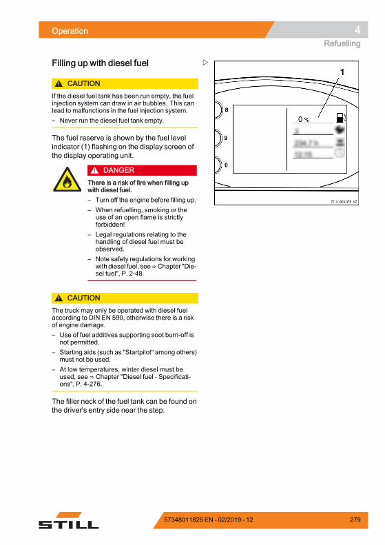
Operation 4Refuelling
Filling up with diesel fuel
CAUTIONIf the diesel fuel tank has been run empty, the fuelinjection system can draw in air bubbles. This canlead to malfunctions in the fuel injection system.– Never run the diesel fuel tank empty.
The fuel reserve is shown by the fuel levelindicator (1) flashing on the display screen ofthe display operating unit.
DANGERThere is a risk of fire when filling upwith diesel fuel.– Turn off the engine before filling up.– When refuelling, smoking or the
use of an open flame is strictlyforbidden!
– Legal regulations relating to thehandling of diesel fuel must beobserved.
– Note safety regulations for workingwith diesel fuel, see⇒Chapter "Die-sel fuel", P. 2-48.
CAUTIONThe truck may only be operated with diesel fuelaccording to DIN EN 590, otherwise there is a riskof engine damage.– Use of fuel additives supporting soot burn-off is
not permitted.– Starting aids (such as "Startpilot" among others)
must not be used.– At low temperatures, winter diesel must be
used, see ⇒ Chapter "Diesel fuel - Specificati-ons", P. 4-276.
The filler neck of the fuel tank can be found onthe driver's entry side near the step.
57348011825 EN - 02/2019 - 12 279
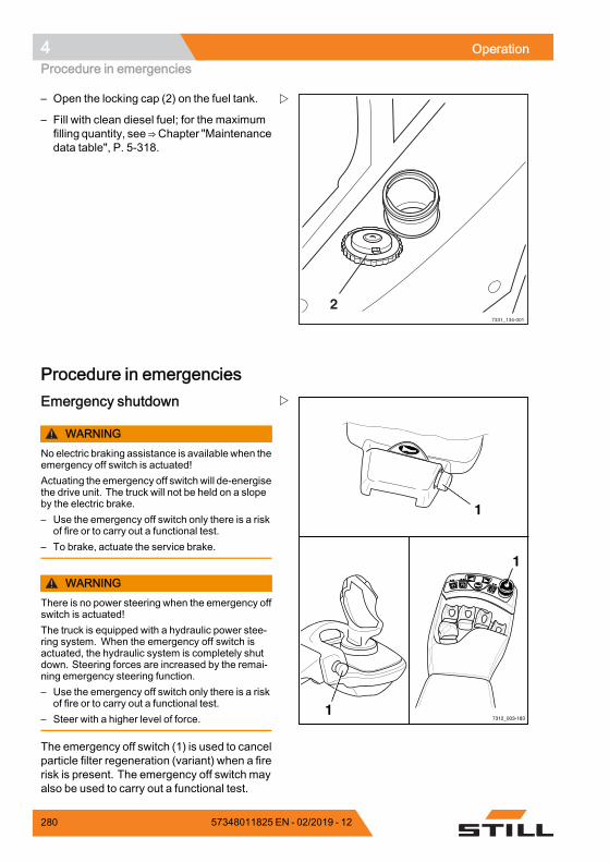
4 OperationProcedure in emergencies
7331_134-001
2
– Open the locking cap (2) on the fuel tank.
– Fill with clean diesel fuel; for the maximumfilling quantity, see⇒Chapter "Maintenancedata table", P. 5-318.
Procedure in emergencies
7312_003-183
F1F1 F2F2
1
1
1
Emergency shutdown
WARNINGNo electric braking assistance is available when theemergency off switch is actuated!Actuating the emergency off switch will de-energisethe drive unit. The truck will not be held on a slopeby the electric brake.– Use the emergency off switch only there is a risk
of fire or to carry out a functional test.– To brake, actuate the service brake.
WARNINGThere is no power steering when the emergency offswitch is actuated!The truck is equipped with a hydraulic power stee-ring system. When the emergency off switch isactuated, the hydraulic system is completely shutdown. Steering forces are increased by the remai-ning emergency steering function.– Use the emergency off switch only there is a risk
of fire or to carry out a functional test.– Steer with a higher level of force.
The emergency off switch (1) is used to cancelparticle filter regeneration (variant) when a firerisk is present. The emergency off switch mayalso be used to carry out a functional test.
280 57348011825 EN - 02/2019 - 12
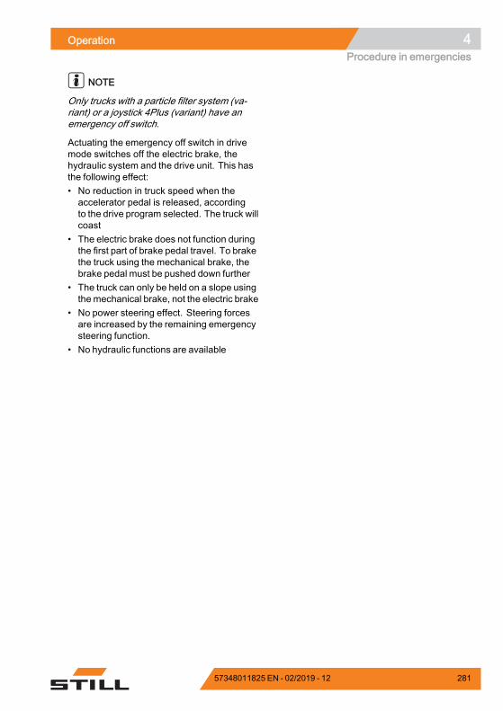
Operation 4Procedure in emergencies
NOTE
Only trucks with a particle filter system (va-riant) or a joystick 4Plus (variant) have anemergency off switch.
Actuating the emergency off switch in drivemode switches off the electric brake, thehydraulic system and the drive unit. This hasthe following effect:• No reduction in truck speed when theaccelerator pedal is released, accordingto the drive program selected. The truck willcoast
• The electric brake does not function duringthe first part of brake pedal travel. To brakethe truck using the mechanical brake, thebrake pedal must be pushed down further
• The truck can only be held on a slope usingthemechanical brake, not the electric brake
• No power steering effect. Steering forcesare increased by the remaining emergencysteering function.
• No hydraulic functions are available
57348011825 EN - 02/2019 - 12 281
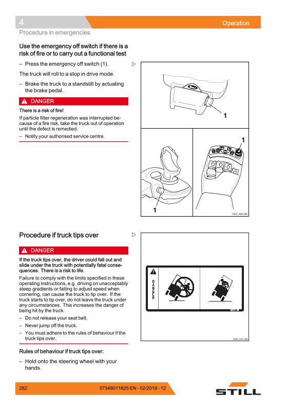
4 OperationProcedure in emergencies
Use the emergency off switch if there is arisk of fire or to carry out a functional test
7312_003-183
F1F1 F2F2
1
1
1
– Press the emergency off switch (1).
The truck will roll to a stop in drive mode.
– Brake the truck to a standstill by actuatingthe brake pedal.
DANGERThere is a risk of fire!If particle filter regeneration was interrupted be-cause of a fire risk, take the truck out of operationuntil the defect is remedied.– Notify your authorised service centre.
7090_001-005
Procedure if truck tips over
DANGERIf the truck tips over, the driver could fall out andslide under the truck with potentially fatal conse-quences. There is a risk to life.Failure to comply with the limits specified in theseoperating instructions, e.g. driving on unacceptablysteep gradients or failing to adjust speed whencornering, can cause the truck to tip over. If thetruck starts to tip over, do not leave the truck underany circumstances. This increases the danger ofbeing hit by the truck.– Do not release your seat belt.– Never jump off the truck.– You must adhere to the rules of behaviour if the
truck tips over.
Rules of behaviour if truck tips over:
– Hold onto the steering wheel with yourhands.
282 57348011825 EN - 02/2019 - 12
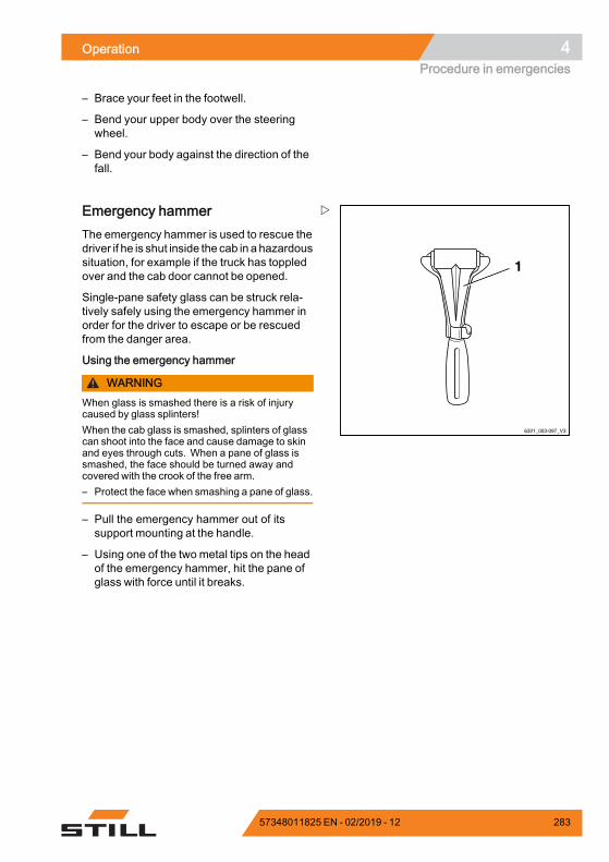
Operation 4Procedure in emergencies
– Brace your feet in the footwell.
– Bend your upper body over the steeringwheel.
– Bend your body against the direction of thefall.
6321_003-097_V3
1
Emergency hammerThe emergency hammer is used to rescue thedriver if he is shut inside the cab in a hazardoussituation, for example if the truck has toppledover and the cab door cannot be opened.
Single-pane safety glass can be struck rela-tively safely using the emergency hammer inorder for the driver to escape or be rescuedfrom the danger area.
Using the emergency hammer
WARNINGWhen glass is smashed there is a risk of injurycaused by glass splinters!When the cab glass is smashed, splinters of glasscan shoot into the face and cause damage to skinand eyes through cuts. When a pane of glass issmashed, the face should be turned away andcovered with the crook of the free arm.– Protect the face when smashing a pane of glass.
– Pull the emergency hammer out of itssupport mounting at the handle.
– Using one of the two metal tips on the headof the emergency hammer, hit the pane ofglass with force until it breaks.
57348011825 EN - 02/2019 - 12 283
4 OperationProcedure in emergencies
Emergency loweringIf the hydraulic controller fails whilst a loadis raised, emergency lowering can be per-formed. An emergency lowering screw islocated on the hydraulics control block for thispurpose.
DANGERThere is a risk of fatal injury fromfalling loads or parts of the truck beinglowered.– Do not walk beneath the raised
load.– Adhere to the steps detailed below.
WARNINGThe load is lowered!The lowering speed is regulated by unscrewing theemergency lowering screw.– Note the list of points below.
Remember the following:• Tightening torque:Max. 2.5 Nm
• When unscrewed a little:The load lowers slowly
• When unscrewed a lot:The load lowers quickly
284 57348011825 EN - 02/2019 - 12
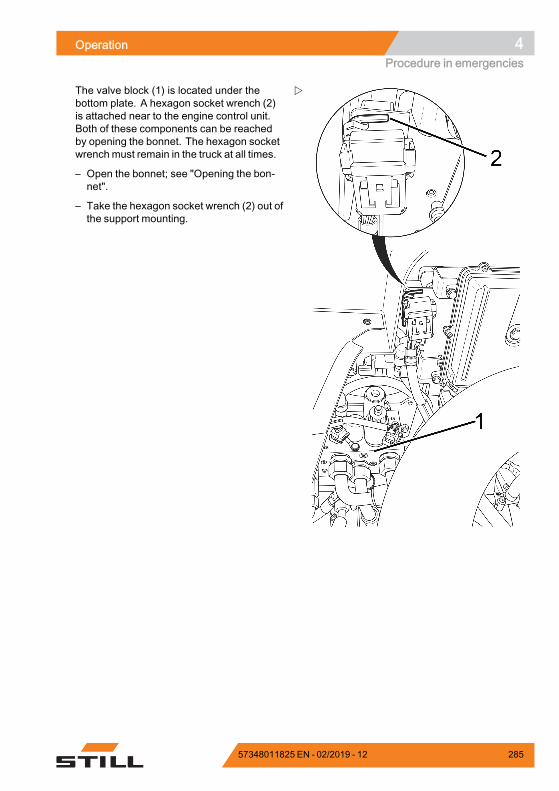
Operation 4Procedure in emergencies
The valve block (1) is located under thebottom plate. A hexagon socket wrench (2)is attached near to the engine control unit.Both of these components can be reachedby opening the bonnet. The hexagon socketwrench must remain in the truck at all times.
– Open the bonnet; see "Opening the bon-net".
– Take the hexagon socket wrench (2) out ofthe support mounting.
57348011825 EN - 02/2019 - 12 285
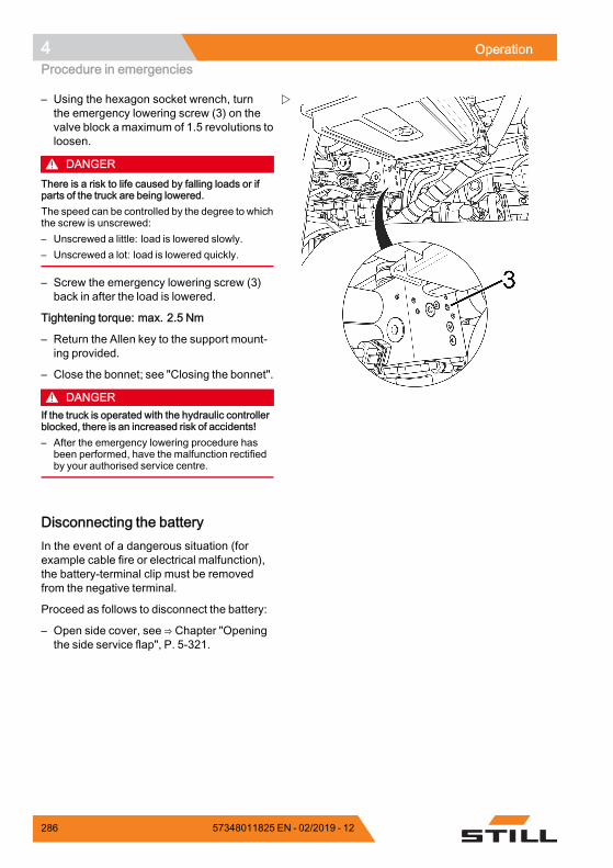
4 OperationProcedure in emergencies
– Using the hexagon socket wrench, turnthe emergency lowering screw (3) on thevalve block a maximum of 1.5 revolutions toloosen.
DANGERThere is a risk to life caused by falling loads or ifparts of the truck are being lowered.The speed can be controlled by the degree to whichthe screw is unscrewed:– Unscrewed a little: load is lowered slowly.– Unscrewed a lot: load is lowered quickly.
– Screw the emergency lowering screw (3)back in after the load is lowered.
Tightening torque: max. 2.5 Nm
– Return the Allen key to the support mount-ing provided.
– Close the bonnet; see "Closing the bonnet".
DANGERIf the truck is operated with the hydraulic controllerblocked, there is an increased risk of accidents!– After the emergency lowering procedure has
been performed, have the malfunction rectifiedby your authorised service centre.
Disconnecting the batteryIn the event of a dangerous situation (forexample cable fire or electrical malfunction),the battery-terminal clip must be removedfrom the negative terminal.
Proceed as follows to disconnect the battery:
– Open side cover, see ⇒ Chapter "Openingthe side service flap", P. 5-321.
286 57348011825 EN - 02/2019 - 12
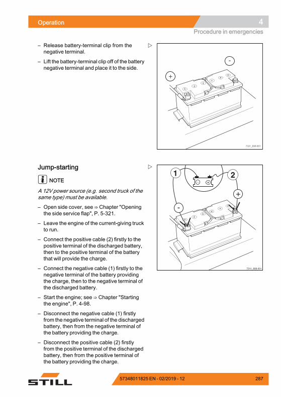
Operation 4Procedure in emergencies
+
-
7331_690-001
– Release battery-terminal clip from thenegative terminal.
– Lift the battery-terminal clip off of the batterynegative terminal and place it to the side.
- +21
+
-
7311_606-001
Jump-starting
NOTE
A 12V power source (e.g. second truck of thesame type) must be available.
– Open side cover, see ⇒ Chapter "Openingthe side service flap", P. 5-321.
– Leave the engine of the current-giving truckto run.
– Connect the positive cable (2) firstly to thepositive terminal of the discharged battery,then to the positive terminal of the batterythat will provide the charge.
– Connect the negative cable (1) firstly to thenegative terminal of the battery providingthe charge, then to the negative terminal ofthe discharged battery.
– Start the engine; see ⇒ Chapter "Startingthe engine", P. 4-98.
– Disconnect the negative cable (1) firstlyfrom the negative terminal of the dischargedbattery, then from the negative terminal ofthe battery providing the charge.
– Disconnect the positive cable (2) firstlyfrom the positive terminal of the dischargedbattery, then from the positive terminal ofthe battery providing the charge.
57348011825 EN - 02/2019 - 12 287
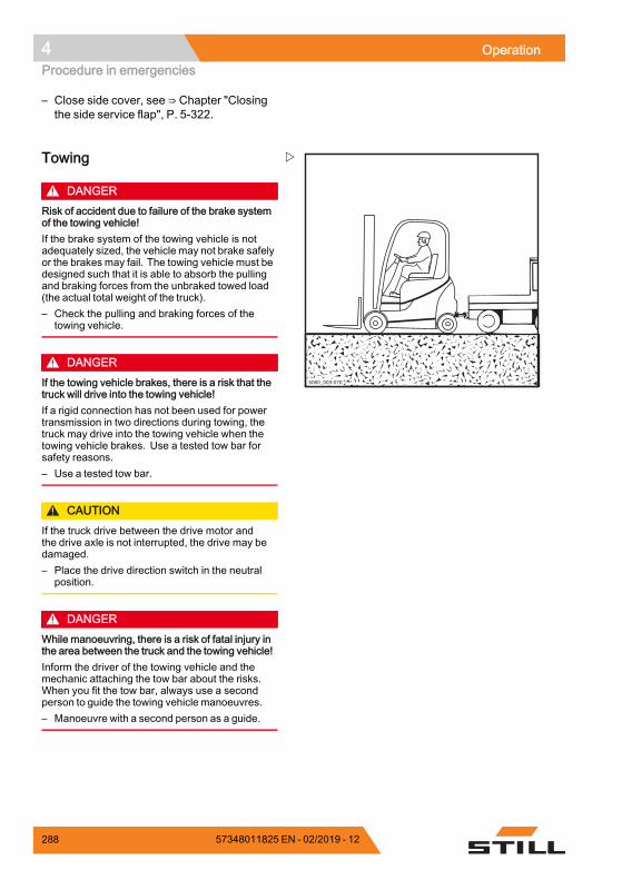
4 OperationProcedure in emergencies
– Close side cover, see ⇒ Chapter "Closingthe side service flap", P. 5-322.
6036Ba-0265060_003-070
Towing
DANGERRisk of accident due to failure of the brake systemof the towing vehicle!If the brake system of the towing vehicle is notadequately sized, the vehicle may not brake safelyor the brakes may fail. The towing vehicle must bedesigned such that it is able to absorb the pullingand braking forces from the unbraked towed load(the actual total weight of the truck).– Check the pulling and braking forces of the
towing vehicle.
DANGERIf the towing vehicle brakes, there is a risk that thetruck will drive into the towing vehicle!If a rigid connection has not been used for powertransmission in two directions during towing, thetruck may drive into the towing vehicle when thetowing vehicle brakes. Use a tested tow bar forsafety reasons.– Use a tested tow bar.
CAUTIONIf the truck drive between the drive motor andthe drive axle is not interrupted, the drive may bedamaged.– Place the drive direction switch in the neutral
position.
DANGERWhile manoeuvring, there is a risk of fatal injury inthe area between the truck and the towing vehicle!Inform the driver of the towing vehicle and themechanic attaching the tow bar about the risks.When you fit the tow bar, always use a secondperson to guide the towing vehicle manoeuvres.– Manoeuvre with a second person as a guide.
288 57348011825 EN - 02/2019 - 12
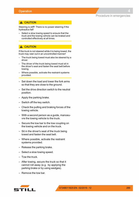
Operation 4Procedure in emergencies
CAUTIONSteering is stiff! There is no power steering if thehydraulics fail!– Select a slow towing speed to ensure that the
truck and the towing vehicle can be braked andcontrolled effectively at all times.
CAUTIONIf the truck is not steered while it is being towed, thetruck may veer out in an uncontrolled manner!– The truck being towedmust also be steered by a
driver.– The driver of the truck being towed must sit in
the driver's seat and fasten the seat belt beforetowing.
– Where possible, activate the restraint systemsprovided.
– Set down the load and lower the fork armsso that they are close to the ground.
– Set the drive direction switch to the neutralposition.
– Apply the parking brake.
– Switch off the key switch.
– Check the pulling and braking forces of thetowing vehicle.
– With a second person as a guide, manoeu-vre the towing vehicle to the truck.
– Secure the tow bar to the tow coupling onthe towing vehicle and on the truck.
– Sit in the driver's seat of the truck beingtowed and fasten the seat belt.
– Where possible, activate the restraintsystems provided.
– Release the parking brake.
– Select a slow towing speed.
– Tow the truck.
– After towing, secure the truck so that itcannot roll away (e.g. by applying theparking brake or by using wedges).
– Remove the tow bar.
57348011825 EN - 02/2019 - 12 289
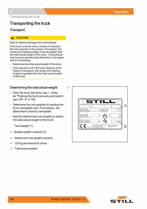
4 OperationTransporting the truck
Transporting the truckTransport
CAUTIONRisk of material damage from overloading!If the truck is driven onto a means of transport,the load capacity of the means of transport, theramps and loading bridges must be greater thanthe total actual weight of the truck. Componentsmay become permanently deformed or damageddue to overloading.– Determine the total actual weight of the truck.– Only load the truck if the load capacity of the
means of transport, the ramps and loadingbridges is greater than the total actual weightof the truck.
Type-Modèle-Typ / Serial no.-No. de série-Serien-Nr. / year-année-Baujahr
Rated capacityCapacité nominaleNenn-Tragfähigkeit
Battery voltageTension batterieBatteriespannung
Rated drive powerPuissance motr.nom.Nenn-Antriebsleist.
Unladen massMasse à videLeergewicht
maxmin.*
* see Operating instructions voir Mode d'emploi siehe Betriebsanleitung
kg kg
kgkg
kgkW
V
*
D-22113 HamburgBerzeliusstr. 10 2
1
Determining the total actual weight– Park the truck securely; see ⇒ Chap-ter "Parking the truck securely and switch-ing it off", P. 4-138.
– Determine the unit weights by reading thetruck nameplate and, if necessary, theattachment (variant) nameplate.
– Add the determined unit weights to obtainthe total actual weight of the truck:
Tare weight (1)
+ Ballast weight (variant) (2)
+ Attachment net weight (variant)
+ 100 kg allowance for driver
= Total actual weight
290 57348011825 EN - 02/2019 - 12
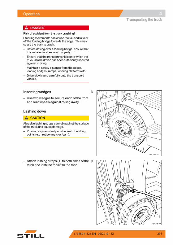
Operation 4Transporting the truck
DANGERRisk of accident from the truck crashing!Steering movements can cause the tail end to veeroff the loading bridge towards the edge. This maycause the truck to crash.– Before driving over a loading bridge, ensure that
it is installed and secured properly.– Ensure that the transport vehicle onto which the
truck is to be driven has been sufficiently securedagainst moving.
– Maintain a safety distance from the edges,loading bridges, ramps, working platforms etc.
– Drive slowly and carefully onto the transportvehicle.
7331_003-002
Inserting wedges– Use two wedges to secure each of the frontand rear wheels against rolling away.
Lashing down
CAUTIONAbrasive lashing straps can rub against the surfaceof the truck and cause damage.– Position slip-resistant pads beneath the lifting
points (e.g. rubber mats or foam).
6321_003-104
1
– Attach lashing straps (1) to both sides of thetruck and lash the forklift to the rear.
57348011825 EN - 02/2019 - 12 291
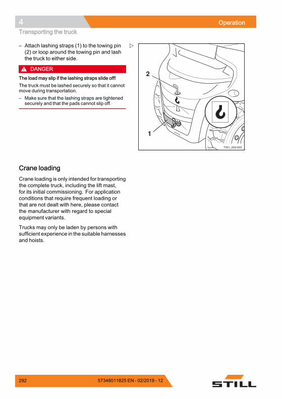
4 OperationTransporting the truck
7331_003-003
1
2
– Attach lashing straps (1) to the towing pin(2) or loop around the towing pin and lashthe truck to either side.
DANGERThe load may slip if the lashing straps slide off!The truck must be lashed securely so that it cannotmove during transportation.– Make sure that the lashing straps are tightened
securely and that the pads cannot slip off.
Crane loadingCrane loading is only intended for transportingthe complete truck, including the lift mast,for its initial commissioning. For applicationconditions that require frequent loading orthat are not dealt with here, please contactthe manufacturer with regard to specialequipment variants.
Trucks may only be laden by persons withsufficient experience in the suitable harnessesand hoists.
292 57348011825 EN - 02/2019 - 12
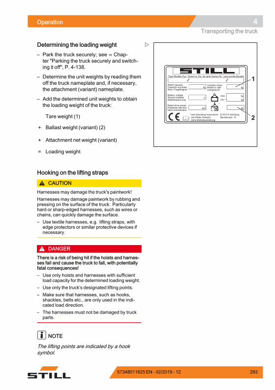
Operation 4Transporting the truck
Type-Modèle-Typ / Serial no.-No. de série-Serien-Nr. / year-année-Baujahr
Rated capacityCapacité nominaleNenn-Tragfähigkeit
Battery voltageTension batterieBatteriespannung
Rated drive powerPuissance motr.nom.Nenn-Antriebsleist.
Unladen massMasse à videLeergewicht
maxmin.*
* see Operating instructions voir Mode d'emploi siehe Betriebsanleitung
kg kg
kgkg
kgkW
V
*
D-22113 HamburgBerzeliusstr. 10 2
1
Determining the loading weight– Park the truck securely; see ⇒ Chap-ter "Parking the truck securely and switch-ing it off", P. 4-138.
– Determine the unit weights by reading themoff the truck nameplate and, if necessary,the attachment (variant) nameplate.
– Add the determined unit weights to obtainthe loading weight of the truck:
Tare weight (1)
+ Ballast weight (variant) (2)
+ Attachment net weight (variant)
= Loading weight.
Hooking on the lifting straps
CAUTIONHarnesses may damage the truck's paintwork!Harnesses may damage paintwork by rubbing andpressing on the surface of the truck. Particularlyhard or sharp-edged harnesses, such as wires orchains, can quickly damage the surface.– Use textile harnesses, e.g. lifting straps, with
edge protectors or similar protective devices ifnecessary.
DANGERThere is a risk of being hit if the hoists and harnes-ses fail and cause the truck to fall, with potentiallyfatal consequences!– Use only hoists and harnesses with sufficient
load capacity for the determined loading weight.– Use only the truck's designated lifting points.– Make sure that harnesses, such as hooks,
shackles, belts etc., are only used in the indi-cated load direction.
– The harnesses must not be damaged by truckparts.
NOTE
The lifting points are indicated by a hooksymbol.
57348011825 EN - 02/2019 - 12 293
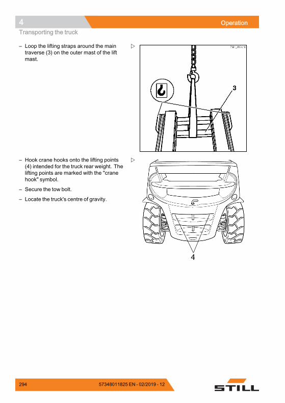
4 OperationTransporting the truck
– Loop the lifting straps around the maintraverse (3) on the outer mast of the liftmast.
– Hook crane hooks onto the lifting points(4) intended for the truck rear weight. Thelifting points are marked with the "cranehook" symbol.
– Secure the tow bolt.
– Locate the truck's centre of gravity.
294 57348011825 EN - 02/2019 - 12
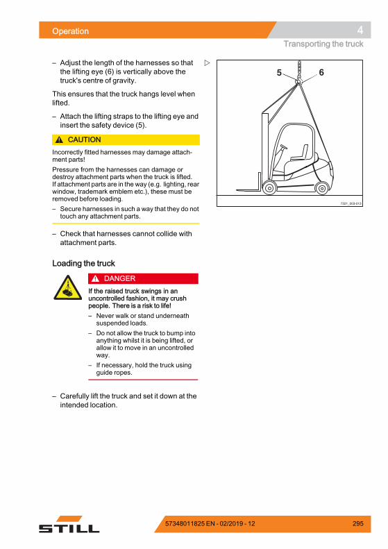
Operation 4Transporting the truck
7321_003-013
5 6– Adjust the length of the harnesses so thatthe lifting eye (6) is vertically above thetruck's centre of gravity.
This ensures that the truck hangs level whenlifted.
– Attach the lifting straps to the lifting eye andinsert the safety device (5).
CAUTIONIncorrectly fitted harnesses may damage attach-ment parts!Pressure from the harnesses can damage ordestroy attachment parts when the truck is lifted.If attachment parts are in the way (e.g. lighting, rearwindow, trademark emblem etc.), these must beremoved before loading.– Secure harnesses in such a way that they do not
touch any attachment parts.
– Check that harnesses cannot collide withattachment parts.
Loading the truck
DANGERIf the raised truck swings in anuncontrolled fashion, it may crushpeople. There is a risk to life!– Never walk or stand underneath
suspended loads.– Do not allow the truck to bump into
anything whilst it is being lifted, orallow it to move in an uncontrolledway.
– If necessary, hold the truck usingguide ropes.
– Carefully lift the truck and set it down at theintended location.
57348011825 EN - 02/2019 - 12 295
4 OperationCleaning
CleaningCleaning the truck
WARNINGRisk of injury from falling off the truck!When climbing onto the truck, thereis a risk of getting stuck or slippingand falling. Use suitable equipment toreach higher points on the truck.– For climbing onto the truck, use
only the steps provided for thispurpose.
– For reaching inaccessible places,use devices such as stepladders orplatforms.
WARNINGRisk of fire due to flammable cleaningmaterials!Flammable cleaning materials can beignited by hot components.– Do not use any flammable cleaning
materials.
CAUTIONRisk of fire due to flammable materi-als!Deposits and solids can be ignited byhot components, e.g. drive units.– Remove deposits and solids.
CAUTIONIf water penetrates the electrical system, there is arisk of short circuit!The engine must be switched off during washing.Do not use water to clean the area around thecentral electrical system; instead, only clean with adry cloth or clean compressed air.– Adhere strictly to the following steps.
CAUTIONExcessive water pressure or water and steam thatare too hot can damage truck components.– Adhere strictly to the following steps.
296 57348011825 EN - 02/2019 - 12
Operation 4Cleaning
CAUTIONAbrasive cleaning materials can damage the surfa-ces of components!Using abrasive cleaning materials that are unsuita-ble for plastics can cause plastic parts to dissolveor become brittle. The screen on the display-opera-ting unit could become cloudy.– Adhere strictly to the following steps.
– Park the truck securely.
– Switch off the key switch.
– Do not spray electric motors and otherelectrical components or their coversdirectly with water.
– Use only high-pressure cleaners with amaximum output power of up to 50 bar and85°C.
– If a high-pressure cleaner is used, maintaina distance of at least 20 cm between thenozzle and the object being cleaned.
– Do not aim the cleaning jet directly atadhesive labels or decal information.
– Remove all deposits and accumulationsof foreign materials in the vicinity of hotcomponents.
– Use only non-flammable fluids for cleaning.
– Observe the manufacturer's guidelines forworking with cleaning materials.
– Clean plastics only with cleaning materialsintended for plastics.
– Observe the manufacturer's guidelines forworking with cleaning materials.
– Clean the truck exterior using water-solublecleaning materials and water. Cleaningwith a water jet, a sponge or a cloth isrecommended.
– Clean all accessible areas.
– Before lubrication, clean the oil fillingopenings and the area around the oil fillingopenings, as well as the lubricating nipples.
57348011825 EN - 02/2019 - 12 297
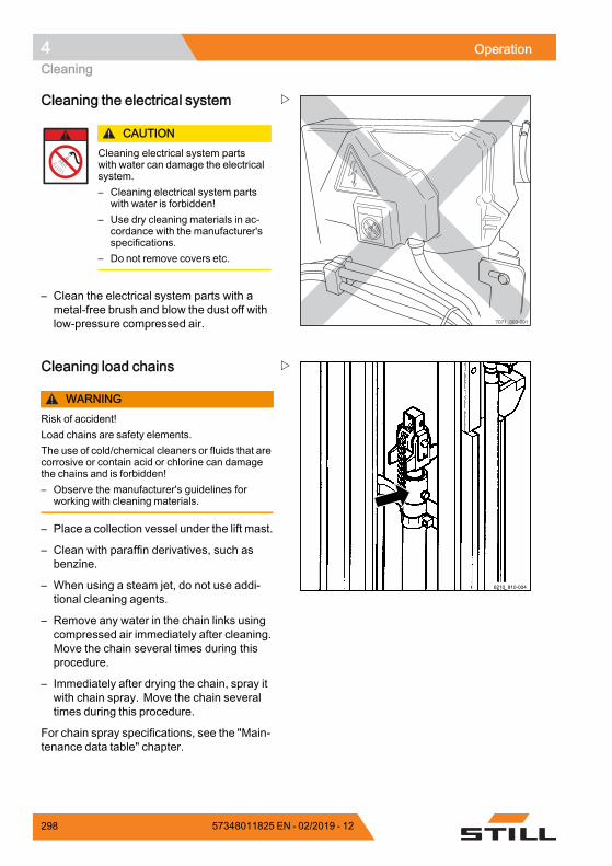
4 OperationCleaning
7071_003-091
Cleaning the electrical system
CAUTIONCleaning electrical system partswith water can damage the electricalsystem.– Cleaning electrical system parts
with water is forbidden!– Use dry cleaning materials in ac-
cordance with the manufacturer'sspecifications.
– Do not remove covers etc.
– Clean the electrical system parts with ametal-free brush and blow the dust off withlow-pressure compressed air.
6210_810-004
Cleaning load chains
WARNINGRisk of accident!Load chains are safety elements.The use of cold/chemical cleaners or fluids that arecorrosive or contain acid or chlorine can damagethe chains and is forbidden!– Observe the manufacturer's guidelines for
working with cleaning materials.
– Place a collection vessel under the lift mast.
– Clean with paraffin derivatives, such asbenzine.
– When using a steam jet, do not use addi-tional cleaning agents.
– Remove any water in the chain links usingcompressed air immediately after cleaning.Move the chain several times during thisprocedure.
– Immediately after drying the chain, spray itwith chain spray. Move the chain severaltimes during this procedure.
For chain spray specifications, see the "Main-tenance data table" chapter.
298 57348011825 EN - 02/2019 - 12
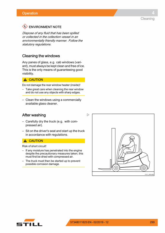
Operation 4Cleaning
ENVIRONMENT NOTE
Dispose of any fluid that has been spilledor collected in the collection vessel in anenvironmentally friendly manner. Follow thestatutory regulations.
Cleaning the windowsAny panes of glass, e.g. cab windows (vari-ant), must always be kept clean and free of ice.This is the only means of guaranteeing goodvisibility.
CAUTIONDo not damage the rear window heater (inside)!– Take great care when cleaning the rear window
and do not use any objects with sharp edges.
– Clean the windows using a commerciallyavailable glass cleaner.
7311_003-058
After washing– Carefully dry the truck (e.g. with com-pressed air).
– Sit on the driver's seat and start up the truckin accordance with regulations.
CAUTIONRisk of short circuit!– If any moisture has penetrated into the engine
despite the precautionary measures taken, thismust first be dried with compressed air.
– The truck must then be started up to preventpossible corrosion damage.
57348011825 EN - 02/2019 - 12 299
4 OperationDecommissioning
DecommissioningShutting down and storing the truck
CAUTIONComponent damage due to incorrect storage!If the truck is stored or shut down incorrectly formore than two months, it may suffer corrosion da-mage. If the truck is parked in an ambient tempera-ture of less than -10°C for an extended period, thebattery will cool down. The electrolyte may freezeand damage the battery.– Carry out the following measures before shut-
down.
CAUTIONTyre deformation as a result of continuous loadingon one side!Have the truck raised and jacked up by the authori-sed service centre so that all the wheels are clear ofthe ground. This prevents permanent deformationof the tyres.
CAUTIONDanger of damage from corrosion due to conden-sation on the truck!Many plastic films and synthetic materials arewatertight. Condensation water on the truck cannotescape through these covers.– Do not use plastic film as this facilitates the
formation of condensation water.
NOTE
Store only fully charged batteries.
Measures to be implemented beforeshutdown– Store the truck in a dry, clean, frost-free andwell ventilated environment.
– Clean the truck thoroughly; see chapter"Cleaning".
– Lift the fork carriage to the stop severaltimes.
– Tilt the lift mast forwards and backwardsseveral times and, if fitted,moveattachmentrepeatedly.
300 57348011825 EN - 02/2019 - 12
Operation 4Decommissioning
– To relieve the strain on the load chains,lower the fork onto a suitable supportingsurface, e.g. a pallet.
– Check hydraulic oil level and top up ifrequired.
– Apply a thin layer of oil or grease to alluntreated moving parts.
– Grease the forklift truck.
– Lubricate the joints and controls.
– Fill the fuel tank.
– Remove the starter battery and store in awarm and dry location.
– Regularly check the charge status andrecharge the starter battery if necessary.
– Spray all exposed electrical contacts with asuitable contact spray.
– Preserve the engine as specified by themanufacturer.
– Cover the truck with vapour permeablematerials, such as cotton, in order to protectagainst dust.
– If the truck is to be shut down for evenlonger periods, contact your authorisedservice centre to find out about additionalmeasures.
Recommissioning after decommis-sioningIf the truck has been decommissioned forlonger than six months, the truck must becarefully checked before being recommis-sioned. As with the yearly safety inspection,this check must also include all safety-relatedaspects of the truck.
– Thoroughly clean the truck.
– Oil joints and controls.
– Lubricate the lubrication points.
– Check the condition and the acid density ofthe battery. Charge the battery if necessary.
57348011825 EN - 02/2019 - 12 301
4 OperationDecommissioning
– Restore engine to normal condition accord-ing to regulations of engine manufacturer.
– Check the engine oil for condensationwaterand replace the oil if necessary.
– Check hydraulic oil for condensation water;change if necessary.
– Have the same checks and tasks carried outby the authorised service centre that werecarried out before initial commissioning.
– Carry out the checks and tasks that are tobe performed before daily use.
– Recommission the truck.
During recommissioning, the following pointsin particular must be checked:• Drive, control, steering• Brake system (service brake, parkingbrake, regenerative brake)
• Lifting system (load-carrying equipment,load chains, mounting)
NOTE
For further information, see the workshop ma-nual for the truck and contact the authorisedservice centre.
302 57348011825 EN - 02/2019 - 12

5
Maintenance
5 MaintenanceSafety regulations for maintenance
Safety regulations for maintenanceGeneral information
DANGERRisk of fatal poisoning!It is dangerous to leave the engine running inenclosed spaces. The engine consumes oxygenand emits carbon dioxide, carbon monoxide andother poisonous gases. There is a risk of fatalpoisoning!– Only operate the truck in areas that are well
ventilated.
To prevent accidents during maintenancework and repair work, all necessary safetymeasures must be taken, e.g.:
– Apply the parking brake.
– Switch off the key switch and remove thekey.
– Ensure that the truck cannot move uninten-tionally or start up inadvertently.
– If required, have the truck jacked up by theauthorised service centre.
– Have the raised fork carriage or the ex-tended lift mast secured against accidentallowering by the authorised service centre.
– Insert an appropriately sized wooden beamas an abutment between the lift mast andthe cab, and secure the lift mast to preventit tilting backwards unintentionally.
– Observe the maximum lift height of the liftmast, and compare the dimensions fromthe technical data with the dimensions ofthe hall into which the truck is to be driven.These steps are taken to prevent a collisionwith the ceiling of the hall and to avoid anydamage caused as a result.
Working on the hydraulic equipmentThe hydraulic systemmust be depressurisedprior to all work on the system.
304 57348011825 EN - 02/2019 - 12
Maintenance 5Safety regulations for maintenance
Working on the electrical equipmentWork may only be performed on the electricalequipment of the truck when it is in a voltage-free state. Function checks, inspectionsand adjustments on energised parts mustonly be performed by trained and authorisedpersons, taking the necessary precautionsinto account. Rings, metal bracelets etc.must be removed before working on electriccomponents.
To prevent damage to electronic systemswith electronic components, such as anelectronic driving regulator or lift control, thesecomponents must be removed from the truckprior to the start of electric welding.
Work on the electrical system (e.g. connectinga radio, additional headlights etc.) is onlypermitted with approval from the authorisedservice centre.
Working on the ignition systemTo prevent personal injury and/or destructionof the ignition system, please observe thefollowing:• Only connect and disconnect ignitionsystem lines, including high-voltage linesandmeasuring device lines, with the ignitionswitched off.
• If the engine is to be operated at startingspeed but not actually started (e.g. for acompression pressure test), disconnect theconnection assembly from the ignition coil.
• Use of a quick charger to jump start theengine is only permitted for a period of up to1 minute at max. 16.5 volts.
• The engine may only be washed when theignition is switched off.
• When performing electric or point welding,completely disconnect the battery.
• Trucks that have a fault in the ignitionsystem, or a suspected fault, may only betowed if the plug is disconnected from theignition coil.
57348011825 EN - 02/2019 - 12 305
5 MaintenanceSafety regulations for maintenance
Safety devicesAfter maintenance and repair work, all safetydevices must be reinstalled and tested foroperational reliability.
Set valuesThe device-dependent set values must beobserved when making repairs and whenchanging hydraulic and electrical compo-nents. These are listed in the appropriatesections.
Lifting and jacking up
DANGERThere is a risk to life if the truck tips over!If not raised and jacked up properly, the truck maytip over and fall off. Only the hoists specified in theworkshop manual for this truck are allowed and aretested for the necessary safety and load capacity.– Only have the truck raised and jacked up by the
authorised service centre.– Only jack the truck up at the points specified in
the workshop manual.
The truck must be raised and jacked up forvarious types of maintenance work. Theauthorised service centre must be informedthat this is to take place. Safe handling ofthe truck and the corresponding hoists isdescribed in the truck's workshop manual.
Working at the front of the truck
DANGERRisk of accident!If the lift mast or fork carriage is raised, no workmay be performed on the lift mast or at the front ofthe truck unless the following safety measures areobserved.– When securing, only use chains with sufficient
load-bearing capacity.– Contact the authorised service centre.
306 57348011825 EN - 02/2019 - 12
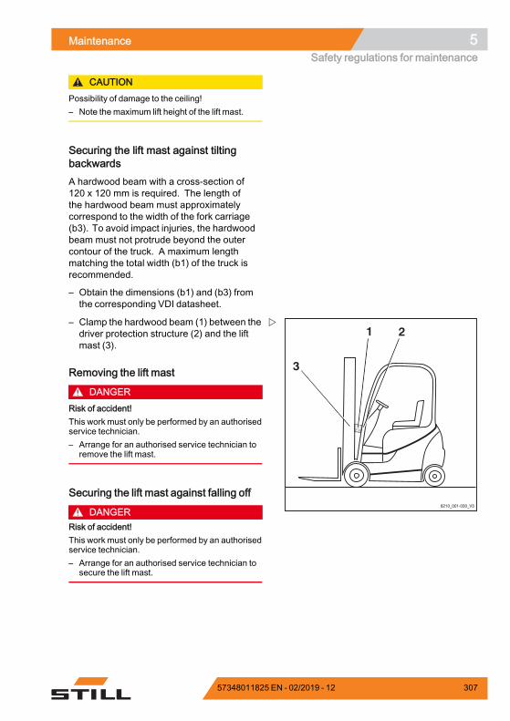
Maintenance 5Safety regulations for maintenance
CAUTIONPossibility of damage to the ceiling!– Note the maximum lift height of the lift mast.
Securing the lift mast against tiltingbackwardsA hardwood beam with a cross-section of120 x 120 mm is required. The length ofthe hardwood beam must approximatelycorrespond to the width of the fork carriage(b3). To avoid impact injuries, the hardwoodbeam must not protrude beyond the outercontour of the truck. A maximum lengthmatching the total width (b1) of the truck isrecommended.
– Obtain the dimensions (b1) and (b3) fromthe corresponding VDI datasheet.
1 2
3
6210_001-030_V3
– Clamp the hardwood beam (1) between thedriver protection structure (2) and the liftmast (3).
Removing the lift mast
DANGERRisk of accident!This work must only be performed by an authorisedservice technician.– Arrange for an authorised service technician to
remove the lift mast.
Securing the lift mast against falling off
DANGERRisk of accident!This work must only be performed by an authorisedservice technician.– Arrange for an authorised service technician to
secure the lift mast.
57348011825 EN - 02/2019 - 12 307
5 MaintenanceGeneral maintenance information
General maintenance informationPersonnel qualificationsOnly qualified and authorised personnel areallowed to perform maintenance work. Reg-ular safety checks and checks after unusualincidents must be performed by a competentperson. The competent person must conducttheir evaluation and assessment from a safetystandpoint, unaffected by operational andeconomic conditions. The competent personmust have sufficient knowledge and experi-ence to be able to assess the condition of atruck and the effectiveness of the protectivedevices in accordance with technical conven-tions and the principles for testing trucks.
Maintenance work without specialqualificationsSimple maintenance work, such as checkingthe hydraulic oil level, may be carried out byuntrained personnel. A qualification suchas those held by a competent person is notrequired to carry out this work. The requiredtasks are described in the chapter entitled"Remaining ready for operation".
Information for carrying out mainte-nanceThis section contains all information requiredto determine when the truck needs mainte-nance. Carry out maintenance work within thetime limits according to the hour meter andusing the following maintenance check lists.This is the only way to ensure that the truckremains ready for operation and provides op-timal performance and service life. It is also aprecondition for any warranty claims.
308 57348011825 EN - 02/2019 - 12
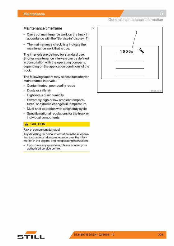
Maintenance 5General maintenance information
7312_003-156_V2
1Maintenance timeframe– Carry out maintenance work on the truck inaccordance with the "Service in" display (1).
– The maintenance check lists indicate themaintenance work that is due.
The intervals are defined for standard use.Shorter maintenance intervals can be definedin consultation with the operating company,depending on the application conditions of thetruck.
The following factors may necessitate shortermaintenance intervals:• Contaminated, poor quality roads• Dusty or salty air• High levels of air humidity• Extremely high or low ambient tempera-tures, or extreme changes in temperature
• Multi-shift operation with a high duty cycle• Specific national regulations for the truck orindividual components
CAUTIONRisk of component damage!Any deviating technical information in these opera-ting instructions takes precedence over the infor-mation in the original engine operating instructions.– If you have any questions, please contact your
authorised service centre.
57348011825 EN - 02/2019 - 12 309

5 MaintenanceGeneral maintenance information
310 57348011825 EN - 02/2019 - 12

Maintenance 5General maintenance information
Maintenance— 1000 hours/annuallyAt operating hours
1000 2000 4000 5000 7000 Carried out8000 10000 11000 13000 14000
Chassis, bodywork and fittings
Check chassis for cracks
Check overhead guard/cab and panes of glass for damage
Check controls, switches and joints for damage, and apply grease and oil
Check driver's seat for correct function and for damage
Check driver restraint system for correct function and for damage, and clean.
Check the signal horn
Variant: Check the dual pedal for damage and correct function, and lubricate
Tyres and wheels
Check the tyres for wear and check the air pressure if necessary
Check wheels for damage and check the tightening torques
Power unit
Check the screw joints and for leaks on the drive axle and clean the cooling fins
Check the oil level in the drive wheel unit and multi-disc brake
Internal combustion engine
Check the condition of the internal combustion engine (visual inspection)
Change the engine oil and replace the oil filter
Check the toothed belt, spur gears and V-belt
Replace the air filter (main cartridge)
Check the cooling system for leaks and correct function
Check coolant; top up if necessary
Check exhaust system
DEUTZ: Check the intercoolers, and remove lubricating oil and condensation water
VW: Replace the spark plugs
Maintain the particle filter
Fuel system
Check the fuel system for leaks and correct function
Check the fuel pre-filter (water trap) and drain water if necessary
57348011825 EN - 02/2019 - 12 311
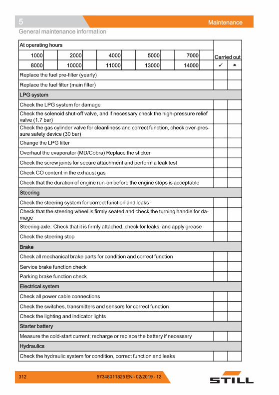
5 MaintenanceGeneral maintenance information
At operating hours
1000 2000 4000 5000 7000 Carried out8000 10000 11000 13000 14000
Replace the fuel pre-filter (yearly)
Replace the fuel filter (main filter)
LPG system
Check the LPG system for damageCheck the solenoid shut-off valve, and if necessary check the high-pressure reliefvalve (1.7 bar)Check the gas cylinder valve for cleanliness and correct function, check over-pres-sure safety device (30 bar)Change the LPG filter
Overhaul the evaporator (MD/Cobra) Replace the sticker
Check the screw joints for secure attachment and perform a leak test
Check CO content in the exhaust gas
Check that the duration of engine run-on before the engine stops is acceptable
Steering
Check the steering system for correct function and leaksCheck that the steering wheel is firmly seated and check the turning handle for da-mageSteering axle: Check that it is firmly attached, check for leaks, and apply grease
Check the steering stop
Brake
Check all mechanical brake parts for condition and correct function
Service brake function check
Parking brake function check
Electrical system
Check all power cable connections
Check the switches, transmitters and sensors for correct function
Check the lighting and indicator lights
Starter battery
Measure the cold-start current; recharge or replace the battery if necessary
Hydraulics
Check the hydraulic system for condition, correct function and leaks
312 57348011825 EN - 02/2019 - 12
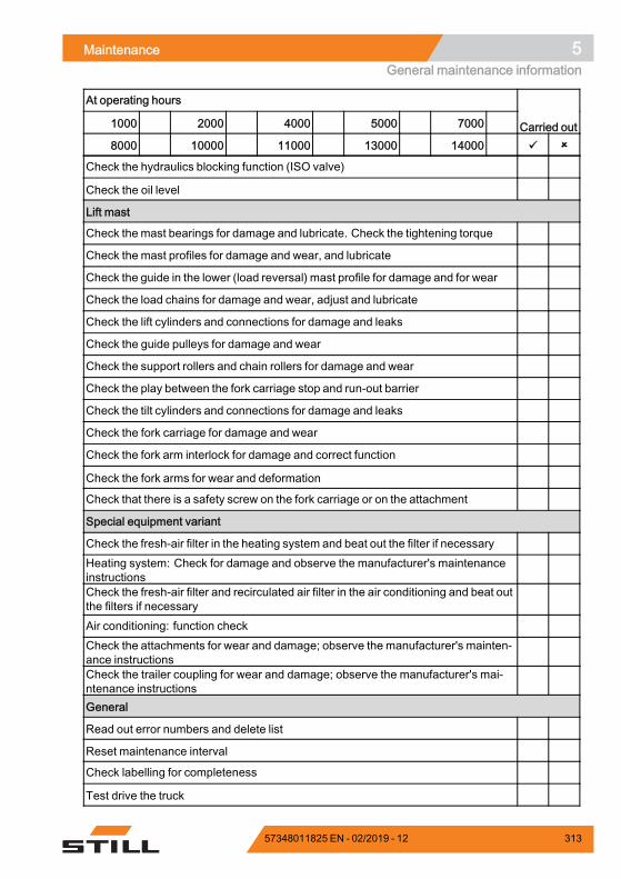
Maintenance 5General maintenance information
At operating hours
1000 2000 4000 5000 7000 Carried out8000 10000 11000 13000 14000
Check the hydraulics blocking function (ISO valve)
Check the oil level
Lift mast
Check the mast bearings for damage and lubricate. Check the tightening torque
Check the mast profiles for damage and wear, and lubricate
Check the guide in the lower (load reversal) mast profile for damage and for wear
Check the load chains for damage and wear, adjust and lubricate
Check the lift cylinders and connections for damage and leaks
Check the guide pulleys for damage and wear
Check the support rollers and chain rollers for damage and wear
Check the play between the fork carriage stop and run-out barrier
Check the tilt cylinders and connections for damage and leaks
Check the fork carriage for damage and wear
Check the fork arm interlock for damage and correct function
Check the fork arms for wear and deformation
Check that there is a safety screw on the fork carriage or on the attachment
Special equipment variant
Check the fresh-air filter in the heating system and beat out the filter if necessaryHeating system: Check for damage and observe the manufacturer's maintenanceinstructionsCheck the fresh-air filter and recirculated air filter in the air conditioning and beat outthe filters if necessaryAir conditioning: function checkCheck the attachments for wear and damage; observe the manufacturer's mainten-ance instructionsCheck the trailer coupling for wear and damage; observe the manufacturer's mai-ntenance instructionsGeneral
Read out error numbers and delete list
Reset maintenance interval
Check labelling for completeness
Test drive the truck
57348011825 EN - 02/2019 - 12 313

5 MaintenanceGeneral maintenance information
314 57348011825 EN - 02/2019 - 12
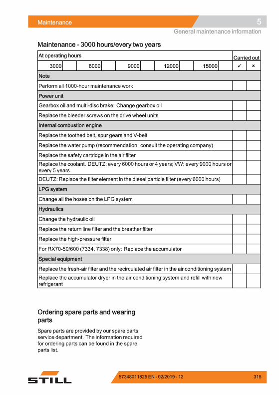
Maintenance 5General maintenance information
Maintenance - 3000 hours/every two yearsAt operating hours Carried out
3000 6000 9000 12000 15000
Note
Perform all 1000-hour maintenance work
Power unit
Gearbox oil and multi-disc brake: Change gearbox oil
Replace the bleeder screws on the drive wheel units
Internal combustion engine
Replace the toothed belt, spur gears and V-belt
Replace the water pump (recommendation: consult the operating company)
Replace the safety cartridge in the air filterReplace the coolant. DEUTZ: every 6000 hours or 4 years; VW: every 9000 hours orevery 5 yearsDEUTZ: Replace the filter element in the diesel particle filter (every 6000 hours)
LPG system
Change all the hoses on the LPG system
Hydraulics
Change the hydraulic oil
Replace the return line filter and the breather filter
Replace the high-pressure filter
For RX70-50/600 (7334, 7338) only: Replace the accumulator
Special equipment
Replace the fresh-air filter and the recirculated air filter in the air conditioning systemReplace the accumulator dryer in the air conditioning system and refill with newrefrigerant
Ordering spare parts and wearingpartsSpare parts are provided by our spare partsservice department. The information requiredfor ordering parts can be found in the spareparts list.
57348011825 EN - 02/2019 - 12 315
5 MaintenanceGeneral maintenance information
Only use spare parts as per the manufac-turer's instructions. The use of unapprovedspare parts can result in an increased risk ofaccidents due to insufficient quality or incor-rect assignment. Anyone using unapprovedspare parts shall assume unlimited liability inthe event of damage or harm.
Quality and quantity of the requiredoperating materialsOnly the operating materials specified in themaintenance data table may be used.
– The required consumables and lubricantscan be found in themaintenance data table.
Oil and grease types of a different qualitymust not be mixed. This negatively affectsthe lubricity. If a change between differentmanufacturers cannot be avoided, drain theold oil thoroughly.
Before carrying out lubricating work, filterchanges or any work on the hydraulic system,carefully clean the area around the partinvolved.
When topping up working materials, use onlyclean containers!
316 57348011825 EN - 02/2019 - 12
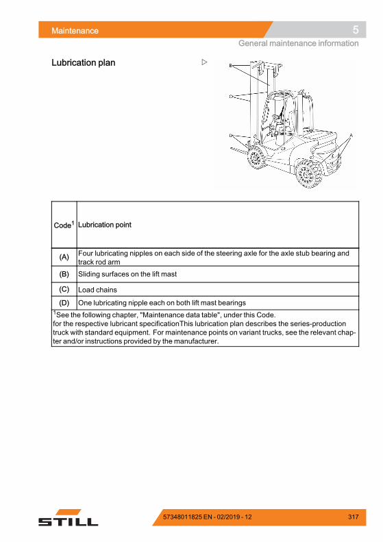
Maintenance 5General maintenance information
Lubrication plan
Code1 Lubrication point
(A) Four lubricating nipples on each side of the steering axle for the axle stub bearing andtrack rod arm
(B) Sliding surfaces on the lift mast
(C) Load chains
(D) One lubricating nipple each on both lift mast bearings1See the following chapter, "Maintenance data table", under this Code.for the respective lubricant specificationThis lubrication plan describes the series-productiontruck with standard equipment. For maintenance points on variant trucks, see the relevant chap-ter and/or instructions provided by the manufacturer.
.
57348011825 EN - 02/2019 - 12 317
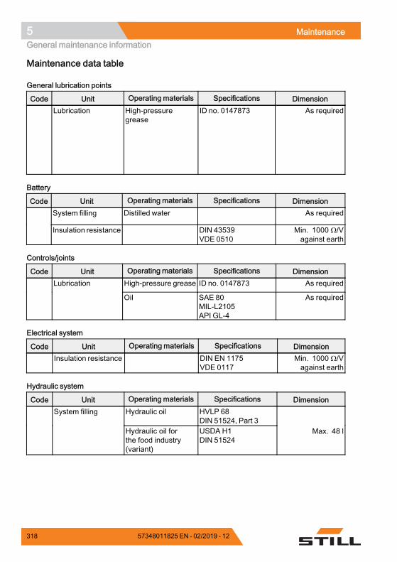
5 MaintenanceGeneral maintenance information
Maintenance data table
General lubrication points
Code Unit Operating materials Specifications DimensionLubrication High-pressure
greaseID no. 0147873 As required
Battery
Code Unit Operating materials Specifications DimensionSystem filling Distilled water As required
Insulation resistance DIN 43539VDE 0510
Min. 1000 Ω/Vagainst earth
Controls/joints
Code Unit Operating materials Specifications DimensionHigh-pressure grease ID no. 0147873 As requiredLubrication
Oil SAE 80MIL-L2105API GL-4
As required
Electrical system
Code Unit Operating materials Specifications DimensionInsulation resistance DIN EN 1175
VDE 0117Min. 1000 Ω/Vagainst earth
Hydraulic system
Code Unit Operating materials Specifications DimensionHydraulic oil HVLP 68
DIN 51524, Part 3System filling
Hydraulic oil forthe food industry(variant)
USDA H1DIN 51524
Max. 48 l
318 57348011825 EN - 02/2019 - 12
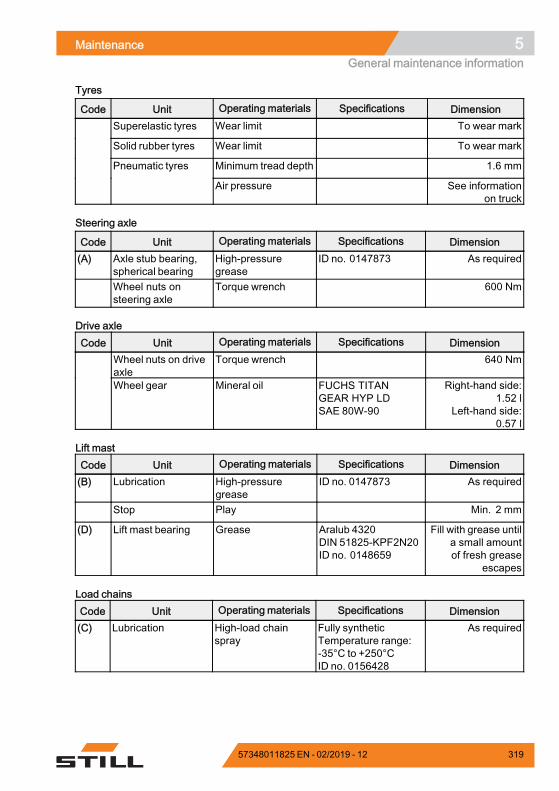
Maintenance 5General maintenance information
Tyres
Code Unit Operating materials Specifications DimensionSuperelastic tyres Wear limit To wear mark
Solid rubber tyres Wear limit To wear mark
Minimum tread depth 1.6 mmPneumatic tyres
Air pressure See informationon truck
Steering axle
Code Unit Operating materials Specifications Dimension(A) Axle stub bearing,
spherical bearingHigh-pressuregrease
ID no. 0147873 As required
Wheel nuts onsteering axle
Torque wrench 600 Nm
Drive axleCode Unit Operating materials Specifications Dimension
Wheel nuts on driveaxle
Torque wrench 640 Nm
Wheel gear Mineral oil FUCHS TITANGEAR HYP LDSAE 80W-90
Right-hand side:1.52 l
Left-hand side:0.57 l
Lift mastCode Unit Operating materials Specifications Dimension(B) Lubrication High-pressure
greaseID no. 0147873 As required
Stop Play Min. 2 mm
(D) Lift mast bearing Grease Aralub 4320DIN 51825-KPF2N20ID no. 0148659
Fill with grease untila small amountof fresh grease
escapes
Load chainsCode Unit Operating materials Specifications Dimension(C) Lubrication High-load chain
sprayFully syntheticTemperature range:-35°C to +250°CID no. 0156428
As required
57348011825 EN - 02/2019 - 12 319
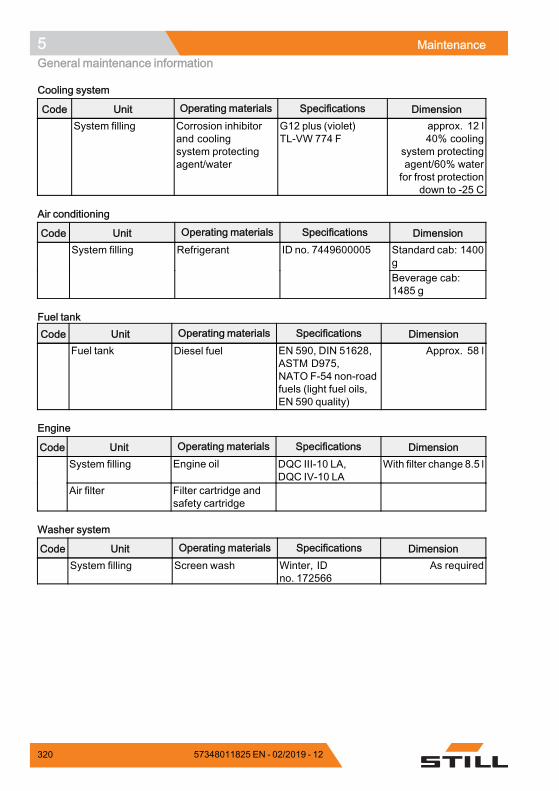
5 MaintenanceGeneral maintenance information
Cooling system
Code Unit Operating materials Specifications DimensionSystem filling Corrosion inhibitor
and coolingsystem protectingagent/water
G12 plus (violet)TL-VW 774 F
approx. 12 l40% cooling
system protectingagent/60% waterfor frost protection
down to -25 C
Air conditioning
Code Unit Operating materials Specifications DimensionStandard cab: 1400g
System filling Refrigerant ID no. 7449600005
Beverage cab:1485 g
Fuel tankCode Unit Operating materials Specifications Dimension
Fuel tank Diesel fuel EN 590, DIN 51628,ASTM D975,NATO F-54 non-roadfuels (light fuel oils,EN 590 quality)
Approx. 58 l
Engine
Code Unit Operating materials Specifications DimensionSystem filling Engine oil DQC III-10 LA,
DQC IV-10 LAWith filter change 8.5 l
Air filter Filter cartridge andsafety cartridge
Washer system
Code Unit Operating materials Specifications DimensionSystem filling Screen wash Winter, ID
no. 172566As required
.
320 57348011825 EN - 02/2019 - 12
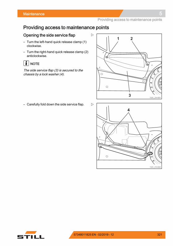
Maintenance 5Providing access to maintenance points
Providing access to maintenance points
7331_314-001
1
3
2Opening the side service flap– Turn the left-hand quick release clamp (1)clockwise.
– Turn the right-hand quick release clamp (2)anticlockwise.
NOTE
The side service flap (3) is secured to thechassis by a lock washer (4).
7331_314-002
4
– Carefully fold down the side service flap.
57348011825 EN - 02/2019 - 12 321
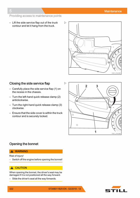
5 MaintenanceProviding access to maintenance points
7331_314-003
– Lift the side service flap out of the truckcontour and let it hang from the truck.
7331_314-004
2
1
3Closing the side service flap– Carefully place the side service flap (1) onthe recess in the chassis.
– Turn the left-hand quick release clamp (2)anticlockwise.
– Turn the right-hand quick release clamp (3)clockwise.
– Ensure that the side cover is within the truckcontour and is securely locked.
Opening the bonnet
WARNINGRisk of injury!– Switch off the engine before opening the bonnet!
CAUTIONWhen opening the bonnet, the driver's seat may bedamaged if it is not positioned all the way forward.– Slide the driver's seat all the way forwards.
322 57348011825 EN - 02/2019 - 12
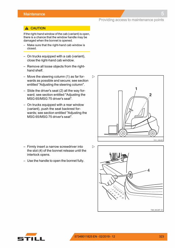
Maintenance 5Providing access to maintenance points
CAUTIONIf the right-handwindow of the cab (variant) is open,there is a chance that the window handle may bedamaged when the bonnet is opened.– Make sure that the right-hand cab window is
closed.
– On trucks equipped with a cab (variant),close the right-hand cab window.
– Remove all loose objects from the right-hand shelf.
7311_120-001
1
2
– Move the steering column (1) as far for-wards as possible and secure; see sectionentitled "Adjusting the steering column".
– Slide the driver's seat (2) all the way for-ward; see section entitled "Adjusting theMSG 65/MSG 75 driver's seat".
– On trucks equipped with a rear window(variant), push the seat backrest for-wards; see section entitled "Adjusting theMSG 65/MSG 75 driver's seat".
7300_003-007_V2
4
– Firmly insert a narrow screwdriver intothe slot (4) of the bonnet release until theinterlock opens.
– Use the handle to open the bonnet fully.
57348011825 EN - 02/2019 - 12 323
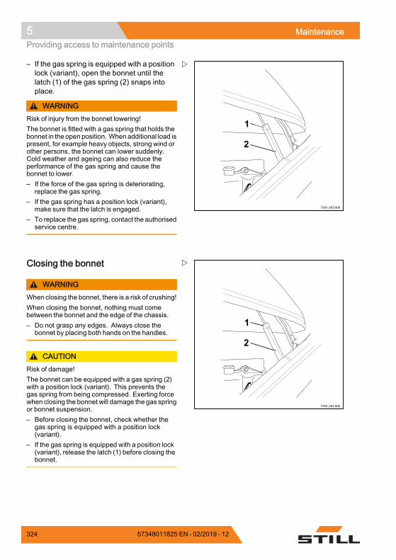
5 MaintenanceProviding access to maintenance points
7300_003-008
2
1
– If the gas spring is equipped with a positionlock (variant), open the bonnet until thelatch (1) of the gas spring (2) snaps intoplace.
WARNINGRisk of injury from the bonnet lowering!The bonnet is fitted with a gas spring that holds thebonnet in the open position. When additional load ispresent, for example heavy objects, strong wind orother persons, the bonnet can lower suddenly.Cold weather and ageing can also reduce theperformance of the gas spring and cause thebonnet to lower.– If the force of the gas spring is deteriorating,
replace the gas spring.– If the gas spring has a position lock (variant),
make sure that the latch is engaged.– To replace the gas spring, contact the authorised
service centre.
7300_003-008
2
1
Closing the bonnet
WARNINGWhen closing the bonnet, there is a risk of crushing!When closing the bonnet, nothing must comebetween the bonnet and the edge of the chassis.– Do not grasp any edges. Always close the
bonnet by placing both hands on the handles.
CAUTIONRisk of damage!The bonnet can be equipped with a gas spring (2)with a position lock (variant). This prevents thegas spring from being compressed. Exerting forcewhen closing the bonnet will damage the gas springor bonnet suspension.– Before closing the bonnet, check whether the
gas spring is equipped with a position lock(variant).
– If the gas spring is equipped with a position lock(variant), release the latch (1) before closing thebonnet.
324 57348011825 EN - 02/2019 - 12
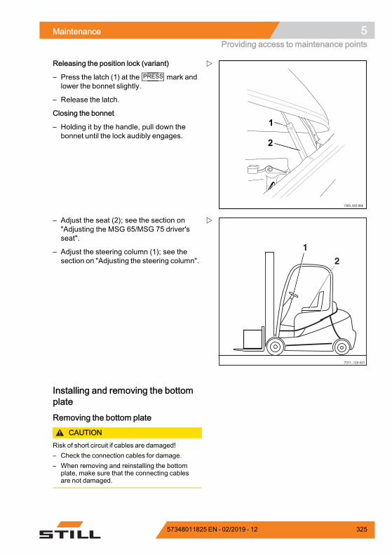
Maintenance 5Providing access to maintenance points
7300_003-008
2
1
Releasing the position lock (variant)
– Press the latch (1) at the PRESS mark andlower the bonnet slightly.
– Release the latch.
Closing the bonnet
– Holding it by the handle, pull down thebonnet until the lock audibly engages.
7311_120-001
1
2
– Adjust the seat (2); see the section on"Adjusting the MSG 65/MSG 75 driver'sseat".
– Adjust the steering column (1); see thesection on "Adjusting the steering column".
Installing and removing the bottomplate
Removing the bottom plate
CAUTIONRisk of short circuit if cables are damaged!– Check the connection cables for damage.– When removing and reinstalling the bottom
plate, make sure that the connecting cablesare not damaged.
57348011825 EN - 02/2019 - 12 325
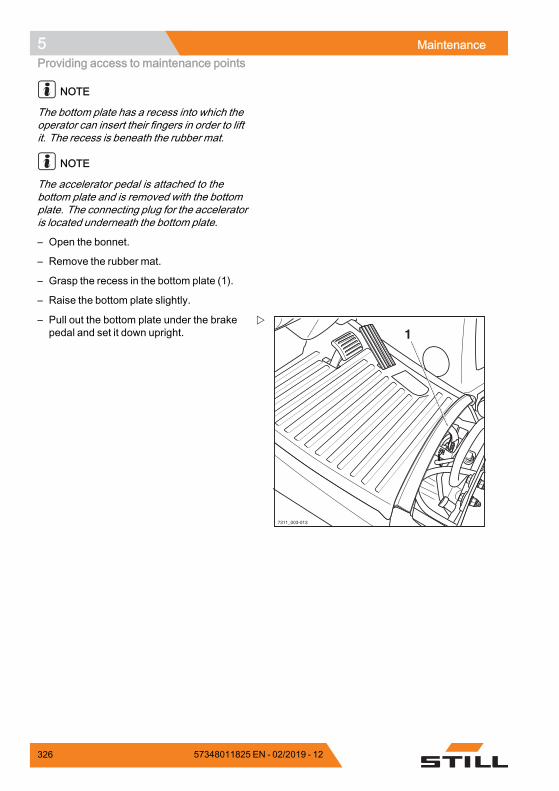
5 MaintenanceProviding access to maintenance points
NOTE
The bottom plate has a recess into which theoperator can insert their fingers in order to liftit. The recess is beneath the rubber mat.
NOTE
The accelerator pedal is attached to thebottom plate and is removed with the bottomplate. The connecting plug for the acceleratoris located underneath the bottom plate.
– Open the bonnet.
– Remove the rubber mat.
– Grasp the recess in the bottom plate (1).
– Raise the bottom plate slightly.
7311_003-013
1– Pull out the bottom plate under the brakepedal and set it down upright.
326 57348011825 EN - 02/2019 - 12
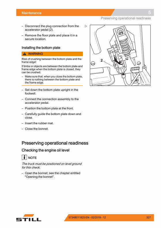
Maintenance 5Preserving operational readiness
7311_003-014
2
– Disconnect the plug connection from theaccelerator pedal (2).
– Remove the floor plate and place it in asecure location.
Installing the bottom plate
WARNINGRisk of crushing between the bottom plate and theframe edge!If limbs or objects are between the bottom plate andframe edge when the bottom plate is closed, theycan be crushed.– Make sure that, when you close the bottom plate,
there is nothing between the bottom plate andthe frame edge.
– Set down the bottom plate upright in thefootwell.
– Connect the connection assembly to theaccelerator pedal.
– Position the bottom plate at the front.
– Carefully guide the bottom plate down andclose.
– Insert the rubber mat.
– Close the bonnet.
Preserving operational readinessChecking the engine oil level
NOTE
The truck must be positioned on level groundfor this check.
– Open the bonnet; see the chapter entitled"Opening the bonnet".
57348011825 EN - 02/2019 - 12 327
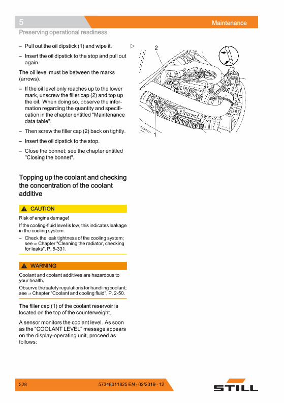
5 MaintenancePreserving operational readiness
– Pull out the oil dipstick (1) and wipe it.
– Insert the oil dipstick to the stop and pull outagain.
The oil level must be between the marks(arrows).
– If the oil level only reaches up to the lowermark, unscrew the filler cap (2) and top upthe oil. When doing so, observe the infor-mation regarding the quantity and specifi-cation in the chapter entitled "Maintenancedata table".
– Then screw the filler cap (2) back on tightly.
– Insert the oil dipstick to the stop.
– Close the bonnet; see the chapter entitled"Closing the bonnet".
Topping up the coolant and checkingthe concentration of the coolantadditive
CAUTIONRisk of engine damage!If the cooling-fluid level is low, this indicates leakagein the cooling system.– Check the leak tightness of the cooling system;
see ⇒ Chapter "Cleaning the radiator, checkingfor leaks", P. 5-331.
WARNINGCoolant and coolant additives are hazardous toyour health.Observe the safety regulations for handling coolant;see ⇒ Chapter "Coolant and cooling fluid", P. 2-50.
The filler cap (1) of the coolant reservoir islocated on the top of the counterweight.
A sensor monitors the coolant level. As soonas the "COOLANT LEVEL" message appearson the display-operating unit, proceed asfollows:
328 57348011825 EN - 02/2019 - 12
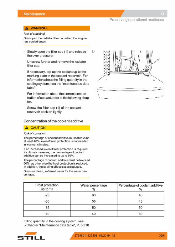
Maintenance 5Preserving operational readiness
WARNINGRisk of scalding!Only open the radiator filler cap when the enginehas cooled down.
– Slowly open the filler cap (1) and releasethe over pressure.
– Unscrew further and remove the radiatorfiller cap.
– If necessary, top up the coolant up to themarking plate in the coolant reservoir. Forinformation about the filling quantity in thecooling system, see the "maintenance datatable".
– For information about the correct concen-trationof coolant, refer to the following chap-ter.
– Screw the filler cap (1) of the coolantreservoir back on tightly.
Concentration of the coolant additive
CAUTIONRisk of corrosion!The percentage of coolant additive must always beat least 40%, even if frost protection is not neededin warmer climates.If an increased level of frost protection is requiredfor climatic reasons, the percentage of coolantadditive can be increased to up to 60%.Thepercentage of coolant additivemust not exceed60%, as otherwise the frost protection is reduced.In addition, the cooling effect is also reduced.Only use clean, softened water for the water per-centage.
Frost protectionup to °C
Water percentage%
Percentage of coolant additive%
-25 60 40
-30 55 45
-35 50 50
-40 40 60
Filling quantity in the cooling system; see⇒Chapter "Maintenance data table", P. 5-318.
57348011825 EN - 02/2019 - 12 329
5 MaintenancePreserving operational readiness
CAUTIONCoolant additive with a different specification mustnot be added!– Top up using coolant additive and corrosion
inhibitor in accordance with the maintenancedata table; see ⇒ Chapter "Maintenance datatable", P. 5-318.
Only use coolant additive according to the manu-facturer's guidelines.
330 57348011825 EN - 02/2019 - 12
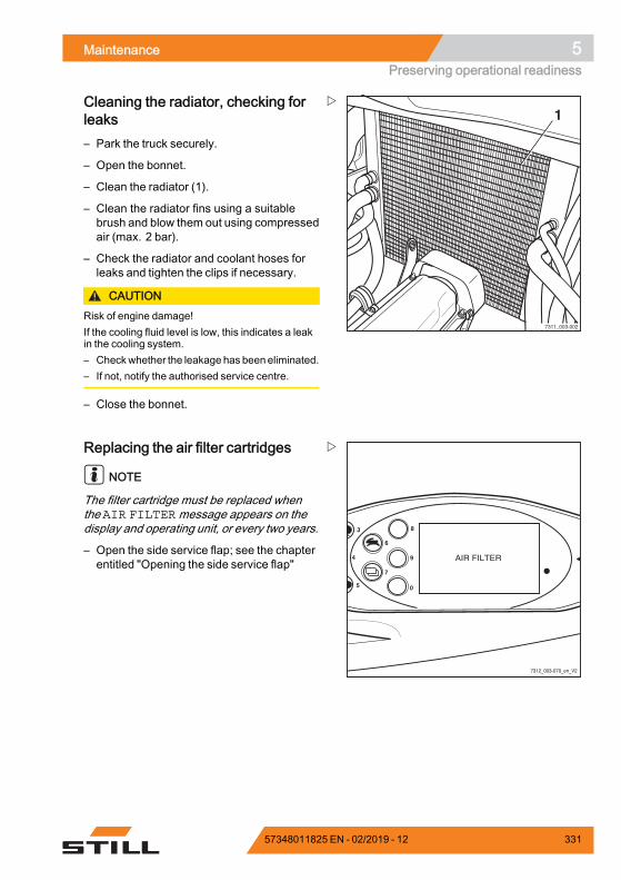
Maintenance 5Preserving operational readiness
7311_003-002
1Cleaning the radiator, checking forleaks– Park the truck securely.
– Open the bonnet.
– Clean the radiator (1).
– Clean the radiator fins using a suitablebrush and blow them out using compressedair (max. 2 bar).
– Check the radiator and coolant hoses forleaks and tighten the clips if necessary.
CAUTIONRisk of engine damage!If the cooling fluid level is low, this indicates a leakin the cooling system.– Checkwhether the leakage has beeneliminated.– If not, notify the authorised service centre.
– Close the bonnet.
8
9
0
6
7
4
3
5
7312_003-070_en_V2
Replacing the air filter cartridges
NOTE
The filter cartridge must be replaced whenthe AIR FILTERmessage appears on thedisplay and operating unit, or every two years.
– Open the side service flap; see the chapterentitled "Opening the side service flap"
57348011825 EN - 02/2019 - 12 331
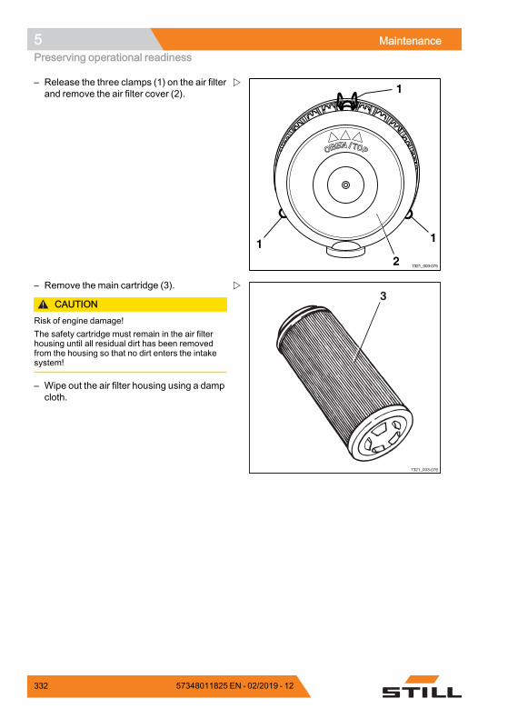
5 MaintenancePreserving operational readiness
7321_003-075
1
112
– Release the three clamps (1) on the air filterand remove the air filter cover (2).
3
7321_003-076
– Remove the main cartridge (3).
CAUTIONRisk of engine damage!The safety cartridge must remain in the air filterhousing until all residual dirt has been removedfrom the housing so that no dirt enters the intakesystem!
– Wipe out the air filter housing using a dampcloth.
332 57348011825 EN - 02/2019 - 12
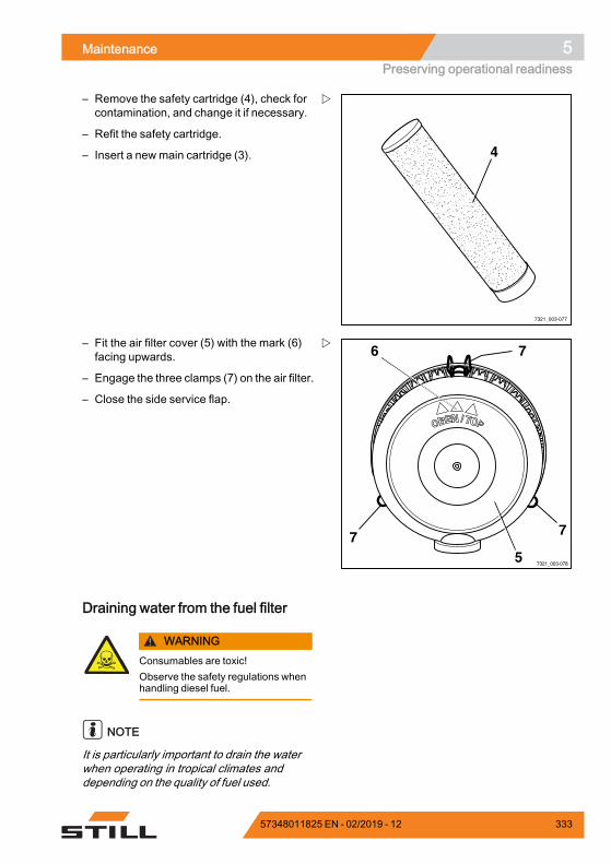
Maintenance 5Preserving operational readiness
4
7321_003-077
– Remove the safety cartridge (4), check forcontamination, and change it if necessary.
– Refit the safety cartridge.
– Insert a newmain cartridge (3).
7321_003-078
7
77
6
5
– Fit the air filter cover (5) with the mark (6)facing upwards.
– Engage the three clamps (7) on the air filter.
– Close the side service flap.
Draining water from the fuel filter
WARNINGConsumables are toxic!Observe the safety regulations whenhandling diesel fuel.
NOTE
It is particularly important to drain the waterwhen operating in tropical climates anddepending on the quality of fuel used.
57348011825 EN - 02/2019 - 12 333
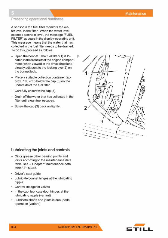
5 MaintenancePreserving operational readiness
A sensor in the fuel filter monitors the wa-ter level in the filter. When the water levelexceeds a certain level, the message "FUELFILTER" appears in the display-operating unit.This message means that the water that hascollected in the fuel filter needs to be drained.To do this, proceed as follows:
– Open the bonnet. The fuel filter (1) is lo-cated in the front left of the engine compart-ment (when viewed in the drive direction),directly adjacent to the locking eye (2) onthe bonnet lock.
– Place a suitable collection container (ap-prox. 100 cm³) below the cap (3) on theunderside of the fuel filter.
– Carefully unscrew the cap (3).
– Drain off the water that has collected in thefilter until clean fuel escapes.
– Screw the cap (3) back on tightly.
Lubricating the joints and controls– Oil or grease other bearing points andjoints according to the maintenance datatable; see ⇒ Chapter "Maintenance datatable", P. 5-318.
• Driver's seat guide• Lubricate bonnet hinges at the lubricatingnipple
• Control linkage for valves• In the cab, lubricate door hinges at thelubricating nipple (variant)
• Lubricate shafts and joints in dual-pedaloperation (variant)
334 57348011825 EN - 02/2019 - 12
Maintenance 5Preserving operational readiness
Checking the door latch– Inspect the condition of the catch bolt andcheck for wear.
– Check the lock mechanism for easy opera-tion.
Maintaining the seat belt
DANGERThere is a risk to life if the seat belt fails during anaccident!If the seat belt is faulty, it may tear or open duringan accident and no longer keep the driver in thedriver's seat. The driver may therefore be hurledagainst the truck components or out of the truck.– Ensure operational reliability by continually
testing.– Do not use a truck with a defective seat belt.– Only have a defective belt replaced by your
service centre.– Only use genuine spare parts.– Do not make any changes to the belt.
NOTE
Carry out the following checks on a regularbasis (monthly). In the case of significantstrain, a daily check is necessary.
57348011825 EN - 02/2019 - 12 335
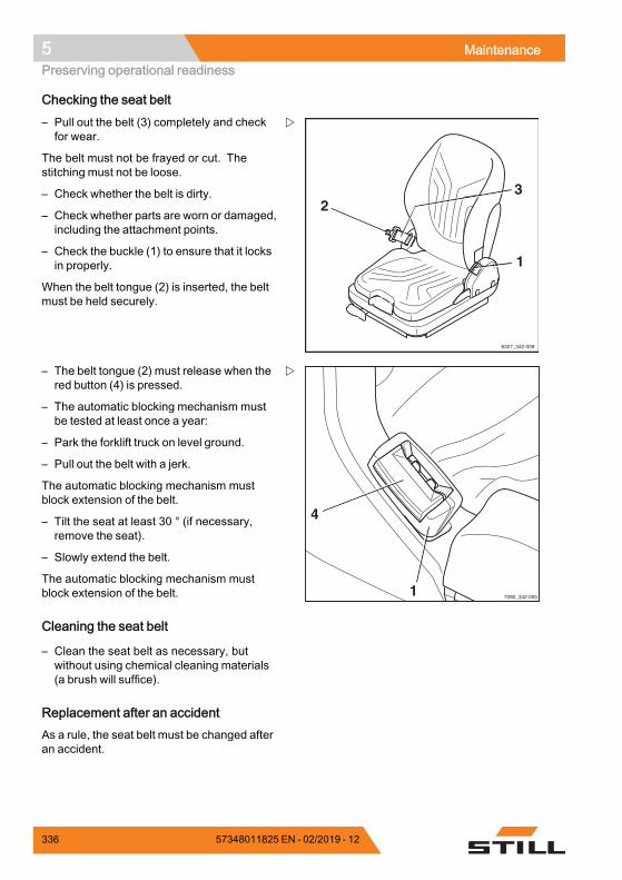
5 MaintenancePreserving operational readiness
Checking the seat belt
6327_342-009
1
23
– Pull out the belt (3) completely and checkfor wear.
The belt must not be frayed or cut. Thestitching must not be loose.
– Check whether the belt is dirty.
– Check whether parts are worn or damaged,including the attachment points.
– Check the buckle (1) to ensure that it locksin properly.
When the belt tongue (2) is inserted, the beltmust be held securely.
7090_342-0051
4
– The belt tongue (2) must release when thered button (4) is pressed.
– The automatic blocking mechanism mustbe tested at least once a year:
– Park the forklift truck on level ground.
– Pull out the belt with a jerk.
The automatic blocking mechanism mustblock extension of the belt.
– Tilt the seat at least 30 ° (if necessary,remove the seat).
– Slowly extend the belt.
The automatic blocking mechanism mustblock extension of the belt.
Cleaning the seat belt
– Clean the seat belt as necessary, butwithout using chemical cleaning materials(a brush will suffice).
Replacement after an accidentAs a rule, the seat belt must be changed afteran accident.
336 57348011825 EN - 02/2019 - 12
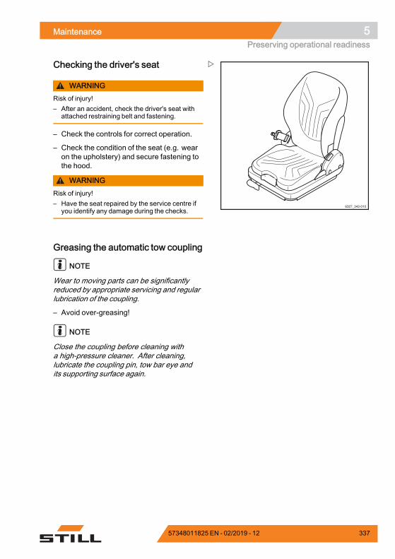
Maintenance 5Preserving operational readiness
6327_342-010
Checking the driver's seat
WARNINGRisk of injury!– After an accident, check the driver's seat with
attached restraining belt and fastening.
– Check the controls for correct operation.
– Check the condition of the seat (e.g. wearon the upholstery) and secure fastening tothe hood.
WARNINGRisk of injury!– Have the seat repaired by the service centre if
you identify any damage during the checks.
Greasing the automatic tow coupling
NOTE
Wear to moving parts can be significantlyreduced by appropriate servicing and regularlubrication of the coupling.
– Avoid over-greasing!
NOTE
Close the coupling before cleaning witha high-pressure cleaner. After cleaning,lubricate the coupling pin, tow bar eye andits supporting surface again.
57348011825 EN - 02/2019 - 12 337
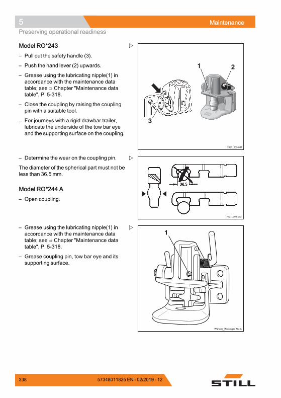
5 MaintenancePreserving operational readiness
3
7321_003-091
21
Model RO*243– Pull out the safety handle (3).
– Push the hand lever (2) upwards.
– Grease using the lubricating nipple(1) inaccordance with the maintenance datatable; see ⇒ Chapter "Maintenance datatable", P. 5-318.
– Close the coupling by raising the couplingpin with a suitable tool.
– For journeys with a rigid drawbar trailer,lubricate the underside of the tow bar eyeand the supporting surface on the coupling.
7321_003-092
– Determine the wear on the coupling pin.
The diameter of the spherical part must not beless than 36.5 mm.
Model RO*244 A– Open coupling.
Wartung_Rockinger 244 A
1– Grease using the lubricating nipple(1) inaccordance with the maintenance datatable; see ⇒ Chapter "Maintenance datatable", P. 5-318.
– Grease coupling pin, tow bar eye and itssupporting surface.
338 57348011825 EN - 02/2019 - 12
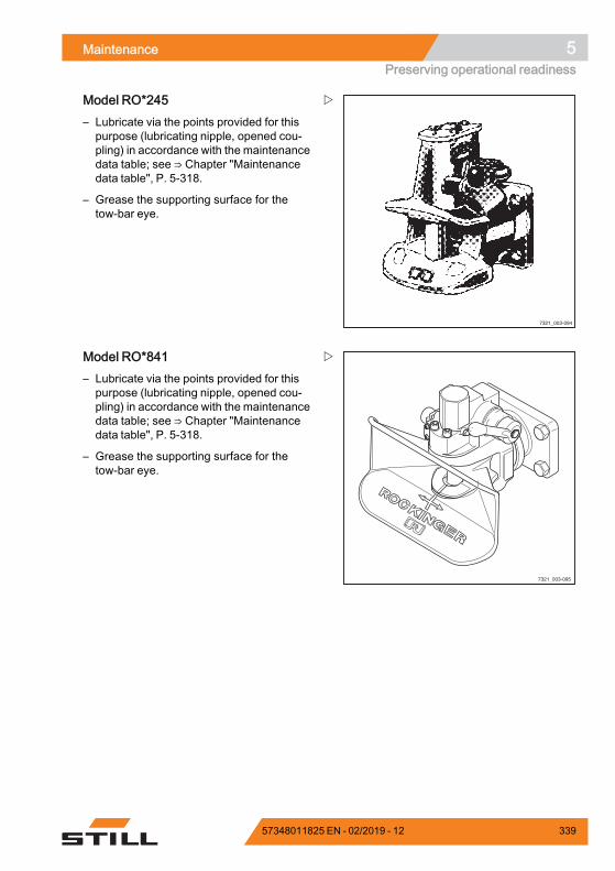
Maintenance 5Preserving operational readiness
7321_003-094
Model RO*245– Lubricate via the points provided for thispurpose (lubricating nipple, opened cou-pling) in accordance with the maintenancedata table; see ⇒ Chapter "Maintenancedata table", P. 5-318.
– Grease the supporting surface for thetow-bar eye.
7321_003-095
Model RO*841– Lubricate via the points provided for thispurpose (lubricating nipple, opened cou-pling) in accordance with the maintenancedata table; see ⇒ Chapter "Maintenancedata table", P. 5-318.
– Grease the supporting surface for thetow-bar eye.
57348011825 EN - 02/2019 - 12 339
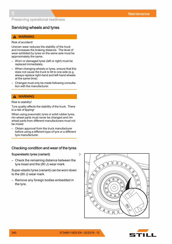
5 MaintenancePreserving operational readiness
Servicing wheels and tyres
WARNINGRisk of accident!Uneven wear reduces the stability of the truckand increases the braking distance. The level ofwear exhibited by tyres on the same axle must beapproximately the same.– Worn or damaged tyres (left or right) must be
replaced immediately.– When changing wheels or tyres, ensure that this
does not cause the truck to tilt to one side (e.g.always replace right-hand and left-hand wheelsat the same time).
– Changes must only be made following consulta-tion with the manufacturer.
WARNINGRisk to stability!Tyre quality affects the stability of the truck. Thereis a risk of tipping!When using pneumatic tyres or solid rubber tyres,rim wheel parts must never be changed and rimwheel parts from different manufacturers must notbe mixed.– Obtain approval from the truck manufacturer
before using a different type of tyre or a differenttyre manufacturer.
Checking condition and wear of the tyres
60 J
60 J
Superelastic tyres (variant)
– Check the remaining distance between thetyre tread and the (60 J) wear mark.
Super-elastic tyres (variant) can beworn downto the (60 J) wear mark.
– Remove any foreign bodies embedded inthe tyre.
340 57348011825 EN - 02/2019 - 12
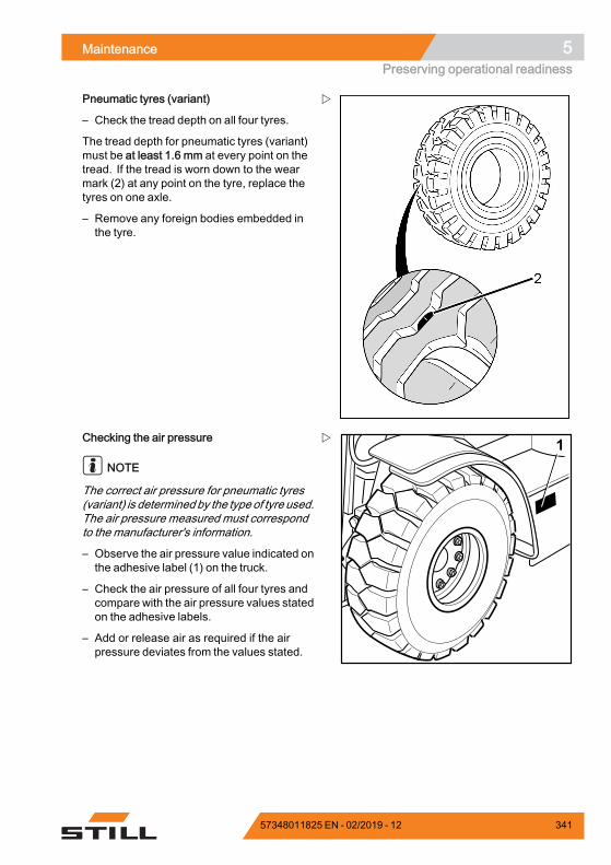
Maintenance 5Preserving operational readiness
Pneumatic tyres (variant)
– Check the tread depth on all four tyres.
The tread depth for pneumatic tyres (variant)must be at least 1.6 mm at every point on thetread. If the tread is worn down to the wearmark (2) at any point on the tyre, replace thetyres on one axle.
– Remove any foreign bodies embedded inthe tyre.
1Checking the air pressure
NOTE
The correct air pressure for pneumatic tyres(variant) is determinedby the type of tyre used.The air pressure measured must correspondto the manufacturer's information.
– Observe the air pressure value indicated onthe adhesive label (1) on the truck.
– Check the air pressure of all four tyres andcompare with the air pressure values statedon the adhesive labels.
– Add or release air as required if the airpressure deviates from the values stated.
57348011825 EN - 02/2019 - 12 341
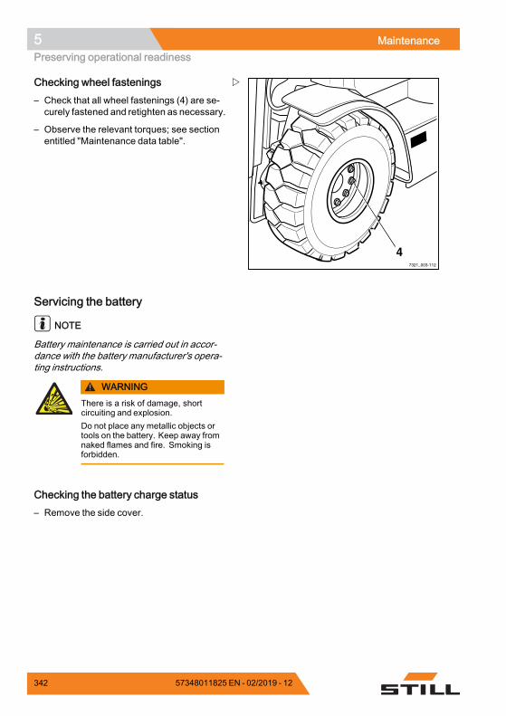
5 MaintenancePreserving operational readiness
47321_003-112
Checking wheel fastenings– Check that all wheel fastenings (4) are se-curely fastened and retighten as necessary.
– Observe the relevant torques; see sectionentitled "Maintenance data table".
Servicing the battery
NOTE
Battery maintenance is carried out in accor-dance with the battery manufacturer's opera-ting instructions.
WARNINGThere is a risk of damage, shortcircuiting and explosion.Do not place any metallic objects ortools on the battery. Keep away fromnaked flames and fire. Smoking isforbidden.
Checking the battery charge status– Remove the side cover.
342 57348011825 EN - 02/2019 - 12
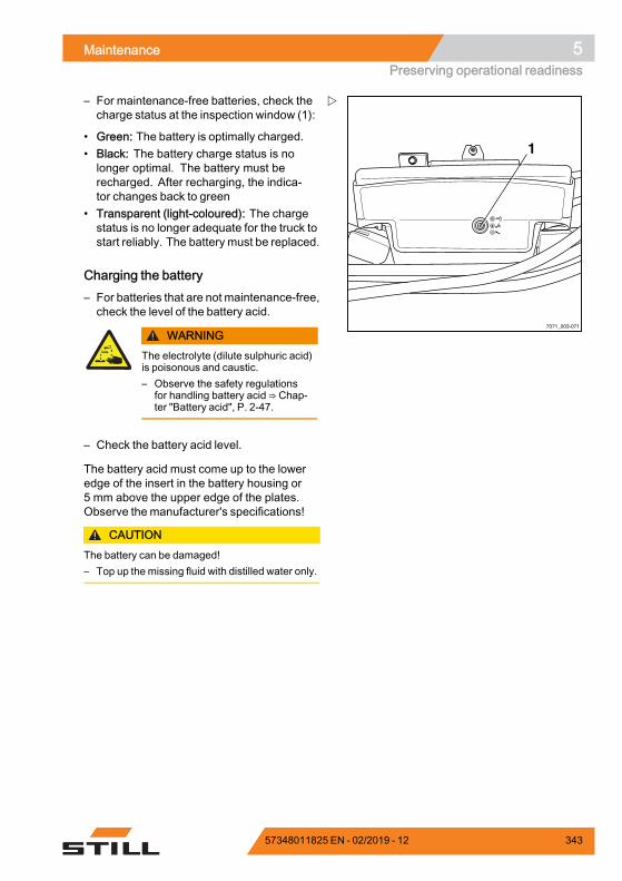
Maintenance 5Preserving operational readiness
7071_003-071
1
– For maintenance-free batteries, check thecharge status at the inspection window (1):
• Green: The battery is optimally charged.• Black: The battery charge status is nolonger optimal. The battery must berecharged. After recharging, the indica-tor changes back to green
• Transparent (light-coloured): The chargestatus is no longer adequate for the truck tostart reliably. The battery must be replaced.
Charging the battery– For batteries that are not maintenance-free,check the level of the battery acid.
WARNINGThe electrolyte (dilute sulphuric acid)is poisonous and caustic.– Observe the safety regulations
for handling battery acid ⇒ Chap-ter "Battery acid", P. 2-47.
– Check the battery acid level.
The battery acid must come up to the loweredge of the insert in the battery housing or5 mm above the upper edge of the plates.Observe the manufacturer's specifications!
CAUTIONThe battery can be damaged!– Top up the missing fluid with distilled water only.
57348011825 EN - 02/2019 - 12 343
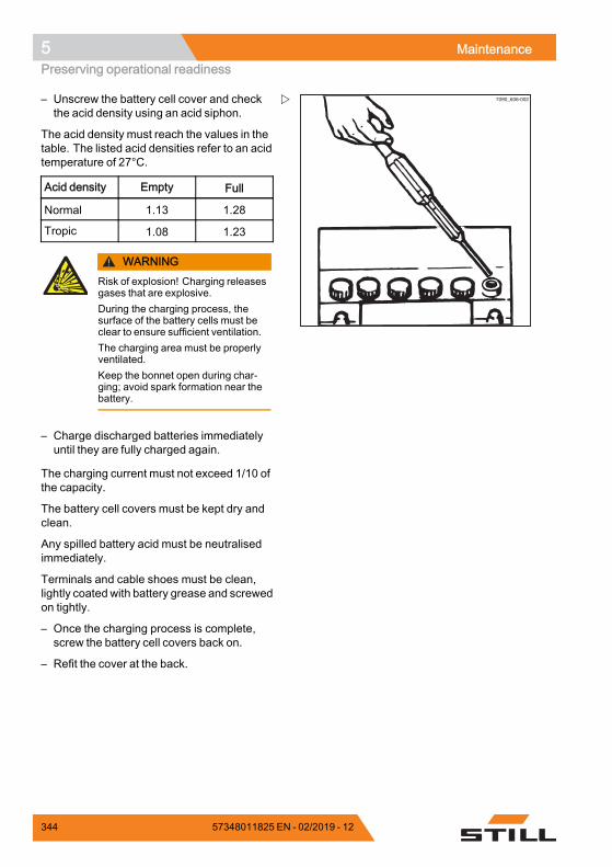
5 MaintenancePreserving operational readiness
7090_606-002– Unscrew the battery cell cover and checkthe acid density using an acid siphon.
The acid density must reach the values in thetable. The listed acid densities refer to an acidtemperature of 27°C.
Acid density Empty Full
Normal 1.13 1.28
Tropic 1.08 1.23
WARNINGRisk of explosion! Charging releasesgases that are explosive.During the charging process, thesurface of the battery cells must beclear to ensure sufficient ventilation.The charging area must be properlyventilated.Keep the bonnet open during char-ging; avoid spark formation near thebattery.
– Charge discharged batteries immediatelyuntil they are fully charged again.
The charging current must not exceed 1/10 ofthe capacity.
The battery cell covers must be kept dry andclean.
Any spilled battery acid must be neutralisedimmediately.
Terminals and cable shoes must be clean,lightly coated with battery grease and screwedon tightly.
– Once the charging process is complete,screw the battery cell covers back on.
– Refit the cover at the back.
344 57348011825 EN - 02/2019 - 12
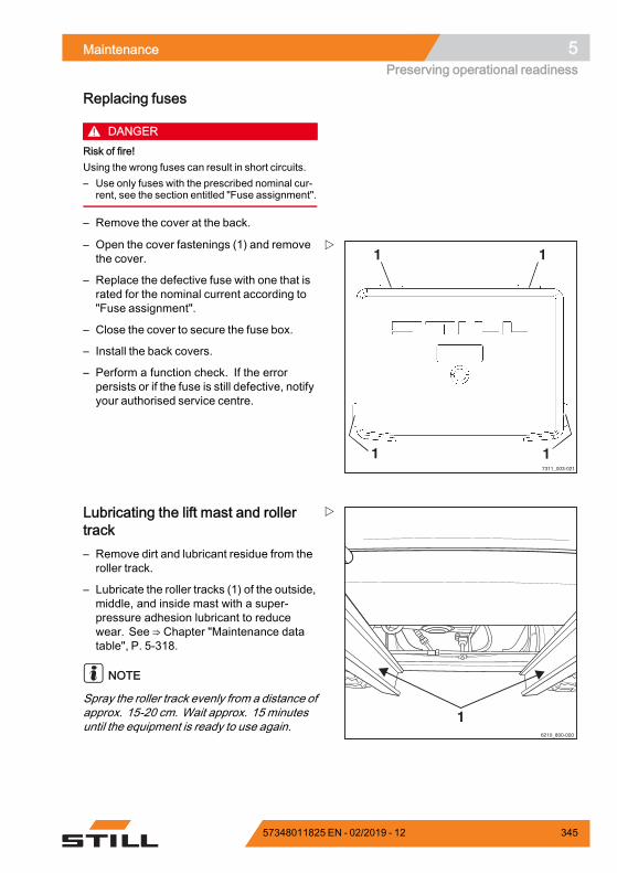
Maintenance 5Preserving operational readiness
Replacing fuses
DANGERRisk of fire!Using the wrong fuses can result in short circuits.– Use only fuses with the prescribed nominal cur-
rent, see the section entitled "Fuse assignment".
– Remove the cover at the back.
1 1
117311_003-021
– Open the cover fastenings (1) and removethe cover.
– Replace the defective fuse with one that israted for the nominal current according to"Fuse assignment".
– Close the cover to secure the fuse box.
– Install the back covers.
– Perform a function check. If the errorpersists or if the fuse is still defective, notifyyour authorised service centre.
16210_800-020
Lubricating the lift mast and rollertrack– Remove dirt and lubricant residue from theroller track.
– Lubricate the roller tracks (1) of the outside,middle, and inside mast with a super-pressure adhesion lubricant to reducewear. See ⇒ Chapter "Maintenance datatable", P. 5-318.
NOTE
Spray the roller track evenly from a distance ofapprox. 15-20 cm. Wait approx. 15 minutesuntil the equipment is ready to use again.
57348011825 EN - 02/2019 - 12 345

5 MaintenancePreserving operational readiness
346 57348011825 EN - 02/2019 - 12
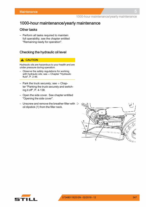
Maintenance 51000-hour maintenance/yearly maintenance
1000-hour maintenance/yearly maintenanceOther tasks– Perform all tasks required to maintainfull operability; see the chapter entitled"Remaining ready for operation".
Checking the hydraulic oil level
CAUTIONHydraulic oils are hazardous to your health and areunder pressure during operation.– Observe the safety regulations for working
with hydraulic oils; see ⇒ Chapter "Hydraulicfluid", P. 2-46.
– Park the truck securely; see ⇒ Chap-ter "Parking the truck securely and switch-ing it off", P. 4-138.
– Open the side cover. See chapter entitled"Opening the side cover".
– Unscrew and remove the breather filter withoil dipstick (1) from the filler neck.
57348011825 EN - 02/2019 - 12 347
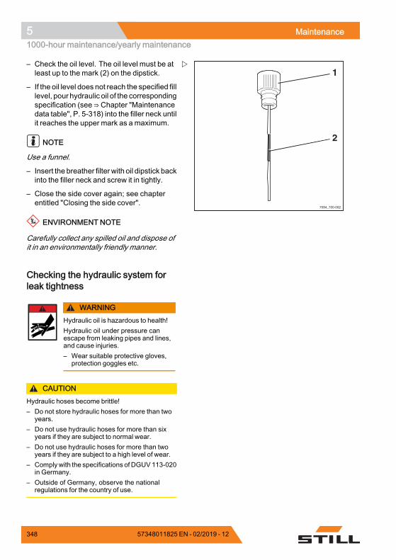
5 Maintenance1000-hour maintenance/yearly maintenance
7094_700-002
1
2
– Check the oil level. The oil level must be atleast up to the mark (2) on the dipstick.
– If the oil level does not reach the specified filllevel, pour hydraulic oil of the correspondingspecification (see ⇒ Chapter "Maintenancedata table", P. 5-318) into the filler neck untilit reaches the upper mark as a maximum.
NOTE
Use a funnel.
– Insert the breather filter with oil dipstick backinto the filler neck and screw it in tightly.
– Close the side cover again; see chapterentitled "Closing the side cover".
ENVIRONMENT NOTE
Carefully collect any spilled oil and dispose ofit in an environmentally friendly manner.
Checking the hydraulic system forleak tightness
WARNINGHydraulic oil is hazardous to health!Hydraulic oil under pressure canescape from leaking pipes and lines,and cause injuries.– Wear suitable protective gloves,
protection goggles etc.
CAUTIONHydraulic hoses become brittle!– Do not store hydraulic hoses for more than two
years.– Do not use hydraulic hoses for more than six
years if they are subject to normal wear.– Do not use hydraulic hoses for more than two
years if they are subject to a high level of wear.– Complywith the specifications ofDGUV113-020
in Germany.– Outside of Germany, observe the national
regulations for the country of use.
348 57348011825 EN - 02/2019 - 12
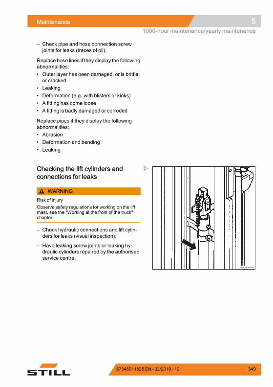
Maintenance 51000-hour maintenance/yearly maintenance
– Check pipe and hose connection screwjoints for leaks (traces of oil).
Replace hose lines if they display the followingabnormalities:• Outer layer has been damaged, or is brittleor cracked
• Leaking• Deformation (e.g. with blisters or kinks)• A fitting has come loose• A fitting is badly damaged or corroded
Replace pipes if they display the followingabnormalities:• Abrasion• Deformation and bending• Leaking
7094_810-004
Checking the lift cylinders andconnections for leaks
WARNINGRisk of injuryObserve safety regulations for working on the liftmast, see the "Working at the front of the truck"chapter.
– Check hydraulic connections and lift cylin-ders for leaks (visual inspection).
– Have leaking screw joints or leaking hy-draulic cylinders repaired by the authorisedservice centre.
57348011825 EN - 02/2019 - 12 349
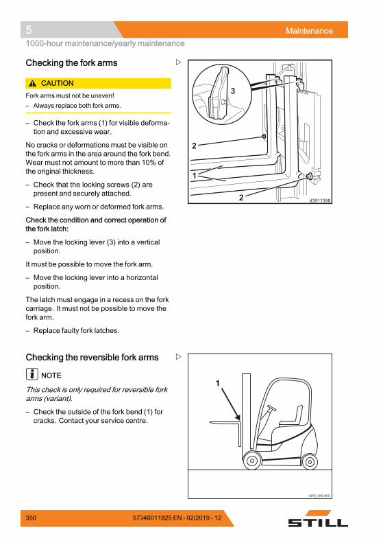
5 Maintenance1000-hour maintenance/yearly maintenance
1
2
2
3
d3911398
Checking the fork arms
CAUTIONFork arms must not be uneven!– Always replace both fork arms.
– Check the fork arms (1) for visible deforma-tion and excessive wear.
No cracks or deformations must be visible onthe fork arms in the area around the fork bend.Wear must not amount to more than 10% ofthe original thickness.
– Check that the locking screws (2) arepresent and securely attached.
– Replace any worn or deformed fork arms.
Check the condition and correct operation ofthe fork latch:
– Move the locking lever (3) into a verticalposition.
It must be possible to move the fork arm.
– Move the locking lever into a horizontalposition.
The latch must engage in a recess on the forkcarriage. It must not be possible to move thefork arm.
– Replace faulty fork latches.
Checking the reversible fork arms
NOTE
This check is only required for reversible forkarms (variant).
– Check the outside of the fork bend (1) forcracks. Contact your service centre.
350 57348011825 EN - 02/2019 - 12

6
Technical data
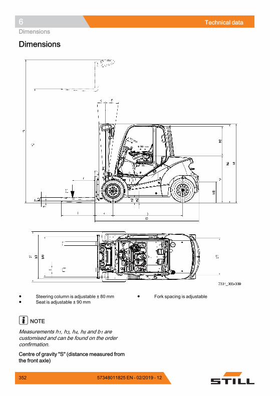
6 Technical dataDimensions
Dimensions
Steering column is adjustable ± 80 mm Seat is adjustable ± 90 mm
Fork spacing is adjustable
NOTE
Measurements h1, h3, h4, h6 and b1 arecustomised and can be found on the orderconfirmation.
Centre of gravity "S" (distance measured fromthe front axle)
352 57348011825 EN - 02/2019 - 12
Technical data 6Dimensions
NOTE
The centre of gravity "S" depends on thetruck's individual equipment, e.g. the typeof lift mast, any attachments or the driverprotection structure. This can vary from onetruck to another. If necessary, the centre ofgravity "S" must be determined individuallyfor each truck. Please contact the qualifiedservice centre in relation to this matter.
57348011825 EN - 02/2019 - 12 353
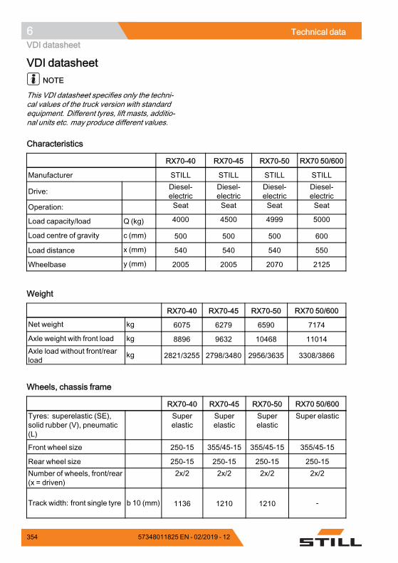
6 Technical dataVDI datasheet
VDI datasheetNOTE
This VDI datasheet specifies only the techni-cal values of the truck version with standardequipment. Different tyres, lift masts, additio-nal units etc. may produce different values.
Characteristics
RX70-40 RX70-45 RX70-50 RX70 50/600
Manufacturer STILL STILL STILL STILL
Drive: Diesel-electric
Diesel-electric
Diesel-electric
Diesel-electric
Operation: Seat Seat Seat Seat
Load capacity/load Q (kg) 4000 4500 4999 5000
Load centre of gravity c (mm) 500 500 500 600
Load distance x (mm) 540 540 540 550
Wheelbase y (mm) 2005 2005 2070 2125.
Weight
RX70-40 RX70-45 RX70-50 RX70 50/600
Net weight kg 6075 6279 6590 7174
Axle weight with front load kg 8896 9632 10468 11014Axle load without front/rearload
kg 2821/3255 2798/3480 2956/3635 3308/3866.
Wheels, chassis frame
RX70-40 RX70-45 RX70-50 RX70 50/600Tyres: superelastic (SE),solid rubber (V), pneumatic(L)
Superelastic
Superelastic
Superelastic
Super elastic
Front wheel size 250-15 355/45-15 355/45-15 355/45-15
Rear wheel size 250-15 250-15 250-15 250-15Number of wheels, front/rear(x = driven)
2x/2 2x/2 2x/2 2x/2
Track width: front single tyre b 10 (mm) 1136 1210 1210 -
354 57348011825 EN - 02/2019 - 12
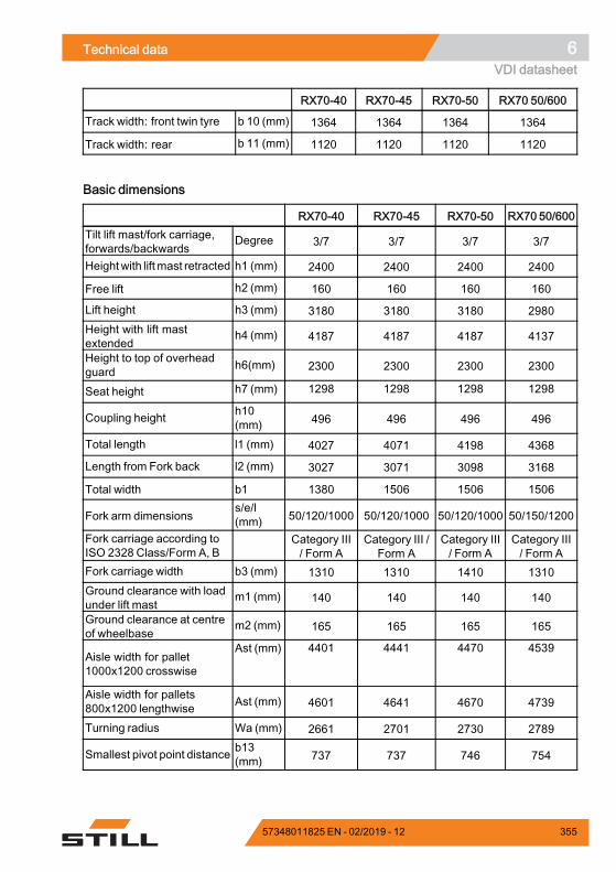
Technical data 6VDI datasheet
RX70-40 RX70-45 RX70-50 RX70 50/600
Track width: front twin tyre b 10 (mm) 1364 1364 1364 1364
Track width: rear b 11 (mm) 1120 1120 1120 1120.
Basic dimensions
RX70-40 RX70-45 RX70-50 RX70 50/600Tilt lift mast/fork carriage,forwards/backwards
Degree 3/7 3/7 3/7 3/7
Heightwith liftmast retracted h1 (mm) 2400 2400 2400 2400
Free lift h2 (mm) 160 160 160 160
Lift height h3 (mm) 3180 3180 3180 2980Height with lift mastextended
h4 (mm) 4187 4187 4187 4137
Height to top of overheadguard h6(mm) 2300 2300 2300 2300
Seat height h7 (mm) 1298 1298 1298 1298
Coupling height h10(mm) 496 496 496 496
Total length l1 (mm) 4027 4071 4198 4368
Length from Fork back l2 (mm) 3027 3071 3098 3168
Total width b1 1380 1506 1506 1506
Fork arm dimensionss/e/l(mm) 50/120/1000 50/120/1000 50/120/1000 50/150/1200
Fork carriage according toISO 2328 Class/Form A, B
Category III/ Form A
Category III /Form A
Category III/ Form A
Category III/ Form A
Fork carriage width b3 (mm) 1310 1310 1410 1310Ground clearance with loadunder lift mast
m1 (mm) 140 140 140 140
Ground clearance at centreof wheelbase
m2 (mm) 165 165 165 165
Aisle width for pallet1000x1200 crosswise
Ast (mm) 4401 4441 4470 4539
Aisle width for pallets800x1200 lengthwise Ast (mm) 4601 4641 4670 4739
Turning radius Wa (mm) 2661 2701 2730 2789
Smallest pivot point distance b13(mm) 737 737 746 754
.
57348011825 EN - 02/2019 - 12 355
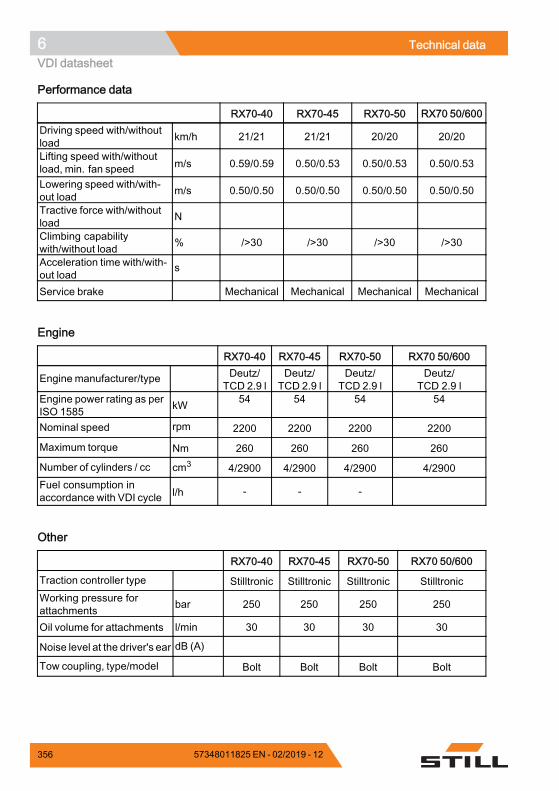
6 Technical dataVDI datasheet
Performance data
RX70-40 RX70-45 RX70-50 RX70 50/600Driving speed with/withoutload km/h 21/21 21/21 20/20 20/20
Lifting speed with/withoutload, min. fan speed m/s 0.59/0.59 0.50/0.53 0.50/0.53 0.50/0.53
Lowering speed with/with-out load m/s 0.50/0.50 0.50/0.50 0.50/0.50 0.50/0.50
Tractive force with/withoutload N
Climbing capabilitywith/without load % />30 />30 />30 />30
Acceleration time with/with-out load
s
Service brake Mechanical Mechanical Mechanical Mechanical.
Engine
RX70-40 RX70-45 RX70-50 RX70 50/600
Engine manufacturer/type Deutz/TCD 2.9 l
Deutz/TCD 2.9 l
Deutz/TCD 2.9 l
Deutz/TCD 2.9 l
Engine power rating as perISO 1585 kW 54 54 54 54
Nominal speed rpm 2200 2200 2200 2200
Maximum torque Nm 260 260 260 260
Number of cylinders / cc cm3 4/2900 4/2900 4/2900 4/2900Fuel consumption inaccordance with VDI cycle l/h - - -
.
Other
RX70-40 RX70-45 RX70-50 RX70 50/600
Traction controller type Stilltronic Stilltronic Stilltronic StilltronicWorking pressure forattachments bar 250 250 250 250
Oil volume for attachments l/min 30 30 30 30
Noise level at the driver's ear dB (A)
Tow coupling, type/model Bolt Bolt Bolt Bolt.
356 57348011825 EN - 02/2019 - 12
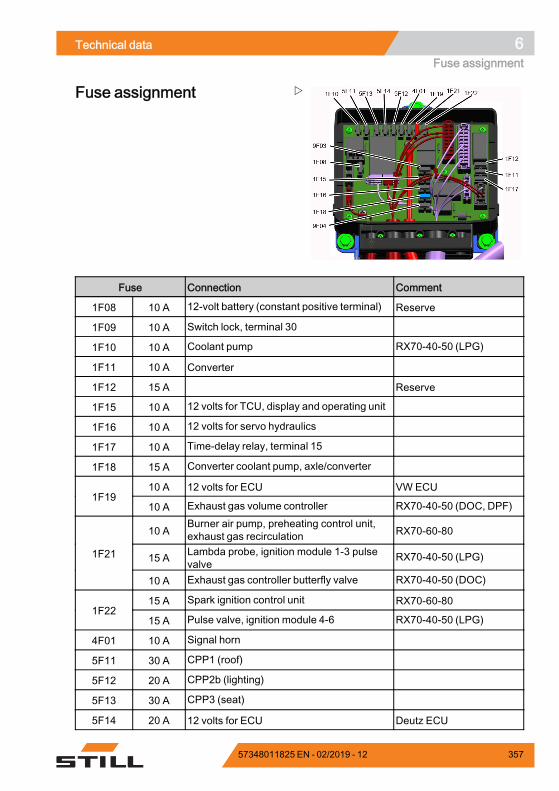
Technical data 6Fuse assignment
Fuse assignment
Fuse Connection Comment
1F08 10 A 12-volt battery (constant positive terminal) Reserve
1F09 10 A Switch lock, terminal 30
1F10 10 A Coolant pump RX70-40-50 (LPG)
1F11 10 A Converter
1F12 15 A Reserve
1F15 10 A 12 volts for TCU, display and operating unit
1F16 10 A 12 volts for servo hydraulics
1F17 10 A Time-delay relay, terminal 15
1F18 15 A Converter coolant pump, axle/converter
10 A 12 volts for ECU VW ECU1F19
10 A Exhaust gas volume controller RX70-40-50 (DOC, DPF)
10 ABurner air pump, preheating control unit,exhaust gas recirculation RX70-60-80
15 A Lambda probe, ignition module 1-3 pulsevalve
RX70-40-50 (LPG)1F21
10 A Exhaust gas controller butterfly valve RX70-40-50 (DOC)
15 A Spark ignition control unit RX70-60-801F22
15 A Pulse valve, ignition module 4-6 RX70-40-50 (LPG)
4F01 10 A Signal horn
5F11 30 A CPP1 (roof)
5F12 20 A CPP2b (lighting)
5F13 30 A CPP3 (seat)
5F14 20 A 12 volts for ECU Deutz ECU
57348011825 EN - 02/2019 - 12 357
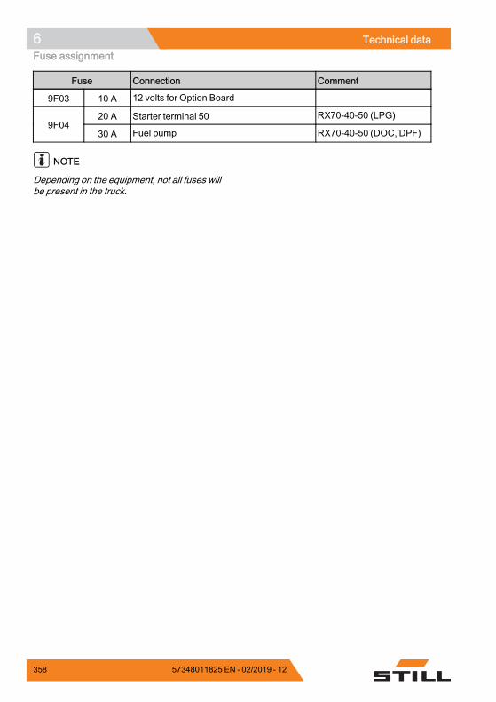
6 Technical dataFuse assignment
Fuse Connection Comment
9F03 10 A 12 volts for Option Board
20 A Starter terminal 50 RX70-40-50 (LPG)9F04
30 A Fuel pump RX70-40-50 (DOC, DPF)
NOTE
Depending on the equipment, not all fuses willbe present in the truck.
358 57348011825 EN - 02/2019 - 12
Indexg
AAccess authorisation
Changing the password . . . . . . . . . . . 91Defining the driver PIN . . . . . . . . . . . . 87Entering the access code . . . . . . . . . 85Selecting the driver PIN . . . . . . . . . . . 88
Access authorisation with PIN code . . . . 84Accessories
Overview . . . . . . . . . . . . . . . . . . . . . . 8Actuating the drive direction switch
Fingertip version . . . . . . . . . . . . . . . 127Joystick 4Plus version . . . . . . . . . . 126Mini-console version . . . . . . . . . . . . 127Mini-lever version . . . . . . . . . . . . . . 126
Address of manufacturer . . . . . . . . . . . . . IAdjusting the armrest . . . . . . . . . . . . . . . 79Adjusting the fork . . . . . . . . . . . . . . . . . 168Adjusting the steering column . . . . . . . . . 80After washing . . . . . . . . . . . . . . . . . . . . 299Aisle widths . . . . . . . . . . . . . . . . . . . . . 123
AttachmentsAssembly . . . . . . . . . . . . . . . . . . . . 190Controlling using a double
mini-lever . . . . . . . . . . . . . . . . . . 196Controlling using the double
mini-lever and the 5th function . . 198Controlling using the joystick 4Plus
and the 5th function . . . . . . . . . . 209Controlling using the quadruple
mini-lever and the 5th function . . 206Controlling using the triple
mini-lever and the 5th function . . 202Controlling via the joystick 4Plus . . . 208Controlling with a quadruple
mini-lever . . . . . . . . . . . . . . . . . . 204Controlling with a triple mini-lever . . . 200Controlling with the fingertip . . . . . . . 210Controlling with the fingertip and 5th
function . . . . . . . . . . . . . . . . . . . 211General controlling . . . . . . . . . . . . . 194Mounting . . . . . . . . . . . . . . . . . . . . 191Releasing the pressure from the
connections . . . . . . . . . . . . . . . . 192Special risks . . . . . . . . . . . . . . . . . . . 36Taking up a load . . . . . . . . . . . . . . . 216
Automatic lift cut out . . . . . . . . . . . . . . . 140Automatic tow coupling . . . . . . . . . . . . 247
Coupling RO*243 . . . . . . . . . . . . . . 249Coupling RO*244 A . . . . . . . . . . . . . 251Coupling RO*245 . . . . . . . . . . . . . . 253Coupling RO*841 . . . . . . . . . . . . . . 254Uncoupling RO*243 . . . . . . . . . . . . 250Uncoupling RO*244 A . . . . . . . . . . . 252Uncoupling RO*245 . . . . . . . . . . . . 254Uncoupling RO*841 . . . . . . . . . . . . 255
BBattery
Charging . . . . . . . . . . . . . . . . . . . . . 343Checking the charge status . . . . . . . 342Disposal . . . . . . . . . . . . . . . . . . . . . . 22Servicing . . . . . . . . . . . . . . . . . . . . 342
Battery acid . . . . . . . . . . . . . . . . . . . . . . 47
57348011825 EN - 02/2019 - 12 359
Indexg
Before taking up load . . . . . . . . . . . . . . 163Blue-Q
Configure . . . . . . . . . . . . . . . . . . . . 115Functional description . . . . . . . . . . . 118Switching off . . . . . . . . . . . . . . . . . . 119Switching off additional consumers . 119Switching on . . . . . . . . . . . . . . . . . . 119
Bottom plateInstalling . . . . . . . . . . . . . . . . . . . . . 327Removing . . . . . . . . . . . . . . . . . . . . 325
CCab
Operating the interior lighting . . . . . . 240Operating the rear window heating . . 241
CE labelling . . . . . . . . . . . . . . . . . . . . . . . 6Ceiling sensor . . . . . . . . . . . . . . . . . . . 231Changes to the forklift truck . . . . . . . . . . 27Changing the drive direction . . . . . . . . . 129
Dual pedal version . . . . . . . . . . . . . 131Changing the fork arms . . . . . . . . . . . . 156Changing the password . . . . . . . . . . . . . 91Checking the coolant concentration . . . 328Checking the door latch . . . . . . . . . . . . 335Checking the driver's seat . . . . . . . . . . . 337Checking the emergency off function . . 102Checking the engine oil level . . . . . . . . 327Checking the fork arms . . . . . . . . . . . . . 350Checking the lift cylinders and
connections for leaks . . . . . . . . . 349Checking the side cover
is locked . . . . . . . . . . . . . . . . . . . . . . 74Checking wheel fastenings . . . . . . . . . . 342Clamp locking mechanism
Releasing . . . . . . . . . . . . . . . . . . . . 213Cleaning the dust valve . . . . . . . . . . . . 105Cleaning the electrical system . . . . . . . 298Cleaning the truck . . . . . . . . . . . . . . . . 296Cleaning the windows . . . . . . . . . . . . . 299Climbing into the truck . . . . . . . . . . . . . . 71Climbing out of the truck . . . . . . . . . . . . . 71Closing the bonnet . . . . . . . . . . . . . . . . 324
Closing the cab door . . . . . . . . . . . . . . . 238Closing the side windows . . . . . . . . . . . 239Consumables . . . . . . . . . . . . . . . . . . . . 45
Coolant and cooling fluid safetyinformation . . . . . . . . . . . . . . . . . . 50
Disposal . . . . . . . . . . . . . . . . . . . . . . 50Safety information for diesel fuel . . . . 48Safety information for handling
battery acid . . . . . . . . . . . . . . . . . 47Safety information for handling oils . . . 45Safety information for hydraulic fluid . . 46
Contact details . . . . . . . . . . . . . . . . . . . . . ICoolant . . . . . . . . . . . . . . . . . . . . . . . . 328
Topping up . . . . . . . . . . . . . . . . . . . 328Coolant and cooling fluid . . . . . . . . . . . . 50Copyright and trademark rights . . . . . . . . 17Coupling pin in the counterweight . . . . . 245
Coupling . . . . . . . . . . . . . . . . . . . . . 245Uncoupling . . . . . . . . . . . . . . . . . . . 246
Crane loading . . . . . . . . . . . . . . . . . . . 292Determining the loading weight . . . . 293Hooking on the lifting straps . . . . . . . 293
Cruise control . . . . . . . . . . . . . . . . . . . 227
DDamage . . . . . . . . . . . . . . . . . . . . . . . . 30Danger area . . . . . . . . . . . . . . . . . . . . 168Danger to employees . . . . . . . . . . . . . . . 41Declaration of conformity . . . . . . . . . . . . . 7Decommissioning
Recommissioning . . . . . . . . . . . . . . 301Defects . . . . . . . . . . . . . . . . . . . . . . . . . 30Defining the driver PIN . . . . . . . . . . . . . . 87Definition of directions . . . . . . . . . . . . . . 20Diesel engine emissions
Checking . . . . . . . . . . . . . . . . . . . . . 42Diesel fuel . . . . . . . . . . . . . . . . . . . . . . . 48
Filling up . . . . . . . . . . . . . . . . . . . . . 279Non-road fuels . . . . . . . . . . . . . . . . 278Specifications . . . . . . . . . . . . . . . . . 276Sulphur content . . . . . . . . . . . . . . . . 277Winter operation . . . . . . . . . . . . . . . 278
360 57348011825 EN - 02/2019 - 12
Indexg
Dimensions . . . . . . . . . . . . . . . . . . . . . 352Display and operating unit . . . . . . . . . . . 58
Additional indicators . . . . . . . . . . . . 106Adjusting the displays . . . . . . . . . . . 107Configure Blue Q . . . . . . . . . . . . . . . 115Standard display elements . . . . 83, 106
Display messagesDisplay content . . . . . . . . . . . . . . . . 257Drive-specific . . . . . . . . . . . . . . . . . 269General . . . . . . . . . . . . . . . . . . . . . 260
Display operating unitAdditional settings . . . . . . . . . . . . . . 117Resetting the daily kilometres . . . . . 114Setting the date . . . . . . . . . . . . . . . . 113Setting the language . . . . . . . . . . . . 114Setting the time . . . . . . . . . . . . . . . . 113
Display symbols . . . . . . . . . . . . . . . . . . 108Auxiliary equipment softkey
functions . . . . . . . . . . . . . . . . . . 110Error messages . . . . . . . . . . . . . . . 110Menu navigation softkey functions . . 111Numeric keypad . . . . . . . . . . . . . . . 112Operating messages . . . . . . . . . . . . 108Status LEDs . . . . . . . . . . . . . . . . . . 112Warning messages . . . . . . . . . . . . . 109
DisposalBattery . . . . . . . . . . . . . . . . . . . . . . . 22Components . . . . . . . . . . . . . . . . . . . 22
Documentation scope . . . . . . . . . . . . . . 15Double mini-lever . . . . . . . . . . . . . . . . . . 60
Lifting/lowering the fork carriage . . . 150Tilting the lift mast . . . . . . . . . . . . . . 150
Driver rights, duties and rules ofbehaviour . . . . . . . . . . . . . . . . . . 25
Driver's cabUse . . . . . . . . . . . . . . . . . . . . . . . . . 97
Drivers . . . . . . . . . . . . . . . . . . . . . . . . . . 25Driving
Ascending gradients . . . . . . . . . . . . 136Descending gradients . . . . . . . . . . . 136
Driving lightsSwitching on and off . . . . . . . . . . . . 217
Driving on gradients . . . . . . . . . . . . . . . 123Driving on lifts . . . . . . . . . . . . . . . . . . . 180Driving on loading bridges . . . . . . . . . . 181
EEC declaration of conformity in
accordance with MachineryDirective . . . . . . . . . . . . . . . . . . . . 7
EmergenciesDisconnecting the battery . . . . . . . . 286Truck tipping over . . . . . . . . . . . . . . 282Using the emergency hammer . . . . . 283
Emergency hammer . . . . . . . . . . . . . . . 283Emergency lowering . . . . . . . . . . . . . . 284Emergency shutdown . . . . . . . . . . . . . 280Emissions . . . . . . . . . . . . . . . . . . . . . . . 52
Diesel engine emissions . . . . . . . . . . 53Exhaust gases . . . . . . . . . . . . . . . . . 52Heat . . . . . . . . . . . . . . . . . . . . . . . . . 53Noise emissions . . . . . . . . . . . . . . . . 52Vibrations . . . . . . . . . . . . . . . . . . . . . 52
Entering the access code . . . . . . . . . . . . 85Error code table . . . . . . . . . . . . . . . . . . 258Example . . . . . . . . . . . . . . . . . . . . . . . 164
FFilling the washer system . . . . . . . . . . . 226Fingertip . . . . . . . . . . . . . . . . . . . . . . . . 64
Lifting/lowering the fork carriage . . . 155Tilting the lift mast . . . . . . . . . . . . . . 155
Fitting attachments . . . . . . . . . . . . . . . 190FleetManager . . . . . . . . . . . . . . . . . . . 227
Shock recognition . . . . . . . . . . 116, 227Fork arms
Length . . . . . . . . . . . . . . . . . . . . 30, 33Fork extension . . . . . . . . . . . . . . . . . . . 158Four-way mini-lever . . . . . . . . . . . . . . . . 62Fuel filter
Draining water from . . . . . . . . . . . . . 333
57348011825 EN - 02/2019 - 12 361
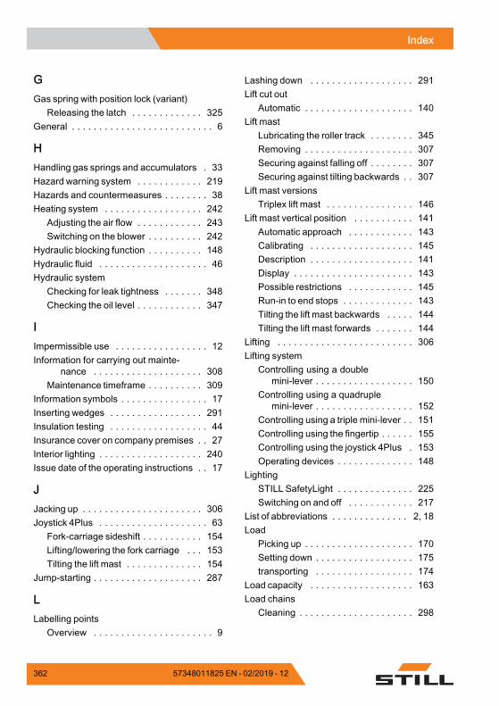
Indexg
GGas spring with position lock (variant)
Releasing the latch . . . . . . . . . . . . . 325General . . . . . . . . . . . . . . . . . . . . . . . . . . 6
HHandling gas springs and accumulators . 33Hazard warning system . . . . . . . . . . . . 219Hazards and countermeasures . . . . . . . . 38Heating system . . . . . . . . . . . . . . . . . . 242
Adjusting the air flow . . . . . . . . . . . . 243Switching on the blower . . . . . . . . . . 242
Hydraulic blocking function . . . . . . . . . . 148Hydraulic fluid . . . . . . . . . . . . . . . . . . . . 46Hydraulic system
Checking for leak tightness . . . . . . . 348Checking the oil level . . . . . . . . . . . . 347
IImpermissible use . . . . . . . . . . . . . . . . . 12Information for carrying out mainte-
nance . . . . . . . . . . . . . . . . . . . . 308Maintenance timeframe . . . . . . . . . . 309
Information symbols . . . . . . . . . . . . . . . . 17Inserting wedges . . . . . . . . . . . . . . . . . 291Insulation testing . . . . . . . . . . . . . . . . . . 44Insurance cover on company premises . . 27Interior lighting . . . . . . . . . . . . . . . . . . . 240Issue date of the operating instructions . . 17
JJacking up . . . . . . . . . . . . . . . . . . . . . . 306Joystick 4Plus . . . . . . . . . . . . . . . . . . . . 63
Fork-carriage sideshift . . . . . . . . . . . 154Lifting/lowering the fork carriage . . . 153Tilting the lift mast . . . . . . . . . . . . . . 154
Jump-starting . . . . . . . . . . . . . . . . . . . . 287
LLabelling points
Overview . . . . . . . . . . . . . . . . . . . . . . 9
Lashing down . . . . . . . . . . . . . . . . . . . 291Lift cut out
Automatic . . . . . . . . . . . . . . . . . . . . 140Lift mast
Lubricating the roller track . . . . . . . . 345Removing . . . . . . . . . . . . . . . . . . . . 307Securing against falling off . . . . . . . . 307Securing against tilting backwards . . 307
Lift mast versionsTriplex lift mast . . . . . . . . . . . . . . . . 146
Lift mast vertical position . . . . . . . . . . . 141Automatic approach . . . . . . . . . . . . 143Calibrating . . . . . . . . . . . . . . . . . . . 145Description . . . . . . . . . . . . . . . . . . . 141Display . . . . . . . . . . . . . . . . . . . . . . 143Possible restrictions . . . . . . . . . . . . 145Run-in to end stops . . . . . . . . . . . . . 143Tilting the lift mast backwards . . . . . 144Tilting the lift mast forwards . . . . . . . 144
Lifting . . . . . . . . . . . . . . . . . . . . . . . . . 306Lifting system
Controlling using a doublemini-lever . . . . . . . . . . . . . . . . . . 150
Controlling using a quadruplemini-lever . . . . . . . . . . . . . . . . . . 152
Controlling using a triple mini-lever . . 151Controlling using the fingertip . . . . . . 155Controlling using the joystick 4Plus . 153Operating devices . . . . . . . . . . . . . . 148
LightingSTILL SafetyLight . . . . . . . . . . . . . . 225Switching on and off . . . . . . . . . . . . 217
List of abbreviations . . . . . . . . . . . . . . 2, 18Load
Picking up . . . . . . . . . . . . . . . . . . . . 170Setting down . . . . . . . . . . . . . . . . . . 175transporting . . . . . . . . . . . . . . . . . . 174
Load capacity . . . . . . . . . . . . . . . . . . . 163Load chains
Cleaning . . . . . . . . . . . . . . . . . . . . . 298
362 57348011825 EN - 02/2019 - 12
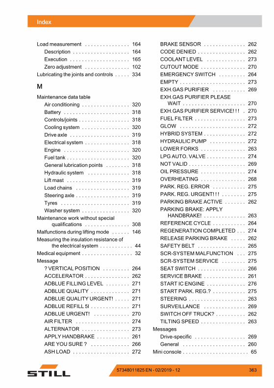
Indexg
Load measurement . . . . . . . . . . . . . . . 164Description . . . . . . . . . . . . . . . . . . . 164Execution . . . . . . . . . . . . . . . . . . . . 165Zero adjustment . . . . . . . . . . . . . . . 102
Lubricating the joints and controls . . . . . 334
MMaintenance data table
Air conditioning . . . . . . . . . . . . . . . . 320Battery . . . . . . . . . . . . . . . . . . . . . . 318Controls/joints . . . . . . . . . . . . . . . . . 318Cooling system . . . . . . . . . . . . . . . . 320Drive axle . . . . . . . . . . . . . . . . . . . . 319Electrical system . . . . . . . . . . . . . . . 318Engine . . . . . . . . . . . . . . . . . . . . . . 320Fuel tank . . . . . . . . . . . . . . . . . . . . . 320General lubrication points . . . . . . . . 318Hydraulic system . . . . . . . . . . . . . . 318Lift mast . . . . . . . . . . . . . . . . . . . . . 319Load chains . . . . . . . . . . . . . . . . . . 319Steering axle . . . . . . . . . . . . . . . . . . 319Tyres . . . . . . . . . . . . . . . . . . . . . . . 319Washer system . . . . . . . . . . . . . . . . 320
Maintenance work without specialqualifications . . . . . . . . . . . . . . . 308
Malfunctions during lifting mode . . . . . . 146Measuring the insulation resistance of
the electrical system . . . . . . . . . . . 44Medical equipment . . . . . . . . . . . . . . . . . 32Message
? VERTICAL POSITION . . . . . . . . . 264ACCELERATOR . . . . . . . . . . . . . . . 262ADBLUE FILLING LEVEL . . . . . . . . 271ADBLUEQUALITY . . . . . . . . . . . . . 271ADBLUEQUALITY URGENT! . . . . . 271ADBLUE REFILL 5l . . . . . . . . . . . . . 271ADBLUE URGENT! . . . . . . . . . . . . 270AIR FILTER . . . . . . . . . . . . . . . . . . 274ALTERNATOR . . . . . . . . . . . . . . . . 273APPLY HANDBRAKE . . . . . . . . . . . 261ARE YOU SURE ? . . . . . . . . . . . . . 266ASH LOAD . . . . . . . . . . . . . . . . . . . 272
BRAKE SENSOR . . . . . . . . . . . . . . 262CODEDENIED . . . . . . . . . . . . . . . . 262COOLANT LEVEL . . . . . . . . . . . . . 273CUTOUTMODE . . . . . . . . . . . . . . . 270EMERGENCY SWITCH . . . . . . . . . 264EMPTY . . . . . . . . . . . . . . . . . . . . . . 273EXH.GAS PURIFIER . . . . . . . . . . . 269EXH.GAS PURIFIER PLEASE
WAIT . . . . . . . . . . . . . . . . . . . . . 270EXH.GAS PURIFIER SERVICE! ! ! . 270FUEL FILTER . . . . . . . . . . . . . . . . . 273GLOW . . . . . . . . . . . . . . . . . . . . . . 272HYBRID SYSTEM . . . . . . . . . . . . . . 272HYDRAULIC PUMP . . . . . . . . . . . . 272LOWER FORKS . . . . . . . . . . . . . . . 263LPG AUTO. VALVE . . . . . . . . . . . . . 274NOT VALID . . . . . . . . . . . . . . . . . . . 269OIL PRESSURE . . . . . . . . . . . . . . . 274OVERHEATING . . . . . . . . . . . . . . . 268PARK. REG. ERROR . . . . . . . . . . . 275PARK. REG. URGENT! ! ! . . . . . . . . 275PARKING BRAKE ACTIVE . . . . . . . 262PARKING BRAKE: APPLY
HANDBRAKE! . . . . . . . . . . . . . . 263REFERENCECYCLE . . . . . . . . . . . 264REGENERATION COMPLETED . . . 274RELEASE PARKING BRAKE . . . . . 262SAFETY BELT . . . . . . . . . . . . . . . . 265SCR-SYSTEMMALFUNCTION . . . 275SCR-SYSTEMSERVICE . . . . . . . . 275SEAT SWITCH . . . . . . . . . . . . . . . . 266SERVICE BRAKE . . . . . . . . . . . . . . 261START IC ENGINE . . . . . . . . . . . . . 276START PARK. REG.? . . . . . . . . . . . 275STEERING . . . . . . . . . . . . . . . . . . . 263SURVEILLANCE . . . . . . . . . . . . . . 269SWITCHOFF TRUCK? . . . . . . . . . . 262TILTING SPEED . . . . . . . . . . . . . . . 263
MessagesDrive-specific . . . . . . . . . . . . . . . . . 269General . . . . . . . . . . . . . . . . . . . . . 260
Mini console . . . . . . . . . . . . . . . . . . . . . . 65
57348011825 EN - 02/2019 - 12 363
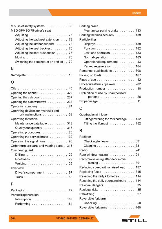
Indexg
Misuse of safety systems . . . . . . . . . . . . 30MSG 65/MSG 75 driver's seat
Adjusting . . . . . . . . . . . . . . . . . . . . . 75Adjusting the backrest extension . . . . 78Adjusting the lumbar support . . . . . . . 78Adjusting the seat backrest . . . . . . . . 76Adjusting the seat suspension . . . . . . 77Moving . . . . . . . . . . . . . . . . . . . . . . . 76Switching the seat heater on and off . . 79
NNameplate . . . . . . . . . . . . . . . . . . . . . . . 10
OOils . . . . . . . . . . . . . . . . . . . . . . . . . . . . 45Opening the bonnet . . . . . . . . . . . . . . . 322Opening the cab door . . . . . . . . . . . . . . 237Opening the side windows . . . . . . . . . . 238Operating company . . . . . . . . . . . . . . . . 24Operating devices for hydraulic and
driving functions . . . . . . . . . . . . . . 59Operating materials
Maintenance data table . . . . . . . . . . 318Quality and quantity . . . . . . . . . . . . 316
Operating procedures . . . . . . . . . . . . . . 20Operating the service brake . . . . . . . . . 132Operating the signal horn . . . . . . . . . . . . 93Ordering spare parts andwearing parts . 315Overhead guard
Drilling . . . . . . . . . . . . . . . . . . . . . . . 29Roof loads . . . . . . . . . . . . . . . . . . . . 29Welding . . . . . . . . . . . . . . . . . . . . . . 29
OverviewDriver's compartment . . . . . . . . . . . . 57Truck . . . . . . . . . . . . . . . . . . . . . . . . 56
PPackaging . . . . . . . . . . . . . . . . . . . . . . . 22Parked regeneration
Interruption . . . . . . . . . . . . . . . . . . . 183Performing . . . . . . . . . . . . . . . . . . . 184
Parking brakeMechanical parking brake . . . . . . . . 133
Parking the truck securely . . . . . . . . . . 138Particle filter
Displays . . . . . . . . . . . . . . . . . . . . . 188Function . . . . . . . . . . . . . . . . . . . . . 182Low-load operation . . . . . . . . . . . . . 183Normal operation . . . . . . . . . . . . . . 183Operational requirements . . . . . . . . . 43Parked regeneration . . . . . . . . . . . . 184
Personnel qualifications . . . . . . . . . . . . 308Picking up loads . . . . . . . . . . . . . . . . . . 167Place of use . . . . . . . . . . . . . . . . . . . . . . 12Procedure if truck tips over . . . . . . . . . . 282Production number . . . . . . . . . . . . . . . . 10Prohibition of use by unauthorised
persons . . . . . . . . . . . . . . . . . . . . 26Proper usage . . . . . . . . . . . . . . . . . . . . . 11
QQuadruple mini-lever
Lifting/lowering the fork carriage . . . 152Tilting the lift mast . . . . . . . . . . . . . . 152
RRadiator
Checking for leaks . . . . . . . . . . . . . . 331Cleaning . . . . . . . . . . . . . . . . . . . . . 331
Radio . . . . . . . . . . . . . . . . . . . . . . . . . 241Rear window heating . . . . . . . . . . . . . . 241Recommissioning after decommis-
sioning . . . . . . . . . . . . . . . . . . . . 301Reducing speed with a raised load . . . . 137Replacing fuses . . . . . . . . . . . . . . . . . . 345Resetting the daily kilometres . . . . . . . . 114Resetting the daily operating hours . . . . 114Residual dangers . . . . . . . . . . . . . . . . . . 35Residual risks . . . . . . . . . . . . . . . . . . . . 35Retrofitting . . . . . . . . . . . . . . . . . . . . . . . 27Reversible fork arm
Checking . . . . . . . . . . . . . . . . . . . . 350Reversible fork arms . . . . . . . . . . . . . . 160
364 57348011825 EN - 02/2019 - 12
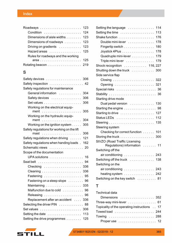
Indexg
Roadways . . . . . . . . . . . . . . . . . . . . . . 123Condition . . . . . . . . . . . . . . . . . . . . 124Dimensions of aisle widths . . . . . . . . 123Dimensions of roadways . . . . . . . . . 123Driving on gradients . . . . . . . . . . . . 123Hazard areas . . . . . . . . . . . . . . . . . 125Rules for roadways and the working
area . . . . . . . . . . . . . . . . . . . . . . 125Rotating beacon . . . . . . . . . . . . . . . . . . 219
SSafety devices . . . . . . . . . . . . . . . . . . . 306Safety inspection . . . . . . . . . . . . . . . . . . 42Safety regulations for maintenance
General information . . . . . . . . . . . . 304Safety devices . . . . . . . . . . . . . . . . 306Set values . . . . . . . . . . . . . . . . . . . . 306Working on the electrical equip-
ment . . . . . . . . . . . . . . . . . . . . . 305Working on the hydraulic equip-
ment . . . . . . . . . . . . . . . . . . . . . 304Working on the ignition system . . . . . 305
Safety regulations for working on the liftmast . . . . . . . . . . . . . . . . . . . . . 306
Safety regulations when driving . . . . . . 121Safety regulations when handing loads . 162Schematic views . . . . . . . . . . . . . . . . . . 20Scope of the documentation
UPA solutions . . . . . . . . . . . . . . . . . . 16Seat belt . . . . . . . . . . . . . . . . . . . . . . . . 94
Checking . . . . . . . . . . . . . . . . . . . . 336Cleaning . . . . . . . . . . . . . . . . . . . . . 336Fastening . . . . . . . . . . . . . . . . . . . . . 95Fastening on a steep slope . . . . . . . . 96Maintaining . . . . . . . . . . . . . . . . . . . 335Malfunction due to cold . . . . . . . . . . . 96Releasing . . . . . . . . . . . . . . . . . . . . . 96Replacement after an accident . . . . 336
Selecting the driver PIN . . . . . . . . . . . . . 88Set values . . . . . . . . . . . . . . . . . . . . . . 306Setting the date . . . . . . . . . . . . . . . . . . 113Setting the drive programmes . . . . . . . . 125
Setting the language . . . . . . . . . . . . . . 114Setting the time . . . . . . . . . . . . . . . . . . 113Shake function . . . . . . . . . . . . . . . . . . . 176
Double mini-lever . . . . . . . . . . . . . . 178Fingertip switch . . . . . . . . . . . . . . . . 180Joystick 4Plus . . . . . . . . . . . . . . . . . 178Quadruple mini-lever . . . . . . . . . . . . 179Triple mini-lever . . . . . . . . . . . . . . . 179
Shock recognition . . . . . . . . . . . . 116, 227Shutting down the truck . . . . . . . . . . . . 300Side service flap
Closing . . . . . . . . . . . . . . . . . . . . . . 322Opening . . . . . . . . . . . . . . . . . . . . . 321
Special risks . . . . . . . . . . . . . . . . . . . . . 36Stability . . . . . . . . . . . . . . . . . . . . . . . . . 36Starting drive mode
Dual pedal version . . . . . . . . . . . . . 130Starting the engine . . . . . . . . . . . . . . . . . 98Starting to drive . . . . . . . . . . . . . . . . . . 127Status LEDs . . . . . . . . . . . . . . . . . . . . 112Steering . . . . . . . . . . . . . . . . . . . . . . . . 135Steering system
Checking for correct function . . . . . . 101Storing the truck . . . . . . . . . . . . . . . . . . 300StVZO (Road Traffic Licensing
Regulations) information . . . . . . . 11Switching off the
air conditioning . . . . . . . . . . . . . . . . 243Switching off the truck . . . . . . . . . . . . . 138Switching on the
air conditioning . . . . . . . . . . . . . . . . 243heating system . . . . . . . . . . . . . . . . 242
Switching on the key switch . . . . . . . . . . 81
TTechnical data
Dimensions . . . . . . . . . . . . . . . . . . 352Three-waymini-lever . . . . . . . . . . . . . . . 61Topicality of the operating instructions . . 17Towed load . . . . . . . . . . . . . . . . . . . . . 244Towing . . . . . . . . . . . . . . . . . . . . . . . . 288
Proper use . . . . . . . . . . . . . . . . . . . . 12
57348011825 EN - 02/2019 - 12 365
Indexg
TrailersTowing . . . . . . . . . . . . . . . . . . . . . . 255
Transport . . . . . . . . . . . . . . . . . . . . . . . 290Transporting pallets . . . . . . . . . . . . . . . 169Transporting suspended loads . . . . . . . 169Triple mini-lever
Lifting/lowering the fork carriage . . . 151Tilting the lift mast . . . . . . . . . . . . . . 151
Turn indicator . . . . . . . . . . . . . . . . . . . . 220Fingertip version . . . . . . . . . . . . . . . 221Mini-console version . . . . . . . . . . . . 222Mini-lever version . . . . . . . . . . . . . . 220
Types of lift mast . . . . . . . . . . . . . . . . . 145Telescopic mast . . . . . . . . . . . . . . . 146
TyresSafety principles . . . . . . . . . . . . . . . . 31
UUnlocking the emergency off switch . . . . 81Using working platforms . . . . . . . . . . . . . 14
VVariant
Ceiling sensor . . . . . . . . . . . . . . . . . 231
VariantsAccess authorisation with PIN code . . 84Automatic lift cut out . . . . . . . . . . . . 140Automatic shut-off of the internal
combustion engine . . . . . . . . . . . 137Clamp locking mechanism . . . . . . . . 213Cruise control . . . . . . . . . . . . . . . . . 227Emergency off switch . . . . . . . . . . . . 81FleetManager . . . . . . . . . . . . . . . . . 227Fork extension . . . . . . . . . . . . . . . . 158Gas spring with position lock . . . . . . 325Lift mast vertical position . . . . . . . . . 141Lifting systems . . . . . . . . . . . . . . . . 140Loadmeasurement . . . . . . . . . . . . . 164Radio . . . . . . . . . . . . . . . . . . . . . . . 241Reducing speed with a raised load . . 137Reversible fork arms . . . . . . . . . . . . 160Shake function . . . . . . . . . . . . . . . . 176Shock recognition . . . . . . . . . . 116, 227Triplex lift mast . . . . . . . . . . . . . . . . 146Wheel chock . . . . . . . . . . . . . . . . . . 139Windscreen wiper/washer . . . . . . . . 226Zero braking . . . . . . . . . . . . . . . . . . 133
Vertical lift mast positionChecking for correct function . . . . . . 104
View of functions and operations . . . . . . . 20View of operating procedures . . . . . . . . . 20Views of the display operating unit . . . . . 21Visual inspections . . . . . . . . . . . . . . . . . 68
WWarning regarding non-original parts . . . 29Wheel chock . . . . . . . . . . . . . . . . . . . . 139Wheels and tyres
Checking condition and wear of thetyres . . . . . . . . . . . . . . . . . . . . . 340
Checking the air pressure . . . . . . . . 341Checking wheel fastenings . . . . . . . 342Servicing . . . . . . . . . . . . . . . . . . . . 340
Windscreen wiper/washer . . . . . . . . . . 226Working at the front of the truck . . . . . . . 306Working on the electrical equipment . . . 305
366 57348011825 EN - 02/2019 - 12
Indexg
Working on the hydraulic equipment . . . 304Working on the ignition system . . . . . . . 305Working spotlight for reverse travel
Switching on and off . . . . . . . . . . . . 218Working spotlights
Automatically switching on/off . . . . . 224Lift-height-controlled switching
on/off . . . . . . . . . . . . . . . . . . . . . 224Manually switching on/off . . . . . . . . 223Switching on and off . . . . . . . . 218, 223
ZZero adjustment of the load measure-
ment . . . . . . . . . . . . . . . . . . . . . 102
57348011825 EN - 02/2019 - 12 367


STILL GmbH
57348011825 EN – 02/2019 - 12
Related Documents