Page 1 of 10 WIKA data sheet FL 10.01 ∙ 06/2013 WIKA data sheet FL 10.01 Flow measurement Orifice plate, model FLC-OP Orifice flange, model FLC-FL Annular chamber, model FLC-AC Orifice plate, model FLC-OP Applications ■ Power generation ■ Oil production and refining ■ Water treatment and distribution ■ Gas processing and transmission ■ Chemical and petrochemical industry Special features ■ Maximum operating temperature up to 800 °C ■ Maximum operating pressure up to 400 bar ■ Suitable for liquid, gas and steam flow measurement ■ Accuracy ≤ ±0.5 % of actual flow rate ■ Repeatability of measurement of 0.1 % Description Differential pressure flow meters are used in many industrial applications. As primary flow elements, orifice plates repre- sent the most common solution. This instrument is notable for its easy installation and management. The differential pressure generated by the primary flow element is normally transformed into an electrical signal proportional to the flow rate by a differential pressure trans- mitter. Orifice flange, model FLC-FL Annular chamber, model FLC-AC

Welcome message from author
This document is posted to help you gain knowledge. Please leave a comment to let me know what you think about it! Share it to your friends and learn new things together.
Transcript
Page 1 of 10WIKA data sheet FL 10.01 ∙ 06/2013
WIKA data sheet FL 10.01
Flow measurement
Orifice plate, model FLC-OPOrifice flange, model FLC-FLAnnular chamber, model FLC-AC
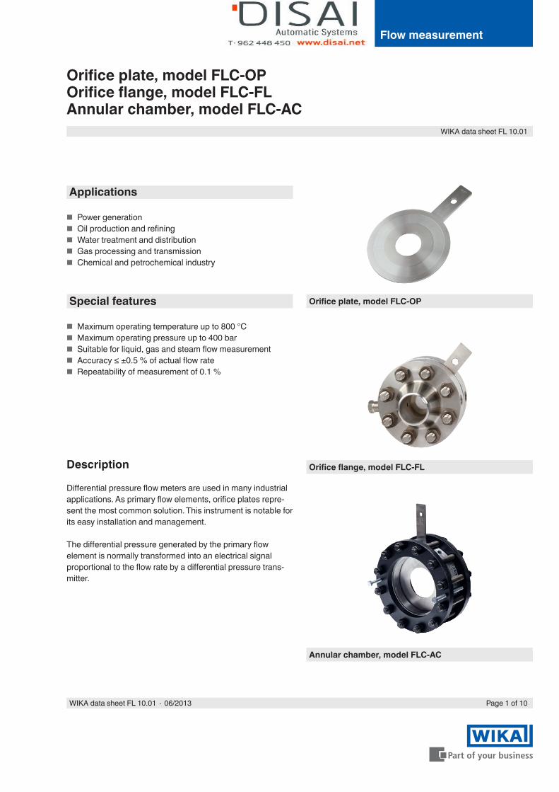
Orifice plate, model FLC-OP
Applications
■ Power generation ■ Oil production and refining ■ Water treatment and distribution ■ Gas processing and transmission ■ Chemical and petrochemical industry
Special features
■ Maximum operating temperature up to 800 °C ■ Maximum operating pressure up to 400 bar ■ Suitable for liquid, gas and steam flow measurement ■ Accuracy ≤ ±0.5 % of actual flow rate ■ Repeatability of measurement of 0.1 %
Description
Differential pressure flow meters are used in many industrial applications. As primary flow elements, orifice plates repre-sent the most common solution. This instrument is notable for its easy installation and management.
The differential pressure generated by the primary flow element is normally transformed into an electrical signal proportional to the flow rate by a differential pressure trans-mitter.
Orifice flange, model FLC-FL
Annular chamber, model FLC-AC
Page 2 of 10 WIKA data sheet FL 10.01 ∙ 06/2013
Orifice plates, model FLC-OP
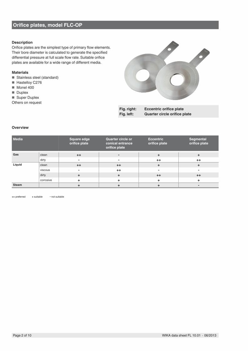
DescriptionOrifice plates are the simplest type of primary flow elements. Their bore diameter is calculated to generate the specified differential pressure at full scale flow rate. Suitable orifice plates are available for a wide range of different media.
Materials ■ Stainless steel (standard) ■ Hastelloy C276 ■ Monel 400 ■ Duplex ■ Super Duplex
Others on request
Overview
Media Square edge orifice plate
Quarter circle or conical entrance orifice plate
Eccentric orifice plate
Segmental orifice plate
Gas clean ++ - + +dirty - - ++ ++
Liquid clean ++ ++ + +viscous - ++ - -dirty + + ++ ++corrosive + + + +
Steam + + + -
++ preferred - not suitable+ suitable
Fig. right: Eccentric orifice plateFig. left: Quarter circle orifice plate
Page 3 of 10WIKA data sheet FL 10.01 ∙ 06/2013
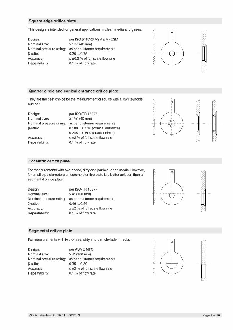
This design is intended for general applications in clean media and gases.
Design: per ISO 5167-2/ ASME MFC3MNominal size: ≥ 1½" (40 mm)Nominal pressure rating: as per customer requirementsβ-ratio: 0.20 ... 0.75Accuracy: ≤ ±0.5 % of full scale flow rateRepeatability: 0.1 % of flow rate
They are the best choice for the measurement of liquids with a low Reynolds number.
Design: per ISO/TR 15377Nominal size: ≥ 1½" (40 mm)Nominal pressure rating: as per customer requirementsβ-ratio: 0.100 ... 0.316 (conical entrance)
0.245 ... 0.600 (quarter circle)Accuracy: ≤ ±2 % of full scale flow rateRepeatability: 0.1 % of flow rate
Square edge orifice plate
Quarter circle and conical entrance orifice plate
For measurements with two-phase, dirty and particle-laden media.
Design: per ASME MFCNominal size: ≥ 4" (100 mm)Nominal pressure rating: as per customer requirementsβ-ratio: 0.35 ... 0.80Accuracy: ≤ ±2 % of full scale flow rateRepeatability: 0.1 % of flow rate
Segmental orifice plate
For measurements with two-phase, dirty and particle-laden media. However, for small pipe diameters an eccentric orifice plate is a better solution than a segmental orifice plate.
Design: per ISO/TR 15377Nominal size: > 4" (100 mm)Nominal pressure rating: as per customer requirementsβ-ratio: 0.46 ... 0.84Accuracy: ≤ ±2 % of full scale flow rateRepeatability: 0.1 % of flow rate
Eccentric orifice plate
Page 4 of 10 WIKA data sheet FL 10.01 ∙ 06/2013
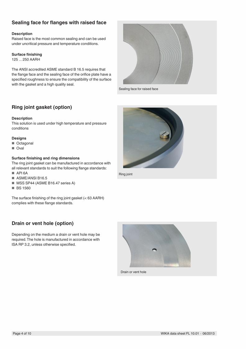
Sealing face for raised face
Sealing face for flanges with raised face
DescriptionRaised face is the most common sealing and can be used under uncritical pressure and temperature conditions.
Surface finishing125 ... 250 AARH
The ANSI accredited ASME standard B 16.5 requires that the flange face and the sealing face of the orifice plate have a specified roughness to ensure the compatibility of the surface with the gasket and a high quality seal.
Ring joint gasket (option)
DescriptionThis solution is used under high temperature and pressure conditions
Designs ■ Octagonal ■ Oval
Surface finishing and ring dimensionsThe ring joint gasket can be manufactured in accordance with all relevant standards to suit the following flange standards:
■ API 6A ■ ASME/ANSI B16.5 ■ MSS SP44 (ASME B16.47 series A) ■ BS 1560
The surface finishing of the ring joint gasket (< 63 AARH) complies with these flange standards.
Drain or vent hole (option)
Depending on the medium a drain or vent hole may be required. The hole is manufactured in accordance with ISA RP 3.2, unless otherwise specified.
Ring joint
Drain or vent hole
Page 5 of 10WIKA data sheet FL 10.01 ∙ 06/2013
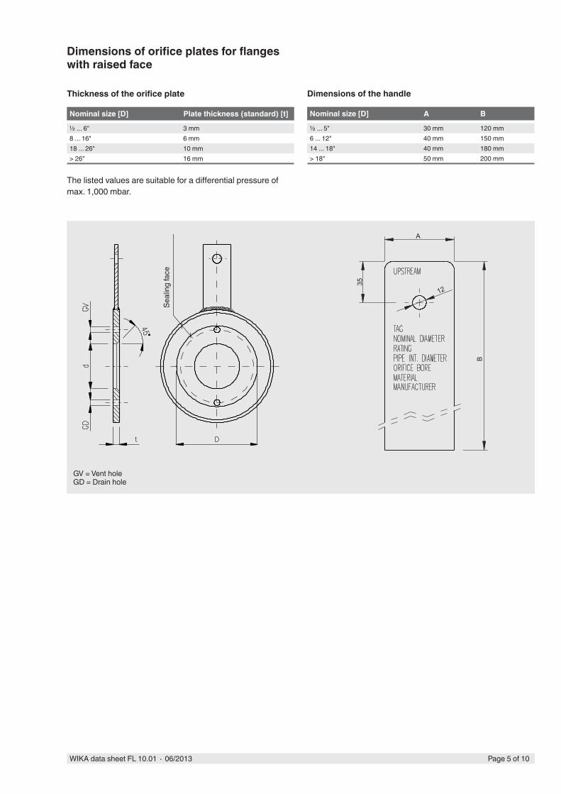
Dimensions of orifice plates for flanges with raised face
Thickness of the orifice plate
Nominal size [D] Plate thickness (standard) [t]
½ ... 6" 3 mm8 ... 16" 6 mm18 ... 26" 10 mm> 26" 16 mm
The listed values are suitable for a differential pressure of max. 1,000 mbar.
Dimensions of the handle
Nominal size [D] A B
½ ... 5" 30 mm 120 mm6 ... 12" 40 mm 150 mm14 ... 18" 40 mm 180 mm> 18" 50 mm 200 mm
GV = Vent holeGD = Drain hole
A
35
12
B
Seal
ing
face
Page 6 of 10 WIKA data sheet FL 10.01 ∙ 06/2013
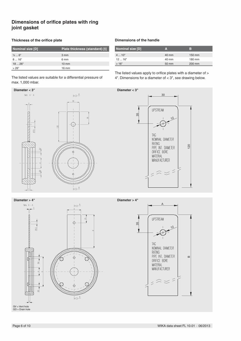
Dimensions of orifice plates with ring joint gasket
Thickness of the orifice plate
Nominal size [D] Plate thickness (standard) [t]
½ ... 6" 3 mm8 ... 16" 6 mm18 ... 26" 10 mm> 26" 16 mm
The listed values are suitable for a differential pressure of max. 1,000 mbar.
Dimensions of the handle
Nominal size [D] A B
4 ... 10" 40 mm 150 mm12 ... 16" 40 mm 180 mm> 16" 50 mm 200 mm
The listed values apply to orifice plates with a diameter of > 4". Dimensions for a diameter of < 3", see drawing below.
GV = Vent holeGD = Drain hole
30
35
12
120
A
35
12
B
Diameter < 3"
Diameter > 4"
Diameter < 3"
Diameter > 4"
Page 7 of 10WIKA data sheet FL 10.01 ∙ 06/2013
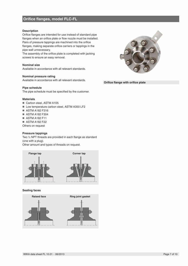
Orifice flanges, model FLC-FL
DescriptionOrifice flanges are intended for use instead of standard pipe flanges when an orifice plate or flow nozzle must be installed. Pairs of pressure tappings are machined into the orifice flanges, making separate orifice carriers or tappings in the pipe wall unnecessary.The assembly of the orifice plate is completed with jacking screws to ensure an easy removal.
Nominal sizeAvailable in accordance with all relevant standards.
Nominal pressure ratingAvailable in accordance with all relevant standards.
Pipe scheduleThe pipe schedule must be specified by the customer.
Materials ■ Carbon steel, ASTM A105 ■ Low temperature carbon steel, ASTM A350 LF2 ■ ASTM A182 F316 ■ ASTM A182 F304 ■ ASTM A182 F11 ■ ASTM A182 F22
Others on request
Pressure tappingsTwo ½ NPT threads are provided in each flange as standard (one with a plug).Other amount and types of threads on request.
Orifice flange with orifice plate
Sealing faces
Raised face Ring joint gasket
Flange tap Corner tap

Page 8 of 10 WIKA data sheet FL 10.01 ∙ 06/2013
Dimensions and weight
Standard dimensions per ASME B16.36
DN Class 300 Class 600 Class 900 Class 1,500Weight L E_D Weight L E_D Weight L E_D Weight L E_Dkg mm mm kg mm mm kg mm mm kg mm mm
1" 9 171 124 9 171 124 13 171 149 13 171 1491 ½" 13 178 155 13 178 155 18 184 178 18 184 1782" 14 178 165 14 178 165 29 209 216 29 209 2162 ½" 18 184 191 18 284 191 41 215 244 41 215 2443" 21 184 210 21 184 210 34 209 241 58 241 2674" 31 190 245 41 209 273 59 235 292 82 254 3116" 50 206 318 82 241 356 120 285 381 186 349 3948" 73 232 381 124 276 419 204 333 470 306 435 48310" 100 244 445 208 314 508 291 377 546 500 517 58412" 151 269 521 250 320 559 405 409 610 746 574 67314" 207 294 584 - 339 603 - 434 641 - 606 74916" 275 301 648 - 365 686 - 441 705 - 631 82618" 341 327 711 - 377 743 - 466 787 - 663 91420" 408 333 775 - 390 813 - 504 857 - 720 98424“ 604 345 914 - 415 940 - 593 1.041 - 822 1.168
Values approx weight (kg) and dimensions (mm) for the assembly assuming a gasket with a thickness of 1.5 mm and a plate thickness in accordance with our standard (see page 5 + 6).
Example: Flange with raised face and flange tapping
Page 9 of 10WIKA data sheet FL 10.01 ∙ 06/2013
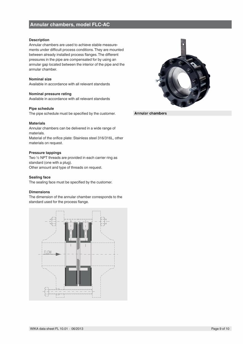
Annular chambers, model FLC-AC
DescriptionAnnular chambers are used to achieve stable measure-ments under difficult process conditions. They are mounted between already installed process flanges. The different pressures in the pipe are compensated for by using an annular gap located between the interior of the pipe and the annular chamber.
Nominal sizeAvailable in accordance with all relevant standards
Nominal pressure ratingAvailable in accordance with all relevant standards
Pipe scheduleThe pipe schedule must be specified by the customer.
MaterialsAnnular chambers can be delivered in a wide range of materials.Material of the orifice plate: Stainless steel 316/316L, other materials on request.
Pressure tappingsTwo ½ NPT threads are provided in each carrier ring as standard (one with a plug).Other amount and type of threads on request.
Sealing faceThe sealing face must be specified by the customer.
DimensionsThe dimension of the annular chamber corresponds to the standard used for the process flange.
Annular chambers
Page 10 of 10WIKA data sheet FL 10.01 ∙ 06/2013
WIKA Alexander Wiegand SE & Co. KGAlexander-Wiegand-Straße 3063911 Klingenberg/GermanyTel. (+49) 9372/132-0Fax (+49) 9372/132-406E-mail [email protected]
06/2
013
GB
© 2013 WIKA Alexander Wiegand SE & Co. KG, all rights reserved. The specifications given in this document represent the state of engineering at the time of publishing.We reserve the right to make modifications to the specifications and materials.
Ordering information
■ Orifice plate (model FLC-OP)Nominal size / Nominal pressure rating / Version / Sealing face / Drain or vent hole / Material
■ Orifice flange (FLC-FL)Nominal size / Nominal pressure rating / Pipe schedule / Sealing face / Pressure tappings / Material
■ Annular chamber (model FLC-AC)Nominal size / Nominal pressure rating / Pipe schedule / Sealing face / Pressure tappings / Material
Related Documents


