BID DOCUMENTS PROJECT MANUAL for the Organizational Storage Building Boiler Replacement and UST Removal at Branford Armory Branford, Connecticut PROJECT NO. 21MIL21501 Prepared By van Zelm, Heywood and Shadford Inc. 10 Talcott Notch FARMINGTON, CONNECTICUT 06032 CONNECTICUT ARMY NATIONAL GUARD FACILITIES MANAGEMENT OFFICE 360 Broad Street, Hartford, Connecticut Agency Tracking No. BN 14-001 10/28/2021

Welcome message from author
This document is posted to help you gain knowledge. Please leave a comment to let me know what you think about it! Share it to your friends and learn new things together.
Transcript
BID DOCUMENTS
PROJECT MANUAL
for the
Organizational Storage Building Boiler Replacement and UST Removal
at
Branford Armory Branford, Connecticut
PROJECT NO.
21MIL21501
Prepared By
van Zelm, Heywood and Shadford Inc. 10 Talcott Notch
FARMINGTON, CONNECTICUT 06032
CONNECTICUT ARMY NATIONAL GUARD FACILITIES MANAGEMENT OFFICE
360 Broad Street, Hartford, Connecticut
Agency Tracking No. BN 14-001
10/28/2021

This page intentionally blank
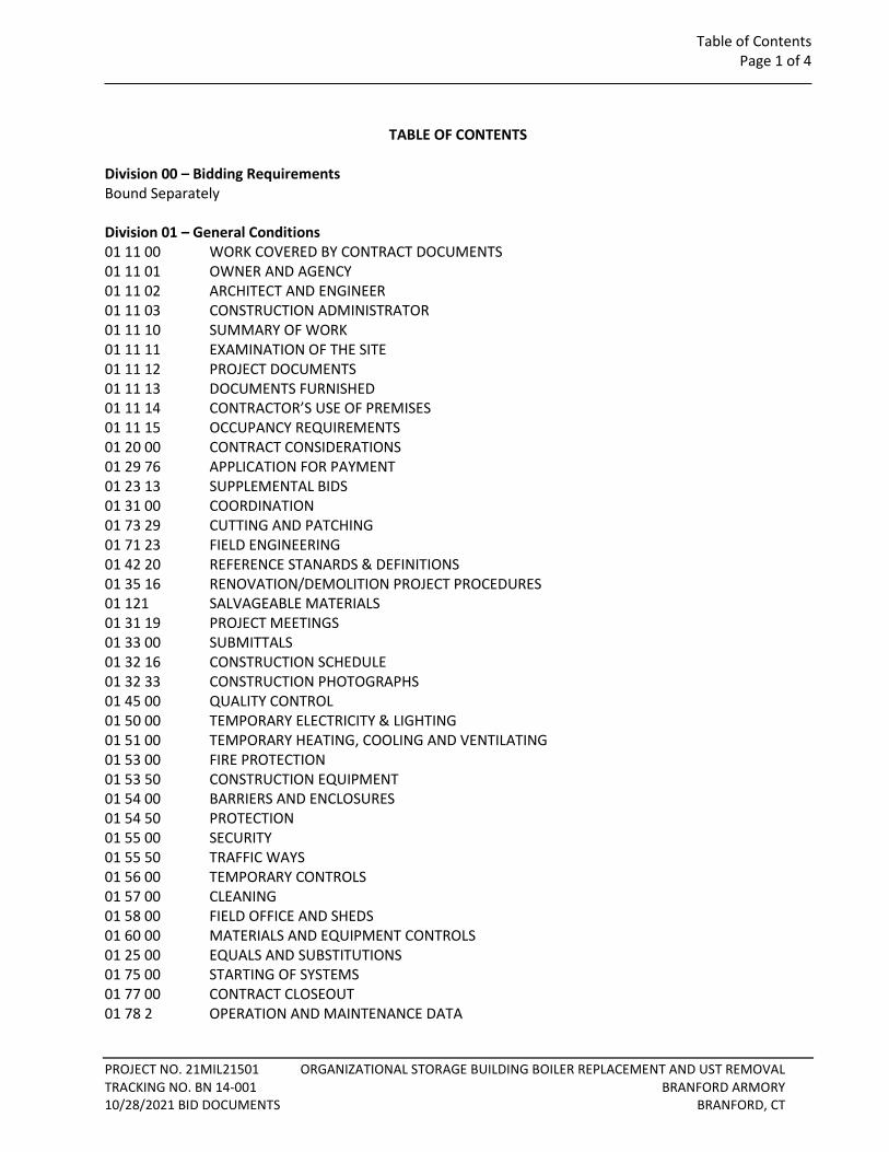
Table of Contents Page 1 of 4
PROJECT NO. 21MIL21501 ORGANIZATIONAL STORAGE BUILDING BOILER REPLACEMENT AND UST REMOVAL TRACKING NO. BN 14-001 BRANFORD ARMORY 10/28/2021 BID DOCUMENTS BRANFORD, CT
TABLE OF CONTENTS
Division 00 – Bidding Requirements Bound Separately Division 01 – General Conditions 01 11 00 WORK COVERED BY CONTRACT DOCUMENTS 01 11 01 OWNER AND AGENCY 01 11 02 ARCHITECT AND ENGINEER 01 11 03 CONSTRUCTION ADMINISTRATOR 01 11 10 SUMMARY OF WORK 01 11 11 EXAMINATION OF THE SITE 01 11 12 PROJECT DOCUMENTS 01 11 13 DOCUMENTS FURNISHED 01 11 14 CONTRACTOR’S USE OF PREMISES 01 11 15 OCCUPANCY REQUIREMENTS 01 20 00 CONTRACT CONSIDERATIONS 01 29 76 APPLICATION FOR PAYMENT 01 23 13 SUPPLEMENTAL BIDS 01 31 00 COORDINATION 01 73 29 CUTTING AND PATCHING 01 71 23 FIELD ENGINEERING 01 42 20 REFERENCE STANARDS & DEFINITIONS 01 35 16 RENOVATION/DEMOLITION PROJECT PROCEDURES 01 121 SALVAGEABLE MATERIALS 01 31 19 PROJECT MEETINGS 01 33 00 SUBMITTALS 01 32 16 CONSTRUCTION SCHEDULE 01 32 33 CONSTRUCTION PHOTOGRAPHS 01 45 00 QUALITY CONTROL 01 50 00 TEMPORARY ELECTRICITY & LIGHTING 01 51 00 TEMPORARY HEATING, COOLING AND VENTILATING 01 53 00 FIRE PROTECTION 01 53 50 CONSTRUCTION EQUIPMENT 01 54 00 BARRIERS AND ENCLOSURES 01 54 50 PROTECTION 01 55 00 SECURITY 01 55 50 TRAFFIC WAYS 01 56 00 TEMPORARY CONTROLS 01 57 00 CLEANING 01 58 00 FIELD OFFICE AND SHEDS 01 60 00 MATERIALS AND EQUIPMENT CONTROLS 01 25 00 EQUALS AND SUBSTITUTIONS 01 75 00 STARTING OF SYSTEMS 01 77 00 CONTRACT CLOSEOUT 01 78 2 OPERATION AND MAINTENANCE DATA
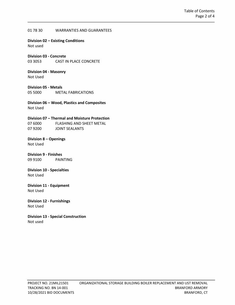
Table of Contents Page 2 of 4
PROJECT NO. 21MIL21501 ORGANIZATIONAL STORAGE BUILDING BOILER REPLACEMENT AND UST REMOVAL TRACKING NO. BN 14-001 BRANFORD ARMORY 10/28/2021 BID DOCUMENTS BRANFORD, CT
01 78 30 WARRANTIES AND GUARANTEES Division 02 – Existing Conditions Not used Division 03 - Concrete 03 3053 CAST IN PLACE CONCRETE Division 04 - Masonry Not Used Division 05 - Metals 05 5000 METAL FABRICATIONS Division 06 – Wood, Plastics and Composites Not Used Division 07 – Thermal and Moisture Protection 07 6000 FLASHING AND SHEET METAL 07 9200 JOINT SEALANTS Division 8 – Openings Not Used Division 9 - Finishes 09 9100 PAINTING Division 10 - Specialties Not Used Division 11 - Equipment Not Used Division 12 - Furnishings Not Used Division 13 - Special Construction Not used
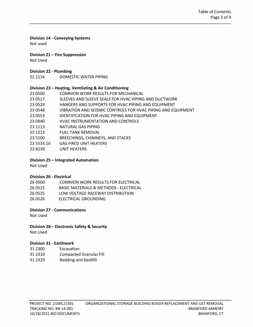
Table of Contents Page 3 of 4
PROJECT NO. 21MIL21501 ORGANIZATIONAL STORAGE BUILDING BOILER REPLACEMENT AND UST REMOVAL TRACKING NO. BN 14-001 BRANFORD ARMORY 10/28/2021 BID DOCUMENTS BRANFORD, CT
Division 14 - Conveying Systems Not used Division 21 – Fire Suppression Not Used Division 22 - Plumbing 22 1116 DOMESTIC WATER PIPING Division 23 – Heating, Ventilating & Air Conditioning 23 0500 COMMON WORK RESULTS FOR MECHANICAL 23 0517 SLEEVES AND SLEEVE SEALS FOR HVAC PIPING AND DUCTWORK 23 0529 HANGERS AND SUPPORTS FOR HVAC PIPING AND EQUIPMENT 23 0548 VIBRATION AND SEISMIC CONTROLS FOR HVAC PIPING AND EQUIPMENT 23 0553 IDENTIFICATION FOR HVAC PIPING AND EQUIPMENT 23 0940 HVAC INSTRUMENTATION AND CONTROLS 23 1113 NATURAL GAS PIPING 23 1213 FUEL TANK REMOVAL 23 5100 BREECHINGS, CHIMNEYS, AND STACKS 23 5533.16 GAS FIRED UNIT HEATERS 23 8239 UNIT HEATERS Division 25 – Integrated Automation Not Used Division 26 - Electrical 26 0500 COMMON WORK RESULTS FOR ELECTRICAL 26 0515 BASIC MATERIALS & METHODS - ELECTRICAL 26 0525 LOW VOLTAGE RACEWAY DISTRIBUTION 26 0526 ELECTRICAL GROUNDING Division 27 - Communications Not Used Division 28 – Electronic Safety & Security Not Used Division 31 - Earthwork 31 2300 Excavation 31 2310 Compacted Granular Fill 31 2320 Bedding and Backfill
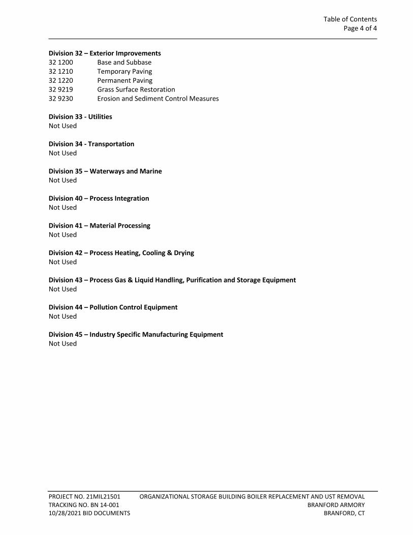
Table of Contents Page 4 of 4
PROJECT NO. 21MIL21501 ORGANIZATIONAL STORAGE BUILDING BOILER REPLACEMENT AND UST REMOVAL TRACKING NO. BN 14-001 BRANFORD ARMORY 10/28/2021 BID DOCUMENTS BRANFORD, CT
Division 32 – Exterior Improvements 32 1200 Base and Subbase 32 1210 Temporary Paving 32 1220 Permanent Paving 32 9219 Grass Surface Restoration 32 9230 Erosion and Sediment Control Measures Division 33 - Utilities Not Used Division 34 - Transportation Not Used Division 35 – Waterways and Marine Not Used Division 40 – Process Integration Not Used Division 41 – Material Processing Not Used Division 42 – Process Heating, Cooling & Drying Not Used Division 43 – Process Gas & Liquid Handling, Purification and Storage Equipment Not Used Division 44 – Pollution Control Equipment Not Used Division 45 – Industry Specific Manufacturing Equipment Not Used
List of Drawings Page 1 of 1
PROJECT NO. 21MIL21501 ORGANIZATIONAL STORAGE BUILDING BOILER REPLACEMENT AND UST REMOVAL TRACKING NO. BN 14-001 BRANFORD ARMORY 10/28/2021 BID DOCUMENTS BRANFORD, CT
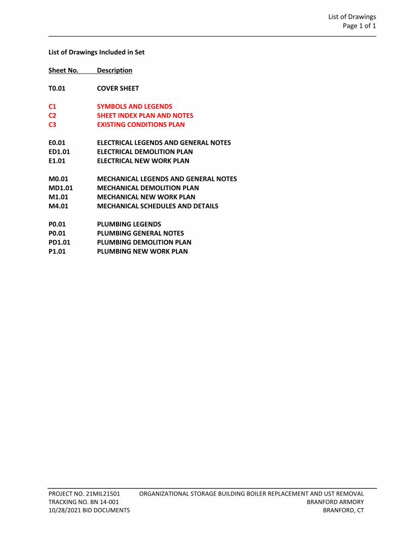
List of Drawings Included in Set Sheet No. Description T0.01 COVER SHEET C1 SYMBOLS AND LEGENDS C2 SHEET INDEX PLAN AND NOTES C3 EXISTING CONDITIONS PLAN E0.01 ELECTRICAL LEGENDS AND GENERAL NOTES ED1.01 ELECTRICAL DEMOLITION PLAN E1.01 ELECTRICAL NEW WORK PLAN M0.01 MECHANICAL LEGENDS AND GENERAL NOTES MD1.01 MECHANICAL DEMOLITION PLAN M1.01 MECHANICAL NEW WORK PLAN M4.01 MECHANICAL SCHEDULES AND DETAILS P0.01 PLUMBING LEGENDS P0.01 PLUMBING GENERAL NOTES PD1.01 PLUMBING DEMOLITION PLAN P1.01 PLUMBING NEW WORK PLAN

DIVISION 1 GENERAL REQUIREMENTS
PAGE 1 OF 55
PROJECT NO. 21MIL21501 ORGANIZATIONAL STORAGE BUILDING BOILER REPLACEMENT AND UST REMOVAL TRACKING NO. BN 14-001 BRANFORD ARMORY 10/28/2021 BID DOCUMENTS BRANFORD, CT
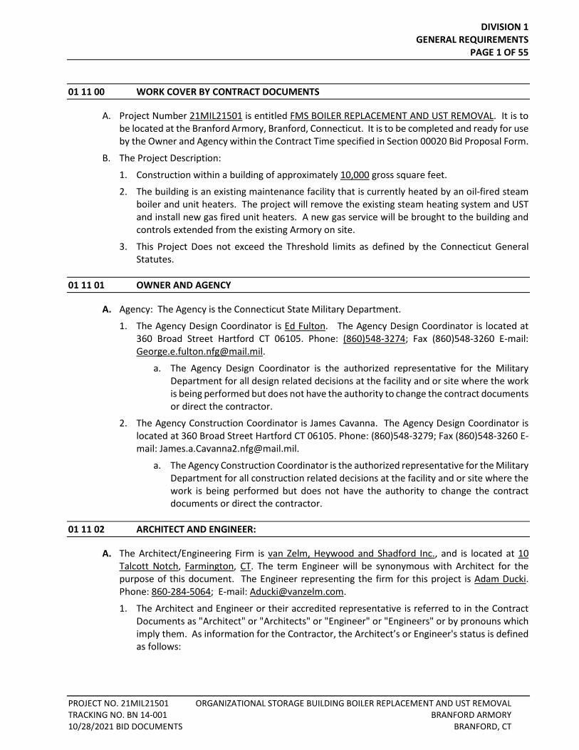
01 11 00 WORK COVER BY CONTRACT DOCUMENTS
A. Project Number 21MIL21501 is entitled FMS BOILER REPLACEMENT AND UST REMOVAL. It is to be located at the Branford Armory, Branford, Connecticut. It is to be completed and ready for use by the Owner and Agency within the Contract Time specified in Section 00020 Bid Proposal Form.
B. The Project Description:
1. Construction within a building of approximately 10,000 gross square feet.
2. The building is an existing maintenance facility that is currently heated by an oil-fired steam boiler and unit heaters. The project will remove the existing steam heating system and UST and install new gas fired unit heaters. A new gas service will be brought to the building and controls extended from the existing Armory on site.
3. This Project Does not exceed the Threshold limits as defined by the Connecticut General Statutes.
01 11 01 OWNER AND AGENCY
A. Agency: The Agency is the Connecticut State Military Department.
1. The Agency Design Coordinator is Ed Fulton. The Agency Design Coordinator is located at 360 Broad Street Hartford CT 06105. Phone: (860)548-3274; Fax (860)548-3260 E-mail: [email protected].
a. The Agency Design Coordinator is the authorized representative for the Military Department for all design related decisions at the facility and or site where the work is being performed but does not have the authority to change the contract documents or direct the contractor.
2. The Agency Construction Coordinator is James Cavanna. The Agency Design Coordinator is located at 360 Broad Street Hartford CT 06105. Phone: (860)548-3279; Fax (860)548-3260 E-mail: [email protected].
a. The Agency Construction Coordinator is the authorized representative for the Military Department for all construction related decisions at the facility and or site where the work is being performed but does not have the authority to change the contract documents or direct the contractor.
01 11 02 ARCHITECT AND ENGINEER:
A. The Architect/Engineering Firm is van Zelm, Heywood and Shadford Inc., and is located at 10 Talcott Notch, Farmington, CT. The term Engineer will be synonymous with Architect for the purpose of this document. The Engineer representing the firm for this project is Adam Ducki. Phone: 860-284-5064; E-mail: [email protected].
1. The Architect and Engineer or their accredited representative is referred to in the Contract Documents as "Architect" or "Architects" or "Engineer" or "Engineers" or by pronouns which imply them. As information for the Contractor, the Architect’s or Engineer's status is defined as follows:

DIVISION 1 GENERAL REQUIREMENTS
PAGE 2 OF 55
PROJECT NO. 21MIL21501 ORGANIZATIONAL STORAGE BUILDING BOILER REPLACEMENT AND UST REMOVAL TRACKING NO. BN 14-001 BRANFORD ARMORY 10/28/2021 BID DOCUMENTS BRANFORD, CT
a. The Architect and Engineer will not make interpretations or decisions directly to the Contractor. All interpretations or decisions will be conveyed through the Construction Administrator.
b. As the authorized representative of the Department of Public Works Commissioner, the Architect and Engineer is responsible for review of shop drawings, materials, and equipment intended for the work, in accordance with the "General Conditions", and the "Supplementary Conditions”.
2. Wherever the Architect or Engineer is mentioned in the documents in connection with an administrative function, it shall include the Construction Administrator in that function except for shop drawings.
01 11 03 CONSTRUCTION ADMINISTRATOR:
A. The Construction Administrator is James Cavanna The Agency Design Coordinator is located at 360 Broad Street Hartford CT 06105. Phone: (860)548-3279; Fax: (860)548-3260 E-mail: [email protected]..
1. The Construction Administrator is referred to in the Contract Documents as "Construction Administrator" or "Construction Manager" or by pronouns which imply it. All communications concerning the project will be directed through the Construction Administrator or a designated representative(s).
2. As information to the Contractor, the Construction Administrator’s status is defined as follows:
a. The Construction Administrator is the Owner's Agent who will, among other thing’s, monitor the General Contractor's performance, scheduling and construction, process shop drawings, material, and equipment submittals, review and process periodic billings, review and recommend cost changes.
b. The Construction Administrator will process all requests for information, interpretations and decisions regarding the meaning and intent of the Contract Documents, consulting with appropriate parties prior to rendering the interpretations or decisions to the Contractor. All such requests and replies shall be in writing.
01 11 10 SUMMARY OF WORK
A. Summary of Work includes but is not limited to the following:
1. Sitework, Landscaping, Site Utilities;
2. Cast-in-Place Concrete, Architectural Precast Concrete;
3. Miscellaneous Metals;
4. Rough Carpentry;
5. Waterproofing, Roofing, Sheet metal, and Joint Sealants;
6. Painting;
7. Mechanical equipment, piping, demolition and installation
8. Electrical equipment, demolition and installation
DIVISION 1 GENERAL REQUIREMENTS
PAGE 3 OF 55
PROJECT NO. 21MIL21501 ORGANIZATIONAL STORAGE BUILDING BOILER REPLACEMENT AND UST REMOVAL TRACKING NO. BN 14-001 BRANFORD ARMORY 10/28/2021 BID DOCUMENTS BRANFORD, CT
B. The Contractor will include in his bid, all items required in order to carry out the intent of the work as described, shown and implied in the Contract Documents.
C. It shall be the Contractor's responsibility upon discovery to immediately notify the Construction Administrator, in writing, of errors, omissions, discrepancies, and instances of noncompliance with applicable codes and regulations within the documents, and of any work which will not fit or properly function if installed as indicated on the Contract Documents. Any additional costs arising from the Contractor's failure to provide such notification shall be borne by the Contractor.
D. The Work will be constructed under a single lump.
E. Work Sequence - Phase(s):
1. The entire Project shall be constructed in 1 Phase(s). Work of these Phase(s) shall be substantially complete, ready for occupancy within 180 Calendar Days of commencement of the Work.
01 11 11 EXAMINATION OF SITE
A. It is not the intent of the Documents to show all existing conditions. All contractors are advised to visit and examine the site with the Construction Administrator prior to submitting bids.
B. Contractors should investigate and satisfy themselves as to the conditions affecting the work, including but no restricted to those bearing upon transportation, disposal, handling and storage of materials, availability of labor, water, electric power, uncertainties of weather, roads or similar physical conditions of the ground, the character of equipment, and facilities needed preliminary to and during the prosecution of the Work. The Contractor should further satisfy himself as to the character, quality, and quantity of surface and subsurface materials or obstacles to be encountered insofar as this information is reasonably ascertainable from an inspection of the site, as well as from information presented by the Contract Documents. Any failure by the Contractor to acquaint himself with the available information shall not relieve him from the responsibility for estimating properly the difficulty and cost of successfully performing the Work.
C. Review Of Geo-Technical Reports and Boring Logs are contained in a separate Volume of this Project Manual, the Boring Location Plans are in the Contract Documents.
D. Pre-Bid Conference:
1. A Pre-Bid Conference and tour of the site will be conducted as scheduled in the Invitation to Bid. This scheduled conference is the only official opportunity for the bidders to tour the site with the Owner, Architect, Engineer, Construction Administrator, and Agency.
01 11 12 PROJECT DOCUMENTS
A. The Specifications and Drawings are intended to describe and illustrate the materials and labor necessary for the work of this Project.
B. Throughout the Technical Specifications, the Connecticut Department of Transportation Standard Specifications for Roads, Bridges, and Incidental Construction Form 817, 2017 including any interim and supplemental specifications are referenced. Where so referenced the requirements set forth therein are applicable and made a part hereof Copies of Form 817 are available from the Connecticut Department of Transportation at a nominal charge.
DIVISION 1 GENERAL REQUIREMENTS
PAGE 4 OF 55
PROJECT NO. 21MIL21501 ORGANIZATIONAL STORAGE BUILDING BOILER REPLACEMENT AND UST REMOVAL TRACKING NO. BN 14-001 BRANFORD ARMORY 10/28/2021 BID DOCUMENTS BRANFORD, CT
01 11 13 DOCUMENTS FURNISHED
A. The General Contractor will be given sets of the Contract Documents on or about the time of execution of Contract, free of charge. If additional copies are wanted, they will be available at the direct additional cost of their reproduction, to the contractor.
B. The Contractor shall receive one (1) set of AutoCAD compatible (latest version) Floor Plans on disks at no cost on or about the time of execution of the Contract from the Architect. Additional sets of AutoCAD compatible (latest version) Floor Plans on disks from the Architect at the cost of their reproduction, to the contractor.
01 11 14 CONTRACTOR'S USE OF PREMISES
A. The Contractor shall confine his operations, including storage of apparatus, equipment and materials to the contract limit lines as directed by the Construction Administrator.
B. The areas and/or spaces, including their access, shall be maintained free and clear throughout the contract term.
C. Parking for Contractor's employees will be limited to an area (or areas) designated by the Construction Administrator. The Contractor may be required to provide identification stickers for employees' cars.
01 11 15 OCCUPANCY REQUIREMENTS
A. Partial Agency Occupancy: The Agency reserves the right to occupy and to place and install equipment in completed areas of the building prior to Substantial Completion, provided such occupancy does not interfere with completion of the Work. Such placing of equipment and partial occupancy shall not constitute acceptance of the total Work.
1. Should it become necessary or advisable, as the work nears final completion, for the Agency to occupy a portion of the building prior to final acceptance, the Contractor shall cooperate in completing such areas and making same accessible.
2. The Construction Administrator will determine whether such occupancy or use is possible and, if so, will make arrangements for holding a job inspection with the Project Manager, Agency Representative, Architect and General Contractor.
3. A comprehensive list of items to be completed or corrected as issued by the General Contractor, together with the status of completion and terms of occupancy, will be forwarded to the Project Manager and the Architect by the Construction Administrator. A letter will be issued by the Project Manager and Architect to Construction Administrator granting such occupancy and will state the terms and conditions of occupancy.
4. Prior to partial Agency occupancy, mechanical and electrical systems shall be fully operational. Required inspections and tests shall have been successfully completed. Upon occupancy, the Agency will operate and maintain mechanical and electrical systems serving occupied portions of the building.
5. The Architect will prepare a “Certificate of Substantial Completion” for each specific portion of the Work to be occupied prior to Agency occupancy. Use the “Certificate of Substantial Completion” form as required by the Owner.
DIVISION 1 GENERAL REQUIREMENTS
PAGE 5 OF 55
PROJECT NO. 21MIL21501 ORGANIZATIONAL STORAGE BUILDING BOILER REPLACEMENT AND UST REMOVAL TRACKING NO. BN 14-001 BRANFORD ARMORY 10/28/2021 BID DOCUMENTS BRANFORD, CT
6. The Project Manager will request a signed “Certificate of Compliance” from Commissioner of the Department of Public Works, Architect, and Contractor, if required.
6. The Project Manager will request a signed “Certificate of Compliance” from the , Architect, and Contractor, and forward the Certificate to the Office of State Building Inspector for a Certificate of Occupancy and obtain the same after his review and approval.
7. A letter from the Project Manager to the Agency Representative with copy to the General Contractor granting occupancy will state the terms and conditions of occupancy and that fire insurance coverage has been requested, the effective date of which will indicate to the Contractor that he may cancel fire insurance coverage for that portion of the project.
8. Upon occupancy, the Agency will assume responsibility for maintenance and custodial service for occupied portions of the building.
9. Work after Partial Agency Occupancy:
a. For all work to complete the area occupied, warranty work, the balancing and commissioning of systems, repair of latent defects and adjustments after partial occupancy, the contractor is responsible for all costs associated with working in occupied buildings.
B. Agency Occupancy:
1. The Construction Administrator will determine whether such occupancy is possible and, if so, will make arrangements for holding a job inspection with the Project Manager, Agency Representative, Architect and General Contractor.
2. A comprehensive list of items to be completed or corrected as issued by the General Contractor, together with the status of completion and terms of occupancy, will be forwarded to the Project Manager and the Architect by the Construction Administrator. A letter will be issued by the Project Manager and Architect to Construction Administrator granting such occupancy and will state the terms and conditions of occupancy.
3. Prior to Agency occupancy, mechanical and electrical systems shall be fully operational. Required inspections and tests shall have been successfully completed. Upon occupancy, the Agency will operate and maintain mechanical and electrical systems serving occupied portions of the building.
4. The Architect will prepare a “Certificate of Substantial Completion” for the Work to be occupied prior to Agency occupancy. Use the “Certificate of Substantial Completion” form as required by the Owner.
5. The Project Manager will request a signed “Certificate of Compliance” from Commissioner of the Department of Public Works, Architect, and Contractor, if required.
5. The Project Manager will request a signed “Certificate of Compliance” from the Architect, and Contractor, and forward the Certificate to the State Building Inspector a Certificate of Occupancy and obtain the same after his review and approval.
6. A letter from the Project Manager to the Agency Representative with copy to the General Contractor granting occupancy will state the terms and conditions of occupancy and that fire insurance coverage has been requested, the effective date of which will indicate to the Contractor that he may cancel fire insurance coverage for the project.
7. Upon occupancy, the Agency will assume responsibility for maintenance and custodial service for occupied portions of the building.
DIVISION 1 GENERAL REQUIREMENTS
PAGE 6 OF 55
PROJECT NO. 21MIL21501 ORGANIZATIONAL STORAGE BUILDING BOILER REPLACEMENT AND UST REMOVAL TRACKING NO. BN 14-001 BRANFORD ARMORY 10/28/2021 BID DOCUMENTS BRANFORD, CT
8. Work after Agency Occupancy:
a. For all work to complete the occupied building, warranty work, the balancing and commissioning of systems, repair of latent defects and adjustments after occupancy, the contractor is responsible for all costs associated with working in occupied buildings.
01 20 00 CONTRACT CONSIDERATIONS
1. Architect/Engineer Responsibilities:
a. Consult with Contractor for consideration of Products, suppliers and installers.
b. Select Products in consultation with the Project Manager and Agency Representatives and transmit decision to Construction Administrator.
c. Prepare Change Order.
2. Construction Administrator Responsibilities:
a. Consult with Architect/Engineer, Contractor, Project Manager and Agency Representatives for consideration of Products, suppliers and installers.
b. Select Products in consultation with Architect/Engineer, Project Manager and Agency Representatives and transmit decision to Contractor
c. Prepare Change Order.
3. Contractor Responsibilities:
a. Assist Architect/Engineer and Construction Administrator in selection of Products and Suppliers.
b. Obtain proposals from Suppliers and offer recommendations.
c. On notification of selection by Construction Administrator execute purchase agreement with designated supplier.
d. Arrange for and process shop drawings, product data, and samples. Arrange for delivery.
e. If the actual cost of an Allowance item is more or less than the given amount, the Contract Sum will be adjusted by Change Order.
A. Unit Prices - General:
1. Definition - Unit Price: Amount the General Contractor acknowledges in the Bid Proposal Form as a price per unit of measurement for materials or services as described in the Bidding Documents or in the Contract Documents.
2. Procedures:
a. Unit Prices included in the Contract Documents are to be used for determining compensation to the Contractor or Owner for changes to the scope of the work indicated in the Contract Documents, and included in the Lump Sum Contract Price. Special Unit Prices are for items complete, in place, and shall be inclusive of furnishing and installing of all material, labor, trucking, overhead, profit, equipment, hoisting, engineering, scaffolding, power hookups, protection, shop drawings, taxes, permits, appliances, delivery, insurance, supervision, cost of bond, etc. and shall remain in effect until completion of the Contract.
DIVISION 1 GENERAL REQUIREMENTS
PAGE 7 OF 55
PROJECT NO. 21MIL21501 ORGANIZATIONAL STORAGE BUILDING BOILER REPLACEMENT AND UST REMOVAL TRACKING NO. BN 14-001 BRANFORD ARMORY 10/28/2021 BID DOCUMENTS BRANFORD, CT
b. Unit Price: Is identified by the Owner as a price per unit of measurement for materials or services added to or deducted from the Contract Sum by appropriate modification, if the estimated quantities of Work required by the Contract Documents are increased or decreased.
c. Increases or Decreases: Should the amount of the Work required be increased or decreased because of changes in the work ordered in writing by the Project Manager, the Undersigned agrees that the following supplemental UNIT PRICES will be decreased 10% for a reduction of work. Each Unit Price shall include all equipment, tools, labor, permits, fees, etc., incidental to the completion of the work involved. All items marked with an asterisk (*) in the unit price schedules shall include the completion of the excavation, formation and compaction of sub-grade and the disposal of surplus or unsuitable materials in accordance with the Plans and Specifications or as directed by the Construction Administrator.
2. The Owner reserves the right to reject the Contractor's measurement of work-in-place that involves use of established unit prices, and to have this work measured, at the Owner's expense, by an independent surveyor acceptable to the Contractor.
3. Defect Assessment: Replace the Work, or portions of the Work, not conforming to the specified requirements. If, in the opinion of the Architect/Engineer it is not practical to remove and replace the work the Architect/Engineer will direct an appropriate remedy or adjust the payment.
4. Unit Price Schedule: A "Unit Price Schedule" is included at the end of this Section. Specification Sections referenced in the Schedule contain requirements for materials described under each unit price.
B. Unit Price Schedule - Earth and Rock Excavation: This Section includes administrative and procedural requirements for the following unit prices and provisions are to be included in and become part of this Contract to be used in evaluating additions to or deductions from the work called for in the specifications and/or plans.
1. Unless otherwise specified elsewhere in these documents, Contractors are to assume that all excavation is earth; however, if unspecified rock is encountered, it will be paid for at the given unit prices listed in paragraph “E”. Rock prices are net in that allowances for reduced quantities of earth are also included in the unit prices. The prices given include all costs for overhead, profit and rock surveys.
2. Wherever rock to be excavated is encountered, the Contractor shall strip or expose the rock to such an extent that in the Owner’s opinion the necessary measurements can be taken. The Contractor shall provide the Owner with a survey by a licensed land surveyor indicating top of rock elevations at points of intersection on a rectilinear grid with lines spaced sufficiently close to show accurately the rock surface contours. At the Owner’s option, an additional survey may be furnished by the Owner from a licensed surveyor.
3. If the conditions of the excavation work indicated are clearly of a special nature, the Contractor may ask the Owner for reconsideration of the established unit prices and if granted, the unit prices will not apply, and prices will be negotiated in accordance with Article 13 “Compensations for Changes in the Work” of the General Conditions.
C. Definitions:
DIVISION 1 GENERAL REQUIREMENTS
PAGE 8 OF 55
PROJECT NO. 21MIL21501 ORGANIZATIONAL STORAGE BUILDING BOILER REPLACEMENT AND UST REMOVAL TRACKING NO. BN 14-001 BRANFORD ARMORY 10/28/2021 BID DOCUMENTS BRANFORD, CT
1. “EARTH” - is defined, as excavation shall include removal of all materials other than ‘water’ and ‘rock’.
2. “ROCK” - is defined as a boulder of 1 cubic yard or more in volume (1/2 cubic yard for a boulder in trenches), and rock in definite ledge formation and masonry structures of one cubic yard or more in volume, the removal of which requires the use of mechanical equipment or the use of explosives. Rock removed by scarification or ripping method is considered as a separate classification under paragraph 4.a.(1).
3. “ORIGINAL GRADE” - is defined as being the grade which exists at the time of Contract Award.
4. “ROUGH GRADE” - is defined as being the completed surface of required excavations greater than 13’ in width.
5. “MASS” - excavation is to be considered as an open area whose minimum horizontal dimensions exceeds 13’.
6. “TRENCH” - is defined as excavation is defined as the removal of material from areas 13 feet or less in its minimal horizontal dimensions and below the elevation of rough grade or original grade, whichever is lower.
D. Procedures: 1. Rock Excavation In Trenches: Basis For Horizontal Measurement:
a. Horizontal Measurements: Will be taken between the vertical planes as defined below.
b. The Minimum Width Of Trenches In Rock: Will be taken as 3’ 0”.
c. Excavation - For Walls Or Piers With Footings: The measurements will be taken parallel to and one foot outside of the edges of the concrete footings as called for in the plans (i.e. for 4’ 0” footing, rock will be taken as 6’ 0” in width).
d. Excavation For Walls Or Piers Without Footings: The limits of the excavation will be 1’ 6” outside of the line of concrete at bottom as shown or called for in the plans (i.e. for a wall with a bottom thickness of 1’ 0”, the width of the trench will be considered to be 4’ 0”). (Caissons are excluded from these measurements).
e. Excavation For Pipe Lines: Will be measured at 2’ 0” more than the nominal inside diameter of the pipe but in no case less than 3’ 0” wide.
f. Excavation For Tanks, Vaults, Manholes, Pits, Etc.: Will be measured as 2’ 0” greater in both length and width or diameter than the actual exterior dimensions of the structures and this excavation is considered to be trench only if any measured horizontal dimensions is 13’ or less.
g. No allowance will be made for rock removed beyond the above limits.
2. Rock Excavation In Trenches - Basis for Vertical Measurement:
a. To determine depth of trench, vertical measurements will be taken from original grade or rough grade, (whichever is applicable), to the bottom of required excavation. These measurements will define the maximum depths for payments.
b. To determine quantity of rock in trench, vertical measurements will be taken from the top of rock as encountered in the trench to 12” below the bottom of required rock excavation. Any over excavation below the required elevation shall be filled with concrete or other material as specified at no cost to the Owner.
DIVISION 1 GENERAL REQUIREMENTS
PAGE 9 OF 55
PROJECT NO. 21MIL21501 ORGANIZATIONAL STORAGE BUILDING BOILER REPLACEMENT AND UST REMOVAL TRACKING NO. BN 14-001 BRANFORD ARMORY 10/28/2021 BID DOCUMENTS BRANFORD, CT
c. No allowance will be made for rock removed beyond the above limits.
3. Earth Excavation In Trenches - Basis Of Measurement: (Horizontal & Vertical): The basis of measurements and allowance limit for earth excavation in trenches is identical to that indicated for rock excavation in trenches, except that there will be no allowance for 12” below the required elevation. In addition the following will prevail:
a. Maximum allowable widths for earth excavation in trenches without shoring: Trench Depth - Classification Add To Nominal ID Of Pipe Or To Footing Width
0 ft. - 6 ft. 3 ft. Over 6 ft. - 10 ft. 5 ft. Over 10 ft. - 15 ft. 7 ft. Below 15 ft. deep the width of the trench shall be based on the individual case. The final depth of trench will determine the actual width for payment.
b. If shoring is required the measurement shall be taken between the exterior walls of the shoring not to exceed 4’ plus the I.D. of the pipe (for all depths).
c. To determine quantity of earth in trench, vertical measurements will be taken from the original or rough grade to actual bottom of earth excavation required.
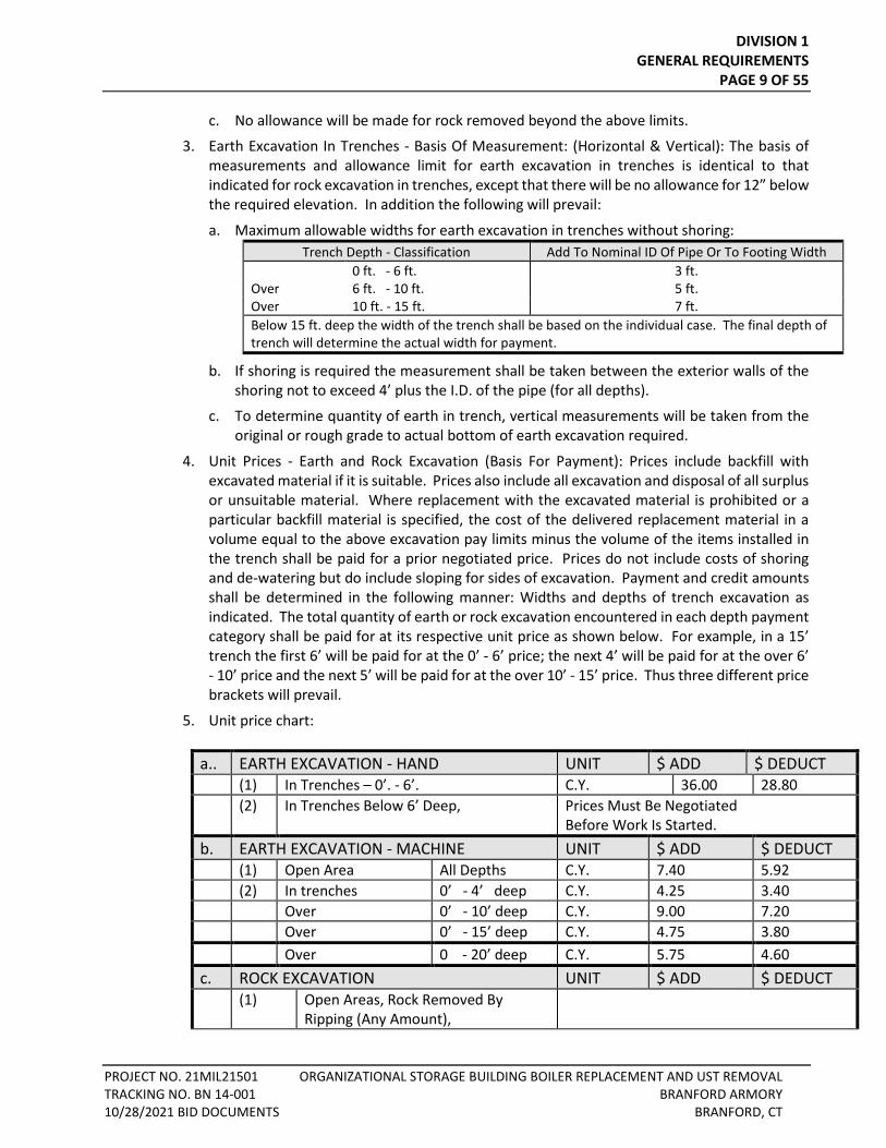
4. Unit Prices - Earth and Rock Excavation (Basis For Payment): Prices include backfill with excavated material if it is suitable. Prices also include all excavation and disposal of all surplus or unsuitable material. Where replacement with the excavated material is prohibited or a particular backfill material is specified, the cost of the delivered replacement material in a volume equal to the above excavation pay limits minus the volume of the items installed in the trench shall be paid for a prior negotiated price. Prices do not include costs of shoring and de-watering but do include sloping for sides of excavation. Payment and credit amounts shall be determined in the following manner: Widths and depths of trench excavation as indicated. The total quantity of earth or rock excavation encountered in each depth payment category shall be paid for at its respective unit price as shown below. For example, in a 15’ trench the first 6’ will be paid for at the 0’ - 6’ price; the next 4’ will be paid for at the over 6’ - 10’ price and the next 5’ will be paid for at the over 10’ - 15’ price. Thus three different price brackets will prevail.
5. Unit price chart:
a.. EARTH EXCAVATION - HAND UNIT $ ADD $ DEDUCT (1) In Trenches – 0’. - 6’. C.Y. 36.00 28.80 (2) In Trenches Below 6’ Deep, Prices Must Be Negotiated
Before Work Is Started. b. EARTH EXCAVATION - MACHINE UNIT $ ADD $ DEDUCT (1) Open Area All Depths C.Y. 7.40 5.92 (2) In trenches 0’ - 4’ deep C.Y. 4.25 3.40 Over 0’ - 10’ deep C.Y. 9.00 7.20 Over 0’ - 15’ deep C.Y. 4.75 3.80 Over 0 - 20’ deep C.Y. 5.75 4.60 c. ROCK EXCAVATION UNIT $ ADD $ DEDUCT (1) Open Areas, Rock Removed By
Ripping (Any Amount),
DIVISION 1 GENERAL REQUIREMENTS
PAGE 10 OF 55
PROJECT NO. 21MIL21501 ORGANIZATIONAL STORAGE BUILDING BOILER REPLACEMENT AND UST REMOVAL TRACKING NO. BN 14-001 BRANFORD ARMORY 10/28/2021 BID DOCUMENTS BRANFORD, CT
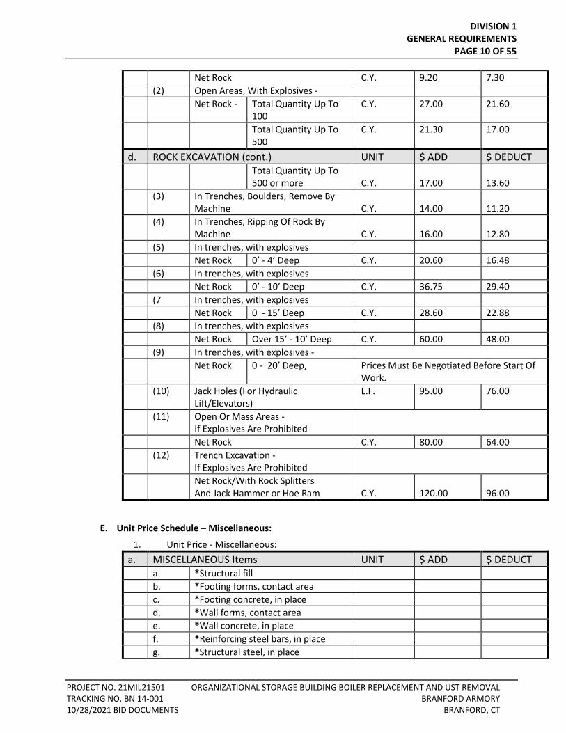
Net Rock C.Y. 9.20 7.30 (2) Open Areas, With Explosives - Net Rock - Total Quantity Up To
100 C.Y. 27.00 21.60
Total Quantity Up To 500
C.Y. 21.30 17.00
d. ROCK EXCAVATION (cont.) UNIT $ ADD $ DEDUCT Total Quantity Up To
500 or more C.Y.
17.00
13.60
(3) In Trenches, Boulders, Remove By Machine
C.Y.
14.00
11.20
(4) In Trenches, Ripping Of Rock By Machine
C.Y.
16.00
12.80
(5) In trenches, with explosives Net Rock 0’ - 4’ Deep C.Y. 20.60 16.48 (6) In trenches, with explosives Net Rock 0’ - 10’ Deep C.Y. 36.75 29.40 (7 In trenches, with explosives Net Rock 0 - 15’ Deep C.Y. 28.60 22.88 (8) In trenches, with explosives Net Rock Over 15’ - 10’ Deep C.Y. 60.00 48.00 (9) In trenches, with explosives - Net Rock 0 - 20’ Deep, Prices Must Be Negotiated Before Start Of
Work. (10) Jack Holes (For Hydraulic
Lift/Elevators) L.F. 95.00 76.00
(11) Open Or Mass Areas - If Explosives Are Prohibited
Net Rock C.Y. 80.00 64.00 (12) Trench Excavation -
If Explosives Are Prohibited
Net Rock/With Rock Splitters And Jack Hammer or Hoe Ram
C.Y.
120.00
96.00
E. Unit Price Schedule – Miscellaneous:
1. Unit Price - Miscellaneous: a. MISCELLANEOUS Items UNIT $ ADD $ DEDUCT a. *Structural fill b. *Footing forms, contact area c. *Footing concrete, in place d. *Wall forms, contact area e. *Wall concrete, in place f. *Reinforcing steel bars, in place g. *Structural steel, in place
DIVISION 1 GENERAL REQUIREMENTS
PAGE 11 OF 55
PROJECT NO. 21MIL21501 ORGANIZATIONAL STORAGE BUILDING BOILER REPLACEMENT AND UST REMOVAL TRACKING NO. BN 14-001 BRANFORD ARMORY 10/28/2021 BID DOCUMENTS BRANFORD, CT
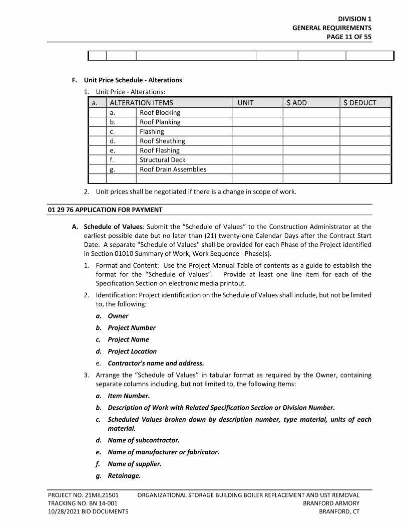
F. Unit Price Schedule - Alterations
1. Unit Price - Alterations: a. ALTERATION ITEMS UNIT $ ADD $ DEDUCT a. Roof Blocking b. Roof Planking c. Flashing d. Roof Sheathing e. Roof Flashing f. Structural Deck g. Roof Drain Assemblies
2. Unit prices shall be negotiated if there is a change in scope of work.
01 29 76 APPLICATION FOR PAYMENT
A. Schedule of Values: Submit the “Schedule of Values” to the Construction Administrator at the earliest possible date but no later than (21) twenty-one Calendar Days after the Contract Start Date. A separate "Schedule of Values" shall be provided for each Phase of the Project identified in Section 01010 Summary of Work, Work Sequence - Phase(s).
1. Format and Content: Use the Project Manual Table of contents as a guide to establish the format for the “Schedule of Values”. Provide at least one line item for each of the Specification Section on electronic media printout.
2. Identification: Project identification on the Schedule of Values shall include, but not be limited to, the following:
a. Owner
b. Project Number
c. Project Name
d. Project Location
e. Contractor's name and address.
3. Arrange the “Schedule of Values” in tabular format as required by the Owner, containing separate columns including, but not limited to, the following Items:
a. Item Number.
b. Description of Work with Related Specification Section or Division Number.
c. Scheduled Values broken down by description number, type material, units of each material.
d. Name of subcontractor.
e. Name of manufacturer or fabricator.
f. Name of supplier.
g. Retainage.
DIVISION 1 GENERAL REQUIREMENTS
PAGE 12 OF 55
PROJECT NO. 21MIL21501 ORGANIZATIONAL STORAGE BUILDING BOILER REPLACEMENT AND UST REMOVAL TRACKING NO. BN 14-001 BRANFORD ARMORY 10/28/2021 BID DOCUMENTS BRANFORD, CT
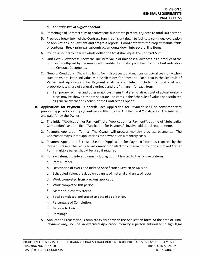
h. Contract sum in sufficient detail.
4. Percentage of Contract Sum to nearest one-hundredth percent, adjusted to total 100 percent.
5. Provide a breakdown of the Contract Sum in sufficient detail to facilitate continued evaluation of Applications for Payment and progress reports. Coordinate with the Project Manual table of contents. Break principal subcontract amounts down into several line items.
6. Round amounts to nearest whole dollar; the total shall equal the Contract Sum.
7. Unit-Cost Allowances: Show the line-item value of unit-cost allowances, as a product of the unit cost, multiplied by the measured quantity. Estimate quantities from the best indication in the Contract Documents.
8. General Conditions: Show line items for indirect costs and margins on actual costs only when such items are listed individually in Applications for Payment. Each item in the Schedule of Values and Applications for Payment shall be complete. Include the total cost and proportionate share of general overhead and profit margin for each item.
a. Temporary facilities and other major cost items that are not direct cost of actual work-in-place may be shown either as separate line items in the Schedule of Values or distributed as general overhead expense, at the Contractor's option.
B. Applications for Payment - General: Each Application for Payment shall be consistent with previous applications and payments as certified by the Architect and Construction Administrator and paid for by the Owner.
1. The initial “Application for Payment”, the “Application for Payment”, at time of “Substantial Completion”, and the final “Application for Payment”, involve additional requirements.
2. Payment-Application Terms: The Owner will process monthly progress payments. The Contractor may submit applications for payment on a monthly basis.
3. Payment-Application Forms: Use the “Application for Payment” form as required by the Owner. Present the required information on electronic media printout or approved Owner Form, multiple pages should be used if required.
4. For each item, provide a column including but not limited to the following items:
a. Item Number.
b. Description of Work and Related Specification Section or Division.
c. Scheduled Value, break down by units of material and units of labor.
d. Work completed from previous application.
e. Work completed this period.
f. Materials presently stored.
g. Total completed and stored to date of application.
h. Percentage of Completion.
i. Balance to Finish.
j. Retainage
5. Application Preparation: Complete every entry on the Application form. At the time of Final Payment only, include an executed Application form by a person authorized to sign legal
DIVISION 1 GENERAL REQUIREMENTS
PAGE 13 OF 55
PROJECT NO. 21MIL21501 ORGANIZATIONAL STORAGE BUILDING BOILER REPLACEMENT AND UST REMOVAL TRACKING NO. BN 14-001 BRANFORD ARMORY 10/28/2021 BID DOCUMENTS BRANFORD, CT
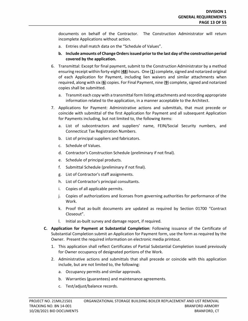
documents on behalf of the Contractor. The Construction Administrator will return incomplete Applications without action.
a. Entries shall match data on the “Schedule of Values”.
b. Include amounts of Change Orders issued prior to the last day of the construction period covered by the application.
6. Transmittal: Except for final payment, submit to the Construction Administrator by a method ensuring receipt within forty-eight (48) hours. One (1) complete, signed and notarized original of each Application for Payment, including lien waivers and similar attachments when required, along with six (6) copies. For Final Payment, nine (9) complete, signed and notarized copies shall be submitted.
a. Transmit each copy with a transmittal form listing attachments and recording appropriate information related to the application, in a manner acceptable to the Architect.
7. Applications for Payment: Administrative actions and submittals, that must precede or coincide with submittal of the first Application for Payment and all subsequent Application for Payments including, but not limited to, the following items:
a. List of subcontractors and suppliers’ name, FEIN/Social Security numbers, and Connecticut Tax Registration Numbers.
b. List of principal suppliers and fabricators.
c. Schedule of Values.
d. Contractor's Construction Schedule (preliminary if not final).
e. Schedule of principal products.
f. Submittal Schedule (preliminary if not final).
g. List of Contractor's staff assignments.
h. List of Contractor's principal consultants.
i. Copies of all applicable permits.
j. Copies of authorizations and licenses from governing authorities for performance of the Work.
k. Proof that as-built documents are updated as required by Section 01700 “Contract Closeout”.
l. Initial as-built survey and damage report, if required.
C. Application for Payment at Substantial Completion: Following issuance of the Certificate of Substantial Completion submit an Application for Payment form, use the form as required by the Owner. Present the required information on electronic media printout.
1. This application shall reflect Certificates of Partial Substantial Completion issued previously for Owner occupancy of designated portions of the Work.
2. Administrative actions and submittals that shall precede or coincide with this application include, but are not limited to, the following:
a. Occupancy permits and similar approvals.
b. Warranties (guarantees) and maintenance agreements.
c. Test/adjust/balance records.
DIVISION 1 GENERAL REQUIREMENTS
PAGE 14 OF 55
PROJECT NO. 21MIL21501 ORGANIZATIONAL STORAGE BUILDING BOILER REPLACEMENT AND UST REMOVAL TRACKING NO. BN 14-001 BRANFORD ARMORY 10/28/2021 BID DOCUMENTS BRANFORD, CT
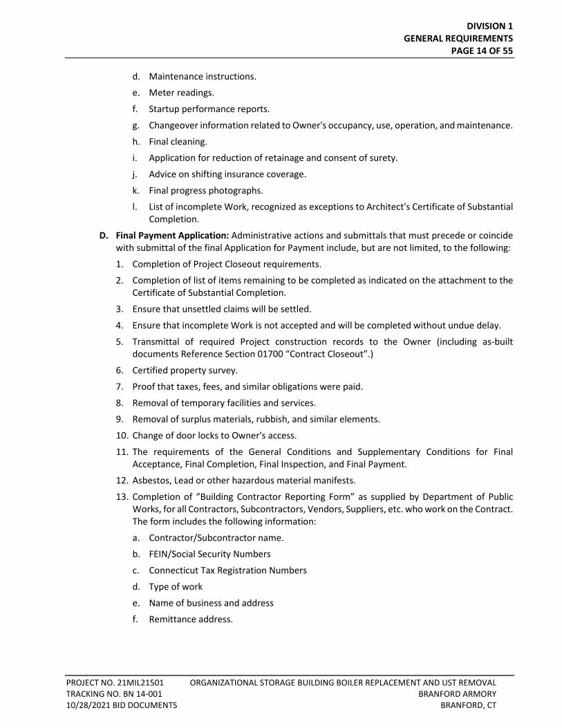
d. Maintenance instructions.
e. Meter readings.
f. Startup performance reports.
g. Changeover information related to Owner's occupancy, use, operation, and maintenance.
h. Final cleaning.
i. Application for reduction of retainage and consent of surety.
j. Advice on shifting insurance coverage.
k. Final progress photographs.
l. List of incomplete Work, recognized as exceptions to Architect's Certificate of Substantial Completion.
D. Final Payment Application: Administrative actions and submittals that must precede or coincide with submittal of the final Application for Payment include, but are not limited, to the following:
1. Completion of Project Closeout requirements.
2. Completion of list of items remaining to be completed as indicated on the attachment to the Certificate of Substantial Completion.
3. Ensure that unsettled claims will be settled.
4. Ensure that incomplete Work is not accepted and will be completed without undue delay.
5. Transmittal of required Project construction records to the Owner (including as-built documents Reference Section 01700 “Contract Closeout”.)
6. Certified property survey.
7. Proof that taxes, fees, and similar obligations were paid.
8. Removal of temporary facilities and services.
9. Removal of surplus materials, rubbish, and similar elements.
10. Change of door locks to Owner's access.
11. The requirements of the General Conditions and Supplementary Conditions for Final Acceptance, Final Completion, Final Inspection, and Final Payment.
12. Asbestos, Lead or other hazardous material manifests.
13. Completion of “Building Contractor Reporting Form” as supplied by Department of Public Works, for all Contractors, Subcontractors, Vendors, Suppliers, etc. who work on the Contract. The form includes the following information:
a. Contractor/Subcontractor name.
b. FEIN/Social Security Numbers
c. Connecticut Tax Registration Numbers
d. Type of work
e. Name of business and address
f. Remittance address.
DIVISION 1 GENERAL REQUIREMENTS
PAGE 15 OF 55
PROJECT NO. 21MIL21501 ORGANIZATIONAL STORAGE BUILDING BOILER REPLACEMENT AND UST REMOVAL TRACKING NO. BN 14-001 BRANFORD ARMORY 10/28/2021 BID DOCUMENTS BRANFORD, CT
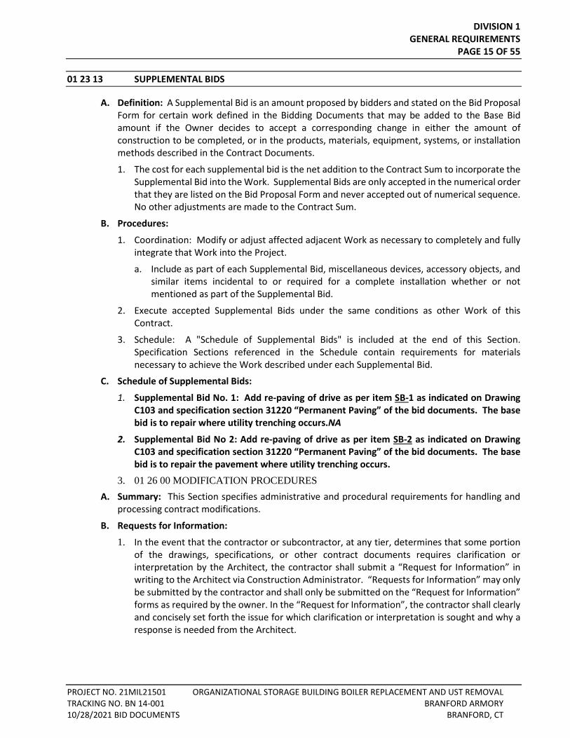
01 23 13 SUPPLEMENTAL BIDS
A. Definition: A Supplemental Bid is an amount proposed by bidders and stated on the Bid Proposal Form for certain work defined in the Bidding Documents that may be added to the Base Bid amount if the Owner decides to accept a corresponding change in either the amount of construction to be completed, or in the products, materials, equipment, systems, or installation methods described in the Contract Documents.
1. The cost for each supplemental bid is the net addition to the Contract Sum to incorporate the Supplemental Bid into the Work. Supplemental Bids are only accepted in the numerical order that they are listed on the Bid Proposal Form and never accepted out of numerical sequence. No other adjustments are made to the Contract Sum.
B. Procedures:
1. Coordination: Modify or adjust affected adjacent Work as necessary to completely and fully integrate that Work into the Project.
a. Include as part of each Supplemental Bid, miscellaneous devices, accessory objects, and similar items incidental to or required for a complete installation whether or not mentioned as part of the Supplemental Bid.
2. Execute accepted Supplemental Bids under the same conditions as other Work of this Contract.
3. Schedule: A "Schedule of Supplemental Bids" is included at the end of this Section. Specification Sections referenced in the Schedule contain requirements for materials necessary to achieve the Work described under each Supplemental Bid.
C. Schedule of Supplemental Bids:
1. Supplemental Bid No. 1: Add re-paving of drive as per item SB-1 as indicated on Drawing C103 and specification section 31220 “Permanent Paving” of the bid documents. The base bid is to repair where utility trenching occurs.NA
2. Supplemental Bid No 2: Add re-paving of drive as per item SB-2 as indicated on Drawing C103 and specification section 31220 “Permanent Paving” of the bid documents. The base bid is to repair the pavement where utility trenching occurs.
3. 01 26 00 MODIFICATION PROCEDURES A. Summary: This Section specifies administrative and procedural requirements for handling and
processing contract modifications.
B. Requests for Information:
1. In the event that the contractor or subcontractor, at any tier, determines that some portion of the drawings, specifications, or other contract documents requires clarification or interpretation by the Architect, the contractor shall submit a “Request for Information” in writing to the Architect via Construction Administrator. “Requests for Information” may only be submitted by the contractor and shall only be submitted on the “Request for Information” forms as required by the owner. In the “Request for Information”, the contractor shall clearly and concisely set forth the issue for which clarification or interpretation is sought and why a response is needed from the Architect.
DIVISION 1 GENERAL REQUIREMENTS
PAGE 16 OF 55
PROJECT NO. 21MIL21501 ORGANIZATIONAL STORAGE BUILDING BOILER REPLACEMENT AND UST REMOVAL TRACKING NO. BN 14-001 BRANFORD ARMORY 10/28/2021 BID DOCUMENTS BRANFORD, CT
a. In the “Request for Information”, the contractor shall set forth an interpretation or understanding of the requirement along with reasons why such an understanding was reached.
b. The owner acknowledges that this is a complex project. Based upon the owner’s past experience with projects of similar complexity, the owner anticipates that there will probably be some “Requests for Information” on this project.
c. The Architect will review all “Requests for Information” to determine whether they are “Requests for Information” within the meaning of this term. If it is determined that the document is not a “Request for Information”, it will be returned to the contractor, unreviewed as to content, for resubmittal on the proper form and in the proper manner.
d. “Requests for Information Response” shall be issued within seven (7) Working Calendar Days of receipt of the request from the contractor unless the owner determines that a longer time is necessary to provide an adequate response. If a longer time is determined necessary by the owner, the owner will, within seven (7) Working Calendar Days of receipt of the request, notify the contractor of the anticipated response time. If the contractor submits a “Request for Information” on an activity with seven (7) Working Calendar Days or less of float on the current project schedule, the contractor shall not be entitled to any time extension due to the time it takes the Architect to respond to the request provided that the Architect responds within the seven (7) Working Calendar Days set forth above.
e. “Requests for Information Response” from Architect will not change any requirement of the contract documents. In the event the contractor believes that the “Requests for Information Response” will cause a change to the requirements of the contract document, the contractor shall immediately give written notice to the Construction Administrator stating that the contractor believes the “Requests for Information Response” will result in “Change Order” and the Contractor intends to submit a “Change Order Proposal” request. Failure to give such written notice immediately shall waive the contractor’s right to seek additional time or cost under the requirement these Requirements.
C. Minor Changes in the Work
1. The Architect, through the Construction Administrator, will issue supplemental instruction authorizing minor changes in the Work, not involving adjustment to the Contract Sum or Contract time, on the “Supplemental Instructions” form as required by the Owner.
D. Proposal Request:
1. Architect/Owner-Initiated Requests For Proposals: The Architect or Owner will issue a detailed description of proposed changes in the Work via the Construction Administrator that will require adjustment to the Contract Sum or Contract Time. If necessary, the description will include supplemental or revised Drawings and Specifications. Such requests shall be on a “Proposal Request” form as required by the owner.
2. “Proposal Request” is issued for information only. Do not consider them as an instruction either to stop work in progress or to execute the proposed change.
3. Within Fourteen (14) Working Calendar Days of receipt of a “Proposal Request”, submit an “Change Order Proposal” with the required information necessary to execute the change to the Construction Administrator for the Architect’s/Owner's review.

DIVISION 1 GENERAL REQUIREMENTS
PAGE 17 OF 55
PROJECT NO. 21MIL21501 ORGANIZATIONAL STORAGE BUILDING BOILER REPLACEMENT AND UST REMOVAL TRACKING NO. BN 14-001 BRANFORD ARMORY 10/28/2021 BID DOCUMENTS BRANFORD, CT
4. Include a list of quantities of products required and unit costs, with the total amount of purchases to be made. Where requested, furnish survey data to substantiate quantities.
a. Indicate applicable delivery charges, equipment rental, and amounts of trade discounts.
b. Include a statement indicating the effect the proposed change in the Work will have on the Contract Time.
c. The Agency is tax exempt. All Contractor and Subcontractor services provided under your contract with the State of Connecticut may not be exempt from taxes. The Department of Revenue Services can guide you as to which services are exempt and which are not. Please contact the State of Connecticut, Department of Revenue Services at 1-800-382-9463 or 860 541-3280.
d. Dollar values shown on the Schedule of Values shall not be the governing (or deciding) final amounts for change orders involving either additional charges or deletions.
E. Change Order Proposal:
1. When either a “Request for Information” from the Contractor or a “Proposal Request” from the Architect or Owner results in conditions that may require modifications to the Contract, the Contractor may propose changes by submitting a request for a “Change Order Proposal” to the Architect via the Construction Administrator on forms as required by the Owner. These forms shall also include “Change Order Proposal Worksheets” as required by the Owner.
a. Include statements outlining the reasons for the change and the effect of the change on the Work. Provide a complete description of the proposed change. Indicate the effect of the proposed change on the Contract Sum and Contract Time.
b. Include a list of quantities of products required and unit costs, with the total amount of purchases to be made. Where requested, furnish survey data to substantiate quantities as directed by Article 13 “Compensation for Changes in the Work” of the General Conditions of the Contract for Construction.
c. Indicate applicable delivery charges, equipment rental, and amounts of trade discounts.
d. Comply with requirements in Section 01631 “Equals and Substitutions” if the proposed change requires an equal or substitution of one product or system for a product or system specified.
2. The State of Connecticut construction contract has the following tax exemptions:
a. Purchasing of materials which will be physically incorporated and become a permanent part of the project.
b. Tools, supplies and equipment used in fulfilling the construction contract are not exempt.
c. Services that are resold by the contractor are exempt, i.e. if a General Contractor hires a plumber, carpenter or electrician, a resale certificate may be issued to the subcontractor because these services are considered to be integral and inseparable component parts of the building contract
3. “Change Order Request” Forms: Use “Change Order Proposal” and “Change Order Proposal Worksheets” forms as required by Owner.
4. “Change Order Proposal” cannot be submitted without the Contractor either prior submission of a “Request for Information” from the Contractor or as a response to a “Proposal Request” submitted by the Architect or Owner.
DIVISION 1 GENERAL REQUIREMENTS
PAGE 18 OF 55
PROJECT NO. 21MIL21501 ORGANIZATIONAL STORAGE BUILDING BOILER REPLACEMENT AND UST REMOVAL TRACKING NO. BN 14-001 BRANFORD ARMORY 10/28/2021 BID DOCUMENTS BRANFORD, CT
5. Any “Change Order Request ” submitted without a prior submittal of a “Request for Information” or as a response to a “Proposal Request” will be immediately rejected and returned to the Contractor.
F. Construction Change Directive:
1. “Construction Change Directive”: When the Owner and the Contractor disagree on the terms of a “Change Order Proposal” resulting from either a “Request for Information” or “Proposal Request”, then the Architect through the Construction Administrator may issue a “Construction Change Directive” on a “Construction Change Directive” as authorized by the Owner on the form required by the Owner. The “Construction Change Directive” instructs the Contractor to proceed with a change in the Work, for subsequent inclusion in a “Change Order”.
a. The “Construction Change Directive” contains a complete description of the change in the Work. It also designates the method to be followed to determine change in the Contract Sum or Contract Time.
2. Documentation: The Contractor shall maintain detailed records on a time and material basis of work required by the “Construction Change Directive”.
a. After completion of the change, submit an itemized account and supporting data necessary to substantiate cost and time adjustments to the Contract.
b. The final value shall be negotiated based on the supporting data to determine the value of the work.
G. Change Order Procedures:
1. Upon the Owner's approval of a Contractor’s “Change Order Proposal”, the Construction Administrator will issue a “Change Order” for signatures of the Architect, Owner and the Contractor on “Change Order” form as required by the Owner.
01 31 00 COORDINATION
A. Construction Administrator:
1. The Construction Administrator is identified in Division 1 Section 01003 “Construction Administrator”.
2. Construction Mobilization:
a. Cooperate with the Construction Administrator in the allocation of mobilization areas of the site, for field offices and sheds, for agency facility access, traffic, and parking facilities.
b. During Construction, coordinate use of site and facilities through the Construction Administrator.
c. Comply with Construction Administrators procedures for intra-project communications; submittals, reports and records, schedules, coordination drawings, and recommendations; and resolution of ambiguities and conflicts.
d. Comply with instructions of the Construction Administrator for use of temporary utilities and construction facilities.
e. Coordinate field engineering layout as specified in Section 01050 “Field Engineering” for work under the instructions of the Construction Administrator.
DIVISION 1 GENERAL REQUIREMENTS
PAGE 19 OF 55
PROJECT NO. 21MIL21501 ORGANIZATIONAL STORAGE BUILDING BOILER REPLACEMENT AND UST REMOVAL TRACKING NO. BN 14-001 BRANFORD ARMORY 10/28/2021 BID DOCUMENTS BRANFORD, CT
B. Coordinate construction operations included in various Sections of these Specifications to assure efficient and orderly installation of each part of the Work. Coordinate construction operations included under different Sections that depend on each other for proper installation, connection, and operation.
1. Schedule construction operations in the sequence required to obtain the best results where installation of one part of the Work depends on installation of other components, before or after its own installation.
2. Coordinate installation of different components to assure maximum accessibility for required maintenance, service, and repair.
3. Make provisions to accommodate items scheduled for later installation.
C. Where necessary, prepare memoranda for distribution to each party involved, outlining special procedures required for coordination. Include such items as required notices, reports, and attendance at meetings.
1. Prepare similar memoranda for the Construction Administrator, Owner and separate contractors where coordination of their work is required.
D. Administrative Procedures: Coordinate scheduling and timing of required administrative procedures with other construction activities to avoid conflicts and assure orderly progress of the Work. Such administrative activities include, but are not limited to, the following:
1. Preparation of schedules.
2. Installation and removal of temporary facilities.
3. Delivery and processing of submittals.
4. Progress meetings.
5. Project closeout activities.
E. General Coordination Provisions:
1. Inspection of Conditions: Require the Installer of each major component to inspect both the substrate and conditions under which Work is to be performed and coordinate such inspections with the Construction Administrator and authorities having jurisdictions. If unsatisfactory conditions exist notify the Construction Administrator immediately. Do not proceed until unsatisfactory conditions have been corrected in an acceptable manner.
2. The Contractor shall coordinate temporary enclosures with required inspections and tests to minimize the necessity of uncovering completed construction for that purpose.
3. Coordination Drawings:
a. The HVAC Subcontractor will initiate mylar at 1/4" scale drawings done on AutoCAD showing ducts and piping in plan and section. Sheet metal shop drawings must be approved prior to starting coordination drawings.
b. The Sprinkler Subcontractor will then superimpose his piping layout on the tracing.
c. The Electrical subcontractor will superimpose all the electrical information on the tracing. Said information to include but not necessary limited to cable trays, equipment, lighting, conduits, bus duct, etc.
d. The sprinkler subcontractor will complete the coordination drawing by drawing his piping (include pitch) on the tracing.
DIVISION 1 GENERAL REQUIREMENTS
PAGE 20 OF 55
PROJECT NO. 21MIL21501 ORGANIZATIONAL STORAGE BUILDING BOILER REPLACEMENT AND UST REMOVAL TRACKING NO. BN 14-001 BRANFORD ARMORY 10/28/2021 BID DOCUMENTS BRANFORD, CT
e. The Construction Administrator will review the completed coordination drawing for general compliance and then submit it to the Architect for his review. All subcontractors shall rework the mylar drawings until all systems are properly coordinated.
4. The Construction Administrator will meet with the Contractor on all major items of coordination.
5. See also General Conditions Article 7 “Cooperation of Trades”.
01 73 29 CUTTING AND PATCHING
A. Openings and chases may not be shown on the Drawings. It is the responsibility of the Contractor to examine the Architectural, Electrical, Heating, Cooling, Ventilating and Plumbing Drawings and to provide chases, channels or openings where needed.
B. The Contractor shall install sleeves, inserts and hangers furnished by the trades needing same.
C. After installing work into openings, channels and/or chases, the Contractor shall close same. If finishes are to be restored, the new work shall match the original and shall be done by the trade customarily responsible for the particular kind of work.
D. Permission shall be obtained from the Construction Administrator before cutting beams, arches, lintels or other structural members.
E. Requirements for Structural Work: Do not cut and patch structural elements in a manner that would change their load-carrying capacity or load-deflection ratio.
1. Obtain approval from the Architect/Engineers of the cutting and patching proposal before cutting and patching the following structural elements:
a. Foundation construction.
b. Bearing and retaining walls.
c. Structural concrete.
d. Structural steel.
e. Lintels.
f. Structural decking.
g. Miscellaneous structural metals.
h. Exterior curtain-wall construction.
i. Equipment supports.
j. Piping, ductwork, vessels, and equipment.
k. Structural systems of special construction in Division 13 Sections.
F. Do cutting and patching to integrate all elements of the work. Provide penetrations of existing surfaces. Provide samples for testing. Seal penetrations through floors, walls, ceilings and roofs, as applicable; restore or preserve fire-rated and smoke-barrier construction. Construction and finishes shall match original work.
G. The Contractor shall verify dimensions for built-in work and/or work adjoining that of other trades before ordering any material or doing any work. Discrepancies shall be submitted to the Construction Administrator before proceeding with the work.
DIVISION 1 GENERAL REQUIREMENTS
PAGE 21 OF 55
PROJECT NO. 21MIL21501 ORGANIZATIONAL STORAGE BUILDING BOILER REPLACEMENT AND UST REMOVAL TRACKING NO. BN 14-001 BRANFORD ARMORY 10/28/2021 BID DOCUMENTS BRANFORD, CT
H. Existing Warranties: Replace, patch, and repair material and surfaces cut or damaged by methods and with materials in such a manner as not to void any warranties required or existing.
I. See also General Conditions Article 23 “Cutting, Fitting, Patching and Digging”.
01 71 23 FIELD ENGINEERING
A. Provide field engineering services to establish and record grades, lines and elevations.
B. The Contractor shall retain a Professional Engineer or Land Surveyor registered by the State of Connecticut to lay out the building, underground utility lines and other site work from the horizontal and vertical control information furnished by the Owner and to establish and record the necessary elevations, at no additional cost to the State.
C. The Contractor shall forward a letter from his Land Surveyor or Professional Engineer stating that the control information furnished by the Owner, is accurate or shall identify inaccuracies, if they exist. The Contractor shall not take advantage of errors, which may be included in the control information. Stakes and markings shall be preserved.
01 42 20 REFERENCE STANDARDS & DEFINITIONS
A. For products specified by association or trade standards, comply with requirements of the standard, except when more rigid requirements are specified or are required by applicable codes.
B. References to standard specifications and codes refer to the editions current at the bid due date. An exception is, buildings exceeding the threshold limit must be in substantial compliance with the requirements of the effective code at the time of receipt of completed application to the Office of State Building Inspector (OSBI). References include their addenda and errata, if any, and shall be considered a part of these specifications as if they were printed herein in full.
C. The manufacturers' standard warranties or guarantees shall apply when their products are used on this project.
D. Flame Spread Ratings - all materials that are required of obligated to meet specified standards shall be submitted to the owner for their records as part of the shop drawing submittal process for their construction records.
01 35 16 RENOVATION/DEMOLITION PROJECT PROCEDURES
A. Products For Patching And Extending Work:
1. New materials: As specified in product sections; match existing Products and Work .for patching and extending Work.
2. Type and Quality of Existing Products: Determine by inspecting and testing Products where necessary, referring to existing Work as a standard.
B. Inspection- General:
1. Verify that demolition is complete and areas are ready for installation of new Work.
2. Beginning of restoration Work means acceptance of existing conditions.
C. Project Procedures for Work Involving Lead Containing Material (LBP):
1. Exposure levels for lead in the construction industry are regulated by 29 CFR 1926.62. Construction activities disturbing surfaces containing lead-based paint (LBP) which are likely
DIVISION 1 GENERAL REQUIREMENTS
PAGE 22 OF 55
PROJECT NO. 21MIL21501 ORGANIZATIONAL STORAGE BUILDING BOILER REPLACEMENT AND UST REMOVAL TRACKING NO. BN 14-001 BRANFORD ARMORY 10/28/2021 BID DOCUMENTS BRANFORD, CT
to be employed, such as sanding, grinding, welding, cutting and burning, have been known to expose workers to levels of lead in excess of the Permissible Exposure Limit (PEL). Conduct demolition and removal Work specified in the technical sections of this specification in conformance with these regulations. In addition, construction debris/waste may be classified as hazardous waste. Disposal of hazardous waste material shall be in accordance with 40 CFR Parts 260 through 271 and Connecticut Hazardous Waste Management Regulations Section 22a-209-1; 22a-209-8(c); 22a-449(c)-11; and 22a-449(c)-100 through 110.
2. The Contractor's Work shall be based on a child under the age of six (6) in residence; the Work shall also be in accordance with Connecticut Regulations Section 19a-111-1 through 11.
3. This facility was constructed prior to 1978 and is likely to have painted surfaces containing lead-based paint.
4. Testing for lead-based paint has been conducted at the facility scheduled for renovation, demolition, reconstruction, alteration, remodeling, or repair. Results of the LBP testing are for information purposes only. The testing results are in a separate Volume of this Project Manual. Under no circumstance shall this information be the sole means used by the Contractor for determining the extent of LBP. The Contractor shall be responsible for verification of all field conditions affecting performance of the Work.
D. Project Procedures for Work Involving Asbestos Containing Material (ACM):
1. If the Contractor should encounter any material suspect or known to contain ACM, he should immediately notify the Construction Administrator of same. It is the State’s responsibility to have the material tested and abated (if necessary). The Owner will respond within twenty-four (24) hours after receiving the Contractor’s written request to the Construction Administrator for testing the suspect material. The Owner will abate ACM (if necessary) within a reasonable time period, i.e. with seven (7) Working Calendar Days.
2. Testing for asbestos has been conducted at the facility in the areas scheduled for renovation, demolition, reconstruction, alteration, remodeling, or repair. Results of the asbestos testing are for information purposes only. The testing results are in a separate Volume of this Project Manual. Under no circumstance shall this information be the sole means used by the Contractor for determining the extent of asbestos. The Contractor shall be responsible for verification of all field conditions affecting performance of the Work.
3. See also General Conditions Article 23 “Cutting, Fitting, Patching and Digging”.
E. Project Procedures for Work Involving Products Containing Persistent Bioaccumulative Toxic Chemicals” (PBT’s) such as Polychlorinated Biphenols (PCB’s), Di-2-ethylhexyl Phthalate (DEHP), and Mercury:
1. The Contractor is responsible for abating all PCB’s, DEHP, and mercury prior to the start any work involving construction, renovation or demolition (if necessary).
2. Exposure Levels for Products Containing Persistent Bioaccumulative Toxic Chemicals (PBT’s) such as PCB’s. DEHP, and mercury in the construction industry is regulated by 29CFR1910.1200 and 29CFR1926.28 et. al. Construction, renovation or demolition activities disturbing Products Containing Persistent Bioaccumulative Toxic Chemicals” (PBT’s) such as PCB’s and DEHP which are likely to be employed. These materials include but are not limited to fluorescent light fixture & exit sign, ballast’s, high density discharge (HID) lamps , and certain types of construction products containing vinyl, and mercury containing electrical switches and thermostats. These activities may expose workers in excess of the respective
DIVISION 1 GENERAL REQUIREMENTS
PAGE 23 OF 55
PROJECT NO. 21MIL21501 ORGANIZATIONAL STORAGE BUILDING BOILER REPLACEMENT AND UST REMOVAL TRACKING NO. BN 14-001 BRANFORD ARMORY 10/28/2021 BID DOCUMENTS BRANFORD, CT
Permissible Exposure Limit (PEL). Conduct demolition and removal Work specified in the technical sections of these specifications in conformance with these regulations. In addition construction debris/waste may be classified as hazardous waste. Disposal of all hazardous materials shall be in accordance with but not limited to 40CRF Parts 761 Subpart K, 761, and 761.65 and the Connecticut General Hazardous Waste Statute Sec. 22a-454.
3. A Survey for Products Containing Persistent Bioaccumulative Toxic Chemicals (PBT’s) such as PCB’s, DEHP and Mercury has NOT been conducted at the facility. Examples include but are not limited to fluorescent light fixture & exit sign, ballast’s, high density discharge(HID) lamps , and certain types of construction products containing vinyl, and mercury containing electrical switches and thermostats. It is the Contractors responsibility for verification of all material and field conditions prior to construction, renovation, and demolition that may affect the performance of their Work.
F. Preparation:
1. Cut, move, or remove items as are necessary for access to alterations and renovation Work. Replace and restore at completion.
2. Remove unsuitable material not marked for salvage, such as rotted wood, corroded metals, and deteriorated masonry and concrete. Replace materials as specified for finished Work.
3. Remove debris and abandoned items from area and from concealed spaces.
4. Prepare surface and remove surface finishes to provide for proper installation of new Work and finishes.
5. Close openings in exterior surfaces to protect existing Work and salvage items from weather and extremes of temperature and humidity. Insulate ductwork and piping to prevent condensation in exposed areas.
G. Installation:
1. Coordinate Work of alterations and renovations to expedite completion and if required sequence Work to accommodate Owner occupancy.
2. Remove, cut and patch Work in a manner to minimize damage and to provide restoring Products and finishes to original and or specified condition in accordance with Section 01045 “Cutting and Patching”.
3. Refinish visible existing surfaces to remain in renovated rooms and spaces, to specified condition for each material, with neat transition to adjacent finishes in accordance with Section 01045 “Cutting and Patching”.
4. In addition to specified replacement of equipment, restore existing plumbing, heating, ventilation, air conditioning, electrical, systems to full operational condition.
5. Recover and refinish Work that exposes mechanical and electrical Work exposed accidentally during the Work.
6. Install Products as specified in individual sections.
H. Transitions:
1. Where new Work abuts or aligns with existing, perform a smooth and even transition. Patch work to match existing adjacent Work in texture and appearance.
DIVISION 1 GENERAL REQUIREMENTS
PAGE 24 OF 55
PROJECT NO. 21MIL21501 ORGANIZATIONAL STORAGE BUILDING BOILER REPLACEMENT AND UST REMOVAL TRACKING NO. BN 14-001 BRANFORD ARMORY 10/28/2021 BID DOCUMENTS BRANFORD, CT
2. When finished surfaces are cut so that a smooth transition with new Work is not possible, terminate existing surface along a straight line at a natural line of division and make recommendation to Architect/Engineer.
I. Adjustments:
1. Where removal of partitions or walls result in adjacent spaces becoming one, rework floors, walls, and ceilings to a smooth plane without breaks, steps, or bulkheads.
2. Where a change of plane of ¼ inch in 12 inches or more occurs, request recommendation from Architect/Engineer for providing a smooth transition.
3. Trim existing doors as necessary to clear new floor finish. Refinish trim as required.
4. Fit Work at penetrations of surfaces as specified in Section 01045 “Cutting and Patching”.
J. Repair of Damaged Surfaces:
1. Patch or replace portions of existing surfaces that are damaged, lifted, discolored, or showing imperfections.
2. Repair substrate prior to patching finish.
K. Finishes:
1. Finish surfaces as specified in individual Product sections.
2. Finish patches to produce uniform finish and texture over entire area. When finish cannot be matched, refinish entire surface to nearest intersections.
L. Cleaning:
1. In addition cleaning specified in Section 01700 “Project Closeout”, clean Agency occupied areas of Work
01121 SALVAGEABLE MATERIALS
A. The Contractor shall be responsible for removing the following salvageable items from premises and transporting said items to a location on site.
1. Equipment: UST Tank monitoring system.
B. The Contractor shall notify the Construction Administrator in writing (7) seven working Calendar Days prior to removing all salvageable items from the existing alteration project location and unloading all salvageable items at the Branford Armory, and store items in the appropriate location as directed by facilities personnel.
01 31 19 PROJECT MEETINGS
A. Pre-construction Conference:
1. The Contractor will attend a Pre-construction Conference before starting construction, as scheduled by the Construction Administrator convenient to the Owner, the Construction Administrator, Architect, and Contractor. This meeting will take place within fourteen (14) Calendar Days after the written Notice to Proceed and before the Contract Start Date. Hold the conference at the Project Site or another convenient location as directed by the Construction Administrator. The Construction Administrator shall conduct the Pre-
DIVISION 1 GENERAL REQUIREMENTS
PAGE 25 OF 55
PROJECT NO. 21MIL21501 ORGANIZATIONAL STORAGE BUILDING BOILER REPLACEMENT AND UST REMOVAL TRACKING NO. BN 14-001 BRANFORD ARMORY 10/28/2021 BID DOCUMENTS BRANFORD, CT
construction Conference to review the Contractor and Subcontractor responsibilities and personnel assignments.
2. Attendees: Authorized representatives of the Construction Administrator, Owner, Architect, and their consultants; the Contractor and its superintendent; major subcontractors; agency; and other concerned parties shall attend the conference. All participants at the conference shall be familiar with the Project and authorized to conclude matters relating to the Work.
3. Agenda: Discuss items of significance that could affect progress, including the following:
a. Tentative construction schedule.
b. Critical work sequencing.
c. Progress meeting schedule.
d. Designation of responsible personnel.
e. Procedures for processing field decisions and Change Orders.
f. Procedures for processing Applications for Payment.
g. Distribution of Contract Documents.
h. Submittal of Shop Drawings, Product Data, and Samples.
i. Preparation of record documents.
j. Use of the premises.
k. Parking availability.
l. Office, work, and storage areas.
m. Equipment deliveries and priorities.
n. Safety procedures.
o. First aid.
p. Security.
q. Housekeeping.
r. Working hours.
s. Coordination with Audio-Visual and Telecommunications.
B. Progress Meetings:
1. The Construction Administrator will conduct progress meetings, bi-weekly, at the Project Site or at regular intervals as agreed upon at the Pre-construction Conference. The Construction Administrator will notify the Owner, the Architect, and the Contractor of the scheduled Progress Meeting dates. Coordinate dates of Progress Meetings with preparation of Application for Payment requests.
2. Attendees: In addition to representatives of the Contractor, Construction Administrator, Owner and the Architect, subcontractor, supplier, or other entity concerned with current progress or involved in planning, coordination, or performance of future activities may be requested to attend these meetings on an as needed basis. All participants at the meeting shall be familiar with the Project and authorized to conclude matters relating to the Work. The Contractor shall include the site superintendent as a minimum.
DIVISION 1 GENERAL REQUIREMENTS
PAGE 26 OF 55
PROJECT NO. 21MIL21501 ORGANIZATIONAL STORAGE BUILDING BOILER REPLACEMENT AND UST REMOVAL TRACKING NO. BN 14-001 BRANFORD ARMORY 10/28/2021 BID DOCUMENTS BRANFORD, CT
3. Agenda: Progress Meetings shall review and correct or approve minutes of the previous Progress Meeting. Review other items of significance that could affect progress. Include topics for discussion as appropriate to the status of the Project.
a. Construction Schedule: Review progress since the last Progress Meeting. Determine where each activity is in relation to the required Contractor's “Construction Schedule” and whether each activity is on time or ahead or behind Schedule. Determine how Work that is behind Schedule will be expedited; secure commitments from parties involved to do so. Discuss whether Schedule revisions are required to insure that current and subsequent activities will be completed within the Contract Time.
b. Review the present and future needs of each entity present
4. Reporting: The Construction Administrator will distribute minutes of the meeting to each party present, promptly and before the next scheduled meeting, and to parties who should have been present.
5. A schedule of regular Project Meetings will be established at the Pre-construction Conference.
01 33 00 SUBMITTALS
A. Summary
1. This Section includes administrative and procedural requirements for submittals required for performance of the Work, including but not limited to the following:
a. Submittal Procedures.
b. Submittal schedule.
c. Daily Construction reports.
d. Shop Drawings.
e. Shop Drawings for Fire Protection Systems.
f. Product Data.
g. Samples.
h. Quality assurance submittals.
i. Architects Action.
j. Submittals shall comply with all requirements in Division 1 Section 01631 “Equals and Substitutions”.
k. Submittals shall comply with all requirements in Division 1 Section 01740 “Warrantees and Bonds”.
l. Submittals shall comply with all requirements in Division 1 Section 01040 “Coordination”.
m. Submittals shall comply with all requirements in Division 1 Section 01730 “Operation & Maintenance Manuals”.
B. Administrative Submittals: Refer to other Division 1 Sections and other Contract Documents for requirements for administrative submittals. Such submittals include, but are not limited to, the following:
1. Permits.
DIVISION 1 GENERAL REQUIREMENTS
PAGE 27 OF 55
PROJECT NO. 21MIL21501 ORGANIZATIONAL STORAGE BUILDING BOILER REPLACEMENT AND UST REMOVAL TRACKING NO. BN 14-001 BRANFORD ARMORY 10/28/2021 BID DOCUMENTS BRANFORD, CT
2. Applications for Payment.
3. Performance and payment bonds.
4. Contractor’s construction schedule.
5. Daily construction reports.
6. Construction Photographs.
7. Insurance certificates.
8. List of subcontractors.
9. Subcontractors/Suppliers FEIN #’s and Connecticut tax registration #.
C. Related Sections: The following Sections contain requirements that relate to this Section:
1. Division 1 Section 01027 "Application for Payment" specifies requirements for submittal of the Schedule of Values.
2. Division 1 Section 01040 "Coordination" specifies requirements governing preparation and submittal of required Coordination Drawings.
3. Division 1 Section 01200 "Project Meetings" specifies requirements for submittal and distribution of meeting and conference minutes.
4. Division 1 Section 01310 “Construction Schedules”.
5. Division 1 Section 01315 "CPM Schedule" specifies requirements for contractor's schedule submittal.
6. Division 1 Section 01380 "Construction Photographs" specifies requirements for submittal of periodic construction photographs.
7. Division 1 Section 01400 "Quality Control" specifies requirements for submittal of inspection and test reports.
8. Division 1 Section 01631 "Equals and Substitutions" specifies requirements for submittal of requests to use products other than those specified.
9. Division 1 Section 01700 "Contract Closeout" specifies requirements for submittal of Project Record Documents and warranties at project closeout.
10. Division 1 Section 01740 “Warranties and Bonds”.
D. Definitions
1. Coordination Drawings show the relationship and integration of different construction elements that require careful coordination during fabrication or installation to fit in the space provided or to function as intended and as identified in the Specification Division 2 through 16.
2. Preparation of Coordination Drawings is specified in Division 1 Section "Coordination" and may include components previously shown in detail on Shop Drawings or Product Data.
3. Field samples are full-size physical examples erected on-site to illustrate finishes, coatings, or finish materials. Field samples are used to establish the standard by which the Work will be judged.
4. Mockups are full-size assemblies for review of construction, coordination, testing, or operation; they are not Samples.
DIVISION 1 GENERAL REQUIREMENTS
PAGE 28 OF 55
PROJECT NO. 21MIL21501 ORGANIZATIONAL STORAGE BUILDING BOILER REPLACEMENT AND UST REMOVAL TRACKING NO. BN 14-001 BRANFORD ARMORY 10/28/2021 BID DOCUMENTS BRANFORD, CT
E. Submittal Procedures
1. Coordination: Coordinate preparation and processing of submittals with performance of construction activities. Transmit each submittal sufficiently in advance of performance of related construction activities to avoid delay.
2. Coordinate each submittal with fabrication, purchasing, testing, delivery, other submittals, and related activities that require sequential activity.
3. Coordinate transmittal of different types of submittals for related elements of the Work so processing will not be delayed by the need to review submittals concurrently for coordination.
a. The Architect reserves the right to withhold action on a submittal requiring coordination with other submittals until all related submittals are received.
b. The Architect reserves the right to reject incomplete submitted packages.
4. Processing: To avoid the need to delay installation as a result of the time required to process submittals, allow sufficient time for submittal review, including time for resubmittals.
a. Allow (2) two weeks for initial review. Allow additional time if the Architect must delay processing to permit coordination with subsequent submittals.
b. If an intermediate submittal is necessary, process the same as the initial submittal.
c. Allow (2) two weeks for reprocessing each submittal.
d. No extension of Contract Time will be authorized because of failure to transmit submittals to the Architect sufficiently in advance of the Work to permit processing.
F. Submittal Preparation: Place a permanent label, title block or 8-1/2 inches x 11 inches cover page approved by the Architect, on each submittal for identification. Indicate the name of the entity that prepared each submittal on the label or title block.
1. The minimum number of copies required for each submittal shall be at a minimum 7 copies or as determine otherwise at the pre-construction conference or by the Construction Administrator.
2. Provide a space approximately 4 inches by 5 inches on the label, beside the title block or on the cover page on Shop Drawings to record the Contractor's review and approval markings and the action taken.
3. Include the following information on the label for processing and recording action taken.
a. Project Name and State of Connecticut Project Number.
b. Date.
c. Name and address of the Architect, Construction Administrator, and Owner Representative.
d. Name and address of the Contractor.
e. Name and address of the subcontractor.
f. Name and address of the supplier.
g. Name of the manufacturer.
h. Number and title of appropriate Specification Section.
i. Drawing number and detail references, as appropriate.
DIVISION 1 GENERAL REQUIREMENTS
PAGE 29 OF 55
PROJECT NO. 21MIL21501 ORGANIZATIONAL STORAGE BUILDING BOILER REPLACEMENT AND UST REMOVAL TRACKING NO. BN 14-001 BRANFORD ARMORY 10/28/2021 BID DOCUMENTS BRANFORD, CT
j. Indicate either initial or resubmittal.
k. Indicate deviations from Contract Documents.
l. Indicate if "equal" or "substitution".
G. Submittal Transmittal: Package each submittal appropriately for transmittal and handling. Transmit each submittal from the Contractor to the Architect using a transmittal form. Copy the Construction Administrator on the transmittal. The Architect will return all submittals to the Contractor after action is taken with a complete copy of the submittal package and one complete copy of the submittal package. The Architect will not accept submittals received from sources other than the Contractor.
1. On the transmittal, record relevant information and requests for data. On the form, or separate sheet, record deviations from Contract Document requirements, including variations and limitations. Include Contractor's certification that information complies with Contract Document requirements.
H. Submittal Schedule
1. After development and review by the Owner and Architect acceptance of the Contractor's Construction or CPM schedule prepare a complete schedule of submittals. Submit the schedule to the Construction Administrator within 30 days of Contract Award.
2. Coordinate Submittal Schedule with the list of subcontracts, Schedule of Values, and the list of products as well as the contractor’s Construction or CPM Schedule.
3. Prepare the schedule in chronological order. Provide the following information:
a. Schedule date for the initial submittal.
b. Related section number.
c. Submittal category (Shop Drawings, Product Data, or Samples).
d. Name of Subcontractor.
e. Description of the part of Work covered.
f. Scheduled date for resubmittal.
g. Scheduled date for the Architect’s final release of approval.
I. Distribution: Following response to the initial submittal, print and distribute copies to the Construction Administrator, Architect, Owner, subcontractors, and other parties required to comply with submittal dates indicated. Post copies in the Project meeting room and field office.
1. When revisions are made, distribute to the same parties and post in the same locations. Delete parties from distribution when they have completed their assigned portion of the Work and are no longer involved in construction activities.
J. Schedule Updating: Revise the schedule after each meeting or activity where revisions have been recognized or made. Issue the updated schedule concurrently with the report of each meeting.
K. Daily Construction Reports
DIVISION 1 GENERAL REQUIREMENTS
PAGE 30 OF 55
PROJECT NO. 21MIL21501 ORGANIZATIONAL STORAGE BUILDING BOILER REPLACEMENT AND UST REMOVAL TRACKING NO. BN 14-001 BRANFORD ARMORY 10/28/2021 BID DOCUMENTS BRANFORD, CT
1. Prepare a daily construction report recording the following information concerning events at the site, and submit duplicate copies to the Construction Administrator at weekly intervals:
a. List of subcontractors at the site.
b. Approximate count of personnel at the site.
c. High and low temperatures, general weather conditions.
d. Accidents and unusual events.
e. Meetings and significant decisions.
f. Stoppages, delays, shortages, and losses.
g. Meter readings and similar recordings.
h. List of equipment on site and identify if idle or in use.
i. Orders and requests of governing authorities.
j. Change Orders received, start and end dates.
k. Services connected, disconnected.
l. Equipment or system tests and startups.
m. Partial Completion’s, occupancies.
n. Substantial Completion’s authorized.
o. Equals or Substitutions approved or rejected.
L. Shop Drawings
1. Submit newly prepared information drawn accurately to scale. Highlight, encircle, or otherwise indicate deviations from the Contract Documents. Do not reproduce Contract Documents or copy standard information as the basis of Shop Drawings. Standard information prepared without specific reference to the Project is not a Shop Drawing.
2. Shop Drawings include fabrication and installation Drawings, setting diagrams, schedules, patterns, templates and similar Drawings. Include the following information:
a. Dimensions.
b. Identification of products and materials included by sheet and detail number.
c. Compliance with specified standards.
d. Notation of coordination requirements.
e. Notation of dimensions established by field measurement.
f. Sheet Size: Except for templates, patterns and similar full-size Drawings, submit Shop Drawings on sheets at least 8-1/2 by 11 inches but no larger than 36 by 48 inches.
g. Submit one (1) reproducible media and seven (7) prints as directed by the Construction Administrator. The Contractor's submittal shall identify the specification section and/or drawing number applicable to the submittal.
h. Details shall be large scale and/or full size.
3. The Contractor shall review the Shop Drawings, stamp with this approval, and submit them with reasonable promptness and in orderly sequence so as to cause no delay in his Workor in
DIVISION 1 GENERAL REQUIREMENTS
PAGE 31 OF 55
PROJECT NO. 21MIL21501 ORGANIZATIONAL STORAGE BUILDING BOILER REPLACEMENT AND UST REMOVAL TRACKING NO. BN 14-001 BRANFORD ARMORY 10/28/2021 BID DOCUMENTS BRANFORD, CT
the Workof any subcontractor. Shop Drawings shall be properly identified as specified for item, material, workmanship, and project number. At the submission, the Contractor shall inform the Architect, in writing of any deviation in the shop drawings from the requirements of the Contract Documents.
4. The Architect will review and comment on shop drawings with reasonable promptness so as to cause no delay, but only for conformance with the design concept of the project and with the information given in the Contract Documents. Refer to Article 5 of General Conditions. Shop Drawings received by the Architect that indicate insufficient study of drawings and specifications, illegible portions or gross errors, will be rejected outright. Such rejections shall not constitute an acceptable reason for granting the Contractor additional time to perform the work.
5. The Contractor shall make any corrections required by the Architect and shall resubmit the required number of corrected copies of shop drawings until fully reviewed.
6. Upon final review submit four (4) additional prints, same as submitted, to the Construction Administrator for his use.
7. The Architect's review and comments on shop drawings shall not relieve the Contractor of responsibility for any deviation from the requirements of the Contract Documents.
8. Only final reviewed shop drawings are to be used on the project site.
9. The Work installed shall be reviewed in accordance with the shop drawings and the drawings and specifications. Final Review of the shop drawings by the Architect shall constitute acceptance by the State and the Architect of a variation or departure that is clearly identified. Final reviewed shop drawings shall not replace or be used as a vehicle to issue or incorporate change orders.
M. Product Data
1. Collect Product Data into a single submittal for each element of construction or system. Product Data includes printed information, schedules, such as manufacturer's installation instructions, catalog cuts, standard color charts, roughing-in diagrams and templates, standard wiring diagrams, and performance curves.
2. Mark each copy to show applicable choices and options. Where printed Product Data includes information on several products that are not required, mark copies to indicate the applicable information. Include the following information:
a. Manufacturer's printed recommendations.
b. Compliance with trade association standards.
c. Compliance with recognized testing agency standards.
d. Application of testing agency labels and seals.
e. Notation of dimensions verified by field measurement.
f. Notation of coordination requirements.
3. Do not submit Product Data until compliance with requirements of the Contract Documents has been confirmed.
4. Preliminary Submittal: Submit a preliminary single copy of Product Data where selection of options is required.
DIVISION 1 GENERAL REQUIREMENTS
PAGE 32 OF 55
PROJECT NO. 21MIL21501 ORGANIZATIONAL STORAGE BUILDING BOILER REPLACEMENT AND UST REMOVAL TRACKING NO. BN 14-001 BRANFORD ARMORY 10/28/2021 BID DOCUMENTS BRANFORD, CT
5. Submittals: Submit 7 copies of each required submittal; submit 5 copies where required for maintenance manuals. The Architect will retain one and will return the other marked with action taken and corrections or modifications required.
a. Unless noncompliance with Contract Document provisions is observed, the submittal may serve as the final submittal.
6. Distribution: Furnish copies of final submittal to installers, subcontractors, suppliers, manufacturers, fabricators, and others required for performance of construction activities. Show distribution on transmittal forms.
a. Do not proceed with installation until a copy of Product Data is in the Installer's possession.
b. Do not permit use of unmarked copies of Product Data in connection with construction.
N. Quality Assurance Submittals
1. Submit quality-control submittals, including design data, certifications, manufacturer's instructions, manufacturer's field reports, and other quality-control submittals as required under other Sections of the Specifications.
2. Certifications: Where other Sections of the Specifications require certification that a product, material, or installation complies with specified requirements, submit a notarized certification from the manufacturer certifying compliance with specified requirements.
a. Signature: Certification shall be signed by an officer of the manufacturer or other individual authorized to sign documents on behalf of the company.
3. Inspection and Test Reports: Requirements for submittal of inspection and test reports from independent testing agencies are specified in Division 1 Section "Quality Control."
O. Architect’s Action
1. Except for submittals for the record or information, where action and return is required, the Architect will review each submittal, mark to indicate action taken, and return promptly.
a. Compliance with specified characteristics is the Contractor's responsibility.
2. Action Stamp: The Architect will stamp each submittal with a uniform, action stamp. The Architect will mark the stamp appropriately to indicate the action taken, as follows:
a. Final Unrestricted Release: When the Architect marks a submittal "Approved for fabrication," the Work covered by the submittal may proceed provided it complies with requirements of the Contract Documents. Final payment depends on that compliance.
b. Final-But-Restricted Release: When the Architect marks a submittal "Incorporate Notations," the Work covered by the submittal may proceed provided it complies with notations or corrections on the submittal and requirements of the Contract Documents. Submit corrected copies for record. Final payment depends on that compliance.
c. Returned for Resubmittal: When the Architect marks a submittal "Rejected, or Revise and Resubmit," do not proceed with Work covered by the submittal, including purchasing,
DIVISION 1 GENERAL REQUIREMENTS
PAGE 33 OF 55
PROJECT NO. 21MIL21501 ORGANIZATIONAL STORAGE BUILDING BOILER REPLACEMENT AND UST REMOVAL TRACKING NO. BN 14-001 BRANFORD ARMORY 10/28/2021 BID DOCUMENTS BRANFORD, CT
fabrication, delivery, or other activity. Revise or prepare a new submittal according to the notations; resubmit without delay. Repeat if necessary to obtain different action mark. 1) Do not use, or allow others to use, submittals marked "Rejected, or Revise and
Resubmit" at the Project Site or elsewhere where Work is in progress. 2) Other Action: Where a submittal is for information or record purposes or special
processing or other activity, the Architect will return the submittal marked "Action Not Required."
d. Unsolicited Submittals: The Architect will discard unsolicited submittals without action.
01 32 16 CONSTRUCTION SCHEDULE
A. Definitions:
1. Construction Schedule: A method of planning and scheduling a construction project utilizing a horizontal bar chart with a separate bar for each major portion of the Work or operation to make the schedule an effective tool for planning and monitoring the progress of the work.
B. Quality Assurance: The Contractor's Consultant: Retain a consultant to provide planning, evaluating, and reporting by CPM scheduling.
1. In-house Option: The Owner may waive the requirement to retain a consultant if the Contractor can demonstrate that:
a. The Contractor has the computer equipment required to produce construction schedules.
b. The Contractor employs skilled personnel with experience in construction scheduling and reporting techniques.
2. Program: Use “Microsoft Project”, latest version.
3. Standards: Comply with procedures contained in AGC's "Construction Planning & Scheduling."
C. Construction Schedule Format:
1. Format: Utilize a horizontal bar chart (gantt) with a separate bar for each major portion of the Work or operation, identifying first work day of each week.
2. Program: Use Microsoft Project, latest version.
3. Sequence of Listings: Utilize the Table of Contents of this Project Manual and the chronological order of the start of each item of work.
4. Scale and Spacing: Provide space for notations and revisions.
5. Sheet Size: To be coordinated with Construction Administrator.
D. Content:
1. Show complete sequence of construction by activity, with dates beginning and completion of each element of construction.
2. Identify each item by specification section number.
3. Identify work of separate phases other and other logically grouped activities.
DIVISION 1 GENERAL REQUIREMENTS
PAGE 34 OF 55
PROJECT NO. 21MIL21501 ORGANIZATIONAL STORAGE BUILDING BOILER REPLACEMENT AND UST REMOVAL TRACKING NO. BN 14-001 BRANFORD ARMORY 10/28/2021 BID DOCUMENTS BRANFORD, CT
4. Show accumulated percentages of completion of each item, and total percentage of Work completed, as of the first day of each month.
5. Provide separate schedule of submittal dates for shop drawings, product data, and samples, Owner/Agency furnished products and any products identified as under Allowances, and dates reviewed submittals will be required from Architect/Engineer. Indicate decision dates for selection of finishes.
6. Indicate delivery dates for Owner/Agency furnished products and any products identified as under Allowances.
7. Coordinate content with Schedule of Values specified in Section 01027 “Application for Payment”.
8. Indicate critical path with original baseline indicated.
E. Submittals And Revisions To Schedules:
1. Indicate progress of each activity to date of submittal, and projected completion date of each activity.
2. Identify activities modified since previous submittal, major changes in scope, and other identifiable changes.
3. Provide narrative report to define problem areas, anticipated delays, and impact on Schedule. Report corrective action taken, or proposed, and its effect.
4. An initial bar graph (gantt) schedule is to be prepared by the General Contractor and submitted to the Construction Administrator within seven (7) Working calendar days of award of contract. This schedule is to cover all items of work from the start of the project up to the completion of the project. After review, resubmit required revised data within five (5) Working calendar days. This schedule must be revised monthly and when the actual schedule of significant items varies more than seven (7) Calendar days from the proposed schedule. The critical path with baseline must be indicated.
5. Submit revised Construction Schedules each Application for Payment.
6. Submit four (4) copies of the Construction Schedule to the Construction Administrator.
F. Distribution:
1. Distribute copies of the Construction Schedules to Construction Administrator, Architect, Owner, Subcontractors, suppliers, and other concerned parties.
2. Instruct recipients to promptly report, in writing, problem anticipated by projections indicated in schedules.
01 32 33 CONSTRUCTION PHOTOGRAPHS
A. On the date the work is begun and every thirty (30) days thereafter (typically at the end of the month- until the work is at least 95 percent complete), the Contractor shall have photographs of the construction taken by a professional photographer or an individual approved by the Owner.
B. Photographs: Provide a digital camera to take (24) or more photos each time. Deliver 1 sets of photo files on CD-ROM and one set of prints to the Construction Administrator for the
DIVISION 1 GENERAL REQUIREMENTS
PAGE 35 OF 55
PROJECT NO. 21MIL21501 ORGANIZATIONAL STORAGE BUILDING BOILER REPLACEMENT AND UST REMOVAL TRACKING NO. BN 14-001 BRANFORD ARMORY 10/28/2021 BID DOCUMENTS BRANFORD, CT
department. Label each CD-ROM with project name and the date the photographs were taken. With each submittal provide an index sheet of digital photos and where the photos were taken.
C. As photographs are a record of the work progress, they shall be taken each month, whether or not they show work done during the preceding month. Deliver digital photos to the Construction Administrator within 10 days of their taking.
01 45 00 QUALITY CONTROL
A. Contractor Responsibilities: Unless otherwise indicated as the responsibility of another identified entity, the Owner, through the Construction Administrator, shall provide Fire Alarm Acceptance testing, inspections, tests, and other quality-control services specified elsewhere in the Contract Documents and required by authorities having jurisdiction. All tests required by the individual specification sections are required to be scheduled and notification given to the Construction Administrator twenty-four (24), forty-eight (48) hours in advance to the test/inspection as applicable. Costs for these services are not included in the Contract Sum.
1. Where individual Sections specifically indicate that certain inspections, tests, and other quality-control services are the Contractor's responsibility, the Contractor shall employ and pay a qualified independent testing agency to perform quality-control services. Costs for these services are included in the Contract Sum.
2. Where individual Sections specifically indicate that certain inspections, tests, and other quality-control services are the Owner's responsibility, the Owner will employ and pay a qualified independent testing agency to perform those services.
a. Such services include Special Inspections as required by the latest adoption of the “Connecticut State building Code”.
b. Where the Owner has engaged a testing agency for testing and inspecting part of the Work, and the Contractor is also required to engage an entity for the same or related element, the Contractor shall not employ the entity engaged by the Owner. The Owner will engage the services of a qualified Special Inspector for this project. The Special Inspector, as a representative of the Owner, shall document and confirm compliance with the provisions of the Connecticut State Building Code for Special Inspections.
c. Materials and assemblers for this project will be tested and construction operations inspected as the work progresses. Failure to detect any defective work or material shall not in any way prevent later rejection when such defect is discovered nor shall it obligate the State for final acceptance.
d. The Owner use of testing and inspection services shall in no way relieve the contractor of the responsibility to furnish materials and finished construction in full compliance with the Contract Documents and the Connecticut State Building Codes.
B. Retesting: The Contractor is responsible for retesting where results of inspections, tests, or other quality-control services prove unsatisfactory and indicate noncompliance with Contract Document requirements, regardless of whether the original test was Contractor's responsibility.
1. The cost of retesting construction, revised or replaced by the Contractor, is the Contractor's responsibility where required tests performed on original construction indicated noncompliance with Contract Document requirements.
DIVISION 1 GENERAL REQUIREMENTS
PAGE 36 OF 55
PROJECT NO. 21MIL21501 ORGANIZATIONAL STORAGE BUILDING BOILER REPLACEMENT AND UST REMOVAL TRACKING NO. BN 14-001 BRANFORD ARMORY 10/28/2021 BID DOCUMENTS BRANFORD, CT
2. The Owner will issue a credit change order to cover all costs incurred related to all re-tests/re-inspection due to non-compliance to the contract documents, including but not limited to the Owners costs and the Consultants costs.
C. Associated Services: Cooperate with agencies performing required inspections, tests, and similar services, and provide reasonable auxiliary services as requested. Notify the agency sufficiently in advance of operations to permit assignment of personnel. Auxiliary services required include, but are not limited to, the following:
1. Provide access to the Work.
2. Furnish incidental labor and facilities necessary to facilitate inspections and tests.
3. Take adequate quantities of representative samples of materials that require testing or assist the agency in taking samples.
4. Provide facilities for storage and curing of test samples.
5. Deliver samples to testing laboratories.
6. Provide an approved design mix proposed for use for material mixes that require control by the testing agency.
7. Provide security and protection of samples and test equipment at the Project Site.
D. Duties of the Testing Agency: The independent testing agency engaged to perform inspections, sampling, and testing of materials and construction specified in individual Sections shall cooperate with the Construction Administrator, Architect and the Contractor in performance of the testing agency's duties. The testing agency shall provide qualified personnel to perform required inspections and tests.
1. The testing agency shall notify the Construction Administrator and the Contractor promptly of irregularities or deficiencies observed in the Work during performance of its services.
2. The testing agency is not authorized to release, revoke, alter, or enlarge requirements of the Contract Documents or approve or accept any portion of the Work.
3. The testing agency shall not perform any duties of the Contractor.
E. Owner will pay for the services of an independent testing agency laboratory to perform inspections, tests and other services required by the Specifications except as noted below, listed for which the Owner will issue a deduct change order to cover the cost associated with these tests:
1. When the Contractor notifies the Construction Administrator and/or Testing Agency less than twenty-four (24) hours before the expected time of testing.
2. When the Contractor requires testing for his own convenience.
3. When the Contractor schedules a test and is not ready for the required test.
F. Reports of test that are part of the submittal requirements which indicate compliance or non-compliance with the specified standard.
DIVISION 1 GENERAL REQUIREMENTS
PAGE 37 OF 55
PROJECT NO. 21MIL21501 ORGANIZATIONAL STORAGE BUILDING BOILER REPLACEMENT AND UST REMOVAL TRACKING NO. BN 14-001 BRANFORD ARMORY 10/28/2021 BID DOCUMENTS BRANFORD, CT
G. See also General Conditions Article 16 “Inspections and Tests”.
H. Submittals:
1. Unless the Contractor is responsible for this service, the independent testing agency shall submit a certified written report, in duplicate, of each inspection, test, or similar service to the Construction Administrator. If the Contractor is responsible for the service, submit a certified written report, in duplicate, of each inspection, test, or similar service through the Contractor.
2. Submit additional copies of each written report directly to the governing authority, when the authority so directs.
3. Report Data: Written reports of each inspection, test, or similar service include, but are not limited to, the following:
a. Date of issue.
b. Project title and number.
c. Name, address, and telephone number of testing agency.
d. Dates and locations of samples and tests or inspections.
e. Names of individuals making the inspection or test.
f. Designation of the Work and test method.
g. Identification of product and Specification Section.
h. Complete inspection or test data.
i. Test results and an interpretation of test results.
j. Ambient conditions at the time of sample taking and testing.
k. Comments or professional opinion on whether inspected or tested Work complies with Contract Document requirements.
l. Name and signature of laboratory inspector.
m. Recommendations on re-testing.
I. Quality Assurance:
1. Qualifications for Service Agencies: Engage inspection and testing service agencies, including independent testing laboratories, that are pre-qualified as complying with the National Voluntary Laboratory Accreditation Program and that specialize in the types of inspections and tests to be performed.
a. Each independent inspection and testing agency engaged on the Project shall be authorized by authorities having jurisdiction to operate in the state where the Project is located.
DIVISION 1 GENERAL REQUIREMENTS
PAGE 38 OF 55
PROJECT NO. 21MIL21501 ORGANIZATIONAL STORAGE BUILDING BOILER REPLACEMENT AND UST REMOVAL TRACKING NO. BN 14-001 BRANFORD ARMORY 10/28/2021 BID DOCUMENTS BRANFORD, CT
J. Repair and Protection:
1. General: Upon completion of inspection, testing, sample taking and similar services, repair damaged construction and restore substrates and finishes. Comply with Contract Document requirements for Division 1 Section "Cutting and Patching."
2. Protect constructions exposed by or for quality-control service activities, and protect repaired construction.
3. Repair and protection is Contractor's responsibility, regardless of the assignment of responsibility for inspection, testing, or similar services.
01 50 00 TEMPORARY ELECTRICITY AND LIGHTING
A. Power and lighting may be taken from the power company's nearest pole with temporary poles, if needed, to extend the line to project. If permanent power lines have been installed before beginning project, then temporary lines can be brought in from the last pole.
B. Provide service required for construction with branch wiring and distribution boxes located to provide power and lighting by construction-type extension cords. Meter shall be provided and installed by the Contractor.
C. All costs of temporary power and light shall be paid by the Contractor.
D. Connect to existing service, provide branch wiring and distribution boxes located to provide power and lighting by construction-grade extension cords. Owner will pay cost of energy used. Take measures to conserve energy. Provide lighting for construction operations. At the termination of construction, return the facilities to their original condition.
01 51 00 TEMPORARY HEATING, COOLING AND VENTILATING
A. Provide temporary heat during construction for interior areas included in the Contract to counteract low temperatures or excessive dampness and, in any event, between October 15th and April 15th. Maintain during said period or periods until final completion of the Contract, unless otherwise approved by the Department of Public Works in writing. Windows, doors, ventilators and similar openings shall be temporarily closed. Provide heat and ventilation to maintain specified conditions for construction operations and to protect materials and finishes from damage by temperature or humidity. The permanent heating system is not to be used for temporary heating unless approved, in writing, by the Department of Public Works. The Contractor shall pay costs. See individual Sections for temperature/humidity limits. Temporary H methods shall comply with OSHA regulations and other applicable codes, statutes, rules and regulations and shall be approved by the Department of Public Works.
B. Permanent air handling equipment, when used for temporary heating, shall be equipped with disposable "construction" filters. The construction filters shall have an average efficiency at least equal to the filters specified under Division 15, but not less than 30% when tested in accordance with ASHRAE 52-76. The filters shall have an average arrestance of not less than 90% efficiency on one (1) micron size particles. Before turning over the system for final acceptance, the contractor shall remove and dispose of the construction filters; spray clean the heating and cooling coils, and drain pans to "like new" condition; and install the filters specified in Division 15.
C. The General Contractor may use the existing heating system with temporary extensions, radiators or unit heaters, but such use is subject to the Owner's approval. Coordinate use of existing
DIVISION 1 GENERAL REQUIREMENTS
PAGE 39 OF 55
PROJECT NO. 21MIL21501 ORGANIZATIONAL STORAGE BUILDING BOILER REPLACEMENT AND UST REMOVAL TRACKING NO. BN 14-001 BRANFORD ARMORY 10/28/2021 BID DOCUMENTS BRANFORD, CT
facilities with Owner. Provide additional, temporary extensions and units to satisfy the criteria given in the preceding paragraph. Owner will pay cost of energy used. Take measures to conserve energy. At the termination of construction, return the facilities to their original condition. Before operation of permanent facilities, verify that installation is approved for operation and that filters are in place.
D. Steam from the Agency's lines shall be metered and paid for by the Contractor at a price approved by the Agency and Department of Public Works. The Contractor shall arrange with his Heating Subcontractor to install and maintain temporary piping, radiators, or unit heaters, reducing valves, steam traps and other necessary fittings and accessories. Traps shall be provided to prevent steam from entering main returns. The temporary layout shall meet the approval of the Architect/Engineer. Condensate meter (or meters) shall be installed to record usage of steam. (The following sentence shall be used when steam is supplied free: "Steam from the Agency's lines will be furnished to the Contractor without cost, but may be discontinued if use is unreasonable or wasteful".) At the termination of construction, return the facilities to their original condition.
01 53 00 FIRE PROTECTION
A. The Contractor, during construction, shall be responsible for loss or damage by fire to the work of the Contract until completion. Any fire used within the structure for working purposes shall be extinguished when not in use. Bitumen or tar shall be melted on the ground only. No flammable material shall be stored in the structure in excess of amounts allowed by the authorities. No gasoline shall be stored in or close to the building at any time. The Contractor shall assign a responsible employee to be in charge of fire protection measures.
01 53 50 CONSTRUCTION EQUIPMENT
A. The Contractor shall furnish tools, apparatus and appliances, hoists and/or cranes and power for same, scaffolding, runways, ladders, temporary supports and bracing and similar work or material necessary to insure convenience and safety in the execution of the Contract except where this is otherwise specified in any Specification Section. All such items shall meet the approval of the Department of Public Works but responsibility for design, strength and safety shall remain with the Contractor. All such items shall comply with Federal OSHA regulations and applicable codes, statutes, rules and regulations, including compliance with the requirements of the current edition of the "Manual of Accident Prevention in Construction" published by the A.G.C. and the standards of the State Labor Department.
B. Staging, exterior and interior, required for the execution of this Contract, shall be furnished, erected, relocated if necessary and removed by the General Contractor. Staging shall be maintained in a safe condition without charge to and for the use of all trades as needed.
01 54 00 BARRIERS AND ENCLOSURES
A. Provide barriers to prevent public entry into construction areas and to protect existing facilities from damage by construction operations.
B. Provide a fence around construction site; equip with vehicular and pedestrian gates with locks.
DIVISION 1 GENERAL REQUIREMENTS
PAGE 40 OF 55
PROJECT NO. 21MIL21501 ORGANIZATIONAL STORAGE BUILDING BOILER REPLACEMENT AND UST REMOVAL TRACKING NO. BN 14-001 BRANFORD ARMORY 10/28/2021 BID DOCUMENTS BRANFORD, CT
C. Provide covered walkways as required by governing authorities for public rights-of-way and for public access to existing buildings.
D. Provide barriers around trees and plants designated to remain. Protect against vehicular traffic, materials' dumping, chemically injurious materials, puddling or running water.
E. Provide temporary, insulated, weathertight closures at openings to the exterior to provide acceptable working conditions and protection for materials, to allow for temporary heating and to prevent entry of unauthorized persons. Provide doors with self-closing hardware and locks.
F. Barriers and enclosures shall be in conformance with code requirements. Do not block egress from occupied buildings unless necessary to further the work of the Contract. In this case, secure the Department's approval of an alternate egress plan.
G. See also General Conditions Article 19 “Protection of the Work, Persons and Property”.
01 54 50 PROTECTION
A. Protect buildings, equipment, furnishings, grounds and plantings from damage. Any damage shall be repaired or otherwise made good at no expense to the State.
B. Provide protective coverings and barricades to prevent damage. The Contractor shall be held responsible for, and must make good at his own expense, any water or other type of damage due to improper coverings. Protect the public and building personnel from injury.
C. Provide temporary protection for installed products. Control traffic in immediate area to minimize damage.
D. Provide protective coverings for walls, projections, jambs, sills and soffits of openings. Protect finished floors and stairs from traffic, movement of heavy objects and storage. Prohibit traffic and storage on waterproofed and roofed surfaces and on lawn and landscaped areas.
E. Provide temporary partitions and ceilings to separate work areas from Owner-occupied areas to prevent penetration of dust and moisture into Owner-occupied areas and equipment. Erect framing and sheet materials with closed joints and sealed edges at intersections with existing surfaces.
F. See also General Conditions Article 19 “Protection of the Work, Persons and Property”.
01 55 00 SECURITY
A. Provide security program and facilities to protect work, existing facilities and Owner's operations from unauthorized entry, vandalism and theft. Coordinate with Owner's security program.
B. The Contractor shall be solely responsible for damage, loss or liability due to theft or vandalism.
01 55 50 TRAFFIC WAYS
A. The Contractor may use on-site paved roads and parking areas but shall not encumber same or their access. Public highways shall not be blocked by standing trucks, parked cars, material storage, construction operations or in any other manner.
B. Public roads and existing paved roads, drives and parking areas on Owner's property shall be kept free from scrap or debris due to construction operations and any damage to their surface caused by the Contractor shall be repaired by him at his own expense.
DIVISION 1 GENERAL REQUIREMENTS
PAGE 41 OF 55
PROJECT NO. 21MIL21501 ORGANIZATIONAL STORAGE BUILDING BOILER REPLACEMENT AND UST REMOVAL TRACKING NO. BN 14-001 BRANFORD ARMORY 10/28/2021 BID DOCUMENTS BRANFORD, CT
C. If the work of the Contract affects public use of any street, road, highway or thoroughfare, the G. C. shall confer with the police authority having jurisdiction to determine if and how many police are needed for public safety in addition to any barriers and signals that may be needed. The G.C. will be responsible for payment of any needed police services.
01 56 00 TEMPORARY CONTROLS
A. Temporary Environmental Controls: Contractor is to provide the following controls.
1. Rodent and Pest Control: Before deep foundation work has been completed, retain a local exterminator or pest control company to recommend practices to minimize attraction and harboring of rodents, roaches, and other pests. Employ this service to perform extermination and control procedures at regular intervals so the Project will be free of pests and their residues at materials.
2. Dust Control (construction and demolition).
3. Noise Control.
4. Erosion and Sediment Control.
5. Pollution Control.
6. Traffic Control.
01 57 00 CLEANING
A. Maintain areas under Contractor's control free of waste materials, debris and rubbish. Maintain in a clean and orderly condition.
B. Remove debris and rubbish from pipe chases, plenums, attics, crawl spaces and other closed or remote spaces before closing the space.
C. Periodically clean interior areas before start of surface finishing and continue cleaning on an as-needed basis.
D. Control cleaning operations so that dust and other particulates will not adhere to wet or newly-coated surfaces.
E. Remove waste materials, debris and rubbish from site daily and dispose of legally off-site. No scrap/debris shall remain inside the building or anywhere on site upon final acceptance of the project.
F. See also General Conditions Article 24 “Cleaning Up”.
01 58 00 FIELD OFFICES AND SHEDS
A. Field Offices:
1. The Agency will furnish, without charge, (1) one room(s) for the Contractor's use as an office in an existing building. The Contractor shall provide and install a 5 lb. ABC fire extinguisher and an approved first aid kit. The Contractor shall be responsible for furniture and shall keep this area clean and return it to its original condition after use. OR
DIVISION 1 GENERAL REQUIREMENTS
PAGE 42 OF 55
PROJECT NO. 21MIL21501 ORGANIZATIONAL STORAGE BUILDING BOILER REPLACEMENT AND UST REMOVAL TRACKING NO. BN 14-001 BRANFORD ARMORY 10/28/2021 BID DOCUMENTS BRANFORD, CT
01 60 00 MATERIALS AND EQUIPMENT CONTROLS
A. Materials and Equipment: Shall be delivered, stored and handled to prevent intrusion of foreign matter and damage by weather or breakage. Packaged materials shall be delivered and stored in original, unbroken packages.
1. Promptly inspect shipments to assure that products comply with requirements, that quantities are correct and products are undamaged.
2. Packages, materials and equipment showing evidence of damage will be rejected and replaced at no additional cost to the Owner.
B. Storage and Protection:
1. Store products in accordance with manufacturers' instructions with seals and labels intact and legible. Store sensitive products in weathertight enclosures; maintain within temperature and humidity range required by manufacturer.
2. For exterior storage of fabricated products, place on sloped supports above ground. Cover products subject to deterioration with impervious sheet covering; provide ventilation to avoid condensation.
3. Store loose granular material on solid surfaces in a well-drained area; prevent mixing with foreign matter.
4. Arrange storage to provide access for inspection. Periodically inspect to insure products are undamaged and are maintained under required conditions. Keep log showing date, time and problems, if any.
5. Stone, masonry units and similar materials shall be stored on platforms or dry skids and shall be adequately covered and protected against damage.
6. The Contractor shall prepare, as directed by the Owner, one area or space in the building for storage of State-owned equipment.
01 25 00 EQUALS AND SUBSTITUTIONS
A. Definitions: Definitions in this Article do not change or modify the meaning of other terms used in the Contract Documents.
1 Equals or Substitutions General: Changes in products, materials, equipment, and methods of construction required by the Contract Documents proposed by the Contractor after award of the Contract.
2 Equal: Any deviation from the specification which is defined as follows: A replacement for the specified material, device, procedure, equipment, etc., which is recognized and accepted as substantially equal to the first listed manufacturer or first listed procedure specified, after review, by the Architect and may be rejected or approved at the sole discretion of the owner. All equals must be substantially equivalent to the first manufacturer or first procedure listed in the Specifications with reference to all of the following areas: the substance and function considering quality, workmanship, economy of operation, durability and suitability for purposes intended; size, rating and cost. The equal does not constitute a modification in the scope of Work, the Schedule or Architect/Engineer’s design intent of the specified material, device, procedure, equipment, etc.
DIVISION 1 GENERAL REQUIREMENTS
PAGE 43 OF 55
PROJECT NO. 21MIL21501 ORGANIZATIONAL STORAGE BUILDING BOILER REPLACEMENT AND UST REMOVAL TRACKING NO. BN 14-001 BRANFORD ARMORY 10/28/2021 BID DOCUMENTS BRANFORD, CT
3 Substitution: Any deviation from the specified requirements, which is defined as follows: A replacement for the specified material, device, procedure, equipment, etc., which is not recognized or accepted as equal to the first manufacturer or procedure listed in the Specification after review by the Architect and may be rejected or approved by the Owner. The Substitution is not equal to the specified requirement in comparison to the first manufacture or first procedure listed in the Specifications in one or more of the following areas: the substance and function considering quality, workmanship, economy of operation, durability and suitability for purposes intended; size; cost and rating. The Substitution constitutes a modification in the scope of Work, the Schedule or the Architect/Engineer’s design intent of the specified material, device, procedure, equipment, etc.
4 The following are not considered to be requests for Equals or Substitutions:
a. Revisions to the Contract Documents requested by the Owner or Architect.
b. Specified options of products and construction methods included in the Contract Documents.
c. The Contractor's determination of and compliance with governing regulations and orders issued by governing authorities having jurisdiction.
B. Submittals:
1. Equals and Substitution Request Submittals: The Owner will consider requests for equals or substitutions if received within time period designated in the General Conditions Article 15 “Materials; Standards”. Requests received more than the days specified in Article 15 after the start date of the contract will be rejected.
a. The Contractor is required to prepare and submit 3 copies of the required data for the first manufacturer listed or procedure listed in the specifications section with reference to all of the following areas: the substance and function considering quality, workmanship, economy of operation, durability and suitability for purposes intended including the size, rating and cost. All submissions must include all the required data for the first listed manufacturer or procedure as specified, as well as the required data for the proposed Equal or Substitution. This will enable the Owner and Architect to determine that the proposed Equal or Substitution is or is not substantially equal to the first listed manufacturer or procedure.
2. Identify the product or the fabrication or installation method to be replaced in each request. Include related Specification Section and Drawing numbers.
3. Provide complete documentation showing compliance with the requirements for equals or substitutions, and the following information, as appropriate on a “Substitution Request” form as required by the Owner:
a. Coordination information, including a list of changes or modifications needed to other parts of the Work and to construction performed by the Owner and separate contractors, that will be necessary to accommodate the proposed Equal or Substitution.
b. A detailed comparison chart of significant qualities of the proposed substitution with those of the Work specified. Significant qualities may include elements, such as performance, weight, size, durability, and visual effect.
c. Product Data, including Shop Drawings and descriptions of products and fabrication and installation procedures.
DIVISION 1 GENERAL REQUIREMENTS
PAGE 44 OF 55
PROJECT NO. 21MIL21501 ORGANIZATIONAL STORAGE BUILDING BOILER REPLACEMENT AND UST REMOVAL TRACKING NO. BN 14-001 BRANFORD ARMORY 10/28/2021 BID DOCUMENTS BRANFORD, CT
d. Samples, where applicable or requested.
e. A statement indicating the effect on the Contractor's Construction Schedule or CPM Schedule compared to the schedule without approval of the Equal or Substitution. Indicate the effect on overall Contract Time.
f. Cost information, broken down, including a proposal of the net change, if any in the Contract Sum.
g. The Contractor's certification that the proposed Equal or Substitution conforms to requirements in the Contract Documents in every respect and is appropriate for the applications indicated.
h. The Contractor's waiver of rights to additional payment or time that may subsequently become necessary because of the failure of the Equal or Substitution to perform adequately.
4. Architect's Action: If necessary, the Architect will request additional information or documentation for evaluation within one week of receipt of the original request for equal or substitution request. The Architect will notify the Construction Administrator who will notify the Owner of recommended acceptance or rejection of the proposed equal or substitution, within two (2) weeks of receipt of the request, or one (1) week of receipt of additional information or documentation, whichever is later. The Construction Administrator will give final acceptance or rejection by the Owner not less than one (1) week after notification.
a. Any request deemed an "Equal" and accepted by the Construction Administrator, Architect, Owner, and Agency will result in written notification to the Contractor and will not be in the form of a change order for an "Equal”.
b. Any request deemed a "Substitution" and rejected or approved by Construction Administrator, Architect, and Owner may result in written notification to the Contractor and may be in the form of a change order if the “Substitution” is approved.
C. Equal or Substitutions:
1. Conditions: The Architect will consider the Contractor's request for Equal or Substitution of a product or method of construction when one or more of the following conditions are satisfied, as determined by the Architect. If the following conditions are not satisfied, the Architect will return the requests to the Construction Administrator without action except to record noncompliance with these requirements.
a. The proposed request does not require extensive revisions to the Contract Documents.
b. The proposed request is in accordance with the general intent of the Contract Documents.
c. The proposed request is timely, fully documented, and/or properly submitted.
d. The proposed request can be provided within the Contract Time. However, the Architect will not consider the proposed request if it is a result of the Contractor’s failure to pursue the Work promptly or coordinate activities properly.
e. The proposed request will offer the Owner a substantial advantage, in cost, time, energy conservation, or other considerations, after deducting additional responsibilities the Owner must assume. However, if the proposed request requires the Owner to incur additional responsibilities, including but not limited to, additional compensation to the Architect for redesign and evaluation services, increased cost of other construction by the
DIVISION 1 GENERAL REQUIREMENTS
PAGE 45 OF 55
PROJECT NO. 21MIL21501 ORGANIZATIONAL STORAGE BUILDING BOILER REPLACEMENT AND UST REMOVAL TRACKING NO. BN 14-001 BRANFORD ARMORY 10/28/2021 BID DOCUMENTS BRANFORD, CT
Owner or similar considerations, then the Owner will have just cause to reject the request for Equal or Substitution.
f. The proposed request can receive the necessary approvals, in a timely manner, required by governing authorities having jurisdiction.
g. The proposed request can be provided in a manner that is compatible with the Work as certified by the Contractor.
h. The proposed request can be coordinated with the Work as certified by the Contractor.
i. The proposed request can uphold the warranties required by the Contract Documents as certified by the Contractor.
2. The Contractor's submission and the Architect's review of Submittals, including but not limited to, Samples, Manufacturer’s Data, Shop Drawings, or other such items, which are not clearly identified as a request for an Equal or Substitution, will not be considered or accepted as a valid request for an Equal or Substitution, nor does it constitute an approval.
01 75 00 STARTING OF SYSTEMS
A. General:
1. Coordinate schedule for start-up of various equipment and systems.
2. Provide written notification the Construction Administrator thirty (30) Calendar Days prior to start-up of each item.
3. Verify that each piece of equipment or system has been checked for proper lubrication, drive rotation, belt tension, and control sequence for other conditions that may cause damage.
4. Verify that tests, meter readings, and specified electrical characteristics agree with those required by the equipment or system manufacturer.
5. Verify in wiring and support components are complete and tested.
6. Execute the start-up under supervision of manufacturer’s representative, in accordance with manufacturer’s instructions.
7. When referenced in individual specification sections, require manufacturer to provide an authorized representative to be present at the site to inspect, check, and approve equipment or system installation prior to start-up, and to supervise placing equipment or system in operation.
8. Submit a written report in accordance Section 01400 “Quality Control” that the equipment or system has been properly installed and is functioning properly.
B. Demonstration and Instructions:
1. Demonstrate operation and maintenance of Products to Owner and Agency Personnel two (2) weeks prior to substantial completion.
2. Demonstrate Project equipment and instruct in a classroom environment at location designated by the Construction Administrator and instructed by a qualified manufacturer’s representative who is knowledgeable about the project.
3. For equipment or systems requiring seasonal operation perform demonstration for season within six (6) months.
DIVISION 1 GENERAL REQUIREMENTS
PAGE 46 OF 55
PROJECT NO. 21MIL21501 ORGANIZATIONAL STORAGE BUILDING BOILER REPLACEMENT AND UST REMOVAL TRACKING NO. BN 14-001 BRANFORD ARMORY 10/28/2021 BID DOCUMENTS BRANFORD, CT
4. Utilize operation and maintenance manuals as basis for instruction. Review contents of manual with Owner and Agency Personnel in detail to explain all aspects of operation and maintenance.
5. Demonstrate start-up, operation, control, adjustment, troubleshooting, servicing, and maintenance, and shutdown of each item at agreed upon scheduled time and at equipment or designated location.
6. Prepare and insert additional data in operations and maintenance manuals when need for additional data becomes apparent during demonstration.
C. Testing Adjusting, and Balancing:
1. The Contractor will employ and pay for the testing services of an independent consultant to verify the testing, adjusting, and balancing.
2. Reports will be submitted by the independent testing consultant to the Construction Administrator indicating observations and results of tests and indicating compliance or non-compliance with the requirements of the Contract Documents.
3. The Owner may employ and pay for the services of an independent consultant to verify testing, adjusting, and balancing which was performed by the Contractor.
01 77 00 CONTRACT CLOSEOUT
A. Substantial Completion:
1. Preliminary Procedures: Before requesting inspection for Certification of Substantial Completion, complete the following. List exceptions in the request.
a. In the Application for Payment that coincides with, or first follows, the date Substantial Completion is claimed, show 100 percent completion for the portion of the Work claimed as substantially complete.
1) Include supporting documentation for completion as indicated in these Contract Documents and a statement showing an accounting of changes to the Contract Sum.
2) If 100 percent completion cannot be shown, include a list of incomplete items, the value of incomplete construction, and reasons the Work is not complete.
b. Advise the Owner of pending insurance changeover requirements.
c. Submit specific warranties, workmanship bonds, maintenance agreements, final certifications, and similar documents.
d. Obtain and submit releases enabling the Owner unrestricted use of the Work and access to services and utilities. Include occupancy permits, operating certificates, and similar releases.
e. Submit record drawings, maintenance manuals, damage or settlement surveys, property surveys, and similar final record information.
f. Deliver tools, spare parts, extra stock, and similar items.
g. Make final changeover of permanent locks and transmit keys to the Owner. Advise the Owner's personnel of changeover in security provisions.
DIVISION 1 GENERAL REQUIREMENTS
PAGE 47 OF 55
PROJECT NO. 21MIL21501 ORGANIZATIONAL STORAGE BUILDING BOILER REPLACEMENT AND UST REMOVAL TRACKING NO. BN 14-001 BRANFORD ARMORY 10/28/2021 BID DOCUMENTS BRANFORD, CT
h. Demonstration, thru operation and testing, the functions of all systems and/or equipment to the satisfaction of the Owner for compliance to the contract. Complete testing of systems, and instruction of the Owner's operation and maintenance personnel. Discontinue and remove temporary facilities from the site, along with mockups, construction tools, and similar elements.
i. Complete final cleanup requirements, including touchup painting.
j. Touch up and otherwise repair and restore marred, exposed finishes.
2. Inspection Procedures: The Contract shall be ready and prepared when they request a Substantial Completion inspection. If the inspection reveals that the work is not complete, there are extensive punchlist items and as the items listed above are not complete, the Construction Administrator, Architect, and Owner will determine the inspection has failed.
3. The Contractor is responsible for all costs to re-inspect due to a failed inspection. The Owner will issue a deduct change order to cover all costs for re-inspection.
a. The Architect will repeat inspection when requested and assured that the Work is substantially complete.
b. Results of the completed inspection will form the basis of requirements for final acceptance.
B. Final Acceptance:
1. Preliminary Procedures: Before requesting final inspection for certification of final acceptance and final payment, complete the following. List exceptions in the request.
a. Submit the final payment request with releases and supporting documentation not previously submitted and accepted. Include insurance certificates for products and completed operations where required.
b. Submit an updated final statement, accounting for final additional changes to the Contract Sum.
c. Submit a certified copy of the Architect's final inspection list of items to be completed or corrected, endorsed and dated by the Architect. The certified copy of the list shall state that each item has been completed or otherwise resolved for acceptance and shall be endorsed and dated by the Architect.
d. Submit final meter readings for utilities, a measured record of stored fuel, and similar data as of the date of Substantial Completion or when the Owner took possession of and assumed responsibility for corresponding elements of the Work.
e. Submit consent of surety to Final Payment.
f. Submit evidence of final, continuing insurance coverage complying with insurance requirements.
2. Reinspection Procedure: The Inspection Group will re-inspect the Work upon receipt of notice from the Construction Administrator that the Work, including inspection list items from earlier inspections, has been completed, except for items whose completion is delayed under circumstances acceptable to the Owner.
a. Upon completion of reinspection, the Construction Administrator will prepare a certificate of final acceptance. If the Work is incomplete, the Construction Administrator
DIVISION 1 GENERAL REQUIREMENTS
PAGE 48 OF 55
PROJECT NO. 21MIL21501 ORGANIZATIONAL STORAGE BUILDING BOILER REPLACEMENT AND UST REMOVAL TRACKING NO. BN 14-001 BRANFORD ARMORY 10/28/2021 BID DOCUMENTS BRANFORD, CT
will advise the Contractor of Work that is incomplete or of obligations that have not been fulfilled but are required for final acceptance.
C. As Built Document Submittals:
1. General: Do not use record documents for construction purposes. Protect Record Documents from deterioration and loss in a secure, fire-resistant location. Provide access to record documents for the Architect's reference during normal working hours. Keep documents current; do not permanently conceal any work until required information has been recorded. Failure to keep documents current is sufficient cause to withhold progress payments.
a. The Contractor shall also hire the services of a Surveyor registered in the State of Connecticut to conduct a final survey to determine the location of exterior underground utility lines and to record the results, and update existing electronic media
b. The record of exterior underground utilities shall be made at the time of installation on Mylar film drawing and AutoCAD (latest version) compatible disks. The drawing shall bear the seal of the Land Surveyor and a statement of accuracy.
2. As-built Drawings: The Contractor shall maintain one clean, complete undamaged set of blue or black line white-prints of Contract Drawings and Shop Drawings. Mark the set to show the actual installation where the installation varies substantially from the Work as originally shown. Mark which drawing is most capable of showing conditions fully and accurately. Where Shop Drawings are used, record a cross-reference at the corresponding location on the Contract Drawings. Give particular attention to concealed elements that would be difficult to measure and record at a later date.
a. Mark record sets with erasable pencil to distinguish between variations in separate categories of the Work.
b. Mark all new information that is not shown on Contract Drawings.
c. Note related change-order numbers where applicable.
d. Organize record drawing sheets into manageable sets. Bind sets with durable-paper cover sheets; print suitable titles, dates, and other identification on the cover of each set.
e. Upon completion of the work, the Contractor shall submit Record Drawings to the Construction Administrator for the Owner's Records who will pass them on to the Architect or Engineer for transferring the changes to the Record Drawing Mylar Tracings.
f. Submit electronic format data of all Coordination Drawings as required by the owner, at no additional cost.
g. Refer to Section 01400 “Quality Control” Section 1.3 for required as built drawings and specifications for fire alarm systems.
3. Record Specifications: The Contractor shall maintain one complete copy of the Project Manual, including Addenda. Include with the Project Manual one copy of other written construction documents, such as Change Orders and modifications issued in printed form during construction.
a. Mark these documents to show substantial variations in actual Work performed in comparison with the text of the Specifications and modifications.
DIVISION 1 GENERAL REQUIREMENTS
PAGE 49 OF 55
PROJECT NO. 21MIL21501 ORGANIZATIONAL STORAGE BUILDING BOILER REPLACEMENT AND UST REMOVAL TRACKING NO. BN 14-001 BRANFORD ARMORY 10/28/2021 BID DOCUMENTS BRANFORD, CT
b. Give particular attention to equals and substitutions and selection of options and information on concealed construction that cannot otherwise be readily discerned later by direct observation.
c. Note related record drawing information and Product Data.
d. Upon completion of the Work, submit record Specifications to the Construction Administrator for the Owner's records.
4. Record Product Data: The Contractor shall maintain one copy of each Product Data submittal. Note related Change Orders and markup of record drawings and Specifications.
a. Mark these documents to show significant variations in actual Work performed in comparison with information submitted. Include variations in products delivered to the site and from the manufacturer's installation instructions and recommendations.
b. Give particular attention to concealed products and portions of the Work that cannot otherwise be readily discerned later by direct observation.
c. Upon completion of markup, submit complete set of Record Product Data to the Construction Administrator for the Owner's records.
5. Record Sample Submitted: Immediately prior to Substantial Completion, the Contractor shall meet with the Construction Administrator, Architect and the Owner's personnel at the Project Site to determine which Samples are to be transmitted to the Owner for record purposes. Comply with the Owner's instructions regarding delivery to the Owner's Sample storage area.
6. Miscellaneous Record Submittals: Refer to other Specification Sections for requirements of miscellaneous record keeping and submittals in connection with actual performance of the Work. Immediately prior to the date or dates of Substantial Completion, complete miscellaneous records and place in good order. Identify miscellaneous records properly and bind or file, ready for continued use and reference. Submit to the Construction Administrator for the Owner's records.
7. Maintenance Manuals: Organize operation and maintenance data into suitable sets of manageable size. Bind properly indexed data in individual, heavy-duty, 2-inch, 3-ring, vinyl-covered binders, with pocket folders for folded sheet information. Mark appropriate identification on front and spine of each binder according to section 01730 “Operations & Maintenance Data”. Included but not limited to the following types of information:
a. Emergency instructions.
b. Spare parts list.
c. Copies of warranties.
d. Wiring diagrams.
e. Recommended "turn-around" cycles.
f. Inspection procedures.
g. Shop Drawings and Product Data.
h. Fixture lamping schedule.
DIVISION 1 GENERAL REQUIREMENTS
PAGE 50 OF 55
PROJECT NO. 21MIL21501 ORGANIZATIONAL STORAGE BUILDING BOILER REPLACEMENT AND UST REMOVAL TRACKING NO. BN 14-001 BRANFORD ARMORY 10/28/2021 BID DOCUMENTS BRANFORD, CT
D. Closeout Procedures:
1. Operation and Maintenance Instructions: Arrange for each Installer of equipment that requires regular maintenance to meet with the Owner's personnel to provide instruction in proper operation and maintenance. Provide instruction by manufacturer's representatives if installers are not experienced in operation and maintenance procedures. Include a detailed review of the following items:
a. Maintenance manuals.
b. Record documents.
c. Spare parts and materials.
d. Tools.
e. Lubricants.
f. Fuels.
g. Identification systems.
h. Control sequences.
i. Hazards.
j. Cleaning.
k. Warranties and bonds.
l. Maintenance agreements and similar continuing commitments.
2. As part of instruction for operating equipment, demonstrate the following procedures:
a. Startup.
b. Shutdown.
c. Emergency operations.
d. Noise and vibration adjustments.
e. Safety procedures.
f. Economy and efficiency adjustments.
g. Effective energy utilization.
E. Final Cleaning:
1. General: The General Conditions requires general cleaning during construction. Regular site cleaning is included in Division 1 Section 01570 “Cleaning”".
2. Employ experienced workers or professional cleaners for final cleaning. Clean each surface or unit to the condition expected in a normal, commercial building cleaning and maintenance program. Comply with manufacturer's instructions. Complete the following cleaning operations before requesting inspection for Certification of Substantial Completion and Certification of Occupancy.
3. Interior:
a. Remove labels that are not permanent labels.
DIVISION 1 GENERAL REQUIREMENTS
PAGE 51 OF 55
PROJECT NO. 21MIL21501 ORGANIZATIONAL STORAGE BUILDING BOILER REPLACEMENT AND UST REMOVAL TRACKING NO. BN 14-001 BRANFORD ARMORY 10/28/2021 BID DOCUMENTS BRANFORD, CT
b. Clean transparent materials, including mirrors and glass in doors and windows. Remove glazing compounds and other substances that are noticeable vision-obscuring materials. Replace chipped or broken glass and other damaged transparent materials. Remove paint spots; wash and polish glass
c. Clean exposed interior hard-surfaced finishes to a dust-free condition, free of stains, films, and similar foreign substances. Restore reflective surfaces to their original condition. Leave concrete floors broom clean. Vacuum carpeted surfaces.
d. Wash washable surfaces of mechanical, electrical equipment and fixtures and replace filters, clean strainers on mechanical equipment. Remove excess lubrication and other substances. Clean plumbing fixtures to a sanitary condition. Clean light fixtures and lamps.
e. Clean and polish finish hardware.
f. Clean and polish tile and other glazed surfaces.
g. Clean floors; wax and buff resilient tile. Clean vinyl or rubber base.
h. Vacuum and/or dust walls, ceilings, lighting fixtures, ceiling diffusers and other wall and ceiling items.
i. Remove defacements, streaks, fingerprints and erection marks.
4. Exterior:
a. Clean the site, including landscape development areas, of rubbish, litter, and other foreign substances. Sweep paved areas broom clean; remove stains, spills, and other foreign deposits. Rake grounds that are neither paved nor planted, to a smooth, even-textured surface.
b. Clean exposed exterior hard-surfaced finishes to a dust-free condition, free of stains, films, and similar foreign substances.
c. Clean roofs, gutters and downspouts.
d. Remove waste and surplus materials, rubbish and construction equipment and facilities from the site, and deposit it legally elsewhere.
e. Clean transparent materials, including mirrors and glass in doors and windows. Remove glazing compounds and other substances that are noticeable vision-obscuring materials. Replace chipped or broken glass and other damaged transparent materials. Remove paint spots; wash and polish glass.
5. Pest Control: Engage an experienced, licensed exterminator to make a final inspection and rid the work of rodents, insects, and other pests.
6. Removal of Protection: Remove temporary protection and facilities installed for protection of the Work during construction.
7. Compliance: Comply with regulations of authorities having jurisdiction and safety standards for cleaning. Do not burn waste materials. Do not bury debris or excess materials on the Owner's property. Do not discharge volatile, harmful, or dangerous materials into drainage systems. Remove waste materials from the site and dispose of lawfully.
a. Where extra materials of value remain after completion of associated Work, they become the Owner's property. Dispose of these materials as directed by the Construction Administrator.
DIVISION 1 GENERAL REQUIREMENTS
PAGE 52 OF 55
PROJECT NO. 21MIL21501 ORGANIZATIONAL STORAGE BUILDING BOILER REPLACEMENT AND UST REMOVAL TRACKING NO. BN 14-001 BRANFORD ARMORY 10/28/2021 BID DOCUMENTS BRANFORD, CT
b. Leave building clean and ready for occupancy. If the Contractor fails to clean up, the Owner may do so, with the cost charged to the Contractor. The Owner will issue a credit change order to cover the costs.
01 78 2 OPERATION AND MAINTENANCE DATA
A. The Contractor shall instruct the State's designated personnel in the operation of new equipment and shall provide manuals and if required, provide video tapes of this basic maintenance of the equipment for training purposes. Provide qualified personnel for as long as necessary to instruct the State's personnel.
B. Submit four copies of the manuals in 3-ring, loose-leaf notebooks to the Architect/Engineer for approval. Manuals may consist of plain paper copies of approved shop drawings and catalog cuts. Upon completion and approval, 3 copies will be forwarded to the State and one copy retained by the Architect/Engineer.
C. Manuals shall include:
1. Operating Procedures:
a. Typewritten procedures for each mode of operation of each piece of equipment. Procedures shall indicate the status of each component of a system in each operating mode.
b. Procedures shall include names, symbols, valve tags, circuit numbers, schematic wiring diagrams, locations of thermostats, manual starters, control cabinets and other controls of each system.
D. Emergency shut-down procedures for each piece of equipment or system, both automatic and manual, as appropriate.
1. Maintenance Schedule:
a. Typewritten schedule describing manufacturers schedule of maintenance and maintenance procedures.
2. Catalog Cuts:
a. To illustrate each piece of installed equipment, including options.
b. Include equipment descriptions including physical, electrical and mechanical; performance characteristics; installation or erection diagrams.
c. Include spare parts numbers and names, address and phone number of manufacturer; name, address and phone number of local representative or service department.
d. Typewritten list of all subcontractors on the project, including name, address and phone number of local representative or service department.
3. Manuals shall be indexed with dividers indicating each system or piece of equipment.
DIVISION 1 GENERAL REQUIREMENTS
PAGE 53 OF 55
PROJECT NO. 21MIL21501 ORGANIZATIONAL STORAGE BUILDING BOILER REPLACEMENT AND UST REMOVAL TRACKING NO. BN 14-001 BRANFORD ARMORY 10/28/2021 BID DOCUMENTS BRANFORD, CT
01 78 30 WARRANTIES AND GUARANTEES
A. Disclaimers and Limitations: Manufacturer's disclaimers and limitations on product warranties do not relieve the Contractor of the warranty on the Work that incorporates the products. Manufacturer's disclaimers and limitations on product warranties do not relieve suppliers, manufacturers, and subcontractors required to countersign special warranties with the Contractor.
B. Related Damages and Losses: When correcting failed or damaged warranted construction, remove and replace construction that has been damaged as a result of such failure or must be removed and replaced to provide access for correction of warranted construction.
C. Reinstatement of Warranty: When Work covered by a warranty has failed and been corrected by replacement or rebuilding, reinstate the warranty by written endorsement. The reinstated warranty shall be equal to the original warranty with an equitable adjustment for depreciation.
D. Replacement Cost: Upon determination that Work covered by a warranty has failed, replace or rebuild the Work to an acceptable condition complying with requirements of the Contract Documents. The Contractor is responsible for the cost of replacing or rebuilding defective Work regardless of whether the Owner has benefited from use of the Work through a portion of its anticipated useful service life.
E. Owner's Recourse: Expressed warranties made to the Owner are in addition to implied warranties and shall not limit the duties, obligations, rights, and remedies otherwise available under the law. Expressed warranty periods shall not be interpreted as limitations on the time in which the Owner can enforce such other duties, obligations, rights, or remedies.
1. Rejection of Warranties: The Owner reserves the right to reject warranties and to limit selection to products with warranties not in conflict with requirements of the Contract Documents.
F. Where the Contract Documents require a special warranty, or similar commitment on the Work or part of the Work, the Owner reserves the right to refuse to accept the Work, until the Contractor presents evidence that entities required to countersign such commitments are willing to do so.
G. The Contractor shall guarantee all materials and workmanship for a period of eighteen months from the date of acceptance of the Work. In addition, the Contractor shall furnish the warranties listed below. Submit four copies of each to the Construction Administrator in the supplier's standard form or in the form given below if there is no standard form available.
DIVISION 1 GENERAL REQUIREMENTS
PAGE 54 OF 55
PROJECT NO. 21MIL21501 ORGANIZATIONAL STORAGE BUILDING BOILER REPLACEMENT AND UST REMOVAL TRACKING NO. BN 14-001 BRANFORD ARMORY 10/28/2021 BID DOCUMENTS BRANFORD, CT
H. The Contractor shall guarantee all materials and workmanship for a period of eighteen months from the date of acceptance of the Work. In addition, the Contractor shall furnish the warranties listed below. Submit four copies of each to the Construction Administrator in the supplier's standard form or in the form given below if there is no standard form available.
1. Section 076000, Metal Flashing and Sheet Metal: 3-year, material and workmanship.
I. Submit certification that finish materials are fire rated as specified.
J. Form of Guarantees and Warranties:
Commissioner Of the State Military Department
360 Broad Street Hartford, Connecticut 06105 (Project Title and Number)
I (We) hereby guarantee and warranty)
the ________________ work on the referenced project for a period of ____________ years
from ______________, 19___ against failures of workmanship and materials in accordance
with the requirements of Section ____, Page ____, Paragraph ____, of the Specifications.
Signed
3) General Contractor
(or authorized agent)
K. Bonds shall be by approved Surety Companies, made out to the Commissioner, Department of Public Works on companies’ standard form.
L. Guarantees, warranties or bonds supplied by Subcontractors, Suppliers or Manufacturers shall reference the project name, number, and location and be certified by the General Contractor to be for the product and installation on the project and must be countersigned by the General Contractor.
M. Submittals:
1. Submit written warranties prior to the date certified for Substantial Completion. If the Architect's Certificate of Substantial Completion designates a commencement date for warranties other than the date of Substantial Completion for the Work, or a designated portion of the Work, submit written warranties upon request of the Architect.
2. Forms for special warranties are included in this Section. Prepare a written document utilizing the appropriate form, ready for execution by the Contractor, or by the Contractor,
DIVISION 1 GENERAL REQUIREMENTS
PAGE 55 OF 55
PROJECT NO. 21MIL21501 ORGANIZATIONAL STORAGE BUILDING BOILER REPLACEMENT AND UST REMOVAL TRACKING NO. BN 14-001 BRANFORD ARMORY 10/28/2021 BID DOCUMENTS BRANFORD, CT
subcontractor, supplier, or manufacturer. Submit a draft to the Owner, through the Construction Administrator, for approval prior to final execution.
a. Refer to Divisions 2 through 17 Sections for specific content requirements and particular requirements for submitting special warranties.
3. Form of Submittal: At Final Completion compile 2 copies of each required warranty properly executed by the Contractor, or by the Contractor, subcontractor, supplier, or manufacturer. Organize the warranty documents into an orderly sequence based on the table of contents of the Project Manual.
4. Bind warranties and bonds in heavy-duty, commercial-quality, durable 3-ring, vinyl-covered loose-leaf binders, thickness as necessary to accommodate contents, and sized to receive 8-1/2-by-11-inch paper.
a. Provide heavy paper dividers with celluloid covered tabs for each separate warranty. Mark the tab to identify the product or installation. Provide a typed description of the product or installation, including the name of the product, and the name, address, and telephone number of the Installer.
b. Identify each binder on the front and spine with the typed or printed title "WARRANTIES," Project title or name, and name of the Contractor.
c. When warranted construction requires operation and maintenance manuals, provide additional copies of each required warranty, as necessary, for inclusion in each required manual.
END OF DIVISION 1- GENERAL REQUIREMENTS

SECTION 033053 CAST-IN-PLACE CONCRETE PAGE 1 OF 10
PROJECT NO. 21MIL21501 ORGANIZATIONAL STORAGE BUILDING BOILER REPLACEMENT AND UST REMOVAL TRACKING NO. BN 14-001 BRANFORD ARMORY 10/28/2021 BID DOCUMENTS BRANFORD, CT
SECTION 033053 - (SHORT FORM) CAST-IN-PLACE CONCRETE
PART 1 - GENERAL
1.1 SUMMARY
A. Section Includes:
1. Slab on grade infill.
2. Equipment pads.
3. Preparation of existing surfaces to receive concrete.
1.2 RELATED WORK
A. NA
1.3 APPLICABLE PUBLICATIONS
A. Comply with references to extent specified in this Section.
B. American Concrete Institute (ACI):
117-10(R2015) ........................... Specification for Tolerances for Concrete Construction and
Materials and Commentary
211.1-91(R2009) ........................ Standard Practice for Selecting Proportions for Normal,
Heavyweight, and Mass Concrete.
211.2-98(R2004) ........................ Standard Practice for Selecting Proportions for Structural
Lightweight Concrete.
301/301M-16 ............................. Specifications for Structural Concrete.
305.1-14 - .................................. Hot Weather Concreting.
306.1-90(R2002) ........................ Cold Weather Concreting.
318/318M-19 ............................. Building Code Requirements for Structural Concrete and
Commentary
347R-14 - ................................... Guide to Formwork for Concrete.
SP-66-04- .................................... ACI Detailing Manual.
C. ASTM International(ASTM):
A615/A615M-20 ........................ Standard Specification for Deformed and Plain Carbon Steel
Bars for Concrete Reinforcement
A996/A996M-16 ........................ Standard Specification for Rail Steel and Axle Steel Deformed
Bars for Concrete Reinforcement
SECTION 033053 CAST-IN-PLACE CONCRETE PAGE 2 OF 10
PROJECT NO. 21MIL21501 ORGANIZATIONAL STORAGE BUILDING BOILER REPLACEMENT AND UST REMOVAL TRACKING NO. BN 14-001 BRANFORD ARMORY 10/28/2021 BID DOCUMENTS BRANFORD, CT
A1064/A1064M-18a................... Standard Specification for Carbon-Steel Wire and Welded Wire
Reinforcement, Plain and Deformed, for Concrete
C33/C33M-18 ............................. Standard Specification for Concrete Aggregates.
C39/C39M-20 ............................. Standard Test Method for Compressive Strength of Cylindrical
Concrete Specimens.
C94/C94M-20 ............................. Standard Specification for Ready-Mixed Concrete.
C143/C143M-20 ......................... Standard Test Method for Slump of Hydraulic Cement Concrete.
C150/C150M-20 ......................... Standard Specification for Portland Cement.
C171-16 ...................................... Standard Specification for Sheet Materials for Curing Concrete.
C192/C192M-19 ......................... Standard practice for Making and Curing Concrete Test
Specimens in the Laboratory.
C219-20a .................................... Standard Terminology Relating to Hydraulic and Other Inorganic
Cements.
C260/C260M-10a(2016) ............ Standard Specification for Air-Entraining Admixtures for
Concrete.
C330/C330M-17a ....................... Standard Specification for Lightweight Aggregates for Structural
Concrete.
C494/C494M-19 ......................... Standard Specification for Chemical Admixtures for Concrete.
C618-19 ..................................... Standard Specification for Coal Fly Ash and Raw or Calcined
Natural Pozzolan for Use in Concrete.
C881/C881M-20 ........................ Standard Specification for Epoxy-Resin-Base Bonding Systems
for Concrete.
C989/C989M-18a ...................... Standard Specification for Slag Cement for Use in Concrete and
Mortars.
C1240-20 .................................. Standard Specification for Silica Fume Used in Cementitious
Mixtures.
D1751-18 ................................... Standard Specification for Preformed Expansion Joint Fillers for
Concrete Paving and Structural Construction (Non-extruding
and Resilient Bituminous Types).
E1155-20 .................................... Determining FF Floor Flatness and FL Floor Levelness Numbers.
SECTION 033053 CAST-IN-PLACE CONCRETE PAGE 3 OF 10
PROJECT NO. 21MIL21501 ORGANIZATIONAL STORAGE BUILDING BOILER REPLACEMENT AND UST REMOVAL TRACKING NO. BN 14-001 BRANFORD ARMORY 10/28/2021 BID DOCUMENTS BRANFORD, CT
E1745-17 ................................... Standard Specification for Water Vapor Retarders Used in
Contact with Soil or Granular Fill under Concrete Slabs.
D. International Concrete Repair Institute:
310.2R-2013 - ............................. Selecting and Specifying Concrete Surface Preparation for
Sealers, Coatings, Polymer Overlays, and Concrete Repair.
1.4 SUBMITTALS
A. Submittal Procedures: Refer to Section 01 33 23, SHOP DRAWINGS, PRODUCT DATA, AND
SAMPLES. All items indicated below are required submittals requiring Contracting Officer’s
Representative (COR) review and approval.
B. Submittal Drawings:
1. Submit large scale drawings of reinforcing steel, including all reinforcing bend diagrams and
reinforcing details, to the COR for review and approval.
C. Manufacturer's Literature and Data:
1. Concrete Mix Design.
2. Air-entraining admixture, chemical admixtures, and curing compounds.
3. Indicate manufacturer's recommendation for each application.
D. Certificates: Certify products comply with specifications.
1. Each ready mix concrete batch delivered to site.
1.5 DELIVERY
A. Deliver each ready-mixed concrete batch with mix certification in duplicate according to
ASTM International(ASTM) C94/C94M.
1.6 WARRANTY
A. Construction Warranty: FAR clause 52.246-21, "Warranty of Construction."
PART 2 - PRODUCTS
2.1 MATERIALS
A. Portland Cement: ASTM C150/C150M, Type I or II.
B. Coarse Aggregate: ASTM International(ASTM) C33/C33M.
1. Size 467 for footings and walls over 300 mm (12 inches) thick.
2. Size 7 for coarse aggregate for applied topping and metal pan stair fill.
3. Size 67 for other applications.
SECTION 033053 CAST-IN-PLACE CONCRETE PAGE 4 OF 10
PROJECT NO. 21MIL21501 ORGANIZATIONAL STORAGE BUILDING BOILER REPLACEMENT AND UST REMOVAL TRACKING NO. BN 14-001 BRANFORD ARMORY 10/28/2021 BID DOCUMENTS BRANFORD, CT
C. Fine Aggregate: ASTM International(ASTM) C33/C33M.
D. Lightweight Aggregate for Structural Concrete: ASTM International(ASTM) C330/C330M, Table
1.
E. Mixing Water: Fresh, clean, and potable.
F. Air-Entraining Admixture: ASTM International(ASTM) C260/C260M.
G. Chemical Admixtures: ASTM International(ASTM) C494/C494M.
H. Vapor Barrier: ASTM International(ASTM) E1745, Class A with a minimum puncture resistance of
2200 g (3000 pounds); minimum 0.38 mm (15 mil) thick.
I. Reinforcing Steel: ASTM International(ASTM) A615/A615M or
ASTM International(ASTM) A996/A996M, deformed. See Structural Drawings for grade.
J. Forms: Wood, plywood, metal, or other materials, approved by Contracting Officer, of grade or
type suitable to obtain type of finish specified.
1. Plywood: Exterior grade, free of defects and patches on contact surface.
2. Lumber: Sound, grade-marked, S4S stress graded softwood.
3. Form coating: As recommended by Contractor.
K. Welded Wire Fabric: ASTM International(ASTM) A1064/A1064M, // plain; // deformed; //
// Grade 56; // Grade 65; // Grade 70; // Grade 75; // Grade 80; // sized as indicated.
L. Expansion Joint Filler: ASTM International(ASTM) D1751.
M. Sheet Materials for Curing Concrete: ASTM International(ASTM) C171.
N. Abrasive Aggregates: Aluminum oxide grains or emery grits.
O. Liquid Densifier/Sealer: 100 percent active colorless aqueous siliconate solution.
P. Grout, Non-Shrinking: Premixed ferrous or non-ferrous. Grout to show no settlement or vertical
drying shrinkage at 3 days. Compressive strength for grout, at least 18 MPa (2500 psi) at 3 days
and 35 MPa (5000 psi) at 28 days.
2.2 ACCESSORIES
A. Bonding Agent: ASTM International (ASTM) C 1059/C 1059M, Type II.
B. Structural Adhesive: ASTM International (ASTM) C881, 2-component material suitable for use on
dry or damp surfaces. Provide material Type, Grade, and Class to suit Project requirements.
C. Water Stops: Rubber base with self-healing properties. Expanding clay based products not
acceptable.
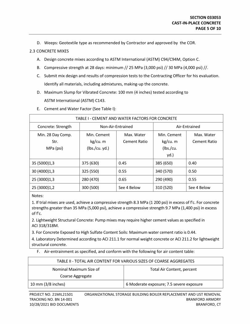
SECTION 033053 CAST-IN-PLACE CONCRETE PAGE 5 OF 10
PROJECT NO. 21MIL21501 ORGANIZATIONAL STORAGE BUILDING BOILER REPLACEMENT AND UST REMOVAL TRACKING NO. BN 14-001 BRANFORD ARMORY 10/28/2021 BID DOCUMENTS BRANFORD, CT
D. Weeps: Geotextile type as recommended by Contractor and approved by the COR.
2.3 CONCRETE MIXES
A. Design concrete mixes according to ASTM International (ASTM) C94/C94M, Option C.
B. Compressive strength at 28 days: minimum // 25 MPa (3,000 psi) // 30 MPa (4,000 psi) //.
C. Submit mix design and results of compression tests to the Contracting Officer for his evaluation.
Identify all materials, including admixtures, making-up the concrete.
D. Maximum Slump for Vibrated Concrete: 100 mm (4 inches) tested according to
ASTM International (ASTM) C143.
E. Cement and Water Factor (See Table I):
TABLE I - CEMENT AND WATER FACTORS FOR CONCRETE
Concrete: Strength Non-Air-Entrained Air-Entrained
Min. 28 Day Comp. Str.
MPa (psi)
Min. Cement kg/cu. m
(lbs./cu. yd.)
Max. Water Cement Ratio
Min. Cement kg/cu. m (lbs./cu.
yd.)
Max. Water Cement Ratio
35 (5000)1,3 375 (630) 0.45 385 (650) 0.40
30 (4000)1,3 325 (550) 0.55 340 (570) 0.50
25 (3000)1,3 280 (470) 0.65 290 (490) 0.55
25 (3000)1,2 300 (500) See 4 Below 310 (520) See 4 Below
Notes: 1. If trial mixes are used, achieve a compressive strength 8.3 MPa (1 200 psi) in excess of f'c. For concrete strengths greater than 35 MPa (5,000 psi), achieve a compressive strength 9.7 MPa (1,400 psi) in excess of f’c. 2. Lightweight Structural Concrete: Pump mixes may require higher cement values as specified in ACI 318/318M. 3. For Concrete Exposed to High Sulfate Content Soils: Maximum water cement ratio is 0.44. 4. Laboratory Determined according to ACI 211.1 for normal weight concrete or ACI 211.2 for lightweight structural concrete.
F. Air-entrainment as specified, and conform with the following for air content table:
TABLE II - TOTAL AIR CONTENT FOR VARIOUS SIZES OF COARSE AGGREGATES
Nominal Maximum Size of Coarse Aggregate
Total Air Content, percent
10 mm (3/8 inches) 6 Moderate exposure; 7.5 severe exposure
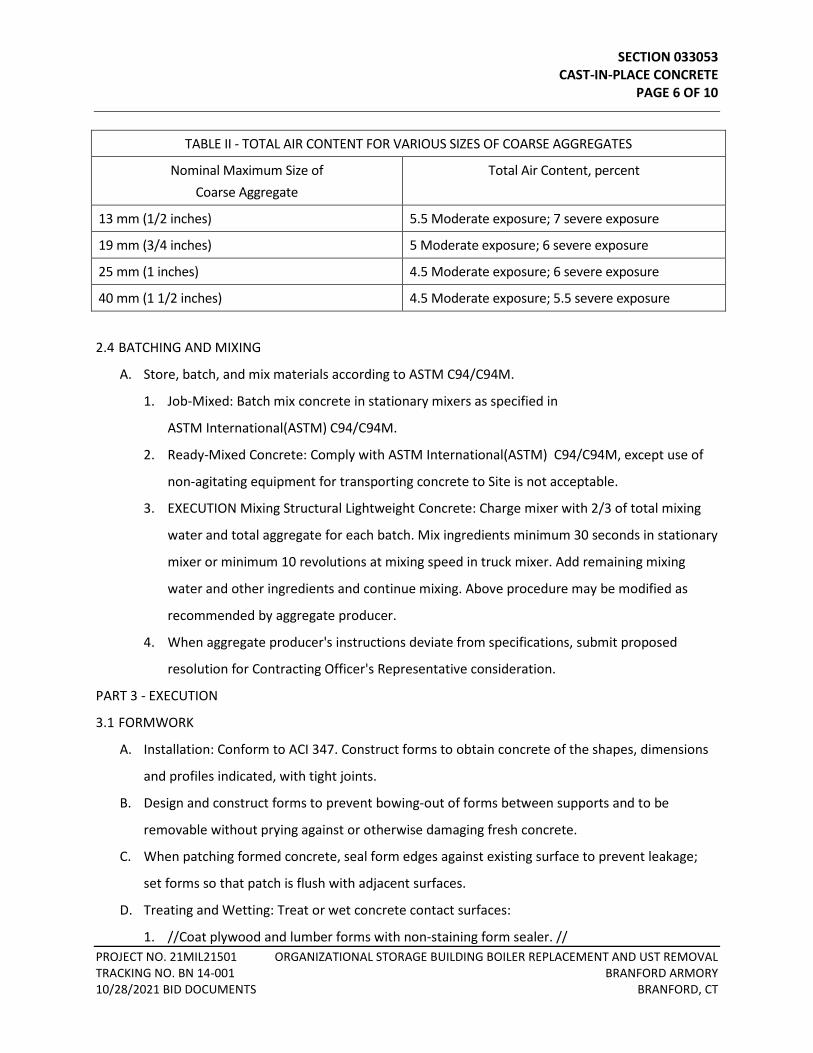
SECTION 033053 CAST-IN-PLACE CONCRETE PAGE 6 OF 10
PROJECT NO. 21MIL21501 ORGANIZATIONAL STORAGE BUILDING BOILER REPLACEMENT AND UST REMOVAL TRACKING NO. BN 14-001 BRANFORD ARMORY 10/28/2021 BID DOCUMENTS BRANFORD, CT
TABLE II - TOTAL AIR CONTENT FOR VARIOUS SIZES OF COARSE AGGREGATES
Nominal Maximum Size of Coarse Aggregate
Total Air Content, percent
13 mm (1/2 inches) 5.5 Moderate exposure; 7 severe exposure
19 mm (3/4 inches) 5 Moderate exposure; 6 severe exposure
25 mm (1 inches) 4.5 Moderate exposure; 6 severe exposure
40 mm (1 1/2 inches) 4.5 Moderate exposure; 5.5 severe exposure
2.4 BATCHING AND MIXING
A. Store, batch, and mix materials according to ASTM C94/C94M.
1. Job-Mixed: Batch mix concrete in stationary mixers as specified in
ASTM International(ASTM) C94/C94M.
2. Ready-Mixed Concrete: Comply with ASTM International(ASTM) C94/C94M, except use of
non-agitating equipment for transporting concrete to Site is not acceptable.
3. EXECUTION Mixing Structural Lightweight Concrete: Charge mixer with 2/3 of total mixing
water and total aggregate for each batch. Mix ingredients minimum 30 seconds in stationary
mixer or minimum 10 revolutions at mixing speed in truck mixer. Add remaining mixing
water and other ingredients and continue mixing. Above procedure may be modified as
recommended by aggregate producer.
4. When aggregate producer's instructions deviate from specifications, submit proposed
resolution for Contracting Officer's Representative consideration.
PART 3 - EXECUTION
3.1 FORMWORK
A. Installation: Conform to ACI 347. Construct forms to obtain concrete of the shapes, dimensions
and profiles indicated, with tight joints.
B. Design and construct forms to prevent bowing-out of forms between supports and to be
removable without prying against or otherwise damaging fresh concrete.
C. When patching formed concrete, seal form edges against existing surface to prevent leakage;
set forms so that patch is flush with adjacent surfaces.
D. Treating and Wetting: Treat or wet concrete contact surfaces:
1. //Coat plywood and lumber forms with non-staining form sealer. //
SECTION 033053 CAST-IN-PLACE CONCRETE PAGE 7 OF 10
PROJECT NO. 21MIL21501 ORGANIZATIONAL STORAGE BUILDING BOILER REPLACEMENT AND UST REMOVAL TRACKING NO. BN 14-001 BRANFORD ARMORY 10/28/2021 BID DOCUMENTS BRANFORD, CT
2. //Wet wood forms thoroughly when they are not treated with form release agent. //
3. //Prevent water from accumulating and remaining within forms. //
4. Clean and coat removable metal forms with light form oil before reinforcement is placed.
5. In hot weather, cool metal forms by thoroughly wetting with water just before placing
concrete.
6. Prevent water from accumulating and remaining within forms.
E. Inserts, Sleeves, and Similar Items: Install flashing reglets, masonry ties, anchors, inserts, wires,
hangers, sleeves, boxes for floor hinges, and other cast-in items specified in other Sections.
Place where indicated, square, flush and secured to formwork.
F. Construction Tolerances - General: Install and maintain concrete formwork to assure completion
of work within specified tolerances.
G. Adjust or replace completed work exceeding specified tolerances before placing concrete.
3.2 REINFORCEMENT
A. Install concrete reinforcement according to ACI 318 and ACI SP-66.
B. Support and securely tie reinforcing steel to prevent displacement during placing of concrete.
C. Drilling for Dowels in Existing Concrete: Use sharp bits, drill hole slightly oversize, fill with epoxy
grout, inset the dowel, and remove excess epoxy.
3.3 VAPOR BARRIER
A. Except where membrane waterproofing is required, place interior concrete slabs on a
continuous vapor barrier.
B. Lap joints 150 mm (6 inches) and seal with a compatible pressure-sensitive tape.
C. Patch punctures and tears.
3.4 PLACING CONCRETE
A. Remove water from excavations before concrete is placed. Remove hardened concrete, debris
and other foreign materials from interior of forms, and from inside of mixing and conveying
equipment. Obtain approval from Contracting Officer's Representative before placing concrete.
B. Install screeds at required elevations for concrete slabs.
C. Roughen and clean free from laitance, foreign matter, and loose particles before placing new
concrete on existing concrete.
SECTION 033053 CAST-IN-PLACE CONCRETE PAGE 8 OF 10
PROJECT NO. 21MIL21501 ORGANIZATIONAL STORAGE BUILDING BOILER REPLACEMENT AND UST REMOVAL TRACKING NO. BN 14-001 BRANFORD ARMORY 10/28/2021 BID DOCUMENTS BRANFORD, CT
1. Blow-out areas with compressed air and immediately coat contact areas with adhesive in
compliance with manufacturer's instructions.
D. Place structural concrete according to ACI 301 and ACI 318.
E. Convey concrete from mixer to final place of deposit by method that will prevent segregation or
loss of ingredients. Do not deposit, in Work, concrete that has attained its initial set or has
contained its water or cement more than 1 1/2 hours. Do not allow concrete to drop freely
more than 1500 mm (5 feet) in unexposed work nor more than 900 mm (3 feet) in exposed
work.
F. Place and consolidate concrete in horizontal layers not exceeding 300 mm (12 inches) in
thickness. Consolidate concrete by spading, rodding, and mechanical vibrator. Do not secure
vibrator to forms or reinforcement. Continuously vibrate during placement of concrete.
G. Concrete Fill in Stair Tread and Landing Pans: Coat steel with bonding agent and fill pans with
concrete. Reinforce with 2 inch by 2 inch by 1.6 mm (0.06 inch) welded wire mesh at midpoint.
H. Hot Weather Concrete Placement: As recommended by ACI 305.1 to prevent adversely affecting
properties and serviceability of hardened concrete.
I. Cold Weather Concrete Placement: As recommended by ACI 306.1, to prevent freezing of thin
sections less than 300 mm (12 inches) and to permit concrete to gain strength properly.
1. Do not use calcium chloride without written approval from Contracting Officer's
Representative.
3.5 TOLERANCES
A. Slab on Grade Finish Tolerance: Comply with ACI 117, FF-number and FL-number method.
1. Paragraph 4.8.3, Class A 3 mm (1/8 inches) for offset in form-work.
2. Table R4.8.4, "Flat" 6 mm (1/4 inch) in 3 m (10 feet) for slabs.
3.6 PROTECTION AND CURING
A. Protect exposed surfaces of concrete from premature drying, wash by rain or running water,
wind, mechanical damage, and excessive hot or cold temperatures.
B. Curing Methods: Cure concrete with curing compound using wet method with sheets.
C. Formed Concrete Curing: Wet the tops and exposed portions of formed concrete and keep
moist until forms are removed.

SECTION 033053 CAST-IN-PLACE CONCRETE PAGE 9 OF 10
PROJECT NO. 21MIL21501 ORGANIZATIONAL STORAGE BUILDING BOILER REPLACEMENT AND UST REMOVAL TRACKING NO. BN 14-001 BRANFORD ARMORY 10/28/2021 BID DOCUMENTS BRANFORD, CT
1. If forms are removed before 14 days after concrete is cast, install sheet curing materials as
specified above.
D. Concrete Flatwork Curing:
1. Install sheet materials according to the manufacturer's instructions.
a. When manufacturer's instructions deviate from specifications, submit proposed
resolution for Contracting Officer's Representative consideration.
3.7 FORM REMOVAL
A. Maintain forms in place until concrete is self-supporting, with construction operation loads.
B. Remove fins, laitance and loose material from concrete surfaces when forms are removed.
Repair honeycombs, rock pockets, sand runs, spalls, or otherwise damaged surfaces by patching
with the same mix as concrete minus the coarse aggregates.
C. Finish to match adjacent surfaces.
3.8 FINISHES
A. Slab Finishes:
1. Allow bleed water to evaporate before surface is finished. Do not sprinkle dry cement on
surface to absorb water.
2. Scratch Finish: Rake or wire broom after partial setting slab surfaces to received bonded
applied cementitious application, within 2 hours after placing, to roughen surface and
provide permanent bond between base slab and applied cementitious materials.
3. Float Finish: Interior and exterior platforms, both equipment pads, and slabs to receive
non-cementitious materials, except as specified.
a. Screen and float to smooth dense finish.
b. After first floating, while surface is still soft, check surfaces for alignment using
straightedge or template. Correct high spots by cutting down with trowel or similar tool.
Correct low spots by filling in with material same composition as floor finish. Remove
any surface projections on floated finish by rubbing or dry grinding. Refloat slab to
uniform sandy texture.
4. Steel Trowel Finish: Applied toppings, concrete surfaces to receive resilient floor covering or
carpet, future floor roof and other monolithic concrete floor slabs exposed to view without
other finish indicated or specified.
SECTION 033053 CAST-IN-PLACE CONCRETE PAGE 10 OF 10
PROJECT NO. 21MIL21501 ORGANIZATIONAL STORAGE BUILDING BOILER REPLACEMENT AND UST REMOVAL TRACKING NO. BN 14-001 BRANFORD ARMORY 10/28/2021 BID DOCUMENTS BRANFORD, CT
a. Delay final steel troweling to secure smooth, dense surface, usually when surface can no
longer be dented by fingers. During final troweling, tilt steel trowel at slight angle and
exert heavy pressure on trowel to compact cement paste and form dense, smooth
surface.
b. Finished surface: Free from trowel marks. Uniform in texture and appearance.
5. Broom Finish: Finish exterior slabs, ramps, and stair treads with bristle brush moistened
with clear water after surfaces have been floated.
6. Finished Slab Flatness (FF) and Levelness (FL):
a. Slab on Grade: Specified overall value FF 25/FL 20. Minimum local value FF 17/FL 15.
b. Test flatness and levelness according to ASTM E1155.
END OF SECTION 033053
SECTION 055000 METAL FABRICATIONS PAGE 1 OF 4
PROJECT NO. 21MIL21501 ORGANIZATIONAL STORAGE BUILDING BOILER REPLACEMENT AND UST REMOVAL TRACKING NO. BN 14-001 BRANFORD ARMORY 10/28/2021 BID DOCUMENTS BRANFORD, CT
SECTION 055000 - METAL FABRICATIONS
PART 1 - GENERAL
1.1 DESCRIPTION
A. This section specifies items and assemblies fabricated from structural steel shapes and other
materials as shown and specified.
B. Items specified.
1. Safety Nosings.
1.2 SUBMITTALS
A. Submit in accordance with Section 01300 of DIVISION 01, GENERAL REQUIREMENTS.
B. Manufacturer's Literature and Data:
1. Safety nosing.
C. Shop Drawings:
1. Each item specified, showing complete detail, location in the project, material and size of
components, method of joining various components and assemblies, finish, and location,
size and type of anchors.
D. Furnish setting drawings and instructions for installation of anchors to be preset into concrete
and masonry work, and for the positioning of items having anchors to be built into concrete or
masonry construction.
1.3 QUALITY ASSURANCE
A. Each manufactured product shall meet, as a minimum, the requirements specified, and shall be
a standard commercial product of a manufacturer regularly presently manufacturing items of
type specified.
B. Each product type shall be the same and be made by the same manufacturer.
C. Assembled product to the greatest extent possible before delivery to the site.
D. Include additional features, which are not specifically prohibited by this specification, but which
are a part of the manufacturer's standard commercial product.
1.4 APPLICABLE PUBLICATIONS
A. The publications listed below form a part of this specification to the extent referenced. The
publications are referenced in the text by the basic designation only.
B. American Society of Mechanical Engineers (ASME):
B18.6.1-97 .................................. Wood Screws
SECTION 055000 METAL FABRICATIONS PAGE 2 OF 4
PROJECT NO. 21MIL21501 ORGANIZATIONAL STORAGE BUILDING BOILER REPLACEMENT AND UST REMOVAL TRACKING NO. BN 14-001 BRANFORD ARMORY 10/28/2021 BID DOCUMENTS BRANFORD, CT
B18.2.2-87(R2005) ..................... Square and Hex Nuts
C. American Society for Testing and Materials (ASTM):
A48-03(R2012) ........................... Gray Iron Castings
A123-12 ...................................... Zinc (Hot-Dip Galvanized) Coatings on Iron and Steel Products
G. Federal Specifications (Fed. Spec):
RR-T-650E ................................... Treads, Metallic and Nonmetallic, Nonskid
PART 2 - PRODUCTS
2.1 MATERIALS
A. Aluminum, Extruded: ASTM B221, Alloy 6063-T5 unless otherwise specified. For structural
shapes use alloy 6061-T6 and alloy 6061-T4511.
B. Grout: ASTM C1107, pourable type.
2.2 FABRICATION GENERAL
A. Material
1. Use material as specified. Use material of commercial quality and suitable for intended
purpose for material that is not named or its standard of quality not specified.
2. Use material free of defects which could affect the appearance or service ability of the
finished product.
B. Fasteners and Anchors
1. Use methods for fastening or anchoring metal fabrications to building construction as
shown or specified.
2. Where fasteners and anchors are not shown, design the type, size, location and spacing to
resist the loads imposed without deformation of the members or causing failure of the
anchor or fastener, and suit the sequence of installation.
3. Use material and finish of the fasteners compatible with the kinds of materials which are
fastened together and their location in the finished work.
4. Fasteners for securing metal fabrications to new construction only, may be by use of
threaded or wedge type inserts or by anchors for welding to the metal fabrication for
installation before the concrete is placed or as masonry is laid.
5. Fasteners for securing metal fabrication to existing construction or new construction may be
expansion bolts, toggle bolts, power actuated drive pins, welding, self-drilling and tapping
screws or bolts.
SECTION 055000 METAL FABRICATIONS PAGE 3 OF 4
PROJECT NO. 21MIL21501 ORGANIZATIONAL STORAGE BUILDING BOILER REPLACEMENT AND UST REMOVAL TRACKING NO. BN 14-001 BRANFORD ARMORY 10/28/2021 BID DOCUMENTS BRANFORD, CT
C. Workmanship
1. General:
a. Fabricate items to design shown.
b. Furnish safety nosings in one piece.
c. Fabricate straight, true, free from warp and twist, and where applicable square and in
same plane.
d. Provide holes, sinkages and reinforcement shown and required for fasteners and
anchorage items.
f. Prepare members for the installation and fitting of hardware.
h. Fabricate surfaces and edges free from sharp edges, burrs and projections which may
cause injury.
4. Anchors:
a. Where metal fabrications are shown to be preset in concrete, weld 32 x 3 mm (1-1/4 by
1/8 inch) steel strap anchors, 150 mm (6 inches) long with 25 mm (one inch) hooked
end, to back of member at 600 mm (2 feet) on center, unless otherwise shown.
5. Cutting and Fitting:
a. Accurately cut, machine and fit joints, corners, copes, and miters.
i. The fit of components and the alignment of holes shall eliminate the need to modify
component or to use exceptional force in the assembly of item and eliminate the need
to use other than common tools.
D. Finish:
1. Finish exposed surfaces in accordance with NAAMM AMP 500 Metal Finishes Manual.
2. Aluminum: NAAMM AMP 501.
a. Mill finish, AA-M10, as fabricated, use unless specified otherwise.
E. Protection:
1. Insulate aluminum surfaces that will come in contact with concrete, masonry, plaster, or
metals other than stainless steel, zinc or white bronze by giving a coat of heavy-bodied alkali
resisting bituminous paint or other approved paint in shop.
SECTION 055000 METAL FABRICATIONS PAGE 4 OF 4
PROJECT NO. 21MIL21501 ORGANIZATIONAL STORAGE BUILDING BOILER REPLACEMENT AND UST REMOVAL TRACKING NO. BN 14-001 BRANFORD ARMORY 10/28/2021 BID DOCUMENTS BRANFORD, CT
PART 3 - EXECUTION
3.1 INSTALLATION, GENERAL
A. Set work accurately, in alignment and where shown, plumb, level, free of rack and twist, and set
parallel or perpendicular as required to line and plane of surface.
B. Items set into concrete or masonry.
1. Provide temporary bracing for such items until concrete or masonry is set.
2. Place in accordance with setting drawings and instructions.
D. Field weld in accordance with AWS.
1. Design and finish as specified for shop welding.
2. Use continuous weld unless specified otherwise.
E. Install anchoring devices and fasteners as shown and as necessary for securing metal
fabrications to building construction as specified. Power actuated drive pins may be used except
for removable items and where members would be deformed or substrate damaged by their
use.
F. Spot prime all abraded and damaged areas of zinc coating as specified and all abraded and
damaged areas of shop prime coat with same kind of paint used for shop priming.
G. Isolate aluminum from dissimilar metals and from contact with concrete and masonry materials
as required to prevent electrolysis and corrosion.
3.2 CLEAN AND ADJUSTING
A. Clean after installation exposed prefinished items and items fabricated from aluminum as
recommended by the metal manufacture and protected from damage until completion of the
project.
END OF SECTION 055000
SECTION 076000 FLASHING AND SHEET METAL PAGE 1 OF 22
PROJECT NO. 21MIL21501 ORGANIZATIONAL STORAGE BUILDING BOILER REPLACEMENT AND UST REMOVAL TRACKING NO. BN 14-001 BRANFORD ARMORY 10/28/2021 BID DOCUMENTS BRANFORD, CT
SECTION 076000 - FLASHING AND SHEET METAL
PART 1 - GENERAL
1.1 DESCRIPTION
A. Formed sheet metal work for wall and roof flashing and formed expansion joint covers are
specified in this section.
1.2 RELATED WORK
A. Section 09 9100, PAINTING: Paint materials and application.
B. Division 23 HVAC: Integral flashing components of manufactured roof specialties and
accessories or equipment.
1.3 APPLICABLE PUBLICATIONS
A. Publications listed below form a part of this specification to the extent referenced. Publications
are referenced in the text by the basic designation only. Editions of applicable publications
current on date of issue of bidding documents apply unless otherwise indicated.
B. Aluminum Association (AA):
AA-C22A41 ................................. Aluminum Chemically etched medium matte, with clear anodic
coating, Class I Architectural, 0.7-mil thick
AA-C22A42 ................................. Chemically etched medium matte, with integrally colored
anodic coating, Class I Architectural, 0.7 mils thick
AA-C22A44 ................................. Chemically etched medium matte with electrolytically deposited
metallic compound, integrally colored coating Class I
Architectural, 0.7-mil thick finish
C. American National Standards Institute/Single-Ply Roofing Institute/Factory Mutual
(ANSI/SPRI/FM):
4435/ES-1-11 ............................. Wind Design Standard for Edge Systems Used with Low Slope
Roofing Systems
D. American Architectural Manufacturers Association (AAMA):
AAMA 620-02 ............................. Voluntary Specification for High Performance Organic Coatings
on Coil Coated Architectural Aluminum
SECTION 076000 FLASHING AND SHEET METAL PAGE 2 OF 22
PROJECT NO. 21MIL21501 ORGANIZATIONAL STORAGE BUILDING BOILER REPLACEMENT AND UST REMOVAL TRACKING NO. BN 14-001 BRANFORD ARMORY 10/28/2021 BID DOCUMENTS BRANFORD, CT
AAMA 621-02 ............................. Voluntary Specification for High Performance Organic Coatings
on Coil Coated Architectural Hot Dipped Galvanized (HDG) and
Zinc-Aluminum Coated Steel Substrates
E. ASTM International (ASTM):
A240/A240M-20 ........................ Standard Specification for Chromium and Chromium-Nickel
Stainless Steel Plate, Sheet and Strip for Pressure Vessels and
for General Applications.
A653/A653M-20 ........................ Steel Sheet Zinc-Coated (Galvanized) or Zinc Alloy Coated
(Galvanized) by the Hot- Dip Process
B32-08(2014) ............................. Solder Metal
B209-14 ...................................... Aluminum and Aluminum-Alloy Sheet and Plate
B370-12(2019) ........................... Copper Sheet and Strip for Building Construction
D173/D173M-03(2018) .............. Bitumen-Saturated Cotton Fabrics Used in Roofing and
Waterproofing
D412-16 ...................................... Vulcanized Rubber and Thermoplastic Elastomers-Tension
D1187/D1187M-97(2018) .......... Asphalt Base Emulsions for Use as Protective Coatings for Metal
D1784-20 .................................... Rigid Poly (Vinyl Chloride) (PVC) Compounds and Chlorinated
Poly (Vinyl Chloride) (CPVC) Compounds
D3656/D3656M-13 .................... Insect Screening and Louver Cloth Woven from Vinyl-Coated
Glass Yarns
D4586/D4586M-07(2018) .......... Asphalt Roof Cement, Asbestos Free
F. Sheet Metal and Air Conditioning Contractors National Association (SMACNA): Architectural
Sheet Metal Manual.
G. National Association of Architectural Metal Manufacturers (NAAMM):
AMP 500-06 ............................... Metal Finishes Manual
H. Federal Specification (Fed. Spec):
A-A-1925A .................................. Shield, Expansion; (Nail Anchors)
UU-B-790A ................................. Building Paper, Vegetable Fiber
SECTION 076000 FLASHING AND SHEET METAL PAGE 3 OF 22
PROJECT NO. 21MIL21501 ORGANIZATIONAL STORAGE BUILDING BOILER REPLACEMENT AND UST REMOVAL TRACKING NO. BN 14-001 BRANFORD ARMORY 10/28/2021 BID DOCUMENTS BRANFORD, CT
I. International Code Commission (ICC): International Building Code, Current Edition
1.4 PERFORMANCE REQUIREMENTS
A. Wind Uplift Forces: Resist the following forces per FM Approvals 1-49:
1. Wind Zone 1: 0.48 to 0.96 kPa (10 to 20 pound force/square foot): 1.92-kPa (40 pound
force/square foot) perimeter uplift force, 2.87-kPa (60 pound force/square foot pound
force/square foot) corner uplift force, and 0.96-kPa (20- pound force/square foot) outward
force.
2. Wind Zone 1: 1.00 to 1.44 kPa (21 to 30 pound force/square foot): 2.87-kPa (60 pound
force/square foot) perimeter uplift force, 4.31-kPa (90 pound force/square foot) corner
uplift force, and 1.44-kPa (30 pound force/square foot) outward force.
3. Wind Zone 2: 1.48 to 2.15 kPa (31 to 45 pound force/square foot): 4.31-kPa (90 pound
force/square foot) perimeter uplift force, 5.74-kPa (120 pound force/square foot) corner
uplift force, and 2.15-kPa (45 pound force/square foot) outward force.
4. Wind Zone 3: 2.20 to 4.98 kPa (46 to 104 pound force/square foot): 9.96-kPa (208 pound
force/square foot) perimeter uplift force, 14.94-kPa (312 pound force/square foot) corner
uplift force, and 4.98-kPa (104 pound force/square foot) outward force.
1.5 SUBMITTALS
A. Submit in accordance with Section 01 300, SUBMITTALS.
B. Shop Drawings: For all specified items, including:
1. Flashings
C. Manufacturer's Literature and Data: For all specified items, including:
1. Two-piece counterflashing
2. Thru wall flashing
3. Expansion joint cover, each type
4. Nonreinforced, elastomeric sheeting
5. Copper clad stainless steel
6. Polyethylene coated copper
7. Bituminous coated copper
8. Copper covered paper
SECTION 076000 FLASHING AND SHEET METAL PAGE 4 OF 22
PROJECT NO. 21MIL21501 ORGANIZATIONAL STORAGE BUILDING BOILER REPLACEMENT AND UST REMOVAL TRACKING NO. BN 14-001 BRANFORD ARMORY 10/28/2021 BID DOCUMENTS BRANFORD, CT
D. Certificates: Indicating compliance with specified finishing requirements, from applicator and
contractor.
PART 2 - PRODUCTS
2.1 FLASHING AND SHEET METAL MATERIALS
A. Stainless Steel: ASTM A240, Type 302B, dead soft temper.
B. Copper ASTM B370, cold-rolled temper.
C. Bituminous Coated Copper: Minimum copper ASTM B370, weight not less than 1 kg/m² (3
oz/sf). Bituminous coating shall weigh not less than 2 kg/m² (6 oz/sf); or, copper sheets may be
bonded between two layers of coarsely woven bitumen-saturated cotton fabric ASTM D173.
Exposed fabric surface shall be crimped.
D. Copper Covered Paper: Fabricated of electro-deposit pure copper sheets ASTM B 370, bonded
with special asphalt compound to both sides of creped, reinforced building paper, UU-B-790,
Type I, style 5, or to a three-ply sheet of asphalt impregnated crepe paper. Grooves running
along the width of sheet.
E. Polyethylene Coated Copper: Copper sheet ASTM B370, weighing 1 Kg/m² (3 oz/sf) bonded
between two layers of (two mil) thick polyethylene sheet.
F. Aluminum Sheet: ASTM B209, alloy 3003-H14.
G. Galvanized Sheet: ASTM, A653.
H. Nonreinforced, Elastomeric Sheeting: Elastomeric substances reduced to thermoplastic state
and extruded into continuous homogenous sheet (0.056 inch) thick. Sheeting shall have not less
than 7 MPa (1,000 psi) tensile strength and not more than seven percent tension-set at 50
percent elongation when tested in accordance with ASTM D412. Sheeting shall show no cracking
or flaking when bent through 180° over a 1 mm (1/32 inch) diameter mandrel and then bent at
same point over same size mandrel in opposite direction through 360° at temperature of -30°C
(-20 °F).
2.2 FLASHING ACCESSORIES
A. Solder: ASTM B32; flux type and alloy composition as required for use with metals to be
soldered.
B. Rosin Paper: Fed-Spec. UU-B-790, Type I, Grade D, Style 1b, Rosin-sized sheathing paper,
weighing approximately 3 Kg/10 m²(6 pounds/100 square feet).
SECTION 076000 FLASHING AND SHEET METAL PAGE 5 OF 22
PROJECT NO. 21MIL21501 ORGANIZATIONAL STORAGE BUILDING BOILER REPLACEMENT AND UST REMOVAL TRACKING NO. BN 14-001 BRANFORD ARMORY 10/28/2021 BID DOCUMENTS BRANFORD, CT
C. Bituminous Paint: ASTM D1187, Type I.
D. Fasteners:
1. Use copper, copper alloy, bronze, brass, or stainless steel for copper and copper clad
stainless steel, and stainless steel for stainless steel and aluminum alloy. Use galvanized
steel or stainless steel for galvanized steel.
2. Nails:
a. Minimum diameter for copper nails: 3 mm (0.109 inch).
b. Minimum diameter for aluminum nails 3 mm (0.105 inch).
c. Minimum diameter for stainless steel nails: 2 mm (0.095 inch) and annular threaded.
d. Length to provide not less than 22 mm (7/8 inch) penetration into anchorage.
3. Rivets: Not less than 3 mm (1/8 inch) diameter.
4. Expansion Shields: Fed Spec A-A-1925A.
E. Sealant: As specified in Section 07 92 00, JOINT SEALANTS for exterior locations.
F. Insect Screening: ASTM D3656, 18 by 18 regular mesh.
G. Roof Cement: ASTM D4586.
2.3 SHEET METAL THICKNESS
A. Except as otherwise shown or specified use thickness or weight of sheet metal as follows:
B. Concealed Locations (Built into Construction):
1. Copper: 30g (10 oz) minimum 0.33 mm (0.013 inch thick).
2. Stainless steel: 0.25 mm (0.010 inch) thick.
3. Copper clad stainless steel: 0.25 mm (0.010 inch) thick.
4. Galvanized steel: 0.5 mm (0.021 inch) thick.
C. Exposed Locations:
1. Copper: 0.4 Kg (16 oz).
2. Stainless steel: 0.4 mm (0.015 inch).
3. Copper clad stainless steel: 0.4 mm (0.015 inch).
D. Thickness of aluminum or galvanized steel is specified with each item.
SECTION 076000 FLASHING AND SHEET METAL PAGE 6 OF 22
PROJECT NO. 21MIL21501 ORGANIZATIONAL STORAGE BUILDING BOILER REPLACEMENT AND UST REMOVAL TRACKING NO. BN 14-001 BRANFORD ARMORY 10/28/2021 BID DOCUMENTS BRANFORD, CT
2.4 FABRICATION, GENERAL
A. Jointing:
1. In general, copper, stainless steel and copper clad stainless-steel joints, except expansion
and contraction joints, shall be locked and soldered.
2. Jointing of copper over 0.5 Kg (20 oz) weight or stainless steel over 0.45 mm (0.018 inch)
thick shall be done by lapping, riveting and soldering.
3. Joints shall conform to following requirements:
a. Flat-lock joints shall finish not less than 19 mm (3/4 inch) wide.
b. Lap joints subject to stress shall finish not less than 25 mm (one inch) wide and shall be
soldered and riveted.
c. Unsoldered lap joints shall finish not less than 100 mm (4 inches) wide.
4. Flat and lap joints shall be made in direction of flow.
5. Edges of bituminous coated copper, copper covered paper, nonreinforced elastomeric
sheeting and polyethylene coated copper shall be joined by lapping not less than 100 mm (4
inches) in the direction of flow and cementing with asphalt roof cement or sealant as
required by the manufacturer's printed instructions.
6. Soldering:
a. Pre tin both mating surfaces with solder for a width not less than 38 mm (1 1/2 inches)
of uncoated copper, stainless steel, and copper clad stainless steel.
b. Wire brush to produce a bright surface before soldering lead coated copper.
c. Treat in accordance with metal producer’s recommendations other sheet metal
required to be soldered.
d. Completely remove acid and flux after soldering is completed.
B. Expansion and Contraction Joints:
1. Fabricate in accordance with the Architectural Sheet Metal Manual recommendations for
expansion and contraction of sheet metal work in continuous runs.
2. Space joints as shown or as specified.
3. Space expansion and contraction joints for copper, stainless steel, and copper clad stainless
steel at intervals not exceeding 7200 mm (24 feet).
SECTION 076000 FLASHING AND SHEET METAL PAGE 7 OF 22
PROJECT NO. 21MIL21501 ORGANIZATIONAL STORAGE BUILDING BOILER REPLACEMENT AND UST REMOVAL TRACKING NO. BN 14-001 BRANFORD ARMORY 10/28/2021 BID DOCUMENTS BRANFORD, CT
4. Space expansion and contraction joints for aluminum at intervals not exceeding 5400 mm
(18 feet), except do not exceed 3000 mm (10 feet) for gravel stops.
5. Fabricate slip-type or loose locked joints and fill with sealant unless otherwise specified.
6. Fabricate joint covers of same thickness material as sheet metal served.
C. Cleats:
1. Fabricate cleats to secure flashings and sheet metal work over 300 mm (12 inches) wide and
where specified.
2. Provide cleats for maximum spacing of 300 mm (12 inch) centers unless specified otherwise.
3. Form cleats of same metal and weights or thickness as the sheet metal being installed unless
specified otherwise.
4. Fabricate cleats from 50 mm (2 inch) wide strip. Form end with not less than 19 mm (3/4
inch) wide loose lock to item for anchorage. Form other end of length to receive nails free of
item to be anchored and end edge to be folded over and cover nail heads.
D. Edge Strips or Continuous Cleats:
1. Fabricate continuous edge strips where shown and specified to secure loose edges of the
sheet metal work.
2. Use material compatible with sheet metal to be secured by the edge strip.
3. Fabricate in 3000 mm (10 feet) maximum lengths with not less than 19 mm (3/4 inch) loose
lock into metal secured by edge strip.
4. Fabricate Strips for fascia anchorage to extend below the supporting wood construction to
form a drip and to allow the flashing to be hooked over the lower edge at least 19 mm (3/4-
inch).
E. Drips:
1. Form drips at lower edge of sheet metal counter-flashings (cap flashings), gravel stops, by
folding edge back 13 mm (1/2 inch) and bending out 45° from vertical to carry water away
from the wall.
2. Form drip to provide hook to engage cleat or edge strip for fastening for not less than 19
mm (3/4 inch) loose lock where shown.
SECTION 076000 FLASHING AND SHEET METAL PAGE 8 OF 22
PROJECT NO. 21MIL21501 ORGANIZATIONAL STORAGE BUILDING BOILER REPLACEMENT AND UST REMOVAL TRACKING NO. BN 14-001 BRANFORD ARMORY 10/28/2021 BID DOCUMENTS BRANFORD, CT
F. Edges:
1. Edges of flashings concealed in masonry joints opposite drain side shall be turned up 6 mm
(1/4 inch) to form dam, unless otherwise specified or shown otherwise.
2. Finish exposed edges of flashing with a 6 mm (1/4 inch) hem formed by folding edge of
flashing back on itself when not hooked to edge strip or cleat. Use 6 mm (1/4 inch)
minimum penetration beyond wall face with drip for through-wall flashing exposed edge.
3. All metal roof edges shall meet requirements of IBC, current edition.
G. Metal Options:
1. Where options are permitted for different metals use only one metal throughout.
2. Stainless steel may be used in concealed locations for fasteners of other metals exposed to
view.
3. Where copper gravel stops and flashings will carry water onto cast stone, stone, or
architectural concrete, or stainless steel.
2.5 FINISHES
A. Use same finish on adjacent metal or components and exposed metal surfaces unless specified
or shown otherwise.
B. In accordance with NAAMM Metal Finishes Manual AMP 500, unless otherwise specified.
C. Finish exposed metal surfaces as follows, unless specified otherwise:
1. Copper: Mill finish.
2. Stainless Steel: Finish No. 2B or 2D.
3. Aluminum:
a. Clear Finish: AA-C22A41 medium matte, clear anodic coating, Class 1 Architectural, 18
mm (0.7 mils) thick.
b. Colored Finish: AA-C22A42 (anodized) or AA-C22A44 (electrolytically deposited metallic
compound) medium matte, integrally colored coating, Class 1 Architectural, 18 mm (0.7
mils) thick. Dyes will not be accepted.
c. Fluorocarbon Finish: AAMA 620, high performance organic coating.
d. Mill finish.
4. Steel and Galvanized Steel:
a. Finish painted under Section 09 91 00, PAINTING unless specified as prefinished item.
SECTION 076000 FLASHING AND SHEET METAL PAGE 9 OF 22
PROJECT NO. 21MIL21501 ORGANIZATIONAL STORAGE BUILDING BOILER REPLACEMENT AND UST REMOVAL TRACKING NO. BN 14-001 BRANFORD ARMORY 10/28/2021 BID DOCUMENTS BRANFORD, CT
b. Manufacturer's finish:
1) Baked on prime coat over a phosphate coating.
2) Baked-on prime and finish coat over a phosphate coating.
3) Fluorocarbon Finish: AAMA 621, high performance organic coating.
2.6 THROUGH-WALL FLASHINGS
A. Form through-wall flashing to provide a mechanical bond or key against lateral movement in all
directions. Install a sheet having 2 mm (1/16 inch) deep transverse channels spaced four to
every 25 mm (one inch), or ribbed diagonal pattern, or having other deformation unless
specified otherwise.
1. Fabricate in not less than 2400 mm (8 feet) lengths; 3000 mm (10 feet) maximum lengths.
2. Fabricate so keying nests at overlaps.
B. For Masonry Work When Concealed Except for Drip:
1. Either copper, stainless steel, or copper clad stainless steel.
2. Form an integral dam at least 5 mm (3/16 inch) high at back edge.
3. Form exposed portions of flashing with drip, approximately 6 mm (1/4 inch) projection
beyond wall face.
C. For Masonry Work When Exposed Edge Forms a Receiver for Counter Flashing:
1. Use same metal and thickness as counter flashing.
2. Form an integral dam at least 5 mm (3/16 inch) high at back edge.
3. Form exposed portion as snap lock receiver for counter flashing upper edge.
D. For Flashing at Architectural Precast Concrete Panels or Stone Panels.
1. Use plan flat sheet of stainless steel.
2. Form exposed portions with drip as specified or receiver.
E. Window Sill Flashing and Lintel Flashing:
1. Use either copper, stainless steel, copper clad stainless-steel plane flat sheet, or
nonreinforced elastomeric sheeting, bituminous coated copper, copper covered paper, or
polyethylene coated copper.
2. Fabricate flashing at ends with folded corners to turn up 5 mm (3/16 inch) in first vertical
masonry joint beyond masonry opening.
3. Turn up back edge as shown.
SECTION 076000 FLASHING AND SHEET METAL PAGE 10 OF 22
PROJECT NO. 21MIL21501 ORGANIZATIONAL STORAGE BUILDING BOILER REPLACEMENT AND UST REMOVAL TRACKING NO. BN 14-001 BRANFORD ARMORY 10/28/2021 BID DOCUMENTS BRANFORD, CT
4. Form exposed portion with drip as specified or receiver.
F. Door Sill Flashing:
1. Where concealed, use either 0.5 Kg (20 ounce) copper, 0.5 mm (0.018 inch) thick stainless
steel, or 0.5 mm (0.018 inch) thick copper clad stainless steel.
2. Where shown on drawings as combined counter flashing under threshold, sill plate, door sill,
or where subject to foot traffic, use either 0.6 Kg (24 ounce) copper, 0.6 mm (0.024 inch)
stainless steel, or 0.6 mm (0.024 inch) thick stainless steel.
3. Fabricate flashing at ends to turn up 5 mm (3/16 inch) in first vertical masonry joint beyond
masonry opening with folded corners.
2.7 BASE FLASHING
A. Use metal base flashing at vertical surfaces intersecting built-up roofing where shown.
1. Use either copper, or stainless steel, thickness specified unless specified otherwise.
2. When flashing is over 250 mm (10 inches) in vertical height or horizontal width use either
0.5 Kg (20 oz) copper or 0.5 mm (0.018 inch) stainless steel.
3. Use stainless steel at aluminum roof curbs where flashing contacts the aluminum.
4. Use either copper, or stainless steel at pipe flashings.
B. Fabricate metal base flashing up vertical surfaces not less than 200 mm (8 inch) nor more than
400 mm (16 inch).
C. Fabricate roof flange not less than 100 mm (4 inches) wide unless shown otherwise. When base
flashing length exceeds 2400 mm (8 feet) form flange edge with 13 mm (1/2 inch) hem to
receive cleats.
D. Form base flashing bent from strip except pipe flashing. Fabricate ends for riveted soldered lap
seam joints. Fabricate expansion joint ends as specified.
E. Pipe Flashing: (Other than engine exhaust or flue stack)
1. Fabricate roof flange not less than 100 mm (4 inches) beyond sleeve on all sides.
2. Extend sleeve up and around pipe and flange out at bottom not less than 13 mm (1/2 inch)
and solder to flange and sleeve seam to make watertight.
3. At low pipes 200 mm (8 inch) to 450 mm (18 inch) above roof:
a. Form top of sleeve to turn down into the pipe at least 25 mm (one inch).
b. Allow for loose fit around and into the pipe.
SECTION 076000 FLASHING AND SHEET METAL PAGE 11 OF 22
PROJECT NO. 21MIL21501 ORGANIZATIONAL STORAGE BUILDING BOILER REPLACEMENT AND UST REMOVAL TRACKING NO. BN 14-001 BRANFORD ARMORY 10/28/2021 BID DOCUMENTS BRANFORD, CT
4. At high pipes and pipes with goosenecks or other obstructions which would prevent turning
the flashing down into the pipe:
a. Extend sleeve up not less than 300 mm (12 inch) above roofing.
b. Allow for loose fit around pipe.
2.8 COUNTERFLASHING (CAP FLASHING OR HOODS)
A. Either copper or stainless steel, unless specified otherwise.
B. Fabricate to lap base flashing a minimum of 100 mm (4 inches) with drip:
1. Form lock seams for outside corners. Allow for lap joints at ends and inside corners.
2. In general, form flashing in lengths not less than 2400 mm (8 feet) and not more than 3000
mm (10 feet).
3. Two-piece, lock in type flashing may be used in-lieu-of one-piece counter-flashing.
4. Manufactured assemblies may be used.
5. Where counterflashing is installed at new work use an integral flange at the top designed to
be extended into the masonry joint or reglet in concrete.
6. Where counterflashing is installed at existing work use surface applied type, formed to
provide a space for the application of sealant at the top edge.
C. One-piece Counterflashing:
1. Back edge turned up and fabricate to lock into reglet in concrete.
2. Upper edge formed to extend full depth of masonry unit in mortar joint with back edge
turned up 6 mm (1/4 inch).
D. Two-Piece Counterflashing:
1. Receiver to extend into masonry wall depth of masonry unit with back edge turned up 6 mm
(1/4 inch) and exposed edge designed to receive and lock counterflashing upper edge when
inserted.
2. Counterflashing upper edge designed to snap lock into receiver.
E. Surface Mounted Counterflashing; one or two-piece:
1. Use at existing or new surfaces where flashing cannot be inserted in vertical surface.
2. One piece fabricated upper edge folded double for 65 mm (2 1/2 inches) with top 19 mm
(3/4 inch) bent out to form "V" joint sealant pocket with vertical surface. Perforate flat
double area against vertical surface with horizontally slotted fastener holes at 400 mm (16
SECTION 076000 FLASHING AND SHEET METAL PAGE 12 OF 22
PROJECT NO. 21MIL21501 ORGANIZATIONAL STORAGE BUILDING BOILER REPLACEMENT AND UST REMOVAL TRACKING NO. BN 14-001 BRANFORD ARMORY 10/28/2021 BID DOCUMENTS BRANFORD, CT
inch) centers between end holes. Option: One piece surface mounted counter-flashing (cap
flashing) may be used. Fabricate as detailed on Plate 51 of SMACNA Architectural Sheet
Metal Manual.
3. Two pieces: Fabricate upper edge to lock into surface mounted receiver. Fabricate receiver
joint sealant pocket on upper edge and lower edge to receive counterflashing, with slotted
fastener holes at 400 mm (16 inch) centers between upper and lower edge.
F. Pipe Counterflashing:
1. Form flashing for water-tight umbrella with upper portion against pipe to receive a draw
band and upper edge to form a "V" joint sealant receiver approximately 19 mm (3/4 inch)
deep.
2. Fabricate 100 mm (4 inch) over lap at end.
3. Fabricate draw band of same metal as counter flashing. Use 0.6 Kg (24 oz) copper or 0.33
mm (0.013 inch) thick stainless steel or copper coated stainless steel.
4. Use stainless steel bolt on draw band tightening assembly.
5. Vent pipe counter flashing may be fabricated to omit draw band and turn down 25 mm (one
inch) inside vent pipe.
G. Where vented edge decks intersect vertical surfaces, form in one piece, shape to slope down to
a point level with and in front of edge-set notched plank; then, down vertically, overlapping
base flashing.
2.9 GRAVEL STOPS
A. General:
1. Fabricate in lengths not less than 2400 mm (8 feet) long and maximum of 3000 mm (10
feet).
2. Fabricate internal and external corners as one-piece with legs not less than 600 mm (2 feet)
or more than 1200 mm (4 feet) long.
3. Fabricate roof flange not less than 100 mm (4 inches) wide.
4. Fabricate top edge to extend above roof not less than 25 mm (one inch) for embedded
gravel aggregate and not less than 100 mm (4 inches) for loose laid ballast.
5. Fabricate lower edge outward at an angle of 45° to form drip and as fascia or as counter
flashing as shown:
SECTION 076000 FLASHING AND SHEET METAL PAGE 13 OF 22
PROJECT NO. 21MIL21501 ORGANIZATIONAL STORAGE BUILDING BOILER REPLACEMENT AND UST REMOVAL TRACKING NO. BN 14-001 BRANFORD ARMORY 10/28/2021 BID DOCUMENTS BRANFORD, CT
a. Fabricate of one-piece material of suitable width for fascia height of 250 mm (10 inch)
maximum or counterflashing lap of not less than 100 mm (4 inch) over base flashing.
b. Fabricate bottom edge of formed fascia to receive edge strip.
c. When fascia bottom edge forms counter flashing over roofing lap roofing not less than
150 mm (6 inches).
B. Formed Flat Sheet Metal Gravel Stops:
1. Fabricate as shown of 1.25 mm (0.050 inch) thick aluminum.
2. At joint between ends of sheets, provide a concealed clip soldered or welded near one end
of each sheet to hold the adjoining sheet in lapped position. The clip shall be approximately
100 mm (4 inches) wide and shall be the full depth of the fascia less 25 mm (one inch) at top
and bottom. Clip shall be of the same thickness as the fascia.
3. Provide edge strip as specified with lower hooked edge bent outward at an angle of 45°.
C. Formed (Corrugated Sheet) Sheet Metal Gravel Stops:
1. Fabricate as shown of 0.8 mm (0.032 inch) thick aluminum/.
2. Sheets shall have 2 mm (1/16 inch) deep corrugations either transversely or diagonally
rolled into the sheet. Crimped sheets are not acceptable.
3. Factory fabricate prepackaged system, complete with fastenings.
4. Provide concealed flashing splice plate at joints not less than 150 mm (6 inches) long and
continuous edge strip at lower edge of fascia made from same metal.
5. Fabricate as two-piece fascia when fascia depth exceeds 175 mm (7 inches).
2.10 BITUMEN STOPS
A. Fabricate bitumen stops for bituminous roofing edges for use with formed sheet metal gravel
stops, pipe penetrations, and other penetrations through roof deck without a curb.
B. Fabricate with 19 mm (3/4 inch) vertical legs and 75 mm (3 inch) horizontal legs.
C. When used with gravel stop or metal base flashing use same metal for bitumen stop in thickness
specified for concealed locations.
2.11 INSULATED EXPANSION JOINT COVERS
A. Either type optional, use only one type throughout.
B. Types:
SECTION 076000 FLASHING AND SHEET METAL PAGE 14 OF 22
PROJECT NO. 21MIL21501 ORGANIZATIONAL STORAGE BUILDING BOILER REPLACEMENT AND UST REMOVAL TRACKING NO. BN 14-001 BRANFORD ARMORY 10/28/2021 BID DOCUMENTS BRANFORD, CT
1. Construct of two preformed, stainless steel strips, not less than 0.4 mm (0.015 inch) thick,
mechanically and adhesively bonded to both sides of a 2 mm (1/16 inch) thick neoprene or
butyl sheet, or to a 0.4 mm (32 mil) thick reinforced chlorinated polyethylene sheet.
Adhesively attach a 10 mm (3/8 inch) thick sheet of closed cell, neoprene foam insulation, to
the underside of the neoprene, butyl, or chlorinated polyethylene sheet.
2. Constructed of a 2 mm (1/16 inch) thick vinyl sheet, flanged at both sides with stainless steel
strips not less than 0.4 mm (0.015 inch) thick. Vinyl sheet locked and encased by the
stainless-steel strip and pre-punched for nailing. A 10 mm (3/8 inch) thick closed cell
polyvinyl chloride foam insulating strip shall be heat laminated to the underside of the vinyl
sheet between the stainless-steel strips.
C. Expansion joint covers shall have factory fabricated mitered corners, crossing tees, and other
necessary accessories. Furnish in the longest available lengths.
D. Metal flange of sufficient width to extend over the top of the curb and down curb sides 50 mm
(2 inches) with hemmed edge for lock to edge strip.
2.12 ENGINE EXHAUST PIPE OR FLUE OR STACK FLASHING
A. Flashing at penetrations through roofing shall consist of a metal collar, sheet metal flashing
sleeve and hood.
B. Fabricate collar with roof flange of 1.2 mm (0.047 inch) minimum thick black iron or galvanized
steel sheet.
1. Fabricate inside diameter of collar 100 mm (4 inches) larger than the outside diameter of
the item penetration the roofing.
2. Extend collar height from structural roof deck to not less than 350 mm (14 inches) above
roof surface.
3. Fabricate collar roof flange not less than 100 mm (4 inches) wide.
4. Option: Collar may be of steel tubing 3 mm (0.125 inch) minimum wall thickness, with not
less than four, 50 mm x 100 mm x 3 mm (2 inch by 4 inch by 0.125 inch) thick tabs bottom
edge evenly spaced around tube in lieu of continuous roof flange. Full butt weld joints of
collar.
C. Fabricate sleeve base flashing with roof flange of either copper, stainless steel, or copper clad
stainless steel.
SECTION 076000 FLASHING AND SHEET METAL PAGE 15 OF 22
PROJECT NO. 21MIL21501 ORGANIZATIONAL STORAGE BUILDING BOILER REPLACEMENT AND UST REMOVAL TRACKING NO. BN 14-001 BRANFORD ARMORY 10/28/2021 BID DOCUMENTS BRANFORD, CT
1. Fabricate sleeve roof flange not less than 100 mm (4 inches) wide.
2. Extend sleeve around collar up to top of collar.
3. Flange bottom of sleeve out not less than 13 mm (1/24 inch) and soldered to 100 mm (4
inch) wide flange to make watertight.
4. Fabricate interior diameter 50 mm (2 inch) greater than collar.
D. Fabricate hood counter flashing from same material and thickness as sleeve.
1. Fabricate the same as pipe counter flashing except allow not less than 100 mm (4 inch) lap
below top of sleeve and to form vent space minimum of 100 mm (4 inch) wide.
2. Hem bottom edge of hood 13 mm (1/2 inch).
3. Provide a 50 mm (2 inch) deep draw band.
E. Fabricate insect screen closure between sleeve and hood. Secure screen to sleeve with sheet
metal screws.
PART 3 - EXECUTION
3.1 INSTALLATION
A. General:
1. Install flashing and sheet metal items as shown in Sheet Metal and Air Conditioning
Contractors National Association, Inc., publication, ARCHITECTURAL SHEET METAL MANUAL,
except as otherwise shown or specified.
2. Apply Sealant as specified in Section 07 92 00, JOINT SEALANTS.
3. Apply sheet metal and other flashing material to surfaces which are smooth, sound, clean,
dry and free from defects that might affect the application.
4. Remove projections which would puncture the materials and fill holes and depressions with
material compatible with the substrate. Cover holes or cracks in wood wider than 6 mm (1/4
inch) with sheet metal compatible with the roofing and flashing material used.
5. Coordinate with masonry work for the application of a skim coat of mortar to surfaces of
unit masonry to receive flashing material before the application of flashing.
6. Apply a layer of 7 Kg (15 pound) saturated felt followed by a layer of rosin paper to wood
surfaces to be covered with copper. Lap each ply 50 mm (2 inch) with the slope and nail with
large headed copper nails.
SECTION 076000 FLASHING AND SHEET METAL PAGE 16 OF 22
PROJECT NO. 21MIL21501 ORGANIZATIONAL STORAGE BUILDING BOILER REPLACEMENT AND UST REMOVAL TRACKING NO. BN 14-001 BRANFORD ARMORY 10/28/2021 BID DOCUMENTS BRANFORD, CT
7. Confine direct nailing of sheet metal to strips 300 mm (12 inch) or less wide. Nail flashing
along one edge only. Space nail not over 100 mm (4 inches) on center unless specified
otherwise.
8. Install bolts, rivets, and screws where indicated, specified, or required in accordance with
the SMACNA Sheet Metal Manual. Space rivets at 75 mm (3 inch) on centers in two rows in a
staggered position. Use neoprene washers under fastener heads when fastener head is
exposed.
9. Coordinate with roofing work for the installation of metal base flashings and other metal
items having roof flanges for anchorage and watertight installation.
10. Nail continuous cleats on 75 mm (3 inch) on centers in two rows in a staggered position.
11. Nail individual cleats with two nails and bend end tab over nail heads. Lock other end of
cleat into hemmed edge.
12. Install flashings in conjunction with other trades so that flashings are inserted in other
materials and joined together to provide a water tight installation.
13. Where required to prevent galvanic action between dissimilar metal isolate the contact
areas of dissimilar metal with sheet lead, waterproof building paper, or a coat of bituminous
paint.
14. Isolate aluminum in contact with dissimilar metals others than stainless steel, white bronze
or other metal compatible with aluminum by:
a. Paint dissimilar metal with a prime coat of zinc-chromate or other suitable primer,
followed by two coats of aluminum paint.
b. Paint dissimilar metal with a coat of bituminous paint.
c. Apply an approved caulking material between aluminum and dissimilar metal.
15. Paint aluminum in contact with or built into mortar, concrete, plaster, or other masonry
materials with a coat of bituminous paint.
16. Paint aluminum in contact with absorptive materials that may become repeatedly wet with
two coats of bituminous paint or two coats of aluminum paint.
17. Bitumen Stops:
a. Install bitumen stops for built-up roof opening penetrations through deck and at formed
sheet metal gravel stops.
SECTION 076000 FLASHING AND SHEET METAL PAGE 17 OF 22
PROJECT NO. 21MIL21501 ORGANIZATIONAL STORAGE BUILDING BOILER REPLACEMENT AND UST REMOVAL TRACKING NO. BN 14-001 BRANFORD ARMORY 10/28/2021 BID DOCUMENTS BRANFORD, CT
b. Nail leg of bitumen stop at 300 mm (12 inch) intervals to nailing strip at roof edge
before roofing material is installed.
3.2 THROUGH-WALL FLASHING
A. General:
1. Install continuous through-wall flashing between top of concrete foundation walls and
bottom of masonry building walls; at top of concrete floors; under masonry, concrete, or
stone copings and elsewhere as shown.
2. Where exposed portions are used as a counter-flashings, lap base flashings at least 100 mm
(4 inches) and use thickness of metal as specified for exposed locations.
3. Exposed edge of flashing may be formed as a receiver for two-piece counter flashing as
specified.
4. Terminate exterior edge beyond face of wall approximately 6 mm (1/4 inch) with drip edge
where not part of counter flashing.
5. Turn back edge up 6 mm (1/4 inch) unless noted otherwise where flashing terminates in
mortar joint or hollow masonry unit joint.
6. Terminate interior raised edge in masonry backup unit approximately 38 mm (1 1/2 inch)
into unit unless shown otherwise.
7. Under copings terminate both edges beyond face of wall approximately 6 mm (1/4 inch)
with drip edge.
8. Lap end joints at least two corrugations, but not less than 100 mm (4 inches). Seal laps with
sealant.
9. Where dowels, reinforcing bars and fastening devices penetrate flashing, seal penetration
with sealing compound. Sealing compound is specified in Section 07 92 00, JOINT SEALANTS.
10. Coordinate with other work to set in a bed of mortar above and below flashing so that total
thickness of the two layers of mortar and flashing are same as regular mortar joint.
11. Where ends of flashing terminate turn ends up 25 mm (1 inch) and fold corners to form dam
extending to wall face in vertical mortar or veneer joint.
12. Turn flashing up not less than 200 mm (8 inch) between masonry or behind exterior veneer.
13. When flashing terminates in reglet extend flashing full depth into reglet and secure with
lead or plastic wedges spaced 150 mm (6 inch) on center.
SECTION 076000 FLASHING AND SHEET METAL PAGE 18 OF 22
PROJECT NO. 21MIL21501 ORGANIZATIONAL STORAGE BUILDING BOILER REPLACEMENT AND UST REMOVAL TRACKING NO. BN 14-001 BRANFORD ARMORY 10/28/2021 BID DOCUMENTS BRANFORD, CT
14. Continue flashing around columns:
a. Where flashing cannot be inserted in column reglet hold flashing vertical leg against
column.
b. Counter-flash top edge with 75 mm (3 inch) wide strip of saturated cotton unless shown
otherwise. Secure cotton strip with roof cement to column. Lap base flashing with
cotton strip 38 mm (1 1/2 inch).
B. Flashing at Top of Concrete Foundation Walls Where concrete is exposed. Turn up not less than
200 mm (8 inch) high and into masonry backup mortar joint or reglet in concrete backup as
specified.
C. Flashing at Top of Concrete Floors (except where shelf angles occur): Place flashing in horizontal
masonry joint not less than 200 mm (8 inch) below floor slab and extend into backup masonry
joint at floor slab 38 mm (1 1/2 inch).
D. Flashing at Cavity Wall Construction: Where flashing occurs in cavity walls turn vertical portion
up against backup under waterproofing, if any, into mortar joint. Turn up over insulation, if any,
and horizontally through insulation into mortar joint.
E. Flashing at Veneer Walls:
1. Install near line of finish floors over shelf angles or where shown.
2. Turn up against sheathing.
3. At stud framing, hem top edge 19 mm (3/4 inch) and secure to each stud with stainless steel
fasteners through sheathing.
4. At concrete backing, extend flashing into reglet as specified.
5. Coordinate with installation of waterproofing or asphalt felt for lap over top of flashing.
F. Flashing at Masonry, Stone, or Precast Concrete Copings:
1. Install flashing with drips on both wall faces unless shown otherwise.
2. Form penetration openings to fit tight against dowel or other item with edge turned up. Seal
penetrations with sealant.
3.3 BASE FLASHING
A. Install where roof membrane type base flashing is not used and where shown.
1. Install flashing at intersections of roofs with vertical surfaces or at penetrations through
roofs, to provide watertight construction.
SECTION 076000 FLASHING AND SHEET METAL PAGE 19 OF 22
PROJECT NO. 21MIL21501 ORGANIZATIONAL STORAGE BUILDING BOILER REPLACEMENT AND UST REMOVAL TRACKING NO. BN 14-001 BRANFORD ARMORY 10/28/2021 BID DOCUMENTS BRANFORD, CT
2. Install metal flashings and accessories having flanges extending out on top of the built-up
roofing before final bituminous coat and roof aggregate is applied.
3. Set flanges in heavy trowel coat of roof cement and nail through flanges into wood nailers
over bituminous roofing.
4. Secure flange by nailing through roofing into wood blocking with nails spaced 75 mm (3
inch) on centers or, when flange over 100 mm (4 inch) wide terminate in a 13 mm (1/2 inch)
folded edge anchored with cleats spaced 200 mm (8 inch) on center. Secure one end of cleat
over nail heads. Lock other end into the seam.
B. For long runs of base flashings install in lengths of not less than 2400 mm (8 feet) nor more than
3000 mm (ten feet). Install a 75 mm (3 inch) wide slip type, loose lock expansion joint filled with
sealant in joints of base flashing sections over 2400 mm (8 feet) in length. Lock and solder
corner joints at corners.
C. Extend base flashing up under counter flashing of roof specialties and accessories or equipment
not less than 75 mm (3 inch).
3.4 COUNTERFLASHING (CAP FLASHING OR HOODS)
A. General:
1. Install counterflashing over and in conjunction with installation of base flashings, except as
otherwise specified or shown.
2. Install counterflashing to lap base flashings not less than 100 mm (4 inch).
3. Install upper edge or top of counterflashing not less than 225 mm (9 inch) above top of the
roofing.
4. Lap joints not less than 100 mm (4 inch). Stagger joints with relation to metal base flashing
joints.
5. Use surface applied counterflashing on existing surfaces and new work where not possible
to integrate into item.
6. When fastening to concrete or masonry, use screws driven in expansion shields set in
concrete or masonry. Use screws to wood and sheet metal. Set fasteners in mortar joints of
masonry work.
B. One Piece Counterflashing:
SECTION 076000 FLASHING AND SHEET METAL PAGE 20 OF 22
PROJECT NO. 21MIL21501 ORGANIZATIONAL STORAGE BUILDING BOILER REPLACEMENT AND UST REMOVAL TRACKING NO. BN 14-001 BRANFORD ARMORY 10/28/2021 BID DOCUMENTS BRANFORD, CT
1. Where flashing is installed at new masonry, coordinate to ensure proper height, embed in
mortar, and end lap.
2. Where flashing is installed in reglet in concrete insert upper edge into reglet. Hold flashing
in place with lead wedges spaced not more than 200 mm (8 inch) apart. Fill joint with
sealant.
3. Where flashing is surface mounted on flat surfaces.
a. When top edge is double folded anchor flat portion below sealant "V" joint with
fasteners spaced not over 400 mm (16 inch) on center:
1) Locate fasteners in masonry mortar joints.
2) Use screws to sheet metal or wood.
b. Fill joint at top with sealant.
4. Where flashing or hood is mounted on pipe.
a. Secure with draw band tight against pipe.
b. Set hood and secure to pipe with a one by 25 mm x 3 mm (1 x 1/8 inch) bolt on stainless
steel draw band type clamp, or a stainless worm gear type clamp.
c. Completely fill joint at top with sealant.
C. Two-Piece Counterflashing:
1. Where receiver is installed at new masonry coordinate to ensure proper height, embed in
mortar, and lap.
2. Surface applied type receiver:
a. Secure to face construction in accordance, with manufacturers’ instructions.
b. Completely fill space at the top edge of receiver with sealant.
3. Insert counter flashing in receiver in accordance with fabricator or manufacturer's
instructions and to fit tight against base flashing.
D. Where vented edges occur, install so lower edge of counterflashing is against base flashing.
E. When counter flashing is a component of other flashing install as shown.
3.5 REGLETS
A. Install reglets in a manner to provide a watertight installation.
B. Locate reglets not less than 225 mm (9 inch) nor more than 400 mm (16 inch) above roofing,
and not less than 125 mm (5 inch) nor more than 325 mm (13 inch) above cant strip.
SECTION 076000 FLASHING AND SHEET METAL PAGE 21 OF 22
PROJECT NO. 21MIL21501 ORGANIZATIONAL STORAGE BUILDING BOILER REPLACEMENT AND UST REMOVAL TRACKING NO. BN 14-001 BRANFORD ARMORY 10/28/2021 BID DOCUMENTS BRANFORD, CT
C. Butt and align end joints or each section of reglet and securely hold in position until concrete or
mortar are hardened:
1. Coordinate reglets for anchorage into concrete with formwork construction.
2. Coordinate reglets for masonry to locate horizontally into mortar joints.
3.6 GRAVEL STOPS
A. General:
1. Install gravel stops with allowance for expansion at each joint; minimum of 6 mm (1/4 inch).
2. Extend roof flange of gravel stop and splice plates not less than four inches out over roofing
and nail or screw to wood nailers. Space fasteners on 75 mm (3 inch) centers in staggered
pattern.
3. Install continuous cleat for fascia drip edge. Secure with fasteners as close to lower edge as
possible on 75 mm (3 inch) centers.
4. Where ends of gravel stops abut a vertical wall, provide a watertight, flashed and sealant
filled joint.
5. Set flange in roof cement when installed over built-up roofing.
6. Edge securement for low-slope roofs: Low-slope membrane roof systems metal edge
securement, except gutters, shall be designed in accordance with ANSI/SPRI/FM ES-1,
except the basic wind speed shall be determined from Figure 1609, of IBC 2003.
B. Sheet metal gravel stops and fascia:
1. Install with end joints of splice plates sheets lapped three inches.
2. Hook the lower edge of fascia into a continuous edge strip.
3. Lock top section to bottom section for two-piece fascia.
C. Corrugated sheet gravel stops and fascia:
1. Install 300 mm (12 inch) wide sheet flashing centered under joint. A combination bottom
and cover plate, extending above and beneath the joint, may be used.
2. Hook lower edge of fascia into a continuous edge strip.
D. Scuppers:
1. Install scupper with flange behind gravel stops; leave 6 mm (1/4 inch) joint to gravel stop.
2. Set scupper at roof water line and fasten to wood blocking.
3. Use sealant to seal joint with fascia gravel stops at ends.
SECTION 076000 FLASHING AND SHEET METAL PAGE 22 OF 22
PROJECT NO. 21MIL21501 ORGANIZATIONAL STORAGE BUILDING BOILER REPLACEMENT AND UST REMOVAL TRACKING NO. BN 14-001 BRANFORD ARMORY 10/28/2021 BID DOCUMENTS BRANFORD, CT
4. Coordinate to lap over conductor head and to discharge water into conductor head.
3.7 EXPANSION JOINT COVERS, INSULATED
A. Install insulated expansion joint covers at locations shown on curbs not less than 200 mm (8
inch) high above roof surface.
B. Install continuous edge strips of same metal as expansion joint flange, nailed at not less than 75
mm (3 inch) centers.
C. Install insulated expansion joint covers in accordance with manufacturer's directions locking
edges to edge strips.
3.8 ENGINE EXHAUST PIPE OR STACK FLASHING
A. Set collar where shown and secure roof tabs or flange of collar to structural deck with 13 mm
(1/2 inch) diameter bolts.
B. Set flange of sleeve base flashing not less than 100 mm (4 inch) beyond collar on all sides as
specified for base flashing.
C. Install hood to above the top of the sleeve 50 mm (2 inch) and to extend from sleeve same
distance as space between collar and sleeve beyond edge not sleeve:
1. Install insect screen to fit between bottom edge of hood and side of sleeve.
2. Set collar of hood in high temperature sealant and secure with one by 3 mm (1/8 inch) bolt
on stainless steel draw band type, or stainless-steel worm gear type clamp. Install sealant at
top of head.
END OF SECTION 076000
SECTION 079200 JOINT SEALANTS PAGE 1 OF 9
PROJECT NO. 21MIL21501 ORGANIZATIONAL STORAGE BUILDING BOILER REPLACEMENT AND UST REMOVAL TRACKING NO. BN 14-001 BRANFORD ARMORY 10/28/2021 BID DOCUMENTS BRANFORD, CT
SECTION 079200 - JOINT SEALANTS
PART 1 - GENERAL
1.1 DESCRIPTION
A. This section covers interior and exterior sealant and their application, wherever required for
complete installation of building materials or systems.
1.2 RELATED WORK (INCLUDING BUT NOT LIMITED TO THE FOLLOWING)
A. Mechanical Work: Section 23 0500, COMMON WORK RESULTS FOR MECHANICAL.
1.3 QUALITY ASSURANCE
A. Installer Qualifications: An experienced installer with a minimum of three (3) years’ experience
and who has specialized in installing joint sealants similar in material, design, and extent to
those indicated for this Project and whose work has resulted in joint-sealant installations with a
record of successful in-service performance. Submit qualification.
B. Source Limitations: Obtain each type of joint sealant through one (1) source from a single
manufacturer.
C. Product Testing: Obtain test results from a qualified testing agency based on testing current
sealant formulations within a 12-month period.
1. Testing Agency Qualifications: An independent testing agency qualified according to ASTM
C1021.
2. Test elastomeric joint sealants for compliance with requirements specified by reference to
ASTM C920, and where applicable, to other standard test methods.
3. Test other joint sealants for compliance with requirements indicated by referencing
standard specifications and test methods.
D. Lab Tests: Submit samples of materials that will be in contact or affect joint sealants to joint
sealant manufacturers for tests as follows:
1. Adhesion Testing: Before installing elastomeric sealants, test their adhesion to protect joint
substrates according to the method in ASTM C794 to determine if primer or other specific
joint preparation techniques are required.
2. Compatibility Testing: Before installing elastomeric sealants, determine compatibility when in
contact with glazing and gasket materials.
3. Stain Testing: Perform testing per ASTM C1248 on interior and exterior sealants to determine
if sealants or primers will stain adjacent surfaces.
SECTION 079200 JOINT SEALANTS PAGE 2 OF 9
PROJECT NO. 21MIL21501 ORGANIZATIONAL STORAGE BUILDING BOILER REPLACEMENT AND UST REMOVAL TRACKING NO. BN 14-001 BRANFORD ARMORY 10/28/2021 BID DOCUMENTS BRANFORD, CT
1.4 CERTIFICATION
A. Contractor is to submit to the Engineer written certification that joints are of the proper size and
design, that the materials supplied are compatible with adjacent materials and backing, that the
materials will properly perform to provide permanent watertight, airtight or vapor tight seals (as
applicable), and that materials supplied meet specified performance requirements.
1.5 SUBMITTALS
A. Submit in accordance with Section 01 300, SUBMITTALS.
B. Installer qualifications.
C. Contractor certification.
D. Manufacturer's installation instructions for each product used.
E. Cured samples of exposed sealants for each color.
F. Manufacturer's Literature and Data:
1. Primers
2. Sealing compound, each type, including compatibility when different sealants are in contact
with each other.
G. Manufacturer warranty.
1.6 PROJECT CONDITIONS
A. Environmental Limitations:
1. Do not proceed with installation of joint sealants under following conditions:
a. When ambient and substrate temperature conditions are outside limits permitted by
joint sealant manufacturer or are below 4.4° C (40° F).
b. When joint substrates are wet.
B. Joint-Width Conditions:
1. Do not proceed with installation of joint sealants where joint widths are less than those
allowed by joint sealant manufacturer for applications indicated.
C. Joint-Substrate Conditions:
1. Do not proceed with installation of joint sealants until contaminants capable of interfering
with adhesion are removed from joint substrates.
1.7 DELIVERY, HANDLING, AND STORAGE
A. Deliver materials in manufacturers' original unopened containers, with brand names, date of
manufacture, shelf life, and material designation clearly marked thereon.
B. Carefully handle and store to prevent inclusion of foreign materials.
SECTION 079200 JOINT SEALANTS PAGE 3 OF 9
PROJECT NO. 21MIL21501 ORGANIZATIONAL STORAGE BUILDING BOILER REPLACEMENT AND UST REMOVAL TRACKING NO. BN 14-001 BRANFORD ARMORY 10/28/2021 BID DOCUMENTS BRANFORD, CT
C. Do not subject to sustained temperatures exceeding 32° C (90° F) or less than 5° C (40° F).
1.8 DEFINITIONS
A. Definitions of terms in accordance with ASTM C717 and as specified.
B. Backing Rod: A type of sealant backing.
C. Bond Breakers: A type of sealant backing.
D. Filler: A sealant backing used behind a back-up rod.
1.9 WARRANTY
A. Construction Warranty: Comply with FAR clause 52.246-21 "Warranty of Construction".
B. Manufacturer Warranty: Manufacturer shall warranty their sealant for a minimum of five (5)
years from the date of installation and final acceptance. Submit manufacturer warranty.
1.10 APPLICABLE PUBLICATIONS
A. Publications listed below form a part of this specification to extent referenced. Publications are
referenced in text by basic designation only.
B. ASTM International (ASTM):
C509-06 ...................................... Elastomeric Cellular Preformed Gasket and Sealing Material
C612-14 ...................................... Mineral Fiber Block and Board Thermal Insulation
C717-14a .................................... Standard Terminology of Building Seals and Sealants
C734-06(R2012) ......................... Test Method for Low-Temperature Flexibility of Latex Sealants
after Artificial Weathering
C794-10 ...................................... Test Method for Adhesion-in-Peel of Elastomeric Joint Sealants
C919-12. ..................................... Use of Sealants in Acoustical Applications.
C920-14a .................................... Elastomeric Joint Sealants.
C1021-08(R2014) ....................... Laboratories Engaged in Testing of Building Sealants
C1193-13 .................................... Standard Guide for Use of Joint Sealants.
C1248-08(R2012) ....................... Test Method for Staining of Porous Substrate by Joint Sealants
C1330-02(R2013) ....................... Cylindrical Sealant Backing for Use with Cold Liquid Applied
Sealants
C1521-13 .................................... Standard Practice for Evaluating Adhesion of Installed
Weatherproofing Sealant Joints
D217-10 ...................................... Test Methods for Cone Penetration of Lubricating Grease
D1056-14 .................................... Specification for Flexible Cellular Materials—Sponge or
Expanded Rubber
SECTION 079200 JOINT SEALANTS PAGE 4 OF 9
PROJECT NO. 21MIL21501 ORGANIZATIONAL STORAGE BUILDING BOILER REPLACEMENT AND UST REMOVAL TRACKING NO. BN 14-001 BRANFORD ARMORY 10/28/2021 BID DOCUMENTS BRANFORD, CT
E84-09 ........................................ Surface Burning Characteristics of Building Materials
C. Sealant, Waterproofing and Restoration Institute (SWRI).
The Professionals’ Guide
D. Environmental Protection Agency (EPA):
40 CFR 59(2014) ......................... National Volatile Organic Compound Emission Standards for
Consumer and Commercial Products
PART 2 - PRODUCTS
2.1 SEALANTS
A. Exterior Sealants:
1. Vertical surfaces, provide non-staining ASTM C920, Type S or M, Grade NS, Class 25, Use NT.
2. Horizontal surfaces, provide ASTM C920, Type S or M, Grade P, Class 25, Use T.
3. Provide location(s) of exterior sealant as follows:
a. Joints formed where vents adjoin masonry, concrete, or metal frames. Provide sealant at
exterior surfaces of exterior wall penetrations.
b. Metal to metal.
c. Masonry to masonry or stone.
d. Stone to stone.
e. Cast stone to cast stone.
f. Masonry expansion and control joints.
g. Wood to masonry.
h. Masonry joints where shelf angles occur.
i. Voids where items penetrate exterior walls.
j. Metal reglets, where flashing is inserted into masonry joints, and where flashing is
penetrated by coping dowels.
B. Interior Sealants:
1. VOC Content of Interior Sealants: Sealants and sealant primers used inside the
weatherproofing system are to comply with the following limits for VOC content when
calculated according to 40 CFR 59, (EPA Method 24):
a. Architectural Sealants: 250 g/L.
b. Sealant Primers for Nonporous Substrates: 250 g/L.
c. Sealant Primers for Porous Substrates: 775 g/L.
2. Vertical and Horizontal Surfaces: ASTM C920, Type S or M, Grade NS, Class 25, Use NT.

SECTION 079200 JOINT SEALANTS PAGE 5 OF 9
PROJECT NO. 21MIL21501 ORGANIZATIONAL STORAGE BUILDING BOILER REPLACEMENT AND UST REMOVAL TRACKING NO. BN 14-001 BRANFORD ARMORY 10/28/2021 BID DOCUMENTS BRANFORD, CT
3. Provide location(s) of interior sealant as follows:
a. Typical narrow joint 6 mm, (1/4 inch) or less at walls and adjacent components.
b. Interior surfaces of exterior wall penetrations.
c. Joints at masonry walls and columns, piers, concrete walls or exterior walls.
2.2 COLOR
A. Sealants used with exposed masonry are to match color of mortar joints.
B. Sealants used with unpainted concrete are to match color of adjacent concrete.
C. Color of sealants for other locations to be light gray or aluminum, unless otherwise indicated in
construction documents.
2.3 JOINT SEALANT BACKING
A. General: Provide sealant backings of material and type that are nonstaining; are compatible with
joint substrates, sealants, primers, and other joint fillers; and are approved for applications
indicated by sealant manufacturer based on field experience and laboratory testing.
B. Cylindrical Sealant Backings: ASTM C1330, of type indicated below and of size and density to
control sealant depth and otherwise contribute to producing optimum sealant performance:
1. Type C: Closed-cell material with a surface skin.
C. Elastomeric Tubing Sealant Backings: Neoprene, butyl, EPDM, or silicone tubing complying with
ASTM D1056 or synthetic rubber (ASTM C509), nonabsorbent to water and gas, and capable of
remaining resilient at temperatures down to minus 32° C (minus 26° F). Provide products with
low compression set and of size and shape to provide a secondary seal, to control sealant depth,
and otherwise contribute to optimum sealant performance.
D. Bond-Breaker Tape: Polyethylene tape or other plastic tape recommended by sealant
manufacturer for preventing sealant from adhering to rigid, inflexible joint-filler materials or
joint surfaces at back of joint where such adhesion would result in sealant failure. Provide self-
adhesive tape where applicable.
2.4 FILLER
A. Mineral fiberboard: ASTM C612, Class 1.
B. Thickness same as joint width.
C. Depth to fill void completely behind back-up rod.
2.5 PRIMER
A. As recommended by manufacturer of caulking or sealant material.
B. Stain free type.
SECTION 079200 JOINT SEALANTS PAGE 6 OF 9
PROJECT NO. 21MIL21501 ORGANIZATIONAL STORAGE BUILDING BOILER REPLACEMENT AND UST REMOVAL TRACKING NO. BN 14-001 BRANFORD ARMORY 10/28/2021 BID DOCUMENTS BRANFORD, CT
2.6 CLEANERS-NON POROUS SURFACES
A. Chemical cleaners compatible with sealant and acceptable to manufacturer of sealants and
sealant backing material. Cleaners to be free of oily residues and other substances capable of
staining or harming joint substrates and adjacent non-porous surfaces and formulated to
promote adhesion of sealant and substrates.
PART 3 - EXECUTION
3.1 INSPECTION
A. Inspect substrate surface for bond breaker contamination and unsound materials at adherent
faces of sealant.
B. Coordinate for repair and resolution of unsound substrate materials.
C. Inspect for uniform joint widths and that dimensions are within tolerance established by sealant
manufacturer.
3.2 PREPARATIONS
A. Prepare joints in accordance with manufacturer's instructions and SWRI (The Professionals’
Guide).
B. Clean surfaces of joint to receive caulking or sealants leaving joint dry to the touch, free from
frost, moisture, grease, oil, wax, lacquer paint, or other foreign matter that would tend to
destroy or impair adhesion.
1. Clean porous joint substrate surfaces by brushing, grinding, blast cleaning, mechanical
abrading, or a combination of these methods to produce a clean, sound substrate capable of
developing optimum bond with joint sealants.
2. Remove loose particles remaining from above cleaning operations by vacuuming or blowing
out joints with oil-free compressed air. Porous joint surfaces include but are not limited to
the following:
a. Concrete.
b. Masonry.
3. Remove laitance and form-release agents from concrete.
4. Clean nonporous surfaces with chemical cleaners or other means that do not stain, harm
substrates, or leave residues capable of interfering with adhesion of joint sealants.
Nonporous surfaces include but are not limited to the following:
a. Metal.
C. Do not cut or damage joint edges.
SECTION 079200 JOINT SEALANTS PAGE 7 OF 9
PROJECT NO. 21MIL21501 ORGANIZATIONAL STORAGE BUILDING BOILER REPLACEMENT AND UST REMOVAL TRACKING NO. BN 14-001 BRANFORD ARMORY 10/28/2021 BID DOCUMENTS BRANFORD, CT
D. Apply non-staining masking tape to face of surfaces adjacent to joints before applying primers,
caulking, or sealing compounds.
1. Do not leave gaps between ends of sealant backings.
2. Do not stretch, twist, puncture, or tear sealant backings.
3. Remove absorbent sealant backings that have become wet before sealant application and
replace them with dry materials.
E. Apply primer to sides of joints wherever required by compound manufacturer's printed
instructions or as indicated by pre-construction joint sealant substrate test.
1. Apply primer prior to installation of back-up rod or bond breaker tape.
2. Use brush or other approved means that will reach all parts of joints. Avoid application to or
spillage onto adjacent substrate surfaces.
3.3 BACKING INSTALLATION
A. Install backing material, to form joints enclosed on three sides as required for specified depth of
sealant.
B. Where deep joints occur, install filler to fill space behind the backing rod and position the rod at
proper depth.
C. Cut fillers installed by others to proper depth for installation of backing rod and sealants.
D. Install backing rod, without puncturing the material, to a uniform depth, within plus or minus 3
mm (1/8 inch) for sealant depths specified.
E. Where space for backing rod does not exist, install bond breaker tape strip at bottom (or back)
of joint so sealant bonds only to two opposing surfaces.
3.4 SEALANT DEPTHS AND GEOMETRY
A. At widths up to 6 mm (1/4 inch), sealant depth equal to width.
B. At widths over 6 mm (1/4 inch), sealant depth 1/2 of width up to 13 mm (1/2 inch) maximum
depth at center of joint with sealant thickness at center of joint approximately 1/2 of depth at
adhesion surface.
3.5 INSTALLATION
A. General:
1. Apply sealants and caulking only when ambient temperature is between
5° C and 38° C (40° and 100° F).
SECTION 079200 JOINT SEALANTS PAGE 8 OF 9
PROJECT NO. 21MIL21501 ORGANIZATIONAL STORAGE BUILDING BOILER REPLACEMENT AND UST REMOVAL TRACKING NO. BN 14-001 BRANFORD ARMORY 10/28/2021 BID DOCUMENTS BRANFORD, CT
2. Do not install polysulfide base sealants where sealant may be exposed to fumes from
bituminous materials, or where water vapor in continuous contact with cementitious
materials may be present.
3. Do not install sealant type listed by manufacture as not suitable for use in locations
specified.
4. Apply caulking and sealing compound in accordance with manufacturer's printed
instructions.
5. Avoid dropping or smearing compound on adjacent surfaces.
6. Fill joints solidly with compound and finish compound smooth.
7. Tool exposed joints to form smooth and uniform beds, with slightly concave surface
conforming to joint configuration per Figure 5A in ASTM C1193 unless shown or specified
otherwise in construction documents. Remove masking tape immediately after tooling of
sealant and before sealant face starts to “skin” over. Remove any excess sealant from
adjacent surfaces of joint, leaving the working in a clean finished condition.
8. Finish paving or floor joints flush unless joint is otherwise detailed.
9. Apply compounds with nozzle size to fit joint width.
10. Test sealants for compatibility with each other and substrate. Use only compatible sealant.
Submit test reports.
11. Replace sealant which is damaged during construction process.
B. For application of sealants, follow requirements of ASTM C1193 unless specified otherwise. Take
all necessary steps to prevent three-sided adhesion of sealants.
C. Interior Sealants: Where gypsum board partitions are of sound rated, fire rated, or smoke
barrier construction, follow requirements of ASTM C919 only to seal all cut-outs and
intersections with the adjoining construction unless specified otherwise.
1. Apply a 6 mm (1/4 inch) minimum bead of sealant each side of runners (tracks), including
those used at partition intersections with dissimilar wall construction.
2. Coordinate with application of gypsum board to install sealant immediately prior to
application of gypsum board.
3. Partition intersections: Seal edges of face layer of gypsum board abutting intersecting
partitions, before taping and finishing or application of veneer plaster-joint reinforcing.
SECTION 079200 JOINT SEALANTS PAGE 9 OF 9
PROJECT NO. 21MIL21501 ORGANIZATIONAL STORAGE BUILDING BOILER REPLACEMENT AND UST REMOVAL TRACKING NO. BN 14-001 BRANFORD ARMORY 10/28/2021 BID DOCUMENTS BRANFORD, CT
4. Openings: Apply a 6 mm (1/4 inch) bead of sealant around all cutouts to seal openings of
electrical boxes, ducts, pipes and similar penetrations. To seal electrical boxes, seal sides
and backs.
5. Control Joints: Before control joints are installed, apply sealant in back of control joint to
reduce flanking path for sound through control joint.
3.6 FIELD QUALITY CONTROL
A. Inspect joints for complete fill, for absence of voids, and for joint configuration complying with
specified requirements.
B. Repair sealants pulled from test area by applying new sealants following same procedures used to
originally seal joints. Ensure that original sealant surfaces are clean and new sealant contacts
original sealant.
C. Evaluation of Field-Test Results: Sealants not evidencing adhesive failure from testing or
noncompliance with other indicated requirements, will be considered satisfactory. Remove
sealants that fail to adhere to joint substrates during testing or to comply with other
requirements. Retest failed applications until test results prove sealants comply with indicated
requirements.
3.7 CLEANING
A. Fresh compound accidentally smeared on adjoining surfaces: Scrape off immediately and rub
clean with a solvent as recommended by manufacturer of the adjacent material or if not
otherwise indicated by the caulking or sealant manufacturer.
B. Leave adjacent surfaces in a clean and unstained condition.
END OF SECTION 079200

SECTION 099100 PAINTING PAGE 1 OF 20
PROJECT NO. 21MIL21501 ORGANIZATIONAL STORAGE BUILDING BOILER REPLACEMENT AND UST REMOVAL TRACKING NO. BN 14-001 BRANFORD ARMORY 10/28/2021 BID DOCUMENTS BRANFORD, CT
SECTION 099100 - PAINTING
PART 1-GENERAL
1.1 DESCRIPTION
A. Section specifies field painting.
B. Section specifies prime coats which may be applied in shop under other sections.
C. Painting includes shellacs, stains, varnishes, coatings specified, and striping or markers and identity
markings.
1.2 RELATED WORK
A. Division 05 - METALS
B. Division 23 – HEATING, VENTILATION AND AIR-CONDITIONING
C. Division 26 - ELECTRICAL
D. Type of Finish, Color, and Gloss Level of Finish Coat: By Owner
1.3 SUBMITTALS
A. Submit in accordance with Section 01300 of DIVISION 01, GENERAL REQUIREMENTS.
B. Manufacturer's Literature and Data:
Before work is started, or sample panels are prepared, submit manufacturer's literature, the
current Master Painters Institute (MPI) "Approved Product List" indicating brand label, product
name and product code as of the date of contract award, will be used to determine compliance
with the submittal requirements of this specification. The Contractor may choose to use
subsequent MPI "Approved Product List", however, only one list may be used for the entire
contract and each coating system is to be from a single manufacturer. All coats on a particular
substrate must be from a single manufacturer. No variation from the MPI "Approved Product List"
where applicable is acceptable.
C. Sample of identity markers if used.
D. Manufacturers' Certificates indicating compliance with specified requirements:
1. Manufacturer's paint substituted for Federal Specification paints meets or exceeds
performance of paint specified.
2. High temperature aluminum paint.
3. Epoxy coating.
4. Intumescent clear coating or fire-retardant paint.
5. Plastic floor coating.
SECTION 099100 PAINTING PAGE 2 OF 20
PROJECT NO. 21MIL21501 ORGANIZATIONAL STORAGE BUILDING BOILER REPLACEMENT AND UST REMOVAL TRACKING NO. BN 14-001 BRANFORD ARMORY 10/28/2021 BID DOCUMENTS BRANFORD, CT
1.4 DELIVERY AND STORAGE
A. Deliver materials to site in manufacturer's sealed container marked to show following:
1. Name of manufacturer.
2. Product type.
3. Batch number.
4. Instructions for use.
5. Safety precautions.
B. In addition to manufacturer's label, provide a label legibly printed as following:
1. Federal Specification Number, where applicable, and name of material.
2. Surface upon which material is to be applied.
3. If paint or other coating, state coat types; prime, body or finish.
C. Maintain space for storage, and handling of painting materials and equipment in a neat and orderly
condition to prevent spontaneous combustion from occurring or igniting adjacent items.
D. Store materials at site at least 24 hours before using, at a temperature between 18 and 30° C (65
and 85° F).
1.5 APPLICABLE PUBLICATIONS
A. Publications listed below form a part of this specification to the extent referenced. Publications are
referenced in the text by basic designation only.
B. American Conference of Governmental Industrial Hygienists (ACGIH):
ACGIH TLV-BKLT-2008 ................ Threshold Limit Values (TLV) for Chemical Substances and Physical
Agents and Biological Exposure Indices (BEIs)
ACGIH TLV-DOC-2008 ................ Documentation of Threshold Limit Values and Biological Exposure
Indices, (Seventh Edition)
C. American National Standards Institute (ANSI):
A13.1-07 ..................................... Scheme for the Identification of Piping Systems
D. American Society for Testing and Materials (ASTM):
D260-86(1995)e1..........Boiled Linseed Oil
E. Commercial Item Description (CID):
A-A-1555 .................................... Water Paint, Powder (Cementitious, White and Colors) (WPC)
(cancelled)
A-A-3120 .................................... Paint, For Swimming Pools (RF) (cancelled)
SECTION 099100 PAINTING PAGE 3 OF 20
PROJECT NO. 21MIL21501 ORGANIZATIONAL STORAGE BUILDING BOILER REPLACEMENT AND UST REMOVAL TRACKING NO. BN 14-001 BRANFORD ARMORY 10/28/2021 BID DOCUMENTS BRANFORD, CT
F. Federal Specifications (Fed Spec):
TT-P-1411A ................................. Paint, Copolymer-Resin, Cementitious (For Waterproofing Concrete
and Masonry Walls) (CEP)
G. Master Painters Institute (MPI):
No. 1-07...................................... Aluminum Paint (AP)
No. 4-07...................................... Interior/ Exterior Latex Block Filler
No. 5-07...................................... Exterior Alkyd Wood Primer
No. 7-07...................................... Exterior Oil Wood Primer
No. 8-07...................................... Exterior Alkyd, Flat MPI Gloss Level 1 (EO)
No. 9-07...................................... Exterior Alkyd Enamel MPI Gloss Level 6 (EO)
No. 10-07.................................... Exterior Latex, Flat (AE)
No. 11-07.................................... Exterior Latex, Semi-Gloss (AE)
No. 18-07.................................... Organic Zinc Rich Primer
No. 22-07.................................... Aluminum Paint, High Heat (up to 590% - 1100F) (HR)
No. 26-07.................................... Cementitious Galvanized Metal Primer
No. 27-07.................................... Exterior / Interior Alkyd Floor Enamel, Gloss (FE)
No. 31-07.................................... Polyurethane, Moisture Cured, Clear Gloss (PV)
No. 36-07.................................... Knot Sealer
No. 43-07.................................... Interior Satin Latex, MPI Gloss Level 4
No. 44-07.................................... Interior Low Sheen Latex, MPI Gloss Level 2
No. 45-07.................................... Interior Primer Sealer
No. 46-07.................................... Interior Enamel Undercoat
No. 47-07.................................... Interior Alkyd, Semi-Gloss, MPI Gloss Level 5 (AK)
No. 48-07.................................... Interior Alkyd, Gloss, MPI Gloss Level 6 (AK)
No. 49-07.................................... Interior Alkyd, Flat, MPI Gloss Level 1 (AK)
No. 50-07.................................... Interior Latex Primer Sealer
No. 51-07.................................... Interior Alkyd, Eggshell, MPI Gloss Level 3
No. 52-07.................................... Interior Latex, MPI Gloss Level 3 (LE)
No. 53-07.................................... Interior Latex, Flat, MPI Gloss Level 1 (LE)
No. 54-07.................................... Interior Latex, Semi-Gloss, MPI Gloss Level 5 (LE)
No. 59-07.................................... Interior/Exterior Alkyd Porch & Floor Enamel, Low Gloss (FE)
SECTION 099100 PAINTING PAGE 4 OF 20
PROJECT NO. 21MIL21501 ORGANIZATIONAL STORAGE BUILDING BOILER REPLACEMENT AND UST REMOVAL TRACKING NO. BN 14-001 BRANFORD ARMORY 10/28/2021 BID DOCUMENTS BRANFORD, CT
No. 60-07.................................... Interior/Exterior Latex Porch & Floor Paint, Low Gloss
No. 66-07.................................... Interior Alkyd Fire Retardant, Clear Top-Coat (ULC Approved) (FC)
No. 67-07.................................... Interior Latex Fire Retardant, Top-Coat (ULC Approved) (FR)
No. 68-07.................................... Interior/ Exterior Latex Porch & Floor Paint, Gloss
No. 71-07.................................... Polyurethane, Moisture Cured, Clear, Flat (PV)
No. 74-07.................................... Interior Alkyd Varnish, Semi-Gloss
No. 77-07.................................... Epoxy Cold Cured, Gloss (EC)
No. 79-07.................................... Marine Alkyd Metal Primer
No. 90-07.................................... Interior Wood Stain, Semi-Transparent (WS)
No. 91-07.................................... Wood Filler Paste
No. 94-07.................................... Exterior Alkyd, Semi-Gloss (EO)
No. 95-07.................................... Fast Drying Metal Primer
No. 98-07.................................... High Build Epoxy Coating
No. 101-07 ................................. Epoxy Anti-Corrosive Metal Primer
No. 108-07 ................................. High Build Epoxy Coating, Low Gloss (EC)
No. 114-07 ................................. Interior Latex, Gloss (LE) and (LG)
No. 119-07 ................................. Exterior Latex, High Gloss (acrylic) (AE)
No. 135-07 ................................. Non-Cementitious Galvanized Primer
No. 138-07 ................................. Interior High Performance Latex, MPI Gloss Level 2 (LF)
No. 139-07 ................................. Interior High Performance Latex, MPI Gloss Level 3 (LL)
No. 140-07 ................................. Interior High Performance Latex, MPI Gloss Level 4
No. 141-07 ................................. Interior High Performance Latex (SG) MPI Gloss Level 5
H. Steel Structures Painting Council (SSPC):
SSPC SP 1-04 (R2004) ................. Solvent Cleaning
SSPC SP 2-04 (R2004) ................. Hand Tool Cleaning
SSPC SP 3-04 (R2004) ................. Power Tool Cleaning
PART 2 - PRODUCTS
2.1 MATERIALS
A. Cementitious Paint (CEP): TT-P-1411A [Paint, Copolymer-Resin, Cementitious (CEP)], Type 1 for
exterior use, Type II for interior use.
SECTION 099100 PAINTING PAGE 5 OF 20
PROJECT NO. 21MIL21501 ORGANIZATIONAL STORAGE BUILDING BOILER REPLACEMENT AND UST REMOVAL TRACKING NO. BN 14-001 BRANFORD ARMORY 10/28/2021 BID DOCUMENTS BRANFORD, CT
B. Wood Sealer: MPI 31 (gloss) or MPI 71 (flat) thinned with thinner recommended by manufacturer
at rate of about one part of thinner to four parts of varnish.
C. Identity markers options:
1. Pressure sensitive vinyl markers.
2. Snap-on coil plastic markers.
D. Aluminum Paint (AP): MPI 1.
E. Interior/Exterior Latex Block Filler: MPI 4.
F. Exterior Alkyd Wood Primer: MPI 5.
G. Exterior Oil Wood Primer: MPI 7.
H. Exterior Alkyd, Flat (EO): MPI 8.
I. Exterior Alkyd Enamel (EO): MPI 9.
J. Exterior Latex, Flat (AE): MPI 10.
K. Exterior Latex, Semi-Gloss (AE): MPI 11.
L. Organic Zinc rich Coating (HR): MPI 22.
M. High Heat Resistant Coating (HR): MPI 22.
N. Cementitious Galvanized Metal Primer: MPI 26.
O. Exterior/ interior Alkyd Floor Enamel, Gloss (FE): MPI 27.
P. Knot Sealer: MPI 36.
Q. Interior Satin Latex: MPI 43.
R. Interior Low Sheen Latex: MPI 44.
S. Interior Primer Sealer: MPI 45.
T. Interior Enamel Undercoat: MPI 47.
U. Interior Alkyd, Semi-Gloss (AK): MPI 47.
V. Interior Alkyd, Gloss (AK): MPI 49.
W. Interior Latex Primer Sealer: MPI 50.
X. Interior Alkyd, Eggshell: MPI 51
Y. Interior Latex, MPI Gloss Level 3 (LE): MPI 52.
Z. Interior Latex, Flat, MPI Gloss Level 1 (LE): MPI 53.
AA. Interior Latex, Semi-Gloss, MPI Gloss Level 5 (LE): MPI 54.
BB. Interior / Exterior Alkyd Porch & Floor Enamel, Low Gloss (FE): MPI 59.
CC. Interior/ Exterior Latex Porch & Floor Paint, Low Gloss: MPI 60.
SECTION 099100 PAINTING PAGE 6 OF 20
PROJECT NO. 21MIL21501 ORGANIZATIONAL STORAGE BUILDING BOILER REPLACEMENT AND UST REMOVAL TRACKING NO. BN 14-001 BRANFORD ARMORY 10/28/2021 BID DOCUMENTS BRANFORD, CT
DD. Interior Alkyd Fire Retardant, Clear Top-Coat (ULC Approved) (FC): MPI 66.
EE. Interior Latex Fire Retardant, Top-Coat (ULC Approved) (FR): MPI 67.
FF. Interior/ Exterior Latex Porch & Floor Paint, gloss: MPI 68.
GG. Epoxy Cold Cured, Gloss (EC): MPI 77.
HH. Marine Alkyd Metal primer: MPI 79.
II. Interior Wood Stain, Semi-Transparent (WS): MPI 90.
JJ. Wood Filler Paste: MPI 91.
KK. Exterior Alkyd, Semi-Gloss (EO): MPI 94.
LL. Fast Drying Metal Primer: MPI 95.
MM. High Build Epoxy Coating: MPI 98.
NN. Epoxy Anti-Corrosive Metal Primer: MPI 101.
OO. High Build Epoxy Marine Coating (EC): MPI 108.
PP. Interior latex, Gloss (LE) and (LG): MPI 114.
QQ. Exterior Latex, High Gloss (acrylic) (AE): MPI 119.
RR. Waterborne Galvanized Primer: MPI 134.
SS. Non-Cementitious Galvanized Primer: MPI 135.
TT. Interior High Performance Latex, MPI Gloss Level 2(LF): MPI 138.
UU. Interior High Performance Latex, MPI Gloss Level 3 (LL): MPI 139.
VV. Interior High Performance Latex, MPI Gloss Level 4: MPI 140.
WW. Interior High Performance Latex (SG), MPI Gloss Level 5: MPI 141.
XX. Epoxy Coated MPI 77-07.
2.2 PAINT PROPERTIES
A. Use ready-mixed (including colors), except two component epoxies, polyurethanes, polyesters,
paints having metallic powders packaged separately and paints requiring specified additives.
B. Where no requirements are given in the referenced specifications for primers, use primers with
pigment and vehicle, compatible with substrate and finish coats specified.
2.3 REGULATORY REQUIREMENTS/QUALITY ASSURANCE
A. Paint materials shall conform to the restrictions of the local Environmental and Toxic Control
jurisdiction.
SECTION 099100 PAINTING PAGE 7 OF 20
PROJECT NO. 21MIL21501 ORGANIZATIONAL STORAGE BUILDING BOILER REPLACEMENT AND UST REMOVAL TRACKING NO. BN 14-001 BRANFORD ARMORY 10/28/2021 BID DOCUMENTS BRANFORD, CT
1. Volatile Organic Compounds (VOC): VOC content of paint materials shall not exceed 10g/l for
interior latex paints/primers and 50g/l for exterior latex paints and primers.
2. Lead-Based Paint:
a. Comply with Section 410 of the Lead-Based Paint Poisoning Prevention Act, as amended,
and with implementing regulations promulgated by Secretary of Housing and Urban
Development.
b. Regulations concerning prohibition against use of lead-based paint in federal and federally
assisted construction, or rehabilitation of residential structures are set forth in Subpart F,
Title 24, Code of Federal Regulations, Department of Housing and Urban Development.
3. Asbestos: Materials shall not contain asbestos.
4. Chromate, Cadmium, Mercury, and Silica: Materials shall not contain zinc-chromate, strontium-
chromate, Cadmium, mercury or mercury compounds or free crystalline silica.
5. Human Carcinogens: Materials shall not contain any of the ACGIH-BKLT and ACGHI-DOC
confirmed or suspected human carcinogens.
6. Use high performance acrylic paints in place of alkyd paints, where possible.
7. VOC content for solvent-based paints shall not exceed 250g/l and shall not be formulated with
more than one percent aromatic hydro carbons by weight.
PART 3 - EXECUTION
3.1 JOB CONDITIONS
A. Safety: Observe required safety regulations and manufacturer's warning and instructions for
storage, handling and application of painting materials.
1. Take necessary precautions to protect personnel and property from hazards due to falls,
injuries, toxic fumes, fire, explosion, or other harm.
2. Deposit soiled cleaning rags and waste materials in metal containers approved for that
purpose. Dispose of such items off the site at end of each day’s work.
B. Atmospheric and Surface Conditions:
1. Do not apply coating when air or substrate conditions are:
a. Less than 3° C (5° F) above dew point.
b. Below 10° C (50° F) or over 35° C (95° F), unless specifically pre-approved by the product
manufacturer. Under no circumstances shall application conditions exceed manufacturer
recommendations.
SECTION 099100 PAINTING PAGE 8 OF 20
PROJECT NO. 21MIL21501 ORGANIZATIONAL STORAGE BUILDING BOILER REPLACEMENT AND UST REMOVAL TRACKING NO. BN 14-001 BRANFORD ARMORY 10/28/2021 BID DOCUMENTS BRANFORD, CT
2. Maintain interior temperatures until paint dries hard.
3. Do no exterior painting when it is windy and dusty.
4. Do not paint in direct sunlight or on surfaces that the sun will soon warm.
5. Apply only on clean, dry and frost-free surfaces except as follows:
a. Apply water thinned acrylic and cementitious paints to damp (not wet) surfaces where
allowed by manufacturer's printed instructions.
b. Dampened with a fine mist of water on hot dry days concrete and masonry surfaces to
which water thinned acrylic and cementitious paints are applied to prevent excessive
suction and to cool surface.
6. Varnishing:
a. Apply in clean areas and in still air.
b. Before varnishing vacuum and dust area.
c. Immediately before varnishing wipe down surfaces with a tack rag.
3.2 SURFACE PREPARATION
A. Method of surface preparation is optional, provided results of finish painting produce solid even
color and texture specified with no overlays.
B. General:
1. Remove prefinished items not to be painted such as lighting fixtures, escutcheon plates,
hardware, trim, and similar items for reinstallation after paint is dried.
2. Remove items for reinstallation and complete painting of such items and adjacent areas when
item or adjacent surface is not accessible or finish is different.
3. See other sections of specifications for specified surface conditions and prime coat.
4. Clean surfaces for painting with materials and methods compatible with substrate and
specified finish. Remove any residue remaining from cleaning agents used. Do not use solvents,
acid, or steam on concrete and masonry.
C. Ferrous Metals:
1. Remove oil, grease, soil, drawing and cutting compounds, flux and other detrimental foreign
matter in accordance with SSPC-SP 1 (Solvent Cleaning).
2. Remove loose mill scale, rust, and paint, by hand or power tool cleaning, as defined in SSPC-SP
2 (Hand Tool Cleaning) and SSPC-SP 3 (Power Tool Cleaning). Exception: where high
SECTION 099100 PAINTING PAGE 9 OF 20
PROJECT NO. 21MIL21501 ORGANIZATIONAL STORAGE BUILDING BOILER REPLACEMENT AND UST REMOVAL TRACKING NO. BN 14-001 BRANFORD ARMORY 10/28/2021 BID DOCUMENTS BRANFORD, CT
temperature aluminum paint is used, prepare surface in accordance with paint manufacturer's
instructions.
3. Fill dents, holes and similar voids and depressions in flat exposed surfaces of hollow steel doors
and frames, access panels, roll-up steel doors and similar items specified to have semi-gloss or
gloss finish with TT-F-322D (Filler, Two-Component Type, For Dents, Small Holes and Blow-
Holes). Finish flush with adjacent surfaces.
a. This includes flat head countersunk screws used for permanent anchors.
b. Do not fill screws of item intended for removal such as glazing beads.
4. Spot prime abraded and damaged areas in shop prime coat which expose bare metal with same
type of paint used for prime coat. Feather edge of spot prime to produce smooth finish coat.
5. Spot prime abraded and damaged areas which expose bare metal of factory finished items with
paint as recommended by manufacturer of item.
D. Zinc-Coated (Galvanized) Metal, Aluminum, Copper and Copper Alloys Surfaces Specified Painted:
1. Clean surfaces to remove grease, oil and other deterrents to paint adhesion in accordance with
SSPC-SP 1 (Solvent Cleaning).
2. Spot coat abraded and damaged areas of zinc-coating which expose base metal on hot-dip zinc-
coated items with MPI 18 (Organic Zinc Rich Coating). Prime or spot prime with MPI 134
(Waterborne Galvanized Primer) or MPI 135 (Non- Cementitious Galvanized Primer) depending
on finish coat compatibility.
E. Masonry, Concrete, Cement Board, Cement Plaster and Stucco:
1. Clean and remove dust, dirt, oil, grease efflorescence, form release agents, laitance, and other
deterrents to paint adhesion.
2. Use emulsion type cleaning agents to remove oil, grease, paint and similar products. Use of
solvents, acid, or steam is not permitted.
3. Remove loose mortar in masonry work.
4. Neutralize Concrete floors to be painted by washing with a solution of 1.4 Kg (3 pounds) of zinc
sulfate crystals to 3.8 L (1 gallon) of water, allow to dry three days and brush thoroughly free of
crystals.
5. Repair broken and spalled concrete edges with concrete patching compound to match adjacent
surfaces as specified in CONCRETE Sections. Remove projections to level of adjacent surface by
grinding or similar methods.
SECTION 099100 PAINTING PAGE 10 OF 20
PROJECT NO. 21MIL21501 ORGANIZATIONAL STORAGE BUILDING BOILER REPLACEMENT AND UST REMOVAL TRACKING NO. BN 14-001 BRANFORD ARMORY 10/28/2021 BID DOCUMENTS BRANFORD, CT
3.3 PAINT PREPARATION
A. Thoroughly mix painting materials to ensure uniformity of color, complete dispersion of pigment
and uniform composition.
B. Do not thin unless necessary for application and when finish paint is used for body and prime coats.
Use materials and quantities for thinning as specified in manufacturer's printed instructions.
C. Remove paint skins, then strain paint through commercial paint strainer to remove lumps and
other particles.
D. Mix two component and two-part paint and those requiring additives in such a manner as to
uniformly blend as specified in manufacturer's printed instructions unless specified otherwise.
E. For tinting required to produce exact shades specified, use color pigment recommended by the
paint manufacturer.
3.4 APPLICATION
A. Start of surface preparation or painting will be construed as acceptance of the surface as
satisfactory for the application of materials.
B. Unless otherwise specified, apply paint in three coats; prime, body, and finish. When two coats
applied to prime coat are the same, first coat applied over primer is body coat and second coat is
finish coat.
C. Apply each coat evenly and cover substrate completely.
D. Allow not less than (48) hours between application of succeeding coats, except as allowed by
manufacturer's printed instructions.
E. Finish surfaces to show solid even color, free from runs, lumps, brush marks, laps, holidays, or
other defects.
F. Apply by brush, roller or spray, except as otherwise specified.
G. Do not spray paint in existing occupied spaces, except in spaces sealed from existing occupied
spaces.
1. Apply painting materials specifically required by manufacturer to be applied by spraying.
2. In areas, where paint is applied by spray, mask or enclose with polyethylene, or similar air tight
material with edges and seams continuously sealed including items specified in WORK NOT
PAINTED, motors, controls, telephone, and electrical equipment, fronts of sterilizes and other
recessed equipment and similar prefinished items.
SECTION 099100 PAINTING PAGE 11 OF 20
PROJECT NO. 21MIL21501 ORGANIZATIONAL STORAGE BUILDING BOILER REPLACEMENT AND UST REMOVAL TRACKING NO. BN 14-001 BRANFORD ARMORY 10/28/2021 BID DOCUMENTS BRANFORD, CT
H. Do not paint in closed position operable items such as access doors and panels, window sashes,
overhead doors, and similar items except overhead roll-up doors and shutters.
3.5 PRIME PAINTING
A. After surface preparation prime surfaces before application of body and finish coats, except as
otherwise specified.
B. Spot prime and apply body coat to damaged and abraded painted surfaces before applying
succeeding coats.
C. Additional field applied prime coats over shop or factory applied prime coats are not required
except for exterior exposed steel apply an additional prime coat.
D. Prime rebates for stop and face glazing of wood, and for face glazing of steel.
E. Metals except boilers, incinerator stacks, and engine exhaust pipes:
1. Steel and iron: MPI 95 (Fast Drying Metal Primer). Use MPI 101 (Cold Curing Epoxy Primer)
where MPI 77 (Epoxy Cold Cured, Gloss (EC)), MPI 98 (High Build Epoxy Coating), or MPI 108
(High Build Epoxy Marine Coating (EC)) finish is specified.
2. Zinc-coated steel and iron: MPI 134 (Waterborne Galvanized Primer).
3. Aluminum scheduled to be painted: MPI 95 (Fast Drying Metal Primer).
4. Terne Metal: MPI 95 (Fast Drying Metal Primer).
5. Copper and copper alloys scheduled to be painted: MPI 95 (Fast Drying Metal Primer).
6. Machinery not factory finished: MPI 9 (Exterior Alkyd Enamel (EO)).
7. Asphalt coated metal: MPI 1 (Aluminum Paint (AP)).
8. Metal over 94° C. (200° F), Boilers, Incinerator Stacks, and Engine Exhaust Pipes: MPI 22 (High
Heat Resistant Coating (HR)).
F. Concrete Masonry Units except glazed or integrally colored and decorative units:
1. MPI 4 (Block Filler) on interior surfaces.
2. Prime exterior surface as specified for exterior finishes.
G. Cement Plaster or stucco, Concrete Masonry, Brick Masonry and Cement board Interior Surfaces of
Ceilings and Walls:
1. MPI 54 (Interior Latex, Semi-Gloss, MPI Gloss Level 5 (LE)) except use two coats where
substrate has aged less than six months.
2. Use MPI 139 (Interior High Performance Latex, MPI Gloss level 3 (LL)) as scheduled.
H. Concrete Floors: MPI 77-07 EPOXY COATED.
SECTION 099100 PAINTING PAGE 12 OF 20
PROJECT NO. 21MIL21501 ORGANIZATIONAL STORAGE BUILDING BOILER REPLACEMENT AND UST REMOVAL TRACKING NO. BN 14-001 BRANFORD ARMORY 10/28/2021 BID DOCUMENTS BRANFORD, CT
3.6 EXTERIOR FINISHES
A. Apply following finish coats where specified.
B. Steel and Ferrous Metal:
1. Two coats of MPI 94 (Exterior Alkyd, Semi-Gloss (EO)) on exposed surfaces, except on surfaces
over 94° C (200° F).
2. One coat of MPI 22 (High Heat Resistant Coating (HR)) on surfaces over 94° K (200° F) and on
surfaces of boiler stacks.
C. Machinery without factory finish except for primer: One coat MPI 94 (Exterior Alkyd, Semi-Gloss
(EO)).
D. Concrete Masonry Units, Brick, Cement Plaster, Concrete:
1. General:
a. Mix as specified in manufacturer's printed directions.
b. Do not mix more paint at one time than can be used within four hours after mixing. Discard
paint that has started to set.
c. Dampen warm surfaces above 24° C (75° F) with fine mist of water before application of
paint. Do not leave free water on surface.
d. Cure paint with a fine mist of water as specified in manufacturer's printed instructions.
2. Use two coats of TT-P-1411 (Paint, Co-polymer-Resin, Cementitious (CEP)), unless specified
otherwise.
3.7 INTERIOR FINISHES
A. Apply following finish coats over prime coats in spaces or on surfaces.
B. Metal Work:
1. Apply to exposed surfaces.
2. Omit body and finish coats on surfaces concealed after installation except electrical conduit
containing conductors over 600 volts.
3. Ferrous Metal, Galvanized Metal, and Other Metals Scheduled:
a. Apply two coats of MPI 47 (Interior Alkyd, Semi-Gloss (AK)) unless specified otherwise.
b. Two coats of MPI 48 (Interior Alkyd Gloss (AK).
c. One coat of MPI 46 (Interior Enamel Undercoat) plus one coat of MPI 47 (Interior Alkyd,
Semi-Gloss (AK)) on exposed interior surfaces of alkyd-amine enamel prime finished
windows.
SECTION 099100 PAINTING PAGE 13 OF 20
PROJECT NO. 21MIL21501 ORGANIZATIONAL STORAGE BUILDING BOILER REPLACEMENT AND UST REMOVAL TRACKING NO. BN 14-001 BRANFORD ARMORY 10/28/2021 BID DOCUMENTS BRANFORD, CT
d. Machinery: One coat MPI 9 (Exterior Alkyd Enamel (EO)).
e. Asphalt Coated Metal: One coat MPI 1 (Aluminum Paint (AP)).
f. Ferrous Metal over 94° K (200° F): Boilers, Incinerator Stacks, and Engine Exhaust Pipes:
One coat MPI 22 (High Heat Resistant Coating (HR).
C. Plaster:
1. One coat of MPI 46 (Interior Enamel Undercoat) plus one coat of MPI 139 (Interior High
Performance Latex, MPI Gloss level 3 (LL)).
2. Two coats of MPI 51 (Interior Alkyd, Eggshell) (AK)).
3. One coat of MPI 46 (Interior Enamel Undercoat) plus one coat of 139 (Interior High
Performance Latex, MPI Gloss level 3 (LL)).
4. One coat MPI 101 (Cold Curing Epoxy Prime (EC)).
D. Masonry and Concrete Walls:
1. Over MPI 4 (Interior/Exterior Latex Block Filler) on CMU surfaces.
2. Two coats of MPI 52 (Interior Latex, MPI Gloss Level 3 (LE)).
3. Two coats of MPI 139 (Interior High Performance Latex, MPI Gloss level 3 (LL).
E. Concrete Floors: One coat of MPI 68 (Interior/ Exterior Latex Porch & Floor Paint, Gloss (FE)).
F. Miscellaneous:
1. MPI 1 (Aluminum Paint): Two coats of aluminum paint.
2. Gold Paint (GP): Two coats of gold paint.
3.8 REFINISHING EXISTING PAINTED SURFACES
A. Clean, patch and repair existing surfaces as specified under surface preparation.
B. Remove and reinstall items as specified under surface preparation.
C. Remove existing finishes or apply separation coats to prevent non-compatible coatings from having
contact.
D. Patched or Replaced Areas in Surfaces and Components: Apply spot prime and body coats as
specified for new work to repaired areas or replaced components.
E. Except where scheduled for complete painting apply finish coat over plane surface to nearest break
in plane, such as corner, reveal, or frame.
F. In existing rooms and areas where alterations occur, clean existing stained and natural finished
wood retouch abraded surfaces and then give entire surface one coat of MPI 31 (Polyurethane,
Moisture Cured, Clear Gloss).
SECTION 099100 PAINTING PAGE 14 OF 20
PROJECT NO. 21MIL21501 ORGANIZATIONAL STORAGE BUILDING BOILER REPLACEMENT AND UST REMOVAL TRACKING NO. BN 14-001 BRANFORD ARMORY 10/28/2021 BID DOCUMENTS BRANFORD, CT
G. Refinish areas as specified for new work to match adjoining work unless specified or scheduled
otherwise.
H. Coat knots and pitch streaks showing through old finish with MPI 36 (Knot Sealer) before
refinishing.
I. Sand or dull glossy surfaces prior to painting.
J. Sand existing coatings to a feather edge so that transition between new and existing finish will not
show in finished work.
3.9 PAINT COLOR
A. Color and gloss of finish coats as specified by Owner or Section 3.10
B. Coat Colors:
1. Color of priming coat: Lighter than body coat.
2. Color of body coat: Lighter than finish coat.
3. Color prime and body coats to not show through the finish coat and to mask surface
imperfections or contrasts.
C. Painting, Caulking, Closures, and Fillers Adjacent to Casework:
1. Paint to match color of casework where casework has a paint finish.
2. Paint to match color of wall where casework is stainless steel, plastic laminate, or varnished
wood.
3.10 MECHANICAL AND ELECTRICAL WORK FIELD PAINTING SCHEDULE
A. Field painting of mechanical and electrical consists of cleaning, touching-up abraded shop prime
coats, and applying prime, body and finish coats to materials and equipment if not factory finished
in space scheduled to be finished.
B. In spaces not scheduled to be finish painted, under paragraph H, colors.
C. Paint various systems specified in Division 23 – HEATING, VENTILATION AND AIR-CONDITIONING,
Division 26 - ELECTRICAL.
D. Paint after tests have been completed.
E. Omit prime coat from factory prime-coated items.
F. Finish painting of mechanical and electrical equipment is not required when located in interstitial
spaces, above suspended ceilings, in concealed areas such as pipe and electric closets, pipe
basements, pipe tunnels, trenches, attics, roof spaces, shafts and furred spaces except on electrical
conduit containing feeders 600 volts or more.
SECTION 099100 PAINTING PAGE 15 OF 20
PROJECT NO. 21MIL21501 ORGANIZATIONAL STORAGE BUILDING BOILER REPLACEMENT AND UST REMOVAL TRACKING NO. BN 14-001 BRANFORD ARMORY 10/28/2021 BID DOCUMENTS BRANFORD, CT
G. Omit field painting of items specified in paragraph, Building and Structural WORK NOT PAINTED.
H. Color:
1. Paint items having no color specified, match surrounding surfaces.
2. Paint other non-specified items:
a. White: Exterior unfinished surfaces of enameled plumbing fixtures. Insulation coverings on
breeching and uptake inside boiler house, drums and drum-heads, oil heaters, condensate
tanks and condensate piping.
b. Gray: Heating, ventilating, air conditioning and refrigeration equipment (except as required
to match surrounding surfaces), and water and sewage treatment equipment and sewage
ejection equipment.
c. Aluminum Color: Ferrous metal on outside of boilers and in connection with boiler settings
including supporting doors and door frames and fuel oil burning equipment, and steam
generation system (bare piping, fittings, hangers, supports, valves, traps and miscellaneous
iron work in contact with pipe).
d. Federal Safety Red: Exposed fire protection piping hydrants, post indicators, electrical
conducts containing fire alarm control wiring, and fire alarm equipment.
e. Federal Safety Orange: Entire lengths of electrical conduits containing feeders 600 volts or
more.
f. Color to match brickwork sheet metal covering on breeching outside of exterior wall of
boiler house.
I. Apply paint systems on properly prepared and primed surface as follows:
1. Exterior Locations:
a. Apply two coats of MPI 9 (Exterior Alkyd Enamel (EO)) to the following ferrous metal items:
Vent and exhaust pipes with temperatures under 94° C
(200° F), roof drains, fire hydrants, post indicators, yard hydrants, exposed piping and
similar items.
b. Apply two coats of MPI 11 (Exterior Latex, Semi-Gloss (AE)) to the following metal items:
Galvanized and zinc-copper alloy metal.
c. Apply one coat of MPI 22 (High Heat Resistant Coating (HR)), 650° C (1200° F) to incinerator
stacks, boiler stacks, and engine generator exhaust.
SECTION 099100 PAINTING PAGE 16 OF 20
PROJECT NO. 21MIL21501 ORGANIZATIONAL STORAGE BUILDING BOILER REPLACEMENT AND UST REMOVAL TRACKING NO. BN 14-001 BRANFORD ARMORY 10/28/2021 BID DOCUMENTS BRANFORD, CT
2. Interior Locations:
a. Apply two coats of MPI 47 (Interior Alkyd, Semi-Gloss (AK)) to following items:
1) Metal under 94° C (200° F) of items such as bare piping, fittings, hangers and supports.
2) Equipment and systems such as hinged covers and frames for control cabinets and
boxes, cast-iron radiators, electric conduits and panel boards.
3) Heating, ventilating, air conditioning, plumbing equipment, and machinery having shop
prime coat and not factory finished.
b. Not used.
c. Apply one coat of MPI 50 (Interior Latex Primer Sealer) and one coat of MPI 53 (Interior
Latex, Flat, MPI Gloss Level 1 (LE)) feed water heaters, tanks and piping.
d. Apply two coats of MPI 22 (High Heat Resistant Coating (HR)) to ferrous metal surface over
94° K (200° F) of following items:
1) Garbage and trash incinerator.
2) Medical waste incinerator.
3) Exterior of boilers and ferrous metal in connection with boiler settings including
supporting members, doors and door frames and fuel oil burning equipment.
4) Steam line flanges, bare pipe, fittings, valves, hangers and supports over 94° K (200° F).
5) Engine generator exhaust piping and muffler.
e. Paint electrical conduits containing cables rated 600 volts or more using two coats of MPI 9
(Exterior Alkyd Enamel (EO)) in the Federal Safety Orange color in exposed and concealed
spaces full length of conduit.
3. Other exposed locations:
a. Cloth jackets of insulation of ducts and pipes in connection with plumbing, air conditioning,
ventilating refrigeration and heating systems: One coat of MPI 50 (Interior Latex Primer
Sealer) and one coat of MPI 10 (Exterior Latex, Flat AE).
3.11 BUILDING AND STRUCTURAL WORK FIELD PAINTING
A. Painting and finishing of interior and exterior work:
1. Painting and finishing of new and existing work including colors and gloss of finish selected is
specified elsewhere
2. Painting of disturbed, damaged and repaired or patched surfaces when entire space is not
scheduled for complete repainting or refinishing.
SECTION 099100 PAINTING PAGE 17 OF 20
PROJECT NO. 21MIL21501 ORGANIZATIONAL STORAGE BUILDING BOILER REPLACEMENT AND UST REMOVAL TRACKING NO. BN 14-001 BRANFORD ARMORY 10/28/2021 BID DOCUMENTS BRANFORD, CT
3. Painting of ferrous metal and galvanized metal.
4. Identity painting and safety painting.
B. Building and Structural Work not Painted:
1. Prefinished items:
a. Casework, doors, metal panels, wall covering, and similar items specified factory finished
under other sections.
b. Factory finished equipment.
2. Finished surfaces:
a. Hardware except ferrous metal.
b. Anodized aluminum, stainless steel, chromium plating, copper, and brass, except as
otherwise specified.
c. Signs, fixtures, and other similar items integrally finished.
3. Concealed surfaces:
a. Inside duct shafts, interstitial spaces, pipe basements, crawl spaces, pipe tunnels, above
ceilings, attics, except as otherwise specified.
b. Inside walls or other spaces behind access doors or panels.
c. Surfaces concealed behind permanently installed casework and equipment.
4. Moving and operating parts:
a. Shafts, chains, gears, mechanical and electrical operators, linkages, and sprinkler heads,
and sensing devices.
b. Tracks for overhead or coiling doors, shutters, and grilles.
5. Labels:
a. Code required label, such as Underwriters Laboratories Inc., Inchcape Testing Services, Inc.,
or Factory Mutual Research Corporation.
b. Identification plates, instruction plates, performance rating, and nomenclature.
6. Galvanized metal:
c. Except where specifically specified to be painted.
7. Gaskets.
8. Concrete curbs, gutters, pavements, retaining walls, exterior exposed foundations walls and
interior walls in pipe basements.
9. Face brick.
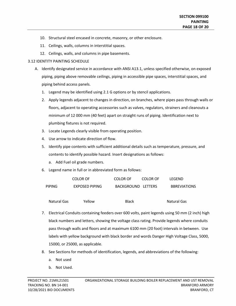
SECTION 099100 PAINTING PAGE 18 OF 20
PROJECT NO. 21MIL21501 ORGANIZATIONAL STORAGE BUILDING BOILER REPLACEMENT AND UST REMOVAL TRACKING NO. BN 14-001 BRANFORD ARMORY 10/28/2021 BID DOCUMENTS BRANFORD, CT
10. Structural steel encased in concrete, masonry, or other enclosure.
11. Ceilings, walls, columns in interstitial spaces.
12. Ceilings, walls, and columns in pipe basements.
3.12 IDENTITY PAINTING SCHEDULE
A. Identify designated service in accordance with ANSI A13.1, unless specified otherwise, on exposed
piping, piping above removable ceilings, piping in accessible pipe spaces, interstitial spaces, and
piping behind access panels.
1. Legend may be identified using 2.1 G options or by stencil applications.
2. Apply legends adjacent to changes in direction, on branches, where pipes pass through walls or
floors, adjacent to operating accessories such as valves, regulators, strainers and cleanouts a
minimum of 12 000 mm (40 feet) apart on straight runs of piping. Identification next to
plumbing fixtures is not required.
3. Locate Legends clearly visible from operating position.
4. Use arrow to indicate direction of flow.
5. Identify pipe contents with sufficient additional details such as temperature, pressure, and
contents to identify possible hazard. Insert designations as follows:
a. Add Fuel oil grade numbers.
6. Legend name in full or in abbreviated form as follows:
COLOR OF COLOR OF COLOR OF LEGEND
PIPING EXPOSED PIPING BACKGROUND LETTERS BBREVIATIONS
Natural Gas Yellow Black Natural Gas
7. Electrical Conduits containing feeders over 600 volts, paint legends using 50 mm (2 inch) high
black numbers and letters, showing the voltage class rating. Provide legends where conduits
pass through walls and floors and at maximum 6100 mm (20 foot) intervals in between. Use
labels with yellow background with black border and words Danger High Voltage Class, 5000,
15000, or 25000, as applicable.
8. See Sections for methods of identification, legends, and abbreviations of the following:
a. Not used
b. Not Used.
SECTION 099100 PAINTING PAGE 19 OF 20
PROJECT NO. 21MIL21501 ORGANIZATIONAL STORAGE BUILDING BOILER REPLACEMENT AND UST REMOVAL TRACKING NO. BN 14-001 BRANFORD ARMORY 10/28/2021 BID DOCUMENTS BRANFORD, CT
c. Not Used.
d. Not Used.
e. Not Used.
f. Conduits containing high voltage feeders over 600 volts: Section 26 05 33, RACEWAY AND
BOXES FOR ELECTRICAL SYSTEMS and Section 28 05 28.33, CONDUITS AND BACKBOXES FOR
ELECTRONIC SAFETY AND SECURITY.
B. Identify columns in pipe basements and interstitial space:
1. Apply stenciled number and letters to correspond with grid numbering and lettering shown.
2. Paint numbers and letters 100 mm (4 inches) high, locate 450 mm (18 inches) below overhead
structural slab.
3. Apply on four sides of interior columns and on inside face only of exterior wall columns.
4. Color:
a. Use black on concrete columns.
b. Use white or contrasting color on steel columns.
3.13 PROTECTION CLEAN UP, AND TOUCH-UP
A. Protect work from paint droppings and spattering by use of masking, drop cloths, removal of items
or by other approved methods.
B. Upon completion, clean paint from hardware, glass and other surfaces and items not required to
be painted of paint drops or smears.
C. Before final inspection, touch-up or refinished in a manner to produce solid even color and finish
texture, free from defects in work which was damaged or discolored.
- - - E N D - - -
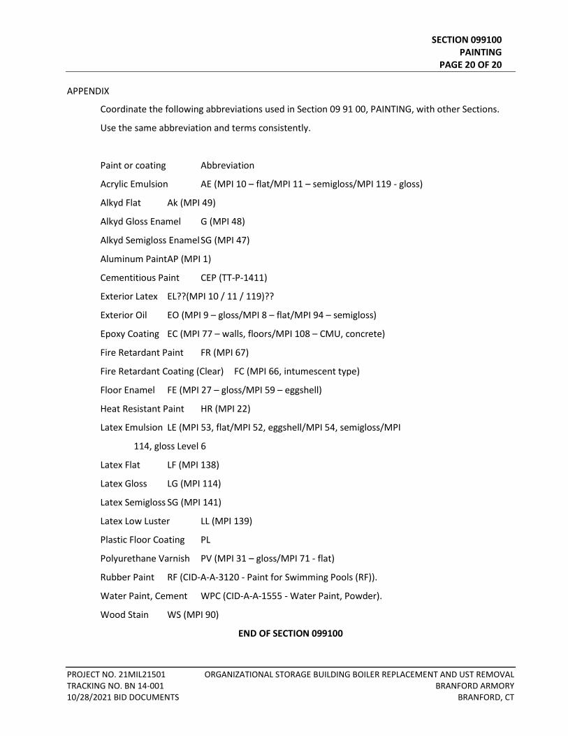
SECTION 099100 PAINTING PAGE 20 OF 20
PROJECT NO. 21MIL21501 ORGANIZATIONAL STORAGE BUILDING BOILER REPLACEMENT AND UST REMOVAL TRACKING NO. BN 14-001 BRANFORD ARMORY 10/28/2021 BID DOCUMENTS BRANFORD, CT
APPENDIX
Coordinate the following abbreviations used in Section 09 91 00, PAINTING, with other Sections.
Use the same abbreviation and terms consistently.
Paint or coating Abbreviation
Acrylic Emulsion AE (MPI 10 – flat/MPI 11 – semigloss/MPI 119 - gloss)
Alkyd Flat Ak (MPI 49)
Alkyd Gloss Enamel G (MPI 48)
Alkyd Semigloss Enamel SG (MPI 47)
Aluminum Paint AP (MPI 1)
Cementitious Paint CEP (TT-P-1411)
Exterior Latex EL??(MPI 10 / 11 / 119)??
Exterior Oil EO (MPI 9 – gloss/MPI 8 – flat/MPI 94 – semigloss)
Epoxy Coating EC (MPI 77 – walls, floors/MPI 108 – CMU, concrete)
Fire Retardant Paint FR (MPI 67)
Fire Retardant Coating (Clear) FC (MPI 66, intumescent type)
Floor Enamel FE (MPI 27 – gloss/MPI 59 – eggshell)
Heat Resistant Paint HR (MPI 22)
Latex Emulsion LE (MPI 53, flat/MPI 52, eggshell/MPI 54, semigloss/MPI
114, gloss Level 6
Latex Flat LF (MPI 138)
Latex Gloss LG (MPI 114)
Latex Semigloss SG (MPI 141)
Latex Low Luster LL (MPI 139)
Plastic Floor Coating PL
Polyurethane Varnish PV (MPI 31 – gloss/MPI 71 - flat)
Rubber Paint RF (CID-A-A-3120 - Paint for Swimming Pools (RF)).
Water Paint, Cement WPC (CID-A-A-1555 - Water Paint, Powder).
Wood Stain WS (MPI 90)
END OF SECTION 099100
TABLE OF CONTENTS SECTION 221116 – DOMESTIC WATER PIPING PART 1 - GENERAL ......................................................................................................................................... 1
1.1 RELATED DOCUMENTS .................................................................................................................. 1 1.2 SUMMARY ..................................................................................................................................... 1 1.3 SUBMITTALS .................................................................................................................................. 1 1.4 QUALITY ASSURANCE .................................................................................................................... 1 1.5 PROJECT CONDITIONS ................................................................................................................... 1 1.6 COORDINATION ............................................................................................................................ 2
PART 2 - PRODUCTS ...................................................................................................................................... 2 2.1 PIPING MATERIALS ........................................................................................................................ 2 2.2 COPPER TUBE AND FITTINGS ........................................................................................................ 2 2.3 PIPING JOINING MATERIALS ......................................................................................................... 2
PART 3 - EXECUTION ..................................................................................................................................... 2 3.1 PIPING INSTALLATION ................................................................................................................... 2 3.2 JOINT CONSTRUCTION .................................................................................................................. 3 3.3 FIELD QUALITY CONTROL .............................................................................................................. 3 3.4 CLEANING ...................................................................................................................................... 3 3.5 PIPING SCHEDULE ......................................................................................................................... 4

SECTION 221116 DOMESTIC WATER PIPING PAGE 1 OF 5
PROJECT NO. 21MIL21501 ORGANIZATIONAL STORAGE BUILDING BOILER REPLACEMENT AND UST REMOVAL TRACKING NO. BN 14-001 BRANFORD ARMORY 10/28/2021 BID DOCUMENTS BRANFORD, CT
SECTION 221116 - DOMESTIC WATER PIPING
PART 1 - GENERAL
1.1 RELATED DOCUMENTS
A. Drawings and general provisions of the Contract, including General and Supplementary Conditions and Division 01 Specification Sections, apply to this Section.
1.2 SUMMARY
A. Section Includes:
1. Aboveground domestic water pipes, tubes, fittings, and specialties inside the building.
1.3 SUBMITTALS
A. Product Data: For the following products:
1. Piping.
B. Water Samples: Specified in "Cleaning" Article.
1.4 QUALITY ASSURANCE
A. Piping materials shall bear label, stamp, or other markings of specified testing agency.
B. Comply with NSF 61 for potable domestic water piping and components.
1.5 PROJECT CONDITIONS
A. Interruption of Existing Water Service: Do not interrupt water service to facilities occupied by Owner or others unless permitted under the following conditions and then only after arranging to provide temporary water service according to requirements indicated:
1. Notify Owner no fewer than two days in advance of proposed interruption of water service.
2. Do not proceed with interruption of water service without Owner's written permission.
SECTION 221116 DOMESTIC WATER PIPING PAGE 2 OF 5
PROJECT NO. 21MIL21501 ORGANIZATIONAL STORAGE BUILDING BOILER REPLACEMENT AND UST REMOVAL TRACKING NO. BN 14-001 BRANFORD ARMORY 10/28/2021 BID DOCUMENTS BRANFORD, CT
1.6 COORDINATION
A. Coordinate sizes and locations of concrete bases with actual equipment provided.
PART 2 - PRODUCTS
2.1 PIPING MATERIALS
A. Comply with requirements in "Piping Schedule" Article for applications of pipe, tube, fitting materials, and joining methods for specific services, service locations, and pipe sizes.
2.2 COPPER TUBE AND FITTINGS
A. Hard Copper Tube: ASTM B 88, Type L water tube, drawn temper.
1. Wrought-Copper Solder-Joint Fittings: ASME B16.22, wrought-copper pressure fittings. 2. Copper Pressure-Seal-Joint Fittings:
a. Manufacturers: Subject to compliance with requirements, [provide products by one of the following] [available manufacturers offering products that may be incorporated into the Work include, but are not limited to, the following]:
1) Elkhart Products Corporation; Industrial Division. 2) NIBCO INC. 3) Viega; Plumbing and Heating Systems.
b. NPS 2 (DN 50) and Smaller: Bronze fitting with EPDM-rubber O-ring seal in each end.
2.3 PIPING JOINING MATERIALS
A. Solder Filler Metals: ASTM B 32, lead-free 95/5 solder with lead free flux.
PART 3 - EXECUTION
3.1 PIPING INSTALLATION
A. Drawing plans, schematics, and diagrams indicate general location and arrangement of domestic water piping. Indicated locations and arrangements are used to size pipe and calculate friction loss, expansion, and other design considerations. Install piping as indicated unless deviations to layout are approved on Coordination Drawings.
SECTION 221116 DOMESTIC WATER PIPING PAGE 3 OF 5
PROJECT NO. 21MIL21501 ORGANIZATIONAL STORAGE BUILDING BOILER REPLACEMENT AND UST REMOVAL TRACKING NO. BN 14-001 BRANFORD ARMORY 10/28/2021 BID DOCUMENTS BRANFORD, CT
B. Cap piping shown to be removed at closest main branch.
C. Install domestic water piping level and plumb.
3.2 JOINT CONSTRUCTION
A. Ream ends of pipes and tubes and remove burrs. Bevel plain ends of steel pipe.
B. Remove scale, slag, dirt, and debris from inside and outside of pipes, tubes, and fittings before assembly.
C. Soldered Joints: Apply ASTM B 813, water-flushable flux to end of tube. Join copper tube and fittings according to ASTM B 828 or CDA's "Copper Tube Handbook."
3.3 FIELD QUALITY CONTROL
A. Perform tests and inspections.
B. Piping Tests:
1. Fill domestic water piping. Check components to determine that they are not air bound and that piping is full of water.
2. Test for leaks and defects in new piping and parts of existing piping that have been altered, extended, or repaired. If testing is performed in segments, submit a separate report for each test, complete with diagram of portion of piping tested.
3. Leave new, altered, extended, or replaced domestic water piping uncovered and unconcealed until it has been tested and approved. Expose work that was covered or concealed before it was tested.
4. Cap and subject piping to static water pressure of 50 psig above operating pressure, without exceeding pressure rating of piping system materials. Isolate test source and allow to stand for four hours. Leaks and loss in test pressure constitute defects that must be repaired.
5. Repair leaks and defects with new materials and retest piping or portion thereof until satisfactory results are obtained.
6. Prepare reports for tests and for corrective action required.
C. Domestic water piping will be considered defective if it does not pass tests and inspections.
D. Prepare test and inspection reports.
3.4 CLEANING
A. Clean and disinfect potable domestic water piping as follows:
SECTION 221116 DOMESTIC WATER PIPING PAGE 4 OF 5
PROJECT NO. 21MIL21501 ORGANIZATIONAL STORAGE BUILDING BOILER REPLACEMENT AND UST REMOVAL TRACKING NO. BN 14-001 BRANFORD ARMORY 10/28/2021 BID DOCUMENTS BRANFORD, CT
1. Purge new piping and parts of existing piping that have been altered, extended, or repaired before using.
2. Use purging and disinfecting procedures prescribed by authorities having jurisdiction; if methods are not prescribed, use procedures described in either AWWA C651 or AWWA C652 or follow procedures described below:
a. Flush piping system with clean, potable water until dirty water does not appear at outlets.
b. Fill and isolate system according to either of the following:
1) Fill system or part thereof with water/chlorine solution with at least 50 ppm of chlorine. Isolate with valves and allow to stand for 24 hours.
2) Fill system or part thereof with water/chlorine solution with at least 200 ppm of chlorine. Isolate and allow to stand for three hours.
c. Flush system with clean, potable water until no chlorine is in water coming from system after the standing time.
d. Submit water samples in sterile bottles to authorities having jurisdiction. Repeat procedures if biological examination shows contamination.
B. Prepare and submit reports of purging and disinfecting activities.
C. Clean interior of domestic water piping system. Remove dirt and debris as work progresses.
3.5 PIPING SCHEDULE
A. Transition and special fittings with pressure ratings at least equal to piping rating may be used in applications below unless otherwise indicated.
B. Flanges and unions may be used for aboveground piping joints unless otherwise indicated.
C. Fitting Option: Brazed joints may be used on aboveground copper tubing.
D. The "Piping Schedule" Article below is organized to first present the service and pipe size or size range; then to present optional piping materials and joining methods. Retain the services and sizes and size ranges applicable to the Project, then retain the selected piping materials and joining methods. Coordinate selection of piping materials and joining methods with piping materials described in Part 2.
E. Retain "one of" option in first paragraph below to allow Contractor to select piping materials from those retained. Piping for this application matches exterior underground water service piping specified in Division 22 Section "Facility Water Distribution Piping."
F. Aboveground domestic water piping, NPS 2 and smaller , shall be the following:
SECTION 221116 DOMESTIC WATER PIPING PAGE 5 OF 5
PROJECT NO. 21MIL21501 ORGANIZATIONAL STORAGE BUILDING BOILER REPLACEMENT AND UST REMOVAL TRACKING NO. BN 14-001 BRANFORD ARMORY 10/28/2021 BID DOCUMENTS BRANFORD, CT
1. Hard copper tube, ASTM B 88, Type L; wrought-copper solder-joint fittings; and soldered joints.
END OF SECTION 221116

TABLE OF CONTENTS SECTION 230500 – COMMON WORK RESULTS FOR MECHANICAL PART 1 - GENERAL ......................................................................................................................................... 1
1.1 REFERENCES .................................................................................................................................. 1 1.2 INTENT .......................................................................................................................................... 1 1.3 EXAMINATION OF SITE AND CONTRACT DOCUMENTS ................................................................ 1 1.4 DEFINITIONS .................................................................................................................................. 2 1.5 STANDARDS ................................................................................................................................... 3 1.6 PERMITS, LAWS, ORDINANCES AND CODES ................................................................................. 4 1.7 COORDINATION DRAWINGS ......................................................................................................... 5 1.8 SHOP DRAWING SUBMITTALS ...................................................................................................... 5 1.9 PRODUCT SELECTION .................................................................................................................... 7 1.10 SUBSTITUTIONS ............................................................................................................................. 7 1.11 SAMPLES ....................................................................................................................................... 9 1.12 RECORD DRAWINGS ...................................................................................................................... 9 1.13 OPERATING AND MAINTENANCE MANUALS .............................................................................. 10 1.14 GUARANTEE ................................................................................................................................ 12
PART 2 - PRODUCTS .................................................................................................................................... 13 2.1 GENERAL PRODUCT REQUIREMENTS ......................................................................................... 13
PART 3 - EXECUTION ................................................................................................................................... 14 3.1 ARRANGEMENT OF WORK .......................................................................................................... 14 3.2 COORDINATION .......................................................................................................................... 14 3.3 WORKMANSHIP .......................................................................................................................... 15 3.4 OPERATION OF SERVICES AND UTILITIES .................................................................................... 15 3.5 PROTECTION ............................................................................................................................... 16 3.6 IDENTIFICATION .......................................................................................................................... 16 3.7 LUBRICATION .............................................................................................................................. 17 3.8 ATTACHMENT OF SUPPORTS TO BUILDING STRUCTURE ............................................................ 17 3.9 ACCESSIBILITY, ACCESS PANELS AND ACCESS DOORS ................................................................ 17 3.10 WATERPROOFING ....................................................................................................................... 18 3.11 GROUTING ................................................................................................................................... 18 3.12 BASES AND SUPPORTS ................................................................................................................ 18 3.13 PAINTING..................................................................................................................................... 19 3.14 TESTS - GENERAL ......................................................................................................................... 19 3.15 INSTRUCTIONS ............................................................................................................................ 20 3.16 QUIET OPERATION ...................................................................................................................... 21 3.17 FINAL CLEANING ......................................................................................................................... 21 3.18 DEMOLITION, RENOVATION, IMPACT TO EXISTING ................................................................... 21

SECTION 230500 COMMON WORK RESULTS FOR MECHANICAL PAGE 1 OF 22
PROJECT NO. 21MIL21501 ORGANIZATIONAL STORAGE BUILDING BOILER REPLACEMENT AND UST REMOVAL TRACKING NO. BN 14-001 BRANFORD ARMORY 10/28/2021 BID DOCUMENTS BRANFORD, CT
SECTION 230500 – COMMON WORK RESULTS FOR MECHANICAL
PART 1 - GENERAL
1.1 REFERENCES
A. Refer to the GENERAL CONDITIONS, SUPPLEMENTARY CONDITIONS and applicable parts of DIVISION 1 for other general requirements. These requirements may be repeated in this Division for emphasis or for inclusion of more stringent/additional related requirements. Such repetition shall NOT be construed to reduce the requirements of those Divisions NOR to eliminate other requirements under those Divisions.
B. The requirements of this Section apply to ALL work specified in this Division, unless modified to be of higher quality or more stringent in another Section.
1.2 INTENT
A. The CONTRACT DOCUMENTS are inclusive of all Drawings and Specifications, both those specifically covering the work of this Division and those covering other subjects of work.
B. It is the intent of the Contract Documents to require finished work, tested and ready for operation.
C. It is not intended that Contract Documents show every pipe, wire, conduit, fitting and appurtenance; however, such parts as may be necessary to complete the systems in accordance with best trade practice and Code requirements and to Architect/Engineer's satisfaction shall be deemed to be included.
D. Drawings are diagrammatic and indicate the general arrangement of systems and work included in the Contract. DO NOT SCALE THE DRAWINGS.
1.3 EXAMINATION OF SITE AND CONTRACT DOCUMENTS
A. Before submitting prices or beginning work, thoroughly examine the site and the Contract Documents.
B. No claim for extra compensation will be recognized if difficulties are encountered which would have been revealed by examination of site conditions and Contract Documents prior to executing Contract.
C. Where discrepancies occur within Contract Documents, notify Architect/Engineer, in writing, of discrepancy and request clarification. Until notified of Architect/Engineer's decision, include item or arrangement of better quality, greater quantity or higher cost in Contract price.
SECTION 230500 COMMON WORK RESULTS FOR MECHANICAL PAGE 2 OF 22
PROJECT NO. 21MIL21501 ORGANIZATIONAL STORAGE BUILDING BOILER REPLACEMENT AND UST REMOVAL TRACKING NO. BN 14-001 BRANFORD ARMORY 10/28/2021 BID DOCUMENTS BRANFORD, CT
D. For material, device and equipment identified on Contract Drawings by manufacturer and/or model: Coordinate with Specification for ancillary requirements and include with furnished item.
E. Notify Architect/Engineer, in writing, of materials and apparatus believed to be omitted, inadequate or unsuitable, or in violation of laws, ordinances, rules or regulations of authorities having jurisdiction. In absence of such written notice, it is mutually agreed that bid price for work under each Section has included the cost of items required for acceptable satisfactory functioning of entire system.
1.4 DEFINITIONS
A. Where more than one material, item, or grade is listed in same paragraph, first one named is preferred choice.
B. The following terms are used in this Division and are defined as follows:
1. "Indicated", "shown", "noted", "scheduled", "specified": These terms are a cross-reference to graphics, notes or schedules on the Drawings, to other paragraphs or schedules in the Specifications, and to similar means of recording requirements in Contract Documents. NO limitation of location is intended except as specifically noted.
2. "Directed", "requested", "authorized", "selected", "required", "permitted": Where not otherwise explained, these terms mean "directed by the Architect/Engineer", "requested by the Architect/Engineer", etc. However, NO such implied meaning will be interpreted to extend the Architect/Engineer's responsibility into Contractor's area of construction supervision or means and methods.
3. "Provide": To furnish and install, ready for safe and regular operation the item, material or service indicated.
4. "Furnish": To purchase, acquire and deliver to the site, complete with related accessories.
5. "Install": To erect, mount and connect completely, by acceptable methods. 6. "Work": Labor, materials, equipment, apparatus, controls and accessories required for
proper and complete installation. 7. “Finished Spaces”: Spaces other than the following:
a. Mechanical and electrical equipment rooms. b. Furred spaces. c. Pipe and duct shafts. d. Unheated spaces immediately below roof. e. Spaces above ceilings. f. Unexcavated spaces. g. Crawl spaces. h. Tunnels. i. Garages
SECTION 230500 COMMON WORK RESULTS FOR MECHANICAL PAGE 3 OF 22
PROJECT NO. 21MIL21501 ORGANIZATIONAL STORAGE BUILDING BOILER REPLACEMENT AND UST REMOVAL TRACKING NO. BN 14-001 BRANFORD ARMORY 10/28/2021 BID DOCUMENTS BRANFORD, CT
8. “Exposed”, Interior Installations: Exposed to view indoors. Examples include finished occupied spaces and mechanical or electrical equipment rooms.
9. “Exposed”, Exterior Installations: Exposed to view outdoors or subject to outdoor ambient temperatures and weather conditions. Examples include rooftop locations.
10. “Concealed”, Interior Installations: Concealed from view and protected from physical contact by building occupants. Examples include above ceilings and in shafts.
11. “Concealed”, Exterior Installations: Concealed from view and protected from weather conditions and physical contact by building occupants but subject to outdoor ambient temperatures. Examples include installations within unheated structures.
12. "Acceptable equivalent" or "Equal": Of weight, size, design, capacity and efficiency to meet requirements specified and shown, and of acceptable manufacture, as determined in the opinion of the Architect/Engineer.
13. "Acceptable": Acceptable, as determined in the opinion of the Architect/Engineer. 14. "Contractor": General Contractor, Trade Contractor, sub-Contractor, or Construction
Manager. 15. "Named" Product: Manufacturer's name for product, as recorded in published
documents of latest issue as of date of Contract Documents. Obtain Architect/Engineer's permission before using products of later or earlier model.
1.5 STANDARDS
A. Standards, specifications and tests of following technical societies, organizations and governmental bodies, as referenced in Contract Documents, are hereby made part of Contract Documents.
1. ANSI: American National Standards Institute 2. ASTM: American Society for Testing and Materials 3. EPA: Environmental Protection Agency 4. FSSC: Federal Specification 5. IRI: Industrial Risk Insurers 6. ISO: Insurance Services Office 7. NBS: National Bureau of Standards 8. NEC: National Electrical Code. 9. NEMA: National Electrical Manufacturers Association 10. NFPA: National Fire Protection Association 11. NSC: National Safety Council 12. OSHA: Occupational Safety and Health Administration 13. UL: Underwriters Laboratories 14. AABC: Associated Air Balance Council 15. ACGIH: American Conference of Governmental Industrial Hygienists 16. ADC: Air Diffusion Council 17. AGA: American Gas Association 18. AMCA: Air Movement and Control Association 19. API: American Petroleum Institute 20. ARI: Air Conditioning and Refrigeration Institute
SECTION 230500 COMMON WORK RESULTS FOR MECHANICAL PAGE 4 OF 22
PROJECT NO. 21MIL21501 ORGANIZATIONAL STORAGE BUILDING BOILER REPLACEMENT AND UST REMOVAL TRACKING NO. BN 14-001 BRANFORD ARMORY 10/28/2021 BID DOCUMENTS BRANFORD, CT
21. ASCE: American Society of Civil Engineers 22. ASE: Association of Safety Engineers 23. ASHRAE: American Society of Heating, Refrigeration and Air Conditioning Engineers 24. ASME: American Society of Mechanical Engineers 25. ASPE: American Society of Plumbing Engineers 26. AWS: American Welding Society 27. AWWA: American Water Works Association 28. CGA: Compressed Gas Association 29. CSA: Canadian Standards Association 30. CISPI: Cast Iron Soil Pipe Institute 31. EJMA: Expansion Joint Manufacturing Association 32. FM: Factory Mutual Engineering Division 33. HIS: Hydraulic Institute Standards 34. IBR: Institute of Boiler and Radiator Manufacturers 35. MCAA: Mechanical Contractors Association of America 36. NEBB: National Environmental Balancing Bureau 37. NOFI: National Oil Fuel Institute 38. SBI: Steel Boiler Industry (Division of Hydronics Institute) 39. SMACNA: Sheet Metal and Air Conditioning Contractors National Association 40. STI: Steel Tank Institute 41. CODE: Codes and regulations of the Federal, State and local governments and of utility
companies having jurisdiction, as appropriate.
B. Use of singular or plural reference form in the Contract Documents shall not be construed to limit number of units required. Specifications are intended to define quality and performance characteristics; quantity of units supplied shall be as needed to meet requirements as specified and at a minimum, as shown on Contract Documents.
1.6 PERMITS, LAWS, ORDINANCES AND CODES
A. Contractor shall obtain and pay for permits, inspections, licenses and certificates required for work under this Division.
B. Complete Utility connections as indicated or needed, extension to Project, metering as required, and connection to building systems, including:
1. Apply for all services and pay for all fees, assessments and charges of the Utility for each connection, all in a timely manner and according to the Project Schedule.
2. Provide and install all metering equipment and accessories as required by Utility. Install entire service in accordance with the Utility’s requirements or other applicable regulation.
3. Coordinate with Utility to determine scope of work provided by Utility and the part provided by Contractor so that a complete Utility connection is made.
4. Schedule all work required by utility companies in order to maintain project schedule.
C. Contractor shall pay utility company charges associated with work of this Division.
SECTION 230500 COMMON WORK RESULTS FOR MECHANICAL PAGE 5 OF 22
PROJECT NO. 21MIL21501 ORGANIZATIONAL STORAGE BUILDING BOILER REPLACEMENT AND UST REMOVAL TRACKING NO. BN 14-001 BRANFORD ARMORY 10/28/2021 BID DOCUMENTS BRANFORD, CT
D. Contractor shall comply with laws, ordinances, rules and regulations of Local, State and Federal authorities having jurisdiction; and shall comply with rules and regulations of National Board of Fire Underwriters, National Electrical Code and local utility companies.
E. Contract Documents shall govern whenever they are more stringent than Code requirements.
1.7 COORDINATION DRAWINGS
A. Before materials are purchased or work is begun, prepare coordination drawings showing relationship of work among all trades.
B. Submit completed and signed coordination drawings to the Architect/Engineer for review.
C. Coordination drawings are for use by Contractors and Architect/Engineer during construction and are not replacements for shop, as built, or record drawings required elsewhere in the Contract Documents
1.8 SHOP DRAWING SUBMITTALS
A. General
1. Prior to submission of specific shop drawings, submit for review a preliminary list of intended or proposed manufacturers for all items for which shop drawings are required.
2. Submit through contractual channels for review. 3. Electronic Submittals: Identify and incorporate information in each electronic submittal
file. a. Electronic Submittals: Submit in accordance with requirements of Project website
submittals procedures. b. Assemble complete submittal package into a single submittal, incorporating
submittal requirements of a single Specification Section.
B. Other Submittals
1. Refer to Sections of this Division for additional submittal requirements relating to specific equipment or systems.
C. Submission of shop drawings of an unnamed manufacture or shop drawings at variance with the Contract Documents is NOT a proper request for substitution.
D. Repeat submission of products without addressing all comments from prior review will be returned to the Contractor without review for correction. Note:
1. Contractor may be liable for additional efforts expended by the Architect/Engineer 2. Contractor WILL be liable for impact to project schedule.
SECTION 230500 COMMON WORK RESULTS FOR MECHANICAL PAGE 6 OF 22
PROJECT NO. 21MIL21501 ORGANIZATIONAL STORAGE BUILDING BOILER REPLACEMENT AND UST REMOVAL TRACKING NO. BN 14-001 BRANFORD ARMORY 10/28/2021 BID DOCUMENTS BRANFORD, CT
E. Test reports are to be submitted to Architect/Engineer for review prior to acceptance of equipment or systems for beneficial use.
F. Shop Drawings - Electronic: Identify and incorporate information in each electronic submittal file as follows:
1. Electronic Submittals: Submit in accordance with requirements of Project website submittals procedures.
2. Assemble complete submittal package into a single submittal, incorporating submittal requirements of a single Specification Section.
3. Metadata: Include the following information as keywords in the electronic submittal metadata: a. Project name. b. Number and title of appropriate Specification Section. c. Manufacturer name. d. Product name.
G. Options: Identify options requiring selection by Architect.
H. Deviations and Additional Information: Include relevant information, requests for data, revisions other than those requested by Architect on previous submittals, and deviations from requirements in the Contract Documents, including minor variations and limitations. Include same identification information as related submittal.
I. Resubmittals: Make resubmittals in same manner as initial submittal.
1. Note date and content of previous submittal. 2. Note date and content of revision and clearly indicate extent of revision. 3. Resubmit submittals until they are marked with approval notation from Architect's
action stamp.
J. Distribution: Furnish copies of final submittals to manufacturers, subcontractors, suppliers, fabricators, installers, authorities having jurisdiction, and others as necessary for performance of construction activities. Show distribution on transmittal forms.
K. Use for Construction: Retain complete copies of submittals on Project site. Use only final action submittals that are marked with approval notation from Architect's action stamp.
L. Material Safety Data Sheets (MSDS):
1. If required by the Owner, submit MSDSs directly to the Owner; do not submit to Architect. a. Architect will not review submittals that include MSDSs and will return without
review. b. Do not include MSDSs and remove MSDS sheets attached to product data or
included with other submittals that require submission to the Architect.
SECTION 230500 COMMON WORK RESULTS FOR MECHANICAL PAGE 7 OF 22
PROJECT NO. 21MIL21501 ORGANIZATIONAL STORAGE BUILDING BOILER REPLACEMENT AND UST REMOVAL TRACKING NO. BN 14-001 BRANFORD ARMORY 10/28/2021 BID DOCUMENTS BRANFORD, CT
1.9 PRODUCT SELECTION
A. Options for selecting products are limited by Contract Document requirements and governing regulations and are NOT controlled by industry traditions or procedures experienced by Contractor on previous construction projects. Required procedures include, but are NOT necessarily limited to, following specifying methods in Contract Documents:
1. Single Product Manufacturer Named: Provide product indicated. 2. Two or More Manufacturers' Products Named: Provide one of the named products, at
Contractor's option, but excluding products which do NOT comply with requirements. 3. "Acceptable equivalent" or "Or Equal": Where named products are accompanied by this
term or words of similar effect, provide one of named products or propose substitute product according to paragraph 1.10, SUBSTITUTIONS.
4. Standards, Codes and Regulations: Where specification requires only compliance with a standard, code or regulation, Contractor may select any product which complies with requirements of that standard, code or regulation.
5. Performance Requirements: Provide products which comply with specific performances indicated and which are recommended by manufacturer (in published product literature or by individual certification) for application intended. Overall performance of product is implied where product is specified with only certain specific performance requirements.
6. Prescriptive Requirements: Provide products which have been produced in accordance with prescriptive requirements using specified materials and components, and complying with specified requirements for fabricating, finishing, testing and other manufacturing processes.
7. Visual Matching: Where matching with an established material is required, Architect/Engineer's judgment of whether proposed product matches established material shall be final.
8. "Color as Selected by Architect": Unless otherwise noted, where specified product requirements include "color as selected by Architect" or words of similar effect, the selection of manufacturer and basic product complying with Contract Documents is Contractor's option and subsequent selection of color is Architect's option.
B. Inclusion by name, of more than one manufacturer or fabricator, does NOT necessarily imply acceptability of standard products of those named. All manufacturers, named or proposed, shall conform, with modification by manufacturer as necessary, to criteria established by Contract Documents for performance, efficiency, materials and special accessories.
1.10 SUBSTITUTIONS
A. Contractor's request for substitution may be submitted only after award of Contract. Requests shall be in writing and presented through appropriate contractual channels.
B. Substitution Request to include the following:
SECTION 230500 COMMON WORK RESULTS FOR MECHANICAL PAGE 8 OF 22
PROJECT NO. 21MIL21501 ORGANIZATIONAL STORAGE BUILDING BOILER REPLACEMENT AND UST REMOVAL TRACKING NO. BN 14-001 BRANFORD ARMORY 10/28/2021 BID DOCUMENTS BRANFORD, CT
1. Detailed comparison of significant differences in quality, construction, performance, features, options, and appearance between specified item and proposed substitution. Citation, where applicable, to where a specified requirement is located in the Contract Documents is to be provided.
2. Statement of effect on construction time, coordination with other affected work, and cost of work.
3. Contractor's statement to the effect that proposed substitution will result in overall work equal to, or better than, work originally intended.
C. Substitution requests will be considered based on all of the following:
1. If extensive revisions to Contract Documents are NOT required. 2. If changes are in keeping with general intent of Contract Documents. 3. If submitted in timely and proper manner, fully documented. 4. If one or more of following conditions is satisfied; all as judged by Architect/Engineer:
a. Where request is directly related to "acceptable equivalent" clause, "or equal" clause or words of similar effect in Contract Documents.
b. Where specified product, material or method CANNOT be provided within Contract Time; but NOT as a result of Contractor's failure to pursue the work promptly or properly coordinate Contractor’s efforts.
c. Where substantial advantage is offered Owner; in terms of cost, time, energy conservation or other valuable considerations; after deducting offsetting responsibilities that Owner may be required to bear, including additional compensation to Architect/Engineer for redesign and evaluation services, increased cost of other work by Owner or separate contractors, and similar considerations.
D. The burden is upon the Contractor, supplier and manufacturer to satisfy Architect/Engineer that:
1. Proposed substitute is equal to, or superior to, the item specified. 2. Intent of the Contract Documents, including required performance, capacity, efficiency,
quality, durability, safety, function, appearance, space clearances and delivery date, will be equaled or bettered.
E. Submission of shop drawings of unspecified manufacture or shop drawings at variance with the Contract Documents is NOT a proper request for substitution.
F. Changes in work of other trades, such as structural supports, which are required as a result of substitution and the associated costs for such changes shall be the complete responsibility of Contractor proposing substitution. Except as noted in subparagraph 1.10.C.4 (a) above, there shall be NO additional expense to the Owner.
G. Substitution requests that require the Architect/Engineer to expend additional efforts for review, investigation, verification, or similar activities, will require the Contractor to compensate the Architect/Engineer at the rate of $120/hour if:
SECTION 230500 COMMON WORK RESULTS FOR MECHANICAL PAGE 9 OF 22
PROJECT NO. 21MIL21501 ORGANIZATIONAL STORAGE BUILDING BOILER REPLACEMENT AND UST REMOVAL TRACKING NO. BN 14-001 BRANFORD ARMORY 10/28/2021 BID DOCUMENTS BRANFORD, CT
1. Architect/Engineer is not familiar with the proposed manufacturer or the proposed product from that manufacturer.
2. Architect/Engineer needs to investigate proposed product, attend presentations, confer with other professionals, contact references, or similar activities that would not otherwise have been required if one of the named products was proposed.
3. Architect/Engineer must travel to the manufacturer’s facilities or a representative installation of the proposed product to review, confirm, or assess product characteristics or directly communicate with manufacturer’s representatives on technical or product support subjects.
1.11 SAMPLES
A. Submit samples where required or referenced elsewhere in this Division of work.
B. Where in the opinion of the Architect/Engineer, a sample is required to clarify the acceptable characteristics of a material or product, additional samples may be required.
1.12 RECORD DRAWINGS
A. Furnish and keep on the job at all times, a minimum of one complete and separate set of Contract Documents for the purpose of tracking installation of the work.
B. As work progresses, record changes, revisions and additions to the work clearly, neatly, accurately and promptly. Items to be indicated include but are not limited to:
1. Dimensional change of equipment or material 2. Revision to Drawing Detail 3. Location and depth of underground utilities, structures, equipment, tanks, etc -
referenced from project benchmarks 4. Location and depth of underslab utilities and distribution 5. Actual routing of distribution systems 6. Revision to power or control wire circuiting/source 7. Actual equipment location 8. Location of concealed distribution work such a pipes, conduits, ducts, etc 9. Location of concealed work and access panels, where access for maintenance or service
is required. 10. Changes made by Change Order 11. Details not on original Contract Drawing, but used for installation of the work. 12. Information on concealed elements which would be difficult to identify or measure
later. 13. Valve locations and numbers reflecting the final valve tag charts.
C. Indicate daily progress on these prints by coloring in the various lines, fixtures, apparatus and associated appurtenances as they are erected.
SECTION 230500 COMMON WORK RESULTS FOR MECHANICAL PAGE 10 OF 22
PROJECT NO. 21MIL21501 ORGANIZATIONAL STORAGE BUILDING BOILER REPLACEMENT AND UST REMOVAL TRACKING NO. BN 14-001 BRANFORD ARMORY 10/28/2021 BID DOCUMENTS BRANFORD, CT
D. Approval of requisition for payment for work installed will NOT be given unless supported by record prints as required above.
E. At the conclusion of work, prepare final record drawings reflecting all field recorded data, neatly transferred from documents used in the field to a clean paper set of the Original Contract Documents. Submit record drawings for review by Architect/Engineer. After review and acceptance, the Contractor will be furnished with an electronic set of the original contract documents to be edited to reflect modifications and field data as reported on record drawings. Electronic copy of final “as-built” contract documents to be provided to the Owner in a format agreed upon at the commencement of work.
F. Coordination Drawings are to be updated, reflecting installation of work that differs from that presented on the Coordination Drawings which were signed off at the start of work. All trades will review and sign off on these documents as accurate. Electronic copy of final “as-built” coordination drawings to be provided to the Owner in a format agreed upon at the commencement of work.
G. Refer to DIVISION 1, GENERAL CONDITIONS and SUPPLEMENTARY CONDITIONS for further requirements.
1.13 OPERATING AND MAINTENANCE MANUALS
A. Submit for review, at least two (or greater quantity if otherwise specified in Division 1), operating and maintenance (O&M) manuals for each system or piece of equipment. Applicable content, as generated, is to be collected continuously during the construction process and maintained in a DRAFT manual format for review by the Architect/Engineer at any time.
B. Completed manual will be reviewed by the Architect/Engineer and modifications made as identified, before distribution or use. Acceptance will be required prior to scheduling of Owner Training and Instructions.
C. Required modifications identified during Training and Instruction activities are to be made before final Manual is delivered to the Owner.
D. Refer to DIVISION 1 for additional requirements and procedures relating to O&M manuals.
E. Operating and maintenance manual(s) will be organized with the following fundamental content:
1. Table of Contents and Index
2. Project Information
a. Contractor name, address, contact information, and primary contact individual specific to this project
SECTION 230500 COMMON WORK RESULTS FOR MECHANICAL PAGE 11 OF 22
PROJECT NO. 21MIL21501 ORGANIZATIONAL STORAGE BUILDING BOILER REPLACEMENT AND UST REMOVAL TRACKING NO. BN 14-001 BRANFORD ARMORY 10/28/2021 BID DOCUMENTS BRANFORD, CT
b. Sub-contractor names, responsibility, address, contact information, and primary contact individual specific to this project.
c. Summary description of project scope and period of time work was executed.
3. Guarantees and Warrantees
a. Documentation describing covered work/materials, effective coverage dates, and terms/conditions
b. Contact information for initiating a claim and responsible party
4. Each Major Building System
a. Supplier information including
1) Technical Support contact 2) Source of parts / replacement units 3) Chain of purchase (Supply house, manufacturer’s sales vendor, sub-
contractor, etc), including Original order number/identification for tracking purposes
b. Operating Instructions
1) Prepared specific for this project
a) System Description b) Operating parameters c) Adjustable settings and purpose d) Warnings and cautions e) Sequence of Operations and Control Diagrams
2) Description of training and instruction provided to Owner including:
a) Date(s) of instruction/training b) Agenda c) Attendee list
c. Maintenance Instructions
1) Prepared specific for this project
a) Preventative maintenance schedule b) Summary of consumable materials / regularly replaced elements c) Recommended stocking materials and specialized tools or
equipment necessary to perform regular and preventative maintenance
d) Maintenance contracts secured under this project, or separately contracted for through this provider.
SECTION 230500 COMMON WORK RESULTS FOR MECHANICAL PAGE 12 OF 22
PROJECT NO. 21MIL21501 ORGANIZATIONAL STORAGE BUILDING BOILER REPLACEMENT AND UST REMOVAL TRACKING NO. BN 14-001 BRANFORD ARMORY 10/28/2021 BID DOCUMENTS BRANFORD, CT
d. Test Reports
1) Documentation of all inspection and testing activities performed with associated reports and corrective measures undertaken (if applicable).
2) Factory test reports 3) Certification letters for equipment manufacturers attesting to the complete
and satisfactory installation and operation of systems/products. 4) Seismic inspection and certification 5) Special inspections 6) Sign off by Authorities Having Jurisdiction 7) Air and water balance report.
e. Parts / Material List
1) Bill of materials for each system or piece of equipment
f. Product Literature
1) Copy of shop drawings reflecting final acceptance by Architect/Engineer, with modifications made reflecting changes to the installed work which is not represented accurately.
g. Manufacturer’s Operation & Maintenance Literature
1) Materials provided with equipment/products shipped for use on project 2) Supplementary materials which are required to provide the Owner with a
complete representation of manufacturer’s instructions and recommendations.
F. In addition to the above, the following Content is to be included in the Operation & Maintenance Manual(s):
1. BMS and temperature control shop drawings. 2. HVAC testing and balancing reports. 3. Commissioning and testing reports. 4. Other data, as required under pertinent Sections of these Specifications.
1.14 GUARANTEE
A. Furnish standard manufacturers' guarantees for work under this Division. Such guarantees shall be in addition to, and NOT in lieu of, other liabilities under the law or by other provisions of the Contract Documents.
SECTION 230500 COMMON WORK RESULTS FOR MECHANICAL PAGE 13 OF 22
PROJECT NO. 21MIL21501 ORGANIZATIONAL STORAGE BUILDING BOILER REPLACEMENT AND UST REMOVAL TRACKING NO. BN 14-001 BRANFORD ARMORY 10/28/2021 BID DOCUMENTS BRANFORD, CT
B. Materials, equipment and workmanship shall carry the standard warranty against defects in material and workmanship. Failure which may develop due to defective or improper material, equipment, workmanship or design shall be made good, forthwith, by and at the expense of the Contractor, including damage done to areas, materials and other systems resulting from this failure.
C. Guarantee that all elements of the systems are of sufficient capacity to meet the specified performance requirements as set forth in Contract Documents.
D. Upon receipt of notice from Owner of a failure of system(s) or component(s) during the guarantee period, replace affected components within reasonable time period at no additional cost.
E. Guarantee period shall extend for one year from Date of Substantial Completion.
F. Before final request for payment, furnish written guarantee covering above requirements.
PART 2 - PRODUCTS
2.1 GENERAL PRODUCT REQUIREMENTS
A. Products shall be undamaged and unused at time of installation and shall be complete with accessories, trim, finish, safety guards and other devices and details needed for complete installation and for intended use.
B. Where available, products shall be standard products of types which have been produced and used previously and successfully on other projects and in similar applications.
C. Labels and Stamps
1. Locate labels and stamps required to be observed after installation on accessible surfaces. In occupied spaces, select locations that are not conspicuous.
2. Locate labels and stamps not required to be observed after installation on concealed surfaces.
D. Provide corrosion resistant fasteners of galvanized or stainless construction where exposed to moist corrosive conditions. Including but not limited to tunnels, manholes, greenhouses and exterior to the building.
SECTION 230500 COMMON WORK RESULTS FOR MECHANICAL PAGE 14 OF 22
PROJECT NO. 21MIL21501 ORGANIZATIONAL STORAGE BUILDING BOILER REPLACEMENT AND UST REMOVAL TRACKING NO. BN 14-001 BRANFORD ARMORY 10/28/2021 BID DOCUMENTS BRANFORD, CT
PART 3 - EXECUTION
3.1 ARRANGEMENT OF WORK
A. Consult Architectural Contract Drawings and Details for exact locations of fixtures and equipment. If exact location is not given, obtain information from Architect/Engineer. Verify measurements in field. Base measurements on Architect/Engineer's established benchmarks.
B. Install work as closely as possible to layouts shown on Contract Drawings. Modify work as necessary to:
1. Provide maximum possible headroom and space clearance on each side. 2. Provide adequate clearance and ready access to all parts of the work, for inspection,
operation, safe maintenance and repair, and code conformance. 3. Coordinate and arrange work to avoid conflicts with work of other trades, to avoid
unnecessary cutting and patching, and as needed for satisfactory space conditions shown on coordination drawing submittals.
4. Where space appears inadequate, consult Architect/Engineer before proceeding with installation.
C. Coordinate installation of required supporting devices.
D. Set sleeves in cast-in-place concrete for services that will need to pass through concrete. Coring of installed concrete is not intended and the Contractor will be responsible for determining the impact on structural integrity, certifying that there will be no impact, and any remedial work required to accommodate impact from coring.
E. Work shall present a neat coordinated appearance.
3.2 COORDINATION
A. Examine Contract Documents and coordinate with Contractor and other trades as necessary to facilitate the progress of the work.
B. Each trade shall keep Contractor and other trades fully informed as to shape, size, and locations of openings, chases, equipment, panels, access doors, sleeves, inserts and anchor bolts required; whether temporary or permanent. Coordinate sizes, depths, fill and bedding requirements with excavation trades. Give sufficient advance notice so that coordination may be completed in advance. If information is not furnished in proper and timely fashion, the trade involved shall do own cutting and patching or have same done by Contractor, without additional cost to Owner.
SECTION 230500 COMMON WORK RESULTS FOR MECHANICAL PAGE 15 OF 22
PROJECT NO. 21MIL21501 ORGANIZATIONAL STORAGE BUILDING BOILER REPLACEMENT AND UST REMOVAL TRACKING NO. BN 14-001 BRANFORD ARMORY 10/28/2021 BID DOCUMENTS BRANFORD, CT
C. Coordinate size and location of concrete bases with DIVISION 3 and the following:
1. Dimensional requirements for embedded anchors as necessary for support, vibration isolation, and seismic restraint.
2. Access and walkway requirements 3. Work of other trades
D. Particular emphasis is placed on timely installation of major apparatus and furnishing of other trades and Contractor with relevant information.
E. Do NOT install a system until critical components of system and related systems have been coordinated and applicable shop drawings have been accepted.
3.3 WORKMANSHIP
A. Work covered under this Division shall be constructed and finished in every respect in a workmanlike and substantial manner.
B. Equipment and materials shall be new, of first quality, selected and arranged to fit properly into spaces indicated.
C. Obtain detailed information from manufacturer as to proper methods for installation and connections. This includes such tests as equipment manufacturer recommends. Where documentation regarding installation is NOT obtainable, work shall be installed in accordance with best trade practice.
1. Unless specifically indicated otherwise on Contract Documents, equipment and materials shall be installed in accordance with manufacturer's recommendations.
2. Notify Architect/Engineer of conflicts between manufacturer's recommendations and Contract Documents requirements, and request clarification before proceeding with installation.
D. Where equipment, piping, ductwork, conduit, etc. is exposed, color of finish or paint shall be as selected by Architect/Engineer.
3.4 OPERATION OF SERVICES AND UTILITIES
A. During the construction period and until finally inspected, tested and accepted, maintain new services and utilities.
B. Shutdown of existing services and utilities shall, without exception, be coordinated with the proper utility and with the Owner as to date, time of day, and duration.
SECTION 230500 COMMON WORK RESULTS FOR MECHANICAL PAGE 16 OF 22
PROJECT NO. 21MIL21501 ORGANIZATIONAL STORAGE BUILDING BOILER REPLACEMENT AND UST REMOVAL TRACKING NO. BN 14-001 BRANFORD ARMORY 10/28/2021 BID DOCUMENTS BRANFORD, CT
1. Notify Architect/Engineer and Owner of estimated duration of shutdown period at least ten days in advance of date when shutdown is proposed. Approval of shutdown shall be obtained from proper utility and Owner, before any service is interrupted.
2. Work during shutdown period shall be arranged for continuous performance, including overtime if required, to ensure that existing operating services will be shut down only for time actually necessary to complete connections.
3.5 PROTECTION
A. Contractor shall be responsible for work and equipment until fully inspected, tested and accepted. Carefully store materials and equipment which are not immediately installed after delivery to site. Close open ends of work with temporary covers or plug during construction to prevent entry of obstructing material or damaging water.
B. Equipment shall be protected against damage while in storage either on or off the construction site. The equipment shall be stored in a dry environment with temperature and controlled to within ranges specified by the manufacturer. Space heaters shall be installed and energized when required to control humidity. Store light sensitive materials where not subjected to direct sunlight.
C. Protect work and material of other trades from damage that might be caused by work of this and other Divisions and correct damage thus caused.
D. Maintain protective measures used for transport of equipment or materials to project site until ready to set and connect utilities and related work. If protective covers need to be removed for inspection or coordination of work, repair or replace to equivalent.
3.6 IDENTIFICATION
A. Distribution systems such as pipes, tubing, conduits, sheetmetal, insulation, etc shall have following information clearly printed on the material: manufacturer's name, material grade, gauge, thickness, type, and data to identify required methods of attachment; as applicable. Unmarked material shall NOT be used.
B. Permanent nameplates shall be provided on each piece of service-connected, power-operated, or distribution equipment, on easily accessible surface. Nameplate shall include product name, model number, serial number, capacity, speed, ratings, and similar essential operating data.
1. Manufacturer's nameplate, name, trademark and address shall be attached permanently to equipment and material furnished. Nameplate showing distributor or Contractor will NOT be permitted.
2. Unless otherwise specified or requested, letters and numbers shall be 1/2” high. 3. Attach nameplates with screws or rivets. Wherever covers of adjacent units are
interchangeable, attach nameplates to wall or backboard rather than covers.
SECTION 230500 COMMON WORK RESULTS FOR MECHANICAL PAGE 17 OF 22
PROJECT NO. 21MIL21501 ORGANIZATIONAL STORAGE BUILDING BOILER REPLACEMENT AND UST REMOVAL TRACKING NO. BN 14-001 BRANFORD ARMORY 10/28/2021 BID DOCUMENTS BRANFORD, CT
C. Unless specified elsewhere in this Section, labels shall be provided to indicate equipment according to designations used in Contract Documents. Label shall be plastic nameplate with letters and numbers 1-1/2” high. Furnish directory indicating number, location and use of each item. After finish painting is completed, apply identification label where it will be readily visible from normal operating position on floor.
3.7 LUBRICATION
A. Equipment shall be furnished and installed so that lubrication points are conveniently and readily accessible for maintenance. Make these provisions by whatever means is appropriate: extended fittings, access doors, equipment location, etc.
B. No equipment shall be operated for temporary service or for testing purposes without proper lubrication. Items requiring lubrication shall be left freshly and fully lubricated at time of substantial completion.
C. Prior to substantial completion, deliver to Owner, along with itemized list: one complete new set of special lubrication devices required for servicing, such as grease guns, fittings and adapters.
3.8 ATTACHMENT OF SUPPORTS TO BUILDING STRUCTURE
A. Equipment shall be securely attached to building structure in acceptable manner. Attachments shall be of strong and durable nature as determined by Architect/Engineer.
B. Attachment of supports to roof decking is NOT permitted. Pipes, ducts, conduits, boxes, etc. must be supported from building structural framing (bar joist, beams, columns) or by supplementary members installed by the Contractor, spanning structural framing in a method acceptable to the structural engineer.
C. Cut, Fit and place miscellaneous metal supports for installation of work.
D. Field Welding: Comply with AWS D1.1 or other applicable standards
E. Refer to DIVISION 5 and Section 230529 for material specification of supplemental members to be installed.
3.9 ACCESSIBILITY, ACCESS PANELS AND ACCESS DOORS
A. Locate equipment which must be serviced, including motor starters, switches, panels and junction boxes, in accessible locations if at all possible. For other locations, furnish access panels as described under DIVISION 1.
B. Access doors shall be located to conveniently serve intended purpose and shall be installed so that adjacent piping, equipment and structures do NOT render doors unusable.
SECTION 230500 COMMON WORK RESULTS FOR MECHANICAL PAGE 18 OF 22
PROJECT NO. 21MIL21501 ORGANIZATIONAL STORAGE BUILDING BOILER REPLACEMENT AND UST REMOVAL TRACKING NO. BN 14-001 BRANFORD ARMORY 10/28/2021 BID DOCUMENTS BRANFORD, CT
C. Access doors are not required in removable panel ceilings if suitable identifying markers are provided to indicate access locations.
D. During project closeout, Contractor shall perform walk-through identifying and demonstrating access to equipment for service and/or replacement. Walk-through shall be arranged at times convenient for Engineer and Owner to attend.
1. Equipment with insufficient access shall be relocated or provided with additional access panels at no additional cost to Owner.
2. Trade responsible for access problem shall be responsible for costs of access modifications. In general, this shall be understood to be the trade installing the equipment. If access problem was caused by architectural layout changes which occurred subsequent to equipment installation, cost of access modifications shall be borne by trade responsible for architectural changes.
3.10 WATERPROOFING
A. Where work pierces waterproofing, including waterproof concrete and floor of a wet area, submit method of installation for review by the Architect/Engineer before work is done.
B. Provide necessary sleeves, caulking and flashing required to make openings waterproof.
3.11 GROUTING
A. Mix and install grout for equipment base bearing surfaces, base plates, and anchors
3.12 BASES AND SUPPORTS
A. Unless noted otherwise, provide necessary supports, rails, framing, bases and piers required for equipment furnished or installed under this Division.
B. Unless otherwise indicated: floor-mounted equipment shall be mounted on concrete pads. Concrete and associated reinforcing materials shall be as specified in DIVISION 3, CONCRETE.
1. Pads shall be three-inch thick minimum. Pads for seismically supported equipment shall extend at least 6 inches beyond equipment footprint. Coordinate final extension requirements with approved seismic shop drawing calculations and details. All other pads shall NOT extend more than one inch beyond equipment footprint. Top edge of pads shall be chamfered.
2. Furnish dimensional and load information so that shop drawings for pads may be submitted and reviewed prior to pad installation.
3. Equipment shall be firmly grouted into concrete pads and anchor bolted.
C. Where mounted on the floor: Foundations, supports, pads, bases and piers shall be of the same finish quality as the adjacent flooring material.
SECTION 230500 COMMON WORK RESULTS FOR MECHANICAL PAGE 19 OF 22
PROJECT NO. 21MIL21501 ORGANIZATIONAL STORAGE BUILDING BOILER REPLACEMENT AND UST REMOVAL TRACKING NO. BN 14-001 BRANFORD ARMORY 10/28/2021 BID DOCUMENTS BRANFORD, CT
D. Equipment supports shall be designed and constructed so that equipment will be capable of resisting both vertical and horizontal movement. Refer to Section “VIBRATION AND SEISMIC CONTROLS” in this Division.
3.13 PAINTING
A. Unless otherwise specified, materials furnished under this Division shall have prime coat and standard manufacturer's finish.
B. Finish painting of exposed work and equipment is covered under DIVISION 9.
C. Paint equipment and appurtenances in concealed and unfinished areas with one coat of rust-inhibiting paint or with an appropriate bitumastic protective product designed for the intended application. Asphalt paint is NOT acceptable. Items to be painted shall include, but not be limited to: non-insulated hangers, supports, piping, conduit, tanks and other ferrous metal work, which are concealed or inaccessible but not galvanized.
D. Special care shall be taken to avoid painting or spattering equipment nameplates.
E. Cooperate in identifying systems for painters. Refer to paragraph, IDENTIFICATION.
3.14 TESTS - GENERAL
A. Make final adjustments to equipment before testing. Manufacturer's authorized representative shall verify proper installation and adjustment prior to startup of major equipment; refer to paragraph, OPERATING AND MAINTENANCE MANUALS.
B. Furnish labor, materials, instruments, supplies and services necessary for testing required under this Division. Correct defects appearing during tests, and repeat tests until no defects are disclosed. Final tests shall be made in Architect/Engineer's presence.
C. Use true RMS ammeter to measure current, for equipment which may have harmonic (non-linear) load component.
D. Notify Owner, Architect and Engineer of testing schedule at least 48 hours in advance of tests.
E. Perform specified tests and tests required by legal authorities and by agencies having jurisdiction over this Work. Tests shall be performed to the satisfaction of legal authorities, agencies having jurisdiction, and Owner.
F. Each piece of equipment, including motors and controls, shall be operated continuously for minimum test period of one hour.
G. If manufacturer's startup services are specified under other Sections in this Division, furnish services of factory-trained service engineering representative to provide following. If manufacturer's startup services are not required, Contractor shall furnish following services.
SECTION 230500 COMMON WORK RESULTS FOR MECHANICAL PAGE 20 OF 22
PROJECT NO. 21MIL21501 ORGANIZATIONAL STORAGE BUILDING BOILER REPLACEMENT AND UST REMOVAL TRACKING NO. BN 14-001 BRANFORD ARMORY 10/28/2021 BID DOCUMENTS BRANFORD, CT
1. Inspection of equipment/system installation. 2. Assistance in initial startup and adjustment of equipment; including necessary time to
achieve proper installation and adjustments. 3. Instruction of Owner's staff; see paragraph, INSTRUCTIONS.
H. Upon completion of tests, demonstrate the following:
1. Equipment and systems are installed and operating in accordance with manufacturer's specifications and instructions and with Contract Documents.
2. Proper adjustment of equipment and systems. 3. Systems are properly cleaned and free of contaminants. 4. Systems are properly phase balanced. 5. Circuits and motorized equipment are equipped with proper overload protection and
are not operating under overload. 6. Instruments are recording properly.
I. Refer to testing requirements in other Sections of this Division for addition work.
3.15 INSTRUCTIONS
A. Arrange for each installer of work requiring continuing maintenance or operation, to meet with Owner's personnel at project site and instruct them in the operation and maintenance. Include instruction by manufacturer's representatives where installers are not expert in the required procedures. Instruction periods for all trades shall be minimum of 8 hours total; refer to individual SECTIONS for further requirements.
B. Instructions include, but are not limited to, the following:
1. Review of Operation and Maintenance manuals, record documentation, tools, spare parts and materials, lubricants, fuels, identification system, control sequences, hazards, cleaning, and similar procedures and facilities.
2. Demonstration of the following:
a. Start up procedures b. Shutdown procedures c. Emergency operations d. Noise/vibration control adjustments e. Safety concerns and protective equipment f. Economy/efficiency adjustments g. Cleaning h. Similar operations
3. Review of applicable guarantees and warranties. 4. Demonstration of procedures for routine maintenance, at the equipment involved, to
ensure proper accessibility to components involved.
SECTION 230500 COMMON WORK RESULTS FOR MECHANICAL PAGE 21 OF 22
PROJECT NO. 21MIL21501 ORGANIZATIONAL STORAGE BUILDING BOILER REPLACEMENT AND UST REMOVAL TRACKING NO. BN 14-001 BRANFORD ARMORY 10/28/2021 BID DOCUMENTS BRANFORD, CT
3.16 QUIET OPERATION
A. Equipment and material provided as part of the Work shall NOT produce sound level greater than 55 decibels (or level required by Code, if more stringent) in adjacent occupied areas. Sound level shall be as measured on A-weighting scale of sound level meter or sound survey meter.
B. Methods described in ASHRAE guide and data books may be used to determine sound level of equipment when total of background sound and equipment sound exceeds the required minimum.
C. Contractor shall ensure that equipment and materials provided as part of the Work do NOT produce excessive noise/vibration and do NOT transmit excessive noise/vibration to occupied spaces. If objectionable noise/vibration occurs, Contractor shall provide systems, devices, and equipment necessary to eliminate objectionable noise/vibration at no additional cost to Owner.
D. Refer to VIBRATION AND SEISMIC CONTROLS FOR MECHANICAL SYSTEMS for further requirements.
3.17 FINAL CLEANING
A. Clean each surface of each unit of work, to normal "clean" condition expected for a first-class building cleaning and maintenance program. Comply with manufacturer's instructions for cleaning operations. The following are examples, but not limitations, of cleaning required:
1. Remove labels which are not required as permanent labels. 2. Clean transparent materials, removing substances which are noticeable as vision-
obscuring. 3. Clean exposed hard-surfaced finishes, until free of dust, stains, films and similar
noticeable substances. 4. Wipe surfaces of mechanical and electrical equipment clean, remove excess lubrication
and other substances. 5. Remove debris and surface dust from limited-access spaces such as plenums, shafts, and
ceiling spaces. 6. Clean lighting fixtures and lamps; removing dust, smudge marks and protective wraps;
so as to function with full efficiency.
3.18 DEMOLITION, RENOVATION, IMPACT TO EXISTING
A. Demolition:
1. In areas where demolition of systems of this Division are indicated, the following requirements apply:
SECTION 230500 COMMON WORK RESULTS FOR MECHANICAL PAGE 22 OF 22
PROJECT NO. 21MIL21501 ORGANIZATIONAL STORAGE BUILDING BOILER REPLACEMENT AND UST REMOVAL TRACKING NO. BN 14-001 BRANFORD ARMORY 10/28/2021 BID DOCUMENTS BRANFORD, CT
a. Disconnect and remove from the project site, and dispose of in a legal manner, all materials not otherwise identified to be handled otherwise.
b. Investigate impact to areas outside the designated area for demolition and identify any impact that demolition may have on those areas.
c. Building structure, partitions, floors, and walls to remain shall not be impacted by demolition work.
B. Selective Demolition
1. Major changes to existing building spaces and systems have been shown on Contract Drawings; minor changes have NOT been shown. Contractor shall anticipate that there will be numerous minor changes including:
a. Removal and/or relocation of pipes, conduits, wiring, etc b. Removal and/or relocation of wall and ceiling mounted devices due to
architectural revisions or phasing c. Temporary relocation of existing devices or distribution equipment to permit
installation of new work. d. Temporary work and modifications to existing systems to maintain Owner’s use
and operations in areas outside the boundaries of the work. e. Work related to phased demolition of existing systems f. Work related to phased installation of new work
2. Remove, store, clean and relocate equipment designated to be relocated and reused.
3. Material which is removed and is not designated for reuse shall, at the Owner's option,
either:
a. Be delivered to Owner's storage location OR b. Become Contractor's property and be removed from the site and disposed of
properly
END OF SECTION 230500
TABLE OF CONTENTS SECTION 230517 – SLEEVES AND SLEEVE SEALS FOR HVAC PIPING AND DUCTWORK PART 1 - GENERAL ......................................................................................................................................... 1
1.1 RELATED DOCUMENTS .................................................................................................................. 1 1.2 SUMMARY ..................................................................................................................................... 1 1.3 SUBMITTALS .................................................................................................................................. 1
PART 2 - PRODUCTS ...................................................................................................................................... 1 2.1 SLEEVES ......................................................................................................................................... 1 2.2 GROUT ........................................................................................................................................... 1
PART 3 - EXECUTION ..................................................................................................................................... 2 3.1 SLEEVE INSTALLATION .................................................................................................................. 2 3.2 SLEEVE-SEAL-FITTING INSTALLATION ........................................................................................... 2 3.3 SLEEVE AND SLEEVE-SEAL SCHEDULE ........................................................................................... 3

SECTION 230517 SLEEVES AND SLEEVE SEALS FOR HVAC PIPING AND DUCTWORK PAGE 1 OF 3
PROJECT NO. 21MIL21501 ORGANIZATIONAL STORAGE BUILDING BOILER REPLACEMENT AND UST REMOVAL TRACKING NO. BN 14-001 BRANFORD ARMORY 10/28/2021 BID DOCUMENTS BRANFORD, CT
SECTION 230517 - SLEEVES AND SLEEVE SEALS FOR HVAC PIPING AND DUCTWORK
PART 1 - GENERAL
1.1 RELATED DOCUMENTS
A. Drawings and general provisions of the Contract, including General and Supplementary Conditions and Division 01 Specification Sections, apply to this Section.
B. Refer to Section, “COMMON WORK RESULTS FOR MECHANICAL”.
1.2 SUMMARY
A. Section Includes:
1. Sleeves. 2. Sleeve-seal systems. 3. Sleeve-seal fittings. 4. Grout.
1.3 SUBMITTALS
A. Product Data: For each type of product indicated.
PART 2 - PRODUCTS
2.1 SLEEVES
A. Galvanized-Steel Wall Sleeves: ASTM A 53/A 53M, Schedule 40, with plain ends and welded steel collar; zinc coated.
B. Galvanized-Steel-Pipe Sleeves: ASTM A 53/A 53M, Type E, Grade B, Schedule 40, zinc coated, with plain ends.
C. Galvanized-Steel-Sheet Sleeves: 0.0239-inch minimum thickness; round tube closed with welded longitudinal joint.
2.2 GROUT
A. Standard: ASTM C 1107/C 1107M, Grade B, post-hardening and volume-adjusting, dry, hydraulic-cement grout.
SECTION 230517 SLEEVES AND SLEEVE SEALS FOR HVAC PIPING AND DUCTWORK PAGE 2 OF 3
PROJECT NO. 21MIL21501 ORGANIZATIONAL STORAGE BUILDING BOILER REPLACEMENT AND UST REMOVAL TRACKING NO. BN 14-001 BRANFORD ARMORY 10/28/2021 BID DOCUMENTS BRANFORD, CT
B. Characteristics: Nonshrink; recommended for interior and exterior applications.
C. Design Mix: 5000-psi, 28-day compressive strength.
D. Packaging: Premixed and factory packaged.
PART 3 - EXECUTION
3.1 SLEEVE INSTALLATION
A. Install sleeves for piping passing through penetrations in floors, partitions, roofs, and walls.
B. For sleeves that will have sleeve-seal system installed, select sleeves of size large enough to provide 1-inch (2-inch when seismic) annular clear space between piping and concrete slabs and walls.
C. Install sleeves in concrete floors, concrete roof slabs, and concrete walls as new slabs and walls are constructed.
1. Cut sleeves to length for mounting flush with both surfaces.
a. Exception: Extend sleeves installed in floors of mechanical equipment areas or other wet areas 2 inches above finished floor level.
2. Using grout, seal the space outside of sleeves in slabs and walls without sleeve-seal system.
D. Install sleeves for pipes passing through interior partitions.
1. Cut sleeves to length for mounting flush with both surfaces. 2. Install sleeves that are large enough to provide 1/4-inch annular clear space between
sleeve and pipe or pipe insulation. 3. Seal annular space between sleeve and piping or piping insulation; use joint sealants
appropriate for size, depth, and location of joint. Comply with requirements for sealants specified in Division 07 Section "Joint Sealants." Where no barrier is specifically defined by the Architect, the contractor shall install loose fill of therma-fiber and caulk sealant for acoustic and pest/rodent mitigation
3.2 SLEEVE-SEAL-FITTING INSTALLATION
A. Install sleeve-seal fittings in new walls and slabs as they are constructed.
B. Coordinate OD of sleeve with wall placement, and width dimensions, to ensure the sleeve does not impact wall finishes. This may require dimensional coordination drawings collaboratively developed by all trades.
SECTION 230517 SLEEVES AND SLEEVE SEALS FOR HVAC PIPING AND DUCTWORK PAGE 3 OF 3
PROJECT NO. 21MIL21501 ORGANIZATIONAL STORAGE BUILDING BOILER REPLACEMENT AND UST REMOVAL TRACKING NO. BN 14-001 BRANFORD ARMORY 10/28/2021 BID DOCUMENTS BRANFORD, CT
C. Assemble fitting components of length to be flush with both surfaces of concrete slabs and walls. Position waterstop flange to be centered in concrete slab or wall.
D. Secure nailing flanges to concrete forms.
E. Using grout, seal the space around outside of sleeve-seal fittings.
3.3 SLEEVE AND SLEEVE-SEAL SCHEDULE
A. Use sleeves and sleeve seals for the following piping-penetration applications:
1. Exterior Concrete Walls above Grade:
a. Piping Smaller Than NPS 6: Galvanized-steel wall sleeves with link seals. b. Piping NPS 6 and Larger: Galvanized-steel wall sleeves with link seals.
END OF SECTION 230517

TABLE OF CONTENTS SECTION 230529 – HANGERS AND SUPPORTS FOR HVAC PIPING AND EQUIPMENT PART 1 - GENERAL ......................................................................................................................................... 1
1.1 RELATED DOCUMENTS .................................................................................................................. 1 1.2 SUMMARY ..................................................................................................................................... 1 1.3 DEFINITIONS .................................................................................................................................. 1 1.4 PERFORMANCE REQUIREMENTS .................................................................................................. 1 1.5 SUBMITTALS .................................................................................................................................. 2 1.6 QUALITY ASSURANCE .................................................................................................................... 2
PART 2 - PRODUCTS ...................................................................................................................................... 2 2.1 METAL PIPE HANGERS AND SUPPORTS ........................................................................................ 2 2.2 TRAPEZE PIPE HANGERS ................................................................................................................ 3 2.3 METAL FRAMING SYSTEMS ........................................................................................................... 3 2.4 FASTENER SYSTEMS ...................................................................................................................... 4 2.5 EQUIPMENT SUPPORTS ................................................................................................................ 4 2.6 MISCELLANEOUS MATERIALS ....................................................................................................... 4
PART 3 - EXECUTION ..................................................................................................................................... 4 3.1 HANGER AND SUPPORT INSTALLATION ........................................................................................ 4 3.2 EQUIPMENT SUPPORTS ................................................................................................................ 5 3.3 METAL FABRICATIONS .................................................................................................................. 6 3.4 ADJUSTING .................................................................................................................................... 6 3.5 PAINTING....................................................................................................................................... 6 3.6 HANGER AND SUPPORT SCHEDULE .............................................................................................. 6

SECTION 230529 HANGERS AND SUPPORTS FOR HVAC PIPING AND EQUIPMENT PAGE 1 OF 8
PROJECT NO. 21MIL21501 ORGANIZATIONAL STORAGE BUILDING BOILER REPLACEMENT AND UST REMOVAL TRACKING NO. BN 14-001 BRANFORD ARMORY 10/28/2021 BID DOCUMENTS BRANFORD, CT
SECTION 230529 - HANGERS AND SUPPORTS FOR HVAC PIPING AND EQUIPMENT
PART 1 - GENERAL
1.1 RELATED DOCUMENTS
A. Drawings and general provisions of the Contract, including General and Supplementary Conditions and Division 01 Specification Sections, apply to this Section.
1.2 SUMMARY
A. Section Includes:
1. Metal pipe hangers and supports. 2. Trapeze pipe hangers. 3. Metal framing systems. 4. Fastener systems. 5. Equipment supports.
1.3 DEFINITIONS
A. MSS: Manufacturers Standardization Society of The Valve and Fittings Industry Inc.
1.4 PERFORMANCE REQUIREMENTS
A. Delegated Design: Design trapeze pipe hangers and equipment supports, including comprehensive engineering analysis by a qualified professional engineer, using performance requirements and design criteria indicated.
1. The Professional Engineer shall be legally qualified to practice in jurisdiction where project is located, and shall be experienced in providing engineering services of the kind indicated. Engineering services are defined as those performed for design and installation of hangers and supplies.
B. Structural Performance: Hangers and supports for HVAC piping and equipment shall withstand the effects of gravity loads and stresses within limits and under conditions indicated according to ASCE/SEI 7.
1. Design supports for multiple pipes, including pipe stands, capable of supporting combined weight of supported systems, system contents, and water.
2. Design equipment supports capable of supporting combined operating weight of supported equipment and connected systems and components.
SECTION 230529 HANGERS AND SUPPORTS FOR HVAC PIPING AND EQUIPMENT PAGE 2 OF 8
PROJECT NO. 21MIL21501 ORGANIZATIONAL STORAGE BUILDING BOILER REPLACEMENT AND UST REMOVAL TRACKING NO. BN 14-001 BRANFORD ARMORY 10/28/2021 BID DOCUMENTS BRANFORD, CT
3. Design seismic-restraint hangers and supports for piping and equipment and obtain approval from authorities having jurisdiction.
C. Refer to Section 230548 “Vibration and Seismic Controls for HVAC Piping and Equipment” for additional requirements.
1.5 SUBMITTALS
A. Product Data: For each type of product indicated.
B. Shop Drawings: Signed and sealed by a qualified Professional Engineer. Show fabrication and installation details and include calculations for the following; include Product Data for components:
1. Trapeze pipe hangers. 2. Metal framing systems. 3. Equipment supports. 4. Seismic restraints.
C. Delegated-Design Submittal: For trapeze hangers indicated to comply with performance requirements and design criteria, including analysis data signed and sealed by the qualified Professional Engineer responsible for their preparation.
1. Detail fabrication and assembly of trapeze hangers. 2. Design Calculations: Calculate requirements for designing trapeze hangers.
D. Welding certificates.
1.6 QUALITY ASSURANCE
A. Structural Steel Welding Qualifications: Qualify procedures and personnel according to AWS D1.1/D1.1M, "Structural Welding Code - Steel."
B. Pipe Welding Qualifications: Qualify procedures and operators according to ASME Boiler and Pressure Vessel Code.
PART 2 - PRODUCTS
2.1 METAL PIPE HANGERS AND SUPPORTS
A. Carbon-Steel Pipe Hangers and Supports:
1. Description: MSS SP-58, Types 1 through 58, factory-fabricated components. 2. Galvanized Metallic Coatings: Pregalvanized or hot dipped.
SECTION 230529 HANGERS AND SUPPORTS FOR HVAC PIPING AND EQUIPMENT PAGE 3 OF 8
PROJECT NO. 21MIL21501 ORGANIZATIONAL STORAGE BUILDING BOILER REPLACEMENT AND UST REMOVAL TRACKING NO. BN 14-001 BRANFORD ARMORY 10/28/2021 BID DOCUMENTS BRANFORD, CT
3. Nonmetallic Coatings: Plastic coating, jacket, or liner. 4. Padded Hangers: Hanger with fiberglass or other pipe insulation pad or cushion to
support bearing surface of piping. 5. Hanger Rods: Continuous-thread rod, nuts, and washer made of carbon steel.
2.2 TRAPEZE PIPE HANGERS
A. Description: MSS SP-69, Type 59, shop- or field-fabricated pipe-support assembly made from structural carbon-steel shapes with MSS SP-58 carbon-steel hanger rods, nuts, saddles, and U-bolts.
2.3 METAL FRAMING SYSTEMS
A. MFMA Manufacturer Metal Framing Systems:
1. Manufacturers: Subject to compliance with requirements, provide products by one of the following:
a. Cooper B-Line, Inc. b. Flex-Strut Inc. c. Thomas & Betts Corporation. d. Unistrut Corporation; Tyco International, Ltd.
2. Description: Shop- or field-fabricated pipe-support assembly for supporting multiple parallel pipes.
3. Standard: MFMA-4. 4. Channels: Continuous slotted steel channel with inturned lips. 5. Channel Nuts: Formed or stamped steel nuts or other devices designed to fit into
channel slot and, when tightened, prevent slipping along channel. 6. Hanger Rods: Continuous-thread rod, nuts, and washer made of carbon steel. 7. Metallic Coating: Hot-dipped galvanized. 8. Paint Coating: Epoxy.
B. Non-MFMA Manufacturer Metal Framing Systems:
1. Manufacturers: Subject to compliance with requirements, provide products by one of the following:
a. Anvil International; a subsidiary of Mueller Water Products Inc. b. Empire Industries, Inc. c. ERICO International Corporation. d. Haydon Corporation; H-Strut Division. e. NIBCO INC. f. PHD Manufacturing, Inc. g. PHS Industries, Inc.
SECTION 230529 HANGERS AND SUPPORTS FOR HVAC PIPING AND EQUIPMENT PAGE 4 OF 8
PROJECT NO. 21MIL21501 ORGANIZATIONAL STORAGE BUILDING BOILER REPLACEMENT AND UST REMOVAL TRACKING NO. BN 14-001 BRANFORD ARMORY 10/28/2021 BID DOCUMENTS BRANFORD, CT
2. Description: Shop- or field-fabricated pipe-support assembly made of steel channels, accessories, fittings, and other components for supporting multiple parallel pipes.
3. Standard: Comply with MFMA-4. 4. Channels: Continuous slotted steel channel with inturned lips. 5. Channel Nuts: Formed or stamped steel nuts or other devices designed to fit into
channel slot and, when tightened, prevent slipping along channel. 6. Hanger Rods: Continuous-thread rod, nuts, and washer made of carbon steel. 7. Coating: Zinc.
2.4 FASTENER SYSTEMS
A. Mechanical-Expansion Anchors: Insert-wedge-type, zinc-coated steel anchors, for use in hardened portland cement concrete; with pull-out, tension, and shear capacities appropriate for supported loads and building materials where used.
2.5 EQUIPMENT SUPPORTS
A. Description: Welded, shop- or field-fabricated equipment support made from structural carbon-steel shapes.
2.6 MISCELLANEOUS MATERIALS
A. Structural Steel: ASTM A 36/A 36M, carbon-steel plates, shapes, and bars; black and galvanized.
B. Grout: ASTM C 1107, factory-mixed and -packaged, dry, hydraulic-cement, nonshrink and nonmetallic grout; suitable for interior and exterior applications.
1. Properties: Nonstaining, noncorrosive, and nongaseous. 2. Design Mix: 5000-psi, 28-day compressive strength.
PART 3 - EXECUTION
3.1 HANGER AND SUPPORT INSTALLATION
A. Metal Pipe-Hanger Installation: Comply with MSS SP-69 and MSS SP-89. Install hangers, supports, clamps, and attachments as required to properly support piping from the building structure.
B. Metal Trapeze Pipe-Hanger Installation: Comply with MSS SP-69 and MSS SP-89. Arrange for grouping of parallel runs of horizontal piping, and support together on field-fabricated trapeze pipe hangers.
SECTION 230529 HANGERS AND SUPPORTS FOR HVAC PIPING AND EQUIPMENT PAGE 5 OF 8
PROJECT NO. 21MIL21501 ORGANIZATIONAL STORAGE BUILDING BOILER REPLACEMENT AND UST REMOVAL TRACKING NO. BN 14-001 BRANFORD ARMORY 10/28/2021 BID DOCUMENTS BRANFORD, CT
1. Pipes of Various Sizes: Support together and space trapezes for smallest pipe size or install intermediate supports for smaller diameter pipes as specified for individual pipe hangers.
2. Field fabricate from ASTM A 36/A 36M, carbon-steel shapes selected for loads being supported. Weld steel according to AWS D1.1/D1.1M.
C. Metal Framing System Installation: Arrange for grouping of parallel runs of piping, and support together on field-assembled metal framing systems.
D. Fastener System Installation:
1. Install mechanical-expansion anchors in concrete after concrete is placed and completely cured. Install fasteners according to manufacturer's written instructions.
E. Install hangers and supports complete with necessary attachments, inserts, bolts, rods, nuts, washers, and other accessories.
F. Equipment Support Installation: Fabricate from welded-structural-steel shapes.
G. Install hangers and supports to allow controlled thermal and seismic movement of piping systems, to permit freedom of movement between pipe anchors, and to facilitate action of expansion joints, expansion loops, expansion bends, and similar units.
H. Install lateral bracing with pipe hangers and supports to prevent swaying.
I. Install building attachments within concrete slabs or attach to structural steel. Install additional attachments at concentrated loads, including valves, flanges, and strainers, NPS 2-1/2 and larger and at changes in direction of piping. Install concrete inserts before concrete is placed; fasten inserts to forms and install reinforcing bars through openings at top of inserts.
J. Load Distribution: Install hangers and supports so that piping live and dead loads and stresses from movement will not be transmitted to connected equipment.
K. Pipe Slopes: Install hangers and supports to provide indicated pipe slopes and to not exceed maximum pipe deflections allowed by ASME B31.9 for building services piping.
3.2 EQUIPMENT SUPPORTS
A. Fabricate structural-steel stands to suspend equipment from structure overhead or to support equipment above floor.
B. Grouting: Place grout under supports for equipment and make bearing surface smooth.
C. Provide lateral bracing, to prevent swaying, for equipment supports.
SECTION 230529 HANGERS AND SUPPORTS FOR HVAC PIPING AND EQUIPMENT PAGE 6 OF 8
PROJECT NO. 21MIL21501 ORGANIZATIONAL STORAGE BUILDING BOILER REPLACEMENT AND UST REMOVAL TRACKING NO. BN 14-001 BRANFORD ARMORY 10/28/2021 BID DOCUMENTS BRANFORD, CT
3.3 METAL FABRICATIONS
A. Cut, drill, and fit miscellaneous metal fabrications for trapeze pipe hangers and equipment supports.
B. Fit exposed connections together to form hairline joints. Field weld connections that cannot be shop welded because of shipping size limitations.
C. Field Welding: Comply with AWS D1.1/D1.1M procedures for shielded, metal arc welding; appearance and quality of welds; and methods used in correcting welding work; and with the following:
1. Use materials and methods that minimize distortion and develop strength and corrosion resistance of base metals.
2. Obtain fusion without undercut or overlap. 3. Remove welding flux immediately. 4. Finish welds at exposed connections so no roughness shows after finishing and so
contours of welded surfaces match adjacent contours.
3.4 ADJUSTING
A. Hanger Adjustments: Adjust hangers to distribute loads equally on attachments and to achieve indicated slope of pipe.
B. Trim excess length of continuous-thread hanger and support rods to 1-1/2 inches.
3.5 PAINTING
A. Touchup: Cleaning and touchup painting of field welds, bolted connections, and abraded areas of shop paint on miscellaneous metal are specified in Division 09.
B. Galvanized Surfaces: Clean welds, bolted connections, and abraded areas and apply galvanizing-repair paint to comply with ASTM A 780.
3.6 HANGER AND SUPPORT SCHEDULE
A. Specific hanger and support requirements are in Sections specifying piping systems and equipment.
B. Comply with MSS SP-69 for pipe-hanger selections and applications that are not specified in piping system Sections.
C. Use hangers and supports with hot dipped galvanized metallic coatings for piping and equipment that will not have field-applied finish.
SECTION 230529 HANGERS AND SUPPORTS FOR HVAC PIPING AND EQUIPMENT PAGE 7 OF 8
PROJECT NO. 21MIL21501 ORGANIZATIONAL STORAGE BUILDING BOILER REPLACEMENT AND UST REMOVAL TRACKING NO. BN 14-001 BRANFORD ARMORY 10/28/2021 BID DOCUMENTS BRANFORD, CT
D. Use nonmetallic coatings on attachments for electrolytic protection where attachments are in direct contact with copper tubing.
E. Use carbon-steel pipe hangers and supports metal trapeze pipe hangers and metal framing systems and attachments for general service applications.
F. Use padded hangers for piping that is subject to scratching.
G. Horizontal-Piping Hangers and Supports: Unless otherwise indicated and except as specified in piping system Sections, install the following types:
1. Adjustable, Steel Clevis Hangers (MSS Type 1): For suspension of noninsulated or insulated, stationary pipes NPS 1/2 to NPS 30.
2. Yoke-Type Pipe Clamps (MSS Type 2): For suspension of up to 1050 deg F, pipes NPS 4 to NPS 24, requiring up to 4 inches of insulation.
3. Carbon- or Alloy-Steel, Double-Bolt Pipe Clamps (MSS Type 3): For suspension of pipes NPS 3/4 to NPS 36, requiring clamp flexibility and up to 4 inches of insulation.
4. Steel Pipe Clamps (MSS Type 4): For suspension of cold and hot pipes NPS 1/2 to NPS 24 if little or no insulation is required.
5. Pipe Hangers (MSS Type 5): For suspension of pipes NPS 1/2 to NPS 4, to allow off-center closure for hanger installation before pipe erection.
6. Adjustable, Swivel Split- or Solid-Ring Hangers (MSS Type 6): For suspension of noninsulated, stationary pipes NPS 3/4 to NPS 8.
7. Split Pipe Ring with or without Turnbuckle Hangers (MSS Type 11): For suspension of noninsulated, stationary pipes NPS 3/8 to NPS 8.
8. Extension Hinged or Two-Bolt Split Pipe Clamps (MSS Type 12): For suspension of noninsulated, stationary pipes NPS 3/8 to NPS 3.
9. U-Bolts (MSS Type 24): For support of heavy pipes NPS 1/2 to NPS 30. 10. Clips (MSS Type 26): For support of insulated pipes not subject to expansion or
contraction.
H. Hanger-Rod Attachments: Unless otherwise indicated and except as specified in piping system Sections, install the following types:
1. Steel Turnbuckles (MSS Type 13): For adjustment up to 6 inches for heavy loads. 2. Steel Clevises (MSS Type 14): For 120 to 450 deg F piping installations. 3. Swivel Turnbuckles (MSS Type 15): For use with MSS Type 11, split pipe rings. 4. Malleable-Iron Sockets (MSS Type 16): For attaching hanger rods to various types of
building attachments. 5. Steel Weldless Eye Nuts (MSS Type 17): For 120 to 450 deg F piping installations.
I. Building Attachments: Unless otherwise indicated and except as specified in piping system Sections, install the following types:
1. Steel or Malleable Concrete Inserts (MSS Type 18): For upper attachment to suspend pipe hangers from concrete ceiling.
SECTION 230529 HANGERS AND SUPPORTS FOR HVAC PIPING AND EQUIPMENT PAGE 8 OF 8
PROJECT NO. 21MIL21501 ORGANIZATIONAL STORAGE BUILDING BOILER REPLACEMENT AND UST REMOVAL TRACKING NO. BN 14-001 BRANFORD ARMORY 10/28/2021 BID DOCUMENTS BRANFORD, CT
2. Side-Beam or Channel Clamps (MSS Type 20): For attaching to bottom flange of beams, channels, or angles.
3. Center-Beam Clamps (MSS Type 21): For attaching to center of bottom flange of beams. 4. Welded Beam Attachments (MSS Type 22): For attaching to bottom of beams if loads
are considerable and rod sizes are large. 5. C-Clamps (MSS Type 23) with retaining clips: For structural shapes. 6. Top-Beam Clamps (MSS Type 25): For top of beams if hanger rod is required tangent to
flange edge. 7. Side-Beam Clamps (MSS Type 27): For bottom of steel I-beams. 8. Steel-Beam Clamps with Eye Nuts (MSS Type 28): For attaching to bottom of steel I-
beams for heavy loads. 9. Linked-Steel Clamps with Eye Nuts (MSS Type 29): For attaching to bottom of steel I-
beams for heavy loads, with link extensions. 10. Malleable-Beam Clamps with Extension Pieces (MSS Type 30): For attaching to
structural steel. 11. Welded-Steel Brackets: For support of pipes from below or for suspending from above
by using clip and rod. Use one of the following for indicated loads:
a. Light (MSS Type 31): 750 lb. b. Medium (MSS Type 32): 1500 lb. c. Heavy (MSS Type 33): 3000 lb.
12. Side-Beam Brackets (MSS Type 34): For sides of steel or wooden beams. 13. Plate Lugs (MSS Type 57): For attaching to steel beams if flexibility at beam is required. 14. Horizontal Travelers (MSS Type 58): For supporting piping systems subject to linear
horizontal movement where headroom is limited.
J. Comply with MSS SP-69 for trapeze pipe-hanger selections and applications that are not specified in piping system Sections.
K. Comply with MFMA-103 for metal framing system selections and applications that are not specified in piping system Sections.
L. Use mechanical-expansion anchors instead of building attachments where required in concrete construction.
END OF SECTION 230529
TABLE OF CONTENTS SECTION 230548 – VIBRATION AND SEISMIC CONTROLS FOR HVAC PIPING AND EQUIPMENT
PART 1 - GENERAL ......................................................................................................................................... 1 1.1 RELATED DOCUMENTS .................................................................................................................. 1 1.2 SUMMARY ..................................................................................................................................... 1 1.3 DEFINITIONS .................................................................................................................................. 1 1.4 PERFORMANCE REQUIREMENTS .................................................................................................. 1 1.5 ACTION SUBMITTALS .................................................................................................................... 2 1.6 INFORMATIONAL SUBMITTALS ..................................................................................................... 3 1.7 QUALITY ASSURANCE .................................................................................................................... 3
PART 2 - PRODUCTS ...................................................................................................................................... 4 2.1 SEISMIC-RESTRAINT DEVICES ........................................................................................................ 4 2.2 FACTORY FINISHES ........................................................................................................................ 5
PART 3 - EXECUTION ..................................................................................................................................... 5 3.1 EXAMINATION ............................................................................................................................... 5 3.2 APPLICATIONS ............................................................................................................................... 6 3.3 VIBRATION-CONTROL AND SEISMIC-RESTRAINT DEVICE INSTALLATION ..................................... 6 3.4 ACCOMMODATION OF DIFFERENTIAL SEISMIC MOTION ............................................................. 7 3.5 FIELD QUALITY CONTROL .............................................................................................................. 7 3.6 ADJUSTING .................................................................................................................................... 8 3.7 DEMONSTRATION ......................................................................................................................... 8 3.8 HVAC VIBRATION-CONTROL AND SEISMIC-RESTRAINT DEVICE SCHEDULE ................................. 9

SECTION 230548 VIBRATION AND SEISMIC CONTROLS FOR HVAC PIPING AND EQUIPMENT PAGE 1 OF 12
PROJECT NO. 21MIL21501 ORGANIZATIONAL STORAGE BUILDING BOILER REPLACEMENT AND UST REMOVAL TRACKING NO. BN 14-001 BRANFORD ARMORY 10/28/2021 BID DOCUMENTS BRANFORD, CT
SECTION 230548 - VIBRATION AND SEISMIC CONTROLS FOR HVAC PIPING AND EQUIPMENT
PART 1 - GENERAL
1.1 RELATED DOCUMENTS
A. Drawings and general provisions of the Contract, including General and Supplementary Conditions and Division 01 Specification Sections, apply to this Section.
1.2 SUMMARY
A. This Section includes the following:
1. Isolation pads. 2. Isolation mounts. 3. Restrained elastomeric isolation mounts. 4. Freestanding and restrained spring isolators. 5. Housed spring mounts. 6. Elastomeric hangers. 7. Spring hangers. 8. Spring hangers with vertical-limit stops. 9. Pipe riser resilient supports. 10. Resilient pipe guides. 11. Restrained vibration isolation roof-curb rails. 12. Seismic snubbers. 13. Restraining braces and cables. 14. Steel and inertia, vibration isolation equipment bases.
1.3 DEFINITIONS
A. IBC: International Building Code.
B. ICC-ES: ICC-Evaluation Service.
C. OSHPD: Office of Statewide Health Planning and Development for the State of California.
1.4 PERFORMANCE REQUIREMENTS
A. Wind-Restraint Loading:

SECTION 230548 VIBRATION AND SEISMIC CONTROLS FOR HVAC PIPING AND EQUIPMENT PAGE 2 OF 12
PROJECT NO. 21MIL21501 ORGANIZATIONAL STORAGE BUILDING BOILER REPLACEMENT AND UST REMOVAL TRACKING NO. BN 14-001 BRANFORD ARMORY 10/28/2021 BID DOCUMENTS BRANFORD, CT
1. Minimum 10 lb/sq. ft. multiplied by the maximum area of the HVAC component projected on a vertical plane that is normal to the wind direction, and 45 degrees either side of normal.
B. Seismic-Restraint Loading:
1. Site Class as Defined in the IBC: B. 2. Assigned Seismic Use Group or Building Category as Defined in the IBC: II.
a. Component Importance Factor: 1.5. b. Component Response Modification Factor: Per IBC. c. Component Amplification Factor: Per IBC.
1.5 ACTION SUBMITTALS
A. Product Data: For the following:
1. Include rated load, rated deflection, and overload capacity for each vibration isolation device.
2. Illustrate and indicate style, material, strength, fastening provision, and finish for each type and size of seismic-restraint component used.
a. Tabulate types and sizes of seismic restraints, complete with report numbers and rated strength in tension and shear as evaluated by an evaluation service member of ICC-ESor OSHPD or an agency acceptable to authorities having jurisdiction.
b. Annotate to indicate application of each product submitted and compliance with requirements.
3. Interlocking Snubbers: Include ratings for horizontal, vertical, and combined loads.
B. Delegated-Design Submittal: For vibration isolation and seismic-restraint details indicated to comply with performance requirements and design criteria, including analysis data signed and sealed by the qualified professional engineer responsible for their preparation. Engineering stamp shall be of the state in which the project takes place.
1. Design Calculations: Calculate static and dynamic loading due to equipment weight and operation, seismic and wind forces required to select vibration isolators, seismic and wind restraints, and for designing vibration isolation bases.
a. Coordinate design calculations with wind load calculations required for equipment mounted outdoors. Comply with requirements in other Sections for equipment mounted outdoors.
2. Riser Supports: Include riser diagrams and calculations showing anticipated expansion and contraction at each support point, initial and final loads on building structure, spring deflection changes, and seismic loads. Include certification that riser system has been examined for excessive stress and that none will exist.
SECTION 230548 VIBRATION AND SEISMIC CONTROLS FOR HVAC PIPING AND EQUIPMENT PAGE 3 OF 12
PROJECT NO. 21MIL21501 ORGANIZATIONAL STORAGE BUILDING BOILER REPLACEMENT AND UST REMOVAL TRACKING NO. BN 14-001 BRANFORD ARMORY 10/28/2021 BID DOCUMENTS BRANFORD, CT
3. Vibration Isolation Base Details: Detail overall dimensions, including anchorages and attachments to structure and to supported equipment. Include auxiliary motor slides and rails, base weights, equipment static loads, power transmission, component misalignment, and cantilever loads.
4. Seismic and Wind-Restraint Details:
a. Design Analysis: To support selection and arrangement of seismic and wind restraints. Include calculations of combined tensile and shear loads.
b. Details: Indicate fabrication and arrangement. Detail attachments of restraints to the restrained items and to the structure. Show attachment locations, methods, and spacings. Identify components, list their strengths, and indicate directions and values of forces transmitted to the structure during seismic events. Indicate association with vibration isolation devices.
c. Coordinate seismic-restraint and vibration isolation details with wind-restraint details required for equipment mounted outdoors. Comply with requirements in other Sections for equipment mounted outdoors.
d. Preapproval and Evaluation Documentation: By an evaluation service member of ICC-ES OSHPD an agency acceptable to authorities having jurisdiction, showing maximum ratings of restraint items and the basis for approval (tests or calculations).
1.6 INFORMATIONAL SUBMITTALS
A. Coordination Drawings: Show coordination of seismic bracing for HVAC piping and equipment with other systems and equipment in the vicinity, including other supports and seismic restraints.
B. Qualification Data: For professional engineer and testing agency.
C. Welding certificates.
D. Field quality-control test reports.
1.7 QUALITY ASSURANCE
A. Testing Agency Qualifications: An independent agency, with the experience and capability to conduct the testing indicated, that is a nationally recognized testing laboratory (NRTL) as defined by OSHA in 29 CFR 1910.7, and that is acceptable to authorities having jurisdiction.
B. Comply with seismic-restraint requirements in the IBC unless requirements in this Section are more stringent.
C. Welding: Qualify procedures and personnel according to AWS D1.1/D1.1M, "Structural Welding Code - Steel."

SECTION 230548 VIBRATION AND SEISMIC CONTROLS FOR HVAC PIPING AND EQUIPMENT PAGE 4 OF 12
PROJECT NO. 21MIL21501 ORGANIZATIONAL STORAGE BUILDING BOILER REPLACEMENT AND UST REMOVAL TRACKING NO. BN 14-001 BRANFORD ARMORY 10/28/2021 BID DOCUMENTS BRANFORD, CT
D. Seismic-restraint devices shall have horizontal and vertical load testing and analysis and shall bear anchorage preapproval OPA number from OSHPD, preapproval by ICC-ES, or preapproval by another agency acceptable to authorities having jurisdiction, showing maximum seismic-restraint ratings. Ratings based on independent testing are preferred to ratings based on calculations. If preapproved ratings are not available, submittals based on independent testing are preferred. Calculations (including combining shear and tensile loads) to support seismic-restraint designs must be signed and sealed by a qualified professional engineer.
PART 2 - PRODUCTS
2.1 SEISMIC-RESTRAINT DEVICES
A. Basis-of-Design Product: Subject to compliance with requirements, provide Mason Industries or a comparable product by one of the following:
1. Cooper B-Line, Inc.; a division of Cooper Industries. 2. Hilti, Inc. 3. TOLCO Incorporated; a brand of NIBCO INC. 4. Unistrut; Tyco International, Ltd. 5. Vibro-Acoustics.
B. General Requirements for Restraint Components: Rated strengths, features, and applications shall be as defined in reports by an evaluation service member of ICC-ESor OSHPD or an agency acceptable to authorities having jurisdiction
1. Structural Safety Factor: Allowable strength in tension, shear, and pullout force of components shall be at least fourtimes the maximum seismic forces to which they will be subjected.
C. Channel Support System: MFMA-3, shop- or field-fabricated support assembly made of slotted steel channels with accessories for attachment to braced component at one end and to building structure at the other end and other matching components and with corrosion-resistant coating; and rated in tension, compression, and torsion forces.
D. Restraint Cable Assemblies: Mason Industries Model SCB/SCBH, ASTM A 603 galvanized, steel cables with end connections made of steel assemblies with thimbles, brackets, swivel, and bolts designed for restraining cable service; and with a minimum of two clamping bolts for cable engagement.
E. Hanger Rod Stiffener: Mason Industries Model SRC, reinforcing steel angle clamped to hanger rod.
F. Bushings for Floor-Mounted Equipment Anchor Bolts: Mason Industries Model HG. Bridge bearing neoprene bushings designed for rigid equipment mountings, and matched to type and size of anchor bolts and studs.
SECTION 230548 VIBRATION AND SEISMIC CONTROLS FOR HVAC PIPING AND EQUIPMENT PAGE 5 OF 12
PROJECT NO. 21MIL21501 ORGANIZATIONAL STORAGE BUILDING BOILER REPLACEMENT AND UST REMOVAL TRACKING NO. BN 14-001 BRANFORD ARMORY 10/28/2021 BID DOCUMENTS BRANFORD, CT
G. Bushing Assemblies for Wall-Mounted Equipment Anchorage: Mason Industries Model PB. Assemblies of neoprene elements and steel sleeves designed for rigid equipment mountings, and matched to type and size of attachment devices used.
H. Resilient Isolation Washers and Bushings: Mason Industries Model HG. One-piece, molded, oil- and water-resistant neoprene, with a flat washer face.
I. Mechanical Anchor Bolts: Mason Industries Model SAB/SAS. Drilled-in and stud-wedge or female-wedge type in zinc-coated steel for interior applications and stainless steel for exterior applications. Select anchor bolts with strength required for anchor and as tested according to ASTM E 488. Minimum length of eight times diameter.
J. Adhesive Anchor Bolts: Mason Industries Model SAA. Drilled-in and capsule anchor system containing polyvinyl or urethane methacrylate-based resin and accelerator, or injected polymer or hybrid mortar adhesive. Provide anchor bolts and hardware with zinc-coated steel for interior applications and stainless steel for exterior applications. Select anchor bolts with strength required for anchor and as tested according to ASTM E 488.
2.2 FACTORY FINISHES
A. Finish: Manufacturer's standard paint applied to factory-assembled and -tested equipment before shipping.
1. Powder coating on springs and housings for indoor use. 2. All hardware shall be galvanized. Hot-dip galvanize metal components for exterior use. 3. Baked enamel or powder coat for metal components on isolators for interior use. 4. Color-code or otherwise mark vibration isolation and seismic and wind control devices
to indicate capacity range.
PART 3 - EXECUTION
3.1 EXAMINATION
A. Examine areas and equipment to receive vibration isolation and seismic- and wind-control devices for compliance with requirements for installation tolerances and other conditions affecting performance.
B. Examine roughing-in of reinforcement and cast-in-place anchors to verify actual locations before installation.
C. Proceed with installation only after unsatisfactory conditions have been corrected.
SECTION 230548 VIBRATION AND SEISMIC CONTROLS FOR HVAC PIPING AND EQUIPMENT PAGE 6 OF 12
PROJECT NO. 21MIL21501 ORGANIZATIONAL STORAGE BUILDING BOILER REPLACEMENT AND UST REMOVAL TRACKING NO. BN 14-001 BRANFORD ARMORY 10/28/2021 BID DOCUMENTS BRANFORD, CT
3.2 APPLICATIONS
A. Multiple Pipe Supports: Secure pipes to trapeze member with clamps approved for application by an evaluation service member of ICC-ES or OSHPD or an agency acceptable to authorities having jurisdiction.
B. Hanger Rod Stiffeners: Install hanger rod stiffeners where indicated or scheduled on Drawings to receive them and where required to prevent buckling of hanger rods due to seismic forces.
C. Strength of Support and Seismic-Restraint Assemblies: Where not indicated, select sizes of components so strength will be adequate to carry present and future static and seismic loads within specified loading limits.
3.3 VIBRATION-CONTROL AND SEISMIC-RESTRAINT DEVICE INSTALLATION
A. Comply with requirements in Section 077200 "Roof Accessories" for installation of roof curbs, equipment supports, and roof penetrations.
B. Equipment Restraints:
1. Install seismic snubbers on HVAC equipment mounted on vibration isolators. Locate snubbers as close as possible to vibration isolators and bolt to equipment base and supporting structure.
2. Install resilient bolt isolation washers on equipment anchor bolts where clearance between anchor and adjacent surface exceeds 0.125 inch.
3. Install seismic-restraint devices using methods approved by an evaluation service member of ICC-ES or OSHPD or an agency acceptable to authorities having jurisdiction providing required submittals for component.
C. Piping Restraints:
1. Comply with requirements in MSS SP-127. 2. Space lateral supports a maximum of 40 feet o.c., and longitudinal supports a maximum
of 80 feet o.c. 3. Brace a change of direction longer than 12 feet.
D. Install cables so they do not bend across edges of adjacent equipment or building structure.
E. Install seismic-restraint devices using methods approved by an evaluation service member of ICC-ES or OSHPD or an agency acceptable to authorities having jurisdiction providing required submittals for component.
F. Install bushing assemblies for anchor bolts for floor-mounted equipment, arranged to provide resilient media between anchor bolt and mounting hole in concrete base.
SECTION 230548 VIBRATION AND SEISMIC CONTROLS FOR HVAC PIPING AND EQUIPMENT PAGE 7 OF 12
PROJECT NO. 21MIL21501 ORGANIZATIONAL STORAGE BUILDING BOILER REPLACEMENT AND UST REMOVAL TRACKING NO. BN 14-001 BRANFORD ARMORY 10/28/2021 BID DOCUMENTS BRANFORD, CT
G. Install bushing assemblies for mounting bolts for wall-mounted equipment, arranged to provide resilient media where equipment or equipment-mounting channels are attached to wall.
H. Attachment to Structure: If specific attachment is not indicated, anchor bracing to structure at flanges of beams, at upper truss chords of bar joists, or at concrete members.
I. Drilled-in Anchors:
1. Identify position of reinforcing steel and other embedded items prior to drilling holes for anchors. Do not damage existing reinforcing or embedded items during coring or drilling. Notify the structural engineer if reinforcing steel or other embedded items are encountered during drilling. Locate and avoid prestressed tendons, electrical and telecommunications conduit, and gas lines.
2. Do not drill holes in concrete or masonry until concrete, mortar, or grout has achieved full design strength.
3. Wedge Anchors: Protect threads from damage during anchor installation. Heavy-duty sleeve anchors shall be installed with sleeve fully engaged in the structural element to which anchor is to be fastened.
4. Adhesive Anchors: Clean holes to remove loose material and drilling dust prior to installation of adhesive. Place adhesive in holes proceeding from the bottom of the hole and progressing toward the surface in such a manner as to avoid introduction of air pockets in the adhesive.
5. Set anchors to manufacturer's recommended torque, using a torque wrench. 6. Install zinc-coated steel anchors for interior and stainless-steel anchors for exterior
applications.
3.4 ACCOMMODATION OF DIFFERENTIAL SEISMIC MOTION
A. Install flexible connections in piping where they cross seismic joints, where adjacent sections or branches are supported by different structural elements, and where the connections terminate with connection to equipment that is anchored to a different structural element from the one supporting the connections as they approach equipment. Mason Industries Model V-Loop. Comply with requirements in Section 232113 "Hydronic Piping" for piping flexible connections.
3.5 FIELD QUALITY CONTROL
A. Testing Agency: Engage a qualified testing agency to perform tests and inspections. Selection of testing agency to be approved by owner.
B. Perform tests and inspections.
C. Tests and Inspections:
SECTION 230548 VIBRATION AND SEISMIC CONTROLS FOR HVAC PIPING AND EQUIPMENT PAGE 8 OF 12
PROJECT NO. 21MIL21501 ORGANIZATIONAL STORAGE BUILDING BOILER REPLACEMENT AND UST REMOVAL TRACKING NO. BN 14-001 BRANFORD ARMORY 10/28/2021 BID DOCUMENTS BRANFORD, CT
1. Provide evidence of recent calibration of test equipment by a testing agency acceptable to authorities having jurisdiction.
2. Schedule test with Owner, through Architect, before connecting anchorage device to restrained component (unless postconnection testing has been approved), and with at least seven days' advance notice.
3. Obtain Architect's approval before transmitting test loads to structure. Provide temporary load-spreading members.
4. Test at least four of each type and size of installed anchors and fasteners selected by Architect.
5. Test to 90 percent of rated proof load of device. 6. Measure isolator restraint clearance. 7. Measure isolator deflection. 8. Verify snubber minimum clearances. 9. If a device fails test, modify all installations of same type and retest until satisfactory
results are achieved.
D. Remove and replace malfunctioning units and retest as specified above.
E. Prepare test and inspection reports.
3.6 ADJUSTING
A. Adjust isolators after piping system is at operating weight.
B. Adjust limit stops on restrained spring isolators to mount equipment at normal operating height. After equipment installation is complete, adjust limit stops so they are out of contact during normal operation.
C. Adjust active height of spring isolators.
D. Adjust restraints to permit free movement of equipment within normal mode of operation.
3.7 DEMONSTRATION
A. Engage a factory-authorized service representative to train Owner's maintenance personnel to adjust, operate, and maintain air-mounting systems. Refer to Section 017900 "Demonstration and Training."
B. Engage the services of a qualified seismic engineer to inspect the final installation and write a stamped letter of compliance certifying that all required devices have been properly installed and adjusted.
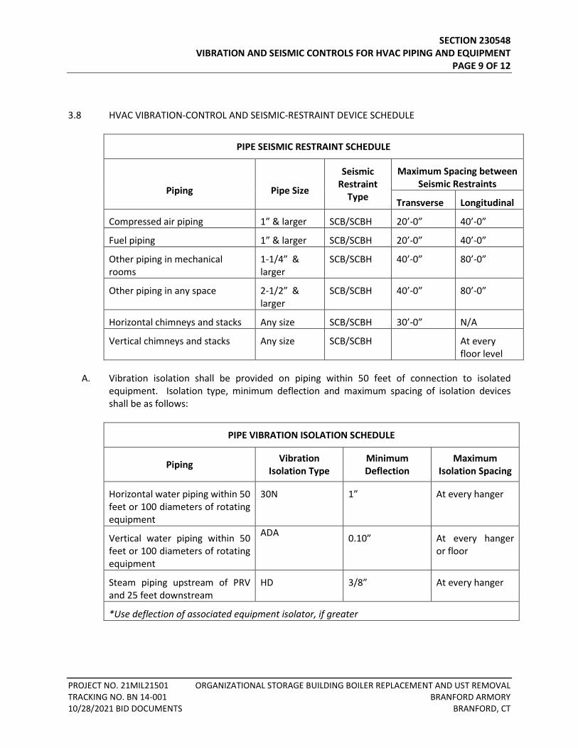
SECTION 230548 VIBRATION AND SEISMIC CONTROLS FOR HVAC PIPING AND EQUIPMENT PAGE 9 OF 12
PROJECT NO. 21MIL21501 ORGANIZATIONAL STORAGE BUILDING BOILER REPLACEMENT AND UST REMOVAL TRACKING NO. BN 14-001 BRANFORD ARMORY 10/28/2021 BID DOCUMENTS BRANFORD, CT
3.8 HVAC VIBRATION-CONTROL AND SEISMIC-RESTRAINT DEVICE SCHEDULE
PIPE SEISMIC RESTRAINT SCHEDULE
Piping
Pipe Size
Seismic Restraint
Type
Maximum Spacing between Seismic Restraints
Transverse Longitudinal
Compressed air piping 1” & larger SCB/SCBH 20’-0” 40’-0”
Fuel piping 1” & larger SCB/SCBH 20’-0” 40’-0”
Other piping in mechanical rooms
1-1/4” & larger
SCB/SCBH 40’-0” 80’-0”
Other piping in any space 2-1/2” & larger
SCB/SCBH 40’-0” 80’-0”
Horizontal chimneys and stacks Any size SCB/SCBH 30’-0” N/A
Vertical chimneys and stacks Any size SCB/SCBH At every floor level
A. Vibration isolation shall be provided on piping within 50 feet of connection to isolated equipment. Isolation type, minimum deflection and maximum spacing of isolation devices shall be as follows:
PIPE VIBRATION ISOLATION SCHEDULE
Piping Vibration Isolation Type
Minimum Deflection
Maximum Isolation Spacing
Horizontal water piping within 50 feet or 100 diameters of rotating equipment
30N 1” At every hanger
Vertical water piping within 50 feet or 100 diameters of rotating equipment
ADA 0.10” At every hanger or floor
Steam piping upstream of PRV and 25 feet downstream
HD 3/8” At every hanger
*Use deflection of associated equipment isolator, if greater
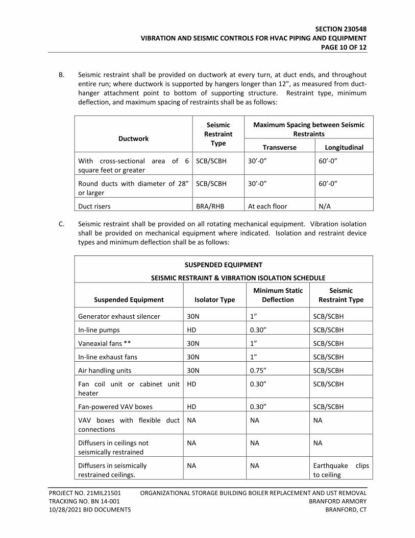
SECTION 230548 VIBRATION AND SEISMIC CONTROLS FOR HVAC PIPING AND EQUIPMENT PAGE 10 OF 12
PROJECT NO. 21MIL21501 ORGANIZATIONAL STORAGE BUILDING BOILER REPLACEMENT AND UST REMOVAL TRACKING NO. BN 14-001 BRANFORD ARMORY 10/28/2021 BID DOCUMENTS BRANFORD, CT
B. Seismic restraint shall be provided on ductwork at every turn, at duct ends, and throughout entire run; where ductwork is supported by hangers longer than 12”, as measured from duct-hanger attachment point to bottom of supporting structure. Restraint type, minimum deflection, and maximum spacing of restraints shall be as follows:
Ductwork
Seismic Restraint
Type
Maximum Spacing between Seismic Restraints
Transverse Longitudinal
With cross-sectional area of 6 square feet or greater
SCB/SCBH 30’-0” 60’-0”
Round ducts with diameter of 28” or larger
SCB/SCBH 30’-0” 60’-0”
Duct risers BRA/RHB At each floor N/A
C. Seismic restraint shall be provided on all rotating mechanical equipment. Vibration isolation shall be provided on mechanical equipment where indicated. Isolation and restraint device types and minimum deflection shall be as follows:
SUSPENDED EQUIPMENT
SEISMIC RESTRAINT & VIBRATION ISOLATION SCHEDULE
Suspended Equipment
Isolator Type
Minimum Static Deflection
Seismic Restraint Type
Generator exhaust silencer 30N 1” SCB/SCBH
In-line pumps HD 0.30” SCB/SCBH
Vaneaxial fans ** 30N 1” SCB/SCBH
In-line exhaust fans 30N 1” SCB/SCBH
Air handling units 30N 0.75” SCB/SCBH
Fan coil unit or cabinet unit heater
HD 0.30” SCB/SCBH
Fan-powered VAV boxes HD 0.30” SCB/SCBH
VAV boxes with flexible duct connections
NA NA NA
Diffusers in ceilings not seismically restrained
NA NA NA
Diffusers in seismically restrained ceilings.
NA NA Earthquake clips to ceiling
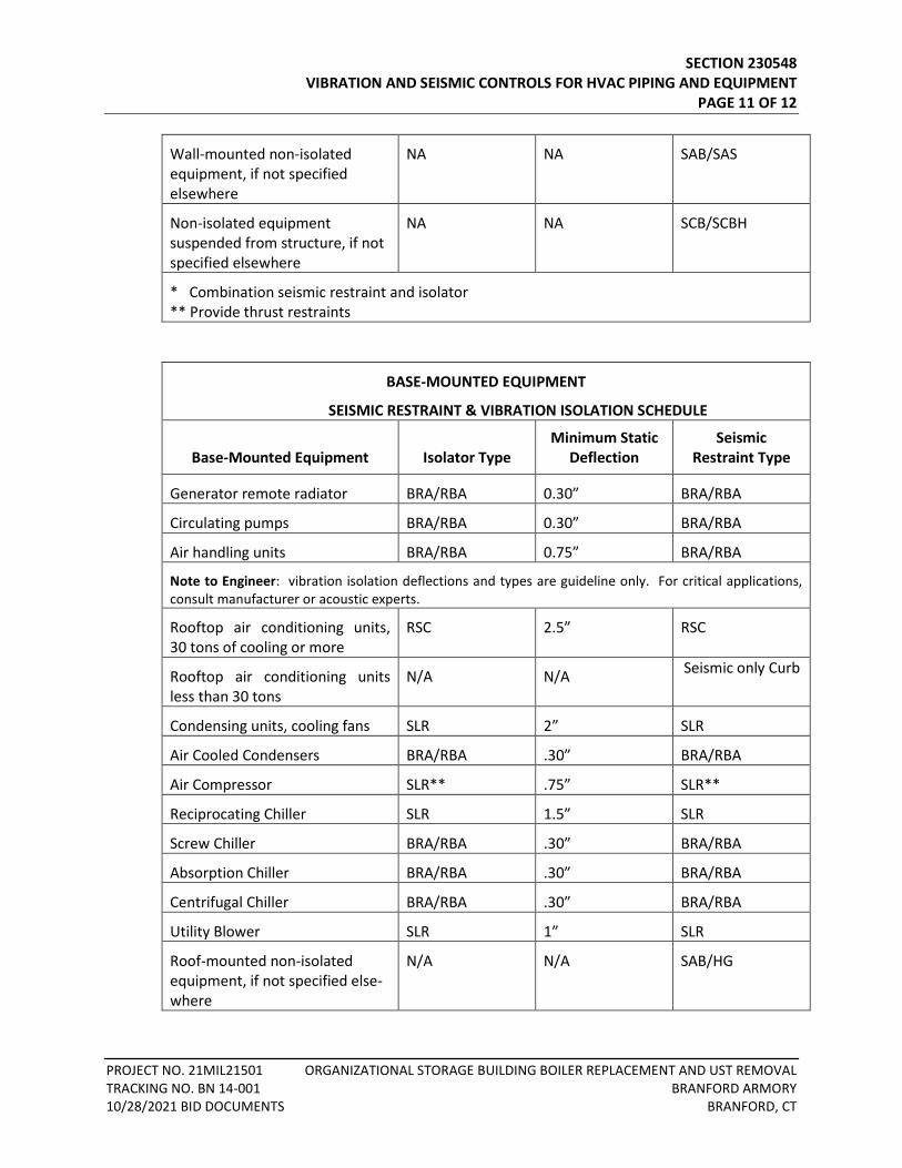
SECTION 230548 VIBRATION AND SEISMIC CONTROLS FOR HVAC PIPING AND EQUIPMENT PAGE 11 OF 12
PROJECT NO. 21MIL21501 ORGANIZATIONAL STORAGE BUILDING BOILER REPLACEMENT AND UST REMOVAL TRACKING NO. BN 14-001 BRANFORD ARMORY 10/28/2021 BID DOCUMENTS BRANFORD, CT
Wall-mounted non-isolated equipment, if not specified elsewhere
NA NA SAB/SAS
Non-isolated equipment suspended from structure, if not specified elsewhere
NA NA SCB/SCBH
* Combination seismic restraint and isolator ** Provide thrust restraints
BASE-MOUNTED EQUIPMENT
SEISMIC RESTRAINT & VIBRATION ISOLATION SCHEDULE
Base-Mounted Equipment
Isolator Type
Minimum Static Deflection
Seismic Restraint Type
Generator remote radiator BRA/RBA 0.30” BRA/RBA
Circulating pumps BRA/RBA 0.30” BRA/RBA
Air handling units BRA/RBA 0.75” BRA/RBA
Note to Engineer: vibration isolation deflections and types are guideline only. For critical applications, consult manufacturer or acoustic experts.
Rooftop air conditioning units, 30 tons of cooling or more
RSC 2.5” RSC
Rooftop air conditioning units less than 30 tons
N/A N/A Seismic only Curb
Condensing units, cooling fans SLR 2” SLR
Air Cooled Condensers BRA/RBA .30” BRA/RBA
Air Compressor SLR** .75” SLR**
Reciprocating Chiller SLR 1.5” SLR
Screw Chiller BRA/RBA .30” BRA/RBA
Absorption Chiller BRA/RBA .30” BRA/RBA
Centrifugal Chiller BRA/RBA .30” BRA/RBA
Utility Blower SLR 1” SLR
Roof-mounted non-isolated equipment, if not specified else-where
N/A N/A SAB/HG
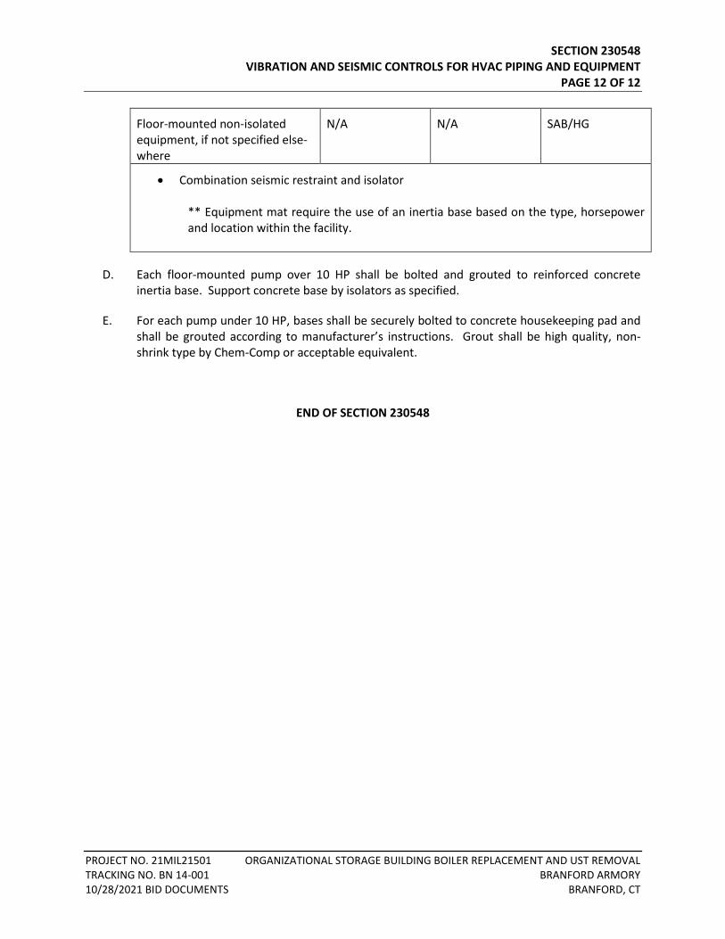
SECTION 230548 VIBRATION AND SEISMIC CONTROLS FOR HVAC PIPING AND EQUIPMENT PAGE 12 OF 12
PROJECT NO. 21MIL21501 ORGANIZATIONAL STORAGE BUILDING BOILER REPLACEMENT AND UST REMOVAL TRACKING NO. BN 14-001 BRANFORD ARMORY 10/28/2021 BID DOCUMENTS BRANFORD, CT
Floor-mounted non-isolated equipment, if not specified else-where
N/A N/A SAB/HG
• Combination seismic restraint and isolator ** Equipment mat require the use of an inertia base based on the type, horsepower and location within the facility.
D. Each floor-mounted pump over 10 HP shall be bolted and grouted to reinforced concrete inertia base. Support concrete base by isolators as specified.
E. For each pump under 10 HP, bases shall be securely bolted to concrete housekeeping pad and shall be grouted according to manufacturer’s instructions. Grout shall be high quality, non-shrink type by Chem-Comp or acceptable equivalent.
END OF SECTION 230548
TABLE OF CONTENTS SECTION 230553 – IDENTIFICATION FOR HVAC PIPING AND EQUIPMENT PART 1 - GENERAL ......................................................................................................................................... 1
1.1 RELATED DOCUMENTS .................................................................................................................. 1 1.2 SUMMARY ..................................................................................................................................... 1 1.3 ACTION SUBMITTALS .................................................................................................................... 1 1.4 COORDINATION ............................................................................................................................ 1
PART 2 - PRODUCTS ...................................................................................................................................... 1 2.1 EQUIPMENT LABELS ...................................................................................................................... 1
PART 3 - EXECUTION ..................................................................................................................................... 2 3.1 PREPARATION ............................................................................................................................... 2 3.2 EQUIPMENT LABEL INSTALLATION ............................................................................................... 2

SECTION 230553 IDENTIFICATION FOR HVAC PIPING AND EQUIPMENT PAGE 1 OF 2
PROJECT NO. 21MIL21501 ORGANIZATIONAL STORAGE BUILDING BOILER REPLACEMENT AND UST REMOVAL TRACKING NO. BN 14-001 BRANFORD ARMORY 10/28/2021 BID DOCUMENTS BRANFORD, CT
SECTION 230553 - IDENTIFICATION FOR HVAC PIPING AND EQUIPMENT
PART 1 - GENERAL
1.1 RELATED DOCUMENTS
A. Drawings and general provisions of the Contract, including General and Supplementary Conditions and Division 01 Specification Sections, apply to this Section.
1.2 SUMMARY
A. Section Includes:
1. Equipment labels.
1.3 ACTION SUBMITTALS
A. Product Data: For each type of product indicated.
B. Samples: For color, letter style, and graphic representation required for each identification material and device.
C. Equipment Label Schedule: Include a listing of all equipment to be labeled with the proposed content for each label.
1.4 COORDINATION
A. Coordinate installation of identifying devices with completion of covering and painting of surfaces where devices are to be applied.
B. Coordinate installation of identifying devices with locations of access panels and doors.
C. Install identifying devices before installing acoustical ceilings and similar concealment.
PART 2 - PRODUCTS
2.1 EQUIPMENT LABELS
A. Metal Labels for Equipment:
SECTION 230553 IDENTIFICATION FOR HVAC PIPING AND EQUIPMENT PAGE 2 OF 2
PROJECT NO. 21MIL21501 ORGANIZATIONAL STORAGE BUILDING BOILER REPLACEMENT AND UST REMOVAL TRACKING NO. BN 14-001 BRANFORD ARMORY 10/28/2021 BID DOCUMENTS BRANFORD, CT
1. Material and Thickness: Stainless steel, 0.025-inch minimum thickness, and having predrilled or stamped holes for attachment hardware.
2. Minimum Label Size: Length and width vary for required label content, but not less than 2-1/2 by 3/4 inch.
3. Minimum Letter Size: 1/4 inch for name of units if viewing distance is less than 24 inches , 1/2 inch for viewing distances up to 72 inches, and proportionately larger lettering for greater viewing distances. Include secondary lettering two-thirds to three-fourths the size of principal lettering.
4. Fasteners: Stainless-steel rivets or self-tapping screws. 5. Adhesive: Contact-type permanent adhesive, compatible with label and with substrate.
PART 3 - EXECUTION
3.1 PREPARATION
A. Clean piping and equipment surfaces of substances that could impair bond of identification devices, including dirt, oil, grease, release agents, and incompatible primers, paints, and encapsulants.
3.2 EQUIPMENT LABEL INSTALLATION
A. Install or permanently fasten labels on each major item of mechanical equipment.
B. Locate equipment labels where accessible and visible.
END OF SECTION 230553
TABLE OF CONTENTS SECTION 230940 – HVAC INSTRUMENTATION AND CONTROLS
PART 1 - GENERAL ......................................................................................................................................... 1
1.1 RELATED DOCUMENTS .................................................................................................................. 1 1.2 SUMMARY ..................................................................................................................................... 1 1.3 SCOPE ............................................................................................................................................ 1 1.4 SHOP DRAWINGS AND OTHER SUBMITTALS ................................................................................ 2 1.5 INSTRUCTION TRAINING ............................................................................................................... 4
PART 2 - PRODUCTS ...................................................................................................................................... 4 2.1 CONTROL SYSTEM – GENERAL REQUIREMENTS ........................................................................... 4 2.2 TRANSMISSION NETWORK ............................................................................................................ 6 2.3 ELECTRONIC TRANSMITTERS AND SENSORS ................................................................................ 6 2.4 CONTROL DAMPERS ...................................................................................................................... 7 2.5 DAMPER ACTUATORS ................................................................................................................... 7 2.6 CONTROL PANELS ......................................................................................................................... 8 2.7 SYSTEM SOFTWARE AND GRAPHICS ............................................................................................. 8 2.8 ENERGY MANAGEMENT ROUTINES ............................................................................................ 12 2.9 SEQUENCE OF OPERATION: UNIT HEATERS ............................................................................... 12 2.10 SEQUENCE OF OPERATION: VENT LOUVER DAMPERS............................................................... 12
PART 3 - EXECUTION ................................................................................................................................... 13 3.1 COORDINATION .......................................................................................................................... 13 3.2 INSTALLATION OF CONTROL WIRING ......................................................................................... 13 3.3 INSTALLATION OF EQUIPMENT SENSORS ................................................................................... 13 3.4 ADJUSTMENT AND CALIBRATION ............................................................................................... 14 3.5 DEMOLITION: IMPACT ON EXISTING SYSTEMS .......................................................................... 14

SECTION 230940 HVAC INSTRUMENTATION AND CONTROLS PAGE 1 OF 15
PROJECT NO. 21MIL21501 ORGANIZATIONAL STORAGE BUILDING BOILER REPLACEMENT AND UST REMOVAL TRACKING NO. BN 14-001 BRANFORD ARMORY 10/28/2021 BID DOCUMENTS BRANFORD, CT
SECTION 230940 – HVAC INSTRUMENTATION AND CONTROLS
PART 1 - GENERAL
1.1 RELATED DOCUMENTS
A. Drawings and General Provisions of the Contract, including General and Supplementary Conditions Division 1 Specification Sections, apply to this Section.
1.2 SUMMARY
A. This Section includes control sequences for HVAC systems, subsystems and equipment.
B. Manufacturers:
1. Acceptable manufacturers of electronic and DDC controls are, Automatic Logic, 2. Other manufacturers will NOT be considered unless specifically requested in writing and
specifically approved by the Engineer.
1.3 SCOPE
A. Provide labor, materials, services, equipment and transportation necessary for complete and operational system of automatic temperature control and building management (i.e., DDC system), as indicated on Contract Drawings and specified herein, including, but NOT limited to, the following:
1. Controls for space heating systems including unit heaters, control dampers and wall heater(s).
2. Connect building BAS system to Campus BAS system. 3. Building Management System including:
a. Control of mechanical systems b. Monitoring c. Alarm d. Energy Management e. Energy use reporting f. Calculation of data for custom reports g. Color graphics of floor plans and mechanical systems h. Totalization logs i. Historical trend logs
4. Low voltage wiring for power and control, for BAS system. 5. Hangers, anchors, guides, bases and other supports. 6. Access panels and access doors.
SECTION 230940 HVAC INSTRUMENTATION AND CONTROLS PAGE 2 OF 15
PROJECT NO. 21MIL21501 ORGANIZATIONAL STORAGE BUILDING BOILER REPLACEMENT AND UST REMOVAL TRACKING NO. BN 14-001 BRANFORD ARMORY 10/28/2021 BID DOCUMENTS BRANFORD, CT
7. System identification, including valve tags. 8. Noise and vibration control. 9. Seismic restraints, including equipment bolts and welding. 10. Cleaning, lubrication, testing, balancing and adjusting. 11. Record drawings. 12. Operating and Maintenance Manuals. 13. Instructions.
1.4 SHOP DRAWINGS AND OTHER SUBMITTALS
A. Make preliminary submittal of two sets of Pneumatic and Electric control drawings to Engineer for review before shop drawings are submitted through normal channels. The purpose of this preliminary submittal is to save time. Include the following information:
1. Temperature control ranges 2. Method of control 3. Control devices selected 4. Description of operation
B. Submit, for review, shop drawings for each item of material, equipment and system component furnished or installed as part of the work of this Section. Shop drawing requirements are specified under SECTION 230500 COMMON WORK RESULTS FOR MECHANICAL and under DIVISION 1.
C. Shop drawings shall include control layout and data on sensitivity, pressure ranges, temperature ranges, means of adjustment, means of calibration, spring ranges and other data necessary for review of each device, its function and its intended application.
D. Devices on shop drawings shall be identified by numbers and letters. These identifiers shall also be used in description of operation, in control layouts and on data sheets for ease in cross-referencing.
E. Shop drawings shall include motor efficiency data for three-phase motors 1 HP and larger.
F. Submit circuit coordination information for review by Engineer and Contractor, indicating circuit requirements by electrical panel, i.e., panel identification and maximum load of each circuit required for control system. Submittal will be returned indicating Engineer’s final determination of panels and circuits to be used.
1. Furnish copy of final circuit determinations to DIVISION 26 Contractor, for use in preparing panel directories. Information on circuits shall include control component and area served.
G. Furnish certificate from manufacturer of control system that expansion hardware and software shall be available for next 10 years.
SECTION 230940 HVAC INSTRUMENTATION AND CONTROLS PAGE 3 OF 15
PROJECT NO. 21MIL21501 ORGANIZATIONAL STORAGE BUILDING BOILER REPLACEMENT AND UST REMOVAL TRACKING NO. BN 14-001 BRANFORD ARMORY 10/28/2021 BID DOCUMENTS BRANFORD, CT
H. Furnish ASME certified test certificates for receiver tank on air compressor.
I. Furnish instruction manual for review. Manual shall describe function and operation of all control and management system components and shall include trouble-shooting and operating procedures. Manual shall be easily understood, for use by Owner’s personnel; shall show the total integrated control system; and shall include:
1. System description. 2. Control devices, including number, system, service, location and normal position of
each. 3. Information on sequencing of related devices. 4. Calibration charts and instructions.
J. Submit software manual to Owner for review. Software manual shall describe programming and testing, including:
1. System overview and detailed description of each software feature. 2. Instructions for user operation, including verifying status and errors, changing
passwords, and initiating or disabling control programs. 3. Description of programming language including commands, editing and writing control
programs, algorithms, printouts and logs, mathematical calculations and passwords. 4. Copies of application program software and documentation necessary for Owner to
interpret program and make any changes desired. 5. Instructions for user programming or reprogramming any portion of DDC system
including control programs, algorithms, mathematical equations, variables, setpoints, time periods, messages and other information necessary to load, alter, test and execute DDC system.
6. Reference summary sheets, which compare control programs with pertinent information about hardware and field wiring information.
7. Point identification including terminal number, symbol, engineering units and control program reference number.
8. Field information including DDC system hardware and locations, device type and function, electrical parameters and record drawing reference numbers.
K. Submit data summary forms to Owner for review. Forms shall define following information, for inclusion into DDC system, for each point in DDC system.
1. Description of each piece of equipment and the functions to be controlled. 2. For each DDC system function, a listing of digital and/or analog hardware required to
interface DDC system to equipment. 3. Listing of digital and analog alarms. 4. Listing of DDC system application programs associated with each piece of equipment.
This listing shall include control algorithms and mathematical equations and shall be in easy-to-understand English format.
SECTION 230940 HVAC INSTRUMENTATION AND CONTROLS PAGE 4 OF 15
PROJECT NO. 21MIL21501 ORGANIZATIONAL STORAGE BUILDING BOILER REPLACEMENT AND UST REMOVAL TRACKING NO. BN 14-001 BRANFORD ARMORY 10/28/2021 BID DOCUMENTS BRANFORD, CT
L. Upon completion of project, submit for review pneumatic control and electric control shop drawings corrected for “as-built” conditions. Shop drawings shall include final pressure settings, spring ranges, temperature ranges, throttling ranges and temperature control settings. Three copies of accepted “record” shop drawings shall be furnished to Architect.
1.5 INSTRUCTION TRAINING
A. Competent technicians shall provide {8} hours of instruction to the Owner’s personnel. Instructions shall include, but are NOT limited to, the following:
1. Familiarization with HVAC Control system, hardware and operation procedures. 2. Familiarization with Management System Hardware. 3. Use of management system. 4. Modifications of software packages. 5. Trouble-shooting and service procedures.
PART 2 - PRODUCTS
2.1 CONTROL SYSTEM – GENERAL REQUIREMENTS
A. All equipment shall be by one manufacturer, insofar as possible. Unless specified otherwise, equipment shall be fully modulating and state-of-the-art.
B. Contract Drawings do NOT show every control device and every location. It shall be understood that Specifications are the primary guide to control requirements and that, unless specifically excluded, every piece of heating and cooling equipment shown on Contract Drawings requires controlling device.
C. Control system shall be complete in all respects including:
1. Room, insert and immersion thermostats and sensors. 2. Relays. 3. Control panels. 4. Dampers, actuators 5. Electronic analog sensors: temperature, humidity, pressure, flow and/or others as
required. 6. Digital controllers. 7. Central monitoring terminal (CMT). 8. Transmission power supply. 9. Operators’ terminal and printer. 10. Control wiring. 11. Auxiliary devices and accessories, including equipment interface panels. 12. Interface with fire alarm system. 13. Modem/telephone interface and associated software.
SECTION 230940 HVAC INSTRUMENTATION AND CONTROLS PAGE 5 OF 15
PROJECT NO. 21MIL21501 ORGANIZATIONAL STORAGE BUILDING BOILER REPLACEMENT AND UST REMOVAL TRACKING NO. BN 14-001 BRANFORD ARMORY 10/28/2021 BID DOCUMENTS BRANFORD, CT
D. Electronic monitoring system shall be UL listed or ETL approved.
E. Insofar as possible:
1. Sequencing shall be accomplished by selection and application of proper spring ranges to damper operators and valve operators; pilot positioners shall NOT be used in lieu of proper spring range selection.
2. Ranges and sensitivities of master controllers shall be selected to eliminate need for submaster controllers.
F. Provide power and control wiring, conduit, junction boxes, fittings and other electrical appurtenances that are required for complete and operational control and monitoring systems; conform to electrical standards, codes and requirements specified under DIVISION 26, ELECTRICAL WORK. This work shall include:
1. Wiring of control and monitoring devices and circuits carrying voltages up to and including 120 Volt, unless otherwise indicated.
2. Wiring of 120 VAC power feeds to temperature control panels, CPU, digital controllers, printer and other control system equipment.
3. Wiring required for interfacing with building fire alarm, security and emergency generator systems; including wiring between DDC panels and fire alarm system panels.
4. Wiring of control system including wiring from sensors to panels, wiring from panels to CPU, and wiring from CPU to operator’s terminal.
5. Wiring to “Auto” side of hand-off-auto switches on units being controlled as part of work of this Division.
6. Wiring of devices controlled as part of the work of this Division, whether furnished under this Division or another Division. Examples of devices include: alarm device, relay, solenoid valve, actuator and electro-mechanical device at control cabinet.
7. Wiring of devices providing control inputs, whether furnished under this Division or another Division. Examples of devices include: smoke detector contact; fire alarm relay contact; pressure, temperature, limit level and motion switches; PE switch and analog sensor.
8. Wiring from temperature control panel to terminal strips. 9. Wiring between panel terminal strips and field-mounted devices. 10. Wiring from modems and alarm dialers to telephone jacks. Coordinate with Owner’s
telephone contractor.
G. For bidding purposes, unless otherwise indicated, closest appropriate electrical panel shall be assumed to have circuit(s) available for control system use. Coordinate selection of circuits for control system use, by special submittal; refer to paragraph 1.4.F where mechanical equipment is designed to operate on standby power during utility outages, derive all control power for end devices and panels/CPU from a standby power source.
H. Power wiring installed and terminated as part of the work of DIVISION 26, ELECTRICAL WORK, shall include:
SECTION 230940 HVAC INSTRUMENTATION AND CONTROLS PAGE 6 OF 15
PROJECT NO. 21MIL21501 ORGANIZATIONAL STORAGE BUILDING BOILER REPLACEMENT AND UST REMOVAL TRACKING NO. BN 14-001 BRANFORD ARMORY 10/28/2021 BID DOCUMENTS BRANFORD, CT
1. Wiring of devices and circuits carrying voltages GREATER than 120 Volts, unless otherwise indicated.
2. Wiring of power feeds to disconnects, starters and electric motors. 3. Installation of, and wiring of line power to, fused disconnects for each air compressor. 4. Wiring from disconnects to equipment motor starters. 5. Wiring from equipment motor starters to equipment motors.
2.2 TRANSMISSION NETWORK
A. Automatic system shall have multi-drop digital transmission network that provides communication link between operator's terminal and all DDC panels.
B. System shall have error checking feature to ensure signal reliability and shall identify signal transmission network failures. System shall ensure signal quality and strength. System shall support multiple multi-drop trunks.
1. All multi-drop trunks shall be interfaced to the system via standard EIA interface. 2. When used with modems, multi-drop trunk shall interface to unconditioned voice-band
3002 telephone lines for remote building tie-in to automation system.
C. Transmission network shall be run in conduit . Wiring shall NOT be run in same conduit with fire alarm, security, lighting, building power or other dedicated systems.
D. Transmission network speed shall be minimum 9600 baud rate.
2.3 ELECTRONIC TRANSMITTERS AND SENSORS
A. Electronic Temperature Transmitters: shall be solid state; RTD, thermistor or IC type which transmit electric analog signal to DDC panel; shall have proper range and accessories to transmit temperature value to DDC panel with accuracy of +/-1°F; shall be field calibrated, wired between point of sensing and DDC panel.
B. Space Temperature Sensors: shall be thermistor RTD or IC type; with cover of brushed aluminum or as accepted by Architect; with locking vandal-resistant guards keyed alike.
C. Sensors for outdoor shall have suitable radiation shield and weatherproof enclosure. Outdoor air temperature sensor shall be RTD type with platinum element.
D. Analog sensors shall be compatible with systems specified, carefully selected for the required span.
E. All sensor wiring - analog or digital, input or output - shall be capable of sharing single conduit runs without affecting signal performance. Sensor wiring shall be capable of sharing single conduit runs with switched 120 VAC or 240 VAC. If this is NOT possible, provide separate conduits for sensor wiring, to ensure signal integrity.
SECTION 230940 HVAC INSTRUMENTATION AND CONTROLS PAGE 7 OF 15
PROJECT NO. 21MIL21501 ORGANIZATIONAL STORAGE BUILDING BOILER REPLACEMENT AND UST REMOVAL TRACKING NO. BN 14-001 BRANFORD ARMORY 10/28/2021 BID DOCUMENTS BRANFORD, CT
2.4 CONTROL DAMPERS
A. Provide control dampers as indicated on the drawings, to allow effective modulation or close-off of air flow as required.
B. Dampers shall be low leakage design, with seals along both edges and ends of damper blades to provide tight closure.
C. Dampers shall be sized for design velocities of 1500 fpm through free area of damper at maximum system air flows.
D. Dampers shall be arranged for normally open or normally closed operation, as required. Linkage shall be serviceable without removal of entire damper.
E. Damper construction shall be suitable for damper operation at maximum fan pressure, without failure, binding or distortion.
F. Damper frames shall be either galvanized steel or aluminum, constructed to facilitate field assembly. Frames shall have openings or mounting clips which allow secure fastening of frame to surrounding ductwork, duct collar or fan housing.
G. Damper blades shall be either galvanized steel or aluminum, with maximum blade length of 48" in any section. Blades shall have suitable bearings for smooth operation and shall be interconnected to provide unison operation.
H. Provide stiffening or bracing for frame sections over 48" high.
I. Outdoor air dampers shall have separate minimum and maximum sections.
J. Provide insulated damper blades on outside air plenums, dog house louvers, etc., that do not have ductwork connected.
2.5 DAMPER ACTUATORS
A. Motor actuators shall have non-overloading motors, and shall be direct drive by Belimo or acceptable equivalent. Actuators shall have moisture- and corrosion-resistant construction suitable for the environment in which they are installed.
B. Actuator sizing and quantity shall be determined by control manufacturer:
C. As needed to meet system requirements.
D. Each actuator shall be matched to the type of analog output available from the controller and shall have a matching control range.
E. Assembly shall include necessary mounting hardware and brackets.
SECTION 230940 HVAC INSTRUMENTATION AND CONTROLS PAGE 8 OF 15
PROJECT NO. 21MIL21501 ORGANIZATIONAL STORAGE BUILDING BOILER REPLACEMENT AND UST REMOVAL TRACKING NO. BN 14-001 BRANFORD ARMORY 10/28/2021 BID DOCUMENTS BRANFORD, CT
F. Motors at outdoor air ducts (intake and exhaust) and motors interlocked with them shall have a power-fail safety device which return motors to their normal position.
G. Where required, provide end switches and/or feedback potentiometer to report actuator position.
2.6 CONTROL PANELS
A. Control panels shall be fully enclosed, all metal construction. Panels shall have hinged door with full piano hinges or heavy duty concealed hinges, with locking latch or bolt-on cover plate and with work light and switch. All panel locks shall be common keyed. Panels shall be finished with two coats of enamel paint.
B. Indicating devices and manual adjustment devices required for routing operation of system shall be located on panel door or cover plate. Other devices shall be located on sub-panel within panel.
C. Panels shall have ample room for control device mounting and wiring.
D. Panels shall house control apparatus, relays, I-P transducers, EP and PE switches, gauges, and other items required to implement the control sequence.
E. Panel shall display: discharge air temperature, return air temperature, mixed air temperature, outdoor air temperature, and alarm lights.
2.7 SYSTEM SOFTWARE AND GRAPHICS
A. Provide software required for efficient operation of functions required. Software shall be modular in design with flexibility in expansion and revision of the system. Software shall include, as a minimum:
1. Complete database entry. 2. Configuration of application programs to provide the sequence of operation indicated. 3. Graphics of each system as shown on the I/O Summary Table. 4. Alarm limits and alarm messages for critical and non-critical alarms. 5. Configuration of reports and point summaries indicted. 6. Capability for graphic programming.
B. Software package shall display graphically, in different colors, the following system information:
1. General area maps, showing locations of controlled buildings in relation to local landmarks.
2. Floor plan maps, showing heating and cooling zones throughout the buildings. Colors shall provide visual display of temperature relative to zone's respective setpoints. Colors shall be updated dynamically as the zones' comfort conditions change. Setpoint
SECTION 230940 HVAC INSTRUMENTATION AND CONTROLS PAGE 9 OF 15
PROJECT NO. 21MIL21501 ORGANIZATIONAL STORAGE BUILDING BOILER REPLACEMENT AND UST REMOVAL TRACKING NO. BN 14-001 BRANFORD ARMORY 10/28/2021 BID DOCUMENTS BRANFORD, CT
adjustment and color band displays shall be provided as specified in paragraph 3.02.D.5 "Setpoints".
3. Mechanical system graphics, showing the type of mechanical system components serving each zone, by use of pictorial representation of components. Graphic shall provide current status of I/O points being controlled, as applicable to each piece of equipment, including analog readouts in appropriate engineering units, at appropriate locations on the graphic.
C. Each category of software shall consist of interactive software modules. Each module shall have an associated priority level and shall execute as determined by the program controller as defined in the real-time operating system.
D. Software package shall allow receipt of alarms and messages while in a functional mode other than energy management, i.e., incoming alarms shall be displayed while the operator is in word processing, spreadsheet or other operating mode. System must automatically: switch from non-energy management mode, respond to an alarm, and return to the exact position left in the previous functional mode.
E. Operator must be able to communicate and direct control functions through the use of two-button "mouse" operator interface to monitor and control functions and sequences within the system.
F. System shall operate on a "System" Format basis, regardless of the manner or hardware configuration in which the data is acquired. A "system" shall consist of a logical grouping of data points, related to a piece of mechanical equipment, an energy distribution system, or an architectural area. Output displays, logs of a point and logs of a group of points shall contain following information:
1. Graphic presentation of the system 2. User name of point 3. Point descriptor 4. Current value/status 5. Associated engineering units 6. Alarm description
G. System shall have capability to display setpoints and variables for each zone graphically. System shall allow setpoints to be changed in the graphics mode. System shall update the variable display continuously.
H. DDC/EMS shall be programmed to provide separate color graphic for:
1. Each piece of equipment being monitored or controlled 2. Each floor and zone being controlled 3. Each schedule 4. Each trend 5. Each report
SECTION 230940 HVAC INSTRUMENTATION AND CONTROLS PAGE 10 OF 15
PROJECT NO. 21MIL21501 ORGANIZATIONAL STORAGE BUILDING BOILER REPLACEMENT AND UST REMOVAL TRACKING NO. BN 14-001 BRANFORD ARMORY 10/28/2021 BID DOCUMENTS BRANFORD, CT
I. Operator sign-on shall require as a signable password. System shall have up to 32 passwords, each of which may be one of six levels of system access.
J. Power Failure/Automatic Restart at the Control Module
1. Power failure shall cause the control module to go into an orderly shutdown with no loss of program memory.
2. Upon resumption of power, control module shall automatically restart and shall print out the time and date of power failure and of power restoration, at the respective central site system.
3. Restart program shall automatically restart affected field equipment. Operator shall be able to define an automatic power-up time delay for each piece of equipment under control.
K. Changes to database and program shall be done using standard procedures and shall be capable of being done while the system is on-line and operational. System shall allow changes to be made at the local site through a portable computer. System shall permit the operator to perform the following:
1. Add and delete points. 2. Modify point parameters.
L. Graphics software shall permit the easy construction of infinitely variable shapes and sizes through the use of the mouse pointing device. Graphics software shall be fully implemented and operational to accomplish the following:
1. Create a new graphic picture 2. Modify a portion of a graphic picture 3. Delete a graphic picture 4. Delete a portion of a graphic picture 5. Call up a graphic picture 6. Cancel the display of a graphic picture 7. Assign conditions which automatically initiate the display 8. Overlay alpha numeric and graphics 9. Save the graphic picture 10. Display the latest process data fully integrated with the graphic display
M. System shall be able to trend and to display, either numerically or graphically: each analog point, each digital point and each calculated point. System shall be able to display graphically simultaneously two trended points within a module function block showing the most recent sixty samples. Each field module shall be capable of storing the more recent 288 samples for every hardware point in the module, with sample intervals as small as one second. Operator shall be able to select and to display graphically the trends of up to four points simultaneously on a single trend graph.
N. System shall provide runtime information for digital output points and for digital input points, for modules, upon operator command. Maximum runtime limits shall be operator definable
SECTION 230940 HVAC INSTRUMENTATION AND CONTROLS PAGE 11 OF 15
PROJECT NO. 21MIL21501 ORGANIZATIONAL STORAGE BUILDING BOILER REPLACEMENT AND UST REMOVAL TRACKING NO. BN 14-001 BRANFORD ARMORY 10/28/2021 BID DOCUMENTS BRANFORD, CT
and shall be capable of automatically issuing a printed message when the runtime maximum is exceeded. Operator shall be able to reset the runtime accumulator. Runtime hours and start time date shall be retained in non-volatile module memory.
O. System shall allow receipt of alarms and messages while in a functional mode other than energy management, i.e., incoming alarms shall be displayed while the operator is using another mode such as word processing and shall allow the operator to automatically return to word processing after the alarm is received.
1. System shall distinguish between alarms and messages, with alarms having a higher priority.
2. System shall be capable of calling up to three different remote locations to deliver an alarm or message. Operator shall determine if alarms or messages are to be based on temperature limit, status, or off-normal reporting.
3. Text for operator alarm and messages shall be operator definable. System shall be capable of storing minimum 100 messages, each of different length.
P. Field modules shall be capable of calling the central processing unit during off-peak phone rate hours to automatically upload current and accumulated data. System shall be capable of reporting and archiving the following information:
1. Outdoor air temperature history and degree-day history. 2. Electric demand and usage history. 3. All trended points. 4. All alarms and messages. 5. Equipment runtime information.
Q. System shall be capable of reporting following information, for which archiving is not applicable:
1. All points summary. 2. Building operating schedules. 3. Printout of graphic screen.
R. Provide DOS-based text editor program which allows operator to create custom report and logging formats. Custom report generation shall be able to be initiated: manually, based on field occurrence, based on time and any combination. Operator shall be able to have the system:
1. Report the desired point data from the field. 2. Insert the data in custom report format. 3. Store the report on disk. 4. Print out the report on the system printer and/or a remote printer.
S. Provide following application software for optimizing energy consumption while maintaining occupant comfort:
SECTION 230940 HVAC INSTRUMENTATION AND CONTROLS PAGE 12 OF 15
PROJECT NO. 21MIL21501 ORGANIZATIONAL STORAGE BUILDING BOILER REPLACEMENT AND UST REMOVAL TRACKING NO. BN 14-001 BRANFORD ARMORY 10/28/2021 BID DOCUMENTS BRANFORD, CT
1. Scheduled start/stop (OSS) 2. Optimum start/stop (OSS) and optimum enable/disable (OED) 3. Source temperature optimization (STO) 4. Demand limiting (DL) 5. Day/night setback (DNS) 6. Timed local override (TLO) 7. Direct digital unitary zone control
2.8 ENERGY MANAGEMENT ROUTINES
A. Automation system shall include software for energy management applications. Application routines shall be compatible with, and capable of simultaneous use in, system. Use of any routine shall NOT cause other software to malfunction.
B. Provide the following application routines for energy management:
1. Time of Day 2. Remote Reset 3. Start/Stop Time Optimization 4. Warmup/Cooldown Cycles 5. Timed Override 6. Major system performance reporting including:
a. Heat Btu/Degree Day b. Daily, weekly and monthly totalization of heating and cooling energy
2.9 SEQUENCE OF OPERATION: UNIT HEATERS
A. The BMS through the corresponding space sensor shall enable gas unit heaters, as needed to maintain space temperature of 60-65°F (adjustable) Subject to time of day and weekly schedule and start up testing routines. The unit heater burner and fan will operate under it’s own factory controls.
B. The BMS shall monitor and alarm space temperatures and humidity if out of range (alarms shall be fully customizable): Low Temp: 40 deg. F High Humidity: 90% RH
2.10 SEQUENCE OF OPERATION: VENT LOUVER DAMPERS
A. Dampers to be normally closed, two position operation.
B. Electric single-temperature line voltage thermostat shall operate louver dampers as needed to maintain a space temperature of 68°F (adjustable).

SECTION 230940 HVAC INSTRUMENTATION AND CONTROLS PAGE 13 OF 15
PROJECT NO. 21MIL21501 ORGANIZATIONAL STORAGE BUILDING BOILER REPLACEMENT AND UST REMOVAL TRACKING NO. BN 14-001 BRANFORD ARMORY 10/28/2021 BID DOCUMENTS BRANFORD, CT
C. Provide manual override switch at each damper. Program BMS for 30 minute (adjustable) automatic re-closing of dampers after switch activation.
PART 3 - EXECUTION
3.1 COORDINATION
A. Coordinate with work of DIVISION 26, ELECTRICAL WORK, and work of other Sections of this Division for following:
1. Smoke alarms for air systems, indicated from dry contact relays at local temperature control panels. Relays shall be provided under DIVISION 26, ELECTRICAL WORK.
2. Power to control panels.
B. Provide self-tuning control loops or readjust hardware and software as necessary to compensate for equipment interactions and extremes of outdoor conditions while preserving efficiency and comfort.
3.2 INSTALLATION OF CONTROL WIRING
A. Control troughing and conduit shall be properly supported and anchored; shall be installed in harmony with building lines; and shall NOT interfere with maintenance, service or replacement of other equipment, conduit or piping.
B. Wiring and cables in mechanical equipment spaces or above hung ceilings shall be supported independently from pipes, conduits and ducts of other trades.
C. Wiring, cables and piping shall NOT be dropped over lighting fixtures nor allowed to lay directly on top of ceiling panels or panel support members.
D. Control cable to VFD speed input shall be shielded and shall be installed without excess cable so that electrical noise shall be minimized.
E. Wiring shall be concealed in occupied spaces and protected by conduit where exposed in mechanical rooms, floor-to-floor risers, drops to wall sensor boxes or where subject to damage.
3.3 INSTALLATION OF EQUIPMENT SENSORS
A. Thermostats shall be mounted 6 feet above finished floors in corridors or stairs; elsewhere, they shall be mounted 66 inches above finished floors. Exact locations shall be coordinated with adjacent light switches and other wall-mounted devices. Space temperature sensor shall be mounted adjacent to thermostat.
SECTION 230940 HVAC INSTRUMENTATION AND CONTROLS PAGE 14 OF 15
PROJECT NO. 21MIL21501 ORGANIZATIONAL STORAGE BUILDING BOILER REPLACEMENT AND UST REMOVAL TRACKING NO. BN 14-001 BRANFORD ARMORY 10/28/2021 BID DOCUMENTS BRANFORD, CT
3.4 ADJUSTMENT AND CALIBRATION
A. Calibrate, test and adjust controls and control system including pneumatic and electric controls, thermostats, damper motors and relays until system is properly adjusted and ready for use. Management system's hardware and software shall be completely checked, test run and modified as required.
B. Be present for functional tests on systems. Before Engineer is asked to witness functional tests, ensure that:
1. Entire control and management system is complete. 2. Controls are calibrated. 3. Controlled devices and equipment have been physically inspected and checked to
ensure that these terminal devices are under proper control and working smoothly over their entire range of operation.
C. Adjustment procedure shall include following steps:
1. Preliminary setup and calibration, as specified and as shown on shop drawings. 2. Physical checkout of all components for completeness and accuracy. 3. Review of system with Engineer. 4. Functional tests for Owner's benefit, instruction and acceptance. 5. Review of problems with Owner, rechecking adjustments and calibration as required.
Review, rechecking and calibration shall occur NOT less than 30 days nor more than 60 days after systems have been in full operation.
D. Control and Management systems shall NOT be considered complete nor acceptable until:
1. All conditions of Sequence of Operation have been attained. 2. All temperatures are maintained within specified limits under all operating conditions.
E. As part of work of this Section, provide calibration and adjustment of airflow control components and be responsible for setting control setpoints, operating sequences, and alarming systems contained within airflow control centers, to produce following overall system performance.
3.5 DEMOLITION: IMPACT ON EXISTING SYSTEMS
A. Major changes to existing building spaces have been shown on Contract Drawings; minor changes have NOT been shown. Contractor shall anticipate that there will be numerous minor changes including:
1. Relocation of control piping and control wiring. 2. Relocation of thermostats, due to architectural revisions. 3. Relocation of diffusers and registers.
SECTION 230940 HVAC INSTRUMENTATION AND CONTROLS PAGE 15 OF 15
PROJECT NO. 21MIL21501 ORGANIZATIONAL STORAGE BUILDING BOILER REPLACEMENT AND UST REMOVAL TRACKING NO. BN 14-001 BRANFORD ARMORY 10/28/2021 BID DOCUMENTS BRANFORD, CT
B. Electrical connections to existing equipment which is to be removed or relocated, including motors, shall be disconnected under DIVISION 26, ELECTRICAL WORK.
C. Electrical system equipment shall be relocated or removed under DIVISION 26, ELECTRICAL WORK.
D. Remove, store and relocate mechanical equipment designated to be relocated and reused.
E. Existing piping, ductwork, controls and mechanical system equipment which are located in areas designated for demolitions and which are not designated to remain shall be removed under other DIVISIONS (by the General Contractor). Material which is removed and is not designated for reuse shall, at the Owner's option, either:
1. Be delivered to Owner's storage location, OR 2. Become Contractor's property and be removed from the site.
F. Existing piping, ductwork, controls or equipment which are to remain and which are disturbed or damaged during construction shall be replaced with appropriate new materials, equipment or components at no extra cost to the Owner.
END OF SECTION 230940

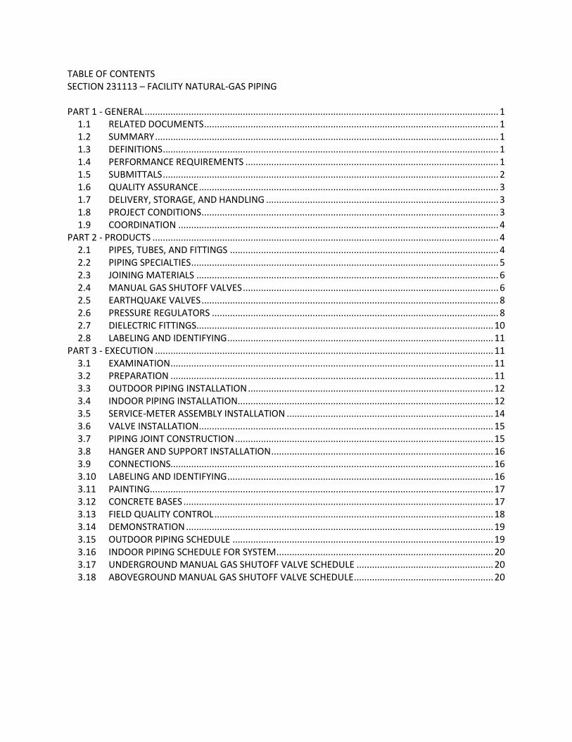
TABLE OF CONTENTS SECTION 231113 – FACILITY NATURAL-GAS PIPING PART 1 - GENERAL ......................................................................................................................................... 1
1.1 RELATED DOCUMENTS .................................................................................................................. 1 1.2 SUMMARY ..................................................................................................................................... 1 1.3 DEFINITIONS .................................................................................................................................. 1 1.4 PERFORMANCE REQUIREMENTS .................................................................................................. 1 1.5 SUBMITTALS .................................................................................................................................. 2 1.6 QUALITY ASSURANCE .................................................................................................................... 3 1.7 DELIVERY, STORAGE, AND HANDLING .......................................................................................... 3 1.8 PROJECT CONDITIONS ................................................................................................................... 3 1.9 COORDINATION ............................................................................................................................ 4
PART 2 - PRODUCTS ...................................................................................................................................... 4 2.1 PIPES, TUBES, AND FITTINGS ........................................................................................................ 4 2.2 PIPING SPECIALTIES ....................................................................................................................... 5 2.3 JOINING MATERIALS ..................................................................................................................... 6 2.4 MANUAL GAS SHUTOFF VALVES ................................................................................................... 6 2.5 EARTHQUAKE VALVES ................................................................................................................... 8 2.6 PRESSURE REGULATORS ............................................................................................................... 8 2.7 DIELECTRIC FITTINGS ................................................................................................................... 10 2.8 LABELING AND IDENTIFYING ....................................................................................................... 11
PART 3 - EXECUTION ................................................................................................................................... 11 3.1 EXAMINATION ............................................................................................................................. 11 3.2 PREPARATION ............................................................................................................................. 11 3.3 OUTDOOR PIPING INSTALLATION ............................................................................................... 12 3.4 INDOOR PIPING INSTALLATION................................................................................................... 12 3.5 SERVICE-METER ASSEMBLY INSTALLATION ................................................................................ 14 3.6 VALVE INSTALLATION .................................................................................................................. 15 3.7 PIPING JOINT CONSTRUCTION .................................................................................................... 15 3.8 HANGER AND SUPPORT INSTALLATION ...................................................................................... 16 3.9 CONNECTIONS............................................................................................................................. 16 3.10 LABELING AND IDENTIFYING ....................................................................................................... 16 3.11 PAINTING..................................................................................................................................... 17 3.12 CONCRETE BASES ........................................................................................................................ 17 3.13 FIELD QUALITY CONTROL ............................................................................................................ 18 3.14 DEMONSTRATION ....................................................................................................................... 19 3.15 OUTDOOR PIPING SCHEDULE ..................................................................................................... 19 3.16 INDOOR PIPING SCHEDULE FOR SYSTEM .................................................................................... 20 3.17 UNDERGROUND MANUAL GAS SHUTOFF VALVE SCHEDULE ..................................................... 20 3.18 ABOVEGROUND MANUAL GAS SHUTOFF VALVE SCHEDULE ...................................................... 20

SECTION 231113 NATURAL-GAS PIPING PAGE 1 OF 21
PROJECT NO. 21MIL21501 ORGANIZATIONAL STORAGE BUILDING BOILER REPLACEMENT AND UST REMOVAL TRACKING NO. BN 14-001 BRANFORD ARMORY 10/28/2021 BID DOCUMENTS BRANFORD, CT
SECTION 231113 - NATURAL-GAS PIPING
PART 1 - GENERAL
1.1 RELATED DOCUMENTS
A. Drawings and general provisions of the Contract, including General and Supplementary Conditions and Division 01 Specification Sections, apply to this Section.
1.2 SUMMARY
A. Section Includes:
1. Pipes, tubes, and fittings. 2. Piping specialties. 3. Piping and tubing joining materials. 4. Valves. 5. Pressure regulators. 6. Service meters. 7. Concrete bases.
1.3 DEFINITIONS
A. Finished Spaces: Spaces other than mechanical and electrical equipment rooms, furred spaces, pipe and duct shafts, unheated spaces immediately below roof, spaces above ceilings, unexcavated spaces, crawlspaces, and tunnels.
B. Exposed, Interior Installations: Exposed to view indoors. Examples include finished occupied spaces and mechanical equipment rooms.
C. Exposed, Exterior Installations: Exposed to view outdoors or subject to outdoor ambient temperatures and weather conditions. Examples include rooftop locations.
1.4 PERFORMANCE REQUIREMENTS
A. Minimum Operating-Pressure Ratings:
1. Piping and Valves125 psig minimum unless otherwise indicated. 2. Service Regulators: 65 psig minimum unless otherwise indicated. 3. Minimum Operating Pressure of Service Meter: 5 psig.
B. Natural-Gas System Pressure within Buildings: 0.5 psig .

SECTION 231113 NATURAL-GAS PIPING PAGE 2 OF 21
PROJECT NO. 21MIL21501 ORGANIZATIONAL STORAGE BUILDING BOILER REPLACEMENT AND UST REMOVAL TRACKING NO. BN 14-001 BRANFORD ARMORY 10/28/2021 BID DOCUMENTS BRANFORD, CT
C. Delegated Design: Design restraints and anchors for natural-gas piping and equipment, including comprehensive engineering analysis by a qualified professional engineer, using performance requirements and design criteria indicated.
1.5 SUBMITTALS
A. Product Data: For each type of the following:
1. Piping specialties. 2. Corrugated, stainless-steel tubing with associated components. 3. Valves. Include pressure rating, capacity, settings, and electrical connection data of
selected models. 4. Pressure regulators. Indicate pressure ratings and capacities. 5. Service meters. Indicate pressure ratings and capacities. Include bypass fittings and
meter bars and supports. 6. Dielectric fittings.
B. Shop Drawings: For facility natural-gas piping layout. Include plans, piping layout and elevations, sections, and details for fabrication of pipe anchors, hangers, supports for multiple pipes, alignment guides, expansion joints and loops, and attachments of the same to building structure. Detail location of anchors, alignment guides, and expansion joints and loops.
1. Shop Drawing Scale: [1/4 inch per foot]. 2. Detail mounting, supports, and valve arrangements for[ service meter assembly and]
pressure regulator assembly.
C. Delegated-Design Submittal: For natural-gas piping and equipment indicated to comply with performance requirements and design criteria, including analysis data signed and sealed by the qualified professional engineer responsible for their preparation.
1. Detail fabrication and assembly of seismic restraints. 2. Design Calculations: Calculate requirements for selecting seismic restraints.
D. Coordination Drawings: Plans and details, drawn to scale, on which natural-gas piping is shown and coordinated with other installations, using input from installers of the items involved.
E. Site Survey: Plans, drawn to scale, on which natural-gas piping is shown and coordinated with other services and utilities.
F. Qualification Data: For qualified professional engineer.
G. Welding certificates.
H. Field quality-control reports.
SECTION 231113 NATURAL-GAS PIPING PAGE 3 OF 21
PROJECT NO. 21MIL21501 ORGANIZATIONAL STORAGE BUILDING BOILER REPLACEMENT AND UST REMOVAL TRACKING NO. BN 14-001 BRANFORD ARMORY 10/28/2021 BID DOCUMENTS BRANFORD, CT
I. Operation and Maintenance Data: For pressure regulators and service meters to include in emergency, operation, and maintenance manuals.
1.6 QUALITY ASSURANCE
A. Steel Support Welding Qualifications: Qualify procedures and personnel according to AWS D1.1/D1.1M, "Structural Welding Code - Steel."
B. Pipe Welding Qualifications: Qualify procedures and operators according to ASME Boiler and Pressure Vessel Code.
C. Electrical Components, Devices, and Accessories: Listed and labeled as defined in NFPA 70, by a qualified testing agency, and marked for intended location and application.
1.7 DELIVERY, STORAGE, AND HANDLING
A. Handling Flammable Liquids: Remove and dispose of liquids from existing natural-gas piping according to requirements of authorities having jurisdiction.
B. Deliver pipes and tubes with factory-applied end caps. Maintain end caps through shipping, storage, and handling to prevent pipe end damage and to prevent entrance of dirt, debris, and moisture.
C. Store and handle pipes and tubes having factory-applied protective coatings to avoid damaging coating, and protect from direct sunlight.
D. Protect stored PE pipes and valves from direct sunlight.
1.8 PROJECT CONDITIONS
A. Perform site survey, research public utility records, and verify existing utility locations. Contact utility-locating service for area where Project is located.
B. Interruption of Existing Natural-Gas Service: Do not interrupt natural-gas service to facilities occupied by Owner or others unless permitted under the following conditions and then only after arranging to provide purging and startup of natural-gas supply according to requirements indicated:
1. Notify Owner no fewer than five days in advance of proposed interruption of natural-gas service.
2. Do not proceed with interruption of natural-gas service without Owner's written permission.
SECTION 231113 NATURAL-GAS PIPING PAGE 4 OF 21
PROJECT NO. 21MIL21501 ORGANIZATIONAL STORAGE BUILDING BOILER REPLACEMENT AND UST REMOVAL TRACKING NO. BN 14-001 BRANFORD ARMORY 10/28/2021 BID DOCUMENTS BRANFORD, CT
1.9 COORDINATION
A. Coordinate sizes and locations of concrete bases with actual equipment provided.
PART 2 - PRODUCTS
2.1 PIPES, TUBES, AND FITTINGS
A. Steel Pipe: ASTM A 53/A 53M, black steel, Schedule 40, Type E or S, Grade B.
1. Malleable-Iron Threaded Fittings: ASME B16.3, Class 150, standard pattern. 2. Wrought-Steel Welding Fittings: ASTM A 234/A 234M for butt welding and socket
welding. 3. Unions: ASME B16.39, Class 150, malleable iron with brass-to-iron seat, ground joint,
and threaded ends. 4. Forged-Steel Flanges and Flanged Fittings: ASME B16.5, minimum Class 150, including
bolts, nuts, and gaskets of the following material group, end connections, and facings:
a. Material Group: 1.1. b. End Connections: Threaded or butt welding to match pipe. c. Lapped Face: Not permitted underground. d. Gasket Materials: ASME B16.20, metallic, flat, asbestos free, aluminum o-rings,
and spiral-wound metal gaskets. e. Bolts and Nuts: ASME B18.2.1, carbon steel aboveground and stainless steel
underground.
5. Protective Coating for Underground Piping: Factory-applied, three-layer coating of epoxy, adhesive, and PE.
a. Joint Cover Kits: Epoxy paint, adhesive, and heat-shrink PE sleeves.
6. Mechanical Couplings:
a. Manufacturers: Subject to compliance with requirements, provide products by one of the following:
1) Dresser Piping Specialties; Division of Dresser, Inc. 2) Smith-Blair, Inc.
b. Stainless-steel flanges and tube with epoxy finish. c. Buna-nitrile seals. d. Stainless-steel bolts, washers, and nuts. e. Coupling shall be capable of joining PE pipe to PE pipe, steel pipe to PE pipe, or
steel pipe to steel pipe.
SECTION 231113 NATURAL-GAS PIPING PAGE 5 OF 21
PROJECT NO. 21MIL21501 ORGANIZATIONAL STORAGE BUILDING BOILER REPLACEMENT AND UST REMOVAL TRACKING NO. BN 14-001 BRANFORD ARMORY 10/28/2021 BID DOCUMENTS BRANFORD, CT
B. Corrugated, Stainless-Steel Tubing for Final Connections to Equipment and Appliances Only: Comply with ANSI/IAS LC 1.
1. Manufacturers: Subject to compliance with requirements, provide products by one of the following :
a. OmegaFlex, Inc. b. Parker Hannifin Corporation; Parflex Division. c. Titeflex. d. Tru-Flex Metal Hose Corp.
2. Tubing: ASTM A 240/A 240M, corrugated, Series 300 stainless steel. 3. Coating: PE with flame retardant.
a. Surface-Burning Characteristics: As determined by testing identical products according to ASTM E 84 by a qualified testing agency. Identify products with appropriate markings of applicable testing agency.
1) Flame-Spread Index: 25 or less. 2) Smoke-Developed Index: 50 or less.
4. Fittings: Copper-alloy mechanical fittings with ends made to fit and listed for use with corrugated stainless-steel tubing and capable of metal-to-metal seal without gaskets. Include brazing socket or threaded ends complying with ASME B1.20.1.
5. Striker Plates: Steel, designed to protect tubing from penetrations. 6. Manifolds: Malleable iron or steel with factory-applied protective coating. Threaded
connections shall comply with ASME B1.20.1 for pipe inlet and corrugated tubing outlets.
7. Operating-Pressure Rating: 5 psig.
C. Annealed-Temper Copper Tube: Comply with [ASTM B 88, Type K].
1. Copper Fittings: ASME B16.22, wrought copper, and streamlined pattern. 2. Flare Fittings: Comply with ASME B16.26 and SAE J513.
a. Copper fittings with long nuts. b. Metal-to-metal compression seal without gasket. c. Dryseal threads complying with ASME B1.20.3.
3. Protective Coating for Underground Tubing: Factory-applied, extruded PE a minimum of 0.022 inch thick.
2.2 PIPING SPECIALTIES
A. Appliance Flexible Connectors:
1. Indoor, Fixed-Appliance Flexible Connectors: Comply with ANSI Z21.24.
SECTION 231113 NATURAL-GAS PIPING PAGE 6 OF 21
PROJECT NO. 21MIL21501 ORGANIZATIONAL STORAGE BUILDING BOILER REPLACEMENT AND UST REMOVAL TRACKING NO. BN 14-001 BRANFORD ARMORY 10/28/2021 BID DOCUMENTS BRANFORD, CT
2. Indoor, Movable-Appliance Flexible Connectors: Comply with ANSI Z21.69. 3. Outdoor, Appliance Flexible Connectors: Comply with ANSI Z21.75. 4. Corrugated stainless-steel tubing with polymer coating. 5. Operating-Pressure Rating: 0.5 psig. 6. End Fittings: Zinc-coated steel. 7. Threaded Ends: Comply with ASME B1.20.1. 8. Maximum Length: 72 inches.
B. Y-Pattern Strainers:
1. Body: ASTM A 126, Class B, cast iron with bolted cover and bottom drain connection. 2. End Connections: Threaded ends for NPS 2 and smaller; flanged ends for NPS 2-1/2 and
larger. 3. Strainer Screen: 40-mesh startup strainer, and perforated stainless-steel basket with 50
percent free area. 4. CWP Rating: 125 psig.
C. Weatherproof Vent Cap: Cast- or malleable-iron increaser fitting with corrosion-resistant wire screen, with free area at least equal to cross-sectional area of connecting pipe and threaded-end connection.
2.3 JOINING MATERIALS
A. Joint Compound and Tape: Suitable for natural gas.
B. Welding Filler Metals: Comply with AWS D10.12/D10.12M for welding materials appropriate for wall thickness and chemical analysis of steel pipe being welded.
C. Brazing Filler Metals: Alloy with melting point greater than 1000 deg F complying with AWS A5.8/A5.8M. Brazing alloys containing more than 0.05 percent phosphorus are prohibited.
2.4 MANUAL GAS SHUTOFF VALVES
A. See "Underground Manual Gas Shutoff Valve Schedule" and "Aboveground Manual Gas Shutoff Valve Schedule" Articles for where each valve type is applied in various services.
B. General Requirements for Metallic Valves, NPS 2 and Smaller: Comply with ASME B16.33.
1. CWP Rating: [125 psig] . 2. Threaded Ends: Comply with ASME B1.20.1. 3. Dryseal Threads on Flare Ends: Comply with ASME B1.20.3. 4. Tamperproof Feature: Locking feature for valves indicated in "Underground Manual Gas
Shutoff Valve Schedule" and "Aboveground Manual Gas Shutoff Valve Schedule" Articles.
SECTION 231113 NATURAL-GAS PIPING PAGE 7 OF 21
PROJECT NO. 21MIL21501 ORGANIZATIONAL STORAGE BUILDING BOILER REPLACEMENT AND UST REMOVAL TRACKING NO. BN 14-001 BRANFORD ARMORY 10/28/2021 BID DOCUMENTS BRANFORD, CT
5. Listing: Listed and labeled by an NRTL acceptable to authorities having jurisdiction for valves 1 inch and smaller.
C. General Requirements for Metallic Valves, NPS 2-1/2 and Larger: Comply with ASME B16.38.
1. CWP Rating: [125 psig] . 2. Flanged Ends: Comply with ASME B16.5 for steel flanges. 3. Tamperproof Feature: Locking feature for valves indicated in "Underground Manual Gas
Shutoff Valve Schedule" and "Aboveground Manual Gas Shutoff Valve Schedule" Articles.
D. Two-Piece, Full-Port, Bronze Ball Valves with Bronze Trim: MSS SP-110.
1. Manufacturers: Subject to compliance with requirements, provide products by one of the following:
a. NIBCO Model T-585-70 or T-FP-600A
b. BrassCraft Manufacturing Company; a Masco company. c. Conbraco Industries, Inc.; Apollo Div. d. Lyall, R. W. & Company, Inc. e. McDonald, A. Y. Mfg. Co. f. Perfection Corporation; a subsidiary of American Meter Company.
2. Body: Bronze, complying with ASTM B 584. 3. Ball: Chrome-plated bronze. 4. Stem: Bronze; blowout proof. 5. Seats: Reinforced TFE; blowout proof. 6. Packing: Threaded-body packnut design with adjustable-stem packing. 7. Ends: Threaded, flared, or socket as indicated in "Underground Manual Gas Shutoff
Valve Schedule" and "Aboveground Manual Gas Shutoff Valve Schedule" Articles. 8. CWP Rating: 600 psig. 9. Listing: Valves NPS 1 and smaller shall be listed and labeled by an NRTL acceptable to
authorities having jurisdiction. 10. Service: Suitable for natural-gas service.
E. Bronze Plug Valves: MSS SP-78.
1. Manufacturers: Subject to compliance with requirements, provide products by one of the following:
a. Lee Brass Company. b. McDonald, A. Y. Mfg. Co.
2. Body: Bronze, complying with ASTM B 584. 3. Plug: Bronze.
SECTION 231113 NATURAL-GAS PIPING PAGE 8 OF 21
PROJECT NO. 21MIL21501 ORGANIZATIONAL STORAGE BUILDING BOILER REPLACEMENT AND UST REMOVAL TRACKING NO. BN 14-001 BRANFORD ARMORY 10/28/2021 BID DOCUMENTS BRANFORD, CT
4. Ends: Threaded, socket, or flanged as indicated in "Underground Manual Gas Shutoff Valve Schedule" and "Aboveground Manual Gas Shutoff Valve Schedule" Articles.
5. Operator: Square head or lug type with tamperproof feature where indicated. 6. Pressure Class: 125 psig. 7. Listing: Valves NPS 1 and smaller shall be listed and labeled by an NRTL acceptable to
authorities having jurisdiction. 8. Service: Suitable for natural-gas service.
F. Valve Boxes:
1. Cast-iron, two-section box. 2. Top section with cover with "GAS" lettering. 3. Bottom section with base to fit over valve and barrel a minimum of 5 inches in diameter. 4. Adjustable cast-iron extensions of length required for depth of bury. 5. Include tee-handle, steel operating wrench with socket end fitting valve nut or flat head,
and with stem of length required to operate valve.
2.5 EARTHQUAKE VALVES
A. Earthquake Valves: Comply with ASCE 25.
1. Manufacturers: Subject to compliance with requirements, provide products by one of the following:
a. Vanguard Valves, Inc.
2. Listing: Listed and labeled by an NRTL acceptable to authorities having jurisdiction. 3. Maximum Operating Pressure: 5 psig. 4. Cast-aluminum body with nickel-plated chrome steel internal parts. 5. Nitrile-rubber valve washer. 6. Sight windows for visual indication of valve position. 7. Threaded end connections complying with ASME B1.20.1. 8. Wall mounting bracket with bubble level indicator.
2.6 PRESSURE REGULATORS
A. General Requirements:
1. Single stage and suitable for natural gas. 2. Steel jacket and corrosion-resistant components. 3. Elevation compensator. 4. End Connections: Threaded for regulators NPS 2 and smaller; flanged for regulators
NPS 2-1/2 and larger.
B. Line Pressure Regulators: Comply with ANSI Z21.80.
SECTION 231113 NATURAL-GAS PIPING PAGE 9 OF 21
PROJECT NO. 21MIL21501 ORGANIZATIONAL STORAGE BUILDING BOILER REPLACEMENT AND UST REMOVAL TRACKING NO. BN 14-001 BRANFORD ARMORY 10/28/2021 BID DOCUMENTS BRANFORD, CT
1. Manufacturers: Subject to compliance with requirements, provide products by one of the following:
a. Actaris. b. American Meter Company. c. Eclipse Combustion, Inc. d. Fisher Control Valves and Regulators; Division of Emerson Process Management. e. Invensys. f. Maxitrol Company. g. Richards Industries; Jordan Valve Div.
2. Body and Diaphragm Case: Cast iron or die-cast aluminum. 3. Springs: Zinc-plated steel; interchangeable. 4. Diaphragm Plate: Zinc-plated steel. 5. Seat Disc: Nitrile rubber resistant to gas impurities, abrasion, and deformation at the
valve port. 6. Orifice: Aluminum; interchangeable. 7. Seal Plug: Ultraviolet-stabilized, mineral-filled nylon. 8. Single-port, self-contained regulator with orifice no larger than required at maximum
pressure inlet, and no pressure sensing piping external to the regulator. 9. Pressure regulator shall maintain discharge pressure setting downstream, and not
exceed 150 percent of design discharge pressure at shutoff. 10. Overpressure Protection Device: Factory mounted on pressure regulator. 11. Atmospheric Vent: Factory- or field-installed, stainless-steel screen in opening if not
connected to vent piping. 12. Maximum Inlet Pressure: [2 psig].
C. Appliance Pressure Regulators: Comply with ANSI Z21.18.
1. Manufacturers: Subject to compliance with requirements, provide products by one of the following:
a. Eaton Corporation; Controls Div. b. Harper Wyman Co. c. Maxitrol Company. d. SCP, Inc.
2. Body and Diaphragm Case: Die-cast aluminum. 3. Springs: Zinc-plated steel; interchangeable. 4. Diaphragm Plate: Zinc-plated steel. 5. Seat Disc: Nitrile rubber. 6. Seal Plug: Ultraviolet-stabilized, mineral-filled nylon. 7. Factory-Applied Finish: Minimum three-layer polyester and polyurethane paint finish. 8. Regulator may include vent limiting device, instead of vent connection, if approved by
authorities having jurisdiction. 9. Maximum Inlet Pressure: [1 psig].
SECTION 231113 NATURAL-GAS PIPING PAGE 10 OF 21
PROJECT NO. 21MIL21501 ORGANIZATIONAL STORAGE BUILDING BOILER REPLACEMENT AND UST REMOVAL TRACKING NO. BN 14-001 BRANFORD ARMORY 10/28/2021 BID DOCUMENTS BRANFORD, CT
D. Service-Meter Bars:
1. Manufacturers: Subject to compliance with requirements, provide products by one of the following:
a. Actaris. b. American Meter Company. c. Lyall, R. W. & Company, Inc. d. McDonald, A. Y. Mfg. Co. e. Mueller Co.; Gas Products Div.
2. Malleable- or cast-iron frame for supporting service meter. 3. Include offset swivel pipes, meter nuts with o-ring seal, and factory- or field-installed
dielectric unions. 4. Omit meter offset swivel pipes if service-meter bar dimensions match service-meter
connections.
2.7 DIELECTRIC FITTINGS
A. General Requirements: Assembly of copper alloy and ferrous materials with separating nonconductive insulating material. Include end connections compatible with pipes to be joined.
B. Dielectric Flanges:
1. Manufacturers: Subject to compliance with requirements, provide products by one of the following:
a. Matco-Norca, Inc. b. Watts Regulator Co.; a division of Watts Water Technologies, Inc. c. Wilkins; a Zurn company.
2. Description:
a. Standard: ASSE 1079. b. Factory-fabricated, bolted, companion-flange assembly. c. Pressure Rating: [125 psig minimum at 180 deg F]. d. End Connections: Solder-joint copper alloy and threaded ferrous; threaded
solder-joint copper alloy and threaded ferrous.
SECTION 231113 NATURAL-GAS PIPING PAGE 11 OF 21
PROJECT NO. 21MIL21501 ORGANIZATIONAL STORAGE BUILDING BOILER REPLACEMENT AND UST REMOVAL TRACKING NO. BN 14-001 BRANFORD ARMORY 10/28/2021 BID DOCUMENTS BRANFORD, CT
C. Dielectric-Flange Insulating Kits:
1. Manufacturers: Subject to compliance with requirements, provide products by one of the following:
a. Advance Products & Systems, Inc. b. Calpico, Inc. c. Pipeline Seal and Insulator, Inc.
2. Description:
a. Nonconducting materials for field assembly of companion flanges. b. Pressure Rating: [150 psig]. c. Gasket: Neoprene or phenolic. d. Bolt Sleeves: Phenolic or polyethylene. e. Washers: Phenolic with steel backing washers.
2.8 LABELING AND IDENTIFYING
A. Detectable Warning Tape: Acid- and alkali-resistant, PE film warning tape manufactured for marking and identifying underground utilities, a minimum of 6 inches wide and 4 mils thick, continuously inscribed with a description of utility, with metallic core encased in a protective jacket for corrosion protection, detectable by metal detector when tape is buried up to 30 inches deep; colored yellow.
PART 3 - EXECUTION
3.1 EXAMINATION
A. Examine roughing-in for natural-gas piping system to verify actual locations of piping connections before equipment installation.
B. Proceed with installation only after unsatisfactory conditions have been corrected.
3.2 PREPARATION
A. Close equipment shutoff valves before turning off natural gas to premises or piping section.
B. Inspect natural-gas piping according to NFPA 54 to determine that natural-gas utilization devices are turned off in piping section affected.
C. Comply with NFPA 54 requirements for prevention of accidental ignition.
SECTION 231113 NATURAL-GAS PIPING PAGE 12 OF 21
PROJECT NO. 21MIL21501 ORGANIZATIONAL STORAGE BUILDING BOILER REPLACEMENT AND UST REMOVAL TRACKING NO. BN 14-001 BRANFORD ARMORY 10/28/2021 BID DOCUMENTS BRANFORD, CT
3.3 OUTDOOR PIPING INSTALLATION
A. Comply with NFPA 54 for installation and purging of natural-gas piping.
B. Install underground, natural-gas piping buried at least 36 inches below finished grade. Comply with requirements in Division 31 Section "Earth Moving" for excavating, trenching, and backfilling.
1. If natural-gas piping is installed less than 36 inches below finished grade, install it in containment conduit.
C. Steel Piping with Protective Coating:
1. Apply joint cover kits to pipe after joining to cover, seal, and protect joints.
D. Copper Tubing with Protective Coating:
1. Apply joint cover kits over tubing to cover, seal, and protect joints. 2. Repair damage to PE coating on pipe as recommended in writing by protective coating
manufacturer.
E. Install fittings for changes in direction and branch connections.
3.4 INDOOR PIPING INSTALLATION
A. Comply with NFPA 54 for installation and purging of natural-gas piping.
B. Drawing plans, schematics, and diagrams indicate general location and arrangement of piping systems. Indicated locations and arrangements are used to size pipe and calculate friction loss, expansion, and other design considerations. Install piping as indicated unless deviations to layout are approved on Coordination Drawings.
C. Arrange for pipe spaces, chases, slots, sleeves, and openings in building structure during progress of construction, to allow for mechanical installations.
D. Install piping in concealed locations unless otherwise indicated and except in equipment rooms and service areas.
E. Install piping indicated to be exposed and piping in equipment rooms and service areas at right angles or parallel to building walls. Diagonal runs are prohibited unless specifically indicated otherwise.
F. Locate valves for easy access.
G. Install natural-gas piping at uniform grade of 1/4” per 15 feet, down toward drip and sediment traps.
SECTION 231113 NATURAL-GAS PIPING PAGE 13 OF 21
PROJECT NO. 21MIL21501 ORGANIZATIONAL STORAGE BUILDING BOILER REPLACEMENT AND UST REMOVAL TRACKING NO. BN 14-001 BRANFORD ARMORY 10/28/2021 BID DOCUMENTS BRANFORD, CT
H. Install piping free of sags and bends.
I. Install fittings for changes in direction and branch connections.
J. Verify final equipment locations for roughing-in.
K. Comply with requirements in Sections specifying gas-fired appliances and equipment for roughing-in requirements.
L. Drips and Sediment Traps: Install drips at points where condensate may collect, including service-meter outlets. Locate where accessible to permit cleaning and emptying. Do not install where condensate is subject to freezing.
1. Construct drips and sediment traps using tee fitting with bottom outlet plugged or capped. Use nipple a minimum length of 3 pipe diameters, but not less than 3 inches long and same size as connected pipe and install a normally open plug valve to isolate condensation for removal. Install with space below bottom of drip to remove plug or cap.
M. Extend relief vent connections for service regulators, line regulators, and overpressure protection devices to outdoors and terminate with weatherproof vent cap or gooseneck end with insect screening. In hospital type projects, extend to terminate minimum of 25 feet from building openings and fresh air intakes of ventilation equipment.
N. Conceal pipe installations in walls, pipe spaces, utility spaces, above ceilings, below grade, and in floor channels unless indicated to be exposed to view.
O. Concealed Location Installations: Except as specified below, install concealed natural-gas piping and piping installed under the building in containment conduit constructed of steel pipe with welded joints as described in Part 2. Install a vent pipe from containment conduit to outdoors and terminate with weatherproof vent cap. 1. In Floor Channels: Install natural-gas piping in floor channels. Channels must have
cover and be open to space above cover for ventilation. 2. In Walls or Partitions: Protect tubing installed inside partitions or hollow walls from
physical damage using steel striker barriers at rigid supports.
a. Exception: Tubing passing through partitions or walls does not require striker barriers.
3. Prohibited Locations:
a. Do not install natural-gas piping in or through electrical rooms, generator rooms, elevator machine rooms, circulating air ducts, clothes or trash chutes, chimneys or gas vents (flues), ventilating ducts, or dumbwaiter or elevator shafts, or any other location prohibited by Code.
b. Do not install natural-gas piping in solid walls or partitions.
SECTION 231113 NATURAL-GAS PIPING PAGE 14 OF 21
PROJECT NO. 21MIL21501 ORGANIZATIONAL STORAGE BUILDING BOILER REPLACEMENT AND UST REMOVAL TRACKING NO. BN 14-001 BRANFORD ARMORY 10/28/2021 BID DOCUMENTS BRANFORD, CT
P. Use eccentric reducer fittings to make reductions in pipe sizes. Install fittings with level side down.
Q. Connect branch piping from top or side of horizontal piping.
R. Install unions in pipes NPS 2 and smaller, adjacent to each valve, at final connection to each piece of equipment. Unions are not required at flanged connections.
S. Do not use natural-gas piping as grounding electrode.
T. Install strainer on inlet of each line-pressure regulator and automatic or electrically operated valve.
U. Install sleeves for piping penetrations of walls, ceilings, and floors. Comply with requirements for sleeves specified in Division 22 Section "Sleeves and Sleeve Seals for Plumbing Piping."
V. Install sleeve seals for piping penetrations of concrete walls and slabs. Comply with requirements for sleeve seals specified in Division 22 Section "Sleeves and Sleeve Seals for Plumbing Piping."
W. Install escutcheons for piping penetrations of walls, ceilings, and floors. Comply with requirements for escutcheons specified in Division 22 Section "Escutcheons for Plumbing Piping."
3.5 SERVICE-METER ASSEMBLY INSTALLATION
A. Install service-meter assemblies aboveground, on concrete bases.
B. Install metal shutoff valves upstream from service regulators. Shutoff valves are not required at second regulators if two regulators are installed in series.
C. Install strainer on inlet of service-pressure regulator and meter set.
D. Install service regulators mounted outside with vent outlet horizontal or facing down. Install screen in vent outlet if not integral with service regulator.
E. Install metal shutoff valves upstream from service meters. Install dielectric fittings downstream from service meters.
F. Install service meters downstream from pressure regulators.
G. Install metal bollards to protect meter assemblies. Comply with requirements in Division 05 Section "Metal Fabrications" for pipe bollards.
SECTION 231113 NATURAL-GAS PIPING PAGE 15 OF 21
PROJECT NO. 21MIL21501 ORGANIZATIONAL STORAGE BUILDING BOILER REPLACEMENT AND UST REMOVAL TRACKING NO. BN 14-001 BRANFORD ARMORY 10/28/2021 BID DOCUMENTS BRANFORD, CT
3.6 VALVE INSTALLATION
A. Install manual gas shutoff valve for each gas appliance ahead of corrugated stainless-steel tubing, aluminum, or copper connector.
B. Install underground valves with valve boxes.
C. Install regulators and overpressure protection devices with maintenance access space adequate for servicing and testing.
D. Install earthquake valves aboveground outside buildings according to listing.
3.7 PIPING JOINT CONSTRUCTION
A. Ream ends of pipes and tubes and remove burrs.
B. Remove scale, slag, dirt, and debris from inside and outside of pipe and fittings before assembly.
C. Threaded Joints:
1. Thread pipe with tapered pipe threads complying with ASME B1.20.1. 2. Cut threads full and clean using sharp dies. 3. Ream threaded pipe ends to remove burrs and restore full inside diameter of pipe. 4. Apply appropriate tape or thread compound to external pipe threads unless dryseal
threading is specified. 5. Damaged Threads: Do not use pipe or pipe fittings with threads that are corroded or
damaged. Do not use pipe sections that have cracked or open welds.
D. Welded Joints:
1. Construct joints according to AWS D10.12/D10.12M, using qualified processes and welding operators.
2. Bevel plain ends of steel pipe. 3. Patch factory-applied protective coating as recommended by manufacturer at field
welds and where damage to coating occurs during construction.
E. Brazed Joints: Construct joints according to AWS's "Brazing Handbook," "Pipe and Tube" Chapter.
F. Flanged Joints: Install gasket material, size, type, and thickness appropriate for natural-gas service. Install gasket concentrically positioned.
G. Flared Joints: Cut tubing with roll cutting tool. Flare tube end with tool to result in flare dimensions complying with SAE J513. Tighten finger tight, then use wrench. Do not overtighten.
SECTION 231113 NATURAL-GAS PIPING PAGE 16 OF 21
PROJECT NO. 21MIL21501 ORGANIZATIONAL STORAGE BUILDING BOILER REPLACEMENT AND UST REMOVAL TRACKING NO. BN 14-001 BRANFORD ARMORY 10/28/2021 BID DOCUMENTS BRANFORD, CT
3.8 HANGER AND SUPPORT INSTALLATION
A. Install seismic restraints on piping. Comply with requirements for seismic-restraint devices specified in Division 22 Section "Vibration and Seismic Controls for Plumbing Piping and Equipment."
B. Comply with requirements for pipe hangers and supports specified in Division 22 Section "Hangers and Supports for Plumbing Piping and Equipment."
C. Install hangers for horizontal steel piping with the following maximum spacing and minimum rod sizes:
1. NPS 1 and Smaller: Maximum span, 72 inches; minimum rod size, 3/8 inch. 2. NPS 1-1/4: Maximum span, 10 feet; minimum rod size, 3/8 inch. 3. NPS 1-1/2 and NPS 2: Maximum span, 10 feet; minimum rod size, 3/8 inch. 4. NPS 2-1/2 to NPS 3-1/2: Maximum span, 10 feet; minimum rod size, 1/2 inch. 5. NPS 4 and Larger: Maximum span, 10 feet; minimum rod size, 5/8 inch.
D. Install hangers for horizontal drawn-temper copper tubing with the following maximum spacing and minimum rod sizes:
1. NPS 1/2: Maximum span, 48 inches; minimum rod size, 3/8 inch. 2. NPS 3/4 : Maximum span, 84 inches; minimum rod size, 3/8 inch. 3. NPS 1: Maximum span, 96 inches; minimum rod size, 3/8 inch.
3.9 CONNECTIONS
A. Connect to utility's gas main according to utility's procedures and requirements.
B. Install natural-gas piping electrically continuous, and bonded to gas appliance equipment grounding conductor of the circuit powering the appliance according to NFPA 70.
C. Install piping adjacent to appliances to allow service and maintenance of appliances.
D. Connect piping to appliances using manual gas shutoff valves and unions. Install valve within 72 inches of each gas-fired appliance and equipment. Install union between valve and appliances or equipment.
E. Sediment Traps: Install tee fitting with capped nipple in bottom to form drip, as close as practical to inlet of each appliance.
3.10 LABELING AND IDENTIFYING
A. Comply with requirements in Division 22 Section "Identification for Plumbing Piping and Equipment" for piping and valve identification.
SECTION 231113 NATURAL-GAS PIPING PAGE 17 OF 21
PROJECT NO. 21MIL21501 ORGANIZATIONAL STORAGE BUILDING BOILER REPLACEMENT AND UST REMOVAL TRACKING NO. BN 14-001 BRANFORD ARMORY 10/28/2021 BID DOCUMENTS BRANFORD, CT
B. Install detectable warning tape directly above gas piping, 12 inches below finished grade, except 6 inches below subgrade under pavements and slabs.
3.11 PAINTING
A. Comply with requirements in Division 09 painting Sections for painting interior and exterior natural-gas piping.
B. Paint exposed, exterior metal piping, valves, service regulators, service meters and meter bars, earthquake valves, and piping specialties, except components, with factory-applied paint or protective coating.
1. Alkyd System: MPI EXT 5.1D.
a. Prime Coat: Alkyd anticorrosive metal primer. b. Intermediate Coat: Exterior alkyd enamel matching topcoat. c. Topcoat: Exterior alkyd enamel , flat. d. Color: Gray.
C. Paint exposed, interior metal piping, valves, service regulators, service meters and meter bars, earthquake valves, and piping specialties, except components, with factory-applied paint or protective coating.
1. Latex Over Alkyd Primer System: MPI INT 5.1Q.
a. Prime Coat: Alkyd anticorrosive metal primer. b. Intermediate Coat: Interior latex matching topcoat. c. Topcoat: Interior latex (flat). d. Color: Gray.
2. Alkyd System: MPI INT 5.1E.
a. Prime Coat: Alkyd anticorrosive metal primer. b. Intermediate Coat: Interior alkyd matching topcoat. c. Topcoat: Interior alkyd (flat). d. Color: Gray.
D. Damage and Touchup: Repair marred and damaged factory-applied finishes with materials and by procedures to match original factory finish.
3.12 CONCRETE BASES
A. Concrete Bases: Anchor equipment to concrete base according to seismic codes at Project.
1. Construct concrete bases of dimensions indicated, but not less than 4 inches larger in both directions than supported unit.
SECTION 231113 NATURAL-GAS PIPING PAGE 18 OF 21
PROJECT NO. 21MIL21501 ORGANIZATIONAL STORAGE BUILDING BOILER REPLACEMENT AND UST REMOVAL TRACKING NO. BN 14-001 BRANFORD ARMORY 10/28/2021 BID DOCUMENTS BRANFORD, CT
2. Install dowel rods to connect concrete base to concrete floor. Unless otherwise indicated, install dowel rods on [18-inch] centers around the full perimeter of the base.
3. Install epoxy-coated anchor bolts for supported equipment that extend through concrete base, and anchor into structural concrete floor.
4. Place and secure anchorage devices. Use supported equipment manufacturer's setting drawings, templates, diagrams, instructions, and directions furnished with items to be embedded.
5. Install anchor bolts to elevations required for proper attachment to supported equipment.
6. Use [3000-psig], 28-day, compressive-strength concrete and reinforcement as specified in [Division 03 Section "Cast-in-Place Concrete."] [Division 03 Section "Miscellaneous Cast-in-Place Concrete."]
3.13 FIELD QUALITY CONTROL
A. Inspect, test, and purge piping according to ANSI Z223.1, Part 4 "Inspection, Testing, and Purging," and requirements of authorities having jurisdiction.
1. Horizontal runs shall be level or pitched slightly to dirt leg. 2. Branch piping shall be taken off from top of mains. Provide dirt leg at bottom of each
piping drop to boiler, heaters, and other gas-burning equipment. 3. Gas piping exterior to building and exposed to weather (e.g., service piping at meter)
shall have zinc-rich primer and two coats of VOC-compliant epoxy. (VOC = Volatile Organic Compounds.)
4. Mount gas emergency off switches and pushbuttons at handicapped heights. 5. Provide lubricated plug valve on service entrance pipe located at meter. Provide red
lamicoid label adjacent to valve, to read:
EMERGENCY SHUTOFF VALVE
6. Gas Pipe Testing and Purging Procedures
a. Pressure Testing: The building piping shall be pressure tested in accordance with the National Fuel Gas Code (NFPA-54). The test medium shall be nitrogen (N2), carbon dioxide (CO2) or air. The local authority having jurisdiction and the Local Gas Distribution Company (LDC) must approve the test pressure and duration.
b. Purging and Placing Gas Piping into Operation: Upon notification and meter being turned on by Local Distribution Gas Company, the house line can be placed in operation. All purging shall be done in accordance with NFPA-54.
1) The air can be safely displaced with natural gas provided that a moderately rapid and continuous flow of gas is introduced at the meter and air is vented to the outside of the building by means of connecting a rigid pipe or a semi-rigid metallic tubing with appropriate fittings.
SECTION 231113 NATURAL-GAS PIPING PAGE 19 OF 21
PROJECT NO. 21MIL21501 ORGANIZATIONAL STORAGE BUILDING BOILER REPLACEMENT AND UST REMOVAL TRACKING NO. BN 14-001 BRANFORD ARMORY 10/28/2021 BID DOCUMENTS BRANFORD, CT
2) The purge piping must be located outside of the building at a safe distance away from fresh air intakes and away from any sources of ignition. The end of the purge riser must be equipped with a flash back arrester. The purge riser must be manned at all times. A fire extinguisher must be placed nearby while purging is in operation. A combustible gas indicator (CGI) can be used to assure the house line is purged properly to 100% gas.
3) In the event of multi-floor house lines, the longest house line (furthest from the meter) must be purged first, followed by the next longest, until all sections of house lines have been purged to 100% gas.
c. Odorant Level: All house lines must be continuously purged until such a time that the odorant level is sufficiently detectable by smell and confirmed with an odorant level instrument such as a Bacharach Model 5110-200, or equivalent. The instrument shall have a range of 0 to 1.2% gas in air. The line must be purged until a readily detectable odorant reading of 0.25% or less gas in air is maintained.
1) As soon as the acceptable odorant level reading is maintained at all purging locations, turn off the ends of house lines, disconnect the purging tubing, permanently plug all ends and leak test all plugs. Gas utilization equipment can now be purged and placed into operation.
2) Odorant level readings shall be re-taken periodically to ensure proper level of odorant is maintained. Odorant level may decay especially in low flow house lines. If this occurs, purging procedures must be repeated as needed.
B. Repair leaks and defects with new materials and retest system until satisfactory results are obtained.
C. Report test results promptly and in writing to Architect and authorities having jurisdiction.
D. Verify capacities and pressure ratings of valves, and specialties.
E. Verify correct pressure settings for pressure regulators.
F. Verify that specified piping tests are complete.
3.14 DEMONSTRATION
A. Engage a factory-authorized service representative to train Owner's maintenance personnel to adjust, operate, and maintain earthquake valves.
3.15 OUTDOOR PIPING SCHEDULE
A. Underground natural-gas piping shall be one of the following:
SECTION 231113 NATURAL-GAS PIPING PAGE 20 OF 21
PROJECT NO. 21MIL21501 ORGANIZATIONAL STORAGE BUILDING BOILER REPLACEMENT AND UST REMOVAL TRACKING NO. BN 14-001 BRANFORD ARMORY 10/28/2021 BID DOCUMENTS BRANFORD, CT
1. Steel pipe with wrought-steel fittings and welded joints, or mechanical couplings. Coat pipe and fittings with protective coating for steel piping.
2. Annealed-temper copper tube with wrought-copper fittings and brazed joints. Coat pipe and fittings with protective coating for copper tubing.
B. Aboveground natural-gas piping shall be the following:
1. Steel pipe with malleable-iron fittings and threaded joints.
C. Containment Conduit: Steel pipe with wrought-steel fittings and welded joints. Coat pipe and fittings with protective coating for steel piping.
3.16 INDOOR PIPING SCHEDULE FOR SYSTEM
A. Aboveground, branch piping shall be the following:
1. Steel pipe with malleable-iron fittings and threaded joints.
B. Aboveground, distribution piping shall be the following:
1. Steel pipe with malleable-iron fittings and threaded joints.
3.17 UNDERGROUND MANUAL GAS SHUTOFF VALVE SCHEDULE
A. Connections to Existing Gas Piping: Use valve and fitting assemblies made for tapping utility's gas mains and listed by an NRTL.
B. Underground:
1. NPS 2 and Smaller: Bronze plug valves. 2. NPS 2-1/2 and Larger: Cast-iron, lubricated plug valves.
3.18 ABOVEGROUND MANUAL GAS SHUTOFF VALVE SCHEDULE
A. Valves for pipe sizes NPS 2 and smaller at service meter shall be the following:
1. Bronze plug valve.
B. Valves for pipe sizes NPS 2-1/2 and larger at service meter shall be the following:
1. Cast-iron, nonlubricated plug valve.
C. Distribution piping valves for pipe sizes NPS 2 and smaller shall be the following:
1. Two-piece, full-port, bronze ball valves with bronze trim.
SECTION 231113 NATURAL-GAS PIPING PAGE 21 OF 21
PROJECT NO. 21MIL21501 ORGANIZATIONAL STORAGE BUILDING BOILER REPLACEMENT AND UST REMOVAL TRACKING NO. BN 14-001 BRANFORD ARMORY 10/28/2021 BID DOCUMENTS BRANFORD, CT
D. Distribution piping valves for pipe sizes NPS 2-1/2 and larger shall be the following:
1. Cast-iron, lubricated plug valve.
E. Valves in branch piping for single appliance shall be the following:
1. Two-piece, full-port, bronze ball valves with bronze trim.
END OF SECTION 231113

SECTION 231213 FUEL TANK REMOVAL
PAGE 1 OF 4
PROJECT NO. 21MIL21501 ORGANIZATIONAL STORAGE BUILDING BOILER REPLACEMENT AND UST REMOVAL TRACKING NO. BN 14-001 BRANFORD ARMORY 10/28/2021 BID DOCUMENTS BRANFORD, CT
SECTION 231213 – FUEL TANK REMOVAL
PART 1 - GENERAL
1.1 SCOPE OF WORK
A. Provide all labor, materials and equipment required to perform the work called for in this Section of the Specifications; including, but not necessarily limited to the following:
1. Provide and install all OSHA excavation protection. 2. Pump out residual fuel oil, sludge, and water. 3. Removal of an existing 2,000-gallon double walled fiberglass fuel tank, piping, wiring,
etc. 4. Site remediation.
B. Underground Fuel Tank Cleaning and Disposal:
1. Removal and proper disposal of remaining residual fuel oil, sludge, and water. 2. Evacuation of combustible vapors. 3. Tank cleaning. 4. Disassembling of tank. 5. Certification for proper disposal of tank.
C. Underground Fuel Piping Removal
1. Remove existing supply and return piping between the existing building foundation, as shown on the Drawings.
D. Excavation of Soil Pollution:
1. Polluted soil disposal. 2. Certification for proper disposal of polluted soil.
E. Report:
1. Waste manifest describing in detail the quantities of fuel oil, sludge, and water removed from the tank prior to removal.
2. Written disposal report documenting that the tank and residual fuel oil, sludge, and water was properly recycled or disposed of according to federal, state, and local regulations.
1.2 QUALITY ASSURANCE:
A. Underground fuel tank removal and disposal shall comply with the following:
SECTION 231213 FUEL TANK REMOVAL
PAGE 2 OF 4
PROJECT NO. 21MIL21501 ORGANIZATIONAL STORAGE BUILDING BOILER REPLACEMENT AND UST REMOVAL TRACKING NO. BN 14-001 BRANFORD ARMORY 10/28/2021 BID DOCUMENTS BRANFORD, CT
1. Department of Energy and Environmental Protection Section §22a-449(d)-1 of the Regulations of Connecticut State Agencies and all other tank closure guidelines.
2. OSHA Standards 29 CFR Part 1910 and 1926.1128. 3. Tank removal method must comply with the Connecticut State Fire Prevention Code.
1.3 WORK BY OTHERS
A. Engineer will retain a Licensed Environmental Professional to provide environmental sampling and compliance services during and after underground fuel tank removal. These services will include:
i. providing a 30 day written notice to DEEP prior to tank removal, ii. overseeing Contractor’s stockpiling of soil on site while waiting for
analyses, iii. soil and groundwater sampling and analytical testing per DEEP
standards, iv. obtaining copies of all non-hazardous waste manifests and /or bill of
lading for materials removed off-site from the Contractor, and v. preparing a Closure Report which meets DEEP requirements.
B. Contractor shall notify Owner/Engineer seven days in advance of tank removal. Contractor shall notify Fire Marshall at least 48 hours in advance of tank removal.
PART 2 - PRODUCTS (NOT USED)
PART 3 - EXECUTION
3.1 GENERAL
A. Prior to removal of the tank, Contractor will be responsible for the removal of all residual heating oil, sludge, and water remaining in the tank and in the product suction and return piping.
B. Contractor shall remove the existing tank level sensing equipment. Provide to Owner for their re-use.
C. Remove underground storage tank, product and vent piping, TLS wiring, and complete all associated work, including soil removal as specified and indicated on the drawings. The execution of this work may require some hand digging. Carefully contain any spills.
Tank level system shall be carefully removed and provided to the Owner.
SECTION 231213 FUEL TANK REMOVAL
PAGE 3 OF 4
PROJECT NO. 21MIL21501 ORGANIZATIONAL STORAGE BUILDING BOILER REPLACEMENT AND UST REMOVAL TRACKING NO. BN 14-001 BRANFORD ARMORY 10/28/2021 BID DOCUMENTS BRANFORD, CT
D. Excavate and stage soil on 6-mil plastic in the paved parking lot, cover with plastic and surround with hay bales for erosion control. The Engineer will retain the services of a Licensed Environmental Professional to appropriately characterize the soil for reuse.
E. Provide construction fence and barricades around the work area for as long as necessary.
F. Restore the excavated area with new compacted gravel fill as specified to match adjacent (existing) surfaces.
3.2 UNDERGROUND STORAGE TANK LIQUID REMOVAL
A. Contractor shall retain the services of a Connecticut Licensed Hazardous Waste Hauler to vacuum all residual fuel oil, sludge, and water from the tank for recycling / disposal prior to removing the tank from the ground.
B. Provide documentation of the liquid removal and its recycling / disposal in a final report to the Owner.
3.3 UNDERGROUND STORAGE TANK CLEANING AND DISPOSAL
A. Contractor shall notify the local Fire Marshal of the tank removal at least 48 hours in advance.
B. After removing all residual liquids, remove the tank from the ground, place it on level ground adjacent to removal location, and secure it prior to cleaning.
C. Collect, contain and remove all residuals using a Connecticut licensed Hazardous Waste Hauler or place all residuals in a United States Department of Transportation (DOT) approved type 17H, 200 L (55 gallon) capacity drum, for subsequent transporting and disposal by Contractor.
D. Remove tank to an approved disposal facility.
E. Obtain disposal facility receipts noting proper tank disposal.
3.4 REMOVED TANK AREA ASSESSMENT
A. Provide OSHA compliant excavation sloping to allow Engineer’s Licensed Environmental Professional access to the tank grave in order to assess the site for evidence of a release and to allow for the safe collection of soil/water samples by Licensed Environmental Professional or collect the soil samples using the excavator bucket at the Licensed Environmental Professional direction.
SECTION 231213 FUEL TANK REMOVAL
PAGE 4 OF 4
PROJECT NO. 21MIL21501 ORGANIZATIONAL STORAGE BUILDING BOILER REPLACEMENT AND UST REMOVAL TRACKING NO. BN 14-001 BRANFORD ARMORY 10/28/2021 BID DOCUMENTS BRANFORD, CT
3.5 CONTAMINATED SOIL:
A. If an initial inspection of the tank grave excavation area shows that a release of fuel oil may have occurred, Contractor shall notify the Engineer’s Licensed Environmental Professional as soon as possible. Contractor shall, at the direction of the Licensed Environmental Professional segregate up to 24 tons of potentially contaminated soil as part of the base bid tank removal activities. Any volume difference between the tank and the tank boundary shall not exceed 24 tons of soil. Any work beyond this boundary shall be considered extra and shall be based on the unit pricing for Contaminated Soil Removal.
B. Contractor shall excavate contaminated soil at the direction of the Licensed Environmental Professional.
C. Remove all contaminated soil from the site and transport the soil to Clean Earth of Connecticut, LLC located in Plainville, Connecticut or an equivalent disposal facility approved by the Licensed Environmental Professional. The cost for all permits and approvals for disposal of the contaminated soil shall be included in the base bid.
3.6 UNDERGROUND FUEL PIPING REMOVAL
A. Carefully isolate, disconnect and drain existing supply and return fuel piping, located between the existing tank and building foundation.
B. Removal all traces of fuel prior during fuel piping removal. Contain and clean up any spilled oil during fuel piping removal process.
END OF SECTION 231213
TABLE OF CONTENTS SECTION 235100 – BREECHINGS, CHIMNEYS, AND STACKS PART 1 - GENERAL ......................................................................................................................................... 1
1.1 RELATED DOCUMENTS .................................................................................................................. 1 1.2 SUMMARY ..................................................................................................................................... 1 1.3 ACTION SUBMITTALS .................................................................................................................... 1 1.4 INFORMATIONAL SUBMITTALS ..................................................................................................... 2 1.5 QUALITY ASSURANCE .................................................................................................................... 2 1.6 COORDINATION ............................................................................................................................ 2 1.7 WARRANTY.................................................................................................................................... 2
PART 2 - PRODUCTS ...................................................................................................................................... 3 2.1 LISTED SPECIAL GAS VENTS ........................................................................................................... 3 2.2 GUYING AND BRACING MATERIALS .............................................................................................. 3
PART 3 - EXECUTION ..................................................................................................................................... 3 3.1 EXAMINATION ............................................................................................................................... 3 3.2 APPLICATION ................................................................................................................................. 4 3.3 INSTALLATION OF LISTED VENTS AND CHIMNEYS ........................................................................ 4 3.4 CLEANING ...................................................................................................................................... 4

SECTION 235100 BREECHINGS, CHIMNEYS, AND STACKS PAGE 1 OF 5
PROJECT NO. 21MIL21501 ORGANIZATIONAL STORAGE BUILDING BOILER REPLACEMENT AND UST REMOVAL TRACKING NO. BN 14-001 BRANFORD ARMORY 10/28/2021 BID DOCUMENTS BRANFORD, CT
SECTION 235100 - BREECHINGS, CHIMNEYS, AND STACKS
PART 1 - GENERAL
1.1 RELATED DOCUMENTS
A. Drawings and general provisions of the Contract, including General and Supplementary Conditions and Division 01 Specification Sections, apply to this Section.
1.2 SUMMARY
A. This Section includes the following:
1. Listed double-wall vents.
1.3 ACTION SUBMITTALS
A. Product Data: For the following:
1. Special gas vents. 2. Guy wires and connectors.
B. Shop Drawings: For vents, breechings, chimneys, and stacks. Include plans, elevations, sections, details, and attachments to other work.
1. Detail equipment assemblies and indicate dimensions, weights, loads, required clearances, methods of field assembly, components, hangers and seismic restraints, and location and size of each field connection.
2. For installed products indicated to comply with design loads, include calculations required for selecting seismic restraints and structural analysis data signed and sealed by the qualified professional engineer responsible for their preparation.
3. Provide detailed shop drawing layout indicating layout requirements. Manufacturer shall provide anchors, guides and expansion joints at change of direction and at vertical riser. Actual stack size shall be verified based on approved equipment, routing and calculations provided with stack submittals. Factory engineered stack shall include all necessary components for a complete and rated system, such as support assemblies, expansion joints, guides, thimble, collars, etc. No stack submittal will be reviewed without calculations.
SECTION 235100 BREECHINGS, CHIMNEYS, AND STACKS PAGE 2 OF 5
PROJECT NO. 21MIL21501 ORGANIZATIONAL STORAGE BUILDING BOILER REPLACEMENT AND UST REMOVAL TRACKING NO. BN 14-001 BRANFORD ARMORY 10/28/2021 BID DOCUMENTS BRANFORD, CT
1.4 INFORMATIONAL SUBMITTALS
A. Welding certificates.
B. Manufacturer Seismic Qualification Certification: Submit certification that factory-fabricated breeching, chimneys, and stacks; accessories; and components will withstand seismic forces defined in Section 230548 "Vibration and Seismic Controls for HVAC Piping and Equipment." Include the following:
1. Basis for Certification: Indicate whether withstand certification is based on actual test of assembled components or on calculation.
a. The term "withstand" means "the unit will remain in place without separation of any parts from the device when subjected to the seismic forces specified."
b. The term "withstand" means "the unit will remain in place without separation of any parts from the device when subjected to the seismic forces specified and the unit will be fully operational after the seismic event."
2. Dimensioned Outline Drawings of Breeching, Chimneys, and Stacks: Identify center of gravity and locate and describe mounting and anchorage provisions.
3. Detailed description of anchorage devices on which the certification is based and their installation requirements.
1.5 QUALITY ASSURANCE
A. Source Limitations: Obtain listed system components through one source from a single manufacturer.
B. Certified Sizing Calculations: Manufacturer shall certify venting system sizing calculations.
1.6 COORDINATION
A. Coordinate installation of roof curbs, equipment supports, and roof penetrations.
1.7 WARRANTY
A. Special Warranty: Manufacturer's standard form in which manufacturer agrees to repair or replace components of venting system that fail in materials or workmanship within specified warranty period. Failures include, but are not limited to, structural failures caused by expansion and contraction.
1. Warranty Period: 10 years from date of Substantial Completion.
SECTION 235100 BREECHINGS, CHIMNEYS, AND STACKS PAGE 3 OF 5
PROJECT NO. 21MIL21501 ORGANIZATIONAL STORAGE BUILDING BOILER REPLACEMENT AND UST REMOVAL TRACKING NO. BN 14-001 BRANFORD ARMORY 10/28/2021 BID DOCUMENTS BRANFORD, CT
PART 2 - PRODUCTS
2.1 LISTED SPECIAL GAS VENTS
A. Manufacturers: Subject to compliance with requirements, provide products by one of the following:
1. Reznor
B. Description: As scheduled, unit heater manufacturer’s packaged vent terminal/combustion air inlet assembly.
C. Construction: In compliance with manufacturer’s installation manual and all applicable codes.
D. Accessories: Tees, elbows, increasers, draft-hood connectors, terminations, adjustable roof flashings, storm collars, support assemblies, thimbles, firestop spacers, and fasteners; fabricated from similar materials and designs as vent-pipe straight sections; all listed for same assembly.
1. Termination: As part of factory supplied termination package.
2.2 GUYING AND BRACING MATERIALS
A. Cable: Three stainless steel galvanized, stranded wires of the following thickness:
1. Minimum Size: 1/4 inch in diameter. 2. For ID Sizes 4 to 15 Inches: 5/16 inch. 3. For ID Sizes 18 to 24 Inches: 3/8 inch. 4. For ID Sizes 27 to 30 Inches: 7/16 inch. 5. For ID Sizes 33 to 36 Inches: 1/2 inch. 6. For ID Sizes 39 to 48 Inches: 9/16 inch. 7. For ID Sizes 51 to 60 Inches: 5/8 inch.
B. Pipe: Two galvanized steel, NPS 1-1/4.
C. Angle Iron: Two galvanized steel, 2 by 2 by 0.25 inch.
PART 3 - EXECUTION
3.1 EXAMINATION
A. Examine areas and conditions for compliance with requirements for installation tolerances and other conditions affecting performance of work.
SECTION 235100 BREECHINGS, CHIMNEYS, AND STACKS PAGE 4 OF 5
PROJECT NO. 21MIL21501 ORGANIZATIONAL STORAGE BUILDING BOILER REPLACEMENT AND UST REMOVAL TRACKING NO. BN 14-001 BRANFORD ARMORY 10/28/2021 BID DOCUMENTS BRANFORD, CT
1. Proceed with installation only after unsatisfactory conditions have been corrected.
3.2 APPLICATION
A. Listed Special Gas Vent: Condensing gas appliances.
B. Listed Building-Heating-Appliance Chimneys: Dual-fuel boilers, oven vents, water heaters, and exhaust for engines. Fireplaces and other solid-fuel-burning appliances.
3.3 INSTALLATION OF LISTED VENTS AND CHIMNEYS
A. Locate to comply with minimum clearances from combustibles and minimum termination heights according to product listing or NFPA 211, whichever is most stringent.
B. Seal between sections of positive-pressure vents and grease exhaust ducts according to manufacturer's written installation instructions, using sealants recommended by manufacturer.
C. Support vents at intervals recommended by manufacturer to support weight of vents and all accessories, without exceeding appliance loading.
D. Slope breechings down in direction of appliance, with condensate drain connection at lowest point piped to nearest drain.
E. Lap joints in direction of flow.
F. Connect base section to foundation using anchor lugs of size and number recommended by manufacturer.
G. Join sections with acid-resistant joint cement to provide continuous joint and smooth interior finish.
H. Erect stacks plumb to finished tolerance of no more than 1 inch out of plumb from top to bottom.
3.4 CLEANING
A. After completing system installation, including outlet fittings and devices, inspect exposed finish. Remove burrs, dirt, and construction debris and repair damaged finishes.
B. Clean breechings internally, during and after installation, to remove dust and debris. Clean external surfaces to remove welding slag and mill film. Grind welds smooth and apply touchup finish to match factory or shop finish.
SECTION 235100 BREECHINGS, CHIMNEYS, AND STACKS PAGE 5 OF 5
PROJECT NO. 21MIL21501 ORGANIZATIONAL STORAGE BUILDING BOILER REPLACEMENT AND UST REMOVAL TRACKING NO. BN 14-001 BRANFORD ARMORY 10/28/2021 BID DOCUMENTS BRANFORD, CT
C. Provide temporary closures at ends of breechings, chimneys, and stacks that are not completed or connected to equipment.
END OF SECTION 235100

TABLE OF CONTENTS SECTION 235533.16 - GAS-FIRED UNIT HEATERS PART 1 - GENERAL ......................................................................................................................................... 1
1.1 RELATED DOCUMENTS .................................................................................................................. 1 1.2 SUMMARY ..................................................................................................................................... 1 1.3 ACTION SUBMITTALS .................................................................................................................... 1 1.4 INFORMATIONAL SUBMITTALS ..................................................................................................... 1 1.5 CLOSEOUT SUBMITTALS ................................................................................................................ 2 1.6 MAINTENANCE MATERIAL SUBMITTALS ....................................................................................... 2 1.7 QUALITY ASSURANCE .................................................................................................................... 2 1.8 WARRANTY.................................................................................................................................... 2
PART 2 - PRODUCTS ...................................................................................................................................... 3 2.1 MANUFACTURERS ......................................................................................................................... 3 2.2 PERFORMANCE REQUIREMENTS .................................................................................................. 3 2.3 MANUFACTURED UNITS ............................................................................................................... 3
PART 3 - EXECUTION ..................................................................................................................................... 5 3.1 INSTALLATION ............................................................................................................................... 5 3.2 EQUIPMENT MOUNTING .............................................................................................................. 5 3.3 CONNECTIONS............................................................................................................................... 6 3.4 FIELD QUALITY CONTROL .............................................................................................................. 6 3.5 ADJUSTING .................................................................................................................................... 6 3.6 DEMONSTRATION ......................................................................................................................... 7

SECTION 235533.16 GAS-FIRED UNIT HEATERS PAGE 1 OF 7
PROJECT NO. 21MIL21501 ORGANIZATIONAL STORAGE BUILDING BOILER REPLACEMENT AND UST REMOVAL TRACKING NO. BN 14-001 BRANFORD ARMORY 10/28/2021 BID DOCUMENTS BRANFORD, CT
SECTION 235533.16 - GAS-FIRED UNIT HEATERS
PART 1 - GENERAL
1.1 RELATED DOCUMENTS
A. Drawings and general provisions of the Contract, including General and Supplementary Conditions and Division 01 Specification Sections, apply to this Section.
1.2 SUMMARY
A. Section includes gas-fired unit heaters.
1.3 ACTION SUBMITTALS
A. Product Data: For each type of gas-fired unit heater.
1. Include rated capacities, operating characteristics, and accessories.
B. Shop Drawings: For gas-fired unit heaters. Include plans, elevations, sections, and attachment details.
1. Prepare by or under the supervision of a qualified professional engineer detailing fabrication and assembly of gas-fired unit heaters, as well as procedures and diagrams.
2. Design Calculations: Calculate requirements for selecting vibration isolators and for designing vibration isolation bases.
3. Include details of equipment assemblies. Indicate dimensions, weights, loads, required clearances, method of field assembly, components, and location and size of each field connection.
4. Include diagrams for power, signal, and control wiring.
1.4 INFORMATIONAL SUBMITTALS
A. Coordination Drawings: Plans, elevations, and other details, drawn to scale, on which the following items are shown and coordinated with each other, using input from installers of the items involved:
1. Structural members to which equipment will be attached. 2. Items penetrating roof and the following:
a. Vent and gas piping rough-ins and connections.
SECTION 235533.16 GAS-FIRED UNIT HEATERS PAGE 2 OF 7
PROJECT NO. 21MIL21501 ORGANIZATIONAL STORAGE BUILDING BOILER REPLACEMENT AND UST REMOVAL TRACKING NO. BN 14-001 BRANFORD ARMORY 10/28/2021 BID DOCUMENTS BRANFORD, CT
B. Seismic Qualification Certificates: For gas-fired unit heaters, accessories, and components, from manufacturer.
1. Basis for Certification: Indicate whether withstand certification is based on actual test of assembled components or on calculation.
2. Dimensioned Outline Drawings of Equipment Unit: Identify center of gravity and locate and describe mounting and anchorage provisions.
3. Detailed description of equipment anchorage devices on which the certification is based and their installation requirements.
C. Field quality-control reports.
D. Sample Warranty: For special warranty.
1.5 CLOSEOUT SUBMITTALS
A. Operation and Maintenance Data: For gas-fired unit heaters to include in emergency, operation, and maintenance manuals.
1.6 MAINTENANCE MATERIAL SUBMITTALS
A. Furnish extra materials that match products installed and that are packaged with protective covering for storage and identified with labels describing contents.
1. Fan Belts: One for each belt-driven fan size.
1.7 QUALITY ASSURANCE
A. ASHRAE/IES 90.1 Compliance: Applicable requirements in ASHRAE/IES 90.1, Section 6 - "Heating, Ventilating, and Air-Conditioning."
1.8 WARRANTY
A. Special Warranty: Manufacturer agrees to repair or replace heat exchanger of gas-fired unit heater that fails in materials or workmanship within specified warranty period.
1. Warranty Period: Five years from date of Substantial Completion.
SECTION 235533.16 GAS-FIRED UNIT HEATERS PAGE 3 OF 7
PROJECT NO. 21MIL21501 ORGANIZATIONAL STORAGE BUILDING BOILER REPLACEMENT AND UST REMOVAL TRACKING NO. BN 14-001 BRANFORD ARMORY 10/28/2021 BID DOCUMENTS BRANFORD, CT
PART 2 - PRODUCTS
2.1 MANUFACTURERS
A. Reznor
B. Sterling
C. Modine
2.2 PERFORMANCE REQUIREMENTS
A. Seismic Performance: Gas-fired unit heaters shall withstand the effects of earthquake motions determined according to ASCE/SEI 7.
1. Seismic Fabrication Requirements: Fabricate and reinforce suspension attachments of gas-fired unit heaters, accessories mountings, and components with reinforcement strong enough to withstand seismic forces defined in Section 230548 "Vibration and Seismic Controls for HVAC when gas-fired unit heater is anchored to building structure.
2. The term "withstand" means "the unit will remain in place without separation of any parts when subjected to the seismic forces specified[ and the unit will be fully operational after the seismic event]."
B. Electrical Components, Devices, and Accessories: Listed and labeled as defined in NFPA 70, by a qualified testing agency, and marked for intended location and application.
C. Capacities and Characteristics as scheduled on the plans.
2.3 MANUFACTURED UNITS
A. Description: Factory assembled, piped, and wired, and complying with ANSI Z83.8/CSA 2.6.
B. Gas Type: Design burner for natural gas having characteristics same as those of gas available at Project site.
C. Type of Venting: separated combustion vented.
D. Housing: Steel, with integral draft hood and inserts for suspension mounting rods.
1. External Casings and Cabinets: Powder coating over corrosion-resistant-treated surface. 2. Discharge Louvers: Independently adjustable, horizontal blades. 3. Discharge Nozzle: Discharge at 50 to 90 degrees from horizontal.
SECTION 235533.16 GAS-FIRED UNIT HEATERS PAGE 4 OF 7
PROJECT NO. 21MIL21501 ORGANIZATIONAL STORAGE BUILDING BOILER REPLACEMENT AND UST REMOVAL TRACKING NO. BN 14-001 BRANFORD ARMORY 10/28/2021 BID DOCUMENTS BRANFORD, CT
E. Accessories:
1. Four-point suspension kit. 2. Power Venter: Centrifugal aluminized-steel fan, with stainless-steel shaft; 120-V ac
motor. 3. Concentric, Terminal Vent Assembly: Combined combustion-air inlet and power-vent
outlet with wall or roof caps. Include adapter assembly for connection to inlet and outlet pipes, and flashing for wall or roof penetration.
F. Combustion Chamber: Stainless steel.
G. Burner Material: Aluminized steel with stainless-steel inserts.
H. Propeller Unit Fan:
1. Formed-steel propeller blades riveted to heavy-gage steel spider bolted to cast-iron hub, dynamically balanced, and resiliently mounted.
2. Fan-Blade Guard: Galvanized steel, complying with OSHA specifications, removable for maintenance.
I. Centrifugal Unit Fan:
1. Steel, centrifugal fan dynamically balanced and resiliently mounted. 2. Belt-Driven Drive Assembly:
a. Resiliently mounted to housing, with the following features:
1) Fan Shaft: Turned, ground, and polished steel; keyed to wheel hub. 2) Shaft Bearings: Permanently lubricated, permanently sealed, self-aligning
ball bearings. 3) Pulleys: Cast-iron, adjustable-pitch motor pulley.
J. Motors:
1. Comply with NEMA designation, temperature rating, service factor, and efficiency requirements for motors specified in Section 230513 "Common Motor Requirements for HVAC Equipment."
2. Enclosure Materials: Rolled steel. 3. Motor Bearings: <. 4. Unusual Service Conditions:
a. Ambient Temperature: 90 deg C. b. Altitude: 10 above sea level. c. High humidity.
5. Efficiency: Premium efficient. 6. NEMA Design: 2.
SECTION 235533.16 GAS-FIRED UNIT HEATERS PAGE 5 OF 7
PROJECT NO. 21MIL21501 ORGANIZATIONAL STORAGE BUILDING BOILER REPLACEMENT AND UST REMOVAL TRACKING NO. BN 14-001 BRANFORD ARMORY 10/28/2021 BID DOCUMENTS BRANFORD, CT
7. Service Factor: 1.15.
K. Controls: Regulated redundant gas valve containing pilot solenoid valve, electric gas valve, pilot filter, pressure regulator, pilot shutoff, and manual shutoff all in one body.
1. Gas Control Valve: Modulating. 2. Ignition: Electronically controlled electric spark with flame sensor. 3. Fan Thermal Switch: Operates fan on heat-exchanger temperature. 4. Vent Flow Verification: Differential pressure switch to verify open vent. 5. Control transformer. 6. High Limit: Thermal switch or fuse to stop burner. 7. Thermostat: Devices and wiring are specified in Section 230940 "HVAC
INSTRUMENTATION AND CONTROLS." 8. DDC control interface module complete with required sensors, transformers, mounting
hardware and wiring.
L. Electrical Connection: Factory wire motors and controls for a single electrical connection.
PART 3 - EXECUTION
3.1 INSTALLATION
A. Install and connect gas-fired unit heaters and associated gas and vent features and systems according to NFPA 54, applicable local codes and regulations, and manufacturer's written instructions.
3.2 EQUIPMENT MOUNTING
A. Suspended Units: Suspend from substrate using threaded rods, spring hangers, and building attachments. Secure rods to unit hanger attachments. Adjust hangers so unit is level and plumb.
B. Substrate-Mounted Units: Provide supports connected to substrate. Secure units to supports.
1. Threaded Rods, and Building Attachments: Comply with requirements in Section 230529 "Hangers and Supports for HVAC Piping and Equipment" and Section 230548 "Vibration and Seismic Controls for HVAC."Retain both subparagraphs below if Project site is in an active seismic area.
2. Anchor the unit to resist code-required horizontal acceleration.
SECTION 235533.16 GAS-FIRED UNIT HEATERS PAGE 6 OF 7
PROJECT NO. 21MIL21501 ORGANIZATIONAL STORAGE BUILDING BOILER REPLACEMENT AND UST REMOVAL TRACKING NO. BN 14-001 BRANFORD ARMORY 10/28/2021 BID DOCUMENTS BRANFORD, CT
3.3 CONNECTIONS
A. Piping installation requirements are specified in other Sections. Drawings indicate general arrangement of piping, fittings, and specialties.
B. Where installing piping adjacent to gas-fired unit heater, allow space for service and maintenance.
C. Gas Piping: Comply with Section 221111 "Facility Natural-Gas Piping." Connect gas piping to gas train inlet; provide union with enough clearance for burner removal and service.
D. Vent Connections: Comply with Section 235100 - BREECHINGS, CHIMNEYS, AND STACKS.
E. Ground equipment according to Section 260526 "Grounding and Bonding for Electrical Systems."
F. Connect wiring according to Section 260519 "Low-Voltage Electrical Power Conductors and Cables."
3.4 FIELD QUALITY CONTROL
A. Manufacturer's Field Service: Engage a factory-authorized service representative to test and inspect components, assemblies, and equipment installations, including connections.
B. Perform the following tests and inspections with the assistance of a factory-authorized service representative:
1. Test and adjust controls and safeties. Replace damaged and malfunctioning controls and equipment.
2. Verify bearing lubrication. 3. Verify proper motor rotation. 4. Test Reports: Prepare a written report to record the following:
a. Test procedures used. b. Test results that comply with requirements. c. Test results that do not comply with requirements and corrective action taken to
achieve compliance with requirements.
C. Gas-fired unit heater will be considered defective if it does not pass tests and inspections.
D. Prepare test and inspection reports.
3.5 ADJUSTING
A. Adjust initial temperature and humidity set points.
SECTION 235533.16 GAS-FIRED UNIT HEATERS PAGE 7 OF 7
PROJECT NO. 21MIL21501 ORGANIZATIONAL STORAGE BUILDING BOILER REPLACEMENT AND UST REMOVAL TRACKING NO. BN 14-001 BRANFORD ARMORY 10/28/2021 BID DOCUMENTS BRANFORD, CT
B. Adjust burner and other unit components for optimum heating performance and efficiency.
3.6 DEMONSTRATION
A. Train Owner's maintenance personnel to adjust, operate, and maintain gas-fired unit heaters.
END OF SECTION 235533.16

TABLE OF CONTENTS SECTION 238239 – UNIT HEATERS PART 1 - GENERAL ......................................................................................................................................... 1
1.1 RELATED DOCUMENTS ................................................................................................................... 1 1.2 SUMMARY ...................................................................................................................................... 1 1.3 DEFINITIONS ................................................................................................................................... 1 1.4 ACTION SUBMITTALS ...................................................................................................................... 1 1.5 INFORMATIONAL SUBMITTALS ...................................................................................................... 2 1.6 CLOSEOUT SUBMITTALS ................................................................................................................. 3 1.7 MAINTENANCE MATERIAL SUBMITTALS ........................................................................................ 3 1.8 QUALITY ASSURANCE ..................................................................................................................... 3
PART 2 - PRODUCTS ...................................................................................................................................... 3 2.1 ELECTRIC WALL AND CEILING HEATERS ......................................................................................... 3
PART 3 - EXECUTION ..................................................................................................................................... 4 3.1 EXAMINATION ................................................................................................................................ 4 3.2 INSTALLATION ................................................................................................................................ 4 3.3 CONNECTIONS ................................................................................................................................ 5 3.4 FIELD QUALITY CONTROL ............................................................................................................... 5 3.5 ADJUSTING ..................................................................................................................................... 5 3.6 DEMONSTRATION .......................................................................................................................... 6

SECTION 238239 UNIT HEATERS PAGE 1 OF 6
PROJECT NO. 21MIL21501 ORGANIZATIONAL STORAGE BUILDING BOILER REPLACEMENT AND UST REMOVAL TRACKING NO. BN 14-001 BRANFORD ARMORY 10/28/2021 BID DOCUMENTS BRANFORD, CT
SECTION 238239 - UNIT HEATERS
PART 1 - GENERAL
1.1 RELATED DOCUMENTS
A. Drawings and general provisions of the Contract, including General and Supplementary Conditions and Division 01 Specification Sections, apply to this Section.
1.2 SUMMARY
A. Section Includes:
1. Cabinet unit heaters with centrifugal fans and coils. 2. Propeller unit heaters with coils. 3. Wall and ceiling heaters with propeller fans and electric-resistance heating coils.
1.3 DEFINITIONS
A. CWP: Cold working pressure.
B. PTFE: Polytetrafluoroethylene plastic.
C. TFE: Tetrafluoroethylene plastic.
1.4 ACTION SUBMITTALS
A. Product Data: Include rated capacities, operating characteristics, furnished specialties, and accessories for each product indicated.
B. LEED Submittals:
1. Product Data for Prerequisite IEQ 1: Documentation indicating that units comply with ASHRAE 62.1, Section 5 - "Systems and Equipment."
C. Shop Drawings: Detail equipment assemblies and indicate dimensions, weights, loads, required clearances, method of field assembly, components, and location and size of each field connection.
1. Plans, elevations, sections, and details. 2. Location and size of each field connection. 3. Details of anchorages and attachments to structure and to supported equipment.
SECTION 238239 UNIT HEATERS PAGE 2 OF 6
PROJECT NO. 21MIL21501 ORGANIZATIONAL STORAGE BUILDING BOILER REPLACEMENT AND UST REMOVAL TRACKING NO. BN 14-001 BRANFORD ARMORY 10/28/2021 BID DOCUMENTS BRANFORD, CT
4. Equipment schedules to include rated capacities, operating characteristics, furnished specialties, and accessories.
5. Location and arrangement of piping valves and specialties. 6. Location and arrangement of integral controls. 7. Wiring Diagrams: Power, signal, and control wiring.
D. Samples for Initial Selection: Finish colors for units with factory-applied color finishes.
1.5 INFORMATIONAL SUBMITTALS
A. Coordination Drawings: Floor plans, reflected ceiling plans, and other details, drawn to scale, on which the following items are shown and coordinated with each other, based on input from installers of the items involved:
1. Suspended ceiling components. 2. Structural members to which unit heaters will be attached. 3. Method of attaching hangers to building structure. 4. Size and location of initial access modules for acoustical tile. 5. Items penetrating finished ceiling, including the following:
a. Lighting fixtures. b. Air outlets and inlets. c. Speakers. d. Sprinklers. e. Access panels.
6. Perimeter moldings for exposed or partially exposed cabinets.
B. Manufacturer Seismic Qualification Certification: Submit certification that cabinet unit heaters, accessories, and components will withstand seismic forces defined in Section 230548 "Vibration and Seismic Controls for HVAC Piping and Equipment." Include the following:
1. Basis for Certification: Indicate whether withstand certification is based on actual test of assembled components or on calculation.
a. The term "withstand" means "the unit will remain in place without separation of any parts from the device when subjected to the seismic forces specified."
2. Dimensioned Outline Drawings of Equipment Unit: Identify center of gravity and locate and describe mounting and anchorage provisions.
3. Detailed description of equipment anchorage devices on which the certification is based and their installation requirements.
SECTION 238239 UNIT HEATERS PAGE 3 OF 6
PROJECT NO. 21MIL21501 ORGANIZATIONAL STORAGE BUILDING BOILER REPLACEMENT AND UST REMOVAL TRACKING NO. BN 14-001 BRANFORD ARMORY 10/28/2021 BID DOCUMENTS BRANFORD, CT
1.6 CLOSEOUT SUBMITTALS
A. Operation and Maintenance Data: For cabinet unit heaters to include in emergency, operation, and maintenance manuals.
1.7 MAINTENANCE MATERIAL SUBMITTALS
A. Furnish extra materials described below that match products installed and that are packaged with protective covering for storage and identified with labels describing contents.
1. Cabinet Unit Heater Filters: Furnish one spare filter(s) for each filter installed.
1.8 QUALITY ASSURANCE
A. Electrical Components, Devices, and Accessories: Listed and labeled as defined in NFPA 70, Article 100, by a testing agency acceptable to authorities having jurisdiction, and marked for intended use.
B. ASHRAE Compliance: Applicable requirements in ASHRAE 62.1, Section 5 - "Systems and Equipment" and Section 7 - "Construction and Startup."
C. ASHRAE/IESNA 90.1 Compliance: Applicable requirements in ASHRAE/IESNA 90.1, Section 6 - "Heating, Ventilating, and Air-Conditioning."
PART 2 - PRODUCTS
2.1 ELECTRIC WALL AND CEILING HEATERS
A. Manufacturers: Subject to compliance with requirements, provide products by one of the following:
1. QMark Electric Heating. 2. Chromalox, Inc. 3. Indeeco.
B. Description: An assembly including chassis, electric heating coil, fan, motor, and controls. Comply with UL 2021.
SECTION 238239 UNIT HEATERS PAGE 4 OF 6
PROJECT NO. 21MIL21501 ORGANIZATIONAL STORAGE BUILDING BOILER REPLACEMENT AND UST REMOVAL TRACKING NO. BN 14-001 BRANFORD ARMORY 10/28/2021 BID DOCUMENTS BRANFORD, CT
C. Cabinet:
1. Front Panel: Stamped-steel louver, with removable panels fastened with tamperproof fasteners.
2. Finish: Baked enamel over baked-on primer with manufacturer's standard color selected by Architect, applied to factory-assembled and -tested wall and ceiling heaters before shipping.
3. Airstream Surfaces: Surfaces in contact with the airstream shall comply with requirements in ASHRAE 62.1.
D. Surface-Mounting Cabinet Enclosure: Steel with finish to match cabinet.
E. Electric-Resistance Heating Coil: Nickel-chromium heating wire, free from expansion noise and hum, embedded in magnesium oxide refractory and sealed in corrosion-resistant metallic sheath. Terminate elements in stainless-steel, machine-staked terminals secured with stainless-steel hardware, and limit controls for high temperature protection. Provide integral circuit breaker for overcurrent protection.
F. Fan: Aluminum propeller directly connected to motor.
1. Motor: Permanently lubricated.
G. Controls: Unit-mounted thermostat.
H. Electrical Connection: Factory wire motors and controls for a single field connection with disconnect switch.
I. Capacities and characteristics shall be as listed on the Drawing Schedules.
PART 3 - EXECUTION
3.1 EXAMINATION
A. Examine areas to receive unit heaters for compliance with requirements for installation tolerances and other conditions affecting performance.
B. Examine roughing-in for piping and electrical connections to verify actual locations before unit heater installation.
C. Proceed with installation only after unsatisfactory conditions have been corrected.
3.2 INSTALLATION
A. Install wall boxes in finished wall assembly; seal and weatherproof. Joint-sealant materials and applications are specified in Section 079200 "Joint Sealants."
SECTION 238239 UNIT HEATERS PAGE 5 OF 6
PROJECT NO. 21MIL21501 ORGANIZATIONAL STORAGE BUILDING BOILER REPLACEMENT AND UST REMOVAL TRACKING NO. BN 14-001 BRANFORD ARMORY 10/28/2021 BID DOCUMENTS BRANFORD, CT
B. Install cabinet unit heaters to comply with NFPA 90A.
C. Install propeller unit heaters level and plumb.
D. Suspend cabinet unit heaters from structure with elastomeric hangers. Vibration isolators are specified in Section 230548 "Vibration and Seismic Controls for HVAC Piping and Equipment."
E. Install new filters in each fan-coil unit within two weeks of Substantial Completion.
3.3 CONNECTIONS
A. Ground equipment according to Section 260526 "Grounding and Bonding for Electrical Systems."
B. Connect wiring according to Section 260519 "Low-Voltage Electrical Power Conductors and Cables."
3.4 FIELD QUALITY CONTROL
A. Manufacturer's Field Service: Engage a factory-authorized service representative to inspect field-assembled components and equipment installation, including connections. Report results in writing.
B. Perform the following field tests and inspections and prepare test reports:
1. Operational Test: After electrical circuitry has been energized, start units to confirm proper motor rotation and unit operation.
2. Operate electric heating elements through each stage to verify proper operation and electrical connections.
3. Test and adjust controls and safety devices. Replace damaged and malfunctioning controls and equipment.
C. Remove and replace malfunctioning units and retest as specified above.
3.5 ADJUSTING
A. Adjust initial temperature set points.
B. Occupancy Adjustments: When requested within 12 months of date of Substantial Completion, provide on-site assistance in adjusting system to suit actual occupied conditions. Provide up to two visits to Project during other-than-normal occupancy hours for this purpose.

SECTION 238239 UNIT HEATERS PAGE 6 OF 6
PROJECT NO. 21MIL21501 ORGANIZATIONAL STORAGE BUILDING BOILER REPLACEMENT AND UST REMOVAL TRACKING NO. BN 14-001 BRANFORD ARMORY 10/28/2021 BID DOCUMENTS BRANFORD, CT
3.6 DEMONSTRATION
A. Engage a factory-authorized service representative to train Owner's maintenance personnel to adjust, operate, and maintain cabinet unit heaters. Refer to Section 017900 "Demonstration and Training."
END OF SECTION 238239
TABLE OF CONTENTS SECTION 260500 – COMMON WORK RESULTS FOR ELECTRICAL WORK PART 1 - GENERAL ......................................................................................................................................... 1
1.1 REFERENCES .................................................................................................................................. 1 1.2 INTENT .......................................................................................................................................... 1 1.3 EXAMINATION OF SITE AND CONTRACT DOCUMENTS ................................................................ 1 1.4 DEFINITIONS .................................................................................................................................. 2 1.5 STANDARDS ................................................................................................................................... 3 1.6 PERMITS, LAWS, ORDINANCES AND CODES ................................................................................. 4 1.7 COORDINATION DRAWINGS ......................................................................................................... 4 1.8 SHOP DRAWING SUBMITTALS ...................................................................................................... 5 1.9 PRODUCT SELECTION .................................................................................................................... 7 1.10 SUBSTITUTIONS ............................................................................................................................. 8 1.11 SAMPLES ....................................................................................................................................... 9 1.12 RECORD DRAWINGS .................................................................................................................... 10 1.13 OPERATING AND MAINTENANCE MANUALS .............................................................................. 11 1.14 GUARANTEE ................................................................................................................................ 13
PART 2 - PRODUCTS .................................................................................................................................... 13 2.1 GENERAL PRODUCT REQUIREMENTS ......................................................................................... 13
PART 3 - EXECUTION ................................................................................................................................... 14 3.1 ARRANGEMENT OF WORK .......................................................................................................... 14 3.2 COORDINATION .......................................................................................................................... 14 3.3 WORKMANSHIP .......................................................................................................................... 15 3.4 OPERATION OF SERVICES AND UTILITIES .................................................................................... 16 3.5 PROTECTION ............................................................................................................................... 16 3.6 IDENTIFICATION .......................................................................................................................... 16 3.7 LUBRICATION .............................................................................................................................. 17 3.8 ATTACHMENT OF SUPPORTS TO BUILDING STRUCTURE ............................................................ 17 3.9 ACCESSIBILITY, ACCESS PANELS AND ACCESS DOORS ................................................................ 18 3.10 WATERPROOFING ....................................................................................................................... 18 3.11 GROUTING ................................................................................................................................... 18 3.12 BASES AND SUPPORTS ................................................................................................................ 18 3.13 PAINTING..................................................................................................................................... 19 3.14 TESTS - GENERAL ......................................................................................................................... 19 3.15 INSTRUCTIONS ............................................................................................................................ 20 3.16 QUIET OPERATION ...................................................................................................................... 21 3.17 FINAL CLEANING ......................................................................................................................... 21 3.18 DEMOLITION, RENOVATION, IMPACT TO EXISTING ................................................................... 22

SECTION 260500 COMMON WORK RESULTS FOR ELECTRICAL WORK PAGE 1 OF 23
PROJECT NO. 21MIL21501 ORGANIZATIONAL STORAGE BUILDING BOILER REPLACEMENT AND UST REMOVAL TRACKING NO. BN 14-001 BRANFORD ARMORY 10/28/2021 BID DOCUMENTS BRANFORD, CT
SECTION 260500 – COMMON WORK RESULTS FOR ELECTRICAL WORK
PART 1 - GENERAL
1.1 REFERENCES
A. Refer to the GENERAL CONDITIONS, SUPPLEMENTARY CONDITIONS and applicable parts of DIVISION 1 for other general requirements. These requirements may be repeated in this Division for emphasis or for inclusion of more stringent/additional related requirements. Such repetition shall NOT be construed to reduce the requirements of those Divisions NOR to eliminate other requirements under those Divisions.
B. The requirements of this Section apply to ALL work specified in this Division, unless modified to be of higher quality or more stringent in another Section.
1.2 INTENT
A. The CONTRACT DOCUMENTS are inclusive of all Drawings and Specifications, both those specifically covering the work of this Division and those covering other subjects of work.
B. It is the intent of the Contract Documents to require finished work, tested and ready for operation.
C. It is not intended that Contract Documents show every pipe, wire, conduit, fitting and appurtenance; however, such parts as may be necessary to complete the systems in accordance with best trade practice and Code requirements and to Engineer's satisfaction shall be deemed to be included.
D. Drawings are diagrammatic and indicate the general arrangement of systems and work included in the Contract. DO NOT SCALE THE DRAWINGS.
1.3 EXAMINATION OF SITE AND CONTRACT DOCUMENTS
A. Before submitting prices or beginning work, thoroughly examine the site and the Contract Documents.
B. No claim for extra compensation will be recognized if difficulties are encountered which would have been revealed by examination of site conditions and Contract Documents prior to executing Contract.
C. Where discrepancies occur within Contract Documents, notify Engineer, in writing, of discrepancy and request clarification. Until notified of Engineer's decision, include item or arrangement of better quality, greater quantity or higher cost in Contract price.
SECTION 260500 COMMON WORK RESULTS FOR ELECTRICAL WORK PAGE 2 OF 23
PROJECT NO. 21MIL21501 ORGANIZATIONAL STORAGE BUILDING BOILER REPLACEMENT AND UST REMOVAL TRACKING NO. BN 14-001 BRANFORD ARMORY 10/28/2021 BID DOCUMENTS BRANFORD, CT
D. For material, device and equipment identified on Contract Drawings by manufacturer and/or model: Coordinate with Specification for ancillary requirements and include with furnished item.
E. Notify Engineer, in writing, of materials and apparatus believed to be omitted, inadequate or unsuitable, or in violation of laws, ordinances, rules or regulations of authorities having jurisdiction. In absence of such written notice, it is mutually agreed that bid price for work under each Section has included the cost of items required for acceptable satisfactory functioning of entire system.
1.4 DEFINITIONS
A. Where more than one material, item, or grade is listed in same paragraph, first one named is preferred choice.
B. The following terms are used in this Division and are defined as follows:
1. "Indicated", "shown", "noted", "scheduled", "specified": These terms are a cross-reference to graphics, notes or schedules on the Drawings, to other paragraphs or schedules in the Specifications, and to similar means of recording requirements in Contract Documents. NO limitation of location is intended except as specifically noted.
2. "Directed", "requested", "authorized", "selected", "required", "permitted": Where not otherwise explained, these terms mean "directed by the Engineer", "requested by the Engineer", etc. However, NO such implied meaning will be interpreted to extend the Engineer's responsibility into Contractor's area of construction supervision or means and methods.
3. "Provide": To furnish and install, ready for safe and regular operation the item, material or service indicated.
4. "Furnish": To purchase, acquire and deliver to the site, complete with related accessories.
5. "Install": To erect, mount and connect completely, by acceptable methods. 6. "Work": Labor, materials, equipment, apparatus, controls and accessories required for
proper and complete installation. 7. “Finished Spaces”: Spaces other than the following:
a. Mechanical and electrical equipment rooms. b. Furred spaces. c. Pipe and duct shafts. d. Unheated spaces immediately below roof. e. Spaces above ceilings. f. Unexcavated spaces. g. Crawl spaces. h. Tunnels.
8. “Exposed”, Interior Installations: Exposed to view indoors. Examples include finished occupied spaces and mechanical or electrical equipment rooms.
SECTION 260500 COMMON WORK RESULTS FOR ELECTRICAL WORK PAGE 3 OF 23
PROJECT NO. 21MIL21501 ORGANIZATIONAL STORAGE BUILDING BOILER REPLACEMENT AND UST REMOVAL TRACKING NO. BN 14-001 BRANFORD ARMORY 10/28/2021 BID DOCUMENTS BRANFORD, CT
9. “Exposed”, Exterior Installations: Exposed to view outdoors or subject to outdoor ambient temperatures and weather conditions. Examples include rooftop locations.
10. “Concealed”, Interior Installations: Concealed from view and protected from physical contact by building occupants. Examples include above ceilings and in shafts.
11. “Concealed”, Exterior Installations: Concealed from view and protected from weather conditions and physical contact by building occupants but subject to outdoor ambient temperatures. Examples include installations within unheated structures.
12. "Acceptable equivalent" or "Equal": Of weight, size, design, capacity and efficiency to meet requirements specified and shown, and of acceptable manufacture, as determined in the opinion of the Engineer.
13. "Acceptable": Acceptable, as determined in the opinion of the Engineer. 14. "Contractor": General Contractor, Trade Contractor, sub-Contractor, or Construction
Manager. 15. "Named" Product: Manufacturer's name for product, as recorded in published
documents of latest issue as of date of Contract Documents. Obtain Engineer's permission before using products of later or earlier model.
1.5 STANDARDS
A. Standards, specifications and tests of following technical societies, organizations and governmental bodies, as referenced in Contract Documents, are hereby made part of Contract Documents.
1. ANSI: American National Standards Institute 2. ASTM: American Society for Testing and Materials 3. EPA: Environmental Protection Agency 4. FSSC: Federal Specification 5. IRI: Industrial Risk Insurers 6. ISO: Insurance Services Office 7. NBS: National Bureau of Standards 8. NEC: National Electrical Code. 9. NEMA: National Electrical Manufacturers Association 10. NETA: International Electrical Testing Association 11. NFPA: National Fire Protection Association 12. NSC: National Safety Council 13. OSHA: Occupational Safety and Health Administration 14. UL: Underwriters Laboratories 15. NRTL: Nationally Recognized Testing Laboratory (3rd Party) 16. ASHRAE: American Society of Heating Refrigeration and Air Conditioning Engineers 17. ICC: International Code Council 18. IES/IESNA: Illuminating Engineering Society of North America 19. IEEE: The Institute of Electrical & Electronics Engineering 20. BICSI: Building Industry Consulting Services International 21. INETA/NETA: InterNational Electrical Testing Association 22. NECA: National Electrical Contractors Association
SECTION 260500 COMMON WORK RESULTS FOR ELECTRICAL WORK PAGE 4 OF 23
PROJECT NO. 21MIL21501 ORGANIZATIONAL STORAGE BUILDING BOILER REPLACEMENT AND UST REMOVAL TRACKING NO. BN 14-001 BRANFORD ARMORY 10/28/2021 BID DOCUMENTS BRANFORD, CT
23. CODE: Codes and regulations of the Federal, State and local governments and of utility companies having jurisdiction, as appropriate.
B. Use of singular or plural reference form in the Contract Documents shall not be construed to limit number of units required. Specifications are intended to define quality and performance characteristics; quantity of units supplied shall be as needed to meet requirements as specified and at a minimum, as shown on Contract Documents.
1.6 PERMITS, LAWS, ORDINANCES AND CODES
A. Contractor shall obtain and pay for permits, inspections, licenses and certificates required for work under this Division.
B. Complete Utility connections as indicated or needed, extension to Project, metering as required, and connection to building systems, including:
1. Apply for all services and pay for all fees, assessments and charges of the Utility for each connection, all in a timely manner and according to the Project Schedule.
2. Provide and install all metering equipment and accessories as required by Utility. Install entire service in accordance with the Utility’s requirements or other applicable regulation.
3. Coordinate with Utility to determine scope of work provided by Utility and the part provided by Contractor so that a complete Utility connection is made.
4. Schedule all work required by utility companies in order to maintain project schedule.
C. Contractor shall pay utility company charges associated with work of this Division.
D. Contractor shall comply with laws, ordinances, rules and regulations of Local, State and Federal authorities having jurisdiction; and shall comply with rules and regulations of National Board of Fire Underwriters, National Electrical Code and local utility companies.
E. Contract Documents shall govern whenever they are more stringent than Code requirements.
1.7 COORDINATION DRAWINGS
A. Before materials are purchased or work is begun, prepare coordination drawings showing relationship of work among all trades.
B. Submit completed and signed coordination drawings to the Engineer for review.
C. Coordination drawings are for use by Contractors and Engineer during construction and are not replacements for shop, as built, or record drawings required elsewhere in the Contract Documents.
SECTION 260500 COMMON WORK RESULTS FOR ELECTRICAL WORK PAGE 5 OF 23
PROJECT NO. 21MIL21501 ORGANIZATIONAL STORAGE BUILDING BOILER REPLACEMENT AND UST REMOVAL TRACKING NO. BN 14-001 BRANFORD ARMORY 10/28/2021 BID DOCUMENTS BRANFORD, CT
1.8 SHOP DRAWING SUBMITTALS
A. General
1. Prior to submission of specific shop drawings, submit for review a preliminary list of intended or proposed manufacturers for all items for which shop drawings are required.
2. Submit through contractual channels for review. 3. Number of copies as directed in DIVISION 1. 4. Electronic Submittals: Identify and incorporate information in each electronic submittal
file. a. Electronic Submittals: Submit in accordance with requirements of Project website
submittals procedures. b. Assemble complete submittal package into a single submittal, incorporating
submittal requirements of a single Specification Section.
B. Shop Drawings – Hard Copy: Identify and incorporate information in each submittal as follows:
1. Shop drawings shall include the following information:
a. Descriptive and product data necessary to verify compliance with Contract Documents.
b. Manufacturer’s specifications including materials of construction, metal gauge, thickness, and finish.
c. Certified dimensional drawings including clearances required for maintenance or access.
d. Performance data, ratings, operating characteristics, and operating limits. e. Operating points on curves. f. Electrical ratings and characteristics. g. Wiring and control diagrams, where applicable. h. Certifications requested, including UL label or listing. i. List of accessories which are required but are NOT being furnished by the product
manufacturer or are NOT being provided by this Section. Identify the Section(s) by which the accessories are being furnished or provided.
2. Clearly mark submittals with the following:
a. Where equipment is specified, as follows:
1) Specifications: Section and paragraph. 2) Drawings: Drawing number, schedule, note, and detail, as required.
b. Equipment or fixture identification corresponding to that used in Contract Documents.
c. Accessories and special or non-standard features and materials, which are being provided.
SECTION 260500 COMMON WORK RESULTS FOR ELECTRICAL WORK PAGE 6 OF 23
PROJECT NO. 21MIL21501 ORGANIZATIONAL STORAGE BUILDING BOILER REPLACEMENT AND UST REMOVAL TRACKING NO. BN 14-001 BRANFORD ARMORY 10/28/2021 BID DOCUMENTS BRANFORD, CT
3. The selection and intention to use a product specified by name shall NOT excuse the need for timely submission of shop drawings for that product.
4. For samples submitted in lieu of shop drawings, submit as follows:
a. Submit samples in duplicate. b. Clearly identify the samples. c. All samples that are not accepted will be returned. d. For samples that are approved, one sample will be returned and one sample will
be kept by the Engineer.
5. Upon completion of shop drawing review, shop drawings will be returned, marked with one of the following notations: Furnish as Submitted, Furnish as Corrected, Revise and Resubmit, Rejected, or Submit Specified Item. Use only products whose shop drawings are marked Furnish as Submitted or Furnish as Corrected.
C. Shop Drawings - Electronic: Identify and incorporate information in each electronic submittal file as follows:
1. Electronic Submittals: Submit in accordance with requirements of Project website submittals procedures.
2. Assemble complete submittal package into a single submittal, incorporating submittal requirements of a single Specification Section.
3. Metadata: Include the following information as keywords in the electronic submittal metadata: a. Project name. b. Number and title of appropriate Specification Section. c. Manufacturer name. d. Product name.
D. Options: Identify options requiring selection by the Engineer.
E. Deviations and Additional Information: Include relevant information, requests for data, revisions other than those requested by the Engineer on previous submittals, and deviations from requirements in the Contract Documents, including minor variations and limitations. Include same identification information as related submittal.
F. Resubmittals: Make resubmittals in same manner as initial submittal.
1. Note date and content of previous submittal. 2. Note date and content of revision and clearly indicate extent of revision. 3. Resubmit submittals until they are marked with approval notation from Engineer's
action stamp.
G. Distribution: Furnish copies of final submittals to manufacturers, subcontractors, suppliers, fabricators, installers, authorities having jurisdiction, and others as necessary for performance of construction activities. Show distribution on transmittal forms.
SECTION 260500 COMMON WORK RESULTS FOR ELECTRICAL WORK PAGE 7 OF 23
PROJECT NO. 21MIL21501 ORGANIZATIONAL STORAGE BUILDING BOILER REPLACEMENT AND UST REMOVAL TRACKING NO. BN 14-001 BRANFORD ARMORY 10/28/2021 BID DOCUMENTS BRANFORD, CT
H. Use for Construction: Retain complete copies of submittals on Project site. Use only final action submittals that are marked with approval notation from Engineer's action stamp.
I. Material Safety Data Sheets (MSDS):
1. If required by the Owner, submit MSDSs directly to the Owner; do not submit to the Engineer. a. Engineer will not review submittals that include MSDSs and will return without
review. b. Do not include MSDSs and remove MSDS sheets attached to product data or
included with other submittals that require submission to the Engineer.
J. Other Submittals
1. Refer to Sections of this Division for additional submittal requirements relating to specific equipment or systems.
K. Submission of shop drawings of an unnamed manufacture or shop drawings at variance with the Contract Documents is NOT a proper request for substitution.
L. Repeat submission of products without addressing all comments from prior review will be returned to the Contractor without review for correction. Note:
1. Contractor may be liable for additional efforts expended by the Engineer 2. Contractor WILL be liable for impact to project schedule.
M. Test reports are to be submitted to Engineer for review prior to acceptance of equipment or systems for beneficial use.
1.9 PRODUCT SELECTION
A. Options for selecting products are limited by Contract Document requirements and governing regulations and are NOT controlled by industry traditions or procedures experienced by Contractor on previous construction projects. Required procedures include, but are NOT necessarily limited to, following specifying methods in Contract Documents:
1. Single Product Manufacturer Named: Provide product indicated. 2. Two or More Manufacturers' Products Named: Provide one of the named products, at
Contractor's option, but excluding products which do NOT comply with requirements. 3. "Acceptable equivalent" or "Or Equal": Where named products are accompanied by this
term or words of similar effect, provide one of named products or propose substitute product according to paragraph SUBSTITUTIONS.
4. Standards, Codes and Regulations: Where specification requires only compliance with a standard, code or regulation, Contractor may select any product which complies with requirements of that standard, code or regulation.
SECTION 260500 COMMON WORK RESULTS FOR ELECTRICAL WORK PAGE 8 OF 23
PROJECT NO. 21MIL21501 ORGANIZATIONAL STORAGE BUILDING BOILER REPLACEMENT AND UST REMOVAL TRACKING NO. BN 14-001 BRANFORD ARMORY 10/28/2021 BID DOCUMENTS BRANFORD, CT
5. Performance Requirements: Provide products which comply with specific performances indicated and which are recommended by manufacturer (in published product literature or by individual certification) for application intended. Overall performance of product is implied where product is specified with only certain specific performance requirements.
6. Prescriptive Requirements: Provide products which have been produced in accordance with prescriptive requirements using specified materials and components, and complying with specified requirements for fabricating, finishing, testing and other manufacturing processes.
7. Visual Matching: Where matching with an established material is required, Engineer's judgment of whether proposed product matches established material shall be final.
8. "Color as Selected by Engineer": Unless otherwise noted, where specified product requirements include "color as selected by Engineer" or words of similar effect, the selection of manufacturer and basic product complying with Contract Documents is Contractor's option and subsequent selection of color is Engineer's option.
B. Inclusion by name, of more than one manufacturer or fabricator, does NOT necessarily imply acceptability of standard products of those named. All manufacturers, named or proposed, shall conform, with modification by manufacturer as necessary, to criteria established by Contract Documents for performance, efficiency, materials and special accessories.
1.10 SUBSTITUTIONS
A. Contractor's request for substitution may be submitted only after award of Contract. Requests shall be in writing and presented through appropriate contractual channels.
B. Substitution Request to include the following:
1. Detailed comparison of significant differences in quality, construction, performance, features, options, and appearance between specified item and proposed substitution. Citation, where applicable, to where a specified requirement is located in the Contract Documents is to be provided.
2. Statement of effect on construction time, coordination with other affected work, and cost of work.
3. Contractor's statement to the effect that proposed substitution will result in overall work equal to, or better than, work originally intended.
C. Substitution requests will be considered based on all of the following:
1. If extensive revisions to Contract Documents are NOT required 2. If changes are in keeping with general intent of Contract Documents 3. If submitted in timely and proper manner, fully documented 4. If one or more of following conditions is satisfied; all as judged by Engineer:
a. Where request is directly related to "acceptable equivalent" clause, "or equal" clause or words of similar effect in Contract Documents.
SECTION 260500 COMMON WORK RESULTS FOR ELECTRICAL WORK PAGE 9 OF 23
PROJECT NO. 21MIL21501 ORGANIZATIONAL STORAGE BUILDING BOILER REPLACEMENT AND UST REMOVAL TRACKING NO. BN 14-001 BRANFORD ARMORY 10/28/2021 BID DOCUMENTS BRANFORD, CT
b. Where specified product, material or method CANNOT be provided within Contract Time; but NOT as a result of Contractor's failure to pursue the work promptly or properly coordinate Contractor’s efforts.
c. Where substantial advantage is offered Owner; in terms of cost, time, energy conservation or other valuable considerations; after deducting offsetting responsibilities that Owner may be required to bear, including additional compensation to Engineer for redesign and evaluation services, increased cost of other work by Owner or separate contractors, and similar considerations.
D. The burden is upon the Contractor, supplier and manufacturer to satisfy Engineer that:
1. Proposed substitute is equal to, or superior to, the item specified. 2. Intent of the Contract Documents, including required performance, capacity, efficiency,
quality, durability, safety, function, appearance, space clearances and delivery date, will be equaled or bettered.
E. Submission of shop drawings of unspecified manufacture or shop drawings at variance with the Contract Documents is NOT a proper request for substitution.
F. Changes in work of other trades, such as structural supports, which are required as a result of substitution and the associated costs for such changes shall be the complete responsibility of Contractor proposing substitution. Except as noted in subparagraph 1.10.C.4 (a) above, there shall be NO additional expense to the Owner.
G. Substitution requests that require the Engineer to expend additional efforts for review, investigation, verification, or similar activities, will require the Contractor to compensate the Engineer at the rate of $120/hour if:
1. Engineer is not familiar with the proposed manufacturer or the proposed product from that manufacturer
2. Engineer needs to investigate proposed product, attend presentations, confer with other professionals, contact references, or similar activities that would not otherwise have been required if one of the named products was proposed.
3. Engineer must travel to the manufacturer’s facilities or a representative installation of the proposed product to review, confirm, or assess product characteristics or directly communicate with manufacturer’s representatives on technical or product support subjects.
1.11 SAMPLES
A. Submit samples where required or referenced elsewhere in this Division of work.
B. Where in the opinion of the Engineer, a sample is required to clarify the acceptable characteristics of a material or product, additional samples may be required.
SECTION 260500 COMMON WORK RESULTS FOR ELECTRICAL WORK PAGE 10 OF 23
PROJECT NO. 21MIL21501 ORGANIZATIONAL STORAGE BUILDING BOILER REPLACEMENT AND UST REMOVAL TRACKING NO. BN 14-001 BRANFORD ARMORY 10/28/2021 BID DOCUMENTS BRANFORD, CT
1.12 RECORD DRAWINGS
A. Furnish and keep on the job at all times, a minimum of one complete and separate set of Contract Documents for the purpose of tracking installation of the work.
B. As work progresses, record changes, revisions and additions to the work clearly, neatly, accurately and promptly. Items to be indicated include but are not limited to:
1. Dimensional change of equipment or material. 2. Revision to Drawing Detail. 3. Location and depth of underground utilities, structures, equipment, tanks, etc -
referenced from project benchmarks. 4. Location and depth of under-slab utilities and distribution. 5. Actual routing of distribution systems. 6. Revision to power or control wire circuiting/source. 7. Actual equipment location. 8. Location of concealed distribution work such as pipes, conduits, ducts, etc. 9. Location of concealed work and access panels, where access for maintenance or service
is required. 10. Changes made by Change Order. 11. Details not on original Contract Drawing, but used for installation of the work. 12. Information on concealed elements which would be difficult to identify or measure
later.
C. Indicate daily progress on these prints by coloring in the various lines, fixtures, apparatus and associated appurtenances as they are erected.
D. Approval of requisition for payment for work installed will NOT be given unless supported by record prints as required above.
E. At the conclusion of work, prepare final record drawings reflecting all field recorded data, neatly transferred from documents used in the field to a clean paper set of the Original Contract Documents. Submit record drawings for review by Engineer. After review and acceptance, the Contractor will be furnished with an electronic set of the original contract documents to be edited to reflect modifications and field data as reported on record drawings. Electronic copy of final “as-built” contract documents to be provided to the Owner in a format agreed upon at the commencement of work.
F. Coordination Drawings are to be updated, reflecting installation of work that differs from that presented on the Coordination Drawings which were signed off at the start of work. All trades will review and sign off on these documents as accurate. Electronic copy of final “as-built” coordination drawings to be provided to the Owner in a format agreed upon at the commencement of work.
G. Refer to DIVISION 1, GENERAL CONDITIONS and SUPPLEMENTARY CONDITIONS for further requirements.
SECTION 260500 COMMON WORK RESULTS FOR ELECTRICAL WORK PAGE 11 OF 23
PROJECT NO. 21MIL21501 ORGANIZATIONAL STORAGE BUILDING BOILER REPLACEMENT AND UST REMOVAL TRACKING NO. BN 14-001 BRANFORD ARMORY 10/28/2021 BID DOCUMENTS BRANFORD, CT
1.13 OPERATING AND MAINTENANCE MANUALS
A. Submit for review operating and maintenance (O&M) manuals for each system or piece of equipment. Applicable content, as generated, is to be collected continuously during the construction process and maintained in a DRAFT manual format for review by the Engineer at any time.
B. Completed manual will be reviewed by the Engineer and modifications made as identified, before distribution or use. Acceptance will be required prior to scheduling of Owner Training and Instructions.
C. Required modifications identified during Training and Instruction activities are to be made before final Manual is delivered to the Owner.
D. Refer to DIVISION 1 for additional requirements and procedures relating to O&M manuals.
E. Operating and maintenance manual(s) will be organized with the following fundamental content:
1. Table of Contents and Index
2. Project Information
a. Contractor name, address, contact information, and primary contact individual specific to this project
b. Sub-contractor names, responsibility, address, contact information, and primary contact individual specific to this project.
c. Summary description of project scope and period of time work was executed.
3. Guarantees and Warranties
a. Documentation describing covered work/materials, effective coverage dates, and terms/conditions
b. Contact information for initiating a claim and responsible party
4. Each Major Building System
a. Supplier information including
1) Technical Support contact 2) Source of parts / replacement units 3) Chain of purchase (Supply house, manufacturer’s sales vendor, sub-
contractor, etc.), including Original order number/identification for tracking purposes
b. Operating Instructions
1) Prepared specific for this project
SECTION 260500 COMMON WORK RESULTS FOR ELECTRICAL WORK PAGE 12 OF 23
PROJECT NO. 21MIL21501 ORGANIZATIONAL STORAGE BUILDING BOILER REPLACEMENT AND UST REMOVAL TRACKING NO. BN 14-001 BRANFORD ARMORY 10/28/2021 BID DOCUMENTS BRANFORD, CT
a) System Description b) Operating parameters c) Adjustable settings and purpose d) Warnings and cautions e) Sequence of Operations and Control Diagrams
2) Description of training and instruction provided to Owner including:
a) Date(s) of instruction/training b) Agenda c) Attendee list
c. Maintenance Instructions
1) Prepared specific for this project
a) Preventative maintenance schedule b) Summary of consumable materials / regularly replaced elements c) Recommended stocking materials and specialized tools or
equipment necessary to perform regular and preventative maintenance
d) Maintenance contracts secured under this project, or separately contracted for through this provider.
d. Parts / Material List
1) Bill of materials for each system or piece of equipment
e. Product Literature
1) Copy of shop drawings reflecting final acceptance by Engineer, with modifications made reflecting changes to the installed work which is not represented accurately.
f. Manufacturer’s Operation & Maintenance Literature
1) Materials provided with equipment/products shipped for use on project 2) Supplementary materials which are required to provide the Owner with a
complete representation of manufacturer’s instructions and recommendations.
F. In addition to the above, the following Content is to be included in the Operation & Maintenance Manual(s)
1. Copy of All Panelboard, Power Panel, Distribution Panel, and Switchboard Directory 2. Copy of final Short Circuit Coordination and Arc Flash Study. Copy of all PPE labels,
electronic copy and hard copy in color
SECTION 260500 COMMON WORK RESULTS FOR ELECTRICAL WORK PAGE 13 OF 23
PROJECT NO. 21MIL21501 ORGANIZATIONAL STORAGE BUILDING BOILER REPLACEMENT AND UST REMOVAL TRACKING NO. BN 14-001 BRANFORD ARMORY 10/28/2021 BID DOCUMENTS BRANFORD, CT
3. Copy of all electrical testing reports for cables, breakers, distribution system equipment, generation equipment, control and transfer equipment when such is included in project scope.
4. Copy of all testing reports for life safety systems as witness and signed off by Authority Having Jurisdiction.
5. Other data, as required under pertinent Sections of these Specifications.
1.14 GUARANTEE
A. Furnish standard manufacturers' guarantees for work under this Division. Such guarantees shall be in addition to, and NOT in lieu of, other liabilities under the law or by other provisions of the Contract Documents.
B. Materials, equipment and workmanship shall carry the standard warranty against defects in material and workmanship. Failure which may develop due to defective or improper material, equipment, workmanship or design shall be made good, forthwith, by and at the expense of the Contractor, including damage done to areas, materials and other systems resulting from this failure.
C. Guarantee that all elements of the systems are of sufficient capacity to meet the specified performance requirements as set forth in Contract Documents.
D. Upon receipt of notice from Owner of a failure of system(s) or component(s) during the guarantee period, replace affected components within reasonable time period at no additional cost.
E. Guarantee period shall extend for one year from Date of Substantial Completion.
F. Before final request for payment, furnish written guarantee covering above requirements.
PART 2 - PRODUCTS
2.1 GENERAL PRODUCT REQUIREMENTS
A. Products shall be undamaged and unused at time of installation and shall be complete with accessories, trim, finish, safety guards and other devices and details needed for complete installation and for intended use.
B. Where available, products shall be standard products of types which have been produced and used previously and successfully on other projects and in similar applications.
C. Labels and Stamps
1. Locate labels and stamps required to be observed after installation on accessible surfaces. In occupied spaces, select locations that are not conspicuous.
SECTION 260500 COMMON WORK RESULTS FOR ELECTRICAL WORK PAGE 14 OF 23
PROJECT NO. 21MIL21501 ORGANIZATIONAL STORAGE BUILDING BOILER REPLACEMENT AND UST REMOVAL TRACKING NO. BN 14-001 BRANFORD ARMORY 10/28/2021 BID DOCUMENTS BRANFORD, CT
2. Locate labels and stamps not required to be observed after installation on concealed surfaces.
PART 3 - EXECUTION
3.1 ARRANGEMENT OF WORK
A. Consult Contract Drawings and Details for exact locations of fixtures and equipment. If exact location is not given, obtain information from Engineer. Verify measurements in field. Base measurements on Engineer's established benchmarks.
B. Install all conduits concealed from view and protected from physical contact by building occupants unless otherwise indicated or when routed in equipment, rooms and service areas.
C. Install work as closely as possible to layouts shown on Contract Drawings. Modify work as necessary to:
1. Provide maximum possible headroom and space clearance on each side. 2. Provide adequate clearance and ready access to all parts of the work, for inspection,
operation, safe maintenance and repair, and code conformance. 3. Coordinate and arrange work to avoid conflicts with work of other trades, to avoid
unnecessary cutting and patching, and as needed for satisfactory space conditions shown on coordination drawing submittals.
4. Where space appears inadequate, consult Engineer before proceeding with installation.
D. Coordinate installation of required supporting devices.
E. Set sleeves in cast-in-place concrete for services that will need to pass through concrete. Coring of installed concrete is not intended and the Contractor will be responsible for determining the impact on structural integrity, certifying that there will be no impact, and any remedial work required to accommodate impact from coring.
F. Work shall present a neat coordinated appearance.
3.2 COORDINATION
A. Examine Contract Documents and coordinate with Contractor and other trades as necessary to facilitate the progress of the work.
SECTION 260500 COMMON WORK RESULTS FOR ELECTRICAL WORK PAGE 15 OF 23
PROJECT NO. 21MIL21501 ORGANIZATIONAL STORAGE BUILDING BOILER REPLACEMENT AND UST REMOVAL TRACKING NO. BN 14-001 BRANFORD ARMORY 10/28/2021 BID DOCUMENTS BRANFORD, CT
B. Each trade shall keep Contractor and other trades fully informed as to shape, size, and locations of openings, chases, equipment, panels, access doors, sleeves, inserts and anchor bolts required; whether temporary or permanent. Coordinate sizes, depths, fill and bedding requirements with excavation trades. Give sufficient advance notice so that coordination may be completed in advance. If information is not furnished in proper and timely fashion, the trade involved shall do own cutting and patching or have same done by Contractor, without additional cost to Owner.
C. Coordinate size and location of concrete bases with DIVISION 3 and the following:
1. Floor Drains and under-slab utilities 2. Dimensional requirements for embedded anchors as necessary for support, vibration
isolation, and seismic restraint. 3. Access and walkway requirements 4. Work of other trades
D. Particular emphasis is placed on timely installation of major apparatus and furnishing of other trades and Contractor with relevant information.
E. Do NOT install a system until critical components of system and related systems have been coordinated and applicable shop drawings have been accepted.
3.3 WORKMANSHIP
A. Work covered under this Division shall be constructed and finished in every respect in a workmanlike and substantial manner.
B. Equipment and materials shall be new, of first quality, selected and arranged to fit properly into spaces indicated.
C. Obtain detailed information from manufacturer as to proper methods for installation and connections. This includes such tests as equipment manufacturer recommends. Where documentation regarding installation is NOT obtainable, work shall be installed in accordance with best trade practice.
1. Unless specifically indicated otherwise on Contract Documents, equipment and materials shall be installed in accordance with manufacturer's recommendations.
2. Notify Engineer of conflicts between manufacturer's recommendations and Contract Documents requirements, and request clarification before proceeding with installation.
D. Where equipment, piping, ductwork, conduit, etc. is exposed, color of finish or paint shall be as selected by Engineer.
SECTION 260500 COMMON WORK RESULTS FOR ELECTRICAL WORK PAGE 16 OF 23
PROJECT NO. 21MIL21501 ORGANIZATIONAL STORAGE BUILDING BOILER REPLACEMENT AND UST REMOVAL TRACKING NO. BN 14-001 BRANFORD ARMORY 10/28/2021 BID DOCUMENTS BRANFORD, CT
3.4 OPERATION OF SERVICES AND UTILITIES
A. During the construction period and until finally inspected, tested and accepted, maintain new services and utilities.
B. Shutdown of existing services and utilities shall, without exception, be coordinated with the proper utility and with the Owner as to date, time of day, and duration.
1. Notify Engineer and Owner of estimated duration of shutdown period at least ten days in advance of date when shutdown is proposed. Approval of shutdown shall be obtained from proper utility and Owner, before any service is interrupted.
2. Work during shutdown period shall be arranged for continuous performance, including overtime if required, to ensure that existing operating services will be shut down only for time actually necessary to complete connections.
3.5 PROTECTION
A. Contractor shall be responsible for work and equipment until fully inspected, tested and accepted. Carefully store materials and equipment which are not immediately installed after delivery to site. Close open ends of work with temporary covers or plug during construction to prevent entry of obstructing material or damaging water.
B. Equipment shall be protected against damage while in storage either on or off the construction site. The equipment shall be stored in a dry environment with temperature and controlled to within ranges specified by the manufacturer. Space heaters shall be installed and energized when required to control humidity. Store light sensitive materials where not subjected to direct sunlight.
C. Protect work and material of other trades from damage that might be caused by work of this and other Divisions and correct damage thus caused.
D. Maintain protective measures used for transport of equipment or materials to project site until ready to set and connect utilities and related work. If protective covers need to be removed for inspection or coordination of work, repair or replace to equivalent.
3.6 IDENTIFICATION
A. Distribution systems such as pipes, tubing, conduits, sheet metal, insulation, etc. shall have following information clearly printed on the material: manufacturer's name, material grade, gauge, thickness, type, and data to identify required methods of attachment; as applicable. Unmarked material shall NOT be used.
SECTION 260500 COMMON WORK RESULTS FOR ELECTRICAL WORK PAGE 17 OF 23
PROJECT NO. 21MIL21501 ORGANIZATIONAL STORAGE BUILDING BOILER REPLACEMENT AND UST REMOVAL TRACKING NO. BN 14-001 BRANFORD ARMORY 10/28/2021 BID DOCUMENTS BRANFORD, CT
B. Permanent nameplates shall be provided on each piece of service-connected, power-operated, or distribution equipment, on easily accessible surface. Nameplate shall include product name, model number, serial number, capacity, speed, ratings, and similar essential operating data.
1. Manufacturer's nameplate, name, trademark and address shall be attached permanently to equipment and material furnished. Nameplate showing distributor or Contractor will NOT be permitted.
2. Unless otherwise specified or requested, letters and numbers shall be 1/2” high. 3. Attach nameplates with screws or rivets. Wherever covers of adjacent units are
interchangeable, attach nameplates to wall or backboard rather than covers.
C. Unless specified elsewhere in this Section, labels shall be provided to indicate equipment according to designations used in Contract Documents. Label shall be plastic nameplate with letters and numbers 1-1/2” high. Furnish directory indicating number, location and use of each item. After finish painting is completed, apply identification label where it will be readily visible from normal operating position on floor.
3.7 LUBRICATION
A. Equipment shall be furnished and installed so that lubrication points are conveniently and readily accessible for maintenance. Make these provisions by whatever means is appropriate: extended fittings, access doors, equipment location, etc.
B. No equipment shall be operated for temporary service or for testing purposes without proper lubrication. Items requiring lubrication shall be left freshly and fully lubricated at time of substantial completion.
C. Prior to substantial completion, deliver to Owner, along with itemized list: one complete new set of special lubrication devices required for servicing, such as grease guns, fittings and adapters.
3.8 ATTACHMENT OF SUPPORTS TO BUILDING STRUCTURE
A. Equipment shall be securely attached to building structure in acceptable manner. Attachments shall be of strong and durable nature as determined by Engineer.
B. Attachment of supports to roof decking is NOT permitted. Pipes, ducts, conduits, boxes, etc. must be supported from building structural framing (bar joist, beams, columns) or by supplementary members installed by the Contractor, spanning structural framing in a method acceptable to the structural engineer.
C. Cut, Fit and place miscellaneous metal supports for installation of work.
D. Field Welding: Comply with AWS D1.1 or other applicable standards
SECTION 260500 COMMON WORK RESULTS FOR ELECTRICAL WORK PAGE 18 OF 23
PROJECT NO. 21MIL21501 ORGANIZATIONAL STORAGE BUILDING BOILER REPLACEMENT AND UST REMOVAL TRACKING NO. BN 14-001 BRANFORD ARMORY 10/28/2021 BID DOCUMENTS BRANFORD, CT
E. Refer to DIVISION 5 for material specification of supplemental members to be installed.
3.9 ACCESSIBILITY, ACCESS PANELS AND ACCESS DOORS
A. Locate equipment which must be serviced, including motor starters, switches, panels and junction boxes, in accessible locations if at all possible. For other locations, furnish access panels as described under DIVISION 1.
B. Access doors shall be located to conveniently serve intended purpose and shall be installed so that adjacent piping, equipment and structures do NOT render doors unusable.
C. Access doors are not required in removable panel ceilings if suitable identifying markers are provided to indicate access locations.
D. During project closeout, Contractor shall perform walk-through identifying and demonstrating access to equipment for service and/or replacement. Walk-through shall be arranged at times convenient for Engineer and Owner to attend.
1. Equipment with insufficient access shall be relocated or provided with additional access panels at no additional cost to Owner.
2. Trade responsible for access problem shall be responsible for costs of access modifications. In general, this shall be understood to be the trade installing the equipment. If access problem was caused by layout changes which occurred subsequent to equipment installation, cost of access modifications shall be borne by trade responsible for layout changes.
3.10 WATERPROOFING
A. Where work pierces waterproofing, including waterproof concrete and floor of a wet area, submit method of installation for review by the Engineer before work is done.
B. Provide necessary sleeves, caulking and flashing required to make openings waterproof. See DIVISION 7 on WATERPROOFING.
3.11 GROUTING
A. Mix and install grout for equipment base bearing surfaces, base plates, and anchors
3.12 BASES AND SUPPORTS
A. Unless noted otherwise, provide necessary supports, rails, framing, bases and piers required for equipment furnished or installed under this Division.
SECTION 260500 COMMON WORK RESULTS FOR ELECTRICAL WORK PAGE 19 OF 23
PROJECT NO. 21MIL21501 ORGANIZATIONAL STORAGE BUILDING BOILER REPLACEMENT AND UST REMOVAL TRACKING NO. BN 14-001 BRANFORD ARMORY 10/28/2021 BID DOCUMENTS BRANFORD, CT
B. Unless otherwise indicated: floor-mounted equipment shall be mounted on concrete pads. Concrete and associated reinforcing materials shall be as specified in DIVISION 3, CONCRETE.
1. Pads shall be four-inch thick minimum. Pads for seismically supported equipment shall extend at least 6 inches beyond equipment footprint. Coordinate final extension requirements with approved seismic shop drawing calculations and details. All other pads shall NOT extend more than one inch beyond equipment footprint. Top edge of pads shall be chamfered.
2. Furnish dimensional and load information so that shop drawings for pads may be submitted and reviewed prior to pad installation.
3. Equipment shall be firmly grouted into concrete pads and anchor bolted.
C. Where mounted on the floor: Foundations, supports, pads, bases and piers shall be of the same finish quality as the adjacent flooring material.
D. Equipment supports shall be designed and constructed so that equipment will be capable of resisting both vertical and horizontal movement. Refer to Section VIBRATION AND SEISMIC CONTROLS in this Division.
3.13 PAINTING
A. Unless otherwise specified, materials furnished under this Division shall have prime coat and standard manufacturer's finish.
B. Finish painting of exposed work and equipment is covered under DIVISION 9.
C. Paint equipment and appurtenances in concealed and unfinished areas with one coat of rust-inhibiting paint or with an appropriate bitumastic protective product designed for the intended application. Asphalt paint is NOT acceptable. Items to be painted shall include, but not be limited to: non-insulated hangers, supports, piping, conduit, tanks and other ferrous metal work, which are concealed or inaccessible but not galvanized.
D. Special care shall be taken to avoid painting or spattering equipment nameplates.
E. Cooperate in identifying systems for painters. Refer to paragraph, IDENTIFICATION in this Section.
3.14 TESTS - GENERAL
A. Make final adjustments to equipment before testing. Manufacturer's authorized representative shall verify proper installation and adjustment prior to startup of major equipment; refer to paragraph, OPERATING AND MAINTENANCE MANUALS in this Section.
B. Furnish labor, materials, instruments, supplies and services necessary for testing required under this Division. Correct defects appearing during tests, and repeat tests until no defects are disclosed. Final tests shall be made in Engineer's presence.
SECTION 260500 COMMON WORK RESULTS FOR ELECTRICAL WORK PAGE 20 OF 23
PROJECT NO. 21MIL21501 ORGANIZATIONAL STORAGE BUILDING BOILER REPLACEMENT AND UST REMOVAL TRACKING NO. BN 14-001 BRANFORD ARMORY 10/28/2021 BID DOCUMENTS BRANFORD, CT
C. Use true RMS ammeter to measure current, for equipment which may have harmonic (non-linear) load component.
D. Notify Owner and Engineer of testing schedule at least (48) hours in advance of tests.
E. Perform specified tests and tests required by legal authorities and by agencies having jurisdiction over this Work. Tests shall be performed to the satisfaction of legal authorities, agencies having jurisdiction, and Owner.
F. Each piece of equipment, including motors and controls, shall be operated continuously for minimum test period of one hour.
G. If manufacturer's startup services are specified under other Sections in this Division, furnish services of factory-trained service engineering representative to provide following. If manufacturer's startup services are not required, Contractor shall furnish following services.
1. Inspection of equipment/system installation. 2. Assistance in initial startup and adjustment of equipment; including necessary time to
achieve proper installation and adjustments. 3. Instruction of Owner's staff; see paragraph, INSTRUCTIONS in this Section.
H. Upon completion of tests, demonstrate the following:
1. Equipment and systems are installed and operating in accordance with manufacturer's specifications and instructions and with Contract Documents.
2. Proper adjustment of equipment and systems. 3. Systems are properly cleaned and free of contaminants. 4. Systems are properly phase balanced. 5. Circuits and motorized equipment are equipped with proper overload protection and
are not operating under overload. 6. Instruments are recording properly.
I. Refer to testing requirements in other Sections of this Division for addition work.
3.15 INSTRUCTIONS
A. Arrange for each installer of work requiring continuing maintenance or operation, to meet with Owner's personnel at project site and instruct them in the operation and maintenance. Include instruction by manufacturer's representatives where installers are not expert in the required procedures. Instruction periods for all trades shall be minimum of 8 hours total; refer to individual SECTIONS for further requirements.
B. Instructions include, but are not limited to, the following:
1. Review of Operation and Maintenance manuals, record documentation, tools, spare parts and materials, lubricants, fuels, identification system, control sequences, hazards, cleaning, and similar procedures and facilities.
SECTION 260500 COMMON WORK RESULTS FOR ELECTRICAL WORK PAGE 21 OF 23
PROJECT NO. 21MIL21501 ORGANIZATIONAL STORAGE BUILDING BOILER REPLACEMENT AND UST REMOVAL TRACKING NO. BN 14-001 BRANFORD ARMORY 10/28/2021 BID DOCUMENTS BRANFORD, CT
2. Demonstration of the following:
a. Start-up procedures b. Shutdown procedures c. Emergency operations d. Noise/vibration control adjustments e. Safety concerns and protective equipment f. Economy/efficiency adjustments g. Cleaning h. Similar operations
3. Review of applicable guarantees and warranties. 4. Demonstration of procedures for routine maintenance, at the equipment involved, to
ensure proper accessibility to components involved.
3.16 QUIET OPERATION
A. Equipment and material provided as part of the Work shall NOT produce sound level greater than 55 decibels (or level required by Code, if more stringent) in adjacent occupied areas. Sound level shall be as measured on A-weighting scale of sound level meter or sound survey meter.
B. Methods described in ASHRAE guide and data books may be used to determine sound level of equipment when total of background sound and equipment sound exceeds the required minimum.
C. Contractor shall ensure that equipment and materials provided as part of the Work do NOT produce excessive noise/vibration and do NOT transmit excessive noise/vibration to occupied spaces. If objectionable noise/vibration occurs, Contractor shall provide systems, devices, and equipment necessary to eliminate objectionable noise/vibration at no additional cost to Owner.
D. Refer to Section VIBRATION AND SEISMIC CONTROLS FOR ELECTRICAL SYSTEMS in this Division for further requirements.
3.17 FINAL CLEANING
A. Clean each surface of each unit of work, to normal "clean" condition expected for a first-class building cleaning and maintenance program. Comply with manufacturer's instructions for cleaning operations. The following are examples, but not limitations, of cleaning required:
1. Remove labels which are not required as permanent labels. 2. Clean transparent materials, removing substances which are noticeable as vision-
obscuring.
SECTION 260500 COMMON WORK RESULTS FOR ELECTRICAL WORK PAGE 22 OF 23
PROJECT NO. 21MIL21501 ORGANIZATIONAL STORAGE BUILDING BOILER REPLACEMENT AND UST REMOVAL TRACKING NO. BN 14-001 BRANFORD ARMORY 10/28/2021 BID DOCUMENTS BRANFORD, CT
3. Clean exposed hard-surfaced finishes, until free of dust, stains, films and similar noticeable substances.
4. Wipe surfaces of mechanical and electrical equipment clean, remove excess lubrication and other substances.
5. Remove debris and surface dust from limited-access spaces such as plenums, shafts, and ceiling spaces.
6. Clean lighting fixtures and lamps; removing dust, smudge marks and protective wraps; so as to function with full efficiency.
3.18 DEMOLITION, RENOVATION, IMPACT TO EXISTING
A. Demolition:
1. In areas where demolition of systems of this Division are indicated, the following requirements apply:
a. Disconnect and remove from the project site, and dispose of in a legal manner, all materials not otherwise identified to be handled otherwise.
b. Investigate impact to areas outside the designated area for demolition and identify any impact that demolition may have on those areas.
c. Building structure, partitions, floors, and walls to remain shall not be impacted by demolition work.
B. Selective Demolition
1. Major changes to existing building spaces and systems have been shown on Contract Drawings; minor changes have NOT been shown. Contractor shall anticipate that there will be numerous minor changes including:
a. Removal and/or relocation of pipes, conduits, wiring, etc. b. Removal and/or relocation of wall and ceiling mounted devices due to layout
revisions or phasing. c. Temporary relocation of existing devices or distribution equipment to permit
installation of new work. d. Temporary work and modifications to existing systems to maintain Owner’s use
and operations in areas outside the boundaries of the work. e. Work related to phased demolition of existing systems. f. Work related to phased installation of new work.
2. Remove, store, clean and relocate equipment designated to be relocated and reused.
3. Material which is removed and is not designated for reuse shall, at the Owner's option, either:
a. Be delivered to Owner's storage location OR
SECTION 260500 COMMON WORK RESULTS FOR ELECTRICAL WORK PAGE 23 OF 23
PROJECT NO. 21MIL21501 ORGANIZATIONAL STORAGE BUILDING BOILER REPLACEMENT AND UST REMOVAL TRACKING NO. BN 14-001 BRANFORD ARMORY 10/28/2021 BID DOCUMENTS BRANFORD, CT
b. Become Contractor's property and be removed from the site and disposed of properly
END OF SECTION 260500

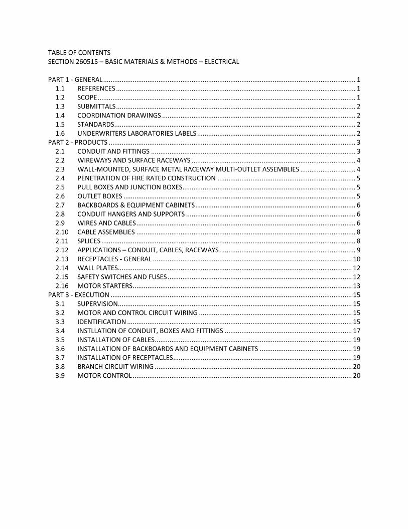
TABLE OF CONTENTS SECTION 260515 – BASIC MATERIALS & METHODS – ELECTRICAL PART 1 - GENERAL ......................................................................................................................................... 1
1.1 REFERENCES .................................................................................................................................. 1 1.2 SCOPE ............................................................................................................................................ 1 1.3 SUBMITTALS .................................................................................................................................. 2 1.4 COORDINATION DRAWINGS ......................................................................................................... 2 1.5 STANDARDS ................................................................................................................................... 2 1.6 UNDERWRITERS LABORATORIES LABELS ...................................................................................... 2
PART 2 - PRODUCTS ...................................................................................................................................... 3 2.1 CONDUIT AND FITTINGS ............................................................................................................... 3 2.2 WIREWAYS AND SURFACE RACEWAYS ......................................................................................... 4 2.3 WALL-MOUNTED, SURFACE METAL RACEWAY MULTI-OUTLET ASSEMBLIES .............................. 4 2.4 PENETRATION OF FIRE RATED CONSTRUCTION ........................................................................... 5 2.5 PULL BOXES AND JUNCTION BOXES .............................................................................................. 5 2.6 OUTLET BOXES .............................................................................................................................. 5 2.7 BACKBOARDS & EQUIPMENT CABINETS ....................................................................................... 6 2.8 CONDUIT HANGERS AND SUPPORTS ............................................................................................ 6 2.9 WIRES AND CABLES ....................................................................................................................... 6 2.10 CABLE ASSEMBLIES ....................................................................................................................... 8 2.11 SPLICES .......................................................................................................................................... 8 2.12 APPLICATIONS – CONDUIT, CABLES, RACEWAYS .......................................................................... 9 2.13 RECEPTACLES - GENERAL ............................................................................................................ 10 2.14 WALL PLATES ............................................................................................................................... 12 2.15 SAFETY SWITCHES AND FUSES .................................................................................................... 12 2.16 MOTOR STARTERS ....................................................................................................................... 13
PART 3 - EXECUTION ................................................................................................................................... 15 3.1 SUPERVISION ............................................................................................................................... 15 3.2 MOTOR AND CONTROL CIRCUIT WIRING ................................................................................... 15 3.3 IDENTIFICATION .......................................................................................................................... 15 3.4 INSTLLATION OF CONDUIT, BOXES AND FITTINGS ..................................................................... 17 3.5 INSTALLATION OF CABLES ........................................................................................................... 19 3.6 INSTALLATION OF BACKBOARDS AND EQUIPMENT CABINETS .................................................. 19 3.7 INSTALLATION OF RECEPTACLES ................................................................................................. 19 3.8 BRANCH CIRCUIT WIRING ........................................................................................................... 20 3.9 MOTOR CONTROL ....................................................................................................................... 20

SECTION 260515 BASIC MATERIALS & METHODS - ELECTRICAL PAGE 1 OF 20
PROJECT NO. 21MIL21501 ORGANIZATIONAL STORAGE BUILDING BOILER REPLACEMENT AND UST REMOVAL TRACKING NO. BN 14-001 BRANFORD ARMORY 10/28/2021 BID DOCUMENTS BRANFORD, CT
SECTION 260515 - BASIC MATERIALS & METHODS - ELECTRICAL
PART 1 - GENERAL
1.1 REFERENCES
A. This Section covers the specification of basic materials and methods for electrical work. Refer to Section – COMMON WORK RESULTS FOR ELECTRICAL WORK, GENERAL CONDITIONS, SUPPLEMENTARY CONDITIONS, applicable sections of DIVISION 1, and all other project instructions for other requirements.
1.2 SCOPE
A. Provide labor, materials, services, equipment and transportation necessary for complete and operational electrical systems as indicated on Contract Drawings and specified herein.
B. Interface with work of Mechanical Trades (Divisions 21, 22, & 23): 1. Division 26 is responsible to supply disconnects, starters and motor controls NOT
supplied integral to equipment provided under other divisions, unless otherwise noted. 2. Variable Frequency Drives (VFD) for control of motors which are integral to packaged
equipment supplied under other Divisions will be supplied by that Division. 3. Variable Frequency Drives (VFD) will be provided by Division 23, unless otherwise noted. 4. Division 26 is responsible for all power wiring to and from Disconnect Switches, Motor
Starters (including VFD’s), and Motors, unless otherwise noted. 5. A source of power to feed mechanical control panels for Building Management (BMS,
DDC, etc.) systems is to be made available by Division 26. Line voltage wiring from power source (breaker in panel) to control panels is to be provided by Mechanical Trade where wiring/homerun has not been indicated elsewhere on Contract Drawings. Coordinate with Division 23 Section, HVAC INSTRUMENTATION AND CONTROLS.
C. This section includes but is not limited to the following: 1. Conduit, cable and fittings 2. Pull boxes and junction boxes 3. Outlet boxes 4. Surface raceways and multi-outlet assemblies 5. Backboards and equipment cabinets 6. Conduit hangers and supports 7. Wires and cables 8. Splices 9. Receptacles 10. Wall plates 11. Timeclocks 12. Safety switches and fuses
SECTION 260515 BASIC MATERIALS & METHODS - ELECTRICAL PAGE 2 OF 20
PROJECT NO. 21MIL21501 ORGANIZATIONAL STORAGE BUILDING BOILER REPLACEMENT AND UST REMOVAL TRACKING NO. BN 14-001 BRANFORD ARMORY 10/28/2021 BID DOCUMENTS BRANFORD, CT
13. Motor starters 14. Labeling and identification
1.3 SUBMITTALS
A. Submit, for review, list of manufacturers and grade or type of material proposed, including wire, wiring devices, terminating systems, connectors, conduit, wireway and fittings. Submit samples if requested.
B. Submit for review shop drawings for all equipment and materials specified under this Section.
C. Prior to final inspection, submit test reports to Engineer for review.
D. Upon completion of job, furnish reproducible copies of wiring and interconnection diagrams required for clear and permanent record of interconnected equipment, such as alarms and annunciator panels.
1.4 COORDINATION DRAWINGS
A. Refer to Section, PROJECT COORDINATION AND COORDINATION DRAWINGS in this Division.
1.5 STANDARDS
A. All work shall conform to following standards: 1. NEMA Standards. 2. ANSI Standard CI: National Electrical Code (NFPA 70). 3. ANSI Standard C50: Rotating Electrical Machinery. 4. ANSI Standard C501-1: Construction and guide for selection, installation and use of
electric motors. 5. ANSI Standard C52.1: Motors and generators (NEMA MG1). 6. ADA: Americans with Disabilities Act 7. Refer to Section COMMON WORK RESULTS for additional requirements
1.6 UNDERWRITERS LABORATORIES LABELS
A. Equipment, materials and components, for which there are listings in UL Product Directories, shall bear UL labels.
SECTION 260515 BASIC MATERIALS & METHODS - ELECTRICAL PAGE 3 OF 20
PROJECT NO. 21MIL21501 ORGANIZATIONAL STORAGE BUILDING BOILER REPLACEMENT AND UST REMOVAL TRACKING NO. BN 14-001 BRANFORD ARMORY 10/28/2021 BID DOCUMENTS BRANFORD, CT
PART 2 - PRODUCTS
2.1 CONDUIT AND FITTINGS
A. The generic term “Conduit” when reference is made to method of installation and fittings, includes all types of conduit and EMT.
B. Rigid conduit (RMC) shall be UL listed, hot dipped galvanized steel with full cut hot dipped galvanized NPT threads. RMC shall be chromated on all surfaces for corrosion and abrasion protection. Connectors and couplings shall be galvanized steel threaded type listed for RMC use.
C. Intermediate metal conduit (IMC) shall be UL listed, hot galvanized steel with full cut hot galvanized NPT threads and factory-applied interior coating or lining for ease in pulling wires. Connectors and couplings shall be galvanized steel threaded type listed for IMC use.
D. Electric metallic tubing (EMT) shall be UL listed, hot galvanized steel with factory-applied interior coating or lining for ease in pulling wires. Connectors and couplings shall be galvanized steel, either compression type or heavy-duty set screw-type, listed for EMT use. Indent or crimp-type connectors are NOT allowed.
E. Non-metallic conduit (NMC) shall be rigid PVC, heavy-wall Schedule 40, UL rated, acceptable equivalent to Carlon "Type 40". Where non-metallic conduit is installed below paved areas, conduit shall be rigid PVC, heavy wall Schedule 80, UL rated and of same manufacturer as the Schedule 40 conduit.
F. Flexible metal conduit (FMC) shall be UL listed, single strip, spirally wound, corrosion-resistant, galvanized steel acceptable equivalent to Liquatite "Type BR". Use galvanized steel fittings and clamps listed for FMC use.
G. Liquid tight flexible metal conduit (LFMC) shall be UL listed, with a flexible core of single spiral wound strip of hot dipped galvanized steel and a liquid-tight jacket of flame-retardant, sun/oil/acid-resistant flexible PVC: Acceptable equivalent to Liquatite "Type LA". Connectors and couplings shall be zinc-plated malleable iron or steel, with engagement inspection window, locknut and sealing ring; liquid-, oil-, and rain-tight; suitable for wet locations; listed for LFMC use: acceptable equivalent to O-Z/Gedney "Type 4Q". 1. Blue Type LA liquid-tight flexible metal conduit (LFMC) shall be used for all wiring
beneath raised floor. 2. Grey/Tan Type LA liquid-tight flexible metal conduit (LFMC) shall be used for final
connections to vibrating equipment.
H. Minimum Conduit and EMT size: 3/4”
I. Minimum Flexible Metal Conduit Size: 1/2”
SECTION 260515 BASIC MATERIALS & METHODS - ELECTRICAL PAGE 4 OF 20
PROJECT NO. 21MIL21501 ORGANIZATIONAL STORAGE BUILDING BOILER REPLACEMENT AND UST REMOVAL TRACKING NO. BN 14-001 BRANFORD ARMORY 10/28/2021 BID DOCUMENTS BRANFORD, CT
J. Special Fittings 1. Where conduit penetrates air handling unit walls or plenums and in hazardous
(classified) locations: provide sealing fittings acceptable equivalent to Crouse-Hinds "EYS Series".
2. Where conduit penetrates waterproof foundation, floor or roof: provide through-wall seals acceptable equivalent to O.Z./Gedney “Type CSMI” on each side of existing walls and O.Z./Gedney “Type FSK” on new walls.
3. Where conduit from underground distribution system enters building, provide cable terminators acceptable equivalent to O.Z./Gedney "Type CSB".
4. Where conduit is exposed at building expansion joint: provide expansion fittings acceptable equivalent to O.Z./Gedney "Type EX" or "Type EXE".
K. Where conduit is in concrete at building expansion or seismic joint and where conduit is exposed at seismic joint: provide expansion/deflection fittings acceptable equivalent to O.Z./Gedney "Type DX".
2.2 WIREWAYS AND SURFACE RACEWAYS
A. Wireways shall be steel, UL listed, with hinged or screwed covers by Lee Products, Keystone or acceptable equivalent. 1. Minimum Wireway Size: 4” x 4”
B. Surface raceways shall be UL labeled, steel or aluminum with finish as scheduled or selected by Engineer. Refer to schedule on drawings for basis of design, sizes, and types. Acceptable manufacturers shall be Hubbell or Wiremold. 1. Surface raceways shall be Series 2000 as required and/or noted.
2.3 WALL-MOUNTED, SURFACE METAL RACEWAY MULTI-OUTLET ASSEMBLIES
A. Performance Criteria: 1. Description: Two-piece or three-piece surface metal raceway, field assembled and wired
or with factory-wired multi-outlet harness, including outlets. 2. Standards:
a. UL Listed for exposed power, communications and/or data raceway and fittings. b. Provide separate paths for management of telecommunications and power
cables.
B. Source Limitations: Obtain products from single manufacturer designed for use as complete, matching assembly of raceways, receptacles, and switches.
C. Wall-Mounted, Surface Metal Raceway Power Multi-Outlet Assembly: 1. Two-piece surface metal raceway for power outlets. Steel, with manufacturer's standard
finish.
SECTION 260515 BASIC MATERIALS & METHODS - ELECTRICAL PAGE 5 OF 20
PROJECT NO. 21MIL21501 ORGANIZATIONAL STORAGE BUILDING BOILER REPLACEMENT AND UST REMOVAL TRACKING NO. BN 14-001 BRANFORD ARMORY 10/28/2021 BID DOCUMENTS BRANFORD, CT
2. Receptacles used with multi-outlet assembly shall be 20A, duplex type unless noted otherwise.
3. Power Outlet Spacing shall be as indicated in Surface Raceway Schedule. 4. Wiring shall be as indicated in Surface Raceway Schedule.
D. Wall-Mounted, Surface Metal Raceway Power and Communications Multi-Outlet Assembly: 1. Multi-piece surface metal raceway for power and communications/data outlets with
separate raceway channels for power and communications wiring and separate covers for each channel. Steel, with manufacturer's standard finish.
2. Receptacles used with multi-outlet assembly shall be 20A, duplex type unless noted otherwise.
3. Power Outlet Spacing shall be as indicated in Surface Raceway Schedule. 4. Wiring shall be as indicated in Surface Raceway Schedule.
2.4 PENETRATION OF FIRE RATED CONSTRUCTION
A. Refer to Section 260544 for specific requirements for penetrations of fire rated construction.
2.5 PULL BOXES AND JUNCTION BOXES
A. Boxes shall be heavy duty, stamped steel with covers attached by screws. Provide locknuts for conduit size to which boxes are connected. In finished areas, boxes shall have neatly mitered frame and flush steel cover screwed to the frame.
B. Boxes shall be sized according to NEC.
C. Boxes shall be flush mounted where installed with concealed conduit, and surface mounted elsewhere.
D. Low Voltage Boxes: refer to Section LOW VOLTAGE RACEWAY DISTRIBUTION in this Division.
2.6 OUTLET BOXES
A. Outlet boxes for light fixtures in concrete walls or slabs shall be 4” octagonal mud boxes, not less than 2-1/2” deep; other outlet boxes shall be 4” octagonal boxes not less than 2-1/8” deep. Include fixture studs where required.
B. Switch and receptacle outlet boxes in masonry walls and partitions where wiring is concealed shall be standard 4” square, 2-1/8” deep, galvanized boxes with extension cover for the particular device they will receive. 1. Use plaster extension not less than 1/2” deep for boxes installed in plastered or gypsum
board walls or cast in concrete. Actual depth of extension ring shall be coordinated with wall finishes to ensure they are flush, or within 1/4”, of the finished surface as dictated by the NEC.
SECTION 260515 BASIC MATERIALS & METHODS - ELECTRICAL PAGE 6 OF 20
PROJECT NO. 21MIL21501 ORGANIZATIONAL STORAGE BUILDING BOILER REPLACEMENT AND UST REMOVAL TRACKING NO. BN 14-001 BRANFORD ARMORY 10/28/2021 BID DOCUMENTS BRANFORD, CT
2. Use 1-1/2” deep square corner tile wall extension for boxes installed in tiles, exposed brick or exposed block masonry walls.
C. Where conduit is exposed: switch outlet boxes, plug outlet boxes and fixture outlet boxes shall be acceptable equivalent to Crouse-Hinds "Type FD", with covers to fit devices use.
D. Low Voltage Device Boxes: refer to Section, LOW VOLTAGE RACEWAY DISTRIBUTION in this Division.
2.7 BACKBOARDS & EQUIPMENT CABINETS
A. Backboards shall be 3/4” fire-rated plywood painted on all sides before installation, stamp/cable indicating “fire-rating” shall not be painted over. Backboards shall be 3/4” Type A-C plywood painted on all sides before installation. Paint shall be one coat primer and two coats latex, intumescent, fire-retardant paint acceptable equivalent to Benjamin-Moore “Insul-X” or Sherwin-Williams “FireTex FX5120”. Backboards shall be used for mounting panelboards, grouped switches, starters and other equipment.
B. Equipment cabinets shall be UL listed, sheet steel cabinet with hinged door with catch and lock; mounted on backboard. Cabinets shall be flush or surface-mounted, sized as required to suit equipment.
C. Refer to Section – LOW VOLTAGE RACEWAY DISTRIBUTION in this Division.
2.8 CONDUIT HANGERS AND SUPPORTS
A. Hangers, clips and accessories supporting conduit shall be UL listed.
B. Individual large conduits shall be supported by means of adjustable, malleable hangers of acceptable design placed on maximum 8’-0” centers. Individual small conduits may be held in place by one-hole malleable clips.
C. MC cable shall be supported by hangers of acceptable design placed on maximum 4’-0” centers. MC cable shall be supported within 12” of each fitting.
2.9 WIRES AND CABLES
A. Secondary conductors shall be new copper with 600 V code gauge insulation, conforming to NEC requirements, and shall be Type THHN/THWN, rated 75° wet location/90° dry location except as follows: 1. Type XHHW rated 75° wet location/90° dry location shall be used for conductors #3
AWG and larger. 2. Ground wires shall be as specified under Section, ELECTRICAL GROUNDING in this
Division, and in accordance with NEC.
SECTION 260515 BASIC MATERIALS & METHODS - ELECTRICAL PAGE 7 OF 20
PROJECT NO. 21MIL21501 ORGANIZATIONAL STORAGE BUILDING BOILER REPLACEMENT AND UST REMOVAL TRACKING NO. BN 14-001 BRANFORD ARMORY 10/28/2021 BID DOCUMENTS BRANFORD, CT
3. Type MI cable shall be used where 2-hour ratings are required or where specifically shown in the documents.
4. Type XHHW-2 with cross-linked polyethylene insulation and mineral filler shall be used for low leakage circuits (isolated power).
B. Feeders and branch circuit conductors located below slabs shall be Type THWN-2/XHHW-2, rated 90° for use in dry or wet locations unless noted otherwise.
C. Feeders and branch circuits located below grade shall be Type THWN-2/XHHW-2, rated 90° for use in dry or wet locations unless noted otherwise.
D. Feeders and branch circuit conductors located above grade and within buildings shall be Type THHN/XHHW for use in dry or damp locations unless noted otherwise.
E. When wire sizes are not shown on Contract Drawings, sizes shall be in accordance with NEC but no smaller than following: 1. Light and power wiring: #12 AWG. 2. Control wiring: #14 AWG. 3. Wiring and cable for alarm and signal systems: as recommended by equipment
manufacturer.
F. Miscellaneous cables and wires shall be new copper with 600 V code gauge insulation, conforming to NEC requirements as follows: 1. Type XF or SFF 150°C shall be used for fixture wiring. 2. Type TFE shall be used for high temperature applications. 3. All Variable Frequency Drives (VFD) and harmonic filters shall have VFD cables as
manufactured by Belden or equal for the following: a. Sizes #12 AWG - #2 AWG, 600 VAC, UL1277, TC-ER, (3) stranded tinned copper
conductors plus full-size insulated ground, overall Beldfoil plus 85% tinned copper braid shield, full size drain wire, XLPE insulated conductors, black PVC jacket, 1000V UL flexible motor supply cable. Belden #29502 – 29507.
b. Sizes #1AWG - #4/0 AWG – Provide symmetrical design with (3) stranded tinned copper conductors plus (3) symmetrical bare copper grounds, (2) spiral copper tape shields (100% coverage), XLPE insulation, black PVC jacket, 1000V UL flexible motor supply cable. Belden #29528- 29532.
c. Sizes 250kcmil, 350kcmil or 500kcmil, Belden #29533, 29534 or 29535.
G. All multi-purpose feeders and circuits shall include a full size neutral and separate insulated ground conductor. 1. All 277/120 VAC circuits shall include separate full sized neutral and insulated ground
conductors. Shared neutrals or ground conductors are not permitted.
H. Provide cable supports per NEC ARTICLE 300.19, acceptable equivalent to O.Z./Gedney "Type R" for large cables and Kellems "Grips" for bundles of smaller wires.
SECTION 260515 BASIC MATERIALS & METHODS - ELECTRICAL PAGE 8 OF 20
PROJECT NO. 21MIL21501 ORGANIZATIONAL STORAGE BUILDING BOILER REPLACEMENT AND UST REMOVAL TRACKING NO. BN 14-001 BRANFORD ARMORY 10/28/2021 BID DOCUMENTS BRANFORD, CT
2.10 CABLE ASSEMBLIES A. Type MC cable shall be UL listed, 600 V, 90°C rated, flexible metal encased multi-conductor
assembly; with cable sheath of interlocked galvanized steel strip, copper conductors with Code gauge THHN insulation, and internal green insulated ground: Acceptable equivalent to AFC "Type MC Tuff". Connectors and fittings shall be galvanized steel, threaded box connectors, listed for MC cable use. Cable sheath of interlocked aluminum is NOT acceptable. Use of MCAP (all-purpose) cable with built-in armor ground and internal un-insulated grounding conductor is NOT acceptable. Type MC cable shall NOT be used for homeruns.
B. Type MC Luminary cable shall be UL listed, 600 V, 90°C rated, flexible metal encased multi-conductor assembly; with cable sheath of interlocked galvanized steel strip, copper conductors with Code gauge THHN/THWN (Power and Neutral) TFN (Control) insulation, and internal green insulated ground: Acceptable equivalent to AFC Type MC Tuff Luminary Cable. Connectors and fittings shall be galvanized steel, threaded box connectors, listed for MC cable use. Cable sheath of interlocked aluminum is NOT acceptable. Use of MCAP (all-purpose) cable with built-in armor ground and internal un-insulated grounding conductor is NOT acceptable.
C. Type MC Luminary cable shall be UL listed, 600 V, 90°C rated, flexible metal encased multi-conductor assembly; with cable sheath of interlocked aluminum strip,, copper conductors with Code gauge THHN/THWN (Power and Neutral) TFN (Control) insulation, and internal green insulated ground: Acceptable equivalent to AFC Type MC Lite Luminary Cable. Connectors and fittings shall be galvanized steel, threaded box connectors, listed for MC cable use. Use of MCAP (all-purpose) cable with built-in armor ground and internal un-insulated grounding conductor is NOT acceptable.
D. Type MC “Super Neutral” cable shall be UL listed, 600 V, 90°C rated, flexible metal encased multi-conductor assembly; with cable sheath of interlocked galvanized steel strip, copper conductors with Code gauge THHN/THWN (Power and Neutral) TFN (Control) insulation, and internal green insulated ground: Acceptable equivalent to AFC Type MC Super Neutral Cable. Cable assembly shall be comprised of 1 phase conductor per leg, 1 oversized neutral conductor, 1 ground conductor. Connectors and fittings shall be galvanized steel, threaded box connectors, listed for MC cable use. Cable sheath of interlocked aluminum is NOT acceptable. Use of MCAP (all-purpose) cable with built-in armor ground and internal un-insulated grounding conductor is NOT acceptable.
2.11 SPLICES
A. Splices for #10 or smaller wires shall be made with UL approved solderless connectors: spring type acceptable equivalent to Minnesota Mining and Manufacturing Company "Scotchlock"; or crimp-type acceptable equivalent to Thomas & Betts "Sta-Kon".
SECTION 260515 BASIC MATERIALS & METHODS - ELECTRICAL PAGE 9 OF 20
PROJECT NO. 21MIL21501 ORGANIZATIONAL STORAGE BUILDING BOILER REPLACEMENT AND UST REMOVAL TRACKING NO. BN 14-001 BRANFORD ARMORY 10/28/2021 BID DOCUMENTS BRANFORD, CT
B. Splices, cable taps and terminals for #8 and larger shall be made with UL approved compression connectors: compression taps acceptable equivalent to Thomas & Betts "Colored Keyed" "C" taps applied with special tools according to manufacturer's recommendations; or bolted pressure connectors, bronze or copper construction, by Thomas & Betts, Burndy or acceptable equivalent.
2.12 APPLICATIONS – CONDUIT, CABLES, RACEWAYS
A. RMC: buried in floor slabs, in concrete walls, concealed in exterior masonry walls, wiring in fire pump rooms, hazardous locations, applications above 600 V.
B. IMC: where noted on drawings.
C. EMT: unless otherwise noted: 1. Feeders 2. Power wiring in mechanical rooms 3. Wiring for fire alarm systems 4. Wiring for emergency and exit lighting 5. Wiring for emergency communication, security and alarm systems 6. Branch circuits 7. Control wiring, including work done under Division 23 8. Wiring above non-accessible ceilings
D. LFMC: final connections to motors and equipment-mounted controls from minimum of 18” to maximum of 6 feet lengths.
E. FMC: light fixture whips above accessible ceilings, except not in damp or wet locations and limited to maximum lengths of 6 feet.
F. NMC: sleeves through interior walls, below slab-on-grade, electrical ductbanks, and below grade unless otherwise noted.
G. MC Cable: Galvanized steel jacket cable only, aluminum jacket will not be accepted. 1. Light fixture whips above accessible ceilings, except not in damp or wet locations and
limited to maximum lengths of 6 feet. Leave sufficient slack for future removal or servicing of fixtures in finished ceiling.
2. MC Cable shall not be used in wiring of Life Safety or Critical circuits.
H. MC Cable: Galvanized steel jacket, aluminum jacket will not be accepted. 1. Light fixture whips above accessible ceilings, except not in damp or wet locations and
limited to maximum lengths of 6 feet. Leave sufficient slack for future removal or servicing of fixtures in finished ceiling.
2. MC cable in interior walls constructed of metal studs and gypsum wall board.
SECTION 260515 BASIC MATERIALS & METHODS - ELECTRICAL PAGE 10 OF 20
PROJECT NO. 21MIL21501 ORGANIZATIONAL STORAGE BUILDING BOILER REPLACEMENT AND UST REMOVAL TRACKING NO. BN 14-001 BRANFORD ARMORY 10/28/2021 BID DOCUMENTS BRANFORD, CT
3. Where MC cable is allowed, EMT shall be installed from electrical panels to a collector box and from the collector box to the first device in each circuit or to a separate junction box installed in an accessible ceiling space directly above the first device.
4. Self-grounding type MC cables assemblies shall NOT be used. 5. Provide with a separate dedicated insulated ground wire, AFC Type MC/IG or equal
where an isolated, redundant, or dedicated ground is required. 6. Record the location of all junction boxes feeding wall devices on the as-built drawings. 7. MC Cable shall not be used in wiring of Life Safety circuits. 8. MC-FPLP cable may only be used in wiring of the fire alarm system when specified as
allowed elsewhere in this specification.
I. MC Luminary Cable: Galvanized steel jacket cable only, aluminum jacket will not be accepted. 1. 2. Light fixture wiring with integral control wiring, except not in damp or wet locations.
Leave sufficient slack for future removal or servicing of fixtures in finished ceiling. 3. MC Luminary Cable shall not be used in wiring of Life Safety circuits.
K. In any case not specifically covered, rigid conduit shall be used unless otherwise approved by Engineer.
L. EMT is NOT permitted as a substitute for rigid conduit; MC is NOT permitted as a substitute for flexible metal conduit.
M. AC (BX) cable shall NOT be used.
2.13 RECEPTACLES - GENERAL
A. Receptacles shall be ivory unless noted otherwise or as directed by Engineer. Receptacles wired to emergency circuits shall be red.
B. Receptacles shall be acceptable equivalent to manufacturer's specification grade listed below and shall include grounding screw terminal. Acceptable manufacturers are Hubbell, Leviton and Pass & Seymour. 1. Receptacles for general use (120 V): 20A, duplex-grounding type with finder-face,
Hubbell #5362. 2. Safety type receptacles: 20A, tamper-resistant, duplex-grounding type with smooth
face, that prohibit single conductive objects from making contact with energized device contacts by the use of an internal mechanism that opens rotating trap doors that enable a second mechanism to open once contact is made by both inserted blades, Hubbell #BR20TR.
3. Plugload “dual” controllable receptacles (120V): 20A, duplex-grounding type, decorator face with printed ink identification marking, fully controlled, color to be unique color, (grey unless noted otherwise) other than that used for general use receptacles, (blue and red shall not be used), Hubbell #DR20C2* or P&S #26352CD*. Unless otherwise indicated, “dual” controllable type shall be used.
SECTION 260515 BASIC MATERIALS & METHODS - ELECTRICAL PAGE 11 OF 20
PROJECT NO. 21MIL21501 ORGANIZATIONAL STORAGE BUILDING BOILER REPLACEMENT AND UST REMOVAL TRACKING NO. BN 14-001 BRANFORD ARMORY 10/28/2021 BID DOCUMENTS BRANFORD, CT
4. Plugload “half” controllable receptacles (120V): 20A, duplex-grounding type, decorator face with printed ink identification marking, half controlled, color shall match general use receptacles (blue and red shall not be used), Hubbell #DR20C1* or P&S #26352CH*.
5. USB charger/Duplex receptacles (120V): 20A, duplex-grounding type, decorator face with (2) USB ports with minimum 3Amp, 5VDC, class 2.0 capacity and green LED indicator to show USB power available, color shall match general use receptacles Hubbell #USB20X2*.
6. USB charger station: decorator face with (4) USB ports with minimum 3Amp, 5VDC, class 2.0 capacity and green LED indicator to show USB power available, color shall match general use receptacles Hubbell #USB20X2*.
7. Receptacles for exterior locations: weatherproof Crouse-Hinds FS box with Hubbell "Rayntite" (raintight while in use) aluminum pad-lockable enclosure and with GFCI duplex receptacles.
8. Isolated ground receptacles: 20A, orange, duplex-grounding type with finder-face; Hubbell #IG5362.
9. Surge suppression/isolated ground receptacles: 20A, blue, duplex-grounding type with smooth face; Hubbell #IG5362SA.
10. Special two- and three-pole, 250V receptacles and other receptacles required for special equipment: as required to suit equipment; in general, based on Hubbell "HBL9300 Series" for straight blade configuration with appropriate line caps and Hubbell "HBL2300 Series" with safety-shroud for twist-lock configuration with appropriate line caps.
11. Single twist-locking receptacles: 120V-1Ø, 20A, and 30A ratings; comply with NEMA WD1 and NEMA WD6 in the following configurations: L5-20R and L5-30R, Hubbell "HBL2300 Series" with safety-shroud, and appropriate line caps.
12. Single twist-locking receptacles: 250V-1Ø, 20A, and 30A ratings; comply with NEMA WD1 and NEMA WD6 in the following configurations: L6-20R and L6-30R, Hubbell "HBL2300 Series" with safety-shroud, and appropriate line caps.
13. Single twist-locking receptacles: 125/250V-3Ø, 20A and 30A ratings; comply with NEMA WD1 and NEMA WD6 in the following configurations: L14-20R, Hubbell "HBL2400 Series" with safety-shroud, and appropriate line caps and L14-30R, Hubbell "HBL2700 Series" with safety-shroud, and appropriate line caps.
14. Duplex floor receptacles: as specified for general use, for use in floor boxes and in poke-through fittings.
C. Ground Fault Circuit Interrupter branch breakers for personnel protection shall be 20A single-pole molded case circuit breakers with neutral pigtail; shall sense current unbalance between branch circuit and its neutral and shall trip upon unbalance; shall be Class "A", 5 mA sensitivity; and shall be by same manufacturer as panelboards.
D. Ground fault circuit interrupter (GFI) receptacles, shall be NEMA 5-20R, Class “A”, 5 mA sensitivity; self-testing, tamper resistant, duplex-grounding type with smooth face, ground fault indicator and power indicating LED; Hubbell #GFRST20 Series, or acceptable equivalent.
SECTION 260515 BASIC MATERIALS & METHODS - ELECTRICAL PAGE 12 OF 20
PROJECT NO. 21MIL21501 ORGANIZATIONAL STORAGE BUILDING BOILER REPLACEMENT AND UST REMOVAL TRACKING NO. BN 14-001 BRANFORD ARMORY 10/28/2021 BID DOCUMENTS BRANFORD, CT
E. Ground fault circuit interrupter (GFI) receptacles, shall be NEMA 5-20R, Class “A”, 5 mA sensitivity; self-testing, tamper resistant, weather-resistant, duplex-grounding type with smooth face, ground fault indicator and power indicating LED; Hubbell #GFWRST20 Series, or acceptable equivalent.
F. Arc-fault circuit interrupter (AFCI) receptacles shall be NEMA 5-20R, duplex receptacle, tamper resistant, duplex-grounding type. 20A feed-through protection. Push-to-test and reset push button on face. Equal to Hubbell #AFR20TR or Leviton #AFTR2.
G. Modular wiring connectors are not allowed unless specifically indicated otherwise.
2.14 WALL PLATES
A. Wall plates for switches, receptacles and clock outlets where wiring is concealed shall be Ivory, high impact resistant thermoplastic, specification grade, with blank plates on unused flush boxes: Acceptable Manufacturers are Hubbell, Leviton and Pass & Seymour. 1. Plates for devices on emergency circuits shall be red with "EMERGENCY" hot-stamped in
1/4” letters.
B. Plates on exposed conduit boxes shall be galvanized zinc-coated with rounded edges.
C. Plates for special receptacles, other than 120 V, shall be engraved to indicate the voltage. Cover on three phase switches shall read "3 PHASE".
D. Wherever switches are grouped, they shall be ganged and provided with one-piece gang plates to suit installation.
E. Provide blank plates for unused telephone and data outlet boxes.
2.15 SAFETY SWITCHES AND FUSES
A. Work of this Division shall include: 1. Furnishing and installing an appropriate fusible safety switch for each motor, unless
otherwise noted. 2. Installation of safety switches furnished under DIVISION 23, MECHANICAL WORK. 3. Fuses for safety switches. 4. Power wiring to and from safety switches.
B. Disconnect Switches for Motor Starters 1. Provide disconnect switch ahead of each magnetic motor starter. The disconnect switch
shall be located in sight of the controller location and not more than 50' apart. 2. Where more than one motor is connected to single branch feeder, provide fused
disconnect switch for each motor, even if within sight of feeder branch breaker.
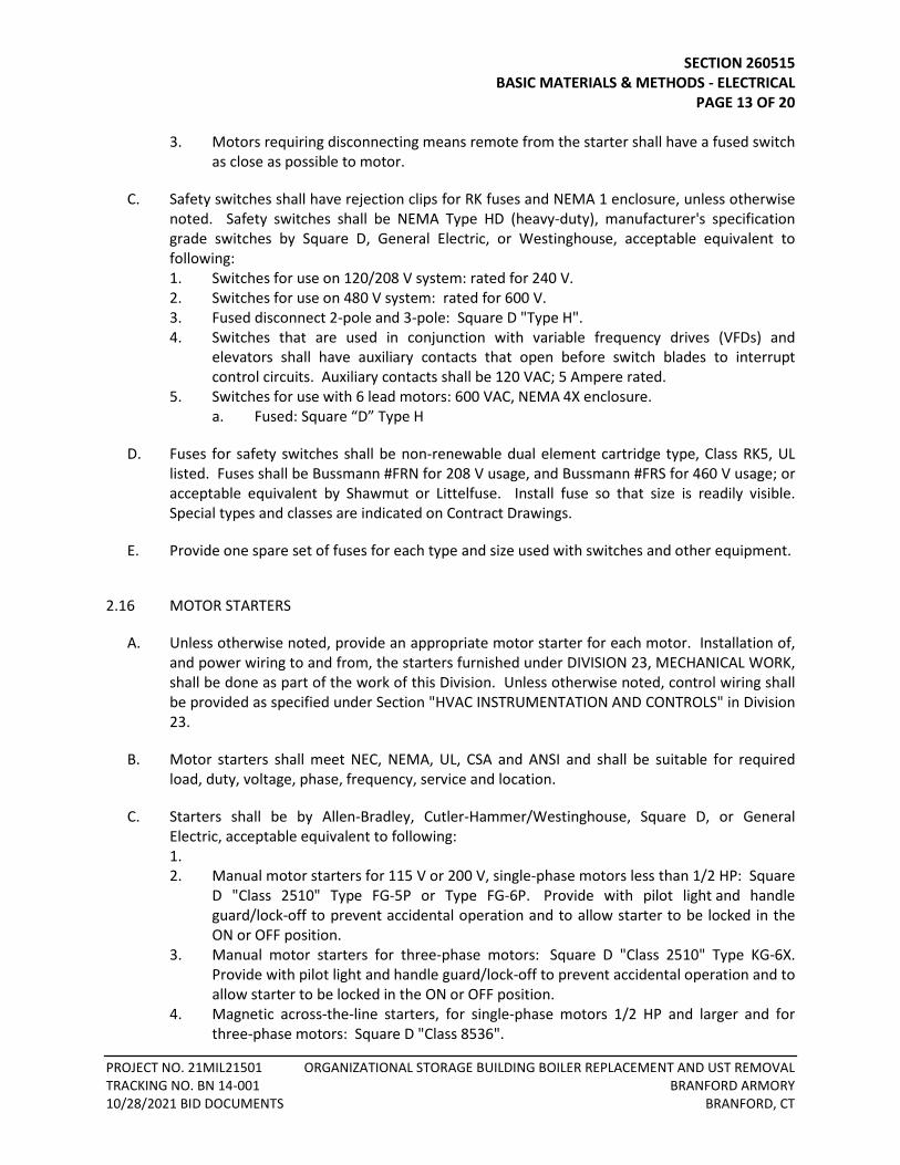
SECTION 260515 BASIC MATERIALS & METHODS - ELECTRICAL PAGE 13 OF 20
PROJECT NO. 21MIL21501 ORGANIZATIONAL STORAGE BUILDING BOILER REPLACEMENT AND UST REMOVAL TRACKING NO. BN 14-001 BRANFORD ARMORY 10/28/2021 BID DOCUMENTS BRANFORD, CT
3. Motors requiring disconnecting means remote from the starter shall have a fused switch as close as possible to motor.
C. Safety switches shall have rejection clips for RK fuses and NEMA 1 enclosure, unless otherwise noted. Safety switches shall be NEMA Type HD (heavy-duty), manufacturer's specification grade switches by Square D, General Electric, or Westinghouse, acceptable equivalent to following: 1. Switches for use on 120/208 V system: rated for 240 V. 2. Switches for use on 480 V system: rated for 600 V. 3. Fused disconnect 2-pole and 3-pole: Square D "Type H". 4. Switches that are used in conjunction with variable frequency drives (VFDs) and
elevators shall have auxiliary contacts that open before switch blades to interrupt control circuits. Auxiliary contacts shall be 120 VAC; 5 Ampere rated.
5. Switches for use with 6 lead motors: 600 VAC, NEMA 4X enclosure. a. Fused: Square “D” Type H
D. Fuses for safety switches shall be non-renewable dual element cartridge type, Class RK5, UL listed. Fuses shall be Bussmann #FRN for 208 V usage, and Bussmann #FRS for 460 V usage; or acceptable equivalent by Shawmut or Littelfuse. Install fuse so that size is readily visible. Special types and classes are indicated on Contract Drawings.
E. Provide one spare set of fuses for each type and size used with switches and other equipment.
2.16 MOTOR STARTERS
A. Unless otherwise noted, provide an appropriate motor starter for each motor. Installation of, and power wiring to and from, the starters furnished under DIVISION 23, MECHANICAL WORK, shall be done as part of the work of this Division. Unless otherwise noted, control wiring shall be provided as specified under Section "HVAC INSTRUMENTATION AND CONTROLS" in Division 23.
B. Motor starters shall meet NEC, NEMA, UL, CSA and ANSI and shall be suitable for required load, duty, voltage, phase, frequency, service and location.
C. Starters shall be by Allen-Bradley, Cutler-Hammer/Westinghouse, Square D, or General Electric, acceptable equivalent to following: 1. 2. Manual motor starters for 115 V or 200 V, single-phase motors less than 1/2 HP: Square
D "Class 2510" Type FG-5P or Type FG-6P. Provide with pilot light and handle guard/lock-off to prevent accidental operation and to allow starter to be locked in the ON or OFF position.
3. Manual motor starters for three-phase motors: Square D "Class 2510" Type KG-6X. Provide with pilot light and handle guard/lock-off to prevent accidental operation and to allow starter to be locked in the ON or OFF position.
4. Magnetic across-the-line starters, for single-phase motors 1/2 HP and larger and for three-phase motors: Square D "Class 8536".
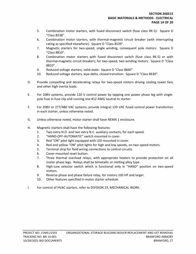
SECTION 260515 BASIC MATERIALS & METHODS - ELECTRICAL PAGE 14 OF 20
PROJECT NO. 21MIL21501 ORGANIZATIONAL STORAGE BUILDING BOILER REPLACEMENT AND UST REMOVAL TRACKING NO. BN 14-001 BRANFORD ARMORY 10/28/2021 BID DOCUMENTS BRANFORD, CT
5. Combination motor starters, with fused disconnect switch (fuse class RK-5): Square D "Class 8538".
6. Combination motor starters, with thermal-magnetic circuit breaker (with interrupting rating as specified elsewhere): Square D "Class 8539".
7. Magnetic starters for two-speed, single winding, consequent pole motors: Square D "Class 8810".
8. Combination motor starters with fused disconnect switch (fuse class RK-5) or with thermal-magnetic circuit breakers; for two-speed, two winding motors: Square D "Class 8810".
9. Reduced voltage starters, solid-state: Square D "Class 8660". 10. Reduced voltage starters, wye-delta, closed transition: Square D "Class 8630".
D. Provide compelling and decelerating relays for two-speed motors driving cooling tower fans and other high inertia loads.
E. For 208V systems, provide 120 V control power by tapping one power phase leg with single-pole fuse in fuse clip and running one #12 AWG neutral to starter.
F. For 208V or 277/480 VAC systems, provide integral 120 VAC fused control power transformer in each starter, unless otherwise noted.
G. Unless otherwise noted, motor starter shall have NEMA 1 enclosure.
H. Magnetic starters shall have the following features: 1. Two extra N.O. and two extra N.C. auxiliary contacts, for each speed. 2. "HAND-OFF-AUTOMATIC" switch mounted in cover. 3. Red "ON" pilot light equipped with LED mounted in cover. 4. Red and yellow "ON" pilot lights for high and low speeds, on two-speed motors. 5. Terminal strip for field wiring connections to control circuits. 6. Cover-mounted reset button. 7. Three thermal overload relays, with appropriate heaters to provide protection on all
motor phase legs. Relays shall be bimetallic or melting alloy type. 8. High-Low selector switch which is functional only in "HAND" position on two-speed
motors. 9. Reverse phase and phase failure relay, for motors 100 HP and larger. 10. Other features specified in motor starter schedule.
I. For control of HVAC starters, refer to DIVISION 23, MECHANICAL WORK.
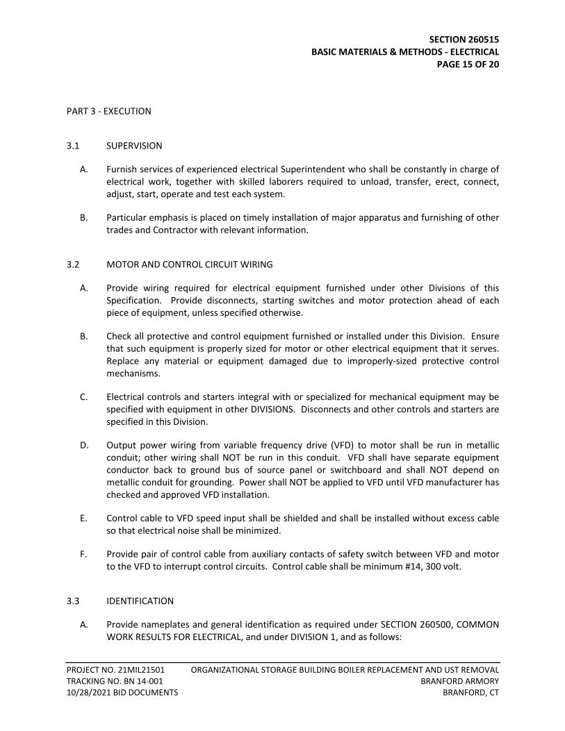
SECTION 260515 BASIC MATERIALS & METHODS - ELECTRICAL PAGE 15 OF 20
PROJECT NO. 21MIL21501 ORGANIZATIONAL STORAGE BUILDING BOILER REPLACEMENT AND UST REMOVAL TRACKING NO. BN 14-001 BRANFORD ARMORY 10/28/2021 BID DOCUMENTS BRANFORD, CT
PART 3 - EXECUTION
3.1 SUPERVISION
A. Furnish services of experienced electrical Superintendent who shall be constantly in charge of electrical work, together with skilled laborers required to unload, transfer, erect, connect, adjust, start, operate and test each system.
B. Particular emphasis is placed on timely installation of major apparatus and furnishing of other trades and Contractor with relevant information.
3.2 MOTOR AND CONTROL CIRCUIT WIRING
A. Provide wiring required for electrical equipment furnished under other Divisions of this Specification. Provide disconnects, starting switches and motor protection ahead of each piece of equipment, unless specified otherwise.
B. Check all protective and control equipment furnished or installed under this Division. Ensure that such equipment is properly sized for motor or other electrical equipment that it serves. Replace any material or equipment damaged due to improperly-sized protective control mechanisms.
C. Electrical controls and starters integral with or specialized for mechanical equipment may be specified with equipment in other DIVISIONS. Disconnects and other controls and starters are specified in this Division.
D. Output power wiring from variable frequency drive (VFD) to motor shall be run in metallic conduit; other wiring shall NOT be run in this conduit. VFD shall have separate equipment conductor back to ground bus of source panel or switchboard and shall NOT depend on metallic conduit for grounding. Power shall NOT be applied to VFD until VFD manufacturer has checked and approved VFD installation.
E. Control cable to VFD speed input shall be shielded and shall be installed without excess cable so that electrical noise shall be minimized.
F. Provide pair of control cable from auxiliary contacts of safety switch between VFD and motor to the VFD to interrupt control circuits. Control cable shall be minimum #14, 300 volt.
3.3 IDENTIFICATION
A. Provide nameplates and general identification as required under SECTION 260500, COMMON WORK RESULTS FOR ELECTRICAL, and under DIVISION 1, and as follows:
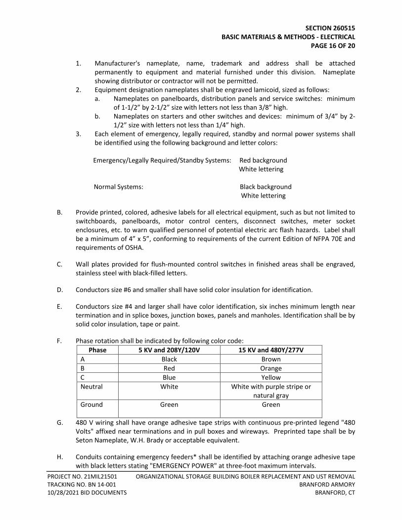
SECTION 260515 BASIC MATERIALS & METHODS - ELECTRICAL PAGE 16 OF 20
PROJECT NO. 21MIL21501 ORGANIZATIONAL STORAGE BUILDING BOILER REPLACEMENT AND UST REMOVAL TRACKING NO. BN 14-001 BRANFORD ARMORY 10/28/2021 BID DOCUMENTS BRANFORD, CT
1. Manufacturer's nameplate, name, trademark and address shall be attached permanently to equipment and material furnished under this division. Nameplate showing distributor or contractor will not be permitted.
2. Equipment designation nameplates shall be engraved lamicoid, sized as follows: a. Nameplates on panelboards, distribution panels and service switches: minimum
of 1-1/2” by 2-1/2” size with letters not less than 3/8” high. b. Nameplates on starters and other switches and devices: minimum of 3/4” by 2-
1/2” size with letters not less than 1/4” high. 3. Each element of emergency, legally required, standby and normal power systems shall
be identified using the following background and letter colors: Emergency/Legally Required/Standby Systems: Red background White lettering Normal Systems: Black background White lettering
B. Provide printed, colored, adhesive labels for all electrical equipment, such as but not limited to switchboards, panelboards, motor control centers, disconnect switches, meter socket enclosures, etc. to warn qualified personnel of potential electric arc flash hazards. Label shall be a minimum of 4” x 5”, conforming to requirements of the current Edition of NFPA 70E and requirements of OSHA.
C. Wall plates provided for flush-mounted control switches in finished areas shall be engraved, stainless steel with black-filled letters.
D. Conductors size #6 and smaller shall have solid color insulation for identification.
E. Conductors size #4 and larger shall have color identification, six inches minimum length near termination and in splice boxes, junction boxes, panels and manholes. Identification shall be by solid color insulation, tape or paint.
F. Phase rotation shall be indicated by following color code: Phase 5 KV and 208Y/120V 15 KV and 480Y/277V
A Black Brown B Red Orange C Blue Yellow Neutral White White with purple stripe or
natural gray Ground Green Green
G. 480 V wiring shall have orange adhesive tape strips with continuous pre-printed legend "480
Volts" affixed near terminations and in pull boxes and wireways. Preprinted tape shall be by Seton Nameplate, W.H. Brady or acceptable equivalent.
H. Conduits containing emergency feeders* shall be identified by attaching orange adhesive tape with black letters stating "EMERGENCY POWER" at three-foot maximum intervals.
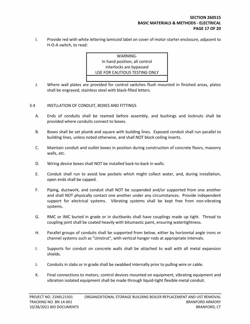
SECTION 260515 BASIC MATERIALS & METHODS - ELECTRICAL PAGE 17 OF 20
PROJECT NO. 21MIL21501 ORGANIZATIONAL STORAGE BUILDING BOILER REPLACEMENT AND UST REMOVAL TRACKING NO. BN 14-001 BRANFORD ARMORY 10/28/2021 BID DOCUMENTS BRANFORD, CT
I. Provide red with white lettering lamicoid label on cover of motor starter enclosure, adjacent to H-O-A switch, to read:
WARNING- In hand position, all control
interlocks are bypassed USE FOR CAUTIOUS TESTING ONLY
J. Where wall plates are provided for control switches flush mounted in finished areas, plates
shall be engraved, stainless steel with black-filled letters.
3.4 INSTLLATION OF CONDUIT, BOXES AND FITTINGS
A. Ends of conduits shall be reamed before assembly, and bushings and locknuts shall be provided where conduits connect to boxes.
B. Boxes shall be set plumb and square with building lines. Exposed conduit shall run parallel to building lines, unless noted otherwise, and shall NOT block ceiling inserts.
C. Maintain conduit and outlet boxes in position during construction of concrete floors, masonry walls, etc.
D. Wiring device boxes shall NOT be installed back-to-back in walls.
E. Conduit shall run to avoid low pockets which might collect water, and, during installation, open ends shall be capped.
F. Piping, ductwork, and conduit shall NOT be suspended and/or supported from one another and shall NOT physically contact one another under any circumstances. Provide independent support for electrical systems. Vibrating systems shall be kept free from non-vibrating systems.
G. RMC or IMC buried in grade or in ductbanks shall have couplings made up tight. Thread to coupling joint shall be coated heavily with bitumastic paint, ensuring watertightness.
H. Parallel groups of conduits shall be supported from below, either by horizontal angle irons or channel systems such as "Unistrut", with vertical hanger rods at appropriate intervals.
I. Supports for conduit on concrete walls shall be attached to wall with all metal expansion shields.
J. Conduits in slabs or in grade shall be swabbed internally prior to pulling wire or cable.
K. Final connections to motors, control devices mounted on equipment, vibrating equipment and vibration isolated equipment shall be made through liquid-tight flexible metal conduit.
SECTION 260515 BASIC MATERIALS & METHODS - ELECTRICAL PAGE 18 OF 20
PROJECT NO. 21MIL21501 ORGANIZATIONAL STORAGE BUILDING BOILER REPLACEMENT AND UST REMOVAL TRACKING NO. BN 14-001 BRANFORD ARMORY 10/28/2021 BID DOCUMENTS BRANFORD, CT
L. Use standard radius bends on concealed conduit; on exposed work, use either standard bends or "L" type fittings acceptable equivalent to Crouse-Hinds.
M. Wherever MC cable is used, leave sufficient slack for future removal or withdrawal of boxes or fixtures from finished ceiling or partitions. All cables shall be rigidly supported from the building structure using products listed and identified for securement and support at least 4' O.C. and within 12" from every fitting and shall run in lines parallel or perpendicular to building structural members. Cable shall not rest on the ceiling structure.
N. Exposed wiring shall be kept as close as possible to underside of roof and floor slabs or bottom of beams, unless noted otherwise. Space above hung ceilings is extremely critical and coordination with mechanical trades is essential.
O. Conduit and wiring shall NOT be run in roof fill and shall NOT pierce roof deck, unless specifically noted to on Contract Drawings.
P. Galvanized electrical conduit of 1/2” nominal diameter may be embedded within 4-1/2” overall thickness suspended concrete slabs over permanent metal floor forms; galvanized electrical conduit of 1” nominal diameter may be embedded within slabs of 6” thickness overall.
Q. Conduits concealed in or beneath slab on grade: Conduits larger than 3/4” nominal diameter shall be completely buried below vapor barrier within the porous fill layer, such that surface of vapor barrier is smooth and level within ±1/4” tolerance. Conduits 3/4” and smaller may be:
1. Completely buried below the vapor barrier within the porous fill, or 2. Placed above the vapor barrier, within the slab, at mid-height of slab, or 3. If within the slab, spaced minimum of 3 diameters away from parallel conduits.
R. Additional Requirements for Low Voltage Systems: refer to Section 260525.
S. Field cut IMC and RMC conduits shall be field threaded. Field threads to be cold galvanized by brush or spray. Cold galvanize to be minimum 95% zinc and shall cure before attaching to threaded fitting. Set screw and compression fittings shall not be acceptable.
T. Where PVC conduit, whether direct buried or in ductbank, terminates within a building or utility structure, the PVC conduit shall transition to rigid metal conduit at least 10 feet prior to entering building or utility structure. Additionally, sweeps up through slabs on grade shall be RMC.
U. Seal all conduits at the last structure prior to conduits entering a building and where conduits enter a building with Carlon “MAT” or “MAQ” series duct plug for conduits with wires and Carlon “MAE” series for spare conduits or equal. All spare conduits shall have nylon pull string and footage tape.
SECTION 260515 BASIC MATERIALS & METHODS - ELECTRICAL PAGE 19 OF 20
PROJECT NO. 21MIL21501 ORGANIZATIONAL STORAGE BUILDING BOILER REPLACEMENT AND UST REMOVAL TRACKING NO. BN 14-001 BRANFORD ARMORY 10/28/2021 BID DOCUMENTS BRANFORD, CT
3.5 INSTALLATION OF CABLES
A. Parallel groups of cables shall be supported from below, either by horizontal angle irons or channel systems such as “Unistrut”, with vertical hanger rods at maximum of three-foot intervals.
B. Supports for cables on concrete walls shall be attached to wall with all metal expansion shields.
C. All insulated conductors run in plenum spaces shall be plenum rated and carry UL listing for flame spread and smoke propagation.
3.6 INSTALLATION OF BACKBOARDS AND EQUIPMENT CABINETS
A. Backboards shall be installed over sheetrock, screwed into wall studs or with screw anchors in masonry walls. Bottom of backboard shall be set at 6” AFF, extending to a maximum of 8’6” AFF. Backboards shall be set on 13/16” x 1-5/8” Unistrut framing, secured to wall using toggle bolts. Bottom of backboard shall be set at 6” AFF, extending to a maximum of 8’6” AFF.
B. Equipment shall be mounted to backboards at minimum of 4 points, with screws and washers. Equipment cabinets shall be set on 13/16” x 1-5/8” Unistrut framing, which is secured to wall using toggle bolts.
C. Freestanding Unistrut framing for mounting of backboards or equipment cabinets shall be secured to floor and structure above.
3.7 INSTALLATION OF RECEPTACLES
A. Receptacles shall be installed vertical with the U-ground up above the floor and below ceiling. Coordinate with Electrical and Mechanical Contract Drawings for elevations and mounting heights of receptacles and surface raceway. Verify all final locations of devices with Engineer prior to installation.
B. Use of modular wiring connectors to devices is NOT permitted.
C. If receptacles are located within six feet of edge of sink, or water source; GFCI/GFI receptacles shall be used.
D. Where GFI circuit breakers are used, all receptacles on the circuit shall be labeled GFCI/GFI with the circuit number.
E. Where receptacle is required to have GFCI protection and is not in a readily accessible location GFCI circuit breaker is to be used.
SECTION 260515 BASIC MATERIALS & METHODS - ELECTRICAL PAGE 20 OF 20
PROJECT NO. 21MIL21501 ORGANIZATIONAL STORAGE BUILDING BOILER REPLACEMENT AND UST REMOVAL TRACKING NO. BN 14-001 BRANFORD ARMORY 10/28/2021 BID DOCUMENTS BRANFORD, CT
3.8 BRANCH CIRCUIT WIRING
A. Multiple branch circuits within a single enclosure (junction box, pull box, panel board) must have individual neutrals (grounded conductors) identified or tie-wrap to line conductors of same circuit.
B. Parallel conductors shall be installed in groups consisting of not more than one conductor per phase, neutral or ground conductor to prevent current imbalance.
3.9 MOTOR CONTROL
A. Mount grouped switches, starters and other equipment on backboards. See Paragraph BACKBOARDS & EQUIPMENT CABINETS in this section. Where wall space is not adjacent to equipment being served, or where additional wall space is required, provide free-standing assembly, constructed of metal uni-strut or similar, for mounting of equipment.
END OF SECTION 260515
TABLE OF CONTENTS SECTION 260525 – LOW VOLTAGE RACEWAY DISTRIBUTION PART 1 - GENERAL ......................................................................................................................................... 1
1.1 GENERAL REQUIREMENTS ............................................................................................................ 1 1.2 SCOPE ............................................................................................................................................ 1 1.3 SUBMITTALS .................................................................................................................................. 1
PART 2 - PRODUCTS ...................................................................................................................................... 2 2.1 MULTIPLE DUCT CONDUIT ............................................................................................................ 2 2.2 BACKBOARDS ................................................................................................................................ 2
PART 3 - EXECUTION ..................................................................................................................................... 3 3.1 GENERAL ....................................................................................................................................... 3 3.2 TELECOMMUNICATIONS AND EMPTY RACEWAYS ....................................................................... 3 3.3 OUTLETS ........................................................................................................................................ 6

SECTION 260525 LOW VOLTAGE RACEWAY DISTRIBUTION PAGE 1 OF 6
PROJECT NO. 21MIL21501 ORGANIZATIONAL STORAGE BUILDING BOILER REPLACEMENT AND UST REMOVAL TRACKING NO. BN 14-001 BRANFORD ARMORY 10/28/2021 BID DOCUMENTS BRANFORD, CT
SECTION 260525 - LOW VOLTAGE RACEWAY DISTRIBUTION
PART 1 - GENERAL
1.1 GENERAL REQUIREMENTS
A. This section covers the specification of raceway systems to support telephone, video, data wiring and security systems. Refer to Section - COMMON WORK RESULTS FOR ELECTRICAL WORK, GENERAL CONDITIONS, SUPPLEMENTARY CONDITIONS, applicable Sections of Division 1, and all other project instructions for other requirements.
B. Installation shall be in accordance with applicable Codes and ANSI/TIA/EIA 569 Commercial Building Standards for Telecommunications Pathways and Spaces.
1.2 SCOPE
A. Provide labor, materials, equipment and services equipment and transportation necessary for complete and operational raceway system including but not limited to the following: 1. Raceways 2. Outlet, pull and junction boxes 3. Sleeves 4. Backboards 5. Grounding
B. Provide a telecommunications raceway system including all interior raceways, boxes, plywood backboards, outlets, fittings and all other appurtenances required, leaving the entire installation ready for installation of equipment and cables.
1.3 SUBMITTALS
A. Submit for review shop drawings for the following: 1. Raceways 2. Boxes
SECTION 260525 LOW VOLTAGE RACEWAY DISTRIBUTION PAGE 2 OF 6
PROJECT NO. 21MIL21501 ORGANIZATIONAL STORAGE BUILDING BOILER REPLACEMENT AND UST REMOVAL TRACKING NO. BN 14-001 BRANFORD ARMORY 10/28/2021 BID DOCUMENTS BRANFORD, CT
PART 2 - PRODUCTS
2.1 MULTIPLE DUCT CONDUIT
A. Provide multiple duct conduits as indicated on the Drawings and specified herein.
B. Multiple duct conduits shall consist of four-inch outer conduit with three 1-1/2 inch or four 1-1/4 inch pre-lubricated PVC inner ducts as indicated. Inner ducts shall each be a different color (3-cell white/gray/orange and 4 cell white/gray/orange/green).
C. Outer conduit material shall be as follows: 1. Underground - Schedule 40. 2. Underground connection to foundation or manholes - last ten feet shall be galvanized
rigid steel with deflection joint. 3. Above-ground subject to abuse - galvanized rigid steel (GRC) including the first ten feet
of exposed conduit. 4. Above ground not subject to abuse - Electrical Metallic Tubing (EMT). 5. Riser from underground - Galvanized rigid steel with expansion joint.
D. Inner ducts shall have low co-efficient of friction (0.06 - 0.09), be watertight and suitable air tight to allow for line blowing.
E. Provide 1700 lb. Rated slick braid rope pull line in all inner ducts.
F. Provide termination kits where entering or leaving manholes or buildings to seal inner ducts and outer ducts.
G. Provide Carlon Multi-Guard multi-cell raceway system or acceptable equivalent.
2.2 BACKBOARDS
A. Backboards shall be 3/4” fire-rated plywood painted on all sides before installation, stamp/cable indicating “fire-rating” shall not be painted over. Backboards shall be 3/4” Type A-C plywood painted on all sides before installation. Paint shall be one coat primer and two coats latex, intumescent, fire-retardant paint acceptable equivalent to Benjamin-Moore “Insul-X” or Sherwin-Williams “FireTex FX5120”. Backboards shall be used for mounting telecommunications and other equipment in telecommunications rooms/closets.
B. Equipment cabinets shall be UL listed, sheet steel cabinet with hinged door with catch and lock; mounted on backboard. Cabinets shall be flush or surface-mounted, sized as required to suit equipment.
C. Refer to Section – LOW VOLTAGE RACEWAY DISTRIBUTION in this Division.
SECTION 260525 LOW VOLTAGE RACEWAY DISTRIBUTION PAGE 3 OF 6
PROJECT NO. 21MIL21501 ORGANIZATIONAL STORAGE BUILDING BOILER REPLACEMENT AND UST REMOVAL TRACKING NO. BN 14-001 BRANFORD ARMORY 10/28/2021 BID DOCUMENTS BRANFORD, CT
PART 3 - EXECUTION
3.1 GENERAL
A. In general, the telecommunications system raceways, outlets and terminal backboard locations shall be as indicated on the Drawings.
B. All work and the entire installation of same shall be coordinated with the Architectural/Engineering Coordination Office of the Telephone Company and the Cable TV Company, the Owner, the Telephone System, Video System and Data System Installers before the start of the construction and shall be in full conformance with their requirements and recommendations.
C. Verify service point with Owner, and provide service raceways to meet requirements and as indicated on the Drawings and Specifications.
D. At telecommunications rooms/closets provide backboards installed over sheetrock, screwed into wall studs or with screw anchors in masonry walls. Bottom of backboard shall be set at 6” AFF, extending to a maximum of 8’6” AFF. Backboards shall be set on 13/16” x 1-5/8” Unistrut framing, secured to wall using toggle bolts. Bottom of backboard shall be set at 6” AFF, extending to a maximum of 8’6” AFF.
E. Provide a double duplex surge suppression outlet on an individual 20A/1P, 120 V circuit at each backboard.
3.2 TELECOMMUNICATIONS AND EMPTY RACEWAYS
A. Empty Raceways and Raceways installed for Telecommunications Systems including telephone, data, security, alarm, CATV, sound, video, low voltage conductors, etc. shall be installed in accordance with the Electrical Code, as required for raceways specified in this Section and as indicated herein.
B. Provide 1-1/4 inch conduit for all voice, data and video, unless otherwise indicated, from outlets indicated on the Drawings in partition, extended a minimum of 6 inches above an accessible ceiling or to the backboard if there is no nearby accessible ceiling. Provide 90° bend at top of wall.
C. Terminate conduits with insulated throat fittings. Provide grounding bushings for backbone and riser conduits and for conduits entering equipment rooms or wiring closets. Ground conduits, cable trays and raceways to the local Telecommunications ground bus using braided hollow copper conductor equal to Belden #8669 (60A ampacity).
D. Provide pull boxes each time raceway installation exceeds a 100-foot (30M) section or a total of 180 degrees in bends and offsets between pull boxes. Do not install a pull box in lieu of a conduit bend. Align the corresponding conduits on opposite sides of pull box with each other.
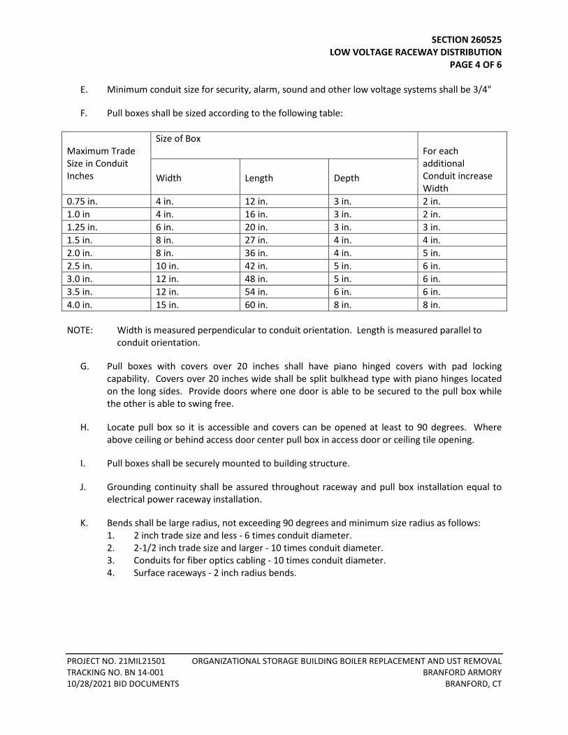
SECTION 260525 LOW VOLTAGE RACEWAY DISTRIBUTION PAGE 4 OF 6
PROJECT NO. 21MIL21501 ORGANIZATIONAL STORAGE BUILDING BOILER REPLACEMENT AND UST REMOVAL TRACKING NO. BN 14-001 BRANFORD ARMORY 10/28/2021 BID DOCUMENTS BRANFORD, CT
E. Minimum conduit size for security, alarm, sound and other low voltage systems shall be 3/4"
F. Pull boxes shall be sized according to the following table: Maximum Trade Size in Conduit Inches
Size of Box For each additional Conduit increase Width
Width
Length
Depth
0.75 in. 4 in. 12 in. 3 in. 2 in. 1.0 in 4 in. 16 in. 3 in. 2 in. 1.25 in. 6 in. 20 in. 3 in. 3 in. 1.5 in. 8 in. 27 in. 4 in. 4 in. 2.0 in. 8 in. 36 in. 4 in. 5 in. 2.5 in. 10 in. 42 in. 5 in. 6 in. 3.0 in. 12 in. 48 in. 5 in. 6 in. 3.5 in. 12 in. 54 in. 6 in. 6 in. 4.0 in. 15 in. 60 in. 8 in. 8 in. NOTE: Width is measured perpendicular to conduit orientation. Length is measured parallel to
conduit orientation.
G. Pull boxes with covers over 20 inches shall have piano hinged covers with pad locking capability. Covers over 20 inches wide shall be split bulkhead type with piano hinges located on the long sides. Provide doors where one door is able to be secured to the pull box while the other is able to swing free.
H. Locate pull box so it is accessible and covers can be opened at least to 90 degrees. Where above ceiling or behind access door center pull box in access door or ceiling tile opening.
I. Pull boxes shall be securely mounted to building structure.
J. Grounding continuity shall be assured throughout raceway and pull box installation equal to electrical power raceway installation.
K. Bends shall be large radius, not exceeding 90 degrees and minimum size radius as follows: 1. 2 inch trade size and less - 6 times conduit diameter. 2. 2-1/2 inch trade size and larger - 10 times conduit diameter. 3. Conduits for fiber optics cabling - 10 times conduit diameter. 4. Surface raceways - 2 inch radius bends.
SECTION 260525 LOW VOLTAGE RACEWAY DISTRIBUTION PAGE 5 OF 6
PROJECT NO. 21MIL21501 ORGANIZATIONAL STORAGE BUILDING BOILER REPLACEMENT AND UST REMOVAL TRACKING NO. BN 14-001 BRANFORD ARMORY 10/28/2021 BID DOCUMENTS BRANFORD, CT
L. Raceways and outlets shall be separated from sources of EMI and RFI such as transformers, ballasts and power lines. Do not install raceways parallel to power raceways unless four-foot distance is maintained. Cross other raceways at 90 degrees. Maintain minimum 24 inch clearance in all directions from lighting fixtures and power wiring rated over 20 A. Maintain a minimum 6-inch clearance elsewhere from raceways and outlets. Maintain 48-inch clearance from transformers. Clearances are measured all around raceway and outlets including through walls and floors.
M. Provide sleeves for raceways and cable trays penetrating full height walls or floors. Install approved fire stop between sleeve and rated wall or floor. Install approved watertight seal between sleeve and wall or floor for penetrations to the exterior or underground. Sleeves shall extend two inches above the floor and shall be watertight.
N. Provide sleeves for telecommunications cabling and at full height walls in path of cabling from outlet location to termination point in closet minimum size two inch except four 4-inch sleeves into telecommunications closets or rooms, computer class rooms, media center and equipment head end rooms.
O. Provide four-inch conduit sleeves between stacked Telecommunication closets or rooms. Provide a minimum of four sleeves per closet, provide more if indicated.
P. Provide one multi-duct conduit in underground ductbanks and between Telcom room or closets where raceways are installed for non-stacked areas. Provide additional multi-duct conduits where indicated.
Q. Align sleeves and conduits on opposite walls of rooms, closets or manholes so there is a straight line between corresponding openings, parallel or perpendicular to structure. Provide 4 inch conduits between telecommunications rooms, closets and backboards. As a minimum provide one conduit for telephone cables, one multiple duct conduit with three 1-1/2 inch inner ducts for data and one spare conduit for future use.
R. Provide a 200 lb test pull line in each raceway. Leave 12 inches of exposed slack at each end. Secure pull line at each end to prevent it from slipping back into raceway.
S. Non-metallic raceways or boxes are not allowed in interiors of buildings.
T. Provide insulated bushings at all cable or pull string penetrations through steel studs.
U. No cabling to an outlet is to be installed exposed. Provide conduit to outlet where cabling would have to be installed exposed.
V. Provide direct raceway from outlet boxes to an accessible location above the finished corridor ceiling, or in area with non-accessible ceilings directly to the plywood termination backboard in the nearest telecommunications closet/room on the same floor or as indicated on the Drawings.
SECTION 260525 LOW VOLTAGE RACEWAY DISTRIBUTION PAGE 6 OF 6
PROJECT NO. 21MIL21501 ORGANIZATIONAL STORAGE BUILDING BOILER REPLACEMENT AND UST REMOVAL TRACKING NO. BN 14-001 BRANFORD ARMORY 10/28/2021 BID DOCUMENTS BRANFORD, CT
3.3 OUTLETS
A. Provide blank device outlet cover plates for all outlets without device plates installed at time of Substantial Completion. All outlet cover plates shall be of the same finish material and by the manufacturer furnishing all other device and switch plates installed throughout the buildings. Provide blank plate or outlet plate as coordinated with the Telephone, Video and Data System Installer.
B. Provide 4-11/16 inch square by 2-1/8 inch deep box with single gang plaster ring for each outlet, unless otherwise indicated.
C. Outlet shall be spaced 6 inches minimum from an electrical outlet.
END OF SECTION 260525
TABLE OF CONTENTS SECTION 260526 – ELECTRICAL GROUNDING
PART 1 - GENERAL ......................................................................................................................................... 1
1.1 REFERENCES .................................................................................................................................. 1 1.2 SCOPE ............................................................................................................................................ 1 1.3 SHOP DRAWING SUBMITTALS ...................................................................................................... 1
PART 2 - PRODUCTS ...................................................................................................................................... 1 2.1 EQUIPMENT GROUNDS ................................................................................................................. 1 2.2 GROUND FAULT PROTECTION ...................................................................................................... 2 2.3 MATERIALS .................................................................................................................................... 2
PART 3 - EXECUTION ..................................................................................................................................... 2 3.1 INSTALLATION - GENERAL ............................................................................................................. 2 3.2 EQUIPMENT GROUNDS ................................................................................................................. 2 3.3 IDENTIFICATION ............................................................................................................................ 4 3.4 TESTS ............................................................................................................................................. 4

SECTION 260526 ELECTRICAL GROUNDING PAGE 1 OF 4
PROJECT NO. 21MIL21501 ORGANIZATIONAL STORAGE BUILDING BOILER REPLACEMENT AND UST REMOVAL TRACKING NO. BN 14-001 BRANFORD ARMORY 10/28/2021 BID DOCUMENTS BRANFORD, CT
SECTION 260526 - ELECTRICAL GROUNDING
PART 1 - GENERAL
1.1 REFERENCES
A. This Section covers the specification of grounding for electrical equipment and systems. Refer to Section – COMMON WORK RESULTS FOR ELECTRICAL WORK, GENERAL CONDITIONS, SUPPLEMENTARY CONDITIONS, applicable Sections of DIVISION 1, and all other project instructions for other requirements.
1.2 SCOPE
A. Provide labor, materials, services, equipment and transportation necessary for complete and operational grounding systems as indicated on Contract Drawings and specified herein, including but not limited to following: 1. Equipment grounds 2. Ground fault protection
1.3 SHOP DRAWING SUBMITTALS
A. Submit for review shop drawings for the following: 1. Ground rods 2. Bus 3. Bushings and pressure lugs 4. Pipe clamps 5. Circuit breakers 6. Grounding conductors 7. Receptacles 8. Plug-in tester unit
PART 2 - PRODUCTS
2.1 EQUIPMENT GROUNDS
A. Provide green insulated copper equipment grounding conductor between the ground bus of the source distribution panel or switchboard and each load being served. Conductor shall be sized according to NEC Article 250, Table for “Minimum size of Equipment Grounding Conductors”.
B. Provide separate grounding conductor for each branch circuit.
SECTION 260526 ELECTRICAL GROUNDING PAGE 2 OF 4
PROJECT NO. 21MIL21501 ORGANIZATIONAL STORAGE BUILDING BOILER REPLACEMENT AND UST REMOVAL TRACKING NO. BN 14-001 BRANFORD ARMORY 10/28/2021 BID DOCUMENTS BRANFORD, CT
2.2 GROUND FAULT PROTECTION
A. If excessive ground current flows in feeders to 480 V main switchboard, main breakers and/or circuit breakers with ground fault sensing shall trip to protect switchboard against arcing ground faults.
B. Provide ground fault circuit interrupter protection for receptacles as required and indicated.
2.3 MATERIALS
A. Ground rods shall be 3/4” x 10’-0” copper-clad steel, by Carolina or acceptable equivalent.
B. Below-grade and concealed connections shall be Thermweld, Cadweld or acceptable equivalent. Above-grade and exposed connections shall be Burndy or acceptable equivalent.
C. Wire shall be stranded bare copper or insulated copper, as indicated on Contract Drawings.
D. Bus shall be copper bar, as indicated on Contract Drawings.
E. Bushings and Pressure Lugs shall be by T&B, O.Z./Gedney or acceptable equivalent.
F. Pipe Clamps shall be by O.Z./Gedney or acceptable equivalent.
PART 3 - EXECUTION
3.1 INSTALLATION - GENERAL
A. Refer to SECTION 260515, BASIC MATERIALS & METHODS - ELECTRICAL.
B. Grounding shall be installed and tested in accordance with NEC (NFPA 70) and to satisfaction of local electrical inspector and Engineer.
C. If outlet is located within six feet of edge of sink or water source; GFCI/GFI receptacles shall be used.
3.2 EQUIPMENT GROUNDS
A. Equipment grounds shall be continuous from ground bus to electrical equipment and devices.
B. Provide equipment grounds for electrical equipment furnished or installed as part of this Contract.
SECTION 260526 ELECTRICAL GROUNDING PAGE 3 OF 4
PROJECT NO. 21MIL21501 ORGANIZATIONAL STORAGE BUILDING BOILER REPLACEMENT AND UST REMOVAL TRACKING NO. BN 14-001 BRANFORD ARMORY 10/28/2021 BID DOCUMENTS BRANFORD, CT
C. Grounded service conductor (neutral) of 480Y/277 V distribution system shall be grounded at only one point: neutral connection to the ground bus. Under no circumstances shall system neutral be grounded at any other point. As part of final inspection procedures, demonstrate purity of system neutral.
D. Regardless of rating or length, circuits run in FMC shall carry grounding conductor for that portion of circuit in FMC; bond conductor at each end.
E. Current return conductors (neutrals), which are grounded at the source, shall NOT be used for equipment grounding. Provide separate conductors for equipment grounding; refer to SECTION 260515, paragraph on IDENTIFICATION, for color requirements.
F. Grounding conductor shall be secured to equipment enclosure at power source (usually to a ground bus) and at apparatus being served by AC supply. Grounding conductors shall be insulated and shall be large enough to carry ground fault current safely.
G. Provide following for panelboards: neutral bus insulated from enclosure; and grounding bus bonded to enclosure. Grounding bus shall have means for termination of grounding conductors to panelboard cabinet.
H. Maintain electrical continuity of raceways by the following means: 1. Threaded fittings with joints made up wrench-tight where threaded rigid conduit is
used. 2. Threadless fittings made up tight. 3. Metal bushing inside and locknut outside of metal boxes and cabinets when threaded
conduit is used. If outside locknut is inaccessible for tightening after installation, provide additional locknut inside. If bushing is composed entirely of insulating material, use locknuts inside and outside.
4. Bonding jumper across joints of wireways, cable trays, expansion or deflection fittings, etc.
5. Devices listed for the purpose by UL.
I. NOTE: Addition of equipment grounding conductor to AC circuits run in metallic enclosures does NOT lessen the requirement for conductor enclosure continuity, since part of total ground fault current will flow through the raceway and enclosure system. Therefore, the continuity of this system shall be maintained.
J. Bond neutrals of each 208Y/120 V distribution transformer to ground so as to be separately derived system and shall be grounded locally to building steel. If building steel does not exist (i.e., concrete structures), the transformer shall be grounded to main service ground bus. Transformer ground shall also be bonded to nearest available local metal water pipe. The primary feeder ground is supplemental and shall be sized for primary feeder protection. Refer to contract drawings for additional bonding requirements.
SECTION 260526 ELECTRICAL GROUNDING PAGE 4 OF 4
PROJECT NO. 21MIL21501 ORGANIZATIONAL STORAGE BUILDING BOILER REPLACEMENT AND UST REMOVAL TRACKING NO. BN 14-001 BRANFORD ARMORY 10/28/2021 BID DOCUMENTS BRANFORD, CT
3.3 IDENTIFICATION A. Engrave nameplates of receptacles wired to GFI breakers to read "GFI" adjacent to or above
receptacle opening.
3.4 TESTS
A. Acceptance testing for electrical grounding systems, specified herein, shall be performed by independent testing firm with minimum ten years experience in testing the specified items. Firm shall be member of International Electrical Testing Association (INETA).
B. Testing procedures shall be as described in INETA "Acceptance Testing Specifications" (ATS).
C. Testing firm shall immediately notify Contractor and Engineer, of any deficiencies requiring correction before electrical system is placed in service and shall confirm information in writing within five days.
D. Discrepancies found shall be corrected by firm which installed switchboard. However, testing firm shall make minor field adjustments that may be found necessary.
E. Test report shall include typewritten test results on firm's standard test forms.
F. Test and inspect the main grounding electrode system in accordance with Section 7.13 of the NETA Acceptance Testing Specification. Perform a resistance to ground test and ensure that resistance is no greater than 5 (five) ohms. Investigate and supplement grounding system where resistance exceeds recommended values and re-test as required.
G. Ground Fault Circuit Interruption shall be tested after installation by random connection of plug-in tester to various protected receptacles, as directed by Engineer.
H. All ground fault systems including but not limited to the main service overcurrent protective device ground fault protection equipment shall be performance tested when first installed on site per manufacturer’s instructions and Section 7.14 of the NETA Acceptance Testing Specifications Inspection and Test Procedures for Ground-Fault Protection Systems. Tests shall include, but not be limited to, resistance measurements through all bolted connections, insulation resistance test on all control wiring and pick up tests using primary injection.
END OF SECTION 260526
SECTION 312300 EXCAVATION PAGE 1 OF 4
PROJECT NO. 21MIL21501 ORGANIZATIONAL STORAGE BUILDING BOILER REPLACEMENT AND UST REMOVAL TRACKING NO. BN 14-001 BRANFORD ARMORY 10/28/2021 BID DOCUMENTS BRANFORD, CT
SECTION 312300 – EXCAVATION
PART 1 - GENERAL
1.1 SCOPE OF WORK
A. Provide all labor, tools, materials, equipment and incidentals required to perform the work called for in this Section of the Specifications, including, but not necessarily limited to, the following:
1. RELATED DOCUMENTS
ConnDOT Form 817- State of Connecticut, Department of Transportation, Standard Specifications for Roads, Bridges, Facilities and Incidental Construction, 2017
Construction staking of gas piping, electrical conduit and associated construction. Comply with ConnDOT Form 817, Article 9.80.01.
3. The Contractor shall make all earth excavations and rock excavations, including removal of existing pavements, road base, curbs, walks, and abandoned pipes and structures encountered in the construction of the utilities, services, appurtenances, structures, roadway, as required for the proper completion of the work included under this Contract, and shall dispose of all unsuitable excavated materials as specified herein.
4. The excavation shall include stripping topsoil, saw cutting of pavements and sidewalks, removal, handling, stockpiling and disposal of any and all materials encountered within the limits of the work, and shall include all pumping, bailing, draining, sheeting, shoring, coffer damming and protection therefore.
5. The placement of calcium chloride for dust control.
6. The excavation of test pits as directed by the Engineer or Owner.
7. Comply with ConnDOT Form 817, Article 2.05.01.
PART 2 - SUBMITTALS
2.1 DESIGN DRAWINGS
A. Prepare and submit the following design drawings. All design drawings shall be signed and sealed by an engineer registered in the State of Connecticut:
1. Excavation Plan - The excavation plan shall outline the methods and procedures that the Contractor will employ to successfully stabilize excavations, as required to construct the work.
SECTION 312300 EXCAVATION PAGE 2 OF 4
PROJECT NO. 21MIL21501 ORGANIZATIONAL STORAGE BUILDING BOILER REPLACEMENT AND UST REMOVAL TRACKING NO. BN 14-001 BRANFORD ARMORY 10/28/2021 BID DOCUMENTS BRANFORD, CT
2. Excavation Dewatering Plan - The excavation dewatering plan shall outline the methods and procedures that the Contractor will employ to successfully dewater excavation and dispose of the dewatering wastewater, including measures for erosion control and sediment removal.
2.2 MATERIALS:
A. "Earth" shall consist of all materials, with the exception of rock, removed as indicated or directed from within the excavation limit lines.
B. "Rock Excavation" – Rock shall consist of:
1. Rock in definite ledge formation, or
2. Boulders, portions of boulders, cement-masonry structures or concrete structures, each discrete object a minimum of one cubic yard or more in volume.
PART 3 - EXECUTION
3.1 PAVEMENT SAW CUTTING
A. Utilities – Saw cut existing pavement for gas piping, electrical conduits and associated construction per contract limit lines as outlined on the detail sheets.
3.2 ROADWAY EXCAVATION
A. Roadway excavation shall conform to Section 2.02 of Form 817. It shall include removal of existing pavement, base and sub-base, portions of driveways including pavement and base, with limits shown on the plans.
B. Structure excavation shall conform to Section 2.03 of Form 817.
C. Pavement, driveways, curbs and sidewalks shall be cut as required with a pneumatic tool or saw, removed, and disposed of by the Contractor.
D. If the bottom of any excavation is taken out beyond the limits indicated or prescribed, the resulting void shall be backfilled at the Contractor's expense with thoroughly compacted, suitable backfill material as described in Section 31 23 10, Compacted Gravel Fill.
E. All suitable material removed in making the excavation shall be used for backfill where required. All surplus or unsuitable material shall be removed and disposed of by the Contractor. Suitable material is specified under Section 31 23 10, Compacted Gravel Fill.
SECTION 312300 EXCAVATION PAGE 3 OF 4
PROJECT NO. 21MIL21501 ORGANIZATIONAL STORAGE BUILDING BOILER REPLACEMENT AND UST REMOVAL TRACKING NO. BN 14-001 BRANFORD ARMORY 10/28/2021 BID DOCUMENTS BRANFORD, CT
If material unsuitable for subgrade in the roadways and beneath paved areas, or in other locations on the site (in the opinion of the Engineer) is found at or below the grade to which excavation would normally be carried, the Contractor shall remove such material to the required width and depth and replace it with thoroughly compacted Gravel Fill as directed. The Contractor will be compensated for this compacted Gravel Fill under section 31 23 10.
F. The Contractor shall note that there may be other existing utilities in close proximity to the work. These utilities have been indicated on the drawings, but the completeness or accuracy of the information given is not guaranteed. It is the Contractor's responsibility to make himself aware of these locations and to contact Call-Before-You-Dig prior to any excavation.
G. As the excavation approaches pipes, conduits or other underground structures, digging by machinery shall be discontinued and the excavation shall be done by means of hand tools. Such manual excavation, when incidental to normal excavation, shall be included in the work to be done under items involving normal excavation.
H. Where determination of the exact location of pipe or other underground structure is necessary for doing the work properly, the Contractor may be required to excavate test pits to determine such locations, at no extra cost to the Owner.
I. Until final acceptance of the work, the Contractor shall pump out, or otherwise remove and dispose of as fast as it may collect, any water or other liquids which may be found or may accumulate in the excavations. Perform this in full conformance with their approved Excavation Dewatering Plan.
J. There shall be upon the work at all times during the construction proper and approved machinery of sufficient capacity (including spare units kept ready for immediate use in case of breakdowns) to meet the maximum requirements for the removal of the water or other liquids and their disposal in such a manner as not to withdraw sand or cement from the concrete and so as not to interfere with the proper laying of pipe and/or masonry, or the prosecution of work under this or other contract, nor endanger existing structures.
K. All existing walks, pipes, conduits, poles, wires, fences, stairways, curbing, property line markers, walls, buildings and other structures which do not, in the opinion of the Engineer, require to be changed in location, shall be carefully supported and protected from injury by the Contractor without additional compensation, and in case of injury, they shall be restored by him without compensation therefor, to as good condition as that in which they were found.
L. Tree roots shall not be mutilated, nor shall they be cut, except by permission of the Engineer. When permitted to cut tree roots, the ends shall be cut off smooth, without splitting or shattering. The trunks of the trees shall be carefully protected from damage, and if unavoidable damage occurs, the injured portions shall be neatly trimmed and covered with an application of grafting wax or other approved preparation. Power driven excavation machinery shall be handled with care to prevent damage to shade trees, particularly to overhanging branches, and branches shall not be cut off except by special permission of the Engineer.
SECTION 312300 EXCAVATION PAGE 4 OF 4
PROJECT NO. 21MIL21501 ORGANIZATIONAL STORAGE BUILDING BOILER REPLACEMENT AND UST REMOVAL TRACKING NO. BN 14-001 BRANFORD ARMORY 10/28/2021 BID DOCUMENTS BRANFORD, CT
M. The Contractor shall, at his own expense, dig up, handle, protect and properly reset hedges, small trees, shrubbery, signs, posts, guard rails, curbing other than bituminous and the like along the line of or adjacent to the work, and shall take all reasonable care in this work not to disturb any object that can be saved in its existing condition.
3.3 DUST CONTROL
Calcium Chloride shall conform to Section M12.10 - Calcium Chloride for Dust Control, of Form 817. The Contractor shall place calcium chloride on disturbed earthen or road base area for dust control, when directed to by the Owner or Engineer.
3.4 TEST PITS
A. The Contractor shall conduct test pits in locations directed by the Engineer or Owner, to provide more exact locations on existing utility or drainage infrastructure, or other items of interest to the Engineer. Included in these test pits will be saw-cutting of pavement (if in paved areas), traffic control where required, bracing of excavations as required, pumping of water as required, backfilling the test pit with materials removed during excavation, and placement of compacted gravel fill on the top 12” of the test pit.
END OF SECTION 312300
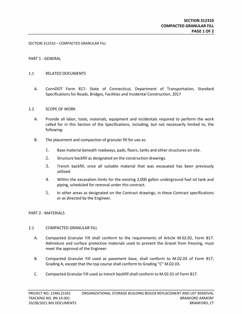
SECTION 312310 COMPACTED GRANULAR FILL
PAGE 1 OF 2
PROJECT NO. 21MIL21501 ORGANIZATIONAL STORAGE BUILDING BOILER REPLACEMENT AND UST REMOVAL TRACKING NO. BN 14-001 BRANFORD ARMORY 10/28/2021 BID DOCUMENTS BRANFORD, CT
SECTION 312310 – COMPACTED GRANULAR FILL
PART 1 - GENERAL
1.1 RELATED DOCUMENTS
A. ConnDOT Form 817- State of Connecticut, Department of Transportation, Standard Specifications for Roads, Bridges, Facilities and Incidental Construction, 2017
1.2 SCOPE OF WORK
A. Provide all labor, tools, materials, equipment and incidentals required to perform the work called for in this Section of the Specifications, including, but not necessarily limited to, the following:
B. The placement and compaction of granular fill for use as:
1. Base material beneath roadways, pads, floors, tanks and other structures on-site.
2. Structure backfill as designated on the construction drawings.
3. Trench backfill, once all suitable material that was excavated has been previously utilized.
4. Within the excavation limits for the existing 2,000 gallon underground fuel oil tank and piping, scheduled for removal under this contract.
5. In other areas as designated on the Contract drawings, in these Contract specifications or as directed by the Engineer.
PART 2 - MATERIALS
2.1 COMPACTED GRANULAR FILL
A. Compacted Granular Fill shall conform to the requirements of Article M.02.02, Form 817. Admixture and surface protective materials used to prevent the Gravel from freezing, must meet the approval of the Engineer.
B. Compacted Granular Fill used as pavement base, shall conform to M.02.03 of Form 817, Grading A, except that the top course shall conform to Grading "C" M.02.03.
C. Compacted Granular Fill used as trench backfill shall conform to M.02.01 of Form 817.
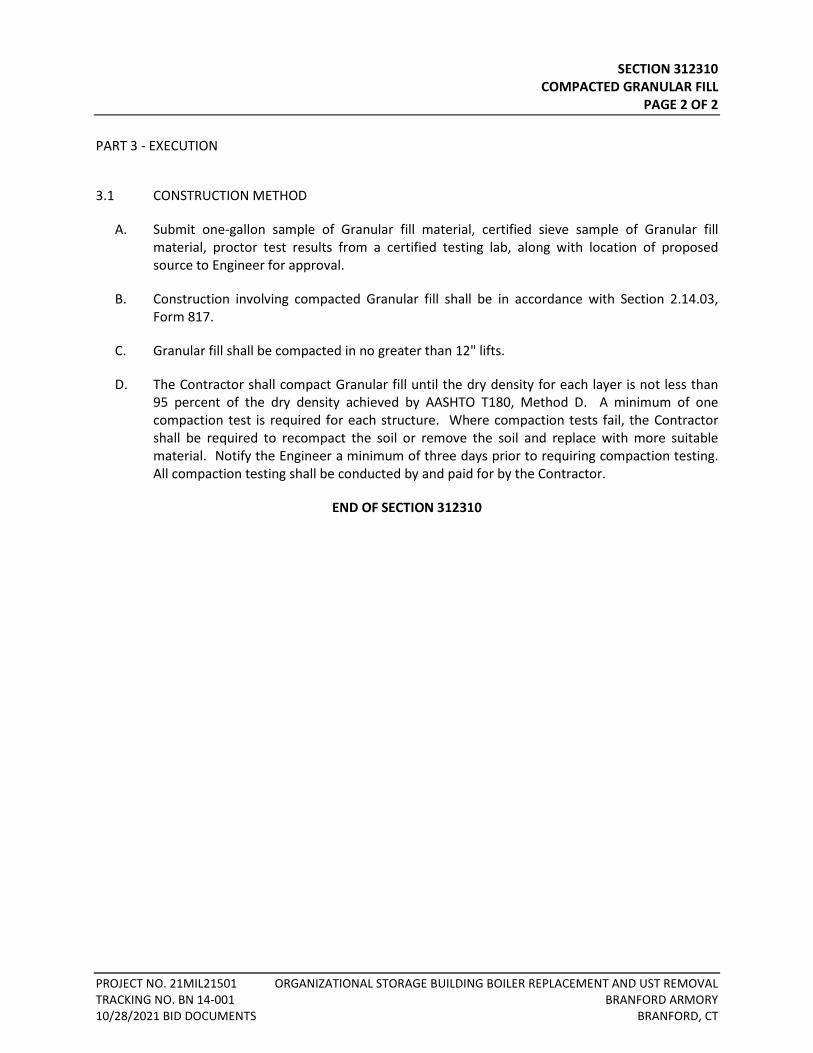
SECTION 312310 COMPACTED GRANULAR FILL
PAGE 2 OF 2
PROJECT NO. 21MIL21501 ORGANIZATIONAL STORAGE BUILDING BOILER REPLACEMENT AND UST REMOVAL TRACKING NO. BN 14-001 BRANFORD ARMORY 10/28/2021 BID DOCUMENTS BRANFORD, CT
PART 3 - EXECUTION
3.1 CONSTRUCTION METHOD
A. Submit one-gallon sample of Granular fill material, certified sieve sample of Granular fill material, proctor test results from a certified testing lab, along with location of proposed source to Engineer for approval.
B. Construction involving compacted Granular fill shall be in accordance with Section 2.14.03, Form 817.
C. Granular fill shall be compacted in no greater than 12" lifts.
D. The Contractor shall compact Granular fill until the dry density for each layer is not less than 95 percent of the dry density achieved by AASHTO T180, Method D. A minimum of one compaction test is required for each structure. Where compaction tests fail, the Contractor shall be required to recompact the soil or remove the soil and replace with more suitable material. Notify the Engineer a minimum of three days prior to requiring compaction testing. All compaction testing shall be conducted by and paid for by the Contractor.
END OF SECTION 312310
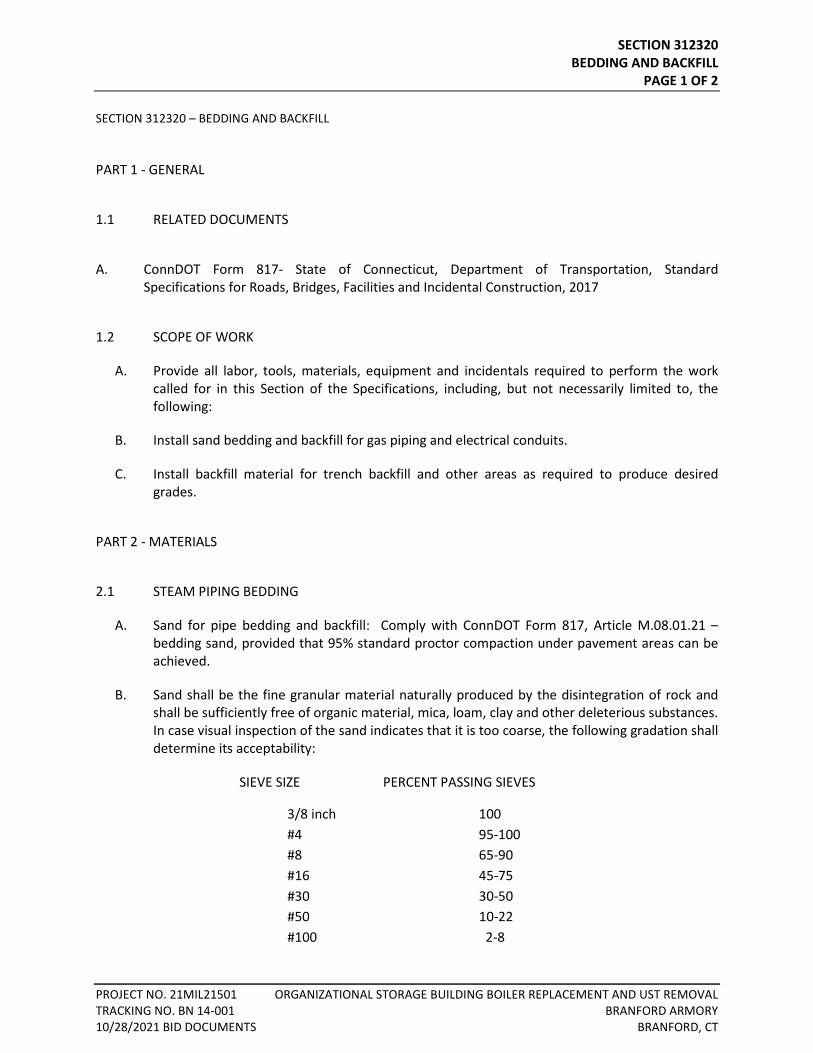
SECTION 312320 BEDDING AND BACKFILL
PAGE 1 OF 2
PROJECT NO. 21MIL21501 ORGANIZATIONAL STORAGE BUILDING BOILER REPLACEMENT AND UST REMOVAL TRACKING NO. BN 14-001 BRANFORD ARMORY 10/28/2021 BID DOCUMENTS BRANFORD, CT
SECTION 312320 – BEDDING AND BACKFILL
PART 1 - GENERAL
1.1 RELATED DOCUMENTS
A. ConnDOT Form 817- State of Connecticut, Department of Transportation, Standard Specifications for Roads, Bridges, Facilities and Incidental Construction, 2017
1.2 SCOPE OF WORK
A. Provide all labor, tools, materials, equipment and incidentals required to perform the work called for in this Section of the Specifications, including, but not necessarily limited to, the following:
B. Install sand bedding and backfill for gas piping and electrical conduits.
C. Install backfill material for trench backfill and other areas as required to produce desired grades.
PART 2 - MATERIALS
2.1 STEAM PIPING BEDDING
A. Sand for pipe bedding and backfill: Comply with ConnDOT Form 817, Article M.08.01.21 – bedding sand, provided that 95% standard proctor compaction under pavement areas can be achieved.
B. Sand shall be the fine granular material naturally produced by the disintegration of rock and shall be sufficiently free of organic material, mica, loam, clay and other deleterious substances. In case visual inspection of the sand indicates that it is too coarse, the following gradation shall determine its acceptability:
SIEVE SIZE PERCENT PASSING SIEVES
3/8 inch 100 #4 95-100 #8 65-90 #16 45-75 #30 30-50 #50 10-22 #100 2-8
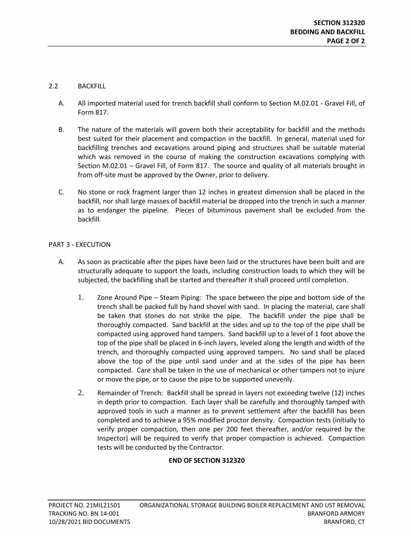
SECTION 312320 BEDDING AND BACKFILL
PAGE 2 OF 2
PROJECT NO. 21MIL21501 ORGANIZATIONAL STORAGE BUILDING BOILER REPLACEMENT AND UST REMOVAL TRACKING NO. BN 14-001 BRANFORD ARMORY 10/28/2021 BID DOCUMENTS BRANFORD, CT
2.2 BACKFILL
A. All imported material used for trench backfill shall conform to Section M.02.01 - Gravel Fill, of Form 817.
B. The nature of the materials will govern both their acceptability for backfill and the methods best suited for their placement and compaction in the backfill. In general, material used for backfilling trenches and excavations around piping and structures shall be suitable material which was removed in the course of making the construction excavations complying with Section M.02.01 – Gravel Fill, of Form 817. The source and quality of all materials brought in from off-site must be approved by the Owner, prior to delivery.
C. No stone or rock fragment larger than 12 inches in greatest dimension shall be placed in the backfill, nor shall large masses of backfill material be dropped into the trench in such a manner as to endanger the pipeline. Pieces of bituminous pavement shall be excluded from the backfill.
PART 3 - EXECUTION
A. As soon as practicable after the pipes have been laid or the structures have been built and are structurally adequate to support the loads, including construction loads to which they will be subjected, the backfilling shall be started and thereafter it shall proceed until completion.
1. Zone Around Pipe – Steam Piping: The space between the pipe and bottom side of the trench shall be packed full by hand shovel with sand. In placing the material, care shall be taken that stones do not strike the pipe. The backfill under the pipe shall be thoroughly compacted. Sand backfill at the sides and up to the top of the pipe shall be compacted using approved hand tampers. Sand backfill up to a level of 1 foot above the top of the pipe shall be placed in 6-inch layers, leveled along the length and width of the trench, and thoroughly compacted using approved tampers. No sand shall be placed above the top of the pipe until sand under and at the sides of the pipe has been compacted. Care shall be taken in the use of mechanical or other tampers not to injure or move the pipe, or to cause the pipe to be supported unevenly.
2. Remainder of Trench: Backfill shall be spread in layers not exceeding twelve (12) inches in depth prior to compaction. Each layer shall be carefully and thoroughly tamped with approved tools in such a manner as to prevent settlement after the backfill has been completed and to achieve a 95% modified proctor density. Compaction tests (initially to verify proper compaction, then one per 200 feet thereafter, and/or required by the Inspector) will be required to verify that proper compaction is achieved. Compaction tests will be conducted by the Contractor.
END OF SECTION 312320
SECTION 321200 BASE and SUBBASE
PAGE 1 OF 2
PROJECT NO. 21MIL21501 ORGANIZATIONAL STORAGE BUILDING BOILER REPLACEMENT AND UST REMOVAL TRACKING NO. BN 14-001 BRANFORD ARMORY 10/28/2021 BID DOCUMENTS BRANFORD, CT
SECTION 321200 – BASE AND SUBBASE
PART 1 - GENERAL
1.1 RELATED DOCUMENTS
A. ConnDOT Form 817- State of Connecticut, Department of Transportation, Standard Specifications for Roads, Bridges, Facilities, and Incidental Construction, 2017.
1.1 SCOPE OF WORK
A. Provide all labor, tools, materials, equipment, and incidentals required to perform the work called for in this Section of the Specifications, including, but not necessarily limited to, the following:
1. Preparation of subgrade, and installation of subbase and base materials prior to bituminous concrete construction.
PART 2 - MATERIALS
2.1 MATERIAL FOR ROAD TRENCH REPAIR
A. "Subbase" material for road trench repair shall conform to Sections 2.12.02 and M.02.02 and M.02.06 of Form 817.
B. "Processed Aggregate Base" material for roadway and parking area trench repair shall conform to Sections 3.04.02 and M.05.01 - Processed Aggregate Base and Pavement, of Form 817.
PART 3 - EXECUTION
3.1 INSTALLATION
A. Just prior to installation, the area shall be thoroughly compacted to subgrade elevations as shown on the plans. Granular fill shall be added or deleted to accomplish this task, as required. All soft and yielding material, and other portions of the subgrade which will not compact readily, shall be removed and replaced with suitable material.
SECTION 321200 BASE and SUBBASE
PAGE 2 OF 2
PROJECT NO. 21MIL21501 ORGANIZATIONAL STORAGE BUILDING BOILER REPLACEMENT AND UST REMOVAL TRACKING NO. BN 14-001 BRANFORD ARMORY 10/28/2021 BID DOCUMENTS BRANFORD, CT
B. The road base shall be constructed in accordance with Section 3.04.03 - Construction Methods, of Form 817. The road base shall be allowed to settle a minimum of 30 days prior to the placement of bituminous concrete. All areas of settlement shall be brought to grade with road base material, and recompacted prior to paving.
END OF SECTION 321200
SECTION 321210 TEMPORARY PAVING
PAGE 1 OF 3
PROJECT NO. 21MIL21501 ORGANIZATIONAL STORAGE BUILDING BOILER REPLACEMENT AND UST REMOVAL TRACKING NO. BN 14-001 BRANFORD ARMORY 10/28/2021 BID DOCUMENTS BRANFORD, CT
SECTION 321210 – TEMPORARY PAVING
PART 1 - GENERAL
1.1 RELATED DOCUMENTS
A. ConnDOT Form 817- State of Connecticut, Department of Transportation, Standard Specifications for Roads, Bridges, Facilities and Incidental Construction, 2017.
1.2 SCOPE OF WORK:
A. The scope of work under this Section includes the placement of roadway subbase, roadway base material, temporary base material, tack coats, and the placement of bituminous pavement within the limits of trench work on town roadways and on other disturbed pavement areas within the project site, as directed by the Engineer. The work also includes maintenance and repair of the temporary trench patch throughout its service life.
1.3 SUBMITTALS
A. Submit batch plant certifications for all pavement.
B. Submit representative gradation test, by a certified material testing laboratory, for processed aggregate base.
C. Submit weight slips during delivery of pavement.
1.4 PROJECT / SITE CONDITIONS
A. Immediately repair damaged or settled trench patch as directed by the Inspector.
1.5 SEQUENCING
A. Place temporary trench patch over all trench work in paved Town roadways or in disturbed paved areas before the conclusion of each day, unless a longer duration is approved by the Owner.
B. Do not leave any pits in paved highways over night or during any shutdown (weekends, holidays, winter, etc.). Backfill all excavations daily or prior to other shutdowns.
C. If steel plates are used, add either hot mix bituminous concrete or cold patch on all edges of steel plate.
SECTION 321210 TEMPORARY PAVING
PAGE 2 OF 3
PROJECT NO. 21MIL21501 ORGANIZATIONAL STORAGE BUILDING BOILER REPLACEMENT AND UST REMOVAL TRACKING NO. BN 14-001 BRANFORD ARMORY 10/28/2021 BID DOCUMENTS BRANFORD, CT
PART 2 - PRODUCTS
2.1 TEMPORARY TRENCH PATCH
A. Processed Aggregate Base:
1. Comply with ConnDOT Form 817, Section 3.04.02 and M.05.01.
B. Tack Coat:
1. Comply with ConnDOT Form 817, Section 4.06.02.
C. Bituminous Concrete:
1. Surface Course: Use (Hot Mix Asphalt) HMA S0.5 bituminous concrete. Comply with ConnDOT Form 817, Section 4.06.02.
PART 3 - EXECUTION
3.1 PAVEMENT SAW CUTTING
A. Saw cut existing pavement throughout the length of all trench work.
3.2 TEMPORARY TRENCH PATCH
A. Preparation:
1. Saw cut full depth of existing pavement throughout the length of all trench work.
2. Prepare subgrade prior to placement of temporary pavement. Comply with ConnDOT Form 817, Paragraph 2.09.03.
B. Processed Aggregate Base:
1. Comply with ConnDOT Form 817, Section 3.04.03.
C. Bituminous Concrete:
1. Place tack coat on all existing bituminous-concrete faces (vertical and horizontal) along the trench work. Comply with ConnDOT Form 817, Section 4.06.03.
2. Place temporary bituminous concrete within the trench limits. Match new trench-pavement grades with existing pavement grades. Comply with ConnDOT Form 817, Section 4.06.03.
SECTION 321210 TEMPORARY PAVING
PAGE 3 OF 3
PROJECT NO. 21MIL21501 ORGANIZATIONAL STORAGE BUILDING BOILER REPLACEMENT AND UST REMOVAL TRACKING NO. BN 14-001 BRANFORD ARMORY 10/28/2021 BID DOCUMENTS BRANFORD, CT
3.3 MAINTENANCE:
A. Maintain temporary pavement patch throughout its service life, to the satisfaction of the Engineer and Owner.
B. Repair or replace any damaged or deteriorated temporary pavement throughout its service life, at the direction of the Engineer and Owner.
C. Any damaged or deteriorated areas identified by the Owner which are not promptly repaired by the Contractor, which require the Owner to make necessary repairs, will be billed to the Contractor by the Owner.
END OF SECTION 321210

SECTION 321220 PERMANENT PAVING
PAGE 1 OF 3
PROJECT NO. 21MIL21501 ORGANIZATIONAL STORAGE BUILDING BOILER REPLACEMENT AND UST REMOVAL TRACKING NO. BN 14-001 BRANFORD ARMORY 10/28/2021 BID DOCUMENTS BRANFORD, CT
SECTION 321220 – PERMANENT PAVING
PART 1 - GENERAL
1.1 RELATED DOCUMENTS
A. ConnDOT Form 817- State of Connecticut, Department of Transportation, Standard Specifications for Roads, Bridges, Facilities, and Incidental Construction, 2017.
1.2 SCOPE OF WORK:
A. Provide all plant, materials, supplies, power, machinery, equipment, tools, superintendence, labor, overhead, profit, insurance, bonds, permits, shop drawings, design services (where required), and other services and accessories required to complete the work of this Section.
B. BASE BID: The scope of work under this Section includes removal of temporary pavement and base material, saw cutting of existing pavement, bituminous concrete sidewalks, and placement of permanent bituminous-concrete pavement (including tack coats) within the limits of trench work on town roadways, or in new areas designated for pavement on the Drawings.
C. SUPPLEMENTAL BID ITEMS SB-1 AND SB-2: The scope of work under this Section includes saw cutting of existing pavement, removal and disposal of existing bituminous pavement and base material to a depth of 16” below existing grades placement of compacted gravel base materials to a depth of 12”, and placement of two- 2” layers of bituminous concrete pavement, in new areas designated for pavement on the Drawings.
1.3 SUBMITTALS
A. Submit weight slips during delivery of pavement.
B. Product Test Data
1. Submit product test data to the Engineer for the following items. All tests shall be conducted by a qualified material testing laboratory and sealed by a licensed professional engineer in the State of Connecticut.
2. Submit batch plant certifications for all pavement types
3. Density test results taken at mixing plant on the day of manufacture.
atownsend
Sticky Note
SECTION 321220 PERMANENT PAVING
PAGE 2 OF 3
PROJECT NO. 21MIL21501 ORGANIZATIONAL STORAGE BUILDING BOILER REPLACEMENT AND UST REMOVAL TRACKING NO. BN 14-001 BRANFORD ARMORY 10/28/2021 BID DOCUMENTS BRANFORD, CT
1.4 PROJECT / SITE CONDITIONS
A. Immediately repair damaged or settled trench patch on town roadways or in parking areas, as directed by the Inspector or Owner.
1.5 SEQUENCING
A. Subbase shall be dry prior to the placement of Permanent Pavement.
PART 2 - PRODUCTS
2.1 TACK COAT:
A. Comply with ConnDOT Form 817, Article 4.06.02
2.2 BASE AND SUB-BASE
B. Refer to Specification Section 32 12 00.
2.3 BITUMINOUS CONCRETE ROADWAY:
A. Base Course (Town Roads and Parking Areas): Use (Hot Mix Asphalt) HMA S0.5. Comply with ConnDOT Form 817, Article 4.06.02and M.04.
B. Surface Course (Town Roads and Parking Areas): Use (Hot Mix Asphalt) HMA S0.5. Comply with ConnDOT Form 817, Article 4.06.02and M.04.
PART 3 - EXECUTION
3.1 PAVEMENT SAW CUTTING
A. Saw cut existing pavement throughout the length of all trench work.
3.2 PREPARATION:
A. Excavate to final subgrade and dispose of all temporary pavement and surplus material, then prepare final pavement-subgrade prior to placement of permanent trench-patch. Comply with ConnDOT Form 817, Paragraph 2.09.03.
B. Remove and dispose of temporary pavement and surplus material immediately prior to, and on the same work-day as, placement of permanent trench patch or new pavement.
SECTION 321220 PERMANENT PAVING
PAGE 3 OF 3
PROJECT NO. 21MIL21501 ORGANIZATIONAL STORAGE BUILDING BOILER REPLACEMENT AND UST REMOVAL TRACKING NO. BN 14-001 BRANFORD ARMORY 10/28/2021 BID DOCUMENTS BRANFORD, CT
3.3 BITUMINOUS CONCRETE:
A. Place tack coat on all existing bituminous-concrete faces (vertical and horizontal) along the trench work. Comply with ConnDOT Form 817, Article 4.06.03.
B. BASE BID: Place permanent bituminous concrete within the trench limits. Match new trench-pavement grades with existing pavement grades. Comply with ConnDOT Form 817, Article 4.06.03.
C. SUPPLEMENTAL BID ITEMS SB-1 AND SB-2: Place permanent bituminous concrete within the areas shown for Bid Items SB-1 and SB-2, if selected . Match new trench-pavement grades with existing pavement grades. Comply with ConnDOT Form 817, Article 4.06.03.
END OF SECTION OF SECTION 321220

SECTION 329219 GRASS SURFACE RESTORATION
PAGE 1 OF 2
PROJECT NO. 21MIL21501 ORGANIZATIONAL STORAGE BUILDING BOILER REPLACEMENT AND UST REMOVAL TRACKING NO. BN 14-001 BRANFORD ARMORY 10/28/2021 BID DOCUMENTS BRANFORD, CT
SECTION 329219 – GRASS SURFACE RESTORATION PART 1 - GENERAL
1.1 RELATED DOCUMENTS
A. ConnDOT Form 817- State of Connecticut, Department of Transportation, Standard Specifications for Roads, Bridges, Facilities and Incidental Construction, 2017.
1.2 SCOPE OF WORK
A. The scope of work in this Section includes the following items:
B. Furnish and place topsoil in areas designated on the Contract Drawings. Comply with ConnDOT Form 817, Article 9.44.01.
C. Establish turf in areas designated in the Contract Drawings. Comply with ConnDOT Form 817, Article 9.50.01. Erosion control matting is not required.
1.3 RELATED DOCUMENTS
A. ConnDOT Form 817.
1.4 SUBMITTALS
A. Material certification for topsoil.
B. Material certifications for grass seed, lime, fertilizer, and mulch.
1.5 PROJECT / SITE CONDITIONS
A. No special conditions apply.
1.6 SEQUENCING
A. Regrade areas disturbed by construction activities and establish turf immediately upon completion of subsurface construction.
SECTION 329219 GRASS SURFACE RESTORATION
PAGE 2 OF 2
PROJECT NO. 21MIL21501 ORGANIZATIONAL STORAGE BUILDING BOILER REPLACEMENT AND UST REMOVAL TRACKING NO. BN 14-001 BRANFORD ARMORY 10/28/2021 BID DOCUMENTS BRANFORD, CT
PART 2 - PRODUCTS
2.1 GRASS SURFACE RESTORATION
A. Topsoil: Comply with ConnDOT Form 817, Article 9.44.02.
B. Turf Establishment: Comply with ConnDOT Form 817, Article 9.50.02.
PART 3 - EXECUTION
3.1 GRASS SURFACE RESTORATION:
A. Topsoil: Comply with ConnDOT Form 817, Article 9.44.03.
B. Turf Establishment: Comply with ConnDOT Form 817, Article 9.50.03.
END OF SECTION 329219
SECTION 329230 EROSION AND SEDIMENT CONTROL MEASURES
PAGE 1 OF 5
PROJECT NO. 21MIL21501 ORGANIZATIONAL STORAGE BUILDING BOILER REPLACEMENT AND UST REMOVAL TRACKING NO. BN 14-001 BRANFORD ARMORY 10/28/2021 BID DOCUMENTS BRANFORD, CT
SECTION 329230 – EROSION AND SEDIMENT CONTROL MEASURES
PART 1 - GENERAL
1.1 RELATED DOCUMENTS
A. ConnDOT Form 817 – State of Connecticut, Department of Transportation, Standard Specifications for Roads, Bridges, Facilities and Incidental Construction, 2017.
1.2 SCOPE OF WORK
B. Provide all labor, tools, materials, equipment and incidentals required to perform the work called for in this Section of the Specifications, including, but not necessarily limited to, the following:
1. Install silt fencing as indicated on the plans.
2. Install hay bale barriers as indicated on plans.
3. Install anti-tracking pads as indicated on the plans.
4. All other aspects of the Sedimentation and Erosion Control Plan.
PART 2 - MATERIALS
2.1 STRAW/HAY BALES
A. Sheet Flow Applications
1. Bales shall be placed in a single row, lengthwise on the contour, with ends of adjacent bales tightly abutting one another.
2. All bales shall be either wire-bound or string-tied. Bales shall be installed so that bindings are oriented around the sides rather than along the tops and bottoms of the bales to prevent deterioration of the bindings.
3. The barrier shall be entrenched and backfilled. A trench shall be excavated the width of a bale and the length of the proposed barrier to a minimum depth of 4". After the bales are staked and chinked, the excavated soil shall be backfilled against the barrier. Backfill soil shall conform to the ground level on the downhill side and shall be built up to 4" against the uphill side of the barrier. Bales should be placed six feet away from toe of slope.
4. Each bale shall be securely anchored by at least two stakes or rebars driven through the bale. The first stake in each bale shall be driven toward the previously laid bale to force
SECTION 329230 EROSION AND SEDIMENT CONTROL MEASURES
PAGE 2 OF 5
PROJECT NO. 21MIL21501 ORGANIZATIONAL STORAGE BUILDING BOILER REPLACEMENT AND UST REMOVAL TRACKING NO. BN 14-001 BRANFORD ARMORY 10/28/2021 BID DOCUMENTS BRANFORD, CT
the bales together. Stakes or re-bars shall be driven deep enough into the ground to securely anchor the bales.
5. The gaps between bales shall be chinked (filled by wedging) with straw to prevent water from escaping between the bales. (Loose straw scattered over the area immediately uphill from a straw bale barrier tends to increase barrier efficiency).
6. Inspection shall be frequent, and repair or replacement shall be made promptly as needed.
7. Bales barriers shall be removed when they have served their usefulness, but not before the upslope areas have been permanently stabilized.
B. Channel Flow Applications
1. Bales shall be placed in a single row, lengthwise, oriented perpendicular to the contour, with ends of adjacent bales tightly abutting one another.
2. The remaining steps for installing a bale barrier for sheet flow applications apply here, with the following addition.
3. The barrier shall be extended to such a length that the bottoms of the end bales are higher in elevation than the top of the lowest middle bale to assure that sediment laden runoff with flow either through or over the barrier, but not around it.
C. Maintenance
1. Inspection shall be made after each storm event, and repair or replacement shall be made promptly as needed.
2. Clean-out of accumulated sediment behind the bales is necessary if one half of the original height of the bales becomes filled in with sediment.
2.2 FILTER FENCES
A. Materials
1. Synthetic Filter Fabric
a. Synthetic filter fabric shall be a pervious sheet of propylene, nylon, polyester or ethylene filaments and shall be certified by the manufacturer or supplier as conforming to the following requirements.
Physical Property Requirements Filtering Efficiency 75% (min.) Tensile Strength at 20% max. Elongation Extra strength – 50 lbs. / linear in. (min) Standard strength – 30 lbs. / linear in. (min) Flow Rate 0.3 gal./square ft./min/ (min.)
B. Synthetic Filter Fabric Requirements
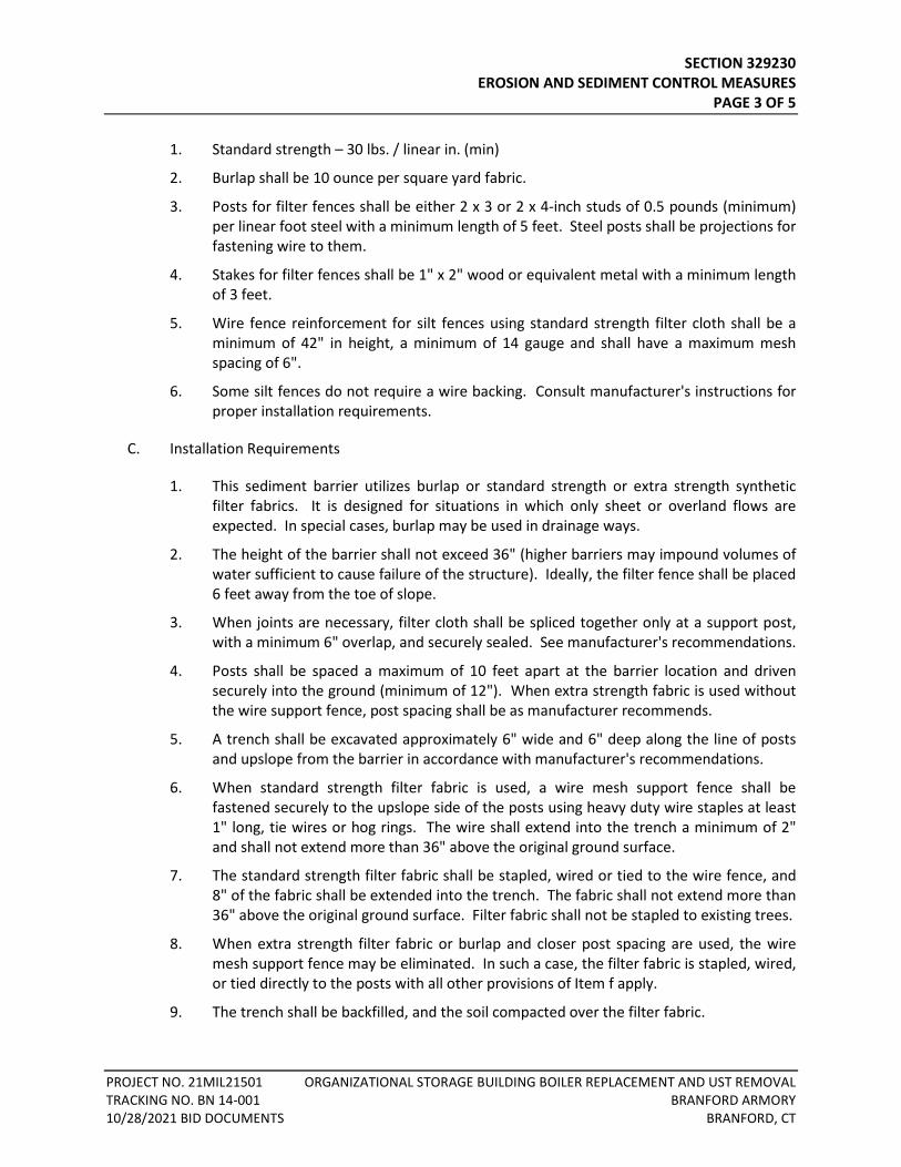
SECTION 329230 EROSION AND SEDIMENT CONTROL MEASURES
PAGE 3 OF 5
PROJECT NO. 21MIL21501 ORGANIZATIONAL STORAGE BUILDING BOILER REPLACEMENT AND UST REMOVAL TRACKING NO. BN 14-001 BRANFORD ARMORY 10/28/2021 BID DOCUMENTS BRANFORD, CT
1. Standard strength – 30 lbs. / linear in. (min)
2. Burlap shall be 10 ounce per square yard fabric.
3. Posts for filter fences shall be either 2 x 3 or 2 x 4-inch studs of 0.5 pounds (minimum) per linear foot steel with a minimum length of 5 feet. Steel posts shall be projections for fastening wire to them.
4. Stakes for filter fences shall be 1" x 2" wood or equivalent metal with a minimum length of 3 feet.
5. Wire fence reinforcement for silt fences using standard strength filter cloth shall be a minimum of 42" in height, a minimum of 14 gauge and shall have a maximum mesh spacing of 6".
6. Some silt fences do not require a wire backing. Consult manufacturer's instructions for proper installation requirements.
C. Installation Requirements
1. This sediment barrier utilizes burlap or standard strength or extra strength synthetic filter fabrics. It is designed for situations in which only sheet or overland flows are expected. In special cases, burlap may be used in drainage ways.
2. The height of the barrier shall not exceed 36" (higher barriers may impound volumes of water sufficient to cause failure of the structure). Ideally, the filter fence shall be placed 6 feet away from the toe of slope.
3. When joints are necessary, filter cloth shall be spliced together only at a support post, with a minimum 6" overlap, and securely sealed. See manufacturer's recommendations.
4. Posts shall be spaced a maximum of 10 feet apart at the barrier location and driven securely into the ground (minimum of 12"). When extra strength fabric is used without the wire support fence, post spacing shall be as manufacturer recommends.
5. A trench shall be excavated approximately 6" wide and 6" deep along the line of posts and upslope from the barrier in accordance with manufacturer's recommendations.
6. When standard strength filter fabric is used, a wire mesh support fence shall be fastened securely to the upslope side of the posts using heavy duty wire staples at least 1" long, tie wires or hog rings. The wire shall extend into the trench a minimum of 2" and shall not extend more than 36" above the original ground surface.
7. The standard strength filter fabric shall be stapled, wired or tied to the wire fence, and 8" of the fabric shall be extended into the trench. The fabric shall not extend more than 36" above the original ground surface. Filter fabric shall not be stapled to existing trees.
8. When extra strength filter fabric or burlap and closer post spacing are used, the wire mesh support fence may be eliminated. In such a case, the filter fabric is stapled, wired, or tied directly to the posts with all other provisions of Item f apply.
9. The trench shall be backfilled, and the soil compacted over the filter fabric.
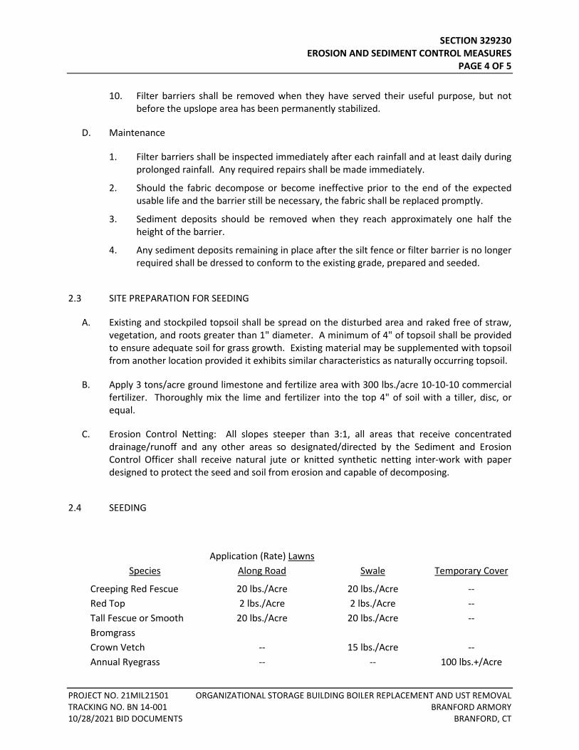
SECTION 329230 EROSION AND SEDIMENT CONTROL MEASURES
PAGE 4 OF 5
PROJECT NO. 21MIL21501 ORGANIZATIONAL STORAGE BUILDING BOILER REPLACEMENT AND UST REMOVAL TRACKING NO. BN 14-001 BRANFORD ARMORY 10/28/2021 BID DOCUMENTS BRANFORD, CT
10. Filter barriers shall be removed when they have served their useful purpose, but not before the upslope area has been permanently stabilized.
D. Maintenance
1. Filter barriers shall be inspected immediately after each rainfall and at least daily during prolonged rainfall. Any required repairs shall be made immediately.
2. Should the fabric decompose or become ineffective prior to the end of the expected usable life and the barrier still be necessary, the fabric shall be replaced promptly.
3. Sediment deposits should be removed when they reach approximately one half the height of the barrier.
4. Any sediment deposits remaining in place after the silt fence or filter barrier is no longer required shall be dressed to conform to the existing grade, prepared and seeded.
2.3 SITE PREPARATION FOR SEEDING
A. Existing and stockpiled topsoil shall be spread on the disturbed area and raked free of straw, vegetation, and roots greater than 1" diameter. A minimum of 4" of topsoil shall be provided to ensure adequate soil for grass growth. Existing material may be supplemented with topsoil from another location provided it exhibits similar characteristics as naturally occurring topsoil.
B. Apply 3 tons/acre ground limestone and fertilize area with 300 lbs./acre 10-10-10 commercial fertilizer. Thoroughly mix the lime and fertilizer into the top 4" of soil with a tiller, disc, or equal.
C. Erosion Control Netting: All slopes steeper than 3:1, all areas that receive concentrated drainage/runoff and any other areas so designated/directed by the Sediment and Erosion Control Officer shall receive natural jute or knitted synthetic netting inter-work with paper designed to protect the seed and soil from erosion and capable of decomposing.
2.4 SEEDING
Species
Application (Rate) Lawns Along Road
Swale
Temporary Cover
Creeping Red Fescue 20 lbs./Acre 20 lbs./Acre -- Red Top 2 lbs./Acre 2 lbs./Acre -- Tall Fescue or Smooth 20 lbs./Acre 20 lbs./Acre -- Bromgrass Crown Vetch -- 15 lbs./Acre -- Annual Ryegrass -- -- 100 lbs.+/Acre
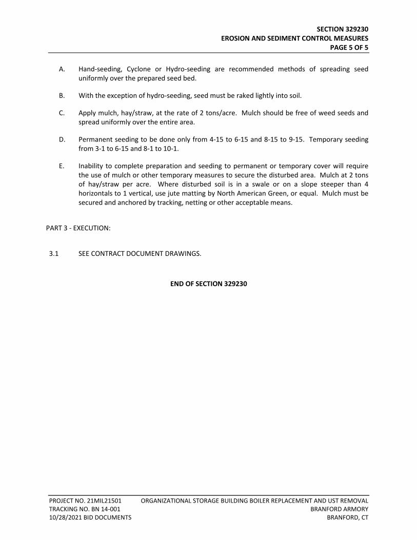
SECTION 329230 EROSION AND SEDIMENT CONTROL MEASURES
PAGE 5 OF 5
PROJECT NO. 21MIL21501 ORGANIZATIONAL STORAGE BUILDING BOILER REPLACEMENT AND UST REMOVAL TRACKING NO. BN 14-001 BRANFORD ARMORY 10/28/2021 BID DOCUMENTS BRANFORD, CT
A. Hand-seeding, Cyclone or Hydro-seeding are recommended methods of spreading seed uniformly over the prepared seed bed.
B. With the exception of hydro-seeding, seed must be raked lightly into soil.
C. Apply mulch, hay/straw, at the rate of 2 tons/acre. Mulch should be free of weed seeds and spread uniformly over the entire area.
D. Permanent seeding to be done only from 4-15 to 6-15 and 8-15 to 9-15. Temporary seeding from 3-1 to 6-15 and 8-1 to 10-1.
E. Inability to complete preparation and seeding to permanent or temporary cover will require the use of mulch or other temporary measures to secure the disturbed area. Mulch at 2 tons of hay/straw per acre. Where disturbed soil is in a swale or on a slope steeper than 4 horizontals to 1 vertical, use jute matting by North American Green, or equal. Mulch must be secured and anchored by tracking, netting or other acceptable means.
PART 3 - EXECUTION:
3.1 SEE CONTRACT DOCUMENT DRAWINGS.
END OF SECTION 329230

Related Documents